new joining technology for metal pipe in the construction
TRANSCRIPT

New Joining Technology for Metal Pipe in the Construction Industry Breakthrough Strategy Committee
BTSC Document 2003-01
September 2003
BREAK THROUGH
Breakthrough Strategy CommitteeConstruction Industry Institute
BREAK THROUGH
Breakthrough Strategy CommitteeConstruction Industry Institute

ii
New Joining Technology for
Metal Pipe in the Construction Industry
Prepared by
Construction Industry Institute
Breakthrough Strategy Committee
BTSC Document 2003-1
September 2003

iii
Breakthrough Strategy Committee Members Steve E. Brindza, The Procter & Gamble Company Paul D. Domich, National Institute of Standards & Technology Edward S. Givens, Construction Industry Institute Paul M. Goodrum, University of Kentucky
* Carl T. Haas, The University of Texas at Austin Robert C. Jacobs, 3M Company John B. Kapustay, Kier/CCC USA
* Changwan Kim, The University of Texas at Austin Kenneth E. Olmsted, Smithsonian Institution Judith W. Passwaters, E. I. DuPont de Nemours & Co., Inc. C. Robert Seay, Tennessee Valley Authority Sivaraj Shyam-Sunder, U.S. Department of Commerce/NIST C. Chatt Smith, Jacobs Gilbert M. Staudt, ExxonMobil Development Company * Principal Author
Past Members Raymond P. Baker, Rohm and Haas Company W. Kendall Burkhart, BIBB & Associates John T. Capener, Dillingham Construction N.A., Inc. Michael P. Childers, The Shaw Group Inc. John L. Cutts, POM Technology Americas John F. Dunn, Chevron Project Resources Company Bryson G. Edmonds, BE&K Construction Company Peter H. Emmons, Structural Group Dwight A. Fiveash, Celanese Lee R. Hale, ALCOA Inc. William B. Hardin, Technip USA Corporation James F. Hilgers, Rust Constructors Inc. Emerson T. Johns, DuPont Company Timothy S. Killen, Bechtel Corporation Brigitte H. Laki, Exxon Chemical Company John S. Lambert, Eli Lilly and Company Michael W. Lowder, Eastman Chemical Company Daniel J. Maas, National Center for Manufacturing Gerhard Meinecke, SAP Labs, Inc. Kim Metcalf-Kupres, Johnson Controls, Inc. James W. Mortell, Cherne Contracting Corporation Get W. Moy, Naval Facilities Engineering Command Jeffrey Jay Osmond, U.S. Department of State Boyd C. Paulson, Stanford University

iv
Kenneth F. Reinschmidt, Kenneth F. Reinschmidt K. Keith Roe, Burns and Roe Enterprises, Inc. Larry E. Ruhland, Bechtel Corporation Robert E. Sellers, Champion International Corporation Mohan Singh, U.S. Army Corps of Engineers Jack E. Snell, U.S. Department of Commerce/NIST Zachary L. Zimmerman, Burns and Roe Enterprises, Inc.

v
Table of Contents
List of Figures ................................................................................................... vi
List of Tables .................................................................................................... vii
Executive Summary .........................................................................................viii
Chapter 1: Introduction ...................................................................................... 1
Chapter 2: Current Joining Processes in the Construction Industry ................. 3
Chapter 3: Need for Advanced Pipe-Joining Technology ................................ 9
Chapter 4: Assessment of Advanced Joining Technologies ........................... 12
Chapter 5: Evaluation Process for Advanced Joining Technologies ............. 30
Chapter 6: Evaluation of Advanced Joining Technologies ............................ 36
Chapter 7: Business Analysis .......................................................................... 45
Chapter 8: Recommendations for Future Research ........................................ 48
Chapter 9: Conclusion and Recommendations ............................................... 55
References ........................................................................................................ 56

vi
List of Figures
Number Page
1. Technology Improvement Needs in the Construction Industry............. 4
2. Taxonomy of Joining Technology ........................................................ 12
3. Pressfit® System .................................................................................... 13
4. Permalok® System ................................................................................ 14
5. Metal Joining Using High Adhesive Bonding ...................................... 15
6. Gas–Tungsten Arc Welding .................................................................. 17
7. Shielded-Metal Arc Welding ................................................................ 18
8. Gas–Metal Arc Welding ....................................................................... 19
9. Electron-Beam Welding ........................................................................ 20
10. Flash Butt Welding ............................................................................... 22
11. Explosion Welding ................................................................................ 23
12. Friction Welding ................................................................................... 24
13. Diffusion Weld Riveted ........................................................................ 25
14. Enclosed Orbital Weldhead .................................................................. 28
15. MIG Welding ........................................................................................ 29
16. Hierarchical Structure ............................................................................ 31
17. Ranking of Weighted Factors ................................................................ 34
18. Ranking of Applicability of Advanced Joining Technologies............... 44

vii
List of Tables
Number Page
1. Profile of Piping Surveyed ................................................................. 3
2. Percentage of Rework in Piping .........................................................4
3. Piping Steps ....................................................................................... 5
4. Pipe Materials .................................................................................... 5
5. Example of Step 2 in Factor-Weighting Process ............................. 32
6. Example of Step 3 in Factor-Weighting Process ............................. 32
7. Example of Step 4 in Factor-Weighting Process ............................. 33
8. Pipe Joining Score Sheet .................................................................. 33
9. Evaluation Model for Pipe Joining ...................................................35
10. Assessment of Mechanical Joining .................................................. 36
11. Assessment of Adhesive Bonding ................................................... 37
12. Assessment of Fusion Welding ........................................................ 39
13. Assessment of Non-Fusion Welding ............................................... 41
14. Assessment of Brazing and Soldering ............................................. 42
15. Assessment of Welding Automation ............................................... 43
16. Welding Expenditure in 2000 ............................................................46
17. Labor Cost for Welding, CII Model Plant ...................................... 47
18. Equipment Cost for Welding ........................................................... 47
19. Total Direct Cost of Welding ........................................................... 47

viii
Executive Summary
Pipe joining is one of the most critical but inefficient processes in the construction
industry. This report identifies several of the underlying causes for that inefficiency,
including: (1) the shortage of skilled labor, (2) the low productivity of joining processes
currently in use, and (3) the reluctance on the part of welders to switch to newer
technology. Also discussed is the general agreement within the construction industry of
the need for identifying breakthrough methods that would improve the pipe-joining
process.
This paper covers mechanical joining, adhesive bonding, welding, and welding
automation. Successful adoption of these advanced joining technologies for metal pipe
could yield notable results, such as significant reductions in both processing time and the
need for skilled labor, a decrease in costs associated with the joining process; and
improvements in the strengths of joints. That is, advanced joining technologies may have
an impact not only on costs and scheduling, but on productivity and maintenance.
Which of these processes holds the most promise is open to question, however, for
two reasons: first, the uncertainty as to what types of joints produced with these methods
would be suitable for typical construction applications; and second, the fact that each of
them would have to be adapted for field application or prefabrication work and then
thoroughly tested before adoption by the industry.
1
1
Introduction
Virtually every manufactured product contains joints that are used to assemble
similar materials into a more complex shape or product. In the U.S., the $50 billion-a-
year business of joining technologies is high tech and research efforts surrounding it are
intense.
In contrast to other industries, however, joining technology in construction has
not seen much advancement. In particular, metal-pipe joining is an extremely labor-
intensive and costly process. In 1982, The Business Roundtable released the summary
publication of its five-year study of the industry, the Construction Industry Cost
Effectiveness (CICE) Project. The Roundtable found that pipe joining is one of the most
expensive yet most inefficient elements of major industrial construction projects.
Furthermore, the Roundtable identified it as the task with the greatest potential for
technological advancement (Rickard and Tucker, 1982). Even today, some 20-plus years
after the CICE Project was completed, the inefficiency of processes used in metal-pipe
joining persists. In fact, according to 2002 benchmarking and metrics data published by
CII, the percentage of work that has to be redone in piping processes is much higher than
in other type of construction tasks.
Besides the need for improved processes, the shortage of skilled labor has also
become an issue of deep concern in the construction industry. Welders are offered lower
compensation in construction than in other industries, and therefore many competent
welders do not even consider taking on construction work.
Although considerable research has been conducted outside of the construction
industry in the area of welding, not all of the available technology is being used to its
potential (Tucker, 1982). Successful application of advanced joining technologies
requires a deep understanding of both current joining practice and advanced joining
technologies (Eager, 1990).

2
The primary objective here is to explore the applicability of advanced joining
technologies to the use of metal pipe in the construction industry. In support of this
objective, this paper investigates current practices in metal-pipe joining in construction as
well as utilization of advanced joining technologies in other industries. It is expected that
an enhanced understanding of both of these areas would result in a better determination
of the potential for application of alternative joining technologies in the construction
industry and more effective implementation of those technologies. In addition, a number
of advanced joining technologies are evaluated, from both technical and business
perspectives, and recommendations are made regarding the adoption of advanced joining
technologies that could serve as a replacement for current practices.
The scope of this paper is limited to metal-pipe used in industrial construction
projects. It begins with a review of current practices with respect to metal-pipe joining in
construction. The current status of pipe joining is examined, and the materials from
which metal pipe is made, the methods used in metal-pipe joining, and piping codes and
specifications are discussed. Needs for, and benefits of, advanced joining technology are
identified, and a tool for evaluating the applicability of various methods to construction is
presented. New joining technologies, including mechanical joining, adhesive bonding,
welding, and welding automation, are then introduced, and their applicability to the
construction industry is assessed by means of this evaluation tool. A business analysis is
then carried out to identify the business impact of advanced joining technologies in the
industry. Finally, business cases are suggested.

3
2 Current Joining Processes in the Construction Industry
This chapter provides background information on the joining of metal, beginning with
a review of processes currently in use for the joining of metal pipe. The current status of
pipe joining is addressed, and the materials and joining methods currently in use, as well
as piping codes and specifications, are discussed.
Status of Pipe Joining
Piping in the Construction Industry
Piping comprises a large portion of the work done in the construction industry, in
terms of both the amount of labor required and the cost of construction (see Table 1).
This is especially true of heavy construction and the power sector, where piping is the
largest single contributing factor of all the different categories of work involved (Tucker,
1982; CII, 2002).
Table 1. Profile of Piping Surveyed (Tucker, 1982)
BuildingLight
Industry Heavy
Industry Power Average Project Cost ($ millions) 25 120 190 470 Average Peak Work Force 300 600 900 1600 Labor Percentage by Craft (%) 9 14 22 18 Construction Cost Distribution (%) 3.4 11.6 23.9 16.1
Piping Productivity
In spite of its importance, piping is the most inefficient of all major construction areas
(Tucker, 1982). According to 2002 CII benchmarking data, the amount of piping work
that has to be redone is about 13.3 percent of the total (Table 2), compared to only six
percent of the total, on average, for all areas of construction combined (CII, 2002).

4
Table 2 Percentage of Rework in Piping
Total Rework (hours/year) 288,480 Total work (hours/year) 2,170,244 Percentage 13.29%
Technology Needs Assessment
Given its low productivity, piping is the area with the greatest need for technological
advancements that would yield improved processes. According to the technology needs
assessment for the CICE Project, piping ranked ahead of all other categories of
construction in terms of the need for technology improvements (Tucker, 1982). In Figure
1, the high numbers present significant opportunities for technological improvement.
0 50 100 150 200 250 300 350
Piping
Electrical
Structure
MechanicalEquipm ent
Enclosure Skin
Interior FinishesBuilding
Light Ind.
Heavy Ind.
Power
Figure 1. Technology Improvement Needs in the Construction Industry (Tucker, 1982)
5
Pipe Joining
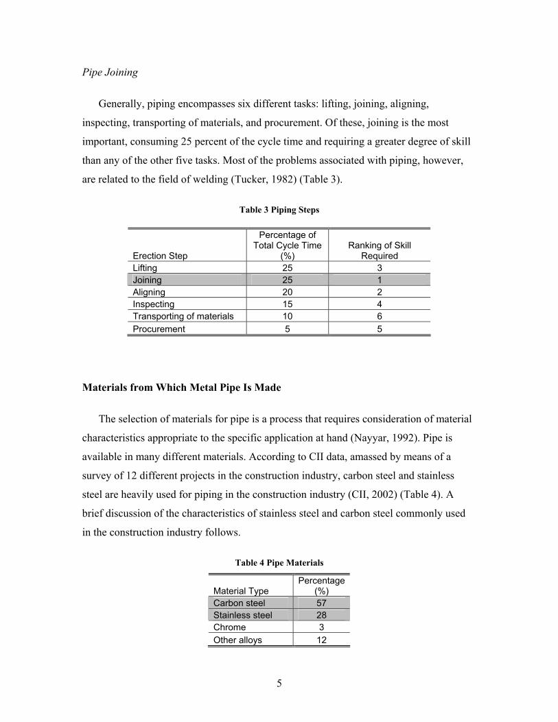
Generally, piping encompasses six different tasks: lifting, joining, aligning,
inspecting, transporting of materials, and procurement. Of these, joining is the most
important, consuming 25 percent of the cycle time and requiring a greater degree of skill
than any of the other five tasks. Most of the problems associated with piping, however,
are related to the field of welding (Tucker, 1982) (Table 3).
Table 3 Piping Steps
Erection Step
Percentage of Total Cycle Time
(%) Ranking of Skill
Required Lifting 25 3 Joining 25 1 Aligning 20 2 Inspecting 15 4 Transporting of materials 10 6 Procurement 5 5
Materials from Which Metal Pipe Is Made
The selection of materials for pipe is a process that requires consideration of material
characteristics appropriate to the specific application at hand (Nayyar, 1992). Pipe is
available in many different materials. According to CII data, amassed by means of a
survey of 12 different projects in the construction industry, carbon steel and stainless
steel are heavily used for piping in the construction industry (CII, 2002) (Table 4). A
brief discussion of the characteristics of stainless steel and carbon steel commonly used
in the construction industry follows.
Table 4 Pipe Materials
Material Type Percentage
(%) Carbon steel 57 Stainless steel 28 Chrome 3 Other alloys 12

6
Stainless Steel
Stainless steel is commonly used in cryogenic and chemical pipelines, as well as in
stainless steel tubing for domestic water supplies, plumbing, and heating. Stainless steel
offers good corrosion resistance, toughness, ductility, and weld-ability, but is rather
expensive (Dickenson, 1999). Schedule 5S pipe and Schedule 10S light-wall stainless
pipe are commonly used to reduce costs (Nayyar, 1992).
Carbon Steel
Carbon steel, widely used for piping material, offers good strength and is relatively
inexpensive. It has low corrosion resistance, however, so its use is limited to non-
corrosive applications (Dickenson, 1999).
Current Methods of Metal-Pipe Joining
The choice of methods of pipe joining depends on a variety of factors, such as pipe
diameter, pipe material, pressure rating, and other service requirements (Dickenson,
1999). A brief discussion of current methods of metal-pipe joining follows.
Welding
Welding can be used to join pipes of any diameter and is a leak-proof method.
Because of the shortage of highly skilled welders, welding is somewhat limited
(Dickenson, 1999). Stick welding (shielded-metal arc welding) is the most popular
method in use in the construction industry. Even though MIG and TIG welding offer
better performance than stick welding, it is still dominant because there has been
considerable reluctance on the part of welders in the various construction trades to use
other methods (Kapustay, 2002).
Two of the major reasons for the welding processes being so inconvenient and costly
are the need to utilize heavy equipment and the high degree of skill required. It is not
uncommon for welders to have to take an hour or more of their time to break down the
heavy equipment before moving it to the place where the next set of welds is to be made.
7
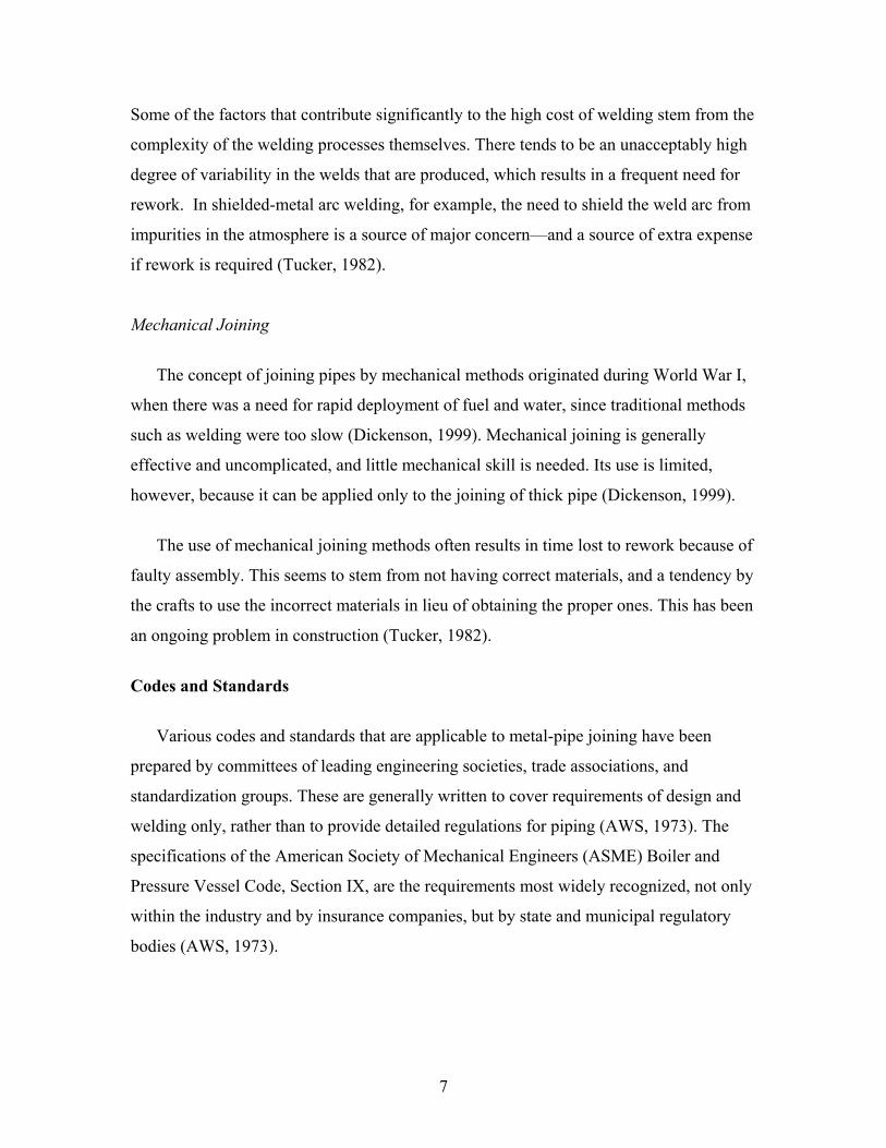
Some of the factors that contribute significantly to the high cost of welding stem from the
complexity of the welding processes themselves. There tends to be an unacceptably high
degree of variability in the welds that are produced, which results in a frequent need for
rework. In shielded-metal arc welding, for example, the need to shield the weld arc from
impurities in the atmosphere is a source of major concern—and a source of extra expense
if rework is required (Tucker, 1982).
Mechanical Joining
The concept of joining pipes by mechanical methods originated during World War I,
when there was a need for rapid deployment of fuel and water, since traditional methods
such as welding were too slow (Dickenson, 1999). Mechanical joining is generally
effective and uncomplicated, and little mechanical skill is needed. Its use is limited,
however, because it can be applied only to the joining of thick pipe (Dickenson, 1999).
The use of mechanical joining methods often results in time lost to rework because of
faulty assembly. This seems to stem from not having correct materials, and a tendency by
the crafts to use the incorrect materials in lieu of obtaining the proper ones. This has been
an ongoing problem in construction (Tucker, 1982).
Codes and Standards
Various codes and standards that are applicable to metal-pipe joining have been
prepared by committees of leading engineering societies, trade associations, and
standardization groups. These are generally written to cover requirements of design and
welding only, rather than to provide detailed regulations for piping (AWS, 1973). The
specifications of the American Society of Mechanical Engineers (ASME) Boiler and
Pressure Vessel Code, Section IX, are the requirements most widely recognized, not only
within the industry and by insurance companies, but by state and municipal regulatory
bodies (AWS, 1973).

8
American National Standards Institute
The American National Standards Institute (ANSI) issued a joint code for pressure
piping nearly 30 years ago with the American Society of Mechanical Engineers (ASME)
Details follow:
ASME/ANSI Code for Pressure Piping B31, Pressure Piping Code Sections:
B31.1, Power Piping
B31.2, Industrial Gas and Air Piping
B31.3, Chemical Plant and Petroleum Refinery Piping
B31.4, Oil Transportation Piping
B31.5, Refrigeration Piping
B31.6, Chemical Industry Process Piping
B31.7, Nuclear Power Piping
B31.8, Gas Transmission and Distribution Piping Systems
American Society of Mechanical Engineers
The ASME has issued code to cover piping connected to boilers. Of the 11 sections of
its Boiler and Pressure Vessel Code, ASME cites the following as related to industrial
piping:
Section I, Power Boilers
Section IV, Heating Boilers
Section VI, Recommended Rules for Care and Operation of Heating Boilers
Section IX, Qualification Standards for Welding and Brazing Procedures, Welders,
Brazers, and Welding and Brazing Operators
American Petroleum Institute
In 1973, the American Petroleum Institute (API) issued a standard for field welding
of pipeline, API Standard 1104, which includes weld-quality acceptability limits,
inspection requirements, and welding-procedure test requirements.
9
3
Need for Advanced Pipe-Joining Technology
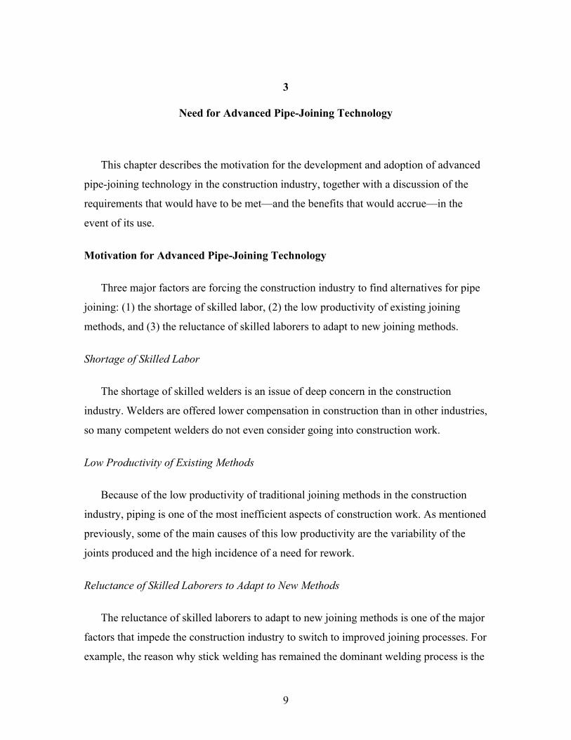
This chapter describes the motivation for the development and adoption of advanced
pipe-joining technology in the construction industry, together with a discussion of the
requirements that would have to be met—and the benefits that would accrue—in the
event of its use.
Motivation for Advanced Pipe-Joining Technology
Three major factors are forcing the construction industry to find alternatives for pipe
joining: (1) the shortage of skilled labor, (2) the low productivity of existing joining
methods, and (3) the reluctance of skilled laborers to adapt to new joining methods.
Shortage of Skilled Labor
The shortage of skilled welders is an issue of deep concern in the construction
industry. Welders are offered lower compensation in construction than in other industries,
so many competent welders do not even consider going into construction work.
Low Productivity of Existing Methods
Because of the low productivity of traditional joining methods in the construction
industry, piping is one of the most inefficient aspects of construction work. As mentioned
previously, some of the main causes of this low productivity are the variability of the
joints produced and the high incidence of a need for rework.
Reluctance of Skilled Laborers to Adapt to New Methods
The reluctance of skilled laborers to adapt to new joining methods is one of the major
factors that impede the construction industry to switch to improved joining processes. For
example, the reason why stick welding has remained the dominant welding process is the

10
considerable degree of reluctance on the part of welders in the various construction trades
to give other methods a try (Kapustay, 2002).
Benefits/Requirements of Advanced Joining Technology
Successful adoption of advanced joining technology for metal pipe could yield
notable results, such as (1) significant reductions in both processing time and the need for
skilled labor, (2) a decrease in costs associated with the joining process, and (3)
improvements in the strengths of joints (Eager, 1990).
To reap the benefits of new technology, however, certain requirements must be
satisfied. The basic characteristics that any viable joining technique with a wide range of
applicability must offer include the following: (1) production of strong and reliable joints,
(2) suitability for small- and large-area bonding, (3) minimal need for surface preparation,
and (4) suitability for use in a production environment (Silverman, 1989). The study by
Thompson suggests six factors that are critical to the success of a pipe-joining operation:
(1) pressure–temperature ratings, (2) material compatibility, (3) external loading, (4)
operability, maintainability, and reliability, (5) long-term effects, and (6) cost.
The following discussion of the impact of using advanced joining technology is
broken down into four main categories: (1) structural integrity, (2) management concerns,
(3) productivity factors, and (4) maintenance issues.
Structural Integrity
The structural integrity of a joint is determined by its ability to function properly
within the overall system(s) of which it is a part. Structural integrity comprises three
elements: (1) joint strength, (2) material compatibility, and (3) durability.
Joint strength is a measure of the ability of a joint to sustain internal forces (such as
internal pressure) and external forces (including shear forces, torsion, and bending) that
are due to factors such as variations in temperature. Material compatibility is the degree
to which the individual elements of a joint are able to function as a unit and resist the

11
tendency to corrode one another; this is important since corrosion can reduce the strength
of a pipe joint (Thompson, 1998). Durability is the ability of a joint to retain its strength
and serve its intended purpose over an extended period of time.
Management Concerns
Management concerns encompass all the factors that have an impact in terms of cost.
Any given type of joining technology that is adopted has the potential to affect not only
the direct costs of production, such as labor and equipment, but also indirect costs such as
training of the welders. The costs that must be considered by management in choosing a
joining technique can be classified as: (1) training, (2) materials, (3) equipment, and (4)
labor.
Productivity Factors
Productivity factors consist of everything that affects the efficiency of the joining
process. Productivity of any joining technique is dependent on the following properties:
(1) processing time, (2) degree of rework, (3) ease of installation, (4) field usability, and
(5) extent of surface preparation.
Maintenance Issues
The initial cost of producing a pipe joint is only part of its total cost. What needs to be
considered are all the costs that accrue over the expected life of the plant, as well as the
performance of the joints that are produced. Long-term effects due to erosion, fatigue,
and creep, all of which can affect the performance of a pipe joint, may be significant.
Maintenance issues can be grouped into two categories: (1) long-term performance
reliability and (2) life-cycle cost.

12
4
Assessment of Advanced Joining Technologies
The three predominant reasons for joining materials are to achieve function, to
achieve structural efficiency, and to minimize costs (Messler, 1993). A number of
different joining technologies exist, each with its own set of advantages and
disadvantages.
Joining processes are usually divided into mechanical joining, welding, and adhesive
bonding (fig. 2). A discussion of the characteristics of existing processes in these three
categories, replete with examples of systems currently on the market, follows.
Mechanical Joining
In mechanical joining, materials are joined by the use of fasteners (mechanical
fasteners) or through an integral design feature (mechanical interlocking; Messler, 1993).
Figure 2. Taxonomy of Joining Technology

13
The mechanical joining process relies on residual stresses, which ensure the integrity of
the joints (Brandon and Kaplan, 1997). These stresses may occur either in the fastening
(mechanical fastener) or in the components themselves (mechanical interlocking;
Brandon and Kaplan, 1997). Mechanical joining has several advantages, such as ease of
installation and stability of the chemical composition of the materials. Because of
significantly concentrated stresses resulting from this approach, however, mechanical
joining has limited applicability (Messler, 1993).
Mechanical Fastening
Mechanical fastening, which applies interference forces to the elements, is divided
into two categories: threaded fasteners and non-threaded fasteners. Threaded fasteners
apply force using threads such as those in bolts, screws, or nuts, while non-threaded
fasteners apply force using pin action such as that which takes place in rivets, pins, or
keys (Messler, 1993).
An example of a mechanical fastening process is the Pressfit® System, developed by
Victaulic ®, which has been widely used; this technology is used in piping installations
and employs a system of Pressfit® couplings, elbows, tees, reducers, and adapters
(Victaulic, 2002). It incorporates Schedule 5 stainless product and carbon steel product
from ¾ inch to 2 inches in length (Victaulic 2002). Currently, the Victaulic® Pressfit®
System is available only on Schedule 5 pipe, and its use is limited to the conveyance of
water because it cannot withstand pressures above 300 psi (Victaulic, 2002).
Figure 3. Pressfit® System (Victaulic, 2002)
14
Mechanical Interlocking
While mechanical fastening uses fasteners to apply force, mechanical interlocking
exploits the interaction between the elements themselves (Messler, 1993).
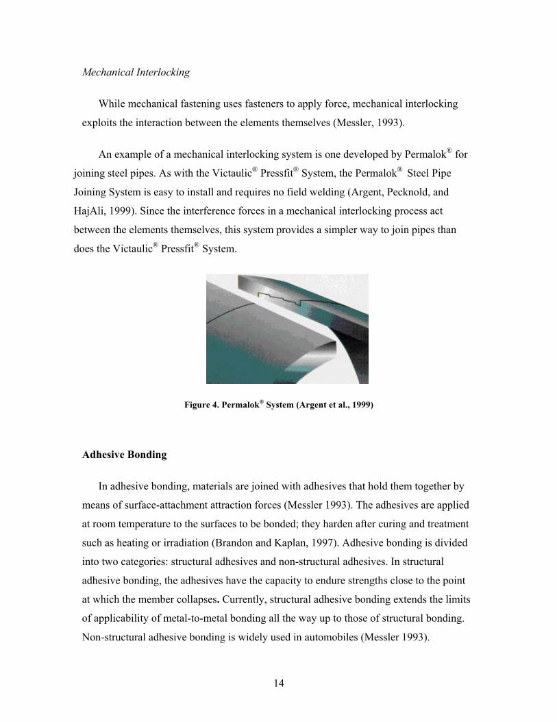
An example of a mechanical interlocking system is one developed by Permalok® for
joining steel pipes. As with the Victaulic® Pressfit® System, the Permalok® Steel Pipe
Joining System is easy to install and requires no field welding (Argent, Pecknold, and
HajAli, 1999). Since the interference forces in a mechanical interlocking process act
between the elements themselves, this system provides a simpler way to join pipes than
does the Victaulic® Pressfit® System.
Adhesive Bonding
In adhesive bonding, materials are joined with adhesives that hold them together by
means of surface-attachment attraction forces (Messler 1993). The adhesives are applied
at room temperature to the surfaces to be bonded; they harden after curing and treatment
such as heating or irradiation (Brandon and Kaplan, 1997). Adhesive bonding is divided
into two categories: structural adhesives and non-structural adhesives. In structural
adhesive bonding, the adhesives have the capacity to endure strengths close to the point
at which the member collapses. Currently, structural adhesive bonding extends the limits
of applicability of metal-to-metal bonding all the way up to those of structural bonding.
Non-structural adhesive bonding is widely used in automobiles (Messler 1993).
Figure 4. Permalok® System (Argent et al., 1999)

15
The major benefits of adhesive bonding are convenience and relatively low cost.
Adhesive bonding is difficult to use in the joining of pipe, however, because of the lack
of a chemical bond between the composite and the adhesive (Lea, Stubblefield, and Pang,
1998). The low resistance of adhesive bonding techniques as a function of bending load
is regarded as the most significant obstacle to its use (Lea, Stubblefield, and Pang, 1998).
The magnitude of the resistance is just 30 percent of that which is obtained using butt-
weld methods, so failure is common at the composite-adhesive interface (Lea,
Stubblefield, and Pang, 1998).
The limitations of adhesive bonding have been lessened as a result of technology
advances. In fact, 3M has developed a high-strength adhesive bonding technique that
offers a normal tensile strength of 160 psi and dynamic shear strength of 100 psi. High-
strength adhesive bonding, developed by 3M, demonstrate the potential of this technique
for use in a wide range of applications. They have been used in interior and exterior
applications for the past 20 years. In many applications, these adhesives can replace
mechanical fasteners while creating virtually invincible bonds. Unlike the stress points
common to mechanical fasteners, high-strength bonding distributes the stress. They
provide a clean, direct, and durable bonding of 24-oz. and 48-oz. copper panels, as well
as 3/16-inch-thick cast-bronze medallions, to brass without the use of mechanical
fasteners. The bond resists weathering and compensates for thermal expansion and
contraction of the metals due to seasonal changes in temperature (3M, 2002).
Figure 5. Metal Joining Using High Adhesive Bonding (3M, 2002)

16
Welding
According to Messler, welding is defined as a process in which materials of the same
type or class are joined together through the formation of primary bonds under the action
of heat, pressure, or the combined action of heat and pressure (Messler, 1993). The
primary reason for welding being used so extensively as a joining process is that it offers
high integrity of joints, a wide variety of processes and approaches, and considerable
opportunities for automation. In spite of its many benefits, however, welding has serious
disadvantages, such as high operating costs, a shortage of skilled labor, and lack of
controllability of the process itself (Messler, 1993).
Even though there are several classification systems for welding processes, welding is
typically classified as either fusion welding or non-fusion welding, depending on whether
or not significant melting is involved (Messler, 1993).
Fusion Welding
In fusion welding, the materials to be joined are heated to a temperature that lies
above the melting points of both of them. Fusion welding processes include all those in
which the melting or fusion of portions of substrates play a significant role in the
formation of joining (Messler 1993). Fusion welding includes gas, arc, resistance, and
high-energy beam welding; it requires significant melting, and usually produces a joint
via the application of heat rather than pressure (Ageorges, Ye, and Hou, 2001)
Arc Welding
Arc welding uses an electric arc as a source of heat. The arc employed is created
between an electrode and a workpiece. Arc welding is further subdivided into
nonconsumable-electrode processes and consumable-electrode processes, depending on
whether the electrode is intended to be permanent or not (Messler, 1993). One important
feature of arc welding is the shielding that is done to prevent oxidation of the highly
reactive molten weld metal, thereby helping to stabilize the arc (Messler, 1993).

17
Gas–tungsten arc welding and plasma arc welding are the predominant forms of
nonconsumable-electrode arc welding. Gas–metal arc welding, shielded-metal arc
welding, flux-cored arc welding, submerged-arc welding, electrogas welding, and
electroslag welding are common forms of consumable-electrode arc welding (Messler,
1993). The processes reviewed here are (a) gas–tungsten arc welding, (b) shielded-metal
arc welding and (c) gas-metal arc welding. Because of their strong potential for
automation, these types of arc welding are the most heavily developed and most widely
used in the industry.
Gas–tungsten arc welding: Gas–tungsten arc welding, also referred to as tungsten–
inert-gas (TIG) welding, enables a wide range of ferrous alloys to be welded without the
use of a flux, which is a chemical agent that is used to clean and activate the surface of a
material in order to promote bonding. Gas—tungsten arc welding uses a permanent,
nonconsumable tungsten electrode to create an arc (Messler, 1993). With this method, the
arc burns between the tungsten electrode and the workpiece, both of which are shielded
by the inert gas argon, thereby keeping out air and preventing contamination of the
electrodes and the molten metal (Davies, 1993). The gas—tungsten arc welding process
is good for welding thin sections and, because of its inherently low heat input, offers
excellent bonding and better control of weld filler dilution by the substrate than many
other processes. Its greatest limitation is its slow deposition rate (Messler, 1993).
Figure 6. Gas–Tungsten Arc Welding (Messler, 1993)

18
Shielded-metal arc welding (stick welding): In shielded-metal arc welding, also
referred to as stick welding, metal joining is brought about by the heat from an electric
arc that is maintained between the tip of a consumable electrode and the surface of the
base metal being welded. A core wire conducts the electric current from a constant-
current power supply to the arc and delivers most of the filler metal to the joint (Messler,
1993). Advantages of shielded-metal arc welding are that it is simple and portable, and
does not require expensive equipment. Like all manual processes, however, and to an
even greater degree than most, shielded-metal arc welding requires considerable welding
skill for best results. In addition, the operating cost of shielded-metal arc welding is
higher than MIG welding because of the lower deposition rate achieved with the former
(Messler, 1993).
Gas-metal arc welding: The gas-metal arc welding process, referred to as metal-inert-
gas (MIG) welding, utilizes an externally supplied inert shielding gas and a continuous
solid-wire electrode. The consumable solid-wire electrode provides all of the filler to the
weld joint. The externally supplied shielding gas guards the arc and the molten weld
metal from penetration by air and offers desired arc uniqueness throughout its effect on
Figure 7. Shielded-Metal Arc Welding (Messler, 1993)

19
ionization (Messler, 1993). Gas-metal arc welding offers flexibility, versatility, and the
potential for automation. In addition, it requires less welding skill and has a higher
deposition rate than shielded-metal arc welding, thus making available a much faster
process. Its greatest limitation is its high cost (Messler, 1993).
Gas Welding.
Typically, gas welding includes any welding process in which the source of heat is a
combustible fuel such as natural gas, propane, or butane. Oxyacetylene welding, which
uses acetylene gas as fuel, is the most commonly applied gas welding technique (Messler,
1993). In this method, the oxygen is supplied from steel cylinders, and the acetylene from
cylinders or an acetylene generator. Acetylene is passed to the blowtorch, where it is
mixed with oxygen in approximately equal proportions and then passed into the tip to be
burned (Davies, 1993).
The oxyacetylene-gas welding process is simple and highly portable, and the
equipment needed for its use is inexpensive. It is rather limited in its applicability,
Figure 8. Gas–Metal Arc welding (Messler, 1993)

20
however, on account of the small amount of energy provided by the source and the very
nature of the process, which provides relatively little in the way of protective shielding
and require high skill to weld (Messler, 1993).
High-Energy Beam Welding
High-energy beam welding, which uses a high-intensity beam as the heat source, is
subdivided into two categories: electron-beam welding and laser-beam welding. In these
two processes, heat is generated from collisions of electrons and photons, respectively,
with the workpieces. High-energy beam welding is quite expensive, yet the joint fit is
excellent, on account of the fact that the process takes place autogenously (Messler,
1993).
Electron-beam welding of pipe was first developed in the late 1970s, but it was
reported that welds exhibited poor mechanical properties on account of the high-vacuum
requirement. Advances in other industrial sectors have since led to the ability to form an
electron beam in the atmosphere (Blackman and Borling, 2000). Kawasaki Heavy
Industries has developed an internal electron-beam welding process in which 30 in. ×
0.76 in. pipe can be welded in the 5G position in only one pass (Hara et al., 2000).
Figure 9. Electron-Beam Welding (Messler, 1993)

21
Resistance Welding
Resistance welding is a process that takes advantage of a workpiece’s inherent
resistance to the flow of electric current. As current is passed through the parts to be
welded, the parts resist the passage of the current, thus generating the welding heat. A
force is simultaneously applied, and the parts are joined together. Unlike other forms of
welding, resistance welding does not utilize additional materials such as fluxes and filler
rods. The weld nugget is formed directly from the base materials (Messler, 1993).
Usually, resistance welding is used for joining overlapping sheets or plates. However,
the rapid rate of heating, extremely short welding time, and rapid rate of cooling allow
resistance welding to be used wherever heat input must be minimized, such as in joining
refractory metals and alloys. The major types of resistance welding are resistance spot
welding, resistance seam welding, projection welding, flash welding, upset welding, and
percussion welding (Messler, 1993).
Flash butt welding: In flash butt welding, heating at the faying surfaces (that is, the
surfaces of the mating parts) is generated by a combination of resistance and arcing. Once
the faying surfaces are heated to the welding temperature under the action of an applied
current, force is applied immediately and a weld is produced. Molten metal is expelled,
the hot metal is plastically upset, and a flash of frozen expelled metal is formed (Davies,
1993).
Flash butt welding was successfully developed for pipelines, and the process was
accepted for inclusion in the API standard. However, it has not been commercialized,
because of the unsatisfactory mechanical properties of the available materials (Blackman
and Dorling, 2000).

22
Non-Fusion Welding
Non-fusion welding is defined as a welding process that occurs through plastic
deformation by the application of pressure, or a combination of heat and pressure, at a
temperature that lies below the melting point of the base material and without the
addition of a filler that melts (Messler, 1993). In non-fusion welding, the base metals are
heated but not significantly melted, and melting is not directly responsible for the joining
process (Messler, 1993). In this regard, non-fusion welding has an advantage over fusion
welding, in that the heat-affected zone is kept to a minimum, resulting in negligible
alterations in the characteristics of the materials involved. Non-fusion welding is divided
into four categories with respect to the source of energy: cold pressure, hot pressure,
friction, and diffusion welding (Messler, 1993).
Cold Pressure Welding
Cold pressure welding is a method of joining sections of metal together by the
application of pressure but using no heat or flux (Davies, 1993). Cold welding uses
substantial pressure at room temperature to produce joining of materials through plastic
deformation at the weld. It is of limited applicability, however, because it requires
extremely clean surfaces and high pressures and it is difficult to accomplish consistently.
Figure 10. Flash Butt Welding (Davies, 1993)
23
However, cold welding provides a valuable option for joining materials in the
environment of outer space (Messler, 1993).
Hot Pressure Welding
Hot pressure welding uses heat and pressure as an energy source to accomplish the
joining of materials through plastic deformation. Hot pressure welding includes forge
welding, hot roll welding, and explosion welding (Messler, 1993). A discussion of
explosion welding, which is the dominant form of hot pressure welding, follows.
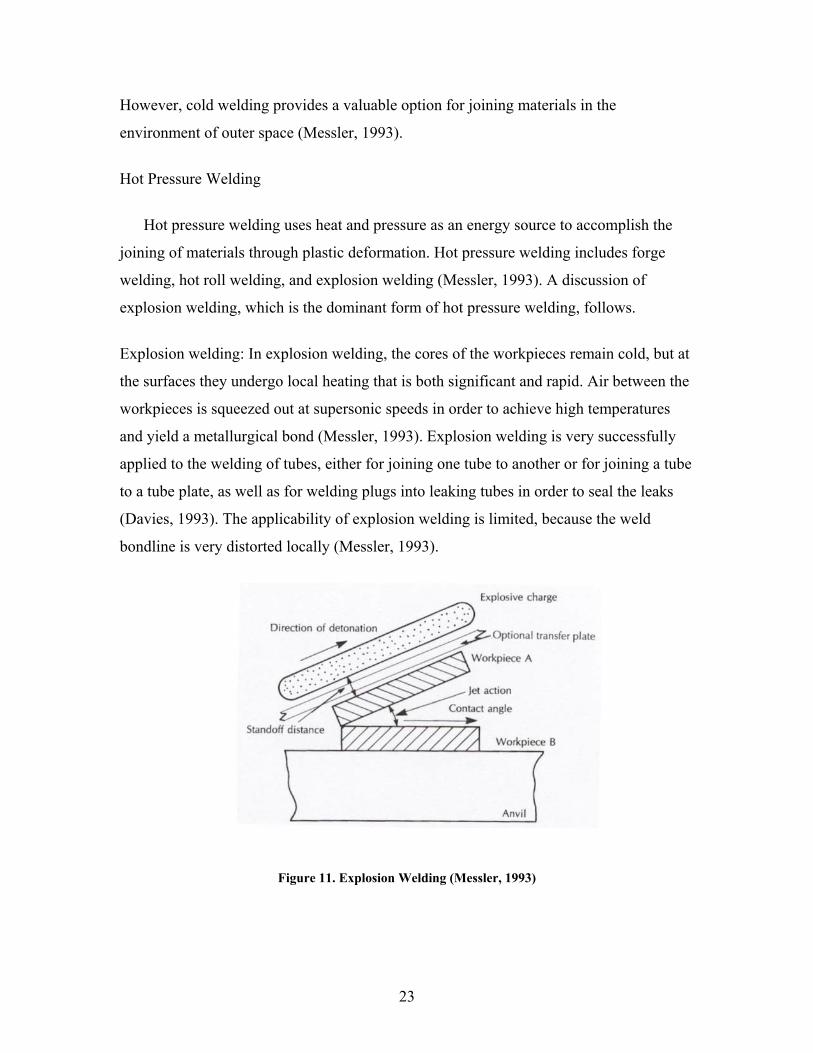
Explosion welding: In explosion welding, the cores of the workpieces remain cold, but at
the surfaces they undergo local heating that is both significant and rapid. Air between the
workpieces is squeezed out at supersonic speeds in order to achieve high temperatures
and yield a metallurgical bond (Messler, 1993). Explosion welding is very successfully
applied to the welding of tubes, either for joining one tube to another or for joining a tube
to a tube plate, as well as for welding plugs into leaking tubes in order to seal the leaks
(Davies, 1993). The applicability of explosion welding is limited, because the weld
bondline is very distorted locally (Messler, 1993).
Figure 11. Explosion Welding (Messler, 1993)

24
Friction Welding
Friction welding relies on friction to cause the heating that is needed to produce a
weld. The friction is created by the use of machines that are designed to convert
mechanical energy into heat at the joint that is to be welded. In friction welding, materials
are joined under the compressive-force contact of workpieces moving relative to one
another, either linearly or in rotation (Messler, 1993). A description of ultrasonic
welding—one type of friction welding, albeit an exceptional form of it—follows.
TWI developed radial friction welding (RFW) for the specific purpose of welding
pipe. This method, in which a radial compression ring is rotated between two stationary
pipes, overcomes some of the handling problems that tend to crop up with other types of
friction welding. The ring is rotated under compression; as a result, heat is generated, and
a weld is created between the ring and the two pipes (Gainand et al., 2000).
Although this technology has been available for some twenty years, the RFW process
has not been commercially exploited, in part due to the high cost of the equipment.
However, its potential for use in the joining of titanium alloy risers for the offshore oil
industry looks rather promising. Affordable RFW equipment will have to be developed,
however, before the advantages of this process can be used to a significant extent in
commercial applications (TWI, 2002).
Figure 12. Friction Welding (Messler, 1993)

25
Diffusion Welding
Diffusion welding is a process that relies on heat and pressure to accelerate diffusion
and produce joining through mass transport in the solid state (Messler, 1993). Usually,
the solid-state bonding process based on the combined application of pressure and heat is
also termed diffusion welding (Brandon and Kaplan, 1997).
In diffusion welding, two surfaces are brought together under load. Under conditions
of both high temperature and high pressure, there is considerable plastic flow in the
region of greatest surface asperity, which continues until the interfaces have achieved a
high degree of conformity with each other. At this point, the joint will have achieved
considerable strength as a result of metallic bonding (Schwartz, 1979). Diffusion welding
offers precise joining, with no fusion zone and no heat-affected zone. However, its use is
limited, because of the expense of the materials involved and the small dimensional
tolerance with which the pieces/components must comply (Messler, 1993).
Brazing and Soldering
A major characteristic of brazing and soldering is that metals are joined without
changing the composition of the workpieces, because the base metal is not melted
(Bowditch, 1997).
Figure 13. Diffusion Weld Riveted (Messler, 1993)

26
Brazing is a type of welding in which the joint is heated to a suitable temperature in
the presence of a filler material having a liquidus that is above 840°F and yet below the
solidus of the base metal. (The liquidus of a pure metal is the lowest temperature at which
it is completely liquid, while its solidus is the highest temperature at which it is
completely solid.) Bonding is accomplished without melting the substrate (Messler 1993).
Brazing offers advantages such as the negligible effect it has on the composition of the
base materials, the ability to join large structures under relatively low-stress conditions,
and its high potential for automation. However, brazing is of limited applicability, on
account of the low melting point of the filler (Messler, 1993).
Soldering is another type of welding that requires a filler that melts and a substrate
that does not. It is distinguished from brazing by the fact that the filler’s liquidus is below
840°F. Soldering offers almost the same advantages as brazing, but because of the
weakness of the soldered joint, it is of limited applicability (Messler, 1993).
Welding Automation
The advantage of using welding automation to improve productivity has long been
realized in the manufacturing industry. Besides improved productivity, welding
automation offers reliability and lower labor costs, and it eliminates variability. One of
the main reasons for the automation of welding is productivity, which is much higher in
automated welding processes than in manual systems. In many cases, welding with a
robot is two to five times faster than other methods (Woodnam, 2001).
The shortage of skilled welders has become a matter of deep concern in the
construction industry. Because welders are offered lower compensation in construction
than in other industries, many competent welders do not consider going into construction
work. In light of this skilled-welder shortage, welding automation is one of the best
alternatives to current welding practice (Eager, 1990).
Welding automation is divided into two categories: semi-automatic and fully
automatic. In semi-automatic welding, a weld controller is involved in the welding
process, to control the motion of the torch and the parts and to adjust the welding

27
parameter. Fully automatic welding uses machines to index the part or torch into position
and to monitor the quality of the welds. A discussion of the characteristics of orbital TIG
welding and MIG welding, which are the dominant automatic welding methods, follows.
Orbital TIG Welding
Orbital TIG welding has been applied in many industries, such as aerospace, boiler
tubes, nuclear piping, offshore applications, semiconductors, and tube/pipefitting. This is
because of its advantages over other joining technologies in the way of productivity,
quality, consistency, and versatility (Mannion and Heinzman, 1999).
Orbital TIG welding uses the gas–tungsten arc welding process as the source of the
electric arc that melts the base material and forms the weld. Orbital TIG welding systems
include a power supply and an orbital weldhead. The power supply/control system sets
the welding parameter according to the specific program in use, which is stored in the
control system.
In orbital TIG welding systems, welding parameters are stored in a controlling
computer for a variety of applications; the computer sets specific welding parameters for
specific applications (Mannion and Heinzman, 1999). An orbital weldhead rotates an
electrode and an electric arc around the joint to be welded, with the angle of rotation as
welding parameter. The power supply/control system also supplies the arc welding
current, switches the shielding gas, and sets the power that drives the motor in the
weldhead (Mannion and Heinzman, 1999). Standard enclosed orbital weldheads are used
in welding tubes with a diameter of 1/16 inch to 6 inches, with a wall thickness of up
to .154 inch. Open orbital heads are used in tubes of larger diameter and wall thickness
(Mannion and Heinzman, 1999).

28
Mechanized Gas-Metal Arc (MIG) Welding
Mechanized gas-metal arc (MIG) welding is an important process in welding
fabrication practice because of advantages such as the consistently high quality of the
joints and the great degree of compliance with radiographic standards for welds that are
to be performed at high welding speeds (Thompson, 1998).
The MIG torches—usually air cooled, even for currents up to 450 A—are carried on
welding heads connected to the control system (Thompson, 1998). For repair work on
thin sheets, as in the motor trade, semi-automatic MIG welding has replaced the
traditional oxyacetylene methods because of the lower heat input required for the former.
For larger fabrication work, use of mechanical handling equipment with automatic MIG
welding heads enables a reduction in the amount of skilled labor employed in the joining
process (Davies, 1993).
Mechanized gas-metal arc welding is the most widely used welding process for large-
diameter transmission pipelines in the U.S (Blackman and Dorling, 2000).
Figure 14. Enclosed Orbital Weldhead (Mannion and Heinzman, 1999)

29
Figure 15. MIG Welding (Davies, 1993).

30
5
Evaluation Process for Advanced Joining Technologies
This chapter provides a discussion of an evaluation process that can be used to
determine the applicability of each of the various joining technologies. In earlier chapters,
the major categories of joining methods were described, and factors that have a
significant impact on the applicability of those techniques to the joining of pipe were
highlighted. Here, the Analytic Hierarchy Process (AHP) is used in order to weight the
various factors according to their degree of impact.
Factor-Weighting Methodology
In Chapter 3, various factors that should be considered in selecting joining technology
for piping in the construction industry were identified. Not all of these factors are equally
important, however, in terms of their potential impact on the joining of pipe. Certain
factors are higher in the hierarchical order than others with respect to their relative
importance. Therefore, it is necessary to weight all of the factors relative to one other.
AHP (Analytic Hierarchy Process)
The Analytic Hierarchy Process (AHP) is a powerful and flexible decision-making
process for establishing priorities among quantitative and qualitative sets of criteria by
using data and the user’s knowledge or experience as input (Satty, 1990). The process has
been formalized by Satty and used in a wide variety of problem areas. The AHP process
involves the structuring of a problem according to a primary objective and then
proceeding to secondary levels of objectives. Once the hierarchies have been established,
comparison matrices are constructed (Satty, 1983).
Factor-Weighting Process
By the use of AHP, a weighting of the major factors that contribute to decisions
regarding the use of various advanced joining technologies is derived. The steps of the
AHP weighting process are given below (Tucker, 2001):

31
Step 1: Establish the hierarchical structure in the following way: First, list the major
categories across the page from left to right. Then, for each of the major categories, list
its subcategories below it (fig. 16).
Step 2: Compare the four major categories in pairwise fashion, ranking each pair on a
scale of 1 to 5 according to the criteria indicated below, and then fill in the upper half of a
matrix with the results. Then, for each of the major categories, use the same procedure to
compare its subcategories in pairwise fashion. An example of one possible outcome of
step 2 for a comparison of the subcategories within the management category is given in
Table 5.
1: The two factors contribute equally
2: One factor is slightly favored over the other
Figure 16. Hierarchical Structure

32
3: One factor is moderate favored over the other
4: One factor is strongly favored over the other
5: One factor dominates
Table 5 Example of Step 2 in Factor Weighting Process
Training Cost Labor Cost Equipment Cost Material Cost Training Cost 1 0.20 0.25 0.33 Labor Cost 1.00 3.00 4.00 Equipment Cost 1.00 3.00 Material Cost 1.00
Step 3: Now complete each of the matrices constructed in Step 2 as follows: First,
compute the reciprocals of the entries in the cells in the upper half of the matrix, and
place the resulting numbers into the appropriate cells in the lower half of the matrix.
Once that has been done, add a new row at the bottom of the matrix, sum up the entries in
each column, and fill in the cells of the new bottom row of the matrix with those sums.
Now, add a new column to the matrix, to the right of the existing rightmost column. For
each row of the matrix, compute the sum of the quantities ai/bi where ai is the entry in the
ith column of the row and bi is the ith column sum. As the computation for each row is
completed, place the resulting “row sum” in the appropriate cell of the new column of the
matrix. The example from step 2 is worked out in Table 6.
Table 6 Example of Step 3 in Factor Weighting Process
Training Cost Labor Cost Equipment Cost Material Cost Row Sum Training Cost 1.00 0.20 0.25 0.33 0.28 Labor Cost 5.00 1.00 3.00 4.00 2.08 Equipment Cost 4.00 0.33 1.00 4.00 1.07 Material Cost 3.00 0.25 0.33 1.00 0.56 Column Sum 13.00 1.78 4.58 8.33 4.00
Step 4: Compute a priority vector from the column of “row sums” by normalizing the
entries in the far-right column to the number in the bottom row. The example from step 3
is worked out in Table 7.

33
Table 7 Example of Step 4 in Factor Weighting Process
Row Sum Normalization0.28 0.07 2.08 0.52 1.07 0.27 0.56 0.24 4.00 1.00
Step 5: Perform a consistency check on the comparison scales. The consistency ratio
should be smaller than 10%.
CR = 0.04 (CI) / 0.9 (Random Consistency Index) = 4.7% The CR is 4.7%, indicating a
good consistency is reached.
Finalizing the Weighting Process
Once the factor-weighting process is completed, the weight for each factor is
finalized by multiplying its weight by the weight for its category. For instance, if the
weight for the structure category is 0.18 and the initial weight for joint strength is 0.61,
then the final weight for joint strength is (0.18)(0.61) = 0.110. The completed score sheet
for pipe joining overall is given in Table 8.
Table 8 Pipe Joining Score Sheet
Category Weight Subcategory Weight Relative Weight
Structure 0.18 Joint Strength 0.61 0.110 Material Compatibility 0.27 0.049 Durability 0.12 0.022 Management 0.4 Training Cost 0.07 0.028 Labor Cost 0.52 0.208 Equipment Cost 0.27 0.108 Material Cost 0.14 0.056 Productivity 0.32 Processing Time 0.14 0.072 Rework Reduction 0.24 0.102 Field Usability 0.40 0.102 Ease of Installation 0.13 0.022 Surface Preparation 0.08 0.035
Maintenance 0.1 Performance Reliability 0.67 0.067
Life-Cycle Cost 0.33 0.033

34
Analyzing the Weighted Factors
The weighted factors are displayed in descending order of their absolute weights, as
shown in Figure 17. The factors with the highest weights may be regarded as the most
important factors in making decisions about the use of advanced joining technology. The
figure shows that the most important factors turn out to be labor cost, field usability, joint
strength, and equipment cost.
Evaluation Model
Now an evaluation model is established and is based on the weights of the various
factors in the table just constructed. First, each factor is divided into three categories—
high, medium, and low—and then the various joining technologies are classified on the
basis of their impacts on that factor. Once the different joining technologies are assessed
relative to each factor, a weighted score is computed for each, and the joining technology
with the highest total score is the one of greatest applicability.
Figure17. Ranking of Weighted Factors
0.000 0.050 0.100 0.150 0.200 0.250
Durability
Surface Preparation
Training Cost
Life-Cycle Cost
Ease of Installation
Material Compatiblity
Processing Time
Material Cost
Performance Reliability
Rework Reduction
Equipment Cost
Joint Strength
Field Usability
Labor Cost

35
Table 9 Evaluation Model for Pipe Joining
Category Weight Subcategory Weight Relative Weight
Level of Impact Weight Weighted
Score Structure 0.18 Joint Strength 0.61 0.110 High 1 0.110 Integrity Medium 0.7 0.077 Low 0.3 0.033 Material Compatibility 0.27 0.049 High 1 0.049 Medium 0.7 0.034 Low 0.3 0.015 Durability 0.12 0.022 High 1 0.022 Medium 0.7 0.015 Low 0.3 0.006 Management 0.4 Training Cost 0.07 0.028 High 1 0.028 Concern Medium 0.7 0.020 Low 0.3 0.008 Labor Cost 0.52 0.208 High 1 0.208 Medium 0.7 0.146 Low 0.3 0.062 Equipment Cost 0.27 0.108 High 1 0.108 Medium 0.7 0.076 Low 0.3 0.032 Material Cost 0.14 0.056 High 1 0.056 Medium 0.7 0.039 Low 0.3 0.017 Productivity 0.32 Processing Time 0.14 0.056 High 1 0.056 Factor Medium 0.7 0.039 Low 0.3 0.017 Rework Reduction 0.24 0.077 High 1 0.077 Medium 0.7 0.054 Low 0.3 0.023 Field Usability 0.4 0.128 High 1 0.128 Medium 0.7 0.090 Low 0.3 0.038 Ease of Installation 0.13 0.042 High 1 0.042 Medium 0.7 0.029 Low 0.3 0.012 Surface Preparation 0.08 0.026 High 1 0.026 Medium 0.7 0.018 Low 0.3 0.008 Maintenance 0.1 Performance 0.67 0.067 High 1 0.067 Issue Reliability Medium 0.7 0.047 Low 0.3 0.020 Life-Cycle Cost 0.33 0.033 High 1 0.033 Medium 0.7 0.023
Low 0.3 0.010

36
6
Evaluation of Advanced Joining Technologies
This chapter provides a brief discussion and assessment of the applicability of each of
the various joining technologies to the joining of pipe. Each joining technology is
assessed by use of the evaluation model, and then the final results are presented.
Mechanical Joining
In general, mechanical joining is uncomplicated and effective, requiring little
mechanical skill to install. Because of the requirement of using thick pipe in this process
and the high cost of the materials involved, however, its applicability to pipe joining is
limited. In addition, many situations do not readily lend themselves to mechanical joining.
An assessment of the applicability of this method to pipe joining is given in Table 10.
Table 10 Assessment of Mechanical Joining
Major Category Subcategory
Joining Methods
Mechanical Fastening
Mechanical Interlocking
Structure Joint Strength 0.077 (High) 0.077 (High) Integrity Material Compatibility 0.034 (Med) 0.034 (Med) Durability 0.015 (Med) 0.015 (Med) Management Training Cost 0.028 (High) 0.028 (High) Concern Labor Cost 0.208 (High) 0.208 (High) Equipment Cost 0.108 (High) 0.108 (High) Material Cost 0.017 (Low) 0.017 (Low) Productivity Processing Time 0.056 (High) 0.056 (High) Factor Rework 0.054 (Med) 0.054 (Med) Field Usability 0.128 (High) 0.128 (High) Ease of Installation 0.029 (Med) 0.029 (Med) Surface Preparation 0.026 (High) 0.026 (High)
Maintenance Performance Reliability 0.047 (Med) 0.047 (Med)
Issue Life-Cycle Cost 0.023 (Med) 0.023 (Med) Total Score 0.85 0.85

37
Adhesive Bonding
Currently, adhesive bonding is used for many applications because of its low cost and
convenience of use. In addition, it is of sufficiently high strength that it can be used in the
assembly of airplane parts. The low resistance of adhesive-bonding techniques as a
function of bending load, however, has been regarded as the most significant obstacle to
the use of adhesive bonding (Lea, Stubblefield, and Pang, 1998). This limitation has been
lessened with technology advances in adhesive bonding. In fact, 3M has developed a
high-strength adhesive bonding technique that offers a normal tensile strength of 160 psi
and dynamic shear strength of 100 psi.
Adhesive bonding has great potential and soon may become one of the best
alternatives to current pipe-joining methods. Table 11 contains an evaluation of the
applicability of adhesive bonding to pipe joining.
Table 11 Assessment of Adhesive Bonding
Joining Method
Major Category Subcategory
Adhesive Bonding
Structure Joint Strength 0.077 (Med) Integrity Material Compatibility 0.049 (High) Durability 0.015 (Med) Management Training Cost 0.028 (High) Concern Labor Cost 0.208 (High) Equipment Cost 0.108 (High) Material Cost 0.039 (Med) Productivity Processing time 0.056 (High) Factor Rework 0.077 (High) Field Usability 0.128 (High) Ease of Installation 0.042 (High) Surface Preparation 0.008 (Low) Maintenance Performance Reliability 0.047 (Med) Issue Life-Cycle Cost 0.033 (High) Total Score 0.915

38
Welding
Fusion Welding
Arc Welding: In general, arc welding techniques have been widely used for pipe joining
for decades, and still dominate this area because of their good track record for durability
and performance. However, various industries are reluctant to use these methods, because
of the requirements for highly skilled labor and the inconsistent quality of the welds, so
they are forced to find alternative technologies. Among arc welding methods, stick
welding is the most popular joining method in the construction industry, even though it
offers low productivity compared to gas—tungsten arc welding (TIG) and gas—metal arc
welding (MIG) (Kapustay, 2002). In spite of the advantage that they have to offer in
terms of performance, however, MIG and TIG welding suffer from some of the same
problems as stick welding, such as a shortage of highly skilled labor. Another factor that
contributes to the relatively low degree of adoption of MIG and TIG welding in the
construction industry is the reluctance of welders to switch to new techniques (Kapustay,
2002).
Gas Welding: The oxyacetylene-gas welding process is simple and highly portable, and
the equipment needed for its use is inexpensive. The main drawbacks to its use in pipe
joining in the construction industry may be its low productivity and the need for highly
skilled labor.
High-Energy Beam Welding: High-energy beam welding offers excellent performance,
so it is extensively used in joint-fabrication applications that require high accuracy in
terms of placement of the weld. Advances made in electron-beam welding, one of the
high-energy beam welding techniques, have eliminated the need to work in vacuum, so
this method can now be used in the atmosphere. Research on high-energy beam welding
is ongoing.
Resistance Welding: Resistance welding is a very useful joining technology because of
benefits such as short processing time, mechanizability of the process, and high

39
performance. It is widely used in the manufacturing industry for the joining of
overlapping sheets or plates.
Flash butt welding, one form of resistance welding, is recognized as a very
satisfactory method for fabrication of pipe (Thompson, 1998). It offers good quality and
productivity because of its automated, remote-control system. However, it requires large
equipment, so its applicability is limited to shop fabrication.
Table 12 provides an assessment of the applicability of various types of fusion
welding to pipe joining.
Table 12 Assessment of Fusion Welding
Major Category Subcategory Joining Methods
TIG Stick
Welding MIG
Oxy-Gas
Welding
Electron-
Beam Welding
Flash Butt
Welding
Structure Joint Strength 0.11
(High) 0.11
(High) 0.11
(High) 0.11
(High) 0.11
(High) 0.11
(High) Integrity
Material Compatibility
0.049 (High)
0.049 (High)
0.049 (High)
0.049 (High)
0.049 (High)
0.049 (High)
Durability 0.022 (High)
0.022 (High)
0.022 (High)
0.022 (High)
0.022 (High)
0.022 (High)
Management Training Cost 0.008 (Low)
0.008 (Low)
0.008 (Low)
0.008 (Low)
0.028 (High)
0.028 (High)
Concern Labor Cost 0.062 (Low)
0.062 (Low)
0.062 (Low)
0.062 (Low)
0.208 (High)
0.208 (High)
Equipment Cost
0.032 (Low)
0.032 (Low)
0.032 (Low)
0.032 (Low)
0.032 (Low)
0.032 (Low)
Material Cost 0.039 (Med)
0.039 (Med)
0.039 (Med)
0.039 (Med)
0.039 (Med)
0.039 (Med)
Productivity Processing Time
0.039 (Med)
0.017 (Low)
0.039 (Med)
0.017 (Low)
0.056 (High)
0.056 (High)
Factor Rework 0.054 (Med)
0.023 (Low)
0.054 (Med)
0.031 (Low)
0.077 (High)
0.077 (High)
Field Usability 0.128 (High)
0.128 (High)
0.128 (High)
0.128 (High)
0.038 (Low)
0.038 (Low)
Ease of Installation
0.012 (Low)
0.012 (Low)
0.012 (Low)
0.012 (Low)
0.029 (Med)
0.029 (Med)
Surface Preparation
0.026 (High)
0.026 (High)
0.026 (High)
0.026 (High)
0.026 (High)
0.026 (High)
Maintenance Performance Reliability
0.047 (Med)
0.047 (Med)
0.047 (Med)
0.047 (Med)
0.067 (High)
0.067 (High)
Issue Life-Cycle Cost 0.01
(Low) 0.01 (Low)
0.01 (Low)
0.01 (Low)
0.023 (Med)
0.023 (Med)
Total Score 0.638 0.593 0.638 0.593 0.804 0.804

40
Non-Fusion Welding
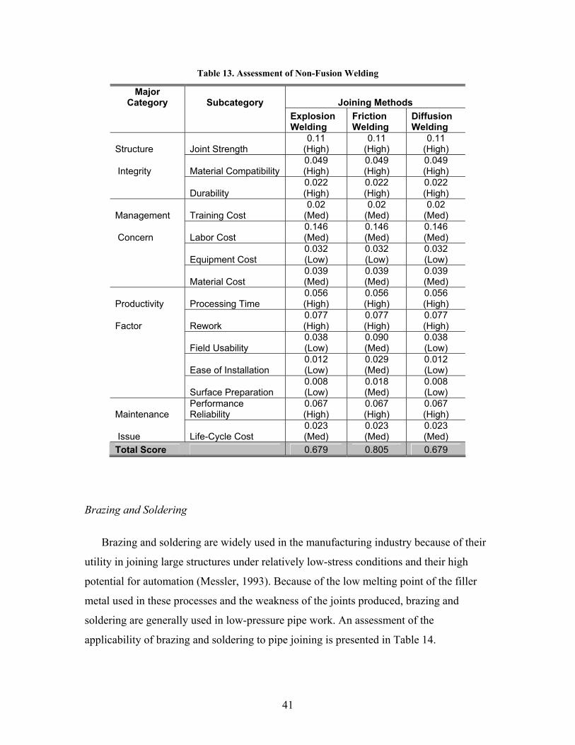
Explosion Welding: Explosion welding, one of the hot pressure welding techniques, has
been successfully applied to the welding of tubes, either for joining one tube to another or
for joining a tube to a tube plate. It has also been used for welding plugs into leaking
tubes in order to seal the leaks (Davies, 1993).
Friction welding: Friction welding has several advantages, such as ease of use, low cost,
and speed of processing. In addition, it can be operated in the field, on account of the
simplicity of the process. TWI developed radial friction welding for the specific purpose
of welding pipe; this technique overcomes some of the handling problems associated with
other types of friction welding. In view of its high cost and the need to use very heavy
machinery that has large hydraulic and power requirements, however, radial friction
welding has seen relatively little use, as it is best suited to the shop environment
(Kapustay, 2002).
Diffusion welding: Diffusion welding is a very precise joining process, with no fusion
zone and no heat zone, so it is an ideal joining technology. However, the high cost of the
materials used with this method militates against its applicability (Messler, 1993).
The suitability of various types of non-fusion welding for pipe joining is summarized
in Table 13.
41
Table 13. Assessment of Non-Fusion Welding
Major Category Subcategory Joining Methods
Explosion Welding
Friction Welding
Diffusion Welding
Structure Joint Strength 0.11
(High) 0.11
(High) 0.11
(High)
Integrity Material Compatibility 0.049 (High)
0.049 (High)
0.049 (High)
Durability 0.022 (High)
0.022 (High)
0.022 (High)
Management Training Cost 0.02
(Med) 0.02
(Med) 0.02
(Med)
Concern Labor Cost 0.146 (Med)
0.146 (Med)
0.146 (Med)
Equipment Cost 0.032 (Low)
0.032 (Low)
0.032 (Low)
Material Cost 0.039 (Med)
0.039 (Med)
0.039 (Med)
Productivity Processing Time 0.056 (High)
0.056 (High)
0.056 (High)
Factor Rework 0.077 (High)
0.077 (High)
0.077 (High)
Field Usability 0.038 (Low)
0.090 (Med)
0.038 (Low)
Ease of Installation 0.012 (Low)
0.029 (Med)
0.012 (Low)
Surface Preparation 0.008 (Low)
0.018 (Med)
0.008 (Low)
Maintenance Performance Reliability
0.067 (High)
0.067 (High)
0.067 (High)
Issue Life-Cycle Cost 0.023 (Med)
0.023 (Med)
0.023 (Med)
Total Score 0.679 0.805 0.679
Brazing and Soldering
Brazing and soldering are widely used in the manufacturing industry because of their
utility in joining large structures under relatively low-stress conditions and their high
potential for automation (Messler, 1993). Because of the low melting point of the filler
metal used in these processes and the weakness of the joints produced, brazing and
soldering are generally used in low-pressure pipe work. An assessment of the
applicability of brazing and soldering to pipe joining is presented in Table 14.

42
Table 14 Assessment of Brazing and Soldering
Major Category Subcategory
Joining Method
Brazing and Soldering Structure Joint Strength 0.033 (Low) Integrity Material Compatibility 0.034 (Med) Durability 0.022 (High) Management Training Cost 0.02 (Med) Concern Labor Cost 0.146 (Med) Equipment Cost 0.076 (Med) Material Cost 0.039 (Med) Productivity Processing Time 0.039 (Med) Factor Rework 0.054 (Med) Field Usability 0.09 (Med) Ease of Installation 0.029 (Med) Surface Preparation 0.026 (High)
Maintenance Performance Reliability 0.067 (High)
Issue Life-Cycle Cost 0.023 (Med) Total Score 0.698
Welding Automation
Welding automation is an emerging technology that has already been successfully
employed in the manufacturing industry. Benefits such as improvements in productivity
and reliability, reductions in labor costs, and elimination of variability in weld quality
have been realized through welding automation. In addition, the shortage of skilled
welders in the construction industry may force companies to use welding automation in
the near future. Despite its high initial cost and its lack of availability under certain
circumstances and environments, the advantages of using welding automation in pipe
joining will eventually become evident to those in the construction industry.
Orbital TIG welding is one of best alternatives to current practice in the construction
industry because it offers highly productivity and the process is simple and portable.
Mechanized MIG welding is more suitable for the shop environment than the field
environment because of the heavy equipment that is required for its use.

43
An assessment of the applicability of welding automation to pipe joining is presented
in Table 15.
Table 15 Assessment of Welding Automation
Major Category Subcategory Joining Methods
Orbital
Arc Welding Mechanized MIG Welding
Structure Joint Strength 0.11
(High) 0.11
(High)
Integrity Material Compatibility 0.049 (High)
0.049 (High)
Durability 0.022 (High)
0.022 (High)
Management Training Cost 0.02
(Med) 0.02
(Med)
Concern Labor Cost 0.208 (High)
0.208 (High)
Equipment Cost 0.032 (Low)
0.032 (Low)
Material Cost 0.039 (Med)
0.039 (Med)
Productivity Processing Time 0.056 (High)
0.056 (High)
Factor Rework 0.077 (High)
0.077 (High)
Field Usability 0.09
(Med) 0.038 (Med)
Ease of Installation 0.042 (High)
0.042 (High)
Surface Preparation 0.026 (High)
0.026 (High)
Maintenance Performance Reliability
0.067 (High)
0.067 (High)
Issue Life-Cycle Cost 0.033 (High)
0.033 (High)
Total Score 0.915 0.819
Conclusion of Evaluation
The applicability of each of the various joining technologies to the joining of pipe has
been determined on the basis of the evaluation described in this chapter. According to the
results of this evaluation, the processes that are of greatest applicability to pipe joining
are orbital arc welding and adhesive bonding.

44
0 0.1 0.2 0.3 0.4 0.5 0.6 0.7 0.8 0.9 1
Stick welding
Oxyacetylen gas welding
Gas-tungsten arc welding
Gas-metal arc welding
Explosion welding
Diffusion welding
Brazing and Soldering
Electron beam welding
Flash butt welding
Friction welding
Mechanized MIG welding
Mechanical Fastening
Mechanical Interlocking
Adhesive Bonding
Orbital Arc welding
Figure 18. Ranking of Applicability of Advanced Joining Technologies to Pipe Joining

45
7
Business Analysis
Market Analysis for Pipe Welding in the Construction Industry
In 2002, the American Welding Society (AWS) released its Welding-Related
Expenditures, Investments, and Productivity Measurement Report, which states that
welding expenditures represent a substantial contribution to the U.S. economy. This
report also states that the construction sector alone spent over $10 billion on welding in
2000 (Table 16) and that this constituted over 30 percent of the total expenditure on
welding in the U.S. that year. Though this report does not provide figures for pipe
welding per se, it does indicate that the total cost of industrial construction (including
factors other than pipe welding) amounted to about $30 billion in 2000. This figure
would be even higher if costs associated with welding of pipe for purposes other than
industrial buildings, such as in the construction of pipe to be used in pipeline construction
and commercial buildings, were taken into account.
Table 16 Welding Expenditures in 2000
Labor ($1 M)
Materials & Consumables
($1 M)
Other Welding-
Related Costs ($1 M)
Total ($1 M)
Industrial Buildings 2,526 201 300 3,027 Commercial Buildings 831 40 48 919 Bridge & Tunnel Construction 17 12 4 32 Pipeline Construction 191 75 115 381 Structural Steel Erection 210 66 11 287 Fabricated Structural Metal Products 2,191 360 69 2,620 Miscellaneous Construction 2,394 509 446 3,349 Totals 8,358 1,264 993 10,615 Source: AWS (2002)
Estimation of the Cost of Welding in the Construction of the CII Model Plant
In the previous section, the total market cost of pipe joining was identified. In this
section, the direct cost of pipe welding for the CII Model Plant is estimated.

46
One factor that figures heavily in the analysis of the impact of applying new
technology to the joining of pipe in the construction industry is the ratio of pipe welding
costs to the total cost of a construction project. An estimate of that ratio, based on the
scope of the CII Model Plant project and data from R.S. Means, is given here.
CII Model Plant. The Model Plant is a hypothetical installation valued at about $85
million that is to be constructed in 78 weeks. The scale and schedule are typical of
industrial projects. Nine major components of a typical plant (refraction unit, tank farm,
compressor unit, two turbine generators, underground piping, pipe bridge, and complete
civil site package) were assembled to form the model plant.
Basic Assumptions about Welding Costs. The estimates of welding costs presented in this
paper are based on the following data, which combine the scope of the CII Model Plant
project with basic data on labor and equipment costs taken from R.S. Means (2002):
• Number of joints: 12,514 (CII Model Plant Project)
• Bare wage of skilled welder: $173 per joint (R.S. Means, 2002)
• Equipment cost: $20.50 per joint (R.S. Means, 2002)
Labor Cost for Welding. The bare wage of a skilled welder is $173 per joint (R.S. Means,
2002), based on use of 12” and schedule 40 steel pipe. Once overhead is calculated, the
cost of labor rises to about $251 per joint (R.S. Means, 2002). Thus the total labor cost of
welding in the construction of the CII Model Plant is about $3.14 million (table 17).

47
Table 17 Labor Cost for Welding, CII Model Plant
Bare Wage of Skilled Welder: $173 per joint $173.00 Worker’s Compensation Insurance Average for U.S.: 18.7% $32.35
Incremented Employee Cost per Joint $205.35Average Fixed Overhead Federal and State Unemployment Insurance Costs: 7.0% $12.11Social Security Taxes (FICA): 7.65% $13.23Builder’s Risk Insurance Costs: 0.3% $0.52Public Liability Costs: 1.55% $2.68
Incremented Employee Cost per Joint $233.89Other Overhead Costs Average for U.S.: 10% (depends on factors such as the contractor’s annual volume and staff requirements) $17.30
Incremented Employee Cost per Joint $251.19Number of Joints 12,514Total Labor Cost $3.14 M
Sources: R.S. Means (2002) and CII Model Plant project
Equipment Cost for Welding. The equipment cost for welding is about $26.50 per joint,
based on use of 12” and schedule 40 steel pipe (R.S. Means, 2001). Therefore, if welding
were the only technique used for all the welding work done on the CII Model Plant, the
total equipment cost of welding in the construction of the CII Model Plant would come to
about $330,000 (Table 18).
Table 18 Equipment Cost for Welding
Cost per Joint $26.50Number of Joints 12,514
Total Equipment Cost $330 k Sources: R.S. Means (2002) and CII Model Plant project
Total Direct Cost of Welding. The total direct cost of pipe joining for the CII Model Plant
project is about $3.47 million (Table 19). Since the total construction cost of the project
is $85 million, the cost of pipe joining makes up more than 4 percent of the total.
Table 19 Total Direct Cost of Stick Welding
Wages $3.14 M Equipment Cost $330 k Total Cost $3.47 M

48
8
Recommendations for Future Research
Several advanced technologies that could be applied to the joining of metal pipe in
the construction industry and that are particularly likely to be of interest to CII members
are recommended below. A brief discussion is given of each of the recommended
techniques, including an identification of potentially interested parties; a classification of
the payoff period, the level of risk, and the potential for success; and a suggested path for
future research.
New Mechanical–Adhesive Bonding Technology
Description
The Welding Institute in the U.K. has done research on a hybrid joining system,
known as AdhFASTTM, in which adhesives and fasteners are combined. The point of
developing such a hybrid system is to exploit the desirable properties of each of the two
components separately, such as the rapidity and ease of use of fasteners and the
significant sealing ability and high fatigue resistance of adhesives.
According to Kellar and Jones (2000), the AdhFASTTM system offers the following
advantages:
• Little or no external jigging
• Simplified dry assembly, which enables greater precision in pinpointing
the area where the weld is to be made and in performing checks of
tolerance levels
• Protection of pre-treated surfaces (prior to bonding) from excessive
atmospheric exposure and operator contamination
• Simplification of the process for applying the adhesive
• Ability to deal with complex joint geometries

49
• Greater control of the bond line and greater precision in the metering of
the amount of adhesive within the joint
• Potential for more accurate control of the fillet profile
• Adaptability to automation (semi or full)
The use of adhesive bonding as a primary structural joining method is often looked
upon with skepticism, but near-total confidence can result if the adhesive is employed in
a highly controlled manner that yields an elevated level of quality assurance. Hybrid
joining systems that employ a combination of adhesive bonding and fasteners do indeed
have the potential for engendering a high level of confidence.
Interested Parties
3M may be one of the major interested parties when it comes to using mechanical-
adhesive technology. Currently, 3M is working on developing techniques for high-
strength adhesive bonding and may expedite research on hybrid systems (3M, 2002).
Also, the Welding Institute (TWI) may have an interest in developing hybrid systems that
could be applied to the joining of pipe.
Payoff
Duration: medium term
Risk: medium
Potential: high
Path for Future Research
Basic research is needed before mechanical-adhesive bonding technology can be
applied in the construction industry. To date, there has been no research on the
application of hybrid systems with fasteners and adhesives to the joining of pipe.
Therefore, research should focus on the most basic issues surrounding use of this
technology.

50
Exploiting the Benefits of Orbital Welding Technology
Description
The advantage of using welding automation to improve productivity has long been
recognized in the manufacturing industry. Besides improved productivity, welding
automation offers reliability and lower labor costs and eliminates variability. One of the
main incentives for the use of automation in welding is productivity, which is much
higher in automated welding processes than in manual systems. In many cases, welding
with a robot is two to five times faster than other methods (Woodnam, 2001).
The shortage of skilled welders has become a matter of deep concern in the construction
industry. Because welders are offered lower compensation in construction than in other
industries, many competent welders do not consider going into construction work. In
light of this skilled-welder shortage, welding automation is one of the best alternatives to
current welding practice (Eager, 1990).
Orbital TIG welding has been applied in many industries, such as aerospace, boiler
tubes, nuclear piping, offshore applications, semiconductors, and tube/pipefitting. This is
because of its advantages over other joining technologies in productivity, quality,
consistency, and versatility (Mannion and Heinzman, 1999).
Interested Parties
Orbital welding is already being applied in a number of industries. Many suppliers of
orbital welding equipment exist, and they have made a vigorous effort to develop and
expand the application of orbital welding. Once the benefits of orbital welding are
identified and widely publicized, CII members could well be among the companies that
end up joining the ranks of the major interested parties.
Payoff
Duration: short term
Risk: low
Potential: medium

51
Path for Future Research
Currently, orbital welding technology is well developed and is ripe for application in
the construction industry. In order to expedite use of this technology, however, a
justification is needed for switching to this mode of operation from more traditional
methods. One obvious justification would be the improvement in productivity that results
from adoption of orbital welding technology. Therefore, research should focus on touting
the benefits of orbital welding and surmounting existing barriers to its use.
Alternative Pipe-Welding Technology for Improved Fabrication
Description
This paper covers several advanced welding technologies including those that have
the potential to replace current practice in the construction industry. By means of an
evaluation process outlined here, it has been shown that at least one of the advanced
welding technologies (such as friction welding or flash butt welding) appears to offer
much greater benefits than traditional methods. On the basis of that evaluation, it seems
likely that advanced technology for joining of pipe will eventually replace current
practice in the construction industry.
Interested Parties
Among the major parties that may be interested in the application of advanced
technology to the joining of metal pipe are organizations such as the American Welding
Society and the Welding Institute, both of which are currently working on the
development of advanced joining technology in general.
Payoff
Duration: medium term
Risk: medium
Potential: medium

52
Path for Future Research
As discussed, several advanced welding technologies have the potential to improve
current pipe-joining practice in the construction industry. However, there is a need for
further research, including a need for constructing test beds in order to measure the
impact of the various technologies. Therefore, research should focus on developing and
testing advanced methods for the joining of metal pipe.
Adhesive-Bonding Technology to Improve Metal Pipe Joining Practice
Description
Currently, adhesive bonding is widely used primarily for two reasons: low
cost/convenience of use and the joints are of sufficiently high strength. In the past, the
low resistance of adhesive-bonding techniques relative to bending load was regarded as
the most significant obstacle to the use of adhesive bonding (Lea, Stubblefield, and Pang,
1998). This limitation has been somewhat lessened, however, as a result of technological
advances in adhesive bonding. In fact, 3M has developed a high-strength adhesive
bonding technique that offers a normal tensile strength of 160 psi and dynamic shear
strength of 100 psi.
Adhesive bonding has great potential, and soon may become one of the best
alternatives to current pipe joining methods.
Interested Parties
3M has made the greatest effort in the development of adhesive bonding thus far, not
only in terms of basic research but also in terms of applications. It appears that 3M is
likely to become a major player in the development, testing, and application of adhesive
bonding in pipe joining.

53
Payoff
Duration: high term
Risk: high
Potential: high
Path for Future Research
Basic research will be needed before adhesive bonding can be applied to the joining
of metal pipe. Test beds need to be constructed and experiments need to be carried out in
order to determine the parameters for using adhesive-bonding techniques in pipe joining.
Remote, Tele-Operated Repair of Fossil-Fueled Power Plants
Description
Tube leaks in coal-fired boilers have consistently been the leading cause of downtime
in the utility industry, and water-wall tubes have been one of the prime candidates for
leaks. Tube leaks occur as a result of blistering, rupturing, cracking, corrosion, leaky
joints, or other types of failure. The presence of a leak is particularly problematic
whenever inspection of the tube reveals that progressive deterioration has already taken
place, which is a sign that tube failure may be imminent—and could occur before the date
of the next scheduled outage. These leaks can cost hundreds of thousands of dollars in
lost generating capacity while repairs are being made. Given the current state-of-the-art
of tube fabrication, however, it is rather unlikely that the incidence of leaks will decrease
significantly, at least not without an inordinate expenditure of money.
Given the urgent need for an affordable solution, perhaps the most feasible approach
would be to devise a way to reduce the time needed for inspection and maintenance of the
tubes so as to keep overall utility downtime to a minimum.
One factor in particular that should be taken into account in minimizing costs of
forced outages is the amount of downtime that’s needed for cooling. According to a

54
report issued by the Electric Power Research Institute (EPRI), the cost of downtime for
cooling typically amounts to $100,000 per hour.
In order to expedite the cooling process as well as reduce costs and increase safety in
regard to the repair of fossil-fueled power plants, perhaps a robot could be designed that
would be capable of entering a boiler soon after shutdown, while the temperature is still
elevated, and perform tasks such as repair of the tubes without exposing personnel to the
hazardous environment.
Interested Parties
The U.S. Department of Energy (DOE) has begun to use remotely deployed, tele-
operated equipment for inspection, maintenance, and cleanup operations in petroleum-
and waste-storage tanks. EPRI has successfully developed a method for removing clinker
buildup in the hoppers of large coal-burning furnaces. Also, the Tennessee Valley
Authority (TVA) is likely to become a major player in the development and deployment
of systems of this type in the field.
Payoff
Duration: medium term
Risk: medium
Potential: high
Path for Future Research
Basic research will be necessary for identifying technologies which are most suited
for use in settings where the temperature and pressure are comparable to those of a
typical coal-fired boiler. Test beds need to be constructed and experiments need to be
carried out under field conditions in order to evaluate the performance of tele-operated
systems that are proposed.

55
9
Conclusion and Recommendations
Pipe joining is one of the most critical yet inefficient processes in the construction
industry. This report identifies several of the underlying causes of inefficiency in pipe-
joining processes currently in use in the construction industry, and describes several
advanced joining technologies that, to varying degrees, have the potential to supplant
conventional methods. Which of these newer processes holds the most promise is open to
question, however, for two reasons: first, uncertainty as to what types of joints produced
with these more advanced methods would be suitable for typical construction
applications and second, the fact that each of the advanced technologies would first have
to be adapted for field application or prefabrication work and then thoroughly tested
before adoption by practitioners in the construction industry.
The eventual impact of the technologies described on the construction industry
presently is unable to be determined
. Therefore, it is recommended that CII consider sponsoring further research on
advanced joining technologies. Furthermore, it is recommended that any plan of action
for future research consider one of the five possible paths forward that are summarized
here:
New mechanical-adhesive bonding technology
Exploiting the benefits of orbital welding technology
Alternative pipe-welding technology for improved fabrication
Adhesive-bonding technology to improve metal pipe joining practice
Remote, tele-operated repair of fossil-fueled plants

56
References
3M Inc. (2002), <http://www.3m.com> (Jan. 2002).
Ageorges, C., Ye, L., and Hou, M. (2001), Advances in Fusion Bonding Techniques
for Joining Thermoplastic Matrix Composites: A Review, Composites: Part A, Aug.
2001, pp. 839–857.
American Welding Society, Welding Handbook, Sixth Edition, Section 5, Miami, Fla.,
1973.
Argent, M., Pecknold, D., and HajAli, R. (1999), New Steel Pipe System for
Trenchless Installation and Rehabilitation, Advance in Underground Pipeline
Engineering II, Jun. 1995, pp. 697–708.
Benchmarking and Metrics Data (2002), Construction Industry Institute
Blackman, S., and Dorling, D. (2000), Technology Advancement Push Pipeline
Welding Productivity, Welding Journal, Aug. 2000, pp. 39–44.
Bowditch, W. (1997), Welding Technology Fundamentals, The Goodheart–Willcox
Company, Inc., Tinley Park, Illinois.
Brandon, D., and Kaplan, W. (1997), Joining Processes: An Introduction, John Wiley
& Sons, New York, N.Y.
Business Roundtable (1982), Construction Technology Needs and Priorities, New
York: The Business Roundtable, 1982, Construction Industry Cost Effectiveness
Project, Report B-3.

57
Davies, A. (1993), The Science and Practice of Welding, Volume 2, Cambridge
University Press, Cambridge, UK.
Dickenson, T. (1999), Valves, Piping & Pipelines Handbook, Elsevier Advanced
Technology, New York, N.Y.
Eager, T. (1990), Joining Technology, Advanced Materials & Processes, Jan. 1990, p.
65.
Gainand, Y., Mas, J.P., Jansen, J.P., Coiffier, J.C., Dupont, J.C., and Vauthier, C.
(2000), Development of electron beam welding for girth welding of gas transmission
pipelines, Proceedings of the 3rd International Pipeline Technology Conference, 2000,
pp. 327–342.
Hara, Y., Toyoda, M., Ushno, M., Irie, H., Masuda, H., and Yamakawa, T. (2000),
Development of electron beam welding for girth welding of gas transmission
pipelines, Proceedings of the 3rd International Pipeline Technology Conference, 2000,
pp. 327–342.
Hastak, M. and Halpin, D. (2000), Assessment of Life-Cycle Benefit-Cost of
Composites in Construction, Journal of Composites for Construction, ASCE, Aug.
2000, pp. 103–111.
Kapustay, J. "Re: Regarding Metal Joining" E-mail to Changwan Kim, 24. June 2002
Kluger, J. (2000), Coming up Next Joining, Time, Dec. 2000, p. 56.
Lea, R., Stubblefield, M., and Pang, S. (1998), Innovative Development of
Joining/Fitting Technology for Advanced Composite Piping System, Final ATP
Technical Report, Advanced Technology Program/National Institute of Standards and
Technology, Sep. 30, 1998.

58
Mannion, B. and Heinzman, J. (1999), Orbital Tube Welding, Pro-Fusion White
Paper, Pro-Fusion Inc., Mar. 1999.
Messler, R. (1993), Joining of Advanced Materials, Butterworth–Heinemann,
Stoneham, Mass.
Nayyar, M. (1992), Piping Handbook, McGraw–Hill Book Company, New York,
N.Y.
Permalok Inc. (2002), <http://www.permalok.com> (Jan. 2002).
Rickard, J., and Tucker, R. (1982), Construction Activities with Significant
Technological Research Opportunities, The University of Texas at Austin, Austin,
Construction Industry Cost Effectiveness Project Final Report.
R.S. Means (2001), Building Construction Cost Data, R.S.Means Company, Kingston,
MA
Schwartz, M. (1979), Metals Joining Manual, McGraw–Hill Book Company, New
York, N.Y.
Seay, B. “Re: Regarding Metal Joining” E-mail to Changwan Kim, 27. June 2002
Stubblefield, M., Lea, R., Pang, S., and Zhao, Y. (1999), Innovative Development of
Joining/Fitting Technology for Advanced Composite Piping Systems, Energy Sources
Technology Conference & Exhibition, 1999, pp. 1–4.
Thompson, G. (1998), An Engineer’s Guide to Pipe Joints, Professional Engineering
Publishing, Suffolk, UK.
Tucker, R. (1982), Construction Technology Needs and Priorities, The University of
Texas at Austin, Austin, Construction Industry Cost Effectiveness Project Report.

59
Tucker, R. (2001), CE 395 R.4. Course Materials, The University of Texas at Austin,
Austin
Victaulic Inc. (2002), <http://www.victaulic .com> (Jan. 2002).
Woodnam, C. (2001), Automation: Return-on-Investment, Welding Design &
Fabrication, Apr. 2001, pp. 71–74.

60
CII Member Companies 3M ABB Lummus Global Inc. Abbott Laboratories Air Products and Chemicals, Inc. Aluminum Company of America Anheuser-Busch Companies, Inc. Aramco Services Company Atlantic Richfield Company Bayer Corporation BE&K, Inc. Bechtel Group, Inc. Black & Veatch BMW Constructors Inc. BP Amoco Corporation Burns and Roe Enterprises, Inc. Butler Construction Company CDI Engineering Group, Inc. Celanese Champion International Corporation Chemtex International Inc. Cherne Contracting Corporation Chevron Corporation Chicago Bridge & Iron Company Cianbro Corporation CITGO Petroleum Corporation Day & Zimmermann International, Inc. Dick Corporation Dillingham Construction Holdings Inc. DuPont Eastman Chemical Company Eichleay Holdings Inc. Eli Lilly and Company Exxon Research & Engineering Company Fisher Controls International, Inc. Fluor Daniel, Inc. Foster Wheeler USA Corporation FPL Energy, Inc. Fru-Con Construction Corporation General Motors Corporation General Services Administration Graycor H. B. Zachry Company H+M Construction Co., Inc.
Hilti Corporation Honeywell Inc. Intel Corporation International Technology Corporation J. A. Jones Inc. Jacobs Engineering Group, Inc. James N. Gray Company, Inc. Kellogg Brown & Root Kiewit Construction Group, Inc. Kværner LTV Steel Company, Inc. M. A. Mortenson Company Mobil Technology Corporation Morrison Knudsen Corporation Murphy Company NASA Naval Facilities Engineering Command Ontario Power Generation Phillips Petroleum Company Raytheon Engineers & Constructors Reliant Energy Rohm and Haas Company S&B Engineers and Constructors Ltd. Shell Oil Company Solutia Inc. Stone & Webster Engineering Corporation Tennessee Valley Authority Texaco The Dow Chemical Company The Parsons Corporation The Procter & Gamble Company The University of Texas System U.S. Air Force Research Laboratory U.S. Army Corps of Engineers U.S. Department of Commerce/NIST U.S. Department of State U.S. Steel Union Carbide Corporation Walbridge Aldinger Weyerhaeuser Company

61
Construction Industry Institute
The University of Texas at Austin
3925 West Braker Lane (R4500)
Austin, Texas 78759-5316

2
Bureau of Engineering Research
The University of Texas at Austin