new image - only - scan to pdf - unt digital library
TRANSCRIPT


AIRCRAFT CIRCULAR NO. 71.
THE BOULTON AND PAUL "SIDESTRAND 1" BOMBER AIRPLANE (BRITISH) . " Two R r i s t o l J u p i t e r V I I r Engines.
I n at tempting t o convey an a,dequate i d e a of t h e new Boulton
and Paul twin-engined bomber which has r e c e n t l y gole i n t o pro-
duct ion f o r t h e Royal A i r Force squadrons, two ways a re open:
One might concent ra te on the mer i t s of t h e a i r p l w e (and they a r e
many) f o r t h e p a r t i c u l a r purpose f o r which i t w a s designed, or
one may approach the subje& along more general l i n e s , examin-
i n g t h e a i rp lane as an a i r c r a f t pure and simple, with but minor
r ega rd t o i t s p a r t i c u l a r func t ion as a m i l i t a r y weapon. In the
former case cne would merely be descr ib ing an +a i rp lane which i s
a very exce l l en t bomber, while by t ak ing t h e a l t e r n a t i v e ap-
proach the m e r i t s of it as a p iece of ae ronau t i ca l engineering
can be examined. On the v~hole , we be l i eve t h a t t h e rnaJjcrity
of our readers adre l i k e l y t o be more i n t e r e s t e d i n t h e general
aerodynamic a ~ i d s t r u c t u r a l f eatur 'es , and a.s t h e r e a r e cer tain:
r e s t r i c t i o n s which prevent a f u l l d iscuss ion of the m i l i t a r y
equipment, the following no tes w i l l be 6evoted t o t h e general de-
s ign of the I S i d e ~ t r w l d , ~ ~ bear ing i n mind t h a t t h e a i rp lane has
been designed as a three-seat day bomber, and t h a t the re fo re
c e r t a i n s p e c i f i e d loads had t o be c a r r i e d , loads c o n s i s t i n g
p a r t l y of equipment, p a r t l y of machine gun armament, and p a r t l y
of bombs. What percentage of each i s involved we a r e not i n a
*From l l F l i g h t , n March 29, 1928.

N,A.C.A, A i r c r a f t Ci rcular No. 71
p o s i t i o n t o s t a t e .
Aerodynaiinic Design
The readers who have followed h i s i n t e r e s t i n g s e r i e s of ar t i -
c l e s on IfAircraf t Performancetf i n I1Flight ' sff monthly t echn ica l
supplement "The Ai rc ra f t Engineer, n i l 1 have obtained a f a i r l y
good i d e a of t h e general des ign pol icy of Fir, J. D. North,
Boulton & P a u l t s ~ h i e i ' Engineer and Designer, and i n examining
t h e tfS!destrandll one looks f o r such f e a t u r e s a s P,:r, Bortll has
advocated i n h i s a r t l c l - e s . kmong these ?erhaps none was more
prominent than the red-uction of indiaced drag by having a high
s 23:E value of the r a t i o of ----- and a glance at the general ar- mc$f_"lt'
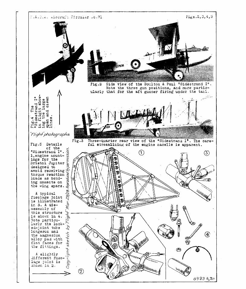
rangement drawings anG so::ie of t h e photo,rrz,phs ( ~ i g s , 1, 2 , 3
and 4) w i l l silow t h a t t h e ffSidestrandfl has 2, very l a r g e s p m f o r
i t s a r e a o r , as we -used t o say before modern a i r f o i l theory be-
came t h e f a sh ion , high tfaspect ratio.If ITiiile M r . North drew at-
t e n t i o n t o t h e importance o f l a r g e span, he a l so poin ted out
t h a t f o r l a r g e a i r p l a n e s i t i s d i f f i c u l t t o obta in a high value
of t h e r a t i o because of the increased wing weight weight which quickly p u t s a l i m i t t o t h e span which i t i s eccno~mic t o
employ. IF t h e l fS ides t rand, l i t h e r e f o r e , one may t ake it tha,t a n
endeavor has Seen made t o ge t t h e bes t compromise between wing
s t r u c t u r e weight and eerod;~naiiic e f f i c i e n c y , and i t w i l l be of
i n t e r e s t t o examine b z i e f l y how f a r the wing arrangement of t h e
ffSidestrandl l riay be expectec? t o have reduced t h a t p a r t of the wing

N . A , C . A . A i r c r a f t Ci rcular No. 7 1 3
drag which i s Ciue, a s ? d r c C . C , Walker put i t , t o Ifcarrying a
c e r t a i n weight; on a c e r t a i n span at a c e r t a i n speedetf
The t o t a l loaded weight of the t l~ ides t ra ,nd t f i s 8850 l b .
and t h e span i s 72 f t . The value of ---- sq'zY i s t h e r e f o r e 0.518 -v'/
and t h e monoplane value of t h e r a t i o of l i f t t o induced drag i s ,
at 70 ; I*Pe9. , f o r ins tance , 20,31. A s t h e gap/spm r a t i o of t h e
t fS ides t ran4t f i s about 0,111, t h i s value i s increased t o 25.9 f o r
t h e biplane arraxgement used. Thus a t 70 M.P,He t h e induced drag
i s only 342 l b . , which i s remarkably low and corresponds t o a
t h r u s t horsepower of 64 B.BP. only f o r o v e r c ~ n i ~ i g induced drag
a t t h a t speed. Since at t h i s low speed (corresponding probably
f a i r l y wel l with the climbing speed of t h e a i r p l a n e ) t h e induced
drag i s a l a r g e percentage of t h e t o t a l wing drag, i t i s seen
t h a t the "high aspect r a t i o f t wing arrangement does appear t o
have proved ext renely benef icent . The value of 0.518 i s weight
q u i t e high f o r an a i rp lane of t h i s weight, and i n a, number of
a i r p l a n e s t h i s r a t i o only reaches a value of 0.3 o r S O L We
be l i eve t h a t a c t u a l l y i n t h e flSid.estra.ndlt t h e e x t r a wing weight
which was the Ifprice pa id t t f o r t h e 'higher value of 'pan2 amount- w ed t o soine 200 15., bv.t a t t h a t i t pa id t a ca r ry t h e e x t r a weight.
While on t h e subject of wing design, a few words concerning
t h e method used by Mr. North and h i s s t a f f i n tile choice of wing
s e c t i o n may be of i n t e r e s t . The method was ou t l ined by M r . North
i n h i s s e r i e s of a r t i c l e s t o which re fe rence has a l ready been
made, an3 c o n s i s t s i n s t a r t i n g of f with a consicleration of t h e

N.A.C.A. A i r c r a f t Ci rcular No* 71 4
opera t iona l condi t ions t o be met, and t h e n , tak ing a s a b a s i s a
good s t reaml ine shape, curving i t s c e n t e r l i n e t o give the r'e-
q u i r e d aerodynamic c h a r a c t e r i s t i c s , t he o r i g i n a l s t r e a a l i n e sec-
t i o n being chosen of such a th ickness t h a t i t w i l l accommodate 9
s p a r s of s u f f i c i e n t depth, Thus, i n any Boulton and Tau1 air-
p l a n e s , one i s not l i k e l y t o f i n d any s te reotyped ning s e c t i o n ,
although saxe of those i n use may, more o r l e s s acc iden ta l ly ,
have a f a i r l y c l o s e resemblance t o c e r t a i n l l a c c e ~ t e d l l sec t ions .
1ncid.ent a l l y , t h e o r i g i n z l s t r e s a l i n e shape talcen as t h e b a s i s
i s generated by t h e gei leral ized Joukcwsky theory.
The vfing c e l l u l e having been c a r e f u l l y designed t o meet
t h e p a r t i c u l z r ~ p e r n t i o m ~ l condi t ions of t h e type ic ques t ion ,
g r e a t care i s again taken i n t h e design of fuselage and engine
n a c e l l e s . I n t h e case o f t h e l l S i d e s t r m d , ~ l f o r i n s t a x e , a
s t a r t was made with a bo&j of very good s t rexi i l ine fillape, gen-
e r a t e d as i n t h e case of tCe wing s e c t i o n s , a rfiodel of which mas
t e s t e d i n t h e wind tunnel . The coEkpits mere then added one by '
one, the drag being measured a f t e r ecch such addi t ion , If a
c e r t a i n cockpit shape o r arrangement w a s found t o add unduly t o
t h e d - r a g , modif icat ions were made u n t i l t h e f i g u r e had been re-
duced t o vhat appeared t o be t h e lowest p r a c t i c a b l e velue. Take,
f o r examgle, t h e prone gun p o s i t i o n under t h e fuselage. Obvi-
ous ly t h i s might . e a s i l y inc rease the ,body drag t o a very high
f i g u r e , but by p e r s i s t e n t experimentation t h e drc,g caused by
t h i s gun emplacement was u l t i m a t e l y r e h c e d t o a very low value ,
indeed.

N.A,C. .A. A i r c r a f t Ci rcular N o , 71 5
The engine n a c e l l e s were t h e subjec t of similar reseaxrh
and tbc f ~ r m f i n a l l y chosen, which i s wel l shovm i n severa l of
our p h o t o g z ~ p h s , has given a3out a s low a drag a s i t i s poss ib le
t o a t t a i n with e n g i ~ e s p laced outboard- The research included
wind tunnel t e s t s with model p r c p e l l e r s running, and at l a r g e
a:ig;.es, i t having becn found t h a t t h e I ' intesference dragff i s
l a r g e l y an i n d ~ c e d dra: 2nd l i a b l e t o be g r e a t e r at l a r g e angles ,
thus a f f ecti:lg pe r fo rxmce on climb, e t c .
The laxding gear design ( ~ i g s . 7 and 8 ) , although perhaps
more of a s - t ruc tu ra l than an ae rody~amis problem, a l s o shows
t h i s s t r i v i n g f o r aerodynamic "c leanness , the landing gear of
t h e ltSidestranci'l being of remarkably low f r o n t a l axea f o r an
a i r p l a n e of t h i s s i ze .
Altogether t h e Boulton and Paul IfSidestrandlf i s an a i rp lane
which well repays a c lose s tudy, the r e s u l t s of t h e very g r e a t
ca re taken i n i t s aerodynamic design being r e f l e c t e d i n the per-
formance f i z u r e s which w i l l be found at t h e end of t h i s repor t .
S t r u c t u r a l Design
I f the aerodyn2ini.c design cf the Ifs idestrandff i s of more
than usual i n t e r e s t , tlie same app l i e s at l e a s t a s much t o the
s t r u c t u r a l f e a t u r e s . Although ia v~hat fol lows the reference i s
p a r t i c u l a r l y t o t h e I1Sidestrand, If mos-t of the cons t ruc t iona l
d e t z . i l s a r e now s tandard Boulton and Paul p r a c t i c e , and would 4
apply fa . i r ly c l o s e l y t o any a i r p l a n e b u i l t by t h a t f i rm, s ince

N.A.C.A, A i r c r a f t C i r c u l a No. 71 6
a process of standardization mithout cramping the f r e e s t possi-
b l e develop9ent has keen evolved by t h e f i rm Curing the l a s t
few years .
I t w i l l be kno1~:n t o most of our r eaders t h a t Boulton and
Paul weze axong t h e very f i r s t a i r c r a f t f i rms i n England t o
t ake up kl l -metal , and more p a r t i c u l a r l y a l l - s t e e l , cons t ruc t ion
of a i r c r a f t , and a v i s i t t o t h e ivorks at Tqorliiiich, very soon re-
v e a l s the f a c t t k a t a, very high degree of p e r f e c t i o n has been
a t t a i n e d , not on l :~ i n t h e des ign of metal members but a l s o ,
and which i s , perha>ps, even more important bccause i t i s a good
dea l more d i f f i c u l t , i n rxg id and r e l a t i v e l y cheap manufacfur-
i n g processes , Concerning t h e l a t t e r , but l i t t l e can b e s a i d
i n t h e present a r t i c l e , i n which we must confine ourse lves .to
t h e f i n i s h e d r e s u l t s r a t h e r than go i n t o d e t a i l s concerning
t h e maiiner i n which these r e s u l t s were obtained.
E a r l i e r forms of Boulton and Paul xieta1 fusela,ge construc-
t i o n have been descr ibed and i l l u s t r a t e d i n l i ~ l i g h t i l from time
t o t ime, but with the present form soaethihg l i k e f i n a l i t y has
been a t t a i n e d , s ince c e r t a i n s i z e s have been standardized. The
b a s i s of the new form of f - ~ s e l a g e cons t ruc t ion i s t h e locked-
j o i n t c i r c u l a r tube , which i s a r e l a t i v e l y recent product of
t h e firm. This type of tube i s made from s t r i p , by a spec ia l
process of r o l l i n g and dra?*ring, and the accuracy obta ined i s
r e a l l y renaxkable. got only does t h e tube leave t h e draw bench
Ifas s t r a i g h t as a d i e , " but t h e locked-joint seam i t s e l f i s per-

M,A.C,A. A i r c r a f t C i rcu la r Xo. '91 7
f e c t l y uniform and s t r a i g h t , i . e . , t h e r e i s no t v i s t i n t h e tube.
This i s important because of t h e attachment of t h e f i t t i n g s , f o r
t ~ h i c h i t i s d e s i r z b l e t o know exac t ly where t h e s c m i s going t o
come, and t h a t i t -ill be i n t h e sm.e p l a c e at a l l f i t t i n g s .
Having evolved an e ~ i i n e n t l y s a t i s f a c t o r y type of tube f o r
longerons and s t r u t s , s tandardized i n a c e r t ~ i n number of s i z e s ,
t h e next s t e p was t o design n neat type of f i t t i n g f o r t h e &tach-
men% of s t r u t s t o longerons. Hoa t h e problem was u l t i m a t e l y
solved i s i n d i c a t e d i n Figure 5 . A t u b u l a r ltpadtl of magnes iu~
a l l o y , f i t t i n g snugly over t h e tubu la r longeron,' and with f l a t
f a c e s inachined on t h e ou t s ide , gave t h e so lu t ion . Bo l t s ?ass
through upad" and lcngeron v e r t i c a l l y and h o r i z o n t a l l y (be ing ,
of course, s l i g h t l y s taggered i n r e l a t i o n t o each o t h e r ) , t he
s t r u t ends being a t tached t o t h e b o l t heads and t h e brac ing wires
t o sheet s t e e l l i n k s o r tiring p l a t e s i n t h e manner shown. The
b o l t s themselves a r e of duraluinin, and bushes a re in terposed be-
tween them and t h e w a l l s of t h e longerons t o increase t h e bear-
i n g area. The arrangement w i l l be c l e a r from Figure 5. By t h e
eiiiploy;-flent of magne sim a l l o y lfpadsll and d u r a l m i n b o l t s , t h e
weight of t h e fuse lage f i t t i n g s i s kept down t o a very low f ig -
u r e , while c e r t a i n l y the locked-joint tubes , of high-grade s t e e l ,
a r e l i g h t e r than any drawn tube could be. The r e s u l t i s a s t ruc -
t u r a l l y very economical cons t ruc t ion . We regre t t h a t we have
no f i g u r e s r e l a t i n g t o t h e ba re s t r u c t u r e weight of t h e Itside-
strandll but knowing %he aniount of equipment c a r r i e d , and t h e

N.A,C .A. A i r c r a f t Ci rcular No. 7 1 8
d i f f e r e n c e b e t ~ ~ ~ e e n t a r e r e i g h t and g ross weight, i t i s f a i r l y
obvious t h a t t h e a i r c r a f t s t r u c t u r e must be a very low per-
centage,
I f t h e fuse lage s t r u c t u r e i s unusual ly i n t e r e s t i n g , t h e
vring s t r u c t u r e i s no l e s s s o , although shovring perhaps, a l e s s
n o t i c e a b l e depar ture froni Boulton and Paul % previous forms of
wing s t r u c t u r e . \Te be l ieve we a re c o r r e c t i n s t a t i n g t h a t t h i s
f i rm was agong t h e piolieers of r o l l e d s t e e l s t r i p wing spar con-
s t r u c t i o n , at l e a s t i n i t s e f f i c i e n t modern form us ing high-
t e n s i l e s t e s l s . And it i s s e r t a i n l y t h e f i r s t B r i t i s h f i rm t o
s tandardize a scheme of cons t ruc t ion by which a l l conceivable
manner m d s i z e s of a ings may be b u i l t from standardized p a r t s ,
Of the 3oul ton & Paul rnethod of rflanufacturing s t e e l spars ,
noth ing need be s a i d here. S u f f i c e i t t o point out t h a t manu-
f a c t u r i n g processes have been evolved which allow of both r a p i d
and cheap produ-ction. That i s of i n t e r e s t i s the system of
s t andard iz ing c e r t a i n spar f l a n g e s , v;ebs and f i t t i n g s i n a man-
n e r which g ives a s u f f i c i e n t number of combinations t o meet well-
nigh every p o s s i b l e de~nand ~ ~ i t h o u t having t o gc t o t h e expense
of making s 3 e c i z l r o l l e r s a d d ies . A few of t h e s tandardized
combinations of webs and f l anges a re shonn dingraamatical ly i n
Figure 6. It sill Se seen t h a t , with t h r e e standard webs, and
s i x s taadard f l axges , 18 d i f f e r e n t spa r s a re produced, g iv ing
q u i t e a vide ra-nge. Add t o t h i s t h e f a c t t h a t f u r t h e r v a r i e t y
rnay be added by a change of m a t e r i a l , even t o a change from s t e e l

E . A . C , A , A i r c r a f t Ci rcular No. 71 9
t o duralur:?in, and i t w i l l be obvious t h a t t h e range immediately
a v a i l a b l e i s very ~ ~ i d e .
I n c i d e n t a l l y , t h e accuracy of product ion i s wi th in 0.01 in . ,
t hus ensuring com;slete i n t e r c h a n g e z b i l i t y , which i s even more
important from t h e point of view of mass production than r e p a i r s .
It might here be ixectioned t h a t a l l Boulton & Paul s t r i p i s
formed i n t h e s o f t s t a t e , and hardened and tempered a f t e r form-
ing,
The r i b Lesign i s very simple, and c o n s i s t s of channel
f l a n g e s and t u b u l a r d is tance p ieces forming t h e g i r d e r webs.
This a p p l i e s t o t h e normal r i b . A t p o i n t s where heav ie r s t r e s s e s
have t o be v i ths tood , modified forms a r e used, a l s o of channel
s e c t i o n , but with l a r g e r channels, and n i t h channel s e c t i o n d is -
tance p ieces , Several types a r e shown i n Fig-ure 6.
The attachment t o the s p a r s of i n t e r n a l drag s t r u t s and
i n t e r p l a n e s t r u t s i s e f f e c t e d v i a br idge p ieces i n such a manner
as t o impose no crusking s t r e s s e s on t k e thin-walled spa r s , t h e
l o a d s beiiig taken e i t h e r on t h e br idge p ieces o r on b o l t s pass-
i n g through t h e d i s t ance tubes i n the spars .
Without being a very d e t a i l e d d e s c r i p t i o n of t h e construc-
t i o n of f fS ides t rand , l f t h e above notes should give a genera l i d e a
of t h e typas of s t r u z t u r e employed. In t h e absence of an expla-
n a t i o n of t h e i n t e r n a l arrangement of t h e fuse lage , which would
n e c e s s i t a t e a re ference t o equipment of a m i l i t a r y na tu re , about
which nothing may be s a i d , we must confine ourselves t o s t a t i n g

N.A,CIA. A i r c r a f t C i rcu la r No. 71 10
t h a t t h e load of bombs forming t h e r a i s o n d l e t r e of t h e a i rp lane
i s c a r r i e d i n s i d e the fuse lage ins tead of outs ide . I n t h i s way
a g r e a t deal of a i r r e s i s t a n c e must be saved, doubt less t h i s
f a c t has con t r ibu ted m a t e r i a l l y towards t h e good performance
at t ained.
Tile B r i s t o l I1Jupiter VIv engines a r e mounted on the lower
wing, t h e suppor t ing s t r u c t u r e being r a t h e r nea t ly t r i a n g u l a t e d
i n a inanner t o avoid torque r e a c t i o n s t r e s s e s being t r ansmi t t ed
t o t h e wing spa r s i n t h e form of bending moments ( ~ i g . 5 ) . The
engines a r e hung on swivel l ing mounts which g r e a t l y f a c i l i t a t e in-
spect ion. The gasol ine tanks a r e s i t u a t e d i n the fuse lage , and
number th ree i n a l l , a f r o n t main, a r e a r main, and a se rv ice
tank. The f u l l tankage i s 260 ga l lons , of which 35 ga l lons rep-
r e s e n t an overload t o be used f o r long f l i g h t s or some such spe-
c i a l occasion, the normal capac i ty being 225 ga l lons , of which
65 ga l lons i n t h e s e r v i c e t ank , 90 g a l l o n s i n the f r o n t main
t a n k , and 70 g a l l o n s i n t h e a f t main tank.
The landing gear of the l fSidestrandif i s of simple two-
wheeled type , with oleo-pneumatic t e l e s c o p i c "legsl1 of somewhat
unusual design. A long s t roke i s one of t h e f e a t u r e s of t h i s
" l e g , " and i t i s q u i t e remarkable t o see t h e ffSidestrandfl taxy-
ing a t high speed across zough ground, tile a i rp lane i t s e l f re-
maining s teady, y h i l e the I1legsu a re t e l e scop ing i n and ou t ,
t h e wheels inoving up and down with t h e uneven sur face , I n place
of a sec t ion81 drawing of t h e a c t u a l l l l e g , N which would have t o

N , A . C , A . A i r c r a f t Ci rcular NO. 71
be of a h ighly t echn ica l n a t u r e , we pub l i sh a diagrammatic repre-
s e n t a t i o n which w i l l serve t o i l l u s t r a t e t h e genera l p r i n c i p l e
upon which t h e 'Ilegff i s designed. ( ~ i g . 8 ) .
The lower p o r t i o n of t h e "lleg" i s f i l l e d with air (pumped i n
at an i n i t i a l pressure of 125 lb . /sq. in . ) , and the upper p a r t
with o i l , a f l o a t i n g diaphragm separa t ing the air from the o i l .
A p i s t o n i s a t t ached t o , and moves up and d.own with, t h e lower
p a r t of t h e l eg . This p i s t o n has i n i t s head a valve s e a t and a
spring-loaded hollow-stem valve. This hollow o r cyl indrica.1
stem i s provided with p o r t s , so t h a t when the valve opens, the
o i l can pass through from one s i d e of t h e p i s t o n t o the other .
In t h e valve head i s a small l e a k hole. This, of course , permits
o i l t o pass through under a l l condi t ions.
When t h e I1leg" i s subjec ted t o a load , the air i s compressed
by t h e upward movement of t h e lower h a l f . If the movement i s a
r e l a t i v e l y g e n t l e one, o i l merely l e a k s through t h e small l eak
hole i n t h e valve head. Vhen a c e r t a i n speed of t r a v e l i s
reached, however, t h e valve opens agains t the a c t i o n of i t s
sp r ing , and t h e o i l i s then permi t ted t o flow through the p o r t s
i n t h e valve stem, from t h e space above t h e p i s t o n t o the space
below it. The s i z e of l eak hole and p o r t s has been c a r e f u l l y
proport ioned so as t o g ive , i n conjunct ion with t h e compressed
a ir and the pneumatic t i r e , a d e f l e c t i o n diagram of t h e r i g h t
shape. I n taxying , the damping of t h e o i l i s such as t o prevent
any tendency t o bouncing, and t h e a i r p l a n e t r a v e l s along on an

N - A . C , A . A i r c r a f t Ci rcular No. 71 1 2
even k e e l , a l thcugh on rough ground t h e wheels may be seen t o be
moving up and do^^ r a p l d l y , fol lowing the irregularities of t h e
ground. The smsl l air vent p ipe shown may poss ib ly pass a small
amount df o i l duxlng the t r a v e l of the Iileg,li but i t s chief func-
t i o n i s t o avoid t h e formation of an a i r lock while the n l e g H i s
being f i l l e d with o i l . The jack shown i n t h e diagrams and i n
Figure 7 c2n be used f o r extending the l l l e g , l l or f o r t i r e chang-
i n g , e t c . , as well as f o r r e l i e v i n g t h e n l e g s n of l o a d when the
a i r p l a n e i s s tanding i n a shed f o r long periods.
S p e c i f i c a t i o n s
. . . . . . . . . . . . . . . . L e n g t h . 40 f t , 8 in .
. . . . . . . . . . . . . . . . . S p a n . 72 " 0
. Areas:
Tota l wing a r e a s . . . . . . . . 943-5 s q . f t .
Ailerons . . . . . . . . . . . . 142.0 l1
S t a b i l i z e r . . . . . . . . . . . 68.6 fl
Eleva to r s . . . . . . . . . . . . 50.7
Fins . . . . . . . . . . . . . . 11.0
Rudder . . . . . . . . . . . 31.8
The main dimensions of t h e "Sides t rand I f i a r e shown i n
Figure 1, The weight of t h e a i r p l a n e l i g l ~ t , i s 5275 l b . (2400
k g ) , and the l o a d c a r r i e d i s 3575 l b . (1625 k g ) , g iv ing a t o t a l
loaded weight of 8850 l b . (4025 kg).

B.A.C.A. Aircraf t Circular Bo, 7 1 13
Wing loading ----- C850 - - 9.37 lb . / sq . f t . (45.9 kg/mZ) 944
Power If (on normal power of 450 BoHPe per engine)
8850 - = 9.84 I ~ . / H P . (4.47 k g / ~ ~ ) 900
tfTJing F~mer = 0.35 ~ ~ ~ . / s q ~ f t . (10.25 H P / m 2 )
Performance
Speed at ground l e v e l , 125 l\foP.H, (201 kml/h).
Speed at 5000 f t . (1525 m ) , 130 M.P.H. (209 kien/'n) .

H . A . C . A . Aircraf t Circular No.71 I Figel
f ee t 6 8 10 12 , I 14
I * 2 3 4
Areas:
Total wings 943.5 s q . f t . Ailerons 142.0 " Stab i l i z e r 68.6 It
Elevators 50 . 7 !I I t
Fins 11.0 I t " Rudder 31.8 I! Ii
Figax Boulton and Paul "Sidestrand I n bomber a i rp lane .
-
Note the th re3 gun pos i t ions , and more p a r t i c - u l a r l y t h a t f o r the a f t g inner f i r i n g under t?ie tai l .
F ia .S D e t a i l s f u l s t reamlining of the engine nace l l e i s apparent .
