new hampshire department of transportation · lighting in new hampshire contact the ... the purpose...
TRANSCRIPT
1 Roadway Lighting Design Manual Design Services
www.nhgov/dot John O. Morton Building December 2010 7 Hazen Drive, PO Box 483 Concord, NH 03302 603-271-3734
New Hampshire Department of Transportation 2010
Highway Lighting Design Manual

2 Roadway Lighting Design Manual Acknowledgements
December 2010
Acknowledgements The NH Department of Transportation expresses gratitude to the Lighting Guide Committee. Membership includes: Jack Schelling, Public Service of New Hampshire; Paul Sanderson, Local Government Center; Robert Gillette, Private Citizen-Ossipee; Gordon Graham, Department of Administrative Services; and from the NHDOT, Lennart Suther, PE, Design Services; Jarrett Roseboom, PE, Design Services; Alan G. Swan, Design Services and Charles Schmidt, PE, Chief of Design Services, Chairman. Without the committees input, suggestions, recommendations and critical review this manual would not be the comprehensive document that it is.

3 Roadway Lighting Design Manual Acknowledgements
December 2010
Roadway Lighting Design Manual Table of Contents
December 2010 1
New Hampshire Department of Transportation
Lighting Design Manual
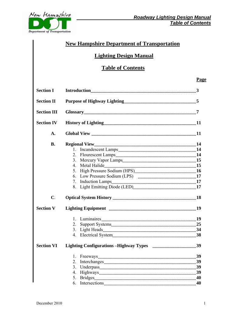
Table of Contents Page Section I Introduction 3 Section II Purpose of Highway Lighting 5 Section III Glossary 7 Section IV History of Lighting 11
A. Global View 11
B. Regional View 14 1. Incandescent Lamps 14 2. Flourescent Lamps 14 3. Mercury Vapor Lamps 15 4. Metal Halide 15 5. High Pressure Sodium (HPS) 16 6. Low Pressure Sodium (LPS) 17 7. Induction Lamps 17 8. Light Emitting Diode (LED) 17
C. Optical System History 18
Section V Lighting Equipment 19
1. Luminaires 19 2. Support Systems 25 3. Light Heads 34 4. Electrical System 38
Section VI Lighting Configurations –Highway Types 39
1. Freeways 39 2. Interchanges 39 3. Underpass 39 4. Highways 39 5. Bridges 40 6. Intersections 40
Roadway Lighting Design Manual Table of Contents
December 2010 2
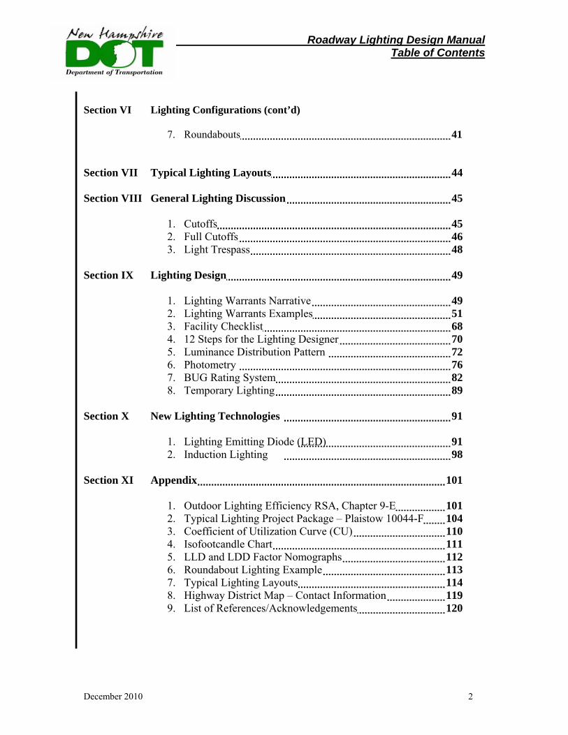
Section VI Lighting Configurations (cont’d)
7. Roundabouts 41
Section VII Typical Lighting Layouts 44 Section VIII General Lighting Discussion 45
1. Cutoffs 45 2. Full Cutoffs 46 3. Light Trespass 48
Section IX Lighting Design 49
1. Lighting Warrants Narrative 49 2. Lighting Warrants Examples 51 3. Facility Checklist 68 4. 12 Steps for the Lighting Designer 70 5. Luminance Distribution Pattern 72 6. Photometry 76 7. BUG Rating System 82 8. Temporary Lighting 89
Section X New Lighting Technologies 91
1. Lighting Emitting Diode (LED) 91 2. Induction Lighting 98
Section XI Appendix 101
1. Outdoor Lighting Efficiency RSA, Chapter 9-E 101 2. Typical Lighting Project Package – Plaistow 10044-F 104 3. Coefficient of Utilization Curve (CU) 110 4. Isofootcandle Chart 111 5. LLD and LDD Factor Nomographs 112 6. Roundabout Lighting Example 113 7. Typical Lighting Layouts 114 8. Highway District Map – Contact Information 119 9. List of References/Acknowledgements 120
109109 Roadway Lighting Design Manual Introduction
December 2010 3
Section I INTRODUCTION This manual is the culmination of extensive research, study and effort by the employees of the NHDOT, Design Services to develop a guidance document for highway lighting designers. The impetus for this manual was driven by a need to develop a well thought out document based on industry guidelines and standards with the practical knowledge of New Hampshire’s highway system; and by the desire to conserve energy and to reduce light pollution. To this end in 2009 a Lighting Guide Committee was established to assist in the development of sound guidelines for lighting highways, Park and Ride facilities, Bus facilities and Buildings with the intent to assist NHDOT lighting designers, municipalities and local boards. The committee comprised members of the NHDOT, the Local Government Center, Public Service of New Hampshire and a private citizen. Also during 2009 a Legislative effort was made and State Law established which required the Department to incorporate Dark Skies principles in its lighting designs and utilize full cutoff luminaries where practical for new or replacement lighting equipment.
The purpose of this manual is to provide a comprehensive source of information concerning the Department’s current policies for new highway lighting installations on State rights-of-way. The manual will provide a means of developing uniformity in the design and plan preparation of highway lighting systems. The material presented in this manual establishes uniform procedures and standards for constructing and maintaining new highway lighting systems on State rights-of-way. The illumination requirements are based on Federal Highway Administration (FHWA) and AASHTO guidelines and the industry consensus of providing maximum illumination benefits at reasonable costs. Light pole location requirements are formulated to minimize the probability of vehicular pole collision.
Nothing in this manual mandates, requires, nor obligates the State of New Hampshire to provide highway lighting. The requirements of this manual are not applicable retroactively to existing lighting systems. Requirements for existing systems will continue to be governed by the original design and any subsequent amendments to that design. All new lighting designs will incorporate the requirements of this manual.
Because of the following combined factors, unlighted highways are considered safe for traveling under varying local conditions:
1. Highway design features including geometry, speed limits etc., are set independently of fixed highway lighting. 2. All vehicles traveling on public highways are required to have headlights. 3. Operators are required to adjust their driving for existing local conditions.
109109 Roadway Lighting Design Manual Introduction
December 2010 4
Although the highways are designed to be safe without fixed highway lighting,
fixed highway lighting may provide increased visibility, better obstacle recognition, and increased driving comfort. This is expected to result in more efficient traffic flow, greater driver security, and economic growth.
Complying with all of the design criteria established in this manual is sometimes difficult. It will require some judgment on the part of the designer to draw the necessary balance. However, it is necessary that the criteria be followed as closely as possible in order to achieve uniformity of design in highway lighting systems. It is recognized that situations will occur where good engineering judgment dictates deviation from this Department policy. Any such deviation shall be detailed in writing and submitted for approval to the Chief of Design Services.
It is not the intent of this manual to reproduce all the information that is adequately covered by textbooks and other publications that are readily available to the designer. This section, when used in conjunction with engineering knowledge of highway lighting design and good judgment, should enable the designer to perform their job more efficiently. The terminology used in this manual, unless stated otherwise, is as defined in the Glossary and the AASHTO - An Informational Guide for Roadway Lighting.
If municipalities, citizens or others have general questions concerning highway lighting in New Hampshire contact the New Hampshire Department of Transportation, Concord, NH, Chief of Design Services. Specific lighting questions related to a project or locality contact the appropriate District Engineer. See appendix Section XI Item 8, Page 120, District Map for a contacts listing.
Roadway Lighting Design Manual Purpose
December 2010 5
Section II Purpose of Highway Lighting
The purpose of roadway lighting is to improve nighttime highway safety by reducing the possibility of motor vehicle collisions with pedestrians, fixed objects, or obstructions on the roadway and to improve traffic flow at night by providing light, beyond that provided by vehicle lights, which aids drivers in orienting themselves, delineating roadway geometries and obstructions, and judging opportunities for overtaking. Quantity of light does not necessarily indicate a good lighting system. Quality of light does. Effective lighting refers to the ability of the light to provide contrast between objects and background so that motorists can detect conflicts in sufficient time to take evasive action. Many interrelated factors contribute to effective lighting. Reducing glare can improve driver performance. Reflected glare conceals some contrast differences and should be reduced.
Nearly all aspects of nighttime traffic safety involve visibility. Some factors that directly influence visibility are:
(1) Brightness of an object on or near the roadway (2) General brightness of roadway background – ambient light (3) Size of object and identifying detail (4) Contrast between an object and its surroundings (5) Contrast between pavement and its surroundings as seen by the observer (6) Time available for seeing the object (7) Glare (8) Driver vision
There are differences of opinion concerning the conditions under which lighting
should be installed and the amount of illumination that should be provided. The following discussion represents the New Hampshire Department of Transportation design guide regarding those sections of highways on which fixed source lighting is warranted and design guidelines for particular lighting installations.
In addition to providing adequate visibility, the lighting design must address the importance of maintenance. Issues that must be addressed include life of the lamp, durability of the luminaire, access to the luminaire due to both location and height of the light standard, and availability of replacement parts. The designer should refer to the current versions of the AASHTO Roadway Lighting Guide, IESNA Lighting Handbook, and the Recommended Practice 8 (RP-8-00) Roadway Lighting, for full descriptions on roadway lighting design.
Roadway Lighting Design Manual Purpose
December 2010 6
Historically, two complementary measures of lighting system performance have been employed: (1) illuminance, or the amount of light from an installation incident upon a given surface of interest (visibility target) in the roadway environment, and (2) luminance, or the amount of reflected light returned to the driver’s eye from the visibility target.
The New Hampshire Department of Transportation typically utilizes the “Illuminance Method” in its highway lighting design.
The optimal design of highway lighting systems incorporates photometric properties of light sources, lighting geometry, targets, road conditions, road surfaces, as well as surrounding features.
Lighting system design dictates not only the amount of light provided by an installation, but also its distribution on the pavement and the amount of glare experienced by drivers. In addition, light distribution critically affects the contrast of targets viewed by drivers. As a case in point, a lighting system in which luminaire height is low and angular coverage is high produces a wide zone over which a reversal in contrast polarity occurs.
Accident Studies
The justification for highway lighting is in terms of a cost savings due to accident reduction. Although estimates vary, the savings can be enough to pay for a lighting installation in a few years. Estimates indicate that appropriately designed lighting can reduce the ratio of night-to-day accidents by as much as 15 - 30 percent of total accidents.
Roadway Lighting Design Manual Glossary
December 2010 7
Section III Glossary of Lighting Terms Ambient Light - Illumination at, near, or around a traffic facility but outside of the right-of-way. Ballast - An auxiliary device used with high intensity discharge (HID) lamps to provide proper starting and operating characteristics. It limits the current through the lamp and may also regulate the voltage. BUG System – A system developed by the Illuminating Engineering Society of North America (IESNA) to make comparing and evaluating outdoor luminaries fast, easy and more complete than older evaluating systems. BUG stands for “Backlight”, “Uplight” and “Glare”. The acronym describes the types of stray light escaping from an outdoor lighting luminaire. “B“ stands for backlight, or the light directed in back of the mounting pole. “U” stands for uplight, or the light directed above the horizontal plane of the luminaire, and “G” stands for glare, or the amount of light emitted from the luminaire at angles known to cause glare. Candela – A measure of the luminous intensity of a light source as seen by the eye. For example, because the eye is less sensitive to blue light than to green light, a blue light source must radiate more power in watts (w) than must a green light source if the two are to have the same luminous intensity. Most light sources have different luminous intensities when viewed from different directions and so the luminous intensity for a light source may vary with the angle at which it is viewed. Candle – The unit of luminous intensity. See Candela. Candle Power – The luminous intensity in a specific direction; expressed in candelas. It is not an indication of the total light output. Coefficient of Utilization – The ratio of the luminous flux from a luminaire received on the surface of the roadway to the lumens emitted by the luminaire’s lamps alone.
Color Rendering Index - The color rendering index (CRI) (sometimes called color rendition index), is a quantitative measure of the ability of a light source to reproduce the colors of various objects faithfully in comparison with an ideal or natural light source. Light sources with a high CRI are desirable in color-critical applications such as photography and cinematography.
Roadway Lighting Design Manual Glossary
December 2010 8
Complete Interchange Lighting - Applying lighting to the interchange to achieve illumination of all roadways in the interchange. Correlated Color Temperature (CCT) - The correlated color temperature is the temperature of the Planckian radiator whose perceived color most closely resembles that of a given stimulus at the same brightness and under specified viewing conditions. Cone of Vision - A fan-shaped field of view extending in front of a vehicle operator. Davit Mast Arm - One-piece shaft which curves from vertical to horizontal. Efficacy, Luminous Efficacy – The quotient of the total luminous flux delivered from a lamp to the total power input to the lamp, expressed in lumens per watt. Footcandle – The unit of illumination when the foot is taken as the unit of length. It is the illumination on a surface one square foot in area on which there is a uniformly disturbed flux of one lumen, or the illumination produced on a surface, all points of which are at a distance of one foot from a directionally uniform source of one candela. Glare - The brightness of a light source which causes eye annoyance, discomfort, or loss in visual performance and visibility. Gore - On a freeway or expressway, the area where the mainline of the roadway and the ramp diverge or converge. High Base - Transformer base which tapers from a base plate to a smaller shaft. Illuminance – The density of the luminous flux incident on a surface. It is the quotient of the luminous flux (lumen) by the area of the surface, when the latter is uniformly illuminated. Illumination – The density of luminous flux incident on a surface; it is the quotient of the luminous flux by the area of the surface when the latter is uniformly illuminated, expressed in lumens per square meter. Lamp - A source of light. The device within a luminaire which converts the electrical energy to light. Light-Loss Factor - A depreciation factor which is applied to the calculated initial average lux to determine the value of depreciated average illumination at a predetermined time in the operating cycle, usually just prior to relamping, and which reflects the decrease in effective light output of a lamp and luminaire during its life.
Roadway Lighting Design Manual Glossary
December 2010 9
Light Standard – A pole provided with the necessary internal attachments for wiring and the external attachments for the bracket and luminaire. Lumen – The unit of luminous flux (time rate of flow of light). Luminance - The luminous intensity of any surface in a given direction per unit of projected area of the surface as viewed from that direction, expressed in candela per square meter Luminaire – A complete lighting unit consisting of a lamp or lamps together with the parts designed to distribute the light, to position and protect the lamps and to connect the lamps to the power supply. Luminaire Dirt Depreciation Factor – A depreciation factor that indicates the expected reduction of a lamps initial lumen output due to the accumulation of dirt on or within the luminaire over time. Lux - The International System (SI) unit of illumination. One lux is defined as the illumination incident on a surface of one square meter, all points of which are one meter from a uniform source of one candela. Mounting Height – The vertical distance between the roadway surface and the center of the light source in the luminaire. Nadir – The vertical axis which passes through the center of the luminaire light source. Offset – The horizontal distance between the face of a light standard and the edge of traveled way. Overhang – The horizontal distance between a vertical line through the nadir of a luminaire and the edge of the traveled way or edge of the area to be illuminated. Partial Interchange Lighting - Illuminating only the parts of the interchange that are most critical to the night driver. Pavement Reflection Factor (or Reflectance) - The ratio of the light reflected by a pavement surface to the light incident upon it. Post Top Lighting Unit - A light pole with a short vertical shaft for mounting the luminaires
Roadway Lighting Design Manual Glossary
December 2010 10
Shoe Base - A low profile casting that connects the shaft to the pole base plate. Spacing – For roadway lighting the distance between successive lighting units, measured along the centerline of the street. Specular Glare - Glare resulting from light being reflected from polished or glossy surfaces. Transformer Base - A box-like structure between the foundation and pole base plate which can be used to accommodate the ballast and the underground wiring connections Truss Mast Arm - A horizontal bracket used to support the luminaire. Uniformity Ratio – The ratio of average maintained horizontal illuminance to the maintained horizontal illuminance at the point of minimum illumination on the pavement. A uniformity ratio of 4: 1 means that the average footcandle value is four times the footcandle value at the point of least illuminance on the pavement.
Roadway Lighting Design Manual History - Globally
December 2010 11
Section IV History of Lighting Technologies A. Globally
The last century of lighting has been dominated by incandescent, fluorescent and high-intensity discharge (HID) light sources.
In 1879, Joseph Swan and Thomas Edison independently developed the first electric lamp based on principles of a blackbody radiator. In the United States, Thomas Edison developed the first incandescent lamp using a carbonized sewing thread taken from his wife’s sewing box. His first commercial product, using carbonized bamboo fibers, operated at about 60 Watts for about 100 hours and had an efficacy of approximately 1.4 lm/W. Further improvements over time have raised the efficacy of the current 120-volt, 60-Watt incandescent lamp to about 15 lm/W for products with an average lifetime of 1,000 hours.
In 1901, Peter Cooper Hewitt, an American inventor, patented the first low-pressure mercury vapor (MV) discharge lamp. It was the first prototype of today’s modern fluorescent lamp. George Inman, working for General Electric, improved upon this original design and created the first practical fluorescent lamp, introduced at the New York and San Francisco World’s Fairs in 1939. Since that time, the efficacy of fluorescent lighting has reached a range of approximately 65-100 lm/W, depending on lamp type and wattage.
In 1801 Sir Humphry Davy, an English chemist, caused platinum strips to glow by passing an electric current through them. In 1810, he demonstrated a discharge lamp to the Royal Institution of Great Britain by creating a small arc between two charcoal rods connected to a battery. This led to the development of high-intensity discharge lighting, but the first high-pressure mercury vapor lamp was not sold until 1932. In 1961, Gilbert Reiling patented the first metal halide (MH) lamp. This lamp demonstrated an increase of lamp efficacy and color properties over MV, which made it more suitable for commercial, street and industrial lighting. The MH lamp was introduced at the 1964 World's Fair. The first high-pressure sodium (HPS) lamp was introduced soon after in 1965. Since that time, the efficacy of HID lighting has reached a range of approximately 45-150 lm/W, a value which again is dependent on lamp type and wattage.
In the 1950s, British scientists conducted experiments on the semiconductor gallium arsenide (GaAs), which exhibited electroluminescence or the emission of a low level of infrared light, leading to the creation of the first “modern” light-emitting diode (LED). In 1962, the first practical visible-spectrum light-emitting diode (LED) was invented at General Electric’s Advanced Semiconductor Laboratory. After subsequent improvements in this technology, the first commercial visible (red) light LEDs were fabricated in the late 1960s using gallium arsenide phosphide (GaAsP).
Roadway Lighting Design Manual History - Globally
December 2010 12
In the mid 1970s, green LEDs were produced using gallium phosphide (GaP). The first blue LEDs emerged in the 1990s using gallium nitride (GaN). Combining the red, green, and blue LEDs or coating the blue LEDs with a yellow phosphor led to the creation of white LEDs, a promising, high-efficiency technology for general illumination. Parallel to efforts to create white LEDs, researchers have been working to improve the efficacy of the technology. Present day LED commercial packages have reached efficacies of 132 lm/W, while commercial luminaires have reached efficacies of 62 lm/W exceeding the efficacies of many fluorescent and certain HID systems.
In the late 1970s, Dr. Ching Tang at Eastman Kodak discovered that sending an electrical impulse through a carbon compound caused such materials to glow. Continuing research in this vein, Dr. Ching Tang developed the first organic light-emitting diode (OLED). A paper on his research was published in 1987. Since then researchers have developed white OLED devices that have reached efficacies up to 90 lm/W in the laboratory. Companies have only recently begun to offer white OLED products commercially. These OLED panels are primarily prototype products and offer efficacies up to 23 lm/W.
The traditional three light sources – incandescent, fluorescent (which includes
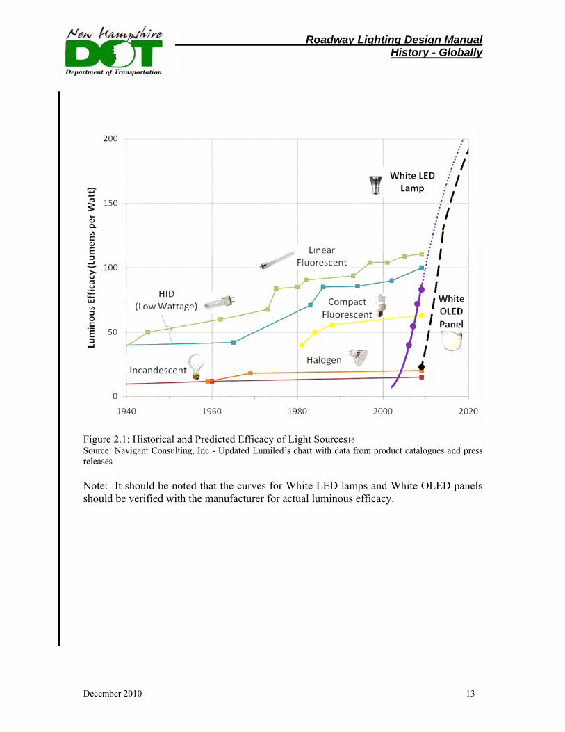
compact fluorescent and linear fluorescent) and HID – have evolved to their present performance levels over the last 60 to 120 years of R&D. Industry researchers have studied all aspects of improving the efficiency of these sources, and while marginal incremental improvements are possible, there is little room for significant, paradigm-shifting efficacy improvements. SSL technology, such as LEDs and OLEDs, on the other hand, has potential to achieve a near two-fold improvement over some of today’s most efficacious white-light sources, based on projections by experts. This projection is illustrated for LED’s and OLED’s in Figure 2.1
Roadway Lighting Design Manual History - Globally
December 2010 13
Figure 2.1: Historical and Predicted Efficacy of Light Sources16 Source: Navigant Consulting, Inc - Updated Lumiled’s chart with data from product catalogues and press releases Note: It should be noted that the curves for White LED lamps and White OLED panels should be verified with the manufacturer for actual luminous efficacy.
Roadway Lighting Design Manual History - Regional
December 2010 14
History of Lighting B. Regional
Various roadway lighting lamps have been used over the years. A description of the lamp and the NHDOT practice regarding its use is included in the paragraphs below. Incandescent or Filament Lamp A description of the incandescent or filament lamp is as follows:
• Was the most commonly used for many years and was inexpensive, simple, and easy to install.
• Produced pleasing color rendition.
• Its small size permitted good light control with a reasonably sized fixture.
NHDOT practice regarding the use of the incandescent or filament lamp is as follows:
• The incandescent lamp is used for roadway lighting in some smaller New Hampshire communities. However these lamps will eventually be replaced with more efficient and longer life light sources. This light source, for highway purposes, was widely used in New Hampshire from the early to mid 1900’s. Incandescent lamps are not currently used for highway lighting on State roadways.
Fluorescent Lamp A description of the fluorescent lamp is as follows:
• Its large size makes it difficult to obtain good light control in reasonably sized luminaires.
• Its light output is affected by low temperature more than other lamps (is adversely affected by cold weather).
• Its one advantage is the broad light patterns that it provides on wet streets.
• Has shown a poor maintenance history.
• Its one advantage is the broad light patterns that it provides on wet streets.
NHDOT practice regarding the use of the fluorescent lamp is as follows:
• No longer used for new roadway and sign lighting installations.

Roadway Lighting Design Manual History - Regional
December 2010 15
Mercury Vapor Lamp A description of the mercury vapor lamp is as follows:
•
• Replaced the incandescent lamp in popularity. The initial cost was higher, but its relatively high efficacy and long life (when it was introduced) made it considerably more attractive than the incandescent lamp.
• The blue-white color of the clear lamp is generally acceptable, and the arc tube size provides a light source that is small enough to permit good light control. A phosphor-coated outer bulb, featuring both higher output and more pleasing color rendition, is also available. However, since light control is more important in roadway lighting than color rendition, clear lamps are normally used.
• NHDOT practice regarding the use of the mercury vapor lamp is as follows:
• No longer used for new roadway and sign lighting installations.
Metal Halide (MH) Lamp A description of the MH Lamp is as follows:
• Is a type of mercury lamp in which the arc tube contains, in addition to mercury, certain iodide compounds that improve both the efficacy and the color rendition without the use of a phosphor-coated bulb.
• The light source size is that of the arc tube, permitting good light control in the
same fixture used for clear mercury lamps and excellent color rendition; however, lamp life is low.
• The color value of the metal halide lamp is good and phosphor is not required.
This lamp is often used in parking lots due to the color rendition.
• There are two versions of the lamp, one designed for basedown operation and the other for baseup operation. The lamp must operate in the proper position.
• NHDOT practice regarding the use of the MH lamp is as follows:
Are occasionally used on NHDOT projects, rest areas and weigh stations when specifically requested.
Roadway Lighting Design Manual History - Regional
December 2010 16
High Pressure Sodium (HPS) Lamp A description of the HPS lamp is as follows:
• Replaced the mercury lamp.
• Characterized by a golden-white color light output.
• Emits light across the spectrum with predominance in the orange-yellow region.
• Normally operated with special ballasts that provide the necessary high voltage to start the lamp.
• Usually cycles on and off at the end of normal life.
• Some of the newer HPS lamps include:
1. Improved color rendition 2. Internal starting devices that operate with mercury or metal halide lamp
ballasts. 3. Dual arc tube or “standby” lamps that provide light as soon as power is
restored after a momentary power interruption and that, in addition, have a rated life of 40,000 hours.
4. End of life indicators. NHDOT practice through utility companies regarding the use of HPS lamps is as follows:
• The most commonly used Lamp. • Very efficient and is the best for most roadway lighting. • Not good for use on signs because the light it produces does not render the proper
colors on standard signs.
Roadway Lighting Design Manual History - Regional
December 2010 17
Low Pressure Sodium (LPS) Lamp
A description of the LPS lamp is as follows:
• Characterized by a monochromatic bright yellow color light output.
• This lamp requires special ballasts and increases materially in size as the wattage increases; the 185-W lamp is 3.5 feet long. This large size makes it difficult to obtain good light control in a reasonably sized fixture.
• The poor color rendition and large size of the LPS lamp have made it unpopular for use in other than industrial or security applications. All objects so lit appear in shades of gray.
• The LPS lamp is a very efficient light source in that it provides the most light for the same amount of electricity of any of the light sources described.
• LPS lighting has proven to have maintenance problems requiring frequent lamp replacement
NHDOT practice regarding the use of the LPS lamp is as follows:
• NHDOT does not use LPS light sources. Induction Lamp A description of the induction lamp is as follows:
• White light
• 60,000 to 100,000 hour life
• Good color rendition
• No flickering or noise
NHDOT practice regarding the use of the induction lamp is as follows:
• NHDOT does not use this lamp. See Section X-2, Page 98. Light Emitting Diode (LED) See Section X-1, Page 91 for further detail on LED lighting.
Roadway Lighting Design Manual History - Optical
December 2010 18
History of Lighting C. Optical System
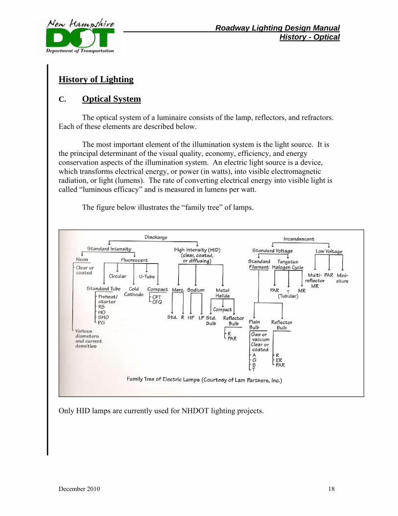
The optical system of a luminaire consists of the lamp, reflectors, and refractors. Each of these elements are described below.
The most important element of the illumination system is the light source. It is the principal determinant of the visual quality, economy, efficiency, and energy conservation aspects of the illumination system. An electric light source is a device, which transforms electrical energy, or power (in watts), into visible electromagnetic radiation, or light (lumens). The rate of converting electrical energy into visible light is called “luminous efficacy” and is measured in lumens per watt.
The figure below illustrates the “family tree” of lamps.
Only HID lamps are currently used for NHDOT lighting projects.
Roadway Lighting Design Manual Equipment - Luminaries
December 2010 19
Section V Lighting Equipment
In this chapter, lighting equipment as it relates to roadway lighting design will be introduced. This chapter will cover the following: Luminaires
Luminaire Support Systems
Selection of Lighting Equipment
1. Luminaires
A luminaire is the complete lighting unit consisting of a lamp together with the parts designed to distribute the light, to position and protect the lamp, and to connect the lamp to the power supply. Luminaire components will be discussed in the following sections and can be grouped in terms of their functions as follows:
• Optical
• Electrical
• Mechanical
•
Several factors have influenced the choice of the type of luminaire that NHDOT currently uses. The luminaires should be a standard type that is maintainable by and approved by the power companies.
The efficiency of a lamp in converting electrical energy to light, the ability of the lamp to maintain its light output over the course of the lamp life, the length of the lamp life, the color of the light, and the distribution of the light are all factors which affect the cost and effectiveness of installing, operating, and maintaining the lights; therefore, they all affect the choice of light source.
The reflector is used to change the direction of the light output. Its purpose is to redirect the otherwise wasted light output in the direction desired. The reflector also serves to protect the lamp from external damage.
The refractor controls and redirects the light emitted by the lamp and coming off the reflector by means of its optical construction.
Roadway Lighting Design Manual Equipment - Luminaries
December 2010 20
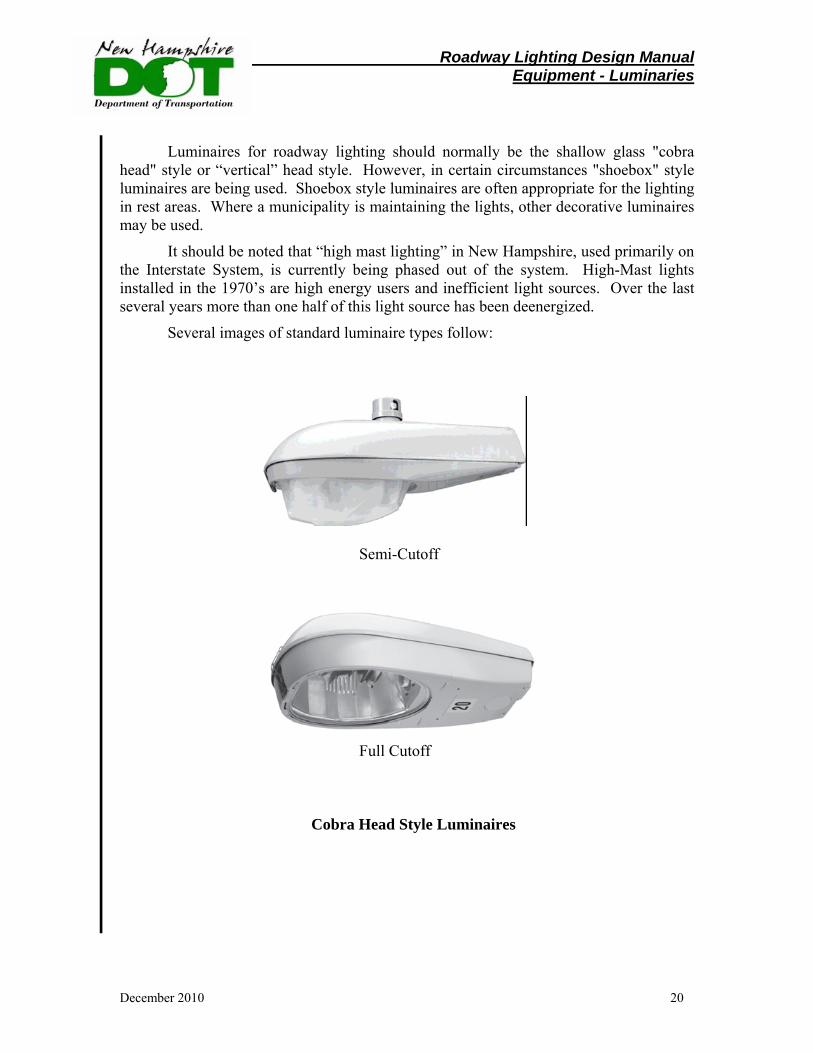
Luminaires for roadway lighting should normally be the shallow glass "cobra head" style or “vertical” head style. However, in certain circumstances "shoebox" style luminaires are being used. Shoebox style luminaires are often appropriate for the lighting in rest areas. Where a municipality is maintaining the lights, other decorative luminaires may be used.
It should be noted that “high mast lighting” in New Hampshire, used primarily on the Interstate System, is currently being phased out of the system. High-Mast lights installed in the 1970’s are high energy users and inefficient light sources. Over the last several years more than one half of this light source has been deenergized.
Several images of standard luminaire types follow:
Semi-Cutoff
Full Cutoff
Cobra Head Style Luminaires
Roadway Lighting Design Manual Equipment - Luminaries
December 2010 21
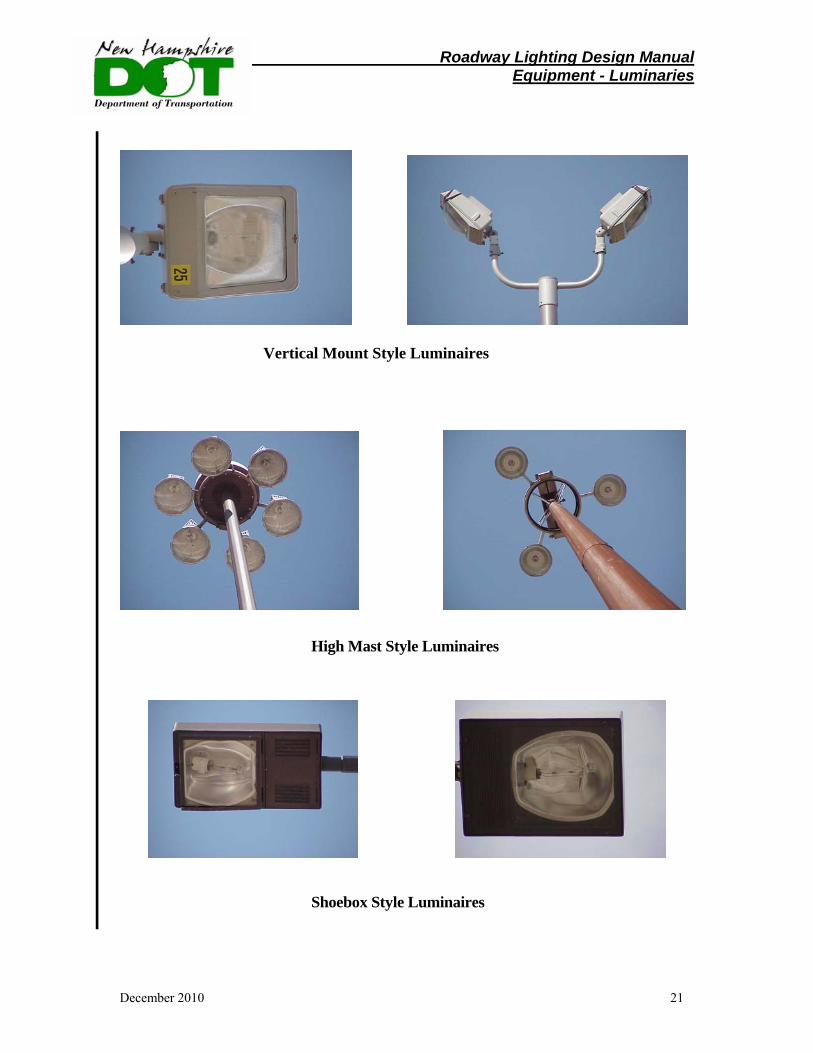
Vertical Mount Style Luminaires
High Mast Style Luminaires
Shoebox Style Luminaires

Roadway Lighting Design Manual Equipment - Luminaries
December 2010 22
Plymouth
Pembroke/Allenstown
Decorative Style Luminaires
Roadway Lighting Design Manual Equipment - Luminaries
December 2010 23
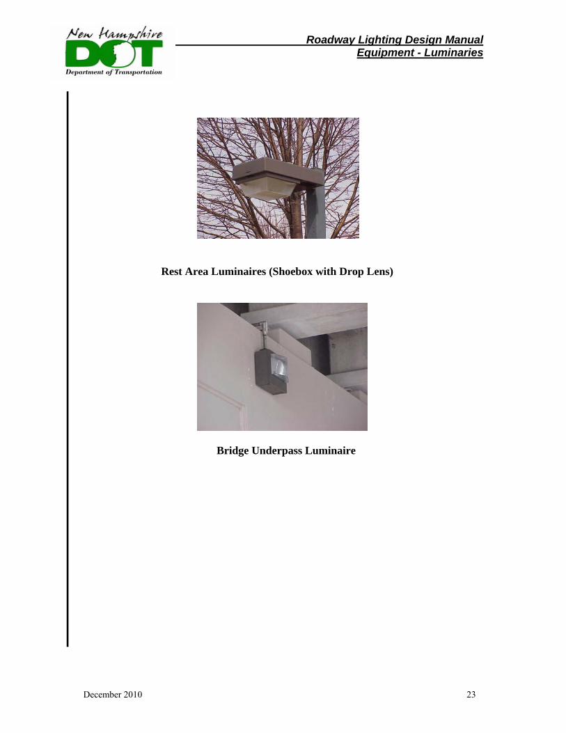
Rest Area Luminaires (Shoebox with Drop Lens)
Bridge Underpass Luminaire

Roadway Lighting Design Manual Equipment - Luminaries
December 2010 24
Light Emitting Diode
Roadway Lighting Design Manual Equipment – Support System
December 2010 25
2. Luminaire Support System
Mast Arms
Mast arms support the luminaire at a lateral dimension from the pole. Mast arm length is usually 6 feet, 8 feet, 12 feet or 16 feet (Typically 12’ in New Hampshire). Conventional lighting units should have davit type mast arms (telescoped onto the top of the pole) or tenon type mounting assembly unless a desire for decorative lighting dictates another type of arm, or unless the lights must match existing light poles with a different type of arm.
Poles
• Pole Height Pole height affects the illumination intensity, uniformity of brightness, area covered, and relative glare of the unit. Higher mounted units provide greater coverage, more uniformity, and a reduction of glare, but a lower foot-candle level. By using higher poles, fewer poles may be required and they can be set back farther from the traveled roadway. Typical pole heights in New Hampshire are 40 feet. Power lines, nearby airports, and nearby residential neighborhoods may limit the height of poles used for lighting. Wooden poles used in some applications are 35 feet in height. Ornamental lighting pole height range from 18-25 feet; see Conway ornamental lighting as an example. High mast tower luminaries have mounting heights varying from 100 feet to 120 feet. (Note: High Mast lighting is gradually being phased out on the NH highway lighting system).
• Pole Type
The pole industry manufactures several different types of poles. In New Hampshire the most common types are spun aluminum round tapered poles.
• Pole Designations
Generally, the pole type designation contains the mast arm length, nominal pole height, and the type of pole. The pole designation is read as follows:
1. The first character before the dash is the mast arm length. 2. The characters(s) just preceding the dash indicate the type of pole used. If
no characters are in this position, the pole has a transformer base or high base, is intended for mounting on a light base, and has no finish for an aluminum or stainless steel pole or is galvanized for a steel pole.
3. The characters after the dash give the nominal pole height.

Roadway Lighting Design Manual Equipment – Support System
December 2010 26
The following are examples of pole designations:
Wooden Pole with 12 Ft. Davit (12-35) – Full Cutoff (NH 4 Chicester)
Typical Installation on wood pole – 12’ Davit Arm – Semi Cutoff (vicinity N. H. Technical College – Concord)
Roadway Lighting Design Manual Equipment – Support System
December 2010 27
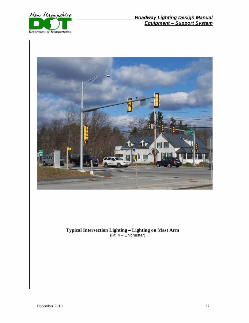
Typical Intersection Lighting – Lighting on Mast Arm (Rt. 4 – Chichester)
Roadway Lighting Design Manual Equipment – Support System
December 2010 28
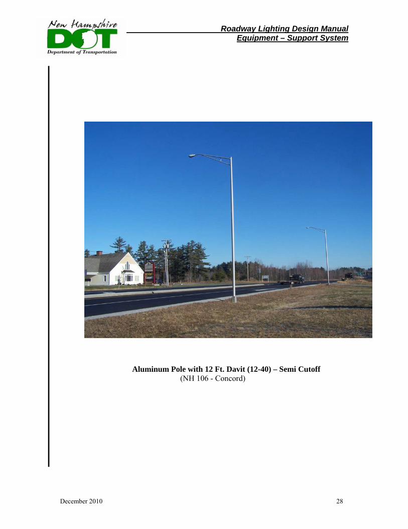
Aluminum Pole with 12 Ft. Davit (12-40) – Semi Cutoff (NH 106 - Concord)
Roadway Lighting Design Manual Equipment – Support System
December 2010 29
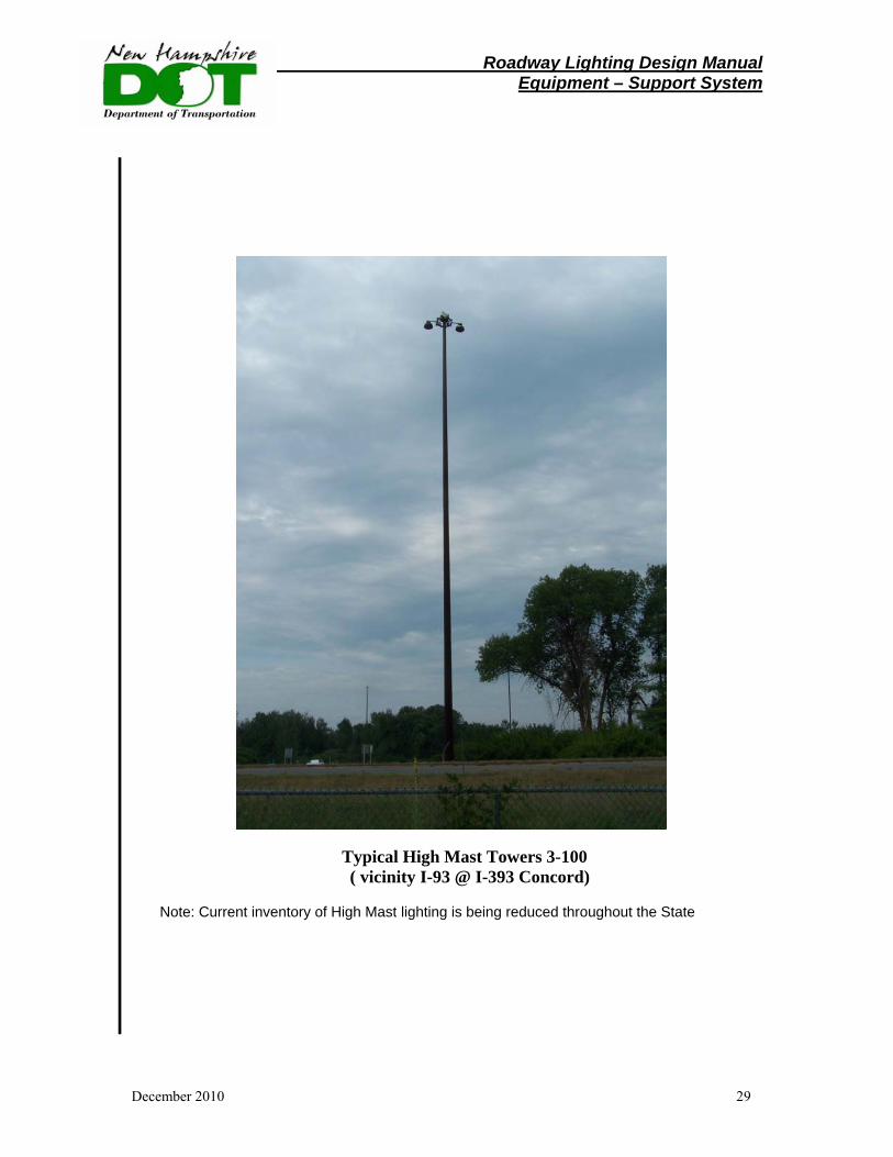
Typical High Mast Towers 3-100 ( vicinity I-93 @ I-393 Concord) Note: Current inventory of High Mast lighting is being reduced throughout the State
Roadway Lighting Design Manual Equipment – Support System
December 2010 30
Breakaway Poles
The latest AASHTO publication of the "Standard Specifications for Structural Supports for Highway Signs, Luminaires and Traffic Signals", specifies structural requirements for light poles. The Federal Highway Administration may have requirements differing from those found in the above noted AASHTO standard, particularly with regard to breakaway devices. The lighting system designer should check on such requirements before specifying types of poles for a lighting project.
A breakaway pole has a special base that has been tested as a complete unit to show that it will "break away" when hit and will not impede a vehicle's movement more than a maximum amount. NHDOT’s standard aluminum poles have been tested to meet breakaway requirements. The following should be used when determining if a breakaway pole is needed:
• Where traffic speeds exceed 40 mph, any poles located within the "clear zone" (see the NHDOT Highway Design Manual for the definition of "clear zone") must either be breakaway devices, or must be protected by a suitable traffic barrier ( such as a guardrail).
• In urban areas with speeds less than 30 mph and pedestrians present, a knocked down pole may present a greater hazard to traffic and pedestrians than would a non-breakaway device. Non-breakaway poles should be used in these locations.
• In urban areas with speeds between 30 mph and 40 mph, the designer may choose either breakaway poles or non-breakaway poles.
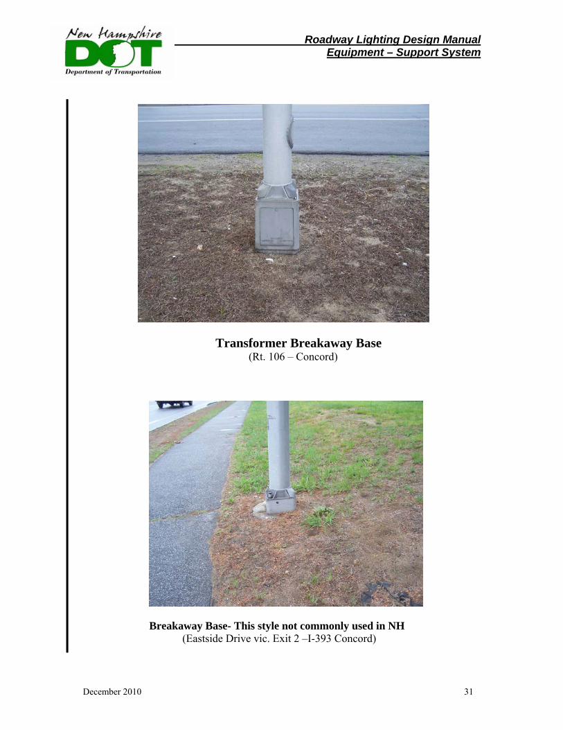
Types of pole bases include the tapered high base, the anchor base, the shoe base, and the standard transformer base. The most commonly used pole base in New Hampshire is the transformer base. Types of breakaway poles include the stainless steel progressive sheer base with a stainless steel shaft, the frangible cast aluminum transformer base with an aluminum pole shaft and arm, a slip base pole, and an aluminum shoe base pole
Roadway Lighting Design Manual Equipment – Support System
December 2010 31
Transformer Breakaway Base (Rt. 106 – Concord)
Breakaway Base- This style not commonly used in NH (Eastside Drive vic. Exit 2 –I-393 Concord)
Roadway Lighting Design Manual Equipment – Support System
December 2010 32
Pole Placement
Pole placement is an engineering decision which should be based upon geometry, character of the roadway, physical features, environment, location for future maintenance, economics, aesthetics, and overall lighting objectives.
Physical roadside conditions may require adjustment of the pole spacing determined from the base levels of illumination, as indicated in the AASHTO Roadway Lighting Design Guide, RP-8. Higher levels of illumination may be justified when overhead structures, safety, and object clearances restrict the placement of poles. It is advisable to provide higher illumination levels at diverging and merging areas.
Site considerations affecting pole placement include noise walls, existing guardrail, rock, narrow roadside clearances, power lines, nearby airports, traffic signals and nearby residential neighborhoods. If space does not permit, poles may be placed behind noise walls, however, access must be provided for maintenance. Poles should be placed behind existing guard rail, as defined in the Utilities Accommodation Manual at a distance that will allow the guard rail to properly deflect upon impact. When street lights are installed in conjunction with traffic signals, the lights should be installed on the same poles as the traffic signals, if possible.
The following pole placement practices relative to the horizontal alignment of the roadway should be followed:
• Long radius curves may be lighted as a straight roadway.
• Luminaires mounted on the inside of a short radius curve require closer spacing in order to produce adequate pavement brightness on the curved section, but are preferred over the outside of a short curve.
• Light poles on the inside of a banked curve should be placed such that they will not be hit by trucks.
Additionally, light pole placement should consider maintenance. Bucket trucks
must be nearly level to operate and are limited in the height and distance from the roadway that the bucket can reach. Different types of trucks may have different working ranges. Finally, poles should be placed to minimize knockdowns. Light Pole Bases/Foundations
In order to adequately support the lighting structure, the foundation must be designed to support the weight of the structure as well as resist wind loads and vibrations. Light pole bases shall be of a type, design, and location as shown on plans and as detailed in the Department’s “Standard Specifications for Road and Bridge Construction”, latest edition thereof.
Roadway Lighting Design Manual Equipment – Support System
December 2010 33
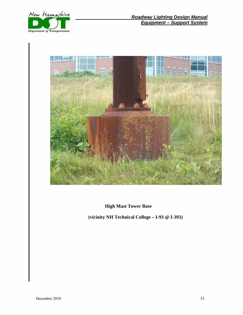
High Mast Tower Base
(vicinity NH Technical College – I-93 @ I-393)
Roadway Lighting Design Manual Equipment – Light Heads
December 2010 34
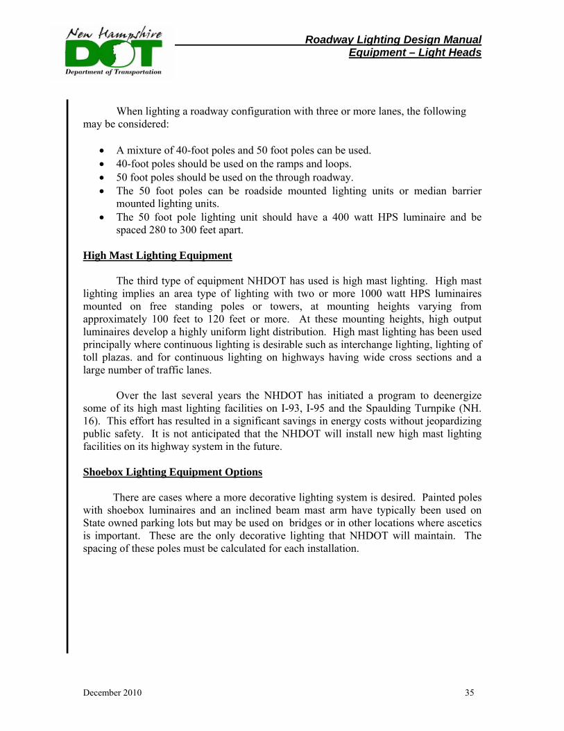
3. Selection of Light Heads
NHDOT utilizes the following four types of lighting head equipment combinations:
• Cobra Head • Vertical Mount – Turnpike Style • High Mast • Shoebox
Cobra Head Lighting Equipment
For roadway configurations with two or three lanes in each direction, the most common equipment used is the following:
• 250 watt HPS cobra head style luminaire • 12 foot Davit type mast arms: • 40-foot pole
The following general pole guidelines may be considered by the designer for two
or three lane configuations:
• Spacing of the 40-foot poles is usually 240 to 250 feet, depending on the desired footcandle level and the number of lanes.
• When 40-foot poles (with 250 watt HPS) are used for three lanes, they should never be spaced more than 240 feet apart.
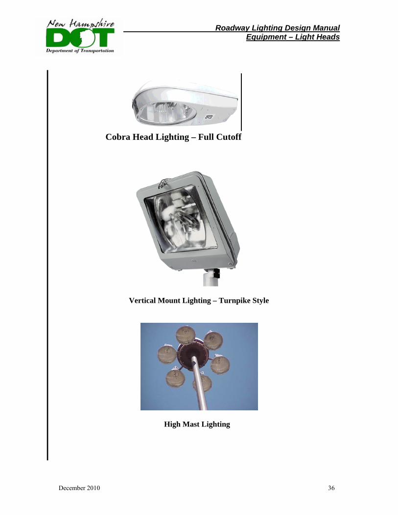
• When circumstances allow, NHDOT may use shoebox luminaires on light poles. Vertical Mount Lighting Equipment
When adequate clearance and back slopes are available, vertical mount lighting units may be utilized. The vertical mount poles are typically 45-foot poles with single or double tenon mounted with a 250 watt HPS luminaire mounted at 40 degrees. 50 foot poles may also be utilized with a 400 watt HPS luminaire. Vertical mounted poles can be used to set the pole and luminaire at least 20 to 30 feet from the travel way to provide safety to the traveling public.
Roadway Lighting Design Manual Equipment – Light Heads
December 2010 35
When lighting a roadway configuration with three or more lanes, the following may be considered:
• A mixture of 40-foot poles and 50 foot poles can be used. • 40-foot poles should be used on the ramps and loops. • 50 foot poles should be used on the through roadway. • The 50 foot poles can be roadside mounted lighting units or median barrier
mounted lighting units. • The 50 foot pole lighting unit should have a 400 watt HPS luminaire and be
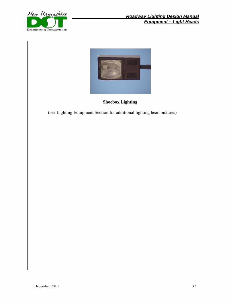
spaced 280 to 300 feet apart. High Mast Lighting Equipment
The third type of equipment NHDOT has used is high mast lighting. High mast lighting implies an area type of lighting with two or more 1000 watt HPS luminaires mounted on free standing poles or towers, at mounting heights varying from approximately 100 feet to 120 feet or more. At these mounting heights, high output luminaires develop a highly uniform light distribution. High mast lighting has been used principally where continuous lighting is desirable such as interchange lighting, lighting of toll plazas. and for continuous lighting on highways having wide cross sections and a large number of traffic lanes.
Over the last several years the NHDOT has initiated a program to deenergize
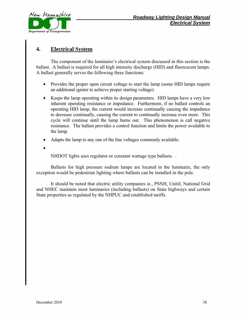
some of its high mast lighting facilities on I-93, I-95 and the Spaulding Turnpike (NH. 16). This effort has resulted in a significant savings in energy costs without jeopardizing public safety. It is not anticipated that the NHDOT will install new high mast lighting facilities on its highway system in the future. Shoebox Lighting Equipment Options
There are cases where a more decorative lighting system is desired. Painted poles with shoebox luminaires and an inclined beam mast arm have typically been used on State owned parking lots but may be used on bridges or in other locations where ascetics is important. These are the only decorative lighting that NHDOT will maintain. The spacing of these poles must be calculated for each installation.
Roadway Lighting Design Manual Equipment – Light Heads
December 2010 36
Cobra Head Lighting – Full Cutoff
Vertical Mount Lighting – Turnpike Style
High Mast Lighting
Roadway Lighting Design Manual Equipment – Light Heads
December 2010 37
Shoebox Lighting
(see Lighting Equipment Section for additional lighting head pictures)
Roadway Lighting Design Manual Electrical System
December 2010 38
4. Electrical System
The component of the luminaire’s electrical system discussed in this section is the ballast. A ballast is required for all high intensity discharge (HID) and fluorescent lamps. A ballast generally serves the following three functions:
• Provides the proper open circuit voltage to start the lamp (some HID lamps require an additional igniter to achieve proper starting voltage).
• Keeps the lamp operating within its design parameters. HID lamps have a very low inherent operating resistance or impedance. Furthermore, if no ballast controls an operating HID lamp, the current would increase continually causing the impedance to decrease continually, causing the current to continually increase even more. This cycle will continue until the lamp burns out. This phenomenon is call negative resistance. The ballast provides a control function and limits the power available to the lamp.
• Adapts the lamp to any one of the line voltages commonly available.
•
NHDOT lights uses regulator or constant wattage type ballasts. .
Ballasts for high pressure sodium lamps are located in the luminaire, the only exception would be pedestrian lighting where ballasts can be installed in the pole.
It should be noted that electric utility companies ie., PSNH, Unitil, National Grid and NHEC maintain most luminaries (including ballasts) on State highways and certain State properties as regulated by the NHPUC and established tariffs.
Roadway Lighting Design Manual Configuration
December 2010 39
Section VI. Lighting Configurations
Various lighting system configurations are defined and discussed in this section.
1. Continuous Freeway Lighting Continuous freeway lighting places continuous lighting that encompasses the
roadway and area immediately adjacent to the roadway over a substantial distance along the freeway. (Rarely used in New Hampshire)
2. Partial Interchange Lighting
Partial interchange lighting is the illumination of only the parts of the interchange that are most critical to the night driver, which are the diverge areas of the ramp connections, intersections, and other critical roadway features. NHDOT primarily illuminates deceleration lanes, ramp nose and gore areas.
Complete Interchange Lighting Complete interchange lighting is applying lighting to the interchange to achieve
illumination of all roadways in the interchange. (Not used in New Hampshire) 3. Underpass Lighting
Where AASHTO’s Roadway Lighting Design Guide indicates that underpass lighting is desirable, the lights are mounted on the abutment of the bridge or on a pier for each direction of travel on the roadway. If such mounting would place a luminaire more than approximately 10 feet from the edge of the traveled roadway, the luminaire is typically mounted on the bottom of the diaphragm.
For underpasses that are longer than 200 feet, underpasses should be lit all day. This may be utilized in large urban areas. 4. Other Streets and Highways Lighting
Lighting levels and uniformity ratios for streets and highways other than freeways are contained in the lighting design section of this manual. On a new lighting project it is often desirable to match the existing municipal lighting design written standards within the municipality.
Roadway Lighting Design Manual Configuration
December 2010 40
5. Bridge Lighting
The roadway on a bridge is normally treated the same as other parts of the roadway. If there is no lighting on the adjacent roadway, there is normally no need for lighting on the bridge. An exception is a very long bridge, which may be lit even though the roadway is not lit at other locations.
Where lights are to be installed on a bridge, the desirable locations for the lighting units are at abutments and at pier locations, or at a distance from an abutment or pier not to exceed 25 percent of the length of the span. This placement of the lighting units reduces the effects of vibration. The light poles should utilize davit type mast arms and shorter mast arm lengths so that there are no joints to be weakened by vibration.
The installation of navigation and air obstruction lights are an integral part of the bridge design. The US Coast Guard may ask the lighting designer to coordinate electrical service points for the roadway lighting and navigational/air obstruction lighting. 6. Intersection Lighting
Lighting at intersections is usually justified and will alert the driver to an approaching intersection. Notes regarding intersection lighting are as follows:
• Luminaires should be placed on or near prominent conflict points.
• Lighting should be provided at signalized intersections. • A signal pole shaft extension with a luminaire mast arm should be utilized whenever possible to avoid adding more poles at the intersection. • Street lights on traffic signal poles should be fed from the traffic signal service point. • The level of illumination of a signalized intersection is dictated by the area classification (commercial, residential) of the roadway.
• Additional light poles may be necessary when the intersection has channelization or complex turning lanes.
Roadway Lighting Design Manual Typical Lighting Layouts
December 2010 41
7. Roundabout Lighting Design Illumination
For a roundabout to operate satisfactorily, a driver must be able to enter the roundabout, move through the circulating traffic, and separate from the circulating stream in a safe and efficient manner. To accomplish this, a driver must be able to perceive the general layout and operation of the intersection in time to make the appropriate maneuvers. Adequate lighting should therefore be provided at all roundabouts. Need for illumination (Roundabout)
The need for illumination varies somewhat based on the location in which the
roundabout is located. In various settings, illumination should be provided for the following reasons:
Urban conditions:
• Most if not all approaches are typically illuminated. • Illumination is necessary to improve the visibility of pedestrians and bicyclists. Suburban conditions: • One or more approaches are illuminated. • An illuminated area in the vicinity can distract the driver’s view. • Heavy nighttime traffic is anticipated.
Continuity of illumination must be provided between illuminated areas and the
roundabout itself. An unlit roundabout with one or more illuminated approaches is dangerous. This is because a driver approaching on an unlit approach will be attracted to the illuminated area(s) and may not see the roundabout. Rural conditions (Roundabout)
For rural roundabouts, illumination is recommended but not mandatory. If there
is no power supply in the vicinity of the intersection, the provision of illumination can be costly. When lighting is not provided, the intersection should be well signed and marked so that it can be correctly perceived by day and night. The use of reflective pavement markers and retroreflective signs (including chevrons supplementing the ONE-WAY signs) should be used when lighting cannot be installed in a cost-effective manner.
Roadway Lighting Design Manual Typical Lighting Layouts
December 2010 42
Where illumination can be provided, any raised channelization or curbing should
be illuminated. In general, a gradual illumination transition zone of approximately 260 ft. should be provided beyond the final trajectory changes at each exit. This helps drivers adapt their vision from the illuminated environment of the roundabout back into the dark environment of the exiting roadway, which takes approximately 1 to 2 seconds. In addition, no short-distance dark areas should be allowed between two consecutive illuminated areas. General recommendations (Roundabout)
The primary goal of illumination is to ensure perception of the approach and
mutual visibility among the various categories of users. To achieve this, the following features are recommended:
• The overall illumination of the roundabout should be approximately equal to the
sum of the illumination levels of the intersecting roadways. Roundabouts should be lit to a level that is 1.3 to 2 times the values used on the best lit approach. Local illumination standards should also be considered when establishing the illumination at the roundabout to ensure that the lighting is consistent.
• Good illumination should be provided on the approach nose of the splitter islands, at all conflict areas where traffic is entering the circulating stream, and at all places where the traffic streams separate to exit the roundabout.
• It is preferable to light the roundabout from the outside in towards the center.
This improves the visibility of the central island and the visibility of circulating vehicles to vehicles approaching to the roundabout. Ground-level lighting within the central island that shines upwards towards objects in the central island can improve their visibility.
• Special consideration should be given to lighting pedestrian crossing and bicycle merging areas.
• The designer should refer to the AASHTO Roadside Design Guide for a more
detailed discussion of clear zone requirements.
Roadway Lighting Design Manual Typical Lighting Layouts
December 2010 43
General Design Guidance Designers should review Chapter 7.3 of the FHWA document Roundabouts: An Informational Guide and Chapter 7 of the AASHTO Roadway Lighting Design Guide for a more detailed description of Roundabout design. Example Roundabout Pole Locations Example locations for poles at a roundabout are shown on a plan in the appendix, page 113, for the Holderness-Plymouth project #11849. It should be noted that this plan is a sample layout only. Each project must be evaluated on a case by case basis utilizing referenced guidelines of AASHTO and FHWA and any unique characteristics of the project.
Roadway Lighting Design Manual Typical Lighting Layouts
December 2010 44
Section VII Typical Lighting Layouts
Typical highway lighting layouts for various highway configurations are shown in the Appendix,pages 114-118, these include:
• Partial Interchange • 4-Way Signalized Intersection • Rural 3-Way Intersection • Raised Island & Channelized Lane entering a Signalized Intersection • 4-Way Intersection – No signals
These layouts represent only a sample of possible lighting layouts. The Designer
should review these prior to completing a lighting design to insure that the proposed design is consistent with Department guidelines and this manual. Special circumstances may dictate a change in a typical layout design therefore it is imperative that the designer complete the facility checklist shown in Section IX - Lighting Design, Item 3 – Facility Checklist Pages 68-69, during the initial stages of design.

Roadway Lighting Design Manual General
December 2010 45
Section VIII General Lighting Discussion 1. Exterior Luminaire Classification. - Cutoffs
The National Electrical Manufacturers Association (NEMA) classifies exterior luminaires by intensity distribution. Table 2 describes the cutoff and distribution classification. One classification refers to the vertical candela distribution of light from an individual luminaire (Table 2) and the other refers to the illuminance pattern produced on the ground or horizontal surface, see “Luminaire Distribution Pattern – Selection of Luminaire” section. Each successive classification provides more vertical illuminance, but also introduces more glare and stray uplight. Full cutoff luminaires are typically used for roadway and area lighting to minimize glare, light trespass, and light pollution. Semi-cutoff and non-cutoff should be used only at low mounting heights and with low output lamps (less than 1800 lumens-per RSA Chapter 9E).
TYPE DESCRIPTION APPLICATIONS
Full Cutoff
A luminaire light distribution where zero candela intensity occurs at an angle of 90° above nadir (straight down) and at all greater angles from nadir. Additionally, the candela per 1000 lumens does not numerically exceed 100 (10%) at a vertical angle of 80° above nadir. This applies to all lateral angles around the luminaire.
Use for roadway, parking, and other vehicular lighting applications. Minimizes glare and light pollution and light trespass.
Cutoff
A luminaire light distribution where the candela per 1000 lamp lumens does not numerically exceed 25 (2.5%) at an angle of 90° above nadir, and 100 (10%) at a vertical angle of 80° above nadir. This applies to all lateral angles around the luminaire.
Use in applications where pedestrians are present. Provides more vertical illuminance than Full Cutoff luminaires. Lamp rating should be less than 1800 lumens. (per RSA-Chapter 9E)
Semicutoff
A luminaire light distribution where the candela per 1000 lamp lumens does not numerically exceed 50 (5%) at an angle of 90° above nadir, and 200 (20%) at a vertical angle of 80° above nadir. This applies to all lateral angles around the luminaire.
Use in pedestrian areas. If using in residential areas, provide with houseside shields to minimize light trespass. Lamp rating should be less than 1800 lumens.(per RSA-Chapter 9E)
Noncutoff
A luminaire light distribution where there is no candela limitation. The light source may be completely unshielded.
Use for decorative applications only. Lamp rating should be less than 1800 lumens.(per RSA-Chapter 9E)
Table 2. Exterior Luminaire Cutoff Classification.

Roadway Lighting Design Manual General – Full Cutoff
December 2010 46
2. Full Cutoff Luminaires
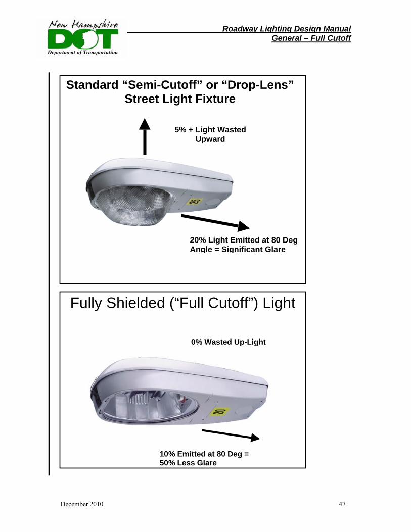
Full Cutoff Luminaires, or fully shielded fixtures, are designed to prevent all emission of direct upward light, the major source of light pollution, and to reduce direct lateral glare that may actually diminish visibility of the illuminated target and thus degrade safety. According to the AASHTO Center for Environmental Excellence, “A ‘full cutoff luminaire’ is one that allows no direct light emissions above a horizontal plane through the luminaire’s lowest light-emitting part.”
Fully shielded cobra-head lights, the most common application for highway lighting, emit zero upward light and no more than 10% above a lateral angle of 80 degrees. Fully shielded fixtures are notable for a flat lens on the underside. In comparison, standard “semi-cutoff” cobra-head fixtures, with its characteristic protruding “drop lens,” typically emits 5% of its light upward and 20% laterally as glare.
The source of lateral glare from such fixtures comes from visibility of the bulb through the drop-lens, either directly or by refracted light. This results in a 20% wider beam pattern, but may also impair the vision of drivers, especially in older drivers.
The bulb in fully shielded fixtures is recessed inside the shielding and consequently is visible only from a close distance. Several state DOT’s, including the NHDOT, have adopted fully shielded cobra-head fixtures as their standard choice for highway lighting.
Roadway Lighting Design Manual General – Full Cutoff
December 2010 47
5% + Light Wasted Upward
20% Light Emitted at 80 Deg Angle = Significant Glare
Standard “Semi-Cutoff” or “Drop-Lens” Street Light Fixture
Fully Shielded (“Full Cutoff”) Light
0% Wasted Up-Light
10% Emitted at 80 Deg = 50% Less Glare
Roadway Lighting Design Manual General – Trespass
December 2010 48
3. Light Trespass
Light trespass is commonly understood to mean light that falls beyond its intended target, and across a property line so as to create a perceived nuisance. Stray light (spill light) of this kind, if it emanates at a high angle from the luminaire, can be a public nuisance and contribute to light pollution. Light trespass is somewhat subjective because it is difficult to define when, where, and how much light is unwanted.
Light Trespass – Control: Light trespass may be controlled or minimized by following these general
guidelines: • Use properly installed, fully shielded (full cutoff) luminaires. • Consider the surrounding area during the design, and select luminaires,
locations, and orientations that minimize spill light onto adjacent properties.
• Select luminaries that control the intensity (candela) distribution. • If designing outside building lighting or non-highway lighting, insure that
aiming angles are low so that the entire beam falls within the intended lighted area.
The lighting industry through the Institution of Lighting Engineers (ILE) has
suggested limits on light trespass that the lighting designer may consider in special circumstances.
Roadway Lighting Design Manual Design - Warrants
December 2010 49
Section IX Lighting Design 1. Lighting Warrants Narrative A lighting warrant is defined as factual evidence justifying or assuring that there is substantial reason for undertaking a proposed lighting project. The meeting of a lighting warrant does not, however, obligate the Department to undertake a lighting project on either existing or proposed highways. Lighting warrants should be based on conditions relating to the need for roadway lighting and the benefits that may be derived from lighting. Factors such as nighttime traffic volume, speed, nighttime accident rate, horizontal and vertical alignment, increased capacity, and general nighttime visibility may be used to justify lighting. Lighting Warrants
The primary purpose of warrants is to assist designers in evaluating locations for lighting needs and selecting locations for installing lighting. Warrants give conditions that should be satisfied to justify the installation of lighting, however meeting these warrants does not obligate the State or other agencies to provide lighting or participate in its cost. Conversely, local information in addition to that reflected by the warrants, such as roadway geometry, ambient lighting, sight distance, signing, crash rates, or frequent occurrences of fog, ice, or snow, may influence the decision to install lighting. Warrants for freeway lighting are contained in AASHTO’s Roadway Lighting Design Guide. Modifications and additions to these warrants are indicated below. Continuous Freeway Lighting – Not used in New Hampshire Complete Interchange Lighting – Not used in New Hampshire Partial Interchange Lighting
Case PIL-1 - Partial interchange lighting is considered to be warranted where the total current ADT ramp traffic entering and leaving the freeway within the interchange areas exceeds 5,000 for urban conditions, 3,000 for suburban conditions, or 1,000 for rural conditions.
Case PIL-2 - Partial interchange lighting is considered to be warranted where the current ADT on the freeway through traffic lanes exceeds 25,000 for urban conditions, 20,000 for suburban conditions, or 10,000 for rural conditions.
Case PIL-3 - Partial interchange lighting is considered to be warranted where the ratio of night to day crash rate within the interchange area is at least 1.25 times the statewide average for all unlighted similar sections, and a study indicates that lighting may be expected to result in a significant reduction in the night crash rate.
Roadway Lighting Design Manual Design - Warrants
December 2010 50
Non-Freeway Lighting
The AASHTO Roadway Lighting Design Guide gives no specific warrants for continuous lighting of roadways other than freeways (roads with fully controlled access, no at-grade intersections), but does suggest some general criteria that may apply when considering the installation of lighting.
Lighting of at-grade intersections is warranted if the geometric conditions mentioned in the AASHTO Roadway Lighting Design Guide exist or if one or more of the following conditions exists:
1. Volume - The traffic signal warrant volumes for the minimum vehicular volume warrant, the interruption of continuous traffic warrant, or the minimum pedestrian volume warrant are satisfied for any single hour during conditions other than daylight, excluding the time period between 6:00 a.m. and 6:00 p.m.
2. Crashes - There are three or more crashes per year occurring during conditions other than daylight. Currently, thresholds for ratios of night to day crash rates are being developed for non-freeway facilities.
3. Intersecting Roadway - The intersecting roadway is lighted.
4. Ambient Light - Illumination in areas adjacent to the intersection adversely affects the drivers' vision.
5. Channelization - The intersection is channelized and the 85th percentile approach speed exceeds 40 miles per hour. A continuous median is not considered as channelization for the purpose of this warrant.
6. School Crossing - Scheduled events occurring at least once per week during the school year make it necessary for 100 or more pedestrians to cross at the school crossing during any single hour in conditions other than daylight, or a traffic engineering study indicates a need for lighting.
7. Signalization - The intersection is signalized.
8. Flashing Beacons - The intersection has a flashing beacon.
Warrants covering lighting for tunnels, underpasses, rest areas, and signs are contained in the AASHTO Roadway Lighting Design Guide. See the following Roadway Warrant Examples section for specific cases of roadway types.
Roadway Lighting Design Manual Design – Warrant Examples
December 2010 51
2. Lighting Warrants Examples
The following application pages begin with a summary of the warrants to determine if lighting is actually necessary. The criteria that should be met by the lighting design are summarized in a table format. In some cases the criteria is given as a range. Specific values must be obtained from the appropriate tables located in the Appendix. A list of the design intent and possible rules of thumb follow to give the designer a starting point for the design as well as an overall view of the design objectives. Any special considerations for that particular application are also listed. On the facing page, an example design is illustrated with a perspective view, a plan view, and a luminaire schedule. These are provided to show how the criteria were met for a given case. It cannot be taken as a standard. All designs must be treated individually.
The criteria and example assume a simple layout such as straight, horizontal stretches of roadway. For sharp curves, steep hills, or any special case consult the latest version of the AASHTO Design Guide or IESNA Handbook, Recommended Practice RP-8.
For some applications, an example calculation is also included. This is intended
to illustrate the type of calculation results that were used to verify the design. For most designs, a typical section of the roadway is all that must be calculated. As with the lighting criteria, the extent and type of calculations will vary with type and complexity of the project.
The following roadway or facility types are shown. It should be noted that these examples are for illustration only and the type of lamp and wattage may vary. Induction lighting shown has not typically been utilized in New Hampshire but it may be an alternative that the designer should consider. :
• Freeways • Partially Lighted Intersections • Rural Intersections • Municipal Streets • Highway Underpass • Bridges • Roundabouts • Park-n-Ride Facilities • Temporary Lighting
Roadway Lighting Design Manual Design – Warrant Examples
December 2010 52
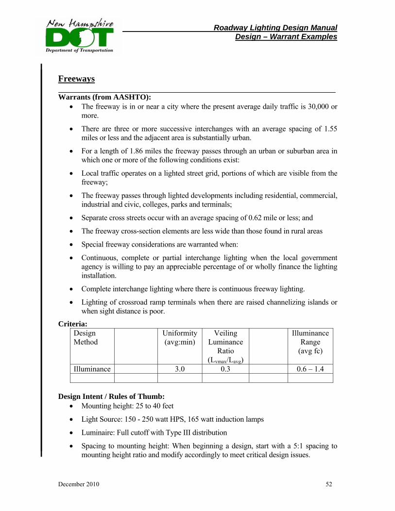
Freeways Warrants (from AASHTO):
• The freeway is in or near a city where the present average daily traffic is 30,000 or more.
• There are three or more successive interchanges with an average spacing of 1.55 miles or less and the adjacent area is substantially urban.
• For a length of 1.86 miles the freeway passes through an urban or suburban area in which one or more of the following conditions exist:
• Local traffic operates on a lighted street grid, portions of which are visible from the freeway;
• The freeway passes through lighted developments including residential, commercial, industrial and civic, colleges, parks and terminals;
• Separate cross streets occur with an average spacing of 0.62 mile or less; and
• The freeway cross-section elements are less wide than those found in rural areas
• Special freeway considerations are warranted when:
• Continuous, complete or partial interchange lighting when the local government agency is willing to pay an appreciable percentage of or wholly finance the lighting installation.
• Complete interchange lighting where there is continuous freeway lighting.
• Lighting of crossroad ramp terminals when there are raised channelizing islands or when sight distance is poor.
Criteria: Design Method
Uniformity (avg:min)
Veiling Luminance
Ratio (Lvmax/Lavg)
Illuminance Range
(avg fc)
Illuminance 3.0 0.3 0.6 – 1.4
Design Intent / Rules of Thumb:
• Mounting height: 25 to 40 feet
• Light Source: 150 - 250 watt HPS, 165 watt induction lamps
• Luminaire: Full cutoff with Type III distribution
• Spacing to mounting height: When beginning a design, start with a 5:1 spacing to mounting height ratio and modify accordingly to meet critical design issues.
Roadway Lighting Design Manual Design – Warrant Examples
December 2010 53
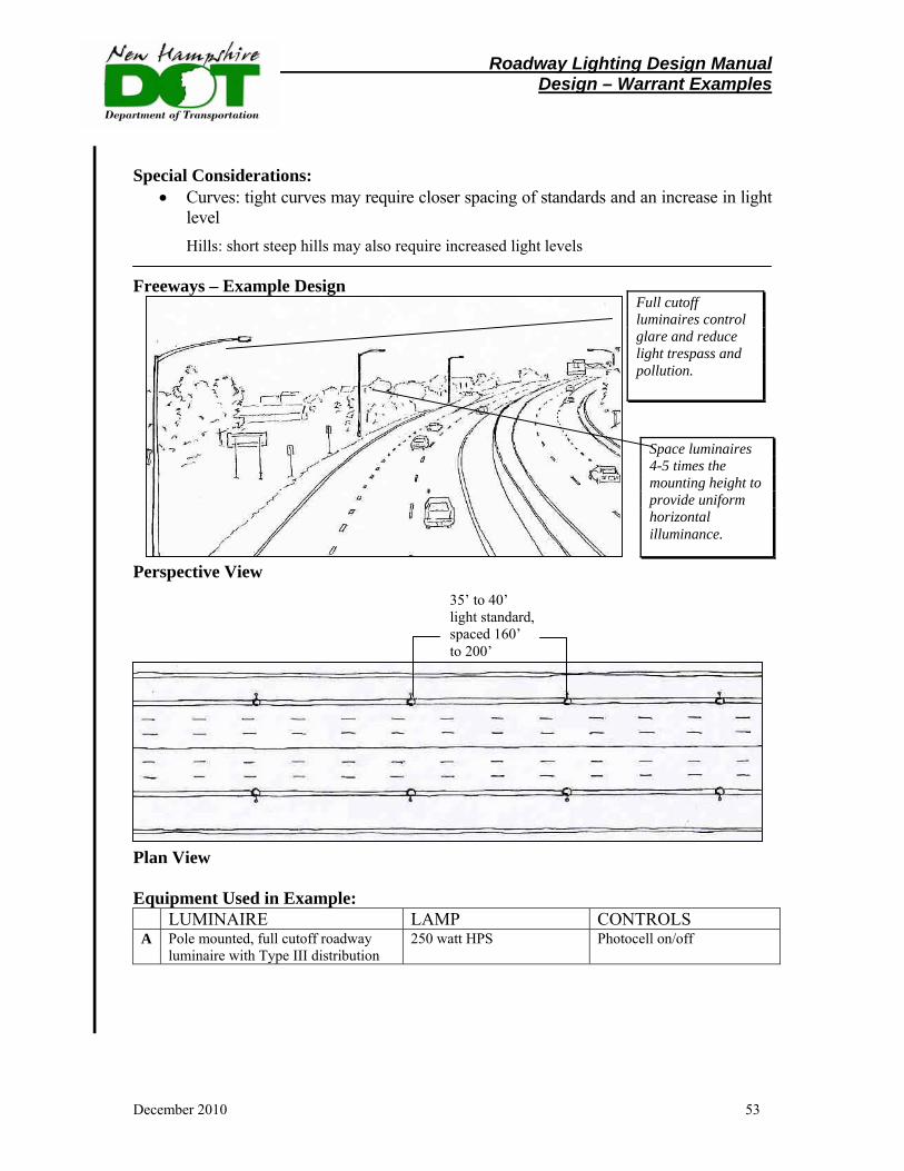
Special Considerations: • Curves: tight curves may require closer spacing of standards and an increase in light
level Hills: short steep hills may also require increased light levels
Freeways – Example Design Perspective View Plan View Equipment Used in Example: LUMINAIRE LAMP CONTROLS A Pole mounted, full cutoff roadway
luminaire with Type III distribution 250 watt HPS Photocell on/off
Space luminaires 4-5 times the mounting height to provide uniform horizontal illuminance.
Full cutoff luminaires control glare and reduce light trespass and pollution.
35’ to 40’ light standard, spaced 160’ to 200’

Roadway Lighting Design Manual Design – Warrant Examples
December 2010 54
Partially Lighted Interchanges Warrants: Partial interchange lighting is warranted if any of the following conditions exist:
• The total ramp average daily traffic exceeds 5,000 in urban areas, 3,000 in suburban areas and 1,000 in rural areas.
• The average daily traffic on the through freeway lanes exceeds 25,000 in urban areas, 20,000 in suburban areas and 10,000 in rural areas.
• The nighttime to daytime accident rate is at least 1.25 times higher than the statewide average for similar unlighted interchanges.
Criteria:
Design Method
Uniformity (avg:min)
Veiling Luminance
Ratio (Lvmax/Lavg)
Illuminance Range (avg fc)
Illuminance 3.0 0.3 0.6 – 1.4
Design Intent / Rules of Thumb:
• Mounting height: 30 – 40 feet
• Light Source: 150 - 250 watt HPS
• Luminaire: Full cutoff with Type III distribution
• Spacing to mounting height: When beginning a design, start with a 5:1 spacing to mounting height ratio and modify accordingly to meet critical design issues
Special Considerations:
• Near residential neighborhoods, house side shields may be required to minimize light trespass.

Roadway Lighting Design Manual Design – Warrant Examples
December 2010 55
Rural Intersections Warrants:
• Rural Intersection lighting is warranted by an unusually high nighttime to daytime accident rate ratio.
• The FHWA Roadway Lighting Handbook(1) suggests that lighting is warranted if the average annual number of nighttime accidents exceeds the average annual number of daytime accidents divided by three.
• Channelized intersections should also be lighted regardless of accident rates. Generally, only minimal lighting is required.
Criteria:
Design Method
Uniformity (avg:min)
Veiling Luminance
Ratio (Lvmax/Lavg)
Illuminance Range
(avg fc)
Illuminance 4.0 0.3 0.4-0.8
Design Intent / Rules of Thumb:
• Rural intersections should not be over lighted since only one or two light standards may be present.
•
Special Considerations: • Use lower wattage lamp for adaptation in and out of rural intersection.
• Use lower height light standards and luminaire shielding if adjacent to residential properties.
Roadway Lighting Design Manual Design – Warrant Examples
December 2010 56
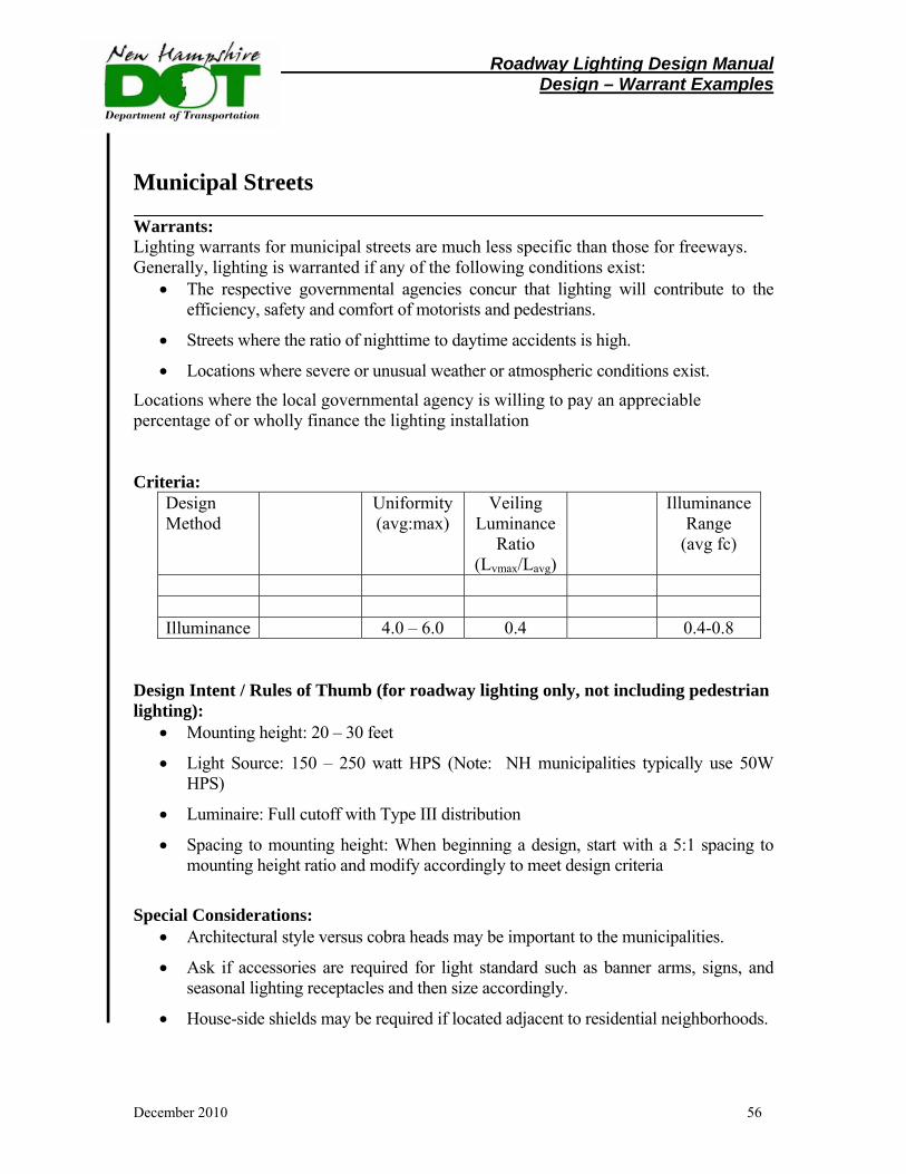
Municipal Streets Warrants: Lighting warrants for municipal streets are much less specific than those for freeways. Generally, lighting is warranted if any of the following conditions exist:
• The respective governmental agencies concur that lighting will contribute to the efficiency, safety and comfort of motorists and pedestrians.
• Streets where the ratio of nighttime to daytime accidents is high.
• Locations where severe or unusual weather or atmospheric conditions exist.
Locations where the local governmental agency is willing to pay an appreciable percentage of or wholly finance the lighting installation Criteria:
Design Method
Uniformity (avg:max)
Veiling Luminance
Ratio (Lvmax/Lavg)
Illuminance Range
(avg fc)
Illuminance 4.0 – 6.0 0.4 0.4-0.8
Design Intent / Rules of Thumb (for roadway lighting only, not including pedestrian lighting):
• Mounting height: 20 – 30 feet
• Light Source: 150 – 250 watt HPS (Note: NH municipalities typically use 50W HPS)
• Luminaire: Full cutoff with Type III distribution
• Spacing to mounting height: When beginning a design, start with a 5:1 spacing to mounting height ratio and modify accordingly to meet design criteria
Special Considerations:
• Architectural style versus cobra heads may be important to the municipalities.
• Ask if accessories are required for light standard such as banner arms, signs, and seasonal lighting receptacles and then size accordingly.
• House-side shields may be required if located adjacent to residential neighborhoods.
Roadway Lighting Design Manual Design – Warrant Examples
December 2010 57
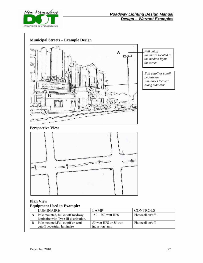
Municipal Streets – Example Design B Perspective View Plan View Equipment Used in Example: LUMINAIRE LAMP CONTROLS A Pole mounted, full cutoff roadway
luminaire with Type III distribution. 150 – 250 watt HPS Photocell on/off
B Pole mounted,Full cutoff or semi cutoff pedestrian luminaire
50 watt HPS or 55 watt induction lamp
Photocell on/off
Full cutoff luminaire located in the median lights the street
A
Full cutoff or cutoff pedestrian luminares located along sidewalk
Roadway Lighting Design Manual Design – Warrant Examples
December 2010 58
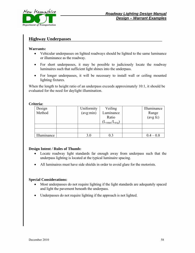
Highway Underpasses Warrants:
• Vehicular underpasses on lighted roadways should be lighted to the same luminance or illuminance as the roadway.
• For short underpasses, it may be possible to judiciously locate the roadway luminaires such that sufficient light shines into the underpass.
• For longer underpasses, it will be necessary to install wall or ceiling mounted lighting fixtures.
When the length to height ratio of an underpass exceeds approximately 10:1, it should be evaluated for the need for daylight illumination. Criteria:
Design Method
Uniformity (avg:min)
Veiling Luminance
Ratio (Lvmax/Lavg)
Illuminance Range
(avg fc)
Illuminance 3.0 0.3 0.4 – 0.8
Design Intent / Rules of Thumb:
• Locate roadway light standards far enough away from underpass such that the underpass lighting is located at the typical luminaire spacing.
• All luminaires must have side shields in order to avoid glare for the motorists.
Special Considerations:
• Most underpasses do not require lighting if the light standards are adequately spaced and light the pavement beneath the underpass.
• Underpasses do not require lighting if the approach is not lighted.
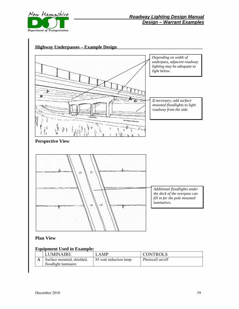
Roadway Lighting Design Manual Design – Warrant Examples
December 2010 59
Highway Underpasses – Example Design
Perspective View Plan View Equipment Used in Example: LUMINAIRE LAMP CONTROLS A Surface mounted, shielded,
floodlight luminaire 85 watt induction lamp Photocell on/off
If necessary, add surface mounted floodlights to light roadway from the side.
Depending on width of underpass, adjacent roadway lighting may be adequate to light below.
A
Additional floodlights under the deck of the overpass can fill in for the pole mounted luminaires.
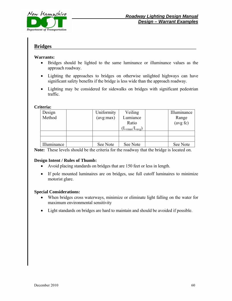
Roadway Lighting Design Manual Design – Warrant Examples
December 2010 60
Bridges Warrants:
• Bridges should be lighted to the same luminance or illuminance values as the approach roadway.
• Lighting the approaches to bridges on otherwise unlighted highways can have significant safety benefits if the bridge is less wide than the approach roadway.
• Lighting may be considered for sidewalks on bridges with significant pedestrian traffic.
Criteria:
Design Method
Uniformity (avg:max)
Veiling Lumiance
Ratio (Lvmax/Lavg)
Illuminance Range
(avg fc)
Illuminance See Note See Note See Note
Note: These levels should be the criteria for the roadway that the bridge is located on. Design Intent / Rules of Thumb:
• Avoid placing standards on bridges that are 150 feet or less in length.
• If pole mounted luminaires are on bridges, use full cutoff luminaires to minimize motorist glare.
Special Considerations:
• When bridges cross waterways, minimize or eliminate light falling on the water for maximum environmental sensitivity
• Light standards on bridges are hard to maintain and should be avoided if possible.
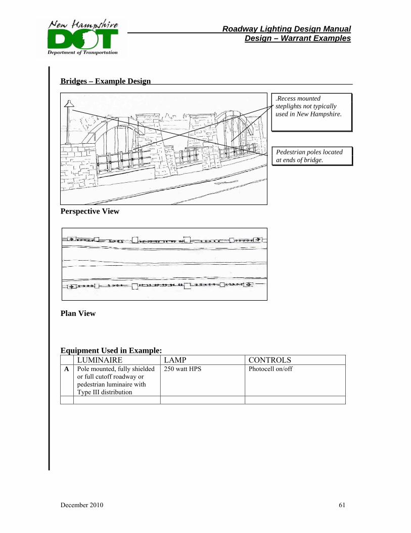
Roadway Lighting Design Manual Design – Warrant Examples
December 2010 61
Bridges – Example Design Perspective View Plan View Equipment Used in Example: LUMINAIRE LAMP CONTROLS A Pole mounted, fully shielded
or full cutoff roadway or pedestrian luminaire with Type III distribution
250 watt HPS Photocell on/off
.Recess mounted steplights not typically used in New Hampshire.
Pedestrian poles located at ends of bridge.
Roadway Lighting Design Manual Design – Warrant Examples
December 2010 62
Roundabouts Warrants:
• Lighting is warranted for all roundabouts.
Criteria:
Illuminance Uniformity (avg:min) 1.3 – 2 X level of the approach 3:1
Design Intent / Rules of Thumb:
• Light standards should not be located in the center of the roundabout.
• Locate light standards on the approach side of each entry such that the maximum amount of light falls on vehicles entering the roundabout
•
Special Considerations: • Lighted features in the center of the roundabout may increase the ambient
brightness. Care must be given to not cause glare for any of the motorists.
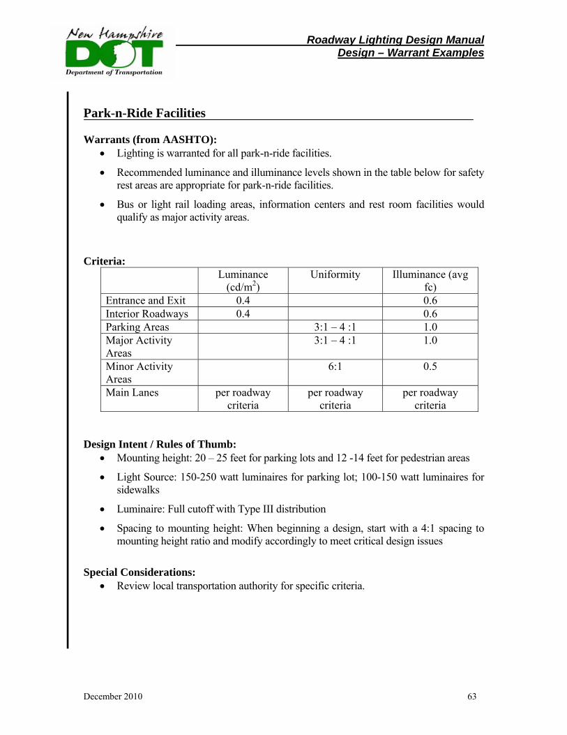
Roadway Lighting Design Manual Design – Warrant Examples
December 2010 63
Park-n-Ride Facilities Warrants (from AASHTO):
• Lighting is warranted for all park-n-ride facilities.
• Recommended luminance and illuminance levels shown in the table below for safety rest areas are appropriate for park-n-ride facilities.
• Bus or light rail loading areas, information centers and rest room facilities would qualify as major activity areas.
Criteria:
Luminance (cd/m2)
Uniformity Illuminance (avg fc)
Entrance and Exit 0.4 0.6 Interior Roadways 0.4 0.6 Parking Areas 3:1 – 4 :1 1.0 Major Activity Areas
3:1 – 4 :1 1.0
Minor Activity Areas
6:1 0.5
Main Lanes per roadway criteria
per roadway criteria
per roadway criteria
Design Intent / Rules of Thumb:
• Mounting height: 20 – 25 feet for parking lots and 12 -14 feet for pedestrian areas
• Light Source: 150-250 watt luminaires for parking lot; 100-150 watt luminaires for sidewalks
• Luminaire: Full cutoff with Type III distribution
• Spacing to mounting height: When beginning a design, start with a 4:1 spacing to mounting height ratio and modify accordingly to meet critical design issues
Special Considerations:
• Review local transportation authority for specific criteria.
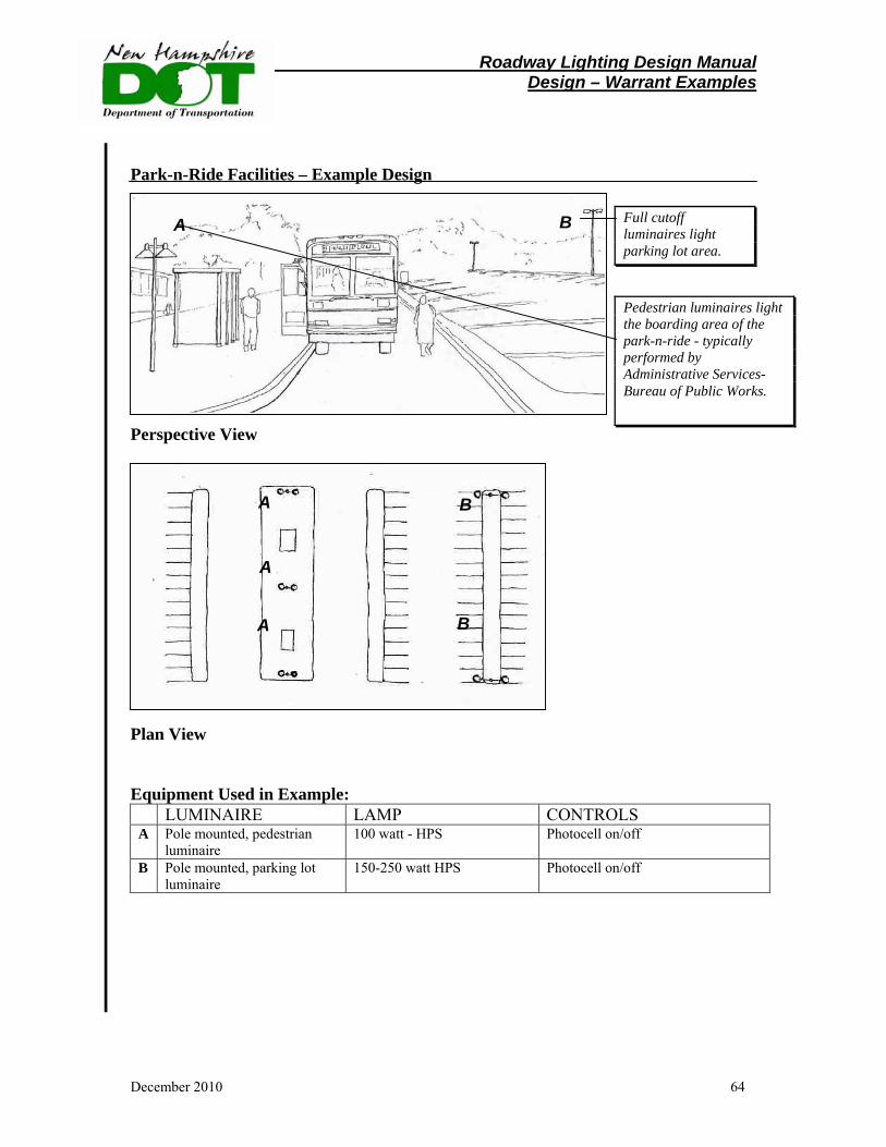
Roadway Lighting Design Manual Design – Warrant Examples
December 2010 64
Park-n-Ride Facilities – Example Design Perspective View Plan View Equipment Used in Example: LUMINAIRE LAMP CONTROLS A Pole mounted, pedestrian
luminaire 100 watt - HPS Photocell on/off
B Pole mounted, parking lot luminaire
150-250 watt HPS Photocell on/off
Full cutoff luminaires light parking lot area.
A B
Pedestrian luminaires light the boarding area of the park-n-ride - typically performed by Administrative Services- Bureau of Public Works.
A
B
BA
A
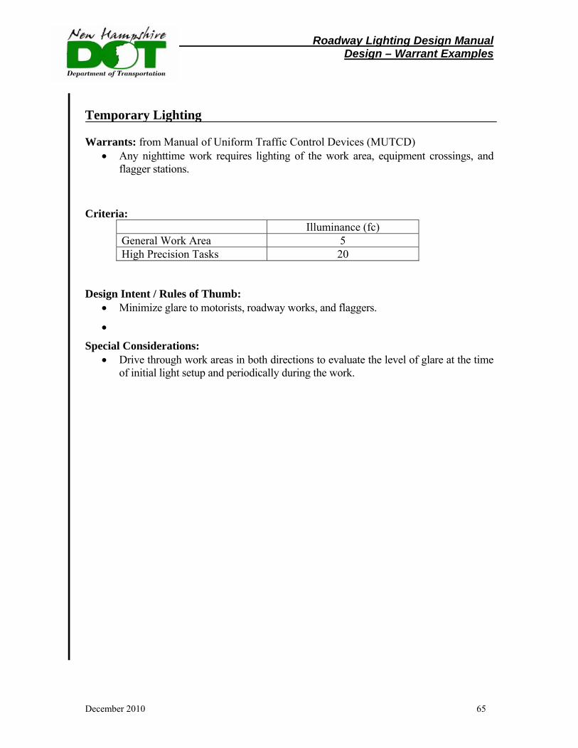
Roadway Lighting Design Manual Design – Warrant Examples
December 2010 65
Temporary Lighting Warrants: from Manual of Uniform Traffic Control Devices (MUTCD)
• Any nighttime work requires lighting of the work area, equipment crossings, and flagger stations.
Criteria:
Illuminance (fc) General Work Area 5 High Precision Tasks 20
Design Intent / Rules of Thumb:
• Minimize glare to motorists, roadway works, and flaggers.
•
Special Considerations: • Drive through work areas in both directions to evaluate the level of glare at the time
of initial light setup and periodically during the work.
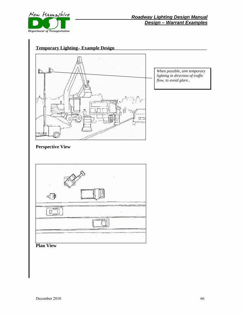
Roadway Lighting Design Manual Design – Warrant Examples
December 2010 66
Temporary Lighting– Example Design Perspective View Plan View
When possible, aim temporary lighting in direction of traffic flow, to avoid glare..
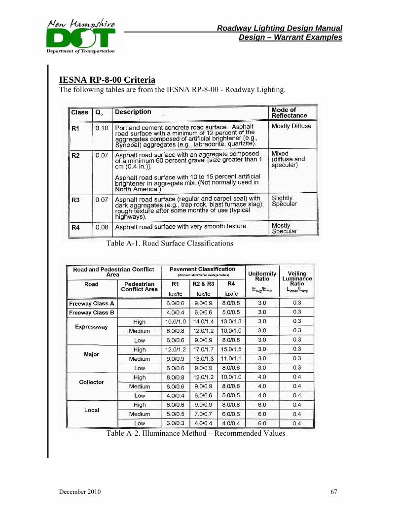
Roadway Lighting Design Manual Design – Warrant Examples
December 2010 67
IESNA RP-8-00 Criteria The following tables are from the IESNA RP-8-00 - Roadway Lighting.
Table A-1. Road Surface Classifications Table A-2. Illuminance Method – Recommended Values
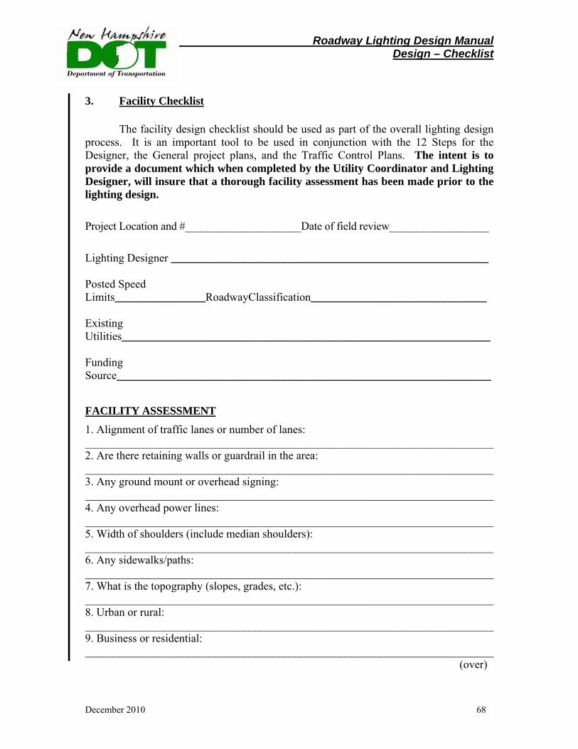
Roadway Lighting Design Manual Design – Checklist
December 2010 68
3. Facility Checklist
The facility design checklist should be used as part of the overall lighting design process. It is an important tool to be used in conjunction with the 12 Steps for the Designer, the General project plans, and the Traffic Control Plans. The intent is to provide a document which when completed by the Utility Coordinator and Lighting Designer, will insure that a thorough facility assessment has been made prior to the lighting design. Project Location and #_____________________Date of field review__________________
Lighting Designer ________________________________________________________ Posted Speed Limits________________RoadwayClassification_______________________________ Existing Utilities_________________________________________________________________ Funding Source__________________________________________________________________
FACILITY ASSESSMENT 1. Alignment of traffic lanes or number of lanes: ________________________________________________________________________ 2. Are there retaining walls or guardrail in the area: ________________________________________________________________________ 3. Any ground mount or overhead signing: ________________________________________________________________________ 4. Any overhead power lines: ________________________________________________________________________ 5. Width of shoulders (include median shoulders): ________________________________________________________________________6. Any sidewalks/paths: ________________________________________________________________________ 7. What is the topography (slopes, grades, etc.): ________________________________________________________________________ 8. Urban or rural: ________________________________________________________________________ 9. Business or residential: ________________________________________________________________________ (over)
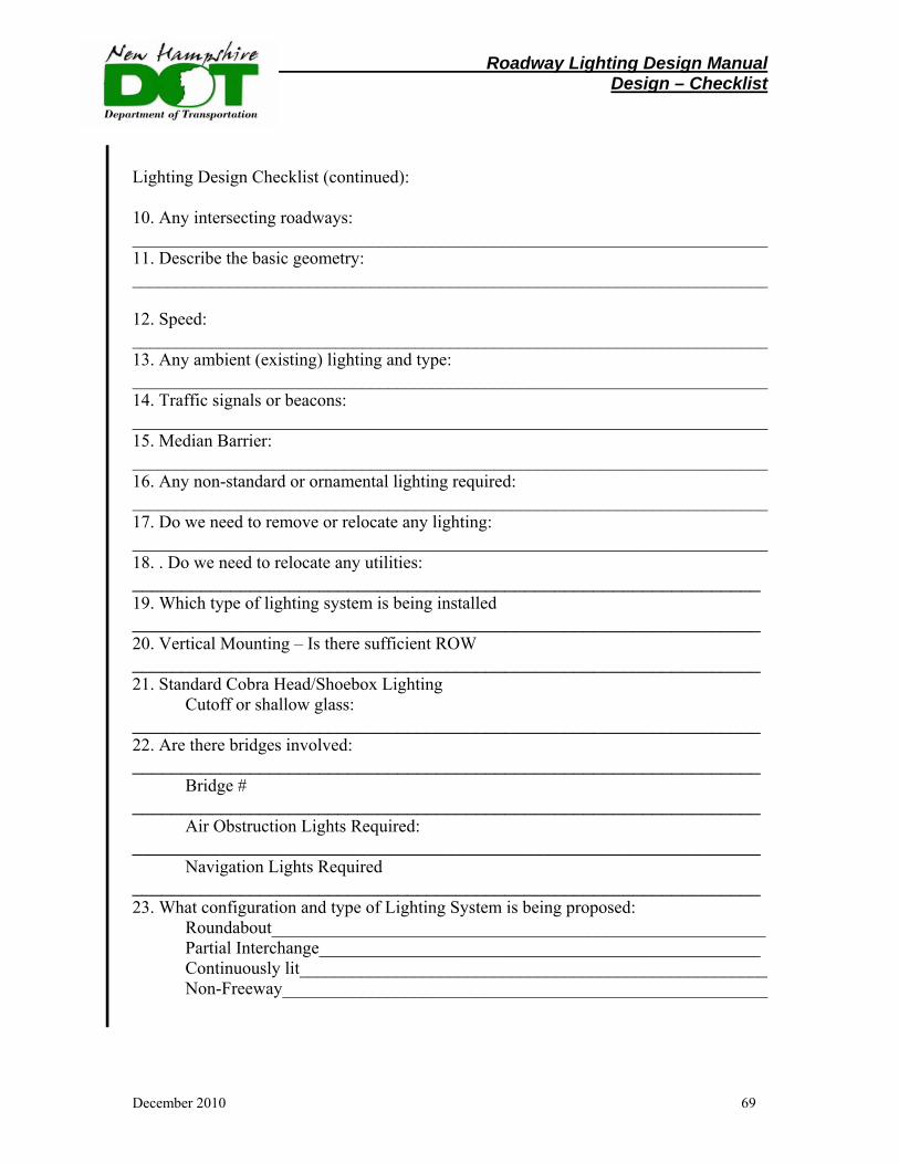
Roadway Lighting Design Manual Design – Checklist
December 2010 69
Lighting Design Checklist (continued): 10. Any intersecting roadways: ________________________________________________________________________ 11. Describe the basic geometry: ________________________________________________________________________ 12. Speed: ________________________________________________________________________ 13. Any ambient (existing) lighting and type: ________________________________________________________________________ 14. Traffic signals or beacons: ________________________________________________________________________ 15. Median Barrier: ________________________________________________________________________ 16. Any non-standard or ornamental lighting required: ________________________________________________________________________ 17. Do we need to remove or relocate any lighting: ________________________________________________________________________ 18. . Do we need to relocate any utilities: ________________________________________________________________ 19. Which type of lighting system is being installed ________________________________________________________________ 20. Vertical Mounting – Is there sufficient ROW ________________________________________________________________ 21. Standard Cobra Head/Shoebox Lighting Cutoff or shallow glass: ________________________________________________________________ 22. Are there bridges involved: ________________________________________________________________ Bridge # ________________________________________________________________ Air Obstruction Lights Required: ________________________________________________________________ Navigation Lights Required ________________________________________________________________ 23. What configuration and type of Lighting System is being proposed: Roundabout________________________________________________________ Partial Interchange__________________________________________________ Continuously lit_____________________________________________________ Non-Freeway_______________________________________________________
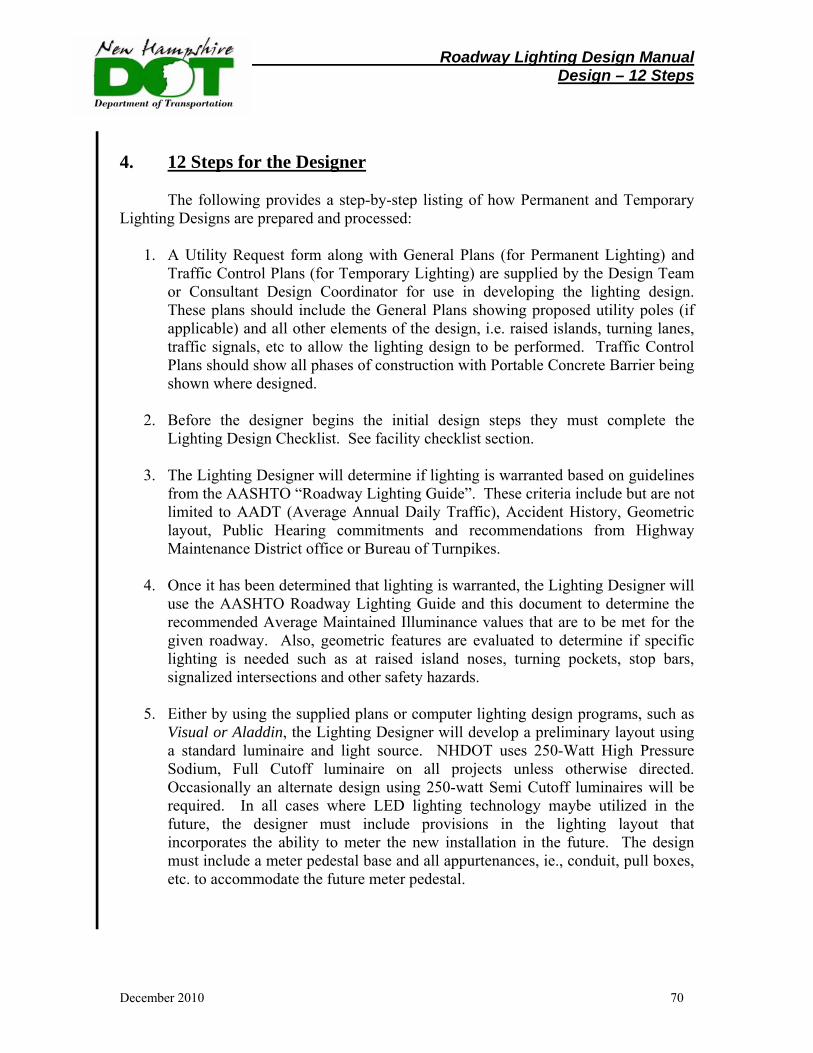
Roadway Lighting Design Manual Design – 12 Steps
December 2010 70
4. 12 Steps for the Designer
The following provides a step-by-step listing of how Permanent and Temporary Lighting Designs are prepared and processed:
1. A Utility Request form along with General Plans (for Permanent Lighting) and Traffic Control Plans (for Temporary Lighting) are supplied by the Design Team or Consultant Design Coordinator for use in developing the lighting design. These plans should include the General Plans showing proposed utility poles (if applicable) and all other elements of the design, i.e. raised islands, turning lanes, traffic signals, etc to allow the lighting design to be performed. Traffic Control Plans should show all phases of construction with Portable Concrete Barrier being shown where designed.
2. Before the designer begins the initial design steps they must complete the
Lighting Design Checklist. See facility checklist section.
3. The Lighting Designer will determine if lighting is warranted based on guidelines from the AASHTO “Roadway Lighting Guide”. These criteria include but are not limited to AADT (Average Annual Daily Traffic), Accident History, Geometric layout, Public Hearing commitments and recommendations from Highway Maintenance District office or Bureau of Turnpikes.
4. Once it has been determined that lighting is warranted, the Lighting Designer will
use the AASHTO Roadway Lighting Guide and this document to determine the recommended Average Maintained Illuminance values that are to be met for the given roadway. Also, geometric features are evaluated to determine if specific lighting is needed such as at raised island noses, turning pockets, stop bars, signalized intersections and other safety hazards.
5. Either by using the supplied plans or computer lighting design programs, such as
Visual or Aladdin, the Lighting Designer will develop a preliminary layout using a standard luminaire and light source. NHDOT uses 250-Watt High Pressure Sodium, Full Cutoff luminaire on all projects unless otherwise directed. Occasionally an alternate design using 250-watt Semi Cutoff luminaires will be required. In all cases where LED lighting technology maybe utilized in the future, the designer must include provisions in the lighting layout that incorporates the ability to meter the new installation in the future. The design must include a meter pedestal base and all appurtenances, ie., conduit, pull boxes, etc. to accommodate the future meter pedestal.
Roadway Lighting Design Manual Design – 12 Steps
December 2010 71
6. Once a preliminary design is complete, the Lighting Designer will present the
design as well as any pertinent backup information for the design, to the Chief of Design Services for approval. Any changes will be made to the plans after this meeting and final plans including conduit and pullbox layout will be drafted to present to the Design Team for their use in creating the final construction plans.
7. The Lighting Designer will create a Lighting memo to the Design Team as well as
the assigned Utility Coordinator defining the proposed lighting as well as develop a cost estimate for the Lighting Force Account Agreement and quantity estimate of conduit and pullboxes so that programmed estimate amounts can be incorporated into the project estimate.
8. The Utility Coordinator will develop a Lighting Estimate Request letter using the
lighting plan along with the conduit and pullbox layout to be sent to the appropriate power company on the project so that a utility company estimate of work can be developed. The Lighting Force Account Agreement is prepared from the lighting plan and the approved estimate.
9. At the same time, the Lighting Designer will use the Traffic Control Plans to
determine if Temporary Lighting is needed during construction. Temporary lighting is primarily used to illuminate the ends of Portable Concrete Barrier located within the clear zone. Additionally temporary lighting is incorporated to illuminate shifts in traffic from the existing alignment.
10. Temporary lighting can be accomplished by either attaching standard roadway
lights to existing utility poles, setting temporary wood poles and attaching standard roadway lights or as a last resort by using trailer-mounted lights. Temporary lighting can be powered by the local power company or contractor supplied generator if the local power company facilities are not readily available. Also, any permanent lighting (existing or proposed) that provides proper coverage of the work area should be used in lieu of temporary lighting.
11. A preliminary temporary lighting plan will be reviewed with the Chief of Design
Services for approval before the final plans and estimate are created.
12. The Lighting Designer will amend the “Permanent Lighting memo” or create a “Temporary Lighting memo” to the Design Team as well as the assigned Utility Coordinator of the proposed lighting. The Lighting Designer will, in addition, develop a cost estimate for the Temporary Lighting items and supply a copy to the Utility Coordinator and Design Team. See sample project package Plaistow NH 125 (10044F) in Appendix, Page 104-108.

Roadway Lighting Design Manual Design – Luminance Pattern
December 2010 72
5. Luminance Distribution Pattern
Luminaires are designed to provide lighting to fit many conditions. For street and area lighting, five basic patterns are available, as shown
Figure 1-9.�\Light distribution patterns for roadway lighting.
Roadway Lighting Design Manual Design – Luminance Pattern
December 2010 73
1. Type I (fig. 1-9a) is intended for narrow roadways with a width about equal to lamp mounting height. The lamp should be near the center of the street. A variation of this (fig. 1-9b) is suitable for intersections of two such roadways with the lamp at the approximate center.
2. Type II (fig. 1-9c) produces more spread than does Type I. It is intended for roadways with a width of about 1.6 times the lamp mounting height, with the lamp located near one side. A variation (fig. 1-9d) is suitable for intersections of two such roadways, with the lamp not near the center of the intersection.
3. Type III (fig. 1-9e) is intended for luminaires located near the side of the roadway with a width of not over 2.7 times the mounting height, typically used on NHDOT highways.
4. Type IV (fig. 1-9f) is intended for side-of road mounting on a roadway with a width of up to 3.7 times the mounting height.
5. Type V (fig. 1-9g) has circular distribution and is suitable for area lighting and wide roadway intersections. Types III and IV can be staggered on opposite sides of the roadway for better uniformity in lighting level or for use on wider roadways.
While many luminaires can be adjusted to produce more than one pattern, no luminaire is suitable for all patterns. Care must be used, especially in repair and replacement, to install the proper luminaire for the desired pattern, as specified in the manufacturer's literature. Even when the proper luminaire is installed, care must be used to ensure that all adjustments have been properly made to produce the desired results.
MOUNTING HEIGHT AND SPACING
There are two criteria for determining a preferred luminaire mounting height: the desirability of minimizing direct glare from the luminaire and the need for a reasonably uniform distribution of illumination on the street surface. The higher the luminaire is mounted, the farther it is above the normal line of vision and the less glare it creates. Greater mounting heights may often be preferable, but heights less than 20 feet cannot be considered good practice.

Roadway Lighting Design Manual Design – Luminance Pattern
December 2010 74
The designer must be somewhat familiar with the terminology relating to how fixtures are located down a roadway. Figure 1-10 shows these relationships graphically. The following information will be useful when determining the most appropriate mounting arrangements:
Figure 1-10.�\Luminaire arrangement and spacing.
The transverse direction is defined as back and forth across the width of the road, and the longitudinal direction is defined as up and down the length of the road.
Modern roadway fixtures are designed to be mounted in the vicinity of one of the curbs of the road. The overhang is defined as the dimension between the curb behind the fixture and a point directly beneath the fixture.
A luminaire overhang should not exceed 25 percent of the mounting height.
No attempt should be made to light a roadway that is more than twice the width of the fixture mounting height. A roadway luminaire produces a beam in both longitudinal directions and is limited in its ability to light across the street.
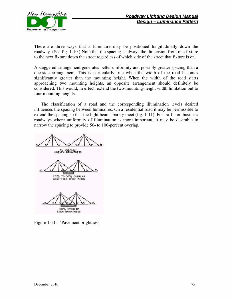
Roadway Lighting Design Manual Design – Luminance Pattern
December 2010 75
There are three ways that a luminaire may be positioned longitudinally down the roadway. (See fig. 1-10.) Note that the spacing is always the dimension from one fixture to the next fixture down the street regardless of which side of the street that fixture is on.
A staggered arrangement generates better uniformity and possibly greater spacing than a one-side arrangement. This is particularly true when the width of the road becomes significantly greater than the mounting height. When the width of the road starts approaching two mounting heights, an opposite arrangement should definitely be considered. This would, in effect, extend the two-mounting-height width limitation out to four mounting heights.
The classification of a road and the corresponding illumination levels desired influences the spacing between luminaires. On a residential road it may be permissible to extend the spacing so that the light beams barely meet (fig. 1-11). For traffic on business roadways where uniformity of illumination is more important, it may be desirable to narrow the spacing to provide 50- to 100-percent overlap.
Figure 1-11.�\Pavement brightness.
Roadway Lighting Design Manual Design – Photometry
December 2010 76
6. PHOTOMETRY
In this section the designer will be introduced to photometry as it relates to roadway lighting design. The items covered include photometrics and lamp and luminaire depreciation factors. It should be noted that this section describes the technical aspects of lighting design and is included as a primer for the designer and should be reviewed as such. In practical terms much of the photometry data and computations are computed by lighting software (currently the Department uses “Visual”).
Photometrics
The term Photometry is used to define any test data which describe the luminaire's
light output characteristics. The most common types of photometric data include isofootcandle performance charts, coefficient of utilization curves, vertical and lateral light distribution data, lumen maintenance curves, and dirt depreciation curves. The isofootcandle performance charts show what the light level will be at any given point.
The purpose of photometry is to accurately describe the performance of a luminaire, over time, to enable the designer to select the lighting equipment and to design a layout plan which best meets the needs of the location. A review of the more frequently used types of photometric data follows.
Coefficient of utilization
The coefficient of utilization (CU) is the ratio of the luminous flux (lumens) from a luminaire received on the roadway surface to the lumens emitted by the luminaire’s lamp alone. The utilization curve defines how much of the total lumen output reaches the area being lighted and is provided for luminaires intended for outdoor use. A Utilization Curve and a schematic for a typical 250W HPS full cutoff luminaire is shown as an example in the appendix, page 110.

Roadway Lighting Design Manual Design – Photometry
December 2010 77
The CU is computed as follows:
1. To obtain the pavement area CU, enter the CU curve for the Street Side at the
correct transverse distance to mounting height ratio. In this case, the ratio would be 46/40 or 1.15. Follow the chart up until you reach the Street curve and read the Utilized Lumens (in percent). This results in 36 percent.
2. To obtain the shoulder area CU, enter the CU curve for the Street Side at the
correct transverse distance to mounting height ratio. In this case, the ratio would be 10/40 or 0.25. Follow the chart up until you reach the Street curve and read the Utilized Lumens (in percent). This results in 10 percent.
3. The CU from the “triangle” that forms from the luminaire to the near pavement
edge is subtracted from the “triangle” that forms from the luminaire to the far side pavement edge. This results in a CU of approximately 26 percent.
Isofootcandle chart
An isofootcandle chart is used to describe the light pattern a luminaire produces. These charts show exact plots or lines of equal footcandle levels on the work plane with the fixture at a designated mounting height.
An isofootcandle curve for a typical full cut-off cobra head 250W HPS luminaire is shown in the appendix page 111. Once the CU is determined, the isofootcandle chart can be used to determine the Minimum Maintained Illumination Value and other discrete points in the system.
Roadway Lighting Design Manual Design – Photometry
December 2010 78
Isofootcandle Chart Example
Before using the isofootcandle chart, the point at which the minimum maintained illumination value is desired must be determined. For purposes of example, assume 120 feet to the right or left of the current position. This is a longitudinal distance along the roadway that will depend on actual pole spacing. The following steps should be followed:
1. Enter the isofootcandle chart at the Luminaire Position point and move left to the correct Ratio of Longitudinal Distance to Mounting Height. In this case the ratio would be 120/40 or 3.0.
2. If required, move up or down to correct for the exact luminaire position
in relation to point of interest (no correction for our example). 3. Read the illumination factor directly from the isobar, use interpolation
if required. In this case, the value would be 0.0125. This value represents the uncorrected footcandles at the location tested.
This information is used to determine the proper spacing and design standards.
Vertical Light Distributions
Vertical light distributions are characteristics of the luminaire and should be considered early in the design process. Vertical light distributions are divided into three groups, short, medium, and long. Classification is based on the distance from the luminaire to where the beam of maximum candlepower strikes the roadway surface. Each distribution is defined below.
Short distribution. The maximum candlepower beam strikes the roadway surface between 1.0 and 2.25 mounting heights from the luminaires.
Medium distribution. The maximum candlepower beam strikes the roadway at some point between 2.25 and 3.75 mounting heights from the luminaires.
Long distribution. The maximum candlepower beam strikes the roadway at a point between 3.75 and 6.0 mounting heights from the luminaires. On the basis of the vertical light distribution, theoretical maximum spacing is such that the maximum candlepower beams from adjacent luminaires are joined on the roadway surface. With this assumption, the maximum luminaire spacings are:
Roadway Lighting Design Manual Design – Photometry
December 2010 79
• Short distribution - 4.5 mounting heights • Medium distribution - 7.5 mounting heights • Long distribution - 12.0 mounting heights From a practical standpoint, the medium distribution is used by NHDOT, and the
spacing of luminaries normally does not exceed five to six mounting heights. Short distributions are not used extensively for reasons of economy, because extremely short spacing is required. At the other extreme, the long distribution is not used to great extent because the high beam angle of maximum candlepower often produces excessive glare. Lateral Light Distributions
As with vertical light distributions, lateral light distributions are characteristics of the luminaire and should be considered early in the design process. The Illuminating Engineering Society established a series of lateral distribution patterns designated as Types I, II, III, IV, and V. In general, we may describe Types I and V as luminaires mounted over the center of the area to be lighted. Type I applies to rectangular patterns on narrow streets, while Type V applies to areas where light is to be distributed evenly in all directions. Type V and a modified Type I are generally the class of luminaire applied in high mast lighting systems.
Types II, III, and IV are classes of luminaires to be mounted near the edge of the area to be lighted. Type II applies to narrow streets, Type III to streets of medium width, while Type IV applies to wide street applications.
These are illustrated as shown in the “luminaire distribution pattern” section, page 72.
Roadway Lighting Design Manual Design – Photometry
December 2010 80
Lamp and Luminaire Depreciation Factors
In determining the light output for a luminaire, the lighting system designer must consider the luminaire light loss factor. The luminaire light loss factor is a combination of several factors, including the Lamp Lumen Depreciation Factor (LLD) and the Lamp Dirt Depreciation Factor (LDD). Terms associated with this topic are defined as follows: Initial Lamp Lumens (LL) - initial bare bulb lumen output of a light source. Lamp Lumen Depreciation Factor (LLD) - a design factor used to depreciate the output of a lamp due to lifecycle output reduction. NHDOT uses a LLD = 0.80. Luminaire Dirt Depreciation Factor (LDD) - a design factor used to depreciate the output of a lamp due to dirt affecting the interior and exterior of the luminaire and to some extent the lamp itself. Various degrees of dirt accumulation may be anticipated depending on the area in which the luminaire is located. NHDOT uses a LDD = 0.90.
The loss factor is applied to the initial lamp lumens to determine the light output of the luminaire after a fixed period of time (maintained light output). The AASHTO Roadway Lighting Design Guide discusses the different aspects of the light loss factor. With these considerations, the factor to apply to arrive at a maintained light output value for the luminaire is an educated guess. However, as stated above, NHDOT uses a LLD of 0.80 (for HPS) and a LDD factor of 0.90, resulting in a combined 0.72 factor. The standard light loss factor would represent a loss of 28 percent of the initial lumen output accounting for output loss due to burn time and dirt covering the luminaire. Adjustments to these factors are warranted under special circumstances.
The LLD and LDD factor nomographs are illustrated in the appendix, page 112.
Roadway Lighting Design Manual Design – Photometry
December 2010 81
Photometry Select the appropriate curve in accordance with the type of ambient as described by the following examples: Very Clean – no nearby smoke or dust generating activities and low ambient contaminant level. Light traffic. Generally limited to residential or rural areas. The ambient particulate level is no more that 150 micrograms per cubic meter. Clean – No nearby smoke or dust generating activities. Moderate to heavy traffic. The ambient particulate level is no more than 300 micrograms per cubic meter. Moderate – Moderate smoke or dust generating activities nearby. The ambient particulate level is no more than 600 micrograms per cubic meter. Dirty – Smoke or dust plumes generated by nearby activities may occasionally envelope the luminaires. Very Dirty – As above but the luminaires are commonly enveloped by smoke or dust plumes.
Roadway Lighting Design Manual Design – BUG SYSTEM
December 2010 82
7. BUG Rating System:
The BUG system, also referred to as the Luminaire Classification System (LCS), was developed by the Illuminating Engineering Society of North America (IESNA) to make comparing and evaluating outdoor luminaires fast, easy and more complete than older methods.
It is expected that by late 2010 BUG values will be published by luminaire
manufacturers so lighting designers and purchasers can tell at a glance how well a certain luminaire controls stray light or compares with other luminaires under consideration for an installation. Work on the BUG system started in 2005 when the IES upgraded the roadway shielding classification system. The original system, which included the ratings full cutoff, cutoff, semi-cutoff and non-cutoff, had been designed as a rating system solely for street lighting. However, increasing demand for control of glare and light trespass extended these terms to all types of outdoor lighting, and the IES realized that a more comprehensive system was needed.
The IESNA defines the light distribution and optical control of roadway and area
lighting luminaires by the number of zonal lumens expressed as a percentage of the total lamp lumens. These classifications allow designers to choose the proper product to control spill light, light trespass, and sky glow. The LCS replaces the older IESNA Cutoff Classification System as shown in the “General Lighting Discussion” section.
BUG stands for “Backlight”, “Uplight” and “Glare.” The acronym describes the
types of stray light escaping from an outdoor lighting luminaire. “B” stands for backlight, or the light directed in back of the mounting pole. “U” stands for uplight, or the light directed above the horizontal plane of the luminaire, and “G” stands for glare, or the amount of light emitted from the luminaire at angles known to cause glare.
The BUG Rating system categorizes luminaires according to the amount of Backlight, Uplight and Glare that they have, and is calculated based on the number of lumens in the various LCS secondary zones. A luminaire's BUG Rating may be used to evaluate its optical performance related to light trespass, sky glow, and high-angle brightness control.
Luminaire Classification System (LCS)
There are three major zones that designers need to reference when creating an outdoor lighting design. These three zones are the Front Lighting Zone, Back Lighting Zone and Upper Lighting Zone. These three areas are further divided into secondary zones to allow the designer to control unwanted light while selecting luminaires with the proper distribution to put light where it is needed. These zones are shown on the below schematic and detailed on the next page:
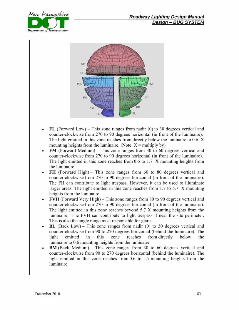
Roadway Lighting Design Manual Design – BUG SYSTEM
December 2010 83
• FL (Forward Low) – This zone ranges from nadir (0) to 30 degrees vertical and counter-clockwise from 270 to 90 degrees horizontal (in front of the luminaire). The light emitted in this zone reaches from directly below the luminaire to 0.6 X mounting heights from the luminaire. (Note: X = multiply by)
• FM (Forward Medium) – This zone ranges from 30 to 60 degrees vertical and counter-clockwise from 270 to 90 degrees horizontal (in front of the luminaire). The light emitted in this zone reaches from 0.6 to 1.7 X mounting heights from the luminaire.
• FH (Forward High) – This zone ranges from 60 to 80 degrees vertical and counter-clockwise from 270 to 90 degrees horizontal (in front of the luminaire). The FH can contribute to light trespass. However, it can be used to illuminate larger areas. The light emitted in this zone reaches from 1.7 to 5.7 X mounting heights from the luminaire.
• FVH (Forward Very High) – This zone ranges from 80 to 90 degrees vertical and counter-clockwise from 270 to 90 degrees horizontal (in front of the luminaire). The light emitted in this zone reaches beyond 5.7 X mounting heights from the luminaire. The FVH can contribute to light trespass if near the site perimeter. This is also the angle range most responsible for glare.
• BL (Back Low) – This zone ranges from nadir (0) to 30 degrees vertical and counter-clockwise from 90 to 270 degrees horizontal (behind the luminaire). The light emitted in this zone reaches from directly below the luminaire to 0.6 mounting heights from the luminaire.
• BM (Back Medium) – This zone ranges from 30 to 60 degrees vertical and counter-clockwise from 90 to 270 degrees horizontal (behind the luminaire). The light emitted in this zone reaches from 0.6 to 1.7 mounting heights from the luminaire.
Roadway Lighting Design Manual Design – BUG SYSTEM
December 2010 84
• BH (Back High) – This zone ranges from 60 to 80 degrees vertical and counter-clockwise from 90 to 270 degrees horizontal (behind the luminaire). The BH can contribute to light trespass especially from perimeter fixtures. However it can be used to illuminate larger areas. The light emitted in this zone reaches from 1.7 to 5.7 mounting heights from the luminaire.
• BVH (Back Very High) – This zone ranges from 80 to 90 degrees vertical and counter-clockwise from 90 to 270 degrees horizontal (behind the luminaire). The light emitted in this zone reaches beyond 5.7 mounting heights from the luminaire. The BVH can contribute to light trespass, especially from perimeter fixtures. This is also the angle range most responsible for glare.
• UL (Up Low) – This zone ranges from 90 to 100 degrees vertical and 360 degrees around the luminaire. The UL is responsible for contributing the most to sky glow, especially as observed from great distances.
• UH(Up High) – This is the highest uplight value and ranges from 100 to 180 degrees vertical and 360 degrees around the luminaire. Light emitted more directly upward affects sky glow directly above a city.
The values for these different zones are determined by the following equation for zonal lumens:
2π (cos θL – cos θH) * Φavg L,H
Where:
θL is the lower bound of the zone calculated
θH is the upper bound of the zone calculated
Φavg L,H is the average candela value of the angles located between θL and θH
When the zonal lumens are calculated, they are then compared to the total lamp lumens, producing a percentage and value for that zone.
Backlight, Uplight, Glare (BUG) Rating System
The Backlight, Uplight, and Glare ratings may be used to evaluate luminaire optical performance related to light trespass, sky glow, and high-angle brightness control. These ratings are based on zonal lumen calculations for the LCS secondary solid angles. Each rating, B, U & G, has six ranges, numbered 0 - 5. The lowest rating value, 0, is the
Roadway Lighting Design Manual Design – BUG SYSTEM
December 2010 85
strictest, and a rating of 5 essentially means no restrictions. For example, a Backlight rating of B0 is very restrictive, while B5 means no restrictions on the backlight emitted from the luminaire. B2-U0-G1 would be an example of a complete luminaire BUG Rating.
Though the BUG system has not been adopted as of early 2010 lighting designers should become familiar with the concept and keep abreast of its initiation into the lighting industry through IES www.iesna.org and the Department of Energy.
Note: See design example below.
“BUG” RATING EXAMPLE: A 250-watt MH area luminaire, Type IV forward throw optical distribution. Based on the photometric test data, the luminaire has the following zonal lumen distribution: Forward Light Lumens % Lamp Lumens FL (0 - 30 degrees) 1618 5.9% FM (30 - 60 degrees) 6093 22.2% FH (60 – 80 degrees) 3748 13.6% FVH (80 – 90 degrees) 27 0.1% Back Light BL (0 – 30 degrees) 985 3.6% BM (30 – 60 degrees) 930 3.4% BH (60 – 80 degrees) 136 0.5% BVH (80 – 90 degrees) 16 0.1% Uplight UL (90 – 100 degrees) 0 0.0%
UH (100 – 180 degrees) 0 0.0%
NOTE: See Table A-1, A-2, and A-3 next page.
Backlight Rating: Determine the lowest rating where the lumens for all of the secondary solid angles do not exceed the threshold lumens from Table A-1. In this example the backlight rating would be B2 based on the BL lumen limit.
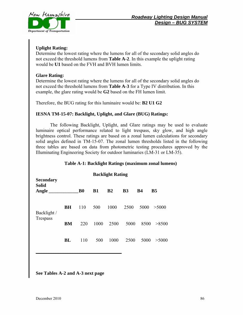
Roadway Lighting Design Manual Design – BUG SYSTEM
December 2010 86
Uplight Rating: Determine the lowest rating where the lumens for all of the secondary solid angles do not exceed the threshold lumens from Table A-2. In this example the uplight rating would be U1 based on the FVH and BVH lumen limits. Glare Rating: Determine the lowest rating where the lumens for all of the secondary solid angles do not exceed the threshold lumens from Table A-3 for a Type IV distribution. In this example, the glare rating would be G2 based on the FH lumen limit.
Therefore, the BUG rating for this luminaire would be: B2 U1 G2
IESNA TM-15-07: Backlight, Uplight, and Glare (BUG) Ratings:
The following Backlight, Uplight, and Glare ratings may be used to evaluate luminaire optical performance related to light trespass, sky glow, and high angle brightness control. These ratings are based on a zonal lumen calculations for secondary solid angles defined in TM-15-07. The zonal lumen thresholds listed in the following three tables are based on data from photometric testing procedures approved by the Illuminating Engineering Society for outdoor luminaries (LM-31 or LM-35). Table A-1: Backlight Ratings (maximum zonal lumens)
Backlight Rating Secondary Solid Angle B0 B1 B2 B3 B4 B5
BH 110 500 1000 2500 5000 >5000 Backlight / Trespass
BM 220 1000 2500 5000 8500 >8500
BL 110 500 1000 2500 5000 >5000
____________________________________ See Tables A-2 and A-3 next page
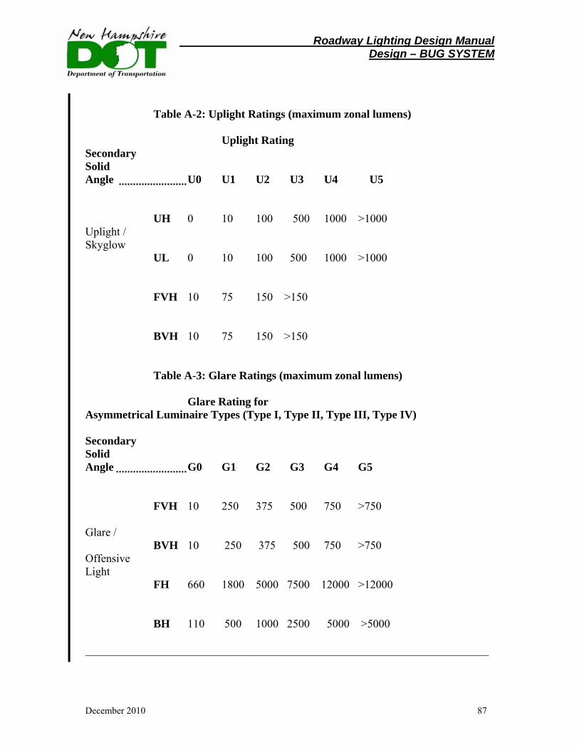
Roadway Lighting Design Manual Design – BUG SYSTEM
December 2010 87
Table A-2: Uplight Ratings (maximum zonal lumens)
Uplight Rating
Secondary Solid Angle U0 U1 U2 U3 U4 U5
UH 0 10 100 500 1000 >1000 Uplight / Skyglow
UL 0 10 100 500 1000 >1000
FVH 10 75 150 >150
BVH 10 75 150 >150
Table A-3: Glare Ratings (maximum zonal lumens)
Glare Rating for Asymmetrical Luminaire Types (Type I, Type II, Type III, Type IV) Secondary Solid Angle G0 G1 G2 G3 G4 G5
FVH 10 250 375 500 750 >750 Glare /
BVH 10 250 375 500 750 >750 Offensive Light
FH 660 1800 5000 7500 12000 >12000
BH 110 500 1000 2500 5000 >5000 _______________________________________________________________________
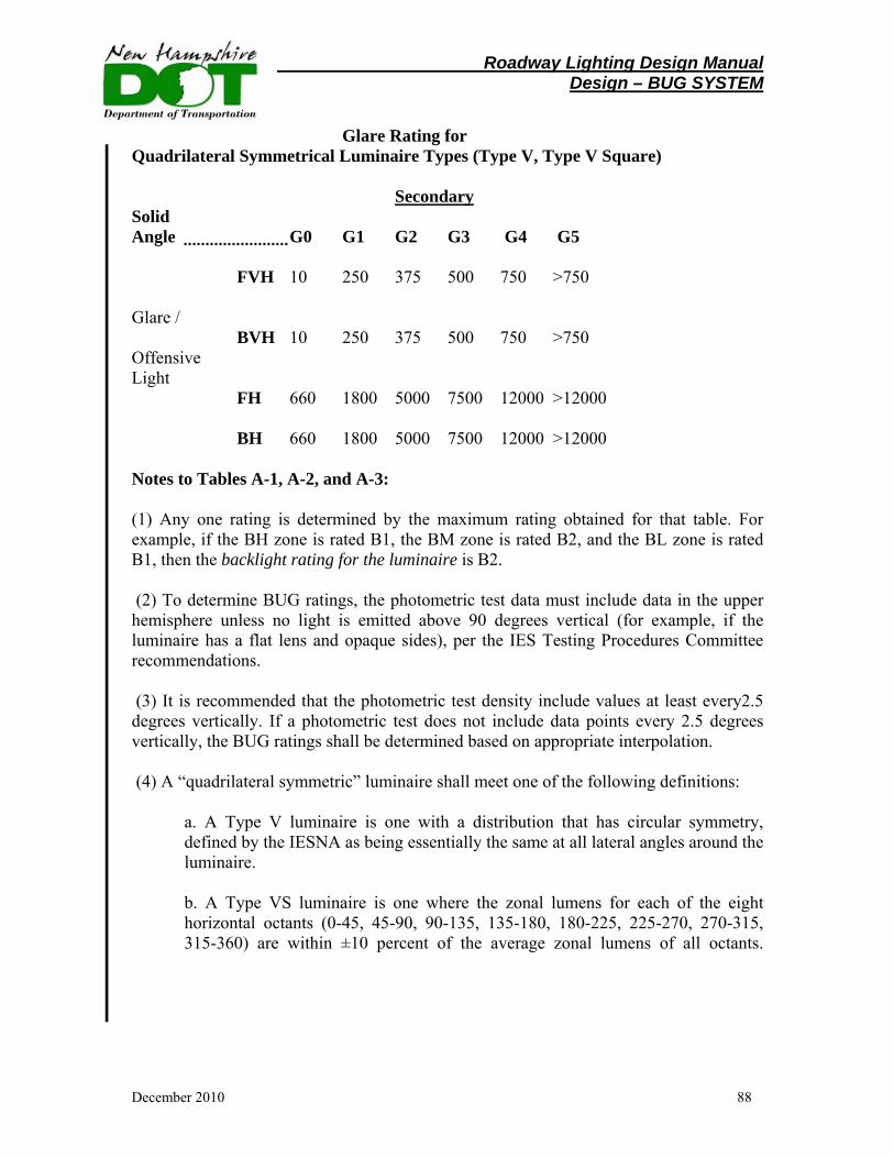
Roadway Lighting Design Manual Design – BUG SYSTEM
December 2010 88
Glare Rating for
Quadrilateral Symmetrical Luminaire Types (Type V, Type V Square)
Secondary Solid Angle G0 G1 G2 G3 G4 G5
FVH 10 250 375 500 750 >750 Glare /
BVH 10 250 375 500 750 >750 Offensive Light
FH 660 1800 5000 7500 12000 >12000
BH 660 1800 5000 7500 12000 >12000 Notes to Tables A-1, A-2, and A-3: (1) Any one rating is determined by the maximum rating obtained for that table. For example, if the BH zone is rated B1, the BM zone is rated B2, and the BL zone is rated B1, then the backlight rating for the luminaire is B2. (2) To determine BUG ratings, the photometric test data must include data in the upper hemisphere unless no light is emitted above 90 degrees vertical (for example, if the luminaire has a flat lens and opaque sides), per the IES Testing Procedures Committee recommendations. (3) It is recommended that the photometric test density include values at least every2.5 degrees vertically. If a photometric test does not include data points every 2.5 degrees vertically, the BUG ratings shall be determined based on appropriate interpolation. (4) A “quadrilateral symmetric” luminaire shall meet one of the following definitions:
a. A Type V luminaire is one with a distribution that has circular symmetry, defined by the IESNA as being essentially the same at all lateral angles around the luminaire. b. A Type VS luminaire is one where the zonal lumens for each of the eight horizontal octants (0-45, 45-90, 90-135, 135-180, 180-225, 225-270, 270-315, 315-360) are within ±10 percent of the average zonal lumens of all octants.

Roadway Lighting Design Manual Temporary Lighting
December 2010 89
8. Temporary Lighting Purpose:
The purpose of temporary roadway lighting is to improve the ability of motorists to navigate a construction area. Temporary roadway lighting is not the same as work zone lighting. Work zone lighting is installed so that the contractor may work at night. If work zone lighting is installed, care should be taken to ensure that the visibility of passing motorists is not reduced below an acceptable level. Temporary roadway lighting helps reduce the negative effect of work zone lighting.
When determining the need for temporary lighting speed limits, alignment, width
of lanes, and traffic volumes should be considered. Special Considerations: Some special considerations affecting the design of temporary lighting include:
• cost of system • ease of installation • ease of maintenance • ease of moving the temporary poles.
Because the purpose of temporary lighting is to make it safer to travel through the
construction area, the lighting should be installed in such a way as to limit glare and avoid the placing of hazardous obstacles near the traveled ways. Roadway delineation should be considered along with any temporary lighting requirements. Types of Temporary Lighting: Some possible types of temporary lighting systems include:
• standard aluminum poles with or without breakaway bases • wood poles, 30- or 40-foot mounting height, protected from traffic, with
standard highway light fixtures • existing lighting standards can be maintained to illuminate the
construction zone. • portable generator powered mobile light towers.
Roadway Lighting Design Manual Temporary Lighting
December 2010 90
Illumination Levels:
Consideration should be given to the following concerning temporary illumination at construction sites:
• illumination levels should be higher than normal, where practicable, in detour areas, gore areas, and other construction zone obstacles (impact attenuators, etc.)
• illumination levels and uniformity may be lower than normally required in areas where the motorist has no special navigational decisions to make.
• Lighting systems should not create excessive glare, a potential problem with low mounting heights.
Placement of Light Poles:
All poles located within the clear zone should be of the breakaway design or should be otherwise protected from vehicle impact (behind concrete barriers or guard rail). If practicable, temporary lighting should be installed before the existing lighting is disabled. Plans and Specifications: Temporary lighting plans should show:
• the type and number of units required • locations, spacing, and offsets of poles • bracket and pole details
Temporary lighting should be coordinated with traffic control plans, which should
show where and when the poles are to be placed or relocated.
Roadway Lighting Design Manual New Technologies - LED
December 2010 91
Section X New Lighting Technologies 1. Light Emitting Diode (LED) Technology
Light Emitting Diodes (LED) technology is rapidly becoming an attractive alternative to high-intensity discharge (HID) light sources for outdoor lighting. The general public is being exposed to LED products on a daily basis; in their homes, shopping areas, intersection signal lighting and other public spaces. This has prompted public officials to question whether LED lighting can be utilized in local and State-wide applications. This section reviews the major design and specification concerns for outdoor lighting, and discusses the potential for LED luminaires to save energy while providing high quality lighting. This section is written with 2009-10 LED data and information in mind. This technology is in a state of flux with new product coming to the market place on a regular basis. At this time utility companies have not yet established a separate rate structure through the NHPUC for LED lighting. In the near future most applications for LED lighting will be in parking areas, Park and Rides, terminals, maintenance areas and very limited highway lighting where all applications can be metered separately.
In 2009 the NHDOT installed new LED equipment at a Park and Ride facility in New London, New Hampshire. This installation was the first large scale LED installation within the NHDOT area of responsibility. Introduction
Lighting of outdoor areas in New Hampshire including streets, roadways, parking lots, and pedestrian areas is currently dominated by high-pressure sodium (HPS) and metal halide (MH) sources. These relatively energy-efficient light sources have been in use for many years and have well-understood performance characteristics. Recent advances in LED technology have resulted in a new option for outdoor lighting, with several potential advantages over HPS and MH sources. Well-designed LED outdoor luminaires can provide the required surface illuminance using less energy and with improved uniformity, compared to HID sources. LED luminaires may also have significantly longer life (50,000 hours or more, compared to 15,000 to 35,000 hours) with better lumen maintenance. Other LED advantages include: they contain no mercury, lead, or other known disposal hazards; and they come on instantly without run-up time or restrike delay. Further, while HPS and MH technologies continue to improve incrementally, LED technology is improving very rapidly in terms of luminous efficacy, color quality, optical design, thermal management, and cost.
Roadway Lighting Design Manual New Technologies - LED
December 2010 92
Current LED product quality can vary significantly among manufacturers, so due
diligence is required in their proper selection and use. LED performance is highly sensitive to thermal and electrical design weaknesses that can lead to rapid lumen depreciation or premature failure. Further, long-term performance data do not exist given the early stage of the technology’s development. The lighting designer should continue to monitor available information sources on product performance and lifetime, such as CALiPER test results and GATEWAY demonstration program reports, available on the U. S. Department of Energy (DOE) Solid State Lighting website (www.netl.doe.gov/ssl). It is important to note that the DOE will be the lead agency in testing and monitoring LED performance data and would determine if LED lighting receives “Energy Star” ratings. Design and Specification Considerations
Many issues enter into design and specification decisions for outdoor lighting. Energy efficiency is especially a priority in this application due to the long running hours and relatively high wattages typically involved. This section repeats some of the information available in other manual sections however, it is necessary when making comparisons to LED technology with other lighting sources. A review of energy efficiency factors, as well as issues related to durability, color quality, life and lumen maintenance, light distribution, glare, and cost will be made.
Energy efficiency
Energy effectiveness encompasses luminous efficacy of the light source and appropriate power supply in lumens per watt (lm/W), optical efficiency of the luminaire (light fixture), and how well the luminaire delivers light to the target area without casting light in unintended directions. The goal is to provide the necessary illuminance in the target area, with appropriate lighting quality, for the lowest power density. One step in comparing different light source and luminaire options is to examine luminaire photometric files.
Table 1 provides photometric data for several outdoor luminaires, in testing conducted by DOE, to illustrate basic comparisons. Lumen output and efficacy vary greatly across different outdoor area luminaires, so these data should not be used to generalize the performance of all luminaires using the listed lamp types.
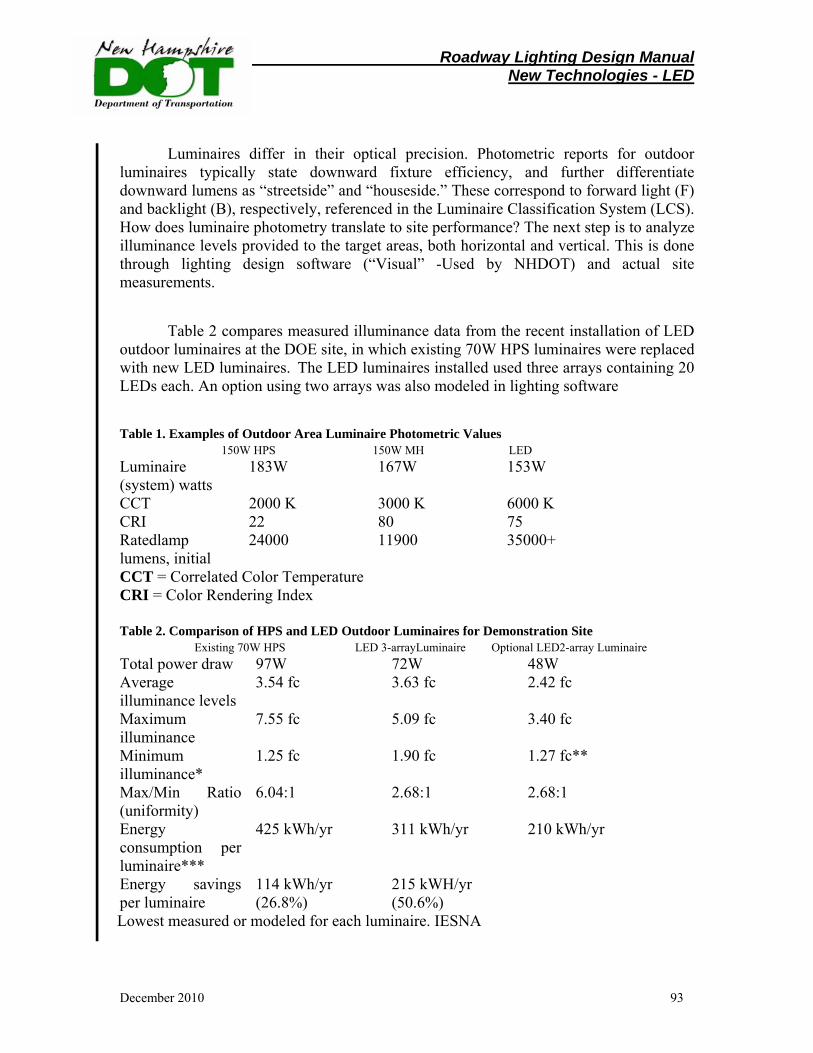
Roadway Lighting Design Manual New Technologies - LED
December 2010 93
Luminaires differ in their optical precision. Photometric reports for outdoor luminaires typically state downward fixture efficiency, and further differentiate downward lumens as “streetside” and “houseside.” These correspond to forward light (F) and backlight (B), respectively, referenced in the Luminaire Classification System (LCS). How does luminaire photometry translate to site performance? The next step is to analyze illuminance levels provided to the target areas, both horizontal and vertical. This is done through lighting design software (“Visual” -Used by NHDOT) and actual site measurements.
Table 2 compares measured illuminance data from the recent installation of LED
outdoor luminaires at the DOE site, in which existing 70W HPS luminaires were replaced with new LED luminaires. The LED luminaires installed used three arrays containing 20 LEDs each. An option using two arrays was also modeled in lighting software
Table 1. Examples of Outdoor Area Luminaire Photometric Values 150W HPS 150W MH LED Luminaire (system) watts
183W 167W 153W
CCT 2000 K 3000 K 6000 K CRI 22 80 75 Ratedlamp lumens, initial
24000 11900 35000+
CCT = Correlated Color Temperature CRI = Color Rendering Index Table 2. Comparison of HPS and LED Outdoor Luminaires for Demonstration Site Existing 70W HPS LED 3-arrayLuminaire Optional LED2-array Luminaire Total power draw 97W 72W 48W Average illuminance levels
3.54 fc 3.63 fc 2.42 fc
Maximum illuminance
7.55 fc 5.09 fc 3.40 fc
Minimum illuminance*
1.25 fc 1.90 fc 1.27 fc**
Max/Min Ratio (uniformity)
6.04:1 2.68:1 2.68:1
Energy consumption per luminaire***
425 kWh/yr 311 kWh/yr 210 kWh/yr
Energy savings per luminaire
114 kWh/yr (26.8%)
215 kWH/yr (50.6%)
Lowest measured or modeled for each luminaire. IESNA
Roadway Lighting Design Manual New Technologies - LED
December 2010 94
(see Table 2, last column). Note that in this installation, the uniformity was improved by more than a factor of two with the LED luminaires. The maximum illuminance decreased and the minimum illuminance was the same or slightly higher than the HID, which led to a lower uniformity ratio. These results cannot be generalized for LEDs, but indicate a potential benefit possible with well-designed LED luminaires for outdoor lighting.
Since HID lamps are high-intensity near-point sources, the optical design for these luminaires causes the area directly below the luminaire to have a much higher illuminance than areas farther away from the luminaire. In contrast, the smaller, multiple point-source and directional characteristics of LEDs can allow better control of the distribution, with a resulting visible improvement in uniformity. This difference is evident in Figure 2, (see appendix) where “hot spots” are visible under the HPS luminaires.
Durability
Outdoor lights often become perches for birds and the debris that comes with them. The luminaire should not collect and retain dirt or water on the top side, and the optical chamber should remain clean for the LED luminaire to truly reduce maintenance. Ingress Protection (IP) ratings describe the luminaire’s resistance to dust and moisture penetration. The designer should look for an IP rating appropriate to the conditions in which the luminaire will be used. For example, a rating of 65 indicates “dust tight, and protected from water jets from any direction.” The designer should also ask the manufacturer about the long-term reliability of gaskets and seals relative to the expected useful life of the LEDs, and make sure the manufacturer will replace the product if it fails before 5 years, similar to the warranty for an HID luminaire. A quick disconnect point between the light engine and the drivers will allow for field maintenance on the power supply. Keeping the maintenance contact points to this level reduces the opportunity for installation mishaps that create reliability issues during normal use.
Color
The most efficient white LEDs at this time emit light of 4500K to 6500K correlated color temperature (CCT). This makes them white to bluish-white in appearance. Some LED luminaire manufacturers mix LEDs of various color temperatures to reach a target CCT for the array or luminaire, balancing the highest efficacy sources with warmer LEDs. Color rendering varies according to the make, model, and CCT of the LEDs, but generally is better than HPS (usually around 22 CRI) and standard MH (around 65 CRI). The nominal CRI for neutral (4000K to 4500K) and cool white (5000K or higher) LEDs is typically 70 to 75. In most roadway and area lighting applications, CRIs of 50 or higher are adequate for gross identification of color.
Roadway Lighting Design Manual New Technologies - LED
December 2010 95
Life and lumen maintenance
Estimating LED life is problematic because the long projected lifetimes make full life testing impractical, and because the technology continues to evolve quickly, superseding past test results. Most LED manufacturers define useful life based on the estimated time at which LED light output will depreciate to 70% of its initial rating; often the target is 50,000 hours for interior luminaires, but some manufacturers claim that their outdoor luminaires are designed for much longer useful lives of 100,000 to 150,000 hours. The designer should confirm, if possible, long life manufacturers’ claims. Luminaire manufacturers typically determine the maximum drive current and LED junction temperature at which the LEDs will produce greater than 70% of initial lumens for at least the target useful life in hours. If the LEDs are driven at lower current and/or maintained at lower temperatures, useful life may be greatly increased. In general, LEDs in well-designed luminaires are less likely to fail catastrophically than to depreciate slowly over time, so it may be difficult for a utility or maintenance crew to identify when to replace the luminaire or LED arrays. In contrast, poorly-designed LED luminaires may experience rapid lumen depreciation or outright failure.
Thermal management is critical to the long-term performance of the LED, since heat can degrade or destroy the longevity and light output of the LED. The temperature at the junction of the diode determines performance, so heat sinking and air flow must be designed to maintain an acceptable range of operating temperature for both the LEDs and the electronic power supply. The lighting designer should ask the luminaire manufacturer to provide operating temperature data at a verifiable temperature measurement point on the luminaire, and data explaining how that temperature relates to expected light output and lumen maintenance for the specific LEDs used.
All light sources experience a decrease in light output (lumen depreciation) over
their operating life. To account for this, lighting designers use mean lumens, usually defined as luminous flux at 40% of rated life, instead of initial lumens. For HPS lamps, mean lumens are about 90% of initial lumens. Pulse-start MH mean lumens are about 75% of initial lumens, while ceramic MH lamps have slightly higher mean lumens, around 80% of initial lumens. See Figure 4 (appendix) for typical lumen maintenance curves for these HID light sources and two example curves for LEDs: one designed for 50,000-hour useful life (LED example 1) and one designed for longer life (LED example 2).
Roadway Lighting Design Manual New Technologies - LED
December 2010 96
Light distribution and glare
LED luminaires use different optics than HPS or MH lamps because each LED is, in effect, an individual point source. Effective luminaire design exploiting the directional nature of LED light emission can translate to lower optical losses, higher luminaire efficacy, more precise cutoff of backlight and uplight, and more uniform distribution of light across the target area. Better surface illuminance uniformity and higher levels of vertical illuminance are possible with LEDs and close-coupled optics, compared to HID luminaires.
Polar plots given in photometric reports depict the pattern of light emitted through the 90° (horizontal) plane and 0° (vertical) plane. In general, designers should look for a reduction in luminous intensity in the 70° to 90° vertical angles to avoid glare and light trespass; zero to little intensity emitted between 90° and 100°, the angles which contribute most seriously to skyglow; and much reduced light between 100° and 180° (zenith) which also contribute to skyglow. Figures 5 and 6 illustrate the forward light and uplight angles referenced in the Luminaire Classification System (LCS). Luminaires for outdoor area lighting are classified in terms of the light patterns they provide on the ground plane. Figure 7 shows IESNA outdoor fixture types classifying the distributions for spacing luminaires.
Cost
As a new technology, LED luminaires currently cost more to purchase than traditional fixtures lamped with commodity-grade HPS or MH light sources. The reduction in relamping cost and potential power savings with LEDs may reduce the overall lifecycle cost. Economic evaluation of LED outdoor luminaires is highly site-specific, depending on variables including electric demand (kW) and consumption (kWh) rates, labor costs, which may be bundled in a broader maintenance contract for the site; and other options available for the site. LED outdoor lighting demonstrations documented by the US Department of Energy to date have shown estimated paybacks from three years to more than 20 years, depending on the assumptions and options assessed.
In some cases, LED technology may address new requirements that change the comparison to traditional sources. For example, some communities in other States (while some New Hampshire Towns are considering) have implemented mandatory reductions in nighttime illumination. LED luminaires can be designed with control circuits that reduce the light output by half late at night, without affecting the uniformity of light on the street or parking lot. Compare this to a design where a single, high-wattage HID luminaire is replaced with two lower-wattage luminaires on the same pole, so that half the fixtures can be extinguished at curfew without affecting the light distribution.
Roadway Lighting Design Manual New Technologies - LED
December 2010 97
Summary
Outdoor lighting appears to be a promising application for LED technology. New products are being introduced regularly. As with all LED products, careful information gathering and research is needed to assess quality, performance, and overall value. The checklist below is provided as a quick summary of issues addressed in this section:
� Ask for photometric test reports based on the IESNA LM-79-08 test procedure.
� Ask about warranty; 3 to 5 years is reasonable for outdoor luminaires.
� Check ingress protection (IP) ratings, and choose an appropriate rating for the intended application.
� Ask for operating temperature information and how this data relates to luminaire efficacy and lumen depreciation.
� Check color temperature for suitability in the intended application.
� Assess glare, preferably with the luminaire at intended mounting height and under typical nighttime viewing conditions, compared to HID technology.
� Evaluate economic payback, based on applicable energy, equipment, maintenance, and control costs for the site.
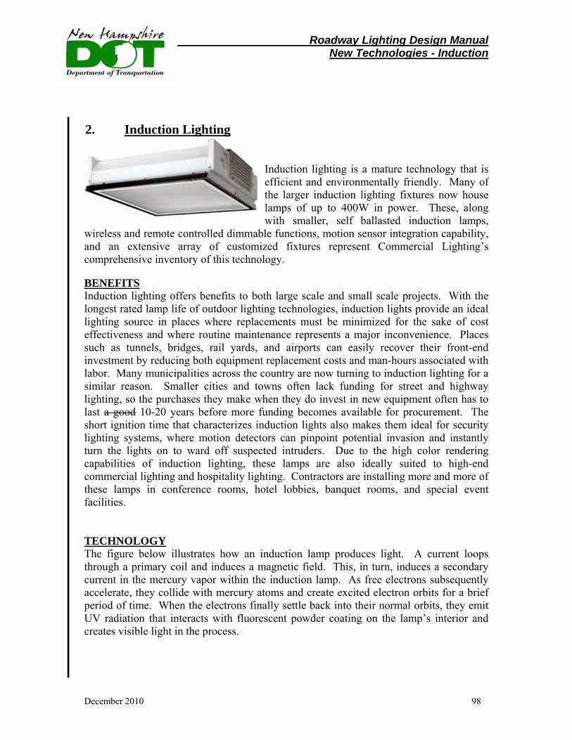
Roadway Lighting Design Manual New Technologies - Induction
December 2010 98
Induction lighting is a mature technology that is efficient and environmentally friendly. Many of the larger induction lighting fixtures now house lamps of up to 400W in power. These, along with smaller, self ballasted induction lamps,
wireless and remote controlled dimmable functions, motion sensor integration capability, and an extensive array of customized fixtures represent Commercial Lighting’s comprehensive inventory of this technology. BENEFITS Induction lighting offers benefits to both large scale and small scale projects. With the longest rated lamp life of outdoor lighting technologies, induction lights provide an ideal lighting source in places where replacements must be minimized for the sake of cost effectiveness and where routine maintenance represents a major inconvenience. Places such as tunnels, bridges, rail yards, and airports can easily recover their front-end investment by reducing both equipment replacement costs and man-hours associated with labor. Many municipalities across the country are now turning to induction lighting for a similar reason. Smaller cities and towns often lack funding for street and highway lighting, so the purchases they make when they do invest in new equipment often has to last a good 10-20 years before more funding becomes available for procurement. The short ignition time that characterizes induction lights also makes them ideal for security lighting systems, where motion detectors can pinpoint potential invasion and instantly turn the lights on to ward off suspected intruders. Due to the high color rendering capabilities of induction lighting, these lamps are also ideally suited to high-end commercial lighting and hospitality lighting. Contractors are installing more and more of these lamps in conference rooms, hotel lobbies, banquet rooms, and special event facilities. TECHNOLOGY The figure below illustrates how an induction lamp produces light. A current loops through a primary coil and induces a magnetic field. This, in turn, induces a secondary current in the mercury vapor within the induction lamp. As free electrons subsequently accelerate, they collide with mercury atoms and create excited electron orbits for a brief period of time. When the electrons finally settle back into their normal orbits, they emit UV radiation that interacts with fluorescent powder coating on the lamp’s interior and creates visible light in the process.
2. Induction Lighting

Roadway Lighting Design Manual New Technologies - Induction
December 2010 99
FEATURES A number of features characterize induction lighting as an across-the-board improvement over HID and incandescent light sources. Induction lamps do not require an electrode or a filament to operate and last for up to 100,000 hours. Because they lack electrodes and filaments, they are vibration resistant and do not flicker when they power on. They produce a very high quality white light ranging between 4,000-5,000K Kelvin, and rate 82 on the color rendering index. They are also highly resistant to cold, having been known to operate reliably at temperatures as low as -40C. Perhaps more than anything, the energy saving abilities of induction lighting makes it a milestone in illumination sourcing. LPW efficiency ranges from 70-90W, even in larger fixtures operating at 200W and 400W. Small wattage lamps feature a medium base and internal ballast. Induction lights are also dimmable, making them ideal for indoor commercial and residential lighting where additional energy savings through lighting control may be required. ADVANTAGES OF INDUCTION LIGHTS The following table shows the many competitive advantages induction lighting offers to commercial designers seeking to bid projects for clients on a budget. In all but one attribute, induction lighting offers a clear superiority to other light sources. While incandescent sourcing does rate slightly higher than induction sourcing on the color rendering index (100 versus 82), this margin is negligible, and the many disadvantages of
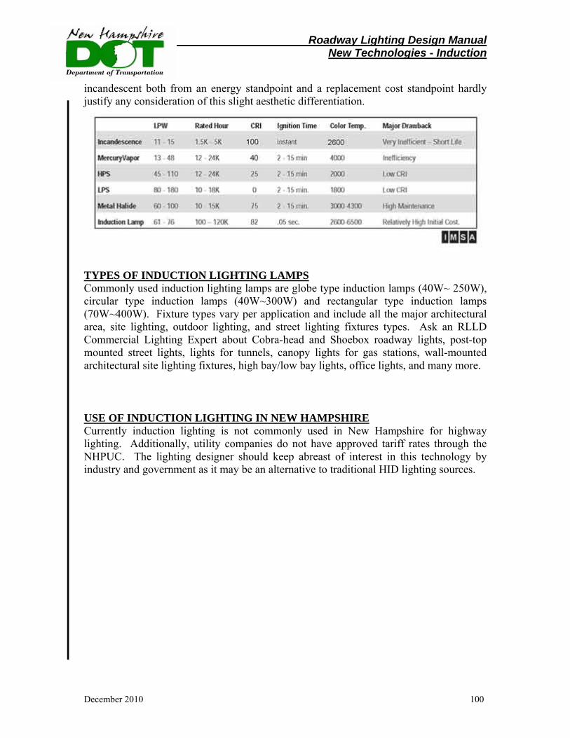
Roadway Lighting Design Manual New Technologies - Induction
December 2010 100
incandescent both from an energy standpoint and a replacement cost standpoint hardly justify any consideration of this slight aesthetic differentiation.
TYPES OF INDUCTION LIGHTING LAMPS Commonly used induction lighting lamps are globe type induction lamps (40W~ 250W), circular type induction lamps (40W~300W) and rectangular type induction lamps (70W~400W). Fixture types vary per application and include all the major architectural area, site lighting, outdoor lighting, and street lighting fixtures types. Ask an RLLD Commercial Lighting Expert about Cobra-head and Shoebox roadway lights, post-top mounted street lights, lights for tunnels, canopy lights for gas stations, wall-mounted architectural site lighting fixtures, high bay/low bay lights, office lights, and many more. USE OF INDUCTION LIGHTING IN NEW HAMPSHIRE Currently induction lighting is not commonly used in New Hampshire for highway lighting. Additionally, utility companies do not have approved tariff rates through the NHPUC. The lighting designer should keep abreast of interest in this technology by industry and government as it may be an alternative to traditional HID lighting sources.

Roadway Lighting Design Manual Appendix
December 2010 101
Section XI Appendix 1. Outdoor Lighting Efficency – RSA Chapter 9-E
Title I The State and its Government
Chapter 9-E Outdoor Lighting Efficiency
9-E:1 Definitions. – In this chapter: I. ""Fixture'' means the assembly that holds a lamp and may include an assembly housing, a mounting bracket or pole socket, a lamp holder, a ballast, a reflector or mirror, and a refractor or lens. II. ""Fully shielded luminaire'' means a luminaire that allows no direct light emissions above a horizontal plane through the luminaire's lowest light-emitting part. III. ""Glare'' means direct light emitting from a luminaire that is significantly greater than luminance to which the eyes are adapted which causes reduced vision or momentary blindness. IV. ""Illuminance'' means the unit measure of light at a surface. V. ""Light trespass'' means light emitted by a luminaire that shines beyond the boundaries of the property on which the luminaire is located. VI. ""Lumen'' means a unit of measure of luminous flux. VII. ""Luminaire'' means the complete lighting system, including the lamp and the fixture. VIII. ""Lamp'' means the component of a luminaire that produces the specific form of radiant energy that is observed as light. IX. ""Permanent outdoor luminaire'' means any luminaire or system of luminaires that is outdoors and intended to be used for 21 days or longer. X. ""State highway'' means any of the highways of the state classified in RSA 229:5.
Source. 2009, 212:1, eff. Sept. 13, 2009.
Roadway Lighting Design Manual Appendix
December 2010 102
9-E:2 State Purchase of Permanent Outdoor Lighting Design. – I. No state funds shall be used to install or replace any permanent outdoor luminaire unless: (a) The luminaire is a fully shielded luminaire when the rated output of the luminaire is greater than 1,800 lumens. (b) The maximum illuminance at the designated surface does not exceed the minimum illuminance level recommended for that purpose by the Illuminating Engineering Society of North America or the Federal Highway Administration. (c) The director of the agency responsible for the funding of such luminaire or having authority over the illuminated infrastructure ensures that consideration is given to minimizing glare and light trespass. II. The requirements of paragraph I shall not apply if: (a) Compliance would create a conflict with federal laws or regulations; (b) The director of the agency responsible for funding the installation of such luminaire or having authority over the illuminated infrastructure determines that there is a compelling safety interest that cannot be addressed by any other method; (c) With respect to roadway lighting on state highways, when in specific instances the commissioner of transportation determines that use of a fully shielded luminaire would compromise the safety of the public utilizing the highway, increase the cost of the lighting plan or lighting replacement for the highway, or violate any provision of federal law; or (d) The luminaire shall be used to illuminate designated public and historic structures, monuments, and flags of the United States of America and the state of New Hampshire. III. No public utility company may install or replace a permanent outdoor luminaire for roadway lighting if the cost of operating such luminaire is paid for by municipal funds, unless: (a) The luminaire is a fully shielded luminaire when the rated output of the luminaire is greater than 1,800 lumens. (b) The maximum illuminance at the designated surface does not exceed the minimum illuminance recommended for that purpose by the Illuminating Engineering Society of North America or the Federal Highway Administration. (c) The governing body of a municipality may waive the provisions of subparagraphs (a) and (b) when, after written notice from the public utility company 30 days prior to the installation or replacement of the luminaire, the governing body determines that a waiver is necessary for the lighting application. Such notice shall be in such form as the governing body shall prescribe and may include a description of the lighting plan and a description of the efforts that have been made to comply with the provisions of RSA 9-E:3. The governing body may consider design safety, costs, and other factors deemed appropriate by the governing body.
Source. 2009, 212:1, eff. Sept. 13, 2009.
Roadway Lighting Design Manual Appendix
December 2010 103
9-E:3 New Hampshire Dark Sky Policy. – It shall be the policy of the state of New Hampshire to encourage municipalities to enact such local ordinances and regulations as they deem appropriate to conserve energy consumed by outdoor lighting; to minimize light pollution and glare; and to preserve dark skies as a feature of rural character wherever practicable.
Source. 2009, 212:1, eff. Sept. 13, 2009.
9-E:4 Part-Night Rate for Roadway and Area Lighting. – To encourage cost savings and energy conservation, the public utilities commission shall, subject to its ratemaking authority under RSA 378, develop a rate for part-night or midnight service for unmetered street or area lighting. Such a rate shall be revenue neutral with respect to utility distribution revenue.
Source. 2009, 212:1, eff. Sept. 13, 2009.
Note: Refer to the NH Public Utilities Commission website for information on the Part-Night Rate per Utility company. http://www.puc.state.nh.us/.
9-E:5 Report by Department of Transportation. – The department of transportation shall: I. Review and update its criteria for roadway lighting to ensure that its current standards and procedures conform to commonly accepted best practices. II. Explore how energy and maintenance costs can be reduced by replacing existing luminaries with lower-wattage, fully shielded luminaries or by eliminating roadway lighting altogether where appropriate. III. Beginning November 1, 2009 and each November 1 thereafter, submit an annual report of its activities and findings to the office of energy and planning.
Source. 2009, 212:1, eff. Sept. 13, 2009.
Roadway Lighting Design Manual Appendix
December 2010 104
2. Typical Lighting Project Package
A typical project lighting design package (Plaistow #10044-F) is shown on
pages 105-109 and these include:
• Lighting Memorandum – Lighting Designer to Project Manager • Lighting Estimate • Lighting Design Plans
Note: The designer should check with utility companies to verify if they are offering rebates on new technology lighting installations.
Roadway Lighting Design Manual Appendix
December 2010 105
8. List of References/Acknowledgements
A Policy on Geometric Design of Highways and Streets, American Association of State Highway andTransportation Officials, Washington, DC, 2001. Roadway Lighting Design Guide, American Association of State Highway and Transportation Officials,Washington, DC, 2005. Manual of Uniform Traffic Control Devices, Federal Highway Administration, Washington, DC, 2007. Minnesota Manual of Uniform Traffic Control Devices, Minnesota Department of Transportation, December 2001. Roadway Lighting Design Manual, Minnesota Department of Transportation – MnDOT, 2006. Lighting Design Guide, Colorado Department of Transportation – CDOT, Februaruy 2006. Indiana Manual on Traffic Control Devices, Indiana Department of Transportation – IDOT, 2008 Specifier Bulletin for Dark Sky Applications – Volume 2: Issue 1, International Dark Sky Association, Tucson, AZ, 2009 Roadway Lighting RP-8, Illuminating Engineering Society of North America – IESNA, New York, NY, 2000 Holophane Product Catalogue, September 2001 Highway Design Manual, New Hampshire Department of Transportation, 2007