new generation of structural concrete systems for seismic … · earthquakes has prompted the need...
TRANSCRIPT

1
First European Conference on Earthquake Engineering and Seismology (a joint event of the 13th ECEE & 30th General Assembly of the ESC)
Geneva, Switzerland, 3-8 September 2006 Paper Number: Keynote Address K6
NEW GENERATION OF STRUCTURAL CONCRETE SYSTEMS FOR SEISMIC RESISTANCE
José I. RESTREPO1
SUMMARY The magnitude of the economic losses sustained by communities following moderate and large earthquakes has prompted the need for developing seismic design philosophies and construction methods aimed at identifying structural and non-structural performance limit-states. Some emerging construction methods aim at specifically increasing benefit/cost ratios by minimizing structural and non-structural damage. The system described in this paper is such an emerging method. The construction method consists of cantilever wall systems that show a characteristic self-centering response. These walls use gravity loading or gravity loading combined with post-tensioning unbonded tendons as restoring force. Lateral displacements in these walls eventually results in a gap forming only at the wall-foundation beam connection. The gap reduces the system stiffness. For as long as the tendons remain elastic, the wall’s lateral force-displacement response has a characteristic non-linear elastic relationship. The integrity of the walls is maintained because no plastic hinges form in the walls and there are no residual post-earthquake displacements. The main shortcoming of a non-linear elastic response is the lack of energy dissipation capacity. Energy dissipaters, in the way of longitudinal mild steel reinforcement or mechanical levers placed between the walls and the foundation, can be designed to preserve the self-centering response characteristics while adding significant energy dissipation capacity.
This paper presents a state-of-the-art report on emerging construction technologies of the types of walls described and summarizes experimental work performed.
1. INTRODUCTION The costs associated with the loss of business downtime, damage to equipment and structural damage following a moderately strong earthquake can be significant to modern society, especially in those centers of advanced technology. Such costs are often comparable, if not greater, than the cost of the building itself. Current design approaches promulgate inelastic response beyond the limit of proportionality during rare but strong intensity earthquakes. Inelastic response develops into a mechanism involving sufficient number of flexural plastic hinges. Therefore, those regions in the structure, where the plastic hinges will form, are detailed for ductility and energy dissipation. While inelastic response is appealing, it has two main drawbacks: First, regions in the principal lateral force resisting system will be sacrificed in moderately strong earthquakes and in need of repair, or damaged beyond repair in strong earthquakes. Second, current design approaches stress the premise that large energy dissipation capacity is necessary to mitigate seismic demands. This premise has often led to the notion that a good structural system should have a response involving "fat" hysteresis loops. However, since a large
1 Associate Professor, Department of Structural Engineering, University of California, San Diego, La Jolla, CA 92093, USA Email : [email protected]

2
fraction of the input energy will be dissipated by mechanical hysteresis, residual displacements and structural damage are expected from such structural systems after a strong earthquake. Another important issue in seismic design nowadays deals with current societal performance expectations. While the principle of mitigating loss of life in a strong earthquake still prevails, society expects buildings to survive a moderately strong earthquake with minimal disturbance. This implies that repairs of incipient structural damage may not be economical, and may no longer be tolerated in small and moderately strong events. Alternatives such as seismic isolation provide some of the desirable response characteristics, but the initial high-cost confine such alternatives to only landmark structures. This paper examines underpinning issues about the seismic design and behavior of emerging systems employing cantilever walls. The system examined here has well-defined self-centering response characteristics and is an economically viable alternative to current lateral force resisting wall systems. This system encompasses reinforced concrete walls or “confined” brick masonry jointed at their base. The walls are properly detailed to rock about their foundation. These walls may require longitudinal prestressing to ensure the self-centering response. Prestressing is exclusively attained with the use of longitudinal unbonded tendons anchored at the foundation beam and somewhere along the height of the wall. Depending on the lateral force-lateral displacement response characteristics, self-centring walls are grouped into rocking or hybrid types, see Fig. 1. Rocking walls display a nonlinear elastic response with minimum energy dissipation capacity, whereas hybrid walls exhibit a stable flag-shaped hysteretic response. In hybrid walls energy dissipaters crossing the joint at the wall-to-foundation beam connection are responsible for the flag-shape response. Figure 1: Classification of self-centering cantilever walls according to their hysteretic response characteristics The notion of self-centering structural systems stems from the rocking concept specifically engineered in the design of the “stepping” rail bridge over the South Rangitikei River, New Zealand (Cormack, 1988). An expansion of the self-centering concept was presented by Priestley and Tao (1993). These researchers proposed the use of moment resisting frame systems prestressed with partially unbonded tendons as the primary lateral force resisting systems in seismically prone areas. A series of non-linear dynamic time-history analyses showed the viability of such systems. Priestley and Tao pointed out that an advantage of these systems is the lack of residual drift following a strong earthquake. MacRae and Priestley (1994) subsequently carried out experimental work on precast beam-column subassemblies. Stone et al. (1995) evolved the concept proposed by Priestley and

3
Tao and proposed a hybrid system, in which mild steel reinforcement was combined with unbonded tendons in the critical connections. The objective of using mild steel reinforcement was to provide hysteretic energy dissipation to the system. Since then, several systems were studied as part of the coordinated four-phase PREcast Seismic Structural Systems (PRESSS) research program in the United States. This program ended with testing a 60% scale five-story building (Priestley et al., 1999; Nakaki et al.,1999). The building incorporated a rocking coupled wall designed to provide lateral force resistance in one direction of loading. In the area of vertically stacked precast walls, Perez et al. (2003) demonstrated the benefits of using unbonded tendons. In their work the walls were simply post-tensioned and did not include energy dissipaters. Rahman and Restrepo (2000) tested three half-scale walls and two of the walls incoporated energy dissipaters. Holden et al. (2003) presented a concept of a hybrid wall in which the concept of prefabrication was optimized. Toranzo (2002) adapted the self-centering wall concept for “confined” masonry construction, a structural system of widespread use in Latin America. The research work performed by Rahman and Restrepo, Holden et al. and Toranzo will be discussed later on in this paper.
2. DESIGN CONSIDERATIONS The fundamental feature of the proposed system is the preclusion of plastic hinges in the precast wall units, with nonlinear response manifested through the development of separation gaps at the horizontal joints between the precast concrete units. The criteria that guarantee the development of this rocking mode of response are presented below. Wall Aspect Ratio The wall aspect ratio is an important reason to ensure a predominantly rocking response in systems that rely only on interface friction in resisting the sliding shear (Rahman and Restrepo, 2000). The sliding shear resistance of a wall may be reached to the combined inertial lateral forces and internal forces because of deformation compatibility between other lateral force resisting elements in the system. With regard to Fig. 2 and using the notation presented at the end of this paper,
w f
eff d fH2L
κ
≤ω ω ω
μ (1)
P
P
V
H
V
Wall Panel
~Lw
Figure 2: Influence of wall aspect ratio on dominance of rocking response.

4
It must be noted that dynamic effects- commonly termed higher mode effects in the literature (Paulay and Priestley, 1992)- influence the distribution of the dynamic inertial forces, usually approximated by a static lateral load distribution in the form of an inverted triangle (Paulay and Priestley, 1992). Dynamic time-history analyses conducted on rocking precast wall systems connected with unbonded prestressing tendons have shown the greater sensitivity of this system to higher mode effects compared to monolithic cast-in-place concrete walls (Kurama, 1998). For hybrid walls the increase in shear force due to dynamic effects is expected to lie between that for monolithic and rocking walls. To the author’s knowledge no data has been reported in the literature to date. Concerning the dynamic coefficient of friction, experimental values of the ratio �f have been reported by Morin et al. (2002). Coefficient ωk is difficult to establish. Only very limited research is available to date and this indicates that for some idealized conditions large internal forces can develop in the dynamic interpaly between walls of different geometry (Rutenberg and Leibovich, 2002). Prevention of sliding shear can also be achieved through proper detailing of the interface between jointed walls and the foundations. The use of dowels, mechanical keys, external levers or embedment of the wall in a slotted foundation are all feasible choices. Examples of application of embedded walls and walls incorporating mechnical keys are discussed by Priestley et al. (1999) and by Holden et al. (2003). An example of the use of external levers is discussed by Toranzo (2002). Energy Dissipaters While prevention of damage in precast walls is a desirable feature from the owner’s perspective, the non-linearly elastic response in rocking walls can significantly influence the response of the system, usually by increasing the lateral displacement, shear force and floor acceleration demands (Toranzo, 2002). A clear example of floor acceleration reduction in walls incorporating energy dissipaters is evidenced in the free-vibration responses shown in Fig 3. Energy dissipaters cross the gap between the wall base to foundation beam connection. These dissipaters contribute to the flexural strength of the wall and must be considered when evaluating the moment capacity and shear force demand in the walls. The dissipaters themselves can be mild steel reinforcement embedded in the foundation beam (Rahman and Restrepo, 2000; Holden et al. 2003) or external mild steel mechanical levers (Toranzo, 2002). These two types will be described later on.
a) Run 58, Wall without dissipators
-1
0
1
0 4 8 12 16 20
time (seconds)Roof
acc
eler
atio
n (g
)
b) Run 59, Wall with dissipators
-1
0
1
0 4 8 12 16 20
time (seconds)
Roof
acc
eler
atio
n (g
)
Figure 3: Influence of energy dissipaters in free-vibration response of a cantilever wall system (Toranzo, 2002).

5
Prestressing level Longitudinal prestressing is needed when the gravity load tributary to a wall in unable to restore it to its upright position. To ensure self-centering response in a wall, the beams and slabs framing in the rocking walls as well as the energy dissipaters that yielded in a cycle must be force to yield back. In many circumstances the gravity load tributary to a wall is not able to restore the wall to the upright position. In such cases it is necessary to supplement the restoring force with unbonded tendons. When a wall is subjected to cyclic reversals under sesimic loading conditions, the forces in the prestressing tendons increase with the amplitude of the lateral displacement. This is because of the effect of the gap opening at the wall base. Variations in the prestressing force are dependent on the location of the prestressing tendons within the length of the wall for a given lateral drift. Thus, the optimum location of the prestressing tendons is at midlength of the wall. This results in the smallest possible elongation in the tendon as well as maximum wall rotation when walls are subjected to reversed cyclic lateral displacmeents. Since jointed walls are expected to display minimum structural damage, a design under a performance-based framework may be simplified to two performance objectives: immediate occupancy and life-safety. The dimensioning of the walls needs to be adequate to control damage in commonly occurring low-intensity earthquakes to acceleration and drift-sensitive non-structural elements. In a rare but strong intensity earthquakes the proposed system can easily be detailed to ensure the prevention of yielding of the tendons, crushing of the concrete and prevention of sliding shear. Rahman and Restrepo (2000) proposed a general equation to determine the tendon stress after immediate losses in precast concrete walls. For the tendons to remain elastic at the life-prevention performance-objective, the following inequality should be satisfied:
( )−≤ − ps ps ps
psi lp lsps
E A d cF F
Lθ
(2)
where the position of the neutral axis depth, c, at ultimate rotation is approximated by
* 0.9 1.41.4
′+ + +≈
′lp ed c e c
c e
N F F f b cc
f b (3) Two important design parameters in this system are the stability of the hysteretic response and the geometrical stability of the walls themselves. In both cases stability can be assured by controlling the neutral axis depth. Compression regions of c/lw > 0.15 can result in significant concrete residual strains and loss of initial stiffness even if significant confinement of the concrete is provided at the wall toes. For example, Perez et al. (2003) reported an unexpected and sudden out-of-plane wall buckling in a rocking wall with a deep compression region. In line with recommendations made in the New Zealand Concrete Design Code (SNZ, 1995) to ensure ductility in prestressed concrete beams, it is recommended that the neutral axis depth c given by Eq. 3 should be limited. A limit of c/lw ≤ 0.15 is recommended. Wall Toe Detailing Appropriate detailing of the wall toes is imperative to ensure satisfactory structural performance. Large compressive strains will develop at the wall toes as a result of gap opening. Detailing of the concrete at the wall toes serves two main purposes: (i) to reduce the residual compressive strains that would decrease the loading stiffness in the walls and (ii) to prevent the concrete from crushing prematurely before the life-safety limit-state. A conservative approach proposed by Rahman and Restrepo (2000) assumed all compressive deformations caused by rocking develop in the wall only, that is any deformation in the concrete in the foundation is ignored. It is also assumed that the concrete deformations develop over a distance from the base of the wall equal to the neutral axis depth. These two assumptions result in a compressive strain demand for the concrete equal to the rotation at the gap opening. For the case in study the strain demand for designing the confining reinforcement of the units tested was εcc = 2.5 percent. Another way to detail the wall toes is through the use of steel cases. Such approach was successfully implemented by Toranzo (2002).

6
Prediction of the Static Monotonic Response Previous studies have shown the validity of a tri-linear or tetra-linear representation of the lateral load-lateral deflection relationship for monotonic response of systems incorporating unbonded prestressing tendons (Kurama, 1997, 1998, 1999; El-Sheik et al., 1999, Holden et al., 2003). Rahman and Restrepo (2000) proposed a bi-linear representation of the lateral force-lateral displacement response for precast walls that is sufficiently accurate for use in design and that is consistent with a two-level performance-based design. The point at which a softening of the initial stiffness at small amplitude lateral displacements occurs is the first point defining this bi-linear lateral force-displacement relationship. This is the limit of proportionality in precast walls prestressed with unbonded tendons. Also, this is the yield point in those walls incorporating energy dissipation devices. Such condition could be associated with the immediate occupancy performance objective. The second point, corresponding to the life-safety performance objective, is associated with the threshold of yielding in the critical tendon. Thus, the lateral displacement measured at the effective height, Δlp, corresponding to the limit of proportionality of the system, may be related to the yield strength of the reinforcement used in the manufacture of these energy dissipaters as follows:
3
2
91
32
⎛ ⎞Δ = + +⎜ ⎟⎜ ⎟
⎝ ⎠ −
y elp eff glp eff
wc g eff g
LV H IHLE I H A c
ε
(4) Eq. 4 takes into account the flexural and shear displacements in the wall panel and the fixed-end rotation at the base. The bending moment at the limit of proportionality, Mlp , can be determined assuming a linear distribution of the compressive stress concrete block. This results in:
( )*
2 3w
lp psi edyL cM N F F ⎛ ⎞= + + −⎜ ⎟
⎝ ⎠ (5) The lateral force, Vlp, associated with this moment is:
( )* 2 3
⎛ ⎞−⎜ ⎟⎝ ⎠= + +
w
lp psi edyeff
L c
V N F FH
(6) The ultimate moment, Mls, is determined from the equivalent stress block shown in which the neutral axis depth, c, is given by Eq. 3,
( ) ( )*
2− +
= + + w cls lp ed
L c cM N F F
(7) and the corresponding lateral force, Vu, is:
( ) ( )*
2− +
= + + w cls lp ed
eff
L c cV N F F
H (8)
The ultimate lateral displacement at the effective height, Δu,ls, for these types of walls is given by

7
3
2
91
3⎛ ⎞ −
Δ = + +⎜ ⎟⎜ ⎟⎝ ⎠
ls eff g eff lp psils ps
c g eff g ps ps
V H I H f fL
E I H A d E (9)
Restrepo (2003) bounded the maximum equivalent viscous damping in hybrid systems to 28%. However, Restrepo pointed out that only a maximum equivalent viscous damping ration of 18% is attained in practice.
3. EXPERIMENTAL WORK The results of quasi-static reversed loading tests carried out by Rahman and Restrepo (2000), Holden et al. (2003) and by Toranzo et al. (2002) are summarized in this section. Rahman and Restrepo tested three half-scale precast concrete wall units, representative of a four-storey building. The units were designed to ensure that yielding of the tendons would not take place below 2.5% drift. The wall specimens were 4 m high by 1.35 m long by 125 mm thick. Units 2 and 3 incorporated energy dissipation devices, whereas Unit 1 was post-tensioned only. Additional gravity loading was simulated in Unit 3 by externally applying 200 kN concentric axial force through a servo-controlled load system. Fig. 4 shows the geometry of the test specimens and the loading frame. Quasi-static reversed cyclic loading was applied to the specimens by a horizontal actuator fitted at the top of the walls. The specified concrete compressive strength was 45 MPa. The wall specimens were prestressed with 2-12.7 mm diameter low relaxation strands. The strands were fed through 70 x 20 mm flat ducts. The ample gap provided by the ducts was deliberately chosen to minimise friction. The total prestressing force in the units at the commencement of the tests was 188 kN. The lowermost corners of the wall units were confined with an arrangement of closely spaced Grade 400 rectangular hoops and cross ties having a nominal volumetric steel ratio ρ = 2%, see Fig. 5 (a). The confining cage was extended up to a height equal to twice the neutral axis depth associated with an extreme compressive strain of 0.4%. A 20 mm diameter Grade 430 steel bar with a nominal strength of 430 MPa was used for the axial energy dissipation devices in Units 2 and 3. The diameter of the milled portion of the bar for Unit 3 was 16 mm. The milled portion was 200 mm long. The milled portion was cast into the foundation beam to ensure that the surrounding concrete prevent buckling from occurring. Fig. 5 (b) shows the energy dissipation devices placed for casting in the foundation beam of Unit 3.
350
40 corrugated ductsfor energy dissipators
(See Detail B)
f
300 mm widefoundation beam
70 x 40 mm flat ducts for12.7 mm prestressing strands
Supports for externalpost-tensioning systemsimulating additional
axial load
Load cell
Load cell
Ram for post-tensioning of strands
Double-actingactuator
1350
Restraint Beam
4960 3620
180 mm
Hold down boltsAA
Shear dowels (R-12 plain round bars)
3000
Strong floor500
1350
650
0
4500
4200
Centrehole ram
5000
Figure 4: Schematic representation of loading frame in tests reported by Rahman and Restrepo (2000)
and Holden et al. (2003).

8
(a) Wall reinforcement
(b) Foundation and energy dissipaters
Figure 5: Reinforcement details of Unit 3 prior to casting of the concrete (Rahman and Restrepo, 2000).
The lateral force-deflection response of Unit 1 is shown in Fig. 6. The non-linear elastic response is clearly evident in this figure. As expected for this system, no residual displacements were observed to develop in the wall during the test. The initial stiffness of the wall specimen at small displacements was maintained even after excursions to large lateral drifts. In addition, no degradation in lateral strength capacity occurred with the progressively increasing lateral drift demands. Fig. 7 shows the hysteretic response of Unit 3. The hysteretic energy dissipation provided by the axial energy dissipaters is evident in the lateral force-lateral drift response. No strength degradation occurred during testing below 3% drift. The prestressing strands, together with the simulated gravity loading, provided sufficient restoring force to ensure the self-centering. After the tendons exceeded the limit of proportionality, some residual drift was observed. The apparent loss of stiffness observed was evident after excursions to large drifts was mainly due to irrecoverable compressive strains developed in the confined concrete at the wall toes. The extent of concrete cracking and spalling in the wall panel of Unit 3 near the end of the test is illustrated in Figs. 6 and 7, respectively. Cosmetic spalling of the concrete took place over a very small region of the walls.

9
-60
-40
-20
0
20
40
60
80
-3 -2 -1 0 1 2 3
Drift , θ h (%)
Lat
eral
For
ce, V
(kN
) (b) Full response
-60
-40
-20
0
20
40
60
80
-3 -2 -1 0 1 2 3
Drift , θ h (%)
Lat
eral
For
ce, V
(kN
) (b) Full response
Drift ratio,
-60
-40
-20
0
20
40
60
80
-3 -2 -1 0 1 2 3
Drift , θ h (%)
Lat
eral
For
ce, V
(kN
) (b) Full response
-60
-40
-20
0
20
40
60
80
-3 -2 -1 0 1 2 3
Drift , θ h (%)
Lat
eral
For
ce, V
(kN
) (b) Full response
Drift ratio,Drift ratio,
-120
-100
-80
-60
-40
-20
0
20
40
60
80
100
120
-4.5 -4
-3.5 -3
-2.5 -2
-1.5 -1
-0.5 0
0.5 1
1.5 2
2.5 3
3.5 4
4.5
Drift, θh (%)
Late
ral F
orce
, V (
kN)
(b) Full response
-4 -3 -2 –1 0 1 2 3 4
Drift ratio,
-120
-100
-80
-60
-40
-20
0
20
40
60
80
100
120
-4.5 -4
-3.5 -3
-2.5 -2
-1.5 -1
-0.5 0
0.5 1
1.5 2
2.5 3
3.5 4
4.5
Drift, θh (%)
Late
ral F
orce
, V (
kN)
(b) Full response
-4 -3 -2 –1 0 1 2 3 4-120
-100
-80
-60
-40
-20
0
20
40
60
80
100
120
-4.5 -4
-3.5 -3
-2.5 -2
-1.5 -1
-0.5 0
0.5 1
1.5 2
2.5 3
3.5 4
4.5
Drift, θh (%)
Late
ral F
orce
, V (
kN)
(b) Full response
-4 -3 -2 –1 0 1 2 3 4
Drift ratio,
Figure 6: Lateral force-drift response of Unit 1 reported by Rahman and Restrepo (2002).
Figure 7: Lateral force-drift response of Unit 3 reported by Rahman and Restrepo (2002).

10
Fig. 8 shows the equivalent viscous damping ratios obtained from the hysteretic response of Unit 3. The equivalent damping levels ranged between 9 and 12% in the first large amplitude cycles associated with drifts varying between 1 and 2.5%. This was principally due to the presence of the energy dissipaters in this unit. The stress-strain relationship for a dissipater installed in Unit 3 is plotted in Fig. 9. The dissipaters yielded extensively within the tensile strain domain, as expected. Strains of up to 7% were recorded in the dissipater.
Unit 3
0
2
4
6
8
10
12
14
16
0 0.5 1 1.5 2 2.5 3 3.5 4 4.5
Drift, θ h (%)
Equ
ival
ent V
isco
us D
ampi
ng (%
)
1st Cycle2nd Cycle3rd Cycle
Figure 8: Equivalent viscous damping ratios per cycle calculated for Unit 3 (Rahman and Restrepo, 2000)
Figure 9: Force-strain characteristics of (east) energy dissipater in Unit 3.
-120
-100
-80
-60
-40
-20
0
20
40
60
80
100
120
-1 0 1 2 3 4 5 6 7
Ave
rage
For
ce (k
N)
Average Axial Strain (%)
11
0
20
40
60
80
100
120
140
0 0.5 1 1.5 2 2.5 3 3.5
Drift, θh (%)
Late
ral f
orce
(kN
)
Theoretical, fpsy = 1435 MPaTheoretical, fpsy = 1760 MPaMeasured, Positive loadingMeasured, Negative loading
Unit 3
f psy
f psy
0
20
40
60
80
0 0.5 1 1.5 2 2.5 3 3.5
Drift, θh (%)
Late
ral f
orce
(kN
)
Theoretical, fpsy = 1435 MPaTheoretical, fpsy = 1760 MPaMeasured, Positive loadingMeasured, Negative loadingfrom back calculationsfrom back calculations
Unit 1
f psy
f psy
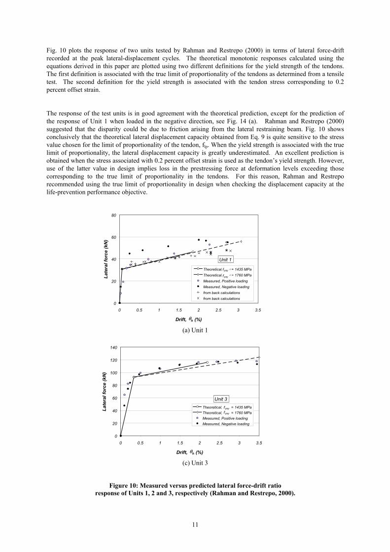
Fig. 10 plots the response of two units tested by Rahman and Restrepo (2000) in terms of lateral force-drift recorded at the peak lateral-displacement cycles. The theoretical monotonic responses calculated using the equations derived in this paper are plotted using two different definitions for the yield strength of the tendons. The first definition is associated with the true limit of proportionality of the tendons as determined from a tensile test. The second definition for the yield strength is associated with the tendon stress corresponding to 0.2 percent offset strain. The response of the test units is in good agreement with the theoretical prediction, except for the prediction of the response of Unit 1 when loaded in the negative direction, see Fig. 14 (a). Rahman and Restrepo (2000) suggested that the disparity could be due to friction arising from the lateral restraining beam. Fig. 10 shows conclusively that the theoretical lateral displacement capacity obtained from Eq. 9 is quite sensitive to the stress value chosen for the limit of proportionality of the tendon, flp. When the yield strength is associated with the true limit of proportionality, the lateral displacement capacity is greatly underestimated. An excellent prediction is obtained when the stress associated with 0.2 percent offset strain is used as the tendon’s yield strength. However, use of the latter value in design implies loss in the prestressing force at deformation levels exceeding those corresponding to the true limit of proportionality in the tendons. For this reason, Rahman and Restrepo recommended using the true limit of proportionality in design when checking the displacement capacity at the life-prevention performance objective.
(a) Unit 1
(c) Unit 3
Figure 10: Measured versus predicted lateral force-drift ratio response of Units 1, 2 and 3, respectively (Rahman and Restrepo, 2000).

12
3-HD10@100 crs (2 legs)
R6@50 crs stirrups
R6@300 crs stirrup
4000
80x40 duct3 - 5.5 mm ØCFRP tendons/duct
50x50x4.0 SHS
1350
350180
200x125 25mm thick plate
1350x125 25mm thick plate
4-HD16
4-HD16
350x130 10mm thick plate
4-HD16
1350
Guide plate
Holden at al. (2003) tested two geometrically identical half-scale precast concrete cantilever wall units with dimensions identical to those tested by Rahman and Restrepo. One unit, Unit 1, was a code compliant conventionally reinforced specimen, designed to emulate the behaviour of a ductile cast-in-place concrete wall. The other unit, Unit 2, was hybrid wall. A constant axial force of 200 kN was applied to each unit to represent gravity loading. Both units were cast with 40 MPa concrete and were tested under quasi-static reversed cyclic loading conditions. The hybrid wall unit contained two ducts with 3-5.5mm diameter carbon fibre tendons unbonded over 5.5 m. The elastic modulus for the tendons was Esp = 160 GPa. These tendons were prestressed to 46% of the ultimate tensile strength to induce an initial prestressing force of 132 kN. The concrete of wall panel in the hybrid unit included 35 mm long high strength steel fibres at a dose of 40 kg/m3. This was done to reduce conventional reinforcement in the wall panel. Axial energy dissipation devices, similar to those used by Rahman and Restrepo but with 15.8 mm in diameter, were provided in this unit. An arrangement of diagonal steel reinforcement welded to steel plates was designed to transfer the internal forces in the wall panel directly to the foundation, without the need for confining the concrete at the wall toes, see Fig. 11. The conventional precast reinforced wall performed very well in terms of ductility capacity and energy absorption capability, reaching 2.5% drift before a number of fractures in the reinforcement resulted in significant strength degradation. This unit, however, showed a significant number of residual cracks in the cycles past 1% drift. The hybrid wall unit achieved drift levels well in excess of 3% with no visible damage to the wall panel prior to failure. Fracture of the energy dissipaters was observed at 5% drift. The carbon fibre tendons fractured at 6.2% drift. This suggests that this system can be designed to have large reserve of lateral deformation capacity.
Fig. 11: Wall panel reinforcement in the hybrid unit tested by Holden et al.

13
-180
-140
-100
-60
-20
20
60
100
140
180
-120 -90 -60 -30 0 30 60 90 120Lateral displacement (mm)
App
lied
late
ral f
orce
(kN
)
Monotonic response
-3.0 -2.0 -1.0 0 +1.0 +2.0 +3.0Drift (%)
Hn = 154 kN
Hn = 154 kN
(a)
-120
-80
-40
0
40
80
120
-120 -90 -60 -30 0 30 60 90 120Lateral displacement (mm)
App
lied
late
ral f
orce
(kN
)
-3.0 -2.0 -1.0 0 +1.0 +2.0 +3.0
Drift (%)
Theoretical pushover response
(b)
Fig. 12 shows a close-up view of the wall panels at the base of the wall. It is evident that the development of plasticity in the monolithic wall is associated with extensive damage, whereas at large levels of drift no visible damage was observed in the hybrid wall. Fig. 13 presents the lateral force-lateral displacement response of the units tested by Holden et al. The monolithic unit, Unit1, showed the characteristic “fat” loops whereas the hybrid unit, Unit 2, showed a characteristic self-centering response. Fig. 20 plots the residual drifts for the units. The monolithic unit displayed significant residual displacements. These displacements were equal to the peak displacement less the small elastic recovery. In contrast, the hybrid wall unit showed essentially no residual displacements.
Fig. 12: Extent of damage in equivalent monolithic and hybrid precast walls (Holden et al., 2003)
Fig. 13: Hysteretic response of precast wall units tested by Holden et al. (2003)

14
In many countries the adoption of seismic design approaches combined with traditional methods of construction has resulted in structural conflict. In actual construction, however, the frames are infilled with unreinforced brick masonry or concrete is cast surrounding the existing brick wall in what is know in Latin America by the name of “confined” masonry. The use of unreinforced masonry infills in the frames leads to a dramatic change in the seismic response. The presence of the infills precludes the formation of the mechanism postulated in design. In turn, the brittle failure of an infill often results in the formation of an intermediate column sideway mechanism and leads to extremely poor building performance and even collapse. Toranzo (2002) reported the first shake table testing of a 40% scale three-storey hybrid “confined” masonry wall unit. The wall unit in this test was built with brick masonry infill, and included the slabs, see Fig. 14. The columns were designed to for strain control to ensure small shear distortions would occur in the wall panel, while the wall rocked at the foundation. Energy dissipation devices, in the way of tapered levers designed to yield in bending with constant curvature, were installed at the wall toes, see Fig. 15. The wall toes were armoured with steel cases depicted in Fig. 16. This test unit was subjected to 60 tests on the 200 KN capacity shake table at the University of Canterbury, New Zealand. Fig. 17 shows the response of the unit under the Taft N21E record of the 1952 Kern County earthquake record magnified to attain a target peak ground acceleration of 0.5g. The seismic response of this unit was excellent. The masonry infill maintained its integrity throughout. No cracking was observed to occur in the infill. The maximum residual drift of 0.13% was observed after an excursion to 1.8% drift. The residual drifts were due to the spreading of yield lines in the slabs.
Fig. 14: Confined masonry shake table test unit reported by Toranzo (2002)
Detail of steel corner case
130
70
110
10
10
10
Front view Side view
Isometric view
Front view
Top view
steel plates (10mm thickness) to protect foundation beam
steel cases to protect wall corners (see detail)
400
130
Fig. 15: Detailing of the wall toes in Toranzo’s unit (2002).
shake table
4585
3980
1260
1260
1260
200
130 580 130
120 470 840 470 120

15
foundation beam
rocking wall
dissipator-end connected to the wall throught pin
dissipator-end fixed to foundation through bracket
brackets fixed to foundation
Fig. 16: Close up view of energy dissipaters in Toranzo’s test unit (2002)
4. CONCLUSIONS
1. The unique seismic response characteristics of an emerging cantilever wall system were described in this paper. The proposed system ensures minimal structural damage during a major or moderate seismic event in addition to the absence of post-earthquake residual drifts in the system.
2. The lateral load-displacement response of a system utilizing the proposed connection mechanism may
be characterised by a bilinearly elastic response. When the overturning moment due to the lateral forces equals the moment due to the stabilising forces, decompression occurs at the horizontal joint at one end of the wall. A gap forms at this end and extends along the horizontal joint with increasing magnitude of the lateral force. The limit of proportionality, at which a reduction in the lateral stiffness of the system occurs, is attained when this gap extends a sufficient distance along the length of the horizontal joint. As a result of this bilinearly elastic response, limited energy can be dissipated due to impacting of the wall against the foundation structure and through radiation to the soil. Damage at the wall toes is limited to spalling of the cover concrete. No residual post-earthquake drifts are expected from well-detailed walls.
3. Energy dissipation capacity can be incorporated into the system through the use of mild steel bars or
external levers.
4. Experimental work conducted on precast concrete walls and on a “confined” masonry wall system showed the excellent seismic response of the construction method described in the paper. Damage sustained by all specimens was cosmetic and manifested itself as spalling of the concrete cover at the ends of the walls at relatively large drifts. A self-centering response was attained in all specimens.
5. AKNOWLEDGEMENTS
The author would also thank the following individuals for their useful contribution, constructive and interesting discussions and valuable advice: Prof. M.J.N. Priestley, Emeritus Professor at the University of California at San Diego; Prof. J. Stanton, University of Washington at Seattle; Dr M. Rodriguez, National University of Mexico, to Drs. L. Toranzo and A. Rahman and Mr. T. Holden for their devotion in making the tests successful.
16
6. REFERENCES Cheok, G.S., Stone, W.C. and Kunnath, S.K., “Seismic Response of Precast Concrete Frames with Hybrid
Connections”, ACI Structural Journal, Vol. 95(5), September-October 1998, pp. 527-539. Cormack, L.G. “The Design and Construction of the Major Bridges on the Mangaweka Rail Deviation”, 1988,
Transaction of the Institute of Professional Engineers of New Zealand, Vol. 15, pp.16-23 El-Sheikh, M.T., Sause, R., Pessiki, S. and Lu, L-.W., “Seismic Behaviour and Design of Unbonded Post-
Tensioned Precast Concrete Frames”, PCI Journal, Vol.44(3), May-June 1999, pp. 54-71. Morin, P. Leger, P and Tinawi, R., “Seismic Behavior of Post-Tensioned Gravity Dams: Shake Table
Experiments and Numerical Simulations”, ASCE J. Struct. Engrg., Volume 128, Issue 2, pp. 140-152, 2002.
Holden, T., Restrepo, J.I., and Mander, J.B., “Seismic Performance of Precast Reinforced and Prestressed Concrete Walls”, ASCE J. Struct. Engrg., Vol. 129, No. 3 3, March 2003, pp. 286-296.
Kurama, Y., Sause, R., Pessiki, S. and Lu, L-.W., “Lateral Load Behavior and Seismic Design of Unbonded Post-Tensioned Precast Concrete Walls”, ACI Structural Journal, Vol. 96(4), July-August 1999, pp. 622-632.
Kurama, Y., Sause, R., Pessiki, S., Lu, L-.W. and El-Sheikh, M., Seismic Design and Response of Unbonded Post-Tensioned Precast Concrete Walls, PRESSS Report No. 98/03 (LU Report No. EQ-97-01), Department of Civil and Environmental Engineering, Lehigh University, Bethlehem, Pennsylvania, USA, 1998.
Kurama, Y. Seismic Analysis, Behavior, and Design of Unbonded Post-Tensioned Precast Concrete Walls, PhD Dissertation, Department of Civil and Environmental Engineering, Lehigh University, Bethlehem, Pennsylvania, USA, May 1997.
MacRae, G.A. and Priestley, M.J.N., Precast Post-Tensioned Ungrouted Concrete Beam-Column Subassemblage Tests, Report No. SSRP-94/10, Department of Applied Mechanics and Engineering Sciences, University of California, San Diego, California, USA, 1994.
Nakaki, S.D., Stanton, J.F. and Sritharan, S., “An Overview of the PRESSS Five-Story Precast Test Building”, PCI Journal, Vol. 44(2), March-April 1999, pp. 26-39.
Perez, F.J., Pessiki, S., Sause, R., Lu, L-W., "Lateral Load Tests of Unbonded Post-Tensioned Precast Concrete Walls," Large Scale-Scale Structural Testing, Edited by M. A. Issa, Y. L. Mo, American Concrete Institute, Farmington Hills, Michigan, 2003, pp. 161-183.
Priestley, M.J.N. and Tao, J.R.T., “Seismic Response of Precast Prestressed Concrete Frames with Partially Debonded Tendons”, PCI Journal, Vol. 38(1), January-February 1993, pp. 58-69.
Priestley, M.J.N., Sritharan, S., Conley, J.R. and Pampanin, S., “Preliminary Results and Conclusions From the PRESSS Five-Story Precast Concrete Test Building”, PCI Journal, Vol.44, No. 6, November-December, 1999, pp.42-67.
Rahman, A. and Restrepo, J.I., “Earthquake Resistant Precast Concrete Buildings: Seismic Performance of Cantilever Walls Prestressed using Unbonded Tendons”, Research Report 2000-5, Department of Civil Engineering, University of Canterbury, Christchurch, New Zealand, 2000.
Paulay, T. and Priestley, M.J.N. Seismic Design of Reinforced Concrete and Masonry Buildings, John Wiley and Sons, Inc., NY, USA, 1992.
Restrepo, J.I. “New Generation of Earthquake Resisting Systems” Proceedings, First fib Congress, Osaka, Japan, October, 2002, pp. 41-60 (also paper E286 on CD-Rom).
Rutenberg, A. Leibovich, E. “On the lateral force distribution among structural walls in multistorey buildings”, Bulletin of the New Zealand Society for Earthquake Engineering, Vol. 35, No. 4, pp. 231-242. Dec. 2002
SNZ, “NZS 3101, Concrete Structures Standard, Part 1: The Design of Concrete Structures and Part 2: Commentary on the Design of Concrete Structures”, Standards New Zealand, Wellington, 1995.
Stone, W.C., Cheok, G.S. and Stanton, J.F., “Performance of Hybrid Moment-Resisting Precast Beam-Column Concrete Connections Subjected to Cyclic Loading”, ACI Structural Journal, Vol. 91(2), March-April 1995, pp. 229-249.
Toranzo, L., “The Use of Rocking Walls in Confined Masonry Structures: a Performance-based Approach”, PhD Thesis, Department of Civil Engineering, University of Canterbury, New Zealand, 2002.
17
APPENDIX II. NOTATION
Roman Symbols
Ag = Wall cross section area, mm2.
Aps = Total area of prestressing steel, mm2.
Asd = Area of reduced segment of energy dissipater, mm2.
psA = Area of prestressing tendons, mm2.
Ar = Aspect ratio of wall = Hw/Lw.
be = Effective width of concrete wall without concrete cover, mm.
bw = Wall width, mm.
c = Distance from extreme compression fibre to neutral axis in the stress distribution profile of a
concrete section, mm.
cc = Concrete cover to the side of transverse reinforcement, mm.
ded = Location of energy dissipater furthest from wall edge in compression, mm.
dps = Distance of prestressing tendon furthest from neutral axis depth from the extreme compression
fibre at the toe of the wall, mm.
Eps = Elastic modulus of a prestressing tendon, MPa.
Ec = Elastic modulus of concrete, MPa.
f c′ = Compressive strength of concrete, MPa.
flp = true limit of proportionality in a tendon, MPa.
fpsu = Ultimate tensile strength of a prestressing tendon, MPa.
fpsi = Initial stress in prestressing tendons after losses, MPa.
fpsy = True limit of proportionality of a prestressing tendon, MPa.
fslp = Nominal limit of proportionality of the prestressing tendon corresponding to 0.2 percent offset
strain, MPa.
f su = Mean ultimate tensile strength of reinforcement used in the manufacture of the energy dissipater,
MPa.
fsu = Ultimate tensile strength of non-prestressed reinforcement, MPa.
fy = specified yield strength of non-prestressed reinforcement, MPa.
Fed = Ultimate tensile force of an energy dissipater, N.
Fedy = Yield strength of an energy dissipater, N.
Flp = Tensile in a prestressing tendon corresponding to the nominal limit of proportionality, N.
Fpsi = Prestressing force in tendons after losses, N.
Heff = Height of the resultant first mode lateral force from base of wall, mm.
Hw = Wall height, mm.
Ig = moment of inertia of the gross cross section, mm4.
Le = Length of milled segment of energy dissipater, mm.
Lps = Total unbonded length of prestressing tendon, mm.
Lw = Length of wall, mm.
Mlp = Bending moment at wall base orresponding to the wall’s limit of proportionality, N.mm.
18
Mls = Bending moment at wall base at the life-safety limit-state, N.mm.
N ∗ = Concentric axial load due to gravity loads, N.
P = Total axial compressive force in wall, which is represented by the initial post-tensioning force in
the prestressing strands and any gravity loads, N.
V = Lateral force acting on the wall, N.
Vlp = Lateral force at “yield” (limit of proportionality) of system, N.
Vls = Lateral force at the life-safety limit-state, N.
Greek Symbols
Δed = Elongation of energy dissipater, mm.
Δ h = Horizontal displacement of wall, mm.
lpΔ = Horizontal displacement of wall at the true limit of proportionality of a tendon, mm.
lsΔ = Horizontal displacement of wall at the life-safety limit-state, mm.
F psΔ = Variation of post-tensioning force in prestressing tendon due to wall rocking, N.
εcc = confined concrete compressive strain.
εed = Average strain in energy dissipater.
εsu = Uniform strain in steel reinforcement.
εy = Yield strain of steel reinforcement.
ζeq = Equivalent viscous damping ratio.
θ = Wall drift ratio = Δ h / Heff.
θls = Wall drift ratio at life-safety limit-state (2.5 percent drift ratio)
μ f = Coefficient of friction.
ωd = Dynamic shear magnification factor designating the location of the resultant of the lateral inertial
forces including higher mode effects. ωd ≥ 1.
ωf = Ratio between static and dynamic friction coefficients at the concrete wall foundation interface. ωf
> 1.
ωk = Wall shear force magnification factor that accounts for development of internal forces due to
deformation compatibility. ωd ≥ 1.
ρt = Ratio of transverse reinforcement in wall units.
ρl = Ratio of longitudinal reinforcement in wall units.