new generation fec in satellite systems - satcom … generation fec in satellite systems 1. ......
TRANSCRIPT

Created on 21/03/2005 00:05:00 Issue 1 www.satcom-services.com
New Generation FEC in Satellite Systems
1. Summary
Due to the inherent ‘long-haul’ nature of satellite communication and the transition of the payload information through many phases of modulation, frequency conversion, amplification, transmission and demodulation, it is not surprising that the occurrence of errors can be high. Fundamental transmission times of around 500ms point towards the use of Forward Error Correction (FEC) techniques (in preference to retransmission requests) to correct errors at the receiving terminal while avoiding significantly extending latency. Such FEC coding expands the data representation of the information (the expansion ratio being known as the coding rate), but pays back in terms of lower error rates.
In the past 10 years a revolution has taken place in FEC technology. The drivers for this revolution were the discovery of so-called Turbo Code FEC technology and the rapid decrease in the cost of logic – driven by ever-smaller silicon geometry’s. These two factors have enabled the production of cost effective high complexity FEC solutions.
This paper aims to briefly overview the history of FEC in Satellite systems and to introduce some of the new ‘Turbo’ FEC solutions. One particular new FEC system, Turbo Product Code FEC technology, is then reviewed in detail and the paper demonstrates how this technology can be applied to different types of Satellite System to greatly improve system performance.
The paper argues that it is critically important to consider a system level when applying Turbo Codes into Satellite systems. The performance of the complete up-link and down-link chain must be considered to gain the most benefit from these new coding schemes. System performance with different modulation schemes, amplifier back-off and demodulator synchronisation and implementation margin are just as important as straight coding gain.
Advantech AMT modem products can optionally be provided with all of the FEC codes (Reed-Solomon, Viterbi, TPC, eTPC and LDPC) described in this paper, enabling system architects to select the optimum balance of elements for their communication solution.
2. Evolution of FEC
Forward error correction techniques are widely used in satellite communication and broadcasting systems, allowing satellite operators to improve link budget without the use of expensive power amplifiers and large dishes.
Satellite operators and equipment manufactures were early adopters of Error correction schemes as the application of any FEC can reduce the power requirements for operating a digital satellite link with acceptable Bit Error Rate performance. The earliest digital satellite systems – installed in the 1970s used simple Viterbi decoders to implement the FEC function.
Conventional techniques that are widely used in today’s satellite communication and broadcasting systems are based on the concatenated Reed-Solomon and Viterbi coding scheme, which was introduced in early 80s. This technique was first been accepted as the CCSDS standard for deep-space missions and then with some modifications as the FEC standard for INTELSAT, DVB-S and DVB-DSNG systems. The vast majority of commercial systems in operation today use this type of concatenated coding scheme.

Created on 21/03/2005 00:05:00 Issue 1 www.satcom-services.com
In 1993, a new class of FEC, called “turbo codes” was introduced. These codes allow near-Shannon1 limit performance with codes that are relatively easy to implement in hardware. Since their introduction, turbo codes have been accepted by a number of standardization bodies as the FEC for next generation systems. These include DVB-RCS, INMARSAT, CCSDS just to name a few. Over the past 10 years, the theory of turbo codes has matured and the technology is well developed with commercial products being available in the form of ASIC, VHDL or DSP cores. A new family of turbo codes, known as enhanced Turbo Product Codes or Hyper Codes (overviewed further in section 6), has recently emerged giving even higher performance.
However, the development of FEC didn’t stop and a new class of FEC, known as low density parity check codes (LDPC) have been re-discovered2 recently. These codes provide performance similar to turbo codes but can actually outperform Turbo codes if the block size is very large. These properties make them very attractive for broadband and direct to home consumer applications. In recognition of these properties, DVB-S2 has accepted LDPC as the mandatory FEC scheme for the next generation of digital satellite TV broadcasting and broadband services.
3. Characteristics of Iterative Turbo Codes
Turbo product codes and Turbo Convolutional codes are by their nature very different coding systems – one is built by the combination of simple Hamming or BCH codes in a 2, 3 or n dimensional array. The other is built by iterating between two Convolutional decoders with an interleave process between the codes to ‘spread out’ the error bursts. This inherent difference in the nature of the codes results in differences in the error correction characteristics.
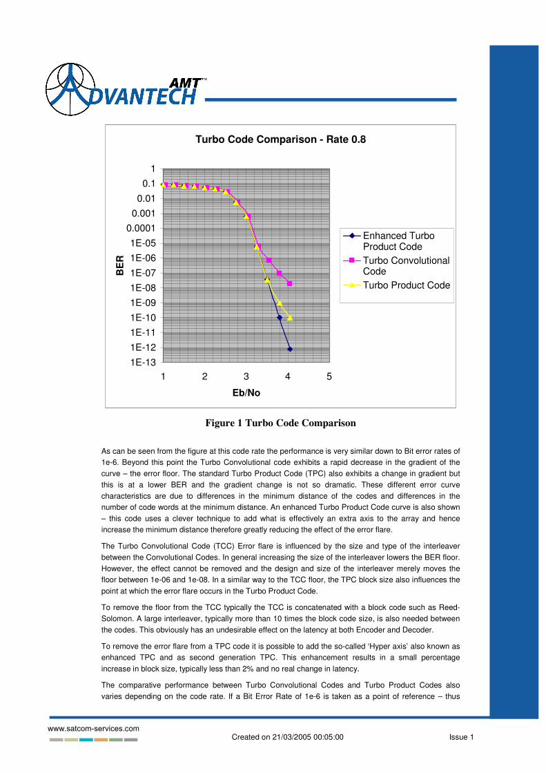
Both Turbo Product codes and Turbo Convolutional codes exhibit steep initial gradients on their error correction performance curves. However, the Turbo Convolutional Code will, at some point, exhibit an error floor while the Turbo Product Code will exhibit an error flare. An error floor can be considered as a point at which despite increases in Signal / Noise the error rate will not decrease significantly. While an error flare can be described as a decrease in the gradient of the performance curve. Figure 1 illustrates the differences between the Error Flare and the error floor comparing equivalent block size Turbo Convolution and Turbo product codes.
1 The seminal work of Claude Shannon in the late 1940’s provides a mathematical model of the upper limit of
information flow possible through a particular communication system
2 LDPC was previously discounted due to the significant computing power required for use. Developments in
processing devices have now re-enabled this class of codes.
Created on 21/03/2005 00:05:00 Issue 1 www.satcom-services.com
Turbo Code Comparison - Rate 0.8
1E-131E-121E-111E-101E-091E-081E-071E-061E-05
0.00010.0010.010.1
1
1 2 3 4 5
Eb/No
BE
R
Enhanced TurboProduct CodeTurbo ConvolutionalCodeTurbo Product Code
Figure 1 Turbo Code Comparison
As can be seen from the figure at this code rate the performance is very similar down to Bit error rates of 1e-6. Beyond this point the Turbo Convolutional code exhibits a rapid decrease in the gradient of the curve – the error floor. The standard Turbo Product Code (TPC) also exhibits a change in gradient but this is at a lower BER and the gradient change is not so dramatic. These different error curve characteristics are due to differences in the minimum distance of the codes and differences in the number of code words at the minimum distance. An enhanced Turbo Product Code curve is also shown – this code uses a clever technique to add what is effectively an extra axis to the array and hence increase the minimum distance therefore greatly reducing the effect of the error flare.
The Turbo Convolutional Code (TCC) Error flare is influenced by the size and type of the interleaver between the Convolutional Codes. In general increasing the size of the interleaver lowers the BER floor. However, the effect cannot be removed and the design and size of the interleaver merely moves the floor between 1e-06 and 1e-08. In a similar way to the TCC floor, the TPC block size also influences the point at which the error flare occurs in the Turbo Product Code.
To remove the floor from the TCC typically the TCC is concatenated with a block code such as Reed-Solomon. A large interleaver, typically more than 10 times the block code size, is also needed between the codes. This obviously has an undesirable effect on the latency at both Encoder and Decoder.
To remove the error flare from a TPC code it is possible to add the so-called ‘Hyper axis’ also known as enhanced TPC and as second generation TPC. This enhancement results in a small percentage increase in block size, typically less than 2% and no real change in latency.
The comparative performance between Turbo Convolutional Codes and Turbo Product Codes also varies depending on the code rate. If a Bit Error Rate of 1e-6 is taken as a point of reference – thus

Created on 21/03/2005 00:05:00 Issue 1 www.satcom-services.com
removing the Error Flare problem then TCC codes will typically outperform TPC codes for all code rates below about 0.75 code rate whereas TPC codes will outperform TCC codes for all code rates above 0.75. (This observation is valid when considering single error correcting TPC codes; if 2 error correcting BCH codes are used then the crossover point can be lower to about 0.7 code rate)
Comparison of TCC and TPC against Code Rate
00.10.20.30.40.50.60.70.80.9
1
-2 -1.5 -1 -0.5 0 0.5 1 1.5 2
TPC Advantage dB
Cod
e R
ate
Figure 2 Comparative Performance at 1e-6 BER, TCC v TPC
In conclusion Turbo Product Codes and Turbo Convolutional Codes are both excellent coding schemes offering performance advantages compared to the typical Reed-Solomon Viterbi concatenated coding schemes in use today. Both schemes have their own inherent strengths and comparative weaknesses and so depending on the application one Turbo scheme may be better suited than the other.
In a power limited system with a Bit Error Rate requirement of 1e-7 Turbo Convolutional Codes would a better choice using a low rate TCC code. However, in a Bandwidth limited system where it makes sense to run high code rates the Turbo Product Code will outperform the TCC code. Also, any requirement for Quasi Error Free error performance will automatically better suit TPC than TCC if the added latency of the outer block code and associated interleaver is too great.
4. Turbo Product Code – Examples of codes in use today
Turbo Product Codes have been standardised into several new communications standards – IEEE 802.16.C and ETSI Hiperaccess for LMDS Fixed Wireless Access and IEEE 802.16A and ETSI Hiperman for MMDS Fixed Wireless Access. In addition Turbo Product Codes have become the de facto proprietary replacement technology in the VSAT marketplace.
Turbo Product Codes offer two main advantages to existing VSAT users: better coding performance and lower latency than the existing Viterbi + Reed-Solomon solution. In fact the Turbo Product Code Encoder exhibits near zero latency while the decoder typically exhibits latency between 1 and 2 times the block size. Turbo Product Coding allows the user to trade-off performance with latency. Figure 3 shows two codes applied to QPSK modulation in an AWGN channel – one is a (64,57) x (64,62) enhanced TPC with a code rate of 0.863 and the other is a (128,120) x (128,119) enhanced code with a code rate of 0.872. The first code has a 4kbit block size and the second has a 16kbit block size. The figure shows that the larger block size has almost 0.5 dB performance gain at a BER of 1e-6.

Created on 21/03/2005 00:05:00 Issue 1 www.satcom-services.com
Comparison of TPC block size
1.00E-091.00E-081.00E-071.00E-061.00E-051.00E-041.00E-031.00E-021.00E-011.00E+00
2 2.5 3 3.5 4 4.5 5
Eb/No
BE
R 16kbit4kbit
Figure 3 Comparison of 4 kbit and 16 kbit Block Size
Figures 4, 5 and 6 illustrate some of the achievable performances with TPC and different modulation types. The results compare Signal / Noise ratio and BER. The QPSK code rates are 0.6, 0.78, 0.87, 0.923 and 0.977 respectively.
QPSK TPC Coded Results
1.00E-111.00E-101.00E-091.00E-081.00E-071.00E-061.00E-051.00E-041.00E-031.00E-021.00E-011.00E+00
2.5 4.5 6.5 8.5 10.5
S/N dB
BE
R
(64,57)x(65,57) 16 iters (128,120)x(129,120) 12 iters(128,120)x(129,127) 12 iters (128,127)x(129,127) 12 iters(64,57)x(64,57)x(4,3)
Figure 4 QPSK Modulation with TPC coding

Created on 21/03/2005 00:05:00 Issue 1 www.satcom-services.com
The 8PSK code rates are 0.78, 0.87 and 0.923 respectively.
8PSK Curves
1.00E-09
1.00E-081.00E-07
1.00E-061.00E-05
1.00E-041.00E-03
1.00E-021.00E-01
1.00E+006 8 10 12 14
S/N dB
BE
R
8PSK Rate 0.79 8PSK Rate 0.88 8PSK Rate 0.923
Figure 5 8PSK Modulation with TPC Coding
The 16QAM figure shows code rates of 0.78 and 0.87 respectively.
16QAM S/N Results4 bit Soft I/P 4 bit SISO
1.00E-081.00E-071.00E-061.00E-051.00E-041.00E-031.00E-021.00E-011.00E+00
8 9 10 11 12 13 14
S/N dB
BE
R
16QAM (128,120) x (128,119) 12 iterations16QAM (64,57) x (64,56) 12 iterations
Figure 6 16QAM Modulation with TPC Coding
Created on 21/03/2005 00:05:00 Issue 1 www.satcom-services.com
5. Applying Turbo Product Coding to Satellite Systems
Since the introduction of turbo-codes their main benefit was widely accepted as being able to provide approximately 2 dB additional coding gain in comparison with a conventional FEC scheme, e.g. concatenated RS and Convolutional codes. In a number of applications, this additional coding gain can be utilised to increase the power efficiency of the system, resulting either in the increased range of communication systems or alternatively, in bandwidth limited systems the gain can be used to increase data throughput.
While both scenarios provide a basis for the enhancement of the system, they are not universal and do not always achieve the desired goal. For example, the use of R=1/3 turbo codes in conjunction with QPSK allows the achievement of approx. 2.5 dB additional coding gain when compared with the RSV coding scheme of the similar rate. However, practical realisation of this gain is not a simple process, as the carrier recovery and clock synchronisation of commercial QPSK demodulators cannot operate effectively at such low Signal Noise Ratios without suffering a large implementation margin or without the addition of special helper signals.
When a system is not power limited but bandwidth limited then the benefit of the Turbo Code can be applied in a different way. Consider a system targeting a spectral efficiency of 1.8 Bit/S/Hz. It is apparent that the desired bandwidth efficiency can be achieved in 2 ways:
1. Using 8PSK modulation with concatenated RS and R=2/3 turbo code;
2. Using QPSK modulation with R=0.9 turbo code.
Surprisingly, a straight comparison of coding gain is not a sufficient criterion to make the choice between the two options. This doesn’t take into account all the benefits of the second option as these benefits become transparent only when the proposed technical solutions are evaluated based on system level comparison.
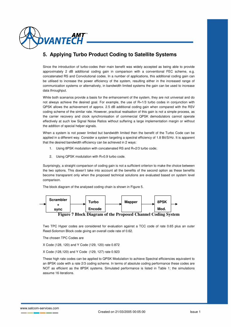
The block diagram of the analysed coding chain is shown in Figure 5.
Figure 7 Block Diagram of the Proposed Channel Coding System
Two TPC Hyper codes are considered for evaluation against a TCC code of rate 0.65 plus an outer Reed-Solomon Block code giving an overall code rate of 0.62.
The chosen TPC Codes are
X Code (128, 120) and Y Code (129, 120) rate 0.872
X Code (128,120) and Y Code (129, 127) rate 0.923
These high rate codes can be applied to QPSK Modulation to achieve Spectral efficiencies equivalent to an 8PSK code with a rate 2/3 coding scheme. In terms of absolute coding performance these codes are NOT as efficient as the 8PSK systems. Simulated performance is listed in Table 1; the simulations assume 16 iterations.
Turbo
Encode
Mapper 8PSK
Mod.
Scrambler +
sync

Created on 21/03/2005 00:05:00 Issue 1 www.satcom-services.com
Modulation Code Rate Bits/s/Hz Eb/No @ PER 1e-7 S/N dB
QPSK 0.872 1.74 3.9 dB 6.3 dB
QPSK 0.923 1.846 4.8 dB 7.5 dB
8PSK 0.62 1.87 4.3 7 dB
Table 1 QPSK Performance
Although the TPC coding performance appears weaker than the 8PSK system there are some interesting advantages to using a QPSK modulation scheme. It is well known that the implementation margin for an 8PSK modem is higher than that for a QPSK modem. The figure for the difference between the actual implementation margins can be argued but the current DVB-DSNG standard suggests the difference to be 0.5 dB. In addition, the carrier recovery systems for QPSK demodulators are more robust, providing up to 0.5 dB additional gain compared to 8PSK demodulators. On top of this difference the 8PSK system will require a very slightly higher peak-to-mean ratio through the Satellite High Power Amplifier meaning that the power achieved through the HPA with QPSK will be higher. Finally, the use of QPSK would allow an Offset-QPSK signal to be transmitted. Offset QPSK has a lower Peak-to-Mean ratio than both QPSK and 8PSK, which would enable the Satellite to be driven with a yet higher output power – again practical experience puts the power advantage in the region of 0.5 dB. When these System level factors are taken into account the actual performance of the QPSK + TPC coding system will be equivalent or better than the currently proposed 8PSK systems. A QPSK demodulator is also inherently much simpler technology than an 8PSK demodulator and so the use of this system will also simplify the overall demodulator ASIC.
The same arguments can be applied to the use of high rate Hyper Codes with 8PSK instead of using a ¾ rate code with 16QAM. In fact because of the 3 dB extra amplifier back-off requirement of 16QAM the advantage of the 8PSK + Hyper code system is even more pronounced when it comes to real world operation. Table 2 shows the simulated 8PSK + Hyper code performance using 16 iterations and it also lists the performance of a DVB-DSNG 16QAM system of near equivalent spectral efficiency.
Modulation Code Rate Bits/s/Hz Eb/No @ PER 1e-7
S/N dB
8PSK 0.872 2.616 6.85dB 11 dB
16QAM 0.69 2.76 7.5 dB 11.9 dB
Table 2 8PSK Turbo Product Code v 16QAM PTCM
In this case the 8PSK Turbo Product coded system carrying only 5% less data outperforms the 16QAM system by 1 dB in terms of coding gain. However, when the extra amplifier back off of 3 dB is taken into account a 4 dB system gain can be realized by the appropriate use of the TPC system.
Hardware measurements of both 14.5Mbaud and 29MBaud signals have been made with noise added at 70 MHz using a Noise and Interference Test set. The hardware results for the QPSK systems and 8PSK rate 0.873 at a BER of 1e-9 are listed in Table 3 below. These results were compiled using 16 turbo iterations.
Created on 21/03/2005 00:05:00 Issue 1 www.satcom-services.com
Modulation Code Rate Bits/s/Hz S/N dB Eb/No
QPSK 0.872 1.74 6.5 dB 4.1 dB
QPSK 0.923 1.846 7.75 dB 5.1 dB
8PSK 0.872 2.62 11.5 dB 7.3 dB
Table 3 Hardware Measurements
In conclusion the application of Turbo Product Coding FEC to Satellite systems can typically provide a basic 2 dB of coding gain over and above today’s concatenated Reed-Solomon Viterbi FEC solutions. However, if the system gain provided by this new technology can be even greater if intelligent combinations of coding and modulation are applied together. In this case it can be possible in some scenarios to gain up to 4 dB of system performance.
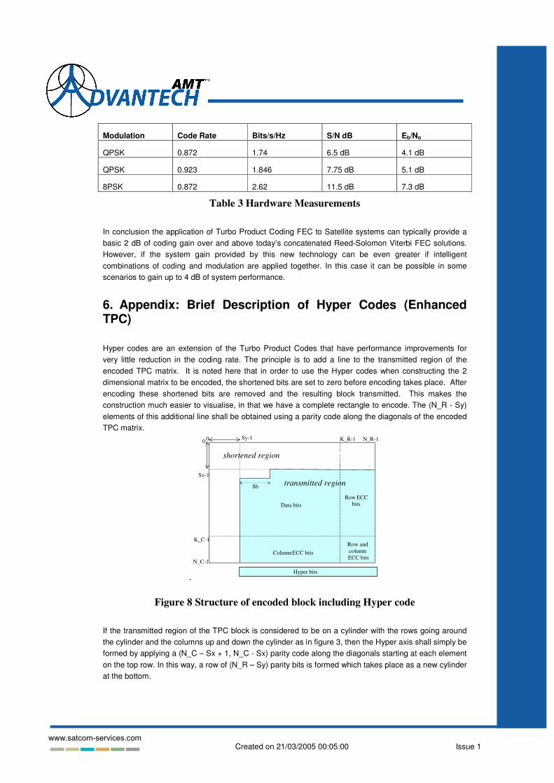
6. Appendix: Brief Description of Hyper Codes (Enhanced TPC)
Hyper codes are an extension of the Turbo Product Codes that have performance improvements for very little reduction in the coding rate. The principle is to add a line to the transmitted region of the encoded TPC matrix. It is noted here that in order to use the Hyper codes when constructing the 2 dimensional matrix to be encoded, the shortened bits are set to zero before encoding takes place. After encoding these shortened bits are removed and the resulting block transmitted. This makes the construction much easier to visualise, in that we have a complete rectangle to encode. The (N_R - Sy) elements of this additional line shall be obtained using a parity code along the diagonals of the encoded TPC matrix.
.
0 K_R-1 N_R-1 0
K_C-1
N_C-1
Data bits
Column ECC bits
Row ECC bits
Row and column ECC bits
shortened region
transmitted region Sx-1
Sy-1
Sb
Hyper bits
Figure 8 Structure of encoded block including Hyper code
If the transmitted region of the TPC block is considered to be on a cylinder with the rows going around the cylinder and the columns up and down the cylinder as in figure 3, then the Hyper axis shall simply be formed by applying a (N_C – Sx + 1, N_C - Sx) parity code along the diagonals starting at each element on the top row. In this way, a row of (N_R – Sy) parity bits is formed which takes place as a new cylinder at the bottom.

Created on 21/03/2005 00:05:00 Issue 1 www.satcom-services.com
Column ECC bits
Hyper bits
Data and row ECC
bits
Figure 9 Exemplifying the Hyper code formation
Looking again at figure 2, label the bits as x0,0 in the top left to x(N_C-Sx),(N_R-Sy) in the bottom right, then the Hyper parity bits (h0, h1, … , h(N_R-Sy) - 1) can be found by the equation:
1 ) _ ( ,..., 0 , ) (
1 _
0 ) _ mod( )) _ ( ) _ ( ( , − − = = �
− −
= − − − − + + Sy R N i x h
Sx C N
j Sy R N Sx R N Sx C N i j j i