new feature guide v8 - video security systems | ip …€¦ · · 2009-02-13feature guide for...
TRANSCRIPT

New Feature Guide V8.3

© 2009 GeoVision, Inc. All rights reserved. Under the copyright laws, this manual may not be copied, in whole or in part, without the written consent of GeoVision. Every effort has been made to ensure that the information in this manual is accurate. GeoVision is not responsible for printing or clerical errors. GeoVision, Inc. 9F, No. 246, Sec. 1, Neihu Rd., Neihu District, Taipei, Taiwan Tel: +886-2-8797-8377 Fax: +886-2-8797-8335 http://www.geovision.com.tw Trademarks used in this manual: GeoVision, the GeoVision logo and GV series products are trademarks of GeoVision, Inc. Windows and Windows XP are registered trademarks of Microsoft Corporation. January 2009

i
Welcome to the Feature Guide for V8.3 GeoVision Surveillance System. This Guide provides an overview of key features in V8.3 GV-System. It also includes information about how the features differ from similar features in earlier versions.
Important Notice The version 8.3 only supports the following GV video capture cards: • GV-600(S) V3.20 and later • GV-650(S) V3.30 and later • GV-800(S) V3.30 and later • GV800-4A V3.10 and later • GV-600(V4) • GV-650(V4) • GV-800(V4) • GV-1120 All Series • GV-1240 All Series • GV-1480 All Series • GV-2004 • GV-2008 For more information on the upgrade, please visit our website at http://www.geovision.com.tw/english/5_0.asp, or contact your dealer.
Feature Guide for V8.3 GeoVision Surveillance System

ii
Contents
1. 32-Channel Support...............................................1 1.1 Implementing 32 Channels ................................................................... 1 1.2 System Requirements for 32 Channels................................................. 2 1.3 Rules to Use Two Cards ....................................................................... 3 1.4 Specifications for Single-Card and Two-Card Modes............................ 5
2. Main System...........................................................6 2.1 Automatic Adjustment for Daylight Saving Time ................................... 6 2.2 Digital Matrix ......................................................................................... 7
Activating Multiple Monitors .................................................................. 8 Setting Live View................................................................................. 10 Setting Scanned Pages....................................................................... 11 Setting Pop-up Alert ............................................................................ 12 Setting Live View with Pop-up Alert .................................................... 14
2.3 Windows-Based Direct POS Integration ............................................. 15 Before You Start.................................................................................. 15 Connection.......................................................................................... 15 Settings ............................................................................................... 16
2.4 Crowd Detection.................................................................................. 18 2.5 Advanced Scene Change Detection ................................................... 20 2.6 Advanced Unattended Object Detection ............................................. 22 2.7 Advanced Missing Object Detection.................................................... 24 2.8 Single Camera Tracking...................................................................... 26
Adding a PTZ Camera ........................................................................ 26 Setting PTZ Tracking .......................................................................... 26 Activating PTZ Tracking ...................................................................... 27
2.9 PTZ Tour Schedule for Idle Protection ................................................ 28 2.10 Turbo Mode......................................................................................... 29
Comparison for GV-Combo Card and GV-Combo A Card .................. 29 System Requirements......................................................................... 30 Activating Turbo Mode ........................................................................ 30
2.11 Overlaying Input Name onto Screen upon Alarm Events .................... 31 2.12 Lost Signal Alarm................................................................................ 32

iii
2.13 Colorful Mode...................................................................................... 33 2.14 Support for New PTZ Cameras ........................................................... 34 2.15 Support for New IP Cameras .............................................................. 34 2.16 Improved Support for IP Video Devices .............................................. 36 2.17 Other Enhanced Features................................................................... 38
3. ViewLog ................................................................39 3.1 GPS Tracks Playback ......................................................................... 39 3.2 Video Effects Applied on Multiple Channels........................................ 41 3.3 Increased Number of Multi Views........................................................ 41 3.4 Increased Number of Quad Views ...................................................... 42 3.5 Video Color Enriched for Playback...................................................... 42
4. WebCam................................................................43 4.1 Multicast and Audio Broadcast............................................................ 43
Configuring Multicast and Broadcast Settings..................................... 43 Sending Audio Broadcast.................................................................... 44 Receiving Multicast and Audio Broadcast ........................................... 45
4.2 WebCam Enhancements .................................................................... 47 4.3 BlackBerry Support ............................................................................. 49
Installing BBView ................................................................................ 49 Activating the BBView Function .......................................................... 49 Connecting to GV-System................................................................... 49
5. Center V2 ..............................................................50 5.1 Unlimited Log Retention Time............................................................. 50 5.2 Controlling I/O Devices of GV IP Devices ........................................... 51 5.3 Assigning a Subscriber to Another Center V2..................................... 52 5.4 Simple Audio and Microphone Panels ................................................ 53 5.5 Fast Backup and Restore (FBR) Support............................................ 54 5.6 Support for New GV-IO Boxes ............................................................ 55

iv
6. Dispatch Server....................................................56 6.1 Unlimited Log Retention Time............................................................. 56 6.2 Fast Backup and Restore (FBR) Support............................................ 56
7. Vital Sign Monitor (VSM) .....................................57 7.1 Unlimited Log Retention Time............................................................. 57 7.2 Controlling I/O Devices of GV IP Devices ........................................... 57 7.3 Fast Backup and Restore (FBR) Support............................................ 57 7.4 Support for New GV-IO Boxes ............................................................ 58 7.5 Other Features .................................................................................... 58
8. Control Center......................................................61 8.1 Support for New IP Cameras .............................................................. 61 8.2 Pop-Up Live View after Input Trigger .................................................. 61 8.3 Controlling I/O Devices of GV IP Devices ........................................... 62 8.4 Matrix Enhancements ......................................................................... 63 8.5 Live View Enhancements.................................................................... 67 8.6 Fast Backup and Restore (FBR) Support............................................ 67 8.7 VMD Enhancement ............................................................................. 68
9. Remote E-Map......................................................69 9.1 Simultaneous Display of Multiple Live Videos..................................... 69
10. Authentication Server .........................................70 10.1 Unlimited Log Retention Time............................................................. 70
11. SMS Server ...........................................................71 11.1 Unlimited Log Retention Time............................................................. 71 11.2 Support for a New GPRS Modem ....................................................... 71

32-Channel Support
1
1
1. 32-Channel Support In version 8.3, all GV software, including GV-System, GV-NVR, CMS applications and mobile phone applications, support video and audio for up to 32 channels.
1.1 Implementing 32 Channels You can choose one of these methods to implement 32 channels.
1. Two Cards: You can install two video capture cards of the same model for a total of 32 channels. For example, 2 x GV-650 Cards (16 channels) = 32 channels.
2. Hybrid Solution: You can install one video capture cards plus IP video sources to have a total of 32 channels.
3. GV-NVR Solution: You can implement 32 channels of IP video sources.
Note: Besides GV-250 and GV-800_4A Cards, all GV video capture cards support two cards.
For details on Hybrid and NVR Solution, see Chapter 2 in User’s Manual on the Surveillance System Software CD.

2
1.2 System Requirements for 32 Channels The following is the minimum and recommend system requirements to build a 32-channel DVR. • GV-NVR CPU Core 2 Quad, 2.4 GHz
RAM 2 × 1 GB Dual Channels
VGA ATI X700 256MB
HDD 4
Important: For GV-NVR with 32 channels of megapixel IP video sources, the size of transmitted
data may be quite large and reach beyond the processing speed limit of hard drive. For smooth
processing, it is highly recommended to use 4 hard drives of Seagate SV35.3 Series (certified by
GeoVision) or other brands. And assign the maximum of 8 IP camera recordings to a single hard
drive.
Note: For more details, see GV-NVR Quick Start Guide.
• Two Cards CPU RAM VGA
GV-600 x 2 Pentium 4, 2.6 GHz with HT
GV-650 x 2 Pentium 4, 2.8 GHz with HT
ATI Radeon 9550 /
NVIDIA 6200
GV-800 x 2
2 x 512 MB
Dual Channels
GV-1120 x 2 Pentium 4, 3.0 GHz, Dual Core
GV-1240 x 2
GV-1480 x 2 Core 2 Duo, 2.53 GHz
GV-1120A x 2 Pentium 4, 3.0 GHz, Dual Core
GV-1240A x 2 Core 2 Duo, 2.53 GHz
GV-1480A x 2 Core 2 Quad, 2.4 GHz
2 x 1 GB
Dual Channels
ATI Radeon X550 PCI-E /
NVIDIA 6200 PCI-E
Note: For more details, see Installation Guide.

32-Channel Support
3
1
1.3 Rules to Use Two Cards GV video capture cards have two interface types: PCI and PCI Express (PCI-E). When you install two video capture cards, ensure they are installed in the right slots as instructed in the following tables.
Important:
1. The two-card mode only supports two video capture cards of the same model.
2. It is possible to implement the two video capture cards of different channels. For example, GV-650 Card (12 channels) + GV-650 Card (16 channels) = 28 channels.
• GV-600, GV-650, GV-800 Card Combination V3.20 and later V4.20 and later
V3.20 and later
GV-600 (V4) PCI x 2
PCI x 2
PCI-E x 2 GV-650 (V4)
PCI x 1+ PCI-E x 1
PCI-E x 2
V4.20 and later
GV-800 (V4) PCI x 1+ PCI-E x 1
1. The V3.20 (and later) Cards or the combination of V3.20 and V4.20 (and later) Cards do not support two-card mode.
2. For GV-600 (V4) cards, it is required to use two PCI slots.
3. For GV-650 (V4) cards, you can use two PCI slots, two PCI Express slots, or the combination of PCI and PCI Express slots.
4. For GV-800 (V4) cards, you can use two PCI Express slots, or the combination of PCI and PCI Express slots.
Note: GV-800_4A (4 Ports) Card does not support two cards.

4
• GV-1120, GV-1240, GV-1480
Card Combination V1.02/V2.00 and later
Combo A Cards
(GV-1120A/GV-1240A/GV-1480A)
PCI-E x 2 V1.02/V2.00 and later
PCI x 1+ PCI-E x 1
Combo A Cards
(GV-1120A/GV-1240A/GV-1480A) PCI-E x 2
1. V1.02/V2.00 (and later) and Combo A Cards all support two-card mode, but the combination of V1.02/V2.00 (and later) and Combo A Cards does not support two-card mode.
2. When you install two V1.02/V2.00 (and later) Cards, it is required to use two PCI Express slots or the combination of PCI and PCI Express slots.
3. When you install two Combo A Cards, it is required to use only two PCI Express slots.

32-Channel Support
5
1
1.4 Specifications for Single Card and Two Cards
• GV-600, GV-650, GV-800
GV-600/GV-650/GV-800 Single Card Two Cards Video Input 1-16 Cams 2-32 Cams
GV-600 1 Channel (Ch1)
GV-600 2 Channels (Ch1, Ch17)
GV-650 2 Channels (Ch1-Ch2)
GV-650 4 Channels (Ch1-Ch2, Ch17-Ch18)
Audio Input
GV-800 4 Channels (Ch1-Ch4)
GV-800 8 Channels (Ch1-Ch4, Ch17-Ch20)
Support for GV-A16 Card O X GV-NET/IO Card O O 1
GV-Loop Through Card O O 2
GV-Multi Quad Card O O 3
• GV-1120, GV-1240, GV-1480
GV-1120/GV-1240/GV-1480 Single Card Two Cards Video Input 8-16 Cams 16-32 Cams
Audio Input 8-16 Channels 16-32 Channels
Real-Time Display (DSP) O O
Support for GV-A16 Card X X GV-NET/IO Card O O 1
GV-Loop Through Card O O 2
GV-Multi Quad Card O O 3
Note:
1. Connect the GV-NET/IO Card to the video capture card of 1 to16 channels.
2. You can connect the GV-Loop Through Card for each video capture card.
3. Only connect one GV-Multi Quad Card to any of two cards.
4. Since version 8.3, GV-System will not support GV-Hybrid DVR (MPEG2) Card and GV-DSP Card.

6
2. Main System This chapter introduces the new features of Main System.
2.1 Automatic Adjustment for Daylight Saving Time
The GV-System can automatically adjust to Daylight Saving Time (DST).
To enable the DST function, click Windows Start button, click Control Panel, click Date and Time, click the Time Zone tab, select a time zone of your location, and then select Automatically adjust clock for daylight saving changes.
Figure 2-1
On System Log, the DST recordings can be identified in the D.S.T Rollback column.
Figure 2-2

Main System
7
2
On ViewLog, a separate DST subfolder will be displayed in the Date Tree.
Figure 2-3
Note: The AVI file recorded during the DST period is named with the prefix “GvDST”, e.g. GvDST20081022xxxxxxxxx.avi, to differentiate from the regular AVI file named with the prefix “Event”, e.g. Event20081022xxxxxxxxx.avi.
2.2 Digital Matrix To create more screen space to display multiple channels, such as 32 channels, Digital Matrix is thus introduced to provide a way to view and manage up to 8 monitor displays. The monitor of the computer where you configure the settings and control is called the “primary monitor” and up to 7 additional monitors can be connected with. Additional VGA cards are required to install multiple monitors. Most VGA cards now support dual monitors at least. To connect up to 8 monitors, you may need 4 VGA cards installed in the computer of GV-System. The Digital Matrix includes these features: Live view: You can set different live views and screen divisions for each monitor. Automatic channel scan: You can set up to 16 scanned pages with different screen
divisions and channels for each monitor. Pop-up Alert: You can be alerted by pop-up live videos when motion is detected or I/O
devices are triggered.

8
Activating Multiple Monitors Use Windows Display Property to activate multiple monitors. Here we use Windows XP to illustrate the steps of configuration.
1. Right-click the desktop, click Properties and click the Settings tab. This dialog box appears.
Figure 2-4
2. Click the Display list. If you do not see multiple monitors listed, check if your additional monitors are connected with the computer properly.
3. Select the primary monitor from the list, and select Use This Device as the Primary Monitor.
4. Select additional monitors from the list, and select Extend my Windows desktop onto this monitor for each monitor.
5. Click Identify. Windows XP displays a large number to identify your monitors. Drag and drop the monitor icons to match the physical arrangement of your monitors.
6. Click OK.
7. Start the GV-System, click Configure, click Accessories, select Digital Matrix Setting, select monitors from the Display list and select Activate for each monitor. For example, if you install 7 additional monitors, you need to activate Display 1 to Display 7 one by one.

Main System
9
2
8. Click Apply. Your additional monitors should now display the channels seen on the primary monitor. See the figure below for example.
Figure 2-5
Primary Monitor (Monitor 1) Monitor 2 Monitor 3 Monitor 4

10
Setting Live View You can set different live views and screen divisions for each monitor.
1. On the main screen, click Configure, click Accessories, and select Digital Matrix Setting. This dialog box appears.
Figure 2-6
2. Use the Display list to select the monitor to be configured.
3. Select Screen Division.
4. Drag and drop the camera numbers to the desired positions on the divisions. To clear the assignment, drag and drop the “C” icon to that position.
5. Select Live Mode.
6. Repeat above steps to configure other monitors.
7. Click OK to apply the settings.

Main System
11
2
Setting Scanned Pages You can set up to 16 scanned pages with different screen divisions and channels for each monitor.
1. Use the Display list to select the monitor to be configured.
2. In the upper-left column, expand the Matrix folder tree, and then click Page 1. This page appears.
Figure 2-7
3. Select Activate Scan Page 1.
4. Select Screen Division.
5. Drag and drop the camera numbers to the desired positions on the divisions. To clear the assignment, drag and drop the “C” icon to that position.
6. Specify Dwell Time for how long this scanned page remains on the monitor.
7. Repeat Steps 2 to 5 to configure more scanned pages for the specific monitor.
8. Repeat Steps 1 to 7 to configure scanned pages for other monitors.
9. In the upper-left column, click the Matrix icon and return to Figure 2-6.
10. Select Auto Scan.
11. Click OK to start scanning among pages.

12
Setting Pop-up Alert You can be alerted by pop-up live videos when motion is detected or I/O devices are triggered.
1. Use the Display list to select the monitor to be configured.
2. In the upper-left column, click Event Popup. This page appears.
Figure 2-8
Motion Trigger: The live video of selected cameras pops up when motion is detected.
I/O Trigger: The live video of assigned camera pops up when the selected input device is triggered.
Popup Dwell Time: Specify the amount of time that a pop-up live video remains in the foreground.
Popup Interruption Interval: Specify the interval between camera pop-ups. This option is useful when several cameras are activated for pop-up alert at the same time.
3. Use the Display list to select other monitors for setup.
4. After above settings, click the Matrix icon and return to Figure 2-6.
5. Select Event Popup Mode. Then select Fixed Position of Camera or Random Position of Camera. For these two options, see Setting Pop-up Positions topic later.
6. Click OK.
7. Start monitoring. When motion is detected or the input device is triggered, the live video will pop up for alert.

Main System
13
2
Setting Pop-up Positions When you select Random Position of Camera, you can decide the positions for pop-up cameras.
Fixed Position of Camera: The cameras pop up in their assigned positions. To assign positions, select Screen Division. Then drag and drop the cameras number to the desired potions on the divisions.
Random Position of Camera: The positions of pop-up cameras are based on the sequence order of triggers. There are two modes for this position:
1. Cascade Mode: This mode can avoid the same cameras popping up on different monitors. This is suggested to be used when multiple monitors are placed close to each other.
Example:
Camera 1, Camera 2, Camera 3, Camera 4 and Camera 5 are assigned for pop-up alert on both Monitor 1 and Monitor 2. Monitor 1 is set at 4 screen divisions. When the five cameras are triggered at same time, the pop-up positions of cameras will be that the first 4 cameras show up in Monitor 1 and the 5th in Monitor 2.
2. Parallel Mode: This mode allows the same cameras simultaneously pop up on different monitors. This is suggested to be used when multiple monitors are placed in separate rooms.
Example:
Camera 1, Camera 2, Camera 3 and Camera 4 are assigned for pop-up alert on both Monitor 1 and Monitor 2. When the four cameras are triggered at the same time, they will show up simultaneously on both Monitor 1 and Monitor 2.
21
3 4
5
Monitor 1 Monitor 2
21
3 4
Monitor 1 Monitor 2

14
Setting Live View with Pop-up Alert You can set a different live view mode with pop-up alert together for each monitor. When alert events occur, the live video of the associated camera will pop up on the assigned monitor to replace its live view mode.
1. To configure live view mode, follow the instructions in Setting Live View topic earlier.
2. To configure pop-up alert, in the upper left column, click Event Popup. Figure 2-8 appears.
3. Configure Motion Trigger, I/O Trigger, Popup Dwell Time and Popup Interruption Interval for each monitor. For details see Setting Pop-up Alert topic earlier.
4. Click the Matrix icon and return to Figure 2-6. Ensure the Live Mode option is selected.
5. Click OK. The live view mode you configured for each monitor is displayed.
6. Start monitoring. When alert events occur, the associated camera will pop up on the desired monitor.
Main System
15
2
2.3 Windows-Based Direct POS Integration You can integrate a POS device with the GV-System without requiring a GV-Data Capture Box. The transaction data is directly transferred to the GV-System via a RS-232 serial cable or TCP/IP connection.
Before You Start
Before you start, note the specifications below for the integration:
• This integration only supports the Windows-based POS device that can generate TXT, INI or JNL files.
• An appropriate dongle is required for the integration to work.
• For serial port connection, up to 4 POS devices can be connected to one GV-System. For TCP/IP connection, up to 16 POS devices can be connected to one GV-System.
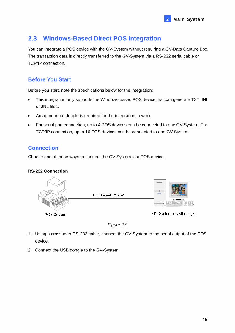
Connection Choose one of these ways to connect the GV-System to a POS device. RS-232 Connection
Figure 2-9
1. Using a cross-over RS-232 cable, connect the GV-System to the serial output of the POS device.
2. Connect the USB dongle to the GV-System.
16
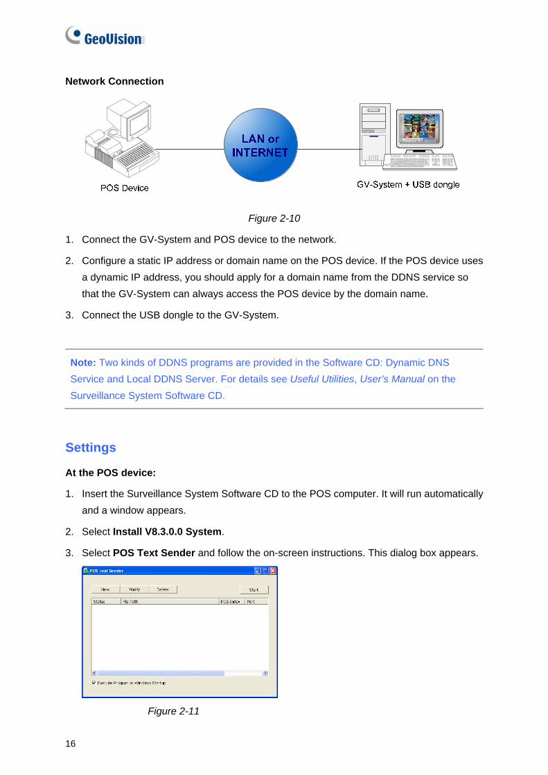
Network Connection
Figure 2-10
1. Connect the GV-System and POS device to the network.
2. Configure a static IP address or domain name on the POS device. If the POS device uses a dynamic IP address, you should apply for a domain name from the DDNS service so that the GV-System can always access the POS device by the domain name.
3. Connect the USB dongle to the GV-System.
Note: Two kinds of DDNS programs are provided in the Software CD: Dynamic DNS Service and Local DDNS Server. For details see Useful Utilities, User’s Manual on the Surveillance System Software CD.
Settings
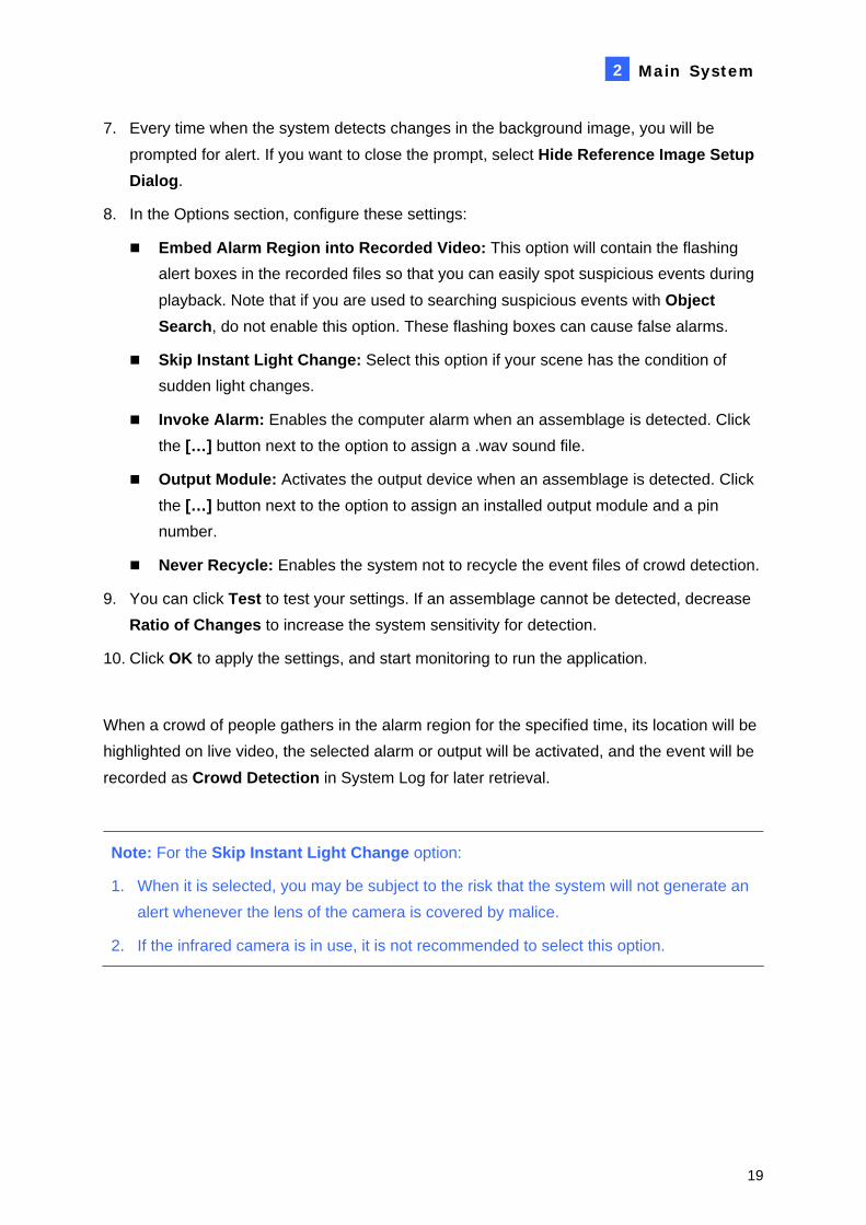
At the POS device:
1. Insert the Surveillance System Software CD to the POS computer. It will run automatically and a window appears.
2. Select Install V8.3.0.0 System.
3. Select POS Text Sender and follow the on-screen instructions. This dialog box appears.
Figure 2-11

Main System
17
2
4. Click the New button. This dialog box appears.
Figure 2-12
Printer Type: Select the type of the POS device: Serial Port or TCP/IP Port.
File Path: Locate the data file to be transferred to GV-System.
POS Num: Number the POS device.
COM Port: Select the COM port that is used in connection with GV-System.
The parameter/IP address button:
For the serial type of POS device, click this button to configure Baud Rate, Data Bits, Parity and Stop Bits of the POS device.
For the TCP/IP type of POS device, click this button to configure Device Port and Password to match those of the GV-System.
5. Click Add to apply the settings.
6. In the POS Text Sender dialog box, the POS device is added to the connection list. Click Start to start the connection. You can also minimize the dialog box to the notification area
.
At the GV-System:
It is required to insert an appropriate dongle to the GV-System for this integration to work.
To set up a POS device in GV-System, see Setting a POS Device, POS Application, User’s Manual on the Surveillance System Software CD.
Note: The maximum data size of each transaction to be transferred to a GV-System is 100 KB. When the data size of a transaction exceeds the limit, only the latest data will be transferred and displayed at the GV-System.

18
2.4 Crowd Detection Crowd detection is used to generate an alert when a crowd of people gathers in a specified area and exceeds the defined threshold.
Note: This function is only available when an AVP dongle is used. Up to 16 cameras can be configured for this application.
1. On the main screen, click Configure, click Advanced Video Analysis, and select Crowd Detection Setting.
2. Select the desired camera(s) to be configured, and click Configure. This dialog box appears.
Figure 2-13
3. Select a camera from the Camera Selection drop-down list.
4. By default the whole camera view is set to be the alarm region. Click the button to
clear the default setting. Click the button to freely draw the alarm region. To cancel the previously drawn area, click the button.
5. Select Ratio of Changes in the defined alarm region to activate the alarm. The smaller the ratio of changes, the more sensitive the system is for changes in the camera view.
6. Specify Tolerance Time of Alarm in seconds that allows a crowd to stay before an alarm condition is activated.
Main System
19
2
7. Every time when the system detects changes in the background image, you will be prompted for alert. If you want to close the prompt, select Hide Reference Image Setup Dialog.
8. In the Options section, configure these settings:
Embed Alarm Region into Recorded Video: This option will contain the flashing alert boxes in the recorded files so that you can easily spot suspicious events during playback. Note that if you are used to searching suspicious events with Object Search, do not enable this option. These flashing boxes can cause false alarms.
Skip Instant Light Change: Select this option if your scene has the condition of sudden light changes.
Invoke Alarm: Enables the computer alarm when an assemblage is detected. Click the […] button next to the option to assign a .wav sound file.
Output Module: Activates the output device when an assemblage is detected. Click the […] button next to the option to assign an installed output module and a pin number.
Never Recycle: Enables the system not to recycle the event files of crowd detection.
9. You can click Test to test your settings. If an assemblage cannot be detected, decrease Ratio of Changes to increase the system sensitivity for detection.
10. Click OK to apply the settings, and start monitoring to run the application.
When a crowd of people gathers in the alarm region for the specified time, its location will be highlighted on live video, the selected alarm or output will be activated, and the event will be recorded as Crowd Detection in System Log for later retrieval.
Note: For the Skip Instant Light Change option:
1. When it is selected, you may be subject to the risk that the system will not generate an alert whenever the lens of the camera is covered by malice.
2. If the infrared camera is in use, it is not recommended to select this option.

20
2.5 Advanced Scene Change Detection Compared to Scene Change Detection that can only be applied in the indoor scenes, the advanced version of Scene Change Detection can be applied in the outdoor scenes with sudden light changes, thus avoiding false alarms. The Advanced Scene Change Detection detects and prevents any changes of scene, viewing angle or focus clearness made by malice.
Note:
1. This function is only available when an AVP dongle is used. Up to 16 cameras can be configured for this application.
2. It is highly recommended not to use Advanced Scene Change Detection and Scene Change Detection together.
1. On the main screen, click Configure, click Advanced Video Analysis, and select Advanced Scene Change Detection Setting.
2. Select the desired camera(s) to be configured, and click Configure. This dialog box appears.
Figure 2-14
3. Select a camera from the Camera Selection drop-down list, and configure these settings:
Mask Region: If necessary, mask off the area on the camera view where motion will be ignored.

Main System
21
2
Sensitivity: Adjusts detection sensitivity. The higher the value, the more sensitive the system is for changes in the camera view.
Tolerance Time of Alarm: Sets the duration of scene change before an alarm condition is activated.
Skip Instant Light Change: Select this option if your scene has the condition of sudden light changes. See the Note in 2.4 Crowd Detection.
Invoke Alarm: Enables the computer alarm when the scene change is detected. Click the […] button next to the option to assign a .wav sound file.
Output Module: Activates the output device when the scene change is detected. Click the […] button next to the option to assign an installed output module and a pin number.
Never Recycle: Enables the system not to recycle the event files of scene change.
4. You can click Test to test your settings. If the scene change cannot be detected, increase Sensitivity value to increase system sensitivity to changes in the camera view.
5. Click OK to apply the settings, and start monitoring to run the application.
When a scene change is detected in the camera view for the specified time, its location will be highlighted in live video, the selected alarm or output will be activated, and the event will be recorded as Advanced Scene Change in System Log for later retrieval.
22
2.6 Advanced Unattended Object Detection Compared to Unattended Object Detection that can only be applied in the indoor scenes, the advanced version of Unattended Object Detection can be applied in the outdoor scenes with sudden light changes, thus avoiding false alarms. The Advanced Unattended Object Detection can generate an alert when any unattended object stays within the camera view.
Note:
1. This function is only available when an AVP dongle is used. Up to 16 cameras can be configured for this application.
2. It is highly recommended not to use Advanced Unattended Object Detection and Unattended Object Detection together.
1. On the main screen, click Configure, click Advanced Video Analysis, and select Advanced Unattended Object Detection Setting.
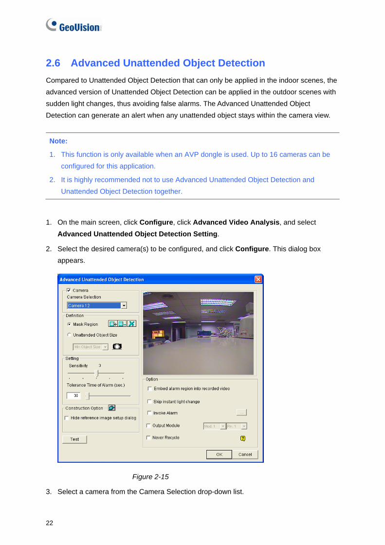
2. Select the desired camera(s) to be configured, and click Configure. This dialog box appears.
Figure 2-15
3. Select a camera from the Camera Selection drop-down list.

Main System
23
2
4. If necessary, use the Mask Region function to mask off the area on the camera view where motion will be ignored.
5. Select Unattended Object Size, and click the Camera icon to freeze the camera view.
6. Outline Min Object Size on the camera view, and select Max Object Size from the drop-down list and outline it on the camera view.
7. Select Sensitivity. The higher the value, the more sensitive the system is for changes in the camera view.
8. Specify Tolerance Time of Alarm in seconds that allows any unattended object to stay before an alarm condition is activated.
9. Every time when the system detects changes in the background image, you will be prompted for alert. If you want to close the prompt, select Hide Reference Image Setup Dialog.
10. In the Options section, configure these settings:
Embed Alarm Region into Recorded Video: This option will contain the flashing alert boxes in the recorded files so that you can easily spot suspicious events during playback. Note that if you are used to searching suspicious events with Object Search, do not enable this option. These flashing boxes can cause false alarms.
Skip Instant Light Change: Select this option if your scene has the condition of sudden light changes. See the Note in 2.4 Crowd Detection.
Invoke Alarm: Enables the computer alarm when an assemblage is detected. Click the […] button next to the option to assign a .wav sound file.
Output Module: Activates the output device when an assemblage is detected. Click the […] button next to the option to assign an installed output module and a pin number.
Never Recycle: Enables the system not to recycle the event files of crowd detection.
11. You can click Test to test your settings. If the unattended object cannot be detected, increase Sensitivity value to increase system sensitivity to changes in the camera view.
12. Click OK to apply the settings, and start monitoring to run the application.
When any unattended object is detected in the camera view for the specified time, its location will be highlighted in live video, the selected alarm or output will be activated, and the event will be recorded as Advanced Unattended Object in System Log for later retrieval.

24
2.7 Advanced Missing Object Detection Compared to Missing Object Detection that can only be applied in the indoor scenes, the advanced version of Missing Object Detection can be applied in the outdoor scenes with sudden light changes, thus avoiding false alarms. The Advanced Missing Object Detection can generate an alert when any object disappears from the camera view.
Note:
1. This function is only available when an AVP dongle is used. Up to 16 cameras can be configured for this application.
2. It is highly recommended not to use Advanced Missing Object Detection and Missing Object Detection together.
1. On the main screen, click Configure, click Advanced Video Analysis, and select Advanced Missing Object Detection Setting.
2. Select the desired camera(s) to be configured, and click Configure. This dialog box appears.
Figure 2-16
3. Select a camera from the Camera Selection drop-down list.

Main System
25
2
4. Click the button to outline the regions on the objects you want to detect. To cancel the previously drawn area, click the button.
5. Select Sensitivity. The higher the value, the more sensitive the system is for changes in the camera view.
6. Specify Tolerance Time of Alarm in seconds that allows any object missing before an alarm condition is activated.
7. Every time when the system detects changes in the background image, you will be prompted for alert. If you want to close the prompt, select Hide Reference Image Setup Dialog.
8. In the Options section, configure these settings:
Embed Alarm Region into Recorded Video: This option will contain the flashing alert boxes in the recorded files so that you can easily spot suspicious events during playback. Note that if you are used to searching suspicious events with Object Search, do not enable this option. These flashing boxes can cause false alarms.
Skip Instant Light Change: Select this option if your scene has the condition of sudden light changes. See the Note in 2.4 Crowd Detection.
Invoke Alarm: Enables the computer alarm when an assemblage is detected. Click the […] button next to the option to assign a .wav sound file.
Output Module: Activates the output device when an assemblage is detected. Click the […] button next to the option to assign an installed output module and a pin number.
Never Recycle: Enables the system not to recycle the event files of crowd detection.
9. You can click Test to test your settings. If the missing object cannot be detected, increase Sensitivity value to increase system sensitivity to changes in the camera view.
10. Click OK to apply the settings, and start monitoring to run the application.
When any object, which you have outlined the regions for, disappears from the camera view for the specified time, its location will be highlighted in live video, the selected alarm or output will be activated, and the event will be recorded as Advanced Missing Object in System Log for later retrieval.

26
2.8 Single Camera Tracking Single Camera Tracking can track a moving object using only one PTZ camera. When an object moves within the view of camera, the PTZ camera will follow its movement. When the object is out of view, the PTZ camera can be set to return its designated position. The certified PTZ cameras for this feature include:
Brand / Model Canon VC-C4 Pelco Spectra III
Dyna Color D7722 Sensormatic Ultra IV
Lilin 7000NF SONY EVI D-100
Messoa SDS730 StorVision PTZ
Note the feature also supports the certified PTZ cameras connected from GV-Video Server and GV-Compact DVR.
Adding a PTZ Camera Before setting the tracking function, add the PTZ camera to the system.
1. Click the Configure button, select General Setting, and select System Configure. The System Configure dialog box appears.
2. In the PTZ Control section, select PTZ Device Setup and select the PTZ camera from the drop-down list.
3. Click the button. A setup dialog box appears.
4. Select Activate.
5. Select Object Tracking Only. Note if you want to configure the preset points, first select Normal and configure presets from the PTZ control panel on the screen. After setup, select Object Tracking Only here.
6. Specify COM port, Baud Rate and Speed of the PTZ camera.
7. Click OK to apply the settings.
Setting PTZ Tracking
1. Click the Configure button, select Video Analysis, select Object Tracking Application, select Object Tracking Setup and click the Single Camera Tracking tab. This dialog box appears.

Main System
27
2
Figure 2-17
2. Select Enable Tracking. The PTZ Selection dialog box appears.
3. Select the specific camera and its hardware address, and click OK.
4. Select the corresponding camera view from the PTZ Selection drop-down list.
5. Click the button to adjust the direction and zoom level of the camera.
6. Use the mouse to outline the maximum and minimum object size for tracking on the image. Every time when you finish the outlining, you will be prompted to enter Maximum Object Size or Minimum Object Size.
7. To set the camera to return to home position or a preset when it remains stationary for a certain time, specify Idle Mode and Idle Time in seconds. Note that your camera should support the home position and the preset should be configured in the system ahead (see Step 5 in Adding PTZ Camera topic earlier).
8. Click Test. Move an object through the view of camera and its movement should be tracked. If not, increase Sensitivity value to increase system sensitivity to motion in the camera view.
9. Click OK to apply the settings.
Activating PTZ Tracking After above settings, you can start the Single Camera Tracking. Click the Configure button, select Video Analysis, select Object Tracking Application, and click Object Tracking Start.

28
2.9 PTZ Tour Schedule for Idle Protection When the PTZ camera remains stationary for a certain time, the camera will start the defined behaviors, such as activating the auto pan or returning the designated preset, in the defined time frames.
1. Click the Configure button, select Accessories and click Camera Mapping PTZ Dome. This dialog box appears.
Figure 2-18
2. Select the camera channel.
3. Select the PTZ device connected to the camera channel.
4. If you have two identical PTZ cameras set in the system, you may use the Address drop-down list to choose the one with the correct address.
5. Select PTZ Inactivity.
6. Set the idle time after which to start to the protection mode.
7. Select Tour Schedule and click the Setting button. This dialog box appears.
Figure 2-19

Main System
29
2
8. Select Span 1, specify a period of time, and select a camera behavior to be activated during the defined time period.
9. Set another span.
10. If you want to apply a different setting to weekends, select Weekend Apply and select a camera behavior. And define whether the weekend includes Saturday or not.
11. Click OK to apply the settings.
Note: It is required to set more than one span so that a specified camera behavior will only run in the defined time frame. Otherwise, you can select the Auto, Preset or Multi Position Tour option (see Figure 2-18) to configure the idle protection.
2.10 Turbo Mode Turbo mode allows recording at the highest speed that GV-Combo A Card (GV-1120A, GV-1240A and GV-1480A) can provide at the VGA and DI resolutions.
Comparison for GV-Combo Card and GV-Combo A Card
Total Recording Rate (NTSC/PAL)
GV-1480 GV-1480A GV-1240 GV-1240A GV-1120 GV-1120A
VGA 120 / 100 fps 240 / 200 fps 120 / 100 fps 120 / 100 fps 80 / 72 fps 80 / 72 fps
D1 120 / 100 fps 240 / 200 fps 120 / 100 fps 120 /100 fps 80 / 72 fps 80 / 72 fps
Turbo VGA 416 / 400 fps 240 / 200 fps 120 / 100 fpsTurbo D1 352 / 320 fps 240 / 200 fps 120 / 100 fps
Note: When Turbo Mode is activated, the DSP (Real-Time Display) and TV-Out functions will be disabled.

30
System Requirements Following is the basic system requirements to activate the turbo mode. Video Capture Card CPU RAM GV-1120A x 1 Pentium 4, 3.0 GHz Dual Core
GV-1240A x 1 Core 2 Duo, 3.0 GHz
GV-1480A x 1 Core 2 Quad, 2.4 GHz
2 x 512 MB Dual Channels
GV-1120A x 2 Core 2 Quad, 2.4 GHz
GV-1240A x 2 Core 2 Quad, 2.8 GHz
GV-1480A x 2 Core i7, 920, 2.66 GHz
2 x 1 GB Dual Channels
Activating Turbo Mode
1. Click Configure, select A/V Setting and select Video Source. This dialog box appears.
Figure 2-20
2. Use the drop-down list to select the Video Resolution. If D1 or VGA resolution is selected, the Turbo mode option appears.
3. Select Turbo mode, and click OK.
4. You will be prompted to restart the GV-System. Restart the GV-System to take effect.

Main System 2
2.11 Overlaying Input Name onto Screen upon Alarm Events You can overlay the name of input device on live video for alert or save it to video files whenever the input is triggered.
1. To map cameras to input devices, click Configure on the main screen, click Accessories, select I/O Application, and select I/O Application Setting.
2. In the I/O Application dialog box, select Input Overlay and click Setup in the I/O Overlay section. This dialog box appears.
Figure 2-21
3. Use the drop-down lists to select the input module and pin number, and then select the cameras associated with the input device.
4. To overlay the name of triggered input onto the screen or save it to video file, click the Configure button on the main screen, select General Setting, and select Text Overlay Setting. This dialog box appears.
Figure 2-22
31

32
5. Select Print on screen (Only for I/O alarm) or Print on video file. You can also select the position of the name stamp on the screen. For details, see Superimposing POS Data onto Camera Screen, Chapter 7 in User’s Manual on the Surveillance System Software CD.
Note: Up to 5 input names can be stamped on each channel when inputs are triggered.
2.12 Lost Signal Alarm An output alarm can be generated when the video connection is discontinued or video signal is lost.
1. On the main screen, click Configure, click Accessories, click I/O Application and then select I/O Application Setting. This dialog box appears.
Figure 2-23
2. Select Video Lost / Connection Lost Trigger Output, and then specify the desired camera and its corresponding output module for alarm.

Main System
33
2
2.13 Colorful Mode
You can enhance the coloring of live video to have more vivid and saturated images. Note this function does not affect the original files.
Follow the steps below to close DirectDraw Overlay before applying the Colorful Mode since the two features cannot be run together.
For the users of GV-600, GV-650 and GV-800 Card:
1. Click the Configure button, clear the selection of Enable DirectDraw Overlay, and restart the main system.
2. To access the Colorful Mode, click the Configure button, select Tools, select DirectDraw Configuration and select Use Colorful Mode. Then restart the main system for the mode to take effect.
For the users of GV-1120, GV-1240, GV-1480, GV-2004 and GV-2008 Card:
1. Click the Configure button, select Accessories, select DSP Spot Monitor, select Spot Monitor Setup, select Use DSP as Spot Monitor at next startup, and restart the main system.
2. Click the Configure button, clear the selection of Enable DirectDraw Overlay, and restart the main system.
3. To access the Colorful Mode, click the Configure button, select Tools, select DirectDraw Configuration and select Use Colorful Mode. Then restart the main system for the mode to take effect.

34
2.14 Support for New PTZ Cameras In V8.3, more PTZ cameras are supported:
Brand Model COP 15-CD53W (Pelco D)
PTC-200C
PTC-400C Elmo PTC-1000
Eyeview T2-SA27
JVC TK-C686E
Lilin Lilin PIH-820
Nanwang Nanwang NVD 2300PNT (firmware version 4.1)
StorVision StorVision
360 Vision ViD-18COP04 (Pelco P)
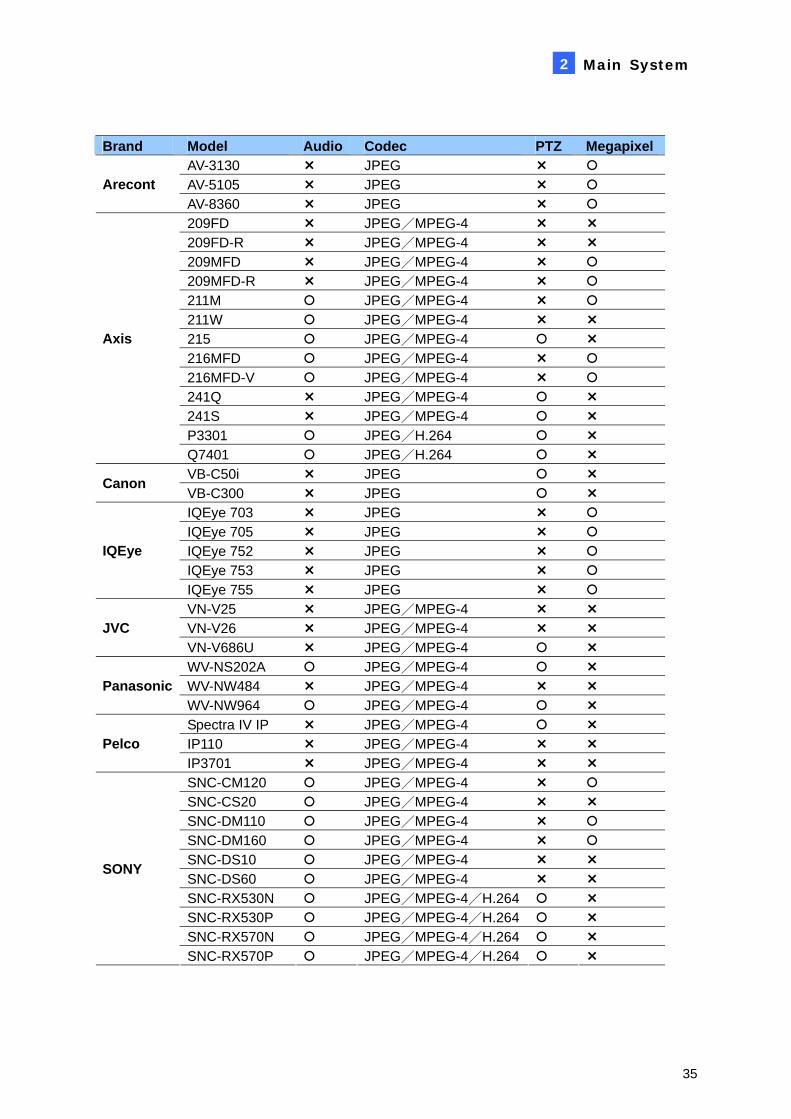
2.15 Support for New IP Cameras In V8.3, more third-party IP cameras are supported:
Audio: A “ ” mark indicates the GV-System supports the two-way audio communication with the device; otherwise, a “ ” mark is given.
Codec: You can find what video codecs these models support.
PTZ: An IP device with PTZ function is marked with “ ”; otherwise, a “ ” mark is given.
Megapixel: An IP device supporting megapixel resolution is marked with “ ”; otherwise, a “ ” mark is given.
Main System
35
2
Brand Model Audio Codec PTZ Megapixel AV-3130 JPEG AV-5105 JPEG Arecont AV-8360 JPEG 209FD JPEG/MPEG-4 209FD-R JPEG/MPEG-4 209MFD JPEG/MPEG-4 209MFD-R JPEG/MPEG-4 211M JPEG/MPEG-4 211W JPEG/MPEG-4 215 JPEG/MPEG-4 216MFD JPEG/MPEG-4 216MFD-V JPEG/MPEG-4 241Q JPEG/MPEG-4 241S JPEG/MPEG-4 P3301 JPEG/H.264
Axis
Q7401 JPEG/H.264 VB-C50i JPEG Canon VB-C300 JPEG IQEye 703 JPEG IQEye 705 JPEG IQEye 752 JPEG IQEye 753 JPEG
IQEye
IQEye 755 JPEG VN-V25 JPEG/MPEG-4 VN-V26 JPEG/MPEG-4 JVC VN-V686U JPEG/MPEG-4 WV-NS202A JPEG/MPEG-4 WV-NW484 JPEG/MPEG-4 Panasonic WV-NW964 JPEG/MPEG-4 Spectra IV IP JPEG/MPEG-4 IP110 JPEG/MPEG-4 Pelco IP3701 JPEG/MPEG-4 SNC-CM120 JPEG/MPEG-4 SNC-CS20 JPEG/MPEG-4 SNC-DM110 JPEG/MPEG-4 SNC-DM160 JPEG/MPEG-4 SNC-DS10 JPEG/MPEG-4 SNC-DS60 JPEG/MPEG-4 SNC-RX530N JPEG/MPEG-4/H.264 SNC-RX530P JPEG/MPEG-4/H.264 SNC-RX570N JPEG/MPEG-4/H.264
SONY
SNC-RX570P JPEG/MPEG-4/H.264

36
2.16 Improved Support for IP Video Devices
Easy access to configuration interfaces of IP devices.
You can access the configuration interface of the connected IP device with one-click ease from GV-System.
In the Hybrid Video Server dialog box, click one listed camera, and select Remote camera setting. You will be linked to the configuration interface of that IP device.
Figure 2-24
PTZ Idle Protection support for IP devices.
You can now configure the PTZ idle protection for the connected IP camera with PTZ functions. For details, see PTZ Idle Protection, Chapter 1, User’s Manual on the Surveillance System Software CD.
Figure 2-25

Main System
37
2
Adjustable recording frame rate for IP cameras.
When configuring IP cameras, you can set the recording frame rate to meet your bandwidth requirements.
Figure 2-26
Maximum recording frame rate: This option is available when the recording codec of the IP camera is set to JEPG. Select the frame rate from 1 to 30 fps.
Record key frame only: This option is available when the recording codec of the IP camera is set to MPEG4 or H.264. You can choose to record key frames instead of all frames. This option is related to the GOP setting if it is available on your IP camera. For example, if the GOP value is set to 30, there is only one key frame among 30 frames.
For the GOP setting, see GV-Video Server and GV-IP Camera User’s Manuals.
H.264 codec support for third-party IP devices.
This version supports video streaming of H.264 from third-party IP devices.

38
2.17 Other Enhanced Features
Up to 64 PTZ preset points and addresses can be supported.
Up to 64 PTZ preset points and addresses are supported. Note these features are available on the PTZ cameras that have equivalent capability.
Up to 16 storage groups can be created.
The maximum number of storage groups you can create is increased from 8 to 16.
Triggering recordings on multiple cameras upon input trigger.
When the input device is triggered, it can now trigger recordings on more than one camera.
Figure 2-27

ViewLog
39
3
3. ViewLog This chapter introduces the new features of ViewLog.
3.1 GPS Tracks Playback
Since GV-Video Server and GV-Compact DVR support GPS tracking, GPS tracks are recorded along with video on these devices. On the GV-System, you can retrieve GPS tracks from these devices and play them back in Google Maps, Microsoft Virtual Earth and even user-defined maps.
1. GV IP device must allow the remote access with ViewLog Server activated. See
ViewLog Server in its user’s manual.
2. To remotely connect to GV IP device from GV-System, click the Tools button and select Remote ViewLog Service. The Connect to Remote ViewLog Service dialog box appears.
3. Enter the connection information of GV IP device, and click Connect. Once the connection is established, the video events will be displayed on the Video Event list.
4. To select a map API (Application Program Interface), click the Tools button and click Select Map API. This dialog box appears.
Figure 3-1
5. In Please Select a Map API, select a Map API. For Google Maps, you need to sign up for an API key from Google website (http://code.google.com/apis/maps/signup.html), and enter the API key in the Please enter the map authorization key or license key field.

40
6. To play back GPS tracks, click the Tools button and select Display GIS Window. The first-time user will be prompted for a License Agreement. Read through the license terms before you click I understand and agree to continue.
7. Select the events with GPS tracks from the Video Event list, select the desired video mode, and click the Play button to start.
Figure 3-2
Note:
1. If you like to use the maps created yourself, overwrite the files at :\GV folder\GIShtm-User, and select User Defined from the “Please Select a Map API” drop-down list (Figure 3-1).
2. You can also attach the USB mass storage device with the recorded files to GV-System for playback. For this kind of playback, first load the data to ViewLog by following the instructions in the section of Playback Using USB Mass Storage Device in GV-Video Server or GV-Compact DVR User’s Manual. Then follow Steps 4-7 above to play back GPS tracks.

ViewLog
41
3
3.2 Video Effects Applied on Multiple Channels
Now you can apply video effects to more than one channel. The applied video effects include contrast, brightness, light enhancement, equalization, sharpen, smooth, gray, defog and stabilizer.
3.3 Increased Number of Multi Views The ViewLog player allows you to configure up to 10 sets of Multi Views for simultaneous playback of multiple camera recordings. And in each Multi View you can select the maximum of 16 cameras for playback.
1. To configure the Multi View, click the Setting button, click the Multi View tab, and drag up to 16 cameras from the right panel to the desired number of Multi View.
Figure 3-3
2. To switch among Multi Views, click the View Mode button, click Multi View and select the desired one.

42
3.4 Increased Number of Quad Views The ViewLog player allows you to configure up to 10 sets of Quad Views for simultaneous playback of up to 4 camera recordings.
1. To configure the Quad View, click the Setting button, click the Quad View tab, and drag up to four cameras from the right panel to the desired number of Quad View.
Figure 3-4
2. To switch among Quad Views, click the View Mode button, click Quad View and select the desired one.
3.5 Video Color Enriched for Playback
During playback of video files, you can enhance the coloring to have more vivid and saturated images. Note this function does not affect the original files.
To access this function, click the Setting button, click the Display tab, select Apply Scaling render, click the arrow button and select Use Colorful Mode. Restart the ViewLog for the mode to take effect.

WebCam
43
4
4. WebCam This chapter introduces the new features of WebCam Server.
4.1 Multicast and Audio Broadcast Multicast sends a single video and audio stream to multiple hosts using the same multicast IP address and within the same LAN. Multicast can greatly increase the bandwidth efficiency when multiple hosts access the same video and audio stream. As for audio broadcast, it allows a host to speak to other hosts using the same broadcast IP address and within the same LAN.
Note: To perform multicast within a LAN with different IP sequence numbers, e.g. 192.168.1.1 and 192.168.2.1, you need a router supporting Multicast Pass Through function.
Configuring Multicast and Broadcast Settings On GV-System, you can configure two settings. One is to allow remote access to multicast delivered from the GV-System; the other is to receive audio broadcast from other host. Activate Multicast
1. Click the Network button, select WebCam Server and click the Multicast tab. This dialog box appears.
Figure 4-1
44
2. Select Multicast to enable the multicast settings.
3. By default the IP address is 224.1.1.2 and port number is 8300 to send the video and audio stream. Modify default values if necessary.
4. Optionally specify a Password for hosts to access multicast.
5. Click the Camera and Audio buttons to select which camera and audio is accessible through multicast.
Receive Audio Broadcast
6. If you like to receive audio broadcast from other host on the GV-System, select Receive broadcast audio. By default the IP address is 224.1.1.3 and port number is 8400 to receive broadcasting. Modify default values if necessary.
7. Click OK to start the WebCam server.
Now the GV-System can not only deliver the multicast stream but receive audio broadcast from other host. Ensure a speaker is installed on the GV-System.
Sending Audio Broadcast You can start audio broadcasting on any host by installing the following program.
1. Ensure a microphone is properly installed.
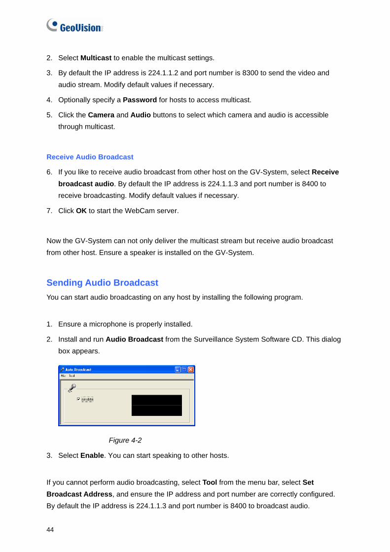
2. Install and run Audio Broadcast from the Surveillance System Software CD. This dialog box appears.
Figure 4-2
3. Select Enable. You can start speaking to other hosts.
If you cannot perform audio broadcasting, select Tool from the menu bar, select Set Broadcast Address, and ensure the IP address and port number are correctly configured. By default the IP address is 224.1.1.3 and port number is 8400 to broadcast audio.

WebCam
45
4
Receiving Multicast and Audio Broadcast
To remotely receive multicast and audio broadcast, there are three methods: use the multicast program included in the software CD, through the web interface of WebCam server, and through the Multi View of WebCam server.
Use Multicast Program on Software CD
1. Install and run Multicast from the Surveillance System Software CD. This dialog box appears.
Figure 4- 3
2. The host(s), using the same multicast IP address within the same LAN, is displayed automatically on the host list. If you cannot see any host displayed, click the Configure button, select General Setup, and ensure the relevant IP address and port number are correctly configured.
3. Drag the desired cameras to the screen for display. If the host has already set a password, you will be promoted to enter it at this step.
4. To receive audio broadcast, first ensure a speaker is properly installed on this computer. Click the Configure button, select General Setup, select Receive Broadcast Audio, and ensure the broadcast IP address and port number are correctly configured, and click OK.
5. To save the current settings of screen division and camera display for future use, click the Configure button, select Video List Setup, and select Export. You can also select Import to apply the pre-defined settings.
Host List
Configure Button

46
Through the Web Interface of WebCam
1. Type the IP address or the domain name of GV-System on the IE browser. Enter ID and password to log into the GV-System. When the connection is established, the Single View page appears.
2. On the left panel, select Live View and select Multicast. The Multicast Viewer (Figure 4-2) appears.
3. To receive multicast and audio broadcast, follow Steps 2-4 in the section of Use Multicast Program on Software CD above.
Through the Multi View of WebCam
1. Click the Multicast button on the Multi View screen. The Multicast Viewer (Figure 4-2) appears.
Figure 4-4
2. To receive multicast and audio broadcast, follow Steps 2-4 in the section of Use Multicast Program on Software CD above.

WebCam
47
4
4.2 WebCam Enhancements
• POS/Wiegand Live View. On the Single View, the POS/Wiegand option is added, allowing you to view POS transactions or cardholder data along with live video. If the monitoring is activated on GV-System, you can access instant playback by double-clicking any transaction items or cardholder data.
Figure 4-5
• New Resolution. Both Single View and Multi View support two new resolutions of 80 x 60 and 160 x 120. Note when any of them is selected, the features of Visual Automation, Visual PTZ, PIP and PAP will be unavailable because of small video size.
• DST Rollback Events available on Event List Query. On the Event List Query, you have the option to search the video events recorded during the Daylight Saving Time period.
Figure 4-6

48
• New user interface for Remote Playback (RPB): The new user interface makes it very easy to remotely play back the desired recording. Additionally, you can right click on the image to have more features, such as changing playback mode and turning on audio if available.
Figure 4-7

WebCam
49
4
4.3 BlackBerry Support
With the BBView phone application, you can remotely view live video, force output devices to be triggered, and start and stop monitoring from your BlackBerry phone.
Installing BBView
1. Insert the Surveillance System Software CD to the computer. It runs automatically and a window pops up.
2. Click Install V 8.3.0.0 System
3. Select BlackBerry Smartphone Viewer, and follow the on-screen instructions. The default installation directory is C:\BlackBerry Smartphone Viewer.
4. Through the synchronization program such as Desktop Manager, install BBView.alx from the created installation directory to your BlackBerry. Consult the BlackBerry user’s manual for how to install a program to the phone.
Activating the BBView Function To allow remote access to GV-System, follow these steps:
1. Click the Network button, select WebCam Server, click the JPG tab, and select Create JPEG/GIF file(s).
2. Click the Mobile tab, and activate the settings of communication ports.
3. Click OK to start the WebCam server.
Connecting to GV-System To connect your BlackBerry phone to GV-System, follow these steps:
1. To activate TCP/IP connection on your BlackBerry, check your service provider for the correct APN (Access Point Name) and configure the APN on your phone. (e.g. go to Options and TCP).
2. To connect to GV-System, select the BBView application installed on your phone, and select Create Live Connection. The Login screen appears.
3. Enter the IP address, port number, username and password to log into GV-System. The default port value is 8866.
4. Select Connect to start.

50
5. Center V2 This chapter introduces the new features of Center V2.
5.1 Unlimited Log Retention Time You can keep log data for an unlimited amount of time by not specifying the number of keep days. To access the feature, click the Preference Settings button, select Event Log Settings, and clear the selection of Keep Days.
Figure 5-1

Center V2
51
5
5.2 Controlling I/O Devices of GV IP Devices Without interrupting monitoring, the Center V2 operator can arm or disarm the physical I/O devices from a client GV IP device, including GV-Video Server, GV-IP Camera and GV-Compact DVR.
1. In the Subscriber List, right-click one GV IP device subscriber, and select I/O Enable Setting. This dialog box appears.
Figure 5-2
2. To arm the I/O devices, select the desired ones. To disarm the I/O devices, clear the selections or leave the options empty.
Note: The function is only available for the IP devices of these firmware versions:
GV-Compact DVR: Firmware V1.43 or above
GV-IP Camera: Firmware V1.05 or above
GV-Video Server: Firmware V1.45 or above

52
5.3 Assigning a Subscriber to Another Center V2 You can assign one subscriber to another Center V2 without ending the current connection. For this function to work, the subscriber must also use GV-System V8.3 or later.
Note: The function is not available for the client GV-Video Server, GV-Compact DVR and GV-IP Camera.
1. In the Subscriber List, right-click the desired subscriber, and select Dispatch to other Center V2. This dialog box appears.
Figure 5-3
2. Type the IP address of another Center V2. The default port value is 5547. Modify it if necessary.
3. Click OK. The subscriber will be therefore assigned to the designated Center V2. In the Subscriber List of the local Center V2, that subscriber’s icon shows offline.

Center V2
53
5
5.4 Simple Audio and Microphone Panels To facilitate the communication between the Center V2 operator and subscribers, the simple control panels are provided for better control. For this function to work, the subscriber must use GV-System V8.0 or later.
1. To speak to a connected subscriber, right-click that subscriber in the Subscriber List or one of its channels on the window, and select Microphone. This panel appears.
Figure 5-4
2. To access the audio from a connected camera, right-click that camera in the Subscriber List or on the window, and select Audio. This panel appears.
Figure 5-5
3. To switch to another subscriber, click the subscriber icon in the panel, type that ID in the Search Account dialog box and then click GO.
Note: To enable this two-way communication, the subscriber must grant the privilege by activating the Allow Audio-Out to Center V2 and Accept Audio-In from Center V2 functions. See Advanced Settings, 1.5 Connecting to Center V2 in GV-CMS Series User’s Manual.
Subscriber’s ID
Microphone status

54
5.5 Fast Backup and Restore (FBR) Support With the Fast Backup and Restore program, you can not only change interface skin, but also back up and restore configurations of Center V2.
Note: This function only supports Center V2 version 8.3 and later.
Figure 5-6
For details, see B. Fast Backup and Restore in Appendix in CMS User’s Manual.

Center V2
55
5
5.6 Support for New GV-IO Boxes Center V2 version 8.3 is compatible with new I/O devices: GV-IO Box 4, GV-IO Box 8 and GV-IO Box 16. These devices offers options of 4, 8 and 16 relay outputs that can be connected directly to the Center V2 computer and used as auxiliary output devices to alert the operator.
1. To configure any of these devices at the Center V2 site, click the Preference Settings button on the Center V2 window and select I/O Device.
Figure 5-7
2. In the Device field, select GVIO-USB(4) for GV-IO Box 4, GVIO-USB(8) for GV-IO Box 8, or GVIO-USB(16) for GV-IO Box 16.
For details, see 1.14 Output Alerts in CMS User’s Manual and Installation Guide V8.3.

56
6. Dispatch Server This chapter introduces the new feature of Dispatch Server.
6.1 Unlimited Log Retention Time You can keep log data for an unlimited amount of time by not specifying the number of keep days. To access the feature, click the Sever Setting button on the toolbar, and then clear the selection of Keep Days.
Figure 6-1
6.2 Fast Backup and Restore (FBR) Support You can use the Fast Backup and Restore program to back up and restore configurations of Dispatch Server. For details, see the same feature in Chapter 5 Center V2 or B. Fast Backup and Restore in Appendix in CMS User’s Manual.
Note: This function only supports Dispatch Server version 8.3 and later.

Vital Sign Monitor
57
7
7. Vital Sign Monitor (VSM) This chapter introduces the new features of Vital Sign Monitor (VSM).
7.1 Unlimited Log Retention Time You can keep log data for an unlimited amount of time by not specifying the number of keep days. To access the feature, click Configure on the menu bar, select Event Log Settings, and clear the selection of Keep Days. Refer to Figure 5-1 in Chapter 5 Center V2.
7.2 Controlling I/O Devices of GV IP Devices Without interrupting monitoring, the VSM operator can arm or disarm the physical I/O devices from a client GV IP device, including GV-Video Server, GV-IP Camera and GV-Compact DVR. To access the feature, right-click one GV IP device subscriber and select View Subscriber Status. The Subscriber Status dialog box will appear. Click the Enable/Disable I/O button for setup. For details, see the same feature in Chapter 5 Center V2.
7.3 Fast Backup and Restore (FBR) Support You can use the Fast Backup and Restore program to back up and restore configurations of VSM Server. For details, see the same feature in Chapter 5 Center V2 or B. Fast Backup and Restore in Appendix in CMS User’s Manual.
Note: This function only supports VSM Server version 8.3 and later.

58
7.4 Support for New GV-IO Boxes VMS version 8.3 is compatible with new I/O devices: GV-IO Box 4, GV-IO Box 8 and GV-IO Box 16. These devices offers options of 4, 8 and 16 relay outputs that can be connected directly to the VSM computer and used as auxiliary output devices to alert the operator. Refer to the same feature in Chapter 5 Center V2.
7.5 Other Features
• Event Categories. To sort the events by their types, a list of categories is provided.
1. On the menu bar, click View, point to My Favorite Events, and select the desired event categories. These categories include System, Motion, Trigger, Connection, Alarm, Login/Logout, Wiegand Data, Device Lost and Offline Event.
2. Once you select the categories, the relevant tabs appear at the bottom of the Event List. Click the tab to view the events of that category.
Figure 7-1 Category tabs

Vital Sign Monitor
59
7
• Subscriber Status Indicator. In V8.3, an indicator is added to the Subscriber List to show the numbers of total subscribers and currently online subscribers.
Figure 7-2
• Automatic Insertion of ID and Camera Name to SMS Messages. The subscriber’s ID and camera name can be automatically inserted to your SMS message when it is sent out.
1. Click Configure on the window menu and select Notification. This dialog box appears.
Figure 7-3
2. Select an alert condition in the left column, select Send SMS Alerts, and then click Edit. This dialog box appears.
Figure 7-4
Number indicator
60
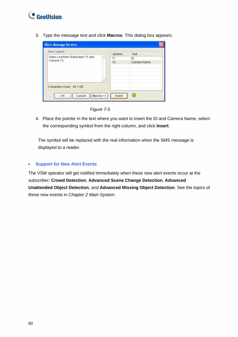
3. Type the message text and click Macros. This dialog box appears.
Figure 7-5
4. Place the pointer in the text where you want to insert the ID and Camera Name, select the corresponding symbol from the right column, and click Insert.
The symbol will be replaced with the real information when the SMS message is displayed to a reader.
• Support for New Alert Events
The VSM operator will get notified immediately when these new alert events occur at the subscriber: Crowd Detection, Advanced Scene Change Detection, Advanced Unattended Object Detection, and Advanced Missing Object Detection. See the topics of these new events in Chapter 2 Main System.

Control Center
61
8
8. Control Center This chapter introduces the new features of Control Center.
8.1 Support for New IP Cameras For the supported models, refer to 2.15 Support for New IP Cameras
8.2 Pop-Up Live View after Input Trigger In the I/O Central Panel, you can be alerted by a pop-up live video after an input device is triggered. Up to 16 live videos can be accessed simultaneously.
1. In the Advanced I/O List, right-click the window to create a group. For details, see Creating a Group for Cascade Triggers, Chapter 4 in the GV-CMS Series User’s Manual.
2. On the toolbar of I/O Central Panel, click the Configure button, select Panel Setting and click the Notify tab. This dialog box appears.
Figure 8-1
3. Specify the Maximum Number of Invoked Camera Views that can pup up at the same time when inputs are triggered. Note that the maximum number of popup videos is 16.
4. Select Enable digital input to invoke the associated camera to activate the function.

62
5. To map a camera to an input device, right-click an input device in the Advanced I/O List, and select Setting. This dialog box appears.
Figure 8-2
6. Select Associated Camera, assign a camera from the drop-down list, and select Digital Input Invokes the Associated Camera.
7. Click OK. When the input is triggered, the live video of its associated camera will pop up.
8.3 Controlling I/O Devices of GV IP Devices Without interrupting monitoring, the Control Center operator can arm or disarm the physical I/O devices from a connected GV IP device host, including GV-Video Server, GV-IP Camera and GV-Compact DVR. In the I/O Central Panel, right-click a GV IP device host and select I/O Enable Setting. For details, see the same feature in Chapter 5 Center V2.

Control Center
63
8
8.4 Matrix Enhancements
Increased Number of Displayed Matrix Views
Now you can display up to 6 Matrix views in 1 monitor or separate 6 monitors at a time. For the connection to up to 6 monitors, make sure your computer is equipped with 3 VGA cards.
QView for Channel Display on Another Monitor
If the Control Center is equipped with multiple monitors, you can use the QView feature to display a desired channel on another monitor screen.
1. Open the Matrix window, click the Configure button, and select QView. This dialog box appears.
Figure 8-3
2. Use the drop-down list to select a desired monitor.
3. Click one channel to be displayed on that monitor.
Figure 8-4
4. To switch to another channel, simply click another channel in the Matrix.

64
Automatic Channel Scan at Startup
Channels can be set for automatic scan when the Matrix is started.
To access this feature, open the Matrix window, click the Configure button, select System Configure, and select Auto scan at startup. Next time when the Matrix is started, it will automatically scan through channels.
Figure 8-5
Easy Assignment and Replacement of Camera Views
To add or replace one camera view in a Matrix view, simply drag the camera from the Group List to the desired channel position.
GV-Keyboard Support
You can use a GV-Keyboard for assistance in controlling a Matrix view. It is required to run the following program in the background while you use the GV-Keyboard with Matrix.
1. Run mcamctrl.exe from the Control Center program folder. This dialog box appears.
Figure 8-6

Control Center
65
8
2. In the Port field, select the COM port that the GV-Keyboard is connected to.
3. If you want to define the eight function keys on the GV-Keyboard for a quick control of Matrix, click a function key. This dialog box appears.
Figure 8-7
4. Select a function you want to assign to this function key.
5. If you set up multiple Matrix views and want to have a quick access, select Matrix Switch, and select a desired function including Previous Matrix, Next Matrix and Matrix 1 to Matrix 6.
6. Repeat Steps 3 and 4 to set up other function keys.
7. Click the Start Service button (see Figure 8-6). Now you can use the GV-Keyboard to control Matrix View.
For more details, see the GV-Keyboard User’s Manual.
Note: These four keys on the GV-Keyboard do not function at all when Matrix is in use:

66
Delayed Screen Notification of Video and Connection Lost
If video sources or connections tend to be interrupted, or you want to prevent the operator from knowing the broken connection, you can set the duration that the last frame remains on the screen to avoid the instant and frequent display of “Video Lost” or “Disconnect” messages.
To access this feature, open the Matrix window, click the Configure button, select System Configure and select Keep last frame when video lost or connect lost. In the Keep field, set the length of time that the last frame should remain on the screen after the video or connection is lost.
Figure 8-8

Control Center
67
8
8.5 Live View Enhancements
Codec Selection for IP Cameras Supporting Dual Streams
When the connected IP camera supporting dual streams, the Control Center allows you to switch the codec between MPEG4 and JEPG.
To select the codec, click the Change Size button on the toolbar of Live View.
Changing Cameras without Closing a Live View
A Change Camera button is added to the toolbar of Live View. To view another camera for live images, click the Change Camera button and select that camera.
Figure 8-9
8.6 Fast Backup and Restore (FBR) Support With the Fast Backup and Restore program you can not only change interface skin, but also back up and restore configurations of Control Center. For details, see the same feature in Chapter 5 Center V2 in this guideor B. Fast Backup and Restore in Appendix in CMS User’s
Manual.
Note: This function only supports Control Center version 8.3 and later.
Change another camera

68
8.7 VMD Enhancement In this version, the VMD (Video Motion Detection) supports the new AVP (Advanced Video Analysis) settings, including Crowd Detection, Advanced Unattended Objects Detection, Advanced Scene Change Detection and Advanced Missing Object Detection, for a pop-up alert. When these AVP events occur, the live video of related cameras will pop up in the VMD window.
1. In the Group List, right-click the desired camera in VMD Group, click Video Analysis, select the desired types of events that have been configured for this camera at the client GV-System. Note Motion Detection is selected by default.
2. By default each popup remains on screen for 60 seconds. To change the time length, click the Show System Menu button on the toolbar of VMD window, and select Event Popup. This dialog box appears.
Figure 8-10
3. Click in the desired Dwell Time column and specify the time length.
4. Click OK to apply the setting.
When the events occur at the GV-System site, the live video of associated cameras will pop up in the VMD window to alert the operator.

Remote E-Map
69
9
9. Remote E-Map The Remote E-Map includes the following new feature.
9.1 Simultaneous Display of Multiple Live Videos
Up to 16 live videos can be accessed simultaneously on the remote E-Map. On the E-Map, click the desired cameras to view live videos.

70
10. Authentication Server The Authentication Server includes the following new features.
10.1 Unlimited Log Retention Time
You can keep log data for an unlimited amount of time by not specifying the number of keep days.
To access the feature, click Log button, select Log Setup, and clear the selection of Keep Days. Refer to Figure 5-1 in Chapter 5 Center V2.

SMS Server
71
11
11. SMS Server This chapter introduces new features of SMS Server.
11.1 Unlimited Log Retention Time You can keep log data for an unlimited amount of time by not specifying the number of keep days. To access the feature, click the SMS Log Setting button, select SMS Log Setting, and clear the selection of Keep Days. Refer to Figure 5-1 in Chapter 5 Center V2.
11.2 Support for a New GPRS Modem
In V8.3, the SMS Server supports Wavecom GPRS modem.