new energy-efficient materials for the building envelope
TRANSCRIPT
Building and Environment, Vol. 20, No. 2, pp. 95~101, 1985. 0360-1323/85 $3.00 + 0.00 Printed in Great Britain. © 1985 Pergamon Press Ltd,
New Energy-efficient Materials for the Building Envelope
S. A. JUROVICS* C.-H. HOI" F. Y. SORRELLI"
An hour-by-hour thermal loads program, developed fiom N BSLD, has been embedded into a nonlinear optimization program. The resulting methodology is used to determine the optimal envelope properties-thickness, conductivity and heat capacity-of one or several layers in a composite wall. Optimal is defined here as the wall construction which produces minimum total heating plus cooling loads. All three properties may be subject to linear inequality constraints. Both a representative perimeter o, Oice in a building, and a small structure have been simulated under different climatic conditions. Values for conductivity and heat capacity have been derived which depict new materials; composite walls with these materials yield considerably lower heating plus cooling loads than with the initial typical wall design. The methodology has been verified by comparing initial and final loads with those computed using DO E-2.1B. It appears that the reported methodology may uncover a wide range of energy e Ofcient materials applicable to any type of building in any climatic region.
1. INTRODUCTION
ENERGY conservation in building is achieved by a variety of practices affecting the design, control system, and HVAC equipment. This paper concentrates on the first aspect, and reports upon research aimed at finding new building materials which permit a greater reduction in heating and cooling loads than can be achieved with conventional materials.
In 1978, Jurovics [ 1] reported a technique for determining the heat transfer properties of materials which reduce thermal loads; that technique has been applied here in a much broader manner than the earlier work. The methodology consists of using an hour-by-hour loads determination program to calculate the total heating plus cooling loads over some period of time. That total load constitutes a quantity to be minimized, and for that one employs a nonlinear optimization program. Length, conductivity and volumetric specific heat (or heat capacity) are three properties which may vary within a specified domain. The minimization of total load is achieved by finding optimal values for these properties within the constraint domain.
The optimization routine requires first partial deriva- tives of total load with respect to the properties being varied, and these are calculated concurrent with the load determination using analytic expressions [f].
The structure used in this analysis consists of both a one- zone representative office in a multi-storey building, and a one-zone floor in such a building. We seek in both cases to
*IBM Academic Information Systems, PO Box 26688, Raleigh, NC 27611, U.S.A.
t Department of Mechanical and Aerospace Engineering, North Carolina State University, Raleigh, NC 27695-7910, U.S.A.
95
find the optimal two-layer external wall. Future work may consider walls with three or more layers, fabrication of the materials derived, and construction questions arising from building with materials of these properties.
2. METHODOLOGY
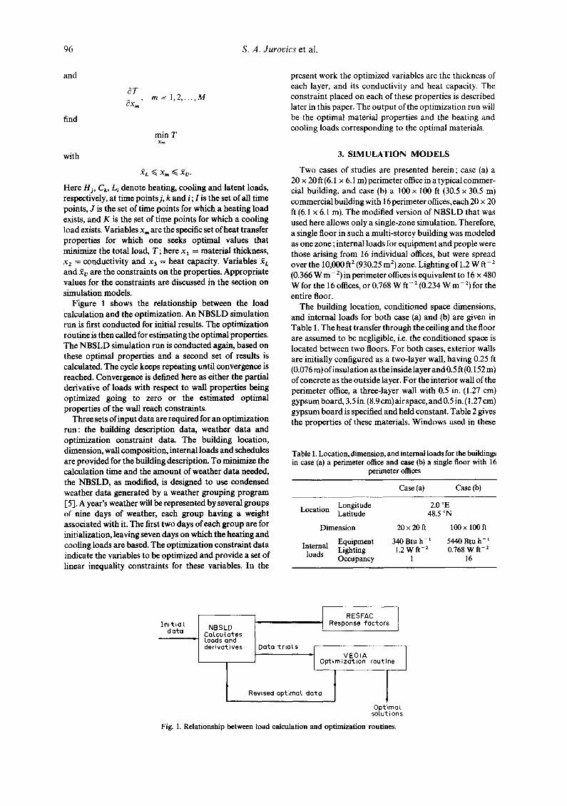
Optimization of the building envelope materials as conducted in this work involves two tasks : (1) calculation of building heating and cooling loads, and (2) optimiza- tion of material properties corresponding to currently calculated loads and their partial derivative. Figure 1 shows the relationship of these two tasks.
For the calculation of building loads, a computer program developed by the National Bureau of Standards--NBSLD [2J--was modified and used. The NBSLD handles transient heat conduction through the exterior wall by the response factor method. Modifications were made by the IBM Scientific Center at Los Angeles and include rewriting a restricted version of the program into the APL language [3] and inserting functions for computing the partial derivative of loads with respect to the properties being optimized Ell.
An optimization routine, VEO1A [4], available in the Harwell Subroutine Library is used for the second task. It minimizes a function of n independent variables subject to m linear inequality constraints. The calculated building loads and their partial derivative are taken by this routine as values of the function and its partial derivative. Estimated optimal properties are calculated and trans- mitted back to NBSLD for computing corresponding building loads. That is, given
T = E H j + ~ , C k + E L , j c J keK i¢I
96 S .A . durovics et al.
and
find
with
c~T c~xm' m = 1,2 . . . . . M
min T x m
XL ~ Xm ~ XU"
Here Hi, Ck, L~ denote heating, cooling and latent loads, respectively, at time points j, k and i; I is the set of all time points, J is the set of time points for which a heating toad exists, and K is the set of time points for which a cooling load exists. Variables x= are the specific set of heat transfer properties for which one seeks optimal values that minimize the total load, T; here xl = material thickness, x2 = conductivity and x3 = heat capacity. Variables ~L and ~v are the constraints on the properties. Appropriate values for the constraints are discussed in the section on simulation models.
Figure 1 shows the relationship between the load calculation and the optimization. An NBSLD simulation run is first conducted for initial results. The optimization routine is then called for estimating the optimal properties. The NBSLD simulation run is conducted again, based on these optimal properties and a second set of results is calculated. The cycle keeps repeating until convergence is reached. Convergence is defined here as either the partial derivative of loads with respect to wall properties being optimized going to zero or the estimated optimal properties of the wall reach constraints.
Three sets of input data are required for an optimization run: the building description data, weather data and optimization constraint data. The building location, dimension, wall composition, internal loads and schedules are provided for the building description. To minimize the calculation time and the amount of weather data needed, the NBSLD, as modified, is designed to use condensed weather data generated by a weather grouping program I-5]. A year's weather will be represented by several groups of nine days of weather, each group having a weight associated with it. The first two days of each group are for initialization, leaving seven days on which the heating and cooling loads are based. The optimization constraint data indicate the variables to be optimized and provide a set of linear inequality constraints for these variables. In the
present work the optimized variables are the thickness of each layer, and its conductivity and heat capacity. The constraint placed on each of these properties is described later in this paper. The output of the optimization run will be the optimal material properties and the heating and cooling loads corresponding to the optimal materials.
3. SIMULATION MODELS
Two cases of studies are presented herein; case (a) a 20 x 20 ft (6.1 x 6.1 m) perimeter office in a typical commer- cial building, and case (b) a 100 × 100 ft (30.5 x 30.5 m) commercial building with 16 perimeter offices, each 20 x 20 ft (6.1 x 6.1 m). The modified version of NBSLD that was used here allows only a single-zone simulation. Therefore, a single floor in such a multi-storey building was modeled as one zone ; internal loads for equipment and people were those arising from 16 individual offices, but were spread over the 10,000 ft 2 (930.25 m 2) zone. Lighting of 1.2 W ft - 2 (0.366 W m - 2) in perimeter offices is equivalent to 16 × 480 W for the 16 offices, or 0.768 W ft- 2 (0.234 W m - 2) for the entire floor.
The building location, conditioned space dimensions, and internal loads for both case (a) and (b) are given in Table 1. The heat transfer through the ceiling and the floor are assumed to be negligible, i.e. the conditioned space is located between two floors. For both cases, exterior walls are initially configured as a two-layer wall, having 0.25 ft (0.076 m) of insulation as the inside layer and 0.5 ft (0.152 m) of concrete as the outside layer. For the interior wall of the perimeter office, a three-layer wall with 0.5 in. (1.27 cm) gypsum board, 3.5 in. (8.9 cm) air space, and 0.5 in. (1.27 cm) gypsum board is specified and held constant. Table 2 gives the properties of these materials. Windows used in these
Table l. Location, dimension, and internal loads for the buildings in case (a) a perimeter office and case (b) a single floor with 16
perimeter offices
Case (a) Case (b)
Location Longitude Latitude
Dimension
Internal Equipment loads Lighting
Occupancy
2.0 °E 48.5 °N
20 x 20 ft 100x 10Oft
340 Btu h- l 5440 Btu h- l 1.2 W ft -2 0.768 W ft -2
1 16
In i t ia l data L NBSLD Calculates
Loads and derivatives
I RESFAC Response ~actors
Data friars VEOIA I O~imization routine
I Revised optimal data I
F
Optimal solutions
Fig. 1. Relationship between load calculation and optimization routines.

New Energy-efficient Materials for the Building Envelope 97
Table 2. Material properties of walls used in case (a) and case (b)
Exterior wall Interior wall
Insulation Concrete Gypsum board Air space Gypsum board k p k p k p R k p
0.0258 1.0 0.7576 28.0 0.0925 13.0 1.01 0.0925 13.0
Units: k = BTU h- 1 ft - 1 o F- 1 ; p = BTU ft- a o F- 1 ; R - ft °F BTU- 1.
models are modeled as double-pane, heat-absorbing glass comprising one quarter of the area of the exterior wall. Sketches of buildings for cases (a) and (b) are given in Figs 2 and 3, respectively.
Two sets of weather data were used: PARIS6 and PARIS7; both are grouped weather data for Paris. PARIS6 is a 'spring' weather week having dry-bulb temperature ranging from 55 to 70°F (12.7 to 21°(3), while PARIS7 is a 'winter' week with dry-bulb temperature ranging from 35 to 50°F (1.67 to 10°(3). An optimization run was also conducted for 1 yr of Paris weather data (seven groups, each has an appropriate weight factor) for the perimeter office.
Simulation runs were made to optimize the material properties of the exterior walls. In order to let the optimization program choose its own optimal materials for both layers, a simple 'box' constraint is taken for all properties--thickness, conductivity and heat capacity:
0.01 < LI < 1.5 (It) 0.30 < L i < 46 (era) i = 1, 2
0.02 < ki < 1.5 (BTU h - 1 ft- t o F - 1) 0.035 < ki < 2.6 (W m - 1 °C- 1) i = 1, 2
1.00 < pci < 30 (BTU ft -3 °F -1) 67 < pci < 2000 (kJ m - a °C- 1) i = 1, 2.
These constraints were developed by reviewing the properties of 'conventional' building materials and then restricting the wall materials to reasonable values. The constraints are somewhat larger than ordinary materials in order to investigate potentially new wall materials for reducing energy consumption. They do, however, limit the values of conductivity and heat capacity to values that can be realized physically. Also, the total thickness of the exterior wall is limited to be within 1.5 ft, that is
0.01 < L t + L 2 < 1.5 fit)
0.30 < LI+L 2 < 46 (cm).
Inter ior watt
, ~ IOO'
2.5 ' High window Exter ior walt
Fig. 3. Simulation model case (b) the I00 x 100 ft (30.5 x 30.5 m) commercial building with 16 perimeter offices.
4. RESULTS
Results of the optimization were somewhat dependent on the initial values chosen for the wall properties. This means that the minimum energy that is calculated is a local minimum in load for the range of wall parameters chosen. This was verified by calculating the load around the minimum by making small changes in the calculated optimal wall properties. The load is dependent on wall properties in a very complex manner, and thus there are a variety of combinations which may give a local minimum in total load. The optimization procedure was checked by choosing a number of different initial conditions relatively close to each other. In all cases the same final optimal wall properties were found. This shows the solution is not directly dependent on initial condition. However, when the initial wall properties differ by a large amount (such as reversing the inner and outer layers) different optimal conditions were sometimes found to occur. This simply means that there is often more than one local minimum within the constraint space.
Interior wall
Inter ior watt
Exter ior walt 2 0 ' ~ ~
Fig. 2. Simulation model case (a) the perimeter office in a typical commercial building.
Inside layer Outside Layer ( insutat ion) (concrete)
Exter ior watt sect(ion

98 S . A . Jurovics et al.
Table 3. Optimization results of perimeter offices with different orientation for weather PARIS6 [Tdb -- 55-70' F (12.7-21°C)] (loads in BTU)
Facing Inside layer Outside layer Reduction direction Case thick k p thick k p Loads (%)
South init 0.250 0.026 1.000 0.500 0.758 28.000 188,468 opt 0.010 1.412 1.000 1.490 2.000 30.000 145,005 23.06
West init 0.250 0.026 1.000 0.500 0.758 28.000 179,304 opt 0.011 0.670 30.000 1.489 2.000 30.000 143.443 20.00
North init 0.250 0.026 1.000 0.500 0.758 28.000 131,169 opt 0.056 0.445 1.000 1.444 2.000 30.000 101,813 22.38
East init 0.250 0.026 1.000 0.500 0.758 28.000 174,695 opt 0.010 2.000 1.000 1.043 2.000 30.000 140,825 19.39
Both the perimeter office and the commercial building have been optimized using the previously described weather data and optimization constraints. Significant load reductions were observed in both cases. Tables 3 and 4 give the initial and optimal loads for case (a), the perimeter offices with weather PARIS6 and PARIS7; they show that a 20--30~o reduction of total loads may be obtained by using the optimal materials for the exterior wall. The percentage of loads reduction for case (b), the 100 x 100 ft (30.5 x 30.5 m) commercial building, is also quite large.
Given that a large percentage decrease in the load can be achieved by changing the wall properties, it is interesting to look at the type of wall construction that gives the lower energy use. Table 3 gives the results for the perimeter office and the weather group PARIS6. Outside wall exposures for all four directions were investigated. PARIS6 weather consists of moderate temperatures, and it is to be expected that the heat capacity of the wall may play an important role. Table 3 shows that in all cases the inside insulating layer is reduced to a very small thickness, in two cases to the constraint, and thus the outer layer controls the heat transfer. It is interesting to note that in all exposures the outer layer tends to the maximum (as defined by the constraints) conductivity, K, as well as the maximum heat capacity.
PARIS7 weather grouping is a 'winter' week, and thus consists of lower temperatures [Tdb = 35-50°F (1.67- 10°C)]. Results for all four exposures with PARIS7 weather are given in Table 4. One unusual result is immediately apparent, which is that the standard initial conditions are also optimal wall conditions for the west and north exposures. The office with the south exposure
tends toward a single layer with moderate K and maximum heat capacity. Even with the lower tempera- tures the solar gain apparently makes the heat capacity very important, and lower energy use occurs with a moderate (not minimum) conductivity. Here the wall material that gives the lowest energy use is not a standard material, in that it has high heat capacity and median conductivity.
The perimeter office with east exposure is one of the few cases where the optimal wall consists of two layers. The inner layer, which was initially insulation, tends toward a high heat capacity, high conductivity material ; the outer layer, which was initially concrete, tends toward an insulating material, but with increased heat capacity. This outer layer again has intermediate values for K and heat capacity; this finding shows the large potential for energy saving with this nonstandard, theoretical material.
There was a question as to the relevance of results restricted to a single perimeter office, and thus a study was undertaken of a complete floor of a moderate sized building. The present restricted version of our implemen- tation of NBSLD will model only a single zone. Thus all perimeter offices in a 100 x 100 ft (30.5 x 30.5 m) office building were included in one zone. Internal loads for this zone were taken to be those due only to 16 perimeter offices. Initial conditions were the same as with the single perimeter office, which was 3 in. (7.6 cm) of insulation on the inside and 6 in. (15.25 cm) of concrete on the outside. The program seeks, in this case, a single optimal wall construction for all four walls. The optimal wail condition shown in Table 5 increases both wall thicknesses and, in addition, reverses the properties of the wall. That is, the
Table 4. Optimization results of perimeter offices with different orientation for weather PARIS7 [Tdb = 35-50°F (1.67-10°C)] (loads in BTU)
Facing Inside layer Outside layer Reduction direction Case thick k p thick k p Loads (%)
South init 0.250 opt 0.010
West init 0.250 opt
North init 0.250 opt
East init 0.250 opt 0.999
0.026 1.000 0.500 0.758 28.000 180,938 0.714 13.604 1.490 0.674 30.000 127,560 29.50 0.026 1.000 0.500 0.758 28.000 137,914
same as the initial condition 0.00 0.026 1.000 0.500 0.758 28.000 99,998
same as the initial condition 0.00 0.026 1.000 0.500 0.758 28.000 115,068 2.000 30.000 0.501 0.097 14.451 77,449 32.69
New Energy-efficient Materials for the Building Envelope
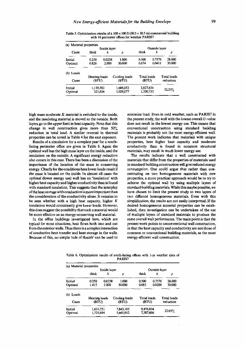
Table 5. Optimization results of a 100 x 100 ft (30.5 x 30.5 m) commercial building with 16 perimeter offices for weather PARIS7
(a) Material properties Inside layer Outside layer
Cases thick k p thick k p
Initial 0.250 0.0258 1.000 0.500 0 .7576 28.000 Optimal 0.826 2.000 30.000 0.674 0.0411 30.000
(b) Loads Heating loads Cooling loads Total loads Total loads
Cases (BTU) (BTU) (BTU) reduction
Initial 1,139,582 1 , 6 8 8 , 0 5 2 2,827,634 52.23% Optimal 321,656 1 , 0 2 9 , 0 7 7 1,350,733
99
high mass moderate K material is switched to the inside, and the insulating material is moved to the outside. Both layers go to the upper limit in heat capacity. Note that this change in wall construction gives more than 50?/0 reduction in total load. A similar reversal in thermal properties can be noted in Table 4 for the east exposure.
Results of a simulation for a complete year for a south- facing perimeter office are given in Table 6. Again the optimal wall has the high mass layer on the inside, and the insulation on the outside. A significant energy reduction also occurs in this case. There has been a discussion of the importance of the location of the mass in conserving energy. Clearly for the conditions here lower loads result if the mass is located on the inside. In almost all cases the optimal (lower energy use) wall has an 'insulation' with higher heat capacity and higher conductivity than is found with standard insulation. This suggests that the interplay oftbe heat storage with conduction is more important than the consideration of the conductivity alone. It remains to be seen whether with a high heat capacity, higher K insulation would consistently give lower loads. However, this does suggest the possibility that such a material would be more effective as an energy-conserving wall material.
In the office buildings investigated here, which are typical for most situations, heat flows both into and out from the exterior walls. Thus there is a complex interaction of conductive heat transfer and heat storage in the walls. Because of this, no simple 'rule of thumb' Can be used to
minimize load. Even in cold weather, such as PARIS7 in the present study, the wall with the lowest overall U-value does not result in the lowest energy use. This means that conventional construction using standard building materials is probably not the most energy-efficient wall. The present work indicates that materials with unique properties, here higher heat capacity and moderate conductivity than is found in common structural materials, may result in much lower energy use.
The results indicate that a wall constructed with materials that differ from the properties of materials used in standard building construction will give reduced energy consumption. One could argue that rather than con- centrating on two homogeneous materials with new properties, a more practical approach would be to try to achieve the optimal wall by using multiple layers of standard building materials. While this maybe possible, we have chosen to limit the present study to two layers of two different homogeneous materials. Even with this simplification, the results are not easily interpreted. If the desired homogeneous material properties can be estab- lished, then investigation can be undertaken of the use of multiple layers of standard materials to produce the same overall wall performance. The main point is that the present work points to unconventional wall construction, in that the heat capacity and conductivity are not those of common or conventional building materials, as the most energy-efficient wall construction.
Table 6. Optimization results of south-facing offices with 1-yr weather data of PARIS7
(a) Material properties Inside layer Outside layer
thick k p thick k p
Initial 0.250 0.0258 1.000 0.500 0 .7576 28.000 Optimal 1.415 2 . 0 0 0 30.000 0.085 0 .0200 30.000
(b) Loads Heating loads Cooling loads Total loads Total loads
Cases (BTU) (BTU) (BTU) reduction
Initial 1,631,751 7 , 8 4 5 , 1 0 3 9,476,854 22.05% Optimal 1,725,694 5 , 6 6 1 , 9 1 2 7,387,606
100 S.A. Jurovics et al.
5. VALIDATION
The complexity and size of the computer code used for these calculations and the novelty of the results provided the motivation for a validation procedure. The technique for this was to use an existing and well-established computer code to calculate the initial and final (optimal) values of heating, cooling and total load. These loads were then compared to the values given by the present code. Agreement between the two assures that the loads calculation is correct. A check that a systematic reduction in load occurs then confirms that the optimization procedure is accurate. In order to check that a minimum in loads was actually located, the wall properties were varied around the computed minimum; an increase for all validations assures that at least a local minimum has been found.
DOE-2.1B was chosen as the code to validate the accuracy of the methodology. DOE-2 has a number of similarities to NBSLD and is well established. The initial and final (optimal) wall and thus building description could be input into DOE-2 in a straightforward manner. Only the windows could not be input exactly the same in the two codes. The weather was more difficult to get into DOE-2, this is primarily because the present methodology uses 'grouped' weather data. The procedure chosen was to use one week of the 'grouped' weathe r data and to prepare it in the format ofa TMY weather file. In order to do this the direct normal and diffuse radiation from the 'grouped' weather was combined into total horizontal and diffuse radiation. This is the form for the solar radiation that is needed for a TMY file. This weather file was run through the DOE-2 weather pre-processor, then checked and corrected with the edit operation of the pre-processor. The division of the radiation into direct normal and diffuse was very close to that in the original 'grouped' weather. By this procedure both the building description and the weather were virtually the same for the two codes.
The validation was carried out for two different weather conditions, PARIS6 and PARIS7, and for a north- and a
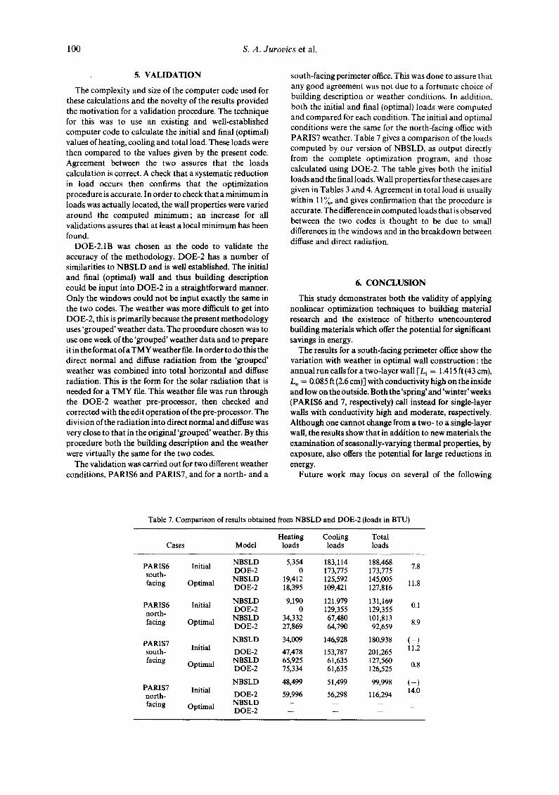
south-facing perimeter office. This was done to assure that any good agreement was not due to a fortunate choice of building description or weather conditions. In addition, both the initial and final (optimal) loads were computed and compared for each condition. The initial and optimal conditions were the same for the north-facing office with PARIS7 weather. Table 7 gives a comparison of the loads computed by our version of NBSLD, as output directly from the complete optimization program, and those calculated using DOE-2. The table gives both the initial loads and the final loads. Wall properties for these cases are given in Tables 3 and 4. Agreement in total load is usually within 11%, and gives confirmation that the procedure is accurate. The difference in computed loads that is observed between the two codes is thought to be due to small differences in the windows and in the breakdown between diffuse and direct radiation.
6. CONCLUSION
This study demonstrates both the validity of applying nonlinear optimization techniques to building material research and the existence of hitherto unencountered building materials which offer the potential for significant savings in energy.
The results for a south-facing perimeter office show the variation with weather in optimal wall construction : the annual run calls for a two-layer wall [L~ = 1.415 ft (43 cm), L o = 0.085 ft (2.6 cm)] with conductivity high on the inside and low on the outside. Both the 'spring' and 'winter' weeks (PARIS6 and 7, respectively) call instead for single-layer walls with conductivity high and moderate, respectively. Although one cannot change from a two- to a single-layer wall, the results show that in addition to new materials the examination of seasonally-varying thermal properties, by exposure, also offers the potential for large reductions in energy.
Future work may focus on several of the following
Table 7. Comparison of results obtained from NBSLD and DOE-2 (loads in BTU)
Heating Cooling Total Cases Model loads loads loads
PARIS6 Initial NBSLD 5,354 1 8 3 , 1 1 4 188,468 7.8 DOE-2 0 1 7 3 , 7 7 5 173,775 south-
facing Optimal NBSLD 19,412 1 2 5 , 5 9 2 145,005 11.8 DOE-2 18,395 109 ,421 127,816
PARIS6 Initial NBSLD 9,190 1 2 1 . 9 7 9 131,169 0.1 DOE-2 0 129 ,355 129,355 north-
facing Optimal NBSLD 34,332 67,480 101,813 8.9 DOE-2 27,869 64,790 92,659
NBSLD 34,009 1 4 6 , 9 2 8 180,938 ( - ) PARIS7 Initial 11.2 south- DOE-2 47,478 1 5 3 , 7 8 7 201,265 facing Optimal NBSLD 65,925 61,635 127,560 0.8
DOE-2 75,334 61,635 126,525
NBSLD 48,499 51,499 99,998 ( - ) PARIS7 Initial 14.0 north- DOE-2 59,996 56,298 116,294 facing Optimal NBSLD -- -- -- __
DOE-2 -- --
N e w Energy-eJ~icient Materials for the Building Envelope 101
objectives: determine the findings with three- and four- layer walls; investigate the fabrication of the derived materials; investigate construction techniques with the derived materials; examine representative buildings in additional climatic regions.
The results clearly show that manufacturers of building materials can find new products which would dramatically reduce the thermal load demand; with the demand down, one can be confident that the system, consisting of both controls and HVAC equipment, would result in
significantly less energy use than with conventional building materials.
Acknowledgements--The authors gratefully acknowledge the support and cosponsorship of this research by the IBM Corporation and North Carolina State University. In particular, we wish to thank Dr J. Jordan, Jr. of the IBM Scientific Center, Los Angeles, and Professors R. Burton and J. Bailey of the Department of Mechanical and Aerospace Engineering, NCSU, Raleigh, NC. The help ofT. J. Luckenbach in the validation part of the project is also gratefully acknowledged.
REFERENCES
1. S. Jurovics, An investigation of the minimization of building energy load through optimization techniques. Proc. Third Int. Symposium on the Use of Computers for Environmental Engineering Related to Buildings, National Research Council of Canada, pp. 239-246 (1978).
2. T. Kusuda, NBSLD, the computer program for heating and cooling loads in buildings, NBS-BSS-69. U.S. Government Printing Office, Washington, D.C. (1976).
3. S.F. Kimbrough, QOPT Manual, IBM Corporation, Los Angeles Scientific Center 0979). 4. M.J. Hopper, Compiler, Harwell Subroutine Library, Theoretical Physics Division, Atomic Energy
Research Establishment, Harwell, Berkshire, U.K. 5. D.W. Low, A directed weather data filter, ASHRAE Trans. 84 (1978).