new dynacraft manual 2006-sm
TRANSCRIPT

OWNERS MANUALFOR SINGLE SPEED AND MULTI-SPEED BICYCLES
This manual contains important safety, performance and maintenance information.Read the manual before taking your first ride on your new bicycle,
and keep the manual handy for future reference.
, Inc.

CORRECT FITTING - MAKESURE YOUR HELMET COVERSYOUR FOREHEAD.
INCORRECT FITTING. FOREHEADIS EXPOSED AND VULNERABLETO SERIOUS INJURY.
ALWAYS WEAR A PROPERLYFITTED HELMET WHENYOU RIDE YOUR BICYCLE.DO NOT RIDE AT NIGHT.AVOID RIDING IN WET CONDITIONS.
HELMETSSAVELIVES !!!

Dynacraft Customer Service1.800.551.0032
7AM TO 4PM PACIFIC TIME
DO NOT Return this Product to the Store.Please Call Dynacraft for Assistance.
STOP
Please have the following information available when you call:Model Number: (Sample: 8595-95)Production Date: (Sample: 2003.10.10)Serial Number: (Sample: 03TD5899988)
Having this information is required and helps us handle your callmore effectively. For help on where to find this information pleasesee page IV.
I.

PLEASE RETAIN YOUR SALES RECEIPT AS PROOFOF PURCHASE. FILL OUT THE INFORMATION BELOW
AND KEEP THIS MANUAL IN A SAFE PLACE.
BRAND/DESCRIPTION:___________________________________________________
MODEL#:_______________________________________________________________
PRODUCTION DATE:____________________________________________________
SERIAL#:_______________________________________________________________
DATE OF PURCHASE:____________________________________________________
STORE/PLACE OF PURCHASE:___________________________________________
II.
A SPECIAL NOTE FOR PARENTSIt is a tragic fact that most bicycle accidents involve children. As a parent or guardian, you bear the responsibility for the activities and safety of your minor child. Among these responsibilities are to make sure that the bicycle which your child is riding is properly fitted to the child: that it is in good repair and safe operating condition; that you and your child have learned, understandand obey not only the applicable local motor vehicle, bicycle, and traffic laws, but also the common sense rules of safe and responsible bicycling. As a parent, you should read this manual before letting your child ride the bicycle. Please make sure thatyour child always wears an approved bicycle helmet when riding.
Note: The illustrations in this manual are used simply to provide examples; the components of your bicycle mightdiffer. In addition, some of the parts shown might be optional and not part of the bicycle’s standard equipment.
III.
ABOUT THIS MANUALThis manual was written to help you get the most performance, comfort, enjoyment and safety when riding your new bicycle.
It is important for you to understand your new bike. By reading this manual beforeget the most from your new bicycle.
It is also important that your first ride on your new bicycle is taken in a controlled environment, away from cars, obstacles, andother cyclists.
you go out on your first ride, you’ll know how to
GENERAL WARNINGBicycling can be a hazardous activity even under the best of circumstances. Proper maintenance of your bicycle is your responsi-bility as it helps reduce the risk of injury. This manual contains many failure to maintain or inspect your bicycle. Many of the warnings and cautions say, “you may lose control and fall.” Because anyfall can result in serious injury or even death, we do not repeat the warning of possible injury or death whenever the risk of falling ismentioned.
“Warnings” and “Cautions” concerning the consequences of
Dynacraft does not encourage stunting, trick riding, ramp riding, jumping, aggressive riding, riding on severe terrain, riding in severe climates, riding with heavy loads, commercial activities, or any similar activities; such use is inherently dangerous, can cause serious injury to the rider, and if done it is with the rider’s express and implied assumption of the risk of such use and Dynacraft shall not have any responsibility for any break down of the bicycle, its components or rider injuries that occur during such use.

The following manual is only a guide to assist you and is not a complete or comprehensive manual of all aspects ofmaintaining and repairing your bicycle. The bicycle you have purchased is a complex object. We recommend that youconsult a bicycle specialist if you have doubts or concerns as to your experience or ability to properly assemble, repair, ormaintain your bicycle. You will save time and the inconvenience of having to go back to the store if you choose to write orcall us concerning missing parts, service questions, operating advice, and/or assembly questions.
DYNACRAFT CUSTOMER SERVICE1.800.551.0032
7AM TO 4PM PACIFIC TIME
Serial Number
Model Number & Production Date
IV.
Dynacraft BSC, Inc. 89 S. Kelly Rd.
American Canyon, CA 94503 Customer Service 1-800-551-0032
www.dynacraftbikes.com

..........................................................................................2-4
........................................................................................5-20
......................................................................................21-53
......................................................................................54-64
......................................................................................65-67
..................................................................................100-102
Warning / ImportantTake notice of this symbol throughout this manual andpay particular attention to the instructions blocked off andpreceded by this symbol.
......................................................................................68-99
?
Dynacraft BSC, Inc.
89 S. Kelly Road American Canyon, CA 94503Customer Service 1-800-551-0032 www.dynacraftbikes.com
Parts Identification
Before You Ride
Assembly
Servicing
Detailed Maintenance
How Things Work
Registration Cardand Warranty
DIR
EC
TO
RY
V.
..............................................................................................1Index

1. PARTS IDENTIFICATIONMountain Bicycles 2BMX Bicycles 3Road Bicycles 4
2. BEFORE YOU RIDECorrect Frame Size 5Riding Position 9-Saddle Height 9-Reach 9-Handlebar Height 10Rules of the Road 6-7
Safety Checklist-Brakes 11-Wheels & Tires 11-Steering 11-Chain 12-Bearings 12-Cranks & Pedals 11-Derailleurs 12-Frame & Fork 12-Accessories 12-Helmets 12-Reflectors 14-15
Gears - How to Operate-Derailleur Gears 16-Operating Principles 16-Hand Grip Shifters 17-Thumb Shifters 18-Below the Bar Shifters 18
Bicycle Care-Basic Maintenance 19-Storage 20-Security 20
3. ASSEMBLY
Derailleur Geared Bicycle 21Handlebars 22Forks 24Seat and Seat Post 25Pedals & Crank Set 26Front Wheel 21Quick Release Axle 25
Brakes-Cantilever with Link Wire 27-Cantilever with Straddle Cable 28-V-Style 30-Check your Brakes 32-Disk Brakes 33
Derailleur-Rear Derailleur 34-Front Derailleur 35
Dual Suspension 36Rear Pivots 37Accessories 38Reflectors 38Final Check 39
Single Speed & BMX 40Handlebars 41Seat 42Pedals & Crank Set 42Frontwheel 40Front Brake 43Side Pull Brake 43Cantilever with Link Wire 44V-Brake 46U-Brake 48Check your Brakes 49Training Wheels 49Rotors 50Final Check 53
4. HOW THINGS WORK 54-A. Wheel Quick Release 55-B. Seatpost Quick Release 56-C. Brakes 57-D. Shifting 58-60-E. Toeclips & Straps -F. Clipless (“step-in”) pedals -G. Tires and Tubes 62-63-H. Bicycle Suspension 64
5. SERVICINGSchedule 1 - Lubrication 65Schedule 2 - Service Checklist 66Tools Required 67
6. DETAILED MAINTENANCEWheel Inspection 68Tire Inspection 69Tire Pressures 69Hub Bearing Adjustment 70Flat Tire Repair 70Handlebar Stem 72Handlebars 73
Grip Shift Installation 74
Cables & Cable Housing 76
Headset-Inspection 77-Adjustment 77
Saddle & Seat Post-Inspection 78-Lubrication 78-Adjustment 79
Brakes-Inspection 80-Lubrication 81-Adjustment Sidepull Calipers 81-Adjustment Cantilever Calipers 82
DrivetrainPedals 84-Inspection 84-Lubrication & Adjustment 85 -Attachment 85
Crank Set 86-Inspection 86-Lubrication & Adjustment 87
(one piece cranks)-Lubrication & Adjustment 88
(cotterless cranks)
-Chain 90-Inspection 90-Lubrication 91-Adjustment & Replacement 91-Freewheel 92-Inspection 91-Lubrication 92-Coaster Hub 92
Derailleur Systems-Inspection 93-Lubrication 95-Adjustment (Rear) 94-Adjustment (Front) 94
Reflectors 96
Troubleshooting 97-99
7. Registration Card 100-102 & Warranty
IND
EX
01

02
PA
RT
S I
DE
NT
IFIC
AT
ION
Gear ControlCable
Rear Derailleur
Mountain Bicycles . Mountain bicycles are designed to give maximum comfort over a wide variety of road surfaces. The widerhandlebars and convenient shift lever position make them very easy to control. Wider rims and tires give them a softer ride withmore traction on rough surfaces. The frame and fork on mountain bicycles are much sturdier than those on racing style bicycles.
Top Tube
Seat
Seat Post
Quick Release
Seat Stay
Rear Reflector
Rear Brake
Wheel Reflector
Freewheel
Shift Lever
Handlebar
Brake Lever
Brake Control Cables
Front Reflector
Front Brake
Front Fork
Wheel Reflector
Front Hub
Spokes
Handlebar Stem
Head Set
Head Tube
Seat Tube
Down Tube
Gear Control Cable
Front Derailleur
Bottom Bracket Axle
Rim
Tire
Chain Wheel
Crank Arm
Pedal
Chainstay
ChainTire Valve

BMX Bicycles . BMX bicycles are a popular general purpose type most suited for young riders. They are valued because of their sturdy and simple construction, and low maintenance.
Seat
Seat Post
Seat Post Binder Bolt
Seat Stay
Rear Reflector
Wheel Reflector
Chain Wheel
Crank Arm
Pedal
Rim
Tire
Tire Valve
Chain
Rear Sprocket
Training Wheels (16” and smaller)
Brake Lever
Handlebar
Brake Control Cable
Reflector
Front Brake
Brake Pad
Front Fork
Wheel Reflector
Front Hub
Spokes
Handlebar Grip
Handlebar Stem
Head Set
Head Tube
Top Tube
Seat Tube
Down Tube
PA
RT
S ID
EN
TIF
ICA
TIO
N
03

04
Gear ControlCable
Rear Derailleur
Road Bicycles .Road bikes are designed for fast travel, hard training and competition on paved surfaces exclusively. It is thelightest, most aerodynamic and “fastest” type of bicycle.
Top Tube
Seat
Seat Post
Rear Reflector
Quick Release
Seat Stay
Rear Brake
Wheel Reflector
Freewheel
Shift Lever
Handlebar
Front Reflector
Brake Lever
Brake Control Cables
Front Brake
Front Fork
Wheel Reflector
Front Hub
Spokes
Handlebar Stem
Head Set
Head Tube
Seat Tube
Down Tube
Gear Control Cable
Front Derailleur
Bottom Bracket Axle
Rim
Tire
Chain Wheel
Crank Arm
Pedal
Chainstay
ChainTire Valve
PA
RT
S I
DE
NT
IFIC
AT
ION

CORRECT FRAME SIZE
When selecting a new bicycle, the correct choice of frame size is a very important safety consideration.
For safe and comfortable riding there should be a clearance of not less than 1 inch betweenthe groin area of the intended rider and the top tube of the bicycle frame, while the rider straddles the bicycle with both feet flat on the ground.
The ideal clearance will vary between types of bicycles and rider preference. This makes straddling the framewhen off the saddle easier and safer in situations such as sudden traffic stops. Women can use a men’s style bicycle to determine the correct size women’s model.
25-50mmNot less than 1 inch.
SAFE SIZING FOR JUVENILE AND SIDEWALK BICYCLES
It is assumed that the bicycle you have bought is sized correctly for the user. Some parents make the mistake ofbuying a bicycle too large for the intended rider, planning on the child "growing into" it. There should be a minimumof one inch clearance above the highest point of the top tube when the child is straddling the bicycle with both feeton the ground (see drawing below).
Warning: If the bicycle is too large the rider cannot reach the pedals easily, or the ground whenstopping which may result in loss of control and/or injury.
Not less than 1 inch.
05
BE
FO
RE
YO
U R
IDE

06
BE
FO
RE
YO
U R
IDE
RULES OF THE ROAD AND SAFETY TIPS
NOTE: Like any sport, bicycling involves risk of injury and damage. By choosing to ride a bicycle, you assume theresponsibility for that risk. Not the people who sold you the bike. Not the people who made it. Not the people who dis-tribute it. Not the people who manage or maintain the roads and trails you ride on. YOU. So you need to know - and topractice - the rules of safe and responsible riding.
1. IN THE INTEREST OF SAFER CYCLING, MAKE SURE YOU READ AND UNDERSTAND YOUR OWNER’S MANUAL.2. NOTICE: Some state and locals laws may require that your bicycle be equipped with a warning device such as a horn or bell
and a light if the bicycle is to be ridden after dark.3. ALWAYS WEAR SHOES when riding a bicycle AND AVOID LOOSE FITTING CLOTHES.4. CHECK YOUR BRAKES FREQUENTLY. THE ABILITY TO STOP YOUR BICYCLE IS CRITICAL. Roads are slippery in wet
weather so avoid sharp turns and allow more distance stopping. Caliper brakes may become less efficient when wet. Leaves,loose gravel, and other debris can also effect stopping.
5. ALWAYS RIDE IN THE SAME DIRECTION AS TRAFFIC. Never ride against traffic.6. STOP AND LOOK BEFORE YOU LEAVE AN ALLEY, DRIVEWAY OR PARKING LOT. Stop, look to the left, to the right and to
the left again for traffic. Ride only when it is clear.7. KEEP TO THE RIGHT. Follow the traffic flow in a straight line and stay close to the curb. Watch for cars moving in and out of
traffic.8. OBEY ALL TRAFFIC REGULATIONS. Most traffic regulations apply to bike riders as well as automobile operators.9. ALWAYS RIDE ALONE. NEVER CARRY OTHER RIDERS. This is dangerous and makes the bike harder to control. The
bicycles distributed by Dynacraft BSC, Inc. are intended for one rider only.10. ALWAYS BE ALERT. Be ALERT - pedestrians have the right away. Be ALERT - when riding near parked cars - ride far
enough away from the cars so that you won’t get hit if somone opens their car door.11. USE CAUTION AT ALL INTERSECTIONS AND STOP SIGNS. STOP AND LOOK BOTH WAYS BEFORE PROCEEDING.12. USE HAND SIGNALS. Communicate by using hand signals to tell other drivers what you are going to do. Signal 100 feet
before the turning unless your hand is needed to control the bike.
LEFT STOP RIGHT

BE
FO
RE
YO
U R
IDE
13. HAVE PROPER LIGHTS AND REFLECTORS. IF YOU RIDE AT NIGHT, be sure to have a strong headlight, a tail light, and a full set of reflectors. CHECK THAT REFLECTORS ARE CLEAN, STRAIGHT, UNBROKEN, AND SECURELY MOUNTED.
14. NEVER CARRY PACKAGES OR OBJECTS WHICH OBSTRUCT VISION.15. NEVER HITCH RIDES, Never hold onto a moving vehicle while riding.16. THE KICKSTAND IS DESIGNED TO SUPPORT THE BICYCLE ONLY, not the bicycle and the rider.17. AVOID THE FOLLOWING HAZARDS: Drain grates, potholes, soft road edges, gravel, sand, wet leaves, and/or any
obstruction in the road. Failure to do so could cause wheel(s) to buckle and result in personal injury to the rider.18. WET WEATHER RIDING - Riding your bicycle in wet conditions is not recommended. In wet conditions traction and braking
power is reduced. Riding in such conditions could result in personal injury.19. PROPER HELMET USE. A helmet that meets the CPSC (Consumer Product Safety Commission) standard should always
be worn when riding a bicycle. The helmet should fit properly and worn on the crown of the head, not tipped back.20. USE BIKE LANES when available. Also note that in certain states, cars may use bike lanes when turning.21. Respect “Bicycles Are Prohibited” signs.
07

08
BE
FO
RE
YO
U R
IDE
Pedaling Technique- Position the ball of your foot on the center of the pedal.- When pedaling, ensure your knees are parallel to the bicycle frame.- To absorb shock, keep your elbows slightly bent.- Learn to operate the gears properly. (Refer to p. 16-18)
Hill Technique- Gear down before a climb and continue gearing down as required to maintain pedaling speed.- If you reach the lowest gear and are struggling, stand up on your pedals. You will then obtain more power from each pedal revolution.- On the descent, use the high gears to avoid rapid pedaling.- Do not exceed a comfortable speed, maintain control and take additional care.
Cornering TechniqueBrake slightly before cornering and prepare to lean your body into the corner. Maintain the inside pedal at the 12 o'clockposition and slightly point the inside knee in the direction you are turning. Keep the other leg straight, don't pedal throughfast or tight corners.
Rules for ChildrenTo avoid accidents, teach children good riding skills with an emphasis on safety from an early age.1. Always wear a properly fitted helmet.2. Do not play in driveways or the road.3. Do not ride on busy streets.4. Do not ride at night.5. Obey all the traffic laws, especially stop signs and red lights.6. Be aware of other road vehicles behind and nearby.7. Before entering a street: Stop, look left, right, and left again for traffic.
If there's no traffic, proceed into the roadway.8. If riding downhill, be extra careful. Slow down using the brakes and maintain control of the steering.9. Never take your hands off the handlebars, or your feet off the pedals when riding downhill.
The Consumer Product Safety Commission advises that the riding of small wheel diameter bicycles at excessive speeds can lead to instability and is not recommended.
Children should be made aware of all possible riding hazards and correct riding behavior before they take to the streets
- Do not leave it up to trial and error.

BE
FO
RE
YO
U R
IDE
RIDING POSITION
Saddle HeightIn order to obtain the most comfortable riding position and offer thebest possible pedaling efficiency, the seat height should be setcorrectly in relation to the rider’s leg length. The correct saddle heightshould not allow leg strain from over-extension, and the hips shouldnot rock from side to side when pedaling. While sitting on the bicyclewith one pedal at its lowest point, place the ball of your foot on thatpedal. The correct saddle height will allow the knee to be slightlybent in this position. If the rider then places the heel of that foot onthe pedal, the leg should be almost straight.
Under no circumstances should the seat post projectfrom the frame beyond its “Minimum Insertion” or“Maximum Extension” mark. If your seat post pro-jects from the frame beyond these markings, the seat
post or frame may break, which could cause you to lose controland fall. After any saddle adjustment, be sure to tighten the sad-dle adjusting mechanism properly before riding. A loose saddleclamp or seat post binder can cause damage to the bicycle orcan cause you to lose control and fall. Periodically check to makesure that the saddle adjusting mechanism is properly tightened.
ReachTo obtain maximum comfort, the rider should not overextend his or herreach when riding.
To adjust this distance, the position of the seat can be altered in relation to the seat pillar. (Refer to p. 25 on how to adjust the seatclamp.)
Maximum Height / Mini-mum Insertion Mark
(Should not be visible)
Arms not over-extended
Handlebar stem height about the
same as seat height
Pedal at bottom position
09
10
BE
FO
RE
YO
U R
IDE
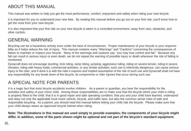
Handlebar HeightMaximum comfort is usually obtained when the handlebar height isequal to the height of the seat. You may wish to try different heightsto find the most comfortable position.
The stem’s “Minimum Insertion” mark must not be visible above the top of the headset.If the stem is extended beyond this mark, the stem may break or damage the fork’ssteerer tube, which could cause you to lose control and fall.
Failure to properly tighten the stem wedge bolt, the handlebar binder bolt, or the barend extension clamping bolts may compromise steering action, which could cause youto lose control and fall. Place the front wheel of the bicycle between your legs andattempt to twist the handlebar/stem assembly. If you can twist the stem in relation tothe front wheel, turn the handlebars in relation to the stem, or turn the bar end exten-sions in relation to the handlebar, you must tighten the appropriate bolts accordingly.
Stem Wedge Bolt
Maximum Height/Minimum InsertionMark
Handlebar Binder Bolt
Exceeds 2 1/2”(64mm)
Warning: Over tightening the stem bolt or headset assembly may cause damage to the bicycle and/or injury to the rider.

BE
FO
RE
YO
U R
IDE
SAFETY CHECKLIST
Before every ride, it is important to carry out the following safety checks:(For information and instructions on performing specific equipment checks locate the relevent section in the manual using the index on page 1)
1. Brakes- Ensure front and rear brakes work properly.- Ensure brake shoe pads are not over worn and are correctly positioned in relation to the rims. - Ensure brake control cables are lubricated, correctly adjusted, and display no obvious wear.- Ensure brake control levers are lubricated and tightly secured to the handlebar.
2. Steering- Ensure handlebar and stem are correctly adjusted and tightened, and allow proper steering. - Ensure that the handlebars are set correctly in relation to the forks and the direction of travel.- Check that the head set locking mechanism is properly adjusted and tightened.- If the bicycle is fitted with handlebar end extensions, ensure they are properly positioned and tightened.
3. Cranks and Pedals- Ensure pedals are securely tightened to the cranks.- Ensure cranks are securely tightened to the axle and are not bent.
4. Wheels and Tires- Ensure tires are inflated to within the maximum recommended limit as displayed on the tire sidewall.- Ensure tires have tread and have no bulges or excessive wear. - Ensure rims run true and have no obvious wobbles or kinks. - Ensure all wheel spokes are tight and not broken.- Check that axle nuts are tight.
11

12
BE
FO
RE
YO
U R
IDE 5. Chain
- Ensure chain is oiled, clean and runs smoothly.- Extra care is required in wet or dusty conditions.- On bicycles equipped with coaster brakes, check for proper chain tension.
6. Derailleurs- Check that front and rear mechanisms are adjusted and function properly.- Ensure control levers are securely attached. - Ensure derailleurs, shift levers and control cables are properly lubricated.
7. Bearings- Ensure all bearings are lubricated, run freely and display no excess movement, grinding or rattling.- Check headset, wheel bearings, pedal bearings and bottom bracket bearings.
8. Frame and Fork- Check that the frame and fork are not bent or broken.- If either are bent or broken, they should be replaced.
9. Accessories- Ensure that all reflectors are properly fitted and not obscured.- Ensure all other fittings on the bike are properly and securely fastened, and functioning.- Ensure the rider is wearing a helmet.

BE
FO
RE
YO
U R
IDE
HelmetsIt is strongly advised that a properly fitting, CSPC approved, bicyclesafety helmet be worn at all times when riding your bicycle. In addi-tion, if you are carrying a passenger in a child safety seat, they mustalso be wearing a helmet.
The correct helmet should:- be comfortable- be lightweight- have good ventilation- fit correctly
Always wear a properly fitted helmet when riding a bicycle. Many states require specific safety devices.It is your responsibility to familiarize yourself with the laws of the state where you ride and to complywith all applicable laws, including properly equipping yourself and your bike as the law requires. Reflec-tors are important safety devices which are designed as an integral part of your bicycle. Federal regula-tions require most types of bicycles to be equipped with front, rear, wheel, and pedal reflectors. Thesereflectors are designed to pick up and reflect street lights and car lights in a way that helps you to beseen and recognized as a moving bicyclist. Check reflectors and their mounting brackets regularly tomake sure they are clean, straight, unbroken, and securely mounted. Replace damaged reflectors andstraighten or tighten any that are bent or loose.
13
14
BE
FO
RE
YO
U R
IDE
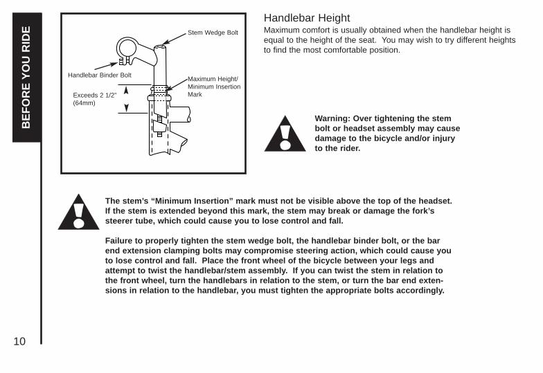
ReflectorsYour bicycle is supplied with one front (white), one rear (red), two wheel (white), and two pedal (orange) reflectors. These are an important safety and legal requirement, and should remain securely fitted and in good, clean condi-tions at all times. Periodically, inspect all reflectors, brackets and mounting hardware for signs of wear or damage. Replaceimmediately if damage is found. Some bicycles will require you to install your reflectors onto your bicycle. Please refer to thefollowing section for instructions on all the types of bicycle reflectors.
Note: CPSC regulations do not require reflectors on 10", 12" and 16" Sidewalk Bicycles- we recommend, however, that you attach reflectors for the protection of the rider.These types of bicycles should be operated during daylight hours only, on a smooth,paved surface such as a sidewalk, under the direct supervision of an adult. These bicycles should never be ridden in the street, on an incline, or on rough terrain. Under nocircumstances should these types of bicycles be operated at speeds that would make itdifficult to control, nor should it be raced or used for stunting, jumping, motocross, or off-road use or other activities not normally associated with a Sidewalk Bicycle.
Fork Mount Reflector Bracket AssemblySlide reflector over bracket as shown in diagram and insure that the tab clicks in tothe top hole of the bracket. Insert one washer onto the hex bolt and insert hex boltthrough the reflector bracket and then through the fork. Next, insert a second washeronto the bolt and thread a hex nut onto the bolt behind the fork. Tighten bolts untilsnug, making sure the reflector is in an upright position.
Wheel Reflectors The wheel reflectors should come already attached to the spokes of both the frontand rear wheels. To attach reflector to the wheel, fit the groove in the reflector to aspoke that matches the groove. The reflector should be mounted across from thevalve stem and as close to the rim as possible. The reflector should fit firmlybetween a single spoke on one side and two spokes on the other. Use the suppliedclip (with two locking prongs), fit the clip over the spoke and into the hole and pressuntil the locking prongs “click” into place. be sure to fit reflectors to both wheels.

BE
FO
RE
YO
U R
IDE
Seat and Handlebar Mounting ReflectorsSlide reflector over bracket as shown in diagram (p.14) and ensure that the tabclicks in to the top hole of the bracket. Next, remove the clamp screw and open theclamping reflector bracket. Place clamping reflector bracket around the handlebar orseatpost. If the clamp is too loose, insert the shim inside of the clamp. Tighten theclamp screw to hold reflector assembly in place, see the second diagram. Finally,adjust the reflector assembly in place. Finally, adjust the reflector such that it isupright and facing away from the bike.
Seatstay Mount Reflector Bracket AssemblySlide reflector over bracket as shown in diagram (P. 14) and ensure that the tabclicks in to the top hole of the bracket. Insert one washer onto the hex bolt and inserthex bolt through the reflector bracket and then through the seatstay bridge. Next,insert a second washer onto the bolt and thread a hex nut onto the bolt behind theseatstay bridge. Tighten bolts until snug, making sure the reflector is in an uprightposition. See diagram at the right.
15

16
GEARS - HOW TO OPERATE
Derailleur GearsMost multi-speed bicycles today are equipped with what are known asderailleur gears. They operate using a system of levers and mecha-nisms to move the drive chain between different sized driving gears orcogs. The purpose of gears is to let you maintain a constant, steadypedaling pace under varying conditions. This means your riding willbe less tiring without unnecessary straining up hills or fast pedalingdown hill. Bicycles come with a variety of gear configurations from 5to 27 speeds. A 5-6 speed bicycle will have a single front chain-wheel, a rear derailleur, and 5 or 6 cogs on the rear hub. Bicycleswith more gears will also have a front derailleur, a front chainwheelwith 2-3 cogs, and up to 7 cogs on the rear hub.
Operating PrinciplesNo matter how many gears, the operating principles are the same.The front derailleur is operated by the left shift lever and the rearderailleur by the right. To operate you must be pedaling forward. Youcan not shift derailleur gears when you are stopped or when pedalingbackwards. Before shifting ease up on your pedaling pressure. For asmooth gear change when approaching a hill, shift to a lower gearBEFORE your pedaling speed slows down too much. When comingto a stop, shift to a lower gear first so it will be easier when you startriding again. If, after selecting a new gear position, you hear a slightrubbing noise from the front or rear gears, gently adjust the appropriateshifter using the barrel adjusters until the noise goes away. For opti-mal performance and extended chain life, it is recommended that youavoid using the extreme combinations of gear positions (diagram p.17) for extended periods.
Drivetrain
Front Derailleur
Guide Pulley
Rear Derailleur
Front Chainwheels
Crank Arm
Pedal
Derailleur ControlCable
Freewheel Cogs
BE
FO
RE
YO
U R
IDE

BE
FO
RE
YO
U R
IDE
6 5 43 2 1
6 5 43 2 1
Recommended Chainwheel/Rear Sprocket Gear Combinations
Hand Grip ShiftersMany bicycles are now being equipped with a shifting mechanismthat is built into the handlebar grips and does not make use of separate levers. (The shifting is built into the inside part of the gripthat allows the thumb and index finger around.) To select a lowergear, twist the grip towards you to engage a larger rear cog. Youcan shift one gear at a time by moving the shifter one click, orthrough multiple gears by continuing twisting. By twisting the leftshifter forward or away from you, a smaller chainwheel can beselected. To select a higher gear, twist the right shifter forward oraway from you to engage a smaller rear cog. To engage a largerfront chainwheel, twist the left shifter towards you. Note: somebicycles may be equipped with a rear derailleur mechanismthat works in reverse to the directions above.
Front Low Gear Rear Low Gear
Front High Gear Rear High Gear
32 1
High Middle Low2
High
1
LowFor optimal performance,
NOT RECOMMENDEDFor optimal performance,
NOT RECOMMENDED
17

18
Thumb Shifters (Top Mounted)Many mountain style bicycles are equipped with shifters mounted on the top of the handlebars and operated by the thumbs.To select a lower, easier gear, shift to a bigger rear cog and a smallchainwheel. Pull the left shifter back to operate the front derailleur,and push the right shifter forward to operate the rear derailleur. Toselect a higher, harder gear, shift to a smaller rear cog and a largerchainwheel. Push the left shifter forward for the front, and pull theright lever back for the rear.
Below the Bar ShiftersMany mountain style bicycles now use a shift lever arrangementmounted on the underside of the handlebars, which use two leversoperated by the thumb and index finger. To select a lower gear pushthe larger (lower) right shifter with your thumb to engage a larger rearcog. One firm push shifts the chain one cog, continuing to push willmove the chain over multiple cogs. Pulling the smaller (upper) leftshifter with your index finger moves the chain from a larger to a smaller chainwheel. To select a higher gear pull the smaller (upper) rightlever with your index finger to engage a smaller rear cog. Pushingthe larger (lower) left lever with your thumb will move the chain from asmaller to a larger chainwheel.
Top Gear(Harder)
Small rear sprocketLarge chainwheel
Left hand lever forwardRight hand lever back
Bottom Gear(Easier)
Large rear sprocketSmall chainwheel
Left hand lever backRight hand lever forward
Left hand lever Right hand lever
Left hand lever Right hand lever
BE
FO
RE
YO
U R
IDE

BE
FO
RE
YO
U R
IDE
BICYCLE CARE
Basic MaintenanceThe following procedures will help you maintain your bicycle for years of enjoyable riding.
For painted frames, dust the surface and remove any loose dirt with a dry cloth. To clean, wipe with a damp clothsoaked in a mild detergent mixture. Dry with a cloth and polish with car or furniture wax. Use soap and water to cleanplastic parts and rubber tires. Chrome plated bikes should be wiped over with a rust preventative fluid.
Store your bicycle under shelter. Avoid leaving it in the rain or exposed to corrosive materials.Riding on the beach or in coastal areas exposes your bicycle to salt which is very corrosive. Wash your bicycle frequently and wipe or spray all unpainted parts with an anti-rust treatment. Make sure wheel rims are dry so brakingperformance is not affected. After rain, dry your bicycle and apply anti-rust treatment.
If the hub and bottom bracket bearings of your bicycle have been submerged in water, they should be taken out andre-greased. This will prevent accelerated bearing deterioration.
If paint has become scratched or chipped to the metal, use touch up paint to prevent rust. Clear nail polish can also beused as a preventative measure. Your local hobby shop will carry paints in small containers and a variety of colors thatyou can use to touch up paint.
Regularly clean and lubricate all moving parts, tighten components and make adjustments as required. (Refer to Parts5 and 6 of this manual for further details).
The selected use of alloy component and surface treatments helps prevent rust and corrosion from affecting someareas of your bike.
19
20
StorageKeep your bicycle in a dry location away from the weather and the sun. Ultraviolet rays may cause paint to fade or rubberand plastic parts to crack.Before storing your bicycle for a long period of time, clean and lubricate all components and waxthe frame. Deflate the tires to half pressure and hang the bicycle off the ground. Don't store near electric motors as ozoneemissions may effect the rubber and paint. Don't cover with plastic as "sweating” will result which may cause rusting.Please notice that your bicycle warranty does not cover paint damage, rust, corrosion, dry rot, or theft.
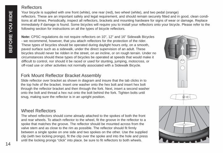
SecurityIt is advisable that the following steps be taken to prepare for and helpprevent possible theft.
1. Maintain a record of the bicycle’s serial number, generally locatedon the frame underneath the bottom bracket.
2. Register the bicycle with the local police.3. Invest in a high quality bicycle lock that will resist hack saws and
bolt cutters. Always lock your bicycle to an immovable object if itis left unattended.
BE
FO
RE
YO
U R
IDE

DERAILLEUR GEARED BICYCLESIncludes 20", 24” and 26" Wheel Mountain BikesAssembly is the same for men’s and women’s bikes..
Getting StartedOpen the carton from the top and remove the bicycle. Remove the strapsand protective wrapping from the bicycle. Inspect the bicycle and all acces-sories and parts for possible shortages. It is recommended that the threadsand all moving parts in the parts package be lubricated prior to installation.Do not discard packing materials until assembly is complete to insure thatno required parts are accidentally discarded. Assemble your bicycle follow-ing the steps that pertain to your model. Note: Your bicycle may beequipped with different style components than the ones illustrated.
Foreword: Assembling a bicycle is an important responsibility. Properassembly not only gives the rider more enjoyment of the bicycle; italso offers an important measure of safety.
Front Wheel1. Make sure the brakes are loose enough to allow the wheel to
pass through the brake pads easily.2. Place wheel into fork drop outs.3. Install retaining washers with raised lip pointed towards the fork,
and insert into the small hole of the fork blade.4. Install axle nut and securely tighten. Make sure the wheel is
centered between the fork blades.5. Spin the wheel to make sure that it is centered and clears the
brake shoes. Tighten the brakes if necessary.6. Turn the bicycle upright using the kickstand to support it.
It is very important to check the front wheelconnection to the bicycle. Failure to properly tightenmay cause the front wheel to dislodge.
Axle Nut
AxleHub
Cone Nuts
Fork Drop Out
RetainingWasher
AS
SE
MB
LY
21

AS
SE
MB
LY
NOTE: Comfort style bicycles may be equipped with a stem that has an adjustable angle. In addition to the normal assembly, these stems will require angling the stem to the desired position,and securely tightening the 6mm angle bolt located in front of the stem bolt. Failure to do this may cause loss of steering control.
If the stem is not inserted into the top nut to at least the “Minimum Insertion” mark, it ispossible to over-tighten the stem wedge bolt and damage the fork steerer tube. If theseinstructions are not followed, it could cause an unsafe condition and risk injury to therider. Check steering tightness prior to riding by straddling the front wheel. Try turningthe handlebar. If you can turn it without turning the front wheel, the stem is too loose. Re-align the handlebar with the front wheel and re-tighten the stem wedge bolt.
Minimum InsertionMark
Stem Wedge Bolt
Head Tube
Handlebar Binder Bolt
Top Nut
Wedge
Warning: Over tightening the stem bolts or headset assembly may cause damage to the bicycle and/or injury to the rider.
HandlebarsRemove the protective cap from the handlebar stem wedge and loosen theAllen key bolt using the 6mm Allen key. Some models may use a 13mmhexagonal bolt instead of an Allen key bolt. Place the handlebar stem intothe top of the head tube, ensuring that all cables are free of tangles. Tightenthe stem wedge bolt observing the minimum insertion mark and checking thatthe forks and the handlebars are facing forward. Check the headset forsmooth rotation and that the top nut is secured tightly. Loosen the 6mmHandlebar Binder Bolt and rotate the handlebar forward so the levers are ata 45 degree angle below the handlebar. Retighten the Binder Bolt to ensurethe handlebar does not rotate in the stem.
22

23
AS
SE
MB
LY
Tighten all bolts that clamp the shifters, brake levers, and bar ends tothe handlebar using a 5mm Allen key or Phillips head screwdriver.(Figure 1) Handlebar with Grip Shifter.(Figure 2) Top mounted thumb shifter.
Failure to properly tighten clamping bolts maycause sudden movement of the componentresulting in loss of steering control.
1.
2.
Bar end (5mm Allen key)
Shifter binder bolt(2.5 Allen key)
Brake lever binder bolt(5mm Allen key)
Shift binderbolt (Phillipshead or 5mmAllen key)
NOTE:When assembling the bicycle or setting it up for a rider, the shifters,brake levers and bar ends may needto be rotated on the handlebars to aposition that allows safe and easyoperation on the controls.

24
AS
SE
MB
LYForksThere are two different types of forks that range in stylesand dimensions. One type is a rigid fork (Figure 1) consistingof stationary tubing with curved blades. The other type is asuspension fork (Figure 2) consisting of stanchion tubesriding on elastomers or springs inside of a straight fork leg.This mechanism acts as a shock absorber with a specifiedamount of travel that varies between models. If service isneeded on a suspension fork, consult a professional bicyclerepair technician.
Do not attempt to disassemble a suspen-sion fork yourself. Consult a professionalbicycle repair technician.
Check the tightness of the headset and the fork. Rotate thefork checking for smoothness. If it feels like the fork isbinding, then an adjustment will need to be made to theheadset. Move the fork in a push/pull manner checking fortightness. If any play is detected, loosen the top nut, adjustthe bearing cup, and retighten the top nut. Recheck therotation and tightness. If necessary, readjust until a smoothrotation is achieved without backward or forward movement.If your bike is equipped with a suspension fork, check thatthe fork compresses and rebounds smoothly. To do this,place the fork dropouts against the ground, push andrelease the handlebar. The fork will generally compress 1-2”and rebound quickly. Most elastomer type forks will graduallysoften with use.
Steering Tube
Crown
Brake Boss
Fork Leg
Drop-out
Steering Tube
Brake Boss
Fork Leg
Drop-out
Brake BridgeCrown
1.
2.

25
AS
SE
MB
LYSeat and Seat PostAttach the seat to the seat post by loosening the nuts on the seat clamp. Insert thetapered end of the seat post into the seat clamp until it is at the top of the clamp.Partially tighten the nuts on the seat clamp until the seat is snug, but can still beturned. Insert the seat assembly into the frame of the bicycle and adjust the seatto the proper height. The seat post must be inserted to at least the “MinimumInsertion” line marked on the seat post. If equipped with a quick release; tightenthe adjusting nut by hand and move the quick release lever to the closed position.You should feel considerable resistance while moving the lever. If not, re-open andre-tighten the lever, then move it to the closed position so it is in line with the frameas pictured. For more detailed information see page 56. If equipped with a binderclamp; Insure the lip on the binder clamp is fitted completely against the top of theseat tube of the frame. With the seat post inserted, tighten the binder bolt secure-ly. Position the top of the seat parallel with the ground. Push the front of the seatup and down to firmly mesh the serrations together. The serrations must meshcompletely together to insure a stabilized riding position. Securely tighten the nuton the seat clamp. If there is a nut on both sides of the clamp, tighten each one byalternating from one to the other. Check for tightness by twisting the seat from sideto side, and from front to back. If the seat moves at the seat clamp or quickrelease, reposition and re-tighten the appropriate clamping mechanism.
NOTE: Comfort style bicycles may be equipped with a suspensionseat post (See Diagram-bottom left).
The seat post must be inserted so that the minimum insertionmark cannot be seen. The quick release mechanism must betightened securely to prevent a sudden shift of the seat whenriding. Failure to do this may cause loss of bicycle control.
SeatClamp
SeatPost
QuickRelease
AdjustingNut
Attach Seat Here
Boot
MinimumInsertionMark Insert this
end intoframe

26
Attachment of an incorrect pedal into a crank arm willcause irreparable damage. Before your first ride, pleasecheck to insure your pedals are attached correctly.
Pedals & Crank SetCheck for the right (R, red) sticker and left (L, green) sticker on eachpedal and crank arm. Match the appropriate pedal to each crank (right toright and left to left) for assembly. Start each pedal spindle by hand toavoid stripping the threads. Tighten with a 15mm narrow open endedwrench so that the shoulder of the pedal spindle is securely tightenedagainst the crank arm. Note that the right hand pedal attaches to thechainwheel side crank arm with a right-hand (clockwise) thread. The leftpedal attaches to the other crank arm and has a left-hand (counter-clock-wise) thread. It is very important that you check the crank set for correctadjustment and tightness before riding your bicycle. New cotterlesscranks may become loose with initial use, refer to page 87-89 for cranktype identification and instructions for adjustment and maintenance. Oncethe pedals have been installed, remove the dust caps from the center ofeach crank arm. Using a 14mm socket wrench, tighten the spindle nutssecurely and replace the dust caps.
DustCap
Never ride your bike if the cotterless cranks are loose. Thismay be dangerous and will damage the crank arms beyondrepair.
AS
SE
MB
LY

27
AS
SE
MB
LYBrakesDetermine which type of brake your bike is equipped with and refer tothe appropriate assembly instructions. For more information on brakeadjustment and maintenance, refer to p. 80-82.
Cantilever Brakes - Utilizing a Link WireIf fitted with cantilever type brakes, insert the brake cable into the linkwire lead, and notch the cable end into the slot of the left brake arm.Loosen the anchor bolt on the right brake arm and slide the brake cableunder the tabbed washer. Squeeze both brake arms together so thebrake shoes hit the rim, pull all slack out of the brake cable, and tightenthe anchor bolt. With the cable fitted, the straddle holder should sit 10-20mm above the reflector bracket. Adjust the brake shoes using a10mm wrench so that they are parallel with the rim and are positioned1-2mm away from the rim. Several adjustments may be necessary toachieve the correct brake position.
3
1. Install the cable intothe link wire.
2. Set the cable intothe straddle holder. 1
2
CantileverBrakes
CableEnd

28
3
3. Temporarily tighten the cable sothat the link wire is at the position inthe illustration.
1 2
1 2
5. Secure one of the shoes at a time.The adjustment of the shoe clearance isnot necessary at this time. Shoe fixing nut tightening torque: 7.84 - 8.82 Nm (70 - 78 in. lbs.)
1 mm
10 mm wrench
5 mm Allen keyCable Anchor Bolt
Touch ing
End cap
Cut off any unnecessarycable, attach an end cap,and hook it onto thenotched part of the nutwhich secures the shoe.
Cable Casing Holder
Link Wire
AS
SE
MB
LY

29
AS
SE
MB
LYV-Style BrakesIf not already assembled, take the brake noodle from the parts boxand slide the cable through the larger opening. The cable housing willthen seat into the end of the noodle. Slide the cable through the cablelead on the end of the left brake arm, this will cause the noodle to fitinto the lead. Slip the brake cable boot over the cable and position itbetween both brake arms. Next, loosen the 5mm anchor bolt at theend of the right brake arm and slide the cable under the retainingwasher. Pull the slack out of the cable making sure a distance of39mm or more remains between the end of the lead and the start ofthe anchor bolt. Once the cable is secured to the brake arms, engagethe brake lever several times, checking the position of the brakeshoes at the rim. The brake shoes should be 1mm away from the rimwhen in a relaxed position. When the brake lever is engaged, thebrake shoe should hit the rim flush (never the tire) with the front touch-ing slightly before the rear. If this position is not achieved, adjustmentsto the brake shoe are required. Loosen the brake shoe hardware andreposition the brake shoe. It may take several shoe and cable adjust-ments before the required position is accomplished.
BrakeNoodle
Outer CableLead
BrakeCableBoot
AnchorBolt
BrakeArm
TensionScrewBrake
Shoe
PivotBolt

30
V - Brake
If fitted with V-Brakes, insert the brake body intothe center spring hole in the frame mountingboss, and then secure the brake body to theframe with the link fixing bolt.
1.
While holding the shoe against the rim, adjust theamount of shoe protrusion by interchanging theposition of the B washers (i.e. 6 mm and 3 mm) so thatdimension A is kept at 39 mm or more.
2.
5 mm Allen key
Washer
Link fixing
bolt
Stopper pin
Spring hole
39 mm or moreA
3 mm washer B 6 mm washer B
Washer A
Shoe fixing linkWasher A
Washer
Shoe fixing nut
AS
SE
MB
LY

31
AS
SE
MB
LYWhile holding the shoe against therim, tighten the shoe fixing nut.
3. Adjust the balance with the springtension adjustment screws.
5.
Depress the brake lever about 10 times asfar as the grip to check that everything isoperating correctly and that the shoeclearance is correct before using the brakes.
6.Pass the inner cable through the innercable lead. Set the cable with a clearanceof 1mm between each brake pad and therim, tighten the cable fixing bolt.
4.
5 mm Allen key
5 mm Allen key
1mm 1mm
1 mm
Spring tensionadjustment screw
Spring tensionadjustment screw
Depress about10 times
1 mm 1 mm
shoe fixing nut

32
Check your BrakesPress each brake lever to make sure that there is no binding and that the brake pads press hard enough on the rims tostop the bike. The brake pads should be adjusted so they are 1 mm to 2 mm away from the rim when the brakes arenot applied. Brake pads should be centered on the rim and the rear portion of each brake pad should be about 0.5 - 1.0mm farther from the rim than the front portion of the brake pad.
Do not ride the bicycle until the brakes are functioning properly. To test, apply the brakes while trying to push the bike forward to make sure they will stop the bicycle.Never ride a bicycle that is not functioning properly.
Sudden or excessive application of the front brake maypitch the rider over the handlebars, causing serious injuryor death.
Brake pad aligned with the rim surface Pad and rim should be parallel. Direction of rimrotation
0.5 - 1.0 mm
1- 2 mm
AS
SE
MB
LY

33
AS
SE
MB
LY
These brakes require breaking in! Ride and use the brakes gently for 13miles before using the brakes in downhill conditions, for sudden stops, orany other serious braking. Please be aware that your brake system willchange in performance throughout the wear-in process. The disc brakeshould be cleaned before the first ride using rubbing alcohol. NEVER use oilor similar products to clean your disc brake system.
Disk BrakesSome models of bicycles may be equipped with disc brakes. The set up and maintenance of disc brakes vary by model andmanufacturer, please read the instructions supplied with your bicycle for the specific instructions and warnings for the discbrakes supplied on your bicycle before adjusting your brakes or riding your bicycle.
Disc brakes require breaking in before full breaking power is achieved. While the break in period varies by model and manufac-turer, a distance of 13 miles or 40 to 50 applications is the minimum before using the brakes for downhill conditions, for suddenstops, or other serious braking. Please read the specific instructions and warnings for the disc brakes supplied on your bicyclebefore riding your bicycle. Disc brakes are extremely powerful. You should take extra care in becoming familiar with brakes andexercise particular care when using them.
DISC GETS HOT! Severe injury could result fromcontact with the hot disc! Mind your legs, as wellas your hands.

34
AS
SE
MB
LYDerailleurAlthough the front and rear derailleurs are initially adjusted at thefactory, you will need to inspect and possibly readjust both beforeriding the bicycle.
Rear DerailleurBegin by shifting the rear shifter to largest number indicated, dis-connect the cable from the rear derailleur cable anchor bolt, andplace the chain on the smallest sprocket. Adjust the High limitscrew so the guide pulley and the smallest sprocket are lined upvertically. Reconnect the cable, pull out any slack, and retightenthe anchor bolt securely. Shift through the gears, making sureeach gear achieved is done quietly and without hesitation.Shift therear shifter to the gear one and place the chain on the largest cog.Adjust the Low limit screw in quarter turn increments until theguide pulley and the largest cog are aligned vertically. Again, shiftthrough each gear several times, checking that each gear isachieved smoothly. It may take several attempts before the rearderailleur and cable is adjusted properly. Note: Some bicycles may be equipped with a rear derailleurmechanism that works in reverse to the directions above.Some derailleurs may have an adjusting barrel (see drawing). Usethe adjusting barrel to fine tune the adjustment of the chain loca-tion. Turn the adjusting barrel clockwise will move the derailleuroutboard - away from the wheel, while turning it clockwise willdirect the chain inboard - towards the wheel.
Ensure all bolts are secured tightly and the chaindoes not fall off in either direction.
Guide Pulley
Barrel Adjuster
AdjustmentScrews
Freewheel Outer side of Top Gear
Pulley AdjustmentScrew
Tension Pulley
High GearAdjustment Screw
Low GearAdjustment Screw
BarrelAdjuster
Rear Derailleur Side View
H
L

35
AS
SE
MB
LYFront DerailleurShift both shifters to the smallest number indicated and placethe chain on the corresponding cog and chainwheel. Discon-nect the front derailleur cable from the cable anchor bolt.Check the position of the front derailleur; it should be parallel withthe outer chainwheel and clear the largest chainwheel by 3-5mm when fully engaged. With the chain on the smallestchainwheel in front and the largest cog in back, adjust the Lowlimit screw so the chain is centered in the front derailleur cage.Reconnect the cable, pull any slack out, and tighten theanchor bolt securely. Shift the front shifter to the largest chain-wheel. If the chain does not go onto the largest chainwheel, turnthe high limit screw in 1/4 turn increments counter-clockwise untilthe chain engages the largest chainwheel. If the chain falls offthe largest chainwheel, and into the pedals, you will need toturn the High limit screw in 1/4 turn increments clockwise untilthe chain no longer falls off.Some shifters may have an adjusting barrel. to fine tune theadjusting of the chain location. Turn the adjusting barrel clock-wise will move the derailleur inboard - towards the frame,while turning it clockwise will direct the chain outboard - awayfrom the frame.
Do not ride a bicycle that is not shifting properly. Overlooking proper adjustments maycause irreparable damage to the bicycle and/orbodily injury. Never move the shifter whilepedaling backward, nor pedal backwardsafter having moved the shifter. This couldjam the chain and cause serious damage tothe bicycle and/or rider.
Cable Anchor Bolt
Chainguideclearance of
3-5mm

36
AS
SE
MB
LY
Dual SuspensionDual Suspension bikes are equipped with a front fork as wellas a rear suspension generally located below the seat. Therear suspension unit is a combination of a piston that works inconjunction with a spring to allow the rear swing arm to rotateon a pivot point. Ensure all attaching hardware is secured andthere is no lateral movement of the rear triangle. The amountof Rear Suspension travel can be adjusted by turning theadjusting plate. Clockwise will increase springtension and decrease travel, while turning counter-clockwisewill decrease spring tension and increase travel. There aremany different types of suspension systems-too many to dealwith individually in this manual.
There must be enough tension on the spring to holdthe spring plate in place. Failure to do this may causethe mechanism to fail. Failure to maintain, check andproperly adjust the suspension system may result insuspension malfunction, which can cause you to losecontrol and fall. Changing suspension adjustment canchange the handling and braking characteristics ofyou bicycle. Always check for changes in the perfor-mance of your bicycle by taking a careful test ride in ahazard free area. If your bike has suspension equip-ment, the increased speed you may develop alsoincreases your risk. When braking, the front of a sus-pended bike dips. You could lose control and fall ifyour skill is not up to handling this system. Get toknow how to handle your suspension system safelybefore trying any downhill or very fast biking.
Anchor bolt
Spring plate Spring
Piston
Adjusting plate
Anchor bolt

37
AS
SE
MB
LYRear PivotsThe pivot assembly is a simple mechanism that allowsthe rear swing arm to move up and down in combinationwith a rear suspension unit. Size, shape and compo-nents will vary between models: however operating prin-ciples are the same. The pivot point consists of a splitbushing set, held in place by a bolt that rotates inside offixed bushings in the frame. The pivot point should bekept clean and free of grime, and should be disassem-bled and re-greased at least once a season. Please notethat on some models the drive side crank arm must beremoved from the spindle before attempting to work onthe pivot. After removing the fixing bolt, the bushingsmay need to be tapped out using a drift, punch or otherblunt ended tool. After disassembly and cleaning, theparts should be lightly coated with a lithium-basedgrease. Reassemble the pivot bushing assembly andtighten the fixing bolt securely. Note: Never use WD-40 or similar products to greaseor lubricate components. It is a degrease that willnot provide required lubrication and has a tendencyto attract dust.
1
2
1. Pivot Assembly2. Bottom Bracket Cup & Lockring3. Rear Triangle
1
3

38
AS
SE
MB
LYAccessoriesIf your bike is supplied with a water bottle and cage, attach thecage to the bicycle using the allen bolts provided.
If the kickstand is not mounted to your bicycle; place the bicy-cle in an upright position against a wall or have someone holdit upright. Place the kickstand in the bracket mounted on theframe and use the fixing bolt to secure the kickstand in place .Be sure to tighten the fixing bolt securely. Some kickstandsuse a top plate to locate the bolt and secure the kickstandusing the fixing bolt. Be sure to tighten the fixing bolt securely.
Other: Some 20”, 24” and 26” model bicycles come with a rearderailleur guard to protect the rear derailleur from damage. Toinstall, remove the the rear wheel axle nut on the drive side,install the rear derailleur guard over the axle with the U-shapedguard pointing down, and retighten the axle nut. The guard willsit between the frame and the axle nut.
Tighten both rear wheel axle nuts. Failure todo this may cause the rear wheel todislodge from the frame dropouts resultingin serious damage or injury.
ReflectorsAttach the white reflector to the front reflector bracket andsecure to the fork or handlebar using the hardware provided.Attach the red reflector to the rear reflector bracket and secureto the frame or seat post, depending on the bracket style, withthe hardware provided.
Saddle Bag
Frame Bag
Reflector
ReflectorReflector
Water bottle and cage
The kickstand is designed to support theBICYCLE ONLY; not the bicycle and the rider.

39
AS
SE
MB
LYFinal Check
- Check that brakes operate smoothly with no binding. To test, apply the brakes while trying to push the bicycle forward to make sure they will stop the bicycle. Do not ride your bicycle unless the brakes are functioning properly.
- Test the security of the handlebar within the stem, and the stem within the fork steerer tube, by clamping the front wheel between your knees and trying to move the handlebar up and down, and from side to side. The stem and/or handlebar should not move when applying pressure.
- After all adjustments have been made, shift through every gear several times at varying speeds. This will ensure allyour adjustments are correct and will allow you to pinpoint any trouble areas. If you encounter any problems, refer tothe appropriate section and make any necessary adjustments.
- Check the tire pressure and inflate each tire to the recommended psi as stated on the sidewall of the tire.
- Check that the kickstand operates smoothly and the kickstand bolt is secured tightly.
- Finally, examine the bicycle. Make sure all accessories are attached and all quick releases, nuts and bolts have beentightened securely.
- Correct maintenance of your bicycle will ensure many years of happy riding. Service your bicycle regularly by referringto the relevant sections of this manual, OR take it to a professional bicycle shop.
Remember: Always wear a helmet and obey all traffic laws.
Never inflate a tire beyond the maximum pressure marked on the tire’s sidewall.Exceeding the recommended pressure may blow the tire off the rim, which couldcause damage to the bicycle and injury to the rider and bystanders.

40
AS
SE
MB
LYSINGLE SPEED & BMXIncludes 16" and 20" BMX BikesAssembly is the same for boy’s and girl’s bikes.
Getting StartedOpen the carton from the top and remove the bicycle. Remove thestraps and protective wrapping from the bicycle. Inspect the bicycle andall accessories and parts for possible shortages. It is recommended thatthe threads and all moving parts in the parts package be lubricated prior toinstallation. Do not discard packing materials until assembly is completeto insure that no required parts are accidentally discarded. Assembleyour bicycle following the steps that pertain to your model.
Note: Your bicycle may be equipped with different style componentsthan the ones illustrated.
Foreword: Assembling a bicycle is an important responsibility. Properassembly not only gives the rider more enjoyment of the bicycle; italso offers an important measure of safety.
Front Wheel1. Make sure the brakes are loose enough to allow the wheel to pass
through the brake pads easily.2. Place wheel into fork drop outs.3. Install retaining washers with raised lip pointed towards the fork,
and insert into the small hole of the fork blade.4. Install axle nut and tighten. Make sure the wheel is centered
between the fork blades.5. Spin the wheel to make sure that it is centered and clears the
brake shoes. Tighten the brakes if necessary.6. Turn the bicycle upright using the kickstand to support it.
It is very important to check the front wheelconnection to the bicycle. Failure to properly tightenmay cause the front wheel to dislodge.
Axle Nut
AxleHub
Cone Nuts
Fork Drop Out
RetainingWasher

41
AS
SE
MB
LY
Note: Some models may come packed with the stem pointing up. Loosen the stem/handlebar binder bolt(s) and rotate the stemso that the neck is pointing down.
Important Note: Test the security of the handlebar within the stem, and the stem within the fork steerer tube, by clamping thefront wheel between your knees and trying to move the handlebar and/or stem, and from side to side. The handlebar should notmove when applying pressure.
Never ride unless the handlebar clampingmechanism has been securely tightened.
StemWedgeBolt
Minimum Insertion Mark
HeadTube
Stem Cap Binder Bolts
Stem Wedge
Handlebars and StemRemove the protective cap from the stem wedge and loosen the bolt usingthe 6mm Allen key. Some models may use a 13mm hexagonal bolt instead ofan Allen key bolt. Place the handlebar stem into the head tube, checking thatthe curved rake of the fork and handlebars are facing forward. Align the stemwith the front wheel, observing the minimum insetion mark on the stem andensuring that all cables are free of tangles. Tighten the stem wedge bolt. Setthe handlebar at the desired angle and tighten the Stem Cap Binder Bolts(see drawing) securely using a 5mm allen key.
Warning:The handlebar must be inserted so that the minimuminsertion mark cannot be seen.Warning: Over tightening the stem bolt or headset assembly maycause damage to the bicycle and/or injury to the rider.

42
AS
SE
MB
LYSeatLoosen nut on the seat clamp and add 3 or 4 drops of oil onto thethreads of the bolt. Place the smaller end of the seat post into the seatclamp until it stops with the bolt to the rear of the seat post. Thread thenut on the seat clamp loosely. Insert the larger end of the seat post intothe seat tube of the bicycle frame observing the minimum insertion markon the seat post. Position the top surface of the seat parallel with theground. The serrations on the seat clamp must mesh completely with theseat frame serrations, push the front of the seat up and down to align the ser-rations. Securely tighten the seat clamp. Securely tighten the boltson the seat post clamp. If your bicycle is equipped with a quick release,refer to page 56 for proper adjustment instructions.
Pedals & Crank SetCheck for the right (R, red) stricker and left (L, green) sticker on each pedaland crank arm. Match the appropriate pedal to each crank (right to right andleft to left) for assembly. Start each pedal spindle by hand to avoid strippingthe threads. Tighten with a 15mm narrow open ended wrench so that theshoulder of the spindle is securely tightened against the crank arm. Note thatthe right hand pedal attaches to the chainwheel side crank arm with a right-hand (clockwise) thread. The left pedal attaches to the other crank arm andhas a left-hand (counter-clockwise) thread. It is very important that you checkthe crank set for correct adjustment and tightness before riding your bicycle.New cranks may become loose with initial use, refer to p.87-89 for propercrank set adjustment and maintenance. Once the pedals have been attached,check that the crank arm rotates smoothly and that there is no lateral move-
ment.
The seat post must be inserted so that the minimum insertion mark cannot be seen.
Attachment of an incorrect pedal into a crank arm will cause irreparable damage.

43
AS
SE
MB
LY
Side Pull BrakeLoosen the cable anchor nut and thread the brake cable through it. Tighten the nut by hand until it holds the cable in place. Squeeze thebrake arms together against the rim of the wheel. Loosen the nuts on thebrake shoes and turn until they match the angle of the rim. Tighten thenuts securely. Loosen the cable anchor nut and squeeze both brakearms together so that both brake shoes are in contact with the rim, pull allthe slack out of the brake cable, and securely tighten the cable anchornut. Spin the wheel, the brake shoes should not contact the rim at anypoint and should be an equal distance from the rim on both sides. Makesure all nuts and bolts are securely tightened. Test the brake levers 20-25 times to take care of any initial cable stretch. Be sure to tightly secure the brake fixing nut behind the fork.
Side PullBrakes
Cable Adjusting
Barrel
Center Bolt
CableAnchor
Nut
Brake Shoe
Fixing Nutin Back
BrakeArm
BrakeDetermine which type of brake your bike is equipped with and refer to theappropriate assembly instructions. For more information on brake adjust-ment and maintenance, refer to p. 80-82. It is important to become familiarwith the use of hand brakes. When properly adjusted, hand brakes are anefficient braking system. Keep the rim and brake shoes clean and free fromwax, lubricants and dirt at all times. Keep brakes properly adjusted andin good working condition at all times.
Brake Lever NippleFerrule
Grip Handlebar
CableAdjusting
Barrel

44
AS
SE
MB
LY
3
1. Install the cable intothe cable carrier.
2. Set the cable ontothe straddle holder. 1
2
CantileverBrakes
Cantilever Brakes - Utilizing a Link WireIf fitted with cantilever type brakes, insert the brake cable into the linkwire lead, and notch the cable end into the slot of the left brake arm.Loosen the anchor bolt on the right brake arm and thread brake cablethrough it. Adjust the brake shoes using a 10mm wrench and 5mmAllen key so that they are parallel with the rim and are positioned 1-2mm away from the rim. Several adjustments may be necessary toachieve the correct brake position.
When assembling or adjusting the brakes, makesure the cable anchor is tight. Failure to securelytighten the nut could result in brake failure andpersonal injury.
CableEnd

45
AS
SE
MB
LY3
3. Temporarily tighten the cable sothat the link wire is at the position inthe illustration.
5. Secure one of the shoes at a time. Theadjustment of the shoe clearance is notnecessary at this time.
1 mm
10 mm wrench
5 mm Allen keyCable Anchor Bolt
Touch ing
End cap
Cut off any unnecessarycable, attach an end cap,and hook it onto thenotched part of the nutwhich secures the shoe.
Link Wire
Pad and rim should be parallel. Direction of rimrotation
0.5 - 1.0 mm
1- 2 mm
Pad and rim should be parallel. Direction of rimrotation
0.5 - 1.0 mm
1- 2 mm

46
AS
SE
MB
LYV - Brake
If fitted with V-Brakes, insert the brake body intothe center spring hole in the frame mountingboss, and then secure the brake body to theframe with the link fixing bolt.
1.
While holding the shoe against the rim, adjust theamount of shoe protrusion by interchanging theposition of the B washers (i.e. 6 mm or 3 mm) so thatdimension A is kept at 39 mm or more.
2.
5 mm Allen key
Washer
Link fixing
bolt
Stopper pin
Spring hole
39 mm or moreA
3 mm washer B 6 mm washer B
Washer A
Shoe fixing linkWasher A
Washer
Shoe fixing nut

47
AS
SE
MB
LYWhile holding the shoe againstthe rim, tighten the shoe fixing nut.
3. Adjust the balance with the springtension adjustment screws.
5.
Depress the brake lever about 10 times asfar as the grip and check that everything isoperating correctly and that the shoe clearanceis correct before using the brakes.
6.Pass the inner cable through the innercable lead. Set the cable with a clearanceof 1mm between each brake pad and therim, tighten the cable fixing bolt.
4.
5 mm Allen key
5 mm Allen key
B C
B + C = 2 mm
1 mm
Spring tensionadjustment screw
Spring tensionadjustment screw
Depress about10 times
1 mm 1 mm

48
AS
SE
MB
LYU-BRAKE INSTRUCTIONS
Adjust the pads of the U-brake using a 10mm wrench. Make sure the pad is hitting the rim and not the tire. Ideally the front ofthe pad should hit the rim approximately 1mm before the rear pad. Next tighten the Cable Carrier to the brake cable approxi-mately 20mm from the brake arms when they are closed against the rim. Attach the Straddle cable to the carrier. Hook cableend into the brake slot, pull excess straddle cable through the cable anchor and tighten the cable anchor. For brake adjust-ments, use a 13mm box end wrench and a 5mm allen wrench and loosen the 5mm allen bolt. For the non-drive side (left),turn the spring tension nut with box end wrench clockwise to increase tension on the spring. When the desired tension isacheived, hold the tension nut with the 13mm wrench and tighten the 5mm allen bolt. The tension on each side should beequal so that the brake arms move the same distance when the brake is activated.

49
AS
SE
MB
LY
Training Wheels1. Position frame clip over rear axle nut with tab located in
frame axle slot.
2. Locate brace over frame clip and secure with nut using 15mm or adjustable wrench.
3. The elongated hole on the brace allows for raising or lowering the training wheels to the proper height. Once proper height is determined, secure brace in position bytightening nut securely.
Check your BrakesPress each brake lever to make sure that there is no binding and that the brake pads press hard enough on the rims to stopthe bike. The brake pads should be adjusted so they are 1mm to 2 mm away from the rim when the brakes are not applied.Brake pads should be centered on the rim and the rear portion of each brake pad should be about 0.5 - 1.0 mm farther fromthe rim than the front portion of the brake pad.
Do not ride the bicycle until the brakes are functioning properly.To test, apply the brakes while trying to push the bike forward tomake sure they will stop the bicycle.
Training Wheel
Frame
Brace
Frame Clip
Axle

50
AS
SE
MB
LYRotorsSome freestyle BMX bicycles come equipped with a detanglersystem that will allow the handlebar to spin 360-degreeswithout binding the cables. CAUTION: Bicycles not equippedwith rotors do not have this capability for spinning thehandlebars. It is very important that this system is adjustedcorrectly. Installation should only be done by a qualifiedbicycle mechanic with the correct tools.Upper Cable1. First connect the barrel end of the upper cable to the
rear brake lever. Make sure the long cable casing is ontop of the short cable casing; otherwise, the upper cablewill have a twist in it.
2. Route the upper cable through the handlebars (belowthe crossbar) with the short cable casing on the sameside as the rear brake lever.
3. Connect the upper cable to the upper plate by passingthe football ends of the upper cable through the threadedholes in the upper plate and connecting them to the bearing.
4. Screw the adjusting barrels into the upper plate. Don’ttighten the locknuts at this time.
Lower Cable1. Slide the cable casing through the cable guide on the frame.2. Connect the lower cable to the lower plate by passing
the football ends of the lower cable through the threadedholes in the lower plate and connecting them to the bearing.
3. Screw the adjusting barrels into the lower plate. Don’ttighten the locknuts at this time.
4. Connect the lower cable to the rear brake. Don’t adjustthe rear brake at this time.NOTE: Check to make sure all 11 cable casing ends onthe upper and lower cables are seated correctly, and thatthe spring tension of the rear brake is pulling the bearing down.
Adjustment1. Screw the cable adjusters on the rear brake lever and the
upper cable splitter all the way in.2. Screw the adjusting barrels in the upper plate in (or out)to set
the bearing for maximum travel. The bearing should
be as far down as it can go without resting on the lowerplate or the adjusting barrels screwed into the lower plate.
3. Use the adjusting barrels that are screwed into theupper plate to make the bearing parallel to the upperplate. Use a 10mm wrench to tighten the locknut on theleft adjusting barrel of the upper cable. Leave the right adjusting barrel loose.
4. Screw the lower cable adjusting barrel into (or out of)the lower plate until they are as close to the bearing asthey can get without touching it.
5. Screw the cable adjuster on the upper cable splitter outuntil all slack is removed from the upper cable. Thenscrew the cable adjuster out one more turn to raise thebearing an additional 1mm away from the lower cableadjusting barrels.CAUTION: Don’t screw the cable adjuster on the uppercable splitter out more than 8mm. Use the cable adjusteron the rear brake lever if more adjustment is needed.
6. Check for bearing flop by placing the handlebars in thenormal riding position, then quickly rotate the handlebarsback and forth. Perform the following steps to eliminatebearing flop.NOTE: The bearing should never be allowed to rest onthe lower plate or lower cable adjusting barrels.a) Screw the lower cable adjusting barrels out of (or
into) the lower plate until all bearing flop is eliminated.b) Tighten the locknut of the right adjusting barrel on the
lower cable.c) Rotate the handlebars 180 degrees and recheck for
bearing flop. If there is any bearing flop, use the “loose” adjusting barrels on the upper and lower cable to remove it.
d) Repeat steps (6a) and (6c) until the handlebars can be rotated 360 degrees without any bearing flop.
7. Finish adjusting the rear brakes.

51
AS
SE
MB
LY
Barrel End
Single Cable Casing
Cable Adjuster
Cable Splitter
Upper Cable(short casing)
Upper Cable(long casing)
Upper Plate
Bearing
Football Ends
Lower Plate
Lower Cable Adjusting Barrel
Locknut
Keyed Washer
Locknut
Adjusting Barrel
37mm + or - 1mm
Set for Max. Travel
Minimum 1mm (1/32”)
Failure to adjust correctly may result in lossof braking power and personal injury.

52
AS
SE
MB
LY
Non-ThreadedMake sure the axle nuts are tight with a 15mmwrench or adjustable wrench. Place the domedwasher (if supplied) over the axle and axle nut. Slidethe peg onto the axle, and then using the suppliedtool or a 15mm socket and extended driver, threadthe peg-fixing nut onto the axle. Tighten the nutclockwise until snug. Repeat for all the remainingpegs.
ThreadedThis style of peg is threaded to fit the axle. Make sureaxle nuts are tight using a 15mm wrench or adjustablewrench. Place the domed washer (if supplied) over theaxle and axle nut, and then thread the peg on the axleturning clockwise until snug.
PLEASE NOTE: Not all axles are able to accept axle pegs. Please consult your localbicycle specialist if you have any questions. Some BMX bicycles come with two or four pegs.

53
AS
SE
MB
LYFinal CheckInstall any additional parts that are supplied with your bike.NOTE: Your bicycle may be equipped with different stylecomponents than the ones illustrated.Reflectors: If not already attached, attach the reflctor mounts tothe bicycle (see pages 14-15). Mount the white reflector on thefront bracket and the red reflector on the rear bracket by slidingthe reflectors over the brackets (see diagram, page 14) andensure that the tab clicks in to the top hole of the bracket. It isimportant to make sure that all connections are tightenedsecurely and that the reflectors are properly angled.Pads: If your bike is supplied with pads, wrap the foam innercushion around the appropriate bar. Place the outer cover overthe inner cushion and press the velcro together securely. Turnthe pad so the velcro faces the ground.Chainguards: If not already attached, attach the chainguard tothe bicycle frame using the hardware provided. Secure in placemaking sure the guard does not bind or get caught on thechain.Tire Pressure: Check tire pressure, inflate to the rangerecommended on the tire sidewalls.
Before riding, ensure all nuts, bolts and fittingson the bicycle have been correctly tightened.
RearReflector(Red)
FrontReflector
(White)
Pads
Chainguard

54
6. How Things WorkIt’s important to your performance, enjoyment and safety to understand how things work on your bicycle. Even if you’re anexperienced bicyclist, don’t assume that the way things work on your new bike is the same as how they work on older bikes.Be sure to read and to understand this section of the Manual. If you have even the slightest doubt as to whether you under-stand something, talk to your local bicycle specialist. Call 1-800-551-0032 with any further questions.
HO
WT
HIN
GS
WO
RK

55
A. Removing and Installing Bolt-On Wheelsa. Removing a Bolt-On Front Wheel
(1) Open up the brake shoes.(2) With a 15mm box wrench or a six inch adjustable wrench, loosen the two axle nuts.(3) If your front fork has a clip-on type secondary retention device, disengage it and go to step (4). If your front fork has an integral seondary retention device, loosen the axle nuts about six full turns; then go to step (4).(4) Raise the front wheel a few inches off the ground and tap the top of the wheel with the palm of your hand to knock the wheel out of the fork ends.
b. Installing a Bolt-On Front Wheel(1) With the steering fork facing forward, insert the wheel between the fork blades so that the axle seats firmly at the top of the slots which are at the tips of the fork blades. The axle nut washers should be on the outside, between the fork blade and the axle nut. If your bike has a clip-on type secondary retention device, engage it.(2) While pushing the wheel firmly to the top of the slots in the fork dropouts, and at the same time centering the wheel rim in the fork, use a six-inch adjustable wrench or a 15mm box wrench to tighten the axle nuts securely.(3) Close the brake shoes; then spin the wheel to make sure that it is centered in the frame and clears the brake shoes.
c. Removing a Bolt-On Rear Wheel(1) Open the rear brake shoes.(2) Shift the rear derailleur to high gear (the smallest rear sprocket) and pull the derailleur body back with your right hand(3) With a 15mm box wrench or a six-inch adjustable wrench, loosen the two axle nuts.(4) Lift the rear wheel off the ground a few inches and, with the derailleur still pulled back, push the wheel forward and down until it comes out of the rear dropouts.
d. Installing a Bolt-On Rear Wheel(1) Shift the rear derailleur to its outermost position and pull the derailleur body back with your right hand.(2) Put the chain on to the smallest sprocket. Then, insert the wheel into the frame dropouts and pull it all the way in to the dropouts. The axle nut washers should be on the outside, between the frame and the axle nut.(3) Tighten the axle nuts securely, using a six-inch adjustable wrench or a 15mm box wrench.(4) Push the rear derailleur back into position.(5) Close the brake; then spin the wheel to make sure that it is centered in the frame and clears the brake shoes.
HO
WT
HIN
GS
WO
RK

56
B. Seatpost Quick ReleaseMany bikes are equipped with quick-release seat post binders. While a quick release looks like a long bolt with a lever on oneend and a nut on the other, in fact the quick release uses a cam action to firmly clamp the seat post.
WARNING: Riding with an improperly tightened seat post can allow the saddle to turn or move and cause you tolose control and fall. Therefore:1. Ask your local bicycle specialist to help you make sure you know how to correctly clamp your seat post.2. Understand and apply the correct technique for clamping your seat post quick release.3. Before you ride the bike, first check that the seatpost is securely clamped.
Adjusting the quick release mechanismThe action of the quick release cam squeezes the seat collar around the seat post to hold the seat post securely in place. Theamount of clamping force is controlled by the tension adjusting nut. Turning the tension adjusting nut clockwise while keepingthe cam lever from rotating increases clamping force; turning it counterclockwise while keeping the cam lever from rotatingreduces clamping force. Less than half a turn of the tension adjusting nut can make the difference between safe clamping forceand unsafe clamping force.
CAUTION: The full force of the cam action is needed to clamp the seatpost securely. Holding the nut with one handand turning the lever like a wing nut with the other hand until everything is as tight as you can get it will not clampthe seatpost safely.
CAUTION: If you can fully close the quick release without wrapping your fingers around the seatpost for leverage,and the lever does not leave a clear imprint in the palm of your hand, the tension is insufficient. Open the lever; turnthe tension adjusting nut clockwise a quarter turn; then try again.
HO
WT
HIN
GS
WO
RK

57
C. BrakesNOTE: For most effective braking, use both brakes and apply them simultaneously.WARNING: Sudden or excessive application of the front brake may pitch the rider over the handlebars, causingserious injury or death.
1. How brakes workIt’s important to your safety that you instinctively know which brake lever controls which brake on your bike. In the U.S., bikesare required to be set up with the right brake lever controlling the rear brake, and the left lever controlling the front brake. Makesure that your hands can reach and squeeze the brake levers comfortably.
The braking action of a bicycle is a function of the friction between the brake surfaces -- usually the brake shoes and the wheelrim. To make sure that you have maximum friction available, keep your wheel rims and brake shoes clean and free of lubricants,waxes or polishes.
Brakes are designed to control your speed, not just to stop the bike. Maximum braking force for each wheel occurs at the pointjust before the wheel “locks up” (stops rotating) and starts to skid. Once the tire skids, you actually lose most of your stoppingforce and all directional control. You need to practice slowing and stopping smoothly without locking up a wheel. The techniqueis called progressive brake modulation. Instead of jerking the brake lever to the position where you think you’ll generate appro-priate braking force, squeeze the lever, progressively increasing the braking force. If you feel the wheel begin to lock up, releasepressure just a little to keep the wheel rotating just short of lockup. It’s important to develop a feel for the amount of brake leverpressure required for each wheel at different speeds and on different surfaces. To better understand this, experiment a little bywalking your bike and applying different amounts of pressure to each brake lever, until the wheel locks.
WARNING: Some bicycle brakes, such as linear-pull and disc brakes, are extremely powerful. You should takeextra care in becoming familiar with these brakes and exercise particular care when using them. Applying thesebrakes too hard or too suddenly can lock up a wheel, which could cause you to lose control and fall.
HO
WT
HIN
GS
WO
RK

58
When you apply one or both brakes, the bike begins to slow, but your body wants to continue at the speed at which it was going.This causes a transfer of weight to the front wheel (or, under heavy braking, around the front wheel hub, which could send youflying over the handlebars). A wheel with more weight on it will accept greater brake pressure before lockup; a wheel with lessweight will lock up with less brake pressure. So, as you apply brakes and your weight shifts forward, you need to shift your bodytoward the rear of the bike, to transfer weight back on to the rear wheel; and at the same time, you need to both decrease rearbraking and increase front braking force. This is even more important on steep descents, because descents shift weight forward.The keys to effective speed control and safe stopping are controlling wheel lockup and weight transfer. Practice braking andweight transfer techniques where there is no traffic or other hazards and distractions.
Everything changes when you ride on loose surfaces or in wet weather. Tire adhesion is reduced, so the wheels have less cor-nering and braking traction and can lock up with less brake force. Moisture or dirt on the brake shoes reduces their ability to grip.The way to maintain control on loose or wet surfaces is to go more slowly to begin with.
2. Adjusting your brakesIf either brake lever on your bike fails the Mechanical Safety Check you can restore brake lever travel by turning the brake cableadjusting barrel counterclockwise, then lock the adjustment in by turning the barrel’s lock nut clockwise as far as it will go. If thelever still fails the Mechanical Safety Check, or if you have any question about whether your brakes are working properly haveyour brakes checked by a bicycle specialist. Caution: The brake cable adjusting barrels are for minor adjustments only.For major adjustments see the appropriate section in the manual for the type of brakes on your bicycle.
D. ShiftingYour multi-speed bicycle will have a derailleur drivetrain, an internal gear hub drivetrain or, in some special cases, a combinationof the two.
1. Why all those gears?You will get the greatest fitness benefit, produce the greatest sustained power and have the greatest endurance if you learn tospin the pedals at high revolutions per minute(called cadence) against low resistance. You will get the least fitness benefit andhave the least endurance by pushing hard on the pedals against heavy resistance. The purpose of having multiple gears on abicycle is to let you chose the gear that allows you to maintain your optimum cadence under the widest range of riding condi-tions. Depending on your fitness level and experience (the more fit, the higher the cadence), optimum cadence is between 60and 90 pedal revolutions per minute.
HO
WT
HIN
GS
WO
RK

59
2. Shifting a derailleur drivetrainIf your bicycle has a derailleur drivetrain, the gear-changing mechanism will consist of:• a rear sprocket cluster, called a freewheel or freewheel cassette• a rear derailleur• usually a front derailleur• one or two shifters• one or two control cables• one, two or three front sprockets called chainrings• a drive chainThe number of possible gear combinations (“speeds”) is the product of multiplying the number of sprockets at the rear of the drivetrain by the number of sprockets at the front (6 x 2 = 12, 6 x 3 = 18, 7 x 3 = 21 and so on).
Shifting GearsThere are many different types of shifter mechanisms, each preferred for specific types of application because of its ergonomic, performance and price characteristics. The designers of your bike have selected the shifter design which they believe will give the best results on your bike.
The vocabulary of shifting can be pretty confusing. A downshift is a shift to a “slower” gear, one which is easier to pedal. An upshift is a shift to a “faster”, harder to pedal gear. What’s confusing is that what’s happening at the front de-railleur is the opposite of what’s happening at the rear derailleur (for details, read the instructions on Shifting the Rear Derailleur and Shifting the Front Derailleur below). For example, you can select a gear which will make pedaling easier on a hill (make a downshift) in one of two ways: shift the chain down the gear “steps” to a smaller gear at the front, or up the gear “steps” to a larger gear at the rear. So, at the rear gear cluster, what is called a downshift looks like an upshift. The way to keep things straight is to remember that shifting the chain in towards the centerline of the bike is for accelerating and climbing and is called a downshift. Moving the chain out or away from the centerline of the bike is for speed and is called an upshift.
Whether upshifting or downshifting, the bicycle derailleur system design requires that the drive chain be moving forward and be under at least some tension. A derailleur will shift only if you are pedaling forward.
HO
WT
HIN
GS
WO
RK

60
1) Shifting the Rear DerailleurThe rear derailleur is controlled by the right shifter. The function of the rear derailleur is to move the drive chain from one gear toanother on the rear gear cluster, thereby changing gear drive ratios. The smaller sprockets on the gear cluster produce highergear ratios. Pedaling in the higher gears requires greater pedaling effort, but takes you a greater distance with each revolution ofthe pedal cranks. The larger sprockets produce lower gear ratios. Using them requires less pedaling effort, but takes you a short-er distance with each pedal crank revolution. Moving the chain from a smaller sprocket of the gear cluster to a larger sprocketresults in a downshift. Moving the chain from a larger sprocket to a smaller sprocket results in an upshift. In order for thederailleur to disengage the chain from one sprocket and move it on to another, the chain must be moving forward (i.e. the ridermust be pedaling forward).
2) Shifting the Front Derailleur:The front derailleur, which is controlled by the left shifter, shifts the chain between the larger and smaller chainrings. Shifting thechain onto a smaller chainring makes pedaling easier (a downshift). Shifting to a larger chainring makes pedaling harder (anupshift).Which gear should I be in?The combination of largest rear, smallest front gears is for the steepest hills. The smallest rear, largest front combination is for the greatest speed. It is not necessary to shift gears in sequence. Instead, find the “starting gear” which is right for your level of ability -- a gear which is hard enough for quick acceleration but easy enough to let you start from a stop without wobbling — and experiment with up-shifting and downshifting to get a feel for the different gear combinations. At first, practice shifting where there are no obstacles, hazards or other traffic, until you’ve built up your confidence. Once you’ve learned the basics, experience will teach you which gear is appropriate for which condition, and practice will help you shift smoothly and at precisely the optimum moment.
HO
WT
HIN
GS
WO
RK

61
3. Shifting an internal gear hub drivetrainIf your bicycle has an internal gear hub drivetrain, the gear changing mechanism will consist of:
• a 3, 5, 7 or possibly 12 speed internal gear hub• one, or sometimes two shifters• one or two control cables• one front sprockets called chainrings• a drive chaina) Shifting internal gear hub gearsShifting with an internal gear hub drivetrain is simply a matter of moving the shifter to the indicated position for the desired gear. After you have moved the shifter to the gear position of your choice, ease the pressure on the pedals for an instant to allow the hub to complete the shift.
b) Which gear should I be in?The numerically lowest gear (1) is for the steepest hills. The numerically largest gear (3, 5, 7 or 12, depending on the number of speeds of your hub) is for the greatest speed. Shifting from an easier, “slower” gear (like 1) to a harder, “faster” gear (like 2 or 3) is called an upshift. Shifting from a harder, “faster” gear to an easier, “slower” gear is called a downshift. It is not necessary to shift gears in sequence. Instead, find the “starting gear” for the conditions -- a gear which is hard enough for quick acceleration but easy enough to let you start from a stop without wobbling -- and experiment with up-shifting and downshifting to get a feel for the different gears. At first, practice shifting where there are no obstacles, hazards or other traffic, until you’ve built up your confidence. Once you’ve learned the basics, ex-perience will teach you which gear is appropriate for which condition, and practice will help you shift smoothly and at precisely the optimum moment.
HO
WT
HIN
GS
WO
RK

62
G. Tires and Tubes1. TiresBicycle tires are available in many designs and specifications, ranging from general-purpose designs to tires designed to per-form best under very specific weather or terrain conditions. Your bicycle has been equipped with tires which the bike’s manu-facturer felt were the best balance of performance and value for the use for which the bike was in-tended. If, once you’vegained experience with your new bike, you feel that a different tire might better suit your riding needs, your local bicycle spe-cialist can help you select the most appropriate design.
The size, pressure rating, and on some high-performance tires the specific recommended use, are marked on the sidewall ofthe tire. The part of this information which is most important to you is Tire Pressure.
WARNING: Never inflate a tire beyond the maximum pressure marked on the tire’s sidewall. Exceeding the recommended maximum pressure may blow the tire off the rim, which could cause damage to the bike and injuryto the rider and bystanders. The best way to inflate a bicycle tire to the correct pressure is with a bicycle pump.Your local bicycle specialist can help you select an appropriate pump.
CAUTION: Gas station air hoses move a large volume of air very rapidly, and will raise the pressure in your tirevery rapidly. To avoid overinflation when using a gas station air hose, put air into your tire in short, spaced bursts.
HO
WT
HIN
GS
WO
RK

63
Tire pressure is given either as maximum pressure or as a pressure range. How a tire performs under different terrain or weatherconditions depends largely on tire pressure. Inflating the tire to near its maximum recommended pressure gives the lowest rollingresistance; but also produces the harshest ride. High pressures work best on smooth, dry pavement. Very low pressures, at thebottom of the recommended pressure range, give the best performance on smooth, slick terrain such as hard-packed clay, andon deep, loose surfaces such as deep, dry sand. Tire pressure that is too low for your weight and the riding conditions can causea puncture of the tube by allowing the tire to deform sufficiently to pinch the inner tube between the rim and the riding surface.
CAUTION: Pencil type automotive tire gauges and gas station air hose pressure settings can be inaccurate andshould not be relied upon for consistent, accurate pressure readings. Instead, use a high quality dial gauge.
NOTE: Some tires may need to be brought up to pressure every week or two.
Some special high-performance tires have unidirectional treads: their tread pattern is designed to work better in one directionthan in the other. The sidewall marking of a unidirectional tire will have an arrow showing the correct rotation direction. If yourbike has unidirectional tires, be sure that they are mounted to rotate in the correct direction.
2. Tire ValvesThe tire valve allows air to enter the tire’s inner tube under pressure, but doesn’t let it back out unless you want it to. The tirevalve on your bicycle is like the valve on a car tire. To inflate the tire/tube, remove the dust cap and push the air hose or pumpfitting onto the end of the valve stem. To let air out of the valve, depress the pin in the end of the valve stem with end of a key orother appropriate object.
The Schraeder is like the valve on a car tire. To inflate a Schraeder valve tube, remove the valve cap and push the air hose orpump fitting onto the end of the valve stem. To let air out of a Schraeder valve, depress the pin in the end of the valve stem withthe end of a key or other appropriate object.
The Presta valve has a narrower diameter and is only found on bicycle tires. To inflate a Presta valve tube using a Presta head-ed bicycle pump, remove the valve cap; unscrew (counterclockwise) the valve stem lock nut; and push down on the valve stemto free it up. Then push the pump head on to the valve head, and inflate. To inflate a Presta valve with a gas station air hose,you’ll need a Presta adapter (available at your bike shop) which screws on to the valve stem once you’ve freed up the valve. Theadapter fits the end of the air hose fitting. Close the valve after inflation. To let air out of a Presta valve, open up the valve stemlock nut and depress the valve stem.
HO
WT
HIN
GS
WO
RK

64
H. Bicycle SuspensionSome Mountain Bikes come equipped with suspension systems which are designed to smooth out some of the shocks encoun-tered in riding.
WARNING: Failure to maintain,check and properly adjust the suspension system may result in suspension mal-function, which may cause you to lose control and fall.
CAUTION: Changing suspension adjustment can change the handling and braking characteristics of your bicycle.Always check for changes in the handling and braking characteristics of the bicycle after a suspension adjustmentby taking a careful test ride in a hazard-free area.
CAUTION: Not all bicycles can be safely retrofitted with some types of suspension systems. Before retrofitting abicycle with any suspension, check with the bicycle’s manufacturer to make sure that what you want to do is com-patible with the bicycle’s design.
WARNING: If your bike has suspension, the increased speed you may develop also increases your risk. Whenbraking, the front of a suspended bike dips. You could lose control and fall if your skill is not up to handling this sys-tem. Get to know how to handle your suspension system safely before trying any downhill or very fast mountainbiking.
Suspension can increase the handling capabilities and comfort of your bicycle. This enhanced capability mayallow you to ride faster; but you must not confuse the enhanced capabilities of the bicycle with your owncapabilities as a rider. Increasing your skill will take time and practice. Proceed carefully until you are sureyou are competent to handle the full capabilities of your bike. Never ride at a speed or on terrain which isnot suitable for your personal riding skill and experience. Always proceed cautiously in areas where you arenot familiar with the terrain. If you exceed your limitations, serious injury or death could occur.
HO
WT
HIN
GS
WO
RK

65
Correct routine maintenance of your new bike will ensure:
Smooth running - Longer lasting components - Safer riding - Lower running costs
Every time you ride your bicycle, its condition changes. The more you ride, the more frequently maintenance will berequired. We recommend you spend a little time on regular maintenance tasks. The following schedules are a useful guideand by referring to Part 5 of this manual, you should be able to accomplish most tasks. If you require assistance, werecommend you see a bicycle specialist.
FrequencyWeekly
Monthly
Every Six Months
Yearly
Componentchain
derailleur wheels
derailleurs
brake calipers
brake levers
shift levers
freewheel
brake cables
bottom bracket
pedals
derailleur cables
wheel bearings
headset
seat pillar
Lubricantchain lube or light oil
chain lube or light oil
oil
oil
oil
lithium based grease
oil
lithium based grease
lithium based grease
lithium based grease
lithium based grease
lithium based grease
lithium based grease
lithium based grease
How to Lubricatebrush on or squirt
brush on or squirt
oil can
3 drops from oil can
2 drops from oil can
disassemble
2 squirts from oil can
disassemble
disassemble
disassemble
disassemble
disassemble
disassemble
disassemble
Schedule 1 - Lubrication
Note: The frequency of maintenance should increase with lots of usage and use in wet or dusty conditions. Do not overlubricate - remove excess lubricant to prevent dirt build up. Never use a degreaser to lubricate your chain (WD-40)
SE
RV
ICIN
G

66
SE
RV
ICIN
G
Task
Check tire pressure
Check brake operation
Check wheels for loose spokes
Make sure nothing is loose
Quick wipe down with damp cloth
Lubrication as per schedule 1
Lubrication as per schedule 1
Check derailleur adjustment
Check brake adjustment
Check brake and gear cable adjustment
Check tire wear and pressure
Check wheels are true and spokes tight
Check hub, head set and crank bearings for looseness
Check pedals are securely tightened
Check handlebars are tight
Check seat and seat post are tight and comfortably adjusted
Check frame and fork for trueness
Check all nuts and bolts are tight
Lubrication as per schedule 1
Check all points as per monthly service
Check and replace brake pads, if required
Check chain for excess play or wear
Lubrication as per schedule 1
Frequency
Before every ride
After every ride
Weekly
Monthly
Every Six Months
Yearly
Page Reference
55
66-69
54
54
16-17
51
51
79-81
66-69
61,66
55
54
56,62,73
70
58-59
64
63
51
52
69
76
51
Schedule 2 - Service Checklist

67
Travel Tools
1. Spare Tube2. Patch kit3. Pump4. Tire levers5. Multi-tool6. Change (phone call)
SE
RV
ICIN
G
1Open end or pedal
wrench 15mm
9. Open ended wrench or ring wrenches: 8mm, 9mm, 10mm, 12mm, 13mm, 14mm, 15mm
10. Tube repair kit
2Allen key wrench-es: 4mm, 5mm,
6mm, 8mm
3Adjustable wrench
4Tire levers
5Tire pump
6Standard slip joint
pliers
7Standard Phillipshead screwdriver
8Standard flat head
screwdriver
Tools Required

68
DE
TAIL
ED
MA
INT
EN
AN
CE
WHEELS AND TIRES
Wheel InspectionIt is most important that wheels are kept in top condition. Properly maintaining your bicycle's wheels will help brakingperformance and stability when riding. Be aware of the following potential problems:
•Dirty or greasy rims: Caution: These can render your brakes ineffective. Do not clean them with oily or greasy materials. When cleaning, use a clean rag or wash with soapy water, rinse and air dry. Don't ride while they're wet.
When lubricating your bicycle, don't get oil on the rim braking surfaces.
•Wheels not straight: Lift each wheel off the ground and spin them to see if they are crooked or out of round. If wheels are not straight, theywill need to be adjusted. This is quite difficult and is best left to a bicycle specialist.
•Broken or loose spokes: Check that all spokes are tight and that none are missing or damaged.
Caution: Such damage can result in severe instability and possibly an accident if not corrected.Again, spoke repairs are best handled by a specialist.
•Loose hub bearings: Lift each wheel off the ground and try to move the wheel from side to side.
Caution: If there is movement between the axle and the hub, do not ride the bicycle. Adjustment is required.
•Axle nuts: Check that these are tight before each ride.
Caution: It is very important to check the front wheel connection to the bicycle. Failure to properly tighten maycause the front wheel to dislodge.

69
DE
TAIL
ED
MA
INT
EN
AN
CE
Recommended Tire pressures:The recommended pressure molded on the sidewall of your bicycle tires should match the following chart. Use this as a general guide.
BMX
MTB
Road Touring
Road Racing
Hybrid/Crossbike
35-50 p.s.i.
40-65 p.s.i.
70-90 p.s.i.
110-125 p.s.i.
60-100 p.s.i.
Tire InspectionTires must be maintained properly to ensure road holding and stability. Check the following areas:
Inflation: Ensure tires are inflated to the pressure indicated on the tire sidewalls. It is better to use a tire gaugeand a hand pump than a service station pump.Caution: If inflating tires with a service station pump, take care that sudden over inflation does not causetire to blow up.
Bead Seating: When inflating or refitting tire, make sure that the bead is properly seated in the rim.
Tread: Check that the tread shows no signs of excessive wear or flat spots, and that there are no cuts or other damage.
Caution: Excessively worn or damaged tires should be replaced.
Valves: Make sure valve caps are fitted and that valves are free from dirt. A slow leak caused by the entry of the dirt canlead to a flat tire, and possibly a dangerous situation.

70
DE
TAIL
ED
MA
INT
EN
AN
CE
Hub Bearing AdjustmentWhen checked, the hub bearings of either wheel will require adjustment if there is any more than slight side play.
1. Check to make sure neither locknut is loose.2. To adjust, remove wheel from bicycle and loosen the locknut on
one side of the hub while holding the bearing cone on the sameside with bicycle cone wrench or flat, thin open end wrench.
3. Rotate the adjusting cone as needed to eliminate free play.4. Re-tighten the locknut while holding the adjusting cone in position. 5. Re-check that the wheel can turn freely without excessive side play.
How To Fix a Flat TireIf you need to repair a tire, follow these steps:
1. Remove the wheel from the bicycle.2. Deflate the tire completely via the valve.
Loosen the tire bead by pushing it inward all the way around. 3. Press one side of the tire bead up over the edge of the rim.
Note: Use tire levers, not a screwdriver, otherwise you maydamage the rim.
4. Remove the tube, leaving the tire on the rim.5. Locate the leaks and patch using a tube repair kit, carefully
following the instructions, or replace the tube.Note: Ensure that the replacement tube size matches the sizestated on the tire sidewall and that the valve is the correct typefor your bicycle.
Axle
Lock Nut
Hub Body
Ball Bearings
BearingCone
Washer
Axle Nut
Push tire bead into the center
of the rim.

71
DE
TAIL
ED
MA
INT
EN
AN
CE
Remove tire bead from the rim.
Pull tire back onto the rim.
6. Match the position of the leak in the tube with the tire to locate the possiblecause and mark the location on the tire.
7. Remove the tire completely and inspect for a nail, glass, etc. and remove iflocated. Also inspect the inside of the rim to ensure there are no protrudingspokes, rust or other potential causes. Replace the rim tape which covers thespoke ends, if damaged.
8. Remount one side of the tire onto the rim.
9. Using a hand pump, inflate the tube just enough to give it some shape.
10. Place the valve stem through the hole in the rim and work the tube into thetire. Note: Do not let it twist.
11. Using your hands only, remount the other side of the tire by pushing the edgetoward the center of the rim. Start on either side of the valve and work aroundthe rim.
12. Before the tire is completely mounted, push the valve up into the rim to makesure the tire can sit squarely in position.
13. Fit the rest of the tire, rolling the last, most difficult part on using your thumbs.Note: Avoid using tire levers as these can easily puncture the tube or damagethe tire.
14. Check that the tube is not caught between the rim and the tire bead at any point.
15. Using a hand pump, inflate the tube until the tire begins to take shape, and checkthat the tire bead is evenly seated all the way around the rim. When properlyseated, fully inflate the tire to the pressure marked on the sidewall. Use a tire airpressure gauge to check.
16. Replace the wheel into the frame checking that all gears, and brakes are properly adjusted.

72
DE
TAIL
ED
MA
INT
EN
AN
CE
HANDLEBARS AND STEM
Handlebar StemThe handlebar stem fits into the steering column and is held firm bythe action of a binder bolt and expander wedge which, when tightened,binds with the inside of the fork steerer tube.When removing the stem, loosen the stem wedge bolt two or threeturns, then give it a tap to loosen the wedge inside.Lubricate by first wiping off any old grease and grime, then applying athin film of grease to the part, including the wedge, that will be insertedinto the frame.The height of the handlebar can be adjusted to suit your comfort preference. If the stem is removed from the steering column, you will notice amark about 65mm up from the bottom with the words “max. height” or“minimum insertion".
Never ride a bicycle if the stem hasbeen raised so that the max. height/minimum insertion line can be seen.
Handlebar Clamp BoltsHandlebar Binder Bolt
Stem Bolt
Max. Height/ Min. Insertion Mark
Stem Bolt Wedge
Max. Height/Minimum InsertionMark
Warning: Over tightening the stem bolt or headset assembly may cause damage to the bicycle and/or injury to the rider.

73
DE
TAIL
ED
MA
INT
EN
AN
CE
When re-fitting the stem, make sure the handlebars are correctlyaligned and tightened using the appropriate hex wrench or allen key.
Do not over tighten.
Test the security of the handlebar within the stem, and the stem within the fork steerer tube, by clamping the front wheel between yourknees and trying to move the handlebar up and down, and from sideto side. The handlebar should not move when applying turning pressure.
HandlebarsThe exact positioning of the handlebar is a matter of personal comfort. For MTB bicycles, the bar should be approximately horizontal, with the ends pointing back and slightly up. On BMXbicycles, the handlebar should remain in an approximately uprightposition but can be angled back or forward slightly for comfort. OnMTB and racing style bicycles, the handlebar is usually tightened inthe stem by a single allen key bolt or hexagonal bolt. On BMX stylebicycles there may be four clamping bolts.
Make sure, when setting the handlebars in the fork, that the curvedrake of the fork is angled to the front of the bicycle.Please note that if you need to replace the forks in your bicycle at anytime, the replacement forks must have the same rake and the sametube inner diameter as those originally fitted to the bicycle.
Never ride unless the handlebar clampingmechanism has been securely tightened.
Make sure handlebars and fork are facing
forward
Note, curved rake of fork faces forward
MTB Handlebar Assembly
Grip
HandlebarStem Wedge Bolt
Handlebar Stem
Stem Bolt Wedge
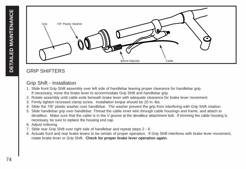
74
DE
TAIL
ED
MA
INT
EN
AN
CE
GRIP SHIFTERS
Grip Shift - Installation1. Slide front Grip Shift assembly over left side of handlebar leaving proper clearance for handlebar grip.
If necessary, move the brake lever to accommodate Grip Shift and handlebar grip.2. Rotate assembly until cable exits beneath brake lever with adequate clearance for brake lever movement.3. Firmly tighten recessed clamp screw. Installation torque should be 20 in.-lbs.4. Slide the 7/8” plastic washer over handlebar. The washer prevent the grip from interfering with Grip Shift rotation.5. Slide handlebar grip over handlebar. Thread the cable inner wire through cable housings and frame, and attach to
derailleur. Make sure that the cable is in the V groove at the derailleur attachment bolt. If trimming the cable housing isnecessary, be sure to replace the housing end cap.
6. Adjust indexing.7. Slide rear Grip Shift over right side of handlebar and repeat steps 2 - 6. 8. Actuate front and rear brake levers to be certain of proper operation. If Grip Shift interferes with brake lever movement,
rotate brake lever or Grip Shift. Check for proper brake lever operation again.
Grip 7/8” Plastic Washer
Barrel Adjuster Cable

75
DE
TAIL
ED
MA
INT
EN
AN
CE
Cables and Cable HousingCables and housing are one of the most overlookedparts on the bicycle. The first indication that yourcables and housing need to be replaced is anincreased amount of pressure needed to operate thebrakes or shifters. Before every ride, check that thereare no kinks or frays in the cables and housing.Check that the brake cables are correctly routed andnot wrapped around the stem or frame in a mannerthat prevents smooth operation or hampers control ofthe bicycle. Also check that the housing is seatedproperly into each cable stop of the bicycle. It is recommended that the cables and housing arereplaced at least every riding season to prolong the lifeof your bike.
Do not ride a bicycle that is notoperating properly.
kink
fray
good cable
Always check the brake cable routing toensure smooth and free application ofthe brakes. Cables that are kinked,frayed or otherwise damaged, or cables
that are wrapped around the stem or frame mayaffect braking power or cause unintended suddenstops and loss of control.

76
DE
TAIL
ED
MA
INT
EN
AN
CE
HEADSET
InspectionThe headset bearing adjustment should be checked every month.This is important as it is the headset which locks the fork into theframe, and if loose, can cause damage or result in an accident.While standing over the frame top tube with both feet on the ground,apply the front brake firmly and rock the bicycle back and forth; if youdetect any looseness in the headset, it will need adjustment. Checkthat the headset is not over tight by slowly rotating the fork to the rightand left. If the fork tends to stick or bind at any point, the bearingsare too tight.
Note: If your bike is equipped with a threadless headset, please seea qualified specialist for repairs and adjustments.
AdjustmentLoosen the headset top locknut or remove it completely along with thereflector bracket, if fitted. Turn the adjusting cup clockwise until fingertight. Replace the lock washer or reflector bracket and re-tighten thelock nut using a suitable wrench.
Note: Do not over tighten or bearing damage will occur.
Always make sure that the headset is properlyadjusted and that the headset locknut is fullytightened before riding.
Lock Nut
Lock Washer
Adjusting Cup/Cone
Ball Retainer
Top Head Cup
Bottom Head Cup
Ball Retainer
Crown Race
Warning: Over tightening the stem bolt or headset assembly may cause damage to the bicycle and/or injury to the rider.
Standard Headset

77
DE
TAIL
ED
MA
INT
EN
AN
CE
SADDLE AND SEAT POST
InspectionThe seat fixing bolt and the seat post binder bolt should be checkedfor tightness and adjustment every month. On removing the seat postfrom the frame, you will notice a mark about 65mm up from thebottom with the words “max. height” or “minimum insertion”.
Under no circumstances should the seat post pro-ject from the frame beyond its “Minimum Insertion”or “Maximum Extension” mark. If your seat postprojects from the frame beyond these markings, the
seat post or frame may break, which could cause you to losecontrol and fall. After any saddle adjustment, be sure to tightenthe saddle adjusting mechanism properly before riding. A loosesaddle clamp or seat post binder can cause damage to the bicy-cle or can cause you to lose control and fall. Periodically checkto make sure that the saddle adjusting mechanism is properlytightened.
LubricationRemove the seat post from the frame and wipe off any grease, rust ordirt. Then apply a thin film of new grease to the part that will be insertedinto the frame. Re-insert, adjust and tighten the seat post in the frame.
Seat Clamp Nut
StandardSeat Post

78
DE
TAIL
ED
MA
INT
EN
AN
CE
AdjustmentAs mentioned in Part 2, the seat can be adjusted in height, angle and distance from the handlebars to suit theindividual rider.Saddle angle is a matter of personal preference but the most comfortable position will usually be found when the topof the seat is almost parallel to the ground, or slightly raised at the front.
The saddle can also be adjusted by sliding it forward or back along the mounting rails to obtain the most comfortable reach to the handlebars.When fitting, position the seat post into the clamp under the seat and place it in the frame without tightening. Adjust it to the desired angle and position, and tighten the clamping mechanism securely.
Note that the type of binder bolt may be either a hexagonal bolt, an Allen head bolt, or a quick release mechanism.Test the security by grasping the seat and trying to turn it sideways. If it moves, you will need to further tighten thebinder bolt.
Note: Remember that the minimum insertion mark must remain inside the frame assembly.
The seat post must be inserted so that the minimum insertionmark cannot be seen. The quick release mechanism must betightened securely to prevent a sudden shift of the seat whenriding. Failure to do this may cause loss of bicycle control.

79
DE
TAIL
ED
MA
INT
EN
AN
CEInspection
Brake levers should be checked for tightness at least every threemonths. They should be set in a comfortable position within easyreach of the rider's hands, and must not be able to move on the handlebar. Some brake levers make use of a reach adjustment screw,which can be altered to the distance between the handlebar grip andthe lever, as required. The brake pads should be checked for correctpositioning and tightness before every ride, and the various bolts andnuts at least every three months. Squeeze each brake lever to makesure they operate freely and that the brake pads press hard enough onthe rims to stop the bike. There should be about 1mm - 2mm clear-ance between each pad and the rim when the brakes are not applied.The brake pads must be properly centered for maximumcontact with the rim. Replace the brake pads if they are over worn sothat the grooves or pattern cannot be seen. The brake cable wiresshould be checked for kinks, rust, broken strands or frayed ends. The outer casing should also be checked for kinks, stretched coils andother damage. If the cables are damaged, they should be replaced.Cantilever Brakes
Brake Cable
Brake Arm Straddle Cable
BRAKESThe correct adjustment and operation of your bicycle's brakes is extremely important for safe operation. Brakes should bechecked for effective operation before every ride. Frequent checking of adjustment is necessary as the control cables willstretch and the brake pads will become worn with use.
Never ride a bicycle unless the brakes are functioning properly.
There are three types of hand operated bicycle brakes in common use: sidepull brakes, cantilever brakes, and V-brakes (orDirect Pull brakes). All utilize a handlebar mounted lever which controls a cable to operate the brakes. Sidepull brakes andV-brakes use two brake pivot arms, each mounted on separate pivots on either side of the frame/fork.

80
DE
TAIL
ED
MA
INT
EN
AN
CE Lubrication
The brake lever and brake caliper pivot points should be oiled with2-3 drops of light oil at least every three months to ensure smoothoperation and to reduce wear. Cables should be greased alongtheir entire length, after removing them from their casings, at leastevery six months. Always grease new cables before fitting.
Adjustment - Sidepull CalipersMinor brake adjustment can be made via the cable adjusting barrel, usually located at the upper cable arm.
Caution:The brake cable adjusting barrels are for minor adjustments only. For major adjustments see the appropriate section in the manual for the type of brakes on your bicycle.
To adjust, squeeze the brake pads against the rim, loosen the locknut and turn the adjuster Brake pad clearance should be a maxi-mum 2mm from the rim. When correct, re-tighten the lock nut. Ifthe pads cannot be set close enough to the rim in this manner, youmay have to adjust the cable length. Screw the barrel adjuster 3/4of the way in, squeeze the pads against the rim, undo the cableanchor bolt and pull the cable through with pliers. Re-tighten thecable anchor bolt and apply full force to the brake lever to test,then fine tune using the barrel adjuster. If one pad is closer to therim than the other, loosen the fixing nut at the back of the brake,apply the brake to hold it centered, and re-tighten the fixing nut.
Brake Lever
Brake Lever Housing
Cable Adjusting Barrel
Lock nut
Cable Adjusting Barrel
Center Bolt
Brake Shoe
Side-Pull Brakes
Fixing Nutin Back
CableAnchor
Bolt
Ensure the Brake fixing nut is secured tightly.Failure to do this may cause the Brake assemblyto dislodge from the fork/frame.

81
DE
TAIL
ED
MA
INT
EN
AN
CE
Brake pads should finally be adjusted so that the leading edge of thepad makes first contact with the rim. Some brakes have specialcurved washers to allow this, but on less complex models it will benecessary to apply a little force to the pad and its mounting.
Adjustment - Cantilever CalipersMinor brake adjustment can be made via the barrel cable adjusterswhich are located on each brake lever.
Caution: The brake cable adjustiong barrels are for minoradjustments only. For major adjustments see the appropriate section in the manual for the type of brakes on your bicycle.
To adjust, squeeze the brake pads against the rim, loosen the locknut, and turn the adjuster to pull the brake pads closer to, or spreadthem away from the rim as required.Brake pad clearance should be a maximum 2mm from the rim.When correct, re-tighten the lock nut.If the pads cannot be set close enough to the rim in this manner, youmay have to adjust the length of the brake cable. To adjust the brake cable length: The main brake cable routesthrough a link cable to the anchor bolt on one of the brake arms.Squeeze both arms together so the brake shoes hit the rim, loosenthe cable anchor bolt and pull all the slack out of the cable. Retightenthe cable anchor bolt securely.
Parallel
Parallel
Fully Adjustable Brake Shoes
CurvedAdjustmentWasher
CurvedAdjustmentWasher
2mm clearance

82
DE
TAIL
ED
MA
INT
EN
AN
CE
Adjust the brake pad position so that it is parallel to the wheel rimand so that the leading edge makes first contact.To do this, fit an Allen key into the brake pad holding bolt, loosenthe fixing nut and adjust. Move the brake pad along its mountingpost to alter the distance from the rim, and move the curved adjustmentwasher to alter the angle of the pad.
Usable Brake Shoe Worn Out Brake Shoe (Replace)
Tread Tread Worn Off
Align brake shoe with rim surface
Direction of rimrotation
0.5 - 1.0 mm
Brake Shoe Holding Nut

83
DE
TAIL
ED
MA
INT
EN
AN
CE
DRIVETRAINThe drivetrain of a bicycle refers to all parts that transmit power to therear wheel including the pedals, chain, chainwheel, crank set, andfreewheel.
PEDALSPedals are available in a variety of shapes, sizes and materials, andeach are designed with a particular purpose in mind. Some pedalscan be fitted with toe clips and straps. These help to keep the feetcorrectly positioned and allow the rider to exert pulling force, as wellas downward pressure, on the pedals. Use of toe clips with strapsrequires practice to acquire the necessary skill to operate them safely.
InspectionPedals should be inspected every month, taking note of the following areas: - Check that the pedals are tightened securely against the crank
arm. If pedals are allowed to become loose, they will not only be dangerous but will also cause irreparable damage to the cranks.
- Check that pedal bearings are properly adjusted. Move the pedalsup and down, and right to left, and also rotate them by hand. Ifyou detect any looseness or roughness in the pedal bearings thenadjustment, lubrication or replacement is required.
- Ensure that the front and rear pedal reflectors are clean andsecurely fitted.
L = Left
Turn counter-clockwiseto tighten.
R = Right
Turn clockwiseto tighten.
Never ride with loose pedals. Always wearshoes.

84
DE
TAIL
ED
MA
INT
EN
AN
CE
Lubrication and AdjustmentMany pedals cannot be disassembled to allow access to the internal bearings and axle. However, it is usually possible toinject a little oil onto the inside bearings, and this should be done every six months. If the pedal is the type that can befully disassembled, then the bearings should be removed, cleaned and greased every six to twelve months. Because ofthe wide variety of pedal types and their internal complexity, disassembly procedures are beyond the scope of this manualand further assistance should be sought from a specialist.
Attachment
Note: The right and left pedals of a bicycle each have a different thread and are not interchangeable.Never force a pedal into the incorrect crank arm.Check for the right (R, red) sticker and left (L, green) sticker on each pedal and crank arm. Match the appropriate pedalto each crank (right to right and left to left) for assembly.Insert the correct pedal into the crank arm and begin to turn the thread with your fingers only. When the axle is screwedall the way in, securely tighten using a 15mm narrow open-ended wrench so that the shoulder of the pedal spindle issecurely tightened against the crank arm.If removing a pedal, remember that the right pedal axle must be turned counter clockwise, i.e. the reverse of when fitting.If replacing the original pedals with a new set, make sure the size and the axle thread is compatible with the cranks onyour bicycle. Bicycles use one of two types of cranks and these use different axle threads. Your bike may be equippedwith cranks that are a one piece design with no separate axle. These operate with pedals that have a 1/2"(12.7mm)thread. Bikes equipped with three piece crank sets with a separate axle, left crank and right crank, use a slightly larger9/16"(14mm) thread.
Note: Never try and force a pedal with the wrong thread size into a bicycle crank.

85
DE
TAIL
ED
MA
INT
EN
AN
CE
CRANK SETThe crank set refers to the bottom bracket axle and bearings, thecrank arms, and chainrings. Your bike may be fitted with either a onepiece crank, where the crank arms and bottom bracket are a singlecomponent, or cotterless cranks, where the crank arms bolt onto thebottom bracket axle without using old fashioned type cotterpins. Theone piece system is simpler and requires less maintenance, while thecotterless system requires a little extra care.
Never ride your bike if the cotterless cranks areloose. This may be dangerous and will damage thecrank arms beyond repair.
InspectionThe crank set should be checked for correct adjustment and tightnessevery month. Cotterless crank axle nuts must be kept tight, and thebottom bracket bearings must be properly adjusted.Remove the chain and try to move the cranks from side to side withyour hands. The cranks should not move on the axle, and thereshould be only very slight movement in the bottom bracket. Next,spin the cranks. If they don't spin freely without grinding noise, thenadjustment or lubrication will be needed. Also check that there are nobroken teeth on the chainrings, and wipe off excess dirt and greasethat may have built up on them.
Fixed Cup
Ball Bearing
Lockring
AdjustingCup
Axle
Standard Bottom Bracket Assembly (Cotterless)
Cotterless Crank

86
DE
TAIL
ED
MA
INT
EN
AN
CE Lubrication and Adjustment - One Piece Cranks
To adjust the free play in a one piece type bottom bracket, loosen the locknut on the left side by turning it clockwiseand tighten the adjusting cone counter-clockwise using a screwdriver in the slot. When correctly adjusted, re-tightenthe locknut counter-clockwise.To disassemble:1. Remove the chain from the chainwheel.2. Remove the left pedal by turning the spindle clockwise.3. Remove the left side locknut by turning it clockwise and remove the keyed lockwasher.4. Remove the adjusting cone by turning it clockwise with a screwdriver.5. Remove the left ball retainer, slide the crank assembly out of the frame to the right, and remove the right ball retainer.
Clean and inspect all bearing surfaces and ball retainers, and replace any damaged parts. Pack the ball bearingretainers with grease, then re-assemble in the reverse of the above procedure.
One Piece Crank Assembly
Crank
Fixed Cone
Ball RetainerBall Retainer
Adjusting Cone
Chainwheel
Bearing Cup
Bearing Cup
Lockwasher
Locknut

87
DE
TAIL
ED
MA
INT
EN
AN
CE
Lubrication and Adjustment- Cotterless CranksTo adjust the free play in a three piece type bottom bracket, loosenthe lockring on the left side by turning it counter-clockwise, then turnthe adjusting cup as required. Re-tighten the lockring taking care notto alter the cup adjustment.
To disassemble:1. Remove the cranks from the axle. (see below)2. Remove the left side lockring by turning it counter-clockwise.3. Remove the adjusting cup by turning it counter-clockwise.4. Remove the left ball retainer and slide the axle out of the frame to
the left.5. Remove the right side fixed cup by turning it counter-clockwise and
remove the right ball retainer. Clean and inspect all bearing surfacesand ball retainers, and replace any damaged parts. Pack the ballbearing retainers with grease, then re-assemble in reverse ofthe above procedure.
Cotterless Crank RemovalTo remove cotterless cranks use the following procedure.Note that a special tool will be required.1. Remove the dust cap with a coin or screwdriver.2. Loosen the flange nut or bolt and washer, and remove.3. Screw the removing tool into the crank and tighten.4. Turn the screw bolt down until the crank comes away from
the axle.
Remove the dust cap.
Loosen and removethe flange nut.
Fixed Cup
Ball Retainer
Axle
Adjusting Cup
LockringBottom BracketShell
Bottom Bracket
Cotterless Crank removing tool

88
DE
TAIL
ED
MA
INT
EN
AN
CE Cotterless Crank Replacement:
1. Replace the crank arm onto the axle.2. Tap the crank arm lightly with a mallet.3. Refit the washer and tighten flange nut or bolt securely to a
torque of 27Nm.4. Replace the dust cover
Adjustment After Use:1. Remove dust cap.2. Tap the crank arm lightly with a mallet.3. Re-tighten the flange nuts, and refit the dust caps.
New cotterless cranks may become loose with initialuse. Tighten the flange nuts (see illustration below)after several hours of riding, and repeat it two orthree times after further use. Cranks should then remain tight.
Tighten the flange nut.
Replace the dust cap.
Position the crank on the axle.
Lightly tap the crank onto the axle.
Screw in the removal tool.
Turn the screw bolt clockwise.

89
DE
TAIL
ED
MA
INT
EN
AN
CE
CHAIN
InspectionThe chain must be kept clean, rust free and frequently lubricated inorder to extend its life as long as possible. It will require replacementif it stretches, breaks, or causes inefficient gear shifting. Make surethat there are no stiff links, they must all move freely.
LubricationThe chain should be lubricated with light oil at least every month, or after use in wet, muddy, or dusty conditions.Take care to wipe off excess oil, and not to get oil on the tires or rim braking surfaces.
Adjustment and ReplacementOn derailleur geared bicycles the rear derailleur automatically tensions the chain.To adjust the chain on single speed freewheel, coaster hub braked or 3-speed hub geared bicycles:
1. Loosen the rear axle nuts (and coaster brake arm clip if fitted) and move the wheel forward to loosen, or backward totighten, in the frame.
2. When correctly adjusted, the chain should have approximately 10mm of vertical movement when checked in the centerbetween the chainwheel and rear sprocket. Center the wheel in the frame and re-tighten the axle nuts after anyadjustment.
Straightedge10 mm
Rear Sprocket Front Chainwheel
Pull up

90
DE
TAIL
ED
MA
INT
EN
AN
CE Chains require a special tool to fit and remove chain links, or to
change the length. To remove, fit the rivet tool so that the punchpin is centered over any one of the chain rivets. Push the rivetalmost all the way out, then back out the punch and remove thetool. Holding the chain on both sides of the punched rivet, bend itslightly to release link from the rivet. To install, feed chain aroundchainwheel, rear sprocket (and through front and rear derailleurson multi-speed bikes) with protruding rivet facing away from thebicycle. Bring the two ends together within the special tool andpunch the rivet into place. Be sure not to push rivet too far throughside plate.
FREEWHEELInspectionLike the chain, the freewheel must be kept clean and well lubricated. If the chain has become worn and needs replacing,then it is likely that the freewheel will also have become worn andshould also be replaced. Take the chain off the freewheel androtate it with your hand. If you hear a grinding noise or thefreewheel stops suddenly after spinning it, it may need adjustmentor replacement. Such action is beyond the scope of this manualand you should consult a specialist.
Chain Rivet Tool

91
DE
TAIL
ED
MA
INT
EN
AN
CE
LubricationRemove any accumulated dirt from the freewheel with a brushand a degreaser. Disassembly of the freewheel is a complicatedprocedure requiring special tools, and should be left to aspecialist. Apply oil to the freewheel whenever you lubricate thechain, taking care to wipe off any excess.
COASTER HUB
Many BMX style and other children's bicycles are fitted with acoaster hub brake in the rear wheel. This type of brake offersthe advantages of reliability and easy operation. The brake isoperated by applying back pedal pressure and allows the riderto 'coast' without pedaling, if desired. There are several modelsof coaster hubs available, and the internal mechanisms are verycomplex. They require infrequent attention as far as lubrication,adjustment or replacement of internal parts; if needed, thisshould be left to a specialist. Keep the coaster hub sprocket cleanand oil it along with the chain.
Make sure the brake arm is correctly attached tothe chainstay with the brake arm clip. Thebrake will not operate otherwise.
Brake Arm Clip
Brake Arm
Sprocket

92
DE
TAIL
ED
MA
INT
EN
AN
CE DERAILLEUR SYSTEMS
The derailleur system includes the front and rear derailleurs, the shift levers, and the derailleur control cables, all of whichmust function correctly for smooth gear shifting to occur. There are several different types of derailleur systems but alloperate using similar principles. Your new bicycle may be fitted with a standard 'friction' type system where you will needto feel each gear shift into position. It may be fitted with an ‘index’ system (e.g. SIS) which links each different gear positionto a positive click mechanism in the shifter, and makes shifting very simple and precise.
InspectionThe operation of the derailleur system should be checked atleast every month. Check the operation of the rear derailleurfirst, then the front. The rear derailleur should shift the chaincleanly from one cog to the next without hesitation. On IndexSystem equipped bicycles, each notched position in the shiftermust equate to a new gear position. After shifting, the rearderailleur should not rub on the chain. The derailleur shouldnever cause the chain to fall off the inner or outer freewheelcogs. The front derailleur should also shift the chain cleanly and without hesitation between each chainring. When the chain hasbeen positioned onto a new chainring, it should not rub on thefront derailleur. The chain should not fall off a chainring at anytime. Derailleur control cables are a critical component thatmust be well maintained for accurate shifting performance.Check them for any sign of rust, fraying, kinks, broken strands,and any damage to the cable housing. If you find anyproblems, the cables may need replacing before you ride.
Pre-stretch the derailleurcables to remove slack
Stretch

93
DE
TAIL
ED
MA
INT
EN
AN
CE
Adjustment - Front Derailleur1. Shift the rear shifter to the smallest number indicated, then shift
the front shifter to the smallest number indicated. Disconnect thefront derailleur cable from the cable anchor bolt and place thechain on the smallest chainwheel.
2. Make sure the front derailleur cage is parallel with the outerchainwheel on the crankset. There must be a 3-5mm gap betweenthe bottom of the derailleur cage and the top of the outer chainwheelteeth to ensure the derailleur will clear the chainwheel when shifting.
3. Adjust the low limit screw so the chain is centered in the middle ofderailleur cage. Pull all slack out of the cable by pulling it taut, thenreconnect the cable and tighten the cable anchor bolt securely.
4. Shift the front shifter into the largest gear and pedal the bike so thechain jumps to the largest chainwheel. If the chain does not shiftonto the largest chainwheel, you will need to turn the High limit screw counter-clockwise until the chain moves to the largestchainwheel. If the chain falls into the pedals, the High limit screw hasbeen turned too far. You will need to readjust the High screwclockwise in 1/4 turn increments until the chain no longer falls off.
5. Shift through each gear ensuring all are achieved quietly and withouthesitation.
6. Some shifters may have an adjusting barrel. Use the adjusting barrel to fine tune the adjustement of the chain location. Turn the adjusting barrel clockwise will move the derailleur outboard - away from the frame, while turning it clockwise will direct the chain inboard - towardsthe frame.
NOTE: It may take several adjustments to achieve the desired positioning.
Cable Fixing Bolt
Outer Chainguide
Inner Chainguide
Low Adjusting Screw
High AdjustingScrew
Chainguide clearance of
1-3 mm

94
DE
TAIL
ED
MA
INT
EN
AN
CE Lubrication
All the pivoting points of the front and rear derailleurs should be lubricated with light oil at least every month. Be sure to wipe off anyexcess oil to prevent attraction of dirt into the mechanisms. The shiftingcables should be cleaned and re-coated with a thin layer of greaseevery six months, or whenever new cables are being installed.
Adjustment - Rear DerailleurThe Low limit screw determines how far the rear derailleur will traveltoward the wheel of the bicycle, while the High limit screw determineshow far the cage will travel toward the frame.1. Shift the rear shifter to the largest number indicated, disconnect the
rear derailleur cable from the cable anchor bolt and place the chainon the smallest sprocket.
2. Adjust the High limit screw so the chain and the smallest sprocketare lined up vertically. Remove any slack in the cable by pulling ittaut, then re-connect the cable and tighten the cable anchor bolt securely.
3. Some derailleurs have an adjusting barrel (see drawing). Use the adjusting barrel to fine tune the adjustment of the chain location. Turning the adjusting barrel clockwise will move the derailleur outboard - away from the wheel - while turning it clockwise will direct the chain inboard - towards the wheel.
4. Shift the chain onto the largest sprocket; adjust the low limit screw so thechain and the largest cog are lined up vertically. If you are unable to getthe chain to the largest cog, turning the Low limit screw counter-clockwisewill enable the chain to move towards the wheel.
5. Shift through the gears ensuring each gear is achieved quietly and withouthesitation.
NOTE: It may take several adjustments to achieve the desired positioning.Please refer to the troubleshooting section for more assistance.
NOTE: Some bicycles may be equipped with a rear derailleur mechanism that works in REVERSE to the directions above.
Rear Derailleur Rear View
Freewheel
SIS Cable Adjuster
Outer side of Top Gear
Pulley AdjustmentScrew
Guide Pulley
Tension Pulley
AdjustmentScrews
Rear Derailleur Side View
SIS CableAdjuster
High Gear Adjustment Screw
Low Gear Adjustment Screw

95
DE
TAIL
ED
MA
INT
EN
AN
CE
REFLECTORSYour bicycle is supplied with one front (white), one rear (red), two wheel (white), and two pedal (orange) reflectors. These are an important safety and legal requirement, and should remain securely fitted and in good,clean conditions at all times. Periodically, inspect all reflectors, brackets and mounting hardware for signs ofwear or damage. Replace immediately if damage is found. Please see pages 14-15 for more information.
Reflectors Reflectors
Wear reflective clothing when riding.
Attach a light to your bike if you ride at night.

96
Problem
Gear shifts not working properly
Slipping chain
Chain jumping off freewheelsprocket or chainring
Constant clicking noises whenpedaling
Grinding noise when pedaling
Possible Cause
- Derailleur cablessticking/stretched/damaged
- Front or rear derailleur not adjustedproperly
- Indexed shifting not adjusted properly
- Excessively worn/chipped chainringor freewheel sprocket teeth
- Chain worn/stretched- Stiff link in chain- Non compatible chain/chainring/
freewheel
- Chainring out of true- Chainring loose- Chainring teeth bent or broken - Rear or front derailleur side-to-side
travel out of adjustment
- Stiff chain link- Loose pedal axle/bearings- Loose bottom bracket axle/bearings- Bent bottom bracket or pedal axle
- Loose crankset
- Pedal bearings too tight- Bottom bracket bearings too tight - Chain fouling derailleurs- Derailleur jockey wheels
dirty/binding
Remedy
- Lubricate/tighten/replace cables
- Adjust derailleurs
- Adjust indexing
- Replace chainring, sprockets andchain
- Replace chain- Lubricate or replace link- Seek advice at a bicycle shop
- Re-true if possible, or replace- Tighten mounting bolts- Repair or replace chainring/set- Adjust derailleur travel
- Lubricate chain / Adjust chain link- Adjust bearings/axle nut- Adjust bottom bracket- Replace bottom bracket axle or pedals- Tighten crank bolts
- Adjust bearings- Adjust bearings- Adjust chain line- Clean and lubricate jockey wheels
TR
OU
BL
ES
HO
OT
ING

TR
OU
BL
ES
HO
OT
ING
97
Problem
Freewheel does not rotate
Brakes not working effectively
When applying the brakesthey squeal/squeak
Knocking or shuddering whenapplying brakes
Wobbling wheel
Possible Cause
- Freewheel internal pawl pins arejammed
- Brake blocks worn down- Brake blocks/rim greasy, wet or dirty- Brake cables are
binding/stretched/damaged- Brake levers are binding- Brakes out of adjustment
- Brake blocks worn down- Brake block toe-in incorrect- Brake blocks/rim dirty or wet- Brake arms loose
- Bulge in the rim or rim out of true
- Brake mounting bolts loose- Brakes out of adjustment
- Fork loose in head tube
- Axle broken- Wheel out of true- Hub comes loose- Headset binding- Hub bearings collapsed- QR mechanism loose
Remedy
- Lubricate. If problem persists,replace freewheel
- Replace brake blocks- Clean blocks and rim
- Clean/adjust/replace cables- Adjust brake levers- Center brakes
- Replace blocks- Correct block toe-in- Clean blocks and rim- Tighten mounting bolts
- True wheel or take to a bike shopfor repair
- Tighten bolts- Center brakes and/or adjust brake
block toe-in- Tighten headset
- Replace axle- True wheel- Adjust hub bearings- Adjust headset- Replace bearings- Adjust QR mechanism

98
Remedy
- Align wheels correctly- Adjust/tighten headset- Take bike to a bike shop for possible
frame realignment
- Replace Inner tube- Replace tire- Replace with correct tire- Remove sharp object embedded
in tire- Correct tire pressure- File down spoke
Problem
Steering not accurate
Frequent punctures
Possible Cause
- Wheels not aligned in frame- Headset loose or binding- Front forks or frame bent- Stem wedge bolt not tight
- Inner tube old or faulty- Tire tread/casing worn- Tire unsuited to rim- Tire not checked after previous
puncture- Tire pressure too low- Spoke protruding into rim
TR
OU
BL
ES
HO
OT
ING

Subject to the following limitations, all bicycles manufactured for Dynacraft are warranted to the original purchaser to be free of defects in materials and workmanship for a period from the date of purchase of:
Lifetime For The Bicycle Frame and Fork Two Years On All Other Component Parts
No other express or implied warranty is given. Dynacraft will replace without charge the bicycle frame, fork or those component parts that are determined by Dynacraft to be defective in materials or manufacture under normal use and service during the applicable warranty period. The original purchaser will be responsible for any and all labor charges connected with the repair or replacement of the frame, fork, and/or parts. Component parts subject to wear in use, tires, tubes, seats, grips and brake shoes are not covered under this warranty.
CAUTION: This limited warranty does not apply to normal wear and tear, nor to claimed defects, malfunctions, or failures that result from abuse, neglect, improper assembly, improper maintenance, alteration, collision, crash or misuse. Dynacraft does not encourage stunting, trick riding, ramp riding, jumping, aggressive riding, riding on severe terrain, riding in severe climates, riding with heavy loads, commercial activities, or any similar activities; such use is inherently dangerous, can cause serious injury to the rider, and if done it is with the rider’s express and implied assumption of the risk of such use and Dynacraft shall not have any responsibility for any break down of the bicycle, its components or rider injuries that occur during such use.
Bicycle riding can be inherently dangerous such that bodily injury or death can occur, especially if the rider does not make the safety and maintenance checks recommended in this manual, if the rider does not wear a helmet, if the rider does not follow the rules of the road, if the rider goes into traffic, rides double, or engages in aggressive, stunt or extreme terrain riding. Riders taking such actions will assume their own risk of injury, and Dynacraft will not be responsible.
THE PURCHASE OF THIS BICYCLE WILL CONFIRM THE BUYER’S AGREEMENT THAT DYNACRAFT’S LIABILITY UNDER THIS WARRANTY SHALL BE NO GREATER THAN THE AMOUNT OF THE ORIGINAL PURCHASE PRICE AND IN NO EVENT SHALL DYNACRAFT BE LIABLE FOR INCIDENTAL OR CONSEQUENTIAL DAMAGES.
Dynacraft BSC, Inc.89 South Kelly Road
American Canyon, CA 94503Call Toll Free 1.800.551.0032
Monday-Friday 7:00 a.m. to 4:00 p.m. Pacific Time
LIMITED WARRANTY

100
DYNACRAFT BSC, INC.
PLACESTAMPHERE
Cut along dotted line before mailing
Cu
t alon
g d
otted
line b
efore m
ailing
89 S. KELLY RD. AMERICAN CANYON, CA 94503

101
Thank You for purchasing your bicycle. Please take a moment to fill out this registration card,and mail it back to us. We value your business and appreciate your feedback.
Model Number/Description: __________________________________________________________
Serial Number: ____________________________________________________________________
Name: ____________________________________________________________________________
Address: __________________________________________________________________________
City/State: __________________________________________ Zip:__________________________
Date of Purchase: ____________________________________ Users Date of Birth: ____________
Date of Birth of Person’s Whose Name Appears Above: __________________________________
Place of Purchase: ________________________________________________________________
Check the 2 most important reasons you selected this brand of bicycle:
Friend or relative ownsstoreNewspaper Ad
Who selected this bicycle?
Cut along dotted line before mailing
Cu
t al
on
g d
ott
ed l
ine
bef
ore
mai
ling
Price
Appearance/Style
Special Features
Character
Color
Other (Please specify)
Father of user
Mother of user
Child
Grandparents
Relative
Other
Who is using this bicycle?
Male
Female

1.800.551.0032www.dynacraftbikes.com
BSC, Inc
89 S. Kelly Rd. American Canyon, CA 94503