new brunswick bioflo /celligen 115 benchtop … brunswick bioflo®/celligen® 115 benchtop fermentor...
TRANSCRIPT

New Brunswick BioFlo®/CelliGen® 115
Benchtop Fermentor & Bioreactor
Operating Manual M1369-0050 Revision E
2
BioFlo®/CelliGen® 115 M1369-0050 Operating manual
COPYRIGHT: Copyright © 2012-2013 Eppendorf AG, Germany. No part of this publication may be reproduced without the prior permission of the copyright owner. Eppendorf reserves the right to change information in this document without notice. Updates to information in this document reflect our commitment to continuing product development and improvement.
TRADEMARKS: BioFlo®, CelliGen®, BioCommand® and Eppendorf® are registered trademarks, and New Brunswick™ and the New Brunswick Logo™ are trademarks of Eppendorf AG, Hamburg, Germany. Marprene® is a registered trademark of Watson-Marlow Limited in Falmouth, Cornwall, UK. PharMed® is a registered trademark of Saint-Gobain Performance Plastics in Akron, Ohio. Windows® is a registered trademark of Microsoft Corporation in the United States and other countries. Trademarks are not marked in all cases with ™ or ® in this manual. Eppendorf has attempted to identify the ownership of all trademarks from public records. Any omissions or errors are unintentional. June 6, 2012 Revision E M1369-0050

3
Operating manual
FERMENTOR/BIOREACTOR
INFORMATION SHEET
On this page, record the information for your fermentor/bioreactor and retain this for future reference. MODEL NUMBER: ________________________________ VOLTAGE: ________________________________ SERIAL NUMBER: ________________________________
The above information can be found on the electrical specification plate. Purchased with the following installed options:
__________________________________________________ __________________________________________________ __________________________________________________ __________________________________________________ __________________________________________________
4
BioFlo®/CelliGen® 115 M1369-0050 Operating manual
TABLE OF CONTENTS
1 USER INSTRUCTIONS ..................................................................................................9
1.1 HAZARD ICONS ............................................................................................................9 1.2 DANGER LEVELS ..........................................................................................................9 1.3 MANUAL CONVENTIONS.............................................................................................10 1.4 ABBREVIATIONS ........................................................................................................10
2 INSPECTION & UNPACKING OF EQUIPMENT ...................................................11
2.1 INSPECTION OF BOX(ES) .............................................................................................11 2.2 PACKING LIST VERIFICATION......................................................................................11 2.3 BASIC COMPONENTS ..................................................................................................11
3 INTRODUCTION & OVERVIEW...............................................................................12
3.1 SYSTEM......................................................................................................................12 3.2 VESSELS.....................................................................................................................12 3.3 AGITATION SYSTEM ...................................................................................................12 3.4 TEMPERATURE CONTROL ...........................................................................................13 3.5 AERATION..................................................................................................................13 3.6 PH CONTROL ..............................................................................................................13 3.7 DO CONTROL .............................................................................................................13 3.8 FOAM/LEVEL CONTROL..............................................................................................14 3.9 EXHAUST SYSTEM......................................................................................................14 3.10 RECOMMENDED ACCESSORIES & SUPPLIES ................................................................14 3.11 SUPERVISORY SOFTWARE...........................................................................................15
4 INSTALLATION............................................................................................................16
4.1 PHYSICAL LOCATION..................................................................................................16 4.2 ENVIRONMENT...........................................................................................................16 4.3 INSTALLING THE CONTROL CABINET .........................................................................17 4.4 CONNECTING UTILITY CABINETS................................................................................20 4.5 UTILITIES ...................................................................................................................22
4.5.1 Electrical Requirements....................................................................................23 4.5.2 Water and drain connections ............................................................................24 4.5.3 Gas connections ................................................................................................25
4.6 **IMPORTANT SAFETY NOTES** ................................................................................27 4.7 VESSEL ASSEMBLY: NON-JACKETED..........................................................................29
4.7.1 Headplate..........................................................................................................31 4.7.2 Install heat blanket............................................................................................34 4.7.3 Install vessel in vessel stand .............................................................................34 4.7.4 Install baffle (14.0 L fermentation vessels ONLY)............................................35
4.8 VESSEL ASSEMBLY: WATER-JACKETED .....................................................................35 4.8.1 Install headplate clamping ring ........................................................................37 4.8.2 Install vessel on base plate ...............................................................................37
5
Operating manual
4.8.3 Filling the water jacket .....................................................................................38 4.8.4 Install baffle (14.0 L fermentation vessels ONLY)............................................38 4.8.5 Install impeller(s)..............................................................................................39 4.8.6 Install cooling coil ............................................................................................40 4.8.7 Install sparger (3.0 L, 7.5 L & 14.0 L vessels) .................................................40 4.8.8 Install harvest tube............................................................................................41 4.8.9 Install sampler tube...........................................................................................41 4.8.10 Install thermowell .............................................................................................41 4.8.11 Install foam probe .............................................................................................41 4.8.12 Install foam exhaust tube ..................................................................................42 4.8.13 Install level probe(s) .........................................................................................42 4.8.14 Install addition tube(s)......................................................................................42 4.8.15 Install pH probe ................................................................................................42 4.8.16 Install dO2 probe ..............................................................................................44 4.8.17 Install exhaust condenser..................................................................................46 4.8.18 Install sampler ..................................................................................................47 4.8.19 Install foam trap................................................................................................50 4.8.20 Plug unused ports .............................................................................................51 4.8.21 Install 1.3 L, 3.0 L or 7.5 L fermentation vessel baffle .....................................51 4.8.22 Install headplate................................................................................................52 4.8.23 Install vessel......................................................................................................52 4.8.24 Install motor assembly ......................................................................................53 4.8.25 Make all connections ........................................................................................53
4.9 ON/OFF SWITCH .......................................................................................................54 4.10 OPTIONAL BIOCOMMAND SOFTWARE ........................................................................55
5 SPECIFICATIONS.........................................................................................................57
5.1 CERTIFICATIONS ........................................................................................................58
6 OPERATING CONTROLS...........................................................................................60
6.1 TOUCHSCREEN...........................................................................................................60 6.2 DISPLAY SCREENS......................................................................................................60
6.2.1 Touchscreen calibration ...................................................................................60 6.2.2 Start-Up screen .................................................................................................61 6.2.3 Summary screen ................................................................................................61 6.2.4 Keypads.............................................................................................................64 6.2.5 Gauge screens...................................................................................................66 6.2.6 Selecting loop control modes ............................................................................67 6.2.7 Entering loop setpoints .....................................................................................68 6.2.8 Modifying setpoints...........................................................................................70 6.2.9 Calibration screen ............................................................................................70 6.2.10 Cascade screen .................................................................................................70 6.2.11 Pump screen......................................................................................................71 6.2.12 Setup screen ......................................................................................................72
7 PROBE PREPARATION & CALIBRATION ............................................................74
7.1 PH PROBE INSPECTION................................................................................................74
6
BioFlo®/CelliGen® 115 M1369-0050 Operating manual
7.2 PH PROBE CALIBRATION.............................................................................................74 7.2.1 pH probe installation ........................................................................................76 7.2.2 pH probe maintenance & storage.....................................................................78
7.3 DISSOLVED OXYGEN (DO) PROBE PREPARATION .......................................................78 7.3.1 Inspecting the DO probe...................................................................................78 7.3.2 DO probe preparation ......................................................................................78 7.3.3 DO probe installation .......................................................................................79 7.3.4 DO probe polarization......................................................................................81 7.3.5 DO probe calibration: setting zero..................................................................81 7.3.6 DO probe calibration: setting span .................................................................82
7.4 LEVEL PROBE CALIBRATION.......................................................................................82 7.5 ABOUT PUMP CALIBRATION .......................................................................................83
8 VESSEL STERILIZATION ..........................................................................................84
8.1 INITIAL PREPARATION FOR AUTOCLAVING .................................................................85 8.2 AUTOCLAVING THE VESSEL........................................................................................86
8.2.1 Sterilization time and temperature....................................................................87
9 REINSTALLING THE VESSEL ASSEMBLY ...........................................................88
9.1 REINSTALL THE VESSEL ASSEMBLY............................................................................88 9.2 LOAD PUMP TUBING ...................................................................................................88 9.3 CONFIRM PH CALIBRATION........................................................................................90 9.4 INSTALL LIQUID ADDITION SYSTEMS ..........................................................................90
9.4.1 Addition tubing size...........................................................................................91 9.5 RECONNECT GASES ....................................................................................................92 9.6 INSTALL TEMPERATURE (RTD) PROBE.......................................................................92
10 CASCADE CONTROL..............................................................................................93
10.1 CREATING A CASCADE...............................................................................................94
11 ABOUT PUMPS..........................................................................................................96
11.1 PUMP ASSIGNMENT ....................................................................................................96 11.2 PUMP SETPOINT..........................................................................................................97 11.3 PUMP CONTROL MODE................................................................................................99 11.4 PUMP FLOW RATE & CALIBRATION METHODS ............................................................99 11.5 PUMP PERIOD ...........................................................................................................100 11.6 USING LEVEL PROBES TO PROGRAM FEED PUMPS .....................................................101
11.6.1 Setting a feed pump to add liquid ...................................................................101 11.6.2 Setting a feed pump to harvest ........................................................................102 11.6.3 Level control off ..............................................................................................102 11.6.4 Pump calibration ............................................................................................102
12 USING THE SETUP SCREEN ...............................................................................103
12.1 CONTROLLER SETUP ................................................................................................103 12.1.1 Gas control......................................................................................................106
12.2 SYSTEM SETTINGS....................................................................................................108 12.2.1 Resetting date/time..........................................................................................109
7
Operating manual
12.2.2 Updating software...........................................................................................109 12.3 HARDWARE SETUP...................................................................................................109
12.3.1 Identifying utility station(s) added ..................................................................112 12.3.2 Removing a Utility Station ..............................................................................112
13 PERFORMING A RUN ...........................................................................................113
13.1 SET UP FOAM CONTROL............................................................................................113 13.2 PREPARING FOR A FERMENTATION RUN....................................................................113 13.3 INOCULATION ..........................................................................................................114 13.4 START BIOCOMMAND (IF PRESENT) .........................................................................115 13.5 SAMPLING PROCEDURE ............................................................................................115 13.6 FERMENTATION PHASES...........................................................................................116
13.6.1 Lag phase ........................................................................................................116 13.6.2 Exponential growth phase...............................................................................116 13.6.3 Steady state phase ...........................................................................................117 13.6.4 Decline phase..................................................................................................117
13.7 BATCH OPERATION ..................................................................................................117 13.8 FED BATCH OPERATION............................................................................................117 13.9 CONTINUOUS OPERATION.........................................................................................117 13.10 ANAEROBIC AND MICROAEROPHILIC CULTURE ....................................................118 13.11 HARVESTING PROCEDURE ....................................................................................118 13.12 SHUTDOWN PROCEDURE ......................................................................................119
14 ESSENTIAL OPERATING TIPS...........................................................................120
14.1 PRECAUTIONS FOR GLASS VESSEL ASSEMBLY ..........................................................120 14.2 EXHAUST CONDENSER & EXHAUST FILTERS.............................................................120 14.3 INSTALL A DOUBLE FILTER SYSTEM..........................................................................120
15 CLEANING...............................................................................................................122
15.1 CLEANING THE VESSEL ............................................................................................122 15.1.1 List of wetted parts..........................................................................................122
15.2 CLEANING THE CABINET ..........................................................................................122
16 MAINTENANCE......................................................................................................123
16.1 PH PROBE MAINTENANCE AND STORAGE..................................................................123 16.2 DO PROBE MAINTENANCE AND STORAGE.................................................................123 16.3 VESSEL & TUBING....................................................................................................124 16.4 PERIODIC INSPECTION ..............................................................................................124 16.5 AGITATOR BEARING HOUSING..................................................................................124
16.5.1 Motor assembly replacement ..........................................................................124 16.6 REPLACEMENT PARTS ..............................................................................................125
17 SERVICE...................................................................................................................129
17.1 TROUBLESHOOTING .................................................................................................129
18 DRAWINGS ..............................................................................................................131
18.1 LIST OF DRAWINGS...................................................................................................131
8
BioFlo®/CelliGen® 115 M1369-0050 Operating manual
18.2 LIST OF TABLES........................................................................................................132
19 APPENDIX A: SOME GENERAL CONCEPTS .................................................134
19.1 WHAT IS A CONTROLLER? ........................................................................................134 19.2 WHAT IS A CONTROL LOOP? .....................................................................................134 19.3 WHAT IS PROBE CALIBRATION?................................................................................134 19.4 WHAT ARE P-I-D CONSTANTS? ................................................................................134 19.5 WHAT IS P-I-D TUNING? ..........................................................................................135 19.6 WHAT DO THE CONSTANTS MEAN?...........................................................................136
20 APPENDIX B: OTR ................................................................................................137
20.1 DETERMINING AN OXYGEN TRANSFER RATE ............................................................137 20.1.1 OTR calculations ............................................................................................137
20.2 SOME FACTORS THAT AFFECT OTR AND HORSEPOWER............................................138
21 APPENDIX C: FERMENTATION TECHNIQUES............................................140
21.1 MEDIA FORMULATION..............................................................................................140 21.2 ANTIFOAM FORMULATION .......................................................................................141 21.3 TUBING SIZE.............................................................................................................141 21.4 ACID & BASE ...........................................................................................................142 21.5 GLUCOSE FEED.........................................................................................................142 21.6 RECOMMENDED PROCESS CONTROL SETTINGS .........................................................143 21.7 TYPICAL FERMENTATION RUN..................................................................................143
21.7.1 Vessel preparation before autoclaving ...........................................................143 21.7.2 Vessel sterilization ..........................................................................................145 21.7.3 Post-sterilization vessel set-up........................................................................145 21.7.4 Vessel operation..............................................................................................146 21.7.5 Vessel shutdown & cleaning ...........................................................................147
22 APPENDIX D: CORROSION RESISTANCE .....................................................149
23 APPENDIX E: GENERAL CHARACTERISTICS OF EPR..............................150
23.1 IDENTIFYING EPR....................................................................................................150 23.2 GENERAL CHARACTERISTICS ...................................................................................150
24 INDEX........................................................................................................................151
9
Operating manual
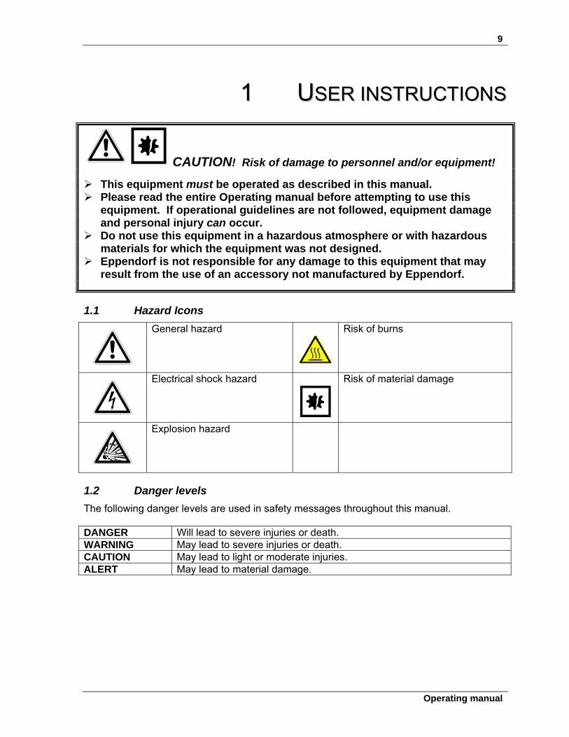
11 UUSSEERR IINNSSTTRRUUCCTTIIOONNSS
CAUTION! Risk of damage to personnel and/or equipment!
This equipment must be operated as described in this manual. Please read the entire Operating manual before attempting to use this
equipment. If operational guidelines are not followed, equipment damage and personal injury can occur.
Do not use this equipment in a hazardous atmosphere or with hazardous materials for which the equipment was not designed.
Eppendorf is not responsible for any damage to this equipment that may result from the use of an accessory not manufactured by Eppendorf.
1.1 Hazard Icons
General hazard
Risk of burns
Electrical shock hazard Risk of material damage
Explosion hazard
1.2 Danger levels
The following danger levels are used in safety messages throughout this manual. DANGER Will lead to severe injuries or death. WARNING May lead to severe injuries or death. CAUTION May lead to light or moderate injuries. ALERT May lead to material damage.
10
BioFlo®/CelliGen® 115 M1369-0050 Operating manual
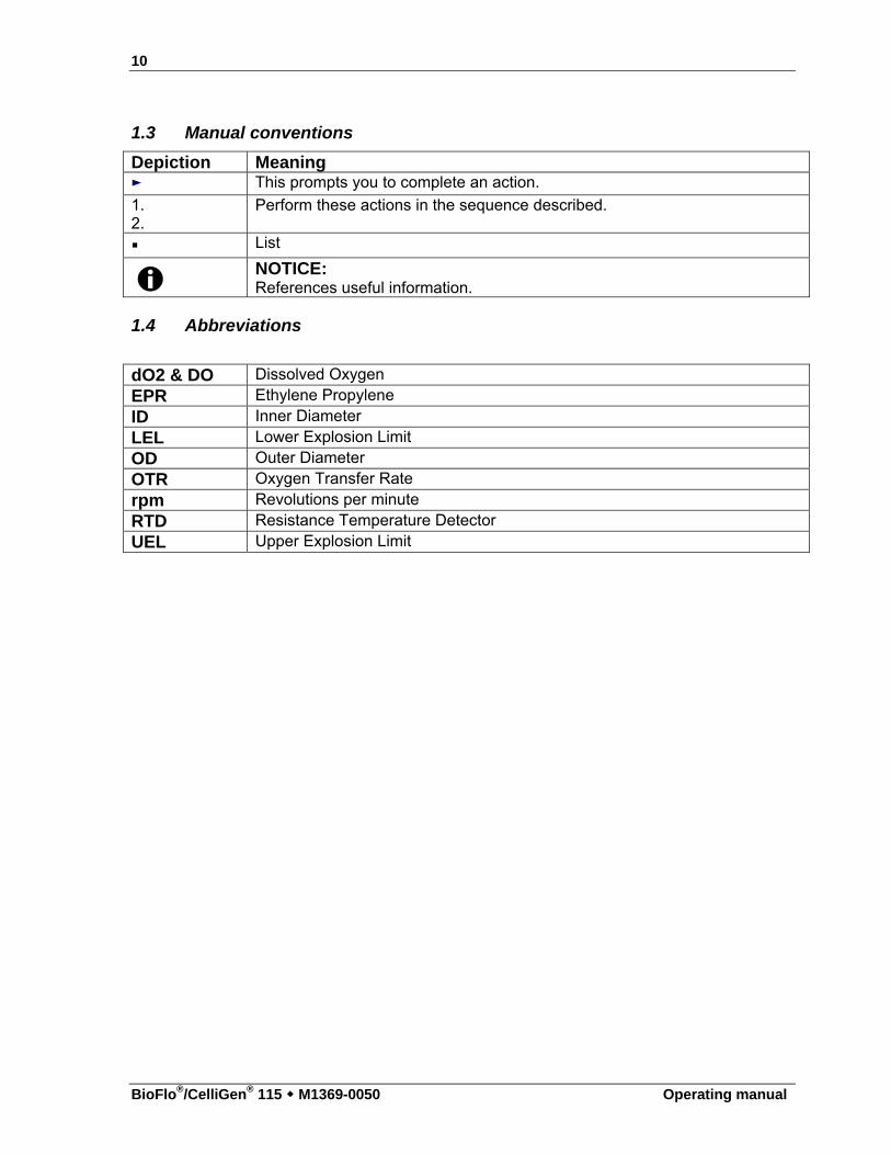
1.3 Manual conventions
Depiction Meaning ► This prompts you to complete an action.
1. 2.
Perform these actions in the sequence described.
List
NOTICE: References useful information.
1.4 Abbreviations
dO2 & DO Dissolved Oxygen EPR Ethylene Propylene ID Inner Diameter LEL Lower Explosion Limit OD Outer Diameter OTR Oxygen Transfer Rate rpm Revolutions per minute RTD Resistance Temperature Detector UEL Upper Explosion Limit
11
Operating manual
22 IINNSSPPEECCTTIIOONN && UUNNPPAACCKKIINNGG OOFF
EEQQUUIIPPMMEENNTT
2.1 Inspection of box(es)
When you have received your order from Eppendorf, carefully inspect all parts of the shipment for damage that may have occurred during shipping. Report any damage immediately to the carrier and to your local Eppendorf Sales Order Department.
2.2 Packing list verification
Verify against your Eppendorf packing list that you have received the correct materials. Report any missing parts to your local Eppendorf Sales Order Department.
2.3 Basic components
You should have at least the following components, which will be described in greater detail later in this manual:
Control Cabinet with Touchscreen Bearing Housing Vessel Filters & connectors Thermowell & RTD Inoculation/Addition System Baffles (for fermentation only) Sampling System Impellers Harvesting System Probe Kits (i.e., pH, DO, Foam, Level) Sparging System Motor
The assembled Control Cabinet/Touchscreen assembly is called a Control Station. For purposes of clarity in this manual, however, the control cabinet (which houses the controller) and the touchscreen will be referred to separately by their component names.
12
BioFlo®/CelliGen® 115 M1369-0050 Operating manual
33 IINNTTRROODDUUCCTTIIOONN && OOVVEERRVVIIEEWW
3.1 System
BioFlo/CelliGen 115 is a versatile fermentor/bioreactor that provides a fully equipped system in one compact package. It can be employed for batch, fed batch or continuous culture with process control for pH, dissolved oxygen (DO), agitation, temperature, pump feed, antifoam and foam/level. Systems can be configured as either control stations or utility stations. Each individual stand-alone system is a control station. One control station can run up to two additional utility stations, which are dependent on the control station.
3.2 Vessels
One of the most versatile features of the BioFlo/CelliGen 115 is the wide variety of glass vessels available. There are two types of vessels, non-jacketed (heat-blanketed) and water-jacketed. Each type of vessel is available in four sizes: 1.3 liters, 3.0 liters, 7.5 liters and 14.0 liters. Ports in the headplate are provided for, but not limited to, the following purposes: inoculation; base and acid addition; a thermowell for a resistance temperature detector (RTD); a foam probe; a sparger; a harvest tube; a sampling tube; an exhaust condenser; and dissolved oxygen (DO) and pH electrodes. The drive bearing housing is also located on the headplate.
3.3 Agitation system
A removable agitation motor located on top of the bearing housing on the headplate is connected to the agitation shaft with a direct drive coupling or a magnetic coupling.
The motor can be easily disconnected before autoclaving the vessel and easily replaced after sterilization. The motor will provide a speed range from 50 to 1200 rpm for fermentation with direct drive, from 25 to 400 rpm for cell culture with direct drive, or from 25 to 200 rpm for cell culture with magnetic drive. The process control software ensures agitation speed control throughout the speed range.
It is possible to cascade Dissolved Oxygen (DO) to Agitation (AGIT) so the agitation speed will vary between the user-specified minimum and maximum setpoints in order to maintain the set percentage of DO. (See Section 10 for further information on setting up cascades.)
Default P & I (proportional & integral) values are preset at the factory. We strongly recommend that you maintain the factory-set parameters. (See Sections 19.4-19.6 for more information on P & ! values.)
13
Operating manual
3.4 Temperature control
The culture temperature setpoint may be selected within the range from 20C above coolant temperature to 70C for 1.3- to 7.5-liter vessels, and from 20C above coolant temperature to 65C for 14.0-liter vessels. It is controlled by the process control software which then sends information to either a heater blanket and cooling coil or to a water jacket. The media temperature is sensed by a Resistance Temperature Detector (RTD) submerged in the thermowell.
Default P & I (proportional & integral) values are preset at the factory. We strongly recommend that you maintain the factory-set parameters.
3.5 Aeration
Up to four gases, including air, nitrogen, carbon dioxide and oxygen, can be introduced into the media through the ring sparger or optional microsparger. The flow rate is controlled manually by one, two, three or four Rotameter(s) or automatically by thermal mass flow controller (TMFC), according to the definition of your system. The TMFC is regulated automatically according to values set via the control station touchscreen.
The gas mix can either be controlled manually by adjusting the flow of gases through their Rotameters or automatically if 4-gas mixing was purchased as an option. (For further information on cascading, see Section 10.) 4-gas mixing allows the system to automatically calculate the gas mix in response to culture needs.
Default P & I (proportional & integral) values are preset at the factory. We strongly recommend that you maintain the factory-set parameters.
3.6 pH control
pH is controlled in the range of 2.00-14.00. The pH is sensed by a gel-filled pH probe. Control is maintained by a P & I (proportional & integral) controller which operates peristaltic pumps, assigned to perform acid or base addition, or which controls the use of gas(es) for this purpose. The user can also select a deadband value to control pH within the user-assigned range: no acid or base will be added when the pH value falls within the deadband tolerance above or below the setpoint.
Default P & I (proportional & integral) values are preset at the factory. We strongly recommend that you maintain the factory-set parameters.
3.7 DO control
Dissolved oxygen (DO) is controlled in the range of 0-200%. It is sensed by the DO electrode and control is maintained by the P & I controller by changing the speed of agitation, the thermal mass flow controller-regulated flow rate (if your system is so equipped), and/or the percentage of oxygen in aeration.
14
BioFlo®/CelliGen® 115 M1369-0050 Operating manual
Default P & I (proportional & integral) values are preset at the factory. We strongly recommend that you maintain the factory-set parameters.
The DO probe is a polarographic probe. Be sure to inspect the DO probe before every run, changing the electrolyte solution and membrane as needed.
3.8 Foam/Level control
Foam can be monitored during batch fermentation by a foam/level probe located in the headplate. The controller operates the antifoam-assigned pump that adds chemical defoamer into the vessel as needed. The internal level can also be controlled by using this feature. Pumps can be triggered to turn on or off in response to the presence or absence of liquid.
3.9 Exhaust system
The exhaust gases pass into the exhaust condenser where moisture is removed, then returned to the vessel. The remaining gases then pass through a 0.2 m exhaust filter. Be sure to inspect filters before every run, replacing them as needed.
WARNING! Risk of explosion! NEVER block the exhaust to pressurize the vessel.
3.10 Recommended accessories & supplies
Before you begin to assemble your BioFlo/CelliGen 115, it would be prudent to verify that you have all of the following accessories and supplies readily at hand:
An autoclave An inoculation syringe Rubber gloves Media Silicone tubing Antifoam agent A tie gun Aluminum foil Plastic ties (multiple colors can be helpful) Rubber bands Plastic tubing connectors pH 4 buffer Addition bottles pH 7 buffer A liquid trap Silicone O-ring lubricant (for Polysulfone quick-connects fermentation only)
User’s kits and start-up kits are available from Eppendorf with many of the commonly required items (including a selection of tubing, clamps, filters, connectors and addition vessels). See Section 16.6 for a list of spare parts, and speak to your Eppendorf sales representative for more information.
15
Operating manual
3.11 Supervisory software
In addition to the built-in software that you interface with through the touchscreen, your BioFlo/CelliGen 115 system can be remotely controlled from a PC via New Brunswick BioCommand optional supervisory software (see Section 4.10). Consult your Eppendorf representative for details; be sure to ask for ModBus protocol.
16
BioFlo®/CelliGen® 115 M1369-0050 Operating manual
44 IINNSSTTAALLLLAATTIIOONN
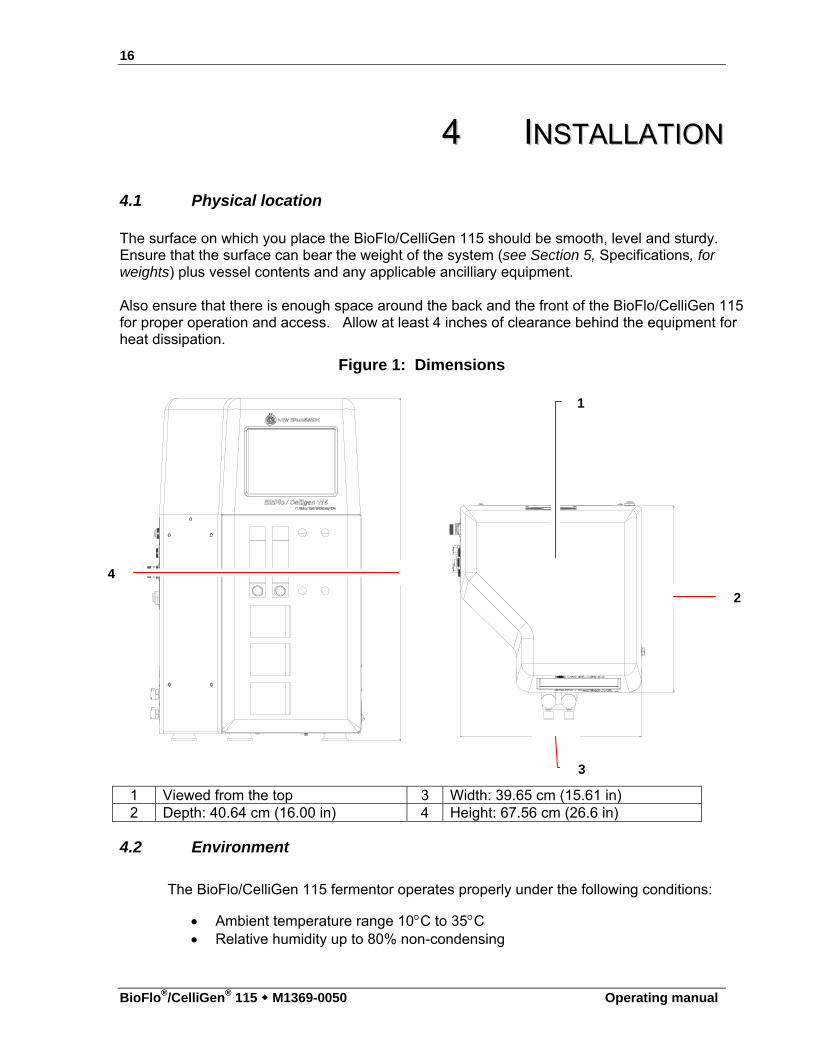
4.1 Physical location
The surface on which you place the BioFlo/CelliGen 115 should be smooth, level and sturdy. Ensure that the surface can bear the weight of the system (see Section 5, Specifications, for weights) plus vessel contents and any applicable ancilliary equipment.
Also ensure that there is enough space around the back and the front of the BioFlo/CelliGen 115 for proper operation and access. Allow at least 4 inches of clearance behind the equipment for heat dissipation.
Figure 1: Dimensions
16.00"
1 Viewed from the top 3 Width: 39.65 cm (15.61 in) 2 Depth: 40.64 cm (16.00 in) 4 Height: 67.56 cm (26.6 in)
4.2 Environment
The BioFlo/CelliGen 115 fermentor operates properly under the following conditions:
Ambient temperature range 10C to 35C Relative humidity up to 80% non-condensing
1
2
3
4
17
Operating manual
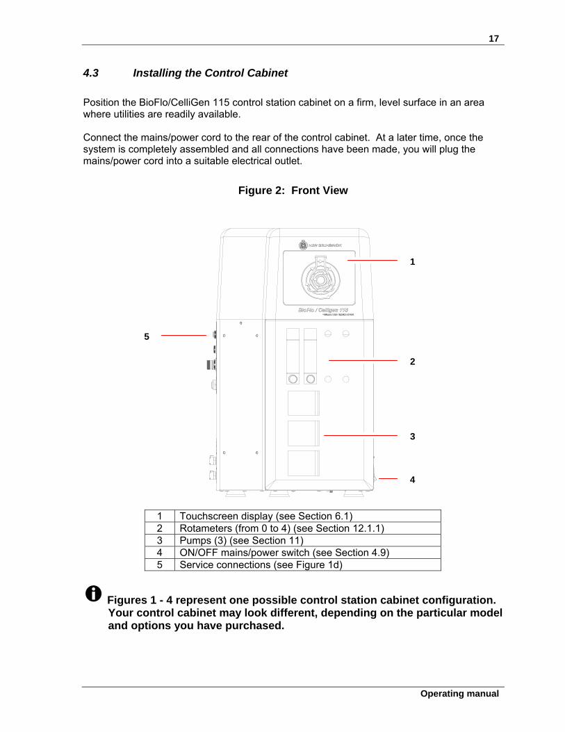
4.3 Installing the Control Cabinet
Position the BioFlo/CelliGen 115 control station cabinet on a firm, level surface in an area where utilities are readily available.
Connect the mains/power cord to the rear of the control cabinet. At a later time, once the system is completely assembled and all connections have been made, you will plug the mains/power cord into a suitable electrical outlet.
Figure 2: Front View
1 Touchscreen display (see Section 6.1) 2 Rotameters (from 0 to 4) (see Section 12.1.1) 3 Pumps (3) (see Section 11) 4 ON/OFF mains/power switch (see Section 4.9) 5 Service connections (see Figure 1d)
Figures 1 - 4 represent one possible control station cabinet configuration. Your control cabinet may look different, depending on the particular model and options you have purchased.
1
2
3
4
5
18
BioFlo®/CelliGen® 115 M1369-0050 Operating manual
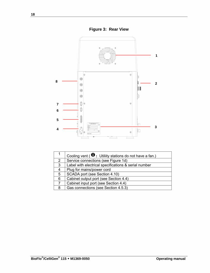
Figure 3: Rear View
1 Cooling vent ( : Utiliity stations do not have a fan.) 2 Service connections (see Figure 1d) 3 Label with electrical specifications & serial number 4 Plug for mains/power cord 5 SCADA port (see Section 4.10) 6 Cabinet output port (see Section 4.4) 7 Cabinet input port (see Section 4.4) 8 Gas connections (see Section 4.5.3)
1
2
3 4
5
6
7
8
19
Operating manual
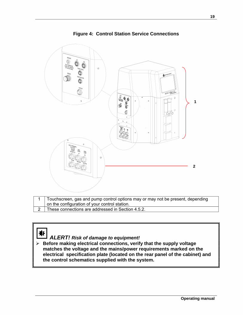
Figure 4: Control Station Service Connections
1 Touchscreen, gas and pump control options may or may not be present, depending
on the configuration of your control station. 2 These connections are addressed in Section 4.5.2.
ALERT! Risk of damage to equipment! Before making electrical connections, verify that the supply voltage
matches the voltage and the mains/power requirements marked on the electrical specification plate (located on the rear panel of the cabinet) and the control schematics supplied with the system.
1
2
20
BioFlo®/CelliGen® 115 M1369-0050 Operating manual
4.4 Connecting utility cabinets
ALERT! Risk of damage to equipment function! When connecting multiple utility stations, be sure to connect, power, and
configure only one at a time. Any attempt to connect and power two or more utility stations simultaneously can cause communication problems between the master control and utility stations.
ALERT! Risk of damage to equipment function! If only one utility station will be installed, connect the provided terminators
to the master control station’s input COM port and to the utility station’s output COM port.
If a second utility station will be installed, connect the provided terminators
to the master control station’s input COM port and to the 2nd utility station’s output COM port.
The terminators are provided in your BioFlo®/CelliGen® 115 shipping kit. If you have a control station and one or two utility stations, use the bus cable(s) and terminators provided in the following way:
1. Verify that the first utility station is not yet connected to the control station, and that both are turned off.
2. Connect the RS-495 cable provided to the control station’s output COM port and to the utility station’s input COM port, as shown in Figure 5. Verify that the cable is securely connected to both cabinets.
21
Operating manual
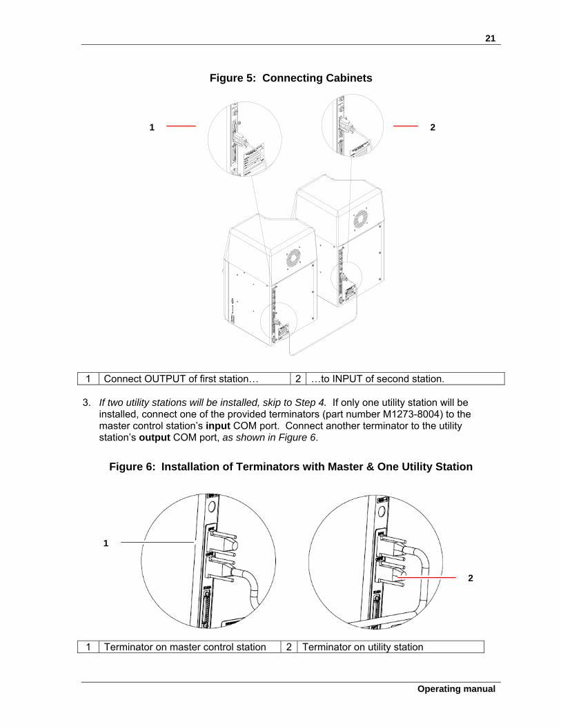
Figure 5: Connecting Cabinets
1 Connect OUTPUT of first station… 2 …to INPUT of second station. 3. If two utility stations will be installed, skip to Step 4. If only one utility station will be
installed, connect one of the provided terminators (part number M1273-8004) to the master control station’s input COM port. Connect another terminator to the utility station’s output COM port, as shown in Figure 6.
Figure 6: Installation of Terminators with Master & One Utility Station
1 Terminator on master control station 2 Terminator on utility station
1 2
2
1
22
BioFlo®/CelliGen® 115 M1369-0050 Operating manual
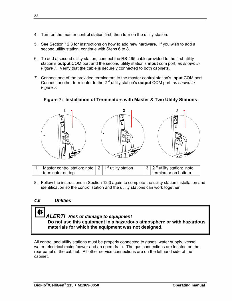
4. Turn on the master control station first, then turn on the utility station. 5. See Section 12.3 for instructions on how to add new hardware. If you wish to add a
second utility station, continue with Steps 6 to 8. 6. To add a second utility station, connect the RS-495 cable provided to the first utility
station’s output COM port and the second utility station’s input com port, as shown in Figure 7. Verify that the cable is securely connected to both cabinets.
7. Connect one of the provided terminators to the master control station’s input COM port.
Connect another terminator to the 2nd utility station’s output COM port, as shown in Figure 7.
Figure 7: Installation of Terminators with Master & Two Utility Stations
1 Master control station: note terminator on top
2 1st utility station 3 2nd utility station: note terminator on bottom
8. Follow the instructions in Section 12.3 again to complete the utility station installation and
identification so the control station and the utility stations can work together.
4.5 Utilities
ALERT! Risk of damage to equipment Do not use this equipment in a hazardous atmosphere or with hazardous materials for which the equipment was not designed.
All control and utility stations must be properly connected to gases, water supply, vessel water, electrical mains/power and an open drain. The gas connections are located on the rear panel of the cabinet. All other service connections are on the lefthand side of the cabinet.
1 2 3
23
Operating manual
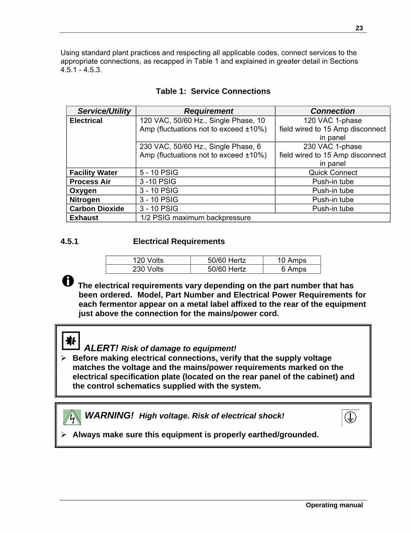
Using standard plant practices and respecting all applicable codes, connect services to the appropriate connections, as recapped in Table 1 and explained in greater detail in Sections 4.5.1 - 4.5.3.
Table 1: Service Connections
Service/Utility Requirement Connection 120 VAC, 50/60 Hz., Single Phase, 10 Amp (fluctuations not to exceed ±10%)
120 VAC 1-phase field wired to 15 Amp disconnect
in panel
Electrical
230 VAC, 50/60 Hz., Single Phase, 6 Amp (fluctuations not to exceed ±10%)
230 VAC 1-phase field wired to 15 Amp disconnect
in panel Facility Water 5 - 10 PSIG Quick Connect Process Air 3 -10 PSIG Push-in tube Oxygen 3 - 10 PSIG Push-in tube Nitrogen 3 - 10 PSIG Push-in tube Carbon Dioxide 3 - 10 PSIG Push-in tube Exhaust 1/2 PSIG maximum backpressure
4.5.1 Electrical Requirements
120 Volts 50/60 Hertz 10 Amps 230 Volts 50/60 Hertz 6 Amps
The electrical requirements vary depending on the part number that has been ordered. Model, Part Number and Electrical Power Requirements for each fermentor appear on a metal label affixed to the rear of the equipment just above the connection for the mains/power cord.
ALERT! Risk of damage to equipment! Before making electrical connections, verify that the supply voltage
matches the voltage and the mains/power requirements marked on the electrical specification plate (located on the rear panel of the cabinet) and the control schematics supplied with the system.
WARNING! High voltage. Risk of electrical shock!
Always make sure this equipment is properly earthed/grounded.
24
BioFlo®/CelliGen® 115 M1369-0050 Operating manual
4.5.2 Water and drain connections
ALERT! Risk of water leaks! Make sure all utility connections have been securely made before
connecting to WATER-IN and before turning on the main water supply. Failure to observe these precautions will result in water leaking out of the unconnected hoses and the cabinet.
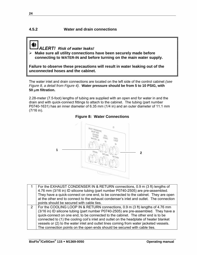
The water inlet and drain connections are located on the left side of the control cabinet (see Figure 8, a detail from Figure 4). Water pressure should be from 5 to 10 PSIG, with 50 m filtration. 2.28-meter (7.5-foot) lengths of tubing are supplied with an open end for water in and the drain and with quick-connect fittings to attach to the cabinet. The tubing (part number P0740-1631) has an inner diameter of 6.35 mm (1/4 in) and an outer diameter of 11.1 mm (7/16 in).
Figure 8: Water Connections
1 For the EXHAUST CONDENSER IN & RETURN connections, 0.9 m (3 ft) lengths of 4.76 mm (3/16 in) ID silicone tubing (part number P0740-2505) are pre-assembled. They have a quick-connect on one end, to be connected to the cabinet. They are open at the other end to connect to the exhaust condenser’s inlet and outlet. The connection points should be secured with cable ties.
2 For the COOLING LOOP IN & RETURN connections, 0.9 m (3 ft) lengths of 4.76 mm (3/16 in) ID silicone tubing (part number P0740-2505) are pre-assembled. They have a quick-connect on one end, to be connected to the cabinet. The other end is to be connected to (1) the cooling coil’s inlet and outlet on the headplate of heater blanket vessels or (2) to the water inlet and outlet lines coming from water jacketed vessels. The connection points on the open ends should be secured with cable ties.
1 2
25
Operating manual
ALERT! Risk of water leaks! Before connecting or disconnecting the water hoses to/from the vessel
and/or the cabinet at any time, make sure the main water supply is closed.
4.5.3 Gas connections
Gas inlets are located on the rear panel of the control cabinet. The sparge outlet is located on the left side of the cabinet.
There are push-in tube connectors for air, nitrogen, oxygen and carbon dioxide. These connectors accept flexible 3.2 mm (⅛ in) ID tubing; a 7.6 m (25 ft) length of blue polyurethane tubing (part number P0740-3113C3) is supplied with the cabinet; it can be cut to the appropriate sizes to attach to the utilities. Other soft, flexible-walled, chemically inert tubing (such as Marprene®, Pharmed®, etc.) may be used as well.
Gas inlets plugged with black plastic are unavailable to your configuration and must remain plugged.
WARNING! Risk of explosion!
Use gases in this equipment only within the range between their lower explosion limit (LEL) and their upper explosion limit (UEL).
If your process requires or produces gases, be sure to verify their LEL and UEL concentration range (available online or ask your gas supplier).
WARNING! ALERT! Risk of explosion! Risk of equipment damage! No gas pressure should rise above 10 PSIG. Do not use this equipment in a hazardous atmosphere or with hazardous
materials for which the equipment was not designed. All gases supplied should be medical grade.
All gases should be regulated using a two-stage regulator. The scale of the regulator gauge for gases going into the fermentor should be such that one can regulate pressure from 3 to 10 PSIG maximum.
Connect the barbed sparge connector (part number P0242-0600) to the SPARGE outlet at top left side of the cabinet (see the following page); connect the silicone tube attached to the sparge connector to the inlet filter on the vessel headplate. The sparge connector/tubing assembly is found in the tubing kit provided with your system.
26
BioFlo®/CelliGen® 115 M1369-0050 Operating manual
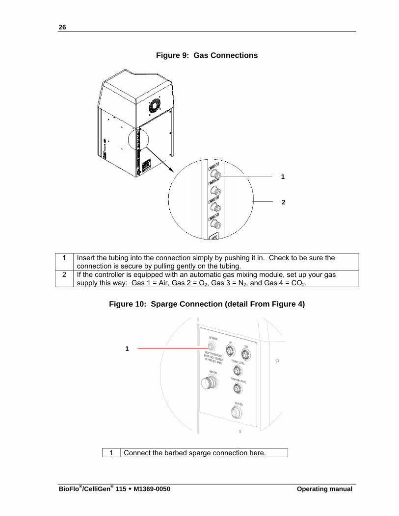
Figure 9: Gas Connections
1 Insert the tubing into the connection simply by pushing it in. Check to be sure the connection is secure by pulling gently on the tubing.
2 If the controller is equipped with an automatic gas mixing module, set up your gas supply this way: Gas 1 = Air, Gas 2 = O2, Gas 3 = N2, and Gas 4 = CO2.
Figure 10: Sparge Connection (detail From Figure 4)
1 Connect the barbed sparge connection here.
1
2
1
27
Operating manual
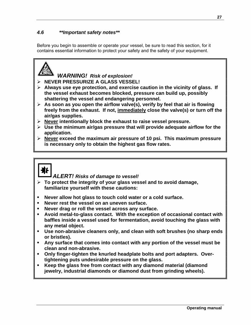
4.6 **Important safety notes**
Before you begin to assemble or operate your vessel, be sure to read this section, for it contains essential information to protect your safety and the safety of your equipment.
WARNING! Risk of explosion! NEVER PRESSURIZE A GLASS VESSEL! Always use eye protection, and exercise caution in the vicinity of glass. If
the vessel exhaust becomes blocked, pressure can build up, possibly shattering the vessel and endangering personnel.
As soon as you open the airflow valve(s), verify by feel that air is flowing freely from the exhaust. If not, immediately close the valve(s) or turn off the air/gas supplies.
Never intentionally block the exhaust to raise vessel pressure. Use the minimum air/gas pressure that will provide adequate airflow for the
application. Never exceed the maximum air pressure of 10 psi. This maximum pressure
is necessary only to obtain the highest gas flow rates.
ALERT! Risks of damage to vessel! To protect the integrity of your glass vessel and to avoid damage,
familiarize yourself with these cautions:
Never allow hot glass to touch cold water or a cold surface. Never rest the vessel on an uneven surface. Never drag or roll the vessel across any surface. Avoid metal-to-glass contact. With the exception of occasional contact with
baffles inside a vessel used for fermentation, avoid touching the glass with any metal object.
Use non-abrasive cleaners only, and clean with soft brushes (no sharp ends or bristles).
Any surface that comes into contact with any portion of the vessel must be clean and non-abrasive.
Only finger-tighten the knurled headplate bolts and port adapters. Over-tightening puts undesirable pressure on the glass.
Keep the glass free from contact with any diamond material (diamond jewelry, industrial diamonds or diamond dust from grinding wheels).
28
BioFlo®/CelliGen® 115 M1369-0050 Operating manual
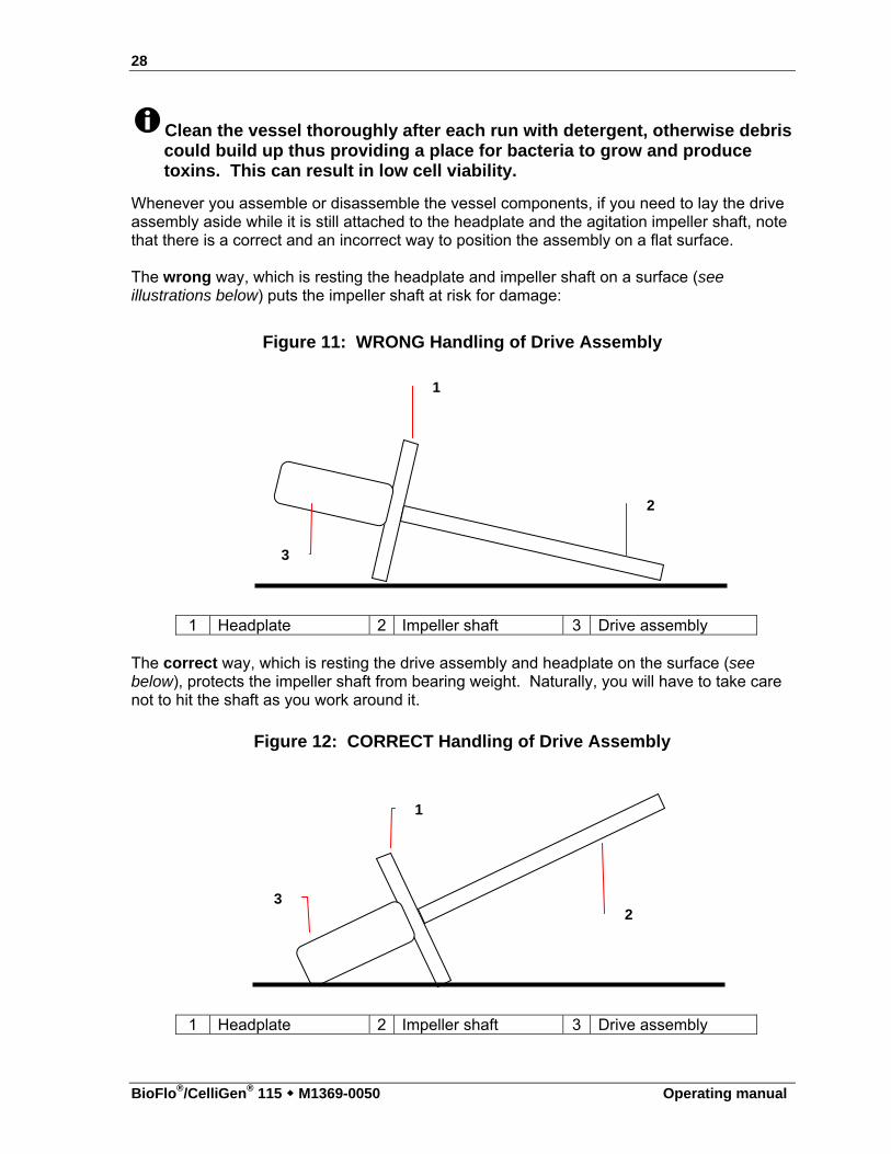
Clean the vessel thoroughly after each run with detergent, otherwise debris could build up thus providing a place for bacteria to grow and produce toxins. This can result in low cell viability.
Whenever you assemble or disassemble the vessel components, if you need to lay the drive assembly aside while it is still attached to the headplate and the agitation impeller shaft, note that there is a correct and an incorrect way to position the assembly on a flat surface.
The wrong way, which is resting the headplate and impeller shaft on a surface (see illustrations below) puts the impeller shaft at risk for damage:
Figure 11: WRONG Handling of Drive Assembly
1 Headplate 2 Impeller shaft 3 Drive assembly
The correct way, which is resting the drive assembly and headplate on the surface (see below), protects the impeller shaft from bearing weight. Naturally, you will have to take care not to hit the shaft as you work around it.
Figure 12: CORRECT Handling of Drive Assembly
1 Headplate 2 Impeller shaft 3 Drive assembly
1
2
3
1
2 3
29
Operating manual
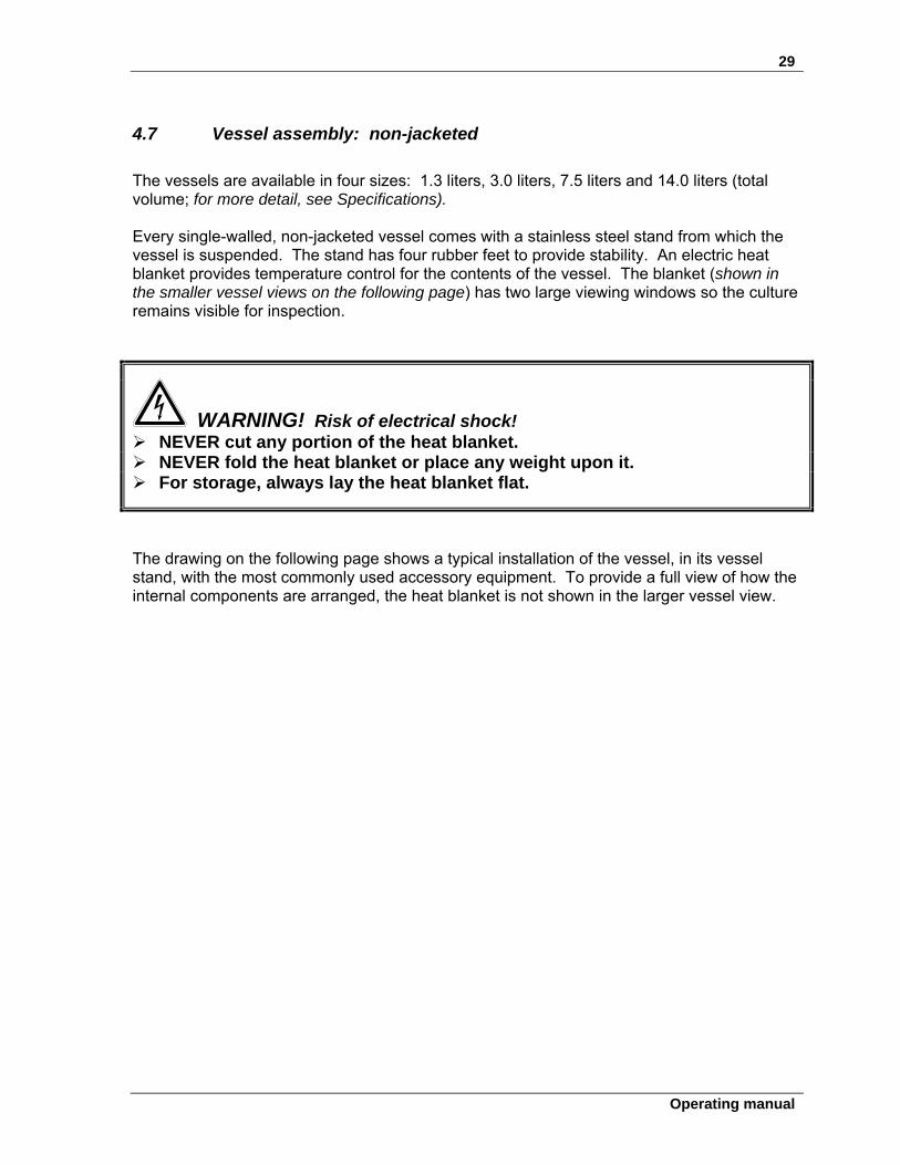
4.7 Vessel assembly: non-jacketed
The vessels are available in four sizes: 1.3 liters, 3.0 liters, 7.5 liters and 14.0 liters (total volume; for more detail, see Specifications). Every single-walled, non-jacketed vessel comes with a stainless steel stand from which the vessel is suspended. The stand has four rubber feet to provide stability. An electric heat blanket provides temperature control for the contents of the vessel. The blanket (shown in the smaller vessel views on the following page) has two large viewing windows so the culture remains visible for inspection.
WARNING! Risk of electrical shock! NEVER cut any portion of the heat blanket. NEVER fold the heat blanket or place any weight upon it. For storage, always lay the heat blanket flat.
The drawing on the following page shows a typical installation of the vessel, in its vessel stand, with the most commonly used accessory equipment. To provide a full view of how the internal components are arranged, the heat blanket is not shown in the larger vessel view.
30
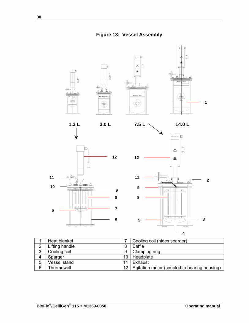
BioFlo®/CelliGen® 115 M1369-0050 Operating manual
Figure 13: Vessel Assembly
1.3 L 3.0 L 7.5 L 14.0 L
1 Heat blanket 7 Cooling coil (hides sparger) 2 Lifting handle 8 Baffle 3 Cooling coil 9 Clamping ring 4 Sparger 10 Headplate 5 Vessel stand 11 Exhaust 6 Thermowell 12 Agitation motor (coupled to bearing housing)
1
2
3
4
5 5
6 7
8 8
9 9
10
11 11
12 12
31
Operating manual
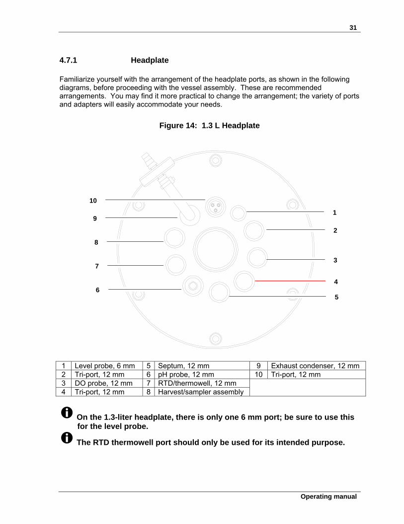
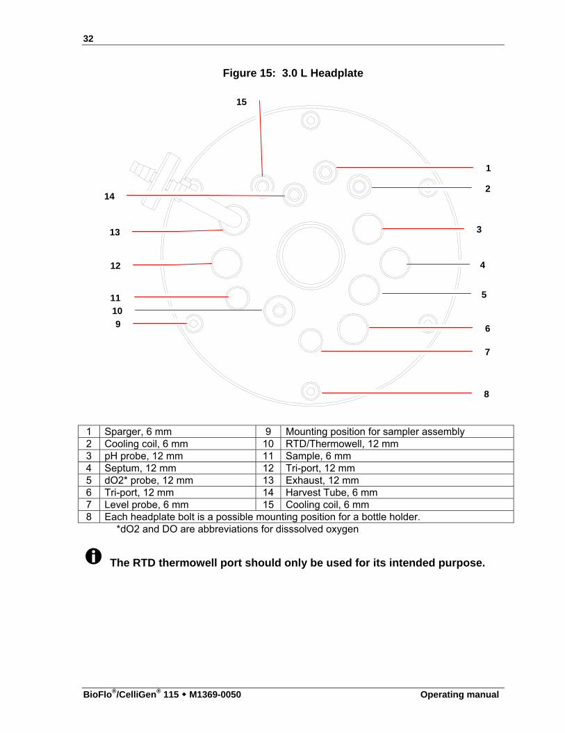
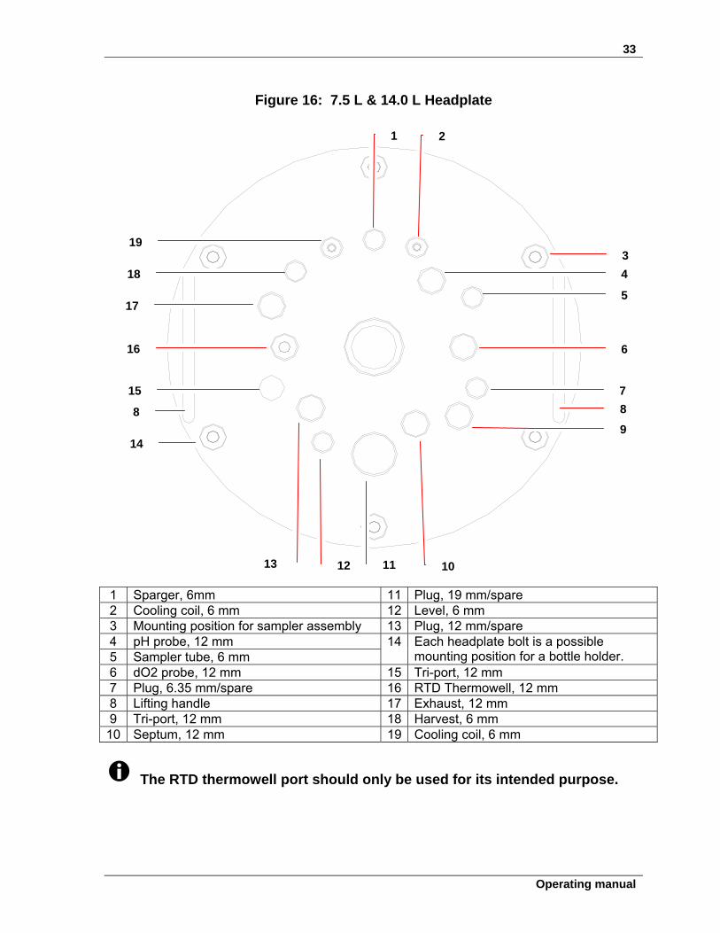
4.7.1 Headplate Familiarize yourself with the arrangement of the headplate ports, as shown in the following diagrams, before proceeding with the vessel assembly. These are recommended arrangements. You may find it more practical to change the arrangement; the variety of ports and adapters will easily accommodate your needs.
Figure 14: 1.3 L Headplate
1 Level probe, 6 mm 5 Septum, 12 mm 9 Exhaust condenser, 12 mm 2 Tri-port, 12 mm 6 pH probe, 12 mm 10 Tri-port, 12 mm 3 DO probe, 12 mm 7 RTD/thermowell, 12 mm 4 Tri-port, 12 mm 8 Harvest/sampler assembly
On the 1.3-liter headplate, there is only one 6 mm port; be sure to use this for the level probe.
The RTD thermowell port should only be used for its intended purpose.
1
2
3
4
5 6
7
8
9
10
32
BioFlo®/CelliGen® 115 M1369-0050 Operating manual
Figure 15: 3.0 L Headplate
1 Sparger, 6 mm 9 Mounting position for sampler assembly 2 Cooling coil, 6 mm 10 RTD/Thermowell, 12 mm 3 pH probe, 12 mm 11 Sample, 6 mm 4 Septum, 12 mm 12 Tri-port, 12 mm 5 dO2* probe, 12 mm 13 Exhaust, 12 mm 6 Tri-port, 12 mm 14 Harvest Tube, 6 mm 7 Level probe, 6 mm 15 Cooling coil, 6 mm 8 Each headplate bolt is a possible mounting position for a bottle holder.
*dO2 and DO are abbreviations for disssolved oxygen
The RTD thermowell port should only be used for its intended purpose.
1
2
3
4
5
7
11
12
13
6
8
10
9
14
15
33
Operating manual
Figure 16: 7.5 L & 14.0 L Headplate
1 Sparger, 6mm 11 Plug, 19 mm/spare 2 Cooling coil, 6 mm 12 Level, 6 mm 3 Mounting position for sampler assembly 13 Plug, 12 mm/spare 4 pH probe, 12 mm 5 Sampler tube, 6 mm
14 Each headplate bolt is a possible mounting position for a bottle holder.
6 dO2 probe, 12 mm 15 Tri-port, 12 mm 7 Plug, 6.35 mm/spare 16 RTD Thermowell, 12 mm 8 Lifting handle 17 Exhaust, 12 mm 9 Tri-port, 12 mm 18 Harvest, 6 mm
10 Septum, 12 mm 19 Cooling coil, 6 mm
The RTD thermowell port should only be used for its intended purpose.
1 2
4
3
5
6
7
8
9
10 11 12 13
14
8
15
16
17
18
19
34
BioFlo®/CelliGen® 115 M1369-0050 Operating manual
4.7.2 Install heat blanket 1. Wrap the heat blanket as snugly as possible around the vessel, taking care to leave one
of the viewing windows facing forward. You will probably want to orient the blanket so the mains/power cord connection is out of the way.
2. Secure the blanket by overlapping the Velcro strips, and pressing them together.
WARNING! Risk of electrical shock! NEVER cut any portion of the heat blanket. NEVER fold the heat blanket or place any weight upon it. For storage, always lay the heat blanket flat.
4.7.3 Install vessel in vessel stand
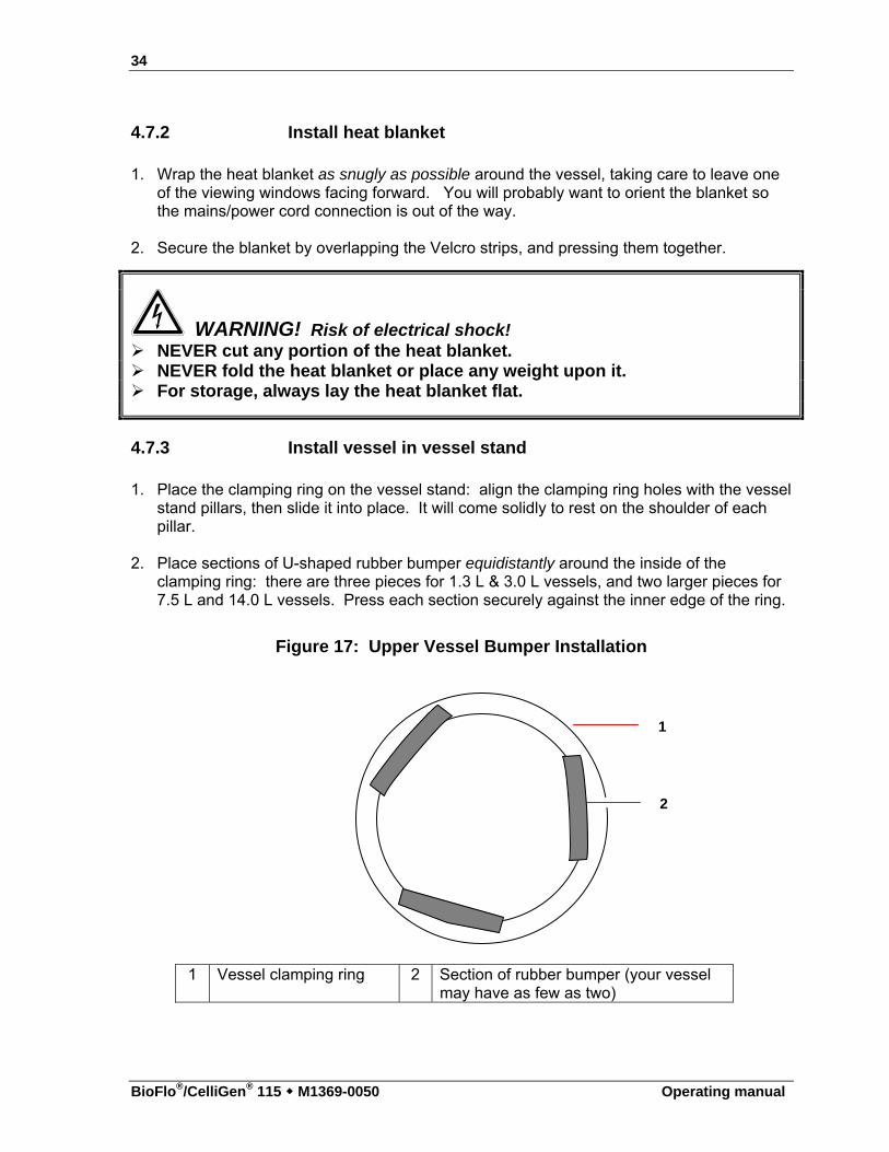
1. Place the clamping ring on the vessel stand: align the clamping ring holes with the vessel stand pillars, then slide it into place. It will come solidly to rest on the shoulder of each pillar.
2. Place sections of U-shaped rubber bumper equidistantly around the inside of the
clamping ring: there are three pieces for 1.3 L & 3.0 L vessels, and two larger pieces for 7.5 L and 14.0 L vessels. Press each section securely against the inner edge of the ring.
Figure 17: Upper Vessel Bumper Installation
1 Vessel clamping ring 2 Section of rubber bumper (your vessel
may have as few as two)
2
1
35
Operating manual
3. Gently lower the glass vessel through the center of the clamping ring, until the vessel flange rests snugly against the rubber bumpers.
4. Orient the vessel so the gradations on the glass are clearly visible at the front, facing the user, and situated between two vessel stand pillars.
4.7.4 Install baffle (14.0 L fermentation vessels ONLY)
For installation of the 1.3 L, 3.0 L and 7.5 L vessel baffle, see Section 4.8.21. If you are using a 14.0 L vessel, install the baffle assembly inside the glass vessel: 1. Gently compress the baffle ring at its ends (to avoid scratching the vessel walls). You
may find it convenient to squeeze the tab with your thumb. 2. Slide the assembly inside, with the tab facing up, until it comes to rest at the bottom of the
vessel. 3. Orient the baffle so the opening is opposite the gradations on the vessel, and the tab is
aligned with the back vessel stand pillar.
4.8 Vessel assembly: water-jacketed
Water-jacketed vessels need no stand; the water jacket, which is part of the vessel, is flared and flat at the bottom to provide secure, stable support. At the bottom is a metal base plate, to provide additional security against breakage. In operation, the jacked vessel sits on the Jacket Water Heater. The jacket water heater is designed so that the vessel water inlet and outlet fit in a notch at the rear, and the vessel feet fit into the four holes at the perimeter of the heater plate. Figure 8 on the following page shows a typical installation of the double-walled, water-jacketed vessel, with the most commonly used accessory equipment.
ALERT! Risk of damage to equipment! The Jacket Water Heater base (see the following page) includes a magnetic stir bar and plate. For stability during shipping, the stir bar is tied to the inner cage by cable: Do not fill the water jacket or operate the vessel until you have cut the cable
ties and released the stir bar.
Familiarize yourself with the arrangement of the headplate ports, as shown in Section 4.7.1, before proceeding with the vessel assembly. You may find it more practical to change the arrangement; the variety of ports and adapters will easily accommodate your needs.
36
BioFlo®/CelliGen® 115 M1369-0050 Operating manual
Figure 18: Water-Jacketed Vessel Assembly
1.3 L 3.0 L 7.5 L 14.0 L
…See legend on the following page…
1
2
3
4
5
6
7
8 9
10
11
12
13
14
15
37
Operating manual
1 Shown installed on the jacket water heater. 9 Cooling water inlet (cool loop in) 2 Agitation motor 10 Base plate 3 Bearing housing 11 Thermowell 4 Headplate 12 Water jacket 5 Cooling water outlet tube 13 Baffle 6 Sparger 14 Top clamping plate 7 Bottom clamping ring 15 Lifting handle 8 Cooling water outlet (cool loop return—tubing
connected inside the jacket)
4.8.1 Install headplate clamping ring
The clamping ring that secures the headplate to the vessel is split in half to facilitate installation under the vessel flange. They are joined with two rectangular mounting plates. 1. As shown below, install one mounting plate with two Phillips head screws (provided) on
the end of one ring half so that the plate extends beyond the ring.
Figure 19: Installing Headplate Clamping Ring
2. In the same manner, install the second mounting plate on the other end of the ring half. 3. Bring the two halves of the headplate clamping ring together under the vessel flange, with
the mounting plates on the bottom for easy access from below. 4. Align the mounting plates with their corresponding holes on the other ring half, and drop
in the remaining Phillips head screws. Tighten the screws to fasten the ring in place.
4.8.2 Install vessel on base plate 1. Place the base plate on a level surface.
2. Lightly lubricate the base plate O-ring, and seat it securely in its groove. 3. Fit the one-piece water jacket guard (rubber gasket) around the outside of the bottom
vessel flange, against the water jacket (see the following page).
38
BioFlo®/CelliGen® 115 M1369-0050 Operating manual
4. With the clamping screws in place on the ring, fit the bottom clamping ring onto the base
plate.
Figure 20: Water Jacket Guard Installation (top view)
1 Rubber gasket, part number M1155-9902 (1.3 L & 3.0 L) or M1227-9903 (7.5 L &
14.0 L) 2 Bottom vessel flange
5. With the gradations marked on the glass facing front (toward the user), slide the vessel
into the bottom clamping ring, until it rests securely against the base plate. Make sure the water inlet tube stands free (not kinked) inside the water jacket.
6. Finger tighten the six knurled thumb screws, to securely attach the clamping ring to the
base plate. This seals the water jacket.
4.8.3 Filling the water jacket To fill the water jacket: 1. After the tubing and water supply are connected, make sure the solenoid valve cable
and the RTD cable are plugged into the Power Controller. 2. Set the temperature control mode to Off. 3. Check that the temperature reading is higher than 5ºC. 4. Allow water to enter the piping system; it will stop at the solenoid valve. 5. Set the temperature loop control mode to Auto. 6. Enter a temperature setpoint (SP) that is at least 12ºC below the current value (CV).
The controller will respond to the call for cooling by opening the solenoid valve, filling the jacket with water.
4.8.4 Install baffle (14.0 L fermentation vessels ONLY)
For installation of the 1.3 L, 3.0 L & 7.5 L vessel baffle, see Section 4.8.21.
1
2
39
Operating manual
If you are using a 14.0 L vessel, install the baffle assembly inside the glass vessel: 1. Gently compress the baffle ring at its ends (to avoid scratching the vessel walls). You
may find it convenient to squeeze the tab with your thumb. 2. Slide the assembly inside, with the tab facing up, until it comes to rest at the bottom of the
vessel. 3. Orient the baffle so the opening is opposite the gradations on the vessel.
4.8.5 Install impeller(s) Install the impeller(s) as follows:
A. For Cell Culture: Slide the impeller onto the agitation drive shaft (from the bearing
housing). Position the impeller at least 10 mm above the sparger. Clamp it down in place.
It is normal for the agitation impeller shaft to be very resistant to turning by hand. The shaft seal resistance ensures sterile operation.
B. For Fermentation: Slide one impeller onto the agitation drive shaft (from the bearing
housing). Position this lower impeller according to the table below. Clamp it down in place. Then install the second (upper) impeller in the same manner.
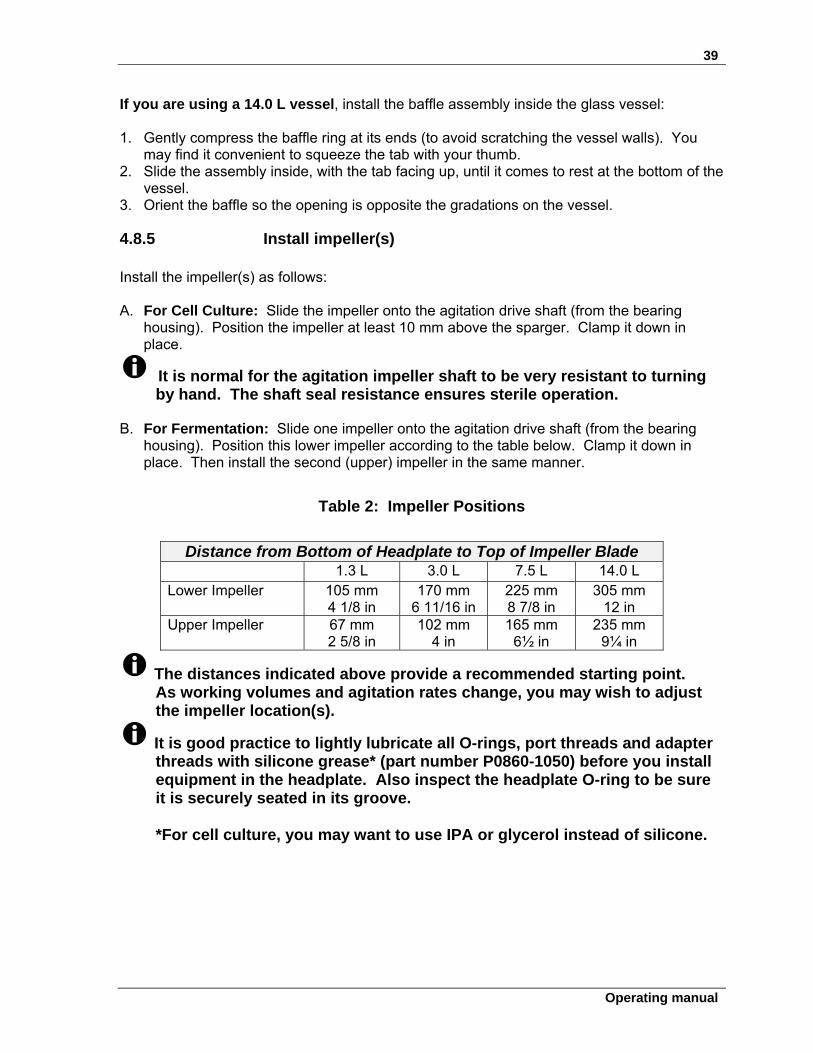
Table 2: Impeller Positions
Distance from Bottom of Headplate to Top of Impeller Blade
1.3 L 3.0 L 7.5 L 14.0 L Lower Impeller 105 mm
4 1/8 in 170 mm
6 11/16 in 225 mm 8 7/8 in
305 mm 12 in
Upper Impeller 67 mm 2 5/8 in
102 mm 4 in
165 mm 6½ in
235 mm 9¼ in
The distances indicated above provide a recommended starting point. As working volumes and agitation rates change, you may wish to adjust the impeller location(s).
It is good practice to lightly lubricate all O-rings, port threads and adapter threads with silicone grease* (part number P0860-1050) before you install equipment in the headplate. Also inspect the headplate O-ring to be sure it is securely seated in its groove. *For cell culture, you may want to use IPA or glycerol instead of silicone.
40
BioFlo®/CelliGen® 115 M1369-0050 Operating manual
4.8.6 Install cooling coil
1.3 L Vessel Cooling Coil/Sparger Assembly The cooling coil and sparger connections are welded into one special 12mm tri-port assembly. 1. From beneath the headplate, insert the assembly into the appropriate port(s). 2. From above the headplate, lock the assembly in place with a knurled 12mm to 12mm
adapter. Finger tighten. 3. There are three set screws in the adapter. If you need to raise or lower the adapter/tri-
port assembly, use the Allen key provided to adjust the set screw that is easiest to access. You only need to adjust one.
3.0 L, 7.5 L & 14.0 L Vessel Cooling Coil 1. From beneath the headplate, insert both ends of the coil into the Cooling Coil (In) port
and the Cooling Coil (Out) port. 2. From above the headplate, finger tighten the knurled adapter on each side of the cooling
coil.
4.8.7 Install sparger (3.0 L, 7.5 L & 14.0 L vessels) 1. From beneath the headplate, insert the sparger tube into the sparger port. 2. Finger tighten the knurled adapter on the sparger, then use the Allen key provided to
tighten the set screw. Do not overtighten.
ALERT! Risk of damage to ferrule! Only finger tighten any adapter that has a white Teflon ferrule (tapered,
cone-shaped insert under the Teflon washer). The ferrule can deform under too much pressure.
41
Operating manual
4.8.8 Install harvest tube 1. Working from beneath the headplate, install the harvest tube in the harvest port. If you
are using the 1.3 L vessel, the harvest tube and sampler tube are welded into the same tri-port to save space. When the headplate is in place on the vessel, the bottom of the harvest tube should rest at the bottom of the vessel.
2. Finger tighten the knurled adapter on the harvest tube, then use the Allen key provided
to tighten the set screw. Do not overtighten.
4.8.9 Install sampler tube 1. Working from beneath the headplate, install the optional sampler tube in the sample port.
If you are using the 1.3 L vessel, the sampler tube and harvest tube are welded into the same tri-port to save space.
2. Finger tighten the knurled adapter on the sampler tube, then use the Allen key provided
to tighten the set screw.
4.8.10 Install thermowell 1. Working from above the headplate, insert the thermowell tube into the RTD port. Be
sure to use the port designated for the RTD to avoid damaging the glass.
ALERT! Risk of damage to equipment! Make sure that the thermowell does not touch the cooling coil or come
into contact with the glass vessel.
2. Finger tighten the knurled adapter on the thermowell.
4.8.11 Install foam probe If you are using a foam sensor with a foam trap kit: 1. Working from above the headplate, insert the foam sensor into the appropriate port. 2. Finger tighten the knurled adapter.
42
BioFlo®/CelliGen® 115 M1369-0050 Operating manual
4.8.12 Install foam exhaust tube If you are using a foam trap, install the foam exhaust tube: 1. Working from beneath the headplate, insert the foam exhaust tube into the appropriate
port, close to a headplate clamping nut where you will later mount the foam trap.
2. Finger tighten the knurled adapter. If you need to raise or lower the tube at any time, use the Allen key provided to adjust the adapter’s set screw.
4.8.13 Install level probe(s)
If you are using a level probe as part of the antifoam system and/or a level probe to detect media level, one at a time: 1. Working from above the headplate, insert the level probe into the appropriate port. 2. Finger tighten the knurled adapter.
4.8.14 Install addition tube(s) Insert addition tubes and/or tri-ports in the appropriate ports for any or all of the following additions: media, nutrients, acid, base, antifoam. For each insertion: 1. Finger tighten the knurled addition or tri-port adapter. 2. Working from above the headplate, insert the addition tube or tri-port into the appropriate
port.
4.8.15 Install pH probe
Prior to installation, any pH probe you are using should be inspected for damage, and replaced if necessary.
To avoid damage to the probes during operation, be sure that there is no interference between the probes and the baffle assembly, impeller blades, or cooling coil.
1. Wear protective gloves to protect yourself in case of accidental breakage. 2. Lightly coat the pH probe with glycerol.
43
Operating manual
ALERT! Risk of damage to pH probe! Always fit the pH port adaptor onto the probe first. Then insert the probe with its adaptor into the headplate, following Steps 3-
11 shown after the drawing below. Never attempt to install the pH port adaptor in the headplate without the
probe.
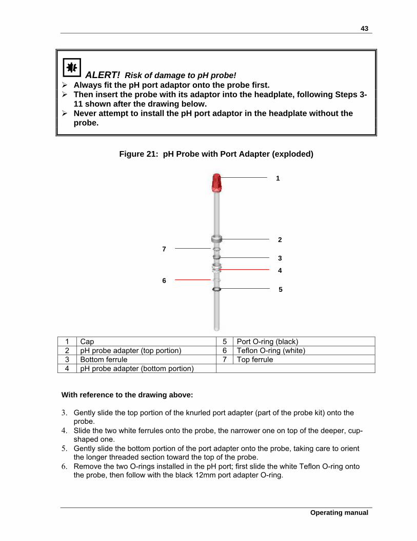
Figure 21: pH Probe with Port Adapter (exploded)
1 Cap 5 Port O-ring (black) 2 pH probe adapter (top portion) 6 Teflon O-ring (white) 3 Bottom ferrule 7 Top ferrule 4 pH probe adapter (bottom portion)
With reference to the drawing above: 3. Gently slide the top portion of the knurled port adapter (part of the probe kit) onto the
probe. 4. Slide the two white ferrules onto the probe, the narrower one on top of the deeper, cup-
shaped one. 5. Gently slide the bottom portion of the port adapter onto the probe, taking care to orient
the longer threaded section toward the top of the probe. 6. Remove the two O-rings installed in the pH port; first slide the white Teflon O-ring onto
the probe, then follow with the black 12mm port adapter O-ring.
1
2
3
4
5 6
7
44
BioFlo®/CelliGen® 115 M1369-0050 Operating manual
7. Do not yet close up all the elements of the port adapter. 8. Gently insert the probe into the appropriate port, allowing the O-rings to seat fully into the
port.
The fit may be snug. Gently rotate the probe as you press it into the port to avoid breakage.
9. Finger tighten the bottom portion of the port adapter into the port. 10. Adjust the probe to the desired height; then, nesting the ferrules, close the top portion of
the adapter onto the bottom portion. 11. Finger tighten the knurled adapter assembly.
4.8.16 Install dO2 probe
Prior to installation, any dissolved oxygen probe you are using should be inspected for damage and replaced if necessary.
To avoid damage to the probes during operation, be sure that there is no interference between the probes and the baffle assembly, impeller blades or cooling coil.
1. Wear protective gloves to protect yourself in case of accidental breakage. 2. Lightly coat the dO2 probe with glycerol.
ALERT! Risk of damage to dissolved oxygen probe! Always fit the dO2 port adaptor onto the probe first. Then insert the probe with its adaptor into the headplate, following Steps 3-
11 shown after the drawing on the following page. Never attempt to install the dO2 port adaptor in the headplate without the
probe.
45
Operating manual
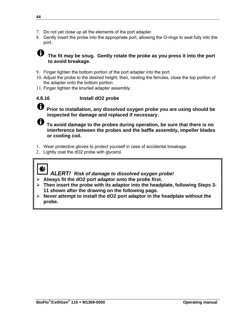
Figure 22: dO2 Probe with Port Adapter (exploded)
1 dO2 probe adapter (top portion) 5 Teflon O-ring (white) 2 Bottom ferrule 6 Top ferrule 3 dO2 probe adapter (bottom portion) 7 Cap 4 Port O-ring (black)
With reference to the drawing above: 3. Gently slide the top portion of the knurled port adapter (part of the probe kit) onto the
probe. 4. Slide the two white ferrules onto the probe, the narrower one on top of the deeper, cup-
shaped one. 5. Gently slide the bottom portion of the port adapter onto the probe, taking care to orient
the longer threaded section toward the top of the probe. 6. Remove the two O-rings installed in the dO2 port; first slide the white Teflon O-ring onto
the probe, then follow with the black 12mm port adapter O-ring. 7. Do not yet close up all the elements of the port adapter. 8. Gently insert the probe into the appropriate port, allowing the O-rings to seat fully into the
port.
The fit may be snug. Gently rotate the probe as you press it into the port to avoid breakage.
9. Finger tighten the bottom portion of the port adapter into the port. 10. Adjust the probe to the desired height; then, nesting the ferrules, close the top portion of
the adapter onto the bottom portion. 11. Finger tighten the knurled adapter assembly.
1
2
3
4 5
6
7
46
BioFlo®/CelliGen® 115 M1369-0050 Operating manual
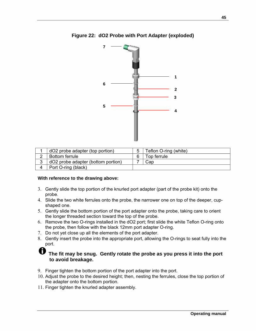
4.8.17 Install exhaust condenser
WARNING! Risk of explosion! Never intentionally block the exhaust to raise vessel pressure.
If you are using the optional exhaust condenser: 1. Unscrew the spare/exhaust port plug from the headplate, saving it for reuse. 2. Place the 12mm exhaust condenser adapter into the port. 3. Place the exhaust condenser inlet (see drawings below) into the port, and finger tighten
the knurled adapter. 4. Tighten it with the Allen key provided, until it is secure. 5. Attach the exhaust filter (respecting the direction of flow if stamped on the filter) to the
condenser outlet. Secure the filter with a plastic tie. 6. Connect silicone tubing to the inlet port of the exhaust condenser. Secure with a plastic
tie.
Figure 23: Exhaust Condenser (1.3L, 3.0 L & 7.5 L Vessels)
1 Sterile filter 4 Exhaust port 2 Set screw in port adaptor 5 Water inlet (Exh. Cond. In) 3 Headplate 6 Water outlet (Exh. Cond. Return)
Be sure to see important NOTICE on the following page.
1
2 3
4
5
6
47
Operating manual
If the weight of the exhaust filter kinks the tubing, fasten a short length of stiffening material to the tubing, using rubber bands or tie wraps, to support the filter.
Ensure that gas flow through the exhaust condenser is unobstructed during runs and during autoclaving.
Figure 24: Exhaust Condenser (14.0 L Vessel only)
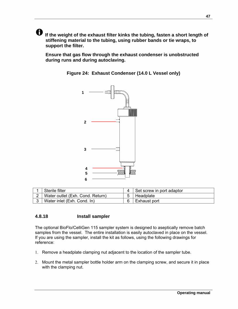
1 Sterile filter 4 Set screw in port adaptor 2 Water outlet (Exh. Cond. Return) 5 Headplate 3 Water inlet (Exh. Cond. In) 6 Exhaust port
4.8.18 Install sampler The optional BioFlo/CelliGen 115 sampler system is designed to aseptically remove batch samples from the vessel. The entire installation is easily autoclaved in place on the vessel. If you are using the sampler, install the kit as follows, using the following drawings for reference:
1. Remove a headplate clamping nut adjacent to the location of the sampler tube.
2. Mount the metal sampler bottle holder arm on the clamping screw, and secure it in place
with the clamping nut.
1
4 5
6
2
3
48
BioFlo®/CelliGen® 115 M1369-0050 Operating manual
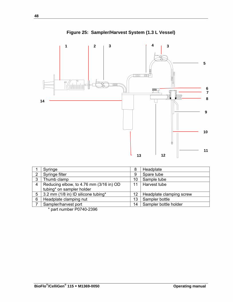
Figure 25: Sampler/Harvest System (1.3 L Vessel)
1 Syringe 8 Headplate 2 Syringe filter 9 Spare tube 3 Thumb clamp 10 Sample tube 4 Reducing elbow, to 4.76 mm (3/16 in) OD
tubing* on sampler holder 11 Harvest tube
5 3.2 mm (1/8 in) ID silicone tubing* 12 Headplate clamping screw 6 Headplate clamping nut 13 Sampler bottle 7 Sampler/harvest port 14 Sampler bottle holder
* part number P0740-2396
1 2 3 4 3
5
7
8
9
10
11 12 13
6
14
49
Operating manual
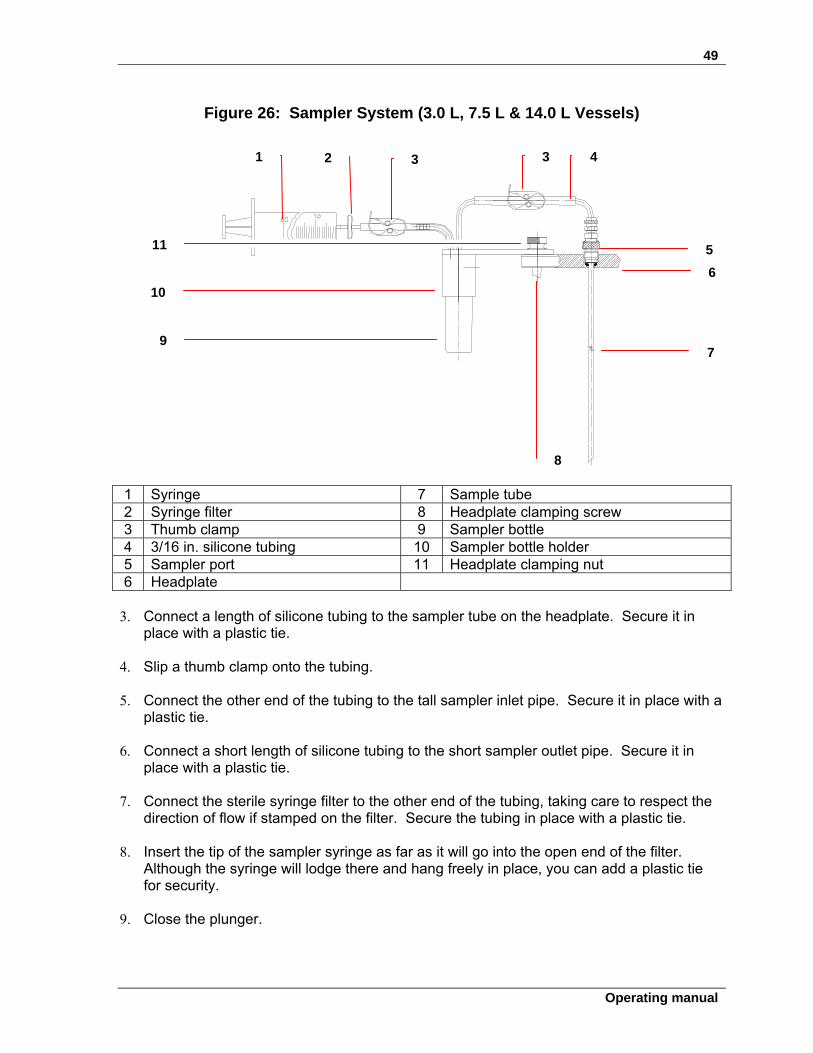
Figure 26: Sampler System (3.0 L, 7.5 L & 14.0 L Vessels)
1 Syringe 7 Sample tube 2 Syringe filter 8 Headplate clamping screw 3 Thumb clamp 9 Sampler bottle 4 3/16 in. silicone tubing 10 Sampler bottle holder 5 Sampler port 11 Headplate clamping nut 6 Headplate
3. Connect a length of silicone tubing to the sampler tube on the headplate. Secure it in
place with a plastic tie. 4. Slip a thumb clamp onto the tubing.
5. Connect the other end of the tubing to the tall sampler inlet pipe. Secure it in place with a
plastic tie. 6. Connect a short length of silicone tubing to the short sampler outlet pipe. Secure it in
place with a plastic tie.
7. Connect the sterile syringe filter to the other end of the tubing, taking care to respect the direction of flow if stamped on the filter. Secure the tubing in place with a plastic tie.
8. Insert the tip of the sampler syringe as far as it will go into the open end of the filter.
Although the syringe will lodge there and hang freely in place, you can add a plastic tie for security.
9. Close the plunger.
1 2 3 4 3
5
6
7
8
9
10
11
50
BioFlo®/CelliGen® 115 M1369-0050 Operating manual
10. Remove the cap from one of the sample bottles and screw the bottle into the metal holder.
11. Position the entire assembly to your satisfaction, then finger tighten the clamping nut.
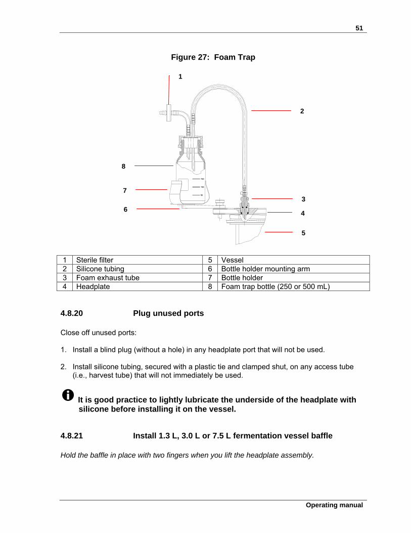
4.8.19 Install foam trap If you are using a foam trap kit (see the drawing on the following page):
1. Unscrew the headplate clamping nut (or base clamping nut, if you prefer to mount the
trap at the base of the vessel) closest to the foam exhaust tube. 2. Mount the foam trap bottle holder on the clamping screw, using the hole at the end of the
holder’s mounting arm. 3. Secure the holder in place with the clamping nut. Leave the nut loose enough to swivel
the holder. 4. Firmly place the foam trap bottle (250 mL or 500 mL) in the holder.
5. With the bottle cap in place, aseptically install a sterile (0.2 ) filter on the shorter tube
that penetrates the cap. Be sure to respect the proper flow direction if stamped on the filter.
6. Connect a length of silicone tubing to the longer tube in the other bottle cap penetration.
Secure the tubing with a plastic tie, and clamp it off on the top. 7. Connect the tubing, securing it with a plastic tie, to the foam exhaust tube in the
headplate. 8. After autoclaving, you will position the bottle holder where you want it, then finger tighten
the clamping nut.
51
Operating manual
Figure 27: Foam Trap
1 Sterile filter 5 Vessel 2 Silicone tubing 6 Bottle holder mounting arm 3 Foam exhaust tube 7 Bottle holder 4 Headplate 8 Foam trap bottle (250 or 500 mL)
4.8.20 Plug unused ports Close off unused ports: 1. Install a blind plug (without a hole) in any headplate port that will not be used. 2. Install silicone tubing, secured with a plastic tie and clamped shut, on any access tube
(i.e., harvest tube) that will not immediately be used.
It is good practice to lightly lubricate the underside of the headplate with silicone before installing it on the vessel.
4.8.21 Install 1.3 L, 3.0 L or 7.5 L fermentation vessel baffle Hold the baffle in place with two fingers when you lift the headplate assembly.
1
2
3
4
5
6
7
8
52
BioFlo®/CelliGen® 115 M1369-0050 Operating manual
1. Gently place the baffle, tab facing up, around all of the other instruments protruding from the headplate, including the cooling coil.
2. Position the tab between the two uprights of the cooling coil.
4.8.22 Install headplate 1. Orient the cooling coil uprights toward the back, opposite the gradations marked on the
vessel glass. If this is a 1.3 L, 3.0 L or 7.5 L fermentation vessel, squeeze and hold the baffle in place (opening toward the back) with thumb and forefinger. You may find it convenient to squeeze the tab with your thumb.
2. Carefully lower the headplate, easing all of its attachments into the vessel without hitting
the glass (or the baffle inside, if this is a 14.0 L fermentation vessel).
If you are using a baffle, after installing the headplate, insert any convenient length of wood, plastic or stainless steel (do not use any other kind of metal) through an unused port to push the baffle down as far as it will go.
The baffle is stainless steel; repeated installations may cause it to retain a compressed position. Expand it before you squeeze it for installation, so it will spring back against the vessel walls.
3. Align the headplate holes with the vessel stand pillars, then slide it down until it rests
securely against the vessel flange. 4. Finger tighten each clamping nut a little at a time to secure the headplate on the vessel
stand, working diagonally from one to another (rather than working around the circle) to apply equal pressure.
ALERT! Risk of damage to vessel! To avoid vessel stress cracks, especially during autoclaving, never
overtighten vessel clamping nuts.
4.8.23 Install vessel
Position the vessel next to the control cabinet, in the rounded cut-out designed for vessel placement between pumps and connectors. Be sure to keep the water line quick-connects to the left.
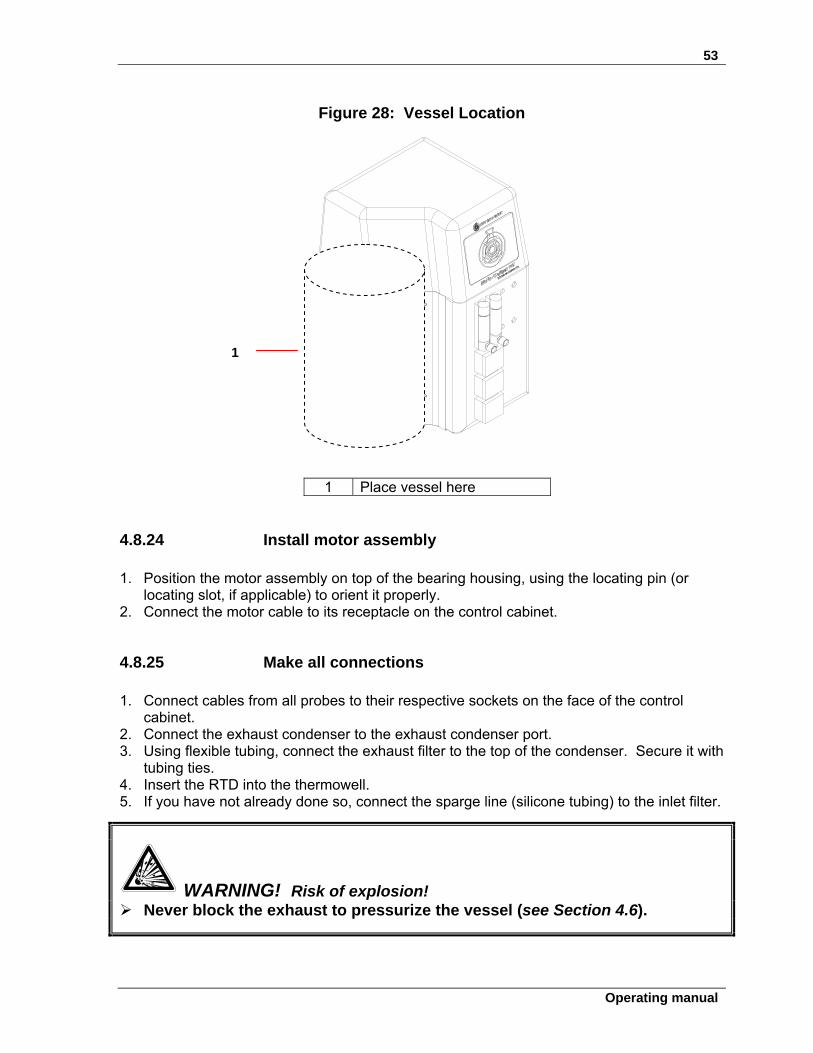
53
Operating manual
Figure 28: Vessel Location
1 Place vessel here
4.8.24 Install motor assembly
1. Position the motor assembly on top of the bearing housing, using the locating pin (or locating slot, if applicable) to orient it properly.
2. Connect the motor cable to its receptacle on the control cabinet.
4.8.25 Make all connections
1. Connect cables from all probes to their respective sockets on the face of the control cabinet.
2. Connect the exhaust condenser to the exhaust condenser port. 3. Using flexible tubing, connect the exhaust filter to the top of the condenser. Secure it with
tubing ties. 4. Insert the RTD into the thermowell. 5. If you have not already done so, connect the sparge line (silicone tubing) to the inlet filter.
WARNING! Risk of explosion! Never block the exhaust to pressurize the vessel (see Section 4.6).
1
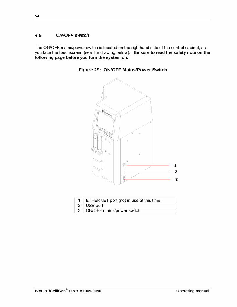
54
BioFlo®/CelliGen® 115 M1369-0050 Operating manual
4.9 ON/OFF switch
The ON/OFF mains/power switch is located on the righthand side of the control cabinet, as you face the touchscreen (see the drawing below). Be sure to read the safety note on the following page before you turn the system on.
Figure 29: ON/OFF Mains/Power Switch
1 ETHERNET port (not in use at this time) 2 USB port 3 ON/OFF mains/power switch
1
2
3
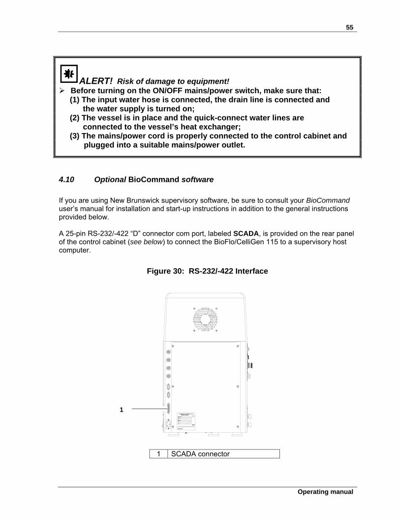
55
Operating manual
ALERT! Risk of damage to equipment! Before turning on the ON/OFF mains/power switch, make sure that: (1) The input water hose is connected, the drain line is connected and the water supply is turned on; (2) The vessel is in place and the quick-connect water lines are connected to the vessel’s heat exchanger; (3) The mains/power cord is properly connected to the control cabinet and
plugged into a suitable mains/power outlet.
4.10 Optional BioCommand software
If you are using New Brunswick supervisory software, be sure to consult your BioCommand user’s manual for installation and start-up instructions in addition to the general instructions provided below. A 25-pin RS-232/-422 “D” connector com port, labeled SCADA, is provided on the rear panel of the control cabinet (see below) to connect the BioFlo/CelliGen 115 to a supervisory host computer.
Figure 30: RS-232/-422 Interface
1 SCADA connector
1
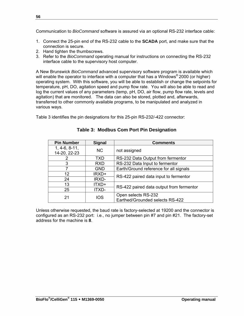
56
BioFlo®/CelliGen® 115 M1369-0050 Operating manual
Communication to BioCommand software is assured via an optional RS-232 interface cable: 1. Connect the 25-pin end of the RS-232 cable to the SCADA port, and make sure that the
connection is secure. 2. Hand tighten the thumbscrews. 3. Refer to the BioCommand operating manual for instructions on connecting the RS-232
interface cable to the supervisory host computer. A New Brunswick BioCommand advanced supervisory software program is available which will enable the operator to interface with a computer that has a Windows® 2000 (or higher) operating system. With this software, you will be able to establish or change the setpoints for temperature, pH, DO, agitation speed and pump flow rate. You will also be able to read and log the current values of any parameters (temp, pH, DO, air flow, pump flow rate, levels and agitation) that are monitored. The data can also be stored, plotted and, afterwards, transferred to other commonly available programs, to be manipulated and analyzed in various ways.
Table 3 identifies the pin designations for this 25-pin RS-232/-422 connector:
Table 3: Modbus Com Port Pin Designation
Pin Number Signal Comments 1, 4-6, 8-11, 14-20, 22-23
NC not assigned
2 TXD RS-232 Data Output from fermentor 3 RXD RS-232 Data Input to fermentor 7 GND Earth/Ground reference for all signals
12 IRXD+ 24 IRXD-
RS-422 paired data input to fermentor
13 ITXD+ 25 ITXD-
RS-422 paired data output from fermentor
21 IOS Open selects RS-232 Earthed/Grounded selects RS-422
Unless otherwise requested, the baud rate is factory-selected at 19200 and the connector is configured as an RS-232 port: i.e., no jumper between pin #7 and pin #21. The factory-set address for the machine is 8.
57
Operating manual
55 SSPPEECCIIFFIICCAATTIIOONNSS All systems may differ in configuration; please refer to your sales representative for details.
BioFlo/CelliGen 115 System Total Volume 1.3 L 3.0 L 7.5 L 14.0 L Working Volume
0.4-1.0 L 0.8-2.2 L 2.0-5.6 L 4.0-10.5 L Vessels
Design Heat-blanketed and Water-jacketed All vessels are borosilicate glass, autoclavable, with dished-bottom
Design Advanced compact controller with integrated utility station capable of supporting 2 additional utility stations and vessels
Display 21.3 cm (8.4 in) industrial color touchscreen display is standard with control station but not included with for 2nd or 3rd utility station
Control Station/ Utility Station
Function Fermentation and cell culture monitoring and control Indication Digital display in 0.1°C increments Range 70°C max temperature (65°C max temperature for 14.0 L) Control PID for heating and cooling
Heat-blanketed Vessels: External heating blanket and immersed stainless steel coiling coil Water-jacketed Vessels: Water jacket heater and circulation loop
Temperature
Sensor Platinum RTD probe (Pt 100) Drive Magnetic Drive or Direct Drive. Indication Digital display in 1 rpm increments. Range Direct Drive: 50-1200 rpm for fermentation, 25-400 for cell culture
Magnetic Drive : 25-200 rpm Control PID control; manual, automatic, or cascade settings Impellers Rushton-style standard with fermentation system
Pitched blade standard with cell culture Optional: Spin filter
Agitation
Baffles Removable 316L stainless steel; fermentation only Gas Flow options
0-4 Rotameters 0-150 mLpm 250-2500 mLpm 1-5 Lpm 1-20 Lpm
1 Thermal Mass flow Controller (TMFC) 0.04-20.00 SLPM
Gas Mixing options
Automatic 4-Gas Mixing (via 4 solenoids) Manual Gas mixing (via 4 gas manifold)
Sparger Standard: Ring sparger Optional: Microsparger
Inlet Filter 0.2μm interchangeable cartridge
Aeration
N2 Gas For calibration of DO probe
Indication Digital display in 0.01 pH increments
Range 2-14 pH
Control PID, link to pumps or gases, adjustable deadband
pH
Sensor pH probe
...continued...
58
BioFlo®/CelliGen® 115 M1369-0050 Operating manual
BioFlo/CelliGen 115 System Indication Digital display in 0.1% increments
Range 0-200%
Control PID, Cascade to Agitation, Gases, GasFlo if equipped with TMFC
DO
Sensor Polargraphic DO probe Filter 0.2μm interchangeable cartridge Exhaust Condenser Stainless steel, water-cooled in headplate
3 Pumps Control 12 rpm Water 10 PSIG maximum, 50 μm filtration Utilities Gases 10 PSIG maximum 120VAC 50/60 Hertz Single phase 10 Amps Electrical
requirements 230VAC 50/60 Hertz Single phase 6 Amps With Exhaust Condenser w/o Exhaust Condenser
Width Depth Height Width Height Heat-Blanketed
cm in cm in cm in cm in cm in
1.3 L Vessel 24 9.5 22 8.5 56 22 22 8.5 42 16.5
3.0 L Vessel 24 9.5 22 8.5 56 22 22 8.5 42 16.5
7.5 L Vessel 37 14.5 29 11.5 65 23 29 11.5 49.5 19.5
14.0 L Vessel 29 11.5 29 11.5 74 29 29 11.5 61 24
With Exhaust Condenser w/o Exhaust Condenser Width Depth Height Width Height
Water-Jacketed
cm in cm in cm in cm in cm in
1.3 L Vessel 29 11.5 29 11.5 52 20.5 24 9.3 41 16
3.0 L Vessel 29 11.5 29 11.5 56 22.5 24 9.3 45 18
7.5 L Vessel 29 11.5 29 11.5 68 26.8 29 11.5 52 20.5
Control Station / Utility Station Dimensions
14.0 L Vessel 29 11.5 29 11.5 80 31.5 29 11.5 67 26.5
1.3 L 3.0 L 7.5 L 14.0 L Vessel (empty) 6.8 kg (15 lb) 9.3 kg (20.5 lb) 18 kg (39.5 lb) 19.5 kg (43 lb)
Net Weight
Control Station
29.5 kg (65 lb)
Communications: USB for easy firmware upgrades (Control station only) BioCommand Port for communication with optional BioCommand/SCADA software Ethernet for future expansion
Certified to: Conforms to: UL Standard UL 61010-1
Regulatory Compliance c ETL us
CAN/CSA C22.2 No. 61010-1 Ambient Operating Conditions 10-35C, up to 80% relative humidity, non-condensing
Specifications are subject to change without notice.
5.1 Certifications
The BioFlo/CelliGen 115 has been tested and meets the requirements of U.S. and Canadian electrical and safety standards. And, as attested in the CE Declaration of Conformity reproduced on the following page, they also conform to the appropriate electrical and safety requirements set out in European Directives.
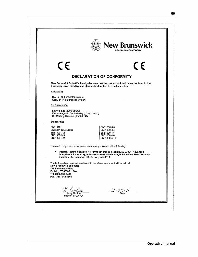
59
Operating manual
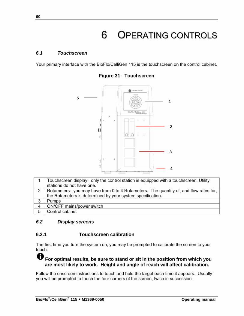
60
BioFlo®/CelliGen® 115 M1369-0050 Operating manual
66 OOPPEERRAATTIINNGG CCOONNTTRROOLLSS
6.1 Touchscreen
Your primary interface with the BioFlo/CelliGen 115 is the touchscreen on the control cabinet.
Figure 31: Touchscreen
1 Touchscreen display: only the control station is equipped with a touchscreen. Utility
stations do not have one. 2 Rotameters: you may have from 0 to 4 Rotameters. The quantity of, and flow rates for,
the Rotameters is determined by your system specification. 3 Pumps 4 ON/OFF mains/power switch 5 Control cabinet
6.2 Display screens
6.2.1 Touchscreen calibration
The first time you turn the system on, you may be prompted to calibrate the screen to your touch.
For optimal results, be sure to stand or sit in the position from which you are most likely to work. Height and angle of reach will affect calibration.
Follow the onscreen instructions to touch and hold the target each time it appears. Usually you will be prompted to touch the four corners of the screen, twice in succession.
1
2
3
4
5
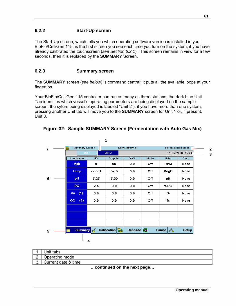
61
Operating manual
6.2.2 Start-Up screen The Start-Up screen, which tells you which operating software version is installed in your BioFlo/CelliGen 115, is the first screen you see each time you turn on the system, if you have already calibrated the touchscreen (see Section 6.2.1). This screen remains in view for a few seconds, then it is replaced by the SUMMARY Screen.
6.2.3 Summary screen The SUMMARY screen (see below) is command central; it puts all the available loops at your fingertips. Your BioFlo/CelliGen 115 controller can run as many as three stations; the dark blue Unit Tab identifies which vessel’s operating parameters are being displayed (in the sample screen, the sytem being displayed is labeled “Unit 2”); if you have more than one system, pressing another Unit tab will move you to the SUMMARY screen for Unit 1 or, if present, Unit 3.
Figure 32: Sample SUMMARY Screen (Fermentation with Auto Gas Mix)
1 Unit tabs 2 Operating mode 3 Current date & time
…continued on the next page…
1
2 3
4
6
7
5
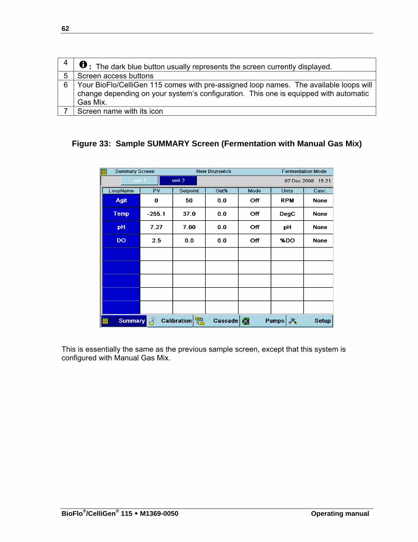
62
BioFlo®/CelliGen® 115 M1369-0050 Operating manual
4 : The dark blue button usually represents the screen currently displayed. 5 Screen access buttons 6 Your BioFlo/CelliGen 115 comes with pre-assigned loop names. The available loops will
change depending on your system’s configuration. This one is equipped with automatic Gas Mix.
7 Screen name with its icon
Figure 33: Sample SUMMARY Screen (Fermentation with Manual Gas Mix)
This is essentially the same as the previous sample screen, except that this system is configured with Manual Gas Mix.
63
Operating manual
Figure 34: Sample SUMMARY Screen (Cell Culture without TMFC)
This is essentially the same as the previous sample screens, except that this systen is configured with Gas Mix, without thermal mass flow controller (TMFC), and is in Cell Culture operating mode. The screen below is essentially the same as the one above, in Cell Culture mode and with Gas Mix, but this system is configured with at least one TMFC.
Figure 35: Sample SUMMARY Screen (Cell Culture with TMFC)
1 A GasFlo loop indicates that the system is configured with at least one thermal mass
flow controller (TMFC).
64
BioFlo®/CelliGen® 115 M1369-0050 Operating manual
Table 4 identifies the other interactive features of the SUMMARY screen:
Table 4: SUMMARY Screen Features
Parameter Column Description
LoopName Each system comes with standard factory-assigned loops (e.g., Agitation, Temperature, pH, DO, etc.). Loops are factory-assigned according to the configuration of your system.
PV Process Variable: here the display reflects the current value for each loop, in comparison to its setpoint (displayed in the next column).
Setpoint The current setpoint (default or user-set) for each loop. Out% The current percent output for each loop. This is an
automatic control function to maintain current readings within the setpoint tolerance range.
Control Mode Depending on the loop, the control mode may be Off, Auto, Manual, On, or O2 Enrich.
Unit (of measure) This is the unit of measure used for the PV and Setpoint. Cascade If any cascades have been programmed, they will be
displayed here. Navigation Buttons (for screen access)
Description
Summary This screen is command central; it shows all your loops, their current readings, setpoints and what has been programmed for them.
Calibration This screen allows you to calibrate the pH, DO & Level probes and the gas flow.
Cascade A cascade is a control function that uses the output of one loop to influence the action and output of one or more other loop(s). This screen allows you to set up cascades, to view current settings, and to make changes to those settings.
Pumps This screen gives you access to the Pump Gauges screen, where the three pump gauges are displayed, providing both current readings and the opportunity to change pump settings.
Setup This screen allows you to make changes to your system settings, hardware setup & controller setup
6.2.4 Keypads When an alphanumerical or a numerical keypad is needed for you to put information into edit boxes, clicking in the edit box will open the required keypad (see the following pages).
65
Operating manual
Figure 36: Alphanumeric Keypad
1 This keypad is used to designate a Unit Name. 2 What you type on the keypad appears here. 3 Pressing the Cancel key clears the entry and closes the keypad. 4 When you have finished typing the entry, press the OK key to save the entry and close
the keypad. 5 Pressing the BackSp (backspace) key clears the entry one character at a time, each
time you press the key, without closing the keypad. 5 Pressing the Clear key clears the entry without closing the keypad.
1
2
3
4 5
6
66
BioFlo®/CelliGen® 115 M1369-0050 Operating manual
Figure 37: Numeric Keypad
1 This keypad is used to designate a setpoint speed for Agitation. 2 What you type on the keypad will appear here. 3 When you have finished typing the entry, press the OK key to save the entry and close
the keypad. 4 To clear the entry without saving it, and to close the keypad, press the Cancel key. 5 To clear the entry without closing the keypad, press the Clear key.
6.2.5 Gauge screens Every loop has its own gauge screen. To access it, in the SUMMARY screen, touch the screen in the appropriate blue box in the LoopName column. Your touch will open that loop’s GAUGE screen (see the following page).
1
2
3
4
5
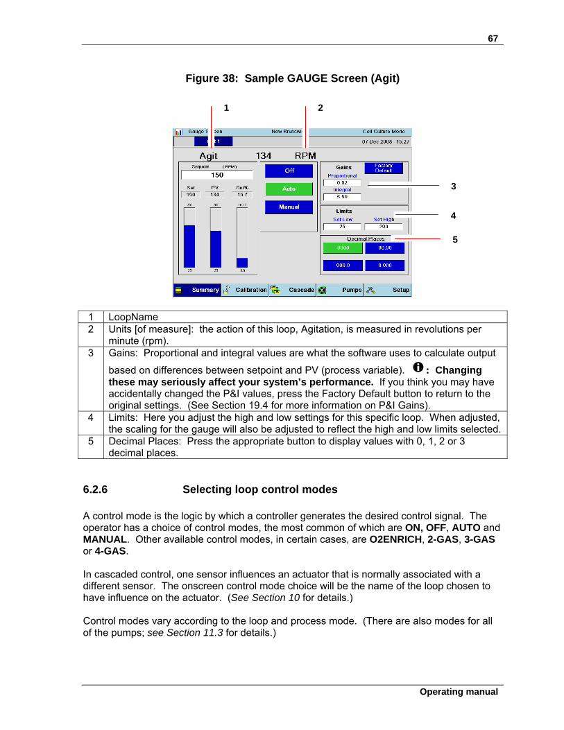
67
Operating manual
Figure 38: Sample GAUGE Screen (Agit)
1 LoopName 2 Units [of measure]: the action of this loop, Agitation, is measured in revolutions per
minute (rpm). 3 Gains: Proportional and integral values are what the software uses to calculate output
based on differences between setpoint and PV (process variable). : Changing these may seriously affect your system’s performance. If you think you may have accidentally changed the P&I values, press the Factory Default button to return to the original settings. (See Section 19.4 for more information on P&I Gains).
4 Limits: Here you adjust the high and low settings for this specific loop. When adjusted, the scaling for the gauge will also be adjusted to reflect the high and low limits selected.
5 Decimal Places: Press the appropriate button to display values with 0, 1, 2 or 3 decimal places.
6.2.6 Selecting loop control modes
A control mode is the logic by which a controller generates the desired control signal. The operator has a choice of control modes, the most common of which are ON, OFF, AUTO and MANUAL. Other available control modes, in certain cases, are O2ENRICH, 2-GAS, 3-GAS or 4-GAS.
In cascaded control, one sensor influences an actuator that is normally associated with a different sensor. The onscreen control mode choice will be the name of the loop chosen to have influence on the actuator. (See Section 10 for details.)
Control modes vary according to the loop and process mode. (There are also modes for all of the pumps; see Section 11.3 for details.)
1 2
3
5
4
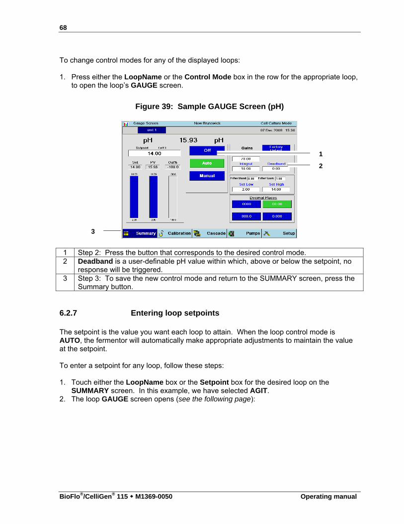
68
BioFlo®/CelliGen® 115 M1369-0050 Operating manual
To change control modes for any of the displayed loops:
1. Press either the LoopName or the Control Mode box in the row for the appropriate loop,
to open the loop’s GAUGE screen.
Figure 39: Sample GAUGE Screen (pH)
1 Step 2: Press the button that corresponds to the desired control mode. 2 Deadband is a user-definable pH value within which, above or below the setpoint, no
response will be triggered. 3 Step 3: To save the new control mode and return to the SUMMARY screen, press the
Summary button.
6.2.7 Entering loop setpoints The setpoint is the value you want each loop to attain. When the loop control mode is AUTO, the fermentor will automatically make appropriate adjustments to maintain the value at the setpoint.
To enter a setpoint for any loop, follow these steps:
1. Touch either the LoopName box or the Setpoint box for the desired loop on the
SUMMARY screen. In this example, we have selected AGIT. 2. The loop GAUGE screen opens (see the following page):
1
2
3
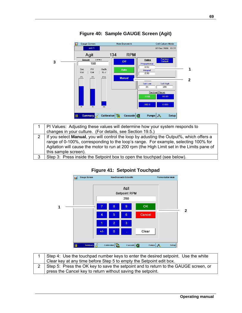
69
Operating manual
Figure 40: Sample GAUGE Screen (Agit)
1 PI Values: Adjusting these values will determine how your system responds to
changes in your culture. (For details, see Section 19.5.) 2 If you select Manual, you will control the loop by adusting the Output%, which offers a
range of 0-100%, corresponding to the loop’s range. For example, selecting 100% for Agitation will cause the motor to run at 200 rpm (the High Limit set in the Limits pane of this sample screen).
3 Step 3: Press inside the Setpoint box to open the touchpad (see below).
Figure 41: Setpoint Touchpad
1 Step 4: Use the touchpad number keys to enter the desired setpoint. Use the white Clear key at any time before Step 5 to empty the Setpoint edit box.
2 Step 5: Press the OK key to save the setpoint and to return to the GAUGE screen, or press the Cancel key to return without saving the setpoint.
1
2
3
2 1
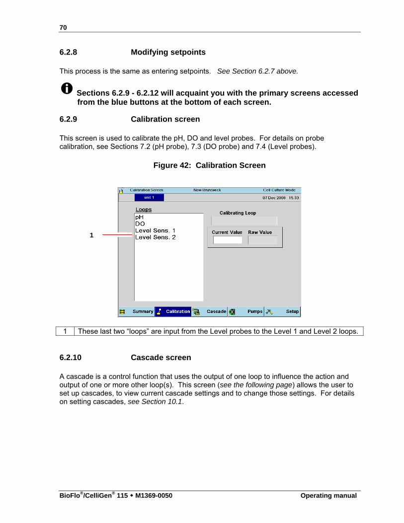
70
BioFlo®/CelliGen® 115 M1369-0050 Operating manual
6.2.8 Modifying setpoints This process is the same as entering setpoints. See Section 6.2.7 above.
Sections 6.2.9 - 6.2.12 will acquaint you with the primary screens accessed from the blue buttons at the bottom of each screen.
6.2.9 Calibration screen This screen is used to calibrate the pH, DO and level probes. For details on probe calibration, see Sections 7.2 (pH probe), 7.3 (DO probe) and 7.4 (Level probes).
Figure 42: Calibration Screen
1 These last two “loops” are input from the Level probes to the Level 1 and Level 2 loops.
6.2.10 Cascade screen A cascade is a control function that uses the output of one loop to influence the action and output of one or more other loop(s). This screen (see the following page) allows the user to set up cascades, to view current cascade settings and to change those settings. For details on setting cascades, see Section 10.1.
1
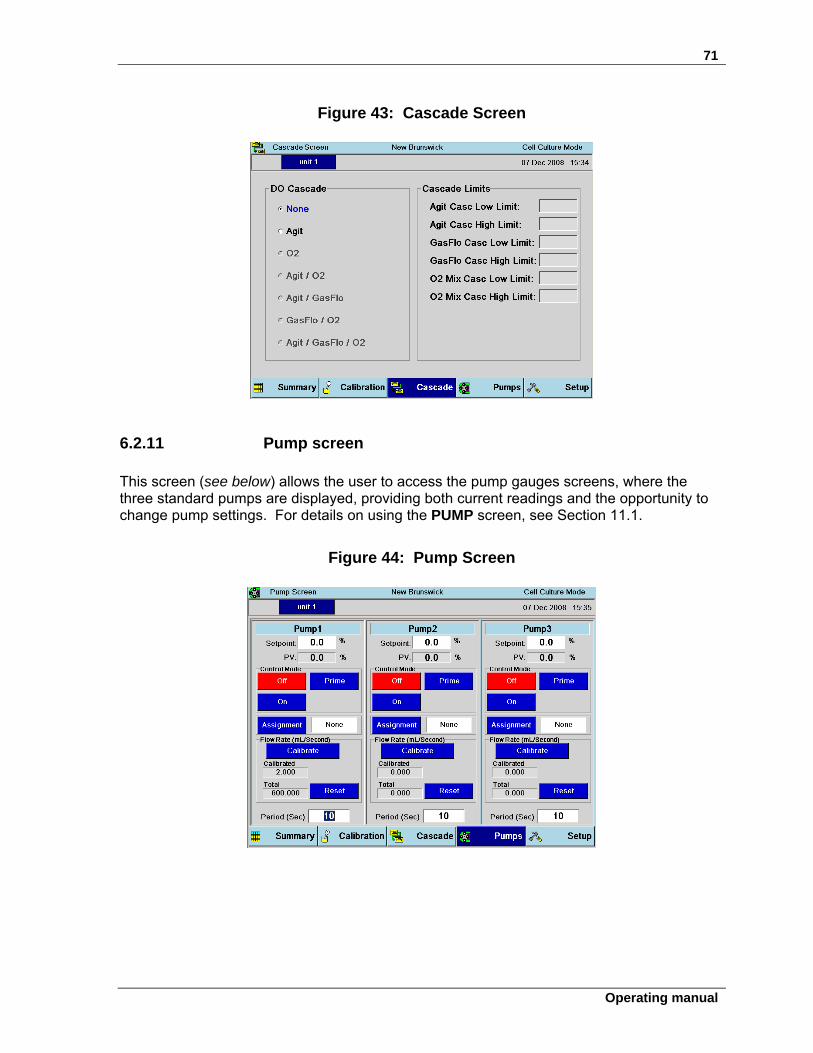
71
Operating manual
Figure 43: Cascade Screen
6.2.11 Pump screen This screen (see below) allows the user to access the pump gauges screens, where the three standard pumps are displayed, providing both current readings and the opportunity to change pump settings. For details on using the PUMP screen, see Section 11.1.
Figure 44: Pump Screen
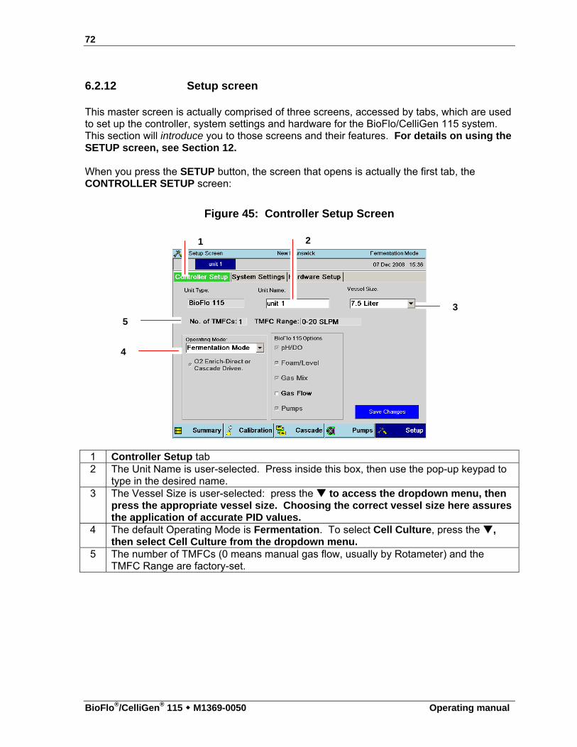
72
BioFlo®/CelliGen® 115 M1369-0050 Operating manual
6.2.12 Setup screen This master screen is actually comprised of three screens, accessed by tabs, which are used to set up the controller, system settings and hardware for the BioFlo/CelliGen 115 system. This section will introduce you to those screens and their features. For details on using the SETUP screen, see Section 12.
When you press the SETUP button, the screen that opens is actually the first tab, the CONTROLLER SETUP screen:
Figure 45: Controller Setup Screen
1 Controller Setup tab 2 The Unit Name is user-selected. Press inside this box, then use the pop-up keypad to
type in the desired name. 3 The Vessel Size is user-selected: press the to access the dropdown menu, then
press the appropriate vessel size. Choosing the correct vessel size here assures the application of accurate PID values.
4 The default Operating Mode is Fermentation. To select Cell Culture, press the , then select Cell Culture from the dropdown menu.
5 The number of TMFCs (0 means manual gas flow, usually by Rotameter) and the TMFC Range are factory-set.
1 2
3
4
5
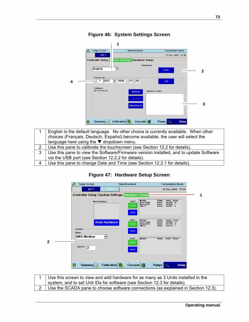
73
Operating manual
Figure 46: System Settings Screen
1 English is the default language. No other choice is currently available. When other choices (Français, Deutsch, Español) become available, the user will select the language here using the dropdown menu.
2 Use this pane to calibrate the touchscreen (see Section 12.2 for details). 3 Use this pane to view the Software/Firmware version installed, and to update Software
via the USB port (see Section 12.2.2 for details). 4 Use this pane to change Date and Time (see Section 12.2.1 for details).
Figure 47: Hardware Setup Screen
1 Use this screen to view and add hardware for as many as 3 Units installed in the system, and to set Unit IDs for software (see Section 12.3 for details).
2 Use the SCADA pane to choose software connections (as explained in Section 12.3).
1
2
3
4
1
2
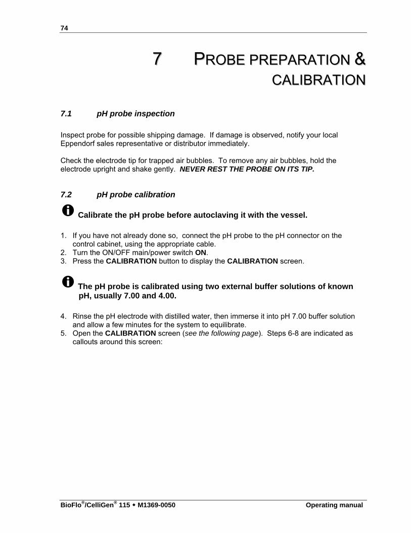
74
BioFlo®/CelliGen® 115 M1369-0050 Operating manual
77 PPRROOBBEE PPRREEPPAARRAATTIIOONN &&
CCAALLIIBBRRAATTIIOONN
7.1 pH probe inspection
Inspect probe for possible shipping damage. If damage is observed, notify your local Eppendorf sales representative or distributor immediately. Check the electrode tip for trapped air bubbles. To remove any air bubbles, hold the electrode upright and shake gently. NEVER REST THE PROBE ON ITS TIP.
7.2 pH probe calibration
Calibrate the pH probe before autoclaving it with the vessel.
1. If you have not already done so, connect the pH probe to the pH connector on the control cabinet, using the appropriate cable.
2. Turn the ON/OFF main/power switch ON. 3. Press the CALIBRATION button to display the CALIBRATION screen.
The pH probe is calibrated using two external buffer solutions of known pH, usually 7.00 and 4.00.
4. Rinse the pH electrode with distilled water, then immerse it into pH 7.00 buffer solution and allow a few minutes for the system to equilibrate.
5. Open the CALIBRATION screen (see the following page). Steps 6-8 are indicated as callouts around this screen:
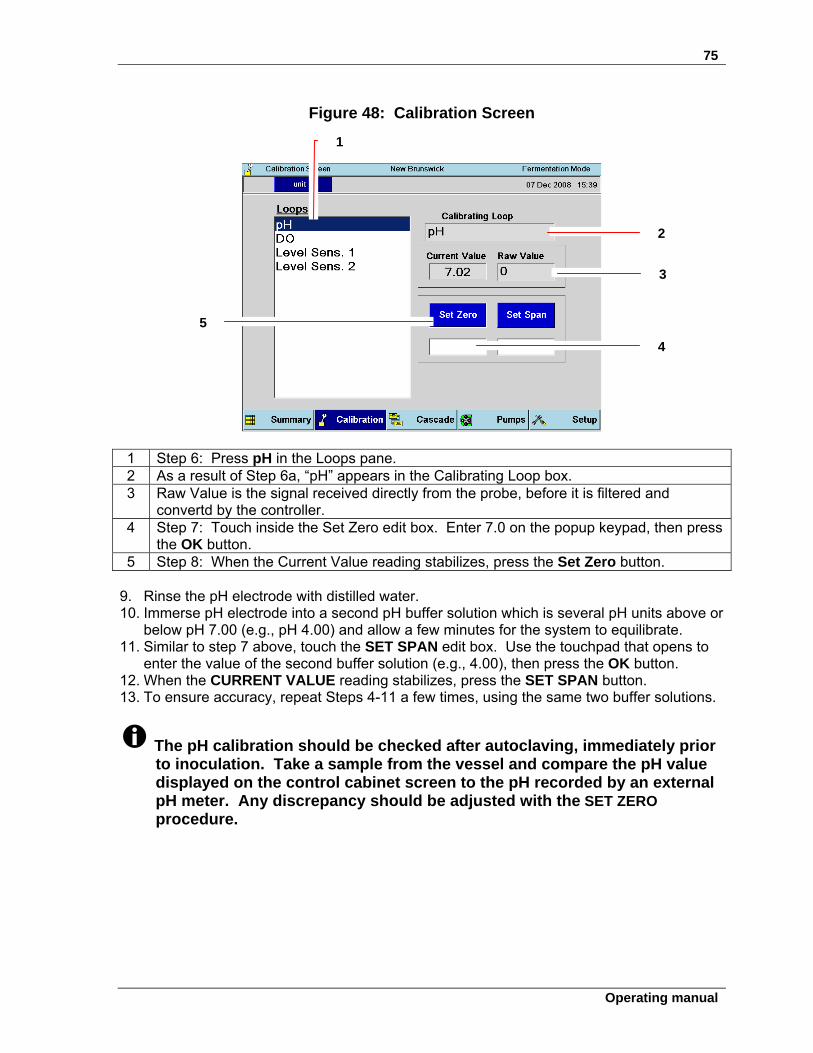
75
Operating manual
Figure 48: Calibration Screen
1 Step 6: Press pH in the Loops pane. 2 As a result of Step 6a, “pH” appears in the Calibrating Loop box. 3 Raw Value is the signal received directly from the probe, before it is filtered and
convertd by the controller. 4 Step 7: Touch inside the Set Zero edit box. Enter 7.0 on the popup keypad, then press
the OK button. 5 Step 8: When the Current Value reading stabilizes, press the Set Zero button.
9. Rinse the pH electrode with distilled water. 10. Immerse pH electrode into a second pH buffer solution which is several pH units above or
below pH 7.00 (e.g., pH 4.00) and allow a few minutes for the system to equilibrate. 11. Similar to step 7 above, touch the SET SPAN edit box. Use the touchpad that opens to
enter the value of the second buffer solution (e.g., 4.00), then press the OK button. 12. When the CURRENT VALUE reading stabilizes, press the SET SPAN button. 13. To ensure accuracy, repeat Steps 4-11 a few times, using the same two buffer solutions.
The pH calibration should be checked after autoclaving, immediately prior to inoculation. Take a sample from the vessel and compare the pH value displayed on the control cabinet screen to the pH recorded by an external pH meter. Any discrepancy should be adjusted with the SET ZERO procedure.
1
2
3
4
5
76
BioFlo®/CelliGen® 115 M1369-0050 Operating manual
7.2.1 pH probe installation
WARNING! Risk of broken glass! Be sure to wear protective gloves when installing a glass electrode.
Prior to installation, any pH probe you are using should be inspected for damage, and replaced if necessary.
To avoid damage to the probes during operation, be sure that there is no interference between the probes and the baffle assembly, impeller blades, or cooling coil.
1. Wear protective gloves to protect yourself in case of accidental breakage. 2. Lightly coat the pH probe with glycerol.
ALERT! Risk to pH probe! Always fit the pH port adaptor onto the probe first. Then insert the probe with its adaptor into the headplate, following Steps 3-
11 shown after the drawing on the following page. Never attempt to install the pH port adaptor in the headplate without the
probe.
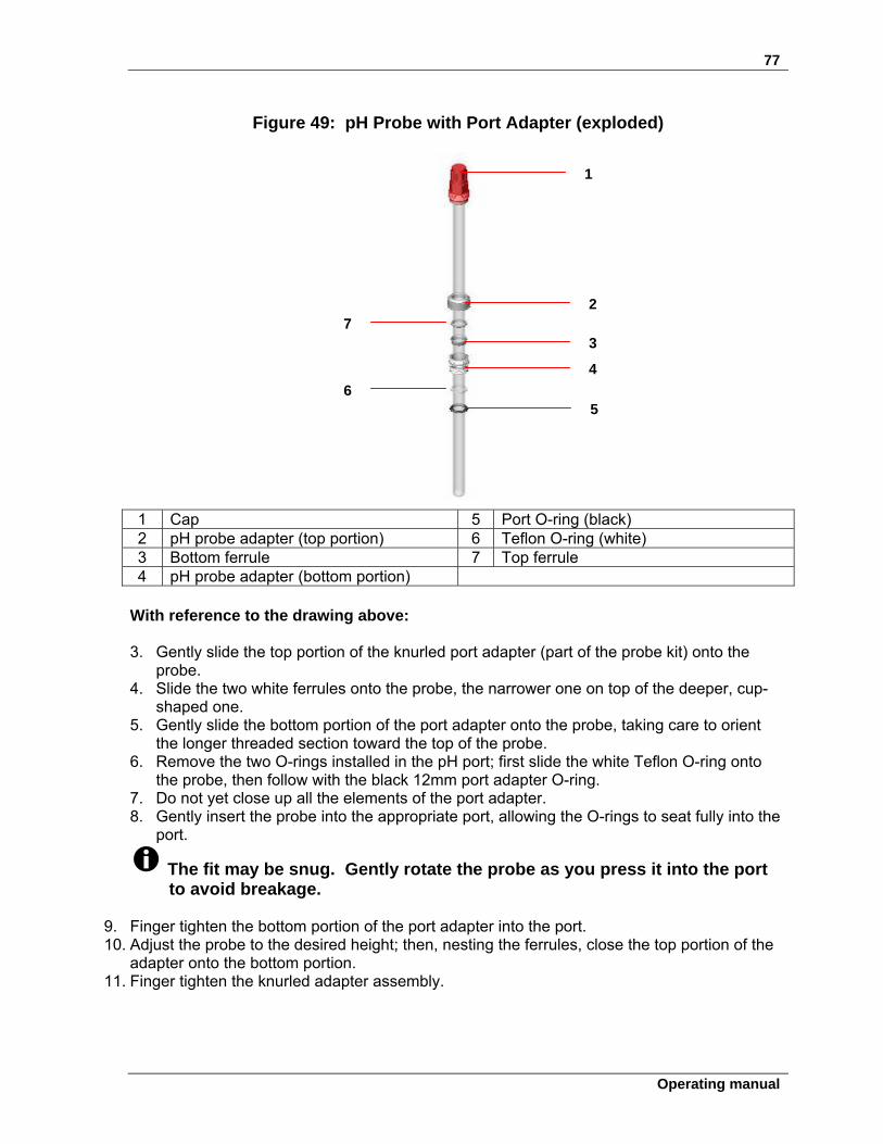
77
Operating manual
Figure 49: pH Probe with Port Adapter (exploded)
1 Cap 5 Port O-ring (black) 2 pH probe adapter (top portion) 6 Teflon O-ring (white) 3 Bottom ferrule 7 Top ferrule 4 pH probe adapter (bottom portion)
With reference to the drawing above:
3. Gently slide the top portion of the knurled port adapter (part of the probe kit) onto the
probe. 4. Slide the two white ferrules onto the probe, the narrower one on top of the deeper, cup-
shaped one. 5. Gently slide the bottom portion of the port adapter onto the probe, taking care to orient
the longer threaded section toward the top of the probe. 6. Remove the two O-rings installed in the pH port; first slide the white Teflon O-ring onto
the probe, then follow with the black 12mm port adapter O-ring. 7. Do not yet close up all the elements of the port adapter. 8. Gently insert the probe into the appropriate port, allowing the O-rings to seat fully into the
port.
The fit may be snug. Gently rotate the probe as you press it into the port to avoid breakage.
9. Finger tighten the bottom portion of the port adapter into the port. 10. Adjust the probe to the desired height; then, nesting the ferrules, close the top portion of the
adapter onto the bottom portion. 11. Finger tighten the knurled adapter assembly.
1
2
3
4
5 6
7
78
BioFlo®/CelliGen® 115 M1369-0050 Operating manual
ALERT! Risk of damage to equipment! We recommend that you avoid the use of hydrochloric acid (HCl) with the
BioFlo/CelliGen 115 for pH control or any other purpose, because HCl corrodes stainless steel. Over time, it will severely damage the headplate, a costly component to replace, and other stainless steel components.
Phosphoric and sulfuric (10% maximum concentration) acids are acceptable and are commonly used for pH control.
7.2.2 pH probe maintenance & storage
Check for any trapped air bubbles in the electrode’s tip to remove bubbles, hold electrode upright and shake electrode gently. The probe should be stored standing upright, and the electrode tip should be immersed in the solution of 3 molar KCl or a buffer solution between pH 4.00 and pH 7.00. If the probe is so equipped, the two rubber T stoppers should be inserted.
ALERT! Risk of damage to pH probe! Never let a pH probe rest on its tip, and never leave a pH probe in DI water.
7.3 Dissolved oxygen (DO) probe preparation
7.3.1 Inspecting the DO probe
Inspect the probe for possible shipping damage. Immediately report any damage you may observe to your local Eppendorf sales representative or distributor. Remove the protective cap from the electrode end. The membrane is delicate and care must be exercised to prevent accidental damage. NEVER REST THE PROBE ON ITS MEMBRANE.
7.3.2 DO probe preparation
To ensure stable output, the probe should be sent through two or three sterilization (autoclaving) cycles prior to use. The probe will be operable after the second cycle, but it will be more stable with additional sterilizations. The shorting plug should be installed on the probe during autoclaving or sterilization.
79
Operating manual
Default P & I (proportional & integral) gains are preset at the factory. They are different for each operating mode, fermentation and cell culture, to ensure proper DO control.
It is recommended that you use the factory-set P & I values. Do not attempt to change the settings unless you are experienced with P & I control.
If you choose to make changes, P & I gains for the DO loop can be modified by using the touchpad on the front of the control cabinet. For details, see Section 20, Appendix B. It is unlikely that you will ever need to reset or change the P & I values. Even if the mains/power fails during a run, the P & I values (factory preset or your own) are stored in memory and should still be in effect when the mains/power is restored. However, it is recommended that you check these values at the beginning of each run.
7.3.3 DO probe installation
Prior to installation, any dissolved oxygen probe you are using should be inspected for damage and replaced if necessary.
To avoid damage to the probes during operation, be sure that there is no interference between the probes and the baffle assembly, impeller blades or cooling coil.
1. Wear protective gloves to protect yourself in case of accidental breakage. 2. Lightly coat the dO2 probe with glycerol.
ALERT! Risk of damage to dissolved oxygen probe! Always fit the dO2 port adaptor onto the probe first. Then insert the probe with its adaptor into the headplate, following Steps 3-
11 shown after the drawing on the following page. Never attempt to install the dO2 port adaptor in the headplate without the
probe.
80
BioFlo®/CelliGen® 115 M1369-0050 Operating manual
Figure 50: dO2 Probe with Port Adapter (exploded)
1 dO2 probe adapter (top portion) 5 Teflon O-ring (white) 2 Bottom ferrule 6 Top ferrule 3 dO2 probe adapter (bottom portion) 7 Cap 4 Port O-ring (black)
With reference to the drawing above:
3. Gently slide the top portion of the knurled port adapter (part of the probe kit) onto the
probe. 4. Slide the two white ferrules onto the probe, the narrower one on top of the deeper, cup-
shaped one. 5. Gently slide the bottom portion of the port adapter onto the probe, taking care to orient
the longer threaded section toward the top of the probe. 6. Remove the two O-rings installed in the dO2 port; first slide the white Teflon O-ring onto
the probe, then follow with the black 12mm port adapter O-ring. 7. Do not yet close up all the elements of the port adapter. 8. Gently insert the probe into the appropriate port, allowing the O-rings to seat fully into the
port.
The fit may be snug. Gently rotate the probe as you press it into the port to avoid breakage.
9. Finger tighten the bottom portion of the port adapter into the port. 10. Adjust the probe to the desired height; then, nesting the ferrules, close the top portion of
the adapter onto the bottom portion. 11. Finger tighten the knurled adapter assembly.
1
2
3
4 5
6
7
81
Operating manual
7.3.4 DO probe polarization
If the probe has been disconnected from a voltage source (either the system’s O2 amplifier or a separate polarizing module) for longer than 5 minutes, it will need to be re-polarized. To re-polarize: Connect the probe to the operating O2 amplifier (or polarizing module). Allow SIX HOURS FOR POLARIZATION prior to calibrating the probe.
7.3.5 DO probe calibration: setting zero
The DO probe is calibrated AFTER sterilization.
There are two methods to obtain zero for calibrating the DO probe. Review both methods and use the one you prefer:
Method 1:
1. Remove the DO cable from the DO electrode. 2. Go to the CALIBRATION screen and select DO. 3. Enter 0 in the SET ZERO edit box (see the following page), then press SET ZERO. 4. Reconnect the DO cable to the DO electrode.
If you use Method 1, make sure the probe is not disconnected for more than one minute.
Method 2:
Nitrogen is needed for Method 2. There is an N2 gas inlet on the control cabinet for this purpose; make sure that your nitrogen source is connected to this inlet.
1. Connect the DO cable to the DO electrode and the control cabinet. 2. Go to the CALIBRATION screen and select DO. 3. Press the N2 (3) ON button. Depending on your system’s configuration, however, this
button may not be present. In this case, manually turn the N2 loop on from the SUMMARY screen, or manually turn on the Rotameter, and set it to 1 - 20 SLPM (depending on vessel size and flow controller).
4. In approximately 10 - 30 minutes, the current value reading will stabilize. 5. Press the SET ZERO edit box (see the following page), use the touchpad to enter 0,
press the OK button, then press the SET ZERO button. 6. Press N2 (3) OFF (or, if in Step 3 you manually turned the N2 loop on, now manually shut
off the nitrogen flow to the vessel).
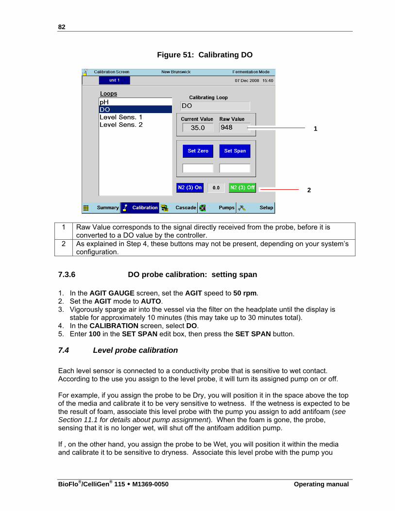
82
BioFlo®/CelliGen® 115 M1369-0050 Operating manual
Figure 51: Calibrating DO
1 Raw Value corresponds to the signal directly received from the probe, before it is
converted to a DO value by the controller. 2 As explained in Step 4, these buttons may not be present, depending on your system’s
configuration.
7.3.6 DO probe calibration: setting span 1. In the AGIT GAUGE screen, set the AGIT speed to 50 rpm. 2. Set the AGIT mode to AUTO. 3. Vigorously sparge air into the vessel via the filter on the headplate until the display is
stable for approximately 10 minutes (this may take up to 30 minutes total). 4. In the CALIBRATION screen, select DO. 5. Enter 100 in the SET SPAN edit box, then press the SET SPAN button.
7.4 Level probe calibration
Each level sensor is connected to a conductivity probe that is sensitive to wet contact. According to the use you assign to the level probe, it will turn its assigned pump on or off. For example, if you assign the probe to be Dry, you will position it in the space above the top of the media and calibrate it to be very sensitive to wetness. If the wetness is expected to be the result of foam, associate this level probe with the pump you assign to add antifoam (see Section 11.1 for details about pump assignment). When the foam is gone, the probe, sensing that it is no longer wet, will shut off the antifoam addition pump. If , on the other hand, you assign the probe to be Wet, you will position it within the media and calibrate it to be sensitive to dryness. Associate this level probe with the pump you
1
2
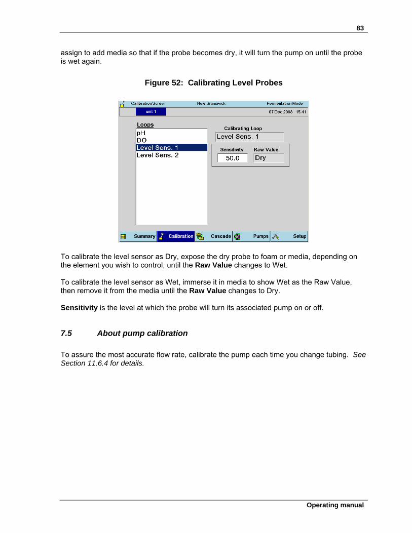
83
Operating manual
assign to add media so that if the probe becomes dry, it will turn the pump on until the probe is wet again.
Figure 52: Calibrating Level Probes
To calibrate the level sensor as Dry, expose the dry probe to foam or media, depending on the element you wish to control, until the Raw Value changes to Wet. To calibrate the level sensor as Wet, immerse it in media to show Wet as the Raw Value, then remove it from the media until the Raw Value changes to Dry. Sensitivity is the level at which the probe will turn its associated pump on or off.
7.5 About pump calibration
To assure the most accurate flow rate, calibrate the pump each time you change tubing. See Section 11.6.4 for details.
84
BioFlo®/CelliGen® 115 M1369-0050 Operating manual
88 VVEESSSSEELL SSTTEERRIILLIIZZAATTIIOONN
Before proceeding, consult the dimensions of your vessel assemblies to be sure your autoclave is large enough to accommodate the vessel with its various components.
WARNING! Risk of explosion! During autoclaving, the vessel exhaust filter must be vented to avoid
explosion.
WARNING! Risk of burns! Use protective gloves when handling hot components.
ALERT! Risk of water leaks! Make sure the main water supply is closed before connecting or
disconnecting the water hoses to/from the vessel and/or cabinet at any time.
ALERT! Risk of equipment damage from steam! Install the bearing housing cap on the fermentation vessel bearing housing
before sterilization, to keep steam from damaging the internal bearings.
ALERT! Risk of damage to tubing! Never autoclave PVC tubing (clear with white braiding).
There are four objectives to preparing a vessel for sterilization:
A. To minimize pressure differences throughout the sterilization process by ensuring that the air can transfer freely between the inside and the outside of the vessel;
85
Operating manual
B. To ensure that minor pressure differences do not expel liquid from the vessel by clamping off all penetrations that go below liquid level;
C. To protect hydrophobic filters from blockage, which would occur if condensation were allowed to wet and block the filter surface;
D. To protect susceptible vessel assembly components from steam damage. The first objective is met by leaving at least one vessel port open, the second by clamping shut flexible tubing attached to immersed penetrations, and the third by wrapping filters with a protective cap of aluminum foil. Use protective caps on probes and bearings to meet the fourth objective.
8.1 Initial preparation for autoclaving
To prepare the vessel for sterilization: 1. Remove the motor from the top of the vessel and carefully put it aside. 2. Lubricate the vinyl bearing housing cap with silicone grease to facilitate sliding the cap
securely onto the housing. 3. Place the bearing housing cap on the top of the bearing housing. 4. Disconnect the air and/or gas lines from the inlet filter on the sparger. 5. Disconnect the water lines. Remove all PVC tubing. 6. Clamp off the harvest tube, the sample tube and all other penetrations that are immersed
in the media. 7. Remove the RTD from the thermowell. 8. Disconnect all probes and sensors, and remove their cables. 9. If you are using pH and DO probes, install each probe’s shorting cap (provided in the
probe kit). 10. Before placing the vessel into the autoclave, loosen the glass sample bottle by ½ turn. 11. Wrap all filters with aluminum foil to protect them from steam. 12. Attach a piece of tubing, wrapped with some non-absorbent material (such as glass wool
or non-absorbent cotton) to each of the addition ports. Wrap foil around the end of the tubing, shaped like a funnel, to allow the vessel to vent more easily during autoclaving. Place a clamp on the tubing.
Be sure to leave one clamp open during autoclaving to equalize pressure.
If you have addition, foam trap or harvest bottles mounted at the base of the vessel, you can autoclave them with the vessel. Without detaching their tubing from the headplate:
13. Remove the bottle holder(s) and reinstall each on one of the headplate clamping screws. 14. Reinsert the bottle and turn the holder until the bottle and holder are positioned over the
headplate, rather than extended over the edge. 15. Finger tighten the knurled nut. 16. Clamp off the tubing, and, where appropriate, remove it from the pump.
Probe tips must be moist during sterilization:
If you will be doing batch fermentation, be sure the vessel is filled with media so the media will also be sterilized.
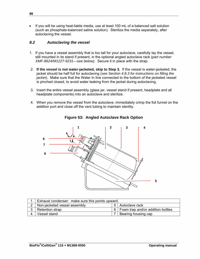
86
BioFlo®/CelliGen® 115 M1369-0050 Operating manual
If you will be using heat-liable media, use at least 100 mL of a balanced salt solution (such as phosphate-balanced saline solution). Sterilize the media separately, after autoclaving the vessel.
8.2 Autoclaving the vessel
1. If you have a vessel assembly that is too tall for your autoclave, carefully lay the vessel,
still mounted in its stand if present, in the optional angled autoclave rack (part number XMF-8624/M1227-9231—see below). Secure it in place with the strap.
2. If the vessel is not water-jacketed, skip to Step 3. If the vessel is water-jacketed, the
jacket should be half full for autoclaving (see Section 4.8.3 for instructions on filling the jacket). Make sure that the Water In line connected to the bottom of the jacketed vessel is pinched closed, to avoid water leaking from the jacket during autoclaving.
3. Insert the entire vessel assembly (glass jar, vessel stand if present, headplate and all
headplate components) into an autoclave and sterilize. 4. When you remove the vessel from the autoclave, immediately crimp the foil funnel on the
addition port and close off the vent tubing to maintain sterility.
Figure 53: Angled Autoclave Rack Option
1 Exhaust condenser: make sure this points upward. 2 Non-jacketed vessel assembly 5 Autoclave rack 3 Retention strap 6 Foam trap and/or addition bottles 4 Vessel stand 7 Bearing housing cap
1 2 3 4
5
6
6
7
87
Operating manual
8.2.1 Sterilization time and temperature Sterilization time varies with autoclave characteristics, temperature settings, vessel size and contents (i.e., media properties). As a starting point, autoclave for 25 minutes after the autoclave reaches 121° C.
ALERT! Risk of vessel damage! Be sure to vent the vessel at all times during autoclaving. Release the autoclave pressure only when the temperature has dropped
below 90° C. Use slow exhaust (30 - 60 minutes). If available, put the autoclave on liquid cycle pressure release.
Filter manufacturers generally advise limiting filter sterilization to 30 minutes, but the longer time required for slow exhaust is essential to protecting the vessel integrity. New Brunswick’s long experience has shown no adverse effects at all on filters exposed to longer autoclaving times.
Adjust the time and temperature as needed. If, after autoclaving, most of the liquid has left the vessel, the autoclave is exhausting too quickly. Adjust the autoclave to exhaust more slowly.
88
BioFlo®/CelliGen® 115 M1369-0050 Operating manual
99 RREEIINNSSTTAALLLLIINNGG TTHHEE VVEESSSSEELL AASSSSEEMMBBLLYY
9.1 Reinstall the vessel assembly
ALERT! Risk of damage to vessel! Cold water and hot glass is a potentially dangerous mix! Be sure to let the
vessel cool for a few minutes before reconnecting the water line.
1. Position the vessel next to the BioFlo/CelliGen 115 control cabinet. Connect the water
lines to the heat exchanger and the exhaust condenser (see Vessel Assembly section). 2. Connect the drain line. 3. Connect the Cooling Loop In and Cooling Loop Return between the cabinet and the
vessel. 4. Connect Exhaust In and Return between the cabinet and the exhaust condenser (if
present). 5. Secure all connections. 6. Connect the Water In to your water supply. 7. Turn your water utility on to 10 PSIG. 8. Carefully place the motor on the bearing housing, on top of the vessel assembly. 9. Remove the pH shorting cap and connect the pH cable to the pH connector on the control
cabinet. 10. Remove the DO shorting cap and connect the DO cable to the DO connector on the
control cabinet. 11. Connect the foam probe cable to the foam connector on the control cabinet.
9.2 Load pump tubing
If you have pumps in your configuration, the three standard pumps are located on the front of the control cabinet (see the following page):
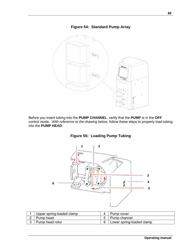
89
Operating manual
Figure 54: Standard Pump Array
Before you insert tubing into the PUMP CHANNEL, verify that the PUMP is in the OFF control mode. With reference to the drawing below, follow these steps to properly load tubing into the PUMP HEAD:
Figure 55: Loading Pump Tubing
1 Upper spring-loaded clamp 4 Pump cover 2 Pump head 5 Pump channel 3 Pump head rotor 6 Lower spring-loaded clamp
1 2
3
4
5
6
90
BioFlo®/CelliGen® 115 M1369-0050 Operating manual
1. Open the PUMP cover to gain access to the interior of the pump. 2. Select the desired tubing size (see Table 6 in Section 11.4 for reference) and cut a length
sufficient to reach from the inlet source, through the pump, and to the outlet recipient, allowing a few extra inches.
3. Form a loop large enough to go around the pump head. 4. Fit one side of the tubing loop into one of the spring-loaded clamps, pulling the clamp
open with your finger.
CAUTION! Risk of injury to hands! Be careful not to pinch your fingers in the pump head levers.
5. Then, as you rotate the pump’s rotor by hand in a clockwise direction to clear the
channel, lay the tubing in the channel around the pump head. 6. Fit the other end of the tubing loop into the second spring-loaded clamp, making sure the
tubing fits tightly around the pumphead. 7. Press and hold the pump mode Prime button or change the pump mode to ON at 100%
setpoint and ensure that the pump operates smoothly. See Section 11.1 for details on pump assignment and Section 11 for details on pump set-up and operation.
9.3 Confirm pH calibration
Autoclaving can alter the zero characteristics of pH probes, typically by 0.1 - 0.3 pH. To check, and to compensate for any discrepancy, you will need an accurate external pH meter. 1. Following sterilization, with the media at room temperature, note the pH value on the
BioFlo/CelliGen 115 SUMMARY screen. 2. Take a sample of media and measure the pH using the external meter. 3. If the two values disagree, return to the pH calibration screen (see Section 7.2) and Set
Zero to the value reported by the external meter. Do not change the Span or you will invalidate the entire calibration.
The pH value will now agree with the external meter’s reading.
9.4 Install liquid addition systems
Figure 33 is a simple depiction of a typical addition system. Depending on the liquids (base, acid, nutrients, media) to be added, your system may be slightly different. 1. Aseptically install (if applicable) a sterile (0.2 µm) filter in one of the two penetrations on
the addition bottle cap. 2. Aseptically connect the tubing, securing it with a plastic tie, to the harvest tube in the
addition bottle. Clamp it off at the top. 3. If you have not already done so, thread the tubing through the selected feed pump.
91
Operating manual
4. Connect the tubing, securing it with a plastic tie, to the appropriate addition port on the headplate.
5. Remove the clamp.
ALERT! Risk of incorrect pH control! Be aware that proper pH control is critically dependent on tubing size,
which should be as small as possible. Consult Table 6, the flow rate/tubing size chart, for guidance.
9.4.1 Addition tubing size
pH can be controlled by automatic additions of liquid acid and base. Additions are triggered by the BioFlo/CelliGen 115 controller, which is constantly comparing current pH value with the pH setpoint and making adjustments as necessary.
Figure 56: Typical Liquid Addition System
1 Peristaltic pump 4 Plastic ties 2 Tubing 5 Addition bottle 3 Breathing port with sterile filter (0.2 µ) 6 Access to addition port
2
3
4
5
6
4
1
4
92
BioFlo®/CelliGen® 115 M1369-0050 Operating manual
The concentrations of acid and base, and the inner diameter of the acid and base addition tubing (where they pass through the peristaltic pumps), are critical parameters in the proper operation of a P&I pH control system. If the tubing is too large, excessive doses will be added. The result is that the system will “overcontrol,” alternating in close succession between adding one liquid, then the other, providing little or no change in pH reading. A user-selected deadband value is an aid to control pH within the user-assigned range: no acid or base will be added when the pH value falls within the deadband tolerance above or below the setpoint. 5-normal solutions make a good trade-off between moderate addition volume and good control characteristics. The correct tubing diameter varies a little with process, but inside diameters as small as 0.2 mm sometimes eliminate overcontrol while supplying sufficient liquid during high-demand culture phases.
Whatever the tubing ID, the tubing wall thickness must be 1/16-inch (1.6 mm).
Eppendorf suggests that you begin with the supplied tubing, which is correct for most applications. If the system oscillates, reduce the tubing ID where it passes through the pump. Use commonly available step-up/step-down adapters and narrower bore tubing to make the tubing modifications, if required. Consult Table 6, the flow rate/tubing size chart, for further information.
9.5 Reconnect gases
Ensure that all gas lines (air, oxygen, etc.) are routed to the appropriate ports and secured at both ends with plastic ties.
9.6 Install temperature (RTD) probe
1. Turn the ON/OFF mains/power switch ON. 2. Add 1 - 2 mL of glycerin to the thermowell and insert the RTD temperature probe. 3. Attach the RTD cable to the RTD connector on the control cabinet. 4. Set agitation (AGIT) to the desired speed and then set its control mode to AUTO. 5. Set TEMP to the desired working temperature, and set its control mode to AUTO.
93
Operating manual
1100 CCAASSCCAADDEE CCOONNTTRROOLL A cascade is a control scheme in which the output of one control loop influences the setpoint of one or more other loops. In other words, it uses one or more parameter(s) to influence others. For example, if the DO control loop is cascaded to Agitation, whenever the DO process variable drops below its setpoint causing an increase in DO control loop output, the agitation setpoint will increase. This is effective, because agitation strongly influences DO. With this type of cascade, errors in DO are corrected by changes in agitation rpm. The BioFlo/CelliGen 115 controller allows cascading from the DO loop to as many as three other loops, usually agitation, gas flow and oxygen (each complete loops with their own probes and actuators). When more than one loop is configured as the recipient of a cascaded loop, they respond sequentially: as one maxes out, the next begins to ramp up. Depending on the options installed in your system you will have the ability to select one of the following cascades. Those unavailable will be greyed out and not selectable. None, which means that dissolved oxygen will not be controlled by means of a cascade Agitation controls dissolved oxygen through automatically controlled agitation speed.
When the actual DO2 value drops below the setpoint, the system will increase the agitation speed up to as much as the high limit to meet the culture demands. Once the DO setpoint is reached or exceeded, the agitation will fall back down to the low limit.
Oxygen controls dissolved oxygen by automatically adjusting the mix of air and oxygen. (This is not available without the Automatic Gas Mix Option.) When the actual DO2 value drops below the setpoint, the system will increases the percentage of O2 to as much as the high limit to meet the culture demands.
Agitation/Oxygen controls dissolved oxygen by first increasing Agitation to the high limit,
then, if DO still has not reached the setpoint, increasing the oxygen percentage being entered through the sparger to as much as the high limit. This cascade is most frequently used in fermentation. (This is not available without the Automatic Gas Mix Option.)
Agitation/GasFlo controls dissolved oxygen by first increasing Agitation to the high limit,
then, if DO still has not reached the setpoint, increasing the GasFlo entering through the sparger to as much as the high limit. This cascade is most frequently used in fermentation. (This is not available without the Automatic GasFlo Option.)
GasFlo/O2 controls dissolved oxygen by first increasing GasFlo to the high limit, then, if
DO still has not reached the setpoint, increasing oxygen percentage entering the system through the sparger to as much as the high limit. (This is not available without the Automatic GasFlo Option and Automatic Gas Mix Option.)
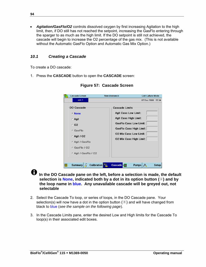
94
BioFlo®/CelliGen® 115 M1369-0050 Operating manual
Agitation/GasFlo/O2 controls dissolved oxygen by first increasing Agitation to the high limit, then, if DO still has not reached the setpoint, increasing the GasFlo entering through the sparger to as much as the high limit. If the DO setpoint is still not achieved, the cascade will begin to increase the O2 percentage of the gas mix. (This is not available without the Automatic GasFlo Option and Automatic Gas Mix Option.)
10.1 Creating a Cascade
To create a DO cascade: 1. Press the CASCADE button to open the CASCADE screen:
Figure 57: Cascade Screen
In the DO Cascade pane on the left, before a selection is made, the default selection is None, indicated both by a dot in its option button () and by the loop name in blue. Any unavailable cascade will be greyed out, not selectable
2. Select the Cascade To loop, or series of loops, in the DO Cascade pane. Your
selection(s) will now have a dot in the option button () and will have changed from black to blue (see the sample on the following page).
3. In the Cascade Limits pane, enter the desired Low and High limits for the Cascade To
loop(s) in their associated edit boxes.
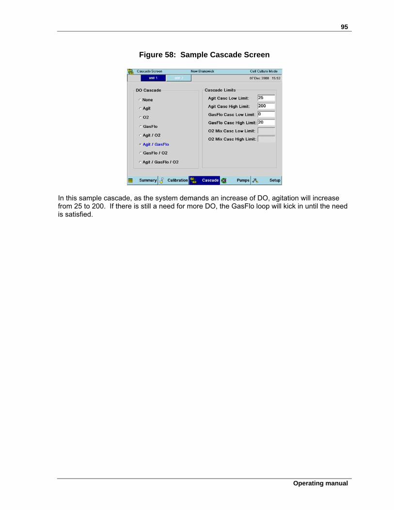
95
Operating manual
Figure 58: Sample Cascade Screen
In this sample cascade, as the system demands an increase of DO, agitation will increase from 25 to 200. If there is still a need for more DO, the GasFlo loop will kick in until the need is satisfied.
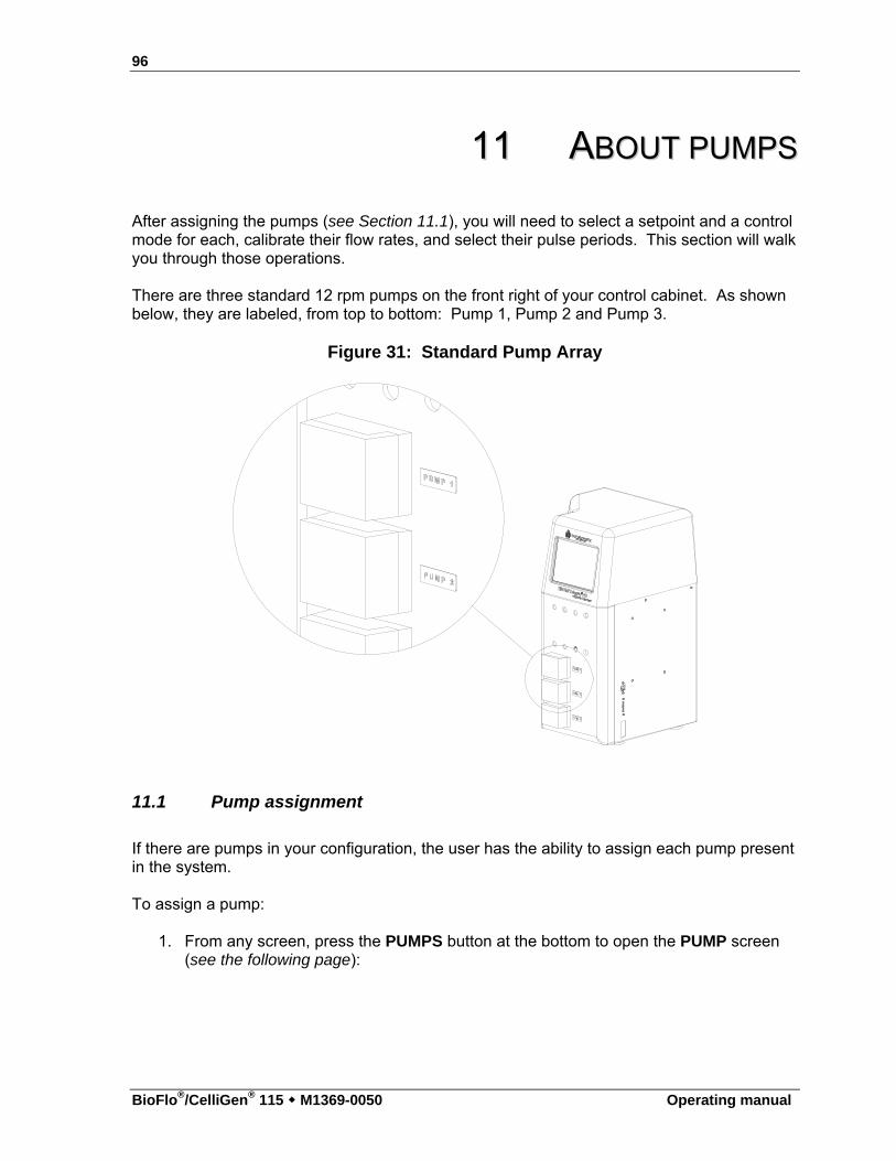
96
BioFlo®/CelliGen® 115 M1369-0050 Operating manual
1111 AABBOOUUTT PPUUMMPPSS After assigning the pumps (see Section 11.1), you will need to select a setpoint and a control mode for each, calibrate their flow rates, and select their pulse periods. This section will walk you through those operations. There are three standard 12 rpm pumps on the front right of your control cabinet. As shown below, they are labeled, from top to bottom: Pump 1, Pump 2 and Pump 3.
Figure 31: Standard Pump Array
11.1 Pump assignment
If there are pumps in your configuration, the user has the ability to assign each pump present in the system. To assign a pump:
1. From any screen, press the PUMPS button at the bottom to open the PUMP screen (see the following page):
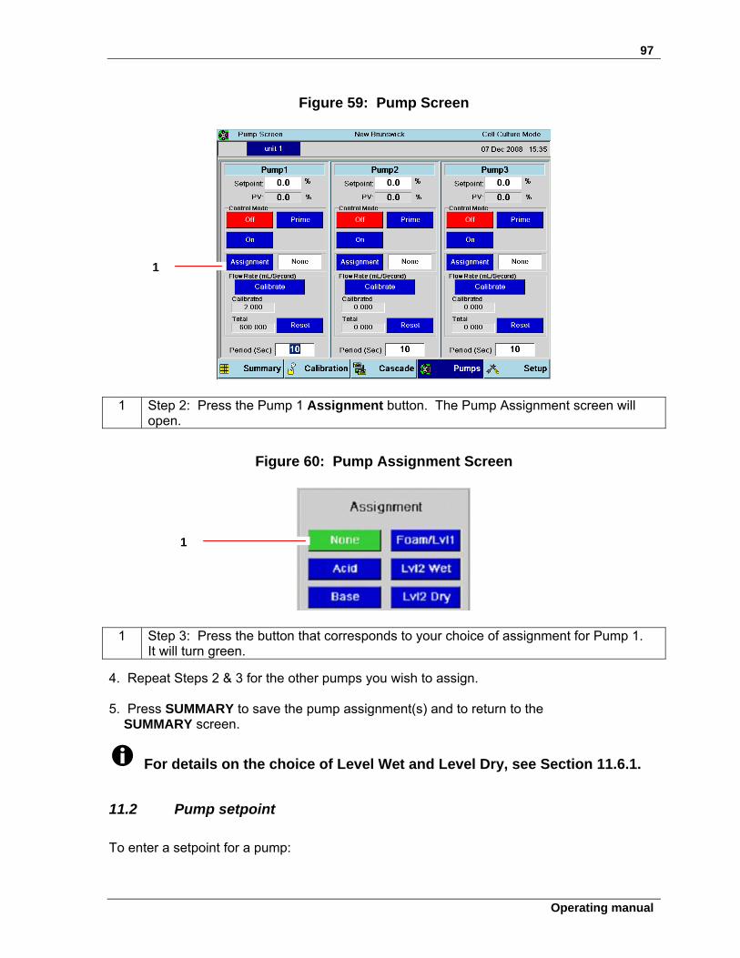
97
Operating manual
Figure 59: Pump Screen
1 Step 2: Press the Pump 1 Assignment button. The Pump Assignment screen will open.
Figure 60: Pump Assignment Screen
1 Step 3: Press the button that corresponds to your choice of assignment for Pump 1. It will turn green.
4. Repeat Steps 2 & 3 for the other pumps you wish to assign.
5. Press SUMMARY to save the pump assignment(s) and to return to the SUMMARY screen.
For details on the choice of Level Wet and Level Dry, see Section 11.6.1.
11.2 Pump setpoint
To enter a setpoint for a pump:
1
1
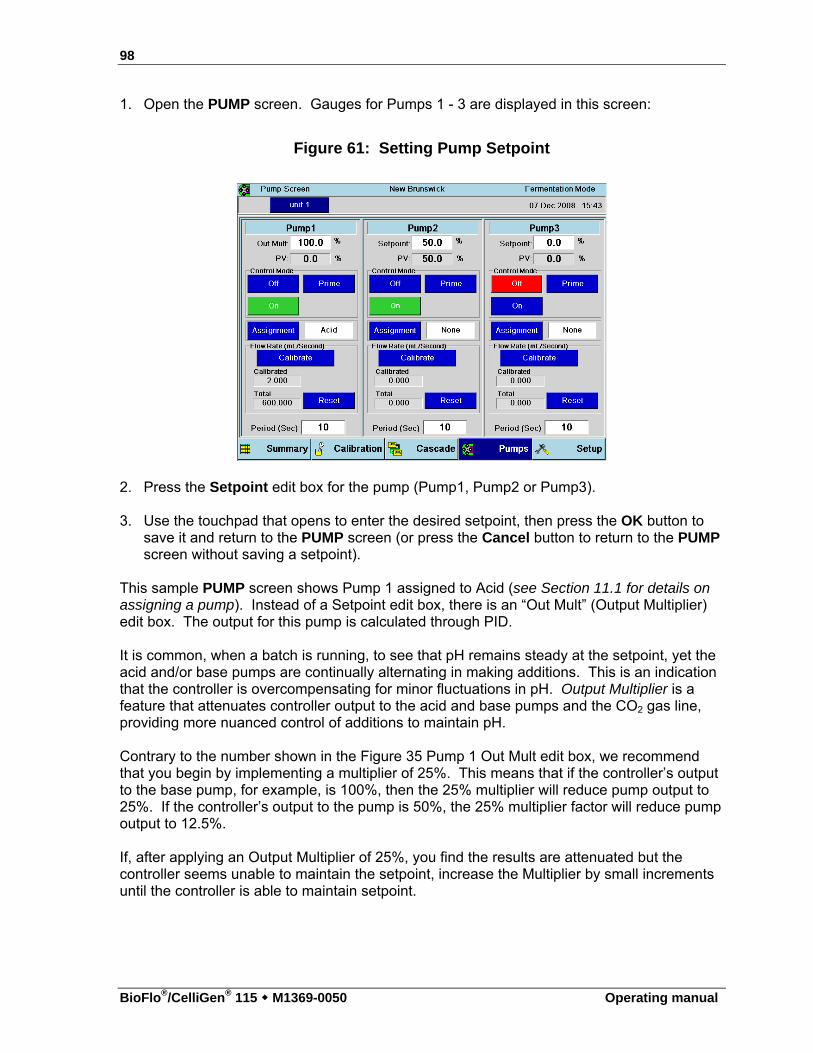
98
BioFlo®/CelliGen® 115 M1369-0050 Operating manual
1. Open the PUMP screen. Gauges for Pumps 1 - 3 are displayed in this screen:
Figure 61: Setting Pump Setpoint
2. Press the Setpoint edit box for the pump (Pump1, Pump2 or Pump3). 3. Use the touchpad that opens to enter the desired setpoint, then press the OK button to
save it and return to the PUMP screen (or press the Cancel button to return to the PUMP screen without saving a setpoint).
This sample PUMP screen shows Pump 1 assigned to Acid (see Section 11.1 for details on assigning a pump). Instead of a Setpoint edit box, there is an “Out Mult” (Output Multiplier) edit box. The output for this pump is calculated through PID. It is common, when a batch is running, to see that pH remains steady at the setpoint, yet the acid and/or base pumps are continually alternating in making additions. This is an indication that the controller is overcompensating for minor fluctuations in pH. Output Multiplier is a feature that attenuates controller output to the acid and base pumps and the CO2 gas line, providing more nuanced control of additions to maintain pH. Contrary to the number shown in the Figure 35 Pump 1 Out Mult edit box, we recommend that you begin by implementing a multiplier of 25%. This means that if the controller’s output to the base pump, for example, is 100%, then the 25% multiplier will reduce pump output to 25%. If the controller’s output to the pump is 50%, the 25% multiplier factor will reduce pump output to 12.5%. If, after applying an Output Multiplier of 25%, you find the results are attenuated but the controller seems unable to maintain the setpoint, increase the Multiplier by small increments until the controller is able to maintain setpoint.
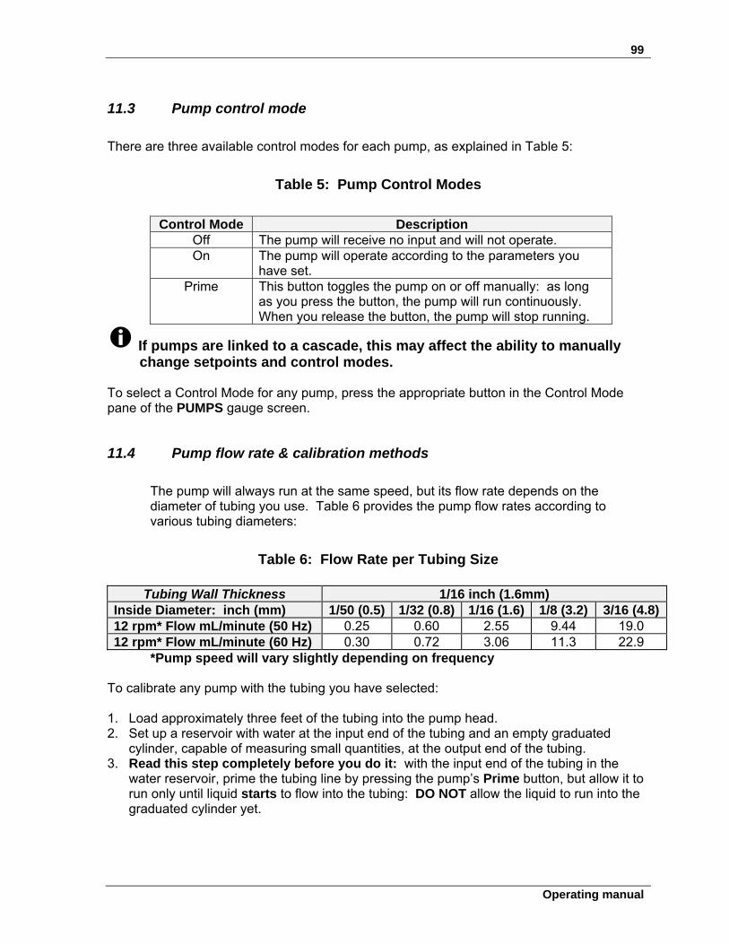
99
Operating manual
11.3 Pump control mode
There are three available control modes for each pump, as explained in Table 5:
Table 5: Pump Control Modes
Control Mode Description
Off The pump will receive no input and will not operate. On The pump will operate according to the parameters you
have set. Prime This button toggles the pump on or off manually: as long
as you press the button, the pump will run continuously. When you release the button, the pump will stop running.
If pumps are linked to a cascade, this may affect the ability to manually change setpoints and control modes.
To select a Control Mode for any pump, press the appropriate button in the Control Mode pane of the PUMPS gauge screen.
11.4 Pump flow rate & calibration methods
The pump will always run at the same speed, but its flow rate depends on the diameter of tubing you use. Table 6 provides the pump flow rates according to various tubing diameters:
Table 6: Flow Rate per Tubing Size
Tubing Wall Thickness 1/16 inch (1.6mm) Inside Diameter: inch (mm) 1/50 (0.5) 1/32 (0.8) 1/16 (1.6) 1/8 (3.2) 3/16 (4.8)12 rpm* Flow mL/minute (50 Hz) 0.25 0.60 2.55 9.44 19.0 12 rpm* Flow mL/minute (60 Hz) 0.30 0.72 3.06 11.3 22.9
*Pump speed will vary slightly depending on frequency
To calibrate any pump with the tubing you have selected: 1. Load approximately three feet of the tubing into the pump head. 2. Set up a reservoir with water at the input end of the tubing and an empty graduated
cylinder, capable of measuring small quantities, at the output end of the tubing. 3. Read this step completely before you do it: with the input end of the tubing in the
water reservoir, prime the tubing line by pressing the pump’s Prime button, but allow it to run only until liquid starts to flow into the tubing: DO NOT allow the liquid to run into the graduated cylinder yet.
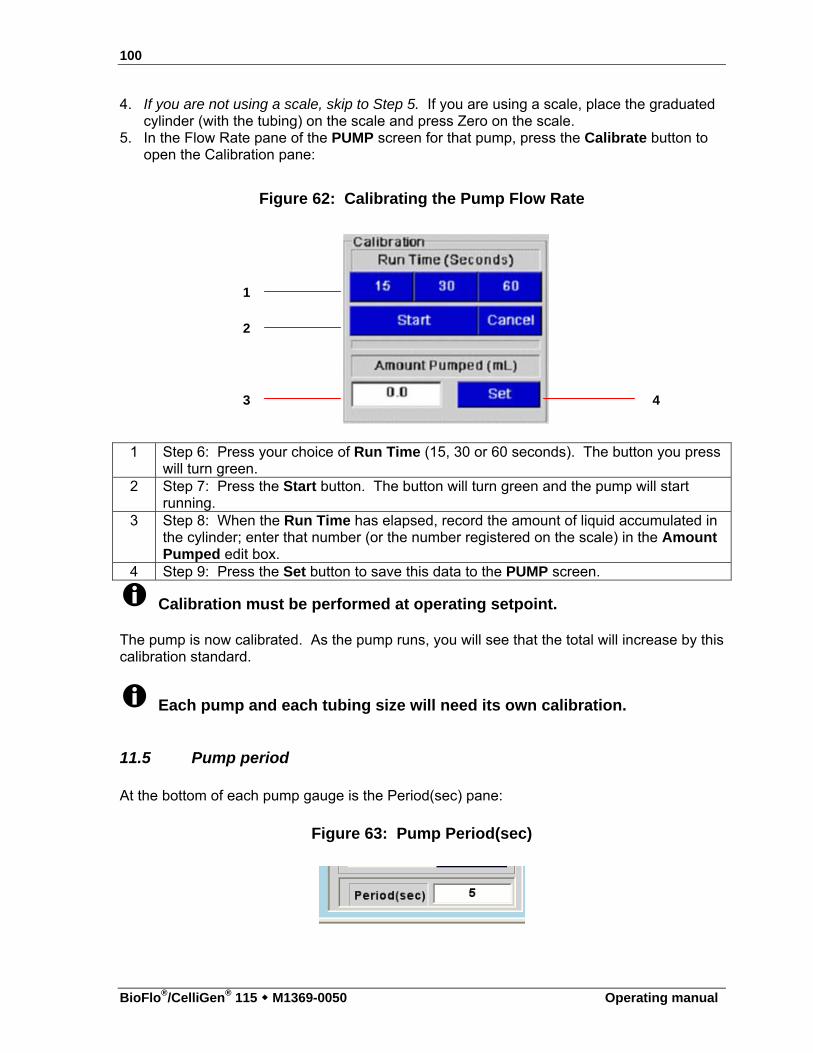
100
BioFlo®/CelliGen® 115 M1369-0050 Operating manual
4. If you are not using a scale, skip to Step 5. If you are using a scale, place the graduated cylinder (with the tubing) on the scale and press Zero on the scale.
5. In the Flow Rate pane of the PUMP screen for that pump, press the Calibrate button to open the Calibration pane:
Figure 62: Calibrating the Pump Flow Rate
1 Step 6: Press your choice of Run Time (15, 30 or 60 seconds). The button you press will turn green.
2 Step 7: Press the Start button. The button will turn green and the pump will start running.
3 Step 8: When the Run Time has elapsed, record the amount of liquid accumulated in the cylinder; enter that number (or the number registered on the scale) in the Amount Pumped edit box.
4 Step 9: Press the Set button to save this data to the PUMP screen.
Calibration must be performed at operating setpoint.
The pump is now calibrated. As the pump runs, you will see that the total will increase by this calibration standard.
Each pump and each tubing size will need its own calibration.
11.5 Pump period
At the bottom of each pump gauge is the Period(sec) pane:
Figure 63: Pump Period(sec)
1
2
3 4
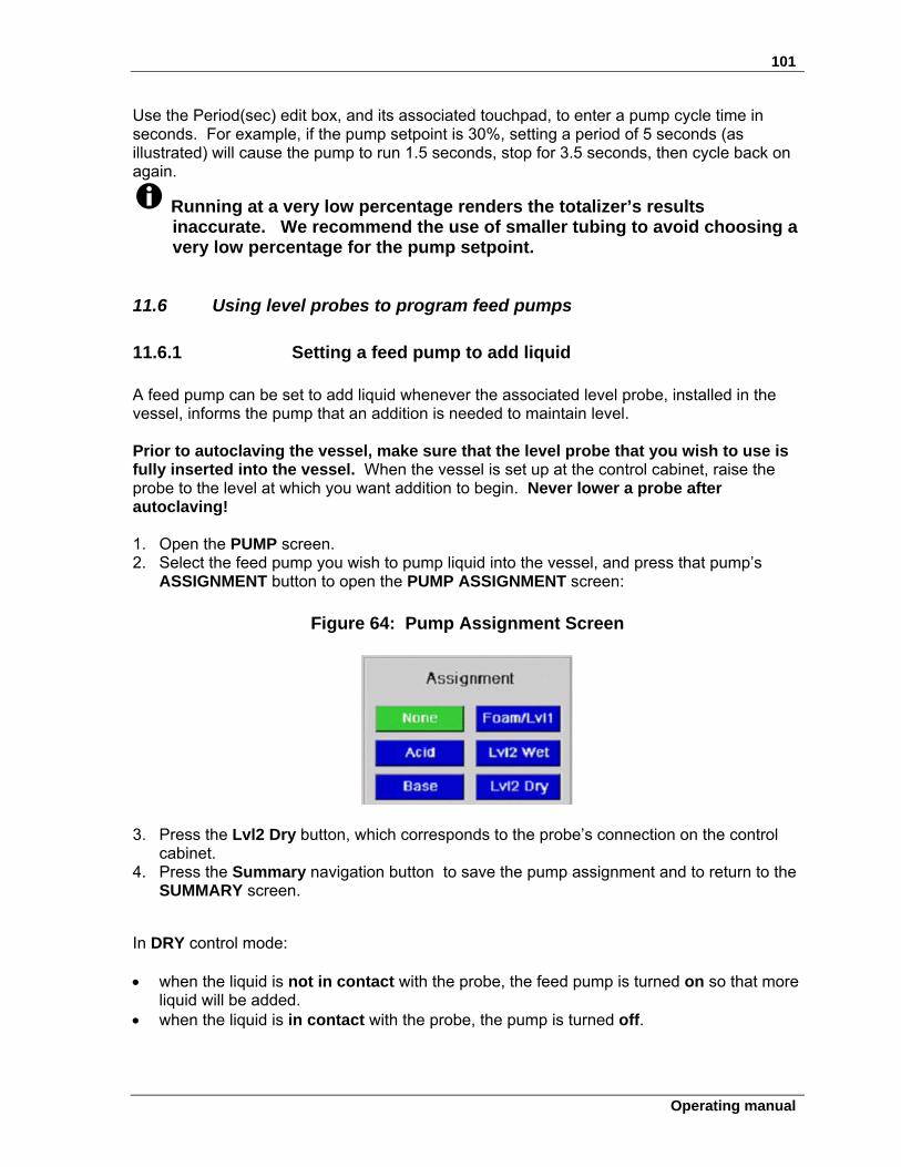
101
Operating manual
Use the Period(sec) edit box, and its associated touchpad, to enter a pump cycle time in seconds. For example, if the pump setpoint is 30%, setting a period of 5 seconds (as illustrated) will cause the pump to run 1.5 seconds, stop for 3.5 seconds, then cycle back on again.
Running at a very low percentage renders the totalizer’s results inaccurate. We recommend the use of smaller tubing to avoid choosing a very low percentage for the pump setpoint.
11.6 Using level probes to program feed pumps
11.6.1 Setting a feed pump to add liquid A feed pump can be set to add liquid whenever the associated level probe, installed in the vessel, informs the pump that an addition is needed to maintain level.
Prior to autoclaving the vessel, make sure that the level probe that you wish to use is fully inserted into the vessel. When the vessel is set up at the control cabinet, raise the probe to the level at which you want addition to begin. Never lower a probe after autoclaving!
1. Open the PUMP screen. 2. Select the feed pump you wish to pump liquid into the vessel, and press that pump’s
ASSIGNMENT button to open the PUMP ASSIGNMENT screen:
Figure 64: Pump Assignment Screen
3. Press the Lvl2 Dry button, which corresponds to the probe’s connection on the control cabinet.
4. Press the Summary navigation button to save the pump assignment and to return to the SUMMARY screen.
In DRY control mode: when the liquid is not in contact with the probe, the feed pump is turned on so that more
liquid will be added. when the liquid is in contact with the probe, the pump is turned off.
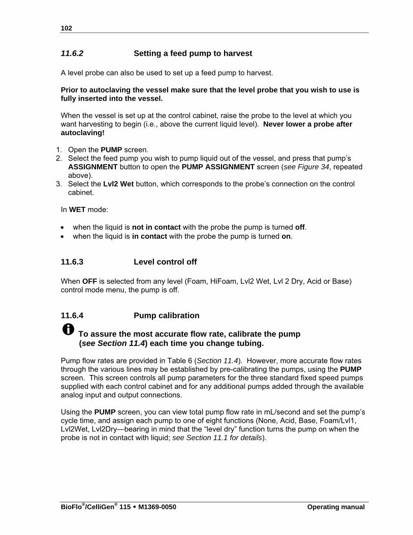
102
BioFlo®/CelliGen® 115 M1369-0050 Operating manual
11.6.2 Setting a feed pump to harvest A level probe can also be used to set up a feed pump to harvest. Prior to autoclaving the vessel make sure that the level probe that you wish to use is fully inserted into the vessel. When the vessel is set up at the control cabinet, raise the probe to the level at which you want harvesting to begin (i.e., above the current liquid level). Never lower a probe after autoclaving!
1. Open the PUMP screen. 2. Select the feed pump you wish to pump liquid out of the vessel, and press that pump’s
ASSIGNMENT button to open the PUMP ASSIGNMENT screen (see Figure 34, repeated above).
3. Select the Lvl2 Wet button, which corresponds to the probe’s connection on the control cabinet.
In WET mode: when the liquid is not in contact with the probe the pump is turned off. when the liquid is in contact with the probe the pump is turned on.
11.6.3 Level control off When OFF is selected from any level (Foam, HiFoam, Lvl2 Wet, Lvl 2 Dry, Acid or Base) control mode menu, the pump is off.
11.6.4 Pump calibration
To assure the most accurate flow rate, calibrate the pump (see Section 11.4) each time you change tubing.
Pump flow rates are provided in Table 6 (Section 11.4). However, more accurate flow rates through the various lines may be established by pre-calibrating the pumps, using the PUMP screen. This screen controls all pump parameters for the three standard fixed speed pumps supplied with each control cabinet and for any additional pumps added through the available analog input and output connections.
Using the PUMP screen, you can view total pump flow rate in mL/second and set the pump’s cycle time, and assign each pump to one of eight functions (None, Acid, Base, Foam/Lvl1, Lvl2Wet, Lvl2Dry—bearing in mind that the “level dry” function turns the pump on when the probe is not in contact with liquid; see Section 11.1 for details).
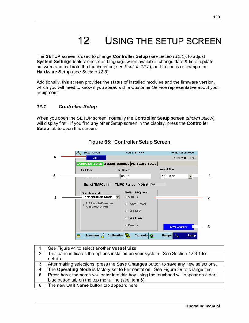
103
Operating manual
1122 UUSSIINNGG TTHHEE SSEETTUUPP SSCCRREEEENN The SETUP screen is used to change Controller Setup (see Section 12.1), to adjust System Settings (select onscreen language when available, change date & time, update software and calibrate the touchscreen; see Section 12.2), and to check or change the Hardware Setup (see Section 12.3). Additionally, this screen provides the status of installed modules and the firmware version, which you will need to know if you speak with a Customer Service representative about your equipment.
12.1 Controller Setup
When you open the SETUP screen, normally the Controller Setup screen (shown below) will display first. If you find any other Setup screen in the display, press the Controller Setup tab to open this screen.
Figure 65: Controller Setup Screen
1 See Figure 41 to select another Vessel Size. 2 This pane indicates the options installed on your system. See Section 12.3.1 for
details. 3 After making selections, press the Save Changes button to save any new selections. 4 The Operating Mode is factory-set to Fermentation. See Figure 39 to change this. 5 Press here; the name you enter into this box using the touchpad will appear on a dark
blue button tab on the top menu line (see item 6). 6 The new Unit Name button tab appears here.
6
1 5
4 2
3
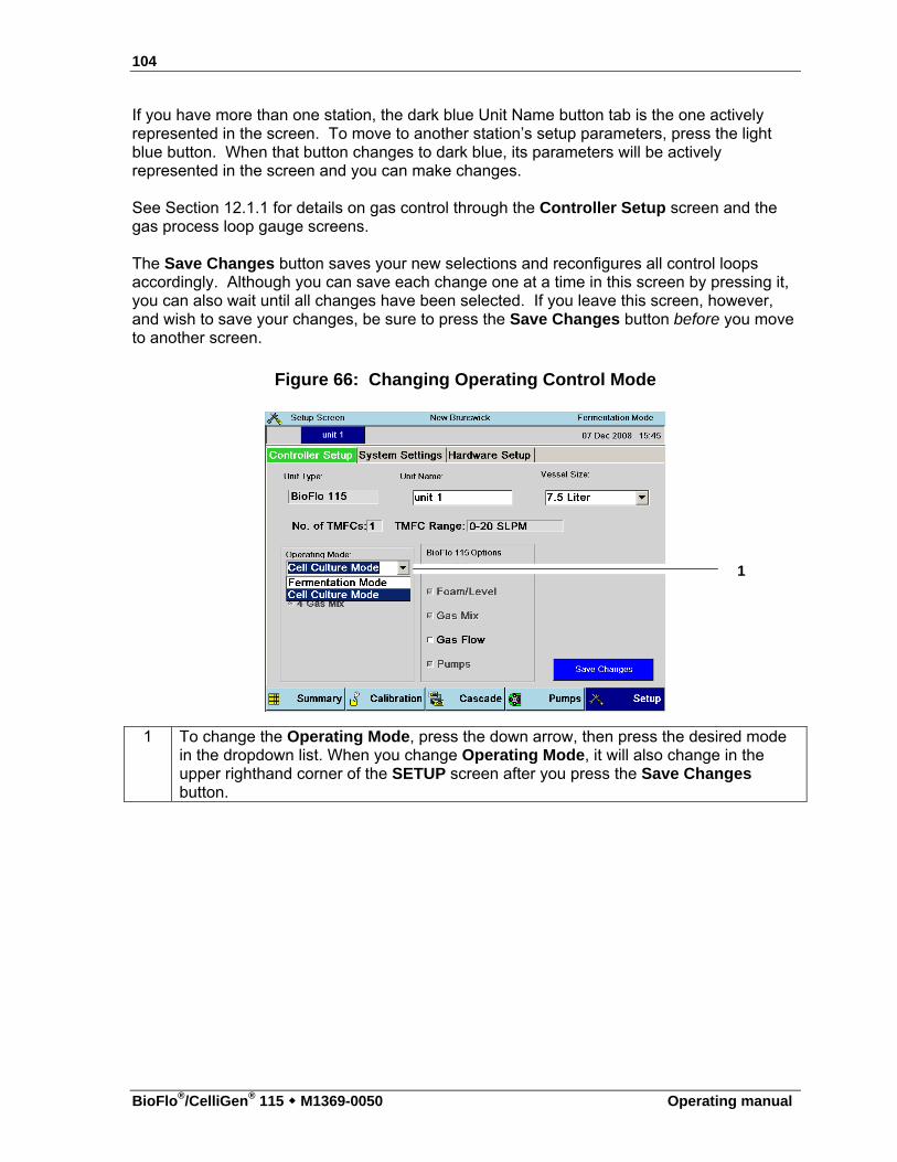
104
BioFlo®/CelliGen® 115 M1369-0050 Operating manual
If you have more than one station, the dark blue Unit Name button tab is the one actively represented in the screen. To move to another station’s setup parameters, press the light blue button. When that button changes to dark blue, its parameters will be actively represented in the screen and you can make changes. See Section 12.1.1 for details on gas control through the Controller Setup screen and the gas process loop gauge screens.
The Save Changes button saves your new selections and reconfigures all control loops accordingly. Although you can save each change one at a time in this screen by pressing it, you can also wait until all changes have been selected. If you leave this screen, however, and wish to save your changes, be sure to press the Save Changes button before you move to another screen.
Figure 66: Changing Operating Control Mode
1 To change the Operating Mode, press the down arrow, then press the desired mode in the dropdown list. When you change Operating Mode, it will also change in the upper righthand corner of the SETUP screen after you press the Save Changes button.
1
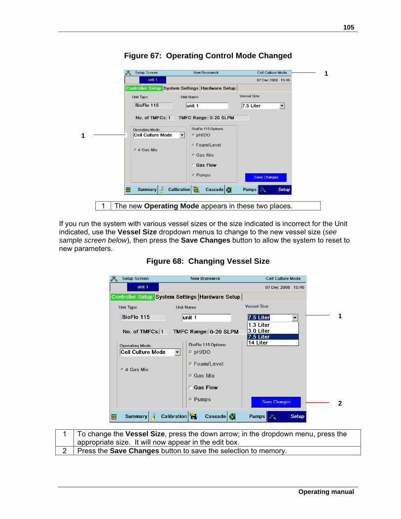
105
Operating manual
Figure 67: Operating Control Mode Changed
1 The new Operating Mode appears in these two places. If you run the system with various vessel sizes or the size indicated is incorrect for the Unit indicated, use the Vessel Size dropdown menus to change to the new vessel size (see sample screen below), then press the Save Changes button to allow the system to reset to new parameters.
Figure 68: Changing Vessel Size
1 To change the Vessel Size, press the down arrow; in the dropdown menu, press the appropriate size. It will now appear in the edit box.
2 Press the Save Changes button to save the selection to memory.
1
1
1
2
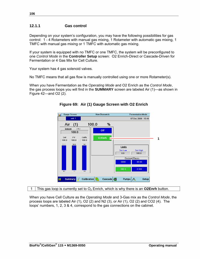
106
BioFlo®/CelliGen® 115 M1369-0050 Operating manual
12.1.1 Gas control
Depending on your system’s configuration, you may have the following possibilities for gas control: 1 - 4 Rotameters with manual gas mixing, 1 Rotameter with automatic gas mixing, 1 TMFC with manual gas mixing or 1 TMFC with automatic gas mixing. If your system is equipped with no TMFC or one TMFC, the system will be preconfigured to one Control Mode in the Controller Setup screen: O2 Enrich-Direct or Cascade-Driven for Fermentation or 4 Gas Mix for Cell Culture. Your system has 4 gas solenoid valves. No TMFC means that all gas flow is manually controlled using one or more Rotameter(s). When you have Fermentation as the Operating Mode and O2 Enrich as the Control Mode, the gas process loops you will find in the SUMMARY screen are labeled Air (1)—as shown in Figure 42—and O2 (2).
Figure 69: Air (1) Gauge Screen with O2 Enrich
1 This gas loop is currently set to O2 Enrich, which is why there is an O2Enrh button.
When you have Cell Culture as the Operating Mode and 3-Gas mix as the Control Mode, the process loops are labeled Air (1), O2 (2) and N2 (3), or Air (1), O2 (2) and CO2 (4). The loops’ numbers, 1, 2, 3 & 4, correspond to the gas connections on the cabinet.
1
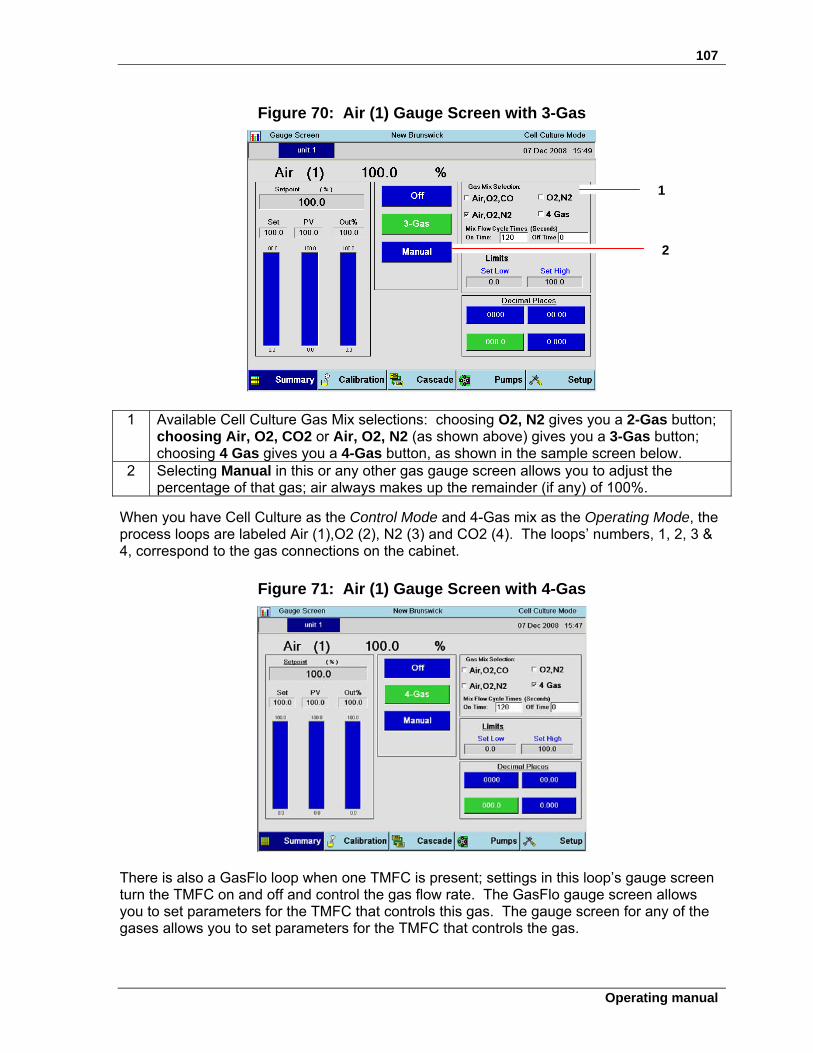
107
Operating manual
Figure 70: Air (1) Gauge Screen with 3-Gas
1 Available Cell Culture Gas Mix selections: choosing O2, N2 gives you a 2-Gas button;
choosing Air, O2, CO2 or Air, O2, N2 (as shown above) gives you a 3-Gas button; choosing 4 Gas gives you a 4-Gas button, as shown in the sample screen below.
2 Selecting Manual in this or any other gas gauge screen allows you to adjust the percentage of that gas; air always makes up the remainder (if any) of 100%.
When you have Cell Culture as the Control Mode and 4-Gas mix as the Operating Mode, the process loops are labeled Air (1),O2 (2), N2 (3) and CO2 (4). The loops’ numbers, 1, 2, 3 & 4, correspond to the gas connections on the cabinet.
Figure 71: Air (1) Gauge Screen with 4-Gas
There is also a GasFlo loop when one TMFC is present; settings in this loop’s gauge screen turn the TMFC on and off and control the gas flow rate. The GasFlo gauge screen allows you to set parameters for the TMFC that controls this gas. The gauge screen for any of the gases allows you to set parameters for the TMFC that controls the gas.
1
2
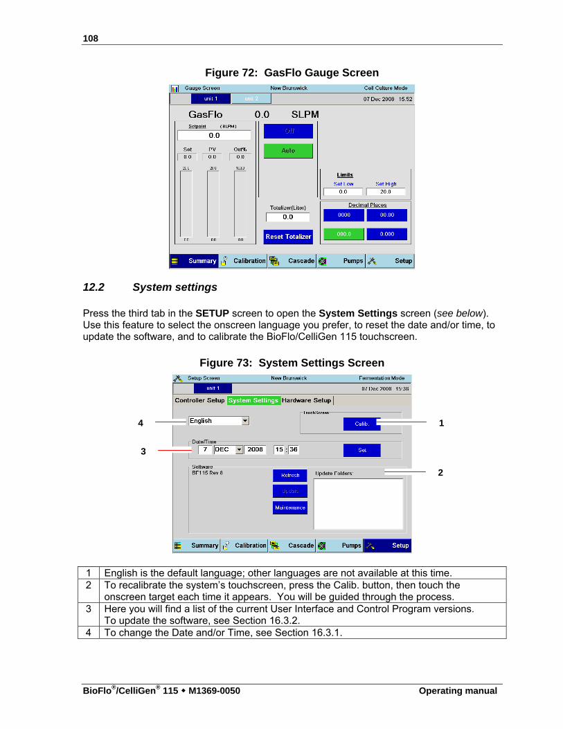
108
BioFlo®/CelliGen® 115 M1369-0050 Operating manual
Figure 72: GasFlo Gauge Screen
12.2 System settings
Press the third tab in the SETUP screen to open the System Settings screen (see below). Use this feature to select the onscreen language you prefer, to reset the date and/or time, to update the software, and to calibrate the BioFlo/CelliGen 115 touchscreen.
Figure 73: System Settings Screen
1 English is the default language; other languages are not available at this time. 2 To recalibrate the system’s touchscreen, press the Calib. button, then touch the
onscreen target each time it appears. You will be guided through the process. 3 Here you will find a list of the current User Interface and Control Program versions.
To update the software, see Section 16.3.2. 4 To change the Date and/or Time, see Section 16.3.1.
3
4 1
2
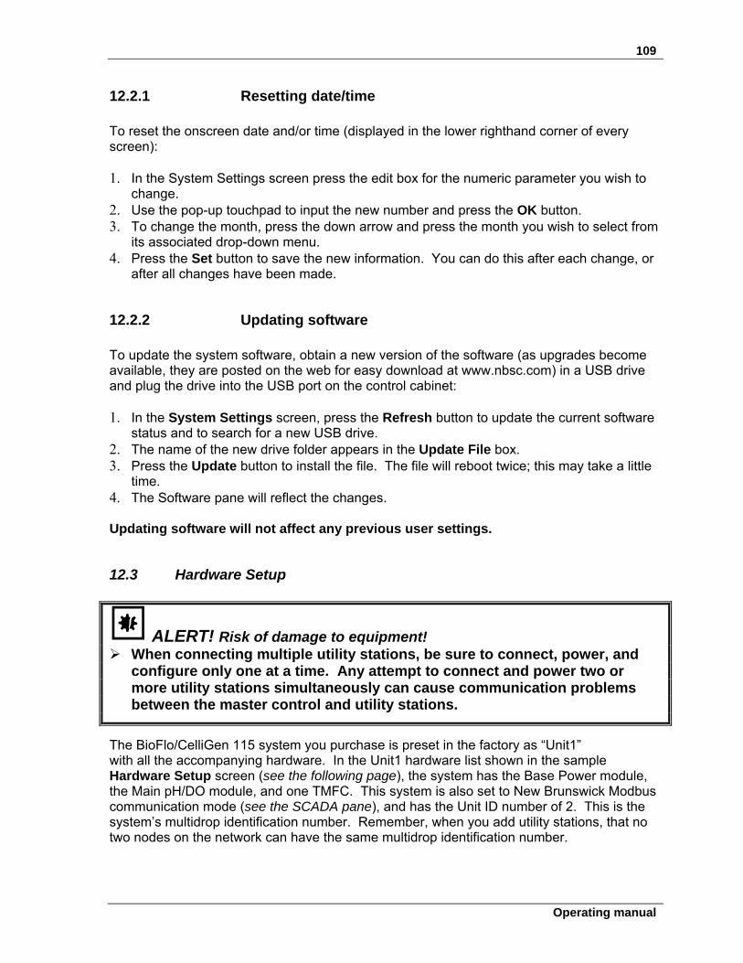
109
Operating manual
12.2.1 Resetting date/time To reset the onscreen date and/or time (displayed in the lower righthand corner of every screen): 1. In the System Settings screen press the edit box for the numeric parameter you wish to
change. 2. Use the pop-up touchpad to input the new number and press the OK button. 3. To change the month, press the down arrow and press the month you wish to select from
its associated drop-down menu. 4. Press the Set button to save the new information. You can do this after each change, or
after all changes have been made.
12.2.2 Updating software To update the system software, obtain a new version of the software (as upgrades become available, they are posted on the web for easy download at www.nbsc.com) in a USB drive and plug the drive into the USB port on the control cabinet: 1. In the System Settings screen, press the Refresh button to update the current software
status and to search for a new USB drive. 2. The name of the new drive folder appears in the Update File box. 3. Press the Update button to install the file. The file will reboot twice; this may take a little
time. 4. The Software pane will reflect the changes. Updating software will not affect any previous user settings.
12.3 Hardware Setup
ALERT! Risk of damage to equipment! When connecting multiple utility stations, be sure to connect, power, and
configure only one at a time. Any attempt to connect and power two or more utility stations simultaneously can cause communication problems between the master control and utility stations.
The BioFlo/CelliGen 115 system you purchase is preset in the factory as “Unit1” with all the accompanying hardware. In the Unit1 hardware list shown in the sample Hardware Setup screen (see the following page), the system has the Base Power module, the Main pH/DO module, and one TMFC. This system is also set to New Brunswick Modbus communication mode (see the SCADA pane), and has the Unit ID number of 2. This is the system’s multidrop identification number. Remember, when you add utility stations, that no two nodes on the network can have the same multidrop identification number.
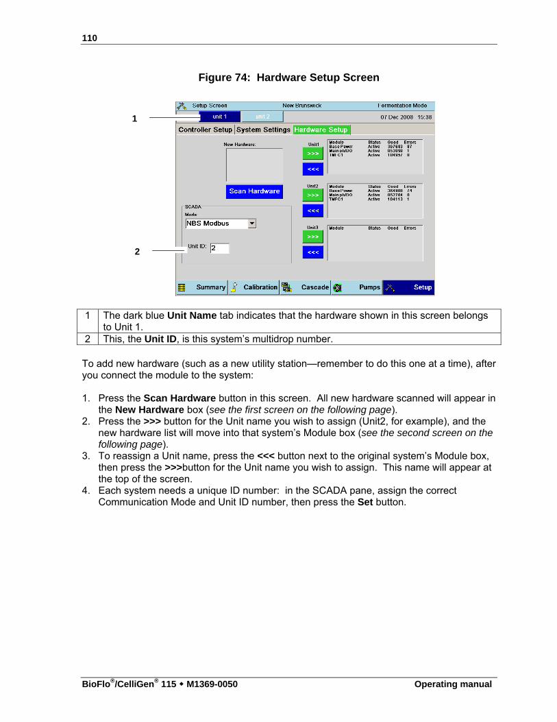
110
BioFlo®/CelliGen® 115 M1369-0050 Operating manual
Figure 74: Hardware Setup Screen
1 The dark blue Unit Name tab indicates that the hardware shown in this screen belongs to Unit 1.
2 This, the Unit ID, is this system’s multidrop number.
To add new hardware (such as a new utility station—remember to do this one at a time), after you connect the module to the system: 1. Press the Scan Hardware button in this screen. All new hardware scanned will appear in
the New Hardware box (see the first screen on the following page). 2. Press the >>> button for the Unit name you wish to assign (Unit2, for example), and the
new hardware list will move into that system’s Module box (see the second screen on the following page).
3. To reassign a Unit name, press the <<< button next to the original system’s Module box, then press the >>>button for the Unit name you wish to assign. This name will appear at the top of the screen.
4. Each system needs a unique ID number: in the SCADA pane, assign the correct Communication Mode and Unit ID number, then press the Set button.
1
2
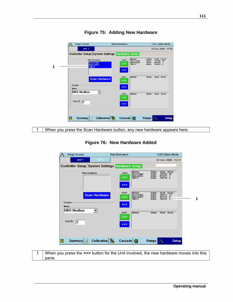
111
Operating manual
Figure 75: Adding New Hardware
1 When you press the Scan Hardware button, any new hardware appears here.
Figure 76: New Hardware Added
1 When you press the >>> button for the Unit involved, the new hardware moves into this pane.
1
1
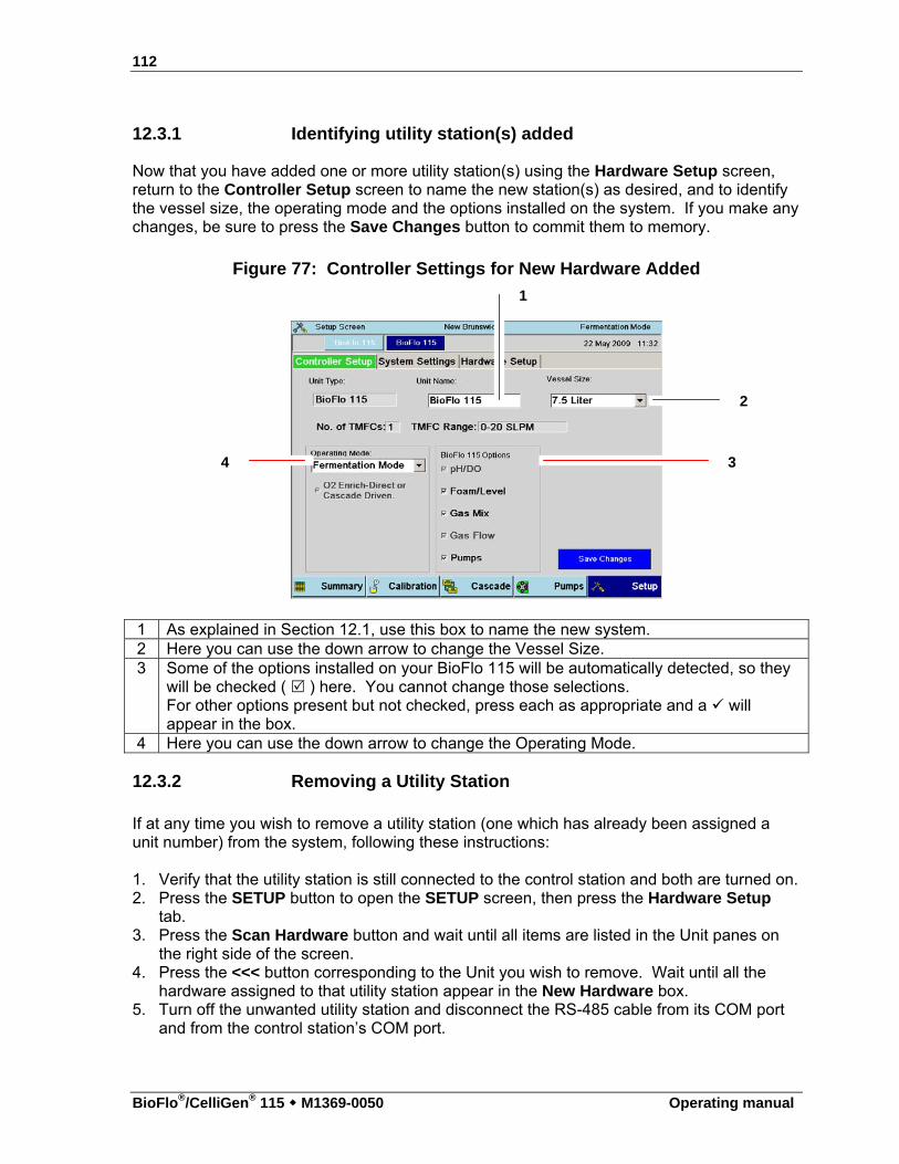
112
BioFlo®/CelliGen® 115 M1369-0050 Operating manual
12.3.1 Identifying utility station(s) added
Now that you have added one or more utility station(s) using the Hardware Setup screen, return to the Controller Setup screen to name the new station(s) as desired, and to identify the vessel size, the operating mode and the options installed on the system. If you make any changes, be sure to press the Save Changes button to commit them to memory.
Figure 77: Controller Settings for New Hardware Added
1 As explained in Section 12.1, use this box to name the new system. 2 Here you can use the down arrow to change the Vessel Size. 3 Some of the options installed on your BioFlo 115 will be automatically detected, so they
will be checked ( ) here. You cannot change those selections. For other options present but not checked, press each as appropriate and a will appear in the box.
4 Here you can use the down arrow to change the Operating Mode.
12.3.2 Removing a Utility Station If at any time you wish to remove a utility station (one which has already been assigned a unit number) from the system, following these instructions: 1. Verify that the utility station is still connected to the control station and both are turned on. 2. Press the SETUP button to open the SETUP screen, then press the Hardware Setup
tab. 3. Press the Scan Hardware button and wait until all items are listed in the Unit panes on
the right side of the screen. 4. Press the <<< button corresponding to the Unit you wish to remove. Wait until all the
hardware assigned to that utility station appear in the New Hardware box. 5. Turn off the unwanted utility station and disconnect the RS-485 cable from its COM port
and from the control station’s COM port.
1
2
34
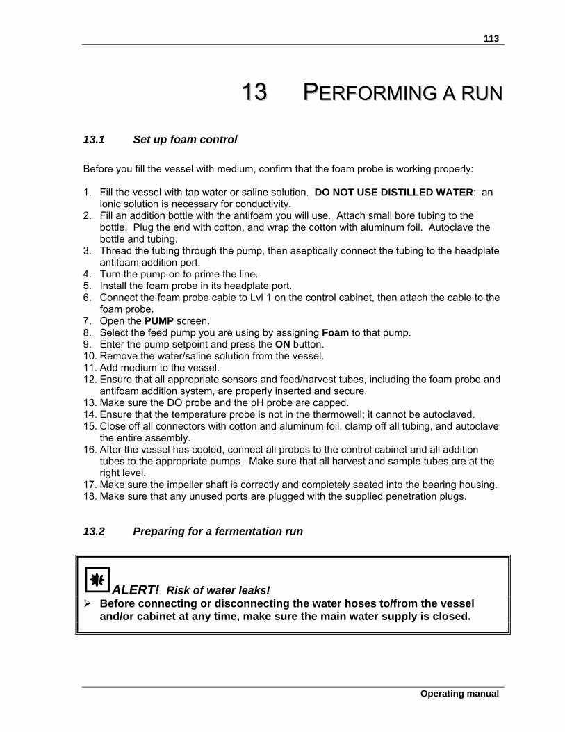
113
Operating manual
1133 PPEERRFFOORRMMIINNGG AA RRUUNN
13.1 Set up foam control
Before you fill the vessel with medium, confirm that the foam probe is working properly:
1. Fill the vessel with tap water or saline solution. DO NOT USE DISTILLED WATER: an
ionic solution is necessary for conductivity. 2. Fill an addition bottle with the antifoam you will use. Attach small bore tubing to the
bottle. Plug the end with cotton, and wrap the cotton with aluminum foil. Autoclave the bottle and tubing.
3. Thread the tubing through the pump, then aseptically connect the tubing to the headplate antifoam addition port.
4. Turn the pump on to prime the line. 5. Install the foam probe in its headplate port. 6. Connect the foam probe cable to Lvl 1 on the control cabinet, then attach the cable to the
foam probe. 7. Open the PUMP screen. 8. Select the feed pump you are using by assigning Foam to that pump. 9. Enter the pump setpoint and press the ON button. 10. Remove the water/saline solution from the vessel. 11. Add medium to the vessel. 12. Ensure that all appropriate sensors and feed/harvest tubes, including the foam probe and
antifoam addition system, are properly inserted and secure. 13. Make sure the DO probe and the pH probe are capped. 14. Ensure that the temperature probe is not in the thermowell; it cannot be autoclaved. 15. Close off all connectors with cotton and aluminum foil, clamp off all tubing, and autoclave
the entire assembly. 16. After the vessel has cooled, connect all probes to the control cabinet and all addition
tubes to the appropriate pumps. Make sure that all harvest and sample tubes are at the right level.
17. Make sure the impeller shaft is correctly and completely seated into the bearing housing. 18. Make sure that any unused ports are plugged with the supplied penetration plugs.
13.2 Preparing for a fermentation run
ALERT! Risk of water leaks! Before connecting or disconnecting the water hoses to/from the vessel
and/or cabinet at any time, make sure the main water supply is closed.
114
BioFlo®/CelliGen® 115 M1369-0050 Operating manual
1. Connect water to the system and turn it on. 2. Make sure the drain line is properly connected to the system. 3. Connect the quick-connect plastic water lines to the exhaust condenser. 4. Add glycerin to the thermowell and insert the temperature probe. 5. Make sure the motor is not connected. Turn the mains/power ON. 6. Set the TEMP setpoint to the desired working temperature. 7. Check that agitation (Agit) is in OFF mode. Connect the motor, then set agitation to the
desired speed, and select Auto as its control mode. 8. Remove the shorting cap from the pH probe. Connect the pH cable to the pH probe. 9. Remove the protective cap from the DO probe and connect the DO cable to the DO
probe. 10. If you have a water-jacketed vessel, be sure to refill the water jacket if required.
The DO polarographic probe will need to be connected for a minimum of six hours, to be properly polarized, before it can be correctly calibrated.
11. Calibrate the DO probe (see Section 7.3). 12. Set pH and DO to the desired setpoints 13. Set the pH control mode to Auto. 14. Set the DO control mode to Auto. 15. Open the PUMP screen and assign a pump to Acid and another pump to Base. Turn the
pumps ON. 16. If you are using oxygen, set the O2 control loop to the desired setpoint for oxygen
enrichment. If, however, you are using Air only, set the O2 setpoint to 0 (zero). 17. Set the O2 (or Air) control loop control mode to O2 Enrich. 18. Enable the pumps. 19. Go to the CASCADE screen and select the DO loop. 20. Set up cascades as desired.
Aeration is required whenever the agitation setpoint is greater than 750 rpm. Eppendorf suggests a minimum airflow rate of 0.25 VVM when running at speeds 750 rpm.
13.3 Inoculation
Using the septum port:
1. Aseptically remove the inoculum from its flask with the inoculation syringe. 2. Inject the inoculum through the septum in the inoculation port. If you prefer to inoculate via an addition port, be sure to flame the connectors and use an inoculum flask as your “addition vessel”.
115
Operating manual
13.4 Start BioCommand (if present)
1. Start the New Brunswick BioCommand supervisory software on your computer, reset the
EFT (Elapsed Fermentation Time) to zero, make appropriate program selections to begin logging data.
2. Make sure all gas pressures are 10 PSI and the water pressure is 10 PSI. 3. If your BioFlo/CelliGen 115 has Rotameter air flow control, adjust the airflow to the
desired rate. Check to see that flow is stable and that all gases are properly connected.
13.5 Sampling procedure
Referring to
116
BioFlo®/CelliGen® 115 M1369-0050 Operating manual
Figure 25 or Figure 26, whichever represents your sampling system: 1. Check to be sure that the sample bottle is slightly loose, not tight against the gasket. 2. Close the valve on the sampler tube, if it is open. 3. Squeeze the bulb and, holding it compressed, tighten the sample bottle against the
gasket. 4. Open the valve and gradually let go of the rubber bulb to obtain the desired sample
volume. 5. When you have obtained the desire volume, close the valve. 6. Unscrew the sample bottle from the sampler. Take the cap from a new bottle, and place
it on the sample-filled bottle. 7. Install the new bottle in the sampler and make sure that the sample bottle is firmly sealed
against the sampler gasket. Always use aseptic techniques. 8. Repeat the above steps until you have the desired number of samples.
13.6 Fermentation phases
In a typical fermentation run, you can expect to see four characteristic phases: (1) the Lag phase, (2) the Exponential Growth phase, (3) the Steady State phase, and (4) the Decline phase.
13.6.1 Lag phase This initial phase is aptly named because it is the slow beginning of your fermentation run, while the microbes become accustomed to their medium.
13.6.2 Exponential growth phase After the initial lag, a sudden spurt in growth will indicate that the environment is fully hospitable to the microbes. Compared to the nearly inanimate lag phase, this activity will appear to be nearly uncontrolled.
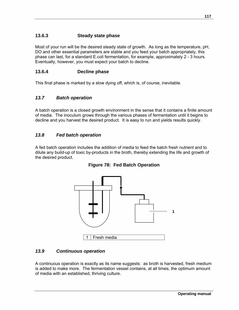
117
Operating manual
13.6.3 Steady state phase Most of your run will be the desired steady state of growth. As long as the temperature, pH, DO and other essential parameters are stable and you feed your batch appropriately, this phase can last, for a standard E.coli fermentation, for example, approximately 2 - 3 hours. Eventually, however, you must expect your batch to decline.
13.6.4 Decline phase
This final phase is marked by a slow dying off, which is, of course, inevitable.
13.7 Batch operation
A batch operation is a closed growth environment in the sense that it contains a finite amount of media. The inoculum grows through the various phases of fermentation until it begins to decline and you harvest the desired product. It is easy to run and yields results quickly.
13.8 Fed batch operation
A fed batch operation includes the addition of media to feed the batch fresh nutrient and to dilute any build-up of toxic by-products in the broth, thereby extending the life and growth of the desired product.
Figure 78: Fed Batch Operation
1 Fresh media
13.9 Continuous operation
A continuous operation is exactly as its name suggests: as broth is harvested, fresh medium is added to make more. The fermentation vessel contains, at all times, the optimum amount of media with an established, thriving culture.
1
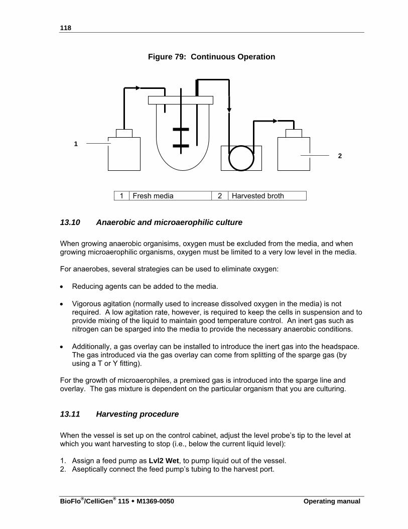
118
BioFlo®/CelliGen® 115 M1369-0050 Operating manual
Figure 79: Continuous Operation
1 Fresh media 2 Harvested broth
13.10 Anaerobic and microaerophilic culture
When growing anaerobic organisims, oxygen must be excluded from the media, and when growing microaerophilic organisms, oxygen must be limited to a very low level in the media. For anaerobes, several strategies can be used to eliminate oxygen: Reducing agents can be added to the media.
Vigorous agitation (normally used to increase dissolved oxygen in the media) is not
required. A low agitation rate, however, is required to keep the cells in suspension and to provide mixing of the liquid to maintain good temperature control. An inert gas such as nitrogen can be sparged into the media to provide the necessary anaerobic conditions.
Additionally, a gas overlay can be installed to introduce the inert gas into the headspace. The gas introduced via the gas overlay can come from splitting of the sparge gas (by using a T or Y fitting).
For the growth of microaerophiles, a premixed gas is introduced into the sparge line and overlay. The gas mixture is dependent on the particular organism that you are culturing.
13.11 Harvesting procedure
When the vessel is set up on the control cabinet, adjust the level probe’s tip to the level at which you want harvesting to stop (i.e., below the current liquid level):
1. Assign a feed pump as Lvl2 Wet, to pump liquid out of the vessel. 2. Aseptically connect the feed pump’s tubing to the harvest port.
1
2
119
Operating manual
3. Turn the pump ON. Since the liquid is in contact with the probe, the circuit will close, and the pump will begin pumping liquid out of the vessel.
4. When the liquid drops below the probe tip, the pump will stop. See also Section 11.1, Pump Assignment. If you assign the pump to None instead of Lvl2 Wet, it will harvest as much as possible.
13.12 Shutdown procedure
At the end of a run, to shut down the system, follow these steps:
1. Set GasFlo to OFF. 2. Set Agit and Temp to OFF. 3. Set all other control loops to OFF. 4. Turn off the mains/power. 5. If the system is not to be used for several days, disconnect the mains/power plug. 6. Remove, drain and clean the vessel as outlined in Section 15. See also Section 21.7.5 for shutdown and cleaning tips.
Never wash the filters or get them wet.
120
BioFlo®/CelliGen® 115 M1369-0050 Operating manual
1144 EESSSSEENNTTIIAALL OOPPEERRAATTIINNGG TTIIPPSS
14.1 Precautions for glass vessel assembly
There are certain precautions you should take to avoid cracking or breaking the glass vessel during assembly and autoclaving: Glass can crack or break during assembly if the clamping screws are overtightened. As
a precaution, tighten the screws only finger tight prior to autoclaving. You should be able to insert a business card between the glass and the metal.
If the vessel is not sufficiently vented during autoclaving, it can crack or break. As a
precaution, make certain that the exhaust filter(s) is (are) not wet or clogged. Also loosen the inoculation diaphragm cap for additional venting.
After autoclaving, tighten the inoculation cap. When the vessel is installed on the control
cabinet and air is freely flowing through it, you may retighten all nuts and screws, again taking care not to overtighten.
To maintain the best possible seal, O-rings should be replaced every six months or more frequently if needed.
14.2 Exhaust condenser & exhaust filters
The inner assembly of the exhaust condenser can be removed for cleaning:
1. Pass warm water and detergent through the top of the condenser, but not through the
quick-connects. Do this twice. 2. Run clear water through once. 3. Blow out with air. 4. Autoclave.
Clean the exhaust condenser after each run. This is most critical when operating as a chemostat for protracted fermentation times.
14.3 Install a double filter system
Double exhaust and double inlet filters are recommended. To install them:
1. Attach a Y fitting to the top of the condenser with a piece of tubing. Be sure to secure
the tubing with a tie at each end.

121
Operating manual
2. Attach an exhaust filter to each branch of the Y. This allows you the flexibility to exchange sterilized filters during a run should one filter become clogged: all you have to do is pinch off the unused line with a clamp.
122
BioFlo®/CelliGen® 115 M1369-0050 Operating manual
1155 CCLLEEAANNIINNGG
ALERT! Risk of damage to equipment! Never clean the vessel or its components or the control cabinet with
abrasive chemicals or materials.
15.1 Cleaning the vessel
If applicable, be sure to follow the bio-safety regulations regarding the release of microorganisms into the environment.
1. Fill the vessel with a mild detergent and water solution. 2. Let it stand for one hour, then brush it thoroughly with a soft brush. Use the brush both
on inside and on outside surfaces. 3. Drain the vessel and rinse several times with tap water. 4. Repeat rinsing with distilled water and let it dry.
15.1.1 List of wetted parts
For further reference in your choice of cleaning detergents, Table 7 provides a list of wetted parts in the vessel assembly and the materials they are made of:
Table 7: Wetted Parts
Wetted Parts Material
Headplate O-ring EPDM O-ring lubricant Silicone Headplate penetration O-rings EPDM Metal surfaces 316L or 316 stainless steel Vessel glass Borosilicate glass Inoculation septum Pure gum rubber, color tan
15.2 Cleaning the cabinet
At least once a month, clean all the metal and plastic parts of your equipment. Use a soft, damp cloth moistened with water or mild detergent. If a detergent is used, remove all residue by rinsing them with clean water.
123
Operating manual
1166 MMAAIINNTTEENNAANNCCEE Preventive maintenance keeps your equipment in proper working condition. When performed routinely, maintenance results in longer life for your equipment. It also reduces time lost due to equipment failure.
WARNING! Risk of electrical shock! Always turn your BioFlo/CelliGen 115 off and disconnect the mains/power
cord before performing maintenance.
16.1 pH probe maintenance and storage
The pH probe should be stored standing upright, with the electrode tip immersed in a solution of 3 molar KCl or a buffer solution between pH 4.00 and pH 7.00.
ALERT! Risk of damage to pH probe! Never let a pH probe rest on its tip. Never leave a pH probe in DI water.
16.2 DO probe maintenance and storage
Use soft facial tissue to clean the DO probe. Check the probe’s Teflon membrane to be sure there are no punctures, puckers or wrinkles. If there are, the probe should be replaced. When it is not in use in the vessel, the DO probe should be stored standing upright with the shorting cap in place and the membrane isolated from the air environment. At no time should the probe be allowed to rest on its membrane.
ALERT! Risk of damage to DO probe! Never let a DO probe rest on its tip.
124
BioFlo®/CelliGen® 115 M1369-0050 Operating manual
16.3 Vessel & tubing
After each and every run, clean the vessel and the headplate with its associated parts. All tubing and filters should be replaced.
16.4 Periodic inspection
To maintain the best possible seal, O-rings should be replaced every six months or more frequently if needed.
At three-month intervals, perform the following checks and inspections.
Before you begin, make sure that the ON/OFF mains/power switch is in the OFF position and that the mains/power supply has been disconnected.
1. Check all controls and accessible items (mains/power switch, connectors, screws, nuts
and bolts) to make sure they are properly tightened. Tighten any loose item(s). 2. Check that all controls and connectors are free of dust. 3. Check that all O-rings in the headplate and impellers are intact and in good condition.
Replace those that are not.
16.5 Agitator bearing housing
Every 3-6 months, the ball bearings and the shaft seals in the bearing housing should be checked and cleaned. Replace any worn-out bearings and/or shaft seals.
16.5.1 Motor assembly replacement
WARNING! Risk of electrical shock! No one but a professional service person should touch electric or electronic
parts or assemblies in the control cabinet.
If the motor assembly should require replacement, call for an authorized Eppendorf service technician.
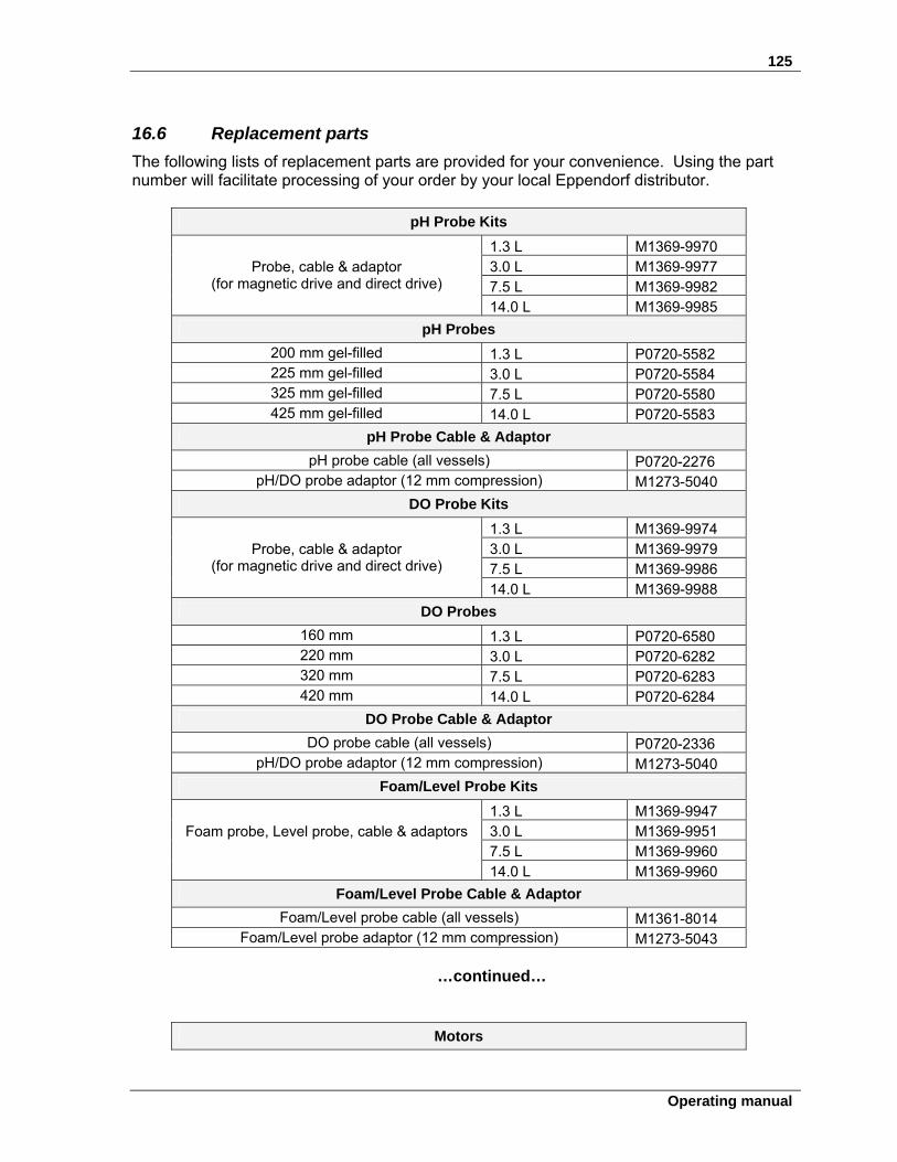
125
Operating manual
16.6 Replacement parts
The following lists of replacement parts are provided for your convenience. Using the part number will facilitate processing of your order by your local Eppendorf distributor.
pH Probe Kits
1.3 L M1369-9970 3.0 L M1369-9977 7.5 L M1369-9982
Probe, cable & adaptor (for magnetic drive and direct drive)
14.0 L M1369-9985
pH Probes
200 mm gel-filled 1.3 L P0720-5582 225 mm gel-filled 3.0 L P0720-5584 325 mm gel-filled 7.5 L P0720-5580 425 mm gel-filled 14.0 L P0720-5583
pH Probe Cable & Adaptor
pH probe cable (all vessels) P0720-2276 pH/DO probe adaptor (12 mm compression) M1273-5040
DO Probe Kits
1.3 L M1369-9974 3.0 L M1369-9979 7.5 L M1369-9986
Probe, cable & adaptor (for magnetic drive and direct drive)
14.0 L M1369-9988
DO Probes
160 mm 1.3 L P0720-6580 220 mm 3.0 L P0720-6282 320 mm 7.5 L P0720-6283 420 mm 14.0 L P0720-6284
DO Probe Cable & Adaptor
DO probe cable (all vessels) P0720-2336 pH/DO probe adaptor (12 mm compression) M1273-5040
Foam/Level Probe Kits
1.3 L M1369-9947 3.0 L M1369-9951 7.5 L M1369-9960
Foam probe, Level probe, cable & adaptors
14.0 L M1369-9960
Foam/Level Probe Cable & Adaptor
Foam/Level probe cable (all vessels) M1361-8014 Foam/Level probe adaptor (12 mm compression) M1273-5043
…continued…
Motors
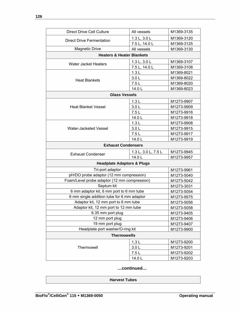
126
BioFlo®/CelliGen® 115 M1369-0050 Operating manual
Direct Drive Cell Culture All vessels M1369-3135
1.3 L, 3.0 L M1369-3120 Direct Drive Fermentation 7.5 L, 14.0 L M1369-3125
Magnetic Drive All vessels M1369-3130
Heaters & Heater Blankets
1.3 L, 3.0 L M1369-3107 Water Jacket Heaters
7.5 L, 14.0 L M1369-3108 1.3 L M1369-8021 3.0 L M1369-8022 7.5 L M1369-8020
Heat Blankets
14.0 L M1369-8023
Glass Vessels
1.3 L M1273-9907 3.0 L M1273-9909 7.5 L M1273-9916
Heat Blanket Vessel
14.0 L M1273-9918 1.3 L M1273-9908 3.0 L M1273-9915 7.5 L M1273-9917
Water-Jacketed Vessel
14.0 L M1273-9919
Exhaust Condensers
1.3 L, 3.0 L, 7.5 L M1273-9945 Exhaust Condenser
14.0 L M1273-9957
Headplate Adaptors & Plugs
Tri-port adaptor M1273-9961 pH/DO probe adaptor (12 mm compression) M1273-5040
Foam/Level probe adaptor (12 mm compression) M1273-5042 Septum kit M1273-3031
6 mm adaptor kit, 6 mm port to 6 mm tube M1273-5054 6 mm single addition tube for 6 mm adaptor M1273-9575
Adaptor kit, 12 mm port to 6 mm tube M1273-5056 Adaptor kit, 12 mm port to 12 mm tube M1273-5058
6.35 mm port plug M1273-9405 12 mm port plug M1273-9406 19 mm port plug M1273-9407
Headplate port washer/O-ring kit M1273-9900
Thermowells
1.3 L M1273-9200 3.0 L M1273-9201 7.5 L M1273-9202
Thermowell
14.0 L M1273-9203
…continued…
Harvest Tubes
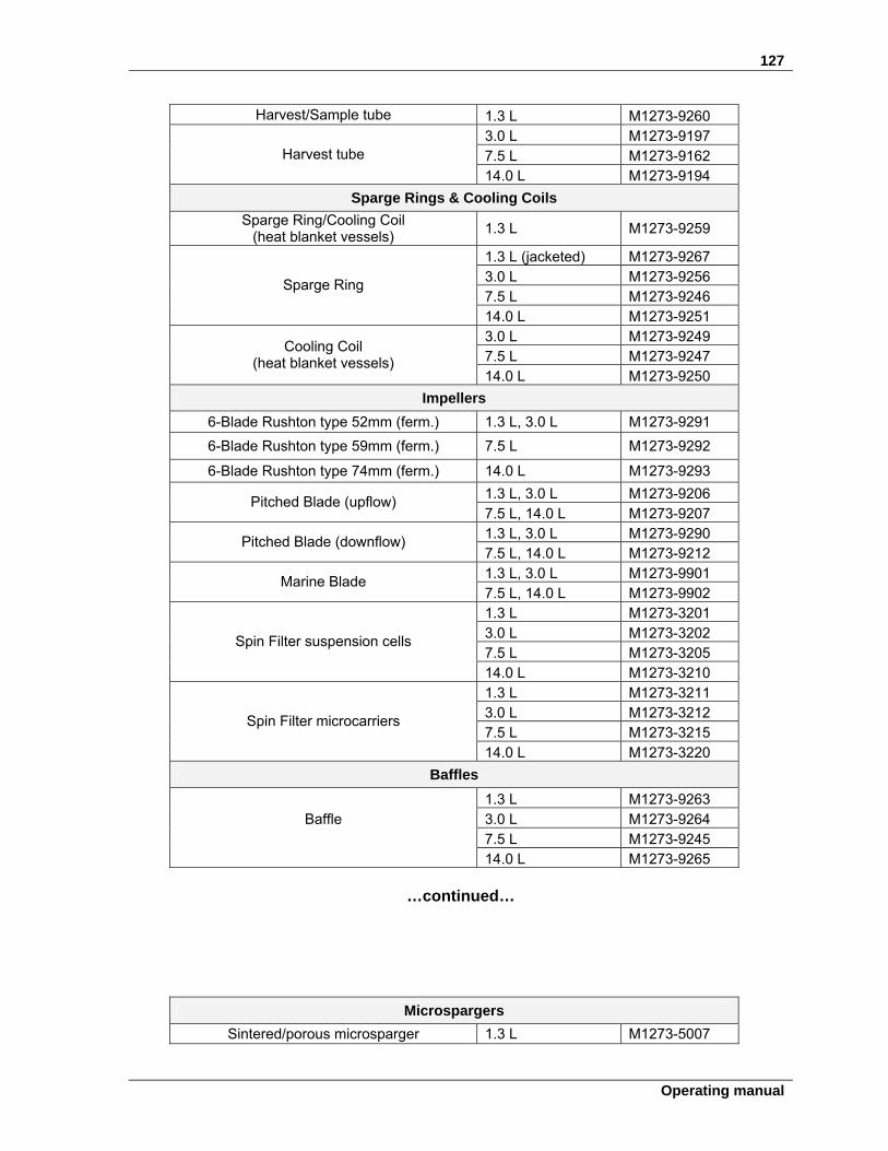
127
Operating manual
Harvest/Sample tube 1.3 L M1273-9260 3.0 L M1273-9197 7.5 L M1273-9162 Harvest tube
14.0 L M1273-9194
Sparge Rings & Cooling Coils
Sparge Ring/Cooling Coil (heat blanket vessels)
1.3 L M1273-9259
1.3 L (jacketed) M1273-9267 3.0 L M1273-9256 7.5 L M1273-9246
Sparge Ring
14.0 L M1273-9251 3.0 L M1273-9249 7.5 L M1273-9247
Cooling Coil (heat blanket vessels)
14.0 L M1273-9250
Impellers
6-Blade Rushton type 52mm (ferm.) 1.3 L, 3.0 L M1273-9291
6-Blade Rushton type 59mm (ferm.) 7.5 L M1273-9292
6-Blade Rushton type 74mm (ferm.) 14.0 L M1273-9293
1.3 L, 3.0 L M1273-9206 Pitched Blade (upflow)
7.5 L, 14.0 L M1273-9207 1.3 L, 3.0 L M1273-9290
Pitched Blade (downflow) 7.5 L, 14.0 L M1273-9212 1.3 L, 3.0 L M1273-9901
Marine Blade 7.5 L, 14.0 L M1273-9902 1.3 L M1273-3201 3.0 L M1273-3202 7.5 L M1273-3205
Spin Filter suspension cells
14.0 L M1273-3210 1.3 L M1273-3211 3.0 L M1273-3212 7.5 L M1273-3215
Spin Filter microcarriers
14.0 L M1273-3220
Baffles
1.3 L M1273-9263 3.0 L M1273-9264 7.5 L M1273-9245
Baffle
14.0 L M1273-9265
…continued…
Microspargers
Sintered/porous microsparger 1.3 L M1273-5007
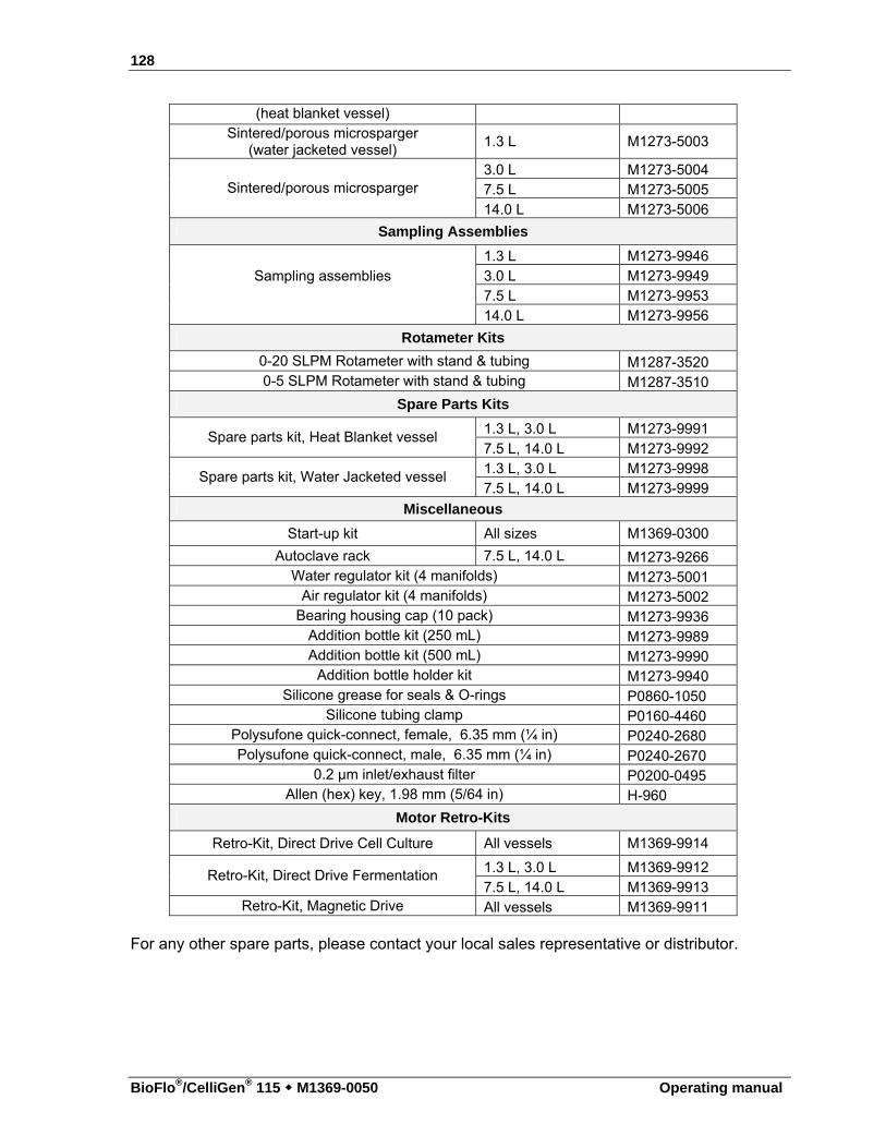
128
BioFlo®/CelliGen® 115 M1369-0050 Operating manual
(heat blanket vessel) Sintered/porous microsparger
(water jacketed vessel) 1.3 L M1273-5003
3.0 L M1273-5004 7.5 L M1273-5005 Sintered/porous microsparger
14.0 L M1273-5006
Sampling Assemblies
1.3 L M1273-9946 3.0 L M1273-9949 7.5 L M1273-9953
Sampling assemblies
14.0 L M1273-9956
Rotameter Kits
0-20 SLPM Rotameter with stand & tubing M1287-3520 0-5 SLPM Rotameter with stand & tubing M1287-3510
Spare Parts Kits
1.3 L, 3.0 L M1273-9991 Spare parts kit, Heat Blanket vessel
7.5 L, 14.0 L M1273-9992 1.3 L, 3.0 L M1273-9998
Spare parts kit, Water Jacketed vessel 7.5 L, 14.0 L M1273-9999
Miscellaneous
Start-up kit All sizes M1369-0300
Autoclave rack 7.5 L, 14.0 L M1273-9266 Water regulator kit (4 manifolds) M1273-5001
Air regulator kit (4 manifolds) M1273-5002 Bearing housing cap (10 pack) M1273-9936
Addition bottle kit (250 mL) M1273-9989 Addition bottle kit (500 mL) M1273-9990
Addition bottle holder kit M1273-9940 Silicone grease for seals & O-rings P0860-1050
Silicone tubing clamp P0160-4460 Polysufone quick-connect, female, 6.35 mm (¼ in) P0240-2680 Polysufone quick-connect, male, 6.35 mm (¼ in) P0240-2670
0.2 µm inlet/exhaust filter P0200-0495 Allen (hex) key, 1.98 mm (5/64 in) H-960
Motor Retro-Kits
Retro-Kit, Direct Drive Cell Culture All vessels M1369-9914
1.3 L, 3.0 L M1369-9912 Retro-Kit, Direct Drive Fermentation 7.5 L, 14.0 L M1369-9913
Retro-Kit, Magnetic Drive All vessels M1369-9911 For any other spare parts, please contact your local sales representative or distributor.
129
Operating manual
1177 SSEERRVVIICCEE If any problems occur with your BioFlo/CelliGen 115 system or its individual components, do not attempt to perform any service on it. Unauthorized servicing may void the warranty. Please contact your local Eppendorf Service Department or your local New Brunswick distributor. In any correspondence with Eppendorf, please refer to the Model Number (BioFlo/CelliGen 115), and the Manufacturing Part Number and Serial Number of the system.
17.1 Troubleshooting
WARNING! Risk of electrical shock! Always turn your BioFlo/CelliGen 115 off and disconnect the mains/power
cord before performing maintenance.
As with any equipment, difficulties sometimes arise. If you experience a problem with the operation of your BioFlo/CelliGen 115, consult the following list of symptoms. You may be able to resolve the situation easily and quickly yourself. If the problem is not listed below, or if the suggested solutions do not work, please call your Eppendorf representative to request a service technician. Other than the solutions proposed below, do not attempt to fix the equipment yourself.
Problem Possible Solution TEMPERATURE: Readout is a negative value (typically –225° C).
Inspect the temperature probe for obvious damage; replace it if necessary.
Make sure the temperature probe is connected to the cabinet jack.
The system will not heat up. Make sure the system was primed at start-up. Make sure the temperature probe is plugged into the
vessel thermowell. Water pressure may be too low; raise pressure within
recommended range. Verify correct connection (click to lock) of the water
inlet and outlet lines on the vessel heat exchanger. Hit reset button on hot plate (if appropriate).
The system is leaking water. Inlet water pressure may be too high; lower pressure within the recommended range.
Check for any loose connection of inlet hoses; tighten if necessary.
...continued...
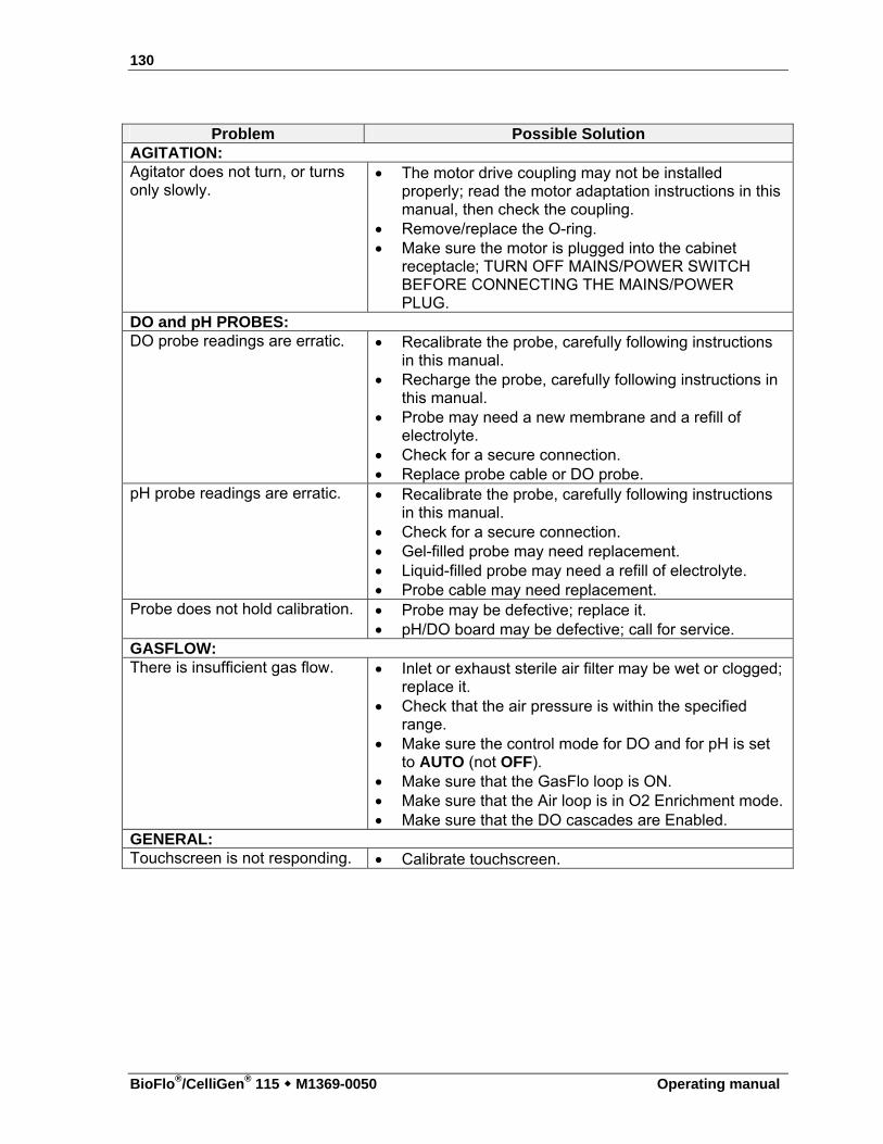
130
BioFlo®/CelliGen® 115 M1369-0050 Operating manual
Problem Possible Solution
AGITATION: Agitator does not turn, or turns only slowly.
The motor drive coupling may not be installed properly; read the motor adaptation instructions in this manual, then check the coupling.
Remove/replace the O-ring. Make sure the motor is plugged into the cabinet
receptacle; TURN OFF MAINS/POWER SWITCH BEFORE CONNECTING THE MAINS/POWER PLUG.
DO and pH PROBES: DO probe readings are erratic. Recalibrate the probe, carefully following instructions
in this manual. Recharge the probe, carefully following instructions in
this manual. Probe may need a new membrane and a refill of
electrolyte. Check for a secure connection. Replace probe cable or DO probe.
pH probe readings are erratic. Recalibrate the probe, carefully following instructions in this manual.
Check for a secure connection. Gel-filled probe may need replacement. Liquid-filled probe may need a refill of electrolyte. Probe cable may need replacement.
Probe does not hold calibration. Probe may be defective; replace it. pH/DO board may be defective; call for service.
GASFLOW: There is insufficient gas flow. Inlet or exhaust sterile air filter may be wet or clogged;
replace it. Check that the air pressure is within the specified
range. Make sure the control mode for DO and for pH is set
to AUTO (not OFF). Make sure that the GasFlo loop is ON. Make sure that the Air loop is in O2 Enrichment mode. Make sure that the DO cascades are Enabled.
GENERAL: Touchscreen is not responding. Calibrate touchscreen.
131
Operating manual
1188 DDRRAAWWIINNGGSS
18.1 List of drawings
Figure 1: Dimensions...............................................................................................................16 Figure 2: Front View................................................................................................................17 Figure 3: Rear View.................................................................................................................18 Figure 4: Control Station Service Connections .......................................................................19 Figure 5: Connecting Cabinets.................................................................................................21 Figure 6: Installation of Terminators with Master & One Utility Station ...............................21 Figure 7: Installation of Terminators with Master & Two Utility Stations .............................22 Figure 8: Water Connections ...................................................................................................24 Figure 9: Gas Connections.......................................................................................................26 Figure 10: Sparge Connection (detail From Figure 4).............................................................26 Figure 11: WRONG Handling of Drive Assembly..................................................................28 Figure 12: CORRECT Handling of Drive Assembly ..............................................................28 Figure 13: Vessel Assembly ....................................................................................................30 Figure 14: 1.3 L Headplate ......................................................................................................31 Figure 15: 3.0 L Headplate ......................................................................................................32 Figure 16: 7.5 L & 14.0 L Headplate.......................................................................................33 Figure 17: Upper Vessel Bumper Installation .........................................................................34 Figure 18: Water-Jacketed Vessel Assembly ..........................................................................36 Figure 19: Installing Headplate Clamping Ring ......................................................................37 Figure 20: Water Jacket Guard Installation (top view)............................................................38 Figure 21: pH Probe with Port Adapter (exploded).................................................................43 Figure 22: dO2 Probe with Port Adapter (exploded)...............................................................45 Figure 23: Exhaust Condenser (1.3L, 3.0 L & 7.5 L Vessels).................................................46 Figure 24: Exhaust Condenser (14.0 L Vessel only) ...............................................................47 Figure 25: Sampler/Harvest System (1.3 L Vessel).................................................................48 Figure 26: Sampler System (3.0 L, 7.5 L & 14.0 L Vessels) ..................................................49 Figure 27: Foam Trap ..............................................................................................................51 Figure 28: Vessel Location ......................................................................................................53 Figure 29: ON/OFF Mains/Power Switch ...............................................................................54 Figure 30: RS-232/-422 Interface ............................................................................................55 Figure 31: Touchscreen............................................................................................................60 Figure 32: Sample SUMMARY Screen (Fermentation with Auto Gas Mix) .........................61 Figure 33: Sample SUMMARY Screen (Fermentation with Manual Gas Mix) .....................62 Figure 34: Sample SUMMARY Screen (Cell Culture without TMFC) ..................................63 Figure 35: Sample SUMMARY Screen (Cell Culture with TMFC) .......................................63 Figure 36: Alphanumeric Keypad............................................................................................65 Figure 37: Numeric Keypad.....................................................................................................66 Figure 38: Sample GAUGE Screen (Agit) ..............................................................................67 Figure 39: Sample GAUGE Screen (pH).................................................................................68
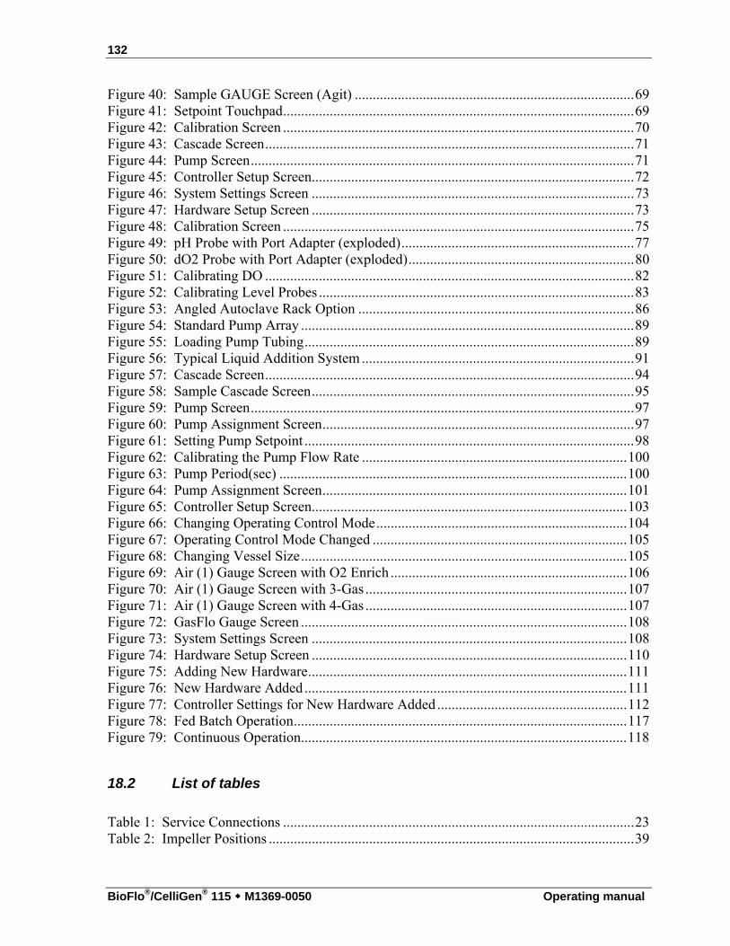
132
BioFlo®/CelliGen® 115 M1369-0050 Operating manual
Figure 40: Sample GAUGE Screen (Agit) ..............................................................................69 Figure 41: Setpoint Touchpad..................................................................................................69 Figure 42: Calibration Screen ..................................................................................................70 Figure 43: Cascade Screen.......................................................................................................71 Figure 44: Pump Screen...........................................................................................................71 Figure 45: Controller Setup Screen..........................................................................................72 Figure 46: System Settings Screen ..........................................................................................73 Figure 47: Hardware Setup Screen ..........................................................................................73 Figure 48: Calibration Screen ..................................................................................................75 Figure 49: pH Probe with Port Adapter (exploded).................................................................77 Figure 50: dO2 Probe with Port Adapter (exploded)...............................................................80 Figure 51: Calibrating DO .......................................................................................................82 Figure 52: Calibrating Level Probes ........................................................................................83 Figure 53: Angled Autoclave Rack Option .............................................................................86 Figure 54: Standard Pump Array .............................................................................................89 Figure 55: Loading Pump Tubing............................................................................................89 Figure 56: Typical Liquid Addition System ............................................................................91 Figure 57: Cascade Screen.......................................................................................................94 Figure 58: Sample Cascade Screen..........................................................................................95 Figure 59: Pump Screen...........................................................................................................97 Figure 60: Pump Assignment Screen.......................................................................................97 Figure 61: Setting Pump Setpoint ............................................................................................98 Figure 62: Calibrating the Pump Flow Rate ..........................................................................100 Figure 63: Pump Period(sec) .................................................................................................100 Figure 64: Pump Assignment Screen.....................................................................................101 Figure 65: Controller Setup Screen........................................................................................103 Figure 66: Changing Operating Control Mode......................................................................104 Figure 67: Operating Control Mode Changed .......................................................................105 Figure 68: Changing Vessel Size...........................................................................................105 Figure 69: Air (1) Gauge Screen with O2 Enrich ..................................................................106 Figure 70: Air (1) Gauge Screen with 3-Gas .........................................................................107 Figure 71: Air (1) Gauge Screen with 4-Gas .........................................................................107 Figure 72: GasFlo Gauge Screen ...........................................................................................108 Figure 73: System Settings Screen ........................................................................................108 Figure 74: Hardware Setup Screen ........................................................................................110 Figure 75: Adding New Hardware.........................................................................................111 Figure 76: New Hardware Added..........................................................................................111 Figure 77: Controller Settings for New Hardware Added .....................................................112 Figure 78: Fed Batch Operation.............................................................................................117 Figure 79: Continuous Operation...........................................................................................118
18.2 List of tables
Table 1: Service Connections ..................................................................................................23 Table 2: Impeller Positions ......................................................................................................39

133
Operating manual
Table 3: Modbus Com Port Pin Designation ...........................................................................56 Table 4: SUMMARY Screen Features ....................................................................................64 Table 5: Pump Control Modes.................................................................................................99 Table 6: Flow Rate per Tubing Size ........................................................................................99 Table 7: Wetted Parts.............................................................................................................122
134
BioFlo®/CelliGen® 115 M1369-0050 Operating manual
1199 AAPPPPEENNDDIIXX AA:: SSOOMMEE GGEENNEERRAALL
CCOONNCCEEPPTTSS
In this section, all discussions of P-I-D control are to explain the theory on which it is based. This product uses only P (proportional) & I (integral) control, not D (derivative).
19.1 What is a controller?
The local process controller is a multi-loop controller, which means it can control several process parameters simultaneously. It compares current values with setpoints and creates independent control signals for each controlled parameter. The control signals are used to drive appropriate actuators that maintain the various parameters at their setpoints. Using temperature as an example, the controller compares the output of a temperature sensor to the user-entered temperature setpoint, and generates a signal to activate either a heater or a cooler to maintain vessel temperature at the temperature setpoint. The controller provides the logic that generates appropriate drive signals to various actuators so that process parameters remain at their setpoints.
19.2 What is a control loop?
A control loop is the basic element of automatic process control. Three components comprise one control loop: a sensor, a controller, and an actuator. Based on information from a sensor, the controller generates an actuator control signal that maintains a parameter at its setpoint. Control will fail if any element in the control loop fails.
19.3 What is probe calibration?
In bioprocess control, calibration generally refers to establishing a correspondence between a probe’s output and the actual value of whatever that probe senses. For example, pH probes are often calibrated with pH 7.0 and pH 4.0 buffers to establish a “zero” (pH 7.0) and a “span” (pH 4.0). Other buffers can be used, but the principle is always the same. For any probe calibration, two values—a zero and a span—are required for the controller to correctly translate inputs from that probe. DO and pH probes are routinely calibrated before each use. Most other probes need be calibrated only infrequently.
19.4 What are P-I-D constants?
135
Operating manual
The mathematics of P-I-D control is familiar to most control and process engineers.
In P-I-D mode, the controller creates a control signal that is based upon the deviation between the setpoint and input from a sensor. The magnitude of the control signal is determined by a mathematical formula that can include proportional (“P”), integral (“I”) and derivative (“D”) terms. The P, I and D constants are three numbers that determine the relative sizes of the proportional, integral and derivative terms, respectively. To use a temporal analogy, the P or proportional part of the control signal reflects present deviations between setpoint and current value. The I or integral component reflects past deviations, and the D or derivative term anticipates future values of the error.
Generally, with noisy or slow-responding sensors, such as dissolved oxygen and pH probes, the D constant should be set to zero. If the constants for a loop are too large, that loop will oscillate, displaying extreme swings in actuator output. If, for example, agitation changes suddenly and frequently between minimum and maximum rpm, one should suspect incorrect P, I and D values for the agitation control loop. This condition can easily be mistaken for a defective component when it actually results from incorrect settings. If the constants are too small, control response will be slow, and setpoints may never be reached. Again, this can be mistaken for defective components. P-I-D constants are usually established by methodical trial and error.
19.5 What is P-I-D tuning?
Tuning consists of establishing controller settings (the proportional, integral, and derivative constants) such that the controller provides proper control. If the P-I-D constants are incorrect, the control signal may be too weak for the parameter to ever reach setpoint or, at the other extreme, the controller may respond excessively to small errors, causing the actuator to oscillate between high and low values. Usable P-I-D constants must be determined for each P-I-D loop. The process is largely one of calculated trial and error. All loops that are configured with the P-I-D control mode must be tuned. When delivered as part of a New Brunswick system, P-I-D loops will have been tuned at the factory to work correctly with the New Brunswick-controlled instruments. For other applications, the user is responsible for P-I-D tuning. Tuning can be a complex task for those unfamiliar with the process, which is why a trained engineer or technician normally performs this task. A number of textbooks1 that explain the theory and describe the process could be useful for the mathematically-inclined novice. The Ziegler-Nichols method, described in the footnoted reference, is used at our production facilities.
The following suggestions are intended for novices. Be sure to refer to a textbook, and consider utilizing the services of a technician.
1 For example, Chinks, F.G., Process Control Systems: Application, Design, and Tuning, McGraw-Hill (1988), New York, Auckland, Bogota, London, Toronto, Sydney, Tokyo, Montreal.
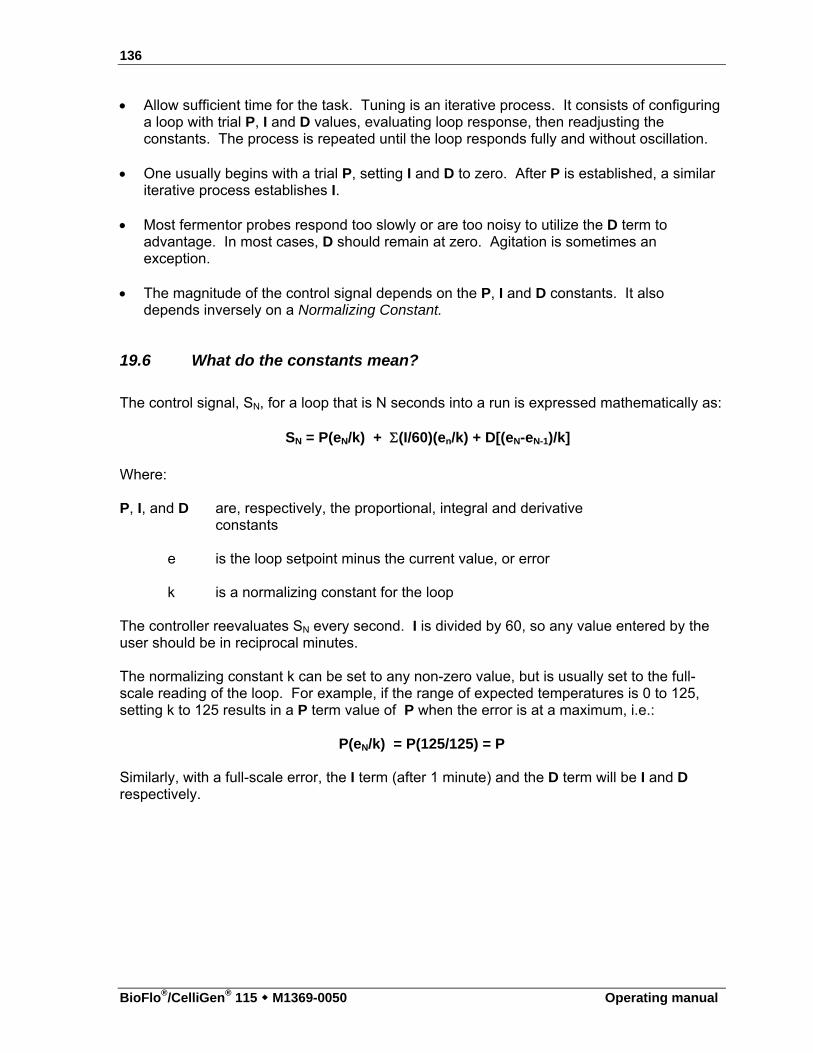
136
BioFlo®/CelliGen® 115 M1369-0050 Operating manual
Allow sufficient time for the task. Tuning is an iterative process. It consists of configuring a loop with trial P, I and D values, evaluating loop response, then readjusting the constants. The process is repeated until the loop responds fully and without oscillation.
One usually begins with a trial P, setting I and D to zero. After P is established, a similar
iterative process establishes I. Most fermentor probes respond too slowly or are too noisy to utilize the D term to
advantage. In most cases, D should remain at zero. Agitation is sometimes an exception.
The magnitude of the control signal depends on the P, I and D constants. It also
depends inversely on a Normalizing Constant.
19.6 What do the constants mean?
The control signal, SN, for a loop that is N seconds into a run is expressed mathematically as:
SN = P(eN/k) + (I/60)(en/k) + D[(eN-eN-1)/k]
Where: P, I, and D are, respectively, the proportional, integral and derivative
constants
e is the loop setpoint minus the current value, or error
k is a normalizing constant for the loop The controller reevaluates SN every second. I is divided by 60, so any value entered by the user should be in reciprocal minutes. The normalizing constant k can be set to any non-zero value, but is usually set to the full-scale reading of the loop. For example, if the range of expected temperatures is 0 to 125, setting k to 125 results in a P term value of P when the error is at a maximum, i.e.:
P(eN/k) = P(125/125) = P
Similarly, with a full-scale error, the I term (after 1 minute) and the D term will be I and D respectively.
137
Operating manual
2200 AAPPPPEENNDDIIXX BB:: OOTTRR
20.1 Determining an oxygen transfer rate
The oxygen transfer rate (OTR) of all New Brunswick fermentors is determined by a standard sulfite oxidation test. The standard operating conditions for determining OTR are:
Temperature: 30C Agitation: 1000 rpm Aeration: 1 VVM
20.1.1 OTR calculations OTR can be estimated by titrating a fixed amount of sodium sulfite, Na2SO3, with air, CU+2:
2SO3 + 02 2SO4
The Procedure
Calibrate the DO electrode: Set zero on DO. Fully oxygenate the fermentor with agitation and airflow. Set span to 100%. Introduce a known amount of Na2SO3 into the fermentor when fully oxygenated. OTR = 30,000 n mM O2/L/hr
V T
n = number of moles of sodium sulfite
V = vessel volume in liters T = time taken from DO curve at two points of 50% DO min.
138
BioFlo®/CelliGen® 115 M1369-0050 Operating manual
20.2 Some factors that affect OTR and horsepower
Many factors influence OTR, not the least of which are type, size and placement of impellers in the reactor. (Factors which effect OTR are vessel dimensions, impeller diameter, type of impeller, i.e. turbine, marine, pitched blade, etc.). Eppendorf selects and recommends the placement of impellers in the vessel to attain a minimum of 350 mM O2/L/hr of OTR. The BioFlo/CelliGen 115 fermentor is supplied with two properly sized Rushton Impellers. Placement of the impellers should be as indicated in Section 4.8.5.
In some processes, users may wish to use a third impeller. Should this be the case, however, a smaller impeller diameter is required, since the systems are specifically designed such that the vessel diameter, motor, impellers, to produce a specific OTR. When any of the factors is changed, other features may also change.
For example, the standard impeller used on the 10-liter BioFlo/CelliGen 115 has a 3.24-inch (± 0.015) diameter. If three impellers are to be used, 3.06” diameter impellers are required. This size impeller is normally used in a 7.5 L BioFlo/CelliGen 115 vessel. These impellers should be placed such that the bottom impeller is placed one impeller diameter from the bottom of the vessel. The second impeller should be placed one impeller diameter above the bottom impeller, and the third impeller should be placed one impeller diameter above the second. To determine the horsepower utilized by a given number of impellers, the following formula can be used. The impeller diameter varies to the 5th power with respect to horsepower. A very slight change in the diameter of an impeller can make a great deal of difference in the HP required to drive that impeller. The approximate horsepower utilized to drive a given set of impellers is determined as follows:
HP = D5 x RPM3 x (4.5 x 10-13) x I Where:
HP = Horsepower D = Impeller diameter in inches RPM = Agitator speed in rpm 4.5 x 10-13 = Constant (factor based on unaerated water at 20C
with a six-bladed Rushton impeller) I = factor based on the number of impellers used in the
vessel: Use 1 for one impeller Use 1.8 for two impellers Use 2.4 for three impellers
139
Operating manual
The HP requirements are substantially affected by aeration. An airflow rate of one vessel volume per minute (VVM) may produce as much as 40% reduction in the horsepower used. It is required that some air/gas flow be utilized when running at speeds above 750 rpm. The relationship in the reduction of horsepower when gas is added into the system is not linear. A small amount of air can produce a 20% reduction in horsepower.
140
BioFlo®/CelliGen® 115 M1369-0050 Operating manual
2211 AAPPPPEENNDDIIXX CC:: FFEERRMMEENNTTAATTIIOONN
TTEECCHHNNIIQQUUEESS The following section outlines step-by-step procedures for carrying out a benchtop fermentation. Provided in a question and answer format, this discussion covers such topics as which media formulation, tubing size, and concentration of various additives should be used. It also addresses the preparation, autoclaving and clean-up procedures for the vessel and accessories. While this example refers specifically to an E. coli fermentation in a BioFlo/CelliGen 115, the information is generally applicable for any fermentation.
21.1 Media formulation
Question: What kind of media should be used, and does it differ from media used in shake flasks? Answer: The media used in shake flasks does differ from the standard media used in a fermentation vessel. Shake flask media is generally of a much simpler composition. LB Broth and Tryptic Soy Broth are standard shake flask media. Here is an example of a more complex media used in a recombinant E. coli fermentation:
Chemical g/L KH2PO4 3.5 K2HPO4 5.0 (NH4)2HPO4 3.5 MgSO4
.7H2O 0.5 Glucose 5.0 (for fed batch) 30.0 (for batch) Yeast Extract 5.0 Trace Metals 1.0 mL/L Antifoam 0.5 mL/L Trace metals formulation: FeCl3 1.6 CoCl2
.6H2O 0.2 CuCl2 0.1 ZnCl2
.4H2O 0.2 NaMoO4 0.2 H3BO4 0.05 Hcl 10 mL H2O to 1000 mL
For fermentation, the glucose solution is usually sterilized in a separate flask. It is then added aseptically to the other (heat labile) components that cannot be subjected to
141
Operating manual
autoclaving, such as Ampicillin and the trace metal solution. These are prepared in advance by sterile filtration so that they are available as stock solutions. The magnesium sulfate is sometimes sterilized separately. Most materials are available from a variety of vendors. Note that Sigma and Difco are often the best sources for the more unusual biological and chemical materials. The exact formulations of the trace metals solution and the fermentation media for the fermentors will depend on the precise fermentation you wish to conduct. Various formulations can be found in the handbooks and literature.
21.2 Antifoam formulation
Question: What kind of antifoam should be used, and in what concentration? Answer: Please visit our website at www.nbsc.com (click on the FAQs tab, then click on Fermentation and Cell Culture) for recommendations on types of antifoam agents to use. The initial concentration of antifoam is usually 0.1-0.5 mL/L. When the foam probe is used, the pumping of antifoam is controlled by the system.
The pump should be set to add the minimum amount of antifoaming agent required to prevent foaming in your particular process. That amount varies depending on the amount of protein in the media, the amount of protein secreted by the microorganism, agitation speed, and other factors. Therefore, you will have to experiment to get the proper pump setting.
21.3 Tubing size
Question: What is the correct tubing size for acid, base, antifoam and nutrient feed for a fed-batch run? Answer: For vessels up to 5 liters, part number TU202. This is Marprene tubing with an inside dimension (ID) of 1.6 mm. It has an OD of 4.8mm (3/16"NOM) and a wall thickness of 1.6mm. Larger tubing will be required for vessels over 5 liters. It may also be necessary to use a connecting fitting to allow two different tubing sizes to be used (in cases when the tubing size required for the pump and the size required for the direct connection to the vessel differ). Eppendorf recommends silicon tubing for use with the pump heads provided as standard on BioFlo fermentors. However, Marprene tubing may be used as well, as long as the tubing size does not exceed 3/16” bore x 1/16” wall. Marprene tubing of this size or smaller can be used with Watson-Marlow 101 pump heads under low pressure and with clockwise rotation.
142
BioFlo®/CelliGen® 115 M1369-0050 Operating manual
Take note that silicon tubing should not be used with hydrochloric acid (HCL), sulfuric acid (H2SO4)) or sodium hydroxide solutions since this material deteriorates rapidly when in contact with such solutions. Another reason for avoiding HCL is that HCL (and to a lesser extent H2SO4 ) causes corrosion of stainless steel. NaOH solutions equal to or less than 20% can be used in silicon tubing at temperatures less than 120 F without destroying the tubing. Solutions of sulfuric acid less than 10% can cause moderate damage to silicon tubing.
21.4 Acid & base
Question: What concentration and type of acid and base should be used? Answer: The acid solution is 2 - 3N H2SO4. The base solution is either 5N NaOH or NH4OH ~ 29% (which is the standard commercially available concentration.) Note that these are fairly concentrated. The acid can affect the stainless steel parts of the fermentor vessel. To avoid damage to the entry ports, it is a good idea to use a sterile, disposable needle at the end of the addition tubing and to add the acid (or base) through the disposable needle. The needle will corrode, but it saves the fermentor vessel. Insert the needle though a septum port so that the drip point is away from stainless steel components and fairly close to the liquid level. You may also use a more diluted solution of the acid or base. However, take note that this may cause the complication of adding a larger volume of liquid to the vessel. Also, it is not a good idea to add acid and base through a single double or triple port adapter. The combined effects of both causes rapid corrosion of the adapter. The pump setting is usually 20.0 - 25.0 under acid or base mode. For these concentrations of acid and base, Marprene tubing should be used. To avoid damage to the stainless steel headplate, use a septum port for introduction of these strong solutions into the vessel. If you are using silicon tubing, reduce the concentration of H2SO4 to less than 8% (about 5%) and use a 20% solution of NaOH. When selecting an acid for use in fermentation, select the lowest possible concentration that allows for pH control.
21.5 Glucose feed
Question: What is the proper concentration of glucose feed? Answer: The glucose is 50% concentration. The feed rate is not usually a constant value as this will differ not only from run to run, but it will vary greatly over the course of a run, depending upon the organism's growth. This operation can be controlled automatically by BioCommand, New Brunswick' proprietary Windows-based software. Glucose feeding can be set to respond to other sensor cues (such as DO level, the pH reading, the turbidity measurement, the glucose measurement, etc.). The pumping profile to be used must generally be determined through experimental experience.
143
Operating manual
21.6 Recommended process control settings
Question: What are the recommended process control settings (i.e., temperature, pH, agitation speed, DO & gas sparge rate)?
Answer: For E. coli, temperature is usually set to 32° - 35°C and pH is set at 7.0 - 7.2. For yeast the values are 30°C and a pH value of 5.0. Agitation speed is usually set to a minimum of 200 - 300 rpm with a maximum value of 1000 rpm. Dissolved oxygen (or DO) level is usually 30%. The gas sparge rate is generally 0.5 to 1.0 VVM.
21.7 Typical fermentation run
Question: Can you review the steps involved in set-up through shutdown of a fermentation run? Answer: To answer properly, let's break the process down, as follows:
21.7.1 Vessel preparation before autoclaving It is advisable to rinse the previously cleaned vessel prior to use. When doing this, remember that all clamps must be open and the valve for the sampling tube must be in the open position. If the glass wool is going to be replaced for the run, then remove it (and the rubber sampler bulb) prior to rinsing. The protective bearing housing cap must also be in place. It will be necessary to hold the protective cap in place if you plan to invert the headplate while rinsing it. In this case it is usually advisable to also remove the clamps that hold the headplate onto the rest of the vessel, as failure to do so will result in their falling out during inversion. The pH and DO probes should not be in the headplate while you rinse it. All gas filters must be removed prior to rinsing. The sparger must, in particular, be checked to ensure that it isn't clogged. The headplate must be oriented in combination with the vessel and the internal baffle so as to allow for the exhaust condenser lines to be connected. Also, the baffle must be positioned so that it does not interfere with the insertion of the pH and DO probes into their ports. Do not place the sample port to the rear of the vessel, and position it so that ample room is available to take a sample. It is advantageous to have the addition ports for acid, base, etc., on the same side as (or at least not opposite) the pumps. The old grease on the top of the glass cylinder should be wiped clean. Reapply grease (Dow Corning silicone grease) prior to installing the headplate: smear a very thin layer around the top of the cylinder with your fingertip. (Take care to ensure that no residual grease remains on your hands when you touch other parts of the vessel.) When the headplate is in place, be sure to properly tighten the headplate clamps.
All tubing connected to the headplate should be secured at the headplate connection point, as well as to any addition bottles or other connectors. A tie-gun is useful for this purpose. Note that both the air sparger and the exhaust line will have a terminal filter. (For the BioFlo/CelliGen 115 vessel, the part numbers are P0200-0491 for the sparge line’s small filter, and P0200-0490 for the exhaust line’s large filter.) All tubing connected to ports that have their terminus within the vessel below the liquid level (i.e., the harvest and sparge ports)
144
BioFlo®/CelliGen® 115 M1369-0050 Operating manual
must be clamped prior to autoclaving. The sampler valve must be in the closed position. Other hoses, such as those attached to base or addition ports, should be clamped to facilitate sterile hook-ups. Eppendorf primarily uses the following clamps: a Hosecock Clamp (Fisher catalog number 05-847) and a Hoffman Side Tubing Clamp (Fisher catalog number 05-875B). Do not rely on polymer clamps to survive autoclaving; they often pop open in the autoclave. If you wish to use the newer polymer clamps during the running of your fermentation, then place them onto the tubing but leave them open. Use easily removable metal clamps to actually close the line during autoclaving. These may be removed after the vessel has been autoclaved. Be sure to use the polymer clamp to close off the tubing BEFORE you remove the metal clamp. Clamps can be placed at any point on tubing, but be sure they don't clamp down onto a port or connector, because that would interfere with proper sealing. The open end of the tubing should be covered with cotton, then with aluminum foil. The clamp on the tubing be below the foil & cotton. The sparger filter should also be covered, but not quite as tightly. The exhaust filter is usually not covered. All tubing should be inspected both prior to and after autoclaving to insure integrity.
The above description also applies to any side harvest ports in use. Note that this type of port is often below the media fill line. It is also possible to use a hose that has been tied off and crimped at one end to provide a cap for the base port & addition port, as well as other ports. These caps must fit very securely over the port, in order to avoid loss of sterility due to displacement while autoclaving. All O-rings should be checked for damage prior to autoclaving. All fittings must be checked for tightness. A loose fitting is often an indication that the small O-ring in the fitting assembly requires replacement.
Verify that the bottom of the glass cylinder is properly secured to its base. The agitation shaft must have its protective cap on prior to autoclaving. It is advisable to check that the connectors from the system to the vessel (exhaust gas condenser) are compatible. This is a good time to check that the air and water lines to the system are open and that (if required) an oxygen source is available and correctly connected. The pH probe must be inspected prior to insertion: enough electrolyte must be present and in good condition, and the rubber stoppers must be securely in place. The pH probe must be properly calibrated prior to insertion in the headplate. (Be sure to carefully follow the manufacturer's instructions for probe calibration, or the instructions in this manual.) It is often necessary to coat the probe with a very thin layer of glycerin or deionized water in order to avoid jamming or breaking it during insertion. The pH probe must be inserted carefully, using two hands, with one hand holding the base of the probe near the port opening.
Never force the probe, and never insert the pH or the DO probe until the headplate is properly secured. It is absolutely critical that both the pH and DO probes have their protective caps on prior to autoclaving; in fact, the caps should always be on except when the probe is being hooked up to the system. NEVER autoclave a pH probe or a DO probe without its protective cap.
145
Operating manual
Check the DO probe to be sure the required amount of electrolyte is present prior to insertion; Eppendorf usually replaces electrolyte for each new run. The DO probe's membrane must also be inspected prior to use. The glass wool for the sampler is prepared by rolling a small quantity up and inserting it into the small tube that attaches to the bulb. It may be necessary to trim any glass wool fibers that stick out. Note that it is undesirable to pack glass wool too tightly; use the bulb and a sampling tube to see if a vacuum can be held and released properly, as when a sample is normally taken. Attach a sample tube prior to autoclaving. This tube should be ¼ to ½ turn loose to avoid explosion or implosion. The glass wool should be covered with a piece of foil.
21.7.2 Vessel sterilization When autoclaving, the vessel exhausts through the exhaust filter, so it is essential that the line be prevented from crimping and that the filter be good (unplugged). To ensure that crimping does not occur, use a short piece of fairly rigid tubing. If rigid tubing is not available, use a small splint to support the tubing. The vessel is normally sterilized for 45 minutes. Note, however, that certain media formulations cannot be sterilized for this length of time, as degradation will occur (check the media manufacturer's instructions). The probes must never be autoclaved dry. If it becomes necessary to sterilize the vessel without media, use a balanced salt (phosphate-buffered saline) solution to cover the ends of the probes. Aseptically remove the PBS prior to filling the vessel with the desired media. NEVER PLACE PROBES IN DISTILLED OR DEIONIZED WATER: THIS WILL CAUSE YOUR PROBE TO LOSE ELECTROLYTE. The maximum fill is ~70% of the vessel's maximum volume. Autoclaving should be done (when liquid is present in the vessel) on a slow exhaust setting (see autoclave manufacturer’s instructions for autoclaving liquids). Sterilization is at 121°C. When sterilization is complete, check the exhaust line to verify that it didn't crimp, and check the vessel's integrity.
21.7.3 Post-sterilization vessel set-up The vessel must be handled gently when removed from the autoclave, to prevent the media from boiling up. Confirm that any unprotected vented lines are clamped off upon removing the vessel from the autoclave. Check the vessel's integrity again, then transport it to the bench system. Place the vessel next to the control cabinet. The orientation must allow for proper hook-up to the the exhaust gas condenser lines. Connect the water lines, connecting the outgoing (return) lines before the incoming (delivery) lines, and ensuring that the delivery and return lines are not inverted. Insert the temperature probe into the thermowell. Check that the water lines to the system are open. Set the temperature value below ambient temperature and set the control to Auto. After ~2-5 minutes, the system can be switched to the desired temperature setting. This can be checked by making sure that water is truly leaving the system: observe the water drained through the Drain or Water Out port.
146
BioFlo®/CelliGen® 115 M1369-0050 Operating manual
Remove the protective caps from the pH and DO probes and connect the probes to the system. Be careful with the pH probe: do not twist the probe into its connection to the system, as this can compromise sterility. The connection must be screwed onto the probe. The pH probe should also be checked to ensure that its rubber stoppers have not been displaced. Note the time that the DO probe is connected, since the probe requires a minimum of 6 hours for polarization. Remove the bearing housing cap and attach the motor. Open the SUMMARY screen and set the air from OFF to O2 Enrichment. Return to the SUMMARY screen and make sure that GasFlo is in ON mode. Connect the air line from the system to the sparger’s terminal filter as aseptically as possible (although the filter will prevent external contamination, good technique is always a good idea). Open the clamp on the sparger line and visually observe the vessel to ensure that air is flowing properly. Then set the agitation to the minimum desired value. After set-up, the system should be carefully observed to ensure that there are no problems, (especially no water line leaks).
21.7.4 Vessel operation The vessel must have any and all necessary addition bottles connected prior to use. If another bottle, such as the glucose feed, is not initially required, it can be hooked up later. The pH will probably need to be adjusted. This is done by setting the pH control to Auto. Note that due to the system’s tendency to overshoot the target pH during this initial adjustment, it is desirable to set the initial pH setpoint a little conservatively. (For example: post-sterilization pH reading is 6.8, and desired setpoint is 7.2. Set the system to setpoint 7.0 when conducting the initial adjustment.) Note that the pH reading must be taken from a vessel that has already cooled down. Additional media components that are not autoclaved can be added once the vessel has cooled sufficiently. The protocol for this is the same as for inoculation, as described below. Inoculation can be performed by aseptically pouring liquids into the vessel through the inoculation port, although Eppendorf normally uses the harvest port to inoculate. A peristaltic pump or gravity is used to introduce the inoculum. The shake flask is connected to the port terminus using aseptic techniques, and then the clamps are opened to allow for addition. Once the material is all in (except for any residual inoculum which must be retained for testing), secure the clamps and disconnect the shake flask. At this point, the harvest port terminus must be covered up again, using asceptic techniques, with sterile cotton and foil. To harvest from the vessel, attach a line to the harvest port and use a peristaltic pump to pump the culture broth out.
147
Operating manual
21.7.5 Vessel shutdown & cleaning When the fermentation run is complete, it is necessary to carefully shut the process down. First, all operating parameters (agitation, temperature, DO level, pH, and gas feed) must be set from their current control modes (such as Auto, Manual, or ON) to the OFF mode. Additionally, if a supplemental oxygen feed was used, it will be necessary to close the gas tank valve and its lines to the system. If a recirculating chiller is in use, it should be shut off when the temperature control is shut off. Clamp off the feed lines (from any addition bottles used) prior to detaching them from the vessel. The next step is to disconnect the vessel from the system. Remove the temperature probe from the thermowell. Remove the motor and place the protective cap over the agitation shaft/bearing housing. When you disconnect the water lines, always disconnect the incoming lines prior to the outgoing lines. Disconnect the air line from the sparger. Disconnect the pH and DO probes from the system, and put on their protective caps. The DO probe presents an easy removal as you simply unscrew the thread and gently pull it out. Immediately rinse it off, then gently wipe it dry, always remembering to never touch the membrane at the tip. Some runs will result in an accumulation of biomaterial on the probe, so and it may be necessary to wipe the probe down more vigorously; nevertheless, in no case should the tip be touched. After cleaning the DO probe, visually inspect the tip for damage. (If it is damaged, replace the probe.) Store the probe in a clean area in such a way as to protect the sensitive tip. Removing the pH probe is usually not so difficult inserting it because the shaft is wet and should be relatively easy to remove. The danger of probe breakage is still very real, however, so extreme care must be taken while removing it. Be sure to use two hands, with one hand at the top of the port acting as a guide to ensure proper removal. A gentle pace is required; if at any point in the process the probe should jam, absolutely avoid forcing. It may be necessary to reinsert the probe partway, and to apply a lubricant such as glycerin to the shaft and port in order to effect the removal. In extreme cases, it may be necessary to remove the headplate with the probe still inside so that you can approach the problem from both ends. In such a case, it is critical to remove the headplate very carefully. (We recommend that you have a spare probe available at all times, in case of breakage.) Once the pH probe has been removed, it should be immediately washed off with warm water. If biomaterial has accumulated on the probe, use a sponge (or an equivalent that will not scratch glass) with gentle pressure to clean the surface. The very tip of the probe should be handled with extreme care and a Kimwipe should be used to gently dry it off after washing. The probe should be stored with the tip immersed in either electrolyte or pH 7 buffer. This electrolyte/buffer can be reused, but it should always be inspected prior to each use for precipitation or contamination.
148
BioFlo®/CelliGen® 115 M1369-0050 Operating manual
Now that the vessel is detached from the system, it can be cleaned. Remove any remaining cotton and foil covering the ports. The rubber sampler bulb should be removed and rinsed separately. The glass wool can be removed at this point, too. Detach the sampling tube and wash it separately. Open the valve on the sampling port and all clamps on all tubing connected to ports for proper washing (be sure to remove the media prior to unclamping any tubing below liquid level, such as a side harvest line). The headplate should be detached by loosening and then removing the clamps that hold it to the rest of the vessel. Those clamps may require rinsing. The remaining culture broth should be sterilized, or emptied into a bucket and disinfected by using bleach or other accepted disinfectant prior to disposal. Note that some media may be incompatible with this procedure, in which case the media can be placed into another container for sterilization prior to disposal.
The headplate should be washed thoroughly with warm water and then with deionized (DI) water. It may be necessary to scrub off any accumulations of biomaterial. A pad that won't scratch the steel is required for this. The agitation shaft, thermowell, harvest and sparger tubes, and the short beveled tips of the interior portion of the base-type addition ports will often require special attention. All tubes and shafts must be cleaned. Note that there may be some residual base or acid left in those lines, so extreme caution and the use of chemically-resistant gloves is highly recommended for this procedure. It is often necessary to hand wipe surfaces with a paper towel in order to fully remove residual traces of small particulate debris. The washing of the bottom portion of the vessel requires the same procedures as the headplate. Note that the sides of the vessel, particularly near the baffle, may require special attention. The vessel can now be cleaned by washing with detergent, or by using a cleaning solution. If the vessel is to be sterilized, all standard precautions must be taken. Note that for this purpose, the vessel does not need to be sealed except for those previously cited valves and tubing which run under the liquid level. It will be necessary to use water in the vessel. We recommend the use of DI (deionized) water, and the fill should be at least as high as your standard level for a run.
Unless you have already specifically wiped the residual grease off the top of the glass cylinder, there should be enough so that the headplate can be clamped to the glass vessel. DO NOT tighten the headplate clamps with the same force used to install the headplate prior to a run, as this could lead to vessel damage. Instead, the lightest possible pressure should be used. The advantage to sterilization is that not only are residual viable organisms killed, but also residual debris will loosen and become removable by washing after the vessel has cooled. If a cleaning solution is required, we recommend a 10% dilution of Micro cleaning solution (International Products Corporation, catalog number 6732). Alternatively, if you are using the vessel for consecutive runs with the same media, rinsing it with warm tap water and with DI water may suffice. Note that if water will run over a vessel surface that is greased, the grease should be removed: wipe it off with a wet paper towel. In cases where the vessel must be decontaminated prior to cleaning, add water so that the liquid level reaches the maximum working volume of the vessel. This will help prevent biological materials from adhering.

149
Operating manual
2222 AAPPPPEENNDDIIXX DD:: CCOORRRROOSSIIOONN
RREESSIISSTTAANNCCEE Websites such as www.outokumpu.com provide up-to-date information about the 316 type stainless steel used in your BioFlo/CelliGen 115 vessels.
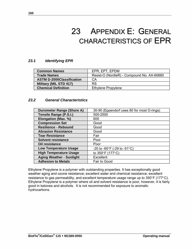
150
BioFlo®/CelliGen® 115 M1369-0050 Operating manual
2233 AAPPPPEENNDDIIXX EE:: GGEENNEERRAALL
CCHHAARRAACCTTEERRIISSTTIICCSS OOFF EEPPRR
23.1 Identifying EPR
Common Names EPR, EPT, EPDM Trade Names Resist-O (NordleR) - Compound No. AX-60660 ASTM D-2000Classification CA Military (MIL STD 417) RS Chemical Definition Ethylene Propylene
23.2 General Characteristics
Durometer Range (Shore A) 30-90 (Eppendorf uses 80 for most O-rings) Tensile Range (P.S.I.) 500-2500 Elongation (Max. %) 600 Compression Set Good Resilience - Rebound Good Abrasion Resistance Good Tear Resistance Fair Solvent resistance Poor Oil resistance Poor Low Temperature Usage -20 to -60F (-29 to -51C) High Temperature Usage to 350F (177C) Aging Weather - Sunlight Excellent Adhesion to Metals Fair to Good
Ethylene Propylene is a polymer with outstanding properties. It has exceptionally good weather aging and ozone resistance; excellent water and chemical resistance; excellent resistance to gas permeability, and excellent temperature usage range up to 350F (177C). Ethylene Propylene is a polymer where oil and solvent resistance is poor, however, it is fairly good in ketones and alcohols. It is not recommended for exposure to aromatic hydrocarbons.
151
Operating manual
2244 IINNDDEEXX
A
Acid Concentration, 142 Acid Type, 142 Adding a Utility Station, 110 Adding New Hardware, 110 Addition Tubing
Size of, 91 Aeration, 13 Agitation System, 12 Air(1), 106, 107 Airflow Control
Automatic, 13 Manual, 13
Anaerobic Culture, 118 Antifoam Formulation, 141 Antifoam Probe, 14 Autoclaving, 143
Preparing for, 85 Autoclaving the Vessel, 86, 145
B
Baffle Installation of, 35, 38, 51
Base Concentration, 142 Base Plate
Installing Vessel on, 37 Base Type, 142 Batch Operation, 117 Bearing Housing
Maintenance of, 124 BioCommand, 15, 55, 56, 115 BioFlo 115 Options
Setting the, 112 Bottom Clamping Ring
Installing the, 37
C
Cabinet Cleaning of, 122
Calibration of Touchscreen, 108
Calibration Screen, 70 Cascade
Creating a, 94 Cascade Screen, 70, 94 Certifications, 58, 59 Cleaning, 122, 147 CO2(4), 106, 107 Connecting Cabinets, 20 Connecting Stations, 20 Continuous Operation, 117 Control Cabinet
Installing the, 17 Control Cabinet Connections, 19 Control Loop
Definition of, 134 Control Station, 12 Controller
Definition of, 134 Cooling Coil
Installation of, 40 Corrosion Resistance, 149
D
Deadband, 13, 68, 92 Decline Phase, 117 Description of Vessel, 12 DO Probe
Calibration of, 81 Charging of, 114 Inspection of, 78 Installation of, 80
dO2 Probe Installation of, 44, 79
Double Filter System, 120 Drawing Index, 132 Drawings
1.3L Headplate, 31 7.5L & 14.0L Headplate, 33 Non-Jacketed Vessel, 30
152
BioFlo®/CelliGen® 115 M1369-0050 Operating manual
Sampler System, 49 Vessel Bumper Installation, 34
Drive Assembly Handling, 28
E
Electrical Connections, 23 Electrical Requirements, 23 End of Run, 119 EPR
General Characteristics of, 150 Essential Warnings, 27 Exhaust Condenser, 14, 53
Installation of, 53 Operation Tips, 120
Exhaust Filter Operation Tips, 120
Exhaust System, 14 Exponential Growth Phase, 116
F
Fed Batch Operation, 117 Feed Pumps
To Add Liquid, 101 Fermentation Run
Phases of, 116 Preparing for, 113
Fermentation Techniques, 140 Fermentor Information Sheet, 3 Filling the Water Jacket, 38 Foam Control, 14, 113 Foam Exhaust Tube
Installing the, 42 Foam Level, 14 Foam Probe
Installing the, 41
G
Gas Connections, 25 Gas Control, 106 Gas Overlay, 118 GasFlo, 107 Gauge Screen, 67 Glucose Feed Concentration, 142
H
Handling Tips, 28 Harvest Tube
Installation of, 41 Harvesting, 119 Headplate
Installation of, 52 Headplates
1.3L, 31 3.0L, 32
Heat Blanket Installation of, 34
Horsepower Factors that Affect, 138
I
Impellers Installation of, 39
Important Warnings, 27 Index of Drawings, 132 Index of Tables, 132 Information Sheet, 3 Inoculation, 114, 146 Inspection
of Boxes, 11 Installation
Gas Connections, 25 Water & Drain Connections, 24
L
Lag Phase, 116 Level Probe(s)
Installing the, 42 Level Probes
Application of, 101 Liquid Addition Systems, 90 Location
Environment, 16 Physical, 16
Loop Setpoints Entering the, 68 Modifying the, 70
M
Maintenance, 123

153
Operating manual
Maintenance Inspections, 124 Mass Flow Controller, 13 Media Formulation, 140 Microaerophilic Culture, 118 Modbus Com Port Pin Designation, 56 Motor Assembly
Installation of, 53 Motor Replacement, 124
N
N2(3), 106, 107
O
O2(2), 106, 107 Operating Control Mode
Changing the, 104 Operating Controls, 60 OTR
Calculating an, 137 Determining an, 137 Factors that Affect, 138
Out Mult, 98 Output Multiplier, 98
P
Parts Lists, 125 pH
Control of, 13 pH Probe, 13
Calibration of, 74 Inspection of, 74 Installation of, 42, 76 Maintenance of, 78 Storage of, 78
PID Explanation of Constants, 135 Explanation of Tuning, 135
Preparing for a Fermentation Run, 113 Preparing Vessel for Autoclaving, 143 Probe Calibration
Definition of, 134 Probe Cleaning, 147 Probe Removal, 147 Probe Storage, 123, 147 Process Control Settings
Recommendations for, 143 Pump Array
Standard, 96 Pump Assignment, 96 Pump Assignment Screen, 101 Pump Calibration, 99, 102 Pump Control Modes, 99 Pump Flow Rate, 99 Pump Period (sec), 100 Pump Screen, 71 Pump Setpoints, 97
R
Regulatory Compliance, 58 Removing a Utility Station, 112 Renaming Control Loops, 66 Replacement Parts, 125 Rotameter, 13 RTD, 41 RTD Probe
Installation of, 92
S
Sampler Installation of, 47
Sampler Tube Installation of, 41
Sampling, 115 Save Changes Button, 104 Saving a Process Configuration, 134, 135 Service, 129 Service Connections, 19, 23 Service/Utility
Electrical, 23 Setting Up the Vessel, 145 Setup Screen, 72, 103 Shutdown, 119, 147 Spare Parts, 125 Sparger
Installation of, 40 Start-Up Screen, 61 Steady State Phase, 117 Sterilization
Preparing for, 85 Sterilization Temperature, 87 Sterilization Time, 87
154
BioFlo®/CelliGen® 115 M1369-0050 Operating manual
Sterilizing the Vessel, 145 Summary Screen, 61 Summary Screen Features, 61 Supervisory Software, 15
T
Table Index, 132 Table of Contents, 8 Temperature
Control, 13 RTD, 13 Setpoint, 13
Temperature Probe Installation of, 92
Terminators Installation of, 21
Thermowell Installation of, 41
Touchscreen Calibrating the, 108
Troubleshooting, 129 Tubing Recommendations, 141 Tubing Size, 141
U
Unused Ports, 51 Utilities, 22 Utility Station, 12
Adding a, 110 Removing a, 112
V
Vessel Description of, 12 Installation of, 52
Vessel Assembly Non-Jacketed, 29
Vessel Assembly Precautions, 120 Vessel Bumpers, 34, 38 Vessel Cleaning, 122, 147 Vessel Operation, 146 Vessel Preparation for Autoclaving, 143 Vessel Pressurization, 25 Vessel Set-Up, 145 Vessel Shutdown, 147 Vessel Size
Changing the, 105 Vessel Stand, 34 Vessel Sterilization, 145
W
Water & Drain Connections, 24 Water Jacket
Filling the, 38 Wetted Parts, 122

Evaluate your operating manual www.eppendorf.com/manualfeedback
Your local distributor for New Brunswick products: www.nbsc.com/ContactUs New Brunswick Scientific, 175 Freshwater Boulevard, Enfield, CT 06082-4444 USA
Eppendorf AG • 22331 Hamburg • Germany • Tel: +49 40 538 01-0 • Fax: +49 40 538 01-556 • E-mail: [email protected] New Brunswick Scientific Europe B.V. • Nijmegen • The Netherlands • Tel: +31 (0) 24 3717 600 • E-mail: [email protected]
Eppendorf North America, Inc. • Hauppauge, NY • USA • Tel: +1 516 334 7500 • +1 800 645 3050 • E-mail: [email protected]
Application Support Europe, International: Tel: +49 1803 666 789 • E-mail: [email protected] North America : Tel : +1 800 645 3050 menu option 2 • E-mail: [email protected]
Asia Pacific: Tel: +603 8023 6869 • E-mail: [email protected]
Your local distributor for New Brunswick products: www.nbsc.com/ContactUs New Brunswick Scientific, 175 Freshwater Boulevard, Enfield, CT 06082-4444 USA
Eppendorf AG 22331 Hamburg Germany Tel: +49 40 538 01-0 Fax: +49 40 538 01-556 E-mail: [email protected] New Brunswick Scientific Europe B.V. Nijmegen The Netherlands Tel: +31 (0) 24 3717 600 E-mail: [email protected]
Eppendorf North America, Inc. Hauppauge, NY USA Tel: +1 516 334 7500 +1 800 645 3050 E-mail: [email protected]
Application Support Europe, International: Tel: +49 1803 666 789 E-mail: [email protected] North America : Tel : +1 800 645 3050 menu option 2 E-mail: [email protected]
Asia Pacific: Tel: +603 8023 6869 E-mail: [email protected]