new approaches to modeling failure and fracture of
TRANSCRIPT

Adv Polym Sci (2021) 286: 131–152https://doi.org/10.1007/12_2020_64© Springer Nature Switzerland AG 2020Published online: 11 December 2020
New Approaches to Modeling Failureand Fracture of Rubberlike Materials
K. Y. Volokh
Contents1 Introduction . . . . . . . . . . . . . . . . . . . . . . . . . . . . . . . . . . . . . . . . . . . . . . . . . . . . . . . . . . . . . . . . . . . . . . . . . . . . . . . . . . 1322 Failure as Onset of Damage . . . . . . . . . . . . . . . . . . . . . . . . . . . . . . . . . . . . . . . . . . . . . . . . . . . . . . . . . . . . . . . . . 132
2.1 Elasticity with Energy Limiters . . . . . . . . . . . . . . . . . . . . . . . . . . . . . . . . . . . . . . . . . . . . . . . . . . . . . . . 1332.2 Cavitation . . . . . . . . . . . . . . . . . . . . . . . . . . . . . . . . . . . . . . . . . . . . . . . . . . . . . . . . . . . . . . . . . . . . . . . . . . . . . . 1352.3 Strength of Soft Composites . . . . . . . . . . . . . . . . . . . . . . . . . . . . . . . . . . . . . . . . . . . . . . . . . . . . . . . . . . 1372.4 Prediction of Crack Direction . . . . . . . . . . . . . . . . . . . . . . . . . . . . . . . . . . . . . . . . . . . . . . . . . . . . . . . . . 140
3 Fracture as Damage Localization . . . . . . . . . . . . . . . . . . . . . . . . . . . . . . . . . . . . . . . . . . . . . . . . . . . . . . . . . . . 1433.1 Material Sink Formulation . . . . . . . . . . . . . . . . . . . . . . . . . . . . . . . . . . . . . . . . . . . . . . . . . . . . . . . . . . . . 1453.2 Dynamic Crack Propagation . . . . . . . . . . . . . . . . . . . . . . . . . . . . . . . . . . . . . . . . . . . . . . . . . . . . . . . . . . 146
4 Final Remarks . . . . . . . . . . . . . . . . . . . . . . . . . . . . . . . . . . . . . . . . . . . . . . . . . . . . . . . . . . . . . . . . . . . . . . . . . . . . . . . 148References . . . . . . . . . . . . . . . . . . . . . . . . . . . . . . . . . . . . . . . . . . . . . . . . . . . . . . . . . . . . . . . . . . . . . . . . . . . . . . . . . . . . . . . 149
Abstract In this chapter we review some recent approaches to modeling failure andfracture of soft materials. By failure we mean the onset of damage via materialinstability. By fracture we mean further localization of damage into cracks with theirsubsequent propagation.
Mathematical description of failure is simple and it only requires some boundingof the strain energy density. The bounded strain energy automatically implies thebounded achievable stress, which is an indicator of material failure. By bounding thestrain energy via energy limiters we show, for instance, how to explain cavitation,analyze strength of soft composites, and predict direction of possible cracks.
Mathematical description of fracture is more involved because it requires regu-larized formulations suppressing the so-called pathological mesh sensitivity. Mostexisting approaches utilize purely formal regularization schemes that lack physicalgrounds. We discuss a more physically based approach rooted in the idea that bulk
K. Y. Volokh (*)Faculty of Civil and Environmental Engineering, Technion – Israel Institute of Technology,Haifa, Israele-mail: [email protected]

cracks are not a peaceful unzipping of adjacent atomic layers but rather a cata-strophic explosion of bonds localized within a finite characteristic area.
1 Introduction
Failure and fracture are the central unsolved problems in solid mechanics generallyand in mechanics of soft materials particularly. In this chapter we present somerecent developments towards the solution of the problem. We emphasize the dis-tinction between the concept of failure, which we interpret as the onset of materialinstability and damage, and the concept of fracture, which we interpret as thelocalization of damage into cracks and their dynamic propagation. We stronglybelieve that the only consistent description of failure and fracture should be theone incorporated in constitutive equations. For the general theoretical backgroundand notation we refer to [1].
2 Failure as Onset of Damage
Traditional strength-of-materials approach defines material strength as the maximumstress achievable in uniaxial tension experiments. Various other criteria can beimposed on stresses or strains to define the state of failure. Importantly, such criteriaare not a part of the constitutive laws. Rather, they are extra conditions or constraintsthat should be obeyed in analysis and design in order to provide reliable mechanicalbehavior of materials and structures. The strength-of-materials approach is seem-ingly simple yet it can be dangerous. For example, the critical strains of highlystretchable elastomers are much lower in equibiaxial as compared to uniaxialtension. Thus, the criterion of the critical uniaxial stretches is not applicable tostructures under biaxial deformation. The latter notion is not always appreciatedand understood by designers.
More convincing would be a description of failure which is directly incorporatedin the constitutive law. In the latter case, there is no need to search for and obey extraconstraints and the onset of failure naturally comes out of the stress analysis. Wenote that the traditional constitutive laws for elastomers do not describe failure:numerous hyperelastic models describe the intact mechanical behavior of materials.Moreover, various restrictions (e.g. poly-convexity, strong ellipticity, Baker–Ericksen inequalities, etc. [2]) are usually imposed on the hyperelastic constitutivelaws in order to provide material stability. Such restrictions preclude from a descrip-tion of material failure. Obviously, that is not physical because all materials fail.
To describe material failure the approach of continuum damage mechanics(CDM) was developed in which a damage variable was used [3–12]. The damagevariable is an internal parameter whose physical meaning is open to debate.
132 K. Y. Volokh

Mathematically, the internal variable is utilized to reduce material stiffness duringthe damage process. The additional variable requires extra evolution equation and athreshold condition for its activation. This approach is especially appealing when theaccumulation of damage is gradual. In the case of the abrupt damage a simplerapproach is available [13] which does not require any internal variables. The latterapproach of energy limiters and its implications are considered below.
2.1 Elasticity with Energy Limiters
We assume that the local deformation of material is described by the deformationgradient: F¼Grady¼∂y∕∂x; where x2 Ω0 and y(x)2Ω denote the referential andcurrent positions of a generic material point accordingly. The linear and angularmomenta balance and the hyperelastic constitutive law read
ρ0€y ¼ DivP, PFT ¼ FPT, P ¼ ∂ψ=∂F, ð1Þ
where ρ0 is the referential mass density; €y is the acceleration; P is the first Piola–Kirchhoff stress tensor; (Div P)i¼∂Pij/∂xj; and ψ is the strain energy density.
The corresponding natural boundary condition expresses this same linearmomentum balance law on the boundary ∂Ω0,
Pn0 ¼ t0, ð2Þ
where t0 is the given surface traction and n0 is a unit outward normal to ∂Ω0.Alternatively to (2), essential boundary conditions for placements can be pre-
scribed on ∂Ω0
y ¼ y: ð3Þ
In addition, initial conditions in Ω0 complete the formulation of the problem
yðt ¼ 0Þ ¼ y0, _yðt ¼ 0Þ ¼ v0: ð4Þ
We note again that a traditional strain energy function describes material thatnever fails. Such a description directly contradicts reality. Indeed, the number ofatoms/molecules is limited within any material volume and, consequently, theirbond energy is limited. The latter notion implies that the macroscopic strain energydensity must also be limited. We emphasize that the latter conclusion is a directconsequence of the structure of matter. Introduction of the limited strain energy isnot a matter of choice – it is a physics demand.
New Approaches to Modeling Failure and Fracture of Rubberlike Materials 133
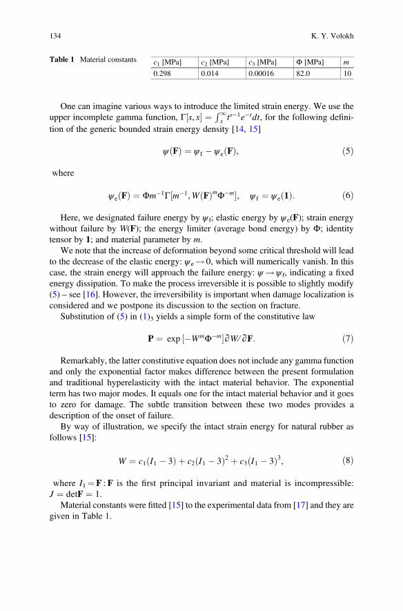
One can imagine various ways to introduce the limited strain energy. We use theupper incomplete gamma function, Γ½s, x� ¼ R1
x ts�1e�tdt, for the following defini-tion of the generic bounded strain energy density [14, 15]
ψðFÞ ¼ ψ f � ψ eðFÞ, ð5Þ
where
ψ eðFÞ ¼ Φm�1Γ½m�1,WðFÞmΦ�m�, ψ f ¼ ψ eð1Þ: ð6Þ
Here, we designated failure energy by ψ f; elastic energy by ψe(F); strain energywithout failure by W(F); the energy limiter (average bond energy) by Φ; identitytensor by 1; and material parameter by m.
We note that the increase of deformation beyond some critical threshold will leadto the decrease of the elastic energy: ψe! 0, which will numerically vanish. In thiscase, the strain energy will approach the failure energy: ψ !ψ f, indicating a fixedenergy dissipation. To make the process irreversible it is possible to slightly modify(5) – see [16]. However, the irreversibility is important when damage localization isconsidered and we postpone its discussion to the section on fracture.
Substitution of (5) in (1)3 yields a simple form of the constitutive law
P ¼ exp ½�WmΦ�m�∂W ∕∂F: ð7Þ
Remarkably, the latter constitutive equation does not include any gamma functionand only the exponential factor makes difference between the present formulationand traditional hyperelasticity with the intact material behavior. The exponentialterm has two major modes. It equals one for the intact material behavior and it goesto zero for damage. The subtle transition between these two modes provides adescription of the onset of failure.
By way of illustration, we specify the intact strain energy for natural rubber asfollows [15]:
W ¼ c1ðI1 � 3Þ þ c2ðI1 � 3Þ2 þ c3ðI1 � 3Þ3, ð8Þ
where I1¼F : F is the first principal invariant and material is incompressible:J ¼ detF ¼ 1.
Material constants were fitted [15] to the experimental data from [17] and they aregiven in Table 1.
Table 1 Material constants c1 [MPa] c2 [MPa] c3 [MPa] Φ [MPa] m
0.298 0.014 0.00016 82.0 10
134 K. Y. Volokh

The stress–stretch curve for uniaxial tension is shown on the left of Fig. 1. Thebounded strain energy automatically provides the bounded stress and the limit pointon the diagram.
This same model was also used to create the failure envelope in biaxial tension –
Fig. 1 right. The theoretical critical points were calculated from the condition of thevanishing determinant of the Hessian of strain energy [15].
In summary, we showed a simple way to account for material failure in theconstitutive law without introducing internal variables. In this case, all materialconstants can be fitted in macroscopic experiments. Despite its simplicity, theproposed formulation allows attacking various interesting problems related withthe onset of damage. Some of them are considered in the next three subsections.
2.2 Cavitation
Cavitation is the phenomenon of a sudden irreversible expansion of micro-voids intothe visible macroscopic voids. Gent and Lindley [18] nicely demonstrated thisphenomenon in tension experiments on the poker-chip rubber samples – Fig. 2left. Such thin samples exposed to uniaxial tension in out-of-plane direction exhibithighly triaxial deformation – hydrostatic tension. The hydrostatic tension, in its turn,leads to the void expansion – cavitation.
Mathematically the void expansion can be described by the following integralformula [1]:
pðλaÞ ¼R λa
1
1λ3 � 1
dψdλ
dλ, ð9Þ
Fig. 1 Left: Cauchy stress [MPa] versus stretch: dashed line denotes the intact model; solid linedenotes the model with failure. Right: Failure envelope for biaxial tension: theory (stars) versusexperiment (triangles)
New Approaches to Modeling Failure and Fracture of Rubberlike Materials 135

where p is the hydrostatic tension; λ is the hoop stretch; λa¼ a∕A with A anda denoting the initial and current radius of the void accordingly; and the strainenergy is expressed in terms of the principal stretches for incompressible material
ψðλ1, λ2, λ3Þ ¼ ψðλ�2, λ, λÞ: ð10Þ
Ultimately λa!1 and (9) should converge to the critical tension [19]
pcr ¼R1
1
1λ3 � 1
dψdλ
dλ: ð11Þ
In the case of neo-Hookean material model we define the strain energy as follows:
ψ ¼ ðμ∕2ÞðI1 � 3Þ, I1 ¼ λ�4 þ 2λ2, ð12Þ
where μ is the shear modulus.Then, substitution of (12) in (11) yields
pcr ¼ ð5∕2Þμ: ð13Þ
The latter result was used by Gent and Lindley [18] to explain the cavitationphenomenon theoretically. Such explanation proliferated in the subsequent literatureand it tacitly relies upon the following assumptions:
(a) cavitation is a purely elastic phenomenon;(b) neo-Hookean material model is applicable for analysis of large stretches;(c) the obtained critical hydrostatic tension (13) is universal for all materials with the
given initial shear modulus μ.
All these assumptions are incorrect:
Fig. 2 Left: Grown voids in the poker-chip test [18]. Right: Hydrostatic tension [MPa] versus hoopstretch for void growth
136 K. Y. Volokh

[a] if the cavitation phenomenon was purely elastic, then we would not observe itafter unloading while we do observe it;
[b] Neo-Hookean model is only relevant for very moderate stretches not exceedingvalues of 1.4 while the critical hydrostatic tension is achieved for much greaterstretches;
[c] the integral in (11) converges to the finite critical tension for the neo-Hookeanmaterial model while it does not converge for more realistic materialmodels [20].
We emphasize that the very fact of irreversibility of the void growth clearlyindicates that cavitation is related to damage and only theories describing damagecan be used for the explanation of the phenomenon. Particularly, the model withenergy limiters presented in the previous subsection can be used in (9). The tension–stretch curve for this model is presented in Fig. 2 right [21]. The horizontal line givesthe critical tension of � 2.3 MPa that can be calculated from (11). The experimentalestimate of the critical tension of about � 2.7 MPa [18] is encouraging for thetheoretical analysis. Various models without failure can be enhanced with energylimiters to provide convergence to critical tensions [20, 22]. Without the limiterssuch models would not be able to explain the cavitation phenomenon.
The role of inertia forces and viscosity in cavitation was uncovered in [23] whilethe thermal effects were considered in [24] for the first time.
We note, in passing, that the specific constitutive model for natural rubberdescribed in the previous subsection nicely fits experimental data in uniaxial, biaxial,and triaxial (cavitation) states of deformation including failure.
2.3 Strength of Soft Composites
Soft composites comprise soft matrix and reinforcements of various shapes. They areused in various applications ranging from rubber bearings to soft robots andadvanced biomedical devices. Soft biocomposites can be created, for example, bythe natural process of tissue calcification, etc. The reinforcement stiffens a softground matrix. What is the effect of reinforcement on the strength of the composite?The answer is not evident at all.
We developed micromechanical approach to analysis of the onset of failure in softcomposites combining the elasticity with energy limiters and high fidelity general-ized method of cells (HFGMC) [25].
We used the approach to study strength of an idealized calcified aneurysmaltissue [26]. Particularly, we analyzed the effect of the varying amount of calcification(10%, 40%, and 70%), i.e. the relative volume of the hard inclusion within theperiodic elementary cell, on the tissue stiffness and strength. We found that theincrease of the relative volume of calcium particles unconditionally led to thestiffening of the tissue. At the same time, the strength did not increase in the mostconsidered cases – it could significantly decrease. Quantitatively, the strength
New Approaches to Modeling Failure and Fracture of Rubberlike Materials 137
decrease could vary from 10% to 40% and more. One might find it contrary tointuition that the strength can decrease while the stiffness always increases withcalcification. This interesting finding emphasizes the difference between the con-cepts of stiffness and strength which is not always appreciated. The strength of acomposite is significantly affected by the locally nonuniform state of deformation.Small hard particles rather than big ones can be stress concentrators amplifying thelikelihood of the local material failure. Also the hard particles restrain deformation intheir vicinity creating the state of hydrostatic tension which, in its turn, may triggercavitation with the subsequent fracturing. The obtained results have limitationsbecause an ideally periodic distribution of calcified particles was assumed in com-putations while in reality the distribution is random. Thus, additional research instochastic mechanics of failure analysis is required.
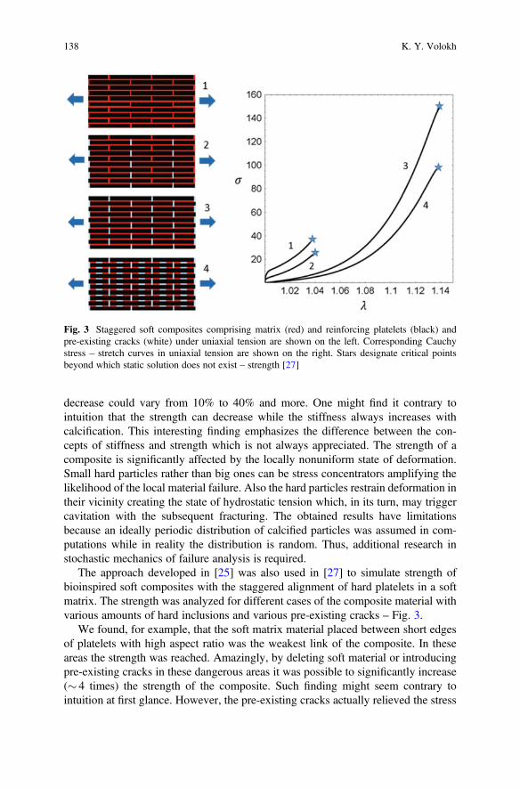
The approach developed in [25] was also used in [27] to simulate strength ofbioinspired soft composites with the staggered alignment of hard platelets in a softmatrix. The strength was analyzed for different cases of the composite material withvarious amounts of hard inclusions and various pre-existing cracks – Fig. 3.
We found, for example, that the soft matrix material placed between short edgesof platelets with high aspect ratio was the weakest link of the composite. In theseareas the strength was reached. Amazingly, by deleting soft material or introducingpre-existing cracks in these dangerous areas it was possible to significantly increase(� 4 times) the strength of the composite. Such finding might seem contrary tointuition at first glance. However, the pre-existing cracks actually relieved the stress
Fig. 3 Staggered soft composites comprising matrix (red) and reinforcing platelets (black) andpre-existing cracks (white) under uniaxial tension are shown on the left. Corresponding Cauchystress – stretch curves in uniaxial tension are shown on the right. Stars designate critical pointsbeyond which static solution does not exist – strength [27]
138 K. Y. Volokh

and strain concentrators providing greater material resistance. The main load bearingarea of the matrix became the region connecting long edges of platelets. This regionwas predominantly in the state of shear. The failure of the soft matrix in shear wasresponsible for the overall strength of the composite. Importantly, the overallstrength did not exceed the strength of the matrix material in the uniaxial tension.
In order to validate the computational analysis described above, we performedexperiments on 3D printed composites – Fig. 4.
Unfortunately, the 3D printing procedure did not allow to create the naturalrubber material used in simulations. Instead, soft interfaces were printed in softhyperelastic digital material and stiff platelets were printed in rigid VeroWhitepolymer. Samples were fabricated by using a multi-material Polyjet technique witha help of the 3D-printer Objet Connex 260. Performing the uniaxial tension testshown in Fig. 4, we observed that after reaching the critical level of loading –
point A, the soft matrix at the short platelet edges ruptured. This led to a significantdrop in stress level during the following loading up to point B. Then the sheardeformation in the soft matrix along the lengthy edges of platelets dominated untilapproximately point C soon after which the ultimate stress – strength – was reachedand material started disintegrating as at point D. This observation qualitativelysupported the numerically predicted phenomena – Fig. 3 – showing that the cata-strophic failure originated in the soft interface phase, and it had a significant
Fig. 4 Experiments with 3D printed soft composite: snapshots on the left correspond to the pointson the stress – stretch curve on the right [27]
New Approaches to Modeling Failure and Fracture of Rubberlike Materials 139

influence on the overall strength of the composite. We emphasize the qualitativerather than quantitative resemblance in view of the different matrix materials used insimulations and experiments. The resemblance is encouraging.
2.4 Prediction of Crack Direction
In this subsection, we show how to predict the onset of cracks including theirdirection by using the elasticity with energy limiters and strong ellipticity condition.
We start with a brief description of the underlying theory [28]. Designatingincrements with tildes it is possible to derive incremental equations of momentabalance and constitutive law
ρ0€~y ¼ Div~P, ~PFT þ P~FT ¼ ð~PFT þ P~F
TÞT, ~P ¼ ∂2ψ ∕∂F∂F : ~F: ð14Þ
Alternatively, these incremental equations can be reformulated in the Eulerianform where the current configuration Ω is referential
ρ€~y ¼ div~σ, ~σ þ σ~LT ¼ ð~σ þ σ~L
TÞT, ~σ ¼ : ~L, ð15Þ
where ρ¼ J�1ρ0; σ¼ J�1PFT is the Cauchy stress tensor and ðdiv~σÞi ¼ ∂~σij=∂y j;~σ ¼ J�1~PFT is the incremental Cauchy stress; ~L ¼ ~FF�1 is the incremental velocitygradient; is the fourth order elasticity tensor with Cartesian components
Aijkl ¼ J�1F jsFlr∂2ψ
∂Fis∂Fkr: ð16Þ
For the strain energy defined by (5), we further calculate
∂ψ∂Fis
¼ ∂ψ∂W
∂W∂Fis
¼ exp ½�WmΦ�m� ∂W∂Fis
, ð17Þ
and
∂2ψ∂Fis∂Fkr
¼ ∂2W∂Fis∂Fkr
� mWm�1Φ�m ∂W∂Fkr
∂W∂Fis
� �exp ½ �WmΦ�m�: ð18Þ
Substitution of (18) in (16) yields
140 K. Y. Volokh

Aijkl ¼ J�1F jsFlr∂2W
∂Fis∂Fkr� mWm�1Φ�m ∂W
∂Fkr
∂W∂Fis
� �exp ½ �WmΦ�m�: ð19Þ
We look for a plane wave solution of the incremental initial boundary valueproblem
~y ¼ rgðs � y� vtÞ, ð20Þ
where r and s are the unit vectors in the directions of wave polarization and wavepropagation, respectively; and v is the wave speed.
Substituting for ~L ¼ grad~y ¼ ∂~y∕∂y from (20) to (15)3, we get the incrementalstress ~σ . Then, substituting for ~y from (20) and ~σ to the linear momentum balance(15)1, we get
ρv2r ¼ ΛðsÞr, ð21Þ
where Λ(s) is the acoustic tensor with Cartesian components
Λik ¼ Aijkls jsl: ð22Þ
Taking scalar product of (21)with r, we obtain for the wave speed
Jρv2 ¼ Jr � Λr ¼ f 1 f 2, ð23Þ
where
f 1 ¼ f 3 � mWm�1Φ�m f 24,
f 2 ¼ exp ½ �WmΦ�m�,f 3 ¼ s jslrirkF jsFlr∂
2W ∕∂Fis∂Fkr,
f 4 ¼ rkslFlr∂W ∕∂Fkr:
ð24Þ
The positive wave speed corresponds to the mathematical condition of the strongellipticity of the incremental initial boundary value problem. Zero wave speedmathematically means violation of the strong ellipticity condition and, physically,it means inability of the material to propagate a wave in direction s. The latter notioncan also be interpreted as the onset of a crack perpendicular to s.
Consider, for example, longitudinal wave (P-wave) and transverse wave (S-wave)in plane of a material sheet. Denoting the unit vectors in the plane by e1 and e2, wecan write
New Approaches to Modeling Failure and Fracture of Rubberlike Materials 141

s ¼ r ¼ cos αe1 þ sin αe2 ð25Þ
for the P-wave and
s ¼ cos αe1 þ sin αe2,
r ¼ � sin αe1 þ cos αe2ð26Þ
for the S-wave, where α is unknown angle in plane.Then, we have from (23) for the vanishing wave speed
Jρv2ðF, αÞ ¼ f 1ðF, αÞ f 2ðFÞ ¼ 0: ð27Þ
This condition can be explained mathematically as follows. The Rayleigh quo-tient rule for the given s states that z � Λ(s)z∕(z �z) is minimized by the first eigen-vector z¼ r and ζ¼ r � Λ(s)r∕(r �r) is its minimum value, which is the smallesteigenvalue of Λ(s). Obviously, this eigenvector r might not obey conditions of thelongitudinal (r¼ s) or transverse (r �s¼ 0) waves. However, the situation changeswhen we assume the minimum value in advance: ζ¼ r � Λ(s)r¼ 0. In this particularcase both longitudinal and transverse waves can be found by the direct solution of r �Λ(s)r¼ 0. Any r providing the zero minimum eigenvalue becomes thecorresponding eigenvector. The very existence of the longitudinal (r¼ s) or trans-verse (r �s¼ 0) waves comes directly from the computation itself.
The described approach was used to predict the onset of cracks and their directionin a series of publications [29–32].
Bridge rubber bearings undergo a simultaneous compression and shear underearthquakes and cracks appear in them in the direction of shear – Fig. 5. Such shearcracks were predicted by the analysis described above [29].
This analysis included the assumption of material incompressibility. However,the incompressibility constraint suppresses longitudinal waves and, thus, valuableinformation about cracks can be missed. The latter issue was explored in [30] wherethe incompressibility constraint was abandoned. It was found, indeed, that the
Fig. 5 Great East Japan Earthquake in 2011: bridge rubber bearings on the left and the horizontalcrack is observed on the right [33]
142 K. Y. Volokh
constraint could turn into a Trojan Horse in the analytical calculations and animportant information about cracks could be missed. Particularly, in the cases ofuniaxial tension and pure shear, it was found that namely longitudinal waves helpedto predict cracks perpendicular to the direction of tension. Amazingly, it was alsofound that the transverse wave led to the prediction of cracks whose direction wasclose to the direction of tension. The latter prediction seemed unrealistic; however,such cracks in the direction of tension were found in recent experiments [34]!
The onset of cracks in anisotropic soft materials – arterial wall – was consideredin [31, 32]. Particularly in [32], we developed two constitutive models with 16 and8 structure tensors to account for anisotropy and failure of the wall. The intactmaterial behavior was calibrated based on the experimental data for human adven-titia and energy limiters were introduced to describe failure. These models were usedin analysis of the loss of strong ellipticity in uniaxial tension and pure shear incircumferential and axial directions of the artery and in biaxial tension. Directions ofpossible cracks were obtained from the condition of the vanishing speed of thesuperimposed longitudinal and transverse waves. The vanishing longitudinal wavespeed predicted the appearance of cracks in the direction perpendicular to tension inuniaxial tension and pure shear. As in the case of isotropic material discussed above,such prediction would be suppressed by the incompressibility constraint. Thevanishing transverse wave speed predicted the appearance of cracks in the directioninclined to tension in uniaxial tension and pure shear. Equibiaxial stretching can leadto the appearance of cracks in any direction despite the anisotropy of material. Theinclined cracks oriented along the bundles of collagen fibers have been found inexperiments [35].
3 Fracture as Damage Localization
Fracture in the form of cracks was first considered by Griffith [36]. Analogously tothe strength-of-materials approach, he suggested a criterion of growth of pre-existingcracks based on the global energy balance. Such integral balance ignores the role ofthe strain and stress concentrations at the tip of the crack and, therefore, it is open tocriticism [37]. There are various conceptual approaches to fracture in the literature.We believe that fracture should be incorporated in the constitutive description ofmaterials and crack initiation and propagation should be an outcome of the solutionof the clearly formulated initial boundary value problems. In this spirit, there are twomain approaches to modeling fracture – surface and bulk crack models.
Surface crack models, or cohesive surface models (CSM), consider continuumenriched with discontinuities along surfaces with additional traction-displacement-separation constitutive laws [37–47]. If the location of the separation surface isknown in advance (e.g. fracture along weak interfaces), then the use of CSM isnatural. Otherwise, the insertion of cracks in the bulk in the form of separationsurfaces remains an open problem, which includes definition of criteria for cracknucleation, orientation, branching, and arrest. Besides, the CSM approach presumes
New Approaches to Modeling Failure and Fracture of Rubberlike Materials 143

the simultaneous use of two different constitutive models: one for the cohesivesurface and another for the bulk, for the same real material. Certainly, a correspon-dence between these two constitutive theories is desirable yet not promptlyaccessible.
Bulk crack models, or continuum damage mechanics (CDM), introduce failure inconstitutive laws in the form of the falling stress–strain curves [48–55].1 Damagenucleation, propagation, branching, and arrest naturally come out of the constitutivelaws. Unfortunately, numerical simulations based on bulk failure laws show theso-called pathological mesh sensitivity, which means that finer meshes lead tonarrower damage localization areas. In the limit case, the energy dissipation indamage tends to zero with the diminishing size of the computational mesh. Thisphysically unacceptable mesh sensitivity is caused by the lack of a characteristiclength in the traditional formulation of continuum mechanics. To surmount the latterpitfall gradient- or integral-type nonlocal continuum formulations are used where acharacteristic length is incorporated to limit the size of the spatial damage localiza-tion [56–60]. In the gradient-type approaches, for example, an additional internaldamage variable is introduced together with additional differential equation ofreaction-diffusion type. This equation has a small parameter – the characteristiclength – as a scaling factor for the highest spatial derivatives of the damage variable.The characteristic length provides solution of the boundary layer type. This layer isinterpreted as a diffused crack of finite thickness rather than a surface ofdiscontinuity.
A special choice of the additional regularizing equation, called phase-fieldapproach, gained popularity in recent years [61–63]. It is claimed that the phase-field formulation provides convergence of the diffused crack to the surface ofdiscontinuity under the decrease of the characteristic length. Thus, the characteristiclength is interpreted as a purely numerical parameter which can be varied. However,the case of the uniform uniaxial tension shows that, in the phase-filed formulation,the characteristic length is a physical parameter linked to material strength2 and itcannot be varied. Thus, the phase-field approach is a possible yet not superiorregularization of the gradient type.
The regularization strategy rooted in the nonlocal continua formulations is attrac-tive because it is lucid mathematically. Unluckily, the generalized nonlocal continuatheories are based (often tacitly) on the physical assumption of long-range particleinteractions while the actual particle interactions are short-range – on nanometer orangstrom scale. Therefore, the physical basis for the nonlocal models appearsdisputable. A more physically based treatment of the pathological mesh sensitivityof the bulk failure simulations should likely include multi-physics coupling. Such a
1These works were not devoted to soft materials per se.2For example, the authors of [63] rightfully note that “although the length-scale parameter associ-ated with the phase-field approximation is introduced as a numerical parameter it is, in fact, amaterial parameter that influences the critical stress at which crack nucleation occurs.”
144 K. Y. Volokh

theory coupling mass flow (sink) and finite elastic deformation is considered in thenext subsections.
3.1 Material Sink Formulation
We can see crack surfaces and we rightfully conclude that these surfaces are a resultof material separation. However, people usually and tacitly make one more logicalstep and assume that the separation is a result of debonding of two adjacent atomic ormolecular layers – Fig. 6 left. At the first thought, the latter assumption is thesimplest one and it appeals to intuition. At the second thought, it is possible torealize that the assumption is wrong because cracks are visible by a naked eye –
Fig. 6 middle. Indeed, if the separation was between two adjacent atomic layers, thenwe would not see closed cracks because our eye can only distinguish objects on thescale of microns and not angstroms. Thus, the crack surfaces are not created by twoadjacent atomic layers – they are created by a massive bond breakage spread over aregion with characteristic length l – Fig. 6 right.
It is crucial to realize that the process of the bond breakage is diffusive rather thanconfined to one atomic plane. Some atoms fly out of the bulk material. Generally, wecannot see them because of their very small amount (as compared to the bulk).Sometimes, we can see them – remember the dust which comes out of cracks inbrittle concrete. The characteristic length of the damage region is so big in the lattercase that we can see small pieces of concrete that left the bulk during fracture.
Summarizing the qualitative picture of the crack formation we note that materialsinks within the characteristic small region of damage. Such notion gives rise to themathematical formulation in which momenta and mass balance are coupled [64].
Thus, the mass balance equations should be coupled with (1)1,2 in Ω0
Divs0 þ ξ0 ¼ 0, ð28Þ
where s0 and ξ0 are the referential mass flux and source (sink) accordingly.The corresponding natural boundary condition expresses this same mass balance
law on the boundary ∂Ω0
Fig. 6 Left: idealized crack with zero thickness; middle: visible closed crack in unloaded tire; right:realistic bulk crack with finite thickness l
New Approaches to Modeling Failure and Fracture of Rubberlike Materials 145

s0 � n0 ¼ 0: ð29Þ
We note that we use the mass balance in the reduced form: Divs0 + ξ0¼ 0; insteadof the general form: _ρ0 ¼ Divs0 þ ξ0 ; because we are only interested in pre- andpost-cracked states while the transition – bond rupture – process is so fast that it canbe ignored. Such simplification is analogous to consideration of the buckling processin thin-walled structures. In the latter case, pre- and post-buckled states of a structureare usually analyzed by using a time-independent approach while the very process ofthe fast dynamic transition to the buckled state is ignored in analysis by dropping theinertia terms from the momentum balance equation.
We define constitutive equations for the stress [64]
P ¼ ðρ0=ρ0Þ∂W ∕∂F, ð30Þ
mass sink
ξ0 ¼ βρ0HðγÞ exp ½�WmΦ�m� � βρ0, ð31Þ
and mass flux
s0 ¼ κHðγÞ exp ½�WmΦ�m�JðFTFÞ�1Gradρ0, ð32Þ
where ρ0 ¼ ρ0ðt ¼ 0Þ is the initial referential density; β > 0 and κ > 0 are materialconstants; H(γ) is a unit step function, i.e. H(γ)¼ 0 if γ < 0 and H(γ)¼ 1 otherwise;the switch parameter γ 2 (�1, 0] is necessary to prevent from material healing and itis defined by the evolution equation _γ ¼ �Hðε� ρ0=ρ0Þ , γ(t¼ 0)¼ 0 where0 < ε� 1 is a dimensionless precision constant.
It is important to emphasize that the formulation presented in this subsection is ageneralization of elasticity with energy limiters described above. Indeed, the elas-ticity with energy limiters emerges as a particular case where there is no damagelocalization via diffusion of broken bonds. In the latter case, we have the vanishingmass flux: s0¼ 0; and sink: ξ0¼ 0. In view of the zero material sink we calculatefrom (31): ρ0=ρ0 ¼ HðγÞ exp ½�WmΦ�m� . Since the irreversibility of the processis not important in this case and H(γ)� 1, we further simplify: ρ0=ρ0 ¼exp ½�WmΦ�m� . Substitution of the latter formula in (30) yields: P ¼exp ½�WmΦ�m�∂W ∕∂F, which coincides with (7).
3.2 Dynamic Crack Propagation
Most works on modeling cracks consider quasi-static crack propagation. Yet inreality, most cracks propagate dynamically unless they are highly restrained. Indeed,the onset and localization of damage are usually related to the loss of the static
146 K. Y. Volokh

stability of a structure. The process of crack propagation becomes dynamic. Thelatter notion is not properly appreciated in the literature and many authors preferstatic analysis over the dynamic one because of its relative simplicity rather thanphysical adequacy. A review of the crack propagation in rubberlike materials can befound in [65].
We implemented the material sink formulation presented above in analysis ofdynamic crack propagation in aneurysm material and we refer to [66] for details.Nevertheless, we note that substitution of constitutive equations (31) and (32) in themass balance law (28) yields the following second order partial differential equationwith respect to the referential mass density, ρ0,
l2DivfHðγÞ exp ½�WmΦ�m�JðFTFÞ�1Gradρ0g
þρ0HðγÞ exp ½�WmΦ�m� � ρ0 ¼ 0:ð33Þ
Remarkably, we do not need to know material constants κ and β separatelyanymore. We only need to know their ratio, which gives us the characteristic length
l ¼ ffiffiffiffiffiffiffiffiκ=β
p: ð34Þ
Such length serves as a small multiplier for the highest (second) spatial derivativeof the mass density and, consequently, it causes solution of the boundary layer type.This boundary layer regularizes the crack width suppressing the pathological meshsensitivity.
Some results of modeling propagation of a single crack and bridging of twocracks are shown in Fig. 7. These simulations led to the following interestingconclusions.
First, the inertia forces play crucial role at the tip of the propagating crack. Ifinertia is not canceled together with the material stiffness, then cracks tend tononphysically widen with the increasing speed of their propagation. Most existing
t = 150 ms t = 170 ms
ba
t = 200 ms
Fig. 7 (a) Propagation of Mode 1 crack in aneurysm material in current (top) and referential(bottom) configurations; (b) crack bridging and kinking
New Approaches to Modeling Failure and Fracture of Rubberlike Materials 147

models of cracks completely ignore this fact and they do not cancel inertia when theycancel stiffness. Remarkably, the very recent works based on the phase-field formu-lations [67, 68] started recognizing the importance of canceling inertia. Needless tosay, the simultaneous cancellation of stiffness and inertia are a direct consequence ofthe material sink formulation presented in this chapter.
Second, the proposed material sink formulation allows suppressing the strong orthe classical pathological mesh-dependence linked to the zero energy fracture. Thelatter is due to the fact that the augmented initial boundary volume problem enforcescharacteristic length and solutions of the boundary layer type. The boundary layer,associated with the crack thickness does not vanish under the mesh refinement.
Third, we observed a weak mesh-dependence, which we defined as the effect ofthe mesh shape and size on the specific crack pattern. We observed that variousmeshes caused slightly different crack patterns for the same amount of dissipatedenergy. The weak mesh-dependence remained even after a significant mesh refine-ment, which showed that the regularized formulations were not a universal solutionfor any mesh sensitivity as many would expect. The weak mesh-dependence issimilar to the effect of structural inhomogeneities in real materials, which affectthe crack path depending on the specific sample under consideration. Though allsamples are made of the same material they have various microstructural patternsand, consequently, slightly different propagating cracks.
4 Final Remarks
We presented review of our recent developments concerning analysis of failure andfracture in soft materials. Approaches for modeling failure and fracture are different.Failure is identified with the onset of material instability and damage. We consideredsuch instability as a direct consequence of the bounded strain energy density. Thebounded strain energy, in its turn, follows from the fact that the number of physicalparticles and their integral bond energy are limited. We presented a general formulaallowing for the enforcement of energy bounds in the known hyperelastic models ofsoft materials and we called it elasticity with energy limiters.
After the onset, material damage localizes into cracks and they propagate. We callthis process fracture. To model fracture, we introduced an augmented formulation, inwhich momenta and mass balance are coupled. The mass balance equation reflectsupon the physical fact that broken bonds are diffused in the area of characteristic sizerather than confined to a single atomic plane. The mass balance equation regularizesnumerical simulations creating solutions of the boundary layer type and suppressingthe pathological mesh-dependence. The latter means that refining the mesh onewould not be able to reduce fracture energy to zero.
It is remarkable that the approaches described in the present work are based ontwo physical observations only: bond energy is bounded and broken bonds arediffused. Based on these observations it was possible to formulate theories of failureand fracture without introducing any internal variables.
148 K. Y. Volokh

Acknowledgment This research was supported by the Israel Science Foundation (grant No.394/20).
References
1. Volokh KY (2019) Mechanics of soft materials. Springer, Singapore2. Truesdell C, Noll W (2004) The non-linear field theories of mechanics. Springer, Berlin3. Simo JC (1987) On a fully three-dimensional finite strain viscoelastic damage model: formu-
lation and computational aspects. Comp Meth Appl Mech Eng 60:153–1734. Govindjee S, Simo JC (1991) A micro-mechanically based continuum damage model of carbon
black-filled rubbers incorporating the mullins effect. J Mech Phys Solids 39:87–1125. Johnson MA, Beatty MF (1993) A constitutive equation for the Mullins effect in stress
controlled in uniaxial extension experiments. Cont Mech Therm 5:301–3186. Miehe C (1995) Discontinuous and continuous damage evolution in Ogden-type large-strain
elastic materials. Eur J Mech A/Solids 14:697–7207. De Souza Neto EA, Peric D, Owen DRJ (1998) Continuum modeling and numerical simulation
of material damage at finite strains. Arch Comp Meth Eng 5:311–3848. Ogden RW, Roxburgh DG (1999) A pseudo-elastic model for the Mullins effect in filled rubber.
Proc Roy Soc Lond Ser A 455:2861–28779. Menzel A, Steinmann P (2001) A theoretical and computational framework for anisotropic
continuum damage mechanics at large strains. Int J Solids Struct 38:9505–952310. Guo Z, Sluys L (2006) Computational modeling of the stress-softening phenomenon of rubber
like materials under cyclic loading. Eur J Mech A/Solids 25:877–89611. De Tommasi D, Puglisi G, Saccomandi G (2008) Localized vs diffuse damage in amorphous
materials. Phys Rev Lett 100:085502.12. Dal H, Kaliske M (2009) A micro-continuum-mechanical material model for failure of rubber-
like materials: application to ageing-induced fracturing. J Mech Phys Solids 57:1340–135613. Volokh KY (2013) Review of the energy limiters approach to modeling failure of rubber.
Rubber Chem Technol 86:470–48714. Volokh KY (2007) Hyperelasticity with softening for modeling materials failure. J Mech Phys
Solids 55:2237–226415. Volokh KY (2010) On modeling failure of rubberlike materials. Mech Res Commun
37:684–68916. Volokh KY (2014) On irreversibility and dissipation in hyperelasticity with softening. J Appl
Mech 81:07450117. Hamdi A, Nait Abdelaziz M, Ait Hocine N, Heuillet P, Benseddiq N (2006) A fracture criterion
of rubber-like materials under plane stress conditions. Polym Test 25:994–100518. Gent AN, Lindley PB (1959) Internal rupture of bonded rubber cylinders in tension. Proc Roy
Soc A 2:195–20519. Ball JM (1982) Discontinuous equilibrium solutions and cavitation in nonlinear elasticity. Phil
Trans Roy Soc Lond A 306:557–61020. Lev Y, Volokh KY (2016) On cavitation in rubberlike materials. J Appl Mech 83:04450121. Volokh KY (2011) Cavitation instability in rubber. Int J Appl Mech 3:2931122. Volokh KY (2015) Cavitation instability as a trigger of aneurysm rupture. Biomech Model
Mechanobiol 14:1071–107923. Faye A, Rodrguez-Martnez JA, Volokh KY (2017) Spherical void expansion in rubber-like
materials: the stabilizing effects of viscosity and inertia. Int J Non-Linear Mech 92:118–12624. Lev Y, Faye A, Volokh KY (2019) Thermoelastic deformation and failure of rubberlike
materials. J Mech Phys Solids 122:538–554
New Approaches to Modeling Failure and Fracture of Rubberlike Materials 149

25. Aboudi J, Volokh KY (2015) Failure prediction of unidirectional composites undergoing largedeformations. J Appl Mech 82:071004
26. Volokh KY, Aboudi J (2016) Aneurysm strength can decrease under calcification. J MechBehav Biomed Mater 57:164–174
27. Slesarenko V, Volokh KY, Aboudi J, Rudykh S (2017) Understanding the strength ofbioinspired soft composites. Int J Mech Sci 131–132:171–178
28. Volokh KY (2017) Loss of ellipticity in elasticity with energy limiters. Eur J Mech A Solids63:36–42
29. Mythravaruni P, Volokh KY (2018) Failure of rubber bearings under combined shear andcompression. J Appl Mech 85:074503
30. Mythravaruni P, Volokh KY (2019) On incompressibility constraint and crack direction in softsolids. J Appl Mech 86:101004
31. Volokh KY (2019) Constitutive model of human artery adventitia enhanced with a failuredescription. Mech Soft Mater 1:8
32. Mythravaruni P, Volokh KY (2020) On the onset of cracks in arteries. Mol Cell Biomech17:1–17
33. Takahashi Y (2012) Damage of rubber bearings and dumpers of bridges in 2011 great EastJapan earthquake. Proceedings of the International Symposium on Engineering, LessonsLearned from the 2011 Great East Japan Earthquake, March 1–4, Tokyo, Japan
34. Lee S, Pharr M (2019) Sideways and stable crack propagation in a silicone elastomer. PNAS116:9251–9256
35. Sugita S, Matsumoto T (2017) Local distribution of collagen fibers determines crack initiationsite and its propagation direction during aortic rupture. Biomech Model Mechnobiol17:577–587
36. Griffith AA (1921) The phenomena of rupture and flow in solids. Philos Trans R Soc Lond A221:163–198
37. Volokh KY, Trapper P (2008) Fracture toughness from the standpoint of softeninghyperelasticity. J Mech Phys Solids 56:2459–2472
38. Barenblatt GI (1959) The formation of equilibrium cracks during brittle fracture. General ideasand hypotheses. Axially-symmetric cracks. J Appl Math Mech 23:622–636
39. Needleman A (1987) A continuum model for void nucleation by inclusion debonding. J ApplMech 54:525–531
40. Rice JR, Wang JS (1989) Embrittlement of interfaces by solute segregation. Mater Sci Eng A107:23–40
41. Tvergaard V, Hutchinson JW (1992) The relation between crack growth resistance and fractureprocess parameters in elastic-plastic solids. J Mech Phys Solids 40:1377–1397
42. Camacho GT, Ortiz M (1996) Computational modeling of impact damage in brittle materials.Int J Solids Struct 33:2899–2938
43. de Borst R (2001) Some recent issues in computational failure mechanics. Int J Numer MethEng 52:63–95
44. Xu XP, Needleman A (1994) Numerical simulations of fast crack growth in brittle solids. JMech Phys Solids 42:1397–1434
45. Moes N, Dolbow J, Belytschko T (1999) A finite element method for crack without remeshing.Int J Num Meth Eng 46:131–150
46. Park K, Paulino GH, Roesler JR (2009) A unified potential-based cohesive model of mixed-mode fracture. J Mech Phys Solids 57:891–908
47. Gong B, Paggi M, Carpinteri A (2012) A cohesive crack model coupled with damage forinterface fatigue problems. Int J Fract 137:91–104
48. Kachanov LM (1958) Time of the rupture process under creep conditions. Izvestiia AkademiiNauk SSSR, Otdelenie Teckhnicheskikh Nauk 8:26–31
49. Gurson AL (1977) Continuum theory of ductile rupture by void nucleation and growth: partI-yield criteria and flow rules for porous ductile media. J Eng Mat Tech 99:2–151
150 K. Y. Volokh

50. Voyiadjis GZ, Kattan PI (1992) A plasticity-damage theory for large deformation of solids—I.Theoretical formulation. Int J Eng Sci 30:1089–1108
51. Gao H, Klein P (1998) Numerical simulation of crack growth in an isotropic solid withrandomized internal cohesive bonds. J Mech Phys Solids 46:187–218
52. Klein P, Gao H (1998) Crack nucleation and growth as strain localization in a virtual-bondcontinuum. Eng Fract Mech 61:21–48
53. Lemaitre J, Desmorat R (2005) Engineering damage mechanics: ductile, creep, fatigue andbrittle failures. Springer, Berlin
54. Volokh KY (2004) Nonlinear elasticity for modeling fracture of isotropic brittle solids. J ApplMech 71:141–143
55. Benzerga AA, Leblond JB, Needleman A, Tvergaard V (2016) Ductile failure modeling. Int JFract 201:29–80
56. Pijaudier-Cabot G, Bazant ZP (1987) Nonlocal damage theory. J Eng Mech 113:1512–153357. Lasry D, Belytschko T (1988) Localization limiters in transient problems. Int J Solids Struct
24:581–59758. Peerlings RHJ, de Borst R, Brekelmans WAM, de Vree JHP (1996) Gradient enhanced damage
for quasi-brittle materials. Int J Num Meth Eng 39:3391–340359. de Borst R, van der Giessen E (1998) Material instabilities in solids. Wiley, Chichester60. Silling SA (2000) Reformulation of elasticity theory for discontinuities and long-range forces. J
Mech Phys Solids 48:175–20961. Francfort GA, Marigo JJ (1998) Revisiting brittle fracture as an energy minimization problem. J
Mech Phys Solids 46:1319–134262. Hofacker M, Miehe C (2012) Continuum phase field modeling of dynamic fracture: variational
principles and staggered FE implementation. Int J Fract 178:113–12963. Borden MJ, Verhoosel CV, Scott MA, Hughes TJR, Landis CM (2012) A phase-field descrip-
tion of dynamic brittle fracture. Comp Meth Appl Mech Eng 217–220:77–9564. Volokh KY (2017) Fracture as a material sink. Mater Theory 1:365. Persson BNJ, Albohr O, Heinrich G, Ueba H (2005) Crack propagation in rubber-like materials.
J Phys Condens Matter 17:R1071–R114266. Faye A, Lev Y, Volokh KY (2019) The effect of local inertia around the crack tip in dynamic
fracture of soft materials. Mech Soft Mater 1:467. Chen CH, Bouchbinder E, Karma A (2017) Instability in dynamic fracture and the failure of the
classical theory of cracks. Nat Phys 13:118668. Agrawal V, Dayal K (2017) Dependence of equilibrium Griffith surface energy on crack speed
in phase-field models for fracture coupled to elastodynamics. Int J Fract 207:243–249
New Approaches to Modeling Failure and Fracture of Rubberlike Materials 151