new 12a7 tube in midget - world radio history
TRANSCRIPT
REG. U.S. PAT. OFF.
The First National Radio Weekly - 639th Issue 13th. Year
JUNE 23rd 1934
15c Per Copy
Short - Wave Inductances
New 12A7 Tube in Midget
A Station - Finder
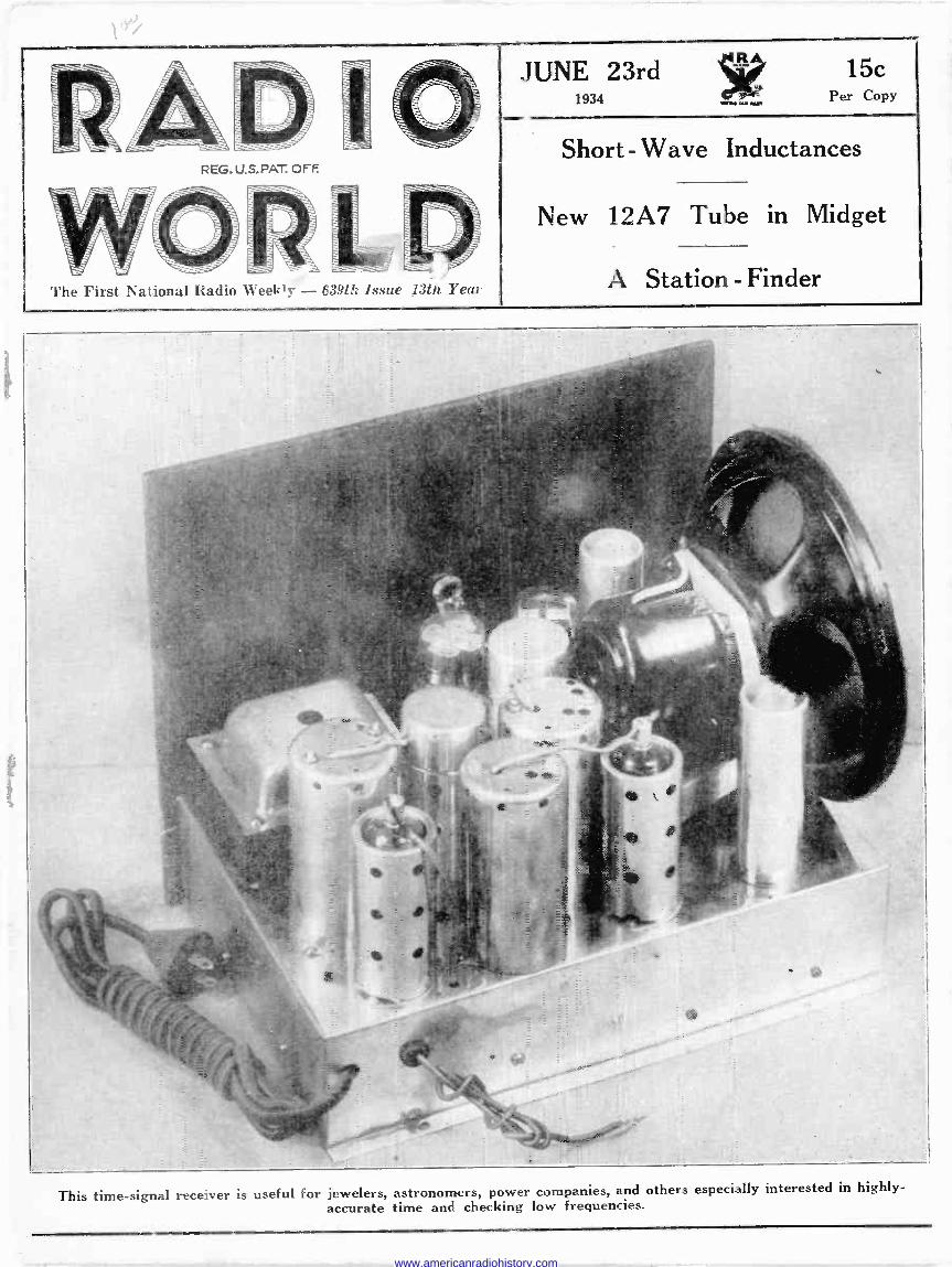
This time -signal rets -_ver is useful for jewelers, astronomers, power companies, and others especially interested in highly - accurate time and checking low frequencies.
www.americanradiohistory.com

RADIO WORLD June 23, 1934
1,645 to 3,530 Kc Chart for Hammarlund 0.00014 Mfd. c id Green -Ringed Alden Coil
/600
/700
/800
1900
Z000
2/00
ZL00
2300
2400
2300
2600
,2700
2800
2900
3000
.3/00
3200
5300
3400
3500
3600
non mIIIUIIIIIUIIHinilill 111I
WIIIIIIhIIIINIINIIIIIIIIIIIIIIIIIIIIiIl1IIaIIIII,IIIIIIIIIIIIIlllllll W®®IIiIIIIIlllllll,IllllIlIII81IIIllIWIW11IIi I11111 IIIIIINI!!lIIII
®IBIIlllllllll NIINÌIiIIIIIIIIINIIIIIWIIIIIIIBIIIIIIIflIiIuIIIIIIIIIlI11iiI8II
II1111111111III111P11131111I111111I111W 1111W11 i11111111111111iI111
IIII 11111I
N11 I l 1111
úI11 Ii11Il ÿW
HEW NII11i1III
1111111"U11111111ff
::._i ''il: ir nu NIII
1111W111t1111. ` I r`aII!! !!W® '
:
1111!lI11II1111 Illllllllll!iIiii'IJÍt'°'I !11l111l111111111WIÍ1l11111111111Wú'u11111111111 !11í1111111
111111
I &Iran Rai RIME.
0 5 /0 /5 ¿0 .Z5 50 35 40 45 50 55 60 65 70 75 80 85 90 95 /00
With this issue is begun publication of a series of charts relating frequencies to the dial settings for the popular Hammarlund 0.00014 mfd. condenser of the single -hole panel mounting type. This is a midline condenser and is not be confused with the straight capacity line small condensers made by the same manufacturer. As so many readers have short-wave sets using the Hammarlund condenser of this midline type, and commercially - wound plug-in coils, the information thus imparted as to where frequencies will come in on the dial is vastly important, especially since all the popular makes of plug-in coils will be charted in connection with this condenser. There are four charts to any series relating a particular condenser to the short-wave coils used. The next two higher frequency brackets for the Alden coils and this condenser will be found on pages 19 and 20,
while the highest -frequency band will be given next week, issue of June 30th.
DISPOSAL OF R.C.A. SHARES Only 7.5 per cent of the outstanding common
stock of the Radio Corporation of America is now owned by the Westinghouse Electric and Manufacturing Company and the General Electric Company. At the time the Federal consent decree that dissolved the relationship between the electrical companies and R.C.A. was entered into on November 21st, 1932, these companies owned 61 per cent. General Electric Co. distributed to its stockholders on February 20th, 1933, exactly 4,807,321 of its 5,188,755 common shares in the R.C.A., while the Westinghouse Company dis- posed of 1,334,000 of its 2,842.950 common shares in the R.C.A. to its stockholders. Nineteen months remain in which to dispose of the rest of their holdings.
LITERATURE WANTED
A. C. Boettcher, 1725 West Center St., Milwaukee Wisc.
W. L. Reed, 701 South Park St., Shawnee, Okla. J. Van Henderson, care Security Nataional Bank
Greensboro, N. C. Joseph L. Berry, 140 Reiman St., Buffalo, N. Y J. A. Pons, P. O. Box No. 1156, Havana, Cuba. Joseph Gutowski, 31 Main St., South River, N. J. Wayne Clay, Prop., The Radio Laboratories, 402
East Elm St., Springfield, Mo. H. C. Boss, 1354 E. Harvard St., Glendale, Calif.
SPARKS-WITHINGTON BUSY Plants of the Sparks-Withington Company, of
Jackson, Mich., are reported by Harry Sparks, vice-president, to be operating twenty-four hours a day, with unfilled orders on its books exceeding those at any time since the fall of 1928. More than 9,000 automobile horns are being turned out daily; also production is expanding in the re- frigerator and radio plants.
* * * Stewart -Warner Corporation and Subsidiaries-
Net profit for the quarter ended March 31, 1934, after taxes, depreciation and other charges, $167,495, which equals 13 cents a share on 1,246,847 $10 par capital shares. This contrasts with a net loss in the first quarter of 1933 of $775,005. Total sales were $4,045,721, compared with $1,462,531.
www.americanradiohistory.com
June 23, 1934 RADIO WORLD 3
"JIFFY 3" Short Wave Set Worldwide Earphone Reception
3 Tube self - contained BAKELITE base, RESISTANCE COUPLED thru- out so that it can be ASSEMBLED in a JIFFY. Almost no wiring needed. Wonder set for amateurs and experi- menters. 2-30's and a 32; the latter tube controls both regeneration and
detection. Smooth, clear, quiet performance assured. Offering complete BAND -SPREAD TUNING and LOW CURRENT drain.
KIT including 4 short
$6.25 wave coils, tubes extra, $1.50.
Wired, $7.75
RELIABLE RADIO CO., 145 West 45th St., N. Y. City
They Work! FILTER CONDENSERS
Here is a dry electrolytic self - healing condenser of 8 mfd. capacity which will give long, hum -free service in power supplies. The condenser is intended for use with an operating voltage of 400 volts, or slightly over, but will withstand a peak voltage of 600.
Type D Condenser, 99c RELIABLE RADIO CO.
143 West 45th St. New York, N. Y.
Power Transformer
for a BIG SET
INSTEAD of using undersized, over- heating, inefficient power transformers for a big set, why not use a cool -
running, efficient transformer and pay the little extra? The Reliable transformer, Model 104 -SP, will work an 18 -tube set. Provides also the voltage for a 25Z5 rectifier.
Primarp 115 v., 60 cycles Secondary X = 14 amp., 254 v., et. secondary Y = 6 amp., 254 y., et.
Secondary R = 5 v., et. Secondary 11V = 400-0-400 v., 200 ma.
Secondary Z = 25 ., 0.6 ma. Lug terminais at bottom
Price, $3.95 Shipping weight, 13 lbs.
Immediate Delivery
RELIABLE RADIO CO. 145 W. 45th St., New York, N. Y.
"AMATEUR MOVIE CRAFT," by James R. Cameron. A book dealing with the making and shcwing of 16 m/m pictures and equipment neces- sary for same. Paper cover, $1.00; Cloth, $L50. Radio World, 145 W. 45th St., New York N Y
ANDERSON'S AUTO SET
l)esignad by J. E. ANDERSON
FOREIGN RECEPTION ON 6 -INCH AERIAL
This new auto let le the most affinitive ear receiver we have ever tome stroll. Mexican and Canadian station were tuned L from New York City on a s -inch aerial. The circuit. as I -tuba euperbeterodwne, with automatic volume control.
Complete set, which Includes set chassis and let sntald battery box. remote control. battery sabla, all condensers. emitters and colli, speaker with shielded cable; and a kit of RCA tubes (two 139. two 136, two tbl, one 89. and one fig t are supplied less aerial.
Wired model, licensed by RCA. with complete equipment, leer aerial, but including RCA tubes. Cat. 898-W $37.40
RELIABLE RADIO CO. 143 West 45th St. N. Y. City
"DYKE'S AUTOMOBILE AND GASOLINE EN- GINE ENCYCLOPEDIA," by A. L Dyke. New 16th Edition, covering all the latest developments. A complete training in every part of automotive work, and for easy study is divided into a series of 85 simple instruction, 1,339 pages, 4,40 illus- trations and diagrams. 654 x 9 4. Includes chap- ters on Free Wheeling and Radio Receiving Equip- ment for Autos. Cloth, $6.00, Flexible, $7.50_
Radio World. 145 W. 45th St., New York City.
TUBE SHIELDS FREE! Send $1.50 for a 13 -
week subscription for Radio World and get, free, eight (8) tube shields suitable for the 57, 58 and other modern tubes. Subscription Dept., Radio World, 145 West 45th St., New York, N. Y.
24 Years of CONDENSER LEADERSHIP
THE basic refinements which made Hammar- lund Condensers the first choice of radio pioneers, still make the new models the
unchallenged preference of today's leaders. There is a Hammarlund Condenser for every receiving and transmitting need --single, dual, double-spaced and "band -spread" tuning - all so moderately priced there is no excuse for "economizing" on condensers of lesser prestige.
Write Dept. RW for Complete 1934 Catalog
HAMMARLUND MFG. CO. 424-438 West 33rd Street New York
3m. 2a.ttith. T2 a c{ is ammarlunä
PRECISION PRODUCTS
RADIO WORLD, 145
SHORT-WAVE MATERIAL Issue of May 26, 1934-Two-Tube Short -Wave
Battery Set, with Resistance Coupled Audio; Nine -Tube All -Wave Superheterodyne, with AVC; Modulation of Waves (Part III of "The Short - Wave Authority").
Issue of June 2, 1934 --Calibration of Short -Wave Receivers (4 Charts); A Precision Calibration Process; Aerials for Short Waves (Part IIV of "The Short -Wave Authuority").
Issue of June 9, 1934-Two Short -Wave Receivers Using 25Z5; Precision Calibration of High Fre- quencies; The 19 -Tube for Short Waves; Short - Wave Midget; Short -Wave Tuners (Part V of "The Short -Wave Authority").
Issue of June 16, 1934-Finding Frequencies in a Small Short -Wave Set; Tuning Charts for All Plug-in Coils; The Mascot "Two" Short -Wave Set; Types of Receivers Used for Bringing in Short Waves (Part VI of "The Short -Wave Authority"). 15c a copy; or start subscription with any ante of
these issues. Radio World, 145 W. 45th St., New York, N. Y.
"SERVICING RECEIVERS BY MEANS OF RESISTANCE MEASUREMENT"
by John F. Rider The new printing is ready for delivery. Right in line with the latest type of testing equipment offered by Weston, Supreme, Hickok and Reed -
rite. All interested in resistance measurement method of servicing and who use their ohmmeter or who are purchasing the new type of point-to- point testing equipment produced by Weston and the other manufacturers, and the selective - reference -point type of testing equipment as pro- duced by Supreme, can make very good use of SERVICING RECEIVERS BY MEANS OF RESISTANCE MEASUREMENT.
Still selling at $1.00 Book Dept., RADIO WORLD
145 West 45th Street New York City
TEST OSCILLATOR THIS
Test Oscillator, Model 30-N, is service. able for all intermediate frequencies from 135
k.c. up, and all broadcast frequencies, for lining up the receiver channels. It is constantly modula- ted and the same instrument works on 90-120 volts a.c. (any line frequency), line d.c. or bat- teries. Frequencies from 135 to 1,520 k.c. are direct -reading and never more than 1% oE. Model 30-N is contained in shield cabinet. Etched metal scale is non -warping. Oscillator sent free (complete with 30 -tube, ready to operate) on receipt of $12 for a 2 -year subscription for Radio World (104 issues, one each week). Order Cat. ]0- N.
West 45th Street, New York, N. Y.
www.americanradiohistory.com

RADIO WORLD June 23, 1934
Introducing .. 2 NEW POWERTONE RECEIVERS
Duo Amplydyne "Scout" Portable S.W. Receiver Tune in 2 -Tube AC -DC
S.W. Receiver Stations
from All Parts
of the World
For the Short -Wave enthusiast with a limited finance. Radically new -two -tube results with the new '19 2 -volt series tube. Covers from 15 to 550 meters Complete kit of parts $4.95 Wired (extra), $1.00. Licensed RCA tubes, 88c. Set of headphones, 95c. B. C. coil (200-550 meters), 39c.
Covers the short-wave range from 15-550 meters. Powertone the first to use the new '79 tube. Extremely light in weight. Compartment for extra coils, headphones. Complete kit of $6.95 parts Carrying case, $1.46. Headphones, 95c. RCA licensed tube, $1.25. Wired, $2.00 extra.
i
TRY -1440 II 4 DIO CO., INC. 179 GREENWICH STREET, NEW YORK, N. Y.
Branch: 85 Cortlandt St., New Yore- City
"ACCEPTED -THE WORLD OVER" As a standard of quality, performance and economy by amateurs, experimenters and engineers who know. The name BUD means the highest engineering standards. A complete line of dependable, high fidelity components.
BUD LO -COIL KITS Wound on special low loss bakelite extended rib forms. Winding is space wound, 90 percent air core. Greatly increases short wave efficiency. Dia- grams packed in each Kit.
No. 222-4 Prong Coil Kit (16-200 meters) $3.00 No. 224 -Broadcast Coil (185-360 meters) .75 No. 223 -Broadcast Coil (350-565 meters) .75 No. 916-5 Prong Kit (16-200 meters) 3.50 No. 917 -Matched R.F. and Det. Coil Kit consisting of 8 Coils (14-200
meters) 6.75 No. 918-6 Prong Coil Kit (16-200 meters) 3.75 No. 960 -Broadcast Coil (185-360 meters) 1.00 No. 961 -Broadcast Coil (350-565) meters) 1.00
HY-FREQ. R.F. CHOKES For all types of high frequency receivers and low powered trans- mitters. Continuous four pie wind- ing, mounted on Isotex.
Cat. No. I 920 I 922 I 923 I 924
Induct. M. H. Dist. Cap. MMF. D. C. Res. Ohms Cur't Rating M.A Price
.
2.5 I 5.5 I 8 I 10
1 I 2 I 2.5 I 3
45 160 I 72 I 78 125 I100 I100 1100
.60 I.75 I.80 I.85
BASE or PANEL SOCKETS
Moulded of finest low loss bakelite. Genuine phospher bronze contacts, grooved tube guide.
No. 264 4 Prong $ .30
No. 265-5 Prong .35
No. 266-6 Prong .40
No. 267-7 Prong (Reg.) .45
No. 885-7 Prong (Small) .45
Listed above are but a few of the items in the complete BUD line. Write for our 1934 Catalog! All list prices shown in this advertisement are subject to 40% discount when purchase is made from an authorized BUD jobber. If your jobber cannot supply BUD parts, send your order direct to us together with your jobber's name and we will make shipment. direct.
BUD RADIO INC. 1CLEVELAND, ST OHIO
T
°RADIO TROUBLE SHOOTING," E. R Haan.
j61 pages. 300 illustrations. $3. RADIO WORLD 145 W. 45th., N. Y. City.
RADIO WORLD AND RADIO NEWS. Both for one year, $7.00. Foreign $8.50. Radio World, 145 W. 45th St., N. Y. City.
-sue ALL -WAVE AIR SCOUT
Y Onl Set of Its Kind in the World Designed by H. G. CISIN, Inventor of the Universal A.C.- D.C. Circuit
-,r e.r si' " THIS
powerful little set brings in all standard
broadcast stations and also pollee calls, foreign stations, code and trans -atlan- tic phone conversations. Powered by inexpensive batteries. Available in KIT form. Novel ter- minal color coding feature eliminates need for wiring diagram. Red is connected to red, black to black, etc., and set is ready to operate. Used by thousands of Boy Scouts. Scout John Stott of Sanford. Me., brought in England, Holland, Ger- many and South America on this set.
COMPLETE KIT with tube, Earphone. Two. Colle, clear instructions, valuable data, etc. NOTHING ELSE TO BUY except $5.00 inexpensive batteries POSTPAID COMPLETE KIT, same as above, but less earphone POSTPAID $4.50 ASSEMBLED. WIRED AND READY TO USE. INCLUDING PHONE, less batteries, $5.95 Postpaid
RELIABLE RADIO COMPANY 143 West 45th St. New York City
BIZMII 1MM IMIn
SPECIAL Set of 16 "1934 Design"
IlIUF PRINTS
Short Wave Receivers Short Wave Converter Tuners, P.A. Systems Broadcast Receivers
For Limited MIIC Time Only
Add Sc for postage. 10e for foreign
RELIABLE RADIO CO. 145 W. 45th St., New York City
Quick -Action Classified
Advertisements 7c a Word -$1.00 Minimum
RADIO SERVICEMEN WANTED! An opportunity to train for only 50c. Offer consists of service instructions and League privileges. P. C. Produc- tion Co., 453 N. 3rd St., San Jose, Calif.
le EACH, MDNEY MAKING IDEAS; free infor- mation, Cronin, 144 Flint, Rochester, N. Y.
"RADIO AND TELEVISION," by James R. Cameron. Over 540 pages, 275 illustrations; cloth bound. The subject of radio and television covered in such a manner that it is easily understood even by a beginner. Price $4.00. RADIO WORLD, 145 West 45th St., New York City.
NEW RADIO AMATEURS HANDBOOK, 180,000 words, 207 illustrations, 218 pages (10th edition, issued 1933). Issued by the American Radio Relay League. Price. $1.00 per copy. Radio World, 145 West 45th Street, New York, N. Y.
HENLEY'S "TWENTIETH CENTURY BOOK OF RECIPES, FORMULAS & PROCESSES." New 1933 Edition. Ten thousand processes, recipes, trade secrets and money -making formulas. For the laboratory, workshop, factory and home. Some subjects fully covered: Dyes, Inks, Waterproofing, Perfumes, Cement, Plating, Glass, Dentifrices, Varnishes, Soaps, Glues, Paints, Adhesives, En. smelling, Hairdressings, Cosmetics, Oils. Price, $4.00. Book Dept., Radio World, 145 W. 45th St.,
Vol. XXV. June 23rd, 1934. No. 15. Whole No, 639, RADIO WORLD, published weekly by Hennessy Radio Publications Corporation, 145 West 45th Street, New York, N. Y. Editorial and executive offices, 145 West 45th Street, New York, N. Y. Executives of RADIO WORLD: Roland Burke Hennessy, editor and
business manager; Herman Bernard, managing editor; J. E. Anderson, technical editor. Officers of corporation: Roland Burke Hennessy, president and
Treasurer; M. B. Hennessy, vice-president; Herman Bernard, secretary. Entered as second-class matter March, 1922, at the Post Office at New York, N. Y., wei.. A -+ ,.s ""^--`3 o,,.
www.americanradiohistory.com

ROLAND BURKE HENNESSY Editor
HERMAN BERNARD Managing Editor
OA REG.U.So/.T OFF.
flL1 D The First National Radio Weekly
THIRTEENTH YEAR
J. E. ANDERSON Technical Editor
J. MURRAY BARRON Advertising Manager
Vol. XXV JUNE 23d, 1934 No. 15. Whole No. 639
Published
OFFICERS: Roland Burke Hennessy, President and Treasurer.
M. B. Hennessy, Vice - President.
Herman Bernard, Secre- tary.
Weekly by Hennessy Radio Publications Corporation, 145 West 45th Street, New York, N. Y.
Editorial and Executive Offices : 145 West 45th Street, New York Telephone: BR -gant 9-0558
Entered as second-class matter March, 1922, at the Post Office at New York, N. Y., under Act of March 3 1879. Title registered in U. S. Patent Office. Printed in the United States of America. We do not assume any responsibility for unsolicited manuscripts, photographs, drawings, etc., although we are careful with them.
Price, 15c per Copy; $6.00 per Year by mail. $1.00 extra per year in foreign countries. Subscribers' change of ad- dress becomes effective two weeks after receipt of notice.
SHORT-WAVE ASPECTS of Inductance, Capacity and Resistance
By J. E. Anderson and Herman Bernard [This is the seventh instalment of "The Short -Wave Authority."
The eighth will appear next week.-EDITOR.]
ANY electrical circuit, or portion of such a circuit, has three properties ; inductance, capacity, and resistance. A coil is supposed to have inductance exclusively, yet it has both
capacity and resistance. A condenser is supposed to have capacity only, but every condenser has also inductance and resistance. And a resistor, supposed to be the seat of resistance only, has both inductance and capacity. A device is called an inductor (coil), or condenser, or a resistor according to the property it is supposed to have predominantly. But it may not have the same property at all frequencies. For instance, a coil may be an in- ductor at low frequencies, yet may become a condenser at high frequencies. A resistor may also change to a condenser as the frequency becomes high. In dealing with short-wave circuits it is necessary constantly to keep in mind that the properties are distributed.
Inductance If electric current flows through a conductor a magnetic field
is set up about that conductor.. The total magnetic flux about the conductor per unit of current is a measure of the inductance. The same applies to an entire circuit. Since there can be no current unless there is a closed circuit, the inductance of a cir- cuit is the total magnetic flux threading the circuit per unit of current. The inductance of a coil can be measured by noting the change in the total inductance of a circuit when the coil is inserted or removed. It can also be measured by substitution, that is, by first inserting the coil under test in a given circuit and then substituting a known and adjustable inductor in its place, adjusting until the known has the same effect as the un- known had when it was in the same position.
For certain simple forms of conductors the inductance can be computed with the aid of well-known formulas. If all the fac- tors affecting the inductance are taken into account, the com- puted inductance will be the same as that obtained by measuring by substitution, assuming that the standard was correct. When the form of the conductor is irregular it is not possible to com- pute the inductance, but it is still possible to measure it.
In dealing with inductance it is common practice to put a coil in a circuit and assume that the measured or computed value of the inductance of this coil is the total inductance in the cir- cuit. We have just found that this is not the case, for the con- ductors closing the circuit also have some inductance, and even a condenser has some. Therefore the effective inductance in the closed circuit will be greater than the inductance of the coil alone, and the frequency of resonance if the circuit is periodic will be lower than that computed by using the inductance of the coil and the capacity of the condenser.
Broadcast Frequencies
For frequencies in the broadcast band and for lower fre- quencies, the difference between the actual frequency of reso-
nance and that obtained by using the computed value of the inductance of the coil is small and usually negligible. But for frequencies much higher than broadcast frequencies, that is, higher than 1,600 kc, the inductance of the connecting leads is often of the same order of magnitude as the inductance of the coil inserted in the circuit. Large errors must be expected. In- deed, it is entirely unpractical to attempt accurate computations at the short-wave frequencies.
One fact that should be kept in mind is that a coil is not always an inductor, but may be a condenser. A coil may be in- serted in the circuit for its supposed high reactance, yet the reactance may be low due to the fact that the coil has become a condenser. Instead of inserting a choke in the line, then, we insert a condenser and only aggravate a condition the coil was intended to remove.
The self -capacity of a coil depends on the size of the coil, size of the wire, the separation between the turns, and on the materials used for coil form and wire insulation. In designing an inductance coil, whether it is to be used in a tuned circuit or in a filter, the self -capacity should be kept as low as possible. This will be accomplished by making the coil form as small as practicable, by using air for insulation for the most part, and by separating the turns. A choke coil that is to be used at very high frequency should be wound in sections' having a shape some- what like a coin, the sections should be mounted coaxially with an axial separation of about one-fourth inch, and the sections should then be connected in series aiding. A coil so constructed will have a negligible self -capacity even at frequencies as high as 30,000 kc, yet it may have a comparatively high inductance.
Selection of Inductance In designing receivers the question of choice of inductance
always comes up, and several times for each set at that. Well, how much inductance should be used? We have to know what the function of the coil is before we can answer the question. Is the coil to be used for tuning or for choking?
Suppose that the purpose of the coil is filtering. The first re- quirement then is that it have as high reactance as possible. But reactance is a direct function of frequency, and therefore we must know the frequency at which it is to function. We then have to make the reactance at this frequency as high as practicable or necessary. In case the coil is to be used in a circuit where the frequency will vary, we usually select the lowest frequency as the frequency at which the coil is to have a certain reactance, for then it will have a higher reactance at all other frequencies, if we assume negligible self -capacity.
A filter or choke coil is usually employed in shunt with some other device, such as a resistor or a condenser. The inductance then will depend on the reactance of this device. The choke should have such a high inductance that when it is connected in shunt with some device there should be a negligible lowering of the total reactance. If the coil is used in series with some other device, the choke should have an inductance so high that
(Continued on next page)
www.americanradiohistory.com
6 RADIO WORLD June 23, 1934
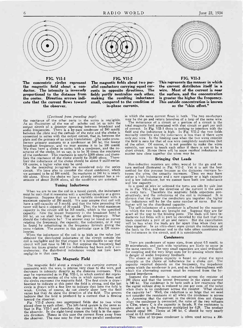
FIG. VII -1 The concentric circles represent the magnetic field about a con- ductor. The intensity is inversely proportional to the distance from the center. Direction arrows indi- cate that the current flows toward
the observer.
FIG. VII -2 The magnetic fields about two par- allel conductors carrying equal cur- rents in opposite directions. The fields partly neutralize each other, making the resulting inductance small, compared to the condition of
in -phase currents.
(Continued from Preceding page) the reactance of the other parts in the series is negligible. As an illustration of the use of achoke coil let us take the output circuit of a detector operating between broadcast and audio frequencies. There is a by-pass condenser of 500 mmfd. between the plate and the cathode of the tube and the choke is connected in series with the output circuit, that is, between the plate and the primary of an audio transformer. he audio trans- former primary amounts to a condenser at 540 kc, the lowest broadcast frequency, and we may assume it to be 100 mmfd. We then have a choke in series with a condenser, and the re- actance of the choke, let us say, is to be 10 times the reactance of the condenser. This reactance is nearly 3,000 ohms and there- fore the reactance of the choke should be 30,000 ohms. There- fore the inductance of the choke should be about 9 millihenries. Of course, a higher value may be used.
In the preceding paragraph we considered only the series circuit. We have also to consider the shunt condenser, which we assumed to be of 500 mmfd. Its reactance at 540 kc is nearly 600 ohms. S'ince the choke we have already selected has a re- actance of about 30,000 ohms, all the conditions are satisfied.
Tuning Inductance
When we, are to use the coil in a tuned circuit, the inductance must be such that it resonates with a specified capacity at a given frequency. Suppose that we have a variable condenser with a maximum capacity of 350 mmfd. We may assume that coil will have a self -capacity of 5 mmfd. and that the tube preceding the tuner will have a capacity of 10 mmfd. Then the total maximum capacity in the circuit will be 365 mmfd., which is the specified capacity. Now the lowest frequency in the broadcast band is 540 kc, so we shall take that as the given frequency. What should the inductance be? The answer may be found on curves relating the frequency, the capacity, the inductance, or it may be found by substituting in the frequency formula giving the same relation. The answer in this particular case is 238 micro - henries.
When the inductance of the coil is as high as the value just obtained the distributed inductance of the circuit outside the coil is negligible and for that reason it is permissible to say that circuit will just tune to 540 kc. But suppose the frequency had been ten times greaterand the inductance had been only 2 mi- crohenries; the distributed inductance would not have been negligible in that case.
The Magnetic Field
The magnetic field about a straight wire carrying current is concentric with the wire, is intense very close to the wire, and decreases in intensity directly as the distance increases. This may be represented as in Fig. VII -1, in which central dot repre- sents the cross-section of the wire in which current flows and the circles represent the magnetic field. The first circle is drawn heaviest to indicate at this point the field is strong, and the last circle is drawn with a fine line to indicate that here the field is weak. Circles, of course, do not clearly show how the field varies but they do show the direction of the field. The arrows indicate that the field is produced by a current that is flowing toward the observer.
Fig. VII -2 shows two superposed fields due to two wires placed close to each other. The left-hand system is the same as that in Fig. VII -1 and therefore the current is flowing toward the observer. In the right-hand system the field is in the oppo- site direction. Hence in this case the current flows away from the observer. The case may be that of two parallel conductors
FIG. VII -3 This represents the manner in which the current distributes itself in a wire. Most of the current is near the surface, and the concentration is greater the higher the frequency. This outside concentration is known
as the "skin effect."
in which the same current flows in both. The two conductors may be the go and return branches of a loop of the same wire.
The inductance of a circuit or a portion of a circuit is the total magnetic field associated with that circuit or part per unit of current. In Fig. VII -1 there is nothing to interfere with the field and the inductance is high. In ' Fig. VII -2 the two fields mutually interfere and the inductance is less than if there were only one wire. In the limiting case when the two wires coincide the field is zero for that of one wire completely neutralizes that of the other. Of course, it is not possible to make the wires coincide, nor even to touch each other if there is not to be a short circuit. Hence there will be some residual inductance no matter how close together the wires may be.
Bringing Out Leads Non -inductive resistors are often wound by the go and re-
turn method illustrated in Fig. VII -2. Yet it is not the best method for this purpose because as the distances decrease be- tween the wires the capacity increases. Thus we may have either a high inductance and a now capacity or a high capacity and a low inductance, but we cannot have both low inductance and low capacity.
In a spool of wire nor solenoid the turns are side by side just as in Fig. VII -2, but the direction of the current is the same in every turn. Therefore the magnetic fields superpose con- structively, and the inductance of the coil is increased. It is obvious that the closer the conductors are together the higher the inductance will be for the same number of turns. But the higher will be the distributed capacity.
The self-inductance of a condenser is affected by the manner in which the two leads are brought out. Suppose they are far apart all the way to the binding posts. The leads will have in- ductance but fields will in part be canceled by the fact that the leads constitute a pair of go and return. But the cancellation will be less when the leads are far apart than when they are close together. In an ultra -short wave circuit the inductance of the leads to the condenser and to the tube often constitutes all the inductance in the circuit, and it is considerable.
Condensers There are condensers of many sizes, from about 0.5 mmfd. to
50 microfarads, and such wide variations are likely to occur in the same receiver. The very small capacities are used ordinarily for coupling and the very large ones for by-passing where there is danger of audio frequency feedback.
The choice of bypass capacity is based on about the same principle as the choice of inductance for a choke coil. The capacity required depends on the frequency, the impedance across which the condenser is put, and on the thoroughness with which the alternating current must be removed from the by- passed impedance.
Suppose the condenser is connected across the resistor of 300 ohms and that the lowest frequency in the signal current is 540 kc. The condenser is to have such a low reactance that the signal voltage drop is reduced to one per cent. of the value when there is no condenser across the resistor. What should the capacity be? Well, the reduction is so large that we need not consider the resistance at all when the condenser is across it. Assuming that the current in the circuit does not change when the condenser is connected, the ratio of the two voltages is CRw, where C is the capacity in farads, R the resistance in ohms and w is the frequency multiplied by 6.28. The product should equal 100. Hence at 540 kc, C should be very nearly equal to 0.1 microfarad.
This value of by-pass condenser is often used across a 300-
www.americanradiohistory.com

June 23, 1934 RADIO WORLD 7
ohm bias resistor for a 58 tube, for example; but the reduction in the radio -frequency voltage is hardly enough to prevent oscil- lation in some instances, not without additional filtering. Con- densers of the order of 1.0 or 2.0 mfd. do the filtering properly across small resistors.
The Coupling Condenser
When a small condenser is used for coupling the required capacity also depends on the frequency and on the impedances surrounding it. While it is customary to say that the small con- denser is used for coupling, it would be more nearly correct to say that it was used for uncoupling, at least in some instances. Suppose there are two resonant circuits tuned to the same fre- quency and that they are not coupled inductively or resistively. A very small condenser is then connected between the high potential sides of the circuit, the other sides of the circuits being at ground potential. Are the two circuits coupled now, that is, will energy be transferred from one to the other? The answer depends on what we mean by circuits. We can call the entire combination one circuit. In that case if there is current in any portión it will necessarily flow in all the circuit. Or we can say that there are three meshes in the complex circuit in which the middle mesh consists of the two tuning condensers and the coupling condenser. On this view the two tuning condensers are the coupling condensers, for they are the elements which constitute common impedances. It seems that the latter view is the more logical and that the so-called coupling condenser aids in the formation in a coupling link or coupling mesh.
Regardless of how the coupling is looked upon the two reso- nant loops are loosely coupled together if the coupling condenser is very small and closely coupled if it is large. The smaller the condensers in the tuned circuits are, the smaller must the coup- ling condenser be in order that the coupling should have a speci- fied low value. That is, the required value of the coupling capacity for a specified degree of coupling depends as much on the tuning condensers as on frequency.
The choice of condenser for a tuner in which the tuning is
done by varying the capacity depends on the frequency range to be covered. It is usually desirable to have the capacity at any one setting as small as practical, and this requires that the minimum capacity in the circuit be as small as possible and that the tuner does not cover a wire frequency range than is neces- sary.
Capacity Ratios
The present broadcast band ranges from 540 ke to 1,600 kc, making the ratio of the highest to the lowest frequency 2.96. The capacity ratio in the tuner, that is, the ratio of the maxi- mum to the minimum capacity, should be the square of this, namely, 8.78. About the lowest minimum capacity that can be obtained in a shielded tùned circuit operating between two vacuum tube amplifiers is 25 mmfd., but in most practical cases more is allowed. Let us assume that the minimum is 45
mmfd. The maximum should then be 45 x 8.78, or 395 mmfd. Of the total minimum about 15 mmfd. would be outside the tuning condenser. Therefore the maximum capacity of the con- denser alone would be 380 mmfd.
This capacity is larger than the usual tuning capacities in broadcast sets by approximately 25 mmfd. Suppose the maxi- mum capacity of a tuning condenser is 350 mmfd. and- that the distributed capacity in the circuit outside the' condenser is 15
mmfd. What must the minimum capacity in the circuit be if the present broadcast band is to be covered? The maximum capacity will be 365 mmfd. and therefore the minimum must be 365/8.78, or 41.6 mmfd. That value is easily obtainable and for that reason it is not difficult to cover the present broadcast band with the tuning condenser that was designed for a slightly nar- rower band,
When the tuner is to operate at only one frequency, as in the case of the intermediate frequency selector of a superhetero- dyne, highest sensitivity will be obtained if the total tuning capacity is as small as practical; and the smallest possible is the sum of the self capacity of the coil and the tube capacity. If the coil and the tube are shielded, this might be as high as 50 mmfd. Besides this minimum there must be a trimmer with which to effect tuning, and this might have a maximum capacity of 50 mmfd. With the added condenser the mini mum capacity might be of the order of 70 mmfd. The tuning col should have such inductance that it would resonate near this minimum.
Condenser Construction
Any two conductors placed near and insulated from each other form a condenser. One of the conductors may be the earth, so that a single conductor will have capacity.
The capacity of any condenser depends on the effective area of the opposing conductors, the distance between them, and on the dielectric constant of the insulator separating them. The capacity is directly proportional to the area, inversely propor- tional to the distance between them, and directly proportional to the dielectric constant.
A tuning condenser usually is of the air dielectric type, and in such a condenser the capacity depends only on the area of the plates facing each other and the distance between them, for the dielectric constant of air is unity. Naturally, a condenser
FIG. VII -4
The regenerative detector at left in this figure repre- sents inductance in the secondary and tickler, resistance in the grid leak and capacity in the tuning condensers
and grid condenser.
cannot have 100 per cent. air insulation, for the plates must be held firmly at a given distance apart, and this can only be done with rigid insulation. Insulators used for holding the opposing plates at definite distances apart are bakelite, mica, hard rubber, glass, porcelain, quartz, and many other materials that are suffi- ciently rigid and which at the same time do not introduce losses. In a well constructed tuning condenser possibly only one per cent. of the insulation is other than air, and the solid insulators are placed in weak electric fields so as to minimize losses. The least amount of the solid insulator that will satisfy the mechani- cal requirements is the best electrically.
In so-called paper condensers the two conductors take the form of thin metal foils and the insulator is a thin strip of paper impregnated with some oil or wax. Two strips of foil and two of paper are stacked up alternately and then rolled firmly together. After the winding the condensers are impreg- nated with wax.
Paper condensers made in this manner may be either induc- tive or non -inductive, depending on how the terminals are con- nected to the metal foils. If the terminals are connected to the ends of the foils, the inductance is comparatively high because then the condenser simulates a coil. But if the termi- nals are connected to the sides of the foils, and along the entire length, one terminal being brought out at one side and the other terminal at the other side, the inductance is practically zero.
Formation of Electrolytics
If the by-pass condenser is to be used in circuits where only low frequency currents flow, it makes little difference which type of condenser is used, for the inductance is negligible in either case. Cost of the condenser would be the determining factor. If, on the other hand, the condenser is to be used for by-passing high frequency currents, only the non -inductive type will do, for otherwise the condenser might act as a choke.
When extremely large capacities are required it becomes uneconomical to use paper condensers and electrolytic conden- sers are used in their place. They are made by immersing thin sheets of pure aluminum in certain solutions and passing a current through the solution and the metal sheets. A thin layer of aluminum oxide is formed on the positive plate and this layer forms the dielectric. Because the layer is extremely thin the capacity of the condenser is very large per unit of conductor surface.
This thickness of the film, and therefore the capacity of the condenser, depends on the voltage used in forming the layer. For a very thin film the capacity is very large, but then the condenser cannot be used for high voltages. If the forming voltage is high, the capacity is small, comparatively, because then the film is thick. Such a condenser can be used on high voltages. The highest voltage that can be used depends on the electrolytic and on the kind of metal employed, the limit being between 400 and 600 volts.
Leakage Current
There is always some leakage current through an electrolytic condenser. This is very small if the aluminum electrodes are pure. Very small amounts of impurities, such as other metal particles, will increase the leakage current because no oxide film will form on these impurities. While a high leakage current is detrimental, a small leakage is essential, apparently, to maintain the film of oxide.
The leakage current is a function of the voltage across the terminals of the electrolytic condenser. Thus at 400 volts and below the current may be 5 microamperes per farad while at 500 volts it may be ten times as great. As the voltage increases the increase in the leakage current is very rapid.
Electrolytic condensers have polarity, for the oxide film has formed on the positive electrode. If the polarity is reversed, the oxide film breaks down, and the condenser ceases to func- tion. It is very important that the polarity be observed because
(Continued, on next page)
www.americanradiohistory.com

8 RADIO WORLD June 23, 1934
(Continued from preceding page) if the voltage is reversed, a heavy current will flow and this will cause heating in the condenser, which, if prolonged, might end in an explosion.
The capacity of an electrolytic condenser depends not only on the active surface of the conductor and the thickness of the film, but also on the frequency. The capacity is greatest at zero frequency, but it decreases only slowly as the frequency in- creases. Just the same, the effective capacity of an electrolytic condenser at radio frequency is only a small part of the capacity at low frequencies. Besides, the effective series resistance of the condenser may be high at radio frequencies, whereas at audio frequencies the resistance may be negligible. Because of the low capacity and the - high resistance at radio frequencies, electrolytic condensers are not used at these frequencies. When both low and high frequencies are to be by-passed, it is common to connect a small mica or paper condenser in shunt with the electrolytic.
Resistance If a current I is flowing in a circuit or conductor and energy
is lost at the rate of W watts, the resistance is R = W/I2, that is, the ratio of the power lost to the square of the current. This definition is quite general and applies to direct current as well as alternating current of any frequency. The loss need not represent a conversion of electrical energy into heat energy in the wire, for part of the energy may become radiant, when it would not be a loss at all, but only energy absorbed from the source. In certain cases the energy radiated is really lost, because the radiation takes place where it is not desired. As an example, an open transmission line radiates a little energy all along the line, and that is lost because it does not get to the antenna where it could be radiated usefully.
The resistance of wires and other forms of conductors is well known for the metals and most alloys in respect to direct cur- rent, but it is not the same for alternating current; and the higher the frequency the greater is the deviation from the direct -current values.
The increase in resistance as the frequency increases is mostly due to what is known as the "skin effect." When the current is rapidly alternating it cannot penetrate into the interior of a conductor because of the formation of eddy currents. The current density decreases very rapidly as the distance from the surface increases. Fig. VII -3 gives an idea how the current density decreases, although the decrease is so rapid at high frequencies that it is impossible to make a true representation.
Penetration of Wire by Current It is clear that the concentration of the current near the
surface of the conductor increases the resistance, for it is the equivalent of decreasing the cross-section of the wire. About 98 per cent. of the total current flows in an extremely thin layer near the surface. That this is the case is brought out by numerical examples. If the conductor is heavy and Of copper it can be proved that the current density is reduced to 2 per cent. of its surface value at a depth given by d= 26.1/n% cm, where n is the frequency of the current. Since the current density decreases rapidly, it is obvious that although the current density has been reduced to 2 per cent., the percentage of current deeper than d is very much less than 2 per cent. of the total current. If we assume that the frequency is one million cycles, the depth is 0.261 mm; and if we assume that the frequency is 100 million cycles, the depth is only 0.0261 mm.
The penetration depends not only on the frequency but also on the conductivity of the material and on the magnetic permea- bility. The greater the conductivity the less the penetration. Thus if we had taken silver the penetration would have been less than what we ,found above, but if we had taken a lead conductor, which has a low conductivity, the pentration would have been much greater. Had we selected iron with a high permeability, the penetration would have been practically zero even at one million cycles. The penetration is greatest in non- magnetic conductors of low conductivity, but the skin effect is the greatest in conductors of conductivity and high permeability.
Use of Stranded Wire It is clear that mere avoidance of skin effect is not desirable
in a conductor when the loss is to be low. Nothing is gained by using a conductor of low conductivity. The only way to avoid the skin effect advantageously is to break up the con- ductor so that no appreciable eddy currents can flow. Stranding the conductors as is done in Litz wire will break up the eddy cúrrents and will increase the effective conducting area, pro- yided the frequency is not excessive. Unfortunately, it is not practical to use this wire at ultra -high frequencies, for the losses are usually greater with stranded wire than with solid. This is due to the fact that the individual strands cannot be made fine enough to avoid surface concentration of current and to the fact that necessary insulation of the individual strands introduces losses.
Proximity Effect All the loss of energy from a coil carrying high frequency
current does not occur because of resistance in the wire. We
A Piezo Using Rochelle Salt
By J. E. USES of the piezo-electric effect are multiplying rapidly.
The two main applications are to frequency control and microphones. For frequency control quartz crystals are
used for the most part, but tourmaline is used occasionally for the higher frequencies. For microphones Rochelle salt crystals are used because these crystals show by far the greatest effect.
A noteworthy development in piezo-electric microphone design has been made by the Brush Development Co., Cleveland, O. To get a clear idea of the principle on which the microphone works let us review the properties of the Rochelle crystal. In Fig. 1 we have a section of such a crystal and the three axes of figure, aa, bb, and cc. A slice of the crystal in the form of a parallelopiped has been sketched by dotted lines. This slice lies in the plane of bb and cc and it is perpendicular to axis aa.
In Fig. 2 this slice has been lifted out of the crystal rough. S'uppose, now, that an electric force is impressed across the crystal in the direction aa. The crystal becomes distorted in the direction of the arrows, that is, so that a square slice would become diamond -shaped.
The method of applying the electric force across the face is to cement tin foil to the two faces and to apply a potential difference to the foils.
Obtaining Flexure In Fig. 2 a rectangular bar has been sketched in such a direc-
tion that the long dimension of the bar is parallel to the elonga- tion of the crystal and so that the short dimension is parallel to the contraction of the crystal. When an electric force is applied to this bar in the direction of as the bar will lengthen or shorten depending on the polarity of the applied force.
Now let another bar be prepared from a similar crystal slice, but in this case let the long dimension be in the direction oppo- site to that in Fig. 2, that is, at right angles. The long dimen- sion will now point to the opposite corners of the square. This bar, also, will respond to an electric force applied in the direc- tion aa, but it will respond the same way when the polarity .is opposite. If these two bars are placed side by side and if they are subjected to the same electric stress, one will shorten and the other will lengthen. The strains will be small, even when the stresses are high, but they can be increased enormously by combining the effects of the two bars of opposite polarity..
Let the two bars be cemented firmly together so that mechani- cally they are one, and let one end of the assembly be clamped so that it cannot move under the applied stress. The other end will be free. Now when the electric force is applied across the crystal in the direction aa, one of the components will lengthen and the other will shorten. Since the two bars are cemented together, the only strain will be a flexure. If the combined bar started out straight, it will become curved; and since one end is firmly clamped, all the bending will appear as a transverse movement of the free end. This movement will be very much greater than the elongation or contraction of either component of the bi -element bar. It is this effect that is utilized in sensi- tive loudspeakers, and it is the converse effect that is applied in crystal microphones.
Construction of Microphone We have just found that the composite bar bends under an
applied electric stress. The converse of this effect is also true, that is, if a bar of this construction is bent by a mechanical
have found that loss occurs by radiation. There is also loss in the insulation about the coil, because no matter how good an insulator is, it is never perfect. Losses will also occur because of the proximity of the current -carrying conductor to other conductors. Eddy currents are set up, and wherever a current flows there is loss of energy. If there are many turns in a coil carrying the same current, supposedly, the current in each turn will set up eddy currents in the other turns.
Wherever a high frequency coil may be placed, there will always be other conductors around. In practically all cases where a high frequency coil is used there is also a tuning con- denser. It must necessarily be fairly close to the coil, and therefore there will be losses by eddy currents. There will also be shielding around the coil, or between the coil and the oper- ator. If there is any need for a shield at all, there will be eddy currents in the shield when it is put in position, for only the eddy currents make the shielding effective. Losses result. When the entire coil is placed inside a metal shield, large eddy currents flow in the shielding and these add to the losses. The shield around a coil should be as large as space permits, for the larger the shield the lower will be the losses, but the shielding will be equally good.
www.americanradiohistory.com
June 23, 1934 RADIO WORLD 9
Microphone Crystal for Conversion Anderson
C
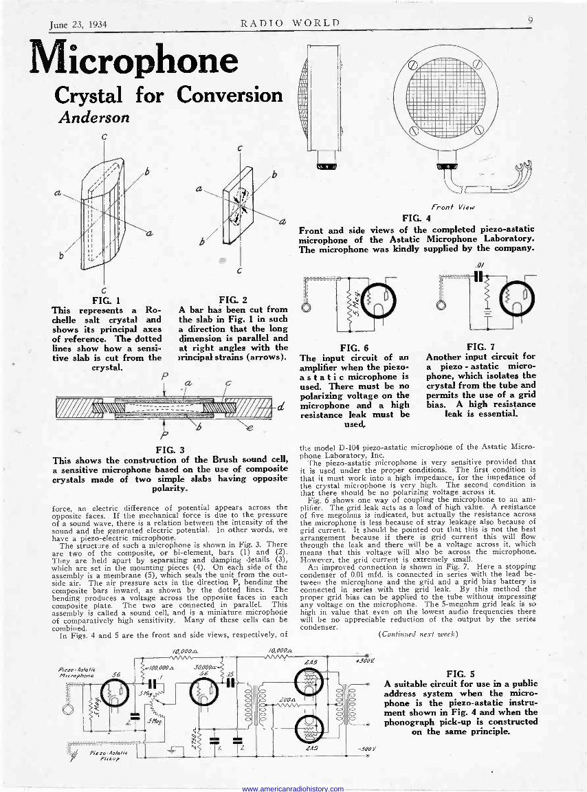
FIG. 1
This represents a Ro- chelle salt crystal and shows its principal axes of reference. The dotted lines show how a sensi- tive slab is cut from the
crystal.
r INN
P
C
FIG. 2 A bar has been cut from the slab in Fig. 1 in such a direction that the long dimension is parallel and at right angles with the wrincipal strains (arrows).
-------------
P 6
vxSSY te
FIG. 3 This shows the construction of the Brush sound cell, a sensitive microphone based on the use of composite crystals made of two simple slabs having opposite
polarity.
force, an electric difference of potential appears across the opposite faces. If the mechanical force is due to the pressure of a sound wave, there is a relation between the intensity of the sound and the generated electric potential. In other words, we have a piezo-electric microphone.
The structure of such a microphone is shown in Fig. 3. There are two of the composite, or bi -element, bars (1) and (2). They are held apart by separating and damping details (3), which are set in the mounting pieces (4). On each side of the assembly is a membrane (5), which seals the unit from the out- side air. The air pressure acts in the direction P, bending the composite bars inward, as shown by the dotted lines. The bending produces a voltage across the opposite faces in each composite plate. The two are connected in parallel. This assembly is called a sound cell, and is a miniature microphone of comparatively high sensitivity. Many of these cells can be combined.
In Figs. 4 and 5 are the front and side views, respectively, of
Piezo As/a/ic Microphone 56
Piezo-As/a/ic Pickup
/0,0004x /0,000.a.
Front View
FIG. 4
Front and side views of the completed piezo-astatic microphone of the Astatic Microphone Laboratory. The microphone was kindly supplied by the company.
FIG. 6 The input circuit of an amplifier when the piezo- astatic microphone is used. There must be no polarizing voltage on the microphone and a high resistance leak must be
used,
.0/
FIG. 7
Another input circuit for a piezo - astatic micro- phone, which isolates the crystal from the tube and permits the use of a grid bias. A high resistance
leak is essential.
the model D-104 piezo-astatic microphone of the Astatic Micro- phone Laboratory, Inc.
The piezo-astatic microphone is very sensitive provided that it is used under the proper conditions. The first condition is that it must work into a high impedance, for the impedance of the crystal microphone is very high. The second condition is that there should be no polarizing voltage across it.
Fig. 6 shows one way of coupling the microphone to an am- plifier. The grid leak acts as a load of high value. A resistance of five megohms is indicated, but actually the resistance across the microphone is less because of stray leakage also because of grid current. It should be pointed out that this is not the best arrangement because if there is grid current this will flow through the leak and there will be a voltage across it, which means that this voltage will also be across the microphone. However, the grid current is extremely small.
An improved connection is shown in Fig. 7. Here a stopping condenser of 0.01 mfd. is connected in series with the lead be- tween the microphone and the grid and a grid bias battery is connected in series .with the grid leak. By this method the proper grid bias can be applied to the tube without impressing any voltage on the microphone. The 5-megohm grid leak is so high in value that even on the lowest audio frequencies there will be no appreciable reduction of the output by the series condenser.
LA5 +300e
-500 V
(Continued next week)
FIG. 5 A suitable circuit for use in a public address system when the micro- phone is the piezo-astatic instru- ment shown in Fig. 4 and when the phonograph pick-up is constructed
on the same principle.
www.americanradiohistory.com
10 RADIO WORLD June 23, 1934
Methods of Sim of Signal Generators for Steadin
By Herma THE manufacturers of test oscillators, or signal generators,
as these instruments are now being called, strive for a high degree of accuracy and some of them also for frequency
stability. The prospective purchaser does not always know what these claims mean. For instance, is frequency stability something quite apart from accuracy? Does a certain per- centage of accuracy mean that it applies only to the high - frequency extreme of tuning any particular band, as is the similar case with meters, where the percentage accuracy applies to the full-scale deflection only? And in addition, or by way of further elucidation, how are frequency stability and a certain percentage of accuracy achieved?
First, an accuracy of 1 per cent. means that the frequency can be read to an accuracy of 1 per cent. at any frequency in the range, or, if there are more than one range, any frequency in any of the ranges may be read that closely. Thus the appli- cation of this rating differs entirely from the percentage accuracy rating applied to meters.
Second, frequency stability means that the oscillator, when tuned to a particular frequency, maintains that frequency. How well it maintains it seldom is stated. The device may be described as "unusually stable." That is simply a statement that it is not wobbly due to any cause.
Two Causes The two principal causes of instability are the inherent insta-
bility of the radio -frequency generator, or oscillator itself, and the wobbly output caused by poor forms of modulation. Grid blocking, which by including a large leak value stops the plate current at audio periods, constitutes one of these forms of poor modulation. When the output of a set is read with a meter, and the modulated signal -generator's carrier is introduced in the tuner, the meter needle will not stand still.
Starting with frequency stability, the first goal, it is achieved by making the tube behave as a pure resistance. A convenient method of checking for frequency stability is to put a d -c milliammeter in the signal generator plate circuit, tune the generator over its full frequency ratio, any band, and note the behavior of the needle. If the oscillator is stable the needle will stand still. Often one will find that the needle stands still for frequencies represented by the higher capacities of the tuning condenser settings, but will change abruptly for lower capacity settings.
This test is as good as any for a prompt and reliable determi- nation, although devoid of absolute values. The reason it is good is that all variable factors that might be present would show up in the plate current condition, and if there are no variable factors, that is, the needle stands still, the tube behavior is like that of a pure resistance. It will be remembered that a pure resistance is one that has no inductance or capacity.
One of the simplest stabilizing devices, although not a perfect one, is the grid -leak -condenser combination. This has been used for all the years of broadcasting, though not for that purpose, and amounts to diode -biased detection, where the grid to cathode circuit is the input to the triode as well as constituting the diode.
Stabilization Methods Alone, the leak -condenser method falls short at the higher
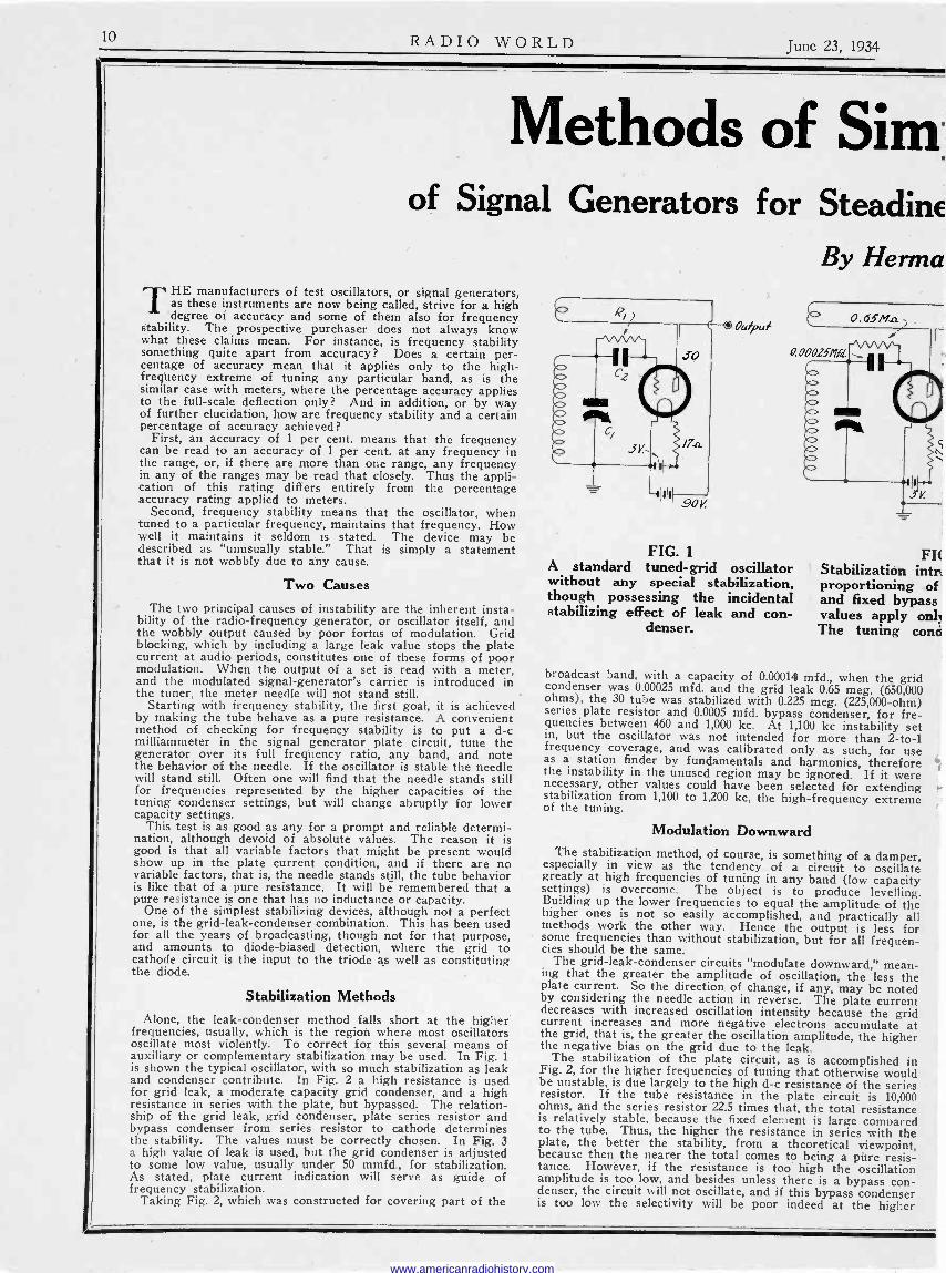
frequencies, usually, which is the region where most oscillators oscillate most violently. To correct for this several means of auxiliary or complementary stabilization may be used. In Fig. 1 is shown the typical oscillator, with so much stabilization as leak and condenser contribute. In Fig. 2 a high resistance is used for grid leak, a moderate capacity grid condenser, and a high resistance in series with the plate, but bypassed. The relation- ship of the grid leak, grid condenser, plate series resistor and bypass condenser from series resistor to cathode determines the stability. The values must be correctly chosen. In Fig. 3 a high value of leak is used, but the grid condenser is adjusted to some low value, usually under 50 mmfd., for stabilization. As stated, plate current indication will serve as guide of frequency stabilization.
Taking Fig. 2, which was constructed for covering part of the
Oufput
FIG. 1
A standard tuned -grid oscillator without any special stabilization, though possessing the incidental stabilizing effect of leak and con-
denser.
FIt Stabilization intra proportioning of and fixed bypass values apply only The tuning conci
broadcast band, with a capacity of 0.00014 mfd., when the grid condenser was 0.00025 mfd. and the grid leak 0.65 meg. (650,000 ohms), the 30 tube was stabilized with 0.225 meg. (225,000 -ohm) series plate resistor and 0.0005 mfd. bypass condenser, for fre- quencies between 460 and 1,000 kc. At 1,100 kc instability set in, but the oscillator was not intended for more than 2 -to -1 frequency coverage, and was calibrated only as such, for use as a station finder by fundamentals and harmonics, therefore the instability in the unused region may be ignored. If it were necessary, other values could have been selected for extending stabilization from 1,100 to 1,200 kc, the high -frequency extreme of the tuning.
Modulation Downward The stabilization method, of course, is something of a damper, especially in view as the tendency of a circuit to oscillate greatly at high frequencies of tuning in any band (low capacity
settings) is overcome. The object is to produce levelling. Building up the lower frequencies to equal the amplitude of the higher ones is not so easily accomplished, and practically all methods work the other way. Hence the output is less for some frequencies than without stabilization, but for all frequen- cies should be the same.
The grid -leak -condenser circuits "modulate downward," mean- ing that the greater the amplitude of oscillation, the less the plate current. So the direction of change, if any, may be noted by considering the needle action in reverse. The plate current decreases with increased oscillation intensity because the grid current increases and more negative electrons accumulate at the grid, that is, the greater the oscillation amplitude, the higher the negative bias on the grid due to the leak.
The stabilization of the plate circuit, as is accomplished in Fig. 2, for the higher frequencies of tuning that otherwise would be unstable, is due largely to the high d -c resistance of the series resistor. If the tube resistance in the plate circuit is 10,000 ohms, and the series resistor 22.5 times that, the total resistance is relatively stable, because the fixed element is large compared to the tube. Thus, the higher the resistance in series with the plate, the better the stability, from a theoretical viewpoint, because then the nearer the total comes to being a pure resis- tance. Howéver, if the resistance is too high the oscillation amplitude is too low, and besides unless there is a bypass con- denser, the circuit will not oscillate, and if this bypass condenser is too low the selectivity will be poor indeed at the higher
www.americanradiohistory.com

June 23, 1934 RADIO WORLD 11
ple Stabilization ;ss Comparable to Crystal Control n Bernard
Output
1 2 educed by proper
high resistances condensers. The
r to the 30 tube. enser is 0.00014.
Output
FIG. 3 If a high -resistance leak is used, of the order of a few megohms, the plate current kink at the higher fre- quencies may be removed by grid
condenser adjustment.
frequencies of tuning any band, and if the condenser is too high the time constant will be in the audio -frequency region that results in modulation of the same type as is present when grjd blocking is introduced. With such modulation, either grid or plate type, the Output is wobbly.
Air -Dielectric Condensers
The method used in Fig. 3 requires an air -dielectric condenser for the grid condenser, as the compression type will not retain its capacity constant, and the fixed type would require too great an assortment to select from, and besides would not stay put, because, even if molded, it permits creeping of plates and mica dielectric inside the space left for the condenser.
With a high grid leak, and no condenser, the circuit might not oscillate, as the resistance constitutes a damper. The greater the condenser capacity across the leak, the less the damping effect, within reasonable limits of capacity, say 0.001 mid., and reasonable resistance value, say, 2.0 meg. The higher the frequency, the more effective any particular capacity in this position, so the capacity is made small enough to permit the leak to act as a damper at the high frequency part of the tuning of a band, and take the kinks out of the plate current curve.
Another point to consider is the size of the tickler and the degree of coupling to the secondary. If the tickler is made so large that at the high -frequency end it stops oscillation, due to the tickler behaving as a choke, a few turns may be removed until oscillation at this extreme is restored, and then some aid is gained toward stabilization, although this alone is a critical method and not one easy to use. As an adjunct, however, it is helpful. Then any of the other methods may be used addi- tionally, as the tickler already renders some help, since it tends somewhat, though not completely, to act as a choke where damping is desired, in the higher -frequency brackets.
Effect on Frequency An unbypassed series resistor in the grid circuit, between the
regular leak -condenser combination and the grid, will serve as astabilization agency, as will an unbypassed resistor in the plate leg. The reason is the same as before, that the damping effect is greatest at the higher frequencies. At the lower frequencies it is not substantial. However, these resistors would have low values, say, 1,000 ohms or so for the grid circuit, 10,000 to 20,000 ohms for the plate circuit, considering the 30 tube only, and
the d -c voltages as in Figs. 4 and 5. Other tubes might require different values.
The introduction of any of these resistances and condensers changes the frequency from what it would be for the same tuning condenser and coil without these additions so any cali- bration made on the basis of particular inclusions must not be deemed to hold strictly if the parts are altered or omitted. The capacity change of the condensers, if of the fixed mica dielectric molded type, is not of any importance in this regard, though a resistor's of more than 10 per cent., such as might arise from use and age, is important. Occasional checking of the resistance value is advisable, if a particular calibration is to be followed.
Using standards as bases of comparison, we run a curve, or create a dial calibration for direct -reading, and as the standards are accurate, including broadcasting stations, if such are used, the particular frequencies may be registered accurately, and then since we have frequency stabilization we will generate a certain frequency at one setting and, leaving the setting thus, the frequency always will be the same, say, to one part in 100,000 or even better.
Unstable Change Even if the oscillator were unstable, the change in frequency
scarcely ever would extend beyond the audio range, that is, for a frequency of 1,000,000 cycles generated, the change would not exceed 10,000 cycles, or one part in 100. It -can be seen that frequency stabilization improves the stability a thousand -fold.
The percentage of accuracy referred to by manufacturers has nothing to do with the accuracy just mentioned. If there is a change of 100 cycles out of 1,000,000 cycles, then the frequency stability is 0.0001, or one one -hundredth of one per cent. (0.01 per cent.). As stated, this factor is never mentioned, except in precision apparatus of the costly kind, as used in elaborate research.
Since the electrical part is stable now, the question arises as to what can be accomplished in the mechanical part. That mechanical part may be considered to consist of the dial mecha- nism, the plotting of the curve, the ability to read the curve closely, or the plotting of the direct -reading scale and the ability to read that scale closely. To these matters the accuracy men- tioned by manufacturers pertains, and it can be seen to be a mechanical aspect. Frequency stability does not enter here, because whether the oscillator is stable or unstable, the differ- ence can not be read on the dial or curve. However, the output reading will be constant, which is important, if stabilization is present, even if the tested circuit is highly selective.
Dial Index One of the considerations in respect to the dial is that it
should have an indicator devoid of parallax. No matter from what angle you read the scale, the reading should be the same. If the index is far enough removed from the scale, and there is no other guide between, when the reading is taken from the left it is one value, at center another, and at right another. If there is only slight possibility of parallax, conditions are weh enough satisfied if the reading is taken exactly from the center, as one would do naturally.
Suppose the oscillator is direct -reading, that is, the frequen- cies are imprinted on the scale. It is then a problem to coincide the tuning system to the scale. This may be done by such methods as the designer originally intended. A trimming capacity is one method, but the trimmer must be an air -dielec- tric condenser. Another method is to use different values of grid condenser until the correct one is found. Another is to select the proper series resistor. All such tests are made for the highest frequency to be tuned in for a particular band. The variable factor for the low -frequency setting, since the capacity will be always the same for any particular dial position, is the secondary inductance, and the making of the coil to proper closeness of inductance is taken for granted, if the oscil- lator is to have any respectable rating at all.
By using utmost pains it is possible to have a direct -reading (Continued on next page)
www.americanradiohistory.com

12 RADIO WORLD June 23, 1934
r -
FIG. 4 An unbypassed series resistor R in the grid leg, outside the tuned cir- cuit, will create stabilization also.
Try values of 1,000 ohms up.
OuJpat
FIG. 5 Also a series resistor R in the plate leg, unbypassed, offers stabilization possibilities. Values of 10,000 ohms
up should be tried.
dial scale, and use commercial condensers, and accurate induc- tances, to attain a production accuracy of 1 per cent. By some refinements, particularly of close adjustments that take the time of experienced engineers, this accuracy may be doubled, but it is an expensive process, and requires the occasional discarding of a tuning condenser, meaning practically the tearing down and rebuilding of an oscillator. that could go out as one of an accuracy of 1 per cent.
Figs. 2 and 6 were built with special pains and the accuracy was / per cent. By devoting a few hours more to testing and adjustments, the accuracy might -be improved to % per cent. The frequency generated was so stable that during two hours of testing the change did not amount to more than 100 cycles out of 1,250,000 cycles.
Perhaps the easiest external test to make to confirm stabili- zation is to zero -beat the signal generator with a broadcasting station. This usually requires a vernier dial, or very close handling of a knob for direct actuation, as getting zero differ- ence of frequency is no rough and ready matter, despite the facility with which the advice is given to "zero -beat with a broadcasting station."
For those not familiar with the process it will be detailed. As you tune an oscillator to the frequency of a station, since
the station itself is sending out an oscillating voltage or current, you have an instance of two oscillators.
If the local oscillator or signal generator is- not quite in tune, but approximately so, there will be a difference in frequency small enough to be in the audio range. Thus, turning the dial from right to left, approaching the station frequency, you begin to hear a high-pitched squeal, the pitch declines until it becomes zero, and then, continuing in the same direction, as you move the dial slowly the pitch rises again and keeps rising, because the difference is increasing, although due to the generator work -
FIG. 6 An a -c -operated signal generator,. with hum as modulation, serves as a station -finder. This is an adapta-
tion of Fig. 2.
ing in the other frequency direction, and finally the difference is too great to hear, that is, becomes radio frequency.
That central point between the audible high-pitched extremes, that point where there is no difference in frequency, represents zero beat.
Now if you will zero beat with a station, since the station frequency is accurate to plus or minus 50 cycles, and since you would be using a receiver which, in all likelihood, does not pass 50 cycles, but does pass 100 cycles, if you left the oscillator going for an hour, and could not hear any beat, you would be safe in assuming that your oscillator during that period did not change its frequency more than 100 cycles out of n cycles, where n represents the frequency of the broadcasting station in cycles.
The behavior of Figs. 2 and 6 was exactly that of an oscillator so stable as to be comparable to the stability of a crystal - controlled oscillator that did not have a temperature oven, for instance, the crystal method used in single-sideband super - heterodynes.
No modulation is present in any of the oscillators, Figs. 1 to 5 inclusive, but a.c. may be used as modulation, as shown in Fig. 6, which is an adaptation of Fig. 2 to this extent.
Since the stabilization is not difficult, it is suggested that the time is ripe to introduce stabilization in the local oscillators of superheterodynes, particularly those that include the short-wave spectrum.. The trimming condenser must be air -dielectric, remember, that the higher the frequencies to be tuned in, the more important is this precaution, while the stabilization at- tained for one band will have to be checked for its continued existence on other bands. In general it has been found that the stabilization is a function of the capacity and resistance, and not of the inductance in the tuned circuit, therefore the tnethods have real and extensive possibilities.
The 12A7 for Midget Sets
H
Bottom view of a small seven -hole socket to be used for insertion of the 12A7 tube, which combines a half -wave rectifier for B supply, and a pentode output tube. For the pentode P1 is the plate, Sc is the screen, G is the control grid, con- nected to cap of tube, while Kl is the cathode. The rectifier consists of P2, plate, and K2, cathode, and is to be connected in series with the line, for transformerless use, or to a secondary of a power transformer
for a -c use alone.
H
Since in the last audio stage only "harmless" audio frequencies are present, a rectifier tube may be combined in the same envelope as the output tube, as is done in the 12A7, which Kenrad makes. Thus one fewer envelope may be used in a rectifier, although electrically there will be the same number of functioning tubes. However, as soon as duplex tubes become popular the fact isn't even mentioned that there are two tubes in one envelope, and the mechanical and elec- trical count becomes one. One envelope, one tube.
On this basis a pretty good four -tube set can be built, consisting of two stages of tuned radio -frequency amplification, a detector and the 12A7. Also, practically any small circuit can be changed to encompass the space economy offered by the new tube.
Biasing Resistor The rectifier is the same as any other half -wave type. The pentode is the same
as other pentodes as to general application, although the plate current may be less, so that the biasing resistor for the power tube may be around 800 to 1,000 ohms. The value is not critical, and even less than 800 ohms may be tried.
Across the biasing resistor should be placed a large -capacity condenser. Such a type is obtainable in electrolytic form at 30 to 50 mfd. for low voltage rating (around 30 volts rating, normally). The actual applied voltage never will be more then half that.
Choke Option The same filter may be used for this rectifier as for others. Of course the electrical independence of the two tubes must be preserved, as
it is when the cathodes are used independently. The choke for the B supply may be in either the negative or the positive leg, but if in the negative leg then take the precaution to insulate the condenser nearer the rectifier cathode from possible chassis or ground connection, since this first condenser is between B minus and cathode, and B minus is not grounded in negative -leg -choke systems.
www.americanradiohistory.com

June 23, 1934 RADIO WORLD 13
A Time -Signal Device Provides Accurate Check of Line Frequency
By Alan Mannion Mannion Radio Laboratories
A six -tube a -c -operated set for bringing in the time signals from NAA, Arlington, Va. This is a tuned -radio - frequency set of the fixed -frequency type. The transmissions are on two different frequencies, but only one
of them need be selected. There are various uses for the signals besides just telling time for time's sake.
SINCE the early days of radio there has been available a highly accurate service through the daily time -signal
transmissions from NAA, Arlington, Va. This service is correct to the degree of accuracy of the Naval Observatory, and is therefore suitable for the setting of chronometers and the adjustment of other high -precision time apparatus. The sig- nals are broadcast daily over two chan- nels as follows :
Type A2 113 kc (2,653 meters) Greenwich Civil
Time: 02 :55 to 03:00, 07:55 to 08:00, and from 16:55 to 17:00.
Type A3 690 kc (435 meters) Greenwich Civil
Time: 02:55 to 03 :00 and from 16:55 to 17:00.
Checking Line Frequency It is not generally realized that these
time -signals also provide a means of checking line frequency to a very high degree of accuracy. This need has be- come increasingly great within recent years due to the use of synchronous clocks in homes. The speed of synchronous motors depends upon the frequency of excitation. It follows that any variation in frequency will -cause a corresponding variation in clock speed. The increasing use of electric clocks makes necessary a far greater accuracy_ of line frequency than do most other commercial usages. -Variation of a fraction of a cycle from true frequency of 60 cycles causes much less variation in power transformer sec- ondaries than that caused by a slight change in line voltage. This is not so in the case of a chronometer with a syn- chronous motor. The changes in line voltage, even when amounting to several volts, will not cause the clock to gain or lose, whereas any change in frequency, however slight, if consistently neglected,
will cause a decided variation from accu- rate time.
It follows therefore that the accuracy of 'clocks in consumers' homes will be no greater than the accuracy of frequency adjustment at the local power plant. Every power company has a master clock so constructed as to keep accurate time when the line frequency -average is ex- actly 60 cycles. Here is where the time signal receiver provides a needed service to the company. If the master clock can be compared to Naval Observatory time, and kept accurate to that standard, all the clocks on the power lines will be equally accurate. This of course postulates clocks without individual physical defects.
Checked Thrice Daily
The receiver pictured was designed and constructed for one of the largest power companies in the East. It was responsive to the first frequency listed, 113 kc. This is usually referred to as the "2,600 -meter time -signal." This company supplies cur- rent for tens of thousands of home clocks, as well as those in more public use, and an accuracy of one -thirtieth part of a sec- ond is maintained in checking the master clock. Three times a day this master clock is checked with the time -signal transmissions and adjustments made in generator speed to bring the frequency back in line, should variations occur.
The diagram shows an untuned input followed by three stages of tuned -grid, tuned -plate, radio frequency amplification. This makes six tuned circuits in all. Since the input is untuned, variations in antenna length, leadin capacities, etc., will not cause serious detuning of the receiver. This allows a very accurate alignment at the wanted frequency right in the lab- oratory, and no adjustments are required in installation. A long, high aerial should be used.
The detector is a 57, selected for its
high signal sensitivity, and biased for power detection. Its output is fed into a 2A5 power amplifier, the coupling being resistive. A dynamic speaker, though not required, may be economically used in this circuit, since it does duty as a filter choke, and also as a means of providing bias for the output tube. Filtering must be good if this receiver is to be used in the same building with the power gener- ators. Thoroughness in this respect pays dividends.
Adjusting the Tuner
Each tuned circuit consists of a 20 milli- henry and a 120 (max.) mmfd. variable condenser. They are constructed similar- ly to i -f transformers, the choke coils be- ing mounted on u -inch dowel rod, and spaced about 1% inches apart. The prop- er band-pass effect may be obtained ex- perimentally by changing this distance.
The circuits may be approximately lined up using a modern service oscillator. The i -f range of these oscillators usually ex- tends down to 113 kc. The final adjust- ment must be done with the aid of the time -signal itself. This is not difficult with an output meter.
The construction of these modernized time -signal receivers may boost the' serv- ice man's reduced summer income. Local watchmakers and power companies may mean new customers. Astronomers have use for the same device.
When aligning the receiver to the time signal, an output meter may show dips in the pulses between beats, which are ex- actly one second apart. By observing the maximum swing of the needle on each beat, resonance is easily established. A long tone is sent exactly on the hour, fol= lowed by NAA in Continental: dah-dit, dit-dah, dit-dah. The beginning of this tone is the checking cue.
[Other illustration on front cover.]
www.americanradiohistory.com

14 RADIO WORLD June 23, 1934
The Triplett 4686 Universal Tester, With Facilities for Measuring
High Alternating Currents By Jack Tully
o
ZERO ADJ.
A. G.
o
/5 M.A.A.C.
/50 M.A.A.C.
1.5 MA-
A.C. VOLTS M.A.
O. C.
VOLTS M. A.
OHMS
(o OFF
750 VOLTS
/50 VOLTS
-/5VOLTS
CHASSIS
/5 M. A. /.5 MfGOHMS
/50 M.A./ T \ 1500 OHMS o T MEGOHMS
D.0
o FIG. 1
A drawing of the panel of a universal meter. The instrument measures alternating and direct currents and voltages, output power, and resistance. The instrument has an exceptionally wide range in all its applications.
IN previous issues we have shown many circuit testers, some of which have been of the universal type. Nearly all
the testers have inclosed provision for measuring medium values of resistances, but none has contained means for mea- suring alternating currents higher than one milliampere. Now we have a sim- plified universal tester that measures al- ternating and direct currents and volt- ages as well as resistances of different ranges in the Triplett Universal Model 4686.
In most testers the switch which con- verts the circuit from one service to an- other is usually very complicated, which follows an attempt to make the tester fool -proof. No switch, however simple or complex, can make the circuit such. By the introduction of a two-way switch by which the circuit can be adapted for a -c or d -c measurements, the general se- lector switch, and hence the circuit, can be greatly simplified.
An idea what the tester will measure
can be gained from Fig. 1, which is a drawing of the panel. First it will be noticed that the dial contains three scales, one for resistance, at the top, one for direct current, in the middle, and one for alternating current, at the bottom. A knife-edge pointer sweeps over these scales in such a manner that it is possible to read all the scales with equal accu- racy.
Details of Circuit For the details of what the tester will
do we have to examine the dial of the selector switch. There are twelve stops on the switch, one of which is neutral. That leaves eleven different positions for measurements of as many different things. But the eleven live steps are for each of the positions of the two-way switch for a -c or d -c. Hence there are really 22 possibilities.
If we turn the selector switch in the clockwise direction, we first come to the 750 -volt stop. This is for either a -c or
d -c provided that we apply the unknown voltage at the proper terminals. The ones to use are clearly marked. At the second step in the same direction we come to the 150 -volt stop, which is also for either a -c or d -c according to the position of the two-way switch and the terminals used for the application of the unknown. The third stop is like the other two, but the voltage to be measured on it is only 15. These three voltage ranges, a -c and d -c, are sufficient for the measurement of all voltages that- are likely to occur in a ra- dio receiver or public address amplifier.
Resistance Ranges The three steps following the voltage
steps are for resistance measurements. These are for 1,500 ohms, 1.5 megohms and 3 megohms. The scale, it will be noticed, runs from zero to 1.5 megohm. Therefore when the switch is on the first resistance step, the scale is to be read directly in megohms, or in ohms, depend- ing on where the needle points. If the switch is on the second step, the correct resistance is obtained by reading the scale and dividing by 1,000, whereas when the switch is on the third resistance step the readings must be multiplied by 2.
The useful range of the resistance meter is from less than one ohm to 3 megohms, and that certainly covers all practical cases. While there are resistances great- er than three megohms, they can seldom be measured accurately with any meter available, and frequently they do not re- tain the values while in service. Hence there is little object of measuring them.
Current Ranges In turning the selector switch to the
left from the neutral position we first come to a stop for 15 milliamperes alter- nating current and after that we come to a 150 milliampere a -c stop. 'In either of these positions the two-way switch must be set on a -c and the unknown must be applied at the a -c terminals.
After the a -c stops we have three d -c stops, for 1.5, 15, and 150 milliamperes direct current. Of course, the d -c termi- nals and the d -c setting of the two-way switch must be used when direct current is being measured.
In the diagram is a terminal post marked "plate," and between this post and the post marked "chassis" is a line marked "output." This indicates that the two posts in question are to be used in making output measurements on power stages. The post marked "plate" and the one directly below it are connected to- gether with a condenser of 0.5 mfd. This makes it safe to connect the plate of the output tube to the terminal marked "plate" when measuring the a -c compo- nent of the output of the tube. Since the output of the power tube is alternating current, the two-way switch must be set on a -c when a measurement of output is made.
A Full -Wave Rectifier Since the meter employed is of the d -c
type, a rectifier is necessary to convert a -c to d -c when alternating current is measured. The rectifier used is of the copper oxide type and is full -wave. The rectifier element is not built into the meter
www.americanradiohistory.com
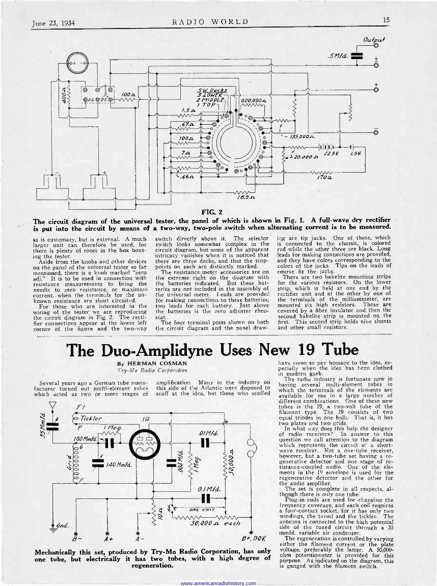
June 23, 1934 RADIO WORLD 15
The circuit is put into
/00n
" '
JOO.a -Oo /
n ', 7.n © \,
FIG. 2
diagram of the universal tester, the panel of which is shown in Fig. 1. A full -wave dry rectifier the circuit by means of a two-way, two -pole switch when alternating current is to be measured.
/8.5-a
`- /35,000-
Ow' pa/ 0
.5/'lfd. ±- 0
/70-a
as is customary, but is external. A much larger unit can therefore be used, for there is plenty of room in the box hous- ing the tester.
Aside from the knobs and other devices on the panel of the universal tester so far mentioned, there is a knob marked "zero adj." It is to be used in connection with resistance measurements to bring the needle to zero resistance, or maximum current, when the terminals for the un- known resistance are short circuited.
For those who are interested in the wiring of the tester we are reproducing the circuit diagram in Fig. 2. The recti- fier connections appear at the lower left corner of the figure and the two-way
switch directly above it. The selector switch looks somewhat complex in the circuit diagram, but some of the apparent intricacy vanishes when it is noticed that there are three decks, and that the stop - points on each are distinctly marked.
The resistance, meter accessories are on the extreme right on the diagram with the batteries indicated. But these bat- teries are not included in the assembly of the universal meter. Leads are provided for making connections to these batteries, two leads for each battery. Just above the batteries is the zero adjuster rheo- stat.
The four terminal posts shown on both the circuit diagram and the panel draw-
ing are tip jacks. One of these, which is connected to the chassis, is colored red while the other three are black. Long leads for making connections are provided, and they have colors corresponding to the colors of the jacks. Tips on the leads of course fit the jacks.
There are two bakelite mounting strips for the various resistors. On the lower strip, which is held at one end by the rectifier unit and at the other by one of the terminals of the milliammeter, are mounted six high resistors. These are covered by a fibre insulator and then the second bakelite strip is mounted on the first. This second strip holds nine shunts and other small resistors.
The Duo-Amplidyne Uses New 19 Tube By HERMAN COSMAN Try -Mo Radio Corporation
Several years ago a German tube manu- facturer turned out multi -element tubes which acted as two or more stages of
F/ C Tck/er
P / /leg.
IOOMmfd. , ,.0 0 0 0 KZ>
140 Mmfd.
E
6nd.
B- e
A+
/9
A -
amplification. Many in the industry on this side of the Atlantic were disposed to scoff at the idea, but those who scoffed
ó T Y.)
.0/Mid.
ONE UNIT
S0, 000 ..n. each e
B+ s0V.
Mechanically this set, produced by Try -Mo Radio Corporation, has only one tube, but electrically it has two tubes, with a high degree of
regeneration.
have come to pay homage to the idea, es- pecially when the idea has been clothed in modern garb.
The radio industry is fortunate now in having several multi -element tubes in which the terminals of the elements are available for use in a large number of different combinations. One of these new tubes is the 19, a two -volt tube of the filament type. The 19 consists of two equal triodes in one bulb. That is, it has two plates and two grids.
In what way does this help the designer of radio receivers? In answer to this question we call attention to the diagram which represents the circuit of a short- wave receiver. Not a one -tube receiver, however, but a two -tube set having a re- generative detector and one stage of re- sistance -coupled audio. One of the ele- ments in the 19 envelope is used for the regenerative detector and the other for the audio amplifier.
The set is complete in all respects, al- though there is only one tube.
Plug-in coils are used for changing the frequency coverage, and each coil requires a four -contact socket, for it has only two windings, the tuned and the tickler. The antenna is connected to the high potential side of the tuned circuit through a 35 mmfd. variable air condenser.
The regeneration is controlled by varying either the filament current or the plate voltage, preferably the latter. A 50,000 - ohm potentiometer is provided for this purpose. As indicated on the diagram, this is ganged with the filament switch.
www.americanradiohistory.com

16 RADIO WORLD June 23, 1934
Radio University
0.5 Met.
34
0.02 MFD.
0 B+I35.c A.45K e-
0.02 ltd. 32 o.o2m fQ. 30
nected to B minus, whereby some current will flow through this resistor, and the oscillation voltage may be taken there- from through a condenser, the "plate" acting as an electron -coupled pickup ele- ment This constitutes the tube a quad - rode,, as the plate that would make it a pentode really isn't a functioning part of
SwircN
A+ 4-.5v.
Untuned R -F Stage HOW CAN the tuned detector circuit
be kept free from the effects of antenna capacity, inductance and swinging aerial, without an extra tuned stage?-K. C.
By using an untuned stage. A resistor will serve the purpose. However, there is some sacrifice, as the antenna ca- pacity across the resistance becomes a serious attenuator of signal intensity as the radio -frequency carriers exceed 15 mgc or so.
* * *
Oscillation Frequency IS IT POSSIBLE to determine accu-
rately by computation what will be the resonant frequency of an oscillator? I have particular reference to short waves, where the inductance is small compared to the capacity.-P. O.
There is no known method of accurate computation of practical inductance for short waves, because of limitations im- posed by the receiver or oscillator. The capacity and inductance of the leads in the set are a serious uncertainty, therefore there is no stable basis of computation. Assuming low frequencies, the resonant frequency of an oscillator may be com- puted closely, of course, but this need not necessarily be the frequency of oscillation. The oscillator may oscillate at other than the resonant frequency, and usually does, the slight difference being due to a phase shift.
* * *
Current -Fed Line FOR A TRANSMISSION LINE input,
should the receiver be voltage -fed or cur- rent -fed ?-K. L.
It is usual to have a voltage -fed trans- mission line., This is the method employed in telephone and power line practice. Of course audio frequencies are involved. However, for short-wave use, it is well to consider the possibilities of a current - fed line, because the frequencies are so high. Take the power line example. Any stray capacity to ground is negligible in the light of a frequency of 60 cycles. But the same capacity to ground in a transmission line from antenna used for short-wave reception is serious. There- fore it is suggested that a step-down r -f transformer be used with antenna con- nected to the large primary and the trans- mission line to the small secondary. There being negligible transformer loss, the power in primary and secondary is the same, but the voltage has been reduced in the secondary, perhaps to a few per
cent. of the primary voltage. The sec- ondary current has been increased pro- portionately to the voltage decrease, since the power is approximately the same in both branches. Hence the current is very large compared to the voltage, and this would constitute a current -fed line. The loss due to capacity to ground would be smaller than in the voltage -fed transmis- sion line because the percentage of cur- rent through this capacity to ground is much less than in the example of a voltage -fed line. A point needing watch- ing, however, is the loss in the resistance of the transmission line. Since the cur- rent is large, if the transmission line has even a small resistance, the drop in this resistance will be a ratable factor.
* * *
Unusual Tube Uses WHEN A TUBE is used in other than
its orthodox manner, as is sometimes done by unusual connections of grids and screens, is it permissible to consider the tube as functioning in its originally in- tended manner, and apply the specifica- tions of an orthodox installation, or must one start anew, and where is this infor- mation obtainable?-J. K. C.
The tube characteristics as given in commercial charts apply only when the connections are as stated in the chart, which are the orthodox connections. When a departure is made from the usual meth- od the operation of the tube is quite dif- ferent. In general, no data are available as to the characteristics of the tubes in these special uses, and the experimenter would have to run his own curves. For instance, consider a 58 tube. It usually has the control grid independent, the sup- pressor tied externally to the cathode, the screen and plate independent, the heater independent. If the tube is subjected to automatic volume control, and the sup- pressor is tied to the grid return, which is negative d -c side of the a -v -c circuit, the plate resistance declines with increase in signal amplitude and increase in a -v -c voltage, a method used for automatic tone control, as the circuit is less selective on strong signals, and thus locals come in with excellent quality, whereas distant stations, from which quality is not so gen- erally expected, are subjected to greatly heightened selectivity, where selectivity is needed most. The curves for this per- formance are obtainable from tube manu- facturers. Consider now the 58 used in an oscillator, with feedback in the screen circuit, suppressor tied to cathode, and the formal plate having a load resistor con -
An unturned r -f stage may be used for short waves, the load being a resistor, fixed or variable.
the tube proper. The information on this type of operation of the tube is not now obtainable from the tube manufacturers.
* * *
Difference in Aerials WHY CAN NOT the same antenna con-
ditions be used for transmission of short, medium and long waves, and why must special attention be given to short-wave installations ?-K. L.
The same antenna can not be used for the same reason that not everybody can wear the same size shoe. Short waves may be compared to children with little feet, long waves to giant adults with large feet. The proper antenna is selected so that the shoe will fit the foot., Stated technically, the whole antenna system should be sensibly related to the wave- length, and that is true of reception as well as propagation. Another way of stating this is to say that for efficient radiation the dimensions of the circuit should be comparable to the wavelength or frequency. For short waves very short aerials are as efficient as very long ones are for long waves. Hence the difference in aerial installations is simply a recog- nition of a scientific fact, or obedience to nature.
* * *
The "R" Rating HAS THE "R" RATING a scientific
standard, and if so, will you please state what that standing is?-T. W. ,
The "R" rating has no scientific stand- ing, and. is simply a method of stating approximately tEe comparison of recep- tion, being better than no method at all, but devoid of accuracy. The rating is ex- pressed as Rl to R9, where R1 represents the worst conditions of reception and R9 the best. Hence a statement that "sig- nals were R9" means they were excellent. As to the relative values encompassed by the R's of lesser magnitude, the mean- ing depends as much on what the expres- sor intended it should be as it does upon what the recipient of the information thinks that the expressor meant. When a system is related to a more definite basis it is of improved value. The Bureau of Standards, Department of Commerce, United States Government, sends out standard frequencies, and encourages re- ports on reception. The Bureau states ; "The data required are approximate field intensity, fading characteristics, and the suitability of the transmissions for fre- quency measurements. It is suggested that in reporting on intensities, the fol-
www.americanradiohistory.com
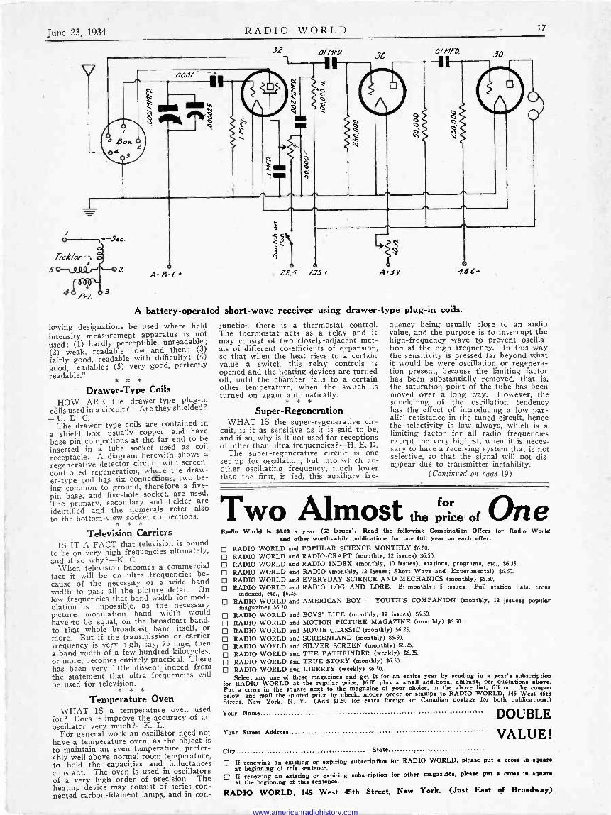
-une 23, 1934 RADIO WORLD 17
5
32
Z1ao/
ó J.ó
2 0
o A-8 C+
0/MFR
11
o /35f
CiMfQ 30
A+3V.
N
o
45 C-
A battery -operated short-wave receiver using drawer -type plug-in coils.
lowing designations be used where field intensity measurement apparatus is not used: (1) hardly perceptible, unreadable; (2) weak, readable now and then; (3)
fairly good, readable with difficulty; (4)
good, readable; (5) very good, perfectly readable."
* * *
Drawer -Type Coils HOW ARE the drawer -type plug-in
còils used in a circuit? Are they shielded? -U. D. C.
The drawer type coils are contained in a shield box, usually copper, and have base pin connections at the far end to be inserted in a tube socket used as coil_
receptacle. A diagram herewith shows a regenerative detector circuit, with screen - controlled regeneration, where the draw- er -type çoil has six conneceions, two be- ing common to ground, therefore a five - pin base, and five -hole socket, are used. The primary, secondary and tickler are identified and the numerals refer also to the bottom -view socket connections.
* * *
Television Carriers IS IT A FACT that television is bound
to be on very high frequencies ultimately, and if so why?-K. C.
When television becomes a commercial fact it will be on ultra frequencies be- cause of the necessity of a wide band width to pass all the picture detail. On low frequencies that band width for mod- ulation is impossible, as the necessary picture modulation band width would have 4o be equal, on the broadcast band, to that whole broadcast band itself, or more. But if the transmission or carrier frequency is very high, say, 75 mge, then a band width of a few hundred kilocycles, or more, becomes entirely practical. There has been very little dissent indeed from the statement that ultra frequencies will be used for television.
* * *
Temperature Oven WHAT IS a temperature oven used
for? Does it improve the accuracy of an oscillator very much?-K. L.
Fdr general work an oscillator need not have a temperature oven, as the object is to maintain an even temperature, prefer- ably well above normal room temperature, to hold the capacities and inductances constant. The oven is used in oscillators of a very high order of precision. The heating device may consist of series -con- nected carbon -filament lamps, and in con-
junction there is a thermostat control. The thermostat acts as a relay and it may consist of two closely -adjacent met- als of different co -efficients of expansion, so that when the heat rises to a certain value a switch this relay controls is opened and the heating devices are turned off, until the chamber falls to a certain other temperature, when the switch is turned on again automatically.
* * *
Super -Regeneration WHAT IS the super -regenerative cir-
cuit, is it as sensitive as it is said to be, and if so, why is it not used for receptions of other than ultra frequencies?-H. E, D.
The super -regenerative circuit is one set up for oscillation, but into which an- other oscillating frequency, much lower than the first, is fed, this auxiliary fre-
quency being usually close to an audio value, and the purpose is to interrupt the high -frequency wave to prevent oscilla- tion at the high frequency. In this way the sensitivity is pressed far beyond what it would be were oscillation or regenera- tion present, because the limiting factor has been substantially removed, that is, the saturation point of the tube has been moved over a long way. However, the squelching of the oscillation tendency has the effect of introducing a low par- allel resistance in the tuned circuit, hence the selectivity is low always, which is a limiting factor for all radio frequencies except the very highest, when it is neces- sary to have a receiving system that is not selective, so that the signal will not dis- appear due to transmitter instability.
(Continued on page 19)
Two Almost the(rice of One P Radio World hp NMI a year (52 issues). Read the following Combination Offers for Radio World
and other worth -while publications for one full year on each offer.
RADIO WORLD and POPULAR SCIENCE MONTHLY $6.50.
RADIO WORLD and RADIO -CRAFT (monthly, 12 issues) $6.50.
D RADIO WORLD and RADIO INDEX (monthly, 10 issues), stations, programs, etc., $6.35.
RADIO WORLD and RADIO (monthly, 12 issues; Short Wave and Experimental) $6.60.
RADIO WORLD and EVERYDAY SCIENCE AND MECHANICS (monthly) $6.50.
D RADIO WORLD and RADIO LOG AND LORE. Bi -monthly; 5 issues. Full station lists, crow indexed, etc., $6.25.
RADIO WORLD and AMERICAN BOY - YOUTH'S COMPANION (monthly, 12 issues; popular magazine) $6.50.
D RADIO WORLD and BOYS' LIFE (monthly, 12 issues) $6.50.
RADIO WORLD and MOTION PICTURE MAGAZINE (monthly) $6.50.
D RADIO WORLD and MOVIE CLASSIC (monthly) $6.25.
RADIO WORLD and SCREENLAND (monthly) $6.50.
RADIO WORLD and SILVER SCREEN (monthly) $6.25.
RADIO WORLD and THE PATHFINDER (weekly) $6.25.
RADIO WORLD and TRUE STORY (monthly) $6.50.
RADIO WORLD and LIBERTY (weekly) $6.50.
Select any one of these magazines and get it for an entire year by sending in a year's subscription for RADIO WORLD at the regular price, $6.00 plus a small additional amount, per quotations above. Put a cross in the square next to the magazine of your choice, in the above list, fill out the coupon below, and mail the quoted price by check, money order or stamps to RADIO WORLD, 145 West 45th Street, New York, N. Y. (Add $1.50 for extra foreign or Canadian postage for both publications.)
Your Name
Your Street Address
DOUBLE
VALUE! City State
D If renewing an existing or expiring subscription for RADIO WORLD, please put a cross in square at beginning of this sentence.
3 Ií renewing an existing or expiring subscription for other magazines, please put a croes in square at the beginning of this sentence.
RADIO WORLD, 145 West 45th Street, New York. (Just East of Broadway)
www.americanradiohistory.com
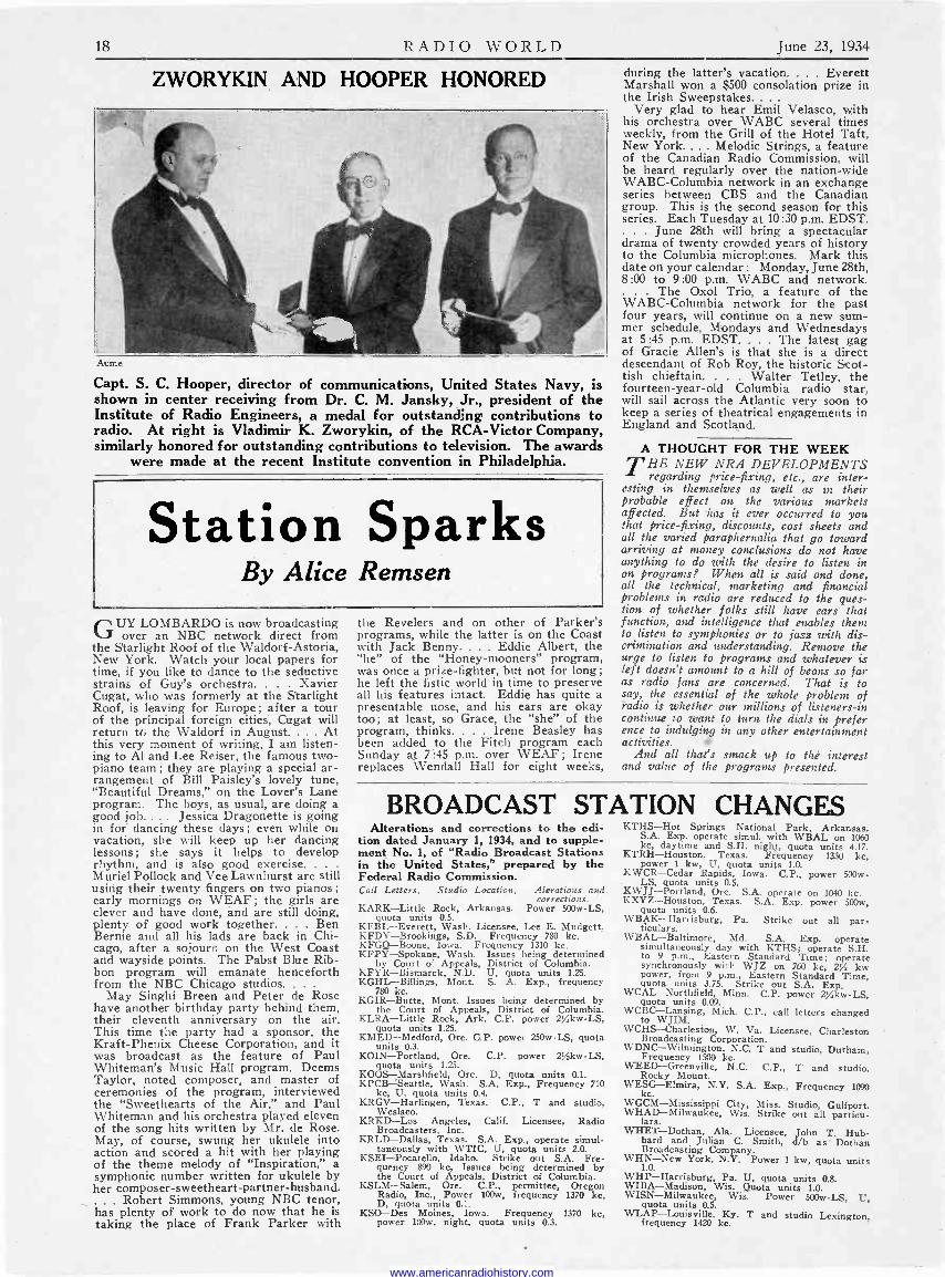
18 RADIO WORLD June 23, 1934
ZWORYKIN AND HOOPER HONORED
Acme
Capt. S. C. Hooper, director of communications, United States Navy, is shown in center receiving from Dr. C. M. Jansky, Jr., president of the Institute of Radio Engineers, a medal for outstanding contributions to radio. At right is Vladimir K. Zworykin, of the RCA -Victor Company, similarly honored for outstanding contributions to television. The awards
were made at the recent Institute convention in Philadelphia.
Station Sparks By Alice Remsen
GUY LOMBARDO is now broadcasting over an NBC network direct from
the Starlight Roof of the Waldorf-Astoria, New York. Watch your local papers for time, if you like to dance to the seductive strains of Guy's orchestra. . Xavier Cugat, who was formerly at the Starlight Roof, is leaving for Europe ; after a tour of the principal foreign cities, Cugat will return tb the Waldorf in August.... At this very moment of writing, I am listen- ing to Al and Lee Reiser, the famous two - piano team ; they are playing a special ar- rangement of Bill Paisley's lovely tune, "Beautiful Dreams," on the Lover's Lane program. The boys, as usual, are doing a good job.... Jessica Dragonette is going in for dancing these days; even while on vacation, she will keep up her dancing lessons; she says it helps to develop rhythm, and is also good exercise. .
Muriel Pollock and Vee Lawnhurst are still using their twenty fingers on two pianos ;
early mornings on WEAF; the girls are clever and have done, and are still doing, plenty of good work together. . Ben Bernie and all his lads are back in Chi- cago, after a sojourn on the West Coast and wayside points. The Pabst Blue Rib- bon program will emanate henceforth from the NBC Chicago studios. .
May Singhi Breen and Peter de Rose have another birthday party behind them, their eleventh anniversary on the air. This time the party had a sponsor, the Kraft -Phenix Cheese Corporation, and it was broadcast as the feature of Paul Whiteman's Music Hall program. Deems Taylor, noted composer, and master of ceremonies of the program, interviewed the "Sweethearts of the Air," and Paul Whiteman and his orchestra played eleven of the song hits written by Mr. de Rose. May, of course, swung her ukulele into action and scored a hit with her playing of the theme melody of "Inspiration," a symphonic number written for ukulele by her composer -sweetheart -partner -husband.
Robert Simmons, young NBC tenor, has plenty of work to do now that he is taking the place of Frank Parker with
the Revelers and on other of Parker's programs, while the latter is on the Coast with Jack Benny.... Eddie Albert, the "he" of the "Honey-mooners" program, was once a prize-fighter, but not for long; he left the fistic world in time to preserve all his features intact. Eddie has quite a presentable nose, and his ears are okay too; at least, so Grace, the "she" of the program, thinks. . Irene Beasley has been added to the Fitch program each Sunday at 7:45 p.m. over WEAF; Irene replaces Wendall Hall for eight weeks,
during the latter's vacation. . . Everett Marshall won a $500 consolation prize in the Irish Sweepstakes... .
Very glad to hear Emil Velasco, with his orchestra over WABC several times weekly, from the Grill of the Hotel Taft, New York. ... Melodic Strings, a feature of the Canadian Radio Commission, will be heard regularly over the nation-wide WABC-Columbia network in an exchange series between CBS and the Canadian group. This is the second season for this series. Each Tuesday at 10:30 p.m. EDST.
June 28th will bring a spectacular drama of twenty crowded years of history to the Columbia microphones. Mark this date on your calendar : Monday, June 28th, 8:00 to 9:00 p.m. WABC and network.
The Oxol Trio, a feature of the WABC-Columbia network for the past four years, will continue on a new sum- mer schedule. Mondays and Wednesdays at 5:45 p.m. EDST.... The latest gag of Gracie Allen's is that she is a direct descendant of Rob Roy, the historic Scot- tish chieftain. . Walter Tetley, the fourteen -year -old Columbia radio star, will sail across the Atlantic very soon to keep a series of theatrical engagements in England and Scotland.
A THOUGHT FOR THE WEEK T HE NEW NRA DEVELOPMENTS regarding price-fixing, etc., are inter-
esting in themselves as well as in their probable effect on the various markets affected. But has it ever occurred to you that price-fixing, discounts, cost sheets and all the varied paraphernalia that go toward arriving at money conclusions do not have anything to do with the desire to listen in on programs? When all is said and done, all the technical, marketing and financial problems in radio are reduced to the ques- tion of whether folks still have ears that function, and intelligence that enables them to listen to symphonies or to jazz with dis- crimination and understanding. Remove the urge to listen to programs and whatever is left doesn't amount to a hill of beans so far as radio fans are concerned. That is to say, the essential of the whole problem of radio is whether our millions of listeners -in continue to want to turn the dials in prefer ence to indulging in any other entertainment activities.
And all that's smack up to thé interest and value of the programs presented.
BROADCAST STATION CHANGES Alterations and corrections to the edi-
tion dated January 1, 1934, and to supple- ment No. 1, of "Radio Broadcast Stations in the United States," prepared by the Federal Radio Commission. Call Letters, Studio Location, Aterations and
corrections. KARK-Little Rock, Arkansas. Power 500w -LS,
quota units 0.5. KFBL-Everett, Wash. Licensee, Lee E. Mudgett. KFDY-Brookings, S.D. Frequency 780 kc. KFGQ-Boone, Iowa. Frequency 1310 kc. KFPY-Spokane, Wash. Issues being determined
by Court of Appeals, District of Columbia. KFYR-Bismarck, N.D. U, quota units 1.25. KGHL-Billings, Mont. S. A. Exp., frequency
780 kc. KGIR-Butte, Mont. Issues being determined by
the Court of Appeals, District of Columbia. KLRA-Little Rock, Ark. C.P. power 254kw-LS,
quota units 1.25. KMED-Medford, Ore. C.P. power 250w -LS, quota
units 0.3. KOIN-Portland, Ore. C.P. power 254kw-LS,
quota units 1.25. KOOS-Marshfield, Ore. D, quota units 0.1. KPCB-Seattle, Wash. S.A. Exp., Frequency 710
kc, U, quota units 0.4. KRGV-Harlingen, Texas. C.P., T and studio,
Weslaco. KRKD-Los Angeles, Calif. Licensee, Radio
Broadcasters, Inc. KRLD-Dallas, Texas. S.A. Exp., operate simul-
taneously with WTIC, U, quota units 2.0. KSEI-Pocatello, Idaho. Strike out S.A. Fre-
quency 890 kc, Issues being determined by the Court of Appeals, District of Columbia.
KSLM-Salem, Ore. Cl'.,. permittee, Oregon Radio, Inc., Power 100w, frequency 1370 kc, D, quota units 0.1.
KSO-Des Moines, Iowa. Frequency 1370 kc, power 100w, night, quota units 0.3.
KTHS-Hot Springs National Park, Arkansas. S.A. Exp. operate simul. with WBAL on 1060 kc, daytime and S.H. nightt, quota units 4.17.
KTRH-Houston, Texas. Frequency 1330 kc, power 1 kw, U, quota units 1.0.
KWCR-Cedar Rapids, Iowa. G.P., power 500w - LS, quota units 0.5.
KWJJ-Portland, Ore. S.A. operate on 1040 kc. KXYZ-Houston, Texas. S.A. Exp. power 500w,
quota units 0.6. WBAK-Harrisburg, Pa. Strike out all par-
ticulars. WBAL-Baltimore, Md. S.A. Exp. operate
simultaneously day with KTHS; operate S.H. to 9 p.m., Eastern Standard Time; operate synchronously with WJZ on 760 kc, 2% kw power, from 9 p.m., Eastern Standard Time, quota units 3.75. Strike out S.A. Exp.
WCAL-Northfield, Minn. C.P. power 2/,kw-LS, quota units 0.09.
WCBC-Lansing, Mich. C.P., call letters changed to WJIM.
WCHS-Charleston, W. Va. Licensee, Charleston Broadcasting Corporation.
WDNC-Wilmington, N.C. T and studio, Durham, Frequency 1500 kc.
WEED-Greenville, N.C. C.P., T and studio, Rocky Mount.
WESG-Elmira, N.Y. S.A. Exp., Frequency 1090 kc.
WGCM-Mississippi City, Miss. Studio, Gulfport. WHAD-Milwaukee, Wis. Strike out all particu- lars.
WHET-Dothan, Ala. Licensee, John T. Hub- bard and Julian C. Smith, d/b as Dothan Broadcasting Company.
WHN-New York, N.Y. Power 1 kw, quota units 1.0.
WHP-Harrisburg, Pa. U, quota units 0.8. WIBA-Madison, Wis. Quota units 1.0. WISN-Milwaukee, Wis. Power 500w -LS, U, quota units 0.5. WLAP-Louisville, Ky. T and studio Lexington,
frequency 1420 kc.
www.americanradiohistory.com

June 23. 1934 RADIO WORLD
3,000 to 8,000 Kc Chart for Hamma rl and 0.00014 Mfd. and Alden Yellow -Ringed Coil
31,so
3750
449oo
ígSoo
s.,s0
,3-ooa
,5.2 50
SSao
7so
6000
4,2 50
C500
75ó
700o
7a.5'o
7Soo
7)So
to 00
ó,Zbb
irso0
87So
9C°
1 111111111111111111141
II19Iii11ill7[II10N1 5 --...:.:.,..
:
.
i,, lllHi
1 >!.-_
i3u=.==°=.i/ili1i111i 1 MN i fiiiiil ' i`i3iiii iiif °i'ii -: iilii I
O' .S /o /5 .25 3o 540 SoS .So 55 Co Gs ,o 75 8o êS 90 9s /00
Radio University ANSWERS to Questions of General Interest to Readers. Only Selected
Questions Are Answered and Only by Publication in These Columns. No
Correspondence Can Re Undertaken.
(Continued fr Vernier Control
IS IT necessary to have a vernier for short-wave tuning?-J. C.
The tuning condenser should he equipped with a vernier dial, unless the dial itself is
orn page 17)
extremely large, e.g., is a drum around 30 inches in circumference. The necessity of small change in condenser rotor position for a relatively large change of the tuning knob is to enable tuning thereceiver accurately to
a station, and that stations mas' not be un- knowingly passed over.
* a. *
Effect of Ground WHY IS IT that when I attach a
ground wire to my short-wave set, while body capacity in tuning is reduced, the signal strength of the station does not increase? -- H. X.
This is due to the fact that the short waves travel the sky route, hence the ground lead, which might pick up waves traveling close to the ground, has nothing in the short- wave category to deliver.
www.americanradiohistory.com

.\1I() W!11) June 23, 1934
8,000 to 14,000 Kc Chart for Ha m m a rl u n d 0.00014 Mfd. and Alden Red -Ringed Coil
7) sa
2So o
,750
OOGo
!i
Ii
{
,I
/
!= a 1Ni iii iiEiEe IN3M;imÉm-leáeI :::EsEi:=é ïiiE= =..-.-_-...;-A^M:ié_ 111111éMiéliMaEIiEiriléEfflésuiázwjeR
i ii3 =a =iáBé
_s ür= iiii
11
i:. - º t. !---r-_
,
4_:It
J I i i ii r
I ii i
oa
/o,Soo
/0 7So
000
//.20 //500
//7so
/r?, 00O
/aZy2So
42, Soo
/ot 7So
/.3, coo -
/3,.2 -So
/3,500
7579
/4000
/5,pSo 1
/55500
O
0 0
:.L
III .11
anion 11
aromas" e nun
1111
111
.r
trI
.
I !l-7
02o aS 3a 35- 540 51.5- So
I11
ÍI fi i -t,+i rh, i
SS6o
r'T- 1Tr---
65
r ;
o
!-
I
{
Ir
!II ,
iÍ I! I
II 1
-t i
nl-I ! I;I,I
` I
2S go
ij?, ,III tÍi
9S Ale
www.americanradiohistory.com