networks & networking · ae4b33oss lecture 11 / page 6 silberschatz, galvin and gagne ©2005...
TRANSCRIPT
Lecture 8: Networks & Networking

Lecture 11 / Page 2 AE4B33OSS Silberschatz, Galvin and Gagne ©2005
Contents Distributed systems Network types Network standards ISO and TCP/IP network models Internet architecture IP addressing IP datagrams
Lecture 11 / Page 3 AE4B33OSS Silberschatz, Galvin and Gagne ©2005
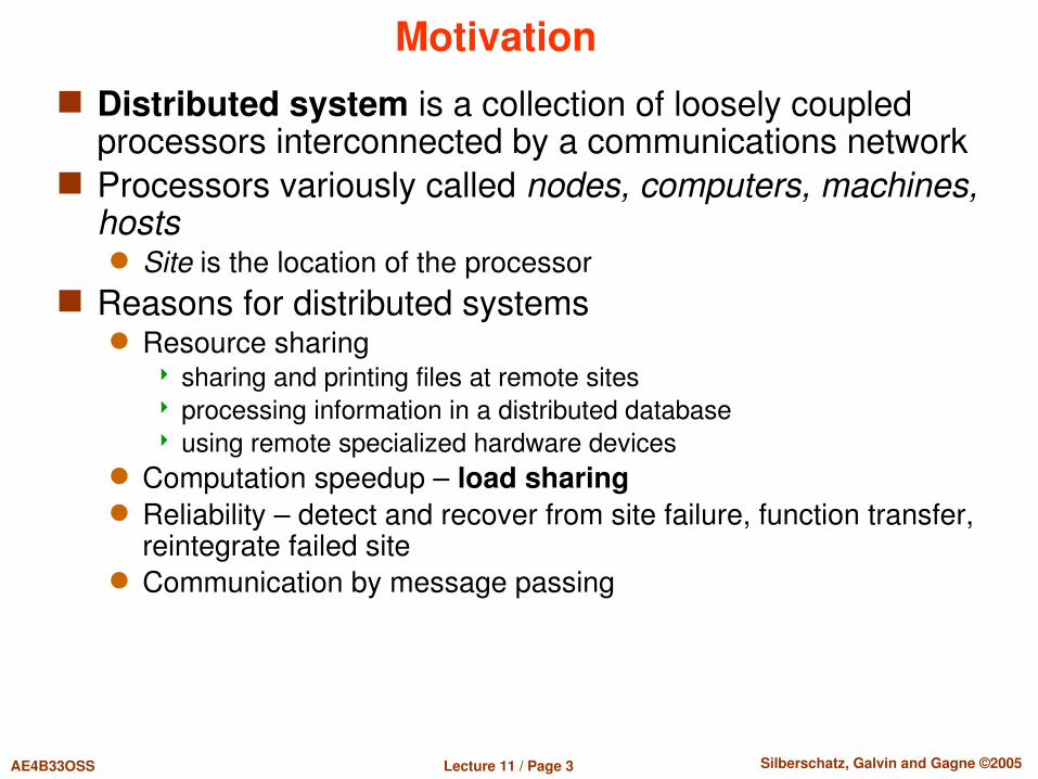
Motivation Distributed system is a collection of loosely coupled
processors interconnected by a communications network Processors variously called nodes, computers, machines,
hosts Site is the location of the processor
Reasons for distributed systems Resource sharing
sharing and printing files at remote sites processing information in a distributed database using remote specialized hardware devices
Computation speedup – load sharing Reliability – detect and recover from site failure, function transfer,
reintegrate failed site Communication by message passing
Lecture 11 / Page 4 AE4B33OSS Silberschatz, Galvin and Gagne ©2005
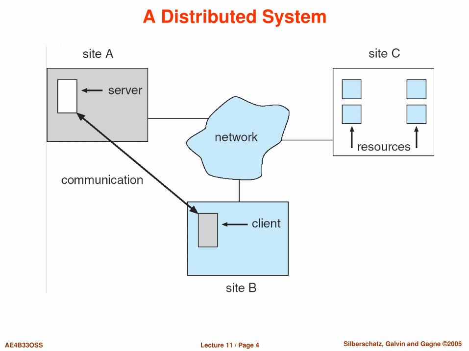
A Distributed System

Lecture 11 / Page 5 AE4B33OSS Silberschatz, Galvin and Gagne ©2005
Types of Distributed Operating Systems Network Operating Systems
Users are aware of multiplicity of machines. Access to resources of various machines is done explicitly by: Remote logging into the appropriate remote machine (telnet, ssh) Transferring data from remote machines to local machines, via the
File Transfer Protocol (FTP) mechanism
Distributed Operating Systems Features follow
Lecture 11 / Page 6 AE4B33OSS Silberschatz, Galvin and Gagne ©2005
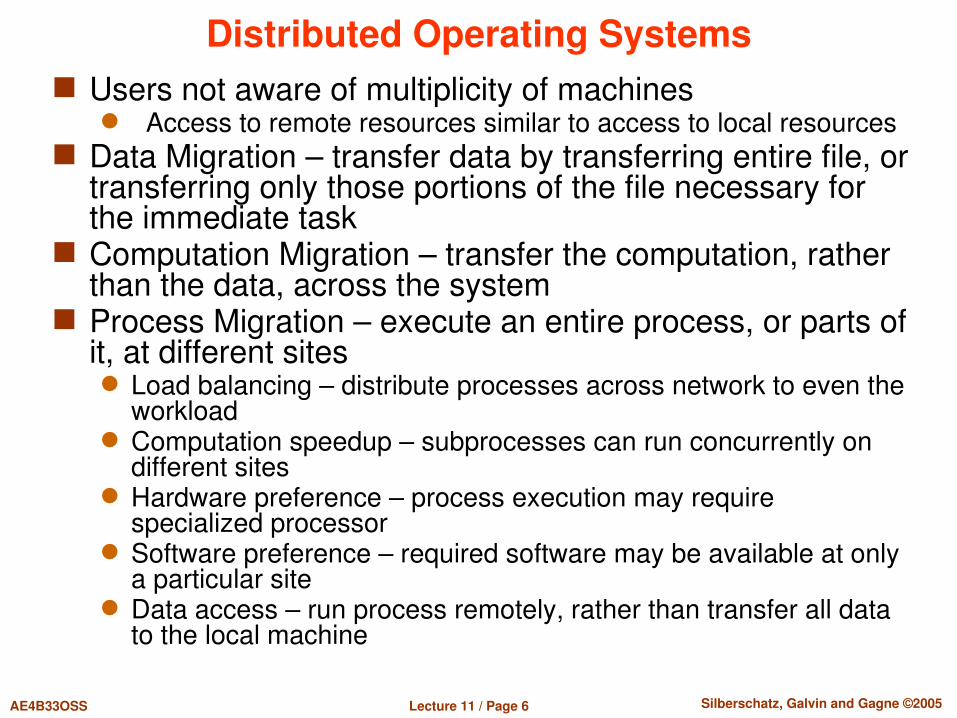
Distributed Operating Systems Users not aware of multiplicity of machines
Access to remote resources similar to access to local resources Data Migration – transfer data by transferring entire file, or
transferring only those portions of the file necessary for the immediate task
Computation Migration – transfer the computation, rather than the data, across the system
Process Migration – execute an entire process, or parts of it, at different sites
Load balancing – distribute processes across network to even the workload
Computation speedup – subprocesses can run concurrently on different sites
Hardware preference – process execution may require specialized processor
Software preference – required software may be available at only a particular site
Data access – run process remotely, rather than transfer all data to the local machine

Lecture 11 / Page 7 AE4B33OSS Silberschatz, Galvin and Gagne ©2005
Network Structure LAN LocalArea Network (LAN) – designed to cover small
geographical area. Multiaccess bus, ring, or star network Speed 10 megabits/second, or higher Broadcast is fast and cheap Nodes:
usually workstations and/or personal computers
a few (usually one or two) mainframes
Lecture 11 / Page 8 AE4B33OSS Silberschatz, Galvin and Gagne ©2005
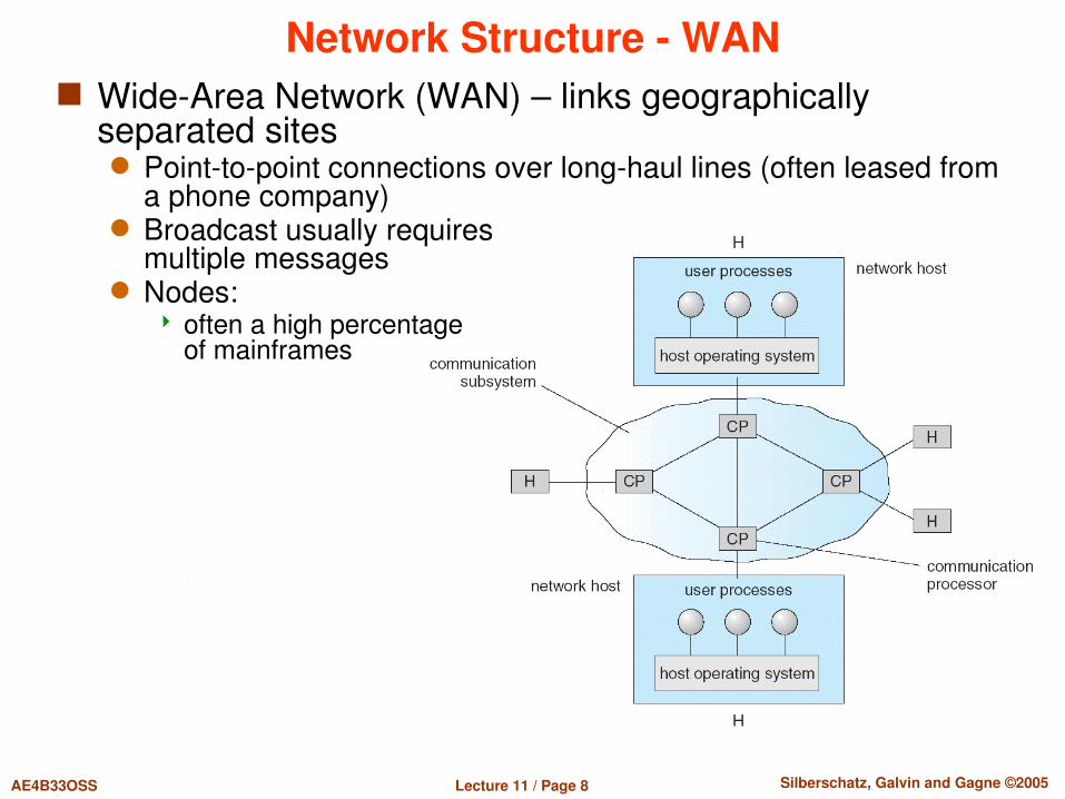
Network Structure WAN WideArea Network (WAN) – links geographically
separated sites Pointtopoint connections over longhaul lines (often leased from
a phone company) Broadcast usually requires
multiple messages Nodes:
often a high percentage of mainframes
Lecture 11 / Page 9 AE4B33OSS Silberschatz, Galvin and Gagne ©2005
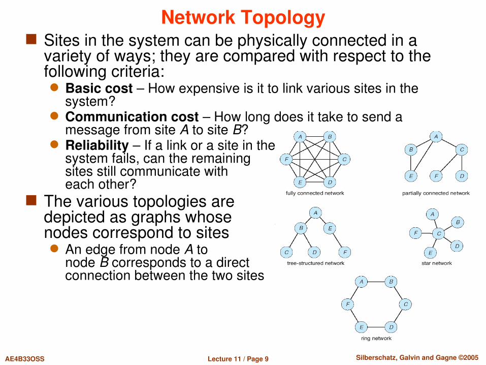
Network Topology Sites in the system can be physically connected in a
variety of ways; they are compared with respect to the following criteria:
Basic cost – How expensive is it to link various sites in the system?
Communication cost – How long does it take to send a message from site A to site B?
Reliability – If a link or a site in thesystem fails, can the remaining sites still communicate with each other?
The various topologies are depicted as graphs whose nodes correspond to sites
An edge from node A to node B corresponds to a direct connection between the two sites

Lecture 11 / Page 10 AE4B33OSS Silberschatz, Galvin and Gagne ©2005
CESNET structure
Lecture 11 / Page 11 AE4B33OSS Silberschatz, Galvin and Gagne ©2005
Communication Structure
The design of a communication network must address four basic issues:
Naming and name resolution How do two processes locate each other to communicate?
Routing strategies How are messages sent through the network?
Connection strategies How do two processes send a sequence of messages?
Contention The network is a shared resource, so how do we resolve
conflicting demands for its use?

Lecture 11 / Page 12 AE4B33OSS Silberschatz, Galvin and Gagne ©2005
Naming and Name Resolution Name systems in the network Address messages with the processidentifier Identify processes on remote systems by
<hostidentifier, processidentifier> pair
Domain name service (DNS) Specifies the naming structure of the hosts, as well as name to
address resolution (Internet)

Lecture 11 / Page 13 AE4B33OSS Silberschatz, Galvin and Gagne ©2005
Open Systems Interconnection (OSI)
Physical layer – handles the mechanical and electrical details of the physical transmission of a bit stream, voltages, layout of pins, line impedance, cable specification, Token ring, FDDI, IEEE 802.11, Bluetooth
Datalink layer – handles the frames, or fixedlength parts of packets, including any error detection and recovery that occurred in the physical layer, Ethernet IEEE 802.3
Network layer – provides connections and routes packets in the communication network, including handling the address of outgoing packets, decoding the address of incoming packets, and maintaining routing information for proper response to changing load levels
The communication network is partitioned into the following multiple layers:
Lecture 11 / Page 14 AE4B33OSS Silberschatz, Galvin and Gagne ©2005
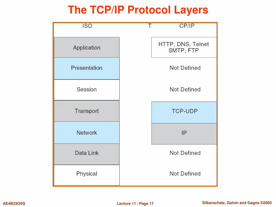
Communication Protocol (Cont.) Transport layer – responsible for lowlevel network
access and for message transfer between clients, including partitioning messages into packets, maintaining packet order, controlling flow, and generating physical addresses
Session layer – implements sessions, or processtoprocess communications protocols
Presentation layer – resolves the differences in formats among the various sites in the network, including character conversions, and half duplex/full duplex (echoing)
Application layer – interacts directly with the users’ deals with file transfer, remotelogin protocols and electronic mail, as well as schemas for distributed databases, etc.

Lecture 11 / Page 15 AE4B33OSS Silberschatz, Galvin and Gagne ©2005
The ISO/OSI Protocol Layers

Lecture 11 / Page 16 AE4B33OSS Silberschatz, Galvin and Gagne ©2005
Communication Via ISO/OSI Network Model
Lecture 11 / Page 17 AE4B33OSS Silberschatz, Galvin and Gagne ©2005
The TCP/IP Protocol Layers
Lecture 11 / Page 18 AE4B33OSS Silberschatz, Galvin and Gagne ©2005
Failure detection Detecting hardware failure is difficult To detect a link failure, a handshaking protocol can be
used Assume Site A and Site B have established a link
At fixed intervals, each site will exchange an Iamup message indicating that they are up and running
If Site A does not receive a message within the fixed interval, it assumes either (a) the other site is not up or (b) the message was lost
Site A can now send an Areyouup? message to Site B If Site A does not receive a reply, it can repeat the message or try
an alternate route to Site B If Site A does not ultimately receive a reply from Site B, it
concludes some type of failure has occurred Types of failures:
Site B is down The direct link between A and B is down The alternate link from A to B is down The message has been lost
However, Site A cannot determine exactly why the failure has occurred

Lecture 11 / Page 19 AE4B33OSS Silberschatz, Galvin and Gagne ©2005
Reconfiguration
When Site A determines a failure has occurred, it must reconfigure the system:1. If the link from A to B has failed, this must be broadcast to every
site in the system2. If a site has failed, every other site must also be notified
indicating that the services offered by the failed site are no longer available
When the link or the site becomes available again, this information must again be broadcast to all other sites

Lecture 11 / Page 20 AE4B33OSS Silberschatz, Galvin and Gagne ©2005
Design Issues Transparency – the distributed system should appear as
a conventional, centralized system to the user
Fault tolerance – the distributed system should continue to function in the face of failure
Scalability – as demands increase, the system should easily accept the addition of new resources to accommodate the increased demand
Clusters – a collection of semiautonomous machines that acts as a single system

Lecture 11 / Page 21 AE4B33OSS Silberschatz, Galvin and Gagne ©2005
Example: Networking Link layer the transmission of a network packet between
hosts on an Ethernet network For link layer you can use alternative protocols – for
example PPP – Point to Point protocol for connection of two nodes using HDLC frames
Every host has a unique IP address and a corresponding Ethernet (MAC) address
Communication requires both addresses Domain Name Service (DNS) can be used to acquire IP
addresses Address Resolution Protocol (ARP) is used to map MAC
addresses to IP addresses If the hosts are on the same network, ARP can be used
If the hosts are on different networks, the sending host will send the packet to a router which routes the packet to the destination network

Lecture 11 / Page 22 AE4B33OSS Silberschatz, Galvin and Gagne ©2005
An Ethernet Packet
Destination Source Frame Preamble:
7 bytes [10101010] + 1 byte [10101011] used to synchronize the transfer rate
6 byte addresses (MAC addresses) World unique addresses If destination address = 0xFFFFFFFFFFFF then broadcast
Frame type – indicates different standards: 0x0800 = the packet contains an IPv4 datagram 0x86DD indicates an IPv6 frame 0x0806 indicates an ARP frame
Message data usually 1500 bytes Encapsulates packet with the transferred data

Lecture 11 / Page 23 AE4B33OSS Silberschatz, Galvin and Gagne ©2005
Internet Architecture Basic Internet properties
Each host has its unique identification: the IP address IP address is composed by the network address and the host address
within the network The applications and the network API behavior is independent of the
LAN technology Basic architecture of the Internet (and general internetworking)
Gateways and routers connect LAN’s LAN’s may be based on different technologies
Gateways keep info on hosts belonging to LAN’s they connect Routers maintain knowledge about networks
Routers forward packets based on the network part of the IP address (the host part is ignored when forwarding)
Units connecting LAN’s usually merge gateway and router functionality
IP protocols consider all LAN’s as equivalent regardless of the technology
LAN 1 LAN 2 LAN 3gateway or router
gateway or router

Lecture 11 / Page 24 AE4B33OSS Silberschatz, Galvin and Gagne ©2005
Internet addresses Current Internet – v. 4 uses 32 bits addresses
Convention: decimal numbers per 8 bits each – 147.32.85.1 Internet v. 6 uses 128 bits addresses
More details next lesson Not easy to switch from v4 to v6 Tunneling v6 through v4 World IPv6 day was 8 June 2011 You can test your IPv6 configuration on testipv6.com
IP address Identifies each single network adaptor
Host can have several adaptors („multihomed“ host) One adaptor can even have more addresses
Is composed of two parts Identification (address) of the network – netid (leftmost bits) Identification (address) of the host within the network – hostid (rightmost
bits)
Lecture 11 / Page 25 AE4B33OSS Silberschatz, Galvin and Gagne ©2005
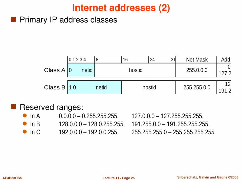
Internet addresses (2) Primary IP address classes
Reserved ranges: In A 0.0.0.0 – 0.255.255.255, 127.0.0.0 – 127.255.255.255, In B 128.0.0.0 – 128.0.255.255, 191.255.0.0 – 191.255.255.255, In C 192.0.0.0 – 192.0.0.255, 255.255.255.0 – 255.255.255.255
0 1 2 3 4 8 16 24 31 Net Mask Address range
Class A 0 netid hostid 255.0.0.0 0.0.0.0 –127.255.255.255
Class B 1 0 netid hostid 255.255.0.0 128.0.0.0 –191.255.255.255

Lecture 11 / Page 26 AE4B33OSS Silberschatz, Galvin and Gagne ©2005
Internet addresses (3) Convention:
Network address netid is the full IP address with hostid = 0 Address composed by netid and the hostid part is full of "1" serves
for addressing all hosts in the network (network broadcast address) Net maska:
Address „arithmetic“
Special addresses 127.0.0.1 – loopback address – a host speaks to itself Private addresses – may not spread over Internet – routers must
not forward datagrams containing these addresses 1 class A network: 10.0.0.0 – 10.255.255.255 16 class B networks: 172.16.0.0 – 172.31.255.255 256 class C networks: 192.168.0.0 – 192.168.255.255
Multicast addresses – one host sends info to many “subscribed” hosts (e.g. Internet TV)
range 224.0.0.0 – 238.255.255.255
IPAddress ∧ NetMask = netidIPAddress ∧ ¬ (NetMask ) = hostid

Lecture 11 / Page 27 AE4B33OSS Silberschatz, Galvin and Gagne ©2005
Internet addresses (4) CIDR addressing (= Classless InterDomain Routing)
Address arithmetic enables for more efficient splitting netid|hostid – the border between netid and hostid may be anywhere
Net mask may be any number composed of n (n=0 ... 32) leftmost “1” bits
CIDR notation: IP_Address/n; e.g.: 147.32.85.128 – 147.32.85.191 = 147.32.85.128/26 Reserved ranges in CIDR notation:
0.0.0.0/8, 127.0.0.0 /8, 128.0.0.0/16, 191.255.0.0/16,192.0.0.0/24, 255.255.255.0/24
LAN 192.168.200.64/30 contains 4 addresses: 192.168.200.64 = netid, 192.168.200.65=host1, 192.168.200.66=host2, 192.168.200.67 = LAN broadcast
Saving IP addresses Using private addresses and their translation to “public” addresses
(NAT = Network Address Translation) Many private addresses is translated into 1 public Problem with publicly available servers on the private address LAN
(behind the NAT router) The principle of NAT is connected to IP protocols
InternetInternetLAN with private
IP addressesRouter
with NAT147.32.85.27 192.168.100.1
Lecture 11 / Page 28 AE4B33OSS Silberschatz, Galvin and Gagne ©2005
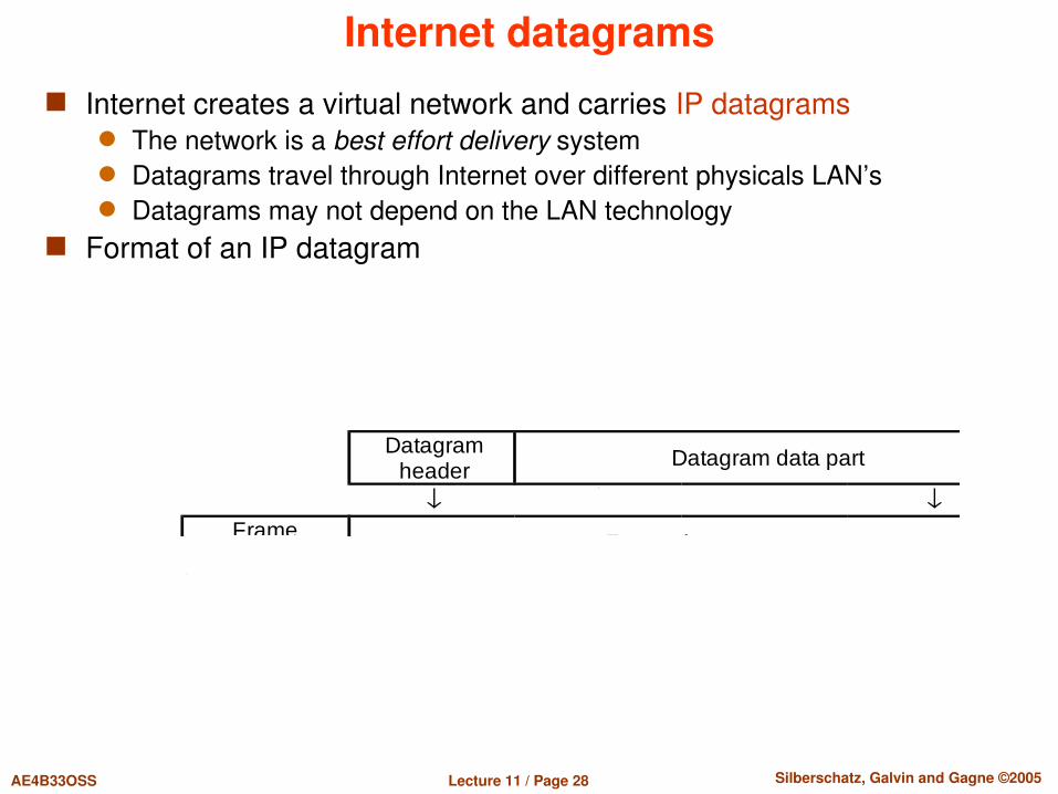
Internet datagrams Internet creates a virtual network and carries IP datagrams
The network is a best effort delivery system Datagrams travel through Internet over different physicals LAN’s Datagrams may not depend on the LAN technology
Format of an IP datagram
Datagramheader Datagram data part
Frame Frame data part

Lecture 11 / Page 29 AE4B33OSS Silberschatz, Galvin and Gagne ©2005
IP datagram header Every IP datagram has a header carrying information
necessary for datagram delivery
Fields VERS: IP protocol version – for IP v. 4 VERS = 4 HLEN: Header length in 32bit words (standard 5) TOTAL LENGTH: of the datagram in bytes (header+data) – max. 64 kB SOURCE IP ADDRESS: sender’s IP address DESTINATION IP ADDRESS: IP address where to deliver IDENTIFICATION: usually sequential or a random number generated
by the datagram sender
0 4 8 16 19 24VERS HLEN SERVICE TYPE TOTAL LENGTH
IDENTIFICATION FLAGS FRAGMENT OFFSETTIME TO LIVE PROTOCOL HEADER CHECKSUM
SOURCE IP ADDRESSDESTINATION IP ADDRESS
IP OPTIONS (IF ANY) PADDINGDATA
Lecture 11 / Page 30 AE4B33OSS Silberschatz, Galvin and Gagne ©2005
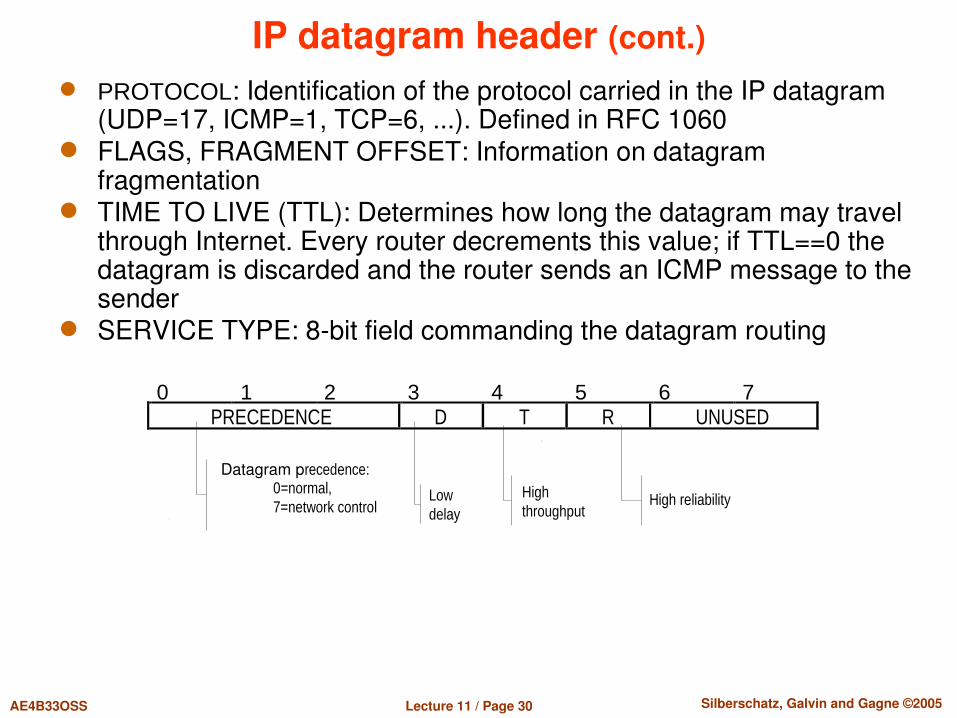
IP datagram header (cont.) PROTOCOL: Identification of the protocol carried in the IP datagram
(UDP=17, ICMP=1, TCP=6, ...). Defined in RFC 1060 FLAGS, FRAGMENT OFFSET: Information on datagram
fragmentation TIME TO LIVE (TTL): Determines how long the datagram may travel
through Internet. Every router decrements this value; if TTL==0 the datagram is discarded and the router sends an ICMP message to the sender
SERVICE TYPE: 8bit field commanding the datagram routing
0 1 2 3 4 5 6 7 PRECEDENCE D T R UNUSED
Datagram precedence: 0=normal, 7=network control
Low delay
High throughput High reliability
Lecture 11 / Page 31 AE4B33OSS Silberschatz, Galvin and Gagne ©2005
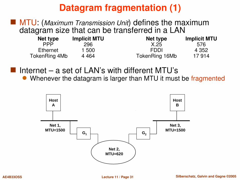
Datagram fragmentation (1) MTU: (Maximum Transmission Unit) defines the maximum
datagram size that can be transferred in a LANNet type Implicit MTU Net type Implicit MTU
PPP 296 X.25 576 Ethernet 1 500 FDDI 4 352TokenRing 4Mb 4 464 TokenRing 16Mb 17 914
Internet – a set of LAN’s with different MTU’s Whenever the datagram is larger than MTU it must be fragmented
HostB
Net 3,MTU=1500
HostA
Net 1,MTU=1500
Net 2,MTU=620
G1 G2
Lecture 11 / Page 32 AE4B33OSS Silberschatz, Galvin and Gagne ©2005
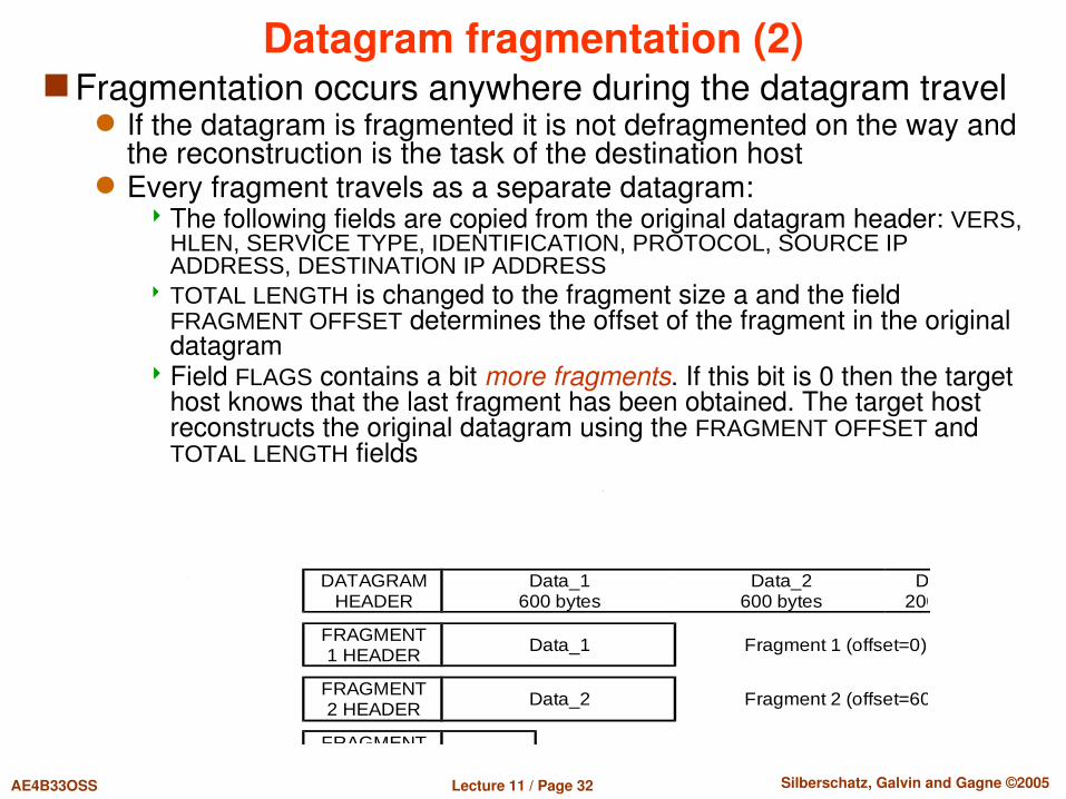
Datagram fragmentation (2) Fragmentation occurs anywhere during the datagram travel
If the datagram is fragmented it is not defragmented on the way and the reconstruction is the task of the destination host
Every fragment travels as a separate datagram: The following fields are copied from the original datagram header: VERS,
HLEN, SERVICE TYPE, IDENTIFICATION, PROTOCOL, SOURCE IP ADDRESS, DESTINATION IP ADDRESS
TOTAL LENGTH is changed to the fragment size a and the field FRAGMENT OFFSET determines the offset of the fragment in the original datagram
Field FLAGS contains a bit more fragments. If this bit is 0 then the target host knows that the last fragment has been obtained. The target host reconstructs the original datagram using the FRAGMENT OFFSET and TOTAL LENGTH fields
DATAGRAMHEADER
Data_1600 bytes
Data_2600 bytes
Data_3200 bytes
FRAGMENT1 HEADER Data_1 Fragment 1 (offset=0)
FRAGMENT2 HEADER Data_2 Fragment 2 (offset=600)
FRAGMENT Data_3 Fragment 3 (offset=1200)
Lecture 11 / Page 33 AE4B33OSS Silberschatz, Galvin and Gagne ©2005
Datagram routing (1) Routing is a decision making process on where to forward
the datagram (or its fragment). Any device making such decision is called router Routing can be direct or indirect
Direct routing occurs when the destination host is a part of the LAN directly connected to the router so that the datagram can be delivered directly to the destination.
All other cases represent indirect routing Routers in the Internet form a cooperative interconnected structure.
Datagrams pass from router to router until they reach a router capable to deliver directly (locally) to the destination
Table driven routing Every router maintains a routing table with entries in the form of pairs
(N, G), where N is netid of the destination network and G is the IP address of the “next router” along the path to the destination network N. The “next router” must be reachable directly so that the datagram can be forwarded there without further routing

Lecture 11 / Page 34 AE4B33OSS Silberschatz, Galvin and Gagne ©2005
Datagram routing (2)
Default routes Often LAN’s are connected to the “rest of world” through a single
router. Such router is called default gateway, i.e. the address where all host on the LAN send datagrams with the destination outside the LAN
HostSpecific Routes Sometimes it may be reasonable to assign a special routing
information for administrative, security, or technical reasons (e.g., dedicated serial line connection)
Network10.0.0.0
Network20.0.0.0
Network30.0.0.0
Network40.0.0.0F G H
10.0.0.5 20.0.0.6 30.0.0.7
20.0.0.5 30.0.0.6 40.0.0.7
Destination is on the net Forward datagram to 20.0.0.0 Deliver directly 30.0.0.0 Deliver directly 10.0.0.0 20.0.0.5 40.0.0.0 30.0.0.7
Routing table of G

Lecture 11 / Page 35 AE4B33OSS Silberschatz, Galvin and Gagne ©2005
Datagram routing (3) Routing algorithm
Extract the destination IP address DA from the datagram and using the netmask determine the netid of the destination network
1. If DA corresponds to a hostspecific route send the datagram directly to the destination host
2. If netid is equal to the netid of a directly connected LAN then deliver directly (locally)
3. If netid can be found in the routing table send the datagram to the corresponding “next router”
4. If the default route is specified send the datagram to the default gateway
5. Otherwise send a ICMP “Destination unreachable” message to the datagram sender

Lecture 11 / Page 36 AE4B33OSS Silberschatz, Galvin and Gagne ©2005
Local datagram delivery Direct routing must assure local datagram delivery
The same has to be done when forwarding to a router directly connected on the LAN (not through pointtopoint link)
Datagram contains the destination IP address but the delivery must be accomplished using a LAN specific physical address
Mapping IP addresses to physical addresses Address Resolution Protocol (ARP) – dynamic mapping Ethernet case example solution: datagram sent by host A to host B
The sender has IP address IA and physical address PA needs to learn the physical address PB but knows only the IP address IB.
Host A sends an ARP ethernet broadcast frame and in its data part will contain both IA and IB (Whohas ARP request). This frame get all hosts on the LAN.
Host which recognizes its IP address IB responds to this broadcast (ARP reply) and tells the requestor its physical address PB.
The ethernet broadcast makes a big load for the LAN host; so the requestor caches PB for some time (5 minutes as standard)
Host B has learnt from ARP request also addresses IA a PA so it caches it, too (an early datagram from B to A can be expected).
A real network capture:12:32:35.363 arp who-has 147.32.85.117 tell 147.32.85.812:32:35.696 arp reply 147.32.85.117 is-at 00:1a:80:d9:27:64

Lecture 11 / Page 37 AE4B33OSS Silberschatz, Galvin and Gagne ©2005
ICMP Protocol ICMP (= Internet Control Message Protocol), IP protocol number
= 1 (cf. IP datagram header) The simplest protocol for network control and error message
passing defined in RFC 792
ICMP header does not have a fixed structure (except for the first 4 bytes)
Field TYPE shows ICMP message purpose and determines also the format and meaning of other fields – some ICMP types are:
E.g., „ping“ uses ICMP Echo request/Echo reply; for more click here
TYPE Purpose TYPE Purpose0 Echo reply 8 Echo request3 Destination unreachable 11 Datagram TTL exceeded5 Redirect (route change) 12 Datagram parameter problem

Lecture 11 / Page 38 AE4B33OSS Silberschatz, Galvin and Gagne ©2005
IPv6 IPv6 has 128 bits address (IPv4 only 32 bit) IPv6 improves some issues from IPv4 but it is still IP
layer Why 6? Internet Stream Protocol from 1979 uses in IP
header byte version 5. Next free number was 6. Improvements
Larger address space – aprox 3.4×1038 of address Multicasting – sending one packet to different computers SLAAC – Stateless address autoconfiguration –automatic
configuration using Neighbor Discovery from router with ICMPv6 protocol (can be used DHCPv6 or static settings)
Network security is in IPv6 mandatory Mobility – avoid triangular routing for mobile devices Jumbogram – datagram with size 232 – 1 (in IPv4 max 65535)

Lecture 11 / Page 39 AE4B33OSS Silberschatz, Galvin and Gagne ©2005
IPv6 address Notation 8 groups with 16 bits – each group has 4
hexadecimal numbers 2001:0db8:85a3:0000:0000:8a2e:0370:7334 Zeros are not necessary, if they has no meaning 2001:db8:85a3:::8a2e:370:7334
General format unicast and anycast: 48 or more – routing prefix 16 or fewer – subnetid ( subnetid+routing prefix = 64) 64 – interface identifier (it can be MACaddress of network card,
assigned by DHCPv6, generated randomly, assigned manually) Format for multicast:
8 bits prefix – started with FF 4 bits flag 4 bits scope 112 bits group ID
Lecture 11 / Page 40 AE4B33OSS Silberschatz, Galvin and Gagne ©2005
IPv6 routing Simplified processing by routers Packet header in IPv6 is more simple IPv6 Routers do not perform fragmentation
Minimal MTU (Maximal transmission unit) is 1280 Perform MTU discovery – it means detect MTU for specific route
IPv6 has no checksum (it is in transport and link layer) TTL – (Time To Live) is replaced by Hop Limit – routers
need not to compute time in queues Routing prefix specify all routing information
RFC 3177 (2001) suggested that all end sites receive /48 address allocation
RFC 6177 (2011) reduces this address allocation to /56
Lecture 11 / Page 41 AE4B33OSS Silberschatz, Galvin and Gagne ©2005
From IPv4 to IPv6 IPv4 with CIDR routing and NAT slow down change to
IPv6 How to transform IPv4 to IPv6
Dualstack – router can handle IPv4 and IPv6 together Tunneling – encapsulation of IPv6 into IPv4 protocol Proxying and translation for IPv6only host Backward compatibility, IPv6 host can communicate with IPv4
network You can check your computer on:
www.testipv6.cz www.testipv6.com ipv6test.google.com

Lecture 11 / Page 42 AE4B33OSS Silberschatz, Galvin and Gagne ©2005
Goals of transportation layer Endtoend communication Distinguish different senders and receivers on one host Enable connectionoriented data transfer Ensure reliability Ensure Quality of service Control data transfer
Main features of TCP Data arrive inorder Data hava minimal error – correctness Duplicate data are discarded Lost/discarded data are resent
Lecture 11 / Page 43 AE4B33OSS Silberschatz, Galvin and Gagne ©2005
Transportation Layer Transportation layer suppose 3 types of network layer:
Category A: no lost packets, no disconnection – local networks Category B: no lost packets, some disconnection – private data
networks Category C: lost packets and disconnections – whole internet
5 classes of transportation layer: TP0 – simple layer for category A TP1 – layer for category B, solve disconnections TP2 – for category A, enable use one network layer for more
transport connections – ports TP3 – for category B, enable use one network layer for more
transport connection and handle disconnections TP4 – transport layer for category C, reliable data transfer

Lecture 11 / Page 44 AE4B33OSS Silberschatz, Galvin and Gagne ©2005
Transportation layer Network layer and bellow layers are minimalistic, layers
focus on speed and robustness, no connections and no reliability
Transport layer can change character of network layer if the application wants
Transportation layer can be reliable and connectionoriented
UDP – simple transport layer with no connection and no reliability
TCP – connectionoriented and reliable Application can select TCP or UDP
Lecture 11 / Page 45 AE4B33OSS Silberschatz, Galvin and Gagne ©2005
Transportation layer Network layer uses host as a unit Transportation layer distinguishes users on host –
different applications from different users Transportation layer is making multiplex – gathers data
from different users and makes demultiplex – received data are assigned to different users
To distinguish users transportation layer cannot use PID, because PIDs are dynamical, the static gates are used
ISO/OSI defines SAP – Service Access Point, TCP calls this gates as ports
Application connects to SAP and use the SAP as distinguish descriptor

Lecture 11 / Page 46 AE4B33OSS Silberschatz, Galvin and Gagne ©2005
Socket vs. port Port is number that define SAP for connection from
different applications Socket was created as abstract file for controlling data
transfer through SAP Sockets were used for networking as API for using ports
SAPs Ports are same for different computers Sockets depend on specific implementation (WINSOCK
for Windows, BSD Socket for unix)
Lecture 11 / Page 47 AE4B33OSS Silberschatz, Galvin and Gagne ©2005
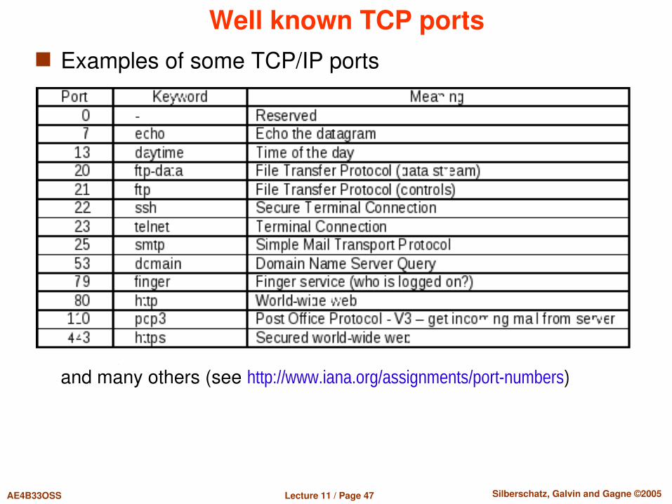
Well known TCP ports Examples of some TCP/IP ports
and many others (see http://www.iana.org/assignments/port-numbers)

Lecture 11 / Page 48 AE4B33OSS Silberschatz, Galvin and Gagne ©2005
API for network services The basic system API for network communication is a socket (see
also Berkeley sockets) Create socket (get a socket “file” descriptor)
sock_descr = socket(af, type, protocol) af – specifies address and protocol family (for IP af = AF_INET) type – determines the way of communication
– SOCK_STREAM, SOCK_DGRAM, SOCK_RAW, ... protocol – particular protocol type (TCP, UDP, ICMP, ...)
Assign socket a local address (passive socket open – server side)bind(sock_descr, local_addr, addr_len) sock_descr – socket local_addr – local address, for AF_INET a structure including port addr_len – address length in bytes
Listen for incoming connections (server side)listen(sock_descr, backlog) sock_descr – socket, backlog – number of allowable connections
An incoming connection arrived (server gets the client identification)new_sd = accept(sock_descr, *client_addr, *client_addr_len)
Connect to a remote address (active open – client side)connect(sock_descr, remote_addr, addr_len) – parameters like for bind()
Data transfers using write, send, sendmsg, read, recv, recvmsg
Terminating the connectionclose(sock_descr)
Lecture 11 / Page 49 AE4B33OSS Silberschatz, Galvin and Gagne ©2005
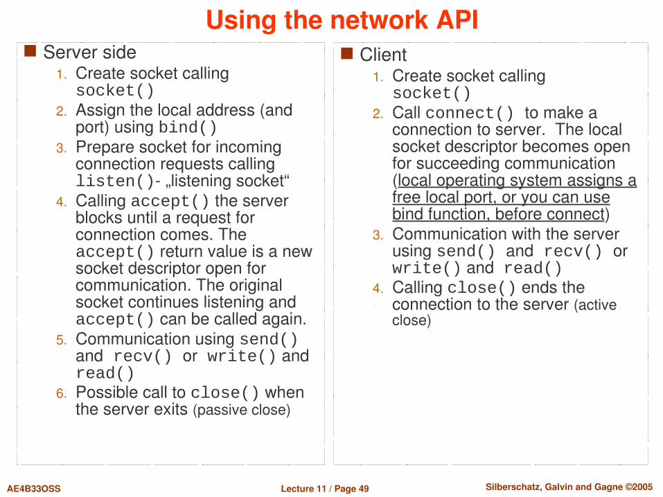
Using the network API Server side
1. Create socket callingsocket()
2. Assign the local address (and port) using bind()
3. Prepare socket for incoming connection requests calling listen() „listening socket“
4. Calling accept() the server blocks until a request for connection comes. The accept() return value is a new socket descriptor open for communication. The original socket continues listening and accept() can be called again.
5. Communication using send() and recv() or write() and read()
6. Possible call to close() when the server exits (passive close)
Client1. Create socket callingsocket()
2. Call connect() to make a connection to server. The local socket descriptor becomes open for succeeding communication (local operating system assigns a free local port, or you can use bind function, before connect)
3. Communication with the server using send() and recv() or write() and read()
4. Calling close() ends the connection to the server (active close)
Lecture 11 / Page 50 AE4B33OSS Silberschatz, Galvin and Gagne ©2005
Retransmission timeouts
Constant value of timeout when to resend the TCP/IP segment is inappropriate
Internet is too heterogeneous and is composed of a huge number of LAN’s based on different HW technologies
Gigabit ethernet, 33 kbit serial line, intercontinental satellite link, etc. TCP/IP adapts to changing timing parameters of the virtual
connection A simple adaptive algorithm to adjust the timeout is used The algorithm is based on continuous monitoring of „round trip time“
(RTT) Time between dispatching the packet and its acknowledgement.
The real timeout is computed as a weighted average and dispersion of RTT measured in the recent history.
This strategy quickly accommodates to the speed and load changes on the intermediate networks and routers

Lecture 11 / Page 51 AE4B33OSS Silberschatz, Galvin and Gagne ©2005
Flow control The receiver sends to sender size of its free part of
receiving buffer Sender sends packet with data Receiver accepts data and computes new size of free
part of buffer and sends acknowledgment with this new size
If there is no free space in buffer, receiver sends 0 and blocks the sender
After reading data from application, receiver sends again acknowledgment with new size of free part of receiving buffer

Lecture 11 / Page 52 AE4B33OSS Silberschatz, Galvin and Gagne ©2005
Establishing the TCP connection TCP uses a threestage procedure to establish the virtual
connection:1. In the first step, the connection initiator (client) sends the other party
(server) a segment containing SYN bit = 1, randomly generated SEQUENCE NUMBER = x and an empty data section.
2. The server responds by a segment with SYN and ACK set to 1, random SEQUENCE NUMBER = y and ACKNOWLEDGMENT NUMBER = x+1.
3. After receiving this segment, the client acknowledges it by sending a segment with ACK set to 1, SYN bit=0 and the ACKNOWLEDGMENT NUMBER = y+1.
This way the initial values of SEQUENCE NUMBER and ACKNOWLEDGMENT NUMBER fields are synchronized for the future life time of the virtual connection and are used to number the following TCP/IP segments
The sequential numbers are random It enables to detect a failure or restart of hosts on the connection ends
that can happen during a longer timeout

Lecture 11 / Page 53 AE4B33OSS Silberschatz, Galvin and Gagne ©2005
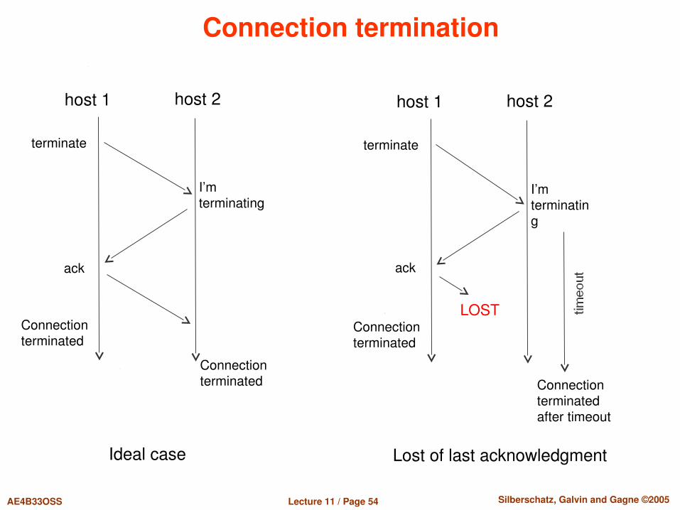
TCP connection termination
Connection is normally terminated on request of one of the connected applications
Application tells TCP that there are no more data to be exchanged If server – passive close If client – active close
TCP software closes the connection by sending a segment with a set FIN bit
For the final termination of the virtual connection, it is necessary also to close the opposite direction. The party that received the segment with FIN bit reacts by sending a segment with FIN bit, too.
The TCP connection can be terminated forcibly using the RST bit
Lecture 11 / Page 54 AE4B33OSS Silberschatz, Galvin and Gagne ©2005
Connection termination
Ideal case
host 1
I’mterminating
ack
Connectionterminated
Connectionterminated
terminate
host 2
Lost of last acknowledgment
host 1
I’mterminating
ack
Connectionterminated
Connectionterminated after timeout
terminate
host 2
LOST

Lecture 11 / Page 55 AE4B33OSS Silberschatz, Galvin and Gagne ©2005
Connection termination
Lost of more datagram's
host 1
I’mterminating
Connectionterminatedafter timeout
Connectionterminated after timeout
terminate
host 2
LOST
Lost of first acknowledgment
host 1
I’mterminating
ack
Connectionterminated
Connectionterminated
terminate
host 2
LOST
terminate
I’mterminating
LOST
terminate
Lecture 11 / Page 56 AE4B33OSS Silberschatz, Galvin and Gagne ©2005
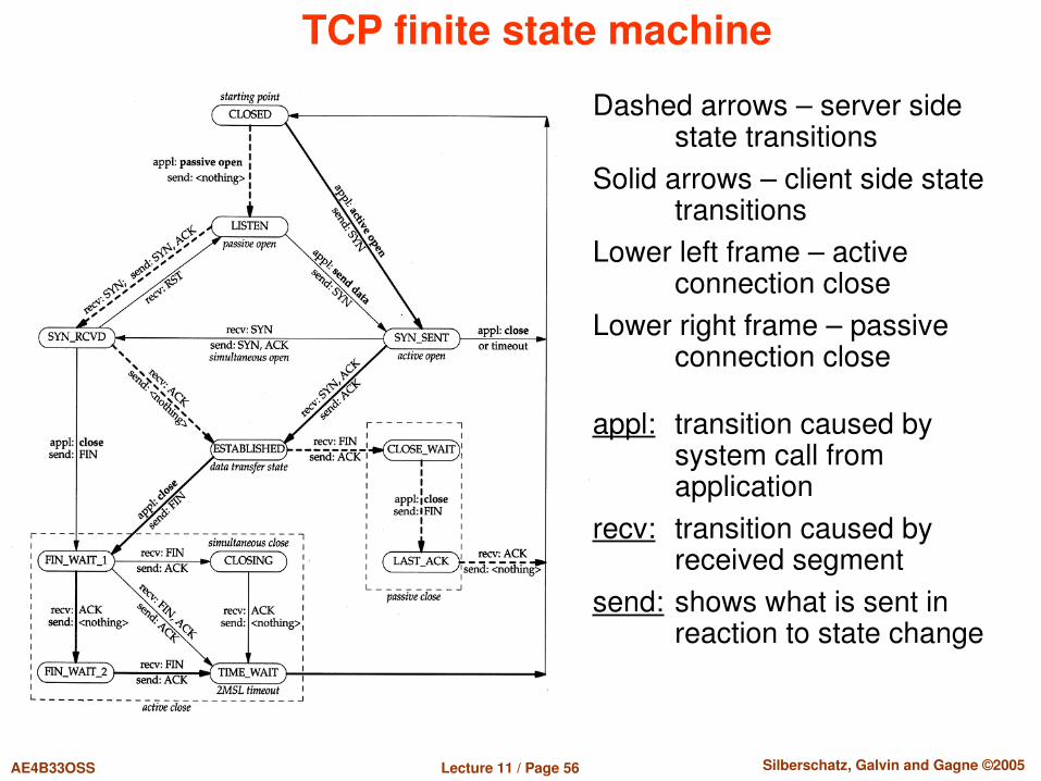
TCP finite state machine
Dashed arrows – server side state transitions
Solid arrows – client side state transitions
Lower left frame – active connection close
Lower right frame – passive connection close
appl: transition caused by system call from application
recv: transition caused by received segment
send: shows what is sent in reaction to state change
Lecture 11 / Page 57 AE4B33OSS Silberschatz, Galvin and Gagne ©2005
QoS Different applications have different demands Standard functionality of transport layers is best effort – as much as
possible Solution
Brute force – increase network capacity QoS – Quality of Service – different demands
QoS – different qualities Dropped packets The routers might fail to deliver (drop) some packets if
their data is corrupted or they arrive when the buffers are already full. The receiving application may ask for this information to be retransmitted, possibly causing severe delays in the overall transmission.
Errors Sometimes packets are corrupted due to bit errors caused by noise and interference, especially in wireless communications and long copper wires. The receiver has to detect this and, just as if the packet was dropped, may ask for this information to be retransmitted.

Lecture 11 / Page 58 AE4B33OSS Silberschatz, Galvin and Gagne ©2005
QoS QoS types
Latency It might take a long time for each packet to reach its destination, because it gets held up in long queues, or takes a less direct route to avoid congestion. This is different from throughput, as the delay can build up over time, even if the throughput is almost normal. In some cases, excessive latency can render an application such as VoIP or online gaming unusable.
Jitter Packets from the source will reach the destination with different delays. A packet's delay varies with its position in the queues of the routers along the path between source and destination and this position can vary unpredictably. This variation in delay is known as jitter and can seriously affect the quality of streaming audio and/or video.
Outoforder delivery When a collection of related packets is routed through a network, different packets may take different routes, each resulting in a different delay. The result is that the packets arrive in a different order than they were sent. This problem requires special additional protocols responsible for rearranging outoforder packets to an synchronous state once they reach their destination. This is especially important for video and VoIP streams where quality is dramatically affected by both latency and lack of sequence.
Lecture 11 / Page 59 AE4B33OSS Silberschatz, Galvin and Gagne ©2005
QoS Different applications have different demands:
Email – minimal error FTP – minimal error, maximal capacity WWW – Minimal error, big capacity, low latency Audio on Demand – can have error, average latency, minimal
jitter, big capacity IP telephony – can have error, minimal latency, minimal jitter,
good capacity (to understand voice you can lost 20% of information)
Videoconference – can have error, minimal latency, minimal jitter, maximal capacity
Solution Support for QoS on network layer – all routers must support QoS Integrated Services Differentiated Services
Lecture 11 / Page 60 AE4B33OSS Silberschatz, Galvin and Gagne ©2005
Integrated Services Flow specification – TSPEC
Token bucket algorithm Use tokens to limit data transfer Without token you cannot send data
Resource Reservation Protocol – RSVP All routers on path must support this function Reserve capacity for specific transmission Routers can accept requested reservation and once they accept
reservation, they have to carry traffic Router can reject request for reservation
Lecture 11 / Page 61 AE4B33OSS Silberschatz, Galvin and Gagne ©2005
Differentiated Services Smaller influence on network layer In December 1998, the IETF published RFC 2474 Definition of the
Differentiated Services Field (DS field) in the IPv4 and IPv6 Headers, which replaced the IPv4 TOS field with the DS field a range of eight values (Class Selectors) is used for backward compatibility with the IP precedence specification in the former TOS field
DiffServ operates on the principle of traffic classification, where each data packet is placed into a limited number of traffic classes, rather than differentiating network traffic based on the requirements of an individual flow. Each router on the network is configured to differentiate traffic based on its class. Each traffic class can be managed differently, ensuring preferential treatment for higherpriority traffic on the network.
PerHop Behaviors: Default PHB (Per hop behavior)—which is typically besteffort traffic Expedited Forwarding (EF) PHB—dedicated to lowloss, lowlatency traffic Assured Forwarding (AF) PHB—gives assurance of delivery under prescribed
conditions Class Selector PHBs—which maintain backward compatibility with the IP
Precedence field.

Lecture 11 / Page 62 AE4B33OSS Silberschatz, Galvin and Gagne ©2005
Application solutionClient buffering – QoS on application layer• oneway no interactive multimedia (for example video playback) can remove “jitter” with buffering• interactive video can use buffer too, but the overall delay cannot be too big
RTSP – Real Time Streaming Protocol• Application protocol• Enable mutual setup on speed transfer
time
Video is generated with constant speed
Video is replayed with constant speed
changingdelay

Lecture 11 / Page 63 AE4B33OSS Silberschatz, Galvin and Gagne ©2005
RTP/RTCPSupport for QoS on transportation layer• standard for packing multimedia data into transported packets with support according to type of multimedia• no influence to network layer and type of network transfer – best effortRTP – Real Time Protocol• creates it’s own multimedia packets and this packet are inserted into UDP packet• add information
• multimedia type (PCM 64kbps, GSM 13kbps, Motion JPEG, MPEG2 video)• order of packets – each packet has sequentional number, enable to detect lost packets and order• timestamp – time when the data were created, improve buffering on client side• stream identification – one RTP can be used for more streams• support multicast
RTCP – Real Time Control Protocol• exchange information between generator to receiver• information about reliability of connection – ration of lost packets, average delay, dispersion of delay, ability of receiver• description of RTP stream

End of Lecture 8
Questions?