networking
DESCRIPTION
Ongc ReportTRANSCRIPT

TABLE OF CONTENTS
Sr. no Topic Page No.

1.2.3.4.5.6.7.8.9.10.
DeclarationAcknowledgment
PrefaceCompany Profile
NetworkingScale
OSI ModelTelephone Exchange
NDB RadioRefrences
23468913273637
COMPANY PROFILE
Oil and Natural Gas Corporation

ONGC is an Indian state-owned oil and gas company headquartered at Dehradun, India. It is a Fortune Global 500 company ranked 413, and contributes 77% of India's crude oil production and 81% of India's natural gas production. It is the highest profit making corporation in India, according to filings with the BSE of latest quarter results External Link. It was set up as a commission on 14 August 1956. Indian government holds 74.14% equity stake in this company.
ONGC is one of the Asia's largest and most active company involved in exploration and production of oil. It is involved in exploring for and exploiting hydrocarbons in 26 sedimentary basins of India. It produces about 30% of India's crude oil requirement. It owns and operates more than 11,000 kilometres of pipelines in India. It is one of the highest profit making companies in India. In 2010, it stood at 18th position in thePlatts Top 250 Global Energy Company Rankings.
A turning point in the history of India’s oil sector was in 1994. While the oil sector was on the backburner of India's political realm for some time, is was brought to the forefront by the privatization of India's leading oil E&P organization, the ONGC. Simultaneously, there were steps taken for the

enhancement of production on the Bombay High oil fields as the result of a INR 150 billion development investment.
One of Asia's largest oil E&P companies, ONGC became a publicly held company as of February 1994, following the Indian government's decision to privatize. This privatization was conceived and achieved (sweat equity) to a great extent by ONGC’s influential Association of Scientific and Technical Officers (ASTO) – spearheaded by the then Bombay top executives Ganesh P. Shahi and Amarjit S. Jowandha (DGM and Head - Management Services Group too) who worked closely with the then ONGC CMDs S. K. Manglik and S.L. Khosla, IAS and with Dr. Vijay Kelkar, Secretary, Ministry of Petroleum & Natural Gas, Government of India, among others. Amarjit S. Jowandha was able to usher in change from his imbibed learnings, inter alia, from his alma mater University of Bombay [Jamnalal Bajaj Institute of Management Studies (also referred to as JBIMS or just Bajaj]. Eighty percent of ONGC assets were subsequently owned by the government, the other 20% were sold to the public. At this time, ONGC employed 48,000 people and had reserves and surpluses worth INR 104.34 billion, in addition to its intangible assets. The corporation's net worth of INR 107.77 billion was the largest of any Indian company.
After its initial privatization, ONGC had authorized capital of INR 150 billion: it also met its need to raise INR 35 billion to invest in viable oil and gas projects. The Asian Development Bank (ADB) had also set a deadline for privatizing and restructuring at 30 June 1994, if loans were to be granted for development of two ONGC projects. As a consequence of the successful privatization, the loans were granted - US$267 million for development of Gandhar Field, and US$300 million for the gas flaring reduction project in the Bombay Basin. The successfully formulated and implemented privatization strategy put ONGC at par with other large multinational and domestic oil companies.
COMPUTER NETWORKING

DEFINATION:
A computer network, often simply referred to as a network, is a collection of computers and devices interconnected by communications channels that facilitate communications and allows sharing of resources and information among interconnected devices.
Computer networking or Data Communications (Datacom) is the engineering discipline concerned with computer networks. Computer networking is sometimes considered a sub-discipline of electrical engineering, telecommunications, computer science, information technology and/or computer engineering since it relies heavily upon the theoretical and practical application of these scientific and engineering disciplines.
In the world of computers, networking is the practice of linking two or more computing devices together for the purpose of sharing data. Networks are built with a mix of computer hardware and computer software.
COMPUTER NETWORKING
Scale

Networks are often classified by their physical or organizational extent or their purpose, such as
local area network (LAN), wide area network (WAN), metropolitan area network (MAN), personal area network (PAN), virtual private network (VPN), campus area network (CAN), storage area network (SAN), Controller area network (CAN).
Usage, trust level, and access rights differ between these types of network
Local area network
A local area network (LAN) is a network that connects computers and devices in a limited geographical area such as home, school, computer laboratory, office building, or closely positioned group of buildings. Each computer or device on the network is a node. Current wired LANs are most likely to be based on Ethernet technology, although new standards like ITU-T G.hn also provide a way to create a wired LAN using existing home wires (coaxial cables, phone lines and power lines
Typical library network, in a branching tree topology and controlled access to resources
All interconnected devices must understand the network layer (layer 3), because they are handling multiple subnets (the different colors). Those inside the

library, which have only 10/100 Mbit/s Ethernet connections to the user device and a Gigabit Ethernet connection to the central router, could be called "layer 3 switches" because they only have Ethernet interfaces and must understand IP. It would be more correct to call them access routers, where the router at the top is a distribution router that connects to the Internet and academic networks' customer access routers.
The defining characteristics of LANs, in contrast to WANs (Wide Area Networks), include their higher data transfer rates, smaller geographic range, and no need for leased telecommunication lines.
Personal area network
A personal area network (PAN) is a computer network used for communication among computer and different information technological devices close to one person. Some examples of devices that are used in a PAN are personal computers, printers, fax machines, telephones, PDAs, scanners, and even video game consoles. A PAN may include wired and wireless devices. The reach of a PAN typically extends to 10 meters. A wired PAN is usually constructed with USB and Fire wire connections while technologies such as Bluetooth and infrared communication typically form a wireless PAN.
Home network
A home network is a residential LAN which is used for communication between digital devices typically deployed in the home, usually a small number of personal computers and accessories, such as printers and mobile computing devices. An important function is the sharing of Internet access, often a broadband service through a cable TV or Digital Subscriber Line (DSL) provider.
Wide area network
A wide area network (WAN) is a computer network that covers a large geographic area such as a city, country, or spans even intercontinental distances, using a communications channel that combines many types of media such as telephone lines, cables, and air waves. A WAN often uses transmission facilities provided by common carriers, such as telephone companies. WAN technologies

generally function at the lower three layers of the OSI reference model: the physical layer, the data link layer, and the network layer.
Campus network
A campus network is a computer network made up of an interconnection of local area networks (LANs) within a limited geographical area. The networking equipment (switches, routers) and transmission media (optical fiber, copper plant, Cat5 cabling etc.) are almost entirely owned (by the campus tenant / owner: an enterprise, university, government etc.).
In the case of a university campus-based campus network, the network is likely to link a variety of campus buildings including, for example, academic colleges or departments, the university library, and student residence halls.
Metropolitan area network
(MAN) is a large computer network that usually spans a city or a large campus.
Sample EPN made of Frame relay WAN connections and dialup remote access.

Sample VPN used to interconnect 3 offices and remote users
Enterprise private network
An enterprise private network is a network built by an enterprise to interconnect various company sites, e.g., production sites, head offices, remote offices, shops, in order to share computer resources.
Virtual private network
A virtual private network (VPN) is a computer network in which some of the links between nodes are carried by open connections or virtual circuits in some larger network (e.g., the Internet) instead of by physical wires. The data link layer protocols of the virtual network are said to be tunneled through the larger network when this is the case. One common application is secure communications through the public Internet, but a VPN need not have explicit security features, such as authentication or content encryption. VPNs, for example, can be used to separate the traffic of different user communities over an underlying network with strong security features.
VPN may have best-effort performance, or may have a defined service level agreement (SLA) between the VPN customer and the VPN service provider. Generally, a VPN has a topology more complex than point-to-point.

OSI MODEL
The Open Systems Interconnection model (OSI model) was a product of the Open Systems Interconnection effort at the International Organization for Standardization. It is a way of sub-dividing a communications system into smaller parts called layers. Similar communication functions are grouped into logical layers. A layer provides services to its upper layer while receiving services from the layer below. On each layer, an instance provides service to the instances at the layer above and requests service from the layer below.

Layer 1: Physical Layer
The Physical Layer defines electrical and physical specifications for devices. In particular, it defines the relationship between a device and a transmission medium, such as a copper or optical cable. This includes the layout of pins, voltages, cable specifications, hubs, repeaters, network adapters, host bus adapters (HBA used in storage area networks) and more.
The major functions and services performed by the Physical Layer are:
Establishment and termination of a connection to a communications medium.

Participation in the process whereby the communication resources are effectively shared among multiple users. For example, contention resolution and flow control.
Modulation, or conversion between the representation of digital data in user equipment and the corresponding signals transmitted over a communications channel. These are signals operating over the physical cabling (such as copper and optical fiber) or over a radio link.
Layer 2: Data Link Layer
The Data Link Layer provides the functional and procedural means to transfer data between network entities and to detect and possibly correct errors that may occur in the Physical Layer. Originally, this layer was intended for point-to-point and point-to-multipoint media, characteristic of wide area media in the telephone system. Local area network architecture, which included broadcast-capable multi access media, was developed independently of the ISO work in IEEE Project 802. In modern practice, only error detection, not flow control using sliding window, is present in data link protocols such as Point-to-Point Protocol (PPP), and, on local area networks, the IEEE 802.2 LLC layer is not used for most protocols on the Ethernet, and on other local area networks, its flow control and acknowledgment mechanisms are rarely used. Sliding window flow control and acknowledgment is used at the Transport Layer by protocols such as TCP.
Layer 3: Network Layer:
The Network Layer is Layer 3 of the seven-layer OSI model of computer networking.The Network Layer is responsible for routing packets delivery including routing through intermediate routers, whereas the Data Link Layer is responsible for Media Access Control, Flow Control and Error Checking.
The Network Layer provides the functional and procedural means of transferring variable length data sequences from a source to a destination host via one or more networks while maintaining the quality of service functions.
Functions of the Network Layer include:

Connection model: connectionless communication
For example, IP is connectionless, in that a frame can travel from a sender to a recipient without the recipient having to send an acknowledgement. Connection-oriented protocols exist at other higher layers of that model.
Host addressing
Every host in the network needs to have a unique address which determines where it is. This address will normally be assigned from a hierarchical system, so you can be "Fred Murphy" to people in your house, "Fred Murphy, Main Street 1" to Dubliners, or "Fred Murphy, Main Street 1, Dublin" to people in Ireland, or "Fred Murphy, Main Street 1, Dublin, Ireland" to people anywhere in the world. On the Internet, addresses are known as Internet Protocol (IP) addresses.
Message forwarding
Since many networks are partitioned into subnetworks and connect to other networks for wide-area communications, networks use specialized hosts, called gateways or routers to forward packets between networks. This is also of interest to mobile applications, where a user may move from one location to another, and it must be arranged that his messages
follow him. Version 4 of the Internet Protocol (IPv4) was not designed fwith this feature in mind, although mobility extensions exist. IPv6 has a better designed solution.
Within the service layering semantics of the OSI network architecture the Network
Layer responds to service requests from the Transport Layer and issues service
requests to the Data Link Layer.
LAYER 4: TRANSPORT LAYER

In computer networking, the Transport Layer provides end-to-end communication services for applications within a layered architecture of network components and protocols. The transport layer provides convenient services such as connection-oriented data stream support, reliability, flow control, and multiplexing.
Transport layers are contained in both the TCP/IP model, which is the foundation of the Internet, and the Open Interconnection (OSI) model of general networking.
The most well-known transport protocol is the Transmission Control Protocol (TCP). It lent its name to the title of the entire Internet Protocol Suite, TCP/IP. It is used for connection-oriented transmissions
LAYER 5: SESSION LAYER
The Session Layer is Layer 5 of the seven-layer OSI model of computer networking.
The Session Layer provides the mechanism for opening, closing and managing a session between end-user application processes, i.e. a semi-permanent dialogue.
An example of a Session Layer protocol is the OSI protocol suite Session Layer Protocol, also known as X.225 or ISO 8327. In case of a connection loss this protocol may try to recover the connection
The session layer is responsible for setting up, managing and then tearing down sessions between Presentation layer entites. This layer also provides dialogue control between devices, or nodes. It coordinates communication between system and servers to organise there communication by offering three different modes:
1) Simplex2) Half duplex3) Full duplex
To sum up, the Session layer basically keeps different applications, data separate from other applications.
Layer 6: Presentation Layer

The Presentation Layer is Layer 6 of the seven-layer OSI model of computer networking and serves as the data translator for the network .It is sometimes called the syntax layer.
The Presentation Layer is responsible for the delivery and formatting of information to the application layer for further processing or display.[4] It relieves the application layer of concern regarding syntactical differences in data representation within the end-user systems.An example of a presentation service would be the conversion of an EBCDIC-coded text file to an ASCII-coded file.
The Presentation Layer is the lowest layer at which application programmers consider data structure and presentation, instead of simply sending data in form of data grams or packets between hosts. This layer deals with issues of string representation - whether they use the Pascal method or the C/C++ method . The idea is that the application layer should be able to point at the data to be moved, and the Presentation Layer will deal with the rest.
Layer 7: Application Layer
The Internet Protocol Suite (TCP/IP) and the Open Systems Interconnection model (OSI model) of computer networking each specify a group of protocols and methods identified by the name Application Layer.
In TCP/IP, the Application Layer contains all protocols and methods that fall into the realm of process-to-process communications across an Internet Protocol (IP) network. Application Layer methods use the underlying Transport Layer protocols to establish host-to-host connections.
In the OSI model, the definition of its Application Layer is narrower in scope, explicitly distinguishing additional functionality above the Transport Layer at two additional levels, the Session Layer and the Presentation Layer. OSI

specifies strict modular separation of functionality at these layers and provides protocol implementations for each layer.
ROUTERS AND SWITCHES
Network switch:
A network switch or switching hub is a computer networking device that connects network segments.
The term commonly refers to a multi-port network bridge that processes and routes data at the data link layer (layer 2) of the OSI model. Switches that additionally process data at the network layer (Layer 3) and above are often referred to as Layer 3 switches or multilayer switches.
Function

The network switch plays an integral part in most modern Ethernet local area networks (LANs). Mid-to-large sized LANs contain a number of linked managed switches. Small office/home office (SOHO) applications typically use a single switch, or an all-purpose converged device such as a gateway to access small office/home broadband services such as DSL or cable internet. In most of these cases, the end-user device contains a router and components that interface to the particular physical broadband technology. User devices may also include a telephone interface for VoIP.
An Ethernet switch operates at the data link layer of the OSI model to create a separate collision domain for each switch port. With 4 computers (e.g., A, B, C, and D) on 4 switch ports, A and B can transfer data back and forth, while C and D also do so simultaneously, and the two conversations will not interfere with one another. In the case of a hub, they would all share the bandwidth and run in half duplex, resulting in collisions, which would then necessitate retransmissions. Using a switch is called micro segmentation. This allows computers to have dedicated bandwidth on a point-to-point connections to the network and to therefore run in full duplex without collisions.
Role of switches in networks
Switches may operate at one or more layers of the OSI model, including data link, network, or transport (i.e., end-to-end). A device that operates simultaneously at more than one of these layers is known as a multilayer switch.
In switches intended for commercial use, built-in or modular interfaces make it possible to connect different types of networks, including Ethernet, Fibre Channel, ATM, ITU-T G.hn and802.11. This connectivity can be at any of the layers mentioned. While Layer 2 functionality is adequate for bandwidth-shifting within one technology, interconnecting technologies such as Ethernet and token ring are easier at Layer 3.
Interconnection of different Layer 3 networks is done by routers. If there are any features that characterize "Layer-3 switches" as opposed to general-purpose routers, it tends to be that they are optimized, in larger switches, for high-density Ethernet connectivity.

In some service provider and other environments where there is a need for a great deal of analysis of network performance and security, switches may be connected between WAN routers as places for analytic modules. Some vendors provide firewall, network intrusion detection, and performance analysis modules that can plug into switch ports. Some of these functions may be on combined modules.
In other cases, the switch is used to create a mirror image of data that can go to an external device. Since most switch port mirroring provides only one mirrored stream, network hubscan be useful for fanning out data to several read-only analyzers, such as intrusion detection systems and packet sniffers
ROUTERS
A router is a device that forwards data packets between telecommunications networks, creating an overlay internetwork. A router is connected to two or more data lines from different networks. When data comes in on one of the lines, the router reads the address information in the packet to determine its ultimate destination. Then, using information in its routing table or routing

policy, it directs the packet to the next network on its journey or drops the packet. A data packet is typically forwarded from one router to another through networks that constitute the internetwork until it gets to its destination node.
The most familiar type of routers are home and small office routers that simply pass data, such as web pages and email, between the home computers and the owner's cable or DSL modem, which connects to the Internet (ISP). However more sophisticated routers range from enterprise routers, which connect large business or ISP networks up to the powerful core routers that forward data at high speed along the optical fibre lines of the Internet backbone.
Figure 18-8: Cisco 3660 Router Rear View
Software version 10.3 and earlier should run the following
router commands:
Show config Same as show startup-config Write term Same as show running-config Write erase Same as erase startup-config Write mem Same as copy running-config startup config
The password can be set up as follows:
Router#config t
Router(config)#line vty 0 4
Router(config-line)#login
Router(config-line)#password kit (kit is the password)

Other Networking Components:-
Network Interface Cards :
The network interface card (NIC) provides the physical connection between the network and the computer workstation. NICs are normally used in LANtopologies like BUS, STAR, RING, etc. Now-a-days NIC provides speed at rate of 10/100/100 mbps and works at full/half duplex.Vision Infosystems (VIS)
HUB :
It is multi port repeater that provides a central point of connection all network devices like clients, servers and other devices. HUB is used in star topology using twisted pair cables. HUB works at layer 1 of OSI model. HUB uses broadcast method for packet forwarding.
HUB does not maintain MAC table for efficient frame forwarding.
Repeaters :
Since a signal loses strength as it passes along a cable, it is often necessary to boost the signal with a device called a repeater. The repeater electrically amplifies the signal it receives and rebroadcasts it. Repeaters can be separate devices or they can be incorporated into a concentrator. They are used when the total length of your network cable exceeds the standards set for the type of cable being used.
Bridges :
A bridge is a device that allows you to segment a large network into two smaller, more efficient networks. If you are adding to an older wiring scheme and want the new network to be up-to-date, a bridge can connect the two.

ETHERNET CABLING:
Three types of cable are available
1) Straight through cable2) Cross over cable3) Rolled cable
STRAIGHT THROUGH CABLE
The straight cable is use to connect
Host to switch or hub Router to switch or hub
Four wires are used in straight through cable to connect Ethernet devices.
It is relatively simple to create this device
CROSS OVER CABLE
The cross over cable can be used to connect
Switch to switch Hub to Hub Host to host Hub to switch Router direct to host
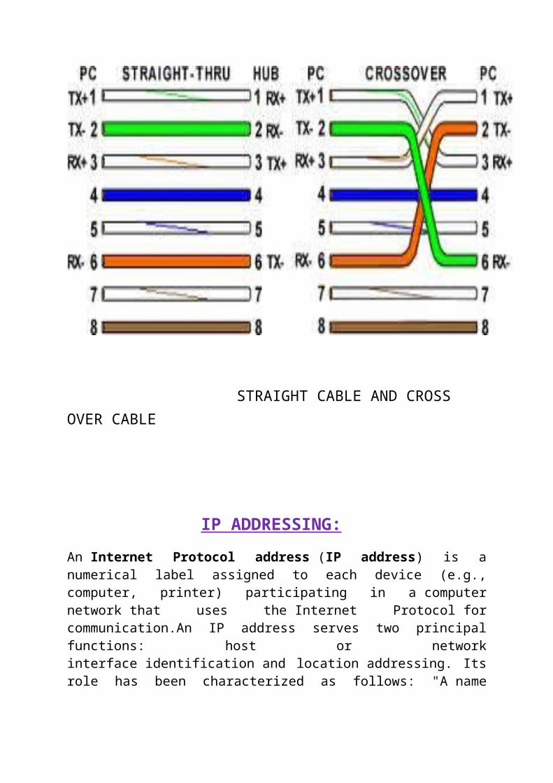
The same four wire are used in this as it is used in Straight through cable, we just connect different pin together.
ROLLED CABLES
Although rolled cables are not used to connect any Ethernet connections together, you can use a rolled Ethernet cable to connect a host to a router console serial communication port.
If you have Cisco switch or router , you would use this cable to connect your PC running HyperTerminal to the Cosco hardware. Eight wire are used in this cable to connect serial devices, although not all eight are used to send the information, just as in Ethernet working.

STRAIGHT CABLE AND CROSS OVER CABLE
IP ADDRESSING:
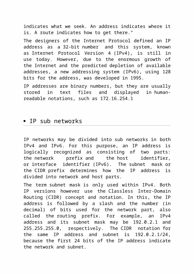
An Internet Protocol address (IP address) is a numerical label assigned to each device (e.g., computer, printer) participating in a computer network that uses the Internet Protocol for communication.An IP address serves two principal functions: host or network interface identification and location addressing. Its role has been characterized as follows: "A name indicates what we seek. An address indicates where it is. A route indicates how to get there."
The designers of the Internet Protocol defined an IP address as a 32-bit number and this system, known as Internet Protocol Version 4 (IPv4), is still in use today. However, due to the enormous growth of the Internet and the predicted depletion of available addresses, a new addressing system (IPv6), using 128 bits for the address, was developed in 1995.

IP addresses are binary numbers, but they are usually stored in text files and displayed in human-readable notations, such as 172.16.254.1
IP sub networks
IP networks may be divided into sub networks in both IPv4 and IPv6. For this purpose, an IP address is logically recognized as consisting of two parts: the network prefix and the host identifier, or interface identifier (IPv6). The subnet mask or the CIDR prefix determines how the IP address is divided into network and host parts.
The term subnet mask is only used within IPv4. Both IP versions however use the Classless Inter-Domain Routing (CIDR) concept and notation. In this, the IP address is followed by a slash and the number (in decimal) of bits used for the network part, also called the routing prefix. For example, an IPv4 address and its subnet mask may be 192.0.2.1 and 255.255.255.0, respectively. The CIDR notation for the same IP address and subnet is 192.0.2.1/24, because the first 24 bits of the IP address indicate the network and subnet.
IP version 4 addresses
In IPv4 an address consists of 32 bits which limits the address space to 4294967296 (232) possible unique addresses. IPv4 reserves some addresses for special purposes such as private networks (~18 million addresses) or multicast addresses (~270 million addresses).
IPv4 addresses are canonically represented in dot-decimal notation, which consists of four decimal numbers, each ranging from 0 to 255, separated by dots, e.g., 172.16.254.1. Each part represents a group of 8 bits (octet) of the address. In some cases of technical writing, IPv4 addresses may be presented in various hexadecimal, octal, or binary representations.

bit offse
t0–3 4–7 8–13 14-15 16–18 19–31
0 VersionHeader Length
Differentiated Services Code Point
Explicit Congestion Notificatio
n
Total Length
32 Identification Flags Fragment Offset
64 Time to Live Protocol Header Checksum
96 Source IP Address
128 Destination IP Address
160 Options ( if Header Length > 5 )
160or
192+
Data
IP version 6 addresses
The rapid exhaustion of IPv4 address space, despite conservation techniques, prompted the Internet Engineering Task Force(IETF) to explore new technologies to expand the Internet's addressing capability. The permanent solution was deemed to be a redesign of the Internet Protocol itself. This next generation of the Internet Protocol, intended to replace IPv4 on the Internet, was eventually named Internet Protocol Version 6 (IPv6) in 1995[3][4] The address size was increased from 32 to 128 bits or 16 octets. This, even with a generous assignment of network blocks, is deemed sufficient for the foreseeable future.

Mathematically, the new address space provides the potential for a maximum of 2128, or about 3.403×1038 unique addresses.
The new design is not intended to provide a sufficient quantity of addresses on its own, but rather to allow efficient aggregation of subnet routing prefixes to occur at routing nodes. As a result, routing table sizes are smaller, and the smallest possible individual allocation is a subnet for 264 hosts, which is the square of the size of the entire IPv4 Internet. At these levels, actual address utilization rates will be small on any IPv6 network segment. The new design also provides the opportunity to separate the addressing infrastructure of a network segment — that is the local administration of the segment's available space — from the addressing prefix used to route external traffic for a network. IPv6 has facilities that automatically change the routing prefix of entire networks, should the global connectivity or the routing policy change, without requiring internal redesign or renumbering.
The large number of IPv6 addresses allows large blocks to be assigned for specific purposes and, where appropriate, to be aggregated for efficient routing. With a large address space, there is not the need to have complex address conservation methods as used in Classless Inter-Domain Routing (CIDR).
DOMAIN NAME SYSTEM
The Domain Name System (DNS) is a hierarchical naming system built on a distributed database for computers, services, or any resource connected to the Internet or a private network. Most importantly, it translates domain names meaningful to humans into the numerical identifiers associated with networking equipment for the purpose of locating and addressing these devices worldwide.
The Domain Name System makes it possible to assign domain names to groups of Internet resources and users in a meaningful way, independent of each

entity's physical location. Because of this, World Wide Web (WWW) hyperlinks and Internet contact information can remain consistent and constant even if the current Internet routing arrangements change or the participant uses a mobile device. Internet domain names are easier to remember than IP addresses such as 208.77.188.166 (IPv4) or 2001: db8:1f70::999:de8:7648:6e8(IPv6). Users take advantage of this when they recite meaningful Uniform Resource Locators (URLs) and e-mail addresses without having to know how the computer actually locates them.
The Domain Name System distributes the responsibility of assigning domain names and mapping those names to IP addresses by designating authoritative name servers for each domain. Authoritative name servers are assigned to be responsible for their particular domains, and in turn can assign other authoritative name servers for their sub-domains. This mechanism has made the DNS distributed and fault tolerant and has helped avoid the need for a single central register to be continually consulted and updated.
In general, the Domain Name System also stores other types of information, such as the list of mail servers that accept email for a given Internet domain. By providing a worldwide, distributed keyword-based redirection service, the Domain Name System is an essential component of the functionality of the Internet.
SATELLITE COMMUNICATION
Communications satellite
A communications satellite (sometimes abbreviated to COMSAT) is an artificial satellite stationed in space for the purpose of telecommunications. Modern communications satellites use a variety of orbits including geostationary orbits, Molina orbits, other elliptical orbits and low (polar and non-polar) Earth orbits.
For fixed (point-to-point) services, communications satellites provide a microwave radio relay technology complementary to that of communication cables. They are also used for mobile applications such as communications to ships, vehicles, planes and hand-held terminals, and for TV and radio broadcasting, for which application of other technologies, such as cable, is impractical or impossible.
Structure of a Communications Satellite
Communications Satellites are usually composed of the following subsystems:
Communication Payload, normally composed of transponders, antenna and switching systems
Engines used to bring the satellite to its desired orbit Station Keeping Tracking and stabilization subsystem used to keep the
satellite in the right orbit , with its antennas pointed in the right direction, and its power system pointed towards the sun
Power subsystem, used to power the Satellite systems, normally composed of Solar Cell, and batteries that maintain power during Solar Eclipse
Command and Control subsystem, which maintains communications with ground control stations, The ground controls earth stations monitor the satellite performance and control its functionality during various phases of its life-cycle.
Bandwidth of a satellite
The bandwidth available from a satellite depends upon the number of transponders provided by the satellite. Each service (TV, Voice, Internet, radio) requires a different amount of bandwidth for transmission. The bandwidth of transponder is used to carry these services
Satellite Applications
Telephone

Satellite television Fixed Service Satellite Direct broadcast satellite Mobile satellite technology Satellite Radio Satellite internet Militiary use
ANTENNA
Antennas are required by any radio receiver or transmitter in order to couple its electrical connection to the electromagnetic field. Radio waves are electromagnetic waves which carry signals through the air (or through space) at the speed of light with almost no transmission loss. Radio transmitters and receivers are used to convey signals (information) in systems including broadcast (audio) radio, television, mobile telephones, wi-fi (WLAN) data networks, trunk lines and point-to-point communications links (telephone, data networks), satellite links, many remote controlled devices such as garage door openers, and wireless remote sensors, among many others. Radio waves are also used directly for measurements in technologies including RADAR, GPS, and
radio astronomy. In each and every case, the transmitters and receivers involved require antennas, although these are sometimes hidden (such as the antenna inside an AM radio or inside a laptop computer equipped with wi-fi).
According to their applications and technology available, antennas generally fall in one of two categories:
1. Omni directional or only weakly directional antennas which receive or radiate more or less in all directions. These are employed when the relative position of the other station is unknown or arbitrary. They are also used at lower frequencies where a directional antenna would be too large, or simply to cut costs in applications where a directional antenna isn't required.
2. Directional or beam antennas which are intended to preferentially radiate or receive in a particular direction or directional pattern.
.
Both the vertical and dipole antennas are simple in construction and relatively inexpensive. The dipole antenna, which is the basis for most antenna designs, is a balanced component, with equal but opposite voltages and currents applied at its two terminals through a balanced transmission line (or to a coaxial transmission line through a so-called balun). The vertical antenna, on the other hand, is a monopole antenna. It is typically connected to the inner conductor of a coaxial transmission line (or a matching network); the shield of the transmission line is connected to ground. In this way, the ground (or any large conductive surface) plays the role of the second conductor of a dipole, thereby forming a complete circuit. Since monopole antennas rely on a conductive ground, a so-called grounding structure may be employed in order to provide a better ground contact to the earth or which itself acts as a ground plane to perform that function regardless of (or in absence of) an actual contact with the earth.
For instance, a phased array consists of two or more simple antennas which are connected together through an electrical network. This often involves a number of parallel dipole antennas with a certain spacing. Depending on the relative phase introduced by the network, the same combination of dipole antennas can operate as a "broadside array" (directional normal to a line connecting the elements) or as an "end-fire array" (directional along the line connecting the elements). Antenna arrays may employ any basic (omnidirectional or weakly directional) antenna type, such as dipole, loop or slot antennas. These elements are often identical.
An antenna lead-in is the transmission line (or feed line) which connects the antenna to a transmitter or receiver. The antenna feed may refer to all components connecting the antenna to the transmitter or receiver, such as an impedance matching network in addition to the transmission line. In a so-called aperture antenna, such as a horn or parabolic dish, the "feed" may also refer to a basic antenna inside the entire system (normally at the focus of the parabolic dish or at the throat of a horn) which could be considered the one active element in that antenna system. A microwave antenna may also be fed directly from a waveguide in lieu of a (conductive) transmission line.
RADIO ROOM
1. Radio is the transmission of signals by modulation of
electromagnetic waves with frequencies below those of visible
light.
2. Electromagnetic radiation travels by means of oscillating
electromagnetic fields that pass through the air and the vacuum of

space. Information is carried by systematically changing
(modulating) some property of the radiated waves, such as
amplitude, frequency, or phase.
3. When radio waves pass an electrical conductor, the oscillating
fields induce an alternating current in the conductor..
4. This can be detected and transformed into sound or other signals
that carry information.
5. Different parts of radio room:-
Non-Directional Radio Room(NDB)
Aero VHF
Marine VHF
Single side band high frequency radio
6. A Non-directional beacon (NDB) is a radio transmitter at a known
location, used as an aviation or marine navigational aid
7. NDB signal is affected more by atmospheric conditions,
mountainous terrain, coast al refraction and electrical storms,
particularly at long range
8. Uses of Non-directional beacon:-Airways,Fixes
9. Marine VHF radio is installed on all large ships and most
motorized small craft. It is used for a wide variety of purposes,
including summoning rescue services and communicating with
harbours and marinas, and operates in the VHF frequency range,
between 156 to 174 MHz.

10. Types of equipment:- Sets can be fixed or portable. A fixed set
generally has the advantages of a more reliable power source,
higher transmit power, a larger and more effective aerial and a
bigger display and buttons. A portable set (often essentially a
waterproof, VHF walkie-talkie in design) can be carried to a
lifeboat in an emergency, has its own power source and is more
easily water-proofed.
RDF
A radio direction finder (RDF) is a device for finding the direction to a radio source. Due to radio's ability to travel very long distances and "over the horizon", it makes a particularly good navigation system for ships, small boats, and aircraft that might be some distance from their destination
ONGC,PANVEL takes the following specifications:-
LATITUDE:18 58 35 N
LONGITUDE:73 07 40 E
Aero VHF:118.2 MHz
NDB Frequency:272 KHz
CODE:PNVL
Telephone exchange
In the field of telecommunications, a telephone exchange or telephone switch is a system of electronic components that connects telephone calls. A central office is the physical building used to house inside plant equipment including telephone switches, which make telephone calls "work" in the sense of making connections and relaying the speech information.
The term exchange area can be used to refer to an area served by a particular switch, but is typically known as a wire center in the US telecommunications industry. The exchange code or Central Office Code refers to the first three digits of the local number (NXX). It is sometimes confused with the area code (NPA). In the United States, local exchange areas together make up a legal

entity called local access and transport areas (LATA) under the Modification of Final Judgment (MFJ).
1. In the field of telecommunications, a telephone exchange or telephone
switch is a system of electronic components that connects telephone calls.
2. A central office is the physical building used to house inside plant equipment
including telephone switches, which make telephone calls "work" in the
sense of making connections and relaying the speech information.
3. The term exchange can also be used to refer to an area served by a particular
switch (typically known as a wire center in the US telecommunications
industry). It is sometimes confused with other concepts of telephone
geography, such as NPA or area code.

4. More narrowly, in some areas it can refer to the first three digits of the local
number. In the three-digit sense of the word, other obsolete Bell System
terms include office code and NXX. In the United States, the word exchange
can also have the legal meaning of a local access and transport area under the
Modification of Final Judgment
Primary Rate Interface: –
The primary rate interface (PRI) is a telecommunications standard for
carrying multiple DS0 voice and data transmissions between a network and a
user.
PRI is the standard for connections to offices. It's based on a T1 line in the
US, and E1 line in Europe. The T1 consists of 24 channels, the E1 of 32
In the Integrated Services Digital Network (ISDN), there are two levels of
service: the Basic Rate Interface (BRI), intended for the home and small

enterprise, and the Primary Rate Interface (PRI), for larger users. Both rates
include a number of B-channels and a D-channel. Each B-channel carries
data, voice, and other services. The D-channel carries control and signaling
information. The Basic Rate Interface consists of two 64 kbit/s B-channels
and one 16 kbit/s D-channel
Fewer active B channels (also called user channels) can be used for a
fractional T1. More channels can be used with more T1s, within certain
design limits
APPLICATION:-
The Primary Rate Interface channels are typically used by medium to large
enterprises with digital PBXs to provide them digital access to the Public
Switched Telephone Network (PSTN).
INTEGRATED SERVICE DIGITAL NETWORK
Integrated Services Digital Network is a telephone system network. Prior to the ISDN, the phone system was viewed as a way to transport voice, with some special services available for data. The key feature of the ISDN is that it integrates speech and data on the same lines, adding features that were not available in the classic telephone system. There are several kinds of access interfaces to the ISDN defined: Basic Rate Interface (BRI), Primary Rate Interface (PRI) and Broadband-ISDN (B-ISDN).

ISDN is a circuit-switched telephone network system,that also provides access to packet switched networks, designed to allow digital transmission of voice and data over ordinary telephone copper wires, resulting in better voice quality than an analog phone. It offers circuit-switched connections (for either voice or data), and packet-switched connections (for data), in increments of 64 kbit/s. Another major market application is Internet access, where ISDN typically provides a maximum of 128 kbit/s in both upstream and downstream directions (which can be considered to be broadband speed, since it exceeds the narrowband speeds of standard analog 56k telephone lines). ISDN B-channels can be bonded to achieve a greater data rate, typically 3 or 4 BRIs (6 to 8 64 kbit/s channels) are bonded.
ISDN should not be mistaken for its use with a specific protocol, such as Q.931 whereby ISDN is employed as the network, data-link and physical layers in the context of the OSI model. In a broad sense ISDN can be considered a suite of digital services existing on layers 1, 2, and 3 of the OSI model. ISDN is designed to provide access to voice and data services simultaneously.
However, common use has reduced ISDN to be limited to Q.931 and related protocols, which are a set of protocols for establishing and breaking circuit switched connections, and for advanced call features for the user. They were introduced in 1986.
In a videoconference, ISDN provides simultaneous voice, video, and text transmission between individual desktop videoconferencing systems and group (room) videoconferencing systems.
ISDN ELEMENTS:-
Integrated Services refers to ISDN's ability to deliver at minimum two simultaneous connections, in any combination of data, voice, video, and fax, over a single line. Multiple devices can be attached to the line, and used as needed. That means an ISDN line can take care of most people's complete communications needs at a much higher transmission rate, without forcing the purchase of multiple analog phone lines.

180 px-T-Concepy ISDN
Basic Rate Interface:-
The entry level interface to ISDN is the Basic Rate Interface (BRI), a 144 kbit/s service delivered over a pair of standard telephone copper wires. The 144 kbit/s rate is broken down into two 64 kbit/s bearer channels ('B' channels) and one 16 kbit/s signaling channel ('D' channel or Delta channel).
BRI is sometimes referred to as 2B+D
The Interface specifies the following network interfaces:
The U interface is a two-wire interface between the exchange and the Network Terminating Unit which is usually the demarcation point in non-North American networks.
The T interface is a serial interface between a computing device and a Terminal Adapter, which is the digital equivalent of a modem.
The S interface is a four-wire bus that ISDN consumer devices plug into; the S & T reference points are commonly implemented as a single interface labeled 'S/T' on an NT1
The R interface defines the point between a non-ISDN device and a terminal adapter (TA) which provides translation to and from such a device.
BRI-ISDN is very popular in Europe but is much less common in North America.

Primary Rate Interface:-
The other ISDN service available is the Primary Rate Interface (PRI) which is carried over an E1 (2048 kbit/s) in most parts of the world. An E1 is 30 'B' channels of 64 kbit/s, one 'D' channel of 64 kbit/s and a timing and alarm channel of 64 kbit/s. In North America PRI service is delivered on one or more T1s (sometimes referred to as 23B+D) of 1544 kbit/s (24 channels). A T1 has 23 'B' channels and 1 'D' channel for signalling (Japan uses a circuit called a J1, which is similar to a T1).
In North America, NFAS allows two or more PRIs to be controlled by a single D channel, and is sometimes called "23B+D + n*24B". D-channel backup allows you to have a second D channel in case the primary fails. One popular use of NFAS is on a T3.
PRI-ISDN is popular throughout the world, especially for connection of PSTN circuits to PBXs.
Even though many network professionals use the term "ISDN" to refer to the lower-bandwidth BRI circuit, in North America by far the majority of ISDN services are in fact PRI circuits serving PBXs.
References
