network protector instruction manual - eti-nj.com manual - im1232-001b.pdf · i disclaimer of...
TRANSCRIPT

Network Protector Instruction Manual
Type 316NP
ichards MANUFACTURING COMPANY, SALES, INC. 517 LYONS AVENUE, IRVINGTON, NJ 07111 Phone 973-371-1771 Fax 973-371-9538
IM 1232-001B


i
DISCLAIMER OF WARRANTIES AND LIMITATION OF LIABILITY
All equipment or component parts manufactured or distributed by Richards Mfg. Co., Sales Inc. are expressly warranted by Richards to be free from defect in workmanship or material when subjected to normal and proper use. Said warranty shall be for a period of one (1) year from the date of installation of such equipment not to exceed eighteen (18) months from the date of shipment of such equipment. Notice of any claim arising out of this warranty shall be made in writing within the warranty period. Richards’ sole liability and buyer’s sole remedy under this warranty shall be limited to the repair or replacement, FOB factory, of any equipment or part determined to be defective in either material or workmanship. This warranty does not apply to any equipment, part or component requiring repair or replacement due to improper use or when determined to have been subjected to abnormal operating conditions or in the event of buyer’s failure to follow normal maintenance procedures. No warranty or guarantee expressed or implied, including any warranty or representation as to the design, operation, merchantability or fitness for any purpose is made other than those expressly set forth above which are made in lieu of any and all warranties or guarantees. Richards Mfg. Co. shall not be liable for any loss or damage, directly or indirectly, arising out of the use of equipment or parts (including software) or for any consequential damages, including but not limited to, any claims for buyer’s lost profits or for any claim or demand against the buyer by a third party. Richards Mfg. Co. assumes no responsibility for any damage or loss resulting from the use of this manual. Information in this document is subject to change without notice.

ii
SAFETY INFORMATION
This manual is intended for use by qualified individuals responsible for the installation, maintenance and operation of network protectors. Potentially unsafe conditions exist when installing, maintaining or operating network protectors. All applicable safety procedures should be adhered to when installing, maintaining, or operating network protectors. Only qualified electrical personnel should be permitted to work on 316NP Network Protectors. De-energize and rack out the network protector mechanism before any maintenance procedure. Never defeat safety interlocks on the network protector. Never energize a partially assembled network protector. Use extreme caution when installing or working on an energized protector. Use insulated tools and gloves when working on energized network protectors. Perform all appropriate electrical tests before any installation or operation of the network protector.
WARNING
Before unpacking, installing, servicing, or operating 316NP network protectors read this manual thoroughly. For additional information, contact Richards Mfg. Co. directly. For application information, consult Richards Mfg. Co. or see appropriate ANSI Standards. Do not operate 316NP network protectors under load except in appropriate enclosures. The Richards 316NP Network Protectors are designed for secondary network application at 125/216 volt and 277/480 volt wye connected systems. Do not exceed design ratings.

iii
Submersible Transformer Mounted

iv
Mechanism Racked Out on Rails

v
TABLE OF CONTENTS PAGE I. OVERVIEW
A. Introduction 1 B. 316NP Ratings 1 C. 316NP Housings 1
II. INSTALLATION
A. Receipt Of The 316NP 2 B. Preliminary Testing 2 C. Mounting the 316NP – Mechanical Connection to Transformer
1. Open Frame Protectors 2 2. Transformer Mounted Protectors 3
D. Mounting the 316NP – Testing and Electrical Connection to Transformer 3 E. Energizing the Feeder 3 F. Checking a Submersible Housing for Water-Tightness 4
III. 316NP DESIGN
A. 316NP Circuit Breaker 5 B. 316NP Mechanism 7 C. Operating Handle 7 D. Relay Panel 7 E. Closing Motor 8 F. Shunt Trip Assembly 8 G. Motor Circuit Control 9 H. Position Indicator and Operations Counter 10 I. Auxiliary Switches 10
IV. MAINTENANCE
A. Inspection 11 B. Racking Out the Mechanism 12 C. Contact Inspection 13 D. Relay Panel Removal 14
VI. DIAGRAMS
A. Wiring Diagram, 125/216 Volt Protectors 15 B. Schematic Diagram, 125/216 Volt Protectors 16 C. Wiring Diagram, 277/480 Volt Protectors 17 D. Schematic Diagram, 277/480 Volt Protectors 18

vi

1
I. OVERVIEW
A. Introduction
The Richards 316NP Network Protector consists of a circuit breaker, a motor operated stored energy closing mechanism, and an ETI Microprocessor Network Protector Relay that combines the functions of a network master relay, and a network-phasing relay. The ETI MNPR® provides all modes of operation, including sensitive, insensitive, time delay, instant, watt-var, and inverse watt-var.
The circuit breaker has contacts fashioned from silver tungsten. In addition, the breaker has arcing contacts to protect the main contacts from the initial arc generated when the protector is closed. When the protector is closed, the contact pressure is significant so as to create a solid electrical contact. In the event that the protector fails to open at the time of a severe fault, fuses are present as a final safety precaution. Current transformers for operating the relay are located on each phase of the main bus bars, above the disconnect links. The mechanism is mechanically trip free. The mechanism will not close if it receives a trip instruction at any point in the closing cycle. A shunt trip device, designed to trip at very low voltages when necessary retains the latch. The breaker unit includes accelerating springs so that the breaker contacts may be opened quickly.
B. 316NP Ratings
Network protectors are furnished with a current rating of 2250 amperes. The voltage ratings are 125/216 (phase to ground/phase to phase) and 277/480, 3 phase, 4-wire wye. All units have an interrupting and fault close and latch rating of 30,000 amperes.
C. 316NP Housings
All Network Protector housings are designed to allow the mechanism to be rolled out on rails for easy maintenance. The mechanism is able to roll out to the point that it can be vertically lifted out of the housing. The 316NP is available with submersible transformer mounted and open frame configuration. Many different types of terminals are available. The type of terminals is tailored to each customer’s needs. The submersible housing is manufactured from copper bearing steel. An external operating handle can be locked in two different positions “Automatic” and “Open.” The door contains a window so that the operations counter and position indicator can be inspected without opening the protector’s door.
2
II. INSTALLATION
A. Receipt Of The 316NP The 316NP Network Protector should be removed from its packaging in a careful manner such that no parts are damaged. The protector should be immediately inspected to ensure that no damage has occurred during shipment. If the unit has been damaged, the common carrier should be contacted immediately. Any dust that has accumulated during shipment should be removed from the unit. All 316NP protectors should be stored upright in a clean, dry location. Submersible units should be stored with their doors sealed. All 316NP protectors are equipped with holes for lifting the unit into place. The lifting eyes are welded to each side of the housing, near the top. A nylon sling should be used to lift the protector so not to scratch the housing. The sling should be used in conjunction with a spreader so that the cable terminals are not damaged. For a submersible housing, care should be taken to ensure that the housing is supported before the door is opened and the protector mechanism rolled out. The feet of the protector cannot support the weight of both the door and the mechanism in the rolled out position.
316NP Weight Chart
Mechanism Only Pounds 2250 Amperes 400
Housings Only Submersible 2250 Amperes 850 D13 Frame 500
B. Preliminary Testing
The 316NP protector should be tested before it is installed on a network system. The protector should be firmly mounted and secured. Before connecting the protector to a network system, the fuses and disconnect links should be opened to ensure the isolating of the protector during installation.
The first preliminary test is to ensure that the manual handle is able to move to the "Open" and "Automatic" positions. Each of the two positions is marked on the handle position indicator, which is part of the handle assembly.
C. Mounting the 316NP – Mechanical Connection to Transformer
1. Open Frame Protectors
Open frame network protectors should be secured to prevent tipping. Enough space should be allocated for the input and output cable connections. The unit should be mounted as close to vertical as possible.

3
2. Transformer Mounted Protectors
Before mounting the protector to the transformer the operator should ensure that the transformer is not energized. The housing for the transformer mounted submersible protector is attached to the network transformer at two points, at the low voltage throat and by means of pads located near the bottom of the protector. Richards will supply the hardware for connecting the protector to the transformer. The protector housing should first be supported on the transformer throat using two dowel pins. The pins are located on the transformer and line up with holes at the back of the protector housing. After the pins are in place on the housing, the back of the housing should be bolted to the transformer throat using the bolts provided. When the housing to throat connection is secure, the bottom of the housing is connected to the bottom of the transformer using the mounting brackets provided.
D. Mounting the 316NP – Testing and Electrical Connection to Transformer When the housing has been secured to the transformer, the housing bus bars should be connected to the transformer outlet bushings on the transformer throat using a flexible connector designed to join the threaded stud emerging from the throat area to the housing bus bars. The mechanism is then ready to be installed in the housing. In order to install the mechanism, the handle must be locked in the open position. Then the mechanism is placed on the housing rails. Before closing the protector into a network, every mechanism should be opened and closed at least five times under control of the ETI MNPR® (See the wiring diagrams located at the end of this manual). The operator should ensure that the relay is programmed to the desired specifications. The appropriate voltage for conducting automatic tests should then be applied across the protector using a three-phase test set. If the ETI MNPR® is not fully operational, the protector may still be operated by applying rated voltage across the outside poles of the circuit breaker and then issuing commands through the ETI MNPR® Field Programmer (See Field Programmer Manual). The trip-free action of the mechanism may be tried by immediately tripping the protector after the circuit breaker arcing contacts have touched, during a closing cycle. Once the mechanism has been tested and displays the desired performance, it is ready to be connected to the transformer. The mechanism should be rolled into the housing and bolted in on the left and right side. The housing bus bar should then be connected to the mechanism by closing the disconnect links. When the mechanism has been installed the fuses are then bolted into place.
E. Energizing the Feeder
Once the protector is mechanically and electrically connected to the transformer and the mechanism has been tested, the main cables leading to the secondary network should be connected to the protector terminals. A connection should then be made between the protector housing and ground. The protector should still be physically locked open using the handle and a locking block. The primary feeder is now ready to be energized. Once it is energized, a suitable voltmeter should be used to measure the voltage differential and phase relations across the protector. If the phase relations are proper and the transformer voltage is
4
higher than the network voltage by the proper amount, the handle should be moved to the automatic position, which should close the protector.
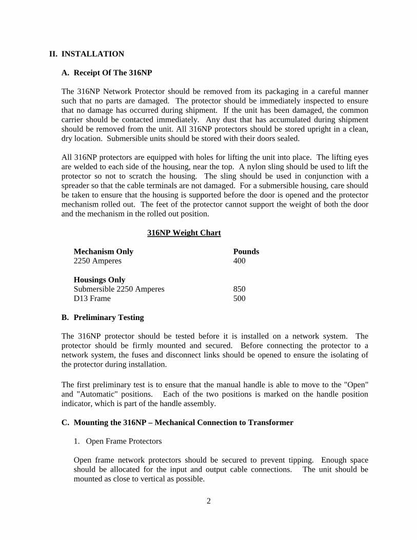
F. Checking a Submersible Housing for Water-Tightness
Although every 316NP Submersible Housing is tested for water-tightness at the factory, the user may wish to retest once the protector is installed. With the protector closed and operating properly, the housing door should be closed and tightened to the case. The seals on the gasket can then be tested by attaching a pressure gauge together with bottled nitrogen to the sampling valve and charging the housing with a pressure of six psi. Leaks can then be detected placing soapy water over the gasket seal and checking for air bubbles.

5
316NP DESIGN
A. 316NP Circuit Breaker
The circuit breaker on the 316NP consists of three independent bus bars (each representing a phase) mounted on an insulating panel along with control wiring. Five fingers make up the main stationary contact assembly. Individual springs provide pressure against the main moving contacts when the protector is closed. Above the main contacts is the arcing contact. The stationary arcing contacts oppose each other and are spring biased together. When the protector closes the moving arcing contact wedges in between the opposing stationary contacts.
A gap of 0.050 inches is maintained on the main stationary contacts to be certain that contact pressure is uniform.
The five main moving contacts are bolted between six contact blades that pivot on a pin through the lower bus assembly. Bellville washers maintain contact pressure between coined silver plated rings and the lower bus assembly.
The moving contact assemblies are connected by individual adjustable linkages to the main operating shaft. Contact gap is adjusted by changing the threaded linkage length. The main operating shaft has three levers for the three phases, an opening spring lever, an auxiliary switch and indicator lever, and a main actuation linkage attachment point at the center phase lever. Bearings support the main shaft in four locations. Bumper stops of neoprene rubber washers and steel washers absorb the shock of stopping the opening motion.

6
Fuses are provided at the top or bottom of the network protector. Opposite the fuse end scissor type links are provided to connect to the housing bus. In order to isolate the protector for tests or repairs, both the fuses and the disconnecting links should be removed. If the mounting bolts are then removed, the mechanism can be rolled out on its rails.
Fuses
Disconnect Links Current transformers on each bus bar work in conjunction with the ETI MNPR® to trip the protector on reverse current.
The main contacts of the circuit breaker are made of a weld-resisting alloy. The arcing contacts described above, part shortly after the main contacts have opened and reduces stress to the main contacts.

7
B. 316NP Mechanism
The 316NP network protector mechanism is a stored energy design. A closing motor first charges a spring which then provides the closing force for the contacts. A close and latch rating of 30,000 amperes is thus obtained. A cam and clutch arrangement is used to provide this function. A trip free linkage assembly is used to provide breaker opening anytime a trip command is issued. The shunt trip coil releases the trip free lever allowing the toggle link to move upward thus opening the breaker very rapidly. After opening, the linkage resets itself to be ready for the next closing cycle. C. The Operating Handle
On the submersible housing an external handle is provided that mates with the internal trip linkage that provides two positions “Open” and “Automatic”. A lever at the shaft engages with a lever of the mechanism toggle so that the movement of the handle from the “Automatic” to the “Open” position will actuate the trip linkage. Both an electrical and mechanical interlock prevent the mechanism from closing when the handle is in the open position. When the handle is returned to the automatic position the MNPR® is then able to cause a reclose of the protector if system conditions are met. The handle must be put in the open position in order to rack out the network protector. D. Relay Panel The ETI MNPR® and required devices for controlling the operation of the protector are pre-wired on the relay panel. The relay plugs into the front of the panel so that no adjustment need be made to the permanent wiring when installing or removing the MNPR®.
8
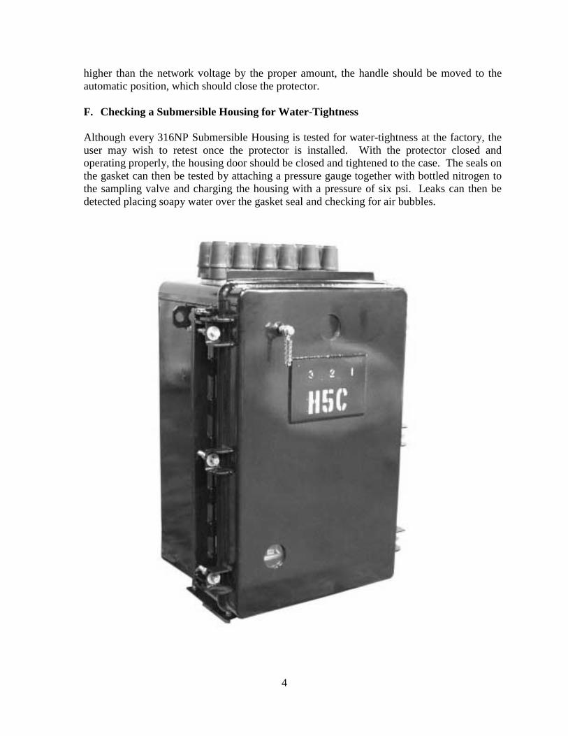
E. Closing Motor
The closing motor is a single-phase universal wound motor with an integral gear reduction. Additional external gears further reduce the speed between motor and closing cam. The rotation of the closing cam charges the closing spring to provide a stored energy source for rapid closing of the protector contacts. The stored energy design provides high amperage make and latch ratings for closing into fault conditions. The motor is designed to close the protector at 73% of the motor’s rated voltage. The motor can be removed through the left side of the assembly.
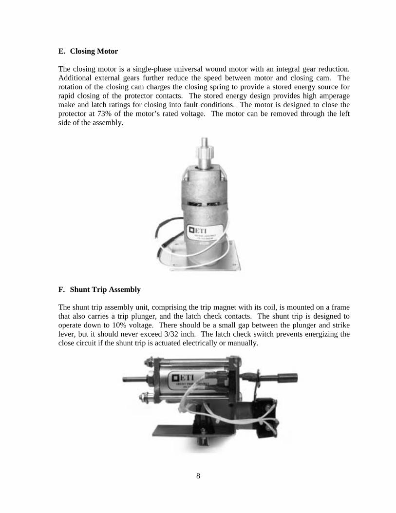
F. Shunt Trip Assembly
The shunt trip assembly unit, comprising the trip magnet with its coil, is mounted on a frame that also carries a trip plunger, and the latch check contacts. The shunt trip is designed to operate down to 10% voltage. There should be a small gap between the plunger and strike lever, but it should never exceed 3/32 inch. The latch check switch prevents energizing the close circuit if the shunt trip is actuated electrically or manually.

9
A tripping cycle consists of the following sequence of operations:
1. The MNPR® closes its tripping contacts (due to system conditions prevailing), thereby closing the circuit through the shunt trip coil. 2. The opening of the circuit breaker returns the auxiliary switches to their original position, thereby opening the circuit of the shunt trip coil and closing the circuit of the motor control relay, in preparation for the next closing operation.
G. Motor Circuit Control
The closing motor is energized by the motor control relay that is controlled by the ETI MNPR®, the auxiliary switch and by the latch check switch of the mechanism. A signal from the MNPR® energizes the coil of the motor control relay, which then closes its contacts. The closing of these contacts serves to energize the circuit of the motor. The motor control relay seals in the energized position independent of the MNPR® contacts. The motor charges the closing spring and spring energy closes the protector. After the mechanism latches, the auxiliary switch opens, and de-energizes the motor control relay. To prevent attempting to close the protector at voltages below the minimum motor closing voltage, motor control relay is adjusted to pick up at 80% of nominal voltage. A closing cycle consists of the following sequence of operation:
1. The MNPR® contacts close, thereby completing the circuit to the coil of the motor control relay. 2. The motor control relay energizes and seals in. 3. The motor, being energized by the relay, then rotates the closing cam charging the closing spring. 4. When the spring is fully charged its energy is released to close the network protector. 5. The closing of the protector opens the auxiliary switch contacts, de-energizing the motor control relay and stopping the motor. At the same time the auxiliary switch contacts in the shunt trip circuit are closed.

10
H. Position Indicator and Operations Counter
The "Open" or “Closed” status of the breaker is identified by a position indicator that gives a mechanical indication. The words “Open” and “Closed” on a semaphore flag give the position indication. One word or the other is visible from the front of the protector depending on the breaker position. A non-resetable mechanical operations counter is mounted at the front of the protector where it is visible through the window in the enclosure.
I. Auxiliary Switch A rotary control switch is used as the main auxiliary switch. Twelve circuits are provided for, although they are not all used in the standard wiring arrangement. Contacts are made and opened by metal segments rotated between stationary fingers. The switch contacts are controlled through a mechanical connection with the operating mechanism.
11
IV. MAINTENANCE 316NP protectors should be inspected on a scheduled basis. The inspection should consist of both a mechanical checkup followed by a test of the electrical operations of the protector. Caution: Before making any inspection of the protector or the relay, it is crucial to isolate the unit from both the transformer and the network. Isolation is accomplished by locking the protector in the open position using the handle and the locking block. The fuses should then be removed, isolating the unit from the network, as well as the disconnect links, which isolates the unit from the transformer. Before performing any work, an appropriate voltmeter, or continuity meter should be used to ensure that the unit is not energized.
A. Inspection
1. The Circuit Breaker Unit The following regular maintenance should be performed:
a. All electrical connections should be tightened. b. All springs should be properly placed and in working order. c. All nuts, pins, cotters, and screws should be properly placed and tightened. d. All current carrying elements should be checked for damage due to overheating. e. All contacts should be cleaned and checked to see that they form good electrical
connections. f. All fiberglass barriers should be checked to ensure that they are not broken. g. All connections on the terminal blocks should be checked and tightened. h. The control circuits should be tested.
3. The Housing The following regular maintenance should be performed:
a. All electrical connections should be tightened. b. The fuses, disconnect links and terminals should be examined for damage
associated with overheating. c. The housing itself should be checked for corrosion. d. All fiberglass barriers should be examined to make sure that none are broken. e. The housing itself should be checked to ensure that it is watertight. f. The handle should be checked to ensure that it operates properly.

12
B. Racking Out the Mechanism
Caution: If not attached to the transformer the housing must be supported to prevent tipping over when the door is opened and the mechanism racked out.
1. Place the handle in the “open” position.
2. Remove the fuses.
3. Open the disconnect devices.
4. Install the extension rails.
5. Loosen the two red bolts at each side of roll out unit.
6. Pull the mechanism out onto the rails and pin into desired position.
13
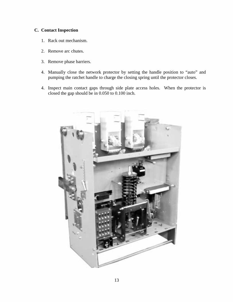
C. Contact Inspection
1. Rack out mechanism. 2. Remove arc chutes.
3. Remove phase barriers. 4. Manually close the network protector by setting the handle position to “auto” and
pumping the ratchet handle to charge the closing spring until the protector closes.
4. Inspect main contact gaps through side plate access holes. When the protector is closed the gap should be in 0.050 to 0.100 inch.

14
D. Removing the Relay Panel
1. Rack out mechanism. 2. Remove arc chutes.
3. Remove phase barriers.
4. Remove closing spring cover and mechanism front cover.
5. Disconnect the electrical plugs at the front panel.
6. Remove the MNPR®
7. Remove the left (2) and right (3) 5/16-18 hex head screws supporting the relay panel.
Lift and remove the relay panel.
8. When working inside the main mechanism release the closing spring bias force by loosening the stop nut at the top of the spring.
9. When the closing spring force has been removed, inspect the arcing contact closing
by slowing pumping the ratchet handle. When the arcing contacts touch, the main contacts should be 3/16 to 5/16 inch away.

15

16

17

18