network management plan 2011-2016 - transgrid · 3.2 network planning 22 3.3 service standards and...
TRANSCRIPT

Network Management Plan2011-2016
Disclaimer 2
Introduction 3
AboutTransGrid 4
NetworkSafetyandReliability 7Part 1: Framework of the Plan 71.1 Introduction 8
1.2 Customers and Stakeholders 8
1.3 Structure of the Plan 8
1.4 Assets 8
1.5 Working Assumptions of the Plan 8
1.6 TransGrid’s Network Management Model 8
1.7 Schedule of Reports 10
Part 2: Management Support Systems 112.1 Quality System 12
2.2 Health and Safety Management System 14
2.3 Environmental Management System 16
2.4 Emergency Management System 19
Part 3: Planning and Service Delivery 213.1 Corporate Planning 22
3.2 Network Planning 22
3.3 Service Standards and Asset Performance 33
Part 4: Asset Strategies 394.1 Asset Maintenance and Operating Strategies 40
4.2 Specific Asset Profiles and Strategies 43
4.3 Asset Disposal Strategies 71
Contents
Chapter
1

1
Appendices
CustomerInstallationSafety 731. Introduction 74
2. Design, Construction and Maintenance Standards 74
3. Testing, Connection and Notification Criteria 74
4. Inspection Regime and Procedures to Remedy Faulty Work 74
5. Reporting Defective Installation Work 74
PublicElectricalSafetyAwareness 751. Introduction 76
2. Background 76
3. Action Plans 76
4. Annual Review and Report 77
BushFireRiskManagement 791. Introduction 80
2. Objectives 80
3. Strategies for Bush Fire Risk Management 81
4. Performance Indicators 85
Appendices 87Appendix A: Corporate Policies 87Corporate Social Responsibility 88
Health and Safety 88
Environment Policy 90
Quality Policy 90
Appendix B: Asset Inventory 91Schedule of Substations and Switching Stations 92
TransGrid System Transformers 94
Circuit Breakers 97
Transmission Lines and Underground Cables 99
1
Chapter
2Chapter
3
Chapter
4
2 TransGrid Network Management Plan 2011-2016Disclaimer
Disclaimer
This Network Management Plan 2011-2016 has been prepared and made available solely for information purposes. Nothing in this document can be or should be taken as a recommendation in respect of any possible investment.
The information in this document reflects the forecasts, proposal and opinions adopted by TransGrid as at 1 January 2011 except where otherwise specifically stated. These forecasts, proposals and opinions may change at any time without warning. Anyone considering this document at any date should independently seek the latest forecasts, proposals and opinions.
The document includes information obtained from external sources, which are identified. TransGrid has no reason to doubt that information, but is not equipped to verify or test its currency, accuracy, completeness, reliability or suitability for anyone else’s purposes. It is repeated for what it is worth. Anyone proposing to use the information should check it at source, or with independent consultants or using their own judgement.
The information in this document should be read in the context of other relevant regulatory and NEM documents. It does not purport to contain all of the information that AEMO, a prospective investor or Registered Participant or potential participant in the NEM, or any other person or Interested Parties may require for making decisions. In preparing this document it is not possible nor is it intended for TransGrid to have regard to the investment objectives, financial situation and particular needs of each person or organisation which reads or uses this document.
In all cases, anyone proposing to rely on or use the information in this document should:
1. Independently verify and check the currency, accuracy, completeness, reliability and suitability of that information.
2. Independently verify and check the currency, accuracy, completeness, reliability and suitability of reports relied on by TransGrid in preparing this document.
3. Obtain independent and specific advice from appropriate experts or other sources.
Accordingly, TransGrid makes no representations or warranty as to the currency, accuracy, reliability, completeness or suitability for particular purposes of the information in this document. Persons reading or utilising this Network Management Plan 2011-2016 acknowledge and accept that TransGrid and/or its employees, agents and consultants shall have no liability (including liability to any person by reason of negligence or negligent misstatement) for any statements, opinions, information or matter (expressed or implied) arising out of, contained in or derived from, or for any omissions from, the information in this document, except insofar as liability under any New South Wales and Commonwealth statute cannot be excluded.

3TransGrid Network Management Plan 2011-2016Introduction
Introduction
There are many challenges we face to ensure that our electricity network meets the needs of our stakeholders in a sustainable and ongoing manner.
The safe operation of the electricity transmission network is TransGrid’s highest priority. Our transmission lines exist on both private and public land, and are maintained in a condition that allows them to be operated safely at all times. Our substations and switchyards are designed with public safety as a fundamental consideration, to ensure that our network does not adversely impact the safety of the community.
TransGrid’s network forms the backbone of the National Electricity Market (NEM), facilitating interstate trading and transfer of electricity. TransGrid works closely with the Australian Energy Market Operator (AEMO) to ensure that our central role in the NEM supports the operation of the market and upholds the NEM Objective. As the NEM evolves through developments and reviews, such as the Transmission Frameworks Review by the Australian Energy Market Commission (AEMC), TransGrid participates in these developments to seek the best outcome for our customers and market participants.
The Annual Planning Report 2010 forecasts that peak electricity demand in New South Wales will increase by 2.3 per cent each year on average for the next 10 years. This is due to growth in the New South Wales population, higher electricity consumption per capita than previously, and increased use of electronics such as computers and televisions. TransGrid is undertaking a significant augmentation program to ensure that the New South Wales transmission network can meet the demand expectations of our customers.
TransGrid is well placed to promote environmentally sustainable energy technologies. Our extensive network facilitates the connection and transmission of energy from low emission generation sources such as wind and large scale solar generation. The promotion of Demand Management as an alternative to new generation and transmission is an initiative that encourages environmentally responsible patterns of energy use.
At a State level, there has been a continuing focus by customers and stakeholders on the performance of transmission and distribution companies, both on efficient operation of their networks and reliability and availability of supply. This has been reinforced through the New South Wales Electricity Supply (Safety & Network Management) Regulation 2008 that requires Network Operators to develop Network Management Plans and report annually on the performance of the network.
Against this backdrop, TransGrid has reviewed and updated its Network Management Plan to cover the period from 2011 to 2016 inclusive. The Plan includes chapters on network safety and reliability, customer installation safety, public electrical safety awareness and bush fire risk management. The Plan provides a focus for continually improving the management of the transmission system. It also provides a formal method for information dissemination to customers, stakeholders and regulators.
TransGrid’s corporate objectives for electricity supply, safety, quality and the environment are achieved primarily through the strategies in this Plan. The Plan describes the model TransGrid uses to manage its assets and develop the asset management strategies for network augmentation, maintenance and disposal. These strategies are integrated with non-asset strategies such as human resources, finance, information technology and procurement.
In many cases, and in particular where network additions or augmentation are involved, the need for such work is driven directly by customer needs and requirements. This Plan has been developed in parallel with an annual planning review conducted by TransGrid as the Jurisdictional Planning Body for New South Wales and therefore will by necessity be a living document that will change in response to feedback from customers and market participants.
Feedback on the Network Management Plan is welcome, in order that TransGrid is able to continue to effectively meet the requirements of its customers and stakeholders.
Peter McIntyre Managing Director February 2011
TransGrid is committed to providing the people of New South Wales with a reliable and efficient electricity transmission supply. A reliable electricity supply is essential to the wide range of activities undertaken in our communities, and is relied upon every day by industries, businesses and families. The efficient delivery of this electricity supply is paramount to the economic wellbeing of electricity customers in New South Wales.

4 TransGrid Network Management Plan 2011-2016About TransGrid
About TransGrid
TransGrid is the owner and manager of one of the largest electricity transmission networks in Australia, connecting generators, distributors and major end users in NSW and the ACT.
TransGrid, with 91 substations and over 12,600 kilometres of transmission lines, facilitates interstate energy trading and forms the backbone of Australia’s National Electricity Market, one of the most extensive electricity systems in the world.
OPERATING SYSTEM VOLTAGES 500kV Transmission Lines
330kV Transmission Lines
220kV Transmission Lines
132kV Transmission Lines
66kV Transmission Lines
330kV Underground Cable
Customer Exchange Point
Interstate Exchange Point
500kV Substations
330kV Substations
220kV Substations
132kV Substations
INSET
Tomago
BHP (EA)
Eraring
Vales Point
Munmorah
Tuggerah
Sydney East
RegentvilleSydney West
Sydney South
NewcastleWaratah
West
Liverpool
Kemps Creek
Vineyard
Sydney North
Dapto
Ingleburn
Wallerawang
Yass Avon
Bayswater
Liddell
Beaconsfield West
Haymarket
INSET
TumutBurrinjuck
YassMarulan
Yanco
Griffith
Buronga
Broken Hill
FinleyDeniliquin
Darlington Point
AlburyHume
Cooma
Munyang
Snowy Adit
Queanbeyan
Canberra
Murrumburrah
Cowra
Kangaroo Valley
Panorama
Molong
Orange
Beryl
Parkes
Forbes
Wellington BayswaterLiddell
DaptoBannaby
Muswellbrook
Tamworth 330
Armidale
Dumaresq Lismore
Tamworth 132
Gunnedah
Narrabri
Moree
Inverell Glen Innes
Tenterfield
Koolkhan
Coffs Harbour
Nambucca
Kempsey
Port Macquarie
Taree
Balranald
Coleambally
Murray
Upper Tumut
Lower Tumut
ANM
Geehi
Jindera
Guthega
Mt Piper132
Wallerawang
Mt Piper500/330
Avon
Wagga Wagga North132
Wagga330
Redcliffs
Dederang
Wodonga
Bulli CreekMudgeeraba
Uranquinty
Gadara
Raleigh
Macksville
Boambee South
Capital Wind Farm
Mt Druitt (IE)
Mt Colah (EA)
Wollar

5TransGrid Network Management Plan 2011-2016About TransGrid
Our ObjectivesTransGrid is a State Owned Corporation (SOC) with its principal objectives stated in Section 6B of the Energy Services Corporations Act 1995 No 95:
>> To be a successful business, and, to this end: – To operate at least as efficiently as any comparable
businesses – Maximise the net worth of the State’s investment in it – Exhibit a sense of social responsibility by having regard
to the interests of the community in which it operates>> Protect the environment by conducting its operations in compliance with the principles of ecologically sustainable development contained in section 6 (2) of the Protection of the Environment Administration Act, 1991.
>> Exhibit a sense of responsibility towards regional development and decentralisation in the way in which it operates.
>> Operate efficient, safe and reliable facilities for the transmission of electricity and other forms of energy.
>> Promote effective access to those transmission facilities.
Our NetworkThe system, which has a replacement value of almost $10 billion, operates at voltage levels of 500, 330, 220 and 132kV. The substations are normally located on land owned by TransGrid, with the transmission lines generally constructed on easements acquired across private or public land.
TransGrid has staff strategically based at locations throughout NSW in order to meet day to day operation and maintenance requirements as well as being able to provide emergency response. The head office is located at the corner of Park and Elizabeth Streets in Sydney. Field staff are co-ordinated from major depots located in Western Sydney, Newcastle, Tamworth, Orange, Wagga Wagga and Yass.
TransGrid’s network is shown on the electricity network maps below.
Tomago
BHP (EA)
Eraring
Vales Point
Munmorah
Tuggerah
Sydney East
RegentvilleSydney West
Sydney South
NewcastleWaratah
West
Liverpool
Kemps Creek
Vineyard
Sydney North
Dapto
Ingleburn
Wallerawang
Yass Avon
Bayswater
Liddell
Beaconsfield West
Haymarket
INSET
Mt Druitt (IE)
Mt Colah (EA)
Macarthur
OPERATING SYSTEM VOLTAGES 500kV Transmission Lines
330kV Transmission Lines
220kV Transmission Lines
132kV Transmission Lines
330kV Underground Cable
Customer Exchange Point
Interstate Exchange Point
500kV Substations
330kV Substations
220kV Substations
132kV Substations
INSET
Tomago
Eraring
Vales PointMunmorah
Tuggerah
Sydney East
RegentvilleSydney West
Sydney South
WaratahWest
LiverpoolKemps Creek
Vineyard
Sydney North
Dapto
Ingleburn
Wallerawang
Yass Avon
Bayswater
Liddell
Beaconsfield West
Haymarket
Newcastle
66

Chapter 1 Part 1
1.1 Introduction1.2 Customers and Stakeholders1.3 Structure of the Plan1.4 Assets 1.5 Working Assumptions of the Plan1.6 TransGrid’s Network Management Model1.7 Schedule of Reports
Network Safety and ReliabilityPart 1: Framework of the Plan
8 TransGrid Network Management Plan 2011-2016Chapter 1: Network Safety and Reliability Part 1: Framework of the Plan
Chapter 1 Part 1
1.1 IntroductionIn this Network Management Plan (“the Plan”), TransGrid has continued with its asset management model which reflects industry best practice. The model recognises that in a high voltage electricity transmission network, planning of the network in relation to system augmentations and capacity upgrades plays just as an important role as managing the existing assets.
It also ensures that from an organisational perspective, there is a corporate approach towards service standards as distinct from a primarily engineering approach towards managing individual assets or groups of assets. For these reasons, TransGrid manages its assets within the framework known as the “Network Management Plan”.
The Plan integrates service delivery, planning, capital investment, operations, maintenance, replacement and disposal strategies. It has been prepared to provide corporate direction to the organisation and to demonstrate responsible management of TransGrid’s assets on behalf of its stakeholders and customers.
The Plan is TransGrid’s statement of the resources and programs required to ensure that:
>> Customers’ requirements and service delivery continue to be met.
>> The condition and performance of the assets are being maintained or improved to comply with TransGrid’s standards and policies.
>> The operating capability (and hence the value) of the network is being maintained.
Within this framework, the objective of the Network Management Plan is to provide a systematic approach to planning and managing assets. This ensures that the condition and performance of the transmission and associated network assets is effectively monitored, maintained and developed to meet customer and stakeholder expectations.
The Plan covers the period 2011-2016, and includes some tentative or long-term activities which may extend beyond the period.
1.2 Customers, Stakeholders and Other Parties for which the Plan is preparedTransGrid’s customers are electricity distributors, generators, transmission network operators and directly connected end use customers.
TransGrid aims to provide customers a safe, adequate and reliable transmission service and to deliver this over the long term, at minimum cost.
TransGrid’s shareholder is the NSW Government. The Government wishes to ensure, as the ultimate owners of the assets, that their financial capital is secure.
Other parties with a potential interest in this Plan include employees, contractors, members of the public through whose land the network is built, retailers and energy traders who use the network for trading and any of the regulatory bodies with which TransGrid liaises.
1.3 Structure of the PlanThis Plan is structured to meet all the requirements, for a Network Management Plan, of the Electricity Supply (Safety and Network Management) Regulation 2008, as stipulated in Clauses 9, 10, 11, 12 and Schedule 1 of the Regulation.
The Plan specifically describes and details the planning and service delivery strategies and standards and the resulting capital investment strategy.
It details TransGrid’s asset management approach including the various associated policies, strategies and standards. It lists the programs for each of the asset categories detailing specific issues and the strategy for dealing with the issues. It also details the different processes used to determine the performance of the assets including technical performance assessments, quarterly asset performance reviews and benchmarking studies.
Asset disposal and waste strategies are included in the Plan.
1.4 AssetsThe Plan covers all assets comprising or relating to the network including:
>> Transmission lines and cables including easements and access tracks.
>> Substations and switching stations including all associated primary and secondary plant.
>> Communications equipment and associated facilities.
The Plan does not cover non-network assets such as motor vehicles, furniture, non-system related land, buildings and equipment (e.g. corporate computers and business systems).
1.5 Working Assumptions of this PlanThe Plan was prepared on the following basis:
>> It is an overview document that leads to the preparation of more detailed working documents identified in the Network Management Process. These include the Annual Planning Report, the Asset Management Strategies, the Maintenance Policies and the Capital Expenditure (CAPEX) and Major Operating Projects (MOPs) Resource Plan.
>> It does not represent an authorisation to commit expenditure, nor does it represent a commitment on the part of TransGrid to proceed with any specific projects or programs. Authorisation of expenditure will result from specific expenditure, technical and environmental approvals.
1.6 TransGrid’s Network Management ModelThe Model shown on the following page provides a framework for the strategic planning and management of TransGrid’s physical asset resources and is based on the NSW Government’s Total Asset Management (TAM) Model.
The model shows the direct linkages between TransGrid’s Corporate Plan, its Service Delivery Strategies and the Network Management Plan.

9TransGrid Network Management Plan 2011-2016Chapter 1: Network Safety and Reliability Part 1: Framework of the Plan
Chapter 1 Part 1
Network Management Model
Government Shareholder
TransGrid Board
TransGrid Corporate Plan
Regulator, Customers, Community, and Market Participants
ASSET STRATEGIES
Non-Asset Strategies
(Demand Management/ Local Generation) (Finance) (HR) (IT) (Procurement)
PLANNING & SERVICE DELIVERY STRATEGIES
Capital Investment Strategies
Maintenance & Operating Strategies
Disposal Strategies
Acquisition or Construction
of New Assets
Renewal and Adaptation of Assets
Maintenance, Operation and
Refurbishment of Existing Assets
Disposal of Surplus Assets
Saf
ety
Qua
lity
Env
ironm
ent

10 TransGrid Network Management Plan 2011-2016Chapter 1: Network Safety and Reliability Part 1: Framework of the Plan
Chapter 1 Part 1
The following table illustrates the relationships and linkages between specific aspects of TransGrid’s Network Management Plan, associated strategies and related performance indicators. Ultimately, TransGrid’s performance is judged against community, customer and shareholder expectations and the key performance indicators shown below are the parameters by which this performance is assessed.
TRANSGRID’S CUSTOMER SERVICE DELIVERY STANDARDS, STATUTORY AND BUSINESS REQUIREMENTS
OUTPUT PERFORMANCE Capital Investment Strategies
Asset Management Strategies
Asset Disposal Strategies
Key Drivers
System adequacy to meet service delivery, load growth, quality of supply and security criteria
Design and construction standards
Asset performance Community and legislative requirements
Asset life expectation
Key Activities
Planning and development processes
Consultation processes
Construction of new assets
Asset management strategies
Maintenance policies
Outage planning and coordination
Condition monitoring
Asset equipment register to include materials such as PCBs
Identification of surplus assets
Waste management strategies
Key Performance Indicators
Satisfy customer service requirements
Network reliability and availability
Compliance with National Electricity Rules
Completion of major CAPEX projects to program and budget
Lack of safety and environmental incidents
Routine maintenance achievement
Network reliability and availability
Minimisation of market impact from TransGrid’s activities
Lack of safety and environmental incidents
Implementation of disposal plans
Safe and cost effective disposal of surplus assets
Lack of safety and environmental incidents
1.7 Schedule of ReportsTransGrid will, as required by notice in writing from the Director-General, lodge its Network Management Plan with the Director-General within such period as may be specified in the notice, to meet the requirements of Part 3, Part 5 and Schedule 1 of the Electricity Supply (Safety and Management) Regulation 2008.
TransGrid will, at times required by the Director-General, provide the Director-General with a report from a nominated auditor to meet the requirements of Part 4 of the Regulation.
TransGrid will measure its performance against the Network Management Plan and an annual report will be provided to the Director-General as set out in Part 5 (Clause 21) of the Regulation. The annual report will be in the form of the Electricity Network Performance Report submitted annually to Industry & Investment NSW.
TransGrid will publish its Electricity Network Performance Report in accordance with Part 5 (Clause 21).
TransGrid will, as required by the Director-General, provide additional reports to meet the requirements of Part 5 (Clause 22).

11TransGrid Network Management Plan 2011-2016Chapter X: Chapter Heading
Chapter 1 Part 2
2.1 Quality System2.2 Health and Safety Management System2.3 Environmental Management System2.4 Emergency Management System
Network Safety and ReliabilityPart 2: Management Support Systems

12 TransGrid Network Management Plan 2011-2016Chapter 1: Network Safety and Reliability Part 2: Management Support Systems
Chapter 1 Part 2
Part 2: Management Support SystemsThe key network deliverable for TransGrid is to manage its assets and resources in order to provide safe, reliable and efficient transmission services, while meeting its corporate social responsibility.
TransGrid manages its corporate social responsibility through management plans and systems including Quality, Safety, Environmental and Emergency Management Systems.
TransGrid ensures confidence in the effective application of identical policies and practices across the network through maintaining its certification to AS/NZS ISO 9001 for Quality Management, AS/NZS 4801 for Occupational Health and Safety Management Systems and AS/NZS ISO 14001 for Environmental Management Systems. To achieve the maintenance of these certifications, TransGrid follows a 3 year cycle consisting of annual audits and a 3 yearly certification assessment by an appropriate Certification Body.
This section of the Plan describes these systems.
2.1 Quality System
2.1.1 TransGrid’s Quality PolicyTransGrid’s Quality System is summarised by its Quality Policy, a copy of which is in Appendix A.
The system lays a firm foundation for TransGrid to achieve its objectives of providing a safe, reliable, environmentally effective and efficient transmission service to TransGrid’s customers and the community.
The Quality System underpins all of TransGrid’s activities, facilitating consistency in commercial rigour, technical excellence and environmental sensitivity.
2.1.2 Quality CertificationTransGrid demonstrates its ongoing commitment to quality through its compliance with, and continuing external certification to ISO 9001.
2.1.3 Quality System Organisational StructureThe Managing Director is ultimately accountable for the Quality System within TransGrid, while direct overall responsibility for the implementation and maintenance of the system is delegated to the General Manager/Strategic Projects, reporting directly to the Managing Director.
Ensuring the flow through all levels of the organisation, managers throughout the organisation have responsibility for the implementation of quality practices within their part of the business and the quality of products and services provided by contractors.
Further, team leaders at all levels are responsible for ensuring that those activities under their control are carried out in accordance with established procedures.
As a consequence, TransGrid has confidence in the consistent application of quality procedures across its geographically diverse workforce.
2.1.4 Structure of Quality System DocumentationThe backbone of TransGrid’s Quality System is its hierarchy of documentation. This documentation, under regular review to meet TransGrid’s ongoing business activities, ensures that all the requirements of the elements of ISO 9001 are met. The document hierarchy is as follows:
Quality Policy >> A statement of TransGrid’s policy and objectives for quality
Corporate Procedures >> Procedures to control and implement activities so that business needs and the requirements of ISO 9001 are met
>> Cross-functional, applicable across business units and groups
Asset Management Standards
>> Set the requirements for the management of assets
Business Unit Documents
>> Cover specific needs for TransGrid>> Includes business unit policies, procedures, work instructions, specifications, standards, manuals, forms and check sheets
Project Specific Documents
>> Includes project plans, design plans and contract project plans
>> Other documents for a specific project
2.1.5 Overall PrinciplesTransGrid’s quality approach provides its workforce with the tools and management support to:
>> Consistently deliver quality products and services which satisfy the customer’s needs.
>> Improve organisation performance and eliminate waste by reforming work processes.
>> Work towards continuous improvement on all fronts.>> Deliver the right result the first time.
2.1.6 Standards and Procedures
2.1.6.1 Design and Construction StandardsTransGrid’s network assets are designed in accordance with TransGrid’s Engineering Design Instructions, series number 1/A/1 to 6/C/1. These Design Instructions are based on relevant Australian and International Standards and incorporate additional TransGrid requirements developed from experience in operating the transmission network. Construction is carried out in accordance with designs. Post-construction review meetings are held to provide feedback on the design and construction process.
All design and construction of equipment for use in TransGrid includes, as part of the specification, the requirements of TransGrid’s Safety Rules – GD SA G2 012 and requirements as nominated in Grid Standards and Grid Asset Management Standards.

13TransGrid Network Management Plan 2011-2016Chapter 1: Network Safety and Reliability Part 2: Management Support Systems
Chapter 1 Part 2
As applicable, relevant Australian Standards and Codes of Practice are used in designing, selecting and maintaining equipment. Particular codes taken into account and implemented are:
>> ENA DOC 001-2008 National Electricity Network Safety Code>> Code of Practice: Electricity transmission and distribution asset management – February 2009, except that: – In relation to Clause 7.3.4, the ESAA NENS 04 – 2006
National Guidelines for Safe Approach Distances to Electrical Apparatus are applied as guidelines for the purposes of this clause
>> Transmission Network Design and Reliability Standard for NSW – December 2010
>> Crossings of NSW Navigable Waters: Electricity Industry Code.>> ISSC 33 Guideline for Network Configuration during High Bush Fire Risk Days
The following Codes of Practice and Guidelines have been taken into account but not implemented in the Network Management Plan as they are intended for application in distribution networks and are not applicable to TransGrid’s activities:
>> Demand Management for Electricity Distributors: Code of Practice
>> Electricity Service Standards: Code of Practice>> ISSC 31 Guidelines for the Management of Private Lines>> Contestable Works: Code of Practice>> Installation Safety Management: Code of Practice>> Service and Installation Rules: Code of Practice>> Service and Installation Rules for NSW
Design and construction standards are located on TransGrid’s intranet, or in controlled local folders in the design office.
2.1.6.2 Maintenance StandardsTransGrid’s assets are managed as directed in the Network Asset Management Procedure – GD AS G2 003. All maintenance work is carried out in accordance with the relevant Asset Management Standard or Grid Standards.
>> Substation Maintenance Policy – GM AS S1 001>> Protection Maintenance Policy – GM AS P1 001>> Metering Maintenance Policy – GM AS M1 001>> Telecommunications Maintenance Policy – GM AS C1 001>> Control Systems Maintenance Policy – GM AS D1 001>> Transmission Lines Maintenance Policy – GM AS L1 001>> Easements and Access Track Maintenance Policy – GM AS L1 002
>> Underground Cable Assets Maintenance Policy – GM AS S1 005
>> Network Security Maintenance Policy – GM AS S1 011
Maintenance standards are located on TransGrid’s intranet and controlled local folders in the relevant offices.
2.1.6.3 Operation and Work ProceduresTransGrid’s work procedures are based on a formal process of task analysis and risk assessment supported by the accumulated experience of the organisation and best practice work methods. All work carried out within TransGrid, whether by TransGrid
employees or contractors, is carried out in accordance with these procedures. TransGrid’s procedures comply with all relevant legislation, the ENA National Electricity Network Safety Code and other Codes of Practice and Guidelines, including those issued by WorkCover Authority of NSW and Safe Work Australia.
Operation and work procedures are contained in TransGrid Safety Rules – GD SA G2 012 which details the rules for safe work on the transmission system, and Operating Manuals which provide operation parameters for specific sites and operating practices and requirements to facilitate safe switching operations.
Work Procedures are contained in Grid and Asset Management Standards:
>> Substation Procedures and Instructions – GM AS S2 – S3 series
>> Lines Procedures and Instructions – GM AS L2 – L3 series>> Live Line Procedures and Instructions – GM LL L2 – L3 series>> Protection Procedures and Instructions – GM AS P2 – P3 series
>> Metering Procedures and Instructions – GM AS M2 – M3 series
>> Communications Procedures and Instructions – GM AS C2 – C3 series
>> Safety Procedures and Instructions – GM SA G2 – G3 series>> Environmental Procedures – GD EN G2 series and GM EN G2 series
Operations procedures are contained in Operating Manuals. These cover aspects of operating the network such as equipment ratings, switching procedures, operation during outages, response to incidents, load shedding, system restart, synchronising, logging and statistics recording.
These standards are located on TransGrid’s intranet site or in controlled local folders in the relevant offices.
2.1.6.4 Description of Engineering Records and DrawingsTransGrid maintains the following engineering records and drawings for the transmission system:
DrawingsAll electrical layouts and diagrams for all sites and equipment are maintained in the Electronic Drawing Management System.
Maintenance RecordsAll records of completed maintenance work are maintained electronically in the Enterprise Resource Planning (ERP) System.
Operating RecordsThe operators log is used by TransGrid’s control room staff to record all significant activity associated with operating the network.
Outage requests and records of all completed outages are maintained in TransGrid’s outage system, THEOS. Management of outages under TransGrid’s safety rules including Requests for Access, preparation of switching instructions and the management of Access Authorities is done via the HVPRI application.
14 TransGrid Network Management Plan 2011-2016Chapter 1: Network Safety and Reliability Part 2: Management Support Systems
Chapter 1 Part 2
2.2 Health and Safety Management System
2.2.1 Health and Safety PolicyTransGrid’s Health and Safety Policy, a copy of which is in Appendix A, reflects the organisation’s commitment to safety and underpins the Health and Safety Management System.
2.2.2 Health and Safety Commitment and PrinciplesTransGrid also has a documented Health and Safety Commitment and a number of associated principles based on the Policy. They are as follows:
Commitment: >> Our goal is zero injuries, occupational illnesses and incidents. We believe that all accidents are preventable on and off the job.
Principles: >> Safety is our first priority.>> We will not budget for injuries.>> Working safely is a condition of employment.>> No shortcuts when it comes to safety.>> Management and team leaders demonstrate leadership in health and safety.
>> Employees and contractors take ownership of safety by not accepting unsafe behaviour from anyone.
2.2.3 OH&S Organisational StructureThe Board of TransGrid has the final responsibility for ensuring that the necessary resources and organisational procedures exist throughout TransGrid. This responsibility is discharged through the Managing Director and the Executive Occupational Health and Safety Committee.
Safety policies and procedures are approved by the Managing Director following review and recommendation by the Executive Occupational Health and Safety Committee and/or other relevant stakeholders. The Executive Occupational Health and Safety Committee’s Charter is the development of corporate occupational health and safety policy and the promotion and monitoring of health and safety performance within TransGrid. The committee’s goal is the elimination of all workplace injuries and incidents.
The Executive Occupational Health and Safety Committee has a number of subcommittees reporting to it. They are:
>> High Voltage Safe Working Practices Committee>> Fire Protection Committee>> Safety Rules Committee>> Electric and Magnetic Fields Committee>> Safety Communications Steering Committee>> Personal Protective Equipment and Clothing Committee>> Working at Heights Committee
Each of TransGrid’s seven major sites has an established Occupational Health and Safety Committee. These committees meet every two to three months to address local issues and discuss endorsed recommendations of the Executive Occupational Health and Safety Committee.
2.2.4 Health and Safety Management SystemTransGrid’s document Health and Safety Management System – GD HS G2 020 outlines TransGrid’s organisational structure, planning activities, responsibilities, practices, procedures, processes and resources for developing, implementing, achieving, reviewing and maintaining health and safety systems.
The document provides guidance to managers, team leaders and employees for the effective implementation and maintenance of health and safety systems and procedures in each of TransGrid’s business units.
An integral part of TransGrid’s Health and Safety Management System is a schedule of audits to monitor compliance with both TransGrid and legislative requirements. Currently, all TransGrid business units are audited at least every two years, with plans to move to a more risk based approach in determining audit frequency and scope.
TransGrid’s Health and Safety Management System is also audited by NSW WorkCover to ensure compliance as a Self Insurer for worker’s compensation. TransGrid was successfully audited by NSW WorkCover in October 2009 against the requirements in WorkCover’s National Audit Tool (NAT). The next audit is due at the end of 2012.
2.2.5 Safety PerformanceTransGrid is required to report all fatal and non-fatal incidents involving electric shock, flash or burns or any falls from elevated positions associated with work on electrical apparatus as soon as practicable to the Director-General of Industry & Investment NSW.
TransGrid is also required to report any failure of equipment that could have consequences regarding the safety of staff, contractors or the public to the Director-General of Industry & Investment NSW.
All accidents and safety incidents are investigated to ascertain causes and develop corrective and preventive measures to eliminate future occurrences. Any safety incident involving the general public is viewed as a most serious occurrence that involves thorough investigation.
Occupational Health and Safety performance data is provided as required by the Electricity Supply (Safety and Network Management) Regulation 2008 in the Electricity Network Performance Report.
2.2.6 Accident Statistics
TransGrid StaffHealth and safety performance measures and statistics are recorded and maintained for employees in accordance with Australian Standard AS 1885. The following safety related statistics are kept on a rolling twelve month basis and reviewed monthly:
>> Number of Lost Time Injuries (LTIs)>> Number of Non-Lost Time Injuries>> Lost Time Injury Frequency Rate>> Average Lost Time Injury Rate>> Number of work days lost due to statistical LTI>> Number of work days lost due to non-statistical LTI>> Number of days since last LTI

15TransGrid Network Management Plan 2011-2016Chapter 1: Network Safety and Reliability Part 2: Management Support Systems
Chapter 1 Part 2
A summary of TransGrid’s Lost Time Injury Frequency Rate (LTIFR) is shown in the chart below. The frequency rate is calculated as injuries per million hours worked.
Lost Time Injury Frequency Rate
0
5
10
15
20
2009
/10
2008
/09
2007
/08
2006
/07
2005
/06
2004
/05
2003
/04
2002
/03
2001
/02
2000
/01
1999
/00
8.3
6.3
4.7
2.13.6
2.1
3.7
1.6
3.7 3.52.0
ContractorsTransGrid requires all contractors to provide details of any accident or incident during the performance of the contract. In addition, TransGrid seeks monthly reports from contractors of the safety performance indicators as listed above.
The General PublicStatistics are kept on public accidents and incidents and their causes together with prevention strategies.
2.2.7 Safety Rules, Equipment Design, Use and MaintenanceTransGrid’s Safety Rules – GD SA G2 012 details the rules for safe work on the transmission system, and Operating Manuals provide the operating parameters for specific sites and operating practices and requirements to facilitate safe switching operations.
The requirements for design, care, use and maintenance of safety equipment used by TransGrid employees and contractors are detailed in TransGrid High Voltage Safety Equipment and Procedures which are located in TransGrid’s Grid Standards (GD Series Documents):
>> High Voltage Operating Rods – GD SA G2 002 >> Safe Working Practices for Work on High Voltage Transmission Lines – GD SA G2 013
>> Proving High Voltage Equipment De-energised – GD SA G2 014
>> Portable Earthing of High Voltage Electrical Equipment – GD SA G2 015
>> Safeguards for Work on High Voltage Insulated Cables – GD SA G2 016
>> Confined Spaces – GD SA G2 022>> Live Line Methods Manual – GM LL series
Relevant Australian Standards and Codes of Practices are used in designing, selecting and maintaining equipment as applicable.
These standards are located on TransGrid’s intranet site, or in controlled local folders in the relevant central or regional offices.
A range of Personal Protective Equipment (PPE) is used in TransGrid. PPE is selected with reference to relevant Australian Standards and Codes of Practice and by consultation with stakeholder employees. Guidelines for employees and managers for appropriate PPE are established in TransGrid’s Guide to Safe Working Practices, Equipment and Tools – GD HS G2 050 which is accessible to all staff on the intranet.
2.2.8 Analysis of Hazards
2.2.8.1 Hazard Identification and Risk AssessmentTransGrid has in place a robust system to identify hazards and assess the risk of those hazards prior to commencing work, as described in OHS Risk Assessment – GD HS G2 005. An analysis of hazards is carried out to ensure that appropriate protective and preventative measures are implemented.
Management review and auditing of the work of staff and contractors is carried out to ensure that any new hazards are appropriately identified and safe processes of work are implemented.
This hazard identification and risk assessment system is regularly audited to ensure compliance.
2.2.8.2 Hazards During New Construction WorkNew construction by contractors:Major contractors to TransGrid are required to comply with the requirements of NSW Government OH&S Management Systems Guidelines, developed by the Construction Agency Coordination Committee (CACC), and to abide by the Codes of Practice developed by the CACC and relevant TransGrid Policies and Procedures. The need to comply with the NSW Occupational Health and Safety Act and Regulations and relevant environmental legislation is included in all contracts and orders.
Contractors, their staff and agents are required to be inducted onto a site and sign a declaration acknowledging that they have been advised of the relevant OH&S issues associated with the work to be undertaken.
New construction by TransGrid:TransGrid engages in new construction work both within the organisation and in the external market. As part of this process, TransGrid will submit an OHS Management Plan if required.
2.2.8.3 Measures to Prevent Hazards to Community and EnvironmentIn addition to the steps taken to identify hazardous events, their potential causes and consequences to staff and contractors, TransGrid through its range of design standards, maintenance policies, plant refurbishment and replacement strategies and operational work practices undertakes to address all foreseeable events relating to plant and processes that may cause hazards to the environment and community.
Num
ber
of
inju
ries
/mill
ions
ho
urs
wo
rked

16 TransGrid Network Management Plan 2011-2016Chapter 1: Network Safety and Reliability Part 2: Management Support Systems
Chapter 1 Part 2
More details of these processes are in Section 2.1.6 of this Chapter. Specific examples of hazards addressed are:
>> Analysis of environmental hazards is contained in TransGrid’s Environmental Management System (Part 2.3 of this Plan) and the Environmental Manual – GD EN G2 002. These include a consideration of section 4.3.1 of ISO 14001 for environmental aspects and impacts, and are summarised in an Environmental Risk Register. Relevant substation, transmission line and environmental standards address the issues raised in this process.
>> The potential risks of electrical incidents involving the public have been assessed and strategies developed to address these are detailed in TransGrid’s Public Electrical Safety Awareness Plan, Chapter 3 of this Plan.
>> The risks of bush fires associated with the management of transmission lines and their easements are addressed in TransGrid’s Bush Fire Risk Management Plan, Chapter 4 of this Plan.
>> Transformer fires and oil spills are major potential hazards to the community and environment. Should they happen, TransGrid maintains extensive safeguards to prevent these events from causing damage to the environment or community.
TransGrid’s document Substation Oil Containment – GD AS G2 101 sets out items to be considered in the design of substations with regard to spill containment systems and other places where bulk oil or liquid hazardous materials are kept.
Other substation and environmental standards, covered by Section 2.1.6.3 of this Chapter, provide for the regular inspection of plant oil containment systems and emergency oil spill control equipment. Emergency response to a fire involving TransGrid assets is managed by the process indicated in Section 2.4.
2.2.9 Employee Competency SystemTo ensure that all TransGrid’s employees and contractor staff who work on or near the electricity network assets have the appropriate competencies to undertake the work safely, TransGrid maintains and implements the following procedures and guidelines:
>> Training and Assessment in TransGrid – GD ES G2 066>> Safety Rules Authorisation – GD SA G2 028>> Technical Training Guidelines – BS TT G2 003
In addition, TransGrid also implements training for qualification within the following National Training packages:
>> Electricity Supply Industry – Transmission & Distribution – UTT98
>> Electro-technology Industry – UTE99
2.2.10 Public Liability InsuranceTransGrid secures public liability insurance to cover risks associated with its normal business operations. The insurance is sourced from both domestic and internationally based organisations. Responsibilities and procedures for this insurance are covered by TransGrid’s document Insurance and Damaged Assets – GD FN G2 019.
2.3 Environmental Management SystemTransGrid has continued to develop and implement an Environmental Management System (EMS) in accordance with ISO 14001. TransGrid’s EMS was first accredited in 1996 and the system successfully passed its last certification audit by SAI Global in 2009.
Key achievements over the past five years include:
>> Continued certification of the EMS to ISO 14001.>> Review and update of TransGrid’s Environment Policy.>> Conduct of annual aspects/impacts workshop with key environmental staff.
>> Update of a number of EMS procedures.>> Review of all operational procedures with environmental content.
>> Environmental audits completed in line with the environmental audit schedule.
>> Completion of internal EMS audits.>> Development of a new Environmental Impact Assessment (EIA) tool in TransGrid’s geographical information system, TAMIS.
2.3.1 Environment PolicyTransGrid’s Environment Policy, a copy of which is provided in Appendix A, reflects the organisation’s commitment to protection of the environment.
The Environment Policy includes a commitment to:
>> Maintain an Environmental Management System that provides the framework for setting and reviewing TransGrid’s environmental objectives and targets, including the implementation, monitoring and review of these objectives and targets.
>> Continue to develop systems that recognise sensitive environmental and cultural sites on or near TransGrid’s infrastructure, and provides processes to manage and minimise TransGrid’s potential impacts.
>> Integrate environmental management considerations into the planning, design, siting, construction, maintenance, operation, decommissioning and disposal of all TransGrid assets.
>> Provide environmental training, assessment and authorisation under TransGrid’s Environmental Rules to employees and contractors to enable them to perform their duties in an environmentally sensitive manner.
>> Engage with the community, customers, employees, government and other stakeholders regarding potential environmental or cultural impacts associated with TransGrid’s plans and activities.
>> Pursue opportunities to maximise resource efficiencies and reduce the generation of waste through avoidance, reduction, reuse and recycling programs.
All TransGrid staff and contractors have a responsibility to protect the environment in which they work.
17TransGrid Network Management Plan 2011-2016Chapter 1: Network Safety and Reliability Part 2: Management Support Systems
Chapter 1 Part 2
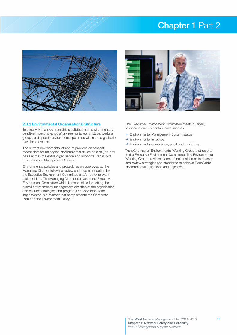
2.3.2 Environmental Organisational StructureTo effectively manage TransGrid’s activities in an environmentally sensitive manner a range of environmental committees, working groups and specific environmental positions within the organisation have been created.
The current environmental structure provides an efficient mechanism for managing environmental issues on a day-to-day basis across the entire organisation and supports TransGrid’s Environmental Management System.
Environmental policies and procedures are approved by the Managing Director following review and recommendation by the Executive Environment Committee and/or other relevant stakeholders. The Managing Director convenes the Executive Environment Committee which is responsible for setting the overall environmental management direction of the organisation and ensures strategies and programs are developed and implemented in a manner that complements the Corporate Plan and the Environment Policy.
The Executive Environment Committee meets quarterly to discuss environmental issues such as:
>> Environmental Management System status>> Environmental initiatives>> Environmental compliance, audit and monitoring
TransGrid has an Environmental Working Group that reports to the Executive Environment Committee. The Environmental Working Group provides a cross-functional forum to develop and review strategies and standards to achieve TransGrid’s environmental obligations and objectives.
18 TransGrid Network Management Plan 2011-2016Chapter 1: Network Safety and Reliability Part 2: Management Support Systems
Chapter 1 Part 2
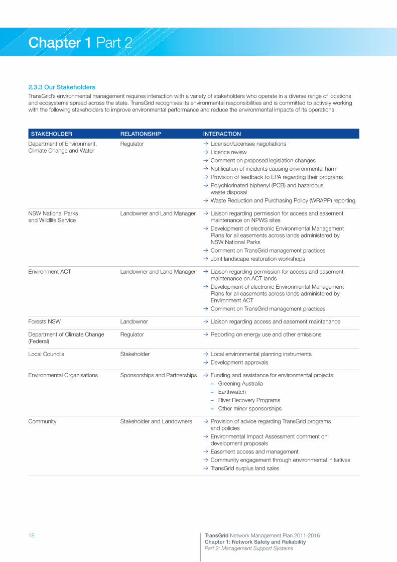
2.3.3 Our StakeholdersTransGrid’s environmental management requires interaction with a variety of stakeholders who operate in a diverse range of locations and ecosystems spread across the state. TransGrid recognises its environmental responsibilities and is committed to actively working with the following stakeholders to improve environmental performance and reduce the environmental impacts of its operations.
STAKEHOLDER RELATIONSHIP INTERACTION
Department of Environment, Climate Change and Water
Regulator >> Licensor/Licensee negotiations >> Licence review>> Comment on proposed legislation changes>> Notification of incidents causing environmental harm>> Provision of feedback to EPA regarding their programs >> Polychlorinated biphenyl (PCB) and hazardous waste disposal
>> Waste Reduction and Purchasing Policy (WRAPP) reporting
NSW National Parks and Wildlife Service
Landowner and Land Manager >> Liaison regarding permission for access and easement maintenance on NPWS sites
>> Development of electronic Environmental Management Plans for all easements across lands administered by NSW National Parks
>> Comment on TransGrid management practices>> Joint landscape restoration workshops
Environment ACT Landowner and Land Manager >> Liaison regarding permission for access and easement maintenance on ACT lands
>> Development of electronic Environmental Management Plans for all easements across lands administered by Environment ACT
>> Comment on TransGrid management practices
Forests NSW Landowner >> Liaison regarding access and easement maintenance
Department of Climate Change (Federal)
Regulator >> Reporting on energy use and other emissions
Local Councils Stakeholder >> Local environmental planning instruments>> Development approvals
Environmental Organisations Sponsorships and Partnerships >> Funding and assistance for environmental projects: – Greening Australia – Earthwatch – River Recovery Programs – Other minor sponsorships
Community Stakeholder and Landowners >> Provision of advice regarding TransGrid programs and policies
>> Environmental Impact Assessment comment on development proposals
>> Easement access and management >> Community engagement through environmental initiatives>> TransGrid surplus land sales

19TransGrid Network Management Plan 2011-2016Chapter 1: Network Safety and Reliability Part 2: Management Support Systems
Chapter 1 Part 2
2.4 Emergency Management System
2.4.1 Emergency Management ProceduresTransGrid has a Business Continuity Management Framework – GD AS G3 021 which covers the areas of business continuity, emergency management and contingency planning.
Business continuity management is addressed through a number of documents including:
>> Business Continuity Management Plan – GD AD G2 002 which describes business continuity actions, guidelines and responsibilities and the preparation of business continuity plans. This is supported by specific business continuity plans for each key business process.
>> The Continuity of Transmission Supply Plan – GD AS S1 012, which outlines the general approach to continuity of electricity supply following the loss of a significant network asset.
>> An Information Technology Service Recovery Plan which covers continuity of IT processes.
Emergency management procedures are specified in the Corporate and Regional Emergency Management Plan (CREMP). The CREMP is used to co-ordinate the management measures necessary to ensure a state of preparedness for emergencies which may impact upon reliability of supply, the safety of staff, members of the public or the environment. The CREMP is also required to respond to such emergencies, as well as emergencies declared under the NSW State Disaster Plan (Displan) and AEMO’s Power System Emergency Management Plan (PSEMP).
The CREMP categorises various levels of emergency and details the specific command structures and responsibilities associated with each.
Whilst TransGrid’s assets are exposed to the elements and are therefore impacted by natural events such as bush fires, storms and earthquakes, the CREMP also applies to failures of major system components and abnormal events such as vandalism and sabotage.
Each office/depot within TransGrid has a Local Evacuation Plan for incidents such as fire or bomb threats. These plans are located prominently on notice boards throughout the offices and buildings. These plans comply with Australian Standard – AS 3745-2010 Planning for Emergencies in Facilities.
These plans detail the site emergency control personnel, evacuation measures including annual training exercises, debrief session and the testing of alarms. All visitors to sites are advised of the existence of these procedures as part of their site induction.
The abovementioned plans are reviewed following any significant emergency to ensure that they were applied, that they worked effectively and noting any areas requiring amendment.
Each substation site has an individually designed Emergency Response Manual to deal with environmental emergencies or incidents at that site. These manuals are maintained to ensure their currency and are subject to regular independent audits.
Security incidents are recorded in the Incident Notification System on the intranet and are regularly reviewed to identify trends and determine any appropriate action.
2.4.2 CollaborationTransGrid actively participates in several industry forums and working groups for information sharing and collaborative action regarding security, including:
>> Energy & Utility Services Functional Area, co-ordinated by Industry & Investment NSW
>> Energy Sector Group, part of the Trusted Information Sharing Network co-ordinated by the Federal Government
>> NSW Utilities “Mutual Aid” Forum>> NSW Utilities Metal Theft Working Group
2.4.3 Operating StaffTransGrid’s system operation centres are staffed on a 24 hour basis. Operating staff at these centres are trained to operate the system in a safe manner in response to emergency conditions of all types, including:
>> Supply disruptions>> Asset damage>> Fire, explosion, impact>> Natural disaster>> Civil disturbances
In response to natural disasters and disturbances, the operator is required to contact the appropriate emergency service organisation. Operating staff escalate and coordinate responses with field staff who access other resources as required to address these emergencies in accordance with the CREMP.
Other relevant documentation includes:
>> Operating Manuals>> Fire Protection Manual Operations and Maintenance – GD HS G2 001
>> Environmental Management System (EMS) Manual – GD EN G2 002 and associated Emergency Response Manuals
Operating Manuals that are relevant to emergency response include:
>> Notification of System Incidents – OM 550>> Operational Failure of a Control Centre – OM 667>> Operational Communication Facilities – OM 801>> Restart of New South Wales System – OM 666
2.4.4 Testing of the Emergency ProceduresThe CREMP is tested on a regular basis by the simulation of emergency incidents. The testing sometimes involves the participation of other parties such as AEMO, distributors, other TNSPs and Jurisdictional bodies.
Evacuation plans are routinely tested at all our staffed sites.
Due to the nature of the emergencies that could occur at a substation site, no specific exercises are conducted other than to audit the Emergency Response systems and to train staff. However, when employed during previous genuine conditions, the emergency systems were found satisfactory. TransGrid’s first aid and fire fighting capabilities are tested at the annual Safety Day, where skills of staff from across the state are tested under competition conditions.

20

21TransGrid Network Management Plan 2011-2016Chapter X: Chapter Heading
Chapter 1 Part 3
3.1 Corporate Planning3.2 Network Planning3.3 Service Standards and Asset Performance
Network Safety and ReliabilityPart 3: Planning and Service Delivery

22 TransGrid Network Management Plan 2011-2016Chapter 1: Network Safety and Reliability Part 3: Planning and Service Delivery
Chapter 1 Part 3
3.1 Corporate Planning TransGrid’s Corporate Plan defines the organisation’s vision, mission, strategic direction, initiatives and primary measures. It is the high level plan from which specific business unit plans and strategies flow.
The Corporate Plan is developed using a balanced scorecard approach which considers four perspectives:
>> People, learning and growth>> Internal process>> Customers and stakeholders>> The financial perspective
The Corporate Plan is reviewed every year and performance is reported quarterly.
3.2 Network Planning
3.2.1 ObjectivesPlanning and development of TransGrid’s network is undertaken in accordance with the National Electricity Rules (NER). The NER sets out processes that require TransGrid to consult with Registered Participants, AEMO and interested parties on development options (which must include consideration of demand side management and local generation options) and apply the AER’s regulatory test or Regulatory Investment Test for Transmission (RIT-T), as appropriate1, to determine the most economic option.
The NER also specifies performance requirements of the network that form part of TransGrid’s service standards.
Accordingly, TransGrid plans to develop its network so that it:
>> Provides adequate power transmission capability.>> Provides electricity supply whose quality and reliability are determined by its customer service standards.
>> Provides a standard of connection to individual customers determined by Connection Agreements.
>> Ensures that, as far as possible, connection of a customer has no adverse effect on other connected customers.
>> Satisfies environmental constraints.>> Satisfies social constraints.>> Maintains acceptable safety standards.>> Is developed in accordance with the NER and the regulatory test or RIT-T for prescribed network augmentations.
3.2.2 Main ActivitiesThe main activities that support planning and development of the network include:
>> Load forecasting.>> Identification of network constraints.>> Justification and regulatory assessment of development options.
1 At present, the regulatory test applies when the limitation necessitating an augmentation is within a distribution network. However, it is expected that once the Regulatory Investment Test for Distribution (RIT-D) is finalised and comes into force, all limitations for which a transmission development is a credible option will be subject to the RIT-T.
>> Joint planning with electricity distributors and other major customers.
>> Annual Planning Review for New South Wales.>> Input to TransGrid’s capital works budget.
3.2.3 Annual Planning ReportThe National Electricity Rules require each Transmission Network Service Provider (TNSP) to undertake an Annual Planning Review and to prepare and publish an Annual Planning Report (APR) by 30 June of each year.
The purpose of the Planning Review and the APR is to:
>> Identify emerging constraints in New South Wales transmission networks over appropriate planning horizons.
>> Provide advance information on the nature, quantification and location of the constraints, and provides an indication of TransGrid’s intent to issue a Request for Proposal for non-network services. The level of information included in the APR is intended to be sufficient to encourage market participants and interested parties to formulate and propose options to relieve the constraints, including those that may include components of Demand Management (DM) and local generation or other options that may provide economically efficient outcomes.
>> Discuss options that have been identified for relieving each constraint including network, local generation, DM and other options.
>> Comply with NER requirements in respect of preparation of a Transmission Network Service Provider’s Annual Planning Report and the associated consultation on proposed new small network transmission assets.
>> Provide further details on the load forecast data that has been provided for input to the Electricity Statement of Opportunities (ESOO).
>> Provide a basis for annual reporting to the New South Wales Minister for Energy (the Minister) on the outcome of the Annual Planning Review.
The APR is intended to provide electricity market participants and interested parties with information that will assist them in contributing to the optimum and economically efficient development of transmission networks in NSW.
3.2.4 Approach to PlanningTransGrid’s approach to network planning of the NSW transmission network is derived from its planning obligation under the NER, jurisdictional requirements and customer expectations. The approach is documented each year in TransGrid’s APR.
TransGrid undertakes regular reviews of its planning approach to take account of:
>> Amendments and additions to the National Electricity Rules>> Jurisdictional requirements including new and amended legislation, Rules, Regulations and Licence conditions;
>> Technological developments, particularly those that can impact on reliability
>> Customer requests and expectations>> Good electricity industry practice

23TransGrid Network Management Plan 2011-2016Chapter 1: Network Safety and Reliability Part 3: Planning and Service Delivery
Chapter 1 Part 3
The approach used for the preparation of TransGrid’s APR 2010 is as follows.
3.2.4.1 GeneralThe NSW transmission network has been planned and developed by TransGrid and its predecessor organisations, commencing with the Electricity Commission of NSW, for over 50 years.
Under NSW legislation, TransGrid has responsibilities that include planning for future NSW transmission needs, including interconnection with other networks.
In addition, as a Transmission Network Service Provider (TNSP) TransGrid is obliged to meet the requirements of the NER. In particular, TransGrid is obliged to meet the requirements of clause S 5.1.2.1:
“Network Service Providers must plan, design, maintain and operate their transmission networks to allow the transfer of power from generating units to Customers with all facilities or equipment associated with the power system in service and may be required by a Rule Participant under a connection agreement to continue to allow the transfer of power with certain facilities or plant associated with the power system out of service, whether or not accompanied by the occurrence of certain faults (called “credible contingency events”).
The NER sets out the required processes for developing networks as well as minimum performance requirements of the network and connections to the network. It also requires TransGrid to consult with Registered Participants, AEMO and interested parties and to apply the AER’s regulatory test or RIT-T to development proposals.
TransGrid’s planning obligations are also interlinked with the licence obligations placed on Distribution Network Service Providers (DNSPs) in NSW. TransGrid must ensure that the system is adequately planned to enable the licence requirements to be met.
TransGrid also has obligations to meet community expectations in the supply of electricity, including ensuring that developments are undertaken in a socially and environmentally responsible manner.
In meeting these obligations, TransGrid’s approach to network planning is socially and economically based and is consistent with both the NER and the regulatory test or RIT-T as appropriate. Joint planning with DNSPs, directly supplied industrial customers, generators and interstate TNSPs is carried out to ensure that the most economic options consistent with customer and community requirements are identified and implemented.
TransGrid has traditionally planned the network to achieve supply at least community cost, without being constrained by State borders or ownership considerations. Transmission augmentations have been subjected to a cost-benefit assessment according to NSW State Treasury guidelines since the 1980s. A similar approach is applied in the NEM where the AER’s regulatory test or RIT-T is applied to meet the requirements of Chapter 5 of the NER.
Jurisdictional Planning RequirementsIn addition to meeting requirements imposed by the NER, environmental legislation and other statutory instruments, TransGrid is expected by the NSW jurisdiction to plan and
develop its transmission network on an “n-1” basis. That is, unless specifically agreed otherwise by TransGrid and the affected distribution network owner or major directly connected end-use customer, there will be no inadvertent loss of load (other than load which is interruptible or dispatchable) following an outage of a single circuit (a line or a cable) or transformer, during periods of forecast high load.
In fulfilling this obligation, TransGrid must recognise specific customer requirements as well as AEMO’s role as system operator for the NEM. To accommodate this, the standard “n-1” approach can be modified in the following circumstances:
>> Where agreed between TransGrid and a distribution network owner or major directly connected end use customer, agreed levels of supply interruption can be accepted for particular single outages, before augmentation of the network is undertaken (for example the situation with radial supplies).
>> Where requested by a distribution network owner or major directly connected end use customer and agreed with TransGrid, there will be no inadvertent loss of load (other than load which is interruptible or dispatchable) following an outage of a section of busbar or coincident outages of agreed combinations of two circuits, two transformers or a circuit and a transformer (for example supply to the inner metropolitan/CBD of Sydney).
>> The main transmission network, which is operated by AEMO, should have sufficient capacity to accommodate AEMO’s operating practices without inadvertent loss of load (other than load which is interruptible or dispatchable) or uneconomic constraints on the energy market. At present AEMO’s operational practices include the re-dispatch of generation and ancillary services following a first contingency, such that within 30 minutes the system will again be “secure” in anticipation of the next critical credible contingency.
In 2005, the NSW Government introduced mandatory licence conditions on DNSPs which set out certain reliability standards for sub-transmission and distribution networks. The licence conditions specify “n-1, 1 minute” reliability standards for sub-transmission lines and zone substations supplying loads greater than or equal to specified minimums, e.g. 15MVA in urban and non-urban areas.
These requirements imply a consequential requirement on TransGrid to provide a commensurate level of reliability in its network supplying NSW DNSPs.
Country Energy has requested TransGrid to provide a commensurate reliability standard at connection points to its network, i.e. “n-1, 1 minute” reliability where Country Energy’s maximum demand is greater than or equal to 15MVA.
These jurisdictional requirements and other obligations require the following to be observed in planning the network:
>> At all times when the system is either in its normal state with all elements in service or following a credible contingency: – Electrical and thermal ratings of equipment will not
be exceeded. – Stable control of system voltage will be maintained, with
system voltages maintained within acceptable levels .>> A quality of electricity supply at least to NER requirements is to be provided.
24 TransGrid Network Management Plan 2011-2016Chapter 1: Network Safety and Reliability Part 3: Planning and Service Delivery
Chapter 1 Part 3
>> A standard of connection to individual customers as specified by Connection Agreements is to be provided.
>> As far as possible connection of a customer is to have no adverse effect on other connected customers.
>> Environmental constraints are to be satisfied.>> Social constraints are to be satisfied.>> Acceptable safety standards are to be maintained.>> The power system in NSW is to be developed at the lowest cost possible whilst meeting the constraints imposed by the above factors.
Consistent with a responsible approach to the environment, it is also aimed to reduce system energy losses where economic.
A further consideration is the provision of sufficient capability in the system to allow components to be maintained in accordance with TransGrid’s asset management strategies.
National Planning RequirementsAEMO has the role of the national transmission planner and is required to produce a National Transmission Network Development Plan (NTNDP). The NTNDP will have regard to jurisdictional planning and regulatory documents (such as APRs) and, in turn, the jurisdictional planning bodies need to have regard to the NTNDP in formulating their plans. The first NTNDP was published in 2010. Through a close working relationship, TransGrid’s future plans will be consistent with AEMO’s.
The Network Planning ProcessThe network planning process is undertaken at three levels:
1. Connection PlanningConnection planning is concerned with the local network directly related to the connection of loads and generators. Connection planning typically includes connection enquiries and the formulation of draft connection agreements leading to a preliminary review of the capability of connections. Further discussions are held with specific customers where there is a need for augmentation or for provision of new connection points.
2. Network Planning within the New South Wales RegionThe main 500kV, 330kV and 220kV transmission system is developed in response to the overall load growth and generation requirements and may be influenced by interstate interconnection power transfers. Any developments include negotiation with affected NSW and interstate parties.
The assessment of the adequacy of 132kV systems requires joint planning with DNSPs. This ensures that development proposals are optimal with respect to both TransGrid and DNSP requirements leading to the lowest possible cost of transmission to the end customer. This is particularly important where the DNSP’s network operates in parallel with the transmission network, forming a meshed system.
3. Inter-regional PlanningThe development of interconnectors between regions, and of augmentations within regions that have a material effect on inter-regional power transfer capability are coordinated with network owners in other states in accordance with the NER. The inter-regional developments will be consistent with the NTNDP.
Planning HorizonsTransmission planning is carried out over a short-term time frame of one to five years and also over a longer-term time frame of five to 20 years or more. The short-term planning supports commitments to network developments with relatively short lead times. The long-term planning considers options for future major developments and provides a framework for the orderly and economic development of the transmission network and the strategic acquisition of critical line and substation sites.
In the Annual Planning Report, constraints that appear over a longer time frame are considered to be indicative. The timing and capital cost of possible network options to relieve them may change significantly as system conditions evolve. TransGrid has published its outline plans for long-term developments.
Identifying Network Constraints and Assessing Possible SolutionsAn emerging constraint may be identified during various planning activities covering the planning horizon. It may be identified through:
>> TransGrid’s planning activities>> Joint planning with a DNSP>> The impact of prospective generation developments>> The occurrence of constraints affecting generation dispatch in the NEM
>> The impact of network developments undertaken by other TNSPs
>> As a result of a major load development
During the initial planning phase a number of options for addressing the constraint are developed. In accordance with NER requirements, consultation with interested parties is carried out to determine a range of options including network, DM and local generation options and/or to refine existing options.
A cost effectiveness or cost-benefit analysis is carried out in which the costs and benefits of each option are compared in accordance with the AER’s regulatory test or RIT-T. In applying the applicable test, the cost and benefit factors may include:
>> Avoiding unserved energy caused by either a generation shortfall or inadequate transmission capability or reliability.
>> Loss reductions>> Alleviating constraints affecting generation dispatch>> Avoiding the need for generation developments>> Fuel cost savings>> Improvement in marginal loss factors>> Deferral of related transmission works>> Reduction in operation and maintenance costs
Options with similar Net Present Value would be assessed with respect to factors that may not be able to be quantified and/or included in the regulatory test or RIT-T, but nonetheless may be important from environmental or operational viewpoints. These factors include:
>> Reduction in greenhouse gas emissions or increased capability to apply greenhouse-friendly plant
>> Improvement in quality of supply above minimum requirements
>> Improvement in operational flexibility
25TransGrid Network Management Plan 2011-2016Chapter 1: Network Safety and Reliability Part 3: Planning and Service Delivery
Chapter 1 Part 3
Application of Power System Controls and TechnologyTransGrid seeks to take advantage of the latest proven technologies in network control systems and electrical plant where these are found to be economic. For example, the application of Static Var Compensators has had a considerable impact on the power transfer capabilities of parts of the main grid and has deferred or removed the need for higher cost transmission line developments.
System Protection Schemes have been applied in several areas of the NSW system to reduce the impact of network limitations on the operation of the NEM and to facilitate removal of circuits for maintenance.
The broad approach to planning and consideration of these technologies together with related issues of protection facilities, transmission line design, substation switching arrangements and power system control and communication is set out in the following sections. This approach is in line with international practice and provides a cost effective means of maintaining a safe, reliable, secure and economic supply system consistent with maintaining a responsible approach to environmental and social impacts.
3.2.4.2 Planning CriteriaThe NER specifies the minimum and general technical requirements in a range of areas including:
>> A definition of the minimum level of credible contingency events to be considered
>> The power transfer capability during the most critical single element outage, ranging from zero in the case of a single element supply to a portion of the normal power transfer capability
>> Frequency variations>> Magnitude of power frequency voltages>> Voltage fluctuations>> Voltage harmonics>> Voltage unbalance>> Voltage stability>> Synchronous stability>> Damping of power system oscillations>> Fault clearance times>> The need for two independent high speed protection systems>> Rating of transmission lines and equipment
In addition to adherence to NER and regulatory requirements, TransGrid’s transmission planning approach has been developed taking into account the historical performance of the components of the NSW system, the sensitivity of loads to supply interruption and state-of-the-art asset maintenance procedures. It has also been recognised that there is a need for an orderly development of the system taking into account the long-term requirements of the system to meet future load and generation developments.
A set of deterministic criteria, detailed below, are applied as a point of first review, from which point a detailed assessment of each individual case is made.
Main Transmission NetworkPower flows on the main transmission network are subject to overall state load patterns and the dispatch of generation within the NEM, including interstate export and import of power. AEMO operates the interconnected power system and applies operational constraints on generator dispatch to maintain power flows within the capability of the NSW and other regional networks. These constraints are based on the ability of the networks to sustain credible contingency events that are defined in the NER. These events mainly cover forced outages of single generation or transmission elements, but also provide for multiple outages to be redefined as credible from time to time. Constraints are often based on short-duration loadings on network elements, on the basis that generation can be re-dispatched to relieve the line loading within 15 minutes.
The rationale for this approach is that, if operated beyond a defined power transfer level, credible contingency disturbances could potentially lead to system wide loss of load with severe social and economic impact.
Following any transmission outage, for example during maintenance or following a forced line outage for which line reclosure has not been possible, AEMO applies more severe constraints within a short adjustment period, in anticipation of the impact of a further contingency event. This may require:
>> The re-dispatch of generation and dispatchable loads>> The re-distribution of ancillary services>> Where there is no other alternative, the shedding of load
AEMO may direct the shedding of customer load, rather than operate for a sustained period in a manner where overall security would be at risk for a further contingency. The risk is, however, accepted over a period of up to 30 minutes. In performing its planning analysis, TransGrid must consider AEMO’s imperative to operate the network in a secure manner.
Therefore in the first instance, TransGrid’s planning for its main network concentrates on the security of supply to load connection points under sustained outage conditions, consistent with the overall principle that supply to load connection points must be satisfactory after any single contingency.
The main 500kV, 330kV and 220kV transmission system is augmented in response to the overall load growth and generation requirements and may be influenced by interstate interconnection power transfers. Any developments include negotiation with affected NSW and interstate parties.
The reliability of the main system components and the ability to withstand a disturbance to the system are critically important in maintaining the security of supply to NSW customers. A high level of reliability implies the need for a robust transmission system. The capital cost of this system is balanced by:
>> Avoiding the large cost to the community of widespread shortages of supply.
>> Providing flexibility in the choice of economical generating patterns leading to the most economic energy supply to consumers.
>> Allowing reduced maintenance costs through easier access to equipment.
>> Minimising electrical losses which also provides benefit to the environment.
26 TransGrid Network Management Plan 2011-2016Chapter 1: Network Safety and Reliability Part 3: Planning and Service Delivery
Chapter 1 Part 3
The planning of the main system must take into account the risk of forced outages of a transmission element coinciding with adverse conditions of load and generation dispatch. Two levels of load forecast (summer and winter) are considered, as follows.
Loads at or exceeding a one in two year probability of occurrence (50% probability of exceedence)The system will be able to withstand a single contingency under all reasonably probable patterns of generation dispatch or interconnection power flow. In this context, a single contingency is defined as the forced outage of a single transmission circuit, a single generating unit, a single transformer, a single item of reactive plant or a single busbar section.
Provision will be made for a prior outage (following failure) of a single item of reactive plant.
Further the system will be able to be secured by re-dispatching generation (AEMO action) so as to withstand the impact of a second contingency.
Loads at or exceeding a one in ten year probability of occurrence (10% probability of exceedence)The system will be able to withstand a single contingency under a limited set of patterns of generation dispatch or interconnection power flow.
Further the system will be able to be secured by re-dispatching generation (AEMO action) so as to withstand the impact of a second contingency.
These criteria do not apply to radial sections of the main system.
Under all conditions, there is a need to achieve adequate voltage control capability. TransGrid has traditionally assumed that all on-line generators can provide reactive power support within their rated capability but in the future intends to align with other utilities in relying only on the reactive capability given by performance standards. Reactive support beyond the performance standards may need to be procured under network support arrangements.
A further consideration is the provision of sufficient capability in the system to allow components to be maintained in accordance with TransGrid’s asset management strategies.
Overall supply in NSW is heavily dependent on base-load coal-fired generation in the Hunter Valley, western area and Central Coast. These areas are interconnected with the load centres via numerous single and double circuit lines. In planning the NSW system, taking into account AEMO’s operational approach to the system, there is a need to consider the risk and impact of overlapping outages of circuits under high probability patterns of load and generation.
The analysis of network adequacy must take into account the probable load patterns, typical dispatch of generators and loads, the availability characteristics of generators (as influenced by maintenance and forced outages), energy limitations and other factors relevant to each case.
Options to address an emerging inability to meet all connection point loads would be considered with allowance for the lead time for a network augmentation solution.
Before this time, consideration may be given to the costs involved in re-dispatch in the energy and ancillary services markets to manage single contingencies. In situations where these costs appear to exceed the costs of a network augmentation, this will be brought to the attention of network load customers for consideration. TransGrid may then initiate the development of a network or non-network solution through a consultation process.
Relationship with Inter-Regional PlanningIn addition to concerns about security of supply to load point connections, TransGrid also monitors the occurrence of constraints in the main transmission system that affect generator dispatch. TransGrid’s planning therefore also considers the scope for network augmentations to reduce constraints that may satisfy the RIT-T.
Under the provisions of the NER, a Region may be created where constraints to generator dispatch are predicted to occur with reasonable frequency when the network is operated in the “system normal” (all significant elements in service) condition. The creation of a Region does not however consider the consequences to load connection points if there should be a network contingency.
In effect, the capacity of interconnectors that is applied in the market dispatch is the short-time capacity determined by the ability to maintain secure operation in the system normal state in anticipation of a single contingency. The operation of the interconnector at this capacity must be supported by appropriate ancillary services. However, AEMO does not operate on the basis that the contingency may be sustained but TransGrid must consider the impact of a prolonged plant outage.
As a consequence, it is probable that for parts of the network that are critical to the supply to loads, TransGrid would initiate augmentation to meet an ‘n-1’ criterion before the creation of a new Region.
The development of interconnectors between regions will be undertaken where the augmentation satisfies the RIT-T. The planning of interconnections will be undertaken in consultation with the jurisdictional planning bodies of the other states.
It is not planned to maintain the capability of an interconnector where relevant network developments would not satisfy the RIT-T.
Networks Supplied from the Main Transmission NetworkSome parts of TransGrid’s network are primarily concerned with supply to local loads and are not significantly impacted by the dispatch of generation (although they may contain embedded generators). The loss of a transmission element within these networks does not have to be considered by AEMO in determining network constraints, although ancillary services may need to be provided to cover load rejection in the event of a single contingency.
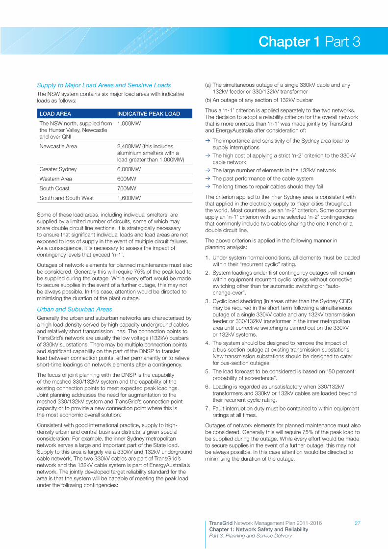
27TransGrid Network Management Plan 2011-2016Chapter 1: Network Safety and Reliability Part 3: Planning and Service Delivery
Chapter 1 Part 3
Supply to Major Load Areas and Sensitive LoadsThe NSW system contains six major load areas with indicative loads as follows:
LOAD AREA INDICATIVE PEAK LOAD
The NSW north, supplied from the Hunter Valley, Newcastle and over QNI
1,000MW
Newcastle Area 2,400MW (this includes aluminium smelters with a load greater than 1,000MW)
Greater Sydney 6,000MW
Western Area 600MW
South Coast 700MW
South and South West 1,600MW
Some of these load areas, including individual smelters, are supplied by a limited number of circuits, some of which may share double circuit line sections. It is strategically necessary to ensure that significant individual loads and load areas are not exposed to loss of supply in the event of multiple circuit failures. As a consequence, it is necessary to assess the impact of contingency levels that exceed ‘n-1’.
Outages of network elements for planned maintenance must also be considered. Generally this will require 75% of the peak load to be supplied during the outage. While every effort would be made to secure supplies in the event of a further outage, this may not be always possible. In this case, attention would be directed to minimising the duration of the plant outage.
Urban and Suburban AreasGenerally the urban and suburban networks are characterised by a high load density served by high capacity underground cables and relatively short transmission lines. The connection points to TransGrid’s network are usually the low voltage (132kV) busbars of 330kV substations. There may be multiple connection points and significant capability on the part of the DNSP to transfer load between connection points, either permanently or to relieve short-time loadings on network elements after a contingency.
The focus of joint planning with the DNSP is the capability of the meshed 330/132kV system and the capability of the existing connection points to meet expected peak loadings. Joint planning addresses the need for augmentation to the meshed 330/132kV system and TransGrid’s connection point capacity or to provide a new connection point where this is the most economic overall solution.
Consistent with good international practice, supply to high-density urban and central business districts is given special consideration. For example, the inner Sydney metropolitan network serves a large and important part of the State load. Supply to this area is largely via a 330kV and 132kV underground cable network. The two 330kV cables are part of TransGrid’s network and the 132kV cable system is part of EnergyAustralia’s network. The jointly developed target reliability standard for the area is that the system will be capable of meeting the peak load under the following contingencies:
(a) The simultaneous outage of a single 330kV cable and any 132kV feeder or 330/132kV transformer
(b) An outage of any section of 132kV busbar
Thus a ‘n-1’ criterion is applied separately to the two networks. The decision to adopt a reliability criterion for the overall network that is more onerous than ‘n-1’ was made jointly by TransGrid and EnergyAustralia after consideration of:
>> The importance and sensitivity of the Sydney area load to supply interruptions
>> The high cost of applying a strict ‘n-2’ criterion to the 330kV cable network
>> The large number of elements in the 132kV network>> The past performance of the cable system>> The long times to repair cables should they fail
The criterion applied to the inner Sydney area is consistent with that applied in the electricity supply to major cities throughout the world. Most countries use an ‘n-2’ criterion. Some countries apply an ‘n-1’ criterion with some selected ‘n-2’ contingencies that commonly include two cables sharing the one trench or a double circuit line.
The above criterion is applied in the following manner in planning analysis:
1. Under system normal conditions, all elements must be loaded within their “recurrent cyclic” rating.
2. System loadings under first contingency outages will remain within equipment recurrent cyclic ratings without corrective switching other than for automatic switching or “auto- change-over”.
3. Cyclic load shedding (in areas other than the Sydney CBD) may be required in the short term following a simultaneous outage of a single 330kV cable and any 132kV transmission feeder or 330/132kV transformer in the inner metropolitan area until corrective switching is carried out on the 330kV or 132kV systems.
4. The system should be designed to remove the impact of a bus-section outage at existing transmission substations. New transmission substations should be designed to cater for bus-section outages.
5. The load forecast to be considered is based on “50 percent probability of exceedence”.
6. Loading is regarded as unsatisfactory when 330/132kV transformers and 330kV or 132kV cables are loaded beyond their recurrent cyclic rating.
7. Fault interruption duty must be contained to within equipment ratings at all times.
Outages of network elements for planned maintenance must also be considered. Generally this will require 75% of the peak load to be supplied during the outage. While every effort would be made to secure supplies in the event of a further outage, this may not be always possible. In this case attention would be directed to minimising the duration of the outage.
28 TransGrid Network Management Plan 2011-2016Chapter 1: Network Safety and Reliability Part 3: Planning and Service Delivery
Chapter 1 Part 3
Non Urban Areas Generally these areas are characterised by lower load densities and, generally, lower reliability requirements than urban systems. The areas are often supplied by relatively long, often radial, transmission systems. Connection points are either on 132kV lines or on the low voltage busbars of 132kV substations. Although there may be multiple connection points to a DNSP, they are often far apart and there will be little capacity for power transfer between them. Frequently, supply limitations will apply to the combined capacity of several supply points together.
The focus of joint planning with the DNSP will usually relate to:
>> Augmentation of connection point capacity>> Duplication of radial supplies>> Extension of the 132kV system to reinforce or replace existing lower voltage systems and to reduce losses
>> Development of a higher voltage system to provide a major augmentation and to reduce network losses
TransGrid’s aim is to provide a level and reliability of supply at connection points that is complementary to that provided by the DNSP within its own network. For example, Country Energy provides fully duplicated supply (‘n-1’ reliability) to a load area of 15MW or more, and will provide a switched alternative supply if the load exceeds about 5MW, and requires TransGrid to provide a commensurate level of reliability at connection points to its network.
Supply to one or more connection points would be considered for augmentation when the forecast peak load at the end of the planning horizon exceeds the load firm ‘n-1’ capacity of TransGrid’s network. However, consistent with the lower level of reliability that may be appropriate in a non-urban area, an agreed level of risk of loss of supply may be accepted. Thus augmentations may actually be undertaken:
>> When the forecast load exceeds the firm capacity by an agreed amount
>> Where the period that some load is at risk exceeds an agreed proportion of the time
>> An agreed amount of energy (or proportion of annual energy supplied) is at risk
As a result of the application of these criteria some radial parts of the 330kV and 220kV network are not able to withstand the forced outage of a single circuit line at time of peak load, and in these cases provision has been made for under-voltage load shedding.
Provision is also required for the maintenance of the network. Additional redundancy in the network is required where maintenance cannot be scheduled without causing load restrictions or an unacceptable level of risk to the security of supply.
Transformer AugmentationIn considering the augmentation of transformers, appropriate allowance is made for the transformer cyclic rating and the practicality of load transfers between connection points. The outage of a single transformer (or single-phase unit) or a transmission line that supports the load carried by the transformer is allowed for.
Provision is also required for the maintenance of transformers. This has become a critical issue at a number of sites in NSW where there are multiple transformers in service. To enable maintenance to be carried out, additional transformer capacity or a means of transferring load to other supply points via the underlying lower voltage network may be required.
Consideration of Low Probability EventsAlthough there is a high probability that loads will not be shed as a result of system disturbances, no power system can be guaranteed to deliver a firm capability 100% of the time, particularly when subjected to disturbances that are severe or widespread. In addition, extreme loads can occur above the level allowed for in planning, usually under extreme weather conditions.
The NSW network contains numerous lines of double circuit construction and whilst the probability of overlapping outages of both circuits of a line is very low, the consequences could be widespread supply disturbances.
Thus there is a potential for low probability events to cause localised or widespread disruption to the power system. These events can include:
>> Loss of several transmission lines within a single corridor, as may occur during bush fires
>> Loss of a number of cables sharing a common trench>> Loss of more than one section of busbar within a substation, possibly following a major plant failure
>> Loss of a number of generating units>> Occurrence of three-phase faults, or faults with delayed clearing
In TransGrid’s network, appropriate facilities and mechanisms are frequently put in place to minimise the probability of such events and to ameliorate their impact. The decision process considers the underlying economics of facilities or corrective actions, taking account of the low probability of the occurrence of extreme events. TransGrid will take measures, where practicable, to minimise the impact of disturbances in the power system by implementing power system control systems at minimal cost in accordance with the NER.
3.2.4.3 Protection RequirementsBasic protection requirements are included in the NER. The NER requires that protection systems be installed so that any fault can be detected by at least two fully independent protection systems. Backup protection is provided against circuit breaker failure. Provision is also made for detecting high resistance earth faults.
Required protection clearance times are specified by the NER and determined by stability considerations as well as the characteristics of modern power system equipment. Where special protection facilities or equipment are required for high-speed fault clearance, they are justified on either a NER compliance or a benefit/cost basis.
All modern distance protection systems on the main network include the facility for power swing blocking (PSB). PSB is utilised to control the impact of a disturbance that can cause synchronous instability. PSB is enabled at locations where it has been assessed that there are benefits to system operation to be realised. This feature will become increasingly more important as the interconnected system is developed and extended.

29TransGrid Network Management Plan 2011-2016Chapter 1: Network Safety and Reliability Part 3: Planning and Service Delivery
Chapter 1 Part 3
3.2.4.4 Transient StabilityIn accordance with the NER, transient stability is assessed on the basis of the angular swings following a solid fault on one circuit at the most critical location that is cleared by the faster of the two protections (with intertrips assumed in service where installed). At the main system level, a two phase-to-ground fault is applied, and on 132kV systems which are to be augmented, a three-phase fault is applied.
Recognition of the potential impact of a three-phase fault at the main system level is made by instituting maintenance and operating precautions to minimise the risk of such a fault.
The determination of the transient stability capability of the main grid is undertaken using software that has been calibrated against commercially available system dynamic analysis software.
Where transient stability is a factor in the development of the main network, preference is given to the application of advanced control of the power system or high-speed protection systems before consideration is given to the installation of high capital cost plant.
3.2.4.5 Steady State StabilityThe requirements for control of steady state stability are included in the NER. For planning purposes, steady state stability (or system damping) is considered adequate under any given operating condition if, after the most critical credible contingency, simulations indicate that the halving time of the least damped electromechanical mode of oscillation is not more than five seconds.
The determination of the steady state stability performance of the system is undertaken using software that has been calibrated against commercially available software and from data derived from the monitoring of system behaviour.
In planning the network, maximum use is made of existing plant, through the optimum adjustment of plant control system settings, before consideration is given to the installation of high capital cost plant.
3.2.4.6 Line and Equipment Thermal RatingsLine thermal ratings have traditionally been based on a fixed continuous rating and a fixed short time rating. TransGrid applies probabilistic-based line ratings, which are dependent on the likelihood of coincident adverse weather conditions and unfavourable loading levels. This approach has been applied to selected lines whose design temperature is 100˚C or less. For these lines, a contingency rating and a short-time emergency rating have been developed. Typically the short-time rating is based on a load duration of 15 minutes, although the duration can be adjusted to suit the particular load pattern to which the line is expected to be exposed. The duration and level of loading must take into account any requirements for re-dispatch of generation or load control.
TransGrid is installing ambient condition monitors on critical transmission lines to enable the application of real-time line conductor ratings in the generation dispatch systems.
Transformers are rated according to their specification. Provision is also made for use of the short-time capability of the transformers during the outage of a parallel transformer or transmission line.
TransGrid owns two 330kV cables and these are rated according to manufacturer’s recommendations that have been checked against an appropriate thermal model of the cable.
The rating of line terminal equipment is based on manufacturers’ advice.
3.2.4.7 Reactive Support and Voltage StabilityIt is necessary to maintain voltage stability, with voltages within acceptable levels, following the loss of a single element in the power system at times of peak system loading. The single element includes a generator, a single transmission circuit, a cable and single items of reactive support plant.
To cover fluctuations in system operating conditions, uncertainties of load levels, measurement errors and errors in the setting of control operating points, it is necessary to maintain a margin from operating points that may result in a loss of voltage control. A reactive power margin is maintained over the point of voltage instability or alternatively a margin is maintained with respect to the power transfer compared to the maximum feasible power transfer.
The system voltage profile is set during generator dispatch to minimise the need for post-contingency reactive power support.
Reactive power plant generally has a low cost relative to major transmission lines and the incremental cost of providing additional capacity in a shunt capacitor bank can be very low. Such plant can also have a very high benefit/cost ratio and therefore the timing of reactive plant installations is generally less sensitive to changes in load growth than the timing of other network augmentations. Even so, TransGrid aims to make maximum use of existing reactive sources before new installations are considered.
TransGrid has traditionally assumed that all on-line generators can provide reactive power support within their rated capability but in the future intends to align with other utilities in relying only on the reactive capability given by performance standards. Reactive support beyond the performance standards may need to be procured under network support arrangements.
Reactive power plant is installed to support planned power flows up to the capability defined by limit equations, and is often the critical factor determining network capability. On the main network, allowance is made for the unavailability of a single major source of reactive power support in the critical area affected at times of high load, but not at the maximum load level.
It is also necessary to maintain control of the supply voltage to the connected loads under minimum load conditions.
The factors that determine the need for reactive plant installations are:
>> In general it has proven prudent and economic to limit the voltage change between the pre and post-contingency operating conditions.
>> It has also proven prudent, in general, and economic to ensure that the post-contingency operating voltage at major 330kV busbars lies above a lower limit.
>> The reactive margin from the point of voltage collapse is maintained to be greater than a minimum acceptable level.
>> A margin between the power transmitted and the maximum feasible power transmission is maintained.

30 TransGrid Network Management Plan 2011-2016Chapter 1: Network Safety and Reliability Part 3: Planning and Service Delivery
Chapter 1 Part 3
>> At times of light system load, it is essential to ensure that voltages can be maintained within the system highest voltage limits of equipment.
At some locations on the main network, relatively large voltage changes are accepted and agreed with customers following forced outages, providing voltage stability is not placed at risk. These voltage changes can approach, and in certain cases, exceed 10% at peak load.
On some sections of the network, the possibility of loss of load due to depressed voltages following a contingency is also accepted. However, there is a preference to install load shedding initiated by under-voltage so that the disconnection of load occurs in a controlled manner.
When determining the allowable rating of switched reactive plant, the requirements of the NER are observed.
3.2.4.8 Transmission Line Voltage and Conductor Sizes Determined by Economic ConsiderationsConsideration is given to the selection of line design voltages within the standard nominal 132kV, 220kV, 275kV, 330kV and 500kV range, taking due account of transformation costs.
Minimum conductor sizes are governed by losses and radio interference and field strength considerations.
TransGrid strives to reduce the overall cost of energy and network services by the economic selection of line conductor size. The actual losses that occur are governed by generation dispatch in the market.
For a line whose design is governed by economic loading limits, the conductor size is determined by a rigorous consideration of capital cost versus loss costs. Hence, the impact of the development on generator and load marginal loss factors in the market is considered. For other lines, the rating requirements will determine the conductor requirements.
Double circuit lines are built in place of two single circuit lines where this is considered to be both economic and to provide adequate reliability. Consideration would be given to the impact of a double circuit line failure, both over relatively short terms and for extended durations. This means that supply to a relatively large load may require single rather than double circuit transmission line construction where environmentally acceptable.
In areas prone to bush fire, any parallel single circuit lines would preferably be routed well apart.
3.2.4.9 Short-Circuit Rating RequirementsSubstation high voltage equipment is designed to withstand a maximum design short-circuit duty in accordance with the applicable Australian Standard.
Operating constraints are enforced to ensure equipment is not exposed to fault duties beyond the plant rating.
In general, the short circuit capability of all of the plant at a site would be designed to match or exceed the maximum short circuit duty at the relevant busbar. In order to achieve cost efficiencies when augmenting an existing substation, the maximum possible short-circuit duty on individual substation components may be calculated and applied in order to establish the adequacy of the equipment.
Short circuit duty calculations are based on the following assumptions:
>> All main network generators that are capable of operating, as set out in connection agreements, are assumed to be in service
>> All generating units that are embedded in distribution networks are assumed to be in service
>> Maximum fault contribution from interstate interconnections is assumed
>> Worst-case pre-fault power flow conditions are assumed>> Normally open connections are treated as open>> Networks are modelled in full>> Motor load contributions are not modelled>> Generators are modelled as a constant voltage behind sub-transient reactance
3.2.4.10 Substation Switching ArrangementsSubstation switching arrangements are adopted that provide acceptable reliability at minimum cost, consistent with the overall reliability of the transmission network. In determining a switching arrangement, consideration is also given to:
>> Site constraints>> Reliability expectations with respect to connected loads and generators
>> The physical location of “incoming” and “outgoing” circuits>> Maintenance requirements>> Operating requirements>> Transformer arrangements
TransGrid has applied the following arrangements:
>> Single busbar>> Double busbar>> Multiple element mesh>> Breaker-and-a-half
In general, at main system locations, a mesh or breaker-and- a-half arrangement is now usually adopted.
Where necessary, the expected reliability performance of potential substation configurations can be compared using equipment reliability parameters derived from local and international data.
The forced outage of a single busbar zone is generally provided for. Under this condition, the main network is planned to have adequate capability although loss of load may eventuate. In general, the forced outage of a single busbar zone should not result in the outage of any base-load generating unit.
Where appropriate, a 330kV bus section breaker would ordinarily be provided when a second “incoming” 330kV line is connected to the substation.
A 132kV bus section circuit breaker would generally be considered necessary when the peak load supplied via that busbar exceeds 120MW. A bus section breaker is generally provided on the low voltage busbar of 132kV substations when supply is taken over more than two low voltage feeders.

31TransGrid Network Management Plan 2011-2016Chapter 1: Network Safety and Reliability Part 3: Planning and Service Delivery
Chapter 1 Part 3
3.2.4.11 AutoreclosureAs most line faults are of a transient nature, all TransGrid’s overhead transmission lines are equipped with autoreclose facilities.
Slow speed three-pole reclosure is applied to most overhead circuits. On the remaining overhead circuits, under special circumstances, high-speed single-pole autoreclosing may be applied.
For public safety reasons, reclosure is not applied to underground cables.
Autoreclose is inhibited following the operation of breaker-fail protection.
3.2.4.12 Power System Control and CommunicationIn the design of the network and its operation to designed power transfer levels, reliance is generally placed on the provision of some of the following control facilities:
>> Automatic excitation control on generators>> Power system stabilisers on generators and SVCs>> Load drop compensation on generators and transformers>> Supervisory control over main network circuit breakers>> Under frequency load shedding>> Under voltage load shedding>> Under and over-voltage initiation of reactive plant switching>> High speed transformer tap changing>> Network connection control>> Check and voltage block synchronisation>> Control of reactive output from SVCs>> System Protection Schemes (SPS)
The following communication, monitoring and indication facilities are also provided where appropriate:
>> Network-wide SCADA and Energy Management System (EMS)>> Telecommunications and data links>> Mobile radio>> Fault locators and disturbance monitors>> Protection signalling>> Load monitors
Protection signalling and communication is provided over a range of media including pilot wire, power line carrier, microwave links and increasingly optical fibres in overhead earthwires.
3.2.4.13 Scenario PlanningScenario planning assesses network capacity, based on the factors described above, for a number of NEM load and generation scenarios. The process entails:
1. Identification of possible future load growth scenarios. These are generally based on the Baseline, High, and Low economic growth scenarios in the most recent TransGrid load forecast for NSW or the Electricity Statement of Opportunities, published by AEMO for other States. They can also incorporate specific possible local developments such as the establishment of new loads or the expansion of existing industrial loads.
2. Development of a number of generation scenarios for each load growth scenario. These generation scenarios relate to the development of new generators and utilisation of existing generators. This is generally undertaken by a specialist electricity market modelling consultant, using their knowledge of relevant factors, including:
– Generation costs – Impacts of government policies – Impacts of energy related developments such as gas
pipeline projects3. Modelling of the NEM for load and generation scenarios to
quantify factors which affect network performance, including:
– Generation from individual power stations – Interconnector flows
4. Modelling of network performance for the load and generation scenarios utilising the data from the market modelling.
The resulting set of scenarios is then assessed over the planning horizon to establish the adequacy of the system and to assess network and non-network augmentation options.
The future planning scenarios developed by TransGrid will take into account AEMO’s future scenarios.
3.2.5 Consideration of Local Generation and Demand Management OptionsThe Annual Planning Report provides advance information to the market on the nature and location of emerging network constraints. This is intended to encourage interested parties to formulate and propose feasible non-network options, including Demand Management (DM), Demand Side Response (DSR) and local or embedded generation options, to relieve the emerging network constraints.
The advantages that non-network options offer in relieving transmission network constraints are that they may:
>> Reduce, defer or eliminate the need for new transmission or distribution investment.
>> Reduce, defer or eliminate the costs and environmental impacts of construction and operation of fossil fuel based power stations.
TransGrid considers DM, local/embedded generation and bundled options on an equal footing with network options when planning its network augmentations and applying the AER’s regulatory test or RIT-T.
For any option to be considered during the evaluation and analysis process, it must be feasible and capable of being implemented in time to relieve the emerging constraint.
For an option to be recommended for implementation after the evaluation and analysis, it must satisfy the RIT-T. It must also have a proponent who is committed to implement the option and to accept the associated risks, responsibilities and accountabilities.
It is expected that local generation and demand management options would emerge either from joint planning with DNSPs, the market or from interested parties.

32 TransGrid Network Management Plan 2011-2016Chapter 1: Network Safety and Reliability Part 3: Planning and Service Delivery
Chapter 1 Part 3
TransGrid’s joint planning with the NSW DNSPs provides a mechanism to identify opportunities for local generation and demand management options. The NSW DNSPs follow a similar process to TransGrid in preparing planning reports for their networks, thereby providing another useful source of information for proponents of generation and demand management options.
Price Signals and Financial Incentives to Encourage DM and Local GenerationTransGrid is a provider of bulk transmission network services and is best placed to implement ‘bulk’ DM options. For example, it is the customers connected at the transmission voltage levels and electricity distribution businesses that are exposed to and respond to transmission pricing structures. These pricing structures reflect the requirements of the NER and the associated Transmission Pricing Methodology approved by the AER.
Among these structures, the monthly maximum demand charge is designed to encourage demand side response at the time of maximum demand on the transmission network.
In addition, TransGrid can and does provide financial incentives via direct payments under network support contracts with wholesale suppliers of demand reductions such as larger end users or embedded generators or DM aggregators. Contractual payments to smaller suppliers of DM are now proving practical for TransGrid with the advent of DM aggregators. Significantly, the regulatory incentive framework is evolving to provide improved commercial incentives for TransGrid to engage in these activities.
The full impact of transmission pricing structures, as well as distribution sector DM activities, is not always obvious at TransGrid’s ‘bulk’ connection points with DNSPs. This is because this level of demand response is ‘embedded’ in the aggregated actual demand at these connection points. The forecast demand at these connection points, provided by the electricity distributors for transmission planning purposes, also includes anticipated demand response within each DNSP’s franchise area.
TransGrid actively promotes DM and local generation alternatives through:
>> Identifying opportunities for DM and local generation options through joint planning with the DNSPs and engaging expert external consultants where warranted.
>> Informing the market of constraints via the Annual Planning Report and consultations for alleviating individual constraints.
>> Participation in initiatives and reviews that include consideration of DM and its relationship to the development of electricity networks.
>> Joint sponsorship of research projects involving DM and embedded generation.
Demand Management or Demand Side ResponseDM or DSR options may include, but are not limited to, combinations of the following:
>> Reduction in electricity demand at points of end-use through: – Improved energy efficiency devices and systems – Thermal insulation – Renewable energy sources such as solar – Alternative reticulated energy sources such as natural gas
>> Reduction in peak electricity consumption at points of end-use through: – Tariff incentives – Load interruption and reduction incentives – Arrangements to transfer load from peak to off-peak times – Energy storage systems – Standby generators – Power factor correction equipment
Embedded or Local GenerationEmbedded or local generation options may include generation or cogeneration facilities located on the load side of a transmission constraint. Alternative energy sources may include, but are not limited to:
>> Bagasse>> Biomass>> Gas (e.g. natural gas or LPG)>> Hydro>> Solar>> Wind

33TransGrid Network Management Plan 2011-2016Chapter 1: Network Safety and Reliability Part 3: Planning and Service Delivery
Chapter 1 Part 3
3.3 Service Standards and Asset PerformanceInternationally, there is a range of service standards that are used to assess the performance of transmission networks. These include cost, reliability of supply, availability of the network, forced outages and equipment performance.
An individual organisation’s performance in any one of these performance measures is very much dependent on a variety of factors such as their planning criteria, external environment, asset age, funding arrangements and technology employed. Accordingly, “best practice” for an organisation may not necessarily result in the particular organisation being a “best performer” when benchmarked.
TransGrid participates in an international benchmarking study, the International Transmission Operations & Maintenance Study (ITOMS) which benchmarks the performance of over 25 companies in terms of cost and service level. In the latest study, ITOMS 2009, TransGrid continues to be one of the leading performers with the lowest cost amongst the participants and above average service level.
3.3.1 Network ReliabilityReliability is a measure of the service level of the transmission network as perceived by the customer. It relates to the amount of energy not supplied resulting from a temporary failure of a component of the network. The measure used to describe reliability is system minutes where
System minutes = Energy not supplied (MWh) x 60
Annual system maximum demand (MW)
TransGrid’s objective is to use all reasonable and practicable efforts to minimise the number and duration of unplanned interruptions.
For the 2009 – 2014 regulatory period, the AER has set annual network reliability targets, on a statistical basis, related to the number of energy not supplied (ENS) events greater than specified values. These targets are four events or fewer for events with an ENS over 0.05 system minutes, and one or fewer events with an ENS greater than 0.25 system minutes.
ITOMS 2009 Overall Composite Benchmark – Weighted Average
High
Weak
Strong
Low
TransGrid
AP
Composite Cost Measure
Com
posi
te S
ervi
ce L
evel
EUR
NA
Individual Transmission CompanyRegional Average
SCAN
AP – Asia Pacific
EUR – Europe
NA – North America
SCAN – Scandinavia

34 TransGrid Network Management Plan 2011-2016Chapter 1: Network Safety and Reliability Part 3: Planning and Service Delivery
Chapter 1 Part 3
The following graph shows TransGrid’s reliability performance since 1999:
Network Reliability
0
1
2
3
4
5
6
7
8
No. >= 0.25 system minutes
Events from 0.05 system minutes
2009/102008/092007/082006/072005/062004/052003/042002/032001/022000/011999/001998/99
Num
ber
of
Loss
of
Sup
ply
Eve
nts
Events >= 0.05 system minutes Events >= 0.25 system minutes Target for 0.05 system minutes Target for 0.25 system minutes
In addition, the service standards for reliability are cascaded down to individual customers and provide further details of performance at each supply point. A summary of this performance over recent years is given in the tables below.
Loss of Supply in MWh per Customer per Year
Actew AGL
Country Energy
Energy Australia
Integral Energy
Norske Skog
Tomago Aluminium
Visy Paper
2001/02 0 41 0 47.7 0 0 0
2002/03 0 809.3 19.8 46.4 0 0 28.3
2003/04 13 147 266 34.7 0 0 0
2004/05 0 33.5 0 0 0 0 0
2005/06 15.7 128.67 2.25 4.68 0 0 0
2006/07 0 267.05 0 0.63 0 0 0
2007/08 0 79.73 0 4.9 0 0 0
2008/09 0 58.04 0 0 0 41.25 0
2009/10 0 97.01 34.2 76.95 0 91.8 0
Number of Interruptions Involving Loss of Supply per Customer per Year
Actew AGL
Country Energy
Energy Australia
Integral Energy
Norske Skog
Tomago Aluminium
Visy Paper
2001/02 0 7 0 2 0 0 0
2002/03 0 14 2 3 0 0 1
2003/04 1 8 1 1 0 0 0
2004/05 0 8 0 0 0 0 0
2005/06 1 10 1 2 0 0 0
2006/07 0 8 0 2 0 0 0
2007/08 0 7 0 1 0 0 0
2008/09 0 5 0 0 0 1 0
2009/10 0 14 2 2 0 1 0
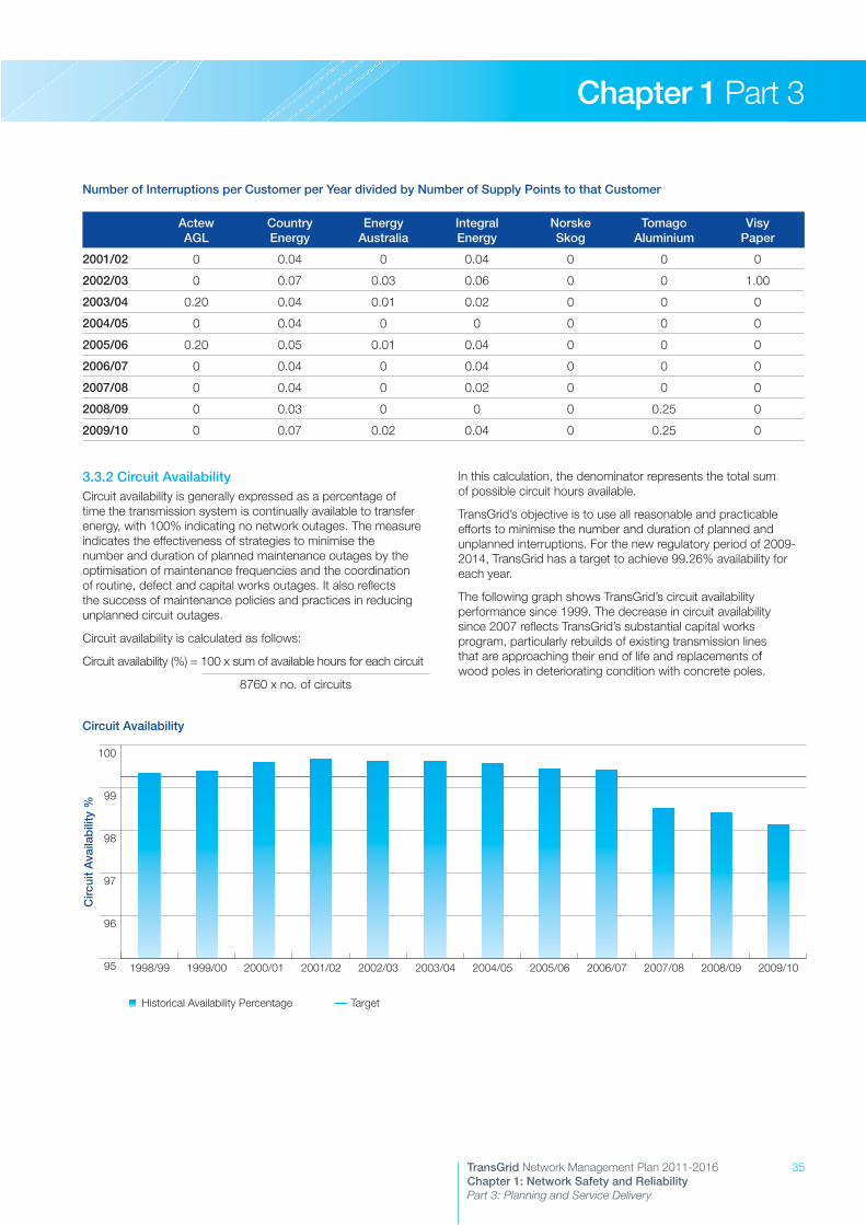
35TransGrid Network Management Plan 2011-2016Chapter 1: Network Safety and Reliability Part 3: Planning and Service Delivery
Chapter 1 Part 3
3.3.2 Circuit AvailabilityCircuit availability is generally expressed as a percentage of time the transmission system is continually available to transfer energy, with 100% indicating no network outages. The measure indicates the effectiveness of strategies to minimise the number and duration of planned maintenance outages by the optimisation of maintenance frequencies and the coordination of routine, defect and capital works outages. It also reflects the success of maintenance policies and practices in reducing unplanned circuit outages.
Circuit availability is calculated as follows:
Circuit availability (%) = 100 x sum of available hours for each circuit
8760 x no. of circuits
In this calculation, the denominator represents the total sum of possible circuit hours available.
TransGrid’s objective is to use all reasonable and practicable efforts to minimise the number and duration of planned and unplanned interruptions. For the new regulatory period of 2009-2014, TransGrid has a target to achieve 99.26% availability for each year.
The following graph shows TransGrid’s circuit availability performance since 1999. The decrease in circuit availability since 2007 reflects TransGrid’s substantial capital works program, particularly rebuilds of existing transmission lines that are approaching their end of life and replacements of wood poles in deteriorating condition with concrete poles.
Number of Interruptions per Customer per Year divided by Number of Supply Points to that Customer
Actew AGL
Country Energy
Energy Australia
Integral Energy
Norske Skog
Tomago Aluminium
Visy Paper
2001/02 0 0.04 0 0.04 0 0 0
2002/03 0 0.07 0.03 0.06 0 0 1.00
2003/04 0.20 0.04 0.01 0.02 0 0 0
2004/05 0 0.04 0 0 0 0 0
2005/06 0.20 0.05 0.01 0.04 0 0 0
2006/07 0 0.04 0 0.04 0 0 0
2007/08 0 0.04 0 0.02 0 0 0
2008/09 0 0.03 0 0 0 0.25 0
2009/10 0 0.07 0.02 0.04 0 0.25 0
Circuit Availability
95
96
97
98
99
100
Historical Availability Percentage
2009/102008/092007/082006/072005/062004/052003/042002/032001/022000/011999/001998/99
Circ
uit
Ava
ilab
ility
%
Historical Availability Percentage Target
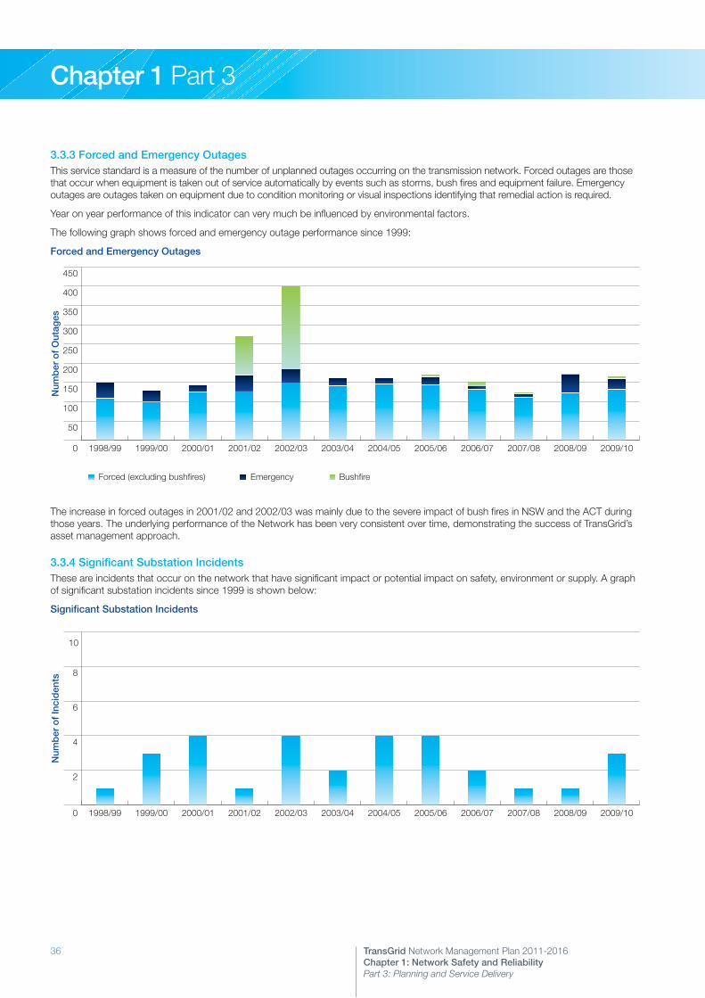
36 TransGrid Network Management Plan 2011-2016Chapter 1: Network Safety and Reliability Part 3: Planning and Service Delivery
Chapter 1 Part 3
3.3.3 Forced and Emergency OutagesThis service standard is a measure of the number of unplanned outages occurring on the transmission network. Forced outages are those that occur when equipment is taken out of service automatically by events such as storms, bush fires and equipment failure. Emergency outages are outages taken on equipment due to condition monitoring or visual inspections identifying that remedial action is required.
Year on year performance of this indicator can very much be influenced by environmental factors.
The following graph shows forced and emergency outage performance since 1999:
Forced and Emergency Outages
0
50
100
150
200
250
300
350
400
450
Bush�re
Emergency
Forced (excluding bush�res)
2009/102008/092007/082006/072005/062004/052003/042002/032001/022000/011999/001998/99
Num
ber
of
Out
ages
Forced (excluding bushfires) Emergency Bushfire
The increase in forced outages in 2001/02 and 2002/03 was mainly due to the severe impact of bush fires in NSW and the ACT during those years. The underlying performance of the Network has been very consistent over time, demonstrating the success of TransGrid’s asset management approach.
3.3.4 Significant Substation IncidentsThese are incidents that occur on the network that have significant impact or potential impact on safety, environment or supply. A graph of significant substation incidents since 1999 is shown below:
Significant Substation Incidents
0
2
4
6
8
10
Historical Availability Percentage
2009/102008/092007/082006/072005/062004/052003/042002/032001/022000/011999/001998/99
Num
ber
of
Inci
den
ts

37TransGrid Network Management Plan 2011-2016Chapter 1: Network Safety and Reliability Part 3: Planning and Service Delivery
Chapter 1 Part 3
3.3.5 Market Impact of Transmission ConstraintsSince early in the commencement of the National Electricity Market, TransGrid has monitored the occurrence of transmission constraints on its network and the impact on market participants. A transmission constraint occurs where not all of the low cost generation available can be dispatched due to limits of the transmission network, and higher cost generation from an alternative source is dispatched to make up the required total generation.
In July 2009, TransGrid became the first TNSP in the National Electricity Market to participate in the market impact component of the AER’s Service Target Performance Incentive Scheme. The market impact component provides an incentive for transmission providers to reduce the occurrence of constraints during outages of transmission network elements. The incentive can be influenced by generation bid patterns as well as the operation of the transmission network, and is a challenging incentive to respond to.
TransGrid has achieved a positive incentive result under the scheme in its early stages.
3.3.6 Network Maintenance Costs and Asset Replacement ExpenditureIn the early years of TransGrid’s existence, substantial inroads were made into reducing network maintenance costs through the introduction of improved maintenance practices, whilst still achieving a routine maintenance completion in excess of 95% each year, and the replacement of selected plant based on condition or other factors impacting on continued service delivery.
Over the period 2009/10 to 2013/14, TransGrid’s asset base is anticipated to grow by approximately 25%. The additional maintenance costs for these new assets will not be able to be fully absorbed through efficiency improvements, as has been done in the previous five year period. However, TransGrid’s efficiency will still improve through economies of scale, which will be reflected in measures of operating efficiency such as the ratio between operating expenditure and the Regulated Asset Base.
TransGrid’s anticipated expenditure on capital asset replacement, life extension programs and major operating projects for refurbishment of assets is tailored to sharing project delivery resources across the asset replacement/refurbishment projects and the network augmentation projects. It is expected that there will be an increase in the asset replacement programs as more assets develop symptoms of end-of-life issues.

38

39TransGrid Network Management Plan 2011-2016Chapter X: Chapter Heading
Chapter 1 Part 4
4.1 Asset Maintenance and Operating Strategies4.2 Specific Asset Profiles and Strategies4.3 Asset Disposal Strategies
Network Safety and ReliabilityPart 4: Asset Strategies

40 TransGrid Network Management Plan 2011-2016Chapter 1: Network Safety and Reliability Part 4: Asset Strategies
Chapter 1 Part 4
4.1 Asset Maintenance and Operating Strategies
4.1.1 Maintenance Strategies
Principles of TransGrid’s Asset Management ProcessTransGrid uses well-developed and documented processes to ensure that its existing assets are effectively and efficiently managed.
A simple overview of the Asset Management Process is shown in the figure below.
TransGrid Asset Management Process
ASSET MANAGEMENT WORKING GROUPS
Corporate Policies & Grid
Standards
Benchmarking
Safety Standards
Research & Development
Projects
Technology Changes
Environmental Policy
NETWORK ASSET MANAGEMENT PLANS
30 year and 5 year horizons
Customer Requirements
Business Requirements
Network Enhancement
& Development Plans
ASSET MANAGEMENT STRATEGIES
Refurbishment/Replacement
Strategies
Maintenance Policies
NETWORK PROJECTS
CAPITAL BUDGET
Technical Performance Assessments
Quarterly Asset Performance Reviews
Equipment Service Performance
RESOURCE PLAN
WORKS MANAGEMENT SYSTEM
WORK PERFORMED
Maintenance Standards
Service Instructions
NEM RulesManufacturer’s
InputIndustry
Experience
Co-ordinated Outage Programme
Outage Requests
Work Orders Job Sheets Test Reports
Defect Reports
PLA
N
CH
EC
K
DO
AC
T
41TransGrid Network Management Plan 2011-2016Chapter 1: Network Safety and Reliability Part 4: Asset Strategies
Chapter 1 Part 4
Elements of TransGrid’s Maintenance Strategy Process
1. StructureThe development and updating of both the Asset Management Strategies and the Maintenance Policies is carried out by Working Groups made up of a cross-section of maintenance, design and asset management staff. The Working Groups meet regularly to discuss issues and resolve problems identified.
2. Asset Management PolicyThe key corporate policy is the Asset Management Policy which is a high level document describing the principles of asset management that apply to all of TransGrid’s assets.
The work identified as necessary is categorised as either capital or operating for budgetary purposes. The operating work is further split into two categories.
(i) Maintenance work – which is routine and repetitive in nature and specified by the relevant maintenance policy.
(ii) Major Operating Projects – these are non-repetitive and require the investment of significant resources on a one-off basis. Refurbishment work and some replacements fall into this category. The performance issues and proposed solutions are detailed in the relevant Asset Management Strategy.
3. Asset Management StrategiesAsset Management Strategies are prepared for each of the following functional areas:
>> Substations>> Underground cables>> Transmission lines>> Easements>> Protection schemes>> Metering installations>> Telecommunications>> Control systems and SCADA
These Asset Management Strategies are updated annually and detail both the short and medium term strategies used to address issues beyond the scope of routine maintenance activities.
Information relating to the performance of the assets such as maintenance history, defect history and availability of spares are all used in the review process to determine if any action is required on a specific issue.
Condition monitoring information is used extensively to identify equipment approaching the end of its useful service life thus allowing for planned replacement or refurbishment programs to be implemented.
4. Asset Maintenance PoliciesMaintenance Policies for each of the functional areas are also reviewed annually and updated as required. As with the Asset Management Strategies, extensive use is made of maintenance history, defect history, benchmarking and condition monitoring data.
The maintenance policies are implemented through a computerised Asset Management and Planning System that schedules, initiates and records both preventative and corrective maintenance and defect repairs.
TransGrid has a policy of minimal intrusive maintenance, preferring instead to carry out diagnostic testing to determine if a need exists for any further work. Maintenance is generally targeted according to the following criteria:
>> Significance of a failure of the item>> Past reliability and service performance>> Physical location/environmental factors>> Operating history
5. Maintenance Planning Asset maintenance plans are detailed in a Maintenance Policy and Asset Management Strategy for each asset category. Each Maintenance Policy describes the preventative maintenance frequency and extent of preventative maintenance for each item of plant. The Asset Management Strategies take a broader perspective and detail refurbishment, replacement and repair strategies for particular types, makes or categories of equipment.
In planning any routine or non routine work (including new project or construction work) that involves a system outage, a significant effort is made to package as much work as possible to minimise the number and duration of any outages as these may impact on the availability of the network.
6. Risk ManagementIn addition to developing, enhancing and maintaining its transmission network, TransGrid ensures that risks to the system are understood and quantified.
Both the Maintenance Polices and Asset Management Strategies are reviewed using risk management principles, considering the criticality and exposure associated with a particular course of action that could materially affect the network and the quality, availability and reliability of supply to our customers.
7. Contingency Planning TransGrid works closely with the emergency service organisations (police, ambulance, fire brigade) for natural disaster events and is suitably prepared to manage operations and restorations of supplies. However, customer expectations for the security and reliability of electricity supplies is high as regional and state economies are very dependent on achievement of these expectations.
Contingency planning is an integral part of the risk management process and although it is not realistic to plan for all possible events, there needs to be a common understanding of the extent of anticipated events and the extent of the contingency planning necessary to cover these events.
A Corporate and Regional Emergency Management Plan (CREMP) has been prepared to coordinate the management measures necessary to ensure that TransGrid is prepared for emergencies which may impact upon reliability of supply, the safety of staff and the public or the environment.
8. Loss of EquipmentThe outcome of some events occurring on the network will be the temporary or permanent loss of specific network equipment.
42 TransGrid Network Management Plan 2011-2016Chapter 1: Network Safety and Reliability Part 4: Asset Strategies
Chapter 1 Part 4
TransGrid’s asset procurement policy ensures that, for reasons of economy, there is a reasonable degree of plant commonality across the state. There are a number of unique installations where there is only limited opportunity for direct interchange of spare equipment. In most cases, however, spare equipment can be readily obtained and modified if necessary to effect temporary repairs.
Emergency transmission line structures are held by TransGrid, which can be quickly assembled and erected in the unlikely event of major line failures. These are held at key sites throughout the state and are suitable for most tower line locations.
A number of spare transformers are held at strategic locations throughout the state. A formal policy exists defining the number of spares of a given type to be held based on the size of the transformer population. Other spares such as circuit breakers, instrument transformers, surge arrestors and protection relays are constantly monitored to ensure optimal levels are held.
9. Asset Performance ReviewsThe ultimate measure of whether the asset management process is achieving its stated goals is determined by the performance of the transmission network. Consequently, within TransGrid a number of methods are used to objectively measure the outcomes of the process and these are used to indicate whether:
>> Policies are appropriate>> Policies are being applied>> Equipment performance is satisfactory>> Performance and costs are comparable
The actual methods used to perform this function include the following:
Technical Performance AssessmentsTechnical Performance Assessments are carried out across the State on a yearly basis and the assessment formally audits the technical performance of the maintenance groups. The assessment is conducted over a number of days and checks processes, documentation and the physical condition of the assets.
Independent internal assessors with specialist knowledge of the functional area conduct the assessments. A formal report detailing non-conformances, observations and improvement opportunities is prepared and follow up reports required to ensure that any issues identified are addressed.
Quarterly Asset Performance ReviewsOnce each quarter, design, maintenance, operating and asset management staff are brought together to specifically review the performance of the network assets during the previous three months.
All forced and emergency outages during the period are reviewed and where necessary further action initiated. The group also reviews the long-term outage and reliability trends to determine issues requiring further investigation.
Issues identified by either a Technical Performance Assessment or the Quarterly Asset Performance Review are passed on to the relevant Working Group for inclusion in their policy and strategy deliberations.
10. BenchmarkingSince 1995 TransGrid has been a participant in the International Transmission Operating and Maintenance Study (ITOMS) that benchmarks maintenance activities performed by high voltage transmission utilities. The study typically involves some twenty five transmission organisations from Australia, New Zealand, USA, Europe, UK, Scandinavia and the Middle East.
The ITOMS results are used by TransGrid as a basis to carry out a detailed review of the various maintenance policies and strategies being adopted by not only overseas utilities but also most of the Australian utilities. The results from ITOMS 1999 through ITOMS 2009 have confirmed the success of TransGrid’s maintenance policies and asset management processes and provided data to enable implementation of further improvements.
In 2010 TransGrid participated for the first time in a new international benchmarking study on asset management practices, ITAMS 2010. The aim of participation in this study is to learn from the asset management practices of other transmission utilities, and ensure that TransGrid remains at the forefront of asset management practices.
11. Asset Management Research and DevelopmentTransGrid promotes research relationships with external organisations and educational institutions for projects that align with business needs. This enables TransGrid to provide innovative solutions to achieve core objectives.
TransGrid has a number of research projects or is involved in projects in the following areas:
>> Pioneering smart grid technologies as part of the consortium under the Smart Grid, Smart City project led by EnergyAustralia.
>> Demand management in conjunction with all NSW and ACT DNSPs.
>> Continuing support for the Australian Power Institute, including a proposal to establish a Cooperative Research Centre in Power Systems.
>> Sponsor of the Centre for Power Transformer Monitoring, Diagnosis and Life Management at Monash University.
>> Development of smart power transformers with intelligent monitoring, diagnostic and life management systems, in conjunction University of Queensland.
>> Dynamic performance of the power system, in conjunction with University of Adelaide.
>> Emergency control of catastrophic disturbances, in conjunction with University of Wollongong.
>> Implications, control and capability of power systems with diverse generation sources, in conjunction with University of Sydney.
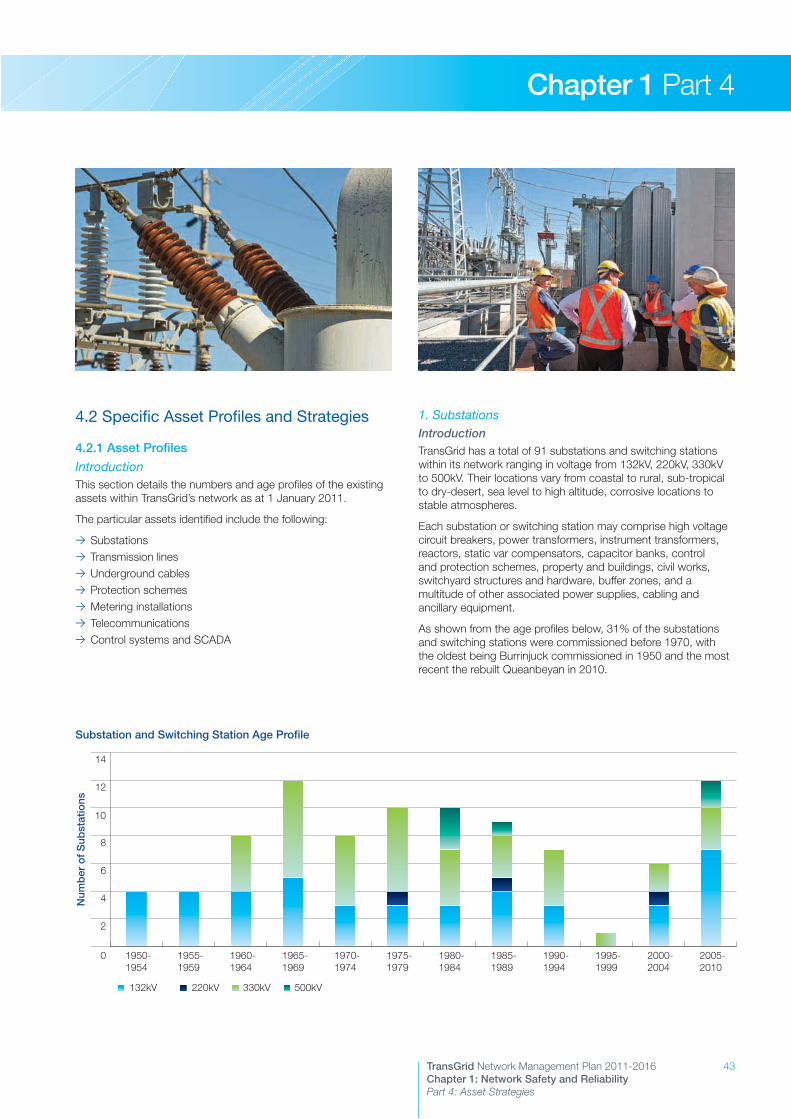
43TransGrid Network Management Plan 2011-2016Chapter 1: Network Safety and Reliability Part 4: Asset Strategies
Chapter 1 Part 4
4.2 Specific Asset Profiles and Strategies
4.2.1 Asset Profiles
IntroductionThis section details the numbers and age profiles of the existing assets within TransGrid’s network as at 1 January 2011.
The particular assets identified include the following:
>> Substations>> Transmission lines>> Underground cables>> Protection schemes>> Metering installations>> Telecommunications>> Control systems and SCADA
1. SubstationsIntroductionTransGrid has a total of 91 substations and switching stations within its network ranging in voltage from 132kV, 220kV, 330kV to 500kV. Their locations vary from coastal to rural, sub-tropical to dry-desert, sea level to high altitude, corrosive locations to stable atmospheres.
Each substation or switching station may comprise high voltage circuit breakers, power transformers, instrument transformers, reactors, static var compensators, capacitor banks, control and protection schemes, property and buildings, civil works, switchyard structures and hardware, buffer zones, and a multitude of other associated power supplies, cabling and ancillary equipment.
As shown from the age profiles below, 31% of the substations and switching stations were commissioned before 1970, with the oldest being Burrinjuck commissioned in 1950 and the most recent the rebuilt Queanbeyan in 2010.
Substation and Switching Station Age Profile
0
2
4
6
8
10
12
14
500kV
330kV
220kV
132kV
2005-2010
2000-2004
1995-1999
1990-1994
1985-1989
1980-1984
1975-1979
1970-1974
1965-1969
1960-1964
1955-1959
1950-1954
Num
ber
of
Sub
stat
ions
132kV 220kV 330kV 500kV

44 TransGrid Network Management Plan 2011-2016Chapter 1: Network Safety and Reliability Part 4: Asset Strategies
Chapter 1 Part 4
Power Transformers TransGrid’s power transformer population comprises of 219 individual units and of these 68% are rated above 100MVA with a primary voltage of 132kV or higher. Also 33% of this population comprises single-phase units and 90% of three phase equivalent transformer installations have on-load tapchangers.
The power transformer age profile shown below indicates that 19% were commissioned before 1970. The oldest units were manufactured in 1955.
Transformer Age Profile
0
10
20
30
40
50
60
70
500kV
330kV
220kV
132kV
66kV
2005-2010
2000-2004
1995-1999
1990-1994
1985-1989
1980-1984
1975-1979
1970-1974
1965-1969
1960-1964
1955-1959
Num
ber
of
Tran
sfo
rmer
s
132kV 220kV 330kV 500kV66kV
Reactors TransGrid’s reactor population comprises oil-filled, SF6 insulated and air cored types.
TransGrid’s oil filled reactor population comprises two series reactors at 330kV, and 29 three-phase equivalent shunt reactors. These shunt reactors consist of nine single-phase units at 330kV, 18 three-phase units at 330kV, five three-phase units at 220kV and three three-phase units at 132kV.
The age profile for oil filled reactors shown below indicates that 14% of the individual installed units were commissioned before 1980. The oldest units were manufactured in 1975.
Oil Filled Reactors Age Profile
0
2
4
6
8
10
12
330kV
220kV
132kV
2005-20102000-20041995-19991990-19941985-19891980-19841975-1979
Num
ber
of
Rea
cto
rs
132kV 220kV 330kV
TransGrid operates three single-phase SF6 gas insulated reactors at Haymarket. In addition, TransGrid maintains 21 single-phase air-cored series reactors at 132kV, 33 single-phase air-cored shunt reactors at 33kV, and two three-phase oil filled reactors at 11kV. These units are not included in the above profile.
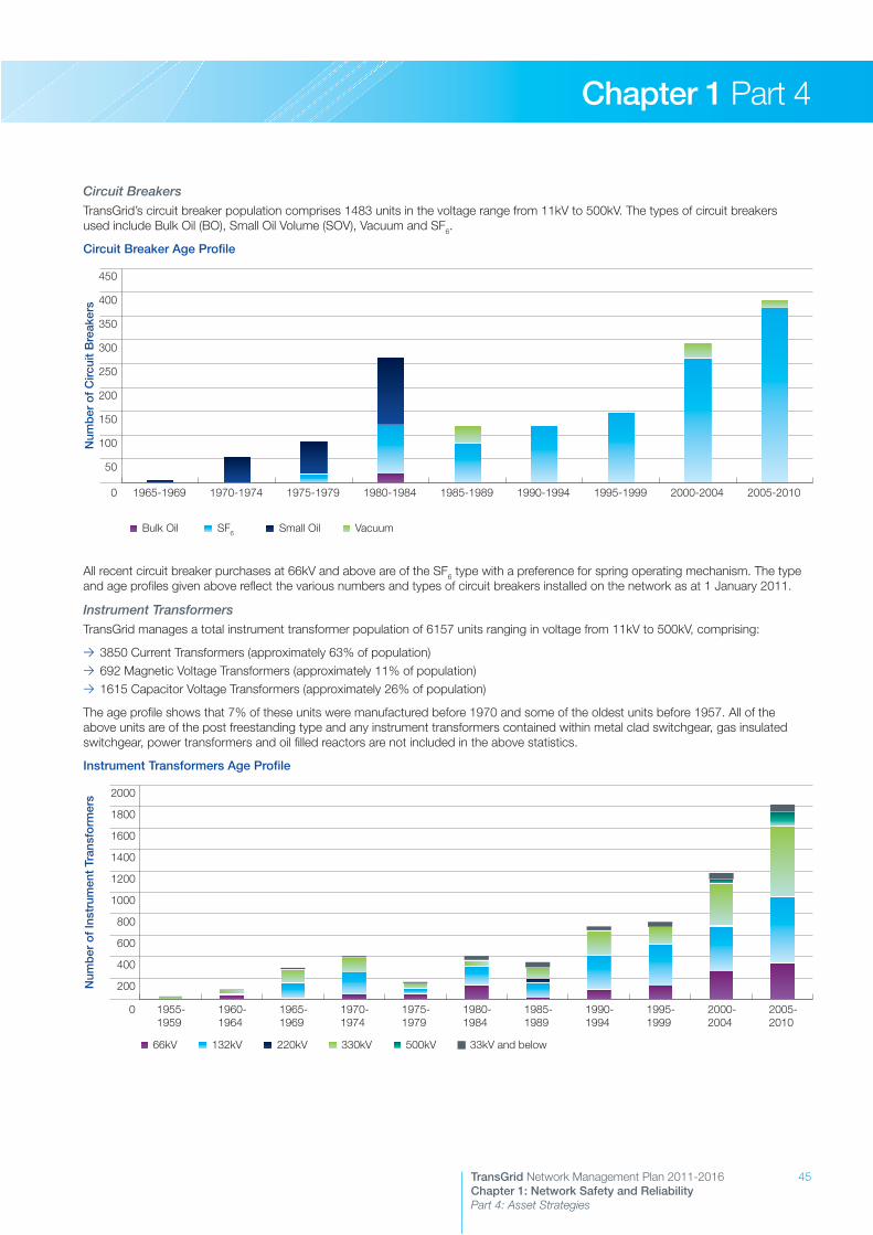
45TransGrid Network Management Plan 2011-2016Chapter 1: Network Safety and Reliability Part 4: Asset Strategies
Chapter 1 Part 4
Circuit BreakersTransGrid’s circuit breaker population comprises 1483 units in the voltage range from 11kV to 500kV. The types of circuit breakers used include Bulk Oil (BO), Small Oil Volume (SOV), Vacuum and SF6.
Circuit Breaker Age Profile
0
50
100
150
200
250
300
350
400
450
Vacuum
Small Oil
SF6
Bulk Oil
2005-20102000-20041995-19991990-19941985-19891980-19841975-19791970-19741965-1969
Num
ber
of
Circ
uit
Bre
aker
s
SF6 Small Oil VacuumBulk Oil
All recent circuit breaker purchases at 66kV and above are of the SF6 type with a preference for spring operating mechanism. The type and age profiles given above reflect the various numbers and types of circuit breakers installed on the network as at 1 January 2011.
Instrument TransformersTransGrid manages a total instrument transformer population of 6157 units ranging in voltage from 11kV to 500kV, comprising:
>> 3850 Current Transformers (approximately 63% of population)>> 692 Magnetic Voltage Transformers (approximately 11% of population)>> 1615 Capacitor Voltage Transformers (approximately 26% of population)
The age profile shows that 7% of these units were manufactured before 1970 and some of the oldest units before 1957. All of the above units are of the post freestanding type and any instrument transformers contained within metal clad switchgear, gas insulated switchgear, power transformers and oil filled reactors are not included in the above statistics.
Instrument Transformers Age Profile
0
200
400
600
800
1000
1200
1400
1600
1800
2000
33kV and below
500kV
330kV
220kV
132kV
66kV
2005-2010
2000-2004
1995-1999
1990-1994
1985-1989
1980-1984
1975-1979
1970-1974
1965-1969
1960-1964
1955-1959
Num
ber
of
Inst
rum
ent
Tran
sfo
rmer
s
132kV 220kV 330kV 500kV 33kV and below66kV
E1 > E2
E3 > E1
46 TransGrid Network Management Plan 2011-2016Chapter 1: Network Safety and Reliability Part 4: Asset Strategies
Chapter 1 Part 4
Static Var CompensatorsTransGrid has seven Static Var Compensators (SVCs) located at:
LocationConnected Voltage (kV)
SVC Volts (kV)
Rating (MVAr)
Comm-issioned
Armidale (1) 330 13.6 +280/-120 2000
Broken Hill (2) 22 22 +/- 25 each 1986
Kemps Creek (2) 330 16 +150/-100 each
1990
Lismore (1) 132 26 +150/-100 2000
Sydney West (1) 330 18 +280/-100 2004
Gas Insulated SwitchgearTransGrid owns two Gas Insulated Switchgear (GIS) installations located at:
>> Beaconsfield West Substation 132kV, commissioned 1979
>> Haymarket Substation 330kV and 132kV, commissioned 2004
Shunt CapacitorsTransGrid has a total of 133 shunt capacitor banks in service within the network with an installed capacity of 8380 MVAr ranging in voltage from 33kV to 330kV. 93% have been manufactured and installed since 1980.
The majority of the capacitor units installed are of the internal fuse type but some externally fused units have also been used. All units are PCB free, with the possible exception of three large tank type capacitors which are in the process of being replaced.
Surge ArrestersSurge arresters are used to protect expensive items of plant such as transformers from failure due to transient voltage surges. There are over 1850 arresters installed within TransGrid’s system.
BushingsTransGrid’s transformers and reactors contain some 1925 bushings ranging in voltage from 500kV to 11kV. In general the age profile would follow closely that of the transformers and reactors. These indicate that approximately half of the transformer bushings are more than 20 years old and approximately half of the reactor bushings are over 10 years of age.
Control and Alarm SystemsControl and alarm systems within TransGrid’s 91 substations and switching stations range widely from composite mechanical relays to systems built using discrete components that use printed circuit cards, composite electronic relays, programmable logic controllers or microprocessor based systems of various configurations. The age profiles of these systems range from the early 1950s to the present modern technology and some sites have a combination of interconnected systems.
Ancillary EquipmentAll substation and switching stations also contain ancillary equipment such as disconnectors, earth switches, surge arresters, busbars, batteries and battery chargers, control and protection cabling, security systems, fire protection equipment, air conditioning, light and power.
Substation Property and Buildings Each of TransGrid’s substations and switching stations contain a control room building, which may vary in size from a small single level building to, particularly in the case of older establishments originally designed for local staffing, a large multi-level building. These buildings generally contain a relay room, battery room, communication room, amenities room and workshop.
Sites also may contain fencing, roads, drainage systems, landscaping, environmental buffer zones and other services, which need to be kept in good order.
The age profile for these sites is normally the same as the substation and the style and construction methods vary due to the location, environmental issues and the era built.

47TransGrid Network Management Plan 2011-2016Chapter 1: Network Safety and Reliability Part 4: Asset Strategies
Chapter 1 Part 4
2. Transmission LinesTransGrid has a total of 11,020 route kilometres and 12,609 circuit kilometres of transmission line with details of constructed and operating voltage given in the following table:
TRANSMISSION LINES (km)
LINE TYPE Route Circuit
500kV in Service at 500kV
Total 500kV
533
533
1067
1067
330kV in Service at 330kV
330kV in Service at 132kV
Total 330kV
4539
56
4595
5337
111
5448
220kV in Service at 220kV
Total 220kV
681
681
681
681
132kV in Service at 132kV
Total 132kV
5211
5211
5413
5413
Totals 11020 12609
These lines are of steel lattice tower, steel pole, concrete pole and wood pole construction. The construction line type and age profiles are shown below in terms of structure numbers:
Transmission Line Structure Type Profile
132kV Concrete Pole 15%
132kV Steel Pole 0%
132kV Steel Tower 2%
132kV Wood Pole 43%
220kV Steel Tower 5%
330kV Steel Pole 0%
330kV Concrete Pole 0%
330kV Steel Tower 31%
330kV Wood Pole 1%
500kV Steel Tower 3%
Transmission Line Structures Age Profile
0
1000
2000
3000
4000
5000
6000
7000
500kV Steel Tower
330kV Wood Pole
330kV Steel Tower
330kV Steel Pole
330kV Concrete Pole
220kV Steel Tower
132kV Wood Pole
132kV Steel Tower
132kV Steel Pole
132kV Concrete Pole
2005-2010
2000-2004
1995-1999
1990-1994
1985-1989
1980-1984
1975-1979
1970-1974
1965-1969
1960-1964
1955-1959
1950-1954
1940-1944
Str
uctu
re C
oun
t
132kV Concrete Pole
220kV Steel Tower
330kV Wood Pole
132kV Steel Pole
330kV Concrete Pole
500kV Steel Tower
132kV Steel Tower
330kV Steel Pole
132kV Wood Pole
330kV Steel Tower
E1 > E2
E3 > E1

48 TransGrid Network Management Plan 2011-2016Chapter 1: Network Safety and Reliability Part 4: Asset Strategies
Chapter 1 Part 4
3. Underground CablesThe primary cable assets owned by TransGrid are:
>> 330kV Cable 41, 19.7km, installed between the Beaconsfield West Substation and the Sydney South Substation at Picnic Point. This is a paper-oil cable system that was placed into service in 1979. Associated with Cable 41 is the pilot cable 160.
>> 330kV Cable 42, 28km, installed between the Haymarket Substation and the Sydney South Substation at Picnic Point. This is a polypropylene laminated paper (PPLP) oil cable system that was placed into service in 2004. Associated with Cable 42 is a 4km length of tunnel between Sydney Park, St Peters and Haymarket Substation.
TransGrid also has short lengths of cable energised at 132kV, 66kV, 33kV and 11kV which in general, though not exclusively, run within substation boundaries.
4. Protection RelaysIntroductionProtection equipment at TransGrid sites can be grouped into a number of broad categories. These include:
>> Line protection relays (distance, pilot wire and current differential)
>> Transformer differential relays>> Busbar protection relays>> Overcurrent relays (instantaneous and IDMT)>> Auxiliary relays (timers, multitrips, followers)
The graph below apportions these categories:
Protection Relay Profile
E1 > E2
E3 > E1
Line 17%
Overcurrent 34%
Tx Diff 8%
BBP 8%
Auxiliary 33%
Auxiliary relays represent the largest category and whilst installed in all protection schemes these can generally be considered as secondary components. The primary components of a protection scheme will normally be comprised of one or more relays from the other four categories.
The population, condition, performance and status of manufacturer support of this equipment represent some of the factors that need to be considered when determining a replacement program. The replacement program would also need to include the upgrading of auxiliary relays as a natural consequence of any primary relay change.
It is recognised that all primary relays currently installed on TransGrid’s system will need to be replaced at some time. The population and age of the primary protection equipment installed on TransGrid’s network is set out in the following pages.

49TransGrid Network Management Plan 2011-2016Chapter 1: Network Safety and Reliability Part 4: Asset Strategies
Chapter 1 Part 4
Line Protection RelaysTransGrid’s line protection relay population comprises over 1235 individual schemes ranging in age from 0 to 50 years. The age profile shown below indicates that 32% of TransGrid’s distance relay population were commissioned before 1980, with some of the oldest schemes being manufactured in 1960.
Age Profile of Line Protection Relays
0
50
100
150
200
250
300
350
400
450
Microprocessor
Solid State
Electromechanical
2000-101990-991980-891970-791960-69
Num
ber
of
Line
Pro
tect
ion
Rel
ays
Solid State ElectromechanicalMicroprocessor
Transformer Differential RelaysTransGrid’s transformer differential relay population comprises around 600 individual schemes ranging in age from 0 to 50 years. The age profile shown below indicates that 28% of TransGrid’s transformer differential relay population were commissioned before 1980, with some of the oldest schemes being manufactured in 1960.
Age Profile of Transformer Differential Relays
0
50
100
150
200
250
Microprocessor
Solid State
Electromechanical
2000-101990-991980-891970-791960-69Num
ber
of
Tran
sfo
rmer
Diff
eren
tial R
elay
s
Solid State ElectromechanicalMicroprocessor
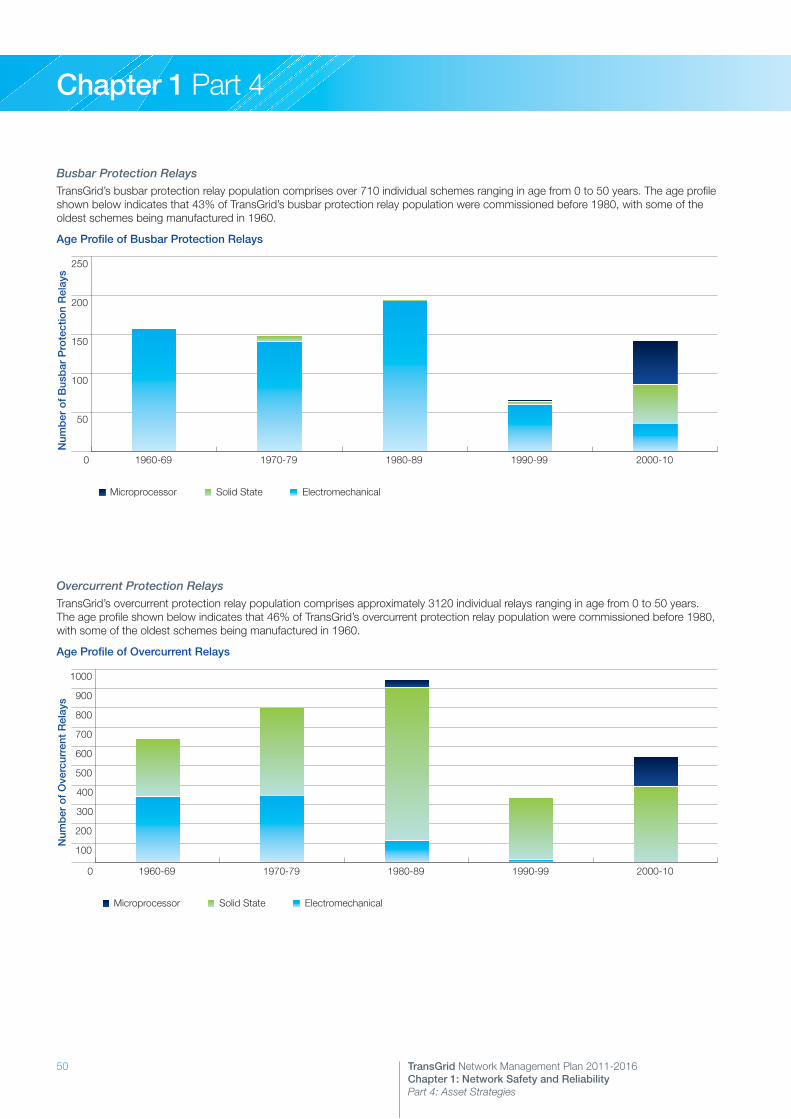
50 TransGrid Network Management Plan 2011-2016Chapter 1: Network Safety and Reliability Part 4: Asset Strategies
Chapter 1 Part 4
Busbar Protection RelaysTransGrid’s busbar protection relay population comprises over 710 individual schemes ranging in age from 0 to 50 years. The age profile shown below indicates that 43% of TransGrid’s busbar protection relay population were commissioned before 1980, with some of the oldest schemes being manufactured in 1960.
Age Profile of Busbar Protection Relays
0
50
100
150
200
250
Microprocessor
Solid State
Electromechanical
2000-101990-991980-891970-791960-69
Num
ber
of
Bus
bar
Pro
tect
ion
Rel
ays
Solid State ElectromechanicalMicroprocessor
Overcurrent Protection RelaysTransGrid’s overcurrent protection relay population comprises approximately 3120 individual relays ranging in age from 0 to 50 years. The age profile shown below indicates that 46% of TransGrid’s overcurrent protection relay population were commissioned before 1980, with some of the oldest schemes being manufactured in 1960.
Age Profile of Overcurrent Relays
0
100
200
300
400
500
600
700
800
900
1000
Microprocessor
Solid State
Electromechanical
2000-101990-991980-891970-791960-69
Num
ber
of
Ove
rcur
rent
Rel
ays
Solid State ElectromechanicalMicroprocessor

51TransGrid Network Management Plan 2011-2016Chapter 1: Network Safety and Reliability Part 4: Asset Strategies
Chapter 1 Part 4
5. MeteringMetering equipment at TransGrid sites can be grouped into a number of broad categories. These include:
>> Energy meters>> Remote Interrogation Meters (RIMs)>> Auxiliary devices (voltage selection relays, transformers)>> Transducers
The graph below apportions these categories:
Metering Installation Profile
E1 > E2
E3 > E1
Energy Meters 38%
RIM Devices 4%
Transducers 51%
Modems 7%
Transducers form the largest category and provide an important function in relation to SCADA or real time operational data used to manage the operation of the high voltage network. NEM metering installation equipment represents the second largest category and consists of energy meters, Remote Interrogation Meters (RIMs) and auxiliary devices (modems and voltage selection relays), forming the essential components of any revenue or backup metering scheme.
Replacement programs will generally include the upgrading of auxiliary devices as a consequence of any revenue or backup metering scheme replacements.
It is recognised that 36% of energy meters, 100% of RIMs and 47% of transducers currently installed on TransGrid’s system will need to be replaced in current strategies. The population and age of the primary metering equipment installed on TransGrid’s network is set out in the following pages.
Energy MetersTransGrid’s energy meter population comprises some 774 individual units ranging in age to 35 years old. The age profile shown below indicates that 36% of TransGrid’s energy meter population are older induction disc and early electronic pulsing meters that were commissioned before 1993 and require replacement with modern interval meters.
Age Profile of Energy Meters
0
50
100
150
200
250
300
350
400
Microprocessor
Solid State
Electromechanical
2000-101990-991980-891970-79
Num
ber
of
Ene
rgy
Met
ers
Solid State ElectromechanicalMicroprocessor

52 TransGrid Network Management Plan 2011-2016Chapter 1: Network Safety and Reliability Part 4: Asset Strategies
Chapter 1 Part 4
Remote Interrogation Meters (RIMs)TransGrid’s datalogger (RIM) population comprises 83 individual units, the majority of which are 12 to 20 years of age. These devices are only used in conjunction with pulsing meters and are progressively being phased out and no longer used, as modern meters incorporate internal data logging functionality.
Age Profile of RIM Devices
0
20
40
60
80
100
PSI
Aptech
2000-101990-991980-891970-79
Num
ber
of
RIM
Dev
ices
Email AptechPSI
Transducers
TransGrid’s transducer population comprises almost 900 individual units up to 35 years old. The age profile shown below indicates that 60% of TransGrid’s transducer population were commissioned before 1980.
Age Profile of Transducers
0
50
100
150
200
250
300
350
400
Microprocessor
Solid State
2000-101990-991980-891970-79
Num
ber
of
Tran
duc
ers
Solid StateMicroprocessor
Note: Some substations such as at Gadara, Molong and Balranald do not include discrete transducers but utilise equivalent functions built into the protection relays.
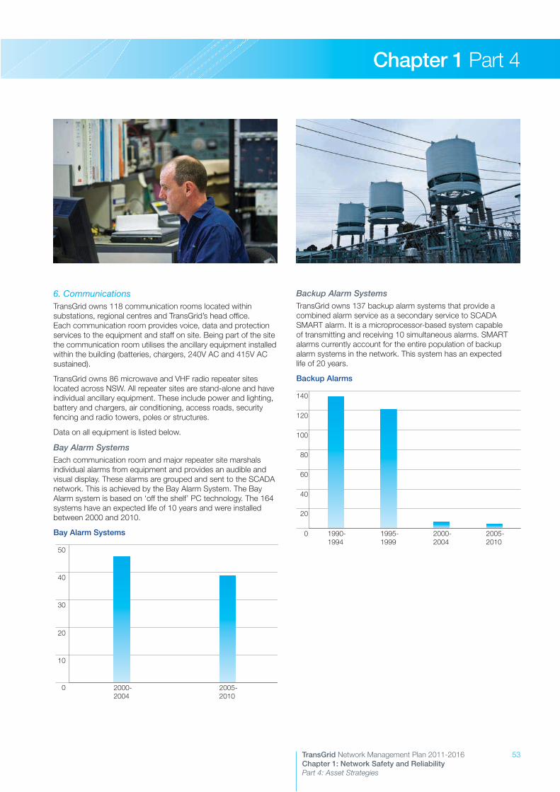
53TransGrid Network Management Plan 2011-2016Chapter 1: Network Safety and Reliability Part 4: Asset Strategies
Chapter 1 Part 4
6. CommunicationsTransGrid owns 118 communication rooms located within substations, regional centres and TransGrid’s head office. Each communication room provides voice, data and protection services to the equipment and staff on site. Being part of the site the communication room utilises the ancillary equipment installed within the building (batteries, chargers, 240V AC and 415V AC sustained).
TransGrid owns 86 microwave and VHF radio repeater sites located across NSW. All repeater sites are stand-alone and have individual ancillary equipment. These include power and lighting, battery and chargers, air conditioning, access roads, security fencing and radio towers, poles or structures.
Data on all equipment is listed below.
Bay Alarm SystemsEach communication room and major repeater site marshals individual alarms from equipment and provides an audible and visual display. These alarms are grouped and sent to the SCADA network. This is achieved by the Bay Alarm System. The Bay Alarm system is based on ‘off the shelf’ PC technology. The 164 systems have an expected life of 10 years and were installed between 2000 and 2010.
Bay Alarm Systems
0
10
20
30
40
50
2005-2010
2000-2004
Backup Alarm SystemsTransGrid owns 137 backup alarm systems that provide a combined alarm service as a secondary service to SCADA SMART alarm. It is a microprocessor-based system capable of transmitting and receiving 10 simultaneous alarms. SMART alarms currently account for the entire population of backup alarm systems in the network. This system has an expected life of 20 years.
Backup Alarms
0
20
40
60
80
100
120
140
2005-2010
2000-2004
1995-1999
1990-1994

54 TransGrid Network Management Plan 2011-2016Chapter 1: Network Safety and Reliability Part 4: Asset Strategies
Chapter 1 Part 4
Power Line CarrierTransGrid owns some 152 Power Line Carrier (PLC) systems that provide communication services between substations. These systems carry voice, SCADA and backup alarm systems.
Voice PLC (Fujitsu)
0
5
10
15
20
25
30
2005-2010
2000-2004
1995-1999
1990-1994
1985-1989
1980-1984
1975-1979
1970-1974
1965-1969
Voice PLC (Dimat)
0
5
10
15
20
25
30
2005-2010
2000-2004
1995-1999
Power Line Carrier Protection Intertrip SystemsTransGrid owns over 250 PLC intertrip systems. These systems provide intertrip function over transmission lines.
Protection I/Ts PLC
0
10
20
30
40
50
60
70
80
2005-2010
2000-2004
1995-1999
1990-1994
1985-1989
1980-1984
1975-1979
1970-1974
1965-1969
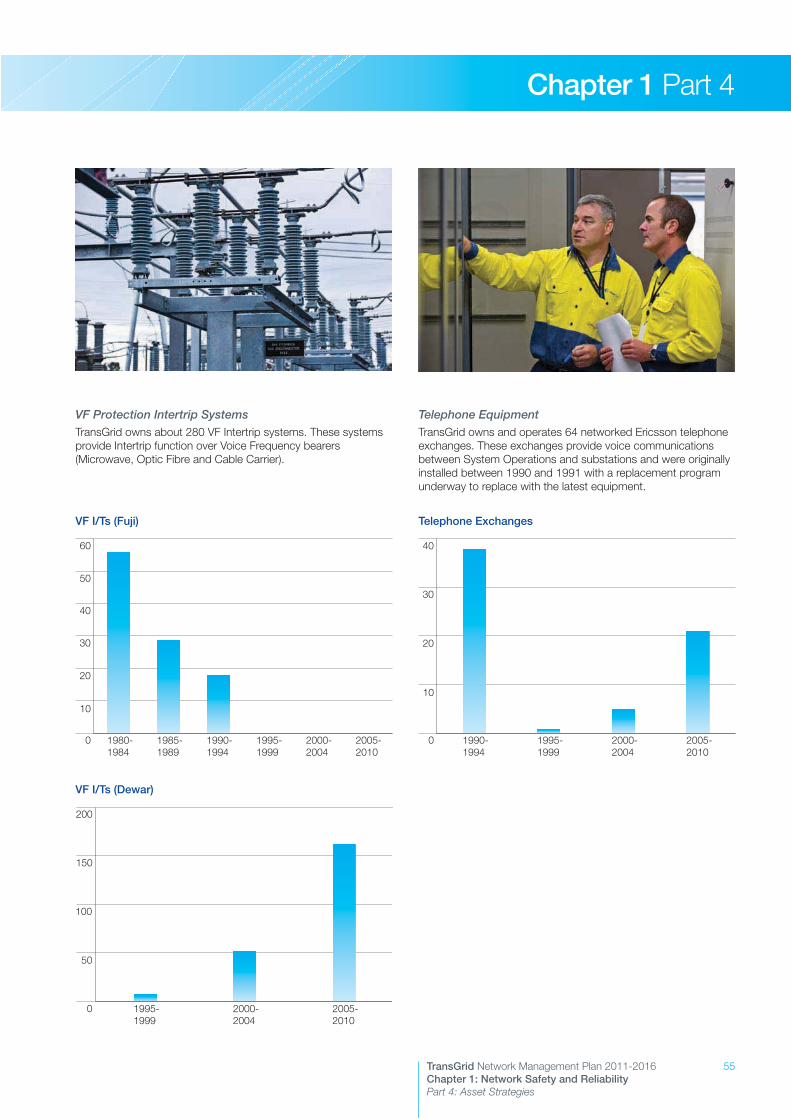
55TransGrid Network Management Plan 2011-2016Chapter 1: Network Safety and Reliability Part 4: Asset Strategies
Chapter 1 Part 4
VF Protection Intertrip SystemsTransGrid owns about 280 VF Intertrip systems. These systems provide Intertrip function over Voice Frequency bearers (Microwave, Optic Fibre and Cable Carrier).
VF I/Ts (Fuji)
0
10
20
30
40
50
60
2005-2010
2000-2004
1995-1999
1990-1994
1985-1989
1980-1984
VF I/Ts (Dewar)
0
50
100
150
200
2005-2010
2000-2004
1995-1999
Telephone EquipmentTransGrid owns and operates 64 networked Ericsson telephone exchanges. These exchanges provide voice communications between System Operations and substations and were originally installed between 1990 and 1991 with a replacement program underway to replace with the latest equipment.
Telephone Exchanges
0
10
20
30
40
2005-2010
2000-2004
1995-1999
1990-1994

56 TransGrid Network Management Plan 2011-2016Chapter 1: Network Safety and Reliability Part 4: Asset Strategies
Chapter 1 Part 4
Microwave Radio EquipmentTransGrid owns and operates microwave systems that in conjunction with the OPGW network provide communication bearers to all major substations.
Microwave Systems
0
20
40
60
80
2005-2010
2000-2004
1995-1999
VHF Radio EquipmentTransGrid owns and operates a VHF Radio network covering all Substations and major transmission lines in NSW.
VHF Network
0
10
20
30
40
50
60
2005-2010
2000-2004
1995-1999
1990-1994
Substation Control SystemsTransGrid owns and operates 96 Substation Control Systems consisting of 1901 individual RTU units
RTU Units
0
50
100
150
200
250
300
2005-2010
2000-2004
1995-1999
1990-1994
1985-1989
1980-1984
Optical Fibre Network (OPGW)The overhead earth wire optic fibre (OPGW) backbone network in conjunction with microwave networks provide communication bearers from Western Sydney to the Victorian border (Southern System), Western Sydney to Mount Piper (Western System) and Western Sydney to the Queensland border (Northern System). The OPGW network provides the majority of backbone communication.
OPGW
0
200
400
600
800
1000
1200 OPGW 48 Core Type B (klms)
OPGW 48 Core Type A (Klms)
OPGW 24 Core Type B (Klms)
OPGW 24 Core Type A (Klms)
OPGW 48 CoreType B (km)
OPGW 48 CoreType A (km)
OPGW 24 CoreType B (km)
OPGW 24 CoreType A (km)
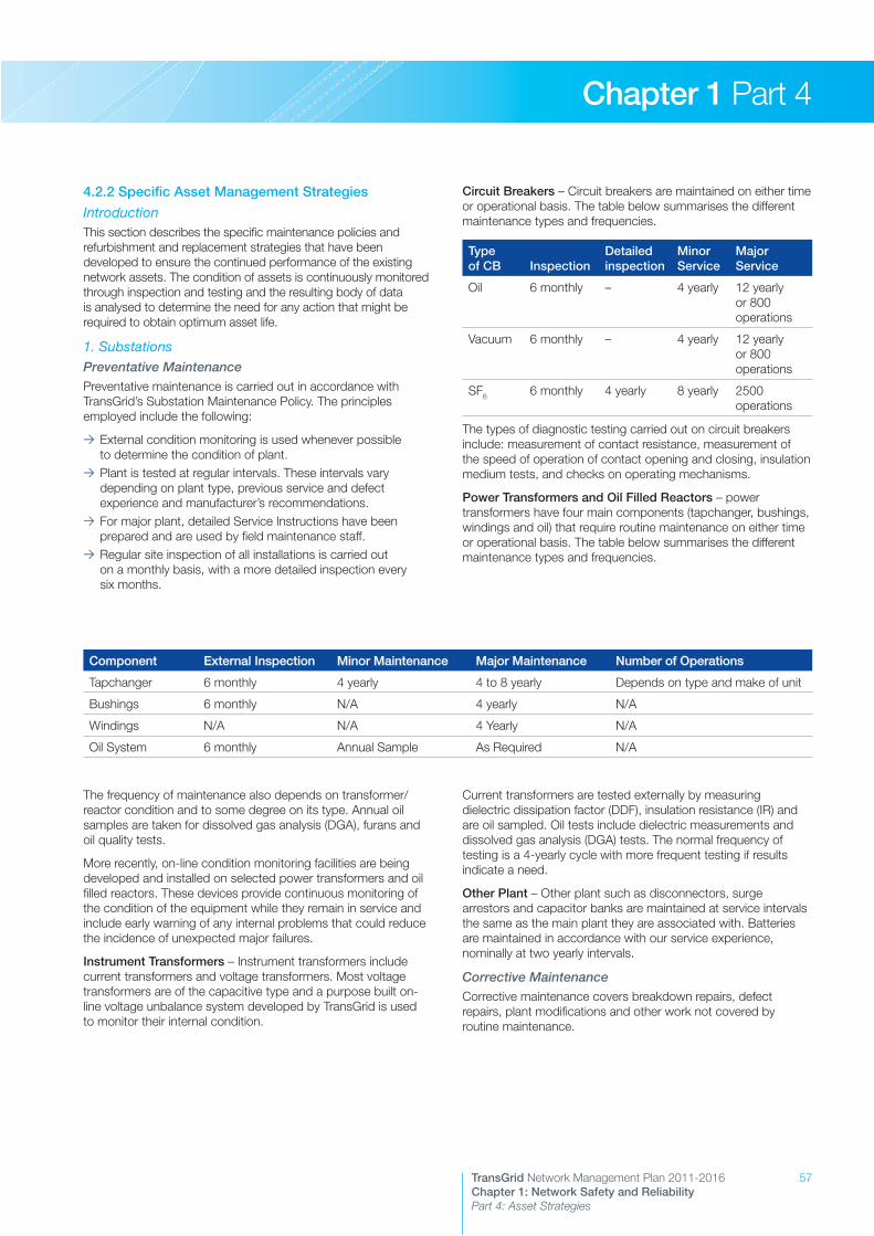
57TransGrid Network Management Plan 2011-2016Chapter 1: Network Safety and Reliability Part 4: Asset Strategies
Chapter 1 Part 4
4.2.2 Specific Asset Management Strategies
IntroductionThis section describes the specific maintenance policies and refurbishment and replacement strategies that have been developed to ensure the continued performance of the existing network assets. The condition of assets is continuously monitored through inspection and testing and the resulting body of data is analysed to determine the need for any action that might be required to obtain optimum asset life.
1. SubstationsPreventative MaintenancePreventative maintenance is carried out in accordance with TransGrid’s Substation Maintenance Policy. The principles employed include the following:
>> External condition monitoring is used whenever possible to determine the condition of plant.
>> Plant is tested at regular intervals. These intervals vary depending on plant type, previous service and defect experience and manufacturer’s recommendations.
>> For major plant, detailed Service Instructions have been prepared and are used by field maintenance staff.
>> Regular site inspection of all installations is carried out on a monthly basis, with a more detailed inspection every six months.
Circuit Breakers – Circuit breakers are maintained on either time or operational basis. The table below summarises the different maintenance types and frequencies.
Type of CB Inspection
Detailed inspection
Minor Service
Major Service
Oil 6 monthly – 4 yearly 12 yearly or 800 operations
Vacuum 6 monthly – 4 yearly 12 yearly or 800 operations
SF6 6 monthly 4 yearly 8 yearly 2500 operations
The types of diagnostic testing carried out on circuit breakers include: measurement of contact resistance, measurement of the speed of operation of contact opening and closing, insulation medium tests, and checks on operating mechanisms.
Power Transformers and Oil Filled Reactors – power transformers have four main components (tapchanger, bushings, windings and oil) that require routine maintenance on either time or operational basis. The table below summarises the different maintenance types and frequencies.
Component External Inspection Minor Maintenance Major Maintenance Number of Operations
Tapchanger 6 monthly 4 yearly 4 to 8 yearly Depends on type and make of unit
Bushings 6 monthly N/A 4 yearly N/A
Windings N/A N/A 4 Yearly N/A
Oil System 6 monthly Annual Sample As Required N/A
The frequency of maintenance also depends on transformer/reactor condition and to some degree on its type. Annual oil samples are taken for dissolved gas analysis (DGA), furans and oil quality tests.
More recently, on-line condition monitoring facilities are being developed and installed on selected power transformers and oil filled reactors. These devices provide continuous monitoring of the condition of the equipment while they remain in service and include early warning of any internal problems that could reduce the incidence of unexpected major failures.
Instrument Transformers – Instrument transformers include current transformers and voltage transformers. Most voltage transformers are of the capacitive type and a purpose built on-line voltage unbalance system developed by TransGrid is used to monitor their internal condition.
Current transformers are tested externally by measuring dielectric dissipation factor (DDF), insulation resistance (IR) and are oil sampled. Oil tests include dielectric measurements and dissolved gas analysis (DGA) tests. The normal frequency of testing is a 4-yearly cycle with more frequent testing if results indicate a need.
Other Plant – Other plant such as disconnectors, surge arrestors and capacitor banks are maintained at service intervals the same as the main plant they are associated with. Batteries are maintained in accordance with our service experience, nominally at two yearly intervals.
Corrective MaintenanceCorrective maintenance covers breakdown repairs, defect repairs, plant modifications and other work not covered by routine maintenance.
Substation Control SystemsTransGrid owns and operates 96 Substation Control Systems consisting of 1901 individual RTU units
RTU Units
Optical Fibre Network (OPGW)The overhead earth wire optic fibre (OPGW) backbone network in conjunction with microwave networks provide communication bearers from Western Sydney to the Victorian border (Southern System), Western Sydney to Mount Piper (Western System) and Western Sydney to the Queensland border (Northern System). The OPGW network provides the majority of backbone communication.
OPGW
58 TransGrid Network Management Plan 2011-2016Chapter 1: Network Safety and Reliability Part 4: Asset Strategies
Chapter 1 Part 4
Asset Renewal ProjectsAsset renewal projects are non-routine works requiring substantial resources that are non-repetitive in nature. They include both refurbishment and replacement of equipment and may also include capital work such as transformer life extension.
The following factors are used to identify, analyse and substantiate any new asset renewal project:
>> Need for work based on issues such as performance, maintenance needs, safety, lack of spare parts, environmental factors, type faults.
>> Risk assessment analysis associated with continued repairs, future reliability, system security.
>> Total quantity and costs which may consider either refurbishment or replacement options.
>> Time period over which the work has to be done.>> Priority factor giving importance relative to other projects.
In general, all asset renewal programs are determined by condition, economic, safety or environmental considerations and not on age alone.
Increasing use of condition monitoring is being made to substantiate equipment replacement and refurbishment. On-line continuous condition monitoring systems are becoming available for a wide variety of substation plant such as power transformers and oil filled reactors, bushings, on-load tapchangers, circuit breakers, instrument transformers and protection relays.
TransGrid has implemented a strategy to purchase a range of these on-line monitoring systems for installation at selected locations initially, and then to include other sites as considered appropriate.
Substation ReconstructionTransGrid’s oldest substations were constructed in the 1950s. In some cases, a wide range of issues exist due to deterioration in the condition of:
>> High voltage plant>> Protection systems>> Metering equipment>> Control systems>> Infrastructure such as earthing systems, buildings, steelwork, cabling and kiosks
Where a range of issues have developed at a site, the most efficient and effective approach to management of the substation may be reconstruction.
Management of these issues is difficult to achieve in situ due to the need to maintain the substation in operation and maintain supply. This introduces risks associated with the safety of work, reliability of supply, ability to complete the work in required timeframes and ability to obtain specialised resourcing to complete the work through contracting. It is also unlikely that all site issues will be resolved by this type of piecemeal approach.
Reconstruction allows the use of construction contractors with no site constraints to interfere with the efficiency of work. In addition, the total substation is renewed and built to meet current needs and design standards.
Hence, where significant issues exist for an older substation, reconstruction may be the preferred option where space is available and it is a feasible option. Currently, complete or partial reconstruction is being planned for Orange, Cooma, Burrinjuck, Tamworth 132kV and Wallerawang 132kV substations.
Secondary System RenewalsFor secondary systems, the shift to system replacements rather than replacement of components such as individual protection relay replacements has become a significant priority due to the shorter life span of modern secondary systems. For example, while electromechanical relays that were common in the 1960s and 1970s are expected to have a lifetime of 40 years, modern numerical relays have an expected life of 15 years. Given this shorter lifespan of modern secondary systems, it is expected that it will become imperative to have processes in place to effect the replacement of entire secondary systems at periodic intervals.
In recognition of this, TransGrid has developed a strategy of utilising modular control buildings which will house the secondary systems for a substation and facilitate the planned replacement of the secondary systems when the equipment reaches the end of life (expected to be well before the primary plant it is servicing reaches end of life).
This approach is currently being implemented at the existing Dapto Substation (replacement of existing secondary system) and at the new Tomago 330/132kV Substation.
Planning is underway for replacement of secondary systems at Sydney West 330/132kV Substation and a strategy for ongoing replacements is under consideration.
Power Transformers and Oil Filled ReactorsInvestigations into the performance of transformers have identified potential issues that may impact on the expected operational life of these units. These issues relate to problems with on-load tapchangers, high voltage bushings, loose windings, cooling systems, oil quality and moisture ingress. All of these issues when identified early enough can be satisfactorily and economically managed thereby ensuring the continued performance of the transformer or reactor.
Existing condition monitoring and maintenance practices such as regular visual inspections, oil sampling and major maintenance of transformers and oil filled reactors identify those issues that require oil treatment, refurbishment or repair.
The types of refurbishment programs applicable to most power transformers and oil filled reactors include the following work:
>> Refurbishing or replacing insulating oil to improve quality>> Drying out to reduce moisture content in paper and oil>> Retightening and reclamping loose windings>> Replacing faulty high voltage bushings>> Repairing of oil leaks>> Painting and corrosion repairs>> Refurbishing or replacing tapchangers including sealing of the diverter compartment
>> Refurbishing of cooling, control or protection equipment
Determined by the transformer condition (assessed by the monitoring program), transformers and reactors may be subject to refurbishment projects to ensure optimum service life.
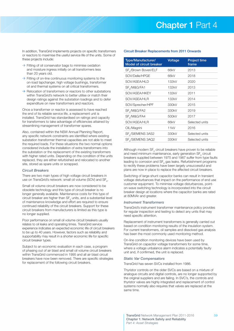
59TransGrid Network Management Plan 2011-2016Chapter 1: Network Safety and Reliability Part 4: Asset Strategies
Chapter 1 Part 4
In addition, TransGrid implements projects on specific transformers or reactors to maximise the useful service life of the units. Some of these projects include:
>> Fitting of oil conservator bags to minimise oxidation and moisture ingress initially on all transformers less than 20 years old.
>> Fitting of on-line continuous monitoring systems to the on-load tapchanger, high voltage bushings, transformer oil and thermal systems on all critical transformers.
>> Relocation of transformers or reactors to other substations within TransGrid’s network to better utilise or match their design ratings against the substation loadings and to defer expenditure on new transformers and reactors.
Once a transformer or reactor is assessed to have reached the end of its reliable service life, a replacement unit is installed. TransGrid has standardised on ratings and capacity for transformers to take advantage of efficiencies attained by streamlining management of transformer spares.
Also, contained within the NSW Annual Planning Report, any specific network constraints are identified where existing substation transformer thermal capacities are not able to meet the required loads. For these situations the two normal options considered include the installation of extra transformers into the substation or the replacement of the existing transformers with higher rated units. Depending on the condition of the units replaced, they are either refurbished and relocated to another site, stored as spare units or scrapped.
Circuit BreakersThere are two main types of high voltage circuit breakers in use on TransGrid’s network: small oil volume (SOV) and SF6.
Small oil volume circuit breakers are now considered to be obsolete technology and this type of circuit breaker is no longer generally available. Maintenance costs for this type of circuit breaker are higher than SF6 units, and a substantial level of maintenance knowledge and effort are required to ensure continued reliability of the circuit breakers. Support for these circuit breakers from manufacturers is limited as this type is no longer supplied.
Poor performance on small oil volume circuit breakers usually relates to oil leaks and operating times. TransGrid service experience indicates an expected economic life of circuit breakers to be up to 40 years. However, factors such as reliability and supportability may result in a shorter economic life for specific circuit breaker types.
Subject to an economic evaluation in each case, a program of phasing out of air blast and small oil volume circuit breakers within TransGrid commenced in 1995 and all air blast circuit breakers have now been removed. There are specific strategies for replacement of the following circuit breakers.
Circuit Breaker Replacements from 2011 Onwards
Type/Manufacturer/Model of circuit breaker
Voltage Project time frame
SF6/Brown Boveri/ELF 66kV 2013
SOV/Delle/HPGE 66kV 2018
SOV/ASEA/HLD 132kV 2020
SF6/M&G/FA1 132kV 2013
SOV/ASEA/HKEY 132kV 2011
SOV/ASEA/HLR 132kV 2014
SOV/Sprecher/HPF 330kV 2015
SF6/M&G/FA2 330kV 2019
SF6/M&G/FA4 500kV 2017
SOV/ASEA/HLR 66kV Selected units
OIL/Magrini 11kV 2016
SF6/SIEMENS 3AS2 330kV Selected units
SF6/SIEMENS 3AQ2 330kV Selected units
Although modern SF6 circuit breakers have proven to be reliable and need minimum maintenance, early generation SF6 circuit breakers supplied between 1975 and 1987 suffer from type faults leading to corrosion and SF6 gas leaks. Refurbishment programs to rectify these problems have been largely unsuccessful and plans are now in place to replace the affected circuit breakers.
Switching of large shunt capacitor banks can result in transient voltage disturbances that impact on the performance of end use customer equipment. To minimise voltage disturbances, point-on-wave switching technology is incorporated into the circuit breaker design at locations where the capacitor banks are rated at 80MVAr and greater.
Instrument TransformersTransGrid’s instrument transformer maintenance policy provides for regular inspection and testing to detect any units that may need specific attention.
Replacement of instrument transformers is generally carried out based on condition monitoring results of the insulation system. For current transformers, oil samples and dissolved gas analysis has been the most commonly used monitoring method.
On-line condition monitoring devices have been used by TransGrid on capacitor voltage transformers for some time, where a voltage unbalance alarm indicates a potentially faulty unit and, if confirmed, the unit is replaced.
Static Var CompensatorsTransGrid has seven SVCs installed from 1986.
Thyristor controls on the older SVCs are based on a mixture of analogue circuits and digital controls, are no longer supported by the original suppliers and are failing. In SVC’s, the controls and thyristor valves are highly integrated and replacement of control systems normally also requires that valves are replaced at the same time.
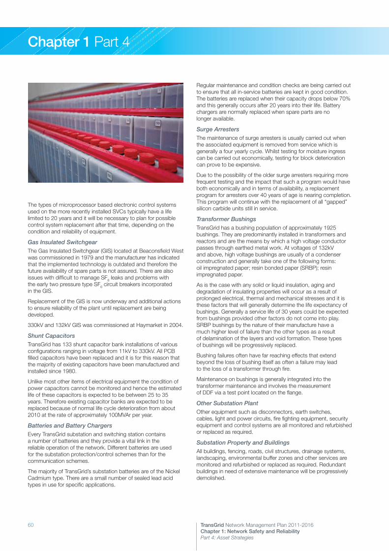
60 TransGrid Network Management Plan 2011-2016Chapter 1: Network Safety and Reliability Part 4: Asset Strategies
Chapter 1 Part 4
The types of microprocessor based electronic control systems used on the more recently installed SVCs typically have a life limited to 20 years and it will be necessary to plan for possible control system replacement after that time, depending on the condition and reliability of equipment.
Gas Insulated Switchgear The Gas Insulated Switchgear (GIS) located at Beaconsfield West was commissioned in 1979 and the manufacturer has indicated that the implemented technology is outdated and therefore the future availability of spare parts is not assured. There are also issues with difficult to manage SF6 leaks and problems with the early two pressure type SF6 circuit breakers incorporated in the GIS.
Replacement of the GIS is now underway and additional actions to ensure reliability of the plant until replacement are being developed.
330kV and 132kV GIS was commissioned at Haymarket in 2004.
Shunt CapacitorsTransGrid has 133 shunt capacitor bank installations of various configurations ranging in voltage from 11kV to 330kV. All PCB filled capacitors have been replaced and it is for this reason that the majority of existing capacitors have been manufactured and installed since 1980.
Unlike most other items of electrical equipment the condition of power capacitors cannot be monitored and hence the estimated life of these capacitors is expected to be between 25 to 35 years. Therefore existing capacitor banks are expected to be replaced because of normal life cycle deterioration from about 2010 at the rate of approximately 100MVAr per year.
Batteries and Battery ChargersEvery TransGrid substation and switching station contains a number of batteries and they provide a vital link in the reliable operation of the network. Different batteries are used for the substation protection/control schemes than for the communication schemes.
The majority of TransGrid’s substation batteries are of the Nickel Cadmium type. There are a small number of sealed lead acid types in use for specific applications.
Regular maintenance and condition checks are being carried out to ensure that all in-service batteries are kept in good condition. The batteries are replaced when their capacity drops below 70% and this generally occurs after 20 years into their life. Battery chargers are normally replaced when spare parts are no longer available.
Surge ArrestersThe maintenance of surge arresters is usually carried out when the associated equipment is removed from service which is generally a four yearly cycle. Whilst testing for moisture ingress can be carried out economically, testing for block deterioration can prove to be expensive.
Due to the possibility of the older surge arresters requiring more frequent testing and the impact that such a program would have both economically and in terms of availability, a replacement program for arresters over 40 years of age is nearing completion. This program will continue with the replacement of all “gapped” silicon carbide units still in service.
Transformer BushingsTransGrid has a bushing population of approximately 1925 bushings. They are predominantly installed in transformers and reactors and are the means by which a high voltage conductor passes through earthed metal work. At voltages of 132kV and above, high voltage bushings are usually of a condenser construction and generally take one of the following forms: oil impregnated paper; resin bonded paper (SRBP); resin impregnated paper.
As is the case with any solid or liquid insulation, aging and degradation of insulating properties will occur as a result of prolonged electrical, thermal and mechanical stresses and it is these factors that will generally determine the life expectancy of bushings. Generally a service life of 30 years could be expected from bushings provided other factors do not come into play. SRBP bushings by the nature of their manufacture have a much higher level of failure than the other types as a result of delamination of the layers and void formation. These types of bushings will be progressively replaced.
Bushing failures often have far reaching effects that extend beyond the loss of bushing itself as often a failure may lead to the loss of a transformer through fire.
Maintenance on bushings is generally integrated into the transformer maintenance and involves the measurement of DDF via a test point located on the flange.
Other Substation PlantOther equipment such as disconnectors, earth switches, cables, light and power circuits, fire fighting equipment, security equipment and control systems are all monitored and refurbished or replaced as required.
Substation Property and BuildingsAll buildings, fencing, roads, civil structures, drainage systems, landscaping, environmental buffer zones and other services are monitored and refurbished or replaced as required. Redundant buildings in need of extensive maintenance will be progressively demolished.

61TransGrid Network Management Plan 2011-2016Chapter 1: Network Safety and Reliability Part 4: Asset Strategies
Chapter 1 Part 4
2. Transmission LinesPreventative MaintenanceA preventative maintenance strategy is in place to ensure that all transmission line structures are regularly inspected. These inspections aim to detect likely component deterioration or defects such that remedial work can be undertaken to ensure no loss of supply will occur. The location of the assets, past performance and the material or form of construction determines the inspection intervals.
Inspection cycles for each individual line are based on past performance, current condition and significance in the transmission system. All transmission lines are inspected from the air once per year.
A summary of maintenance requirements is shown in the table below:
Construction Task Frequency
Steel Tower, Steel Pole and Concrete Pole
Aerial Inspection Annual
Ground Inspection 1-3 yearly
Foundation Inspection 6 yearly
Wood Pole Aerial Inspection Annual
Ground Inspection 1-3 yearly
Ground Line Inspection
3-6 yearly
Climbing Inspection 3-6 yearly
Inspections are scheduled to make the most efficient use of the inspection resources, such that the foundation, ground line or climbing inspections are carried out at a frequency that is a multiple of the ground inspection frequency for that line. For example, a two yearly ground inspection would lead to a four or six yearly ground line inspection and climbing inspection for a wood pole line.
Easement MaintenanceTransGrid is progressing with a transformation of its easements to allow for routine maintenance to be undertaken on a periodic basis. This transformation involves the removal of all tall growing species where they have the ability to encroach within safe clearances to the transmission line conductors when the transmission line is at its maximum operating temperature.
Once these tall growing species are removed, the easement will be maintained on a periodic basis with return periods of up to six years. Areas where only limited clearing is allowed such as waterway crossings or other sensitive areas will be targeted for maintenance on a more frequent localised basis.
The annual aerial inspection identifies any out of the ordinary defects that require attention prior to the next routine maintenance. This method allows for savings through programmed preventative maintenance in blocks of area rather than more frequent reactive maintenance in isolated pockets.
Replacement and Life Extension StrategiesAs part of TransGrid’s Asset Management Process, a number of emerging medium to long-term issues have been identified and detailed strategies have been developed to manage these emerging issues and extend the useful life of TransGrid’s transmission lines.
InsulatorsIf problems are identified with particular families of insulators, samples are taken out of service for testing where there is a large population of that type across the network. Should testing confirm a type problem then a strategy is developed to deal with it. If the problem is only a local issue, possibly related to the surrounding environment, then a watching brief will be maintained to see if the condition develops into a more widespread issue. If there is only a small population of that type of insulator across the network, it is generally considered that the cost and effort of removing insulators for testing is not warranted, and that it is more cost effective to simply replace the entire population that is exhibiting the identified problem.
As a result of that sampling and testing, a number of insulator types have been replaced over the years.
Overhead Earthwire (OHEW) ReplacementEarthwire is replaced due to fault rating limitations, corrosion problems or for the installation of OPGW (OHEW with embedded optical fibre for communications).
Fault rating limitations have occurred on sections close to substations where fault levels have risen over time. As fault levels are identified as approaching the limitations of the earthwires, projects are raised to replace the affected sections of earthwire.
Galvanised steel earthwire close to marine or industrial environments suffers from accelerated corrosion. Amongst the most susceptible are some older lines in the Newcastle-Sydney-Wollongong region.
OHEW has been sampled from some locations where it is visibly pitted. Testing of these samples has shown that at this stage there is no significant reduction in the strength of these earthwires. As such, a watching brief continues, with more samples to be removed in the future where inspections identify advancing corrosion. Where major line works are undertaken on a line with corroded earthwire, replacement of that earthwire as part of the work will be considered.
Wood PolesWood poles are generally replaced following detection of significant defects during routine maintenance. In the past less than 1% of the overall pole population has been replaced each year.
On some specific lines, however, the defect rate has increased to a level where it is no longer cost effective to detect the defective poles by inspection prior to failure, or where it becomes economic to undertake large-scale replacements to extend the useful life of the line. The principal causes of these accelerated defect rates are wood decay due to rot generally at ground line, and the impact of termites. TransGrid has almost completed the replacement of all structures that were uprated in the 1970s by addition of a timber pole section attached to the top of existing poles with a steel cylinder. These structures were susceptible to wood rot in the area of the cylinder, leading to premature pole failure.

62 TransGrid Network Management Plan 2011-2016Chapter 1: Network Safety and Reliability Part 4: Asset Strategies
Chapter 1 Part 4
A strategy has been implemented to establish replacement projects for nominated lines to replace all wood poles with steel or concrete. The timing of each project and rate of replacement shall take into account rate of defect, funding requirements, availability of outages, availability of local resources and projected system augmentations.
In the five year period these lines include:
>> 94B Wellington – Beryl 132kV>> 967 Koolkhan – Lismore 132kV>> 99J Yanco – Griffith 132kV>> 99F Uranquinty – Yanco 132kV>> 970 Yass – Burrinjuck 132kV
In addition to these lines, 944 Wallerawang – Orange 132kV has been scheduled for a complete rebuild due to its condition. This line will be rebuilt with new concrete or steel structures and new conductor and OHEW.
Grillage FoundationsEarly practice in steel tower construction, particularly where access was difficult, was to place a steel quadraped on the bottom of each tower leg and back fill with earth. Over time the reaction of the acids in the soil have slowly corroded the zinc coating and now the steel of many towers. Early strategies focussed on encasing the leg with concrete to prevent further corrosion. Sacrificial anodes were then installed on all structures with grillage foundations over the period since 1996. New testing methods have been documented to determine the condition of sacrificial anodes, as it is expected that some of the anodes in more aggressive locations are showing signs of becoming ineffective. Anodes that are becoming ineffective are scheduled for replacement in accordance with the maintenance procedures.
Concrete PolesIt is expected that concrete poles will have a significantly longer service life than wood poles. Although there have been some specific issues (such as corrosion in highly corrosive areas) these poles have not had sufficient service life to require the establishment of general life extension strategies. Corrosion of fittings, cross arm bracing and pole steps are likely to be the issues that will determine the service life and life extension strategies. It is anticipated that a small number of existing poles that were installed in highly corrosive areas will need to be replaced within the next 10 to 15 years, due to corrosion of the steel reinforcing near the ground line.
Steel TowersSteel towers have an anticipated service life averaging around 75 years. It is expected that this life will be somewhat reduced for towers in coastal or corrosive industrial environments. TransGrid has a number of towers in coastal environments that are showing significant signs of corrosion. 330kV transmission line 11 Sydney South – Dapto is a coastal line constructed in the early 1960s with significant corrosion occurring on the tower steelwork and fittings. This line has been scheduled for a life extension program involving painting with a zinc coating that has an expected effective life of 20-25 years. As this line has grillage foundations that have been corroding over this lifetime, it is expected that the line will need to be replaced at around 20 years after the life extension, when the grillages will no longer be serviceable.
Other steel tower lines in coastal or corrosive environments showing signs of corrosion are 330kV transmission lines in the Vales Point to Munmorah area, and other line sections constructed in the early 1960s around Liddell and Bayswater Power Stations.
TransGrid is undertaking assessments of all lines that are over 45 years old to determine the future strategies for these assets. Those lines that are assessed as showing significant signs of deterioration will require further strategies to be developed.
Aerial Laser SurveysTransGrid has completed a program to survey all transmission lines using Aerial Laser Surveys (ALS). The results of the initial phases of the ALS showed that under the most onerous operating conditions a small number of spans may infringe design clearances. As a result of the surveys, there is a requirement to address any issues identified through a variety of methods ranging from simple insulator rearrangements through re-tensioning of sections to complete replacement of structures. This work is expected to take up to five years from the completion of the ALS work.
Aerial Marker BallsSome older lines built before 1990 do not fully comply with the current standard AS 3891.1 – Air Navigation – Cables and their Supporting Structures – Mapping and Marking.
The locations where aerial marker balls are required have been accurately confirmed by aerial laser surveys and calculated line models. The work to install marker balls in those locations is underway, with over 50% of locations now complete. The remaining sites will be completed by the end of 2011.
Waterway CrossingsNSW Maritime issued a new Electricity Industry Code in August 2008 for the Crossing of Navigable Waterways by electrical infrastructure.
The primary purpose of this Code is to promote navigation safety outcomes, reduce safety risks to waterway users and the protection of property, including electricity supply.
The Code is, therefore, a guide to owners of infrastructure that crosses waterways (crossing controller) for promoting navigation safety outcomes when planning, installing, maintaining and modifying existing crossings.
The Code is based on a risk management matrix that considers site conditions such as usage patterns, vessel height, water levels, electrical clearances and visibility.
All new crossings will take into account the risks posed by the proposal and provide solutions so that the crossing does not pose unacceptable risks to navigation safety. The solutions may include the installation of signage, alternative type crossing (such as submarine crossing) or the re-routing of the overhead proposal.
Special provisions have been included for existing crossings. Risk assessments have been completed for all crossings identifying those where signage is required to reduce risks to a tolerable level. A program based on the identified level of risk shall be implemented within the time frame specified in the Code to install the required signage, or carry out further works as required.

63TransGrid Network Management Plan 2011-2016Chapter 1: Network Safety and Reliability Part 4: Asset Strategies
Chapter 1 Part 4
Emergency StructuresTransGrid, and other TNSPs, hold emergency transmission line structures to restore structures that have been damaged by events such as vehicle impact, severe storm events, vandalism and sabotage.
TransGrid relies generally on wood pole emergency structures for single circuit lines in readily accessible sites. These have served TransGrid satisfactorily primarily due to failures having occurred in these locations and with adequate backup provided by parallel circuits during the restoration period.
It is recognised throughout the industry that there is an increased risk to the interconnected National Electricity Market following a failure. It has been agreed between all TNSPs to each hold and maintain an Emergency Restoration System that has common components and that can be shared in the event of a major emergency. The system is based on guyed masts that can be erected rapidly in many configurations to suit the different line designs. This system continues to be implemented and supported in TransGrid.
3. Underground CablesTransGrid has two 330kV power cables supplying the Sydney central business district. These are the only high voltage cable systems TransGrid has installed in public areas. Both cables are of a paper and insulating fluid insulation system.
Cable 41 Sydney South – Beaconsfield West was commissioned in 1979. The cable and cable accessories were manufactured and installed by Sumitomo from Japan.
Cable 42 Sydney South – Haymarket was commissioned in 2004. The cable and cable accessories were manufactured and installed by J-Power Systems from Japan.
Preventative MaintenancePreventative maintenance is carried out in accordance with TransGrid’s Underground Cable Assets Maintenance Policy. The key details of this policy include:
>> Cable route patrol and maintenance>> Reading and recording of cable fluid pressure gauges>> Checking of accuracy of cable pressure alarms>> Sampling and testing of cable fluid>> Inspection of cable sealing ends>> Testing of cable outer sheath and link box maintenance>> Monitoring of joint movement>> Monitoring and maintaining cable tunnels and accessories
The frequencies of these activities are set out in the Policy.
Corrective MaintenanceDue to the nature and location of the underground cables in public roads and footways, various defect repairs and modifications not covered by routine maintenance are carried out. These need to be assessed on a case-by-case basis.
Asset Renewal Projects
Cable 41 Condition AssessmentA study has been completed by TransGrid reviewing the cable fluid testing results and the ambient ground temperature conditions recorded using the Cable 42 distributed temperature system. The results of this study show that assumptions regarding
the in ground operating conditions of Cable 41 used for design and rating calculations may have been underestimated. There is the possibility that Cable 41 may have experienced overheating in the past, possibly reducing its overall expected life.
The thermal conditions of Cable 41 are important for a number of reasons:
>> Increased loading, particularly during summer days, has meant that currently applied cyclic ratings are being reached on a number of occasions, possibly increasing the aging rate of the cable. In addition, contingency considerations mean that the ability to obtain outages on other critical items of plant in the Sydney area is becoming increasingly limited.
>> Information on the thermal impact of deeply buried sections of cable has identified the potential for “hot spots” in the cable that could accelerate cable paper deterioration at these locations and affect long-term cable reliability.
>> Reviews of cable temperature undertaken through data received from the distributed temperature system installed on Cable 42 have shown that the ground temperature assumptions may have been under estimated at the design stage. This may lead to changes in how the cable is operated in the warmer months.
A report to assess the condition of Cable 41 based on the new information has been prepared. An independent review of this report including a desktop condition assessment has been commissioned, and the results of this are expected in the early part of 2011. Once this independent assessment is received, further decisions can be made relating to the future of this important circuit.
Oil System ModificationsOn Cable 41, remote on-line monitoring of oil pressure has been trialled. The trial has been successful, however the oil pressure transducers used do not provide adequate resolution for differential pressure monitoring. With further work and improved resolution transducers, a differential (phase to phase comparison) pressure alarm system can be implemented which is expected to be considerably more sensitive than the current absolute pressure system. Further work is proposed on this system.
Civil WorksThere are a number of condition issues affecting the Cable 42 tunnel from Sydney Park to Haymarket. Life extension works are required to ensure the ongoing serviceability of the tunnel. These include:
>> A water treatment plant to replace the temporary oil and solids separator for the treatment of water pumped from the tunnel prior to discharge to stormwater.
>> Improved tunnel drainage systems that are not susceptible to clogging from solids.
>> Improvements to the pumping system.>> Completion of the elastomer lining and grouting works to minimise the ingress of water and the stabilisation of the rock surrounding the tunnel.
These items are included in a capital life extension program for the tunnel.

64 TransGrid Network Management Plan 2011-2016Chapter 1: Network Safety and Reliability Part 4: Asset Strategies
Chapter 1 Part 4
4. Protection SchemesPreventative MaintenanceThe preventative maintenance policy determines the frequency and extent of maintenance required for a given relay type. A summary is given in the table below.
Protection Scheme Category Maintenance Regime
Distance Numerical Self-Checking
6 yearly full routine maintenance Annual in-service auto-reclose checks (for 330kV & above circuits)
All others 6 yearly full routine maintenance 3 yearly performance check Annual in-service auto-reclose checks (for 330kV and above circuits)
Transformers and Reactors
All 4 yearly full routine maintenance
Busbar Numerical Self-Checking
6 yearly full routine maintenance
All others 6 yearly full routine maintenance 3 yearly performance check
Other Protection Schemes
Numerical Self-Checking
6 yearly full routine maintenance
(e.g. SVCs and capacitors)
All others 6 yearly full routine maintenance 3 yearly performance check
Corrective MaintenanceRelays used for the protection system are inspected and tested on a routine basis and where failures or problems are found an investigation is carried out. Subject to the results of the investigations, relays will be replaced, modified or monitored under a “watching brief”.
Capital ReplacementsA number of staged replacement programs for protection relays are currently scheduled to allow significant improvements to the maintenance, performance and functionality of this equipment on the network.
In the short term (five years), these staged programs form the initial steps in the replacement of selected relay types on the network.
In the medium term, trials have commenced for performing complete secondary system replacements at sites where the majority of secondary systems equipment is scheduled for replacement, or the overall secondary systems equipment condition is assessed as approaching the end of its serviceable life.
The following criteria are considered and priorities established on the basis of:
>> Relay age>> Relay failure rates – including history of particular relay mal-operations and the impact on system performance
>> Relay location and criticality in the network – including speed and performance of relays and their “fitness for purpose”
>> Manufacturer support>> The availability of spares and appropriate maintenance tools>> The ability to repair a relay and the cost of repair>> Relay routine and fault maintenance costs
To allow a projection for the number of replacement schemes to be developed, the following assumptions have been made:
>> All main protection relays will be progressively replaced over a 20 year period. This is to improve the reliability of protection relays and to increase functionality through remote interrogation (LAN connectivity), GPS clock synchronisation, internal circuit breaker fail, fault recording and event logging. It will also simplify panel designs and reduce maintenance requirements.
>> Relays will be replaced on a priority basis according to the criteria identified above.
>> Existing relays not targeted for replacement in the period 2011-2016 continue to perform satisfactorily.
>> Appropriate resources are available to perform replacement programs.
>> The expected life of new relays is estimated at between 15 to 20 years.
>> Repair of these new relays is possible during their 15 to 20 year lifetime.
With consideration given to these assumptions and TransGrid’s existing relay population, estimates for the replacement program have been developed. These estimates are based on the following action plan:
>> Relays that can no longer be supported due to lack of manufacturer support, inadequate spares and/or poor service condition or performance will be progressively replaced in the period 2011-2016.
>> The remaining relays will be assessed every 5 years for suitability for replacement as part of the preparation of 5 yearly protection asset replacement plans and budget proposals.
>> The new relays will themselves need replacement from about 15 years of age.
>> Overcurrent relay functionality will be incorporated into the primary relay replacements.
Other strategies being implemented include:
>> Upgrading of fault recorder equipment.>> GPS clock synchronisation of protection relays equipped with this functionality.
>> Ethernet connectivity of protection equipment to substation condition monitoring data servers to permit web-based reviews of relay and fault recorder fault/system disturbance data.
>> Further development of newer testing methods incorporating scheme testing to improve maintenance techniques and reduce operating costs.

65TransGrid Network Management Plan 2011-2016Chapter 1: Network Safety and Reliability Part 4: Asset Strategies
Chapter 1 Part 4
5. Metering InstallationsPreventative MaintenanceTransGrid is a registered Metering Provider (Category B) under the National Electricity Rules, qualified to design, install, maintain and repair revenue and check metering installations. All National Electricity Market (NEM) metering installations are maintained and tested in accordance with the requirements of the National Electricity Rules.
A summary of the preventative maintenance performed for the primary metering equipment is given in the table below.
Metering Equipment Category Maintenance Regime
Revenue Meters
Electronic 5 yearly calibration check
Induction Disc 2.5 yearly calibration check (5 yearly for Type 3 & 4 metering installations)
Check & Statistical Meters
All 5 yearly calibration check
Dataloggers All 4 monthly pulse checks
Transducers All 5 yearly calibration check
CTs and VTs Used in NEM installations
10 yearly calibration check
Metering Installations
Independent Checks
2.5 yearly
Inspections 2.5 yearly
Corrective MaintenanceNEM metering installations are constantly monitored for performance to ensure compliance with the accuracy and data integrity requirements of the NER. Defects and data problems are quickly detected and promptly fixed to ensure accurate metering data is always available for the settlement of the National Electricity Market.
Capital ReplacementsReplacement plans for metering equipment need to cater for the evolving needs of both regulated and unregulated customers in the National Electricity Market. Customer requirements and technological advances will determine what level of metering performance is acceptable. Meters that are now considered of modern design may become functionally inadequate within a relatively short period of time.
Regulated metering equipment will typically include panels, transducers and statistical meters providing operational and network planning data. Unregulated metering equipment generally includes revenue (and check) meters, RIMs and telecommunications equipment (phone services) used to collect and transfer metering data for the settlement of the National Electricity Market.
Strategies for replacing unregulated metering equipment will largely be determined by the financially responsible market participant (customer) and are therefore beyond the scope of this document, except where all secondary systems equipment is being replaced at a site as part of a regulated control room replacement or substation rebuild project.
Traditionally, the replacement of metering equipment has largely been driven by three main criteria:
1. The inability to repair equipment that has failed in service due to lack of spares and support from the manufacturer.
2. New National Electricity Market metering (NER) functionality requirements.
3. The need to keep up to date with technological developments and the utilisation of these advances in the most efficient manner.
In the short term (five years) the replacement program for regulated metering equipment has been developed on the basis of:
>> Equipment condition and performance.>> Failure rates.>> The ability to repair the equipment and the cost of repair. (Dependent upon the availability of spares and manufacturer support).
>> Metering equipment compliance with National Electricity Rules requirements.
The following assumptions underpin the planned replacement strategy:
>> All main meter types will progressively be replaced over a 20 year period.
>> Meters and transducers will be replaced on a priority basis according to the criteria identified above.
>> Transducers may also be replaced as part of control system upgrades and bay refurbishment programs.
>> New metering panels will be installed where all or the majority of meters at a site are targeted for replacement, or where older proprietary rack mount systems are used that are not compatible with the meters available on the current meter period orders.
>> Existing meters and transducers not targeted for replacement in the period 2011-2016 will continue to perform satisfactorily.
>> Appropriate resources are available to perform replacement programs.
>> The expected life of new meters and transducers, and their suitability (fitness for purpose) is estimated at between 15 to 20 years.
With consideration given to these assumptions and TransGrid’s existing metering equipment populations, estimates for the replacement program have been developed, based on the following action plan:
>> Metering equipment that can no longer be supported due to lack of manufacturer support, inadequate spares and/or poor service condition or performance, or that no longer comply with National Electricity Rules requirements will be progressively replaced in the period 2011-2016.

66 TransGrid Network Management Plan 2011-2016Chapter 1: Network Safety and Reliability Part 4: Asset Strategies
Chapter 1 Part 4
>> The remaining metering equipment will be assessed every 5 years for suitability for replacement as part of the preparation of 5 yearly metering asset replacement plans and budget proposals.
>> This new metering equipment will need replacement from about 15 years of age.
6. Communication EquipmentPreventative MaintenancePreventative maintenance is carried out where appropriate to ensure reliable performance of communication systems.
A summary of some of the key preventative maintenance periods is shown in the table below:
Communication Plant Item Maintenance Period
Digital Microwave Nil required
PDH Microwave & VHF Antenna & Feeders
Annually
Line Traps & Secondary Coupling 6 yearly
PLC Intertrips 3 yearly
VF Intertrips 3 yearly
Radio Sites Quarterly to annually – site dependant
Optical Systems including PCM 3 yearly
VHF Repeater and Link Equipment Annually
Control Systems Nil required
OPGW Fibre 6 monthly
Corrective MaintenanceCorrective maintenance is carried out as required in order to achieve a communication systems availability target of 99.5%. Fault repair and equipment replacement is prioritised with regard to the severity and impact of the fault.
Major Operating Projects
Communication Property and BuildingsAll buildings, fencing, roads, civil structures, drainage systems, radio towers and other services are monitored and refurbished or replaced as required. Redundant buildings in need of extensive maintenance will be progressively demolished.
Type of Work Required Estimated Number of Sites/Year
Repair and Paint Repeater Site Buildings 15 sites/5 years
Repair and Paint Communication Room Buildings
15 sites/5 years
Repair Radio Tower Structures 15 sites/5 years
Repair/Replace Fences and Gates 4 sites/5 years
Repair Roads 10 sites/5 years
Bay AlarmsEach communication room marshals individual alarms from equipment and displays them as an audible and visual display. This is achieved by Bay Alarm Systems. The Computer Alarm System (CAS) is used throughout the network to provide this service. CAS is a microprocessor-based system that provides remote interrogation and control facilities.
The current Bay Alarm Systems are serviceable and fit for purpose. The Bay Alarm Systems are to remain in service until a replacement program commences after 2015.
Backup Alarm SystemsSMART Alarm transceivers have been installed as the backup alarm system. They provide a 10-function alarm service in both transmit and receive directions and have been designed to interface with all of TransGrid’s communications channels. SMART alarms currently account for the entire population of backup alarm systems in the network.
This system has an expected life of 20 years and at present there are no performance issues.
Power Line Carrier (PLC)Approximately 70% of the population of PLC voice systems are Dimat and the remaining 30% are Fujitsu systems. The majority of older Fujitsu Power Line Carrier voice systems on TransGrid’s network have been replaced in the past 5 years.
A program was commenced in 2006 to remove Fujitsu PLC systems from the network and is currently ongoing, with a view to replace all the existing units by the end of the 2026 financial year.
The numbers of systems planned for replacement are as follows:
Period (Years) PLC Replacement Systems/Year
2011 12
2012 10
2013 6
2014 7
2015 6
2016 10
Power Line Carrier Protection Intertrip SystemsApproximately 70% of the population of PLC systems are Dimat and the remaining 30% are Fujitsu systems. The majority of older Fujitsu Power Line Carrier systems on TransGrid’s network have been replaced in the past 5 years.
A program was commenced in 2004 to remove these systems from the network and is currently ongoing, with a view to replace all the existing units by the end of the 2024 financial year.
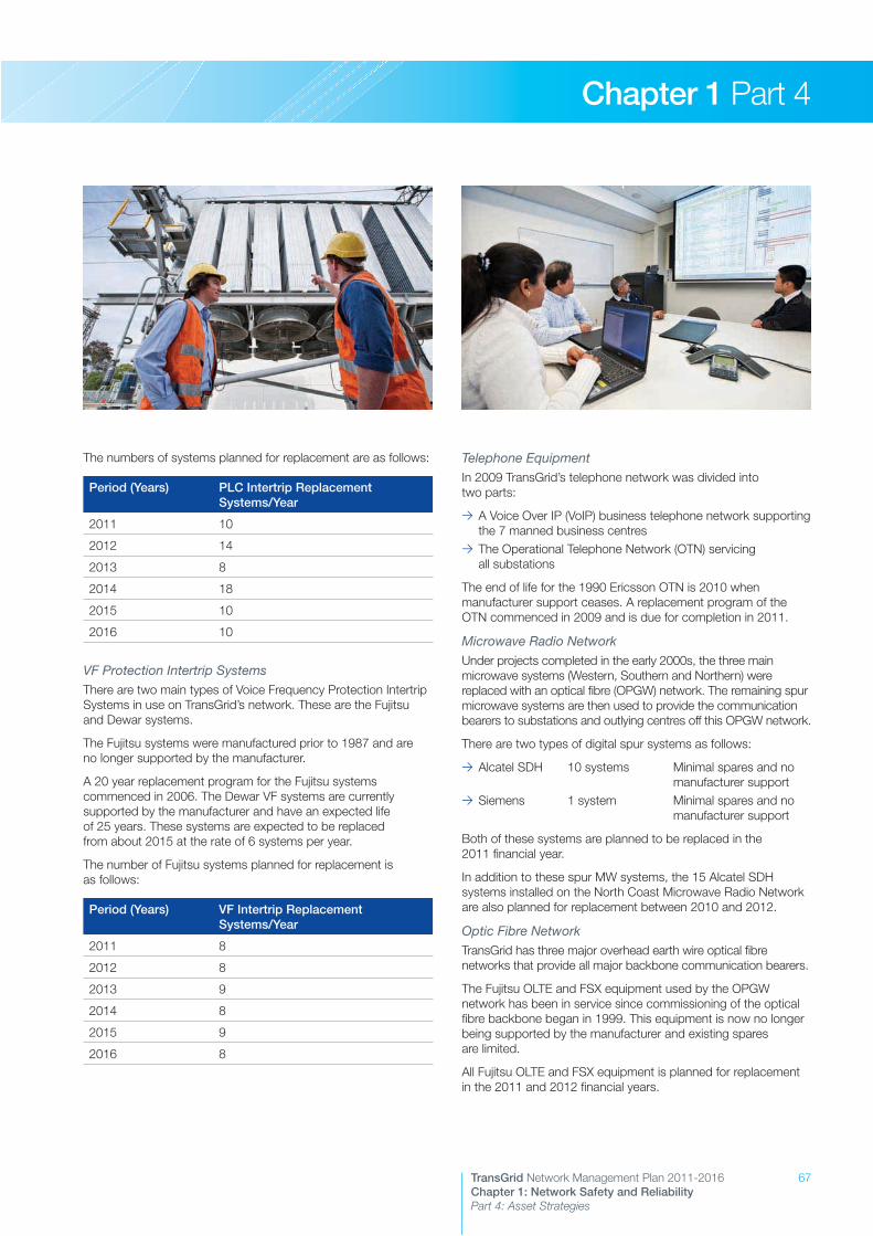
67TransGrid Network Management Plan 2011-2016Chapter 1: Network Safety and Reliability Part 4: Asset Strategies
Chapter 1 Part 4
The numbers of systems planned for replacement are as follows:
Period (Years) PLC Intertrip Replacement Systems/Year
2011 10
2012 14
2013 8
2014 18
2015 10
2016 10
VF Protection Intertrip SystemsThere are two main types of Voice Frequency Protection Intertrip Systems in use on TransGrid’s network. These are the Fujitsu and Dewar systems.
The Fujitsu systems were manufactured prior to 1987 and are no longer supported by the manufacturer.
A 20 year replacement program for the Fujitsu systems commenced in 2006. The Dewar VF systems are currently supported by the manufacturer and have an expected life of 25 years. These systems are expected to be replaced from about 2015 at the rate of 6 systems per year.
The number of Fujitsu systems planned for replacement is as follows:
Period (Years) VF Intertrip Replacement Systems/Year
2011 8
2012 8
2013 9
2014 8
2015 9
2016 8
Telephone EquipmentIn 2009 TransGrid’s telephone network was divided into two parts:
>> A Voice Over IP (VoIP) business telephone network supporting the 7 manned business centres
>> The Operational Telephone Network (OTN) servicing all substations
The end of life for the 1990 Ericsson OTN is 2010 when manufacturer support ceases. A replacement program of the OTN commenced in 2009 and is due for completion in 2011.
Microwave Radio NetworkUnder projects completed in the early 2000s, the three main microwave systems (Western, Southern and Northern) were replaced with an optical fibre (OPGW) network. The remaining spur microwave systems are then used to provide the communication bearers to substations and outlying centres off this OPGW network.
There are two types of digital spur systems as follows:
>> Alcatel SDH 10 systems Minimal spares and no manufacturer support
>> Siemens 1 system Minimal spares and no manufacturer support
Both of these systems are planned to be replaced in the 2011 financial year.
In addition to these spur MW systems, the 15 Alcatel SDH systems installed on the North Coast Microwave Radio Network are also planned for replacement between 2010 and 2012.
Optic Fibre NetworkTransGrid has three major overhead earth wire optical fibre networks that provide all major backbone communication bearers.
The Fujitsu OLTE and FSX equipment used by the OPGW network has been in service since commissioning of the optical fibre backbone began in 1999. This equipment is now no longer being supported by the manufacturer and existing spares are limited.
All Fujitsu OLTE and FSX equipment is planned for replacement in the 2011 and 2012 financial years.

68 TransGrid Network Management Plan 2011-2016Chapter 1: Network Safety and Reliability Part 4: Asset Strategies
Chapter 1 Part 4
VHF Radio NetworkTransGrid’s radio network consists of fixed repeaters and links, and a mobile fleet installed in vehicles or as desk stations.
The fixed repeaters and links consist of Midland Transceivers. This equipment was manufactured in 1997 and is supported by Exicom and is expected to provide service till the year 2020.
The mobile fleet and desk base stations are Tait 2000 series transceivers. This equipment was manufactured in the early 1990s and is supported by Tait. Current spares are adequate to continue services till 2015.
Repeater Site Ancillary EquipmentTransGrid’s repeater sites require ancillary equipment to provide site services.
These services are:
>> Batteries at each site
Batteries have a life of approximately 20 years and are replaced as and when required.
>> Battery Charger Chargers at each site range between 12V, 24V or 50V. They have a life of approximately 30 years and are replaced as and when required.
>> Air Conditioners Air Conditioners at each site are either wall mount or split units. These units run continuously for up to 24 hours a day. The life cycle is 5 to 10 years determined by location. They are replaced as and when required.
>> Aerial Feeders and Antennae
Aerial feeders and antennae provide transmission medium for microwave and VHF services. The life cycle is 10 to 20 years determined by location. They are replaced as and when required or when systems are replaced.
>> Cabling Cabling consists of power, alarm and service wiring. Location and possible rodent damage determine the cabling life cycle. They are replaced as and when required.
Type of Work Required Estimated Number of Sites/Year
Battery and Charger Replacement
20 sites/5 years
Air Conditioning 32 sites/5 years
Antennae and Feeders 16 sites/5 years
Cabling 4 sites/5 years
SCADA OutstationsTransGrid has several different types of remote terminal units (RTUs) in-service that are used to provide data acquisition and supervisory control functions. These RTUs are installed in substations, power stations and other assets.
Following the completion of the ABB SCADA project, a replacement program was initiated to replace the existing Toshiba RTUs with Logica and Serck RTUs. This program is expected to be completed by the end of the 2012 financial year.
Over the period covered by this Plan the existing MITS MD1000 control equipment (which was installed in the early 1990s) is planned to be replaced, as this equipment is no longer manufactured or supported. The number of units to be replaced is as follows:
Period (Years) Control Equipment Replacement Sites / Year
2011 10
2012 10
2013 10
2014 10
2015 10
2016 10
In addition to the MITS replacement program, orphan control systems installed at Gadara, Balranald, Molong and the Armidale SVC (all built as turnkey projects in 2000) are to be replaced during the period covered by this Plan.
4.2.3 Environmental StrategiesTo assist TransGrid to protect the environment in which it operates TransGrid has had in place an Environmental Management System accredited to ISO 14001 since 1996. TransGrid is committed to conducting its activities and services in a manner that minimises pollution and complies with relevant environmental legislation, industry standards and codes of practice.
TransGrid aims to enhance its systems and processes in a manner that promotes continuous improvement in environmental management and which will lead to the achievement of industry best practice.
By working in partnership with communities, non-government organisations and landowners, TransGrid is protecting and enhancing the environment in which it works.
Impacts of Climate ChangeTransGrid has in place a Climate Change Strategy – GD ST G2 025 which considers:
>> The impact of climate change upon the organisation>> Ways in which TransGrid may be contributing to climate change>> How TransGrid may reduce its contribution to climate change

69TransGrid Network Management Plan 2011-2016Chapter 1: Network Safety and Reliability Part 4: Asset Strategies
Chapter 1 Part 4
The strategy defines nine initiatives TransGrid is taking to respond to climate change:
>> Assess the impacts of climate change on the transmission network and its performance.
>> Reduce TransGrid’s network and non-network greenhouse gas emissions.
>> Reporting of our greenhouse gas emissions.>> Identify and respond to the opportunities and impacts associated with a carbon pollution reduction scheme and/or energy efficiency trading scheme.
>> Remain informed of community, political and regulatory developments and adjust policy accordingly.
>> Proactively inform and educate employees about climate change and actions TransGrid is taking to respond to it.
>> Identify how climate change will impact upon our customers and customer base and manage accordingly.
>> Create the necessary internal environment to ensure that TransGrid encourages innovative practices.
>> Periodically review strategic implementation to ensure that TransGrid remains adaptable.
In 2010 TransGrid engaged an external provider to assess the potential impacts of climate change on its transmission network. The assessment includes:
>> Consideration of the meteorological and environmental impacts of climate change for different areas of TransGrid’s network.
>> Joint assessment of the consequences of those meteorological impacts on the TransGrid network.
>> Recommendations for strategies to manage the impacts of climate change.
This work is ongoing and will assist TransGrid to respond appropriately to climate change.
Environmental Aspects of Substations and PremisesSubstations may impact on the environment through their visual appearance, noise emission or escape of oil. Also any work activity proposed to take place at a substation or premises could potentially affect the environment. This particularly applies to water discharges, vegetation clearance and other work requiring chemical handling or which generates industrial or hazardous waste.
Therefore, to reduce any potential impact on the environment, TransGrid substations are designed and sited to minimise their impact. All sites have environmental response systems and emergency response plans designed to ensure that, in the event of equipment failure, the surrounding environment is unaffected. Major oil-filled plant, such as transformers, is located within bunds. Secondary, and on some sites tertiary oil containment systems are installed, to prevent the escape of oil from the substation to the surrounding environment.
Noise emissions from transformers are reduced by construction of suitable enclosures or walls where necessary. In recent years, air-blast circuit breakers have been replaced with quieter SF6 circuit breakers.
To reduce any potential impact on the environment by works programs at a substation or premises TransGrid substation staff are trained to TransGrid’s Environmental Rules for Premises – GD EN G3 025, and require that an environmental impact assessment (EIA) for maintenance activities to be undertaken before any work takes place. The EIA takes into account all possible matters that could or are likely to affect the environment by reason of that activity.
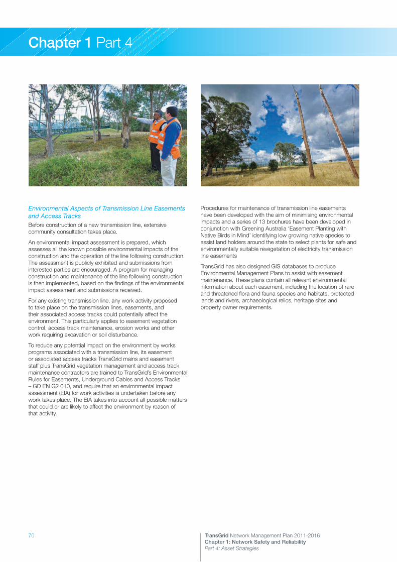
70 TransGrid Network Management Plan 2011-2016Chapter 1: Network Safety and Reliability Part 4: Asset Strategies
Chapter 1 Part 4
Environmental Aspects of Transmission Line Easements and Access TracksBefore construction of a new transmission line, extensive community consultation takes place.
An environmental impact assessment is prepared, which assesses all the known possible environmental impacts of the construction and the operation of the line following construction. The assessment is publicly exhibited and submissions from interested parties are encouraged. A program for managing construction and maintenance of the line following construction is then implemented, based on the findings of the environmental impact assessment and submissions received.
For any existing transmission line, any work activity proposed to take place on the transmission lines, easements, and their associated access tracks could potentially affect the environment. This particularly applies to easement vegetation control, access track maintenance, erosion works and other work requiring excavation or soil disturbance.
To reduce any potential impact on the environment by works programs associated with a transmission line, its easement or associated access tracks TransGrid mains and easement staff plus TransGrid vegetation management and access track maintenance contractors are trained to TransGrid’s Environmental Rules for Easements, Underground Cables and Access Tracks – GD EN G2 010, and require that an environmental impact assessment (EIA) for work activities is undertaken before any work takes place. The EIA takes into account all possible matters that could or are likely to affect the environment by reason of that activity.
Procedures for maintenance of transmission line easements have been developed with the aim of minimising environmental impacts and a series of 13 brochures have been developed in conjunction with Greening Australia ‘Easement Planting with Native Birds in Mind’ identifying low growing native species to assist land holders around the state to select plants for safe and environmentally suitable revegetation of electricity transmission line easements
TransGrid has also designed GIS databases to produce Environmental Management Plans to assist with easement maintenance. These plans contain all relevant environmental information about each easement, including the location of rare and threatened flora and fauna species and habitats, protected lands and rivers, archaeological relics, heritage sites and property owner requirements.

71TransGrid Network Management Plan 2011-2016Chapter 1: Network Safety and Reliability Part 4: Asset Strategies
Chapter 1 Part 4
4.3 Asset Disposal Strategies
4.3.1 IntroductionAssets are of operational value to TransGrid only in so much as they continue to effectively support the delivery of the required service. Once these assets no longer provide the required level of service their worth lies only in the benefits to be gained from their disposal.
Asset disposal is therefore the final stage in the asset life cycle and its proper planning and management is an integral part of TransGrid’s Network Management Plan.
TransGrid’s asset disposal strategies mainly encompass two broad types of assets. The first involves real property holdings and the second involves general assets such as buildings, structures, plant and equipment.
Although real property assets normally have high values and their disposal often involves more complex planning and financial issues, the general disposal processes followed within TransGrid are very similar to the disposal of all other asset types. Therefore this section of the Network Management Plan outlines these general disposal strategies.
4.3.2 Asset Disposal Planning TransGrid’s asset disposal planning involves a detailed assessment of those assets identified in the planning/capital investment strategies and asset management strategies that are no longer required, or no longer effectively meet their service delivery outputs at the lowest long term cost to TransGrid. This allows TransGrid to cull redundant assets that might otherwise reduce efficient and effective service delivery.
Disposal planning incorporates two separate elements:
>> The detailed assessment of assets identified as surplus.>> The analysis and implementation of the physical disposal of the assets.
An asset is identified as surplus when one of the following occurs:
>> The asset is not required for the delivery of service, either currently or over the longer planning time frame.
>> The asset becomes uneconomical to maintain or operate which could be due to advances in technology, social expectations, changing demographic patterns or the economies of scale made possible by new service capacity.
>> The asset wears out or becomes uneconomical to repair or refurbish.
Once an asset is identified as surplus, its physical disposal will depend on one or more of the following:
>> Whether or not there are net disposal benefits to TransGrid, either in financial or other terms such as management, supervision and storage.
>> Whether or not there are secondary (non-core) service obligations associated with the asset which dictate its retention, for example heritage, open space or other social environmental considerations.
>> Whether or not disposal can be carried out without adverse impacts on the physical environment.
>> Compliance with any legislative requirements or Chemical Control Orders such as for Asbestos and Polychlorinated Biphenyls (PCBs).
>> Whenever it is considered likely that under-utilised or surplus assets may be of significant value to other agencies such as NSW DNSPs, such agencies are advised of the asset’s availability.
4.3.3 Asset Disposal Strategy ProcessTransGrid’s asset disposal strategy process is a structured and systematic process aimed at ensuring the asset portfolio comprises only assets that effectively meet their service delivery requirements at the lowest long term cost. The processes involved are therefore directly linked with TransGrid’s service delivery strategies, TransGrid’s planning/capital investment strategies and TransGrid’s asset management strategies.
The disposal strategy has five discrete stages, the main aspects of which as are follows:
Stage 1 – Assessment in detail of those assets identified by the planning/capital investment and asset management strategies as being surplus to service delivery requirements.
Stage 2 – Assessment of the advantages or otherwise to TransGrid, TransGrid’s shareholders or the community in divesting the surplus assets.
Stage 3 – Identifying any opportunities for increasing asset value.
Stage 4 – Identifying related disposal requirements (auction, tender, private treaty or scrap) and processes including probity requirements.
Stage 5 – Preparing and implementing an appropriate disposal plan that satisfies all safety and environmental requirements.
The majority of TransGrid’s aged surplus assets are normally scrapped or sold for material salvage and depending on the materials used in the design and construction of the assets a number of procedures have been established to facilitate this process. Many of these processes are contained within TransGrid’s waste management procedure.
72 TransGrid Network Management Plan 2011-2016Chapter 1: Network Safety and Reliability Part 4: Asset Strategies
Chapter 1 Part 4
4.3.4 Waste Management TransGrid’s procedure Waste Management – GD EN G3 023, has been established in accordance with both NSW and Australian legislation requirements and is closely related to the NSW Waste Avoidance and Resource Recovery Act, 2001. This involves the appropriate disposal methods for various waste and materials, the licensing of TransGrid sites and facilities and direct dealings with the Environmental Protection Authority.
All potentially hazardous waste is required to be tested and classified before disposal is undertaken.
Within TransGrid, specific asset disposal strategies concerning certain types of materials include the following:
Disposal of Polychlorinated Biphenyls (PCB)The NSW PCB Chemical Control Order 1997 requires that:
i) Owners of PCB contaminated materials must carry out a survey by 1st January 1999 to identify items of equipment and articles containing PCB. TransGrid has completed this task.
ii) Concentrated PCB material (i.e. PCB greater than 10%) must be removed from priority areas within two years of completing the survey, and from other than priority areas within five years of completing the survey. TransGrid completed the removal and destruction of all concentrated PCB materials (1,155 tonnes) by January 1999.
iii) Scheduled PCB material (i.e. PCB greater than 50 ppm) must be removed from service, or processed in-situ to reduce the PCB concentration below 50 ppm, within five years of identification. TransGrid has obtained an extension from the EPA that requires that scheduled PCBs must be either removed from service or processed by 2010. TransGrid has completed the removal and destruction of all scheduled PCB materials as identified in the survey undertaken in accordance with the Chemical Control Order. However, isolated cases of plant that could not be sampled without destruction have subsequently been identified as scheduled PCB waste. In concurrence with the Department of Environment, Climate Change and Water (EPA) these newly identified items are scheduled for priority removal in accordance with the disposal process within the Chemical Control Order.
iv) Non-scheduled PCB materials (i.e. PCB less than 50 ppm) are not required to be removed from service within any legislative time-frame. However once removed from service appropriate disposal methods are required.
TransGrid maintains a number of contracts for the disposal of PCB contaminated oil and solid waste of varying contaminations.
Disposal of Chemical Fluid Dow C4 One of the non-PCB fluids introduced for power capacitors in 1980 was the chemical “Dow C4” and within TransGrid 23 capacitor banks contain this fluid (total of 763 MVAr). This fluid is considered a hazardous waste and appropriate handling and disposal methods are used to manage the associated risks.
At present, failed capacitor cans are being stockpiled and disposed when the quantity becomes viable.
A number of Dow C4 contaminated capacitor banks are planned for replacement over the period of this Plan for condition reasons, and their disposal will be incorporated into the replacement project.
Disposal of BatteriesTransGrid has quantities of large station and communication batteries that comprise Lead Acid or Ni-Cad. These batteries have a normal life span of approximately 20 years and their retirement is determined by the asset management strategy and battery maintenance procedures.
Disposal of Ni-Cad batteries is a requirement of TransGrid’s procurement specification for batteries and thus forms part of the contract. The old Ni-Cad cells are returned to Australian manufacturer’s works for shipment overseas for recycling. The entire process is carried out in accordance with the relevant dangerous goods and environmental regulations.
Similarly, return of lead acid type batteries is included in the procurement specification, although the recycling is carried out in Australia. Where a requirement for disposal cannot be aligned with a replacement, a one-off order will be placed subject to the same controls.
Disposal of Chemically Treated Wood PolesTransGrid has a large number of wood poles as part of its transmission network. The pole butts have been treated with preservative chemicals to reduce the impact of rot and termites on pole strength. When wood poles are replaced, the disposal of this treated wood needs to be carefully managed as some of these chemicals are considered hazardous under the NSW Scheduled chemical wastes chemical control order 2004 (e.g. DDT, dieldrin, heptachlor, alderin, benzo-a-pyrene have been used in previous times).
The wood poles can be recycled into timber building products. TransGrid maintains a contract for the disposal of wood poles including contaminated pole butts of varying contaminates. TransGrid is responsible for testing and classifying the contaminated pole butts before they are removed from site and sent for disposal.
Other Waste MaterialsFor all other waste materials generated as a result of any asset disposal process, the procedure Waste Management – GD EN G3 023 must be followed. This procedure provides staff with a simple way of identifying the specific processes required for the storage, transportation and disposal of waste in a manner compliant with environmental legislation. The information provided applies to all TransGrid workplaces where waste is generated, stored, handled or transported.

73TransGrid Network Management Plan 2011-2016Chapter X: Chapter Heading
Chapter 2
1. Introduction2. Design, Construction
and Maintenance Standards3. Testing, Connection and Notification Criteria4. Inspection Regime and Procedures
to Remedy Faulty Work5. Reporting Defective Installation Work
Customer Installation Safety

74 TransGrid Network Management Plan 2011-2016Chapter 2: Customer Installation Safety
Chapter 2
1. IntroductionTransGrid’s transmission network is connected to electricity distributors, other transmission network operators, generators and direct connected customers.
This Chapter of the Network Management Plan describes requirements for direct connected customers with a nominal voltage level below 132kV. TransGrid has three direct connected end use customers, being:
>> Tomago Aluminium Company at Tomago – 330kV>> Norske Skog Paper Mills at Albury – 132kV>> Visy Pulp & Paper Pty Limited at Gadara – 132kV and 11kV
Of these, only one of the connections to Visy Pulp & Paper Pty Limited at Gadara is connected at a nominal voltage level below 132kV.
All direct connected customers have current connection agreements with TransGrid. The agreements specify TransGrid’s and the Customer’s obligations to maintain the equipment in an appropriate state for safe operation.
2. Design, Construction and Maintenance StandardsAll connections to TransGrid’s network must comply with the National Electricity Rules. In addition, Gadara substation was originally constructed by TransGrid, and therefore was designed according to TransGrid’s design standards.
TransGrid connection agreements specify that equipment must be maintained in a manner and to a standard consistent with good electricity industry practice, as defined in the National Electricity Rules. Both TransGrid and direct connected customers must retain maintenance records that may be audited.
Records of testing, outage plans and operating procedures are also maintained.
3. Testing, Connection and Notification CriteriaAll equipment to be connected to TransGrid’s high voltage network is commissioned in accordance with TransGrid procedure Network Alterations - Operational Requirements – GD SO G2 001. This procedure provides guidelines, checklists, notification requirements and responsibilities for customers and TransGrid to ensure the safe initial connection of equipment.
4. Inspection Regime and Procedures to Remedy Faulty WorkUpon identifying a deficiency in the performance within the customer’s site, as measured against the minimum performance specified in the connection agreement, TransGrid may require corrective action to be taken by the customer within a specified timeframe. There are provisions in the connection agreement to consider whether suspension is required (such as when there is risk of damage, injury to persons or loss of property) or whether longer-term corrective action is required, and to reach agreement on the terms of the corrective action.
5. Reporting Defective Installation WorkThe connection agreement is a binding legal document and sets down the process for dealing with disputes in the event that this is necessary.
The agreement considers appropriate timeframes for resolution, the provision for expert determinations, and the binding nature of the determinations.

75TransGrid Network Management Plan 2011-2016Chapter X: Chapter Heading
Chapter 3
1. Introduction2. Background3. Action Plans4. Annual Review and Report
Public Electrical Safety Awareness
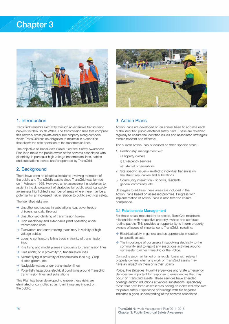
76 TransGrid Network Management Plan 2011-2016Chapter 3: Public Electrical Safety Awareness
Chapter 3
1. IntroductionTransGrid transmits electricity through an extensive transmission network in New South Wales. The transmission lines that comprise this network cross private and public property along corridors which TransGrid has an obligation to maintain in a condition that allows the safe operation of the transmission lines.
The objective of TransGrid’s Public Electrical Safety Awareness Plan is to make the public aware of the hazards associated with electricity, in particular high voltage transmission lines, cables and substations owned and/or operated by TransGrid.
2. BackgroundThere have been no electrical incidents involving members of the public and TransGrid’s assets since TransGrid was formed on 1 February 1995. However, a risk assessment undertaken to assist in the development of strategies for public electrical safety awareness highlighted a number of areas where there may be a potential for an increased risk in relation to public electrical safety.
The identified risks are:
>> Unauthorised access in substations (e.g. adventurous children, vandals, thieves)
>> Unauthorised climbing of transmission towers>> High machinery and extendable plant operating under transmission lines
>> Excavators and earth moving machinery in vicinity of high voltage cables
>> Logging contractors felling trees in vicinity of transmission lines
>> Kite flying and model planes in proximity to transmission lines>> Fires under, or in proximity to, transmission lines>> Aircraft flying in proximity of transmission lines e.g. Crop duster, gliders, etc
>> Navigable waters under transmission lines>> Potentially hazardous electrical conditions around TransGrid transmission lines and substations
This Plan has been developed to ensure these risks are eliminated or controlled so as to minimise any impact on the public.
3. Action PlansAction Plans are developed on an annual basis to address each of the identified public electrical safety risks. These are reviewed regularly to ensure the identified issues and associated strategies remain relevant and effective.
The current Action Plan is focused on three specific areas:
1. Relationship management with
i) Property owners
ii) Emergency services
iii) External organisations
2. Site specific issues – related to individual transmission line structures, cables and substations
3. Community interaction – schools, residents, general community, etc.
Strategies to address these areas are included in the Action Plans based on assessed priorities. Progress with implementation of Action Plans is monitored to ensure compliance.
3.1 Relationship ManagementFor those areas impacted by its assets, TransGrid maintains relationships with respective property owners and conducts routine patrols. This provides an opportunity to inform property owners of issues of importance to TransGrid, including:
>> Electrical safety in general and as appropriate in relation to specific assets.
>> The importance of our assets in supplying electricity to the community and to report any suspicious activities around our assets to either TransGrid or the Police.
Contact is also maintained on a regular basis with relevant property owners when any work on TransGrid assets may have an impact on them or in their vicinity.
Police, Fire Brigades, Rural Fire Services and State Emergency Services are important for response to emergencies that may occur on TransGrid assets. These services have attended briefings and/or inductions at various substations, specifically those that have been assessed as having an increased exposure for public safety. Experience of briefings with fire brigades indicates a good understanding of the hazards associated

77TransGrid Network Management Plan 2011-2016Chapter 3: Public Electrical Safety Awareness
Chapter 3
with substations, which is included in their training. Specific initiatives are therefore aimed at Police, Rural Fire Service (RFS) and State Emergency Services (SES).
Community consultation is mandatory with new projects and construction that may impact on the public. TransGrid has a formal community consultation process that ensures the issue of public safety is addressed.
Supervision and consultation is also maintained with TransGrid’s contractors and sub-contractors to ensure responsibilities in relation to personal and public safety are understood and implemented appropriately. Risk assessments and Safety Management Plans are developed for new construction projects to identify and manage safety risks.
Activities undertaken by others in association with property owners may also impact on TransGrid assets e.g. construction, logging and aerial activities. TransGrid has nominated officers to respond to inquiries and requests for information to assist these organisations to safely carry out their work in the vicinity of our assets.
Dial Before You Dig is a service to which TransGrid remains a participating member. This service provides information on the location of underground services for organisations external to TransGrid for specific work activities (e.g. excavation work).
3.2 Site Specific IssuesAny public safety issues identified for specific transmission lines, cables or substations are assessed and appropriate strategies developed to control the risks. These are incorporated into the Network Management Plan as appropriate.
3.3 Community InteractionIn addition to responding to enquiries, TransGrid is involved in community consultation in relation to specific projects. Information is also made available to various community groups with regard to electrical safety and the reporting of suspicious activities in the vicinity of TransGrid’s assets to TransGrid or the Police. This information may be included in:
>> Publications/brochures>> TransGrid’s website>> Newspaper articles>> Liaison with individual community groups, organisations, etc.
4. Annual Review and ReportEach of the Specific Initiatives is implemented, monitored and reviewed to ensure applicability and effectiveness. Performance Indicators are evaluated and reported to Industry & Investment NSW as part of annual reporting requirements.
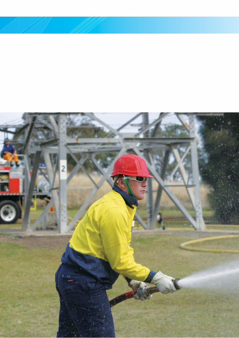
78

79TransGrid Network Management Plan 2011-2016Chapter X: Chapter Heading
Chapter 4
1. Introduction2. Objectives3. Strategies for Bush Fire Risk Management4. Performance Indicators
Bush Fire Risk Management

80 TransGrid Network Management Plan 2011-2016Chapter 4: Bush Fire Risk Management
Chapter 4
1. IntroductionTransGrid’s strategies, policies and procedures are based on the principles of risk management, and bush fire risk management forms an integral part of TransGrid’s overall asset management system. These systems have been developed over many years, and changes and improvements have been made taking into account system performance during bush fires.
These systems have proven effective in previous major bush fire events, such as those in 2001 – 2003. In the period since then, there have been no major bush fire events that have impacted on TransGrid’s transmission lines or infrastructure.
In the past five years, there have been two incidences of initiation of localised fires as a result of TransGrid lines. One incident was the result of externally caused damage to one line between Armidale and Coffs Harbour where the conductors were severed by a third party and fell to the ground, starting a minor fire where the conductors were in contact with the ground. The other incident was a small grass fire initiated by a fallen transmission line conductor due to failure of a line fitting on the Upper Tumut to Canberra transmission line. This fire self extinguished and was limited to the immediate area of the transmission line easement.
TransGrid reviews its processes and the performance of the network for bush fire emergencies. These reviews continue to find that the operating protocols are effective, the network performs very reliably, and communications protocols with emergency services organisations are effective.
The policies, procedures and work instructions required for the implementation of the Bush Fire Risk Management plan are distributed to relevant staff via TransGrid’s intranet.
2. ObjectivesThis Chapter is intended to demonstrate the responsible management of TransGrid’s network assets in relation to bush fire risk and meets the requirements of clause 12 (1) of the Electricity Supply (Safety and Network Management) Regulation 2008 – Objectives of a Bush Fire Risk Management Plan.
The objectives required by the Regulation [in italics below] have been expanded to better represent TransGrid’s existing asset management policies and standards:
a) To ensure public safety:
i. To proactively manage public, employee and contractor safety
ii. To protect the environment from harm
b) To establish standards that must be observed when electricity lines operate near vegetation:
i. To establish design and maintenance standards that ensure bush fires are not initiated due to the normal operation of transmission lines
c) To reduce interruptions to electricity supply that are related to vegetation:
i. Minimise the likelihood of interruption of the electricity supply due to faults on the network as a result of vegetation approaching too close to transmission lines
ii. To minimise interruptions to electricity supply as a result of bush fire initiated outages of the network
d) To minimise the possibility of fire ignition by electricity lines:
i. Minimise the likelihood that bush fires initiated by the operation, mal–operation or failure of transmission lines or electricity substation plant associated with transmission lines
ii. To minimise the likelihood of fire ignition by electricity lines under lightning induced fault conditions, or severe storm events

81TransGrid Network Management Plan 2011-2016Chapter 4: Bush Fire Risk Management
Chapter 4
3. Strategies for Bush Fire Risk Management
3.1 GeneralTransGrid’s transmission line assets traverse the State and are generally located in rural and semi–rural areas. All of these areas have periods of high fire danger during the year and many of the transmission line corridors in these areas have sections of dense vegetation at risk of bush fire. TransGrid’s risk approach to asset management assumes that every transmission line has the potential to be impacted by fire, or to initiate fire, including bush fire.
TransGrid is required to protect the environment by conducting its operations in compliance with the principles of ecologically sustainable development, and to operate efficient, safe and reliable facilities for the transmission of electricity. The asset management and operational strategies therefore encompass all these issues including bush fire risk management.
3.2 Specific StrategiesThe following strategies are the elements of TransGrid’s asset management and operational strategies specific to bush fire risk management. These elements include policies, standards, processes and procedures that together meet the objectives of this plan that were outlined in section 2.
a) To identify:>> Bush fire prone areas within the TransGrid supply area>> Network assets capable of initiating bush fires>> A system to ensure that this information is kept up to date
Transmission LinesTransGrid’s risk approach to asset management is to minimise the likelihood that an asset will initiate a fire, irrespective of the location of that asset. Each line’s maintenance frequencies are determined taking into account the following factors:
>> Vegetation density and growth patterns and associated bush fire initiation risks.
>> Condition of the line.>> Public safety and easement encroachment considerations.>> Local environmental conditions e.g. high corrosion or high termite activity areas.
The allocated maintenance frequencies are reviewed annually. The schedule of lines and their maintenance frequencies are listed in the Transmission Line Maintenance Policy.
Applicable Asset Management Standards:
>> Transmission Line Maintenance Policy – GM AS L1 001
Protection EquipmentProtection equipment is provided to detect electrical faults on overhead lines and/or power system abnormalities so as to mitigate the undesirable effects of such faults or abnormalities by the timely and correct operation of these devices.
This equipment will operate to de–energise transmission lines when flame or dense smoke reaches the HV conductors and causes an electrical arc. It is essential that this equipment operates correctly to ensure minimal system disturbance and supply interruption.
Protection equipment forms a system made up of relays that detect the fault and circuit breakers that electrically isolate the fault by de–energising the line. The frequency of maintenance of protection equipment is governed by TransGrid’s Protection Maintenance Policy. This standard also specifies in service auto–reclose checks that verify the complete protection scheme including intertrips and the mechanical operation of the circuit breakers.
The frequency of maintenance of circuit breakers is governed by TransGrid’s Substation Maintenance Policy.
Applicable Asset Management Standards:
>> Protection Maintenance Policy – GM AS P1 001>> Substation Maintenance Policy – GM AS S1 001
SubstationsTransGrid’s approach to the management of its substation assets takes into consideration:
>> The risk that a fire may be initiated by an ignition source from within a substation.
>> The risk to equipment that may be posed by a fire external to a substation.
The activities required to eliminate these risks are set out in the Substation Maintenance Policy and the Fire Protection Manual Operations and Maintenance and include:
>> Routine inspection of fire fighting equipment>> Routine inspection of transformer fire protection systems>> Routine inspection of control room fire protection systems>> Routine inspection of switchyards and inspection of oil containment systems
>> Grass cutting and weed control on the substation site>> Routine inspection for any rubbish that may present a potential fire hazard, clean up and disposal of rubbish
>> Routine inspection of perimeter firebreaks and rectification of any perimeter bush fire hazards
>> Routine inspection of control room gutters and removal of any combustible material
>> Control of vegetation and weeds within the switchyard>> Removal of grass and or weeds near cable entries
Applicable Asset Management Standards:
>> Substation Maintenance Policy – GM AS S1 001>> Fire Protection Manual Operations & Maintenance – GD HS G2 001
82 TransGrid Network Management Plan 2011-2016Chapter 4: Bush Fire Risk Management
Chapter 4
Radio Repeater SitesThe Telecommunication Maintenance Policy covers property maintenance and includes all cleaning, mowing, clearing, internal or external building remediation work and general repairs to:
>> Communication rooms>> Radio repeater buildings>> Fences>> Compounds>> Buffer zones>> Access roads
This maintenance is performed to ensure Telecommunication Assets are adequately protected from deterioration, the effects of weather, vandalism or bush fire.
Applicable Asset Management Standards:
>> Telecommunication Maintenance Policy – GM AS C1 001
b) To ensure that the identified network assets located in bush fire prone areas are inspected, tested and maintained in accordance with a suitable maintenance schedule.The inspection and maintenance frequencies for all lines and protection equipment are established in accordance with the maintenance policies [(a) above] and are scheduled in TransGrid’s ERP system, Ellipse. Inspection and maintenance includes testing where required.
The maintenance achievement and any variances from targets are reviewed each month and corrective action initiated if required.
Technical Performance Assessments (TPAs) are carried out annually in each of TransGrid’s three geographically based maintenance regions to ensure that maintenance is being carried out in accordance with Asset Management Standards.
Applicable Asset Management Standards:
>> Network Asset Management – GD AS G2 003>> Technical Performance Assessment Process – GM AS G2 005
TransGrid has established maintenance practices that ensure adequate conductor to vegetation clearances are maintained, to minimise the likelihood of bush fire initiation due to arcing. These standards provide sufficient clearances to prevent flashover under all environmental conditions and under all line loadings.
TransGrid has commenced a strategy to transition towards a routine maintenance regime for its easements based upon a return frequency governed by known vegetation issues and growth patterns. Annual aerial inspections of all lines combined with routine ground inspections provide regular checks for any defect vegetation requiring action outside the routine maintenance program. The aim is to remove all tall growing species whose mature height is expected to impact on safe and reliable clearance to the high voltage conductors.
Applicable Asset Management Standards:
>> Transmission Line Maintenance Policy – GM AS L1 001>> Easements and Access Track Maintenance Policy – GM AS L1 002
>> Asset Management Strategy –Transmission Line Easements – GM AS L5 002
c) To review equipment types or construction methods known in their operation or design to have bush fire ignition potential, and develop mitigation strategies in relation to their use.Transmission LinesTransGrid transmission lines do not have any known design or construction flaws that would initiate bush fires provided they are maintained and operated in accordance with TransGrid’s standards and procedures. TransGrid’s asset management process ensures that all incidents are reviewed in the TPA, Quarterly Asset Performance Review (QAPR) and Quality Audit processes (refer to Chapter 1 of this Plan for the detail of these processes). These reviews include design and construction matters.
The focus therefore is to reduce the risk that the design and construction are not compromised by inadequate maintenance or inappropriate operation. Mechanical failure of a transmission line (e.g. dropped conductor), or failure of a transmission line to operate correctly under fault conditions (e.g. faulty earthing at times of lightning strike), can initiate fire under specific conditions.
The Transmission Line Maintenance Policy – GM AS L1 001 governs the policy for maintenance of transmission lines to ensure failures do not occur and to ensure earthing and earthing systems perform adequately during lightning and other fault conditions.
Applicable Asset Management Standards:
>> Transmission Line Maintenance Policy – GM AS L1 001
Protection equipmentAn uncleared fault, or a fault which is not cleared with minimal delay, could lead to consequential mechanical failure of a transmission line (e.g. dropped conductor due to insulator failure, or conductor separation due to arc or heat damage).
TransGrid’s asset management process ensures that the performance, testing and maintenance of these devices are reviewed in the TPA, QAPR and Quality Audit process (refer to Chapter 1 of this Plan). These reviews also include any design matters arising from performance issues.
Applicable Asset Management Standards:
>> Substation Maintenance Policy – GM AS S1 001>> Protection Maintenance Policy – GM AS P1 001
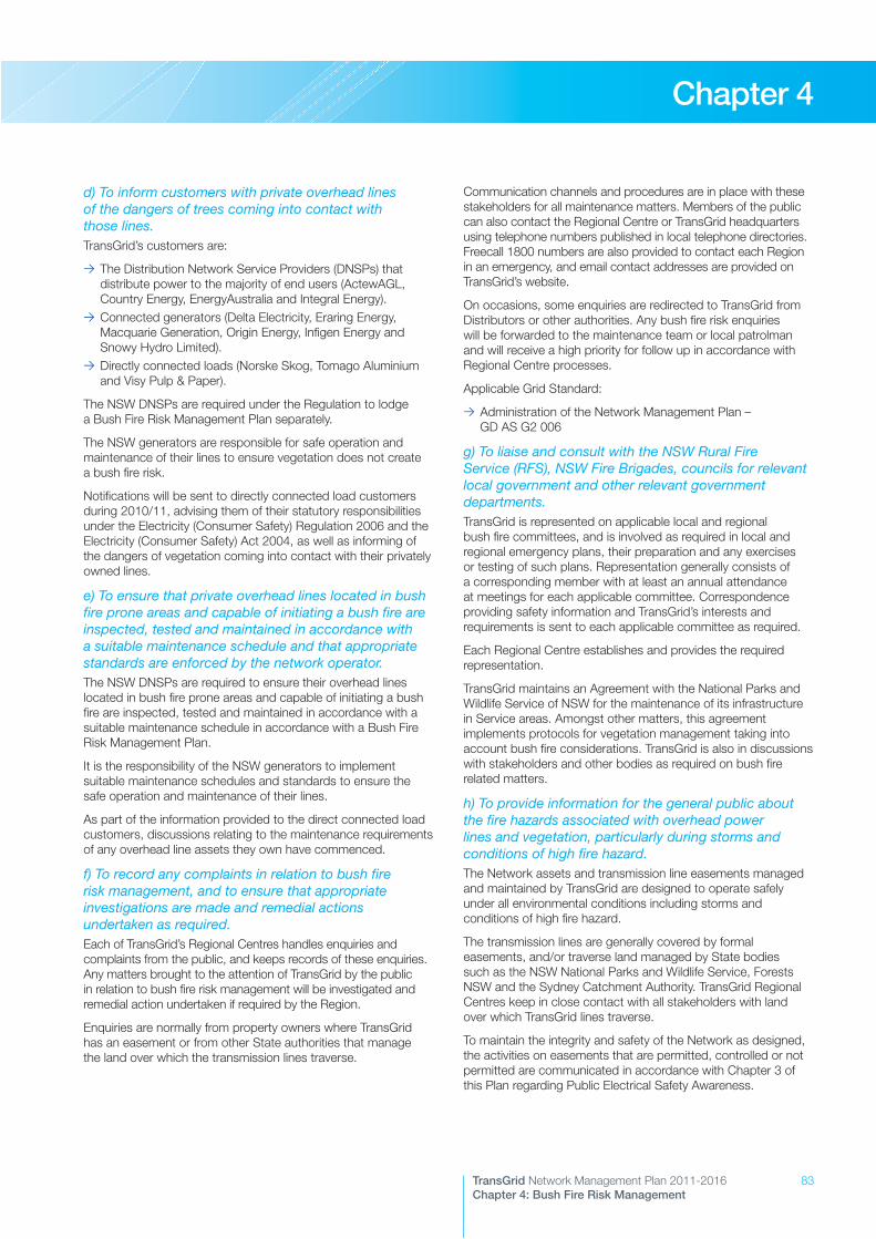
83TransGrid Network Management Plan 2011-2016Chapter 4: Bush Fire Risk Management
Chapter 4
d) To inform customers with private overhead lines of the dangers of trees coming into contact with those lines.TransGrid’s customers are:
>> The Distribution Network Service Providers (DNSPs) that distribute power to the majority of end users (ActewAGL, Country Energy, EnergyAustralia and Integral Energy).
>> Connected generators (Delta Electricity, Eraring Energy, Macquarie Generation, Origin Energy, Infigen Energy and Snowy Hydro Limited).
>> Directly connected loads (Norske Skog, Tomago Aluminium and Visy Pulp & Paper).
The NSW DNSPs are required under the Regulation to lodge a Bush Fire Risk Management Plan separately.
The NSW generators are responsible for safe operation and maintenance of their lines to ensure vegetation does not create a bush fire risk.
Notifications will be sent to directly connected load customers during 2010/11, advising them of their statutory responsibilities under the Electricity (Consumer Safety) Regulation 2006 and the Electricity (Consumer Safety) Act 2004, as well as informing of the dangers of vegetation coming into contact with their privately owned lines.
e) To ensure that private overhead lines located in bush fire prone areas and capable of initiating a bush fire are inspected, tested and maintained in accordance with a suitable maintenance schedule and that appropriate standards are enforced by the network operator.The NSW DNSPs are required to ensure their overhead lines located in bush fire prone areas and capable of initiating a bush fire are inspected, tested and maintained in accordance with a suitable maintenance schedule in accordance with a Bush Fire Risk Management Plan.
It is the responsibility of the NSW generators to implement suitable maintenance schedules and standards to ensure the safe operation and maintenance of their lines.
As part of the information provided to the direct connected load customers, discussions relating to the maintenance requirements of any overhead line assets they own have commenced.
f) To record any complaints in relation to bush fire risk management, and to ensure that appropriate investigations are made and remedial actions undertaken as required.Each of TransGrid’s Regional Centres handles enquiries and complaints from the public, and keeps records of these enquiries. Any matters brought to the attention of TransGrid by the public in relation to bush fire risk management will be investigated and remedial action undertaken if required by the Region.
Enquiries are normally from property owners where TransGrid has an easement or from other State authorities that manage the land over which the transmission lines traverse.
Communication channels and procedures are in place with these stakeholders for all maintenance matters. Members of the public can also contact the Regional Centre or TransGrid headquarters using telephone numbers published in local telephone directories. Freecall 1800 numbers are also provided to contact each Region in an emergency, and email contact addresses are provided on TransGrid’s website.
On occasions, some enquiries are redirected to TransGrid from Distributors or other authorities. Any bush fire risk enquiries will be forwarded to the maintenance team or local patrolman and will receive a high priority for follow up in accordance with Regional Centre processes.
Applicable Grid Standard:
>> Administration of the Network Management Plan – GD AS G2 006
g) To liaise and consult with the NSW Rural Fire Service (RFS), NSW Fire Brigades, councils for relevant local government and other relevant government departments.TransGrid is represented on applicable local and regional bush fire committees, and is involved as required in local and regional emergency plans, their preparation and any exercises or testing of such plans. Representation generally consists of a corresponding member with at least an annual attendance at meetings for each applicable committee. Correspondence providing safety information and TransGrid’s interests and requirements is sent to each applicable committee as required.
Each Regional Centre establishes and provides the required representation.
TransGrid maintains an Agreement with the National Parks and Wildlife Service of NSW for the maintenance of its infrastructure in Service areas. Amongst other matters, this agreement implements protocols for vegetation management taking into account bush fire considerations. TransGrid is also in discussions with stakeholders and other bodies as required on bush fire related matters.
h) To provide information for the general public about the fire hazards associated with overhead power lines and vegetation, particularly during storms and conditions of high fire hazard.The Network assets and transmission line easements managed and maintained by TransGrid are designed to operate safely under all environmental conditions including storms and conditions of high fire hazard.
The transmission lines are generally covered by formal easements, and/or traverse land managed by State bodies such as the NSW National Parks and Wildlife Service, Forests NSW and the Sydney Catchment Authority. TransGrid Regional Centres keep in close contact with all stakeholders with land over which TransGrid lines traverse.
To maintain the integrity and safety of the Network as designed, the activities on easements that are permitted, controlled or not permitted are communicated in accordance with Chapter 3 of this Plan regarding Public Electrical Safety Awareness.
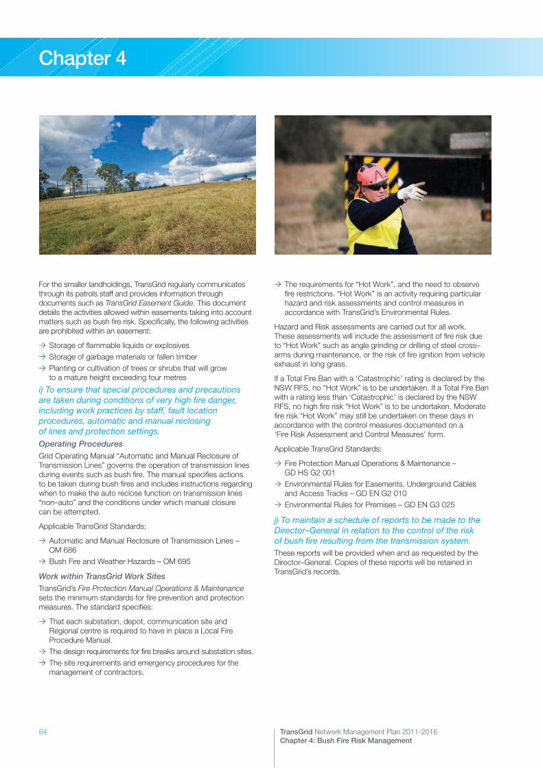
84 TransGrid Network Management Plan 2011-2016Chapter 4: Bush Fire Risk Management
Chapter 4
For the smaller landholdings, TransGrid regularly communicates through its patrols staff and provides information through documents such as TransGrid Easement Guide. This document details the activities allowed within easements taking into account matters such as bush fire risk. Specifically, the following activities are prohibited within an easement:
>> Storage of flammable liquids or explosives>> Storage of garbage materials or fallen timber>> Planting or cultivation of trees or shrubs that will grow to a mature height exceeding four metres
i) To ensure that special procedures and precautions are taken during conditions of very high fire danger, including work practices by staff, fault location procedures, automatic and manual reclosing of lines and protection settings.Operating ProceduresGrid Operating Manual “Automatic and Manual Reclosure of Transmission Lines” governs the operation of transmission lines during events such as bush fire. The manual specifies actions to be taken during bush fires and includes instructions regarding when to make the auto reclose function on transmission lines “non–auto” and the conditions under which manual closure can be attempted.
Applicable TransGrid Standards:
>> Automatic and Manual Reclosure of Transmission Lines – OM 686
>> Bush Fire and Weather Hazards – OM 695
Work within TransGrid Work SitesTransGrid’s Fire Protection Manual Operations & Maintenance sets the minimum standards for fire prevention and protection measures. The standard specifies:
>> That each substation, depot, communication site and Regional centre is required to have in place a Local Fire Procedure Manual.
>> The design requirements for fire breaks around substation sites.>> The site requirements and emergency procedures for the management of contractors.
>> The requirements for “Hot Work”, and the need to observe fire restrictions. “Hot Work” is an activity requiring particular hazard and risk assessments and control measures in accordance with TransGrid’s Environmental Rules.
Hazard and Risk assessments are carried out for all work. These assessments will include the assessment of fire risk due to “Hot Work” such as angle grinding or drilling of steel cross–arms during maintenance, or the risk of fire ignition from vehicle exhaust in long grass.
If a Total Fire Ban with a ‘Catastrophic’ rating is declared by the NSW RFS, no “Hot Work” is to be undertaken. If a Total Fire Ban with a rating less than ‘Catastrophic’ is declared by the NSW RFS, no high fire risk “Hot Work” is to be undertaken. Moderate fire risk “Hot Work” may still be undertaken on these days in accordance with the control measures documented on a ‘Fire Risk Assessment and Control Measures’ form.
Applicable TransGrid Standards:
>> Fire Protection Manual Operations & Maintenance – GD HS G2 001
>> Environmental Rules for Easements, Underground Cables and Access Tracks – GD EN G2 010
>> Environmental Rules for Premises – GD EN G3 025
j) To maintain a schedule of reports to be made to the Director–General in relation to the control of the risk of bush fire resulting from the transmission system.These reports will be provided when and as requested by the Director–General. Copies of these reports will be retained in TransGrid’s records.
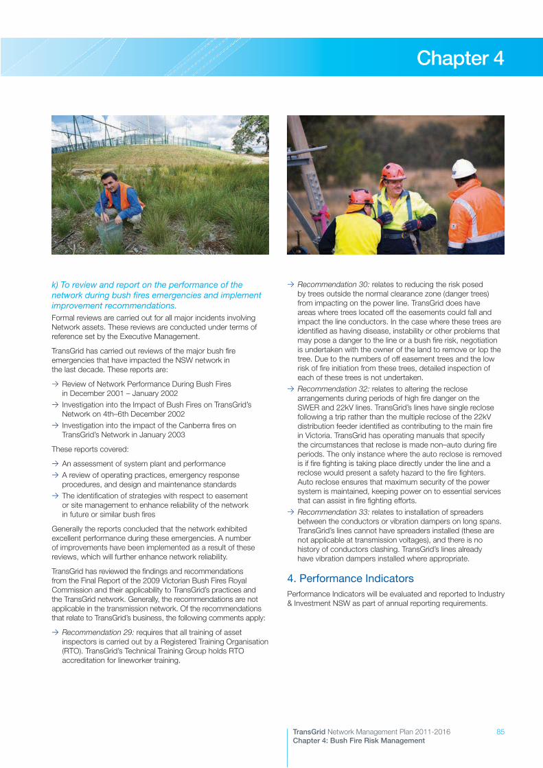
85TransGrid Network Management Plan 2011-2016Chapter 4: Bush Fire Risk Management
Chapter 4
k) To review and report on the performance of the network during bush fires emergencies and implement improvement recommendations.Formal reviews are carried out for all major incidents involving Network assets. These reviews are conducted under terms of reference set by the Executive Management.
TransGrid has carried out reviews of the major bush fire emergencies that have impacted the NSW network in the last decade. These reports are:
>> Review of Network Performance During Bush Fires in December 2001 – January 2002
>> Investigation into the Impact of Bush Fires on TransGrid’s Network on 4th–6th December 2002
>> Investigation into the impact of the Canberra fires on TransGrid’s Network in January 2003
These reports covered:
>> An assessment of system plant and performance>> A review of operating practices, emergency response procedures, and design and maintenance standards
>> The identification of strategies with respect to easement or site management to enhance reliability of the network in future or similar bush fires
Generally the reports concluded that the network exhibited excellent performance during these emergencies. A number of improvements have been implemented as a result of these reviews, which will further enhance network reliability.
TransGrid has reviewed the findings and recommendations from the Final Report of the 2009 Victorian Bush Fires Royal Commission and their applicability to TransGrid’s practices and the TransGrid network. Generally, the recommendations are not applicable in the transmission network. Of the recommendations that relate to TransGrid’s business, the following comments apply:
>> Recommendation 29: requires that all training of asset inspectors is carried out by a Registered Training Organisation (RTO). TransGrid’s Technical Training Group holds RTO accreditation for lineworker training.
>> Recommendation 30: relates to reducing the risk posed by trees outside the normal clearance zone (danger trees) from impacting on the power line. TransGrid does have areas where trees located off the easements could fall and impact the line conductors. In the case where these trees are identified as having disease, instability or other problems that may pose a danger to the line or a bush fire risk, negotiation is undertaken with the owner of the land to remove or lop the tree. Due to the numbers of off easement trees and the low risk of fire initiation from these trees, detailed inspection of each of these trees is not undertaken.
>> Recommendation 32: relates to altering the reclose arrangements during periods of high fire danger on the SWER and 22kV lines. TransGrid’s lines have single reclose following a trip rather than the multiple reclose of the 22kV distribution feeder identified as contributing to the main fire in Victoria. TransGrid has operating manuals that specify the circumstances that reclose is made non–auto during fire periods. The only instance where the auto reclose is removed is if fire fighting is taking place directly under the line and a reclose would present a safety hazard to the fire fighters. Auto reclose ensures that maximum security of the power system is maintained, keeping power on to essential services that can assist in fire fighting efforts.
>> Recommendation 33: relates to installation of spreaders between the conductors or vibration dampers on long spans. TransGrid’s lines cannot have spreaders installed (these are not applicable at transmission voltages), and there is no history of conductors clashing. TransGrid’s lines already have vibration dampers installed where appropriate.
4. Performance IndicatorsPerformance Indicators will be evaluated and reported to Industry & Investment NSW as part of annual reporting requirements.

86
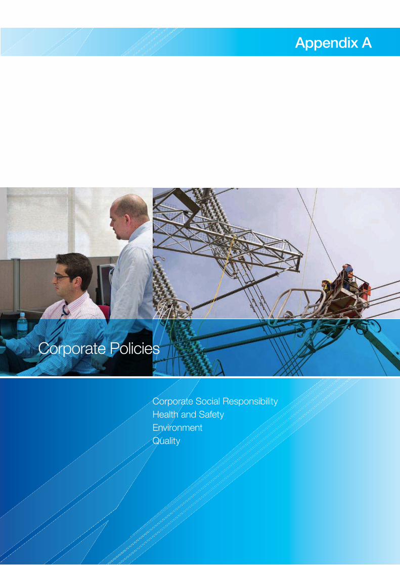
87TransGrid Network Management Plan 2011-2016Chapter X: Chapter Heading
Appendix A
Corporate Social ResponsibilityHealth and SafetyEnvironmentQuality
Corporate Policies

88 TransGrid Network Management Plan 2011-2016Appendix A: Corporate Policies
Appendix A
Corporate Social Responsibility PolicyTransGrid aims to provide a safe and reliable electricity supply. In doing this TransGrid will manage its activities to protect the environment in which it operates, actively participate with customers and other stakeholders to serve them better and provide support for the community. By improving and continuously developing its operations and services, TransGrid can better respond to the expectations of its customers and stakeholders. TransGrid is committed to fulfilling its legislative, organisational and ethical obligations.
In meeting its economic responsibilities TransGrid will:
>> Comply with all relevant legislation and guidelines.>> Ensure that financial and physical resources are applied in the most effective manner to protect and enhance the organisation’s long-term financial and economic viability and commercial success.
>> Conduct business according to the organisation’s Code of Ethics and Conduct.
>> Actively encourage the integration of corporate social responsibility principles into the organisation’s planning and decision making processes.
In meeting its environmental responsibilities TransGrid will:
>> Conduct activities and services in a manner that minimises pollution and complies with relevant environmental legislation, industry standards and codes of practice.
>> Continuously improve the Environmental Management System that provides the framework for setting and reviewing environmental objectives and targets.
>> Provide environmental training, assessment and authorisation under the Environmental Rules to employees and contractors to enable them to perform their duties in an environmentally sensitive manner.
>> Support research which aims to reduce environmental impacts of the organisation.
In meeting its social responsibilities TransGrid will:
>> Ensure efficient, safe and reliable operation of the network to minimise risks, resulting in the provision of a safe and reliable electricity supply.
>> Communicate effectively and actively engage customers and other stakeholders to better respond to their needs and expectations.
>> Continually develop occupational health and safety and promote employee wellbeing to enhance business performance.
>> Develop employees in line with business needs by promoting continuous development and training.
Health and Safety PolicyOur goal is zero injuries and occupational illnesses. We believe that all accidents are preventable on and off the job.
>> Safety is our first priority>> We will not budget for injuries>> Working safely is a condition of employment>> No shortcuts when it comes to safety>> Managers and team leaders demonstrate leadership in health and safety
>> Our people and contractors/agency employees take ownership of safety by not accepting unsafe behaviour from anyone
In order to achieve these principles, TransGrid will:
>> Ensure that managers, team leaders and employees understand their health and safety responsibilities.
>> Provide a safe and healthy work place for our people.>> Consider contractor and agency employee’s health and safety as important as that of our employees.
>> Identify, assess and eliminate or control health and safety risks prior to commencing all activities and projects.
>> Apply standards that meet or exceed relevant health and safety and worker’s compensation legislation, regulations and codes of practice.
>> Provide relevant information and instruction so our people, contractor and agency employees and visitors can safely perform their work.
>> Make health and safety part of all business decisions.>> Continually improve our health and safety performance through regular monitoring and review of the Health and Safety Management System – GD HS G2 020 and by establishing performance measures.
>> Lead, train and motivate our people to work in a safe and responsible manner.
>> Implement this policy through developing and communicating an annual health and safety plan with measurable objectives and actions with the aim to reduce the risk of injury or illness .
>> Communicate openly with our people on health and safety matters.
>> Consult and seek contributions from our people on issues that have the potential to affect their health and safety.
>> Consult any workplace change that may affect our people, contractor and agency employee’s health and safety.
>> Encourage personal responsibility for health and safety behaviour.
TransGrid’s Board and Managing Director are ultimately accountable and responsible for the health and safety of employees, visitors, contractors/agency employees and the public, and for ensuring compliance to all relevant OHS legislation. The Managing Director approves all health and safety policies and the annual Corporate Health and Safety Plan.

89TransGrid Network Management Plan 2011-2016Appendix A: Corporate Policies
Appendix A
Managers and Team Leaders are responsible and accountable for:
>> Ensuring, so far as is reasonably practicable, that their staff work without risk to their health or safety.
>> Complying with health and safety responsibilities outlined in work procedures.
>> Ensuring, as far as is reasonably practicable, that all work procedures, systems and the working environment are safe and without risk to health.
>> Implementing the Health and Safety Management System across their area of responsibility.
>> Providing adequate resources to effectively meet TransGrid’s health and safety commitment.
>> Providing information, training and supervision to allow employees and contractors/labour hire are able to carry out their work safely.
>> Implementing relevant actions from their business unit Health and Safety Plan to meet agreed performance targets.
>> Training their staff so that they can develop and successfully maintain healthy and safe working conditions and systems.
>> Taking steps to control hazards as they are reported.>> Investigating incidents and implementing corrective actions that address the root causes of the incident.
People working for TransGrid at all levels are responsible for:
>> Following occupational health and safety policies and procedures and avoiding “at risk” behaviour in all activities.
>> Complying with health and safety responsibilities outlined in work procedures.
>> Practising safe and healthy work methods and behaviours.>> Using all appropriate plant, equipment, tools, materials and personal protective equipment correctly.
>> Taking steps to fix, where safe to do so, and then report any hazards that are identified at work.
>> Reporting all injuries, illness, and near misses, no matter how minor to their Manager or Team Leader as soon as is reasonably practical.
In addition to these responsibilities, contractors, agency employees and people supplying services to TransGrid are required to know and comply with TransGrid’s Health and Safety policy by:
>> Adhering to any health and safety requirements specified by TransGrid.
>> Conforming to and enforcing all legislation, standards and codes of practice and licensing that apply to work places under their control.
The Health and Safety Committees will be supported by TransGrid people at all levels, and are responsible for:
>> Assisting in the identification of workplace risks and making recommendations on safe systems of work.
>> Reviewing the corrective measures taken to ensure health and safety of TransGrid’s people.
>> Assisting Management to investigate any matter that may be a risk to health and safety at the place of work.
>> Facilitating resolution of the matter but, if unable to do so, to request Management to initiate an investigation.
The Executive Health and Safety Committee are responsible for:
>> Ensuring the establishment of continuous improvement of occupational health and safety systems, practices and procedures.
>> Monitoring, reviewing and, where necessary, amending corporate health and safety objectives and performance measures.
>> Monitoring changes in health and safety legislation and ensuring relevant changes are included in the health and safety management system.
>> Ensuring the effective implementation of occupational health and safety risk management strategies.
>> Monitoring industry trends and co-ordinating participation in industry committees and working groups.
>> Promoting initiatives for the improvement of employee health and safety.
>> Facilitating the open sharing of health and safety information.>> Reviewing incident investigations, recommendations and statistics.
>> Reviewing health and safety audits and monitoring progress on action plans.
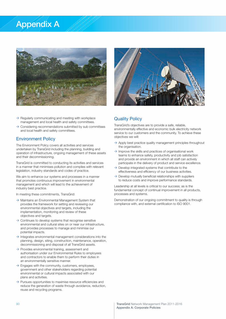
90 TransGrid Network Management Plan 2011-2016Appendix A: Corporate Policies
Appendix A
>> Regularly communicating and meeting with workplace management and local health and safety committees.
>> Considering recommendations submitted by sub committees and local health and safety committees.
Environment PolicyThe Environment Policy covers all activities and services undertaken by TransGrid including the planning, building and operation of infrastructure, ongoing management of these assets and their decommissioning.
TransGrid is committed to conducting its activities and services in a manner that minimises pollution and complies with relevant legislation, industry standards and codes of practice.
We aim to enhance our systems and processes in a manner that promotes continuous improvement in environmental management and which will lead to the achievement of industry best practice.
In meeting these commitments, TransGrid:
>> Maintains an Environmental Management System that provides the framework for setting and reviewing our environmental objectives and targets, including the implementation, monitoring and review of these objectives and targets.
>> Continues to develop systems that recognise sensitive environmental and cultural sites on or near our infrastructure, and provides processes to manage and minimise our potential impacts.
>> Integrates environmental management considerations into the planning, design, siting, construction, maintenance, operation, decommissioning and disposal of all TransGrid assets.
>> Provides environmental training, assessment and authorisation under our Environmental Rules to employees and contractors to enable them to perform their duties in an environmentally sensitive manner.
>> Engages with the community, customers, employees, government and other stakeholders regarding potential environmental or cultural impacts associated with our plans and activities.
>> Pursues opportunities to maximise resource efficiencies and reduce the generation of waste through avoidance, reduction, reuse and recycling programs.
Quality PolicyTransGrid’s objectives are to provide a safe, reliable, environmentally effective and economic bulk electricity network service to our customers and the community. To achieve these objectives we will:
>> Apply best practice quality management principles throughout the organisation.
>> Improve the skills and practices of organisational work teams to enhance safety, productivity and job satisfaction and provide an environment in which all staff can actively participate in the delivery of product and service excellence.
>> Develop integrated systems that contribute to the effectiveness and efficiency of our business activities.
>> Develop mutually beneficial relationships with suppliers to reduce costs and improve performance standards.
Leadership at all levels is critical to our success; as is the fundamental concept of continual improvement in all products, processes and systems.
Demonstration of our ongoing commitment to quality is through compliance with, and external certification to ISO 9001.
91TransGrid Network Management Plan 2011-2016Chapter X: Chapter Heading
Appendix B
Schedule of Substations and Switching StationsTransGrid System TransformersCircuit BreakersTransmission Lines and Underground Cables
Asset Inventory

92 TransGrid Network Management Plan 2011-2016Appendix B: Asset Inventory
Appendix B
Schedule of Substations and Switching Stations
500kV SITES Comm Year System Voltage (kV) 220kV SITES Comm Year System Voltage (kV)
Bannaby 2010 500/330 Balranald 2001 220/22
Bayswater 2009 500/330 Broken Hill 1979 220/22
1984 330 Buronga 1988 220
Eraring 1984 500/330
Mount Piper 500 2009 500/330
1986 330/132
Kemps Creek 1984 500/330
1989 330/16
Wollar 2009 500/330
Total Sites at 500kV = 6 Total Sites at 220kV = 3
330kV SITES Comm Year System Voltage (kV) 132kV SITES Comm Year System Voltage (kV)
Armidale 1972 330/132 Albury 1958 132
1969 132/66 A.N.M. 1981 132
Avon 1974 330 Beryl 1976 132/66
Beaconsfield West 1979 330/132 Boambee South 2010 132
Canberra 1967 330/132 Burrinjuck 1950 132
Capital Wind Farm 2009 330 Coleambally 1993 132
Coffs Harbour 2006 330/132 Cooma 1954 132/66/11
1979 132/66 Cowra 1960 132/66
Dapto 1962 330/132 Deniliquin 1971 132/66
Darlington Point 1988 330/220 Finley 1991 132/66
330/132 Forbes 1969 132/66
Dumaresq 2000 330 Gadara 2000 132/11
Haymarket 2004 330/132 Glen Innes 2007 132/66
Ingleburn 1984 330/66 Griffith 1964 132/33
Jindera 1979 330/132 Gunnedah 1985 132/66
Kangaroo Valley 1976 330 Guthega 1970 132
Liddell 1970 330 Hume 1957 132
Lismore 1992 330/132 Inverell 1984 132/66
Liverpool 1985 330/132 Kempsey 1967 132/33
Lower Tumut 1972 330 66/33
Macarthur 2009 330/132 Koolkhan 1963 132/66
330/66 Macksville 2010 132
Marulan 1992 330/132 Molong 2001 132/66
Munmorah 1967 330/132 Moree 1984 132/66
Murray 1967 330/132 Mount Piper 132 1988 132/66
Muswellbrook 1983 330/132 Munyang 1989 132/33
Newcastle 1969 330/132 Murrumburrah 1985 132/66
Regentville 1997 330/132 Nambucca 2001 132/66

93TransGrid Network Management Plan 2011-2016Appendix B: Asset Inventory
Appendix B
330kV SITES Comm Year System Voltage (kV) 132kV SITES Comm Year System Voltage (kV)
Sydney East 1976 330/132 Narrabri 1965 132/66
Sydney North 1963 330/132 Orange 1954 132/66
Sydney South 1961 330/132 Panorama 1979 132/66
Sydney West 1965 330/132 Parkes 1993 132/66
Tamworth 330 1968 330/132 Port Macquarie 1979 132/33
Tomago 1983 330/132 Queanbeyan 2010 132/66
Tuggerah 1986 330/132 Raleigh 2009 132
Upper Tumut 1969 330 Tamworth 132 1961 132/66
Vales Point 1962 330/132 Taree 1958 132/66/33
Vineyard 1994 330/132 Tenterfield 1970 132/22
Wagga 330 1973 330/132 Tumut 1967 132/66
Wallerawang 330 1975 330/132 Uranquinty 2007 132
Waratah West 1992 330/132 Wagga 132 1955 132/66
Wellington 1984 330/132 Wagga North 2009 132/66
Yass 2006 330/132 Wallerawang 132 1953 132/66
1965 132/66 Yanco 1969 132/33
Total Sites at 330kV = 39 Total Sites at 132kV = 43
Total Sites at all voltages = 91
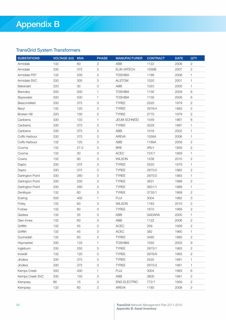
94 TransGrid Network Management Plan 2011-2016Appendix B: Asset Inventory
Appendix B
TransGrid System Transformers
SUBSTATIONS VOLTAGE (kV) MVA PHASE MANUFACTURER CONTRACT DATE QTY
Armidale 132 60 3 ABB 1122 2006 2
Armidale 330 375 3 ELIN VATECH 1056B 2007 2
Armidale PST 132 200 3 TOSHIBA 1199 2008 1
Armidale SVC 330 305 3 ALSTOM 1020 2001 1
Balranald 220 30 3 ABB 1023 2000 1
Bannaby 500 500 1 TOSHIBA 1156 2009 6
Bayswater 500 500 1 TOSHIBA 1156 2009 6
Beaconsfield 330 375 3 TYREE 2520 1979 2
Beryl 132 120 3 TYREE 2976/4 1983 2
Broken Hill 220 100 3 TYREE 2770 1979 2
Canberra 330 133 1 JEUM SCHNEID 1549 1967 6
Canberra 330 375 3 TYREE 3529 1987 1
Canberra 330 375 3 ABB 1016 2002 1
Coffs Harbour 330 375 3 AREVA 1056A 2006 1
Coffs Harbour 132 120 3 ABB 1189A 2009 2
Cooma 132 27.5 3 BRE XRLY 1959 2
Cooma 132 30 3 ACEC 724/1 1959 1
Cowra 132 60 3 WILSON 1238 2010 2
Dapto 330 375 3 TYREE 2520 1979 1
Dapto 330 375 3 TYREE 2875/2 1982 2
Darlington Point 330 280 3 TYREE 2875/2 1983 1
Darlington Point 330 200 3 TYREE 3631 1988 2
Darlington Point 330 280 3 TYREE 3631/1 1988 1
Deniliquin 132 60 3 TYREE 3735/1 1989 2
Eraring 500 400 1 FUJI 3004 1982 3
Finley 132 60 3 WILSON 1183 2010 2
Forbes 132 60 3 TYREE 1670 1969 2
Gadara 132 35 3 ABB GADARA 2000 1
Glen Innes 132 60 3 ABB 1122 2006 2
Griffith 132 45 3 ACEC 209 1956 2
Griffith 132 45 3 ACEC 382 1960 1
Gunnedah 132 60 3 TYREE 3485 1985 2
Haymarket 330 133 1 TOSHIBA 1050 2003 9
Ingleburn 330 250 3 TYREE 2875/1 1983 2
Inverell 132 120 3 TYREE 2976/6 1983 2
Jindera 330 375 3 TYREE 2520 1981 1
Jindera 330 375 3 TYREE 2875/2 1981 1
Kemps Creek 500 400 1 FUJI 3004 1983 6
Kemps Creek SVC 330 150 3 ABB 3800 1991 2
Kempsey 66 15 3 ENG ELECTRIC 772/1 1959 2
Kempsey 132 60 3 AREVA 1185 2008 2

95TransGrid Network Management Plan 2011-2016Appendix B: Asset Inventory
Appendix B
SUBSTATIONS VOLTAGE (kV) MVA PHASE MANUFACTURER CONTRACT DATE QTY
Koolkhan 132 60 3 TYREE 3485 1984 1
Koolkhan 132 60 3 WILSON 1041C 2003 1
Koolkhan 132 60 3 WILSON 1225 2010 1
Lismore 330 375 3 ABB 4005/1A 1992 2
Lismore SVC 132 180 3 ABB 1014 2000 1
Liverpool 330 375 3 TYREE 3529 1985 2
Liverpool 330 375 3 ALSTOM 1056A 2004 1
Macarthur 330 250 3 AREVA 1120B 2008 1
Macarthur 330 375 3 AREVA 1120B 2009 1
Marulan 330 160 3 HITACHI 974 1962 1
Molong 132 30 3 ENG ELECTRIC 724/2 1970 1
Moree 132 60 3 TYREE 2976/2 1983 2
Mount Piper 132 120 3 TYREE 2976/7 1984 2
Mount Piper 330 375 3 TYREE 3631/1 1989 1
Mount Piper 500 500 1 TOSHIBA 1156 2009 6
Munmorah 330 375 3 ABB 1016 2000 1
Munyang 132 30 3 ACEC 60/2 1955 2
Murray 330 40 3 AEG 81/23415 1967 2
Murrumburrah 132 60 3 TYREE 3485 1984 1
Murrumburrah 132 60 3 WILSON 1041C 2002 1
Muswellbrook 330 375 3 TYREE 2875/2 1983 2
Nambucca 132 60 3 ABB 1041B 2001 1
Nambucca 132 60 3 AREVA 1185 2009 1
Narrabri 132 30 3 ELIN E60 1955 1
Narrabri 132 30 3 AEI 1393A 1965 2
Newcastle 330 133 1 MITSUBISHI 1712 1969 8
Newcastle 330 150 1 ASEA 1999/1 1972 1
Newcastle 330 375 3 AREVA 1056A 2005 1
Orange 132 60 3 AREVA 1226 2009 1
Orange 132 60 3 WILSON 1225 2010 1
Panorama 132 120 3 TYREE 2976/3 1981 2
Parkes 132 60 3 ABB 3999/2 1993 1
Parkes 132 60 3 AREVA 1182 2008 1
Port Macquarie 132 60 3 ABB 1122 2006 2
Port Macquarie 132 60 3 ABB 1180 2007 1
Queanbeyan 132 120 3 WILSON 1189B 2010 2
Regentville 330 375 3 TYREE 2875/2 1984 1
Regentville 330 375 3 ABB 4005 1994 1
Sydney East 330 133 1 TYREE 2231 1974 9
Sydney North 330 375 3 TYREE 2875/2 1981 3
Sydney North 330 375 3 TYREE 2875/2 1982 1
Sydney South 330 375 3 ALSTOM 1056A 2003 2

96 TransGrid Network Management Plan 2011-2016Appendix B: Asset Inventory
Appendix B
SUBSTATIONS VOLTAGE (kV) MVA PHASE MANUFACTURER CONTRACT DATE QTY
Sydney South 330 375 3 AREVA/ALSTOM 1056A 2004 1
Sydney South 330 375 3 AREVA 1120B 2008 1
Sydney South 330 375 3 SIEMENS 1120A 2008 1
Sydney West 330 375 3 ABB 1016 2000 1
Sydney West 330 375 3 ELIN 1056B 2005 1
Sydney West 330 375 3 ELIN VATECH 1056B 2006 1
Sydney West 330 375 3 AREVA 1120B 2007 1
Sydney West 330 375 3 ELIN VATECH 1056B 2007 1
Sydney West SVC 330 294 3 ABB 1065 2004 1
Tamworth 330 150 3 PARSON PEEBLE 1517/2 1968 2
Tamworth 330 150 3 ABB 1016 2000 1
Tamworth 132 60 3 TYREE 1670 1969 2
Tamworth 132 60 3 TYREE 2105 1971 1
Taree 132 60 3 TYREE 3666/1 1988 2
Taree 132 60 3 WILSON 1100 2004 2
Tenterfield 132 15 3 ENG ELECTRIC 1849 1970 2
Tuggerah 330 375 3 AREVA 1120B 2009 2
Tumut 132 60 3 TYREE 3485 1985 1
Tumut 132 60 3 WILSON 1041A 2001 1
Vales Point 330 200 3 ABB 4381 1995 1
Vales Point 330 200 3 ABB 1016 2001 1
Vineyard 330 375 3 AREVA/ALSTOM 1056A 2004 1
Vineyard 330 375 3 ELIN 1056B 2005 1
Wagga 132 60 3 TYREE 1670 1968 1
Wagga 132 60 3 TYREE 2105 1975 1
Wagga 132 60 3 TYREE 3735 1991 1
Wagga 330 375 3 AREVA 1120B 2009 2
Wagga North 132 60 3 AREVA 1226 2009 1
Wallerawang 132 60 3 GEC 2179 1971 2
Wallerawang 330 215 3 PARSONS 2091/1 1974 1
Wallerawang 330 200 3 ABB 1016 2000 1
Waratah West 330 375 3 ELIN VATECH 1056B/1 2004 1
Waratah West 330 375 3 TOSHIBA 1229 2010 1
Wellington 330 375 3 AREVA 1056A 2006 1
Wellington 330 375 3 ELIN VATECH 1056B 2006 1
Wollar 500 500 1 TOSHIBA 1156 2009 3
Yanco 132 45 3 ACEC 382 1960 1
Yanco 132 45 3 HACKBRIDGE 1419/1 1969 1
Yass 132 30 3 ELIN 262-1/23 1962 1
Yass 330 200 3 ABB 4381 1995 1
Yass 330 200 3 ELIN VATECH 1056B 2003 1
Total 219
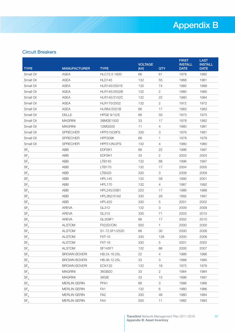
97TransGrid Network Management Plan 2011-2016Appendix B: Asset Inventory
Appendix B
Circuit Breakers
TYPE MANUFACTURER TYPEVOLTAGE (kV) QTY
FIRST INSTALL DATE
LAST INSTALL DATE
Small Oil ASEA HLC72.5 1600 66 61 1978 1982
Small Oil ASEA HLD145 132 55 1968 1981
Small Oil ASEA HLR145/2501E 132 74 1980 1989
Small Oil ASEA HLR145/2502B 132 2 1980 1980
Small Oil ASEA HLR145/3152C 132 22 1980 1984
Small Oil ASEA HLR170/2502 132 2 1972 1972
Small Oil ASEA HLR84/2501B 66 17 1983 1983
Small Oil DELLE HPGE 9/12/E 66 50 1973 1975
Small Oil MAGRINI 38MGE1500 33 17 1978 1982
Small Oil MAGRINI 12MG500 11 4 1980 1981
Small Oil SPRECHER HPF515C6FS 330 3 1976 1981
Small Oil SPRECHER HPF509K 66 1 1978 1978
Small Oil SPRECHER HPF512N/2FS 132 4 1980 1980
SF6 ABB EDFSK1 66 22 1996 1997
SF6 ABB EDFSK1 33 2 2003 2003
SF6 ABB LTB145 132 68 1996 1997
SF6 ABB LTB170 132 17 2004 2005
SF6 ABB LTB420 330 3 2009 2009
SF6 ABB HPL145 132 58 1990 2001
SF6 ABB HPL170 132 4 1987 1992
SF6 ABB HPL245/25B1 220 17 1986 1988
SF6 ABB HPL362/31A2 330 29 1992 1997
SF6 ABB HPL420 330 5 2001 2002
SF6 AREVA GL312 132 3 2009 2009
SF6 AREVA GL315 330 71 2003 2010
SF6 AREVA GL309F1 66 17 2002 2010
SF6 ALSTOM FX22D/CIN 500 1 2000 2000
SF6 ALSTOM S1-72.5F1/2520 66 30 2000 2008
SF6 ALSTOM FXT-15 330 128 2000 2008
SF6 ALSTOM FXT-16 330 5 2001 2002
SF6 ALSTOM SF145F1 132 86 2000 2007
SF6 BROWN BOVERI HB.24.16.25L 22 4 1986 1986
SF6 BROWN BOVERI HB.36.12.25L 33 3 1988 1990
SF6 BROWN BOVERI ECK132 132 18 1975 1978
SF6 MAGRINI 36GB20 33 2 1984 1984
SF6 MAGRINI 36GIE 33 15 1996 1997
SF6 MERLIN GERIN PFA1 66 3 1986 1986
SF6 MERLIN GERIN FA1 132 6 1980 1986
SF6 MERLIN GERIN FA2 330 48 1980 1984
SF6 MERLIN GERIN FA4 500 11 1982 1983
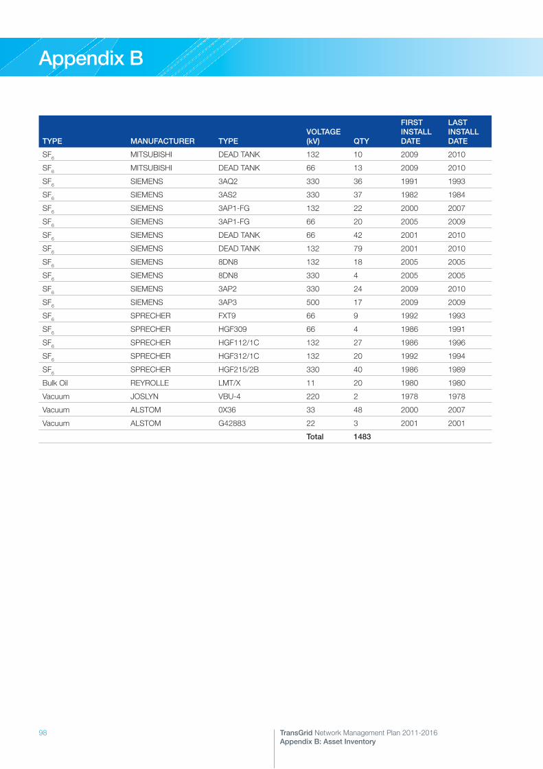
98 TransGrid Network Management Plan 2011-2016Appendix B: Asset Inventory
Appendix B
TYPE MANUFACTURER TYPEVOLTAGE (kV) QTY
FIRST INSTALL DATE
LAST INSTALL DATE
SF6 MITSUBISHI DEAD TANK 132 10 2009 2010
SF6 MITSUBISHI DEAD TANK 66 13 2009 2010
SF6 SIEMENS 3AQ2 330 36 1991 1993
SF6 SIEMENS 3AS2 330 37 1982 1984
SF6 SIEMENS 3AP1-FG 132 22 2000 2007
SF6 SIEMENS 3AP1-FG 66 20 2005 2009
SF6 SIEMENS DEAD TANK 66 42 2001 2010
SF6 SIEMENS DEAD TANK 132 79 2001 2010
SF6 SIEMENS 8DN8 132 18 2005 2005
SF6 SIEMENS 8DN8 330 4 2005 2005
SF6 SIEMENS 3AP2 330 24 2009 2010
SF6 SIEMENS 3AP3 500 17 2009 2009
SF6 SPRECHER FXT9 66 9 1992 1993
SF6 SPRECHER HGF309 66 4 1986 1991
SF6 SPRECHER HGF112/1C 132 27 1986 1996
SF6 SPRECHER HGF312/1C 132 20 1992 1994
SF6 SPRECHER HGF215/2B 330 40 1986 1989
Bulk Oil REYROLLE LMT/X 11 20 1980 1980
Vacuum JOSLYN VBU-4 220 2 1978 1978
Vacuum ALSTOM 0X36 33 48 2000 2007
Vacuum ALSTOM G42883 22 3 2001 2001
Total 1483

99TransGrid Network Management Plan 2011-2016Appendix B: Asset Inventory
Appendix B
Transmission Lines and Underground Cables
CIRCUIT NO. FROM (SITE 1) TO (SITE 2) LENGTH (km) PREDOMINANT CONSTRUCTION
ASSETS CONSTRUCTED AT RATED VOLTAGE: 500kV In service at 500kV
5A1 Eraring Kemps Creek 143.3 Double Circuit Steel Tower
5A1/1 Eraring Field Terminated 2.5 Double Circuit Steel Tower
5A2 Eraring Kemps Creek 143.3 Double Circuit Steel Tower
5A2/1 Eraring Field Terminated 2.5 Double Circuit Steel Tower
5A3 Bayswater Mount Piper 224.4 Double Circuit Steel Tower
5A4 Bayswater Wollar 111.8 Double Circuit Steel Tower
5A5 Wollar Mount Piper 112.6 Double Circuit Steel Tower
5A6 Mount Piper Bannaby 141.3 Double Circuit Steel Tower
5A7 Mount Piper Bannaby 141.3 Double Circuit Steel Tower
ASSETS CONSTRUCTED AT RATED VOLTAGE: 500kV In service at 330kV
35 Bannaby Marulan 19.7 Double Circuit Steel Tower
36 Bannaby Marulan 19.7 Double Circuit Steel Tower
ASSETS CONSTRUCTED AT RATED VOLTAGE: 330kV In service at 330kV
01 Canberra Upper Tumut 99.9 Single Circuit Steel Tower
2 Upper Tumut Yass 148.9 Single Circuit Steel Tower
3 Lower Tumut Yass 128.9 Single Circuit Steel Tower
4 Marulan Yass 113.8 Single Circuit Steel Tower
5 Marulan Yass 118.1 Single Circuit Steel Tower
6 Canberra Capital Wind Farm 59.9 Single Circuit Steel Tower
07 Canberra Lower Tumut 98.8 Single Circuit Steel Tower
8 Dapto Marulan 70.8 Single Circuit Steel Tower
9 Canberra Yass 42.2 Single Circuit Steel Tower
10 Dapto Avon 10.9 Single Circuit Steel Tower
11 Dapto Sydney South 68.0 Single Circuit Steel Tower
12 Liverpool Sydney South 18.3 Double Circuit Steel Pole
13 Kemps Creek Sydney South 24.1 Single Circuit Steel Tower
14 Kemps Creek Sydney North 49.8 Single Circuit Steel Tower
16 Avon Marulan 70.6 Single Circuit Steel Tower
17 Avon Macarthur 41.1 Single Circuit Steel Tower
18 Dapto Kangaroo Valley 42.7 Single Circuit Steel Tower
20 Sydney North Sydney West 33.2 Single Circuit Steel Tower
21 Tuggerah Sydney North 64.4 Single Circuit Steel Tower
22 Sydney North Vales Point 86.1 Single Circuit Steel Tower
23 Munmorah Vales Point 7.2 Single Circuit Steel Tower
24 Vales Point Eraring 25.2 Single Circuit Steel Tower
25 Eraring Vineyard 109.4 Double Circuit Steel Tower
26 Munmorah Sydney West 124.1 Double Circuit Steel Tower

100 TransGrid Network Management Plan 2011-2016Appendix B: Asset Inventory
Appendix B
CIRCUIT NO. FROM (SITE 1) TO (SITE 2) LENGTH (km) PREDOMINANT CONSTRUCTION
27 Sydney North Sydney East 21.9 Single Circuit Steel Tower
28 Sydney North Sydney East 22.3 Single Circuit Steel Tower
29 Vineyard Sydney West 20.7 Double Circuit Steel Tower
2M Munmorah Tuggerah 39.8 Single Circuit Steel Tower
30 Liverpool Sydney West 16.6 Single Circuit Steel Tower
31 Bayswater Regentville 171.0 Double Circuit Steel Tower
32 Bayswater Sydney West 188.5 Double Circuit Steel Tower
33 Bayswater Liddell 6.0 Double Circuit Steel Tower
34 Bayswater Liddell 6.0 Double Circuit Steel Tower
35 Bannaby Marulan 0.6 Double Circuit Steel Tower
36 Bannaby Marulan 0.6 Double Circuit Steel Tower
37 Macarthur Kemps Creek 23.2 Single Circuit Steel Tower
38 Regentville Sydney West 17.5 Double Circuit Steel Tower
39 Bannaby Sydney West 114.1 Single Circuit Steel Tower
3W Capital Wind Farm Kangaroo Valley 129.0 Single Circuit Steel Tower
41 Sydney South Beaconsfield West 19.7 Underground Cable
42 Sydney South Haymarket 27.5 Underground Cable
051 Lower Tumut Wagga 100.3 Single Circuit Steel Tower
060 Jindera Wodonga 42.4 Single Circuit Steel Tower
61 Yass Bannaby 124.2 Single Circuit Steel Tower
62 Jindera Wagga 99.6 Single Circuit Steel Tower
63 Wagga Darlington Point 151.7 Single Circuit Steel Tower
64 Lower Tumut Upper Tumut 40.6 Single Circuit Steel Tower
65 Murray Upper Tumut 45.5 Single Circuit Steel Tower
66 Lower Tumut Murray 73.0 Single Circuit Steel Tower
70 Mount Piper Wallerawang 7.9 Double Circuit Steel Tower
71 Mount Piper Wallerawang 7.9 Double Circuit Steel Tower
72 Mount Piper Wellington 171.0 Single Circuit Steel Tower
76 Wallerawang Sydney South 142.8 Double Circuit Steel Tower
77 Wallerawang Ingleburn 121.4 Double Circuit Steel Tower
78 Ingleburn Sydney South 21.1 Double Circuit Steel Tower
79 Wollar Wellington 117.1 Single Circuit Steel Tower
81 Liddell Newcastle 100.8 Single Circuit Steel Tower
82 Liddell Tomago 114.9 Single Circuit Steel Tower
83 Liddell Muswellbrook 17.7 Single Circuit Steel Tower
84 Liddell Tamworth 330 139.5 Single Circuit Steel Tower
85 Tamworth 330 Armidale 103.7 Single Circuit Steel Tower
86 Tamworth 330 Armidale 110.9 Single Circuit Wood Pole
87 Armidale Coffs Harbour 137.0 Single Circuit Steel Tower
88 Muswellbrook Tamworth 330 126.9 Single Circuit Steel Tower
89 Coffs Harbour Lismore 174.3 Single Circuit Steel Tower
8C Armidale Dumaresq 172.0 Double Circuit Steel Tower

101TransGrid Network Management Plan 2011-2016Appendix B: Asset Inventory
Appendix B
CIRCUIT NO. FROM (SITE 1) TO (SITE 2) LENGTH (km) PREDOMINANT CONSTRUCTION
8E Armidale Dumaresq 172.0 Double Circuit Steel Tower
8L Dumaresq Bulli Creek 49.3 Double Circuit Steel Tower
8M Dumaresq Bulli Creek 49.3 Double Circuit Steel Tower
90 Eraring Newcastle 21.2 Single Circuit Steel Tower
92 Newcastle Vales Point 35.9 Double Circuit Steel Tower
93 Eraring Newcastle 20.7 Double Circuit Steel Tower
94 Newcastle Tomago 24.3 Double Circuit Steel Tower
95 Newcastle Tomago 25.4 Double Circuit Steel Tower
96 Newcastle Waratah West 17.8 Double Circuit Steel Tower
9W Tomago Waratah West 8.8 Single Circuit Steel Tower
L1 Lower Tumut Tumut 3 0.6 Single Circuit Steel Tower
L3 Lower Tumut Tumut 3 0.6 Single Circuit Steel Tower
L5 Lower Tumut Tumut 3 0.5 Single Circuit Steel Tower
M1 Murray Murray 1 4.7 Single Circuit Steel Tower
M3 Murray Murray 1 4.7 Single Circuit Steel Tower
M5 Murray Murray 1 4.8 Single Circuit Steel Tower
M7 Murray Murray 1 4.8 Single Circuit Steel Tower
M9 Murray Murray 1 4.8 Single Circuit Steel Tower
M11 Murray Murray 2 2.2 Single Circuit Steel Tower
M13 Murray Murray 2 2.0 Single Circuit Steel Tower
U1 Upper Tumut Tumut 1 5.2 Single Circuit Steel Tower
U3 Upper Tumut Tumut 1 4.9 Single Circuit Steel Tower
U5 Upper Tumut Tumut 2 3.6 Single Circuit Steel Tower
U7 Upper Tumut Tumut 2 3.8 Single Circuit Steel Tower
ASSETS CONSTRUCTED AT RATED VOLTAGE: 330kV In service at 132kV
219 Mamre Zone Mount Druitt 5.9 Double Circuit Steel Tower
250 Mount Colah Sydney North 8.2 Double Circuit Steel Tower
92Z (1) Mount Colah Sydney East 12.6 Double Circuit Steel Tower
92Z (2) Mount Colah Sydney North 10.5 Double Circuit Steel Tower
932 Mount Druitt Sydney West 5.9 Double Circuit Steel Tower
947 Orange Tee Mount Piper 132 23.8 Double Circuit Steel Tower
959 Sydney East Sydney North 23.1 Double Circuit Steel Tower
968 Narrabri Tamworth 330 3.7 Double Circuit Steel Tower
978 Canberra Williamsdale 48.5 Double Circuit Steel Tower
97D Canberra Williamsdale 48.5 Double Circuit Steel Tower
ASSETS CONSTRUCTED AT RATED VOLTAGE: 220kV In service at 220kV
0X1 Buronga Red Cliffs 23.9 Single Circuit Steel Tower
X2 Buronga Broken Hill 259.5 Single Circuit Steel Tower
X5/1 Darlington Point Balranald 249.8 Single Circuit Steel Tower
X5/3 Balranald Buronga 148.0 Single Circuit Steel Tower

102 TransGrid Network Management Plan 2011-2016Appendix B: Asset Inventory
Appendix B
CIRCUIT NO. FROM (SITE 1) TO (SITE 2) LENGTH (km) PREDOMINANT CONSTRUCTION
ASSETS CONSTRUCTED AT RATED VOLTAGE: 132kV In service at 132kV
097B Blowering Tumut 132 13.3 Single Circuit Wood Pole
219 Mamre Zone Mount Druitt 2.4 Double Circuit Steel Tower
250 Sydney North Mount Colah 0.4 Double Circuit Steel Tower
92Z (2) Sydney North Mount Colah 0.6 Single Circuit Wood Pole
932 Sydney West Mount Druitt 1.4 Double Circuit Steel Tower
939 Sydney West Mamre Zone 3.0 Double Circuit Steel Tower
944 Wallerawang Orange 98.3 Single Circuit Wood Pole
945/1 Molong 945 Tee 60.2 Single Circuit Concrete Pole
945/2 945 Tee Wellington 330 6.2 Single Circuit Concrete Pole
947 Mount Piper 132 Orange Tee 68.9 Single Circuit Wood Pole
947/2 Burrendong Tee Wellington 330 19.0 Single Circuit Wood Pole
947/3 Orange Tee Burrendong Tee 67.8 Single Circuit Wood Pole
947/4 Orange Tee Orange 1.7 Double Circuit Concrete Pole
948 Orange Panorama 44.8 Single Circuit Wood Pole
94B Beryl Wellington 330 52.2 Single Circuit Wood Pole
94E Mount Piper 132 Wallerawang 132 9.0 Single Circuit Wood Pole
94K Parkes 132 Wellington 330 116.7 Single Circuit Wood Pole
94M Mudgee Tee Beryl 29.6 Single Circuit Wood Pole
94M/1 Ilford Tee Mudgee Tee 52.2 Single Circuit Wood Pole
94M/2 Mount Piper 132 Ilford Tee 42.7 Single Circuit Wood Pole
94P Molong Manildra 26.6 Single Circuit Concrete Pole
94T Orange Molong 29.9 Single Circuit Concrete Pole
94U Forbes Parkes 30.3 Single Circuit Wood Pole
94X Panorama Wallerawang 132 57.5 Single Circuit Wood Pole
94Y Mount Piper Mount Piper 132 1.8 Single Circuit Wood Pole
959 Sydney North Sydney East 0.6 Double Circuit Steel Tower
95N Newcastle Field Terminated 0.5 Single Circuit Wood Pole
962/2 Warabrook Waratah West 1.6 Double Circuit Steel Tower
963 Karuah Taree 105.6 Single Circuit Wood Pole
964 Port Macquarie Taree 66.0 Single Circuit Wood Pole
965 Armidale Kempsey 138.7 Single Circuit Wood Pole
966 Armidale Koolkhan 177.0 Single Circuit Wood Pole
967 Koolkhan Lismore 330 90.2 Single Circuit Concrete Pole
968 Tamworth 132 Narrabri 177.0 Single Circuit Wood Pole
969 Tamworth 132 Gunnedah 64.7 Single Circuit Wood Pole
96C/1 (A) Armidale Dorrigo Tee 99.8 Single Circuit Wood Pole
96C/1 (C) Coffs Harbour Dorrigo Tee 40.0 Single Circuit Wood Pole
96F Clarencetown Stroud 31.5 Single Circuit Wood Pole
96G Kempsey Port Macquarie 43.1 Single Circuit Wood Pole
96H Coffs Harbour Koolkhan 80.0 Single Circuit Wood Pole
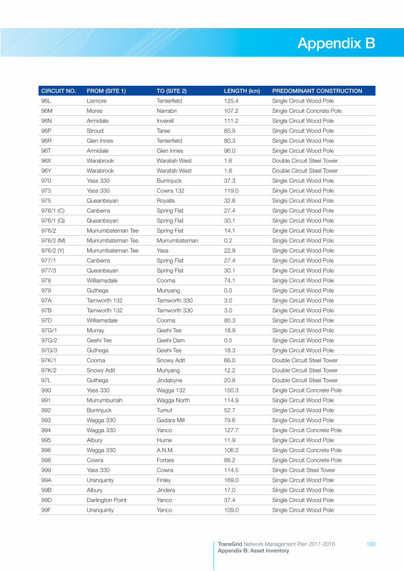
103TransGrid Network Management Plan 2011-2016Appendix B: Asset Inventory
Appendix B
CIRCUIT NO. FROM (SITE 1) TO (SITE 2) LENGTH (km) PREDOMINANT CONSTRUCTION
96L Lismore Tenterfield 125.4 Single Circuit Wood Pole
96M Moree Narrabri 107.2 Single Circuit Concrete Pole
96N Armidale Inverell 111.2 Single Circuit Wood Pole
96P Stroud Taree 85.9 Single Circuit Wood Pole
96R Glen Innes Tenterfield 80.3 Single Circuit Wood Pole
96T Armidale Glen Innes 96.0 Single Circuit Wood Pole
96X Warabrook Waratah West 1.6 Double Circuit Steel Tower
96Y Warabrook Waratah West 1.6 Double Circuit Steel Tower
970 Yass 330 Burrinjuck 37.3 Single Circuit Wood Pole
973 Yass 330 Cowra 132 119.0 Single Circuit Wood Pole
975 Queanbeyan Royalla 32.8 Single Circuit Wood Pole
976/1 (C) Canberra Spring Flat 27.4 Single Circuit Wood Pole
976/1 (Q) Queanbeyan Spring Flat 30.1 Single Circuit Wood Pole
976/2 Murrumbateman Tee Spring Flat 14.1 Single Circuit Wood Pole
976/2 (M) Murrumbateman Tee Murrumbateman 0.2 Single Circuit Wood Pole
976/2 (Y) Murrumbateman Tee Yass 22.9 Single Circuit Wood Pole
977/1 Canberra Spring Flat 27.4 Single Circuit Wood Pole
977/3 Queanbeyan Spring Flat 30.1 Single Circuit Wood Pole
978 Williamsdale Cooma 74.1 Single Circuit Wood Pole
979 Guthega Munyang 0.5 Single Circuit Wood Pole
97A Tamworth 132 Tamworth 330 3.0 Single Circuit Wood Pole
97B Tamworth 132 Tamworth 330 3.0 Single Circuit Wood Pole
97D Williamsdale Cooma 80.3 Single Circuit Wood Pole
97G/1 Murray Geehi Tee 18.9 Single Circuit Wood Pole
97G/2 Geehi Tee Geehi Dam 0.5 Single Circuit Wood Pole
97G/3 Guthega Geehi Tee 18.3 Single Circuit Wood Pole
97K/1 Cooma Snowy Adit 66.0 Double Circuit Steel Tower
97K/2 Snowy Adit Munyang 12.2 Double Circuit Steel Tower
97L Guthega Jindabyne 20.8 Double Circuit Steel Tower
990 Yass 330 Wagga 132 150.3 Single Circuit Concrete Pole
991 Murrumburrah Wagga North 114.9 Single Circuit Wood Pole
992 Burrinjuck Tumut 52.7 Single Circuit Wood Pole
993 Wagga 330 Gadara Mill 79.6 Single Circuit Wood Pole
994 Wagga 330 Yanco 127.7 Single Circuit Concrete Pole
995 Albury Hume 11.9 Single Circuit Wood Pole
996 Wagga 330 A.N.M. 106.2 Single Circuit Concrete Pole
998 Cowra Forbes 88.2 Single Circuit Concrete Pole
999 Yass 330 Cowra 114.5 Single Circuit Steel Tower
99A Uranquinty Finley 169.0 Single Circuit Wood Pole
99B Albury Jindera 17.0 Single Circuit Wood Pole
99D Darlington Point Yanco 37.4 Single Circuit Wood Pole
99F Uranquinty Yanco 109.0 Single Circuit Wood Pole
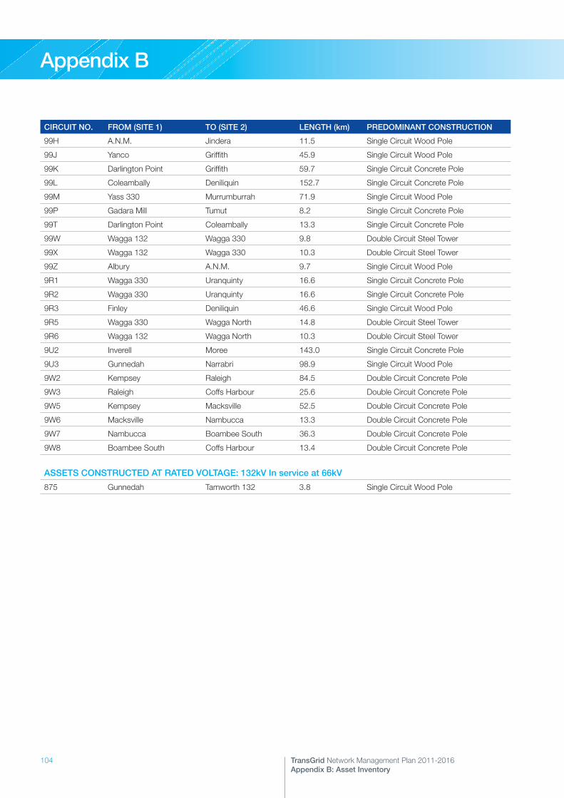
104 TransGrid Network Management Plan 2011-2016Appendix B: Asset Inventory
Appendix B
CIRCUIT NO. FROM (SITE 1) TO (SITE 2) LENGTH (km) PREDOMINANT CONSTRUCTION
99H A.N.M. Jindera 11.5 Single Circuit Wood Pole
99J Yanco Griffith 45.9 Single Circuit Wood Pole
99K Darlington Point Griffith 59.7 Single Circuit Concrete Pole
99L Coleambally Deniliquin 152.7 Single Circuit Concrete Pole
99M Yass 330 Murrumburrah 71.9 Single Circuit Wood Pole
99P Gadara Mill Tumut 8.2 Single Circuit Concrete Pole
99T Darlington Point Coleambally 13.3 Single Circuit Concrete Pole
99W Wagga 132 Wagga 330 9.8 Double Circuit Steel Tower
99X Wagga 132 Wagga 330 10.3 Double Circuit Steel Tower
99Z Albury A.N.M. 9.7 Single Circuit Wood Pole
9R1 Wagga 330 Uranquinty 16.6 Single Circuit Concrete Pole
9R2 Wagga 330 Uranquinty 16.6 Single Circuit Concrete Pole
9R3 Finley Deniliquin 46.6 Single Circuit Wood Pole
9R5 Wagga 330 Wagga North 14.8 Double Circuit Steel Tower
9R6 Wagga 132 Wagga North 10.3 Double Circuit Steel Tower
9U2 Inverell Moree 143.0 Single Circuit Concrete Pole
9U3 Gunnedah Narrabri 98.9 Single Circuit Wood Pole
9W2 Kempsey Raleigh 84.5 Double Circuit Concrete Pole
9W3 Raleigh Coffs Harbour 25.6 Double Circuit Concrete Pole
9W5 Kempsey Macksville 52.5 Double Circuit Concrete Pole
9W6 Macksville Nambucca 13.3 Double Circuit Concrete Pole
9W7 Nambucca Boambee South 36.3 Double Circuit Concrete Pole
9W8 Boambee South Coffs Harbour 13.4 Double Circuit Concrete Pole
ASSETS CONSTRUCTED AT RATED VOLTAGE: 132kV In service at 66kV
875 Gunnedah Tamworth 132 3.8 Single Circuit Wood Pole
© State of New South Wales through TransGrid 2011 All rights reserved.
