network management cards - eaton
TRANSCRIPT

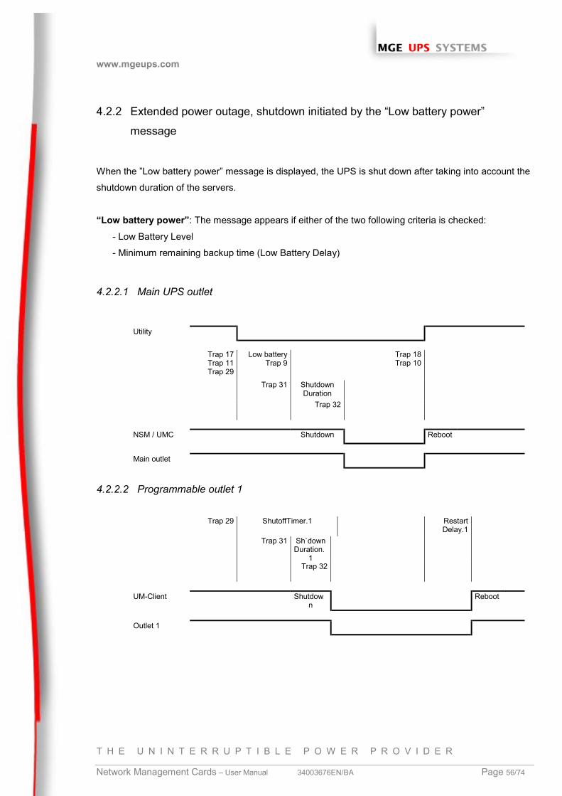
www.mgeups.com
T H E U N I N T E R R U P T I B L E P O W E R P R O V I D E R
Network Management Cards – User Manual 34003676EN/BB
Page 1/74
Network Management CardsUser manual
Network Management Cards
(66244)
Network Management Cards
(66074)
Environment Sensor
(66846)

www.mgeups.com
T H E U N I N T E R R U P T I B L E P O W E R P R O V I D E R
Network Management Cards – User Manual 34003676EN/BA Page 2/74
Table of Contents
1 MGE NETWORK SOLUTION..............................................................................................................5
1.1 INTRODUCTION................................................................................................................................51.1.1 Connecting the UPS to the Network......................................................................................5
The Network Management Card or Proxy: ..........................................................................................6
1.1.2 Protecting the computers / servers........................................................................................6
1.1.3 Monitoring the UPSs over the network..................................................................................6
1.1.4 Connection.............................................................................................................................7
1.2 PRESENTATION OF THE NETWORK MANAGEMENT CARDS (NMC)......................................................81.3 PRESENTATION OF THE ENVIRONMENT SENSOR SOLUTION ...............................................................81.4 DIRECT SENDING OF E-MAIL ............................................................................................................81.5 SENDING TEXT MESSAGES (SMS)....................................................................................................91.6 COMPATIBILITY WITH THE NETWORK MANAGEMENT SYSTEMS (NMS) – TRAP SENDING.....................91.7 COMPATIBILITY THE LEGACY SOLUTION-PAC WAN OFFERING ..........................................................91.8 TECHNICAL DATA ..........................................................................................................................10
1.8.1 Configuration .......................................................................................................................10
1.8.2 Administration......................................................................................................................10
1.8.3 Network................................................................................................................................10
1.8.4 MIB (Management Information Base) .................................................................................10
1.8.5 Environment sensor.............................................................................................................10
2 INSTALLATION AND CONFIGURATION ........................................................................................12
2.1 INSTALLATION...............................................................................................................................122.1.1 Installing the card in the UPS ..............................................................................................12
2.1.2 Connecting the card to the IT network ................................................................................12
2.1.3 Understanding front panel signals.......................................................................................12
2.2 BASIC CONFIGURATION DE BASE....................................................................................................122.2.1 List of default parameters ....................................................................................................12
2.2.2 Adjusting the network parameters.......................................................................................12
2.2.3 Rebooting the card ..............................................................................................................12
2.2.4 Restoring factory configuration............................................................................................12
2.2.5 Lost password – restoring the default password .................................................................12
2.2.6 Checking that the card work is working...............................................................................12
2.3 ENVIRONMENT SENSOR.................................................................................................................12
3 SUPERVISION / ADMINISTRATION VIA A WEB BROWSER ........................................................13
3.1.1 Optimising the performance of your browser ......................................................................13
www.mgeups.com
T H E U N I N T E R R U P T I B L E P O W E R P R O V I D E R
Network Management Cards – User Manual 34003676EN/BA Page 3/74
3.2 UPS.............................................................................................................................................143.2.1 “UPS properties” page.........................................................................................................14
3.2.2 On-line help .........................................................................................................................18
3.2.3 UPS Control.........................................................................................................................19
3.2.4 UPS weekly schedule programming ...................................................................................21
3.2.5 Shutdown parameters .........................................................................................................22
3.2.6 Viewing the alarms ..............................................................................................................24
3.3 LOGS ...........................................................................................................................................253.3.1 Measurements.....................................................................................................................25
3.3.2 Event log..............................................................................................................................27
3.3.3 System log ...........................................................................................................................27
3.4 NOTIFICATION ...............................................................................................................................283.4.1 Email Notification.................................................................................................................28
3.4.2 Email Message Settings ......................................................................................................31
3.5 CONFIGURATION ...........................................................................................................................333.5.1 Network Settings .................................................................................................................34
3.5.2 System.................................................................................................................................36
3.5.3 Notified Applications ............................................................................................................38
3.5.4 Central Shutdown Configuration..........................................................................................40
3.5.5 Access control .....................................................................................................................42
3.5.6 Time.....................................................................................................................................44
3.6 ENVIRONMENT ..............................................................................................................................453.6.1 Characteristics.....................................................................................................................45
3.6.2 Environment status..............................................................................................................46
3.6.3 Environment Settings ..........................................................................................................47
3.6.4 Log.......................................................................................................................................48
4 SERVERS PROTECTION .................................................................................................................50
4.1 SET-UP OF THE SHUTDOWN PARAMETERS ......................................................................................504.1.1 Shutdown criteria managed by the Management Card.......................................................50
4.1.2 Specific set-up for long autonomy installation (> 30 mn) ...................................................51
4.1.3 Controlled outlets.................................................................................................................51
4.1.4 Connecting a server protected by UM-Client to a programmable outlet .............................51
4.2 THE DIFFERENT SERVER AND UPS SHUTDOWN SEQUENCES............................................................534.2.1 Extended power outage, shutdown initiated by the Shutdown Timer .................................53
4.2.2 Extended power outage, shutdown initiated by the “Low battery power” message............56
4.2.3 Extended power outage, shutdown initiated by the Shutdown Timer, but utility restoration
before the end of the Shutdown Duration ..........................................................................................58
4.2.4 Off/On command .................................................................................................................60
www.mgeups.com
T H E U N I N T E R R U P T I B L E P O W E R P R O V I D E R
Network Management Cards – User Manual 34003676EN/BA Page 4/74
5 CONFIGURATION IN LOCAL MODE AND VIA TELNET................................................................62
5.1 CONFIGURATION IN LOCAL MODE ...................................................................................................625.1.1 Choice 1: SNMP agent configuration menu ........................................................................62
5.1.2 Choice 2: UPS parameters..................................................................................................65
5.1.3 Choice 3: Access control .....................................................................................................65
5.1.4 Choice 4: Restore default configuration ..............................................................................66
5.1.5 Choice 5: Reset the card .....................................................................................................66
5.2 CONFIGURATION VIA TELNET.........................................................................................................67
6 MAINTENANCE.................................................................................................................................68
6.1 SOFTWARE UPGRADE....................................................................................................................686.1.1 Card software upgrade using Mupgrade (Windows)...........................................................68
6.1.2 Card software upgrade via TFTP (UNIX and Windows) .....................................................68
6.1.3 Card software upgrade via the serial link ............................................................................68
7 APPENDICES....................................................................................................................................69
7.1 TABLES OF ALARMS AND EVENTS ..................................................................................................697.1.1 Alarm table...........................................................................................................................69
7.1.2 UPS event table...................................................................................................................69
7.1.3 System alarm table..............................................................................................................71
7.2 GLOSSARY ...................................................................................................................................72
www.mgeups.com
T H E U N I N T E R R U P T I B L E P O W E R P R O V I D E R
Network Management Cards – User Manual 34003676EN/BA Page 5/74
1 MGE Network Solution
1.1 Introduction
◗ provides information on events concerning the supply of power to the computers connected to your
computer network,
◗ carries out automatic shutdown of computer systems,
◗ monitors and controls all the UPSs connected to the network.
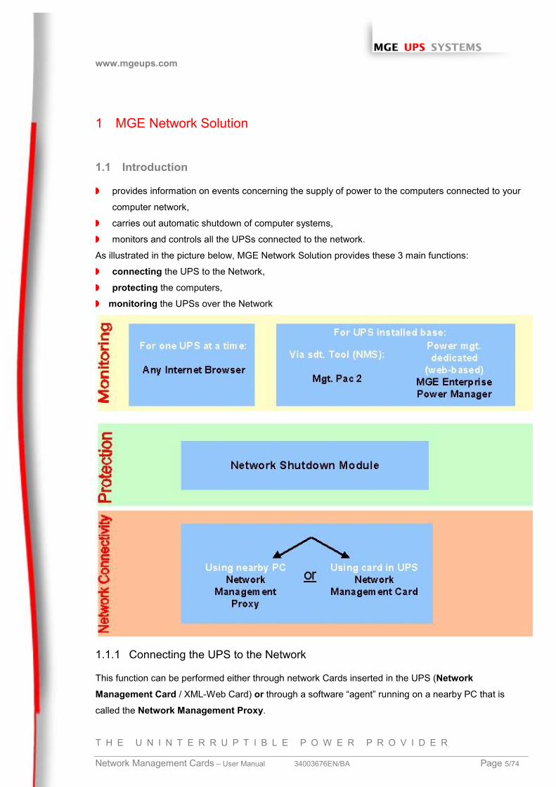
As illustrated in the picture below, MGE Network Solution provides these 3 main functions:
◗ connecting the UPS to the Network,
◗ protecting the computers,
◗ monitoring the UPSs over the Network
1.1.1 Connecting the UPS to the Network
This function can be performed either through network Cards inserted in the UPS (NetworkManagement Card / XML-Web Card) or through a software “agent” running on a nearby PC that is
called the Network Management Proxy.

www.mgeups.com
T H E U N I N T E R R U P T I B L E P O W E R P R O V I D E R
Network Management Cards – User Manual 34003676EN/BA Page 6/74
The Network Management Card or Proxy:◗ manages communication with the UPS (as well as local protection of the machine on which Proxy is
installed),
◗ periodically accesses the information concerning the UPS,
◗ makes this information available to the connected applications (Network Shutdown Modules, Web
Browser, Network Management Systems, Enterprise Power Manager)Operation may be in standard secure mode (the default mode) or in SSL secure mode (Secure Socket
Layer SSL) with the Proxy and the XML Web Card.
1.1.2 Protecting the computers / servers
This function is performed by the Network Shutdown Module installed on each of the servers to be
protected. Note that the Shutdown Module is available on several Operating Systems.
The Network Shutdown module:◗ continuously waits for information from the Network Management Card / Proxy connected to the
MGE UPS.
◗ warns administrators and users if AC power fails and proceeds with graceful system shutdown before
the end of battery backup power is reached.
1.1.3 Monitoring the UPSs over the network
Depending on your needs, you can either use:
◗ your Internet browser to monitor each UPS, as Management Proxy and Management Card include a
Web server.
◗ your company’s standard Network Management System (HP-Openview, CA Unicenter, HP Insight
Manager, IBM Tivoli Netview). To simplify integration of MGE UPSs with these NMS, you can use
one of the Network Management System Kits for MGE devices. These kits are available on
Management Pac 2 CD-Rom. (ref 66923)
◗ the MGE supervisor " Enterprise Power Manager "
www.mgeups.com
T H E U N I N T E R R U P T I B L E P O W E R P R O V I D E R
Network Management Cards – User Manual 34003676EN/BA Page 7/74
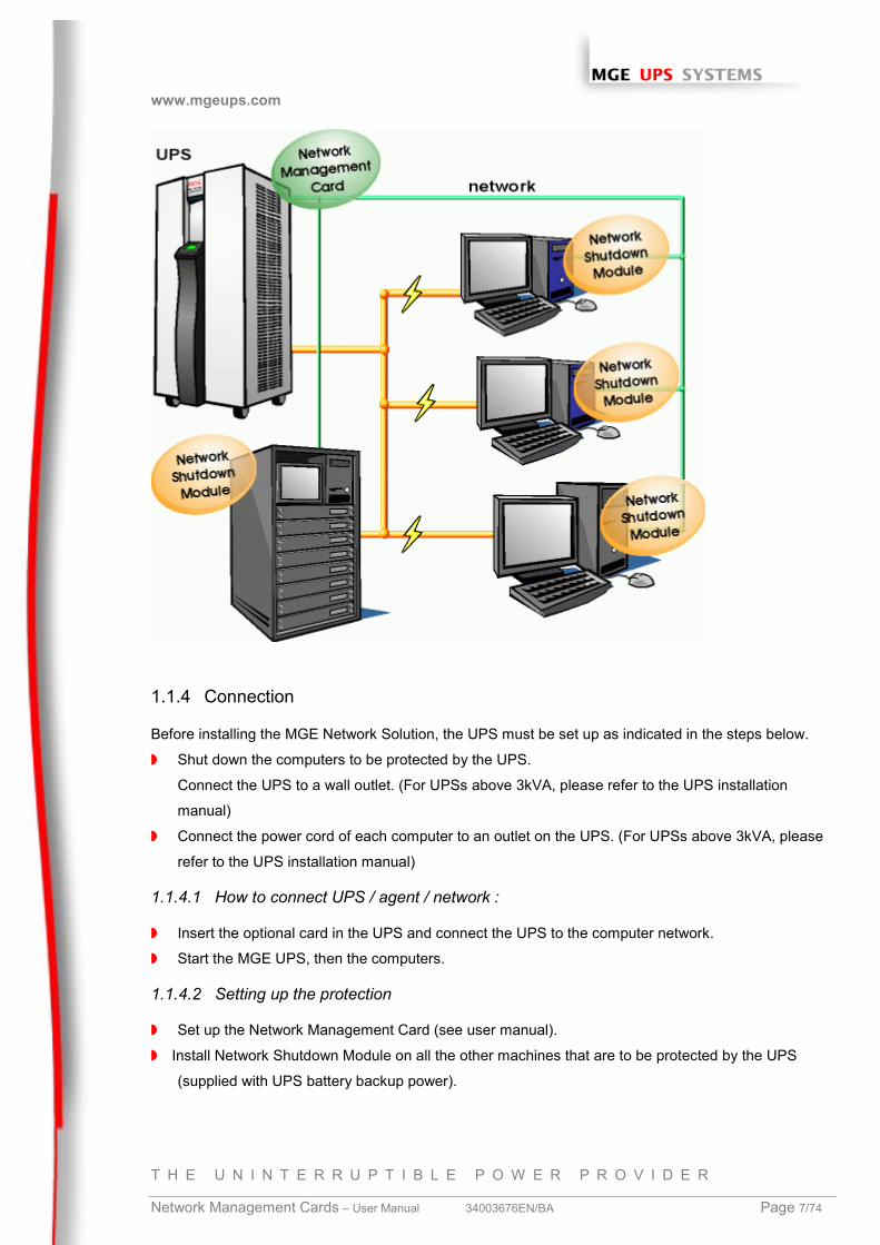
1.1.4 Connection
Before installing the MGE Network Solution, the UPS must be set up as indicated in the steps below.
◗ Shut down the computers to be protected by the UPS.
Connect the UPS to a wall outlet. (For UPSs above 3kVA, please refer to the UPS installation
manual)
◗ Connect the power cord of each computer to an outlet on the UPS. (For UPSs above 3kVA, please
refer to the UPS installation manual)
1.1.4.1 How to connect UPS / agent / network :
◗ Insert the optional card in the UPS and connect the UPS to the computer network.
◗ Start the MGE UPS, then the computers.
1.1.4.2 Setting up the protection
◗ Set up the Network Management Card (see user manual).
◗ Install Network Shutdown Module on all the other machines that are to be protected by the UPS
(supplied with UPS battery backup power).
www.mgeups.com
T H E U N I N T E R R U P T I B L E P O W E R P R O V I D E R
Network Management Cards – User Manual 34003676EN/BA Page 8/74
The software components for each platform and the user manuals are supplied free-of-charge on the
Solution-Pac 2 CD or are available for download on the www.mgeups.com Web site, in the “Download
area” section”
1.2 Presentation of the Network Management Cards (NMC)
MGE provides 2 different form factors for its Network Management Cards :
◗ NMC Minislot for UPS systems like the Evolution, EXtreme C, Pulsar EX, Pulsar/Comet DX series.
◗ NMC Transverse for UPS systems like the Galaxy 3000, Galaxy PW, Pulsar and Comet EXtreme
series. Other MGE UPS systems (3-phase Comet, Galaxy, EPS 6000) can be remotely managed
using the Network Management Link.
The Network Management Cards acquire information on the operation status of the UPS systems and
provide remote control of these systems by means of an ETHERNET network from any SNMP
administration station or Web browser. They also supply alarms to the Network Shutdown Modules to
trigger shutdown or other automatic actions for protected servers.
A simple html browser is used for supervision and configuration.
Network Management Cards are compatible with all MGE UPS SYSTEMS supervision / protection
systems:
◗ Network Shutdown Modules
◗ Entreprise Power Manager
◗ Management-Pac 2
1.3 Presentation of the Environment Sensor solution
The Environment Sensor solution comprises a box to be connected to the Card Settings port of
the Network Management Cards:
Environment Sensor enables measurement of temperature and humidity around the UPS,
consideration of external alarms via 2 dry contacts and notification of alarms according to pre-
programmed thresholds.
1.4 Direct sending of E-mail
When a UPS event occurs, the Network Management Card can directly notify up to 4 intranet or
extranet addressees by e-mail (see Email Notification and Email Message Settings).
www.mgeups.com
T H E U N I N T E R R U P T I B L E P O W E R P R O V I D E R
Network Management Cards – User Manual 34003676EN/BA Page 9/74
1.5 Sending text messages (SMS)
SMS messages can be sent by specific configuration of the e-mail function via the internet access
providers making the e-mail / SMS transfer.
1.6 Compatibility with the Network Management Systems (NMS) – Trap sending
The Network Management Cards are compatible with the major Network Management Systems
(IBM Tivoli, CA Unicenter, HP Insight Manager ..),. The Management-Pac 2 offering includes the
necessary SNMP plug-in to allows an easy integration in the NMS. Events are notified by SNMP
trap
◗ NMS can subscribe on page “Notified Application”
◗ SNMP sequences are described in chapter “Server protection”
◗ The trap list can be looked over in the document ref. 34003641EN available on mgeups.com
1.7 Compatibility the legacy Solution-Pac WAN offering
Network Management Card is compatible with the legacy protection module UM-Client and since
the FA release also with the updated protection module Network Shutdown Module . It is possible
to use the both modules on the same card, therefore, MGEUPS recommends to use the Network
Shutdown Module on new installations.
www.mgeups.com
T H E U N I N T E R R U P T I B L E P O W E R P R O V I D E R
Network Management Cards – User Manual 34003676EN/BA Page 10/74
1.8 Technical data
1.8.1 Configuration
The user can configure the card with one of the following means:
◗ Web browser
◗ Local serial link
◗ Telnet console
◗ BOOTP/DHCP
1.8.2 Administration
◗ Up to 50 workstations protected
◗ Up to 15 browsers connected at the same time
◗ E-mail sending configurable according to UPS alarms and transmission of a periodical report
◗ Measurement of temperature and humidity, adjustable thresholds, possibility of sending e-mails and
shutting down the installation
◗ Control of UPS on/off switching via the HTML interface
◗ Adjustment and control of PowerShare outlets via the HTML interface, sequential starting of the
installation and optimisation of backup time by shutting down non-priority systems
◗ Adjustment of date and time via NTP server - Daylight Saving Time management
◗ Protection by encrypted password.
◗ Saving of logs in the non-volatile memory
◗ Automatic language detection according to browser configuration.
◗ Languages available: English / French / Spanish / German / Italian
◗ On-line help available for each page
◗ Card firmware updated via the network
1.8.3 Network
◗ Fast ETHERNET 10/100 Mbits compatibility with auto-negotiation on the RJ45 outlet
◗ SNMP trap port modifiable (by default = 162)
1.8.4 MIB (Management Information Base)
◗ MIB IETF UPS (RFC1628) / MIB MGE V1.7
1.8.5 Environment sensor
◗ Temperature measurement from 0 to 70 °C with +/- 1°C accuracy
◗ Measurement of humidity from 0 to 100 % with +/- 6 % accuracy
◗ Min / max time-stamped function for temperature and humidity
◗ Choice of temperature readings in Celsius or Fahrenheit
◗ High and low thresholds, hysteresis and offset adjustable via Web interface
www.mgeups.com
T H E U N I N T E R R U P T I B L E P O W E R P R O V I D E R
Network Management Cards – User Manual 34003676EN/BA Page 11/74
◗ Possibility of notification of status changes by e-mail, SMS or SNMP traps
◗ Position detection of 2 dry contacts (maximum sensor/contact distance: 20 m)
◗ Name and status of each configurable contact
◗ Recording of events and measurements in the card log
◗ Possibility of shutting down the installation in the event of a threshold being exceeded or on opening /
closure of a dry contact
◗ Connection to the card with straight CAT5 RJ45 network cables (maximum card/sensor distance: 20
m)
www.mgeups.com
T H E U N I N T E R R U P T I B L E P O W E R P R O V I D E R
Network Management Cards – User Manual 34003676EN/BA Page 12/74
2 Installation and Configuration
For the following sections, read the installation manual supplied with the card or available for download
on the www.mgeups.com web site in the “Download area – embedded Software” section
2.1 Installation
2.1.1 Installing the card in the UPS
2.1.2 Connecting the card to the IT network
2.1.3 Understanding front panel signals
2.2 Basic configuration de base
2.2.1 List of default parameters
2.2.2 Adjusting the network parameters
2.2.3 Rebooting the card
2.2.4 Restoring factory configuration
2.2.5 Lost password – restoring the default password
2.2.6 Checking that the card work is working
2.3 Environment Sensor
Read the installation manual supplied with the box.
www.mgeups.com
T H E U N I N T E R R U P T I B L E P O W E R P R O V I D E R
Network Management Cards – User Manual 34003676EN/BA Page 13/74
3 Supervision / Administration via a Web browser
A JVM (Java Virtual Machine) is required to ensure correct display of information in HTMLpages.
◗ On a computer equipped with a Web browser (Internet Explorer or Netscape recommended), enter
the address initialised previously in the Installation chapter (e.g.: http://213.30.17.30.)
◗ The “UPS properties” home page is displayed.
3.1.1 Optimising the performance of your browser
◗ To view status changes on the UPS in real time, the browser must be configured so that it
automatically refreshes all the objects on the current page.
Example on IE 6: Tools / Internet Options / General / Parameters menu, tick Every time thispage is visited and validate.
www.mgeups.com
T H E U N I N T E R R U P T I B L E P O W E R P R O V I D E R
Network Management Cards – User Manual 34003676EN/BA Page 14/74
3.2 UPS
3.2.1 “UPS properties” page
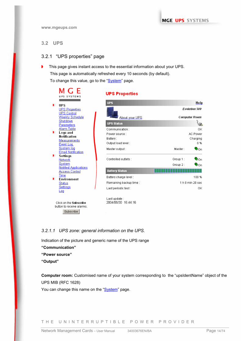
◗ This page gives instant access to the essential information about your UPS.
This page is automatically refreshed every 10 seconds (by default).
To change this value, go to the “System” page.
3.2.1.1 UPS zone: general information on the UPS.
Indication of the picture and generic name of the UPS range
“Communication”“Power source”“Output”
Computer room: Customised name of your system corresponding to the “upsIdentName” object of the
UPS MIB (RFC 1628)
You can change this name on the “System” page.
www.mgeups.com
T H E U N I N T E R R U P T I B L E P O W E R P R O V I D E R
Network Management Cards – User Manual 34003676EN/BA Page 15/74
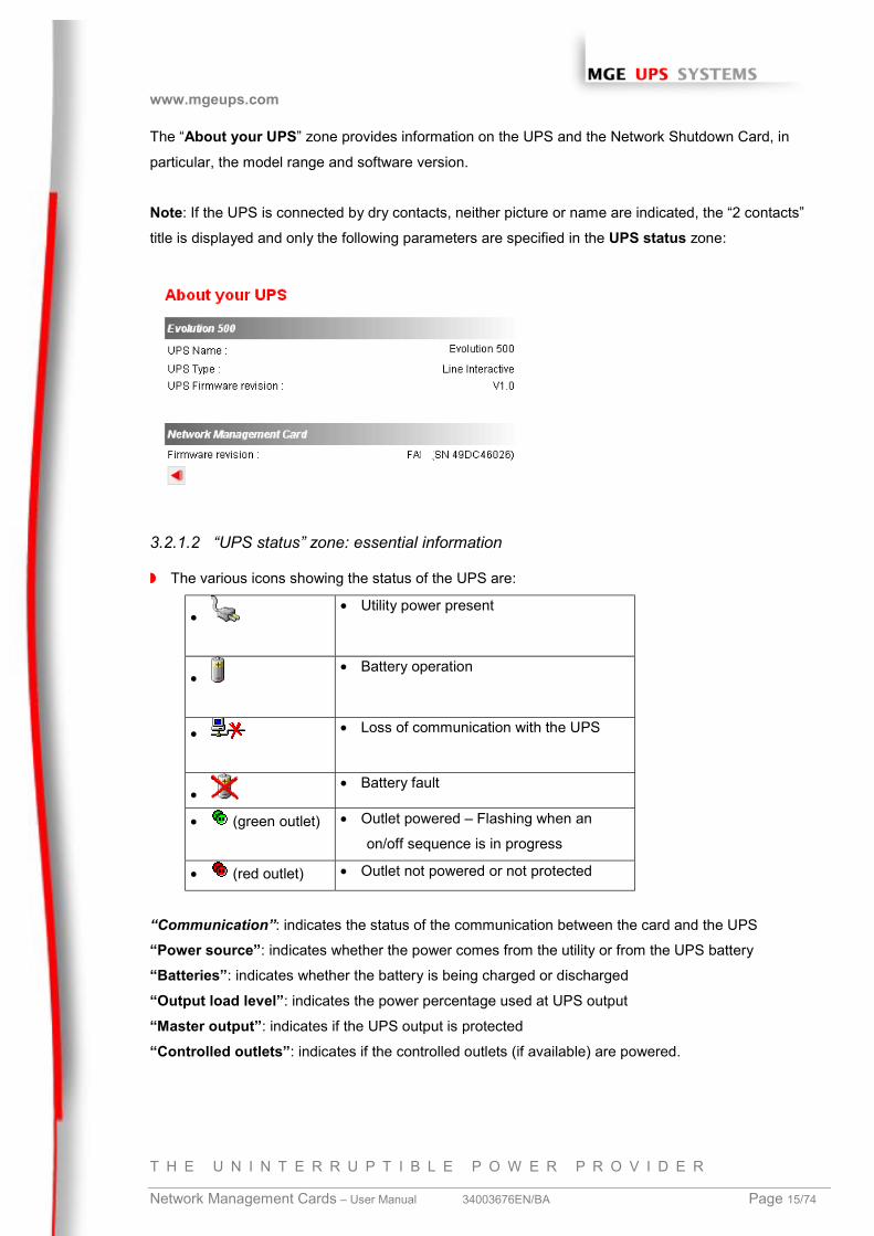
The “About your UPS” zone provides information on the UPS and the Network Shutdown Card, in
particular, the model range and software version.
Note: If the UPS is connected by dry contacts, neither picture or name are indicated, the “2 contacts”
title is displayed and only the following parameters are specified in the UPS status zone:
3.2.1.2 “UPS status” zone: essential information
◗ The various icons showing the status of the UPS are:
• • Utility power present
• • Battery operation
• • Loss of communication with the UPS
• • Battery fault
• (green outlet) • Outlet powered – Flashing when an
on/off sequence is in progress
• (red outlet) • Outlet not powered or not protected
“Communication”: indicates the status of the communication between the card and the UPS
“Power source”: indicates whether the power comes from the utility or from the UPS battery
“Batteries”: indicates whether the battery is being charged or discharged
“Output load level”: indicates the power percentage used at UPS output
“Master output”: indicates if the UPS output is protected
“Controlled outlets”: indicates if the controlled outlets (if available) are powered.
www.mgeups.com
T H E U N I N T E R R U P T I B L E P O W E R P R O V I D E R
Network Management Cards – User Manual 34003676EN/BA Page 16/74
3.2.1.3 “Battery status” zone:
◗ “Bargraph”: Graph showing the remaining battery charge (in percent).
◗ “Battery charge level”: Remaining battery charge (in percent).
◗ “Remaining backup time”: Estimation of the maximum backup time remaining before UPS
shutdown. This time can be modified by the adjustments on the “Shutdown parameters” page
◗ “Last periodical test”: Result of the last automatic battery test carried out by the UPS
Possible values are:
- OK: the test was completed correctly
– NOK: the battery needs to be checked
– Deactivated: the automatic battery test is not validated on the UPS
www.mgeups.com
T H E U N I N T E R R U P T I B L E P O W E R P R O V I D E R
Network Management Cards – User Manual 34003676EN/BA Page 17/74
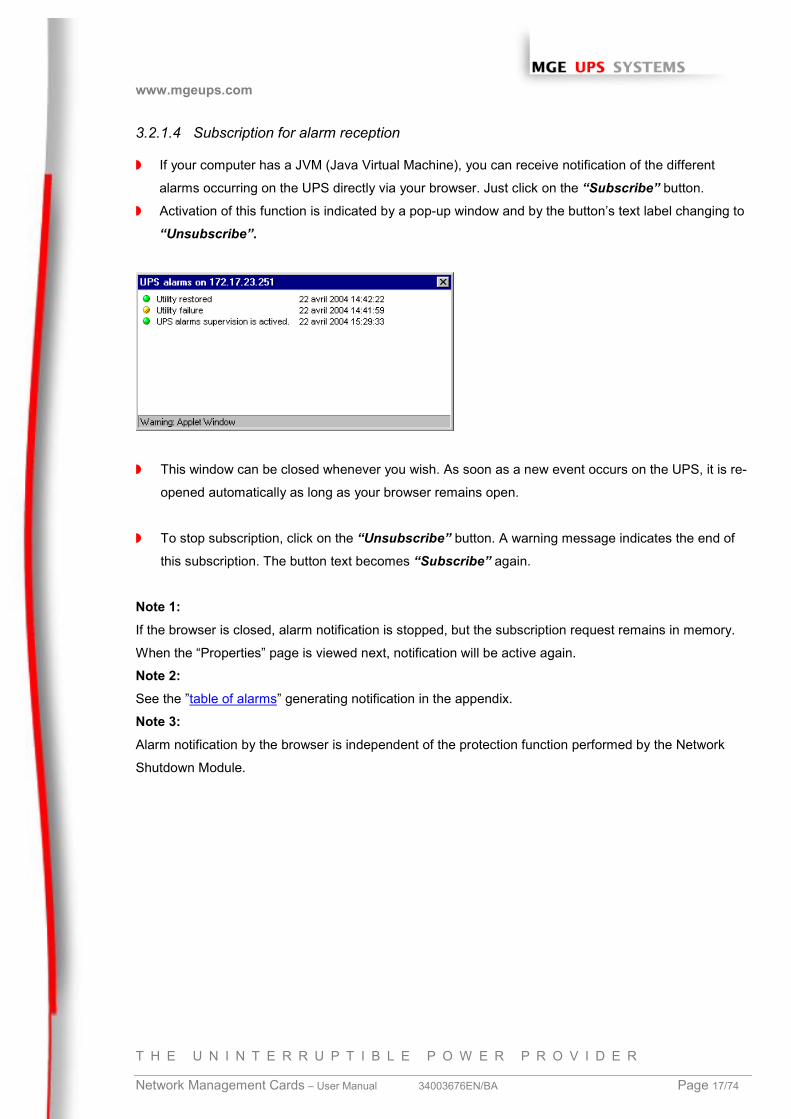
3.2.1.4 Subscription for alarm reception
◗ If your computer has a JVM (Java Virtual Machine), you can receive notification of the different
alarms occurring on the UPS directly via your browser. Just click on the “Subscribe” button.
◗ Activation of this function is indicated by a pop-up window and by the button’s text label changing to
“Unsubscribe”.
◗ This window can be closed whenever you wish. As soon as a new event occurs on the UPS, it is re-
opened automatically as long as your browser remains open.
◗ To stop subscription, click on the “Unsubscribe” button. A warning message indicates the end of
this subscription. The button text becomes “Subscribe” again.
Note 1:If the browser is closed, alarm notification is stopped, but the subscription request remains in memory.
When the “Properties” page is viewed next, notification will be active again.
Note 2:See the ”table of alarms” generating notification in the appendix.
Note 3:Alarm notification by the browser is independent of the protection function performed by the Network
Shutdown Module.
www.mgeups.com
T H E U N I N T E R R U P T I B L E P O W E R P R O V I D E R
Network Management Cards – User Manual 34003676EN/BA Page 18/74
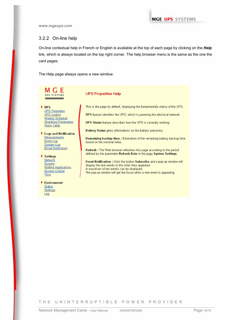
3.2.2 On-line help
On-line contextual help in French or English is available at the top of each page by clicking on the Helplink, which is always located on the top right corner. The help browser menu is the same as the one the
card pages.
The Help page always opens a new window.
www.mgeups.com
T H E U N I N T E R R U P T I B L E P O W E R P R O V I D E R
Network Management Cards – User Manual 34003676EN/BA Page 19/74
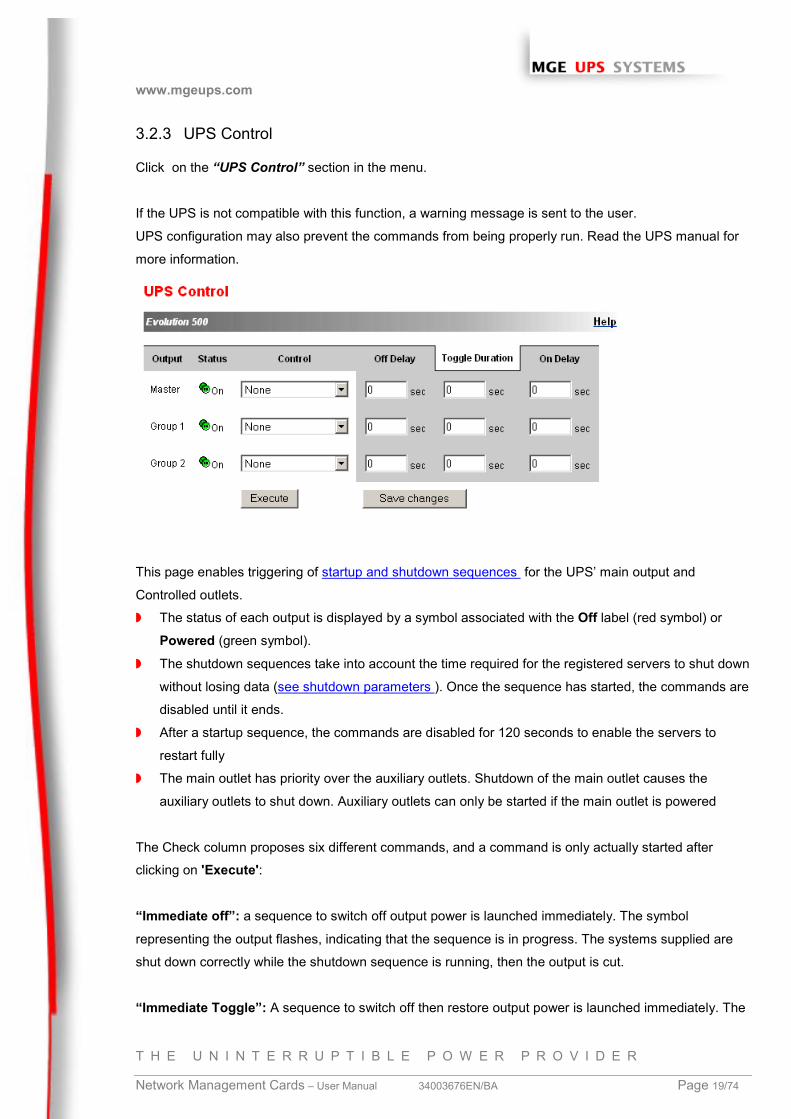
3.2.3 UPS Control
Click on the “UPS Control” section in the menu.
If the UPS is not compatible with this function, a warning message is sent to the user.
UPS configuration may also prevent the commands from being properly run. Read the UPS manual for
more information.
This page enables triggering of startup and shutdown sequences for the UPS’ main output and
Controlled outlets.
◗ The status of each output is displayed by a symbol associated with the Off label (red symbol) or
Powered (green symbol).
◗ The shutdown sequences take into account the time required for the registered servers to shut down
without losing data (see shutdown parameters ). Once the sequence has started, the commands are
disabled until it ends.
◗ After a startup sequence, the commands are disabled for 120 seconds to enable the servers to
restart fully
◗ The main outlet has priority over the auxiliary outlets. Shutdown of the main outlet causes the
auxiliary outlets to shut down. Auxiliary outlets can only be started if the main outlet is powered
The Check column proposes six different commands, and a command is only actually started after
clicking on 'Execute':
“Immediate off”: a sequence to switch off output power is launched immediately. The symbol
representing the output flashes, indicating that the sequence is in progress. The systems supplied are
shut down correctly while the shutdown sequence is running, then the output is cut.
“Immediate Toggle”: A sequence to switch off then restore output power is launched immediately. The
www.mgeups.com
T H E U N I N T E R R U P T I B L E P O W E R P R O V I D E R
Network Management Cards – User Manual 34003676EN/BA Page 20/74
symbol representing the output flashes, indicating that the shutdown sequence is in progress. The
powered systems are shut down correctly during the shutdown sequence, then the output is switched
off.
Finally, the restart sequence is launched at the end of the time delay specified in the “Toggle duration”parameter. The output status is updated.
Immediate On: a sequence to switch on output power is launched immediately. The output is re-
powered and the systems supplied start up again correctly.
Delayed Off: this is the same switch off sequence as for the “ Immediate off ” command, but postponed
by the number of seconds programmed in the “Off Delay” parameter.
Delayed Toggle: this is the same switch off then on sequence as for the “ Immediate Toggle ”
command, but postponed by the number of seconds programmed in the “ Off Delay ” parameter.
Delayed Off: this is the same switch on sequence as for the “ Immediate On ” command, but
postponed by the number of seconds programmed in the “ On Delay ” parameter.
The Save button saves the Off Delay, Toggle duration and On Delay parameters on the card .
Security: The administrator must click on Save and enter his login / password to save modifications
or run commands. The login and password by default are: MGEUPS.
www.mgeups.com
T H E U N I N T E R R U P T I B L E P O W E R P R O V I D E R
Network Management Cards – User Manual 34003676EN/BA Page 21/74
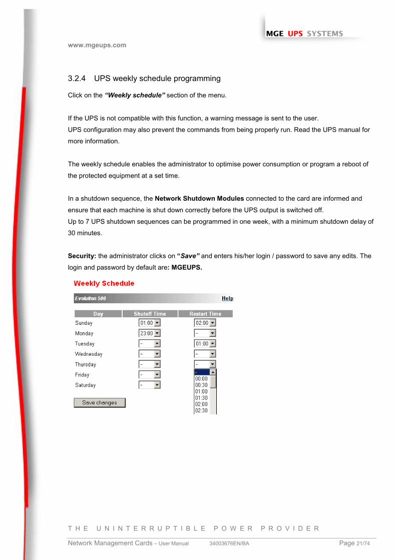
3.2.4 UPS weekly schedule programming
Click on the “Weekly schedule” section of the menu.
If the UPS is not compatible with this function, a warning message is sent to the user.
UPS configuration may also prevent the commands from being properly run. Read the UPS manual for
more information.
The weekly schedule enables the administrator to optimise power consumption or program a reboot of
the protected equipment at a set time.
In a shutdown sequence, the Network Shutdown Modules connected to the card are informed and
ensure that each machine is shut down correctly before the UPS output is switched off.
Up to 7 UPS shutdown sequences can be programmed in one week, with a minimum shutdown delay of
30 minutes.
Security: the administrator clicks on “Save” and enters his/her login / password to save any edits. The
login and password by default are: MGEUPS.
www.mgeups.com
T H E U N I N T E R R U P T I B L E P O W E R P R O V I D E R
Network Management Cards – User Manual 34003676EN/BA Page 22/74
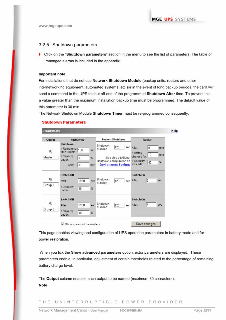
3.2.5 Shutdown parameters
◗ Click on the “Shutdown parameters” section in the menu to see the list of parameters. The table of
managed alarms is included in the appendix.
Important note:For installations that do not use Network Shutdown Module (backup units, routers and other
internetworking equipment, automated systems, etc.)or in the event of long backup periods, the card will
send a command to the UPS to shut off end of the programmed Shutdown After time. To prevent this,
a value greater than the maximum installation backup time must be programmed. The default value of
this parameter is 30 min.
The Network Shutdown Module Shutdown Timer must be re-programmed consequently.
This page enables viewing and configuration of UPS operation parameters in battery mode and for
power restoration.
When you tick the Show advanced parameters option, extra parameters are displayed. These
parameters enable, in particular, adjustment of certain thresholds related to the percentage of remaining
battery charge level.
The Output column enables each output to be named (maximum 30 characters).
Note
www.mgeups.com
T H E U N I N T E R R U P T I B L E P O W E R P R O V I D E R
Network Management Cards – User Manual 34003676EN/BA Page 23/74
Priority is given to the main outlet, so the card does not accept configurations where the auxiliary outlets
can be supplied while the main outlet is switched off
For the main outlet (Master)
◗ Shutdown after is the operating time in minutes left for users after a switch to backup before
starting the shutdown sequences of the UPS and its equipment (from 0 to 1092).
◗ If remaining time under (from 0 to 9999 seconds) and If Capacity under (from 0 to 100%) are
two extra conditions for remaining backup time and battery level that can trigger shutdown
sequences before the “Shutdown after” period runs out
◗ Shutdown duration is the time required for complete shutdown of systems when a switch to
backup time is long enough to trigger the shutdown sequences. It is calculated automatically at
the maximum of Shutdown duration of subscribed clients but can be modified in the Advanced
mode
◗ Restart after is the minimum shutdown time before restarting the UPS after a shutdown
sequence. It is thus possible to limit repeated restarts that may be due to several successive
utility failures.
◗ If the Battery is charged for and If Capacity exceeds are two extra conditions for minimum
battery level and maximum recharge time to be reached before restarting the UPS after utility
restoration
For controlled outlets (group 1 or group 2 ), the page enables programming of operation time and level
in backup mode to manage outlet load shedding in the event of electric power failure:
◗ Switch Off after defines the time during which the outlet is supplied starting from the moment of
utility failure. Caution, this time includes the outlet shutdown duration.
◗ Switch Off if capacity under is an extra condition for outlet shutdown that can trigger the
shutdown sequence before shutdown duration runs out.
◗ Shutdown duration is the time required for complete shutdown of the systems supplied by the
outlet when an outlet shutdown sequence is launched.
It is calculated automatically using the maximum shutdown durations of subscribed clients.
◗ Switch On is the period between main output startup and startup of the relevant programmable
outlet, therefore outlet startup can be delayed in relation to the main output.
Security: The administrator has to click on Save and enter his login/password to save any
modifications. The default login and password are: MGEUPS
www.mgeups.com
T H E U N I N T E R R U P T I B L E P O W E R P R O V I D E R
Network Management Cards – User Manual 34003676EN/BA Page 24/74
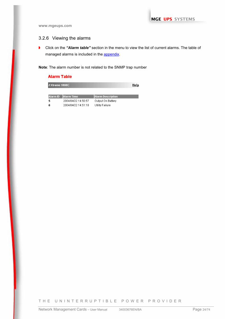
3.2.6 Viewing the alarms
◗ Click on the “Alarm table” section in the menu to view the list of current alarms. The table of
managed alarms is included in the appendix.
Note: The alarm number is not related to the SNMP trap number
www.mgeups.com
T H E U N I N T E R R U P T I B L E P O W E R P R O V I D E R
Network Management Cards – User Manual 34003676EN/BA Page 25/74
3.3 Logs
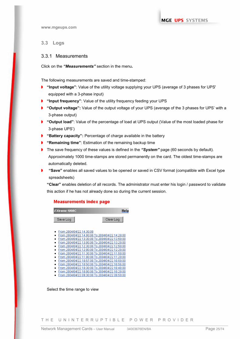
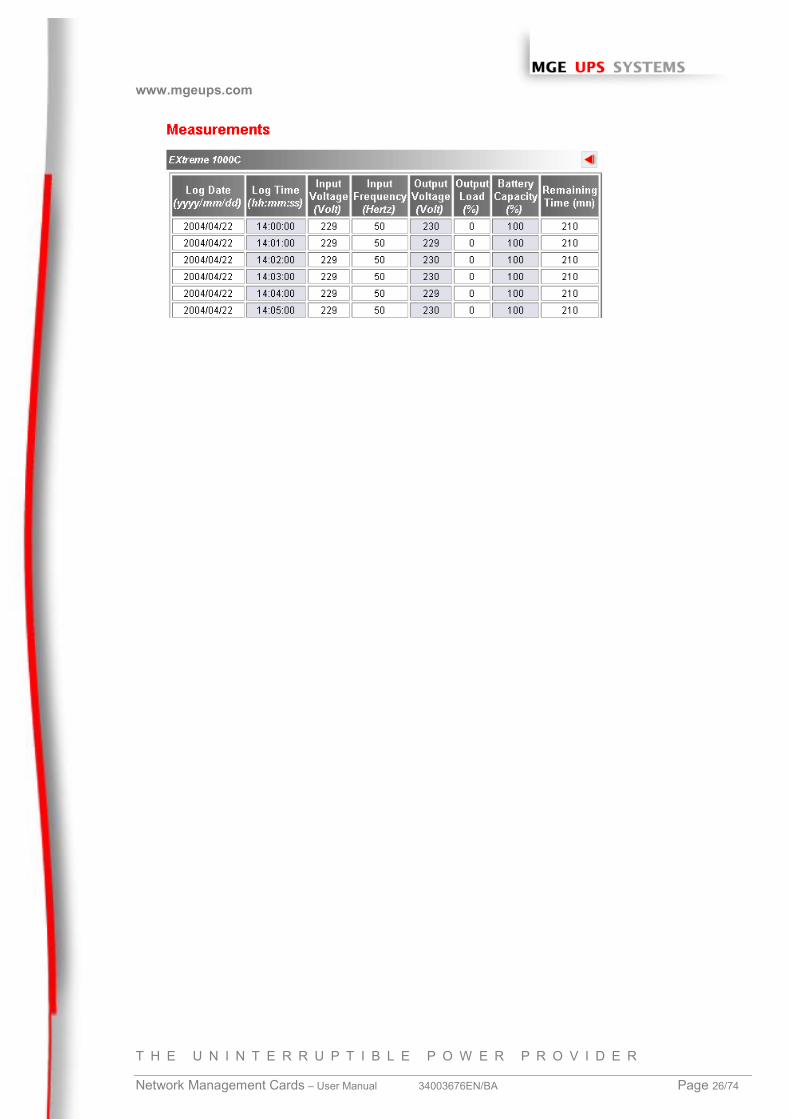
3.3.1 Measurements
Click on the “Measurements” section in the menu.
The following measurements are saved and time-stamped:
◗ “Input voltage”: Value of the utility voltage supplying your UPS (average of 3 phases for UPS'
equipped with a 3-phase input)
◗ “Input frequency”: Value of the utility frequency feeding your UPS
◗ “Output voltage”: Value of the output voltage of your UPS (average of the 3 phases for UPS’ with a
3-phase output)
◗ “Output load”: Value of the percentage of load at UPS output (Value of the most loaded phase for
3-phase UPS’)
◗ “Battery capacity”: Percentage of charge available in the battery
◗ “Remaining time”: Estimation of the remaining backup time
◗ The save frequency of these values is defined in the “System” page (60 seconds by default).
Approximately 1000 time-stamps are stored permanently on the card. The oldest time-stamps are
automatically deleted.
◗ “Save” enables all saved values to be opened or saved in CSV format (compatible with Excel type
spreadsheets)
“Clear” enables deletion of all records. The administrator must enter his login / password to validate
this action if he has not already done so during the current session.
Select the time range to view
www.mgeups.com
T H E U N I N T E R R U P T I B L E P O W E R P R O V I D E R
Network Management Cards – User Manual 34003676EN/BA Page 26/74
www.mgeups.com
T H E U N I N T E R R U P T I B L E P O W E R P R O V I D E R
Network Management Cards – User Manual 34003676EN/BA Page 27/74
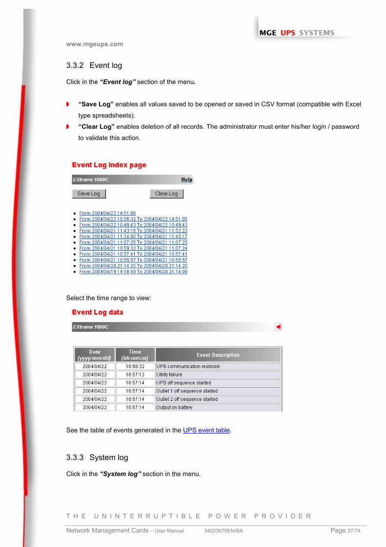
3.3.2 Event log
Click in the “Event log” section of the menu.
◗ “Save Log” enables all values saved to be opened or saved in CSV format (compatible with Excel
type spreadsheets).
◗ “Clear Log” enables deletion of all records. The administrator must enter his/her login / password
to validate this action.
Select the time range to view:
See the table of events generated in the UPS event table.
3.3.3 System log
Click in the “System log” section in the menu.
www.mgeups.com
T H E U N I N T E R R U P T I B L E P O W E R P R O V I D E R
Network Management Cards – User Manual 34003676EN/BA Page 28/74
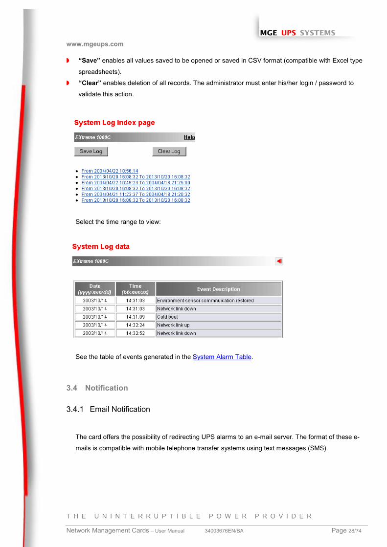
◗ “Save” enables all values saved to be opened or saved in CSV format (compatible with Excel type
spreadsheets).
◗ “Clear” enables deletion of all records. The administrator must enter his/her login / password to
validate this action.
Select the time range to view:
See the table of events generated in the System Alarm Table.
3.4 Notification
3.4.1 Email Notification
The card offers the possibility of redirecting UPS alarms to an e-mail server. The format of these e-
mails is compatible with mobile telephone transfer systems using text messages (SMS).
www.mgeups.com
T H E U N I N T E R R U P T I B L E P O W E R P R O V I D E R
Network Management Cards – User Manual 34003676EN/BA Page 29/74
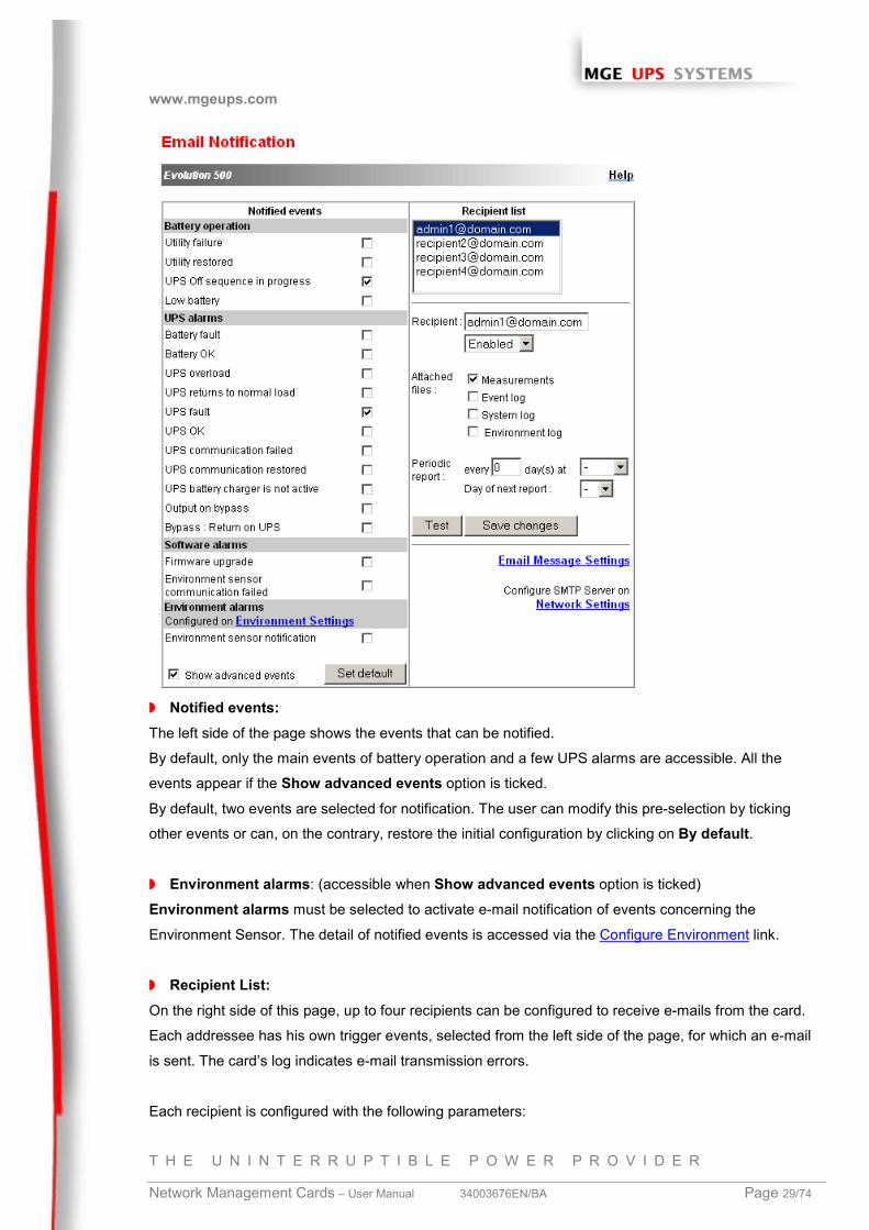
◗ Notified events:The left side of the page shows the events that can be notified.
By default, only the main events of battery operation and a few UPS alarms are accessible. All the
events appear if the Show advanced events option is ticked.
By default, two events are selected for notification. The user can modify this pre-selection by ticking
other events or can, on the contrary, restore the initial configuration by clicking on By default.
◗ Environment alarms: (accessible when Show advanced events option is ticked)
Environment alarms must be selected to activate e-mail notification of events concerning the
Environment Sensor. The detail of notified events is accessed via the Configure Environment link.
◗ Recipient List:On the right side of this page, up to four recipients can be configured to receive e-mails from the card.
Each addressee has his own trigger events, selected from the left side of the page, for which an e-mail
is sent. The card’s log indicates e-mail transmission errors.
Each recipient is configured with the following parameters:
www.mgeups.com
T H E U N I N T E R R U P T I B L E P O W E R P R O V I D E R
Network Management Cards – User Manual 34003676EN/BA Page 30/74
Recipient: this is the e-mail address of the person or department to receive the e-mail.
The default value is [email protected].
Attached files: The files selected (UPS measurements, Event log, System log or Environment
measurements) are enclosed with each e-mail sent. The files are sent in CSV format.
Periodic report: In addition to the e-mails sent when events occur, a periodical e-mail containing the 4
log files can be sent to the recipient every x days at the time specified by the user.
To configure the first transmission, specify the day, time and frequency of the next transmission in the
Day of next report box. After this date, the page will show the date and time of the next transmission.
Data are sent in CSV format.
Save: Saves any modifications.
Test: enables an e-mail to be sent to the recipient immediately. This is one way of checking e-mail
transmission, particularly access to the SMTP server configured in “Network settings”. A transmission
report is added to the system log. In the event of failure, the card will repeat the transmission 3 times, at
one minute intervals, before producing a transmission report.
The event label in the subject and text of the message is replaced with a test label.
If the user makes any modifications to the page, they must be saved before using the “Test” function.
E-mail message configuration: see next page
Network settings: enables the name of the SMTP server to be entered. See “Network settings”
Security: The administrator has to click on Save and enter his login/password to save any
modifications. The default login and password are: MGEUPS
www.mgeups.com
T H E U N I N T E R R U P T I B L E P O W E R P R O V I D E R
Network Management Cards – User Manual 34003676EN/BA Page 31/74
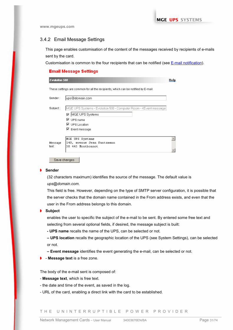
3.4.2 Email Message Settings
This page enables customisation of the content of the messages received by recipients of e-mails
sent by the card.
Customisation is common to the four recipients that can be notified (see E-mail notification).
◗ Sender(32 characters maximum) identifies the source of the message. The default value is
This field is free. However, depending on the type of SMTP server configuration, it is possible that
the server checks that the domain name contained in the From address exists, and even that the
user in the From address belongs to this domain.
◗ Subjectenables the user to specific the subject of the e-mail to be sent. By entered some free text and
selecting from several optional fields, if desired, the message subject is built:
- UPS name recalls the name of the UPS, can be selected or not.
– UPS location recalls the geographic location of the UPS (see System Settings), can be selected
or not.
– Event message identifies the event generating the e-mail, can be selected or not.
◗ - Message text is a free zone.
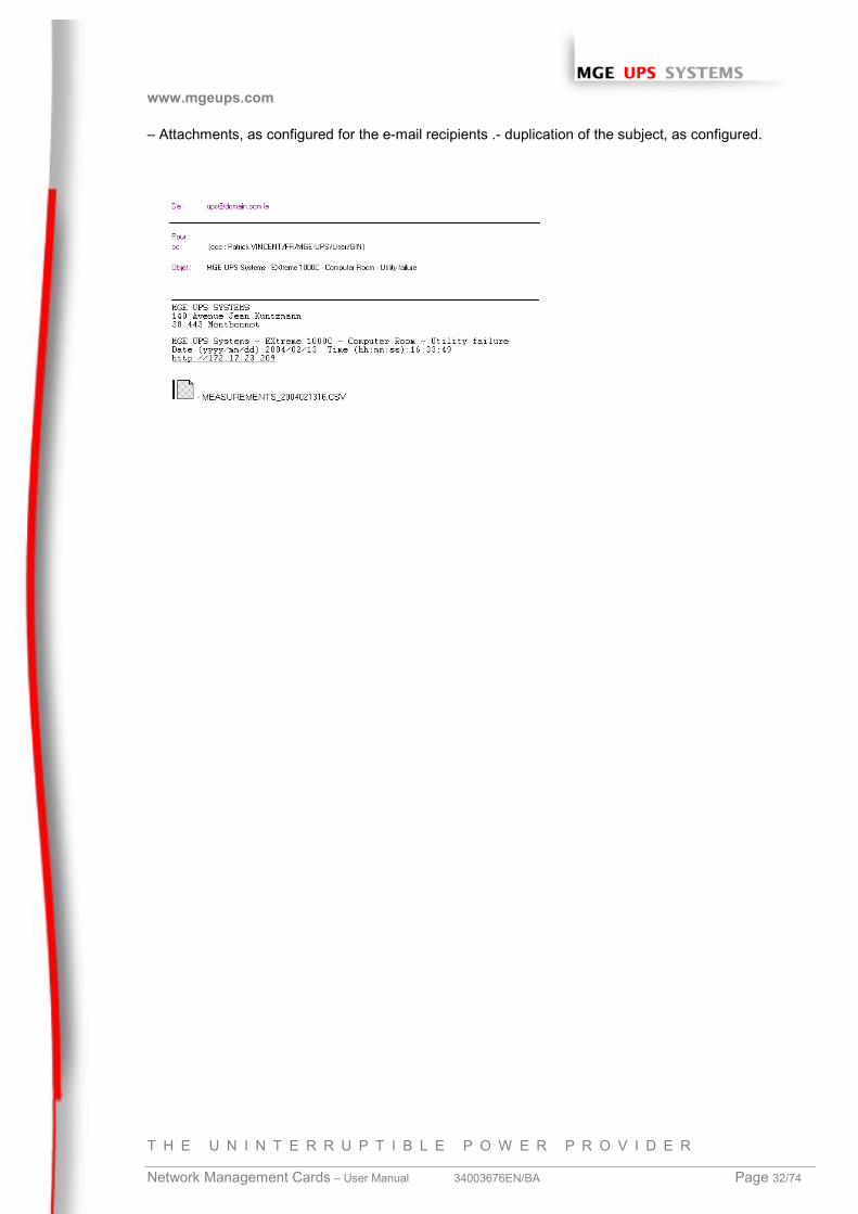
The body of the e-mail sent is composed of:
- Message text, which is free text.
- the date and time of the event, as saved in the log.
- URL of the card, enabling a direct link with the card to be established.
www.mgeups.com
T H E U N I N T E R R U P T I B L E P O W E R P R O V I D E R
Network Management Cards – User Manual 34003676EN/BA Page 32/74
– Attachments, as configured for the e-mail recipients .- duplication of the subject, as configured.
www.mgeups.com
T H E U N I N T E R R U P T I B L E P O W E R P R O V I D E R
Network Management Cards – User Manual 34003676EN/BA Page 33/74
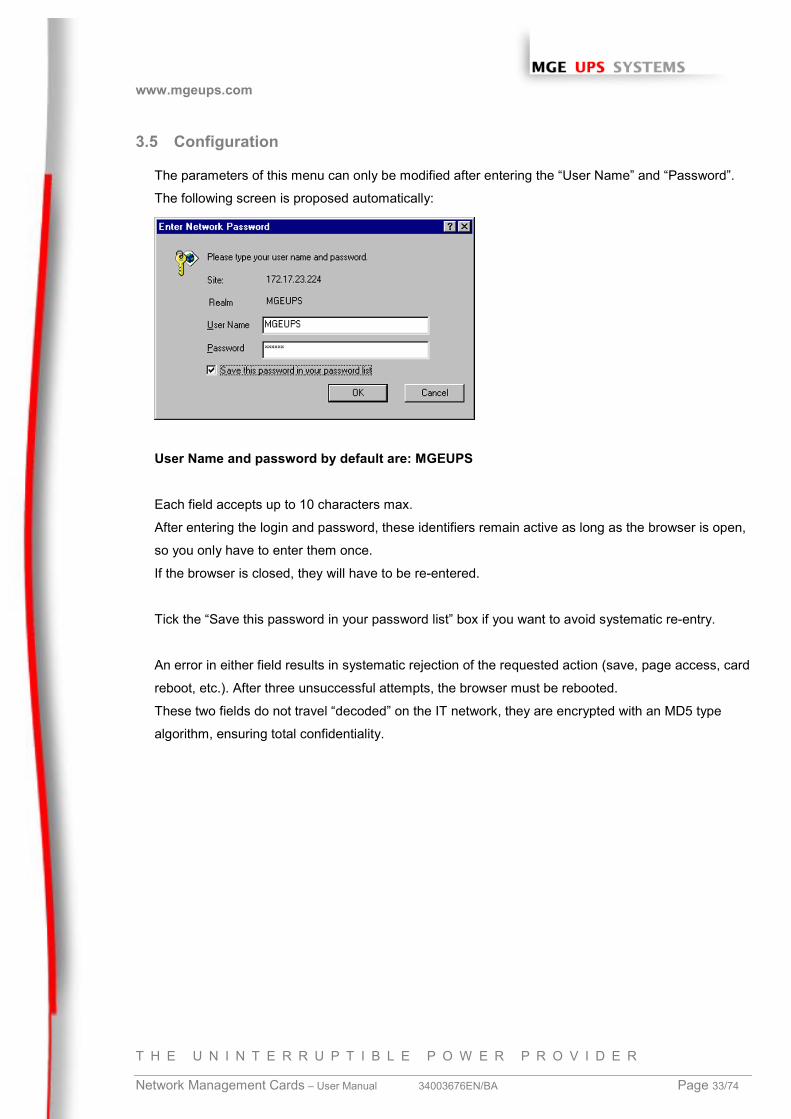
3.5 Configuration
The parameters of this menu can only be modified after entering the “User Name” and “Password”.
The following screen is proposed automatically:
User Name and password by default are: MGEUPS
Each field accepts up to 10 characters max.
After entering the login and password, these identifiers remain active as long as the browser is open,
so you only have to enter them once.
If the browser is closed, they will have to be re-entered.
Tick the “Save this password in your password list” box if you want to avoid systematic re-entry.
An error in either field results in systematic rejection of the requested action (save, page access, card
reboot, etc.). After three unsuccessful attempts, the browser must be rebooted.
These two fields do not travel “decoded” on the IT network, they are encrypted with an MD5 type
algorithm, ensuring total confidentiality.
www.mgeups.com
T H E U N I N T E R R U P T I B L E P O W E R P R O V I D E R
Network Management Cards – User Manual 34003676EN/BA Page 34/74
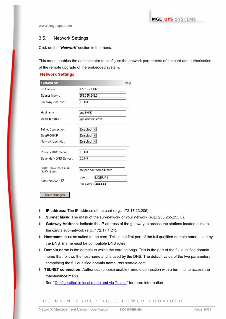
3.5.1 Network Settings
Click on the “Network” section in the menu.
This menu enables the administrator to configure the network parameters of the card and authorisation
of the remote upgrade of the embedded system.
◗ IP address: The IP address of the card (e.g.: 172.17.23.205).
◗ Subnet Mask: The mask of the sub-network of your network (e.g.: 255.255.255.0).
◗ Gateway Address: Indicate the IP address of the gateway to access the stations located outside
the card’s sub-network (e.g.: 172.17.1.24).
◗ Hostname must be suited to the card. This is the first part of the full qualified domain name, used by
the DNS (name must be compatible DNS rules)
◗ Domain name is the domain to which the card belongs. This is the part of the full qualified domain
name that follows the host name and is used by the DNS. The default value of the two parameters
comprising the full qualified domain name: ups.domain.com
◗ TELNET connection: Authorises (choose enable) remote connection with a terminal to access the
maintenance menu.
See “Configuration in local mode and via Telnet “ for more information
www.mgeups.com
T H E U N I N T E R R U P T I B L E P O W E R P R O V I D E R
Network Management Cards – User Manual 34003676EN/BA Page 35/74
◗ BootP/DHCP: Authorises (choose enable) configuration of network parameters with your
BootP/DHCP server when the card is booted
Mode of card operation with server: after any reboot, if this option is enabled, the card tries to recover
the network parameters from the server for 10 sec. If no response is received from the server, the
card boots with the last saved parameters from the previous start. These parameters are those
shown on the page
The default value for this parameter is “Enable”
. Note:
The IP address supplied by the DHCP server must be fixed to maintain connection with the clients
installed on the stations to be protected.
◗ Network Upgrade: Authorises (choose enable) remote upgrading of the embedded system on the
card using the Mupgrade tool. Read the “Maintenance” section for more details.
◗ Primary DNS server: contains the IP address of the main DNS server ensuring conversion of the
domain name to IP address.
◗ Secondary DNS server: contains the IP address of the secondary DNS server ensuring conversion
of the domain name to IP address if the primary DNS server is not available.
◗ SMTP server: contains the name or IP address of the local server with which the card connects to
send e-mails.
It may be filled in either as host + domain name (DNS resolution), or directly with the IP address
The default value is stmpserver.domain.com . The card uses port 25 to send e-mails.
◗ The Authentication option must be selected if the SMPT server requires this parameter for query
submission (see the RFC 2554 for SMTP authentication) for commercial reasons, access control,
etc.
When authentication is selected, the User and Password parameters must be specified for
identification with the local SMTP server.
Default values are MGEUPS/MGEUPS.
Note: The card must be rebooted after any changes to these parameters. See “System”
Security: the administrator must click on Save and enter his login/password to save any modifications.
www.mgeups.com
T H E U N I N T E R R U P T I B L E P O W E R P R O V I D E R
Network Management Cards – User Manual 34003676EN/BA Page 36/74
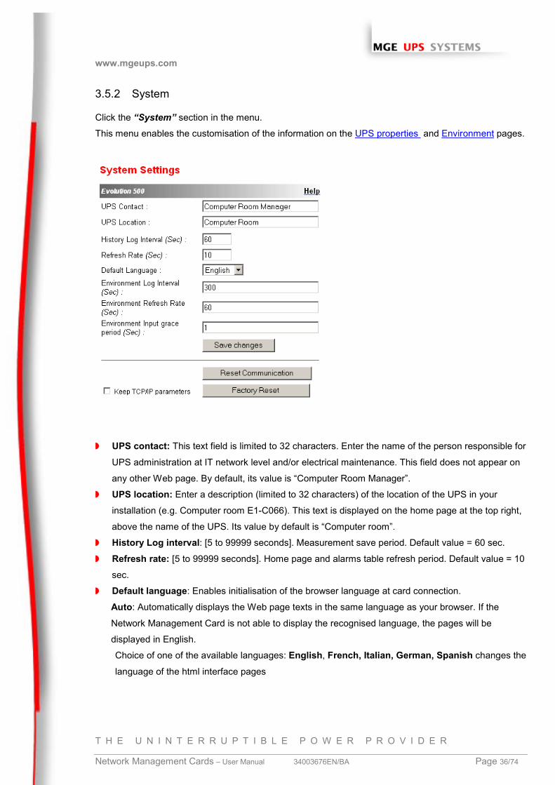
3.5.2 System
Click the “System” section in the menu.
This menu enables the customisation of the information on the UPS properties and Environment pages.
◗ UPS contact: This text field is limited to 32 characters. Enter the name of the person responsible for
UPS administration at IT network level and/or electrical maintenance. This field does not appear on
any other Web page. By default, its value is “Computer Room Manager”.
◗ UPS location: Enter a description (limited to 32 characters) of the location of the UPS in your
installation (e.g. Computer room E1-C066). This text is displayed on the home page at the top right,
above the name of the UPS. Its value by default is “Computer room”.
◗ History Log interval: [5 to 99999 seconds]. Measurement save period. Default value = 60 sec.
◗ Refresh rate: [5 to 99999 seconds]. Home page and alarms table refresh period. Default value = 10
sec.
◗ Default language: Enables initialisation of the browser language at card connection.
Auto: Automatically displays the Web page texts in the same language as your browser. If the
Network Management Card is not able to display the recognised language, the pages will be
displayed in English.
Choice of one of the available languages: English, French, Italian, German, Spanish changes the
language of the html interface pages
www.mgeups.com
T H E U N I N T E R R U P T I B L E P O W E R P R O V I D E R
Network Management Cards – User Manual 34003676EN/BA Page 37/74
◗ Note:
Alarm notification remains in English / French (reboot the browser after modification).
SNMP message remain in English.
◗ Environment log interval: [from 5 to 99999 sec ]. Temperature and humidity measurement save
period. Default value = 300 sec. (only visible if the sensor is present).
◗ Environment refresh rate: [from 5 to 99999 sec]. “Environment status” page refresh rate. Default
value = 60 sec. (only visible if the sensor is present).
◗ Environment input grace period : [from 0 to 9 sec ]. Period during which a status change by one of
the inputs is not considered. Default value = 1 sec. (only visible if the sensor is present).
◗ “Reset communication” button: performs a remote reboot of the card without modifying the
configuration. This action is compulsory for consideration of any changes made on the “Network
settings” page. Security of this operation is ensured by requesting Login and Password.
◗ “Fatory Reset” button: enables restoration of the default configuration of all the card’s parameters.
The TCP/IP parameters: IP address, subnet mask, gateway and BootP/DHCP value are maintained
if the “Keep TCP/IP parameters” option is selected. Security of this operation is ensured by
requesting Login and Password. Default login and Password are: MGEUPSNote:
If any of these parameters are changed, the card must be rebooted.
www.mgeups.com
T H E U N I N T E R R U P T I B L E P O W E R P R O V I D E R
Network Management Cards – User Manual 34003676EN/BA Page 38/74
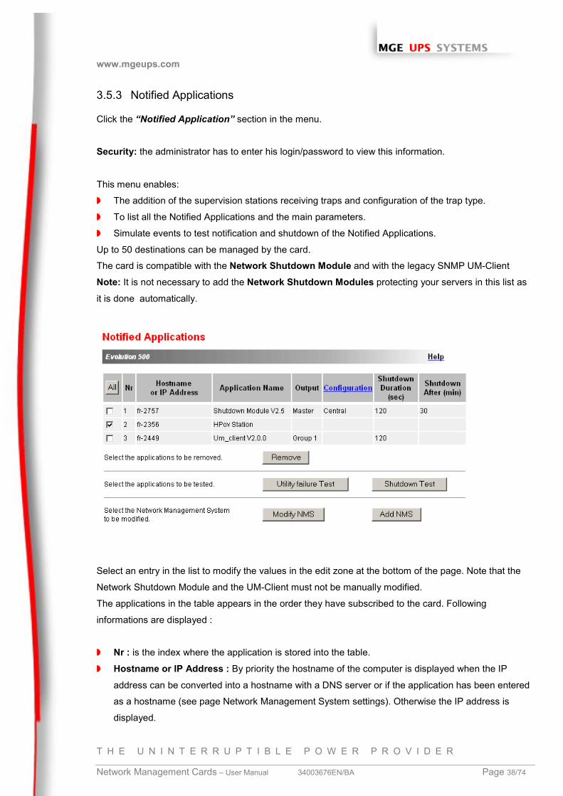
3.5.3 Notified Applications
Click the “Notified Application” section in the menu.
Security: the administrator has to enter his login/password to view this information.
This menu enables:
◗ The addition of the supervision stations receiving traps and configuration of the trap type.
◗ To list all the Notified Applications and the main parameters.
◗ Simulate events to test notification and shutdown of the Notified Applications.
Up to 50 destinations can be managed by the card.
The card is compatible with the Network Shutdown Module and with the legacy SNMP UM-Client
Note: It is not necessary to add the Network Shutdown Modules protecting your servers in this list as
it is done automatically.
Select an entry in the list to modify the values in the edit zone at the bottom of the page. Note that the
Network Shutdown Module and the UM-Client must not be manually modified.
The applications in the table appears in the order they have subscribed to the card. Following
informations are displayed :
◗ Nr : is the index where the application is stored into the table.
◗ Hostname or IP Address : By priority the hostname of the computer is displayed when the IP
address can be converted into a hostname with a DNS server or if the application has been entered
as a hostname (see page Network Management System settings). Otherwise the IP address is
displayed.
www.mgeups.com
T H E U N I N T E R R U P T I B L E P O W E R P R O V I D E R
Network Management Cards – User Manual 34003676EN/BA Page 39/74
◗ Application Name : sent by the application at subscribe time or manually entered.
◗ Output : is the number of the output from which the client is powered.
◗ Configuration : shows where the parameters of Network Shutdown Module comes from :
Local(coming from the application) or Central(coming from the card).
◗ The Central Shutdown Configuration is available by clicking on Configuration link.
◗ Shutdown duration : is the shutdown duration necessary to properly shutdown the computer.
◗ Shutdown after : is the time available to the user from the Power failure until the launch of the
shutoff sequence of the UPS. This parameter is optionnal.
Many actions are available on this page :
◗ Remove : Depending on the kind of application, the selected ones will definitively disappear from the
table as SNMP applications, or they will disappear and automatically re-subscribe as the Network
Shutdown Module application.
◗ Utility failure Test : Two alarms 'Utility failure' and 'Utility restored' spaced of 30 seconds will be sent
to the applications selected, making sure that the applications can be reached over the network.
◗ Shutdown Test : This test simulates a UPS on battery operation, it sends alarms to the selected
applications. It enables an easy check to see if the server protection works correctly.- No
intervention on the UPS is required.
- Simulated alarms will be processed by the applications selected only.
- Warning :This test will generate a REAL shutdown sequence of servers on which Network
Shutdown Module is running.
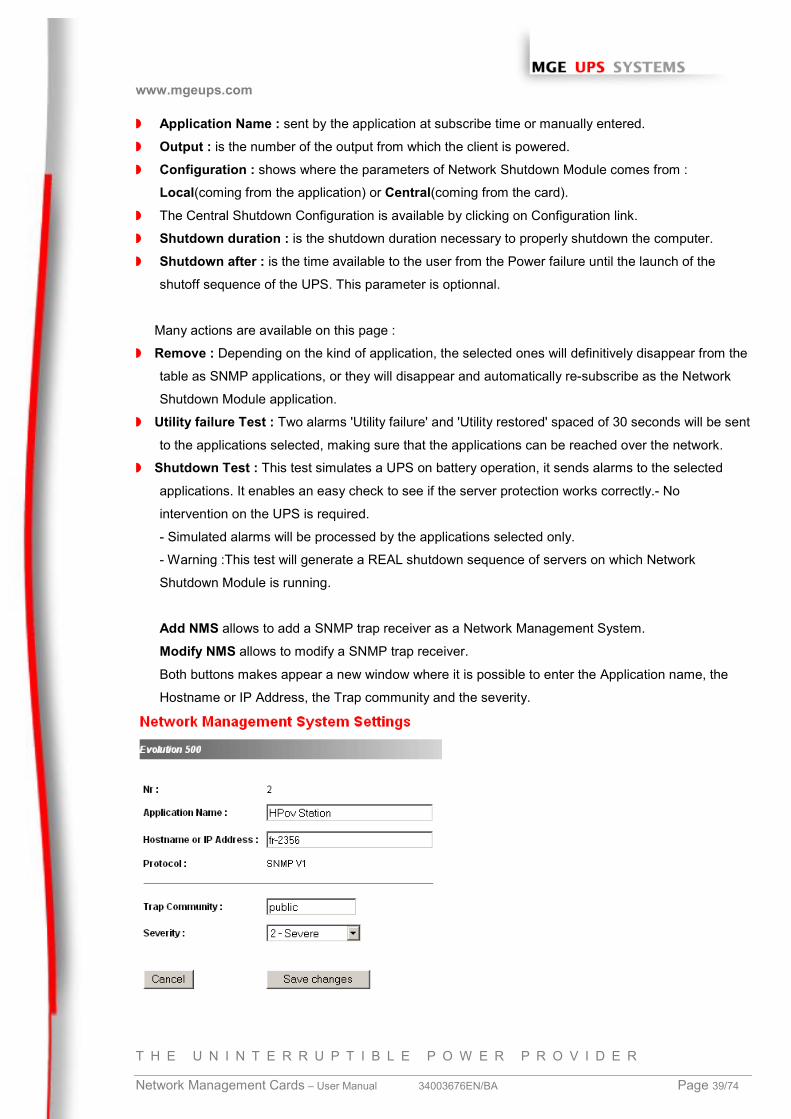
Add NMS allows to add a SNMP trap receiver as a Network Management System.
Modify NMS allows to modify a SNMP trap receiver.
Both buttons makes appear a new window where it is possible to enter the Application name, the
Hostname or IP Address, the Trap community and the severity.
www.mgeups.com
T H E U N I N T E R R U P T I B L E P O W E R P R O V I D E R
Network Management Cards – User Manual 34003676EN/BA Page 40/74
◗ Trap community indicates the name of the SNMP community
For more details, read the MIB description document: 34003627zjaa.pdf , available in the Embedded
zone of the www.mgeups.com site.
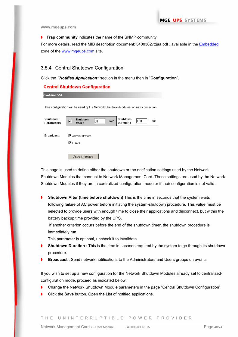
3.5.4 Central Shutdown Configuration
Click the “Notified Application” section in the menu then in “Configuration”.
This page is used to define either the shutdown or the notification settings used by the Network
Shutdown Modules that connect to Network Management Card. These settings are used by the Network
Shutdown Modules if they are in centralized-configuration mode or if their configuration is not valid.
◗ Shutdown After (time before shutdown) This is the time in seconds that the system waits
following failure of AC power before initiating the system-shutdown procedure. This value must be
selected to provide users with enough time to close their applications and disconnect, but within the
battery backup time provided by the UPS.
If another criterion occurs before the end of the shutdown timer, the shutdown procedure is
immediately run.
This parameter is optional, uncheck it to invalidate
◗ Shutdown Duration : This is the time in seconds required by the system to go through its shutdown
procedure.
◗ Broadcast : Send network notifications to the Administrators and Users groups on events
If you wish to set up a new configuration for the Network Shutdown Modules already set to centralized-
configuration mode, proceed as indicated below.
◗ Change the Network Shutdown Module parameters in the page “Central Shutdown Configuration”.
◗ Click the Save button. Open the List of notified applications.

www.mgeups.com
T H E U N I N T E R R U P T I B L E P O W E R P R O V I D E R
Network Management Cards – User Manual 34003676EN/BA Page 41/74
Select the Network Shutdown Modules to receive the new configuration.
Press the button “Remove” They reconnect and use the new configuration
www.mgeups.com
T H E U N I N T E R R U P T I B L E P O W E R P R O V I D E R
Network Management Cards – User Manual 34003676EN/BA Page 42/74
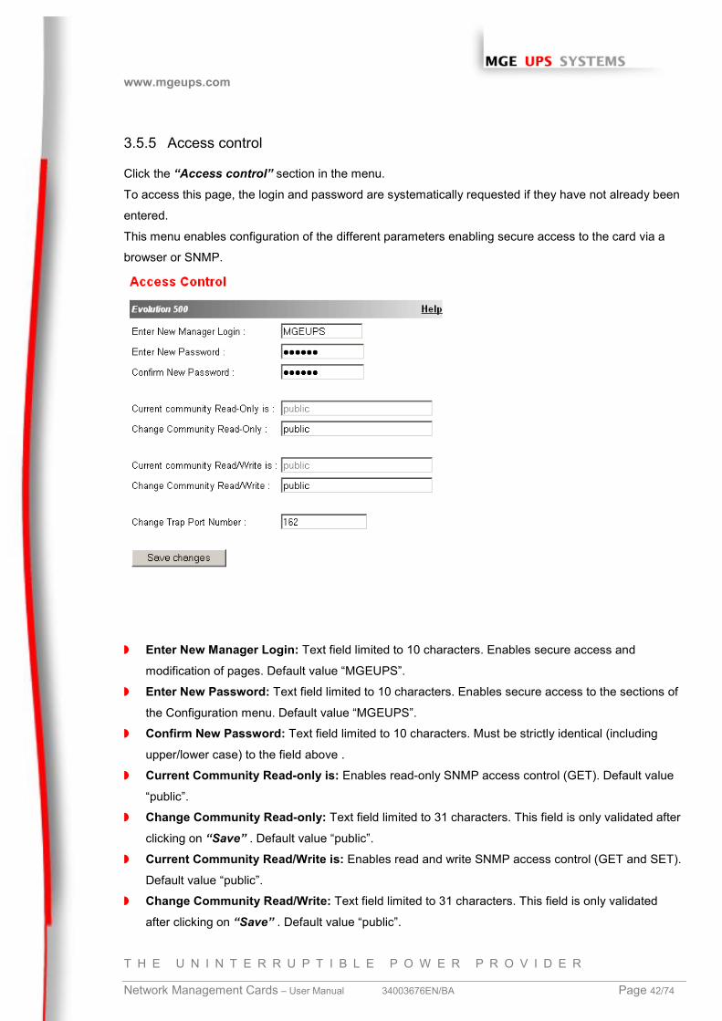
3.5.5 Access control
Click the “Access control” section in the menu.
To access this page, the login and password are systematically requested if they have not already been
entered.
This menu enables configuration of the different parameters enabling secure access to the card via a
browser or SNMP.
◗ Enter New Manager Login: Text field limited to 10 characters. Enables secure access and
modification of pages. Default value “MGEUPS”.
◗ Enter New Password: Text field limited to 10 characters. Enables secure access to the sections of
the Configuration menu. Default value “MGEUPS”.
◗ Confirm New Password: Text field limited to 10 characters. Must be strictly identical (including
upper/lower case) to the field above .
◗ Current Community Read-only is: Enables read-only SNMP access control (GET). Default value
“public”.
◗ Change Community Read-only: Text field limited to 31 characters. This field is only validated after
clicking on “Save” . Default value “public”.
◗ Current Community Read/Write is: Enables read and write SNMP access control (GET and SET).
Default value “public”.
◗ Change Community Read/Write: Text field limited to 31 characters. This field is only validated
after clicking on “Save” . Default value “public”.

www.mgeups.com
T H E U N I N T E R R U P T I B L E P O W E R P R O V I D E R
Network Management Cards – User Manual 34003676EN/BA Page 43/74
◗ Change Trap Port Number: Numeric field limited to 65534. Enables forwarding of traps sent by the
card to a port other than the port usually used for SNMP. Default value 162.

www.mgeups.com
T H E U N I N T E R R U P T I B L E P O W E R P R O V I D E R
Network Management Cards – User Manual 34003676EN/BA Page 44/74
3.5.6 Time
Click the “Time” section in the menu.
This menu enables initialisation of the date and time of the card in three different ways.
◗ Synchronise manually: Enables initialisation of the date and time of the card, with the values
entered in the Date and Time fields. Values are updated after clicking the “Save” button.
◗ Synchronise with computer time: Enables the date and time of your PC to be transferred to the
card. This transfer is made after clicking on the “Save” button. Time is not adjusted regularly, it is
set at the time of the save.
◗ Synchronise with an NTP server: Enables connection with a time server, either available on the
company’s internal network or on the Web. This server communicates GMT time. The IP address of
the time server must be entered, and the time zone of your geographic area must then be selected
from the list. Connection is made with the server and the date and time are set after clicking on the
“Save” button. Time is updated every hour.
The card uses the NTP protocol (UDP 123 port) and the firewall must be set accordingly, no error
message is generated if the time server contact fails
www.mgeups.com
T H E U N I N T E R R U P T I B L E P O W E R P R O V I D E R
Network Management Cards – User Manual 34003676EN/BA Page 45/74
◗ Daylight Saving Time: Enables corrections due to summer / winter time changes, this option must
be supported by the NTP server.
Note 1:Time drift is related to card electronics. It may be up to a maximum of +/- 2min/month.
3.6 Environment
The environment sensor is an option that enables temperature and humidity to be measured, and
indication of the position of two external contacts. It is connected with a standard network cable to the
Card Settings port of the Network Management Card.
On startup, the card automatically detects sensor presence. The main menu then displays an additional
section “Environment” with the following elements:
◗ Status◗ Configuration◗ Log
Note 1 This function is only accessible with the DA version software (or superior) for the card. This
software can be downloaded on the www.mgeups.com site, from the download section.
Note 2: To switch the serial port to the configuration mode, just disconnect the sensor cable and
reinitialise the card by pressing “Reset”. The reverse operation must be performed to manage the
environment sensor once again.
3.6.1 Characteristics
◗ Temperature measurement from 0 to 70 °C with +/- 1°C accuracy
◗ Humidity measurement from 0 to 100 % with +/- 6 % accuracy
◗ Min. / max. time-stamped function for temperature and humidity
◗ Choice of displaying temperature in Celsius or Fahrenheit
◗ High and low thresholds, hysteresis and offset adjustment via Web interface
◗ Possibility of notification of status changes by e-mail, SMS or SNMP trap
◗ Position detection of 2 dry contacts (maximum sensor/contact distance: 20m)
◗ Name and status of each contact can be configured
◗ Recording of events and measurements in the card log
◗ Possibility of shutting down the installation safely if one of the thresholds is exceeded or if a dry
contact closes
◗ Connection to the Network Management Card by CAT5 straight RJ45 network cables (maximum
card/sensor distance: 20m)
www.mgeups.com
T H E U N I N T E R R U P T I B L E P O W E R P R O V I D E R
Network Management Cards – User Manual 34003676EN/BA Page 46/74
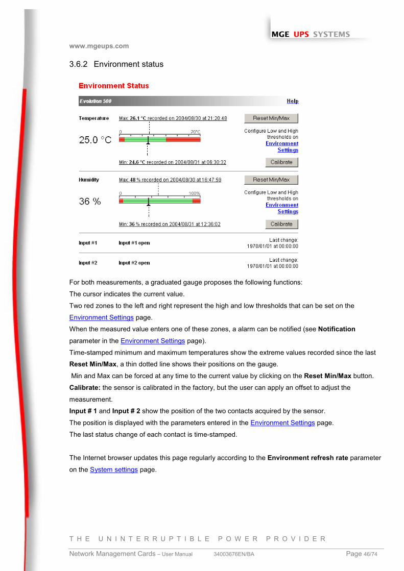
3.6.2 Environment status
For both measurements, a graduated gauge proposes the following functions:
The cursor indicates the current value.
Two red zones to the left and right represent the high and low thresholds that can be set on the
Environment Settings page.
When the measured value enters one of these zones, a alarm can be notified (see Notificationparameter in the Environment Settings page).
Time-stamped minimum and maximum temperatures show the extreme values recorded since the last
Reset Min/Max, a thin dotted line shows their positions on the gauge.
Min and Max can be forced at any time to the current value by clicking on the Reset Min/Max button.
Calibrate: the sensor is calibrated in the factory, but the user can apply an offset to adjust the
measurement.
Input # 1 and Input # 2 show the position of the two contacts acquired by the sensor.
The position is displayed with the parameters entered in the Environment Settings page.
The last status change of each contact is time-stamped.
The Internet browser updates this page regularly according to the Environment refresh rate parameter
on the System settings page.
www.mgeups.com
T H E U N I N T E R R U P T I B L E P O W E R P R O V I D E R
Network Management Cards – User Manual 34003676EN/BA Page 47/74
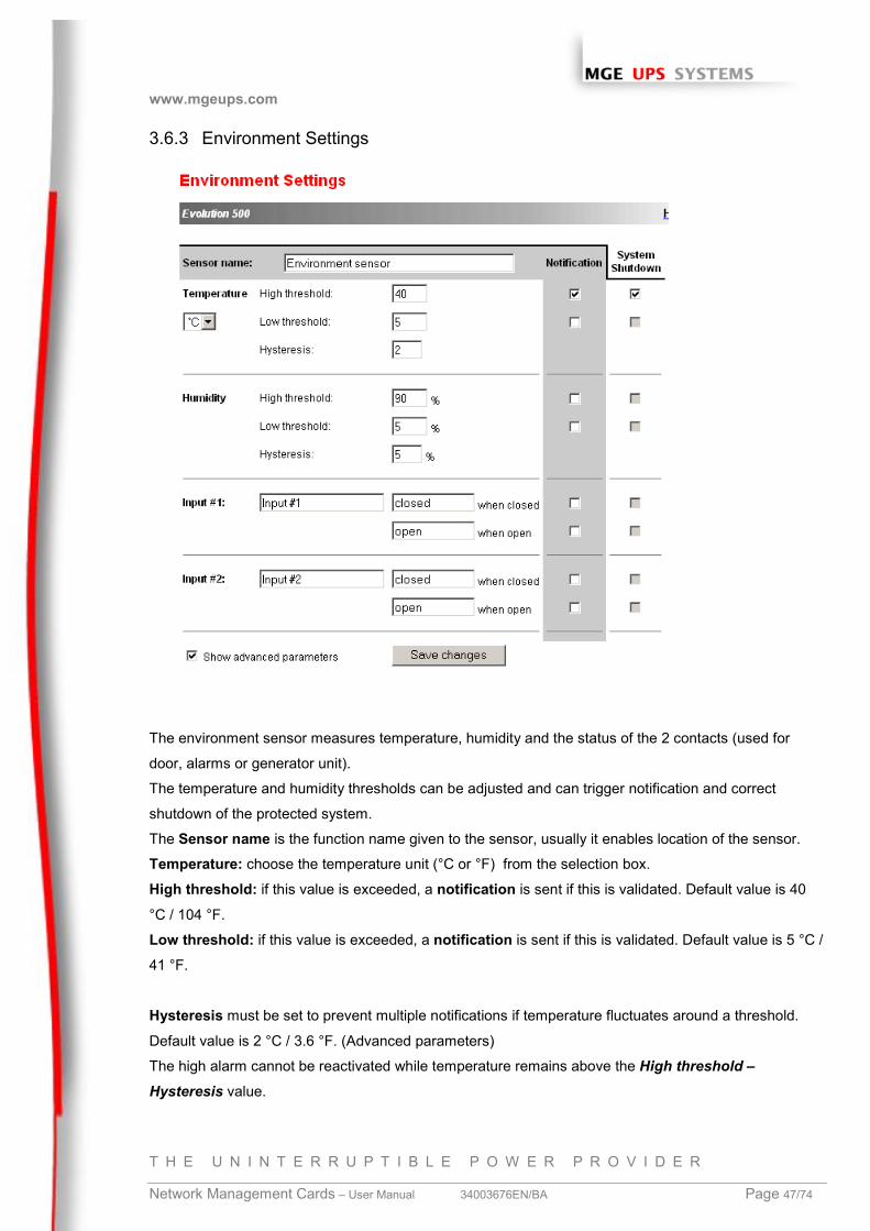
3.6.3 Environment Settings
The environment sensor measures temperature, humidity and the status of the 2 contacts (used for
door, alarms or generator unit).
The temperature and humidity thresholds can be adjusted and can trigger notification and correct
shutdown of the protected system.
The Sensor name is the function name given to the sensor, usually it enables location of the sensor.
Temperature: choose the temperature unit (°C or °F) from the selection box.
High threshold: if this value is exceeded, a notification is sent if this is validated. Default value is 40
°C / 104 °F.
Low threshold: if this value is exceeded, a notification is sent if this is validated. Default value is 5 °C /
41 °F.
Hysteresis must be set to prevent multiple notifications if temperature fluctuates around a threshold.
Default value is 2 °C / 3.6 °F. (Advanced parameters)
The high alarm cannot be reactivated while temperature remains above the High threshold –Hysteresis value.

www.mgeups.com
T H E U N I N T E R R U P T I B L E P O W E R P R O V I D E R
Network Management Cards – User Manual 34003676EN/BA Page 48/74
The low alarm cannot be reactivated while temperature remains below Low threshold + hysteresisvalue.
HumidityHigh threshold: if this value is exceeded, a notification is sent if enabled. Default value is 90%.
Low threshold: if this value is exceeded, a notification is sent if enabled. Default value is 5%.
Hysteresis must be set to prevent multiple notifications if humidity fluctuates around a threshold.
Default value is 5%. (Advanced parameters)
The high alarm cannot be reactivated while humidity remains above the High threshold – Hysteresisvalue.
The low alarm cannot be reactivated while humidity remains below Low threshold + hysteresis value.
Input No 1 and Input No 2: enter an identifier corresponding to the acquired contact (e.g.: rack door, air
conditioning, generator unit, etc.). Max. length is 28 characters.
If contact closed and if contact open: are the names associated to the two contact positions. (e.g.:
"open" and "closed" for a door, "On" and "Off" for a generator).
Each status change triggers a notification if enabled.
Notification includes: Log, Notification by e-mail and generation of SNMP Trap. The list of messages is
given in the appendix.
System shutdown can be triggered for each notification if this option is enabled. If notification is
disabled, the Shutdown option cannot be used. (Advanced parameters)
Security: the administrator has to click on Save and enter his login/password to save any modifications.
3.6.4 Log
www.mgeups.com
T H E U N I N T E R R U P T I B L E P O W E R P R O V I D E R
Network Management Cards – User Manual 34003676EN/BA Page 49/74
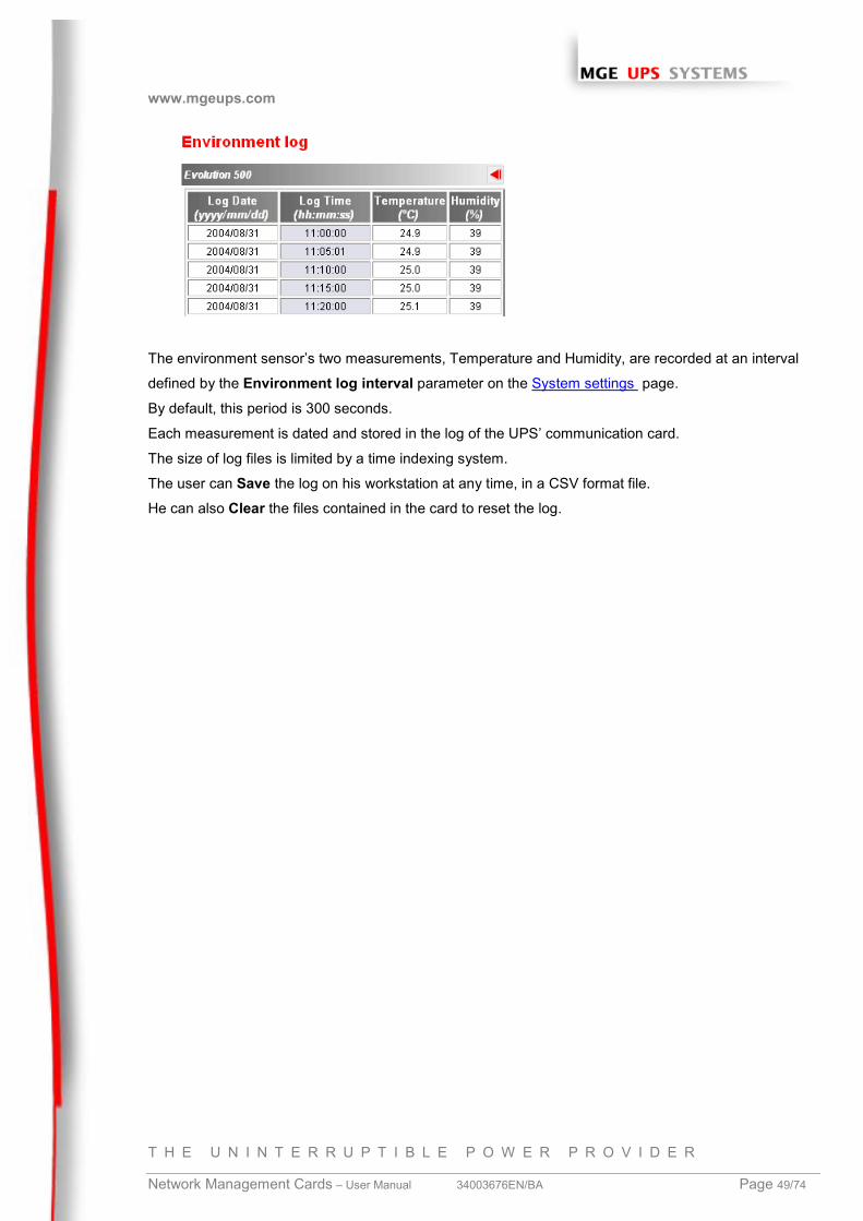
The environment sensor’s two measurements, Temperature and Humidity, are recorded at an interval
defined by the Environment log interval parameter on the System settings page.
By default, this period is 300 seconds.
Each measurement is dated and stored in the log of the UPS’ communication card.
The size of log files is limited by a time indexing system.
The user can Save the log on his workstation at any time, in a CSV format file.
He can also Clear the files contained in the card to reset the log.
www.mgeups.com
T H E U N I N T E R R U P T I B L E P O W E R P R O V I D E R
Network Management Cards – User Manual 34003676EN/BA Page 50/74
4 Servers protection
4.1 Set-up of the shutdown parameters
The Network Shutdown Module, on protected server boot, subscribes itself automatically to Notified
Applications list and sends its essential data:
◗ IP address of the server on which it is installed, to be notified by the card of any power events
◗ Time required to shutdown the server (Shutdown Duration, configurable in the Shutdown Module
“set-up” menu):
The card takes into account the longest shutdown time of all Network Shutdown Modules subscribed
to manage UPS shutdown without affecting any of the connected Shutdown Modules.
In case of a major power event, the Shutdown Module receives messages from the card and regularly
checks its accessibility. The most important messages can generate actions and are sent back to the
administrator and users via the network.
When the server shuts down, the Shutdown Module unsubscribes itself from the Notified Applications.
4.1.1 Shutdown criteria managed by the Management Card
During an extended power failure, three criteria may cause the server shutdown procedure to be
initiated. If several criteria are selected, the first criterion encountered will launch the shutdown
procedure.
At the end of the shutdown procedure, when all servers have been shut down, the UPS may shut down
to avoid unnecessary discharge of its batteries, depending on its configuration.
4.1.1.1 Backup time before initiating the shutdown procedure (Shutdown After)
When the UPS switches to battery, the Network Management Card starts the Shutdown Timer
countdown and launches the system shutdown procedure at the end of the countdown.
This value must be chosen so that users have time to complete their tasks and disconnect, without
exceeding battery backup time.
By default, this value is set to 30 minutes.
Note 1:The Network Shutdown Module also manages its own Shutdown Timer
Note that if this criterion is selected to initiate system shutdown, automatic system reboot when power is
restored is not guaranteed (e.g. power restoration if only this system was shut down). We recommend
leaving this parameter at a value greater than that of the card’s Shutdown Timer.
By default, this value is set to 31 minutes.
www.mgeups.com
T H E U N I N T E R R U P T I B L E P O W E R P R O V I D E R
Network Management Cards – User Manual 34003676EN/BA Page 51/74
4.1.1.2 Initiating the shutdown procedure when the battery level is lower than: (if capacity
under)
When the card detects that the remaining backup time percentage is less than the configured level, the
shutdown sequence is started.
By default, this value is set in the UPS.
Note:Certain types of UPS only accept pre-defined minimum battery level values (e.g. : 20% or 40% for
COMET and PULSAR EXtreme). Check the UPS documentation.
4.1.1.3 Shutdown when backup time is less than
When the Network Management Card detects that the percentage of backup time remaining is less than
the value set, the shutdown sequence is started.
4.1.1.4 Shutdown duration
Duration required for the systems protected by the Shutdown Modules to shut down (in seconds).
4.1.2 Specific set-up for long autonomy installation (> 30 mn)
On installation where the backup period is longer than 30 minutes, the Network Management Card will
initiate automatically a shutdown at the end of the shutdown timer, to avoid that, the shutdown timer
must be programmed to a value higher than the real autonomy.
4.1.3 Controlled outlets
Some UPS models are equipped with outlets (typically 2), that can be controlled individually (while still
remaining dependent on the main UPS control).
Shutdown of the main outlet systematically causes shutdown of the programmable outlets.
Depending on the UPS range, the following notation is used to mark these outlets:
◗ Main outlet: Main or 1
◗ Programmable outlet 1 1 or 2
◗ Programmable outlet 2 2 or 3
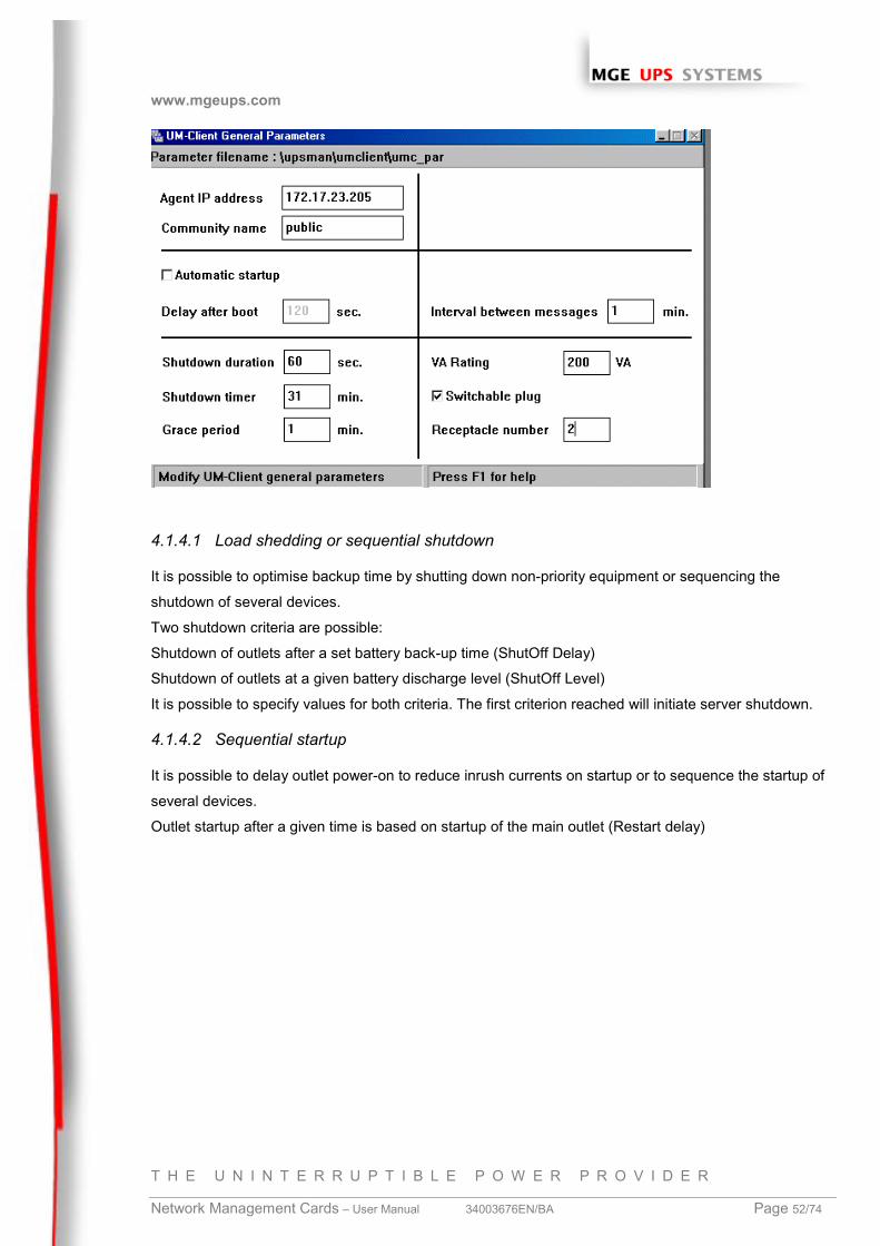
4.1.4 Connecting a server protected by UM-Client to a programmable outlet
Only UM-Client is compatible with the programmable outlets, the Network Shutdown Module will be
compatible with release 3.0.
After connecting the server electrically to one of the controlled outlets, UM-Client must be informed of
the outlet number to which it is connected.
Start UM-Editor (installed with Solution-Pac / WAN), select the “Switchable plug” box and specify the
outlet number (1=main, 2 or 3) in the “Receptacle Number” field.
www.mgeups.com
T H E U N I N T E R R U P T I B L E P O W E R P R O V I D E R
Network Management Cards – User Manual 34003676EN/BA Page 52/74
4.1.4.1 Load shedding or sequential shutdown
It is possible to optimise backup time by shutting down non-priority equipment or sequencing the
shutdown of several devices.
Two shutdown criteria are possible:
Shutdown of outlets after a set battery back-up time (ShutOff Delay)
Shutdown of outlets at a given battery discharge level (ShutOff Level)
It is possible to specify values for both criteria. The first criterion reached will initiate server shutdown.
4.1.4.2 Sequential startup
It is possible to delay outlet power-on to reduce inrush currents on startup or to sequence the startup of
several devices.
Outlet startup after a given time is based on startup of the main outlet (Restart delay)
www.mgeups.com
T H E U N I N T E R R U P T I B L E P O W E R P R O V I D E R
Network Management Cards – User Manual 34003676EN/BA Page 53/74
4.2 The different server and UPS shutdown sequences
4.2.1 Extended power outage, shutdown initiated by the Shutdown Timer
During battery backup time, the Shutdown Timer of the Network Management Card is reached: after
a user-defined backup time period, the shutdown of all servers is initiated, followed by the UPS
shutdown (depending on its configuration). The UPS restarts when utility power is restored (depending
on its configuration).
◗ Shutdown Duration: Maximum value of shutdown times of the Network Shutdown Modules and
UM-Clients subscribed to the card and depending on the main UPS outlet. This value is updated
each time a client subscribes/ unsubscribes.
◗ Shutdown Duration 1 (2): Maximum value of shutdown times of the UM-Client subscribed to the
card and dependent on outlet 1 (2). This value is updated each time a UM-Client dependent on
outlet 1 (2) subscribes /unsubscribes.
Note: During battery operation, these values are not updated.
www.mgeups.com
T H E U N I N T E R R U P T I B L E P O W E R P R O V I D E R
Network Management Cards – User Manual 34003676EN/BA Page 54/74
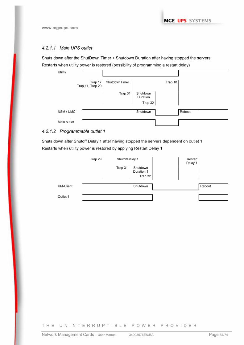
4.2.1.1 Main UPS outlet
Shuts down after the ShutDown Timer + Shutdown Duration after having stopped the servers
Restarts when utility power is restored (possibility of programming a restart delay)Utility
Trap 17Trap,11, Trap 29
ShutdownTimer Trap 18
Trap 31 ShutdownDuration
Trap 32
NSM / UMC Shutdown Reboot
Main outlet
4.2.1.2 Programmable outlet 1
Shuts down after Shutoff Delay 1 after having stopped the servers dependent on outlet 1
Restarts when utility power is restored by applying Restart Delay 1
Trap 29 ShutoffDelay 1 RestartDelay 1
Trap 31 ShutdownDuration.1
Trap 32
UM-Client Shutdown Reboot
Outlet 1
www.mgeups.com
T H E U N I N T E R R U P T I B L E P O W E R P R O V I D E R
Network Management Cards – User Manual 34003676EN/BA Page 55/74
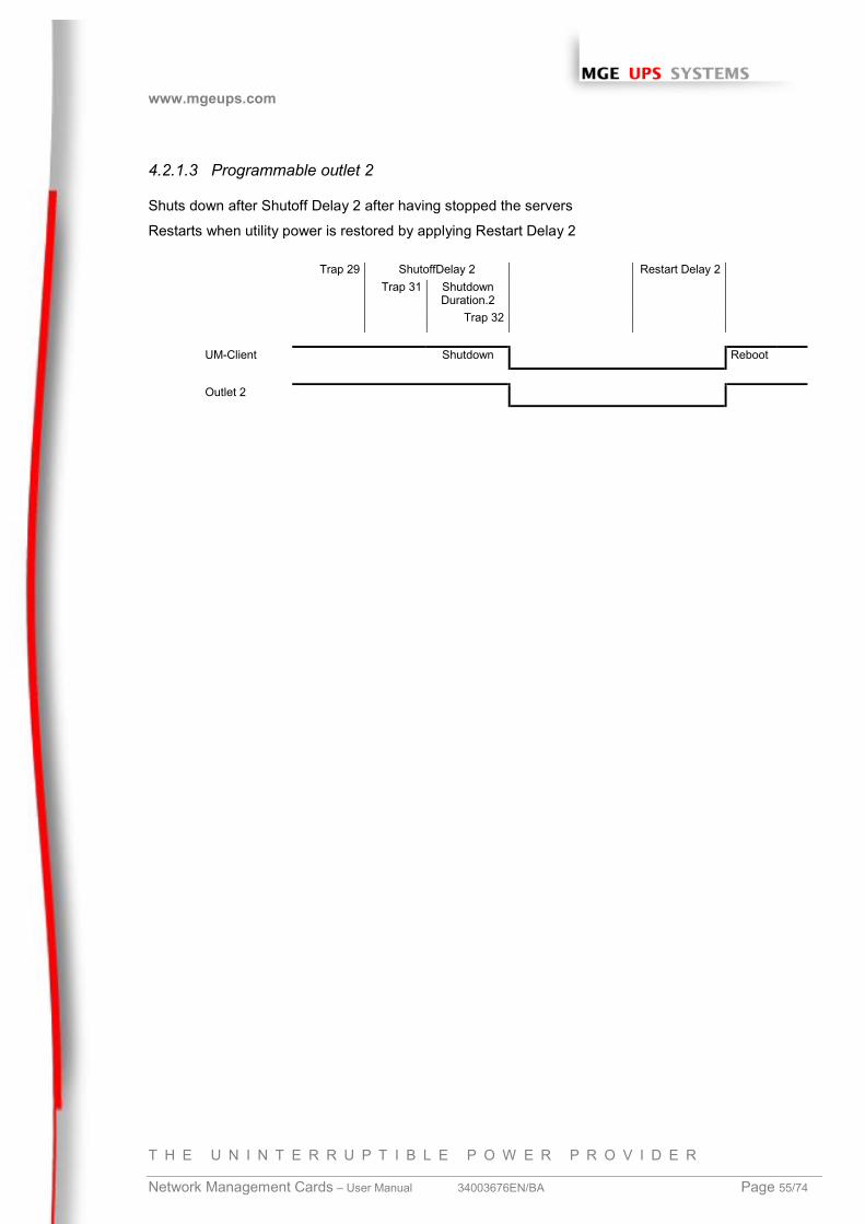
4.2.1.3 Programmable outlet 2
Shuts down after Shutoff Delay 2 after having stopped the servers
Restarts when utility power is restored by applying Restart Delay 2
Trap 29 ShutoffDelay 2 Restart Delay 2Trap 31 Shutdown
Duration.2Trap 32
UM-Client Shutdown Reboot
Outlet 2
www.mgeups.com
T H E U N I N T E R R U P T I B L E P O W E R P R O V I D E R
Network Management Cards – User Manual 34003676EN/BA Page 56/74
4.2.2 Extended power outage, shutdown initiated by the “Low battery power”
message
When the ”Low battery power” message is displayed, the UPS is shut down after taking into account the
shutdown duration of the servers.
“Low battery power”: The message appears if either of the two following criteria is checked:
- Low Battery Level
- Minimum remaining backup time (Low Battery Delay)
4.2.2.1 Main UPS outlet
Utility
Trap 17Trap 11Trap 29
Low batteryTrap 9
Trap 18Trap 10
Trap 31 ShutdownDuration
Trap 32
NSM / UMC Shutdown Reboot
Main outlet
4.2.2.2 Programmable outlet 1
Trap 29 ShutoffTimer.1 RestartDelay.1
Trap 31 Sh`downDuration.
1Trap 32
UM-Client Shutdown
Reboot
Outlet 1
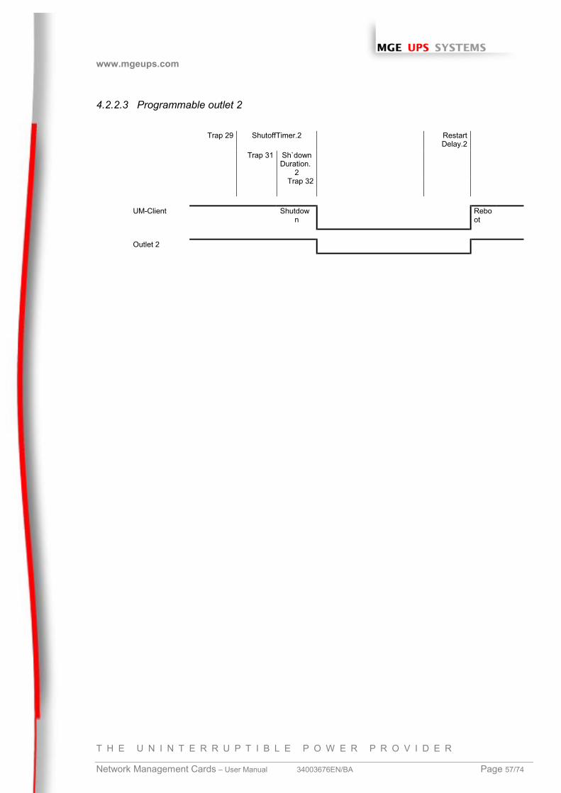
www.mgeups.com
T H E U N I N T E R R U P T I B L E P O W E R P R O V I D E R
Network Management Cards – User Manual 34003676EN/BA Page 57/74
4.2.2.3 Programmable outlet 2
Trap 29 ShutoffTimer.2 RestartDelay.2
Trap 31 Sh`downDuration.
2Trap 32
UM-Client Shutdown
Reboot
Outlet 2
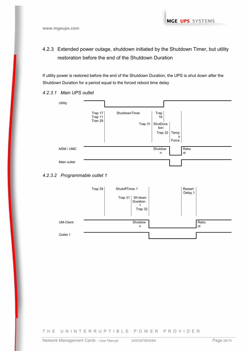
www.mgeups.com
T H E U N I N T E R R U P T I B L E P O W E R P R O V I D E R
Network Management Cards – User Manual 34003676EN/BA Page 58/74
4.2.3 Extended power outage, shutdown initiated by the Shutdown Timer, but utility
restoration before the end of the Shutdown Duration
If utility power is restored before the end of the Shutdown Duration, the UPS is shut down after the
Shutdown Duration for a period equal to the forced reboot time delay
4.2.3.1 Main UPS outlet
Utility
Trap 17Trap 11Trap 29
ShutdownTimer Trap18
Trap 31 ShutDuration
Trap 32 Tempo
Force
NSM / UMC Shutdown
Reboot
Main outlet
4.2.3.2 Programmable outlet 1
Trap 29 ShutoffTimer.1 RestartDelay.1
Trap 31 Sh’downDuration.
1Trap 32
UM-Client Shutdown
Reboot
Outlet 1
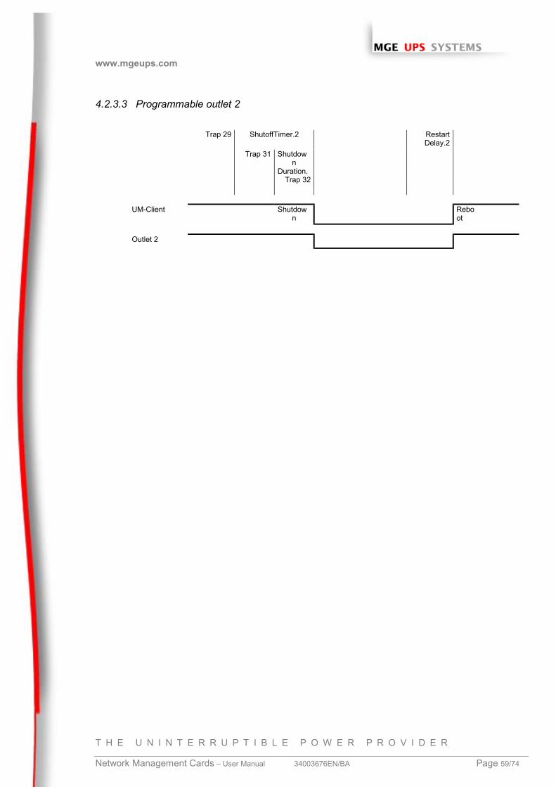
www.mgeups.com
T H E U N I N T E R R U P T I B L E P O W E R P R O V I D E R
Network Management Cards – User Manual 34003676EN/BA Page 59/74
4.2.3.3 Programmable outlet 2
Trap 29 ShutoffTimer.2 RestartDelay.2
Trap 31 Shutdown
Duration.Trap 32
UM-Client Shutdown
Reboot
Outlet 2
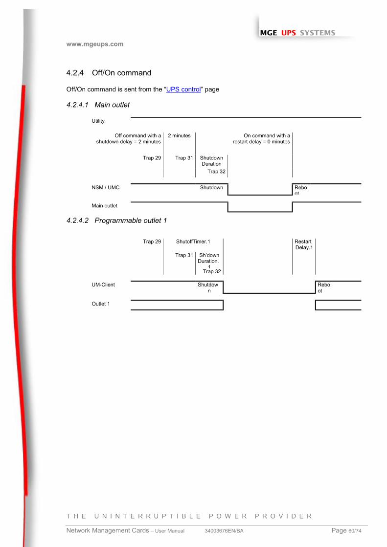
www.mgeups.com
T H E U N I N T E R R U P T I B L E P O W E R P R O V I D E R
Network Management Cards – User Manual 34003676EN/BA Page 60/74
4.2.4 Off/On command
Off/On command is sent from the “UPS control” page
4.2.4.1 Main outlet
Utility
Off command with ashutdown delay = 2 minutes
2 minutes On command with arestart delay = 0 minutes
Trap 29 Trap 31 ShutdownDuration
Trap 32
NSM / UMC Shutdown Reboot
Main outlet
4.2.4.2 Programmable outlet 1
Trap 29 ShutoffTimer.1 RestartDelay.1
Trap 31 Sh’downDuration.
1Trap 32
UM-Client Shutdown
Reboot
Outlet 1
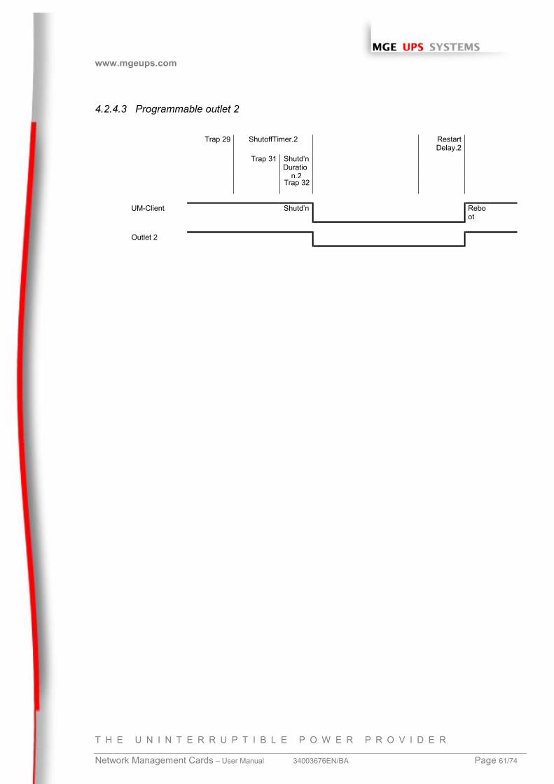
www.mgeups.com
T H E U N I N T E R R U P T I B L E P O W E R P R O V I D E R
Network Management Cards – User Manual 34003676EN/BA Page 61/74
4.2.4.3 Programmable outlet 2
Trap 29 ShutoffTimer.2 RestartDelay.2
Trap 31 Shutd’nDuratio
n.2Trap 32
UM-Client Shutd’n Reboot
Outlet 2
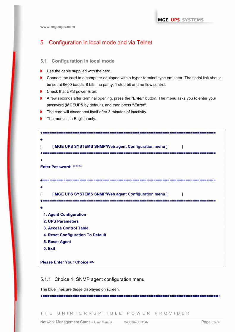
www.mgeups.com
T H E U N I N T E R R U P T I B L E P O W E R P R O V I D E R
Network Management Cards – User Manual 34003676EN/BA Page 62/74
5 Configuration in local mode and via Telnet
5.1 Configuration in local mode
◗ Use the cable supplied with the card.
◗ Connect the card to a computer equipped with a hyper-terminal type emulator. The serial link should
be set at 9600 bauds, 8 bits, no parity, 1 stop bit and no flow control.
◗ Check that UPS power is on.
◗ A few seconds after terminal opening, press the "Enter” button. The menu asks you to enter your
password (MGEUPS by default), and then press “Enter”.◗ The card will disconnect itself after 3 minutes of inactivity.
◗ The menu is in English only.
+===========================================================================+| [ MGE UPS SYSTEMS SNMP/Web agent Configuration menu ] |+===========================================================================+Enter Password: ******
+===========================================================================+| [ MGE UPS SYSTEMS SNMP/Web agent Configuration menu ] |+===========================================================================+ 1. Agent Configuration 2. UPS Parameters 3. Access Control Table 4. Reset Configuration To Default 5. Reset Agent 0. Exit
Please Enter Your Choice =>
5.1.1 Choice 1: SNMP agent configuration menu
The blue lines are those displayed on screen.
+============================================================================+
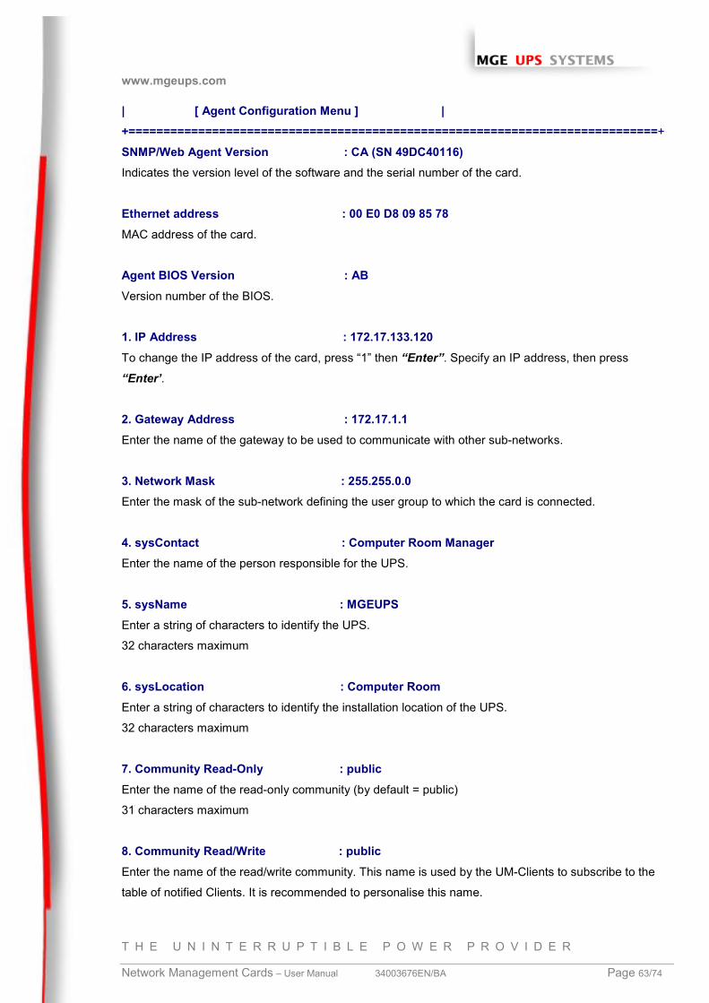
www.mgeups.com
T H E U N I N T E R R U P T I B L E P O W E R P R O V I D E R
Network Management Cards – User Manual 34003676EN/BA Page 63/74
| [ Agent Configuration Menu ] |+============================================================================+
SNMP/Web Agent Version : CA (SN 49DC40116)Indicates the version level of the software and the serial number of the card.
Ethernet address : 00 E0 D8 09 85 78MAC address of the card.
Agent BIOS Version : ABVersion number of the BIOS.
1. IP Address : 172.17.133.120To change the IP address of the card, press “1” then “Enter”. Specify an IP address, then press
“Enter’.
2. Gateway Address : 172.17.1.1Enter the name of the gateway to be used to communicate with other sub-networks.
3. Network Mask : 255.255.0.0Enter the mask of the sub-network defining the user group to which the card is connected.
4. sysContact : Computer Room ManagerEnter the name of the person responsible for the UPS.
5. sysName : MGEUPSEnter a string of characters to identify the UPS.
32 characters maximum
6. sysLocation : Computer RoomEnter a string of characters to identify the installation location of the UPS.
32 characters maximum
7. Community Read-Only : publicEnter the name of the read-only community (by default = public)
31 characters maximum
8. Community Read/Write : publicEnter the name of the read/write community. This name is used by the UM-Clients to subscribe to the
table of notified Clients. It is recommended to personalise this name.
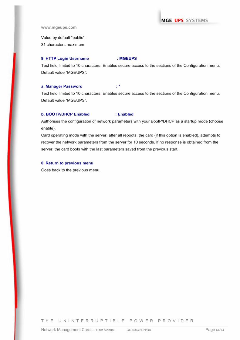
www.mgeups.com
T H E U N I N T E R R U P T I B L E P O W E R P R O V I D E R
Network Management Cards – User Manual 34003676EN/BA Page 64/74
Value by default “public”.
31 characters maximum
9. HTTP Login Username : MGEUPSText field limited to 10 characters. Enables secure access to the sections of the Configuration menu.
Default value “MGEUPS”.
a. Manager Password : *Text field limited to 10 characters. Enables secure access to the sections of the Configuration menu.
Default value “MGEUPS”.
b. BOOTP/DHCP Enabled : EnabledAuthorises the configuration of network parameters with your BootP/DHCP as a startup mode (choose
enable).
Card operating mode with the server: after all reboots, the card (if this option is enabled), attempts to
recover the network parameters from the server for 10 seconds. If no response is obtained from the
server, the card boots with the last parameters saved from the previous start.
0. Return to previous menuGoes back to the previous menu.
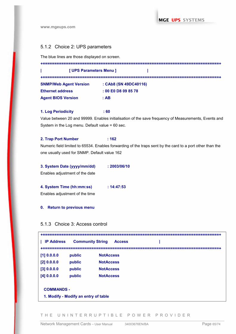
www.mgeups.com
T H E U N I N T E R R U P T I B L E P O W E R P R O V I D E R
Network Management Cards – User Manual 34003676EN/BA Page 65/74
5.1.2 Choice 2: UPS parameters
The blue lines are those displayed on screen.
+============================================================================+| [ UPS Parameters Menu ] |+============================================================================+SNMP/Web Agent Version : CAb8 (SN 49DC40116)Ethernet address : 00 E0 D8 09 85 78Agent BIOS Version : AB
1. Log Periodicity : 60Value between 20 and 99999. Enables initialisation of the save frequency of Measurements, Events and
System in the Log menu. Default value = 60 sec.
2. Trap Port Number : 162Numeric field limited to 65534. Enables forwarding of the traps sent by the card to a port other than the
one usually used for SNMP. Default value 162
3. System Date (yyyy/mm/dd) : 2003/06/10Enables adjustment of the date
4. System Time (hh:mm:ss) : 14:47:53Enables adjustment of the time
0. Return to previous menu
5.1.3 Choice 3: Access control
+============================================================================+| IP Address Community String Access |+============================================================================+[1] 0.0.0.0 public NotAccess[2] 0.0.0.0 public NotAccess[3] 0.0.0.0 public NotAccess[4] 0.0.0.0 public NotAccess
COMMANDS - 1. Modify - Modify an entry of table
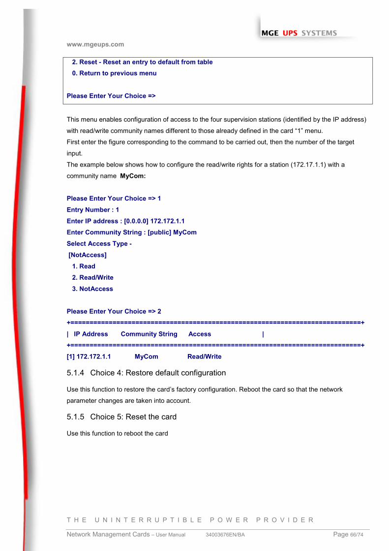
www.mgeups.com
T H E U N I N T E R R U P T I B L E P O W E R P R O V I D E R
Network Management Cards – User Manual 34003676EN/BA Page 66/74
2. Reset - Reset an entry to default from table 0. Return to previous menu
Please Enter Your Choice =>
This menu enables configuration of access to the four supervision stations (identified by the IP address)
with read/write community names different to those already defined in the card “1” menu.
First enter the figure corresponding to the command to be carried out, then the number of the target
input.
The example below shows how to configure the read/write rights for a station (172.17.1.1) with a
community name MyCom:
Please Enter Your Choice => 1Entry Number : 1Enter IP address : [0.0.0.0] 172.172.1.1Enter Community String : [public] MyComSelect Access Type - [NotAccess] 1. Read 2. Read/Write 3. NotAccess
Please Enter Your Choice => 2+============================================================================+| IP Address Community String Access |+============================================================================+[1] 172.172.1.1 MyCom Read/Write
5.1.4 Choice 4: Restore default configuration
Use this function to restore the card’s factory configuration. Reboot the card so that the network
parameter changes are taken into account.
5.1.5 Choice 5: Reset the card
Use this function to reboot the card
www.mgeups.com
T H E U N I N T E R R U P T I B L E P O W E R P R O V I D E R
Network Management Cards – User Manual 34003676EN/BA Page 67/74
5.2 Configuration via Telnet
You can access the configuration menu (see “configuration in local mode” section) from a station
equipped with the Telnet protocol.
As soon as the card is accessible on the network, enter the command:
telnet < card IP address > to access the menu.
The password defined by default is MGEUPS.
The card will disconnect automatically after 3 minutes of inactivity.
www.mgeups.com
T H E U N I N T E R R U P T I B L E P O W E R P R O V I D E R
Network Management Cards – User Manual 34003676EN/BA Page 68/74
6 Maintenance
6.1 Software upgrade
6.1.1 Card software upgrade using Mupgrade (Windows)
6.1.2 Card software upgrade via TFTP (UNIX and Windows)
6.1.3 Card software upgrade via the serial link
Read the relevant documentation available for download on the www.mgeups.com web site, in the
“Download area – embedded Software” section.
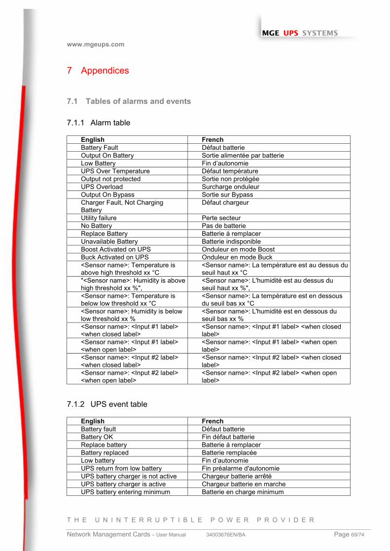
www.mgeups.com
T H E U N I N T E R R U P T I B L E P O W E R P R O V I D E R
Network Management Cards – User Manual 34003676EN/BA Page 69/74
7 Appendices
7.1 Tables of alarms and events
7.1.1 Alarm table
English FrenchBattery Fault Défaut batterieOutput On Battery Sortie alimentée par batterieLow Battery Fin d’autonomieUPS Over Temperature Défaut températureOutput not protected Sortie non protégéeUPS Overload Surcharge onduleurOutput On Bypass Sortie sur BypassCharger Fault, Not ChargingBattery
Défaut chargeur
Utility failure Perte secteurNo Battery Pas de batterieReplace Battery Batterie à remplacerUnavailable Battery Batterie indisponibleBoost Activated on UPS Onduleur en mode BoostBuck Activated on UPS Onduleur en mode Buck<Sensor name>: Temperature isabove high threshold xx °C
<Sensor name>: La température est au dessus duseuil haut xx °C
"<Sensor name>: Humidity is abovehigh threshold xx %",
<Sensor name>: L'humidité est au dessus duseuil haut xx %",
<Sensor name>: Temperature isbelow low threshold xx °C
<Sensor name>: La température est en dessousdu seuil bas xx °C
<Sensor name>: Humidity is belowlow threshold xx %
<Sensor name>: L'humidité est en dessous duseuil bas xx %
<Sensor name>: <Input #1 label><when closed label>
<Sensor name>: <Input #1 label> <when closedlabel>
<Sensor name>: <Input #1 label><when open label>
<Sensor name>: <Input #1 label> <when openlabel>
<Sensor name>: <Input #2 label><when closed label>
<Sensor name>: <Input #2 label> <when closedlabel>
<Sensor name>: <Input #2 label><when open label>
<Sensor name>: <Input #2 label> <when openlabel>
7.1.2 UPS event table
English FrenchBattery fault Défaut batterieBattery OK Fin défaut batterieReplace battery Batterie à remplacerBattery replaced Batterie remplacéeLow battery Fin d’autonomieUPS return from low battery Fin préalarme d'autonomieUPS battery charger is not active Chargeur batterie arrêtéUPS battery charger is active Chargeur batterie en marcheUPS battery entering minimum Batterie en charge minimum
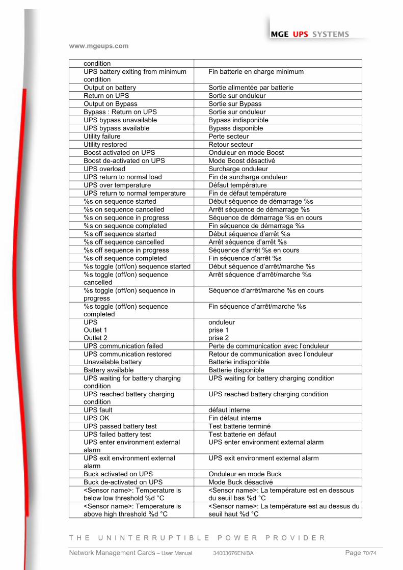
www.mgeups.com
T H E U N I N T E R R U P T I B L E P O W E R P R O V I D E R
Network Management Cards – User Manual 34003676EN/BA Page 70/74
conditionUPS battery exiting from minimumcondition
Fin batterie en charge minimum
Output on battery Sortie alimentée par batterieReturn on UPS Sortie sur onduleurOutput on Bypass Sortie sur BypassBypass : Return on UPS Sortie sur onduleurUPS bypass unavailable Bypass indisponibleUPS bypass available Bypass disponibleUtility failure Perte secteurUtility restored Retour secteurBoost activated on UPS Onduleur en mode BoostBoost de-activated on UPS Mode Boost désactivéUPS overload Surcharge onduleurUPS return to normal load Fin de surcharge onduleurUPS over temperature Défaut températureUPS return to normal temperature Fin de défaut température%s on sequence started Début séquence de démarrage %s%s on sequence cancelled Arrêt séquence de démarrage %s%s on sequence in progress Séquence de démarrage %s en cours%s on sequence completed Fin séquence de démarrage %s%s off sequence started Début séquence d’arrêt %s%s off sequence cancelled Arrêt séquence d’arrêt %s%s off sequence in progress Séquence d’arrêt %s en cours%s off sequence completed Fin séquence d’arrêt %s%s toggle (off/on) sequence started Début séquence d’arrêt/marche %s%s toggle (off/on) sequencecancelled
Arrêt séquence d’arrêt/marche %s
%s toggle (off/on) sequence inprogress
Séquence d’arrêt/marche %s en cours
%s toggle (off/on) sequencecompleted
Fin séquence d’arrêt/marche %s
UPSOutlet 1Outlet 2
onduleurprise 1prise 2
UPS communication failed Perte de communication avec l’onduleurUPS communication restored Retour de communication avec l’onduleurUnavailable battery Batterie indisponibleBattery available Batterie disponibleUPS waiting for battery chargingcondition
UPS waiting for battery charging condition
UPS reached battery chargingcondition
UPS reached battery charging condition
UPS fault défaut interneUPS OK Fin défaut interneUPS passed battery test Test batterie terminéUPS failed battery test Test batterie en défautUPS enter environment externalalarm
UPS enter environment external alarm
UPS exit environment externalalarm
UPS exit environment external alarm
Buck activated on UPS Onduleur en mode BuckBuck de-activated on UPS Mode Buck désactivé<Sensor name>: Temperature isbelow low threshold %d °C
<Sensor name>: La température est en dessousdu seuil bas %d °C
<Sensor name>: Temperature isabove high threshold %d °C
<Sensor name>: La température est au dessus duseuil haut %d °C
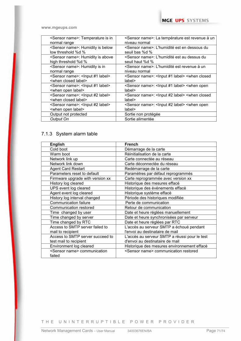
www.mgeups.com
T H E U N I N T E R R U P T I B L E P O W E R P R O V I D E R
Network Management Cards – User Manual 34003676EN/BA Page 71/74
<Sensor name>: Temperature is innormal range
<Sensor name>: La température est revenue à unniveau normal
<Sensor name>: Humidity is belowlow threshold %d %
<Sensor name>: L'humidité est en dessous duseuil bas %d %
<Sensor name>: Humidity is abovehigh threshold %d %
<Sensor name>: L'humidité est au dessus duseuil haut %d %
<Sensor name>: Humidity is innormal range
<Sensor name>: L'humidité est revenue à unniveau normal
<Sensor name>: <Input #1 label><when closed label>
<Sensor name>: <Input #1 label> <when closedlabel>
<Sensor name>: <Input #1 label><when open label>
<Sensor name>: <Input #1 label> <when openlabel>
<Sensor name>: <Input #2 label><when closed label>
<Sensor name>: <Input #2 label> <when closedlabel>
<Sensor name>: <Input #2 label><when open label>
<Sensor name>: <Input #2 label> <when openlabel>
Output not protected Sortie non protégéeOutput On Sortie alimentée
7.1.3 System alarm table
English FrenchCold boot Démarrage de la carteWarm boot Réinitialisation de la carteNetwork link up Carte connectée au réseauNetwork link down Carte déconnectée du réseauAgent Card Restart Redémarrage de la carteParameters reset to default Paramètres par défaut reprogrammésFirmware upgrade with version xx Carte reprogrammée avec version xxHistory log cleared Historique des mesures effacéUPS event log cleared Historique des événements effacéAgent event log cleared Historique système effacéHistory log interval changed Période des historiques modifiéeCommunication failure Perte de communicationCommunication restored Retour de communicationTime changed by user Date et heure réglées manuellementTime changed by server Date et heure synchronisées par serveurTime changed by RTC Date et heure réglées par RTCAccess to SMTP server failed tomail to recipient
L'accès au serveur SMTP a échoué pendantl'envoi au destinataire de mail
Access to SMTP server succeed totest mail to recipient
L'accès au serveur SMTP a réussi pour le testd'envoi au destinataire de mail
Environment log cleared Historique des mesures environnement effacé<Sensor name> communicationfailed
<Sensor name> communication restored
www.mgeups.com
T H E U N I N T E R R U P T I B L E P O W E R P R O V I D E R
Network Management Cards – User Manual 34003676EN/BA Page 72/74
7.2 Glossary
Bootp:Protocol based on UDP used to allocate an IP address corresponding to an Ethernet card during the
startup phase. Defined by the RCF 951
Community name:Access key to access SNMP agent information
DHCP Dynamic Host Configuration Protocol
This IETF protocol enables remote, automatic, self-configuration of the IP addresses of a workstation.
DNS Domain Name Sevicel
The DNS protocol ensure correspondence between the name of a machine and its IP address
DST Daylight Saving Time
Extension of the NTP protocol to manage time changes in summer and winter
E-mailElectronic means of transmitting messages and/or files.
GatewayInterconnection equipment between networks with different conventions, to enable communication
between them
HTML(HyperText Markup Language) Language used to describe hypertext pages on the web.
IPInternet Protocol. Network layer protocol in the TCP/IP stack offering a no-connection inter-network
service . The IP protocol offers functions for addressing, service type specification, fragmentation and
re-assembling and security. Defined in RFC 791.
MD5Message Digest 5. Algorithm producing an output message from an input message of arbitrary length, in
the form of a replica or s
mary 128 bit message. Intended for digital signature applications requiring large files to be compressed
in total security before being coded with a private key, using a public key algorithm, like RSA.
www.mgeups.com
T H E U N I N T E R R U P T I B L E P O W E R P R O V I D E R
Network Management Cards – User Manual 34003676EN/BA Page 73/74
MIB MANAGEMENT INFORMATION BASE
- Group of software commands to control and administrate a device through the network. Each type of
device (server, hub, PC, UPS, etc.) has its own MIB
– The IETF has proposed a standard MIB for each group of devices (hubs, for example) to simplify
administration if they come from different suppliers
MultiSlotExpander module for MGEUPS communication card.
NETWORK MANAGEMENT CARD
Communication cards to supervise UPS and communicate with Network Shutdown Module to insure
power protection on servers
NETWORK MANAGEMENT PROXY
Communication software installed on a PC connected to the UPS to supervise it and communicate with
Network Shutdown Module to insure power protection on servers
NMS NETWORK MANAGEMENT STATION (SNMP)
The dedicated PC or workstation is used on the company’s networks to administrate all devices
connected to the network. Data are transmitted using the SNMP protocol. Popular NMS systems include
HP OpenView, IBM Tivoli, CA Unicenter, etc.
NETWORK SHUTDOWN MODULE
Protection software installed on a PC or server to protect it
NTP Network Time Protocol
Protocol to position a set of machines on a network at the same time.
Programmable outlet (controlled outlet):Outlet that can be remote-switched on or off. UM-Client components enable management of such
outlets.
REBOOT –To restart a system after an interruption.
– To perform an obstacle-free “reboot”, it is essential that the system is correctly and carefully shut down
beforehand.
– The reboot is usually automatic if the computer is re-supplied with electricity (from the utility or from
the UPS).
www.mgeups.com
T H E U N I N T E R R U P T I B L E P O W E R P R O V I D E R
Network Management Cards – User Manual 34003676EN/BA Page 74/74
RFCRequest for Comments. All documents defining internal Internet operation.
SNMP (SIMPLE NETWORK MANAGEMENT PROTOCOL)
Protocol used to remote-supervise, administrate and control devices connected to a company network.
SMTP (SIMPLE MAIL TRANSFER PROTOCOL)
Enables message transfer between e-mail servers or between the client and its server. It is based on the
server’s port 25. It is described in RFC 821
Subnet mask:Mask of bits used to identify and differentiate the network address and the equipment address in an IP
address.
Normally, the mask is automatically determined by the class of address, which defines in a unique
manner the network part/equipment part division of the IP address.
- Class A: internet address: 255.0.0.0.
- Class B: internet address: 255.255.0.0.
- Class C: internet address: 255.255.255.0.
TCP/IPTransmission Control Protocol/Internet Protocol. Common name of a series of protocols developed by
the DOD in the US to help build Internet networks throughout the world.
TelnetInternet protocol used for terminal emulation, i.e. enabling a computer to connect with a server as if it
was a simple terminal locally connected to this server.
Trap (SNMP)This term describes an event that affects an MIB variable. Traps are sent to the manager, which is
programmed to perform specific tasks upon reception of the traps.
UM-ClientUM-Client is a legacy software package (SNMP manager) that uses the information sent by the agent
dedicated to the MGE UPS in order to inform users of the computer of the power quality status.
In case of a power failure, UM-Client triggers a graceful shutdown procedure at the end of a preset
battery runtime.