network layer4-1 data communication and networks lecture 9 networks: part 1 november 4, 2004
Post on 21-Dec-2015
221 views
TRANSCRIPT

Network Layer 4-1
Data Communication and Networks
Lecture 9
Networks: Part 1
November 4, 2004

Network Layer 4-2
Network layer transport segment from sending to receiving
host on sending side encapsulates segments into
datagrams on rcving side, delivers segments to transport
layer network layer protocols in every host, router Router examines header fields in all IP
datagrams passing through it
networkdata linkphysical
networkdata linkphysical
networkdata linkphysical
networkdata linkphysical
networkdata linkphysical
networkdata linkphysical
networkdata linkphysical
networkdata linkphysical
application
transportnetworkdata linkphysical
application
transportnetworkdata linkphysical

Network Layer 4-3
Key Network-Layer Functions
forwarding: move packets from router’s input to appropriate router output
routing: determine route taken by packets from source to dest.
Routing algorithms
analogy:
routing: process of planning trip from source to dest
forwarding: process of getting through single interchange

Network Layer 4-4
1
23
0111
value in arrivingpacket’s header
routing algorithm
local forwarding tableheader value output link
0100010101111001
3221
Interplay between routing and forwarding

Network Layer 4-5
Connection setup
3rd important function in some network architectures: ATM, frame relay, X.25
Before datagrams flow, two hosts and intervening routers establish virtual connection Routers get involved
Network and transport layer cnctn service: Network: between two hosts Transport: between two processes

Network Layer 4-6
Network service model
Q: What service model for “channel” transporting datagrams from sender to rcvr?
Example services for individual datagrams:
guaranteed delivery Guaranteed delivery
with less than 40 msec delay
Example services for a flow of datagrams:
In-order datagram delivery
Guaranteed minimum bandwidth to flow
Restrictions on changes in inter-packet spacing

Network Layer 4-7
Network layer service models:
NetworkArchitecture
Internet
ATM
ATM
ATM
ATM
ServiceModel
best effort
CBR
VBR
ABR
UBR
Bandwidth
none
constantrateguaranteedrateguaranteed minimumnone
Loss
no
yes
yes
no
no
Order
no
yes
yes
yes
yes
Timing
no
yes
yes
no
no
Congestionfeedback
no (inferredvia loss)nocongestionnocongestionyes
no
Guarantees ?

Network Layer 4-8
Virtual circuit vs. datagram networks

Network Layer 4-9
Network layer connection and connection-less service
Datagram network provides network-layer connectionless service
VC network provides network-layer connection service
Analogous to the transport-layer services, but: Service: host-to-host No choice: network provides one or the
other Implementation: in the core

Network Layer 4-10
Virtual circuits
call setup, teardown for each call before data can flow each packet carries VC identifier (not destination host
address) every router on source-dest path maintains “state” for
each passing connection link, router resources (bandwidth, buffers) may be
allocated to VC
“source-to-dest path behaves much like telephone circuit” performance-wise network actions along source-to-dest path

Network Layer 4-11
VC implementation
A VC consists of:1. Path from source to destination2. VC numbers, one number for each link along
path3. Entries in forwarding tables in routers along
path Packet belonging to VC carries a VC
number. VC number must be changed on each
link. New VC number comes from forwarding table

Network Layer 4-12
Forwarding table
12 22 32
1 23
VC number
interfacenumber
Incoming interface Incoming VC # Outgoing interface Outgoing VC #
1 12 2 222 63 1 18 3 7 2 171 97 3 87… … … …
Forwarding table innorthwest router:
Routers maintain connection state information!

Network Layer 4-13
Virtual circuits: signaling protocols
used to setup, maintain teardown VC used in ATM, frame-relay, X.25 not used in today’s Internet
application
transportnetworkdata linkphysical
application
transportnetworkdata linkphysical
1. Initiate call 2. incoming call
3. Accept call4. Call connected5. Data flow begins 6. Receive data

Network Layer 4-14
Datagram networks no call setup at network layer routers: no state about end-to-end connections
no network-level concept of “connection”
packets forwarded using destination host address packets between same source-dest pair may take
different paths
application
transportnetworkdata linkphysical
application
transportnetworkdata linkphysical
1. Send data 2. Receive data

Network Layer 4-15
Forwarding table
Destination Address Range Link Interface
11001000 00010111 00010000 00000000 through 0 11001000 00010111 00010111 11111111
11001000 00010111 00011000 00000000 through 1 11001000 00010111 00011000 11111111
11001000 00010111 00011001 00000000 through 2 11001000 00010111 00011111 11111111
otherwise 3
4 billion possible entries

Network Layer 4-16
Longest prefix matching
Prefix Match Link Interface 11001000 00010111 00010 0 11001000 00010111 00011000 1 11001000 00010111 00011 2 otherwise 3
DA: 11001000 00010111 00011000 10101010
Examples
DA: 11001000 00010111 00010110 10100001 Which interface?
Which interface?

Network Layer 4-17
Datagram or VC network: why?
Internet data exchange among
computers “elastic” service, no
strict timing req. “smart” end systems
(computers) can adapt, perform
control, error recovery simple inside network,
complexity at “edge” many link types
different characteristics uniform service difficult
ATM evolved from telephony human conversation:
strict timing, reliability requirements
need for guaranteed service
“dumb” end systems telephones complexity inside
network

Network Layer 4-18
What’s inside a router?

Network Layer 4-19
Router Architecture Overview
Two key router functions: run routing algorithms/protocol (RIP, OSPF, BGP) forwarding datagrams from incoming to outgoing link

Network Layer 4-20
Input Port Functions
Decentralized switching: given datagram dest., lookup output
port using forwarding table in input port memory
goal: complete input port processing at ‘line speed’
queuing: if datagrams arrive faster than forwarding rate into switch fabric
Physical layer:bit-level reception
Data link layer:e.g., Ethernetsee chapter 5

Network Layer 4-21
Three types of switching fabrics

Network Layer 4-22
Switching Via MemoryFirst generation routers: traditional computers with switching under direct control of CPUpacket copied to system’s memory speed limited by memory bandwidth (2 bus crossings per datagram)
InputPort
OutputPort
Memory
System Bus
Network Layer 4-23
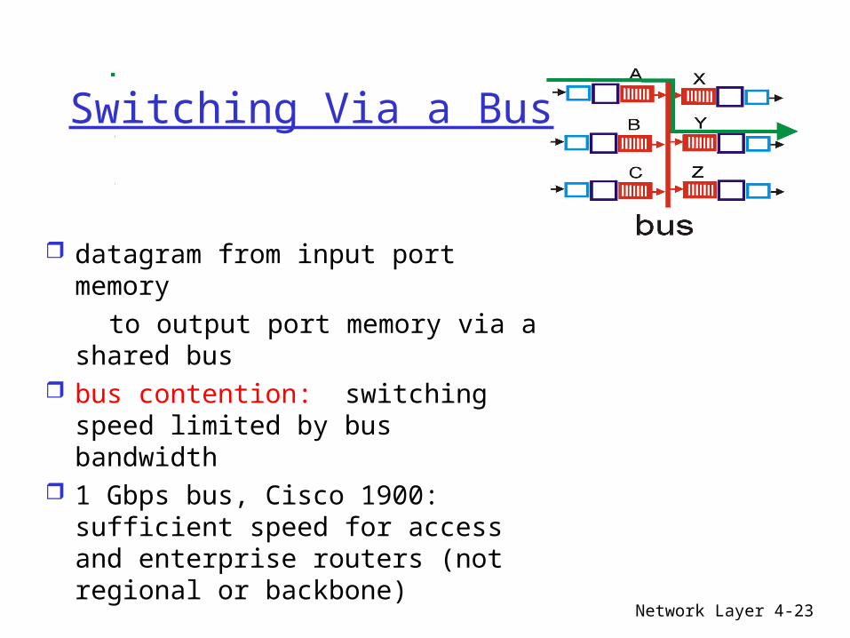
Switching Via a Bus
datagram from input port memory
to output port memory via a shared bus
bus contention: switching speed limited by bus bandwidth
1 Gbps bus, Cisco 1900: sufficient speed for access and enterprise routers (not regional or backbone)

Network Layer 4-24
Switching Via An Interconnection Network
overcome bus bandwidth limitations Banyan networks, other interconnection nets
initially developed to connect processors in multiprocessor
Advanced design: fragmenting datagram into fixed length cells, switch cells through the fabric.
Cisco 12000: switches Gbps through the interconnection network

Network Layer 4-25
Output Ports
Buffering required when datagrams arrive from fabric faster than the transmission rate
Scheduling discipline chooses among queued datagrams for transmission

Network Layer 4-26
Output port queueing
buffering when arrival rate via switch exceeds output line speed
queueing (delay) and loss due to output port buffer overflow!

Network Layer 4-27
Input Port Queuing
Fabric slower than input ports combined -> queueing may occur at input queues
Head-of-the-Line (HOL) blocking: queued datagram at front of queue prevents others in queue from moving forward
queueing delay and loss due to input buffer overflow!

Network Layer 4-28
IP: Internet Protocol

Network Layer 4-29
The Internet Network layer
forwardingtable
Host, router network layer functions:
Routing protocols•path selection•RIP, OSPF, BGP
IP protocol•addressing conventions•datagram format•packet handling conventions
ICMP protocol•error reporting•router “signaling”
Transport layer: TCP, UDP
Link layer
physical layer
Networklayer

Network Layer 4-30
IP datagram format
ver length
32 bits
data (variable length,typically a TCP
or UDP segment)
16-bit identifier
Internet checksum
time tolive
32 bit source IP address
IP protocol versionnumber
header length (bytes)
max numberremaining hops
(decremented at each router)
forfragmentation/reassembly
total datagramlength (bytes)
upper layer protocolto deliver payload to
head.len
type ofservice
“type” of data flgsfragment
offsetupper layer
32 bit destination IP address
Options (if any) E.g. timestamp,record routetaken, specifylist of routers to visit.
how much overhead with TCP?
20 bytes of TCP 20 bytes of IP = 40 bytes + app
layer overhead

Network Layer 4-31
IP Fragmentation & Reassembly network links have MTU
(max.transfer size) - largest possible link-level frame. different link types,
different MTUs large IP datagram divided
(“fragmented”) within net one datagram becomes
several datagrams “reassembled” only at
final destination IP header bits used to
identify, order related fragments
fragmentation: in: one large datagramout: 3 smaller datagrams
reassembly

Network Layer 4-32
IP Fragmentation and Reassembly
ID=x
offset=0
fragflag=0
length=4000
ID=x
offset=0
fragflag=1
length=1500
ID=x
offset=185
fragflag=1
length=1500
ID=x
offset=370
fragflag=0
length=1040
One large datagram becomesseveral smaller datagrams
Example 4000 byte
datagram MTU = 1500 bytes
1480 bytes in data field
offset =1480/8

Network Layer 4-33
IP Addressing: introduction IP address: 32-bit
identifier for host, router interface
interface: connection between host/router and physical link router’s typically have
multiple interfaces host may have
multiple interfaces IP addresses
associated with each interface
223.1.1.1
223.1.1.2
223.1.1.3
223.1.1.4 223.1.2.9
223.1.2.2
223.1.2.1
223.1.3.2223.1.3.1
223.1.3.27
223.1.1.1 = 11011111 00000001 00000001 00000001
223 1 11

Network Layer 4-34
Subnets IP address:
subnet part (high order bits)
host part (low order bits)
What’s a subnet ? device interfaces
with same subnet part of IP address
can physically reach each other without intervening router
223.1.1.1
223.1.1.2
223.1.1.3
223.1.1.4 223.1.2.9
223.1.2.2
223.1.2.1
223.1.3.2223.1.3.1
223.1.3.27
network consisting of 3 subnets
LAN

Network Layer 4-35
Subnets 223.1.1.0/24223.1.2.0/24
223.1.3.0/24
Recipe To determine the
subnets, detach each interface from its host or router, creating islands of isolated networks. Each isolated network is called a subnet. Subnet mask: /24

Network Layer 4-36
SubnetsHow many? 223.1.1.1
223.1.1.3
223.1.1.4
223.1.2.2223.1.2.1
223.1.2.6
223.1.3.2223.1.3.1
223.1.3.27
223.1.1.2
223.1.7.0
223.1.7.1223.1.8.0223.1.8.1
223.1.9.1
223.1.9.2

Network Layer 4-37
IP addressing: CIDR
CIDR: Classless InterDomain Routing subnet portion of address of arbitrary length address format: a.b.c.d/x, where x is # bits in
subnet portion of address
11001000 00010111 00010000 00000000
subnetpart
hostpart
200.23.16.0/23

Network Layer 4-38
IP addresses: how to get one?
Q: How does host get IP address?
hard-coded by system admin in a file Wintel: control-panel->network->configuration->tcp/ip-
>properties UNIX: /etc/rc.config
DHCP: Dynamic Host Configuration Protocol: dynamically get address from as server “plug-and-play”
(more in next chapter)

Network Layer 4-39
IP addresses: how to get one?
Q: How does network get subnet part of IP addr?
A: gets allocated portion of its provider ISP’s address space
ISP's block 11001000 00010111 00010000 00000000 200.23.16.0/20
Organization 0 11001000 00010111 00010000 00000000 200.23.16.0/23 Organization 1 11001000 00010111 00010010 00000000 200.23.18.0/23 Organization 2 11001000 00010111 00010100 00000000 200.23.20.0/23 ... ….. …. ….
Organization 7 11001000 00010111 00011110 00000000 200.23.30.0/23

Network Layer 4-40
Hierarchical addressing: route aggregation
“Send me anythingwith addresses beginning 200.23.16.0/20”
200.23.16.0/23
200.23.18.0/23
200.23.30.0/23
Fly-By-Night-ISP
Organization 0
Organization 7Internet
Organization 1
ISPs-R-Us“Send me anythingwith addresses beginning 199.31.0.0/16”
200.23.20.0/23Organization 2
...
...
Hierarchical addressing allows efficient advertisement of routing information:

Network Layer 4-41
Hierarchical addressing: more specific routes
ISPs-R-Us has a more specific route to Organization 1
“Send me anythingwith addresses beginning 200.23.16.0/20”
200.23.16.0/23
200.23.18.0/23
200.23.30.0/23
Fly-By-Night-ISP
Organization 0
Organization 7Internet
Organization 1
ISPs-R-Us“Send me anythingwith addresses beginning 199.31.0.0/16or 200.23.18.0/23”
200.23.20.0/23Organization 2
...
...

Network Layer 4-42
IP addressing: the last word...
Q: How does an ISP get block of addresses?
A: ICANN: Internet Corporation for Assigned
Names and Numbers allocates addresses manages DNS assigns domain names, resolves disputes

Network Layer 4-43
NAT: Network Address Translation
10.0.0.1
10.0.0.2
10.0.0.3
10.0.0.4
138.76.29.7
local network(e.g., home network)
10.0.0/24
rest ofInternet
Datagrams with source or destination in this networkhave 10.0.0/24 address for
source, destination (as usual)
All datagrams leaving localnetwork have same single source
NAT IP address: 138.76.29.7,different source port numbers

Network Layer 4-44
NAT: Network Address Translation
Motivation: local network uses just one IP address as far as outside word is concerned: no need to be allocated range of addresses from
ISP: - just one IP address is used for all devices can change addresses of devices in local network
without notifying outside world can change ISP without changing addresses of
devices in local network devices inside local net not explicitly
addressable, visible by outside world (a security plus).

Network Layer 4-45
NAT: Network Address Translation
Implementation: NAT router must:
outgoing datagrams: replace (source IP address, port #) of every outgoing datagram to (NAT IP address, new port #). . . remote clients/servers will respond using (NAT IP
address, new port #) as destination addr.
remember (in NAT translation table) every (source IP address, port #) to (NAT IP address, new port #) translation pair
incoming datagrams: replace (NAT IP address, new port #) in dest fields of every incoming datagram with corresponding (source IP address, port #) stored in NAT table

Network Layer 4-46
NAT: Network Address Translation
10.0.0.1
10.0.0.2
10.0.0.3
S: 10.0.0.1, 3345D: 128.119.40.186, 80
1
10.0.0.4
138.76.29.7
1: host 10.0.0.1 sends datagram to 128.119.40, 80
NAT translation tableWAN side addr LAN side addr
138.76.29.7, 5001 10.0.0.1, 3345…… ……
S: 128.119.40.186, 80 D: 10.0.0.1, 3345
4
S: 138.76.29.7, 5001D: 128.119.40.186, 80
2
2: NAT routerchanges datagramsource addr from10.0.0.1, 3345 to138.76.29.7, 5001,updates table
S: 128.119.40.186, 80 D: 138.76.29.7, 5001
3
3: Reply arrives dest. address: 138.76.29.7, 5001
4: NAT routerchanges datagramdest addr from138.76.29.7, 5001 to 10.0.0.1, 3345

Network Layer 4-47
NAT: Network Address Translation
16-bit port-number field: 60,000 simultaneous connections with a
single LAN-side address! NAT is controversial:
routers should only process up to layer 3 violates end-to-end argument
• NAT possibility must be taken into account by app designers, eg, P2P applications
address shortage should instead be solved by IPv6

Network Layer 4-48
ICMP: Internet Control Message Protocol
used by hosts & routers to communicate network-level information error reporting:
unreachable host, network, port, protocol
echo request/reply (used by ping)
network-layer “above” IP: ICMP msgs carried in IP
datagrams ICMP message: type, code
plus first 8 bytes of IP datagram causing error
Type Code description0 0 echo reply (ping)3 0 dest. network unreachable3 1 dest host unreachable3 2 dest protocol unreachable3 3 dest port unreachable3 6 dest network unknown3 7 dest host unknown4 0 source quench (congestion control - not used)8 0 echo request (ping)9 0 route advertisement10 0 router discovery11 0 TTL expired12 0 bad IP header

Network Layer 4-49
Traceroute and ICMP
Source sends series of UDP segments to dest First has TTL =1 Second has TTL=2, etc. Unlikely port number
When nth datagram arrives to nth router: Router discards
datagram And sends to source an
ICMP message (type 11, code 0)
Message includes name of router& IP address
When ICMP message arrives, source calculates RTT
Traceroute does this 3 times
Stopping criterion UDP segment eventually
arrives at destination host
Destination returns ICMP “host unreachable” packet (type 3, code 3)
When source gets this ICMP, stops.

Network Layer 4-50
IPv6 Initial motivation: 32-bit address space
soon to be completely allocated. Additional motivation:
header format helps speed processing/forwarding
header changes to facilitate QoS IPv6 datagram format: fixed-length 40 byte header no fragmentation allowed

Network Layer 4-51
IPv6 Header (Cont)Priority: identify priority among datagrams in flowFlow Label: identify datagrams in same “flow.” (concept of“flow” not well defined).Next header: identify upper layer protocol for data

Network Layer 4-52
Other Changes from IPv4
Checksum: removed entirely to reduce processing time at each hop
Options: allowed, but outside of header, indicated by “Next Header” field
ICMPv6: new version of ICMP additional message types, e.g. “Packet Too
Big” multicast group management functions

Network Layer 4-53
Transition From IPv4 To IPv6
Not all routers can be upgraded simultaneous no “flag days” How will the network operate with mixed IPv4
and IPv6 routers? Tunneling: IPv6 carried as payload in IPv4
datagram among IPv4 routers

Network Layer 4-54
TunnelingA B E F
IPv6 IPv6 IPv6 IPv6
tunnelLogical view:
Physical view:A B E F
IPv6 IPv6 IPv6 IPv6
C D
IPv4 IPv4
Flow: XSrc: ADest: F
data
Flow: XSrc: ADest: F
data
Flow: XSrc: ADest: F
data
Src:BDest: E
Flow: XSrc: ADest: F
data
Src:BDest: E
A-to-B:IPv6
E-to-F:IPv6
B-to-C:IPv6 inside
IPv4
B-to-C:IPv6 inside
IPv4