netpoint lite system manual - netronics networks manuals... · in countries where the radio is not...
TRANSCRIPT

NetPoint Lite Outdoor Access Point Broadband Wireless Networking Solution
SYSTEM MANUAL
Version 1.1.00

Netronics NetPoint Lite System Manual 2
This document contains information that is proprietary to Netronics Technologies Inc. No part of this publication may be reproduced, modified, or distributed without prior written authorization of Netronics Technologies Inc. This document is provided as is, without warranty of any kind. Statement of Conditions The information contained in this document is subject to change without notice. Netronics shall not be liable for errors contained herein or for incidental or consequential damage in connection with the furnishing, performance, or use of this document or equipment supplied with it. Information to User Any changes or modifications of equipment not expressly approved by the manufacturer could void the user's authority to operate the equipment and the warranty for such equipment. Copyright © 2011 by Netronics. All rights reserved.

Netronics NetPoint Lite System Manual 3
Regulatory Compliance General Note This system has achieved Type Approval in various countries around the world. This means that the system has been tested against various local technical regulations and found to comply. The frequency bands in which the system operates may be “unlicensed” and in these bands, the system can be used provided it does not cause interference. FCC - Compliance This equipment has been tested and found to comply with the limits for a Class B digital device, pursuant to Part 15 of the FCC Rules. These limits are designed to provide reasonable protection against harmful interference in a residential installation. This equipment generate, uses and can radiate radio frequency energy and, if not installed and used in accordance with the instructions, may cause harmful interference to radio communications. However, there is no guarantee that interference will not occur in a particular installation. If this equipment does cause harmful interference to radio or television reception, which can be determined by turning the equipment off and on, the user is encouraged to try to correct the interference by one or more of the following measures:
• Reorient or relocate the receiving antenna. • Increase the separation between the equipment and receiver. • Connect the equipment into an outlet on a circuit different from that to which the
receiver is connected. Consult the dealer or an experienced radio/TV technician for help. Changes or modifications to this equipment not expressly approved by the party responsible for compliance could void the user's authority to operate the equipment.
It is the responsibility of the installer to ensure that when using the outdoor antenna kits in the United States (or where FCC rules apply), only those antennas certified with the product are used. The use of any antenna other than those certified with the product is expressly forbidden by FCC rules 47 CFR part 15.204.
It is the responsibility of the installer to ensure that when configuring the radio in the United States (or where FCC rules apply), the Tx power is set according to the values for which the product is certified. The use of Tx power values other than those, for which the product is certified, is expressly forbidden by FCC rules 47 CFR part 15.204.
Outdoor units and antennas should be installed ONLY by experienced installation professionals who are familiar with local building and safety codes and, wherever applicable, are licensed by the appropriate government regulatory authorities. Failure to do so may void the product warranty and may expose the end user or the service provider to legal and financial liabilities. Resellers or distributors of this equipment are not liable for injury, damage or violation of regulations associated with the installation of outdoor units or antennas. The installer should configure the output power level of antennas according to country regulations and antenna type.

Netronics NetPoint Lite System Manual 4
• Where Outdoor units are configurable by software to Tx power values
other than those for which the product is certified, it is the responsibility of the Professional Installer to restrict the Tx power to the certified limits.
• This product was tested with special accessories - indoor unit (IDU or
PoE), FTP CAT 5e shielded cable with sealing gasket, 12 AWG
grounding cable - which must be used with the unit to insure compliance.
Indoor Units comply with part 15 of the FCC rules. Operation is subject to the following two conditions: (1) These devices may not cause harmful interference. (2) These devices must accept any interference received, including interference that may cause
undesired operation. Canadian Emission Requirements for Indoor Units This Class B digital apparatus complies with Canadian ICES-003. Cet appareil numẻrique de la classe B est conforme ả la norme NMB-003 du Canada. Unregulated In countries where the radio is not regulated the equipment can be operated in any regulation configuration, best results will be obtained using Universal regulation configuration. Safety Practices Applicable requirements of National Electrical Code (NEC), NFPA 70; and the National Electrical Safety Code, ANSI/IEEE C2, must be considered during installation. NOTES: 1. A Primary Protector is not required to protect the exposed wiring as long as the exposed wiring
length is limited to less than or equal to 140 feet, and instructions are provided to avoid exposure of wiring to accidental contact with lightning and power conductors in accordance with NEC Sections 725-54 (c) and 800-30.
In all other cases, an appropriate Listed Primary Protector must be provided. Refer to Articles 800
and 810 of the NEC for details. 2. For protection of ODU against direct lightning strikes, appropriate requirements of NFPA 780
should be considered in addition to NEC. 3. For Canada, appropriate requirements of the CEC 22.1 including Section 60 and additional
requirements of CAN/CSA-B72 must be considered as applicable.

Netronics NetPoint Lite System Manual 5
Table of Contents Part 1: Installation
Chapter 1 Introductio n
Welcome to NetPoint Lite Outdoor Access Point!........................................................... 8 NetPoint Lite Highlights.................................................................................................... 8 Who Should Read this Manual .......................................................................................... 8 Prerequisites ..................................................................................................................... 8 Terminology and Concepts............................................................................................... 9 Applications ..................................................................................................................... 9 The NetPoint Lite Package and Accessories .................................................................... 10
Chapter 2 Hardware Installation Safety Practices................................................................................................................ 12 Package Contents............................................................................................................. 13 Outdoor Site Preparation ................................................................................................ 15 Physical Installation .......................................................................................................... 15
Chapter 3 Pre-Configuring a NetPoint Lite What is Pre-Configuration ................................................................................................ 18 Accessing the NetPoint Lite with a Web Browser ............................................................ 19 About the Open Source link ............................................................................................ 20 What we will do here....................................................................................................... 20 Starting Pre-Configuration............................................................................................... 21 Continuing Pre-Configuration........................................................................................... 22 Security ............................................................................................................................. 24 Preparing Additional VAPs ................................................................................................ 25 Confirming our Pre-Configuration ................................................................................... 26 Returning to Install Mode............................................................................................. 27
Chapter 4 Using the Web Interface Overview ........................................................................................................................... 28 Accessing the NetPoint Lite for Management ................................................................ 28 Completing the Configuration .......................................................................................... 28 System Settings ............................................................................................................... 31 Network ........................................................................................................................... 35 Wireless ........................................................................................................................... 36 NetPoint Lite Outdoor Access Point Security Features .................................................. 36 Forgotten or Mislaid IP Address ..................................................................................... 42
Part 2: Product Reference Appendix A Technical Specifications
Scope of these Specifications .......................................................................................... 45 GbE PoE Device - Indoor, AC............................................................................................ 46 Lightning Protector ........................................................................................................... 47
Appendix B Wiring Specifications AP-PoE Cable ..................................................................................................................... 49
Appendix C IEEE 802.11 Wi-Fi Channels Wi-Fi Channels .................................................................................................................. 50

Netronics NetPoint Lite System Manual 6
Part 1
Installation

Netronics NetPoint Lite System Manual 7

Netronics NetPoint Lite System Manual 8
Chapter 1
Introduction
Welcome to NetPoint Lite Outdoor Access Point!
The NetPoint Lite Outdoor Access Point is ruggedized unit, specifically designed for outdoor use. It delivers carrier-class wireless connectivity in harsh environments.
The NetPoint Lite AP supports 2x3 MIMO (Multiple Input Multiple Output) technology reaching a maximum data rate of 300 Mbps attaining high performance and excellent transmission quality.
NetPoint Lite Highlights The NetPoint Lite Outdoor Access Point unit
• Can be initially configured over the air • Can be managed by SNMP V3 based Network Management System • Supports 802.11n with 2x3 MIMO up to 300 Mbps • Is encased in an outdoor rated ruggedized IP 67 compliant cast aluminum enclosure
Who Should Read this Manual? This manual is intended for technicians installing, configuring and maintaining NetPoint Lite units.
Prerequisites This make best use of this Manual, you should be familiar with basic Wi-Fi concepts and terminology. The following links provide basic information: http://en.wikipedia.org/wiki/Wi-Fi
http://en.wikipedia.org/wiki/IEEE_802.11
http://en.wikipedia.org/wiki/List_of_WLAN_channels The Wi-Fi standards governing body is the Wi-Fi Alliance, located here:
http://www.wi-fi.org/

Terminology and Concepts Chapter 1
Netronics NetPoint Lite System Manual 9
Terminology and Concepts Access Point: In computer networking, a wireless access point, or just access point (AP) is a device that allows wireless devices to connect to a wired network using Wi-Fi, Bluetooth or related standards. The AP usually connects to a router (via a wired network) if it's a standalone device, or is part of a router itself.
WLAN: Wireless LAN
SSID: An SSID (SSID - Service Set Identifier) is the public name of a wireless network. All of the wireless devices on a WLAN must employ the same SSID in to communicate with each other. Virtual Access Point: An AP may be required to offer access to several LANs (for example, several ISPs) or simply to separate clients by type. One method for accomplishing this is for the AP to set up virtual ports using separate SSIDs. Each such virtual port is called a virtual access point. From a client’s perspective, he has exclusive access. The NetPoint Lite AP supports up to 256 simultaneous clients across up to eight virtual APs.
BSSID: This is the MAC address of the AP, used as an SSID.
ESSID: (Extended Service Set Identification) is the same as the SSID.
MIMO: (Multiple Input Multiple Output) With MIMO the system doubles the link capacity. At the same time, it keeps the same modulation as would be used with a single antenna, thus increasing capacity, range and availability. Applications
• Extended hotspots for public access • Enterprise, Education and Hospital campus facilities • Industrial and Warehouse operations • Public Safety • Municipal and Operator Access

The NetPoint Lite Packages and Accessories Chapter 1
Netronics NetPoint Lite System Manual 10
The NetPoint Lite Package and Accessories The Wireless Unit Figure 1-1: NetPoint Lite with omni-directional antennas attached Figure 1-2: NetPoint Lite, from the top left clockwise: Rear, front, top, bottom Accessories
• AC GbE PoE device and AC power cord • CAT 5e ODU-PoE cable • PoE female cable gland • Lightning Protector
Gigabit Power over Ethernet (GbE PoE) Devices Chapter 1
Netronics NetPoint Lite System Manual 11
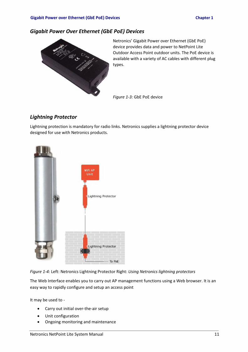
Gigabit Power Over Ethernet (GbE PoE) Devices
Netronics’ Gigabit Power over Ethernet (GbE PoE) device provides data and power to NetPoint Lite Outdoor Access Point outdoor units. The PoE device is available with a variety of AC cables with different plug types.
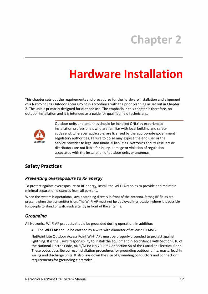
Figure 1-3: GbE PoE device Lightning Protector Lightning protection is mandatory for radio links. Netronics supplies a lightning protector device designed for use with Netronics products. Figure 1-4: Left: Netronics Lightning Protector Right: Using Netronics lightning protectors The Web Interface enables you to carry out AP management functions using a Web browser. It is an easy way to rapidly configure and setup an access point It may be used to -
• Carry out initial over-the-air setup • Unit configuration • Ongoing monitoring and maintenance
Netronics NetPoint Lite System Manual 12
Chapter 2
Hardware Installation
This chapter sets out the requirements and procedures for the hardware installation and alignment of a NetPoint Lite Outdoor Access Point in accordance with the prior planning as set out in Chapter 2. The unit is primarily designed for outdoor use. The emphasis in this chapter is therefore, on outdoor installation and it is intended as a guide for qualified field technicians.
Outdoor units and antennas should be installed ONLY by experienced installation professionals who are familiar with local building and safety codes and, wherever applicable, are licensed by the appropriate government regulatory authorities. Failure to do so may expose the end user or the service provider to legal and financial liabilities. Netronics and its resellers or distributors are not liable for injury, damage or violation of regulations associated with the installation of outdoor units or antennas.
Safety Practices Preventing overexposure to RF energy To protect against overexposure to RF energy, install the Wi-Fi APs so as to provide and maintain minimal separation distances from all persons. When the system is operational, avoid standing directly in front of the antenna. Strong RF fields are present when the transmitter is on. The Wi-Fi AP must not be deployed in a location where it is possible for people to stand or walk inadvertently in front of the antenna. Grounding All Netronics Wi-Fi AP products should be grounded during operation. In addition:
• The Wi-Fi AP should be earthed by a wire with diameter of at least 10 AWG.
NetPoint Lite Outdoor Access Point Wi-Fi APs must be properly grounded to protect against lightning. It is the user's responsibility to install the equipment in accordance with Section 810 of the National Electric Code, ANSI/NFPA No.70-1984 or Section 54 of the Canadian Electrical Code. These codes describe correct installation procedures for grounding outdoor units, masts, lead-in wiring and discharge units. It also lays down the size of grounding conductors and connection requirements for grounding electrodes.

Package Contents Chapter 2
Netronics NetPoint Lite System Manual 13
NetPoint Lite Outdoor Access Point units must be grounded to a Protective Earth in accordance with the Local Electrical Regulations.
Further, you should - • Always make the ground connection first and disconnect it last • Never connect telecommunication cables to ungrounded equipment • Ensure that all other cables are disconnected before disconnecting the ground
Outdoor Installation: Protection against Lightning The use of lightning protection is dependent on regulatory and end user requirements. All of Netronics outdoor units are designed with surge limiting circuits to minimize the risk of damage due to lightning strikes. Netronics recommends the use of additional surge arrestor devices to protect the equipment from nearby lightning strikes. General
• It is recommended that installation of the Wi-Fi AP be contracted to a professional installer.
• Before working on equipment connected to power lines or telecommunication lines, you should remove jewellery or any other metallic object that may come into contact with energized parts.
• Use extreme care when installing antennas near power lines. • Use extreme care when working at heights. • When using an AC power source for NetPoint Lite Outdoor Access Point PoEs always use the
AC power adapter supplied by Netronics. • Use the right tools for the task.
Package Contents
• One NetPoint Lite AP unit • Three omni-directional antennas
Figure 2-1: NetPoint Lite with omni-directional antennas attached

Package Contents Chapter 2
Netronics NetPoint Lite System Manual 14
• One mounting kit
• One horizontal mounting bar
• Two 2” metal mounting bands
• Quick Installation Guide Accessories The following items must be ordered separately from the NetPoint Lite package:
• AC GbE PoE device and AC power cord • CAT 5e ODU-PoE cable • PoE female cable gland • Lightning Protector

Outdoor Site Preparation Chapter 2
Netronics NetPoint Lite System Manual 15
Outdoor Site Preparation Planning the NetPoint Lite Outdoor Access Point Site The main considerations in setting up a NetPoint Lite AP are
• Interference from other nearby Wi-Fi devices • Effect on signal penetration due to walls, ceilings and other objects • External environmental effects, particularly weather
Further performance differences may be expected depending on whether the unit is installed indoors or outdoors.
For an outdoors installation in harsh interference, climatic or topographic conditions, you may need to carry out a site survey to determine the best location and possibly mast height for the unit.
Ultimately, your determination will be a set of compromises. Site Survey Considerations
• Range versus data rate the further out the AP unit placed from its clients, the lower the data rate and vice versa
• Height: Use a mast, a pole, the side of a building or a roof • Obstructions: Trees, buildings, open water
Performing a Site Survey When performing a site survey, consider the following factors:
• Data rates: Range is inversely proportional to data rates • Placing the unit in a clear open area will give better results than placing it in an area
obstructed with trees or clutter • The presence of other transmitters nearby
Physical Installation Outdoor Installation The unit should be mounted horizontally. The antennas may be pointed up or down. To install a NetPoint Lite unit using the supplied mounting elements:
1. Install the mounting kit by attaching the clamps to the pole.

Outdoor Site Preparation Chapter 2
Netronics NetPoint Lite System Manual 16
Figure 2-2: Identifying the installation components and their relationship
2. Slide the (hollowed out) horizontal mounting bar over the ear of the mounting kit clamp.
3. Secure the holding bolt as seen in the next figure.
Figure 2-3: Horizontal mounting using ties on a horizontal arm
4. Mount the radio on the mounting bar using the two supplied 2” metal bands.

Outdoor Site Preparation Chapter 2
Netronics NetPoint Lite System Manual 17
5. Ensure that the CAT 5e cable is securely attached to the unit with the cable gland and
water-proofed as shown in Figure 2-3 using quality sealing material such as Scotch 23 Tape, from 3M.
6. Connect a Lightning Protection Unit as shown in Figure 2-3 paying attention to water-
proofing.
7. Connect a PoE device as shown in Figure 2-3 again paying attention to water-proofing.
Try to ensure that there are no large objects between the AP unit and the clients. Even trees and hedges can cause interference.

Netronics NetPoint Lite System Manual 18
Chapter 3
Pre-Configuring a NetPoint Lite
What is Pre-Configuration
As supplied, the NetPoint Lite is configured as single access point with SSID Install, and accessible over-the-air from a laptop equipped with Wi-Fi hardware, running under Windows XP or later. It should also work correctly under Linux. Under Windows 7, your Wi-Fi system icon and Wi-Fi display should look something like this:
For installation purposes only, the NetPoint Lite is a DHCP/DNS server and you do not need any IP address. You have enough connectivity to pre-configure the NetPoint Lite for service; later you will be able to access it through its LAN cable or through a switch to which it is connected, to effect further configuration changes.

Accessing the NetPoint Lite with a Web Browser Chapter 3
Netronics NetPoint Lite System Manual 19
While you are connected to the NetPoint Lite for pre-configuration, you will probably not have internet access, since the unit uses its own built-in gateway and DNS resolver. Accessing the NetPoint Lite with a Web Browser In what follows, we will use Mozilla Firefox, release 16 for demonstration purposes.
The procedures described in this and the following chapter can be carried out using most web browsers on other Platforms such as Linux, Unix and Mac. Expect the monitor displays to have the same content but to look different
Launch your web browser; if you have a non-blank home page, you will see something like this: Whatever the case, clear the URL field and type in one more random characters: Hit the Enter key. You are offered a log-on window. The initial user name and password are respectively, admin and wireless.
Here is the opening display:

What we will do here Chapter 3
Netronics NetPoint Lite System Manual 20
About the Open Source link The NetPoint Lite Web software makes use of several Open Source packages. The relevant license statements are contained in a “tar ball”, which may be downloaded, unpacked and viewed from the Open Source link. What we will do here We are now ready to commence pre-configuration.
During the use of the GUI, your browser may display this message, followed by apparent inactivity:
Use the browser Refresh function to resume activity.
In this chapter, we will visit all of the browser functions, but we will configure the minimum to get the AP unit operational. In the following chapter, we will examine the browser functions in greater depth as we “fine tune” our configuration.

Starting Pre-Configuration Chapter 3
Netronics NetPoint Lite System Manual 21
Starting Pre-Configuration Click the Interfaces button to open the Interfaces display:
The WAN display shows the AP unit MAC address, which you should store. Ethernet mode is disconnected - that is, the unit is not available for service. Later, we will enable it. The IP address is the default IP address for the unit itself, for maintenance purposes. Later, we will change it to make the unit a DHCP client through a switch. The Received and Transmitted figures are cumulative.
The NetPoint Lite operates as one or more virtual AP (VAP) units up to a maximum of eight. For pre-configuration purposes, the first available VAP, shown as WLAN 1, is set up by default with name and SSID Install.
Do not change the WLAN 1 SSID from Install to anything else until you are certain that you are done with pre-configuration. Changing the Install SSID moves the unit into “service mode” disabling the DHCP/DNS server, enabling Ethernet service and becoming addressable only over wire through an IP address.
Notice further from the WLAN 1 table that each VAP has its own MAC address. From a service perspective, the VAPs look like separate physical AP units.
We will configure three VAPs and check each one for connectivity with a remote laptop.

Continuing Pre-Configuration Chapter 3
Netronics NetPoint Lite System Manual 22
Continuing Pre-Configuration
Preparing the Radio Parameters
The System page items may be configured later. Open the Network page: The Connection Type is Static IP address or DHCP. DHCP is the default. The default IP address and subnet mask are provided for use with a static IP address or if the DHCP server becomes unavailable. For demonstration purposes, we will leave them as is.
Now, open the Wireless page. The most important part of pre-configuration is carried out here.
The Country Code is an absolute must. You cannot proceed without it. NetPoint Lite Outdoor Access Point complies with the IEEE 802.11 Wi-Fi standards which vary from country to country. There are country dependent regulations governing channel allocation and Tx power considerations for the 2.4 GHz Wi-Fi band. An overview is presented in Appendix C.

Continuing Pre-Configuration Chapter 3
Netronics NetPoint Lite System Manual 23
Choose your location:
Click Save to save your changes. You will not be able to proceed without saving your changes. If you touch anything else you will get the following prompt: This prompt will reappear from time to time at “milestones” requiring a commit before you can proceed. With Save done, you may now set radio-wide parameters: The radio is on by default. You may use this button to enable or disable it for maintenance.
Do not change it now. If you do, you will lock yourself out of the unit.
The Mode b/g/n is the only one available. We will also accept the usual Wi-Fi default channel 6. Change it later to channel 1 or 11 if you experience interference.
Tx power may be chosen from 3 dBm to 16 dBm for our location. Your location may offer a different maximum Tx power. For our purposes, it may stay at 3 dBm.

Security Chapter 3
Netronics NetPoint Lite System Manual 24
Security While you are doing pre-configuration, any Wi-Fi client in range can detect the unit with SSID Install. Here is your current situation: Check Show Connected Clients. After a few moments we see this:
The first MAC 90:... is the demonstration workstation. The second item commencing 00:... is unknown and presumed a “snooper”.
Change Network Authentication from Disabled as shown, to WPA2 (PSK):
Change the password and store it in a safe place. The password length must between eight and 32 characters.

Preparing Additional VAPs Chapter 3
Netronics NetPoint Lite System Manual 25
Click Save to preserve your changes. Again, check Show Connected Clients. This time the list is empty. Anyone logged on before must log on again with the password.
You may also set SSID Broadcast to Off when working in Install mode. See page 4-10 for further details about using this feature.
Preparing Additional VAPs Open the Virtual AP 2 page: Click Create: First, notice that the default SSID is default1 and the corresponding button is also so labelled. In line with our program of getting service started with minimum configuration, we just change the SSID to something more meaningful.

Confirming our Pre-Configuration Chapter 3
Netronics NetPoint Lite System Manual 26
Next repeat the procedure for Virtual AP 3.
Finally (this must be the last step, as we are going to be disconnected), change the Install SSID as well.
Here is the situation prior to our last Save: On clicking Save, you are offered a confirmatory message: Click Yes to accept your changes. Your browser may become inactive, since there is no longer an over-the-air connection. Confirming our Pre-Configuration To confirm our work so far, we must connect the NetPoint Lite unit to a DHCP server, and then access each of the VAPs from a remote laptop. Connection to a DHCP Server Logging on to the unit at 10.0.0.121 and opening the Wireless page shows this:

Returning to Install Mode Chapter 3
Netronics NetPoint Lite System Manual 27
Connecting to each VAP as a User A remote Wi-Fi enabled laptop shows this:
We now have an operational (but very unsecured!) NetPoint Pro. In the next chapter we complete the configurations including security features. Returning to Install Mode If you need to return to Install Mode, you may do so by logging on to the unit and changing the SSID of the first VAP back to Install.
The change will disconnect all clients on VAP 1. It will not affect service on the remaining VAPs.
Install mode is only available on VAP 1.

Netronics NetPoint Lite System Manual 28
Chapter 4
Using the Web Interface
Overview This chapter reviews the Web Interface in details with particular attention to completing tasks left open in the pre-configuration described in the previous chapter. Accessing the NetPoint Lite for Management By default, the NetPoint Lite is configured as a DHCP client, typically connected to a DHCP/DNS server through a switch. To access the GUI, you will need to get its assigned default IP Address from the network manager. Our example will continue to be based on the unit pre-configured in the last chapter. It has IP address 10.0.0.121 and subnet mask 255.255.255.0. Completing the Configuration Whichever way you access the unit, the Web home page looks like this:

The System Information Panel Chapter 4
Netronics NetPoint Lite System Manual 29
Figure 4-1: Web GUI Home page The System Information Panel
Figure 4-2: Close-up of the System Information panel

The Interfaces page Chapter 4
Netronics NetPoint Lite System Manual 30
The panel shows the AP unit’s inventory. There is nothing that can be changed here or on the Interface page. However for this or any other AP Web page, you may obtain explanation of the page contents by pressing the F1 Help key
Keep the details of this page in a safe place. You will require them to obtain product support
The Interfaces page
The Interfaces page contains two or more tables. The WAN table shows the AP unit MAC Address and IP Address. It also shows the cumulative throughput of the unit in packets and Mb. Figure 4-3: Interfaces page showing an AP unit configured for two Virtual APs. Additional tables, labelled WLAN 1, WLAN 2 … relate to configured virtual Access Points. At least one and no more than eight may be configured using the Wireless tab. The virtual access points are distinguished by their SSID.

Confirming our Pre-Configuration Chapter 3
Netronics NetPoint Lite System Manual 31
System Settings The System tab opens the following page:
Figure 4-4: System page
System Settings
Host Name
This the Host Name of the Wi-Fi AP unit. You may change it.
Contact and Location
These are optional. They are used by SNMP interface to identify the unit under Network Management environment such as Netronics Network Management System (LNMS).
Time Settings
Time zone
Set up your time zone according to the nearest city of your region from the predefined list. Choose your Time zone from the drop-down list.
You should set the Time zone appropriately, so alarms and other logged data are correctly time-stamped.
Continuing with our example, we set it to UK:

Security Chapter 4
Netronics NetPoint Lite System Manual 32
UTC Offset
This shows the offset in hours from UTC. It is for information only.
NTP Server and NTP Server Port
This is your network time server URL or IP address. Get it from your Network Manage. Security The Security panel looks like this:
Password Change
Password is the log-on password. The default password is wireless.
Web Configuration Settings
The well-known HTTP Port is 80. You should only change this if your browser HTTP setup is different. You may choose between secure and regular (non-secure) HTTP by checking the appropriate radio button.

Backup and Restore Chapter 4
Netronics NetPoint Lite System Manual 33
SNMP Settings
If the Trap Destination IP is left at the default, traps will be sent to the managing computer. Change this to a permanent location if the current managing computer is likely to be disconnected. This is typically the case if you are managing the unit in the field from a laptop.
The Trap Destination Port is also a well-known port. It should however, be the same as that listened to by your logging service.
The Trap Destination User and Trap Destination Password are required by a SNMP based Network Manager to access the traps report. Backup and Restore
Backup
To back up the current AP unit configuration, open the Backup & Restore panel: The Backup button causes the configuration to be automatically saved in config_backup in the standard backup location for your browser. You will see the following message:
The backup file is stored in a binary format and can only be used for a restore.
Restore
The Restore procedure requires that you nominate the restore file and location by hand. The procedure uses standard operating system navigation panels. You must click the Restore button to complete the procedure. You are offered a last warning to cancel:

Firmware Upgrade Chapter 4
Netronics NetPoint Lite System Manual 34
You will be advised that the configuration being restored and it will take about 90 sec.
Service will be dropped and your browser will temporarily loose connection to the AP unit. On completion of the restore, the AP unit will be reset, service restored and you will be returned to the System Backup and Restore page.
Firmware Upgrade
The firmware upgrade process works much the same way as the Restore:
The Browse button opens up the standard operating system file navigator.
Choose the upgrade file and click the Upgrade button to commence the process. You are offered a confirmation notice: Click OK to proceed. You will see a progress bar:

Network Chapter 4
Netronics NetPoint Lite System Manual 35
During this period, service will be dropped and your browser will temporarily loose connection to the AP unit. On completion of the upgrade, the AP unit will be reset, service restored and you will be returned to the unit home page. Operations In the Operations page you are offered three reboot options:
For a simple Reboot, you will be asked to save any changes. The Reboot takes about 90 seconds. You are returned to the home page. The other two options are for restoration of factory defaults
Network
The Network page offers the following display:
Ethernet Mode is Auto Detect by default. Auto Detect supports up to 1000 Mbps if you have a GbE PoE device. The following options are available: The Connection Type is Static IP address or DHCP. DHCP is the default.

Wireless Chapter 4
Netronics NetPoint Lite System Manual 36
The Default IP Address and Default Subnet Mask are provided for use with a static IP address or if the DHCP server becomes unavailable. Wireless In Chapter 3 we set up the radio as follows: What remains to be done is to secure each of the VAPs. NetPoint Lite Outdoor Access Point Security Features
Overview
NetPoint Lite provides all of the common Wi-Fi security features on a per VAP basis. They come under two categories - access control and data encryption. None of them are fool-proof, but the use of an access control method and an authentication mode, can provide a reasonable level of security for applications such as Internet access and local Intranets.
To illustrate these features, we will use the first VAP on our demonstration system:
Figure 4-5: First created VAP prior to configuration

Access Control Methods Chapter 4
Netronics NetPoint Lite System Manual 37
Access Control Methods
SSID Broadcast Control
Normally, SSID Broadcast is on enabling a client to acquire it and make a link. By setting it to off, the client must specifically configure a radio connection by hand, entering the SSID as the link name. Here is the procedure on a remote Windows 7 laptop: Clicking Next verifies the connection: This method of access control is considered quite weak.
MAC Filters Chapter 4
Netronics NetPoint Lite System Manual 38
MAC Filters
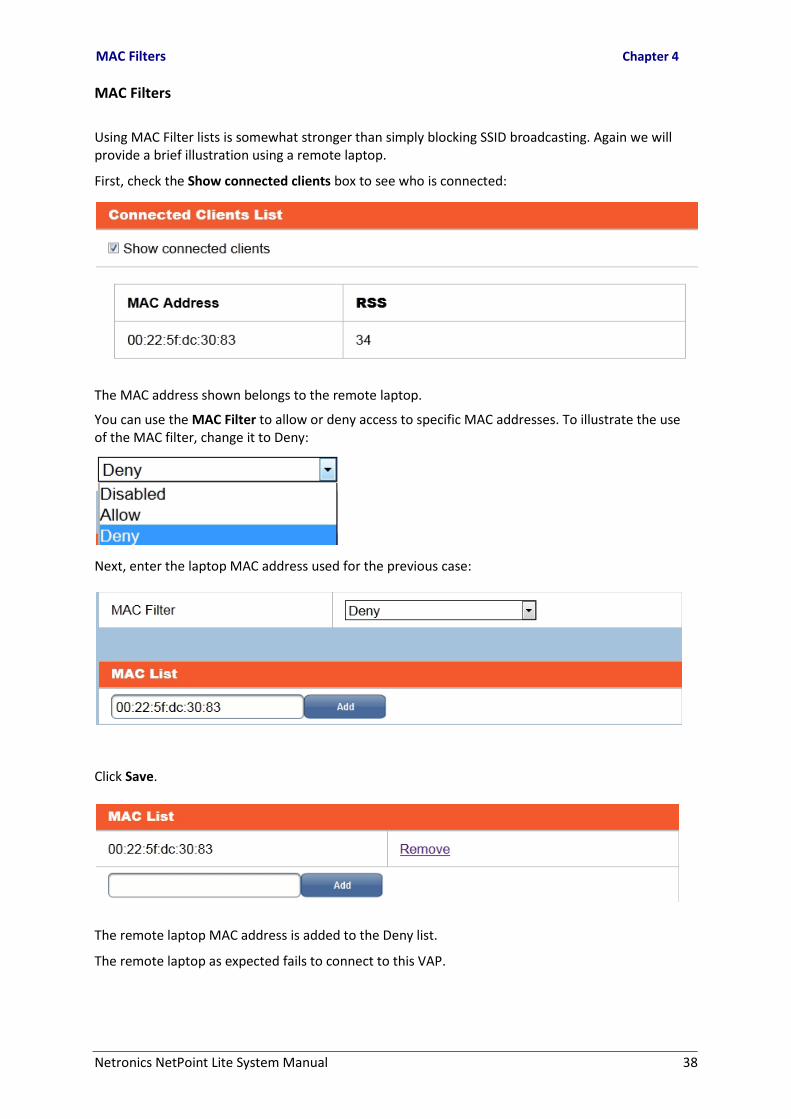
Using MAC Filter lists is somewhat stronger than simply blocking SSID broadcasting. Again we will provide a brief illustration using a remote laptop.
First, check the Show connected clients box to see who is connected:
The MAC address shown belongs to the remote laptop. You can use the MAC Filter to allow or deny access to specific MAC addresses. To illustrate the use of the MAC filter, change it to Deny: Next, enter the laptop MAC address used for the previous case: Click Save.
The remote laptop MAC address is added to the Deny list.
The remote laptop as expected fails to connect to this VAP.

Network Authentication Chapter 4
Netronics NetPoint Lite System Manual 39
• MAC filtering is not particularly secure as transmitted MAC addresses are not encrypted.
• You may only have one list per VAP - that is, an Allow or a Deny list. MAC addresses are not Allowed or Denied on an individual basis.
Network Authentication
Available Options - Summary
The following table lists the available options. Notice that WEP is considered unsafe by the Wi-Fi Alliance group and therefore not included:
Table 4-1: Available Authentication modes
Authentication Remarks
Disabled Default
WPA (PSK) Supports AES and TKIP.
TKIP unsafe
WPA2 (PSK)
WPA+WPA2 (PSK)
WPA (RADIUS)
WPA2 (RADIUS)
WPA+WPA2 (RADIUS)
Setting Authentication Options
Available Options - Detail
Network Authentication mode is defined separately for each VAP. To see the available types online, open or create a VAP and then open the Network Authentication list:

Setting Authentication Options Chapter 4
Netronics NetPoint Lite System Manual 40
Disabled
Leaving Network Authentication disable allows any listening client to acquire access. This may be appropriate for an Internet cafe or other public site.
WPA (PSK)
Because of WEP's weakness the Wi-Fi Alliance approved Wi-Fi Protected Access (WPA) which uses TKIP. WPA was specifically designed to work with older equipment usually through a firmware upgrade. Though more secure than WEP, WPA has known vulnerabilities. Further TKIP is also vulnerable and has largely been superseded by AES.
The password (PSK, Pre-Shared Key) is agreed upon between the VAP owner and eligible clients. It is between eight and 63 characters long.
You may choose between TKIP (not recommended) and AES:
WPA2 (PSK)
WPA2 (PSK) is an improved version of WPA (PSK). It is intended for and small office networks, not requiring an authentication server. The password is agreed upon between the VAP owner and eligible clients. It is between eight and 63 characters long.
WPA+WPA2 (PSK)
This option will support clients using either WPA or WPA2 (PSK). It uses AES encryption.

Setting Authentication Options Chapter 4
Netronics NetPoint Lite System Manual 41
WPA (RADIUS)
Remote Authentication Dial In User Service (RADIUS) is a networking protocol providing centralized Authentication, Authorization, and Accounting management for computers to connect and use a network service. WPA (RADIUS) offers WPA authentication through a RADIUS server.
For more information about RADIUS servers, see http://en.wikipedia.org/wiki/RADIUS You will need to get the RADIUS fields from your Network Manager.
WPA2 (RADIUS)
This method offers WPA2 authentication through a RADIUS server.
WPA+WPA2 (RADIUS)
This method offers both WPA andWPA2 authentications through a RADIUS server.

Setting Authentication Options Chapter 4
Netronics NetPoint Lite System Manual 42
Forgotten or Mislaid IP Address
If you find yourself with an AP unit of unknown IP address, there is a straightforward technique available to recover it. It is available during the first few minutes from power-up: specifically, for two minutes after the unit firmware has becomes fully operational. It involves forcing a temporary IP address of your choice to be associated with an equally temporary MAC address available only during the two minutes. The temporary MAC address is 00-1e-48-00-00-20; the temporary IP address we will use is 192.168.3.1.
To recover the IP address of a NetPoint Lite unit: 1. Ensure that the NIC on your computer is set to a static address. For example,
192.168.3.100 with Subnet Mask 255.255.255.0.
2. Open a command line session on your computer.
3. Connect the AP unit to the NIC and power it up (if necessary, power down and then power up again).
4. Enter the following commands (use your own subnet if different from our example):
arp -s 192.168.3.1 00-1e-48-00-00-20
ping 192.168.3.1
5. If the ping fails, wait a few moments and try again. Eventually (when the firmware is functional) it will respond showing a reply from 192.168.3.1 (or whatever IP address you are using).
6. Navigate to 192.168.3.1 with your browser and you may log on in the usual way. (You may
be asked to allow a security exception. Allow the exception without making it permanent.)
7. From the Status page, open the Interfaces page. The IP Address shown will be the configured address, not the temporary address (exactly as shown in Figure 4-2). Note down the IP Address and the Subnet Mask. If you wish, you can enter the Network page and set a new IP Address and Subnet Mask in the usual way.
8. Exit the AP web pages. If necessary, reset your NIC IP Address and Subnet Mask to match
the AP unit.
9. At the open command line, issue an arp -d 192.168.3.1command. This clears the unit’s temporary IP Address/MAC Address association. You may now continue working with the unit in the usual way.

Netronics NetPoint Lite System Manual 43
Part 2
Product Reference

Netronics NetPoint Lite System Manual 44

Netronics NetPoint Lite System Manual 45
Appendix A
Technical Specifications
Scope of these Specifications This appendix contains technical specifications for the major link components appearing in this User Manual. They are correct at the date of publication, but are intended for general background only. The latest authoritative and most up to date technical specifications are available as Data Sheets obtainable from Netronics Customer Service.
In any event, Netronics reserves the right to change these specifications without notice. Wi-Fi
Standards • 2.4 GHz - ETSI EN 300 328, FCC CFR Part 15.247 and IC RSS-210
• IEEE 802.11b/g/n
Frequency Band 2.4 – 2.484 GHz
• 802.11n: 6.5 Mbps – 130 Mbps (20 MHz) 13 Mbps – 300 Mbps (40 MHz)
Supported Data Rates • 802.11g: 6, 9, 12, 18, 24, 36, 48 and 54 Mbps
• 802.11b: 1, 2, 5.5 and 11 Mbps
Radio Chains 2x3
Spatial Streams 2
RF Power Output • Up to 26 dBm per antenna
• Country-specific power settings are configurable
Channelization 20 MHz and/or 40 MHz
Operating Channels • Europe: 1-13
• US/Canada: 1-11
BSSID Up to 8
Wireless Security • WPA(PSK)-TKIP/AES, WPA2(PSK)-AES
• WPA, WPA2 -RADIUS
Configuration • Web User Interface (HTTP/S)
• SNMP v1, 2 and 3
QoS 802.11WMM; For Voice, Video, Best Effort, and Background service flow
Concurrent Clients 256 distributed over up to 8 SSIDs

Netronics NetPoint Lite System Manual 46
Configuration
Architecture Outdoor Unit Connectorized for Omni Antennas
PoE to ODU Interface Outdoor CAT-5e cable. Maximum cable length: 100 m (75 m for GbE)
Mechanical
Dimensions 17.1 (w) x 19.6 (h) x 7.2 (d) cm
Weight 1.1 kg / 2.4 lbs
Power
Power Feeding Power provided over ODU-IDU cable using PoE device
Power Consumption - alone <12 W
Environmental
Operating Temperatures -35°C to +60°C / -31°F to +140°F
Humidity 100% condensing, IP67 (totally protected against dust and against immersion
up to 1 m)
Safety
FCC/IC (cTUVus) UL 60950-1, UL 60950-22, CAN/CSA C22.2 60950-1, CAN/CSA C22.2 60950-22
ETSI/IEC EN/IEC 60950-1, EN/IEC 60950-22
EMC
FCC 47CFR Class B, Part15, Subpart B
ETSI EN 300 386, EN 301 489-1, EN 301 489-4
CAN/CSA-CEI/IEC CISPR 22 Class B
AS/NZS CISPR 22 Class B
GbE PoE Device - Indoor, AC
Electrical
AC Input Voltage 100 - 240 VAC nominal, 90 - 264 VAC max range
Input Frequency 47 - 63 Hz
Input Current 2.0 A (rms) 115 VAC at Max. load
1.2 A (rms) 230 VAC at Max. load
Max. In-rush Current 30 A for 115 VAC at Max. load
60 A for 230 VAC at Max. load
Standby Power 0.5 W (Max) at 240 Vac
DC Output Voltage 56 VDC
• Short circuit protection
Protection • Auto recovery
• Over voltage protection
Indication Green led for normal operation

Netronics NetPoint Lite System Manual 47
Interfaces
PoE output RJ-45 connector
PoE to ODU Interface Outdoor CAT 5e; Maximum cable length: 75 m for 1000BaseT or 100 m for 10/
100BaseT.
Ethernet input RJ-45 connector
AC input on device Standard socket IEC320 C14 type
AC cable Variety of AC plugs available (see below)
Ethernet / ODU Netronics RJ-45 connector
Ethernet LAN interface type RJ-45, 10/100/1000BaseT Interface (Line Impedance -100 )
Mechanical
Case Plastic
Dimensions 16 (W) x 6.3 (D) x 3.33 (H) cm
Weight 250 g
Environmental
Operating Temperatures 0°C to 40°C/32°F to 104°F
Humidity 90% non-condensing
Safety
UL/CUL 60950-1
ETSI/IEC IEC/EN 60950-1
EMC
IEC IEC 61000-4-2,3,4,5,6,11; CISPR 22
ETSI EN 61000-3-2,3; EN 55022; EN 55024
AS/NZS CISPR 22
Lightning Protector
Electrical
Compatible Interfaces 10/100/1000BaseT
Data Rates Up to 1000 Mbps
Nominal Operational Voltage 48 VDC
Maximum Operational Voltage 60 VDC - 650 mA
Maximum Continuous current 1 A
Impedance 90 to 110 Ohm
Connection type RJ45 CAT 5e STP (shielded)
Pin-out 8 wires + shielding

Netronics NetPoint Lite System Manual 48
Pins Protected All pins protected
Response time <5 microseconds (with ODU)
Nominal discharge currents
Line to Line 500 A @ 8/20 μs
Line to Ground 2000 A @ 8/20 μs
Impulse Discharge Current
20000 A, 8/20 μs 1 operation minimum
10000 A, 8/20 μs > 10 operations
2000 A, 10/350 μs 1 operation
200 A, 10/1000 μs > 300 operations
200 A, 10/700 μs > 500 operations
Impulse Spark-over
DC Spark-over ±20 % @ 100 V/s 150 V
100 V/μs 350 V
1000 V/μs 500 V
Capacitance < 2 pF
DC Holdover Voltage 80 V
Mechanical
Enclosure Metal
Connection to bonding Network Screw
Dimensions 150 mm
Weight 220 gram (0.22 Kg)
Environmental
Operating temperature -40°C to 60°C
Storage temperature -50°C to 70°C
Enclosure rating IP67
Humidity 100% non condensing

Netronics NetPoint Lite System Manual 49
Appendix B
Wiring Specifications
AP-PoE Cable
The ODU-PoE cable is shielded/outdoor class CAT-5e, 4 twisted-pair 24 AWG terminated with RJ-45 connectors on both ends. A cable gland on the ODU side provides hermetic sealing.
The following table shows the connector pin-out: Table B-1: ODU-PoE RJ-45 Connector Pin-out
Function Color PoE ODU
Ethernet (RxN) White/Green 1 1
Ethernet (RxT) Green 2 2
Ethernet (TxT) White/Orange 3 3
Ethernet (TxN) Orange 6 6
Power (+) Blue 4 4
Power (+) White/Blue 5 5
Power ( ) White/Brown 7 7
Power ( ) Brown 8 8

Netronics NetPoint Lite System Manual 50
Appendix C
IEEE 802.11 Wi-Fi Channels
The following description is based on material available from several web sites, mostly without attribution. In the United States and Canada there are 11 channels available for use in the 802.11b 2.4 GHz Wi-Fi Frequency range. This standard is defined by the IEEE. Channels 12 to 14 are available in Japan (802.11b only); 12 and 13 may be available elsewhere.
Table C-1: Wi-Fi Channels Lower Center Upper
Channel Frequency Frequency Frequency GHz GHz GHz
1 2.401 2.412 2.423
2 2.404 2.417 2.428
3 2.411 2.422 2.433
4 2.416 2.427 2.438
5 2.421 2.432 2.443
6 2.426 2.437 2.448
7 2.431 2.442 2.453
8 2.436 2.447 2.458
9 2.441 2.452 2.463
10 2.446 2.457 2.468
11 2.451 2.462 2.473
12 2.456 2.467 2.478
13 2.461 2.472 2.483
14 2.473 2.484 2.495

Netronics NetPoint Lite System Manual 51
There are only 3 non-overlapping channels available in the 802.11b standard. These are Channels 1, 6, and 11. For Wi-Fi access points that are located near each other it is recommended that they each use one of the above non-overlapping channels to minimize the effects of interference.
In general, the whole world supports channels 1 - 11 without restriction for indoor use.
There are local restrictions on the use of channels 12 - 14. For more detailed information about permissible channels by location, see for example,
http://en.wikipedia.org/wiki/List_of_WLAN_channels
This overlapping of 2.4 GHz channels are best visualized from the chart below.
Figure C-1: 802.11 Frequency channel map This list of WLAN channels is the set of legally allowed Wireless LAN channels using IEEE 802.11.
The 802.11 workgroup currently documents use in three distinct frequency ranges, 2.4 GHz, 3.6 GHz and 4.9/5.0 GHz bands. [1] Each range is divided into a multitude of channels. Countries apply their own regulations to both the allowable channels, allowed users and maximum power levels within these frequency ranges. In some countries, such as the United States, licensed Amateur Radio operators may use some of the channels at much higher power for long distance wireless access.