netlink nl 50-mpi and nettap nt 50-mpi (user manual) - hilscher
TRANSCRIPT

User Manual netLINK NL 50-MPI and netTAP NT 50-MPI
Installation, Operation and Hardware Description
Hilscher Gesellschaft für Systemautomation mbH www.hilscher.com
DOC080604UM06EN | Revision 6 | English | 2012-03 | Released | Public
Introduction 2/71
netLINK NL 50-MPI and netTAP NT 50-MPI | Installation, Operation and Hardware Description DOC080604UM06EN | Revision 6 | English | 2012-03 | Released | Public © Hilscher, 2008-2012
Table of Contents 1 INTRODUCTION.........................................................................................................5
1.1 About the User Manual ...............................................................................................5 1.1.1 List of Revisions ...................................................................................................5 1.1.2 Reference to Hardware ........................................................................................6 1.1.3 Reference to Firmware.........................................................................................6 1.1.4 Reference to SyCon Software..............................................................................6 1.1.5 Conventions in this Manual ..................................................................................6
1.2 Contents of the Product DVD .....................................................................................7 1.2.1 Directory Structure of the DVD.............................................................................7 1.2.2 Overview of relevant Documentation ...................................................................8
1.3 Legal Notes.................................................................................................................9 1.3.1 Copyright ..............................................................................................................9 1.3.2 Important notes.....................................................................................................9 1.3.3 Exclusion of liability ............................................................................................10 1.3.4 Warranty .............................................................................................................10 1.3.5 Export Regulations .............................................................................................11 1.3.6 Registered Trademarks......................................................................................11
1.4 Licenses....................................................................................................................11
2 SAFETY ....................................................................................................................12 2.1 Safety Notes .............................................................................................................12 2.2 Intended Use ............................................................................................................12 2.3 Personnel Qualification.............................................................................................12 2.4 Labeling of Safety Instructions..................................................................................13 2.5 Safety Instructions ....................................................................................................14
2.5.1 Electrical Voltage................................................................................................14 2.5.2 Electrostatic Discharge.......................................................................................14
2.6 Safety Instructions USA............................................................................................15 2.6.1 Electrical Current ................................................................................................15 2.6.2 Electrostatic Discharge.......................................................................................15
3 DESCRIPTION AND REQUIREMENTS ...................................................................16 3.1 Description................................................................................................................16
3.1.1 Description netLINK NL 50-MPI .........................................................................16 3.1.2 Compatibility of the netLINK NL 50-MPI to the NL-MPI .....................................16 3.1.3 Description netTAP NT 50-MPI ..........................................................................17 3.1.4 Compatibility of the netTAP NT 50-MPI to the NT 40-MPI.................................17
3.2 System Requirements ..............................................................................................17 3.3 Preconditions for Operation ......................................................................................18
4 DEVICE DRAWING AND CONNECTIONS...............................................................19 4.1 Device and Dimensioned Drawing............................................................................19 4.2 Connections and LEDs .............................................................................................20 4.3 Ethernet Interface (X3) .............................................................................................21
4.3.1 Ethernet pinning at the RJ45 Socket..................................................................21 4.3.2 Ethernet Connection Data ..................................................................................21

Introduction 3/71
netLINK NL 50-MPI and netTAP NT 50-MPI | Installation, Operation and Hardware Description DOC080604UM06EN | Revision 6 | English | 2012-03 | Released | Public © Hilscher, 2008-2012
4.4 PROFIBUS Interface (X11, X2) ................................................................................22 4.5 External Power Supply (X1)......................................................................................23 4.6 Schematic Diagram - Galvanic Isolation...................................................................24
4.6.1 netLINK NL 50-MPI ............................................................................................24 4.6.2 netTAP NT 50-MPI .............................................................................................25
5 MOUNTING AND DISMOUNTING THE DEVICE .....................................................26 5.1 Mounting netLINK NL 50-MPI...................................................................................26 5.2 Mounting and Dismounting netTAP NT 50-MPI........................................................26
5.2.1 Top Hat Rail Mounting of the NT 50-MPI ...........................................................26 5.2.2 Removing the NT 50 from the Top-Hat Rail .......................................................27
5.3 Power Supply............................................................................................................28 5.3.1 netLINK NL 50-MPI ............................................................................................28 5.3.2 netTAP NT 50-MPI .............................................................................................28
5.4 Ethernet Connection .................................................................................................28
6 INSTALLING SOFTWARE ........................................................................................29 6.1 Installing Software from DVD....................................................................................29 6.2 Installation under Windows Vista or Windows 7 .......................................................30 6.3 Install IP Driver .........................................................................................................30
7 CONFIGURING MPI DEVICE ...................................................................................32 7.1 Configuring MPI-Device with Hilscher IP Driver .......................................................32
7.1.1 Assign IP Address to MPI Device.......................................................................32 7.1.2 Configuring of the IP Driver ................................................................................35
7.2 Creating and downloading the Configuration to set a permanent IP Adress ............36 7.2.1 Overview.............................................................................................................36 7.2.2 Step-by-Step Description ...................................................................................38
7.3 Description of the Device Parameters ......................................................................47 7.3.1 IP Address ..........................................................................................................47 7.3.2 Ethernet Parameter ............................................................................................48 7.3.3 PROFIBUS Parameter .......................................................................................49
7.4 Firmware Update – Firmware Download ..................................................................52
8 TROUBLESHOOTING ..............................................................................................55 8.1 Hints on how to solve Problems ...............................................................................55 8.2 Ethernet Failure in 10 MBit/s Half Duplex Mode and Workaround ...........................56
9 LED ...........................................................................................................................57
10 TECHNICAL DATA ...................................................................................................59 10.1 Technical Data of the netLINK NL 50-MPI................................................................59 10.2 Technical Data of the netTAP NT 50-MPI ................................................................61
11 RFC 1006..................................................................................................................63
12 ERROR CODES........................................................................................................64 12.1 TCP/IP Error Codes..................................................................................................64 12.2 netIdent Error Codes ................................................................................................64 12.3 PROFIBUS-FDL Error Codes ...................................................................................65

Introduction 4/71
netLINK NL 50-MPI and netTAP NT 50-MPI | Installation, Operation and Hardware Description DOC080604UM06EN | Revision 6 | English | 2012-03 | Released | Public © Hilscher, 2008-2012
12.4 PROFIBUS-MPI Error Codes ...................................................................................66
13 APPENDIX ................................................................................................................67 13.1 Device Labeling ........................................................................................................67
13.1.1 NT 50-MPI ..........................................................................................................67 13.1.2 NL 50-MPI ..........................................................................................................67
13.2 Disposal of Waste Electronic Equipment..................................................................68
14 APPENDIX ................................................................................................................69 14.1 List of Figures ...........................................................................................................69 14.2 List of Tables ............................................................................................................70 14.3 Contacts....................................................................................................................71

Introduction 5/71
netLINK NL 50-MPI and netTAP NT 50-MPI | Installation, Operation and Hardware Description DOC080604UM06EN | Revision 6 | English | 2012-03 | Released | Public © Hilscher, 2008-2012
1 Introduction 1.1 About the User Manual
This user manual contains a description for • the netLINK NL 50-MPI device and for • the netTAP NT 50-MPI device with an integrated netX 50 communication controller. The netLINK NL 50-MPI device is a successor of the netLINK NL-MPI and netTAP NT 50-MPI device is a successor of the netTAP NT 40-MPI device. This user manual contains information for commissioning and use of the both MPI devices.
1.1.1 List of Revisions Index Date Chapter Revisions 4 2009-06-07 1.1.2
1.1.3 1.1.4 3.3, 5.3.1 4.4 10.1
Hardware revision 4 added Firmware V2.004 added Reference on SyCon Software added PROFIBUS interface is isolated from hardware revision 4 Name of Pin 2 and 5 for the hardware revision PROFIBUS interface is isolated from hardware revision 4
5 2011-09-13 1.1.3 3.3 6.1 8.2 13.2
Section Reference to Firmware updated Section Preconditions for Operation: Windows® Vista and Windows® 7 added, DVD Section Installing Software from DVD updated Section Ethernet Failure in 10 MBit/s Half Duplex Mode and Workaround added Section Disposal of Waste Electronic Equipment added
6 2012-03-01 all netTAP NT 50-MPI device description added
Table 1: List of Revisions
Introduction 6/71
netLINK NL 50-MPI and netTAP NT 50-MPI | Installation, Operation and Hardware Description DOC080604UM06EN | Revision 6 | English | 2012-03 | Released | Public © Hilscher, 2008-2012
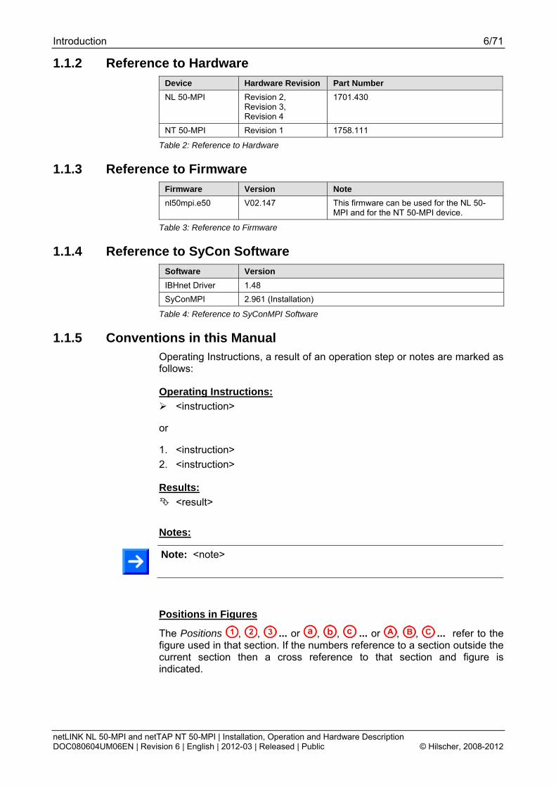
1.1.2 Reference to Hardware Device Hardware Revision Part Number NL 50-MPI Revision 2,
Revision 3, Revision 4
1701.430
NT 50-MPI Revision 1 1758.111
Table 2: Reference to Hardware
1.1.3 Reference to Firmware Firmware Version Note nl50mpi.e50 V02.147 This firmware can be used for the NL 50-
MPI and for the NT 50-MPI device.
Table 3: Reference to Firmware
1.1.4 Reference to SyCon Software Software Version IBHnet Driver 1.48 SyConMPI 2.961 (Installation)
Table 4: Reference to SyConMPI Software
1.1.5 Conventions in this Manual Operating Instructions, a result of an operation step or notes are marked as follows:
Operating Instructions: <instruction>
or
1. <instruction> 2. <instruction>
Results: <result>
Notes:
Note: <note>
Positions in Figures
The Positions , , ... or , , ... or , , ... refer to the figure used in that section. If the numbers reference to a section outside the current section then a cross reference to that section and figure is indicated.
Introduction 7/71
netLINK NL 50-MPI and netTAP NT 50-MPI | Installation, Operation and Hardware Description DOC080604UM06EN | Revision 6 | English | 2012-03 | Released | Public © Hilscher, 2008-2012
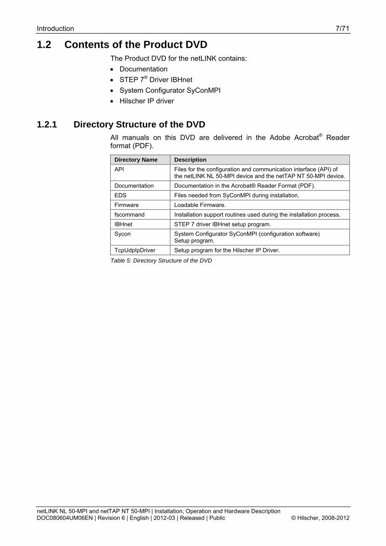
1.2 Contents of the Product DVD The Product DVD for the netLINK contains: • Documentation • STEP 7® Driver IBHnet • System Configurator SyConMPI • Hilscher IP driver
1.2.1 Directory Structure of the DVD All manuals on this DVD are delivered in the Adobe Acrobat® Reader format (PDF).
Directory Name Description API Files for the configuration and communication interface (API) of
the netLINK NL 50-MPI device and the netTAP NT 50-MPI device. Documentation Documentation in the Acrobat® Reader Format (PDF). EDS Files needed from SyConMPI during installation. Firmware Loadable Firmware. fscommand Installation support routines used during the installation process. IBHnet STEP 7 driver IBHnet setup program. Sycon System Configurator SyConMPI (configuration software)
Setup program. TcpUdpIpDriver Setup program for the Hilscher IP Driver.
Table 5: Directory Structure of the DVD

Introduction 8/71
netLINK NL 50-MPI and netTAP NT 50-MPI | Installation, Operation and Hardware Description DOC080604UM06EN | Revision 6 | English | 2012-03 | Released | Public © Hilscher, 2008-2012
1.2.2 Overview of relevant Documentation The following documentation overview gives information, for which items you can find further information in which manual. Documentation for Users
Manual Contents Document name netLINK NL 50-MPI and netTAP NT 50-MPI
Installation, Operation and Hardware Description
netLINK NL 50-MPI and netTAP NT 50-MPI UM xx EN.pdf (this document)
IBHNet Describes the installation and configuration of the STEP®7 driver IBHnet for the use of the NL 50-MPI and the NT 50-MPI device as PG interface with Simatic® STEP® 7. The netLINK NL 50-MPI device is designated as IBH Link S7++.
IBHNet_Manual.pdf This description was created by IBHsoftec Gesellschaft für Automatisierungstechnik mbH .
SyConMPI Description of the configuration software SyConMPI
SyConMPI OI xx EN.pdf
Table 6: Documentations for Users
For the configuration of the MPI device the configuration software SyConMPI or the IBHnet driver can be used. Documentation for Developers
Manual Contents Document name IP Driver Description of the Hilscher IP driver Drv_Ip.pdf netIdent Description of the Hilscher netIdent protocol netIdent_Protocol_API_en.pdf MPI Protocol Interface Manual
Description of the netLINK MPI protocol interface (for both devices)
netLINK_MPI_Protocol_API_en.pdf
FDL Protocol Interface Manual
Description of the netLINK FDL protocol interface (for both devices)
netLINK_FDL_Protocol_API_en.pdf
Table 7: Documentations for Developers

Introduction 9/71
netLINK NL 50-MPI and netTAP NT 50-MPI | Installation, Operation and Hardware Description DOC080604UM06EN | Revision 6 | English | 2012-03 | Released | Public © Hilscher, 2008-2012
1.3 Legal Notes 1.3.1 Copyright
© Hilscher, 2008-2012, Hilscher Gesellschaft für Systemautomation mbH All rights reserved. The images, photographs and texts in the accompanying material (user manual, accompanying texts, documentation, etc.) are protected by German and international copyright law as well as international trade and protection provisions. You are not authorized to duplicate these in whole or in part using technical or mechanical methods (printing, photocopying or other methods), to manipulate or transfer using electronic systems without prior written consent. You are not permitted to make changes to copyright notices, markings, trademarks or ownership declarations. The included diagrams do not take the patent situation into account. The company names and product descriptions included in this document may be trademarks or brands of the respective owners and may be trademarked or patented. Any form of further use requires the explicit consent of the respective rights owner.
1.3.2 Important notes The user manual, accompanying texts and the documentation were created for the use of the products by qualified experts, however, errors cannot be ruled out. For this reason, no guarantee can be made and neither juristic responsibility for erroneous information nor any liability can be assumed. Descriptions, accompanying texts and documentation included in the user manual do not present a guarantee nor any information about proper use as stipulated in the contract or a warranted feature. It cannot be ruled out that the user manual, the accompanying texts and the documentation do not correspond exactly to the described features, standards or other data of the delivered product. No warranty or guarantee regarding the correctness or accuracy of the information is assumed. We reserve the right to change our products and their specification as well as related user manuals, accompanying texts and documentation at all times and without advance notice, without obligation to report the change. Changes will be included in future manuals and do not constitute any obligations. There is no entitlement to revisions of delivered documents. The manual delivered with the product applies. Hilscher Gesellschaft für Systemautomation mbH is not liable under any circumstances for direct, indirect, incidental or follow-on damage or loss of earnings resulting from the use of the information contained in this publication.

Introduction 10/71
netLINK NL 50-MPI and netTAP NT 50-MPI | Installation, Operation and Hardware Description DOC080604UM06EN | Revision 6 | English | 2012-03 | Released | Public © Hilscher, 2008-2012
1.3.3 Exclusion of liability The delivered product (including the technical data) is subject to export or import laws as well as the associated regulations of different counters, in particular those of Germany and the USA. The software may not be exported to countries where this is prohibited by the United States Export Administration Act and its additional provisions. You are obligated to comply with the regulations at your personal responsibility. We wish to inform you that you may require permission from state authorities to export, re-export or import the product.
1.3.4 Warranty Although the hardware and software was developed with utmost care and tested intensively, Hilscher Gesellschaft für Systemautomation mbH does not guarantee its suitability for any purpose not confirmed in writing. It cannot be guaranteed that the hardware and software will meet your requirements, that the use of the software operates without interruption and that the software is free of errors. No guarantee is made regarding infringements, violations of patents, rights of ownership or the freedom from interference by third parties. No additional guarantees or assurances are made regarding marketability, freedom of defect of title, integration or usability for certain purposes unless they are required in accordance with the law and cannot be limited. Warranty claims are limited to the right to claim rectification.

Introduction 11/71
netLINK NL 50-MPI and netTAP NT 50-MPI | Installation, Operation and Hardware Description DOC080604UM06EN | Revision 6 | English | 2012-03 | Released | Public © Hilscher, 2008-2012
1.3.5 Export Regulations The delivered product (including the technical data) is subject to export or import laws as well as the associated regulations of different counters, in particular those of Germany and the USA. The software may not be exported to countries where this is prohibited by the United States Export Administration Act and its additional provisions. You are obligated to comply with the regulations at your personal responsibility. We wish to inform you that you may require permission from state authorities to export, re-export or import the product.
1.3.6 Registered Trademarks Windows® XP/Windows® Vista/Windows® 7 are registered trademarks of Microsoft Corporation. Acrobat® is a registered trademark of Adobe Systems, Inc in the USA and further countries. Pentium® is a registered trademark of Intel Corporation in the USA and further countries. S7, S7-300, S7-400 and MPI are registered trademarks of Siemens AG, Berlin and Munich.
1.4 Licenses The netLINK NL 50-MPI device and the netTAP NT 50-MPI device contain a license for the use with the IBHnet driver.

Safety 12/71
netLINK NL 50-MPI and netTAP NT 50-MPI | Installation, Operation and Hardware Description DOC080604UM06EN | Revision 6 | English | 2012-03 | Released | Public © Hilscher, 2008-2012
2 Safety 2.1 Safety Notes
The user manual, accompanying texts and the documentation were created for the use of the products by qualified experts. When using the products, all safety notes and applicable regulations must be observed. Technical knowledge is required. The user must comply with legal provisions.
2.2 Intended Use The netLINK NL 50-MPI and the NT 50-MPI may only be used as a part of a communication system as described in this manual. The device has been designed exclusively for use in connection with the S7-300 und S7-400 PLCs manufactured by Siemens AG. The device may not be opened or be used when the housing has been removed.
2.3 Personnel Qualification The NL 50-MPI and the NT 50-MPI devices are used as a part of a system which must fulfill safety and accident precaution regulations depending on the respective conditions of use. The user of the system is exclusively responsible for the fulfillment of those regulations. Therefore the system to which the netLINK NL 50-MPI device respectively netTAP NT 50-MPI device belongs may only be used by personnel who has been informed and educated about all relevant regulations.

Safety 13/71
netLINK NL 50-MPI and netTAP NT 50-MPI | Installation, Operation and Hardware Description DOC080604UM06EN | Revision 6 | English | 2012-03 | Released | Public © Hilscher, 2008-2012
2.4 Labeling of Safety Instructions The safety instructions are pinpointed particularly. The instructions are highlighted with a specific safety symbol, a warning triangle and a signal word according to the degree of endangerment. Inside the note the danger is exactly named. Instructions to a property damage message do not contain a warning triangle. Symbol Sort of Warning or Principle
Safety symbol for the warning to personal injury
Warning of damages by electrostatic discharge
Table 8: Safety Symbols and Sort of Warning or Principle
2.4.1.1 Signal Words Signal Word
Meaning
DANGER indicates a direct hazard with high risk, which will have as consequence death or grievous bodily harm if it isn't avoided. The use of this signal word shall be restricted to extremely hazard.
WARNING indicates a possible hazard with medium risk, which will have as consequence death or (grievous) bodily harm if it isn't avoided.
CAUTION indicates a minor hazard with medium risk, which could have as consequence simple battery if it isn't avoided.
Note Indicates an important note in the manual.
Table 9: Signal Words
2.4.1.2 Signal Words USA Signal Word
Meaning
DANGER Indicates a Hazardous Situation Which, if not Avoided, will Result in Death or Serious Injury.
WARNING Indicates a Hazardous Situation Which, if not Avoided, could Result in Death or Serious Injury.
CAUTION Indicates a Hazardous Situation Which, if not Avoided, may Result in Minor or Moderate Injury.
NOTICE Indicates a Property Damage Message. Note Indicates an Important Note in the Manual.
Table 10: Signal Words according to ANSI

Safety 14/71
netLINK NL 50-MPI and netTAP NT 50-MPI | Installation, Operation and Hardware Description DOC080604UM06EN | Revision 6 | English | 2012-03 | Released | Public © Hilscher, 2008-2012
2.5 Safety Instructions This manual contains instructions which must be observed to ensure your own personal safety and to avoid damage to devices of your system.
2.5.1 Electrical Voltage
CAUTION!
Device Destruction! Use only 18 ... 30 V supply voltage to operate the devices. Operation with more than 30 V supply voltage will lead to destruction of the device.
2.5.2 Electrostatic Discharge Adhere to the necessary safety precautions for components that are vulnerable with electrostatic discharge (EN 61340-5-1 und EN 61340-5-2 as well as IEC 61340-5-1 und IEC 61340-5-2).
CAUTION!
Electrostatic Discharge This equipment is sensitive to electrostatic discharge, which cause internal damage and affect normal operation. Follow guidelines when you handle this equipment: Touch a grounded object to discharge potential static. Do not touch connectors or pins. Do not touch circuit components inside the equipment. When not in use, store the equipment in appropriate static-safe packaging.

Safety 15/71
netLINK NL 50-MPI and netTAP NT 50-MPI | Installation, Operation and Hardware Description DOC080604UM06EN | Revision 6 | English | 2012-03 | Released | Public © Hilscher, 2008-2012
2.6 Safety Instructions USA This manual contains instructions which must be observed to ensure your own personal safety and to avoid damage to devices.
2.6.1 Electrical Current
Device Destruction! Use only 18..30 V supply voltage to operate the devices. Operation with more than 30 V supply voltage will lead to destruction of the device.
2.6.2 Electrostatic Discharge Adhere to the necessary safety precautions for components that are vulnerable with electrostatic discharge (EN 61340-5-1 und EN 61340-5-2 as well as IEC 61340-5-1 und IEC 61340-5-2).
Electrostatic Discharge This equipment is sensitive to electrostatic discharge, which cause internal damage and affect normal operation. Follow guidelines when you handle this equipment: Touch a grounded object to discharge potential static. Do not touch connectors or pins. Do not touch circuit components inside the equipment. When not in use, store the equipment in appropriate static-safe packaging.

Description and Requirements 16/71
netLINK NL 50-MPI and netTAP NT 50-MPI | Installation, Operation and Hardware Description DOC080604UM06EN | Revision 6 | English | 2012-03 | Released | Public © Hilscher, 2008-2012
3 Description and Requirements 3.1 Description
The MPI devices netLINK NL 50-MPI and netTAP NT 50-MPI make it possible to communicate via Ethernet to a PROFIBUS MPI automation system. 1. The gateway devices can be used together with the IBHnet driver as a programming adapter with PROFIBUS MPI for a Simatic S7 or a S7 compatible PLC. 2. The gateway devices make it also possible to communicate via Ethernet to PROFIBUS MPI. The Configuration (set IP-Address, PROFIBUS parameter etc.) is carried out via the Ethernet. For this purpose either • the configuration software SyConMPI or alternatively • the IBHnet driver can be used. The configuration is saved in the device in a FLASH memory. Both gateway devices have the same compatible interface regarding communication and configuration. The devices support the PROFIBUS MPI protocol (as a client) at the D-Sub connector and are a complete gateway together with the 10/100 MBit/s Ethernet interface, which detects by auto detection the Ethernet transmission rate of 10 or 100 MBit/s.
3.1.1 Description netLINK NL 50-MPI The netLINK NL 50-MPI device described in this user manual is an Ethernet Gateway based on netX technology. This device is a successor of the netLINK NL-MPI device. Because of its structure in the D-Sub housing, it can be plugged directly on to the fieldbus connection of a PROFIBUS MPI capable device and connects this, using an external Ethernet cable to the next Ethernet switch. The netLINK NL 50-MPI device has a standard RJ45 ethernet socket to connect an Ethernet cable. The power supply is provided directly by the MPI Interface or externally.
3.1.2 Compatibility of the netLINK NL 50-MPI to the NL-MPI The netLINK NL 50-MPI device is compatible to the netLINK NL-MPI with respect to the following details: • The communication functionality for user data exchange is compatible, • the configurations of both device are compatible. With respect to the diagnostic functions there is only a partial compatibility.
Description and Requirements 17/71
netLINK NL 50-MPI and netTAP NT 50-MPI | Installation, Operation and Hardware Description DOC080604UM06EN | Revision 6 | English | 2012-03 | Released | Public © Hilscher, 2008-2012
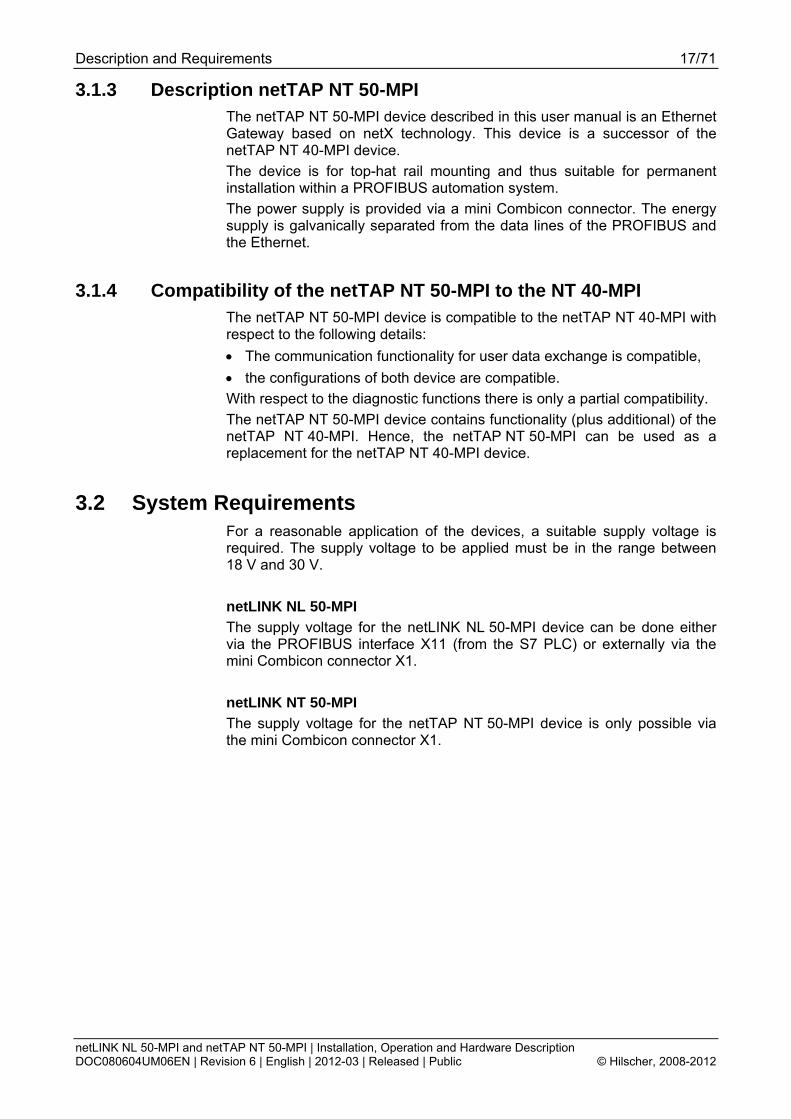
3.1.3 Description netTAP NT 50-MPI The netTAP NT 50-MPI device described in this user manual is an Ethernet Gateway based on netX technology. This device is a successor of the netTAP NT 40-MPI device. The device is for top-hat rail mounting and thus suitable for permanent installation within a PROFIBUS automation system. The power supply is provided via a mini Combicon connector. The energy supply is galvanically separated from the data lines of the PROFIBUS and the Ethernet.
3.1.4 Compatibility of the netTAP NT 50-MPI to the NT 40-MPI The netTAP NT 50-MPI device is compatible to the netTAP NT 40-MPI with respect to the following details: • The communication functionality for user data exchange is compatible, • the configurations of both device are compatible. With respect to the diagnostic functions there is only a partial compatibility. The netTAP NT 50-MPI device contains functionality (plus additional) of the netTAP NT 40-MPI. Hence, the netTAP NT 50-MPI can be used as a replacement for the netTAP NT 40-MPI device.
3.2 System Requirements For a reasonable application of the devices, a suitable supply voltage is required. The supply voltage to be applied must be in the range between 18 V and 30 V. netLINK NL 50-MPI The supply voltage for the netLINK NL 50-MPI device can be done either via the PROFIBUS interface X11 (from the S7 PLC) or externally via the mini Combicon connector X1. netLINK NT 50-MPI The supply voltage for the netTAP NT 50-MPI device is only possible via the mini Combicon connector X1.
Description and Requirements 18/71
netLINK NL 50-MPI and netTAP NT 50-MPI | Installation, Operation and Hardware Description DOC080604UM06EN | Revision 6 | English | 2012-03 | Released | Public © Hilscher, 2008-2012
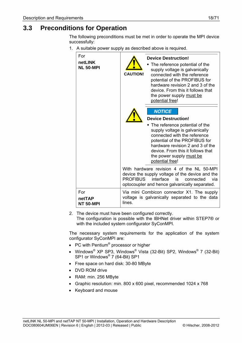
3.3 Preconditions for Operation The following preconditions must be met in order to operate the MPI device successfully: 1. A suitable power supply as described above is required.
For netLINK NL 50-MPI
CAUTION!
Device Destruction! The reference potential of the supply voltage is galvanically connected with the reference potential of the PROFIBUS for hardware revision 2 and 3 of the device. From this it follows that the power supply must be potential free!
Device Destruction! The reference potential of the supply voltage is galvanically connected with the reference potential of the PROFIBUS for hardware revision 2 and 3 of the device. From this it follows that the power supply must be potential free!
With hardware revision 4 of the NL 50-MPI device the supply voltage of the device and the PROFIBUS interface is connected via optocoupler and hence galvanically separated.
For netTAP NT 50-MPI
Via mini Combicon connector X1. The supply voltage is galvanically separated to the data lines.
2. The device must have been configured correctly. The configuration is possible with the IBHNet driver within STEP7® or with the included system configurator SyConMPI.
The necessary system requirements for the application of the system configurator SyConMPI are: • PC with Pentium® processor or higher • Windows® XP SP3, Windows® Vista (32-Bit) SP2, Windows® 7 (32-Bit)
SP1 or Windows® 7 (64-Bit) SP1 • Free space on hard disk: 30-80 MByte • DVD ROM drive • RAM: min. 256 MByte • Graphic resolution: min. 800 x 600 pixel, recommended 1024 x 768 • Keyboard and mouse

Device Drawing and Connections 19/71
netLINK NL 50-MPI and netTAP NT 50-MPI | Installation, Operation and Hardware Description DOC080604UM06EN | Revision 6 | English | 2012-03 | Released | Public © Hilscher, 2008-2012
4 Device Drawing and Connections 4.1 Device and Dimensioned Drawing
netLINK NL 50-MPI netTAP NT 50-MPI
Figure 1: Dimensioned Drawing NL 50-MPI and NT 50-MPI (Size in mm)
Device Drawing and Connections 20/71
netLINK NL 50-MPI and netTAP NT 50-MPI | Installation, Operation and Hardware Description DOC080604UM06EN | Revision 6 | English | 2012-03 | Released | Public © Hilscher, 2008-2012
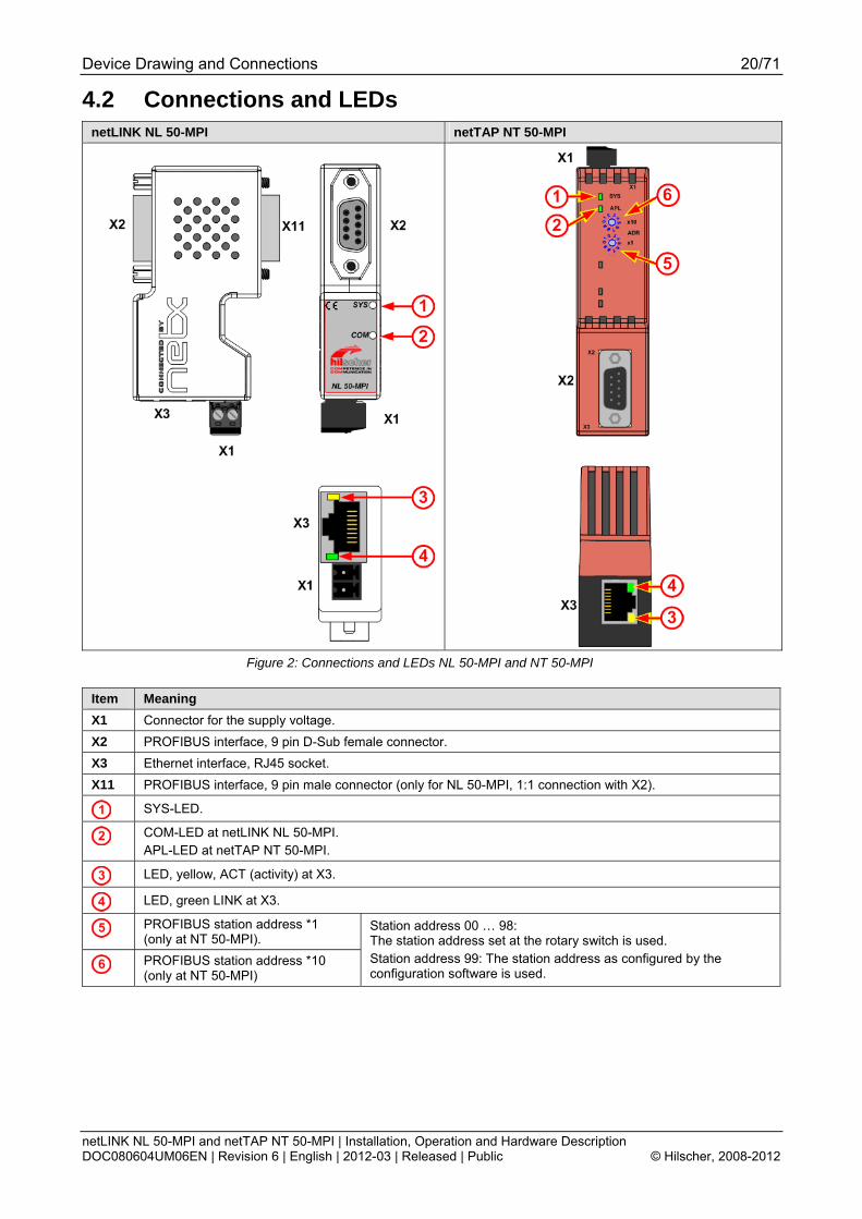
4.2 Connections and LEDs netLINK NL 50-MPI netTAP NT 50-MPI
Figure 2: Connections and LEDs NL 50-MPI and NT 50-MPI
Item Meaning X1 Connector for the supply voltage. X2 PROFIBUS interface, 9 pin D-Sub female connector. X3 Ethernet interface, RJ45 socket. X11 PROFIBUS interface, 9 pin male connector (only for NL 50-MPI, 1:1 connection with X2).
SYS-LED.
COM-LED at netLINK NL 50-MPI. APL-LED at netTAP NT 50-MPI.
LED, yellow, ACT (activity) at X3.
LED, green LINK at X3.
PROFIBUS station address *1 (only at NT 50-MPI).
PROFIBUS station address *10 (only at NT 50-MPI)
Station address 00 … 98: The station address set at the rotary switch is used. Station address 99: The station address as configured by the configuration software is used.

Device Drawing and Connections 21/71
netLINK NL 50-MPI and netTAP NT 50-MPI | Installation, Operation and Hardware Description DOC080604UM06EN | Revision 6 | English | 2012-03 | Released | Public © Hilscher, 2008-2012
4.3 Ethernet Interface (X3) For the Ethernet interface use RJ45 plugs and twisted pair cable of category 5 (CAT5) or higher, which consists of 4 twisted cores and has a maximum transmission rate of 100 MBit/s (CAT5).
4.3.1 Ethernet pinning at the RJ45 Socket
Note: The device supports the Auto Crossover function. Due to this fact RX and TX can be switched. The following figure shows the RJ45 standard pinning.
Ethernet on RJ45 Pin Assignment Ethernet Pin Signal Description
1 TX+ Transmit data positive 2 TX– Transmit data negative 3 RX+ Receive data positive 4 Term 1 5 Term 1
Connected and terminated to PE via RC combination*
6 RX– Receive data negative 7 Term 2 8 Term 2
Connected and terminated to PE via RC combination*
RJ45 socket, female
* Bob Smith Termination
Table 11: Ethernet RJ45 Pin Assignment
4.3.2 Ethernet Connection Data Medium 2 x 2 Twisted-Pair copper cable, CAT5 (100 MBit/s) Length of cable max. 100 m Transmission rate 10 MBit/s / 100 MBit/s
Table 12: Ethernet Connection Data

Device Drawing and Connections 22/71
netLINK NL 50-MPI and netTAP NT 50-MPI | Installation, Operation and Hardware Description DOC080604UM06EN | Revision 6 | English | 2012-03 | Released | Public © Hilscher, 2008-2012
4.4 PROFIBUS Interface (X11, X2) netLINK NL 50-MPI netTAP NT 50-MPI D-Sub plug X11 (male connector) to connect to the S7 PLC (or another MPI capable device). D-Sub socket X2 (female connector) to connect a programming device. X11 and X2 have internally a 1 to 1 connection.
D-Sub connector X2 to connect a PROFIBUS network cable. Use a cable with terminating resistors at the beginning and the end of the cable.
54321
9876
Figure 3: PROFIBUS Interface X11 (D-Sub male connector, 9 pin)
12345
6789
Figure 4: PROFIBUS Interface X2 (D-Sub female connector, 9 pin)
NL
50-
MPI
NT
50-
MPI
Pin D-Sub male / female connector
Signal Meaning
X 1 - unused, is only connected through X 2 DGND
GND
Reference potential (for hardware revision 2 and 3) Ground (for VS) (for hardware revision 4)
X X 3 RxD/TxD-P Receive/send data positive respectively connection B
X X 4 - unused, is only connected through X X 5 DGND
ISOGND
Reference potential (for hardware revision 2 and 3) Reference potential (PROFIBUS) (for hardware revision 4)
X X 6 - unused, is only connected through X 7 VS Positive power supply (24 V) X X 8 RxD/TxD-N Receive/send data negative respectively
connection A X 9 - unused, is only connected through Housing shield shield
Table 13: PROFIBUS Interface (D-Sub female and male connector, 9 pin)
netTAP NT 50-MPI: Only D-Sub female connector X2 is available and pins 1, 2, 7 and 9 are not used.
Device Drawing and Connections 23/71
netLINK NL 50-MPI and netTAP NT 50-MPI | Installation, Operation and Hardware Description DOC080604UM06EN | Revision 6 | English | 2012-03 | Released | Public © Hilscher, 2008-2012
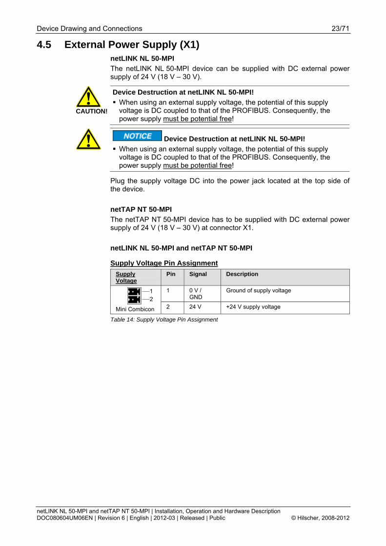
4.5 External Power Supply (X1) netLINK NL 50-MPI The netLINK NL 50-MPI device can be supplied with DC external power supply of 24 V (18 V – 30 V).
CAUTION!
Device Destruction at netLINK NL 50-MPI! When using an external supply voltage, the potential of this supply voltage is DC coupled to that of the PROFIBUS. Consequently, the power supply must be potential free!
Device Destruction at netLINK NL 50-MPI!
When using an external supply voltage, the potential of this supply voltage is DC coupled to that of the PROFIBUS. Consequently, the power supply must be potential free!
Plug the supply voltage DC into the power jack located at the top side of the device. netTAP NT 50-MPI The netTAP NT 50-MPI device has to be supplied with DC external power supply of 24 V (18 V – 30 V) at connector X1. netLINK NL 50-MPI and netTAP NT 50-MPI
Supply Voltage Pin Assignment Supply Voltage
Pin Signal Description
1 0 V / GND
Ground of supply voltage
Mini Combicon 2 24 V +24 V supply voltage
Table 14: Supply Voltage Pin Assignment

Device Drawing and Connections 24/71
netLINK NL 50-MPI and netTAP NT 50-MPI | Installation, Operation and Hardware Description DOC080604UM06EN | Revision 6 | English | 2012-03 | Released | Public © Hilscher, 2008-2012
4.6 Schematic Diagram - Galvanic Isolation 4.6.1 netLINK NL 50-MPI
Figure 5: netLINK NL 50-MPI, Coupling (Hardware Revision 4)
For the netLINK NL 50-MPI device the connection to PE takes place via the metal connection (shielding of the cable).
Area Connection
Interface
galv. Isolation
Coupling
Coupling against PE Functional earthing to PE
HF Lf = 47 μH
X1
- no
Cx1 1 * 1 nF / 1000 V 1 * 22 pF / 63 V
-
X2
PROFIBUS
inductive
Cx2 1 MΩ // 2,2 nF/ 500 V
directly via the metal connection of the D-Sub male connector
X3
Ethernet
inductive
Cx3 4 * 75 Ω, 1 nF / 2000 V
directly via the metal housing of the RJ 45 connector
Table 15: Coupling NL 50-MPI, Hardware Revision 4
Device Drawing and Connections 25/71
netLINK NL 50-MPI and netTAP NT 50-MPI | Installation, Operation and Hardware Description DOC080604UM06EN | Revision 6 | English | 2012-03 | Released | Public © Hilscher, 2008-2012
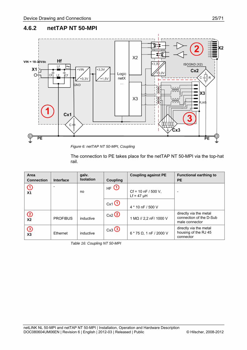
4.6.2 netTAP NT 50-MPI
Figure 6: netTAP NT 50-MPI, Coupling
The connection to PE takes place for the netTAP NT 50-MPI via the top-hat rail.
Area Connection
Interface
galv. Isolation
Coupling
Coupling against PE Functional earthing to PE
HF Cf = 10 nF / 500 V, Lf = 47 μH
X1
- no
Cx1 4 * 10 nF / 500 V
-
X2
PROFIBUS
inductive
Cx2 1 MΩ // 2,2 nF/ 1000 V
directly via the metal connection of the D-Sub male connector
X3
Ethernet
inductive
Cx3 6 * 75 Ω, 1 nF / 2000 V
directly via the metal housing of the RJ 45 connector
Table 16: Coupling NT 50-MPI

Mounting and dismounting the Device 26/71
netLINK NL 50-MPI and netTAP NT 50-MPI | Installation, Operation and Hardware Description DOC080604UM06EN | Revision 6 | English | 2012-03 | Released | Public © Hilscher, 2008-2012
5 Mounting and dismounting the Device 5.1 Mounting netLINK NL 50-MPI
Figure 7: Mounting the netLINK
The NL 50-MPI is slipped and screwed on a S7 MPI / PROFIBUS interface or another compatible device with the MPI / PROFIBUS interface of the NL 50-MPI.
5.2 Mounting and Dismounting netTAP NT 50-MPI The devices can be mounted side-by-side without any gap. On the top side, the devices should have a minimum distance of 20 mm to the next device. The air ventilation slots of the device must not be covered by any objects.
5.2.1 Top Hat Rail Mounting of the NT 50-MPI Mount the top hat rail according to DIN EN 60715 for the netTAP device horizontally at the intended location. The DIN top hat rail has to be connected with the potential equalization conductor (PE).
Push the device onto the top hat rail from above . Then press the device against the mounting surface, according to arrow .
Figure 8: Mounting the netTAP NT 50 device onto the top-hat rail
Afterwards connect the 24 V supply voltage to the device. Grounding is done via a grounding contact located at the backside of the device connecting it electrically to the top-hat rail.

Mounting and dismounting the Device 27/71
netLINK NL 50-MPI and netTAP NT 50-MPI | Installation, Operation and Hardware Description DOC080604UM06EN | Revision 6 | English | 2012-03 | Released | Public © Hilscher, 2008-2012
5.2.2 Removing the NT 50 from the Top-Hat Rail In order to remove the netTAP from the top-hat rail, first remove the power supply cable and all data cables from the device.
To release the device from the top-hat rail, use a screw driver, which you put at the clip in the center of the device. By pressing slightly the screw driver in direction of arrow the lock at the top-hat rail is released. You can then easily pull the device off the top-hat rail in direction of arrow .
Figure 9: Removing the NT 50 device from the Top-Hat Rail

Mounting and dismounting the Device 28/71
netLINK NL 50-MPI and netTAP NT 50-MPI | Installation, Operation and Hardware Description DOC080604UM06EN | Revision 6 | English | 2012-03 | Released | Public © Hilscher, 2008-2012
5.3 Power Supply 5.3.1 netLINK NL 50-MPI
The power supply of the NL 50-MPI device can be done directly by plugging the device onto a PLC, if pin 7 of the D-Sub connector of the PLC provides 24 V DC. Alternatively it is possible to connect the supply voltage of 24 V DC externally using the Mini-Combicon connector.
CAUTION!
Device Destruction! The reference potential of the supply voltage is galvanically connected with the reference potential of the PROFIBUS interface for hardware revision 2 and 3 of the device. From this it follows that the power supply must be potential free!
Device Destruction! The reference potential of the supply voltage is galvanically connected with the reference potential of the PROFIBUS interface for hardware revision 2 and 3 of the device. From this it follows that the power supply must be potential free!
With hardware revision 4 of the NL 50-MPI device the supply voltage and the PROFIBUS interface is galvanically separated by opto coupler.
5.3.2 netTAP NT 50-MPI The supply voltage for the netTAP NT 50-MPI of 24 V DC is only possible via the mini Combicon connector X1. The supply voltage is galvanically separated from the data lines of the PROFIBUS and the Ethernet interface.
5.4 Ethernet Connection The Ethernet connector of the NL 50-MPI is connected by an Ethernet cable to a switch, hub or Ethernet end device. The NL 50-MPI operates its Ethernet interface in the Auto-crossover mode. Thus for the connection with Ethernet devices both crossover cables and patch cables are applicable.
Installing Software 29/71
netLINK NL 50-MPI and netTAP NT 50-MPI | Installation, Operation and Hardware Description DOC080604UM06EN | Revision 6 | English | 2012-03 | Released | Public © Hilscher, 2008-2012
6 Installing Software 6.1 Installing Software from DVD
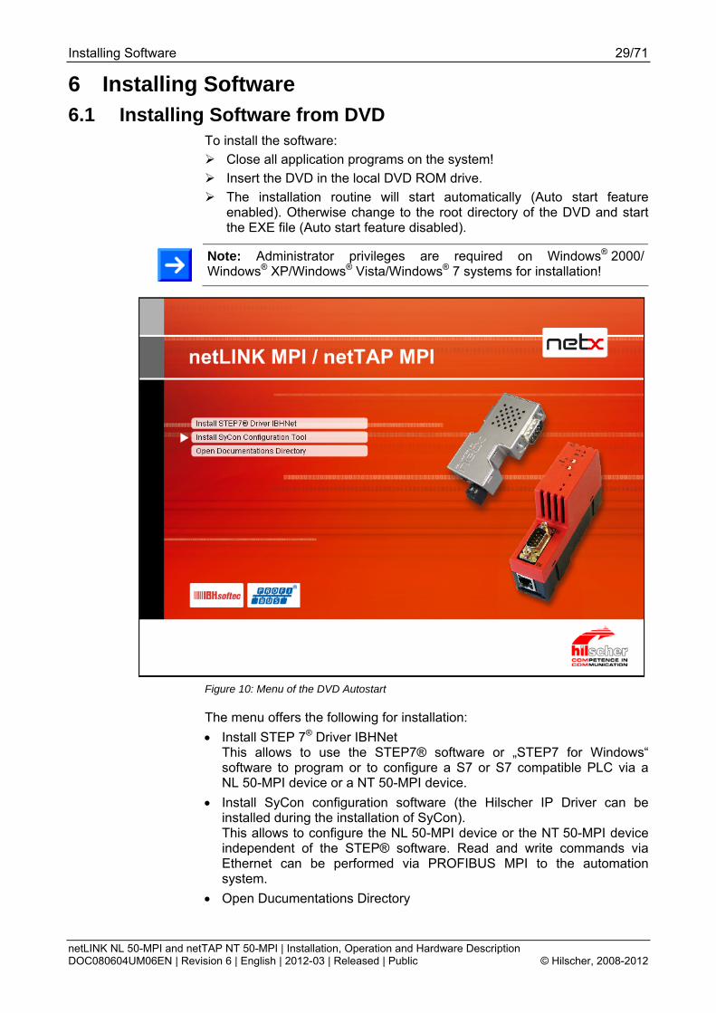
To install the software: Close all application programs on the system! Insert the DVD in the local DVD ROM drive. The installation routine will start automatically (Auto start feature
enabled). Otherwise change to the root directory of the DVD and start the EXE file (Auto start feature disabled).
Note: Administrator privileges are required on Windows® 2000/ Windows® XP/Windows® Vista/Windows® 7 systems for installation!
Figure 10: Menu of the DVD Autostart
The menu offers the following for installation: • Install STEP 7® Driver IBHNet
This allows to use the STEP7® software or „STEP7 for Windows“ software to program or to configure a S7 or S7 compatible PLC via a NL 50-MPI device or a NT 50-MPI device.
• Install SyCon configuration software (the Hilscher IP Driver can be installed during the installation of SyCon). This allows to configure the NL 50-MPI device or the NT 50-MPI device independent of the STEP® software. Read and write commands via Ethernet can be performed via PROFIBUS MPI to the automation system.
• Open Ducumentations Directory

Installing Software 30/71
netLINK NL 50-MPI and netTAP NT 50-MPI | Installation, Operation and Hardware Description DOC080604UM06EN | Revision 6 | English | 2012-03 | Released | Public © Hilscher, 2008-2012
To configure the MPI device you can use either the IBHnet driver or SyConMPI. For the system configurator SyConMPI no license is required as the basic version already contains all functions necessary for the configuration of the devices.
6.2 Installation under Windows Vista or Windows 7 The program WinHlp32.exe is not included in the operating system Windows Vista and Windows 7. It is necessary to display the online help files (*.HLP format). For download and installation information follow this link: http://support.microsoft.com/kb/917607
6.3 Install IP Driver Some application programs use the Hilscher IP Driver to communicate with the MPI device. The installation program for the Hilscher IP driver is on the DVD in the TcpUdpIpDriver folder.
Start on the DVD in the folder TcpUdpIpDriver the setup.exe.
Figure 11: Install IP Driver (1)
At the first screen, you simply have to click Next in order to proceed. Then some information about the IP driver is displayed on the screen.
You should read this text carefully.

Installing Software 31/71
netLINK NL 50-MPI and netTAP NT 50-MPI | Installation, Operation and Hardware Description DOC080604UM06EN | Revision 6 | English | 2012-03 | Released | Public © Hilscher, 2008-2012
At the next screen, you are asked to specify the storage location for the Hilscher IP Driver.
Figure 12: Install IP Driver (2)
You may choose the proposed standard location or choose another one after clicking Browse . Then click Next again in order to proceed.
After that, you will reach the final screen indicating that the installation process has been completed.
Figure 13: Install IP Driver (3)
Click Finish . After the installation the driver has to be configured correctly, i.e. the IP address and the port number of the MPI device need to be specified as described in the next section of this document.

Configuring MPI Device 32/71
netLINK NL 50-MPI and netTAP NT 50-MPI | Installation, Operation and Hardware Description DOC080604UM06EN | Revision 6 | English | 2012-03 | Released | Public © Hilscher, 2008-2012
7 Configuring MPI Device 7.1 Configuring MPI-Device with Hilscher IP Driver 7.1.1 Assign IP Address to MPI Device
Assign an IP address to the device. Proceed as follows:
Start the Program NetIdentDemo
Select Start > Programs > Hilscher IP Driver > NetIdentDemo Program
Figure 14: NetIdent Demo
Click Start .
The window for IP address assignment opens.
Figure 15: netIdent – Scan for Devices (1)
After you have provided supply voltage to the MPI device and connected via an Ethernet cable to the PC, click Start Poll to start the scan.
The scan for devices is done at all Ethernet interfaces on the PC. Found devices are displayed.

Configuring MPI Device 33/71
netLINK NL 50-MPI and netTAP NT 50-MPI | Installation, Operation and Hardware Description DOC080604UM06EN | Revision 6 | English | 2012-03 | Released | Public © Hilscher, 2008-2012
Figure 16: netIdent – Scan for Devices (2)
Select the MPI device that should be configured . Afterwards, click Set IP .
Figure 17: netIdent - Set IP Address The pop-up windows above opens.
Enter the IP address for the MPI device. Afterwards, click SetIP.
If the IP address was set successfully, then the following window appears:
Figure 18: netIdent - Set IP Address (2) Click OK .

Configuring MPI Device 34/71
netLINK NL 50-MPI and netTAP NT 50-MPI | Installation, Operation and Hardware Description DOC080604UM06EN | Revision 6 | English | 2012-03 | Released | Public © Hilscher, 2008-2012
Figure 19: netIdent - Set IP Address (3) Click Exit .
Figure 20: netIdent - Set IP Address (4) Click Exit .
Note: The IP address set is only valid (temporarily) as long as the device is not disconnected from power supply. To set a permanent IP address see section Creating and downloading the Configuration to set a permanent IP Adress on page 36.

Configuring MPI Device 35/71
netLINK NL 50-MPI and netTAP NT 50-MPI | Installation, Operation and Hardware Description DOC080604UM06EN | Revision 6 | English | 2012-03 | Released | Public © Hilscher, 2008-2012
7.1.2 Configuring of the IP Driver Start the configuration program of the Hilscher IP Driver with Start >
Programs > Hilscher IP Driver > IP Driver Setup. The GUI of the Hilscher IP Driver Setup program will appear then:
Figure 21: GUI of the Hilscher IP Driver Setup
Enter the configured IP address of the MPI device in the field IP Address and the Port number in the field Port .
The following settings are necessary: Field Required action
Port Set the port to 1099.
Protocol Set the protocol to TCP.
Mode Set the mode to Client.
Table 17: Configuring IP Driver
Connect Timeout (ms) : In client mode this field holds the time period the driver tries to establish a connection with the selected MPI device.
Note: A time out value that is too small can prevent correct connection establishment to the MPI device.
Note: If this setting shall be changed later again, the program IpDrvSetup.exe and also the programs which use the driver need to be restarted.
Note: If the PC is behind a Firewall, then port 1099 has to be unblocked. For this, contact your network administrator.
Click OK to close the dialog.

Configuring MPI Device 36/71
netLINK NL 50-MPI and netTAP NT 50-MPI | Installation, Operation and Hardware Description DOC080604UM06EN | Revision 6 | English | 2012-03 | Released | Public © Hilscher, 2008-2012
7.2 Creating and downloading the Configuration to set a permanent IP Adress
7.2.1 Overview
Note: The configuration of the MPI device is done via TCP/IP.
To create and to download the configuration of the MPI device, proceed as follows: 1. Start the system configurator SyCon:
Select Start > Programs > SyCon System Configurator > SyCon. 2. Create a new project:
Select menu File > New or File > New > MPI. 3. Insert the MPI device to the project:
Select menu Insert > Device. In the window Insert Device under Available devices select the MPI
device NL 50-MPI or NT 50-MPI. Click Add. Click OK.
4. Setting the IP address and the PROFIBUS parameters:
Select menu Settings > MPI Parameter or double click the MPI device symbol.
The parameter window is displayed. Set the IP address, if necessary also the Net Mask and the gateway
address. A description of these parameters is included in the section IP Address on page 47.
Set the PROFIBUS parameters, especially the station address and the bus parameters.
A description of the PROFIBUS parameters are in the section PROFIBUS Parameter on page 49.

Configuring MPI Device 37/71
netLINK NL 50-MPI and netTAP NT 50-MPI | Installation, Operation and Hardware Description DOC080604UM06EN | Revision 6 | English | 2012-03 | Released | Public © Hilscher, 2008-2012
5. Connecting the System configurator SyCon with the MPI device:
Select menu Settings > Device Assignment. Select in the window Driver Select the driver CIF TCP/IP Driver. Click OK. The window Device Assignment ODM TCP/IP Drive is displayed. Click netIdent Rescan. The local Ethernet network is scanned for MPI devices. Found devices
are displayed under Board Selection. In the list Board Selection mark the check box for the MPI device. A connection from the System configurator SyCon to the MPI device
has been established. Click OK. The window Device Assignment ODM TCP/IP Drive is closed.
6. Downloading the configuration to the device:
Select menu Online > Download. The safety question is displayed, if the download should be executed. Click Yes. The configuration is downloaded to the device.
7. Reset the device to activate the new configuration:
Select menu Online > Firmware/Reset. The window Firmware/Reset is displayed. Click Reset. The safety question is displayed, if the reset shall be executed. Select the button Yes. The reset is executed. By this the configuration is activated.
8. Saving the SyCon project:
Select menu File > Save under. The window Save under is displayed. Enter the file name for the project. Click OK. The project is saved.

Configuring MPI Device 38/71
netLINK NL 50-MPI and netTAP NT 50-MPI | Installation, Operation and Hardware Description DOC080604UM06EN | Revision 6 | English | 2012-03 | Released | Public © Hilscher, 2008-2012
7.2.2 Step-by-Step Description Step 1: Start the system configurator SyConMPI
Select Start > Programs > SyCon System Configurator > SyCon. Step 2: Create a new project
Select File > New or File > New > MPI. An empty project file (configuration file) is created and is displayed.
Figure 22: System Configurator SyConMPI – Create a new Project
Step 3: Insert the MPI device to the project
Select menu Insert > Device . The window Insert Device is displayed.
Figure 23: Insert Device
Under Available devices select the device NL 50-MPI .
Click Add .
Click OK . The MPI device is displayed in the SyCon project or the configuration
file.

Configuring MPI Device 39/71
netLINK NL 50-MPI and netTAP NT 50-MPI | Installation, Operation and Hardware Description DOC080604UM06EN | Revision 6 | English | 2012-03 | Released | Public © Hilscher, 2008-2012
Figure 24: System Configurator SyConMPI – The MPI Device is displayed in the Project
Step 4: Set IP address and PROFIBUS parameters Select menu Settings > MPI Device Parameter or double click to the
MPI device symbol. The parameter window is displayed.
Figure 25: Set IP Address
Step 4A: Set the IP address, if necessary also the Net Mask and the gateway
address. A description of these parameters is included in the section IP Address on page 47.
Configuring MPI Device 40/71
netLINK NL 50-MPI and netTAP NT 50-MPI | Installation, Operation and Hardware Description DOC080604UM06EN | Revision 6 | English | 2012-03 | Released | Public © Hilscher, 2008-2012
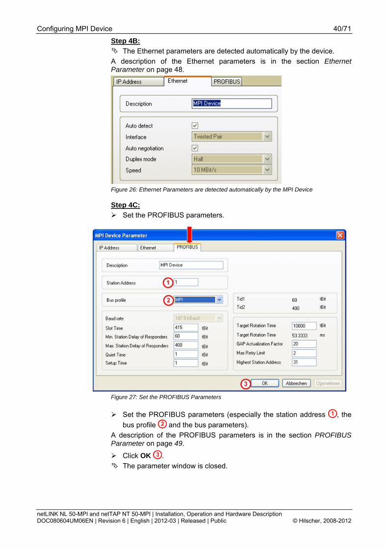
Step 4B: The Ethernet parameters are detected automatically by the device.
A description of the Ethernet parameters is in the section Ethernet Parameter on page 48.
Figure 26: Ethernet Parameters are detected automatically by the MPI Device
Step 4C: Set the PROFIBUS parameters.
Figure 27: Set the PROFIBUS Parameters
Set the PROFIBUS parameters (especially the station address , the bus profile and the bus parameters).
A description of the PROFIBUS parameters is in the section PROFIBUS Parameter on page 49.
Click OK . The parameter window is closed.

Configuring MPI Device 41/71
netLINK NL 50-MPI and netTAP NT 50-MPI | Installation, Operation and Hardware Description DOC080604UM06EN | Revision 6 | English | 2012-03 | Released | Public © Hilscher, 2008-2012
Step 5: Connecting the system configurator SyConMPI to the MPI device A.) Select the driver CIF TCP/IP Driver. B.) Scan for MPI devices. C.) If necessary, change and assign the IP address manually. D.) Connect the system configurator SyConMPI with the MPI device. Proceed as follows: Step 5A: Select the driver CIF TCP/IP Driver
Select menu Settings > Device Assignment.
Figure 28: Window Driver Select
The Driver Select window is displayed.
Figure 29: Window Driver Select
Select in the window Driver Select the driver CIF TCP/IP Driver .
Click OK . The window Device Assignment ODM TCP/IP Drive is displayed.

Configuring MPI Device 42/71
netLINK NL 50-MPI and netTAP NT 50-MPI | Installation, Operation and Hardware Description DOC080604UM06EN | Revision 6 | English | 2012-03 | Released | Public © Hilscher, 2008-2012
Figure 30: Window Device Assignment ODM TCP/IP Driver
Step 5B: Scan for MPI devices In the window Device Assignment ODM TCP/IP Drive click netIdent
Rescan . The local Ethernet network is scanned for devices. The detected
devices are displayed under Board Selection.
Figure 31: Window Device Assignment ODM TCP/IP Drive – Found devices are displayed
If one or more devices were found, they are displayed in the list Board Selection with their MAC-ID. If the device already has an IP address this is shown in the column IP Address.
Step 5C: If necessary, change and assign the IP address manually. If the shown IP address is 0.0.0.0 or the IP address shall be changed, an IP address has to be assigned to the device.
In the window Device Assignment ODM TCP/IP Drive in the list Board Selection mark the check box for MPI device.

Configuring MPI Device 43/71
netLINK NL 50-MPI and netTAP NT 50-MPI | Installation, Operation and Hardware Description DOC080604UM06EN | Revision 6 | English | 2012-03 | Released | Public © Hilscher, 2008-2012
Select the button Set IP Address . The window Configure IP Address is displayed.
Figure 32: Window Configure IP Address
Enter a valid IP address.
Figure 33: Window Configure IP Address – Set the IP address
Click Set IP .
Note: With Set IP only a temporarily IP address is set in the MPI device. To set a permanent IP address a configuration download has to be done.
Note: When the IP address set in this step 5C and the IP address entered in step 4A are different, then the IP address of step 4A is used from the device after a download of the configuration and a reset.
The IP address is assigned to the device. The hint window Setting IP address successful! is displayed.
Figure 34: Hint – Setting IP Address successful
Click OK . In the window Configure IP Address click Exit. The window Configure IP Address is closed.

Configuring MPI Device 44/71
netLINK NL 50-MPI and netTAP NT 50-MPI | Installation, Operation and Hardware Description DOC080604UM06EN | Revision 6 | English | 2012-03 | Released | Public © Hilscher, 2008-2012
Step 5D: Connect the system configurator SyConMPI with the MPI device:
Figure 35: Window Device Assignment ODM TCP/IP Drive – A Connection has been established
In the window Device Assignment ODM TCP/IP Drive in the list Board Selection mark the check box for MPI device.
A connection from the System configurator SyCon to the MPI device has been established.
Click OK . The window Device Assignment ODM TCP/IP Drive is closed.

Configuring MPI Device 45/71
netLINK NL 50-MPI and netTAP NT 50-MPI | Installation, Operation and Hardware Description DOC080604UM06EN | Revision 6 | English | 2012-03 | Released | Public © Hilscher, 2008-2012
Step 6: Download the configuration to the device Select in the system configurator SyCon the menu Online >
Download.
Figure 36: Online Configuration Download
The safety question is displayed, if the download should be executed.
Figure 37: Question – Do you really want to download?
If the download must not be executed: Click No. The download is not executed.
If the download must be executed: Click Yes. The download is executed. During the download the progress bar Data
Base Download is displayed.
Figure 38: Progress Bar Data Base Download
The configuration is downloaded to the MPI device.

Configuring MPI Device 46/71
netLINK NL 50-MPI and netTAP NT 50-MPI | Installation, Operation and Hardware Description DOC080604UM06EN | Revision 6 | English | 2012-03 | Released | Public © Hilscher, 2008-2012
Step 7: Reset the device to activate the new configuration Select in the system configurator SyConMPI menu Online >
Firmware/Reset. The window Firmware/Reset is displayed.
Figure 39: Window Firmware/Reset
Click Reset . The safety question is displayed, if the reset shall be executed.
Figure 40: Question – Do you really want to reset the firmware?
If the reset must not be executed: Click No. The reset is not executed.
If the reset must be executed: Click Yes. The reset is executed and the new configuration is activated.
Step 8: Saving the project
Select menu File > Save under. The window Save under is displayed. Enter the file name for the project. Select OK. The project is saved.

Configuring MPI Device 47/71
netLINK NL 50-MPI and netTAP NT 50-MPI | Installation, Operation and Hardware Description DOC080604UM06EN | Revision 6 | English | 2012-03 | Released | Public © Hilscher, 2008-2012
7.3 Description of the Device Parameters 7.3.1 IP Address
Figure 41: Settings > MPI Device Parameter > IP Address
Description : The description of the device is shown in SyConMPI as the name of the device. The description is changeable in this field. The handing over of the IP parameters which are the IP address, Net mask, and Gateway can result in three ways.
1. DHCP : The device gets the IP parameters from a DHCP server.
2. BOOTP : The device gets the IP parameters from a BOOTP server.
3. IP address, Net mask and Gateway : The IP parameters can be entered in this fields. If more than one configuration way is activated (for example DHCP and manually entered IP parameters), the MPI device tries to process the different configuration ways one after the other. As soon as it got the IP parameters by one of these ways, the MPI device starts with these parameters.

Configuring MPI Device 48/71
netLINK NL 50-MPI and netTAP NT 50-MPI | Installation, Operation and Hardware Description DOC080604UM06EN | Revision 6 | English | 2012-03 | Released | Public © Hilscher, 2008-2012
7.3.2 Ethernet Parameter
Figure 42: Settings > NetLink Parameter > Ethernet
Description : The description of the device is shown in SyCon as the name of the device. The description is changeable in this field.
Auto detect : This option is set. An automatic detection of the Ethernet interface is done by the MPI device.
Interface : Is detected automatically.
Auto negotiation : Auto negotation means, that in case of two connected devices the devices detect the hardware and the features (for example Half- or Full Duplex, 10 or 100 Mbits and so on) of the other device. This option is preselected. Duplex mode : Duplex mode of the Ethernet interface. Is detected automatically.
Speed : Transmission speed of the data in MBits/s: 10 MBits/s and 100 MBits/s. Is detected automatically.

Configuring MPI Device 49/71
netLINK NL 50-MPI and netTAP NT 50-MPI | Installation, Operation and Hardware Description DOC080604UM06EN | Revision 6 | English | 2012-03 | Released | Public © Hilscher, 2008-2012
7.3.3 PROFIBUS Parameter
Figure 43: Settings > MPI Parameters > PROFIBUS
Note: Wrong configured PROFIBUS Parameters can lead to communication failures.
The busparameters and their meaning:
• Station Address The Station Address of the MPI device. The bus address set at the rotary switch is valid for netTAP NT 50-MPI device as long as the bus address set at the rotary switch is unequal to 99. For the position of the rotary switches see section Connections and LEDs on page 20.
• Bus profile Allows the selection of MPI or PROFIBUS
• Baudrate Transmission speed: Number of bits per second.
Baudrate Bit Time (tBit) 9,6 kBaud 104,2 µs 19,2 kBaud 52,1 µs 93,75 kBaud 10,7 µs 187,5 kBaud 5,3 µs 500 kBaud 2 µs 1,5 Mbaud 666,7 ns 3 Mbaud 333,3 ns 6 Mbaud 166,7 ns 12 Mbaud 83,3 ns
Table 18: Baud rates and Bit times

Configuring MPI Device 50/71
netLINK NL 50-MPI and netTAP NT 50-MPI | Installation, Operation and Hardware Description DOC080604UM06EN | Revision 6 | English | 2012-03 | Released | Public © Hilscher, 2008-2012
• Slot Time (TSL) 'Wait for receipt' – monitoring time of the Senders (Requestor) of telegram for the acknowledgement of the recipient (Responder). After expiration, a retry occurs in accordance with the value of 'Max. telegram retries'. Value range: 52 ... 65535
• Minimum Station Delay of Responders (min TSDR) This is the shortest time period that must elapse before a remote recipient (Responder) may send an acknowledgement of a received query telegram. The shortest time period between receipt of the last Bit of a telegram to the sending of the first Bit of a following telegram. Value range: 1 ... 65535
• Maximum Station Delay of Responders (max TSDR) This is the longest time period that must elapse before a Sender (Requestor) may send a further query telegram. Greatest time period between receipt of the last Bit of a telegram to the sending of the first Bit of a following telegram. The Sender (Requestor, Master) must wait at least for this time period after the sending of an unacknowledged telegram (e.g. Broadcast only) before a new telegram is sent. Value range: 1 ... 65535
• Quiet Time (TQUI) This is the time delay that occurs for modulators (Modulator-trip time) and Repeaters (Repeater-switch time) for the change over from sending to receiving. Value range: 0 ... 255
• Setup Time (TSET) Minimum period “reaction time” between the receipt of an acknowledgement to the sending of a new query telegram (Reaction) by the Sender (Requestor). Value range: 1 ... 255
• Target Rotation Time (TTR) Pre-set nominal Token cycling time within the Sender authorization (Token) will cycle around the ring. How much time the Master still has available for sending data telegrams to the Slaves is dependent on the difference between the nominal and the actual token cycling time. Value range: 1 ... 16.777.215
• GAP Update Factor (G) Factor for determining after how many Token cycles an added participant is accepted into the Token ring. After expiry of the time period G*TTR, the Station searches to see whether a further participant wishes to be accepted into the logical ring. Value range: 1 ... 100
• Max number of telegram retries (Max_Retry_Limit) Maximum number of repeats in order to reach a Station. Value range: 1 ... 8

Configuring MPI Device 51/71
netLINK NL 50-MPI and netTAP NT 50-MPI | Installation, Operation and Hardware Description DOC080604UM06EN | Revision 6 | English | 2012-03 | Released | Public © Hilscher, 2008-2012
• Highest Station Address (HSA) Station address of the highest active (Master) Station. Value range: 2 ... 126
The device MPI devices support the automatic baudrate detection.
Figure 44: Settings > MPI Parameters > PROFIBUS > Autobaud
To set the automatic baudrate detection, select in the list of Bus profile the setting PROFIBUS and then select in the list Baud rate the setting AutoBaud.
Note: The automatic detection of the PROFIBUS baudrate can only be used, when additionally to the netLINK NL 50-MPI respectively netTAP NT 50-MPI another PROFIBUS Master is available on the PROFIBUS network.
Note: The automatic detection of the PROFIBUS baudrate can only be used, when the control unit sends the PROFIBUS parameters via a broadcast telegram on the PROFIBUS network.
Note: A download of the configuration has to be done to activate these setting in the MPI device.
Note: In order that the new settings become active after the download reset is required for the MPI device.

Configuring MPI Device 52/71
netLINK NL 50-MPI and netTAP NT 50-MPI | Installation, Operation and Hardware Description DOC080604UM06EN | Revision 6 | English | 2012-03 | Released | Public © Hilscher, 2008-2012
7.4 Firmware Update – Firmware Download The section describes how to do a firmware update. Step A:
Start the System Configurator SyCon with Start > Programs > SyCon System Configurator > SyCon
Step B:
Open an existing project/configuration file with menu File > Open. The extension is *.nd.
or Create a configuration as it is described in steps 2, 3 and 4 in section
Creating and downloading the Configuration to set a permanent IP Adress on page 36.
Step C:
With menu Settings > Device Assignment create a connection to the MPI device. This is described in detail in step 5 in section Creating and downloading the Configuration to set a permanent IP Adress on page 36.
Step D:
Select menu Online > Firmware Download. A safety question is displayed.
Figure 45: Question – Do you really want to download?
If the download must not be executed: Click No. The download is not executed.
If the download must be executed: Click Yes. The window Firmware Copy/Download is displayed.
Configuring MPI Device 53/71
netLINK NL 50-MPI and netTAP NT 50-MPI | Installation, Operation and Hardware Description DOC080604UM06EN | Revision 6 | English | 2012-03 | Released | Public © Hilscher, 2008-2012
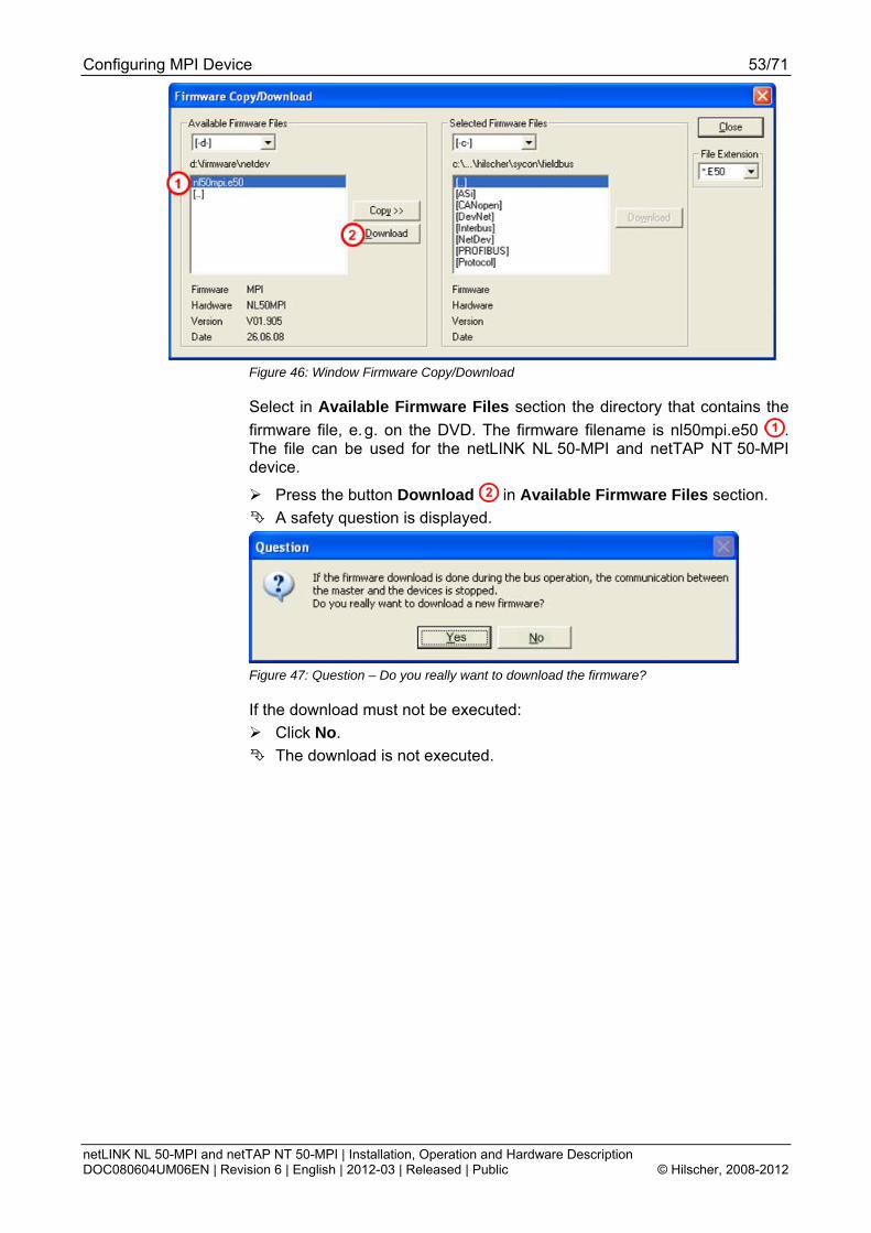
Figure 46: Window Firmware Copy/Download
Select in Available Firmware Files section the directory that contains the firmware file, e. g. on the DVD. The firmware filename is nl50mpi.e50 . The file can be used for the netLINK NL 50-MPI and netTAP NT 50-MPI device.
Press the button Download in Available Firmware Files section. A safety question is displayed.
Figure 47: Question – Do you really want to download the firmware?
If the download must not be executed: Click No. The download is not executed.

Configuring MPI Device 54/71
netLINK NL 50-MPI and netTAP NT 50-MPI | Installation, Operation and Hardware Description DOC080604UM06EN | Revision 6 | English | 2012-03 | Released | Public © Hilscher, 2008-2012
If the download must be executed: Click Yes. The download is executed. During the download the progress bar Data
Base Download is displayed.
Figure 48: Progress Bar Data Base Download
After the firmware download was finished, in the window Firmware Copy/Download click Close.
Step E:
Load with menu Online > Download the configuration into the MPI device. This is describes in step 6 in section Creating and downloading the Configuration to set a permanent IP Adress from page 36.
Step F:
The device uses the new firmware or the new configuration/new parameters after a reset. This is describes in Step 7 in section Creating and downloading the Configuration to set a permanent IP Adress from page 36.

Troubleshooting 55/71
netLINK NL 50-MPI and netTAP NT 50-MPI | Installation, Operation and Hardware Description DOC080604UM06EN | Revision 6 | English | 2012-03 | Released | Public © Hilscher, 2008-2012
8 Troubleshooting 8.1 Hints on how to solve Problems
General Check, if the following preconditions for the MPI device operation are
fulfilled: 1. A suitable supply voltage must be available. 2. The configuration must have been performed correctly using the system
configurator SyConMPI. Further information to this is in section Preconditions for Operation on page 18.
LNK-LED With the Ethernet link status LED (LNK) of the MPI device can be
examined whether a connection to the Ethernet exists. If the LED is off, no connection exists. If the LED is on, the device has a connection to the Ethernet.
ACT-LED With the status LED ACT of the MPI device can be examined whether
communication takes place.
Cable Make sure that the cable is connected to the switch on the Ethernet
side and that the serial interface is connected to the S7.
Configuration Check, whether the MPI device is configured according to the
description given in section Creating and downloading the Configuration to set a permanent IP Adress on page 36.
Diagnostic using the System Configurator SyCon Read out the data with menu Online > Message Monitor.
You can find more information about the Message Monitor and its functions you find in the operating manual SyConMPI Ethernet-TCP/IP Interface
Check the network settings of your PC. With the ping command in MS-DOS Prompt you can easily check if a connection via TCP/IP to the MPI device is possible. Open the MS-DOS Prompt and enter ping 192.168.10.190 (the IP address has to be the same as set in the MPI device) and press the Return key. Could a connection be established then the answer is displayed by the following text Reply from 192.168.10.190... Otherwise a connection timeout is displayed.

Troubleshooting 56/71
netLINK NL 50-MPI and netTAP NT 50-MPI | Installation, Operation and Hardware Description DOC080604UM06EN | Revision 6 | English | 2012-03 | Released | Public © Hilscher, 2008-2012
8.2 Ethernet Failure in 10 MBit/s Half Duplex Mode and Workaround
Not affected are netTAP NT 50-MPI devices and netLINK NL 50-MPI with serial number greater than 27927, which means: devices manufactured after december 2010 are not affected.
Affected Hardware Hardware with the communication controller netX 50, netX 100 or netX 500; netX/Internal PHYs. When can this Failure occur? When using standard Ethernet communication with 10 MBit/s half duplex mode, the PHY gets stuck in case of network collisions. Then no further network communication is possible. Only device power cycling allows Ethernet communication again. This problem can only occur with Ethernet TCP/UDP IP, EtherNet/IP or Modbus TCP protocols when using hubs at 10 MBit/s. The issue described above is not applicable for protocols which use 100 MBit/s or full duplex mode. Solution / Workaround: Do not use 10 MBit/s-only hubs. Use either switches or 10/100 MBit/s Dual Speed hubs, to make sure the netX Ethernet ports are connected with 100 MBit/s or in full duplex mode. This erratum is fixed with all components of the ‘Y’ charge (9 digit charge number shows ‘Y’ at position 5 (nnnnYnnnn). Reference “Summary of 10BT problemon EthernetPHY”, RenesasElectronics Europe, April 27, 2010

LED 57/71
netLINK NL 50-MPI and netTAP NT 50-MPI | Installation, Operation and Hardware Description DOC080604UM06EN | Revision 6 | English | 2012-03 | Released | Public © Hilscher, 2008-2012
9 LED LED Name Meaning System Status SYS System status Communication Status COM Communication status
LNK Link (Ethernet link status) RJ45 ACT Activity (Ethernet activity status)
Table 19: Names and Meaning of LED
LED Display color
Display state Meaning
Duo LED yellow/green
(green)
On Firmware started.
(yellow)
On This state is allowed for a short time only. Stays this LED with permanent yellow on, the a hardware defect is possible.
(yellow/ green)
Blinking yellow/green
Bootloader active. This state is allowed for a short time only.
SYS
(off)
Off Missing power supply or a hardware error occurred.
Duo LED red/green
(green)
On Status The device currently holds the PROFIBUS token and is able to transfer telegrams of data.
(green)
Blinking (regularly) 5 Hz
Status The device is configured to be a part of the PROFIBUS ring, but it must share the PROFIBUS token with other PROFIBUS-Master devices present on the PROFIBUS ring.
(green)
Blinking (regularly) 0.5 Hz
Status Automatic baudrate detection is running
(red)
On Error Communication error at the PROFIBUS.
COM at NL 50-MPI APL at NT 50-MPI
(off)
Off Status/Error The device has not been integrated into the PROFIBUS ring, i.e. it has not been configured correctly or has a wrong configuration or has not received the PROFIBUS token.
LED green beside Ethernet socket
(green)
On The device is currently connected to the Ethernet. LNK
(off)
Off The device is currently not connected to the Ethernet.
LED yellow beside Ethernet socket
(yellow)
On The device currently sends or receives Ethernet-Frames. ACT
(off)
Off The device does currently not send and receive any Ethernet-Frames.
Table 20: Meaning of LED-Signals
Numbers … refer to Figure 2 on page 20.

LED 58/71
netLINK NL 50-MPI and netTAP NT 50-MPI | Installation, Operation and Hardware Description DOC080604UM06EN | Revision 6 | English | 2012-03 | Released | Public © Hilscher, 2008-2012
LED-Display Status
Display Status Description On The display is lighted permanently. Off The display is not lighted at all. Blinking The display is switched on and off in phases,
At regular blinking with a frequency of 5 Hz: On for a duration of 100 ms followed by Off for a duration of 100 ms.
Table 21: Display Status

Technical Data 59/71
netLINK NL 50-MPI and netTAP NT 50-MPI | Installation, Operation and Hardware Description DOC080604UM06EN | Revision 6 | English | 2012-03 | Released | Public © Hilscher, 2008-2012
10 Technical Data 10.1 Technical Data of the netLINK NL 50-MPI
NL 50-MPI Parameter Value Communication controller
Type netX 50
RAM 8 MB SDRAM Memory FLASH 4 MB serial Flash, contains boot
loader, firmware and configuration
Type Client Data transport PROFIBUS FDL telegrams Number of connections max. 32 MPI connections at a
time
PROFIBUS-MPI communication
Access to Data block, Bit memory, Peripheral data, Counter, Timer, State of OP-Mode
Data transport TCP/IP Number of connections max. 16 TCP connections at a
time
Ethernet communication
RFC 1006 Supported Transmission rate 9,6 kBit/s to 12 MBit/s Interface type RS-485,
non-isolated (for revision 2 und 3 of the device) isolated (for revision 4 of the device)
Connector D-Sub plug (9-pin male connector)
PROFIBUS interface
Automatic Baud rate detection
supported
Transmission rate 10/100 MBit/s Interface type 10 BASE-T/100 BASE-TX,
isolated Connector RJ45 socket Auto-Negotiation supported
Ethernet interface
Auto-Crossover supported Interface for programming tool
Connector D-Sub-socket (9-pin female connector) Note: There is a 1:1-connection to the corresponding pins of PROFIBUS-interface
Display LED Display SYS System Status COM Communication status ACT Ethernet activity status LINK Ethernet link status
Table 22: Technical Data netLINK NL 50-MPI (Part 1)

Technical Data 60/71
netLINK NL 50-MPI and netTAP NT 50-MPI | Installation, Operation and Hardware Description DOC080604UM06EN | Revision 6 | English | 2012-03 | Released | Public © Hilscher, 2008-2012
NL 50-MPI Parameter Value
Voltage 18 – 30 V DC Typical current at 18 V 72 mA Typical current at 24 V 57 mA Typical current at 30 V 48 mA Connector for power supply from PLC
via D-Sub-plug (9-pin male connector)
Power supply
Connector for external power supply
Mini-Combicon socket 3,81 mm 2 pin
Electrostatic discharge (ESD) according to IEC/EN 61000-4-2:1995
10 kV Air discharge method, Criterion A 4 kV Contact discharge method, Criterion B
Fast transient interferences (Burst), zone B, according to IEC/EN 61000-4-4:1995
2 kV Power supply connectors DC, Criterion B 1 kV Communication and data lines, Criterion A
Electrical immunity to interference
Surge voltage, zone B, according to IEC/EN 61000-4-5:1995
1 kV CM, 0,5 kV DM Power supply connectors DC, Criterion B 1 kV CM Communication and data lines, Criterion B
Temperature range 0 … + 55 °C Environmental conditions Humidity range 0 … 85 % relative humidity (not
condensing) Dimensions (L x W x H) 74,3 x 40,6 x 16,7 mm Weight appr. 40 g Mounting / Installation directly at MPI interface Protection Class IP 20 RoHS Yes
Device
UL in preparation CE Sign Yes Emission CISPR 11 Class A
CE Sign
Immunity EN 61131-2:2003 Configuration Software SYCON.net or IBHnet driver
Table 23: Technical Data NL 50-MPI (Part 2)
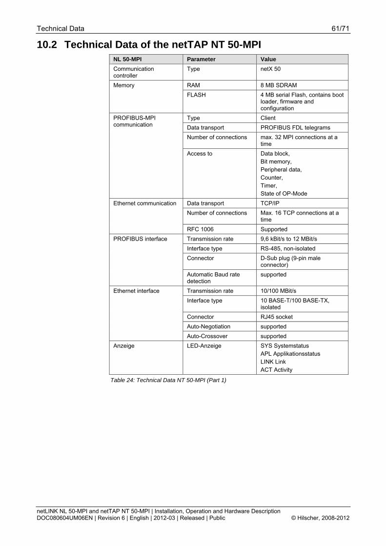
Technical Data 61/71
netLINK NL 50-MPI and netTAP NT 50-MPI | Installation, Operation and Hardware Description DOC080604UM06EN | Revision 6 | English | 2012-03 | Released | Public © Hilscher, 2008-2012
10.2 Technical Data of the netTAP NT 50-MPI NL 50-MPI Parameter Value Communication controller
Type netX 50
RAM 8 MB SDRAM Memory FLASH 4 MB serial Flash, contains boot
loader, firmware and configuration
Type Client Data transport PROFIBUS FDL telegrams Number of connections max. 32 MPI connections at a
time
PROFIBUS-MPI communication
Access to Data block, Bit memory, Peripheral data, Counter, Timer, State of OP-Mode
Data transport TCP/IP Number of connections Max. 16 TCP connections at a
time
Ethernet communication
RFC 1006 Supported Transmission rate 9,6 kBit/s to 12 MBit/s Interface type RS-485, non-isolated Connector D-Sub plug (9-pin male
connector)
PROFIBUS interface
Automatic Baud rate detection
supported
Transmission rate 10/100 MBit/s Interface type 10 BASE-T/100 BASE-TX,
isolated Connector RJ45 socket Auto-Negotiation supported
Ethernet interface
Auto-Crossover supported Anzeige LED-Anzeige SYS Systemstatus
APL Applikationsstatus LINK Link ACT Activity
Table 24: Technical Data NT 50-MPI (Part 1)

Technical Data 62/71
netLINK NL 50-MPI and netTAP NT 50-MPI | Installation, Operation and Hardware Description DOC080604UM06EN | Revision 6 | English | 2012-03 | Released | Public © Hilscher, 2008-2012
NT 50 Parameter Value
Voltage 24 V ± 6 V DC
Current at 24 V (typically) 72 mA 150 mA with short circuit at the output of PROFIBUS
Continuous short circuit may cause device damage
Power Consumption 1,8 W
Power supply
Connector Mini-COMBICON, 2 pin
Temperature rang 0 … + 60 °C Environmental conditions
Humidity no condensation allowed
Dimensions (L x W x H) 100 x 26 x 66 mm (without connector)
Weight appr. 80 g
Mounting on DIN rail EN 60715
Protection Class IP 20
Device
RoHS Yes
CE Sign Yes
Emission CISPR 11 Class A
CE Sign
Immunity EN 61131-2:2003
Configuration Software SyCon oder IBHnet Treiber
Table 25: Technical Data NT 50-MPI (Part 2)
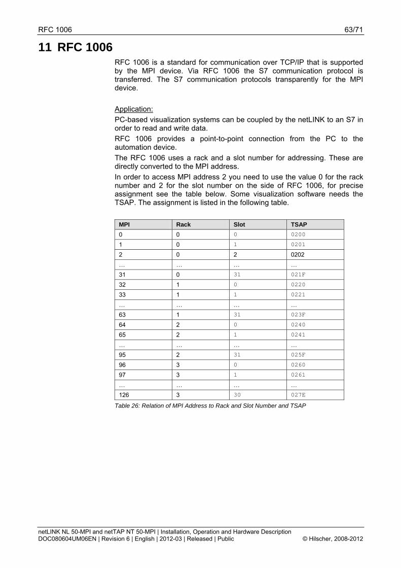
RFC 1006 63/71
netLINK NL 50-MPI and netTAP NT 50-MPI | Installation, Operation and Hardware Description DOC080604UM06EN | Revision 6 | English | 2012-03 | Released | Public © Hilscher, 2008-2012
11 RFC 1006 RFC 1006 is a standard for communication over TCP/IP that is supported by the MPI device. Via RFC 1006 the S7 communication protocol is transferred. The S7 communication protocols transparently for the MPI device. Application: PC-based visualization systems can be coupled by the netLINK to an S7 in order to read and write data. RFC 1006 provides a point-to-point connection from the PC to the automation device. The RFC 1006 uses a rack and a slot number for addressing. These are directly converted to the MPI address. In order to access MPI address 2 you need to use the value 0 for the rack number and 2 for the slot number on the side of RFC 1006, for precise assignment see the table below. Some visualization software needs the TSAP. The assignment is listed in the following table.
MPI Rack Slot TSAP 0 0 0 0200
1 0 1 0201
2 0 2 0202 … … … … 31 0 31 021F
32 1 0 0220
33 1 1 0221
… … … … 63 1 31 023F
64 2 0 0240
65 2 1 0241
… … … … 95 2 31 025F
96 3 0 0260
97 3 1 0261
… … … … 126 3 30 027E
Table 26: Relation of MPI Address to Rack and Slot Number and TSAP

Error Codes 64/71
netLINK NL 50-MPI and netTAP NT 50-MPI | Installation, Operation and Hardware Description DOC080604UM06EN | Revision 6 | English | 2012-03 | Released | Public © Hilscher, 2008-2012
12 Error Codes 12.1 TCP/IP Error Codes
Error Code Description 10013 Permission denied 10024 Too many open sockets. 10048 Address already in use 10049 Cannot assign requested address. 10050 Network is down 10051 Network is unreachable 10052 Network dropped connection on reset 10053 Software caused connection abort. An established connection was aborted by the software in your
host machine, possibly due to a data transmission time-out or protocol error. 10054 Connection reset by peer 10055 No buffer space available 10056 Socket is already connected 10057 Socket is not connected. 10058 Cannot send after socket shutdown 10060 Connection timed out 10061 Connection refused 10065 No route to host 10092 Winsock.dll version out of range
Table 27: TCP/IP Error Code – Standard Win32 Socket API Error Codes
12.2 netIdent Error Codes Error Code Description 0x8004c701 Unknown Device Error 0x8004c702 Request Pending 0x8004c703 Set IP time exceeded 0x8004c704 IP address invalid 0x8004c705 Returned IP address invalid 0x8004c706 Answer from wrong device 0x8004c707 Wrong OP code received 0x8004c708 NetIdent Timeout
Table 28: netIdent Error Codes

Error Codes 65/71
netLINK NL 50-MPI and netTAP NT 50-MPI | Installation, Operation and Hardware Description DOC080604UM06EN | Revision 6 | English | 2012-03 | Released | Public © Hilscher, 2008-2012
12.3 PROFIBUS-FDL Error Codes Error Code Description 0 (00H) CON_OK
Positive acknowledgement: Transmission of data from the sending (local) station completed. 1 (01H) CON_UE
Negative acknowledgement: Remote-User/FDL interface error. 2 (02H) CON_RR
Negative acknowledgement: No remote resources available. 3 (03H) CON_RS
Negative acknowledgement: No Service or no remote address at remote SAP activated. 4 (04H) CON_RA
Negative acknowledgement: Access-point blocked. 8 (08H) CON_DL
Positive acknowledgement for sent data (L_SDU), reply data with low priority available. 9 (09H) CON_NR
Positive acknowledgement for sent data, negative acknowledgement for reply data, as not available to the remote FDL controller.
10 (0AH) CON_DH Positive acknowledgement for sent data (L_SDU), reply data with high priority available.
12 (0CH) CON_RDL Negative acknowledgement for sent data (L_SDU), resource of the remote FDL controller not available or not sufficient, reply data with low priority available.
13 (0DH) CON_RDH Negative acknowledgement for sent data (L_SDU), resource of the remote FDL controller not available or not sufficient, reply data with high priority available.
16 (10H) CON_LS Service at local SAP or local SAP not activated.
17 (11H) CON_NA No reaction (acknowledgement/response) from remote station.
18 (12H) CON_DS Local FDL/PHY not in token ring.
19 (13H) CON_NO Negative acknowledgement: Not ok (different meanings dependent on service). No reply data transmitted.
20 (14H) CON_LR Resource of the local FDL controller not available or not sufficient.
21 (15H) CON_IV Invalid parameter in request - illegal parameters in the request header or - local station is passive or - destination station is own station address
23 (17H) CON_NM Notice.
24 (18H) CON_NC Reaction from only one station.
25 (19H) CON_NP No plausible reaction from remote station.
26 (1AH) CON_NL Local configurator variable is set.
27 (1BH) CON_RD Reply data available.
32 (20H) CON_LO Low prior response data are sent at this SRD.
33 (21H) CON_HI High prior response data are sent at this SRD.
34 (22H) CON_NO_DATA No data are sent at this SRD.
Table 29: PROFIBUS-FDL Error Codes

Error Codes 66/71
netLINK NL 50-MPI and netTAP NT 50-MPI | Installation, Operation and Hardware Description DOC080604UM06EN | Revision 6 | English | 2012-03 | Released | Public © Hilscher, 2008-2012
12.4 PROFIBUS-MPI Error Codes Error Code Description 48 (30H) CON_TO
Timeout, the request message was accepted but no indication is sent back by the remote station. MPI protocol error, or station not present.
57 (39H) CON_SE Sequence fault, internal state machine error. Remote station does not react like awaited or a reconnection was retried while connection is already open or device has no SAPs left to open connection channel
133 (85H) REJ_IV Specified offset address out of limits or not known in the remote station. Check msg.data_adr if present or offset parameter in request message
134 (86H) REJ_PDU Wrong PDU coding in the MPI response of the remote station.
135 (87H) REJ_OP Specified length to write or to read results in an access outside the limits. Check msg.data_cnt length in request message.
136 (88H) REJ_HW Specified address not defined in the remote station. Check msg.data_request message
137 (89H) REJ_MODE MPI remote station not in the right operational mode. Bring S7 into RUN-P Mode.
Table 30: PROFIBUS-MPI Error Codes

Appendix 67/71
netLINK NL 50-MPI and netTAP NT 50-MPI | Installation, Operation and Hardware Description DOC080604UM06EN | Revision 6 | English | 2012-03 | Released | Public © Hilscher, 2008-2012
13 Appendix 13.1 Device Labeling 13.1.1 NT 50-MPI
MAC address of the Ethernet interface
Identification Label
Manufacturer logo
Typical supply voltage
Maximum ambient temperature
Serial number
Hardware revision number
Part number
Internet address of manufacturer
Device name
13.1.2 NL 50-MPI
MAC address of the Ethernet interface
Matrix label with manufacturing information
Serial number
Hardware Revision
Part number of the NL 50-MPI

Appendix 68/71
netLINK NL 50-MPI and netTAP NT 50-MPI | Installation, Operation and Hardware Description DOC080604UM06EN | Revision 6 | English | 2012-03 | Released | Public © Hilscher, 2008-2012
13.2 Disposal of Waste Electronic Equipment Important note from the European Directive 2002/96/EG Waste Electrical and Electronic Equipment (WEEE):
Waste Electronic Equipment This product must not be treated as household waste. You must dispose the device at a designated waste electronic equipment collecting point.
Waste electronic equipment may not be disposed of with household waste. As a consumer you are legally obliged to dispose all Waste electronic equipment professionally, as to the public collection.

Appendix 69/71
netLINK NL 50-MPI and netTAP NT 50-MPI | Installation, Operation and Hardware Description DOC080604UM06EN | Revision 6 | English | 2012-03 | Released | Public © Hilscher, 2008-2012
14 Appendix 14.1 List of Figures Figure 1: Dimensioned Drawing NL 50-MPI and NT 50-MPI (Size in mm) 19 Figure 2: Connections and LEDs NL 50-MPI and NT 50-MPI 20 Figure 3: PROFIBUS Interface X11 (D-Sub male connector, 9 pin) 22 Figure 4: PROFIBUS Interface X2 (D-Sub female connector, 9 pin) 22 Figure 5: netLINK NL 50-MPI, Coupling (Hardware Revision 4) 24 Figure 6: netTAP NT 50-MPI, Coupling 25 Figure 7: Mounting the netLINK 26 Figure 8: Mounting the netTAP NT 50 device onto the top-hat rail 26 Figure 9: Removing the NT 50 device from the Top-Hat Rail 27 Figure 10: Menu of the DVD Autostart 29 Figure 11: Install IP Driver (1) 30 Figure 12: Install IP Driver (2) 31 Figure 13: Install IP Driver (3) 31 Figure 14: NetIdent Demo 32 Figure 15: netIdent – Scan for Devices (1) 32 Figure 16: netIdent – Scan for Devices (2) 33 Figure 17: netIdent - Set IP Address 33 Figure 18: netIdent - Set IP Address (2) 33 Figure 19: netIdent - Set IP Address (3) 34 Figure 20: netIdent - Set IP Address (4) 34 Figure 21: GUI of the Hilscher IP Driver Setup 35 Figure 22: System Configurator SyConMPI – Create a new Project 38 Figure 23: Insert Device 38 Figure 24: System Configurator SyConMPI – The MPI Device is displayed in the Project 39 Figure 25: Set IP Address 39 Figure 26: Ethernet Parameters are detected automatically by the MPI Device 40 Figure 27: Set the PROFIBUS Parameters 40 Figure 28: Window Driver Select 41 Figure 29: Window Driver Select 41 Figure 30: Window Device Assignment ODM TCP/IP Driver 42 Figure 31: Window Device Assignment ODM TCP/IP Drive – Found devices are displayed 42 Figure 32: Window Configure IP Address 43 Figure 33: Window Configure IP Address – Set the IP address 43 Figure 34: Hint – Setting IP Address successful 43 Figure 35: Window Device Assignment ODM TCP/IP Drive – A Connection has been established 44 Figure 36: Online Configuration Download 45 Figure 37: Question – Do you really want to download? 45 Figure 38: Progress Bar Data Base Download 45 Figure 39: Window Firmware/Reset 46 Figure 40: Question – Do you really want to reset the firmware? 46 Figure 41: Settings > MPI Device Parameter > IP Address 47 Figure 42: Settings > NetLink Parameter > Ethernet 48 Figure 43: Settings > MPI Parameters > PROFIBUS 49 Figure 44: Settings > MPI Parameters > PROFIBUS > Autobaud 51 Figure 45: Question – Do you really want to download? 52 Figure 46: Window Firmware Copy/Download 53 Figure 47: Question – Do you really want to download the firmware? 53 Figure 48: Progress Bar Data Base Download 54

Appendix 70/71
netLINK NL 50-MPI and netTAP NT 50-MPI | Installation, Operation and Hardware Description DOC080604UM06EN | Revision 6 | English | 2012-03 | Released | Public © Hilscher, 2008-2012
14.2 List of Tables Table 1: List of Revisions 5 Table 2: Reference to Hardware 6 Table 3: Reference to Firmware 6 Table 4: Reference to SyConMPI Software 6 Table 5: Directory Structure of the DVD 7 Table 6: Documentations for Users 8 Table 7: Documentations for Developers 8 Table 8: Safety Symbols and Sort of Warning or Principle 13 Table 9: Signal Words 13 Table 10: Signal Words according to ANSI 13 Table 11: Ethernet RJ45 Pin Assignment 21 Table 12: Ethernet Connection Data 21 Table 13: PROFIBUS Interface (D-Sub female and male connector, 9 pin) 22 Table 14: Supply Voltage Pin Assignment 23 Table 15: Coupling NL 50-MPI, Hardware Revision 4 24 Table 16: Coupling NT 50-MPI 25 Table 17: Configuring IP Driver 35 Table 18: Baud rates and Bit times 49 Table 19: Names and Meaning of LED 57 Table 20: Meaning of LED-Signals 57 Table 21: Display Status 58 Table 22: Technical Data netLINK NL 50-MPI (Part 1) 59 Table 23: Technical Data NL 50-MPI (Part 2) 60 Table 24: Technical Data NT 50-MPI (Part 1) 61 Table 25: Technical Data NT 50-MPI (Part 2) 62 Table 26: Relation of MPI Address to Rack and Slot Number and TSAP 63 Table 27: TCP/IP Error Code – Standard Win32 Socket API Error Codes 64 Table 28: netIdent Error Codes 64 Table 29: PROFIBUS-FDL Error Codes 65 Table 30: PROFIBUS-MPI Error Codes 66

Appendix 71/71
netLINK NL 50-MPI and netTAP NT 50-MPI | Installation, Operation and Hardware Description DOC080604UM06EN | Revision 6 | English | 2012-03 | Released | Public © Hilscher, 2008-2012
14.3 Contacts
Headquarters Germany Hilscher Gesellschaft für Systemautomation mbH Rheinstrasse 15 65795 Hattersheim Phone: +49 (0) 6190 9907-0 Fax: +49 (0) 6190 9907-50 E-Mail: [email protected] Support Phone: +49 (0) 6190 9907-99 E-Mail: [email protected]
Subsidiaries
China Hilscher Systemautomation (Shanghai) Co. Ltd. 200010 Shanghai Phone: +86 (0) 21-6355-5161 E-Mail: [email protected] Support Phone: +86 (0) 21-6355-5161 E-Mail: [email protected] France Hilscher France S.a.r.l. 69500 Bron Phone: +33 (0) 4 72 37 98 40 E-Mail: [email protected] Support Phone: +33 (0) 4 72 37 98 40 E-Mail: [email protected] India Hilscher India Pvt. Ltd. New Delhi - 110 025 Phone: +91 11 40515640 E-Mail: [email protected] Italy Hilscher Italia srl 20090 Vimodrone (MI) Phone: +39 02 25007068 E-Mail: [email protected] Support Phone: +39 02 25007068 E-Mail: [email protected]
Japan Hilscher Japan KK Tokyo, 160-0022 Phone: +81 (0) 3-5362-0521 E-Mail: [email protected] Support Phone: +81 (0) 3-5362-0521 E-Mail: [email protected] Korea Hilscher Korea Inc. Suwon, 443-734 Phone: +82 (0) 31-695-5515 E-Mail: [email protected] Switzerland Hilscher Swiss GmbH 4500 Solothurn Phone: +41 (0) 32 623 6633 E-Mail: [email protected] Support Phone: +49 (0) 6190 9907-99 E-Mail: [email protected] USA Hilscher North America, Inc. Lisle, IL 60532 Phone: +1 630-505-5301 E-Mail: [email protected] Support Phone: +1 630-505-5301 E-Mail: [email protected]