nes 524 part 1 guide to the selection of cables glands in submarines
DESCRIPTION
Guide to the Selection of Cables Glands in SubmarinesTRANSCRIPT

Guide to the Selection of Cable Glands inSubmarines
Part 1
Pressure Hull Glands
NOTEThis Standard is Provisional
If you have Difficulty with its ApplicationPlease Advise the Directorate of
Standardization
Ministry of Defence Interim Defence Standard 02-524 Part 1
Issue 2 Publication Date 10 August 2002
Category 2

AMENDMENTS ISSUED SINCE PUBLICATION
AMD NO DATE OFISSUE
TEXT AFFECTED SIGNATURE &DATE
Revision Note
This Issue of this Standard has been prepared to incorporate changes to text and presentation.The technical content has been amended.
Historical Record
NES 524 Part 1 Issue 1NES 524 Part 1 Issue 2NES 524 Part 1 Issue 3 Nov 1991Def Stan 02-514 Part 1 Issue 1 Apr 2000

1
DEFENCE STANDARD 524 (NES 524)
GUIDE TO THE SELECTION OF CABLE GLANDS IN SUBMARINES
PART 1 ISSUE 2
PRESSURE HULL GLANDS
This Defence Standard is
authorized for use in MOD contracts
by the Defence Procurement Agency and
the Defence Logistics Organisation
Published by:
Defence Procurement Agency,An Executive Agency of The Ministry of Defence,UK Defence Standardization,Kentigern House,65 Brown Street,Glasgow, G2 8EX.

INT Def Stan 02–524 Part 1 / Issue 2(NES 524)
2
SCOPE
1. All cables fitted outside the hulls of Submarines are to be sheathed with medium densitypolyethylene and are to be passed through the pressure hull by suitable moulded polyethyleneglands. Cables with Polychloroprene (PCP) or Chlorosulphonated Polyethylene (CSP) sheathsare not to be used except when approved by the Ship Support Agency/Marine Electrical Systems 2 (SSA/MLS2).
2. The earliest versions of polyethylene hull glands were the screw type fitted to SSK and earlySSN and the flange type fitted to early SSBN. A later development resulted in the introductionof the spigot (castellated nut) type hull glands which are fitted to Swiftsure, Trafalgar andVanguard Classes of Submarines.
3. All types of moulded polyethylene spigot type hull glands have been included in this DefenceStandard. Also included are multi�stem glands used on existing sonar systems, but these arenot to be considered for any new service requirement.
4. Two standards of pressure hull spigot are in current use: Imperial (23/8 in dia, 60.32 mm dia)for Swiftsure and Trafalgar Classes, and Metric (62.95 mm dia) for Vanguard Class. Glandsin the preferred metric range of Section 4.4 can be supplied with either interface. Whenordering, it is necessary to quote the Service Drawing Number (SDN) for the basicconfiguration and the interface type (imperial or metric), and the lengths of outboard andinboard cable required.

INT Def Stan 02–524 Part 1 / Issue 2(NES 524)
3
FOREWORD
Sponsorship
1. This Defence Standard is sponsored by the Defence Logistics Organisation (DLO), Ministryof Defence (MOD).
2. The complete Standard comprises:
Guide to the Selection of Cable Glands in Submarines:
Part 1: Pressure Hull Glands;
Part 2: Pressure Equipment and Disc Seal Glands;
Part 3: Bulkhead Penetrators and Gland Tubes;
3. Any user of this Def Stan either within MOD or in industry may propose an amendment to it.Proposals for amendments that are not directly applicable to a particular contract are to bemade to the publishing authority identified on Page (i), and those directly applicable to aparticular contract are to be dealt with using existing departmental procedures.
4. If it is found to be unsuitable for any particular requirement, MOD is to be informed in writingof the circumstances.
5. No alteration is to be made to this standard except by the issue of an authorized amendment.
6. Unless otherwise stated, reference in this standard to approval, approved, authorized andsimilar terms means by the MOD in writing.
7. Any significant amendments that may be made to this standard at a later date will be indicatedby a vertical sideline. Deletions will be indicated by 000 appearing at the end of the lineinterval.
8. This Def Stan has been reissued because of Technical Updates.
Conditions of Release
General
9. This Def Stan has been devised solely for the use of the MOD, and its contractors in theexecution of contracts for the MOD. To the extent permitted by law, the MOD hereby excludesall liability whatsoever and howsoever arising (including but without limitation, liabilityresulting from negligence) for any loss or damage however caused when the standard is usedfor any other purpose.
10. This document is Crown Copyright and the information herein may be subject to Crown orthird party rights. It is not to be released, reproduced or published without written permissionof the MOD.
11. The Crown reserves the right to amend or modify the contents of this standard withoutconsulting or informing any holder.
MOD Tender or Contract Process
12. This Def Stan is the property of the Crown. Unless otherwise authorized in writing by theMOD it must be returned on completion of the contract, or submission of the tender, inconnection with which it is issued.
13. When this standard is used in connection with a MOD tender or contract, the user is to ensurethat he is in possession of the appropriate version of each document, including relateddocuments, relevant to each particular tender or contract. Enquiries in this connection maybe made to the authority named in the tender or contract.
14. When standard are incorporated into MOD contracts, users are responsible for their correctapplication and for complying with contractual and any other statutory requirements.Compliance with an Def Stan does not of itself confer immunity from legal obligations.

INT Def Stan 02–524 Part 1 / Issue 2(NES 524)
4
Categories of Naval Defence Standard
15. The Category of this Naval Defence has been determined using the following criteria:
a. Category 1. If not applied may have a Critical affect on the following:
Safety of the vessel, its complement or third parties.
Operational performance of the vessel, its systems or equipment.
b. Category 2. If not applied may have a Significant affect on the following:
Safety of the vessel, its complement or third parties.
Operational performance of the vessel, its systems or equipment.
Through life costs and support.
c. Category 3. If not applied may have a Minor affect on the following:
MOD best practice and fleet commonality.
Corporate Experience and Knowledge.
Current support practice.
Related Documents
16. In the tender and procurement processes the related documents listed in each section andAnnex A can be obtained as follows:
a. British Standards British Standards Institution,389 Chiswick High Road,London, W4 4AL.
b. Defence Standards, including Defence Procurement Agency,An Executive of The Ministry of Defence,UK Defence Standardization,Kentigern House,65 Brown Street,Glasgow, G2 8EX.
c. Other documents Tender or Contract Sponsor to advise.
17. All applications to Ministry Establishments for related documents are to quote the relevantMOD Invitation to Tender or Contract number and date, together with the sponsoringDirectorate and the Tender or Contract Sponsor.
18. Prime Contractors are responsible for supplying their subcontractors with relevantdocumentation, including specifications, standards and drawings.
Health and Safety
Warning
19. This Defence Standard may call for the use of processes, substances and/or procedures thatmay be injurious to health if adequate precautions are not taken. It refers only to technicalsuitability and in no way absolves either the supplier or the user from statutory obligationsrelating to health and safety at any stage of manufacture or use. Where attention is drawn tohazards, those quoted may not necessarily be exhaustive.
20. This Def Stan has been written, and is to be used, taking into account the policy stipulated inJSP�430 MOD Ship Safety Management System Handbook.
Additional Information
(There is no relevant information included)

INT Def Stan 02–524 Part 1 / Issue 2(NES 524)
5
CONTENTS
Page No
TITLE PAGE 1. . . . . . . . . . . . . . . . . . . . . . . . . . . . . . . . . . . . . . . . . . . . . . . . . . . . . . . . . . . . . . .
SCOPE 2. . . . . . . . . . . . . . . . . . . . . . . . . . . . . . . . . . . . . . . . . . . . . . . . . . . . . . . . . . . . . . . . . . . .
FOREWORD 3. . . . . . . . . . . . . . . . . . . . . . . . . . . . . . . . . . . . . . . . . . . . . . . . . . . . . . . . . . . . . . .
Sponsorship 3. . . . . . . . . . . . . . . . . . . . . . . . . . . . . . . . . . . . . . . . . . . . . . . . . . . . . . . . . . . . . . .
Conditions of Release 3. . . . . . . . . . . . . . . . . . . . . . . . . . . . . . . . . . . . . . . . . . . . . . . . . . . . . . . . .
Categories of NES 4. . . . . . . . . . . . . . . . . . . . . . . . . . . . . . . . . . . . . . . . . . . . . . . . . . . . . . . . . . .
Related Documents 4. . . . . . . . . . . . . . . . . . . . . . . . . . . . . . . . . . . . . . . . . . . . . . . . . . . . . . . . . .
Health and Safety 4. . . . . . . . . . . . . . . . . . . . . . . . . . . . . . . . . . . . . . . . . . . . . . . . . . . . . . . . . . . .
Additional Information 4. . . . . . . . . . . . . . . . . . . . . . . . . . . . . . . . . . . . . . . . . . . . . . . . . . . . . . .
CONTENTS 5. . . . . . . . . . . . . . . . . . . . . . . . . . . . . . . . . . . . . . . . . . . . . . . . . . . . . . . . . . . . . . . .
SECTION 1. PERFORMANCE SPECIFICATION 8. . . . . . . . . . . . . . . . . . .
SECTION 2. NATIONAL/INTERNATIONAL REGULATIONS 8. . . . . . . .
SECTION 3. MILITARY STANDARDS/REQUIREMENTS 8. . . . . . . . . . . .
SECTION 4. DESIGN REQUIREMENTS/GUIDANCE 8. . . . . . . . . . . . . . .
4.1 Imperial Spigot Type (Castellated) Hull Glands 8. . . . . . . . . . .
Figure 4.1 Gland and Cable Assembly Spigot Type, 1 Screened Quad,(Type F) 9. . . . . . . . . . . . . . . . . . . . . . . . . . . . . . . . . . . . . . . . . . . .
Figure 4.2 Gland and Cable Assembly Spigot Type, 4 Way, (Type G) 10. .
Figure 4.3 Gland and Cable Assembly Spigot Type, 6 Screened Pairs,(Type B) 11. . . . . . . . . . . . . . . . . . . . . . . . . . . . . . . . . . . . . . . . . . .
Figure 4.4 Gland and Cable Assembly Spigot Type, 8 Pair, (Type A) 12. .
Figure 4.5 Gland and Cable Assembly Spigot Type, 4 Coaxial 75 Ohms,(Type C) 13. . . . . . . . . . . . . . . . . . . . . . . . . . . . . . . . . . . . . . . . . . .
Figure 4.6 Gland and Cable Assembly Spigot Type, 4 Coaxial 50 Ohms,(Type C) 14. . . . . . . . . . . . . . . . . . . . . . . . . . . . . . . . . . . . . . . . . . .
Figure 4.7 Gland and Cable Assembly, Spigot Type, 4 Coaxial 50 Ohms 15. . . . . . . . . . . . . . . . . . . . . . . . . . . . . . . . . . . . . . . . . . .
Figure 4.8 Gland and Cable Assembly, Spigot Type, 1 Screened Pair + 1 x 3 Core (Type H) 16. . . . . . . . . . . . . . . . . .
Figure 4.9 Gland and Cable Assembly, Spigot Type, 19 Screened Pair 17.
Figure 4.10 Gland and Cable Assembly, Spigot Type, 19 Screened Pair 18.

INT Def Stan 02–524 Part 1 / Issue 2(NES 524)
6
Page No
Figure 4.11 Gland and Cable Assembly, Spigot Type, 19 x 3 Core Screened 19. . . . . . . . . . . . . . . . . . . . . . . . . . . . . . . . . . . . . .
Figure 4.12 Gland and Cable Assembly, Spigot Type, 19 Screened Pair 20.
4.2 Multi-Stem Glands 21. . . . . . . . . . . . . . . . . . . . . . . . . . . . . . . . . .
Figure 4.13 Gland and Cable Assembly Multi-Stem Type, 30 Pair 22. . . . .
Figure 4.14 Gland and Cable Assembly Multi-Stem Type, 60 Pair 23. . . . .
Figure 4.15 Gland and Cable Assembly Multi-Stem Type, 60 Pair 24. . . . .
4.3 Special Hull Glands 25. . . . . . . . . . . . . . . . . . . . . . . . . . . . . . . . .
Figure 4.16 Gland and Cable Assembly Spigot Type J 26. . . . . . . . . . . . . . .
Figure 4.17 Gland and Cable Assembly Spigot Type (SPM) 27. . . . . . . . . .
Figure 4.18 Gland and Cable Assembly Spigot Type, 19 Quad 28. . . . . . . .
Figure 4.19 Gland and Cable Assembly Spigot Type, 45 Quad 29. . . . . . . .
Figure 4.20 Gland and Cable Assembly Spigot Type, 4 x 6 Core 30. . . . . . .
Figure 4.21 Gland and Cable Assembly Flange Type, 14 Core 31. . . . . . . .
Figure 4.22 Gland Flange Type, AWJ 32. . . . . . . . . . . . . . . . . . . . . . . . . . . . .
Figure 4.23 Gland, AWJ 33. . . . . . . . . . . . . . . . . . . . . . . . . . . . . . . . . . . . . . . .
4.4 Metric Spigot Type Pressure Hull Glands 34. . . . . . . . . . . . . . .
Figure 4.24 Gland and Cable Assembly, Spigot Type Metric, 4 Coaxial 50 Ohms (Type 11) 35. . . . . . . . . . . . . . . . . . . . . . . . . . . . . . . . . .
Figure 4.25 Gland and Cable Assembly, Spigot Type Metric, 19 Screened Pair (Type 1) 36. . . . . . . . . . . . . . . . . . . . . . . . . . . .
Figure 4.26 Gland and Cable Assembly, Spigot Type Metric, 19 Screened Pair (Type 2) 37. . . . . . . . . . . . . . . . . . . . . . . . . . . .
Figure 4.27 Gland and Cable Assembly, Spigot Type Metric, 19 Screened Pair (Type 3) 38. . . . . . . . . . . . . . . . . . . . . . . . . . . .
Figure 4.28 Gland and Cable Assembly, Spigot Type Metric, 19 Screened Triple (Type 5) 39. . . . . . . . . . . . . . . . . . . . . . . . . . .
Figure 4.29 Gland and Cable Assembly, Spigot Type Metric, 3 x 3 Screened Pair (Type 7) 40. . . . . . . . . . . . . . . . . . . . . . . . . .
Figure 4.30 Gland and Cable Assembly, Spigot Type Metric, 1 Triple (Type 8) 41. . . . . . . . . . . . . . . . . . . . . . . . . . . . . . . . . . . .
Figure 4.31 Gland and Cable Assembly, Spigot Type Metric, 19 Pair 42. . .
Figure 4.32 Gland and Cable Assembly, Spigot Type Metric, 1 x 52 Quad 43. . . . . . . . . . . . . . . . . . . . . . . . . . . . . . . . . . . . . . . .
Figure 4.33 Gland and Cable Assembly, Spigot Type Metric, 4 Single Core 44. . . . . . . . . . . . . . . . . . . . . . . . . . . . . . . . . . . . . . .

INT Def Stan 02–524 Part 1 / Issue 2(NES 524)
7
Page No
SECTION 5. CORPORATE EXPERIENCE & KNOWLEDGE 45. . . . . . . .
ANNEX A. RELATED DOCUMENTS 46. . . . . . . . . . . . . . . . . . . . . . . . . . .
ANNEX B. ABBREVIATIONS AND DEFINITIONS 48. . . . . . . . . . . . . . .
ANNEX C. INDEX OF NATO STOCK NUMBERS 49. . . . . . . . . . . . . . . .

INT Def Stan 02–524 Part 1 / Issue 2(NES 524)
8
1. PERFORMANCE SPECIFICATION
This standard contains no Performance Specification information.
2. NATIONAL/INTERNATIONAL REGULATIONS
This standard contains no National/International Regulations information.
3. MILITARY STANDARDS/REQUIREMENTS
This standard contains no Military Standards/Requirements information.
4. DESIGN REQUIREMENTS/GUIDANCE
4.1 Imperial Spigot Type (Castellated) Hull Glands
a . Hull glands in this section are designed to be fitted to Swiftsure and Trafalgarclasses of Submarine only. They may be installed singularly in a single pressurehull insert or grouped within a five way pressure hull insert.

INT Def Stan 02–524 Part 1 / Issue 2(NES 524)
9
FIGURE 4.1 Gland and Cable Assembly Spigot Type, 1 Screened Quad, (Type F)
Cables HP SideNSN 6145�99�522�7877Type Screened QuadConductor CSA 0.5 mm2
Volts 600Amps 2No. of Cables 1
Dimensions in InchesNot to Scale
Cables LP SideNSN 6145�99�522�7877Type Screened QuadConductor CSA 0.5 mm2
Volts 600Amps 2No. of Cables 1
Gland and Cable AssemblyNSN 5975�99�522�4397ADREF No. J868�440509Cable Length Inboard (LP ) 12 FtCable Length Outboard (HP) 12 Ft
Figure Reproduced From Drawing No. DEE 96872
ø 3.125
3.916UNS 1A Thread
ø 3.798
`O' Seal5330�99�923�7760
ø 2.377
0.8
75
9.7
5

INT Def Stan 02–524 Part 1 / Issue 2(NES 524)
10
FIGURE 4.2 Gland and Cable Assembly Spigot Type, 4 Way, (Type G)
Cables HP SideNSN 6145�99�724�8833Type Single CoreConductor CSA 6 mm2
Volts 600Amps 19.5No. of Cables 4
Cables LP SideNSN 6145�99�525�2037Type Single CoreConductor CSA 6 mm2
Volts 600Amps 19.5No. of Cables 4
Gland and Cable AssemblyNSN 5975�99�522�4398ADREF No. J868�440514Cable Length Inboard (LP ) 12 FtCable Length Outboard (HP) 12 Ft
Figure Reproduced From Drawing No. DEE 96873
Dimensions in InchesNot to Scale
ø 3.125
3.916UNS 1A Thread
ø 3.798
ø 2.377
0.8
75
9.7
5
`O' Seal5330�99�923�7760

INT Def Stan 02–524 Part 1 / Issue 2(NES 524)
11
FIGURE 4.3 Gland and Cable Assembly Spigot Type, 6 Screened Pairs, (Type B)
Cables HP SideNSN 6145�99�543�4475Type Screened Twisted PairConductor CSA 0.6 mm2
Volts 600Amps 2No. of Cables 6
Gland and Cable AssemblyNSN 5975�99�522�4393ADREF No. J868�440505Cable Length Inboard (LP ) 12 FtCable Length Outboard (HP) 12 Ft
Cables LP SideNSN 6145�99�724�8840Type Screened Twisted PairConductor CSA 0.6 mm2
Volts 600Amps 2No. of Cables 6
ø 3.125
3.916UNS 1A Thread
ø 3.798
`O' Seal5330�99�923�7760
ø 2.377
0.8
75
9.7
5
Dimensions in InchesNot to Scale
Figure Reproduced From Drawing No. DEE 96869

INT Def Stan 02–524 Part 1 / Issue 2(NES 524)
12
FIGURE 4.4 Gland and Cable Assembly Spigot Type, 8 Pair, (Type A)
Cables HP SideNSN 6145�99�724�8831Type Twisted PairConductor CSA 1.5 mm2
Volts 600Amps 4No. of Cables 8
Gland and Cable AssemblyNSN 5975�99�522�4392ADREF No. J868�440500Cable Length Inboard (LP ) 12 FtCable Length Outboard (HP) 12 Ft
Cables LP SideNSN 6145�99�724�8840Type Twisted PairConductor CSA 0.6 mm2
Volts 600Amps 2No. of Cables 8
Figure Reproduced From Drawing No. DEE 96868
Dimensions in InchesNot to Scale
ø 3.125
3.916UNS 1A Thread
ø 3.798
ø 2.377
0.8
75
9.7
5
`O' Seal5330�99�923�7760

INT Def Stan 02–524 Part 1 / Issue 2(NES 524)
13
FIGURE 4.5 Gland and Cable Assembly Spigot Type, 4 Coaxial 75 Ohms, (Type C)
Cables HP SideNSN 6145�99�527�8993Type Coaxial 75 OhmsConductor CSA -Volts -Amps -No. of Cables 4
Gland and Cable AssemblyNSN 5975�99�522�4394ADREF No. J868�440506Cable Length Inboard (LP ) 12 FtCable Length Outboard (HP) 12 Ft
Cables LP SideNSN 6145�99�527�8993Type Coaxial 75 OhmsConductor CSA -Volts -Amps -No. of Cables 4
Dimensions in InchesNot to Scale
Figure Reproduced From Drawing No. DEE 96870
ø 3.125
3.916UNS 1A Thread
ø 3.798
ø 2.377
0.8
75
9.7
5
`O' Seal5330�99�923�7760

INT Def Stan 02–524 Part 1 / Issue 2(NES 524)
14
FIGURE 4.6 Gland and Cable Assembly Spigot Type, 4 Coaxial 50 Ohms, (Type C)
Cables HP SideNSN 6145�99�527�8994Type Coaxial 50 OhmsConductor CSA -Volts -Amps -No. of Cables 4
Gland and Cable AssemblyNSN 5975�99�522�4395ADREF No. J868�440507Cable Length Inboard (LP ) 12 FtCable Length Outboard (HP) 12 Ft
Cables LP SideNSN 6145�99�527�8994Type Coaxial 50 OhmsConductor CSA -Volts -Amps -No. of Cables 4
Figure Reproduced From Drawing No. DEE 96870
Dimensions in InchesNot to Scale
ø 3.125
3.916UNS 1A Thread
ø 3.798
ø 2.377
0.8
75
9.7
5
`O' Seal5330�99�923�7760
NOTE Not to be used for new installations
INT Def Stan 02–524 Part 1 / Issue 2(NES 524)
15
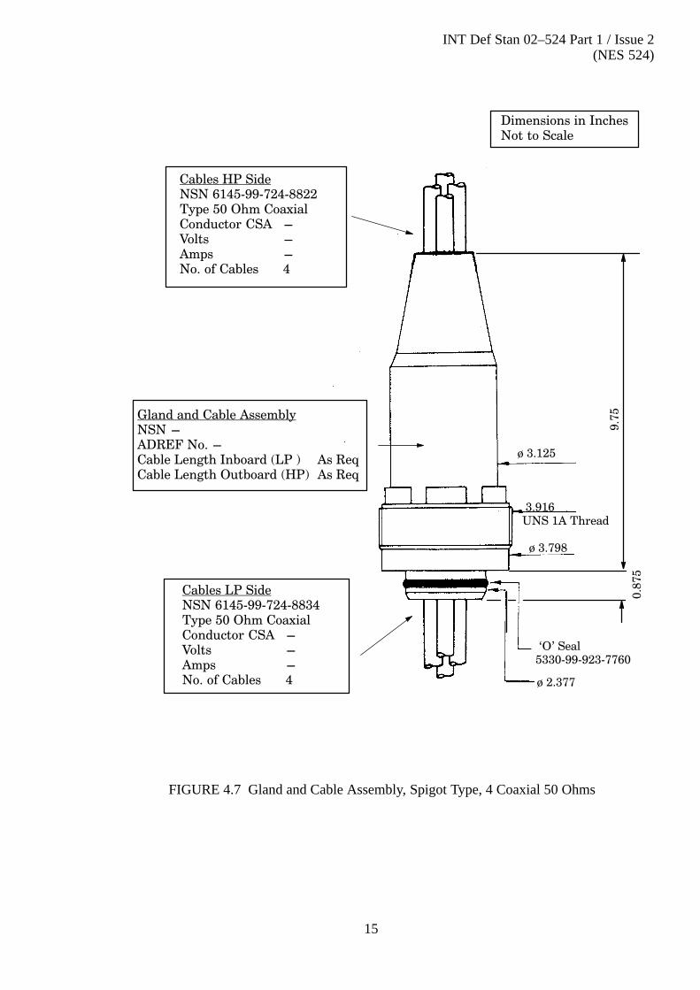
FIGURE 4.7 Gland and Cable Assembly, Spigot Type, 4 Coaxial 50 Ohms
Cables HP SideNSN 6145�99�724�8822Type 50 Ohm CoaxialConductor CSA -Volts -Amps -No. of Cables 4
Gland and Cable AssemblyNSN -ADREF No. -Cable Length Inboard (LP ) As ReqCable Length Outboard (HP) As Req
Cables LP SideNSN 6145�99�724�8834Type 50 Ohm CoaxialConductor CSA -Volts -Amps -No. of Cables 4
Dimensions in InchesNot to Scale
ø 3.125
3.916UNS 1A Thread
ø 3.798
ø 2.377
0.8
75
9.7
5
`O' Seal5330�99�923�7760

INT Def Stan 02–524 Part 1 / Issue 2(NES 524)
16
FIGURE 4.8 Gland and Cable Assembly, Spigot Type, 1 Screened Pair + 1 x 3 Core (TypeH)
Cables HP SideNSN 6145�99�525�5127Type 3 CoreConductor CSA 4.5 mm2
Volts 440Amps 26No. of Cables 1
Gland and Cable AssemblyNSN 5975�99�522�4399ADREF No. J868�440510Cable Length Inboard (LP ) 12 FtCable Length Outboard (HP) 12 Ft
NSN 6145�99�724�8840Type Screened Twisted PairConductor CSA 0.6 mm2
Volts 600Amps 2No. of Cables 1
Figure Reproduced From Drawing No. DEE 96874
Cables LP SideNSN 6145�99�525�5127Type 3 CoreConductor CSA 4.5 mm2
Volts 440Amps 26No. of Cables 1
NSN 6145�99�543�4475Type Screened Twisted PairConductor CSA 0.6 mm2
Volts 600Amps 2No. of Cables 1
Dimensions in InchesNot to Scale
ø 3.125
3.916UNS 1A Thread
ø 3.798
ø 2.377
0.8
75
9.7
5
`O' Seal5330�99�923�7760
INT Def Stan 02–524 Part 1 / Issue 2(NES 524)
17
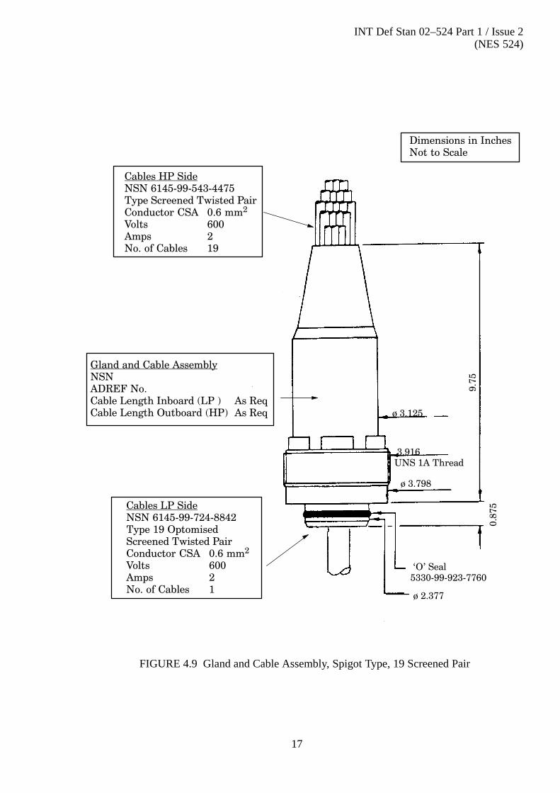
FIGURE 4.9 Gland and Cable Assembly, Spigot Type, 19 Screened Pair
Cables HP SideNSN 6145�99�543�4475Type Screened Twisted PairConductor CSA 0.6 mm2
Volts 600Amps 2No. of Cables 19
Gland and Cable AssemblyNSN ADREF No. Cable Length Inboard (LP ) As ReqCable Length Outboard (HP) As Req
Cables LP SideNSN 6145�99�724�8842Type 19 OptomisedScreened Twisted PairConductor CSA 0.6 mm2
Volts 600Amps 2No. of Cables 1
ø 3.125
3.916UNS 1A Thread
ø 3.798
ø 2.377
0.8
75
9.7
5
Dimensions in InchesNot to Scale
`O' Seal5330�99�923�7760

INT Def Stan 02–524 Part 1 / Issue 2(NES 524)
18
FIGURE 4.10 Gland and Cable Assembly, Spigot Type, 19 Screened Pair
Cables HP SideNSN 6145�99�543�4475Type Screened Twisted PairConductor CSA 0.6 mm2
Volts 600Amps 2No. of Cables 19
Gland and Cable AssemblyNSN ADREF No. Cable Length Inboard (LP ) As ReqCable Length Outboard (HP) As Req
Cables LP SideNSN 6145�99�724�8836Type 19 Super ScreenedTwisted PairConductor CSA 0.4 mm2
Volts 600Amps 1.5No. of Cables 1
ø 3.125
3.916UNS 1A Thread
ø 3.798
ø 2.377
0.8
75
9.7
5
Dimensions in InchesNot to Scale
`O' Seal5330�99�923�7760

INT Def Stan 02–524 Part 1 / Issue 2(NES 524)
19
FIGURE 4.11 Gland and Cable Assembly, Spigot Type, 19 x 3 Core Screened
ø 79
8 TPI UNS
ø 96.3
`O' Seal329
246
Cables HP SideNSN 6145�99�724�8824Type 3 Core ScreenedConductor CSA 0.6 mm2
Volts 600Amps 2No. of Cables 19
Gland and Cable AssemblyNSN 2040�99�219�2669ADREF No. Cable Length Inboard (LP ) 7 mCable Length Outboard (HP) 7 m
Cables LP SideNSN 6145�99�724�8837Type 3 Core ScreenedConductor CSA 0.6 mm2
Volts 600Amps 2No. of Cables 19
Figure Reproduced From Drawing No. SDN 007 528 050
Dimensions in mmNot to Scale
ø 60.32
INT Def Stan 02–524 Part 1 / Issue 2(NES 524)
20
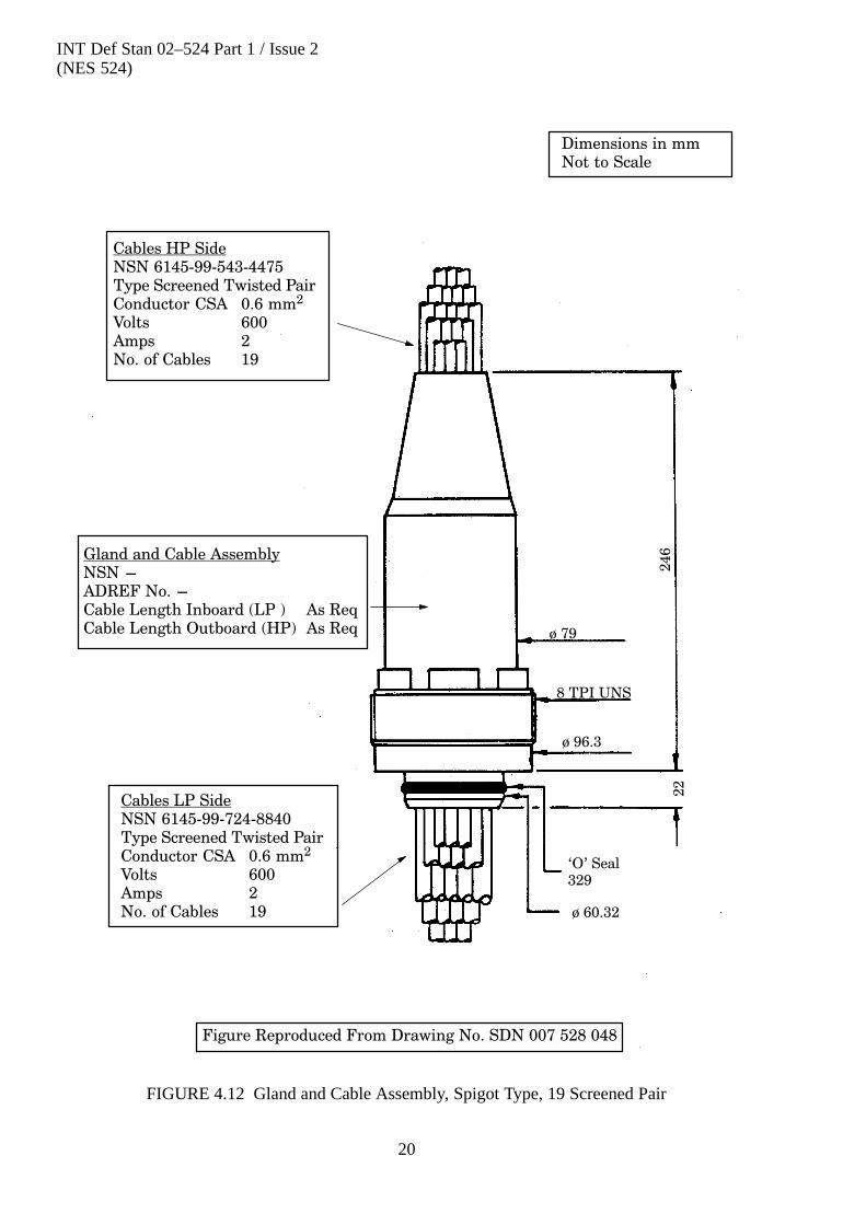
FIGURE 4.12 Gland and Cable Assembly, Spigot Type, 19 Screened Pair
Cables HP SideNSN 6145�99�543�4475Type Screened Twisted PairConductor CSA 0.6 mm2
Volts 600Amps 2No. of Cables 19
Gland and Cable AssemblyNSN -ADREF No. -Cable Length Inboard (LP ) As ReqCable Length Outboard (HP) As Req
Cables LP SideNSN 6145�99�724�8840Type Screened Twisted PairConductor CSA 0.6 mm2
Volts 600Amps 2No. of Cables 19
Figure Reproduced From Drawing No. SDN 007 528 048
Dimensions in mmNot to Scale
ø 79
8 TPI UNS
ø 96.3
`O' Seal329
ø 60.32
22
246

INT Def Stan 02–524 Part 1 / Issue 2(NES 524)
21
4.2 Multi-Stem Glands
a . Hull glands in this section are multi - stem type.

INT Def Stan 02–524 Part 1 / Issue 2(NES 524)
22
FIGURE 4.13 Gland and Cable Assembly Multi-Stem Type, 30 Pair
ø 2.996
14
.12
57.1
25
1.0
ø 18.375
ø 8.0
8 Holes 0.812 DiaEquispaced on 6.5 PCD
Cables HP SideNSN 6145�99�522�7875Type Twisted PairConductor CSA 1.3 mm2
Volts 600Amps 4No. of Cables 30
Cables LP SideNSN 6145�99�522�7892Type 30 Quads (Each QuadIndividually Screened)Conductor CSA 0.5 mm2
Volts 250Amps 1.73No. of Cables 1
Gland and Cable AssemblyNSN 5975�99�522�6244ADREF No. J868�440502Cable Length Inboard (LP ) 40 Ft NomCable Length Outboard (HP) 20 Ft Nom
Dimensions in InchesNot to Scale
Figure Reproduced From Drawing No. DEE 87112

INT Def Stan 02–524 Part 1 / Issue 2(NES 524)
23
FIGURE 4.14 Gland and Cable Assembly Multi-Stem Type, 60 Pair
Cables HP SideNSN 6145�99�522�7875Type Twisted PairConductor CSA 1.3 mm2
Volts 600Amps 4No. of Cables 60
Cables LP SideNSN 6145�99�522�7892Type 30 Quads (Each QuadIndividually Screened)Conductor CSA 0.5 mm2
Volts 250Amps 1.73No. of Cables 1
Gland and Cable AssemblyNSN 5975�99�456�1492ADREF No. J868�440498Cable Length Inboard (LP ) 60 Ft NomCable Length Outboard (HP) 100 Ft Nom
Figure Reproduced From Drawing No. DEE 87124
7.1
25
ø 8.0
8 Holes 0.812 Diaon 6.5 PCD
ø 17.75
4.875
11
.31
25
1.0
ø 2.996
Dimensions in InchesNot to Scale

INT Def Stan 02–524 Part 1 / Issue 2(NES 524)
24
FIGURE 4.15 Gland and Cable Assembly Multi-Stem Type, 60 Pair
Cables HP SideNSN 6145�99�522�7875Type Twisted PairConductor CSA 1.3 mm2
Volts 600Amps 4No. of Cables 60
Cables LP SideNSN 6145�99�522�7892Type 30 Quads (Each QuadIndividually Screened)Conductor CSA 0.5 mm2
Volts 600Amps 1.73No. of Cables 1
Gland and Cable AssemblyNSN 5975�99�525�3848ADREF No. J868�440513Cable Length Inboard (LP ) 35 FtCable Length Outboard (HP) 35 Ft
Figure Reproduced From Drawing No. SDN 007 502 353
ø 15
12 Holes 1.3125 Diaon 12 Inch PCD
15
.62
55.6
9
1.3
75
ø 2.996
`O' Seal
ø 17.75
4.875
Dimensions in InchesNot to Scale
5330�99�923�7764

INT Def Stan 02–524 Part 1 / Issue 2(NES 524)
25
4.3 Special Hull Glands
a . The glands illustrated in this section are special service glands and are not to beadopted for any new service except when approved by SSA/MLS2.

INT Def Stan 02–524 Part 1 / Issue 2(NES 524)
26
FIGURE 4.16 Gland and Cable Assembly Spigot Type J
Dimensions in InchesNot to Scale
ø 3.798
ø 2.377
ø 1.5
`O' Seal
5330�99�923�7760
ø 3.916
UNS 1A Thread
ø 3.125 ø 3.0
ø 1.0
1.0
4.7
5
0.8
75
0.6
56
9.7
5
Cables HP and LP SidesNSN Not ApplicableType Special Coaxial (As UR 67)No. of Cables 1
Service Aerial OutfitsAJE and AWG
Gland and Cable AssemblyNSN 5975�99�522�4400ADREF No. J868�440511Cable Length Inboard (LP ) 12 FtCable Length Outboard (HP) 12 Ft
Figure Reproduced From Drawing No. DEE 96875

INT Def Stan 02–524 Part 1 / Issue 2(NES 524)
27
FIGURE 4.17 Gland and Cable Assembly Spigot Type (SPM)
Cables HP SideNSNType Single Core XLP SheathConductor CSA 0.4 Inches2
Volts 440Amps 400No. of Cables 1
Dimensions in InchesNot to Scale
Conductor Pin ø 2.377
`O' Seal5330�99�923�7760
ø 3.916
UNS 1A Thread
ø 3.125
9.7
5
0.8
75
Service Secondary Propulsion Motor
Figure Reproduced From Drawing No. STC RC 6592
7.0

INT Def Stan 02–524 Part 1 / Issue 2(NES 524)
28
FIGURE 4.18 Gland and Cable Assembly Spigot Type, 19 Quad
Cables HP SideNSN -Type 19 QuadConductor CSA 0.3 mm2
Volts 115Amps 0.3No. of Cables 1
Gland and Cable AssemblyNSN -ADREF No. - Cable Length Inboard (LP ) As ReqCable Length Outboard (HP) As Req
Cables LP SideNSN -Type 19 QuadConductor CSA 0.3 mm2
Volts 115Amps 0.3No. of Cables 1
Figure Reproduced From Drawing No. AUWE 100193�1100
Dimensions in InchesNot to Scale
ø 2.377
ø 3.916
UNS 1A Thread
ø 3.125 9
.75
0.8
75
ø 3.798
`O' Seal5330�99�923�7760
Service Towed Array
INT Def Stan 02–524 Part 1 / Issue 2(NES 524)
29
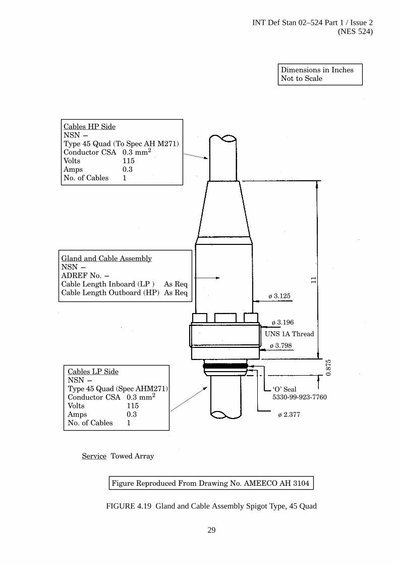
FIGURE 4.19 Gland and Cable Assembly Spigot Type, 45 Quad
Cables HP SideNSN -Type 45 Quad (To Spec AH M271)Conductor CSA 0.3 mm2
Volts 115Amps 0.3No. of Cables 1
Gland and Cable AssemblyNSN -ADREF No. - Cable Length Inboard (LP ) As ReqCable Length Outboard (HP) As Req
Cables LP SideNSN -Type 45 Quad (Spec AHM271)Conductor CSA 0.3 mm2
Volts 115Amps 0.3No. of Cables 1
Figure Reproduced From Drawing No. AMEECO AH 3104
Dimensions in InchesNot to Scale
ø 2.377
ø 3.196
UNS 1A Thread
ø 3.125
11
0.8
75
ø 3.798
Service Towed Array
`O' Seal5330�99�923�7760

INT Def Stan 02–524 Part 1 / Issue 2(NES 524)
30
FIGURE 4.20 Gland and Cable Assembly Spigot Type, 4 x 6 Core
Cables HP SideNSN 6145�99�527�1312Type 6 CoreConductor CSA 0.5 mm2
Volts 600Amps 3No. of Cables 4
Gland and Cable AssemblyNSN -ADREF No. - Cable Length Inboard (LP ) 55 FtCable Length Outboard (HP) 20 Ft
Cables LP SideNSN 6145�99�111�6772Type 6 Core PVC Sheath
DEF STAN 61�12 Pt 5Conductor CSA 0.5 mm2
Volts 440Amps 3No. of Cables 4
Figure Reproduced From Drawing No. SDN 007 509 367
Service Sonar 2007CD
ø 2.377
ø 3.196
UNS 1A Thread
ø 3.1259.7
5
0.8
75
ø 3.798
Dimensions in InchesNot to Scale
`O' Seal5330�99�923�7760

INT Def Stan 02–524 Part 1 / Issue 2(NES 524)
31
FIGURE 4.21 Gland and Cable Assembly Flange Type, 14 Core
Cables HP SideNSN 6145�99�521�6965Type 14 Core Heavy Duty
CSP SheathConductor CSA 35 mm2
Volts 440Amps 70No. of Cables 1
Gland and Cable AssemblyNSN -ADREF No. - Cable Length Inboard (LP ) As ReqCable Length Outboard (HP) As Req
Cables LP SideNSN 6145�99�521�6866Type 14 Core Heavy Duty
CSP SheathConductor CSA 35 mm2
Volts 440Amps 83No. of Cables 1
Figure Reproduced From Drawing No. SDN 007 038 075
Service Degaussing `M' Coils
Dimensions in mmNot to Scale
ø 116
`O' Seal
440
16
0
204 Dia Ten Holes17.5 Dia on 175 PCD

INT Def Stan 02–524 Part 1 / Issue 2(NES 524)
32
FIGURE 4.22 Gland Flange Type, AWJ
20.5
Flange 9.5 Dia 12 Holes 25/32 Dia on 8.0 PCD
13.2
5
Figure Reproduced From Drawing No. ASWE 278477
Dimensions in InchesNot to Scale
Gland and Cable AssemblyNSN 5975�99�924�9194ADREF No. J868�440504
Service AWJ Aerial Feeder
INT Def Stan 02–524 Part 1 / Issue 2(NES 524)
33
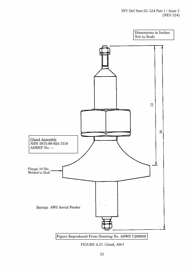
FIGURE 4.23 Gland, AWJ
Flange 10 DiaWelded to Hull
Dimensions in InchesNot to Scale
Gland AssemblyNSN 5975�99�924�7518ADREF No. -
Figure Reproduced From Drawing No. ASWE C299809
Service AWJ Aerial Feeder
12
20

INT Def Stan 02–524 Part 1 / Issue 2(NES 524)
34
4.4 Metric Spigot Type Pressure Hull Glands
a . Hull glands in this section are designed to be fitted to the Vanguard class ofSubmarine only. They may be installed singularly in a single pressure hullinsert or grouped within a multi�pressure hull insert.

INT Def Stan 02–524 Part 1 / Issue 2(NES 524)
35
FIGURE 4.24 Gland and Cable Assembly, Spigot Type Metric, 4 Coaxial 50 Ohms (Type 11)
Cables HP SideNSN 6145�99�724�8822Type 50 Ohm CoaxialConductor CSA -Length 6 mVolts -Amps -No. of Cables 4
Gland and Cable AssemblyNSN 5975�99�794�8800ADREF No. - Cable Length Inboard (LP ) 12 mCable Length Outboard (HP) 5 m
Cables LP SideNSN 6145�99�724�8834Type 50 Ohm CoaxialConductor CSA -Length 6 mVolts -Amps -No. of Cables 4
NSN 6510�99�168�8553ADREF No. - Cable Length Inboard (LP ) 3 mCable Length Outboard (HP) 15 m
NSN 6510�99�192�4968ADREF No. - Cable Length Inboard (LP ) 3 mCable Length Outboard (HP) 3 m
NSN 6510�99�591�2734ADREF No. - Cable Length Inboard (LP ) 15 mCable Length Outboard (HP) 18 m
Figure Reproduced From Drawing No. SDN 007 044 060
Dimensions in mmNot to Scale
ø 62.95
`O' Seal0523�57
M100x3
ø 79
211
22
ø 96.30

INT Def Stan 02–524 Part 1 / Issue 2(NES 524)
36
FIGURE 4.25 Gland and Cable Assembly, Spigot Type Metric, 19 Screened Pair (Type 1)
Cables HP SideNSN 6145�99�543�4475Type Screened Twisted PairConductor CSA 0.6 mm2
Length 6 mVolts 600Amps 2No. of Cables 19
Gland and Cable AssemblyNSN 5975�99�052�4083ADREF No. - Cable Length Inboard (LP ) 30 mCable Length Outboard (HP) 5 m
Cables LP SideNSN 6145�99�724�8842Type 19 Optimized Screened Conductor CSA 0.6 mm2
Length 6 mVolts 600Amps 2No. of Cables 1
Figure Reproduced From Drawing No. SDN 007 528 045
NSN 2040�99�056�3620ADREF No. - Cable Length Inboard (LP ) 20 mCable Length Outboard (HP) 5 m
`O' Seal0523�57
M100x3
ø 79
211
22
ø 96.30
ø 62.95
Dimensions in mmNot to Scale

INT Def Stan 02–524 Part 1 / Issue 2(NES 524)
37
FIGURE 4.26 Gland and Cable Assembly, Spigot Type Metric, 19 Screened Pair (Type 2)
Cables HP SideNSN 6145�99�543�4475Type Screened Twisted PairConductor CSA 0.6 mm2
Length 6 mVolts 600Amps 2No. of Cables 19
Gland and Cable AssemblyNSN 5975�99�765�4444ADREF No. - Cable Length Inboard (LP ) 22 mCable Length Outboard (HP) 48 m
Cables LP SideNSN 6145�99�724�8836Type 19 Super Screened
Twisted Pairs Conductor CSA 0.4 mm2
Length 6 mVolts 600Amps 1.5No. of Cables 1
Figure Reproduced From Drawing No. SDN 007 528 046
Dimensions in mmNot to Scale
M100x3
ø 79
211
22
ø 96.30
ø 62.95
`O' Seal0523�57

INT Def Stan 02–524 Part 1 / Issue 2(NES 524)
38
FIGURE 4.27 Gland and Cable Assembly, Spigot Type Metric, 19 Screened Pair (Type 3)
Cables HP SideNSN 6145�99�543�4475Type Screened Twisted PairConductor CSA 0.6 mm2
Volts 600Amps 2No. of Cables 19
Gland and Cable AssemblyNSN 5975�99�660�6050ADREF No. - Cable Length Inboard (LP ) 20 mCable Length Outboard (HP) 5 m
Cables LP SideNSN 6145�99�724�8840Type Screened Twisted PairConductor CSA 0.6 mm2
Volts 600Amps 2No. of Cables 19
Figure Reproduced From Drawing No. SDN 007 528 047
Dimensions in mmNot to Scale
M100x3
ø 79
211
22
ø 96.30
ø 62.95
`O' Seal0523�57

INT Def Stan 02–524 Part 1 / Issue 2(NES 524)
39
FIGURE 4.28 Gland and Cable Assembly, Spigot Type Metric, 19 Screened Triple (Type 5)
Cables HP SideNSN 6145�99�724�8824Type 3 Core ScreenedConductor CSA 0.6 mm2
Volts 600Amps 2No. of Cables 19
Gland and Cable AssemblyNSN 5975�99�179�9257ADREF No. - Cable Length Inboard (LP ) 5 mCable Length Outboard (HP) 5 m
Cables LP SideNSN 6145�99�724�8837Type 3 Core ScreenedConductor CSA 0.6 mm2
Volts 600Amps 2No. of Cables 19
Figure Reproduced From Drawing No. SDN 007 528 049
Dimensions in mmNot to Scale
M100x3
ø 79
211
22
ø 96.30
ø 62.95
`O' Seal0523�57

INT Def Stan 02–524 Part 1 / Issue 2(NES 524)
40
FIGURE 4.29 Gland and Cable Assembly, Spigot Type Metric, 3 X 3 Screened Pair (Type 7)
Cables HP SideNSN 6145�99�724�8829Type 3 Screened PairsConductor CSA 0.6 mm2
Volts 600Amps 2No. of Cables 3
Cables LP SideNSN 6145�99�724�8841Type 9 Screened PairsConductor CSA 0.6 mm2
Volts 600Amps 2No. of Cables 1
Figure Reproduced From Drawing No. SDN 007 528 051
Dimensions in mmNot to Scale
M100x3
ø 79
211
22
ø 96.30
ø 62.95
`O' Seal0523�57

INT Def Stan 02–524 Part 1 / Issue 2(NES 524)
41
FIGURE 4.30 Gland and Cable Assembly, Spigot Type Metric, 1 Triple (Type 8)
Cables HP SideNSN 6145�99�525�5127Type 3 CoreConductor CSA 4.5 mm2
Volts 440Amps 26No. of Cables 1
Cables LP SideNSN 6145�99�525�5127Type 3 CoreConductor CSA 4.5 mm2
Volts 440Amps 26No. of Cables 1
Figure Reproduced From Drawing No. SDN 007 528 052
Dimensions in mmNot to Scale
`O' Seal0523�57
M100x3
ø 79
211
22
ø 96.30
ø 62.95
Gland and Cable AssemblyNSN 5975�99�849�9861ADREF No. - Cable Length Inboard (LP ) 10 mCable Length Outboard (HP) 5 m

INT Def Stan 02–524 Part 1 / Issue 2(NES 524)
42
FIGURE 4.31 Gland and Cable Assembly, Spigot Type Metric, 19 Pair
Cables HP SideNSN 6145�99�724�8831Type Twisted PairConductor CSA 1.5 mm2
Volts 600Amps 4No. of Cables 19
Cables LP SideNSN 6145�99�724�8843Type Twisted PairConductor CSA 1.5 mm2
Volts 600Amps 4No. of Cables 19
Figure Reproduced From Drawing No. SDN 007 528 433
Gland and Cable AssemblyNSN 6150�99�125�9056ADREF No. - Cable Length Inboard (LP ) 4 mCable Length Outboard (HP) 3 m
Dimensions in mmNot to Scale
M100x3
ø 79211
22
ø 96.30
ø 62.95
`O' Seal0523�57

INT Def Stan 02–524 Part 1 / Issue 2(NES 524)
43
FIGURE 4.32 Gland and Cable Assembly, Spigot Type Metric, 1 X 52 Quad
Cables HP SideNSN -Type 52 Quad Tinned CopperWire ScreenConductor CSA 0.25 mm2
Length 200 mVolts 500Amps 0.75No. of Cables 1
Cables LP SideNSN -Type 208 Conductor ShieldedJacketed CableConductor CSA 0.15 mm2
Length 5 mVolts 600Amps 0.5No. of Cables 1
Figure Reproduced From Drawing No. SDN 007 528 756
M100x3
ø 79
274
22
ø 96.30
ø 62.95
Dimensions in mmNot to Scale
`O' Seal0523�57

INT Def Stan 02–524 Part 1 / Issue 2(NES 524)
44
FIGURE 4.33 Gland and Cable Assembly, Spigot Type Metric, 4 Single Core
Cables HP SideNSN 6145�99�724�8833Type Single CoreConductor CSA 6 mm2
Volts 600Amps 25No. of Cables 4
Cables LP SideNSN 6145�99�724�8845Type Single CoreConductor CSA 6 mm2
Volts 600Amps 25No. of Cables 4
Figure Reproduced From Drawing No. SDN 007 531 320
Gland and Cable AssemblyNSN 2040�99�867�7897ADREF No. - Cable Length Inboard (LP ) 5 mCable Length Outboard (HP) 5 m
Dimensions in mmNot to Scale
M100x3
ø 79211
22
ø 96.30
ø 62.95
`O' Seal0523�57

INT Def Stan 02–524 Part 1 / Issue 2(NES 524)
45
5. CORPORATE EXPERIENCE & KNOWLEDGE
This standard contains no Corporate Experience & Knowledge information.

INT Def Stan 02–524 Part 1 / Issue 2(NES 524
46
ANNEX A.
RELATED DOCUMENTS
A.1 The following documents and publications are referred to in this standard:
Drawing AMEECO HydrospaceAH3104
Gland for 45 Quad Cable for Towed Array
Drawing ASWE 278477 Gland Aerial Feeder NSN 5975-99-924-9194
Drawing ASWE C299809 Gland Aerial Feeder NSN 5985-99-924-7518
Drawing AUWE 100193-1100 Gland 19 Quad Cable for Towed Array
Drawing DEE 87112 Cable and Gland Assembly Submarine Hull, Pressure,30 Pair, NSN 5975-99-522-6244
Drawing DEE 87124 Cable and Gland Assembly, Submarine Hull,Pressure, 60 Pair, NSN 5975-99-456-1492
Drawing DEE 96868 Gland 8 Way (Type A) AssemblyNSN 5975-99-522-4392
Drawing DEE 96869 Gland 6 Way (Type B) AssemblyNSN 5975-99-522-4393
Drawing DEE 96870 Gland 4 Way (Type C) AssemblyNSN 5975-99-522-4394,NSN 5975-99-522-4395
Drawing DEE 96872 Gland Single Way (Type F) AssemblyNSN 5975-99-522-4397
Drawing DEE 96873 Gland 4 Way (Type G) AssemblyNSN 5975-99-522-4398
Drawing DEE 96874 Gland 2 Way (Type H) AssemblyNSN 5975-99-522-4399
Drawing DEE 96875 Harness for Aerial Assembly (Type J) Castellated NutAssembly NSN 5975-99-522-4400
DrawingSDN 007 038 075
Pressure Hull Gland for Degaussing `M' Coils
DrawingSDN 007 044 060
Gland and Cable Assembly, Spigot Type Metric, 4Coax 50 ohms (Type 11)
DrawingSDN 007 502 353
Cable and Gland Assembly. Electrical. SubmarineHull Pressure, 60 Pairs, Flanged Improved TypeNSN 5975-99-525-3848
DrawingSDN 007 509 367
Gland 4 Way 6 Core
DrawingSDN 007 528 045
Gland and Cable Assembly Spigot Type Metric, 19Screened Pair (Type 1)
DrawingSDN 007 528 046
Gland and Cable Assembly Spigot Type Metric, 19Screened Pair (Type 2)
DrawingSDN 007 528 047
Gland and Cable Assembly Spigot Type Metric, 19Screened Pair (Type 3)
DrawingSDN 007 528 048
Gland and Cable Assembly Spigot Type 19 Way
DrawingSDN 007 528 049
Gland and Cable Assembly Spigot Type Metric, 19Screened Triple, (Type 5)

INT Def Stan 02– 524 Part 1 / Issue 2(NES 524)
47
DrawingSDN 007 528 050
Gland and Cable Assembly Spigot Type 19 Way
DrawingSDN 007 528 051
Gland and Cable Assembly Spigot Type Metric, 3 � 3Screened Pair, (Type 7)
DrawingSDN 007 528 052
Gland and Cable Assembly Spigot Type Metric, 1Triple, (Type 8)
DrawingSDN 007 528 433
Gland and Cable Assembly, Spigot Type Metric, 19Pair
DrawingSDN 007 528 756
Gland and Cable Assembly, Spigot Type Metric, 1 �52 Quad
DrawingSDN 007 531 320
Gland and Cable Assembly, Spigot Type Metric, 4Way,
Drawing STC RC6592 Gland Assembly for Secondary Propulsion Motor

INT Def Stan 02–524 Part 1 / Issue 2(NES 524
48
ANNEX B.
ABBREVIATIONS AND DEFINITIONS
B.1 For the purpose of this standard the following abbreviations apply:
ADREF No Admiralty Reference Number
CSA Cross�Sectional Area
CSP Chlorosulphonated Polyethylene
DPA Defence Procurement Agency
DLO Defence Logistics Organisation
HP High Pressure
LP Low Pressure
MLS Marine Electrical Systems
MOD Ministry of Defence
NES Naval Engineering Standard
NSN NATO Stock Number
PCD Pitch Circle Diameter
PCP Polychloroprene
PVC Polyvinyl Chloride
SDN Service Drawing Number
SSA Ship Support Agency
SSK Ship Submersible Kinetic
SSN Ship Submersible Nuclear
SSBN Ship Submersible Ballistic Nuclear
B.2 There are no Definitions for this standard.

INT Def Stan 02– 524 Part 1 / Issue 2(NES 524)
49
ANNEX C.
INDEX OF NATO STOCK NUMBERS
NATO STOCK No PAGE No
2040�99�219�2669 4.13
2040�99�056�3620 4.30
2040�99�867�7897 4.38
5330�99�923�7760 Various
5330�99�923�7764 4.18
5975�99�052�4083 4.30
5975�99�179�9257 4.33
5975�99�456�1492 4.17
5975�99�522�4392 4.6
5975�99�522�4393 4.5
5975�99�522�4394 4.7
5975�99�522�4395 4.8
5975�99�522�4397 4.3
5975�99�522�4398 4.4
5975�99�522�4399 4.10
5975�99�522�4400 4.20
5975�99�522�6244 4.16
5975�99�660�6050 4.32
5975�99�765�4444 4.31
5975�99�794�8800 4.29
5975�99�849�9861 4.35
5975�99�525�3848 4.18
5975�99�924�9194 4.26
5985�99�924�7518 4.27
6145�99�111�6772 4.24
6145�99�521�6866 4.25
6145�99�521�6965 4.25
6145�99�522�7875 4.16 / 4.17 / 4.18
6145�99�522�7877 4.3
6145�99�525�2037 4.4
6145�99�525�5127 4.10 / 4.35
6145�99�527�1312 4.24
6145�99�527�8993 4.7
6145�99�527�8994 4.8
6145�99�543�4475 4.5 / 4.10 / 4.11 / 4.12 / 4.14 / 4.30 / 4.31 / 4.32

INT Def Stan 02–524 Part 1 / Issue 2(NES 524
50
NA TO STOCK No P AGE No
6145�99�724�8822 4.9 / 4.29
6145�99�724�8824 4.13 / 4.33
6145�99�724�8829 4.34
6145�99�724�8831 4.6 / 4.36
6145�99�724�8833 4.4 / 4.38
6145�99�724�8834 4.9 / 4.29
6145�99�724�8836 4.12 / 4.31
6145�99�724�8837 4.13 / 4.33
6145�99�724�8840 4.5 / 4.6 / 4.10 / 4.14 / 4.32
6145�99�724�8841 4.34
6145�99�724�8842 4.11 / 4.30
6145�99�724�8843 4.36
6145�99�724�8845 4.38
6150�99�125�9056 4.36
6510�99�168�8553 4.29
6510�99�192�4968 4.29
6510�99�591�2734 4.29

Inside Rear Cover
© Crown Copyright 2002
Copying Only as Agreed with DStan
Defence Standards are Published by and Obtainable from:
Defence Procurement AgencyAn Executive Agency of The Ministry of Defence
UK Defence StandardizationKentigern House65 Brown Street
GLASGOW G2 8EX
DStan Helpdesk
Tel 0141 224 2531/2 Fax 0141 224 2503
Internet e-mail [email protected]
File Reference
The DStan file reference relating to work on this standard is D/DStan/69/02/524 Pt 1.
Contract Requirements
When Defence Standards are incorporated into contracts users are responsible for their correctapplication and for complying with contractual and statutory requirements. Compliance witha Defence Standard does not in itself confer immunity from legal obligations.
Revision of Defence Standards
Defence Standards are revised as necessary by up issue or amendment. It is important thatusers of Defence Standards should ascertain that they are in possession of the latest issue oramendment. Information on all Defence Standards is contained in Def Stan 00-00 Standardsfor Defence Part 3 , Index of Standards for Defence Procurement Section 4 ‘Index of DefenceStandards and Defence Specifications’ published annually and supplemented regularly byStandards in Defence News (SID News). Any person who, when making use of a DefenceStandard encounters an inaccuracy or ambiguity is requested to notify the Directorate ofStandardization (DStan) without delay in order that the matter may be investigated andappropriate action taken.