neoway opencpu development guide - wless.ru
TRANSCRIPT

Neoway OpenCPU
Development Guide
Version 2.5

Neoway OpenCPU Development Guide
Copyright © Neoway Technology Co., Ltd i
Copyright © Neoway Technology Co., Ltd 2015. All rights reserved.
No part of this document may be reproduced or transmitted in any form or by any means without prior
written consent of Shenzhen Neoway Technology Co., Ltd.
is the trademark of Neoway Technology Co., Ltd.
All other trademarks and trade names mentioned in this document are the property of their respective
holders.
Notice
The information in this document is subject to change without notice due to product version update or
other reasons.
Every effort has been made in preparation of this document to ensure accuracy of the contents, but all
statements, information, and recommendations in this document do not constitute a warranty of any
kind, express or implied.
Neoway provides customers complete technical support. If you have any question, please contact
your account manager or email to the following email addresses:
Website: http://www.neoway.com

Neoway OpenCPU Development Guide
Copyright © Neoway Technology Co., Ltd ii
Revision Record
Issue Modified By Contents Date
V1.0 Yu Haijun Initial draft 2012-11-02
V1.1 Yu Haijun Deleted GPIO7, GPIO16, and GPIO19 2012-11-28
V1.2 Dragon Li Modified the architecture diagram, and added and modified
some description.
2013-07-26
V1.3 Dragon Li Modified and added some figures and description, added GPRS
interfaces, and modified the typesetting format.
2013-08-26
V1.4 Dragon Li Modified the description about pins and added the USB
function. 2013-09-09
V1.5 Dragon Li Added the function of users adding .o files and deleted the Pin
Description column.
2013-09-27
V1.6 Dragon Li Modified the commands and relevant content about download
by air interface.
2013-11-16
V1.7 Dragon.li Added memory operations and AT commands for client
version.
Modified the file system size, task stack size, and relevant
description.
2013-12-18
V1.8 Dragon.li Modified the number of user tasks. The available tasks for users
increase to seven, the memory increases to 512 KB, and the size
of the file system increases to 1 MB.
2014-01-21
V1.9 Dragon.li Added SPI interface in the software schematic diagram.
Modified description about interrupt configuration.
2014-05-12
V2.0 Draogn.li Modified hardware data, such as the GPIO number, open
resources, etc. 2014-06-28
V2.1 Li. Xiaoyun Added description about I2C/SPI/PCM configuration.
Modified the GPIO.
Added FOTA commands.
2014-07-08
V2.2 Zhilong.wu
Modified the quantity of open GPIO pins
Added new GPIO configuration method
Modified the interrupt quantity and only INT7 and INT10 is
opened.
Modified the description of some messages with parameters.
Modified the parameter description of
Neoway_ReadAdcValue
2014-08-27
V2.3 Zhilong.wu
Added the G-sensor development scheme of I2C connecting
to BMA250 chipset.
Modified the GPS operation and deleted the u-blox
description.
2014-09-11
V2.4 Zhilong.wu Modified the note of GPIO configuration.
Added how to set saving path for remote upgrade file path. 2015-01-04

Neoway OpenCPU Development Guide
Copyright © Neoway Technology Co., Ltd iii
V2.5 Zhilong.wu Modified SPI configuration description 2015-03-25
Neoway OpenCPU Development Guide
Copyright © Neoway Technology Co., Ltd iv
Contents
1 Introduction ........................................................................................................................ 1
2 Abbreviations ..................................................................................................................... 1
3 Software Architecture ....................................................................................................... 1
4 Process of Initializing User App..................................................................................... 2
5 Callback Interface.............................................................................................................. 2
5.1 Writing a Callback Function ............................................................................................................... 3
5.2 Registering Callback Function ........................................................................................................... 3
5.3 Cancelling Callback Function ............................................................................................................ 3
6 Task ...................................................................................................................................... 4
6.1 Sending Message ................................................................................................................................ 4
6.2 Processing Message ............................................................................................................................ 4
7 Virtual Serial Port .............................................................................................................. 5
7.1 Virtual UART Transmitting ................................................................................................................ 5
7.2 Virtual UART Receiving .................................................................................................................... 5
8 GPIO Multiplexing ........................................................................................................... 6
8.1 GPIO Configuration ........................................................................................................................... 6
8.2 Interrupt Configuration ....................................................................................................................... 7
8.3 I2C Configuration ............................................................................................................................... 7
8.4 SPI Configuration ............................................................................................................................... 7
8.5 PCM Configuration ............................................................................................................................ 8
9 G-sensor............................................................................................................................... 8
10 Sleep Mode ....................................................................................................................... 9
10.1 Interrupt Triggering .......................................................................................................................... 9
10.2 Software Interface Control ............................................................................................................... 9
11 GPS ..................................................................................................................................... 9
12 GPRS ................................................................................................................................ 10
12.1 Setting Up a TCP Link ................................................................................................................... 10
12.2 Sending TCP Data .......................................................................................................................... 10
12.3 Closing a TCP Link ........................................................................................................................ 10
12.4 Choosing the Way to Receive ......................................................................................................... 10
12.5 Receiving Callback Function.......................................................................................................... 10
13 USB Interface.................................................................................................................. 11
14 File Operations ............................................................................................................... 11
14.1 Opening a File ................................................................................................................................ 11
Neoway OpenCPU Development Guide
Copyright © Neoway Technology Co., Ltd v
14.2 Closing a File .................................................................................................................................. 11
14.3 Reading a File ................................................................................................................................. 11
14.4 Writing a File .................................................................................................................................. 12
14.5 Handing Over Data ......................................................................................................................... 12
14.6 Moving a File Pointer ..................................................................................................................... 12
14.7 Querying the Size of a File ............................................................................................................. 12
14.8 Querying the Remaining Space of the File System ........................................................................ 12
14.9 Deleting a File ................................................................................................................................ 12
15 Memory Operations ...................................................................................................... 12
15.1 Apply for Memory .......................................................................................................................... 12
15.2 Release Memory ............................................................................................................................. 13
15.3 Querying the Remaining Memory .................................................................................................. 13
16 How to Add User Code................................................................................................. 13
16.1 Adding Header Files ....................................................................................................................... 13
16.2 Add .c Files ..................................................................................................................................... 13
16.3 Adding .o Files ............................................................................................................................... 13
17 How to Compile ............................................................................................................. 13
18 How to Debug ................................................................................................................ 14
18.1 Debugging Compiling Errors ......................................................................................................... 14
18.2 Debugging AT Commands .............................................................................................................. 14
18.3 Debugging UART Print .................................................................................................................. 15
19 How to Download ......................................................................................................... 15
19.1 Download Through a Download Tool ............................................................................................ 15
19.2 Download by Air Interface ............................................................................................................. 15
20 FOTA AT Commands ................................................................................................... 16
20.1 FOTA Parameter Setting: +FOTASETUP ...................................................................................... 16
20.2 FOTA Downloading: +FOTAGET ................................................................................................. 17
20.3 FOTA Connection Closed: +FOTACLOSE .................................................................................... 19
20.4 Setting Timing Upgrade: +FOTATIMERGET ............................................................................... 19
20.5 Setting Module Information: +FOTAMSG .................................................................................... 20
20.6 FOTA Upgrade Flowchart .............................................................................................................. 21
21 AT Commands for Client Version ............................................................................. 21
21.1 Querying the OpenCPU version: +READOPENVER .................................................................... 22
21.2 Writing the OpenCPU version: +WRITEOPENVER ..................................................................... 22
22 Tool................................................................................................................................... 23
22.1 Basic Configurations of the Tool .................................................................................................... 23
22.2 Downloading Master bin File ......................................................................................................... 24
22.3 Downloading User .bin File............................................................................................................ 25

Neoway OpenCPU Development Guide
Copyright © Neoway Technology Co., Ltd 1
1 Introduction
This document provides technical details that development engineers should pay attention to when
programming on Neoway OpenCPU. It describes the functions of each module and the process of calling
these APIs so that development engineers can undertake product development on this platform with high
efficiency.
2 Abbreviations
API Application Programming Interface
NV Non-volatile Memory
3 Software Architecture
Figure 3-1 Software architecture
User App
...
Core system
API
Callback
interface
Cal
l
Cal
lbac
k f
un
ctio
n
Sen
d m
essa
ges
to
use
r ap
p d
irec
tly
Tri
gg
er c
allb
ack
even
t
Task 1 Task 7Task 2
Timer NV storageMemory
InterruptGPIO
System API
I2C/SPI
Virtu
al UR
AT
Ex
chan
ge
User App Layer
Interface Layer
System Layer
Flash R/W
Time
File system
Audio
interface
USB interface
Figure 3-1 shows the architecture of the Neoway OpenCPU platform. This platform consists of three layers:
core system layer, interface layer, and user app layer. This architecture allows users to conduct project
development more flexibly and effectively so that they can save manpower during development. The system layer involves drives, which are mainly used to call functions and communicate for the programs of
the interface layer. To facilitate user development, some interfaces of the system layer are open to users. The

Neoway OpenCPU Development Guide
Copyright © Neoway Technology Co., Ltd 2
interface layer includes GPIO configuration interface, interrupt interface, I2C interface, SPI interface,
memory operation interface, NV memory interface, Flash read and write interface, timer interface, system
callback interface, file system interface, audio interface, USB interface, and system interface. All these
interfaces are open to users and can meet users' most requirements for project development. The user app
layer includes task 1, task 2, to task 7, and users' apps. Users' apps can call interfaces of the interface layer
that are open to undertake local development more effectively and conveniently.
4 Process of Initializing User App
Figure 4-1 shows the process of initializing a user app. After powered on, the system will complete the
initialization of the basic hardware and software. Then, it starts to check the size of user codes and obtain the
valid version of user codes. After the valid version is confirmed, the user app is started. The initialization
process is described as follows:
1. Enter the entry function neo_entry() of user app. In case that errors or exceptions occur during
system initialization due to app modification by users, this function is encapsulated in a library.
2. Call the Neoway_RegisterCallbackFunction() function, and register required callback function
information in this interface. The registration is optional. The callback function can be registered or
deregistered during the running of the user app.
3. Call the Neoway_UserInit() function to initialize the user app. This is also the entry function of the
user app. Users can add operations related to the user app to this function if necessary.
4. After the function is executed, the platform will create at most seven tasks for user and then the user
app will run with the core system.
Figure 4-1 Flow chart of user app initialization
Neoway_UserInit()
neo_entry()
Neoway_RegisterCallbackFunction()
Create task
start
Run with system
5 Callback Interface
A lot of information should be transparent to the user app during system running. The real-time
performance of the system would be poor if the user app calls only APIs to query the information. Moreover,
that would also affect the running efficiency of the apps and increase the complexity of the development.

Neoway OpenCPU Development Guide
Copyright © Neoway Technology Co., Ltd 3
The core system cannot call the APIs of the user app due to the software layer structure. Therefore, the
callback mechanism is used to notify the user app of the event.
After the user app starts, it registers the callback interface in accordance with the event it is interested in.
When the event happens, the system will call back the interface to notify the user app.
Users can install the callback interface at anytime. It is not a must when the user app initializes.
5.1 Writing a Callback Function
The callback function is triggered by the callback event. It can be programmed and also can be registered by
the user app.
Every callback event has a function type of the corresponding callback function. In neoway_openplatform.h,
NeowayCallbackIdEnun type corresponds with NeowayCallbackFunctionStruct type.
typedef enum {
NEOWAY_KB_ID_USER_TASK_1,
NEOWAY_KB_ID_USER_TASK_2,
NEOWAY_KB_ID_USER_TASK_3,
…
NEOWAY_KB_ID_GPS_RECEIVE
}NeowayCallbackIdEnum;
typedef struct {
NeowayTaskUserFptr user_task_1;
NeowayTaskUserFptr user_task_2;
NeowayTaskUserFptr user_task_3;
…
NeowayGpsDataReceiveFptr gps_data_receive;
}NeowayCallbackFunctionStruct;
typedef void(*NeowayTaskUserFptr)(NeowayMsgTypeStruct,NeowayModuleTypeEnum);
For example, in the NeowayCallbackEnum event, NEOWAY_KB_ID_USER_TASK_1 corresponds with
function pointer NeowayTaskUserFptr.
Write the callback function according to the type of the function pointer.
void Neoway_UserTask1(NeowayMsgTypeStruct msg_type,NeowayModuleTypeEnum mod_type)
{
…//Add user code
}
5.2 Registering Callback Function
The callback function will be triggered by the corresponding event only if you register it before the event
happens. The following instance is the callback function of the even processing function to register task.
Neoway_RegisterCallBack(NEOWAY_KB_ID_USER_TASK_1,(U32)Neoway_UserTask1);
//The callback function pointer type varies very much from each other, and here it is forced to convert to
U32.
5.3 Cancelling Callback Function
A registered callback function can be deregistered. The callback function will not be triggered by the
corresponding event any more after being deregistered. Simply register the callback function as NULL to
deregister the callback function.
For example, Neoway_RegisterCallBack(NEOWAY_KB_ID_USER_TASK_1,(U32)NULL);

Neoway OpenCPU Development Guide
Copyright © Neoway Technology Co., Ltd 4
6 Task
The Neo OpenCPU platform creates seven tasks for users. Each task's stack size is 10240, and message
queue's size is 100. The priority descends from task 1 to task 7.
6.1 Sending Message
All the applications are driven by messages. A message consists of task ID, message ID and parameters. The
parameter varies for different message IDs.
Source task ID and destination task ID must be filled and matched correctly, or it will cause automatic
restart or the message receiver cannot receive the message. The three task IDs are
NEOWAY_MOD_USER1, NEOWAY_MOD_USER2, NEOWAY_MOD_USER3. They are defined in
neoway_openplatform.h as follows:
typedef enum {
NEOWAY_MOD_USER1=NEOWAY_USER_MOD_BEGIN,
NEOWAY_MOD_USER2,
NEOWAY_MOD_USER3
} NeowayModuleTypeEnum;
In addition, the source task ID is included in parameter NeowayModuleTypeEnum of the callback function
when sending message.
Message ID is defined by NeowayMsgIdEnum in neoway_openplatform.h. A maximum of 500 messages
are supported. Users can add new message IDs. Users can add them between
NEOWAY_MSG_USER_BEGIN and NEOWAY_MSG_ID_END.
typedef enum {
NEOWAY_MSG_ID_TIMER_EXPIRY=13096,
NEOWAY_MSG_USER_BEGIN=23828+100,
NEOWAY_MSG_ID_TASK1_TASK2,
NEOWAY_MSG_ID_TASK2_TASK3,
NEOWAY_MSG_ID_TASK3_TASK1,
…
NEOWAY_MSG_ID_END=NEOWAY_MSG_USER_BEGIN+500
}NeowayMsgIdEnum;
Some messages carry parameters while some do not. The parameters carried by different messages can vary
with each other. Users decide whether the message they added carries parameters or not. When sending
message, the sending function only needs to know the top address and the size of the message. The
following are examples.
Neoway_SendMsgTask(NEOWAY_MOD_USER2,NEOWAY_MOD_USER3,NEOWAY_MSG_ID_
TASK2_TASK3,NULL,0); //User task 2 sends message to user task 3
NEOWAY_MSG_ID_TASK2_TASK3 doesn't carry parameters.
Neoway_SendMsgTask(NEOWAY_MOD_USER1,NEOWAY_MOD_USER2,NEOWAY_MSG_ID_
TASK1_TASK2,data_ptr,3); //User task 1 sends message to user task 2
The parameter is the applied memory address that is pointed to by data_ptr
(data_ptr=Neoway_GetMemory(3);), and the data length is 3 bytes.
6.2 Processing Message
Every task has a corresponding message processing function. When a message is received, the processing
function will be executed. Users just need to check the message ID, obtain the parameters being carried, and
process the message.

Neoway OpenCPU Development Guide
Copyright © Neoway Technology Co., Ltd 5
Message processing functions are the first three functions registered for users. They are
Neoway_UserTask1, Neoway_UserTask2, and Neoway_UserTask1. They are registered at the very
beginning of the user app:
Neoway_RegisterCallBack(NEOWAY_KB_ID_USER_TASK_1,(U32)Neoway_UserTask1);
Neoway_RegisterCallBack(NEOWAY_KB_ID_USER_TASK_2,(U32)Neoway_UserTask2);
Neoway_RegisterCallBack(NEOWAY_KB_ID_USER_TASK_3,(U32)Neoway_UserTask3);
The first parameter in the message processing function includes the message ID and parameters carried by
the message, and the second parameter is the current task ID. The following is the message processing
procedure in example of task 1.
void Neoway_UserTask1(NeowayMsgTypeStruct msg_type,NeowayModuleTypeEnum mod_
type)
{
switch(msg_type.msg_id)
{
case NEOWAY_MSG_ID_TASK3_TASK1://ID of message received
{
if(NULL!=msg_type.data_ptr)
{
Neoway_Print(msg_type.data_ptr);//print out the parameter
Neoway_ReleaseMemory(msg_type.data_ptr);//Release applied memory
}
}
break;
default :
break;
}
}
The previous example is the processing function of NEOWAY_MSG_ID_TASK3_TASK1, and prints
parameters to UART1.
7 Virtual Serial Port
Traditionally, an MCU connected to a module sends AT commands through UART ports to control the
module. Since the OpenCPU platform supports users development, many products will not be connected to
an MCU. Therefore, a virtual serial port is established to transmit AT commands and other data between
user and platform.
7.1 Virtual UART Transmitting
Virtual UART transmitting, that is, sending AT commands or other data for user app and the platform. The
function's parameters are the current task ID, the data to be sent, and the length of the data to be sent. For
example, when querying signal strength, just send string "AT+CSQ\r", that is,
Neoway_VirtualUartSend(NEOWAY_MOD_USER1," AT+CSQ\r",7);
7.2 Virtual UART Receiving
The virtual UART receiving function is used to receive responses of AT commands or other data from the
platform layer for user. The virtual UART receiving function needs to be registered by callback function,
that is,
void Neoway_VirtualUartReceive(U8 *buff_ptr, U16 len, NeowayModuleTypeEnum mod_id)
{
}
Neoway_RegisterCallBack(NEOWAY_KB_ID_VIRTUAL_UART_RECEIVE,(U32)Neoway_VirtualUartReceive
);

Neoway OpenCPU Development Guide
Copyright © Neoway Technology Co., Ltd 6
If the user app receives data from the platform, the interface Neoway_VirtualUartReceive will be called,
this interface is implemented by users.
When the platform sends a block of data to the user app, the callback function may be called more than one
times to receive all the data, so it needs patience and cautious.
Take particular care when debugging in virtual UART receiving function, try not to print out data to UART
in this function. If the print is necessary, please first judge the character strings you want to receive and do
not include them in the data you print to UART.
8 GPIO Multiplexing
The platform provides users with 15 pins that can be configured to GPIO function, some of which can be
multiplexed as interrupts, I2C, SPI, and PCM.
#define NEOWAY_GPIO_0 0
#define NEOWAY_GPIO_3 3
#define NEOWAY_GPIO_9 9
#define NEOWAY_GPIO_11 11
#define NEOWAY_GPIO_13 13
#define NEOWAY_GPIO_25 25
#define NEOWAY_GPIO_26 26
#define NEOWAY_GPIO_29 29 //Interrupt
#define NEOWAY_GPIO_32 32
#define NEOWAY_GPIO_33 33
#define NEOWAY_GPIO_34 34
#define NEOWAY_GPIO_35 35
#define NEOWAY_GPIO_37 37
#define NEOWAY_GPIO_43 43
#define NEOWAY_GPIO_44 44 //Interrupt
Use these macros directly and do not change the defined values.
GPIO29 and GPIO44 pins can be configured as interrupts. GPIO34 is the DTR pin, which can be configured
as interrupt if two interrupts are not enough.
8.1 GPIO Configuration
GPIO can be configured in two methods.
Method 1:
1. Configure pins to GPIO mode.
2. Configure GPIO input or output.
3. Configure pull-down/pull-up enabling if it's configured to input.
4. Configure pull-down/pull-up.
5. GPIO read/write.
Method 2 (Separate input and output modes):
1. Configure pins to GPIO input pull_up/pull_down (Neoway_GpioInputMode)
2. Configure pins to GPIO output and specify the level (Neoway_GpioOutputMode)
3. GPIO read (Neoway_GpioRead)
Method 2 is simple but takes longer time if the GPIO is configured for many times. It is
recommended that you use the method 1 in that situation.

Neoway OpenCPU Development Guide
Copyright © Neoway Technology Co., Ltd 7
8.2 Interrupt Configuration
GPIO29 and GPIO44 can be configured as interrupts, corresponding to INT7 and INT10 respectively. In
interrupt mode, the configuration of each INT pin is independent. They can be configured as level triggered
or edge triggered interrupt. Level triggering interrupt can be configured as low or high level triggering. As
for edge triggering it can be configured as rising edge triggering or falling edge triggering.
For example,
Neoway_InterruptInit(NEOWAY_GPIO_29,NEOWAY_INT_7); //INT7 is initialized.
Neoway_InterruptSetDebounceTime(NEOWAY_INT_7,10); //Set debounce time.
Neoway_InterruptSetTriggerMode(NEOWAY_INT_7,NEOWAY_TRUE);//Edge triggered interrupt
Neoway_InterruptSetPolarity(NEOWAY_INT_7,NEOWAY_TRUE);//Rising edge triggered interrupt
Register the interrupt callback interface:
void Neoway_IntResponse(NeowayIntNumEnum int_no,NeowayModuleTypeEnum mod_id)
{
}
Neoway_RegisterCallBack(NEOWAY_KB_ID_INT_RESPONSE,(U32)Neoway_IntResponse;
When an interrupt occurs, Neoway_IntResponse will be called, and it is implemented by users.
If current configuration is interrupt mode, and the interrupt is configured to high level triggering, the
interrupt will always be triggered if the triggering polarity is not modified in interrupt service function.
General process:
1. Register interruption callback function.
2. Initialize interrupt.
3. Configure interrupt debounce time.
4. Configure interrupt polarity, whether rising edge or falling edge, high level or low level.
5. Configure triggering mode, level triggering or edge triggering.
6. Add processing code in interrupt processing function.
7. The pin should be configured to GPIO mode after using.
8.3 I2C Configuration
I2C is configured using GPIO33 and GPIO43, which are respectively clock pin and data pin. The
configurations are as follows:
Neoway_GpioModeConfigure(33, NEOWAY_MODE_GPIO33_1);
Neoway_GpioDirectionConfigure(33,1);
Neoway_GpioModeConfigure(43, NEOWAY_MODE_GPIO43_1);
Neoway_GpioDirectionConfigure(43,1);
8.4 SPI Configuration
SPI is configured using GPIO33(SCK), GPIO43(CS), GPIO00(MOSI), and GPIO09(MISO). The
configurations are as follows:
Neoway_GpioModeConfigure(33, NEOWAY_MODE_GPIO33_4);
Neoway_GpioDirectionConfigure(33,1);
Neoway_GpioModeConfigure(43, NEOWAY_MODE_GPIO43_4);
Neoway_GpioDirectionConfigure(43,1);
Neoway_GpioModeConfigure(0, NEOWAY_MODE_GPIO00_4);
Neoway_GpioDirectionConfigure(0,1);
Neoway_GpioModeConfigure(9, NEOWAY_MODE_GPIO09_4);
Neoway_GpioDirectionConfigure(9,0);

Neoway OpenCPU Development Guide
Copyright © Neoway Technology Co., Ltd 8
8.5 PCM Configuration
PCM is configured using GPIO37(PCM_SYNC), GPIO32(PCM_IN), GPIO25(PCM_OUT), GPIO11(PCM_CLK). The configurations are as follows:
Neoway_GpioModeConfigure(37, 4);
Neoway_GpioDirectionConfigure(37, 1);
Neoway_GpioModeConfigure(32, 4);
Neoway_GpioDirectionConfigure(32, 0);
Neoway_GpioModeConfigure(25, 4);
Neoway_GpioDirectionConfigure(25, 0);
Neoway_GpioModeConfigure(11, 4);
Neoway_GpioDirectionConfigure(11, 0);
9 G-sensor
The I2C/SPI of Neoway OpenCPU supports external G-sensor chipset. We provide the scheme of G-sensor
function development using Neoway I2C and BMA250 chipset.
The development process and main interfaces of Neoway I2C connecting to BMA250:
1. Use the bma250_init function to initialize the bma250_t structure.
bma250_t t_bma250;
bma250_init(&t_bma250);
Point bma250_WR_FUNC_PTR in the bma250_t structure to the access address
Neoway_i2c_send_ext8 of the I2C data sending function; Point ma250_RD_FUNC_PTR to the
access address Neoway_i2c_receive_ext8 of the I2C data receiving function.
2. Configure Neoway I2C pin.
For how to configure I2C, refer to "8.3 I2C Configuration." Only GPIO33 and GPIO43 can be used
to configure for I2C.
3. Configure the address and communication rate of Neoway I2C device.
Neoway_i2c_configure(0x30, 200);
BMA250 works as I2C device and its address is 0x30. The recommended communication rate is 200
Kbit/s.
4. Configure and query BMA250 range.
unsigned char bma250_set_range(unsigned char Range)
bma250_set_range(1); //Set BMA250 range to 1, which is corresponding to +/-2 g.
The parameter value can be set to 0, 1, 2, and 3, which are respectively corresponding to +/-2 g, +/-4
g, +/-8 g, and +/-16 g.
bma250_get_range(&range);//Query BMA250 range.
When the set value is 0, the queried value is 3; 1 for 5, 2 for 8, and 3 for 12.
5. Read the real-time acceleration values of different coordinate axis.
short s_x = 0;
bma250_read_accel_x(&s_x);
short s_y = 0;
bma250_read_accel_y(&s_y);
short s_z = 0;
bma250_read_accel_z(&s_z);

Neoway OpenCPU Development Guide
Copyright © Neoway Technology Co., Ltd 9
10 Sleep Mode
The Neoway OpenCPU platform supports sleep mode triggered in two manners, one of which is hardware
interrupt, and the other is software interface. They cannot be used at the same time. Power saving triggered
by hardware interrupt requires an external MCU or other master chip to control, and that is not
recommended in OpenCPU.
Module's current can be lower than 3 mA in sleep mode. SMS receiving, incoming calls and GPRS data
receiving can wake up the module. The module will go back to the sleep mode automatically after
processing these events.
10.1 Interrupt Triggering
The module receives external interrupt (from DTR) and the INT pin level controls whether the module
enters the sleep mode or not. The interrupt pin is GPIO34. This type of sleep mode must be enabled by the
command AT+ENPWRSAVE=1.
General steps:
1. Issue the AT+ENPWRSAVE=1 command to enable the sleep mode.
2. Pull down the DTR pin by MCU. The module will enter the sleep mode when each part of the circuit
in the module allows the sleep mode.
3. Pull up DTR, the module will exit the sleep mode.
10.2 Software Interface Control
The Neoway OpenCPU platform has provided sleep mode interface for user. It is recommended that users
choose this way to enter the sleep mode. And this type of triggering is enabled by default after powering on
the module. The status change of DTR will not affect the sleep mode when. Please pull down/up by
hardware.
How to control:
1. Execute the Neoway_Sleep(NEOWAY_TRUE) function to enter the sleep mode. The module will
enter the sleep mode when each parts of the circuit in the module allow the sleep mode.
2. Execute the Neoway_Sleep(NEOWAY_FALSE) function to exit the sleep mode. The module will
exit sleep instantly after executing this function.
11 GPS
Neoway OpenCPU does not include a built-in GPS chipset. If you need to use the GPS function, pleases add
one. The GPS commands will obtain a large volume of data and it is difficult for virtual UART to parsing the
data. We have opened UART2 so that you can use it to communication with your GPS chipset.How to use
GPS:
1. Start the GPS function.
Configure the GPIO connected to the GPS chip high level. For example, GPIO34 is used to control GPS and
then you can use the following statement to start GPS:
Neoway_GpioOutputMode(NEOWAY_GPIO_34, 1);
2. Obtain GPS data.
Obtain the GPS data through the callback interface. Neoway OpenCPU use UART2 to receive GPS data.
Register the UART to receive the callback function and open the UART2:
Neoway_RegisterCallBack(NEOWAY_KB_ID_UART_RECEIVE,(U32)Neoway_UartReceiv);
Neoway_UartOpen(NEOWAY_UART_PORT_2);
void Neoway_UartReceive(NeowayUartPortEnum port,U8 *buffer,U16 lenth,NeowayModu

Neoway OpenCPU Development Guide
Copyright © Neoway Technology Co., Ltd 10
leTypeEnum mod_id)
{
if(port==NEOWAY_UART_PORT_2)
{
//Process GPS data received by UART2.
}
}
This callback function will be executed every second after started GPS. Users can analyse data in this
function.
3. Disable the GPS function.
Configure the GPIO connected to the GPS chip low level. For example, GPIO34 is used to control GPS and
then you can use the following GPS to disable the GPS function:
Neoway_GpioOutputMode(NEOWAY_GPIO_34, 0);
12 GPRS
All GPRS features can be implemented by virtual port operations. Users can decide when to set up a TCP
link, when to send data, and when to close the link. Since GPRS data received can be tremendous, a callback
function is provided for+ users to process the GPRS data received.
12.1 Setting Up a TCP Link
neoway_user_tcp_setup_func(char *str_id,char *str_ip,char *str_port);
Users can use this interface to set up a TCP link.
12.2 Sending TCP Data
neoway_user_tcp_send_func(char *str_id,char *string,int len);
Users can use this interface to send GPRS data.
12.3 Closing a TCP Link
neoway_user_tcp_close_func(char *str_id);
Users can use this interface to close a TCP link.
12.4 Choosing the Way to Receive
The GPRS data received can be obtained and analysed by virtual UART, also can be obtained by the
callback function. Users can choose only one of the two ways. It is chosen by using the function void
Neoway_SetIpDataShowFlag(U8 flag). When the flag value is 1, users obtain the data by the callback
function. When the flag value is 0, data received is output to the virtual UART directly.
12.5 Receiving Callback Function
Neoway_RegisterCallBack(NEOWAY_KB_ID_IP_RECEIVE,(U32)Neoway_IpdataRecieve);
void Neoway_IpdataRecieve(U8 index,U32 length,S8 *data_buffer, NeowayModuleTypeEn
um mod_id)
{
}
If the data is received by the callback function, the callback function is used to process the TCP/UDP data
received.
Parameters:

Neoway OpenCPU Development Guide
Copyright © Neoway Technology Co., Ltd 11
index: the link id
length: the data length
data _buffer: the data buffer
13 USB Interface
This platform provides USB1.1 interface and the computer drives for this interface. Users can use this USB
interface to burn clients and save files on computers to user disk (the size of the user disk is less than 512
KB). On the OpenCPU platform, users can use file operation to read and write files and data on the user
disk.
14 File Operations
The OpenCPU platform provides a small-sized file system for users. The size is more than 512 KB.
14.1 Opening a File
S32 Neoway_FSOpen(const U16 * FileName, U32 Flag);
This function is used to create a file or to open a file and return a file handle. If the file is created or opened
successfully, the return value will be greater than or equal to 0. If it fails, the return value would be less than
0.
Parameters:
FileName: the path and name of the file
Flag: the property of the file. Its value can be FS_READ_WRITE, FS_READ_ONLY,
FS_OPEN_SHARED, FS_CREATE.
For example, create a file using the following statement:
h=(S32)Neoway_FSOpen((constU16*)L"C:\\text.c",NEOWAY_FS_READ_WRITE|NEOWAY_FS_CREATE);
14.2 Closing a File
void Neoway_FSClose(S32 FileHandle);
This function is used to close an opened file. For example,
Neoway_FSClose(h);
14.3 Reading a File
void Neoway_FSRead(S32 FileHandle, void * DataPtr, U32 Length, U32 * Read);
This function is used to fetch the file content to a buffer pointed by DataPtr.
Parameters:
FileHandle: the handle of the opened file.
Length: the number of bytes to read
Read: the number of bytes read out actually. Sometimes the data to be read is not finished. Compare values
of Length and Read after executing this function. If Read is less than Length, users can continue reading
the rest of the file content.

Neoway OpenCPU Development Guide
Copyright © Neoway Technology Co., Ltd 12
14.4 Writing a File
void Neoway_FSWrite(S32 FileHandle, void * DataPtr, U32 Length, U32 * Written);
This function is used to write the data buffer pointed by DataPtr to a file.
Parameters:
Length: the number of bytes to write
Written: the number of bytes written to the file actually
14.5 Handing Over Data
void Neoway_FSCommit(S32 FileHandle);
This function is used to write the rest data in the buffer to a file. It is used after using function
Neoway_FSWrite to ensure all the data is written to the file.
14.6 Moving a File Pointer
void Neoway_FSSeek(S32 FileHandle, int Offset, int Whence);
This function is used to make the file pointer point to a certain position of the file.
Parameters:
Whence can be 0, 1, and 2. When 0, the file pointer points to the start of the file. When 1, the pointer points
to the current position; when 2, the pointer points to the end of the file.
Offset: the offset of the file. If the pointer moves forward for 5 bytes, the offset value is -5. If the pointer
moves afterward for 5 bytes, the offset value is 5.
14.7 Querying the Size of a File
S32 Neoway_FSGetFileSize(S32 FileHandle, U32 * Size);
This function returns the size of the file.
14.8 Querying the Remaining Space of the File System
S32 Neoway_FSLeftSpace();
This function returns the remaining space of the file system.
14.9 Deleting a File
void Neoway_FSDelete(const U16 * FileName);
This function is used to delete a file.
15 Memory Operations
The Neoway OpenCPU platform provides 1024 KB RAM space independently for users. Users can apply
for and release memory and query the remaining space in the RAM space. Preprocessing is done to the
independent RAM space so that the memory operations will be more secure and reliable.
15.1 Apply for Memory
void *Neoway_GetMemory(U32 len);
This function is used to apply for memory with a size of len.

Neoway OpenCPU Development Guide
Copyright © Neoway Technology Co., Ltd 13
15.2 Release Memory
void Neoway_ReleaseMemory(void *address);
This function is used to release allocated memory.
15.3 Querying the Remaining Memory
U32 Neoway_GetLeftMemory(void);
This function is used to query the size of the remaining user memory.
16 How to Add User Code
Users need to add their own files when using the Neoway OpenCPU platform, for example *.h, *.c, and *.o
files.
16.1 Adding Header Files
The Neoway OpenCPU platform provides users with two header files, neoway_openplatform.h and
neoway_type.h. Include neoway_openplatform.h if users do not add any other header files.
Adding a user header file:
Header files added by users should be put in the neowayinc directory.
Include the user-define header files after neoway_openplatform,h.
16.2 Add .c Files
*.c files added by users should be put in the example directory.
Modify the makefile file in example, change *.c to *.o, and add it to compiling scripts. For example, user.c
is added as below:
OBJS = example_helloWorld.o user1.o
16.3 Adding .o Files
Save .o files added by users to the coreSW directory.
Modify the makefiledef file in the main directory and add *.o to the following statement of the compiling
script:
INNERLIB=coreSW\app_start.o coreSW\*.o
For example, add the user.o file: INNERLIB=coreSW\app_start.o coreSW\user.o
17 How to Compile
Double-click cmd.exe. Enter make helloworld in the CLI and press Enter.
If users need to change the project name, change helloworld in the makefile file under the main directory to
users' project name.
The following files will be generated in the build directory after compiling:
build.log: Compiling result log
ROM1: Client file (generated only after the compiling is successful)
Neoway_Remote.bin: Remote upgrade file ((generated only after the compiling is successful))

Neoway OpenCPU Development Guide
Copyright © Neoway Technology Co., Ltd 14
NEOWAY60S_MOD_11B_BB.cfg: Download configuration file
ROM: ROM file of the platform
obj: Folder that contains all generated obj files
18 How to Debug
The Neoway OpenCPU platform provides three methods to bug according to users' different debug
purposes.
18.1 Debugging Compiling Errors
If there is syntax error in user code, the compiling will stop. In the build directory, the builg.log file is
generated during compiling. It contains compiling information, and the error is easy to find by checking the
log file.
18.2 Debugging AT Commands
The Neoway OpenCPU platform provides an AT command callback function for user to test. After
registering the callback function, send command AT+TEST=<PARAM> (PARAM can be any string, users
analyse it in callback function). The module will execute the registered callback function. Users can execute
different functions by different PARAM string according to their needs, and then check the validity of the
function.
For example, to check the UART output function:
Neoway_RegisterCallBack(NEOWAY_KB_ID_TEST,(U32)Neoway_TestFunction);
void Neoway_TestFunction(S8 * parm_ptr, NeowayModuleTypeEnum mod_id)
{
if(memcmp(parm_ptr,"000",3)==0)
{
Neoway_WriteUart1(“aaaaaa”,6);
}
else if(memcmp(parm_ptr,"001",3)==0)
{
Neoway_WriteUart1(“bbbbbb”,6);
}
}

Neoway OpenCPU Development Guide
Copyright © Neoway Technology Co., Ltd 15
Issue the command AT+TEST=000 to the UART, the UART will print out character string aaaaaa. Issue
the command AT+TEST=001, the UART will print out string bbbbbb.
18.3 Debugging UART Print
It is a simple and practical debugging method. The platform provides function Neoway_Print for users.
Users can add this function to their own code. After this function is executed, string converted from the
parameter will be printed out.
19 How to Download
After users obtain the Neoway OpenCPU platform, they can develop their own software and download it to
the code region to execute.
19.1 Download Through a Download Tool
Perform the following steps:
1. Connect UART1 to PC
2. Start the download tool Flash_tool.exe
3. Configure the UART by choosing Option > COM Port > Select the connected UART.
4. Click Scatter/Config File, and choose file .cfg which is generated when compiling in build
directory.
5. Clear the PRIMARY_MAUI check box and select ROMI only.
6. Click Download.
7. Reset the module manually.
19.2 Download by Air Interface
Download by air interface is remote update, which is controlled by a TCP link. The upgrade starting and
completion commands are issued through the TCP link. The data during the process is transferred through
FTP. Users can also control the module's remote upgrade by SMS. However, TCP is recommended since
the real-time performance of SMS is poorer than TCP.
Start and end the upgrade through commands in client code
In the client code, Neoway_VirtualUartReceive() can be used to check specific command string
(defined by users) from the TCP server. If the string is detected, Neoway_StartFtpUpdate() can be
called to start upgrade. Prior to these operations, set the FTP server address, and user name and
password to log to the FTP server. For example, AT+FTPSETTING=1,192.168.13.24,zyx,123 or
AT+FTPSETTING=2, www.baidu.com,zyx,123. The former one uses IP as address, and the latter
one uses domain name as address. If the upgrade is completed successfully, the version is the latest
one, or the upgrade fails, the function Neoway_FtpUpdate() will be called. Users can add
processing code to different branches in this function and report to the TCP server after finishing the
upgrade. Then close the link and restart the module, and the new client code can be started now.
TCP server
The TCP server, as the control platform, can control when to send specific commands to modules
connected to start upgrade, and keep statistics and record according to the status the module reports.
Users can develop programs to meet their requirements.
FTP server
Install a stable and reliable FTP server. After the FTP server is set, the following two files need to be
put in the directory:
− Version control file

Neoway OpenCPU Development Guide
Copyright © Neoway Technology Co., Ltd 16
The name of version control file is version.txt. Users need to fill in the version number and the
name of the client binary file (the extension is not included). The following figure shows its
format.
version.txt must be in ASCII format. Otherwise, the upgrade will fail.
− Client binary file
The suffix of the client binary file is always .bin. The CRC information is added to the file by
MD5 algorithm. The 16 byte checksum calculated by MD5 algorithm is added every 4096 Byte.
The Neoway_Remote.bin file for remote upgrade is saved in the build folder and can be copied
to the FTP server for download.
− Path setting:
To set the saving path of version.txt and Neoway_Remote.bin, create a subdirectory on the
FTP server and copy the two files to the subdirectory. On the client, call void
Neoway_remote_path_set(const char *Ftp_remote_file_path) to set the saving path. For
example, create neoway\\remotefilepath on the FTP server and then copy the two files to the
remotefilepath folder. On the client, call
Neoway_remote_path_set("neoway\\remotefilepath\\"); to set the path.
20 FOTA AT Commands
20.1 FOTA Parameter Setting: +FOTASETUP
Description To set the FOTA URL parameters
Format AT+FOTASETUP=<url><CR>
Parameter url: Destination path
If there is no port in URL provided, the default port is 80.
Return Value
See the Example.
Example at+fotasetup= http://58.60.184.212:9090/api/test
OK
The parameter is set successfully.
at+fotasetup= http://58.60.184.212/api/test
OK
The parameter is set successfully.
The default port is used.
at+fotasetup=http://rom.innos.com:9090/
OK
The parameter is set successfully
with the domain name.
at+fotasetup=http://rom.innos.com:9090
ERROR
Fail to translate the domain name
because slash is omit at the end.
Remarks N/A

Neoway OpenCPU Development Guide
Copyright © Neoway Technology Co., Ltd 17
20.2 FOTA Downloading: +FOTAGET
Description To perform remote upgrade
Format AT+FOTAGET<CR>
Parameter N/A
Return Value
+FOTASETUP: LACK OF PARAMETER
+FOTA: ID is not the same!
+FOTA: Authentication failed!
+FOTA: Authentication OK!
+FOTACHECK: There is no version can be updated!
+FOTACHECK: Update the new version, please wait!
+FOTA: Downloading...
Example at+fotasetup=http://rom.innos.com:9090/
OK
at+fotaget
OK
+FOTA: Authentication OK!
+FOTACHECK: Update the new version,
please waite!
+FOTACLOSE, OK
OK
+FOTA: Downloading... 7%
+FOTA: Downloading... 10%
+FOTA: Downloading... 14%
+FOTA: Downloading... 18%
+FOTA: Downloading... 22%
+FOTA: Downloading... 26%
+FOTA: Downloading... 30%
+FOTA: Downloading... 34%
Connect to the server successfully.
Download
Authentication on the server successful
Check if any new version on the server
Close original link.
Connect to the path provided by the
server successfully.
Download process
Neoway OpenCPU Development Guide
Copyright © Neoway Technology Co., Ltd 18
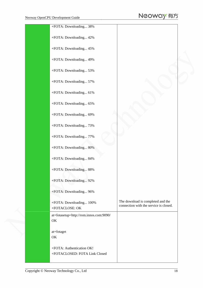
+FOTA: Downloading... 38%
+FOTA: Downloading... 42%
+FOTA: Downloading... 45%
+FOTA: Downloading... 49%
+FOTA: Downloading... 53%
+FOTA: Downloading... 57%
+FOTA: Downloading... 61%
+FOTA: Downloading... 65%
+FOTA: Downloading... 69%
+FOTA: Downloading... 73%
+FOTA: Downloading... 77%
+FOTA: Downloading... 80%
+FOTA: Downloading... 84%
+FOTA: Downloading... 88%
+FOTA: Downloading... 92%
+FOTA: Downloading... 96%
+FOTA: Downloading... 100%
+FOTACLOSE: OK
The download is completed and the
connection with the service is closed.
at+fotasetup=http://rom.innos.com:9090/
OK
at+fotaget
OK
+FOTA: Authentication OK!
+FOTACLOSED: FOTA Link Closed

Neoway OpenCPU Development Guide
Copyright © Neoway Technology Co., Ltd 19
OK
+FOTACHECK: There is no version can be
updated!
+FOTACLOSE: OK
The version is already the latest.
at+fotasetup=http://rom.innos.com:9090/
OK
at+fotaget
ERROR
Failed to connect the server.
Remarks Run at+fotasetup to set parameters before running at+fotaget to update the
software.
If the connection is interrupted during downloading and the module is not restarted,
the download can be started at the point where it stopped.
20.3 FOTA Connection Closed: +FOTACLOSE
Description To close FOTA connection
Format AT+FOTACLOSE<CR>
Parameter N/A
Return Value
See the Example.
Example AT+FOTACLOSE
OK
Close the connection with the server
Remarks N/A
20.4 Setting Timing Upgrade: +FOTATIMERGET
Description To set a timer that control module for upgrade
Format AT+FOTATIMERGET=<l_time,><h_time><CR>
AT+FOTATIMERGET?<CR>
Parameter Set the start time and end time to control the upgrade of large amount of modules.
l_time: start time (unit: s)
h_time: end time (unit: s)
+FOTATIMERGET? Unit: tick
Return Value
See the Example.
Example AT+FOTATIMERGET=0,100
OK
Select a timer from 0 s to 100 s to
start the upgrade.

Neoway OpenCPU Development Guide
Copyright © Neoway Technology Co., Ltd 20
AT+FOTATIMERGET?
6480
OK
OK
+FOTA: Authentication OK!
+FOTACHECK: Update the new version,
please wait!
+FOTACLOSE, OK
OK
+FOTA: Downloading... 4%
+FOTA: Downloading... 7%
+FOTA: Downloading... 9%
AT+FOTATIMERGET=0,100
OK
AT+FOTATIMERGET?
11664
OK
Query the start time. Unit: tick
11664/216 = 54s
AT+FOTATIMERGET=0,100
OK
+FOTASETUP: LACK OF PARAMETER
The URL has not been set.
Remarks Before running this command to set timing upgrade, you must run at+fotasetup to set
URL.
20.5 Setting Module Information: +FOTAMSG
Description To set the manufacturer and production information of the module
Format AT+FOTAMSG=<company,><product_name><CR>
AT+FOTAMSG?<CR>
Parameter company: Company name, NEOWAY by default
product_name: Product name, e.g. M680, GM650, Neoway by default
Return See the Example.

Neoway OpenCPU Development Guide
Copyright © Neoway Technology Co., Ltd 21
Value
Example AT+FOTAMSG="NEOWAY","M680"
OK
Set module information.
AT+FOTAMSG?
company=NEOWAY, product_name=M680
OK
Obtain module information.
Remarks This command is used to manage the upgrade of different products.
The "model" on the server is corresponding to "product_name". They must be the same
so that the server can upgrade the devices.
20.6 FOTA Upgrade Flowchart
AT+FOTASETUP=<url><CR>
AT+FOTAGET<CR>
End
Return value:
· +FOTA: Authentication failed!
//Failed to authenticate. The server
cannot find the IMEI of the module.
· +FOTA: Authentication OK!
//Authentication successful
· +FOTACHECK: There is no version
can be updated! // No later version
for upgrade.
· +FOTACHECK: Update the new
version, please waite! //Downloading
later version.
· +FOTA: Downloading... 100%
//Downloading is completed.
Set IP and port. If no port is provided,
use the default port 80.
21 AT Commands for Client Version
AT commands for the OpenCPU platform version read and write are added to facilitate management of the
client version information.

Neoway OpenCPU Development Guide
Copyright © Neoway Technology Co., Ltd 22
21.1 Querying the OpenCPU version: +READOPENVER
Description To query the OpenCPU version
Format AT+READOPENVER?<CR>
Parameter N/A
Return Value
<CR><LF><version><CR><LF>
<CR><LF>OK<CR><LF>
Or
<CR><LF> OK <CR><LF>
Example AT+READOPENVER?
GM650_1230_MQS63000_V002
OK
Or
AT+READOPENVER?
OK
Remarks If no OpenCPU is written, the return value is left blank.
21.2 Writing the OpenCPU version: +WRITEOPENVER
Description To write the OpenCPU version
Format AT+WRITEOPENVER =<version><CR>
Parameter <version>: the version number of the OpenCPU platform
Return Value
<CR><LF>OK<CR><LF>
Example AT+WRITEOPENVER=GM650_1230_MQS63000_V002
OK
Remarks The version string should be less than 128 bytes.
The client will revise the client version information in accordance with the upgrade file during the
remote upgrade.
Appendix
The Download Process on the OpenCPU
Neoway OpenCPU Development Guide
Copyright © Neoway Technology Co., Ltd 23
22 Tool Neoway OpenCPU requires a specific download tool. Ensure that you use the correct download tool when
downloading.
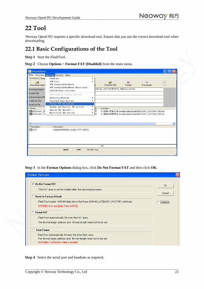
22.1 Basic Configurations of the Tool
Step 1 Start the FlashTool.
Step 2 Choose Options > Format FAT (Disabled) from the main menu.
Step 3 In the Format Options dialog box, click Do Not Format FAT and then click OK.
Step 4 Select the serial port and baudrate as required.

Neoway OpenCPU Development Guide
Copyright © Neoway Technology Co., Ltd 24
Perform the operations as shown in the following figures.
Don't change other default settings.
22.2 Downloading Master bin File
Step 1 On the Download tab, click Scatter/Config File and select the .cfg file in the bin folder.

Neoway OpenCPU Development Guide
Copyright © Neoway Technology Co., Ltd 25
Step 2 Click Download and restart the module to start the download.
When a dialog box with a green circle is displayed, the download is finished.
22.3 Downloading User .bin File
Step 1 On the Download tab, click Scatter/Config File and select the .cfg file in the build folder under
the client folder.

Neoway OpenCPU Development Guide
Copyright © Neoway Technology Co., Ltd 26
:
Clear the PRIMARY_MAUI check box.
Step 2 Click Download and restart the module to start the download.
When a dialog box with a green circle is displayed, the download is finished.
If the master files are modified, copy the two files (.sym and ROM file) of the master in the coreSW
folder of the client before compiling client codes.