neo® dmx-3901h-b4, and dmx- 3901h-c4 - imagine … · 2010 dts, inc. all other trademarks ......
TRANSCRIPT

Delivering the Moment
Installation and Operation Manual
Neo® DMX-3901H-B4, and DMX-3901H-C4HDTV Audio Demultiplexers
Edition B
175-000091-00

Publication Information © 2014 Imagine Communications Corp. Proprietary and Confidential.
Imagine Communications considers this document and its contents to be proprietary and confidential. Except for making a reasonable number of copies for your own internal use, you may not reproduce this publication, or any part thereof, in any form, by any method, for any purpose, or in any language other than English without the written consent of Imagine Communications. All others uses are illegal.
This publication is designed to assist in the use of the product as it exists on the date of publication of this manual, and may not reflect the product at the current time or an unknown time in the future. This publication does not in any way warrant description accuracy or guarantee the use for the product to which it refers. Imagine Communications reserves the right, without notice to make such changes in equipment, design, specifications, components, or documentation as progress may warrant to improve the performance of the product.
Trademarks 6800+™, ADC™, CCS Navigator™, Channel ONE™, ChannelView™, ClipSync™, Delay™, D Series™, D Series DSX™, Deliver the Moment™, Delivering the Moment™, FAME™, Farad™, G8™, G Scribe™, HView™, IconMaster™, IconLogo™, IconSta-tion™, IconKey™, InfoCaster™, InfoCaster Creator™, InfoCaster Manager™, InfoCaster Player™, InstantOnline™, Invenio®, Live Update™, mCAPTURE™, Magellan™, Magellan CCS Navigator™, Magellan Q SEE™, MultiService SDN™, NetPlus™, NetVX™, NewsForce™, Nexio® G8™, Nexio AMP® ChannelView™, Nexio® Channel ONE™, Nexio® ClipSync™, Nexio® Delay™, Nexio® Digital Turnaround Processor™, Nexio® Farad™, Nexio® G Scribe™, Nexio® IconKey™, Nexio® IconLogo™, Nexio® IconMaster™, Nexio® IconStation™, Nexio® InfoCaster™, Nexio® InfoCaster Creator™, Nexio® InfoCaster Manag-er™, Nexio® InfoCaster Player™, Nexio® InfoCaster Traffic™, Nexio® InstantOnline™, Nexio® mCAPTURE™, Nexio® News-Force™, Nexio® NXIQ™, Nexio® Playlist™, Nexio® Remote™, Nexio®RTX Net™, Nexio® TitleMotion™, Nexio® TitleOne™, Nexio® Velocity ESX™, Nexio® Velocity PRX™, Nexio® Velocity XNG™, Nexio® Volt™, OPTO+™, Panacea™, Platinum™, Playlist™, Predator II GRF™, Predator II GX™, Punctuate™, Remote™, RTX Net™, QuiC™, Q SEE™, SD STAR™, Selenio™, Selenio 6800+™, SelenioNext™, Selenio X50™, Selenio X85™, Selenio X100™, TitleMotion™, TitleOne™, Velocity ESX™, Velocity PRX™, Velocity XNG™, Versio™, Videotek® SD STAR™, X50™, and X85™ are trademarks of Imagine Communica-tions or its subsidiaries.
Altitude Express®, Connectus®, Enabling PersonalizedTV®, ICE® Broadcast System, ICE Illustrate®, ICE Q® algorithms, ICE-PAC®, Imagine ICE®, Inscriber®, Inscriber® Connectus®, Invenio®, NEO®, Nexio®, Nexio AMP®, PersonalizedTV®, Router-Works®, Videotek®, Videotek® ASI STAR®, Videotek® GEN STAR®, and Videotek® HD STAR® are registered trademarks of Imagine Communications or its subsidiaries.
Microsoft® and Windows® are registered trademarks of Microsoft Corporation. HD BNC is a trademark of Amphenol Corporation. Some products are manufactured under license from Dolby Laboratories. Dolby and the double D symbol are registered trademarks of Dolby Laboratories. DTS Neural audio products are manufactured under license from DTS Licensing Limited. DTS and the Symbol are registered trademarks & the DTS Logos are trademarks of DTS, Inc. © 2008 2010 DTS, Inc. All other trademarks and trade names are the property of their respective companies.
Contact Information Imagine Communications has office locations around the world. For locations and contact information see: http://www.imaginecommunications.com/contact us/
Support Contact Information For support contact information see:
Support Contacts: http://www.imaginecommunications.com/services/technical support/ eCustomer Portal: http://support.imaginecommunications.com
© 2014 Imagine Communications Corp. Proprietary and Confidential

Edition BSeptember 2005
DMX-3901H-B4 and DMX-3901H-C4HDTV Audio Demultiplexers
Installation and Operation Manual

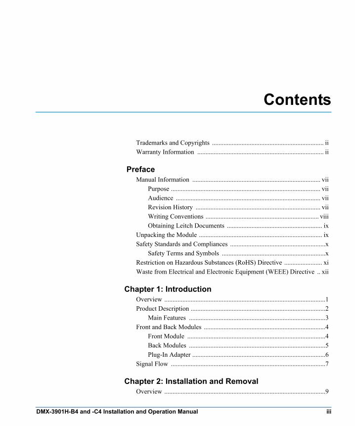
Contents
Trademarks and Copyrights .................................................................... iiWarranty Information ............................................................................. ii
PrefaceManual Information .............................................................................. vii
Purpose ........................................................................................... viiAudience ........................................................................................ viiRevision History ............................................................................ viiWriting Conventions ..................................................................... viiiObtaining Leitch Documents .......................................................... ix
Unpacking the Module ........................................................................... ixSafety Standards and Compliances ..........................................................x
Safety Terms and Symbols ...............................................................xRestriction on Hazardous Substances (RoHS) Directive ....................... xiWaste from Electrical and Electronic Equipment (WEEE) Directive .. xii
Chapter 1: IntroductionOverview ..................................................................................................1Product Description ..................................................................................2
Main Features ...................................................................................3Front and Back Modules ..........................................................................4
Front Module ....................................................................................4Back Modules ...................................................................................5Plug-In Adapter .................................................................................6
Signal Flow ..............................................................................................7
Chapter 2: Installation and RemovalOverview ..................................................................................................9
DMX-3901H-B4 and -C4 Installation and Operation Manual iii

Contents
Packing List ........................................................................................... 10Installing DMX-3901H-B4 and -C4 Modules ..................................... 10Removing DMX-3901H-B4 and -C4 Modules .................................... 10Setting Jumpers ..................................................................................... 11Upgrading DMX-3901H-B4 and -C4 Firmware .................................. 12
Upgrading the Firmware (Discovery Method) ............................... 12Upgrading the Firmware (Drag-and-Drop Method) ...................... 14
Correcting a Failed Upgrading Procedure ............................................. 16Setting the Module to Fail-Safe Loader Mode ............................... 16Upgrading the Firmware in Fail-Safe Mode .................................. 16Rebooting the Module .................................................................... 18
Chapter 3: OperationOverview ............................................................................................... 19Operation Notes ..................................................................................... 20Descriptions of Selected Parameter Values .......................................... 21
Audio Output Channel Status (Out1aStat to Out4b Stat) .............. 21Input Channel V-Bit Feedback (In01VbitFb to In16VbitFb) ........ 21Demux Group Control (Grp1Ctrl to Grp4Ctrl) .............................. 21Audio Group Sample Rate (G1SmplRate to G4SmplRate) ........... 22HD-SDI Input Presence Detection (SdiPrsnt) ................................ 22
Cross-Functional Parameter Changes ................................................... 23Channel Dithering .......................................................................... 25Channel Word Length .................................................................... 25
Navigating the Operator and All Lists .................................................. 26Operator and All List Parameters .......................................................... 27Setup Parameters ................................................................................... 34Alarms ................................................................................................... 35
Alarm Synchronization .................................................................. 35Identifying the Cause of an Alarm ................................................. 35Enabling or Disabling an Alarm Parameter ................................... 36Restoring Default Settings ............................................................. 36DARS Balanced/Unbalanced Input Selection (DMX-3901H-B4 only) ........................................ 37
NEOScope ............................................................................................. 38State Recovery Parameter Availability ................................................. 38LEDs and Indicators .............................................................................. 39General Information .............................................................................. 39
Card-Edge LED Locations ............................................................. 40
iv DMX-3901H-B4 and -C4 Installation and Operation Manual

Contents
LED descriptions ............................................................................41Module Indicator Descriptions .......................................................42
Chapter 4: SpecificationsOverview ................................................................................................43Inputs ......................................................................................................44
SDI Video Input ..............................................................................44DARS Input ....................................................................................44
Outputs ...................................................................................................45AES Balanced Audio (DMX-3901H-B4) .......................................45AES Unbalanced Audio (DMX-3901H-C4) ...................................45HD-SDI Reclocked Video ..............................................................46
Miscellaneous .........................................................................................47Power Consumption ........................................................................47Start-Up Time .................................................................................47Propagation Delay ...........................................................................47
Appendix A: Tree-View NavigationOverview ................................................................................................49Navigating the Tree View ......................................................................50Tree View Parameters ............................................................................51
Appendix B: Audio Bit ManipulationOverview ................................................................................................57Channel Status Bits ................................................................................58
Notes — Channel Status .................................................................61Validity and User Bits .....................................................................61Audio Sampling Frequency (kHz) ..................................................62Audio Sampling Word Length (bits) ..............................................62
IndexKeywords ...............................................................................................63
DMX-3901H-B4 and -C4 Installation and Operation Manual v

Contents
vi DMX-3901H-B4 and -C4 Installation and Operation Manual
Preface
Manual Information
PurposeThis manual details the features, installation, operation, maintenance, and specifications of the NEO™ DMX-3901H-B4 and -C4 HDTV Audio Demultiplexers.
AudienceThis manual is written for engineers, technicians and operators responsible for the installation, setup, maintenance, and operation of the NEO DMX-3901H-B4 and -C4 HDTV Audio Demultiplexers.
Revision History
Table P-1. Revision History of Manual
Edition Date Revision HistoryA November 2003 Initial Release
B September 2005 Revision of product codes and template updates
DMX-3901H-B4 and -C4 Installation and Operation Manual vii
Preface
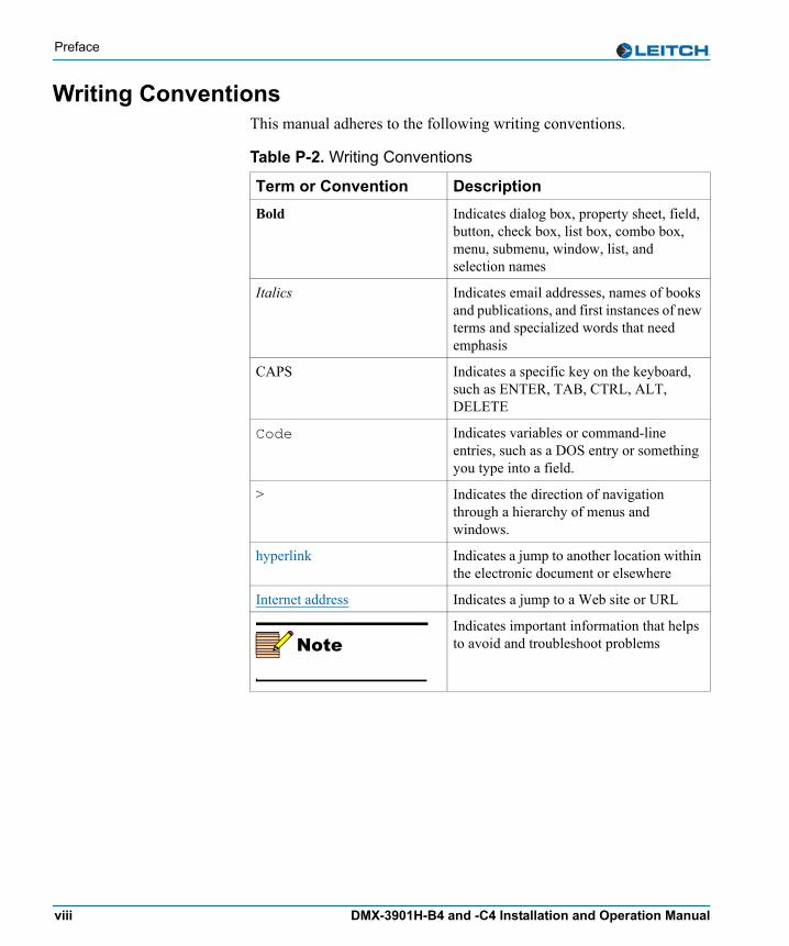
Writing ConventionsThis manual adheres to the following writing conventions.
Table P-2. Writing Conventions
Term or Convention DescriptionBold Indicates dialog box, property sheet, field,
button, check box, list box, combo box, menu, submenu, window, list, and selection names
Italics Indicates email addresses, names of books and publications, and first instances of new terms and specialized words that need emphasis
CAPS Indicates a specific key on the keyboard, such as ENTER, TAB, CTRL, ALT, DELETE
Code Indicates variables or command-line entries, such as a DOS entry or something you type into a field.
> Indicates the direction of navigation through a hierarchy of menus and windows.
hyperlink Indicates a jump to another location within the electronic document or elsewhere
Internet address Indicates a jump to a Web site or URL
NoteIndicates important information that helps to avoid and troubleshoot problems
viii DMX-3901H-B4 and -C4 Installation and Operation Manual

Preface
Obtaining Leitch DocumentsInstallation, navigation, configuration, and setup information is now included in the NEO FR-3901, FR-3903, and FR-3923 Mounting Frames Installation and Operation Manual. If your current NEO frame manual is Edition A, B, C, or D, you will need to download an updated version from the Leitch Web site to access this information.Leitch documents can be viewed or downloaded from the Leitch Web site at www.leitch.com (go to Support>Documentation). Alternatively, contact your Leitch customer service representative to request a document.
Unpacking the ModuleBefore you install and configure NEO modules, follow these steps:1. Check the equipment for any visible damage that may have
occurred during transit.2. Confirm that you have received all items listed on the packing list.3. Remove the anti-static shipping pouch, if present, and all other
packaging material.4. Retain the original packaging materials for possible reuse.5. Contact your Leitch sales representative if parts are missing or
damaged.
Keep at least one set of original packaging in the event that a product needs to be returned for service. If the original package is not available, you can purchase replacement packaging from Leitch Technology. Otherwise, you can supply your own packaging as long as it meets the following criteria:• The packaging must be able to withstand the product’s weight.• The product must be held rigid within the packaging.• There must be at least two inches (five centimeters) of space
between the product and the container.• The corners of the product must be protected.
If the product is still within the warranty period, Leitch Technology will return it to you by prepaid shipment after servicing.
DMX-3901H-B4 and -C4 Installation and Operation Manual ix

Preface
Safety Standards and CompliancesSee the NEO Safety Instructions and Standards Manual to find the safety standards and compliances for this NEO series product. A safety manual is shipped with every FR-3901, FR-3903, and FR-3923 Mounting Frames Installation and Operation Manual and can be downloaded from the Leitch Web site at www.leitch.com. Alternatively, contact your Leitch customer service representative for a copy of this safety manual.
Safety Terms and SymbolsThis manual uses the following safety terms and symbols. See your NEO Safety Instructions and Precautions Guide for more information.
Table P-3. Safety Terms and Symbols Used in Manual
WARNING: Statements identifying conditions or practices that can result in personal injury or loss of life: High voltage is present. Uninsulated dangerous voltage within the product’s enclosure may be sufficient to constitute a risk of electric shock to persons.
CAUTION:Statements identifying conditions or practices that can result in damage to the equipment or other property: Important operating and maintenance (servicing) instructions in the literature accompanying the product.
x DMX-3901H-B4 and -C4 Installation and Operation Manual

Preface
Restriction on Hazardous Substances (RoHS) Directive
Directive 2002/95/EC—commonly known as the European Union (EU) Restriction on Hazardous Substances (RoHS)—sets limits on the use of certain substances found in electrical and electronic equipment. The intent of this legislation is to reduce the amount of hazardous chemicals that may leach out of landfill sites or otherwise contaminate the environment during end-of-life recycling. The Directive takes effect on July 1, 2006, and it refers to the following hazardous substances: • Lead (Pb)• Mercury (Hg)• Cadmium (Cd)• Hexavalent Chromium (Cr-V1)• Polybrominated Biphenyls (PBB)• Polybrominated Diphenyl Ethers (PBDE)In accordance with this EU Directive, all Leitch Technology products sold in the European Union will be fully RoHS-compliant and “lead-free.” (See the Leitch Web site, www.leitch.com, for more information on dates and deadlines for compliance.) Spare parts supplied for the repair and upgrade of equipment sold before July 1, 2006 are exempt from the legislation. Leitch equipment that complies with the EU directive will be marked with a RoHS-compliant symbol, as shown in Figure 1.
Figure 1. RoHS Compliance Symbol
DMX-3901H-B4 and -C4 Installation and Operation Manual xi
Preface
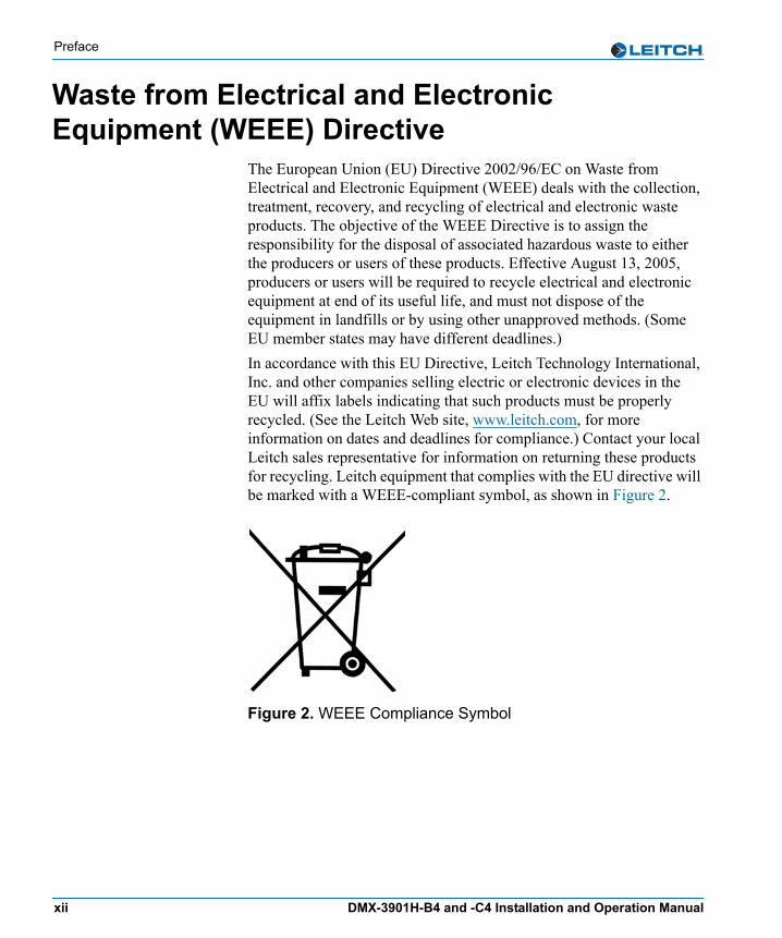
Waste from Electrical and Electronic Equipment (WEEE) Directive
The European Union (EU) Directive 2002/96/EC on Waste from Electrical and Electronic Equipment (WEEE) deals with the collection, treatment, recovery, and recycling of electrical and electronic waste products. The objective of the WEEE Directive is to assign the responsibility for the disposal of associated hazardous waste to either the producers or users of these products. Effective August 13, 2005, producers or users will be required to recycle electrical and electronic equipment at end of its useful life, and must not dispose of the equipment in landfills or by using other unapproved methods. (Some EU member states may have different deadlines.)In accordance with this EU Directive, Leitch Technology International, Inc. and other companies selling electric or electronic devices in the EU will affix labels indicating that such products must be properly recycled. (See the Leitch Web site, www.leitch.com, for more information on dates and deadlines for compliance.) Contact your local Leitch sales representative for information on returning these products for recycling. Leitch equipment that complies with the EU directive will be marked with a WEEE-compliant symbol, as shown in Figure 2.
Figure 2. WEEE Compliance Symbol
xii DMX-3901H-B4 and -C4 Installation and Operation Manual

Chapter 1
Introduction
OverviewThe DMX-3901H-B4 and -C4 modules are HDTV audio demultiplexers designed for NEO 1RU and 3RU rack-mounted frames.This chapter covers the following topics:• “Product Description” on page 2• “Front and Back Modules” on page 4• “Signal Flow” on page 7
See the FR-3901, FR-3903, and FR-3923 Installation and Operation Manual for information about NEO frames. The frame manual includes information about these items: • General information about module unpacking, installation,
removal, navigation, configuration, and setup• Card-edge screen savers• State recovery parameters• Fan modules• Resource modules• Alarm interconnect modules• Power supplies• Servicing instructions
NoteInstallation, navigation, configuration, and setup information is now included in the NEO FR-3901, FR-3903, and FR-3923 Mounting Frames Installation and Operation Manual. If your current NEO frame manual is Edition A, B, C, or D, you will need to download an updated version from the Leitch Web site (www.leitch.com) to access this information.
DMX-3901H-B4 and -C4 Installation and Operation Manual 1

Chapter 1: Introduction
Product DescriptionThe DMX-3901H HDTV Audio Demultiplexer is a processing module that has the capability to de-embed eight channels of audio from HD-SDI video sources and provide AES audio out in both balanced (DMX-3901H-B4) and unbalanced (DMX-3901H-C4) forms. In addition, an audio processing amplifier enables control over the audio.The module provides a high definition video serial digital input, four AES digital audio outputs, one active reclocked HD-SDI output, and a DARS reference input. Like other NEO products, each DMX-3901H module can be operated by card-edge controls, local and remote control panels, and GUI-based control software applications, such as CCS Pilot™ or Navigator™.
2 DMX-3901H-B4 and -C4 Installation and Operation Manual

Chapter 1: Introduction
Main FeaturesThese are the main features of the DMX-3901H-B4 and -C4 modules:• Inputs:
• SMPTE 292M HD-SDI video• DARS AES input
• Outputs: • 1 reclocked serial digital SMPTE 292M• 4 AES digital audio (SMPTE 276M for C4 version)
• Auto-detect or user-forced input video standard• 16-bit, 20-bit or 24-bit audio processing• Digital equalization (supports Belden 8281 and newer, thin coax
cables such as Alcate® SD02)• Audio processing amplifier with controls for delay, gain, invert and
channel multiplexing and averaging• Audio delay is provided to compensate for processing delay in the
video path• NEOscope video signal monitoring at card edge• Capability for card-edge control panel and remote GUI application
control (3901RES-E resource module is required for Ethernet control)
• Audio test tone generator• CCS capability
DMX-3901H-B4 and -C4 Installation and Operation Manual 3
Chapter 1: Introduction
Front and Back Modules
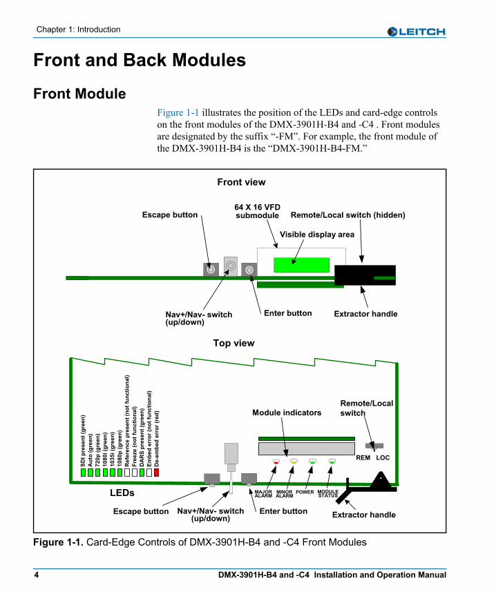
Front ModuleFigure 1-1 illustrates the position of the LEDs and card-edge controls on the front modules of the DMX-3901H-B4 and -C4 . Front modules are designated by the suffix “-FM”. For example, the front module of the DMX-3901H-B4 is the “DMX-3901H-B4-FM.”
Figure 1-1. Card-Edge Controls of DMX-3901H-B4 and -C4 Front Modules
Top view
Nav+/Nav- switch(up/down) Extractor handleEscape button
ModuleStatus
MinorAlarm
MajorAlarm Power
SW1
Rem
ote
Loca
l
Nav +Nav -
EnterEsc
MAJORALARM
MINORALARM
POWER MODULESTATUS
Module indicatorsRemote/Localswitch
LEDs
Enter button
REM LOC
SDI p
rese
nt (g
reen
)A
uto
(gre
en)
720p
(gre
en)
1080
i (gr
een)
1035
i (gr
een)
1080
p (g
reen
)R
efer
ence
pre
sent
(not
func
tiona
l)Fr
eeze
(not
func
tiona
l)D
AR
S pr
esen
t (gr
een)
Embe
d er
ror (
not f
unct
iona
l)D
e-em
bed
erro
r (re
d)
Remote/Local switch (hidden)
Front view
64 X 16 VFDsubmodule
Visible display area
Nav+/Nav- switch(up/down)
Escape button
Enter button Extractor handle
4 DMX-3901H-B4 and -C4 Installation and Operation Manual
Chapter 1: Introduction
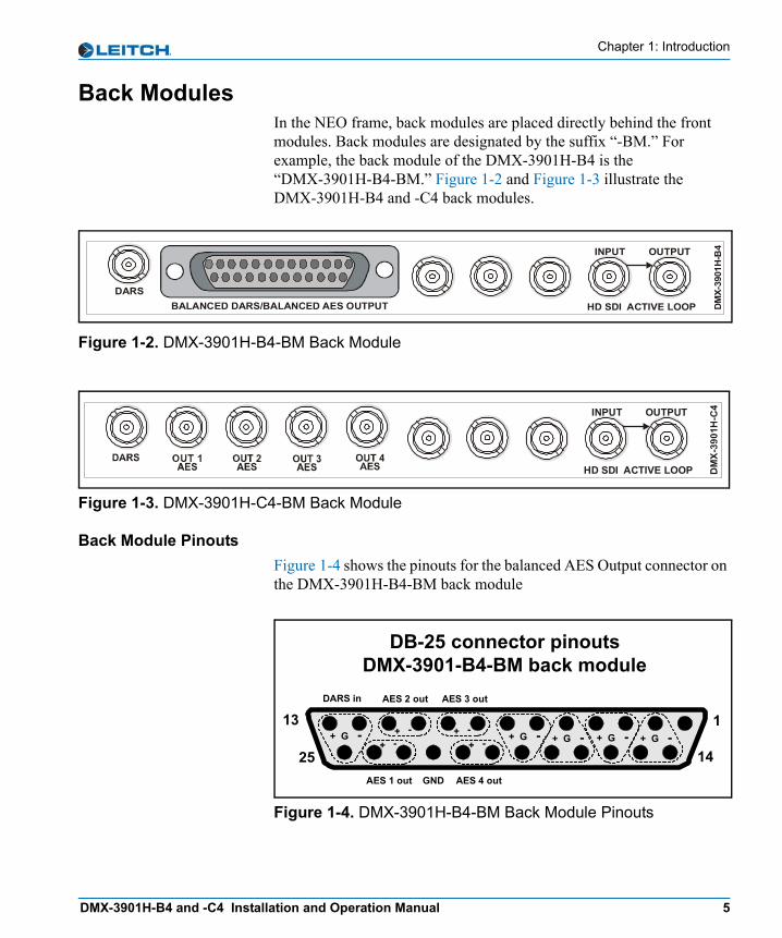
Back ModulesIn the NEO frame, back modules are placed directly behind the front modules. Back modules are designated by the suffix “-BM.” For example, the back module of the DMX-3901H-B4 is the “DMX-3901H-B4-BM.” Figure 1-2 and Figure 1-3 illustrate the DMX-3901H-B4 and -C4 back modules.
Figure 1-2. DMX-3901H-B4-BM Back Module
Figure 1-3. DMX-3901H-C4-BM Back Module
Back Module PinoutsFigure 1-4 shows the pinouts for the balanced AES Output connector on the DMX-3901H-B4-BM back module
Figure 1-4. DMX-3901H-B4-BM Back Module Pinouts
DARSBALANCED DARS/BALANCED AES OUTPUT HD SDI ACTIVE LOOP D
MX-
3901
H-B
4OUTPUT INPUT
HD SDI ACTIVE LOOP
OUTPUT INPUT
DB-25 connector pinoutsDMX-3901-B4-BM back module
113
1425AES 4 out
AES 3 outAES 2 out
AES 1 out GND
+ G - - +- +
- +- +
+ G - + G - + G - + G -
DARS in
DMX-3901H-B4 and -C4 Installation and Operation Manual 5
Chapter 1: Introduction
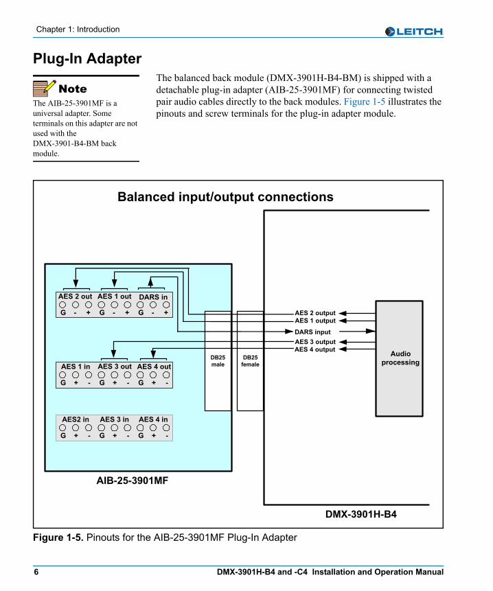
Plug-In AdapterThe balanced back module (DMX-3901H-B4-BM) is shipped with a detachable plug-in adapter (AIB-25-3901MF) for connecting twisted pair audio cables directly to the back modules. Figure 1-5 illustrates the pinouts and screw terminals for the plug-in adapter module.
Figure 1-5. Pinouts for the AIB-25-3901MF Plug-In Adapter
NoteThe AIB-25-3901MF is a universal adapter. Some terminals on this adapter are not used with the DMX-3901-B4-BM back module.
DMX-3901H-B4
DB25male
DB25female
AIB-25-3901MF
Balanced input/output connections
Audioprocessing
G - +
AES 2 out
G - +
AES 1 out
G - +
G + -
AES2 in
G + -
AES 3 in
G + -
AES 4 in
DARS in
AES 3 outputAES 4 output
G + -
AES 1 in
G + -
AES 3 out
G + -
AES 4 out
AES 2 outputAES 1 output
DARS input
6 DMX-3901H-B4 and -C4 Installation and Operation Manual
Chapter 1: Introduction
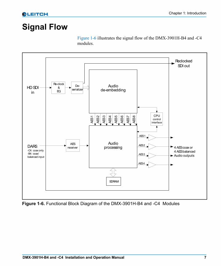
Signal FlowFigure 1-6 illustrates the signal flow of the DMX-3901H-B4 and -C4 modules.
Figure 1-6. Functional Block Diagram of the DMX-3901H-B4 and -C4 Modules
4 AES coax or4 AES balancedAudio outputs
HD SDIin
Re-clock&
EQ
AES 1
AES 2Audioprocessing
Audiode-embedding
AES 3
AES 4
DARS-C4: coax only-B4: coax/balanced input
AES
1
AES
2
AES
3
AES
4
AES
5
AES
6
AES
7
AES
8
De-serializer
AESreceiver
SDRAM
CPUcontrol
interface
ReclockedSDI out
DMX-3901H-B4 and -C4 Installation and Operation Manual 7

Chapter 1: Introduction
8 DMX-3901H-B4 and -C4 Installation and Operation Manual
Chapter 2
Installation and Removal
OverviewInstallation, navigation, configuration, and setup information is now included in the NEO FR-3901, FR-3903, and FR-3923 Mounting Frames Installation and Operation Manual. If your current NEO frame manual is Edition A, B, C, or D, you will need to download an updated version from the Leitch Web site (www.leitch.com) to access this information.In this chapter, you can find information on the following topics:• “Packing List” on page 10• “Installing DMX-3901H-B4 and -C4 Modules” on page 10• “Removing DMX-3901H-B4 and -C4 Modules” on page 10• “Setting Jumpers” on page 11• “Upgrading DMX-3901H-B4 and -C4 Firmware” on page 12• “Correcting a Failed Upgrading Procedure” on page 16
CautionBefore installation, please read the NEO Safety Instructions and Precautions Manual. This document contains important information about the safe installation and operation of NEO products.
DMX-3901H-B4 and -C4 Installation and Operation Manual 9
Chapter 2: Installation and Removal
Packing ListThe NEO DMX-3901H-B4/C4 module packages include these items:• One DMX-3901H-B4 or -C4-FM front module• One DMX-3901H-B4 or -C4-BM back module• One DMX-3901H-B4/C4 HDTV Audio Demultiplexers Installation
and Operation Manual• One AIB-25-3901MF plug-in adapter module
(DMX-3901H-B4 module only)
Installing DMX-3901H-B4 and -C4 ModulesThis module requires no specialized installation procedures. For general information about installing NEO modules, see your NEO FR-3901, FR-3903, and FR-3923 Mounting Frames Installation and Operation Manual.
Removing DMX-3901H-B4 and -C4 ModulesThis module requires no specialized removal procedures. For general information about removing NEO modules, see your NEO FR-3901, FR-3903, and FR-3923 Mounting Frames Installation and Operation Manual.
10 DMX-3901H-B4 and -C4 Installation and Operation Manual

Chapter 2: Installation and Removal
Setting JumpersTable 2-1 illustrates the jumper settings to select the type of DARS input for the DMX-3901H-B4 module..
Table 2-1. Jumper Selection
Jumper Name
DARS Input SelectionDMX-3901H-B4 Jumper Setting
C Balanced Pins 1-2
Unbalanced Pins 2-3
D Balanced Pins 1-2
Unbalanced Pins 2-3
DMX-3901H-B4 and -C4 Installation and Operation Manual 11

Chapter 2: Installation and Removal
Upgrading DMX-3901H-B4 and -C4 FirmwareFirmware upgrading is a routine procedure that you must perform to install newer versions of software on the DMX-3901H-B4 and -C4 modules. Pilot, Co-Pilot, or Navigator software applications are required for this procedure. You can use either the Discovery or the drag-and-drop method. When performing the upgrading procedure, check the appropriate readme file to confirm which files are needed. Use care to ensure that you upload the correct files to the intended module.If for some reason the upgrade fails, the module may not respond to controls and will appear to be non-functional. In that event, follow the procedures described in “Correcting a Failed Upgrading Procedure” on page 16.
Upgrading the Firmware (Discovery Method)Follow these steps to upgrade the firmware using the Discovery method:1. Download the most recent appropriate upgrade package from the
Leitch Web site or from your CD-ROM, and then unzip the upgrade package.
2. If the affected module has not been discovered, perform the Discovery operation, as described in your CCS software application manual or online help.
3. Double-click the device icon.The Configuration... window opens. On the Software Upgrade tab, the /slotx/boot (where x is the slot number) directory appears in the Select the device directory to transfer to: field.
4. Click Add, and in the Add Upgrade Files box, browse and select the boot folder in the module’s upgrade; click OK.The Add Upgrade Files box appears.
5. Select the file and then click OK.6. Click Perform Transfer and then click Yes.
This may take several minutes.7. Wait for the message File transfer to device succeeded in the
status bar.
12 DMX-3901H-B4 and -C4 Installation and Operation Manual
Chapter 2: Installation and Removal
If an fl0 folder is included in the .zip file, the files within that folder must now be uploaded as shown below. (In some cases, the readme file may indicate other separate files must be uploaded instead.)Follow these steps to upload the remaining files:1. On the Software Upgrade tab, select the /slotx/fl0 (where x is the
slot number) directory in the Select the device directory to transfer to: field.
2. Click Add, and in the Add Upgrade Files box, browse and select the fl0 folder in the module’s upgrade package.
3. Click OK.4. Select the files shown in the Add Upgrade Files box, and then
click OK.5. Select and delete unwanted files (for example: vxWorks.lzs) in the
Add upgrade files for transfer to device: field by clicking Remove.
6. Click Perform Transfer and then click Yes.7. Wait for the message File transfer to device succeeded.
This may take a moment.8. Click Reboot Device and then click Yes.9. Wait 30 seconds, and then close the Configuration... box.
The module name appears at the card edge.
CautionYou must delete unwanted files in the Add upgrade files for transfer to device: field before transferring the files. Otherwise, the upgrading procedure will fail.
DMX-3901H-B4 and -C4 Installation and Operation Manual 13
Chapter 2: Installation and Removal
Upgrading the Firmware (Drag-and-Drop Method)Follow these steps to upgrade the firmware using the drag-and-drop method:1. Download the appropriate most recent upgrade package from the
Leitch Web site or from your CD-ROM, and then unzip the upgrade package.
2. If the affected module has not been discovered by your CCS software application, enter the Build mode, and then drag or copy and paste the module’s device icon from the catalog folder into the Network or Discovery folder.
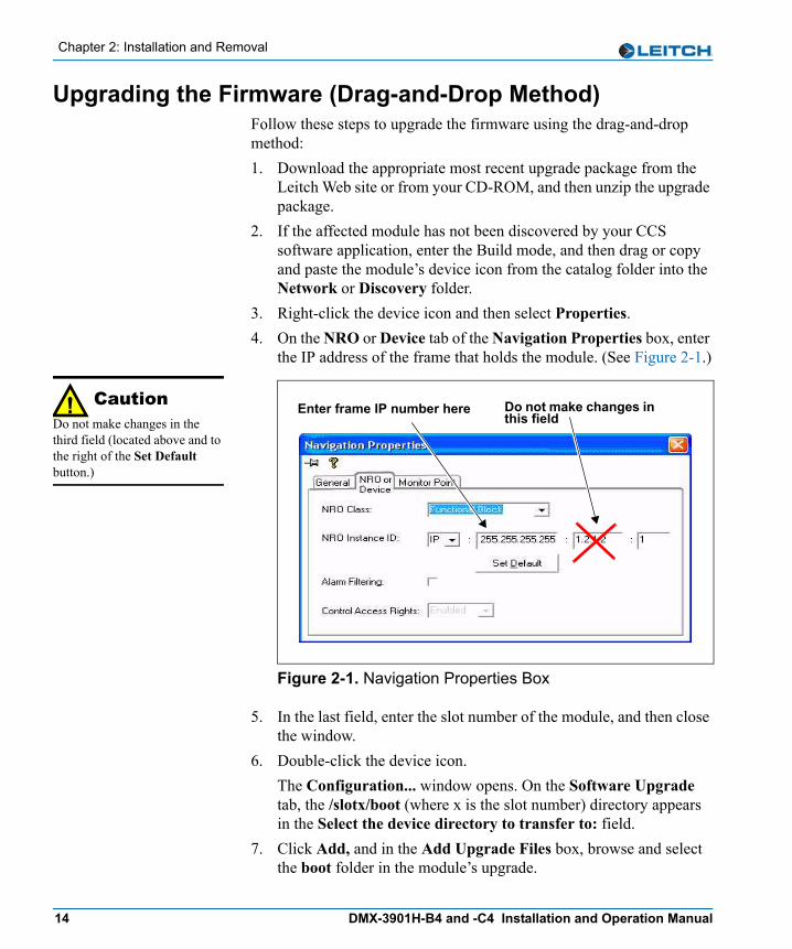
3. Right-click the device icon and then select Properties. 4. On the NRO or Device tab of the Navigation Properties box, enter
the IP address of the frame that holds the module. (See Figure 2-1.)
Figure 2-1. Navigation Properties Box
5. In the last field, enter the slot number of the module, and then close the window.
6. Double-click the device icon.The Configuration... window opens. On the Software Upgrade tab, the /slotx/boot (where x is the slot number) directory appears in the Select the device directory to transfer to: field.
7. Click Add, and in the Add Upgrade Files box, browse and select the boot folder in the module’s upgrade.
CautionDo not make changes in the third field (located above and to the right of the Set Default button.)
Do not make changes in this field
Enter frame IP number here
14 DMX-3901H-B4 and -C4 Installation and Operation Manual
Chapter 2: Installation and Removal
8. Click OK.The Add Upgrade Files box appears.
9. Select the file and then click OK.10. Click Perform Transfer and then click Yes.
This may take several minutes.11. Wait for the message File transfer to device succeeded in the
status bar.If an fl0 folder is included in the .zip file, the files within that folder must now be uploaded as shown below. (In some cases, the readme file may indicate other separate files must be uploaded instead.)Follow these steps to upload the remaining files:1. On the Software Upgrade tab, select the /slotx/fl0 (where x is the
slot number) directory in the Select the device directory to transfer to: field.
2. Click Add, and in the Add Upgrade Files box, browse and select the fl0 folder in the module’s upgrade package.
3. Click OK.4. Select the files shown in the Add Upgrade Files box, and then
click OK.5. Select and delete unwanted files (for example: vxWorks.lzs) in the
Add upgrade files for transfer to device: field by clicking Remove.
6. Click Perform Transfer and then click Yes.7. Wait for the message File transfer to device succeeded.
This may take a moment.8. Click Reboot Device and then click Yes.9. Wait 30 seconds and then close the Configuration... box.
The module name appears at the card edge.
CautionYou must delete unwanted files in the Add upgrade files for transfer to device: field before transferring the files. Otherwise, the upgrading procedure will fail.
DMX-3901H-B4 and -C4 Installation and Operation Manual 15
Chapter 2: Installation and Removal
Correcting a Failed Upgrading ProcedureFirmware upgrades may fail in the event of network interruptions, power failures, or if too much data is uploaded to the NEO module. Often, uploads of too much data can occur for one of the following reasons:• The boot file (typically vxWorks.lzs) was accidentally uploaded
during the fl0 procedure, instead of the boot procedure.• Files were sent to the wrong NEO module.• The particular hardware version of the module requires only some
(but not all) of the available fl0 files.• The upgrade .zip file was mistakenly sent to the module.All of these problems can be corrected by re-installing the firmware while in a fail-safe mode, as described in the following pages. When you are performing this procedure, check the appropriate readme file to confirm which files are needed. Use care to ensure that you upload the correct files to the intended module.
Setting the Module to Fail-Safe Loader ModeFollow these steps to set a NEO module to the fail-safe loader mode:1. Remove the affected module from the NEO frame.2. Press the Nav switch down while simultaneously pressing both the
Escape and Enter buttons.3. While still pressing the buttons and the navigation switch, reinsert
the module into the frame and hold for approximately three seconds until the display on the module reads Offline-H (or Offline-L) Upload Required.
Upgrading the Firmware in Fail-Safe ModeFollow these steps to upgrade the firmware in the fail-safe mode:1. Download the most recent appropriate upgrade package from the
Leitch Web site or from your CD-ROM, and then unzip the upgrade package.
NoteTo successfully upgrade the firmware, you must follow these steps in the exact sequence described.
16 DMX-3901H-B4 and -C4 Installation and Operation Manual

Chapter 2: Installation and Removal
2. If the affected module has not been discovered by your CCS software application, enter the Build mode, and then drag or copy and paste the module’s device icon from the catalog folder into the Network or Discovery folder.
3. Right-click the device icon and then select Properties. 4. On the NRO or Device tab of the Navigation Properties box, enter
the IP address of the frame that holds the module. (See Figure 2-2.)
Figure 2-2. Navigation Properties Box
5. In the last field, enter the slot number of the module, and then close the window.
6. Double-click the device icon. The Configuration... box opens. On the Software Upgrade tab, the /slotx/boot (where x is the slot number) directory appears in the Select the device directory to transfer to: field.
7. Click Add, and in the Add Upgrade Files box, browse and select the boot folder in the module’s upgrade.
8. Click OK.9. Select the file and then click OK.10. Click Perform Transfer and then click Yes.
This may take several minutes.11. Wait for the message File transfer to device succeeded in the
status bar.
CautionDo not make changes in the third field (located above and to the right of the Set Default button.)
Do not make changes in this field
Enter frame IP number here
DMX-3901H-B4 and -C4 Installation and Operation Manual 17
Chapter 2: Installation and Removal
Rebooting the ModuleFollow these steps to reboot the affected NEO module:1. Click Reboot Device, and then click Yes.
After the module has rebooted, a message box advises you to wait until the device has rebooted.
2. Wait 30 seconds.3. On the Software Upgrade tab, select the /slotx/fl0 (where x is the
slot number) directory in the Select the device directory to transfer to: field.
4. Click Add, and then browse and select the fl0 folder in the module’s upgrade package.
5. Click OK.6. Select the files shown in the Add Upgrade Files box, and then
click OK.7. Select and delete unwanted files (for example: vxWorks.lzs) in the
Add upgrade files for transfer to device: field by clicking Remove.
8. Click Perform Transfer and then click Yes.9. Wait for the message File transfer to device succeeded.
This may take a moment.10. Click Reboot Device and then click Yes.11. Wait 30 seconds, and then close the Configuration... box.
The module name appears at the card edge.
NoteSome NEO modules will reboot automatically. In these cases, the Reboot button will be grayed out. During this time, the module’s card-edge display will show the word Rebooting before the name of the module appears. These modules do not require the fl0 file.
CautionYou must delete unwanted files in the Add upgrade files for transfer to device: field before transferring the files. Otherwise, the upgrading procedure will fail.
18 DMX-3901H-B4 and -C4 Installation and Operation Manual
Chapter 3
Operation
OverviewInstallation, navigation, configuration, and setup information is now included in the NEO FR-3901, FR-3903, and FR-3923 Mounting Frames Installation and Operation Manual. If your current NEO frame manual is Edition A, B, C, or D, you will need to download an updated version from the Leitch Web site (www.leitch.com) to access this information.This chapter describes how to operate the DMX-3901H-B4 and -C4 module using card-edge controls. The following topics are found in this chapter:• “Operation Notes” on page 20• “Descriptions of Selected Parameter Values” on page 21• “Cross-Functional Parameter Changes” on page 23• “Navigating the Operator and All Lists” on page 26• “Operator and All List Parameters” on page 27• “Setup Parameters” on page 34• “Alarms” on page 35• “NEOScope” on page 38• “State Recovery Parameter Availability” on page 38• “LEDs and Indicators” on page 39
DMX-3901H-B4 and -C4 Installation and Operation Manual 19

Chapter 3: Operation
Operation NotesWhen using the DMX-3901H-B4 or the DMX-3901H-C4 modules, observe the following operation notes:• If you change parameters within 16 seconds after the
DMX-3901H banner first appears on the VFD, your changes will not be saved. Parameter changes that you make after this 16-second delay will be saved and restored if the module loses power and must be restarted.
• Although the effect of a parameter change may appear to be immediate, the module requires 20 seconds to save the latest change. If another change is made during these 20 seconds, the first parameter change and the second parameter change will not be saved until 20 seconds after the second parameter change. There is no limit to the number of changes that can be made within 20 seconds of each other. However, none of these changes will be saved until 20 seconds after the last parameter change.
• When you set the FctryRcl (factory recall) parameter to Yes, the module takes several seconds to reset all of the parameters. (Setup parameters are not affected by this factory recall mode.) The lists of “Operator and All List Parameters” on page 27 and “Tree View Parameters” on page 51 indicate parameter default settings that are restored when FctryRcl is set to Yes.
• Changes in some parameters will cause additional changes in other parameters, or lock them out entirely. See page 23 for more information on these cross-functional parameter changes.
• Leitch recommends that you terminate any unused coaxial output connectors with a 75Ω terminator.
CautionFailure to observe these Operation Notes will result in accidental changes to the module’s parameter settings.
20 DMX-3901H-B4 and -C4 Installation and Operation Manual

Chapter 3: Operation
Descriptions of Selected Parameter Values
Audio Output Channel Status (Out1aStat to Out4b Stat)Table 3-1 describes the audio output channel status read-only values.
Input Channel V-Bit Feedback (In01VbitFb to In16VbitFb)Table 3-2 describes the input channel v-bit feedback read-only values.
Demux Group Control (Grp1Ctrl to Grp4Ctrl)Table 3-3 describes the demux group control options.
Table 3-1. Audio Output Channel Status
Item DescriptionPeak The audio output level has reached a level of 0 dBFS.
Silence The audio output level is lower than -96 dBFS.
Normal The audio output level is between the Peak and Silence threshold levels.
Table 3-2. Input Channel V-Bit Feedback
Item DescriptionOn The V-Bit of the incoming audio channel is set to 1. This can
indicate that the audio sample word data is invalid (or possibly compressed audio) and is not suitable for D/A conversion.
Off The V-Bit of the incoming audio channel is set to 0. This can indicate that the audio sample word data is valid and is suitable for D/A conversion.
Table 3-3. Demux Group Control
Item DescriptionRepeat Upon detection of a de-embedding error, the de-embedder will
repeat the last good AES sample.
Mute Upon detection of a de-embedding error, the de-embedder will mute the current outgoing AES sample.
DMX-3901H-B4 and -C4 Installation and Operation Manual 21
Chapter 3: Operation
Audio Group Sample Rate (G1SmplRate to G4SmplRate)The output audio rate of the DMX-3901H is always 48 kHz. De-embedding audio that was embedded at a rate other than 48 kHz is not supported. The DMX-3901H will report the embedded audio group sampling rates, as indicated by the "Rate" word of the audio control packet, in the G1SmplRate, G2SmplRate, G3SmplRate and G4SmplRate parameters.
HD-SDI Input Presence Detection (SdiPrsnt)Table 3-4 describes the meaning of the read-only values in the SdiPrsnt parameter..
Table 3-4. HD-SDI Input Signal
SdiPrsnt Value Description
Yes One of the following conditions has taken place:• The SdiStdSet parameter is set to Auto and the SdiStdFb
parameter is recognized as being one of the supported video standards.
• The SdiStdSet parameter matches the detected standard as reported in the SdiStdFb parameter.
No One of the following conditions has taken place:• The HD-SDI signal is physically not connected to the
module. In this situation, the SdiStdFb parameter will report Unknown.
• The SdiStdSet parameter does not match the SdiStdFb parameter. As a result, the module indicates that the user-selected video standard is not present.
22 DMX-3901H-B4 and -C4 Installation and Operation Manual
Chapter 3: Operation
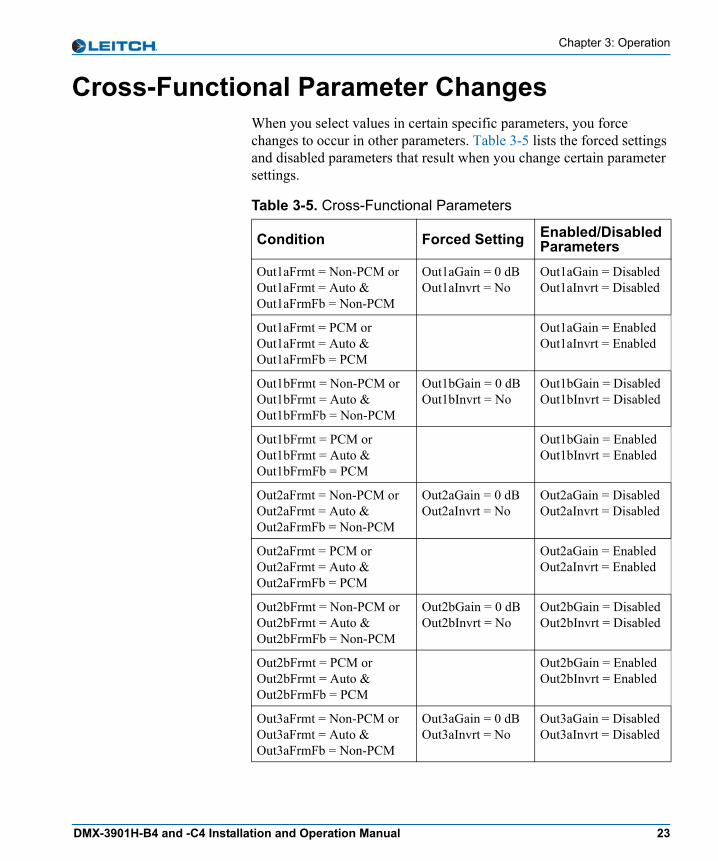
Cross-Functional Parameter ChangesWhen you select values in certain specific parameters, you force changes to occur in other parameters. Table 3-5 lists the forced settings and disabled parameters that result when you change certain parameter settings.
Table 3-5. Cross-Functional Parameters
Condition Forced Setting Enabled/Disabled Parameters
Out1aFrmt = Non-PCM or Out1aFrmt = Auto & Out1aFrmFb = Non-PCM
Out1aGain = 0 dBOut1aInvrt = No
Out1aGain = DisabledOut1aInvrt = Disabled
Out1aFrmt = PCM or Out1aFrmt = Auto & Out1aFrmFb = PCM
Out1aGain = EnabledOut1aInvrt = Enabled
Out1bFrmt = Non-PCM or Out1bFrmt = Auto & Out1bFrmFb = Non-PCM
Out1bGain = 0 dBOut1bInvrt = No
Out1bGain = DisabledOut1bInvrt = Disabled
Out1bFrmt = PCM or Out1bFrmt = Auto & Out1bFrmFb = PCM
Out1bGain = EnabledOut1bInvrt = Enabled
Out2aFrmt = Non-PCM or Out2aFrmt = Auto & Out2aFrmFb = Non-PCM
Out2aGain = 0 dBOut2aInvrt = No
Out2aGain = DisabledOut2aInvrt = Disabled
Out2aFrmt = PCM or Out2aFrmt = Auto & Out2aFrmFb = PCM
Out2aGain = EnabledOut2aInvrt = Enabled
Out2bFrmt = Non-PCM or Out2bFrmt = Auto & Out2bFrmFb = Non-PCM
Out2bGain = 0 dBOut2bInvrt = No
Out2bGain = DisabledOut2bInvrt = Disabled
Out2bFrmt = PCM or Out2bFrmt = Auto & Out2bFrmFb = PCM
Out2bGain = EnabledOut2bInvrt = Enabled
Out3aFrmt = Non-PCM or Out3aFrmt = Auto & Out3aFrmFb = Non-PCM
Out3aGain = 0 dBOut3aInvrt = No
Out3aGain = DisabledOut3aInvrt = Disabled
DMX-3901H-B4 and -C4 Installation and Operation Manual 23
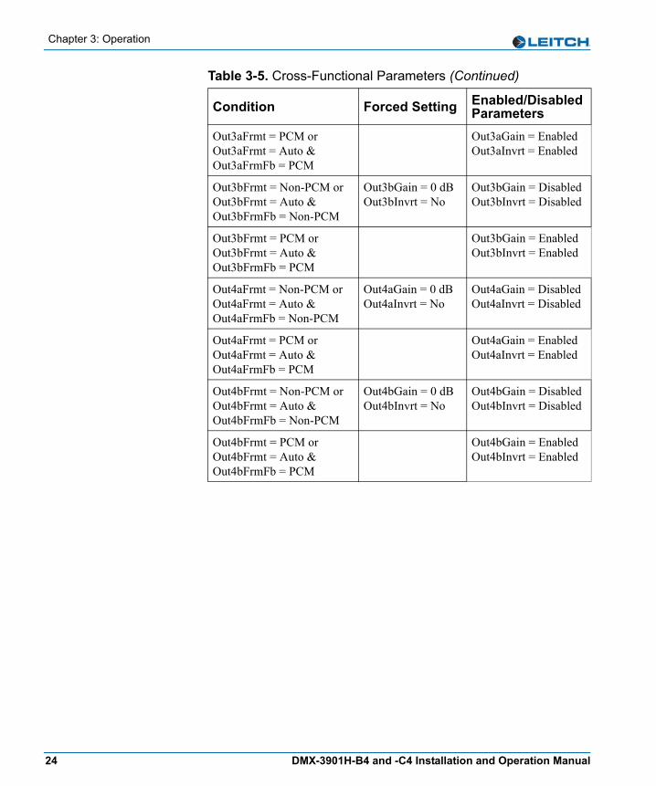
Chapter 3: Operation
Out3aFrmt = PCM or Out3aFrmt = Auto & Out3aFrmFb = PCM
Out3aGain = EnabledOut3aInvrt = Enabled
Out3bFrmt = Non-PCM or Out3bFrmt = Auto & Out3bFrmFb = Non-PCM
Out3bGain = 0 dBOut3bInvrt = No
Out3bGain = DisabledOut3bInvrt = Disabled
Out3bFrmt = PCM or Out3bFrmt = Auto & Out3bFrmFb = PCM
Out3bGain = EnabledOut3bInvrt = Enabled
Out4aFrmt = Non-PCM or Out4aFrmt = Auto & Out4aFrmFb = Non-PCM
Out4aGain = 0 dBOut4aInvrt = No
Out4aGain = DisabledOut4aInvrt = Disabled
Out4aFrmt = PCM or Out4aFrmt = Auto & Out4aFrmFb = PCM
Out4aGain = EnabledOut4aInvrt = Enabled
Out4bFrmt = Non-PCM or Out4bFrmt = Auto & Out4bFrmFb = Non-PCM
Out4bGain = 0 dBOut4bInvrt = No
Out4bGain = DisabledOut4bInvrt = Disabled
Out4bFrmt = PCM or Out4bFrmt = Auto & Out4bFrmFb = PCM
Out4bGain = EnabledOut4bInvrt = Enabled
Table 3-5. Cross-Functional Parameters (Continued)
Condition Forced Setting Enabled/Disabled Parameters
24 DMX-3901H-B4 and -C4 Installation and Operation Manual

Chapter 3: Operation
Channel DitheringWhen any audio output channel is of a Non-PCM format (OutxxFrmt=Non-PCM or OutxxFrmt=Auto and OutxxFrmFb=Non-PCM), the Dithering feature for that channel pair is disabled, even if only one channel of the pair is Non-PCM. Both channels in the pair must be of a PCM format for the Dithering feature for that channel pair to be re-enabled. For example, if Out1aFrmt is set to Non-PCM (or Out1aFrmt=Auto and Out1aFrmFb=Non-PCM), then AES output 1 has dithering disabled (DM_Out1 is set to None and the parameter is disabled), even if Out1bFrmt is PCM. If both Out1aFrmt and Out1bFrmt are changed to PCM (or Auto, and the associated feedback parameters are PCM), then the DM_Out1 parameter is re-enabled.
Channel Word LengthWhen any audio output channel is of a Non-PCM format, the Word Length feature for that channel pair is forced to 24-bits and the parameter is disabled, even if only one channel of the pair is Non-PCM.Both channels in the pair must be of a PCM format for the Word Length feature for that channel pair to be re-enabled.For example, if Out1aFrmt is set to Non-PCM, then the WL_Out1 parameter is set to 24 bits and that parameter is disabled, even if Out1bFrmt is PCM. If both Out1aFrmt and Out1bFrmt are changed to PCM (or Auto, and the associated feedback parameters are PCM), then the WL_Out1 parameter is re-enabled.
DMX-3901H-B4 and -C4 Installation and Operation Manual 25

Chapter 3: Operation
Navigating the Operator and All ListsTo navigate, and then view or change a parameter from the Operator and All Lists, follow these steps:1. Open the front panel of the NEO frame.2. Press any card-edge control to turn on the VFD screen.
The message DMX-3901H appears. If a previous user has left the display at a different parameter name, repeatedly press the Escape button until the message DMX-3901H appears.
3. Push the Enter button.The name of the first parameter option in the list appears.
4. Push the Enter button again to access the options for the parameter displayed on the VFD screen.ORPress the Nav+/Nav- switch down repeatedly to view other parameters, and then press Enter to access an item’s parameter options.
5. Press the Nav+/Nav- switch up or down to scroll through the different selectable parameter options, and then press Enter to select the value you want.ORPress the Nav+/Nav- switch up or down to adjust the numeric parameter value, and then press Enter.
6. Close the front panel of the frame to ensure the cooling system continues to operate properly.
NoteAfter several seconds of inactivity, a scrolling message will appear, describing the purpose of the currently selected parameter.
26 DMX-3901H-B4 and -C4 Installation and Operation Manual
Chapter 3: Operation
Operator and All List ParametersThis complete list of parameter settings is arranged so that the settings most likely requiring changes are placed at the top of the list. Items on the bottom of the list are the least likely to require changing. Parameters with the designation [RO] are “read-only.” An asterisk (*) indicates the default user range or value.The All List is a long flat list of all the available parameters, arranged from the most-used to least-used. It is intended for a “Supervisor” security designation. The Operator List is a condensed version of the All List, and is intended for an “Operator” security designation. The following table shows all available parameters. Parameters accessed only from within the All List are shaded in gray.See “Navigating the Operator and All Lists” on page 26 for instructions on navigating this list using card-edge controls.
NoteYou can reset the default values for all of the parameters automatically via the FctryRcl parameter, found in this table.
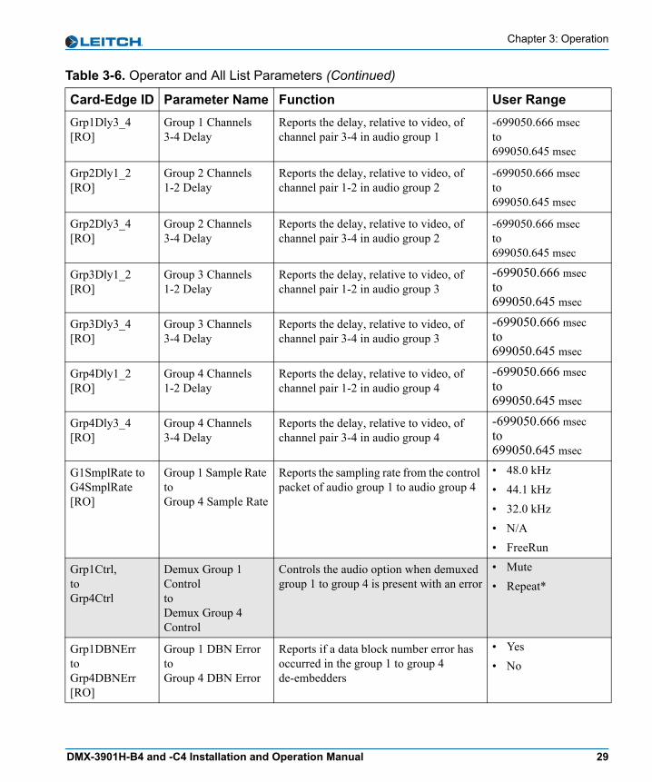
Table 3-6. Operator and All List Parameters
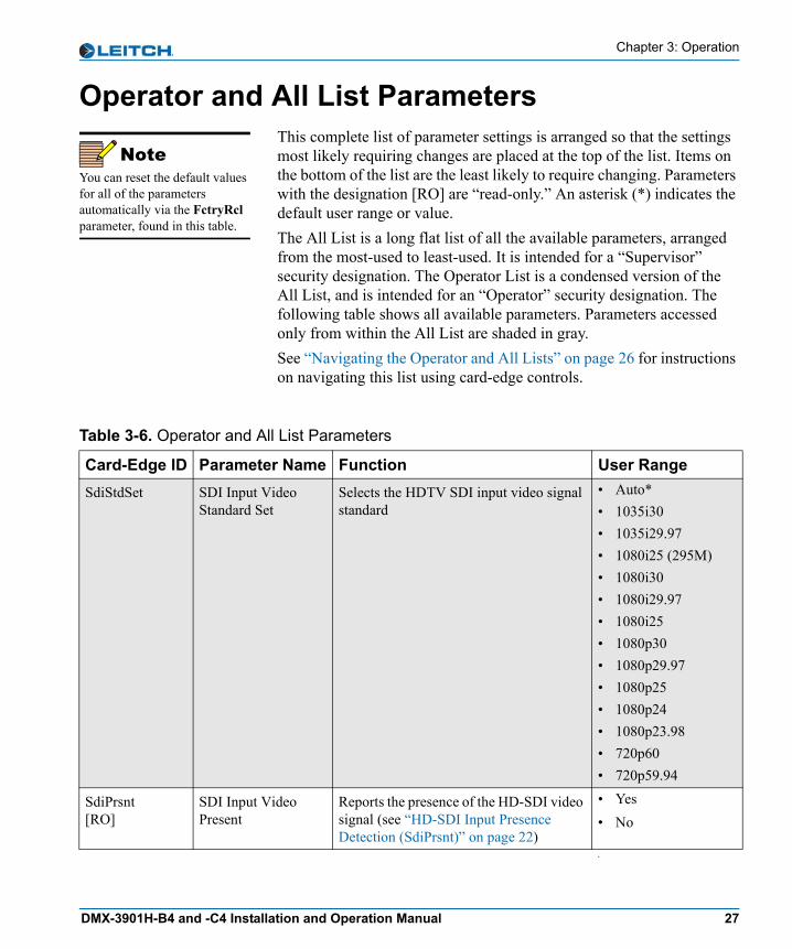
Card-Edge ID Parameter Name Function User RangeSdiStdSet SDI Input Video
Standard SetSelects the HDTV SDI input video signal standard
• Auto* • 1035i30 • 1035i29.97 • 1080i25 (295M)• 1080i30 • 1080i29.97 • 1080i25 • 1080p30 • 1080p29.97 • 1080p25 • 1080p24 • 1080p23.98 • 720p60 • 720p59.94
SdiPrsnt[RO]
SDI Input Video Present
Reports the presence of the HD-SDI video signal (see “HD-SDI Input Presence Detection (SdiPrsnt)” on page 22)
• Yes • No
•
DMX-3901H-B4 and -C4 Installation and Operation Manual 27

Chapter 3: Operation
SdiStdFb[RO]
SDI Input Video Standard Feedback
Reports the detected HD-SDI input video signal standard
• Unknown • 1080p25 • 1035i29.97 • 1035i30 • 1080i25 (295M) • 1080i29.97 • 1080i30 • 720p59.94 • 720p60 • 1080p23.98 • 1080p24 • 1080p29.97 • 1080p30 • 1080i25
YCrcErrCnt[RO]
Luminance CRC Error Counter
Reports the number of occurred luminance CRC errors
0 to 16777215
YCrcErrClr Luminance CRC Error Counter Clear
Clears the luminance CRC error counter • Yes • No*
CCrcErrCnt[RO]
Chrominance CRC Error Counter
Reports the number of occurred chrominance CRC errors
0 to 16777215
CCrcErrClr Chrominance CRC Error Counter Clear
Clears the chrominance CRC error counter
• Yes • No*
Grp1Prsnt toGrp4Prsnt [RO]
Group 1 PresenttoGroup 4 Present
Reports the presence of audio group 1 to group 4 in the HD-SDI stream
• Yes • No
DARSPrsnt[RO]
DARS Input Present Reports the presence of the DARS input signal
• Yes • No
DARSLock[RO]
DARS Locked to Video
Reports the locked status of the DARS input signal
• Yes • No
Grp1Dly1_2[RO]
Group Channels 1-2 Delay
Reports the delay, relative to video, of channel pair 1-2 in audio group 1
-699050.666 msecto699050.645 msec
Table 3-6. Operator and All List Parameters (Continued)
Card-Edge ID Parameter Name Function User Range
28 DMX-3901H-B4 and -C4 Installation and Operation Manual
Chapter 3: Operation
Grp1Dly3_4[RO]
Group 1 Channels 3-4 Delay
Reports the delay, relative to video, of channel pair 3-4 in audio group 1
-699050.666 msecto699050.645 msec
Grp2Dly1_2[RO]
Group 2 Channels 1-2 Delay
Reports the delay, relative to video, of channel pair 1-2 in audio group 2
-699050.666 msecto699050.645 msec
Grp2Dly3_4[RO]
Group 2 Channels 3-4 Delay
Reports the delay, relative to video, of channel pair 3-4 in audio group 2
-699050.666 msecto699050.645 msec
Grp3Dly1_2[RO]
Group 3 Channels 1-2 Delay
Reports the delay, relative to video, of channel pair 1-2 in audio group 3
-699050.666 msecto699050.645 msec
Grp3Dly3_4[RO]
Group 3 Channels 3-4 Delay
Reports the delay, relative to video, of channel pair 3-4 in audio group 3
-699050.666 msecto699050.645 msec
Grp4Dly1_2[RO]
Group 4 Channels 1-2 Delay
Reports the delay, relative to video, of channel pair 1-2 in audio group 4
-699050.666 msecto699050.645 msec
Grp4Dly3_4[RO]
Group 4 Channels 3-4 Delay
Reports the delay, relative to video, of channel pair 3-4 in audio group 4
-699050.666 msecto699050.645 msec
G1SmplRate toG4SmplRate[RO]
Group 1 Sample Rate toGroup 4 Sample Rate
Reports the sampling rate from the control packet of audio group 1 to audio group 4
• 48.0 kHz • 44.1 kHz • 32.0 kHz • N/A • FreeRun
Grp1Ctrl,toGrp4Ctrl
Demux Group 1 ControltoDemux Group 4 Control
Controls the audio option when demuxed group 1 to group 4 is present with an error
• Mute • Repeat*
Grp1DBNErr toGrp4DBNErr[RO]
Group 1 DBN ErrortoGroup 4 DBN Error
Reports if a data block number error has occurred in the group 1 to group 4 de-embedders
• Yes • No
Table 3-6. Operator and All List Parameters (Continued)
Card-Edge ID Parameter Name Function User Range
DMX-3901H-B4 and -C4 Installation and Operation Manual 29
Chapter 3: Operation
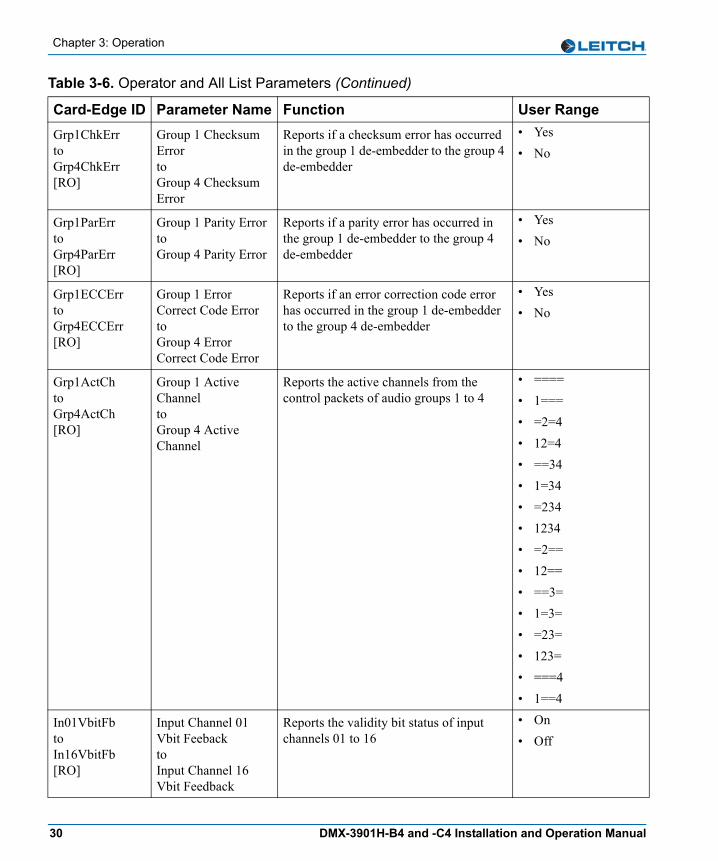
Grp1ChkErr toGrp4ChkErr[RO]
Group 1 Checksum ErrortoGroup 4 Checksum Error
Reports if a checksum error has occurred in the group 1 de-embedder to the group 4 de-embedder
• Yes • No
Grp1ParErrtoGrp4ParErr[RO]
Group 1 Parity ErrortoGroup 4 Parity Error
Reports if a parity error has occurred in the group 1 de-embedder to the group 4 de-embedder
• Yes • No
Grp1ECCErrtoGrp4ECCErr[RO]
Group 1 Error Correct Code ErrortoGroup 4 Error Correct Code Error
Reports if an error correction code error has occurred in the group 1 de-embedder to the group 4 de-embedder
• Yes • No
Grp1ActChtoGrp4ActCh[RO]
Group 1 Active Channel to Group 4 Active Channel
Reports the active channels from the control packets of audio groups 1 to 4
• ==== • 1=== • =2=4 • 12=4 • ==34 • 1=34 • =234 • 1234 • =2== • 12== • ==3= • 1=3= • =23= • 123= • ===4 • 1==4
In01VbitFbtoIn16VbitFb[RO]
Input Channel 01 Vbit FeebacktoInput Channel 16 Vbit Feedback
Reports the validity bit status of input channels 01 to 16
• On • Off
Table 3-6. Operator and All List Parameters (Continued)
Card-Edge ID Parameter Name Function User Range
30 DMX-3901H-B4 and -C4 Installation and Operation Manual
Chapter 3: Operation
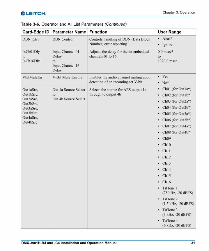
DBN_Ctrl DBN Control Controls handling of DBN (Data Block Number) error reporting
• Alert* • Ignore
InCh01DlytoInCh16Dly
Input Channel 01 Delay toInput Channel 16 Delay
Adjusts the delay for the de-embedded channels 01 to 16
0.0 msec*to 1320.0 msec
VbitMuteEn V-Bit Mute Enable Enables the audio channel muting upon detection of an incoming set V-bit
• Yes • No*
Out1aSrc,Out1bSrc,Out2aSrc,Out2bSrc,Out3aSrc,Out3bSrc,Out4aSrc,Out4bSrc
Out 1a Source SelecttoOut 4b Source Select
Selects the source for AES output 1a through to output 4b
• Ch01 (for Out1a*)• Ch02 (for Out1b*) • Ch03 (for Out2a*) • Ch04 (for Out2b*) • Ch05 (for Out3a*)• Ch06 (for Out3b*)• Ch07 (for Out4a*)• Ch08 (for Out4b*)• Ch09 • Ch10 • Ch11 • Ch12 • Ch13 • Ch14 • Ch15 • Ch16 • TstTone 1
(750 Hz, -20 dBFS)• TstTone 2
(1.5 kHz, -20 dBFS)• TstTone 3
(3 kHz, -20 dBFS)• TstTone 4
(6 kHz, -20 dBFS)
Table 3-6. Operator and All List Parameters (Continued)
Card-Edge ID Parameter Name Function User Range
DMX-3901H-B4 and -C4 Installation and Operation Manual 31
Chapter 3: Operation
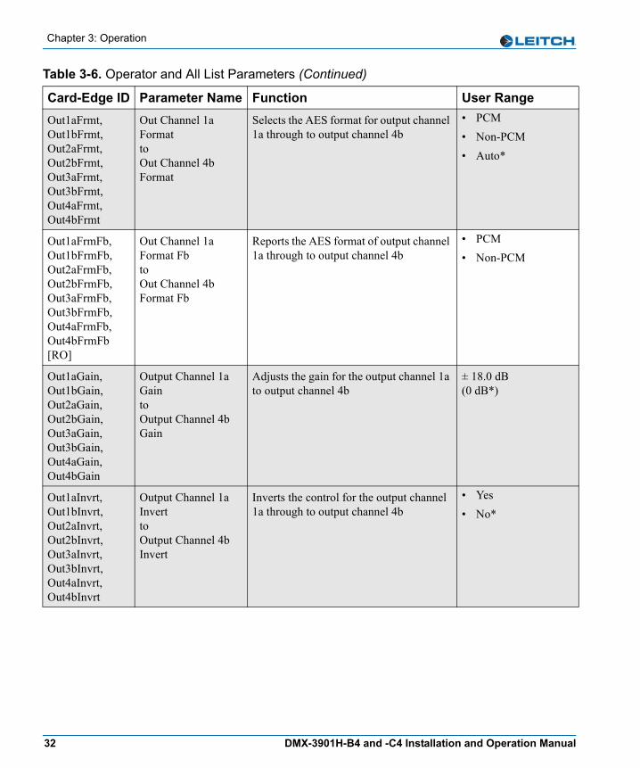
Out1aFrmt,Out1bFrmt,Out2aFrmt,Out2bFrmt,Out3aFrmt,Out3bFrmt,Out4aFrmt,Out4bFrmt
Out Channel 1a FormattoOut Channel 4b Format
Selects the AES format for output channel 1a through to output channel 4b
• PCM • Non-PCM • Auto*
Out1aFrmFb,Out1bFrmFb,Out2aFrmFb,Out2bFrmFb,Out3aFrmFb,Out3bFrmFb,Out4aFrmFb,Out4bFrmFb [RO]
Out Channel 1a Format Fb toOut Channel 4b Format Fb
Reports the AES format of output channel 1a through to output channel 4b
• PCM • Non-PCM
Out1aGain,Out1bGain,Out2aGain,Out2bGain,Out3aGain,Out3bGain,Out4aGain,Out4bGain
Output Channel 1a GaintoOutput Channel 4b Gain
Adjusts the gain for the output channel 1a to output channel 4b
± 18.0 dB(0 dB*)
Out1aInvrt,Out1bInvrt,Out2aInvrt,Out2bInvrt,Out3aInvrt,Out3bInvrt,Out4aInvrt,Out4bInvrt
Output Channel 1a InverttoOutput Channel 4b Invert
Inverts the control for the output channel 1a through to output channel 4b
• Yes • No*
Table 3-6. Operator and All List Parameters (Continued)
Card-Edge ID Parameter Name Function User Range
32 DMX-3901H-B4 and -C4 Installation and Operation Manual

Chapter 3: Operation
Out1aMute,Out1bMute,Out2aMute,Out2bMute,Out3aMute,Out3bMute,Out4aMute,Out4bMute
Output Channel 1a MutetoOutput Channel 4b Mute
Enables the muting for the output channel 1a to output channel 4b
• On • Off*
Out1aStat,Out1bStat,Out2aStat,Out2bStat,Out3aStat,Out3bStat,Out4aStat,Out4bStat [RO]
Out Channel 1a StatustoOut Channel 4b Status
Reports the status (peak/silence/normal) of output channel 1a to output channel 4b
• Peak • Silence • Normal
DM_Out1,DM_Out2,DM_Out3,DM_Out4
Output 1 Dither Mode toOutput 4 Dither Mode
Selects the dithering mode for output channel pair 1 to output channel pair 4
• None*• On
WL_Out1,WL_Out2,WL_Out3,WL_Out4
Output 1 Word Length toOutput 4 Word Length
Selects the word length for output audio channel pair 1 to output audio channel pair 4
• 24 bits* • 20 bits • 16 bits
FadeRate Fade Rate Controls the rate of fading when channels are swapped or muted
0.0 sec to 10.0 sec (1.0 sec*)
ALOVMode Audio Loss of Video Mode
Selects the output audio mode when the input video is disrupted
• Pass • Mute*
FctryRcl Factory Recall Recalls the factory settings. • On • Off*
Setup Setup Parameters Sets the parameters for display and usability (see page 54 for a complete list of Setup parameters and their factory default settings)
Various
Table 3-6. Operator and All List Parameters (Continued)
Card-Edge ID Parameter Name Function User Range
DMX-3901H-B4 and -C4 Installation and Operation Manual 33
Chapter 3: Operation
Setup ParametersYou can modify the Setup parameters to configure the card-edge controls for your personal needs. The Setup section appears at the end of all three navigation lists and consists of these items:• Alarms• NEOScope• Navigation modes• Adjustment modes• Browse modes• Scroll modes• Display intensity• Parameter descriptions• Name• FrameIP• Sync full• About mode
The structure of the Setup menu is located at the end of Appendix A: “Tree View Navigation.” See your NEO FR-3901, FR-3903, and FR-3923 Mounting Frames Installation and Operation Manual for more information on Setup items, including descriptions and operation notes.
NoteSetup parameters on a local or remote control panel may be different from the card-edge parameters described here.
34 DMX-3901H-B4 and -C4 Installation and Operation Manual
Chapter 3: Operation
AlarmsDMX-3901H-B4 and -C4 modules provide a default list of 23 alarms. You can disable any alarm by modifying the Alarms parameter in the Setup section.When you select Alarms, all of the active alarms are visible in the display, below Config (Configurations). If no alarms are active, only Config appears.
Alarm SynchronizationAlarm synchronization is available for this module if your NEO frame contains a 3901RES-E resource module that supports the feature. When active, alarm synchronization ensures that the alarm configuration settings of card-edge controls and the CCS control software and control panels are consistent.If the DMX-3901H-B4 and -C4 modules are set for local control, the alarm settings will appear the same at both the card edge and via CCS, but the settings can only be changed using the card-edge controls. If the module is set for remote control, the alarm settings can be changed via both the card edge and CCS control software and control panels.Alarm configuration settings undergo DejaView (state recovery) automatically. This means that when a module is hot-swapped, the alarm configuration for the new module is updated to the settings of the module that was previously in that slot. See “State Recovery Parameter Availability” in this chapter for more information.
Identifying the Cause of an AlarmTo identify the reason for an alarm, select the active alarm, and then press Enter. A scrolling message appears on the VFD describing the cause of the fault.
DMX-3901H-B4 and -C4 Installation and Operation Manual 35
Chapter 3: Operation
Enabling or Disabling an Alarm ParameterTo enable or disable an alarm parameter, follow these steps:1. Select Alarms, then select Config, and then press Enter.2. Select one of the alarm parameters, and then press Enter.3. Press Enabled or Disabled. 4. Press Enter to activate the selection.
Restoring Default SettingsTo restore the alarms to their default settings, follow these steps:1. Select Alarms, select Config, and then press Enter.2. Scroll down the list of alarms, and then select Reset.3. Press Enter to activate the selection.
The following table lists the default alarms for the DMX-3901H-B4 and -C4 modules. You can enable or disable these settings, but you cannot change the level of the alarm.
Table 3-7. DMX-3901H-B4 and -C4 Default Alarms
Card-Edge Alarm ID Name of Alarm Alarm
Level Meaning
SDI_Prsnt HD-SDI Input Video Present Major Loss of HD-SDI input video
Grp1Prsnt Group 1 Present Major Group 1 embedded audio is not present
Grp2Prsnt Group 2 Present Major Group 2 embedded audio is not present
Grp3Prsnt Group 3 Present Major Group 3 embedded audio is not present
Grp4Prsnt Group 4 Present Major Group 4 embedded audio is not present
DARSPrsnt DARS Input Present Minor DARS input is not present
DARSLock DARS Lock Minor DARS input and video are not locked
Grp1DBNErr Group 1 Data Block Number Error
Minor Group 1 data block number error has occurred
Grp1ChkErr Group 1 Checksum Error Minor Group 1 checksum error has occurred
Grp1ParErr Group 1 Parity Error Minor Group 1 parity error has occurred
36 DMX-3901H-B4 and -C4 Installation and Operation Manual

Chapter 3: Operation
DARS Balanced/Unbalanced Input Selection (DMX-3901H-B4 only)
The DMX-3901H-B4 module has the capability to use either a balanced or an unbalanced DARS reference input. Two jumpers are located in the right rear part of the front module to select between balanced and unbalanced DARS input (see Table 2-1 on page 11).
Grp1ECCErr Group 1 ECC Error Minor Group 1 error correction code error has occurred
Grp2DBNErr Group 2 DBN Error Minor Group 2 data block number error has occurred
Grp2ChkErr Group 2 Checksum Error Minor Group 2 checksum error has occurred
Grp2ParErr Group 2 Parity Error Minor Group 2 parity error has occurred
Grp2ECCErr Group 2 ECC Error Minor Group 2 error correction code error has occurred
Grp3DBNErr Group 3 DBN Error Minor Group 3 data block number error occurred
Grp3ChkErr Group 3 Checksum Error Minor Group 3 checksum error has occurred
Grp3ParErr Group 3 Parity Error Minor Group 3 parity error has occurred
Grp3ECCErr Group 3 ECC Error Minor Group 3 error correction code error has occurred
Grp4DBNErr Group 4 DBN Error Minor Group 4 data block number error has occurred
Grp4ChkErr Group 4 Checksum Error Minor Group 4 checksum error has occurred
Grp4ParErr Group 4 Parity Error Minor Group 4 parity error has occurred
Grp4ECCErr Group 4 ECC Error Minor Group 4 error correction code error has occurred
Table 3-7. DMX-3901H-B4 and -C4 Default Alarms (Continued)
Card-Edge Alarm ID Name of Alarm Alarm
Level Meaning
DMX-3901H-B4 and -C4 Installation and Operation Manual 37
Chapter 3: Operation
NEOScopeThe display screen of the DMX-3901H-B4 and -C4 can be used as a confidence monitor to view outgoing video images. To activate this feature, scroll through the Setup list to NEOScope, and then press the Enter button. The screen will show the outgoing video image. To turn this feature off, press any card-edge button or the Nav-/Nav+ switch.
State Recovery Parameter AvailabilityThe parameter settings for this module are automatically saved onto the 3901RES-E resource module installed in your NEO frame every five minutes. If a module should fail and be replaced with a cold spare, the state parameters can be automatically recovered. For more information on this feature, see the NEO FR-3901, FR-3903, and FR-3923 Mounting Frames Installation and Operation Manual (Edition E and above).
38 DMX-3901H-B4 and -C4 Installation and Operation Manual
Chapter 3: Operation
LEDs and Indicators
General InformationThe DMX-3901H Audio Demultiplexer modules have eleven functional card-edge LEDs and four module indicators.The module indicators include Major Alarm and Minor Alarm. These alarms alert users to failures or impending failures within the module. They are also found in the following locations:• As red or yellow LEDs on the 3901AIC Alarm Interconnect
Module or the 3901RES-E Resource Module (visible via light pipes through the frame’s front panel)
• As part of a list of activated alarms in the Setup menu• In external systems connected to the alarm contact closures at the
back of the NEO frames• On a PC screen where you use CCS Pilot or another GUI-based
control application
DMX-3901H-B4 and -C4 Installation and Operation Manual 39

Chapter 3: Operation
Card-Edge LED LocationsFigure 3-1 illustrates the locations of the LEDs and module indicators on the DMX-3901H-FM front module.
Figure 3-1. Card-Edge LEDs and Module Indicators, Top View
Top view
Nav+/Nav- switch(up/down) Extractor handleEscape button
ModuleStatus
MinorAlarm
MajorAlarm Power
SW1
Rem
ote
Loca
l
Nav +Nav -
EnterEsc
MAJORALARM
MINORALARM
POWER MODULESTATUS
Module indicatorsRemote/Localswitch
LEDs
Enter button
REM LOC
SDI p
rese
nt (g
reen
)A
uto
(gre
en)
720p
(gre
en)
1080
i (gr
een)
1035
i (gr
een)
1080
p (g
reen
)R
efer
ence
pre
sent
(not
func
tiona
l)Fr
eeze
(not
func
tiona
l)D
AR
S pr
esen
t (gr
een)
Embe
d er
ror (
not f
unct
iona
l)D
e-em
bed
erro
r (re
d)
40 DMX-3901H-B4 and -C4 Installation and Operation Manual

Chapter 3: Operation
LED descriptionsSee Figure 3-1 on page 40 for the locations of the card-edge LEDs decribed in Table 3-8.
Table 3-8. Card-Edge LED Color and Meaning
LED Color* Meaning (When Lit)SDI In Present
Green HD-SDI video input is present
Auto Green Detection of the input video signal is enabled
720p Green A 720p video source is present
1080i Green A 1080i video source is present
1080p Green A 1080p video source is present.
1035i Green A 1035i video source is present
Reference Present
None (Not functional on the DMX-3901H)
Freeze None (Not functional on the DMX-3901H)
DARS Present
Green The DARS reference is present
Embed Error
None (Not functional on the DMX-3901H)
Deembed Error
Red An audio deembedding error has occurred
DMX-3901H-B4 and -C4 Installation and Operation Manual 41
Chapter 3: Operation
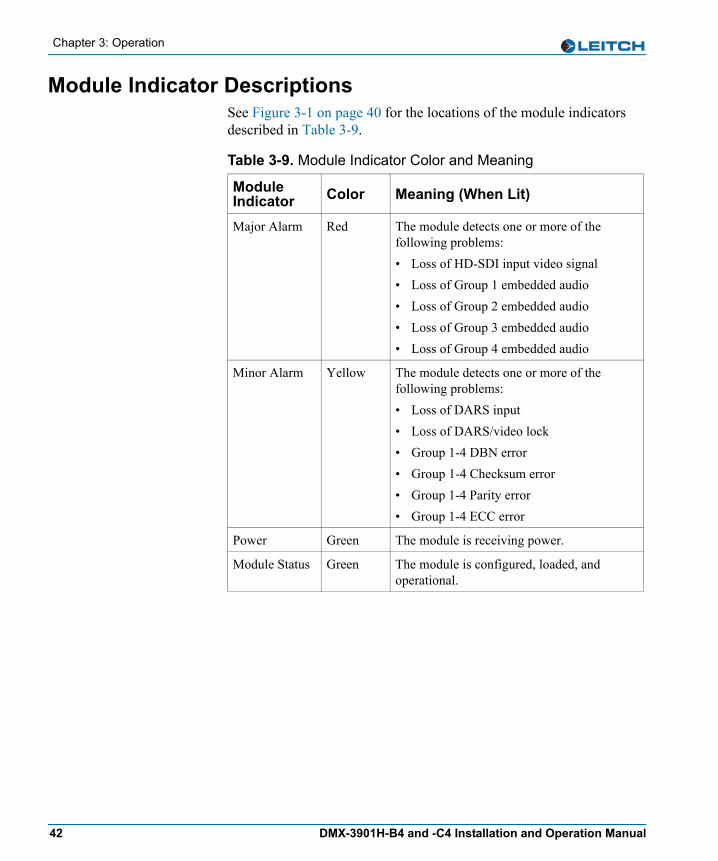
Module Indicator DescriptionsSee Figure 3-1 on page 40 for the locations of the module indicators described in Table 3-9.
Table 3-9. Module Indicator Color and Meaning
Module Indicator Color Meaning (When Lit)
Major Alarm Red The module detects one or more of the following problems:• Loss of HD-SDI input video signal• Loss of Group 1 embedded audio• Loss of Group 2 embedded audio• Loss of Group 3 embedded audio• Loss of Group 4 embedded audio
Minor Alarm Yellow The module detects one or more of the following problems:• Loss of DARS input• Loss of DARS/video lock• Group 1-4 DBN error • Group 1-4 Checksum error • Group 1-4 Parity error • Group 1-4 ECC error
Power Green The module is receiving power.
Module Status Green The module is configured, loaded, and operational.
42 DMX-3901H-B4 and -C4 Installation and Operation Manual
Chapter 4
Specifications
OverviewThe tables in this chapter list the following specifications for the DMX-3901H-B4 and -C4 modules: • “Inputs” on page 44• “Outputs” on page 45• “Miscellaneous” on page 47
Specifications and designs are subject to change without notice.
DMX-3901H-B4 and -C4 Installation and Operation Manual 43
Chapter 4: Specifications
Inputs
SDI Video Input
DARS Input
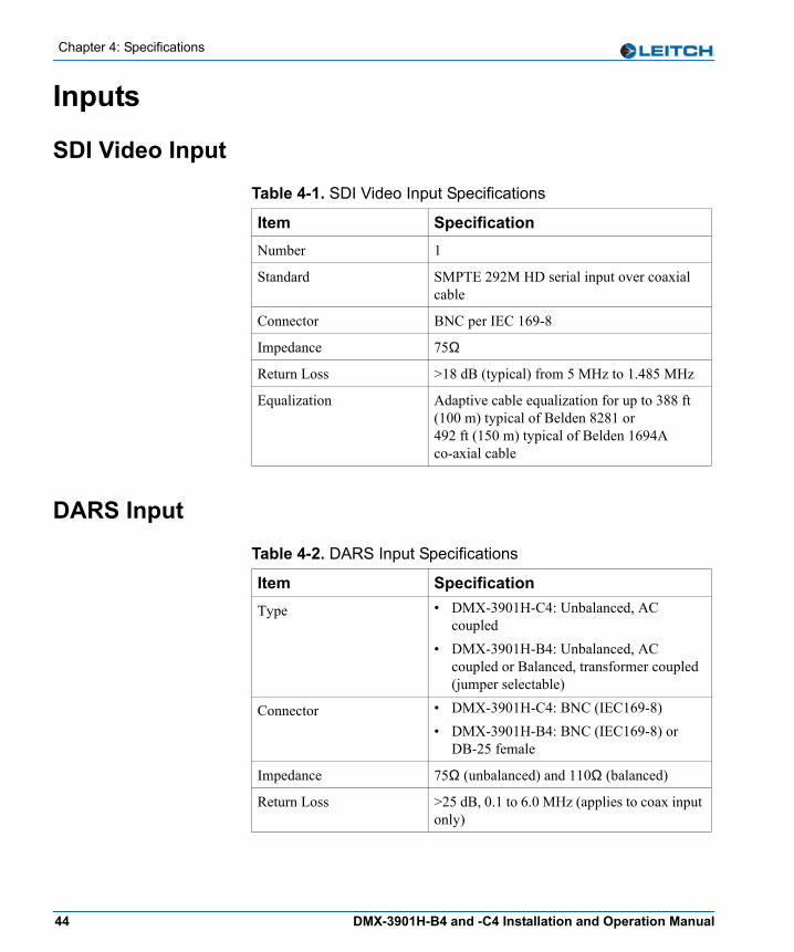
Table 4-1. SDI Video Input Specifications
Item SpecificationNumber 1
Standard SMPTE 292M HD serial input over coaxial cable
Connector BNC per IEC 169-8
Impedance 75Ω
Return Loss >18 dB (typical) from 5 MHz to 1.485 MHz
Equalization Adaptive cable equalization for up to 388 ft (100 m) typical of Belden 8281 or 492 ft (150 m) typical of Belden 1694A co-axial cable
Table 4-2. DARS Input Specifications
Item SpecificationType • DMX-3901H-C4: Unbalanced, AC
coupled• DMX-3901H-B4: Unbalanced, AC
coupled or Balanced, transformer coupled (jumper selectable)
Connector • DMX-3901H-C4: BNC (IEC169-8)• DMX-3901H-B4: BNC (IEC169-8) or
DB-25 female
Impedance 75Ω (unbalanced) and 110Ω (balanced)
Return Loss >25 dB, 0.1 to 6.0 MHz (applies to coax input only)
44 DMX-3901H-B4 and -C4 Installation and Operation Manual
Chapter 4: Specifications
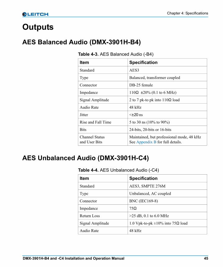
Outputs
AES Balanced Audio (DMX-3901H-B4)
AES Unbalanced Audio (DMX-3901H-C4)
Table 4-3. AES Balanced Audio (-B4)
Item SpecificationStandard AES3
Type Balanced, transformer coupled
Connector DB-25 female
Impedance 110Ω ±20% (0.1 to 6 MHz)
Signal Amplitude 2 to 7 pk-to pk into 110Ω load
Audio Rate 48 kHz
Jitter <±20 ns
Rise and Fall Time 5 to 30 ns (10% to 90%)
Bits 24-bits, 20-bits or 16-bits
Channel Status and User Bits
Maintained, but professional mode, 48 kHzSee Appendix B for full details.
Table 4-4. AES Unbalanced Audio (-C4)
Item SpecificationStandard AES3, SMPTE 276M
Type Unbalanced, AC coupled
Connector BNC (IEC169-8)
Impedance 75Ω
Return Loss >25 dB, 0.1 to 6.0 MHz
Signal Amplitude 1.0 Vpk-to-pk ±10% into 75Ω load
Audio Rate 48 kHz
DMX-3901H-B4 and -C4 Installation and Operation Manual 45

Chapter 4: Specifications
HD-SDI Reclocked Video
Rise and Fall Time 30 to 44 ns (10% to 90%)
Bits 24-bits, 20-bits or 16-bits
Channel Status and User Bits
Maintained, but professional mode, 48 kHzSee Appendix B: “Overview” on page 57 for full details.
Table 4-4. AES Unbalanced Audio (-C4) (Continued)
Item Specification
Table 4-5. HD-SDI Reclocked Video Specifications
Item SpecificationNumber 1 reclocked
Standards SMPTE 292M
Connector BNC (IEC 169-8)
Impedance 75Ω
Return Loss >18 dB (typical) from 5 MHz to 1485 MHz
Signal Level 800 mV ±10%
Dc Offset 0 V ±0.5 V
Rise and Fall Time <270 ps, within 100 ps of each other
Overshoot <10% of amplitude
Jitter <135 ps pk-to-pk
46 DMX-3901H-B4 and -C4 Installation and Operation Manual
Chapter 4: Specifications
Miscellaneous
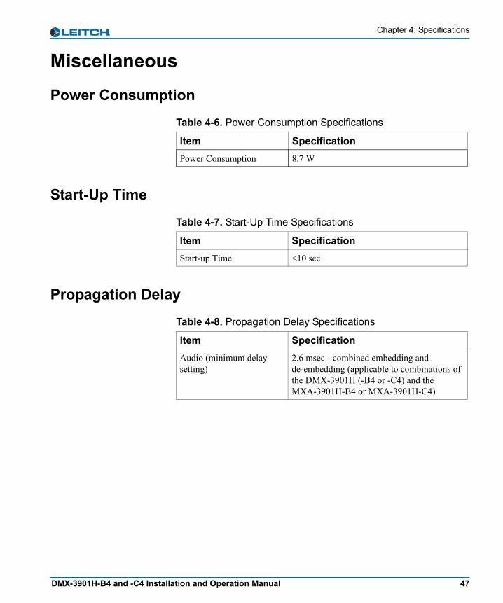
Power Consumption
Start-Up Time
Propagation Delay
Table 4-6. Power Consumption Specifications
Item SpecificationPower Consumption 8.7 W
Table 4-7. Start-Up Time Specifications
Item SpecificationStart-up Time <10 sec
Table 4-8. Propagation Delay Specifications
Item SpecificationAudio (minimum delay setting)
2.6 msec - combined embedding and de-embedding (applicable to combinations of the DMX-3901H (-B4 or -C4) and the MXA-3901H-B4 or MXA-3901H-C4)
DMX-3901H-B4 and -C4 Installation and Operation Manual 47

Chapter 4: Specifications
48 DMX-3901H-B4 and -C4 Installation and Operation Manual
Appendix A
Tree-View Navigation
OverviewThe Tree View is one of the three navigation modes available on the DMX-3901H-B4 and -C4 module. Unlike the other navigation modes, the Tree View is a multi-level list of parameters, arranged in the following main groups:• “Input” on page 51• “Other” on page 52• “Output” on page 52• “Processing” on page 53• “Setup” on page 54(See page 34 for more information on the Setup parameters which govern the operation of the card-edge controls.)
This appendix consists of instructions for navigating the lists (see page 50) and the Tree View Parameter list.
DMX-3901H Installation and Operation Manual 49

Appendix A: Tree-View Navigation
Navigating the Tree ViewTo navigate and then view or change a parameter from the Tree View, follow these steps:1. Open the front panel of the NEO frame.2. Press any card-edge control to turn on the VFD display.
The message DMX-3901H will appear as the banner on the card-edge display.
3. Press the Enter button.The first two items in the Level One list will appear.
4. Click Nav- (down) on the Nav-/Nav+ switch to view more items in the Level One list.
5. Select the desired item in the Level One list, and then press Enter.This leads you to the Level Two list.
6. Repeat steps 3 and 4 to view more items in Levels Two, Three, and Four.
7. If the parameter is selectable, slide the bar to the desired parameter using the Nav+/Nav-switch.ORSelect the desired item in the Level Four list, and then press Enter.
Once the Level Four parameter is set or viewed, you can leave the parameter in its current state, or return to the banner. To return to the DMX-3901H banner, repeatedly press the Escape button. Close the front panel again after you have completed the procedure to prevent the frame from overheating.
NoteIf you do not wish to make changes to your settings, return to the previously selected item in the list, and then press Escape to move up a level. See SelPar Adj Mode in the Setup section at the end of the Tree View to enable or disable this delayed adjust mode feature.
NoteAfter several seconds of inactivity, a scrolling message will appear, describing the purpose of the currently selected parameter.
50 DMX-3901H-B4 and -C4 Installation and Operation Manual
Appendix A: Tree-View Navigation
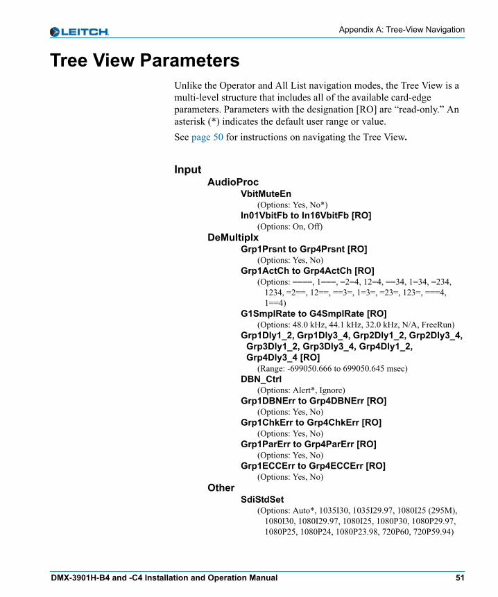
Tree View ParametersUnlike the Operator and All List navigation modes, the Tree View is a multi-level structure that includes all of the available card-edge parameters. Parameters with the designation [RO] are “read-only.” An asterisk (*) indicates the default user range or value.See page 50 for instructions on navigating the Tree View.
Input AudioProc
VbitMuteEn(Options: Yes, No*)
In01VbitFb to In16VbitFb [RO](Options: On, Off)
DeMultiplx Grp1Prsnt to Grp4Prsnt [RO]
(Options: Yes, No) Grp1ActCh to Grp4ActCh [RO]
(Options: ====, 1===, =2=4, 12=4, ==34, 1=34, =234, 1234, =2==, 12==, ==3=, 1=3=, =23=, 123=, ===4, 1==4)
G1SmplRate to G4SmplRate [RO](Options: 48.0 kHz, 44.1 kHz, 32.0 kHz, N/A, FreeRun)
Grp1Dly1_2, Grp1Dly3_4, Grp2Dly1_2, Grp2Dly3_4, Grp3Dly1_2, Grp3Dly3_4, Grp4Dly1_2, Grp4Dly3_4 [RO]
(Range: -699050.666 to 699050.645 msec) DBN_Ctrl
(Options: Alert*, Ignore) Grp1DBNErr to Grp4DBNErr [RO]
(Options: Yes, No) Grp1ChkErr to Grp4ChkErr [RO]
(Options: Yes, No) Grp1ParErr to Grp4ParErr [RO]
(Options: Yes, No) Grp1ECCErr to Grp4ECCErr [RO]
(Options: Yes, No) Other
SdiStdSet(Options: Auto*, 1035I30, 1035I29.97, 1080I25 (295M),
1080I30, 1080I29.97, 1080I25, 1080P30, 1080P29.97, 1080P25, 1080P24, 1080P23.98, 720P60, 720P59.94)
DMX-3901H-B4 and -C4 Installation and Operation Manual 51

Appendix A: Tree-View Navigation
SdiStdFb [RO] (Options: Unknown, 1080P25, 1035I29.97, 1035I30,
1080I25 (295M), 1080I29.97, 1080I30, 720P59.94, 720P60, 1080P23.98, 1080P24, 1080P29.97, 1080P30, 1080I25)
SdiPrsnt [RO](Options: Yes, No)
YCrcErrCnt [RO](Range: 0 to 16777215)
YCrcErrClr(Options: Yes, No*)
CCrcErrCnt [RO](Range: 0 to 16777215)
CCrcErrClr (Options: Yes, No*)
DARSPrsnt [RO](Options: Yes, No)
DARSLock [RO](Options: Yes, No)
Other FctryRcl
(Options: On, Off*) Output
AudioProc Out1aFrmt, Out1bFrmt, Out2aFrmt, Out2bFrmt,
Out3aFrmt, Out3bFrmt, Out4aFrmt, Out4bFrmt(Options: PCM, Non-PCM, Auto*)
Out1aFrmFb, Out1bFrmFb, Out2aFrmFb, Out2bFrmFb, Out3aFrmFb, Out3bFrmFb, Out4aFrmFb, Out4bFrmFb [RO]
(Options: PCM, Non-PCM)Out1aStat, Out1bStat, Out2aStat, Out2bStat,
Out3bStat, Out4aStat, Out4bStat [RO](Options: Peak, Silence, Normal)
DeMultiplx Out1aSrc
(Options: Ch01*, Ch02, Ch03, Ch04, Ch05, Ch06, Ch07, Ch08, Ch09, Ch10, Ch11, Ch12, Ch13, Ch14, Ch15, Ch16, TstTone 1, TstTone 2, TstTone 3, TstTone 4)
Out1bSrc (Options: Ch01, Ch02*, Ch03, Ch04, Ch05, Ch06, Ch07,
Ch08, Ch09, Ch10, Ch11, Ch12, Ch13, Ch14, Ch15, Ch16, TstTone 1, TstTone 2, TstTone 3, TstTone 4)
Out2aSrc (Options: Ch01, Ch02, Ch03*, Ch04, Ch05, Ch06, Ch07,
Ch08, Ch09, Ch10, Ch11, Ch12, Ch13, Ch14, Ch15, Ch16, TstTone 1, TstTone 2, TstTone 3, TstTone 4)
52 DMX-3901H-B4 and -C4 Installation and Operation Manual

Appendix A: Tree-View Navigation
Out2bSrc (Options: Ch01, Ch02, Ch03, Ch04*, Ch05, Ch06, Ch07,
Ch08, Ch09, Ch10, Ch11, Ch12, Ch13, Ch14, Ch15, Ch16, TstTone 1, TstTone 2, TstTone 3, TstTone 4)
Out3aSrc(Options: Ch01, Ch02, Ch03, Ch04, Ch05*, Ch06, Ch07,
Ch08, Ch09, Ch10, Ch11, Ch12, Ch13, Ch14, Ch15, Ch16, TstTone 1, TstTone 2, TstTone 3, TstTone 4)
Out3bSrc (Options: Ch01, Ch02, Ch03, Ch04, Ch05, Ch06*, Ch07,
Ch08, Ch09, Ch10, Ch11, Ch12, Ch13, Ch14, Ch15, Ch16, TstTone 1, TstTone 2, TstTone 3, TstTone 4)
Out4aSrc (Options: Ch01, Ch02, Ch03, Ch04, Ch05, Ch06, Ch07*,
Ch08, Ch09, Ch10, Ch11, Ch12, Ch13, Ch14, Ch15, Ch16, TstTone 1, TstTone 2, TstTone 3, TstTone 4)
Out4bSrc (Options: Ch01, Ch02, Ch03, Ch04, Ch05, Ch06, Ch07,
Ch08*, Ch09, Ch10, Ch11, Ch12, Ch13, Ch14, Ch15, Ch16, TstTone 1, TstTone 2, TstTone 3, TstTone 4)
Processing AudioProc
Out1aGain, Out1bGain, Out2aGain, Out2bGain, Out3aGain, Out3bGain, Out4aGain, Out4bGain
(Range: -18.0 to 18.0 dB; 0 dB*) Out1aInvrt, Out1bInvrt, Out2aInvrt, Out3aInvrt,
Out3bInvrt, Out4aInvrt, Out4bInvrt(Options: Yes, No*)
Out1aMute, Out1bMute, Out2aMute, Out2bMute, Out3bMute, Out4aMute, Out4bMute
(Options: On, Off*) DM_Out1 to DM_Out4
(Options: None*, On) WL_Out1 to WL_Out4
(Options: 24-bits*, 20-bits, 16-bits) FadeRate
(Range: 0.0 to 10.0 seconds; 1.0 sec*) ALOVMode
(Options: Pass, Mute*) Delaying
InCh01Dly to InCh16Dly(Range: 0.00* to 1320.00 msec)
DeMultiplx Grp1Ctrl to Grp4Ctrl
(Options: Mute, Repeat*)
DMX-3901H-B4 and -C4 Installation and Operation Manual 53
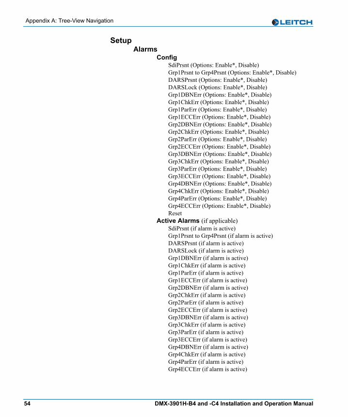
Appendix A: Tree-View Navigation
SetupAlarms
ConfigSdiPrsnt (Options: Enable*, Disable)Grp1Prsnt to Grp4Prsnt (Options: Enable*, Disable)DARSPrsnt (Options: Enable*, Disable)DARSLock (Options: Enable*, Disable)Grp1DBNErr (Options: Enable*, Disable)Grp1ChkErr (Options: Enable*, Disable)Grp1ParErr (Options: Enable*, Disable)Grp1ECCErr (Options: Enable*, Disable)Grp2DBNErr (Options: Enable*, Disable)Grp2ChkErr (Options: Enable*, Disable)Grp2ParErr (Options: Enable*, Disable)Grp2ECCErr (Options: Enable*, Disable)Grp3DBNErr (Options: Enable*, Disable)Grp3ChkErr (Options: Enable*, Disable)Grp3ParErr (Options: Enable*, Disable)Grp3ECCErr (Options: Enable*, Disable)Grp4DBNErr (Options: Enable*, Disable)Grp4ChkErr (Options: Enable*, Disable)Grp4ParErr (Options: Enable*, Disable)Grp4ECCErr (Options: Enable*, Disable)Reset
Active Alarms (if applicable)SdiPrsnt (if alarm is active)Grp1Prsnt to Grp4Prsnt (if alarm is active)DARSPrsnt (if alarm is active)DARSLock (if alarm is active)Grp1DBNErr (if alarm is active)Grp1ChkErr (if alarm is active)Grp1ParErr (if alarm is active)Grp1ECCErr (if alarm is active)Grp2DBNErr (if alarm is active)Grp2ChkErr (if alarm is active)Grp2ParErr (if alarm is active)Grp2ECCErr (if alarm is active)Grp3DBNErr (if alarm is active)Grp3ChkErr (if alarm is active)Grp3ParErr (if alarm is active)Grp3ECCErr (if alarm is active)Grp4DBNErr (if alarm is active)Grp4ChkErr (if alarm is active)Grp4ParErr (if alarm is active)Grp4ECCErr (if alarm is active)
54 DMX-3901H-B4 and -C4 Installation and Operation Manual
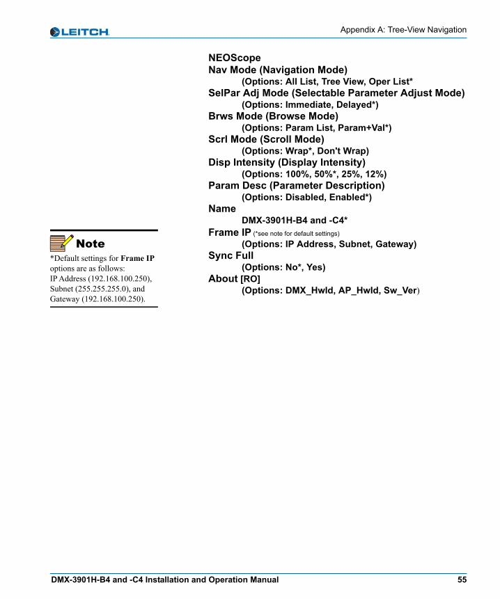
Appendix A: Tree-View Navigation
NEOScopeNav Mode (Navigation Mode)
(Options: All List, Tree View, Oper List*SelPar Adj Mode (Selectable Parameter Adjust Mode)
(Options: Immediate, Delayed*)Brws Mode (Browse Mode)
(Options: Param List, Param+Val*)Scrl Mode (Scroll Mode)
(Options: Wrap*, Don't Wrap)Disp Intensity (Display Intensity)
(Options: 100%, 50%*, 25%, 12%)Param Desc (Parameter Description)
(Options: Disabled, Enabled*)Name
DMX-3901H-B4 and -C4*Frame IP (*see note for default settings)
(Options: IP Address, Subnet, Gateway)Sync Full
(Options: No*, Yes)About [RO]
(Options: DMX_HwId, AP_HwId, Sw_Ver)
Note*Default settings for Frame IP options are as follows: IP Address (192.168.100.250), Subnet (255.255.255.0), and Gateway (192.168.100.250).
DMX-3901H-B4 and -C4 Installation and Operation Manual 55

Appendix A: Tree-View Navigation
56 DMX-3901H-B4 and -C4 Installation and Operation Manual
Appendix B
Audio Bit Manipulation
OverviewThe following tables contain information on the manipulation of bits that occur when using the DMX-3901H-B4 and -C4 modules. RX Key: N = not recognized, Y = recognized, S = recognized and stored or passed through or bothTX Key: N = not transmitted, Y = transmitted
DMX-3901H-B4 and -C4 Installation and Operation Manual 57

Appendix B: Audio Bit Manipulation
Channel Status BitsTable B-1. C-Bit Manipulation
Byte Bit Function RX TX Remarks0 0 [0] Consumer Use
[1] Professional UseNY
NY
• RX ignores bit• TX sets bit to 1
0 1 [0] Audio[1] Non-Audio
SS
YY
• RX sets up audio channel to pass data (Gain=0dB, Invert=off)
• TX bit passes unmodified or forced, according to OutxxFrmt and OutxxFrmFb parameters
0 2 to 4 [000] Not Indicated[100] No Emphasis[110] 50/15 us[111] CCITTJ17
SSSS
YYYY
• RX ignores bits• TX passed bits unmodified
0 5 [0] Locked[1] Unlocked
NN
YN
• RX ignores bits• TX sets bit to 0
0 6 to 7 [00] Not Indicated[01] 48 kHz[10] 44.1 kHz[11] 32 kHz
YYYY
NYNN
• RX ignores bits • TX sets bits to [01]
1 0 to 3 [0000] Not Indicated[0001] Two Channel[0010] Mono[0011] Prim/sec[0100] Stereo[0101] to [1111] Undefined
NNNNNN
YNNNNN
• RX ignores bits • TX sets bits to [0000]
1 4 to 7 [0000] Not Indicated[0001] 192 Bit Block[0010] AES18 (HDLC)[0011] User Defined[0100] to [1111] Undefined
SSSSS
YYYYY
• RX ignores bits• TX passed bits unmodified
2 0 to 2 [000] Aux. Bit Use is Not Indicated[001] Aux. Bit Use is Audio Data[010] Aux. Bit Use is Co-ordination Signal[011] to [111] Undefined
NNNN
YYNN
• RX ignores bits• TX sets bits according to
transmitted word length
58 DMX-3901H-B4 and -C4 Installation and Operation Manual

Appendix B: Audio Bit Manipulation
2 3 to 5 [000] Not Indicated[001] Max Length - 1[010] Max Length - 2[011] Max Length - 3[100] Max Length - 4[101] Max Length[110] to [111] Undefined
NNNNNNN
NNNNYYN
• RX ignores bits• TX sets bits according to
transmitted word length
2 6 to 7 [00] Alignment Level Not Indicated[01] Alignment to SMPTE RP155[10] Alignment to EBU R68[11] Reserved
N Y • RX ignores bits• TX sets bits to [00]
3 0 to 6 bit 7 = 0: Channel NumberBit 7 = 1: [0,1,2,3] Channel Number[4,5,6] Multi-channel Mode
N Y • RX ignores bits• TX sets bits to [0000000]
3 7 [0] Undefined Multi-channel Mode[1] Defined Multi-channel Mode
N Y • RX ignores bits• TX sets bits to [0]
4 0 to 1 [00] Not A Reference [01] Grade 1 Reference[10] Grade 2 Reference[11] Undefined
NNNN
YNNN
• RX ignores bits. • TX sets bits to [00]
4 2 Reserved N Y • RX ignores bits• TX sets bits to [0]
4 3 to 6 [0000] Not Indicated[1000] 24 kHz[0100] 96 kHz[1100] 192 kHz[1001] 22.05 kHz[0101] 88.2 kHz[1101] 176.4 Hz[1111] User Defined
N Y • RX ignores bits • TX sets bits to [0000]
4 7 [0] SAmple Frequency Not Scaled[1] Sample Frequency Scaled by 1/1.001
N Y • RX ignores bits• TX sets bits to [0]
5 0 to 7 Reserved N Y • RX ignores bits• TX sets bits to [00000000]
6 to 9 0 to 7 Alphanumeric Channel Origin Data S Y • RX ignores bits• TX passed bits unmodified
Table B-1. C-Bit Manipulation (Continued)
Byte Bit Function RX TX Remarks
DMX-3901H-B4 and -C4 Installation and Operation Manual 59
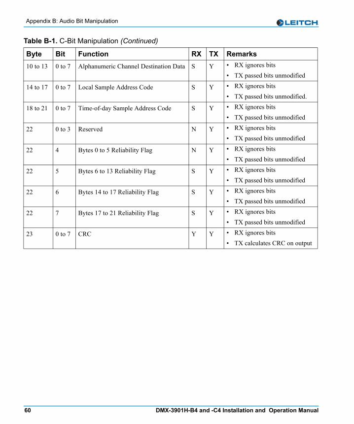
Appendix B: Audio Bit Manipulation
10 to 13 0 to 7 Alphanumeric Channel Destination Data S Y • RX ignores bits• TX passed bits unmodified
14 to 17 0 to 7 Local Sample Address Code S Y • RX ignores bits• TX passed bits unmodified.
18 to 21 0 to 7 Time-of-day Sample Address Code S Y • RX ignores bits• TX passed bits unmodified
22 0 to 3 Reserved N Y • RX ignores bits• TX passed bits unmodified
22 4 Bytes 0 to 5 Reliability Flag N Y • RX ignores bits• TX passed bits unmodified
22 5 Bytes 6 to 13 Reliability Flag S Y • RX ignores bits• TX passed bits unmodified
22 6 Bytes 14 to 17 Reliability Flag S Y • RX ignores bits• TX passed bits unmodified
22 7 Bytes 17 to 21 Reliability Flag S Y • RX ignores bits• TX passed bits unmodified
23 0 to 7 CRC Y Y • RX ignores bits• TX calculates CRC on output
Table B-1. C-Bit Manipulation (Continued)
Byte Bit Function RX TX Remarks
60 DMX-3901H-B4 and -C4 Installation and Operation Manual

Appendix B: Audio Bit Manipulation
Notes — Channel Status
Validity and User Bits
Table B-2. Notes — Channel Status
RX Key TX Key Sample Rate Indication Audio Word Length
N = not recognized N = not transmitted
Byte 0 Bits [6,7], Byte 4 Bits [3,4,5,6]• [00,0100] = 96 kHz• [01,0000] = 48 kHz• [11,0000] = 32 kHz• [00,1000] = 24 kHz• [00,0101] = 88.2 kHz• [10,0000] = 44.1 kHz• [00,1001] = 22.05 kHz
Byte 2 Bits [0,1,2]• [000] = Maximum word length
20 bits (auxiliary bit use not indicated)
• [001] = Maximum word length 24 bits (auxiliary bits used for audio)
Byte 2 Bits [3,4,5]• [100] = Encoded word length =
Maximum word length - 4 bits• [101] = Encoded word length =
Maximum word length - 0 bits
Y = recognized Y = transmitted
S = recognized and stored or passed through or both
Table B-3. V-Bit and U-Bit Manipulation
Bit Manipulation RX TX RemarksValidity (V) Bit S Y • RX optionally mutes data if
enabled• TX passes bit unmodified
User (U) Bit S Y • RX ignores bits• TX passes bits unmodified
DMX-3901H-B4 and -C4 Installation and Operation Manual 61
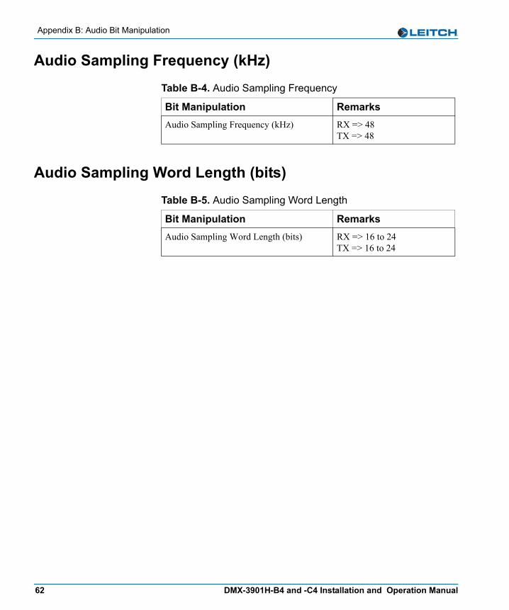
Appendix B: Audio Bit Manipulation
Audio Sampling Frequency (kHz)
Audio Sampling Word Length (bits)
Table B-4. Audio Sampling Frequency
Bit Manipulation RemarksAudio Sampling Frequency (kHz) RX => 48
TX => 48
Table B-5. Audio Sampling Word Length
Bit Manipulation RemarksAudio Sampling Word Length (bits) RX => 16 to 24
TX => 16 to 24
62 DMX-3901H-B4 and -C4 Installation and Operation Manual
Index
KeywordsAAdd Upgrade Files box 12–17AES audio output specifications 45alarms 35–36All List and Operator List 27–33audio output channel status 21
Bback modules 5boot file 12, 14–16buying manuals ix
Ccard-edge led locations 40causes of alarms 35compliance and certification information xconfidence monitoring 38Configuration... window 12–18configuring the module 19correcting a failed upgrade 16cross-functional parameter changes 23
DDARS input specifications 44default settings for alarms 36
DejaView 35demux group control 21disabling or enabling alarms 36Discovery method of upgrading 12–13display screen, confidence monitoring 38drag-and-drop method of upgrading 14–15
Eenabling or disabling alarms 36
Ffail-safe procedure 16FctryRcl parameters 27firmware upgrading 12–18fl0 folder 13, 15, 18front module 4functional block diagram 7
HHD-SDI input reference detection 22HD-SDI reclocked video specifications 46
Iidentifying causes of alarm 35input channel v-bit feedback 21installing and removing modules 10
DMX-3901H-B4 and -C4 Installation and Operation Manual 63
Index
Jjumper settings 11
LLED descriptions 41LEDs and indicators 39–42
Mmanuals, purchasing ixmodule indicator descriptions 42module installation 10
Nnavigating parameter lists 26, 50Navigation Properties box 14, 17NEOScope 38, 55
Ooperating the module 19Operator and All List 27–33
Ppacking equipment for shipping ixpacking list 10parameter lists
Operator and All 27Tree View 51
parametersFctryRcl 27
pinouts 5plug-in adapter 6power consumption specifications 47propagation delay specifications 47
Rrebooting the module 13, 18removing and installing modules 10
restoring default settings for alarms 36returning equipment ixrevision history vii
Ssafety standards and compliances xSDI video input specifications 44setting jumpers 11setting up the module 19Setup parameters 34shipping equipment ixsignal flow 7Software Upgrade tab 13–18specifications
AES audio input 45DARS input 44HD-SDI reclocked video 46power consumption 47propagation delay 47SDI video input 44
state recovery of alarms 35, 38synchronizing alarms 35
Ttrademarks and copyrights iiTree View parameter list 51–55
Uunpacking ixupgrading firmware 12–18
Vviewing outgoing video on display screen 38vxWorks.lzs file 13, 15–16, 18
Wwarranty information iiWeb site, location of manuals ix
64 DMX-3901H-B4 and -C4 Installation and Operation Manual
