nemo 42vdc operation manual feb07 - otronix.com · nemo™ 42 volt configuration wave processing...
TRANSCRIPT

NEMO™ 42 Volt Configuration
Wa v e P r o c e s s i n g M o d u l e
Operation Manual
P/N 950-6052-00 (February 2007) © 2007 Teledyne RD Instruments, Inc. All rights reserved.


Table of Contents NEMO™ 42 Volt Configuration Wave Processing Module Operation Manual ...................................... 1
Introduction...............................................................................................................................................................1 Technical Support ....................................................................................................................................................1 What This Manual Covers ........................................................................................................................................2 Conventions Used in Manuals..................................................................................................................................2
Section 1.0: Overview ................................................................................................................................. 2 System Overview .....................................................................................................................................................3 System Requirements ..............................................................................................................................................5 Packing List ..............................................................................................................................................................5 Hardware Overview..................................................................................................................................................5 Power Overview .......................................................................................................................................................7 Communication Overview.........................................................................................................................................7 Outline Installation Drawing......................................................................................................................................9 Software Overview .................................................................................................................................................10
Section 2.0: Preparation and Setup ........................................................................................................ 11 Visual Inspection ....................................................................................................................................................13 Battery Installation..................................................................................................................................................14 Seal for Deployment ...............................................................................................................................................15
Section 3.0: Bench Testing ...................................................................................................................... 17 NEMO Connections................................................................................................................................................17 Testing the NEMO..................................................................................................................................................19
Section 4.0: Troubleshooting the NEMO ................................................................................................ 21 Section 5.0: Collecting Data..................................................................................................................... 22
Reconfigure the NEMO Wave Processing Module.................................................................................................25 Get Last Current Record and Last Wave Message ................................................................................................26 Retrieve Data from NEMO’s Recorder Card...........................................................................................................26
Section 6.0: NEMO Commands ............................................................................................................... 27 ===.........................................................................................................................................................................27 depthcellsize...........................................................................................................................................................27 depthoffset..............................................................................................................................................................27 dumpconfig.............................................................................................................................................................27 EPB ........................................................................................................................................................................28 fftlen .......................................................................................................................................................................28 findadcp..................................................................................................................................................................28 getappversion.........................................................................................................................................................28 getauditfile ..............................................................................................................................................................28 getavaildiskspace ...................................................................................................................................................29 getawcmsystime.....................................................................................................................................................29 geterrorfile ..............................................................................................................................................................29 getfilelist .................................................................................................................................................................29 getlatest..................................................................................................................................................................30 getsizeoffile ............................................................................................................................................................30 gotosleepnow .........................................................................................................................................................30 headingoffset..........................................................................................................................................................30 load1200khz ...........................................................................................................................................................31 load600khz .............................................................................................................................................................31 load300khz .............................................................................................................................................................31 loadlast ...................................................................................................................................................................31 nomdepth ...............................................................................................................................................................31 nominalheading ......................................................................................................................................................32 numprocessbins .....................................................................................................................................................32 pingsperens............................................................................................................................................................32 reloadconfig............................................................................................................................................................32 resetauditfile ...........................................................................................................................................................32 resetdefault.............................................................................................................................................................33

reseterrorfile ...........................................................................................................................................................33 savelast ..................................................................................................................................................................33 setadcpbaud...........................................................................................................................................................33 setadcpnemobaud..................................................................................................................................................33 setaltitude ...............................................................................................................................................................34 setensemble ...........................................................................................................................................................34 setnemobaud1........................................................................................................................................................34 setnemobaud3........................................................................................................................................................34 setoutputdepthcell ..................................................................................................................................................34 setoutputfirstcell .....................................................................................................................................................35 setoutputstep..........................................................................................................................................................35 setstartat.................................................................................................................................................................35 setwaveburst (TBB)................................................................................................................................................35 startrawdata............................................................................................................................................................35 stoprawdata............................................................................................................................................................36 timebetweenpings ..................................................................................................................................................36 xducerdepth............................................................................................................................................................36
Section 7.0: NEMO Factory Defaults....................................................................................................... 37 Section 8.0: Output Data Format ............................................................................................................. 40
NEMO Processed Directional Wave Data Formats ................................................................................................40 NEMO Processed Current Profile Data Format......................................................................................................41
Section 9.0: Upgrade NEMO Software .................................................................................................... 44 Section 10.0: Telemetry Options ............................................................................................................. 48
Teledyne Benthos Subsea Acoustic Telemetry Modems .......................................................................................48 Seabird™ Underwater Inductive Modems..............................................................................................................49 FreeWave™ Modems.............................................................................................................................................49 Sutron™ Data Logger/Transmitter .........................................................................................................................49
Appendix – Differences between NEMO and NEMO 42 Volt Configuration........................................ 50 Appendix – Shore Powered Real-Time Applications ............................................................................ 51 Appendix – Inductive Modems ................................................................................................................ 52 Appendix – NEMO Printout ...................................................................................................................... 53 Appendix - Example of a BBTalk Script File .......................................................................................... 54 Appendix – Quick Start............................................................................................................................. 56

List of Figures Figure 1. NEMO 42 Volt Configuration Wave Processing Module .................................................. 3 Figure 2. I/O Cable Wiring.............................................................................................................. 7 Figure 3. External Battery Pack Cable ........................................................................................... 8 Figure 4. Pigtail Extension Cable ................................................................................................... 8 Figure 5. Outline Installation Drawing – Integrated Configuration................................................... 9 Figure 6. NEMO Overview - Integrated Configuration .................................................................. 11 Figure 7. NEMO Assembly - Integrated Configuration.................................................................. 12 Figure 8. NEMO Connections – Self-Contained Configuration ..................................................... 17 Figure 9. NEMO Connections – Integrated Configuration ............................................................ 17 Figure 10. NEMO Default Wave and Current Sampling.................................................................. 22 Figure 11. Telemetry Options ......................................................................................................... 48 Figure 12. Functional Diagram ....................................................................................................... 56
List of Tables Table 1. NEMO Wave Processing Module Factory Defaults ....................................................... 37 Table 2. NEMO Processed Directional Wave Data Format – Message 0 .................................... 40 Table 3. NEMO Processed Directional Wave Data Format – Message 1 .................................... 40 Table 4. NEMO Processed Directional Wave Data Format – Message 2 .................................... 41 Table 5. NEMO Processed Current Profile Data Format – Message 0........................................ 41 Table 6. NEMO Processed Current Profile Data Format – Message 1........................................ 42 Table 7. NEMO Processed Current Profile Data Format – Message 2........................................ 43 Table 8. Differences between NEMO and NEMO 42 Volt Configuration...................................... 50

NOTES

NEMO™ 42 Volt Configuration Wave Processing Module Operation Manual
P/N 950-6052-00 (February 2007) page 1
NEMO™ 42 Volt Configuration Wave Processing Module Operation Manual
Introduction Thank you for purchasing the NEMO™ 42 Volt Configuration Wave Processing Module1. This operation manual will lead you through the steps required for a successful deployment. Please read the entire manual, and then follow the instructions in the order they are presented.
Technical Support If you have technical problems with your instrument, contact our field service group in any of the following ways: Teledyne RD Instruments Teledyne RD Instruments Europe
14020 Stowe Drive 5 Avenue Hector Pintus
Poway, California 92064 06610 La Gaude, France
(858) 842-2600 +33(0) 492-110-930
FAX (858) 842-2822 +33(0) 492-110-931
Sales – [email protected] [email protected]
Field Service - [email protected] [email protected]
Web: http://www.rdinstruments.com After Hours Emergency Technical Support +1 858-842-2700
If your instrument works and you have questions involving a specific application, you may call either the field service group (above) or our sales / marketing staff.
NOTE. When the TRDI-US and TRDI-Europe offices are closed, customers may now call +1 858-842-2700 to have their after-hours technical support emergencies resolved.
1 NEMO is a registered trademark of Teledyne RD Instruments, Inc.

NEMO™ 42 Volt Configuration Wave Processing Module Operation Manual
page 2 Teledyne RD Instruments
What This Manual Covers The manual covers the basic operation of the NEMO Wave Processing Module. It will guide you through the inspection of components and verify the deployment of the NEMO on the bench. It will also tell you how to collect data with the NEMO.
Conventions Used in Manuals Conventions used in the NEMO manual have been established to help you learn how to use the unit quickly and easily. Windows menu items are printed in bold: File menu, Collect Data. Items that need to be typed by the user or keys to press will be shown as F1. If a key combina-tion were joined with a plus sign (ALT+F), you would press and hold the first key while you press the second key. Words printed in italics include program names (BBTalk) and file names (default.txt).
Code or sample files are printed using a fixed font. Here is an example: WorkHorse Broadband ADCP RD INSTRUMENTS (c) 1997-2005 ALL RIGHTS RESERVED Firmware Version 16.28 >
You will find two other visual aids that help you: Notes and Cautions.
NOTE. This paragraph format indicates additional information that may help you avoid problems or that should be considered in using the described features.
CAUTION. This paragraph format warns the reader of hazardous procedures (for example, activities that may cause loss of data or damage to the NEMO Wave Processing Module).
Section 1.0: Overview The first step is to familiarize yourself with the components. Check to make sure that every-thing has been shipped to you (see “Packing List,” page 5), and then read the short descriptions of the hardware that comes with the NEMO Wave Processing Module.
This Section Covers:
• System Overview
• System Requirements
• Packing List
• Hardware Overview
• Power Overview
• Communication Overview
• Software Overview

NEMO™ 42 Volt Configuration Wave Processing Module Operation Manual
P/N 950-6052-00 (February 2007) page 3
Figure 1. NEMO 42 Volt Configuration Wave Processing Module
System Overview The NEMO Wave Processing Module is used to process waves data from the ADCP and pro-vide a reduced data set suitable for local storage, and/or transmission to surface/shore via mo-dem, radio telemetry, or direct cable.
The NEMO unit requires a physical connection to the Workhorse ADCP and to an external de-vice (acoustic modem, inductive modem, or some other cable interface) to transmit data through that device to either a topside or shore-based platform. The device with which the Workhorse must interface does not always have the required bandwidth and throughput to han-dle the raw data stream. Therefore, the NEMO acts as a buffer interface and data pre-processor between the Workhorse and the I/O device. It communicates to the I/O device via a serial in-terface and controls the flow of data to/from the Workhorse.
• The NEMO has three serial ports: COM1 is connected to the ADCP, COM2 is not used, and COM3 is the port to the out side world. By default, the baud-rate between the Workhorse and the NEMO is 57600,8,n,1, and from the NEMO to the outside world is 9600,8,n,1.
• The NEMO software does not echo each character in command mode: that means the echo has to be turned on in BBTalk to see the characters when typing a com-mand. The latest release of BBTalk supports echo.
• To reduce power consumption, NEMO is design to go to sleep when it is not proc-essing data. This sleep period is controlled by the NEMO software. The Workhorse will buffer a complete wave-burst and then wake up NEMO and send the data.

NEMO™ 42 Volt Configuration Wave Processing Module Operation Manual
page 4 Teledyne RD Instruments
• The NEMO can be woken up via a modem or PC on COM3 by sending a hardware break and then after waiting three seconds sending = = = to get the system in the command mode. NEMO needs three seconds to get all its hardware devices ready for receiving or sending data.
• In cable/shore powered applications NEMO can be configured to never go to sleep.
• NEMO supports RS-422 for shore powered applications.
NOTE. When using the command $awcm,getlatest, it is not necessary to put the NEMO Wave Processing Module in the command mode.
• The current ensembles that are collected while the Workhorse is collecting a waves-burst will be outputted to NEMO when the Workhorse is done collecting the wave-burst.
• The wave output message will have a time-stamp, when the Workhorse started to collect the wave-burst.
• NEMO will configure the Workhorse depending on its settings and then goes to sleep. NEMO can only process wave-bursts that are in packet mode.
• The first thing NEMO does when it is initially powered up is to look for the baud-rate of the Workhorse on COM1, and then NEMO will query the clock from the Workhorse and set its own clock.
• NEMO does not store the wave-burst data; the raw data will be stored on the Work-horse’s recorder. NEMO will save the processed wave/current data on it’s recorder card as well as sending it to the serial port.
• NEMO has a command-set that controls how many bins are going to be outputted to the serial output port in a current profile.
• After you send commands to the NEMO Wave Processing Module that configures it to start collecting data, the NEMO goes into deployment saver mode. If power is somehow removed and later restored, the NEMO simply picks up where it left off and continues to collect data using the same setup.
• The user can talk directly to the Workhorse via the NEMO Wave Processing Module (NEMO becomes transparent to the user). To do this, a software break needs to be sent to the Workhorse to get the Workhorse in command mode, this is done by send-ing ‘===’ to NEMO. Sending a hardware break to NEMO will not wake up the Workhorse, because this signal is used to wake up NEMO it self.
• After a deployment, the same data that was sent to the output serial-port can be found on the NEMO’s PC card on E:\RD Instruments\Project Files. NEMO does not have a command to delete these data files from the recorder card. The only way to remove these files after a deployment is to take the card out of NEMO and use a Laptop to delete the files.

NEMO™ 42 Volt Configuration Wave Processing Module Operation Manual
P/N 950-6052-00 (February 2007) page 5
System Requirements You must have the following items/requirements in order to use the NEMO Wave Processing Module.
• WorkHorse ADCP with firmware 16.28 or higher
• Wave feature upgrade must be enabled in the ADCP
• The WorkHorse ADCP’s baud-rate must be set to 57600 (CB711) in RS-232 mode
• You must use BBTalk version 3.06 or higher and use baud-rate 9600 to communicate with the NEMO Wave Processing Module
Packing List You should have the following items.
SHIPPING CRATENEMOTOOLS AND SPARE
PARTS KIT
DOCUMENTATION CD
DUMMY PLUGS(INSTALLED ON NEMO)
450 Wh BATTERY(INSTALLED IN NEMO
)BUT NOT CONNECTED
I/O CABLE
EXTENSION CABLE
PIGTAIL EXTENSION CABLE
Inventory
• NEMO Wave Processing Module
• I/O cable
• Extension cable (ADCP – NEMO)
• Pigtail cable
• NEMO Operation Manual
• NEMO Documentation CD
• Tools and Spare Parts kit
• Shipping crate (please save all foam for reshipping use)
Optional Equipment
• Battery “Y” Cable
• External battery case
Hardware Overview The NEMO Wave Processing Module is designed to process real-time wave and current profile data acquired from the Workhorse ADCP Wave Gauge. The processed result is a condensed data string suitable for transmission to surface/shore via modem, radio telemetry, or direct ca-ble. Take a moment to familiarize yourself with the features of the NEMO.

NEMO™ 42 Volt Configuration Wave Processing Module Operation Manual
page 6 Teledyne RD Instruments
NEMO2ELECTRONICS
ADCPELECTRONICS
NEMO Integrated – This is a Nemo Waves Module that has been integrated into the Workhorse Sentinel Pressure Case. It can be powered from shore power (20 to 50VDC) or a standard Workhorse external battery case.
HOUSING
CONNECTORS
NEMOELECTRONICS
END CAP
INTERNALBATTERY
NEMO Self-Contained – This NEMO Wave Processing Module is Self-Contained in its own underwater hous-ing. It is powered with our standard WorkHorse 42 VDC external battery. This configuration has one 7-pin con-nector to interface with the Workhorse, and one 7-pin connector to interface with shore.
Housing - The plastic housing is capa-ble of deployment depths to 200m.
Desiccant – Protects the interior of the housing from condensation.
Connectors – Connects the NEMO Wave Processing Module to the Work-Horse ADCP and to the computer or telemetry device.
Dummy Plugs – Protects connectors while not in use. Use a dummy plug on unused connectors during deployments.
Internal Battery – Provides 42 VDC.

NEMO™ 42 Volt Configuration Wave Processing Module Operation Manual
P/N 950-6052-00 (February 2007) page 7
Power Overview The NEMO Wave Processing Module requires +20 to 50 VDC to operate, supplied by the in-ternal battery (Self-Contained configuration), an external battery case (Integrated Configura-tion), or shore power.
Keep in mind the following:
• Teledyne RD Instruments recommends replacing the battery for every deployment.
• Batteries should be replaced when the voltage falls below 20 VDC (measured across the battery connector under no-load conditions).
• Store batteries in a cool dry location (0 to 21 degrees C).
• If the battery is installed inside the NEMO Wave Processing Module, store the unit in a cool dry location (0 to 21 degrees C) and make sure the battery power cable is disconnected from the NEMO Wave Processing Module.
• Do not store batteries inside the NEMO for extended periods. The batteries may leak.
• Use batteries within one year (shelf life).
Communication Overview The standard communications settings for the NEMO is RS-232/RS-422 (RS-232 is the de-fault), 9600-baud, no parity, 8 data bits and 1 stop bit.
REDYEL
BLK/WHTBLK
41
32985
P2
12564
37
POWER +POWER -
COMMUNICATION RETURN
RS-232 IN / CH A RS-485A / RS-422 OUT ARS-232 OUT / CH A RS-485B/ RS-422 OUT B
CH B RS-485A / RS-422 IN ACH B RS-485B / RS-422 IN B
P1BLKWHTBLUBRNGRN
P3
76
5
4
12
3
12 3
4
PIN 1PIN 6
Figure 2. I/O Cable Wiring
NOTE. The NEMO Wave Processing Module supports RS-232 and RS-422 communications to modems, acoustic modems, inductive modems, or cable.
NEMO™ 42 Volt Configuration Wave Processing Module Operation Manual
page 8 Teledyne RD Instruments
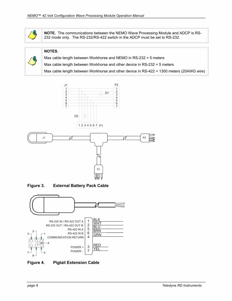
NOTE. The communications between the NEMO Wave Processing Module and ADCP is RS-232 mode only. The RS-232/RS-422 switch in the ADCP must be set to RS-232.
NOTES.
Max cable length between Workhorse and NEMO in RS-232 = 5 meters
Max cable length between Workhorse and other device in RS-232 = 5 meters
Max cable length between Workhorse and other device in RS-422 = 1300 meters (20AWG wire)
1234567
J1
D2
P11 2 3 4 5 6 7
D1
P21234567
J1 P2
P1
Figure 3. External Battery Pack Cable
12564
37
POWER +POWER -
COMMUNICATION RETURN
RS-232 IN / RS-422 OUT ARS-232 OUT / RS-422 OUT B
RS-422 IN ARS-422 IN B
BLKWHTBLUBRNGRN
REDYEL
76
5
4
12
3
Figure 4. Pigtail Extension Cable

NEMO™ 42 Volt Configuration Wave Processing Module Operation Manual
P/N 950-6052-00 (February 2007) page 9
Outline Installation Drawing 46
.51.
83
57.7
2.27
108.
24.
26
91.1
3.59
403.
515
.89
176
6.93
13.5
113
.51
237.
79.
36
292
11.5
0
14.5
.57
33.5
1.32
78.1
3.07
NEM
O2
ELEC
TRO
NIC
S
AD
CP
ELE
CTR
ON
ICS
228
8.98
29.1
1.14
33.5
[1.3
2]
4X M
8 S
HC
SEQ
SP
ON
201.
6 B
C
12
34
203.
28.
00
4X
6.53
TH
RU
.26
EQ
SP
ON
19
0.5
BC4X
M6
SHC
SE
Q S
P O
N19
0.5
BC
REM
OVE
ABLE
DU
MM
Y PL
UG
15.
0°
15.
0°
91.9
03.
62
A 15
CO
NE
AR
OU
ND
EA
CH
BE
AM
KEE
P O
BS
TRU
CTI
ON
S O
UT
OF
THIS
REG
ION
, WH
ICH
INC
LUD
ES
C. B
UBEL
A
PRO
JEC
T
63
Figure 5. Outline Installation Drawing – Integrated Configuration

NEMO™ 42 Volt Configuration Wave Processing Module Operation Manual
page 10 Teledyne RD Instruments
Software Overview You will need BBTalk version 3.06 or higher to communicate with the NEMO. BBTalk is a terminal emulator that allows your computer to communicate with the NEMO via a serial port.
BBTalk Main Screen
Click the Help menu in BBTalk for information about how to use the program.
Communications Tips
• Since the NEMO Wave Processing Module does not echo characters back, you need to select the Echo Characters box on the BBTalk Options screen (see “Testing the NEMO,” page 19). Select NEMO in the BBTalk Connect To screen when you first open a connection will set this on automatically.
• If the NEMO Wave Processing Module is asleep it will not respond to any com-mands.
• Use BBTalk to wake the NEMO Wave Processing Module by sending a hardware break (press the End key) and wait at least three seconds before sending “===” or a command.
NOTE. The NEMO Wave Processing Module needs at least three seconds to wake up from the sleep mode.
NOTE. Under normal operation, the NEMO Wave Processing Module is always in the logging mode. The commands getlatest, dumpconfig, and reloadconfig are the only commands that the NEMO Wave Processing Module accepts without being in the command mode.

NEMO™ 42 Volt Configuration Wave Processing Module Operation Manual
P/N 950-6052-00 (February 2007) page 11
Section 2.0: Preparation and Setup Proper preparation is critical for a successful deployment. In this section we will do a visual inspection to check for obvious damage, install the internal battery, and seal the NEMO for deployment.
This Section Covers:
• Visual Inspection
• NEMO Battery Installation
• NEMO Seal for Deployment
NEMO 42VElectronics
ADCPElectronics
Figure 6. NEMO Overview - Integrated Configuration

NEMO™ 42 Volt Configuration Wave Processing Module Operation Manual
page 12 Teledyne RD Instruments
2
3
4
4
5
6
WORKHORSE SENTINEL
1
4X
4X
4X
4X
4X
Figure 7. NEMO Assembly - Integrated Configuration
1. NEMO Wave Processing Module End-Cap with electronics
2. O-Ring
3. M6 Bolt
4. M6 Flat Washer
5. M6 Split Washer
6. M6 Nut

NEMO™ 42 Volt Configuration Wave Processing Module Operation Manual
P/N 950-6052-00 (February 2007) page 13
Visual Inspection Before deploying the NEMO, make a quick visual inspection of the components to make sure nothing is damaged.
I/O Cable and Dummy Plug
Roll the rubber retaining-strap up so that it does not hinder dummy plug removal.
Remove the dummy plug by pulling with a straight-out motion. Do not wiggle the connector up; this can damage the con-nector. A slight side-to-side wiggle as you are pulling on the cable is OK.
Visual Inspection
Inspect the pins for damage. Make sure that they are straight and that there is no corrosion on the metal surfaces.
Inspect the NEMO housing and end caps for damage. There should be no missing hardware, cracks or peeling surfaces.

NEMO™ 42 Volt Configuration Wave Processing Module Operation Manual
page 14 Teledyne RD Instruments
Battery Installation Before you use the NEMO, you must install the battery. To install the battery pack, do the fol-lowing steps.
NOTE. When the NEMO Wave Processing Module is shipped, the battery is installed but not connected. Open the unit and connect the battery cable.
Place the NEMO on its connector side end-cap.
Loosen and remove the four M6 bolts holding the battery side end-cap to the housing.
Gently slide the end-cap and battery assembly out of the housing.
Disconnect the battery cable from the connector.
Remove old Battery
Remove the rubber band, four wing nuts, lock washers, and washers holding the battery pack onto the posts.
Remove the support plate.
Slide the used battery pack off of the posts.
SUPPORT PLATE
BATTERY PACK
BATTERY POWER CABLE
THREADED ROD (4)
END CAP
SPACER (4)
WING NUT (4)LOCK WASHER (4)FLAT WASHER (4)
Slide a new battery pack onto the four posts. Make sure the cable is not pinched by the battery pack.
Position the support plate over the four posts.
Place a flat washer, lock washer, and wing nut on each of the four posts. Tighten the wing nuts firmly to hold the battery in place.
Place a battery pack rubber band (two spare rubber bands are provided with each new battery) around all four wing nuts. This will prevent the wing nuts from backing off the post.
Use a large rubber band to hold the ca-bles in place.

NEMO™ 42 Volt Configuration Wave Processing Module Operation Manual
P/N 950-6052-00 (February 2007) page 15
CAUTION. The battery pack is held in place by four sets of washers, lock washers, and wing nuts. If the wing nuts are not tight, the assembly of washers and wing nut can become loose and eventually fall onto the electronics. This could cause a short circuit. Place a rubber band around the wing nuts to help hold them in place.
Test the battery pack voltage by meas-uring across the battery connector. The voltage should be +42 VDC or higher for a new battery pack.
Connect the battery cable.
Seal for Deployment Before you put the NEMO into the water, you must seal it for deployment.
Clean the O-ring groove
Clean and inspect the O-ring grooves. Be sure the grooves are free of foreign matter, scratches, indentations, and pit-ting.
Thoroughly remove any old silicone lubricant.
Install a new O-ring
Lubricate the O-ring with a thin coat of silicone lubricant – just enough to make the O-ring “shiny”.
Apply the lubricant using latex gloves. Do not let loose fibers or lint stick to the O-ring. Fibers can provide a leakage path.
CAUTION. Check the O-ring groove thoroughly. Any foreign matter in the O-ring groove or a pinched O-ring will cause the NEMO module to flood.
CAUTION. Apply a very thin coat of silicone lube on the O-ring – just enough to make the O-ring “shiny”. Using too much silicone lube on the O-ring can be more harmful than using no O-ring lube at all.

NEMO™ 42 Volt Configuration Wave Processing Module Operation Manual
page 16 Teledyne RD Instruments
Replace Desiccant
Desiccant bags are used to dehumidify the housing interior.
Remove the old desiccant bag.
Remove the new desiccant bags from the airtight aluminum bag.
Place a new desiccant pack and mois-ture indicator into the housing, next to the electronics.
2-260 O-RING WITHDC-111 SILICONE LUBRICANT
M6X1.0X45 SOCKET HEAD
12.5mm M6 FLAT WASHERM6 SPLIT LOCK
END-CAP
12.5 M6 FLAT WASHER
M6X1.0 HEX NUT
HOUSING
Close Module
Slide the end-cap onto the housing.
Make sure no wires become pinched or that the O-ring falls out of the groove.
Install Hardware
Install all four sets of hardware until “finger-tight.”
Torque Bolts
Tighten the bolts in small increments in a “cross” pattern until the split washer flattens out, and then tighten each bolt ¼ turn more to compress the face seal O-ring evenly.
Tighten the bolts to the recommended torque value of 5.6 Newton-meters (50 pound-inches).
CAUTION. Do not replace the titanium hardware with any other hardware. Corrosion could cause the hardware to fail.

NEMO™ 42 Volt Configuration Wave Processing Module Operation Manual
P/N 950-6052-00 (February 2007) page 17
Section 3.0: Bench Testing The bench-testing process ensures that the NEMO Wave Processing Module is working prop-erly before you put it in the water. The bench-test procedure involves powered tests that will verify that the NEMO’s electronics are functioning.
This Section Covers:
• NEMO Connections • Testing the NEMO
NEMO Connections You will now connect the NEMO Wave Processing Module to a computer that has BBTalk installed.
+42 VDCEXTERNALBATTERY
NEMO
TO ACOUSTIC MODEM or PIGTAILTO COMPUTER (FOR SETUP)
EXTENSION CABLE
OPTIONAL EXTERNAL BATTERY CABLE
EXTERNAL BATTERY CASE
AND CABLESOLD SEPARATELY
ADCP
Note: Multiple External batteries can be used.
Figure 8. NEMO Connections – Self-Contained Configuration
+42 VDCEXTERNALBATTERY
TO ACOUSTIC MODEM or PIGTAILTO COMPUTER (FOR SETUP)
OPTIONAL EXTERNAL BATTERY CABLE
EXTERNAL BATTERY CASE
AND CABLESOLD SEPARATELY
SENTINEL ADCPWITH
NEMO ELECTRONICS
Figure 9. NEMO Connections – Integrated Configuration

NEMO™ 42 Volt Configuration Wave Processing Module Operation Manual
page 18 Teledyne RD Instruments
NOTE. Battery replacement induces both single and double cycle compass errors in the ADCP. The ADCP compass accuracy should be verified after replacing the NEMO battery pack. The compass does not have to be recalibrated if the compass verification passes specification.
If the NEMO unit and all external battery packs are placed a minimum of 30 cm away from the ADCP, no compass calibration will be required.
[BREAK Wakeup A] WorkHorse Broadband ADCP Version 16.28 RD Instruments (c) 1996-2005 All Rights Reserved. > cb711 > >CK [Parameters saved as USER defaults] >
Connect the ADCP to the computer and use BBTalk to verify that the baud rate is set to 57600.
Once the ADCP baud rate is set, exit BBTalk and disconnect the ADCP from the computer.
Open the NEMO Wave Processing Module housing and disconnect the bat-tery cable.
Use the extension cable to connect the NEMO Wave Processing Module and the WorkHorse ADCP. Do so by push-ing straight in against the connector. Don’t wiggle the connector up; this will damage the connector.
NOTE: Place a light amount of silicone lubricant on the connector pins (rubber portion only). This will make it easier to connect or remove the cables and dummy plugs.
Remove the dummy plug and connect the I/O cable between the computer’s serial communication port and the NEMO Wave Processing Module.
NOTE. NEMO units are pre-configured to use RS-232 communications protocols. Your computer’s communication port must match the NEMO, or use an adapter.

NEMO™ 42 Volt Configuration Wave Processing Module Operation Manual
P/N 950-6052-00 (February 2007) page 19
Testing the NEMO Before deploying the NEMO, it is a good idea to make sure that it is working properly. This simple test checks that the NEMO is able to communicate with the computer and ADCP.
Start BBTalk
Start the BBTalk program (for help on using BBTalk, see the RDI Tools User's Guide).
On the Connect To screen, select NEMO. This ensures that the Echo Characters box is selected in the Options screen.
Select the COM port the NEMO cable is connected to.
Click Next.
Enter the Baud Rate, Parity, Stop Bits, and Flow Control. If you are unsure of the settings, leave them at the default settings.
Click Next.
Note: The Baud Rate must be 9600 to “talk” to the NEMO Wave Processing Module unit.
Verify the Echo Characters box is se-lected.
Click Finish.
NEMO™ 42 Volt Configuration Wave Processing Module Operation Manual
page 20 Teledyne RD Instruments
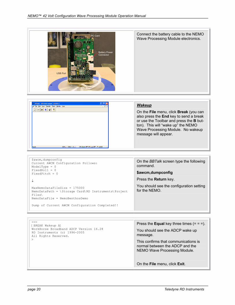
PC Card
USB Port
Battery Power Connector
Connect the battery cable to the NEMO Wave Processing Module electronics.
Wakeup
On the File menu, click Break (you can also press the End key to send a break or use the Toolbar and press the B but-ton). This will “wake up” the NEMO Wave Processing Module. No wakeup message will appear.
$awcm,dumpconfig Current AWCM Configuration Follows: ModelType = 0 FixedRoll = 0 FixedPitch = 0 ↓ MaxNemoDataFileSize = 175000 NemoDataPath = \Storage Card\RD Instruments\Project Files\ NemoDataFile = NemoBenthosDemo Dump of Current AWCM Configuration Completed!!
On the BBTalk screen type the following command.
$awcm,dumpconfig
Press the Return key.
You should see the configuration setting for the NEMO.
=== [BREAK Wakeup A] WorkHorse Broadband ADCP Version 16.28 RD Instruments (c) 1996-2005 All Rights Reserved. >
Press the Equal key three times (= = =).
You should see the ADCP wake up message.
This confirms that communications is normal between the ADCP and the NEMO Wave Processing Module.
On the File menu, click Exit.

NEMO™ 42 Volt Configuration Wave Processing Module Operation Manual
P/N 950-6052-00 (February 2007) page 21
Section 4.0: Troubleshooting the NEMO Use this section if you have a problem communicating with the NEMO Wave Processing Module or ADCP.
PC Card
USB Port
Battery Power Connector
Remove the NEMO Wave Processing Module End Cap/electronics assembly.
Connect the NEMO Wave Processing Module to the ADCP and computer’s serial port.
Start BBTalk.
Disconnect the red/black power cable and then reconnect it in order to recycle the power.
The red LED should light and the NEMO Wave Processing Module should begin to configure the ADCP and start it ping-ing. This should take approximately one minute to complete.
Note: The USB Port is used to upload new NEMO Wave Processing Module software (see “Section 9.0: Upgrade NEMO Software,” page 44).
Fuse
If the ADCP or NEMO Wave Processing Module does not respond, check the NEMO Wave Processing Module cable connections, battery voltage, and fuse (located on the trigger board).
Check that the PCMCIA card is seated properly. If the card is not seated, the NEMO Wave Processing Module soft-ware will not start.
Contact Teledyne RD Instruments Cus-tomer Service department for further help.

NEMO™ 42 Volt Configuration Wave Processing Module Operation Manual
page 22 Teledyne RD Instruments
Section 5.0: Collecting Data This section has simple instructions for using the NEMO Wave Processing Module.
NEMO default Sampling schemeWaves 20 minutes every 3 hours
Currents every 10 minutes
30
10
2040
50
1st Hour
10
20
30
40
50
3rd Hour
10
20
30
40
50
Zero Hour
Waves 2400 pings @ 2Hz
Currents every10 minutes
30
10
2040
50
2nd Hour
10
20
st
10
20
60 Minutes
10
20
10
20
st
rd
180 Minutes
nd Hour
120 Minutes
nd
0 Minutes
Figure 10. NEMO Default Wave and Current Sampling

NEMO™ 42 Volt Configuration Wave Processing Module Operation Manual
P/N 950-6052-00 (February 2007) page 23
Open the NEMO Wave Processing Module housing and disconnect the bat-tery cable.
[BREAK Wakeup A] WorkHorse Broadband ADCP Version 16.28 RD Instruments (c) 1996-2005 All Rights Reserved. >CB711 > >CK [Parameters saved as USER defaults] >
Connect the ADCP to the computer’s serial port using the ADCP’s I/O cable.
Start BBTalk.
Make sure the ADCP baud rate is set to 57600. Use command CB711. Send a CK command to save this setting.
Exit BBTalk and disconnect the ADCP from the computer.
+42 VDCEXTERNALBATTERY
NEMO
TO ACOUSTIC MODEM or PIGTAILTO COMPUTER (FOR SETUP)
EXTENSION CABLE
OPTIONAL EXTERNAL BATTERY CABLE
EXTERNAL BATTERY CASE
AND CABLESOLD SEPARATELY
ADCP
Note: Multiple External batteries can be used.
Connect the NEMO Wave Processing Module I/O cable to the computer’s se-rial port.
Connect the ADCP to the NEMO Wave Processing Module.
Apply power to the ADCP.
Start BBTalk.
Note: the NEMO Wave Processing Module must be set to 9600 Baud (de-fault setting). Contact RDI Field Service if the NEMO Wave Processing Module needs to be set to other baud rates.

NEMO™ 42 Volt Configuration Wave Processing Module Operation Manual
page 24 Teledyne RD Instruments
PC Card
USB Port
Battery Power Connector
Connect the battery cable to the NEMO Wave Processing Module electronics.
æ„ „BXkB”©{kBBFBBOBr�ëIBBJÆïFBÂïBFØNFBBÒNÆÂïFBÂ[�DÒÎÞ!èRÿZÊNÄkâã^kMFß9ê=[RÖÎy�¡åÚù�k5 c^ÿN[mF†„!ˆCÞZoÛ�k5 cc�„¡Ú_noBHBÂ9Íãg„!TúêâÛrk�{KB*i–„!ÆZÊNÄkâã^kMFß9ê=Ëé��Ã_^V�ËîN”�¥á/FÚbcãbLkÆ�ùýînRbBŠy�%Nn=ÎÒyB9ÂÃb„¡J�Ä�3!„Ô+_Ç~C_?nCÿÎ΄…¹ýyFCNþ„�ýÄ9NõÄ cÆú^€”VN�!Þõá%CBÎLþú ËÚ¥mêÆþ���¯'¬�³Î^ýkŒ¯ûSZßB-ÔëB�†%�jzJÛ=ÆB�k†¡~ZïFC9S�’”y�!âCSú{�”µ÷ïëFÓß÷ã{NZßÂ_mJ)ù}BZB@”NާƆµFZßÂ_-çJþBÔù}BZB@”NާƆµFjßBÆ„ú[Þ-zÄJ~ë^ïzÄJþEntering ADCP Auto Detect in Progress - Please Wait!! Nemo Version 2.01 Teledyne RD Instruments (c) 2003-2005 All Rights Reserved. Entering Command Mode - Wave Sample ABORTED!! No Reply From ADCP!! ADCP FOUND During Startup and time sync success!! Posting configuration to ADCP!! [BREAK Wakeup A] WorkHorse Broadband ADCP Version 16.28 RD Instruments (c) 1996-2005 All Rights Reserved. >CR1 [Parameters set to FACTORY defaults] > >CF11110 ↓ >ED00700 >
At startup of NEMO, you will see “junk” characters on the BBTalk screen; this is the WindowsCS startup.
The NEMO Software application will then start and automatically do the fol-lowing:
• Initialize the WorkHorse ADCP,
• Sync the clock with the ADCP’s clock,
• Start the deployment, and then
• Go to sleep.
Note: WindowsCS starts up with a de-fault baud-rate of 38400 and when the NEMO application starts it will change it to 9600 baud.

NEMO™ 42 Volt Configuration Wave Processing Module Operation Manual
P/N 950-6052-00 (February 2007) page 25
Disconnect the I/O cable between the NEMO Wave Processing Module and the computer and connect the acoustic modem or other telemetry device.
Seal the NEMO Wave Processing Mod-ule housing (see “Seal for Deployment,” page 15).
Reconfigure the NEMO Wave Processing Module $awcm,load1200khz Entering Command Mode - Wave Sample ABORTED!! $awcm,savelast $awcm,reloadconfig Posting configuration to ADCP!! Sending CS Command and Exiting Command Mode!!
If the NEMO Wave Processing Module needs to be reconfigured from the fac-tory defaults, do the following.
Send the NEMO Wave Processing Module unit a Break (press the End key). Wait at least 4 seconds before continuing to allow the NEMO Wave Processing Module to reconfigure itself.
Type $awcm,loadxxxxkHz and press Return (where xxxx is the Wave ADCP system frequency).
Type $awcm,savelast and press Return.
Type $awcm,reloadconfig and press Return.

NEMO™ 42 Volt Configuration Wave Processing Module Operation Manual
page 26 Teledyne RD Instruments
Get Last Current Record and Last Wave Message Use the $awcm,getlatest command to get the last current record and the last wave message. The NEMO Wave Processing Module will timeout after sending the data and then go back to sleep and continue normal operation.
$awcm,getlatest $CRNT,10/20/05 11:18:35, 011, 001, 016, 004, 54.662, 23.02, 0.23,-1.20,0.21, -1.30,……….
Start BBTalk.
Press the End key to send a hardware break to the NEMO, to get wake NEMO from a sleep and wait 3 seconds and then type $awcm,getlatest and press Return.
See Table 5, page 41 for the data for-mat. This command is normally used with Seabird’s Inductive modems but can be used with other modems as well.
Retrieve Data from NEMO’s Recorder Card All the wave and current data Nemo sends to the serial port is also stored on Nemo’s recorder card. NEMO does not store the raw data from the Workhorse on its recorder card.
The only way to retrieve all the data from the NEMO’s recorder card is to take the card out of NEMO and install it in a laptop and copy the data to you hard-drive.
It is recommended to delete all the data files on NEMO’s recorder card before starting a new deployment. This must be done with a laptop/PC. The plain text files are located on the \RD Instruments\Project Files folder.
CAUTION. Do not edit or delete files in the \Program Files\RD Instruments\NEMO folder.

NEMO™ 42 Volt Configuration Wave Processing Module Operation Manual
P/N 950-6052-00 (February 2007) page 27
Section 6.0: NEMO Commands === Description Sending = = = (3 equal signs) puts the NEMO Wave Processing Module in to the
command mode. This command has to be sent before any NEMO Wave Process-ing Module command can be issued.
NOTE. Under normal operation, the NEMO Wave Processing Module is always in the logging mode. The commands getlatest, dumpconfig, and reloadconfig are the only commands that the NEMO Wave Processing Module accepts without being in the command mode.
depthcellsize Description Sets the depth cell size. Default 200 (300 kHz), 75 (600 kHz), 35 (1200 kHz) the unit is cm Range 15 to 800 Example See below. $awcm,depthcellsize75
depthoffset Description Sets the DepthOffset. This is to correct the pressure sensor if it doesn’t read the
correct depth. Default 0 dm Range 0 to 500 dm Example See below. $awcm,depthoffset0
dumpconfig Description Prints all the values for the current configuration. Default N/A Range N/A Example See below. $awcm,dumpconfig Current AWCM Configuration Follows: ModelType = 1 FixedRoll = 0 FixedPitch = 0 Tilts = 0 HPRSeries = 0 DirP2 = 0 ↓ MaxNemoDataFileSize = 275000 NemoDataPath = \Storage Card\RD Instruments\Project Files\ NemoDataFile = Nemo_600_Dat Dump of Current AWCM Configuration Completed!!
NOTE. This command does not require the NEMO Wave Processing Module to be in the command mode. When done executing the command, NEMO will go to sleep.

NEMO™ 42 Volt Configuration Wave Processing Module Operation Manual
page 28 Teledyne RD Instruments
EPB Description Sets the number of pings in a wave-burst. Default 2100 Range 128 to 4000 pings Example See below. $awcm,epb2400
fftlen Description Sets the FFTLen value in the configuration. Default 2048 Range 128 to 2048 Example See below. $awcm,fftlen2048
findadcp Description Finds the baud-rate of the Workhorse. Default N/A Range N/A Example See below. $awcm,findadcp ADCP Auto Detect in Progress - Please Wait!! Trying COM1, 9600, 8, None, 1 No Reply!! No Reply!! No Reply!! Trying COM1, 9600, 8, Even, 1 ↓ ↓ Trying COM1, 38400, 8, Space, 1 Trying COM1, 57600, 8, None, 1 ADCP Found at COM1, 57600, 8, None, 1 Data Detected - Aborting Command Mode!!
getappversion Description Prints the banner. Default N/A Range N/A Example See below. $awcm,getappversion Teledyne RD Instruments NEMO Waves 2.01
getauditfile Description Prints the contents of the AuditFile. This command is for engineering use only. Default N/A Range N/A Example See below. $awcm,getauditfile 13/10/2005 13:56:40 | User: ERROR: 0x00000000 | Event: SurfaceTrack Screened Burst # 21 13/10/2005 14:56:39 | User: ERROR: 0x00000000 | Event: Down Facing ADCP Detected and not ExpectedCommand GetAuditFile Completed

NEMO™ 42 Volt Configuration Wave Processing Module Operation Manual
P/N 950-6052-00 (February 2007) page 29
getavaildiskspace Description Prints the available disk space. Default N/A Range N/A Example See below. $awcm,getavaildiskspace Available Disk Space: 5166164 bytes Total Bytes : 5816320 bytes Total Free Bytes: 5166164 bytes
getawcmsystime Description Prints the NEMO Wave Processing Module’s system date and time. Default N/A Range N/A Example See below. $awcm,getawcmsystime AWCM System time 01/01/80 09:35:21.000
geterrorfile Description Prints the content of the ErrorLogFile. This command is for engineering use only. Default N/A Range N/A Example See below. 03/10/2005 19:25:44 | Module: ERROR: 0x00000000 in \FlashFX Disk\Program Files\RD Instru-ments\NEMO\Waves_Codec.dll | Source Addr: 0 | Class: Runtime | Type: Win32 | Priority: Low | HRESULT 0x00000000 | Msg: Waves Packet BAD CHECKSUM Command GetErrorFile Completed
getfilelist Description Prints the file list of any directory. Default N/A Range N/A Example See below. $awcm,getfilelist\Storage Card\RD Instruments\Project Files\*.* Nemo_600_Dat000nemo.DAT <Size 57754 bytes> Nemo_600_Dat001nemo.DAT <Size 275065 bytes> Nemo_600_Dat002nemo.DAT <Size 275006 bytes> Nemo_600_Dat003nemo.DAT <Size 275068 bytes> Nemo_600_Dat004nemo.DAT <Size 157882 bytes> Nemo_600_Dat005nemo.DAT <Size 12 bytes> Nemo_600_Dat006nemo.DAT <Size 2614 bytes> Nemo1200_Dat000nemo.DAT <Size 546 bytes> Nemo1200_Dat001nemo.DAT <Size 174 bytes> Nemo1200_Dat002nemo.DAT <Size 336 bytes> Nemo1200_Dat003nemo.DAT <Size 12 bytes> Nemo_600_Dat007nemo.DAT <Size 12 bytes> Nemo_600_Dat008nemo.DAT <Size 12 bytes> Command GetFileList Completed

NEMO™ 42 Volt Configuration Wave Processing Module Operation Manual
page 30 Teledyne RD Instruments
getlatest Description Prints the last wave and current records. If getlatest is followed by a number, it
will get the last X wave and current records. Default N/A Range maximum 300 Example See below. $awcm,getlatest $WAVES,10/17/05 18:07:56,8.35,6.20,030,338.07 $CRNT,10/17/05 18:57:56,006,002,016,001,5538.354,24.80,-1.267,-0.990,00.096,-1.474,-0.380,-0.216,-1.423,-1.031,-0.332,-1.628,-1.402,00.274,-1.141,-1.022,00.049,-1.405,-1.209,-0.056,-1.371,-1.165,00.151,-1.294,-1.138,00.149,-1.468,-0.902,00.041,-1.232,-1.066,00.346,-1.540,-1.091,00.322,-1.518,-1.024,00.075,-1.493,-0.925,00.308,-1.527,-0.908,00.006,-1.488,-0.913,-0.106
NOTE. This command does not require the NEMO Wave Processing Module to be in the command mode. When done executing the command, NEMO will go to sleep after two seconds.
getsizeoffile Description Gets the size of a specified file. Default N/A Range N/A Example See below. $awcm,getsizeoffile\Storage Card\RD instruments\Project\Nemo_300_0000.dat
gotosleepnow Description This command will take the NEMO Wave Processing Module out of command
mode and put NEMO to sleep. Default N/A Range N/A Example See below. $awcm,gotosleepnow
NOTE. This command will not start the WorkHorse or set the TX command in the WorkHorse.
headingoffset Description Sets the HeadingOffset2 value (EB) in 1/100 degree in configuration. This head-
ing will set the EB command in the WorkHorse. Default 0 degrees Range -17999 to 18000 degrees Example See below. $awcm,headingoffset0

NEMO™ 42 Volt Configuration Wave Processing Module Operation Manual
P/N 950-6052-00 (February 2007) page 31
load1200khz Description Loads the WorkHorse 1200k Hz factory defaults into the current settings. Default N/A Range N/A Example See below. $awcm,load1200khz
And the Nemo will respond back with: 1200kHz Defaults LOADED!!
load600khz Description Loads the WorkHorse 300k Hz factory defaults into the current settings. Default N/A Range N/A Example See below. $awcm,load600khz
And the Nemo will respond back with: 600kHz Defaults LOADED!!
load300khz Description Loads the WorkHorse 600k Hz factory defaults into the current settings. Default N/A Range N/A Example See below. $awcm,load300khz
And the Nemo will respond back with: 300kHz Defaults LOADED!!
loadlast Description Forces loading of the default project Last Settings. Default N/A Range N/A Example See below. $awcm,loadlast
nomdepth Description Sets the NomDepth value in decimeters in the configuration. This command is
used to over-write the range value from surface track in the waves-message. If nomdepth is set to 0, NEMO will use the range to the surface as depth.
Default 0 dm Range 0 to 9999 dm Example See below. $awcm,nomdepth0

NEMO™ 42 Volt Configuration Wave Processing Module Operation Manual
page 32 Teledyne RD Instruments
nominalheading Description Sets the HeadingOffset value in 1/100 degree in the configuration. Default 0 degrees Range 0 to 36000 Example See below. $awcm,nominalheading0
numprocessbins Description Sets the numbers of bins in the current profile. Default 35 (300 kHz), 59 (600 kHz), 42 (1200 kHz) Range 10 to 128 bins Example See below. $awcm,numprocessbins35
pingsperens Description Sets the number of pings in an ensemble. Default 60 Range 1 to 100 pings Example See below. $awcm,pingsperens60
reloadconfig Description Reloads the current settings into the Workhorse. Default N/A Range N/A Example See below. $awcm,reloadconfig Posting configuration to ADCP!! Sending CS Command and Exiting Command Mode!! Last Settings RELOADED!!
NOTE. This command does not require the NEMO Wave Processing Module to be in the command mode. When done executing the command, NEMO will go to sleep.
resetauditfile Description This command will erase the AuditFile. Default N/A Range N/A Example See below. $awcm,resetauditfile Command ResetAuditFile Succeeded

NEMO™ 42 Volt Configuration Wave Processing Module Operation Manual
P/N 950-6052-00 (February 2007) page 33
resetdefault Description Deletes all values in current settings. Default N/A Range N/A Example See below. $awcm,resetdefault Command DeleteFile Completed
reseterrorfile Description This command will erase the ErrorLogFile. Default N/A Range N/A Example See below. $awcm,reseterrorfile Command ResetErrorFile Succeeded
savelast Description Save settings in memory into current settings. Default N/A Range N/A Example See below. $awcm,savelast
The NEMO will respond back with: Last Settings SAVED!!
setadcpbaud Description Set baud-rate of the Workhorse. Default 57600 Baud Range 9600 to 5700 Baud Example See below. $awcm,setadcpbaud57600
setadcpnemobaud Description Set the baud-rate of NEMO’s serial-port to the Workhorse and the Workhorse Default 57600 Baud Range 9600 to 57600 Baud Example See below. $awcm,setadcpnemobaud57600

NEMO™ 42 Volt Configuration Wave Processing Module Operation Manual
page 34 Teledyne RD Instruments
setaltitude Description This command sets the altitude of the Workhorse. This value is needed for the
wave-processing. Default 5 dm Range 1 to 1400 dm Example See below. $awcm,setaltitude5
setensemble Description Sets the time between ensembles. Value should not be set higher than 15 minutes. Default 10 minutes Range 2 to 15 minutes Example See below. $awcm,setensemble001000
setnemobaud1 Description Sets the baud-rate between the NEMO Wave Processing Module and the Work-
horse ADCP. Default 57600 Range 9600 to 57600 Example See below. $awcm,setnemobaud1
setnemobaud3 Description Sets the baud-rate between the NEMO Wave Processing Module and output port. Default 9600 Range 300 to 115200 Example See below. $awcm,setnemobaud39600
setoutputdepthcell Description Sets the number of the last bin to be output in the current output message. This
corresponds to the label in dumpconfig CurrBins2OutputY. Default 30 (300 kHz), 54 (600 kHz), 42 (1200 kHz) Range 2 to 128 bins Example See below. $awcm,setoutputdepthcell54

NEMO™ 42 Volt Configuration Wave Processing Module Operation Manual
P/N 950-6052-00 (February 2007) page 35
setoutputfirstcell Description Sets the first number of the first bin to output in the current message. This corre-
sponds to the label in dumpconfig CurrBins2OutputX. Default 1 bin Range 1 (minimum) to 128 bins Example See below. $awcm,setoutputfirstcell1
setoutputstep Description Set the number of bins between output bins in the current message. This corre-
sponds to the label in dumpconfig CurrBins2OutputZ. Default 3 bins Range 1 to 64 bins Example See below. $awcm,setoutputfirstcell3
setstartat Description Sets a date and time for the NEMO to start. If the date and time is in the past or
the NEMO is reset, the NEMO Wave Processing Module will set setstartat to the next hour. To remove the start time, send the command with no date/time ($awcm,setstartat).
Default OFF Example See below. $AWCM,SETSTARTATyyyy/mm/dd,hh:mn:ss
setwaveburst (TBB) Description Sets the time between bursts. Default 60 min Range 30 to 720 Example See below. $awcm,setwaveburst60
startrawdata Description Sets the Nemo’s serial-port to raw binary mode. This mode does not support the
Y-modem protocol. Default N/A Range N/A Example See below. $awcm,startrawdata

NEMO™ 42 Volt Configuration Wave Processing Module Operation Manual
page 36 Teledyne RD Instruments
stoprawdata Description Sets NEMO back to default text mode. Default N/A Range N/A Example See below. $awcm,stoprawdata
timebetweenpings Description Sets the time between pings. A value of 2 will send TP00:02.00 to the ADCP. Default 2 sec Range 1 to 180 Example See below. $awcm,timebetweenpings2
xducerdepth Description This command will set the ED command in the Workhorse. Default 700 (300 kHz), 400 (600 kHz), 100 (1200 kHz) the unit is dm Range 1 to 9999 Example See below. $awcm,xducerdepth700

NEMO™ 42 Volt Configuration Wave Processing Module Operation Manual
P/N 950-6052-00 (February 2007) page 37
Section 7.0: NEMO Factory Defaults Table 1. NEMO Wave Processing Module Factory Defaults 300KHz 600KHz 1200KHz ExpectWavePackets 1 1 1 Currents 0 0 0 CalPressFromSurf 0 0 0 DoUVW 0 0 0 ApplyMagVar 0 0 0 ModelType 1 1 1 FixedRoll 0 0 0 FixedPitch 0 0 0 Tilts 0 0 0 HPRSeries 0 0 0 DirP2 0 0 0 SmallWaveFreq (unit mm) 100 100 100 SmallWaveThresh 0 0 0 BottomSlopeX 0 0 0 BottomSlopeY 0 0 0 DirFreqBands 128 128 128 AutoBinSel 1 1 1 Iter 1 1 1 ScaleSpec 0 0 0 RemoveBias 1 1 1 ClipPwrSpec 0 0 0 HeadingOffset 0 0 0 HeadingOffset2 0 0 0 VelMin -5000 -5000 -5000 VelMax 5000 5000 5000 VelSTD 4 4 4 VelMaxChng 400 400 400 VelPctGd 80 80 80 SurfMin 0 0 0 SurfMax 100000 100000 100000 SurfSTD 4 4 4 SurfMaxChng 2000 2000 2000 SurfPctGd 90 90 90 TBEMaxDev 500 500 500 HMaxDev 0 0 0 PRMaxDev 0 0 0 FixSOS 0 0 0 NFreqBins 128 128 128 FFTLen 2048 2048 2048 WindowType 1 1 1 Surf4Depth 1 1 1 Press4Depth 0 0 0 TransV2Surf 1 1 1
Continued Next Page

NEMO™ 42 Volt Configuration Wave Processing Module Operation Manual
page 38 Teledyne RD Instruments
Table 1. NEMO Wave Processing Module Factory Defaults (continued) 300KHz 600KHz 1200KHz VSpecOffset 0 0 0 SSpecOffset 0 0 0 PSpecOffset 0 0 0 ORGain 0.9 0.9 0.9 FreqThresh 0.22 0.22 0.22 SFreqThresh 0.65 0.65 0.65 PFreqThresh 0.2 0.2 0.2 LFreqThresh 0.01 0.01 0.01 SampleRate 2 2 2 HsScale 0.001 0.001 0.001 EScale 0.00001 0.00001 0.00001 HWarnLevel 3 3 3 HDanger 15 15 15 TpWarnLevel 9 9 9 TpDanger 9 9 9 NHrsHist 24 24 24 WaveParamSource 86 86 86 ProcBins 0 0 0 NBeams 4 4 4 NBins 0 0 0 VelBins 0 0 0 WaveParams 1 1 1 Skip 0 0 0 NomDepth 0 0 0 XdcrAlt (unit dm) 5 5 5 DepthOffset 0 0 0 AltOffset 0 0 0 ExternAlt 0 0 0 NDir 90 90 90 NBursts 0 0 0 VelTimeSeries 0 0 0 IntTimeSeries 0 0 0 SurfTimeSeries 0 0 0 PressTimeSeries 0 0 0 VelSpectra 1 1 1 SurfSpectra 1 1 1 PressSpectra 1 1 1 DirSpectra 1 1 1 SrfDirSpectra 0 0 0 PVelTimeSeries 1 1 1 PIntTimeSeries 0 0 0 PSurfTimeSeries 1 1 1 PPressTimeSeries 1 1 1 PVelSpectra 1 1 1 PSurfSpectra 1 1 1 PPressSpectra 1 1 1 PDirSpectra 1 1 1 PSrfDirSpectra 0 0 0

NEMO™ 42 Volt Configuration Wave Processing Module Operation Manual
P/N 950-6052-00 (February 2007) page 39
Table 1. NEMO Wave Processing Module Factory Defaults (continued) 300KHz 600KHz 1200KHz PWaveParams 1 1 1 EPB 2100 2100 2100 TBE 50 50 50 TBB 3600 3600 3600 BeamConf 20 20 20 HorzSetup 0 0 0 DownSetup 0 0 0 XducerDepth 700 400 100 PingsPerEns 60 60 60 DepthCellSize 200 75 35 NumProcessBins 35 59 42 TimePerEns 600 600 600 TimeBetweenPings 2 2 2 FirstBinToOutput 1 1 1 TotalBinToOutput 30 54 42 BinSubSampleParam 3 3 3 SendWC0 0 0 0 StartTime VSpecBins 4,5,8,15,16 4,5,8,15,16 4,5,8,15,16 DirSpecBins 4,5,8,15,16 4,5,8,15,16 4,5,8,15,16 MaxNemoDataFileSize 275000 275000 275000 NemoDataPath \Storage Card\RD Instruments\Project Files\ NemoDataFile Nemo300_Dat Nemo600_Dat Nemo1200_Dat

NEMO™ 42 Volt Configuration Wave Processing Module Operation Manual
page 40 Teledyne RD Instruments
Section 8.0: Output Data Format The NEMO Wave Processing Module transmits a NMEA183 messages for wave and current data.
NEMO Processed Directional Wave Data Formats Table 2. NEMO Processed Directional Wave Data Format – Message 0 String Description
$ HEX 24 – start of sentence WAVE Address field <mm/dd/yy hr:mm:ss> Date and time field. Leading zeros are always included to maintain fixed length.
Date - 2 fixed digits for month, 2 fixed digits for day, and 2 fixed digits for year. Time - 2 fixed digits of hours, 2 fixed digits of minutes, and 2 fixed digits of seconds.
<Hs> Significant Wave Height (meters) 04 MHs =
<Tp> Peak Wave Period (seconds) <Dp> Peak Wave Direction (degrees) <WaterLevel> Water Level (this is obtained from the surface track) (meters) <CR><LF> HEX 0D 0A – End of sentence
Example:
$wAVE,mm/dd/yy hh:mn:ss,Hs,Tp,Dp,WL*HH<CR><LF> $wAVE,10/27/05 01:26:33,0.58,0.73,239,10.68*7C
Table 3. NEMO Processed Directional Wave Data Format – Message 1 String Description
$ HEX 24 – start of sentence WAVESE Address field <mm/dd/yy hr:mm:ss> Date and time field. Leading zeros are always included to maintain fixed length.
Date - 2 fixed digits for month, 2 fixed digits for day, and 2 fixed digits for year. Time - 2 fixed digits of hours, 2 fixed digits of minutes, and 2 fixed digits of seconds.
<Hs> Significant Wave Height (meters) 04 MHs =
<Hmax> Maximum Wave Height (meters) <Tp> Peak Wave Period (seconds)
<Tz> Mean-Zero Up-Cross Period (seconds)
2
0
MMTz =
<T01> Mean Period (seconds) 1
001 M
MTT mean ==
<Dp> Peak Wave Direction (degrees) <WaterLevel> Water Level (this is obtained from the surface track) <CR><LF> HEX 0D 0A – End of sentence
Example:
$WAVESE,mm/dd/yy hh:mn:ss,Hs,Hmax,Tp,Tz,T01,Dp,WL*HH $WAVESE,10/27/05 01:26:33,0.58,0.73,9.80,7.23,7.54,297,10.68*3C

NEMO™ 42 Volt Configuration Wave Processing Module Operation Manual
P/N 950-6052-00 (February 2007) page 41
Table 4. NEMO Processed Directional Wave Data Format – Message 2 String Description
$ HEX 24 – start of sentence WAVES01 Address field <mm/dd/yy hr:mm:ss> Date and time field. Leading zeros are always included to maintain fixed length.
Date - 2 fixed digits for month, 2 fixed digits for day, and 2 fixed digits for year. Time - 2 fixed digits of hours, 2 fixed digits of minutes, and 2 fixed digits of seconds.
<WaterLevel> Water Level (this is obtained from the surface track) (meters) <Dp> Peak Wave Direction (degrees) <Hs> Significant Wave Height (meters)
04 MHs =
<Hmax> Maximum Wave Height (meters)
<Tz> Mean-Zero Up-Cross Period (seconds) 2
0
MMTz =
<Tp> Peak Wave Period (seconds) <CR><LF> HEX 0D 0A – End of sentence
Example: $WAVES01,DateTime,WL,Dp,Hs,Hm,Tz,Tp*HH $WAVES01,10/29/06 00:26:33,10.49,273.0,0.52,0.67,5.44,7.10*4F
NEMO Processed Current Profile Data Format Table 5. NEMO Processed Current Profile Data Format – Message 0 String Description
$ HEX 24 – start of sentence CRNT Address field <mm/dd/yy hr:mm:ss> Date and time field. Leading zeros are always included to maintain fixed length.
Date - 2 fixed digits for month, 2 fixed digits for day, and 2 fixed digits for year. Time - 2 fixed digits of hours, 2 fixed digits of minutes, and 2 fixed digits of seconds.
<Ens#> Ensemble number <StartBin> Start bin to output <StopBin> Last bin to output <StepBin> Step between bins <WaterLevel> Water level (from pressure sensor) (meters) <Temp> Water temperature (degrees Celsius ) <EastVelBin1>, <NorthVelBin1>, <ErrorVelBin1>
East velocity, North velocity component for the first bin to output (meters)
…………….. <EastVelBinN>, <NorthVelBinN>, <ErrorVelBinN>
East velocity, North velocity component for the last bin to output (meters)
<CR><LF> HEX 0D 0A – End of sentence
Example: $CRNT,<Date Time>, <Ens#>, <StartBin>,<StopBin>, <Step>, <WaterLevel>, <Temp>, <EastVelBin1>, <NorthVelBin1> ....................<EastVelBinN>,<NorthVelBinN><CR><LF> $CRNT, 10/17/05 10:47:56,6,2,16,1,38.354,24.8, -1.267,-0.99,0.096,-1.474,-0.38,-0.216,-1.423,-1.031,-0.332,-1.628,-1.402,0.274,-1.141,-1.022,0.049,-1.405,-1.209,-0.056,-1.371,-1.165,0.151,-1.294,-1.138,0.149,-1.468,-0.902,0.041,-1.232,-1.066,0.346,-1.54,-1.091,0.322,-1.518,-1.024,0.075,-1.493,-0.925,0.308,-1.527,-0.908,0.006,-1.488,-0.913,-0.106

NEMO™ 42 Volt Configuration Wave Processing Module Operation Manual
page 42 Teledyne RD Instruments
Table 6. NEMO Processed Current Profile Data Format – Message 1 String Description
$ HEX 24 – start of sentence CRNTMD Address field <mm/dd/yy hr:mm:ss> Date and time field. Leading zeros are always included to maintain fixed length.
Date - 2 fixed digits for month, 2 fixed digits for day, and 2 fixed digits for year. Time - 2 fixed digits of hours, 2 fixed digits of minutes, and 2 fixed digits of seconds.
<Ens#> Ensemble number <StartBin> Start bin to output <StopBin> Last bin to output <StepBin> Step between bins <WaterLevel> Water level (from pressure sensor) (meters) <Temp> Water temperature (degrees Celsius ) <Mag_Bin1>, <Dir_Bin1>, <Err_Bin1>
Magnitude, Direction, ErrorVelocity component from the first bin to output (meters/sec, degrees, meter/sec)
…………….. <Mag_BinN>, <Dir_BinN>, <Err_BinN>
Magnitude, Direction, ErrorVelocity component from the first bin to output (meters/sec, degrees, meter/sec)
<CR><LF> HEX 0D 0A – End of sentence
Example: $CRNTMD,<yyyy/mm/dd hh:mm:ss>, <Ens#>, <StartBin>,<StopBin>, <Step>, <WaterLevel>, <Temp>, <Mag_bin1>, <Dir_bin1>, <Err_bin1>...................., <Mag_binN>, <Dir_binN>, <Err_binN>*HH<CR><LF> $CRNTMD,10/27/05 00:26:33,001, 001, 042, 003 , 11.543,15.99, 00.079,341.6,-0.025,00.075,341.6,00.035,263.5,-0.035,-0.004,263.5,00.050,224.2,-0.035,-0.036,224.2,00.047,194.9,-0.012,-0.045,194.9,00.040,229.1,-0.030,-0.026,229.1,00.045,152.3,00.021,-0.040,152.3,00.068,190.2,-0.012,-0.067,190.2,00.054,186.3,-0.006,-0.054,186.3,00.045,171.0,00.007,-0.044,171.0,00.142,108.4,00.135,-0.045,108.4,00.085,115.7,00.077,-0.037,115.7,00.092,119.4,00.080,-0.045,119.4,-32768,-32768,-32768,-32768,-32768,-32768,-32768,-32768,-32768,-32768*33

NEMO™ 42 Volt Configuration Wave Processing Module Operation Manual
P/N 950-6052-00 (February 2007) page 43
Table 7. NEMO Processed Current Profile Data Format – Message 2 String Description
$ HEX 24 – start of sentence CRNT01 Address field <mm/dd/yy hr:mm:ss> Date and time field. Leading zeros are always included to maintain fixed length.
Date - 2 fixed digits for month, 2 fixed digits for day, and 2 fixed digits for year. Time - 2 fixed digits of hours, 2 fixed digits of minutes, and 2 fixed digits of seconds.
<Ens#> Ensemble number <StartBin> Start bin to output <StopBin> Last bin to output <StepBin> Step between bins <WaterLevel> Water level (from pressure sensor) (meters) <Temp> Water temperature (degrees Celsius )
<E_vel_bin1>, <N_vel_bin1>, <W_vel_bin1>, <Dir_bin1>,
East velocity, North velocity, West velocity, and Direction component for the first bin to output (meters and degrees)
…………….. <E_vel_bin1>, <N_vel_bin1>, <W_vel_bin1>, <Dir_bin1>,
East velocity, North velocity, West velocity, and Direction component for the last bin to output (meters and degrees)
<CR><LF> HEX 0D 0A – End of sentence
Example: $CRNT01,<yyyy/mm/dd hh:mm:ss>, <Ens#>, <StartBin>,<StopBin>, <Step>, <WaterLevel>, <Temp>, <E_vel_bin1>, <N_vel_bin1>, <W_vel_bin1>, <Dir_bin1>, .................... <E_vel_BinN>, <N_velBinN>, <W_vel_binN> ,<Dir_binN>*HH<CR><LF> $CRNT01,10/27/05 00:56:33,004,001,042,003,11.546,16.26,-0.012,00.047,-0.006,345.7,-0.035,-0.033,-0.008,226.7,00.022,-0.038,00.001,149.9,-0.040,-0.018,-0.008,245.8,-0.043,-0.041,-0.001,226.4,-0.017,-0.034,-0.005,206.6,00.007,-0.036,-0.002,169.0,00.037,-0.029,-0.007,128.1,-0.035,-0.032,-0.006,227.6,00.142,-0.013,00.013,095.2,00.046,-0.065,-0.019,144.7,00.057,-0.006,00.004,096.0,-0.783,00.676,00.162,310.8,-32768,-32768,-32768,-32768*16

NEMO™ 42 Volt Configuration Wave Processing Module Operation Manual
page 44 Teledyne RD Instruments
Section 9.0: Upgrade NEMO Software To field upgrade the NEMO Wave Processing Module software, do the following steps.
Note: If you have not registered on our web site since March 2006, you will first need to register by clicking on this link http://www.rdinstruments.com/product_register_j.html to receive your new account name and password via email.
Use Teledyne RD Instruments’ cus-tomer service Web site (www.rdinstruments.com) and go to the Customer Service section and download the latest NEMO software.
Unzip the file to a temporary directory.
If this is your first time you are upgrad-ing your NEMO Wave Processing Mod-ule, you need to install Microsoft Active-Sync and the Xscale USB drivers on your computer.
To install the Xscale USB driver, do the following.
1. Locate the Xscale sub-folder in-cluded with the NEMO software.
2. Right-click on the wceusbsh.inf file.
3. Select Install.
4. Reboot your computer after install-ing the Xscale USB driver.
5. Download and install Microsoft’s ActiveSync.
NOTE. ActiveSync can be downloaded from Microsoft’s web-site: www.microsoft.com/windowsmobile/downloads/
NOTE. If you have problems installing the Xscale driver by right-clicking the file name, wait until you connect the USB cable (see page 46). When prompted to “Install new device?”, select the wceusbsh.inf file to install the driver.
Reboot your computer after installing the Xscale USB driver.

NEMO™ 42 Volt Configuration Wave Processing Module Operation Manual
P/N 950-6052-00 (February 2007) page 45
PC Card
USB Port
Battery Power Connector
Connect the output port to your PC’s serial-port.
Start BBTalk. The BBTalk baud-rate should be set at 9600,8,n,1 and echo should be turned on. This is done automatically by selecting NEMO, when a new session is started in BBTalk.
Power up your NEMO Wave Processing Module.
NOTE. When you are establishing a USB connection between the PC and NEMO, NEMO has to be awake. The red LED labeled Wake indicates the status of the NEMO Wave Processing Module.
æ„ „BXkB”©{kBBFBBOBr�ëIBBJÆïFBÂïBFØNFBBÒNÆÂïFBÂ[�DÒÎÞ!èRÿZÊNÄkâã^kMFß9ê=[RÖÎy�¡åÚù�k5 c^ÿN[mF†„!ˆCÞZoÛ�k5 cc�„¡Ú_noBHBÂ9Íãg„!TúêâÛrk�{KB*i–„!ÆZÊNÄkâã^kMFß9ê=Ëé��Ã_^V�ËîN”�¥á/FÚbcãbLkÆ�ùýînRbBŠy�%Nn=ÎÒyB9ÂÃb„¡J�Ä�3!„Ô+_Ç~C_?nCÿÎ΄…¹ýyFCNþ„�ýÄ9NõÄ cÆú^€”VN�!Þõá%CBÎLþú ËÚ¥mêÆþ���¯'¬�³Î^ýkŒ¯ûSZßB-ÔëB�†%�jzJÛ=ÆB�k†¡~ZïFC9S�’”y�!âCSú{�”µ÷ïëFÓß÷ã{NZßÂ_mJ)ù}BZB@”NާƆµFZßÂ_-çJþBÔù}BZB@”NާƆµFjßBÆ„ú[Þ-zÄJ~ë^ïzÄJþEntering ADCP Auto Detect in Progress - Please Wait!! Nemo Version 2.01 Teledyne RD Instruments (c) 2003-2005 All Rights Reserved. Entering Command Mode - Wave Sample ABORTED!! No Reply From ADCP!! ADCP FOUND During Startup and time sync success!! Posting configuration to ADCP!! [BREAK Wakeup A] WorkHorse Broadband ADCP Version 16.28 RD Instruments (c) 1996-2005 All Rights Reserved.
Wait until the NEMO software puts NEMO to sleep and then wakeup NEMO up again by pressing the End key. Now NEMO will stay awake for more than 2 minutes.
Note: At startup, you will see “junk” characters on the BBTalk screen; it is the WindowsCS startup. WindowsCS starts up with a default baud-rate of 38400 and when the NEMO application starts it will change it to 9600 baud.

NEMO™ 42 Volt Configuration Wave Processing Module Operation Manual
page 46 Teledyne RD Instruments
Send a hardware break with BBTalk to wake NEMO up and wait 3 seconds.
Now connect the PC’s USB cable to the NEMO USB port.
When Microsoft ActiveSync starts, se-lect NO to setup a Guest Partnership.
Use the Explore button on ActiveSync to locate the NEMO_InstallerEx.exe file on your PC.
Double-click the file to start the NEMO Wave Processing Module software installer.
Teledyne RD Instruments 14020 Stowe Drive Poway, California 92064 Phone: (858) 842-2600 Fax: (858) 842-2822 Web: www.rdinstruments.com NEMO Waves Installer v1.02 Install NEMO v2.01 ? (enter Y to continue; N to exit)
The installer will start a DOS window and prompt for Yes or No (Y/N) to con-tinue the installation.
Press Y and the Return key (must be upper case “Y”).
At this point the installer will install the new software on the NEMO Wave Proc-essing Module.

NEMO™ 42 Volt Configuration Wave Processing Module Operation Manual
P/N 950-6052-00 (February 2007) page 47
Looking for attached NEMO Attached NEMO Found Creating root directories: Please wait! Completed creating root directories Copying: NEMO_Installer.dll Completed setting NEMO User registration entries. ↓ Flushing Registry: Please wait! WaitCreateProcess Msg Return: Installation of NEMO v2.01 Complete. Press any key to continue
In the DOS window you should see fol-lowing messages.
Wait for the Press and key to continue message and then press any key.
Disconnect the USB cable.
Recycle power to the NEMO Wave Processing Module and test the unit (“Testing the NEMO,” page 19).

NEMO™ 42 Volt Configuration Wave Processing Module Operation Manual
page 48 Teledyne RD Instruments
Section 10.0: Telemetry Options Use the following links for help with telemetry options.
Figure 11. Telemetry Options
Teledyne Benthos Subsea Acoustic Telemetry Modems www.benthos.com
Teledyne Benthos™ subsea acoustic modems serve as the underwater component of the bi-directional acoustic communication link. The subsea modems are interfaced with a host in-strument or AUV, and acoustically transmit/receive data from the host to the topside acoustic modem. Each subsea modem is available in a wide variety of configurations including cus-tomer selected frequency range and integral or remote transducer.
RDI recommends the ATM-885™/ATM-887™ model.
Contact Information:
Teledyne Benthos, Inc. 49 Edgerton Drive North Falmouth, MA 02556
Tel: 508 563-1000 Fax: 508 563-6444

NEMO™ 42 Volt Configuration Wave Processing Module Operation Manual
P/N 950-6052-00 (February 2007) page 49
Seabird™ Underwater Inductive Modems http://www.seabird.com
The SBE 44 Underwater Inductive Modem™ (UIM) makes it possible to integrate current me-ters, Doppler profilers, or other instruments having standard serial interfaces with Micro-CATs™ or other instruments that communicate via Sea-Bird’s inductive modem telemetry sys-tem. The UIM has a built-in inductive cable coupler (split toroid) and cable clamp, providing data communications without the need for electrical connections, and an easy and secure at-tachment to any point on a jacketed mooring wire. An underwater bulkhead connector on the end cap provides the serial data connection, a control line, and switched power out.
RDI recommends the SBE 44 model.
NOTE. The SBE 44 has to have firmware version 1.7 or later and SBE 37 Surface Modem has to have firmware version 2.7 or later.
FreeWave™ Modems http://datataker.com/products/modem.html
FreeWave™ serial radio modems are long-range “set-and-forget” communication modules made by FreeWave Technologies, Inc. (USA). A pair of these modems can replace any RS232 connection with a transparent, error-free wireless link, making them ideal for remote data ac-quisition applications where cabling between the dataTaker and the computer is impractical, inconvenient or expensive. When used for remote data logging, each modem has two func-tions:
1. To receive radio messages from other modems and relay them to the device connected to its serial port (the host computer at the local end, or the dataTaker at the remote end);
2. To receive information from the device connected to its serial port (computer or data-Taker) and relay this, via its radio transmitter, to other modems.
RDI recommends the DT600™ model.
Sutron™ Data Logger/Transmitter http://www.sutron.com
Satlink Logger™ is Sutron’s newest multi-satellite data logger and transmitter designed to re-lay data through environmental satellites. Since 1975, Sutron Corporation has been the leader in design, manufacture, and support of satellite transmitters and data acquisition stations. Sat-link Logger builds upon Sutron’s vast experience of delivering over 30,000 field stations to customers around the world. Years from now, Sutron’s Satlink Logger will still be the Number 1 choice as the most reliable communications device available and will continue to dependably transmit data from thousands of meteorological and hydrological monitoring systems around the world.
Teledyne RD Instruments recommends the SatLink2 Logger/Transmitter SL2 G312-1 and -2 models.

NEMO™ 42 Volt Configuration Wave Processing Module Operation Manual
page 50 Teledyne RD Instruments
Appendix – Differences between NEMO and NEMO 42 Volt Configuration The 12 volt NEMO has red end-caps and the NEMO Software version is 1.xx.
The NEMO 42 volt configuration has blue end-caps and the NEMO Software version is 2.xx.
NOTE. The NEMO Software version 2.xx runs on both configurations.
Table 8. Differences between NEMO and NEMO 42 Volt Configuration NEMO NEMO 42 Volt configuration
Power Supply 12 Volt Yes N/A
Power Supply 20-50 Volt N/A Yes
RS-232 Yes Yes
RS-422 No Yes
Serial port for SeaBird or other sensors No Yes
Disable sleep No Yes
Wave output formats 1 3
Output non-directional spectra N/A Yes
Current output formats 1 3
Disable output (Retrieve data only from getlatest command) N/A Yes

NEMO™ 42 Volt Configuration Wave Processing Module Operation Manual
P/N 950-6052-00 (February 2007) page 51
Appendix – Shore Powered Real-Time Applications Cable Installation
The NEMO Wave Processing Module can also be used in a real-time application with shore power and communication. For this type of application, the NEMO should be set up for RS-422 (NEMO and shore), and powered with 50 VDC. Typically, NEMO would also be config-ured so it does not go to sleep. This means the Workhorse does not have to buffer a wave-burst before the NEMO Wave Processing Module processes it; it is simply receiving the data from the Workhorse as the data get collected. When the NEMO is configured to never go to sleep, NEMO will output a current profile as soon as the Workhorse has sent the data to it.
The NEMO Wave Processing Module has to be configured from the factory or the bench for this application. The command file on the Nemo’s recorder card command.txt needs to have following commands. cf11111 wa255 wc0 we5000 TX000000 CK
The value in the WakeIn tag has to be changed to 1 in the NGSP_CE_Setup.xml file in same folder. Disable output
For some telemetry applications it is useful to turn the NEMO Wave Processing Module output off and only retrieve data when the system gets queried.
To do this, the DisableAutoDataSerialOut tag has to be changed to 1 in the NGSP_CE_Setup.xml file.
CAUTION. Do not change other parameters unless you know what the option does.
Please contact Field Service if there is an issue setting the NEMO Wave Processing Module up for this application (see “Technical Support,” page 1).

NEMO™ 42 Volt Configuration Wave Processing Module Operation Manual
page 52 Teledyne RD Instruments
Appendix – Inductive Modems Inductive modems must be set up this way: S>pwron
sending wake up tone, wait 4 seconds
S>!01ds
SBE 44 UNDERWATER MODEM V 1.7
sensor baud rate = 9600
break character length = 2000 milliseconds
time out after 30 seconds without receiving a valid command
termination character checking is disabled
Relay Command Settings:
relay termination character is 13, char =
total time for response = 8 seconds
wait 0 milliseconds before sending the command
halt relay after a gap of 2500 milliseconds between characters
GDATA Command Settings:
total time for response = 30 seconds
wait 3000 milliseconds before sending the command
halt acquisition after a gap of 1000 milliseconds between characters
GDATA command string = S>
S>ds
SBE 37 SURFACE MODEM V 2.7
wait time for dataNN response = 2000 msec
wait time for relay command response = 1723 seconds
S>
S>

NEMO™ 42 Volt Configuration Wave Processing Module Operation Manual
P/N 950-6052-00 (February 2007) page 53
Appendix – NEMO Printout The following text is displayed in the BBTalk screen when the NEMO unit is setup/tested on the bench: ADCP Auto Detect in Progress - Please Wait!! Nemo Version 2.01 Teledyne RD Instruments (c) 2003-2005 All Rights Reserved. Entering Command Mode - Wave Sample ABORTED!! No Reply From ADCP!! ADCP FOUND During Startup and time sync success!! Posting configuration to ADCP!! [BREAK Wakeup A] WorkHorse Broadband ADCP Version 16.28 RD Instruments (c) 1996-2005 All Rights Reserved. >CR1 [Parameters set to FACTORY defaults] > >CF11110 > >EX11111 > >EB00000 > >ED00700 > >WP60 > >WE5000 > >WS200 > >WN35 > >HD111000000 > >HB5 > >TE00:10:00.00 > >TX00:10:00 > >TP00:02.00 > >HT00:00:00.50 > >HP02100 > >HR01:00:00.00 > >WC64 > >WA255 > >SM3 > >SW63000 > >&m42 100 > >cf11111 > >CK Sending CS Command and Exiting Command Mode!! $CRNT,10/31/05 16:02:25,001,001,005,001,5273.348,19.91,-32768,-32768,-32768,-327 68,-32768,-32768,-32768,-32768,-32768,-32768,-32768,-32768,-32768,-32768,-32768 $CRNT,10/31/05 16:12:25,002,001,005,001,4375.349,20.26,-32768,-32768,-32768,-327 68,-32768,-32768,-32768,-32768,-32768,-32768,-32768,-32768,-32768,-32768,-32768 $WAVES,10/31/05 16:02:25,-0.00,-0.10,-01,317.29 $CRNT,10/31/05 16:22:25,003,001,005,001,5051.626,20.30,-32768,-32768,-32768,-327 68,-32768,-32768,-32768,-32768,-32768,-32768,-32768,-32768,-32768,-32768,-32768
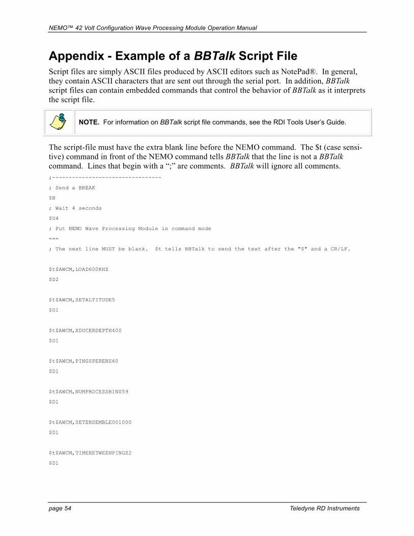
NEMO™ 42 Volt Configuration Wave Processing Module Operation Manual
page 54 Teledyne RD Instruments
Appendix - Example of a BBTalk Script File Script files are simply ASCII files produced by ASCII editors such as NotePad®. In general, they contain ASCII characters that are sent out through the serial port. In addition, BBTalk script files can contain embedded commands that control the behavior of BBTalk as it interprets the script file.
NOTE. For information on BBTalk script file commands, see the RDI Tools User’s Guide.
The script-file must have the extra blank line before the NEMO command. The $t (case sensi-tive) command in front of the NEMO command tells BBTalk that the line is not a BBTalk command. Lines that begin with a “;” are comments. BBTalk will ignore all comments. ;---------------------------------
; Send a BREAK
$B
; Wait 4 seconds
$D4
; Put NEMO Wave Processing Module in command mode
===
; The next line MUST be blank. $t tells BBTalk to send the text after the "$" and a CR/LF.
$t$AWCM,LOAD600KHZ
$D2
$t$AWCM,SETALTITUDE5
$D1
$t$AWCM,XDUCERDEPTH400
$D1
$t$AWCM,PINGSPERENS60
$D1
$t$AWCM,NUMPROCESSBINS59
$D1
$t$AWCM,SETENSEMBLE001000
$D1
$t$AWCM,TIMEBETWEENPINGS2
$D1

NEMO™ 42 Volt Configuration Wave Processing Module Operation Manual
P/N 950-6052-00 (February 2007) page 55
$t$AWCM,EPB2400
$D1
$t$AWCM,SETWAVEBURST60
$D1
$t$AWCM,SETOUTPUTDEPTHCELL54
$D1
$t$AWCM,SETOUTPUTFIRSTCELL1
$D1
$t$AWCM,SETOUTPUTSTEP3
$D1
$t$AWCM,SAVELAST
$D4
;---------------------------------

NEMO™ 42 Volt Configuration Wave Processing Module Operation Manual
page 56 Teledyne RD Instruments
Appendix – Quick Start Before you start the deployment, the Workhorse and NEMO Wave Processing Module must both be connected to their batteries and closed (ready to deploy) (see “Battery Installation,” page 14 and “Seal for Deployment,” page 15).
a. Start BBTalk and connect the Workhorse to you PC/Laptop as shown in Figure 8, page 17.
b. Set the baud-rate of the Workhorse to 57600 with the CB711 command.
c. Use the OL command to check that the Wave feature is installed in the Workhorse.
d. Connect the Workhorse to the NEMO Wave Processing Module.
e. Connect the 8 pin test cable to the PC/Laptop and start BBTalk at baud-rate 9600.
f. Send a hardware break to the NEMO Wave Processing Module and wait three seconds.
g. Type === to get the NEMO Wave Processing Module in the command mode.
h. Type $awcm,load600khz to load the factory default into the current workspace.
i. Type in any other special commands that are required for this deployment.
j. Type $awcm,savelast.
k. Type $awcm,reloadconfig. The system is now ready to be deployed.
l. Connect the Acoustic modem/telemetry options (see “Section 10.0: Telemetry Options,” page 48).
m. Once the deployment is over, remove the recorder card from the NEMO Wave Processing Module and recover the data files (see “Retrieve Data from NEMO’s Recorder Card,” page 26).
RxRx
TxTx
GNDGND
TrigTrig
WorkHorseADCP
NEMOWave
ProcessingModule
Modem/Computer
48VDC Battery
-
- -
+
+ +
Figure 12. Functional Diagram

NEMO™ 42 Volt Configuration Wave Processing Module Operation Manual
P/N 950-6052-00 (February 2007) page 57
NOTES

NEMO™ 42 Volt Configuration Wave Processing Module Operation Manual
page 58 Teledyne RD Instruments
NOTES