neco industries limited -...
TRANSCRIPT
Techno Economic Feasibility Report 1 of 142 NECO Industries Limited
NECO INDUSTRIES LIMITED
DRAFT TECHNO-ECONOMIC FEASIBILITY REPORT FOR
3.0 MTPA CEMENT PLANT AND 70 MW CPP AT
VILLAGE RISDA & DASRAMA, DISTRICT BALODABAJAR
STATE CHHATTISGARH
DEIFY INFRAPROJECTS PRIVATE LIMITED
NAGPUR, MAHARASHTRA
JANUARY, 2016
Techno Economic Feasibility Report 2 of 142 NECO Industries Limited
I N D E X
SECTION – 1 EXECUTIVE SUMMARY
SECTION – 2 MARKET DEMAND STUDY
SECTION – 3 RAW MATERIALS AND RAW MIX DESIGN
SECTION – 4 INFRASTRUCTURES AND PLANT LAYOUT
SECTION – 5 PROCESS DESCRIPTION AND BROAD SIZING OF MAJOR
MACHINERY & STORAGES OF CEMENT AND POWER PLANT
SECTION – 6 CIVIL ENGINEERING CONCEPTS AND REQUIREMENTS OF THE
PROJECTS
SECTION – 7 ELECTRICAL & CONTROL SYSTEMS
SECTION – 8 UTILITIES & AUXILIARY SERVICES
SECTION – 9 MANPOWER & TRAINING
SECTION – 10 ENVIRONMENTAL PROTECTION & POLLUTION CONTROL
MEASURES
SECTION – 11 ESTIMATED PROJECT COST, COST OF PRODUCTION &
FINANCIAL ANALYSIS
SECTION – 12 PROJECT IMPLEMENTATION SCHEDULE
Techno Economic Feasibility Report 3 of 142 NECO Industries Limited
SECTION – 1
EXECUTIVE SUMMARY

Techno Economic Feasibility Report 4 of 142 NECO Industries Limited
SECTION – 1
EXECUTIVE SUMMARY
1.0 INTRODUCTION
The Neco Group of Industries promoted by Mr. B L Shaw is one of India’s largest industrial groups
engaged primarily in ferrous foundry. Started with its humble Grey Iron Foundry established at Nagpur in
1976 the group grew by adding new ventures, expanding capacity and diversifying products and
touched the new heights day by day.
The group product cover a wide spectrum of casting such as these for automobiles, engineering,
construction, steel industry, pumps and valve industry, municipal and railway track castings in grey iron,
malleable iron and ductile iron castings and steel castings. The group has diversified into the
manufacture of refractory, industrial valves and 0.75 MT Blast Furnace complex at Raipur in
Chhattisgarh having the facility of blast furnace, power, oxygen plant, steel melting shop and billet
caster, sinter plant and coke oven plant, Sponge Iron plant, Waste Heat Recovery Power Plant, Wire
rods and merchant bar mill with a capacity of 0.400 million tones/year. The group further expanded its
capacity by installation of another 0.400 MTPA Steel Melt Shop, 0.375 Structural mill and pallet plant of
1.2 million tones/year. The Company is also installing a green field 1 MTPA Integrated steel Plant
complex at Village Dagori, District Bilaspur, for which the company is in the process of acquisition of
land, and complying with other statutory activities.
As a part of their ongoing diversification program the group plans to install a 3 MTPA Cement plant with
70 MW Captive Power Plant in M/s. NECO Industries Limited a Group Company registered with
Registrar of Companies Maharashtra on the Twenty Eighth day of January Nineteen Hundred and
Ninety One.
For the same the company has been allocated captive lime stone mine at Balodabazar District of
Chhattisgarh.
Techno Economic Feasibility Report 5 of 142 NECO Industries Limited
2.0 PROSPECT OF A NEW CEMENT PLANT IN CHHATTISGARH
From the market analysis of cement industries in India and particularly in eastern, north-eastern and
central part of India it is seem that except Chhattisgarh and Jharkhand all the other states of eastern
and north-eastern states like West Bengal, Bihar, Orissa, Assam and other north-eastern states import
cement from outside states. Major supplier of cement to these states are from Madhya Pradesh,
Chhattisgarh, Andhra Pradesh.
The consumption pattern of cement in central and eastern India is 20.57 and 22.67 million tons
respectively in 2005-2006 with an overall growth rate of 28.2 % and 39.3% respectively for central and
eastern India while this figure for all India is 37 %.
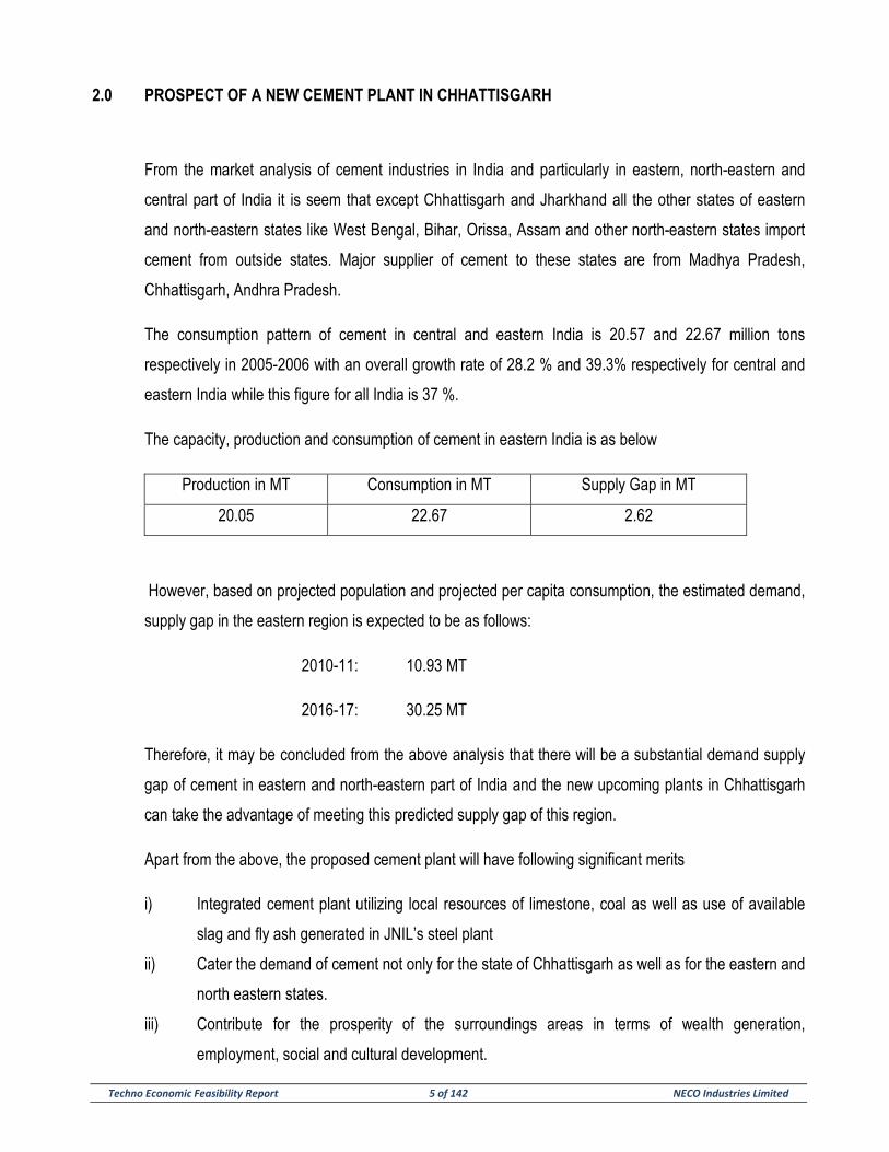
The capacity, production and consumption of cement in eastern India is as below
Production in MT Consumption in MT Supply Gap in MT
20.05 22.67 2.62
However, based on projected population and projected per capita consumption, the estimated demand,
supply gap in the eastern region is expected to be as follows:
2010-11: 10.93 MT
2016-17: 30.25 MT
Therefore, it may be concluded from the above analysis that there will be a substantial demand supply
gap of cement in eastern and north-eastern part of India and the new upcoming plants in Chhattisgarh
can take the advantage of meeting this predicted supply gap of this region.
Apart from the above, the proposed cement plant will have following significant merits
i) Integrated cement plant utilizing local resources of limestone, coal as well as use of available
slag and fly ash generated in JNIL’s steel plant
ii) Cater the demand of cement not only for the state of Chhattisgarh as well as for the eastern and
north eastern states.
iii) Contribute for the prosperity of the surroundings areas in terms of wealth generation,
employment, social and cultural development.
Techno Economic Feasibility Report 6 of 142 NECO Industries Limited
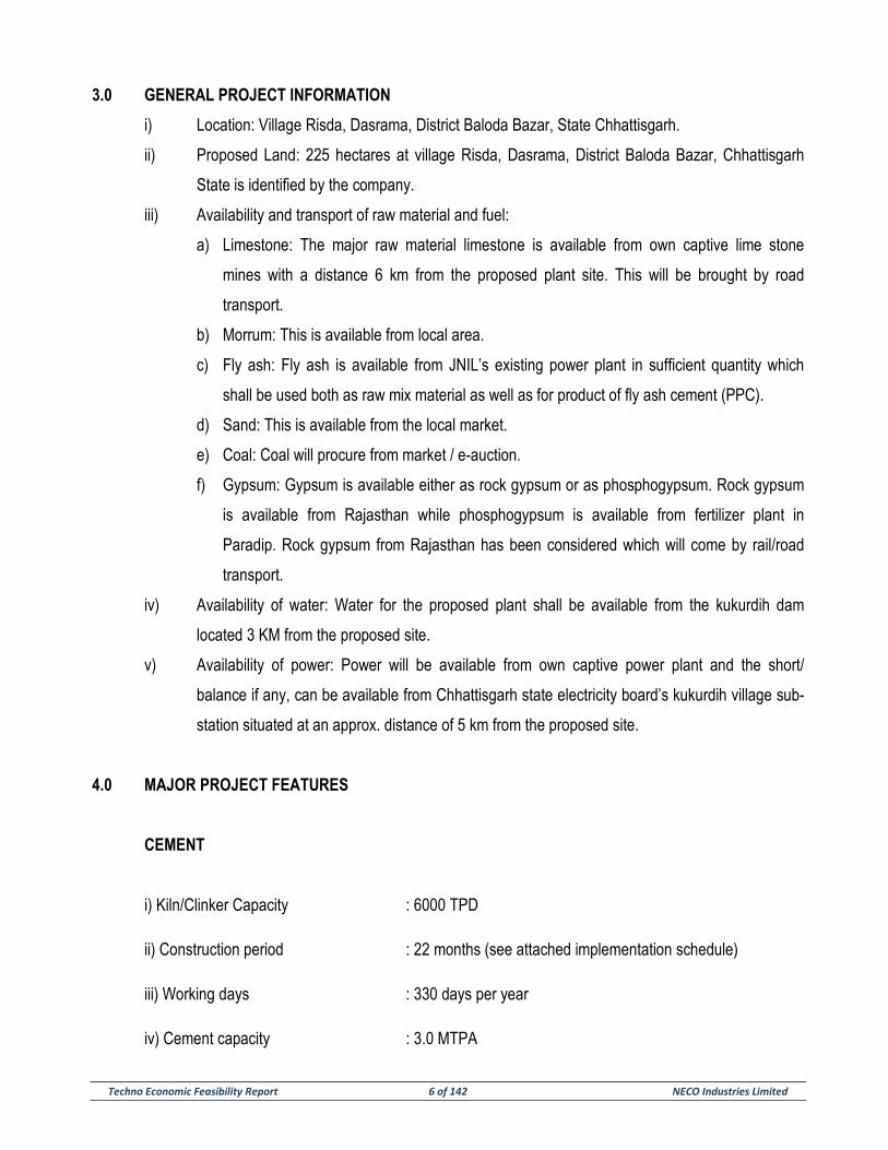
3.0 GENERAL PROJECT INFORMATION
i) Location: Village Risda, Dasrama, District Baloda Bazar, State Chhattisgarh.
ii) Proposed Land: 225 hectares at village Risda, Dasrama, District Baloda Bazar, Chhattisgarh
State is identified by the company.
iii) Availability and transport of raw material and fuel:
a) Limestone: The major raw material limestone is available from own captive lime stone
mines with a distance 6 km from the proposed plant site. This will be brought by road
transport.
b) Morrum: This is available from local area.
c) Fly ash: Fly ash is available from JNIL’s existing power plant in sufficient quantity which
shall be used both as raw mix material as well as for product of fly ash cement (PPC).
d) Sand: This is available from the local market.
e) Coal: Coal will procure from market / e-auction.
f) Gypsum: Gypsum is available either as rock gypsum or as phosphogypsum. Rock gypsum
is available from Rajasthan while phosphogypsum is available from fertilizer plant in
Paradip. Rock gypsum from Rajasthan has been considered which will come by rail/road
transport.
iv) Availability of water: Water for the proposed plant shall be available from the kukurdih dam
located 3 KM from the proposed site.
v) Availability of power: Power will be available from own captive power plant and the short/
balance if any, can be available from Chhattisgarh state electricity board’s kukurdih village sub-
station situated at an approx. distance of 5 km from the proposed site.
4.0 MAJOR PROJECT FEATURES
CEMENT
i) Kiln/Clinker Capacity : 6000 TPD
ii) Construction period : 22 months (see attached implementation schedule)
iii) Working days : 330 days per year
iv) Cement capacity : 3.0 MTPA
Techno Economic Feasibility Report 7 of 142 NECO Industries Limited
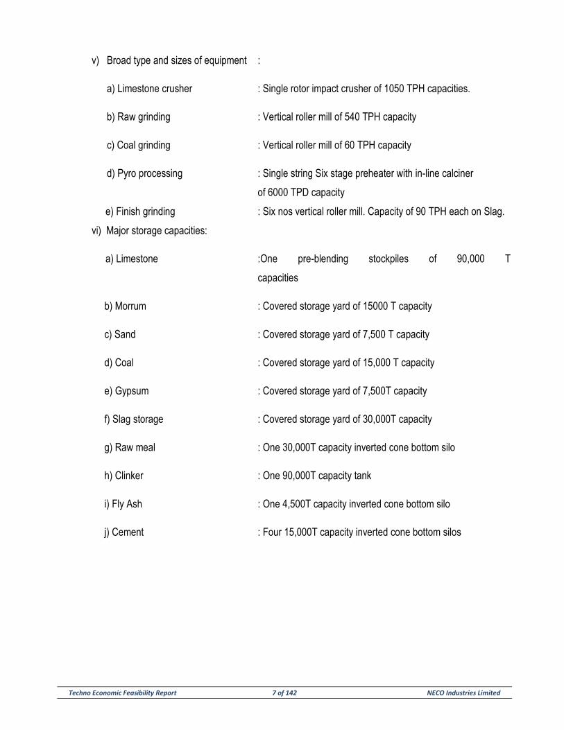
v) Broad type and sizes of equipment :
a) Limestone crusher : Single rotor impact crusher of 1050 TPH capacities.
b) Raw grinding : Vertical roller mill of 540 TPH capacity
c) Coal grinding : Vertical roller mill of 60 TPH capacity
d) Pyro processing : Single string Six stage preheater with in-line calciner
of 6000 TPD capacity
e) Finish grinding : Six nos vertical roller mill. Capacity of 90 TPH each on Slag.
vi) Major storage capacities:
a) Limestone :One pre-blending stockpiles of 90,000 T
capacities
b) Morrum : Covered storage yard of 15000 T capacity
c) Sand : Covered storage yard of 7,500 T capacity
d) Coal : Covered storage yard of 15,000 T capacity
e) Gypsum : Covered storage yard of 7,500T capacity
f) Slag storage : Covered storage yard of 30,000T capacity
g) Raw meal : One 30,000T capacity inverted cone bottom silo
h) Clinker : One 90,000T capacity tank
i) Fly Ash : One 4,500T capacity inverted cone bottom silo
j) Cement : Four 15,000T capacity inverted cone bottom silos
Techno Economic Feasibility Report 8 of 142 NECO Industries Limited
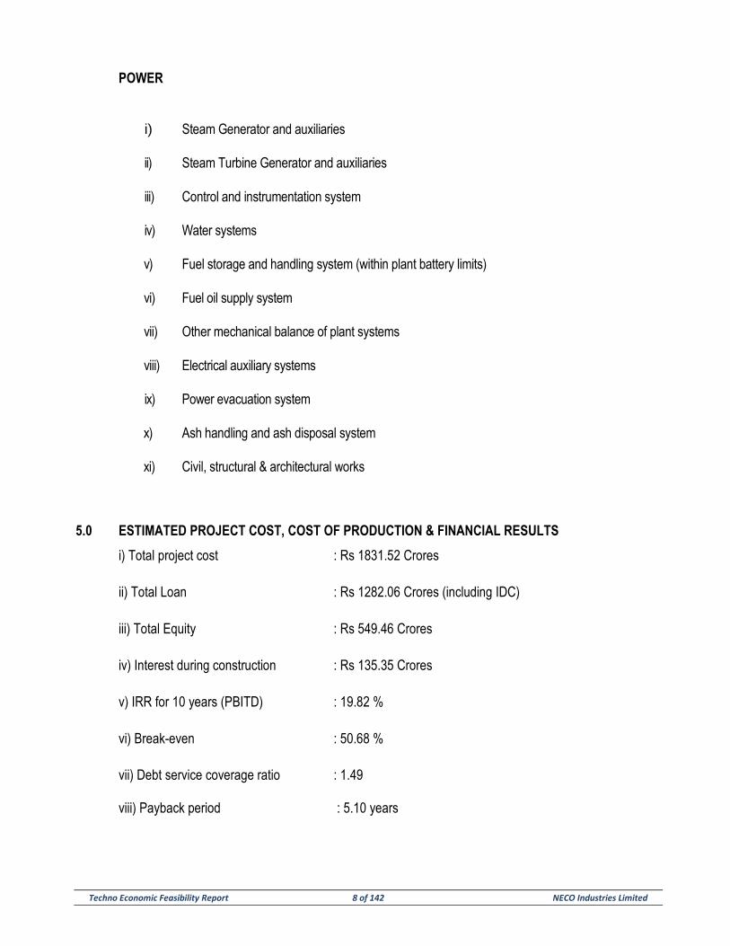
POWER
i) Steam Generator and auxiliaries
ii) Steam Turbine Generator and auxiliaries
iii) Control and instrumentation system
iv) Water systems
v) Fuel storage and handling system (within plant battery limits)
vi) Fuel oil supply system
vii) Other mechanical balance of plant systems
viii) Electrical auxiliary systems
ix) Power evacuation system
x) Ash handling and ash disposal system
xi) Civil, structural & architectural works
5.0 ESTIMATED PROJECT COST, COST OF PRODUCTION & FINANCIAL RESULTS
i) Total project cost : Rs 1831.52 Crores
ii) Total Loan : Rs 1282.06 Crores (including IDC)
iii) Total Equity : Rs 549.46 Crores
iv) Interest during construction : Rs 135.35 Crores
v) IRR for 10 years (PBITD) : 19.82 %
vi) Break-even : 50.68 %
vii) Debt service coverage ratio : 1.49
viii) Payback period : 5.10 years
Techno Economic Feasibility Report 9 of 142 NECO Industries Limited
6.0 SUMMARISED CONTENTS OF THE TEFR
The TEFR contains eleven sections including this Section-1 (Executive summary). Broad contents of
each section are as below:
i) Section-2 (Market demand study): This section highlights the Demand and Supply position of
cement in central & eastern part of India. Cement will be marketed in the above mentioned
area.
ii) Section-3 (Raw materials and raw mix): This Section deals with sources of various raw
materials, fuel, their quality and sufficiency for this project, landed cost of these materials upto
the plant site, mode of transport, etc. and based on these raw materials design of a suitable raw
mix for production of good clinker.
iii) Section-4 (Infrastructure and plant layout): This Sections deals with the available land for the
proposed plant, its suitability available raw materials, fuel, power, water, climatologically data
and other infrastructure facilities as per requirement of the plant. A suitable layout of the plant
has also been described considering the latest technological concept/trend in cement plant
operation.
iv) Section-5 (Process description and broad sizing of major machinery and storages): This Section
depicts the latest process technology suggested, the recommended types of major equipment
like limestone crusher raw material grinding, coal grinding, pyro-processing unit, cement
grinding and packing units with broad size of these equipment along with storage capacities for
limestone, coal, raw meal, clinker, fly ash, cement, power etc. as have been conceived.
v) Section-6 (Civil engineering concepts and requirement of the project): This Section deals with
basic concepts and criterion as have been considered for design of all civil construction and
types of structures, and buildings (RCC or Steel) with their individual capacity etc. for different
buildings and structures.
vi) Section-7 (Electrical and instrumentation system): This section describes the basic concepts,
and criteria as have been considered for system design and equipment selection for the
electrical and control systems of the project.
vii) Section-8 (Utilities and auxiliary services): This section deals with utilities and auxiliary service
requirement of the project like water, compressed air, laboratory and quality control,
maintenance workshop, fire fighting system, in plant handing system as per requirement of the
project.
Techno Economic Feasibility Report 10 of 142 NECO Industries Limited
viii) Section-9 (Manpower and training): This Section highlights the requirement of total man-power
for this project, with their categories, training of personnel etc.
ix) Section-10 (Environmental protection and pollution control measures): This section identifies the
nature of environmental hazards in cement industry, its control measures to mitigate these
hazards as per standards, international norms.
x) Section-11 (Estimated capital cost, cost of production and financial analysis): This section deals
with detail calculation of the capital cost of the project.
xi) Section-12 (Project implementation Schedule): This section identifies the time frame required
for the project.
Techno Economic Feasibility Report 11 of 142 NECO Industries Limited
SECTION – 2
MARKET DEMAND STUDY
Techno Economic Feasibility Report 12 of 142 NECO Industries Limited
SECTION-2
MARKET DEMAND STUDY
1.0 Chhattisgarh: A Brief Profile
Chhattisgarh, carved out of Madhya Pradesh came into being on November 1, 2000 as the 26th State of
the Union. It borders Madhya Pradesh on the northwest, Maharashtra on the west, Andhra Pradesh on
the south, Orissa on the east, Jharkhand on the northeast and Uttar Pradesh on the north. Area wise
Chhattisgarh is the ninth largest state and population-wise it is seventeenth state of the nation.
Area (sq km) : 1, 36,034
Population (‘000) – 2012 Census : 2, 55, 40
Capital : Raipur
Principal Language : Hindi
Agriculture and allied activities account for 80% of the work force in the state. Out of the geographical
area of 13,787 thousand hectares, gross cropped are is 4799 thousand hectares, which constitutes
about 35 per cent of the total geographical area. Forest occupies about 6,247 thousand hectares which
constitutes about 45 per cent of the total geographical area.
Chhattisgarh is generously bestowed with natural resources like forests, minerals and surface water. Till
yesteryears-the State has undergone a radical change and is thriving with industrial activities now.
Large deposits of coal, iron ore, limestone, bauxite, dolomite and tin ore are located in several parts of
the state. There are approximately 130 steel re-rolling mills, a number of mini steel plants, ferro-alloy
units, steel/cast iron casting units, engineering and fabrication units apart from large number of agro
based and food processing, chemical, plastic, constructions material, forest produce b based units.
Within a few years of its formation, Chhattisgarh embarked on social and economic development
through policy reforms, focus on infrastructure development and improving the investment climate in the
state. The state has large untapped potential for development. Potential exists, to substantially increase
the pace of economic development in the state by appropriate exploitation of its mineral wealth.
Techno Economic Feasibility Report 13 of 142 NECO Industries Limited
The state government has come out with a new industrial policy (2009-14) with the following objectives:
• Create additional employment opportunities by accelerating the process of industrialization in the
state.
• Ensuring maximum value addition to the abundant, locally available mineral and forest based
resources.
• Ensuring balanced regional development by attracting industries in the economically backward
areas of the state.
• Make industrial investments in the state competitive vis-à-vis other states in the country.
• Promote private sector participation for creation of industrial infrastructure in the state.
• Create an enabling environment for increasing industrial production, productivity and quality up
gradation to face the challenge of competition emerging from economic liberalization.
Direct incentives will be provided for industrial investment in the state in the form of interest subsidy,
infrastructure development capital investment subsidy, exemption from stamp duty, exemption from
entry tax, allotment of plots at concessional premium in industrial areas, exemption from land diversion
fee, reimbursement of project report expenses, quality certification subsidy, technology patent subsidy,
interest subsidy for technology gradation, etc.
2.0 CEMENT
India is the second largest producer of cement in the world. No wonder, India's cement industry is a vital
part of its economy, providing employment to more than a million people, directly or indirectly. Ever
since it was deregulated in 1982, the Indian cement industry has attracted huge investments, both from
Indian as well as foreign investors. India has a lot of potential for development in the infrastructure and
construction sector and the cement sector is expected to largely benefit from it. Some of the recent
major government initiatives such as development of 98 smart cities are expected to provide a major
boost to the sector. Expecting such developments in the country and aided by suitable government
foreign policies, several foreign players such as Lafarge-Holcim, Heidelberg Cement, and Vicat have
invested in the country in the recent past. A significant factor which aids the growth of this sector is the
ready availability of the raw materials for making cement, such as limestone and coal.
Market Size
Cement demand in India is expected to increase due to government’s push for large infrastructure
projects, leading to 45 million tonnes of cement needed in the next three to four years. India's cement
Techno Economic Feasibility Report 14 of 142 NECO Industries Limited
demand is expected to reach 550-600 million tonnes per annum (MTPA) by 2025. The housing sector is
the biggest demand driver of cement, accounting for about 67 per cent of the total consumption in India.
The other major consumers of cement include infrastructure at 13 per cent, commercial construction at
11 per cent and industrial construction at nine per cent. To meet the rise in demand, cement companies
are expected to add 56 million tonnes (MT) capacity over the next three years. The cement capacity in
India may register a growth of eight per cent by next year end to 395 MT from the current level of 366
MT. It may increase further to 421 MT by the end of 2017. The country's per capita consumption stands
at around 190 kg. The Indian cement industry is dominated by a few companies. The top 20 cement
companies account for almost 70 per cent of the total cement production of the country. A total of 188
large cement plants together account for 97 per cent of the total installed capacity in the country, with
365 small plants account for the rest. Of these large cement plants, 77 are located in the states of
Andhra Pradesh, Rajasthan and Tamil Nadu.
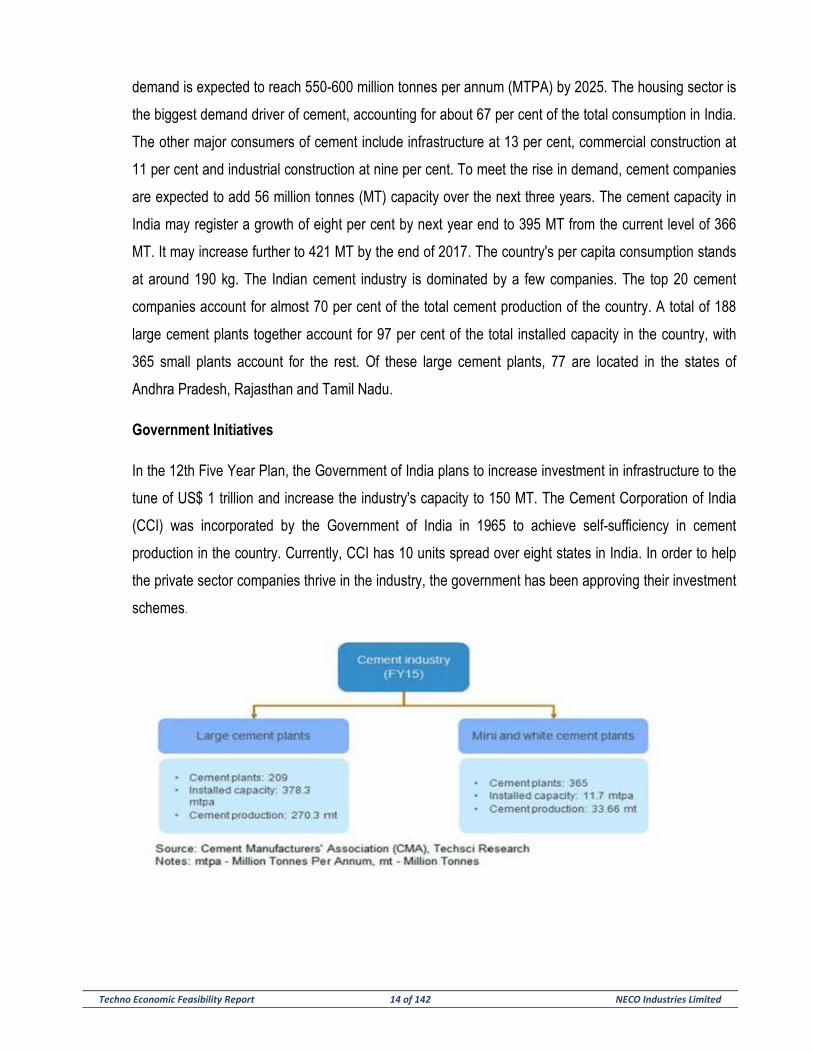
Government Initiatives
In the 12th Five Year Plan, the Government of India plans to increase investment in infrastructure to the
tune of US$ 1 trillion and increase the industry's capacity to 150 MT. The Cement Corporation of India
(CCI) was incorporated by the Government of India in 1965 to achieve self-sufficiency in cement
production in the country. Currently, CCI has 10 units spread over eight states in India. In order to help
the private sector companies thrive in the industry, the government has been approving their investment
schemes.
Techno Economic Feasibility Report 15 of 142 NECO Industries Limited
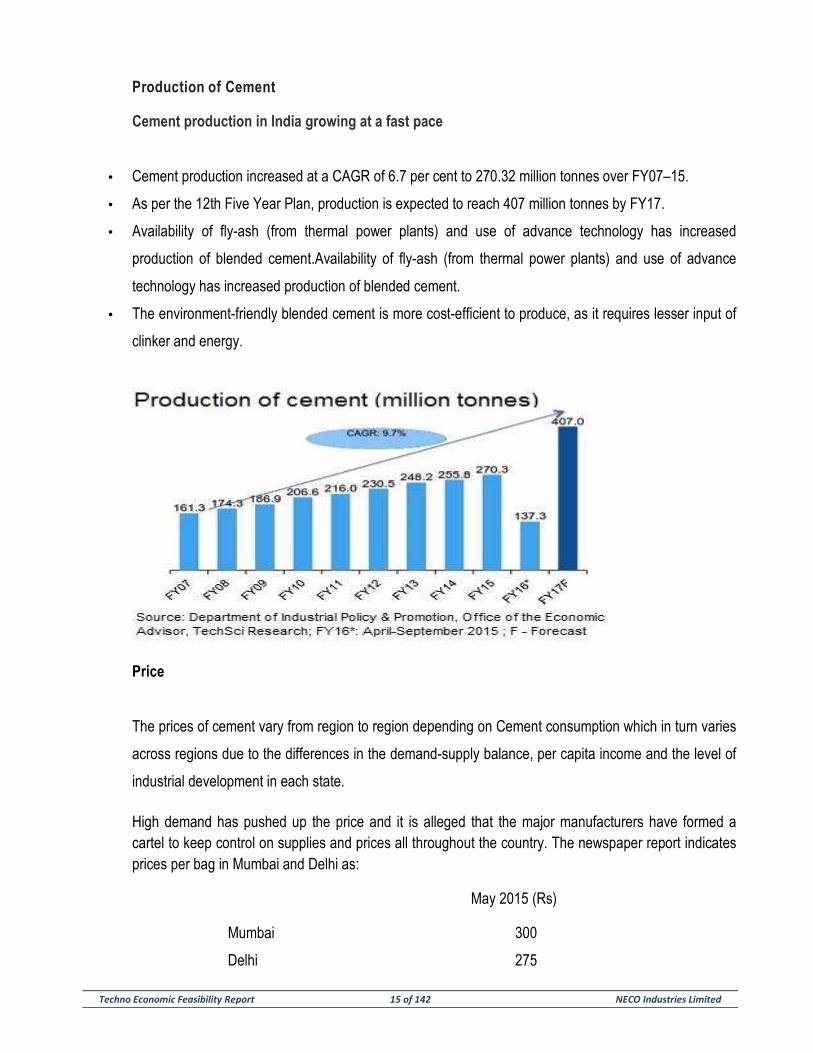
Production of Cement
Cement production in India growing at a fast pace
• Cement production increased at a CAGR of 6.7 per cent to 270.32 million tonnes over FY07–15.
• As per the 12th Five Year Plan, production is expected to reach 407 million tonnes by FY17.
• Availability of fly-ash (from thermal power plants) and use of advance technology has increased
production of blended cement.Availability of fly-ash (from thermal power plants) and use of advance
technology has increased production of blended cement.
• The environment-friendly blended cement is more cost-efficient to produce, as it requires lesser input of
clinker and energy.
Price
The prices of cement vary from region to region depending on Cement consumption which in turn varies
across regions due to the differences in the demand-supply balance, per capita income and the level of
industrial development in each state.
High demand has pushed up the price and it is alleged that the major manufacturers have formed a cartel to keep control on supplies and prices all throughout the country. The newspaper report indicates prices per bag in Mumbai and Delhi as:
May 2015 (Rs)
Mumbai 300
Delhi 275
Techno Economic Feasibility Report 16 of 142 NECO Industries Limited
In Kolkata, presently prices are hovering around Rs 300 per bag. In Chhattisgarh, the price per bag
moves between Rs 230 and Rs 260 at present.
Technological change: Cement industry has made tremendous strides in technological up gradation
and assimilation of latest technology. At present ninety three per cent of the total capacity in the industry
is based on modern and environment-friendly dry process technology and only seven per cent of the
capacity is based on old wet and wet and semi-dry process technology. There is tremendous scope for
waste heat recovery in cement plants and thereby reduction in emission level. One project for co-
generation of power utilizing waste heat in an Indian cement plant is being implemented with Japanese
assistance under Green Aid Plan. The induction of advanced technology has helped the industry
immensely to conserve energy and fuel and to save materials substantially.
3.0 CONCLUSION
The rising demand and the ensuing demand-supply gap till 2015-16 would justify the decision to set up
the proposed One (3.0) MTPA cement plant in Chhattisgarh along with a 70 MW thermal based captive
power plant for meeting the requirement of power.
Techno Economic Feasibility Report 17 of 142 NECO Industries Limited
SECTION - 3
RAW METERIALS & RAW MIX DESIGN
Techno Economic Feasibility Report 18 of 142 NECO Industries Limited
SECTION – 3
RAW MATERIALS & RAW MIX DESIGN
1.0 INTRODUCTION
Cement Plant was projected with the availability of cement grade limestone. Localized the plant in the
particular belt. Extensive belt of cement grade limestone has been located in Baloda Bazar district in
CG.
Major raw material for cement manufacture is limestone.
1.1 LOCATION
The limestone deposit of Parsabhader area is located about 4 Km south-west of Baloda Bazar township.
The prospected blocks of Parsabhader cover an area of about 14.76 sq.km, which is boundary by
latitude 21º37’45” : 21º39’30” and longitudes 82º04’00” : 82º08’30” by survey of India Toposheet No.64
K/2. The deposit area encompasses administrative boundaries of Parsabhader, Bhatagaon, Risda,
Khairwari, Dharndhani, Murhipar and Kukardih villages, all forming part of Baloda Bazar district of CG.
On the above said area, JNIL have been allotted a total area of 159.669 Hectare in Parsabhader
(119.209 Ha) & Kukardih (40.460 Ha) for extracting limestone for its proposed Cement Plant.
i. Accessibility:
• Road
The deposit area Parsabhader is accessible by road from Raipur Via- Baloda Bazar,at a distance of about
approx 70 Km. Another approach to the area from Raipur is via- Bhatapara, which is about 108 Km.
• Rail
The nearest Railway Station for the area is Bhatapara, on Raipur- Bilaspur section of Bombay- Howrah
broad guage line of south-Eastern Railways. The area is about 25 Km due east of Bhatapara and is
connected by metalled road via Baloda Bazar.
• Air
The nearest Airbase for the area is at Raipur.
Techno Economic Feasibility Report 19 of 142 NECO Industries Limited
ii. Physiographic:
The prospected area is mostly flat terrain with gentle slope towards east direction. The north-west and
north east part of the area is a Bhata land forming very gentle sloping mounds with intermittent presence
of limestone outcrops. The outcrops show rough and boundary appearance, at places, because of the
stromatolites. The low lying plains basically covered with the soil are mostly the paddy fields. Karstic
topographic features typical of limestone are also seen. The minimum elevation in the area is 146 m and
the maximum is 273 m above M.S.L.
iii. Drainage:
The limestone deposit area is drained by a number of small seasonal nalas which ultimately join Khorsi-nala, which is the only perennial source of water in the area.
1.2 DESCRIPTION OF THE LIMESTONE DEPOSIT
On the basis of geological mapping and drilling results, it was found that the limestone deposits extends
in 14.76 sq. km. area with small patches of dolomites and shales. It is compact, fine garnic, massive and
exhibits various shades of colour viz. pink, purple, grey and grayish pink. Thin calcite veins are
commonly seen within the limestone. It is almost horizontally bedded with thin shale bands. Cavity filled
with clay etc. are generally seen in this limestone.
The parsabhader deposit contains limestone of good quality which are fairly high in calcium content,
possessing essential qualities that make them eminently suitable for cement manufacture.
Evaluation of the reserve was carried out in Parsabhader area, which was sub divided into two blocks,
i.e. Parsabhader and Kukardih block based upon the drilling data.
Parsabhader Block:
In this block, a total of 87 boreholes were drilled, in an area of 7.83 sq. km. The chemical analysis of the
boreholes samples reveal that the cement grade limestone persist in cement 68 boreholes having Cao
more than 44 %. The cement grade limestone zone covers an area of 6.12 sq. km. and the main zone is
located in the western part of the block. Thickness of the cement grade limestone varies from 3.5 m to a
maximum of 29.90 m with an average of 16.87 m. and occurs below the overburden ranging in thickness
from 0.35 m to 6.0 m with an average of 2.74 m. The average recovery percentage of core is found to
be more than 84 %.
Techno Economic Feasibility Report 20 of 142 NECO Industries Limited
The CaO percentage of the Limestone varies from 44.07 % to 48.53 % the average being 46.03 %. The
limestone in depth is low in grade. The thickness and grade of the limestone increases towards the
north western part of the Block.
Kukardih Block:
Similarly, a total number of 77 boreholes were sunk in an area of 6.89 sq. km. Out of which 56 number
of boreholes were found contain cement grade limestone covering an area of 5.04 sq. km. The
thickness of cement grade limestone varies from 4.5 mts. to a maximum of 29.60 mts. having an
average of 18.739 m. The average recovery percentage of the limestone varies from 44.03% to 47.80
%, the average being 48.32% while the limestone in depth is low in grade.
1.3 BLENDABLE GRADE LIMESTONE
Parsabhader Block
In this block 6 number of boreholes were found the contain blendable grade limestone having average
Cao percentage between 42% to 44%. The thickness of blendable grade limestone ranges from 1.0 m
to a maximum of 26.0 m. having an average of 11.16 m. which occurs below an average over-burden of
3.05 m. The Cao percentage of the limestone varies from 42.07% to 43.51% the average being 42.65%.
Kukardih Block:
The chemical analysis of the borehole samples reveals that the blendable grade limestones persist in 1.
boreholes. The thickness of the blendable grade limestone varies from 0.94 m. to maximum of 30.50 m
with an average of 24.09 m. and occurs below an over-burden ranging in the thickness from 0.94 m. to
7.70 m. with an average of 4.74 m. the Cao percentage of the limestone varies from 42.29% to 43.83%
the average being 43.21%.
1.4 RESERVE ESTIMATION
After computing all the parameters i.e. average core recovery, depth, thickness and extent of the deposit
the reserve of lime stone has been calculate borehole wise by area of influence method.
In this method the area of influence of each borehole was calculated and then multiplied by the
thickness of limestone, to obtain borehole wise reserve. The sum total of these individual figures from
each borehole gave the total reserve. The specific gravity of limestone is taken as 2.5 for reserve
calculation.

Techno Economic Feasibility Report 21 of 142 NECO Industries Limited
Parsabhader Block:
On the basis of chemical analysis of borehole sample, it has been found that 68 number of cement
grade limestone bearing boreholes form a single uniform compact block
From the total of 68 cement grade limestone boreholes, the reserve of the prospected parsabhader
block is 216.382 million tonnes.
Kukardih Block:
Similarly, in kukardih block 56 Nos. of cement grade lime bearing boreholes from a single uniform
compact block .
From the total of 56 cement grade limestone boreholes, the reserve of the kukardih block is 209.795
million tonnes.
From the total of 124 cement grade limestone boreholes, the gross reserve of the prospected
parsabhader area is 426.177 million tonnes.
Blended grade limestone:
Parsabhader block:
On the basis of the chemical analysis of borehole samples, it has been found that 6 numbers of
blendable grade limestone bearing boreholes occur in erratic manner. These 6 numbers of borehole
occurring as isolated blendable grade limestone patches containing 11.719 million tonnes of blendable
grade limestone.
Kukardih block:
Similarly, in Kukardih block 10 numbers of boreholes occurring as isolated blendable grade of limestone
patches containing 46.84 million tonnes of blendable grade limestone.
Reserves of Parsabhader area:
Block Cement grade lime-
stone (M.T.)
Blendable grade lime-
stone (M.T.)
Total (M.T.)
Parsabhader block 216.382 11.719 228.101 Kukardih block 290.795 46.84 256.635 Total 426.177 58.559 484.736
Techno Economic Feasibility Report 22 of 142 NECO Industries Limited
CONCLUSION
The Parsabhader limestone deposit of Baloda Bazar area is a part of famous limestone belt
which has sustained four major cement units viz. The Ambuja Cement, the Tata Cement, the Grasim
Cement and the L & T Cement plants with nearly a million tones of production annually by each plant.
The deposit has been prospected for assessing suitability for use in the manufacture of cement
by putting 164 boreholes in the square grid pattern of 300 x 300 m. achieving a total meterage of
4207.20 m.
The chemical analysis of the samples reveal that the cement grade limestone persist only in
124 boreholes. The reserves calculated from these 124 boreholes is 426.177 million tonnes besides this
an additional reserve of 58.55 million tonnes of blendable grade limestone have also been estimated in
16 boreholes of the area so far, total reserves of 484.736 million tonnes of limestone has been proved in
Parsabhader area. These reserves of limestone are confined into two blocks namely Parsabhader and
Kukardih block. Thus, Parsabhader and Kukardih blocks may be considered suitable for exploitation.
The prevailing infrastructural facilities in the area are lucrative as compared to that of existing
cement units in the near vicinity. Thus, huge reserves of cement grade limestone and the added
infrastructural facilities make this prospect an ideal proposition for establishment of higher capacity
cement plant in the area. It may further be added that this prospect contains patches of high grade
limestone averaging more than 47% CaO. Thus, limestone deposit of the area can easily sustain two high
capacity cement plants of high quality and consistency.
1.5 OTHER ADDITIVE MATERIALS
Based on raw mix calculation the other additive materials as have been conceived are
a. Morrum b. Sand c. Fly ash
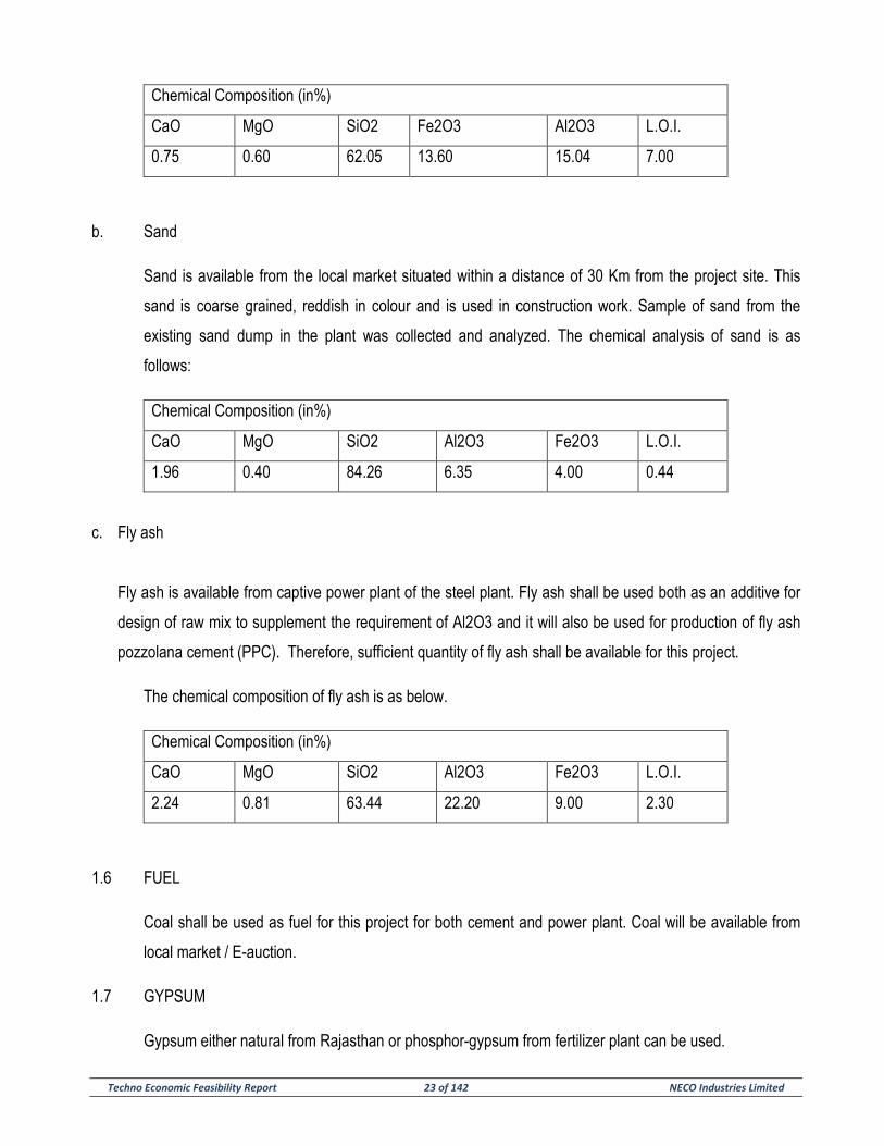
a. Morrum
Morrum is available from the local market situated within a distance of 30 Km from the project site. This
morrum is medium hard, whitish to buff colored. The collected sample is having the following chemical
composition.
Techno Economic Feasibility Report 23 of 142 NECO Industries Limited
Chemical Composition (in%)
CaO MgO SiO2 Fe2O3 Al2O3 L.O.I.
0.75 0.60 62.05 13.60 15.04 7.00
b. Sand
Sand is available from the local market situated within a distance of 30 Km from the project site. This
sand is coarse grained, reddish in colour and is used in construction work. Sample of sand from the
existing sand dump in the plant was collected and analyzed. The chemical analysis of sand is as
follows:
Chemical Composition (in%)
CaO MgO SiO2 Al2O3 Fe2O3 L.O.I.
1.96 0.40 84.26 6.35 4.00 0.44
c. Fly ash
Fly ash is available from captive power plant of the steel plant. Fly ash shall be used both as an additive for
design of raw mix to supplement the requirement of Al2O3 and it will also be used for production of fly ash
pozzolana cement (PPC). Therefore, sufficient quantity of fly ash shall be available for this project.
The chemical composition of fly ash is as below.
Chemical Composition (in%)
CaO MgO SiO2 Al2O3 Fe2O3 L.O.I.
2.24 0.81 63.44 22.20 9.00 2.30
1.6 FUEL
Coal shall be used as fuel for this project for both cement and power plant. Coal will be available from
local market / E-auction.
1.7 GYPSUM
Gypsum either natural from Rajasthan or phosphor-gypsum from fertilizer plant can be used.
Techno Economic Feasibility Report 24 of 142 NECO Industries Limited
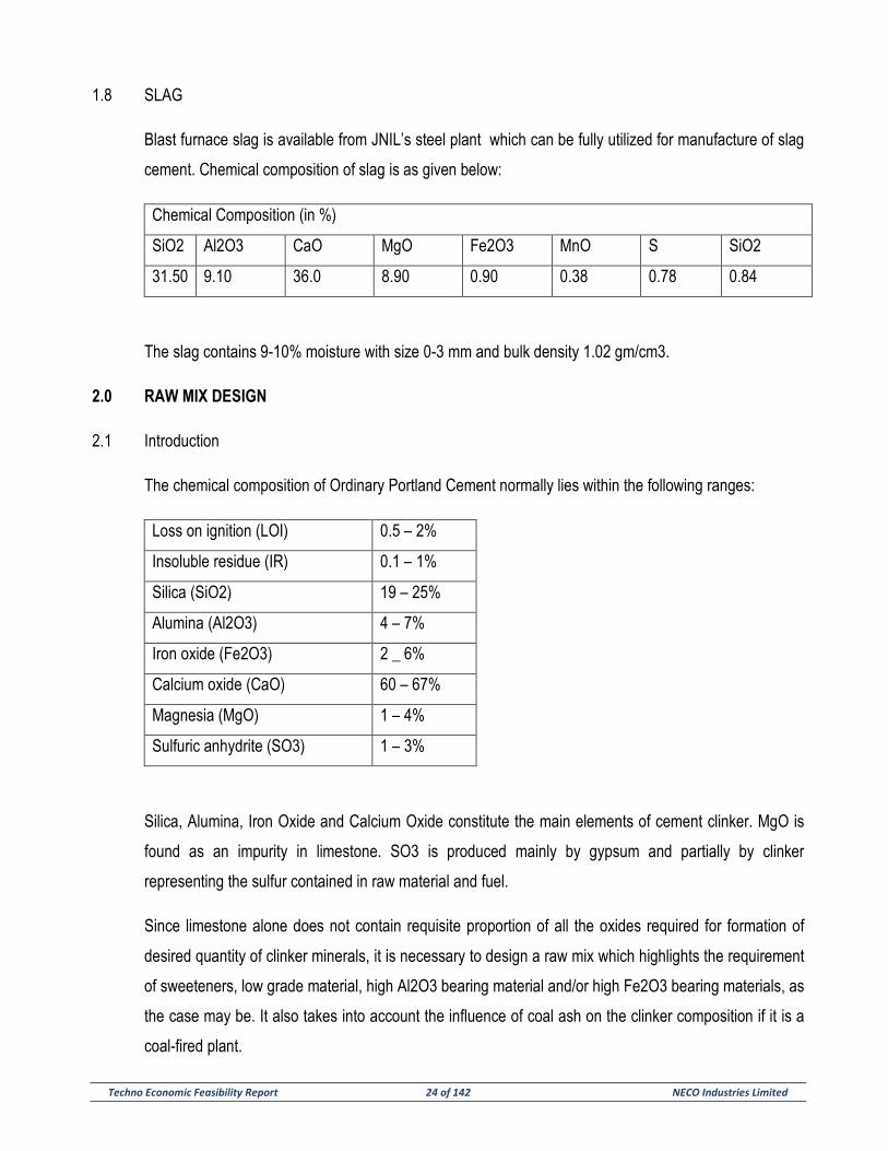
1.8 SLAG
Blast furnace slag is available from JNIL’s steel plant which can be fully utilized for manufacture of slag
cement. Chemical composition of slag is as given below:
Chemical Composition (in %)
SiO2 Al2O3 CaO MgO Fe2O3 MnO S SiO2
31.50 9.10 36.0 8.90 0.90 0.38 0.78 0.84
The slag contains 9-10% moisture with size 0-3 mm and bulk density 1.02 gm/cm3.
2.0 RAW MIX DESIGN
2.1 Introduction
The chemical composition of Ordinary Portland Cement normally lies within the following ranges:
Loss on ignition (LOI) 0.5 – 2%
Insoluble residue (IR) 0.1 – 1%
Silica (SiO2) 19 – 25%
Alumina (Al2O3) 4 – 7%
Iron oxide (Fe2O3) 2 _ 6%
Calcium oxide (CaO) 60 – 67%
Magnesia (MgO) 1 – 4%
Sulfuric anhydrite (SO3) 1 – 3%
Silica, Alumina, Iron Oxide and Calcium Oxide constitute the main elements of cement clinker. MgO is
found as an impurity in limestone. SO3 is produced mainly by gypsum and partially by clinker
representing the sulfur contained in raw material and fuel.
Since limestone alone does not contain requisite proportion of all the oxides required for formation of
desired quantity of clinker minerals, it is necessary to design a raw mix which highlights the requirement
of sweeteners, low grade material, high Al2O3 bearing material and/or high Fe2O3 bearing materials, as
the case may be. It also takes into account the influence of coal ash on the clinker composition if it is a
coal-fired plant.
Techno Economic Feasibility Report 25 of 142 NECO Industries Limited
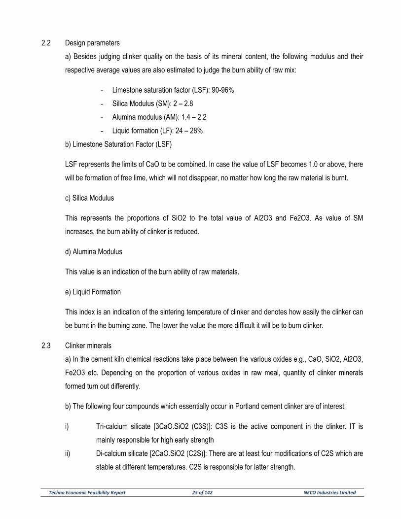
2.2 Design parameters
a) Besides judging clinker quality on the basis of its mineral content, the following modulus and their
respective average values are also estimated to judge the burn ability of raw mix:
- Limestone saturation factor (LSF): 90-96%
- Silica Modulus (SM): 2 – 2.8
- Alumina modulus (AM): 1.4 – 2.2
- Liquid formation (LF): 24 – 28%
b) Limestone Saturation Factor (LSF)
LSF represents the limits of CaO to be combined. In case the value of LSF becomes 1.0 or above, there
will be formation of free lime, which will not disappear, no matter how long the raw material is burnt.
c) Silica Modulus
This represents the proportions of SiO2 to the total value of Al2O3 and Fe2O3. As value of SM
increases, the burn ability of clinker is reduced.
d) Alumina Modulus
This value is an indication of the burn ability of raw materials.
e) Liquid Formation
This index is an indication of the sintering temperature of clinker and denotes how easily the clinker can
be burnt in the burning zone. The lower the value the more difficult it will be to burn clinker.
2.3 Clinker minerals
a) In the cement kiln chemical reactions take place between the various oxides e.g., CaO, SiO2, Al2O3,
Fe2O3 etc. Depending on the proportion of various oxides in raw meal, quantity of clinker minerals
formed turn out differently.
b) The following four compounds which essentially occur in Portland cement clinker are of interest:
i) Tri-calcium silicate [3CaO.SiO2 (C3S)]: C3S is the active component in the clinker. IT is
mainly responsible for high early strength
ii) Di-calcium silicate [2CaO.SiO2 (C2S)]: There are at least four modifications of C2S which are
stable at different temperatures. C2S is responsible for latter strength.
Techno Economic Feasibility Report 26 of 142 NECO Industries Limited
iii) Tri-calcium aluminate [3CaO.Al2O3 (C3A)]: C3A is very reactive and contributes high early
strength. IT helps in coating formation
iv) Tetra-calcium alumino-ferrite [4CaO.Al2O3.Fe2O3 (C4AF)]: It does not influence the
development of strength. IT is formed due to the fluxing compounds present in raw mix. It
also helps in coating formation.
Techno Economic Feasibility Report 27 of 142 NECO Industries Limited
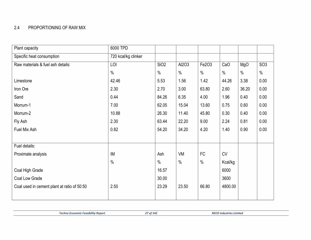
2.4 PROPORTIONING OF RAW MIX
Plant capacity 6000 TPD
Specific heat consumption 720 kcal/kg clinker
Raw materials & fuel ash details:
Limestone
Iron Ore
Sand
Morrum-1
Morrum-2
Fly Ash
Fuel Mix Ash
LOI
%
42.46
2.30
0.44
7.00
10.88
2.30
0.82
SiO2
%
5.53
2.70
84.26
62.05
26.30
63.44
54.20
Al2O3
%
1.56
3.00
6.35
15.04
11.40
22.20
34.20
Fe2O3
%
1.42
63.80
4.00
13.60
45.80
9.00
4.20
CaO
%
44.26
2.60
1.96
0.75
0.30
2.24
1.40
MgO
%
3.38
36.20
0.40
0.60
0.40
0.81
0.90
SO3
%
0.00
0.00
0.00
0.00
0.00
0.00
0.00
Fuel details:
Proximate analysis
Coal High Grade
Coal Low Grade
Coal used in cement plant at ratio of 50:50
IM
%
2.50
Ash
%
16.57
30.00
23.29
VM
%
23.50
FC
%
66.80
CV
Kcal/kg
6000
3600
4800.00
Techno Economic Feasibility Report 28 of 142 NECO Industries Limited
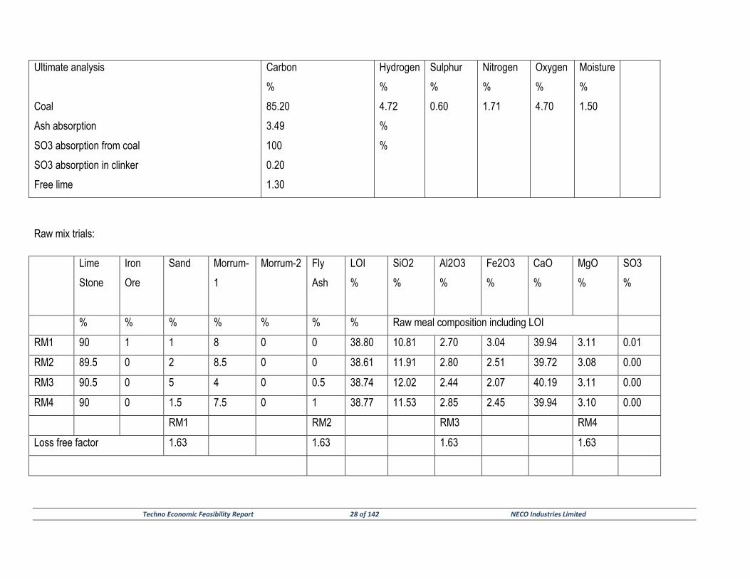
Ultimate analysis
Coal
Ash absorption
SO3 absorption from coal
SO3 absorption in clinker
Free lime
Carbon
%
85.20
3.49
100
0.20
1.30
Hydrogen
%
4.72
%
%
Sulphur
%
0.60
Nitrogen
%
1.71
Oxygen
%
4.70
Moisture
%
1.50
Raw mix trials:
Lime
Stone
Iron
Ore
Sand
Morrum-
1
Morrum-2
Fly
Ash
LOI
%
SiO2
%
Al2O3
%
Fe2O3
%
CaO
%
MgO
%
SO3
%
% % % % % % % Raw meal composition including LOI
RM1 90 1 1 8 0 0 38.80 10.81 2.70 3.04 39.94 3.11 0.01
RM2 89.5 0 2 8.5 0 0 38.61 11.91 2.80 2.51 39.72 3.08 0.00
RM3 90.5 0 5 4 0 0.5 38.74 12.02 2.44 2.07 40.19 3.11 0.00
RM4 90 0 1.5 7.5 0 1 38.77 11.53 2.85 2.45 39.94 3.10 0.00
RM1 RM2 RM3 RM4
Loss free factor 1.63 1.63 1.63 1.63
Techno Economic Feasibility Report 29 of 142 NECO Industries Limited
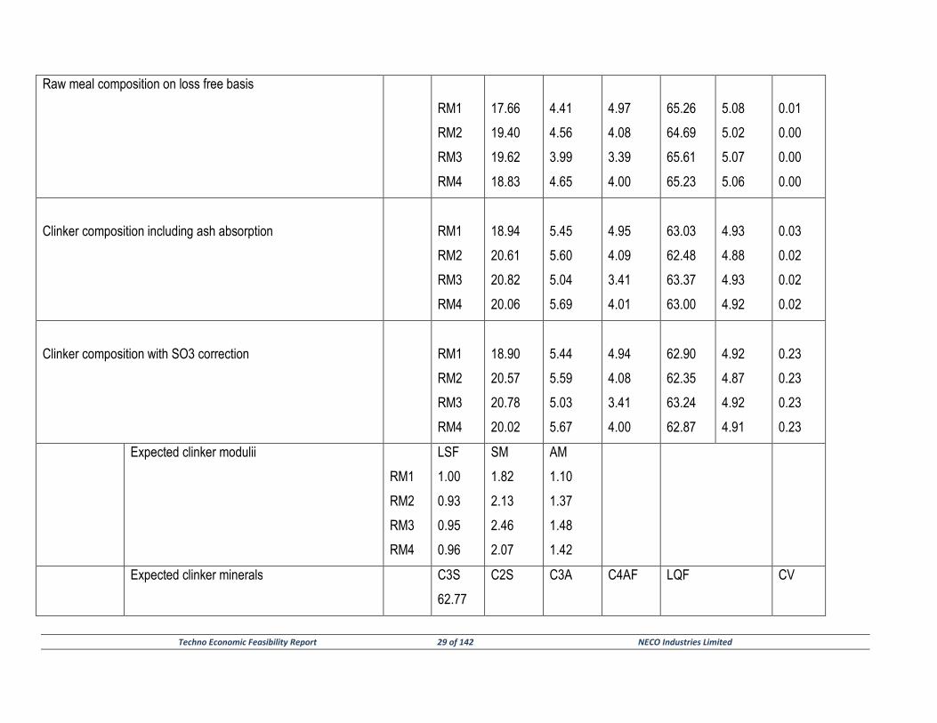
Raw meal composition on loss free basis
RM1
RM2
RM3
RM4
17.66
19.40
19.62
18.83
4.41
4.56
3.99
4.65
4.97
4.08
3.39
4.00
65.26
64.69
65.61
65.23
5.08
5.02
5.07
5.06
0.01
0.00
0.00
0.00
Clinker composition including ash absorption
RM1
RM2
RM3
RM4
18.94
20.61
20.82
20.06
5.45
5.60
5.04
5.69
4.95
4.09
3.41
4.01
63.03
62.48
63.37
63.00
4.93
4.88
4.93
4.92
0.03
0.02
0.02
0.02
Clinker composition with SO3 correction
RM1
RM2
RM3
RM4
18.90
20.57
20.78
20.02
5.44
5.59
5.03
5.67
4.94
4.08
3.41
4.00
62.90
62.35
63.24
62.87
4.92
4.87
4.92
4.91
0.23
0.23
0.23
0.23
Expected clinker modulii
RM1
RM2
RM3
RM4
LSF
1.00
0.93
0.95
0.96
SM
1.82
2.13
2.46
2.07
AM
1.10
1.37
1.48
1.42
Expected clinker minerals
C3S
62.77
C2S
C3A
C4AF
LQF
CV
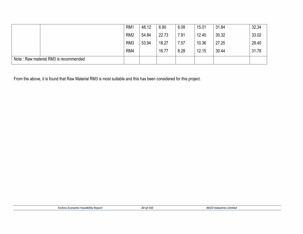
Techno Economic Feasibility Report 30 of 142 NECO Industries Limited
RM1
RM2
RM3
RM4
48.12
54.84
53.94
6.90
22.73
18.27
16.77
6.08
7.91
7.57
8.28
15.01
12.40
10.36
12.15
31.84
30.32
27.25
30.44
32.34
33.02
28.40
31.78
Note : Raw material RM3 is recommended
From the above, it is found that Raw Material RM3 is most suitable and this has been considered for this project.
Techno Economic Feasibility Report 31 of 142 NECO Industries Limited
SECTION – 4
INFRASTRUCTURES & PLANT LAYOUT
Techno Economic Feasibility Report 32 of 142 NECO Industries Limited
SECTION – 4
PLANT SITE & INFRASTRUCTURES
1.0 GENERAL
For location of the plant site the essential parameters that need be considered are as follows
• Sources of raw materials for the proposed plants
• Available of hazard free land.
• Road and railway connection for a raw materials and finished product.
• Availability of fuel, power and water
• Availability of skilled man-power
• Proximity to market for finished good.
• Availability of infrastructural facilities like township, bank, post office, schools, market, medical
facilities, transport, communication facilities etc.
Considering the above factors, the site for the proposed Cement and Captive Power plant of M/s
NECO Industries Ltd. has been identified at Village Risda, Dasrama, Tahsil & District Balodabazar.
The present steel plant of JNIL is approximately 70 Km away from proposed site,
2.0 AVAILABILITY OF SUITABLE LAND
An area of 225 hectare required for Cement Plant and Captive Power Plant has been identified by
the company at proposed site.
3.0 METEOROLOGICAL DATA OF THE PLANT SITE
The area belongs to sub-tropical climate of Central India. The climatologically data as available are
as below:
Temperature
Maximum – 45.1ºC
Minimum – 9.5.1ºC (December & January)
Relative humidity
Maximum – 100%
Minimum – 20%
Rainfall
Maximum annual rainfall : 2000 mm (June & September)
Techno Economic Feasibility Report 33 of 142 NECO Industries Limited
Heaviest rainfall in 24 hrs : 370.3 mm
Prevailing Wind Direction : West to East (March & September)
East to West (October to February)
Earth Quake Zone
The site is situated in region falling under zone -1 as defined by IS : 1893
Soil Bearing Capacity : 25T/m² (morrum type)
4.0 AVAILABILITY OF RAW MATERIALS
The major raw materials like cement grade limestone is available from NIL’s mines within a distance of
approximately 6 Km distances from the proposed site. Similarly, other additive materials lie morrum, sand
and fly ash are either available from the steel plant complex or with approximately 50 Km (Sand) from the
proposed plant site. Slag is available from JNIL’s steel plant.
5.0 ROAD LINKAGE
All raw materials and finished good will be transported upto the cement plant and from the cement plant by
road transport with a good linkage with the proposed site. In future, rail linkage for cement dispatch to long
distances may be considered availing the rail linkage facility in the steel plant.
6.0 SOURCES OF WATER
Water is available from Kukurdih dam which around 3 Km from proposed site. Water is supplied by pipe
line and is stored in a reservoir. All water requirement for the proposed cement plant will be available from
this reservoir which has sufficient capacity to meet the requirement of water This water can be used in the
plant as process and cooling purposes after proper treatment in water treatment and softening plant. An
estimation of 3 MCM water will be required for the Cement and Captive Power Plant.
7.0 AVAILABILITY OF FUEL
Coal will be used as fuel. Coal is available from local market / e-auction by Road /Rail as per availability.
8.0 AVAILABILITY OF POWER
Power will be available from own captive power plant and the short / balance if any, can be made available
/ sale from Chhattisgarh state electricity board’s kukurdih village sub-station situated at an approx. distance
of 5 km from the proposed site.
Techno Economic Feasibility Report 34 of 142 NECO Industries Limited
SECTION – 5
PROCESS DESCRIPTION AND BROAD SIZING
OF MAJOR MACHINERY & STORAGES
Techno Economic Feasibility Report 35 of 142 NECO Industries Limited
SECTION – 5
PROCESS DESCRIPTION AND BROAD SIZING OF MAJOR MACHINERY & STORAGES
CEMENT PLANT
1.0 GENERAL
The cement manufacture consists principally of grinding and blending of the cement raw materials in a definite
proportion and then burning the mixture at high temperature above 1300º C in a kiln. The resulting cement
clinker is cooled and then ground with gypsum to produce finished product (OPC), Gypsum is added to control
the setting of cement.
2.0 RAW MATERIAL DRYING AND GRINDING PROCESS
2.1 The raw grinding system must tolerate the raw materials with their specific characteristics, like high moisture
content, stickiness and abrasiveness. The required characteristics of a modern raw grinding system can be
summarized as follows:
a) High grinding capacity
b) High drying capacity
c) Toleration of sticky and abrasive raw materials
d) Low energy consumption
e) Reliability
2.2 Various plants developed for raw grinding operation are mainly
a) Closed circuit ball mill.
b) Vertical roller mill.
c) Roller press with or without ball mill.
d) Horizontal roller mill.
e) Closed circuit ball mill.
Techno Economic Feasibility Report 36 of 142 NECO Industries Limited
Until the early seventies when cement manufacturers were less concerned about the energy costs, Ball Mills
were considered adequate for a medium sized plant with raw material moisture within acceptable limit.
Some of the common systems installed in various cement plants are:
a) Central discharge ball mill with air separator.
b) End discharge ball mill with air separator.
c) Air swept ball mill with air separator.
Among these the mills with slide shoe bearings are capable of handling higher volume of hot gases in
comparison to mills with journal bearings and considered suitable for drying of raw materials with high
moisture content.
However, as on date the traditional ball mill with high level of operational reliability and availability is not the
most frequently bought grinding units due to its high specific power consumption in comparison to other modes
of grinding discussed in the flowing paragraph.
2.3 Vertical roller mill
Vertical roller mills with integral classifiers have been used successfully for many years for grinding of raw
material. It is also capable of simultaneously drying cement raw material having moisture around 15%. In a
vertical roller mill the mill feed is continued by pressure and friction between a rotating grinding table and 20to
4 grinding rollers pressed hydraulically against it.
The materials being ground is carried by pneumatic and mechanical transport to the classifier located in the
same housing directly above the grinding chamber. The classifier tailings are returned to the grinding process
together with the fresh material. Recirculation system of mill rejects is employed to reduce pressure drop in the
system. Power consumption in the system is low compared to ball mill system.
It addition to its operational reliability other important features of this type of mill are its compact structure and
the simple and economical plant management.
2.4 Roller press with or without ball mill
Roller press or high pressure grinding rolls are integrated in varying configurations into new and existing
grinding plants to increase the output with bar mills.
Techno Economic Feasibility Report 37 of 142 NECO Industries Limited
The fresh material is fed to the high pressure grinding rolls, which operates in closed circuit with
disagglomerator and a classifier. All the tailings from the classifier are returned to the high pressure grinding
rolls. The classifier fines contain about 50 to 80% of finished product. This “semi-finished” product from the
primary grinding circuit is then fed to a ball mill for finish grinding.
The greatest energy saving of more than 50% when compared with ball mill plants can be achieved with the
same material using high-pressure grinding rolls if these operate in a finish grinding configuration in circuit with
a disagglomerator and a classifier.
High pressure grinding rolls are primarily suitable for comminution of materials, which are not too fine and
have only low moisture contents. Very moist feed material has to be pre-dried in separate driers.
2.5 Horizontal roller mills
The latest type of mill is the horizontal roller mill. The horizontal mill tube ha a length/diameter ratio of less
than 1.0. The pressure on the grinding roller is significantly lower than the roller press and is comparable
with that in vertical roller mills. Since no compacted cake is formed in this of mill, there is no need to have
disagglomerator for the cake. So far two different designs have become known, which differ mainly in the
type of material transport in the mill.
3.0 PYROPROCESSING
The kiln of the pyro-processing plant is the heart of the cement plant. Cement manufacturing processes are
termed according to the physical condition of the raw material being fed to the kiln after grinding and
homogenizing.
Based on above the manufacturing processes are termed as
a) Wet process
b) Semi-wet process
c) Semi-dry process
d) Dry-process
The selection of suitable process for production of cement clinker depends on certain number of factors,
which include
i) Overall techo-economic feasibility.
Techno Economic Feasibility Report 38 of 142 NECO Industries Limited
ii) Suitability of raw materials for the particular process.
iii) Availability and cost of utilities including electricity, fuel and water.
3.1 Wet Process
Present day wet process is rarely used and the shift towards dry process is due to the following reason:
a) Higher fuel consumption.
b) Higher water consumption. Higher wear rate of equipment such as kiln chains, liner plates, grinding
media consumption in slurry mills, impellers of slurry pumps etc.
3.2 Semi-wet Process
In semi-wet process, the kiln is fed with raw meal in the form of wet cakes consisting of 15 to 20% moisture
after partial dewatering of wet slurry by-filtration. Heat consumption in this process is 1000-1200 Kcal/Kg. of
clinker.
The advantage of this process is partial fuel saving even when wet grinding of raw material is resorted to
due to characteristics of raw material. However, this process has not been widely adopted in the cement
industry due to additional energy consumption and high maintenance coast filtration unit.
3.3 Semi-dry Process
This process was especially evolved to counter the main drawback of the wet process viz. high fuel
consumption. In this process, raw materials are ground in dry condition with or without coal or coke breeze
depending upon the type of kiln system. Raw meal, thus produced, is homogenized and then nodulized in a
pan nodulizer either of dish or rotary type by adding controlled quantity of water (usually 10 – 12%).
Nosules, thus produced, are fed to the pyro-processing units. Since nodules are fed, this type of process
can obviously be applied to raw materials having proper plasticity for producing nodules of adequate
strength and thus has a limited applicability. This process is adopted where alkali –content in raw materials
& fuels are on the higher side and raw-material properties do not allow the preparation of raw mix in dry-
condition.
The raw-meal nodules are fed to the pyro-processing units having either
a) Shaft kiln
Techno Economic Feasibility Report 39 of 142 NECO Industries Limited
b) Shaft kilns can be recommended only for exploitation of small deposits near the consumption centers.
In India, a considerable number of mini cement plants based on VSK technology are in operation. Fuel
consumption varies from 850-1000 kcal/kg of clinker.
c) Short rotary kiln and traveling grate.
Short Rotary kilns with traveling grate type of kiln plant are not popular. Because the plant, especially the
moving grate, calls for heavy maintenance since it has to withstand high temperature in very dusty kiln
atmosphere and thus reduce the kiln availability and consequently the clinker production. This type of kiln
system consumes heat varying from 800-900 kcal/kg of clinker.
3.4 Dry-Process
a) During the past few decades, the rotary kiln based on dry process has made an impact in cement
industry. In the dry process, raw materials are ground in dry condition and the resultant raw meal is
fed to the rotary kiln in dry state.
Dry process kiln can be of the following types:
i) Long-dry kiln with internal/external heat exchanger.
ii) Kiln with suspension preheater.
iii) Kiln with suspension preheater and precalciner.
b) Long Dry Kiln with internal/external heat exchanger
Long Dry Kiln with internal/external heat exchanger is easy to operate since this os not very sensitive to
upset condition as result of high chloride or alkali content in the raw material. However, this type of kiln is
not very attractive from the point of view of fuel economy. Heat consumption is in the region of 1100-1200
kcal/kg of clinker
d) Kiln with suspension preheater
Invention of suspension preheater was a remarkable development in the heat economy. The raw meal is
preheated in the suspended condition in suspension preheater utilizing kiln waste gases. As a result the
requirement of the length of the kiln is shorter, The specific heat consumption in this process is 750-950
kcal/kg of clinker, depending upon the number of stages of preheater.
Techno Economic Feasibility Report 40 of 142 NECO Industries Limited
Normally for new plants 56 stage suspension preheaters are adopted whereupon the expected specific
heat consumption is around 750 kcal/kg of clinker. No. of stages in preheater is determined mainly on the
moisture-content in raw-materials feeding to the raw-mill as kiln exit gas is used for raw-material drying.
e) Kiln with suspension preheater and precalciner
The most important advancement in cement industry in last 10 year has been the development of pre-
calcination technology for manufacture of cement clinker in rotary kiln. In pre-calcination system a degree
of calcinations of raw meal upto around 90-95% is achieved in the preheater itself before the raw meal
enters the kiln.
This is achieved by introducing a secondary firing at the preheater. With this the volume rating of the kiln
increases and same size of kiln can give much higher output. In fact pre-calcination technology is adopted
for large size plants; however, the same can be used for increasing the output of an existing plant as well.
The pre-calciner used in this process is either of
i) On-line calciner
ii) Separate line calciner
In case of on-time calciner kiln gases are taken through the calciner vessel whereas in case of separate
line calciner only tertiary air is taken through the calciner and kiln gases are diverted to the preheater
stream.
Advantages of pre-calciner system are summarized as below:
i) Kiln feed while entering into kiln will be almost 90-92% calcined as compared to 35-40% for
conventional rotary kiln with suspension preheater. Substantial increase in production from the
existing conventional preheater kiln by incorporating pre-caliner with a separate preheater stream
is possible. So, due to high degree of calcinations of kiln feed (90-92%) the operation of kiln in
case of pre-calciner system is much more stable than the conventional kiln. This results in the
following advantages:
ii) Stable coating in the burning zone, so higher refractory life which leads to higher availability of the
kiln itself and lower inventory cost on refractories.
iii) Due to stable kiln operation, the quality of clinker as well as throughput from the kiln shall also be
consistent over a longer period of operation.
Techno Economic Feasibility Report 41 of 142 NECO Industries Limited
iv) In the pre-calciner vessel low grade fuel be used successfully, if required.
v) The Nox emission itself is lower than conventional kiln. Nox level can further be reduced in case of
pre-calciner system by suitable designed precalciner vessel in a simple and inexpensive way.
Due to the above advantage it is a common practice to install pre-calciner system for kiln capacity
on or above 1500 TPD. All the pre-calciner systems from the reputed cement machinery
manufactures are well proven and working satisfactorily.
Disadvantages of Dry Process using Suspension Preheater
The main disadvantage of dry process using suspension preheaters with or without pre-calciner is
the tendency of raw meal to form deposits on the inside surface of certain parts of the preheater
system, if the raw materials have a high content of alkalis, chlorides and sulfur. These salts tend to
evaporate in the kiln and condense in the preheater cyclone cones, thus obstructing free flow of the
material to the kiln. In such case a suitable by-pass system for the kiln exit gas has to be adopted
to obviate such problems.
4.0 CEMENT GRINDING
Cement grinding system to be chosen must have the following characteristics:
i) High grinding capacity.
ii) Low energy consumption.
iii) Ability to produce high quality cement.
iv) Flexibility to produce various grades of cement.
v) Reliability.
Various modern plants developed for cement grinding operation are mainly:
i) Closed circuit ball mill with high efficiency separator
ii) Vertical roller mill.
iii) Finish grinding in roller press.
iv) Roller press as a pre-grinder and finish grinding in ball mill
Techno Economic Feasibility Report 42 of 142 NECO Industries Limited
4.1 Closed Circuit Ball Mill with high Efficiency Separator
In earlier days cement used to be ground in open circuit mill resulting in high specific power
consumption.
The use of high efficiency air separators in modern cement plants has helped reducing the energy
consumption in grinding process and improving strength properties of cement. The high efficiency
separators incorporate several mechanical features to carry out separation in medium and sub-
micron range. This has resulted In an energy saving upto 33% compared to open circuit grinding.
4.2 Vertical roller mill
In the initial stages application of VRM to clinker and slag grinding was not successful on account
of the following reasons, namely:
i) Intense mechanical wear.
ii) Steeper particle size distribution of the product.
iii) Lower grinding temperature.
However, such problems have since been handled successfully and VRM has emerged as a viable
alternative to ‘Ball Mill with HES’.
4.3 Finish grinding in roller press
Finish grinding of cement in roller press is an attractive proposal from the point of view of energy
saving. The Cement ground in roller press has characteristics similar to those obtained in VRM
grinding, namely:-
i) Steep particle size distribution.
ii) Lower grinding temperature.
It has been separated that this problem is being effectively handled.
a. Roller press or vertical roller mill as a pre-grinder and finish grinding in ball mill
The electrical power consumption in clinker grinding can be significantly lowered by installation of a
suitable pre-grinder unit upstream of a Bar Mill. Development in this area is still being carried out.
Techno Economic Feasibility Report 43 of 142 NECO Industries Limited
The decision regarding the choice of appropriate pre-grinder will rest upon capital investment vis-a
vis increase in the throughout and energy savings, installation and operating cost, maintenance
requirements and the quality of product obtained from the pre-grinder.
5.0 RECOMMENDATION
a) Raw grinding
Vertical roller mill has been chosen for raw grinding operation.
b) Coal grinding
Vertical roller mill has been chosen for coal grinding operation.
c) Pyro-processing
Depending on the availability from different manufacturers, single string six stage preheater with in line pre-
claimer has been selected for the pyro-processing section.
d) Finish grinding of cement
Vertical Roller mill has been selected for cement grinding.
6.0 PROCESS DESCRIPTION
6.1 Process flow sheets enclosed for all the sections describe the flow of materials and process of
manufacture of cement for the complete plant. Clause 6.17 specifies the capacities of major plant sections
and storages.
6.2 Limestone crushing system
a) The main crushing plant will be used for crushing limestone only. They will be fed to the main crusher
of 350 TPH capacity through two dump hoppers.
b) Limestone will be transported by 30T dumpers from open storage or directly from mines and fed into
the crushing plant limestone hopper fitted with a variable speed apron feeder for regulating feed
quantity to the crusher.
c) Crushed limestone and be transported to the 30,000 T capacity circular pre-blending stockpile by
conveyors.
d) Pulse jet type bag filters ate provided for the crushing plant for effective dust control.
Techno Economic Feasibility Report 44 of 142 NECO Industries Limited
6.3 Raw material crushing, pre blending and storage
a) Crushed limestone mixture will be stored in a circular preblending stockpile of 30,000 T capacities by a
700 TPH luffing boom type stacker.
b) A rotating type, bridge scraper reclaimer around central column with outer circular travel rail of 350
TPH capacities will be used for reclaiming of limestone from the stockpile. The complete operation of
stacking and reclaiming will be designed to achieve a minimum preblending ration of 7:1.
c) Morrum, Sand, Coal, Slag and Gypsum will be transported to the plant location by 40T tripper truck and
will be discharged into a ground hopper. Below than apron feeder, diverter and crusher (150 TPH
capacity) has been considered for crushing of material and diverter for by passing sand. All this
crushed material and sand is discharged into a conveyor, which carried them to a transfer tower,
wherein Slag and Gypsum is discharge into one conveyor and Morrum, Sand and Coal into other. This
conveyor carries the material to their respective storage area for individual stockpile.
d) After reclaiming Morrum, Sand, Limestone and coal this are transported by a common conveyor to
transfer tower, wherein Limestone, Morrum and Sand are transported to their respective feed hoppers
for Raw Mill. Whereas Coal is transported to Coal mill feed hopper.
e) On the other hand after reclaiming of slag and Gypsum they are transported to clinker belt for cement
mill by a belt conveyor.
6.4 Raw material proportioning
a) Six 400 T capacity raw mill feed hoppers will be provided for storing crushed limestone.
b) Six 100 T capacity raw mill feed hoppers will be provided in the same complex for storing Morrum and
Sand.
c) Each of these hoppers will be provided with electronic weigh feeders for controlled and measured
extraction of respective materials as per raw mix design. The proportioned raw materials will then be
transported to the raw mill for grinding.
d) Pulse jet type bag filters are provided at hopper top for effective dust control while feeding into and
extraction from the hoppers.
Techno Economic Feasibility Report 45 of 142 NECO Industries Limited
6.5 Raw material drying & grinding
a) Proportioned raw material will be fed into the vertical roller type raw mill of capacity 180 TPH for
drying & grinding to required moistures and fineness. Hot gas from the preheater will be drawn into the
mill for drying of raw material. After grinding coarse fraction will be separated and returned to the mill by
the high efficiency classifier located inside the mill. Material thus separated will be further ground inside
the mill while the fines i.e., product will be sucked by the raw mill fan though a battery of cyclones where
the product will be separated from the gas stream. Variable speed drive will be envisaged for raw mill fan
motor.
b) Dust laden air at the outlet of the raw mill fan along with the balance exhaust gas preheater will be
passed through an ESP for separation of dust before discharged into the atmosphere.
6.6 Raw meal storage & kiln feed
a) Ground raw meal will be stored in one inverted cone bottom silo of 10,000T capacity.
b) Raw meal will be extracted from the bottom and conveyed by air slide to the bucket elevator for feeding to
the kiln feed bin installed in the first floor of preheater building.
c) Raw meal will be extracted from the kiln feed bin at a measured rated and fed into the preheater by
another bucket elevator installed in the preheater building.
d) Pulse jet type bag filters are provided at silo top and kiln feed bin top for effective dust control while
feeding into and extraction from the silos/bin.
6.7 Pyro processing
a) A single string six stage preheater of the latest proven high efficiency, low pressure drop design will
be used for preheating/calcination of raw meal. Coal will be used as fuel for kiln and precalciner. The high
efficiency preheater fan shall be provided with variable speed drive to control gas flow as per process
requirement. Raw meal will be introduced in the gas duct of the top stage cyclones. Gas and raw meal are
intimately mixed as they enter the gas duct. Raw meal will be separated from the gas stream and the
separated raw meal will be fed to the gas duct of the next lower stage cyclone. The heat exchange between
the gas and raw meal takes place the gas ducts and separation of heated raw meal takes place in the
cyclones.
b) Raw meal from penultimate stage cyclone will be fed to the precalciner. Raw meal will be fed to the
precalciner at two points for proper distribution. Fuel and combustion air will be fed to the precalciner at a
point, where they will be intensely mixed, full combustion will take place and the heat will be transferred to
Techno Economic Feasibility Report 46 of 142 NECO Industries Limited
raw meal. The gas velocities and length of the precalciner duct will be designed to achieve the desired of
calcination.
c) The combustion air for the fuel fired in precalciner will be taken from the cooler 1st grate through a
tertiary air duct.
d) Kiln and precalciner burner will be dual fuel type, designed to handle both coal and oil.
e) Continuous carbon monoxide and excess oxygen analyzers will be provided to facilitate the control
of CO formation. to achieve this, the combustion on fuel should be carried out in the presence of a
minimum of 1.5% excess oxygen in the kiln outlet to ensure complete combustion.
6.8 Grate cooler and clinker handling
a) The clinker formed in the kiln (6000 TPH capacity) will be cooled for heat recuperation, easy
handling and development of desired propertied of clinker. It will be cooled in a third generation
reciprocating horizontal cooler with maximum heat recovery by cooling air from the red clinker and
subsequent utilization of the same as tertiary air in the calciner. This reduces the overall energy
consumption for the clinkering process. Adequate numbers of cooling air fans are provided to supply
necessary cooling air. Dust laden gas from the cooler will be vented through a electrostatic precipitator
where clinker dust will be vented to the atmosphere. The cooler vent fan will be of high efficiency type and
will be provided with variable speed drive similar to raw mill fan. Cooler is of hopper less type.
b) The cooled clinker will be discharged to a deep pan conveyor. Spillage from the cooler as well as
the dust collected in the ESP hopper will be also discharged to the same deep bucket conveyor for further
transport to clinker storage.
c) One 30,000T capacity clinker storage tank will be provided. The tank will be provided two bottom
extraction tunnels, fitted with required number of clinker extraction gates and two deep pan conveyors/chain
conveyors upto the first transfer point.
d) Extracted clinker will be transported to the cement mill feed hoppers by heat resistant belt
conveyor.
e) Pulse jet type bag filters are provided at hopper tops for effective dust control while feeding into
and extraction from the hoppers.
6.9 Cement mill feed hoppers
a) Six 300T capacity cement mill feed hopper will be provided for storing clinker & slag.
Techno Economic Feasibility Report 47 of 142 NECO Industries Limited
b) Six 100T capacity cement mill feed hopper will be provided for gypsum and other additive
materials, like limestone, if required.
c) Each of these hoppers will be provided with provided with electronic weigh feeders for controlled
and measured extraction of respective materials as per product mix requirement. The proportioned
materials will then be transported to the cement mill for grinding.
d) Pulse jet type bag filters are provided at hopper top for effective dust control while feeding into and
extraction from the hoppers.
e) Similarly, another set of hoppers & bag filter to be provided for cement mill
6.10 Cement and Slag grinding
a) SIx Cement Mill of capacity 90 TPH are considered for the production of Fly Ash Cement (PPC) and
Slag Cement (PSC). Interchangeable flexibility of product is considered i.e. any VRM can be used for
any material.
Cement Mill #1 : OPC Grinding : 12 Hrs.
Slag Grinding : 8.5 Hrs.
Interchanging time : 1.5 Hrs.
Cement Mill #2 : PPC Grinding : 18 Hrs.
b) Each mill is provided with a Hot Air Generator giving hot air to VRM for drying of Slag. The coal
required for the each FBC boiler is provided through a ground hopper with a conveyor for transportation
of coal to FBC boiler.
c) Each mill is provided with a load cell mounted feed hopper of capacity 200T for feeding of fly ash for
production of PPC.
d) Finished product from both the cement grinding mills will be transported to four cement silos by means
of air slides and bucket elevator.
e) Pulse jet type bag filters are provided at transfer points and for air side venting for effective dust
control.
6.11. Cement storage and extraction
a) Inverted cone type cement silo will be provided for the system. Each silo having capacity of 5,000 T.
Silo1 : OPC storage
Techno Economic Feasibility Report 48 of 142 NECO Industries Limited
Silo2 : Slag storage
Silo3 : PPC storage
Silo4 : PSC storage
b) Silo 3 & 4 will have provision for bulk truck loading of cement. Each bulk loading point will be complete
with a pit less type electronic weigh bridge for loading control and have the facility of receiving cement
from two adjacent cement silos.
c) Silo 3 & 4 will have arrangement for extraction and transportation of cement to the packing plant by air
slides and bucket elevators.
d) After extraction of cement from Silo 1 & 2, they are mixed by a paddle mixture with pre-defined mix
ratio. Then by an air slide and bucket elevator this mixture is stored in Silo 4 which is dedicated for
PSC.
e) Pulse jet type bag filters are provided at Silo tops and for air slide venting for effective dust control.
6.12. Cement packing and dispatch
a) Packing plant will be provided with two (6) packers of capacity 180 TPH with dedicated truck loading
arrangement. Each rotary packer will be provided with two (6) discharge points and each discharge
point will be feeding a separate belt conveyor. Thus there will be a system of belt conveyors carrying
bags to the truck loaders. Total four (4) truck loading points are provided.
b) Pulse jet type bag filters are provided for each packing machine for effective dust control.
6.13. Fly Ash handling and storage
a) Pneumatic System is provided for extraction of Fly Ash from Fly ash truck.
b) Then by mean of suction this fly ash is stored into a 1500 T capacity silo with extraction arrangement at
the bottom of silo. Then by means of air slide and bucket elevator fly ash is transported to fly ash feed
hopper in cement mill building.
c) Pulse type jet bag filters are provided at silo tops and for air slide venting for effective dust control.
6.14 Coal grinding and firing
a) By a conveyor raw coal is transported to Coal Feed Hopper of capacity 200 T.
b) Close circuit VRM of capacity 20 TPH shall be used for drying and grinding of coal.
c) Loss in weight system shall be used for coal weighing purpose.
Techno Economic Feasibility Report 49 of 142 NECO Industries Limited
d) Pneumatic pumps shall do dosing of fine coal to burners. Also one common pneumatic pump has been
provided as stand-by arrangement.
e) The coal is grinded in coal mill and fine coal is stored in two separate 60T capacity fine coal hoppers.
f) Carbon dioxide flooding system will be provided for inertization of coal mill, fine coal hoppers and coal
mill bag filters as a safety measure against fire hazard.
g) Pulse jet type bag filters with anti-static treatment are provided for coal hopper top and for coal mill
venting for effective dust control.
6.15 Water storage and distribution
a) Raw water from the raw water reservoir will be pumped directly to the water treatment plant having
facility at Alum treatment, removal of un-dissolved slid by overflowing method with two chamber
consideration.
b) The clean water from the water treatment plant will be pumped to overhead water tank.
c) The process water requirement of various equipment will be meet by pumping and a portion of the
filtered water will be sent to softening plant is stored in a overhead tank of drinking water storage and
another in ground tank for cooling purpose of various equipment.
d) In order to reduce the overall plant water requirement and consequent plant size, the soft cooling
water, after cooling various equipment will be cooled in cooling tower and pumped back to overhead
soft water tank. This water from cooling tower and makeup water will be again recalculated for cooling
purpose.
6.16 Compressed air system
a) Two compressed air stations will be installed within the plant area. One will be located beside the coal
mill building for catering compressed air requirement around raw grinding and pyro processing area.
Another compressed air station will be located near packing plant area to cater for the compressed air
requirement in cement grinding, storage and packing plant area.
b) Each compressed air station will be complete with required number oil free reciprocating compressors,
respective air receivers, air dryers and distributing piping network.
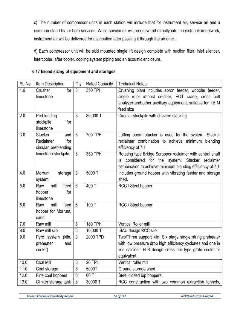
Techno Economic Feasibility Report 50 of 142 NECO Industries Limited
c) The number of compressor units in each station will include that for instrument air, service air and a
common stand by for both services. While service air will be delivered directly into the distribution network,
instrument air will be delivered for distribution after passing it through the air drier.
d) Each compressor unit will be skid mounted single lift design complete with suction filter, inlet silencer,
intercooler, after cooler, cooling system piping and an acoustic enclosure.
6.17 Broad sizing of equipment and storages
SL No Item Description Qty Rated Capacity Technical Notes 1.0 Crusher for
limestone 3 350 TPH Crushing plant includes apron feeder, wobbler feeder,
single rotor impact crusher, EOT crane, cross belt analyzer and other auxiliary equipment, suitable for 1.5 M feed size
2.0 Preblending stockpile for limestone
3 30,000 T Circular stockpile with chevron stacking
3.0 Stacker and Reclaimer for circular preblending limestone stockpile.
3 700 TPH Luffing boom stacker is used for the system. Stacker reclaimer combination to achieve minimum blending efficiency of 7:1
3 350 TPH Rotating type Bridge Scrapper reclaimer with central shaft is considered for the system. Stacker reclaimer combination to achieve minimum blending efficiency of 7:1
4.0 Morrum storage system
3 5000 T Includes ground hopper with vibrating feeder and storage shed.
5.0 Raw mill feed hopper for limestone
6 400 T RCC / Steel hopper
6.0 Raw mill feed hopper for Morrum, sand.
6 100 T RCC / Steel hopper
7.0 Raw mill 3 180 TPH Vertical Roller mill 8.0 Raw mill silo 3 10,000 T IBAU design RCC silo 9.0 Pyro system (kiln,
preheater and cooler)
3 2000 TPD Two/Three support kiln. Six stage single string preheater with low pressure drop high efficiency cyclones and one in line calciner. FLS design cross bar type grate cooler or equivalent.
10.0 Coal Mill 3 20 TPH Vertical roller mill 11.0 Coal storage 3 5000T Ground storage shed 12.0 Fine coal hoppers 6 60 T Steel closed top hoppers 13.0 Clinker storage tank 3 30000 T RCC construction with two common extraction tunnels,
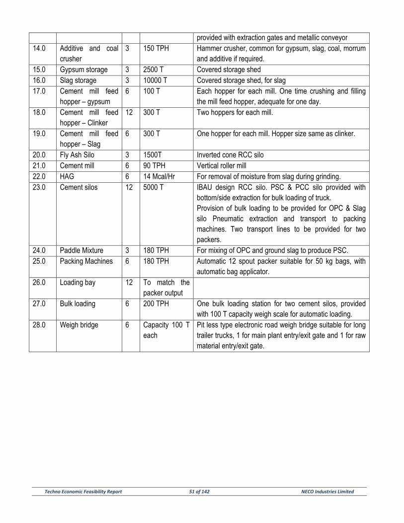
Techno Economic Feasibility Report 51 of 142 NECO Industries Limited
provided with extraction gates and metallic conveyor 14.0 Additive and coal
crusher 3 150 TPH Hammer crusher, common for gypsum, slag, coal, morrum
and additive if required. 15.0 Gypsum storage 3 2500 T Covered storage shed 16.0 Slag storage 3 10000 T Covered storage shed, for slag 17.0 Cement mill feed
hopper – gypsum 6 100 T Each hopper for each mill. One time crushing and filling
the mill feed hopper, adequate for one day. 18.0 Cement mill feed
hopper – Clinker 12 300 T Two hoppers for each mill.
19.0 Cement mill feed hopper – Slag
6 300 T One hopper for each mill. Hopper size same as clinker.
20.0 Fly Ash Silo 3 1500T Inverted cone RCC silo 21.0 Cement mill 6 90 TPH Vertical roller mill 22.0 HAG 6 14 Mcal/Hr For removal of moisture from slag during grinding. 23.0 Cement silos 12 5000 T IBAU design RCC silo. PSC & PCC silo provided with
bottom/side extraction for bulk loading of truck. Provision of bulk loading to be provided for OPC & Slag silo Pneumatic extraction and transport to packing machines. Two transport lines to be provided for two packers.
24.0 Paddle Mixture 3 180 TPH For mixing of OPC and ground slag to produce PSC. 25.0 Packing Machines 6 180 TPH Automatic 12 spout packer suitable for 50 kg bags, with
automatic bag applicator. 26.0 Loading bay 12 To match the
packer output
27.0 Bulk loading 6 200 TPH One bulk loading station for two cement silos, provided with 100 T capacity weigh scale for automatic loading.
28.0 Weigh bridge 6 Capacity 100 T each
Pit less type electronic road weigh bridge suitable for long trailer trucks, 1 for main plant entry/exit gate and 1 for raw material entry/exit gate.
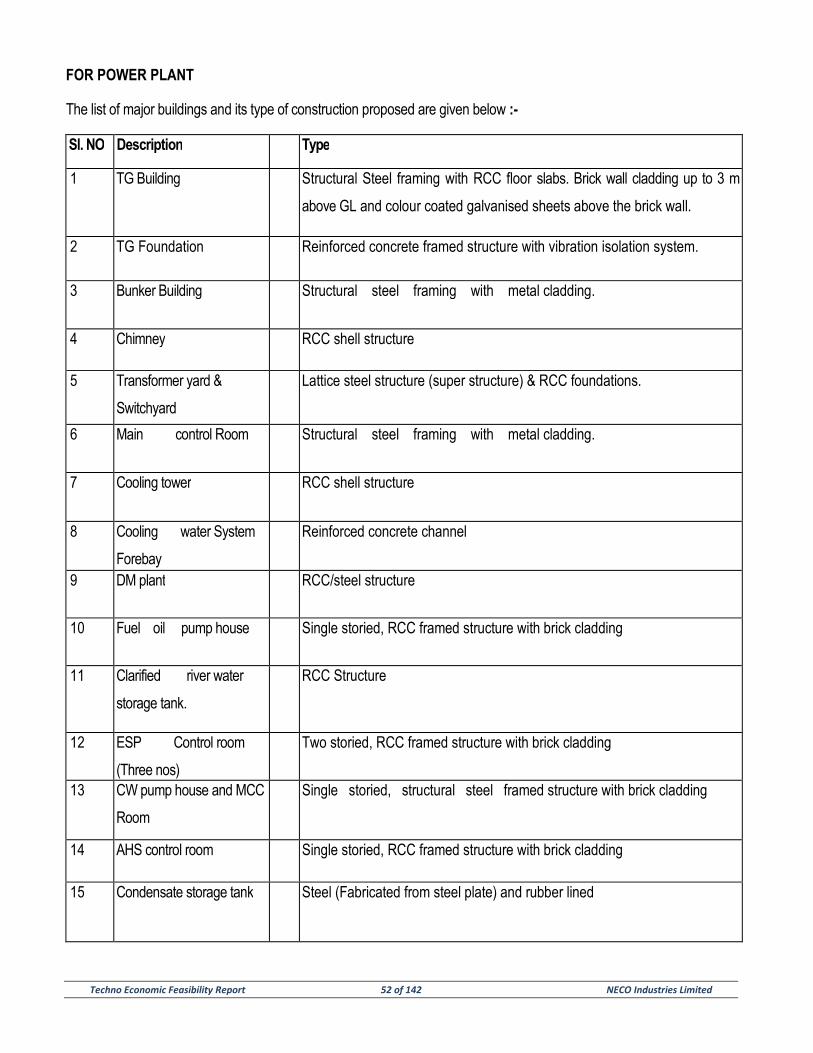
Techno Economic Feasibility Report 52 of 142 NECO Industries Limited
FOR POWER PLANT
The list of major buildings and its type of construction proposed are given below :-
Sl. NO Description Type
1 TG Building Structural Steel framing with RCC floor slabs. Brick wall cladding up to 3 m
above GL and colour coated galvanised sheets above the brick wall.
2 TG Foundation Reinforced concrete framed structure with vibration isolation system.
3 Bunker Building Structural steel framing with metal cladding.
4 Chimney RCC shell structure
5 Transformer yard &
Switchyard
Lattice steel structure (super structure) & RCC foundations.
6 Main control Room Structural steel framing with metal cladding.
7 Cooling tower RCC shell structure
8 Cooling water System
Forebay
Reinforced concrete channel
9 DM plant RCC/steel structure
10 Fuel oil pump house Single storied, RCC framed structure with brick cladding
11 Clarified river water
storage tank.
RCC Structure
12 ESP Control room
(Three nos)
Two storied, RCC framed structure with brick cladding
13 CW pump house and MCC
Room
Single storied, structural steel framed structure with brick cladding
14 AHS control room Single storied, RCC framed structure with brick cladding
15 Condensate storage tank Steel (Fabricated from steel plate) and rubber lined
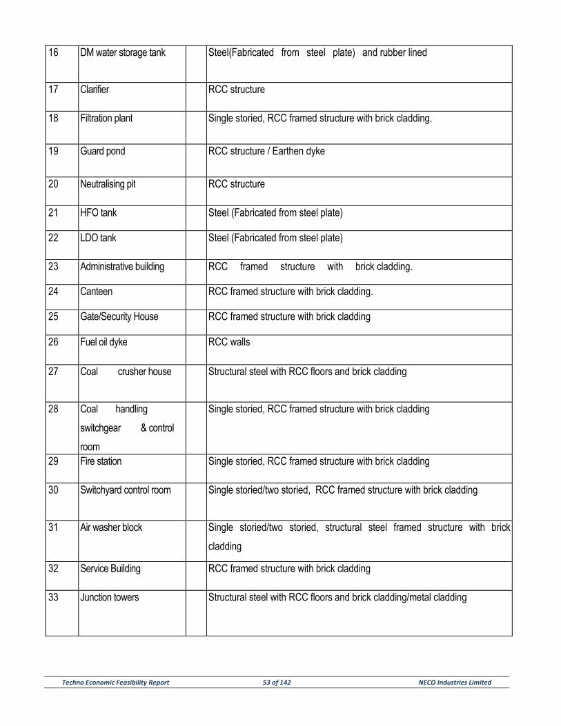
Techno Economic Feasibility Report 53 of 142 NECO Industries Limited
16 DM water storage tank Steel(Fabricated from steel plate) and rubber lined
17 Clarifier RCC structure
18 Filtration plant Single storied, RCC framed structure with brick cladding.
19 Guard pond RCC structure / Earthen dyke
20 Neutralising pit RCC structure
21 HFO tank Steel (Fabricated from steel plate)
22 LDO tank Steel (Fabricated from steel plate)
23 Administrative building RCC framed structure with brick cladding.
24 Canteen RCC framed structure with brick cladding.
25 Gate/Security House RCC framed structure with brick cladding
26 Fuel oil dyke RCC walls
27 Coal crusher house Structural steel with RCC floors and brick cladding
28 Coal handling
switchgear & control
room
Single storied, RCC framed structure with brick cladding
29 Fire station Single storied, RCC framed structure with brick cladding
30 Switchyard control room Single storied/two storied, RCC framed structure with brick cladding
31 Air washer block Single storied/two storied, structural steel framed structure with brick
cladding
32 Service Building RCC framed structure with brick cladding
33 Junction towers Structural steel with RCC floors and brick cladding/metal cladding
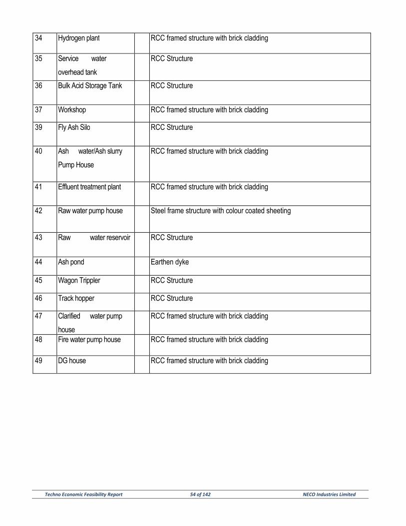
Techno Economic Feasibility Report 54 of 142 NECO Industries Limited
34 Hydrogen plant RCC framed structure with brick cladding
35 Service water
overhead tank
RCC Structure
36 Bulk Acid Storage Tank RCC Structure
37 Workshop RCC framed structure with brick cladding
39 Fly Ash Silo RCC Structure
40 Ash water/Ash slurry
Pump House
RCC framed structure with brick cladding
41 Effluent treatment plant RCC framed structure with brick cladding
42 Raw water pump house Steel frame structure with colour coated sheeting
43 Raw water reservoir RCC Structure
44 Ash pond Earthen dyke
45 Wagon Trippler RCC Structure
46 Track hopper RCC Structure
47 Clarified water pump
house
RCC framed structure with brick cladding
48 Fire water pump house RCC framed structure with brick cladding
49 DG house RCC framed structure with brick cladding
Techno Economic Feasibility Report 55 of 142 NECO Industries Limited
STEAM GENERATOR AND ACCESSORIES
The steam generator (SG) would be designed for firing 100% coal and would natural circulation, single drum type.
The SG would be of two pass design, radiant, single reheat, balanced draft, semi-outdoor type, rated to deliver 430
t/hr of superheated steam at 129.2ata and 540°C when supplied with feed water at a temperature of 2400 C at the
economiser inlet. The reheat steam temperature would also be 5400 C. However, the performance figures indicated
above are preliminary and are subject to discussions and confirmation with the selected suppliers of the main
equipment packages. The steam generator would be provided with coal mills along with individual raw coal
gravimetric feeders and coalbunkers. Sampling arrangement at mill outlet would be provided for purpose of
establishing the average gross calorific value of coal as well as coal fineness. The coal mills would be provided with
steam blanketing system for the purpose of fire protection. The SG would be designed to handle and burn LDO as
secondary fuel for start up upto 7.5% MCR capacity and HFO for low load operation & flame stabilization upto 22.5
% MCR capacity. For unit light up and warm up purposes LDO shall be fired. The required fuel oil pressurising unit
would be provided. High-energy electric arc igniters would be provided to ignite the fuel oil. The steam generator
would consist of water cooled furnace, radiant and convection superheaters, re-heaters, attemperators,
economiser, regenerative air heaters, bunkers, steam coil air pre-heaters, etc. Soot blowers would be provided at
strategic locations and would be designed for sequential fully automatic operation from the unit control room. The
draft plant would comprise of primary air fans, forced draft fans, and induced draft fans. Electrostatic precipitator
(ESP) and fly ash hoppers would be provided for the collection of fly ash. The ESP shall be designed to achieve an
outlet dust concentration of 50 mg/ Nm³. ESP outlet dust concentration shall be finalised as per latest State /
Central Pollution Control Board norms.
STEAM TURBINE GENERATORS AND ACCESSORIES
Turbine – generator assembly will be designed to deliver 70 MW at generator terminal. At the inlet, parameters of
steam will be 126ata and 537°C. Extractions will be taken from turbine for HP heater. Back pressure of 0.19 ata is
estimated. Turbine will be equipped with all the accessories required. Accessories will include, instrumentation for
monitoring its operation, automatic run-up system, test system, seal oil, lube oil, jacking and control oil system,
drain system, HP and LP bypass, it will also include complete oil purification unit with transfer pumps with storage
facilities. Suitable instruments and control devices would be installed to accelerate and synchronize as well as to
put the system on barring gear automatically from the control panel. Instruments will also include system for
protection of the assembly.
Techno Economic Feasibility Report 56 of 142 NECO Industries Limited
PLANT CYCLE
The condensing plant would comprise air cooled condenser with design back pressure of around 0.19ata and would
be located outdoor. The condenser shall be designed to receive and condense the whole of the exhaust steam from
turbine and drains from heaters under all operating conditions. 2 x 100% capacity vacuum pumps would be
provided to create vacuum in the condenser during start-up and to remove the non-condensable gases liberated
during normal operation.
This system comprises of main oil tank of adequate capacity, one Shaft driven pump, 1x100% AC motor driven
auxiliary oil pump (AOP), 1x100% DC motor drive emergency oil pump (EOP), 1x100% AC motor driven jacking oil
pump and 1x100% DC motor drive jacking oil pump with all piping, fitting, valves etc. The AOP, EOP & JOP will be
of centrifugal type mounted on the main oil tank. The pumps will be rated for 100% duty, sufficient to supply all oil
requirements for TG bearings lubricating under all load conditions.
The main oil tank would be of welded construction of high quality carbon steel plate and its capacity would be such
as to provide an adequate residence time under normal operating condition. Two 100% duty AC motor drive oil
vapor extractors would vent the oil tank.
The auxiliary cooling water system would comprise small IDCT , pumps, piping and valves etc. to supply cooling
water to various auxiliaries requiring cooling water.
Auxiliary steam would comprise of piping, valves; fittings further pressure reducing and desuperheating station.
Auxiliary steam will be supplied to Turbine gland sealing, various heater and Boiler start-up burner oil atomization.
Control Oil system would comprise of fluid reservoir, 2x100% Motor driven pumps, one no. Recirculation pump, 2
x100% oil coolers, strainer, piping, valves, fittings and accumulators. This system supplies high pressure oil to
Turbine HP/IP stop and control valve Electro- Hydraulic actuators and LP Bypass stop and control valve actuators.
Separate High Pressure pump for HPBP operation is envisaged for safe SG shutdown.
The regenerative cycle would consist of three low pressure heaters, a variable pressure deaerator, two high
pressure heaters and one gland steam condenser. The actual number of regenerative feed heaters would be
finalized by cycle optimization and configuration for better performance efficiency specific to the standard machines.
Techno Economic Feasibility Report 57 of 142 NECO Industries Limited
The condensate from the condenser hot-well would be pumped by 2 x 100 % capacity condensate extraction
pumps (one working and one standby) to the deaerator, through the gland steam condenser, drain cooler and low
pressure heaters. Feed water would be pumped from the deaerator to the steam generator through the high
pressure heaters by means of 3x50% capacity boiler feed pumps (two working and one standby).
Under normal operating conditions, drains from the high pressure heaters would be cascaded to the next lower
pressure heater and finally to the deaerator. Drains from low pressure heaters would be cascaded successively to
the next lower pressure heater and finally to the condenser hot well. Heaters would be provided with drain level
controls to maintain the drain level automatically throughout the range of operation of the heaters. The system
would consist of split-range control valves to take the drain to a lower pressure heater or to the condenser through a
flash box.
The unit would be provided with a 60% of MCR HP / LP bypass system:
a) To prevent a steam-generator trip in the event of a full export load throw-off and to
maintain the unit in operation at house load.
b) To prevent a steam-generator trip following a turbine trip and enable quick restart
of the turbine generator set.
c) To minimise warm restart duration of the unit after a trip.
d) To conserve condensate during start-up.
e) To facilitate quick load changes in both directions without affecting the steam
generator operation during start-ups.
FEED CYCLE EQUIPMENT
CONDENSATE PUMPS
Condensate extraction pumps (CEP) will have 1 working + 1 stand-by set up i.e. 2X100%. Pumps will be driven by
AC motor. CEPs will have centrifugal action mounted vertically. Cannister type multistage pumps will extract
condensate from hot well and the outlet will be received by feed water heaters.
Techno Economic Feasibility Report 58 of 142 NECO Industries Limited
BOILER FEED PUMPS
Boiler feed pump will have 2 working with 1 stand-by configuration. Each designed to deliver 50% of the total
capacity. BFPs will be centrifugal, horizontally mounted. It will receive water from de-aerator and feed steam
generator to ensure available NPSH. Pumps will be multistage driven by AC motors. The assembly will be equipped
with variable speed hydraulic coupling.
LOW PRESSURE HEATERS
There will be three LP heaters. They will be shell and tube type with stainless steel Utubes (seamless) welded with
their ends rolled in carbon steel tube sheets. Extractions will be taken from turbine to heat the feed water. The LP
heaters would be provided with condensing zones and also with drain cooling zones.
DEAERATOR
The deaerating feed water heater would be a direct contact, variable pressure type heater spray-tray type or spray
type of de-aeration arrangement. The feed water storage tank would have a storage capacity adequate to feed the
steam-generator for 6 minutes when operating at TG VWO conditions.
HIGH PRESSURE HEATERS
The high pressure heaters would be of shell and tube type with stainless steel U-tubes welded into stainless steel
clad carbon steel tube sheets. The HP heaters would be provided with a de-superheating zone and a drain cooling
zone in addition to the condensing zone. The cycle includes two HP heaters.
GLAND STEAM CONDENSER
A surface type gland steam condenser would be used to condense the gland steam exhausted from the turbine
glands. The gland steam condenser would be of single-pass type with the main condensate flowing through the
tubes to condense the steam. Exhausters would be provided to evacuate the air from the shell side and maintain
the shell at the required negative pressure.
Techno Economic Feasibility Report 59 of 142 NECO Industries Limited
TURBINE LUBE OIL PURIFICATION SYSTEM
In the lubrication cycle for the turbine-generator, the lube oil comes in contact with water, air and metal particles
which cause deterioration of the lube oil. In order to prolong the life of the lubricating oil and the parts served by the
lube oil, suitable purification equipment is required to be provided to remove the contamination and restore the oil to
acceptable conditions.
The continuous bypass method of lube oil purification is proposed to be adopted. In this method, about 20% of the
total oil in the turbine oil system is circulated continuously through the lube oil purifier. Since the condition of a
portion of the oil is being restored continuously, impurities are controlled to within permissible values. The lube oil
purification system would comprise the following major equipment :
(a) Centrifuge-type lube oil purifier.
(b) One clean lube oil storage tank and one dirty lube oil storage tank.
(c) One clean lube oil transfer pump and one dirty lube oil transfer pump.
Each lube oil purifier would be capable of purifying lube oil at the rate of 20% of the total charge per hour.
The clean lube oil transfer pump would be used to transfer oil from the clean oil tank to the turbine lube oil tank. The
capacity of the clean oil pump would be such as to fill the fresh charge of oil into the turbine lube oil tank in one
hour. The dirty lube oil transfer pump would be used to transfer oil from the dirty oil tank to the oil purifier before the
oil is stored in the clean oil tank. The capacity of the dirty oil transfer pump would, therefore, match that of the lube
oil purifier.
FUEL OIL SYSTEM
The fuel oil system would be designed for the use of light diesel oil for start up purpose and to raise the temperature
to the recommended level before admitting the HFO and main fuel, coal.
The fuel oil for the power station is expected to be supplied from the oil depots located nearby region and would be
transported to site by road tankers.
Techno Economic Feasibility Report 60 of 142 NECO Industries Limited
CHEMICAL DOSING SYSTEM
Phosphate dosing system would be provided to ensure chemical conditioning of the steam generator drum water so
as to prevent scale formation. In addition, hydrazine / morpholine dosing system would be provided to ensure
chemical conditioning of the feed water by removing the dissolved oxygen and carbon dioxide present in the feed
water. The phosphate solution would be added directly into the steam-generator drum. The hydrazine / morpholine
solution would be injected into the feed water at the feed water pumps suction (continuous basis) and at the
condensate extraction pumps discharge (only during startup).
Both the high pressure phosphate dosing system and the low pressure hydrazine / morpholine dosing system would
comprise solution preparation-cum-metering tanks with motorized agitators, positive displacement type dosing
pumps for the unit, piping, valves, instruments would be operated from main plant DCS.
AIR CONDITIONING SYSTEM
It is proposed to air-condition the unit control room, electronic cubicle room, shift charge Engineer’s room, printer
room, maintenance Engineer’s room, UPS room, switch yard control room, electrical and instrument lab, and ESP
control room. Inside design conditions of 24.5 +1.50C dry bulb temperature and relative humidity not exceeding
60% would be maintained in all air-conditioned areas.
A centralized chilled water system with R22 / 134a based screw compressors are envisaged for air-conditioning the
above areas. This system would consist of three Nos. (Two working and one standby) water chilling units of suitable
capacity. This system also consists of 3 x 50% capacity chilled water pumps, 3 x 50% capacity condenser cooling
water pumps, 3 x 50% capacity induced draft FRP cooling towers, adequate number of air handling units for
circulating the conditioned air through air distribution system to the room. PLC based controls is envisaged for AC &
Ventilation system.
Package air conditioners are envisaged for air conditioning of Ash Handling control room, coal handling control
room and water treatment control room.
Techno Economic Feasibility Report 61 of 142 NECO Industries Limited
VENTILATION SYSTEM
For the ventilation of the station building consisting of, evaporative cooling system (Air washer) is envisaged to
maintain inside temperature not exceeding 400C dry bulb temperature. This system consists of one No. Air washer
unit of suitable capacity, which comprises of 2 x 50 % capacity supply air fans, 3 x 50% capacity air washer
circulating water pumps and air distribution system for distributing the supply air inside the station building. The
exhaust of hot air out of the station building would be achieved by provision of roof extractors and wall mounted
exhaust fans. For ventilation of other buildings, ambient ventilation system shall comprises of supply air fans,
louvers, exhaust air fans, roof extractors or a suitable combination of these along with necessary filters, ducting,
grilles would be provided.
STATION CRANE
One overhead, cabin/pendent operated Electric Overhead Travelling (EOT) crane of about 70 / 20 tonnes capacity
spanning the AB bay for TG building will be installed in the turbine hall of station building for handling various
equipment excepting generator stator in turbine building during erection and maintenance of 70 MW unit. The
generator stator would be erected by cribbing or by employing temporary erection facilities.
The list of major equipment in the station building to be handled by the station building EOT crane is furnished
below :
(a) HP / IP outer casing – upper half
(b) HP/IP turbine rotor
(c) HP / IP inner casing
(d) LP outer casing lower half
(e) LP outer casing upper half.
(f) LP turbine rotor
(g) HP heaters / LP heaters
(h) BFP / CEP modules.
Techno Economic Feasibility Report 62 of 142 NECO Industries Limited
COMPRESSED AIR SYSTEM
Two(2) nos. screw compressors-non oil (one working, and one standby), having adequate capacity and a discharge
pressure of around 8.8 kg / cm2 (g) would be provided. PLC based Air drier would be provided to generate
instrument air. The air compressors proposed would meet the instrument and service air requirements of proposed
unit of 70 MW. PLC based controls is envisaged for Compressed Air System.
MISCELLANEOUS LIFTING TACKLES / HOISTS
For equipment, which weighs above one ton, electrically operated type of hoists and trolleys would be provided. For
equipment weighing less than one ton, manually operated hoists and trolleys would be provided. The areas /
equipment for which the lifting tackles are proposed to be provided are in warehouse, all equipment in the station
building which are not accessible to station building EOT crane, steam generator area (all fans, gear boxes, mill
components, etc.), DM plant (to load the chemicals in to the tanks), coal handling junction towers and ash
water/slurry pump house, cooling tower area, ESPs, raw water/clarified water pump houses, fuel oil pump house,
etc.
System relaying and metering
All high voltage feeders will generally be provided with over-current and earth fault relays having inverse definite
minimum time lag characteristics. Also, instantaneous tripping on heavy short-circuit faults will be provided where
required. The generator transformers will have stabilized high speed differential current protection. 415 V low
voltage breakers will have direct acting over-current and short-circuit releases. Relays for complete generator and
motor protection will be provided as required for effective protection. Measurements of voltage, current, reactive
volt-ampere, energy, power etc. at different points of the power system will be carried out through indicating and
integrating type meters for the generator, generator transformer and the unit auxiliary transformer, adequate
protection will be provided as recommended in standards.
Control desk
The generator will be controlled from a main electrical control desk. All control switches, push-buttons, indicating
instruments, recorders and enunciators will be mounted on the control desk. A swing type synchronization panel
will be provided at one end of the control desk

Techno Economic Feasibility Report 63 of 142 NECO Industries Limited
Earthing
The plant earth grid as well as main machine building-earthing grid will be interconnected in order to achieve
recommended resistance of the earthing system. The design of earthing station will be as per IS:3043. Galvanized
iron flats will be used for earth mats. All electrical equipment and steel structure will be earthed properly and
distinctly at two points. Separate and independent earthing connection will be made for electronic equipment in
order to make its functioning free from system disturbances.
Lightning protection system
The entire power plant building and building / structures at isolated locations will be protected against lightning as
required. The design of the lightning protection system will be as stipulated in IS:2309.
Plant lighting system
Power for lighting system in the power plant and adjoining areas will be fed from separate lighting transformer over
lighting distribution boards and MCB distribution boards. A separate emergency lighting system will provide
minimum level of illumination in the event of normal power supply failure. The emergency lighting loads will be fed
from the 110 V DC battery bank.
INSTRUMENTATION & AUTOMATION SYSTEM
The Instrumentation and Automation System shall serve all the functions for controlling, regulating, data acquisition,
alarm generation and management functions concerning the waste heat recovery boiler and turbo-generator units
along with associated auxiliary facilities.
The Instrumentation and Automation system shall be configured around an Open System Architecture for
implementing smooth inter-operability among disparate system as well as maximum unit availability using an
integrated, functionally distributed, micro-processor based Programmable Logic Controller (PLC) based Distributed
Control System (DCS) for the boiler unit with power generating facilities. The system shall also be suitable for
deciding the process control strategy in respect of set points, logistics etc.

Techno Economic Feasibility Report 64 of 142 NECO Industries Limited
The digital control system shall mainly comprise required number of “Intelligent Visualization System” as operator’s
primary interface, known as Human Machine Interface (HM) and PLC along with the data communication bus for
the boiler and power generating units. The HMI shall consist of required number of colourographic monitors with
keyboards, alarm, event and report printers. The HMI units shall be of hot redundant back-up configuration with
automatic fallback facility.
The design of control system and related equipment shall adhere to the principle of “Fail Safe Operation” at all
system levels. The complete Instrumentation and Automation System shall be powered from uninterrupted power
supply units.
The software for the Instrumentation and Automation System shall be simple, user friendly and have provision of
on-line editing and program development without interrupting on-line functions and the same shall support on-line
diagnostic features.
INTERCOMMUNICATION SYSTEMS
One Electronic Private Automatic Branch Telephone Exchange (EPABX) will be provided for internal
communication within the Power Plant as well as for external communication beyond plant boundary. The EPABX
will be microprocessor based stored program controlled using pulse code modulation and time division multiplexing
technology. The exchange will be modular in design and suitable for easy expansion.
The telephone exchange will essentially comprise a switching cabinet, main distribution frame (MDF), system power
supply unit including emergency battery back up, operator’s console and required number of telephone handsets.
Besides, Tele-fax and E-mail will also be provided for external communication.
All plant telephones will be connected to MDF of EPABX through multi-pair telephone cable distribution network.
Jelly type telephone cables will be used for underground laying and PVC insulated dry core cables will be used for
indoor distribution. Independent Loudspeaker Intercommunication System will be provided to ensure quick
communication facilities between various sections of Power Plant. The Intercommunication system will be ‘Two
channel open line page – party’ type working on distributed amplifier scheme. The system shall essentially
comprise a number subscriber stations connected through an independent cable network.
Techno Economic Feasibility Report 65 of 142 NECO Industries Limited
WATER SYSTEM
Introduction
The water would be used for cooling of SG and TG auxiliaries and various other requirements like SG makeup,
service and potable water. The water system consists of various sub-systems listed below and discussed in the
subsequent paragraphs of this chapter.
• Raw water intake system
• Clarified water system
• Auxiliary Cooling Water (ACW) System
• Closed Circuit Cooling Water (CCW) System
• Closed Circuit Cooling Water (CCW) Make-Up system
• Water treatment plant (WTP)
• Service Water System
• Portable water system
• Fire protection system
• Effluent disposal system
• Chemical Laboratory Equipment
WATER DEMAND ESTIMATION
DEMAND NORMS
Various types of demand are identified for the Power plant and the norms for these types of demands are indicated
below.
• Auxiliary cooling water demand is considered based on previous project experience data.
• Water loss from clarification plant is considered as 1.5% of total inflow to the plant with sludge water recovery.
• DM water for SG Makeup & ACW Make-up is considered based on 3% of SGMCR capacity.
• DM plant regeneration water and filter backwash water requirements are calculated based on preliminary sizing of
treatment units.

Techno Economic Feasibility Report 66 of 142 NECO Industries Limited
• Potable water demand is considered as 45 lpcd as per IS 1172 : 1993
• Water demand for gardening will be met from treated effluent water (filter backwash, DM plant regeneration water
and drain water).
• Loss in raw water transmission system up to plant reservoir is considered as 3%. Evaporation and Infiltration
losses from reservoir are calculated based on the assumption of average loss ≈ 1.8 m/year.
GROSS WATER DEMAND
A zero discharge system is envisaged for the plant. As air cooled condenser has been considered instead of water
cooled condenser, cooling water requirement is only for auxiliary cooling water system for different SG & TG
auxiliaries. The gross water demands for various systems were calculated and it was found out that a zero
discharge system can be achieved and the auxiliary cooling tower blow-down water would be reused for ash/ coal
handling systems and plant gardening.
RAW WATER INTAKE SYSTEM
Raw water required for the power plant would be proposed from kukurdih dam located 3 KM from the proposed site.
The dam reservoir shall be sized adequately to store the water for supply round the year. Raw water will be pumped
from dam reservoir to the plant site.
CLARIFICATION PLANT & CLARIFIED WATER STORAGE
From the raw water reservoir, two raw water pumps (1W+1S) each of capacity 250 m3/hr would supply raw water to
the clarification plant. The raw water pumps would be of vertical wet pit type installed in a separate raw water pump
house located adjacent to the plant raw water reservoir.
Since the raw water is expected to have high turbidity / suspended solids during monsoon and the quality of influent
water required for the various systems in the plant is clarified water (with turbidity and suspended solids less than
15 NTU and 15 ppm respectively), it is proposed to provide 1x100% clarification plant of capacity 250 m3/hr. This
clarifier would take care of any colloidal silica presence, which cannot be removed by ion exchange unit in the water
treatment (WT) plant. Alum/ PAC and polyelectrolyte dosing system will be provided in the clarification plant for
coagulation of suspended and colloidal particles, resulting in efficient reduction of turbidity and suspended solids.
Techno Economic Feasibility Report 67 of 142 NECO Industries Limited
CLARIFIED WATER PUMP HOUSE
The following pumps will be located adjacent to the main clarified water storage tank under a top covered
enclosure.
• DM plant and potable water plant supply pumps.
• Fire water pumps
• Service water pumps.
• ACW make-up pumps.
• Ash water pumps.
• APH/ESP wash water pumps
Chlorination equipment (Sodium hypo-chlorite dosing system) and alum dosing/ lime dosing/ polyelectrolyte dosing
equipment for the Clarification plant would be housed in a separate room. Sodium hypo-chlorite dosing would dose
chlorine at suction of DM plant and potable water plant supply pumps.
AUXILIARY COOLING WATER (ACW) SYSTEM
The ACW system will meet the cooling water requirements of all the auxiliary equipment of the TG and SG units
such as turbine lube oil coolers, seal oil coolers, generator air coolers, ID/FD/PA fan bearing oil coolers, BFP
auxiliaries such as lube oil coolers, working oil coolers, drive motors, etc., condensate pump bearings, sample
coolers and Instrument/ service air/ compressors.
A passivated DM water overhead tank of 350 m3 capacity will be provided to ensure positive suction to the CCW
pumps and also serve as the source of make-up to the CCW system. Normal make-up to the CCW over head tank
will be provided from the condensate extraction pump discharge. Initial fill for the tank will be provided from the
boiler fill pumps discharge.
Auxiliary Cooling Water (ACW) Pumps
3 x 50% (2 Working +1 Common Standby.) nos. of ACW pumps, each of 920 m3/hr capacity, would be provided for
the unit to meet the ACW flow of 1,750 m3/h. Vertical, wet pit, mixed flow, non pullout, self lubricated type of pumps
with cast iron bowl, steel (IS 2602) column with epoxy painting, stainless steel (SS 410) shaft and stainless steel
Techno Economic Feasibility Report 68 of 142 NECO Industries Limited
(SS 316) impeller are proposed. These pumps would be installed in individual chambers connected to the ACW
forebay. Each pump chamber would have provision for installing coarse screens and stop logs. The pumps would
be located indoors in a pump house. Handling of pumps would be through an EOT crane of suitable capacity.
Handling facilities would also be made available for screens and stop logs.
Cooling Tower for Auxiliary Cooling Water System
It is proposed to install one (two cells) induced draught cooling tower for auxiliary cooling water system. The
auxliary cooling water would be collected in a RCC basin. The auxiliary cooling tower would be designed for a
cooling range of 100C and an approach of 4.50C. The design wet bulb temperature would be about 28.50C. The
design hot and cold water temperatures of the auxiliary cooling tower would be 430C and 330C respectively. The
tower would be of RCC construction with PVC film type fill/ splash type.
RC Channel
The total ACW flow from the cooling tower basin is proposed to be conveyed by gravity to the ACW forebay and
ACW pump chambers through RC rectangular open channel. The channel will be designed to accommodate
maximum level luctuations expected under transient flow conditions.
ACW Forebay and sump
The total ACW flow would be discharged from the open channel to a common forebay and ACW pump chambers.
The forebay will be designed to ensure equal distribution of flow to the ACW pumps as well as to limit the entrance
velocity at the ACW pump chambers. The top level of the forebay walls will be fixed on the basis of maximum
upsurge expected in the forebay, when all the ACW pumps trip under normal water level condition. The sump level
of the pump chamber is fixed so as to ensure adequate submergence for the ACW pumps as per HIS standards.
ACW Inlet and outlet conduits
From the ACW pump house, cooling water would be pumped to the plate type heat exchangers located in the
station building, through individual mild steel conduits. Both, cold and hot water conduits will be laid underground.
5.6 ACW Blow Down and Make-Up Water Requirement Make up water requirement of ACW system is obtained as
the sum of drift and evaporation losses from the cooling tower and blow down from the ACW system (by way of
Techno Economic Feasibility Report 69 of 142 NECO Industries Limited
water drained from the hot water conduit of the ACW system). In order to conserve water, part of the blow down
would be utilized to meet the water requirement of ash, coal handling systems. Following table indicates the ACW
blow down/ make up water requirements for the cooling water system.
DE-MINERALISATION PLANT
The water treatment plant broadly consists of DM pre-treatment plant, filtration and DM plant. The DM pre-treatment
consists of:
• Chlorination system in the form of sodium hypochlorite to destroy organic matter and algae.
• Alum dosing system for the purpose of coagulation.
FILTRATION PLANT
The filtration plant consists of 1x100% vertical pressure sand filter with graded quartz sand media to remove
turbidity and suspended solids. The pressure sand filters would be of mild steel construction with five (5) mil thick
epoxy painted internally. Filter media will be graded sand supported on graded gravel. Two (2) nos. (1W+1S)
capacity filter air blowers would be used for loosening filter air bed before filter back-washing. Back washing of
filters would be done by means of gravity flow from filtered water storage tank. Filtered water would be stored in
filtered water overhead storage tank. This tank would supply water for filter backwash, plant potable water systems.
Clarified water would be supplied to the filtration plant by means of two (1W+1S) pumps. The material of
construction of these pumps would be in cast iron casing, bronze impeller and stainless steel (410) shaft. Sodium
Hypochlorite (NaOCl) dosing shall be done at upstream of filters.
DECHLORINATION EQUIPMENT
Sodium meta bi sulphate (SMBS) solution will be dosed for de-chlorinate the filtered water before inlet to DM plant.
For this purpose two (1W+1S) SMBS dosing pumps and two nos. solution preparation cum dilution tanks are
proposed. These tanks will be of GRP. The materials of construction of dosing pumps will be SS-316.
Techno Economic Feasibility Report 70 of 142 NECO Industries Limited
DM PLANT
De-Mineralizing (DM) plant which produces De-Mineralized (DM) water will meet the requirement of steam
generator feed water make up and ACW make up. The DM plant will be designed to provide a make-up of 3% SG
MCR flow. DM plant will consist of ion exchange units with associated acid/ alkali regeneration system and
regenerant effluent neutralization system. DM water will be stored in one (1) DM water storage tank.
The complete mode of operation of DM plant will be fully automatic for which a PLC based control system will be
provided. The DM plant will be located in a building. A common MCC and a control panel/ PLC for the DM plant will
be located as a part of the building in the DM plant area. A chemical lab is also proposed in the same building,
which will have all the required lab instruments and accessories for carrying out water/ coal /flue gas analysis. It is
proposed to provide one (1) x 100% stream DM plant. The DM plant stream will consist of the following:
CATION UNIT
Filtered and de-chlorinated water will pass through the cation units. The cation unit will be designed to limit sodium
slip within 1.0mg/l as CaCO3. Strong acid cation (SAC) unit is proposed.
DEGASSER SYSTEM
The effluent from SAC units will then pass through a forced draft degasser tower to limit the CO2 to 5mg/l as CO2.
For the degasser tower, two (2) nos. 100% capacity degasser air blower will be provided. The degassed water will
be stored in degassed water storage tank located below the degasser. Two (2) nos degassed water transfer pumps
(1W+1S common) for both streams will be provided for transferring the degassed water to anion units. The
degassed water storage tank will be of mild steel construction with 4.5 mm thick rubber lining.
STRONG BASE ANION (SBA) UNIT
The degassed water transfer pumps will pump degassed water through SBA unit. This unit will be designed to
restrict the silica slip within 0.1mg/l as CaCO3
Techno Economic Feasibility Report 71 of 142 NECO Industries Limited
MIXED BED (MB) UNITS
The final polishing of DM water will be done in MB unit. MB unit will be designed to limit the total silica less than
0.02 mg/l as SiO2 and conductivity will be restricted to 0.1 micro mho/cm at 250C. MB Units will be of mild steel
construction (MS: IS 2062) with 4.5 mm thick rubber lining internally and anticorrosive painting externally and all
associated piping/valves of all Ion Exchange Units will be either rubber lined or SS. The DM water from the mixed
bed units will be stored in one (1) no. DM water storage tank. This tank will also be used for supplying DM water for
regeneration. From this tank, 2 x 100% capacity DM transfer pumps will pump DM water to condensate storage
tank.
REGENERATION SYSTEM:
33% hydrochloric acid and 48% sodium hydroxide will be used as regenerants for the purpose of regeneration of
cation and anion resins respectively. The equipment of regeneration system will comprise bulk acid and bulk alkali
storage tanks (the tanks will be sized for storing 33% hydrochloric acid and 48% sodium hydroxide for regeneration
requirements of one stream of cation, anion and MB units for thirty days or one tanker capacity whichever is higher,
acid/alkali transfer pumps, acid/alkali solution preparation and measuring etc. One (1) no each bulk acid and bulk
alkali storage tank will be provided to meet the requirement of both streams. The material of construction of the
chemical preparation and measuring tanks and bulk tanks will be GRP.
NEUTRALISING SYSTEM:
The acidic and alkaline effluents from DM plant will be led to the neutralising pit of DM plant, which will be in two (2)
compartments to facilitate maintenance and cleaning. Each compartment will have a capacity adequate to hold
125% of the regeneration effluent from one stream of proposed DM plant. Acid or alkali will be added to the
neutralizing pit depending on nature of effluents from the above plants. Two (2) nos. sump pumps, (1W+1S) of SS-
316 material of construction are proposed to re-circulate and dispose the neutralized effluents to the guard pond
from each compartment.
SERVICE AND POTABLE WATER SYSTEMS
Service water system would supply water required for ventilation, HVAC system, Service water required for AHS
and CHS, and other miscellaneous water requirements such as canteen, toilets etc. Two (2) horizontal service
Techno Economic Feasibility Report 72 of 142 NECO Industries Limited
water pumps (1 W + 1 S) are proposed. Service water pumps would pump water from the clarified water storage
tank to an overhead tank of capacity 200 m3 from where water would be led to consumer points by gravity.
Pressure filters to be provided for Filtration Plant. Water from the filtered water storage tank would be used as
potable water for plant and colony. Plant potable water would be pumped by two (1 W + 1 S) potable water pumps
each of capacity 5 m3/hr.
EFFLUENT DISPOSAL SYSTEM
Effluent zero discharge concept will be adopted for the proposed plant. The liquid effluents will be collected and
treated/ recycled generally as per the following:
• The blow down from the ACW system would be collected in guard pond.
• The major consumer of blow down water is the ash handling system which employs HCSD
type ash disposal for bottom ash and fly ash.
• The back wash water from would be led to the neutralizing pit.
• The sludge from the clarifiers will be dewatered in the sludge thickener and solids will be
disposed off the plant. Clear water will be led to the raw water reservoir.
• The waste effluents from the DM plant regeneration waste will be collected in neutralizing
pit and neutralized before pumping it to the guard pond.
• The oil water separator will collect water from the areas where there are possibilities of contamination by oil
(transformer yard and fuel oil storage area) and the drains from such areas will be connected to an oil separator.
From the oil separator the clear waste water will be led to guard pond, while the oily waste sludge will be
collected separately and disposed off.
• All the effluents collected in the guard pond will be mixed. Water from the guard pond will
be pumped to the ash/ coal handling system and for plant gardening.
• Ash water recovery from Ash water pond has also to be considered subsequently after
settlement of ash and obtaining constant overflow in the sedimentation tank.
CHEMICAL LABORATORY EQUIPMENT
Suitable chemical laboratory will be provided to enable testing of fuel, water, flue gas, etc. as required for normal
operation of the power plant. The lab will be located on top of the MCC room of WT Plant.
Techno Economic Feasibility Report 73 of 142 NECO Industries Limited
SECTION – 6
CIVIL ENGINEERING CONCEPTS AND REQUIREMENTS OF THE PROJECT

Techno Economic Feasibility Report 74 of 142 NECO Industries Limited
SECTION – 6
CIVIL ENGINEERING CONCEPTS AND REQUIREMENTS OF THE PROJECT
1.0 GENERAL
The proposed cement plant and captive power plant of M/s NECO Industries Limited has been identified at village
Risda, Dasrama Tahsil & District Balodabazar. The present main steel plant of the Company JNIL is approximately
approx 70 KM away from proposed site, Limestone crushing plant will be integrated with the cement plant within the
same area. Mine area is within a distance of approx 6 km from plant site. Mined limestone will be transported to the
plant site by 40 T dumpers.
2.0 DESIGN CRITERIA
2.1 Standards and Regulations
The design and specification of the civil construction proposed shall, in general, be in conformity with the National
Building code of India as applicable, Apart from this, the minimum requirement of the following
codes/Standards/Acts/Regulations as per their latest amendments/revisions shall be followed for the civil and
structural design:
1. Standards and codes of practice of the Indian Standard Institutions or in absence thereof relevant
British/American/German or any other equivalent Standards and Codes of Practice shall be followed.
2. Indian Explosive Act.
3. Indian Electricity Rules.
4. Indian Factory Act with particular application to concerned site area.
5. Codes and recommendations of the Indian Road Congress.
6. Fire protection Manual of India.
7. Any other law or statutory regulation of India that may be in force.
2.2 Design Loads
(a) Dead Loads
Dead loads shall include the weight of the structural components and architectural appurtenances incorporated
in the structure plus hung loads, if any and any other permanent externally applied loads. This shall also
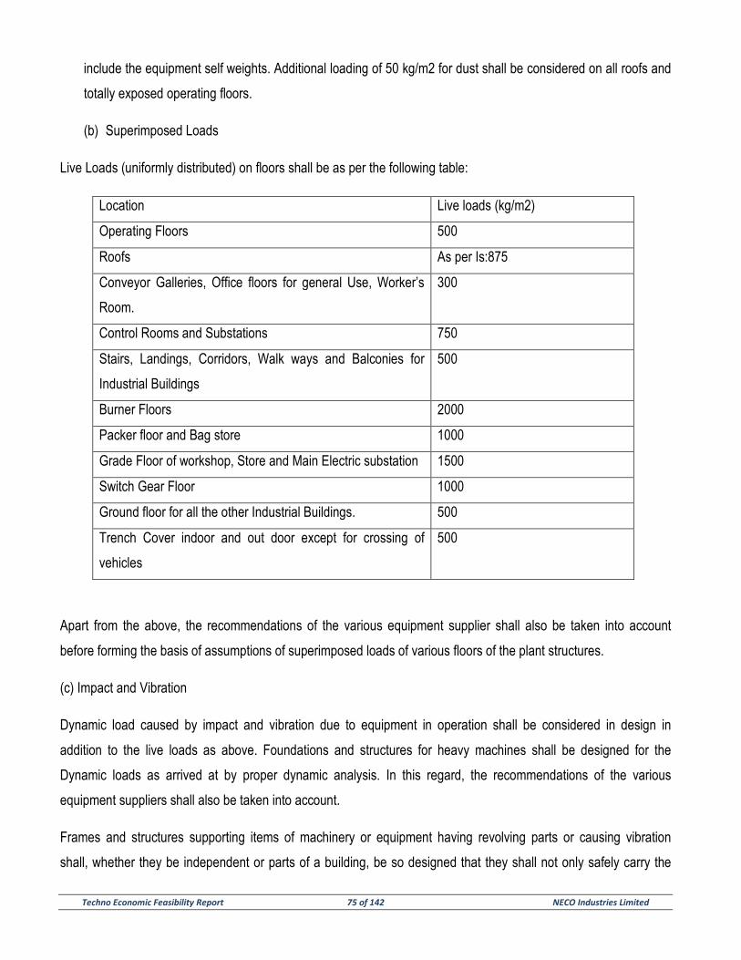
Techno Economic Feasibility Report 75 of 142 NECO Industries Limited
include the equipment self weights. Additional loading of 50 kg/m2 for dust shall be considered on all roofs and
totally exposed operating floors.
(b) Superimposed Loads
Live Loads (uniformly distributed) on floors shall be as per the following table:
Location Live loads (kg/m2)
Operating Floors 500
Roofs As per Is:875
Conveyor Galleries, Office floors for general Use, Worker’s
Room.
300
Control Rooms and Substations 750
Stairs, Landings, Corridors, Walk ways and Balconies for
Industrial Buildings
500
Burner Floors 2000
Packer floor and Bag store 1000
Grade Floor of workshop, Store and Main Electric substation 1500
Switch Gear Floor 1000
Ground floor for all the other Industrial Buildings. 500
Trench Cover indoor and out door except for crossing of
vehicles
500
Apart from the above, the recommendations of the various equipment supplier shall also be taken into account
before forming the basis of assumptions of superimposed loads of various floors of the plant structures.
(c) Impact and Vibration
Dynamic load caused by impact and vibration due to equipment in operation shall be considered in design in
addition to the live loads as above. Foundations and structures for heavy machines shall be designed for the
Dynamic loads as arrived at by proper dynamic analysis. In this regard, the recommendations of the various
equipment suppliers shall also be taken into account.
Frames and structures supporting items of machinery or equipment having revolving parts or causing vibration
shall, whether they be independent or parts of a building, be so designed that they shall not only safely carry the

Techno Economic Feasibility Report 76 of 142 NECO Industries Limited
loads of such items, but in no case shall be in resonance with them. Natural frequencies of structures and
foundations shall vary from the operating speed of the equipment by at least (+-) 20 percent.
(d) Wind Load
Basic wind velocity shall be taken as 39 m/s for the plant and colony area. Reduction / increase of wind pressure on
buildings / structures shall be as part IS:875. Importance factor shall be 1.0.
(e) Seismic Load
The whole area falls under Zone – 11 as per IS: 1893 with zone factor 0.10. The importance factor is taken as 1.0.
Ordinary or I.0. Ordinary or Intermediate Moment Resisting Frames may be used as per provision of code.
(f) Soil and Hydrostatic Pressure
In the design of structures or part of structures below ground level, such as basement floors and walls, the pressure
exerted by the soil or water or both shall be duly accounted for on the basis of established theories. Hydrostatic
load shall also be considered for checking stability of foundation.
Surcharge resulting from foundation loading of adjoining structures or from any stationary of moving loads on the
surface shall be fully considered in the design of building structures.
Water table has been assumed as below 8-10 m for the purpose of Cost estimate based on local information.
(g) Temperature Effect
For all the silos temperature stresses will be considered as per the process requirement. For long buildings viz.
storage halls and conveyor galleries suitable expansion joints shall be provided to take care of the temperature
effect.
(h) Floor and Surge Loads
The plant area being above the HFL, no special care need be taken for the design of buildings/ structures.
(I) Load Combinations
For the safety and economy in the design of various structures, a judicious Combination of working loads stated
above shall be done. Keeping in view the profitability of (a) their acting together and (b) their disposition in relation
to other loads and the severity of stresses or deformations caused by the combination of the various loads.
Techno Economic Feasibility Report 77 of 142 NECO Industries Limited
The load combinations shall be as follows:
I) Dead load + Live Load
II) Dead load + Live Load + fully loaded crane load
III) Dead load + Live Load + Wind load
IV) Dead load + Wind load/ Seismic load
V) Dead load + Live Load + Wind load/ Seismic load + not loaded crane load
2.3 Bearing Capacity of Soil
Soil investigations have been conducted in plant for the adjacent steel plant. A minimum soil bearing capacity of
25t/m2 have been considered at present based on the same data. On this basis buildings/structures are considered
to rest on isolated/raft foundations.
It is recommended that soil investigations shall be carried out to verify the above bearing pressure before finally
taking up the civil design work.
2.4 Land Preparation and plant site Grading
The main plant area is generally flat and only minor site grading work is involved in land preparation and
development. However, the plinth level of all the buildings and structures at the plant site shall be 300 mm above
the highest finished ground level of the adjacent area.
2.5 Type of Buildings and Construction
Based on type of structures, ease of construction and over all economy, RC or structural steel buildings / structures
are adopted as found suitable. The roofs shall be either of RCC or CGI sheeting. Sloped roofs, where provided,
shall have minimum slope of 1:5. Valleys, grooves, notches and side gutters in roofs shall be avoided as far as
possible to minimize dust accumulations. Sides of industrial buildings shall generally be kept open. Where required,
side claddings (CGI sheets) with louvers shall be provided to allow for ventilation and diffused natural lighting.
Masonry filler walls shall be provided for the buildings where necessary from weather protection considerations and
shall be of stone or brick construction.
Administrative buildings, offices, canteen, garage, security office, fencing and gatehouse complex, time office store
etc. shall be of RCC frame / masonry construction with concrete roofs and floors.
Techno Economic Feasibility Report 78 of 142 NECO Industries Limited
2.6 Roofs & Drainage
The roofs will be generally two lane bituminous roads designed for 2.0 million cycles cumulative 8 T axle loads for a
life of 25 years. No topping will be however provided on mine roads. Drainage will be mainly open lined drains. Pipe
culverts will be provided for small discharge and RCC culverts will be provided otherwise. The plant entrance road
(20.0 m wide) shall be from the 30.0 m wide main road which runs parallel to the plant site.
2.7 Finishes
• Plant Buildings
Floors will be integrally finished with selected hard aggregated for topping or shall be vacuum dewatered. Outside
surface of concrete block walls need not be plastered and white washed. False flooring with vinyl antistatic flooring
shall be used for control rooms.
• Non Plant Buildings
Non plant buildings e.g. Administrative building, Canteen etc. will have terrazzo flooring. Toilets will be provided
with glazed tiles. Both inside and outside surfaces of concrete block will be plastered and painted.
• Roofing
Concrete roofing will be provided with cement polymer waterproofing. Tiles will be provided for roofs with access.
3.0 CONCEPT OF DIFFERENT BUILDINGS / STRUCTURES
A. MAIN PLANT
Each buildings and structure shall be designed functionally so as to provide enough space for operation,
maintenance and provide the plant workers good and safe environment. Full access to the machinery shall
be provided by means of walkways, platforms, erection hatches and stairs. Walkways at crane levels shall
be provided for heavy cranes only. All walkways and stairs shall be 1000mm wide and shall have clear
head room of 2.1m from nosing / floor to piping, lighting fixtures etc. Steps shall generally be 250mm tread
and 200mm rise for industrial buildings and 150mm rise for non-plant buildings. Hand rails 1.0m high with
toe guards shall be provided for all stairs and walkways. Access ladder shall be avoided as far as possible.
However, when provided, ladder shall be 400mm clear width, with safety cages around the ladders for over
4m height.
Techno Economic Feasibility Report 79 of 142 NECO Industries Limited
For repair and disassembly, lifting beams and or suspension hooks or HOT cranes shall be provided for all
machines, which contain heavy parts. All lifting beams shall be filled with a suitable movable chain pulley
blocks or geared trolley of appropriate carrying capacity.
Crane girders shall be made of either concrete or steel. Steel Crane Girder where provided, shall be simply
supported and be such that the longitudinal traction and braking forces can be transferred to the vertical
braces through supports.
The brief description of the various imported plant buildings / structures from civil engineering point of view
are given below :
Limestone Crusher Complex
The Limestone Crusher building located inside the plant area shall accommodate a 350 TPH single rotor
impactor crusher, apron feeders, drives, etc. The crusher house shall receive material thru a 120T capacity
RCC hopper which shall be fed by a 30 T dumper / Payloader carrying limestone from the nearby open
storage provided inside the plant. The crusher house will have a depth of 6m below the ground. The
crusher limestone shall be carried by a conveyor installed in a RCC underground tunnel, and conveyor
support above the ground to an open store yard for limestone. The dumper platform in front of the feed
hopper will be about 8 m above ground level. The dumper platform and the approach ramp will be built up
by earth filling in embankment and protecting the side slopes by boulder pitching.
The crusher house building shall be of RCC frame with RCC roof. CGI sheet louvers, CGI sheet side
claddings and masonry filler walls shall be provided at appropriate places. The building shall have a 10 T
EOT crane for maintenance and erection work. The electrical substation, control room for crusher also of
RCC framed construction with masonry filler walls is located adjacent to the crusher house on the ground
level with access road coming right upto the substation.
Storage hall for Crushed Limestone
Crusher Limestone will be stored in the covered storage yard. Crushed Limestone will be stored in the form
of the circular stock pile of capacity 30,000T. One radial stacker supported on central pivot will stack
limestone in the covered yard. A reclaimer supported on circular rails will reclaim limestone from the piles

Techno Economic Feasibility Report 80 of 142 NECO Industries Limited
and discharge on the reclaim belt. The rails will be supported on concrete foundations and the reclaim
conveyor will have separate foundations.
Storage Hall for Additives (Morrum, Sand, Coal, Gypsum and Slag)
All the additives except shall be dumped by trucks into ground hopper. The platform area will have concrete
hard stand over well compacted embankment. An apron feeder will be housed in the building. The crusher
building approx. 40m straight inline distance from apron feeder. The crusher materials shall be conveyed to
the stacker moving on rails having RCC foundation. The stacker will stack morrum, Sand, Coal, Slag and
Gympsum in the yard. For stacking slag and Gypsum separate traveling tippler shall be considered. The
yard will be covered except sand stockpile. The storage structure shall be steel with sheeting and enclosing
stacker and reclaiming equipments with their full operational clearances.
Reclaim will be done through no of ground hoppers follow through the vibro feeder with reclaim conveyor
belt. Reclaim the stored materials and will be conveyed to the Raw Mill Feed Hopper.
For dry slag reclaiming, the reclaiming of materials will be done through RCC tunnel having number of
openings of top. Vibrating feeders will be there below each opening having small hoppers for feeding the
materials on the belt in tunnel. The building shall be RCC framed and steel purlins / runners with CGI roof
and side cladding. The gable ends shall be kept open upto a sufficient height for entry of pay loaders.
Raw Mill Building
The raw mill building shall house the bucket elevator, mill feeding equipment, the twin cyclone and other
auxiliaries. The building shall be RCC framed construction. The substation and power distribution room
shall be provided adjacent to the mill building. Access, floors, platforms, stairs and handrails shall be
provided for ease of operation], maintenance and safety as required. The raw grinding vertical roller mill of
180 TPH, along with its drives and other auxiliary equipment shall be installed adjacent to raw mill building.
• Blending & Storage Silo
Three number Blending Silo having storage capacity of 10,000 T has been envisaged for the project. It will
be of RCC construction inverted cone type provided with inclined air slides for discharge. Bag dust
collectors shall be installed on the roof of silo. Silo shell shall be designed in a manner to suit slip form
concreting. Silo Roofs will be of RCC slabs supported on steel girder & deck plate.

Techno Economic Feasibility Report 81 of 142 NECO Industries Limited
• Kiln Feed Building
The building shall be RCC framed construction with RCC floors & roof annexed to preheater structure.
Sides of the building shall be kept open.
• Preheater Tower Building
The preheater building will be of RCC construction with RCC floors & roof. There will be one stream of
cyclones in this tower type building. Floor shall be designed to facilitate stacking of bricks. The main stack
shall be supported laterally from this building. A lift well shall be constructed where lift can be installed in
further and staircase shall be provided outside the PH tower. There will be a steel bridge from this building
to the roof of blending & storage silo.
• Bag House Structure
The bag house will support the bag filters for the kiln exhaust gases. This will be RCC framed structure
open on all sides and without roof. One intermediate floor with access stair will be provided.
• Coal Mill Building
The entire building will be of RCC framed structure having side cladding with CGI sheeting. The raw coal
feed bunker shall be of RCC and located at one side of the building. But the fine coal hopper is of steel.
The roof and the upper stores support the bag dust filter, fan etc. The compressors, the pneumatic pumps
and MCC are accommodated in the ground floor having masonry filler walls all round. The compressor
foundation shall be isolated from the building structures to avoid any transmission of vibration. The coal
grinding vertical roller mill of 20 TPH, along with its drives and other auxiliary equipment shall be installed
adjacent to the coal mill building.
• Rotary Kiln Foundation
The kiln piers shall be of RCC framed structure. The lubrication room will be located under the first pier. All
the kiln piers shall be connected on both sides by steel platform. Suitable arrangement shall be made to
support the tertiary air duct for precalciner.
Techno Economic Feasibility Report 82 of 142 NECO Industries Limited
• Grate Cooler Building and Burner Platform
The grate cooler building will be made of RCC construction. The clinker carrying deep bucket conveyor will
be above ground below the cooler for ease of maintenance. Thereafter the deep bucket conveyor will pass
through a gallery of steel construction and CGI cladding. The building will remain open on all sides, but the
burner platform will be covered and connected with the adjacent control room. Arrangement of storing
bricks will be provided in the burner platform floor.
• Cooler Exhaust Fan and Stack
The cooler exhaust fan shall have a RCC block foundation resting on soil sub grade. The stack shall be of
steel supported on concrete foundation. The supporting structure for ducts shall be of steel.
• CCR, Laboratory & Electrical Room
This building will house the instrumentation and electrical rooms, control room, laboratory, computer room,
necessary office space and toilet facilities. The building will be a two storied structure of RCC framed
construction with RCC roofs and masonry filler walls. The Laboratory and Electrical room will be located on
the ground floor, Control Room on the first floor.
• Clinker Storage Tank
The clinker storage will be done in a tank type construction of capacity 30,000 T. The tank structure will be
on RCC columns supported on RCC retaining walls. The moment reducing effect of circumferential girders
will be considered, as the structure will be designed as space frame. Reclaiming is done by pan conveyors
placed inside the underground tunnels (6 Nos.) running parallel to each other and discharges into another
tunnel perpendicular to these.
• Raw Mill and Cement Mill Feed Hoppers
RCC hoppers supported on RCC columns are considered for storing different materials. Weigh feeders
shall be provided at the bottom of the hoppers to control the flow of different materials. Bag dust collectors
shall be installed on the roof of the hoppers.
Techno Economic Feasibility Report 83 of 142 NECO Industries Limited
• Cement Mill Building
The cement mill building will be similar to the raw mill building as the vertical roller mill along with its
auxiliaries will be installed adjacent to this building. The building shall be covered and will house the bag
filters, reject hopper and other auxiliaries. The building will be RCC framed construction upto the high
efficiency separator floor. The portion further up shall be of structural steel with CGI roof.
The cement mill electric substation and MCC room will be located adjacent to the electrical drive and will be
fully protected by masonry walls.
• Ground Slag and Cement Silos
Twelve nos. of silos having a capacity of 5000 T each for ground slag and cement have been envisaged for
this project. The silos will have flat bottom fitted with inclined air slides for discharge of materials. Three no.
BDC along with centrifugal fan and drive motor shall be installed on roof of each silo. Silo shell shall be
designed in a manner to suit slip form concreting. Silo Roofs will be of RCC slabs supported on steel girder
& deck plate.
• Packing Plant Building & Empty Bag Store
The packing building will be RCC framed construction. The side cladding will mostly consist of louvers for
proper ventilation and to avoid cement dust.
The empty bag store building is located adjacent to the packing plant building and shall be RCC framed
construction with masonry filler walls. This building will also accommodate the bag branding section and is
provided with suitable lifting and transporting facilities for handling empty bag bales from the stores to the
packer floor.
• Truck Loading Bays
The building shall be of reinforced concrete upto the luffing conveyor level. The luffing conveyor shall be
covered with CGI roof and side cladding. The truck loading area located at the ground floor will be open on
all sides.

Techno Economic Feasibility Report 84 of 142 NECO Industries Limited
• Garage and Services Station
This building will be of RCC framed construction with masonry filler walls. For day to day serving of quarry
equipment the facilities required shall be kept in this building. Temporary storage of POL, emergency
spares, tools shall also be kept in this building. The effluent from the service station will pass through a
sump to separate oil before discharging into the drainage system.
• Equipment Parking Lot
The equipment parking lot will be a open stone paved area to accommodate dumper, bulldozer and
excavator. Apart from the above equipment, trucks, tractor, trailer, explosive vans and water tankers will
also be parked in the parking lot.
• Workshop and Store Building
The workshops meant for general maintenance of mechanical, electrical and other equipment would be of
RCC construction with CGI roof and side masonry walls/cladding. A 5 T HOT crane will be provided in this
building, which will be used both for workshop and the store. An open store yard with barbed wire fencing
will be provided adjacent to the store.
• Electronic Weigh Bridge
The weigh bridge will be pit less type. On one side of the bridge there will be the record room and office
space with automatic recording facilities. The building and foundation will be RCC construction with ample
glazed walls for clear view of the trucks.
• Conveyor Tunnels and Bridges
Conveyor tunnels will have a minimum head room of 2.1 m and shall be of RCC waterproof construction.
The tunnels will have walkways on both sides of the conveyor for Maintenance of equipment. Sloping
conveyor tunnels will have stepped walkways. The floor of the tunnels will have sumps for drainage.The
conveyor galleries are mostly open type except for deep bucket conveyor for the clinker transport, which
will be covered with CGI sheet roofing and CGI louvers on sides. All the conveyor galleries will have
walkways on both the sides. When the bridge is sloped, non-slip surfacing will be provided.
Techno Economic Feasibility Report 85 of 142 NECO Industries Limited
• Main Stack
The main stack will be of steel construction and support from preheater tower as mentioned before.
Aviation light and lightening protectors will be provided as per regulations. Access to the flue-measuring
platform will be from preheater tower. Ladders will be provided to the top from preheater tower. No lining
will be used and corrosion allowance will be kept in the design.
• Main substation
The main substation building will be RCC framed construction with masonry filler walls. The roof and walls
will be fire and waterproof. The HT transformers will be located outside and protected from the building with
fireproof walls as per the statutory regulation.
B. QUARRY
We are considering only statutory requirements for the quarry operation.
• Explosive Magazine Sore Building
• The Explosive Magazine store building shall be located far away from the mine and shall have a safety limit
of a least 600 m all round as per statutory requirement. The building shall be of masonry construction with
RCC roof. The building shall be provided with doors and windows, which open on the outside only and they
shall be provided to enable workers to wash their timber. A Water trough shall be provided to enable
workers to wash their feet before entering the magazine. The magazine will be provided with effective
lighting conductor system and all iron and steel used in the construction of doors and windows, ventilators
etc. shall be properly bonded & earthed. Separate barbed wire fencing, keeping at least 7.6 m of clear
space around this building to ward of stray animals, shall be provided.
• ANFO Mixing Shed
This building is a single storied masonry construction, open on all sides with CGI sheet roofing. The
building will have masonry cubicles for Ammonium Nitrate and Fuel Oil Mixing. A small single storied
masonry room is provided adjacent to it for storing tools. The building is protected with barbed wire fencing,
at a distance of 9 m all round the building to keep unauthorized personnel out.
Techno Economic Feasibility Report 86 of 142 NECO Industries Limited
SECTION – 7
ELECTRICAL AND CONTROL SYSTEM

Techno Economic Feasibility Report 87 of 142 NECO Industries Limited
SECTION – 7
ELECTRICAL AND CONTROL SYSTEM
1.0 ELECTRICAL SYSTEM
1.1 Main Power Supply and Distribution
NECO Industries Limited intends to install an approximately 3.0 MTPA Fly ash and Slag based Cement Production
Plant with a 70 MW captive power plant at village Risda, Dasrama, Tahsil & District Balodabazar, Chhattisgarh.
Estimated power requirement for complete plant will be approximately 70 MW which will be met by own captive
power plant. 132 KV power supply is expected to be taken from nearby CSEB’s 132 kV approx. for meeting the
power and selling the power. The same is 5 km away from the proposed project site/Main receiving substation.
132 kV power will be routed through overhead single circuit line. There will be an outdoor 132 kV Main Receiving
Substation (MRS) within the proposed project premises. The single circuit 132 kV overhead lines shall be
terminated at a 132 kV bus at MRS via necessary lightning arrestors, isolators and circuit breaker. This 132 kV bus
will be connected to primary of one (1) no. 132 kV/ 6.9kV Power Transformer via isolators, circuit breakers and
lightning arrestors. The secondary of the above transformer will be connected to a 6.6kV Switchgear through phase
segregated bus duct / XLPE cables as found suitable, located in MRS. The rating of Power Transformer shall be
so selected such that the aforesaid transformer can handle the total load of the proposed plant. This 6.6 kV
switchgear located in MRS shall supply power to the various Load Centers. Power Factor Improvement capacitors
will be provided for each 6.6kV motors and lumped Power factor improvement capacitor bank will be provided at LV
PMCC to maintain plant power factor not below 0.95 (lag). There will be LV AC Distribution panel at MRS, fed
through a suitably rated step down 6.6kV/0.433kV LV Distribution transformer from 6.6 kV Switchgear to distribute
power supply to various loads to MRS. Suitable rated vented battery with battery charger will be provided for
110VDC power requirement for 132 kV, 6.6kV and LV circuit breaker circuits, isolator circuit, emergency lighting,
signals etc. A single storied MRS building will house entire indoor electrical equipment and LV transformers.
Power will be taken from MRS 6.6kV Switch gear buses to 6.6KV buses of various shop substations. These shop
substations shall be located at the load centers. Following load centers have been envisaged:
(a) Raw Mill Load center (LC-1)
(b) Limestone Crushing Load center (LC-2)
(c) Preheater, Kiln, Cooler Load Center (LC-3)
Techno Economic Feasibility Report 88 of 142 NECO Industries Limited
(d) Cement Mill - 1 Load center (LC-4)
(e) Cement Mill – 2 Load center (LC-5)
(f) Cement Storage & Packing Plant Load Center (LC-6)
(g) Utility Load center (LC-7)
6.6KV motors will be directly fed from the 6.6 KV switchgears of the respective shop substations. 6.6/0.433 KV
transformers of requisite capacity will be installed in each substation to meet the requirement of 415 Volt systems.
415 volt motor control centers will be used to feed 415 volt motors and other auxiliary LV loads. For variable speed
motors, variable frequency drivers would be used. Details of 6.6 KV switchgear, transformers, 415 Volt equipments
and other equipments and system have been described under the common equipment and system.
Key Electrical Single Line Diagram for power distribution is attached with this report.
1.2 General Design Data
Design ambient temperature 50 Deg. C.
Voltage EHV 132 kV, 3 ph
Voltage MV 6.6 kV, 3 ph
Voltage LV 415V, 3 ph/240 V, 1 ph
Voltage variation EHV + 10% and – 15%
Voltage variation MV and LV +/- 10%
Frequency 50 Hz +/- 5%
Combined Voltage and Frequency variation 10.0% (Absolute Sum)
Fault level at 132 KV 31.5 kA / 3 Sec
Fault level at 6.6 KV 25 kA / 3 Sec
Fault level at 415 V 50 kA / 1 Sec
System Grounding – 132 kV Solidly Grounded
System Grounding – 6.6 kV Non-effectively Grounded
System Grounding – 415 V Solidly Grounded
1.3 Outdoor 132 KV Switchyard and Main Transformer in Main Cement Plant
132 KV outdoor switchyard consisting of circuit breaker, isolators, C.T., P.T., lightning arrestors etc. is
envisaged to receive single circuit 132 kV lines from CSEB’s grid sub-station, 132 KV circuit breakers
Techno Economic Feasibility Report 89 of 142 NECO Industries Limited
would be of SF6. Bus and equipment connection would be by combination of tubular bus / ACSR
conductor.
Two (2) no. 20/25 MVA, 132 / 6.9 KV ONAN/ONAF transformer with (+) 10% to (-) 15% on-load tap
changer would be installed outdoor in the substation to step down the receiving voltage to 6.6 K.V. Remote
tap change control cabinet located in MRS will be provided for tap changing control of transformer. Vector
group will be Dyn11. 6.6 KV side neutral would be non-effectively earthed through Neutral Grounding
Resistor for restricting the earth fault current to 400A. 132 KV side of power transformer would be
connected to ACSR conductor and 6.6 KV side to phase-segregated type bus duct / XLPE cables.
1.4 6.6 KV Switchgear
Similar 6.6 KV switchgear would be used for the complete plant. 6.6 KV switchgears would be sheet steel
enclosed, indoor, cubicle type and have single busbar arrangement. Draw-out type SF6/ Vacuum Circuit
Breakers would be used. The interrupting capacity of these breakers would be 25 KA. Continuous rating of
breakers would be of two categories. Incoming feeder and bus coupler breakers would have one rating
while all other outgoing feeder breakers would have another rating. Breakers would have inter-
changeability between the respective types only. Control voltage for the switchgear would be 110V D.C.
1.5 Low Voltage Transformers
Transformers of similar construction would be used for the complete plant. The power distribution at 415
Volt would be effected by the L.V. transformers rated 6.6/0.433kV, 2500/2000/1600/1000/800/630kVA.
Exact rating would be selected during detailed engineering keeping in view the maximum load
Demand of a load-center substation and possibility of using identical rating of transformers as far ask
possible to avoid too many variations.
All the above transformers would be oil filled type ONAN rated, delta connected on HV side and star
connected on LV side having off-circuit tap change system on the HV side with ± 5% range of taps. The
LV star point will be solidly earthed. These transformers would be suitable for outdoor / indoor installation.
Adequately sized cable end box for the HV side suitable fro XLPE cable termination would be provided.
The LV side of the transformers will be suitable for termination to 415 Volt switchgears either by non-phase
segregated bus duct or by cables depending on the current rating of the transformer under a particular
application.

Techno Economic Feasibility Report 90 of 142 NECO Industries Limited
1.6 415 Volt Power cum Motor Control Centers and Motor Control Centers
Similar 415 V Power cum Motor Control Centers (PMCC) and Motor Control Centers (MCC) would be used
for the entire plant. 415 Volt PMCCs & MCCs would be suitable for system having fault level of 50kA for 1
second. PMCCs would be provided with circuit breakers as required. Breakers would have interrupting
capacity of 50 kA at 415 and of air break drawout type. Rating of the breakers would be selected to keep
the variations at the minimum. Motor Control Centers would house mainly switch-fuse units or moulded
case circuit breaker, power & auxiliary contactors and other components as necessary to supply power to
the drives.
Both PMCCs and Motor Control Centers would be sheet steel enclosed and have protection class of IP54.
While the PMCCs would be located in substations, the motor control centers would be distributed over the
process areas with load center concept with respect to the various drives within that area for achieving
optimum cable lengths as well as operational convenience.
1.7 Bus Duct
Busduct is envisaged for connection between transformer and PMCCs, in load center substations for
transformers rated 1600 KVA and above.
6.6 KV bus ducts will be phase-segregated type whereas 415 V busduct will be non-phase segregated
type. All bus duct will be with aluminum conductors. Continuous current rating will be suitable to match
with the transformer rating.
Busduct enclosure would be of sheet steel or aluminum. Maximum temperature rise of the busbars as well
as enclosure would be limited to the value specified in latest relevant IS/IEC.
1.8 Power Factor Improving Capacitors
This would be used for improving power factor of the plant. Principally two systems will be adopted for
power factor compensation. One is the individual compensation, which will be adopted for 6.6 KV motors,
and the other is the group compensation considered for 415V system.
Each 6.6 KV motor will have its own capacitors connected to the outgoing terminal of the breaker of
respective motor feeder along with its isolation device, so that the capacitors may be switched on and off
along with the drive itself. These capacitors will be located in respective load centers substation.
Techno Economic Feasibility Report 91 of 142 NECO Industries Limited
In case of 415V system, a bank of capacitors with associated switching equipment for manual or automatic
control will be connected directly to 415 V switchgear busbars one each for every Switchboard.
The total capacitor rating will be designed to improve the overall power factor of the plant to around 0.95
(lag).
1.9 Control and Relay Panel
Control panel has been envisaged for the MRS equipment located in MRS. Status of plant power supply
from 132kV lines up-to 6.6kV outgoing feeders in MRS 6.6kV Switchgear would be indicated in a mimic
diagram on the control panel, Control, monitoring, metering and annunciation, protective relaying for 132kV
system, main transformers and 6.6 KV incoming feeders and outgoing feeders in MRS would be mounted
on the above panel. Suitable alarm facia would be provided on the above control panel, as necessary, for
annunciation of exact nature of faults. Necessary control switches for other breakers would be mounted on
the respective 6.6kV and LV switchgear panel along with the meters and protective relays. For load center
substations, no separate control panels are envisaged. All control, indication, annunciation, protection
relays and meters will be located in respective switchgears. The same concept would be followed for 415
Volt switchgear also. PLC will be employed for control, status indication and alarms for load centers.
1.10 Motors and Rotor Starters
Similar equipment is envisaged for the complete plant. All 6.6 KV motors would be slip ring induction type.
415 V motors, on the other hand, would be squirrel cage induction type except for those with high inertia
where slip ring induction type may be preferred. Exact selection for such cases will be finalized during
detail engineering stage.
Enclosure protection class of the drives will be IP54 in general. Specific requirement, if any, will be decided
during detail engineering.
Temperature class of insulation for 6.6 KV motor will be 'F' with temperature rise limited upto class 'B'
whereas for 415V motors it will be class 'B' only.
Rotor starters will be used for 6.6 KV slip ring induction motors. Type of starters will be selected during
detail engineering only depending upon the application and requirement. However, for 415V slip ring
induction motors, oil/air cooled grid resistance starters would be used.
Techno Economic Feasibility Report 92 of 142 NECO Industries Limited
1.11 Power and Control Cables
Same type of cables would be used for complete plant. Main factors, which will be considered for selection
of power cable sizes, are as follows:
a) System short circuit current and duration allowed.
b) Derating factors due to higher ambient temperature and grouping of cables.
c) Continuous current rating.
d) Voltage drop during starting and under continuous operation.
e) Standardization of the cable size to avoid too many sizes of cables.
All 6.6 KV cables would be of 6600V (UE) grade stranded aluminum conductor, heavy duty, XLPE
insulated, extruded PVC inner sheathed, each core screened on conductor as well as on insulation, single
round galvanized steel wire armoured (for multicore cables only) and with PVC outer sheath.
Control cables would be multicore 1100 Volt grade PVC insulated, PVC sheathed, round steel wire
armoured and overall PVC served with 2.5 mm2 stranded copper conductor.
1.12 Plant D.C. System
Same system will be used for complete plant. One reliable D.C. Power source would be provided for each
load centre substations and the main receiving substation. This will feed those loads, which are required to
function on a loss of A.C. Power. The D.C. Power supply system would comprise of the following :
− 110 Volt D.C. Battery
− Battery Charger (Float and Boost Charger)
− D.C. Distribution and sub-distribution boards
Basis of selection of the above items would be as follows :
a) Battery
Normal requirement of the battery is to supply power for the following :
II. Control and monitoring of the entire operation.

Techno Economic Feasibility Report 93 of 142 NECO Industries Limited
III. Alarm, Switching and indication of plant condition under emergency. The duty of the battery is
strenuous particularly during the first one minute after occurrence of emergency. During this first
minute the battery will be required to supply:
IV. Tripping power for all major circuit breakers simultaneously and spring charging of the same ;
V. Plant emergency D.C. Illumination system;
VI. Indication, alarm and annunciation;
VII. Other miscellaneous loads.
The storage battery set at ten-hour discharge rate having 55 cells for 110 volts has been envisaged.
Lead –acid type batteries would be provided for the plant.
b) Battery Charger
Battery charger of suitable capacity would be provided with quick boost and trickle charging facility for the aforesaid
battery set. Complete automatic and self-regulating type of battery charger will comprise of float charger-cum-boost
charger.
The float charger would be capable of floating the battery at 2.15 volts per cell and at the same time supply a
continuous D.C. load.
The boost charger, capable of quick charging the battery at 2.75 volts per cell and to restore the capacity of a full
discharged battery to a state of fully charged condition in 8 hours with 25 % spare margin over the maximum
charging rate would be considered.
One standby charger would be provided, if required.
c) D.C. Distribution Board
One main D.C. distribution board for each battery set will be provided with a few D.C. circuit breakers/switch-fuse
and required number of outgoing switch fuse units which will be selected to have a continuous current rating of not
less than 125 % of the normal load current.
Section and 1 No. for Aux. Plant load center for operation of Additive pre blending) comprising of mimic / switches /
illuminated push buttons / Indicators Lamps / Ammeters / Voltmeters / Annunciations and up based recorders and
indicators. No MMI required.

Techno Economic Feasibility Report 94 of 142 NECO Industries Limited
The PLC Control Cabinet will house the multifunction processor module, power supply unit, Input / Output modules
and other accessories and will be located at Main Crushing Plant Control Room.
Communication with CCR – PLC system will be through fiber optic cable for exchange data information only.
Packing Plant Control Room
The packing plant Control Panel shall have Stand-alone PLC Control Cabinet along-with combined hardwired Panel
Desk comprising of mimic / switches / illuminated push buttons / Indicators Lamps / Ammeters / Voltmeters /
Annunciations and up based recorders and indicators.
Additional 1 No. dedicated PC based Operated Console consisting of 21” TFT Color monitor, Keyboard, Mouse &
Black & White Printer will be provided at the Packing Plant Control Room Operator Station for MMI purpose.
The PLC Control Cabinet will house the multifunction processor module, power supply unit, Input / Output modules
and other accessories and will be located at Main Crushing Plant Control Room.
Communication with CCR – PLC system will be through fiber optic cable for exchange data information only.
Water Treatment Plant (WTP) Control Room
The WTP Control Panel Shall-alone PLC Control Cabinet along-with combined hardwired Panel Desk comprising of
mimic / switches / illuminated push buttons / Indicators Lamps / Ammeters / Voltmeters / Annunciations and up
based recorders and indicators. No MMI required.
The PLC Control Cabinet will house the multifunction processor module, power supply unit, Input / Output modules
and other accessories and will be located at WTP Electrical Room.
Communication with CCR – PLC system will be through fiber optic cable for exchange data information only.
Closed Circuit Television Units (CCTV)
For visual monitoring of the sintering zone of the Kiln as well as the Kiln outlet and Clinker Cooler and other
strategic location, closed circuit television will be provided. To protect the cameras from heat radiation the cameras
and accessories shall be housed in Weather proof environmental housing made of aluminum. The housing with
heater and blower installed should provide protection for camera/lens assemblies in the ambient temperature range
of 0oC to 60oC. The housing will have thermostatically controlled heated kit, continuous duty blower kit, and purge
air arrangement, window wipers available within the housing.
Techno Economic Feasibility Report 95 of 142 NECO Industries Limited
i. Operation of the compressors will be from wall / floor mounted local control board located at the
compressor area. Local control board will house a few hardware alarm annunciations, start / stop push
buttons, selector switches etc.
B. Special Application Packages
Following dedicated application packages are considered for archiving consistent qualitative product, maximum
efficiency with reduced cost of production.
i) Management Information system (MIS)
MIS console will be housed in production manager room consisting of LCD color monitor, laser printer, data
logging printer, keyboard, mouse / track ball.
This module is responsible for performance calculation e.g. Energy Management System, Calculation of plant
production etc.
ii) Kiln Optimization System
In order to increase the production and optimize energy consumption, an automatic system for Kiln optimization
will be provided. Kiln Optimization System is a knowledge based second level control system comprising of
supervisory and coordinative control which automatically control the burning plant without Operator’s
Intervention. This is done by optimizing the operating conditions on the basis of the operating parameters which
may be adjusted by the Operation Engineer. Optimization algorithms are processed within a dedicated
computer and is connected to the overall plant highway network for central monitoring and optimum adjustment
of various single loop controllers, responsible for Kiln control, through Operator Station and Field Control
Centre. Expert System is a very important tool in respect of energy saving, increase brick lining lifetime,
increase production capacity and better cement quality.
iii) Simulation & Training Console
Simulation and Training System is a sophisticated dynamic simulation system, which will be used for training
operation and maintenance personnel prior to startup of the plant. The simulation software is housed in a
simulation computer equipped with an Instructor’s Console and Trainer’s Console interfaced to the plant
computer network. Simulation and Training System is an on-going training tool to upgrade the plant staff and
ensure maximum performance. The Simulation and Training Console will be located at the Central Control
Room.
Techno Economic Feasibility Report 96 of 142 NECO Industries Limited
iv) Cross Belt Analyzer
Using the technique of prompt Gamma Neutron Activation Analyzer (PGNAA), this On-line analyzer is used for
ensuring optimum quality control and for monitoring the cumulative chemistry of raw material stockpile during
stacking. One (1) no. Cross Belt Analyzer has been envisaged for the services before stockpile build up.
v) Kiln Shell Scanner and Refractory Monitoring
The Kiln Shell and its refractory lining represent major capital investment. During operation of Cement Kiln, it is
of paramount importance to project Kiln Shell against thermal damage and to maintain a long lifetime of the
refractory lining. The monitoring system will continuously monitor and analyze thermo-graphically the
temperature behavior of rotary Kiln and the operator can consult stored thermal images to understand the
reason of production anomalies like ring and block formation, flush-out, crushing etc. The Scanner System
comprises a high-speed infrared temperature scanner with computational and analytical computer.
vi) X-Ray Analyzer System
Off-line X-Ray Analyzer with Computer System will be provided for the supervision and analysis of chemical
parameters in the various processing stage of cement production. The system comprises fully automatic
simultaneous X-Ray Spectrometer with microprocessor based control unit and computer system and will be
located at the Chemical Laboratory.
vii) Dispatch Management System
Dispatch Management System shall be provided for Packing plant for handling of Truck & Gantry Loading.
2.6 Primary Instrument
i) Temperature
Depending on temperature range and measurement application etc. RTD, Thermocouple and Pyrometers /
Temperature Scanners will be deployed.
ii) Flow Elements
Flow Elements like Venturi, Orifice Plate, and Inlet Cone etc. will be deployed depending on application.
Techno Economic Feasibility Report 97 of 142 NECO Industries Limited
iii) Process Transmitters
Smart Transmitters having high accuracy, tangibility would be deployed. Smart Transmitters would have
capability to directly hooking-up to a standard main system bus utilizing Standard Protocol. It will also have
provision for 4-20 mA DC analog output signal.
iv) Gas Analysis and Sampling System
Gas Analyser with Gas Sampling Station for Oxygen and Co-Analysis will be provided. Analysis of O2
percentage of the kiln flue gas shall be based on Paramagnetic susceptible method and that of CO percentage
by infrared absorption method.
SO@ & NOx analysers shall be selected suitably in flue gas path for environment protection
and shall be of extractive type with Infrared absorption principal.
v) Various process Switches
Various process Switches like pressure, temperature switch etc. will be snap acting micro-switch type with
piston actuator. Level Switches will be float / displacer type / vibration type. Flow switches will be target type.
However, for bin level switch may be employed.
vi) Vibration and Speed Monitoring
A few proximity type vibration instrument, speed switch and motion failure alarm will be deployed to monitor the
operation of moving equipment.
vii) Sonic level Detector
Sonic level Detector is envisaged for monitoring the material level inside the ball mill. The level detector
comprises of microphone with Piezo Electric Crystal and microprocessor based electronic evaluation unit.
viii) Final Control Elements / Actuators
All actuators in regulating service / non-regulating service will be electrically operated motor driven or solenoid
valve operated, depending on the application. In addition to these, variable speed AC / DC drives will also be
deployed for various regulating functions.
Techno Economic Feasibility Report 98 of 142 NECO Industries Limited
ix) Cables
Instrument cable will be laid in trays. Instrument cables will be 0.75 mm.sq. annealed copper twisted pair for 4 –
20 mA signal, thermocouple extension leads for thermocouples and twisted triad for RTDs with 75 mm lay, PVC
insulated with overall screened, extruded FRLS PVC outer sheathed and armored. All cables will be suitable for
continuous operation at 70 Deg.C minimum.
Instrument field cables will be 650 Volt grade, annealed electrolytic grade stranded copper conductor of cross
section 1.0sq.mm. The thermocouple extension/compensation cables will be solid alloy conductor of minimum
size 16 AWG of 600 Volt grade and compatible for the type of thermocouple employed.
Cables will be glanded with metallic double compression type glands at all points of termination. Grounding of
the screen of the cable will be at the control room end only.
All interconnecting cables between cabinets will be preferably pre-fabricated type with suitable pre-fab
connectors. For data highway application optical / co-axial cable will be provided.
x) Erection Hardware
Erection hardware will include all process, sample air line hook-up material like impulse pipe, valves, manifolds,
fittings, sample tubes, junction boxes, cable accessories like glands, lugs, ferrules, conduit, tray etc. All fittings
shall be weldable type.
xi) Spares
Adequate spares for commissioning, operation and maintenance of the plant will be provided.
xii) Local panel, System Cabinet, Signal conditioning unit
Cabinets will be freestanding type with necessary cutouts at the top as well as in the bottom.
2.7 Design of Control Areas and location of various control equipment
i) Control and Display Type
The Control and Display strategy to be adopted for a project has a great bearing on the design of the Control
Room and Control Equipment Room. Basic considerations for selection of Control Room:
The controls will be designed to enable for shift operation and frequent hot start, if necessary.
Techno Economic Feasibility Report 99 of 142 NECO Industries Limited
The Operator’s Desk will have necessary control and display arranged suitably to ensure safe and optimum
operation of the unit at the time of startup, normal running and shutdown.
ii) Basic Layout Considerations
Control Room and Control Equipment Room will contain all panel and equipment.
The layouts of CR, CER etc. will provide adequate space for the above equipment and comfortable working
space for operation and maintenance personnel both under normal as well as emergency conditions when
more people than used may be present in the control area. The design will permit normal maintenance
activity without interfering with plant operation.
The layouts will provide necessary space for little training facilities; visitor’s areas etc. so that these related
activities could take place without distracting or disturbing the plant operators.
The control areas will provide the proper working environment for personnel and equipment. This will include
air conditions, (i.e. calculation of clean air at proper conditions of temperature, humidity, pressure etc.) natural
/ artificial illumination upto a desired level.
iii) Environmental Condition
In view of preferred environmental requirements for the microprocessor based control equipment, the space
for this equipment will be air-conditioned. For non-microprocessor based equipment cabinets such as
marshalling cabinets, relay cabinets and other solid-state cabinets etc. air conditioning will not be necessary.
Load Centers housing the microprocessor-based hardware will be provided with package air-conditioner.
It is recommended that other Control Rooms like Crusher Control Room, Packing Plant Control Room and all
other elect. Auxiliary rooms be suitably ventilated and package a/c may also be provided. As auxiliary
electrical rooms will also contain MCC / Switchgear, it is preferred that these rooms be also divided into two
(2) parts, and the parts containing electronic system cabinets be cooled to around 25oC by window coolers.
iv) Power Supply System
Uninterrupted Power Supply System (UPS) will provide a regulated and uninterrupted single phase AC power
within specified tolerances to C&I System even during main power failure. It will mainly consist of battery
back-up system with static inverter, bypass switches and battery charger. The system will consist of 100%
redundant electronic unit.

Techno Economic Feasibility Report 100 of 142 NECO Industries Limited
1.13 Illumination System
Identical concept will be followed for the complete plant. Suitable illumination is necessary to facilitate
normal operation and maintenance activities and to ensure safety of working personnel. This will be
achieved by artificial lighting.
Power for the illumination system would be obtained from the 415V bus through 415/433V transformers of
adequate capacity for plant areas and buildings. Dry type transformer would be used depending on the
location of installation.
For yard illumination, floodlights would be installed at suitable locations to provide requisite level of
illumination. Pole mounted high pressure sodium vapour fixtures would be used for approach and work
roads and for loading and unloading areas.
Generally fluorescent fixtures would be used for indoor illumination. Combination of mercury vapour,
sodium vapour, fluorescent and incandescent fixtures would be used for high bay areas like mill rooms,
storage halls etc.
The illumination levels at various places will be maintained generally as recommended in relevant Indian
standards. The lighting system design would aim at uniform illumination at working levels avoiding dark
spots and shadows.
The distribution from the lighting transformers would be through 415 Volt, 3 phase and 4-wire distribution
boards. Adequate number of lighting panels would be located in each area, power to which will be supplied
from main lighting distribution boards.
For isolated areas power supply would be given from the nearby M.C.C. and distributed through 415 V/ 433
V transformers to reduce the fault level of the lighting boards/equipment.
In addition to normal illumination scheme, emergency D.C. lighting scheme would be provided in important
areas. Such emergency lighting would be of two categories – one would be supplied from emergency DG
set and the other from 110 V D.C. batteries. Selection of above categories would be decided depending on
degree of importance. Emergency D.C. lighting would be fed from station 110 Volt D.C. distribution system
during failure of A.C. supply. Normally these lights will remain inactive. On failure of the A.C. supply these
lights will come into action and glow from D.C. Battery. Emergency lighting for isolated buildings and in
areas where station 110 V D.C. is not available, would be from self contained battery with charger/flood
lamp units, energized upon loss of normal A.C. supply to such isolated areas.
Techno Economic Feasibility Report 101 of 142 NECO Industries Limited
1.14 Plant Communication System
Identical concept will be followed for the complete plant. For quick communication between plant sections
and outside as well as the operating personnel at various location of the proposed plant following
communication system has been envisaged:
a) Communication with outside
Direct lines from Department of Telecommunication would be used for communication between plant
and outside through public telephone network in the plant.
P&T lines will be terminated in private telephone branch exchange (EPABX) and communication would
be established between outside party and extension of the Exchange. Further, communication between
the extensions also would be realized through this Exchange. EPABX would also provide other
services as available.
Number of P&T lines will be decided during detail engineering stage depending on the requirement of
the extension lines. Norms of the respective DOT would be followed for this purpose.
b) Communication between the Personnel in the plant
Two-channel voice communication system with ‘Paging’ mode as well as ‘Private’ mode has been
envisaged for this purpose. Speaking in ‘Paging’ mode will be heard all over the plant while the ‘Private’
mode will facilitate conversation between two or more stations through close talk channel with
discrimination against back ground noise.
Hand sets for transmitting or acknowledging message would be installed at all important locations. The
sound level throughout the area may differ from zone to zone. Units would be divided on the basis of
sound level and required amplifier will be used to cover these zones. Each handset/loudspeaker station
will have its own-amplifier, line amplifier suitable for long line signal transmission and power amplifier to
suit loudspeaker capacity.
1.15 Grounding and Lighting Protection
The grounding requirement of the plant is divided into the following two main categories:-
- System Grounding
- Equipment Body Grounding
Techno Economic Feasibility Report 102 of 142 NECO Industries Limited
The system grounding is adopted to facilitate ground fault relaying and to reduce the magnitude of
transient over voltage.
For 6.6 KV system, non-effective earthing is envisaged so as to facilitate detection and isolation of
ground fault using appropriate relays.
The 415 Volt system will be solidly grounded. D.C. system will be ungrounded.
The equipment body grounding is adopted to provide protection to personnel from potentials caused by
ground fault currents and lighting discharges.
A stable ground mat/grid is envisaged for grounding of equipment and structures maintaining the step
and touch potentials within safe limits. An earth mat would be laid in and around the switchyard and
main receiving substation. This mat would be buried at a suitable depth below the ground and provided
with ground electrodes with appropriate at suitable spacing. Other load centre substations/ plant
buildings would be earthed by electrodes installed around the periphery and interconnected to form a
grid. All metallic parts of equipment required to be kept at earth potential would be connected to the
grounding system. Buildings, structures, transmission towers/poles, plant railroad tracks, the perimeter
fencing of switchyard etc. would also be connected to the grounding system for equipotential bonding.
Lighting protection system would be installed for protection of the buildings/structures and equipment
against lighting discharge. This would be achieved by providing lightning masts on high structures as
necessary and connecting them with ground grid.
1.16 Emergency Diesel Generator
A diesel generator set with AMF panel would be provided to cater for the emergency loads of the plant
in the event of failure of normal power supply basically for the safety of certain equipment, which might
get damaged due to sudden stoppage from running condition, and also to provide security lighting in
important areas.
Normally, the emergency DG bus would also receive normal power from the main power supply, In the
event of failure of normal power supply, the DG set would start automatically and would be switched on
to the bus. The loads on this bus would include essential drives/system required to run/operate to
protect the equipment/system from damage. This will include illumination in certain selected areas.
Techno Economic Feasibility Report 103 of 142 NECO Industries Limited
1.17 Electric Clock System
One master clock along with some slave clocks is envisaged to have a common time reference
throughout the plant. The system would be complete with associated battery and battery charger unit.
While master clock would be located at central control room, slave clocks would be located at various
key points in the proposed plant.
1.18 Fire Alarm System
A fire alarm system would be provided with alarm press buttons spread all over the plants. In the event
of fire, alarm will be sounded in the central fire alarm panel located in security office with indication of
the location of fire. Suitable fire/smoke detectors would be installed in strategic locations to sense fire
and signal will be transmitted to control room and/or other fire fighting sections.
1.19 List of Major Equipment/System
Sl.No. Equipment/System Approx. Qty
A. Main Receiving Substation
1. 132 KV outdoor type equipment comprising -
a) 145Kv, 800 A Circuit Breaker (3 pole,SF6) 3 No.
b) Lightning Arrestors (1 pole) 18 No.
c) 800 A off-load Isolator with earth switch 6 sets
d) 132 KV 110 V
--------- / ------- V.T., 1000 VA, CL 1.0 & 3P
√3 √3
9 No.
e) 132 KV class, current transformer 150/1/1/1A, 15VA, C1 – 0.2 (1-
Pole)
9 No.
f) ACSR strung bus system, insulators, clamps, connectors and
other necessary hardwares inclusive of all steel structures
Lot
g) Steel Structures Lot
2. 20/25 MVA, 132/6.9KV. ONAN/ONAF outdoor transformers with OLTC and
all fittings and accessories
3 No.
3. 6.6 KV, 3 ph, 50 Hz, 2500A, 25 Ka indoor metal clad, cubicle type
switchgear with drawout type SF6 breakers, busbars, C.T.s, V.T., control,
3 set
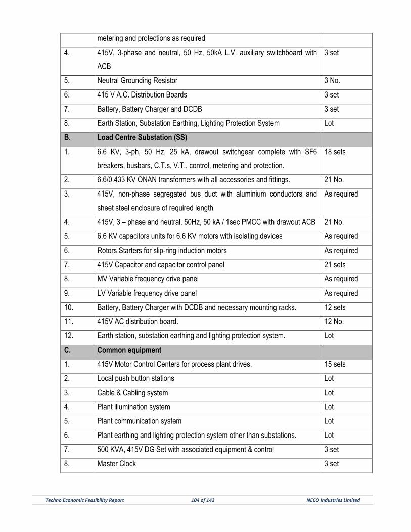
Techno Economic Feasibility Report 104 of 142 NECO Industries Limited
metering and protections as required
4. 415V, 3-phase and neutral, 50 Hz, 50kA L.V. auxiliary switchboard with
ACB
3 set
5. Neutral Grounding Resistor 3 No.
6. 415 V A.C. Distribution Boards 3 set
7. Battery, Battery Charger and DCDB 3 set
8. Earth Station, Substation Earthing, Lighting Protection System Lot
B. Load Centre Substation (SS)
1. 6.6 KV, 3-ph, 50 Hz, 25 kA, drawout switchgear complete with SF6
breakers, busbars, C.T.s, V.T., control, metering and protection.
18 sets
2. 6.6/0.433 KV ONAN transformers with all accessories and fittings. 21 No.
3. 415V, non-phase segregated bus duct with aluminium conductors and
sheet steel enclosure of required length
As required
4. 415V, 3 – phase and neutral, 50Hz, 50 kA / 1sec PMCC with drawout ACB 21 No.
5. 6.6 KV capacitors units for 6.6 KV motors with isolating devices As required
6. Rotors Starters for slip-ring induction motors As required
7. 415V Capacitor and capacitor control panel 21 sets
8. MV Variable frequency drive panel As required
9. LV Variable frequency drive panel As required
10. Battery, Battery Charger with DCDB and necessary mounting racks. 12 sets
11. 415V AC distribution board. 12 No.
12. Earth station, substation earthing and lighting protection system. Lot
C. Common equipment
1. 415V Motor Control Centers for process plant drives. 15 sets
2. Local push button stations Lot
3. Cable & Cabling system Lot
4. Plant illumination system Lot
5. Plant communication system Lot
6. Plant earthing and lighting protection system other than substations. Lot
7. 500 KVA, 415V DG Set with associated equipment & control 3 set
8. Master Clock 3 set
Techno Economic Feasibility Report 105 of 142 NECO Industries Limited
2.0 CONTROL & INSTRUMENTATION SYSTEM
2.1 General
The 3.0 MTPA Cement Plant and 70 MW CPP, as a whole, requires accurate processing of parameters
and efficient transport system. Hence, the co-ordination amongst each Selection and Control of process
parameters at each stage is very important.
In order to achieve the same, geographically as well as functionally distributed Programmable Logic Control
(PLC) system has been envisaged for the whole plant.
The function of Control & Instrumentation is to assist the Operator in achieving safe and efficient operation
at reasonable cost. In order to increase the C&I system availability, necessary redundancy at various levels
in system hierarchy has been achieved.
2.2 Design Objective
The primary objective for the design of C&I System will be to assist the attainment of maximum plant
availability and will be implemented with:
a) The use of equipment whose design, performance and high availability have been demonstrated by a
record of successful operation in identical plants.
b) Provision for ease of equipment maintainability.
c) Use of proven design
d) Provision for redundancy for trip and protection of related equipment and sequential control of drives.
e) Provision for rapid fault diagnosis and logging of events.
f) Provision for data acquisition, data processing and monitoring of plant variables using visual displays
and data logging including trend recording and dynamic color graphics.
2.3 Design for minimizing effects of failures
The design of Control Systems and related equipment will adhere to the principle of “Fail-safe” operation at
all system levels. “Fail-safe” operation means that loss of signal, loss of excitation or failure of any
component will not cause a hazardous condition at the same time prevent occurrence of false trip.
Techno Economic Feasibility Report 106 of 142 NECO Industries Limited
Surge protection of solid-state equipments including hardware for Programmable Logic Controller (PLC)
system and annunciation will conform to the surge with-stand capability. Appropriate rating of electronic
components and parts will be adopted.
Listed below are the tools of application of sound maintainability principles and techniques.
a) Standardization of parts.
b) Minimum use of special tools.
c) Modular replacement.
d) Grouping of functions
e) Separate adjustability
f) Malfunction identification
g) Easy removal, replacement and repair.
h) Easy assembly and disassembly.
i) Full proof design to include proper identification to preclude improper mounting and installation.
2.4 Codes and standards
i. Institute of Electrical & Electronics Engineers (IEEE).
ii. Instrument Society of America (ISA).
iii. Scientific Apparatus Manufacturers Association (SAMA).
iv. International Electro-technical Commission (IEC).
v. Underwriters Laboratories (UL).
vi. Institute of Printed Circuits (IPC).
vii. Deutsche Institute Normal (DIN).
viii. British Standards Institute (BSI).
ix. National Electrical Manufacturers Association (NEMA).
x. American National Standards Institute (ANSI).
xi. American Society of Mechanical Engineers (ASME).
xii. American Society for Testing & Materials (ASTM).
xiii. National Electric Code (NEC).
Techno Economic Feasibility Report 107 of 142 NECO Industries Limited
2.5 Control philosophy
For complete automation of the proposed Cement Plant, the Control System will be built with
microprocessor based geographically distributed Programmable Logic Controller (PLC) with decentralized
intelligence networked by high-speed communication link. The system will encompass functionally following
sub-areas:-
1. Data Acquisition System (DAS)
This sub-system shall be responsible for monitoring and alarm display of the plant parameters without any
control action.
2. Closed Loop Control System (CLCS)
This sub-system shall deal with the automatic modulating control system i.e, closed loop control system.
3. Open Loop Control System (OLCS)
This sub-system will control the open loops i.e, this system will be responsible for plant interlock, protection
and sequence control.
Service wise, the above sub-areas are categorize under Programmable Logic Controller (PLC), and are
generally envisaged to be performed by an integral system.
i) Programmable Logic Controller with in-built microprocessor based multifunction controller with
integrated facility of automatic closed loop Control and Data Acquisition System for monitoring of plant
parameters along with programmable logic control feature for meeting the requirement of sequential
starting / stopping of drives, plant interlock and protection has been conceived.
ii) Programmable Logic Controller will be provided with 1:1 hot redundancy for multifunction
processors, communication processors for communication with main data highway, serial data link interface
modules for connecting remotely located dedicated Input / Output modules and power supply unit.
iii) Section wise dedicated multifunction processor modules, communication processors, serial data
link interface modules and power supply units for the main plant section will be housed in the cabinet and
will be centrally located at the Control Equipment Room in Central Control Room.
iv) Remote I/O Cabinets for various sub-sections of the main plant will be geographically distributed
and located at various MCC / Switchgear Rooms near each sub-plant sections. Remote I/O Cabinets with
Techno Economic Feasibility Report 108 of 142 NECO Industries Limited
service wise centrally located multifunction controller modules will be connected through dual redundant
serial interface links.
v) The multifunction controller modules will be connected over Dual Redundant Data Highway
through Communication Interface Modules. Data for each section, such as process data, operating status
and others, will be transferred through the data highway for centralized monitoring and operation for main
plant sections.
vi) Dual redundant data highway has been recommended. It will lead to reliable operation of the plant
even during breakage of one data highway. Data highway will be noise immune high-speed communication
in the range of 100 MB/sec and will comply with the International Standard IEEE 802.3 (Ethernet) for data
exchange and communication.
vii) Section wise centrally located dedicated multifunction controller modules along with remote I/O
Cabinet named as Field Control Center (FCC) will work autonomously and will perform following tasks:-
1. Closed Loop Control.
2. Open Loop Control.
3. Interlock & Protection.
4. Sequential Logic Control.
5. Limit setting, alarm generation etc.
6. Monitoring.
7. Data acquisition.
The entire Control System will be geographically divided into following sub-systems.
1. Main Plant Section & MRSS (for monitoring purpose)
2. Crushing Plant Automation Sub-System
3. Packing Plant Automation Sub-System
4. Water Treatment Plant
Main Plant Control System & MRSS
Considering the plant layout and process flow, the “Main Plant Control System & Main Receiving Sub-
station (MRSS)” shall have Central Control Cabinet i.e. Programmable Logic Controller (PLC) and will be
located at the Control Equipment Room in the Central Control Room (CCR). The Central Control Cabinet
Techno Economic Feasibility Report 109 of 142 NECO Industries Limited
will house the multifunction processor modules for Main Plant Sections, power supply units, communication
processors, serial interface modules for connecting the Remote Input / Output modules for the Main Plant
Section. It has been divided into the following Field Control Centers (FCC) and will be located at various
load centers of the sub-section of plant.
1. FCC-1
This Field Control Center termed as Remote Input / Output Cabinet will be located at Load Center for Raw
mill Section and will cover the following section:-
a. Reclaiming of raw material from pre-blending yard.
b. Raw material Grinding Section.
c. Raw meal blending-cum-storage and Kiln feed system.
2. FCC-2
The Remote Input / Output Cabinet will be located at the Load Center of Cooler section and will cover the
following:-
a. Clinkerisation Section
b. Grate Cooler
c. Clinker Transportation & Storage Section.
d. Coal Mill
3. FCC-3
The Remote Input / Output Cabinet will be located at the Load Center of Cement Mill and will cover the
following sections:-
a. Gypsum Crushing
b. Clinker & Gypsum transportation to Cement Grinding Section.
c. Cement Grinding Section.
d. Cement transportation to Cement Silo.
4. FCC-4
The Remote Input / Output Cabinet will be located at the Main Receiving Sub-Station (MRSS) for receiving
the Isolated Analogy and Digital inputs in the form of 4-20 mA DC and potential free contacts respectively
Techno Economic Feasibility Report 110 of 142 NECO Industries Limited
from various Electrical Transducers and other alarming status condition for communicating the same to
Central Control Room DAS System through High Speed data Communication link.
Crushing Plant Automation Sub-System
Crushing Plant Sub-System will be located at the Crushing Plant Load Center of Lime Stone Crushing plant
and shall have Stand-alone Programmable Logic Controller (PLC). It will cover the following sections
1. Crusher (Lime Stone)
2. Crusher sampling station.
3. Stacking of raw material into the Pre-Blending Yard.
4. Stacking of additive into the Pre-Blending Yard.
Packing Plant Automation Sub-System
This Packing Plant Sub-System will be located at the Load Center of Cement Mill and shall have Stand-
alone Programmable Logic Controller (PLC). It will cover the following section:-
1. Cement Extraction from Cement Silo.
2. Bagging Plant.
3. Bag Loading & Dispatch.
Control System for Packing Plant will house multifunction processor modules, communication processor,
power supply unit, Input / Output modules etc.
Water Treatment Plant (WTP)
A Stand-alone Programmable Logic Controller (PLC) system has been envisaged for the complete control of
the Water Treatment Plant (WTP). The Control Cabinet will house the multifunction processor module, power
supply unit, Input / Output modules and other accessories and will be located at the Water Treatment Plant
Electrical Room.
i) The “Main Plant Control System & MRSS’ for FCC-1 through 4 will be connected over Dual Redundant Data
Highway through communication interface. Data for FCC-1 through 4 will be transferred through the data
highway for centralized monitoring and operation. Whereas Crushing Plant Automation Sub-System, Packing
Plant Automation Sub-System, Water Treatment Plant (WTP) will work autonomously.
Techno Economic Feasibility Report 111 of 142 NECO Industries Limited
ii) Each FCC of Main Plant Control System will have self-diagnostic features. The hardware fault upto
component level will be detected and will be reported to the operator. This diagnostic routing will not only
check the health of various systems, but also test the health of system buses as well as overall system
integrity.
A. Architecture selection
i) For the proposed Cement Plant the operation of Raw Mill, Kiln, Cooler and Cement Mills are quite interactive.
For Main & Aux. Crusher, Packing Plant Sections and Water Treatment Plant (WTP) can be operated
independent of the operation of the main plant.
ii) In view of this, and to take the advantage of both integrated and segregated system, for this project,
integrated approach has been adopted for main plant Packing viz. Raw Mill, Kiln, Cooler and Cement Mill,
whereas segregated approach would be deployed for rest of the plant. However, in order to have uniformity
and lesser inventory and ease of maintenance, it is suggested and preferred that all control hardware for the
Main Plant & Auxiliary Plants are of the same family.
iii) In view of the fact that both geographical and functional distribution is not mutually exclusive and in
the cement industry various plants are scattered (e.g. Raw Mill Plant, Kiln, Cement Mill Plants are normally at
a distance apart) both geographically distribution as well as functional distribution have been adopted in the
proposed control system.
iv) Geographical distribution in terms of measuring and control point would yield an economic
advantage such as saving of cable cost etc. For each plant separate field control center will be assigned to
carry out open loop, closed loop and monitoring functions respectively giving rise to the functional distribution
of the system.
v) Segregated control has been adopted for the Crusher & Stacker yard, Packing Plant and Water
Treatment Section as the operation of these plants are totally independent and are connected with the main
plant through suitable gateway for data acquisition as applicable.
vi) Moreover, to meet the requirements of interactive controls and for the better system availability, a
number of identical man-machine interface station have been suggested as Operator Stations at the central
control room for entire clinkerisation as well as Clinker Grinding Plant. All the Operator Stations are capable
of accessing any of the graphics of the complete plant, making it possible for one operator station to fall back
on other in case of failure. Operator station is based on latest version (PENTIUM) of PC will 21 inch TFT
Color monitors with associated keyboard/ Track Ball (TB) / Mouse.

Techno Economic Feasibility Report 112 of 142 NECO Industries Limited
vii) It has also been envisaged to provide direct digital link to PLC from several field equipment like
weigh feeders, Smart Transmitters, DC Drives, Shell Temperature Scanner, X- Ray Analyzers, Cross Belt
Analyzer etc.
Operation Philosophy
1. A CRT / KB / Mouse based Operation Philosophy has been envisaged for the entire plant starting
from Reclaiming Conveyor in Pre-blending yard upto Cement Storage from the Central Control Room. The
Clinkerisation Plant and Cement Mill is proposed to be divided into several groups of drives with process
interlocks and sequential start-up and shutdown of various section of the plant as per functional logic
program. Sequential group drive operation (group start / stop of the drives in sequence) has only been
envisaged from remote Operator Station in Central Control Room. Local Operation for each drive has been
envisaged for maintenance / trial purpose and the same shall be done from Sw. Gr. / MCC mounted in Sub-
station (Load Centers). Necessary Remote / stop / Local selection will be effected from Local Control Box
near each drive.
2. Main & Auxiliary Crusher, Packing Plant & Water Treatment Plant shall have independent control
from their Stand-alone PLC for control, monitoring and operations.
Central Control Room (CCR)
Central Control Room has been envisaged for the operation and monitoring of the entire Clinkerisation Plant
starting from Reclaiming of raw material from Pre-blending Yard / Additive Yard, Raw Mill, Blending, Pyro-
processing System, Clinker Transportation & Storage and Cement Mill including cement transportation and
storage.
Following dedicated PC based Operator Console, each consisting of 21” TFT Color monitor, Keyboard,
Mouse & Black & white Printers will be provided at the Central Control Room:-
1. Three (3) No. Console for Raw Material Grinding Sections & kiln Feed
2. Three (3) No. Console for Pre-Heater, Clinker Cooler & Storage Section
3. Three (3) No. Console for Cement Mill Section
4. Three (3) No. Engineer’s Console (EWS) with Black & White Printer shall be provided for editing and
updating programs for computer system. Mechanical locking / password protection will be provided
against unauthorised access into EWS.
5. Three (3) No. Console for MIS with Black & White Printer

Techno Economic Feasibility Report 113 of 142 NECO Industries Limited
6. Three (3) No. Console for Kiln optimization
7. Three (3) No. Console for Kiln Shell Scanner
8. Three (3) No. Console for SER (Sequence of Event Recorder)
9. Three (3) No. Large Video Screen (LVS)
Although separate dedicated console has been envisaged for the control and monitoring purpose of the
different sections of the main plant, however, the system will be so configured that one (1) console will fall
back to the other whenever necessary.
Crushing Plant Control Room
The Crusher Control Panel Shall have Stand –alone PLC Control Cabinet along-with combined hardwired
Panel Desk (1 No. located at Crushing plant load center for operation of lime stone crushing with Limestone
pre blending.
**********************
Techno Economic Feasibility Report 114 of 142 NECO Industries Limited
SECTION – 8
UTILITIES AND AUXILIARY SERVICES
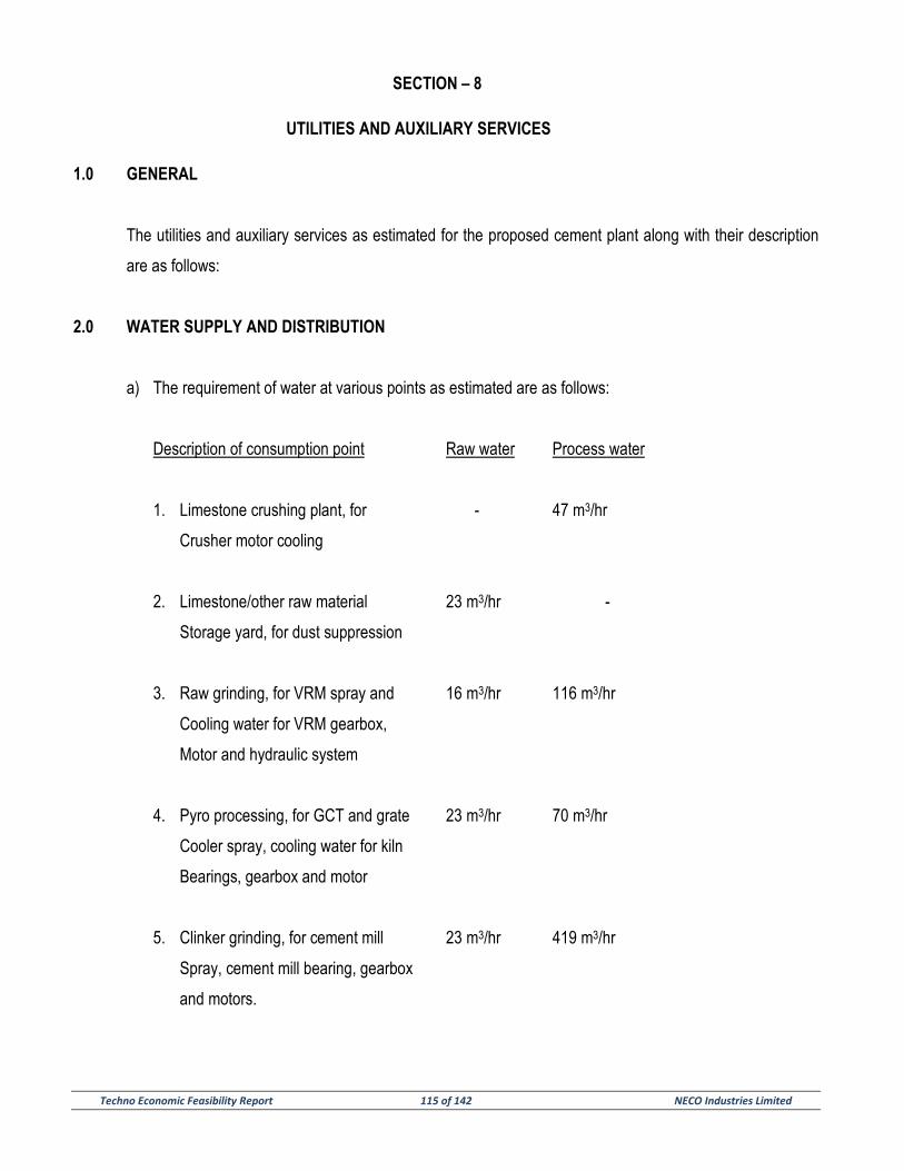
Techno Economic Feasibility Report 115 of 142 NECO Industries Limited
SECTION – 8
UTILITIES AND AUXILIARY SERVICES
1.0 GENERAL
The utilities and auxiliary services as estimated for the proposed cement plant along with their description
are as follows:
2.0 WATER SUPPLY AND DISTRIBUTION
a) The requirement of water at various points as estimated are as follows:
Description of consumption point Raw water Process water
1. Limestone crushing plant, for - 47 m3/hr
Crusher motor cooling
2. Limestone/other raw material 23 m3/hr -
Storage yard, for dust suppression
3. Raw grinding, for VRM spray and 16 m3/hr 116 m3/hr
Cooling water for VRM gearbox,
Motor and hydraulic system
4. Pyro processing, for GCT and grate 23 m3/hr 70 m3/hr
Cooler spray, cooling water for kiln
Bearings, gearbox and motor
5. Clinker grinding, for cement mill 23 m3/hr 419 m3/hr
Spray, cement mill bearing, gearbox
and motors.

Techno Economic Feasibility Report 116 of 142 NECO Industries Limited
6. Coal grinding, for mill spray 2.0 m3/hr 35 m3/hr
Cooling water for gearbox & motor
7. Air compressors, for cooling - 47 m3/hr
8. Water treatment plant, for 5 m3/hr -
Drinking and sanitary use
Sub total 93 m3/hr 733 m3/hr
Net water consumption, at 6% 93 m3/hr 44 m3/hr
Up to circulating process water flow
TOTAL WATER REQUIREMENT: 137 m3/hr
DAILY WATER CONSUMPTION 2740 m3/Day
(at 20 hr consumption per day)
Approx. 2740 m3/Day
b) Water shall be supplied for treatment in water treatment plant to make it suitable for process and
drinking.
c) A water softening plant is envisaged for softening. Treated water shall be distributed to various
consumption points. Return hot water is cooled in cooling towers. A portion of the softened water will
be further treated before sending it to drinking water distribution.
d) Gravity network distribution system is considered.
3.0 COMPRESSED AIR SYSYTEM
a) The estimated requirement of compressed air at various points are as follows:
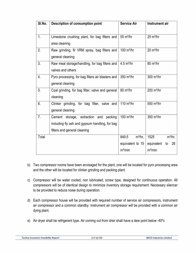
Techno Economic Feasibility Report 117 of 142 NECO Industries Limited
b) Two compressor rooms have been envisaged for the plant, one will be located for pyro processing area and the other will be located for clinker grinding and packing plant.
c) Compressor will be water cooled, non lubricated, screw type, designed for continuous operation. All compressors will be of identical design to minimize inventory storage requirement. Necessary silencer to be provided to reduce noise during operation.
d) Each compressor house will be provided with required number of service air compressors, instrument air compressor and a common standby. Instrument air compressor will be provided with a common air dying plant.
e) Air dryer shall be refrigerant type. Air coming out from drier shall have a dew point below -40ºc
Sl.No.
Description of consumption point Service Air Instrument air
1. Limestone crushing plant, for bag filters and
area cleaning
55 m³/hr 25 m³/hr
2. Raw grinding, fir VRM spray, bag filters and
general cleaning
100 m³/hr 20 m³/hr
3. Raw meal storage/handling, for bag filters and
valves and others
4.5 m³/hr 80 m³/hr
4. Pyro processing, for bag filters air blasters and
general cleaning
350 m³/hr 300 m³/hr
5. Coal grinding, for bag filter, valve and general
cleaning
80 m³/hr 200 m³/hr
6. Clinker grinding, for bag filter, valve and
general cleaning
110 m³/hr 550 m³/hr
7. Cement storage, extraction and packing
including fly ash and gypsum handling, for bag
filters and general cleaning
150 m³/hr 350 m³/hr
Total 849.5 m³/hr,
equivalent to 15
m³/min
1525 m³/hr,
equivalent to 26
m³/min
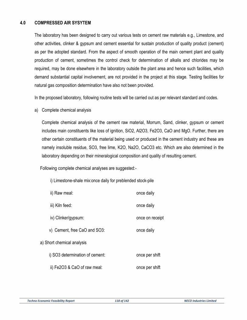
Techno Economic Feasibility Report 118 of 142 NECO Industries Limited
4.0 COMPRESSED AIR SYSYTEM
The laboratory has been designed to carry out various tests on cement raw materials e.g., Limestone, and
other activities, clinker & gypsum and cement essential for sustain production of quality product (cement)
as per the adopted standard. From the aspect of smooth operation of the main cement plant and quality
production of cement, sometimes the control check for determination of alkalis and chlorides may be
required, may be done elsewhere in the laboratory outside the plant area and hence such facilities, which
demand substantial capital involvement, are not provided in the project at this stage. Testing facilities for
natural gas composition determination have also not been provided.
In the proposed laboratory, following routine tests will be carried out as per relevant standard and codes.
a) Complete chemical analysis
Complete chemical analysis of the cement raw material, Morrum, Sand, clinker, gypsum or cement
includes main constituents like loss of ignition, SiO2, Al2O3, Fe2O3, CaO and MgO. Further, there are
other certain constituents of the material being used or produced in the cement industry and these are
namely insoluble residue, SO3, free lime, K2O, Na2O, CaCO3 etc. Which are also determined in the
laboratory depending on their mineralogical composition and quality of resulting cement.
Following complete chemical analyses are suggested:-
i) Limestone-shale mix:once daily for preblended stock-pile
ii) Raw meal: once daily
iii) Kiln feed: once daily
iv) Clinker/gypsum: once on receipt
v) Cement, free CaO and SO3: once daily
a) Short chemical analysis
i) SO3 determination of cement: once per shift
ii) Fe2O3 & CaO of raw meal: once per shift
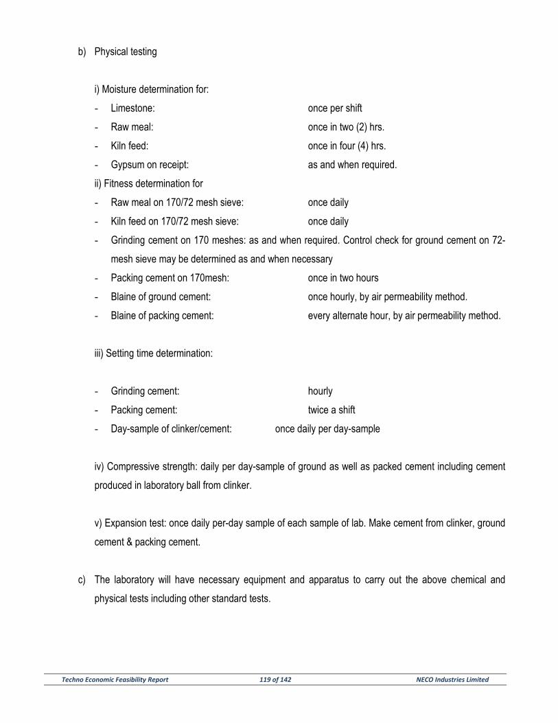
Techno Economic Feasibility Report 119 of 142 NECO Industries Limited
b) Physical testing
i) Moisture determination for:
- Limestone: once per shift
- Raw meal: once in two (2) hrs.
- Kiln feed: once in four (4) hrs.
- Gypsum on receipt: as and when required.
ii) Fitness determination for
- Raw meal on 170/72 mesh sieve: once daily
- Kiln feed on 170/72 mesh sieve: once daily
- Grinding cement on 170 meshes: as and when required. Control check for ground cement on 72-
mesh sieve may be determined as and when necessary
- Packing cement on 170mesh: once in two hours
- Blaine of ground cement: once hourly, by air permeability method.
- Blaine of packing cement: every alternate hour, by air permeability method.
iii) Setting time determination:
- Grinding cement: hourly
- Packing cement: twice a shift
- Day-sample of clinker/cement: once daily per day-sample
iv) Compressive strength: daily per day-sample of ground as well as packed cement including cement
produced in laboratory ball from clinker.
v) Expansion test: once daily per-day sample of each sample of lab. Make cement from clinker, ground
cement & packing cement.
c) The laboratory will have necessary equipment and apparatus to carry out the above chemical and
physical tests including other standard tests.

Techno Economic Feasibility Report 120 of 142 NECO Industries Limited
5.0 MAINTENANCE WORKSHOP.
a) The maintenance workshop will be provided with suitable type and number of mechanical,
electrical and C&I equipment for necessary repair and maintenance of all plant machinery to attain
uninterrupted operation.
b) The workshop will be annexed with a covered store and an open yard for storage of required
spares, liners and structural steel sections/sheets.
c) The workshop building will be provided with an overhead crane for handling the equipment while
repairing/maintenance. Other mobile handling equipment will also be provided for the same
purpose.
6.0 IN PLANT HANDLING EQUPMENT AND OTHER UTILITIES.
In plant handling equipment will be provided for in plant movement of material and equipment. This will
generally include Payloaders, tipper trucks, small DG set, fork lift trucks etc.
7.0 FIRE PROTECTION SYSYTEM.
The cement plant will be provided with a complete automatic fire detection and protection system
complying with relevant NFPA recommendations
The principal features of the fire protection and detection system will be as below:
a) Passive protection:
The plant will be designed to have inherent features to reduce damage during any fire situation. This
will generally include strategically located fir barriers, use of flame resistant or flame retardant
materials, planned emergency escape routes, panic hardware and similar other gadgets etc.
b) Fire protection system:
The complete fire protection system will comprise of following sub systems:
i) First aid protection systems to be used by plant personnel – includes sand and water buckets,
portable fire extinguishers and first aid hose reels.
ii) Fire hydrant system – includes yard hydrants, internal hydrants, and distribution piping system,
hoses and fire water pumping arrangement. This will also supply fire water to first aid hose reels, to
provide first level protection on all plant areas.

Techno Economic Feasibility Report 121 of 142 NECO Industries Limited
iii) Automatic fire protection systems - includes water based automatic spray/sprinkler system on critical
equipment/fire prone areas like oil filled transformers, cable vaults etc.
iv) Automatic gas based fire protection systems – include carbon dioxide inhertization system for fire
prone zones of coal grinding area.
All automatic fire protection systems will be hooked up with shutting down of the respective affected
machinery in the event of a fire situation.
c) Fire detection system:
The fire detection and alarm system will perform the following objectives:
j) Early detection of fire by sensing heat, flame or smoke through addressable detectors and transmitting
signal to the main fire panel.
ii) Detection of any emergency situation from manual call points and transmitting signal to the main
fire panel.
iii) Setting off alarm on detection of fire for personnel safety and timely evacuation.
iv) Activate the automatic fire protection systems, both water and gas based, on detection of fire and
transmits signals to the main fire panel.
v) Self diagnose the system faults and transmit the message to the main fire panel to take up timely
restoration action.
Major components of the fire detection system will include the following:
i) Addressable main fire panel, to be installed in the CCR.
ii) Signaling loop cable for connecting the plant wide detectors with the main fire panel.
iii) Addressable fire detectors, preferably multi sensor type
iv) Addressable manual call points
v) Audio visual alarms, hooters and siren
vi) PA system and emergency communication system with the town’s fire brigade
Techno Economic Feasibility Report 122 of 142 NECO Industries Limited
SECTION – 9
MANPOWER & TRAINNING
Techno Economic Feasibility Report 123 of 142 NECO Industries Limited
SECTION – 9
MANPOWER & TRAINING
1.0 INTRODUCTION
In order to achieve sustained operational efficiency through proper functioning of various units of the
proposed Cement plant, it is essential to have a team of dedicated well trained personnel. While it is
necessary to have competent and experienced staff for the plant, it is also true that if it is advantageous to
employ as many local people from the adjoining areas as possible. This creates minimum social dislocation
and at the same time the necessity of providing accommodation is reduced to the extent the local people are
employed. Since there are few industries in the area, some of the trained and skilled personnel and the entire
management staff may have to be recruited from outside the region. It is expected that unskilled personnel
will be available locally.
2.0 PHILOSOPHY OF MANPOWER RECRUITMENT IN A CEMENT PLANT
The manpower recruitment under company’s direct pay-roll for the operation and the maintenance of the
plant depends primarily on the following factors:
a) The degree of mechanization and automation
b) The number of work places/sections
c) The work culture and productivity of labor force manning the organization
d) Ease of operation and maintenance
e) The facilities available to get some repair work done locally by external agencies.
f) The proper organizational structure.
g) The willingness of the workman to perform more than one type of job.
h) Availability of contract labor or contractor to undertake specific job on contract basis.
For a large plant like this the degree of mechanization has to be the maximum extent possible and the degree
of automation substantial consistent with economy and the skill of the available workforce. The man-power
required by a highly mechanized and automated plant is substantially less.
Though there is going be quite a few sections dictated by the nature of the process, the requirement of
operating staff is not high due to the highly centralized operation with modern technology.
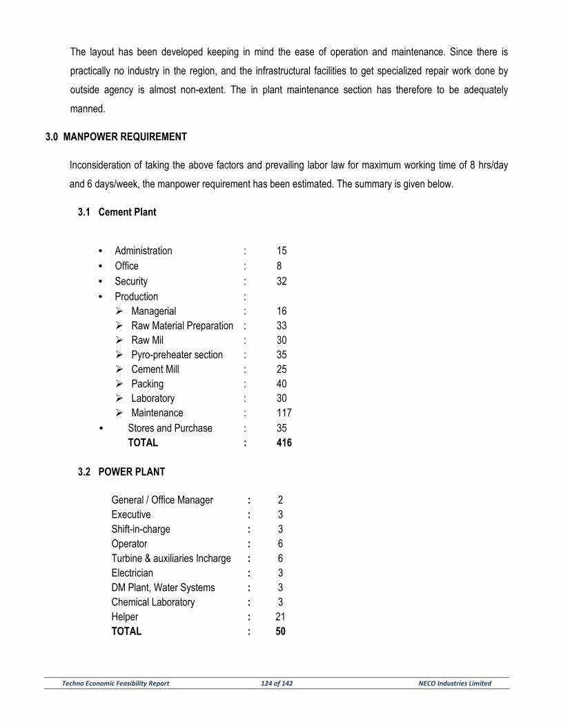
Techno Economic Feasibility Report 124 of 142 NECO Industries Limited
The layout has been developed keeping in mind the ease of operation and maintenance. Since there is
practically no industry in the region, and the infrastructural facilities to get specialized repair work done by
outside agency is almost non-extent. The in plant maintenance section has therefore to be adequately
manned.
3.0 MANPOWER REQUIREMENT
Inconsideration of taking the above factors and prevailing labor law for maximum working time of 8 hrs/day
and 6 days/week, the manpower requirement has been estimated. The summary is given below.
3.1 Cement Plant
• Administration : 15 • Office : 8 • Security : 32 • Production :
� Managerial : 16 � Raw Material Preparation : 33 � Raw Mil : 30 � Pyro-preheater section : 35 � Cement Mill : 25 � Packing : 40 � Laboratory : 30 � Maintenance : 117
• Stores and Purchase : 35 TOTAL : 416
3.2 POWER PLANT
General / Office Manager : 2 Executive : 3 Shift-in-charge : 3 Operator : 6 Turbine & auxiliaries Incharge : 6 Electrician : 3 DM Plant, Water Systems : 3 Chemical Laboratory : 3 Helper : 21 TOTAL : 50
Techno Economic Feasibility Report 125 of 142 NECO Industries Limited
4.0 SALARIES & PERQUISTIES
The salaries & the perquisites for the personnel differ widely from place to place as well as from
plant to plant depending on various factors. In view of the location of the plant it is necessary to
formulate an attractive remuneration pay package for employing competent personnel. Based on clients
information we are considering the pay packages.
5.0 SELECTION
As soon as the investment decision for the project has been finalised, personnel recruitment can be
organised as per following procedure.
Initially a few managers, engineers with a skeleton office staff shall be recruited in the project office at
site. They will look after the various aspects of the project like engineering procurement and
construction. As per the progress of the project personnel at various levels can be recruited and
recruitment can be completed at the brink of starting of commercial production from the plant.
6.0 TRAINING OF PERSONNEL
6.1 Basic Consideration
Cement manufacturing and power generation is a process industry involving sophisticated machinery,
equipment and controls. Personnel employed in the operation and maintenance of the machinery and
equipment need to be trained properly so that with the coordinated efforts of all the plant staff, quality at the
lower possible cost.
The cement manufacturing process and Power generation is continues where the machinery and
equipment is required to run for 24 hours a day and 330 days in a year. It will be necessary to have
operators, skilled and semi-skilled working on the machinery, who would be able to operate the plant at its
optimum efficiency.
It is therefore, advisable to schedule the recruitment is such a way that operational personnel are available
after duly completion of their training at the time of commissioning of the plant. In this manner, by the time
the plant is ready for commissioning, well trained operational personnel will be available in hand. It will also
be necessary to have some personnel readily available, to be associated with the design, construction and
erection of the plant so that they could become fully conversant with the plant and equipment which they
will be called upon to operate and maintain at a later stage.
Techno Economic Feasibility Report 126 of 142 NECO Industries Limited
The top technical personnel upto the Senior executive/engineer level can be directly selected having
previous experience and they do not need training.
But assistant engineers, foreman and main operators attached to plant may be sent for training for plant
operation and maintenance.
Since the main plant will be installed at an area where not many industries are set up, to get skilled
personnel may pose problem. Hence the training scheme should be carefully prepared depending upon the
availability of working personnel having adequate qualification and experience.
In general, the training program shall comprise the following:
a) Training while the plant is under construction by equipment suppliers.
b) On- the job training during commissioning of the plant by equipment suppliers
c) On-the job training with the plant in operation by expatriates.
6.2 Objectives of the training program will be:
a) To achieve smooth start-up of the various units if the plant.
b) To impart technology in the related aspects of cement manufacture and power generation.
c) To achieve production norms as early as possible.
d) To eventually operate the plant efficiently with local personnel only.
6.3 The training program should basically consist of the following:
a) General training in cement plant and power plant
b) Technical lectures
General training in cement plant and power plant
The training program of each trainee should have certain common features besides training in special
aspects for their respective fields of activity. The general training should cover broadly the following:
a) The hazards of their respective sections and precautions to be taken for safety of personnel as well as
equipment.
b) Appreciation of the functions of various units.
c) Familiarization with equipment of their respective sections including the names of important control and
operating parts.
d) Pre-start-up inspection procedure if equipment.

Techno Economic Feasibility Report 127 of 142 NECO Industries Limited
e) Preparation for start-up of machineries of their respective sections.
f) Start-up procedure of the machineries of their respective sections.
g) Routine operation work that they have to look into.
h) Shut-down procedure to be followed for equipment of their respective sections
i) Procedure for attending urgently to critical equipment of their respective section at the time of sudden
stoppage due to power failure.
j) Procedure for emergency stoppage of plants when water and air supply fail suddenly.
7.0 EXPATRIATES
The Cement plant and Power Plant envisaged here is a sophisticated and automatic. Wherein a lot of
interlocks, control etc. has been envisaged with modern equipment.
************
Techno Economic Feasibility Report 128 of 142 NECO Industries Limited
SECTION – 10
ENVIRONMENTAL PROJECTION & POLLUTION CONTROL MEASURES
Techno Economic Feasibility Report 129 of 142 NECO Industries Limited
SECTION-10
ENVIRONMENTAL PROJECTION & POLLUTION CONTROL MEASURES
1.0 GENERAL
Cement industry and Coal based Power plant is classified as a pollution-prone industry by
International Funding Agencies with the potential to cause environment problems if proper mitigation
measures are not taken. The National Environment Policy requires all new industrial units to undertake an
EIA (Environment Impact Assessment) study before being established.
Clinker and cement manufacturing plants and Coal based Power plant pose some environmental hazards
to the land, vegetation, atmosphere and inhabitants within the vicinity of the factory. Most of these
environmental hazards have been identified & measures taken during the design of the plant to minimize
discomfort, inconvenience and ill health to the factory workers as well as the local people. The main identified
areas of degradation land pollution are as follows.
a) Land degradation due to mining activities;
b) Noise hazards associated with mills;
c) Hazards from toxic and corrosive exhaust gases from the kiln especially toxic gas like carbon monoxide
(CO), corrosive gas like sulphur dioxide (SO2);
d) Emission of cement dust.
2.0 LAND DEGRADATION
Limestone deposit at the proposed plant location will be mined by the open cast method. By this
method the land will be stripped of its vegetation and underlying topsoil called overburden in order to get to
the limestone layer. In order to minimize the land degradation, deforestation, overburden disposal and
water pollution adequate and suitable measures shall be considered during the conceptual design of the
plant.
3.0 POLLUTION BY EFFLUENT GASES
The main pollutants in exhaust gases in a clinker plant are gases from the combustion of the residual oil
and dust from the kiln operation. The exhaust gases include carbon dioxide expelled from carbonates of
Techno Economic Feasibility Report 130 of 142 NECO Industries Limited
calcium and magnesium of the raw meal during calcinations of clinker and nitrogen from the theoretical air
needed to provide the oxygen for burning the fuel.
The combustion therefore gives out carbon dioxide predominantly from the combustion of carbon, a little
water vapour from the combustion of hydrogen and some traces of sulphur dioxide from the burning of
sulphur. From the above, the effluent gases contain mostly carbon dioxide from decarbonisation and from
combustion, water vapour, nitrogen and traces of sulphur dioxide. Except for the sulphur dioxide, the
components of the exhaust gases are not polluting agents. Sulphur dioxide picks up water from the
atmosphere to form sulphurous acid, which is responsible for corrosion in roofing sheets and metallic
installations.
4.0 SULFUR DIOXIDE IN THE AMBIENT AIR
Based on the daily production and generation with the maximum percentage of sulphur in the fuel as 0.1%,
attempt can made to calculate the possible amount of sulphur dioxide in the kiln effluent gases and to
establish its acceptability in line with EPA norms.
From the above, it can be concluded that the possible amount of sulphur dioxide, which may be emitted by
the kiln exhaust, should be within the acceptable levels of EPA norms in an industrial area for one year.
There is also the possibility of burning carbon to carbon monoxide, which is very toxic, instead of carbon
dioxide. The occurs, when burning conditions are not well controlled, especially when there is not enough
oxygen or when the burning zone temperature reduces suddenly, or when there is too much dust in the
Clinkerisation zone.
Ducts will be provided at vantage point to draw exhaust gases from time to time for analysis in the
laboratory to make sure that they are free from suspended particles and polluting gases.
Continuous carbon monoxide and excess oxygen analyzers will be provided to facilitate the control of CO
formation. To achieve this, the combustion on fuel should be carried out in the presence of a minimum of
1.5% excess oxygen in the kiln outlet to ensure complete combustion.
Moreover, apart from environmental pollution, the presence of carbon monoxide is undesirable to the
operation of the kiln itself, (i) it is endothermic, i.e. it reduces the temperature of the zone and (ii) it can
explosion in the electrostatics filters and in the cyclones. The operation will be strictly monitored to check
the production of carbon monoxide.
Techno Economic Feasibility Report 131 of 142 NECO Industries Limited
5.0 AIR POLLUTION
Control of dust emission into atmosphere shall be achieved by the following facilities provided for the plant
and machinery of the project:
a) Designing the production system so as to generate minimum dust and arrest the dust at its source.
b) Minimizing the number of material transfer points and maintaining optimum height of fall of materials.
c) Providing high efficiency pulse-jet filters material transfer points including mill feed hoppers.
d) Covering the belt conveyors including walkways.
e) Providing suitable dust collecting equipment either pulse-jet bag filters or ESP for process exhaust
gases.
f) Providing metal roads inside the plant.
g) Efficient cleaning of plant internals using vacuum cleaners.
Control of emission of toxic gases can be achieved to fulfill the prevailing pollution control norms by
a) Using latest technology and equipment in order to minimize generation of various toxic gases
b) Reducing the concentration of pollutants like NOX and SOX in the flue gas
c) Reduce CO formation by use of cleaner
For the project, the emission standards will be so formulated as to limit dust concentration in exhaust gases
from the following sources points within a maximum limit of 50 mg/Nm3 of exhaust volume.
a) Raw meal silo, clinker silos and cement silos by bag-filters.
b) Raw mill and cement mill hoppers by bag-filters.
c) Raw grinding and kiln exit gases by ESP.
d) Clinker cooler exhaust by ESP.
e) Raw mill, cement mill and cement packing plants by bag-filters.
6.0 WATER POLLUTION
Because of the technology of cement production and power generation, the degree of water pollution
caused by waste water is relatively low. The major pollutants are lubricating oil, grease and dust in the
water. Care will therefore, be exercised to design feeding and draining of water for all machinery on close
circuit basis so that no waste water is discharged from the plant during normal operation and the same is
re-circulated after proper treatment.

Techno Economic Feasibility Report 132 of 142 NECO Industries Limited
7.0 NOISE POLLUTION CONTROL
Noise has been defined as “any undesired sound” or “unwanted sound” and thus is a concept of feeling
having adverse effect on human health. The unit of noise measurement used in scientific studies is a
“decibel” (dB) and the prescribed norms for occupational exposure for cement plan is 90 dB in 8 hours
period and 20 dB at a distance of 1m from the source in free field. For any noise control program, the basic
elements of noise source, path and receiver must be attended to.
In a cement plant and power plant, the main sources of noise generation are mills, fans, blowers etc. While
selecting the main plants and equipment for the proposed cement plant and power plant, installation of
alternative low noise generating equipment shall be preferred, all drives and transmission mechanisms
shall be under enclosures. Persons working in and around the noise generating spots shall be provided
with ear plugs/ear muffs. In addition to the above, wherever possible, the travel path of noise shall be
obstructed by providing walls and green belts between the source and the receiver.
8.0 SAFETY PRECAUTIONS
In compliance with international standards on safety, a unit will be created under the production division to
see to the implementation of all safety measures in the factory. The unit will be headed by an inspector who
will go round and ensure that all safety devices and measures put in place are intact. This unit shall be
responsible for the supply of protective working clothes, safety helmets and safety boots to all personnel in
the production division. It will also supply ear and nose marks to personnel at the raw meal mill and the
cement mill, and for Power plant unit where required as well as safety googles, asbestos aprons and
asbestos glove to personnel at the preheater and kiln outlet. Welders will be provided with facemasks and
googles and electricians with insulating gloves. The safety inspector will see to it that all workers wear
these safety aids.
A well-equipped Fire Service will be set-up to see to all fire outbreaks and fire prevention. In addition,
hydrants and fire extinguisher will be positioned at vantage points to be used when necessary.
Electrical safety precautions will be provided in the design e.g. circuit breakers etc. have been placed at
vantage points to strip off and protect and personnel and installation from danger.
Earthing grid for proper system operation as required by I.E.C. standards has been designed for the safety
of personnel and equipment. An efficient illumination system for plant buildings and roads has been
considered and provided.

Techno Economic Feasibility Report 133 of 142 NECO Industries Limited
Other facilities that have been provided for ensuring safety in the plant operation are as follows:
a) Suitable programmable logic control system;
b) Automatic closed circuit control loops with necessary instrumentation;
c) Mimic diagrams / graphic display with fault monitoring system.
*************
Techno Economic Feasibility Report 134 of 142 NECO Industries Limited
SECTION – 11
ESTIMATED PROJECT COST AND FINANCIAL ANALYSIS
Techno Economic Feasibility Report 135 of 142 NECO Industries Limited
SECTION – II
ESTIMATED PROJECT COST, COST OF PRODUCTION & FINANCIAL ANALYSIS
1.0 INTRODUCTION
The financial analysis and evaluation of the project has been presented in this section. The project has
been described in details in other section.
2.0 MAJOR ASSUMPTIONS
Major assumptions for preparation of the cost estimate for the proposed 3.0 Million tonnes per annum
cement plant and a 70 MW Captive Power plant of NECO Industries Limited, at Village Risda, Dasrama,
Tahsil & District Balodabazar, Chhattisgarh are summarized below:
The project implementation period has been considered to be 22 months including Pre-project activities of
3 months.
The following methodology has been adopted while working out the estimates:
Project Cost
The prices of the equipment included in the capital cost estimates of the project have been based on the
prices prevailing market rate as in house data bank.
The cost-estimate for the erection of equipment, piping, electrical and instruments is based on factors of the
supplies cost. For insulation and painting works, cost provision has been made as a percentage of
equipment and piping cost.
i) Land and Site development cost included in the capital cost works out to be Rs 63.60 Crores.
ii) For civil works, based on plant layout & conceptual building dimensions, a preliminary design has
been made and bill of quantities were estimated. Bill of quantities ware multiplied by applicable
prevailing rates to arrive at Civil/Structural Costs. Some margin has been kept for finishing items.
The cost of civil works for plant and non-plant buildings including infrastructure like water supply
from deep tube well, approach road etc. works out to be Rs. 224.35 Crores.
iii) Costing of machinery/equipment is based on sizing of equipment from flow sheets/mass balance
diagram. The cost estimate of Plant and Machinery for both Cement and power plant has been
drawn from the in-house cost data available for similar equipments, which is based on awarded
Techno Economic Feasibility Report 136 of 142 NECO Industries Limited
jobs in the recent past. The cost of plant and machinery has been worked out to be Rs. 1286.93
Crores.
iv) For cost of miscellaneous fixed assets estimation of electrical, control & instrumentation, water
supply & compressed air system etc. has been done. A preliminary motor list has been prepared.
Considering available input and utilization voltages, a single line diagram was prepared. Based on
layout preliminary cable routing was done and cost ware estimated from manufacturer’s input data
and consultant’s own data bank. Cost estimate for water supply, compressed air & control &
instrumentation items are based on suitable percentage of equipment cost.
v) Variable Operating Cost has been worked out based on the consumption of raw materials, fuels,
chemicals, packing materials and utilities estimated for the proposed plant based on consumption
norms and unit rates for the raw materials, fuels, chemicals and utilities.
vi) Existing operational details were examined for estimation of manpower. With advanced automation
level in the plant and compactness of plant this aspect was critically examined and stress was
given to optimize manpower.
vii) Fixed Operating cost has been worked out on the following basis:
� Salaries & Wages
Expense towards salaries and wages are based on estimated manpower requirement for the
smooth plant operation
Expenses on sales overhead for Cement
Expense on deployment of sales personnel as well as sales promotional cost has been
considered as Rs. 20.0 Crores initially and expected to increase @2.5% annually.
� Administrative Overhead for Cement
Administrative overhead has been considered to be Rs 4.5 Crores and expected to increase
@2.5% annually.
� Repair & Maintenance
Expenditure towards repair and maintenance has been considered as 2.0 % of plant and
machinery cost and 1.0% for building and civil works cost as indicated by owner.
viii) Cost of consultancy services was considered based on specific requirement and project execution
through Lump sum Turnkey (LSTK) concept.
ix) Cost provision for preliminary expenses had been kept in the capital cost for construction power
and construction water. Cost provision of Rs.0.60 Crores has been made towards pre-project
activities. These activities includes estimated expenditure by owner towards preparation of
Techno Economic Feasibility Report 137 of 142 NECO Industries Limited
feasibility reports, fund raising, recruitments, deposits to state / local authorities, survey, soil
investigation, selection of consultant & capital issue expenses etc.
x) The pre-operative expenses Rs 8.40 Crores are mainly for establishment, rent, rates, traveling
expenses, insurance during construction etc.
xi) Start-up expenses for the Cement and power plant will include the cost of raw materials,
consumable, utilities etc. and wages and salaries required during trial run and commissioning of
the plant. Cost provision of Rs 2.0 Crores has been made for Start-up & Commissioning expenses
in the capital cost as per owner input.
xii) To account for any unforeseen expenditures, in general a 1.5% contingency over estimated total cost except working capital has been provided.
3.0 FINANCIAL ANALYSIS
Major assumptions for preparation of the financial analysis for the proposed 3 Million tonne per annum
cement plant and 70 MW Captive Power Plant of NECO Industries Limited, at Village Risda, Dasrama,
Tahsil & District Balodabazar, Chhattisgarh are summarized below:
� The Debt/Equity (D/E) ratio of the Project is considered as 70:30
� Rate of interest on long-term loan and on working capital loan has been considered @13.50% per
annum.
� Interest during construction would be capitalized.
� Clinker Raw material considered:
� Repayment of long-term loans has been considered form 3rd year onwards with Two and half year
(2.5) year moratorium.
� Capacity of the plant considered:
- Clinker 6000 TPD (10% extra potential)
- Cement 10419 TPD
� Clinker Raw material considered:
� Limestone : 90.5%
� Sand : 5.0% of Raw Mix.
� Morrum : 4.0% of Raw Mix.
� Fly Ash : 0.5% of Raw Mix.
� Fuel (Coal) : 16.55% of clinker
� Gypsum : 4-5% of OPC
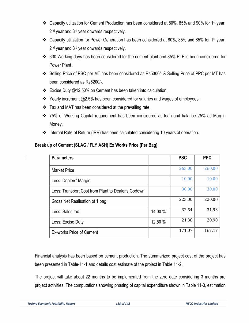
Techno Economic Feasibility Report 138 of 142 NECO Industries Limited
� Capacity utilization for Cement Production has been considered at 80%, 85% and 90% for 1st year,
2nd year and 3rd year onwards respectively.
� Capacity utilization for Power Generation has been considered at 80%, 85% and 85% for 1st year,
2nd year and 3rd year onwards respectively.
� 330 Working days has been considered for the cement plant and 85% PLF is been considered for
Power Plant .
� Selling Price of PSC per MT has been considered as Rs5300/- & Selling Price of PPC per MT has
been considered as Rs5200/-.
� Excise Duty @12.50% on Cement has been taken into calculation.
� Yearly increment @2.5% has been considered for salaries and wages of employees.
� Tax and MAT has been considered at the prevailing rate.
� 75% of Working Capital requirement has been considered as loan and balance 25% as Margin
Money.
� Internal Rate of Return (IRR) has been calculated considering 10 years of operation.
Break up of Cement (SLAG / FLY ASH) Ex Works Price (Per Bag)
.
Financial analysis has been based on cement production. The summarized project cost of the project has
been presented in Table-11-1 and details cost estimate of the project in Table 11-2.
The project will take about 22 months to be implemented from the zero date considering 3 months pre
project activities. The computations showing phasing of capital expenditure shown in Table 11-3, estimation
Parameters PSC PPC
Market Price 265.00 260.00
Less: Dealers' Margin 10.00 10.00
Less: Transport Cost from Plant to Dealer's Godown 30.00 30.00
Gross Net Realisation of 1 bag 225.00 220.00
Less: Sales tax 14.00 % 32.54 31.93
Less: Excise Duty 12.50 % 21.38 20.90
Ex-works Price of Cement 171.07 167.17
Techno Economic Feasibility Report 139 of 142 NECO Industries Limited
of interest during construction shown in Table 11-4 and margin money for working capital are shown in
Table 11-5. Details of manpower cost for the cement plant and power plant has been presented in Table
11-6. The plant will have a rated capacity of 30,00,000 tons per annum from the 3rd year of plant operation
and for details refer statement of estimates of production and sales Table 11-7. The statement of revenue
is shown in Table: 11-8. The cost of production for Cement plant has been presented in Table 11-9(a) and
the cost of generation has been presented in Table 11-9 (b).
Estimates of working results of profitability for initial ten years of operation has been shown in Table 11-10.
Depreciation has been calculated under straight-line method and has been shown in Table: 11.11
Depreciation for tax has been calculated under written down value method has been shown in Table: 11-
12. In estimating tax liabilities it is assumed that Neco Industries Limited will avail MAT or shall pay income
taxes as per prevailing rate. Tax computation has been presented in Table 11-13.
Cash flow statement at the end of the construction period and initial ten (10) years period of operation has
been worked out in Table: 11-14. The project is expected to generate adequate cash to repay its term
liabilities. The repayment of principal will start from 3rd year of operation after a moratorium period of two
and half (2.5) year and shall be repaid within next 7 year. The entire long term as well as short-term loan
will be repaid within 7th year of operation. The payback period of the project after tax works out to be 5.10
years. Working capital requirement at 100% capacity utilization in the first year of production has been
financed partly by short-term loan from equity capital. The result has been presented in Table 11-15. Break-
even analysis in Table 11-16 reveals that the project would break even at 50.68% of its capacity.
The internal rate of return (IRR) after tax, before interest and depreciation works out to be 19.82 % for 10
years whereas IRR after interest. Detailed calculation has been shown in Table 11-17.Balance sheet for 10
years time has been presented in Table 11-18. Loan repayment schedule has been presented in Table 11-
19.
Conclusion From the foregoing analysis it is observed that the project is viable and proposed project may
be implemented.
********************
Techno Economic Feasibility Report 140 of 142 NECO Industries Limited
SECTION – 12
PROJECT IMPLEMENTATION SCHEDULE

Techno Economic Feasibility Report 141 of 142 NECO Industries Limited
SECTION – 12
PROJECT IMPLEMENTATION SCHEDULE
GENERAL
Project Implementation Schedule for the Cement plant along with Captive Power plant has been prepared
considering various activities shown in the enclosed schedule. Referring to the schedule, it may be noted
that the plant can be commissioned within a period of 22 months after approval of loan.
SALIENT FEATURES OF THE PROJECT IMPLEMENTATION SCHEDULE
a) THREE MONTHS REQUIRED FOR – APPRAISAL & APPROVAL OF LOAN.
b) FIVE AND HALF MONTHS REQUIRED FOR – LAND ACQUISITION.
c) TEN MONTHS REQUIRED FOR – EIA/EMP STUDY & REPORT.
d) FOURTEEN MONTHS REQUIRED FOR – MINE PLANNING AND MINE DEVELOPMENT.
e) THREE MONTHS REQUIRED FOR – SPEC., TENDERING, TENDER EVALUATION.
f) FOURTEEN MONTHS REQUIRED FOR – MECHANICAL EQUIPMENT
g) TWELVE MONTHS REQUIRED FOR – ELECTRICAL EQUIPMENT
h) ELEVEN MONTHS REQUIRED FOR – CONTROL & INSTRUMENTATION SYSTEM
i) NINE & QUARTER MONTHS REQUIRED FOR – CIVIL & STRUCTURAL WORK
j) TWELVE MONTHS REQUIRED FOR – AUXILIARY EQUIPMENT
k) NINE MONTHS REQUIRED FOR – EXECUTION OF CIVIL WORK
l) NINE MONTHS REQUIRED FOR – ERECTION WORK.
m) THREE & HALF MONTH REQUIRED FOR – COMMERCIAL PRODUCTION
Three & half month’s time will be required for commissioning and trial production, which ends at 21st month
from the Project Zero Date or 21st months from the date of placement of order for main plant & machinery.
One & half month time has also been shown as start of commercial production.
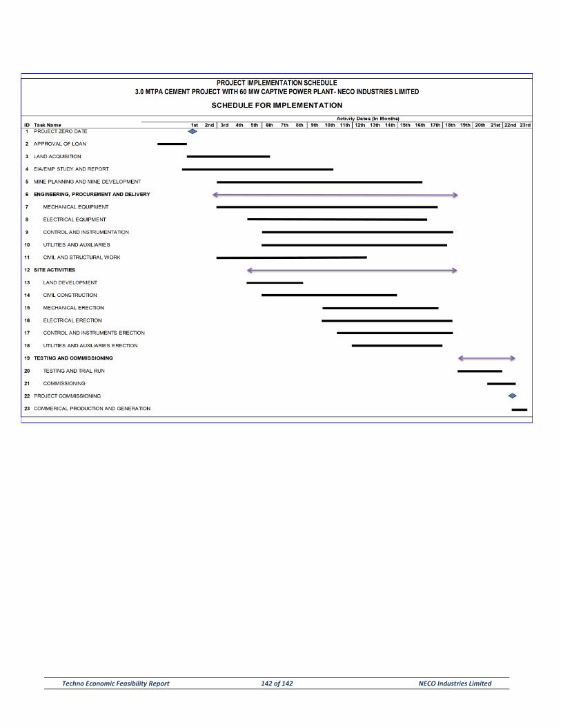
Techno Economic Feasibility Report 142 of 142 NECO Industries Limited