nec powermate 2000 series - nec corporation of america · nec computers inc. when space is at a...
TRANSCRIPT
NEC COMPUTERS INC.
When Space is at a Premium and Flexibility is Key
POWERMATE®®®®
2000PPPP E N T I U ME N T I U ME N T I U ME N T I U M
®®®® I I I 933-MHIII 933-MHIII 933-MHIII 933-MH Z O R Z O R Z O R Z O R HHHH I G H E RI G H E RI G H E RI G H E R
PPPP R O C E S S O RR O C E S S O RR O C E S S O RR O C E S S O R -B-B-B-B A S E D A S E D A S E D A S E D SSSS E R I E SE R I E SE R I E SE R I E S
S E R V I C E A N D
R E F E R E N C E M A N U A L

First Printing � June 2001
Copyright 2001NEC Computers Inc.
15 Business Park WaySacramento, CA 95828
All Rights Reserved
Proprietary Notice and Liability Disclaimer
The information disclosed in this document, including all designs and related materials, is the valuableproperty of NEC Computers Inc. and/or its licensors. NEC Computers and/or its licensors, as appropriate,reserve all patent, copyright and other proprietary rights to this document, including all design, manufacturing,reproduction, use, and sales rights thereto, except to the extent said rights are expressly granted to others.
The NEC Computers product(s) discussed in this document are warranted in accordance with the terms of theWarranty Statement accompanying each product. However, actual performance of each such product isdependent upon factors such as system configuration, customer data, and operator control. Sinceimplementation by customers of each product may vary, the suitability of specific product configurations andapplications must be determined by the customer and is not warranted by NEC Computers.
To allow for design and specification improvements, the information in this document is subject to change atany time, without notice. Reproduction of this document or portions thereof without prior written approval ofNEC Computers is prohibited.
NEC, PowerMate, and MultiSync are registered trademarks and AccuSync is a trademark of NEC Corporation or one ofits subsidiaries. All are used under license.
Microsoft, Windows, and Windows NT are registered trademarks of Microsoft Corporation.Intel, Pentium, and LANDesk are registered trademarks of Intel Corporation.All other trademarks and registered trademarks are the property of their respective trademark owners.

Contents iii
ContentsPreface ..................................................................................................................................ixAbbreviations........................................................................................................................xi
1 System OverviewConfiguration..................................................................................................................... 1-2Features.............................................................................................................................. 1-4
Front Features ............................................................................................................. 1-4System Unit Front Features ................................................................................. 1-5LCD Panel Front Features ................................................................................... 1-5
Right Side Features..................................................................................................... 1-6Left Side Features....................................................................................................... 1-7Rear Features .............................................................................................................. 1-8Bottom Features.......................................................................................................... 1-9Inside Features.......................................................................................................... 1-10Software Features ..................................................................................................... 1-11
Preloaded Software............................................................................................ 1-11PowerMate Application and Driver CD ............................................................ 1-11NEC Product Recovery CD............................................................................... 1-11
Security Features ...................................................................................................... 1-12Password Security ............................................................................................. 1-12Windows Network Security Features ................................................................ 1-12Security Lock Slot ............................................................................................. 1-12Anti-theft Bracket.............................................................................................. 1-12Hard Drive Security........................................................................................... 1-12
Components ..................................................................................................................... 1-13System Board............................................................................................................ 1-13LCD Panel ................................................................................................................ 1-13Diskette Drive........................................................................................................... 1-14Hard Drive ................................................................................................................ 1-14CD-ROM Drive ........................................................................................................ 1-14Combo Drive ............................................................................................................ 1-14AC Power Adapter and AC Power Cord .................................................................. 1-15Keyboard .................................................................................................................. 1-15Mouse ....................................................................................................................... 1-15AGP .......................................................................................................................... 1-15Speakers.................................................................................................................... 1-15Network Board ......................................................................................................... 1-15PC Card Bay ............................................................................................................. 1-16
2 System ConfigurationInterrupt Requests .............................................................................................................. 2-2
System Interrupts........................................................................................................ 2-2Parallel Port Interrupts................................................................................................ 2-3Serial Port Interrupts................................................................................................... 2-3
Jumper Settings.................................................................................................................. 2-3System Board Jumper Settings ................................................................................... 2-4Mobile Hard Drive Jumper Settings ........................................................................... 2-4
BIOS Setup Utility............................................................................................................. 2-5How to Start BIOS Setup............................................................................................ 2-5How to Use Setup ....................................................................................................... 2-5Main Menu ................................................................................................................. 2-6Advanced Menu........................................................................................................ 2-10Security Menu........................................................................................................... 2-13Power Menu.............................................................................................................. 2-15Boot Menu ................................................................................................................ 2-16Exit Menu ................................................................................................................. 2-17

iv Contents
Hard Drive Security ......................................................................................................... 2-18Establishing Hard Drive Passwords .......................................................................... 2-18Changing Hard Drive Passwords .............................................................................. 2-18Using Hard Drive Password Protection .................................................................... 2-19Moving the Hard Drive............................................................................................. 2-19
FLASH Utility.................................................................................................................. 2-20PowerMate Application and Driver CD........................................................................... 2-20NEC INFO Center............................................................................................................ 2-21NEC Product Recovery CD ............................................................................................. 2-22
Performing Full Disk Restore ................................................................................... 2-22Performing Partition Only Restore ........................................................................... 2-23
Intel Processor Serial Number Control Utility ................................................................. 2-24System Requirements................................................................................................ 2-25Installation ................................................................................................................ 2-25Processor Serial Number........................................................................................... 2-25Frequently Asked Questions ..................................................................................... 2-25Technical Support ..................................................................................................... 2-26
3 Disassembly and ReassemblyHard Drive Removal .......................................................................................................... 3-3SO-DIMM Module Removal ............................................................................................. 3-4Bottom Cover Removal...................................................................................................... 3-7CD-ROM Drive Removal .................................................................................................. 3-8Diskette Drive Removal..................................................................................................... 3-9System Board and Support Plate Assembly Removal...................................................... 3-10Processor, CPU Fan, and Heat Sink Removal.................................................................. 3-12Network Board Removal.................................................................................................. 3-15LAN Connector Board Removal...................................................................................... 3-16Hard Drive Bay and Drive Removal ................................................................................ 3-16Auxiliary Cooling Fan Removal ...................................................................................... 3-16PC Card Bay Removal ..................................................................................................... 3-17CMOS Battery Removal .................................................................................................. 3-19LCD Panel Removal ........................................................................................................ 3-20
4 System BoardConnectors, Jumpers, and Sockets ..................................................................................... 4-2
External Cable Connectors.......................................................................................... 4-2External Audio Connectors......................................................................................... 4-3System Board Connectors, Sockets, and Jumper ........................................................ 4-4System Board Jumper ................................................................................................. 4-5Processor Socket ......................................................................................................... 4-6SO-DIMM Upgrade Sockets....................................................................................... 4-6
Components ....................................................................................................................... 4-7Processor and Secondary Cache ................................................................................. 4-9System BIOS............................................................................................................... 4-9System Memory.......................................................................................................... 4-9PCI Local Bus........................................................................................................... 4-10PCI/IDE Port............................................................................................................. 4-10Parallel Interface ....................................................................................................... 4-10Serial Interface .......................................................................................................... 4-11USB Interface ........................................................................................................... 4-11Accelerated Graphics Port ........................................................................................ 4-11Graphics Controller................................................................................................... 4-11Integrated Audio ....................................................................................................... 4-12

Contents v
5 Illustrated Parts BreakdownOrder Spare Parts............................................................................................................... 5-2Field Replaceable Unit List ............................................................................................... 5-2Illustrated Parts Breakdown............................................................................................... 5-4
6 Preventive MaintenanceSystem Cleaning ................................................................................................................ 6-2Keyboard Cleaning ............................................................................................................ 6-2Mouse Cleaning ................................................................................................................. 6-3
7 TroubleshootingChecklist ............................................................................................................................ 7-2
System Problems ........................................................................................................ 7-2Diskette Drive Problems............................................................................................. 7-3LCD Panel Problems .................................................................................................. 7-4Keyboard/Mouse Problems ........................................................................................ 7-4CD-ROM Drive Problems .......................................................................................... 7-4Speaker Problems ....................................................................................................... 7-5
Diagnostics ........................................................................................................................ 7-6
8 NEC Computers Information ServicesService and Support Functions .......................................................................................... 8-2Technical Support .............................................................................................................. 8-2
NEC Computers Web Site .......................................................................................... 8-2Email Technical Support Service ............................................................................... 8-3NEC Computers Technical Support Services ............................................................. 8-3
9 SpecificationsSystem Unit ....................................................................................................................... 9-2LCD Panel ......................................................................................................................... 9-3Keyboard ........................................................................................................................... 9-4Mouse ................................................................................................................................ 9-4AC Power Adapter............................................................................................................. 9-5System Board..................................................................................................................... 9-5Network Board .................................................................................................................. 9-6Diskette Drive.................................................................................................................... 9-6Mobile Hard Drive............................................................................................................. 9-7Mobile CD-ROM Drive..................................................................................................... 9-7Combo Drive ..................................................................................................................... 9-7PC Card Slots..................................................................................................................... 9-7Speakers............................................................................................................................. 9-8Environmental and Safety.................................................................................................. 9-8Compliance ........................................................................................................................ 9-8
Glossary
Index
Regulatory Statements

vi Contents
List of FiguresPowerMate 2000 Series System Components.................................................................... 1-2System Unit Front Features................................................................................................ 1-4LCD Panel Front Features.................................................................................................. 1-4Right Side Features ............................................................................................................ 1-6Left Side Features .............................................................................................................. 1-7System Unit Rear View...................................................................................................... 1-8Bottom Features ................................................................................................................. 1-9Inside the System Unit ..................................................................................................... 1-10NEC INFO Center Opening Screen ................................................................................. 2-21Removing the Hard Drive Access Panel ............................................................................ 3-3Removing the Hard Drive .................................................................................................. 3-4Positioning the LCD Panel................................................................................................. 3-5Removing the SO-DIMM Module Panel ........................................................................... 3-5Releasing the SO-DIMM Module ...................................................................................... 3-6Installing a SO-DIMM Module.......................................................................................... 3-6Removing the Bottom Cover ............................................................................................. 3-7Removing the CD-ROM Drive .......................................................................................... 3-8Removing the Diskette Drive............................................................................................. 3-9Removing the System Board and Support Plate Assembly.............................................. 3-11Removing the Fan and Heat Sink Subassembly............................................................... 3-13Removing the Processor................................................................................................... 3-13Removing the Network Board ......................................................................................... 3-15Removing the Support Plate ............................................................................................ 3-17Removing the PC Card Bay ............................................................................................. 3-18Removing the Battery ...................................................................................................... 3-19Removing the LCD Panel ................................................................................................ 3-20Installing the LCD Panel.................................................................................................. 3-21System Board External Cable Connector Locations .......................................................... 4-2System Board External Audio Connectors......................................................................... 4-3System Board Connector, Socket, and Jumper Locations - Side 1 .................................... 4-4System Board Internal Connector and Socket Locations - Side 2...................................... 4-5PowerMate 2000 Pentium III-Based Series System IPB ................................................... 5-4Removing a Typical Mouse Ball Cover ............................................................................. 6-3

Contents vii
List of TablesPowerMate 2000 Series System Configuration ................................................................. 1-3System Components ........................................................................................................ 1-13Interrupt Level Assignments.............................................................................................. 2-2Parallel Port Interrupts ....................................................................................................... 2-3Serial Port Interrupts.......................................................................................................... 2-3Mobile Hard Drive Jumper Settings .................................................................................. 2-4Setup Key Functions.......................................................................................................... 2-6Main Menu Items............................................................................................................... 2-7Advanced Menu............................................................................................................... 2-10Security Menu Items........................................................................................................ 2-13Power Menu Settings ....................................................................................................... 2-15Boot Menu Settings ......................................................................................................... 2-16Exit Menu Items .............................................................................................................. 2-17PowerMate 2000 Series Disassembly Sequence................................................................ 3-2Sample SO-DIMM Upgrade Paths .................................................................................... 4-6System Board Components................................................................................................ 4-8Parallel Port Addresses .................................................................................................... 4-10Serial Port I/O Addresses................................................................................................. 4-11Ordering Parts.................................................................................................................... 5-2PowerMate 2000 Pentium III Processor-Based Series System FRU List .......................... 5-2Problems and Solutions ..................................................................................................... 7-6NEC Computers Service and Support Telephone Numbers and Web Addresses.............. 8-2System Specifications ........................................................................................................ 9-2System Unit Specifications ................................................................................................ 9-2LCD Panel Specifications.................................................................................................. 9-3Keyboard Specifications .................................................................................................... 9-4Mouse Specifications......................................................................................................... 9-4AC Power Adapter Specifications ..................................................................................... 9-5System Board Specifications ............................................................................................. 9-5Network Board Specifications ........................................................................................... 9-6Diskette Drive Specifications ............................................................................................ 9-6PC Card Slot Specifications............................................................................................... 9-7Speaker Specification ........................................................................................................ 9-8Environmental and Safety Specifications .......................................................................... 9-8System Compliance ........................................................................................................... 9-8

Preface ix
Preface
This manual contains technical information for servicing the NEC® PowerMate® 2000 SeriesPentium® III 933-MHz or higher processor-based computers manufactured by NEC ComputersInc. (For other service and reference manuals in the PowerMate 2000 series, see the list at theend of this section.)
The manual contains hardware and interface information for those who need an overview ofsystem design. The manual includes system setup information, disassembly procedures, anillustrated parts list, maintenance information, and troubleshooting procedures. The manual isprepared for NEC Computers-trained customer engineers and service center personnel.
The manual is organized as follows.
Section 1 � System Overview, provides an overview of system features and includes briefdescriptions of system components.
Section 2 � System Configuration, includes information on system IRQs, board jumpers, andthe BIOS Utility. The section also contains information on power management features andsystem utilities, including the BIOS FLASH Utility and NEC Product Recovery program.
Section 3 � Disassembly and Reassembly, provides system disassembly and reassemblyprocedures. Each procedure is supported by disassembly illustrations.
Section 4 � System Board, includes information on cable and board connector locations,jumper settings, and upgrade sockets. Also provided is information on board components.
Section 5 � Illustrated Parts Breakdown, includes an illustrated parts breakdown diagramand a parts list for field-replaceable parts.
Section 6 � Preventive Maintenance, provides recommended maintenance information formaintaining the system in top condition.
Section 7 � Troubleshooting, includes information to help isolate and repair systemmalfunctions at the field level.Section 8 � NEC Computers Information Services, lists telephone numbers for obtainingservice. The section also includes information on NEC Computers technical support and NECComputers web site.Section 9 � Specifications, provides specifications for the major components in the system,including the system board, LCD panel, network board, diskette drive, hard drive, and CD-ROMdrive.
x Preface
For service and reference information on other computers in the PowerMate 2000 Series, refer tothe appropriate manual in the following list:
! For NEC PowerMate 2000 Series Intel® Celeron® processor-based computers, see the�NEC PowerMate 2000 Series Service and Reference Manual, part number456-00081-000SRV.
! For NEC PowerMate 2000 Series Intel® Pentium® III 500-MHz processor-based computers,see the NEC PowerMate 2000 Series Service and Reference Manual, part number456-00130-000SRV.
! For NEC PowerMate 2000 Series Intel Pentium III 600-MHz processor-based computers,see the NEC PowerMate 2000 Series Service and Reference Manual, part number456-00133-000SRV.
! For NEC PowerMate 2000 Series Intel Pentium III 800-MHz processor-based computers,see the NEC PowerMate 2000 Series Service and Reference Manual, part number456-00139-000SRV.
Abbreviations xi
A ampereAC alternating currentACK acknowledgeAGP accelerated graphics portASIC application-specific integrated circuitAT advanced technology (IBM PC)ATA AT attachmentATAPI AT attachment packet interfaceATM asynchronous transfer modeBBS Bulletin Board ServiceBCD binary-coded decimalBCU BIOS Customized UtilityBIOS basic input/output systembit binary digitBUU BIOS Upgrade Utilitybpi bits per inchbps bits per secondC capacitanceC centigradeCache high-speed buffer storageCAM constantly addressable memoryCAS column address strobeCD-ROM compact disk-ROMCH channelclk clockcm centimeterCMOS complementary metal oxide
semiconductorCOM communicationCONT contrastCPGA ceramic pin grid arrayCPU central processing unitDAC digital-to-analog converterDACK DMA acknowledgedB decibelsDC direct currentDCC direct cable connectionDCE data communications equipmentDDC Display Data ChannelDIMM Dual In-Line Memory ModuleDIP dual in-line packageDMA direct memory access
DMAC DMA controllerDMI Desktop Management InterfaceDOS disk operating systemDRAM dynamic RAMDVD digital versatile discDVMT Dynamic Video Memory TechnologyECC error checking and correctionECP extended capabilities portEDO extended data outputEGA Enhanced Graphics AdapterEIDE Enhanced IDEEISA enhanced ISAemail electronic mailEMI electromagnetic interferenceEPP enhanced parallel portEPROM erasable and programmable ROMESD electrostatic dischargeEVGA Enhanced Video Graphics ArrayF FahrenheitFAX facsimile transmissionFCC Federal Communications CommissionFG frame groundFM frequency modulationFP fast pageFRU field-replaceable unitftp file transfer protocolGB gigabyteGND groundHEX hexadecimalHGA Hercules Graphics AdapterHz hertzIC integrated circuitID identificationIDE intelligent device electronicsIDTR interrupt descriptor table registerin. inchINTA interrupt acknowledgeI/O input/outputIPB illustrated parts breakdownIPC integrated peripheral controllerips inches per secondIR infrared
Abbreviations

xii Abbreviations
IrDA Infrared Data AssociationIRR Interrupt Request registerISA Industry Standard ArchitectureISP internet service providerIRQ interrupt requestK kilo (1024)k kilo (1000)KB kilobyteKbps Kilobits per secondkg kilogramkHz kilohertzlb poundLAN local area networkLED light-emitting diodeLDCM LANDesk Client ManagerLSB least-significant bitLSI large-scale integrationM mega (million)mA milliampsmax maximumMB megabyteMFM modified frequency modulationMHz megahertzMIDI musical instrument digital interfacemm millimeterMMX multimedia extensionsmodem modulator/demodulatorMOS metal-oxide semiconductorMPEG Motion Picture Experts Groupms millisecondMSB most-significant bitNC not connectedNIC networked information centerNIC network interface cardNMI Non-maskable Interruptns nanosecondNSRC National Service Response CenterOCR optical character recognitionOS operating systemPAL programmable array logicPC personal computerPCB printed circuit boardPCI Peripheral Component InterconnectPDA personal digital assistantPFP plastic flat package
PIO parallel input/outputpixel picture elementPLCC plastic leaded chip carrierPLL phase lock loopPOST Power-On Self-Testp-p peak-to-peakPPI programmable peripheral interfacePROM programmable ROMPS/2 personal system/2QFP quad flat packR readRAM random-access memoryRAMDAC RAM digital-to-analog converterRAS row address strobeRGB red green blueRGBI red green blue intensityrms root mean squareROM read-only memoryrpm revolutions per minuteRTC real-time clockR/W read/writeS slaveSCSI Small Computer System InterfaceSDRAM synchronous dynamic random access
memoryS.E.C. single edge contact cartridgeS.E.P.P. single edge processor packageSG signal groundSGRAM synchronous graphics random access
memorySIMM single inline memory moduleS/N signal to noise ratioSNMP simple network management protocolSO-DIMM Small Outline-Dual Inline Memory
ModuleSPM standard page modeSRAM static random access memorySRS Sound Retrieval SystemSSI small scale integrationSVGA Super Video Graphics ArraySW switchT&D test and diagnosticsTSC Technical Support CenterTTL transistor/transistor logictpi tracks per inch
Abbreviations xiii
UART universal asynchronousreceiver/transmitter
UHF ultra high frequencyUL Underwriter�s LaboratoriesUMA unified memory architectureUPS uninterruptible power supplyURL uniform resource locatorUSB universal serial busV voltVac volts, alternating currentVCR video cassette recorderVdc volts, direct currentVDT video display terminalVESA video electronics standards
associationVFC VESA-compliant feature connectorVGA Video Graphics ArrayVHF very high frequencyVLSI very large scale integrationVRAM video RAMW wattWAN wide area networkWRAM Windows RAMW writewww world wide web

1System Overview
! Configuration! Features! Components
1-2 System Overview
This section provides an overview of the NEC PowerMate 2000 Series system and includesdescriptions of:
! system hardware
! system front, back, sides, bottom, and inside
! system security
! major system components.
The major components of the PowerMate 2000 Series system are shown in the following figure.
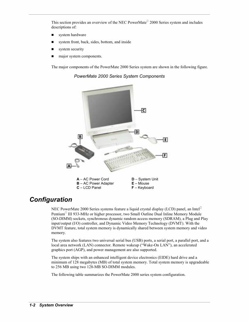
PowerMate 2000 Series System Components
A � AC Power Cord D � System UnitB � AC Power Adapter E � MouseC � LCD Panel F � Keyboard
ConfigurationNEC PowerMate 2000 Series systems feature a liquid crystal display (LCD) panel, an Intel
Pentium III 933-MHz or higher processor, two Small Outline Dual Inline Memory Module(SO-DIMM) sockets, synchronous dynamic random access memory (SDRAM), a Plug and Playinput/output (I/O) controller, and Dynamic Video Memory Technology (DVMT). With theDVMT feature, total system memory is dynamically shared between system memory and videomemory.
The system also features two universal serial bus (USB) ports, a serial port, a parallel port, and alocal area network (LAN) connector. Remote wakeup (�Wake-On LAN�), an acceleratedgraphics port (AGP), and power management are also supported.
The system ships with an enhanced intelligent device electronics (EIDE) hard drive and aminimum of 128 megabytes (MB) of total system memory. Total system memory is upgradeableto 256 MB using two 128-MB SO-DIMM modules.
The following table summarizes the PowerMate 2000 series system configuration.

System Overview 1-3
PowerMate 2000 Series System ConfigurationComponent Description
System Board NEC® proprietary board
Processor Intel Pentium III 933-MHz or higher processor, 133-MHz or higher Front SideBus (FSB)
CPU Mount Socket 370
Cache 32-KB L1 cache and 256-KB L2 cache
Chip Set Intel 810E with 82810E Graphics Memory Controller, 82801AB I/O Controller,and 82802AB Firmware Hub
AGP Direct AGP integrated on the 82810E Graphics Memory Controller
Super I/O Controller Winbond I/O controller for parallel, serial, keyboard, mouse, diskette drive
Audio AC�97 Analog Devices AD1881A SoundMAX® Codec integrated on thesystem board
Total System Memory*(includes system andvideo memory)
128 MB (minimum) to 256 MB (maximum) of PC100 SDRAM (non-ECC) intwo SO-DIMM sockets
LCD Panel 15-inch, high-resolution, active matrix twisted-nematic (TN) TFT Super VideoGraphics Array (SVGA) color display
Hard Drive* Mobile EIDE Ultra DMA/66
Diskette Drive Mobile 3 1/2-inch 1.44-MB
CD-ROM Drive* Mobile ATAPI
Combo Drive* Combination maximum variable speed CD-RW and DVD-ROM drive
LAN Network Board Accton EN2242A-3, 10Base-T/100Base-TX
PC Card Slots Two PCMCIA CardBus slots for Type II and Type III cards
Speakers Two Pioneer 1-watt speakers integrated in base of LCD panel
Keyboard Standard PS/2®-compatible keyboard
Mouse Standard PS/2-compatible mouse
Power AC power adapter with built-in power converter and detachable AC powercord: 80 watt, 100 to 240 Vac, 50-60 Hz
* Component varies by system

1-4 System Overview
FeaturesThe system front, sides, rear, bottom, and inside features are described in the followingparagraphs. Also described are system security features.
Front FeaturesThe following figures identify the lamps, controls, and devices on the front of the system unitand the LCD panel. Brief descriptions of the lamps, controls, and devices follow the figures.
System Unit Front Features
A � Standard CD-ROM Drive G � Diskette Eject ButtonB � CD-ROM Drive Lamp H � Hard Drive LampC � CD-ROM Disc Eject Button I � Power LampD � CD-ROM Emergency Eject J � Sleep LampE � Diskette Drive Lamp K � Power ButtonF � Diskette Drive
LCD Panel Front Features
A � LCD Panel Screen C � Increase Brightness ButtonB � Decrease Brightness Button
System Overview 1-5
System Unit Front FeaturesThe following devices, controls, and lamps are on the front of the system unit (see the previousfigure for device, control, and lamp locations).
! Power/sleep button � press this button to turn power on. To turn off the system, close allapplications and shut down the Microsoft Windows 98 or Microsoft Windows 2000operating system to automatically power down the system. For the Microsoft Windows NT
operating system, close all applications, shut down the operating system, and press in thepower button. Hold in the button until the system powers down (about four seconds).
To avoid losing data, do not turn off the system power until you haveclosed all applications and the Windows operating system.
Press and immediately release the power/sleep button to suspend system operation and gointo the power saving mode. Press any key or move the mouse to exit the power savingmode and resume system operation at the point where it was stopped (the key might have tobe pressed twice to resume operation). If the system does not go into a power saving modeand shuts down, check the power management setting. Click Start, point to Settings, andclick Control Panel. Double click Power Management (Power Options for Windows2000) and click Advanced. Select Standby in the Power buttons drop-down window.
Do not hold in the system�s power/sleep button for more than threeseconds when using the power saving mode. Doing so might cause data to be lost or damaged.
! Power lamp � indicates if system power is on or off. A steady green lamp indicates thatpower is on.
! Sleep lamp � indicates if the system is in sleep mode. An amber sleep lamp indicates thatthe system is in sleep mode with full power reduction.
! Hard drive lamp � when lit, indicates that the hard drive is reading or writing data.
! CD-ROM drive � loads and starts programs from a CD and plays audio CDs.
! Combo drive � if installed, plays movies, starts programs from CDs, plays audio CDs, andcreates data and audio CDs.
! Diskette drive � copies data files to and from a diskette or is for use as a bootable drive forloading and starting programs from a diskette.
LCD Panel Front FeaturesThe LCD panel has the following brightness adjustment buttons (see the previous figure forbutton locations). The buttons provide eight levels of brightness, four levels for each button.
! Decrease brightness level button � use this button to decrease display brightness.
! Increase brightness level button � use this button to increase display brightness.
The default brightness level is maximum brightness. Powering off the system or unplugging thesystem from the power outlet changes any new brightness setting back to the default setting.
The LCD screen has a brightness level of 200 candlepower and a maximum resolution of1024 x 768 pixels.
The LCD panel is adjustable up or down and side-to-side for comfortable viewing. Two 1-wattspeakers are built into the base of the LCD panel.
If an optional video graphics array (VGA) monitor is attached to the system, the monitor can beturned on for simultaneous viewing on the monitor and LCD panel.

1-6 System Overview
Right Side FeaturesThe following figure identifies the controls and devices on the right side of the system unit.Brief descriptions of the controls and devices follow the figure.
Right Side Features
A � Volume Control E � USB Connectors (2)B � Headset Jack F � Anti-theft BracketC � Line-In Jack G � Hard Drive Access PanelD � Microphone-In Jack
The right side of the system unit has the following devices and controls (see the figure �RightSide Features� for device and control locations).
! Volume control � adjusts the volume of the two speakers built into the LCD panel or thevolume of an optional headset.
! Headset jack � use to connect an optional headset. Plugging in the headset disables thebuilt-in speakers.
! Line-in jack � use to connect a stereo audio device.
! Microphone-in jack � use to connect a microphone for recording audio information in datafiles.
! USB connectors � attach up to 127 USB devices to these two connectors, including aprinter, monitor, modem, mouse, game pads/joystick, and speakers.
! Anti-theft bracket � use to secure the mouse and keyboard cables to make it difficult toremove the mouse and keyboard from the system.
! Hard drive access panel � remove the panel to access the system hard drive for removaland replacement.

System Overview 1-7
Left Side FeaturesThe following figure shows the features on the left side of the system unit. Brief descriptions ofthe features follow the figure.
Left Side Features
A � Slot 1 Card Eject Button D � PC Card Slot 1B � Slot 2 Card Eject Button E � Cooling VentsC � PC Card Slot 2
The left side of the system unit has the following features.
! PC Card Slots 1 and 2 � support the use of Type II or Type III cards with 16-bittechnology or 32-bit CardBus technology.
! PC Card eject buttons 1 and 2 � press the button to eject a PC Card or dust cover.
! Cooling vents � allows circulation of air to cool the system. Take care to keep objects fromblocking the cooling vents.

1-8 System Overview
Rear FeaturesThe rear of the system unit contains external connectors and a DC power socket. The followingfigure identifies the connectors on the back of the system. Brief descriptions of each connectorfollow the figure.
System Unit Rear View
A � PS/2 Mouse Port E � Serial PortB � Security Lock Slot F � LAN ConnectorC � PS/2 Keyboard Port G � VGA ConnectorD � Printer Port H � DC Power Connector
The system unit has the following external connectors.
! PS/2 mouse port � Attach a PS/2-compatible mouse with a 6-pin mini DIN connector tothis port.
! Security lock slot � Attach a Kensington® Security Standard connector or other lockingdevice to this slot.
! PS/2 keyboard port � Attach a PS/2-compatible keyboard (101-key or 102-key) with a6-pin mini DIN connector to this port.
! Printer port � Attach a parallel printer with a 25-pin connector to this port.
! Serial port � Attach a serial device with a 9-pin connector to this port. Devices include apointing device, serial printer, or modem.
! Video Graphics Array (VGA) monitor connector � Attach a VGA-compatible monitor(NEC MultiSync® monitor, NEC AccuSync� monitor, or other VGA-compatible monitor)with a 15-pin connector to this connector. The system supports simultaneous displays on theLCD panel and monitor.
! LAN connector � Use this RJ-45 connector to attach a network cable to the system�snetwork board.
! DC power connector � Plug the AC power adapter into this connector. Attach the ACpower cable to the adapter and an AC power outlet to supply DC power to the system.

System Overview 1-9
Bottom FeaturesA panel on the bottom of the system unit provides access to the SO-DIMM memory expansionsockets and the password clear jumper.
Bottom Features
A � SO-DIMM Socket 1 C � SO-DIMM Socket 0B � Password Clear Jumper
The system unit comes with at least one 128-MB SO-DIMM module mounted in one of the twomemory sockets on the system board. System memory can be increased to a maximum of256 MB by using two 128-MB modules.
The password clear jumper is used to clear the password if it is forgotten or if it needs to bechanged.

1-10 System Overview
Inside FeaturesThe following figure shows the interior of the system unit, as viewed from the bottom of thesystem unit with the bottom cover off. Not visible are the processor, network board, CMOSbattery, and hard drive. These components are on the back side of the system board.
Inside the System Unit
A � Diskette Drive D � SO-DIMM Socket 0B � SO-DIMM Socket 1 E � System BoardC � Clear Password Jumper 7G4 F � CD-ROM Drive (or optional combo drive)
The inside of the system contains
! system board with connectors and sockets for the processor, SO-DIMM memory, harddrive, diskette drive, network board, CMOS battery, and CD-ROM drive (or combo drive)
! memory module(s)
! diskette drive
! hard drive
! CD-ROM drive (or combo drive)
! network board
! PC Card slots.
For more information on the above features, see �Components� in this section.
System Overview 1-11
Software FeaturesNEC Computers provides a variety of applications and hardware utilities with the system to takeadvantage of the system hardware capabilities.
Preloaded SoftwareThe system comes preloaded with the Microsoft Windows 98 SE operating system or with theMicrosoft Windows 2000/Windows NT operating system.
If you have a Windows 2000/Windows NT operating system configuration, you must choose theoperating system you want to load. The operating system you choose is the only operatingsystem and is the one that the NEC Computers Product Recovery program restores.
The system also comes preloaded with the Intel Processor Serial Number Control Utility. Usethis utility to enable or disable the reading of the Intel Pentium III processor serial number. See�Intel Processor Serial Number Control Utility� in Section 2 for information about using theutility.
PowerMate Application and Driver CDUse the PowerMate Application and Driver CD with the NEC Customize utility to install NECComputers provided applications, drivers, and utilities on your hard drive. Also use thePowerMate Application and Driver CD and NEC Customize utility to reinstall NEC Computerssupplied software if the software becomes corrupted. See �PowerMate Application and DriverCD� in Section 2 for information about installing software from the CD.
NEC Computers software available on the PowerMate Application and Drive CD includes thefollowing applications:
! Microsoft Internet Explorer BrowserInternet Explorer provides a top-notch browser with preloaded links for easy access to theworld wide web. Also use Internet Explorer to access one of the many new browser-basedutilities.
! Norton AntiVirus� SoftwareProtect the system from viruses by running Norton�s virus scan software.
! Adobe® Acrobat® ReaderUse the Adobe Acrobat Reader to read and print portable document format (PDF) filesfound on the Internet and PDF documents included with various software applications.
! NEC INFO CenterGet quick access to comprehensive information about your system in the online NEC INFOCenter. NEC INFO modules include Tour, User�s Guide, Questions, Solutions, andServices. See �NEC INFO Center� in Section 2 for a description of the documentation andhow to use the INFO Center.
! Intel LANDesk® Client ManagerUse LANDesk software to track system information such as serial number, BIOS version,memory capacity, disk capacity, expansion board settings, and applications. Use LANDesksoftware for remote starts from a server computer using Wake-On LAN and remote reboot.
NEC Product Recovery CDThe system comes with an NEC Product Recovery CD. Should a problem occur that causes dataloss or corruption, you can use the NEC Product Recovery CD to restore the system to itsoriginal factory state. A full system restore loads the operating system and the factory-suppliedsoftware that comes on the hard drive. See �Product Recovery� in Section 2 for informationabout using the restore options.

1-12 System Overview
Security FeaturesThe system has hardware, software, and mechanical security features that offer protectionagainst unauthorized access to the system and data. The following security features areavailable.
Password SecurityThe BIOS Setup Utility includes a feature that allows a user to set a user or supervisor password,or both.
The user password controls booting of the system and controls access to the Setup Utility andthe keyboard. User access to the BIOS Setup Utility is limited when a supervisor password isset. The supervisor password allows full access to the system and the BIOS.
Windows Network Security FeaturesThe Windows Network Security feature is available through the Microsoft Windows operatingsystem. See the Windows documentation for details.
Security Lock SlotThe security lock slot accepts a Kensington Security Standard connector or other locking deviceto physically protect the system unit from intrusion.
Anti-theft BracketThe anti-theft bracket is used to secure the mouse and keyboard cables. Securing the cables inthe bracket makes it difficult to remove the devices from the system.
Hard Drive SecurityThe system supports password protection for the hard drive. Hard drive password protectionrestricts access to the drive if the drive is removed and installed in another system. The systemdoes not prompt for hard drive passwords while the drive remains in the current system.
The passwords are written to the system BIOS and to the hard drive to ensure that the passwordprotection travels with the drive if it is moved to another system. See Section 2, �SystemConfiguration,� for additional information on using hard drive security.

System Overview 1-13
ComponentsThe major system components are listed in the following table, along with the page numberwhere each component is briefly described.
System ComponentsComponent Go to Page
System Board 1-13
LCD Panel 1-13
Diskette Drive 1-14
Hard Drive 1-14
CD-ROM Drive 1-14
Combo Drive 1-14
AC Power Adapter and AC Power Cord 1-15
Keyboard 1-15
Mouse 1-15
AGP 1-15
Speakers 1-15
Network Board 1-15
PC Card Bay 1-16
System BoardThe system board contains the processor in a Slot 370 connector, system SO-DIMM memory inone or two memory sockets, and the Intel 810E chip set. The chip set contains the 82810Graphics Memory Controller Hub, 82801 I/O Controller Hub, and 82802 Firmware Hub.Integrated on the system board is the AGP controller and the AC�97 Codec audio controller.
Internal connectors on the system board include two SO-DIMM sockets, processor Slot 370connector, network board connector, hard drive connector, diskette connector, and CD-ROMdrive connector.
External connectors on the system board include a serial connector, a parallel connector, twoUSB ports, keyboard port, mouse port, LAN connector, and external audio connectors.
The system board supports the standard 1.44-MB diskette drive, the standard hard drive, and theCD-ROM drive (or combo drive).
For further information on the system board, see Section 4, �System Board.�
LCD PanelThe adjustable LCD panel uses a 15-inch, twisted nematic Thin Film Transistor (TFT) SuperVideo Graphics Array (SVGA) color screen. The screen has a brightness of 200 candlepower, amaximum resolution of 1024 x 768 pixels, and supports up to 16.8 million colors (True Color).
The LCD panel screen automatically turns on when the system power button is pressed. Anincrease brightness button and a decrease brightness button on the panel allow the user toincrease or decrease display brightness. The buttons provide eight levels of brightness.

1-14 System Overview
The default power up brightness level is maximum brightness. Powering off the system orunplugging the system from the power outlet changes any new brightness setting back to thedefault setting.
If an optional VGA monitor is attached to the system, the monitor can be turned on forsimultaneous viewing on the monitor and the LCD panel.
The LCD panel specifications are given in Section 9, �Specifications.�
Diskette DriveA single diskette drive is supported in the system. The installed 1.44-MB 3 1/2-inch mobilediskette drive is connected by a single signal and power ribbon cable connected to the systemboard. There are no switches or jumpers to set and the diskette drive is terminated.
Diskette drive specifications are given in Section 9, �Specifications.�
Hard DriveAll systems ship with a mobile hard drive installed on the right side of the system unit. The harddrive is connected to the system board by a single signal and power ribbon cable.
Hard drive jumper settings are given in Section 2, �System Configuration.� Connector locationsfor the hard drive connector on the system board are given in Section 4, �System Board.� Harddrive specifications are given in Section 9, �Specifications.�
CD-ROM DriveAll systems come with a mobile variable speed CD-ROM drive. The drive features fast datatransfer and smooth animation and video. The drive is compatible with Kodak MultisessionPhoto CDs�, CD-I, FMV, and CD Plus, as well as standard CDs. The CD-ROM drive can alsoplay audio CDs.
The CD-ROM drive comes with an ATAPI interface. The drive�s single signal and power ribboncable connects to the system board.
Specifications for the CD-ROM drive are in Section 9, �System Specifications.�
Combo DriveSome systems might come with a combo drive. The drive provides the functions of a maximumvariable speed CD-RW drive and a DVD-ROM drive. Use the drive to create data and audioCDs and to write information to a recordable or re-recordable CD. The drive offers manyimprovements over the standard CD-ROM technology including superior video and audioplayback, faster data access, and greater storage capacities. The drive uses the latest DVDtechnology which reads from specially designed DVD discs as well as standard audio/video CDsand CD-ROMs.
The combo drive comes with an ATAPI interface. The drive�s single signal and power ribboncable connects to the system board.
Specifications for the combo drive are in Section 9, �System Specifications.�

System Overview 1-15
AC Power Adapter and AC Power CordSystem DC power comes from the AC power adapter. A converter built into the AC poweradapter converts 110 to 230 Vac power to the DC power necessary for system operation. TheAC power adapter provides 80 watts of power for system use.
The AC power cord plugs into the AC power adapter and a 115 Vac or 230 Vac power source.The adapter�s DC power cord plugs into the system�s DC power connector at the back of thesystem.
The DC power connector locations on the system board are given in Section 4, �System Board.�Power supply specifications are in Section 9, �Specifications.�
KeyboardThe PS/2-compatible keyboard is standard equipment for the system. The keyboard provides anumeric keypad, separate cursor control keys, 12 function keys, and is capable of up to 48functions. Key status lamps on the keyboard include Num (Numeric) Lock, Caps (Capital) Lock,and Scroll Lock.
The keyboard�s six-pin connector plugs into the back of the system. Keyboard specifications arein Section 9, �Specifications.�
MouseThe system ships with a standard PS/2-compatible mouse. The mouse has a self-cleaningmechanism that prevents a buildup of dust or lint around the mouse ball and trackingmechanism.
The six-pin mouse cable connector plugs into the back of the system. Mouse specifications aregiven in Section 9, �Specifications.�
AGPAll systems come with the graphics accelerator (AGP) integrated on the system board. The AGPprovides an integrated, advanced MPEG (Motion Picture Experts Group) 2D/3D graphics andvideo accelerator for exceptional graphics and superior quality full-screen, full-motion video.
Included on the system board is a standard VGA output connector for connecting aVGA-compatible monitor to the AGP component.
Graphics modes are given in Section 2, �System Configuration.� Graphics board specificationsare in Section 9, �Specifications.�
SpeakersAll systems come with two 1-watt stereo speakers integrated in the base of the LCD panel.Volume is adjusted by a volume control on the right side of the system unit. Volume can also becontrolled by the Windows sound software.
Speaker specifications are in Section 9, �Specifications.�
Network BoardSystems come with a network board installed on the system board. Included on the system boardis a LAN connector for connecting to a local area network and the system�s network board.
Network board specifications are given in Section 9, �Specifications.�

1-16 System Overview
PC Card BayAll systems come with two PC Card slots in the PC Card bay. The two PC Card slots supporttwo Type II cards or one Type III card using CardBus technology or legacy 16-bit technology.PC Cards can provide the system with memory, storage, fax/modem capabilities, serial portinterface, and more.
PC slot connector locations are given in Section 4, �System Board.� PC slot specifications aregiven in Section 9, �Specifications.�

2System Configuration
! Interrupt Requests! Jumper Settings! BIOS Setup Utility! Hard Drive Security! FLASH Utility! NEC Customize Utility! PowerMate Application and Driver CD! NEC INFO Center! NEC Product Recovery CD! Intel Processor Serial Number Control Utility

2-2 System Configuration
This section provides information for configuring the system. The section includes:
! system interrupt request (IRQ) assignments
! system jumper settings
! procedures for using the BIOS Setup Utility to configure the system
! descriptions and procedures for using the following utilities and applications
� hard drive security
� FLASH Utility
� NEC Customize Utility
� NEC INFO Center
� PowerMate Application and Driver CD
� NEC Product Recovery CD
� Intel Processor Serial Number Control Utility.
Interrupt RequestsThe following paragraphs list the system interrupts (IRQs), parallel interrupts, and serialinterrupts (some settings might vary, depending on the operating system). See Section 4,�System Boards,� for parallel and serial addresses.
System InterruptsThe system has 16 IRQs (IRQ 0 through 15) assigned to different devices (for example, printer,keyboard, mouse). Initial IRQ settings are assigned at the factory, with settings dependent on theinstalled device(s). Several IRQs are unassigned. See �BIOS Setup� utility in this section forinformation on using the utility to assign or change the interrupts.
The following table lists the IRQ settings.
Interrupt Level AssignmentsInterrupt Priority Interrupt Device
IRQ00 System Timer
IRQ01 Keyboard
IRQ02 Programmable Interrupt Controller
IRQ03 User Available
IRQ04 Communications Port (COM1)
IRQ05 Intel 82801 AA, SMBus Controller
IRQ06 Diskette Drive Controller
IRQ07 Setting dependent on operating system
IRQ08 Real-Time clock
IRQ09 Texas Instruments PCI-1420 CardBus Controller, Accton EN2242ASeries Mini-PCI Fast Ethernet Adapter, Intel 82801AA USB UniversalHost Controller, SoundMAX Integrated Digital Audio
IRQ10 User Available
IRQ11 User Available
System Configuration 2-3
Interrupt Level AssignmentsInterrupt Priority Interrupt Device
IRQ12 Mouse
IRQ13 Numeric Data Processor
IRQ14 Primary IDE Channel
IRQ15 Secondary IDE Channel
Parallel Port InterruptsThe parallel port I/O interrupts are given in the following table.
Parallel Port InterruptsPort Interrupt
LPT1 IRQ07
LPT2 IRQ07
LPT3 IRQ07
Serial Port InterruptsThe interrupts for the communications serial port are given in the following table.
Serial Port InterruptsPort Interrupt
COM1 IRQ04
COM3 IRQ04
COM2 IRQ04
COM4 IRQ04
Jumper SettingsJumpers on the boards and devices in the system are used to set the system configuration.Boards and devices using jumpers include:
! system board
! hard drive.
The CD-ROM drive and optional combo drive do not have jumpers.
The following paragraphs list the system board and hard drive jumpers and their factory settings.
Jumpers are set correctly at the factory for the system configuration.Only change the appropriate jumper settings. Otherwise, keep the jumpers at their factorysettings.

2-4 System Configuration
System Board Jumper SettingsThe system board has one jumper block: clear password jumper block 7G4. Jumper block 7G4 ison the SO-DIMM side of the system board (see �System Board Connectors, Sockets, andJumpers� in Section 4 for jumper location). The jumper block is briefly described in thefollowing paragraphs.
Jumper block 7G4 is a two-pin jumper block for clearing the system password if the password isforgotten. The factory setting for 7G4 is pins 1 and 2 jumpered. To clear the password, thesystem must be powered down, the jumper removed, the system powered up and then powereddown, the jumper reinstalled, and the system powered up. A new password can be set in theBIOS Setup Utility (see �BIOS Setup Utility� later in this section).
Procedures for setting the jumper are included in Section 4. Specifications for the system boardare included in Section 9.
Mobile Hard Drive Jumper Settings
Note The following information is typical for a mobile hard drive. This information may differ,depending on the manufacturer and size of the drive installed in the system.
The factory settings for the jumper on the interface connector of the hard drive are shown in thefollowing table. The factory setting is for a single drive installed on the IDE primary channel asa master device. The 4-pin jumper block is on the right end of the interface connector on thedrive (when looking at the rear of the drive).
Specifications for the hard drive are included in Section 9.
Mobile Hard Drive Jumper SettingsFunction Jumper Pins Description
Master Device No Jumper Sets hard drive as master device in single drive system.Factory setting: no jumper.
Slave Device Jumperposition 1(pins A-B)
Sets device as slave (pins A and B jumpered).
Cable Select(CSEL)
Jumperposition 3
Not used.
System Configuration 2-5
BIOS Setup UtilityThe Phoenix® Technologies Ltd. BIOS Setup Utility program is used to configure the maincomponents of the system.
The system ships from the factory with the correct system parameters for the configuration.Unless optional hardware is added, it�s not necessary to run the BIOS Setup Utility to operatethe system. However, the Setup Utility should be run to set features that customize the system,such as security features.
NECC recommends that the current BIOS Setup parameters be printed out or written down andthe information stored in a safe place. This lets you restore the system to the current parametersif replacing the CMOS battery (see Section 3, �Disassembly and Reassembly� for batteryreplacement procedures).
How to Start BIOS SetupStart the BIOS Setup Utility as follows.
1. Turn on or reboot the system.
2. Press F2 at the NEC startup screen (F2 appears at the bottom of the screen).
! You have about five seconds to press F2 before the system boot continues.
! Setup�s Main Menu appears.
How to Use SetupThe Setup Utility has a Main Menu window and six top-level menus with submenus. The menubar at the top of the Main Menu window lists the following top-level menus.
! Main Use the Main Menu for basic system configuration. For example, select Main toset the system date, set diskette and hard disk parameters, or check memory parameters.
! Advanced Use the Advanced Menu to set the system for Plug and Play, PCIconfiguration, serial port and printer port addresses and interrupts, memory cacheconfigurations, I/O device configuration, DMI event logging, and more.
! Security Use this menu to set User and Supervisor Passwords, security mode, passwordon boot, network boot, and virus check.
! Power � Use the Power Menu to set power management parameters such as powersavings, auto suspend timeout, and hard disk timeout.
! Boot � Use this menu to set boot options, including restore on ac/power loss, set bootsequence, and assign drive letters to removable devices.
! Exit Exits the Setup Utility with various save or discard options.

2-6 System Configuration
Use the keys shown on the bottom of the Main Menu to make selections or exit the currentmenu. The following table describes the navigation keys.
Setup Key FunctionsKey Function
F1 Provides help for the parameter field being displayed.
Esc Exits the menu.
Up or down arrow keys Moves cursor up and down for item selection.
Left or right arrow keys Selects next menu.
-/+ keys Changes values.
Enter Executes a command or selects submenu.
F9 Loads the default configuration values for the current menu.
F10 Saves the current values and exits Setup.
To select one of the six menus from the menu bar, use the left and right arrow keys. Use the upor down arrow keys to select an item under the menu.
Menu items preceded by a > contain a submenu of selectable fields for setting systemparameters. Display a submenu by using the up or down arrow keys to move the cursor to thedesired submenu, then press Enter.
An Item Specific Help window on the right side of each menu displays the help text for thecurrently selected Setup option. It updates as the cursor moves to each new field.
Pressing F1 on any menu brings up the General Help window that describes the legend keys andtheir functions.
Press Esc to exit the current window.
The following subsections describe the six top level menus and submenus.
Main MenuChoose the Main Menu by selecting Main in the legend bar on the Main Menu screen. OtherMain Menu options are available by selecting submenus.
Use the arrow keys to select one of the Main Menu options and press Enter to select a submenu.Items with grayed-out text are not available.
Explanations of each Main Menu item are given in the following table.
Setting items on this menu to incorrect values can cause the system tomalfunction.
Note The following menu information is typical. The settings on the menu screens may differ,depending upon the hardware installed in the system.

System Configuration 2-7
Main Menu ItemsMenu Item Settings (default is bold)
System Time Set system time in this field. Press Tab or Enter to movebetween hour, minute, and second fields.
Example: 09:30:50
System Date Set system date in this field. Press Tab or Enter to movebetween month, date, and year fields.
Example: 04/26/2001
Language English (US), Japanese
Selects the display language for the BIOS.
Legacy Diskette A Disabled360 KB 5 1/4"1.2 MB 5 1/4"720 KB 3 1/2"1.44/1.25 MB 3 1/2"2.88 MB 3 1/2"
Selects the diskette drive type.
Primary MasterPrimary SlaveSecondary MasterSecondary Slave
xxxxx MBNoneCD-ROMNone
Note: The following setting information applies to the primaryand secondary master and slave devices.
Each device menu item displays the hard drive or CD-ROMidentifier if a device is installed.
If you install a hard drive that does not feature auto IDE typedetection or your IDE hard drive was formatted on anothersystem with parameters different from those reported by thedrive, enter a parameter for each of the fields in the devicesubmenu.
Bring up a device submenu by pressing Enter. The submenusinclude Type, CHS Format, and LBA Format. Each submenuand its fields are described next.

2-8 System Configuration
Main Menu ItemsMenu Item Settings (default is bold)
Type User, Auto, None, CD-ROM, IDE/ATAPI Removable, OtherATAPI
When set to Auto, the values for Cylinders, Heads, Sectors,and Maximum Capacity are displayed but are read only.
When set to Auto, the BIOS detects what the drive is capableof, not the translation mechanism that was used to format thedrive. If a drive is run in a mode other than the mode in whichit was partitioned and formatted, unpredictable results mayoccur, including data loss.
When set to None, informs the system to ignore this drive.
When set to CD-ROM, IDE/ATAPI Removable, or OtherATAPI, allows the manual entry for multi-sector transfers, LBAmode control, 32-bit I/O transfer mode, ultra DMA mode, andSMART monitor.
When set to User, allows the manual entry of all the followingfields.
CHS Format (label field only)
Cylinders When Type is Auto, value in the Cylinders field is auto-detected and field is read only.
Heads When Type is Auto, value in Heads field is auto-detected andfield is read only.
Sectors When Type is Auto, value in Sectors field is auto-detected andfield is read only.
Maximum Capacity xxxx MB
LBA Format (label field only)
Total Sectors xxxxxxxx total sectors
Maximum Capacity xxxxx MB
Multi-Sector Transfers Disabled, 2, 4, 8, 16 sectors
Determines the number of sectors per block for multi-sectortransfers.
When Type is Auto, value in Multi-Sector Transfers field isauto-detected and field is read only.
LBA Mode Control Enabled, Disabled
When Enabled is selected, it causes logical block addressingto be used in place of cylinders, heads, and sectors.
When Type is set to Auto, the value in the LBA Mode field isauto-detected and the field is read only.
32-Bit I/O Disabled, Enabled
When Enabled, allows 32-bit data transfers.

System Configuration 2-9
Main Menu ItemsMenu Item Settings (default is bold)
Transfer Mode Standard, Fast PIO1, Fast PIO2, Fast PIO3, Fast PIO4, FastPIO3/DMA1, Fast PIO4/DMA2
Selects the method for moving data to and from the drive.
When Type is set to Auto, the value in the field is auto-detected and the field is read only.
Ultra DMA Mode Disabled, Mode 0, Mode 1, Mode 2
Selects the Ultra DMA Mode for moving data to and from thedrive. Autotype the drive to select the optimum transfer mode.
When Type is set to Auto, the value in the field is auto-detected and the field is read only.
Keyboard Features Press Enter to check or change keyboard parameters.
Numlock Auto, On, Off
Selects the power-on state for Num Lock.
Key Click Disabled, Enabled
Enables or disables key click.
Keyboard auto-repeat rate
30/sec, 26.7/sec, 21.8/sec, 18.5/sec, 13.3/sec, 10/sec, 6/sec,2/sec
Selects key repeat rate.
Keyboard auto-repeat delay
1/4 sec, 1/2 sec, 3/4 sec, 1 sec
Selects delay before key repeat.
Legacy USB Support Disabled, Enabled
Disables or enables legacy USB support.
USB Packet Size 8, 64
Selects data packet size for BIOS at first detection of USBdevices.
Boot-Time DiagnosticsScreen
Disabled, Enabled
Selecting Enabled displays the diagnostic screen during boot.
System Memory Displays amount of conventional memory detected duringboot.
This field is read-only and cannot be changed from BIOSSetup.
Extended Memory Displays amount of extended memory detected during boot.
This field is read-only and cannot be changed from BIOSSetup.
2-10 System Configuration
Main Menu ItemsMenu Item Settings (default is bold)
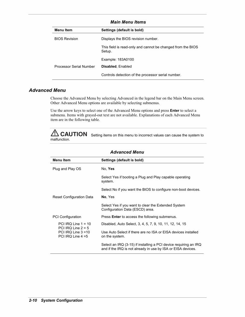
BIOS Revision Displays the BIOS revision number.
This field is read-only and cannot be changed from the BIOSSetup.
Example: 183A0100
Processor Serial Number Disabled, Enabled
Controls detection of the processor serial number.
Advanced MenuChoose the Advanced Menu by selecting Advanced in the legend bar on the Main Menu screen.Other Advanced Menu options are available by selecting submenus.
Use the arrow keys to select one of the Advanced Menu options and press Enter to select asubmenu. Items with grayed-out text are not available. Explanations of each Advanced Menuitem are in the following table.
Setting items on this menu to incorrect values can cause the system tomalfunction.
Advanced MenuMenu Item Settings (default is bold)
Plug and Play OS No, Yes
Select Yes if booting a Plug and Play capable operatingsystem.
Select No if you want the BIOS to configure non-boot devices.
Reset Configuration Data No, Yes
Select Yes if you want to clear the Extended SystemConfiguration Data (ESCD) area.
PCI Configuration Press Enter to access the following submenus.
PCI IRQ Line 1 = 10PCI IRQ Line 2 = 5PCI IRQ Line 3 =10PCI IRQ Line 4 =5
Disabled, Auto Select, 3, 4, 5, 7, 9, 10, 11, 12, 14, 15
Use Auto Select if there are no ISA or EISA devices installedon the system.
Select an IRQ (3-15) if installing a PCI device requiring an IRQand if the IRQ is not already in use by ISA or EISA devices.

System Configuration 2-11
Advanced MenuMenu Item Settings (default is bold)
Cache Memory Press Enter to access the following submenus.
Memory Cache Disabled, Enabled
Sets the state of the memory cache.
Cache System BIOS Area
Uncached, Write Protect
Controls caching of system BIOS area.
Cache Video BIOS Area
Uncached, Write Protect
Controls caching of system video BIOS area.
Cache Base 0-512K Uncached, Write Through, Write Protect, Write Back
Controls caching of 512K base memory.
Cache Base 512-640K Uncached, Write Through, Write Protect, Write Back
Controls caching of 512K-640K base memory.
Cache Extended Memory Area
Uncached, Write Through, Write Protect, Write Back
Controls caching of system memory above one MB.
Cache C800-CBFFCache CC00-CFFFCache D000-D3FFCache D400-D7FFCache D800-DBFFCache DC00-DFFF
Disabled, Write Through, Write Protect, Write Back
Setting at Disabled prohibits caching.
Setting at Write Through permits writes to be cached and sentto main memory at once.
Setting at Write Protect causes the BIOS to ignore writes.
Setting at Write Back permits write caching but delays sendingdata to main memory until necessary.
I/O Device Configuration Press Enter to access the following submenus.
Serial Port A Disabled, Enabled, Auto
Setting at Enabled allows the user to configure the port.
Setting at Auto enables the BIOS or operating system toconfigure the port.
Base I/O Address
3F8, 2F8, 3E8, 2E8
Selects the base I/O address for serial port A.
Interrupt IRQ3, IRQ4
Selects the IRQ for serial port A.

2-12 System Configuration
Advanced MenuMenu Item Settings (default is bold)
Parallel Port Disabled, Enabled, Auto
Setting at Enabled allows the user to configure the port.
Setting at Auto enables the BIOS or operating system toconfigure the port.
Mode Output Only, Bi-directional, ECP
Selects parallel port mode.
Base I/O Address
378, 278, 3BC
Selects the base I/O address for the LPT port.
Interrupt IRQ5, IRQ7
Selects the IRQ for the LPT port.
Floppy Disk Controller Disabled, Enabled, Auto
Setting at Enabled allows the user to configure the controller.
Setting at Auto enables the BIOS or operating system toconfigure the controller.
Base I/O Address
Primary, Secondary
Sets the base I/O address for the controller.
Large Disk Access Mode Other, DOS
Select DOS if using DOS or Windows operating system.
Select Other if using another operating system such as UNIXor Novell NetWare.
Local Bus IDE Adapter Disabled, Primary, Secondary, Both
Enables the integrated local bus IDE adapter.
QuickBoot Mode Disabled, Enabled
When Enabled, the BIOS does not test system memory above1 MB or wait for ready signals, allowing a quick boot.
Sound Enabled, Disabled
Select Disabled to turn off onboard sound.
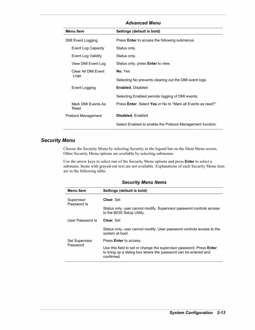
System Configuration 2-13
Advanced MenuMenu Item Settings (default is bold)
DMI Event Logging Press Enter to access the following submenus.
Event Log Capacity Status only.
Event Log Validity Status only.
View DMI Event Log Status only, press Enter to view.
Clear All DMI Event Logs
No, Yes
Selecting No prevents clearing out the DMI event logs.
Event Logging Enabled, Disabled
Selecting Enabled permits logging of DMI events.
Mark DMI Events As Read
Press Enter. Select Yes or No to �Mark all Events as read?�
Preboot Management Disabled, Enabled
Select Enabled to enable the Preboot Management function.
Security MenuChoose the Security Menu by selecting Security in the legend bar on the Main Menu screen.Other Security Menu options are available by selecting submenus.
Use the arrow keys to select one of the Security Menu options and press Enter to select asubmenu. Items with grayed-out text are not available. Explanations of each Security Menu itemare in the following table.
Security Menu ItemsMenu Item Settings (default is bold)
SupervisorPassword Is
Clear, Set
Status only, user cannot modify. Supervisor password controls accessto the BIOS Setup Utility.
User Password Is Clear, Set
Status only, user cannot modify. User password controls access to thesystem at boot.
Set SupervisorPassword
Press Enter to access.
Use this field to set or change the supervisor password. Press Enterto bring up a dialog box where the password can be entered andconfirmed.

2-14 System Configuration
Security Menu ItemsMenu Item Settings (default is bold)
Set UserPassword
Press Enter to access.
Use this field to set or change the user password (supervisorpassword must be set before user password can be set). Press Enterto bring up a dialog box where the password can be entered andconfirmed.
Security Mode Press Enter to access the Security Mode.
Use this mode to select Password (default), SmartCard, orFingerPrint. Press Enter to open the selected field.
Use the SmartCard field to assign access to the SmartCard Reader bythe supervisor and/or user. Press Enter to bring up the SmartCardReader dialog box for setting up SmartCard security.
The Assign Supervisor SmartCard field controls Supervisor access tothe BIOS Setup Utility and the system. A PIN number controls access.
The Assign User SmartCard field controls user access to the systemat boot. A PIN number controls access.
Use the FingerPrint field to assign supervisor and user access to anexternal fingerprint reader for controlling access to the BIOS setuputility. Press Enter to bring up the FingerPrint reader dialog box forsetting up FingerPrint security.
Keep in mind that supervisor access must be established before useraccess can be established.
Password on Boot Disabled, Enabled
When Enabled, requires password entry before boot. System remainsin secure mode until password is entered.
Fixed Disk BootSector
Normal, Write Protect
Write Protect protects the boot sector on the hard disk from viruses.
Diskette Access Supervisor, User
Controls access to the diskette drive.
Network BootSetting
Press Enter to access.
Keyboard Mouse Lock
Disabled, Enabled
Select Enabled to lock the keyboard and mouse when remote booting.
Virus CheckReminder
Disabled, Daily, Weekly, Monthly
Displays reminder message at bootup. Message is daily, everyMonday, or first of every month.
System BackupReminder
Disabled, Daily, Weekly, Monthly
Displays reminder message at bootup. Message is daily, everyMonday, or first of every month.
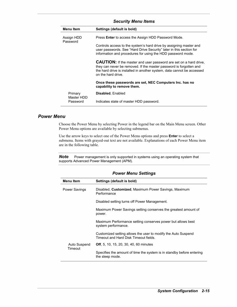
System Configuration 2-15
Security Menu ItemsMenu Item Settings (default is bold)
Assign HDDPassword
Press Enter to access the Assign HDD Password Mode.
Controls access to the system�s hard drive by assigning master anduser passwords. See �Hard Drive Security� later in this section forinformation and procedures for using the HDD password mode.
CAUTION: If the master and user password are set on a hard drive,they can never be removed. If the master password is forgotten andthe hard drive is installed in another system, data cannot be accessedon the hard drive.
Once these passwords are set, NEC Computers Inc. has nocapability to remove them.
PrimaryMaster HDD Password
Disabled, Enabled
Indicates state of master HDD password.
Power MenuChoose the Power Menu by selecting Power in the legend bar on the Main Menu screen. OtherPower Menu options are available by selecting submenus.
Use the arrow keys to select one of the Power Menu options and press Enter to select asubmenu. Items with grayed-out text are not available. Explanations of each Power Menu itemare in the following table.
Note Power management is only supported in systems using an operating system thatsupports Advanced Power Management (APM).
Power Menu SettingsMenu Item Settings (default is bold)
Power Savings Disabled, Customized, Maximum Power Savings, MaximumPerformance
Disabled setting turns off Power Management.
Maximum Power Savings setting conserves the greatest amount ofpower.
Maximum Performance setting conserves power but allows bestsystem performance.
Customized setting allows the user to modify the Auto SuspendTimeout and Hard Disk Timeout fields.
Auto Suspend Timeout
Off, 5, 10, 15, 20, 30, 40, 60 minutes
Specifies the amount of time the system is in standby before enteringthe sleep mode.
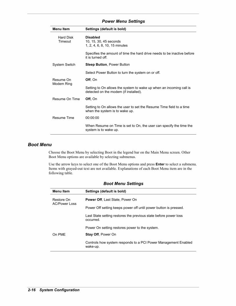
2-16 System Configuration
Power Menu SettingsMenu Item Settings (default is bold)
Hard Disk Timeout
Disabled10, 15, 30, 45 seconds1, 2, 4, 6, 8, 10, 15 minutes
Specifies the amount of time the hard drive needs to be inactive beforeit is turned off.
System Switch Sleep Button, Power Button
Select Power Button to turn the system on or off.
Resume OnModem Ring
Off, On
Setting to On allows the system to wake up when an incoming call isdetected on the modem (if installed).
Resume On Time Off, On
Setting to On allows the user to set the Resume Time field to a timewhen the system is to wake up.
Resume Time 00:00:00
When Resume on Time is set to On, the user can specify the time thesystem is to wake up.
Boot MenuChoose the Boot Menu by selecting Boot in the legend bar on the Main Menu screen. OtherBoot Menu options are available by selecting submenus.
Use the arrow keys to select one of the Boot Menu options and press Enter to select a submenu.Items with grayed-out text are not available. Explanations of each Boot Menu item are in thefollowing table.
Boot Menu SettingsMenu Item Settings (default is bold)
Restore OnAC/Power Loss
Power Off, Last State, Power On
Power Off setting keeps power off until power button is pressed.
Last State setting restores the previous state before power lossoccurred.
Power On setting restores power to the system.
On PME Stay Off, Power On
Controls how system responds to a PCI Power Management Enabledwake-up.
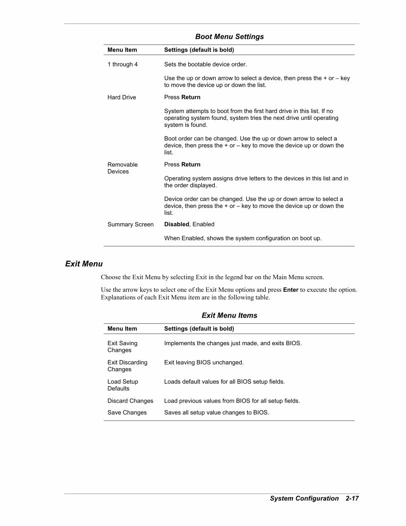
System Configuration 2-17
Boot Menu SettingsMenu Item Settings (default is bold)
1 through 4 Sets the bootable device order.
Use the up or down arrow to select a device, then press the + or � keyto move the device up or down the list.
Hard Drive Press Return
System attempts to boot from the first hard drive in this list. If nooperating system found, system tries the next drive until operatingsystem is found.
Boot order can be changed. Use the up or down arrow to select adevice, then press the + or � key to move the device up or down thelist.
RemovableDevices
Press Return
Operating system assigns drive letters to the devices in this list and inthe order displayed.
Device order can be changed. Use the up or down arrow to select adevice, then press the + or � key to move the device up or down thelist.
Summary Screen Disabled, Enabled
When Enabled, shows the system configuration on boot up.
Exit MenuChoose the Exit Menu by selecting Exit in the legend bar on the Main Menu screen.
Use the arrow keys to select one of the Exit Menu options and press Enter to execute the option.Explanations of each Exit Menu item are in the following table.
Exit Menu ItemsMenu Item Settings (default is bold)
Exit SavingChanges
Implements the changes just made, and exits BIOS.
Exit DiscardingChanges
Exit leaving BIOS unchanged.
Load SetupDefaults
Loads default values for all BIOS setup fields.
Discard Changes Load previous values from BIOS for all setup fields.
Save Changes Saves all setup value changes to BIOS.

2-18 System Configuration
Hard Drive SecurityThe NEC PowerMate 2000 series system allows establishing password protection for theinternal hard drive. Hard disk drive (HDD) password protection restricts access to the drive onlyif the drive is removed from the PowerMate 2000 series system and installed in another system.The system does not prompt you to enter the HDD passwords while the drive remains in thecurrent system.
The HDD passwords are written to the CMOS and to the hard drive to ensure that the passwordprotection travels with the drive if it is moved to another system.
Establishing Hard Drive PasswordsTo establish password protection for the system�s hard drive, you must establish a masterpassword, establish a user password, and enable the established passwords for the internal harddrive. Use the following procedure to establish HDD passwords and to enable HDD passwordprotection.
If you set the master and user password on a hard drive, you can neverremove the passwords. You can change the passwords. If you forget the master password andinstall the drive in another system, you cannot access the data on the hard drive.
Once you set these passwords, NEC Computers Inc. has no capability of removing them.
If you install the hard drive in another PowerMate system with hard disk drive security enabled,you must enter the password to allow access to the hard drive. If this PowerMate system doesnot support hard disk drive security, you cannot access the data on the hard drive.
1. Boot your system. Press F2 when prompted to enter BIOS setup. The Main Menu screenappears.
2. Using the arrow keys, select the Security Menu.
3. Use the down arrow key to highlight Assign HDD Password and press Enter. The systemprompts you to enter a master password.
4. Enter a master HDD password and press Enter. The system prompts you to reenter thepassword to verify.
5. Reenter the master HDD password and press Enter. The system confirms the creation of themaster password and prompts you to enter a user password.
6. Enter a user password and press Enter. The system prompts you to reenter the password toverify.
7. Reenter the user password and press Enter.
8. Highlight and select Primary Master HDD Password. Use the + (plus) and � (minus) keysto enable the selection. (This enables password protection for the internal HDD.)
Changing Hard Drive PasswordsUse the following procedure to change hard disk drive passwords.
1. Boot your system. Press F2 when prompted to enter BIOS Setup.
2. At the Main Menu screen, select the Security Menu.

System Configuration 2-19
3. Highlight Assign HDD Password and press Enter.
! If you enter the current master password, you are prompted to enter a new masterpassword.
! If you enter the current user password, you are prompted to enter the new userpassword.
! If you do not want to establish a new master or user password, press Esc instead ofentering a new password.
4. Save the changes and exit BIOS setup.
Using Hard Drive Password ProtectionTo facilitate the transfer of one or more HDDs between systems, establish a single masterpassword and store the password in a secure place. Forgetting the master password results in theinability to access the data on the hard drive. Establish different user passwords to limit access tospecific systems.
If you set the master and user password on a hard drive, you can neverremove the passwords. You can change the passwords. If you forget the master password andinstall the drive in another system, you cannot access the data on the hard drive.
Once you set these passwords, NEC Computers Inc. has no capability of removing them.
If you install the hard drive in another PowerMate system with hard disk drive security enabled,you must enter the password to allow access to the hard drive. If this PowerMate system doesnot support hard disk drive security, you cannot access the data on the hard drive.
With hard disk drive security enabled on the original NEC PowerMate 2000 series system, thesystem boots normally.
If you install the hard drive in another NEC PowerMate system with security enabled, you mustenter the master password to access the hard drive. If the hard drive is installed in another NECPowerMate 2000 system with security disabled, the system prompts you to enter the masterpassword and then a new user password.
Moving the Hard DriveWhen a password protected hard drive is moved from its original system and installed in anothersystem, error messages appear indicating that the drive is locked. Next, the Security Setupscreen appears requiring the user to enter the master password to unlock the drive. Enter themaster password, when prompted.
To take advantage of HDD password protection in another system, the system must be equippedwith the same HDD password protection feature. To determine if the system has HDD passwordprotection, check the Security Menu in the BIOS Setup to see if there are provisions forestablishing HDD passwords.
2-20 System Configuration
FLASH UtilityThe system BIOS resides on a ROM chip in the system and is updated using the followingprocedure. Before starting the BIOS update, we recommend that you contact NECC forassistance (see Section 8 for NECC contacts).
Update the FLASH ROM with a BIOS FLASH diskette. You can get the diskette from NECC ordownload the BIOS from the NECC web site. See Section 8 for download and web siteinformation.
Update the BIOS from the BIOS FLASH diskette as follows.
1. Write down or print the BIOS Setup parameters currently set on the system.
2. Turn off the system.
3. Put the flash diskette in drive A and turn on the system.
4. At the flash upgrade menu, choose Update Flash Memory Area from a file.
5. When asked for a path/file name, use the arrow keys to select the ROM file and press Enter.
6. The utility asks for confirmation to load the new flash into memory. Select Continue withprogramming.
7. After the upgrade completes, remove the diskette.
8. Reboot the system and start the Setup program. Press F9 to reset the BIOS defaults. Use therecorded Setup selections you made at the beginning of this procedure to set the parameters.
PowerMate Application and Driver CDThe PowerMate Application and Driver CD provides drivers, utilities, NEC INFO Center,internet browser, and a variety of software applications for use with the system. Use the CD toinstall the applications or to reinstall any applications that might have become corrupted.
Use these procedures to launch the Application and Driver CD.
1. Insert the Application and Driver CD into the CD-ROM drive. The CD auto runs.
! If the CD does not auto-run, double click the NEC Customize icon on the Windowsdesktop.
! Highlight Application and Driver CD and click Install to launch the CD.
! The Application and Driver CD dialog box appears.
2. In the Application and Driver CD dialog box, click the selection tab of your choice andclick the desired driver, utility, or application (for example, NEC INFO Center).
3. Click Install and follow the screen prompts to install the selection.
4. Click Exit to close the Application and Driver CD dialog box.
5. Remove the CD from the CD-ROM drive when the installation is complete.

System Configuration 2-21
NEC INFO CenterThe online NEC INFO Center provides quick access to information about the system. The INFOCenter includes the following modules.
! TourUse Tour to find information about easy-to-use NEC Computers printed and onlinedocumentation, software installation tools, and many support services.
! User�s GuideUse this module to get quick access to an online version of the printed user�s guide.
! QuestionsLook in this module to get answers to frequently asked questions about the system.
! SolutionsGo to this module to find solutions to common system problems.
! ServicesCheck this module for a quick reference to the many NEC Computers support servicesavailable to you.
To install the NEC INFO Center from the PowerMate Application and Driver CD, follow theprocedures in the previous section, �PowerMate Application and Driver CD.� To start the NECINFO Center, double click the NEC INFO Center icon on the desktop. The INFO Centeropening screen appears (see the following figure).
Click on an NEC INFO Center module of your choice, depending on the information you wantto see. We suggest you start with the Tour module.
NEC INFO Center Opening Screen
To uninstall the NEC INFO Center, use these steps.
1. At the Windows desktop, click Start, point to Settings, and click Control Panel.
2. At the Control Panel, double click Add/Remove Programs.
3. Double click NEC INFO Center and follow the prompts.
For Windows 2000, select NEC INFO Center, click Change/Remove, and follow theprompts.

2-22 System Configuration
NEC Product Recovery CDThe NEC Product Recovery CD contains the NEC Product Recovery utility that allows you torestore the system to its initial installation state.
You should only use the Product Recovery CD as a last resort. Check the problem checklist inSection 7 for information about solving problems before using the Product Recovery CD. TheProduct Recovery CD provides options that either remove or replace existing files, a process thatmay result in data loss.
Carefully review the following Product Recovery CD information before proceeding with asystem restore.
Choose the restore option carefully to prevent losing data andapplications installed on the system. NEC Computers suggests that you contact TechnicalSupport Services for assistance in restoring the hard drive. See Section 8, �NEC ComputersInformation Services,� for information on obtaining NEC Computers support.
Use the Restore System program if you want to restore the hard drive to its factory-installedstate. Restore System allows you to restore the system in one of two ways.
! Full Disk Drive � This option completely rebuilds the hard drive, destroying all existingdata in the process.
! Partition Only � The Partition Only option lets you preserve the existing hard drivepartition structure and format only the primary partition without affecting the extendedpartition(s).
Note Systems with the Microsoft® Windows® NT® operating system come with the hard drivepartitioned as two drives. Systems with the Microsoft Windows 98 SE operating system or theMicrosoft Windows 2000 operating system come with the hard drive set as one drive.
Performing Full Disk RestoreIf the preinstalled software becomes unusable and you cannot boot from the hard drive, use theProduct Recovery CD to restore the system to its initial shipping configuration. The Full Diskrestore option erases the hard drive completely before reinstalling the files.
The Full Disk Drive restore option deletes all files on the hard drive andreplaces them with the original factory-installed files. Only use the Full Disk Drive restore option ifthe preinstalled software is unusable.
Use the Product Recovery CD to perform a Full Disk Drive restore as follows.
1. Disconnect all peripherals and power on the system.
Before using the Product Recovery CD, enter the BIOS Setup utility,record the current settings, and restore the BIOS default settings. Save the default settingsbefore exiting the BIOS Setup utility.
2. Load the PowerMate Product Recovery CD for the operating system into the CD-ROMdrive. Reboot the system.

System Configuration 2-23
3. Read the License Agreement screen that appears. Click Accept to accept the agreement. Ifyou decline, the recovery utility exits.
Do not turn off or disturb the system during the following recoveryprocess.
4. At the NEC Product Recovery utility screen, select Full Disk Drive to restore the hard driveto its original factory installed state.
5. Read the Warning screen.
A warning displays, indicating that the hard drive is about to be erased.
6. Click Continue to perform a Full Disk Drive restore.
If you click Back, the recovery utility returns to the prior screen, which has an exit option.
If you click Continue, a screen with progress bars displays and lets you know the progressof the recovery.
7. When the recovery process is complete, you are prompted to remove the CD from theCD-ROM drive and reboot the system.
8. Press Enter, click Reboot, or press Alt-R to reboot the system.
9. A series of hardware detection screens display, the system reboots, and the Windows Setupscreen appears. Follow the screen prompts to set up Windows.
Performing Partition Only RestoreIf the system comes with a partitioned hard drive and the factory preinstalled software on driveC: becomes unusable and you cannot boot from the hard drive, use the PowerMate ProductRecovery CD to restore the drive C: partition to its initial shipping configuration.
Note Systems with the Microsoft Windows NT operating system come with the hard drivepartitioned as two drives. Systems with the Microsoft Windows 98 SE operating system or theMicrosoft Windows 2000 operating system come with the hard drive as one drive.
Use the Partition Only restore option only if the hard drive consists ofmultiple partitions and if drive C: contains the operating system and related drivers. Move allother data and applications from drive C: to other partitions (drives) or the Partition Only restoreprocess will erase them completely.
The Partition Only restore option deletes all files on drive C: and replaces them with the originalfactory installed files. Only use the Partition Only restore option if the preinstalled software ondrive C: is unusable.
If you have any question about performing a Partition Only restore, NEC Computers suggeststhat you contact Technical Support Services before starting the restore procedure. See Section 8,�NEC Computers Information Services,� for information on obtaining NEC Computers support.
Use the Product Recovery utility to perform a Partition Only restore as follows.
1. Disconnect all peripherals and power on the system.
Before using the Product Recovery CD, enter the BIOS Setup utility,record the current settings, and restore the BIOS default settings. Save the default settingsbefore exiting the BIOS Setup utility.

2-24 System Configuration
2. Load the PowerMate Product Recover CD for the system into the CD-ROM drive. Rebootthe system.
3. Read the License Agreement screen that appears. Click Accept to accept the agreement. Ifyou decline, the recovery utility exits.
Do not turn off or disturb the system during the following recoveryprocess.
4. At the NEC Product Recovery utility screen, click Partition Only to restore drive C: of amultiple partitioned drive to its original factory installed state.
5. Read the Warning screen.
A warning displays, indicating that drive C: (the primary drive/partition) is about to beerased and formatted. It may be necessary to reinstall software to the other drives(partitions) to reestablish Start Menu links and other configuration requirements stored ondrive C.
6. Click Continue to perform a Partition Only restore.
If you click Back, the recovery utility returns to the prior screen, which has an exit option.
If you click Continue, a screen with progress bars displays and lets you know the progressof the recovery.
7. When the recovery process is complete, you are prompted to remove the CD from theCD-ROM drive and reboot your system.
8. Press Enter, click Reboot, or press Alt-R to reboot your system.
9. A series of hardware detection screens display, the system reboots, and the Windows Setupscreen appears. Follow the screen prompts to set up Windows.
Intel Processor Serial Number Control UtilityThe Intel Processor Serial Number Control Utility is a Windows program that enables ordisables the reading of the Pentium III processor serial number by software. This functioncontrols which software programs or web sites have permission to read the processor serialnumber. When installed, the utility runs automatically each time the system powers on.
This utility places an icon in the Windows system tray. The icon provides a visual status of theprocessor serial number. You have the option of hiding the system tray icon. You can enable ordisable the processor serial number at any time. However, enabling the serial number requiresrestarting the system.
The following information describes:
! system requirements
! installation procedures
! processor serial number features
! FAQs
! technical support.

System Configuration 2-25
System RequirementsThe Intel Processor Serial Number Control Utility requires:
! a Pentium III processor-based system
! Windows 98, Windows NT 4.0 (or later), or Windows 2000
! 2 megabytes of hard drive space.
InstallationThe Intel Processor Serial Number Control Utility (version 1.0) comes already installed on thesystem. The system ships with the processor serial number turned off.
Processor Serial NumberThe Intel processor serial number, a feature of the Pentium III processor, is an identifier for theprocessor. The processor serial number is unique, and when used in conjunction with otheridentification methods, can be used to identify the system or user. This number can be used in awide variety of applications which benefit from stronger forms of system and user identification.
The processor serial number is analogous to a conventional serial number, with these importantdifferences:
! A software application can read the processor serial number.
! You can enable or disable the reading of the serial number via utility programs such as thisone, or via the BIOS, depending on the system configuration.
For additional information about the Pentium III processor and the processor serial number, visitwww.intel.com/pentiumiii.
Frequently Asked QuestionsWhat are the benefits of the processor serial number?
You can use the processor serial number in applications which benefit from stronger forms ofsystem and user identification.
Why would I want to turn off my processor serial number?
Intel believes the processor serial number can provide compelling benefits to users. They aredeveloping features in conjunction with the processor serial number to allow responsible serviceproviders to provide services which maintain your privacy. However, if you are concerned that agiven application/service using your processor number might impact your privacy, you can turnoff the processor serial number using the utility.
What is the default state of the processor serial number?
The default state of the processor serial number is on, until the Processor Serial Number ControlUtility is installed. Once the Processor Serial Number Control Utility is installed, it turns theprocessor serial number off by default. You can use the utility to turn on the processor serialnumber.
Can a web site read my serial number without my knowledge?
No, generally not. Web sites cannot read serial numbers unless you allow them to download aprogram which can read the processor serial number. Almost all browsers are configured towarn users whenever they download executable software. Unless you disable the warning in thebrowser, you should receive a notification.
2-26 System Configuration
Does Intel track serial numbers?
Generally not, other than related to the manufacturing process. Intel does not, in the absences ofadvance and express consent of a user, collect serial number data which is otherwise identifiedwith a user.
Which programs and/or web sites currently use the processor serial number?
You can find a complete list of programs which can take advantage of the processor serialnumber and other new capabilities of the Pentium III processor athttp://www.intel.com/pentiumiii/utility.htm.
How can I tell if my processor serial number is turned on?
The vast majority of Pentium III processor-based systems ship with the processor serial numberenabled. The control utility allows you to check the status by:
! Viewing the icon itself. The disabled icon shows a red circle with a white �x.�
! Clicking the task tray icon and selecting the �Status� menu item. Or you can select themenu from the tool tip shown when you position the mouse over the task tray icon.
Technical SupportFor world wide 7 days a week, 24 hours a day technical support, please visit the Intel supportweb site at http://support.intel.com.
Email: [email protected].
In the United States, call 800-628-8686 from 5:00 a.m. to 5:00 p.m. Pacific Standard Time.
For world wide phone contacts, please see http://support.intel.com/support/feedback.htm.

3Disassembly and Reassembly
! Hard Drive! SO-DIMM Module! Bottom Cover! CD-ROM Drive! Diskette Drive! System Board and Support Plate Assembly! Processor, CPU Fan, and Heat Sink! Network Board! LAN Connector Board! Hard Drive Bay and Drive! Auxiliary Cooling Fan! PC Card Bay! CMOS Battery! LCD Panel

3-2 Disassembly and Reassembly
This section contains step-by-step disassembly procedures for the PowerMate 2000 Seriessystem. A disassembly figure is provided with most procedures. Section 5 includes a field-levelparts list and an illustrated parts breakdown showing an exploded view of the system.
A small flat head screwdriver, a small Phillips-head screwdriver, and an antistatic wrist strap arethe only required tools. For complete disassembly of the system unit, follow the disassemblyorder listed in the following table. To reassemble, follow the table and procedures in reverseorder. Where reassembly is not readily apparent, reassembly procedures are provided.
Electrostatic discharge (ESD) can damage hard drives, boards, andother system components. Before opening the system and handling system components, attachan antistatic wrist strap to your wrist and to chassis ground (any unpainted metal surface on thesystem) to avoid ESD damage.
Hold a board only by its edges. If removing a board, place it component-side up on a grounded,static-free surface or in a static-free wrapper. If installing a new board, do not remove it from itsprotective wrapper until you are ready to install it.
PowerMate 2000 Series Disassembly SequenceSequence Part Name See Page
1 Hard Drive 3-3
2 SO-DIMM Memory Module(s) 3-4
3 Bottom Cover 3-7
4 CD-ROM Drive 3-8
5 Diskette Drive 3-9
6 System Board and Support Plate Assembly 3-10
7 Processor, CPU Fan, and Heat Sink 3-12
8 Network Board Assembly 3-15
9 LAN Connector Board 3-16
10 Hard Drive Bay and Drive 3-16
11 Auxiliary Cooling Fan 3-16
12 PC Card Bay 3-17
13 CMOS Battery 3-19
14 LCD Panel 3-20
When disassembling the system, follow these general rules.
! Turn off the system and disconnect the AC power adapter and AC power cord from thepower source and system unit.
! Disconnect all peripherals before disassembling the system.
! Do not disassemble parts other than those specified in the procedure.
! All screws are Phillips-head, unless otherwise specified.
! Observe each cable connector before attempting to unplug. Some connectors have a specialretainer holding them in place.

Disassembly and Reassembly 3-3
! Use care in disconnecting and connecting cables to prevent breakage. Do not pull on thecable, pull only on the connector.
! Wherever possible, label any cable connector before removing it. Note where the connectorgoes and in what position it was installed.
On completion of any reassembly, perform a power-on test. If a fault occurs, verify that thereassembly was performed correctly.
Hard Drive RemovalRemove the hard drive as follows.
1. Close all applications, shut down the operating system, turn off system unit power, andunplug the AC power adapter and power cable from the power source and the back of thesystem unit.
2. Turn off and disconnect all peripherals.
3. Position the system unit so that the right side is facing you. Swivel the LCD panel awayfrom the side so that is not blocking your view of the side.
4. Remove the hard drive access panel by pressing down on the two latches.
Removing the Hard Drive Access Panel
A � Latches B � Access Panel
5. Carefully unplug the hard drive interface cable from the hard drive (see the followingfigure).
! Do not pull on the interface cable. Evenly pull on the interface cable connector until itreleases from the hard drive connector.
! Note the four pins on the right end of the hard drive connector. These pins are forsetting the drive configuration (factory set as master, no jumper installed). Do notconnect the interface cable connector over these four pins during reassembly.
6. Grasp the pull tab on the hard drive and carefully pull on it to remove the drive from thedrive bay.
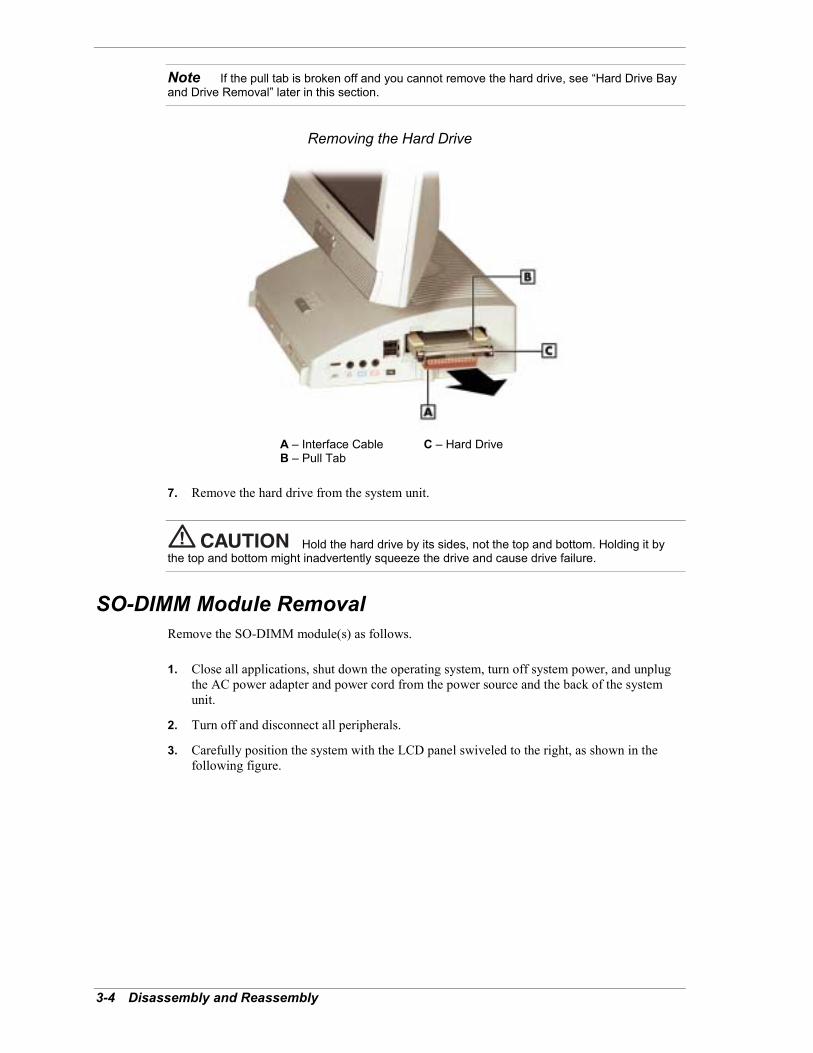
3-4 Disassembly and Reassembly
Note If the pull tab is broken off and you cannot remove the hard drive, see �Hard Drive Bayand Drive Removal� later in this section.
Removing the Hard Drive
A � Interface Cable C � Hard DriveB � Pull Tab
7. Remove the hard drive from the system unit.
Hold the hard drive by its sides, not the top and bottom. Holding it bythe top and bottom might inadvertently squeeze the drive and cause drive failure.
SO-DIMM Module RemovalRemove the SO-DIMM module(s) as follows.
1. Close all applications, shut down the operating system, turn off system power, and unplugthe AC power adapter and power cord from the power source and the back of the systemunit.
2. Turn off and disconnect all peripherals.
3. Carefully position the system with the LCD panel swiveled to the right, as shown in thefollowing figure.
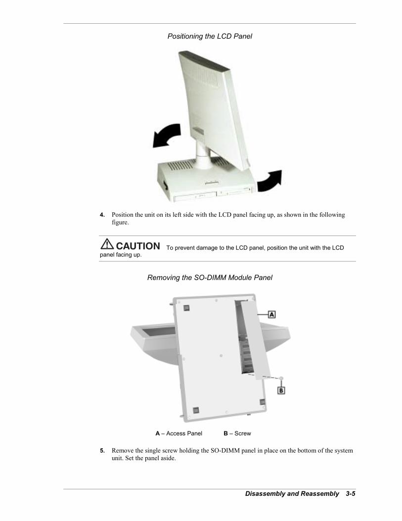
Disassembly and Reassembly 3-5
Positioning the LCD Panel
4. Position the unit on its left side with the LCD panel facing up, as shown in the followingfigure.
To prevent damage to the LCD panel, position the unit with the LCDpanel facing up.
Removing the SO-DIMM Module Panel
A � Access Panel B � Screw
5. Remove the single screw holding the SO-DIMM panel in place on the bottom of the systemunit. Set the panel aside.
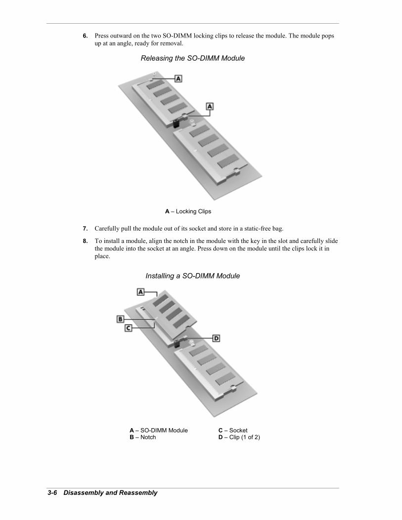
3-6 Disassembly and Reassembly
6. Press outward on the two SO-DIMM locking clips to release the module. The module popsup at an angle, ready for removal.
Releasing the SO-DIMM Module
A � Locking Clips
7. Carefully pull the module out of its socket and store in a static-free bag.
8. To install a module, align the notch in the module with the key in the slot and carefully slidethe module into the socket at an angle. Press down on the module until the clips lock it inplace.
Installing a SO-DIMM Module
A � SO-DIMM Module C � SocketB � Notch D � Clip (1 of 2)
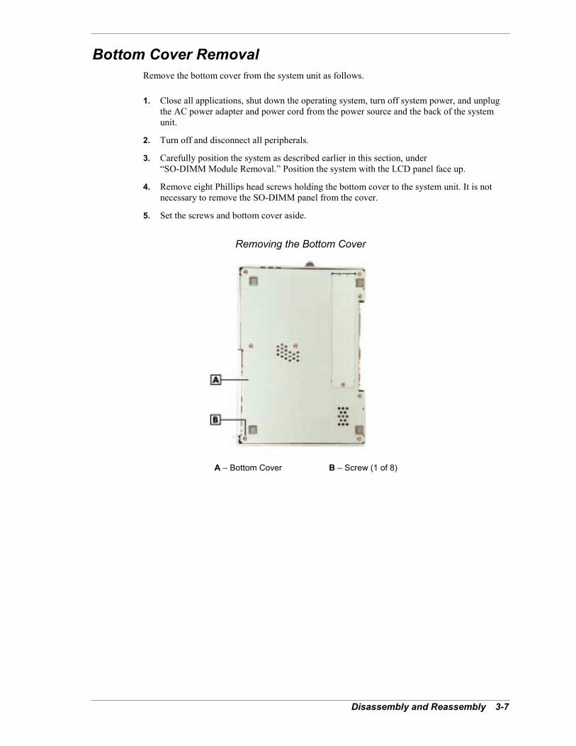
Disassembly and Reassembly 3-7
Bottom Cover RemovalRemove the bottom cover from the system unit as follows.
1. Close all applications, shut down the operating system, turn off system power, and unplugthe AC power adapter and power cord from the power source and the back of the systemunit.
2. Turn off and disconnect all peripherals.
3. Carefully position the system as described earlier in this section, under�SO-DIMM Module Removal.� Position the system with the LCD panel face up.
4. Remove eight Phillips head screws holding the bottom cover to the system unit. It is notnecessary to remove the SO-DIMM panel from the cover.
5. Set the screws and bottom cover aside.
Removing the Bottom Cover
A � Bottom Cover B � Screw (1 of 8)
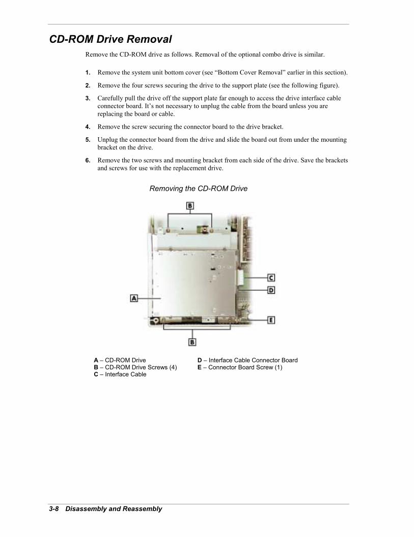
3-8 Disassembly and Reassembly
CD-ROM Drive RemovalRemove the CD-ROM drive as follows. Removal of the optional combo drive is similar.
1. Remove the system unit bottom cover (see �Bottom Cover Removal� earlier in this section).
2. Remove the four screws securing the drive to the support plate (see the following figure).
3. Carefully pull the drive off the support plate far enough to access the drive interface cableconnector board. It�s not necessary to unplug the cable from the board unless you arereplacing the board or cable.
4. Remove the screw securing the connector board to the drive bracket.
5. Unplug the connector board from the drive and slide the board out from under the mountingbracket on the drive.
6. Remove the two screws and mounting bracket from each side of the drive. Save the bracketsand screws for use with the replacement drive.
Removing the CD-ROM Drive
A � CD-ROM Drive D � Interface Cable Connector BoardB � CD-ROM Drive Screws (4) E � Connector Board Screw (1)C � Interface Cable
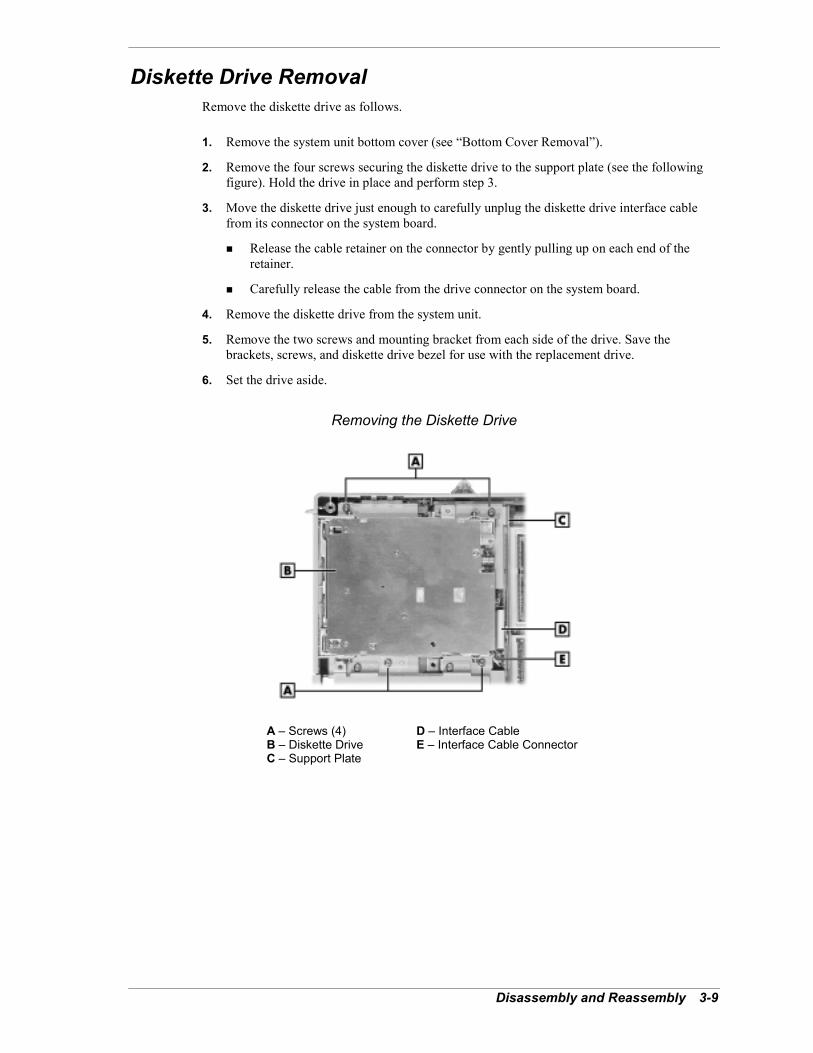
Disassembly and Reassembly 3-9
Diskette Drive RemovalRemove the diskette drive as follows.
1. Remove the system unit bottom cover (see �Bottom Cover Removal�).
2. Remove the four screws securing the diskette drive to the support plate (see the followingfigure). Hold the drive in place and perform step 3.
3. Move the diskette drive just enough to carefully unplug the diskette drive interface cablefrom its connector on the system board.
! Release the cable retainer on the connector by gently pulling up on each end of theretainer.
! Carefully release the cable from the drive connector on the system board.
4. Remove the diskette drive from the system unit.
5. Remove the two screws and mounting bracket from each side of the drive. Save thebrackets, screws, and diskette drive bezel for use with the replacement drive.
6. Set the drive aside.
Removing the Diskette Drive
A � Screws (4) D � Interface CableB � Diskette Drive E � Interface Cable ConnectorC � Support Plate

3-10 Disassembly and Reassembly
System Board and Support Plate Assembly RemovalNote The system board and support plate assembly must be removed from the system unitto remove the network board, processor, CPU fan, auxiliary cooling fan, hard drive bay, or LCDpanel. Use the following procedure to remove the assembly.
Remove the system board and support plate assembly as follows.
1. Close all applications, shut down the operating system, turn off system power, and unplugthe AC power adapter and power cord from the power source and the back of the systemunit.
2. Turn off and disconnect all peripherals.
3. Remove any PC cards or PC card slot covers that might be installed.
! Press the PC card eject button(s) to eject the cards or slot covers.
! Remove the cards or slot covers from the system unit.
! Press in the eject buttons so that they are not in the extended position.
4. Unplug the interface cable from the hard drive (see �Hard Drive Removal� earlier in thissection). It�s not necessary to remove the hard drive.
5. Remove the system unit bottom cover (see �Bottom Cover Removal� earlier in this section).
6. Remove the CD-ROM drive and diskette drive (see �CD-ROM Drive Removal� and�Diskette Drive Removal� earlier in this section).
7. Unplug the CD-ROM drive interface cable from the cable connector on the system board.
! Carefully press out on the black cable lock at each end of the cable connector.
! Carefully remove the cable from the connector.
8. Remove six screws and one standoff securing the system board and support plate assemblyto the system unit chassis (see the following figure �Removing the System Board andSupport Plate Assembly�).
Be sure to save and use these screws for reassembly as they are longer than those fasteningother components.
9. Carefully pull the system board and support plate assembly out just enough to access thecables connected to the system board.
You might need to carefully pull out on the left side of the system unit chassis to release thevolume control and audio connectors from their openings in the side of the chassis.

Disassembly and Reassembly 3-11
10. Carefully unplug the following cables from the system board. Do not pull on the cables. Usea steady pull on the cable connector to release it from its connector on the system board.
! LCD panel interface cable from connector P11
! four-wire cable from connector P12
! three-wire auxiliary cooling fan cable from connector P23.
11. Remove the system board and support plate assembly from the system unit chassis and setthe assembly on a clean, smooth static free surface.
! If you are removing the processor assembly, network board, or LCD panel, you do notneed to remove the support plate from the assembly. (See the device removalprocedures later in this section.)
! If you are removing the PC card bay, you need to remove the support plate (see �PCCard Bay Removal� later in this section for procedures).
Removing the System Board and Support Plate Assembly
A � Support Plate C � Standoff (1)B � System Board D � Screw (1 of 6)

3-12 Disassembly and Reassembly
Processor, CPU Fan, and Heat Sink RemovalThe processor is installed in a Slot 370 socket. The processor is cooled by a heat sink and a CPUfan clamped to the top of the processor.
Remove the fan, heat sink, and processor as follows.
If the system was just running, the processor and heat sink on thesystem board are hot. To avoid a burn, let the components cool for 10 minutes before continuing.
Before handling components, reduce static discharge by wearing anantistatic wrist strap attached to an unpainted metal part on the chassis.
1. Remove the system board and support plate assembly (see �System Board and SupportPlate Assembly Removal� earlier in this section). It is not necessary to remove the supportplate.
2. Position the system board with the processor side facing up and the support plate facingdown. Use care to avoid damaging the cables on the support plate side.
3. Unplug the CPU fan power cable from the CPU FAN connector (P22) on the system board.
4. If replacing only the CPU fan, remove the four screws fastening the fan to the heat sinkassembly. Remove and replace the fan.
Note Before removing the fan, note how it is mounted (flat mounting surface against the heatsink, countersunk screw holes facing up). The fan must be installed the same way, otherwise thedirection of the fan�s air flow is reversed.
5. Remove the fan and heat sink subassembly from the top of the processor as follows.
! Locate the release lever on the retention clip (see the following figure, �Removing theFan and Heat Sink Subassembly�).
! Simultaneously press down on the release lever while carefully pulling out the end tounhook it from the processor socket tab.
! Unhook the retention clip from the tab on the other side of the processor socket.
! Remove the fan and heat sink subassembly.
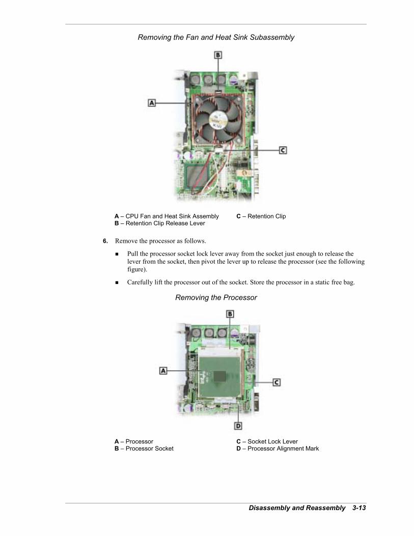
Disassembly and Reassembly 3-13
Removing the Fan and Heat Sink Subassembly
A � CPU Fan and Heat Sink Assembly C � Retention ClipB � Retention Clip Release Lever
6. Remove the processor as follows.
! Pull the processor socket lock lever away from the socket just enough to release thelever from the socket, then pivot the lever up to release the processor (see the followingfigure).
! Carefully lift the processor out of the socket. Store the processor in a static free bag.
Removing the Processor
A � Processor C � Socket Lock LeverB � Processor Socket D � Processor Alignment Mark
3-14 Disassembly and Reassembly
7. Install a replacement processor as follows.
! Align the white triangle (or notch) on the corner of the processor with thecorresponding white triangle on the system board.
! Carefully align the processor pins with the socket pin holes and set the processor intothe socket.
� If aligned correctly and the pins aren�t bent, the processor seats in the socketwithout forcing.
� If the processor does not seat, check the processor alignment and check for bentpins.
! Pivot the lock lever down and press it in towards the socket until it locks in place.
8. Install a replacement heat sink as follows and in accordance with the procedures containedin the heat sink kit.
Using the wrong heat sink or no heat sink can damage the processor,system board, or both. Ensure that the replacement processor has the correct heat sink (refer tothe documentation that comes with the kit).
Additional installation information can be obtained from NEC Computers (see Section 8, �NECComputers Information Services� for information on contacting NEC Computers).
! If the kit includes a thermal pad or thermal grease, center the pad or thermal grease ontop of the processor.
! Align the fan/heat sink assembly and retention clip with the processor and set it downon the processor (see the figure �Releasing the Processor� for alignment).
9. Attach the heat sink retention clip by hooking the small end of the clip over the socket tab.Press the clip�s release lever down and over the tab on the opposite side of the socket untilthe lever locks in place.
10. Plug the CPU fan power cable into the CPU FAN connector on the system board.
11. Reinstall the system board and support plate assembly in the system.

Disassembly and Reassembly 3-15
Network Board RemovalRemove the network board from the system board as follows.
1. Remove the system board and support plate assembly (see �System Board and SupportPlate Assembly Removal� earlier in this section). It is not necessary to remove the supportplate.
2. Position the system board with the processor side facing up and the support plate facingdown. Use care to avoid damaging the cables on the plate side.
3. Remove the network board as follows (see the following figure).
! Unplug the network board cable from its connector (J1) on the board. Remove anyinsulation tape holding the cable to the board and plate. Save for reinstallation.
! Release the board by pressing outward on the retainer clips on each side of the board.The board pops up at an angle for removal.
! Carefully pull the board out of its socket on the system board.
4. Install a replacement board by inserting the board into the connector at an angle. Press downon the board until it locks in place on the system board.
5. Plug the network board cable into the connector on the network board.
6. Reinstall the system board and support plate assembly in the system.
Removing the Network Board
A � LAN Connector Board Screw D � Network BoardB � LAN Connector Board E � Network Board ConnectorC � System Board F � Retainer Clip (1 of 2)
3-16 Disassembly and Reassembly
LAN Connector Board RemovalRemove the LAN connector board from the system board as follows.
1. Remove the system board and support plate assembly (see �System Board and SupportPlate Assembly Removal� earlier in this section).
2. Position the system board with the processor side facing up and the support plate facingdown. Use care to avoid damaging the cables on the support plate side.
3. Unplug the network board cable from its connector on the LAN connector board (see thepreceding figure, �Removing the Network Board�).
4. Remove the screw holding the LAN connector board to the connector frame, remove theboard, and replace with a new board.
Hard Drive Bay and Drive RemovalRemove the hard drive bay and the hard drive as follows.
1. Remove the system board and support plate assembly (see �System Board and SupportPlate Assembly Removal� earlier in this section).
2. Remove the four screws securing the drive bay to the chassis (see the figure �Removing theLCD Panel� later in this section for bay location).
3. Remove the bay and the drive from the chassis.
4. Remove the hard drive from the bay by pulling out on the plastic tab.
Auxiliary Cooling Fan RemovalRemove the auxiliary cooling fan as follows.
1. Remove the system board and support plate assembly (see �System Board and SupportPlate Assembly Removal� earlier in this section).
2. Remove the hard drive bay (see �Hard Drive Bay and Drive Removal� earlier in thissection).
3. Remove the screw and cable tie holding the fan cable in place.
4. Remove the four screws securing the fan to the chassis.
5. Remove the fan from the chassis.

Disassembly and Reassembly 3-17
PC Card Bay RemovalRemove the PC Card bay as follows.
1. Remove the system board and support plate assembly (see �System Board and SupportPlate Assembly Removal� earlier in this section).
Position the assembly with the processor side of the system board facing up. Use care toprevent damage to the cables on the back side of the board.
2. Remove the support plate from the system board as follows.
! Locate the black plastic shield between the PC Card bay and the system board (see thefollowing figure).
! Slide the black shield out for access to the screw (F) fastening the support plate to thesystem board.
! Remove the screw.
! Remove the second support plate screw (B).
! Lift the system board off the support plate and set the board on a static free surface. Usecare to prevent damage to the cables on the board.
Removing the Support Plate
A � Support Plate D � PC Card BayB � Support Plate Screw E � Plastic ShieldC � System Board F � Support Plate Screw (under plastic shield)
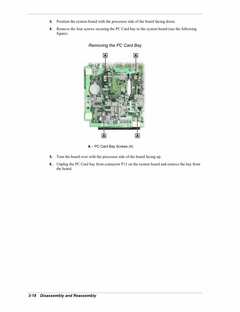
3-18 Disassembly and Reassembly
3. Position the system board with the processor side of the board facing down.
4. Remove the four screws securing the PC Card bay to the system board (see the followingfigure).
Removing the PC Card Bay
A � PC Card Bay Screws (4)
5. Turn the board over with the processor side of the board facing up.
6. Unplug the PC Card bay from connector P13 on the system board and remove the bay fromthe board.

Disassembly and Reassembly 3-19
CMOS Battery RemovalRemove the 3-volt lithium battery from the system board as follows.
1. Remove the bottom cover from the system unit (see �Bottom Cover Removal� earlier in thissection).
2. Remove the CD-ROM drive (see �CD-ROM Drive Removal� earlier in this section).
3. Carefully lift the plastic shield for access to the battery (see the following figure for shieldlocation).
4. Insert a small flat blade screwdriver at the pry point (B in the following figure) andcarefully pry up on the battery until it pops out of the socket.
Removing the Battery
A � Plastic Shield C � BatteryB � Pry Point
The battery can explode if it is incorrectly replaced or improperlydiscarded. Use only the same type battery or an equivalent type recommended by themanufacturer when replacing the battery.
Lithium acts as a catalyst when exposed to water and causes spontaneous combustion oncontact. Discard used batteries according to the manufacturer�s instructions.
5. Remove the battery and discard it in accordance with the manufacturer�s instructions.
6. With the positive (+) side facing up, press the new battery into the socket.
7. After reassembling the system unit, run Setup to reconfigure system parameters accordingto the settings previously recorded (see Section 2, �System Configuration�).
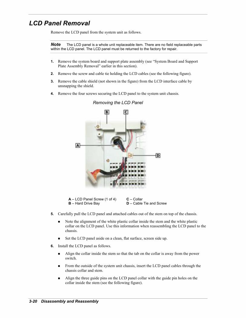
3-20 Disassembly and Reassembly
LCD Panel RemovalRemove the LCD panel from the system unit as follows.
Note The LCD panel is a whole unit replaceable item. There are no field replaceable partswithin the LCD panel. The LCD panel must be returned to the factory for repair.
1. Remove the system board and support plate assembly (see �System Board and SupportPlate Assembly Removal� earlier in this section).
2. Remove the screw and cable tie holding the LCD cables (see the following figure).
3. Remove the cable shield (not shown in the figure) from the LCD interface cable byunsnapping the shield.
4. Remove the four screws securing the LCD panel to the system unit chassis.
Removing the LCD Panel
A � LCD Panel Screw (1 of 4) C � CollarB � Hard Drive Bay D � Cable Tie and Screw
5. Carefully pull the LCD panel and attached cables out of the stem on top of the chassis.
! Note the alignment of the white plastic collar inside the stem and the white plasticcollar on the LCD panel. Use this information when reassembling the LCD panel to thechassis.
! Set the LCD panel aside on a clean, flat surface, screen side up.
6. Install the LCD panel as follows.
! Align the collar inside the stem so that the tab on the collar is away from the powerswitch.
! From the outside of the system unit chassis, insert the LCD panel cables through thechassis collar and stem.
! Align the three guide pins on the LCD panel collar with the guide pin holes on thecollar inside the stem (see the following figure).
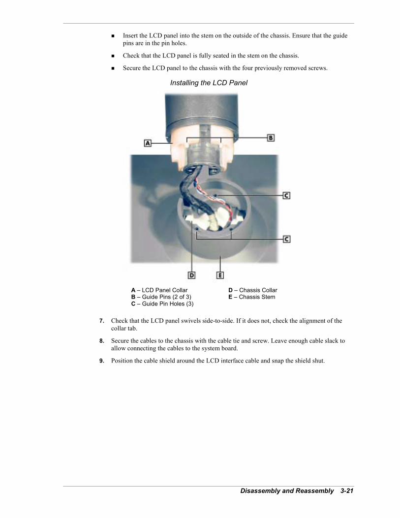
Disassembly and Reassembly 3-21
! Insert the LCD panel into the stem on the outside of the chassis. Ensure that the guidepins are in the pin holes.
! Check that the LCD panel is fully seated in the stem on the chassis.
! Secure the LCD panel to the chassis with the four previously removed screws.
Installing the LCD Panel
A � LCD Panel Collar D � Chassis CollarB � Guide Pins (2 of 3) E � Chassis StemC � Guide Pin Holes (3)
7. Check that the LCD panel swivels side-to-side. If it does not, check the alignment of thecollar tab.
8. Secure the cables to the chassis with the cable tie and screw. Leave enough cable slack toallow connecting the cables to the system board.
9. Position the cable shield around the LCD interface cable and snap the shield shut.
4System Board
! Connectors! Jumpers! Sockets! Components

4-2 System Board
This section describes the locations of connectors, jumpers, and sockets on the system board,including external cable connectors, internal board connectors, jumper locations, and upgradesockets.
Included in this section are procedures for setting jumpers on the system board and a SO-DIMMmemory upgrade path for the SO-DIMM sockets. Also included are descriptions of systemboard components.
Connectors, Jumpers, and SocketsThe following paragraphs describe the system board external cable connector locations, internalboard connector locations, jumper locations, and upgrade sockets. Included are procedures forsetting jumpers on the system board and a table showing the upgrade path for the SO-DIMMsockets.
Electrostatic discharge (ESD) can damage drives, boards, and othersystem components. Before opening the system and handling system components, attach anantistatic wrist strap to your wrist and to chassis ground (any unpainted metal surface on thesystem) to avoid ESD damage.
Hold a board only by its edges. If removing a board, place it component-side up on a grounded,static-free surface or in a static-free wrapper. If installing a new board, do not remove it from itsprotective wrapper until you are ready to install it.
External Cable ConnectorsLocations of the external cable connectors on the system board at the back of the system unit areshown in the following figure. For descriptions of the connectors, see Section 1, �SystemOverview.�
System Board External Cable Connector Locations
A � Mouse Port E � Serial PortB � Kensington Lock Slot F � RJ-45 LAN ConnectorC � Keyboard Port G � VGA ConnectorD � Parallel Port H � DC Power Connector
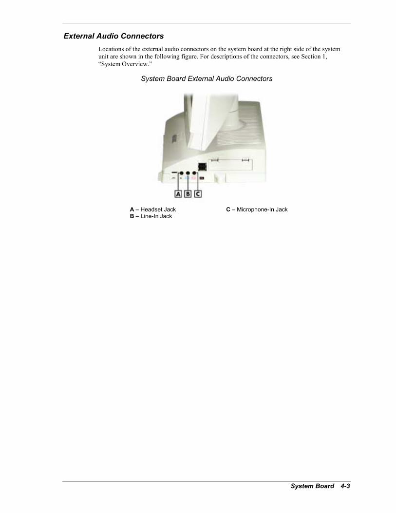
System Board 4-3
External Audio ConnectorsLocations of the external audio connectors on the system board at the right side of the systemunit are shown in the following figure. For descriptions of the connectors, see Section 1,�System Overview.�
System Board External Audio Connectors
A � Headset Jack C � Microphone-In JackB � Line-In Jack
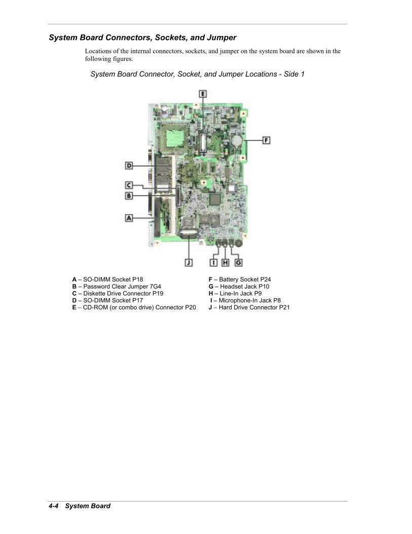
4-4 System Board
System Board Connectors, Sockets, and JumperLocations of the internal connectors, sockets, and jumper on the system board are shown in thefollowing figures.
System Board Connector, Socket, and Jumper Locations - Side 1
A � SO-DIMM Socket P18 F � Battery Socket P24B � Password Clear Jumper 7G4 G � Headset Jack P10C � Diskette Drive Connector P19 H � Line-In Jack P9D � SO-DIMM Socket P17 I � Microphone-In Jack P8E � CD-ROM (or combo drive) Connector P20 J � Hard Drive Connector P21
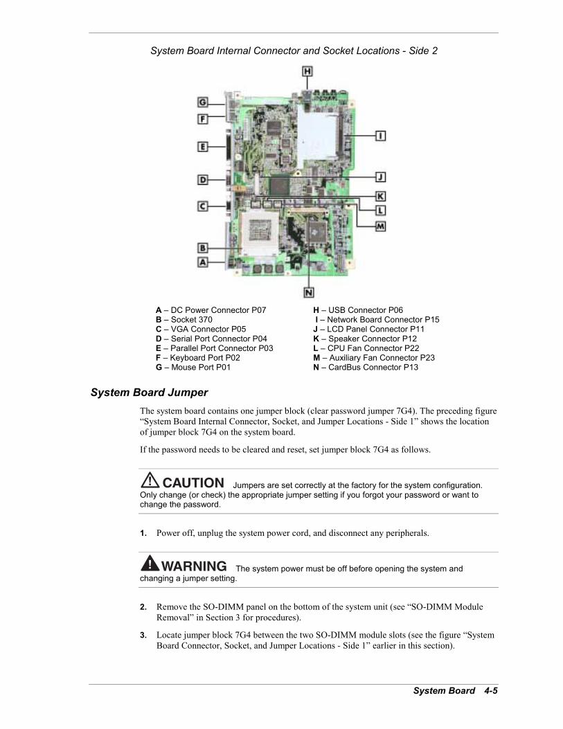
System Board 4-5
System Board Internal Connector and Socket Locations - Side 2
A � DC Power Connector P07 H � USB Connector P06B � Socket 370 I � Network Board Connector P15C � VGA Connector P05 J � LCD Panel Connector P11D � Serial Port Connector P04 K � Speaker Connector P12E � Parallel Port Connector P03 L � CPU Fan Connector P22F � Keyboard Port P02 M � Auxiliary Fan Connector P23G � Mouse Port P01 N � CardBus Connector P13
System Board JumperThe system board contains one jumper block (clear password jumper 7G4). The preceding figure�System Board Internal Connector, Socket, and Jumper Locations - Side 1� shows the locationof jumper block 7G4 on the system board.
If the password needs to be cleared and reset, set jumper block 7G4 as follows.
Jumpers are set correctly at the factory for the system configuration.Only change (or check) the appropriate jumper setting if you forgot your password or want tochange the password.
1. Power off, unplug the system power cord, and disconnect any peripherals.
The system power must be off before opening the system andchanging a jumper setting.
2. Remove the SO-DIMM panel on the bottom of the system unit (see �SO-DIMM ModuleRemoval� in Section 3 for procedures).
3. Locate jumper block 7G4 between the two SO-DIMM module slots (see the figure �SystemBoard Connector, Socket, and Jumper Locations - Side 1� earlier in this section).

4-6 System Board
4. Remove the jumper from pins 1 and 2.
5. Replace the SO-DIMM panel, connect the system power cables, and power on the system.
6. Power off the system and unplug the power cables.
7. Remove the SO-DIMM panel and replace the jumper on pins 1 and 2.
8. Replace the SO-DIMM panel, connect system power cables, and connect external devices.
9. Power on the system.
10. Run the BIOS Setup Utility to set a new password (see Section 2).
Processor SocketThe processor installs in a 370-pin Socket 370 on the system board. The processor is held inplace in the socket by a locking lever attached to the socket and a removable retention clip. Theretention clip anchors both the processor and the processor heat sink to the Socket 370.
To remove or install a processor, see Section 3, �Disassembly and Reassembly.�
SO-DIMM Upgrade SocketsThe system board has two 168-pin, gold-plated SO-DIMM sockets. (See the figure �SystemBoard Internal Connector, Socket, and Jumper Locations - Side 1� for socket locations.) Thesockets support up to 256 MB of high-speed SDRAM memory. The sockets support SO-DIMMmodules in 64-MB and 128-MB unbuffered non-ECC memory configurations.
The SO-DIMM modules
! can be installed in one or two sockets
! size can vary between sockets
! can be single- and double-sided.
See the following table for sample SO-DIMM upgrade paths. To determine the memory neededfor a memory upgrade, see the following paragraph. To remove or install a SO-DIMM, seeSection 3, �Disassembly and Reassembly.�
Sample SO-DIMM Upgrade PathsTotal System Memory SO-DIMM 0 SO-DIMM 1
128 MB 64 MB 64 MB
128 MB 128 MB --
192 MB 128 MB 64 MB
256 MB 128 MB 128 MB
If you do not know how much memory is installed in the system, check the amount as follows.
1. On the Microsoft Windows 98, Windows 2000, or Windows NT 4.0 desktop, point to MyComputer and click the right mouse button.

System Board 4-7
2. With the left mouse button, click Properties. Select the General tab to show the amount ofrandom access memory (RAM) in the computer. For Windows 98 and Windows 2000, youcan also select the Performance tab to show the RAM memory.
Note If a discrepancy is found in the amount of memory displayed at the Power-On Self-Testor in Windows with the amount of memory installed, check that the memory modules wereinstalled correctly.
ComponentsThe system board has the following features:
! Intel 810E chip set is used for AGP, PCI/ISA, memory, and peripheral control. The chip setincorporates
� 82801AB I/O Controller Hub
� 82802AB Firmware Hub
� 82810E Graphics Memory Controller Hub
� System Manageability Bus
� Integrated AC�97 SoundMAX Codec sound controller
� Dynamic Video Memory Technology (DVMT).
! 128 MB to 256 MB of SDRAM upgradeable with 64-MB and 128-MB SO-DIMM modulesinstalled in one or two sockets on the system board
! Phoenix® Technologies Ltd BIOS in a flash memory device supporting system setup andPCI auto-configuration
! 32-KB internal dual write-back cache and 256-KB write-back secondary cache memoryintegrated on the processor
! pipelined 32-bit addressing
! 64-bit data
! Setup Utility built into the BIOS
! 4-Mb FLASH ROM for fast economical BIOS upgrades
! power management with power saving mode, featuring inactivity timer
! external connectors for connecting the following external devices:
� VGA-compatible monitor (standard, super, high-resolution VGA) to AGP port onsystem board. Supports resolutions up to 1024 x 768 pixels with up to 16.8 millioncolors.
� personal system/2 (PS/2®)-style mouse
� PS/2-style keyboard
� bi-directional Enhanced Parallel Port (EPP) and Enhanced Capabilities Port (ECP)support for a parallel printer
� serial device through one buffered 16C550 UART serial port, supporting up to 115.2KB per second
� two USB devices for connecting up to 127 USB devices
� LAN connector for network connection
� connectors for optional headphone and microphone
� two PC Card slots for supporting up to two 16-bit or 32-bit Type II cards or one TypeIII PCMCIA card.
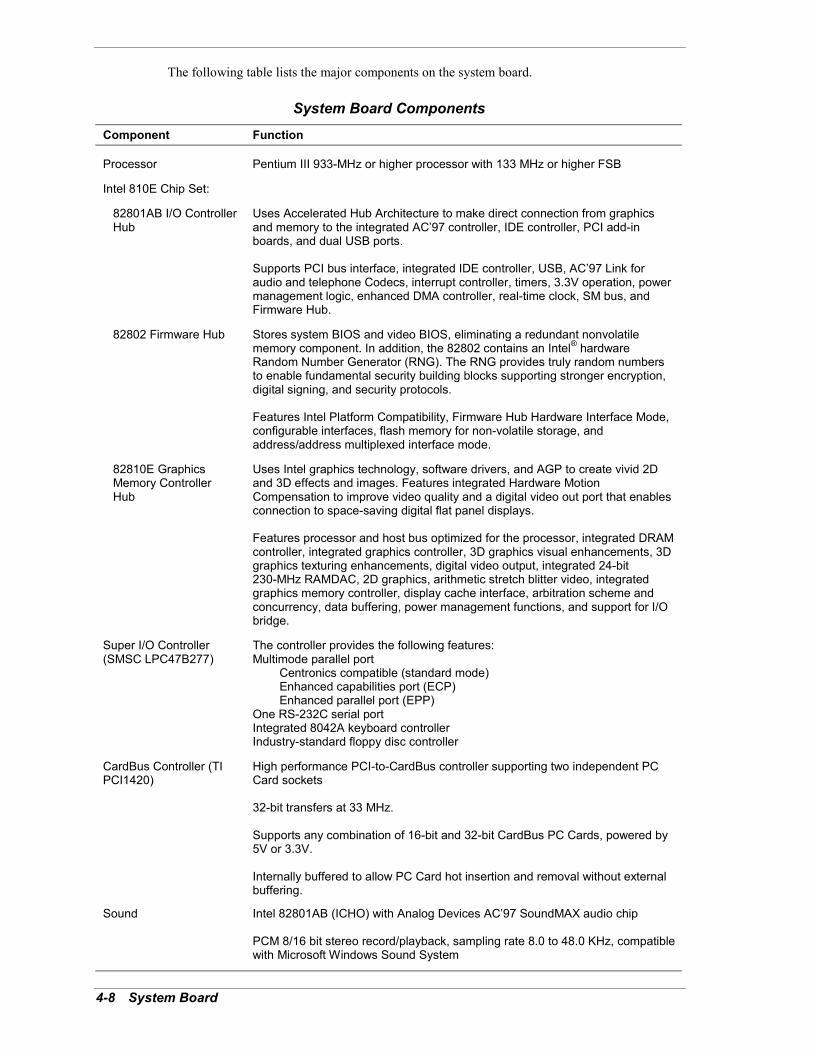
4-8 System Board
The following table lists the major components on the system board.
System Board ComponentsComponent Function
Processor Pentium III 933-MHz or higher processor with 133 MHz or higher FSB
Intel 810E Chip Set:
82801AB I/O Controller Hub
Uses Accelerated Hub Architecture to make direct connection from graphicsand memory to the integrated AC�97 controller, IDE controller, PCI add-inboards, and dual USB ports.
Supports PCI bus interface, integrated IDE controller, USB, AC�97 Link foraudio and telephone Codecs, interrupt controller, timers, 3.3V operation, powermanagement logic, enhanced DMA controller, real-time clock, SM bus, andFirmware Hub.
82802 Firmware Hub Stores system BIOS and video BIOS, eliminating a redundant nonvolatilememory component. In addition, the 82802 contains an Intel® hardwareRandom Number Generator (RNG). The RNG provides truly random numbersto enable fundamental security building blocks supporting stronger encryption,digital signing, and security protocols.
Features Intel Platform Compatibility, Firmware Hub Hardware Interface Mode,configurable interfaces, flash memory for non-volatile storage, andaddress/address multiplexed interface mode.
82810E Graphics Memory Controller Hub
Uses Intel graphics technology, software drivers, and AGP to create vivid 2Dand 3D effects and images. Features integrated Hardware MotionCompensation to improve video quality and a digital video out port that enablesconnection to space-saving digital flat panel displays.
Features processor and host bus optimized for the processor, integrated DRAMcontroller, integrated graphics controller, 3D graphics visual enhancements, 3Dgraphics texturing enhancements, digital video output, integrated 24-bit230-MHz RAMDAC, 2D graphics, arithmetic stretch blitter video, integratedgraphics memory controller, display cache interface, arbitration scheme andconcurrency, data buffering, power management functions, and support for I/Obridge.
Super I/O Controller(SMSC LPC47B277)
The controller provides the following features:Multimode parallel port Centronics compatible (standard mode) Enhanced capabilities port (ECP) Enhanced parallel port (EPP)One RS-232C serial portIntegrated 8042A keyboard controllerIndustry-standard floppy disc controller
CardBus Controller (TIPCI1420)
High performance PCI-to-CardBus controller supporting two independent PCCard sockets
32-bit transfers at 33 MHz.
Supports any combination of 16-bit and 32-bit CardBus PC Cards, powered by5V or 3.3V.
Internally buffered to allow PC Card hot insertion and removal without externalbuffering.
Sound Intel 82801AB (ICHO) with Analog Devices AC�97 SoundMAX audio chip
PCM 8/16 bit stereo record/playback, sampling rate 8.0 to 48.0 KHz, compatiblewith Microsoft Windows Sound System

System Board 4-9
Processor and Secondary CacheThe system uses an Intel Pentium III processor with an internal clock speed of 933 MHz orhigher.
The processor is an advanced pipelined 32-bit addressing, 64-bit data processor designed tooptimize multitasking operating systems. The 64-bit registers and data paths support 64-bitaddresses and data types.
To use the processor�s power, the system features an optimized 64-bit memory interface and256 KB of secondary write-back cache on the processor.
The processor is compatible with 8-, 16-, and 32-bit software written for the Intel386�,Intel486�, Intel Pentium, Intel Pentium II, and Intel Pentium III processors. The processor ismounted in a Socket 370 connector. A fan and heat sink are attached to the top of the processorfor cooling.
System BIOSThe PCI-compatible BIOS is contained in a flash memory device on the system board. TheBIOS provides Power-On Self-Test (POST), system Setup program, PCI and IDE auto-configuration utility, and BIOS recovery code.
The system BIOS is always shadowed. Shadowing allows any BIOS routine to be executed fromfast 32-bit DRAM on the system board, instead of from the slower 8-bit flash device.
The FLASH ROM allows fast, economical BIOS upgrades. The FLASH ROM is areprogrammable EPROM containing both the system and video BIOS.
Using the FLASH ROM to change the ROM BIOS provides the following advantages:
! the BIOS upgrade is performed quickly and easily
! the expense of replacing ROM BIOS chips is eliminated, so system maintenance costs arereduced
! there is less chance of inadvertently damaging the system board than when physicallyreplacing ROMs
! new technology can be incorporated while maintaining corporate standards
! network administrators can exercise company-wide control of BIOS revisions.
The BIOS programs execute the Power-On Self-Test, initialize processor controllers, andinteract with the display, diskette drive, hard drive, communication devices, and peripherals. Thesystem BIOS also contains the Setup Utility. The POST copies the ROM BIOS into RAM(shadowing) for maximum performance.
The FLASH ROM allows the system and video BIOS to be upgraded with the BIOS UpdateUtility, without having to physically remove the ROM (see Section 2 for further information onthe BIOS Update Utility). The FLASH ROM supports the reprogramming of the system BIOSand the video BIOS.
System MemoryThe system comes with 128 MB of SDRAM installed in one of two SO-DIMM sockets on thesystem board.
The SO-DIMM sockets accept 168-pin, 64-bit (non-ECC) 64-MB and 128-MB SO-DIMMs. See�SO-DIMM Sockets� earlier in this section for a list of supported SO-DIMMs.

4-10 System Board
PCI Local BusThe 32-bit PCI local bus is the primary I/O bus for the system. The PCI bus is a highlyintegrated I/O interface that offers the highest performance local bus available for the PentiumIII processor. The bus supports burst modes that send large amounts of data across the bus,allowing fast displays of high-resolution images.
The high-performance PCI local bus provides a processor-independent data path between theCPU and high-speed peripherals. The PCI bus is a robust interconnect mechanism designedspecifically to accommodate multiple high performance peripherals for graphics and full motionvideo.
The PCI local bus supports memory transfer rates of over 100 MB per second for reads and over120 MB per second for writes, depending on processor configuration.
PCI/IDE PortThe system board supports two PCI/IDE ports on the system board, one for the hard drive andone for the CD-ROM drive (or optional combo drive). Each PCI/IDE port has an enhanced IDEinterface that supports a PIO Mode 4 device with 16 MB per second 32-bit wide data transferson the PCI local bus.
Each device is connected to its port with a combined signal and power interface cable.
Parallel InterfaceThe system has a 25-pin bidirectional parallel port on the system board. Port specificationsconform to the IBM-PC standards. The port supports Enhanced Capabilities Port (ECP) andEnhanced Parallel Port (EPP) modes for devices that require ECP or EPP protocols. Theprotocols allow high-speed bi-directional transfer over a parallel port and increase parallel portfunctionality by supporting more devices.
The BIOS has automatic ISA printer port sensing that works with most devices. If the BIOSdetects an ISA printer port mapped to the same address, the built-in printer port is disabled.(Verify in the BIOS Setup that printer ports mapped to the same address are enabled or disabledappropriately.) The BIOS also sets the first parallel interface port it finds as LPT1 and thesecond port it finds as LPT2. The interrupt is set at IRQ7 via the BIOS Setup Utility.Software-selectable base addresses are 228h, 378h, and 278h.
Sets of I/O addresses for the parallel port are given in the following table (see Section 2,�System Configuration,� for interrupt levels). This is a list of all possible configurations. Theparallel port uses only one set.
Parallel Port AddressesStarting I/O Address Port
378 LPT1
278 LPT2
228 LPT3
378 LPT1
278 LPT2
228 LPT3
Parallel interface signals are output through the system board�s 25-pin, D-subconnector. Theconnector is located at the back of the system unit.

System Board 4-11
Serial InterfaceThe system has one 16C550 UART compatible serial port (COM1) integrated on the I/Ocontroller. The serial port supports the standard RS-232C interface. The buffered high-speedserial port supports transfer rates up to 115.2 KB. The port allows the installation of high-speedserial devices for faster data transfer rates.
The I/O addresses for the channel are given in the following table (see Section 2, �SystemConfiguration,� for interrupt levels). Software-selectable base addresses are 3F8h, 2F8h, 3E8h,and 2E8h.
Serial Port I/O AddressesStarting I/O Address Port
3F8 COM1
2F8 COM2
3E8 COM3
2E8 COM4
See Section 2, �System Configuration,� for information on resetting the port through the BIOSSetup Utility. See Section 9, �Specifications,� for the serial interface specifications.
Serial interface signals are output through the system board�s 9-pin, D-subconnector. Theconnector is located at the back of the system unit.
USB InterfaceThe Universal Serial Bus (USB) ports allow Plug and Play serial devices to be added withouthaving to open the system. One USB device can be plugged into each USB port for directsystem connection. With a hub and the proper cabling, up to 127 USB devices can be addressedby the system. The USB determines system resources for each peripheral and assigns themwithout user intervention. Boot support for a USB keyboard is present so the system can bebooted with a USB keyboard instead of a standard keyboard.
Accelerated Graphics PortThe system board contains a direct integrated accelerated graphics port (Direct AGP) thatsupports graphics-intensive, 3D applications. The Direct AGP operates independently of the PCIbus and supports 133-MHz data transfer rates, allowing 500 MB of data to be transmitted persecond.
Attach an optional display monitor to the system board�s VGA-compatible connector on the rearpanel.
Graphics ControllerThe graphics controller is integrated on the Intel 82810E Graphics and Memory Controller Hub.The hub is specifically designed for graphics-intensive operations, including 3D and 2D effects,texture mapping, text and color pixel amplification, and video acceleration. The controllerminimizes bus traffic by off-loading the tasks normally performed by the processor, providing64-bit, high resolution performance for demanding True Color displays and other sophisticatedgraphics functions.
4-12 System Board
The Graphics and Memory Controller Hub supports motion video and motion video playbackhardware. Support includes:
! soft DVD MPEG-2 playback with Hardware Motion Compensation
! Motion Video Acceleration.
MPEG is a compression/decompression standard developed by the Motion Picture ExpertsGroup. MPEG produces full-screen, 30-frames-per-second (fps), broadcast-quality digital video.
Integrated AudioAudio is integrated on the system board through the Intel I/O Controller Hub. The hub supportsthe AC�97 Codec (AD 1881A). The chip provides 16-bit stereo audio.

5Illustrated Parts Breakdown
! Order Spare Parts! Field Replaceable Unit List! Illustrated Parts Breakdown

5-2 Illustrated Parts Breakdown
This section contains the illustrated parts breakdown (IPB) and NEC Computers partdescriptions for the Intel Pentium III-based PowerMate 2000 Series systems.
The following tables list
! telephone number for ordering spare parts
! field-replaceable parts for the system.
The PowerMate 2000 Series system illustrated parts breakdown figure is at the end of thissection.
Order Spare PartsUse the telephone number in the following table to order spare parts.
Ordering Parts
Item Telephone Number
To order spare parts (U.S. and Canada only): 1-800-632-4525
Field Replaceable Unit ListThe following table lists the field replaceable units (FRUs) for the Pentium III-based PowerMate2000 Series system. The following illustrated parts breakdown shows the FRU items.
PowerMate 2000 Pentium III Processor-Based Series System FRU List
Item No. on IPB FRU Description
1 Intel Pentium III 933-MHz or higher Processor
2 CPU Fan
3 Heat Sink
4 Heat Sink Clip
5 Network Board Cable
6a6b
CD-ROM DriveCombo Drive (optional)
7 CD-ROM Interface Connector Board
8 PC Slot Dummy Card
9 PC Card Bay
10 128-MB SDRAM SO-DIMM
11 LCD Panel Assembly
12 Collar, LCD Panel
13 Hard Drive Interface Cable
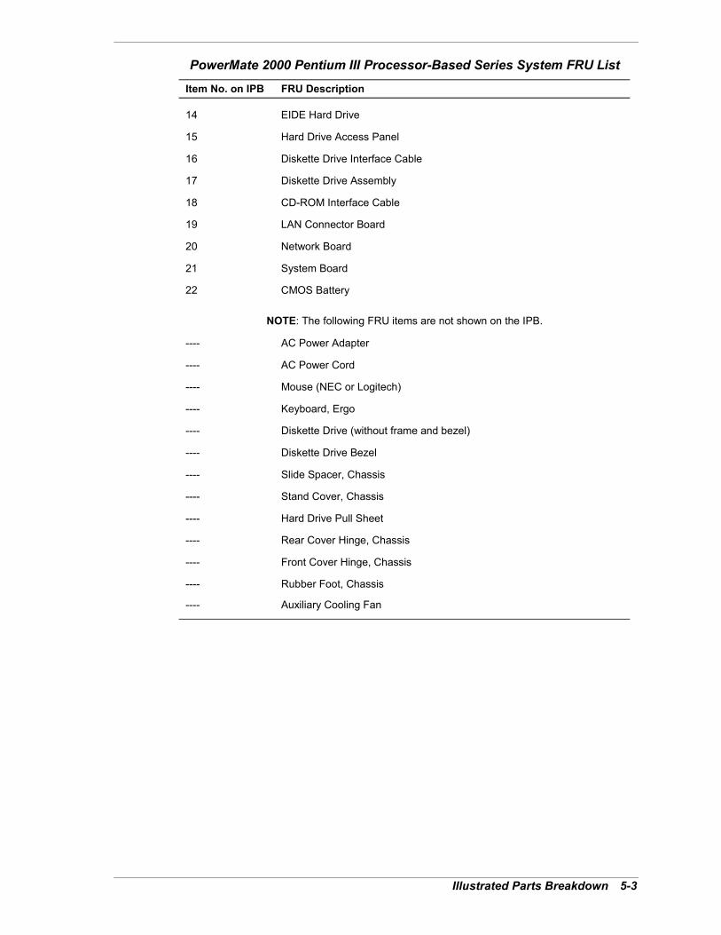
Illustrated Parts Breakdown 5-3
PowerMate 2000 Pentium III Processor-Based Series System FRU List
Item No. on IPB FRU Description
14 EIDE Hard Drive
15 Hard Drive Access Panel
16 Diskette Drive Interface Cable
17 Diskette Drive Assembly
18 CD-ROM Interface Cable
19 LAN Connector Board
20 Network Board
21 System Board
22 CMOS Battery
NOTE: The following FRU items are not shown on the IPB.
---- AC Power Adapter
---- AC Power Cord
---- Mouse (NEC or Logitech)
---- Keyboard, Ergo
---- Diskette Drive (without frame and bezel)
---- Diskette Drive Bezel
---- Slide Spacer, Chassis
---- Stand Cover, Chassis
---- Hard Drive Pull Sheet
---- Rear Cover Hinge, Chassis
---- Front Cover Hinge, Chassis
---- Rubber Foot, Chassis
---- Auxiliary Cooling Fan

5-4 Illustrated Parts Breakdown
Illustrated Parts BreakdownThe following figure shows the illustrated parts breakdown (IPB) for the Pentium III-basedPowerMate 2000 Series system. Each FRU on the IPB is identified with a number that cross-references to the FRU list.
PowerMate 2000 Pentium III-Based Series System IPB

6Preventive Maintenance
! System Cleaning! Keyboard Cleaning! Mouse Cleaning
6-2 Preventive Maintenance
This section contains general information for cleaning and checking the PowerMate 2000 Seriessystem.
The system unit, LCD panel, keyboard, and mouse require cleaning and checking at least once ayear, more often if operating in a dusty environment. No other scheduled maintenance isrequired.
Unplug all power cords before performing any maintenance. Voltage ispresent inside the system even after the power is off. All voltage is removed only when the powercord is unplugged.
System CleaningUse the following procedure for cleaning the system.
1. Power off the system and unplug the AC adapter power cable.
2. Wipe the outside of the system, keyboard, mouse, and LCD panel with a soft, clean cloth.Remove stains with a mild detergent. Do not use solvents or strong, abrasive cleaners onany part of the system.
3. Clean the LCD panel screen with a commercial monitor screen cleaning kit. As analternative, use a glass cleaner, then wipe with a clean lint-free cloth.
4. Local distributors and dealers sell diskette drive head cleaning kits. These kits containspecial diskettes and cleaning solution.
Insert the diskette immediately after powering on the system, before disk bootup. Allow thediskette drive heads to clean for about 30 seconds.
Keyboard CleaningInspect and clean the keyboard as follows.
1. Power off the system and unplug the AC adapter power cable from its power source.
2. Clean the outside of the keyboard and keys with a damp cloth. Do not use any liquidcleaners on the keyboard as they can damage the keyboard.
3. Periodically clean the keys with a vacuum cleaner specifically designed for use withcomputer equipment. Use a brush attachment designed for use on computers.
Note The keyboard and cable together are considered a whole-unit, field-replaceableassembly. Therefore, disassembly of the keyboard is necessary only when cleaning the insideand then only if the keyboard can be disassembled.
4. As appropriate, clean the inside of the keyboard as follows.
! If the keyboard can be disassembled, turn it over, remove the screws (or undo tabs)holding the two halves together, and separate the halves.
! Clean the enclosure and keys with a damp cloth. Use a small, soft-bristle brush to cleanbetween the keys.
! Do not wet or dampen the keyboard�s printed circuit board. If the board accidentallygets wet, thoroughly dry it before reassembling and reattaching the keyboard to thesystem unit.

Preventive Maintenance 6-3
Mouse CleaningThe mouse has a self-cleaning mechanism that prevents a buildup of dust or lint around themouse ball and tracking mechanism under normal conditions. Periodically, however, the mouseball must be cleaned. Clean the mouse as follows.
Note The following procedure describes cleaning of a typical mouse and should be used onlyas a guideline. The procedure might differ, depending on the type of mouse being cleaned.
1. Power off the system and unplug the AC adapter power cable from its power source.
2. Unplug the mouse from the system.
3. Turn the mouse upside down and locate the ball cover.
4. Turn the ball cover counterclockwise and remove the cover.
Removing a Typical Mouse Ball Cover
A � Mouse Ball Cover
5. Turn the mouse over and remove the ball.
6. Clean the mouse as follows:
! Clean the mouse ball with tap water and a mild detergent, then dry it with a lint-freecloth.
! Remove any dust and lint from the mouse socket.
7. Replace the mouse ball in its socket, replace the ball cover, and turn the cover clockwiseuntil it locks in place.
8. Connect the mouse to the mouse port.
9. Plug in the AC power adapter cable and press the power/sleep button.

7Troubleshooting
! Checklist! Diagnostics

7-2 Troubleshooting
This section provides information to help isolate and repair system malfunctions at the fieldlevel. The system has a built-in program that automatically checks its components when thesystem is powered on. If there is a problem, the system displays an error message. If thishappens, follow any instructions on the screen.
If screen messages do not help or an error message does not appear, refer to the information inthis section to help determine and correct the problem. For the more common problems, refer to�Checklist� for assistance. If the information in the checklist does not help, refer to�Diagnostics� for more detailed problem solving.
If disassembly is required, see Section 3, �Disassembly and Reassembly.� Jumper settings aregiven in Section 2, �System Configuration� and in Section 4, �System Board.�
ChecklistCheck the following list for a match to the system problem and the possible cause and solution.
System Problems! No power and power lamp not lit.
Check that system power is on.
Check that the AC power cord is plugged into the AC power adapter.
Check that the AC power adapter cable is plugged into the system unit DC power socket.
Check that the AC power cord is plugged into a live, properly grounded AC power outlet orsurge protector.
Check the outlet or surge protector by plugging in a lamp.
! Non-System Disk error message displays when the system is started.
A diskette is in the diskette drive, and the diskette drive is set before the hard drive in bootorder. Remove the diskette from drive A and restart the system.
! Operating system not found error message displays when the system isstarted.
If a CD disc is in the drive, the system might not be able to boot. Try removing the disc andrebooting.
! System does not boot and error message displayed on screen.
Run the Setup Utility (see Section 2, �System Configuration�). Check that the parametersare set correctly.
! System emits continuous beeps.
Turn the system off, wait at least five seconds, and turn the system on. If the beepscontinue, call the NEC Computers Technical Support Center.
! System does not maintain date, time, system configuration information.
Replace the battery (see �CMOS Battery Removal� in Section 3, �Disassembly andReassembly�).
! System does not boot from hard drive.
The system usually tries to start from the diskette drive before it starts from the hard drive.Remove the diskette from the diskette drive.
Run the Setup Utility (see Section 2, �System Configuration�) and set the Boot parameter tohard disk device instead of floppy disk device.
Troubleshooting 7-3
! System performance appears sluggish.
There might be to many applications open. Close any applications that are not being used.
Check the Internet browser and Windows for excessive Internet cache files. Delete thecache files as necessary (see the browser and Windows online documentation for details).
Check the memory requirements of the software applications. If required, install additionalSO-DIMM memory (see Section 4, �System Board�).
If optional SO-DIMM memory was added, check that it is correctly installed.
! System password forgotten.
Clear the password and reset it. See �System Board Jumpers� in Section 4. See �SecurityMenu� in Section 2 to reset the password.
! System shuts off instead of going into sleep mode.
The power/sleep button might have been held in for four seconds or more. For sleep mode,press in the button and immediately release.
! System does not shut off after pressing the power/sleep button.
The power/sleep button might not have been pressed in and held long enough. Press in thebutton and hold for four or more seconds before releasing.
! System does not resume operation from Standby after pressing a key.
The key might have to be pressed twice. To avoid this, install the Logitech mouse driverfrom the Application and Driver CD. See �PowerMate Application and Driver CD� inSection 2 for procedures.
Diskette Drive ProblemsCheck the following to see the possible cause and solution.
! Diskette won�t load.
Check that the drive does not have a diskette in it.
Check that the diskette is loaded correctly.
Check that the system unit power lamp is on and the power-on screen appears on the LCDpanel.
Check that the diskette is formatted. If not, format it. See the operating systemdocumentation.
Check that the diskette size is 1.44 MB.
If the diskette drive busy lamp does not light when loading the diskette, try a differentdiskette. If this loads, the problem is in the software.
! Non-System Disk or Disk Error message displayed.
If trying to boot from the diskette drive, insert a diskette with system files into drive A.
If a bootable diskette does not boot, use the Setup Utility to verify that the initial bootparameter is set to diskette drive A and not a hard drive.
7-4 Troubleshooting
LCD Panel ProblemsCheck the following problems to see the possible cause and solution.
! LCD panel screen is dark or the display is hard to read.
Press a key or move the mouse to take the system out of the power management mode.
Adjust the LCD panel brightness control settings. (Note that the brightness setting returns tothe system default setting of maximum brightness on power down.)
Check that the AC adapter and power cable are connected together, the adapter is pluggedinto the back of the system unit, and the power cable is plugged into a live power source.
! The screen display is fuzzy or flickering; graphics characters or garbageappears on the screen.
Check that all connections have been made.
Check that the video refresh rate and video driver are correct.
Check display properties. Click the right mouse button anywhere on the Windows desktopand a menu appears. Click Properties and the Display Properties window appears.
Keyboard/Mouse ProblemsCheck the following problem to see the possible cause and solution.
! Mouse or keyboard does not respond.
The mouse or keyboard might have been connected after turning on the system. Turn thesystem off, make sure the mouse or keyboard is connected, and turn the system back on.
! Image appears on screen but nothing happens when using the mouse orkeyboard.
Make sure the keyboard or mouse cable is firmly connected to the back of the system.
If this does not help, turn off the system, wait five or more seconds, and turn on the system.
! Mouse cursor moves erratically or not at all.
Clean the mouse (see Section 6, �Preventive Maintenance�).
If this does not help, the mouse might need to be replaced.
CD-ROM Drive ProblemsCheck the following problems to see the possible cause and solution.
! The drive is not reading a disc.
Check that the disc is inserted in the disc tray with the printed label side up.
Check that the disc is a data disc, not a music disc.
Try a different disc to see if the problem is limited to one disc.
Clean the non-label side of the disc with a soft lint-free cloth, gently rubbing from thecenter of the disc to the outer edge of the disc. Or use a commercial disc cleaner.
Clean the CD-ROM drive with a commercial CD drive cleaning kit.

Troubleshooting 7-5
! The disc does not eject due to a power failure or software error.
Turn off the system and use the emergency eject feature. Insert the end of a paper clip intothe emergency eject hole on the front of the drive. Press inward on the clip to open the door.
! The drive plays music CDs but the sound is not heard.
Adjust the volume control on the side of the system unit.
Check the volume control in the system tray along the taskbar.
Check that the cable connecting the drive to the system board is in place and secure.
Speaker ProblemsCheck the following problems to see the possible cause and solution.
! No sound from the speakers.
Check that the system power is on.
Check that the system AC power adapter and AC power cord are connected to the powersource and the back of the system unit.
If an optional headset was used, check that it is unplugged.
! Sound is only coming from one speaker.
Balance the speaker output by adjusting the balance in the sound software (see theMicrosoft Windows Multimedia online help).
! Speaker volume is too low.
Adjust the volume control on the side of the system unit. If the volume is still too low,adjust the volume through system software (see the Microsoft Windows Multimedia onlinehelp).

7-6 Troubleshooting
DiagnosticsOne beep indicates that the system has completed its POST test. If intermittent beeping occurs,power off the system and try again. If the beeping persists, see the following table. The tablesummarizes problems that might develop during system operation and lists (in sequential order)suggested corrective actions.
Problems and Solutions
Problem Symptom Solution
No power Power lamp on system unit doesnot light.
1. Check that the AC power adapter isplugged into the DC power socket on theback of the system unit.
Check that the other end of the AC poweradapter is plugged into a live, properlygrounded AC power outlet.
2. Systematically eliminate possible shortedPCBs by removing cables and daughterboards.
3. Check +5 and +12 power supply voltages.Measure voltages with system boardinstalled.
4. Replace the AC power adapter.
5. Replace the system board.
Operating systemdoes not boot
Intermittent beeping at power-on.System beeps more than onceand is unable to complete boot-up.
1. Check system configuration (seeSection 2).
2. Check jumper settings and verify thatdrives are enabled (see Section 2).
3. Reseat SO-DIMMs. Inspect system boardfor foreign objects such as paper clips.
4. Replace system board.
�Invalid Configuration� messagedisplayed.
1. Press F2 to run Setup and correct theparameters.
2. Replace the CMOS battery if the date andtime must be set each time the system ispowered on (see Section 3).
System halts during loadingsequence.
1. Power the system off. Check for properjumper settings (see Section 2), then power-on the system.
2. Check condition of selected bootloaddevice (diskette, CD-ROM disc, hard drive)for bad boot track or incorrect operatingsystem files.
3. Try booting operating system fromdiskette or disc, or recopy operating systemfiles onto hard drive.
4. Verify that correct hard drive is selected.

Troubleshooting 7-7
Problems and Solutions
Problem Symptom Solution
Diskette drive doesnot work
Lamp on system unit does notlight when diskette is loaded.
1. Check interface cable connections at thediskette drive and system board.
2. Check diskette drive interface cable.Replace as necessary.
3. Check AC power adapter, replace asnecessary.
4. Replace diskette drive.
5. Replace system board.
Hard drivemalfunction
Hard drive lamp does not lightbut hard drive can be accessed.
1. Check interface cable connections atdrive and system board.
Hard drive controller failuremessage displayed.
1. Check that the IDE channel and harddrive are enabled in Setup (see Section 2).
Cannot access hard drive. 1. Check interface cable connectionsbetween hard drive and system board.
2. Check AC power adapter. Replace asnecessary.
3. Check hard drive jumper settings andBIOS hard drive settings.
4. Check if hard drive was transferredbetween systems and that the passwordsecurity feature is enabled in the BIOS.
5. Check hard drive. Replace as necessary.
Memory malfunction Memory not recognized. 1. Reseat SO-DIMMs.
2. Systematically swap SO-DIMMs.
3. Check to see if the SO-DIMMconfiguration is valid (see Section 4).
4. Replace SO-DIMMs.
5. Replace system board.
Network boardmalfunction
No output. 1. Check interrupts (see Section 2).
2. Check cable connections at networkboard and LAN connector board.
3. Replace network board cable (seeSection 3).
4. Replace LAN connector board (seeSection 3).
5. Replace network board (see Section 3).

7-8 Troubleshooting
Problems and Solutions
Problem Symptom Solution
Keyboard or mousemalfunction
LCD panel display has prompt,but cannot input data usingkeyboard or mouse.
1. Check keyboard/mouse plugged in.
2. Check password (see Section 2).
3. Disable password (see Section 2).
4. Replace keyboard (or mouse).
5. Replace system board.
LCD panelmalfunction
Blank display. 1. Check that system unit power is on.
2. Ensure that system is not in power savingsleep mode. Press the space bar or move themouse to wake the system up.
3. Adjust brightness controls on LCD panel.
4. Check that LCD panel interface cable andswitch cable are connected to system board(see Section 3).
5. Replace LCD panel.
PC Card does notwork
No output. 1. Check PC Card for correct insertion in slot(label side up).
2. Remove PC Card and insert in other slot.
3. Check PC Card driver installation for IRQor I/O conflict.
4. Replace PC Card with a different card tosee if system works. If card works, replacebad card.
5. Replace PC Card bay (see Section 3).
CD-ROM drivemalfunction
System power not on. 1. Turn system unit power on.
2. Check cable connections at CD-ROMdrive and system board.
Disc tray does not open. 1. System unit power not on. Turn systempower on.
2. System power failed. Insert the end of astraightened paper clip into emergency ejecthole, then gently press inward until trayopens.

Troubleshooting 7-9
Problems and Solutions
Problem Symptom Solution
CD-ROM drivemalfunction (cont�d)
No sound from disc. 1. Check system power on and volumecontrol on system side adjusted.
2. Check audio software settings.
3. Check disc for dirt, scratches, label sideup.
4. Check that driver software is loaded andnot corrupted.
5. Replace drive.
6. Replace system board.
Cannot access drive. 1. Check that driver software is loaded andnot corrupted.
2. Check interface cable connections at thedrive and system board.
3. Check the interface cable. Replace asnecessary.
4. Check the AC power adapter. Replace asnecessary.
5. Check the system board. Replace asnecessary.
8NEC Computers Information Services
! Service and Support Functions! Technical Support
8-2 NEC Computers Information Services
This section contains the following NEC Computers service and support information:
! service and support telephone numbers and web addresses
! technical support.
Service and Support FunctionsThe following table lists the telephone numbers and web addresses for the NEC Computersservice and support functions.
NEC Computers Service and Support Telephone Numbers and Web AddressesService Telephone Numbers
To contact NEC Computers Technical Support Center: In the U.S., call 800-632-4525
To order spare parts: Call 800-632-4525
To send technical questions by email: [email protected]
To access the NEC Computers web site: www.neccomp.com/
Technical SupportThe following sections provide information for obtaining technical support from NECComputers. With access to a telephone and/or modem, you can use these services to obtaininformation on a 24-hour basis.
NEC Computers Web SiteIf you have access to the Internet (via a network or modem connection), you can access theNEC Computers web site. You can do this through a commercial online service or through yourInternet account. The NEC Computers web site contains general information about NECComputers and its products. The web site also contains press releases, reviews, and service andsupport information.
Look in the Service and Support area for the following:
! technical documentation, including Frequently Asked Questions, user�s guides, referencemanuals, and warranty information
! BIOS updates, drivers, and setup disk files to download
! contact information, including telephone numbers for Technical Support and links to vendorweb sites
! an automated email form for your technical support questions
! a password accessible area for Reseller�s.
To access the NEC Computers web site, enter the following Internet Uniform Resource Locator(URL) in your browser:
www.neccomp.com/

NEC Computers Information Services 8-3
Email Technical Support ServiceThe NEC Computers Technical Support Center offers technical support by email over theInternet if you have access. The Internet email address is:
When using the email support service, please include the word Desktop in the subject field for aprompt response from the appropriate technical person.
Provide as much specific information in your questions as possible. You should receive aresponse to your questions within one business day.
NEC Computers Technical Support ServicesNEC Computers also offers direct technical support through its Technical Support Center. (NECComputers technical support is for U.S. and Canadian customers only; international customersshould check with their sales provider.)
Direct assistance is available 24 hours a day, 7 days a week. Call the NEC Computers TechnicalSupport Center, toll free, at 800-632-4525 (U.S. and Canada only) for the following support.
! System hardware � toll-free phone support is limited to the length of the standardwarranty.
! Preinstalled software � toll-free phone support for 90 days from the time of your first callto the NEC Computers Technical Support Center.
Please have available the system�s name, model number, serial number, and as muchinformation as possible about the system�s problem before calling.
For callers outside the U.S. and Canada, please contact your local NEC Computers salesprovider.

9Specifications
! System Unit! LCD Panel! Keyboard! Mouse! AC Power Adapter! System Board! Network Board! Diskette Drive! Mobile Hard Drive! Mobile CD-ROM Drive! Combo Drive! PC Card Slots! Speakers! Environmental and Safety! Compliance
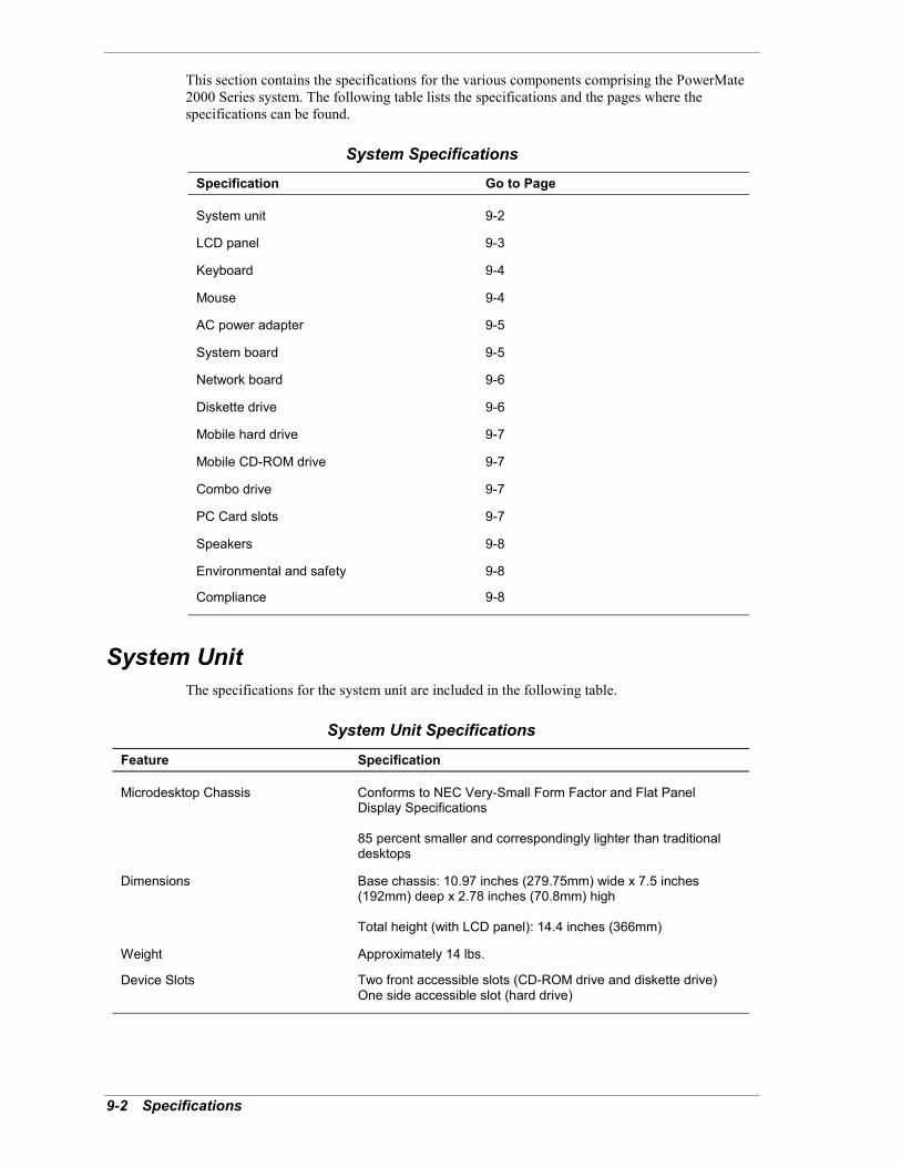
9-2 Specifications
This section contains the specifications for the various components comprising the PowerMate2000 Series system. The following table lists the specifications and the pages where thespecifications can be found.
System SpecificationsSpecification Go to Page
System unit 9-2
LCD panel 9-3
Keyboard 9-4
Mouse 9-4
AC power adapter 9-5
System board 9-5
Network board 9-6
Diskette drive 9-6
Mobile hard drive 9-7
Mobile CD-ROM drive 9-7
Combo drive 9-7
PC Card slots 9-7
Speakers 9-8
Environmental and safety 9-8
Compliance 9-8
System UnitThe specifications for the system unit are included in the following table.
System Unit Specifications
Feature Specification
Microdesktop Chassis Conforms to NEC Very-Small Form Factor and Flat PanelDisplay Specifications
85 percent smaller and correspondingly lighter than traditionaldesktops
Dimensions Base chassis: 10.97 inches (279.75mm) wide x 7.5 inches(192mm) deep x 2.78 inches (70.8mm) high
Total height (with LCD panel): 14.4 inches (366mm)
Weight Approximately 14 lbs.
Device Slots Two front accessible slots (CD-ROM drive and diskette drive)One side accessible slot (hard drive)

Specifications 9-3
System Unit Specifications
Feature Specification
Expansion Two USB ports for up to 127 USB devices
Two PC Card slots for up to two Type II PCMCIA cards or oneType III PCMCIA card
System Unit Front Panel Power/sleep buttonPower indicator lampSleep indicator lampHard drive activity indicator lampDiskette driveCD-ROM drive
System Unit Rear Panel PS/2®-style keyboard connectorPS/2-style mouse connectorOne RS-232C serial portParallel printer portVGA monitor portDC power connectorRJ-45 LAN connectorKensington® Lock Slot
System Unit Right Side Panel Volume controlHeadset jackLine-in jackMicrophone-in jackUSB connectors (2)Anti-theft bracketHard drive
System Unit Left Side Panel Two PC Card slots
LCD PanelThe specifications for the LCD panel are included in the following table.
LCD Panel Specifications
Feature Specification
Display 15-inch high resolution active matrix twisted nematic TFT SuperVideo Graphics Array (SVGA)
Up to 16.7 million colors (True color)
Supported Resolutions 320 x 200 (256/High color), 60-Hz vertical frequency320 x 240 (256/High color), 60-Hz vertical frequency640 x 400 (256/High color), 60-Hz vertical frequency640 x 480 (256/High color/True color), 60-Hz vertical frequency800 x 600 (256/High color/True color), 60-Hz vertical frequency1024 x 768 (256/High color/True color), 60-Hz vertical frequency
Maximum Viewing Angles Horizontal � 60 degrees from center to right or left side of LCDpanel
Vertical � 40 degrees from center of LCD panel and upwards;50 degrees from center of LCD panel and downwards
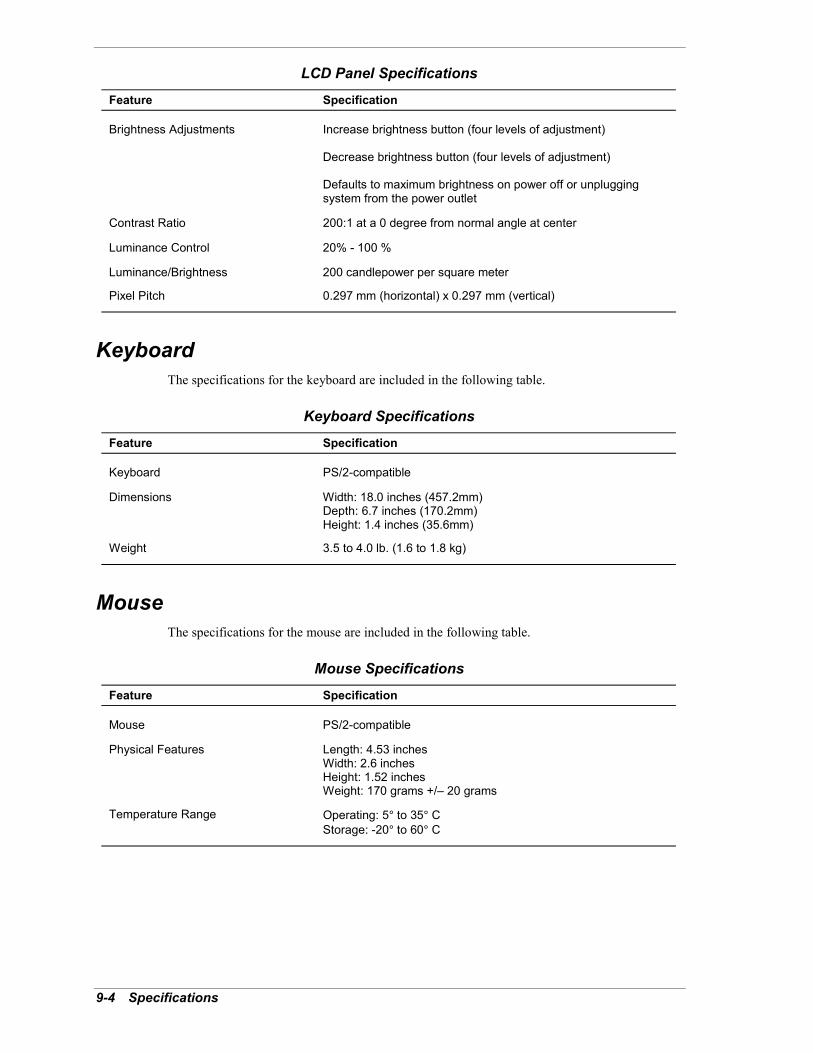
9-4 Specifications
LCD Panel Specifications
Feature Specification
Brightness Adjustments Increase brightness button (four levels of adjustment)
Decrease brightness button (four levels of adjustment)
Defaults to maximum brightness on power off or unpluggingsystem from the power outlet
Contrast Ratio 200:1 at a 0 degree from normal angle at center
Luminance Control 20% - 100 %
Luminance/Brightness 200 candlepower per square meter
Pixel Pitch 0.297 mm (horizontal) x 0.297 mm (vertical)
KeyboardThe specifications for the keyboard are included in the following table.
Keyboard Specifications
Feature Specification
Keyboard PS/2-compatible
Dimensions Width: 18.0 inches (457.2mm)Depth: 6.7 inches (170.2mm)Height: 1.4 inches (35.6mm)
Weight 3.5 to 4.0 lb. (1.6 to 1.8 kg)
MouseThe specifications for the mouse are included in the following table.
Mouse Specifications
Feature Specification
Mouse PS/2-compatible
Physical Features Length: 4.53 inchesWidth: 2.6 inchesHeight: 1.52 inchesWeight: 170 grams +/� 20 grams
Temperature Range Operating: 5° to 35° CStorage: -20° to 60° C

Specifications 9-5
AC Power AdapterThe specifications for the AC power adapter are included in the following table.
AC Power Adapter Specifications
Feature Specification
Adapter Delta ADP90ABC
Input Power 100 Vac to 240 Vac, ~1.4 amps, 50 - 60 Hz
Output Power 18 volts, 4.44 amps, 80 watts
AC Power Cable Separate power cable for connecting adapter to AC power outlet
System BoardThe specifications for the system board are included in the following table.
System Board Specifications
Feature Specification
System Board NEC proprietary
Processor Intel Pentium 933-MHz/133-MHz FSB or higher processormounted in a 370-pin Socket 370 on system board
Cache Memory 32 KB of primary L1 cache (16-KB data, 16-KB instruction)integrated on processor
256 KB of secondary L2 cache
FLASH ROM 4-Mb Flash ROM
Chip Set Intel 810E chipset with 82810E Graphics Memory Controller Hub Dynamic Video Memory Technology System Manageability Bus 82801AB I/O Controller Hub Integrated Audio/Modem Codec AC�97 Controller 82802AB Firmware Hub
Total System Memory (system andvideo)
64 MB to 256 MB in one or two SO-DIMM sockets on systemboard
Optional SO-DIMMs 64 MB and 128 MB, 168-pin, 64-bit (non-ECC) SO-DIMMs
CMOS Battery Replaceable coin-type battery
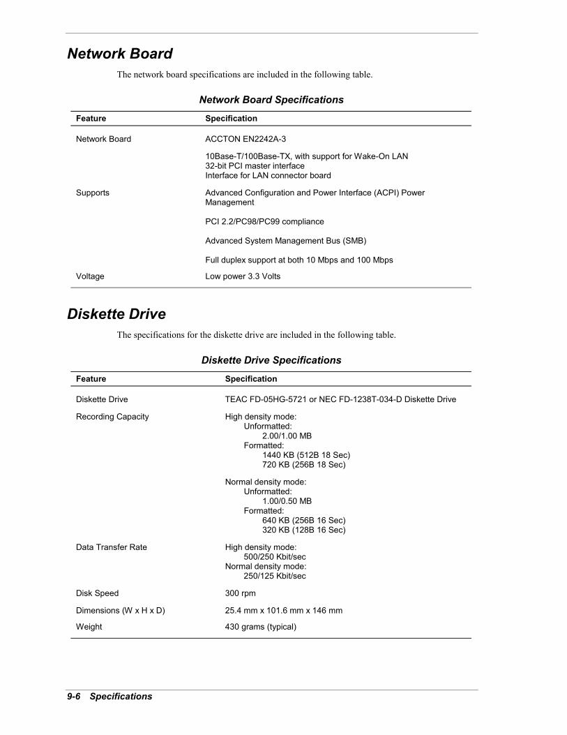
9-6 Specifications
Network BoardThe network board specifications are included in the following table.
Network Board Specifications
Feature Specification
Network Board ACCTON EN2242A-3
10Base-T/100Base-TX, with support for Wake-On LAN32-bit PCI master interfaceInterface for LAN connector board
Supports Advanced Configuration and Power Interface (ACPI) PowerManagement
PCI 2.2/PC98/PC99 compliance
Advanced System Management Bus (SMB)
Full duplex support at both 10 Mbps and 100 Mbps
Voltage Low power 3.3 Volts
Diskette DriveThe specifications for the diskette drive are included in the following table.
Diskette Drive Specifications
Feature Specification
Diskette Drive TEAC FD-05HG-5721 or NEC FD-1238T-034-D Diskette Drive
Recording Capacity High density mode: Unformatted: 2.00/1.00 MB Formatted: 1440 KB (512B 18 Sec) 720 KB (256B 18 Sec)
Normal density mode: Unformatted: 1.00/0.50 MB Formatted: 640 KB (256B 16 Sec) 320 KB (128B 16 Sec)
Data Transfer Rate High density mode: 500/250 Kbit/secNormal density mode: 250/125 Kbit/sec
Disk Speed 300 rpm
Dimensions (W x H x D) 25.4 mm x 101.6 mm x 146 mm
Weight 430 grams (typical)

Specifications 9-7
Mobile Hard DriveThe specifications for the mobile hard drive vary, depending on the manufacturer and size of thedrive installed in the system.
Mobile CD-ROM DriveThe specifications for the mobile CD-ROM drive vary, depending on the manufacturer and sizeof the drive installed in the system.
Use of CD-ROM drive controls, adjustments, or the performance ofprocedures other than those specified in this document may result in hazardous radiationexposure.
Combo DriveThe specifications for the combination DVD-ROM and CD-RW drive vary, depending on themanufacturer and size of the drive installed in the system.
PC Card SlotsThe specifications for the PC Card slots are included in the following table.
PC Card Slot Specifications
Feature Specification
CardBus Support High performance 32-bit/bus master interface supports up to33 MHz
Card Sockets Two sockets that support up to two Type II or one Type III 16-bit5V cards (non-CardBus) or 32-bit 3.3V cards (CardBus)
Controller ExCA-compatible PCMCIA VG469 controller; Intel register,step B compatible
Software SwapFit Flash Filing system driver enabling full floppy disk orhard drive emulation on flash cards; compatible with allcompression and PC-utilities software.
Single drive letter designator for all memory cards
Graphical installation and formatting utilities
Functionality PC Card �hot swap�
Supports mixed voltage (3.3V and 5V) cards
Vcc and Vpp Matrix: Micrel MTC2563

9-8 Specifications
SpeakersThe specifications for the speakers are included in the following table.
Speaker Specification
Feature Specification
Speakers Pioneer
Locations Two speakers mounted in base of LCD panel
Performance 16-bit stereo, 48 kHzSound Blaster compatible
Power 1 watt
Environmental and SafetyThe system environmental and safety specifications are given in the following table.
Environmental and Safety SpecificationsFeature Specification
Recommended OperatingEnvironment
Temperature: 32°F to 95°F (0°C to 35°C) (0°C to 32°C for systems with combo drive)Relative Humidity: 8% to 80%
Administrative Compliance UL 1950 - safetyCSA C22.2 No. 950-m89TUV EN60950: 1988FCC part 15, Subpart J, Class B - emissionsFCC part 68IEC 950 - safetyVDE 0871/6.78, Class B - emissions
ComplianceThe system meets the compliance standards listed in the following table.
System ComplianceUsage Standard
Domestic FCC CFR 47 Part 15, Subpart BUL 1950 3rd edition
Canadian C-UL C22.2 No. 950-95ICES-003 Issue 2, Revision 1
Year 2000 YMARK 2000NEC Y2KTEST.EXEWHQL
DMI DMI 2.3 Self Certification Test Suite
PC99 All hardware in system is PC99 compliant
Energy Star All systems are Energy Star Compliant

Glossary 1
GlossaryA
applications programsSoftware designed to perform specific functions, like solving business or mathematicalproblems.
AC Adapter A device that connects an NEC Versa portable computer and an AC wall outlet to provideAC power for running the system or recharging the battery.
B
base RAM Area of system memory between 0 and 640 kilobytes available to the user for operatingsystem and application programs.
BIOS Basic Input Output System. A collection of primitive computer routines, usually burnt intoROM, that controls the real-time clock, keyboard, disk drives, video display, and otherperipheral devices.
bit Binary digit. The smallest unit of computer data.
bits per second (bps) A unit of transmission. Also called baud rate.
board Printed circuit board. Board onto which computer components are soldered and thin wiresare printed to connect the components.
boot To start up a computer. See cold boot and warm boot.
bus An electronic circuit within a computer used for transmitting data or electrical power fromone device to another.
byte Group of eight contiguous bits.
C
clock Electronic timer used to synchronize computer operations.

2 Glossary
CMOS Complementary Metal Oxide Semiconductor. A chip that contains nonvolatile memory inthe Versa. CMOS is backed up by an internal lithium battery that preserves clock/calendardata and system configuration parameters stored in CMOS.
cold boot Process of starting up the computer by turning on the power. If power is already on, theprocess means to turn off the computer and turn it on again. A cold boot reinitializes alldevices.
crt Cathode-Ray Tube. A type of display screen used in desktop monitors. It forms the screenimage using tiny dots called pixels. See also LCD.
cursor A movable image on the display screen that indicates where the next entered data appears.
D
diskette A thin flexible platter coated with a magnetic material for storing information.
diskette drive A magnetic drive that writes on and retrieves data from a diskette.
DSTN Double-Scan Super-Twisted Nematic. A type of technology used in some Versa LCDscreen displays.
E
enhanced VGA A video interface that offers more colors or higher resolution than VGA.
extended RAM The area of RAM above the first megabyte of memory in the system available forenhancing system performance.
F
function key The set of keys on the keyboard (usually F1 through F12) that let you get help and errormessage information or quickly select frequently used commands.
H
hard disk A rigid magnetic storage device that provides fast access to stored data.

Glossary 3
hardware The electrical and mechanical parts from which a computer is made.
hertz (Hz) A unit of frequency equal to one cycle per second.
hot key Combination of two or three keys (such as Ctrl-Alt-D) that you press simultaneously for aparticular function.
I
input/output (I/O) The process of transferring data between the computer and external devices.
IDE Intelligent Drive Electronics. A hard disk drive type that has controller electronics built intothe drive and delivers high throughput.
interface A connection that enables two devices to communicate.
interrupt A special control signal from an I/O device that diverts the attention of the microprocessorfrom the program to a special address.
K
kilobyte (KB) 1024 bytes.
L
LAN Local Area Network.
LCD Liquid Crystal Display. An LCD consists of a thin sandwich of two glass plates with sealededges, containing nematic liquid-crystal material that forms the screen image. Versadisplays are LCD type. load To copy a program into the computer's memory from a storage device.
M
megabyte (MB) 1,048,576 bytes.
memory Electronic storage area in a computer that retains information and programs. A computerhas two types of memory � read-only memory (ROM) and random access memory(RAM).

4 Glossary
menu A video display of programs or options.
microprocessor A semiconductor central processing unit that is the principal component of amicrocomputer. Usually contained on a single chip that includes an arithmetic logic unit,control logic, and control-memory unit.
mode A method of operation; for example, the Versa operates in either normal or power-savingmodes.
modem MOdulator-DEModulator. A device that links computers over a telephone line.
N
nonvolatile memory Storage media that retains its data when system power is turned off. Nonvolatile memory inthe Versa is a complementary metal oxide semiconductor (CMOS) chip which is backed upby an internal battery. The backup batterypreserves the clock/calendar data and system configuration parameters stored in CMOS. Seevolatile memory.
O
operating system Set of programs that manage the overall operation of the computer.
overwrite Storing information at a location where information is already stored, thus destroying theoriginal information.
P
page A type of message transmission in which a message is sent or received via modem to apaging device from a computer (with paging communications software) or telephone.
parallel interface Interface that communicates eight bits at a time.
parallel printer A printer with a parallel interface.
parameter A characteristic of a device or system.
password A string of characters that the user must enter before the system allows access or systemprivileges.

Glossary 5
PCMCIA A credit card sized peripheral interface standard for portable devices. Types of PCMCIAcards currently offered by major vendors include fax/modems, LAN, storage cards, andwireless communications devices.
peripheralInput or output device not under direct computer control. A printer is a peripheral device.
pixels Picture elements. Tiny dots that make up a screen image.
port Provides the means for an interface between the microprocessor and external devices. Acable connector is usually plugged into the port to attach the device to the computer.
processor In a computer, a functional unit that interprets and executes instructions.
prompt A special symbol indicating the beginning of an input line. Also a message that appears onthe screen indicating that the user must take a certain action.
R
RAM Random Access Memory. A storage device into which data is entered and from which datais retrieved in a nonsequential manner.
read To extract data from a storage device such as a diskette.
ROM Read-Only Memory. Memory in which stored data cannot be modified by the user exceptunder special conditions.
reset The process of returning a device to zero or to an initial or arbitrarily selected condition.
resolution The degree of screen image clarity. Video display resolution is determined by the number ofpixels on the screen. Resolution is usually specified in pixels by scan lines, for example,640 by 480. See pixels.
RS-232C Standard interface for serial devices.
S
scanner An optical device that reads printed material and converts it to a computer screen image.
6 Glossary
serial interface An interface that communicates information one bit at a time.
serial printer A printer with a serial interface.
software Programs that run on a computer, such as operating systems, word processors, andspreadsheets.
super video graphics array (SVGA) A color bit-mapped graphics technology that supports a resolution of up to 1600 by 1200pixels with up to 16 million colors displayed simultaneously.
system board The main printed circuit board inside the system unit into which other boards and majorchip components, such as the system microprocessor, are connected.
T
TFT Thin Film Transistor. A type of Versa LCD color screen that supports 256 colors andprovides exceptional screen display.
V
VGA Video Graphics Array. Graphics technology that supports up to 256 K colors and a graphicsresolution of 640 by 480 pixels.
volatile memory Storage media that loses its data when system power is turned off. Standard memory andmemory that you add to the Versa are volatile memory. See nonvolatile memory.
W
warm boot Process of resetting the computer without turning off the power through keyboard input(pressing Ctrl, Alt, and Del keys simultaneously). A warm boot can also be done through theWindows operating system (typically, select Start, click Shutdown, click Restart, clickOK). The system returns to an initial or arbitrarily selected condition.
write To record or store information to a storage device.

Index-1
AAC power
adapter, 1-15adapter specifications, 9-5cable, 1-15
Acrobat reader, 1-11AGP features, 1-15, 4-11Anti-theft bracket, 1-12Application and Driver CD, 2-20Audio
features, 4-12jacks and controls, 1-6
Auxiliary cooling fan removal, 3-16
BBattery removal, 3-19BIOS
Advanced Menu, 2-10Boot Menu, 2-16Exit Menu, 2-17features, 4-9Main Menu, 2-6navigation keys, 2-6Power Menu, 2-15Security Menu, 2-13Setup Utility, 2-5starting, 2-5using, 2-5
Bottom cover removal, 3-7Bracket
anti-theft, 1-12Browser
Microsoft Internet Explorer, 1-11Buttons
brightness level, 1-5
CCables
CD-ROM drive, 1-14combo drive, 1-14diskette drive, 1-14external audio connector, 4-3external connectors, 4-2, 4-3hard drive, 1-14
Cacheprimary, 1-2secondary, 1-2, 4-9size, 4-9
CD-ROM drivedrive removal, 3-8features, 1-14interface board removal, 3-8specifications, 9-7
CMOS battery removal, 3-19
Combo drivefeatures, 1-14specifications, 9-7
Compliance standards, 9-8Components
AC power adapter, 1-15AGP, 1-15CD-ROM drive, 1-14combo drive, 1-14diskette drive, 1-14hard drive, 1-14keyboard, 1-15LCD panel, 1-13mouse, 1-15network board, 1-15PC Card slots, 1-16speaker set, 1-15system, 1-13system board, 1-13, 4-7
ConfigurationBIOS Setup Utility, 2-5FLASH Utility, 2-20jumper settings, 2-4system, 1-2
Controls and indicatorsbrightness level buttons, 1-5hard drive lamp, 1-5power lamp, 1-5sleep lamp, 1-5
CPU fanremoval, 3-12
DDiagnostics, 7-6Disassembly
auxiliary cooling fan, 3-16bottom cover, 3-7CD-ROM drive, 3-8CD-ROM drive interface board, 3-8CMOS battery, 3-19CPU fan, 3-12diskette drive, 3-9general rules, 3-2hard drive, 3-3hard drive bay, 3-16hard drive bay panel, 3-16heat sink, 3-12LAN connector board, 3-16LCD panel, 3-20network board, 3-15PC Card bay, 3-17processor, 3-12SO-DIMM module, 3-4system board and support plate, 3-10
Index
Index-2
Diskette drivefeatures, 1-14removal, 3-9specifications, 9-6
DisplayLCD panel, 1-8VGA monitor, 1-8
Dynamic Video Memory Technology, 1-2
EElectrostatic discharge
avoiding, 3-2, 4-4Email technical support, 8-3Emergency eject, CD, 7-5Environmental and safety specifications, 9-8
FFeatures
bottom, 1-9front, 1-4LCD panel, 1-5left side, 1-7rear, 1-8right side, 1-6system, 1-4system unit, 1-5
Field replaceable units, 5-2FLASH Utility, 2-20FRU list, 5-2Full disk restore
performing, 2-22
GGraphics controller features, 4-11
HHard drive
bay removal, 3-16jumpers, 2-4removal, 3-3specifications, 9-7
Hard drive securityBIOS setting, 2-15moving drive, 2-19using, 2-18
Heat sinkremoval, 3-12
IIllustrated parts breakdown
IPB, 5-4parts lists, 5-2
INFO Center, 2-21Integrated audio features, 4-12Intel Processor Serial Number Control Utility,
2-24Interrupts
parallel port, 2-3
serial port, 2-3system IRQs, 2-2
JJumpers
clear password, 2-4configuration select, 2-4hard drive, 2-4locations, 4-4password clear, 1-9settings, 2-3, 4-5
KKensington Security Standard lock, 1-12Keyboard
cleaning, 6-2features, 1-15problem solving, 7-4specifications, 9-4
LLAN connector board
removal, 3-16LCD panel
brightness buttons, 1-14brightness settings, 1-5features, 1-5, 1-13front features, 1-5removal, 3-20specifications, 9-3
MMaintenance
keyboard cleaning, 6-2system cleaning, 6-2
Memorychecking amount, 4-6features, 4-9installing, 3-4removing, 3-4upgrade path, 4-6upgrading, 3-4
MenusAdvanced, 2-10Boot, 2-16Exit, 2-17Main, 2-6Power, 2-15Security, 2-13
MicrosoftInternet Explorer browser, 1-11
Motion video controller features, 4-12Mouse
features, 1-15problem solving, 7-4specifications, 9-4

Index-3
NNEC Computers service and support
email technical support, 8-3information, 8-2technical support services, 8-3telephone numbers, 8-2web addresses, 8-2web site, 8-2
NEC INFO Center, 1-11, 2-21installing, 2-21uninstalling, 2-21
NEC Product Recovery CD, 1-11, 2-22Network board
features, 1-15removal, 3-15specifications, 9-6
OOnline documentation, 1-11
PParallel port
addresses, 2-3, 4-10interrupts, 2-3
Partslist, 5-2ordering, 5-2
Passwordsclear and reset, 4-5hard drive security, 2-18security, 1-12
PC Cardbay removal, 3-17slot specifications, 9-7slots, 1-16
PCIIDE port features, 4-10local bus features, 4-10
PowerMate Application and Driver CD, 1-11, 2-20Preloaded software, 1-11Preventive maintenance
keyboard cleaning, 6-2mouse cleaning, 6-3system cleaning, 6-2
Problem solving, 7-6Processor
removal/replacing, 3-12secondary cache, 4-9
Product Recovery CD, 1-11full disk restore, 2-22using, 2-22
SSecurity
features, 1-12hard drive password, 1-12lock slot, 1-12
Serial Number Control Utility, 2-24
Serial portaddresses, 2-3, 4-11interrupts, 2-3
Service and support, 8-2Setup Utility
BIOS, 2-5Simultaneous display, 1-8Sockets
processor, 4-6SO-DIMM upgrade, 4-6
SO-DIMMmodule removal, 3-4supported modules, 4-6upgrade sockets, 4-6
SoftwareAcrobat Reader, 1-11features, 1-11Microsoft Internet Explorer, 1-11Norton AntiVirus, 1-11preloaded, 1-11
Spare parts, 5-2Speakers
set, 1-15specifications, 9-8
SpecificationsAC power adapter, 9-5CD-ROM drive, 9-7combo drive, 9-7compliance, 9-8diskette drive, 9-6environmental and safety, 9-8hard drive, 9-7keyboard, 9-4LCD panel, 9-3mouse, 9-4network board, 9-6PC Card slots, 9-7speaker, 9-8system, 9-2system board, 9-5system unit, 9-2
Systembottom features, 1-9cleaning, 6-2configuration, 1-2front features, 1-4inside features, 1-10interrupts, 2-2left side features, 1-7overview, 1-2rear features, 1-8right side features, 1-6security, 1-12specifications, 9-2
System board, 1-13components, 4-7connectors, sockets, jumper locations, 4-4major components, 4-8removal, 3-10

Index-4
specifications, 9-5System components, 1-13
AC power adapter, 1-15AGP, 1-15CD-ROM drive, 1-14combo drive, 1-14diskette drive, 1-14hard drive, 1-14keyboard, 1-15LCD panel, 1-13mouse, 1-15network board, 1-15pc adapter device, 1-16speaker set, 1-15system board, 1-13
TTechnical support
email support, 8-3NEC Computers web site, 8-2services, 8-3
Telephone numbers, service and support, 8-2Troubleshooting
CD-ROM drive, 7-4diskette drive, 7-3keyboard/mouse, 7-4LCD panel, 7-4problem checklist, 7-2problem diagnostics, 7-6speakers, 7-5system, 7-2
UUpgrade sockets
processor, 4-6SO-DIMM modules, 4-6
USB features, 4-11
VVirus scan
software, 1-11
WWeb addresses
service and support, 8-2Web site, 8-2Windows network security, 1-12

Regulatory StatementsThe following regulatory statements include the Federal Communications Commission(FCC) Radio Frequency Interference Statement, compliance statements for Canada andEurope, battery disposal and replacement information, and the Declaration of Conformity.
FCC Statement for United States Only
Changes or modifications to this unit not expressly approved bythe party responsible for compliance could void the user�s authority to operate theequipment.
Note This equipment has been tested and found to comply with the limits for a Class Bdigital device, pursuant to Part 15 of the FCC Rules. These limits are designed to providereasonable protection against harmful interference in a residential installation. Thisequipment generates, uses and can radiate radio frequency energy and, if not installed andused in accordance with the instructions, may cause harmful interference to radiocommunications.
However, there is no guarantee that interference will not occur in a particular installation. Ifthis equipment does cause harmful interference to radio or television reception, which canbe determined by turning the equipment off and on, the user is encouraged to try to correctthe interference by one or more of the following measures.
! Reorient or relocate the receiving antenna.
! Increase the separation between the equipment and receiver.
! Connect the equipment to an outlet on a circuit different from the one to which thereceiver is connected.
! Consult the dealer or an experienced radio/TV technician for help.
Canadian Department of Communications Compliance StatementThis Class B digital apparatus meets all requirements of the Canadian Interference-CausingEquipment Regulations (pursuant to ICES-003 Issue 2, Revision 1).
Avis de conformité aux normes du ministere des communications du CanadaCet equipment numérique de la Classe B respecte toutes les exigences du Reglement sur lematérial brouillage du Canada (en conformité avec ICES-003 Emission 2, Révision 1).
European Community Directive Conformance StatementThis product is in conformity with the protection requirements of EC Council Directive89/336/EEC on the approximation of laws of the Member States relating to electro-magnetic compatibility. This product satisfied the Class B limits of EN55022.
Battery ReplacementA lithium battery maintains system configuration information. In the event that the batteryfails to maintain system configuration information, NEC Computers recommends that thebattery be replaced (see Section 3, �Disassembly and Reassembly,� for battery replacementprocedures). For additional battery replacement information, call NEC ComputersTechnical Support (see Section 8 for telephone numbers).

There is a danger of explosion if the battery is incorrectlyreplaced. Replace only with the same or equivalent type recommended by the manufacturer.Discard used batteries according to the manufacturer�s instructions.
Il y a danger d�explosion s�il y a replacementincorrect de la batterie. Remplacer uniquement avec une batterie du même type ou d�untype recommandé par le constructeur. Mettre au rébut les batteries usagées conformémentaux instructions du fabricant.
Battery DisposalThe CMOS battery is made of lithium. Contact your local waste management officials forother information regarding the environmentally sound collection, recycling, and disposal ofthe batteries.

NEC Computers Inc.
15 Business Park WaySacramento, CA 95828www.neccomp.com/819-200858-00006/01