índex - rtr · pdf fileíndex electric capacitors ... • three-phase...
TRANSCRIPT


Índex
Electric Capacitors• General Information 10 • Electrical function of a capacitor 11 • Capacitance and dielectric 12 • Voltage influence in capacitors 14 • Single-phase capacitors 16 • Three-phase power capacitors 17 • Couplings 18 • Leakage capacitor’s tangent 19 • Handling precautions and security 20 • Operating conditions 21
Reactive Energy Compensation
Harmonics and Quality Electric Energy
Electric power 24 Reactive energy associated troubles 26 Reactive energy compensation’s benefits 27 Reactive energy compensation’s economic saving 29 Capacitive energy calculation needed for compensation 30 Configurations for reactive energy compensation 32 Motors and transformers compensation 34 Quality, installation and protection 37 Case study: commercial establishment 38 Conclusions 39
Quality of electric energy 42 Electrical network disturbances 43 Harmonics 44 Harmonics Parameters 45 The 3rd and 5th harmonics 47 Reactive energy compensation in harmonic distorted networks 48 Repulsion passive filters 52

Índex
Capacitors Three phase capacitors with connector
MA/C/CE/TER Series 64 Reinforced three phase capacitors with connector
MA/C/CE/TER RTF Series 66 Three phase capacitors with connector for harmonics filter applications
MA/C/CE/TER RCT Series 68 Three phase capacitors with connector
DW Series (New Compact Design) 70 Single phase capacitors with overpressure disconnection system
EA Series 72 Three-phase capacitors
BO/R/TER Series 74 Reinforced three-phase capacitors
BO/R/TER RTF Series 76 Three phase capacitors with connector for harmonics filter applications
BO/R/TER RCT Series 78 Three-phase capacitors
BO/R Series 80 Reinforced three-phase capacitors
BO/R RTF Series 82 Three phase capacitors for harmonics filter applications
BO/R RCT Series 84
Fixed Capacitor Banks
Reactive Energy Formulary
Three-phase protected power capacitor PRE Series 88 Three-phase protected power capacitor PRBA and PRBD Series 90 Three-phase protected power capacitor PR00 and PRC0 Series 92 Three-phase protected power capacitor COMPACT-1 Series 94
Magnitudes and associated units table; most frequent multiples and submultiples table 54 Electric Capacitors 55 Capacitors and filter reactances in case of harmonic presence 59 Reactive Power of a capacitors bank 61

Índex
Accesories
Capacitors duty Contactors 144 On-load break switch 144 Quick discharge resistors 144
Three-phase Harmonic Filters and Transformers
Three-phase harmonic filters 138 Single-phase transformers 140 Single-phase isolating transformers 141 Single-phase Swimming-Pools Transformers 141 Three-phase Transformers 142
• General information of MV Capacitors 126 • Technical characteristics and dimensions of three-phase MV Capacitors 127 • Technical characteristics and dimensions of single-phase MV Capacitors 129 • Medium Voltage Capacitor Banks 131 • Selection chart of MV capacitors for motor and transformers 134 • Medium Voltage harmonic filters 135 • Current limiting reactors for MV Capacitors 135• Three-phase contactor for MV Capacitors 135
Medium Voltage
Automatic Capacitor Banks Automatic capacitor banks COMPACT-3 Series 98 Automatic capacitor banks COMPACT-5 Series 100 Automatic capacitor banks COMPACT-9 Series 102 Automatic capacitor banks MINI-MURAL Series 104 Automatic capacitor banks MURAL Series 108 Automatic capacitor banks MODULAR Series 112 Thyristor switching automatic capacitor banks ST Series 116 Automatic capacitor banks with harmonic filters ARM Series 120
Índex
Controllers Automatic reactive power controller PR-2D Series 146 Automatic reactive power controller PR-5D Series 147 Automatic reactive power controller PR-8D Series 148 Summation current transformers RT Series 149 Split core current transformers RT...P Series 150
Lighting Lighting Capacitors 154 Motor Run Capacitors 156 Ballasts for discharge lamps 158 Ventronic Electronic Ballast 160

NOTES

NOTES

Electric
Capacitors
R
S
T
Ic
C
CC
R
S
T
C
C
C
Ic
R S T

10
Three-phase capacitor
Capacitor’s types
Capacitive element
Free margin
Metallized polypropylene
CA
PACIT
ORS
A capacitor is an electrical component, which sto-res electric charge. Its most important application is that of power factor correction (see Reactive compensation chapter).
The capacitive element’s constructive material de-pends on its application. RTR Energía S.L. manu-factures cylindrical capacitors with propylene film, metallized with elements such as Al o Zn, which makes it self-healing and reduces the possible losses. This film will have different thicknesses depending on the working voltage. The elements used for metallizing act as current conductors, and the polypropylene as a dielectric.
After the manufacturing process and a quality con-trol, the capacitive elements (coils) are introduced in aluminium or plastic cans, and then encapsu-lated with polyurethane resin, which is ecological and non-toxic. This resin is specially designed by the RTR Energía S.L.’s Chemistry Department and can be used with different capacitors and electric equipments which need encapsulation.
ANOTHER TyPE OF CAPACITOR
• MICA capacitors: used as high frequency and telecommunication capacitors.
• CERAMIC capacitors: used in telecommunica-tion applications when there is not enough spa-ce.
• ELECTROLYTIC capacitors: used mainly for di-rectcurrent rectifications.
• TRIM capacitors: their capacitance can be modi-fied depending on the needs of the application.
General Information

11
CA
PACIT
ORS
A capacitor is used for storing electrical energy. The capacitor is charged when the capacitor’s pla-tes voltage, Uc, levels up with the supply voltage, Uca.
The movement of the electrons in between the plates of the capacitor constitutes the electrical capacitive current Ic, which flows through the line and provides electric energy to the capacitor, ge-nerating an electric field between the capacitor’s plates.
If Ic is released, the electrical energy remains sto-red in the electric field, and so, in the capacitor.
CAPACITOR´S CHARGE
The number of electrons which are moving during the charge of the capacitor (Q), measured in Cou-lombs (C) which are dimensionally equivalent to amperes times second (A·s). The charge is the amount of electricity stored in the capacitor.
Once the capacitor is charged, this charge is main-tained even when the outer electrical energy is dis-connected, as the attractive force between plates is also maintained, due to the polarity difference between them.
Because of this, the capacitors have a discharge resistor in their terminals so the discharge in the capacitor can be avoided when an operator is han-dling it.
This resistor must meet the standard UNE EN-60831-1-2 in its 22th chapter for three-phase power capacitors and the standard UNE-EN-61048-49 for lighting capacitors.
Q = I · t
I = Amperes (A)t = Seconds (s)
I
ca
c
c
U
Plates
Plates
Dielectric
Dielectric
U
Electrical function of a capacitor
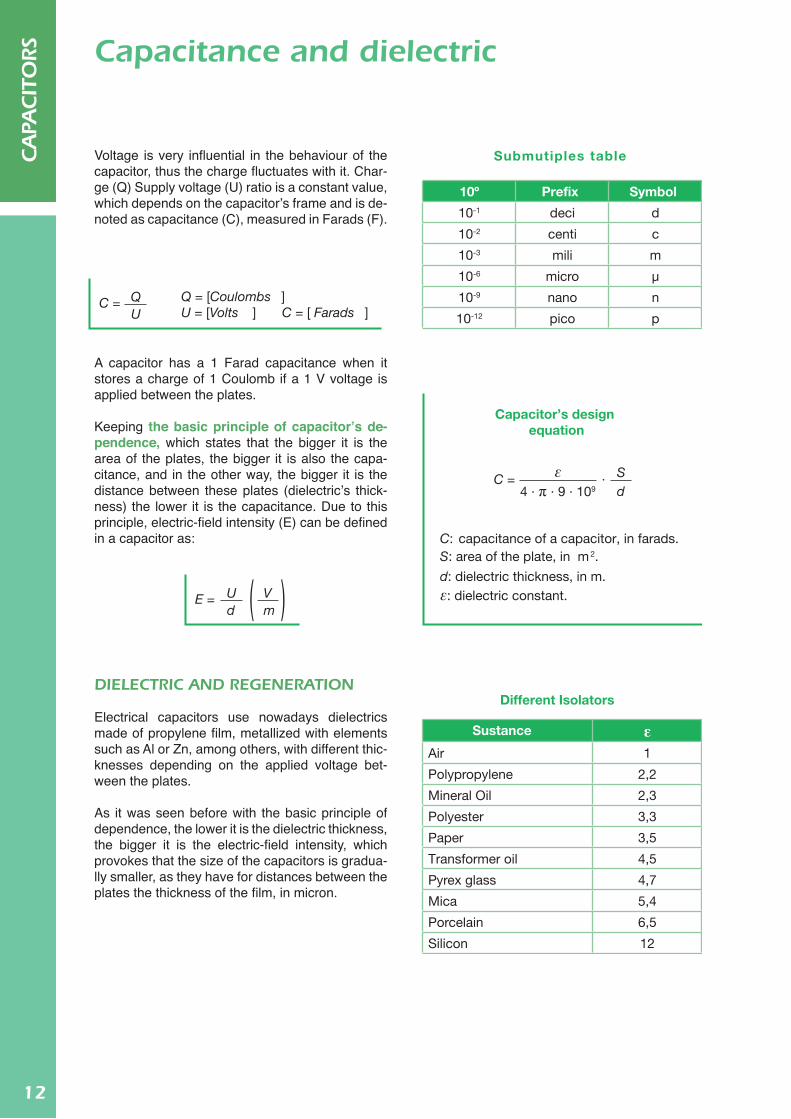
10º Prefix Symbol
10-1 deci d
10-2 centi c
10-3 mili m
10-6 micro µ
10-9 nano n
10-12 pico p
Submutiples table
Capacitor’s design equation
C: capacitance of a capacitor, in farads. S: area of the plate, in m 2.
d: dielectric thickness, in m.ε: dielectric constant.
C = · S d 4 · π · 9 · 109
ε
Different Isolators
Sustance εAir 1
Polypropylene 2,2
Mineral Oil 2,3
Polyester 3,3
Paper 3,5
Transformer oil 4,5
Pyrex glass 4,7
Mica 5,4
Porcelain 6,5
Silicon 12
C = QU
Q = [Coulombs ]U = [Volts ] C = [ Farads ]
E = U Vd m
Voltage is very influential in the behaviour of the capacitor, thus the charge fluctuates with it. Char-ge (Q) Supply voltage (U) ratio is a constant value, which depends on the capacitor’s frame and is de-noted as capacitance (C), measured in Farads (F).
A capacitor has a 1 Farad capacitance when it stores a charge of 1 Coulomb if a 1 V voltage is applied between the plates.
Keeping the basic principle of capacitor’s de-pendence, which states that the bigger it is the area of the plates, the bigger it is also the capa-citance, and in the other way, the bigger it is the distance between these plates (dielectric’s thick-ness) the lower it is the capacitance. Due to this principle, electric-field intensity (E) can be defined in a capacitor as:
DIELECTRIC AND REGENERATION
Electrical capacitors use nowadays dielectrics made of propylene film, metallized with elements such as Al or Zn, among others, with different thic-knesses depending on the applied voltage bet-ween the plates.
As it was seen before with the basic principle of dependence, the lower it is the dielectric thickness, the bigger it is the electric-field intensity, which provokes that the size of the capacitors is gradua-lly smaller, as they have for distances between the plates the thickness of the film, in micron.
CA
PACIT
ORS Capacitance and dielectric
CA
PACIT
ORS
12

13
CA
PACIT
ORS
1 Electrodes (Metallized Film)2 Prolypylene Film (Dielectric)3 Electric connection4 No metallized area
3
214 4Depending on the values of the constants of every
dielectric, there is a limit potential difference, which all materials can manage throughout the thick-ness. This limit is defined as electrical stiffness.
Because of determined electric-power system conditions or extreme temperatures, inadmissible for the correct working of the capacitor, this volta-ge limit can be overfilled. Thus, the dielectric can be bored and an electric arc will be formed bet-ween the plates.
The propylene film self-healing means that the electric arc will not generate a short circuit, but will evaporate the metal which surrounds the breakthrough point. This way, the isolation bet-ween plates is repaired in the latter breakthrough point.
After this self-healing, the capacitor can work in normal conditions, with a capacitance leak inferior to 100 pF.
Capacitance and dielectric
CA
PACIT
ORS
Metallized area
self-healing
In RTR Energía S.L., during the quality control of the metallized propylene film, the breakdown of the dielectric (propylene) is forced and the self-healing of it can be observed. In this photo-graph the evaporated metal-coat and the still working capacitor can be seen.
14
CA
PACIT
ORS
Charge process
U
wt
wt
wt
c
Uc
cI
cI
Discharge process
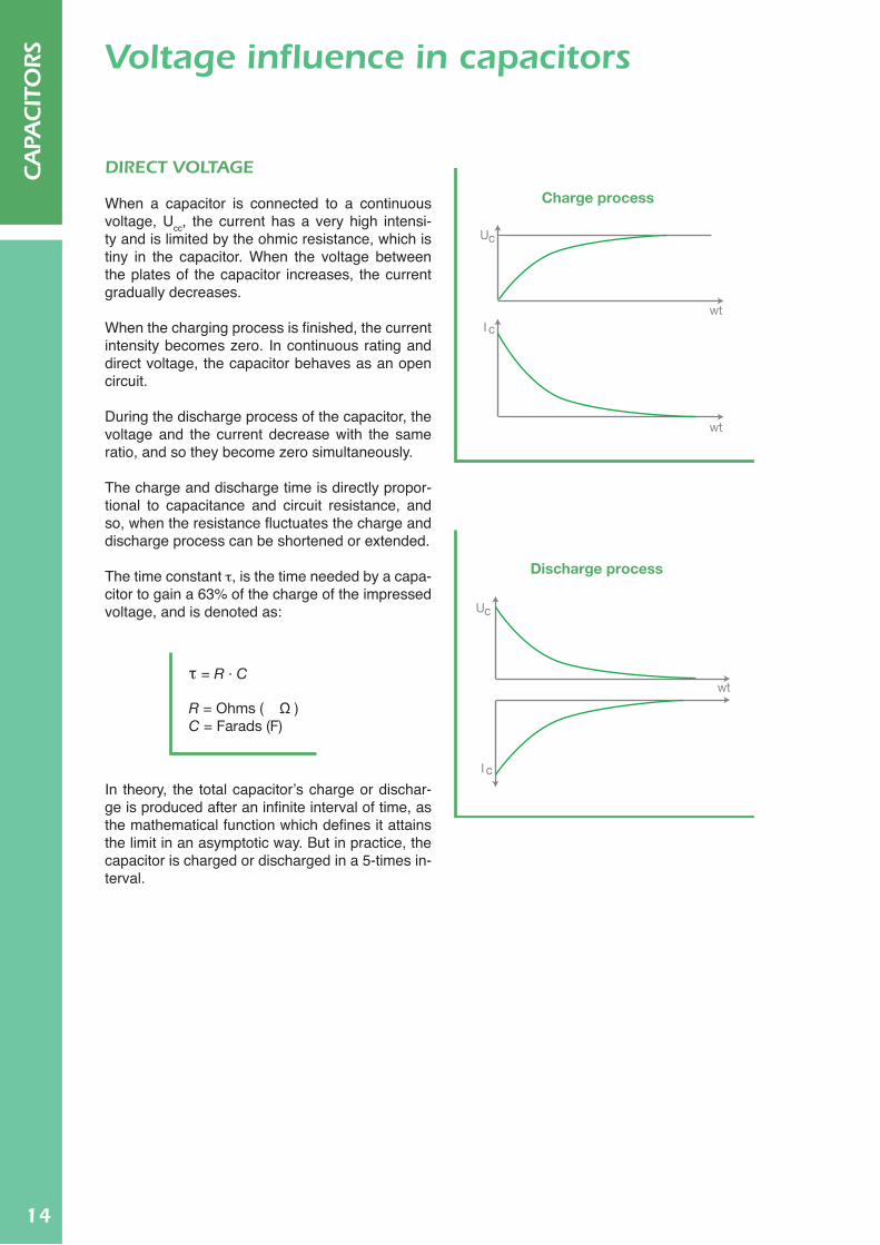
τ = R · C
R = Ohms ( Ω )C = Farads (F)
DIRECT VOLTAGE
When a capacitor is connected to a continuous voltage, Ucc, the current has a very high intensi-ty and is limited by the ohmic resistance, which is tiny in the capacitor. When the voltage between the plates of the capacitor increases, the current gradually decreases.
When the charging process is finished, the current intensity becomes zero. In continuous rating and direct voltage, the capacitor behaves as an open circuit.
During the discharge process of the capacitor, the voltage and the current decrease with the same ratio, and so they become zero simultaneously.
The charge and discharge time is directly propor-tional to capacitance and circuit resistance, and so, when the resistance fluctuates the charge and discharge process can be shortened or extended.
The time constant t, is the time needed by a capa-citor to gain a 63% of the charge of the impressed voltage, and is denoted as:
In theory, the total capacitor’s charge or dischar-ge is produced after an infinite interval of time, as the mathematical function which defines it attains the limit in an asymptotic way. But in practice, the capacitor is charged or discharged in a 5-times in-terval.
Voltage influence in capacitors

15
CA
PACIT
ORS
Tcharge and discharge = 10 ms12π · f · C
(Ω)XC = f = frequency (Hz)C = Fards(F)
0
charge
chargedischarge
discharge
wt
-U
UI
I
o
U+U ca
ca
ALTERNATING VOLTAGE
When a capacitor is connected to an alternating voltage, the plates are positively and negatively charged, in an alternating and periodic way, with a flow of alternating current.
The capacitor is periodically charged and dischar-ged, and so the two processes are simultaneous, because of the alternating current flowing through the network. This periodical process provokes an inversion in the direction of the current when this current’s value is zero. In the same way as in di-rect current, the capacitor acts as a finite resistan-ce, measured in ohms:
When the current’s value is zero, the charge pro-cess in the capacitor is finished as it will be totally charged at the end of the positive half-wave of the current for a known value of voltage, +Uca, and at the end of the negative half-wave with a voltage value of -Uca.
The discharge process is produced when the cu-rrent reaches its maximum value, therefore, the voltage value tends to be zero.
Voltage influence in capacitors
The complete charging and dischar-ging process is done in an electrical voltage semi period. If the electrical voltage’s period in Europe is 20 mili-seconds, a capacitor will need half of this time for completing its charge or discharge.

16
CA
PACIT
ORS
Q, power of the capacitor [VAr]f, line frequency [Hz] C, capacitance of the capacitor [F]Uca, supply voltage [V]Ic, capacitive current [A]
Ic = Uca · ω · C = Uca · 2π · f · C= =Uca Uca
ω·CXc 1
Q = Uca · Ic = Uca · (Uca · 2π · f · C ) = U2ca · 2π · f · C
Customer’ssatisfaction
QualityDesign andinnovation
Uca=230V; f=50Hz
Ic
C
A single-phase capacitor is that which can be im-planted between two phases or between phase and neutral.
The reactive power of the capacitor (Q) is measu-red in VAr, and defined as:
440 V VOLTAGE
Due to the importance of the supply voltage on the reactive capacitor’s power, there is a need of knowing why the nearly totality of capacitors ma-nufacturers, included RTR Energía S.L., design their capacitors for a 440 V voltage.
With this design, the capacitor’s reliability and life increase because it warrants that it will resist an overvoltage that can be produced in the power lead, and that, as it is said in the standard UNE-EN-50160, it can be up to a 10%.
Single-phase capacitors
The content of the standard UNE-EN-60831-1/2 says that, for indus-trial frequencies, a capacitor must exist a voltage value of 1,10·Uca (440 V), at least 8 hours a day.

17
CA
PACIT
ORS
CRS = C∆ + = 1,5 · C∆C∆ · C∆
C∆ + C∆
Ucoil = Uca
√3
For the same 3 wirings:
Qdelta = 3 · Qwye
Q = 3 · U2ca · 2π · f · C∆
IC = Q
√3 · Uca
Q = [ VAr ]
C∆ = [ F ]
f = [ Hz ]
Q = Uca2 · 2π · f · Cγ
Q = [ VAr ] Cγ = [ F ] f = [ Hz ]
R S T
RST
Ic
RST
C
C
C
Ic
C
CC
These capacitors are designed for being connec-ted to a three-phase electric line, R-S-T, and the way of connecting the capacitive elements (coils) in its interior is with two possibilities.
DELTA CONEXION
The total capacitance of the capacitor is divided in three partial capacitances C
D, as shown in the
diagram.
If the capacitance between two phases is taped, for example R-S, the total capacitance will not be the C
D of the RS phases but the C
D(RS) in para-
llel with the series connection CD(RT)-C
D(ST) (see
section G), which means:
Now, the reactive power in the capacitor (Q) can be defined, as well as its capacitive current (Ic).
STAR CONNECTION
This connection scheme is not so usual, and is used when the line voltage is higher than the one that can be allowed by each of the wirings, as:
The Ic is defined in the same way that it is done in the delta connection, while the reactive power is:
Three-phase power capacitors

18
CA
PACIT
ORS
CT = C1 + C2 + C3 + ... Cn
QT = Q1 + Q2 + Q3 + ... Qn
CT C1 C2 C3 Cn
= + + + ... +1 1 1 1 1
= + + + ... +QT Q1 Q2 Q3 Qn
1 1 1 1 1
C1
C2
C3
C3C2C1 Cn
Cn
PARALLEL
In the parallel connection between capacitors, the global equivalent capacitance is the sum of the ca-pacitances. The same occurs with the total reacti-ve energy.
The impressed voltage between the capacitor’s plates is the one that can be allowed depending on the capacitor’s constructive characteristics. All the capacitors are affected by the same voltage.
SERIES
When the working voltage, Uca, is higher than the rated voltage on the manufactured capacitor, a group of capacitors can be connected in series. In this case, every capacitor will have a different voltage between plates, depending on its capaci-tance and reactive power. As every series connec-tion, the current flowing through them is the same for every capacitor.
The inverse of the total capacitance (CT) is the sum of the inverses of the different capacitances.
The reactive power (QT) has the same behaviour as the capacitance, thus the inverse of the total reactive is the sum of the inverses of the different reactives.
Combination of Capacitors
19
CA
PACIT
ORS
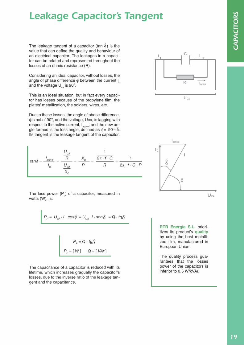
tanδ = Iactive
UCA
UCA
XC
XCR
R RIC
1
12π · f · C
2π · f · C · R= = = =
δ δφPP = UCA · I · cos = UCA · I · sen = Q · tg
PP = [ W ] Q = [ VAr ]
δPP = Q · tg
0.5 ≤PP ( W )
Q ( kVAr )→ δtg ≤ 5 · 10-4
C
active
CA
R
U
I I
I
active
C
I
II
CAU
φ
δ
The leakage tangent of a capacitor (tan d ) is the value that can define the quality and behaviour of an electrical capacitor. The leakages in a capaci-tor can be related and represented throughout the losses of an ohmic resistance (R).
Considering an ideal capacitor, without losses, the angle of phase difference j between the current Ic and the voltage Uca is 90º.
This is an ideal situation, but in fact every capaci-tor has losses because of the propylene film, the plates’ metallization, the solders, wires, etc.
Due to these losses, the angle of phase difference, j , is not of 90º, and the voltage, Uca, is lagging with respect to the active current, Iactive, and the new an-gle formed is the loss angle, defined as j = 90º- d . Its tangent is the leakage tangent of the capacitor.
The loss power (Pp) of a capacitor, measured in watts (W), is:
The capacitance of a capacitor is reduced with its lifetime, which increases gradually the capacitor’s losses, due to the inverse ratio of the leakage tan-gent and the capacitance.
Leakage Capacitor’s Tangent
RTR Energía S.L. priori-tizes its product’s quality by using the best metalli-zed film, manufactured in European Union.
The quality process gua-rantees that the losses power of the capacitors is inferior to 0.5 W/kVAr,
20
CA
PACIT
ORS
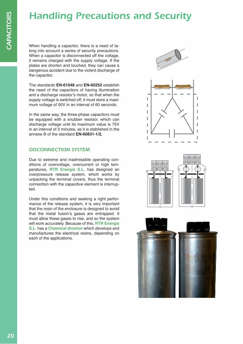
When handling a capacitor, there is a need of ta-king into account a series of security precautions. When a capacitor is disconnected off the voltage, it remains charged with the supply voltage. If the plates are shorten and touched, they can cause a dangerous accident due to the violent discharge of the capacitor.
The standards EN-61048 and EN-60252 establish the need of the capacitors of having illumination and a discharge resistor’s motor, so that when the supply voltage is switched off, it must store a maxi-mum voltage of 50V in an interval of 60 seconds.
In the same way, the three-phase capacitors must be equipped with a snubber resistor, which can discharge voltage until its maximum value is 75V in an interval of 3 minutes, as it is stablished in the annexe B of the standard EN-60831-1/2.
DISCONNECTION SySTEM
Due to extreme and inadmissible operating con-ditions of overvoltage, overcurrent or high tem-peratures, RTR Energía S.L. has designed an overpressure release system, which works by unpacking the terminal covers, thus the terminal connection with the capacitive element is interrup-ted.
Under this conditions and seeking a right perfor-mance of the release system, it is very important that the resin of the enclosure is designed to avoid that the metal fusion’s gases are entrapped. It must allow these gases to rise, and so the system will work accurately. Because of this, RTR Energía S.L. has a Chemical division which develops and manufactures the electrical resins, depending on each of the applications.
Handling Precautions and Security

21
CA
PACIT
ORS
Maximum 55ºC
Daily average 45ºC
Annual average 35ºC
THDUmax 2%
THDImax 25%
CapacitorsRTR Energía
3%<THDU≤7% THDU≥7%
MA/C/CE/TER Series
MA/C/CE/TER RTF Series
MA/C/CE/TER RCT Series
p(%)=7% p(%)=14%
THDU≤2% THDU≤3%
LC LC
TEMPERATURE
The capacitors must operate under the following limits:
This means that a capacitor must never reach a value beyond 55 ºC, or remain more than 24 hours beyond 45 ºC or more than a year beyond 35 ºC of temperature.
VOLTAGE
The maximum overvoltage that a capacitor can bear is of 1,10 times the rated voltage, as it has been explained in the Scheme E.
CURRENT
The maximum current that a capacitor can reach is 1,5 the rated current, (1,5 · In).
ALTITUDE
The capacitor’s installation altitude must not ex-ceed 2000 m over the sea level. In higher altitu-des, the heat dissipation is reduced, and this must be considered when dimensioning the capacitor.
HARMONICS
The harmonics presence which a capacitor can bear is determined taking on account that the vol-tage and current maximum limits must not be sur-mounted. These limits are shown below:
Operating Conditions
Maximum 55ºC
Daily average 45ºC
Annual average 35ºC
THDUmax 2%
THDImax 25%
CapacitorsRTR Energía
3%<THDU≤7% THDU≥7%
MA/C/CE/TER Series
MA/C/CE/TER RTF Series
MA/C/CE/TER RCT Series
p(%)=7% p(%)=14%
THDU≤2% THDU≤3%
LC LC
De tuning factor 5,67%, 7%, 14%
MA/C/CE/TER RTF Series MA/C/CE/TER RCT Series
MA/C/CE/TER Series
LC
Voltage harmonic distortion
≤ 2%
Voltage harmonic distortion
≤ 3%
Voltage harmonic distortion >3%

22
CA
PACIT
ORS NOTES

23
Reactive Energy
Compensation
24
CO
MPE
NSA
TIO
N
Most common industrypower factors:
Asynchronous motor 50% of load 0,73
Asynchronous motor 100% of load 0,85
Arc welding static equipments
0,5
Rotational welding groups 0,7-0,9
Arc welding recitfiers 0,7-0,9
Power factors in small electric installations:
Fluorescent lamp 0,5
Discharge lamp 0,4-0,6
Dielectric heating furnaces
0,85
Arc furnaces 0,8
Induction furnaces 0,85
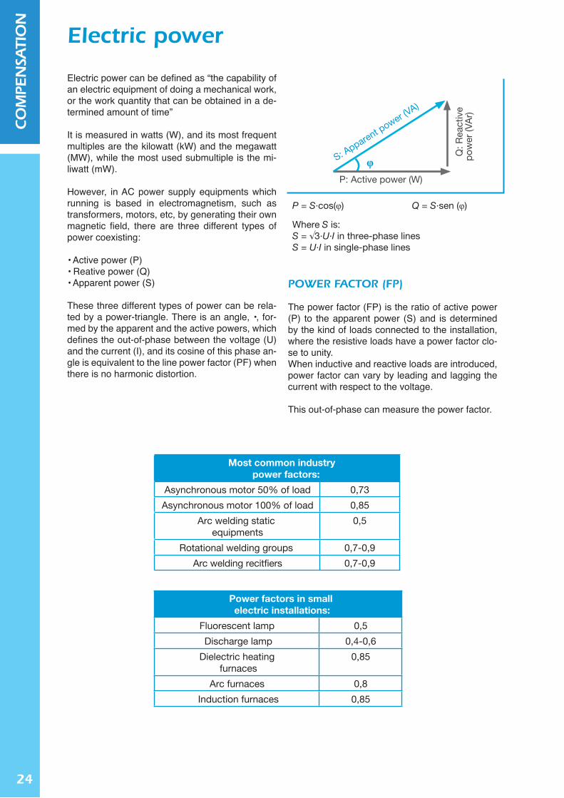
P = S·cos(φ)
Where S is:S = √3·U·I in three-phase linesS = U·I in single-phase lines
Q = S·sen (φ)
S: Apparent p
ower (VA)
P: Active power (W)
Q: R
eact
ive
pow
er (V
Ar)
φ
Most common industrypower factors:
Asynchronous motor 50% of load 0,73
Asynchronous motor 100% of load 0,85
Arc welding static equipments
0,5
Rotational welding groups 0,7-0,9
Arc welding recitfiers 0,7-0,9
Power factors in small electric installations:
Fluorescent lamp 0,5
Discharge lamp 0,4-0,6
Dielectric heating furnaces
0,85
Arc furnaces 0,8
Induction furnaces 0,85
P = S·cos(φ)
Where S is:S = √3·U·I in three-phase linesS = U·I in single-phase lines
Q = S·sen (φ)
S: Apparent p
ower (VA)
P: Active power (W)
Q: R
eact
ive
pow
er (V
Ar)
φ
Electric power can be defined as “the capability of an electric equipment of doing a mechanical work, or the work quantity that can be obtained in a de-termined amount of time”
It is measured in watts (W), and its most frequent multiples are the kilowatt (kW) and the megawatt (MW), while the most used submultiple is the mi-liwatt (mW).
However, in AC power supply equipments which running is based in electromagnetism, such as transformers, motors, etc, by generating their own magnetic field, there are three different types of power coexisting:
• Active power (P)• Reative power (Q)• Apparent power (S)
These three different types of power can be rela-ted by a power-triangle. There is an angle, •, for-med by the apparent and the active powers, which defines the out-of-phase between the voltage (U) and the current (I), and its cosine of this phase an-gle is equivalent to the line power factor (PF) when there is no harmonic distortion.
POWER FACTOR (FP)
The power factor (FP) is the ratio of active power (P) to the apparent power (S) and is determined by the kind of loads connected to the installation, where the resistive loads have a power factor clo-se to unity. When inductive and reactive loads are introduced, power factor can vary by leading and lagging the current with respect to the voltage.
This out-of-phase can measure the power factor.
Electric power

25
CO
MPE
NSA
TIO
N
ACTIVE POWER (P)
Active power represents the real power, measured in watts (W). Thus, the amount of energy used when an electric equipment is functioning and working, i.e. the energy given by a motor shaft when moving a device, the energy given, in terms of heat, by an electric heater resistance, or the light given by a lamp, etc.
Active power is also the hired power to the electric company, and can reach households, industries, offi-ces or any other facility when it is needed, along the supply network. The global amount of power, used by the totality of electric appliances is normally registered by counters or other electrical meters, which are installed by the deliverer companies in order to measure the totality of electric energy consumed in a particular period of time, specified in contracts.
REACTIVE POWER (Q)
Reactive power is the power consumed by motors, transformers or any other electric device including any kind of coil, so that it creates an electromagnetic field. These coils are part of an electric circuit, and in electric systems they constitute loads, consuming both active and reactive power. Their work efficien-cy depends on their power factor; the lower it is (far-off unitiy) the bigger is the amount of reactive power consumed. Besides, reactive power does not produce any effective power and produces a negative im-pact on the energy transmission through the distributing electric lines, thus its consumption is penalized throughout the tariff by the mains supply company. Reactive power is measured by volt-ampere reactive (VAr), and its most frequent multiple is the kilovoltampere (kVAr).
APPARENT POWER (S)
Apparent power or gross power is, according to the Pythagoras theorem, is the active and reactive power sum. These two components represent the total line input power, also the totality of the power given by the electric generators in the set. This power is imparted along distribution cables, also lines, reaching consumers in households, factories, industrial plants, etc. Apparent power is measured in volt-ampere (VA).
Electric power
26
CO
MPE
NSA
TIO
N
Joule effect losses
Plosses = I2·R
I: current flowing through the conductor, in ampere (A)
R: conductor’s resistance, in ohm (Ω)
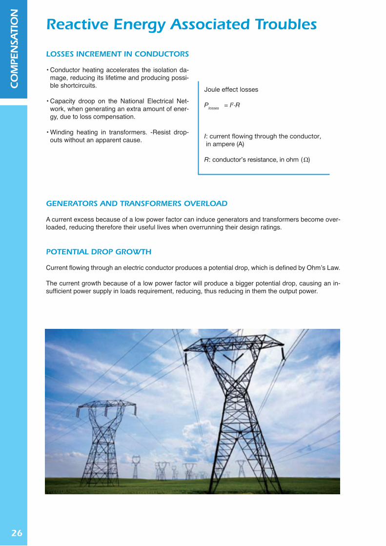
LOSSES INCREMENT IN CONDUCTORS
• Conductor heating accelerates the isolation da-mage, reducing its lifetime and producing possi-ble shortcircuits.
• Capacity droop on the National Electrical Net-work, when generating an extra amount of ener-gy, due to loss compensation.
• Winding heating in transformers. -Resist drop-outs without an apparent cause.
GENERATORS AND TRANSFORMERS OVERLOAD
A current excess because of a low power factor can induce generators and transformers become over-loaded, reducing therefore their useful lives when overrunning their design ratings.
POTENTIAL DROP GROWTH
Current flowing through an electric conductor produces a potential drop, which is defined by Ohm’s Law.
The current growth because of a low power factor will produce a bigger potential drop, causing an in-sufficient power supply in loads requirement, reducing, thus reducing in them the output power.
Reactive Energy Associated Troubles
27
CO
MPE
NSA
TIO
N
Joule effect losses decrement:
cosφinitial
cosφfinal
0,85 0,90 0,95 1,00
0,50 65,40% 69,14% 72,30% 75,00%
0,55 58,13% 62,65% 66,48% 69,75%
0,60 50,17% 55,56% 60,11% 64,00%
0,65 41,52% 47,84% 53,19% 57,75%
0,70 32,18% 39,51% 45,71% 51,00%
0,75 22,15% 30,56% 37,67% 43,75%
0,80 11,42% 20,99% 29,09% 36,00%
0,85 - 10,80% 19,94% 27,75%
0,90 - - 10,25% 19,00%
0,95 - - - 9,75%
Losses i: initial lossesLosses f: final lossescosφi: initial power factorcosφf: final power factor
Lossesf cosφi
Lossesi cosφf
=
2
JOULE EFFECT LOSSES DROOP
If the current is substituted by the active power expression in the Joule’s effect losses formula, the following relation is obtained:
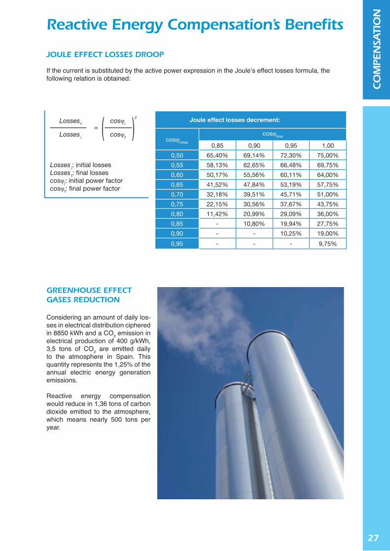
GREENHOUSE EFFECT GASES REDUCTION
Considering an amount of daily los-ses in electrical distribution ciphered in 8850 kWh and a CO2 emission in electrical production of 400 g/kWh, 3,5 tons of CO2 are emitted daily to the atmosphere in Spain. This quantity represents the 1,25% of the annual electric energy generation emissions.
Reactive energy compensation would reduce in 1,36 tons of carbon dioxide emitted to the atmosphere, which means nearly 500 tons per year.
Reactive Energy Compensation’s Benefits

28
CO
MPE
NSA
TIO
N
Potencial drop decrement on distribution lines:
cosφinitial
cosφfinal
0,85 0,90 0,95 1,00
0,50 41,18% 44,44% 47,37% 50,00%
0,55 35,29% 38,89% 42,11% 45,00%
0,60 29,41% 33,33% 36,84% 40,00%
0,65 23,53% 27,78% 31,58% 35,00%
0,70 17,65% 22,22% 26,32% 30,00%
0,75 11,76% 16,67% 21,05% 25,00%
0,80 5,88% 11,11% 15,79% 20,00%
0,85 - 5,56% 10,53% 15,00%
0,90 - - 5,26% 10,00%
0,95 - - - 5,00%
∆ U Pactive ·Z cte cosφi∆ Uf= = =→√3·U·cosφ cosφ cosφf∆ Ui
∆ U Potential drop in the lineU, Distribution voltageZ, Conductor’s impedance
POTENTIAL DROP DECREMENT ON DISTRIBUTION LINES
The current must overcome the conductor’s electric impedance (Z) while the electric energy is being transported, therefore a potential drop is produced.
Potential drop can be determined by Ohm’s law, and is the product of current and resistance. If the value of the demanded current is substituted by its equivalent in terms of line power, the following expression is obtained:
Reactive Energy Compensation’s Benefits
CAPACITy GAIN ON THE ELECTRIC LINE
If the power factor were compensated, part of the extra power, produced in order to reduce losses, could be used in the electrical provided consumption. Checking out the consumption and losses profiles, the Spanish National Electrical Distributor could gain a 0,5% in capacity, enough energy for more than a twoyear Ceuta and Melilla supply.

29
CO
MPE
NSA
TIO
N
Reactive power prices in Spain
cosφ €/kVArh(2009)
€/kVArh(2010)
% Increase2009-2010
cosφ ≥ 0,95 0 0 -
0,9 ≤ cosφ < 0,95 0,000013 0,041554 319,546%
0,85 ≤ cosφ < 0,9 0,017018 0,041554 144,18 %
0,8 ≤ cosφ < 0,85 0,034037 0,041554 22,08 %
cosφ < 0,8 0,051056 0,062332 22,08 %
Reactive power prices in Spain
cosφ €/kVArh(2009)
€/kVArh(2010)
% Increase2009-2010
cosφ ≥ 0,95 0 0 -
0,9 ≤ cosφ < 0,95 0,000013 0,041554 319,546%
0,85 ≤ cosφ < 0,9 0,017018 0,041554 144,18 %
0,8 ≤ cosφ < 0,85 0,034037 0,041554 22,08 %
cosφ < 0,8 0,051056 0,062332 22,08 %
Reactive power compensation is good not only as a technical advantage but also as an eco-nomical one.
Since January 2012, companies in Spain with an electrical contract of 15kW or more (basica-lly, every commercial enterprise from a small store up to a big industry) can be suffering bursts in their billing, because of a legal chan-ge published in BOE, on December 31, 2009, which tries to actuate on energetic efficiency throughout a more responsible use of energy in companies.
Reactive energy compensation is achieved by the installation, in electric lines, of capacitor banks, which can generate capacitive loads, so that reactive losses in the wiring are reduced.
With these new rates, any industrial plant which has basic equipment, such as furnaces or fluo-rescent lamps (see charts in section A), can suffer charge build-ups due to reactive energy.
This amendment means to users which, until now did not pay any reactive energy consump-tion, are suffering, since January 2010, a burst on their electrical billing.
Obviously, this new legislation is specially affecting industrial plants which use trans-formers, motors and any other industrial receptor that needs magnetic fields for run-ning.
Reactive Energy Compensation´S Economic Saving

30
CO
MPE
NSA
TIO
N
FP = cos(φ) = P P
S √P 2 + Q 2=
P = Σ Active powers (kWh)Q = Σ Reactive powers (kVArh)
Decice uponFPdesired = cos(φdesired )
k = tan(φinitial ) - tan(φdesired )
PkVAr = k · F
F (kW):
• Power (kW) measured with a peak demand meter.
• Hired power (kW) by the plant
• The product of the power value(kWh) and the operating numberof hours.
Application Example:
F = 85kW (Maximum Demand)cos(φinitial ) = 0,73cos(φdesired ) = 1
k = 0,936 table values:
PkVAr = 85 · 0,936 = 79,56 kVArPkVAr recommended = 95 kVAr
Value determination
In order to determine the power factor for its co-rrection, a three-step method is used, which can be followed in the attached block diagram:
1. Installation’s reactive power computation 2. Capacitive power, needed to compensate, com-
putation 3. Installation’s power factor (FP) variability com-
putation
REACTIVE ENERGy COMPUTATION
The installation’s reactive power calculation im-plies determining its power factor (FP). Therefore, the facility needs to be studied with, among other equipment:
• An electric line analyser • An energy consumption bills analysis, as shown
in the block diagram.
CAPACITIVE POWER COMPUTATION
Once the installation’s FP is determined, the value of the desired power factor (which will totally re-move reactive energy), FPdesired, must be selected. This value is going as close to unity as possible.
There is a value, named “k factor”, which is de-fined by the tangent’s difference, and its most fre-quent values are listed in the table below.
Once the k and F values have both been defi-ned and calculated, the capacitive power (PkVAr), in kVAr, needed for the FP compensation, can be calculated too. RTR Energía S.L. suggests an in-crease of 15-20% of the PkVAr value, in order to fo-recast any other capacity increments.
Capacitive Energy Calculation Needed for Compensation

31
CO
MPE
NSA
TIO
N
2 steps of 40 kVArStep Sequence: 1:1:
The second 40kVAr step is switched on and offpermanently
4 steps of 20 kVArStep Sequence: 1:1:1:1
The fourth 20kVAr step is switched on and offpermanently
2 steps of 5 kVAr1 steps of 10 kVAr3 steps of 20 kVAr
Step Sequence: 1:1:2:4:4:4
Optimum solutionË NO Ë NO Ë OK
• 1:1:1:1…all the steps’ capacitive power is the same.
• 1:2:2:2…the capacitive power of the first step is half that of the other steps.
• 1:2:4:4…the capacitive power of the first step is half that of second step, and the latter is in turn half that of the rest of the step
FP beforecompensation
PF AFTER COMPENSATION
cosφ
0,400
0,430
0,460
0,490
0,520
0,550
0,580
0,610
0,640
0,670
0,700
0,730
0,760
0,790
0,800
0,810
0,820
0,830
0,840
0,850
0,860
0,870
0,880
0,890
0,900
0,910
0,920
0,930
0,940
0,950
0,960
0,970
0,980
0,990
tgφ
2,291
2,100
1,930
1,779
1,643
1,518
1,405
1,299
1,201
1,108
1,020
0,936
0,855
0,776
0,750
0,724
0,698
0,672
0,646
0,620
0,593
0,567
0,540
0,512
0,484
0,456
0,426
0,395
0,363
0,329
0,292
0,251
0,203
0,142
1,541
1,350
1,180
1,029
0,893
0,768
0,655
0,549
0,451
0,358
0,270
0,186
0,105
0,026
-
-
-
-
-
-
-
-
-
-
-
-
-
-
-
-
-
-
-
-
1,645
1,454
1,284
1,133
0,997
0,873
0,759
0,653
0,555
0,462
0,374
0,290
0,209
0,130
0,104
0,078
0,052
0,026
-
-
-
-
-
-
-
-
-
-
-
-
-
-
-
-
1,752
1,560
1,391
1,239
1,103
0,979
0,865
0,759
0,661
0,568
0,480
0,396
0,315
0,236
0,210
0,184
0,158
0,132
0,106
0,080
0,054
0,027
-
-
-
-
-
-
-
-
-
-
-
-
1,807
1,615
1,446
1,295
1,158
1,034
0,920
0,815
0,716
0,624
0,536
0,452
0,371
0,292
0,266
0,240
0,214
0,188
0,162
0,135
0,109
0,082
0,055
0,028
-
-
-
-
-
-
-
-
-
-
1,865
1,674
1,504
1,353
1,217
1,092
0,979
0,873
0,775
0,682
0,594
0,510
0,429
0,350
0,324
0,298
0,272
0,246
0,220
0,194
0,167
0,141
0,114
0,086
0,058
0,030
-
-
-
-
-
-
-
-
1,963
1,771
1,602
1,450
1,314
1,190
1,076
0,970
0,872
0,779
0,692
0,608
0,526
0,447
0,421
0,395
0,369
0,343
0,317
0,291
0,265
0,238
0,211
0,184
0,156
0,127
0,097
0,067
0,034
-
-
-
-
-
2,000
1,808
1,639
1,487
1,351
1,227
1,113
1,007
0,909
0,816
0,729
0,645
0,563
0,484
0,458
0,432
0,406
0,380
0,354
0,328
0,302
0,275
0,248
0,221
0,193
0,164
0,134
0,104
0,071
0,037
-
-
-
-
2,041
1,849
1,680
1,528
1,392
1,268
1,154
1,048
0,950
0,857
0,770
0,686
0,605
0,525
0,499
0,473
0,447
0,421
0,395
0,369
0,343
0,316
0,289
0,262
0,234
0,205
0,175
0,145
0,112
0,078
0,041
-
-
-
2,088
1,897
1,727
1,576
1,440
1,315
1,201
1,096
0,998
0,905
0,817
0,733
0,652
0,573
0,547
0,521
0,495
0,469
0,443
0,417
0,390
0,364
0,337
0,309
0,281
0,253
0,223
0,192
0,160
0,126
0,089
0,048
-
-
2,149
1,957
1,788
1,637
1,500
1,376
1,262
1,157
1,058
0,966
0,878
0,794
0,713
0,634
0,608
0,581
0,556
0,530
0,503
0,477
0,451
0,424
0,397
0,370
0,342
0,313
0,284
0,253
0,220
0,186
0,149
0,108
0,061
-
2,291
2,100
1,930
1,779
1,643
1,518
1,405
1,299
1,201
1,108
1,020
0,936
0,855
0,776
0,750
0,724
0,698
0,672
0,646
0,620
0,593
0,567
0,540
0,512
0,484
0,456
0,426
0,395
0,363
0,329
0,292
0,251
0,203
0,142
cosφ
tgφ
0,80
0,750
0,84
0,646
0,90
0,484
0,90
0,484
0,95
0,329
0,96
0,292
0,97
0,251
0,98
0,203
0,99
0,142
1,00
0,000
0,88
0,540
Usual k factor vualues
POWER FACTOR’S VARIABILITy COMPUTATION
If a central compensation scheme is chosen (see section F), the fluctuation pattern of the FP with time must be known, in order to decide the number of steps needed by the bank for achieving the calculated capacitive power throughout time.
For example, assuming an 80 kVAr battery is needed, and knowing that 60 kVAr are produced by a fixed motor, the re-maining 20 kVAr can appear and disappear intermittently du-ring the day.
Capacitive Energy Calculation Needed for Compensation

32
CO
MPE
NSA
TIO
N
INDIVIDUAL COMPENSATION
Individual compensation is used in continuous working cycle equipments, where reactive consumption is significant, mainly in electric motors and transformers. The capacitor is installed in every single load, so the only conductors affected by the reactive energy are those who are uniting load and capacitor. This configuration has, on the one hand, the following advantages:
• Reactive energy is confined between load and capacitor. Therefore, the remaining lines are free from this reactive energy.
• The capacitor is switched on only when there is a connected load, as the starter functions as the capacitor’s switch so no other control system is needed.
On the other hand, this configuration has the following disadvantages: • Individual capacitor’s price is higher than that of an equivalent capacitor on its own. • Capacitor’s are under-used when an individual load remains idle for a long period of time.
This fixed-compensation configuration has to be studied carefully when any of the following highlighted cases: in asynchronous motor’s compensation and power transformers (see section G).
Configurations for Reactive Energy Compensation
Circuit
L O A D
33
CO
MPE
NSA
TIO
N
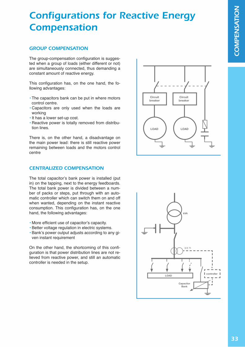
GROUP COMPENSATION
The group-compensation configuration is sugges-ted when a group of loads (either different or not) are simultaneously connected, thus demanding a constant amount of reactive energy.
This configuration has, on the one hand, the fo-llowing advantages:
• The capacitors bank can be put in where motors control centre.
• Capacitors are only used when the loads are working
• It has a lower set-up cost. • Reactive power is totally removed from distribu-
tion lines.
There is, on the other hand, a disadvantage on the main power lead: there is still reactive power remaining between loads and the motors control centre
CENTRALIZED COMPENSATION
The total capacitor’s bank power is installed (put in) on the tapping, next to the energy feedboards. The total bank power is divided between a num-ber of packs or steps, put through with an auto-matic controller which can switch them on and off when wanted, depending on the instant reactive consumption. This configuration has, on the one hand, the following advantages:
• More efficient use of capacitor’s capacity. • Better voltage regulation in electric systems. • Bank’s power output adjusts according to any gi-
ven instant requirement
On the other hand, the shortcoming of this confi-guration is that power distribution lines are not re-lieved from reactive power, and still an automatic controller is needed in the setup.
Configurations for Reactive Energy Compensation
Circuitbreaker
Circuitbreaker
LOADLOAD
LOADcontroller
CapacitorBank
kVA
X/5 TI

34
CO
MPE
NSA
TIO
N
In practice we can consider:
Qcompensation = 0,3·PPrated of motors
Qcompensation = P · ( tanφi - tanφf )
Qcompensation≤ Qlímite
Qlimit = 0.9 √3·Un · I0 ó
Qlímit = 2·P ( 1- cosφinitial )
Circuit breaker
MOTOR
ASyCHRONOUS THREE-PHASE MOTOR’S DIRECT STARTING
When compensating individual asynchronous mo-tors, care must be taken in order to avoid self-exci-tation appearance. Self-excitation begins when the motor is turned off, as it remains spinning because of the inertia, until it finally stops. When the feed is cut out, if the compensation has been done on the motor’s terminals then the capacitor’s capaciti-ve currents on the stator will generate a magnetic field on the rotor in the same direction as the de-creasing magnetic field. Thus, the motor will work as a generator, and this will cause overvoltages in the motor terminals.
There are two possible solutions in order to avoid self-excitation appearance:
• Capacitor’s capacitive currents can be limited through the capacitor bank power’s limitation so that they are lower than the motor’s void current (EN60831-1 standard advices that void current should never be higher than the 90% reactive void motor’s power).
• Compensation can be done in terminals throug-hout a contactor. This way, when the motor is turned off from the feed, capacitors will remain insulated from the motor terminals.
Motors and Transformers Compensation
35
CO
MPE
NSA
TIO
N
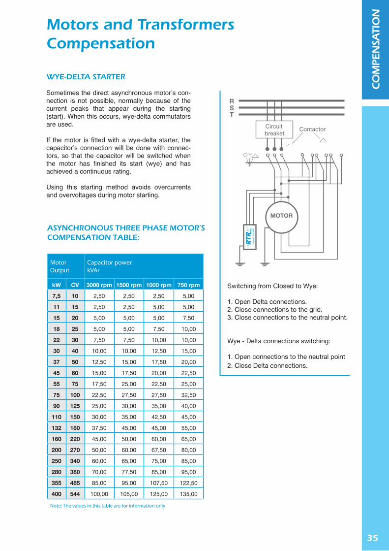
ASYNCHRONOUS THREE PHASE MOTOR’S COMPENSATION TABLE:
MotorOutput
Capacitor powerkVAr
kW
7,5
11
15
18
22
30
37
45
55
75
90
110
132
160
200
250
280
355
400
CV
10
15
20
25
30
40
50
60
75
100
125
150
180
220
270
340
380
485
544
3000 rpm
2,50
2,50
5,00
5,00
7,50
10,00
12,50
15,00
17,50
22,50
25,00
30,00
37,50
45,00
50,00
60,00
70,00
85,00
100,00
1500 rpm
2,50
2,50
5,00
5,00
7,50
10,00
15,00
17,50
25,00
27,50
30,00
35,00
45,00
50,00
60,00
65,00
77,50
95,00
105,00
1000 rpm
2,50
5,00
5,00
7,50
10,00
12,50
17,50
20,00
22,50
27,50
35,00
42,50
45,00
60,00
67,50
75,00
85,00
107,50
125,00
750 rpm
5,00
5,00
7,50
10,00
10,00
15,00
20,00
22,50
25,00
32,50
40,00
45,00
55,00
65,00
80,00
85,00
95,00
122,50
135,00
Note: The values in this table are for information only
Switching from Closed to Wye:
1. Open Delta connections.2. Close connections to the grid.3. Close connections to the neutral point.
Wye - Delta connections switching:
1. Open connections to the neutral point 2. Close Delta connections.
RST
Circuitbreaket
Contactor
MOTOR
La
en
erg
ía q
ue
vie
ne
WyE-DELTA STARTER
Sometimes the direct asynchronous motor’s con-nection is not possible, normally because of the current peaks that appear during the starting (start). When this occurs, wye-delta commutators are used.
If the motor is fitted with a wye-delta starter, the capacitor’s connection will be done with connec-tors, so that the capacitor will be switched when the motor has finished its start (wye) and has achieved a continuous rating.
Using this starting method avoids overcurrents and overvoltages during motor starting.
Motors and Transformers Compensation

36
CO
MPE
NSA
TIO
N
POWER TRANSFORMERS COMPENSATION TABLE
PowerkVA
Voltage< 24 kV
Voltage> 24 kV
25
50
100
160
250
400
500
630
800
1000
1250
1600
2000
2500
2,50
5,00
7,50
10,00
15,00
20,00
25,00
30,00
45,00
60,00
70,00
90,00
112,50
155,00
2,50
5,00
10,00
12,50
20,00
25,00
30,00
40,00
50,00
65,00
80,00
100,00
120,00
165,00
Note: The values in this table are for information only
In practice we can consider:
Qcompensation = 0,05·Sn si Sn ≤ 1000kVA
Qcompensation = 0,03·Sn si Sn > 1000kVA
Primary
Secondary
KVA
Qcompensation = Q0 + Qload
Where:I0 = Magnetizing current in %U = Rated Primary VoltageUCC = Short Circuit Voltage in %S = Rated Apparent PowerSn = Working Power
Qcompensation = √3 · U · + · · Sn
I0 UCC S
Sn100 100
2
POWER TRANSFORMERS
Transformers reactive energy compensation must be enough to rectify the reactive energy that can appear during its void working, as this is a cons-tant value (Q0) and also the absorbed reactive energy when charged.
The following table includes some approximate reactive power values of the capacitors, depen-ding on the transformer power.
Motors and Transformers Compensation
37
CO
MPE
NSA
TIO
N
-
!
RTR Energía S.L. power capacitors are manufactured under a strict Quality Control that verifies the capacitor’s correct working in every production line. In order to obtain the best capacitor’s performance it is very convenient to follow the installation suggestions, supplied with every capacitor.
SWITCHGEARS
They should be, preferably suitable for sudden breakdown, and dimensioned for a 1.6 to 2 times the rated capacitor’s current.
FUSES
As switchgears, they should be suitable for sudden breakdown and able to manage the high charge and discharge current capacitor’s values. So, their calibration must be done between 1.6 and 2 times the capacitor’s rated one.
CONDUCTORS
For the same reasons as exposited before, the minimum wire section must be 1.8 times bigger than that used for rate current.
TEMPERATURE
Ambient temperature for a satisfactory capacitors working should be within -25º C and 55º C. Because of this, if there were reactances placed in the setup, capacitors should be located below them, in venti-lated and air-conditioned areas if needed.
Quality, Installation and Protection
RTR Energía S.L. seeks to maintain conti-nuous improvement, and has been awar-ded the certification of its Quality Assurance System under ISO 9001: 2008 by AENOR and IQNet.
Never manipulate charged ca-pacitors. Before touching a ca-pacitor, even when discharge resistors have been fitted, the capacitor terminals should be short-circuited and grounded.
38
CO
MPE
NSA
TIO
N
I
Powercalculation
FP=cosφ k F(kW) PkVAr
P1
P2
P3
P4
P5
P6
0,77
0,77
0,61
0,78
0,70
0,68
0,826
0,841
1,291
0,807
1,012
1,085
35
40
22
32
32
21
28,89
33,65
28,40
25,82
32,37
22,79
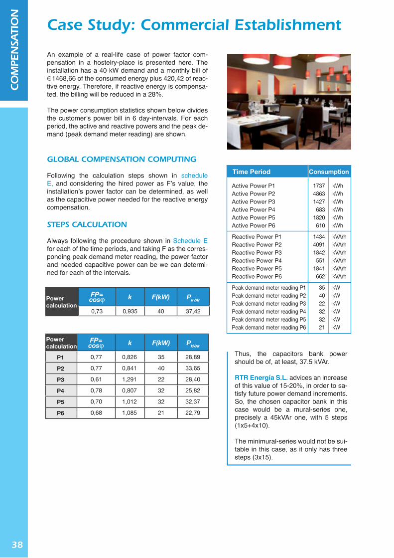
Active Power P1Active Power P2Active Power P3Active Power P4Active Power P5Active Power P6
Reactive Power P1Reactive Power P2Reactive Power P3Reactive Power P4Reactive Power P5Reactive Power P6
Peak demand meter reading P1Peak demand meter reading P2Peak demand meter reading P3Peak demand meter reading P4Peak demand meter reading P5Peak demand meter reading P6
173748631427
6831820
610
143440911842
5511841
662
354022323221
kWhkWhkWhkWhkWhkWh
kVArhkVArhkVArhkVArhkVArhkVArh
kWkWkWkWkWkW
Time Period Consumption
Powercalculation
FP=cosφ k F(kW) PkVAr
0,73 0,935 40 37,42
An example of a real-life case of power factor com-pensation in a hostelry-place is presented here. The installation has a 40 kW demand and a monthly bill of €1468,66 of the consumed energy plus 420,42 of reac-tive energy. Therefore, if reactive energy is compensa-ted, the billing will be reduced in a 28%.
The power consumption statistics shown below divides the customer’s power bill in 6 day-intervals. For each period, the active and reactive powers and the peak de-mand (peak demand meter reading) are shown.
GLOBAL COMPENSATION COMPUTING
Following the calculation steps shown in schedule E, and considering the hired power as F’s value, the installation’s power factor can be determined, as well as the capacitive power needed for the reactive energy compensation.
STEPS CALCULATION
Always following the procedure shown in Schedule E for each of the time periods, and taking F as the corres-ponding peak demand meter reading, the power factor and needed capacitive power can be we can determi-ned for each of the intervals.
Case Study: Commercial Establishment
Thus, the capacitors bank power should be of, at least, 37.5 kVAr.
RTR Energía S.L. advices an increase of this value of 15-20%, in order to sa-tisfy future power demand increments. So, the chosen capacitor bank in this case would be a mural-series one, precisely a 45kVAr one, with 5 steps (1x5+4x10).
The minimural-series would not be sui-table in this case, as it only has three steps (3x15).

39
CO
MPE
NSA
TIO
N
Reactive power compensation offers the following advantages:
INCREASE OF ENERGY USAGE EFFICIENCY by reducing transport losses. When losses are redu-ced, there is no need of producing an extra amount of energy, in order to compensate these losses. Thus, the greenhouse gasses emitted when electric energy is generated are also reduced.
INCREASE OF THE NATIONAL GRID’S CAPACITY, since the energy, generated as an extra due to compensate losses can be used as consumption energy. Based on power consumption and losses statistics, the Spanish National Grid’s capacity would increase by 0.5%, energy enough to supply, for example, more than twice the yearly consumption of Ceuta and Melilla.
OPTIMIZATION OF THE INSTALLATION DESIGN as the increment of the conductor’s size is preven-ted even though the current is increasing. Therefore, resources such as copper, which has an important influence in the installation’s budgets, are used in a more efficient way.
INCREASE OF THE ELECTRICAL MACHINE’S DURABILITY. The reactive energy removal provokes a current’s growth, which is responsible for a reduction of the power appliances useful lifes.
INCREASE OF THE ELECTRICITY SUPPLY QUALITY by reducing the increment in power drops during its transport. This voltage drop is responsible for the decreased output power in loads, such as motors, lamps, etc.
ECONOMICAL SAVING in electrical billing, obtained by removing the reactive energy consumption penalties. This penalties may nowadays mean a 30% of the total power bill.
Conclusions

40
CO
MPE
NSA
TIO
NNOTES

Harmonics and quality
Electric Energy
Jean-Baptiste Joseph Fourier,
French mathematician (1768-1830)
Balanced three-phase system
Unbalanced three-phase system
120º 120º
120º
ε
β

42
HA
RM
ON
ICS Quality of Electric Energy
The basic fundamental parameters which define an electrical energy supply are: supply voltage (U) and current (I).
The right voltage supply (U) and the ability for gi-ving users the amount of needed energy in a par-ticular moment depends on the electricity supplier company, which distributes the energy.
In Spain, voltage is supplied at 400 volts (V) in a three-phase system, with a frequency value of 50Hz, considering this as low voltage up to 1000V. From 1000V up to 25 kilovolts (kV) it is considered as medium voltage, which depends on the areas and the supply companies.
Finally, values over 25 kV are considered high voltage, and it is used basically for transporting electrical energy in large distances.
Actually, QUALITY (correct energy supply) and ELECTRIC ENERGY EFFICIENCY (obtaining the maximum yield out of it) concepts must be unified. Because of this, the maximum consumption of energy must be optimized, as well as its transport and use. This will grant the correct running of the electrical equipment.
The most important characteristic in quality and energetic efficiency is that of generating and trans-porting the maximum amount of active energy, which produces effective power. This compensates the oscillating energy loads, as well as the nonproductive ones, as reactive energy (see chapter of reac-tive energy compensation) or distortion energy, produced by some of the electrical appliances with nonlinear components, such as non-filtered reactances, speed shifters, rectifiers or electronic starters, among many other.
Negative quality aspects of the electri-cal supply, as established in the standard EN-UNE-60150:1996, are:
• Overvoltage • Electric Power Interruptions • Cutoffs • Voltage fluctuations • Flicker • Voltage holes

43
HA
RM
ON
ICSElectrical Network Disturbances
With the aforesaid standard, UNE-EN-60150, here are some of the most important electrical network disturbances.
FREQUENCy VARIATIONS
Frequency disturbances measured in 10 seconds avera-ge values. These variations produce an inaccurate run-ning in electric motors, both synchronous and asynchro-nous, electrical household appliances, etc.
UNBALANCED THREE-PHASE POWER SySTEM
The voltage or current three-phase system is perfectly ba-lanced when its three phases (R, S and T) have a 120º angular displacement between them, and when its vector modulus have the same value.
If the system is unbalanced, it can occur that the modulus of each of the different phases are different, or that the phase shift between two of the vectors is not the usual value of 120º. Furthermore, these two things can happen simultaneously.
Displaying a three-phase system this way, either balanced or unbalanced is valid if the system has three wires or four, including the neutral wire.
The unbalanced systems must not exceed the following values:
Current < 10% Voltage < 3%
When the system is unbalanced, the current through the neutral wire increases.
Balanced three-phase system
Unbalanced three-phase system
120º 120º
120º
ε
β

44
HA
RM
ON
ICS
Jean-Baptiste Joseph Fourier,
French mathematician (1768-1830)
Balanced three-phase system
Unbalanced three-phase system
120º 120º
120º
ε
β
Harmonics
Harmonic voltage is defined by the standard UNEEN-60150:1996 as “a sinusoidal voltage, where the frequency is an integer multiple of the system’s supply voltage fundamental frequency”.
Fourier, a French mathematician, defined this phenomenon by the following assertion: “any pe-riodic signal, no matter its complexity, can be split in a number of signals, and the sum of these sig-nals will have a frequency which will be a multiple of the fundamental or reference frequency”
After analysing this phenomenon, the conclusion in RTR ENRGIA S.L. is that this is the most accu-rate definition for a harmonic, though the Fourier’s mathematic series expansion is not going to be studied here, as it is not part of the purpose of this handbook.
Harmonics generate non-linear loads. These loads, when connected to a sinusoidal and alter-nating electrical network, absorb non-linear cu-rrents. Their amplitude and frequency depends on the current’s wave distortion when a sine voltage is applied to them. These non-linear loads are ge-nerally periodic.
Distorted wave
Fundamental
3rd harmonic
1 2 3
HARMONICS ORIGIN
Among many others, the main causes of the harmonic distortion are the following.
• Electromagnetic and electronic lighting ballasts • Electric welding equipment • Single-phase network connected electronic equipment • Electromagnetic reactance for discharge lamps • Electronic starter • Speed shifters
HARMONICS EFFECTS ON ELECTRICAL NETWORK
• Increase of transported power, worsening the network power factor • Automatic switch untimely drop-out • Conductors overloads • Vibrations and overloads in machinery • Establishment of instabilities in electrical systems • Wrong operation of protective relays • Capacitors’ impedance fall-off ( Xc ) = 1/• · C. This may produce a failure in the automatic regulated ba-
ttery, which is installed in order to rectify the power factor when the resonant phenomenon appears (XL=Xc). This situation is explained in detail in section D.
• Wrong measures in measurement apparatus • Noises in control equipment
The electrical companies analyse the penalties to be applied to industrial installations which generate harmonics, as well as to the ones which generate reactive energy.

45
HA
RM
ON
ICSHarmonics Parameters
Harmonics can be classified by three different parameters: order, frequency and sequence, which can perfectly define each of the harmonic functions in the electrical network.
HARMONICS ORDER
The fundamental frequency value in Spain is 50 Hz, and the order number defines the number of times in which the harmonics’ frequency is higher than the fundamental value: 1, 2, 3, 4, 5, 6, 7… the natural order of numbers.
It can also be defined as the ratio of the harmonic frequency (fn) and the fundamental frequency (f50)
PARÁMETROS DE LOS ARMÓNICOS Los armónicos se clasifican por tres parámetros (Orden, Frecuencia y Secuencia) que definen perfectamente la función del armónico correspondiente en las redes eléctricas. EL ORDEN DE LOS ARMÓNICOS Partiendo de que la frecuencia fundamental en España es de 50 Hz, el número de orden determina el número de veces que la frecuencia de ese armónico es mayor que la fundamental: 1, 2, 3, 4, 5, 6,7… orden natural de los números También se define como la relación que hay entre la frecuencia del armónico (fn) y la frecuencia fundamental (f50). LA FRECUENCIA Se define como el resultado de multiplicar el número de orden del armónico por la frecuencia fundamental (50 Hz), por ejemplo:
3ª armónica 3 x 50 Hz = 150 Hz 5ª armónica 5 x 50 Hz = 250 Hz 7ª armónica 7 x 50 Hz = 350 Hz
Los armónicos de orden impar son los que se encuentran en las redes eléctricas de la industria, edificios y explotaciones industriales, aeropuertos, etc. Los de orden par sólo aparecen cuando hay asimetría en la señal eléctrica.
LA SECUENCIA La secuencia positiva o negativa de los armónicos no determinan un comportamiento concreto de los mismos en la redes eléctricas, son igual de perjudiciales unos que otros. En el caso concreto de las baterías de condensadores para la corrección del factor de potencia son más perjudiciales los de secuencia negativa, y fundamentalmente el 5º. Por el contrario, los de secuencia cero, al ser su frecuencia múltiplo eléctrico de la fundamental, se desplazan por el neutro, haciendo que por él circule la misma o más intensidad que por las fases con el consiguiente calentamiento del mismo, de ahí la necesidad de igualar la sección del neutro a las fases.
Orden Frecuencia Secuencia 1 50 + 2 100 - 3 150 0 4 200 + 5 250 - 6 300 0 7 350 + 8 400 - 9 450 0 ··· ··· ··· n 50·n ···
Parámetros de los armónicos más usuales
50ffn n=
FREQUENCy
The harmonics’ frequency is defined as the result of multiplying the order number of the harmonic and the fundamental frequency (50 Hz), e.g:
3rd harmonic 3 x 50Hz = 150Hz 5th harmonic 5 x 50Hz = 250Hz 7th harmonic 7 x 50Hz = 350Hz
Odd-order harmonics can be found in the electrical network of all kind of industries, buildings, indus-trial runnings, airports, etc. Even-order harmonics can be found in unbalanced electric signals.
Order123456789...
Frequency50
100150200250250350400450...
Sequence+-0+-0+-0...
SEQUENCE
The positive or negative sequence of the harmonics does not establish a specific behaviour of the afo-resaid harmonics in electric networks. They are both equally harmful.
In the particular case of the capacitors’ banks for the correction of the power factor, the most harmful harmonic is that of negative sequence, specially the 5º one.
Instead, harmonics with null sequence have a frequency which is an electrical multiple of the fundamen-tal frequency. These harmonics are displaced along the uncharged wire, so that the current flow is of the same value or even higher than the current flow through the phases. This produces the uncharged wire heating, so it makes it necessary to have the same section on both uncharged and phase wires.
The most usual harmonics parameters are the following:

46
HA
RM
ON
ICS
The harmonic distortion rate can be defined as the voltage or current percentage rate (%), with the effective value of the corresponding harmonic frequency and the effective value of the voltage or current corresponding to the fundamental frequency.
TASA DE DISTORSIÓN ARMÓNICA INDIVIDUAL EN TENSIÓN (U) E INTENSIDAD (I) La tasa de distorsión armónica se define como la relación en tanto por ciento (%) de la tensión (o de la intensidad) en valor eficaz de la frecuencia del armónico correspondiente y la tensión (o intensidad) en valor eficaz de la tensión correspondiente a la frecuencia fundamental. TASA TOTAL DE DISTORSION ARMONICA: THDU - THDI Se llama así a la tasa de distorsión armónica total referenciada a la frecuencia fundamental:
1001
224
23
22
2⋅
++++=
− hhhhh
THD nf n
Para una mejor comprensión se va a referenciar el THD a los dos valores fundamentales: la tensión eficaz (Uca) y la corriente eficaz (Ica).
1001
224
23
22
2⋅
++++=
−
ca
ncacacacaU U
UUUUTHD
n
1001
224
23
22
2 ⋅++++
=−ca
ncacacacanI I
IIIITHD
Como norma de consulta, en la IEC-555 el valor “n” se limita al armónico número 40. La THDI es generada por las cargas de circuitos no lineales en la instalación; mientras que la THDU es generada por las fuentes, como resultado de una corriente en el circuito muy distorsionada.
EL ESPECTRO ARMÓNICO El espectro armónico es la descomposición de una señal en sus armónicos en el dominio de la frecuencia. Así se representa en un diagrama de barras el porcentaje de cada una de las señales armónicas, cuya suma produce la señal total analizada. En la figura adjunta se observa un espectro armónico donde el 5º armónico alcanza un valor próximo al 25% en tensión.
100
100
50
50
⋅=
⋅=
fca
fcan
fca
fcan
II
%IHD
UU
%UHD
n
n
0
10
20
30
40
50
60
70THDU
50 Hz 150 Hz 250 Hz 350 Hz
TOTAL RATE OF HARMONIC DISTORTION: THDU - THDI
THE HARMONIC SPECTRUM
For a better understanding of this parameter, the total rate of harmonic distortion (THD) is going to be referred to the two fundamental values: the effective voltage (Uca) and the effective current (Ica).
TASA DE DISTORSIÓN ARMÓNICA INDIVIDUAL EN TENSIÓN (U) E INTENSIDAD (I) La tasa de distorsión armónica se define como la relación en tanto por ciento (%) de la tensión (o de la intensidad) en valor eficaz de la frecuencia del armónico correspondiente y la tensión (o intensidad) en valor eficaz de la tensión correspondiente a la frecuencia fundamental. TASA TOTAL DE DISTORSION ARMONICA: THDU - THDI Se llama así a la tasa de distorsión armónica total referenciada a la frecuencia fundamental:
1001
224
23
22
2⋅
++++=
− hhhhh
THD nf n
Para una mejor comprensión se va a referenciar el THD a los dos valores fundamentales: la tensión eficaz (Uca) y la corriente eficaz (Ica).
1001
224
23
22
2⋅
++++=
−
ca
ncacacacaU U
UUUUTHD
n
1001
224
23
22
2 ⋅++++
=−ca
ncacacacanI I
IIIITHD
Como norma de consulta, en la IEC-555 el valor “n” se limita al armónico número 40. La THDI es generada por las cargas de circuitos no lineales en la instalación; mientras que la THDU es generada por las fuentes, como resultado de una corriente en el circuito muy distorsionada.
EL ESPECTRO ARMÓNICO El espectro armónico es la descomposición de una señal en sus armónicos en el dominio de la frecuencia. Así se representa en un diagrama de barras el porcentaje de cada una de las señales armónicas, cuya suma produce la señal total analizada. En la figura adjunta se observa un espectro armónico donde el 5º armónico alcanza un valor próximo al 25% en tensión.
100
100
50
50
⋅=
⋅=
fca
fcan
fca
fcan
II
%IHD
UU
%UHD
n
n
0
10
20
30
40
50
60
70THDU
50 Hz 150 Hz 250 Hz 350 Hz
www.rtr.es
TASA DE DISTORSIÓN ARMÓNICA INDIVIDUAL EN TENSIÓN (U) E INTENSIDAD (I) La tasa de distorsión armónica se define como la relación en tanto por ciento (%) de la tensión (o de la intensidad) en valor eficaz de la frecuencia del armónico correspondiente y la tensión (o intensidad) en valor eficaz de la tensión correspondiente a la frecuencia fundamental. TASA TOTAL DE DISTORSION ARMONICA: THDU - THDI Se llama así a la tasa de distorsión armónica total referenciada a la frecuencia fundamental:
1001
224
23
22
2⋅
++++=
− hhhhh
THD nf n
Para una mejor comprensión vamos a referenciar el THD a los dos valores fundamentales: la tensión eficaz (Uca) y la corriente eficaz (Ica).
1001
224
23
22
2⋅
++++=
−
ca
ncacacacaU U
UUUUTHD
n
1001
224
23
22
2 ⋅++++
=−ca
ncacacacanI I
IIIITHD
Como norma de consulta en la IEC-555, el valor “n” se limita al armónico número 40. La THDI es generada por las cargas de circuitos no lineales en la instalación. La THDU es generada por las fuentes, como resultado de una corriente en el circuito muy distorsionada.
EL ESPECTRO ARMÓNICO El espectro armónico es la descomposición de una señal en sus armónicos en el dominio de la frecuencia. Así se representa en un diagrama de barras el porcentaje de cada una de las señales armónicas, cuya suma produce la señal total analizada. En la figura adjunta se observa un espectro armónico donde el 5º armónico alcanza un valor próximo al 25% en tensión.
100
100
50
50
⋅=
⋅=
fca
fcan
fca
fcan
II
%IHD
UU
%UHD
n
n
0
10
20
30
40
50
60
70THDU
50 Hz 150 Hz 250 Hz 350 Hz
The standard to be consulted is the IEC-555, where the “n” value is limited to the 40th harmonic.
The total rate referred to the current, THDI, is generated by the non-linear loads in the wiring circuit.
The total rate referred to the voltage, THDU, is the result of a very distorted current in the circuit.
When decomposing a signal into its harmonics in the frequency domain, the harmonic spectrum is formed. This harmonic spectrum can be repre-sented in a bar-graph, by including the percenta-ge of each of the different harmonic signals. The sum of these percentages gives the total analy-sed signal.
In the attached figure a harmonic spectrum, where de 5th harmonic achieves approximately a 25% of the voltage value, can be observed.
TASA DE DISTORSIÓN ARMÓNICA INDIVIDUAL EN TENSIÓN (U) E INTENSIDAD (I) La tasa de distorsión armónica se define como la relación en tanto por ciento (%) de la tensión (o de la intensidad) en valor eficaz de la frecuencia del armónico correspondiente y la tensión (o intensidad) en valor eficaz de la tensión correspondiente a la frecuencia fundamental. TASA TOTAL DE DISTORSION ARMONICA: THDU - THDI Se llama así a la tasa de distorsión armónica total referenciada a la frecuencia fundamental:
1001
224
23
22
2⋅
++++=
− hhhhh
THD nf n
Para una mejor comprensión se va a referenciar el THD a los dos valores fundamentales: la tensión eficaz (Uca) y la corriente eficaz (Ica).
1001
224
23
22
2⋅
++++=
−
ca
ncacacacaU U
UUUUTHD
n
1001
224
23
22
2 ⋅++++
=−ca
ncacacacanI I
IIIITHD
Como norma de consulta, en la IEC-555 el valor “n” se limita al armónico número 40. La THDI es generada por las cargas de circuitos no lineales en la instalación; mientras que la THDU es generada por las fuentes, como resultado de una corriente en el circuito muy distorsionada.
EL ESPECTRO ARMÓNICO El espectro armónico es la descomposición de una señal en sus armónicos en el dominio de la frecuencia. Así se representa en un diagrama de barras el porcentaje de cada una de las señales armónicas, cuya suma produce la señal total analizada. En la figura adjunta se observa un espectro armónico donde el 5º armónico alcanza un valor próximo al 25% en tensión.
100
100
50
50
⋅=
⋅=
fca
fcan
fca
fcan
II
%IHD
UU
%UHD
n
n
0
10
20
30
40
50
60
70THDU
50 Hz 150 Hz 250 Hz 350 Hz
INDIVIDUAL RATE OF HARMONIC DISTORTION ON VOLTAGE (U) AND CURRENT (I)
The total rate of harmonic distortion is the rate referenced to the fundamental frequency

47
HA
RM
ON
ICSThe 3rd and 5th harmonics
THE 3rd HARMONIC
In the figure attached, the distorted wave is repre-sented and its peak value is the graphical addition of both of the sine waves.
The amplitude of the fundamental wave is three ti-mes the 3rd harmonic, and both of them have the peak value in the same instant of time.
The 3rd harmonic has a special feature: its frequen-cy is an electrical multiple of the fundamental fre-quency, and has a null sequence, so that in a three-phase 4wire system (R, S, T and N) there is a mesh entering with the three phases (R, S and T) while there is a shift along the discharged wire (N). This occurs the same way with the harmonics 6, 9, etc.
THE 5th HARMONIC
In the figure attached, the 5th harmonic is repre-sented, as well as the distorted wave with its peak value. This peak value is the graphical addition of the fundamental and the harmonic waves.
As it was previously mentioned, the amplitude of the fundamental wave is five times the 5th harmonic, and both of them have the peak value in the same instant of time.
In contrast to the 3rd harmonic, the 5th harmonic is NOT an electrical multiple of the fundamental wave, so the frequency shift will be through the phases R, S, and T and it will be the 1st harmonic the one who affects the capacitors and the three-phase system, as well as the harmonics 7, 11, etc.
In RTR ENERGIA S.L., these two harmonic distortions (3rd and 5th) are the most important ones when determining the power factor correction in industrial facilities, since the capacitors must be installed forming passive filters (L-C) as it is explained in section D.
The third harmonic has a frequency three times higher (points. 1, 2 and 3 )
The fifth harmonic has a frequency
five times higher (points 1, 2, 3, 4 and 5)
Distorted wave
Fundamental
3rd harmonic
1 2 3
Distorted wave
Fundamental
5th harmonic
1 2 3 4 5

48
HA
RM
ON
ICS Reactive Energy Compensation
in Harmonic Distorted Networks
In a complex circuit, as the one shown in the image below and the usual ones in almost any industrial facilities, there are commonly different kinds of loads (as linear or non-linear) which can appear, as well as a capacitors’ bank for compensating the power factor of the mounting.
TI
TI
1600 AMP
2500 AMP
1600 KVA 1600 KVA
2500 AMP
400V400V
20 KV 20 KV
80 KVAR/440V 80 KVAR/440V
1600 AMP
TI-ADICTION (5+5/5)
1600 AMP
700 KVAR/440V 700 KVAR/440V 700 KVAR/440V
SINGLEREGULATOR
LOAD Nº4 LOAD Nº3 LOAD Nº2 LOAD Nº1
BANKS OF CAPACITORS
If there is a possibility of harmonic distortion presence in the electrical network of the facility, an analysis of the electrical network must be made with a properly calibrated network analyser.
RTR Energía S.L. performs this sort of network analyses with properly calibrated equipment when their clients ask for it.
Once completed these network analyses, which must last for approximately 4 or 5 days including a weekend, the necessary data will be obtained in order to diagnose the electrical requirements of the mounting.
• Supply voltage “Uca” • Electric current “Ica” • Frequency • Power in the installation • Power factor • Capacitive energy demanded by the installation • Current in the discharged wire • Unbalance in the mounting because of consumption • THDU since the 3th, 5th, 7th… harmonic (total and for each of the harmonics) • THDI since the 3th, 5th, 7th… harmonic (total and for each of the harmonics) • The predominant harmonic in the network both in voltage and current.
Sometimes, in order to check the harmonics presence in the mounting, performing an analysis for a brief period of time is enough to decide the best capacitors’ bank for the installation.
Following there are some examples shown:
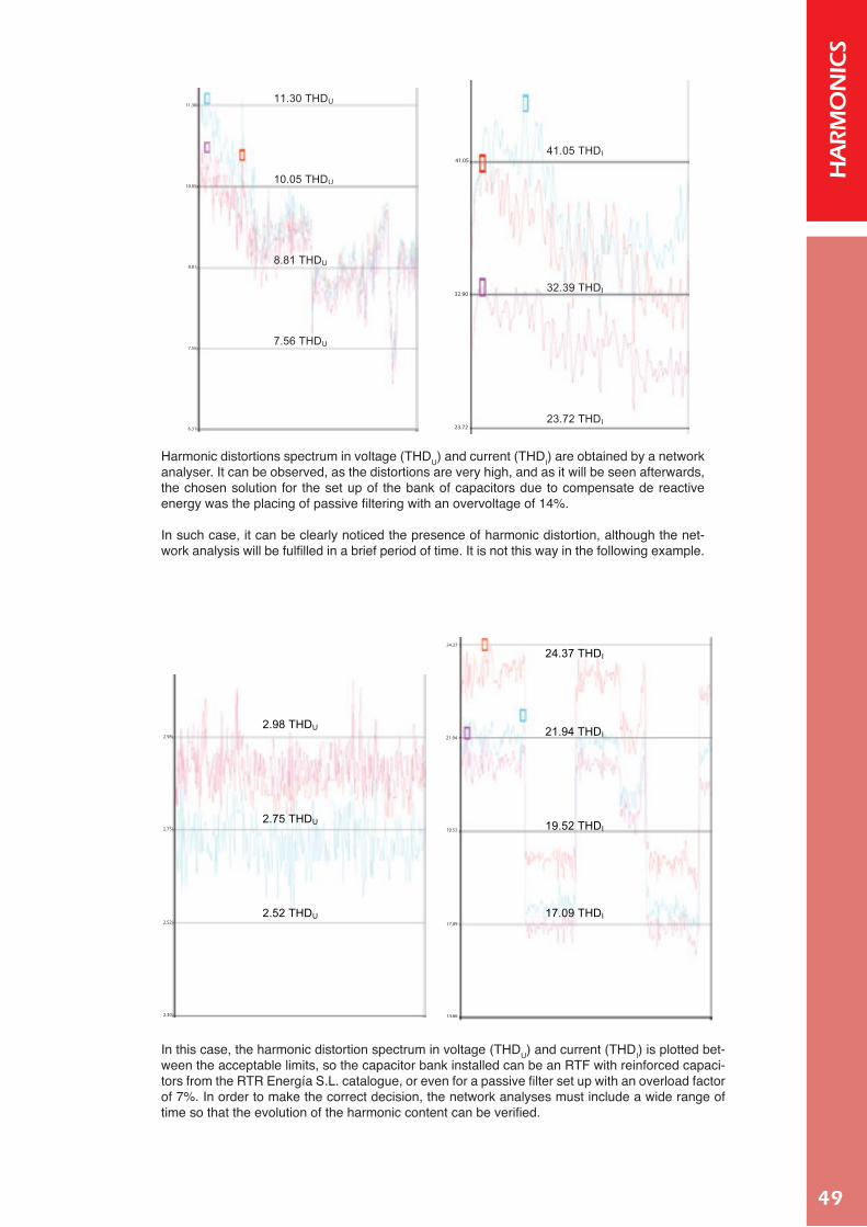
49
HA
RM
ON
ICS
11.30 THDU
10.05 THDU
8.81 THDU
7.56 THDU
41.05 THDI
32.39 THDI
23.72 THDI
11.30
41.05
32.90
23.72
10.05
8.81
7.55
6.31
Harmonic distortions spectrum in voltage (THDU) and current (THDI) are obtained by a network analyser. It can be observed, as the distortions are very high, and as it will be seen afterwards, the chosen solution for the set up of the bank of capacitors due to compensate de reactive energy was the placing of passive filtering with an overvoltage of 14%.
In such case, it can be clearly noticed the presence of harmonic distortion, although the net-work analysis will be fulfilled in a brief period of time. It is not this way in the following example.
24.37 THDI
21.94 THDI
19.52 THDI
19.09 THDI
2.98 THDU
2.75 THDU
2.52 THDU 17.09 THDI
2.98
24.37
21.94
19.52
17.09
14.66
2.75
2.52
2.30
In this case, the harmonic distortion spectrum in voltage (THDU) and current (THDI) is plotted bet-ween the acceptable limits, so the capacitor bank installed can be an RTF with reinforced capaci-tors from the RTR Energía S.L. catalogue, or even for a passive filter set up with an overload factor of 7%. In order to make the correct decision, the network analyses must include a wide range of time so that the evolution of the harmonic content can be verified.

50
HA
RM
ON
ICS HARMONICS RESONANCE
The resonance phenomenon is produced when XL=XC in a parallel or series circuit with non-linear loads, capacitors or inductive loads.
En este caso, el espectro de distorsiones armónicas en tensión (THDU) y en intensidad (THDI) se encuentra en los límites admisibles. Así podría optarse por la instalación de una batería con condensadores reforzados RTF del catálogo de RTR Energía S.L. o bien, por la instalación de filtros pasivos con un factor de sobretensión del 7%. Para poder tomar la decisión más adecuada, el análisis de red debe comprender un periodo amplio de tiempo, para verificar cual es la evolución de dicho contenido armónico. RESONANCIA El fenómeno de resonancia se produce cuando XL=XC en un circuito donde hay colocados en serie o en paralelo cargas no lineales, condensadores, y cargas inductivas.
CL
CXLX
C
L
⋅=⋅⇒
⎭⎬⎫
⋅=
⋅=
ωω
ω
ω 11
La frecuencia para la cual los valores XL y XC se igualan, se denomina frecuencia de resonancia fR.
CLf
CLf
CL RRR⋅
=⇒⋅
=⋅⇒⋅
=π
πω2
1121
24.37 THDI
21.94 THDI
19.52 THDI
19.09 THDI
2.98 THDU
2.75 THDU
2.52 THDU 17.09 THDI
The frequency value in which this occurs, that is, in which XL=XC, is named resonance frequency, fR.
En este caso, el espectro de distorsiones armónicas en tensión (THDU) y en intensidad (THDI) se encuentra en los límites admisibles. Así podría optarse por la instalación de una batería con condensadores reforzados RTF del catálogo de RTR Energía S.L. o bien, por la instalación de filtros pasivos con un factor de sobretensión del 7%. Para poder tomar la decisión más adecuada, el análisis de red debe comprender un periodo amplio de tiempo, para verificar cual es la evolución de dicho contenido armónico. RESONANCIA El fenómeno de resonancia se produce cuando XL=XC en un circuito donde hay colocados en serie o en paralelo cargas no lineales, condensadores, y cargas inductivas.
CL
CXLX
C
L
⋅=⋅⇒
⎭⎬⎫
⋅=
⋅=
ωω
ω
ω 11
La frecuencia para la cual los valores XL y XC se igualan, se denomina frecuencia de resonancia fR.
CLf
CLf
CL RRR⋅
=⇒⋅
=⋅⇒⋅
=π
πω2
1121
24.37 THDI
21.94 THDI
19.52 THDI
19.09 THDI
2.98 THDU
2.75 THDU
2.52 THDU 17.09 THDI
Both of the impedances depend on the frequency (f), but XL has a direct proportionality with the frequen-cy, while XC is inversely proportional to the frequency. So, when there is a raise in the frequency, the value of the impedance XC decreases while XL increases.
Impedancia de una bobina no ideal Impedancia de un condensador no ideal
X
Batería de Distorsióncondensadores armónica
Transformador ycargas reactivas
P activatotal
eq c p nR IX
cXL
f f
X
LR
LR
sR
sR
C
ZZ
L= 1
2∏•f•C
2∏•f•L
FR
Generally, capacitors in industrial facilities are set in parallel as it can be seen in the equivalent circuit attached.
When this configuration acts as a current divider and the value of XC is the lowest one, the majority of the current will flow through the capacitors, and this is why the capacitors may malfunction.
Impedance of a non-linear winding Impedance of a non-linear capacitor
X
Bank of Harmoniccapacitor distortion
Transformer andreactive loads
P activetotal
eq c p nR IX
cXL
f f
X
LR
LR
sR
sR
C
ZZ
L= 1
2∏•f•C
2∏•f•L
FR
PARALLEL RESONANCE
Resonance is produced in a parallel circuit when the resultant current and the line voltage are in-phase. When with a specific value of resonance frequency in the parallel L-C circuit, as wR=150 Hz (frequency on the 5th harmonic), this circuit is inductive (w<wR) the current is delayed so voltage will lead current. If the circuit is capacitive (w>wR), current will lead voltage.
In an L-C circuit, the resultant current of the windings (L, etc.) is the same value as the current of the capacitors (C, etc.) but with the opposite sign, so both the algebraic and vector addition have as a result the maximum value of the impedance and a null value of the resultant current (the opposite results of a series circuit).
In this situation, the current in both L-C branches is extremely high which is hazardous for the capacitor as the XC value is the lowest of the whole circuit.
Impedance of a non-linear winding impedance of a non-linear capacitor

51
HA
RM
ON
ICS
Z
R R
L1 2 nL L
C1 2 nC C
U
C
red
totC
C
R
L
L
L
1+
=
•1
OI
II
ω ω
ωω
Reguladorautomático
It can be clearly seen in the chart how the impedance (Z) raises until reaching the maximum value.
Because of this, it is necessary to protect the capacitors when they are parallel installed in a high har-monic content circuit.
When an industrial facility, with a high harmonic content, is supplied by a power transformer (medium/ low) it is necessary to have the compensating capacitors installed on the base of the transformer so that they can be protected from the harmonics action (see section G on the reactive energy compensation’s chapter).
CAPACITOR PROTECTION
In presence of harmonic distortions, a passive filter (LC) must be used, as their main function is to pro-tect the capacitors. This filtering is recommended in the standard UNEEN-61642 and as a practical data RTR Energía S.L. establishes that in facilities with distortions on voltage on the 5th harmonic higher than 3%, the installation of L-C filters is required, as well as in 5th harmonic current distortions higher than 30%.
RTR Energía S.L. manufactures two classes of capacitors: Standard which can bear harmonic distortions on voltage lower than 2% and in current lower than 25% and Reinforced which can bear distortions on voltage lower than 3% and in current lower than 30%.
Z
R R
L1 2 nL L
C1 2 nC C
U
C
red
totC
C
R
L
L
L
1+
=
•1
OI
II
ω ω
ωω
Automaticcontroller
Maximum 55ºC
Daily average 45ºC
Annual average 35ºC
THDUmax 2%
THDImax 25%
CapacitorsRTR Energía
3%<THDU≤7% THDU≥7%
MA/C/CE/TER Series
MA/C/CE/TER RTF Series
MA/C/CE/TER RCT Series
p(%)=7% p(%)=14%
THDU≤2% THDU≤3%
LC LC
De tuning factor 5,67%, 7%, 14%
MA/C/CE/TER RTF Series MA/C/CE/TER RCT Series
MA/C/CE/TER Series
LC
Voltage harmonic distortion
≤ 2%
Voltage harmonic distortion
≤ 3%
Voltage harmonic distortion >3%

52
HA
RM
ON
ICS
The aim of the repulsion filters is that of avoiding the gain of the facility preponderant harmonic, mainly the 5th harmonic either on voltage or on current and also impeding the parallel resonance between the inductive loads “L” (transformers, starter motors, etc.) and the capacitors “C”, avoiding the overloads and possible damage or destruction of the automatic controlled battery of the bank of capacitors of reactive equalization.
The filter is a cascade arrangement, properly calculated and previously tuned, and is made up of:
• A three phase / single phase reactance. • A three phase / single phase capacitor, with the needed setup power (in kVAr).
This is known as compensation branch, and each of the branches must be designed with the required protection. The various L-C branches form an automatic controlled bank of capacitors,
FILTROS PASIVOS DE RECHAZO El objetivo de los filtros de rechazo es evitar la amplificación del armónico preponderante
de la instalación, generalmente el 5º, bien sea de tensión o de corriente e impedir la
resonancia paralelo entre las cargas inductivas “L” (transformadores, motores
arrancadores…) y los condensadores “C”; evitando así la sobrecarga y posible
destrucción de los condensadores de la batería autorregulada de compensación de
reactiva.
El filtro en sí es un acoplamiento en serie,
debidamente calculado y sintonizada
previamente, formado por:
• una reactancia trifásica/monofásica
• un condensador trifásico/monofásico de
la potencia en kVAr que requiera la
instalación.
A esta situación se llama rama de compensación, cada rama debe estar
diseñada con su correspondiente protección.
La distintas ramas (L-C) conforman la batería autorregulada de condensadores que sería
el filtro completo que tiene como misión compensar el factor de potencia de la instalación
y cuya potencia total será la suma de las potencias de cada una de las ramas de.
CÓMO SE SELECCIONA UNA BATERÍA DE CONDENSADORES (L – C)
A partir del análisis de la red donde se analizan
los armónicos que hay en la instalación, se
determina el armónico preponderante, por lo
general es el 5º armónico (250 Hz frecuencia).
Una vez conocida la frecuencia del armónico,
se establece la frecuencia de resonancia del
filtro ( R), que nunca debe coincidir con ningún
múltiplo entero de la frecuencia de la red (50–
60 Hz) y su valor debe ser inferior la frecuencia
del armónico preponderante, de esta forma la
resonancia con otro armónico es imposible.
La frecuencia de resonancia ( R) se determina
a través del factor de sobretensión (p%) que
establece la relación entre la tensión de la
reactancia y la del condensador:
22
100100100(%) ===resonancia
red
resonancia
red
L
LC
ff
UUU
p C
LLL
C
CC
Repulsion Passive Filters
which acts as a complete filter with the aim of compensating the power factor of the setup and its ove-rall power is the sum of the power of all of the branches.
HOW TO SELECT A BANK OF CAPACITORS (L-C)
With the network analysis of the facilities’ harmo-nics, the preponderant harmonic can be determi-ned, usually being the 5th harmonic (with a fre-quency value of 250Hz).
Once known the frequency value of the harmonic, the resonance frequency of the filter (wR) is esta-blished and it must never coincide with any inte-ger multiple of the current frequency (50-60 Hz). Among this, the value of the resonance frequency (wR) must be a lower value than that of the prepon-derant harmonic one, so that the resonance with any other harmonic is impossible.
The resonance frequency (wR) is determined through the overvoltage factor (p%), which relates both the capacitor and reactance voltages.
FILTROS PASIVOS DE RECHAZO El objetivo de los filtros de rechazo es evitar la amplificación del armónico preponderante de la instalación, generalmente el 5º, bien sea de tensión o de corriente e impedir la resonancia paralelo entre las cargas inductivas “L” (transformadores, motores arrancadores…) y los condensadores “C”; evitando así la sobrecarga y posible destrucción de los condensadores de la batería autorregulada de compensación de reactiva. El filtro en sí es un acoplamiento en serie, debidamente calculado y sintonizada previamente, formado por:
• una reactancia trifásica/monofásica
• un condensador trifásico/monofásico de la potencia en kVAr que requiera la instalación.
A esta situación se llama rama de compensación, cada rama debe estar diseñada con su correspondiente protección.
La distintas ramas (L-C) conforman la batería autorregulada de condensadores que sería el filtro completo que tiene como misión compensar el factor de potencia de la instalación y cuya potencia total será la suma de las potencias de cada una de las ramas de. CÓMO SE SELECCIONA UNA BATERÍA DE CONDENSADORES (L – C) A partir del análisis de la red donde se analizan los armónicos que hay en la instalación, se determina el armónico preponderante, por lo general es el 5º armónico (250 Hz frecuencia). Una vez conocida la frecuencia del armónico, se establece la frecuencia de resonancia del filtro ( R), que nunca debe coincidir con ningún múltiplo entero de la frecuencia de la red (50–60 Hz) y su valor debe ser inferior la frecuencia del armónico preponderante, de esta forma la resonancia con otro armónico es imposible. La frecuencia de resonancia ( R) se determina a través del factor de sobretensión (p%) que establece la relación entre la tensión de la reactancia y la del condensador:
22
100100100(%) ===resonance
red
resonance
red
L
LC
ff
UUU
p C
RTR Energía S.L. designs its own capacitors, with the appropriate passive filters so that they are able to bear a 15% overvoltage, introduced by the filter. As an example, a 440V capacitor with an installed reactance of an overvoltage value of p(%)=7 can bear a voltage value of:
440 · 1,07 · 1,15 = 540 V
THDU p(%) f current f resonance
3-7% 750 Hz 189 Hz
60 Hz 227 Hz
>7% 1450 Hz 134 Hz
60 Hz 160 Hz
R T S
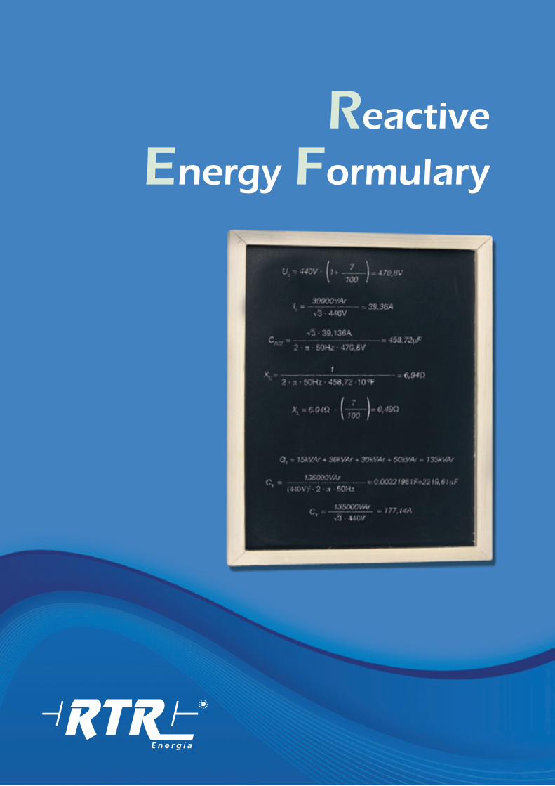
Reactive
Energy Formulary

54
FORM
ULA
Ry Magnitudes and Associated Units Table
Physical Quantity Símbol S.I units Other useful units
Active power P Watt (W) 1kW=1000W
Reactive power Q volt-ampere reactive (VAr) 1kVAr = 1000VAr
Apparent power S volt-ampere (VA) 1kVA = 1000VA
Power factor FP o co sφ - -
Capacitance C Farad (F) 1µF = 10-6F
Inductance L Henry (A) 1mH = 10-3mH
Current I Ampere (A) 1H = 10-3mH
Voltage (electric tension) U Volt (V) -
Electrical resistance R Ohm (Ω) 1kΩ = 1000Ω
Capacitivereactance
XC Ohm (Ω) 1kΩ = 1000Ω
Inductivereactance
XL Ohm (Ω) 1kΩ = 1000Ω
Magnitudes and Associated Units Table
10n Prefix Símbol Equivalencia decimal en los prefijos
1012 Tera T 1.000.000.000.000
109 Giga G 1.000.000.000
106 Mega M 1.000.000
103 Kilo k 1.000
102 Hector h 100
101 Deca da 10
10-1 deci dc 0,1
10-2 centi c 0,01
10-3 mili m 0,001
10-6 micro µ 0,000001
10-9 nano n 0,000000001
10-12 pico p 0,000000000001

55
FORM
ULA
Ry Electric Capacitors
CAPACITOR’S POWER (Q)
CAPACITOR’S CAPACITANCE (C )
Capacitance, in microfarads (μF)=
CAPACITIVE REACTANCE (XC)
Capacitance, in farads (F)
1000 000
Q = U 2 · 2 · π · f · C
Where:
U = line supply voltage, in volts (Vca )f = line frequency, in hertz (Hz)C = capacitor’s capacitance, in farads (F)Q = capacitor’s power, in reactive volt ampere (VAr)
CQ
=U2 · 2 · π · f
Where:
U = line supply voltage, in volts (Vca)f = line frequency, in hertz (Hz)C = capacitor’s capacitance, in farads (F)Q = capacitor’s power, in reactive volt ampere (VAr)
Xc
1=
2 · π · f · C
Where:
Xc = capacitive reactance, in ohms (Ω)f = line frequency, in hertz (Hz)C = capacitor’s capacitance, in farads (F)
C = 0.00049325F=493,25, μF30000VAr
=(440 V) 2 · 2 · π · 50Hz
Example: Three-phase capacitor 30kVAr – 440V – 50Hz

56
FORM
ULA
Ry Electric capacitors
CURRENT THROUGH PHASES IN A THREE-PHASE CAPACITOR (IC )
In single-phase capacitors, √3 is substituted by 1 √3 = 1,7321
INSIDE CONNECTION FOR A THREE-PHASE DELTA-CONNECTED (∆)
Ic
Q=
√3 · U
Where:
U = line supply voltage , in volts (Vca )Q = capacitor’s power, in volt-ampere reactive (VAr)Ic = current, in amperes (A)
C ∆
C=
3
Where:
C = capacitor’s capacitance, in farads (F)C∆= capacitance of each of the windings, in farads (F)
RST
C
C
C
C
C = 2 · C R-s
C ∆ · C R-s
2=
3
How to calculate the capacitance when knowing the capacitance between 2 phases (C
R-S o CR-T o CS-S):
Ic
2 · π · f · C · U=
Where:
U = line supply voltage , in volts (Vca )f = es la frecuencia de la red en hertzios (Hz)C = capacitor’s capacity, in farads (F)Ic = current, in amperes (A)
√3
Ic = 39,36A30000VAr
= √3 .440V
Example: Three-phase capacitor 30kVAr – 440V – 50Hz

57
FORM
ULA
Ry Electric capacitors
INSIDE CONNECTION FOR A THREE-PHASE Y-CONNECTED
SERIES CONNECTION OF CAPACITORS
C Y = C
Where:
C = capacitor’s capacitance, in farads (F)CY = capacitance of each of the windings in farads (F)
C 1 C 2 C 3 C n
The global reactive power of the group (QT) depending on the individual reactive power of each of the united capacitors (Q 1, Q2, Q3,…, Qn) is:
1 1 1 1 1= + + + ...
QT Q1 Q2 Q3 Qn
The global capacitance (CT) for a group of capacitors, where each of the individual capacities are
(C1, C2, C3,..., Cn) when united in series, is:
C T C 1 C 2 C 3 C n
1 1 1 1 1= + + + ...
C = 2 · C R-S
C Y · C R-S
2=
How to calculate the capacitance when knowing the capacitance between 2 phases (C
R-S o CR-T o CS-S):
RST
CY
CY
CY
C
C ∆= 164,42 μF
493,25 μF=
3
Example: Winding capacitance in a three-phase capacitor of 30kVAr – 440V – 50Hz with delta connection.

58
FORM
ULA
Ry
Electric capacitors
PARALLEL CONNECTION OF CAPACITORS
C1
C2
C3
Cn
C T = C 1 + C 2 + C 3 +...+ C n
The global capacitance (CT) for a group of capacitors, where each of the individual capacities are (C1, C2, C3,…, Cn) when united in parallel, is:
QT = Q 1 + Q 2 + Q 3 +...+ Q n
The global reactive power of the group (Q T) depending on the individual reactive power of each of the united capacitors (Q 1, Q2, Q3,…, Qn) is:
IT = I 1 + I 2 + I 3 +...+ I n
The current (Icn
) flowing through each capacitor is the value corresponding to each of them depending on C
T or Q
T and the formula that is used. The global current (I
C) flowing through
the group is valued by the expression:
QT = 15kVAr + 30kVAr + 30kVAr + 60kVAr = 135kVAr
= 0.00221961F=2219,61 μF135000VArC T
= (440V)2 · 2 · π · 50Hz
135000VArI T
= 177,14A= √3 · 440V
Example: Parallel connection between a capacitor of 15 kVAr, two of 30 kVAr and one of 60 kVAr to a 440V and 50Hz line.
The current (IC) flowing through each of the capacitors is going to be the same, and its value
is that of a capacitor which has either CT for capacitance or Q
T for reactive power, depending
on the used formula.
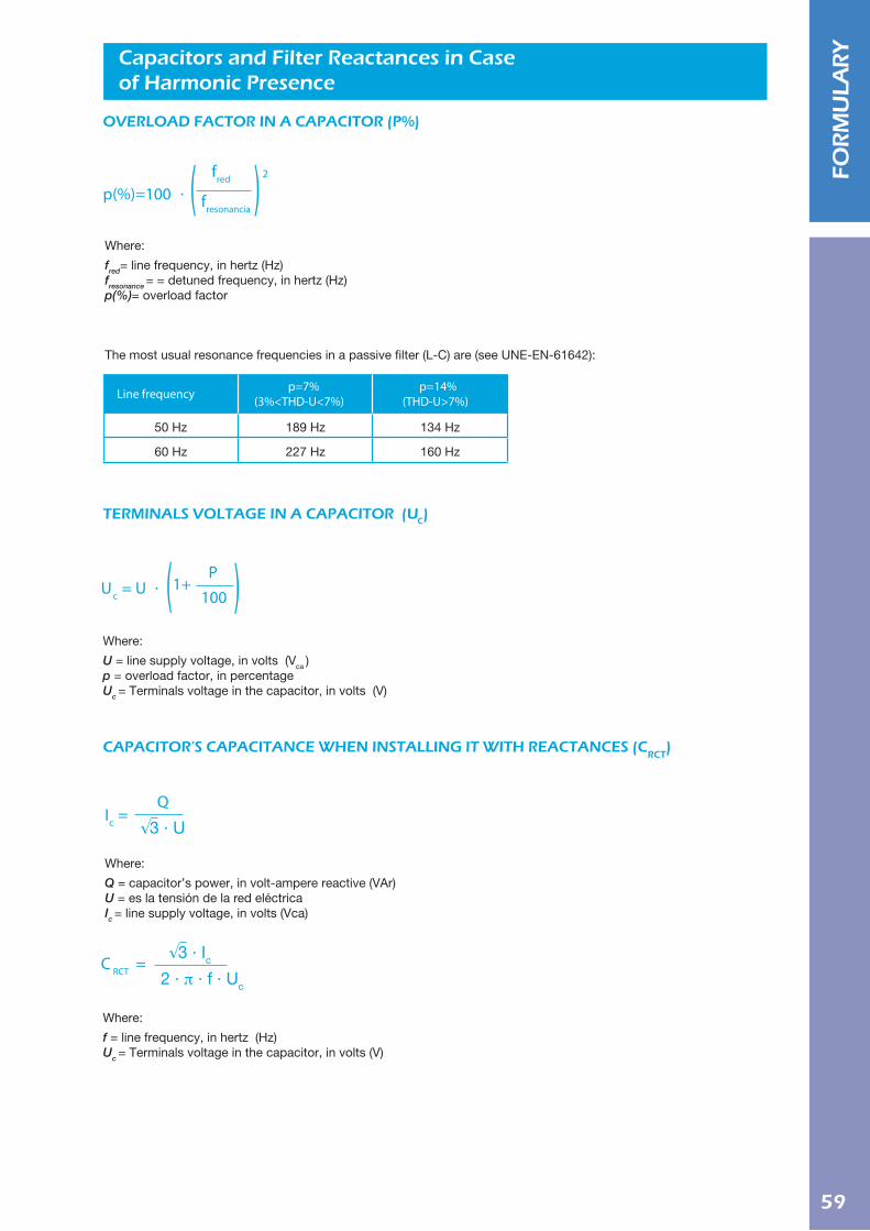
59
FORM
ULA
Ry Capacitors and Filter Reactances in Case
of Harmonic Presence
OVERLOAD FACTOR IN A CAPACITOR (P%)
TERMINALS VOLTAGE IN A CAPACITOR (UC)
CAPACITOR’S CAPACITANCE WHEN INSTALLING IT WITH REACTANCES (CRCT
)
Line frequency p=7%(3%<THD-U<7%)
p=14%(THD-U>7%)
50 Hz 189 Hz 134 Hz
60 Hz 227 Hz 160 Hz
Where:
f = line frequency, in hertz (Hz)Uc = Terminals voltage in the capacitor, in volts (V)
C RCT =√3 · Ic
2 · π · f · Uc
Where:
fred= line frequency, in hertz (Hz)fresonance = = detuned frequency, in hertz (Hz) p(%)= overload factor
The most usual resonance frequencies in a passive filter (L-C) are (see UNE-EN-61642):
p(%)=100 ·fred
fresonancia
2
Where:
U = line supply voltage, in volts (Vca )p = overload factor, in percentage Uc = Terminals voltage in the capacitor, in volts (V)
Uc = U ·P
1001+
Where:
Q = capacitor’s power, in volt-ampere reactive (VAr) U = es la tensión de la red eléctricaIc = line supply voltage, in volts (Vca)
Ic =Q
√3 · U

60
FORM
ULA
Ry Capacitors and filter reactances in case
of harmonic presence
INDUCTIVE REACTANCE IN A FILTER REACTANCE (XL)
REACTANCIES’ INDUCTANCE (L)
L=XL
2 · π · f
Where:
L= inductance, in Henry (H)XL= inductive reactance, in ohms (Ω)
f = line frequency, in hertz (Hz)
Where:
XL= inductive reactance, in ohms (Ω)XC= capacitive reactance, in ohms (Ω)p= overload factor, in percentage
= 39,36AIc =30000VAr
√3 · 440V
= 0,00155H = 1,55mHL =0.49 Ω
2 · π · 50Hz
= 458,72 μFC RCT =√3 · 39,36A
2 · π · 50Hz · 470,8V
= 6,94 ΩXC =1
2 · π · 50Hz · 458,72 ·10-6F
p(%) = 100 · = 7%50Hz
189Hz
2
= 470,8VUc = 440V · 7
1001+
XL = 6.94 Ω · = 0,49 Ω7
100
Example: Capacitor and reactance required for 30kVAr – 440V – 50Hz detuned in 189 Hz
XL = XC ·p
100

61
FORM
ULA
Ry Reactive Power of a Capacitor Bank
POWER FACTOR IN AN INSTALLATION (FP OR COS (ϕ0)
CAPACITOR BANK’S POWER (QB)
VALUE SELECTION FOR TAN (ϕf):
FP final = COS (ϕf ) tan(ϕf )
QB= F · ( tan (ϕ0 ) - tan (ϕf ) )
Where:F = power hired by the installation, in kilowatts (kw). tan(ϕ0 ) = angle’s tangent
= final angle’s tangent ϕ0
tan(ϕf )QB= bank’s reactive power in kilovolt-ampere reactive (kVAr)
Where:
P = global active energy consumed by the electric installation, in kilowatts per hour (kWh) Q = global reactive energy consumed by the electric installation, in kilovoltamperes per hour (kVArh)FP o COS(ϕ0 ) = original installation’s power factor
ϕ0 = arc cos(FP)
PFP = COS( ϕ0 ) = √P2 + Q2
= 0,698FP = COS( ϕ0 ) =10150kWh
√(10150kWh)2 + (10400 kVArh)2
QB = 40kW · (1,026 - 0.000) = 41,04kW
tan(ϕ0 ) = 1,026
tan(ϕf ) = 0,000
Example: Equipment with a hired power of 40 kW, consuming an amount of active energy of 10150 kWh and a reactive one of 10400 kVArh. The final desired value of FP is 1.

62
FORM
ULA
Ry NOTES

Capacitors

64
MA
/C/C
E/T
ER
Three phase capacitors with connector MA/C/CE/TER Series230/400/415/440/480/525/690 V
Standards ..................................... IEC 60831-1/2 EN 60831-1/2
Capacitance tolerance ...................- 5% + 10%Frequency......................................50Hz (60Hz upon request)Temperature range ........................-25ºC + 55ºCDielectric losses.............................≤ 0.2 W/KVArTotal losses* ..................................≤ 0.45 W/KVArMaximum over voltage ..................1,1 x Un **Maximum over current ...................1,5 x In Max. THD in voltage .......................2%Max. THD in current ........................25%Discharge resistance .................... IncorporatedConnection ....................................DeltaCasing ...........................................Aluminium canDisconnection system....................OverpressureDielectric ........................................Metallized polypropilene filmVoltage test between terminals......2,15 x Un 2 sec.Voltage test terminals to case ............3 KV for 10 sec. ACTerminal type .................................ConnectorInrush current ................................Upto 200 x InProtection ...................................... IP 20, indoor mountingHumidity.........................................Max. 95%Expected life ..................................120.000 Hrs (Temp. level C)Altitude...........................................Max. 2000 above sea level
Technical Characteristics
General DescriptionRTR Energía S.L. Power capacitors are manufactured with low loss metallized self-healing polypropylene film. Dry type capacitors are filled with a non-toxic an ecological polyuretha-ne resin manufactured by RTR Energía, this resin provides an excellent heat dissipation properties. This series is enclosed in an aluminium can with overpressure disconnection system.
ApplicationsRTR Energía power capacitors are specially designed for reac-tive power factor correction using them individually or assem-bled into automatic capacitor banks series: Mini, Mural, Modu-lar, ST and Compact Series.
Overpressure disconnection systemIn order to avoid problems caused by overvoltage, harmonics, high temperatures, etc. RTR Energía S.L. power capacitors have been designed with an overpressure disconnection sys-tem. When the terminal cover expands, the internal connec-tions are interrupted and disconnecting the capacitor.
Dimensions
Overpressure disconnection system
DisconnectedConnected
DimensionsD x H (mm)
70 x 215
85 x 215
100 x 215
100 x 300
120 x 300
136 x 300
Cable sectionmm2
2.5 mm2
6 mm2
10 mm2
10 mm2
25 mm2
50 mm2
**Industrial frequency “8 hours every 24 hours” of fluctuation and regulation of voltage, higher values may cause damages in capacitor. EN 60831-1-1996(20.1)
*Without resistors

65
MA/C/CE/TER 50 Hz Series
* Other voltages upon request* 60 Hz upon request
MA
/C/C
E/T
ER
PowerKVAr
2.55
7.510
12.51520
VoltageV.c.a230 V230 V230 V230 V230 V230 V230 V
DimensionsD x H (mm)
70 x 21585 x 215100 x 215100 x 300120 x 300120 x 300136 x 300
Code
C2300255TER0000C2300505TER0000C2300755TER0000C2301005TER0000C2301255TER0000C2301505TER0000C2302005TER0000
PowerKVAr
2,55
7.510
12.515202530354050
VoltageV.c.a400 V400 V400 V400 V400 V400 V400 V400 V400 V400 V400 V400 V
DimensionsD x H (mm)
70 x 21570 x 21585 x 21585 x 215100 x 215100 x 215100 x 300120 x 300120 x 300120 x 300136 x 300136 x 300
Code
C4000255TER0000C4000505TER0000C4000755TER0000C4001005TER0000C4001255TER0000C4001505TER0000C4002005TER0000C4002505TER0000C4003005TER0000C4003505TER0000C4004005TER0000C4005005TER0000
PowerKVAr
2,55
7.510
12.515202530354050
VoltageV.c.a415 V415 V415 V415 V415 V415 V415 V415 V415 V415 V415 V415 V
DimensionsD x H (mm)
70 x 21570 x 21585 x 21585 x 215100 x 215100 x 215100 x 300120 x 300120 x 300120 x 300136 x 300136 x 300
Code
C4150255TER0000C4150505TER0000C4150755TER0000C4151005TER0000C4151255TER0000C4151505TER0000C4152005TER0000C4152505TER0000C4153005TER0000C4153505TER0000C4154005TER0000C4155005TER0000
PowerKVAr
2,55
7.510
12.515202530354050
VoltageV.c.a440 V440 V440 V440 V440 V440 V440 V440 V440 V440 V440 V440 V
DimensionsD x H (mm)
70 x 21570 x 21585 x 21585 x 215100 x 215100 x 215100 x 300100 x 300120 x 300120 x 300136 x 300136 x 300
Code
C4400255TER0000C4400505TER0000C4400755TER0000C4401005TER0000C4401255TER0000C4401505TER0000C4402005TER0000C4402505TER0000C4403005TER0000C4403505TER0000C4404005TER0000C4405005TER0000
PowerKVAr
2,55
7.510
12.515202530354050
VoltageV.c.a480 V480 V480 V480 V480 V480 V480 V480 V480 V480 V480 V480 V
DimensionsD x H (mm)
70 x 21570 x 21585 x 21585 x 215
100 x 215100 x 215100 x 300120 x 300120 x 300120 x 300136 x 300136 x 300
Code
C4800255TER0000C4800505TER0000C4800755TER0000C4801005TER0000C4801255TER0000C4801505TER0000C4802005TER0000C4802505TER0000C4803005TER0000C4803505TER0000C4804005TER0000C4805005TER0000
PowerKVAr
2,55
7.510
12.515202530354050
VoltageV.c.a525 V525 V525 V525 V525 V525 V525 V525 V525 V525 V525 V525 V
DimensionsD x H (mm)
70 x 21570 x 21585 x 21585 x 215
100 x 215100 x 215100 x 300120 x 300120 x 300120 x 300136 x 300136 x 300
Code
C5250255TER0000C5250505TER0000C5250755TER0000C5251005TER0000C5251255TER0000C5251505TER0000C5252005TER0000C5252505TER0000C5253005TER0000C5253505TER0000C5254005TER0000C5255005TER0000
PowerKVAr
2,55
7.510
12.515202530354050
VoltageV.c.a690 V690 V690 V690 V690 V690 V690 V690 V690 V690 V 690 V 690 V
DimensionsD x H (mm)
70 x 21570 x 21585 x 21585 x 215
100 x 215100 x 215100 x 300120 x 300120 x 300120 x 300 136 x 300 136 x 300
Code
C6900255TER0000C6900505TER0000C6900755TER0000C6901005TER0000C6901255TER0000C6901505TER0000C6902005TER0000C6902505TER0000C6903005TER0000C6903505TER0000 C6904005TER0000 C6905005TER0000
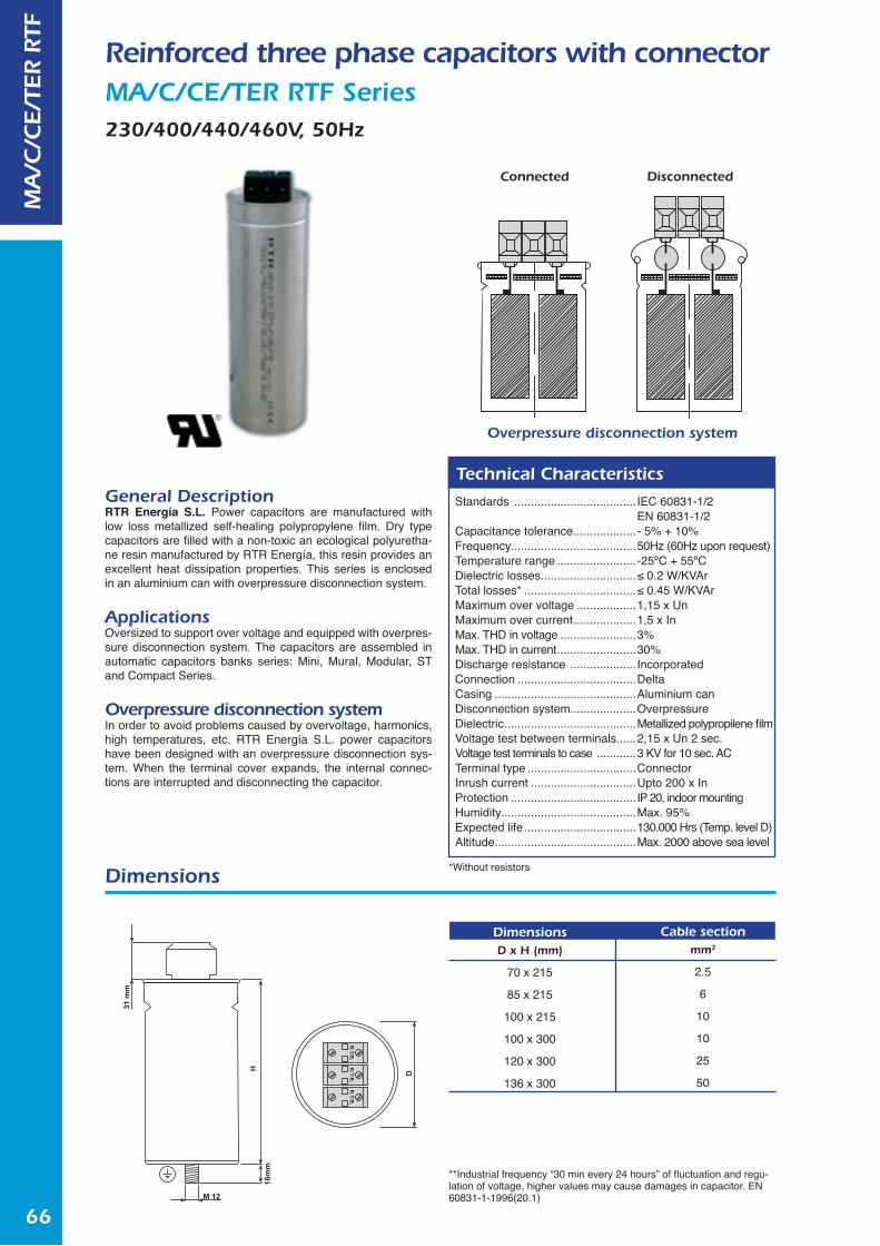
66
Reinforced three phase capacitors with connector MA/C/CE/TER RTF Series230/400/440/460V, 50Hz
Standards ..................................... IEC 60831-1/2 EN 60831-1/2
Capacitance tolerance ...................- 5% + 10%Frequency......................................50Hz (60Hz upon request)Temperature range ........................-25ºC + 55ºCDielectric losses.............................≤ 0.2 W/KVArTotal losses* ..................................≤ 0.45 W/KVArMaximum over voltage ..................1,15 x UnMaximum over current ...................1,5 x InMax. THD in voltage .......................3%Max. THD in current ........................30%Discharge resistance .................... IncorporatedConnection ....................................DeltaCasing ...........................................Aluminium canDisconnection system....................OverpressureDielectric ........................................Metallized polypropilene filmVoltage test between terminals......2,15 x Un 2 sec.Voltage test terminals to case ............3 KV for 10 sec. ACTerminal type .................................ConnectorInrush current ................................Upto 200 x InProtection ...................................... IP 20, indoor mountingHumidity.........................................Max. 95%Expected life ..................................130.000 Hrs (Temp. level D)Altitude...........................................Max. 2000 above sea level
Technical CharacteristicsGeneral DescriptionRTR Energía S.L. Power capacitors are manufactured with low loss metallized self-healing polypropylene film. Dry type capacitors are filled with a non-toxic an ecological polyuretha-ne resin manufactured by RTR Energía, this resin provides an excellent heat dissipation properties. This series is enclosed in an aluminium can with overpressure disconnection system.
ApplicationsOversized to support over voltage and equipped with overpres-sure disconnection system. The capacitors are assembled in automatic capacitors banks series: Mini, Mural, Modular, ST and Compact Series.
Overpressure disconnection systemIn order to avoid problems caused by overvoltage, harmonics, high temperatures, etc. RTR Energía S.L. power capacitors have been designed with an overpressure disconnection sys-tem. When the terminal cover expands, the internal connec-tions are interrupted and disconnecting the capacitor.
Dimensions
Overpressure disconnection system
DisconnectedConnected
DimensionsD x H (mm)
70 x 215
85 x 215
100 x 215
100 x 300
120 x 300
136 x 300
Cable sectionmm2
2.5
6
10
10
25
50
**Industrial frequency “30 min every 24 hours” of fluctuation and regu-lation of voltage, higher values may cause damages in capacitor. EN 60831-1-1996(20.1)
MA
/C/C
E/T
ER R
TF
*Without resistors

67
MA/C/CE/TER RTF 50 Hz Series
* Other voltages upon request* 60 Hz upon request
MA
/C/C
E/T
ER R
TF
Power
KVAr2.55
7.51015
Voltage
V.c.a230 V230 V230 V230 V230 V
Dimensions
D x H (mm)70 x 215
100 x 215100 x 300120 x 300136 x 300
Code
Power Voltage Dimensions Code
Power Voltage Dimensions Code
Power Voltage Dimensions Code
C2300255RTFTER0C2300505RTFTER0C2300755RTFTER0C2301005RTFTER0C2301005RTFTER0
KVAr2,55
7.510
12.5152025303540
V.c.a400 V400 V400 V400 V400 V400 V400 V400 V400 V400 V400 V
D x H (mm)70 x 21570 x 21585 x 215
100 x 215100 x 215100 x 300100 x 300120 x 300120 x 300136 x 300136 x 300
C4000255RTFTER0C4000505RTFTER0C4000755RTFTER0C4001005RTFTER0C4001255RTFTER0C4001505RTFTER0C4002005RTFTER0C4002505RTFTER0C4003005RTFTER0C4003505RTFTER0 C4004005RTFTER0
KVAr2.55
7.510
12.5152025303540
V.c.a440 V440 V440 V440 V440 V440 V440 V440 V440 V440 V440 V
D x H (mm)70 x 21570 x 21585 x 215
100 x 215100 x 215100 x 300100 x 300120 x 300136 x 300136 x 300136 X 300
C4400255RTFTER0C4400505RTFTER0C4400755RTFTER0C4401005RTFTER0C4401255RTFTER0C4401505RTFTER0C4402005RTFTER0C4402505RTFTER0C4403005RTFTER0 C4403505RTFTER0 C4404005RTFTER0
KVAr2.55
7.510
12.5152025303540
V.c.a460 V460 V460 V460 V460 V460 V460 V460 V460 V460 V460 V
D x H (mm)70 x 21570 x 21585 x 215
100 x 215100 x 215100 x 300100 x 300120 x 300136 x 300136 x 300136 X 300
C4600255RTFTER0C4600505RTFTER0C4600755RTFTER0C4601005RTFTER0C4601255RTFTER0C4601505RTFTER0C4602005RTFTER0C4602505RTFTER0C4603005RTFTER0 C4603505RTFTER0 C4604005RTFTER0

68
Three phase capacitors with connector for harmonics filter applications MA/C/CE/TER RCT Series230/400/440/480V, 50Hz
General DescriptionRTR Energía S.L. Power capacitors are manufactured with low loss metallized self-healing polypropylene film. Dry type capaci-tors are filled with a non-toxic an ecological polyurethane resin manufactured by RTR Energía, this resin provides an excellent heat dissipation properties. This series is enclosed in an alumi-nium can with overpressure disconnection system.
Applications Capacitors specially designed to install with 189 Hz (other fre-quencies upon request) three phase harmonic filters. These power capacitors are assembled into Arm´s series Automatic capacitor bank.
Overpressure disconnection systemIn order to avoid problems caused by overvoltage, harmonics, high temperatures, etc. RTR Energía S.L. power capacitors have been designed with an overpressure disconnection sys-tem. When the terminal cover expands, the internal connec-tions are interrupted and disconnecting the capacitor.
Dimensions
Overpressure disconnection system
DisconnectedConnected
**Industrial frequency “30 min every 24 hours” of fluctuation and regu-lation of voltage, higher values may cause damages in capacitor. EN 60831-1-1996(20.1)
MA
/C/C
E/T
ER R
CT
Standard ....................................... EN 60831-1/2Capacitance tolerance ...................- 5% + 10%Frequency......................................50Hz (60Hz upon request)Temperature range ........................-25ºC + 55ºCDielectric losses.............................≤ 0.2 W/KVArTotal losses* ..................................≤ 0.45 W/KVArMaximum over voltage ..................1,15 x UnMaximum over current ...................1,5 x InMax. THD in voltage ....................... Specific design for
harmonicsMax. THD in current ........................30%Discharge resistance .................... IncorporatedConnection ....................................DeltaCasing ...........................................Aluminium canDisconnection system....................OverpressureDielectric ........................................Metallized polypropilene filmVoltage test between terminals......2,15 x Un 2 sec.Voltage test terminals to case ............3 KV for 10 sec. ACTerminal type .................................ConnectorInrush current ................................Upto 200 x InProtection ...................................... IP 20, indoor mountingHumidity.........................................Max. 95%Altitude...........................................Max. 2000 above sea level
Technical Characteristics
DimensionsD x H (mm)
70 x 215
85 x 215
100 x 215
100 x 300
120 x 300
136 x 300
Cable sectionmm2
2.5
6
10
10
25
50
*Without resistors
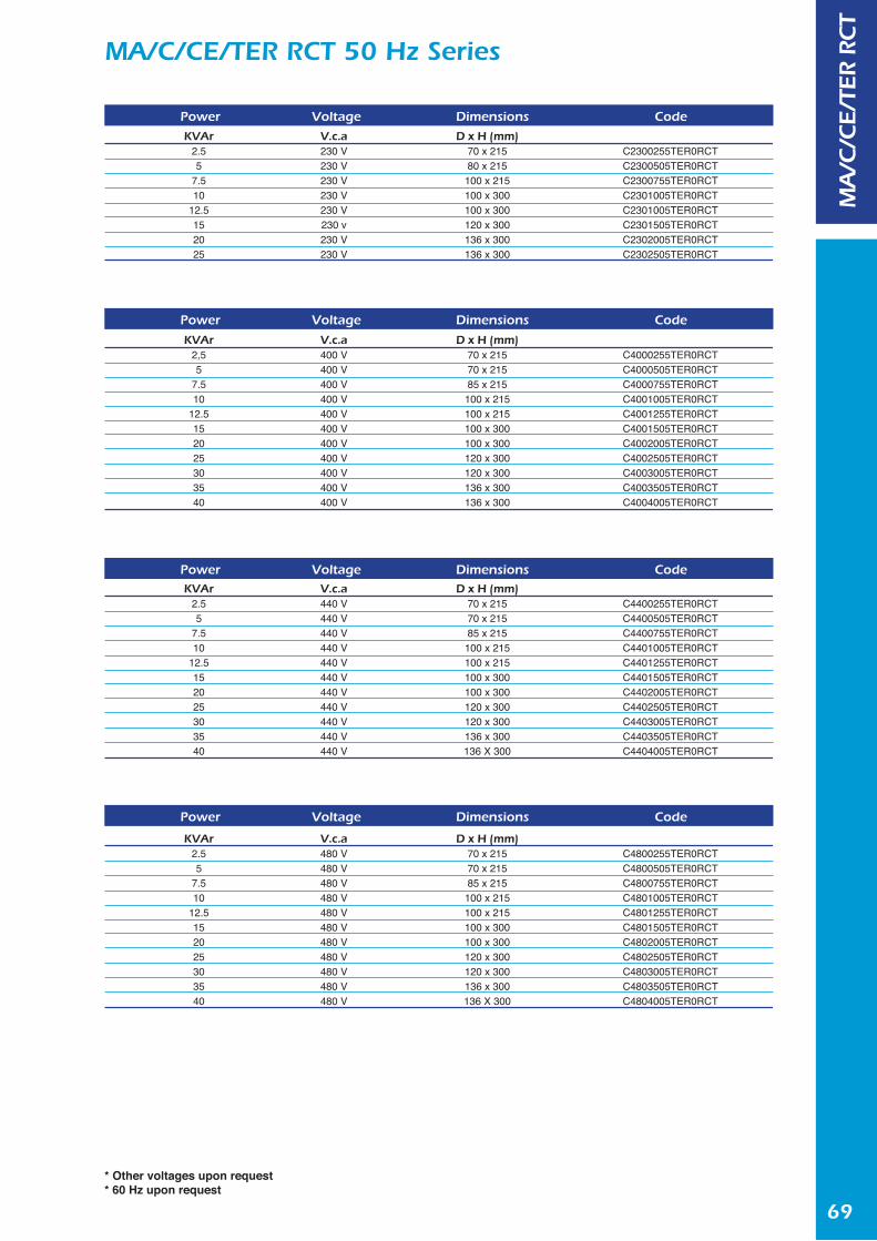
69
MA/C/CE/TER RCT 50 Hz Series
* Other voltages upon request* 60 Hz upon request
MA
/C/C
E/T
ER R
CT
Power
KVAr2.55
7.510
12.5152025
Voltage
V.c.a230 V230 V230 V230 V230 V230 v230 V230 V
Dimensions
D x H (mm)70 x 21580 x 215
100 x 215100 x 300100 x 300120 x 300136 x 300136 x 300
Code
Power Voltage Dimensions Code
Power Voltage Dimensions Code
Power Voltage Dimensions Code
C2300255TER0RCTC2300505TER0RCTC2300755TER0RCTC2301005TER0RCTC2301005TER0RCTC2301505TER0RCTC2302005TER0RCTC2302505TER0RCT
KVAr2,55
7.510
12.5152025303540
V.c.a400 V400 V400 V400 V400 V400 V400 V400 V400 V400 V400 V
D x H (mm)70 x 21570 x 21585 x 215
100 x 215100 x 215100 x 300100 x 300120 x 300120 x 300136 x 300136 x 300
C4000255TER0RCTC4000505TER0RCTC4000755TER0RCTC4001005TER0RCTC4001255TER0RCTC4001505TER0RCTC4002005TER0RCTC4002505TER0RCTC4003005TER0RCTC4003505TER0RCT C4004005TER0RCT
KVAr2.55
7.510
12.5152025303540
V.c.a440 V440 V440 V440 V440 V440 V440 V440 V440 V440 V440 V
D x H (mm)70 x 21570 x 21585 x 215
100 x 215100 x 215100 x 300100 x 300120 x 300120 x 300136 x 300136 X 300
C4400255TER0RCTC4400505TER0RCTC4400755TER0RCTC4401005TER0RCTC4401255TER0RCTC4401505TER0RCTC4402005TER0RCTC4402505TER0RCTC4403005TER0RCT C4403505TER0RCT C4404005TER0RCT
KVAr2.55
7.510
12.5152025303540
V.c.a480 V480 V480 V480 V480 V480 V480 V480 V480 V480 V480 V
D x H (mm)70 x 21570 x 21585 x 215
100 x 215100 x 215100 x 300100 x 300120 x 300120 x 300136 x 300136 X 300
C4800255TER0RCTC4800505TER0RCTC4800755TER0RCTC4801005TER0RCTC4801255TER0RCTC4801505TER0RCTC4802005TER0RCTC4802505TER0RCTC4803005TER0RCT C4803505TER0RCT C4804005TER0RCT
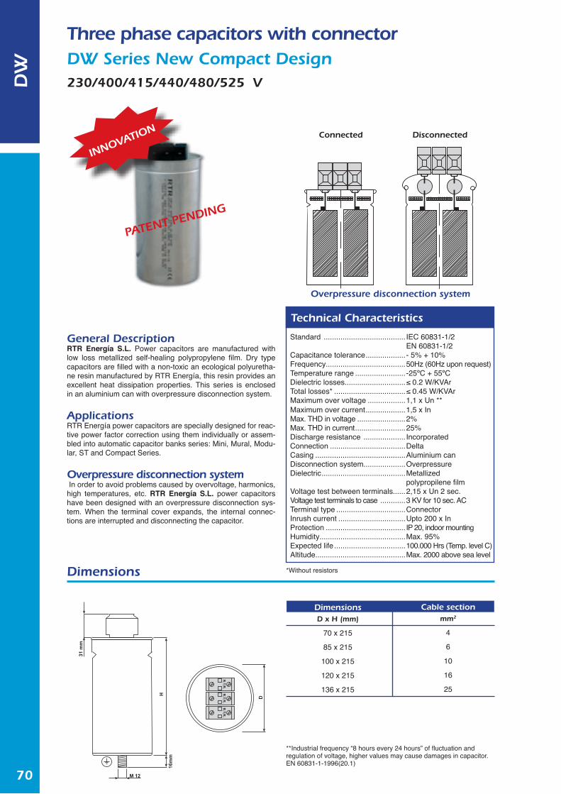
70
DW
Three phase capacitors with connectorDW Series New Compact Design230/400/415/440/480/525 V
Standard ....................................... IEC 60831-1/2 EN 60831-1/2
Capacitance tolerance ...................- 5% + 10%Frequency......................................50Hz (60Hz upon request)Temperature range ........................-25ºC + 55ºCDielectric losses.............................≤ 0.2 W/KVArTotal losses* ..................................≤ 0.45 W/KVArMaximum over voltage ..................1,1 x Un **Maximum over current ...................1,5 x InMax. THD in voltage .......................2%Max. THD in current ........................25%Discharge resistance .................... IncorporatedConnection ....................................DeltaCasing ...........................................Aluminium canDisconnection system....................OverpressureDielectric ........................................Metallized.......................................................polypropilene filmVoltage test between terminals......2,15 x Un 2 sec.Voltage test terminals to case ............3 KV for 10 sec. ACTerminal type .................................ConnectorInrush current ................................Upto 200 x InProtection ...................................... IP 20, indoor mountingHumidity.........................................Max. 95%Expected life ..................................100.000 Hrs (Temp. level C)Altitude...........................................Max. 2000 above sea level
Technical Characteristics
General DescriptionRTR Energía S.L. Power capacitors are manufactured with low loss metallized self-healing polypropylene film. Dry type capacitors are filled with a non-toxic an ecological polyuretha-ne resin manufactured by RTR Energía, this resin provides an excellent heat dissipation properties. This series is enclosed in an aluminium can with overpressure disconnection system.
ApplicationsRTR Energía power capacitors are specially designed for reac-tive power factor correction using them individually or assem-bled into automatic capacitor banks series: Mini, Mural, Modu-lar, ST and Compact Series.
Overpressure disconnection system In order to avoid problems caused by overvoltage, harmonics, high temperatures, etc. RTR Energía S.L. power capacitors have been designed with an overpressure disconnection sys-tem. When the terminal cover expands, the internal connec-tions are interrupted and disconnecting the capacitor.
Dimensions
Overpressure disconnection system
DisconnectedConnected
DimensionsD x H (mm)
70 x 215
85 x 215
100 x 215
120 x 215
136 x 215
Cable sectionmm2
4
6
10
16
25
**Industrial frequency “8 hours every 24 hours” of fluctuation and regulation of voltage, higher values may cause damages in capacitor. EN 60831-1-1996(20.1)
*Without resistors
INNOVATION
PATENT PENDING
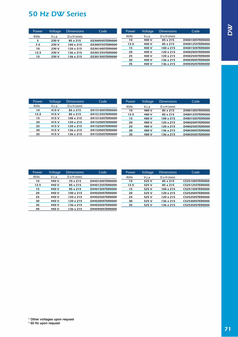
71
50 Hz DW Series
* Other voltages upon request* 60 Hz upon request
PowerKVAr
57.510
12.515
VoltageV.c.a230 V230 V230 V230 V230 V
DimensionsD x H (mm)85 x 215100 x 215120 x 215136 x 215136 x 215
Code
D2300505TER0000D2300755TER0000D2301005TER0000D2301255TER0000D2301505TER0000
KVAr10
12.51520253035
V.c.a415 V415 V415 V415 V415 V415 V415 V
D x H (mm)85 x 21585 x 215
100 x 215120 x 215120 x 215136 x 215136 x 215
D4151005TER0000D4151255TER0000D4151505TER0000D4152005TER0000D4152505TER0000D4153005TER0000D4153505TER0000
KVAr10
12.51520253035
V.c.a400 V400 V400 V400 V400 V400 V400 V
D x H (mm)85 x 21585 x 215
100 x 215120 x 215120 x 215136 x 215136 x 215
D4001005TER0000D4001255TER0000D4001505TER0000D4002005TER0000D4002505TER0000D4003005TER0000D4003505TER0000
Power Voltage Dimensions Code
Power Voltage Dimensions Code
KVAr10
12.5152025303540
V.c.a440 V440 V440 V440 V440 V440 V440 V440 V
D x H (mm)70 x 21585 x 21585 x 215
100 x 215120 x 215120 x 215136 x 215136 x 215
D4401005TER0000D4401255TER0000D4401505TER0000D4402005TER0000D4402505TER0000D4403005TER0000D4403505TER0000D4404005TER0000
Power Voltage Dimensions Code
PowerKVAr
1012.51520253035
VoltageV.c.a480 V480 V480 V480 V480 V480 V480 V
DimensionsD x H (mm)85 x 21585 x 215100 x 215120 x 215120 x 215136 x 215136 x 215
Code
D4801005TER0000D4801255TER0000D4801505TER0000D4802005TER0000D4802505TER0000D4803005TER0000D4803505TER0000
Power Voltage Dimensions CodeKVAr
1012.51520253035
V.c.a525 V525 V525 V525 V525 V525 V525 V
D x H (mm)85 x 21585 x 215100 x 215120 x 215120 x 215136 x 215136 x 215
C5251005TER0000C5251255TER0000C5251505TER0000C5252005TER0000C5252505TER0000C5253005TER0000C5253505TER0000
DW

72
Single phase capacitors with overpressure disconnection systemEA Series230/400/415/440/480V, 50Hz
General DescriptionRTR Energía S.L. Power capacitors are manufactured with low loss metallized self-healing polypropylene film. RTR Energía S.L. dry type capacitors are filled with a non-toxic an ecological polyurethane resin manufactured by RTR Energía, this resin provides an excellent heat dissipation properties. This series is enclosed in an aluminium can with overpressure disconnection system.
ApplicationsRTR Energía power capacitors are specially designed for reac-tive power factor correction using them individually or assem-bled into automatic capacitor banks.
Overpressure disconnection systemIn order to avoid problems caused by overvoltage, harmonics, high temperatures, etc. RTR Energía S.L. power capacitors have been designed with an overpressure disconnection sys-tem. When the terminal cover expands, the internal connec-tions are interrupted and disconnecting the capacitor.
Dimensions
Overpressure disconnection system
DisconnectedConnected
DimensionsD x H (mm)
70 x 140
Terminal∅
FAD 6,3
**Industrial frequency “8 hours every 24 hours” of fluctuation and regulation of voltage, higher values may cause damages in capacitor. EN 60831-1-1996(20.1)
EA
Standard ....................................... EN 60831-1/2Capacitance tolerance ...................- 5% + 10%Frequency......................................50Hz (60Hz upon request)Temperature range ........................-25ºC + 55ºCDielectric losses.............................≤ 0.2 W/KVArTotal losses* ..................................≤ 0.45 W/KVArMaximum over voltage ..................1,1 x Un **Maximum over current ...................1,5 x InMax. THD in voltage .......................2%Max. THD in current ........................25%Discharge resistance .................... IncorporatedConnection ....................................Single-phaseTerminals .......................................2x6.3 QcCasing ...........................................Aluminium canDisconnection system....................OverpressureDielectric ........................................Metallized.......................................................polypropilene filmVoltage test between terminals......2,15 x Un 2 sec.Voltage test terminals to case ............3 KV for 10 sec. ACTerminal cover ...............................Plastic cover PA-6
Technical Characteristics
*Without resistors

73
EA 50 Hz Series
* Other voltages upon request* 60 Hz upon request
EA
Power
KVAr0,831,672,50
Voltage
V.c.a230 V230 V230 V
Dimensions
D x H (mm)70 x 14070 x 14070 x 140
Code
Power Voltage Dimensions Code
Power Voltage Dimensions Code
Power Voltage Dimensions Code
Power Voltage Dimensions Code
EA0230083500000EA0230167500000EA0230250500000
KVAr0,831,672,503,334,17
V.c.a400 V400 V400 V400 V400 V
D x H (mm)70 x 14070 x 14070 x 14070 x 14070 x 140
EA0400083500000EA0400167500000EA0400250500000EA0400333500000EA0400417500000
KVAr0,831,672,503,334,17
V.c.a415 V415 V415 V415 V415 V
D x H (mm)70 x 14070 x 14070 x 14070 x 14070 x 140
EA0415083500000EA0415167500000EA0415250500000EA0415333500000EA0415417500000
KVAr0,831,672,503,334,17
V.c.a440 V440 V440 V440 V440 V
D x H (mm)70 x 14070 x 14070 x 14070 x 14070 x 140
EA0440083500000EA0440167500000EA0440250500000EA0440333500000EA0440417500000
KVAr0,831,672,503,334,17
V.c.a480 V480 V480 V480 V480 V
D x H (mm)70 x 14070 x 14070 x 14070 x 14070 x 140
EA0480083500000EA0480167500000EA0480250500000EA0480333500000EA0480417500000

74
Three-phase capacitorsBO/R TER Series
230/440/460/480/525/690V , 50Hz
Dimensions
DimensionsH x A x P (mm)
300 X 115 X 115
425 X 165 X 150
425 X 320 X 150
Brackets
2
2
2
Cable sectionmm2
2.5 - 10
10 - 50
50
BO
/R T
ER
General DescriptionRTR Energía S.L. Power capacitors are manufactured with low loss metallized self-healing polypropylene film. Dry type capacitors are filled with a non-toxic an ecological polyuretha-ne resin manufactured by RTR Energía, this resin provides an excellent heat dissipation properties. This series is enclosed in an aluminium can with overpressure disconnection system.
ApplicationsRTR Energía power capacitors are specially designed for reac-tive power factor correction used individually or in parallel with other capacitors in order to obtain a bigger steep.
Overpressure disconnection systemIn order to avoid problems caused by overvoltage, harmonics, high temperatures, etc. RTR Energía S.L. power capacitors have been designed with an overpressure disconnection sys-tem. When the terminal cover expands, the internal connec-tions are interrupted and disconnecting the capacitor.
Overpressure disconnection system
DisconnectedConnected
**Industrial frequency “8 hours every 24 hours” of fluctuation and regulation of voltage, higher values may cause damages in capacitor. EN 60831-1-1996(20.1)
Standards ..................................... IEC 60831-1/2 EN 60831-1/2
Capacitance tolerance ...................- 5% + 10%Frequency......................................50Hz (60Hz upon request)Temperature range ........................-25ºC + 55ºCDielectric losses.............................≤ 0.2 W/KVArTotal losses* ..................................≤ 0.45 W/KVArMaximum over voltage ..................1,1 x Un **Maximum over current ...................1,5 x InMax. THD in voltage .......................2%Max. THD in current ........................25%Discharge resistance .................... IncorporatedConnection ....................................DeltaDisconnection system....................OverpressureDielectric ........................................Metallized.......................................................polypropilene filmVoltage test between terminals......2,15 x Un 2 sec.Voltage test terminals to case ............3 KV for 10 sec. ACTerminal type .................................ConnectorInrush current ................................Upto 200 x InProtection ...................................... IP 20, indoor mountingHumidity.........................................Max. 95%Expected life ..................................120.000 Hrs (Temp. level C)Altitude...........................................Max. 2000 above sea level
Technical Characteristics
*Without resistors

75
BO/R TER 50Hz Series
* Other voltages upon request* 60 Hz upon request
BO
/R T
ER
Power
KVAr2.55
7.510
12.515202530354045
Voltage
V.c.a230 V230 V230 V230 V230 V230 V230 V230 V230 V230 V230 V230 V
Dimensions
H x A x P (mm)300 x 115 x 115300 x 115 x 115300 x 115 x 115425 x 165 x 150425 x 165 x 150425 x 165 x 150425 x 165 x 150425 x 320 x 150425 x 320 x 150425 x 320 x 150425 x 320 x 150425 x 320 x 150
Code
R023000255TER00R023000505TER00R023000755TER00R023001005TER00R023001255TER00R023001505TER00R023002005TER00R023002505TER00R023003005TER00R023003505TER00R023004005TER00R023004505TER00
KVAr5
7.510
12.51520253035404550607080
V.c.a440 V440 V440 V440 V440 V440 V440 V440 V440 V440 V440 V440 V440 V440 V440 V
H x A x P (mm)300 x 115 x 115300 x 115 x 115300 x 115 x 115300 x 115 x 115300 x 115 x 115425 x 165 x 150425 x 165 x 150425 x 165 x 150425 x 165 x 150425 x 165 x 150425 x 165 x 150425 x 165 x 150425 x 320 x 150425 x 320 x 150425 x 320 x 150
R044000505TER00R044000755TER00R044001005TER00R044001255TER00R044001505TER00R044002005TER00R044002505TER00R044003005TER00R044003505TER00R044004005TER00R044004505TER00R044005005TER00R044006005TER00R044007005TER00R044008005TER00
KVAr5
7.510
12.51520253035404550607080
V.c.a460 V460 V460 V460 V460 V460 V460 V460 V460 V460 V460 V460 V460 V460 V460 V
H x A x P (mm)300 x 115 x 115300 x 115 x 115300 x 115 x 115300 x 115 x 115300 x 115 x 115425 x 165 x 150425 x 165 x 150425 x 165 x 150425 x 165 x 150425 x 165 x 150425 x 165 x 150425 x 165 x 150425 x 320 x 150425 x 320 x 150425 x 320 x 150
R046000505TER00R046000755TER00R046001005TER00R046001255TER00R046001505TER00R046002005TER00R046002505TER00R046003005TER00R046003505TER00R046004005TER00R046004505TER00R046005005TER00R046006005TER00R046007005TER00R046008005TER00
Power
KVAr5
7.510
12.51520253035404550607080
Voltage
V.c.a480 V480 V480 V480 V480 V480 V480 V480 V480 V480 V480 V480 V480 V480 V480 V
Dimensions
H x A x P (mm)300 x 115 x 115300 x 115 x 115300 x 115 x 115300 x 115 x 115300 x 115 x 115425 x 165 x 150425 x 165 x 150425 x 165 x 150425 x 165 x 150425 x 165 x 150425 x 165 x 150425 x 165 x 150425 x 320 x 150425 x 320 x 150425 x 320 x 150
Code
Power Voltage Dimensions Code Power Voltage Dimensions Code
Power Voltage Dimensions Code Power Voltage Dimensions Code
R048000505TER00R048000755TER00 R048001005TER00 R048001255TER00 R048001505TER00 R048002005TER00 R048002505TER00 R048003005TER00 R048003505TER00 R048004005TER00 R048004505TER00 R048005005TER00 R048006005TER00 R048007005TER00 R048008005TER00
KVAr5
7.510
12.51520253035404550607080
V.c.a525 V525 V525 V525 V525 V525 V525 V525 V525 V525 V525 V525 V525 V525 V525 V
H x A x P (mm)300 x 115 x 115300 x 115 x 115300 x 115 x 115300 x 115 x 115300 x 115 x 115425 x 165 x 150425 x 165 x 150425 x 165 x 150425 x 165 x 150425 x 165 x 150425 x 165 x 150425 x 165 x 150425 x 320 x 150425 x 320 x 150425 x 320 x 150
R052500505TER00R052500755TER00 R052501005TER00 R052501255TER00 R052501505TER00 R052502005TER00 R052502505TER00 R052503005TER00 R052503505TER00 R052504005TER00 R052504505TER00 R052505005TER00 R052506005TER00 R052507005TER00 R052508005TER00
KVAr5
7.510
12.51520253035404550607080
V.c.a690 V690 V690 V690 V690 V690 V690 V690 V690 V690 V690 V690 V690 V690 V690 V
H x A x P (mm)300 x 115 x 115300 x 115 x 115300 x 115 x 115300 x 115 x 115300 x 115 x 115425 x 165 x 150425 x 165 x 150425 x 165 x 150425 x 165 x 150425 x 165 x 150425 x 320 x 150425 x 320 x 150425 x 320 x 150425 x 320 x 150425 x 320 x 150
R069000505TER00R069000755TER00 R069001005TER00 R069001255TER00 R069001505TER00 R069002005TER00 R069002505TER00 R069903005TER00 R069003505TER00 R069004005TER00 R069004505TER00 R069005005TER00 R069006005TER00 R069007005TER00 R069008005TER00

76
Reinforced three phase capacitors BO/R TER RTF Series
230/440V, 50Hz
BO
/R T
ER R
TF
Overpressure disconnection system
DisconnectedConnected
General DescriptionRTR Energía S.L. Power capacitors are manufactured with low loss metallized self-healing polypropylene film. Dry type capaci-tors are filled with a non-toxic an ecological polyurethane resin manufactured by RTR Energía, this resin provides an excellent heat dissipation properties. This series is enclosed in an alumi-nium can with overpressure disconnection system.
ApplicationsOversized to support over voltage and equipped with overpres-sure disconnection system.
Overpressure disconnection systemIn order to avoid problems caused by overvoltage, harmonics, high temperatures, etc. RTR Energía S.L. power capacitors have been designed with an overpressure disconnection sys-tem. When the terminal cover expands, the internal connec-tions are interrupted and disconnecting the capacitor.
Dimensions
DimensionsH x A x P (mm)
300 X 115 X 115
425 X 165 X 150
425 X 320 X 150
Brackets
2
2
2
Cable sectionmm2
2.5 - 10
10 - 50
50
**Industrial frequency “30 min every 24 hours” of fluctuation and regulation of voltage, higher values may cause damages in capacitor. EN 60831-1-1996(20.1)
Standards ..................................... IEC 60831-1/2 EN 60831-1/2
Capacitance tolerance ...................- 5% + 10%Frequency......................................50Hz (60Hz upon request)Temperature range ........................-25ºC + 55ºCDielectric losses.............................≤ 0.2 W/KVArTotal losses* ..................................≤ 0.45 W/KVArMaximum over voltage ..................1,15 x UnMaximum over current ...................1,5 x InMax. THD in voltage .......................3%Max. THD in current ........................30%Discharge resistance .................... IncorporatedConnection ....................................DeltaCasing ...........................................Aluminium canDisconnection system....................OverpressureDielectric ........................................Metallized.......................................................polypropilene filmVoltage test between terminals......2,15 x Un 2 sec.Voltage test terminals to case ............3 KV for 10 sec. ACTerminal type .................................ConnectorInrush current ................................Upto 200 x InProtection ...................................... IP 20, indoor mountingHumidity.........................................Max. 95%Expected life ..................................130.000 Hrs (Temp. level D)Altitude...........................................Max. 2000 above sea level
Technical Characteristics
*Without resistors

77
BO/R TER RTF 50Hz Series
BO
/R T
ER R
TF
PowerKVAr
57.510
12.515202530354045506070
VoltageV.c.a440 V440 V440 V440 V440 V440 V440 V440 V440 V440 V440 V440 V440 V440 V
DimensionsH x A x P (mm)
300 x 115 x 115300 x 115 x 115300 x 115 x 115300 x 115 x 115300 x 115 x 115425 x 165 x 150425 x 165 x 150425 x 165 x 150425 x 165 x 150425 x 165 x 150425 x 320 x 150425 x 320 x 150425 x 320 x 150425 x 320 x 150
PowerKVAr
2.55
7.510
12.515202530
VoltageV.c.a230 V230 V230 V230 V230 V230 V230 V230 V230 V
DimensionsH x A x P (mm)
300 x 115 x 115300 x 115 x 115300 x 115 x 115425 x 165 x 150425 x 165 x 150425 x 165 x 150425 x 165 x 150425 x 320 x 150425 x 320 x 150
Code
R023000255TERTFR023000505TERTFR023000755TERTFR023001005TERTFR023000255TERTFR023001505TERTFR023002005TERTFR023002505TERTFR023003005TERTF
Code
R044000505TERTFR044000755TERTFR044001005TERTFR044001255TERTFR044001505TERTFR044002005TERTFR044002505TERTFR044003005TERTFR044003505TERTFR044004005TERTFR044004505TERTFR044005005TERTFR044006005TERTFR044007005TERTF
* Other voltages upon request* 60 Hz upon request

78
Three phase capacitors for harmonics filter applications BO/R TER RCT Series
230/440V, 50Hz
BO
/R T
ER R
CT
Overpressure disconnection system
DisconnectedConnected
General DescriptionRTR Energía S.L. Power capacitors are manufactured with low loss metallized self-healing polypropylene film. Dry type capacitors are filled with a non-toxic an ecological polyuretha-ne resin manufactured by RTR Energía, this resin provides an excellent heat dissipation properties. This series is enclosed in an aluminium can with overpressure disconnection system.
ApplicationsCapacitors specially designed to install with 189 Hz (other fre-quencies upon request) three phase harmonic filters. These power capacitors are assembled into Arm´s series Automatic capacitor bank
Overpressure disconnection systemIn order to avoid problems caused by overvoltage, harmonics, high temperatures, etc. RTR Energía S.L. power capacitors have been designed with an overpressure disconnection sys-tem. When the terminal cover expands, the internal connec-tions are interrupted and disconnecting the capacitor.
Dimensions
DimensionsH x A x P (mm)
300 X 115 X 115
425 X 165 X 150
425 X 320 X 150
Brackets
2
2
2
Cable sectionmm2
2.5 - 10
10 - 50
50
Standard ....................................... EN 60831-1/2Capacitance tolerance ...................- 5% + 10%Frequency......................................50Hz (60Hz upon request)Temperature range ........................-25ºC + 55ºCDielectric losses.............................≤ 0.2 W/KVArTotal losses* ..................................≤ 0.45 W/KVArMaximum over voltage ..................1,15 x UnMaximum over current ...................1,5 x InMax. THD in voltage ....................... Specific design for
harmonicsMax. THD in current ........................30%Discharge resistance .................... IncorporatedConnection ....................................DeltaCasing ...........................................Aluminium canDisconnection system....................OverpressureDielectric ........................................Metallized.......................................................polypropilene filmVoltage test between terminals......2,15 x Un 2 sec.Voltage test terminals to case ............3 KV for 10 sec. ACTerminal type .................................ConnectorInrush current ................................Upto 200 x InProtection ...................................... IP 20, indoor mountingHumidity.........................................Max. 95%Altitude...........................................Max. 2000 above sea level
Technical Characteristics
*Without resistors

79
BO/R TER RCT 50Hz Series
BO
/R T
ER R
CT
PowerKVAr
2.55
7.510
12.515202530
VoltageV.c.a230 V230 V230 V230 V230 V230 V230 V230 V230 V
DimensionsH x A x P (mm)
300 x 115 x 115300 x 115 x 115300 x 115 x 115425 x 165 x 150425 x 165 x 150425 x 165 x 150425 x 165 x 150425 x 320 x 150425 x 320 x 150
Code
R023000255TERTFR023000505TERTFR023000755TERTFR023001005TERTFR023001255TERTFR023001505TERTFR023002005TERTFR023002505TERTFR023003005TERTF
PowerKVAr
57.510
12.515202530354045506070
VoltageV.c.a440 V440 V440 V440 V440 V440 V440 V440 V440 V440 V440 V440 V440 V440 V
DimensionsH x A x P (mm)
300 x 115 x 115300 x 115 x 115300 x 115 x 115300 x 115 x 115300 x 115 x 115425 x 165 x 150425 x 165 x 150425 x 165 x 150425 x 165 x 150425 x 165 x 150425 x 320 x 150425 x 320 x 150425 x 320 x 150425 x 320 x 150
Code
R044000505TERTFR044000755TERTFR044001005TERTFR044001255TERTFR044001505TERTFR044002005TERTFR044002505TERTFR044003005TERTFR044003505TERTFR044004005TERTFR044004505TERTFR044005005TERTFR044006005TERTFR044007005TERTF
* Other voltages upon request* 60 Hz upon request

80
Three-phase capacitorsBO/R Series
230/400/440/460/480/525/690/1100V , 50HzBO
/R
General DescriptionRTR Energía S.L. Power capacitors are manufactured with low loss metallized self-healing polypropylene film. Dry type capacitors are filled with a non-toxic an ecological polyuretha-ne resin manufactured by RTR Energía, this resin provides an excellent heat dissipation properties. This series is enclosed in a prismatic box with threaded stud for the connection.
ApplicationsThis series power capacitors are specially designed for reactive power factor correction used individually or in parallel with other capacitors in order to obtain a bigger steps.
Standard ............................................... EN 60831-1/2Capacitance tolerance ........................... -5% + 10%Frequency.............................................. 50HzTemperature range ................................ -40ºC + 55ºCDielectric losses..................................... ≤ 0.5 W/KVArTotal losses* .................................. .........≤ 0.45 W/KVArMaximum over voltage .......................... 1,1 x Un **Maximum over current ........................... 1,5 x InTHD Max in voltage ................................ 2%THD Max in current ............................... 25%Discharge resistance ............................ IncorporatedConnection ............................................ DeltaDielectric ................................................ Metallized ............................................................... polypropilene filmVoltage test between terminals.............. 2,15 x Un 2 sec.Voltage test between terminals to case ....... 3 k V for 10sec. AC
Technical Characteristics
**Industrial frequency “8 hours every 24 hours” of fluctuation and regulation of voltage, higher values may cause damages in capacitor. EN 60831-1-1996(20.1)
Dimensions
DimensionsH x A x P (mm)
255 x 210 x 70
370 x 210 x 70
370 x 220 x 150
520 x 220 x 150
620 x 220 x 150
750 x 220 x 150
Brackets
2
2
2
2
2
2
TermM
M 8
M 8
M 12
M 12
M 12
M 12
Power
KVAr2.55
7.510
12.515202530354045
Voltage
V.c.a230 V230 V230 V230 V230 V230 V230 V230 V230 V230 V230 V230 V
Dimensions
H x A x P (mm)255 x 210 x 70255 x 210 x 70370 x 210 x 70370 x 210 x 70370 x 220x 150370 x 220 x 150520 x 220 x 150520 x 220 x 150620 x 220 x 150750 x 220 x 150750 x 220 x 150750 x 220 x 150
Code
R02300025500000R02300050500000R02300075500000R02300100500000R02300125500000R02300150500000R02300200500000R02300250500000R02300300500000R02300350500000R02300400500000R02300450500000
Power
KVAr5
7.510
12.51520253035404550607080
Voltage
V.c.a400 V400 V400 V400 V400 V400 V400 V400 V400 V400 V400 V400 V400 V400 V400 V
Dimensions
H x A x P (mm)255 x 210 x 70255 x 210 x 70255 x 210 x 70370 x 210 x 70370 x 210x 70370 x 210 x 70
370 x 220 x 150370 x 220 x 150520 x 220 x 150520 x 220 x 150520 x 220 x 150520 x 220 x 150620 x 220 x 150750 x 220 x 150750 x 220 x 150
Code
R04000050500000R04000075500000R04000100500000R04000125500000R04000150500000R04000200500000R04000250500000R04000300500000R04000350500000R04000400500000R04000450500000R04000500500000R04000600500000R04000700500000R04000800500000
Dry and Ecological CapacitorRTR Energía S.L. dry type capacitors are filled with a non-toxic and ecological polyurethane resin. Resin manufactured by RTR Energía provides excellent heat dissipation properties, increasing the capacitor expected life.
*Without resistors

81
BO/R 50Hz Series
BO
/R
* Other voltages upon request* 60 Hz upon request
Power
KVAr5
7.510
12.51520253035404550607080
Voltage
V.c.a440 V440 V440 V440 V440 V440 V440 V440 V440 V440 V440 V440 V440 V440 V440 V
Dimensions
H x A x P (mm)255 x 210 x 70255 x 210 x 70255 x 210 x 70370 x 210 x 70370 x 210x 70370 x 210 x 70370 x 220 x 150370 x 220 x 150520 x 220 x 150520 x 220 x 150520 x 220 x 150520 x 220 x 150620 x 220 x 150750 x 220 x 150750 x 220 x 150
Code
R04400050500000R04400075500000R04400100500000R04400125500000R04400150500000R04400200500000R04400250500000R04400300500000R04400350500000R04400400500000R04400450500000R04400500500000R04400600500000R04400700500000R04400800500000
KVAr5
7.510
12.51520253035404550607080
V.c.a460 V460 V460 V460 V460 V460 V460 V460 V460 V460 V460 V460 V460 V460 V460 V
H x A x P (mm)255 x 210 x 70255 x 210 x 70255 x 210 x 70370 x 210 x 70370 x 210 x 70370 x 210 x 70370 x 220 x 150370 x 220 x 150520 x 220 x 150520 x 220 x 150520 x 220 x 150520 x 220 x 150620 x 220 x 150750 x 220 x 150750 x 220 x 150
R04600050500000R04600075500000R04600100500000R04600125500000R04600150500000R04600200500000R04600250500000R04600300500000R04600350500000R04600400500000R04600450500000R04600500500000R04600600500000R04600700500000R04600800500000
KVAr5
7.510
12.51520253035404550607080
V.c.a480 V480 V480 V480 V480 V480 V480 V480 V480 V480 V480 V480 V480 V480 V480 V
H x A x P (mm)255 x 210 x 70255 x 210 x 70255 x 210 x 70370 x 210 x 70370 x 210x 70370 x 210 x 70370 x 220 x 150370 x 220 x 150520 x 220 x 150520 x 220 x 150520 x 220 x 150520 x 220 x 150620 x 220 x 150750 x 220 x 150750 x 220 x 150
R04800050500000R04800075500000 R04800100500000 R04800125500000 R04800150500000 R04800200500000 R04800250500000 R04800300500000 R04800350500000 R04800400500000 R04800450500000 R04800500500000 R04800600500000 R04800700500000 R04800800500000
Power
KVAr5
7.510
12.51520253035404550607080
Voltage
V.c.a525 V525 V525 V525 V525 V525 V525 V525 V525 V525 V525 V525 V525 V525 V525 V
Dimensions
H x A x P (mm)255 x 210 x 70255 x 210 x 70255 x 210 x 70370 x 210 x 70370 x 210x 70370 x 210 x 70
370 x 220 x 150370 x 220 x 150520 x 220 x 150520 x 220 x 150520 x 220 x 150520 x 220 x 150620 x 220 x 150750 x 220 x 150750 x 220 x 150
Code
Power Voltage Dimensions Code Power Voltage Dimensions Code
Power Voltage Dimensions Code Power Voltage Dimensions Code
R05250050500000R05250075500000 R05250100500000 R05250125500000 R05250150500000 R05250200500000 R05250250500000 R05250300500000 R05250350500000 R05250400500000 R05250450500000 R05250500500000 R05250600500000 R05250700500000 R05250800500000
KVAr5
7.510
12.51520253035404550607080
V.c.a690 V690 V690 V690 V690 V690 V690 V690 V690 V690 V690 V690 V690 V690 V690 V
H x A x P (mm)255 x 210 x 70255 x 210 x 70255 x 210 x 70370 x 210 x 70370 x 210x 70370 x 210 x 70
370 x 220 x 150370 x 220 x 150520 x 220 x 150520 x 220 x 150520 x 220 x 150520 x 220 x 150620 x 220 x 150750 x 220 x 150750 x 220 x 150
R06900050500000R06900075500000 R06900100500000 R06900125500000 R06900150500000 R06900200500000 R06900250500000 R06990300500000 R06900350500000 R06900400500000 R06900450500000 R06900500500000 R06900600500000 R06900700500000 R06900800500000
KVAr5
7.510
12.51520253035404550607080
V.c.a1100 V1100 V1100 V1100 V1100 V1100 V1100 V1100 V1100 V1100 V1100 V1100 V1100 V1100 V1100V
H x A x P (mm)255 x 210 x 70255 x 210 x 70255 x 210 x 70370 x 210 x 70370 x 210x 70370 x 210 x 70
370 x 220 x 150370 x 220 x 150520 x 220 x 150520 x 220 x 150520 x 220 x 150520 x 220 x 150620 x 220 x 150750 x 220 x 150750 x 220 x 150
R11000050500000R11000075500000 R11000100500000 R11000125500000 R11000150500000 R11000200500000 R11000250500000 R11000300500000 R11000350500000 R11000400500000 R11000450500000 R11000500500000 R11000600500000 R11000700500000 R11000800500000

82
BO
/R R
TFReinforced three-phase capacitorsBO/R RTF Series
230/400/440V, 50Hz
Standard ............................................... EN 60831-1/2Capacitance tolerance ........................... - 5% + 10%Frequency.............................................. 50Hz (60Hz upon............................................................... request)Temperature range ................................ -40ºC + 55ºCDielectric losses..................................... ≤ 0.5 W/KVArTotal losses* .................................. ........≤ 0.45 W/KVArMaximum over voltage .......................... 1,15 x Un Maximum over current ........................... 1,5 x In THD Max in voltage ................................ 3%THD Max in current ................................. 30%Discharge resistance ............................ IncorporatedConnection ............................................ DeltaDielectric ................................................ Metallized ............................................................... polypropilene filmVoltage test between terminals.............. 2,15 x Un 2 sec.Voltage test between terminals to case ....... 3 k V for 10sec. AC
Technical CharacteristicsGeneral DescriptionRTR Energía S.L. Power capacitors are manufactured with low loss metallized self-healing polypropylene film. Dry type capacitors are filled with a non-toxic an ecological polyuretha-ne resin manufactured by RTR Energía, this resin provides an excellent heat dissipation properties. This series is enclosed in a prismatic box with threaded stud for the connection.
ApplicationsThis series power capacitors are specially oversized designed to support overvoltage in power factor correction applications, used individually or in parallel with other capacitors in order to obtain a bigger steps.
Dry and Ecological CapacitorRTR Energía S.L. dry type capacitors are filled with a non-toxic and ecological polyurethane resin. Resin manufactured by RTR Energía provides excellent heat dissipation properties, increasing the capacitor expected life.
Dimensions
**Industrial frequency “30 min every 24 hours” of fluctuation and regu-lation of voltage, higher values may cause damages in capacitor. EN 60831-1-1996(20.1)
DimensionsH x A x P (mm)
255 x 210 x 70
370 x 210 x 70
370 x 220 x 150
520 x 220 x 150
620 x 220 x 150
750 x 220 x 150
Brackets
2
2
2
2
2
2
TermM
M 8
M 8
M 12
M 12
M 12
M 12
*Without resistors

83
BO
/R R
TF
BO/R RTF 50Hz Series
* Other voltages upon request* 60 Hz upon request
Power
KVAr2.55
7.510
12.515202530354045
Voltage
V.c.a230 V230 V230 V230 V230 V230 V230 V230 V230 V230 V230 V230 V
Dimensions
H x A x P (mm)255 x 210 x 70255 x 210 x 70370 x 210 x 70370 x 210 x 70
370 x 220 x 150370 x 220 x 150520 x 220 x 150520 x 220 x 150620 x 220 x 150750 x 220 x 150750 x 220 x 150750 x 220 x 150
Code
Power Voltage Dimensions Code
Power Voltage Dimensions Code
R023000255RTF00R023000505RTF00R023000755RTF00R023001005RTF00R023001255RTF00R023001505RTF00R023002005RTF00R023002505RTF00R023003005RTF00R023003505RTF00R023004005RTF00R023004505RTF00
KVAr5
7.510
12.51520253035404550607080
V.c.a400 V400 V400 V400 V400 V400 V400 V400 V400 V400 V400 V400 V400 V400 V400 V
H x A x P (mm)255 x 210 x 70255 x 210 x 70255 x 210 x 70370 x 210 x 70370 x 210 x 70370 x 210 x 70
370 x 220 x 150370 x 220 x 150520 x 220 x 150520 x 220 x 150520 x 220 x 150520 x 220 x 150620 x 220 x 150750 x 220 x 150750 x 220 x 150
R040000505RTF00R040000755RTF00R040001005RTF00R040001255RTF00R040001505RTF00R040002005RTF00R040002505RTF00R040003005RTF00R040003505RTF00R040004005RTF00R040004505RTF00R040005005RTF00R040006005RTF00R040007005RTF00R040008005RTF00
KVAr5
7.510
12.51520253035404550607080
V.c.a440 V440 V440 V440 V440 V440 V440 V440 V440 V440 V440 V440 V440 V440 V440 V
H x A x P (mm)255 x 210 x 70255 x 210 x 70255 x 210 x 70370 x 210 x 70370 x 210 x 70370 x 210 x 70
370 x 220 x 150370 x 220 x 150520 x 220 x 150520 x 220 x 150520 x 220 x 150520 x 220 x 150620 x 220 x 150750 x 220 x 150750 x 220 x 150
R044000505RTF00R044000755RTF00R044001005RTF00R044001255RTF00R044001505RTF00R044002005RTF00R044002505RTF00R044003005RTF00R044003505RTF00R044004005RTF00R044004505RTF00R044005005RTF00R044006005RTF00R044007005RTF00R044008005RTF00

84
BO
/R R
CT Three phase capacitors for harmonics
filter applications BO/R RCT Series
230/440V, 50Hz
General DescriptionRTR Energía S.L. Power capacitors are manufactured with low loss metallized self-healing polypropylene film. Dry type capacitors are filled with a non-toxic an ecological polyuretha-ne resin manufactured by RTR Energía, this resin provides an excellent heat dissipation properties. This series is enclosed in a prismatic box with threaded stud for the connection.
ApplicationsCapacitors specially designed to install with 189 Hz (other fre-quencies upon request) three phase harmonic filters.
Dry and Ecological CapacitorRTR Energía S.L. dry type capacitors are filled with a non-toxic and ecological polyurethane resin. Resin manufactured by RTR Energía provides excellent heat dissipation properties, increasing the capacitor expected life.
Dimensions
**Industrial frequency “30 min every 24 hours” of fluctuation and regu-lation of voltage, higher values may cause damages in capacitor. EN 60831-1-1996(20.1)
Standard ............................................... EN 60831-1/2Capacitance tolerance ........................... - 5% + 10%Frequency.............................................. 50Hz (60Hz upon............................................................... request)Temperature range ................................ -40ºC + 55ºCDielectric losses..................................... ≤ 0.5 W/KVArTotal losses* .................................. .........≤ 0.45 W/KVArMaximum over voltage .......................... 1,15 x Un Maximum over current ........................... 1,5 x In THD Max in voltage ................................ Specific design for
harmonicsTHD Max in current ................................. 30%Discharge resistance ............................ IncorporatedConnection ............................................ DeltaDielectric ................................................ Metallized ............................................................... polypropilene filmVoltage test between terminals.............. 2,15 x Un 2 sec.Voltage test between terminals to case ....... 3 k V for 10sec. AC
Technical Characteristics
DimensionsH x A x P (mm)
255 x 210 x 70
370 x 210 x 70
370 x 220 x 150
520 x 220 x 150
620 x 220 x 150
750 x 220 x 150
Brackets
2
2
2
2
2
2
TermM
M 8
M 8
M 12
M 12
M 12
M 12
*Without resistors

85
BO
/R R
CTSerie BO/R RCT 50Hz
PowerKVAr
2.55
7.510
12.515202530354045
PowerKVAr
57.510
12.51520253035404550607080
VoltageV.c.a230 V230 V230 V230 V230 V230 V230 V230 V230 V230 V230 V230 V
VoltageV.c.a440 V440 V440 V440 V440 V440 V440 V440 V440 V440 V440 V440 V440 V440 V440 V
DimensionsD x H (mm)255 x 210 x 70255 x 210 x 70370 x 210 x 70370 x 210 x 70
370 x 220 x 150370 x 220 x 150520 x 220 x 150520 x 220 x 150620 x 220 x 150750 x 220 x 150750 x 220 x 150750 x 220 x 150
DimensionsD x H (mm)255 x 210 x 70255 x 210 x 70255 x 210 x 70370 x 210 x 70370 x 210 x 70370 x 210 x 70
370 x 220 x 150370 x 220 x 150520 x 220 x 150520 x 220 x 150520 x 220 x 150520 x 220 x 150620 x 220 x 150750 x 220 x 150750 x 220 x 150
Code
R023000255RCT00 R023000505RCT00 R023000755RCT00 R023001005RCT00 R023001255RCT00R023001505RCT00R023002005RCT00R023002505RCT00R023003005RCT00R023003505RCT00R023004005RCT00R023004505RCT00
Code
R044000505RCT00 R044000755RCT00R044001005RCT00R044001255RCT00R044001505RCT00R044002005RCT00R044002505RCT00R044003005RCT00R044003505RCT00R044004005RCT00R044004505RCT00R044005005RCT00R044006005RCT00R044007005RCT00R044008005RCT00
* Other voltages upon request* 60 Hz upon request

86
CA
PACIT
ORS NOTES

Fixed Capacitors
Banks

88
PRE
Three-phase protected power capacitor series PRE series230/440V, 50Hz
Standard ............................................... IEC 831-1/2Capacitance tolerance ........................... - 5% + 10%Frecuency .............................................. 50HzTemperature range ................................ -25ºC + 55ºCDielectric losses..................................... ≤ 0.5 W/KVArMaximum over voltage .......................... 1,1 x UnMaximum over current ........................... 1,5 x InTHD Max. in voltage .............................. 2%Discharge resistance ............................. IncorporatedVoltage test between terminals.............. 2,15 x Un 2 sec.Voltage test between terminals to case . 3 KV en AC/10 sec.Connection ............................................ DeltaProtection ............................................. IP-54
Technical Characteristics General Information RTR Energía three-phase protected power capacitors are spe-cially designed for reactive power factor correction for trans-formers and electrical installations where automatic regulation is not required. This series capacitor banks are equiped with automatic switch protection.
Overpressure disconnection system In order to avoid problems caused by overvoltages, harmonics, high temperatures , etc. RTR Energía S.L. power capacitors have been designed with an overpressure disconnection sys-tem . When the terminal cover expands, the internal connec-tions are interrupted and disconnecting the capacitor.
PRE-1 PRE-2 PRE-3

89
PREPower
KVAr12
2.53
PowerKVAr
12
2.5345
PowerKVAr
456789
PowerKVAr
101112
PowerKVAr
7.510
12.515
PowerKVAr17.520
22.525
VoltageV.c.a230 V230 V230 V230 V
VoltageV.c.a440 V440 V440 V440 V440 V440 V
VoltageV.c.a230 V230 V230 V230 V230 V230 V
VoltageV.c.a230 V230 V230 V
VoltageV.c.a440 V440 V440 V440 V
VoltageV.c.a440 V440 V440 V440 V
DimensionsH x A x P (mm)
540 x 136 x 140540 x 136 x 140540 x 136 x 140540 x 136 x 140
DimensionsH x A x P (mm)
540 x 136 x 140540 x 136 x 140540 x 136 x 140540 x 136 x 140540 x 136 x 140540 x 136 x 140
DimensionsH x A x P (mm)
570 x 275 x 140570 x 275 x 140570 x 275 x 140570 x 275 x 140570 x 275 x 140570 x 275 x 140
DimensionsH x A x P (mm)
570 x 380 x 140570 x 380 x 140570 x 380 x 140
DimensionsH x A x P (mm)
570 x 275 x 140570 x 275 x 140570 x 275 x 140570 x 275 x 140
DimensionsH x A x P (mm)
570 x 380 x 140570 x 380 x 140570 x 380 x 140570 x 380 x 140
PRE-1
PRE-2
PRE-3

90
PRB
A y
PRB
DThree-phase protected power capacitor series PRBA and PRBD series230/440V, 50Hz
Standard ............................................... IEC 831-1/2Capacitance tolerance ........................... - 5% + 10%Frecuency .............................................. 50HzTemperature range ................................ -25ºC + 55ºCDielectric losses..................................... ≤ 0.5 W/KVArMaximum over voltage .......................... 1,1 x UnMaximum over current ........................... 1,5 x InTHD Max in voltage ............................... 2%Discharge resistance ............................ IncorporatedVoltage test between terminals.............. 2,15 x Un 2 sec.Voltage test terminals to case ..................... 3 k V for 10sec. ACConnection ............................................ Delta
Technical Characteristics General Information RTR Energía three-phase protected power capacitors are spe-cially designed for reactive power factor correction for transfor-mers and electrical installations where automatic regulation is not required.
PRBDPRBA

91
PRB
A y
PRB
D
PowerKVAr
2.55
7.5101520
PowerKVAr
2.55
7.51015202530
PowerKVAr
2.55
7.510
12.51520253035405060
PowerKVAr
2.55
7.510
12.515202530405060
VoltageV.c.a230 V230 V230 V230 V230 V230 V
VoltageV.c.a230 V230 V230 V230 V230 V230 V230 V230 V
VoltageV.c.a440 V440 V440 V440 V440 V440 V440 V440 V440 V440 V440 V440 V440 V
VoltageV.c.a440 V440 V440 V440 V440 V440 V440 V440 V440 V440 V440 V440 V
DimensionsH x A x P (mm)
255 x 210 x 70255 x 210 x 70
370 x 220 x 150370 x 220 x 150370 x 220 x 150520 x 220 x 150
DimensionsH x A x P (mm)
255 x 210 x 70255 x 210 x 70
370 x 220 x 150370 x 220 x 150520 x 220 x 150520 x 220 x 150520 x 220 x 150370 x 220 x 310
DimensionsH x A x P (mm)
255 x 210 x 70255 x 210 x 70255 x 210 x 70255 x 210 x 70
370 x 220 x 150370 x 220 x 150370 x 220 x 150370 x 220 x 150370 x 220 x 150520 x 220 x 150520 x 220 x 150520 x 220 x 150620 x 220 x 150
DimensionsH x A x P (mm)
255 x 210 x 70255 x 210 x 70255 x 210 x 70255 x 210 x 70
370 x 220 x 150370 x 220 x 150370 x 220 x 150520 x 220 x 150520 x 220 x 150520 x 220 x 150520 x 220 x 150370 x 220 x 310
PRBA Circuit Breaker + Pilot Light
PRBD Disconector + Fuses + Pilot Light
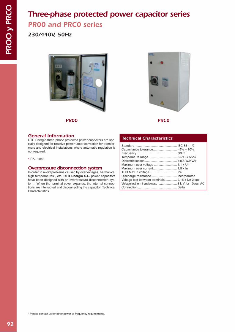
92
PRO
O y
PRCO
Three-phase protected power capacitor series PR00 and PRC0 series230/440V, 50Hz
Standard ............................................... IEC 831-1/2Capacitance tolerance ........................... - 5% + 10%Frecuency .............................................. 50HzTemperature range ................................ -25ºC + 55ºCDielectric losses..................................... ≤ 0.5 W/KVArMaximum over voltage .......................... 1,1 x UnMaximum over current ........................... 1,5 x InTHD Max in voltage ............................... 2%Discharge resistance ............................ IncorporatedVoltage test between terminals.............. 2,15 x Un 2 sec.Voltage test terminals to case ..................... 3 k V for 10sec. ACConnection ............................................ Delta
Technical Characteristics
PRC0PR00
General Information RTR Energía three-phase protected power capacitors are spe-cially designed for reactive power factor correction for transfor-mers and electrical installations where automatic regulation is not required.
RAL 1013
Overpressure disconnection system In order to avoid problems caused by overvoltages, harmonics, high temperatures , etc. RTR Energía S.L. power capacitors have been designed with an overpressure disconnection sys-tem . When the terminal cover expands, the internal connec-tions are interrupted and disconnecting the capacitor. Technical Characteristics
* Please contact us for other power or frequency requirements.

93
PRO
O y
PRCO
PowerKVAr
2.55
7.5101520
PowerKVAr
2.55
7.510152025
PowerKVAr
2.55
7.510
12.51520253040506080
VoltageV.c.a230 V230 V230 V230 V230 V230 V
VoltageV.c.a230 V230 V230 V230 V230 V230 V230 V
VoltageV.c.a440 V440 V440 V440 V440 V440 V440 V440 V440 V440 V440 V440 V440 V
DimensionsH x A x P (mm)
300 x 300 x 200300 x 300 x 200400 x 300 x 200400 x 300 x 200600 x 400 x 260600 x 400 x 260
DimensionsH x A x P (mm)
300 x 300 x 200300 x 300 x 200300 x 300 x 200400 x 300 x 200600 x 400 x 260600 x 500 x 260600 x 500 x 260
DimensionsH x A x P (mm)
300 x 300 x 200300 x 300 x 200300 x 300 x 200300 x 300 x 200300 x 300 x 200400 x 300 x 200400 x 300 x 200400 x 300 x 200600 x 400 x 260600 x 400 x 260600 x 500 x 260600 x 500 x 260600 x 500 x 260
PowerKVAr
2.55
7.510
12.5152025304045506080
VoltageV.c.a440 V440 V440 V440 V440 V440 V440 V440 V440 V440 V440 V440 V440 V440 V
DimensionsH x A x P (mm)
300 x 300 x 200300 x 300 x 200300 x 300 x 200300 x 300 x 200300 x 300 x 200300 x 300 x 200400 x 300 x 200400 x 300 x 200600 x 400 x 260600 x 500 x 260600 x 500 x 260600 x 500 x 260600 x 500 x 260800 x 600 x 300
PR00 Circuit Breaker + Pilot Light
PRC0 Circuit Breaker + Fuses + Pilot Light

94
CO
MPA
CT-
1 Three-phase protected power capacitor series Compact-1 series230V, 50Hz400 - 440V, 50Hz
General Information RTR Energía three-phase protected power capacitors are specially designed for reactive power factor correction for transformers and electrical installations where automatic regulation is not required.
NoteIndoor wall mounting, none dusty, ventilated room, away from direct sun light, inside cabinet temp. Max. ≤ 55ºC.
Fixed capacitor components • Three phase capacitor series MA/C/CE/TER (overpressure
disconnection system).
• Capacitor duty contactors with damping resistors.
• MCB for general protection.
• Quick discharge resistors.
Standard ............................................... IEC 831-1/2Capacitance tolerance ........................... - 5% + 10%Frecuency .............................................. 50HzTemperature range ................................ -25ºC + 55ºCDielectric losses..................................... ≤ 0.5 W/KVArMaximum over voltage .......................... 1,1 x UnMaximum over current ........................... 1,5 x InTHD Max in voltage ............................... 2%Discharge resistance ............................ IncorporatedVoltage test between terminals.............. 2,15 x Un 2 sec.Voltage test terminals to case ..................... 3 k V for 10sec. ACConnection ............................................ Delta
Technical Characteristics
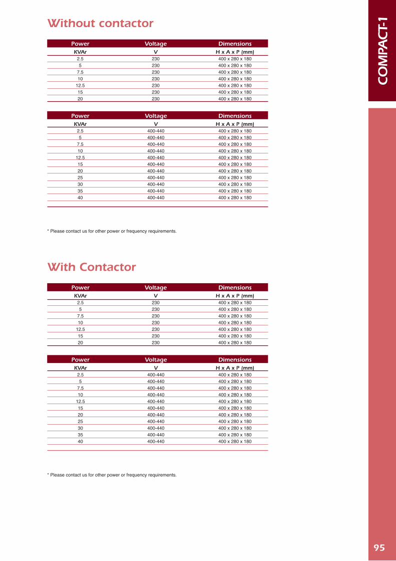
95
CO
MPA
CT-
1
PowerKVAr
2.55
7.510
12.5152025303540
PowerKVAr
2.55
7.510
12.5152025303540
VoltageV
400-440400-440400-440400-440400-440400-440400-440400-440400-440400-440400-440
VoltageV
400-440400-440400-440400-440400-440400-440400-440400-440400-440400-440400-440
DimensionsH x A x P (mm)
400 x 280 x 180400 x 280 x 180400 x 280 x 180400 x 280 x 180400 x 280 x 180400 x 280 x 180400 x 280 x 180400 x 280 x 180400 x 280 x 180400 x 280 x 180400 x 280 x 180
DimensionsH x A x P (mm)
400 x 280 x 180400 x 280 x 180400 x 280 x 180400 x 280 x 180400 x 280 x 180400 x 280 x 180400 x 280 x 180400 x 280 x 180400 x 280 x 180400 x 280 x 180400 x 280 x 180
* Please contact us for other power or frequency requirements.
* Please contact us for other power or frequency requirements.
PowerKVAr
2.55
7.510
12.51520
PowerKVAr
2.55
7.510
12.51520
VoltageV
230230230230230230230
VoltageV
230230230230230230230
DimensionsH x A x P (mm)
400 x 280 x 180400 x 280 x 180400 x 280 x 180400 x 280 x 180400 x 280 x 180400 x 280 x 180400 x 280 x 180
DimensionsH x A x P (mm)
400 x 280 x 180400 x 280 x 180400 x 280 x 180400 x 280 x 180400 x 280 x 180400 x 280 x 180400 x 280 x 180
Without contactor
With Contactor

96
NOTES CO
NDE
NSA
DORE
S

Automatic capacitors
Bank

98
Com
pac
t-3Se
ries
Automatic capacitor Banks with MA/C/CE/TER SeriesCompact-3 serie230V, 50 Hz
General Description These types of capacitors banks are normally used to improve reactive power in small instalations; stores; neughboring com-munities.
NoteIndoor wall , mounting , none dusty, ventilated room, away from direct sun light, incide cabinet temperature max ≤55ºC
Capacitor Banks Components Three phase capacitors series MA/C/CE/TER (overpressure dis-
connection system) Capacitor duty contactors with damping resistors. MCB for general protection. Resistors for fast discharge purpose. Microprocessor based PFC regulator. Top entry for power supply. Cover RAL 1013 and galvanized sheet framework.
PowerKVAr
57.57.51010
12.515
17.520
22.525
VoltageV.c.a230 230 230 230230230 230 230 230 230 230
Program
1:1:11:2:21:1:11:1:11:1:21:2:21:1:11:2:41:1:21:1:11:2:2
CompositionKVAr
2 (2.5 + 2.5)2 (2.5 + 5.0)3 (2.5 + 2.5 + 2.5)2 (5.0 + 5.0)3 (2.5 + 2.5 + 5.0)3 (2.5 + 5.0 + 5.0)3 (5.0 +5.0 + 5.0)3 (2.5 + 5.0 + 10.0)3 (5.0 + 5.0 + 10.0)3 (7.5 + 7.5 + 7.5)3 (5.0 + 10.0 + 10.0)
DimensionsH x A x P (mm)
600 x 360 x 160600 x 360 x 160600 x 360 x 160600 x 360 x 160600 x 360 x 160600 x 360 x 160600 x 360 x 160600 x 360 x 160600 x 360 x 160600 x 360 x 160600 x 360 x 160

99
Com
pac
t-3Se
ries
Automatic capacitor Banks with MA/C/CE/TER SeriesCompact-3 serie400 - 440V, 50Hz
General Description These types of capacitors banks are normally used to improve reactive power in small instalations; stores; neughboring com-munities.
NoteIndoor wall , mounting , none dusty, ventilated room, away from direct sun light, incide cabinet temperature max ≤55ºC
Capacitor Banks Components Three phase capacitors series MA/C/CE/TER (overpressure dis-
connection system) Capacitor duty contactors with damping resistors. MCB for general protection. Resistors for fast discharge purpose. Microprocessor based PFC regulator. Top entry for power supply. Cover RAL 1013 and galvanized sheet framework.
PowerKVAr
57.57.51010
12.51515
17.520
22.522.525303035
37.537.5404550
VoltageV.c.a
400-440400-440400-440400-440400-440400-440400-440400-440400-440400-440400-440400-440400-440400-440400-440400-440400-440400-440400-440400-440400-440
Program
1:1:11:2:21:1:11:1:11:1:21:2:21:2:21:1:11:2:41:1:21:2:21:1:11:2:21:1:21:1:11:2:41:2:21:1:11:1:21:1:11:2:2
CompositionKVAr
2 (2.5 + 2.5)2 (2.5 + 5.0)3 (2.5 + 2.5 + 2.5)2 (5.0 + 5.0)3 (2.5 + 2.5 + 5.0)3 (2.5 + 5.0 + 5.0)2 (5.0 + 10.0)3 (5.0 + 5.0 + 5.0)3 (2.5 + 5.0 + 10.0)3 (5.0 + 5.0 + 10.0)2 (7.5 + 15.0)3 (7.5 + 7.5 + 7.5)3 (5.0 + 10.0 + 10.0)3 (7.5 + 7.5 + 15.0)3 (10.0 + 10.0 + 10.0)3 (5.0 + 10.0 + 20.0)3 (7.5 + 15.0 + 15.0)3 (12.5 + 12.5 + 12.5)3 (10.0 + 10.0 + 20.0)3 (15.0 + 15.0 + 15.0)3 (10.0 + 20.0 + 20.0)
DimensionsH x A x P (mm)
600 x 360 x 160600 x 360 x 160600 x 360 x 160600 x 360 x 160600 x 360 x 160600 x 360 x 160600 x 360 x 160600 x 360 x 160600 x 360 x 160600 x 360 x 160600 x 360 x 160600 x 360 x 160600 x 360 x 160600 x 360 x 160600 x 360 x 160600 x 360 x 160600 x 360 x 160600 x 360 x 160600 x 360 x 160600 x 360 x 160600 x 360 x 160
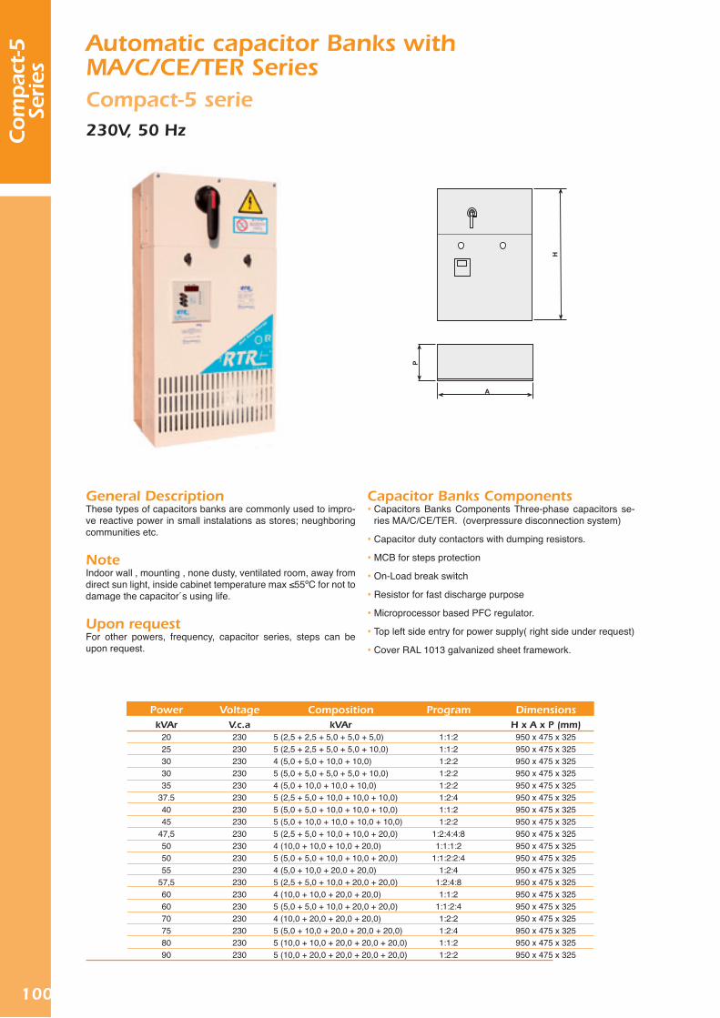
100
Com
pac
t-5Se
ries
Automatic capacitor Banks with MA/C/CE/TER SeriesCompact-5 serie230V, 50 Hz
General DescriptionThese types of capacitors banks are commonly used to impro-ve reactive power in small instalations as stores; neughboring communities etc.
NoteIndoor wall , mounting , none dusty, ventilated room, away from direct sun light, inside cabinet temperature max ≤55ºC for not to damage the capacitor´s using life.
Upon requestFor other powers, frequency, capacitor series, steps can be upon request.
Capacitor Banks Components Capacitors Banks Components Three-phase capacitors se-
ries MA/C/CE/TER. (overpressure disconnection system)
Capacitor duty contactors with dumping resistors.
MCB for steps protection
On-Load break switch
Resistor for fast discharge purpose
Microprocessor based PFC regulator.
Top left side entry for power supply( right side under request)
Cover RAL 1013 galvanized sheet framework.
PowerkVAr
2025303035
37.54045
47,5505055
57,5606070758090
VoltageV.c.a230230230230230230230230230230230230230230230230230230230
Program
1:1:21:1:21:2:21:2:21:2:21:2:41:1:21:2:2
1:2:4:4:81:1:1:2
1:1:2:2:41:2:4
1:2:4:81:1:2
1:1:2:41:2:21:2:41:1:21:2:2
CompositionkVAr
5 (2,5 + 2,5 + 5,0 + 5,0 + 5,0)5 (2,5 + 2,5 + 5,0 + 5,0 + 10,0)4 (5,0 + 5,0 + 10,0 + 10,0)5 (5,0 + 5,0 + 5,0 + 5,0 + 10,0)4 (5,0 + 10,0 + 10,0 + 10,0)5 (2,5 + 5,0 + 10,0 + 10,0 + 10,0)5 (5,0 + 5,0 + 10,0 + 10,0 + 10,0)5 (5,0 + 10,0 + 10,0 + 10,0 + 10,0)5 (2,5 + 5,0 + 10,0 + 10,0 + 20,0)4 (10,0 + 10,0 + 10,0 + 20,0)5 (5,0 + 5,0 + 10,0 + 10,0 + 20,0)4 (5,0 + 10,0 + 20,0 + 20,0)5 (2,5 + 5,0 + 10,0 + 20,0 + 20,0)4 (10,0 + 10,0 + 20,0 + 20,0)5 (5,0 + 5,0 + 10,0 + 20,0 + 20,0)4 (10,0 + 20,0 + 20,0 + 20,0)5 (5,0 + 10,0 + 20,0 + 20,0 + 20,0)5 (10,0 + 10,0 + 20,0 + 20,0 + 20,0)5 (10,0 + 20,0 + 20,0 + 20,0 + 20,0)
DimensionsH x A x P (mm)
950 x 475 x 325950 x 475 x 325950 x 475 x 325950 x 475 x 325950 x 475 x 325950 x 475 x 325950 x 475 x 325950 x 475 x 325950 x 475 x 325950 x 475 x 325950 x 475 x 325950 x 475 x 325950 x 475 x 325950 x 475 x 325950 x 475 x 325950 x 475 x 325950 x 475 x 325950 x 475 x 325950 x 475 x 325
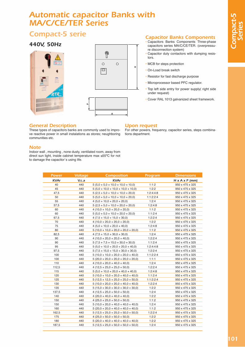
101
Com
pac
t-5Se
ries
Automatic capacitor Banks with MA/C/CE/TER SeriesCompact-5 serie440V, 50Hz
General DescriptionThese types of capacitors banks are commonly used to impro-ve reactive power in small instalations as stores; neughboring communities etc.
NoteIndoor wall , mounting , none dusty, ventilated room, away from direct sun light, inside cabinet temperature max ≤55ºC for not to damage the capacitor´s using life.
Upon requestFor other powers, frequency, capacitor series, steps combina-tions department.
Capacitor Banks Components Capacitors Banks Components Three-phase
capacitors series MA/C/CE/TER. (overpressu-re disconnection system) Capacitor duty contactors with dumping resis-
tors.
MCB for steps protection
On-Load break switch
Resistor for fast discharge purpose
Microprocessor based PFC regulator.
Top left side entry for power supply( right side under request)
Cover RAL 1013 galvanized sheet framework.
PowerKVAr
4045
47,55055
57,56060
67,5707580
82,5909095
97,5100100110
112,5115120125130135
137,5140150150160
162,5175180
187,5
VoltageV.c.a440440440440440440440440440440440440440440440440440440440440440440440440440440440440440440440440440440440
Program
1:1:21:2:2
1:2:4:4:81:1:2:2:4
1:2:41:2:4:81:1:2
1:1:2:41:2:2:41:2:2
1:2:4:81:1:21:2:4
1:2:2:41:1:2:4
1:2:4:4:81:2:2:4
1:1:2:2:41:1:11:2:4
1:2:2:41:2:4:81:1:2:4
1:1:2:2:41:2:2:41:2:21:2:41:2:21:1:21:2:41:1:2
1:2:2:41:2:21:2:21:2:4
CompositionKVAr
5 (5,0 + 5,0 + 10,0 + 10,0 + 10,0)5 (5,0 + 10,0 + 10,0 + 10,0 + 10,0)5 (2,5 + 5,0 + 10,0 + 10,0 + 20,0)5 (5,0 + 5,0 + 10,0 + 10,0 + 20,0)4 (5,0 + 10,0 + 20,0 + 20,0)5 (2,5 + 5,0 + 10,0 + 20,0 + 20,0)4 (10,0 + 10,0 + 20,0 + 20,0)5 (5,0 + 5,0 + 10,0 + 20,0 + 20,0)4 (7,5 + 15,0 + 15,0 + 30,0)4 (10,0 + 20,0 + 20,0 + 20,0)4 (5,0 + 10,0 + 20,0 + 40,0)5 (10,0 + 10,0 + 20,0 + 20,0 + 20,0)4 (7,5 + 15,0 + 30,0 + 30,0)4 (10,0 + 20,0 + 20,0 + 40,0)5 (7,5 + 7,5 + 15,0 + 30,0 + 30,0)5 (5,0 + 10,0 + 20,0 + 20,0 + 40,0)5 (7,5 + 15,0 + 15,0 + 30,0 + 30,0)5 (10,0 + 10,0 + 20,0 + 20,0 + 40,0)5 (20,0 + 20,0 + 20,0 + 20,0 + 20,0)4 (10,0 + 20,0 + 40,0 + 40,0)4 (12,5 + 25,0 + 25,0 + 50,0)5 (5,0 + 10,0 + 20,0 + 40,0 + 40,0)5 (10,0 + 10,0 + 20,0 + 40,0 + 40,0)5 (12,5 + 12,5 + 25,0 + 25,0 + 50,0)5 (10,0 + 20,0 + 20,0 + 40,0 + 40,0)5 (15,0 + 30,0 + 30,0 + 30,0 + 30,0)4 (12,5 + 25,0 + 50,0 + 50,0)4 (20,0 + 40,0 + 40,0 + 40,0)4 (25,0 + 25,0 + 50,0 + 50,0)5 (10,0 + 20,0 + 40,0 + 40,0 + 40,0)5 (20,0 + 20,0 + 40,0 + 40,0 + 40,0)5 (12,5 + 25,0 + 25,0 + 50,0 + 50,0)4 (25,0 + 50,0 + 50,0 + 50,0)5 (20,0 + 40,0 + 40,0 + 40,0 + 40,0)5 (12,5 + 25,0 + 50,0 + 50,0 + 50,0)
DimensionsH x A x P (mm)
950 x 475 x 325950 x 475 x 325950 x 475 x 325950 x 475 x 325950 x 475 x 325950 x 475 x 325950 x 475 x 325950 x 475 x 325950 x 475 x 325950 x 475 x 325950 x 475 x 325950 x 475 x 325950 x 475 x 325950 x 475 x 325950 x 475 x 325950 x 475 x 325950 x 475 x 325950 x 475 x 325950 x 475 x 325950 x 475 x 325950 x 475 x 325950 x 475 x 325950 x 475 x 325950 x 475 x 325950 x 475 x 325950 x 475 x 325950 x 475 x 325950 x 475 x 325950 x 475 x 325950 x 475 x 325950 x 475 x 325950 x 475 x 325950 x 475 x 325950 x 475 x 325950 x 475 x 325

102
Automatic capacitor Banks with MA/C/CE/TER, RTF SeriesCompact-9 series400/440V, 50Hz
General DescriptionThese types of capacitors banks are used in power factor co-rrection in installations where there is high reactive energy con-sumption.
NoteIndoor mounting , none dusty, ventilated room, away from di-rect sun light, inside cabinet temperature max ≤55ºC .
Capacitor Banks Components Capacitors series MA/C/CE/TER.(overpressure disconnection
system) Capacitor duty contactors with dumping resistors HRC fuses for steps protection On-load break switch (Icc)* Resistors for fast discharge purpose Microprocessor based PFC regulator RAL 1013
* Other voltages and frequencies upon request.
PowerkVAr210225
237,5250260275
287,5300315
332,535375
402,5425435455
472,5490510525
542,5560595630
VoltageV.c.a
400-440 V400-440 V400-440 V400-440 V400-440 V400-440 V400-440 V400-440 V400-440 V400-440 V400-440 V400-440 V400-440 V400-440 V400-440 V400-440 V400-440 V400-440 V400-440 V400-440 V400-440 V400-440 V400-440 V400-440 V
Program
1:2:21:2:41:2:41:1:21:2:21:2:21:2:41:1:21:2:41:2:41:1:21:2:21:2:41:2:21:2:41:2:21:2:41:1:21:2:21:2:21:2:41:1:21:2:21:1:1
CompositionkVAr
4 (1x30+3x60)5 (1x15+1x30+3x60)6 (1x12,5+1x25+4x50)6 (2x25+4x50)7 (1x20+6x40)6 (1x25+5x50)7 (1x12,5+1x25+5x50)6 (2x30+4x60)7 (1x15+2x30+4x60)6 (1x17,5+1x35+4x70)6 (2x35+4x70)8 (1x25+7x50)7 (1x17,5+1x35+5x70)9 (1x25+8x50)9 (1x15+2x30+6x60)7 (1x35+6x70)8 (1x17,5+1x35+6x70)8 (2x35+6x70)9(1x30+8x60)8 (1x35+7x70)9 (1x17,5+1x35+7x70)9 (2x35+7x70)9 (1x35+8x70)9 (9x70)
DimensionsH x A x P (mm)1600X1000X5001600X1000X5001600X1000X5001600X1000X5001600X1000X5001600X1000X5001600X1000X5001600X1000X5001600X1000X5001600X1000X5001600X1000X5001600X1000X5001600X1000X5001600X1000X5001600X1000X5001600X1000X5001600X1000X5001600X1000X5001600X1000X5001600X1000X5001600X1000X5001600X1000X5001600X1000X5001600X1000X500
Com
pac
t-9Se
ries

103
Automatic capacitor Banks with MA/C/CE/TER, RTF SeriesCompact-9 series with on-load break switch400/440V, 50Hz
General DescriptionThese types of capacitors banks are used in power factor co-rrection in installations where there is high reactive energy con-sumption.
NoteIndoor mounting , none dusty, ventilated room, away from di-rect sun light, inside cabinet temperature max ≤55ºC .
Capacitor Banks Components Capacitors series MA/C/CE/TER.( overpressure disconnection
system)
Capacitor duty contactors with dumping resistors
HRC fuses for steps protection
On-load break switch (Icc)*
Resistors for fast discharge purpose
Microprocessor based PFC regulator
RAL 1013
* Other voltages and frequencies upon request.
PowerkVAr210225
237,5250260275
287,5300315
332,535375
402,5425435455
472,5490510525
542,5560595630
VoltageV.c.a
400-440 V400-440 V400-440 V400-440 V400-440 V400-440 V400-440 V400-440 V400-440 V400-440 V400-440 V400-440 V400-440 V400-440 V400-440 V400-440 V400-440 V400-440 V400-440 V400-440 V400-440 V400-440 V400-440 V400-440 V
Program
1:2:21:2:41:2:41:1:21:2:21:2:21:2:41:1:21:2:41:2:41:1:21:2:21:2:41:2:21:2:41:2:21:2:41:1:21:2:21:2:21:2:41:1:21:2:21:1:1
CompositionKVAr
4 (1x30+3x60)5 (1x15+1x30+3x60)6 (1x12,5+1x25+4x50)6 (2x25+4x50)7 (1x20+6x40)6 (1x25+5x50)7 (1x12,5+1x25+5x50)6 (2x30+4x60)7 (1x15+2x30+4x60)6 (1x17,5+1x35+4x70)6 (2x35+4x70)8 (1x25+7x50)7 (1x17,5+1x35+5x70)9 (1x25+8x50)9 (1x15+2x30+6x60)7 (1x35+6x70)8 (1x17,5+1x35+6x70)8 (2x35+6x70)9(1x30+8x60)8 (1x35+7x70)9 (1x17,5+1x35+7x70)9 (2x35+7x70)9 (1x35+8x70)9 (9x70)
DimensionsH x A x P (mm)1600X1000X5001600X1000X5001600X1000X5001600X1000X5001600X1000X5001600X1000X5001600X1000X5001600X1000X5001600X1000X5001600X1000X5001600X1000X5001600X1000X5001600X1000X5001600X1000X5001600X1000X5001600X1000X5001600X1000X5001600X1000X5001600X1000X5001600X1000X5001600X1000X5001600X1000X5001600X1000X5001600X1000X500
Com
pac
t-9Se
ries

104
MIN
I-MU
RA
L se
ries
without
on-lo
ad b
reak
sw
itch Automatic capacitor Banks with
MA/C/CE/TER, RTF SeriesMini-Mural series without on-load break switch230V, 50Hz
General DescriptionThese types of capacitors banks are commonly used to impro-ve reactive power in small industrial plants ; stores; neughbo-ring communities etc
These capacitors banks are made up of: Capacitors series MA/C/CE/TER.( overpressure disconnection
system) Capacitor duty contactors with dumping resistors HRC fuses for steps protection On-load break switch (Icc)* Resistors for fast discharge purpose Microprocessor based PFC regulator RAL 1013
NoteIndoor wall , mounting , none dusty, ventilated room, away from direct sun light, inside cabinet temperature max ≤55ºC .
Upon request The capacitor bank model can be fitted with capacitor series
MA/C/CE/TER RTF,BO/R 50-60Hz.
Different power/ voltage can be upon request.
PowerKVAr
57.57.510
12.51515
17.522.522.525
VoltageV.c.a230 V230 V230 V230 V230 V230 V230 V230 V230 V230 V230 V
Program
1:1:11:2:21:1:11:1:21:2:21:2:21:1:11:2:41:2:21:1:11:2:2
CompositionNo. steps x
KVAr2 (2x2.5)2 (1x2.5+1x5)3 (3x2.5)3 (2x2.5+1x5)3 (1x2.5+2x5)2 (1x5+1x10)3 (3x5)3 (1x2.5+1x5+1x10)2 (1x7.5+1x15)3 (3x7.5)
DimensionsH x A x P (mm)
600 x 400 x 260600 x 400 x 260600 x 400 x 260600 x 400 x 260600 x 400 x 260600 x 400 x 260600 x 400 x 260600 x 400 x 260600 x 400 x 260600 x 400 x 260600 x 400 x 260
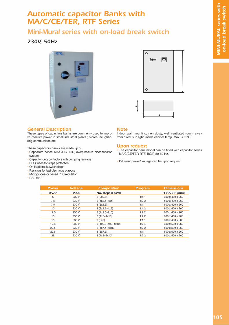
105
MIN
I-MU
RA
L se
ries
wit
h
on
-load
bre
ak s
wit
ch
Automatic capacitor Banks with MA/C/CE/TER, RTF SeriesMini-Mural series with on-load break switch230V, 50Hz
General DescriptionThese types of capacitors banks are commonly used to impro-ve reactive power in small industrial plants ; stores; neughbo-ring communities etc
These capacitors banks are made up of: Capacitors series MA/C/CE/TER.( overpressure disconnection
system) Capacitor duty contactors with dumping resistors HRC fuses for steps protection On-load break switch (Icc)* Resistors for fast discharge purpose Microprocessor based PFC regulator RAL 1013
NoteIndoor wall mounting, non dusty, well ventilated room, away from direct sun light, inside cabinet temp. Max. ≤ 55ºC.
Upon request The capacitor bank model can be fitted with capacitor series
MA/C/CE/TER RTF, BO/R 50-60 Hz.
Different power/ voltage can be upon request.
PowerKVAr
57.57.510
12.51515
17.522.522.525
VoltageV.c.a230 V230 V230 V230 V230 V230 V230 V230 V230 V230 V230 V
Program
1:1:11:2:21:1:11:1:21:2:21:2:21:1:11:2:41:2:21:1:11:2:2
CompositionNo. steps x KVAr2 (2x2.5)2 (1x2.5+1x5)3 (3x2.5)3 (2x2.5+1x5)3 (1x2.5+2x5)2 (1x5+1x10)3 (3x5)3 (1x2.5+1x5+1x10)2 (1x7.5+1x15)3 (3x7.5)3 (1x5+2x10)
DimensionsH x A x P (mm)
600 x 400 x 260600 x 400 x 260600 x 400 x 260600 x 400 x 260600 x 400 x 260600 x 400 x 260600 x 400 x 260600 x 500 x 260600 x 500 x 260600 x 500 x 260600 x 500 x 260

106
MIN
I-MU
RA
L se
ries
without
on-lo
ad b
reak
sw
itch Automatic capacitor Banks with
MA/C/CE/TER, RTF SeriesMini-Mural series without on-load break switch400/440V, 50Hz
General DescriptionThese types of capacitors banks are commonly used to impro-ve reactive power in small industrial plants ; stores; neughbo-ring communities etc
These capacitors banks are made up of: Capacitors series MA/C/CE/TER.( overpressure disconnection
system) Capacitor duty contactors with dumping resistors HRC fuses for steps protection On-load break switch (Icc)* Resistors for fast discharge purpose Microprocessor based PFC regulator RAL 1013
NoteIndoor wall , mounting , none dusty, ventilated room, away from direct sun light, inside cabinet temperature max ≤55ºC .
Upon request The capacitor bank model can be fitted with capacitor series
MA/C/CE/TER RTF,BO/R 50-60Hz.
Different power/ voltage can be upon request.
PowerKVAr
57.57.510
12.51515
17.520
22.525
27.5303035
37.5404550
VoltageV.c.a
400-440 V400-440 V400-440 V400-440 V400-440 V400-440 V400-440 V400-440 V400-440 V400-440 V400-440 V400-440 V400-440 V400-440 V400-440 V400-440 V400-440 V400-440 V400-440 V
Program
1:1:11:2:21:1:11:1:21:2:21:2:21:1:11:2:41:1:21:1:11:2:21:2:41:1:11:1:21:2:41:2:21:1:21:1:11:2:2
CompositionNo. steps x
KVAr2 (2x2.5)2 (1x2.5+1x5)3 (3x2.5)3 (2x2.5+1x5)3 (1x2.5+2x5)2 (1x5+1x10)3 (3x5)3 (1x2.5+1x5+1x10)3 (2x5+1x10)3 (3x7.5)3 (1x5+2x10)4 (1x2,5+1x5+2x10)3 (3x10) 4 (2x5+2x10)3 (1x5+1x10+1x20)3 (1x7.5+2x15)3 (2x10+1x20)
DimensionsH x A x P (mm)
600 x 400 x 260600 x 400 x 260600 x 400 x 260600 x 400 x 260600 x 400 x 260600 x 400 x 260600 x 400 x 260600 x 400 x 260600 x 400 x 260600 x 400 x 260600 x 400 x 260600 x 400 x 260600 x 400 x 260600 x 400 x 260600 x 400 x 260600 x 400 x 260600 x 400 x 260600 x 400 x 260600 x 400 x 260

107
MIN
I-MU
RA
L se
ries
wit
h
on
-load
bre
ak s
wit
ch
Automatic capacitor Banks with MA/C/CE/TER, RTF SeriesMini-Mural series with on-load break switch400/440V, 50Hz
General DescriptionThis types of automatic capacitor banks in normally used to compensate reactive power in small industrial plants, building/office load...etc.
These capacitor banks are made up of: Three phase capacitors series MA/C/CE/TER. Capacitor duty contactors with damping resistors. HRC fuses for protection. On-load break switch (Icc)*. Resistors for fast discharge purpose. Microprocessor based PFC regulator. RAL 1013
NoteIndoor wall mounting, non dusty, well ventilated room, away from direct sun light, inside cabinet temp. Max. ≤ 55ºC.
Upon request The capacitor bank model can be fitted with capacitor series
MA/C/CE/TER RTF, BO/R 50-60 Hz.
Different power/ voltage can be upon request.
PowerKVAr
57.57.510
12.51515
17.520
22.525
27.5303035
37.5404550
VoltageV.c.a
400-440 V400-440 V400-440 V400-440 V400-440 V400-440 V400-440 V400-440 V400-440 V400-440 V400-440 V400-440 V400-440 V400-440 V400-440 V400-440 V400-440 V400-440 V400-440 V
Program
1:1:11:2:21:1:11:1:21:2:21:2:21:1:11:2:41:1:21:1:11:2:21:2:41:1:11:1:21:2:41:2:21:1:21:1:11:2:2
CompositionNo. steps x KVAr2 (2x2.5)2 (1x2.5+1x5)3 (3x2.5)3 (2x2.5+1x5)3 (1x2.5+2x5)2 (1x5+1x10)3 (3x5)3 (1x2.5+1x5+1x10)3 (2x5+1x10)3 (3x7.5)3 (1x5+2x10)4 (1x2,5+1x5+2x10)3 (3x10) 4 (2x5+2x10)3 (1x5+1x10+1x20)3 (1x7.5+2x15)3 (2x10+1x20)3 (3x15)3 (1x10+2x20)
DimensionsH x A x P (mm)
600 x 400 x 260600 x 400 x 260600 x 400 x 260600 x 400 x 260600 x 400 x 260600 x 400 x 260600 x 400 x 260600 x 400 x 260600 x 400 x 260600 x 400 x 260600 x 400 x 260600 x 500 x 260600 x 400 x 260600 x 500 x 260600 x 500 x 260600 x 500 x 260600 x 500 x 260600 x 500 x 260600 x 500 x 260

108
MU
RA
L se
ries
without
on-lo
ad b
reak
sw
itch
Automatic capacitor Banks with MA/C/CE/TER, RTF SeriesMural series without on-load break switch230V, 50Hz
General DescriptionThese types of capacitors banks are commonly used to impro-ve reactive power in small industrial plants ; stores; neughbo-ring communities etc
These capacitors banks are made up of: Capacitors series MA/C/CE/TER.( overpressure disconnection
system) Capacitor duty contactors with dumping resistors HRC fuses for steps protection On-load break switch (Icc)* Resistors for fast discharge purpose Microprocessor based PFC regulator RAL 1013
NoteIndoor wall , mounting , none dusty, ventilated room, away from direct sun light, inside cabinet temperature max ≤55ºC .
Upon request The capacitor bank model can be fitted with capacitor series
MA/C/CE/TER RTF,BO/R 50-60Hz.
Different power/ voltage can be upon request.
PowerKVAr
1522.527.53035
37.537.54045455050555560
VoltageV.c.a230 V230 V230 V230 V230 V230 V230 V230 V230 V230 V230 V230 V230 V230 V230 V
Program
1:1:11:2:21:2:41:1:11:2:21:2:41:1:11:1:11:2:21:1:11:2:21:1:11:2:41:2:21:1:1
CompositionNo. steps x KVAr6 (6x2.5)5 (1x2.5+4x5)4 (1x2.5+1x5+2x10)6 (6x5)4 (1x5+3x10)5 (1x2.5+1x5+3x10)5 (5x7.5)4 (4x10)5 (1x5+4x10)6 (6x7.5)3 (1x10+2x20)5 (5x10)4 (1x5+1x10+2x20)5 (1x5+5x10)6 (6x10)
DimensionsH x A x P (mm)
800 x 600 x 300800 x 600 x 300800 x 600 x 300800 x 600 x 300800 x 600 x 300800 x 600 x 300800 x 600 x 300800 x 600 x 300
1000 x 800 x 3001000 x 800 x 3001000 x 800 x 3001000 x 800 x 3001000 x 800 x 3001000 x 800 x 3001000 x 800 x 300

109
MU
RA
L se
ries
wit
h
on
-load
bre
ak s
wit
ch
Automatic capacitor Banks with MA/C/CE/TER, RTF SeriesMural series with on-load break switch230V, 50Hz
General DescriptionThese types of capacitors banks are commonly used to impro-ve reactive power in small industrial plants ; stores; neughbo-ring communities etc
These capacitors banks are made up of: Capacitors series MA/C/CE/TER.( overpressure disconnection
system) Capacitor duty contactors with dumping resistors HRC fuses for steps protection On-load break switch (Icc)* Resistors for fast discharge purpose Microprocessor based PFC regulator RAL 1013
NoteIndoor wall , mounting , none dusty, ventilated room, away from direct sun light, inside cabinet temperature max ≤55ºC .
Upon request The capacitor bank model can be fitted with capacitor series
MA/C/CE/TER RTF,BO/R 50-60Hz.
Different power/ voltage can be upon request.
PowerKVAr
1522.527.53035
37.537.54045455050555560
VoltageV.c.a230 V230 V230 V230 V230 V230 V230 V230 V230 V230 V230 V230 V230 V230 V230 V
Program
1:1:11:2:21:2:41:1:11:2:21:2:41:1:11:1:11:2:21:1:11:2:21:1:11:2:41:2:21:1:1
CompositionNo. steps x KVAr6 (6x2.5)5 (1x2.5+4x5)4 (1x2.5+1x5+2x10)6 (6x5)4 (1x5+3x10)5 (1x2.5+1x5+3x10)5 (5x7.5)4 (4x10)5 (1x5+4x10)6 (6x7.5)3 (1x10+2x20)5 (5x10)4 (1x5+1x10+2x20)5 (1x5+5x10)6 (6x10)
DimensionsH x A x P (mm)
800 x 600 x 300800 x 600 x 300800 x 600 x 300800 x 600 x 300800 x 600 x 300800 x 600 x 300800 x 600 x 300800 x 600 x 300
1000 x 800 x 3001000 x 800 x 3001000 x 800 x 3001000 x 800 x 3001000 x 800 x 3001000 x 800 x 3001000 x 800 x 300

110
MU
RA
L se
ries
without
on-lo
ad b
reak
sw
itch
Automatic capacitor Banks withMA/C/CE/TER, RTF SeriesMural series without on-load break switch400/440V, 50Hz
General DescriptionThese types of capacitors banks are commonly used to impro-ve reactive power in small industrial plants ; stores; neughbo-ring communities etc
These capacitors banks are made up of: Capacitors series MA/C/CE/TER.( overpressure disconnection
system) Capacitor duty contactors with dumping resistors HRC fuses for steps protection On-load break switch (Icc)* Resistors for fast discharge purpose Microprocessor based PFC regulator RAL 1013
NoteIndoor wall , mounting , none dusty, ventilated room, away from direct sun light, inside cabinet temperature max ≤55ºC .
Upon request The capacitor bank model can be fitted with capacitor series
MA/C/CE/TER RTF,BO/R 50-60Hz.
Different power/ voltage can be upon request.
PowerKVAr37.54040455050
52.555556060
67.57075758080
82.59090100100105110
112.5120120125125135150150165180180
VoltageV.c.a
400-440 V400-440 V400-440 V400-440 V400-440 V400-440 V400-440 V400-440 V400-440 V400-440 V400-440 V400-440 V400-440 V400-440 V400-440 V400-440 V400-440 V400-440 V400-440 V400-440 V400-440 V400-440 V400-440 V400-440 V400-440 V400-440 V400-440 V400-440 V400-440 V400-440 V400-440 V400-440 V400-440 V400-440 V400-440 V
Program
1:2:41:1:11:1:21:2:21:1:11:1:21:2:21:2:41:2:2 1:1:11:2:41:2:21:2:21:2:4 1:1:1 1:1:11:1:21:2:21:1:11:2:21:1:11:1:21:2:21:2:21:2:21:1:11:1:21:1:11:1:21:2:21:1:11:1:21:2:21:1:11:1:2
CompositionNo. steps x
KVAr5 (1x2.5+1x5+3x10)4 (4x10)5(2x5+3x10)5 (1x5+4x10)5 (5x10)6(2x5+4x10)4 (1x7.5+3x15)4 (1x5+1x10+2x20)6 (1x5+5x10)6 (6x10)5(2x5+1x10+2x20)5 (1x7.5+4x15)4 (1x10+3x20)5 (1x5+1x10+3x20)5 (5x15)4 (4x20)5 (2x10+3x20)6 (1x7.5+5x15)6 (6x15)5 (1x10+4x20)5 (5x20)6 (2x10+4x20)4 (1x15+3x30)6 (1x10+5x20)5 (1x12.5+4x25)6 (6x20)7 (2x10+5x20)5 (5x25)6 (2x12.5+4x25)5 (1x15+4x30)6 (6x25)6 (2x15+4x30)6 (1x15+5x30)6 (6x30)
DimensionsH x A x P (mm)
800 x 600 x 300800 x 600 x 300800 x 600 x 300800 x 600 x 300800 x 600 x 300800 x 600 x 300800 x 600 x 300800 x 600 x 300800 x 600 x 300800 x 600 x 300800 x 600 x 300800 x 600 x 300800 x 600 x 300800 x 600 x 300800 x 600 x 300800 x 600 x 300800 x 600 x 300800 x 600 x 300800 x 600 x 300
1000 x 800 x 3001000 x 800 x 3001000 x 800 x 3001000 x 800 x 3001000 x 800 x 3001000 x 800 x 3001000 x 800 x 3001000 x 800 x 3001000 x 800 x 3001000 x 800 x 3001000 x 800 x 3001000 x 800 x 3001000 x 800 x 3001000 x 800 x 3001000 x 800 x 3001000 x 800 x 300

111
MU
RA
L se
ries
wit
h
on
-load
bre
ak s
wit
ch
Automatic capacitor Banks withMA/C/CE/TER, RTF SeriesMural series with on-load break switch400/440V, 50Hz
General DescriptionThese types of capacitors banks are commonly used to impro-ve reactive power in small industrial plants ; stores; neughbo-ring communities etc
These capacitors banks are made up of: Capacitors series MA/C/CE/TER.( overpressure disconnection
system) Capacitor duty contactors with dumping resistors HRC fuses for steps protection On-load break switch (Icc)* Resistors for fast discharge purpose Microprocessor based PFC regulator
RAL 1013
NoteIndoor wall , mounting , none dusty, ventilated room, away from direct sun light, inside cabinet temperature max ≤55ºC .
Upon request The capacitor bank model can be fitted with capacitor series
MA/C/CE/TER RTF,BO/R 50-60Hz.
PowerKVAr37.54040455050
52.555556060
67.57075758080
82.59090100100105110
112.5120120125125135150150165180180
VoltageV.c.a
400-440 V400-440 V400-440 V400-440 V400-440 V400-440 V400-440 V400-440 V400-440 V400-440 V400-440 V400-440 V400-440 V400-440 V400-440 V400-440 V400-440 V400-440 V400-440 V400-440 V400-440 V400-440 V400-440 V400-440 V400-440 V400-440 V400-440 V400-440 V400-440 V400-440 V400-440 V400-440 V400-440 V400-440 V400-440 V
Program
1:2:41:1:11:1:21:2:21:1:11:1:21:2:21:2:41:2:2 1:1:11:2:41:2:21:2:21:2:4 1:1:1 1:1:11:1:21:2:21:1:11:2:21:1:11:1:21:2:21:2:21:2:21:1:11:1:21:1:11:1:21:2:21:1:11:1:21:2:21:1:11:1:2
CompositionNo. steps x KVAr5 (1x2.5+1x5+3x10)4 (4x10)5(2x5+3x10)5 (1x5+4x10)5 (5x10)6(2x5+4x10)4 (1x7.5+3x15)4 (1x5+1x10+2x20)6 (1x5+5x10)6 (6x10)5(2x5+1x10+2x20)5 (1x7.5+4x15)4 (1x10+3x20)5 (1x5+1x10+3x20)5 (5x15)4 (4x20)5 (2x10+3x20)6 (1x7.5+5x15)6 (6x15)5 (1x10+4x20)5 (5x20)6 (2x10+4x20)4 (1x15+3x30)6 (1x10+5x20)5 (1x12.5+4x25)6 (6x20)7 (2x10+5x20)5 (5x25)6 (2x12.5+4x25)5 (1x15+4x30)6 (6x25)6 (2x15+4x30)6 (1x15+5x30)6 (6x30)7 (2x15+5x30)
DimensionsH x A x P (mm)
800 x 600 x 300800 x 600 x 300800 x 600 x 300800 x 600 x 300800 x 600 x 300800 x 600 x 300800 x 600 x 300800 x 600 x 300800 x 600 x 300800 x 600 x 300800 x 600 x 300800 x 600 x 300800 x 600 x 300800 x 600 x 300800 x 600 x 300800 x 600 x 300800 x 600 x 300800 x 600 x 300800 x 600 x 300
1000 x 800 x 3001000 x 800 x 3001000 x 800 x 3001000 x 800 x 3001000 x 800 x 3001000 x 800 x 3001000 x 800 x 3001000 x 800 x 3001000 x 800 x 3001000 x 800 x 3001000 x 800 x 3001000 x 800 x 3001000 x 800 x 3001000 x 800 x 3001000 x 800 x 3001000 x 800 x 300
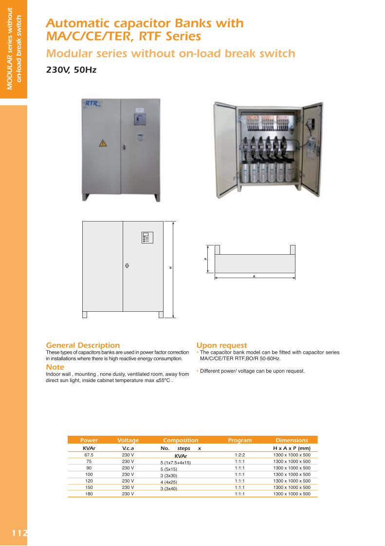
112
MO
DU
LAR s
erie
s w
ithout
on-lo
ad b
reak
sw
itch Automatic capacitor Banks with
MA/C/CE/TER, RTF SeriesModular series without on-load break switch230V, 50Hz
General DescriptionThese types of capacitors banks are used in power factor correction in installations where there is high reactive energy consumption.
NoteIndoor wall , mounting , none dusty, ventilated room, away from direct sun light, inside cabinet temperature max ≤55ºC .
Upon request The capacitor bank model can be fitted with capacitor series
MA/C/CE/TER RTF,BO/R 50-60Hz.
Different power/ voltage can be upon request.
PowerKVAr67.57590100120150180
VoltageV.c.a230 V230 V230 V230 V230 V230 V230 V
Program
1:2:21:1:11:1:11:1:11:1:11:1:11:1:1
CompositionNo. steps x
KVAr5 (1x7.5+4x15)5 (5x15)3 (3x30)4 (4x25)3 (3x40)
DimensionsH x A x P (mm)1300 x 1000 x 5001300 x 1000 x 5001300 x 1000 x 5001300 x 1000 x 5001300 x 1000 x 5001300 x 1000 x 5001300 x 1000 x 500

113
MO
DU
LAR s
erie
s w
ith
on-lo
ad b
reak
sw
itchAutomatic capacitor Banks with
MA/C/CE/TER, RTF SeriesModular series with on-load break switch230V, 50Hz
General DescriptionThese types of capacitors banks are used in power factor correction in installations where there is high reactive energy consumption.
NoteIndoor wall , mounting , none dusty, ventilated room, away from direct sun light, inside cabinet temperature max ≤55ºC .
Upon request The capacitor bank model can be fitted with capacitor series
MA/C/CE/TER RTF,BO/R 50-60Hz.
Different power/ voltage can be upon request.
PowerKVAr67.57590100120150180
VoltageV.c.a230 V230 V230 V230 V230 V230 V230 V
Program
1:2:21:1:11:1:11:1:11:1:11:1:11:1:1
CompositionNo. steps x KVAr5 (1x7.5+4x15)5 (5x15)3 (3x30)4 (4x25)3 (3x40)6 (6x25)6 (6x30)
DimensionsH x A x P (mm)1300 x 1000 x 5001300 x 1000 x 5001300 x 1000 x 5001300 x 1000 x 5001300 x 1000 x 5001300 x 1000 x 5001300 x 1000 x 500

114
MO
DU
LAR s
erie
s w
ithout
on-lo
ad b
reak
sw
itch Automatic capacitor Banks with
MA/C/CE/TER, RTF SeriesModular series without on-load break switch400/440V, 50Hz
General DescriptionThese types of capacitors banks are used in power factor correction in installations where there is high reactive energy consumption.
NoteIndoor wall , mounting , none dusty, ventilated room, away from direct sun light, inside cabinet temperature max ≤55ºC .
Upon request The capacitor bank model can be fitted with capacitor series
MA/C/CE/TER RTF,BO/R 50-60Hz.
Different power/ voltage can be upon request.
PowerKVAr190200200210220225240240250250260275300300315330360360375390405420435450465480480495510525540540555570600600630660660690720
VoltageV.c.a
400-440 V400-440 V400-440 V400-440 V400-440 V400-440 V400-440 V400-440 V400-440 V400-440 V400-440 V400-440 V400-440 V400-440 V400-440 V400-440 V400-440 V400-440 V400-440 V400-440 V400-440 V400-440 V400-440 V400-440 V400-440 V400-440 V400-440 V400-440 V400-440 V400-440 V400-440 V400-440 V400-440 V400-440 V400-440 V400-440 V400-440 V400-440 V400-440 V400-440 V400-440 V
Program
1:2:41:1:21:1:11:2:21:2:21:2:21:1:11:1:21:1:11:1:21:2:21:2:21:1:11:1:21:2:41:2:21:1:11:1:21:2:21:2:21:2:41:1:11:2:41:2:21:2:41:1:11:1:21:2:41:2:21:2:41:1:11:1:21:2:41:2:21:1:11:1:21:2:21:1:11:1:21:2:21:1:1
CompositionNo. steps x KVAr
6 (1x10+1x20+4x40)6 (2x20+4x40)5 (5x40) 4 (1x30+3x60)6 (1x20+5x40)5 (1x25+4x50)6 (6x40)7 (2x20+5x40)5 (5x50)6 (2x25+4x50)7 (1x20+6x40)6 (1x25+5x50)5 (5x60)6 (2x30+4x60)7 (1x15+2x30+4x60)6 (1x30+5x60)6 (6x60)7 (2x30+5x60)8 (1x25+7x50)7 (1x30+6x60)8 (1x15+1x30+6x60)7 (7x60)9 (1x15+2x30+6x60)8 (1x30+7x60)9 (1x15+1x30+7x60)8 (8x60)9 (2x30+7x60)10 (1x15+2x30+7x60)9 (1x30+8x60)10 (1x15+1x30+8x60)9 (9x60)10 (2x30+8x60)11 (1x15+2x30+8x60)10 (1x30+9x60)10 (10x60)11 (2x30+9x60)11 (1x30+10x60)11 (11x60)12 (2x30+10x60)12 (1x30+11x60)12 (12x60)
DimensionsH x A x P (mm)1300 x 1000 x 5001300 x 1000 x 5001300 x 1000 x 5001300 x 1000 x 5001300 x 1000 x 5001300 x 1000 x 5001300 x 1000 x 5001300 x 1000 x 5001300 x 1000 x 5001300 x 1000 x 5001300 x 1000 x 5001300 x 1000 x 5001300 x 1000 x 5001300 x 1000 x 5001300 x 1000 x 5001300 x 1000 x 5001300 x 1000 x 5001300 x 1000 x 5001600 x 1000 x 5001300 x 1000 x 5001600 x 1000 x 5001300 x 1000 x 5001700 x 1500 x 7001600 x 1000 x 5001700 x 1500 x 7001700 x 1500 x 7001700 x 1500 x 7001700 x 1500 x 7001700 x 1500 x 7001700 x 1500 x 7001700 x 1500 x 7001700 x 1500 x 7001700 x 1500 x 7001700 x 1500 x 7001700 x 1500 x 7001700 x 1500 x 7001700 x 1500 x 7001700 x 1500 x 7001700 x 1500 x 7001700 x 1500 x 7001700 x 1500 x 700

115
MO
DU
LAR s
erie
s w
ith
on-lo
ad b
reak
sw
itchAutomatic capacitor Banks with
MA/C/CE/TER, RTF SeriesModular series with on-load break switch400/440V, 50Hz
General DescriptionThese types of capacitors banks are used in power factor correction in installations where there is high reactive energy consumption.
NoteIndoor wall , mounting , none dusty, ventilated room, away from direct sun light, inside cabinet temperature max ≤55ºC .
Upon request The capacitor bank model can be fitted with capacitor series
MA/C/CE/TER RTF,BO/R 50-60Hz.
Different power/ voltage can be upon request.
PowerKVAr190200200210220225240240250250260275300300315330360360375390405420435450465480480495510525540540555570600600630660660690720
VoltageV.c.a
400-440 V400-440 V400-440 V400-440 V400-440 V400-440 V400-440 V400-440 V400-440 V400-440 V400-440 V400-440 V400-440 V400-440 V400-440 V400-440 V400-440 V400-440 V400-440 V400-440 V400-440 V400-440 V400-440 V400-440 V400-440 V400-440 V400-440 V400-440 V400-440 V400-440 V400-440 V400-440 V400-440 V400-440 V400-440 V400-440 V400-440 V400-440 V400-440 V400-440 V400-440 V
Program
1:2:41:1:21:1:11:2:21:2:21:2:21:1:11:1:21:1:11:1:21:2:21:2:21:1:11:1:21:2:41:2:21:1:11:1:21:2:21:2:21:2:41:1:11:2:41:2:21:2:41:1:11:1:21:2:41:2:21:2:41:1:11:1:21:2:41:2:21:1:11:1:21:2:21:1:11:1:21:2:21:1:1
CompositionNo. steps x KVAr
6 (1x10+1x20+4x40)6 (2x20+4x40)5 (5x40) 4 (1x30+3x60)6 (1x20+5x40)5 (1x25+4x50)6 (6x40)7 (2x20+5x40)5 (5x50)6 (2x25+4x50)7 (1x20+6x40)6 (1x25+5x50)5 (5x60)6 (2x30+4x60)7 (1x15+2x30+4x60)6 (1x30+5x60)6 (6x60)7 (2x30+5x60)8 (1x25+7x50)7 (1x30+6x60)8 (1x15+1x30+6x60)7 (7x60)9 (1x15+2x30+6x60)8 (1x30+7x60)9 (1x15+1x30+7x60)8 (8x60)9 (2x30+7x60)10 (1x15+2x30+7x60)9 (1x30+8x60)10 (1x15+1x30+8x60)9 (9x60)10 (2x30+8x60)11 (1x15+2x30+8x60)10 (1x30+9x60)10 (10x60)11 (2x30+9x60)11 (1x30+10x60)11 (11x60)12 (2x30+10x60)12 (1x30+11x60)12 (12x60)
DimensionsH x A x P (mm)1300 x 1000 x 5001300 x 1000 x 5001300 x 1000 x 5001300 x 1000 x 5001300 x 1000 x 5001300 x 1000 x 5001300 x 1000 x 5001300 x 1000 x 5001300 x 1000 x 5001300 x 1000 x 5001300 x 1000 x 5001300 x 1000 x 5001300 x 1000 x 5001300 x 1000 x 5001300 x 1000 x 5001300 x 1000 x 5001300 x 1000 x 5001300 x 1000 x 5001600 x 1000 x 5001300 x 1000 x 5001600 x 1000 x 5001300 x 1000 x 5001700 x 1500 x 7001600 x 1000 x 5001700 x 1500 x 7001700 x 1500 x 7001700 x 1500 x 7001700 x 1500 x 7001700 x 1500 x 7001700 x 1500 x 7001700 x 1500 x 7001700 x 1500 x 7001700 x 1500 x 7001700 x 1500 x 7001700 x 1500 x 7001700 x 1500 x 7001700 x 1500 x 7001700 x 1500 x 7001700 x 1500 x 7001700 x 1500 x 7001700 x 1500 x 700

116
ST s
erie
s w
ithout
on-lo
ad b
reak
sw
itch
Thyristor switching automatic capacitor banks with MA/C/CE/TER, RTF Series ST series without on-load break switch230V, 50Hz
General DescriptionThese types of automatic capacitor banks are used to com-pensate reactive energy in installations where reactive power requirements changes rapidly. This series switch capacitors in the zero crossing point avoiding transient problems.
NoteIndoor floor mounting, non dusty, well ventilated room, away from direct sun light, inside cabine temp. Max. -10ºC + 45ºC.
Upon request The capacitor bank model can be fitted with capacitor series
MA/C/CE/TER RTF, BO/R 50-60Hz. Different power/voltage can be upon request. With harmonic filters can be upon request
Voltage .................................................. 230 V c.a.Tolerance .............................................. +10%-15 %.Frequency ............................................. 50 ó 60 Hz.Ambient temperature ............................ -10ºC+45ºC.
Regulator with fast response to switching.STANDARD UNE EN 60831, IEC 831, EN 60439, IEC 439, IEC 255-5, UNE 21 136.
Technical Characteristics
AccessoriesRTR Energía Banks of capacitors can incorporate as acces-sories the following components:
Thermostats Intensity transformers
PowerKVAr12.517.525
27.537.552.56070
82.5100110140165180220240
VoltageV.c.a230 V230 V230 V230 V 230 V230 V 230 V230 V 230 V230 V230 V230 V 230 V230 V 230 V230 V
Program
1:2:21:2:41:2:21:2:41:2:21:2:21:1:11:2:41:2:41:2:21:2:41:2:21:2:21:2:21:2:21:1:1
CompositionNo. steps x KVAr3 (1x2.5+2x5)3 (1x2.5+1x5+1x10)3 (1x5+2x10)4 (1x2.5+1x5+2x10)3 (1x7.5+2x15)4 (1x7.5+3x15)4 (4x15)3 (1x10+1x20+1x40)4 (1x7.5+1x15+2x30)3 (1x20+2x40)4 (1x10+1x20+2x40)4 (1x20+3x40)6 (1x15+5x30)5 (1x20+4x40)6 (1x20+5x40)6 (6x40)
DimensionsH x A x P (mm)
To be confirmedTo be confirmedTo be confirmedTo be confirmedTo be confirmedTo be confirmedTo be confirmedTo be confirmedTo be confirmedTo be confirmedTo be confirmedTo be confirmedTo be confirmedTo be confirmedTo be confirmedTo be confirmed

117
ST s
erie
s w
ith
on-lo
ad b
reak
sw
itch
Thyristor switching automatic capacitor banks with MA/C/CE/TER, RTF Series ST series with on-load break switch230V, 50Hz
General DescriptionThese types of automatic capacitor banks are used to com-pensate reactive energy in installations where reactive power requirements changes rapidly. This series switch capacitors in the zero crossing point avoiding transient problems.
NoteIndoor floor mounting, non dusty, well ventilated room, away from direct sun light, inside cabine temp. Max. -10ºC + 45ºC.
Upon request The capacitor bank model can be fitted with capacitor series
MA/C/CE/TER RTF, BO/R 50-60Hz. Different power/voltage can be upon request. With harmonic filters can be upon request
Voltage .................................................. 230 V c.a.Tolerance .............................................. +10%-15 %.Frequency ............................................. 50 ó 60 Hz.Ambient temperature ............................ -10ºC+45ºC.
Regulator with fast response to switching.STANDARD UNE EN 60831, IEC 831, EN 60439, IEC 439, IEC 255-5, UNE 21 136.
Technical Characteristics
AccessoriesRTR Energía Banks of capacitors can incorporate as acces-sories the following components:
Thermostats Intensity transformers
PowerKVAr12.517.525
27.537.552.56070
82.5100110140165180220240
VoltageV.c.a230 V230 V230 V230 V 230 V230 V 230 V230 V 230 V230 V230 V230 V 230 V230 V 230 V230 V
Program
1:2:21:2:41:2:21:2:41:2:21:2:21:1:11:2:41:2:41:2:21:2:41:2:21:2:21:2:21:2:21:1:1
CompositionNo. steps x KVAr3 (1x2.5+2x5)3 (1x2.5+1x5+1x10)3 (1x5+2x10)4 (1x2.5+1x5+2x10)3 (1x7.5+2x15)4 (1x7.5+3x15)4 (4x15)3 (1x10+1x20+1x40)4 (1x7.5+1x15+2x30)3 (1x20+2x40)4 (1x10+1x20+2x40)4 (1x20+3x40)6 (1x15+5x30)5 (1x20+4x40)6 (1x20+5x40)6 (6x40)
DimensionsH x A x P (mm)
To be confirmedTo be confirmedTo be confirmedTo be confirmedTo be confirmedTo be confirmedTo be confirmedTo be confirmedTo be confirmedTo be confirmedTo be confirmedTo be confirmedTo be confirmedTo be confirmedTo be confirmedTo be confirmed

118
ST s
erie
s w
ithout
on-lo
ad b
reak
sw
itch
Thyristor switching automatic capacitor banks with MA/C/CE/TER, RTF Series ST series without on-load break switch400/440V, 50Hz
General DescriptionThese types of automatic capacitor banks are used to com-pensate reactive energy in installations where reactive power requirements changes rapidly. This series switch capacitors in the zero crossing point avoiding transient problems.
NoteIndoor floor mounting, non dusty, well ventilated room, away from direct sun light, inside cabine temp. Max. -10ºC + 45ºC.
Voltage .................................................. 400 ó 440 V c.a.Tolerance .............................................. +10%-15 %.Frequency ............................................. 50 ó 60 Hz.Ambient temperature ............................ -10ºC+45ºC.
Regulator with fast response to switching.STANDARD UNE EN 60831, IEC 831, EN 60439, IEC 439, IEC 255-5, UNE 21 136.
Technical Characteristics
Upon request The capacitor bank model can be fitted with capacitor series
MA/C/CE/TER RTF, BO/R 50-60Hz. Different power/voltage can be upon request. With harmonic filters can be upon request
AccessoriesRTR Energía Banks of capacitors can incorporate as acces-sories the following components:
Thermostats Intensity transformers
PowerKVAr12.517.525
27.531.25
3543.75
5055
62.568.75
7080
87.5100105
118.75140165200220280300330360380440460480520540560600640
VoltageV.c.a
400-440 V400-440 V400-440 V400-440 V400-440 V400-440 V400-440 V400-440 V400-440 V400-440 V400-440 V400-440 V400-440 V400-440 V400-440 V400-440 V400-440 V400-440 V400-440 V400-440 V400-440 V400-440 V400-440 V400-440 V400-440 V400-440 V400-440 V400-440 V400-440 V400-440 V400-440 V400-440 V400-440 V400-440 V
Program
1:2:21:2:41:2:21:2:41:2:21:2:41:2:41:2:21:2:41:2:21:2:41:2:21:1:11:2:21:1:11:2:41:2:41:2:41:2:41:2:21:2:21:2:21:2:41:2:21:2:21:2:41:2:21:2:41:1:11:2:21:2:41:1:11:2:21:1:1
CompositionNo. steps x KVAr
3 ( 1x2.5+2x5)3 (1x2.5+1x5+1x10)3 (1x5+2x10)4 (1x2.5+1x5+2x10)3 (1x6.25+2x12.5)3 (1x5+1x10+1x20)3 (1x6.25+1x12.5+1x25)3 (1x10+2x20)4 (1x5+1x10+2x20)3 (1x12.5+2x25)4 (1x6.25+1x12.5+2x25)4 (1x10+3x20)4 (4x20)4 (1x12.5+3x25)4 (4x25)3 (1x15+1x30+1x60)6 (1x6.25+1x12.5+4x25)3 (1x20+1x40+1x80)4 (1x15+1x30+2x60)3 (1x40+2x80)6 (1x20+5x40)4 (1x40+3x80)5 (1x20+1x40+3x80)6 (1x30+5x60)5 (1x40+4x80)6 (1x20+1x40+4x80)6 (1x40+5x80)7 (1x20+1x40+5x80)6 (6x80)7 (1x40+6x80)8 (1x20+1x40+6x80)7 (7x80)8 (1x40+7x80)8 (8x80)
DimensionsH x A x P (mm)
To be confirmedTo be confirmedTo be confirmedTo be confirmedTo be confirmedTo be confirmedTo be confirmedTo be confirmedTo be confirmedTo be confirmedTo be confirmedTo be confirmedTo be confirmedTo be confirmedTo be confirmedTo be confirmedTo be confirmedTo be confirmedTo be confirmedTo be confirmedTo be confirmedTo be confirmedTo be confirmedTo be confirmedTo be confirmedTo be confirmedTo be confirmedTo be confirmedTo be confirmedTo be confirmedTo be confirmedTo be confirmedTo be confirmedTo be confirmed
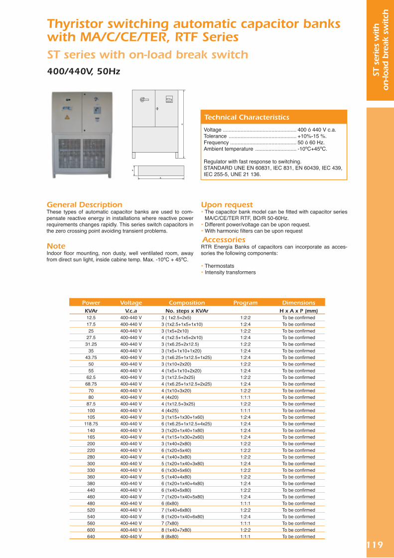
119
ST s
erie
s w
ith
on-lo
ad b
reak
sw
itch
Thyristor switching automatic capacitor banks with MA/C/CE/TER, RTF Series ST series with on-load break switch400/440V, 50Hz
General DescriptionThese types of automatic capacitor banks are used to com-pensate reactive energy in installations where reactive power requirements changes rapidly. This series switch capacitors in the zero crossing point avoiding transient problems.
NoteIndoor floor mounting, non dusty, well ventilated room, away from direct sun light, inside cabine temp. Max. -10ºC + 45ºC.
Voltage .................................................. 400 ó 440 V c.a.Tolerance .............................................. +10%-15 %.Frequency ............................................. 50 ó 60 Hz.Ambient temperature ............................ -10ºC+45ºC.
Regulator with fast response to switching.STANDARD UNE EN 60831, IEC 831, EN 60439, IEC 439, IEC 255-5, UNE 21 136.
Technical Characteristics
Upon request The capacitor bank model can be fitted with capacitor series
MA/C/CE/TER RTF, BO/R 50-60Hz. Different power/voltage can be upon request. With harmonic filters can be upon request
AccessoriesRTR Energía Banks of capacitors can incorporate as acces-sories the following components:
Thermostats Intensity transformers
PowerKVAr12.517.525
27.531.25
3543.75
5055
62.568.75
7080
87.5100105
118.75140165200220280300330360380440460480520540560600640
VoltageV.c.a
400-440 V400-440 V400-440 V400-440 V400-440 V400-440 V400-440 V400-440 V400-440 V400-440 V400-440 V400-440 V400-440 V400-440 V400-440 V400-440 V400-440 V400-440 V400-440 V400-440 V400-440 V400-440 V400-440 V400-440 V400-440 V400-440 V400-440 V400-440 V400-440 V400-440 V400-440 V400-440 V400-440 V400-440 V
Program
1:2:21:2:41:2:21:2:41:2:21:2:41:2:41:2:21:2:41:2:21:2:41:2:21:1:11:2:21:1:11:2:41:2:41:2:41:2:41:2:21:2:21:2:21:2:41:2:21:2:21:2:41:2:21:2:41:1:11:2:21:2:41:1:11:2:21:1:1
CompositionNo. steps x KVAr
3 ( 1x2.5+2x5)3 (1x2.5+1x5+1x10)3 (1x5+2x10)4 (1x2.5+1x5+2x10)3 (1x6.25+2x12.5)3 (1x5+1x10+1x20)3 (1x6.25+1x12.5+1x25)3 (1x10+2x20)4 (1x5+1x10+2x20)3 (1x12.5+2x25)4 (1x6.25+1x12.5+2x25)4 (1x10+3x20)4 (4x20)4 (1x12.5+3x25)4 (4x25)3 (1x15+1x30+1x60)6 (1x6.25+1x12.5+4x25)3 (1x20+1x40+1x80)4 (1x15+1x30+2x60)3 (1x40+2x80)6 (1x20+5x40)4 (1x40+3x80)5 (1x20+1x40+3x80)6 (1x30+5x60)5 (1x40+4x80)6 (1x20+1x40+4x80)6 (1x40+5x80)7 (1x20+1x40+5x80)6 (6x80)7 (1x40+6x80)8 (1x20+1x40+6x80)7 (7x80)8 (1x40+7x80)8 (8x80)
DimensionsH x A x P (mm)
To be confirmedTo be confirmedTo be confirmedTo be confirmedTo be confirmedTo be confirmedTo be confirmedTo be confirmedTo be confirmedTo be confirmedTo be confirmedTo be confirmedTo be confirmedTo be confirmedTo be confirmedTo be confirmedTo be confirmedTo be confirmedTo be confirmedTo be confirmedTo be confirmedTo be confirmedTo be confirmedTo be confirmedTo be confirmedTo be confirmedTo be confirmedTo be confirmedTo be confirmedTo be confirmedTo be confirmedTo be confirmedTo be confirmedTo be confirmed

120
ARM
ser
ies
without
on-lo
ad b
reak
sw
itch
Automatic capacitor banks with harmonic fil-ters and MA/C/CE/TER RCT Series ARM series without on-load break switch230V, 50Hz
General DescriptionThe ARM series capacitor banks are designed to be installed in systems with higher rates of voltage harmonics distortion THD-V 3% and current harmonics distortion THD-I 30%.
These banks are equipped with an “L-C” reactors and special designed capacitors (RCT) of the same power tuned to 189Hz or 134Hz resonance frequency.
The capacitor banks are specially designed for industries who have installed elements that generate non-linear loads of cer-tain values (variable speed drives, electronic ballasts, recti-fiers, static motor starters etc...).
RAL 1013
Voltage .................................................. 230 V c.a.Tolerance .............................................. ±10%.Frequency ............................................. 50 ó 60 Hz.Ambient temperature ............................ -10ºC+45ºC.
Regulator with fast response to switching.STANDARD UNE EN 60831-1-2, EN 60439.
Technical Characteristics
PowerKVAr
5062.575
87.5100
112.5120125
137.5150165180195220240
VoltageV.c.a230 V230 V230 V230 V 230 V230 V 230 V230 V 230 V230 V230 V230 V 230 V230 V 230 V
Program
1:2:21:2:21:1:11:2:21:1:11:2:21:1:11:1:11:2:21:1:11:2:21:1:11:2:21:2:21:1:1
CompositionNo. steps x KVAr3 (1x10+2x20)3 (1x12.5+2x25)3 (3x25)4 (1x12.5+3x25)4 (4x25)5 (1x12.5+4x25)4 (4x30)5 (5x25)6 (1x12.5+5x25)6 (6x25)6 (1x15+5x30)6 (6x30)7 (1x15+6x30)6 (1x20+5x40)6 (6x40)
DimensionsH x A x P (mm)
To be confirmedTo be confirmedTo be confirmedTo be confirmedTo be confirmedTo be confirmedTo be confirmedTo be confirmedTo be confirmedTo be confirmedTo be confirmedTo be confirmedTo be confirmedTo be confirmedTo be confirmed
AccessoriesRTR Energía Banks of capacitors can incorporate as acces-sories the following components:
Thermostats Three-phase harmonic filters Intensity transformers

121
ARM
ser
ies
with
on-lo
ad b
reak
sw
itch
Auto capacitor banks with harmonic filters and MA/C/CE/TER RCT Series ARM series with on-load break switch230V, 50Hz
General DescriptionThe ARM series capacitor banks are designed to be installed in systems with higher rates of voltage harmonics distortion THD-V 3% and current harmonics distortion THD-I 30%.
These banks are equipped with an “L-C” reactors and special designed capacitors (RCT) of the same power tuned to 189Hz or 134Hz resonance frequency.
The capacitor banks are specially designed for industries who have installed elements that generate non-linear loads of cer-tain values (variable speed drives, electronic ballasts, rectifiers, static motor starters etc...).
RAL 1013
Voltage .................................................. 230 V c.a.Tolerance .............................................. ±10%.Frequency ............................................. 50 ó 60 Hz.Ambient temperature ............................ -10ºC+45ºC.
Regulator with fast response to switching.STANDARD UNE EN 60831-1-2, EN 60439.
Technical Characteristics
PowerKVAr
5062.575
87.5100
112.5120125
137.5150165180195220240
VoltageV.c.a230 V230 V230 V230 V 230 V230 V 230 V230 V 230 V230 V230 V230 V 230 V230 V 230 V
Program
1:2:21:2:21:1:11:2:21:1:11:2:21:1:11:1:11:2:21:1:11:2:21:1:11:2:21:2:21:1:1
CompositionNo. steps x KVAr3 (1x10+2x20)3 (1x12.5+2x25)3 (3x25)4 (1x12.5+3x25)4 (4x25)5 (1x12.5+4x25)4 (4x30)5 (5x25)6 (1x12.5+5x25)6 (6x25)6 (1x15+5x30)6 (6x30)7 (1x15+6x30)6 (1x20+5x40)6 (6x40)
DimensionsH x A x P (mm)
To be confirmedTo be confirmedTo be confirmedTo be confirmedTo be confirmedTo be confirmedTo be confirmedTo be confirmedTo be confirmedTo be confirmedTo be confirmedTo be confirmedTo be confirmedTo be confirmedTo be confirmed
AccessoriesRTR Energía Banks of capacitors can incorporate as acces-sories the following components:
Thermostats Intensity transformers
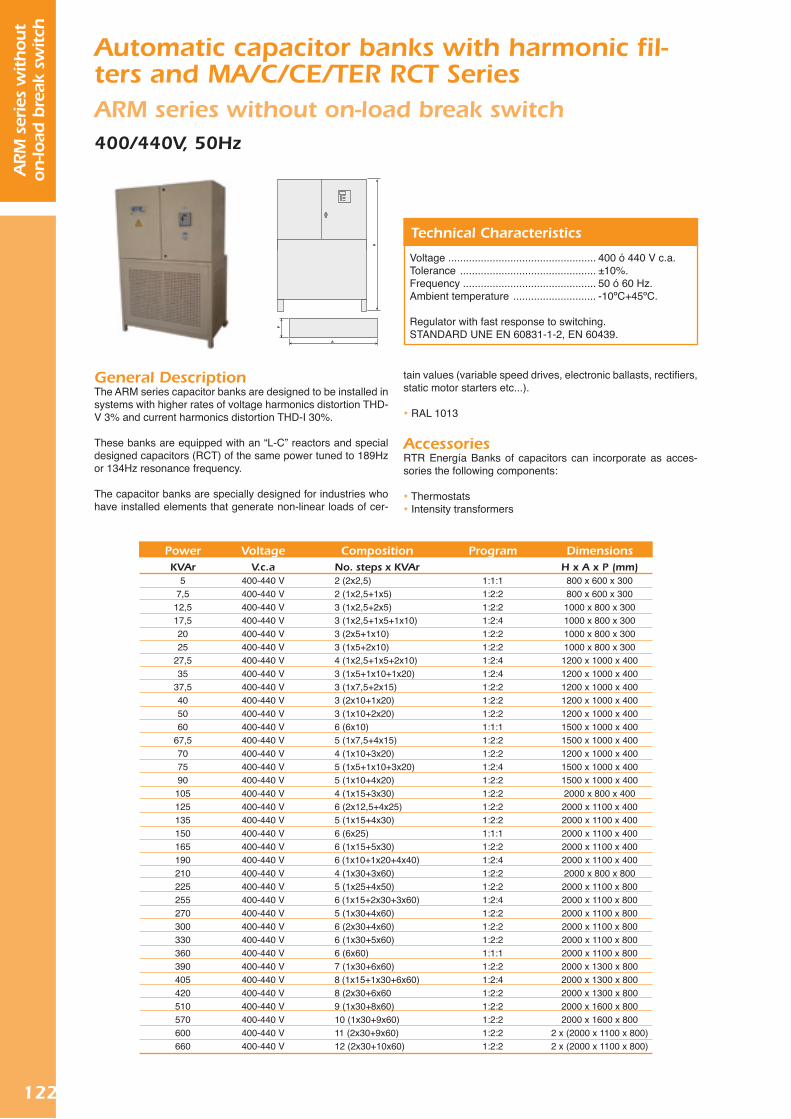
122
ARM
ser
ies
without
on-lo
ad b
reak
sw
itch
Automatic capacitor banks with harmonic fil-ters and MA/C/CE/TER RCT Series ARM series without on-load break switch400/440V, 50Hz
General DescriptionThe ARM series capacitor banks are designed to be installed in systems with higher rates of voltage harmonics distortion THD-V 3% and current harmonics distortion THD-I 30%.
These banks are equipped with an “L-C” reactors and special designed capacitors (RCT) of the same power tuned to 189Hz or 134Hz resonance frequency.
The capacitor banks are specially designed for industries who have installed elements that generate non-linear loads of cer-
Voltage .................................................. 400 ó 440 V c.a.Tolerance .............................................. ±10%.Frequency ............................................. 50 ó 60 Hz.Ambient temperature ............................ -10ºC+45ºC.
Regulator with fast response to switching.STANDARD UNE EN 60831-1-2, EN 60439.
Technical Characteristics
tain values (variable speed drives, electronic ballasts, rectifiers, static motor starters etc...).
RAL 1013
AccessoriesRTR Energía Banks of capacitors can incorporate as acces-sories the following components:
Thermostats Intensity transformers
PowerKVAr
57,512,517,52025
27,535
37,5405060
67,5707590105125135150165190210225255270300330360390405420510570600660
VoltageV.c.a
400-440 V400-440 V400-440 V400-440 V400-440 V400-440 V400-440 V400-440 V400-440 V400-440 V400-440 V400-440 V400-440 V400-440 V400-440 V400-440 V400-440 V400-440 V400-440 V400-440 V400-440 V400-440 V400-440 V400-440 V400-440 V400-440 V400-440 V400-440 V400-440 V400-440 V400-440 V400-440 V400-440 V400-440 V400-440 V400-440 V
Program
1:1:11:2:21:2:21:2:41:2:21:2:21:2:41:2:41:2:21:2:21:2:21:1:11:2:21:2:21:2:41:2:21:2:21:2:21:2:21:1:11:2:21:2:41:2:21:2:21:2:41:2:21:2:21:2:21:1:11:2:21:2:41:2:21:2:21:2:21:2:21:2:2
CompositionNo. steps x KVAr2 (2x2,5)2 (1x2,5+1x5)3 (1x2,5+2x5)3 (1x2,5+1x5+1x10)3 (2x5+1x10)3 (1x5+2x10)4 (1x2,5+1x5+2x10)3 (1x5+1x10+1x20)3 (1x7,5+2x15)3 (2x10+1x20)3 (1x10+2x20)6 (6x10)5 (1x7,5+4x15)4 (1x10+3x20)5 (1x5+1x10+3x20)5 (1x10+4x20)4 (1x15+3x30)6 (2x12,5+4x25)5 (1x15+4x30)6 (6x25)6 (1x15+5x30)6 (1x10+1x20+4x40)4 (1x30+3x60)5 (1x25+4x50)6 (1x15+2x30+3x60)5 (1x30+4x60)6 (2x30+4x60)6 (1x30+5x60)6 (6x60)7 (1x30+6x60)8 (1x15+1x30+6x60)8 (2x30+6x609 (1x30+8x60)10 (1x30+9x60)11 (2x30+9x60)12 (2x30+10x60)
DimensionsH x A x P (mm)
800 x 600 x 300800 x 600 x 300
1000 x 800 x 3001000 x 800 x 3001000 x 800 x 3001000 x 800 x 300
1200 x 1000 x 4001200 x 1000 x 4001200 x 1000 x 4001200 x 1000 x 4001200 x 1000 x 4001500 x 1000 x 4001500 x 1000 x 4001200 x 1000 x 4001500 x 1000 x 4001500 x 1000 x 4002000 x 800 x 4002000 x 1100 x 4002000 x 1100 x 4002000 x 1100 x 4002000 x 1100 x 4002000 x 1100 x 4002000 x 800 x 8002000 x 1100 x 8002000 x 1100 x 8002000 x 1100 x 8002000 x 1100 x 8002000 x 1100 x 8002000 x 1100 x 8002000 x 1300 x 8002000 x 1300 x 8002000 x 1300 x 8002000 x 1600 x 8002000 x 1600 x 800
2 x (2000 x 1100 x 800)2 x (2000 x 1100 x 800)

123
ARM
ser
ies
with
on-lo
ad b
reak
sw
itch
Automatic capacitor banks with harmonic fil-ters and MA/C/CE/TER RCT Series ARM series with on-load break switch400/440V, 50Hz
General DescriptionThe ARM series capacitor banks are designed to be installed in systems with higher rates of voltage harmonics distortion THD-V 3% and current harmonics distortion THD-I 30%.
These banks are equipped with an “L-C” reactors and special designed capacitors (RCT) of the same power tuned to 189Hz or 134Hz resonance frequency.
The capacitor banks are specially designed for industries who have installed elements that generate non-linear loads of cer-
Voltage .................................................. 400 ó 440 V c.a.Tolerance .............................................. ±10%.Frequency ............................................. 50 ó 60 Hz.Ambient temperature ............................ -10ºC+45ºC.
Regulator with fast response to switching.STANDARD UNE EN 60831-1-2, EN 60439.
Technical Characteristics
PowerKVAr
57,512,517,52025
27,535
37,5405060
67,5707590105125135150165190210225255270300330360390405420510570600660
VoltageV.c.a
400-440 V400-440 V400-440 V400-440 V400-440 V400-440 V400-440 V400-440 V400-440 V400-440 V400-440 V400-440 V400-440 V400-440 V400-440 V400-440 V400-440 V400-440 V400-440 V400-440 V400-440 V400-440 V400-440 V400-440 V400-440 V400-440 V400-440 V400-440 V400-440 V400-440 V400-440 V400-440 V400-440 V400-440 V400-440 V400-440 V
Program
1:1:11:2:21:2:21:2:41:2:21:2:21:2:41:2:41:2:21:2:21:2:21:1:11:2:21:2:21:2:41:2:21:2:21:2:21:2:21:1:11:2:21:2:41:2:21:2:21:2:41:2:21:2:21:2:21:1:11:2:21:2:41:2:21:2:21:2:21:2:21:2:2
CompositionNo. steps x KVAr2 (2x2,5)2 (1x2,5+1x5)3 (1x2,5+2x5)3 (1x2,5+1x5+1x10)3 (2x5+1x10)3 (1x5+2x10)4 (1x2,5+1x5+2x10)3 (1x5+1x10+1x20)3 (1x7,5+2x15)3 (2x10+1x20)3 (1x10+2x20)6 (6x10)5 (1x7,5+4x15)4 (1x10+3x20)5 (1x5+1x10+3x20)5 (1x10+4x20)4 (1x15+3x30)6 (2x12,5+4x25)5 (1x15+4x30)6 (6x25)6 (1x15+5x30)6 (1x10+1x20+4x40)4 (1x30+3x60)5 (1x25+4x50)6 (1x15+2x30+3x60)5 (1x30+4x60)6 (2x30+4x60)6 (1x30+5x60)6 (6x60)7 (1x30+6x60)8 (1x15+1x30+6x60)8 (2x30+6x609 (1x30+8x60)10 (1x30+9x60)11 (2x30+9x60)12 (2x30+10x60)
DimensionsH x A x P (mm)
800 x 600 x 300800 x 600 x 300
1000 x 800 x 3001000 x 800 x 3001000 x 800 x 3001000 x 800 x 300
1200 x 1000 x 4001200 x 1000 x 4001200 x 1000 x 4001200 x 1000 x 4001200 x 1000 x 4001500 x 1000 x 4001500 x 1000 x 4001200 x 1000 x 4001500 x 1000 x 4001500 x 1000 x 4002000 x 800 x 4002000 x 1100 x 4002000 x 1100 x 4002000 x 1100 x 4002000 x 1100 x 4002000 x 1100 x 4002000 x 800 x 8002000 x 1100 x 8002000 x 1100 x 8002000 x 1100 x 8002000 x 1100 x 8002000 x 1100 x 8002000 x 1100 x 8002000 x 1300 x 8002000 x 1300 x 8002000 x 1300 x 8002000 x 1600 x 8002000 x 1600 x 800
2 x (2000 x 1100 x 800)2 x (2000 x 1100 x 800)
tain values (variable speed drives, electronic ballasts, rectifiers, static motor starters etc...).
RAL 1013
AccessoriesRTR Energía Banks of capacitors can incorporate as acces-sories the following components:
Thermostats Intensity transformers

124
NOTES B
AN
KS
Medium Voltage

126
MED
IUM
VO
LTA
GE
1. General information for MV capacitors
1.1 Total film dielectric
RTR Capacitors have a dielectric constituted in general by three polypropylene films “hazy”, rough in both faces, of high purity. This construction, instead of which it uses only two layers of a rough film in a single one of his faces, common in other manufacturers, confers to RTR Capacitors greater secu-rity of operation and greater life utility. The rough of both faces of polypropylene is a condition indispensable for the complete impregnating of the film during the process and, therefore, for the stability of the capacitor in the long term.
1.2 Impregnating biodegradable
RTR Capacitors use exclusive impregnating the nonchlorina-ted MDBT, developed for the most demanding applications by Elf-Atochem(France). This it is characterized by his high flash point, great capacity of gas absorption derived from the internal electrical unloadings, and total environmental compatibility (biodegradable).
1.3 Construction with folio extended and wild fold
RTR Capacitors is constituted by elementary units, each one of them consisting of aluminum folio windings of high purity and polypropylene films. The aluminum laminae excel towards the ends of the coil, and their edges are folded forming a ring anticrown that confers to the condenser a tension of insepción ofpartial unloadings superior to 50% of the nominal value. The laminae are welded to each other and with the next coils by means of special alloys of great adhesion and low point of fusion. This way the use of “abatis”, characteristic of the previous designs is avoided.
1.4 Under stress
RTR Energía S.L. uses conservative criteria of design that imply the application of dielectric efforts (kV/ mm) relatively low on the materials. Like consequence, the capacitors are of dimensions somewhat greater than those of other marks, with an expec-tation of greater life utility.
1.5 Inner fuses
RTR Energía S.L. incorporates to a great part of their range of MV. capacitors (specially for the greater powers) with the option of individual inner fuses by coil, of new design. Such they allow to isolate the possible failure of anyone of the elements of the capacitor and other elements can still work in normal condition. The fuses are separated to each other, so that it is impossible that the performance of one of them causes the catuación of the fuse next to. In addition, the condensers with internal fuses allow simpler, light and economic constructions.
1.6 Dielectric low losses
The characteristics of their design, the rigorous selection of the manufacture materials and the artisan care put in their construc-tion and process give like result capacitors of low losses, which is translated in smaller this form and operating temperatures, a greater life utility.

127
MED
IUM
VO
LTA
GE
2. Tecnical characteristics and dimensions for three-phase capacitors
Standard .............................................................................................................................. IEC 871-1/4 Voltage test terminal to terminal .......................................................................................... 1 - 7,2 kV Frequency ........................................................................................................................... 50 - 60 Hz Losses ................................................................................................................................ <0.15 W/KVAr Temperature ....................................................................................................................... -5+50ºC Dielectric liquid ................................................................................................................... MDBT Nonchlorinated Residual Voltage ................................................................................................................ 10% Un later 5 min. Dielectric ............................................................................................................................ Polypropylene Fuses .................................................................................................................................. Optional Use ..................................................................................................................................... Indoor-Inclemency Altitude ............................................................................................................................... 1000 m s.n.m. Maximum over voltage. ...................................................................................................... 1.1 x Un Maximum over current ....................................................................................................... 1.3 x In Tolerance ............................................................................................................................. -5 + 15% Vltage test ........................................................................................................................... 4,3 x Un (10 sec
2.1 Aproximated dimensions
Notes:
1. In these tables the equipments of use have been included mas commonly nevertheless they can be made for other voltages, frequencies, etc.
2. The height corresponding to the fin of fixation (C) could be changed according to the needs of the assembly.
3. Also is possible the construction of single-phase capacitors with one point or two isolated points.
4. The dimensions and others characteristics are subject to changes without previous notice

128
MED
IUM
VO
LTA
GE
2.2 Range from 1 to 1,2 kV
2.3 Range from 2 to 3,6 kV
a 50 Hz10152550100
a 50 Hz255075
83.3100150167200250300
a 60 Hz12183060120
a 60 Hz306090100120180200240300360
Power (kVAr)
Power (kVAr)
Dimensions
Dimensions
A (mm)200200200260450
A (mm)200200300300320500500580660680
B (mm)135135135135135
B (mm)135135135135135135135135135160
C (mm)130130130230230
C (mm)130130230230230230230230230230
WeightKg.1516172032
WeightKg.15172122253535404955
BIL = 25 kVwithout terminal cover
BIL = 40 kVwithout terminal cover
BIL = 25 kVwith terminal cover
BIL = 40 kVwith terminal cover

129
MED
IUM
VO
LTA
GE
2.4 Range from 4 to 7,2 kV
a 50 Hz255075
83.3100150167200250300
a 60 Hz306090100120180200240300360
Power (kVAr) DimensionsA (mm)
260260320320360460500600700720
B (mm)135135135135135135135135135160
C (mm)130130230230230230230230230230
WeightKg.16182223263636415056
BIL = 60 kVwithout terminal cover
3. Technical characteristics and dimensions for single-phase capacitors
Standard .............................................................................................................................. IEC 871-1/4 Frequency ........................................................................................................................... 50 - 60 Hz Losses ................................................................................................................................ <0.15 W/KVAr Temperature ....................................................................................................................... -5+50ºC Dielectric liquid ................................................................................................................... MDBT Nonchlorinated Residual Voltage ................................................................................................................ 10% Un later 5 min. Dielectric ............................................................................................................................ Polypropylene Fuses .................................................................................................................................. Optional Use ..................................................................................................................................... Indoor - Inclemency Altitude ............................................................................................................................... 1000 m s.n.m. Maximum over voltage ....................................................................................................... 1.1 x Un Maximum over current ....................................................................................................... 1.3 x In Tolerance ............................................................................................................................. -5 + 15% Voltage test terminal to terminal .......................................................................................... 4,3 x Un (10 sec)
3.1 Aproximated dimensions
Notes:
1. In these tables the equipments of use have been included mas commonly nevertheless they can be made for other voltages, frequencies, etc.
2. The height corresponding to the fin of fixation (C) could be changed according to the needs of the assembly. 3. Also is possible the construction of single-phase capacitors with one point or two isolated points. 4. The dimensions and others characteristics are subject to changes without previous notice

130
MED
IUM
VO
LTA
GE
3.2 Range from 6 to 36 kV
a 50 Hz3350
83.3100150167200250300333400500
a 60 Hz4060100120180200240300360400480600
Power (kVAr) DimensionsA (mm)
2002003203204505005806607207208601080
B (mm)135135135135135135135135160160160160
C (mm)130130230230230230230230230230230230
WeightKg.151722253535404955596779
BIL = 95 y 110 kV2 stud terminals
BIL = 125 kV2 stud terminals
BIL = 95 y 110 kV1 stud terminal
BIL = 125 kV1 stud terminal

131
MED
IUM
VO
LTA
GE
BIL = 150 kV2 stud terminals
BIL = 150 kV1 stud terminal
4. Capacitors banks of medium voltage
4.1 Fixed banks for medium voltage overhead distribution lines
Simple, compact, low cost, maintenance-free capacitor banks for pole mounting on overhead distribution feeders. They provide voltage level support and loss reduction, in-
creasing power quality offered to costumers.
Reactive Power Range: from 75 to 1500 kVAr (50Hz); from 90 to 1800 kVAr (60 Hz); and voltage level from,3.6 to 36 kV.

132
MED
IUM
VO
LTA
GE
4.2 Automatic capacitor banks for medium voltage overhead distribution lines
They provide finer reactive control according to the load. Con-trol strategies based either on time of day, voltage level, VAR demand, temperature or a combination of them. Micropro-cessor-based controls with metering, event recording, annual programming and remote supervision capacity. Capacitor switching by means of economical oil switches or maintenance-free vacuum switches with dry, solid foam insulation.
Reactive Power Range: from 75 to 1500 kVAr (50Hz); from 90 to 1800 kVAr (60 Hz); and voltage level from,3.6 to 36 kV.
Reactive Power Range: from 75 to 20 kVAr (50Hz); from 90 to 24 kVAr (60 Hz); and voltage level from,3.6 to 36 kV.
Reactive Power Range: from 75 to 1500 kVAr (50Hz); from 90 to 1800 kVAr (60 Hz); and voltage level from,3.6 to 36 kV.
4.3 Fixed, open type medium voltage capacitor banks for industrial installations and small power substations
When the capacitors are installed at the customer’s installa-tion, they provide low power factor penalty reduction or elimi-nation. Floor-or platformmounted banks of reduced fooftprint. Capacitors connected in simple or double wye with unbalance protection. Various sectionalizing and protection schemes available.
4.4 Automatic, open type medium voltage capacitor banks for large industrial ins-tallations and power substations
Control strategies based either on time of day, voltage level, VAR demand, temperature or combination of them. Single- or multista-ge banks, each stage provided with independent switching, protection and inrush current limiting reactors. Off-the-shelf or PLC-based, open-architecture controls. Special control options: Zero-Voltage-Crossing (ZVC) of switches, automatic tripping of bank upon loss of voltage, time-delayed bank reconnection after power restoring.
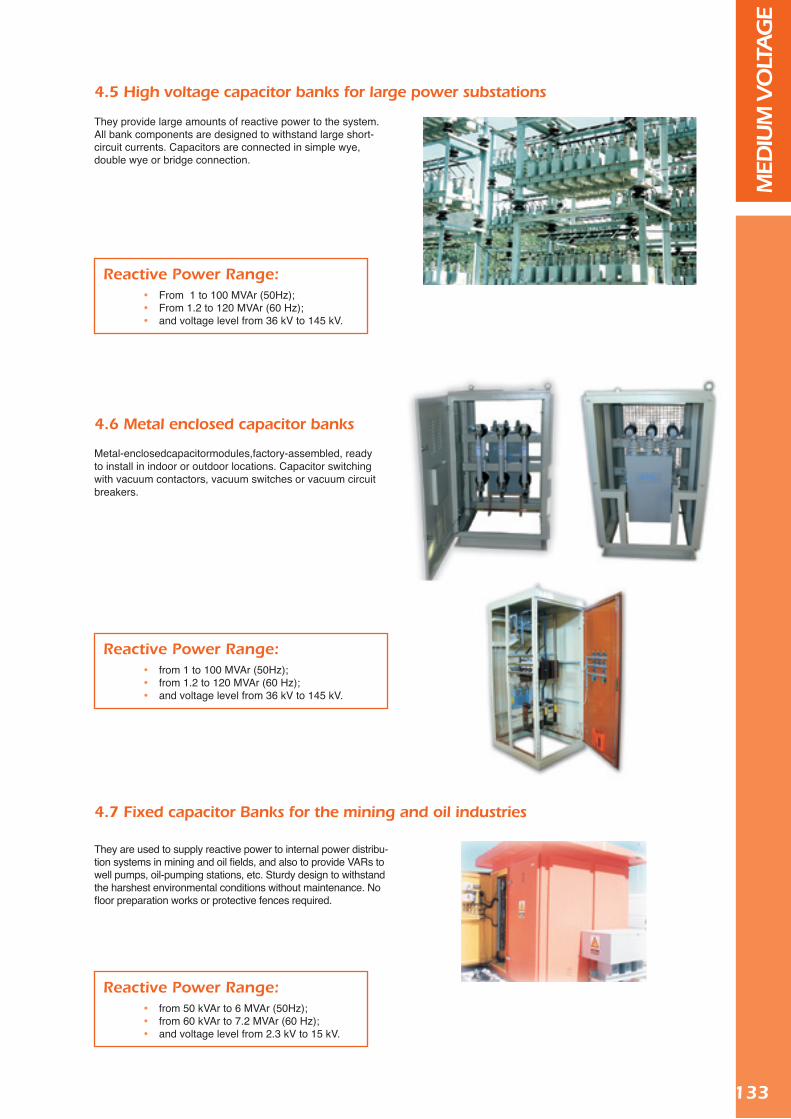
133
MED
IUM
VO
LTA
GE
Reactive Power Range: From 1 to 100 MVAr (50Hz); From 1.2 to 120 MVAr (60 Hz); and voltage level from 36 kV to 145 kV.
Reactive Power Range: from 1 to 100 MVAr (50Hz); from 1.2 to 120 MVAr (60 Hz); and voltage level from 36 kV to 145 kV.
4.5 High voltage capacitor banks for large power substations
They provide large amounts of reactive power to the system. All bank components are designed to withstand large short-circuit currents. Capacitors are connected in simple wye, double wye or bridge connection.
4.6 Metal enclosed capacitor banks
Metal-enclosedcapacitormodules,factory-assembled, ready to install in indoor or outdoor locations. Capacitor switching with vacuum contactors, vacuum switches or vacuum circuit breakers.
Reactive Power Range: from 50 kVAr to 6 MVAr (50Hz); from 60 kVAr to 7.2 MVAr (60 Hz); and voltage level from 2.3 kV to 15 kV.
4.7 Fixed capacitor Banks for the mining and oil industries
They are used to supply reactive power to internal power distribu-tion systems in mining and oil fields, and also to provide VARs to well pumps, oil-pumping stations, etc. Sturdy design to withstand the harshest environmental conditions without maintenance. No floor preparation works or protective fences required.

134
MED
IUM
VO
LTA
GE
5. Selection chart of MV capacitors for motors and transformers
5.1 Charts for MV motors
PowerKW15018020025030040050075010001300160020002500300040005000
AparentPowerMVA
2,53,15
45
6,3810
12,5162025
31,540
NominalC.V.204245272340408543680101913591766217427173397407654356793
PrimaryVoltage
kV≤20≤20≤20v20≤36≤36≤36≤36≤66≤66≤66≤66≤66
SecondaryVoltage
kV≤16≤16≤16≤16≤20≤20≤20≤20≤20≤20≤20≤20≤20
R e a c t i v e power
kVAr190240300375475600750940
1200150018752360
3000 r.p.m3040425363801001502002603204005005908001000
1500 r.p.m.3745506375
100125187250325400500625750
10001250
Reactive power (kVAr)

135
MED
IUM
VO
LTA
GE
7. Medium voltage harmonic filters
They provide reactive compensation and filtering of harmonic distortion produced by electric furnaces, eletrolyctic proces-ses,soft-starters, variable drives and other non-linear loads. Heavyduty capacitors specially designed to operate under permanentovervoltage and high currents.
Rango de Potencia: from 250 kVAr to 6 MVAr (50Hz); from 250 kVAr to 7.2 MVAr (60 Hz); and voltage level from 1 kV to 36 kV.
8. Current limiting reactors fot MV capacitors (*)
9. Three-phase contactor for MV capacitors (*)
PowerKVAr
255075
100150200250300
VoltagekV6.66.66.66.66.66.66.66.6
Electric currentA
2,755,5
8,2511
16,522
27,533
VoltagekV6.6
Electric currentA
400
(*) For any further information please contact to our Technical Dept
(*) For any further information please contact to our Technical Dept

136
MED
IUM
VO
LTA
GE
NOTES

Three Phase Harmonic
Filters and Transformers

138
Three-phase harmonic filters
Complince standard .............................. IEC-60289;IEC-076Tolerance “L”.......................................... 3%Permisible overload ............................... 1,07 x InLinearity Inductance .............................. 1,60 x InHeat insulation ....................................... Clase F (155ºC)Thermal protection................................. 90ºCRoom temperature................................. 45ºCProof stress ........................................... 4KVProtection degree .................................. IP-00Detuning factor (p%).............................. 7% - 14%
Technical Characteristics
Constructive Characteristics Three phase harmonic filters are made of low losses mag-netic plates, permanent regime class F (155ºC) copper con-ductor and 90ºC thermal protection relay.
With the purpose of increasing filters ventilation, windings are separated among them, improving thermal dissipation.
Standard surge factor is 7% and 14% with resonance fre-quency 189 Hz and 134 Hz for 50 Hz networks.
With this standard values in three phase networks and ba-lanced loads, the 5th (250 Hz) harmonic and higher resp-nant phenomenons are eliminated avoiding resonance bet-ween inductive impedance and three phase capacitors for power factor correction and preventing network capacitors and capacitor banks for overloads.
PowerKVAr
2,5510
12,51520253040
PowerKVAr
2,5510
12,51520253040
InductancemH5,072,531,271,010,840,630,510,420,32
InductancemH
10,905,452,732,181,821,361,090,910,68
CapacitanceµF
3x46,633x93,273x186,533x233,173x279,803x373,073x466,333x559,603x746,13
CapacitanceµF
3x43,123x86,253x172,493x215,623x258,743x344,993x431,233x517,483x689,97
CurrentA
6,2812,5525,1031,3837,6550,2062,7675,31
100,41
CurrentA
6,2812,5525,1031,3837,6550,2062,7675,31
100,41
Code
RTF23000251895RTF23000501895RTF23001001895RTF23001251895RTF23001501895RTF23002001895RTF23002501895RTF23003001895RTF23004001895
Code
RTF23000251345RTF23000501345RTF23001001345RTF23001251345RTF23001501345RTF23002001345RTF23002501345RTF23003001345RTF23004001345
Rated Voltage: 230 V; Nominal Frequecy: 50 Hz. Resonance fequency: 189 Hz; Detuning factor: 7 %
Rated Voltage: 230 V; Nominal Frequecy: 50 Hz. Resonance fequency: 134 Hz; Detuning factor: 14 %
REA
CTA
NC
ES
AN
D
TRA
NSF
ORM
ERS
Copper winding

139
PowerKVAr
2,5510
12,5152025304050607080100
PowerKVAr
2,5510
12,5152025304050607080100
PowerKVAr
2,5510
12,5152025304050607080100
PowerKVAr
2,5510
12,5152025304050607080100
InductancemH
15,337,673,833,072,561,921,531,280,960,770,640,550,480,38
InductancemH
32,9816,498,256,605,504,123,302,752,061,651,371,181,030,82
InductancemH
18,559,284,643,713,092,321,861,551,160,930,770,660,580,46
InductancemH
39,9119,959,987,986,654,993,993,332,492,001,661,431,251,00
CapacitanceµF
3x15,423x30,843x61,673x77,093x92,513x123,353x154,183x185,023x246,693x308,363x370,043x431,713x493,383x616,73
CapacitanceµF
3x14,263x28,523x57,033x71,293x85,553x114,063x142,583x171,093x228,123x285,153x342,183x399,213x456,243x570,31
CapacitanceµF
3x12,743x25,483x50,973x63,713x76,453x101,943x127,423x152,913x203,883x254,853x305,813x356,783x407,753x509,69
CapacitanceµF
3x11,783x23,573x47,133x58,923x70,703x94,273x117,833x141,403x188,533x235,663x282,803x329,933x377,063x471,33
CurrentA
3,617,22
14,4318,0421,6528,8736,0843,3057,7472,1786,60
101,04115,47144,34
CurrentA
3,617,22
14,4318,0421,6528,8736,0843,3057,7472,1786,60
101,04115,47144,34
CurrentA
3,286,56
13,1216,4019,6826,2432,8039,3652,4965,6178,7391,85
104,97131,22
CurrentA
3,286,56
13,1216,4019,6826,2432,8039,3652,4965,6178,7391,85
104,97131,22
Code
RTF40000251895RTF40000501895RTF40001001895RTF40001251895RTF40001501895RTF40002001895RTF40002501895RTF40003001895RTF40004001895RTF40005001895RTF40006001895RTF40007001895RTF40008001895RTF40010001895
Code
RTF40000251345RTF40000501345RTF40001001345RTF40001251345RTF40001501345RTF40002001345RTF40002501345RTF40003001345RTF40004001345RTF40005001345RTF40006001345RTF40007001345RTF40008001345RTF40010001345
Code
RTF44000251895RTF44000501895RTF44001001895RTF44001251895RTF44001501895RTF44002001895RTF44002501895RTF44003001895RTF44004401895RTF44005001895RTF44006001895RTF44007001895RTF44008001895RTF44010001895
Code
RTF44000251345RTF44000501345RTF44001001345RTF44001251345RTF44001501345RTF44002001345RTF44002501345RTF44003001345RTF44004401345RTF44005001345RTF44006001345RTF44007001345RTF44008001345RTF44010001345
Rated Voltage: 400 V; Nominal Frequecy: 50 Hz. Resonance fequency: 189 Hz; Detuning factor: 7 %
Rated Voltage: 400 V; Nominal Frequecy: 50 Hz. Resonance fequency: 134 Hz; Detuning factor: 14 %
Rated Voltage: 440 V; Nominal Frequecy: 50 Hz. Resonance fequency: 189 Hz; Detuning factor: 7 %
Rated Voltage: 440 V; Nominal Frequecy: 50 Hz. Resonance fequency: 134 Hz; Detuning factor: 14 %
REA
CTA
NC
ES
AN
D
TRA
NSF
ORM
ERS

140
REA
CTA
NC
ES
AN
D
TRA
NSF
ORM
ERS
Single-phase transformer
Technical Characteristics
Safety and isolating single-phase transformers are made of low losses magnetic plates, permanent regime class F (155 ºC) copper conductor. Clamp type terminal blocks, compact dimensions and weight reduction make easier installation.
Other powers and voltages under request.
Standard ............................................... IEC-61558Protection Index....... .............................. IP-00Heat Insulation........ ............................... Clase F (B)Dielectric Strength ................................. 4kVRoom Temperature max. ......................... 40ºCFrequency ............................................. 50 Hz
Dimensions
*Secondary at 12V-24V, dimensions increasing 15 mm**Dimensions can change without previously notice
Power A B C D E F
VA mm mm 100 75 75 68 63 60 10,5x4,5 160 96 85 85 80 65 14x5,5 200 96 85 85 80 65 14x5,5 250 96 100 85 80 80 14x5,5 300 108 100 95 90 80 16,5x5,5 320 108 110 95 90 85 16,5x5,5 400 108 110* 95 90 85 16,5x5,5 500 108 125* 95 90 100 16,5x5,5 630 150 120* 130 125 90 21,5x8 800 150 130* 130 125 100 21,5x8 1000 150 140* 130 125 110 21,5x8
Transformation Ratio Power
Primary Secondary VA
100 160 200 250 320 400 500 630 800 1000
230 12 38,57 € 50,62 € 53,84 € 56,33 € 76,01 € 93,82 € 112,14 € 147,54 € 167,43 € 202,52 €
230 24 38,11 € 51,40 € 52,23 € 61,16 € 79,17 € 87,54 € 102,23 € 135,87 € 162,02 € 185,34 €
230 48 35,71 € 51,97 € 56,70 € 60,58 € 76,68 € 88,89 € 102,33 € 125,85 € 148,94 € 185,86 €
230 115 35,82 € 53,94 € 53,64 € 58,97 € 74,91 € 87,16 € 97,76 € 127,76 € 148,22 € 182,95 €
230 230 36,96 € 51,14 € 53,78 € 58,09 € 77,26 € 83,84 € 102,59 € 129,33 € 145,83 € 183,16 €
400 12 45,53 € 51,04 € 60,94 € 63,23 € 80,00 € 91,94 € 107,68 € 153,47 € 168,52 € 196,04 €
400 24 37,22 € 49,31 € 51,91 € 58,41 € 77,10 € 80,16 € 100,09 € 135,04 € 157,46 € 178,48 €
400 48 40,70 € 48,95 € 54,72 € 61,63 € 78,29 € 88,67 € 100,92 € 128,60 € 149,67 € 174,86 €
400 115 37,69 € 50,00 € 55,91 € 61,26 € 77,26 € 86,07 € 96,93 € 130,88 € 145,06 € 172,67 €
400 230 36,55 € 47,86 € 56,43 € 60,02 € 75,53 € 80,98 € 100,62 € 154,50 € 148,32 € 168,72 €
F
E
BB
D
A
C
C
A
D E
F
C
F
E
B
D
A

141
REA
CTA
NC
ES
AN
D
TRA
NSF
ORM
ERS
Single-Phase Isolating Transformers
Dimensions
Power A B C D E F Weight
kVA mm mm kg1,30 163 160 245 98 115 8 17,00 1,60 163 165 245 98 120 8 19,00 2,00 163 175 245 98 130 8 21,50 2,50 163 195 245 98 150 8 25,50 3,00 200 200 290 120 140 10 34,00 3,50 200 210 290 120 150 10 38,00 4,00 200 220 290 120 160 10 42,00 5,00 200 240 290 120 180 10 48,00
Rated Voltage Primary...........................................230 V Rated Voltage Secondary......................................230 VThermal Class........................................................BRoom Temperature max........... ............................(40° C)Frequency..............................................................50/60 HzClass......................................................................IProtection Index.....................................................IP00Dielectric strength between windings.....................≥4 kVStandard................................................................IEC-60726
Technical Characteristics
Single-Phase Swimming-Pools Transformers
Dimensions
Class......................................................................100, 300 and 700 VAProtección contra choques eléctricos.....................class IRated Voltage Primary........................................... 230 VRated Voltage Secondary...................................... 12VThermal Class.........................................................B(130° C) and F(155° C)Room Temperature max.......... ..............................(40° C)Frequency...............................................................50/60 HzProtection Index......................................................IP00Dielectric Strength between windings.....................≥4,5 kVDielectric Strength between windings and mass.....≥2,5 kVStandard..................................................................IEC 61558
Technical Characteristics
Single-phase power isolating transformers dry type is especially designed for installations which need galvanic isolation and/or the attenuation of line disturbances. They are manufactured with electrical steel with low losses and copper windings. On request we can manufacture transformers with other voltages, with taps, electrostatic screen, with thermal switch, etc.
Single-phase safety transformers intended to supply spotlights in swimming-pools andmoist locations, where the safety reason it is necesary to supply with safety extra low voltage. It has several taps in the primary winding in order to compensate fot the voltage drop in the transformer-spotlight line conductors.
F
E
BB
D
A
C
C
A
D E
F
C
F
E
B
D
A
F
E
BB
D
A
C
C
A
D E
F
C
F
E
B
D
A
Power Primary Secondary A B C D E F Weight VA V V mm mm kg
100 230 12,5-13-13,5 84 80 9 90 70 5 2,00 300 230 12,5-13-13,5 108 115 93 90 70 5,5 4,00 600 230 12,5-13-13,5 120 135 108 100 110 5,5 7,90
Transformer Light VA W
100 1x100W 300 1x300W 600 2x300W

142
Three-Phase Transformers
Three-phase power isolating transformers dry type are designed for voltage transformation with galvanic isolation and attenuation of line disturbances. They are manufactured with electrical steel with low losses and copper windings. Adjustable connection according the requirements.
Rated Voltage Primary ....................................... 400 V Rated Voltage Secondary................................... 230 VThermal Clas.. .....................................................BRoom Temperature max. ......................................
...........................................................................................................................
.........................................................................
................................
max40° CFrequency.. 50/60 Hz Class IProtection Index....... IP00Dielectric Strength................ ≥4kVNatural air coolingConnection .........................................................Dyn5Standard.............................. EC-61558
Technical Characteristics
Power A B C D E F Weight
kVA mm mm kg 0,50 180 85 200 140 55 6 6,50 1,00 240 110 250 200 75 6 16,00 1,50 240 120 250 200 85 6 18,50 2,00 240 130 250 200 95 6 23,00 3,50 300 135 340 200 105 8 33,50 4,00 300 145 340 200 115 8 40,00 5,00 300 175 340 200 135 8 50,00 6,00 360 170 360 300 115 8 56,00 6,50 360 170 360 300 115 8 56,00 8,00 360 180 360 300 125 8 58,00 10,00 360 190 360 300 135 8 67,00
Dimensions
REA
CTA
NC
ES
AN
D
TRA
NSF
ORM
ERS
Three-Phase Transformers
Three-phase power isolating transformers dry type are designed for voltage transformation with galvanic isolation and attenuation of line disturbances. They are manufactured with electrical steel with low losses and copper windings. Adjustable connection according the requirements.
Rated Voltage Primary ....................................... 400 V Rated Voltage Secondary................................... 230 VThermal Clas.. .....................................................BRoom Temperature max. ......................................
...........................................................................................................................
.........................................................................
................................
max40° CFrequency.. 50/60 Hz Class IProtection Index....... IP00Dielectric Strength................ ≥4kVNatural air coolingConnection .........................................................Dyn5Standard.............................. EC-61558
Technical Characteristics
Power A B C D E F Weight
kVA mm mm kg 0,50 180 85 200 140 55 6 6,50 1,00 240 110 250 200 75 6 16,00 1,50 240 120 250 200 85 6 18,50 2,00 240 130 250 200 95 6 23,00 3,50 300 135 340 200 105 8 33,50 4,00 300 145 340 200 115 8 40,00 5,00 300 175 340 200 135 8 50,00 6,00 360 170 360 300 115 8 56,00 6,50 360 170 360 300 115 8 56,00 8,00 360 180 360 300 125 8 58,00 10,00 360 190 360 300 135 8 67,00
Dimensions F
E
BB
D
A
C
C
A
D E
F
C
F
E
B
D
A

Accessories

144
Quick discharge resistor (*)
Capacitors duty contactors
On-load break switch
ModelTC1-D
TC1-D10TC1-D12TC1-D16TC1-D20TC1-D33TC1-D40TC1-D60
Coil VoltageV
230230230230230230230
Capacitor PowerkVAr2,5-7,5
101520
25-3035-4050-60
Type
RD-1K8
Resistance
2x1800
Code
CSSD40D3CSSD63K3
CSSD125D3CSSD125D3
CSSD160DM3CSSD160DM3CSSD200DM3CSSD250DM3CSSD315DM3CSSD400K3CSSD630K3CSSD630K3CSSD800K3
CSSD1000K3CSSD1250K3CSSD1600K3CSSD1800K3CSSD2500K3CSSD3150K3
Current
40A63A80A
100A125A160A200A250A315A400A500A630A800A
1000A1250A1600A1800A2500A3150A
(*) For any futher information please contact to our Technical Dept.
AC
CESO
RIE
S

Controllers

146
Voltage supply ...................................230 VVoltage measurement........................110-690 VFrequency..........................................50-60 HzCurrent Transformer ..........................x/5 AC/K setting .........................................Automatic ajustement, ...........................................................allows re-adjustements ...........................................................between 0,05 and 0,95Cos j setting .....................................0.85 IND a 0.95 CAPCos j indicator ..................................DigitalTendendy indicator ............................ luminous indicatorCapacitor status................................. luminous indicatorMeasurement system ........................A1 - Automatic, ...........................................................A2-Semiautomatic,...........................................................A3 - ManualVisualization ......................................Secondary signal T.I.Connect time .....................................10 to 20 sec.Programing ........................................1:1:1; 1:2:2; 1:2:4; ...........................................................1:1:2; 1:1:2:2:4Manual connection pulsers ................4 segNumber of steps ................................3,6 and 12
Front panell............................................ 144 x 144 mm
Mounting aperture ................................. 138 x 138 mm
Depth ..................................................... 95 mm
Mounting ................................................ Brackets
Real connection ..................................... Plug-in connector
Protection .............................................. IP 41
Temperature .......................................... -10 + 60 ºC
Weight ................................................... 1,25 Kg
Technical Characteristics Mechanical Characteristics
CodeREG03DPR2500000REG06DPR2500000 REG12DPR2500000
Tipo PR-2DPR-2D 3 StepsPR-2D 6 Steps
PR-2D 12 StepsPR-2D 144 x 144
PR-2
DAutomatic reactive power controllerPR-2D Series
Dimensions

147
Voltage supply ....................................... 380...415 VacFrequency.............................................. 50-60 HzCos j ..................................................... 0.8 IND...0.80 CAPCos j indicator ..................................... DigitalTendendy indicator ................................ Luminous indicatorCapacitor status..................................... Luminous indicatorConnect time .......................................... 5...240 seg.Programing ............................................ 1:1:1; 1:2:2; 1:2:4:4; ............................................................... 1:2:4:8;Number of steps .................................... 5, 7
Front panell............................................ 96 x 96 mm
Mounting aperture ................................. 91 x 91 mm
Depth ..................................................... 65 mm
Protection .............................................. IP 54
Mounting ................................................ Brackets
Real connection ..................................... Plug-in connector
Temperature .......................................... -20 + 60 ºC
Weight ................................................... 440...460 g
Technical Characteristics Mechanical Characteristics
CodeREG05DPR5500000REG07DPR5500000
Tipo PR-5DPR-5D 5 StepsPR-5D 7 StepsPR-5D 96 x 96
PR-5
D
Automatic reactive power controllerPR-5D Series
Dimensions

148
Supply voltage ......................................... (phase-neutral) 220 VACRang of operation .............................. (0.8-1.1) x UnFrequency..........................................50HzPower consumption ...........................<1 VAContact’s current ...............................Máx. 3 A / 240 VCACurrent meaurement rang ....................0.1 - 6 A CADisplay rang.......................................0.00-1.00Ind. y Cap.Min. time of connection & disconnection ..................................50 mAAccuracy ............................................1% +- dígitoRatio of current transformer...............5/5...10000/5 AMax. time of connection & disconnection .................................10...60 sMin. time of connection & disconnection ................................. 2...10 sValue of IND. P.F. adjustment ............10%...50%Value of CAP. P.F. adjustment ...........5%...50%Display ...............................................LED of 4 digit
Protection dig......................................... IP 20
Protection dig. of contacts ..................... IP 00
Amtient temp. ........................................ -5ºC...+50ºC
Humidity................................................. 15%...95%
Type of installation ................................. Panel mounting
Dimensions ............................................ 144x144x40 mm
Technical Characteristics Mechanical Characteristics
CodeREG06DPR8500000REG12DPR8500000
Tipo PR-8DPR-8D 6 Steps
PR-8D 12 Steps
PR-8
DAutomatic reactive power controllerPR-8D Series
Dimensions
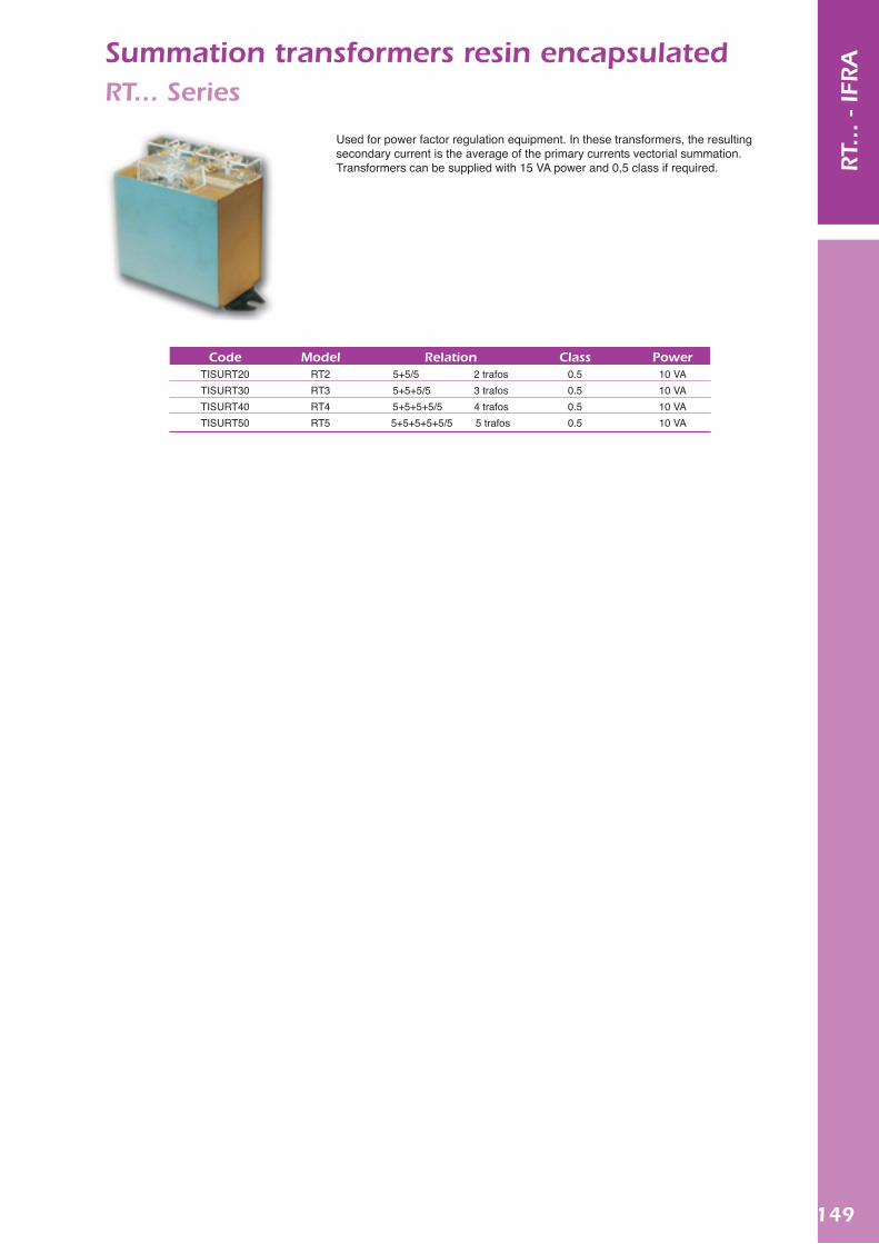
149
RT.
.. -
IFRASummation transformers resin encapsulated
RT... Series
CodeTISURT20TISURT30TISURT40TISURT50
ModelRT2RT3RT4RT5
Relation5+5/5 2 trafos5+5+5/5 3 trafos5+5+5+5/5 4 trafos5+5+5+5+5/5 5 trafos
Class0.50.50.50.5
Power10 VA10 VA10 VA10 VA
Used for power factor regulation equipment. In these transformers, the resulting secondary current is the average of the primary currents vectorial summation. Transformers can be supplied with 15 VA power and 0,5 class if required.
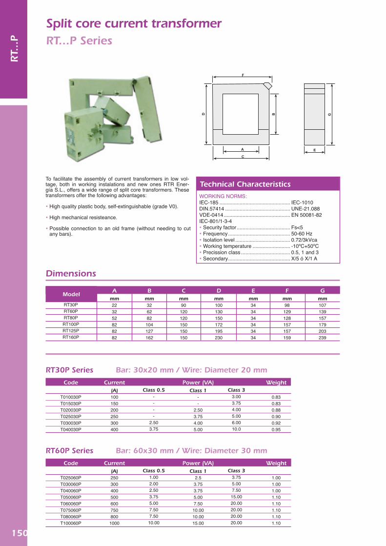
150
RT.
..P
Split core current transformerRT...P Series
To facilitate the assembly of current transformers in low vol-tage, both in working instalations and new ones RTR Ener-gía S.L., offers a wide range of split core transformers. These transformers offer the following advantages:
High quality plastic body, self-extinguishable (grade V0).
High mechanical resisteance.
Possible connection to an old frame (without needing to cut any bars).
WORKING NORMS:IEC-185 ................................................. IEC-1010 DIN.57414 ............................................. UNE-21.088 VDE-0414 .............................................. EN 50081-82IEC-801/1-3-4 Security factor ..................................... Fs<5 Frequency ........................................... 50-60 Hz Isolation level ...................................... 0.72/3kVca Working temperature .......................... -10ºC+50ºC Precission class .................................. 0.5, 1 and 3 Secondary ........................................... X/5 ó X/1 A
Technical Characteristics
Dimensions
RT30PRT60PRT80PRT100PRT125PRT160P
Code
T010030PT015030PT020030PT025030PT030030PT040030P
Code
T025060PT030060PT040060PT050060PT060060PT075060PT080060PT100060P
Amm223252828282
Current(A)100150200250300400
Current(A)2503004005006007508001000
Bmm326282104127162
Class 0.5- ---
2.503.75
Class 0.51.002.002.503.755.007.507.5010.00
Cmm90
120120150150150
Power (VA)Class 1
--
2.503.754.005.00
Power (VA)Class 1
2.53.753.755.007.50
10.0010.0015.00
Dmm100130150172195230
Class 33.003.754.005.006.0010.0
Class 33.755.007.50
15.0020.0020.0020.0020.00
Emm343434343434
Weight
0.830.830.880.900.920.95
Weight
1.001.001.001.101.101.101.101.10
Fmm98
129128157157159
Gmm107139157179203239
Model
RT30P Series Bar: 30x20 mm / Wire: Diameter 20 mm
RT60P Series Bar: 60x30 mm / Wire: Diameter 30 mm

151
RT.
..P
Code
T025080PT030080PT040080PT050080PT060080PT075080PT080080PT100080P
Current(A)2503004005006007508001000
Class 0.51.002.002.503.755.007.507.5010.00
Power (VA)Class 1
2.53.753.755.007.50
10.0010.0015.00
Class 33.755.007.50
15.0020.0020.0020.0020.00
Weight
1.101.151.201.251.301.301.301.35
RT80P Series Bar: 80x50 mm / Wire: Diameter 50 mm
Code
T025100PT030100PT040100PT050100PT060100PT075100PT080100PT100100P T120100P T150100P T200100P
Current(A)2503004005006007508001000120015002000
Class 0.51.002.002.503.755.007.507.5010.0015.0015.0020.00
Power (VA)Class 1
2.53.753.755.007.50
10.0010.0015.0020.0020.0030.00
Class 33.755.007.50
15.0020.0020.0020.0020.0030.0030.0045.00
Weight
1.401.501.501.601.701.751.751.751.801.801.80
RT100P Series Bar: 100x80 mm / Wire: Diameter 80 mm
Code
T050125PT060125PT075125PT080125PT100125PT120125PT150125PT200125P T250125P T300125P
Current(A)500600750800100012001500200025003000
Class 0.51.251.255.007.5010.0015.0020.0025.0025.0030.00
Power (VA)Class 1
5.005.00
10.0010.0020.0020.0030.0030.0030.0045.00
Class 37.50
15.0020.0020.0030.0030.0045.0045.0045.0060.00
Weight
1.651.701.751.751.801.801.901.901.902.05
RT125P Series Bar: 125x80 mm / Wire: Diameter 80 mm
Code
T050160PT060160PT075160PT080160PT100160PT120160PT150160PT200160P T250160P T300160PT400160P T500160P
Current(A)50060075080010001200150020002500300040005000
Class 0.51.251.255.007.5010.0015.0020.0025.0025.0030.0030.0030.00
Power (VA)Class 1
5.005.00
10.0010.0020.0020.0030.0030.0030.0045.0045.0045.00
Class 37.50
15.0020.0020.0030.0030.0045.0045.0045.0060.0060.0060.00
Weight
2.42.42.42.42.42.42.42.42.42.42.42.4
RT160P Series Bar: 160x80 mm / Wire: Diameter 80 mm
Split core current transformerRT...P Series

152
NOTES C
ON
TRO
LLERS

Lighting
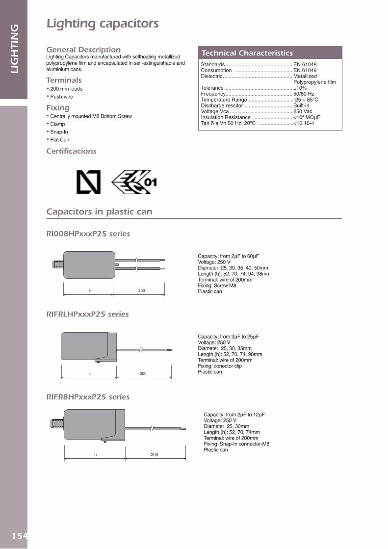
154
LIG
HTI
NG Lighting capacitors
General DescriptionLighting Capacitors manufactured with selfhealing metallized polypropylene film and encapsulated in self-extinguishable and aluminium cans.
Terminals• 200 mm leads• Push-wire
Fixing• Centrally mounted M8 Bottom Screw• Clamp• Snap-In • Flat Can
Certificacions
Standards .............................................. EN 61048 Consumption ........................................ EN 61049 Dielectric ................................................ Metallized
Polypropylene filmTolerance ............................................... ±10% Frequency.............................................. 50/60 Hz Temperature Range ............................... -25 + 85ºC Discharge ressitor ................................. Built-inVoltage Vca ........................................... 250 Vac Insulation Resistance ........................... <104 MΩμF Tan δ a Vn 50 Hz, 20ºC ....................... <10.10-4
Technical Characteristics
200h
200h
200h
200h
200h
200h
200h
200h
200h
Capacity: from 2μF to 60μF Voltage: 250 V Diameter: 25, 30, 35, 40, 50mm Length (h): 52, 70, 74, 94, 98mm Terminal: wire of 200mmFixing: Screw M8 Plastic can
Capacity: from 2μF to 25μFVoltage: 250 VDiameter: 25, 30, 35mmLength (h): 52, 70, 74, 98mmTerminal: wire of 200mmFixing: conector clip Plastic can
Capacity: from 2μF to 12μFVoltage: 250 VDiameter: 25, 30mmLength (h): 52, 70, 74mmTerminal: wire of 200mmFixing: Snap-In connector-M8Plastic can
Capacitors in plastic can
RI008HPxxxP25 series
RIFRLHPxxxP25 series
RIFR8HPxxxP25 series

155
LIG
HTI
NG
h
h
h
200h
h
h
h
h
200h
h
h
h
h
200h
h
h
h
h
200h
h
h
h
h
200h
h
Capacity: from 2μF to 25μFVoltage: 250 VDiameter: 25, 30, 35mmLength (h): 52, 70, 74, 98mmTerminal: Push-wireFixing: Snap-In connectorPlastic can
Capacity: from 2μF to 12μFVoltage: 250 V Diameter: 25, 30mmLength (h): 52, 70, 74mmTerminal: Push-wireFixing: Snap-In connetor-M8Plastic can
Capacity: from 2μF to 60μFVoltage: 250 VDiameter: 25, 30, 35, 40, 50mmLength (h): 58, 76, 100mmTerminal: wire of 200mmFixing: Screw M8Aluminium can
Capacity: from 2μF to 40μFVoltage: 250 VDiameter: 25, 30, 35, 40mmLength (h): 52, 70, 74, 98mmTerminal: Push-wireFixing: Screw M8Plastic can
Capacity: from 2μF to 40μFVoltage: 250 VDiameter: 25, 30, 35, 40mmLength (h): 58, 76, 100mmTerminal: Push-wireFixing: Screw M8Aluminium can
RIFRLCRxxxP25 series
RIFR8CRxxxP25 series
RI008HPxxxA25 series
Serie RI008CRxxxP25
RI008CRxxxA25 series
Capacitors in aluminium can

156
LIG
HTI
NG Motor run capacitors
General DescriptionMotor run Capacitors manufactured with selfhealing metallized polypropylene film and encapsulated in self-extinguishable plastic aluminium cans.
Terminals• Double Faston 6.3mm tags• 2x0.75 of 210mm Twin cable• 200mm Leads
Fixing• Centrally mounted M8 Bottom Screw• Flat Can
Standards .............................................. EN 60252 Dielectric ............................................... Metallized Polypropylene filmTolerance ............................................... ±5%Frequency.............................................. 50/60 HzTemperature Range ............................... .-25 + 85ºCVoltage Vca ........................................... 400/450 VacTest Voltage between terminals to case ................................................... 2,4 kVInsulation resistance .............................. .<104 MΩμFTan δ a Vn 50 Hz, 20ºC ......................... .<10.10-4Can ........................................................ Aluminium/Plastic
Technical Characteristics
h 11
h
h 210
11
Capacity: from 2μF to 60μFVoltage: 450 VDiameter: 25, 30, 35, 45, 50mmLength (h): 52, 56, 74, 94, 98mmTerminal: faston connector 6.3mmFixing: NoPlastic can
Capacity: from 2μF to 65μFVoltage: 450 VDiameter: 25, 30, 35, 40, 45, 50, 55mmLength (h): 52, 56, 74, 94, 98, 120mmTerminal: faston connector 6.3mmFixing: Screw M8Plastic can
Capacity: from 2μF to 60μFVoltage: 450 VDiameter: 25, 30, 35, 40, 45, 50mmLength (h): 52, 56, 74, 94, 98mmTerminal: Twin cable 210mmFixing: NoPlastic can
Capacitors in plastic can
RMLFDxxxP45 series
RM8FDxxxP45 series
RMLMGxxxP45 series

157
LIG
HTI
NG
h 11
h 210
200h
200h
200h
h 11
h 210
200h
200h
200h
h 11
h 210
200h
200h
200h
h 11
h 210
200h
200h
200h
h 11
h 210
200h
200h
200h
Capacity: from 2μF to 65μFVoltage: 450 VDiameter: 25, 30, 35, 40, 45, 50, 55mmLength (h): 52, 56, 74, 94, 98mmTerminal: Twin cable 210mmFixing: Screw M8Plastic can
Capacity: from 2μF to 60μFVoltage: 450 VDiameter: 25, 30, 35, 40, 45, 50mmLength (h): 52, 56, 74, 94, 98, 120mmTerminal: 200mm WireFixing: NoPlastic can
Capacity: from 2μF to 65μFVoltage: 450 VDiameter: 25, 30, 35, 40, 45, 50, 55mmLength (h): 52, 56, 74, 94, 98, 120mmTerminal: 200mm wireFixing: Screw M8 Plastic can
Capacity: from 2μF to 65μFVoltage: 450 V Diameter: 25, 30, 36, 40, 45, 50, 55mmLength (h): 58, 76, 100, 127mmTerminal: faston 6.3mmFixing: Screw M8Aluminium can
Capacity: from 2μF to 65μF Voltage: 450 VDiameter: 25, 30, 36, 40, 45, 50, 55mmLength (h): 58, 76, 100, 127mmTerminal: cable 200mmFixing: Screw M8Aluminium can
RM8MGxxxP45 series
RMLHPxxxP45 series
RM8HPxxxP45 series
RM8FDxxxA45 series
RM8HPxxxA45 series
Capacitors in aluminium can

158
LIG
HTI
NG Ballasts for discharge lamps
General DescriptionOur range of electronic ballasts for discharge lamps has been designed as products to be incorporated in lightings or in indivi-dual boxes. They are prepared for incorporate dependand and independent ignitors. Ballasts´protective wrapper facilitate their assembly and to allow coupling diferents auxiliary elements.
High precision winding with copper or aluminium thread protec-tion degree H,180ºC and magnetic sheets low losses.
High Pressure Sodium/Metal Halide (MH)
Copper control gear
Aluminium Ballasts with thermal protection (PT)
Aluminium Ballasts without thermal protection (PT)
CodeCBD402232DU CBD602232DU
DescriptionCompact-class 1-400W 230/240V 50HZ (4.6A)Compact-class 1-600W 230/240V 50HZ (6.2A)
CodeHSA07223221HSA10223221HSA15223221HSA25223221
DescriptionHSI-SAPI 70W 230/240V 50HZ (1.0A) — PT HSI-SAPI 100W 230/240V 50HZ (1.2A) — PT HSI-SAPI 150W 230/240V 50HZ (1.8A) — PTHSI-SAPI 250W 230/240V 50HZ (3.0A) — PT
CodeHSA07223232HSA10223232HSA15223232HSA25223232
DescriptionHSI-SAPI 70W 230/240V 50HZ (1.0A) HSI-SAPI 100W 230/240V 50HZ (1.2A) HSI-SAPI 150W 230/240V 50HZ (1.8A) HSI-SAPI 250W 230/240V 50HZ (3.0A)
* For any, powers, voltages and frecuencies resquesting please contact our Technical Department

159
LIG
HTI
NG
Mercury (MV) / Metal Halide
Ignitor for discharge lamps
Aluminium Ballasts with thermal protection (PT)
Aluminium Ballasts without thermal protection (PT)
Superposition
CodeHMA25223221HMA40223221
DescriptionHIA-HSI 250W 230/240V 50HZ (2.15) — PT HIA-HSI 400W 230/240V 50HZ (3.5A) — PT
CodeHMA25223232HMA40223232
DescriptionHIA-HSI 250W 230/240V 50HZ (2.15) HIA-HSI 400W 230/240V 50HZ (3.5A)
Semi-parallel
Code Description
CodePXE070255PAE400255PCX070255
Description35-70W SAP
35-400W SAP/HM35-70W SAP/HM — (timed ignitor)
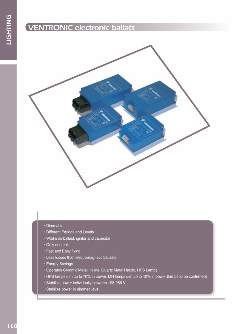
LIG
HTI
NG
VENTRONIC electronic ballats
• Dimmable• Different Periods and Levels• Works as ballast, ignitor and capacitor• Only one unit• Fast and Easy fixing• Less losses than electromagnetic ballasts• Energy Savings• Operates Ceramic Metal Halide, Quartz Metal Halide, HPS Lamps• HPS lamps dim up to 70% in power. MH lamps dim up to 40% in power (lamps to be confirmed)• Stabilize power individually between 198-256 V• Stabilize power in dimmed level
160

161
LIG
HTI
NG
High Frequency Electronic Ballast DALI. For MH UNI-FORM Pulse Start Lamps
Code
VGB250S01VGB400S01VGB250D01VGB400D01
Dimming / Power Min.
Switched & 1-10V / 50% Switched & 1-10V / 35%
DALI / 50% DALI / 35%
Description
VENTRONIC VGB250S01 1-10V MH 250W VENTRONIC VGB400S01 1-10V MH 400W
VENTRONIC VGB250D01 1-10V & DALI MH 250W VENTRONIC VGB400D01 1-10V & DALI MH 400W
Lamp
(W) (a) 20 0.225 35 0.5 50 0.68 70 1.0 100 1.1 140 1.8 150 1.8
Code
VYB020255 VYB035255 VYB050255VYB070255VYB100255VYB140255VYB150255
LineVoltage
(V) 230V 230V 230V230V230V230V 230V
CircuitPower
(W)24455679110150161
Linecurrent
(A)0.1
0.10 0.23 0.330.460.630.67
Máx. Casetemp.
(ºC)8080 8080808080
Ventronic Electronic Ballast
Lamp
(W) (a) 50 0.68 70 1.0 100 1.1 150 1.8
Code
VYB050ES1VYB070ES1VYB100ES1VYB150ES1
LineVoltage
(V) 230V 230V 230V 230V
CircuitPower
(W)5679 110161
Linecurrent
(A)0.240.330.460.67
Máx. Casetemp.
(ºC)808080 80
Dimmable Electronic Ballast. Ventronic Part Night
Lamp (W)250400250400
• Option: Cable terminal & Connector
• ES1 Program Dimming
162
LIG
HTI
NG NOTES

163
LIG
HTI
NGNOTES

164
LIG
HTI
NG NOTES

