ncsx engineering design document design description ... filencsx engineering design document...
TRANSCRIPT
NCSX Engineering Design Document Design Description Facility Systems (WBS 6)
NCSX CDR May 21-23, 2002 Lead Author: Larry Dudek
ii
Table of Contents 1 Introduction......................................................................................................................................................... 1 2 Water Cooling Systems....................................................................................................................................... 1 3 Cryogenic Systems .............................................................................................................................................. 8 3.1 LN2-LHe Supply System.................................................................................................................................. 8 3.2 LN2 Coil Cooling System............................................................................................................................... 10 3.3 GN2 Cryostat Cooling System......................................................................................................................... 12 4 Utility Systems................................................................................................................................................... 14 5 Helium Bakeout System.................................................................................................................................... 16
Table of Figures
Figure 2-1 CS Water System P&ID.............................................................................................................................. 2 Figure 2-2 NB Enclosure Cooling................................................................................................................................. 4 Figure 2-3 VPSCS P&ID .............................................................................................................................................. 5 Figure 2-4 DWCS P&ID............................................................................................................................................... 6 Figure 3-1 LN2-LHe Supply Concept........................................................................................................................... 9 Figure 3-2 LN2 Coil Cooling System Schematic........................................................................................................ 11 Figure 3-3 GN2 Cryostat Cooling System Schematic................................................................................................. 13 Figure 5-1 Helium Bakeout System P&ID ................................................................................................................. 17 Figure 5-2 Similar Helium Bakeout System in Use on NSTX.................................................................................... 18
Tables
Table 2-1 CS Water System Performance Characteristics ............................................................................................ 1 Table 2-2 NB Water Cooling Performance Characteristics .......................................................................................... 3 Table 2-3 VPWCS Performance Characteristics........................................................................................................... 4 Table 2-4 BCWS Performance Characteristics ............................................................................................................. 5 Table 2-5 DWCS Performance Characteristics............................................................................................................. 6 Table 2-6 CS Water Cooling Systems Costs................................................................................................................. 7 Table 3-1 LN2-LHe Supply System Costs .................................................................................................................. 10 Table 3-2 LN2 Coil Cooling System Costs................................................................................................................. 12 Table 3-3 GN2 Cryostat Cooling System Costs.......................................................................................................... 14 Table 4-1 Utility System Performance Characteristics ............................................................................................... 14 Table 4-2 Utility Systems Costs.................................................................................................................................. 15 Table 5-1 Helium Bakeout System Costs ................................................................................................................... 19

NCSX Engineering Design Document Facility Systems
1
1 INTRODUCTION
Facility Systems include the following WBS elements:
• Water Cooling Systems (WBS 62)
• Cryogenic Systems (WBS 63)
• Utility Systems (WBS 64)
• Vacuum Vessel & PFC Heating and Cooling Systems (WBS 65) Systems
2 WATER COOLING SYSTEMS
Design Requirements and Constraints
This WBS element includes all the effort required to add cooling loops to the existing C-site (CS) and HVAC Water Systems as required for NCSX subsystems. This WBS element consists of the following sub-elements:
• Neutral Beam Water Cooling (WBS 622)
• Vacuum Pumping Water Cooling (WBS 623)
• Bakeout Water Cooling (WBS 624)
• Diagnostics Water Cooling (WBS 625)
Design Description and Performance
The CS Water System is a demineralized water cooling system that originally supplied the cooling water for the PBX and PLT experiments. The system currently is inactive and will be recommissioned by the PPPL Maintenance & Operations Division prior to the start of NCSX operation. This system removes heat from the NCSX water cooling subsystems and transfers it to the atmospheric cooling tower. A simplified P&ID diagram of the system is shown in Figure 2-1. CS Water System performance characteristics are provided in Table 2-1.
Table 2-1 CS Water System Performance Characteristics
System Pressure 147 psig
System Flow 3600
Water Quality Deionized, 2 Mohm-cm
System Temperature 60 deg F
System Capacity 400 kW available

NCSX Engineering Design Document Facility Systems
2
Figure 2-1 CS Water System P&ID
A 7500 gallon storage tank is polished at 25 gallons per minute by a deionized water polishing loop maintaining high resistivity. Three existing 150 Hp, 1200 gpm centrifugal pumps, immediately beneath the storage tank, are plumbed in parallel and provide motive force. NCSX will require the use of only one of these pumps.
An existing 720 Ton heat exchanger provides the heat sink to the system. The deionized water can be chilled either by the existing cooling tower or switched to the C-site HVAC chillers.
The system interfaces to the NCSX test cell via 16” diameter supply and return headers, which are located directly below the test cell. The header supplies the cooling water to the following NCSX cooling loops:
• Neutral Beam Water Cooling (WBS 622)
• Bakeout Water Cooling (WBS 624)
• Diagnostics Water Cooling (WBS 625)
(The Vacuum Pumping Water Cooling System (WBS 623) will be connected to the HVAC Water System.)
The primary pumps and heat exchanger alignment for the CS Water System are controlled at a remote location (the C-site MG Control Room). To avoid pressure surges and ensure smooth operation, this equipment is started up before opening the NCSX inlet and return valves. The pumps can be operated individually or in combinations to provide up to 3600 gallons total system flow rate. The CS Water System operates in a normal operating or in a standby mode in which a small circulating pump continuously circulates the system water through a bypass polishing loop to keep the water conductivity low.
Two existing bladder type bypass control valves plumbed in parallel maintain constant pressure to NCSX. In addition, automatic valves on the main supply and return to the NCSX Test Cell will provide the ability to remotely cut off the water supply from the control room if required. Instrumentation on the supply line to NCSX in the test cell will indicate pressure, temperature and resistivity.
NCSX Engineering Design Document Facility Systems
3
Neutral Beam Water Cooling (WBS 622)
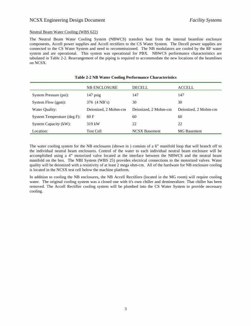
The Neutral Beam Water Cooling System (NBWCS) transfers heat from the internal beamline enclosure components, Accell power supplies and Accell rectifiers to the CS Water System. The Decell power supplies are connected to the CS Water System and need to recommissioned. The NB modulators are cooled by the RF water system and are operational. This system was operational for PBX. NBWCS performance characteristics are tabulated in Table 2-2. Rearrangement of the piping is required to accommodate the new locations of the beamlines on NCSX.
Table 2-2 NB Water Cooling Performance Characteristics
The water cooling system for the NB enclosures (shown in ) consists of a 6” manifold loop that will branch off to the individual neutral beam enclosures. Control of the water to each individual neutral beam enclosure will be accomplished using a 4” motorized valve located at the interface between the NBWCS and the neutral beam manifold on the box. The NBI System (WBS 25) provides electrical connections to the motorized valves. Water quality will be deionized with a resistivity of at least 2 mega ohm-cm. All of the hardware for NB enclosure cooling is located in the NCSX test cell below the machine platform.
In addition to cooling the NB enclosures, the NB Accell Rectifiers (located in the MG room) will require cooling water. The original cooling system was a closed one with it's own chiller and demineralizer. That chiller has been removed. The Accell Rectifier cooling system will be plumbed into the CS Water System to provide necessary cooling.
NB ENCLOSURE DECELL ACCELL
System Pressure (psi): 147 psig 147 147
System Flow (gpm): 376 (4 NB’s) 30 30
Water Quality: Deionized, 2 Mohm-cm Deionized, 2 Mohm-cm Deionized, 2 Mohm-cm
System Temperature (deg F): 60 F 60 60
System Capacity (kW): 319 kW 22 22
Location: Test Cell NCSX Basement MG Basement
NCSX Engineering Design Document Facility Systems
4
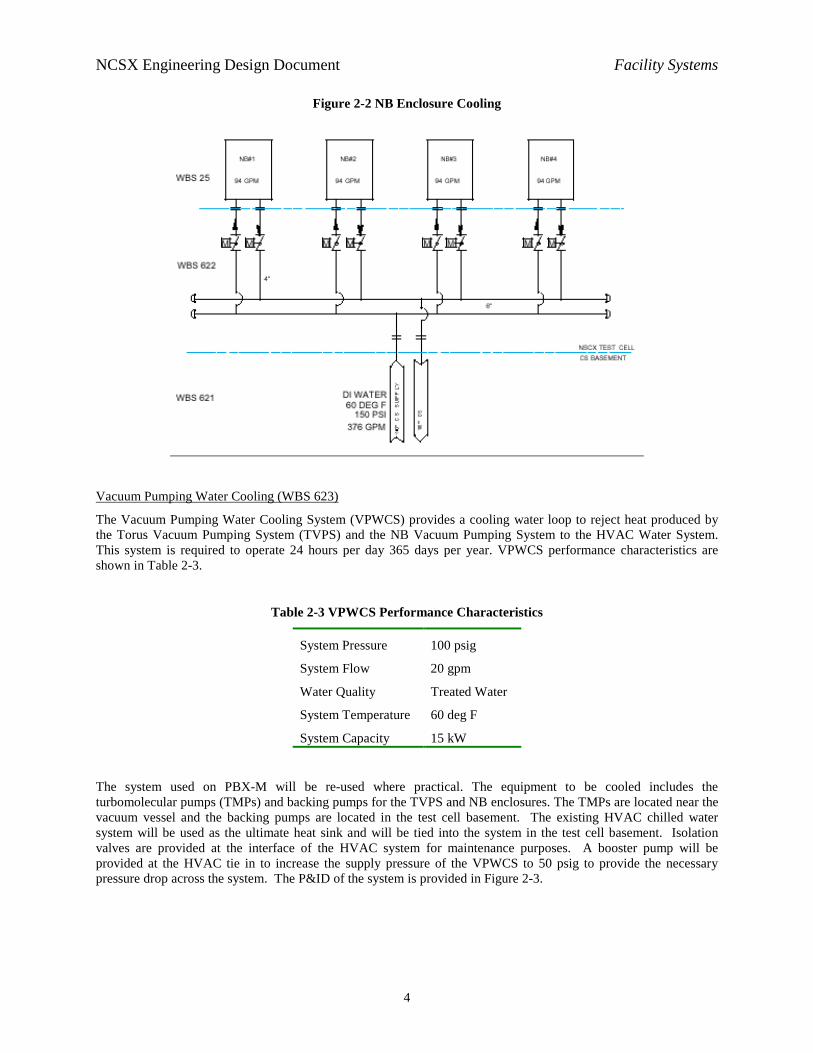
Figure 2-2 NB Enclosure Cooling
Vacuum Pumping Water Cooling (WBS 623)
The Vacuum Pumping Water Cooling System (VPWCS) provides a cooling water loop to reject heat produced by the Torus Vacuum Pumping System (TVPS) and the NB Vacuum Pumping System to the HVAC Water System. This system is required to operate 24 hours per day 365 days per year. VPWCS performance characteristics are shown in Table 2-3.
Table 2-3 VPWCS Performance Characteristics
System Pressure 100 psig
System Flow 20 gpm
Water Quality Treated Water
System Temperature 60 deg F
System Capacity 15 kW
The system used on PBX-M will be re-used where practical. The equipment to be cooled includes the turbomolecular pumps (TMPs) and backing pumps for the TVPS and NB enclosures. The TMPs are located near the vacuum vessel and the backing pumps are located in the test cell basement. The existing HVAC chilled water system will be used as the ultimate heat sink and will be tied into the system in the test cell basement. Isolation valves are provided at the interface of the HVAC system for maintenance purposes. A booster pump will be provided at the HVAC tie in to increase the supply pressure of the VPWCS to 50 psig to provide the necessary pressure drop across the system. The P&ID of the system is provided in Figure 2-3.

NCSX Engineering Design Document Facility Systems
5
Figure 2-3 VPSCS P&ID
Bakeout Water Cooling (WBS 624)
The temperature of the vacuum vessel (20ºC-150ºC) and PFCs (20ºC-350ºC) will be maintained by circulating helium gas through cooling tubes attached to those structures. The helium gas circulation and heat exchange is accomplished on the bakeout skid. The Bakeout Water Cooling System (BWCS) is required to reject waste heat from the Vacuum Vessel and PFC Heating and Cooling System (WBS 65) to the CS Water System. Isolation valves will be provided for maintenance to the bakeout skid. Monitoring of the water system flows, pressure and temperature will be done on the bakeout skid. BWCS performance characteristics are tabulated in Table 2-4.
Table 2-4 BCWS Performance Characteristics
System Pressure 147 psig
System Flow 30 gpm
Water Quality Deionized
System Temperature 60 deg F
System Capacity 22 kW
Diagnostics Water Cooling (WBS 625)
The Diagnostics Water Cooling System (DWCS) will provide a cooling manifold around NCSX to cool various diagnostics components to be installed on or near the vacuum vessel. The manifold shall be installed far enough

NCSX Engineering Design Document Facility Systems
6
away from the machine to avoid space impacts to diagnostics and other equipment occupying real estate close in to the vacuum vessel. DWCS performance characteristics are listed in Table 2-5.
Table 2-5 DWCS Performance Characteristics
System Pressure 147 psig
System Flow 50
Water Quality Treated Water
System Temperature 60 deg F
System Capacity 15 kW
The cooling loop will be connected to the CS cooling water system. Isolation valves are provided on the supply and return connections to the manifold headers for service connections and to provide isolation during maintenance. Water quality shall be deionized with a resistivity of at least 2 mega ohm-cm. The P&ID for the DWCS is provided in Figure 2-4.
Figure 2-4 DWCS P&ID
Design Basis
All new design, replacement valves and equipment will comply with the requirements of ASME B31.1. Pipe sizing will be determined by flow analysis. Piping and supports will meet the local seismic requirements.

NCSX Engineering Design Document Facility Systems
7
Design Implementation
These systems will be comprised of off the shelf components. All construction will utilize standard plumbing construction techniques. Where possible, subassemblies will be assembled in the shop and transported into the field to expedite construction and to minimize cost.
Parts and supplies will be purchased at a local plumbing supply house. Where possible the material required for NCSX water systems will be grouped together to take advantage of quantity discounts. All welding shall be welded according to PPPL EM-002, “General Welding and Torch Brazing Procedure”.
Where practical, individual sections of piping will be hydro tested to 1.5 times design pressure before installation. The completed assembly will be hydro tested in place. Testing will be conducted to PPPL standards using PPPL Procedure ENG-014, “Hydrostatic and Pneumatic Testing”.
All flow switches and other instrumentation requiring calibration will be calibrated on the bench before installation. All wiring and electrical instrumentation will be buzzed out and checked for proper operation. This includes PLC control functions and other I&C interfaces / interlocks.
A pre-operational test will be conducted to verify system operation and flow rates.
Cost, Schedule, and Risk Management
Table 2-6 is a summary of estimated costs for the Water Cooling Systems (WBS 62) in the NCSX Fabrication Project. The total cost is estimated to be $280K in year of expenditure dollars with an overall contingency of 20%.
The schedule for implementing Central Instrumentation and Control may be seen in the Project Master Schedule, provided as part of the Conceptual Design Report. Water Cooling Systems (WBS 62) will be ready to support startup of NCSX subsystems requiring water cooling. Most of the equipment already exists. Only equipment that appears to need replacement will be replaced. Title II design will be completed in FY06. Water systems will be operation in time for subsystem and integrated systems testing.
The most severe risk in this system is the uncertainty about the state of the equipment which is presently not in service. The cost and scheduled estimates to refurbish the system are based on what is known from inspection. Additional parts of the system may need replacement once the system has been started up and tested. Sufficient cost and schedule contingency will be provided to ensure that unforeseen maintenance will not impact other systems.
Table 2-6 CS Water Cooling Systems Costs
Total Estimated Cost (K$)62 Total
622 623 624 625 Manufacturing Development Labor/Other
M&STotal
Design (Title I & II) Labor/Other 55 25 23 21 124M&STotal 55 25 23 21 124
Fabrication/Assembly (incl Title III) Labor/OtherM&STotal
Installation/test Labor/Other 74 0 10 11 95M&S 55 0 3 4 62Total 128 0 13 15 156
Grand Total 183 25 36 36 280

NCSX Engineering Design Document Facility Systems
8
3 CRYOGENIC SYSTEMS
NCSX Cryogenic Systems (WBS 63) consist of the following subsystems:
• LN2-LHe Supply System (WBS 631),
• LN2 Coil Cooling (WBS 632), and
• GN2 Cryostat Cooling (WBS 633).
3.1 LN2-LHe Supply System
Design Requirements and Constraints
The Liquid Nitrogen (LN2) and Liquid Helium (LHe) Supply System (WBS 631) will be used to receive, store, and deliver cryogens to the LN2 Coil Cooling System (WBS 632), to the GN2 Cryostat Cooling System (WBS 633), and to the Neutral Beam Injection System (WBS 25). However, there are only liquid nitrogen supply requirements in this work package in the Fabrication Project. Liquid helium for subsystem testing of individual neutral beamlines will be supplied in dewars as part of the NBI System (WBS 25) work package. A helium supply line will be installed (as a future upgrade) prior to the start of experiments requiring significant neutral beam heating (about 1 year or more after first plasma). It will connect the beamlines to a helium dewar in the C-site helium dewar storage shed located in the courtyard outside the NCSX Test Cell.
The LN2-LHe Supply System must:
• Receive product off-load from DOT-compliant vehicles, either through transfer hoses or in discrete dewars;
• Maintain the product inventories for future use;
• Distribute product to the neutral beam, field coil, and cryostat cooling subsystems; and
• Automatically isolate the supply of liquid nitrogen in the event of a low oxygen alarm in the stellarator machine area.
Design Description and Performance
Figure 3-1 shows the overall liquid nitrogen / liquid helium distribution scheme. Central to the design is the re-use of the existing C-Site liquid nitrogen dewar (currently serving only the Hall Thruster project) and the C-site liquid helium dewar storage shed (not in use).
The liquid nitrogen dewar has a capacity of about 34 m3 with an expected peak NCSX demand of about 20 m3 per day (less than one truck delivery per operating day). The Hall Thruster loads are trivial in comparison. The liquid nitrogen subsystem is a “once-through” type in that the boil-off gas from the stellarator is not reclaimed.
The liquid helium distribution subsystem depends on the delivery of 3.7 m3 dewars of product on an as-required basis. The dewars are physically large, requiring about 16 m3 of space. NCSX will only store one dewar at a time with the empty flask being transported away by the vehicle that delivers a full container.
The delivery piping transiting from the dewar area to the machine services (to be installed as a future upgrade) will be of the vacuum jacketed style with multi-layer infrared radiation shielding.
Continuous oxygen monitoring of the machine area’s atmosphere will be performed. A normally-closed pneumatically operated liquid nitrogen supply valve will be held open, given the condition of adequate measured oxygen content in all monitored areas. Upon a monitor’s alarm of a low oxygen condition, the supply valve will lose its permissive and close to its normal (closed) state.

NCSX Engineering Design Document Facility Systems
9
Figure 3-1 LN2-LHe Supply Concept
Design Basis
The flow characteristics and calculation of the single and two-phase flow of cryogens is understood and described in the literature. Design integrity will be assured by compliance with ASME Standards B31.1, B31.3, B31.9, Section VIII of the B&PV Code, and PPPL Engineering Standards regarding welding and cryogenic piping projects.
Design Implementation
Components for this system are commercially available, off-the-shelf items. Assembly, installation, and testing will require standard shop equipment such as RF-driven welding machines and helium leak detectors.
Cost, Schedule, and Risk Management
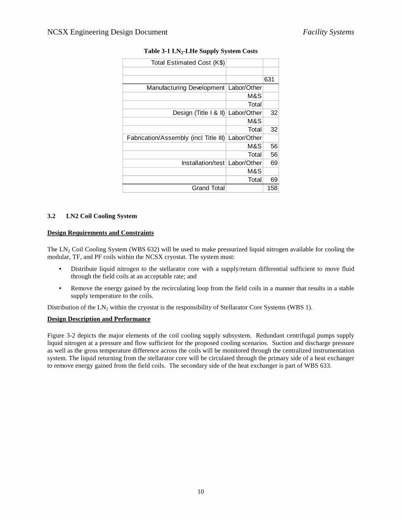
Table 3-1 is a summary of estimated costs for the LN2-LHe Supply System (WBS 631) in the NCSX Fabrication Project. The total cost is estimated to be $158K in year of expenditure dollars with an overall contingency of 23%. The re-use of C-Site assets results in a significant savings for this WBS element.
The schedule for implementing the LN2-LHe Supply System may be seen in the Project Master Schedule, provided as part of the Conceptual Design Report. The system will be ready to support startup of LN2 Coil Cooling and GN2 Cryostat Cooling Systems early in FY06.
No significant technical, cost, or schedule risks are seen for this work package.
NCSX Engineering Design Document Facility Systems
10
Table 3-1 LN2-LHe Supply System Costs
Total Estimated Cost (K$)
631 Manufacturing Development Labor/Other
M&STotal
Design (Title I & II) Labor/Other 32M&STotal 32
Fabrication/Assembly (incl Title III) Labor/OtherM&S 56Total 56
Installation/test Labor/Other 69M&STotal 69
Grand Total 158
3.2 LN2 Coil Cooling System
Design Requirements and Constraints
The LN2 Coil Cooling System (WBS 632) will be used to make pressurized liquid nitrogen available for cooling the modular, TF, and PF coils within the NCSX cryostat. The system must:
• Distribute liquid nitrogen to the stellarator core with a supply/return differential sufficient to move fluid through the field coils at an acceptable rate; and
• Remove the energy gained by the recirculating loop from the field coils in a manner that results in a stable supply temperature to the coils.
Distribution of the LN2 within the cryostat is the responsibility of Stellarator Core Systems (WBS 1).
Design Description and Performance
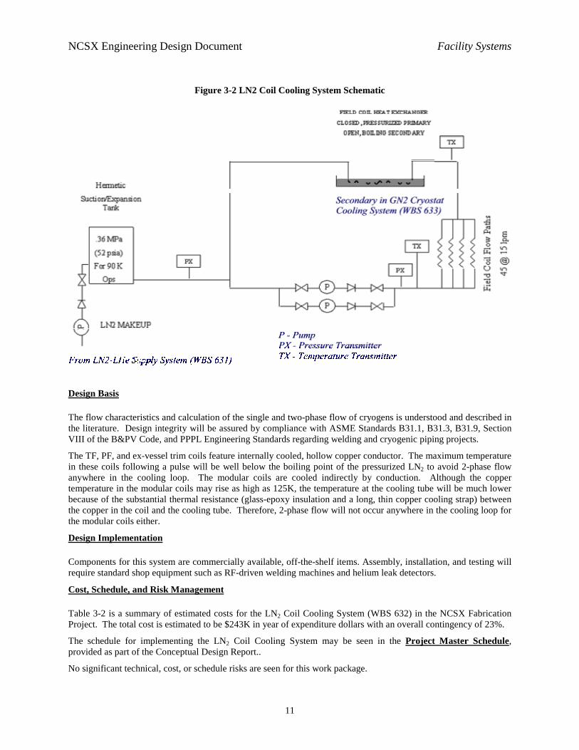
Figure 3-2 depicts the major elements of the coil cooling supply subsystem. Redundant centrifugal pumps supply liquid nitrogen at a pressure and flow sufficient for the proposed cooling scenarios. Suction and discharge pressure as well as the gross temperature difference across the coils will be monitored through the centralized instrumentation system. The liquid returning from the stellarator core will be circulated through the primary side of a heat exchanger to remove energy gained from the field coils. The secondary side of the heat exchanger is part of WBS 633.
NCSX Engineering Design Document Facility Systems
11
Figure 3-2 LN2 Coil Cooling System Schematic
Design Basis
The flow characteristics and calculation of the single and two-phase flow of cryogens is understood and described in the literature. Design integrity will be assured by compliance with ASME Standards B31.1, B31.3, B31.9, Section VIII of the B&PV Code, and PPPL Engineering Standards regarding welding and cryogenic piping projects.
The TF, PF, and ex-vessel trim coils feature internally cooled, hollow copper conductor. The maximum temperature in these coils following a pulse will be well below the boiling point of the pressurized LN2 to avoid 2-phase flow anywhere in the cooling loop. The modular coils are cooled indirectly by conduction. Although the copper temperature in the modular coils may rise as high as 125K, the temperature at the cooling tube will be much lower because of the substantial thermal resistance (glass-epoxy insulation and a long, thin copper cooling strap) between the copper in the coil and the cooling tube. Therefore, 2-phase flow will not occur anywhere in the cooling loop for the modular coils either.
Design Implementation
Components for this system are commercially available, off-the-shelf items. Assembly, installation, and testing will require standard shop equipment such as RF-driven welding machines and helium leak detectors.
Cost, Schedule, and Risk Management
Table 3-2 is a summary of estimated costs for the LN2 Coil Cooling System (WBS 632) in the NCSX Fabrication Project. The total cost is estimated to be $243K in year of expenditure dollars with an overall contingency of 23%.
The schedule for implementing the LN2 Coil Cooling System may be seen in the Project Master Schedule, provided as part of the Conceptual Design Report..
No significant technical, cost, or schedule risks are seen for this work package.

NCSX Engineering Design Document Facility Systems
12
Table 3-2 LN2 Coil Cooling System Costs
Total Estimated Cost (K$)
632 Manufacturing Development Labor/Other
M&STotal
Design (Title I & II) Labor/Other 38M&STotal 38
Fabrication/Assembly (incl Title III) Labor/OtherM&S 107Total 107
Installation/test Labor/Other 99M&STotal 99
Grand Total 243
3.3 GN2 Cryostat Cooling System
Design Requirements and Constraints
The GN2 Cryostat Cooling System (WBS 633) will be used to circulate nitrogen gas of a controlled temperature through the NCSX cryostat and, consequently, around the exposed surfaces of the structures within the cryostat. This will be the primary means of cooling the temperature of the components inside the cryostat (and outside the vacuum vessel) from room temperature (293K) to operating temperature (80K), maintaining the temperature of the components inside the cryostat at operating temperature (excluding those directly cooled by the LN2 Coil Cooling System), and warming those components back up to room temperature. The system must:
• Circulate nitrogen gas having a supply temperature as low as 77K through the cryostat;
• Receive liquid nitrogen and allow its flashing to gas;
• House a boiling bath of liquid nitrogen which serves as the secondary side of the LN2 Coil Cooling System’s primary heat exchanger coil;
• Provide a heating capability to drive the stellarator’s temperature toward ambient, when required; and
• Provide a stack for safely discharging excess nitrogen gas to the atmosphere outside of the NCSX Test Cell.
Design Description and Performance
Figure 3-3 shows the main elements of the GN2 Cryostat Cooling System. Low pressure, insulated ducting contains the cold nitrogen gas. A squirrel cage blower provides the motive force required to circulate the gas through the cryostat and, consequently, over the structures inside the cryostat. Liquid nitrogen can be discharged into the gas stream to provide additional cooling or can be supplied to an open, boiling bath which forms the secondary circuit of the LN2 Coil Cooling System heat exchanger. A resistive heater is also provided for bringing the cold mass back to room temperature.
An exhaust stack with dampers is provided to allow the safe discharge of excess gas from the recirculating stream. Further, the excess gas stream’s temperature may be driven upward with resistive heaters in the exhaust stack.

NCSX Engineering Design Document Facility Systems
13
Figure 3-3 GN2 Cryostat Cooling System Schematic
Design Basis
Flow of gases is understood and is described in many common engineering resources. Piping integrity will be assured by compliance with ASME Standards B31.1, B31.3, B31.9, Section VIII of the B&PV Code. The ductwork be considered with simple stress calculations and will not comply with any particular code.
Design Implementation
Components for this system are commercially available, off-the-shelf items. Assembly, installation, and testing will require standard shop equipment such as RF-driven welding machines and helium leak detectors.
Cost, Schedule, and Risk Management
Table 3-2 is a summary of estimated costs for the GN2 Cryostat Cooling System (WBS 633) in the NCSX Fabrication Project. The total cost is estimated to be $297K in year of expenditure dollars with an overall contingency of 23%.
The schedule for implementing the GN2 Cryostat Cooling System may be seen in the Project Master Schedule, provided as part of the Conceptual Design Report. Installation should be completed in the first half of FY06.
No significant technical, cost, or schedule risks are seen for this work package.

NCSX Engineering Design Document Facility Systems
14
Table 3-3 GN2 Cryostat Cooling System Costs
Total Estimated Cost (K$)
633 Manufacturing Development Labor/Other
M&STotal
Design (Title I & II) Labor/Other 34M&STotal 34
Fabrication/Assembly (incl Title III) Labor/OtherM&S 99Total 99
Installation/test Labor/Other 164M&STotal 164
Grand Total 297
4 UTILITY SYSTEMS
Design Requirements and Constraints
The Utility Systems (WBS 64) are required to provide service manifolds around the NCSX stellarator for compressed air, vacuum pump venting and gaseous nitrogen. The Utility system is comprised of three (3) service manifolds around the NCSX vacuum vessel, one for vacuum venting, one for GN2 service and one for compressed air. Performance characteristics are summarized in Table 4-1. Diagnostics, neutral beams, and water systems will utilize the services.
Table 4-1 Utility System Performance Characteristics
Plant air 90 psig, 1” pipe size
GN2 30 psig min, 3/4 “ diameter tubing size
Vent 3” diameter manifold
Design Description and Performance
The vacuum pump venting system will provide a system to vent the vacuum pump backing skids in the CS basement and the diagnostic vacuum pumps in the NCSX test cell to the outside. Construction of the vent system will be such that the system can be upgraded for use with tri-methyl boron conditioning of the vacuum vessel at a later date.
The compressed air system provides a manifold of compressed air around the NCSX machine for use in operating valves, tools, and other utility uses. Construction of the compressed air system will utilize non-magnetic materials to avoid interactions with NCSX coil systems.
The GN2 manifold provides a dry nitrogen gas utility for clean venting of vacuum spaces and also to be used as a drying agent. Construction of the GN2 system will utilize non-magnetic materials to avoid interactions with NCSX coil systems.
NCSX Engineering Design Document Facility Systems
15
Design Basis
The Diagnostic Water Cooling system design will comply with the requirements of ASME B31.1. Pipe sizing will be determined by flow analysis. Piping and supports will meet the local seismic requirements.
Design Implementation
The Utility systems will be comprised of off the shelf components. All construction will utilize standard plumbing construction techniques. Where possible subassemblies will be assembled in the shop and transported into the field to expedite construction and to minimize cost.
Parts and supplies will be purchased at a local plumbing supply house. Where possible the material required for NCSX water systems will be grouped together to take advantage of quantity discounts. All welding shall be welded according to PPPL EM-002, “General Welding and Torch Brazing Procedure”.
Where practical individual sections of piping will be hydro tested to 1.5 times design pressure before installation. The completed assembly will be hydro tested in place. Testing will be conducted to PPPL standards using “Hydrostatic and Pneumatic Testing” procedure ENG-014
All flow switches and other instrumentation requiring calibration will be calibrated on the bench before installation. All wiring and electrical instrumentation will be buzzed out and checked for proper operation.
A pre-operational test will be conducted to verify system operation and flow rates.
Cost, Schedule, and Risk Management
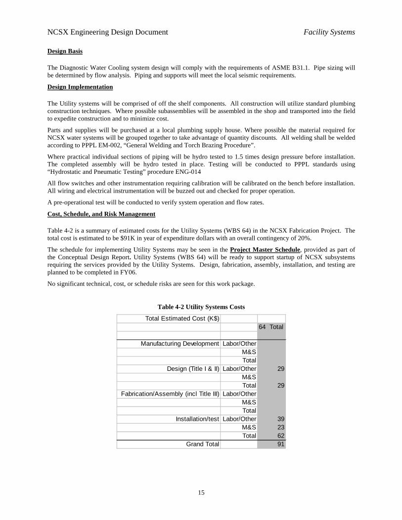
Table 4-2 is a summary of estimated costs for the Utility Systems (WBS 64) in the NCSX Fabrication Project. The total cost is estimated to be $91K in year of expenditure dollars with an overall contingency of 20%.
The schedule for implementing Utility Systems may be seen in the Project Master Schedule, provided as part of the Conceptual Design Report. Utility Systems (WBS 64) will be ready to support startup of NCSX subsystems requiring the services provided by the Utility Systems. Design, fabrication, assembly, installation, and testing are planned to be completed in FY06.
No significant technical, cost, or schedule risks are seen for this work package.
Table 4-2 Utility Systems Costs
Total Estimated Cost (K$)64 Total
Manufacturing Development Labor/OtherM&STotal
Design (Title I & II) Labor/Other 29M&STotal 29
Fabrication/Assembly (incl Title III) Labor/OtherM&STotal
Installation/test Labor/Other 39M&S 23Total 62
Grand Total 91

NCSX Engineering Design Document Facility Systems
16
5 HELIUM BAKEOUT SYSTEM
Design Requirements and Constraints
The WBS element consists of the effort to provide heating and cooling to the vacuum vessel and plasma facing components (PFCs) to effect temperature control. Prior to Initial Auxiliary Heating (Phase 4), there will be only minimal coverage of the interior with carbon tiles so the capability to bake the PFCs at 350ºC is not required for the Fabrication Project. However, accommodating a 350ºC bakeout of the PFCs is required as a future upgrade. In the Fabrication Project, the capability to maintain the temperature of the vacuum vessel and PFCs between 20ºC (the normal operating temperature) and 150ºC (for bakeout of the vacuum vessel and other metallic structures inside the vacuum vessel) is required.
Pressurized helium gas will be circulated to effect temperature control through tubing attached to the outer surface of the vacuum vessel and port extensions. Maximum temperatures in the helium loop will be kept below 175C due to the use of elastomer seals. Heat losses through the thermal insulation between the vacuum vessel and the coils and structures (at 80K) are calculated to be 12 kW with the vacuum vessel at 150C.
The system is required to provide flow to achieve this heat input to nominally 30 parallel paths of 1/2" tubing with each path length approximating 13 meters. This length is enough to encompass two complete revolutions around a vessel cross section. The geometry (length, diameter, and number of parallel paths) of the tubing is a critical requirement to the design of the helium system and will evolve in concert with the vacuum vessel design. It has been assumed that a pressure drop equal to or less than 16 psi at a flow rate of 313 cfm will suffice for baking the vacuum vessel. This WBS includes the installation of supply and return piping up to the vacuum vessel but does not include manifolds or tubing on vacuum vessel, which is the responsibility of the Stellarator Core Systems (WBS 1).
Design Description and Performance
The NCSX Helium Bakeout System is patterned directly after the system used on NSTX. The system uses compressed helium as the heat transfer fluid. Helium presents a low consequence from leaks to NCSX operations. Helium has a high specific heat (Cp), which provides good thermal transfer properties, and adequate density at high pressure. It is not flammable and will not freeze in the event of a loss of flow in the vacuum vessel.
A blower is used to circulate the helium in lieu of a compressor. This provides a cost savings, as helium compressors are expensive. A pressure vessel is provided around the blower to allow the blower to operate at elevated pressures. An electric heater is used to raise the helium up to the required temperature and a recuperative gas-to-gas heat exchanger recovers waste heat reducing capital and operating costs. A gas-to-water heat exchanger is required to pull the remaining heat from the helium and lower it's temperature to acceptable limits for the blower.
The P&ID in Figure 5-1 depicts a steady state condition for heating. The helium is circulated by a blower and then enters the gas-to-gas recuperative heat exchanger (HE#1). Here the gas is heated from 32C to 127C. The helium then enters the heater where the temperature is raised to the final supply inlet temperature of 165C. The gas passes next through the NCSX tubing and raises the vessel temperature to 150C. The temperature of the helium as it leaves the NCSX vessel is 150C. The piping returns the helium to HE#1 where it gives up its waste heat and is cooled down to 56C. The water to gas heat exchanger (HE#2) removes enough of the remaining heat and discharges it to the water so that the gas returns to the blower at 19C. These temperatures were derived from calculations based on a typical heating run with a blower outlet pressure of 270 psig and a flow rate through the vessel of 313 cfm. With these parameters 24 KW of heating is applied to NCSX providing enough margin to heat NCSX within acceptable time constraints.

NCSX Engineering Design Document Facility Systems
17
Figure 5-1 Helium Bakeout System P&ID
Design Basis
The helium bakeout system design for NCSX is based on the successful implementation of a similar design for NSTX, shown in Figure 5-2. While the operating parameters are different, the basic theory and calculations have been proven and benchmarked on NSTX. The design will apply code requirements from ASME B31.1, ASME B31.3 and the Pressure Vessel Section VIII Div. 1.

NCSX Engineering Design Document Facility Systems
18
Figure 5-2 Similar Helium Bakeout System in Use on NSTX
Design Implementation
The Helium Bakeout System will be manufactured as a skid in the mechanical shops at PPPL. The fabrication of the skid will be independent of other NCSX activities with the only tie in to the overall schedule being the final installation connections in the test cell. There are three major semi-custom procurements required. The Heater, the Gas-to-Gas Heat Exchanger, and the Gas-to-Water Heat Exchanger. Delivery of these items is considered to be low risk as their design is consistent with common industry practices. The blower is an off the shelf procurement. The use of the blower within a pressure vessel is an uncommon new approach but it has been proven in the NSTX design.
Pressure testing per code requirements will be specified for the major components. The blower will also undergo pressure and leak testing at the vendor. After the final assembly and before operations, the Helium Bakeout System will be subjected to a pre-operational test of operating parameters and safety interlocks. The finished assembly including interconnecting piping will also be pressure tested.
Cost, Schedule, and Risk Maintenance
The costs and schedule estimates are based on actual experience in the design and installation of the NSTX Helium Bakeout System. Replicating the NSTX design to the maximum extent possible decreases engineering and design costs. Labor and material costs are based on a scaling of actual costs for the NSTX system. The schedule also
NCSX Engineering Design Document Facility Systems
19
draws on past experience and conservatively assumes serial tasks. Contingency in the schedule can be realized by working on some tasks in parallel if the need arises.
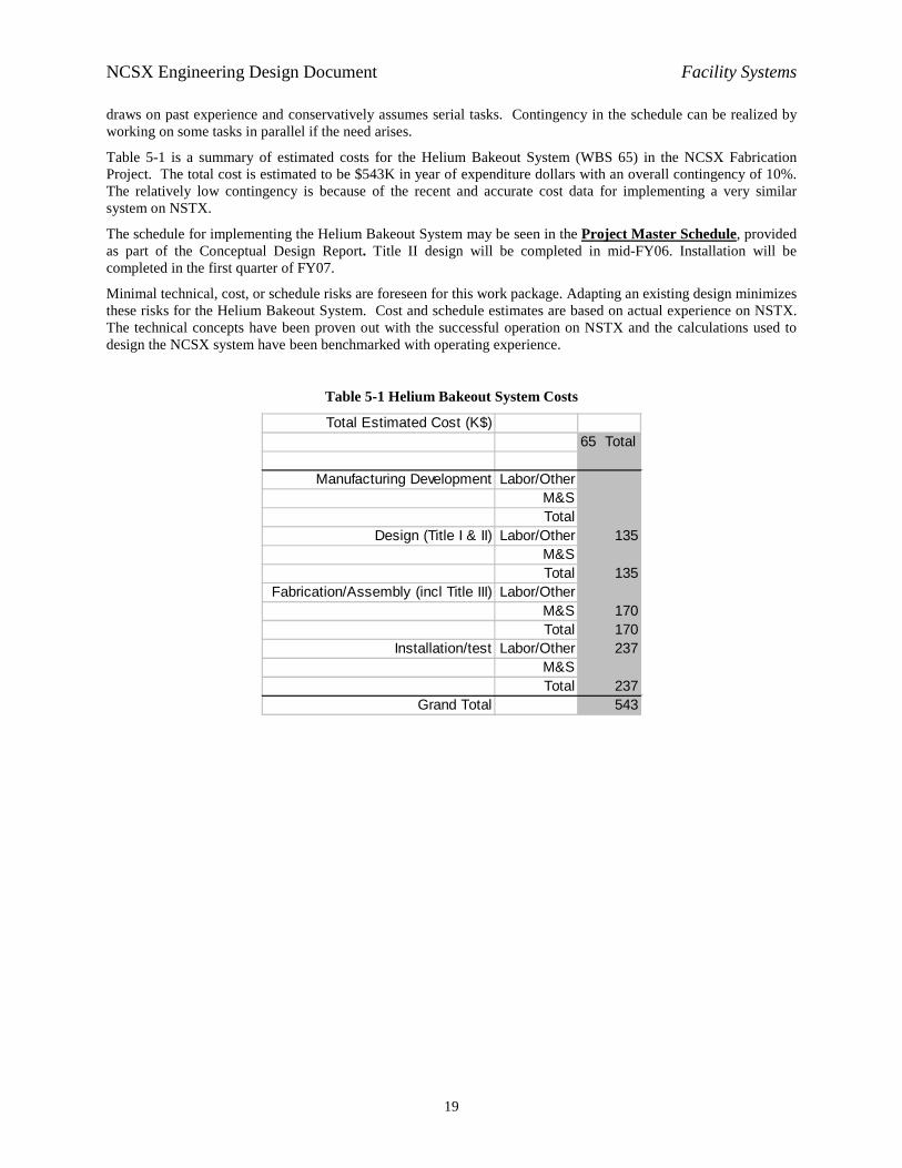
Table 5-1 is a summary of estimated costs for the Helium Bakeout System (WBS 65) in the NCSX Fabrication Project. The total cost is estimated to be $543K in year of expenditure dollars with an overall contingency of 10%. The relatively low contingency is because of the recent and accurate cost data for implementing a very similar system on NSTX.
The schedule for implementing the Helium Bakeout System may be seen in the Project Master Schedule, provided as part of the Conceptual Design Report. Title II design will be completed in mid-FY06. Installation will be completed in the first quarter of FY07.
Minimal technical, cost, or schedule risks are foreseen for this work package. Adapting an existing design minimizes these risks for the Helium Bakeout System. Cost and schedule estimates are based on actual experience on NSTX. The technical concepts have been proven out with the successful operation on NSTX and the calculations used to design the NCSX system have been benchmarked with operating experience.
Table 5-1 Helium Bakeout System Costs
Total Estimated Cost (K$)65 Total
Manufacturing Development Labor/OtherM&STotal
Design (Title I & II) Labor/Other 135M&STotal 135
Fabrication/Assembly (incl Title III) Labor/OtherM&S 170Total 170
Installation/test Labor/Other 237M&STotal 237
Grand Total 543