ncp monitoring guide - ibm.com c. ncp monitor navigation from statistics summary 127 navigation from...
TRANSCRIPT

NCP Monitoring GuideOMEGAMON II for Mainframe Networks
Version 520
GC32-9273-00
March 2002
Candle Corporation201 North Douglas Street
El Segundo, California 90245

Registered trademarks and service marks of Candle Corporation: AF/OPERATOR, AF/PERFORMER,AF/REMOTE, Availability Command Center, Candle Command Center, Candle Electronic Customer Support,Candle Logo, Candle Management Server, Candle Management Workstation, Candle Technologies,CL/CONFERENCE, CL/SUPERSESSION, CT, CT/Data Server, CT/DS, DELTAMON, ETEWatch, IntelliWatch,MQSecure, MQView, OMEGACENTER, OMEGAMON, OMEGAMON/e, OMEGAMON II, OMEGAMONMonitoring Agent, OMEGAVIEW, OMEGAVIEW II, Solutions for Networked Businesses, and Transplex.
Trademarks and service marks of Candle Corporation: Alert Adapter, Alert Adapter Plus, Alert Emitter, AMS,Amsys, AUTOMATED FACILITIES, Availability Management Systems, Candle Business Partner Logo, CandleDirect Logo, CandleLight, CandleNet, CandleNet 2000, CandleNet Portal, CCC, CECS, CICAT, CL/ENGINE,CL/GATEWAY, CL/TECHNOLOGY, CMS, CMW, Command & Control, CommandWatch, Connect-Two, CSAANALYZER, CT/ALS, CT/Application Logic Services, CT/DCS, CT/Distributed Computing Services, CT/Engine,CT/Implementation Services, CT/IX, CT/Workbench, CT/Workstation Server, CT/WS, DB Logo, !DB/DASD,!DB/EXPLAIN, !DB/MIGRATOR, !DB/QUICKCHANGE, !DB/QUICKCOMPARE, !DB/SMU, !DB/Tools,!DB/WORKBENCH, Design Network, DEXAN, eBA*ServiceMonitor, End-to-End, Enterprise Candle CommandCenter, Enterprise Candle Management Workstation, EPILOG, ERPNet, ESRA, HostBridge, IntelliWatch Pinnacle,Lava Console, Messaging Mastered, MQADMIN, MQEdit, MQEXPERT, MQMON, NBX, OMA, OMC Gateway,OMC Status Manager, OMEGACENTER Bridge, OMEGACENTER Gateway, OMEGACENTER Status Manager,OMEGAMON Management Center, OSM, PC COMPANION, Performance Pac, PowerQ, PQConfiguration,PQEdit, PQScope, Response Time Network, Roma, Roma Broker, Roma BSP, Roma Connector, Roma Developer,Roma FS/A, Roma FS/Access, Roma Network, Roma Systems Manager, Roma Workflow Access, RomaWF/Access, RTA, RTN, SentinalManager, Solutions for Networked Applications, Status Monitor, Tracer, UnifiedDirectory Services and Volcano.
Trademarks and registered trademarks of other companies: AIX, DB2, and MQSeries are registeredtrademarks of International Business Machines Corporation. SAP is a registered trademark and R/3 is a trademarkof SAP AG. UNIX is a registered trademark in the U.S. and other countries, licensed exclusively through X/OpenCompany Ltd. HU-UX is a trademark of Hewlett-Packard Company. SunOS is a trademark of Sun Microsystems,Inc.
All other company and product names used herein are trademarks or registered trademarks of their respectivecompanies.
ProtoView Development Corp. - May contain DataTable Version 3.0 Copyright 1989—1996 by ProtoViewDevelopment Corp. and distributed under license by Candle Corporation.
Copyright 2001, Candle Corporation, a California corporation. All rights reserved. International rights secured.
Threaded Environment for AS/400, Patent No. 5,504,898; Data Server with Data Probes Employing Predicate Testsin Rule Statements (Event Driven Sampling), Patent No. 5,615,359; MVS/ESA Message Transport System Usingthe XCF Coupling Facility, Patent No. 5,754,856; Intelligent Remote Agent for Computer Performance Monitoring,Patent No. 5,781,703; Data Server with Event Driven Sampling, Patent No. 5,809,238; Threaded Environment forComputer Systems Without Native Threading Support, Patent No. 5,835,763; Object Procedure Messaging Facility,Patent No. 5,848,234; Communications on a Network, Patent Pending; End-to-End Response Time Measurement forComputer Programs, Patent No. 5,9991,705; Improved Message Queuing Based Network Computing Architecture,Patent Pending; User Interface for System Management Applications, Patent Pending.
NOTICE: This documentation is provided with RESTRICTED RIGHTS. Use, duplication, or disclosure by theGovernment is subject to restrictions set forth in the applicable license agreement and/or the applicable governmentrights clause.
This documentation contains confidential, proprietary information of Candle Corporation that is licensed for yourinternal use only. Any unauthorized use, duplication, or disclosure is unlawful.

Contents
List of Illustrations . . . . . . . . . . . . . . . . . . . . . . . . . . . . . . . . . 7
List of Tables . . . . . . . . . . . . . . . . . . . . . . . . . . . . . . . . . . . . . 9
Read This First . . . . . . . . . . . . . . . . . . . . . . . . . . . . . . . . . . . . 11
What's New . . . . . . . . . . . . . . . . . . . . . . . . . . . . . . . . . . . . . . 17 New Product Name . . . . . . . . . . . . . . . . . . . . . . . . . . . . . . 17 TCP/IP Support Enhanced . . . . . . . . . . . . . . . . . . . . . . . . . 18 Documentation . . . . . . . . . . . . . . . . . . . . . . . . . . . . . . . . . 20
Chapter 1. Introduction to the NCP Monitor . . . . . . . . . . . . . . . 23Introduction . . . . . . . . . . . . . . . . . . . . . . . . . . . . . . . . . . . 24Definition of an NCP . . . . . . . . . . . . . . . . . . . . . . . . . . . . . 25NCP Resources Illustration . . . . . . . . . . . . . . . . . . . . . . . . . 26NCP Data Sources . . . . . . . . . . . . . . . . . . . . . . . . . . . . . . 28Statistics Calculations . . . . . . . . . . . . . . . . . . . . . . . . . . . . 29Single-threaded NPALU . . . . . . . . . . . . . . . . . . . . . . . . . . . 29OMEGAMON II Dynamic Configuration . . . . . . . . . . . . . . . 29NCP Monitor Component Overview . . . . . . . . . . . . . . . . . . . 30NCP Releases . . . . . . . . . . . . . . . . . . . . . . . . . . . . . . . . . . 30Problems Detected . . . . . . . . . . . . . . . . . . . . . . . . . . . . . . 31Status Lights . . . . . . . . . . . . . . . . . . . . . . . . . . . . . . . . . . 31Navigation . . . . . . . . . . . . . . . . . . . . . . . . . . . . . . . . . . . . 32Varying Views . . . . . . . . . . . . . . . . . . . . . . . . . . . . . . . . . 33Trending . . . . . . . . . . . . . . . . . . . . . . . . . . . . . . . . . . . . . 33Exceptions . . . . . . . . . . . . . . . . . . . . . . . . . . . . . . . . . . . . 34Chapters that Follow . . . . . . . . . . . . . . . . . . . . . . . . . . . . . 34
Chapter 2. Monitoring at the NCP Level . . . . . . . . . . . . . . . . . . 35NCP Main Status Light . . . . . . . . . . . . . . . . . . . . . . . . . . . 36NCP Status Lights Hierarchy . . . . . . . . . . . . . . . . . . . . . . . 37NCP Status Summary Panel . . . . . . . . . . . . . . . . . . . . . . . . 38Interpreting Status Lights . . . . . . . . . . . . . . . . . . . . . . . . . . 39NCP Statistics Summary . . . . . . . . . . . . . . . . . . . . . . . . . . 40NCP Resource Summary . . . . . . . . . . . . . . . . . . . . . . . . . . 41
Chapter 3. Line-Level Resources . . . . . . . . . . . . . . . . . . . . . . . 43Line-level Panels . . . . . . . . . . . . . . . . . . . . . . . . . . . . . . . 44SDLC/BSC/CA Line Status . . . . . . . . . . . . . . . . . . . . . . . . 45SDLC Line Resource Summary . . . . . . . . . . . . . . . . . . . . . . 47TIC3 Data Collection . . . . . . . . . . . . . . . . . . . . . . . . . . . . . 48Token-Ring Physical Link Status . . . . . . . . . . . . . . . . . . . . . 49Token-Ring Physical Link Summary . . . . . . . . . . . . . . . . . . 51
Contents 3

Token-Ring Logical Link Status . . . . . . . . . . . . . . . . . . . . . 52Token-Ring Logical Link Summary . . . . . . . . . . . . . . . . . . . 54X.25 Multichannel Link Status . . . . . . . . . . . . . . . . . . . . . . 55X.25 Multichannel Link Resource Summary . . . . . . . . . . . . . 56
Chapter 4. PU-Level Resources . . . . . . . . . . . . . . . . . . . . . . . . 57PU-level Panels . . . . . . . . . . . . . . . . . . . . . . . . . . . . . . . . 58PU Resource Summary . . . . . . . . . . . . . . . . . . . . . . . . . . . 59X.25 Virtual Circuit Status . . . . . . . . . . . . . . . . . . . . . . . . . 60X.25 Virtual Circuit Resource Summary . . . . . . . . . . . . . . . . 61
Chapter 5. LU-Level Resources . . . . . . . . . . . . . . . . . . . . . . . . 63LU-level Panels . . . . . . . . . . . . . . . . . . . . . . . . . . . . . . . . 64LU Status Panel . . . . . . . . . . . . . . . . . . . . . . . . . . . . . . . . 65Resource Analysis . . . . . . . . . . . . . . . . . . . . . . . . . . . . . . . 67LU Resource Summary . . . . . . . . . . . . . . . . . . . . . . . . . . . 68X.25 LU Panels . . . . . . . . . . . . . . . . . . . . . . . . . . . . . . . . 69
Chapter 6. Setting NCP Monitoring Options . . . . . . . . . . . . . . . 71Overview . . . . . . . . . . . . . . . . . . . . . . . . . . . . . . . . . . . . . 72Performance Objectives . . . . . . . . . . . . . . . . . . . . . . . . . . . 73Monitoring Options Pulldown . . . . . . . . . . . . . . . . . . . . . . . 74NCP Performance Options . . . . . . . . . . . . . . . . . . . . . . . . . 75
Chapter 7. Scenarios . . . . . . . . . . . . . . . . . . . . . . . . . . . . . . . 97Recommended Monitoring Scope . . . . . . . . . . . . . . . . . . . . . 98Case Study 1: LU Reporting Poor Response Time . . . . . . . . . 99Case Study 2: Identifying Line Problem Before Users Report 101Case Study 3: Is Additional Line Capacity Required? . . . . . . 103Case Study 4: NCP Storage Shortage . . . . . . . . . . . . . . . . 105
Appendix A. Calculations . . . . . . . . . . . . . . . . . . . . . . . . . . . 107Introduction . . . . . . . . . . . . . . . . . . . . . . . . . . . . . . . . . . 108NCP CCU Statistics Calculations . . . . . . . . . . . . . . . . . . . . 109SDLC Line Statistics Calculations . . . . . . . . . . . . . . . . . . . 110SDLC PU Statistics Calculations . . . . . . . . . . . . . . . . . . . . 112SDLC LU Statistics Calculations . . . . . . . . . . . . . . . . . . . . 114Token-Ring Physical Link Statistics Calculations . . . . . . . . . 115Token-Ring Logical Link Statistics Calculations . . . . . . . . . . 117X.25 MCH Link Statistics Calculations . . . . . . . . . . . . . . . . 119X.25 VC Statistics Calculations . . . . . . . . . . . . . . . . . . . . . 121X.25 LU Statistics Calculations . . . . . . . . . . . . . . . . . . . . . 123
Appendix B. NCP Monitor Navigation from Status Lights . . . . 125Navigation from Status Lights . . . . . . . . . . . . . . . . . . . . . . 126
Appendix C. NCP Monitor Navigation from Statistics Summary 127Navigation from Statistics Summary . . . . . . . . . . . . . . . . . . 128
4 OMEGAMON II for Mainframe Networks NCP Monitoring Guide Version 520

Appendix D. Guide to Candle Customer Support . . . . . . . . . . 129
Index . . . . . . . . . . . . . . . . . . . . . . . . . . . . . . . . . . . . . . . . . . 137
Contents 5

6 OMEGAMON II for Mainframe Networks NCP Monitoring Guide Version 520

List of Illustrations
1. NCP Resources Supported . . . . . . . . . . . . . . . . . . . . . . . . . . . 262. Main Status Panel with NCP Monitor Status Light . . . . . . . . . . . 363. NCP Status Summary Panel . . . . . . . . . . . . . . . . . . . . . . . . . . 384. NCP Statistics Summary Panel . . . . . . . . . . . . . . . . . . . . . . . . 405. NCP Resource Summary Panel . . . . . . . . . . . . . . . . . . . . . . . . 416. Line Type Selection Pop-up . . . . . . . . . . . . . . . . . . . . . . . . . . 447. SDLC Line Status Panel . . . . . . . . . . . . . . . . . . . . . . . . . . . . 458. SDLC Line Resource Summary Panel . . . . . . . . . . . . . . . . . . . 479. Token-Ring Physical Link Status Panel . . . . . . . . . . . . . . . . . . 49
10. TRPL Resource Summary Panel . . . . . . . . . . . . . . . . . . . . . . . 5111. Token-Ring Logical Link Status Panel . . . . . . . . . . . . . . . . . . . 5212. TRLL Resource Summary Panel . . . . . . . . . . . . . . . . . . . . . . . 5413. Multichannel Link Status Panel 1 - Utilization . . . . . . . . . . . . . 5514. X.25 Multichannel Link Resource Summary Panel . . . . . . . . . . . 5615. PU Status Panel . . . . . . . . . . . . . . . . . . . . . . . . . . . . . . . . . . 5816. PU Resource Summary Panel . . . . . . . . . . . . . . . . . . . . . . . . . 5917. X.25 Virtual Circuit Status Panel 1 - Utilization . . . . . . . . . . . . 6018. X.25 Virtual Circuit Summary Panel . . . . . . . . . . . . . . . . . . . . 6119. LU Status Panel . . . . . . . . . . . . . . . . . . . . . . . . . . . . . . . . . . 6520. Resource Analysis for Terminal Panel . . . . . . . . . . . . . . . . . . . 6721. LU Resource Summary Panel . . . . . . . . . . . . . . . . . . . . . . . . . 6822. Monitoring Options Menu . . . . . . . . . . . . . . . . . . . . . . . . . . . 7423. NCP Default Options Menu . . . . . . . . . . . . . . . . . . . . . . . . . . 7624. Default Options for NCPs . . . . . . . . . . . . . . . . . . . . . . . . . . . 7825. Default Options for SDLC Lines . . . . . . . . . . . . . . . . . . . . . . . 7826. Default Options for SDLC PUs . . . . . . . . . . . . . . . . . . . . . . . 7927. Default Options for SDLC LUs . . . . . . . . . . . . . . . . . . . . . . . 7928. Default Options for Token-Ring Physical Links . . . . . . . . . . . . . 8029. Default Options for Token-Ring Logical Links . . . . . . . . . . . . . 8030. X.25 Multichannel Links Default Options Panel . . . . . . . . . . . . 8131. X.25 Virtual Circuits Default Options Panel . . . . . . . . . . . . . . . 8232. X.25 Virtual Circuits Default Options Panel . . . . . . . . . . . . . . . 8233. NCP Site Monitor List . . . . . . . . . . . . . . . . . . . . . . . . . . . . . 8434. NCP Site Monitor List with Subordinate Resources . . . . . . . . . . 8735. NCP Site Monitor List View Menu . . . . . . . . . . . . . . . . . . . . . 8836. NCP Site Monitor List View Some . . . . . . . . . . . . . . . . . . . . . 8937. Change Options for an SDLC Line . . . . . . . . . . . . . . . . . . . . . 9038. Change Options for SDLC PUs Attached to a Line . . . . . . . . . . 9139. Change Options for SDLC LUs Attached to a Line . . . . . . . . . . 9140. Start Options for an SDLC Line . . . . . . . . . . . . . . . . . . . . . . . 9341. Confirm Delete from Site Monitor List . . . . . . . . . . . . . . . . . . 9442. How Product Administrator Maintains NCP Options . . . . . . . . . 9543. NCP Site Profile Hierarchy of Settings . . . . . . . . . . . . . . . . . . 9644. Case Study 1: Utilization Analysis for Line . . . . . . . . . . . . . . 10045. Case Study 2: Retransmission Error Analysis for Line . . . . . . . 10246. Case Study 3: Line Utilization Trending . . . . . . . . . . . . . . . . 103
List of Illustrations 7

47. Case Study 4: NCP Resource Summary . . . . . . . . . . . . . . . . 106
8 OMEGAMON II for Mainframe Networks NCP Monitoring Guide Version 520

List of Tables
1. OMEGAMON II for Mainframe Networks Documentation . . . . . 162. NCP CCU Statistics Calculations . . . . . . . . . . . . . . . . . . . . . 1093. SDLC Line Statistics Calculations . . . . . . . . . . . . . . . . . . . . . 1104. SDLC PU Statistics Calculations . . . . . . . . . . . . . . . . . . . . . . 1125. SDLC LU Statistics Calculations . . . . . . . . . . . . . . . . . . . . . 1146. Token-Ring Physical Link Statistics Calculations . . . . . . . . . . . 1157. Token-Ring Logical Link Statistics Calculations . . . . . . . . . . . 1178. X.25 MCH Link Statistics Calculations . . . . . . . . . . . . . . . . . 1199. X.25 VC Statistics Calculations . . . . . . . . . . . . . . . . . . . . . . 121
10. X.25 LU Statistics Calculations . . . . . . . . . . . . . . . . . . . . . . 123
List of Tables 9

10 OMEGAMON II for Mainframe Networks NCP Monitoring Guide Version 520
Read This First
Preface
About this document
This manual explains how to use the NCP Monitor component ofOMEGAMON II for Mainframe Networks (hereafter referred to asOMEGAMON II). You use this component to monitor and tune your NCPnetwork, including the NCPs and the lines, PUs, and LUs connected to them.This guide also describes how to set NCP monitoring options and thresholds.
See the OMEGAMON II for Mainframe Networks User's Guide forinformation about:
� OMEGAMON II as a whole
� the CUA interface
� the NCP TNSTATs component
� setting NCP monitoring options
� setting user authorities
� using the other main status components of OMEGAMON II
Version 520 of OMEGAMON II contains several new features andenhancements. Please see What's New for a brief description of each feature.
If you are interested in historical reporting or SMF record layouts, pleaserefer to the OMEGAMON II for Mainframe Networks Historical ReportingGuide.
Read This First 11

Adobe Portable Document Format
Introduction
Candle supplies documentation in the Adobe Portable Document Format(PDF). The Adobe Acrobat Reader prints PDF documents with the fonts,formatting, and graphics in the original document. To print a Candledocument, do the following:
1. Specify the print options for your system. From the Acrobat ReaderMenu bar, select File > Print Setup... and make your selections. Asetting of 300 dpi is highly recommended as is duplex printing if yourprinter supports it.
2. To start printing, select File > Print on the Acrobat Reader Menu bar.
3. On the Print popup, select one of the Print Range options for
� a single page� a range of pages� all of the document
4. (Optional) To fit oversize pages to the paper size currently loaded onyour printer, select the Shrink to Fit option.
Printing problems?
Your printer ultimately determines the print quality of your output.Sometimes printing problems can occur. If you experience printingproblems, potential areas to check are:
� settings for your printer and printer driver. (The dpi settings for bothyour driver and printer should be the same. A setting of 300 dpi isrecommended.)
� the printer driver you are using. (You may need a different printer driveror the Universal Printer driver from Adobe. This free printer driver isavailable at www.adobe.com.)
� the halftone/graphics color adjustment for printing color on black andwhite printers. (Check the printer properties under Start > Settings >Printer. For more information, see the online help for the AcrobatReader.)
� the amount of available memory in your printer. (Insufficient memorycan cause a document or graphics to fail to print.)
For additional information on printing problems, refer to the documentationfor your printer or contact your printer manufacturer.
12 OMEGAMON II for Mainframe Networks NCP Monitoring Guide Version 520

Documentation Conventions
Introduction
Candle documentation adheres to accepted typographical conventions forcommand syntax. Conventions specific to Candle documentation arediscussed in the following sections.
Panels and figures
The panels and figures in this document are representations. Actual productpanels may differ.
Revision bars
Revision bars (|) may appear in the left margin to identify new or updatedmaterial.
Variables and literals
In examples of command syntax, uppercase letters are actual values (literals)that the user should type; lowercase letters are used for variables thatrepresent data supplied by the user. Default values are underscored.
LOGON APPLID(cccccccc)
In the above example, you type LOGON APPLID followed by an applicationidentifier (represented by cccccccc) within parentheses. The number ofcharacters indicates the maximum allowable length of the variable.
Note: In ordinary text, variable names appear in italics.
Read This First 13

Symbols
The following symbols may appear in command syntax.
Symbol Usage
| The 'or' symbol is used to denote a choice. Eitherthe argument on the left or the argument on the rightmay be used. Example:
YES | NO
In this example, YES or NO may be specified.
[ ] Denotes optional arguments. Those arguments notenclosed in square brackets are required. Example:
APPLDEST DEST [ALTDEST]
In this example, DEST is a required argument andALTDEST is optional.
{ } Some documents use braces to denote requiredarguments, or to group arguments for clarity.Example:
COMPARE {workload} -REPORT={SUMMARY | HISTOGRAM}
The workload variable is required. The REPORTkeyword must be specified with a value ofSUMMARY or HISTOGRAM.
_ Default values are underscored. Example:
COPY infile outfile -[COMPRESS={YES | NO}]
In this example, the COMPRESS keyword isoptional. If specified, the only valid values are YESor NO. If omitted, the default is YES.
␣ The symbol ␣ indicates a blank space, when neededfor clarity.
14 OMEGAMON II for Mainframe Networks NCP Monitoring Guide Version 520

Documentation Set
Introduction
Candle provides a complete set of documentation for OMEGAMON II forMainframe Networks. Each manual in this documentation set contains aspecific type of information to help you use the product.
Candle welcomes your comments and suggestions for changes or additions tothe documentation set. A user comment form, located at the back of eachmanual, provides simple instructions for communicating with Candle'sInformation Development department. You can also send email [email protected]. Please include the product name, version, and booktitle in the subject line. To order additional manuals, contact CandleCustomer Support.
Online documentation
The following documents in the OMEGAMON II for Mainframe NetworksVersion 520 documentation set are available on the Technical DocumentationCD-ROM:
� OMEGAMON II for Mainframe Networks Configuration andCustomization Guide
� OMEGAMON II for Mainframe Networks User's Guide
� OMEGAMON II for Mainframe Networks NCP Monitoring Guide
� OMEGAMON II for Mainframe Networks Historical Reporting Guide
� End-to-End Response Time Feature (ETE) Reference Manual
� Candle Products Messages Manual
Printed documentation
The documentation listed in the following table is available forOMEGAMON II for Mainframe Networks. To order additional productmanuals, contact your Candle Customer Support representative.
Read This First 15

Table 1. OMEGAMON II for Mainframe Networks Documentation
DocumentNumber
Document Name Description
ON51-6304 OMEGAMON II for Mainframe Networks Configuration and Customization Guide
Shows how to configure, verify, and customize OMEGAMON II for Mainframe Networks to your site's requirements.
ON54-6305 OMEGAMON II for Mainframe Networks User's Guide
Shows how to use OMEGAMON II for Mainframe Networks to monitor and tune your network.
ON99-6306 OMEGAMON II for Mainframe Networks NCP Monitoring Guide
Shows how to use OMEGAMON II for Mainframe Networks to monitor and tune your NCP resources.
ON99-6307 OMEGAMON II for Mainframe Networks Historical Reporting Guide
Shows how to produce reports and graphs from SMF records generated by OMEGAMON II and provides record layouts.
ET53-5586 End-to-End Response TimeFeature (ETE) ReferenceManual
Describes ETE and its commands.
WO52-6238, WO52-6239, WO52-6240, WO52-6256, WO52-6257
Candle Products Messages Manual For OMEGAMON II, OMEGAVIEW, CT/Engine, and End-to-End Response Time Feature (ETE), lists messages issued, their explanations, and suggested responses.
Carnegie Mellon University Copyright and Permission
Candle's OMEGAMON II for Mainframe Networks product employs a subset of the Carnegie Mellon University (CMU)SNMP Library in data collection for versions of TCP/IP greater than V3.2. Such software is subject to the following:Copyright (C) 1998 by Carnegie Mellon University. All Rights Reserved.
Permission to use, copy, modify, and distribute this software and its documentation for any purpose and without fee is herebygranted, provided that the above copyright notice appear in all copies and that both that copyright notice and this permissionnotice appear in supporting documentation, and that the name of CMU not be used in advertising or publicity pertaining todistribution of the software without specific, written prior permission.
CMU disclaims all warranties with regard to this software, including all implied warranties or merchantability and fitness. Inno event shall CMU be liable for any special, indirect or consequential damages or any damages whatsoever resulting from lossof use, data or profits, whether in an action of contract, negligence or other tortious action, arising out of or in connection withthe use or performance of this software.
16 OMEGAMON II for Mainframe Networks NCP Monitoring Guide Version 520

What's New
These What's New pages summarize the new features of Version 520. You can find these pages after the preface in OMEGAMON II for Mainframe Networks (non-install) manuals.
New Product Name
This Candle product has a new name. It changed from OMEGAMON II for VTAM to OMEGAMON II for Mainframe Networks. The new name better expresses the monitoring scope of the product. This product supports monitoring of SNA and TCP/IP networks.
What's New 17

TCP/IP Support Enhanced
These are the enhancements to TCP/IP support in this release.
TCP/IP Console
� From any TCP/IP panel, F6 (Console) takes you to an extended MVS console panel where you can enter any TCP/IP or MVS command for which you are authorized.
� The Commands pulldown provides prompts of commands and parameters to help you build TCP/IP user, display, modify or vary commands.
� The Commands pulldown also includes a MIB browser. It provides prompts of nearly 1000 MIB variables. When you select a variable, a BULKWALK command is constructed for you.
TCP/IP Monitoring Options
� TCP/IP address space monitoring options are now divided into global options and exceptions panels.
� A new gateway exception alerts you when the link is down.
� Throughput exceptions specify whether the warning threshold should be less than or greater than the critical threshold.
18 OMEGAMON II for Mainframe Networks NCP Monitoring Guide Version 520

TCP/IP Performance
� From the TCP/IP Status Summary panel, Action code S (Show Details) takes you to a new resource summary panel. In addition to information carried forward from the TCP/IP Status Summary panel, this panel displays information for the started task:
– IP segments – IP discards – IP reassemblies and failures – IP fragmentation and failures – TCP retransmits – UDP discards
The panel also shows whether the SNMP agent or subagent is down.
� The application and connection list panels are enhanced:
– UDP datagram statistics are presented.
– TCP retransmits are presented.
– You can use the View Some selection on the View pulldown to filter the list.
– You can use the Sort By selection on the View pulldown to sort by columns.
– The Find key (F14) helps you find a specific object in a long list.
– Using M in the command line, ISPF-like scrolling helps you reach a useful place in a long list.
What's New 19

Documentation
Online Documentation
With version 520, Candle Corporation has moved several manuals from IBM BookMaster to Adobe FrameMaker. The move was made to better enable us to address our customers' needs by providing tools that enhance productivity.
One of the results of the move is that it is no longer possible to create BookManager versions of the OMEGAMON II for Mainframe Networks manuals. However, the manuals remain available online in Adobe PDF format on CD-ROM and are also available on the Candle Corporation website at www.Candle.com.
The documentation CD provided with this release has robust and easy-to-use search capabilities. You can search for information in multiple versions and across products. The CD also provides easy setup of search indexes with a single click of the mouse.
If you want to order printed copies of the documentation, please contact your Candle Customer Support representative.
What's New
The Version Release Guide has been replaced by this What's New which appears after the preface in OMEGAMON II for Mainframe Networks (non-install) manuals.
User's Guide
� Enhancements to TCP/IP monitoring have been added to the TCP/IP chapter.
� TCP/IP monitoring options are described in the Monitoring Options chapter.
� The Exceptions appendix has been dropped because you can find the information online. The Exception Displays section in the Monitoring Network Performance chapter tells you how to access exceptions and exception recommendations online. Exceptions are generated when a threshold is exceeded. To view help for the threshold settings:
– Select the Options pulldown from the Action Bar.
20 OMEGAMON II for Mainframe Networks NCP Monitoring Guide Version 520

– Selection Monitoring Options. – Select the type of monitoring option. – Place the cursor on a threshold field. – Press F1 (Help). – The help panel explains the threshold.
Historical Reporting Guide
� TCP/IP SMF record layouts have been expanded.
Installing Candle Products
You can find software and DASD requirements in Installing Candle Products on MVS.
Configuration and Customization Guide
Includes the latest information on configuring OMEGAMON II for Mainframe Networks with CICAT and customizing outside of CICAT.
Candle Product Messages
You can find the messages generated by OMEGAMON II for Mainframe Networks, the End-to-End Response Time Feature and CT/Engine in a new composite messages manual, Candle Products Messages Manual.
What's New 21

22 OMEGAMON II for Mainframe Networks NCP Monitoring Guide Version 520

Chapter 1.Introduction to the NCP Monitor
Chapter Contents
Introduction . . . . . . . . . . . . . . . . . . . . . . . . . . . . . . . . . . . 24Definition of an NCP . . . . . . . . . . . . . . . . . . . . . . . . . . . . . 25NCP Resources Illustration . . . . . . . . . . . . . . . . . . . . . . . . . 26
NCP Resources Supported . . . . . . . . . . . . . . . . . . . . . . . 27NCP Data Sources . . . . . . . . . . . . . . . . . . . . . . . . . . . . . . 28Statistics Calculations . . . . . . . . . . . . . . . . . . . . . . . . . . . . 29Single-threaded NPALU . . . . . . . . . . . . . . . . . . . . . . . . . . . 29OMEGAMON II Dynamic Configuration . . . . . . . . . . . . . . . 29NCP Monitor Component Overview . . . . . . . . . . . . . . . . . . . 30NCP Releases . . . . . . . . . . . . . . . . . . . . . . . . . . . . . . . . . . 30Problems Detected . . . . . . . . . . . . . . . . . . . . . . . . . . . . . . 31Status Lights . . . . . . . . . . . . . . . . . . . . . . . . . . . . . . . . . . 31Navigation . . . . . . . . . . . . . . . . . . . . . . . . . . . . . . . . . . . . 32Varying Views . . . . . . . . . . . . . . . . . . . . . . . . . . . . . . . . . 33Trending . . . . . . . . . . . . . . . . . . . . . . . . . . . . . . . . . . . . . 33Exceptions . . . . . . . . . . . . . . . . . . . . . . . . . . . . . . . . . . . . 34Chapters that Follow . . . . . . . . . . . . . . . . . . . . . . . . . . . . . 34
Chapter 1. Introduction to the NCP Monitor 23

Introduction
This guide describes how you can use the NCP Monitor component ofOMEGAMON II for Mainframe Networks to monitor and tune your NCPresources.
See the OMEGAMON II for Mainframe Networks User's Guide forinformation about:
� OMEGAMON II as a whole
� the CUA interface
� the NCP TNSTATs component
� setting user authorities
� using the other components of OMEGAMON II
24 OMEGAMON II for Mainframe Networks NCP Monitoring Guide Version 520

Definition of an NCP
An Network Control Program (NCP) is resident control software thatexecutes within the IBM 37x5 family of communication controllers. AnNCP, under the direction and control of the VTAM host, provides for thetransport and management of numerous communication resources within itssubarea. The term NCP often refers to both the Communications ControlUnit (CCU) and the software that runs within it. Many larger networksinclude a number of NCPs.
An NCP is a set of load modules running in the CCU device. The programis generated on the host from selected modules in the IBM-provided NCPlibrary to reflect your site's network configuration when loaded into the CCU.
An NCP communicates with VTAM and performs network management andcommunications functions on behalf of VTAM, such as
� route selection� data switching� message sequencing� pacing� data flow control
This relieves the host processor and VTAM from processing overhead andmakes network management and data communications run more efficiently.An NCP can be channel- or link-attached to the host and can communicate
� to the host via channel adapter (CA) lines
� to other NCPs
� to physical units or clusters (PUs) and logical units or terminals (LUs)via attached SDLC or BSC lines (links)
� to a token-ring network via a TIC connection
� to an X.25 network via multichannel (MCH) links and virtual circuits(VCs)
� to other types of network connections such as frame-relay and Ethernet.(These connections are not yet supported by OMEGAMON II.)
The following figure illustrates the NCP network resources supported.
Chapter 1. Introduction to the NCP Monitor 25

NCP Resources Illustration
Figure 1. NCP Resources Supported
26 OMEGAMON II for Mainframe Networks NCP Monitoring Guide Version 520

NCP Resources Supported
An NCP can support various combinations of channels, transmission lines,and token-ring attachments.
The OMEGAMON II NCP monitor component monitors these NCP-relatedresources, from the NCP's point of view:
� CCU including the NCP's view of the channel to the host
� SDLC lines attached to the NCP� PUs attached to the SDLC lines� LUs attached to the SDLC PUs
� BSC lines attached to the NCP� cluster controllers attached to the BSC lines� terminals attached to the BSC cluster controllers
� channel adapter (CA) links attached to the NCP� PUs attached to the channel adapters� LUs attached to the channel adapters
� token-ring physical links attached to the NCP� token-ring logical links, mapped to the token-ring physical links
� X.25 MCH links attached to the NCP� X.25 virtual circuits mapped to the MCH links� X.25 logical units
For VTAM's view of the channel and the NCP, use the OMEGAMON IINCP TNSTATs component described in the OMEGAMON II for MainframeNetworks User's Guide.
Chapter 1. Introduction to the NCP Monitor 27

NCP Data Sources
A single OMEGAMON II includes an NCP collector which connects to thenetwork performance analysis logical unit (NPALU) in the NCP via anLU-to-LU session (LU 0).
You can run multiple copies of OMEGAMON II, but there can only be oneNCP collector. In this case, the other OMEGAMON II address spacesconnect to the OMEGAMON II address space containing the NCP collectorthrough an APPC connection.
The NCP monitor component obtains data from the following sources:
� the NPALU via the NCP collector
� your NCP NEWDEFN generated source in VTAMLST assigned toddname KONSRC
� your resource resolution table (RRT) definitions in a PDS assigned toddname KONRRT
For NCP monitor data to be available, the following are required:
� The NCP collector must be available.� The NCP must be active.� The NCP collector and the NPALU must be connected.� The RRT must be available.� The NCP generation NDF source must be in VTAMLST.
A single NCP collector can monitor the following NCP configurations:
� locally attached NCPs
� remote NCPs managed by the local VTAM domain
� remote NCPs managed by other VTAM domains that are available bycross-domain session
For more information about NCP monitor component requirements, see theinformation about configuration planning and NCP data collectionrequirements in the OMEGAMON II for Mainframe Networks Configurationand Customization Guide.
28 OMEGAMON II for Mainframe Networks NCP Monitoring Guide Version 520

Statistics Calculations
For the formulas OMEGAMON II uses to calculate NCP performancestatistics, see “Calculations” on page 107.
Single-threaded NPALU
Because the NPALU is a single-thread logical unit (only one VTAM sessionis allowed), the NCP monitor component cannot coexist with otherperformance monitors that use the NPALU (such as NPM or NETSPY).
Multiple copies of OMEGAMON II can obtain their NCP data only from theone OMEGAMON II that contains the NCP collector.
OMEGAMON II Dynamic Configuration
You do not have to define your NCP configuration to OMEGAMON II.OMEGAMON II checks for an active NPALU session and then obtains yourNCP topology from the the RRT. Both currently and previously active NCPsare displayed on the NCP Site Monitor List under the Options pulldown.OMEGAMON II saves active NCPs and user-specified monitoring options ina persistent table. It is your product administrator's responsibility to deleteobsolete, inactive NCPs from your Site Monitor List. For more information,see “Setting NCP Monitoring Options” on page 71.
Chapter 1. Introduction to the NCP Monitor 29

NCP Monitor Component Overview
The OMEGAMON II NCP Monitor component provides the following kindsof information about NCPs and the lines, PUs, LUs, token-rings, and X.25resources attached to them:
� status lights and conditions for each monitored resource� lists of subordinate resources for each resource� descriptive information from the RRT and the VTAMLST source� performance statistics for each monitored resource� exceptions for each monitored resource� recent trends of pertinent performance statistics
This information can be used by
� network help desk staff for troubleshooting and problem analysis� network capacity planners for network traffic and load analysis� the data center command center for network problem alerts
NCP Releases
NCP releases 4.3 and above are supported.
30 OMEGAMON II for Mainframe Networks NCP Monitoring Guide Version 520

Problems Detected
The following types of problems can degrade the performance of an NCP orits subordinate resources. The NCP monitor component shows you theindications of problems such as:
NCP cycle shortage Indicated by high CCU utilization.
NCP storage shortage Indicated by high NCP buffer utilization.
Insufficient bandwidth Indicated by high bandwidth utilization forindividual lines. This may be associated with higherror rates or overconfiguration of the line. Usuallyisolated to an individual transmission link.
High non-productive pollsUsually a symptom of low line utilization.
Error retransmissions Transient line errors may induce highretransmission rates, which can reduce the amountof line capacity available for normal transmission.
VC connection count High virtual circuit connection count can impactCCU cycle utilization, storage utilization, andbandwidth on the MCH link.
D-Bit rate High D-Bit rate can adversely affect user responsetimes and generate unnecessary network traffic.
TIC congestion Indicated by high TIC utilization and token-ringreported congestion counts.
Status Lights
NCP performance is indicated by the NCP Monitor status light on the mainstatus display and reflects the highest threshold level exceeded by anymonitored NCP resource. If you select this light, you access the NCP StatusSummary panel, which shows you status lights for all the active NCPs thatyou are monitoring and their subordinate resources.
To highlight problem resources, status lights on the NCP Status Summarypanel display in decreasing order of severity: critical, then warning, thennormal.
Chapter 1. Introduction to the NCP Monitor 31

Navigation
From the NCP Status Summary panel, you can toggle with F4 (NCP List) toan NCP Statistics Summary panel, or with F22 (TNSTATs) to the NCPTNSTATs component. Within the NCP monitor component, you can displayNCP monitor data for a specific resource or for a list of resources attached toa selected resource.
When an NCP resource is in a critical or warning condition, you can navigatedirectly from the NCP Status Summary panel to a resource summary panelthat summarizes utilization data for the resource.
If you want to list or compare the utilization of resources of the same type,you can navigate from the NCP Statistics Summary panel to anywhere in theNCP-to-LU hierarchy.
On any display panel in the NCP monitor component, the return functionkeys operate as follows:
� F12 (Cancel) returns you to the previous panel in the current navigationpath.
� F3 (Exit) returns you to the NCP summary panel from which youoriginated: NCP Status Summary (see Figure 3 on page 38) or NCPStatistics Summary (see Figure 4 on page 40).
You can navigate between the NCP monitor component and otherOMEGAMON II functions in several different ways:
� Use F22 to toggle between the NCP Status or Statistics Summary paneland the NCP TNSTATs - List of NCPs panel.
� Use an action code or the Goto pulldown menu to navigate between LUpanels and the Average Response Times panel.
� Use an action code or the Goto pulldown menu to access resourceanalysis panels for a selected LU.
A substantial amount of data is available from the NPALU. Often there istoo much resource utilization data to fit on a single panel. Use the scrollingfunction keys to display additional data. Scroll right and left with F20 andF19 to view additional data about the same resource or the same list ofresources.
More than one kind of line-level resource is supported, such asSDLC/BSC/CA lines, token-ring physical and logical links, and X.25multichannel links. Scroll to the next or previous type of line resource withF22 and F21.
32 OMEGAMON II for Mainframe Networks NCP Monitoring Guide Version 520
Varying Views
Panels that display lists of resources include the View selection on the actionbar. You can use the View pulldown menu to alter the current display ofresources and their performance statistics in two different ways:
1. You can sort on significant fields, in ascending or descending order.These are some examples:
� Sort on condition so that resources in critical condition appear first.
� Sort on utilization so that resources with the highest utilizationappear first.
2. You can display only those resources that match the criteria you specify.These are some examples:
� Display only those resources that are in critical condition.
� Display only those resources with utilization over a certainpercentage.
� Display only those resources whose names start with the charactersyou specify (a generic filter).
Trending
Use action code T to select Trends. Trend panels show trend records for theresource or performance statistic selected. A trend record is written to theVSAM log file at every recording interval. The trend panels show you themost recent record first, and go backward in time for as many trend recordsas reside in the log file. Trend panels show you the highest occurrence ofthe performance statistic, as well as relative percentages. Some trends areshown in pairs, such as inbound and outbound PIUs. For an example of atrend panel, see Figure 46 on page 103.
Chapter 1. Introduction to the NCP Monitor 33

Exceptions
Use action code X to select Exceptions. Exception messages are displayedfor the resource or performance statistic selected. If a threshold is exceeded,an exception record is written to the VSAM log file at the sampling interval.For NCP resources, the sampling interval is the NCP collection intervalspecified during CICAT configuration of OMEGAMON II. The exceptionpanels show you the most recent exception message first and go backward intime for as many exception records as reside in the log file.
An NCP exception occurs when an NCP-related resource exceeds itsthreshold. Under the Options pulldown, you specify
� recording interval on the Global Options panel
� exception thresholds on the NCP Options panels
You can view the NCP collection interval on the NCP Default MonitoringOptions panel. For more information about NCP settings, see “Setting NCPMonitoring Options” on page 71.
F1When you are using OMEGAMON II, you can press F1 if you need help.Helps include comprehensive field descriptions and detailed technicalinformation. If your cursor is on an input or display field when you pressF1, you get help for that field; otherwise, you get help for the panel.
Chapters that Follow
The following chapters guide you through representative panels in the NCPmonitor component in this order:
1. NCP-level panels2. Line-level panels3. PU-level panels4. LU-level panels
To illustrate how the NCP monitor component can help detect, prevent, andsolve network problems, see the four usage scenarios, starting with “CaseStudy 1: LU Reporting Poor Response Time” on page 99.
You can find the formulas OMEGAMON II uses to calculate performancestatistics for NCP resources in “Calculations” on page 107.
This guide ends with NCP monitor component navigation charts starting onpage 126.
34 OMEGAMON II for Mainframe Networks NCP Monitoring Guide Version 520

Chapter 2.Monitoring at the NCP Level
Chapter Contents
NCP Main Status Light . . . . . . . . . . . . . . . . . . . . . . . . . . . 36NCP Status Lights Hierarchy . . . . . . . . . . . . . . . . . . . . . . . 37NCP Status Summary Panel . . . . . . . . . . . . . . . . . . . . . . . . 38Interpreting Status Lights . . . . . . . . . . . . . . . . . . . . . . . . . . 39NCP Statistics Summary . . . . . . . . . . . . . . . . . . . . . . . . . . 40NCP Resource Summary . . . . . . . . . . . . . . . . . . . . . . . . . . 41
Chapter 2. Monitoring at the NCP Level 35

NCP Main Status Light
The NCP monitor status light appears at the bottom left of theOMEGAMON II main status panel, as shown in the following figure.
� � ____ Actions Goto Options Help
-------------------------------------------------------------18:�7:37 �4/18/�1
KONDMAIN OMEGAMON II for Mainframe Networks System: SYSA
Select with a "/" or an action code.
S=Show details X=Exceptions
+----------------------------+-----------------------------+----------------+
| _ Buffer Pools Critical | _ Response Times Normal | _ VTAM Apps |
| | | |
| _ Virtual Routes Warning | _ VTAM Trace Normal | _ Historical |
| | | |
| _ TNSTATS: CTCs Warning | _ VTAM Addr Space Warning | |
| | | |
| _ TNSTATS: NCPs Normal | _ TCP/IP Critical | |
| | | |
| _ TNSTATS: Locals Normal | | |
| | | |
| _ NCP Monitor Warning | | |
+----------------------------+-----------------------------+----------------+
Command ===>
F1=Help F2=Keys F3=Exit F5=Refresh F6=Console F9=Retrieve F1�=Action Bar
F11=Print
F G
Figure 2. Main Status Panel with NCP Monitor Status Light
On the main status panel, the NCP monitor status light represents the worstcondition of any NCP-related resource being monitored:
� If any monitored NCP, line, PU, or LU is in critical condition, the NCPstatus light is red.
� If no NCP resources are critical, but at least one NCP resource is inwarning condition, the NCP status light is yellow.
� If all NCP resources are in normal condition, the NCP light is green.
The specifications in the NCP monitoring options panels under the Optionspulldown determine which resources are monitored and the criteria for raisingexceptions. See “Setting NCP Monitoring Options” on page 71.
If you enter action code X (Exceptions) next to the NCP monitor light, allNCP monitor exceptions on the VSAM log file display in reversechronological order. On the Exceptions panel, you can use action code S(Show recommendations) to display an explanation, background information,and recommendations for dealing with the exception condition in yournetwork.
36 OMEGAMON II for Mainframe Networks NCP Monitoring Guide Version 520

NCP Status Lights Hierarchy
status lights summary, NCP An NCP is considered the highest level in theNCP-to-LU hierarchy of resources. Subordinate resources are considered asfollows:
Line-level
� SDLC lines� BSC lines� channel adapter lines� token-ring physical links� token-ring logical links� X.25 MCH links
PU-level
� SDLC physical units� BSC clusters� channel adapter physical units� X.25 virtual circuits
LU-level
� SDLC logical units� BSC terminals� channel adapter logical units� X.25 logical units
If you enter action code S (Show details) next to the NCP monitor light onthe main status panel (see previous figure) the NCP Status Summary panelappears.
When you arrive at this panel from the main status panel, only NCPs arelisted. To display subordinate resources on this panel, do the following:
1. Enter action code L (List) next to an NCP.
Result: The lines attached to the selected NCP are listed below the NCP.
2. Enter action code L next to a line.
Result: The PUs attached to the selected line are listed below the line.
3. Enter action code L next to a PU.
Result: The LUs attached to the selected PU are listed below the PU.
Chapter 2. Monitoring at the NCP Level 37
NCP Status Summary Panel
The following figure is an example of an NCP Status Summary wheresubordinate resources have been listed.
� �____ Actions Goto View Options Help
---------------------------------------------------------------�2:45:22 �5/25/96
KONDNNMD NCP Status Summary System: SYSA
More:
Select with a / or an action code Lines 1 to 15 of 15
X=Exceptions S=Show details L=List U=Unlist
+---------------------+-------------+-------------+-------------+--------------+
| | NCP | Line | PU | LU |
| Resource Type | Condition | Condition | Condition | Condition |
+---------------------+-------------+-------------+-------------+--------------+
| _ NCP1� NCP | Critical | Warning | Critical | Warning |
| _ J1�11111 TRLL | | Warning | | |
| _ TRPL2 TRPL | | Warning | | |
| _ L6�� SDLC | | Warning | Critical | Warning |
| _ L6��A PU | | | Warning | Warning |
| _ L6��B PU | | | Critical | Warning |
| _ L6��B��1 LU | | | | Warning |
| _ NCP11 NCP | Warning | Normal | Normal | Critical |
| _ R6�� SDLC | | Normal | Normal | Critical |
| _ R62� SDLC | | | Normal | Normal |
| _ R8��X X25L | | Warning | Normal | Normal |
| _ R8��XV1 SVC | | | Warning | Warning |
| _ R8��XV2 PVC | | | Critical | Warning |
| _ L8��V2�1 LU | | | | Warning |
| _ NCP2� NCP | Normal | Warning | Warning | Critical |
+---------------------+-------------+-------------+-------------+--------------+
Command ===> __________________________________________________________________
F1=Help F2=Keys F3=Exit F4=NCP List F5=Refresh F6=Console **=Bkwd **=Fwd
F9=Retrieve F1�=Action Bar F11=Print F12=Cancel F14=Find
F15=Status_Display F22=TNSTATs
F G
Figure 3. NCP Status Summary Panel
The Status Summary panel shows status lights for every NCP resource level,so that you can see the status of your entire network at a glance. A statuslight represents the highest threshold level exceeded for that group ofresources. The lights displayed next to an NCP mean the following:
NCP Condition Represents the status of the NCP itself.
Line Condition Represents the worst case status of the lines attached tothe NCP.
PU Condition Represents the worst case status of the PUs attached to theNCP.
LU Condition Represents the worst case status of the LUs connected tothe NCP.
38 OMEGAMON II for Mainframe Networks NCP Monitoring Guide Version 520
Interpreting Status Lights
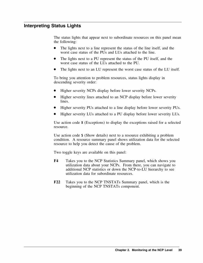
The status lights that appear next to subordinate resources on this panel meanthe following:
� The lights next to a line represent the status of the line itself, and theworst case status of the PUs and LUs attached to the line.
� The lights next to a PU represent the status of the PU itself, and theworst case status of the LUs attached to the PU.
� The lights next to an LU represent the worst case status of the LU itself.
To bring you attention to problem resources, status lights display indescending severity order:
� Higher severity NCPs display before lower severity NCPs.
� Higher severity lines attached to an NCP display before lower severitylines.
� Higher severity PUs attached to a line display before lower severity PUs.
� Higher severity LUs attached to a PU display before lower severity LUs.
Use action code X (Exceptions) to display the exceptions raised for a selectedresource.
Use action code S (Show details) next to a resource exhibiting a problemcondition. A resource summary panel shows utilization data for the selectedresource to help you detect the cause of the problem.
Two toggle keys are available on this panel:
F4 Takes you to the NCP Statistics Summary panel, which shows youutilization data about your NCPs. From there, you can navigate toadditional NCP statistics or down the NCP-to-LU hierarchy to seeutilization data for subordinate resources.
F22 Takes you to the NCP TNSTATs Summary panel, which is thebeginning of the NCP TNSTATs component.
Chapter 2. Monitoring at the NCP Level 39

NCP Statistics Summary
When you press F4 (NCP List) on the NCP Status Summary panel (seeFigure 3 on page 38), the NCP Statistics Summary appears as shown in thefollowing figure.
� �____ Actions Goto View Options Help
-------------------------------------------------------------17:56:52 11/14/94
KONDNNAD NCP Statistics Summary System: SYSA
More: <
Select with a "/" or an action code. Lines 1 to 3 of 3
X=Exceptions S=Show details K=Lines P=PUs L=LUs V-VCs
T=Trends
+------------+------+--------------------+---------------+-------------+------+
| | CCU | Free Buffers | Channel | Slowdown | |
| NCP Name | Util | Avail High Low | INTQ HOLD | Time Pct | Cond |
+------------+------+------+------+------+-------+-------+------+------+------+
| S NCP�1 | 99% | 1��% | 1��% | 1��% | 5 | 5 | 3.8s| 8% | Idle |
| _ NCP11 | 1% | 24% | 34% | 45% | 5 | 6 | �.3s| 1�% | Norm |
| _ NCP12 | 75% | 11% | 26% | 21% | 4 | 5 | 1.5s| 5% | Crit |
+------------+------+-------------+------+-------+-------+------+------+------+
Command ===> __________________________________________________________________
F1=Help F2=Keys F3=Exit F4=NCP Status F5=Refresh F6=Console **=Bkwd
**=Fwd F9=Retrieve F1�=Action Bar F11=Print F12=Cancel F14=Find
F15=Status_Display F22=TNSTATs
F G
Figure 4. NCP Statistics Summary Panel
Active monitored NCP major nodes are listed on this panel. Summaryperformance statistics and a status light are shown for each NCP. To listsubordinate resources and their utilization data, use the K (Lines), P (PUs), V(VCs), or L (LUs) action codes.
Use the X and T action codes to display Exceptions and Trends for a selectedNCP. Trends are available for the following performance data:
� CCU utilization� free buffers low� channel queues� slowdown percentage
Two toggle keys are available:
F4 Returns you to the NCP Status Summary panel, which displays NCPstatus lights.
F22 Takes you to the NCP TNSTATs Summary panel, which is thebeginning of the NCP TNSTATs component.
40 OMEGAMON II for Mainframe Networks NCP Monitoring Guide Version 520

NCP Resource Summary
You can enter action code S (Show details) next to an NCP either on theNCP Statistics Summary (see previous figure) or on the NCP StatusSummary (see Figure 3 on page 38). The NCP Resource Summary panelappears as shown in the following panel.
� �____ Actions Goto Options Help
-------------------------------------------------------------12:12:�� 11/14/94
KONDNNND Resource Summary for NCP: NCP�1 System: SYSA
More:
Select with a "/" or an action code.
X=Exceptions S=Show details T=Trends
+--------------------------+------------------------+-------------------------+
| Name . . . . .: NCP�1 | MAXCOLL . . .: 4�� | Connect. . . : LOCAL |
| Subarea. . . .: 25 | Lines . . . .: 76 | Total buffers: 991 |
| Release. . . .: V6R2 | PUs . . . . .: 18 | SLOWDOWN lim.: 12.31% |
| NPALU. . . . .: NPALU�1 | LUs . . . . .: 38 | Cycle speed .: 4�.69K |
+--------------------------+-----------+------------+-------------------------+
| Generation Date .: �1/�6/94 11:39:�7 | Generation Level.: �5-12-88 23:59:59 |
+----------------+---------+-----------+------------+-------------------------+
| S CCU Cycles | Normal | Utilization.: 17.��% | Cycles used. : 2�.26M|
| _ Channel | Warning | HOLDQ length: 1 | INTQ length. : 1 |
| _ Slowdown | Warning | Percent. . .: 3.32% | Time (secs). : 2.�s|
| _ Buffer Util | Normal | Utilization.: 25.53% | Max free buff: 748 |
+----------------+---------+------------------------+-------------------------+
Command ===> __________________________________________________________________
F1=Help F2=Keys F3=Exit F5=Refresh F6=Console F9=Retrieve F1�=Action Bar
F11=Print F12=Cancel F15=Status_Display
F G
Figure 5. NCP Resource Summary Panel
The upper portion of the panel displays VTAM configuration data for theNCP. The lower portion provides statistics for the NCP controller and astatus light for each type of statistic.
Exceptions, trends, and a Utilization Detail panel are available for each ofthese performance statistics:
� CCU cycles� channel utilization� slowdown percent� buffer utilization
Chapter 2. Monitoring at the NCP Level 41

42 OMEGAMON II for Mainframe Networks NCP Monitoring Guide Version 520

Chapter 3. Line-Level Resources
Chapter Contents
Line-level Panels . . . . . . . . . . . . . . . . . . . . . . . . . . . . . . . 44SDLC/BSC/CA Line Status . . . . . . . . . . . . . . . . . . . . . . . . 45
Line Status Scrolling . . . . . . . . . . . . . . . . . . . . . . . . . . 46SDLC Line Resource Summary . . . . . . . . . . . . . . . . . . . . . . 47TIC3 Data Collection . . . . . . . . . . . . . . . . . . . . . . . . . . . . . 48Token-Ring Physical Link Status . . . . . . . . . . . . . . . . . . . . . 49
Panel Description . . . . . . . . . . . . . . . . . . . . . . . . . . . . . 50Token-Ring Physical Link Summary . . . . . . . . . . . . . . . . . . 51Token-Ring Logical Link Status . . . . . . . . . . . . . . . . . . . . . 52
Panel Description . . . . . . . . . . . . . . . . . . . . . . . . . . . . . 53Token-Ring Logical Link Summary . . . . . . . . . . . . . . . . . . . 54X.25 Multichannel Link Status . . . . . . . . . . . . . . . . . . . . . . 55X.25 Multichannel Link Resource Summary . . . . . . . . . . . . . 56
Chapter 3. Line-Level Resources 43

Line-level Panels
Line-level resources are considered subordinate to NCPs in the NCP-to-LUhierarchy of resources. Several different line types are supported. When youenter action code K (Lines) on the NCP Statistics Summary (see Figure 4 onpage 40), a pop-up appears prompting you to select from a list of supportedline types.
� �
KONDN35P Lines Selection
_ 1. SDLC/BSC/CA line (S)
2. Token-ring physical link (P)
3. Token-ring logical link (L)
4. X.25 multichannel link (X)
F1=Help F12=Cancel
F G
Figure 6. Line Type Selection Pop-up
When you select a line type, a list of lines of the selected type displays. Forexample, if you select SDLC/BSC/CA line from the prompt list, theSDLC/BSC/CA Line Status appears as shown in Figure 7 on page 45.
You can specify a default line type in the Default NCP Monitoring Optionspanel under the Options pulldown. If a default line type is specified, then aLine Status panel for the default line type displays immediately without youhaving to select a type from the prompt list.
Performance statistics are unique for each line type. Once you select aline-type you can use F22 (Next) and F21 (Previous) to navigate betweenlistings of the various line types connected to the same NCP. The order ofaccess is the same as listed in the line type prompt menu above. When youget to the last line type, F22 (Next) returns you to the first line type.
44 OMEGAMON II for Mainframe Networks NCP Monitoring Guide Version 520

SDLC/BSC/CA Line Status
When you specify SDLC as your line type, the SDLC/BSC/CA Line Statuspanel lists the SDLC, BSC, and channel adapter lines attached to the selectedNCP.
� �____ Actions Goto View Options Help
-------------------------------------------------------------18:51:41 11/14/94
KONDNNKD SDLC/BSC/CA Line Status for NCP: NCP�1 System: SYSA
More: >
Select with a "/" or an action code. Lines 1 to 4 of 4
X=Exceptions S=Show details P=PUs L=LUs T=Trends
+------------+------+-------+-----+---------------+--------------------+------+
| | Line | Line | Que | Non-Productve | Polling | |
| Line Name | Util | Speed | Len | Polls Pct | Total Positive | Cond |
+------------+------+-------+-----+--------+------+----------+---------+------+
| S LS96��A | 26% | 56K | 1 | 1,327 | 88% | 1,5�� | 173 | Warn |
| _ LS56K | 52% | 56K | 1 | 1,365 | 91% | 1,5�� | 135 | Warn |
| _ LSDLC1 | 7% | 96�� | 1 | 1,395 | 93% | 1,5�� | 1�5 | Norm |
| _ BSC1 | 18% | 96�� | 1 | 1,35� | 9�% | 1,5�� | 15� | Norm |
+------------+------+-------+-----+--------+------+----------+---------+------+
Command ===> __________________________________________________________________
F1=Help F2=Keys F3=Exit F5=Refresh F6=Console **=Bkwd **=Fwd F9=Retrieve
F1�=Action Bar F11=Print F12=Cancel F14=Find F15=Status_Display **=Left
F2�=Right F21=Prev F22=Next
F G
Figure 7. SDLC Line Status Panel
This panel displays performance statistics and a status light for eachmonitored SDLC/BSC/CA line connected to the NCP. Action codes areavailable as follows:
X Provides exceptions for a selected line.S Displays a Resource Summary panel for a line.P Lists all the PUs attached to a line.L Lists all the LUs attached to a line.T Provides utilization, non-productive poll, or outbound queue length
trends for a line.
Chapter 3. Line-Level Resources 45
Line Status Scrolling
Scrolling is available on this panel as follows:
� There are five more SDLC line list panels providing retransmission,traffic, and high-, medium-, and low-priority frame statistics for the linesattached to the specified NCP. Use F20 (Right) and F19 (Left) to scrollbetween them. A frame is the vehicle for commands, responses, and allinformation that is transmitted using SDLC protocal.
� Token-rings may be attached to the NCP through the TIC. Use F22(Next) to scroll to panels listing the token-ring physical links andtoken-ring logical links attached to the NCP. F21 (Previous) scrolls tothe line-type previously displayed.
46 OMEGAMON II for Mainframe Networks NCP Monitoring Guide Version 520

SDLC Line Resource Summary
When you enter action code S (Show details) next to an SDLC, BSC, orchannel adapter line either on the NCP Status Summary (see Figure 3 onpage 38) or on the SDLC/BSC/CA Line Status panel (see previous figure), aline resource summary appears.
� �____ Actions Goto Options Help
-------------------------------------------------------------18:3�:�1 11/14/94
KONDNNLD Resource Summary for SDLC Line: LS96��A System: SYSA
More:
Select with a "/" or an action code.
X=Exceptions S=Show details A=Analysis T=Trends
+-------------------------+-------------------------+-------------------------+
| Line name: LS96��A | PU entries. . .: 14 | PIUs In. .: 9�7 |
| SPEED . .: 96��/96�� | LU entries. . .: 24 | PIUs Out .: 34� |
| DUPLEX. .: FULL | Reply timeouts.: 3 | Bytes In .: 44.29K |
| NCP name.: NCP�1 | RETRIES: 5,5,6 | Bytes Out.: 66.44K |
| Subarea .: 9 | PAUSE .: �.2 SERVLIM. .: � |
+----------------+--------+-------------------------+-------------------------+
| A Utilization | Normal | Inbound . . .: 12.6�% | Outbound . .: 18.9�% |
| _ Retransmits | Normal | PIUs. . . . .: 1.76% | Bytes. . . .: �.83% |
| _ Polling | Normal | Total polls .: 1,5�� | Non-prod . .: 9�.��% |
| _ Errors | Normal | Rate per kbyt: � | Total error.: 2 |
| _ QLength | Normal | Length (PIUs): 1 | |
+----------------+--------+-------------------------+-------------------------+
Command ===> __________________________________________________________________
F1=Help F2=Keys F3=Exit F5=Refresh F6=Console F9=Retrieve F1�=Action Bar
F11=Print F12=Cancel F15=Status_Display
F G
Figure 8. SDLC Line Resource Summary Panel
The upper portion of the panel shows VTAM configuration data for theSDLC, BSC, or channel adapter line. The lower portion of the panel showsstatistics and status lights for each category of data: utilization,retransmissions, and polling.
For the selected category, you can use the following action codes:
X Gives you the exceptions that have been raised.S Provides more details.A Displays an analysis panel.T Gives you recent trends.
Chapter 3. Line-Level Resources 47

TIC3 Data Collection
There is an important difference between TIC3 data collection and collectionfor all other NCP resource types. You specify the NCP collection intervalfor monitoring NCP resources during OMEGAMON II CICAT configuration.However, the sample interval for TIC3 resources attached to a 3746-M900expansion frame is fixed. It is hardcoded in the 3746 as 225 seconds andcannot be modified.
Here is how OMEGAMON II resolves the difference between NCP andTIC3 intervals. There are three possibilities:
TIC3 interval equals NCP interval.TIC3 data displays at the end of the NCP interval in which theTIC3 interval expires.
TIC3 interval is less than NCP interval.If there is more than one TIC3 interval within the NCP interval,TIC3 data is accumulated. TIC3 data from one or more expiredTIC3 samples displays at the end of the NCP interval.
For example, if the NCP interval is 5 minutes (300 seconds) atleast one but possibly two TIC3 intervals may elapse during theNCP interval.
TIC3 interval is greater than NCP interval.When the TIC3 interval expires within the NCP interval, TIC3 datadisplays at the end of the NCP interval. When no TIC3 intervalexpires within the NCP interval, TIC3 data appears as zeros.
48 OMEGAMON II for Mainframe Networks NCP Monitoring Guide Version 520

Token-Ring Physical Link Status
There are two different ways to reach the panel shown in the followingfigure:
� Enter action code K (Lines) next to an NCP on the NCP StatisticsSummary panel (see Figure 4 on page 40) and then select TRPL as yourline type (see Figure 6 on page 44).
� Press F22 (Next) on the list of SDLC/BSC/CA lines (see Figure 7 onpage 45).
� �____ Actions Goto View Options Help
--------------------------------------------------------------18:51:41 11/14/94
KONDNNWD Token-Ring Physical Link Status for NCP: NCP�1 System: SYSA
More: >
Select with a "/" or an action code. Lines 1 to 4 of 4
X=Exceptions S=Show details T=Trends
+------------+--------+--------+----------------------+--------+--------+------+
| | TIC | Ring | Rate per Minute | Queue | Active | |
| Link Name | Util | Speed | Frames Bytes | Length | Connct | Cond |
+------------+--------+--------+----------------------+--------+--------+------+
| S RING1 | 56% | 4M | 9K 3,456K | 1 | 3 | Crit |
| _ RING2 | 64% | 4M | 16K 5,999K | 1 | 3 | Crit |
| _ RING3 | 45% | 4M | 12K 568K | � | 4 | Crit |
| _ RING4 | 13% | 4M | 18K 74�K | 1 | 3 | Crit |
+------------+--------+--------+----------------------+--------+--------+------+
Command ===> __________________________________________________________________
F1=Help F2=Keys F3=Exit F5=Refresh F6=Console **=Bkwd **=Fwd F9=Retrieve
F1�=Action Bar F11=Print F12=Cancel F14=Find F15=Status_Display **=Left
F2�=Right F21=Prev F22=Next
F G
Figure 9. Token-Ring Physical Link Status Panel
Chapter 3. Line-Level Resources 49

Panel Description
The Token_Ring Physical Link Status for NCP panel lists the token-ringphysical links (TRPLs) attached to the selected NCP. It shows performancestatistics and a status light for each TRPL. For TIC3, queue length andactive connects are unavailable and display as zeros.
Exceptions and trends are available for a selected line. You can displayrecent trends of the following performance data:
� TIC utilization� rate per minute� queue length� active connects
Show details (S) displays a resource summary panel for a selected line.
Scrolling is available on this panel:
� Two more panels provide error and traffic statistics for the TRPLsattached to the specified NCP. Use F20 (Right) and F19 (Left) to scrollbetween them.
� Use F22 (Next) to scroll to the panel listing the token-ring logical linksattached to the NCP and then to the list of SDLC/BSC lines. F21(Previous) scrolls to the line type previously displayed.
50 OMEGAMON II for Mainframe Networks NCP Monitoring Guide Version 520

Token-Ring Physical Link Summary
When you enter action code S (Show details) next to an TRPL either on theNCP Status Summary (see Figure 3 on page 38) or on the TRPL statuspanel (see previous figure), an TRPL resource summary appears as shown inthe following figure.
� �____ Actions Goto Options Help
--------------------------------------------------------------18:3�:�1 11/14/94
KONDNNVD Resource Summary for Token-Ring Physical Link: RING1 System: SYSA
More:
Select with a "/" or an action code.
X=Exceptions S=Show details T=Trends
+-------------------------+-------------------------+--------------------------+
| NCP name.: NCP�1 | TRSPEED(Mbps): 4 | PASSLIM. . . .: 2 |
| ADAPTER .: TIC2 | MAXTSL. . . .: 4�4� | Bytes in . . .: 12.��M |
| ECLTYPE .: PHY,ANY | RCVBUFC . . .: 31.25K | Bytes out. . .: 18.��M |
| LOCADD. .: 4�������4�7� | PORTADD . . .: � | Frames in. . .: 61.44K |
| DYNWIND .: N/A | LSPRI . . . .: N/A | Frames out . .: 23.�4K |
+----------------+--------+-------------------------+--------------------------+
| _ Utilization | Critic | Inbound . . .: 8.4�% | Outbound . . .: 12.6�% |
| _ Congestion | Critic | Percent . . .: 13.52% | Count. . . . .: 8,5�5 |
| _ Retransmits | Warnin | IFrames . . .: 7.7�% | Bytes. . . . .: 3.33% |
| _ Rates | Normal | Frames/min. .: 61.47K | Bytes/minute .: 6144.��K |
| _ Connects | Normal | Active. . . .: 3 | |
| _ QLength | Normal | Length (IFrm): 1 | |
+----------------+--------+-------------------------+--------------------------+
Command ===> __________________________________________________________________
F1=Help F2=Keys F3=Exit F5=Refresh F6=Console F9=Retrieve F1�=Action Bar
F11=Print F12=Cancel F15=Status_Display
F G
Figure 10. TRPL Resource Summary Panel
On this panel, OMEGAMON II is measuring the inbound and outboundtraffic on the TIC. The Utilization field shows the NCP's contribution to thetoken-ring's utilization. The remainder of the ring may be contributing moreto its utilization.
The upper portion of the panel shows VTAM configuration data for theTRPL. The lower portion of the panel shows performance statistics and astatus light for each type of statistic. For TIC3, retransmitted IFrames, activeconnects, queue length, and congestion are unavailable and display as zeros.
For each category of statistics: utilization, retransmissions, and traffic, youcan use the following action codes:
X Gives you the exceptions that have been raised.S Provides more utilization or error details.T Gives you recent trends.
Chapter 3. Line-Level Resources 51

Token-Ring Logical Link Status
Token-ring logical links (TRLLs) represent logical connections to the otherdevices that are attached to the token-ring that the NCP is attached to. Thereare two ways to reach the panel shown in the following figure.
� Enter action code K (Lines) next to an NCP on the NCP StatisticsSummary panel (see Figure 4 on page 40) and then select TRLL as yourline type (see Figure 6 on page 44).
� Press F22 (Next) on the list of TRPLs (see Figure 9 on page 49).
� �____ Actions Goto View Options Help
-------------------------------------------------------------18:51:41 11/14/94
KONDN1UD Token-Ring Logical Link Status for NCP: NCP�1 System: SYSG
More: >
Select with a "/" or an action code. Lines 1 to 4 of 4
X=Exceptions S=Show details T=Trends
+------------+-------------------+-------------------+---------+-----------+
| | Total Frames | Total Bytes | Queue | |
| Link Name | Inbound Outbound | Inbound Outbound | Length | Condition |
+------------+---------+---------+---------+---------+---------+-----------+
| S J���9��7 | 123,456 | 123,456 | 456K | 456K | 1 | Normal |
| _ J���9��6 | 2,966 | 5,999 | 366K | 399K | 4 | Normal |
| _ J���9��3 | 2.�92 | 2,568 | 92K | 568K | 3 | Normal |
| _ J���9��3 | 3,678 | 2,55� | 1,678K | 4��K | 1 | Normal |
+------------+---------+---------+---------+---------+---------+-----------+
Command ===> __________________________________________________________________
F1=Help F2=Keys F3=Exit F5=Refresh F6=Console **=Bkwd **=Fwd F9=Retrieve
F1�=Action Bar F11=Print F12=Cancel F14=Find F15=Status_Display **=Left
F2�=Right F21=Prev F22=Next
F G
Figure 11. Token-Ring Logical Link Status Panel
52 OMEGAMON II for Mainframe Networks NCP Monitoring Guide Version 520

Panel Description
The Token-Ring Logical Link Status panel lists the TRLLs attached to thespecified NCP. It shows inbound and outbound frames and bytes, and astatus light for each TRLL. For TIC3, queue length is unavailable anddisplays as zeros.
Exceptions and trends are available for a selected link. You can displaytrends for the following performance data:
� total frames� total bytes� outbound queue length
Show details displays a Resource Summary panel for a selected link.
Scrolling is available on this panel:
� Two more panels provide traffic and retransmission statistics for thelisted TRLLs. Use F20 (Right) and F19 (Left) to scroll between them.
� F22 (Next) scrolls to the list of SDLC/BSC lines, and F21 (Previous)scrolls to the list of TRPLs.
Chapter 3. Line-Level Resources 53

Token-Ring Logical Link Summary
When you enter action code S (Show details) next to an TRLL either on theNCP Status Summary (see Figure 3 on page 38) or on the TRLL statuspanel (see previous figure), an TRLL resource summary appears as shown inthe following figure.
� �____ Actions Goto Options Help
-------------------------------------------------------------18:3�:�1 11/14/94
KONDNNRD Resource Summary for Token-Ring Logical Link: J���9��1 System: SYSA
More:
Select with a "/" or an action code.
X=Exceptions S=Show details T=Trends
+-------------------------+-------------------------+--------------------------+
| Name. . .: J���9��1 | PU Name . .: | Bytes inbound.: 58.59K |
| ECLTYPE .: LOG,PER | RNRLIMIT. .: N/A | Bytes outbound: 234.37K |
| PHYPORT .: � | RETRIES: 4,6,3,1� | Frames inbound: 1,2�� |
| NCP name.: NCP�1E | T2TIMER: N/A | Frames outbnd.: 1,2�� |
+----------------+--------+-------------------------+--------------------------+
| _ Retransmits | Normal | IFrames . . : �.18% | Bytes . . . .: �.13% |
| _ Timeouts | Warnin | Timeout rate: 3.3�% | Timeout count: 36 |
| _ Rates | Critic | Frames/min. : 2,4�� | Bytes/minute.: 292.96K |
| _ QLength | Normal | Length(PIUs): � | |
+----------------+--------+-------------------------+--------------------------+
Command ===> __________________________________________________________________
F1=Help F2=Keys F3=Exit F5=Refresh F6=Console F9=Retrieve F1�=Action Bar
F11=Print F12=Cancel F15=Status_Display
F G
Figure 12. TRLL Resource Summary Panel
The upper portion of this panel shows VTAM configuration data for theTRLL. The lower portion summarizes the TRLL's performance statistics andprovides a status light for each category of statistics: retransmits, timeouts,rates, or queue length. For TIC3, retransmitted IFrames, timeouts, and queuelength are unavailable and display as zeros.
For each category, you can use the following action codes:
X Gives you exceptions.S Displays utilization or error details.T Gives you trends.
54 OMEGAMON II for Mainframe Networks NCP Monitoring Guide Version 520

X.25 Multichannel Link Status
When you select X.25 Multichannel Links from the Lines Selection menu,the first of five X.25 Multichannel Link Status panels displays.
� �____ Actions Goto View Options Help
-------------------------------------------------------------18:51:41 �5/25/96
KONDNNCD X.25 Multichannel Link Status for NCP: NCP�1 System: SYSA
More: >
Select with a "/" or an action code. Lines 1 to 4 of 4
X=Exceptions S=Show details V=VCs L=LUs T=Trends
+------------+------+-------+------------------+----------------------+------+
| MCH | Link | Link | Total Bytes | Virtual Circuits | |
| Link Name | Util | Speed | Inbound Outbound | Max Curr New Util | Cond |
+------------+------+-------+------------------+----------------------+------+
| _ X259��1A | 1��% | 96�� | 32,�45K 34,656K| 4�96 4�96 56 1��% | Crit |
| _ R9�1 | 34% | 56K| 457K 346K| 1��� 2�� 33 2�% | Norm |
| _ R9�2 | 18% | 56K| 65K 67K| 2��� 1��� 345 5�% | Warn |
| _ R9�3 | 87% | 96�� | 11K 23K| 3��� 1��� 782 33% | Crit |
+------------+------+-------+------------------+----------------------+------+
Command ===> __________________________________________________________________
F1=Help F2=Keys F3=Exit F5=Refresh F6=Console **=Bkwd **=Fwd F9=Retrieve
F1�=Action Bar F11=Print F12=Cancel F14=Find F15=Status_Display **=Left
F2�=Right F21=Prev F22=Next
F G
Figure 13. Multichannel Link Status Panel 1 - Utilization
This panel shows you utilization statistics for the MCH links attached to theselected NCP. You can use the following action codes:
X Provides exceptions for an MCH link.
S Shows a Resource Summary panel for a link.
V Lists the virtual circuits using the link.
L LIsts the logical units attached to the link.
T Provides recent trends for link utilization, total bytes, current VCs, newVCs, and VC utilization.
There are four more MCH Link Status panels that show you retransmission,traffic, polling, and connection statistics for the listed links. Use F20 (Right)and F19 (Left) to scroll between them.
Chapter 3. Line-Level Resources 55

X.25 Multichannel Link Resource Summary
When you use action code S (Show Details) next to a link on an X.25Multichannel Link Status panel (see Figure 13 on page 55) or on the NCPStatus Summary panel (see Figure 3 on page 38), the X.25 Link ResourceSummary panel appears.
� �____ Actions Goto Options Help
--------------------------------------------------------------18:3�:�1 �5/25/96
KONDNNED Resource Summary for X.25 MCH Link: X259��1A System: SYSA
Select with a "/" or an action code.
X=Exceptions S=Show details A=Analysis T=Trends
+---------------------------+----------------------+--------------------------+
| MCH link name: X259��1A | MMODULO .: 8 | ANS. . . . . .:CONTINUE |
| NCP name. . .: NCP�1 | MWINDOW .: 7 | DBIT . . . . .: NO |
| SPEED . . . .: 96��/96�� | FRMLGTH .: 131 | Tot RNR frames: 3�� |
| LLCLIST . . .: (�,4,5) | PKTMODL .: 8 | Tot data pkts.: 15� |
| FTPI. . . . .: N/A | PLPIGGYB .: Yes | Total bytes. .: 263K |
+----------------+----------+----------------------+--------------------------+
| _ Utilization | Warning | Inbound .: 24.97% | Outbound . . .: 49.93% |
| _ Retransmits | Critical | IFrames .: 1�.��% | Bytes. . . . .: �.1�% |
| _ RNRs | Critical | Received .: 11.11% | Sent . . . . .: 11.11% |
| _ Virt Circs | Critical | Active VCs: 66.67% | Maximum VCs. .: 3 |
| _ Errors | Normal | Rate/Kbyte: N/A | Total errors .: N/A |
| _ QLength | Critical | IFrames . : 2 | |
+----------------+----------+----------------------+--------------------------+
Command ===> _________________________________________________________________
F1=Help F2=Keys F3=Exit F5=Refresh F6=Console F9=Retrieve F1�=Action Bar
F11=Print F12=Cancel F15=Status_Display
F G
Figure 14. X.25 Multichannel Link Resource Summary Panel
The upper portion of the panel shows configuration data for the MCH link.The lower portion shows performance statistics and a status light for eachstatistical category: utilization, retransmissions, and polling. For each ofthese categories, you can use the following action codes:
X Gives you exceptions.S Shows more details.A Displays an analysis panel.T Provides recent trends.
56 OMEGAMON II for Mainframe Networks NCP Monitoring Guide Version 520

Chapter 4. PU-Level Resources
Chapter Contents
PU-level Panels . . . . . . . . . . . . . . . . . . . . . . . . . . . . . . . . 58PU Resource Summary . . . . . . . . . . . . . . . . . . . . . . . . . . . 59X.25 Virtual Circuit Status . . . . . . . . . . . . . . . . . . . . . . . . . 60X.25 Virtual Circuit Resource Summary . . . . . . . . . . . . . . . . 61
Chapter 4. PU-Level Resources 57

PU-level Panels
PUs are considered subordinate to SDLC/BSC/CA lines in the NCP-to-LUhierarchy of resources. A PU may be an SDLC or channel adapter physicalunit, or a BSC cluster controller.
You can enter action code P (PUs) next to a specific SDLC/BSC/CA lineeither on the NCP Statistics Summary panel (see Figure 4 on page 40) or onthe SDLC/BSC/CA Line Status panel (see Figure 7 on page 45). The PUStatus panel lists the PUs for a specific line.
� �____ Actions Goto View Options Help
-------------------------------------------------------------17:51:12 11/14/94
KONDNNHD PU Status for SDLC Line: LS96��A System: SYSA
More: >
Select with a "/" or an action code. Lines 1 to 4 of 4
X=Exceptions S=Show details L=LUs T=Trends
+------------+------+-------+-----+---------------+--------------------+------+
| | Line | Line | Que | Non-Productve | Polling | |
| PU Name | Util | Speed | Len | Polls Pct | Total Positive | Cond |
+------------+------+-------+-----+--------+------+----------+---------+------+
| S PS96��A | 56% | 96�� | 1 | 444 | 33% | 4,567 | 455 | Norm |
| _ PS96��B | 1% | 96�� | 2 | 777 | 37% | 7,545 | 431 | Norm |
| _ PS96��C | 3% | 96�� | 1 | 88 | 18% | 943 | 543 | Norm |
| _ PS96��D | 25% | 96�� | 1 | 9 | 32% | 677 | 613 | Norm |
+------------+------+-------+-----+--------+------+----------+---------+------+
Command ===> __________________________________________________________________
F1=Help F2=Keys F3=Exit F5=Refresh F6=Console **=Bkwd **=Fwd F9=Retrieve
F1�=Action Bar F11=Print F12=Cancel F14=Find F15=Status_Display **=Left
F2�=Right
F G
Figure 15. PU Status Panel
This panel shows performance data and a status light for each PU connectedto the line. You can use the following action codes:
X Displays exceptions for a selected PU.S Displays a Resource Summary panel for a PU.L Lists the LUs for a PU.T Provides line utilization or non-productive poll trends for a PU.
Five more panels provide error, traffic, and high-, medium-, and low-priorityframe statistics for the listed PUs. Use F20 (Right) and F19 (Left) to scrollbetween them.
58 OMEGAMON II for Mainframe Networks NCP Monitoring Guide Version 520
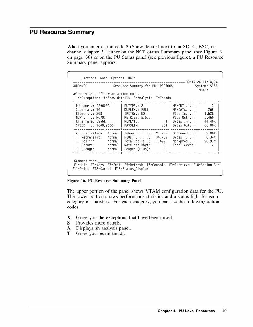
PU Resource Summary
When you enter action code S (Show details) next to an SDLC, BSC, orchannel adapter PU either on the NCP Status Summary panel (see Figure 3on page 38) or on the PU Status panel (see previous figure), a PU ResourceSummary panel appears.
� � ____ Actions Goto Options Help
-------------------------------------------------------------�9:16:24 11/14/94
KONDNNSD Resource Summary for PU: PS96��A System: SYSA
More:
Select with a "/" or an action code.
X=Exceptions S=Show details A=Analysis T=Trends
+-------------------------+-------------------------+-------------------------+
| PU name .: PS96��A | PUTYPE.: 2 | MAXOUT . . .: 7 |
| Subarea .: 1� | DUPLEX.: FULL | MAXDATA. . .: 265 |
| Element .: 2�8 | IRETRY.: NO | PIUs In. . .: 1,528 |
| NCP . . .: NCP�1 | RETRIES: 5,5,6 | PIUs Out . .: 5,46� |
| Line name: LS56K | REPLYTO: 3 | Bytes In . .: 44.4�K |
| SPEED . .: 96��/96�� | PASSLIM: 254 | Bytes Out. .: 66.��K |
+----------------+--------+-------------------------+-------------------------+
| A Utilization | Normal | Inbound . . .: 21.23% | Outbound . .: 52.��% |
| _ Retransmits | Normal | PIUs. . . . .: 34.76% | Bytes. . . .: �.34% |
| _ Polling | Normal | Total polls .: 1,499 | Non-prod . .: 9�.93% |
| _ Errors | Normal | Rate per kbyt: � | Total error.: 2 |
| _ QLength | Normal | Length (PIUs): 9 | |
+----------------+--------+-------------------------+-------------------------+
Command ===> __________________________________________________________________
F1=Help F2=Keys F3=Exit F5=Refresh F6=Console F9=Retrieve F1�=Action Bar
F11=Print F12=Cancel F15=Status_Display
F G
Figure 16. PU Resource Summary Panel
The upper portion of the panel shows VTAM configuration data for the PU.The lower portion shows performance statistics and a status light for eachcategory of statistics. For each category, you can use the following actioncodes:
X Gives you the exceptions that have been raised.S Provides more details.A Displays an analysis panel.T Gives you recent trends.
Chapter 4. PU-Level Resources 59

X.25 Virtual Circuit Status
When you use action code V (Virtual Circuits) on the NCP StatisticsSummary panel (see Figure 4 on page 40), or on a X.25 Multichannel LinkStatus Panel (for example, Figure 13 on page 55), the first of three X.25Virtual Circuit Status panels displays.
� �____ Actions Goto View Options Help
--------------------------------------------------------------18:51:41 �5/25/96
KONDNNGD X.25 Virtual Circuit Status for MCH Link: X259��1A System: SYSA
More: >
Select with a "/" or an action code. Lines 1 to 4 of 4
X=Exceptions S=Show details L=LUs T=Trends
+------------+----------+------+-------+---------------+---------------+------+
| | | Link | Link | Total Bytes | Total IFrames | |
| VC Name | VC Type | Util | Speed | In Out | In Out | Cond |
+------------+----------+------+-------+---------------+---------------+------+
| _ RV56A123 | SVC | 1��% | 56K | 234K 456T| 456M 456M| Crit |
| _ RV96AA | PVC | 96% | 56K | 12K 14K| 745K 45K| Norm |
| _ RV96AB | SVC | 9% | 56K | 999 457| 11K 9K| Warn |
| _ XVC��1 | SVC | 14% | 56K | 365 456| 8K 7K| Crit |
+------------+----------+------+-----------------------+---------------+------+
Command ===> __________________________________________________________________
F1=Help F2=Keys F3=Exit F5=Refresh F6=Console **=Bkwd **=Fwd F9=Retrieve
F1�=Action Bar F11=Print F12=Cancel F14=Find F15=Status_Display **=Left
F2�=Right
F G
Figure 17. X.25 Virtual Circuit Status Panel 1 - Utilization
This panel displays VC utilization statistics, network type, and a status lightfor each VC using the specified MCH link. Depending on the originatingpanel, you see the multichannel link name or the network type (PVC, SVC,or SVC subarea node). You can use the following action codes:
X Displays exceptions for a VC.
S Displays a Resource Summary panel for a VC.
L Lists the LUs attached to a VC.
T Provides utilization, total IFrame, and total byte trends for a VC.
Two more panels provide retransmission and traffic statistics for the listedVCs. Use F20 (Right) and F19 (Left) to scroll between them.
60 OMEGAMON II for Mainframe Networks NCP Monitoring Guide Version 520

X.25 Virtual Circuit Resource Summary
When you use action code S (Show Details) next to a virtual circuit on aVirtual Circuit Status panel (see Figure 17 on page 60) or on the NCPStatus Summary panel (see Figure 3 on page 38), the X.25 Virtual CircuitResource Summary panel appears.
� �____ Actions Goto Options Help
--------------------------------------------------------------18:3�:�1 �5/25/96
KONDNNID Resource Summary for X.25 Virtual Circuit: R9�� System: SYSA
Select with a "/" or an action code.
X=Exceptions S=Show details A=Analysis T=Trends
+-----------------------+-------------------------+----------------------------+
| SVC name. : R9�� | Logical Chnl.: 1/1 | ANS . . . . . .: CONTINUE |
| MCH link. : X259��1A | INSLOW. . . .: (25,�) | DBIT . . . . .: YES |
| NCP name. : NCP�1 | MAXPKTL. . . : 256 | LU count. . . .: 4 |
| LLC type. : � | VWINDOW. . . : 2 +----------------------------+
| PUTYPE. . : 1 | MAXDATA . . .: 256 | Total bytes . .: 14.��K |
| CALL. . . : INOUT | MAXOUT. . . .: 6 | Total data pkts: 3,658 |
| ID. . . . : 1/���2 | INACTO. . . .: N/A | Total IFrames .: 4�233 |
+----------------+------+-------------------------+----------------------------+
| _ Utilization | Norm | Inbound . . .: 21.�5% | Outbound . . .: 79.�9% |
| _ Retransmits | Crit | IFrames . . .: 34.�6% | Bytes . . . . .: 56.6�% |
| _ D-Bits | Crit | Inbound . . .: 15.43% | Outbound. . . .: 41.3�% |
| _ Errors | Crit | Rate/Kbyte. .: � | Total errors. .: � |
| _ QLength | Crit | IFrames . . .: 2 | |
+----------------+------+-------------------------+----------------------------+
Command ===> __________________________________________________________________
F1=Help F2=Keys F3=Exit F5=Refresh F6=Console F9=Retrieve F1�=Action Bar
F11=Print F12=Cancel F15=Status_Display
F G
Figure 18. X.25 Virtual Circuit Summary Panel
The upper portion of this panel shows configuration data for the VC. Thelower portion shows statistics and a status light for each performancecategory: utilization, retransmissions, and D-Bit usage. For each category,you can use the following action codes:
X Displays exceptions.
S Shows more details.
A Displays an analysis panel.
T Provides recent trends.
Chapter 4. PU-Level Resources 61

62 OMEGAMON II for Mainframe Networks NCP Monitoring Guide Version 520

Chapter 5. LU-Level Resources
Chapter Contents
LU-level Panels . . . . . . . . . . . . . . . . . . . . . . . . . . . . . . . . 64LU Status Panel . . . . . . . . . . . . . . . . . . . . . . . . . . . . . . . . 65
Panel Description . . . . . . . . . . . . . . . . . . . . . . . . . . . . . 66Resource Analysis . . . . . . . . . . . . . . . . . . . . . . . . . . . . . . . 67LU Resource Summary . . . . . . . . . . . . . . . . . . . . . . . . . . . 68X.25 LU Panels . . . . . . . . . . . . . . . . . . . . . . . . . . . . . . . . 69
Chapter 5. LU-Level Resources 63

LU-level Panels
LUs are considered subordinate to PUs in the NCP-to-LU hierarchy ofresources. An LU may be an SDLC or channel adapter logical unit, a BSCterminal, or a logical unit device in an X.25 network.
64 OMEGAMON II for Mainframe Networks NCP Monitoring Guide Version 520

LU Status Panel
You can enter action code L (LUs) next to a specific PU or VC on the NCPStatistics Summary panel (see Figure 4 on page 40), on the PU Status panel(see Figure 15 on page 58), or on the VC Status panel (see Figure 17 onpage 60). An LU Status panel lists the LUs attached to a specific PU orVC.
� �____ Actions Goto View Options Help
-------------------------------------------------------------17:51:11 11/14/94
KONDNNQD LU Status for PU: PS96��A System: SYSA
More: >
Select with a "/" or an action code. Lines 1 to 4 of 4
X=Exceptions S=Show details E=RTA R=Resource analysis T=Trends
+------------+------+--------+--------+--------------------------------+------+
| | LU | Line | Queue | Line | Rate per Minute | |
| LU Name | Type | Util | Length | Speed | PIUs Byte | Cond |
+------------+------+--------+--------+--------+------------+----------+------+
| _ LS96��AB | LU | 1�% | 1 | 96�� | 1,423 | 1,623 | Crit |
| _ LS96��A2 | LU | 21% | 2 | 96�� | 345 | 789 | Warn |
| _ LS96��A6 | LU | 6% | 3 | 96�� | 34 | 45 | Norm |
| R LS96��A8 | LU | 16% | 1 | 96�� | 235 | 217 | Crit |
+------------+------+--------+--------+--------+------------+----------+------+
Command ===> ________________________________________________________________
F1=Help F2=Keys F3=Exit F5=Refresh F6=Console **=Bkwd **=Fwd F9=Retrieve
F1�=Actiod Bar F11=Print F12=Cancel F14=Find F15=Status_Display **=Left
F2�=Right
F G
Figure 19. LU Status Panel
Chapter 5. LU-Level Resources 65

Panel Description
The LU Status for PU panel shows performance statistics and a status lightfor each LU attached to the PU or VC. You can use the following actioncodes on this panel:
X Displays exceptions for a selected LU.
S Displays a Resource Summary panel for an LU.
E Takes you directly to the OMEGAMON II Response Times componentwhere the Average Response Times panel shows you response times forthe LU. This action is available for full SNA resources. Therefore, it isnot available for X.25 resources.
R Goes to a Resource Analysis panel for an LU.
T Provides line utilization or rate per minute trends for an LU.
Use F20 (Right) to scroll to a panel showing traffic data for the LUs attachedto the PU and and F19 (Left) to return to this panel.
66 OMEGAMON II for Mainframe Networks NCP Monitoring Guide Version 520

Resource Analysis
If you enter action code R (Resource analysis) next to an LU on an LU Statuspanel (see previous figure), an analysis of the LU appears.
� �____ Goto Options Help
-------------------------------------------------------------12:24:18 11/14/94
KONDARAD Resource Analysis for Terminal LS96��AB System: SYSA
Network Address 25:2�
+----------------------------+----------+--------------------------+----------+
| LU activation date . . . . | �8/3�/94 | Network ID . . . . . . . | CACOWLA1 |
| LU activation time . . . . | �7:52:45 | Owning NCP name. . . . . | NCP1�Y |
| State. . . . . . . . . . . | ACTIVE | Owning line name . . . . | L9�� |
| Desired state. . . . . . . | ACTIVE | Owning PU name . . . . . | L9��A |
| LOGON mode table . . . . . | MODETAB1 | Subarea. . . . . . . . . | 25 |
| Default LOGMODE entry. . . | L32793B | Element address. . . . . | 2� |
| Vary LOGON LOGMODE entry . | | | |
| Active PLU sessions. . . . | � | USSTAB table name. . . . | USSTAB1 |
| Active SLU sessions. . . . | 1 | Major node name. . . . . | LOC66� |
| Pending sessions . . . . . | � | Major node type. . . . . | LCLNSNA |
| Pacing n-count . . . . . . | � | VPacing n-count. . . . . | � |
| Pacing m-count . . . . . . | � | VPacing m-count. . . . . | � |
+----------------------------+----------+--------------------------+----------+
Command ===> _________________________________________________________________
F1=Help F2=Keys F3=Exit F5=Refresh F6=Console F9=Retrieve F1�=Action Bar
F11=Print F12=Cancel F15=Status Display
F G
Figure 20. Resource Analysis for Terminal Panel
This panel displays identifying information as well as details about activation,state, sessions, and pacing.
You can use the Sessions selection on the Goto pulldown menu to accessmore information about this LU's sessions.
Chapter 5. LU-Level Resources 67

LU Resource Summary
When you enter action code S (Show details) next to an LU either on theNCP Status Summary panel (see Figure 3 on page 38) or on the LU Statuspanel (see Figure 19 on page 65), an LU Resource Summary panel appears.
� �____ Actions Goto Options Help
---------------------------------------------------------------:53:11 11/14/94
KONDNNUD Resource Summary for LU: LS96��AB System: SYSA
More:
Select with a "/" or an action code.
X=Exceptions S=Show details T=Trends
+-------------------------+------------------------+-------------------------+
| LU name. : LS96��AB | XDOMAIN. .: N/A | PACING. .: � |
| Subarea. : 25 | DLOGMOD. .: D4A32783 | VPACING .: � |
| Element. : 3467 | PLU. . . .: N/A | PIUs In .: 58 |
| NCP name : NCP�1 | Line speed: 96��/96�� | PIUs Out.: 22 |
| Line name: LS96��A | TERM . . .: N/A | Bytes In.: 2,88� |
| PU name. : PS96��A | | Bytes Out: 4,32� |
+----------------+--------+------------------------+-------------------------+
| S Utilization | Normal | Inbound . . .: �.8�% | Outbound . . : 1.2�% |
| _ Rates | Critic | PIUs per min.: 16 | Bytes per min: 1,44� |
| _ QLength | Normal | Length (PIUs): 1 | |
+----------------+--------+------------------------+-------------------------+
Command ===> __________________________________________________________________
F1=Help F2=Keys F3=Exit F5=Refresh F6=Console F9=Retrieve F1�=Action Bar
F11=Print F12=Cancel F15=Status_Display
F G
Figure 21. LU Resource Summary Panel
The upper portion of the panel shows VTAM configuration data for the LU.The lower portion shows performance statistics and a status light for eachcategory of statistics.
Action code X (Exceptions) gives you utilization, PIU rate, or queue lengthexceptions.
Action code T (Trends) displays utilization, PIU rate, or queue length trends.
Action code S (Show details) displays a Utilization Detail panel.
On this panel you access the Resource Analysis panel from the Gotopulldown menu.
68 OMEGAMON II for Mainframe Networks NCP Monitoring Guide Version 520

X.25 LU Panels
There are no special X.25 logical unit panels. They look the same as SDLClogical unit panels, except for the title which tells you whether the LU isconnected to an X.25 link or virtual circuit.
When you use action code L (LUs) next to an NCP on the NCP StatisticsSummary panel (see Figure 4 on page 40), the Logical Unit Status panelsshow all attached logical units including X.25 logical units. Subsequentresource summary, analysis, and detail panels are available for X.25 as wellas SDLC logical units.
Likewise, when you use action code L (LUs) next to a link on an X.25Multichannel Link Status panel (see Figure 13 on page 55) or next to avirtual circuit on an X.25 Virtual Circuit Status panel (see Figure 17 onpage 60), all attached X.25 logical units appear. Subsequent X.25 LUresource summary, analysis, and detail panels are available.
There is no RTA action on X.25 logical unit panels because X.25 devices donot use full SNA capabilities. The End-to-End Response Time Featurerequires full SNA to generate response time statistics.
Chapter 5. LU-Level Resources 69

70 OMEGAMON II for Mainframe Networks NCP Monitoring Guide Version 520

Chapter 6.Setting NCP Monitoring Options
Chapter Contents
Overview . . . . . . . . . . . . . . . . . . . . . . . . . . . . . . . . . . . . . 72Performance Objectives . . . . . . . . . . . . . . . . . . . . . . . . . . . 73
Warning and Critical Numeric Thresholds . . . . . . . . . . . . 73Warning and Critical Status . . . . . . . . . . . . . . . . . . . . . . 73Determining the Status Lights . . . . . . . . . . . . . . . . . . . . 73
Monitoring Options Pulldown . . . . . . . . . . . . . . . . . . . . . . . 74NCP Performance Options . . . . . . . . . . . . . . . . . . . . . . . . . 75
Default NCP Monitor Options . . . . . . . . . . . . . . . . . . . . 76NCP Site Monitor List . . . . . . . . . . . . . . . . . . . . . . . . . 84Summary of NCP Product Administrator Actions . . . . . . . . 95How Settings Are Determined When Monitoring NCPs . . . 96
Chapter 6. Setting NCP Monitoring Options 71

Overview
The Monitoring Options pulldown includes selections for setting exceptionthresholds and global product defaults, logging exceptions, writing trendrecords to the VSAM log file and SMF, selecting NCP resources to monitor,and other important options.
Only users with administrator authority can alter settings within theMonitoring Options selections. However, any user may view the currentsettings for these selections. A system administrator may grant authorizationduring an OMEGAMON II session via the User Authorities selection (see“User Authorities” in the OMEGAMON II for Mainframe Networks User'sGuide.
OMEGAMON II provides an initial set of default values for MonitoringOptions. However, since the characteristics of NCP networks vary widely,you probably want to tailor the values to your specific network configuration.
Changes to NCP monitoring options take effect at the next sampling interval.
F1When you are using OMEGAMON II, you can press F1 if you need help.Helps include comprehensive field descriptions and detailed technicalinformation. If your cursor is on an input or display field when you pressF1, you get help for that field; otherwise, you get help for the panel.
72 OMEGAMON II for Mainframe Networks NCP Monitoring Guide Version 520

Performance Objectives
OMEGAMON II enables you to set your own performance objectives bysetting thresholds. A threshold is a value that indicates an unsatisfactorylevel of performance. A critical threshold indicates a more unsatisfactory ormore severe condition than a warning threshold.
OMEGAMON II exception monitoring supports warning and criticalconditions for all exceptions.
Warning and Critical Numeric Thresholds
For those exceptions where you specify numeric or percentage thresholds,you can specify both warning and critical values. We recommend settingboth so that you are warned of an impending problem and also alerted whenthe problem needs immediate attention.
Warning and Critical Status
For those exceptions that monitor for the presence or absence of a specificactivity, you can decide how severe the condition is (warning or critical)when it occurs at your site.
Determining the Status Lights
The thresholds and conditions that you specify with the Monitoring Optionspop-ups determine the color of the status lights on OMEGAMON IIperformance displays. When OMEGAMON II detects that thresholds orconditions have been reached, status lights change from green (normal) toyellow (warning) to red (critical).
Be aware that exception recording must be active for normal, warning, andcritical status lights and exception messages to display. Otherwise, the statuslights are turquoise (idle).
Chapter 6. Setting NCP Monitoring Options 73
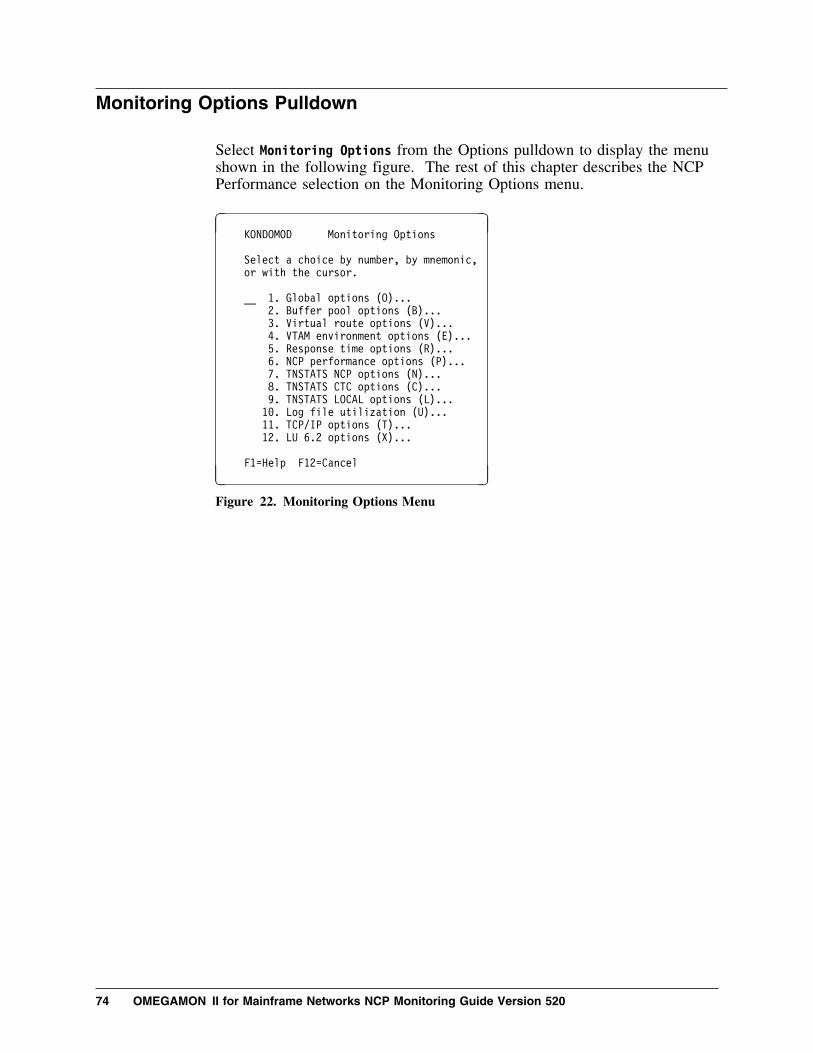
Monitoring Options Pulldown
Select Monitoring Options from the Options pulldown to display the menushown in the following figure. The rest of this chapter describes the NCPPerformance selection on the Monitoring Options menu.
� � KONDOMOD Monitoring Options
Select a choice by number, by mnemonic,
or with the cursor.
__ 1. Global options (O)...
2. Buffer pool options (B)...
3. Virtual route options (V)...
4. VTAM environment options (E)...
5. Response time options (R)...
6. NCP performance options (P)...
7. TNSTATS NCP options (N)...
8. TNSTATS CTC options (C)...
9. TNSTATS LOCAL options (L)...
1�. Log file utilization (U)...
11. TCP/IP options (T)...
12. LU 6.2 options (X)...
F1=Help F12=Cancel
F G
Figure 22. Monitoring Options Menu
74 OMEGAMON II for Mainframe Networks NCP Monitoring Guide Version 520

NCP Performance Options
The NCP Performance Options selection on the Monitoring Options menudisplays a menu with two selections:
Default Monitor Options Use to set site defaults for NCPs, line-level,PU-level, and LU-level resources.
Site Monitor List Use to list your NCPs and their subordinateresources. From this list, you can select specificNCPs or subordinate resources to changemonitor options, start monitoring, and stopmonitoring.
On the NCP options panels and throughout OMEGAMON II, we areassuming a hierarchy of NCP resources. In this manual, in the NCPMonitoring Guide, as well as in the product, NCP resource options andperformance statistics are presented in the following hierarchical order:
Highest level of the NCP hierarchy. |
| Network Control Program CCU (NCP)| Line-level resource (SDLC/BSC/CA line, MCH link, TRPL, TRLL)| PU-level resource (PU, cluster, virtual circuit)| Logical unit (LU, terminal, X.25 LU)
VLowest level of the NCP hierarchy.
Chapter 6. Setting NCP Monitoring Options 75

Default NCP Monitor Options
When you select NCP Default Monitor Options on the NCP PerformanceOptions menu, the following menu appears.
� �KONDO��D NCP Default Options
_ 1. NCP CCU options (A)...
2. Lines (SDLC/BSC/CA (B)...
3. PUs (PUs/clusters) (C)...
4. LUs (LUs/terminals) (D)...
5. Token-ring physical links (E)...
6. Token-ring logical links (F)...
7. X.25 multichannel links (G)...
8. X.25 virtual circuits (H)...
9. X.25 logical units (I)...
F1=Help F12=Cancel
F G
Figure 23. NCP Default Options Menu
This menu lists the types of NCP resources for which you can set defaultmonitoring options. The settings you specify are for all resources of thattype at your site. You can override the settings for specific resources usingthe Site Monitor List (see Figure 33 on page 84). The default settingsremain in effect for all other resources of that type. When you modify sitedefault options, the changes take effect the next sampling interval for thoseresources using the site defaults.
The panels you use to specify default options for each type of resource areshown below. For an explanation of any option, place the cursor in the inputfield and press F1 (Help).
76 OMEGAMON II for Mainframe Networks NCP Monitoring Guide Version 520

Default Monitor Options for NCPs
Use the upper portion of the NCP default options panel shown in thefollowing figure to specify global NCP options. Global options apply to allNCP resources monitored. However, you can override the Start level,Autostart, and Monitor or Collect options for specific resources (see “NCPSite Monitor List” on page 84). The NCP Collection Interval is read-only.
NCP Collection IntervalHow often the NCP collector queries your monitored NCPs forperformance data and OMEGAMON II updates the data in NCPperformance panels. This interval is specified during CICATconfiguration of OMEGAMON II and cannot be changed using thispanel.
For information about how OMEGAMON II synchronizes the NCPcollection interval with the hardcoded TIC3 sample interval in the3746-M900, see “TIC3 Data Collection” on page 48.
Topology Update IntervalHow often to query the NCP collector for the current NCP topology,including resources dynamically added or deleted, and newly activatedNCPs. If you have a network that changes often, specify a smallerinterval to keep the topology current. If you have a fairly staticnetwork, specify a larger interval which conserves system resources.
Exception/Trend RecordingWhether to record exceptions or trends on the VSAM log file orSMF.
Line-type DefaultWhich type of line to display first when specifying options or viewingresource utilization data. You can select the other line types from aprompt menu.
Start Options Pop-upWhether you want to view the current monitor options when you startmonitoring a selected resource. You can use the pop-up to confirm orchange options.
Start levelWhen you start monitoring, how far down the NCP-to-LU hierarchyto perform the start. For example, if you start monitoring an NCPand specify Line, then the NCP and all its lines are started.
AutostartWhether monitoring starts during OMEGAMON II initialization orwhen the NPALU goes into session with the NCP collector, orwhether you use the R (Start) action code on the Site Monitor List tostart monitoring a specific resource.
Chapter 6. Setting NCP Monitoring Options 77

Monitor or CollectWhether to monitor the resource and record exception and trend data,or merely collect trend data for recording on the log file or SMF.
� �KONDO�1D Default Monitor Options for NCPs
NCP collection interval . 3�� Seconds
Topology update interval. 1 H + (M-Min/H-Hours)
Exception recording . . . N + (N-None/L-Log/S-SMF/B-Both)
Trend recording . . . . . N + (N-None/L-Log/S-SMF/B-Both)
Line-type default . . . . None + (none,SDLC,TRPL,TRLL,X.25)
Start options pop-up. . . Yes + (Yes/No)
Start level . . . . . . . N + (N-NCPs/K-Lines/P-PUs/L-LUs)
Autostart . . . . . . . . Yes + (Yes/No)
Monitor or Collect. . . . M + (M-Monitor/C-Collect)
Exceptions Y/N Warning Critical
--------------------------- --- ------- --------
CCU cycle utilization . . . Yes + 75_ 9�_ %
Buffer utilization. . . . . Yes + 75_ 88_ %
Slowdown. . . . . . . . . . Yes + 1__ 1�_ %
PIUs on channel hold queue. No_ + _______ _______
PIUs on intermediate queue. No_ + _______ _______
NPALU failure . . . . . . . Yes + W + (W-Warning/C-Critical)
F1=Help F4=Prompt F12=Cancel F21=Prev F22=Next
F G
Figure 24. Default Options for NCPs
Use the lower portion of this panel to specify site default exceptionconditions, thresholds, and severities for NCP communication control units(CCUs).
Default Options for SDLC Lines
� �KONDO�2D Default Options for SDLC/BSC/CA Lines
Exceptions Y/N Warning Critical
------------------------- --- ------- --------
Line utilization. . . . . Yes + 35_ 5�_ %
Retransmitted bytes . . . Yes + 2__ 5__ %
Retransmitted PIUs. . . . Yes + 2__ 5__ %
Temporary errors. . . . . Yes + 2__ 5__ %
Non-productive polls. . . No_ + 95_ 1�� %
PIUs on outbound queue. . No_ + _______ _______
Idle detection. . . . . . No_ + W + (W=Warning/C=Critical)
F1=Help F4=Prompt F12=Cancel F21=Prev F22=Next
F G
Figure 25. Default Options for SDLC Lines
78 OMEGAMON II for Mainframe Networks NCP Monitoring Guide Version 520

Use this panel to specify site default exception settings for SDLC, BSC, andchannel adapter (CA) communication links.
Default Options for SDLC PUs
� �KONDO�3D Default Options for PUs/Clusters
Exceptions Y/N Warning Critical
------------------------ --- ------- --------
Line utilization. . . . . No + ___ ___ %
Retransmitted bytes . . . No + ___ ___ %
Retransmitted PIUs. . . . No + ___ ___ %
Temporary errors. . . . . No + ___ ___ %
Non-productive polls. . . No + ___ ___ %
PIUs on outbound queue. . No + _______ _______
Idle detection. . . . . . No_ + W + (W=Warning/C=Critical)
F1=Help F4=Prompt F12=Cancel F21=Prev F22=Next
F G
Figure 26. Default Options for SDLC PUs
Use this panel to specify site default exception settings for SDLC andchannel adapter physical units, and BSC cluster controllers.
Default Options for SDLC LUs
� �KONDO�4D Default Options for LUs/Terminals
Exceptions Y/N Warning Critical
------------------------ --- -------- --------
Line utilization. . . . . No_ + ___ ___ %
PIUs per minute . . . . . No_ + ________ ________
PIUs on outbound queue. . No_ + ________ ________
Idle detection. . . . . . No_ + W + (W=Warning/C=Critical)
F1=Help F4=Prompt F12=Cancel F21=Prev F22=Next
F G
Figure 27. Default Options for SDLC LUs
Use this panel to specify site default exception settings for SDLC logicalunits, programmed resource virtual logical units, BSC logical units(terminals), and channel adapter logical units.
Chapter 6. Setting NCP Monitoring Options 79

Default Options for Token-Ring Physical Links
� � KONDO�5D Default Options for Token-Ring Physical Links
Exceptions Y/N Warning Critical
-------------------------- --- ------- --------
TIC utilization. . . . . . Yes + 2�_ 3�_ %
Congestion . . . . . . . . Yes + 1__ 5__ %
Retransmitted bytes. . . . Yes + 2__ 5__ %
Retransmitted IFrames. . . Yes + 2__ 5__ %
Frames per minute. . . . . No_ + ________ ________
Connection count . . . . . No_ + ________ ________
IFrames on outbound queue. No_ + ________ ________
Idle detection . . . . . . No_ + W + (W=Warning/C=Critical)
F1=Help F4=Prompt F12=Cancel F21=Prev F22=Next
F G
Figure 28. Default Options for Token-Ring Physical Links
Use this panel to specify default exception settings for token-ring physicallinks (TRPLs).
Default Options for Token-Ring Logical Links
� � KONDO�6D Default Options for Token-Ring Logical Links
Exceptions Y/N Warning Critical
------------------------- --- ------- --------
Retransmitted bytes . . . Yes + 2__ 5__ %
Retransmitted IFrames . . Yes + 2__ 5__ %
Reply timeouts. . . . . . Yes + 2__ 5__ %
Frames per minute . . . . No_ + ________ ________
IFrames on outbound queue No_ + ________ ________
Idle detection. . . . . . No_ + W + (W=Warning/C=Critical)
F1=Help F4=Prompt F12=Cancel F21=Prev F22=Next
F G
Figure 29. Default Options for Token-Ring Logical Links
Use this panel to specify default exception settings for token-ring logicallinks (TRLLs).
80 OMEGAMON II for Mainframe Networks NCP Monitoring Guide Version 520

TIC3 Exceptions
Because TIC3 data for the following fields is unavailabe, the correspondingexceptions for TIC3 resources are ignored:
� retransmitted IFrames� IFrames on outbound queue� connection count� reply timeouts� congestion count
X.25 Multichannel Link Default Options
Use this panel to specify default exception and threshold settings for X.25multichannel (MCH) links.
� � KONDO1�D Default Options for X.25 Multichannel Links
Exceptions Y/N Warning Critical
------------------------- --- ------- --------
Link utilization . . . . . Yes + 45_ 55_ %
Retransmitted bytes. . . . Yes + 2__ 5__ %
Retransmitted IFrames. . . Yes + 2__ 5__ %
RNR frames . . . . . . . . No_ + ___ ___ %
VC utilization . . . . . . Yes + 9�_ 95_ %
Error rate/kbyte . . . . . Yes + 2_______ 5_______
IFrames on outbound queue. No_ + ________ ________
Idle detection . . . . . . No_ + W + (W-Warning/C-Critical)
F1=Help F4=Prompt F12=Cancel F21=Prev F22=Next
F G
Figure 30. X.25 Multichannel Links Default Options Panel
Chapter 6. Setting NCP Monitoring Options 81

X.25 Virtual Circuits Default Options
Use this panel to specify default exception and threshold settings for X.25virtual circuits.
� � KONDO11D Default Options for X.25 Virtual Circuits
Exceptions Y/N Warning Critical
------------------------- --- ------- --------
Link utilization . . . . . No_ + ___ ___ %
Retransmitted bytes. . . . Yes + 2__ 5__ %
Retransmitted IFrames. . . Yes + 2__ 5__ %
D-bit packets. . . . . . . No_ + ___ ___ %
Error rate/kbyte . . . . . Yes + 2_______ 5_______
IFrames on outbound queue. No_ + ________ ________
Idle detection. . . . . . No_ + W + (W-Warning/C-Critical)
F1=Help F4=Prompt F12=Cancel F21=Prev F22=Next
F G
Figure 31. X.25 Virtual Circuits Default Options Panel
X.25 Logical Units Options
The exception and threshold settings you specify on this panel affect X.25logical units only. Use this panel to specify your site's defaults for X.25LUs.
� � KONDO12D Default Options for X.25 LUs
Exceptions Y/N Warning Critical
------------------------- --- ------- --------
Link utilization . . . . . No_ + ___ ___ %
PIUs per minute. . . . . . No_ + ___ ___ %
PIUs on outbound queue . . No_ + ________ ________
Idle detection. . . . . . No_ + W + (W-Warning/C-Critical)
F1=Help F4=Prompt F12=Cancel F21=Prev F22=Next
F G
Figure 32. X.25 Virtual Circuits Default Options Panel
82 OMEGAMON II for Mainframe Networks NCP Monitoring Guide Version 520

Guidelines
When setting NCP-resource thresholds, consider the following generalguidelines:
� SDLC line utilization thresholds may be slightly higher than BSC lineutilization thresholds.
� Set retransmission and error rates for all line-types low.
� Set TRPL congestion thresholds low.
� Set non-productive polling thresholds high.
� To calculate PU line utilization thresholds, divide total line utilizationamong the number of attached PUs, giving more weight to more heavilyused PUs.
� File and graphics transfers can generate high PIU rates to an LU. SetPIU thresholds for LUs accordingly.
� Refer to the Calculations chapter in the OMEGAMON II for MainframeNetworks NCP Monitoring Guide, for the formulas used to calculate theNCP performance statistics on which exceptions are based.
Navigation
The default options panels include F21 (Prev) and F22 (Next). Thesefunction keys provide a quick way to navigate to the next or previous defaultoptions panel. It is an alternative to returning to the NCP Default Optionsmenu and then selecting another resource. The panels appear in the sameorder that the selections appear on the menu. (See the menu in “DefaultNCP Monitor Options” on page 76.)
For example, when you are on the SDLC PUs options panel,
� F21 (Prev) takes you directly to SDLC Lines� F22 (Next) takes you directly to SDLC LUs
Chapter 6. Setting NCP Monitoring Options 83
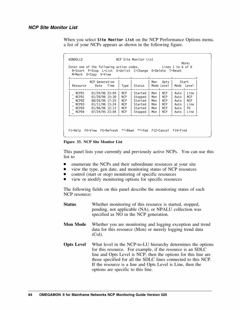
NCP Site Monitor List
When you select Site Monitor List on the NCP Performance Options menu,a list of your NCPs appears as shown in the following figure.
� � KONDOLLD NCP Site Monitor List
More:
Enter one of the following action codes. Lines 1 to 6 of 6
R=Start P=Stop L=List U=Unlist C=Change D=Delete T=Reset
M=Mark O=Copy V=View
+---------------------------+------+---------+------------+-------------+
| NCP Generation | | | Mon Opts | Start |
| Resource Date Time | Type | Status | Mode Level | Mode Level |
+---------------------------+------+---------+-----+------+------+------+
| _ NCP�1 �1/24/96 23:�4 | NCP | Started | Mon | NCP | Auto | Line |
| _ NCP�1 �1/2�/96 15:3� | NCP | Stopped | Mon | NCP | Auto | NCP |
| _ NCP�2 �8/26/96 17:25 | NCP | Started | Mon | NCP | Auto | NCP |
| _ NCP�3 �1/11/96 13:24 | NCP | Started | Mon | NCP | Auto | Line |
| _ NCP�4 �1/�6/96 12:13 | NCP | Started | Mon | NCP | Auto | PU |
| _ NCP�4 �7/24/95 23:�4 | NCP | Stopped | Mon | NCP | Auto | Line |
+---------------------------+------+---------+-----+------+------+------+
F1=Help F4=View F5=Refresh **=Bkwd **=Fwd F12=Cancel F14=Find
F G
Figure 33. NCP Site Monitor List
This panel lists your currently and previously active NCPs. You can use thislist to
� enumerate the NCPs and their subordinate resources at your site� view the type, gen date, and monitoring status of NCP resources� control (start or stop) monitoring of specific resources� view or modify monitoring options for specific resources
The following fields on this panel describe the monitoring status of eachNCP resource:
Status Whether monitoring of this resource is started, stopped,pending, not applicable (NA), or NPALU collection wasspecified as NO in the NCP generation.
Mon Mode Whether you are monitoring and logging exception and trenddata for this resource (Mon) or merely logging trend data(Col).
Opts Level What level in the NCP-to-LU hierarchy determines the optionsfor this resource. For example, if the resource is an SDLCline and Opts Level is NCP, then the options for this line arethose specified for all the SDLC lines connected to this NCP.If the resource is a line and Opts Level is Line, then theoptions are specific to this line.
84 OMEGAMON II for Mainframe Networks NCP Monitoring Guide Version 520

Start Mode Whether this resource is autostarted at OMEGAMON IIinitialization or when the NPALU goes into session with theNCP collector (Auto), or whether you must use the start actionto manually start monitoring (Manu).
Start Level How far down the NCP-to-LU hierarchy monitoring begins.For example, when you start monitoring an NCP, if the startlevel is NCP, only NCP monitoring starts. If the start level isPU, then monitoring begins for the NCP, its lines, and its PUs.
The changes to options that you make via the Site Monitor List override thesite default options. Using the Site Monitor List, you can change optionsonly when monitoring of the resource is stopped.
You can revert to monitoring with the site defaults whenever necessary.
Dynamic Configuration
OMEGAMON II dynamically maintains an NCP topology table from theNCP resource resolution table (RRT) when the following are true:
� The NPALU is available.� The RRT is available.� The NPALU and the NCP collector are connected.� The NCP generation source is in VTAMLST.
The RRT is a load module produced by an NCP generation process. Itdescribes the NCP resources that are defined in the NCP macro sourcedefinitions. For more information about the NPALU and the NCP collector,see the OMEGAMON II for Mainframe Networks Configuration andCustomization Guide.
The NCP topology table is the source of the resources listed on the SiteMonitor List panel. If a resource becomes inactive it remains on the SiteMonitor List. It is the responsibility of the OMEGAMON II productadministrator to remove inactive NCPs from the Site Monitor List when youno longer need them.
Chapter 6. Setting NCP Monitoring Options 85
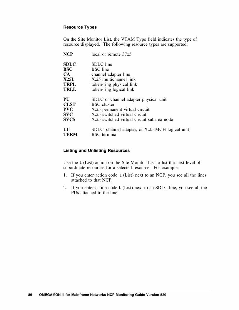
Resource Types
On the Site Monitor List, the VTAM Type field indicates the type ofresource displayed. The following resource types are supported:
NCP local or remote 37x5 SDLC SDLC lineBSC BSC lineCA channel adapter lineX25L X.25 multichannel linkTRPL token-ring physical linkTRLL token-ring logical link PU SDLC or channel adapter physical unitCLST BSC clusterPVC X.25 permanent virtual circuitSVC X.25 switched virtual circuitSVCS X.25 switched virtual circuit subarea node LU SDLC, channel adapter, or X.25 MCH logical unitTERM BSC terminal
Listing and Unlisting Resources
Use the L (List) action on the Site Monitor List to list the next level ofsubordinate resources for a selected resource. For example:
1. If you enter action code L (List) next to an NCP, you see all the linesattached to that NCP.
2. If you enter action code L (List) next to an SDLC line, you see all thePUs attached to the line.
86 OMEGAMON II for Mainframe Networks NCP Monitoring Guide Version 520

� � KONDOLLD NCP Site Monitor List
More: -+
Enter one of the following action codes. Lines 14 to 28 of 246
R=Start P=Stop L=List U=Unlist C=Change D=Delete T=Reset
M=Mark O=Copy V=View
+---------------------------+------+---------+------------+-------------+
| NCP Generation | | | Mon Opt | Start |
| Resource Date Time | Type | Status | Mode Level | Mode Level |
+---------------------------+------+---------+-----+------+------+------+
| XL��2P | X25L | Started | Mon | Line | Auto | Line |
| PP��24�2 | SVC | Started | Mon | VC | Manu | VC |
| XLU��23 | LU | Stopped | Mon | Site | | |
| XLU��22 | LU | Started | Mon | LU | Auto | LU |
| XLU��21 | LU | Stopped | Mon | LU | Manu | LU |
| PP��24�1 | SVC | Stopped | Mon | VC | Manu | VC |
| PP��24�� | SVC | Stopped | Mon | VC | Manu | VC |
| NCP�2 �8/26/96 17:25 | NCP | Started | Mon | Site | Auto | NCP |
| ACADL��� | SDLC | Started | Mon | Site | | |
| ACADCU3P | PU | Pending | Mon | Site | | |
| ACADB3P� | LU | Stopped | Mon | Site | | |
| ACADB3P1 | LU | Stopped | Mon | Site | | |
| ACADB3P2 | LU | Stopped | Mon | Site | | |
| ACADB3P3 | LU | Stopped | Mon | Site | | |
| ACADB3P4 | LU | Stopped | Mon | Site | | |
+---------------------------+------+---------+-----+------+------+------+
Command ===> ____________________________________________________________
F1=Help F4=View F5=Refresh F7=Bkwd F8=Fwd F9=Retrieve F12=Cancel
F14=Find F17=Topology update
F G
Figure 34. NCP Site Monitor List with Subordinate Resources
You can use the U (Unlist) action to remove listed resources from theSite Monitor List. Continuing with the example above:
3. If you enter action code U (Unlist) next to the listed SDLC line, its PUsare removed from the Site Monitor List.
4. If you enter action code U (Unlist) next to the NCP, its lines are removedfrom the Site Monitor List.
Although the List and Unlist actions add and delete subordinate resourcesfrom the Site Monitor List panel, the NCPs and all their subordinateresources remain in the NCP topology table so that they can be monitored.
Updating NCP Topology on Demand
If you are a system administrator, you can use F17 (Topology Update) torequest an update of your NCP topology when required. You specify yoursite's topology update interval on the NCP Default Options panel. (See“Default NCP Monitor Options” on page 76.) You can use F17 to updateyour topology instead of waiting for your site's topology update interval toelapse. The topology update may take several minutes. During that timeyour session is locked.
Chapter 6. Setting NCP Monitoring Options 87

Scrolling through the Site Monitor List
When you use the L (List) action to display subordinate resources, the SiteMonitor List can become quite long. There are several different ways toscroll through the list:
� To scroll to the next page, press F8 (Fwd).
� To scroll to the previous page, press F7 (Bkwd).
� To scroll to a specific resource, press F14 (Find) and then enter theresource name.
� To scroll to the bottom of the display, enter M in the command line andpress F8 (Fwd).
� To scroll to the top of the display, enter M in the command line and pressF7 (Bkwd).
� To scroll forward a number of lines, enter the number in the commandline and press F8 (Fwd).
� To scroll backward a number of lines, enter the number in the commandline and press F7 (Bkwd).
� To scroll to a line number, enter the number after Lines at the upperright.
Sorting and Filtering the Site Monitor List
When you press F4 (View) on the Site Monitor List panel, the View menushown in the following figure appears so that you can filter or sort theresources currently listed.
� �
1 1. All (A)
2. Some (S)...
1 1. Unsorted in list order (L)
2. Sort by NCP name, date, and time (N)...
3. Sort by date and time (D)...
F1=Help F12=Cancel
F G
Figure 35. NCP Site Monitor List View Menu
The default view is all resources in list order. You have the option to sort byNCP name, generation date, and time or just gen date and time.
88 OMEGAMON II for Mainframe Networks NCP Monitoring Guide Version 520

If you select Some from the View menu, the following panel appears.
� � KONDOLLS View Some
Type view criteria and press Enter.
Field Operator Value
-------------- -------- --------
Resource name EQ + ________ (* for generics)
Resource type EQ + ____ + (NCP/LINK....)
VTAM status EQ + _____ + (ACTIV/INACT)
Monitor status EQ + _____ + (ACTIV/INACT/UNDEF)
Mode EQ + ___ + (Mon/Col)
Options EQ + ____ + (Def/Spec)
Autostart EQ + ___ + (Yes/No)
F1=Help F4=Prompt F12=Cancel
F G
Figure 36. NCP Site Monitor List View Some
You specify view criteria in the View Some panel. Only those resources onthe Site Monitor List that match your criteria will be displayed. You canprovide criteria for any or all of the fields shown. You can use a specific orgeneric resource name. Use an asterisk (*) to specify a generic name. Enterspecific values in the remaining fields. F4 (Prompt) prompts you with a listof valid values for the field in which your cursor is positioned.
The filtered or sorted view of the Site Monitor List remains in effect for thecurrent display of the list. The next time you select the Site Monitor Listfrom the NCP Performance Options menu, the default view appears.
Viewing Current Settings
Monitoring options for a resource may be the site defaults, defaults for theowning resource, or specific to the particular resource. To view the settingsthat are currently in effect, enter action code V (View) next to the resource.
Overriding Default Options
The site default monitoring options apply to all NCPs and their subordinateresources unless you specifically override them on the Site Monitor List.The Opt Level field on the Site Monitor List displays Site, Line, VC, PU,or LU. This field tells you from what resource level the monitoring optionsfor the resource were derived, or whether the site defaults apply (Site). Thefollowing sections show you the various ways to override site default optionsand also how to revert to the site defaults.
Chapter 6. Setting NCP Monitoring Options 89

Changing Options for a Specific Resource
Use action code C (Change) next to a selected resource on the Site MonitorList to view the monitoring options currently in effect and to modify them asyou wish. You can use the Change action only when monitoring of theresource is stopped. A Change Options panel appears showing you thecurrent options in effect. They may be specific to that resource or the sitedefaults.
� �KONDO19D Change Options for SDLC/BSC Line: L616A3�
Start level. . . . . . . K + (K-Lines/P-PUs/L-LUs)
Autostart. . . . . . . . Yes + (Yes/No)
Monitor or Collect . . . M + (M-Monitor/C-Collect)
Exceptions Y/N Warning Critical
------------------------ --- ------- --------
Line utilization. . . . . Yes + 35_ 5�_ %
Restransmitted bytes. . . Yes + 2__ 5__ %
Figure 37. Change Options for an SDLC Line
The Change Options panel names the specific resource you selected from theSite Monitor List. You can modify any of the options in this panel. Theoptions apply only to the selected resource. The values you specify on theChange Options panel become overrides for monitoring that particularresource.
Changing Options for Subordinate Resources
If you use the Change action to override monitoring options for a selectedresource that has subordinate resources, you can specify overrides for thesubordinates as well. Resources that have subordinates are NCPs, SDLC,BSC, or channel adapter lines, and PUs. Remember that you can use theChange action only when monitoring of the resource is stoppeed.
The F21 (Prev) and F22 (Next) keys provide direct navigation between theChange Options panel for a selected resource and the Change Options panelsfor its subordinates. The following example illustrates how you can changemonitoring options for subordinates:
1. If you use the Change action to change options for line L616A30 andthen press F22 (Next), a Change PUs Options panel appears. Use thispanel to override the monitoring options for all the PUs connected to theline.
90 OMEGAMON II for Mainframe Networks NCP Monitoring Guide Version 520

� � KONDO23D Change Options for SDLC PUs/Clusters
Attached to Line: L616A3�
Exceptions Y/N Warning Critical
------------------------- --- ------- --------
Line utilization. . . . . No_ + ___ ___ %
Retransmitted bytes . . . No_ + ___ ___ %
Figure 38. Change Options for SDLC PUs Attached to a Line
2. If you press F22 (Next) again, you can use the Change LUs Optionspanel to override the default monitoring options for all the LUsconnected to the line.
� � KONDO24D Change Options for SDLC LUs/Terminals
Attached to Line L616A3�
Exceptions Y/N Warning Critical
------------------------- --- ------- --------
Line utilization. . . . . No_ + ___ ___ %
PIUs per minute . . . . . No_ + ________ ________
Figure 39. Change Options for SDLC LUs Attached to a Line
3. If you press F21 (Prev), the Change PUs Options panel reappears.
4. If you press F21 (Prev) again, the Change Line Options panel reappears.
If you want to change the monitoring options for only one PU attached to theline, use the Change action next to the specific PU on the Site Monitor List.Likewise, if you want to change monitoring options for one LU, use theChange action next to the specific LU on the Site Monitor List.
Copying Options
If you specified options for a particular resource on the Site Monitor List andyou want to use the same options for one or several other resources of thesame type, use the M (Mark) and C (Copy) action codes. Enter the Markaction next to the resource whose options you want to use (the source). Thenenter the Copy action next to the resource(s) for which you want the sameoptions (the targets). For each occurrence of the Copy action, a pop-up asksyou to specify which of the two following options you want:
Single Copies the options for the marked resource to the targetresource only.
Propagate Copies the options for the marked resource and itssubordinates to the target resource and its subordinates.
The options for any resources subordinate to the target but not subordinate tothe source resource are set to site default values.
Chapter 6. Setting NCP Monitoring Options 91
Resetting Options
After specifying monitor options for an NCP resource on the Site MonitorList, you may decide to revert to default values. Enter action code T (Reset)next to the resource on the Site Monitor List. Specific monitoring optionsfor the selected resource are deleted. Options for this resource revert to anyexisting defaults that are in effect for its owning resources, or if none to thesite defaults.
For example, if you use the Reset action on a specific PU, the followinghappens:
1. Options specific to the PU are deleted.
2. If options were specified for the PUs attached to the owning line, thoseoptions take effect.
3. Otherwise, if options were specified for the PUs attached to the owningNCP, those options take effect.
4. Otherwise, the site defaults for PUs take effect.
For a graphical depiction, see “How Settings Are Determined WhenMonitoring NCPs” on page 96.
When you enter the Reset action, a pop-up asks you if you also want to resetoptions for the resources subordinate to the selected resource. If you specifyYes, OMEGAMON II determines default settings for the subordinateresources in the same manner that it determines defaults for the owningresource.
Start Monitoring
On the Site Monitor List, you can use the R (Start) action code next to aspecific NCP or subordinate resource to start monitoring. Monitoring willbegin for the selected resource, its owning resources, and optionally for itssubordinates.
Note: After you specify Start, you will not see any data for the startedresource until at least one full NCP collection interval has elapsed.
When you start monitoring a resource, each of its owning resources is startedautomatically. For example, if you specify the Start action for an SDLC PU,monitoring is also started for the owning line and the owning NCP.
92 OMEGAMON II for Mainframe Networks NCP Monitoring Guide Version 520

In addition, you specify start level on the options panel for the resource. Thestart propagates down the NCP-to-LU hierarchy to the specified start level.For example:
� If you enter action code R (Start) next to an NCP and the start level isNCP, only the selected NCP is monitored.
� If you enter action code R (Start) next to an NCP and the start level isPUs, the NCP, its lines, and its PUs are monitored.
When you start monitoring a resource, you have the option to change thesettings that will be in effect following a successful start. This is an optionyou specify on the NCP Default Options panel. (See “Default MonitorOptions for NCPs” on page 77.) If you specified Yes in the Start OptionsPop-up field, a Start Options panel showing the current monitoring optionsfor the selected resource appears when you start monitoring the resource, asshown below. The options in effect may be specific to that resource or theymay be the site defaults. You use the Start Options panel to confirm ormodify the options under which monitoring is to proceed.
� �KONDO19D Start Options for SDLC Line L616A3�
Start level. . . . . . . K + (K-Lines/P-PUs/L-LUs)
Autostart. . . . . . . . Yes + (Yes/No)
Monitor or Collect . . . M + (M-Monitor/C-Collect)
Exceptions Y/N Warning Critical
------------------------- --- ------- --------
Line utilization. . . . . Yes + 35_ 5�_ %
Restransmitted bytes. . . Yes + 2__ 5__ %
Figure 40. Start Options for an SDLC Line
The Start Options panel looks like the Change Options panel for thatresource type. It includes F21(Prev) and F22(Next) for confirming ormodifying options for the resources subordinate to the selected resource.
If you specified Autostart on the NCP Default Options panel, monitoringstarts during OMEGAMON II initialization and the Start Options panel doesnot appear.
When you change monitoring options for a resource, if the new set of optionsincludes Yes for Autostart, monitoring of the resource is automaticallyrestarted.
Chapter 6. Setting NCP Monitoring Options 93

Stop Monitoring
Use the P (Stop) action code next to a resource on the Site Monitor List tostop monitoring the resource. If you specified Autostart on the NCP DefaultOptions panel, you can use the Stop action to stop monitoring selectedresources.
When you request to stop monitoring a resource, monitoring of itssubordinate resources is also stopped. When subordinate resources areeffected, a confirmation pop-up enables you to cancel the Stop.
Deleting Inactive NCPs
OMEGAMON II derives the NCP resources in the Site Monitor List fromthe NCP topology table, which it constructed from the NCP RRT.OMEGAMON II dynamically adds new resources as the NCP topologychanges. OMEGAMON II does not automatically delete NCPs when theybecome inactive. It is possible that they may become active again at a latertime.
If an NCP is obsolete and therefore no longer requires monitoring, youshould delete the NCP from the Site Monitor List. Enter the D (Delete)action code next to the obsolete NCP on the Site Monitor List. The NCPand all of its subordinate resources are removed from both the Site MonitorList panel and the persistent NCP topology table.
For optimum OMEGAMON II performance, we recommend that youmaintain a current NCP Site Monitor List that includes only the NCPs thatyou require.
When you request NCP deletion, a confirmation pop-up appears as shown inthe following figure.
� �
You asked to delete NCP NCPA6 and
all monitoring options for resources
belonging to this NCP from the Site
Monitor List.
To confirm press Enter.
To cancel press F12.
F1=Help F12=Cancel
F G
Figure 41. Confirm Delete from Site Monitor List
94 OMEGAMON II for Mainframe Networks NCP Monitoring Guide Version 520

Summary of NCP Product Administrator Actions
The following diagram summarizes how an OMEGAMON II productadministrator sets NCP monitoring options.
┌───────────┐ │Product │ │Admin: │ │ │
│ ADMIN=YES │ │ │ └─────┬─────┘ │
Using │ Options Pulldown ┌────────────────────────────┼ │ │ J J ┌───────────┐ ┌───────────┐
│ Update NCP│ │ Update │ │ default │ │ Site │ │ monitoring│ │ Monitor │ │ options │ │ List │ │ │ │ │ └───────────┘ └─────┬─────┘ │ │ │ ┌────────┬──────────────┬──────────────┬─────┴────────┬──────────────┬──────────────┬────────┐ │ D │ R │ P │ C │ C │ C │ C │ M/C
│ J J J NCP J Line J PU J LU ││ ┌───────────┐ ┌───────────┐ ┌───────────┐ ┌───────────┐ ┌───────────┐ ┌───────────┐ │
│ │Start │ │Stop │ │ Change │ │ Change │ │ Change │ │ Change │ │ │ │monitoring │ │monitoring │ │ options │ │ options │ │ options │ │ options │ │ │ │selected │ │selected │ │ for │ │ for │ │ for │ │ for │ │
│ │resource & │ │resource & │ │ selected │ │ selected │ │ selected │ │ selected │ │ │ │owning res.│ │owning res.│ │ NCP │ │ line │ │ PU │ │ LU │ │
│ └───────────┘ └───────────┘ └─────┬─────┘ └──────┬────┘ └─────┬─────┘ └───────────┘ │ │ │ │ │ │ │ ┌──────────────┬────────┴─────┐ │ │ │
│ │ │ │ │ │ │ │ J Lines J PUs J LUs │ J LUs │
│ ┌───────────┐ ┌───────────┐ ┌───────────┐ │ ┌───────────┐ │ │ │Change │ │Change │ │Change │ │ │Change │ │ │ │options for│ │options for│ │options for│ │ │options for│ │
│ │all lines │ │all PUs │ │all LUs │ │ │all LUs │ │ │ │in selected│ │in selected│ │in selected│ │ │in selected│ ┌────────┘
│ │NCP │ │NCP │ │NCP │ │ │PU │ ││ └───────────┘ └───────────┘ └───────────┘ │ └───────────┘ │
J │ J ┌───────────┐ ┌─────┴─────────┐ ┌───────────┐ │ Delete │ ┌───────┐ │ │ │ Copy │ │ inactive │ │Confirm│ J PUs J LUs │ options │ │ NCP & all │M────N│delete │ ┌───────────┐ ┌───────────┐ │ to like │ │ associated│ └───────┘ │Change │ │Change │ │ resource │ │ options │ │options for│ │options for│ │ & subords.│ └───────────┘ │all PUs │ │all LUs │ └───────────┘ │in selected│ │in selected│ │line │ │line │ └───────────┘ └───────────┘
Figure 42. How Product Administrator Maintains NCP Options
Chapter 6. Setting NCP Monitoring Options 95

How Settings Are Determined When Monitoring NCPs
The following diagram illustrates how OMEGAMON II determinesmonitoring options and exceptions settings when monitoring NCP resources.
┌───────────────┐ │ │
│ How ││ NCP settings ││ are │
│ determined │ │ │ └───────┬───────┘ │ ┌───────────────────────┬───────────┴───────────┬───────────────────────┐
│ if LU │ if PU │ if Line │ if NCPJ J J J
┌─────────────────────┐ ┌─────────────────────┐ ┌─────────────────────┐ ┌─────────────────────┐ │ Settings │ │ Settings │ │ Settings │ │ Settings │ │ for specific LU │ │ for specific PU │ │ for specific line │ │ for specific NCP │ │ │ │ │ │ │ │ │ └──────────┬──────────┘ └──────────┬──────────┘ └──────────┬──────────┘ └──────────┬──────────┘ │ otherwise │ otherwise │ otherwise │ otherwise
J │ │ │┌─────────────────────┐ │ │ ││ Settings │ │ │ ││ for LUs │ │ │ │ │ in owning PU │ │ │ │└──────────┬──────────┘ │ │ │
│ otherwise │ │ │J J │ │
┌─────────────────────┐ ┌─────────────────────┐ │ │ │ Settings │ │ Settings │ │ │ │ for LUs │ │ for PUs │ │ │ │ in owning line │ │ in owning line │ │ │ └──────────┬──────────┘ └──────────┬──────────┘ │ │ │ otherwise │ otherwise │ │
J J J │ ┌─────────────────────┐ ┌─────────────────────┐ ┌─────────────────────┐ │ │ Settings │ │ Settings │ │ Settings │ │ │ for LUs │ │ for PUs │ │ for lines │ │ │ in owning NCP │ │ in owning NCP │ │ in owning NCP │ │ └──────────┬──────────┘ └──────────┬──────────┘ └──────────┬──────────┘ │ │ otherwise │ otherwise │ otherwise │
J J J J ┌─────────────────────┐ ┌─────────────────────┐ ┌─────────────────────┐ ┌─────────────────────┐ │ Site default │ │ Site default │ │ Site default │ │ Site default │ │ settings for LUs │ │ settings for PUs │ │ dettings for lines │ │ settings for NCPs │ │ │ │ │ │ │ │ │ └─────────────────────┘ └─────────────────────┘ └─────────────────────┘ └─────────────────────┘
Figure 43. NCP Site Profile Hierarchy of Settings
When monitoring occurs, OMEGAMON II determines the settings by thehierarchy shown, following the diagram downward.
When you use action code T (Reset) on the Site Monitor List,OMEGAMON II resets monitoring options to the next higher level in thehierarchy, following the diagram upward.
96 OMEGAMON II for Mainframe Networks NCP Monitoring Guide Version 520

Chapter 7. Scenarios
Chapter Contents
Recommended Monitoring Scope . . . . . . . . . . . . . . . . . . . . . 98Case Study 1: LU Reporting Poor Response Time . . . . . . . . . 99Case Study 2: Identifying Line Problem Before Users Report 101Case Study 3: Is Additional Line Capacity Required? . . . . . . 103Case Study 4: NCP Storage Shortage . . . . . . . . . . . . . . . . 105
Chapter 7. Scenarios 97

Recommended Monitoring Scope
This chapter presents four scenarios using the NCP monitor component. Inthese cases, we are assuming that you are already monitoring all NCP-relatedresources.
In a real situation, we recommend that you continually monitor only yourNCPs and lines. For your multi-drop lines, monitor the PUs continually aswell. When a problem arises, use the NCP Site Monitor List under theOptions pulldown to start monitoring PUs and LUs as needed. Depending onthe NCP collection interval displayed on the NCP Default MonitoringOptions panel, it may take a little time to gather statistics after you startmonitoring.
98 OMEGAMON II for Mainframe Networks NCP Monitoring Guide Version 520

Case Study 1: LU Reporting Poor Response Time
This scenario illustrates a case in which the user at LU R617A20 reportspoor LU response time.
Step Action Result
1 Select Response Times on themain status panel.
The Average Response Timepanel displays.
2 Use action code A and fill in theAdd Resource panel to startmonitoring response time for LUR617A20.
The Average Response Timepanel shows that networkresponse time for the LU ishigh.
3 Enter action code S next to LUname R617A20.
The Resource Analysis panelshows that the name of theowning line is R617.
4 Return to the Average ResponseTime panel and start monitoringline R617.
Response times are shown as anaverage for all LUs attached tothe line.
5 Enter action code L next to theline to list all the attached LUs.
You notice that all the attachedLUs are experiencing poornetwork response time.
6 Enter action code N (NCPMonitor) next to line R617 to goto the NCP component.
The Line Resource Summarypanel shows that the conditionfor outbound utilization iscritical while the otherconditions are normal.
7 Enter action code A next toUtilization.
The Utilization Analysis panellists two PUs attached to theline. Outbound utilization isnormal for one PU but high forthe other.
8 Enter action code L next to thePU name with high utilization.
The LUs attached to the PU arelisted as in the following figure.
Chapter 7. Scenarios 99

� �____ Actions Goto View Options Help
-------------------------------------------------------------17:22:48 11/14/94
KONDN5�D Utilization Analysis for SDLC Line: R9�� System: SYSA
More: >
Select with a "/" or an action code. Lines 1 to 6 of 6
X=Exceptions S=Show details L=List U=Unlist R=Resource analysis T=Trends
++-------------------+--------------------+--------------------+-------+------+
| | Inbound Traffic | Outbound Traffic | Queue | |
| Resource Type | Pct �.2.4.6.8.M | Pct �.2.4.6.8.M | Lngth | Cond |
+--------------------+------+-------------+------+-------------+-------+------+
| _ R9�� SDLC | 5% | > . . . . . | 62% | ======> . . | 5 | Crit |
| _ R9��A PU | 1% | > . . . . . | 12% | =>. . . . . | 1 | Norm |
| _ R9��B PU | 4% | > . . . . . | 5�% | =====>. . . | 4 | Crit |
| _ R9��B�� LU | 1% | > . . . . . | 2% | > . . . . . | � | Norm |
| _ R9��B�1 LU | 1% | > . . . . . | 3% | > . . . . . | 4 | Norm |
| _ R9��B�2 LU | 2% | > . . . . . | 45% | ====> . . . | 4 | Crit |
+--------------------+------+-------------+------+-------------+-------+------+
Command ===> ___________________________________________________________________
F1=Help F2=Keys F3=Exit F5=Refresh F6=Console **=Bkwd **=Fwd F9=Retrieve
F1�=Action Bar F11=Print F12=Cancel F14=Find F15=Status_Display **=Left
F2�=Right
F G
Figure 44. Case Study 1: Utilization Analysis for Line
Step Action Result
9 Examine the performancestatistics for the LUs.
You notice that one LU has highoutbound traffic.
10 Contact the user of the LU withhigh outbound traffic.
You learn that the LU is a PC inthe process of downloading afile from the host. This iscausing poor response times forthe other LUs attached to theline.
11 Examine tuning parameters andperform tuning or ask the user toperform file transfers outside ofnormal business hours.
The LUs attached to the lineregain reasonable response time.
100 OMEGAMON II for Mainframe Networks NCP Monitoring Guide Version 520

Case Study 2: Identifying Line Problem Before Users Report
In this scenario, we use the NCP component to identify a problem before it isreported by users.
Step Action Result
1 Select NCP Monitor on the mainstatus panel.
The NCP Status Summary panelshows that the line and PUconditions for an NCP arecritical.
2 Use action code L next to theNCP name in question to list itslines.
You see which line is in criticalcondition.
3 Use action code S next to thename of the critical line to showdetails about the line.
On the Line Resource Summarypanel you see that whileutilization is normal, retransmitsand errors have exceeded theircritical thresholds.
4 Use action code A next to Errors. The Retransmission ErrorAnalysis panel shows the lineand two PUs. One PU has ahigh percentage of errors and isin critical condition, as in thefollowing figure.
Chapter 7. Scenarios 101

� �____ Actions Goto Options Help
-------------------------------------------------------------17:33:59 11/14/94
KONDN51D Retransmission Error Analysis for SDLC Line: R9�� System: SYSA
More: < >
Select with a "/" or an action code. Lines 1 to 3 of 3
X=Exceptions S=Show details T=Trends
+-------------------+-----+---------------------+----------------------+------+
| | Err | Retransmitted PIUs | Retransmitted Byte | |
| Resource Type | Pct | Pct �.2.4.6.8.M | Pct �.2.4.6.8.M | Cond |
+-------------------+-----+-------+-------------+-------+--------------+------+
| _ R9�� SDLC | 21% | 21% | ==> . . . . | 17% | =>. . . . . | Crit |
| _ R9��A123 PU | 1% | 1% | > . . . . . | 2% | > . . . . . | Norm |
| X R9��B PU | 2�% | 2�% | ==> . . . . | 15% | =>. . . . . | Crit |
+-------------------+-----+-------+-------------+-------+--------------+------+
Command ===> ___________________________________________________________________
F1=Help F2=Keys F3=Exit F5=Refresh F6=Console **=Bkwd **=Fwd F9=Retrieve
F1�=Action Bar F11=Print F12=Cancel F14=Find F15=Status_Display F19=Left
F2�=Right
F G
Figure 45. Case Study 2: Retransmission Error Analysis for Line
Step Action Result
5 Use action code X next to thename of the critical PU todisplay exceptions.
You see that the PU has beenexceeding critical thresholds forerrors and retransmits during thepast hour.
6 Request modem/circuit tests onthe portions of the circuit thatattach to the PU generating thehigh percentage of errors.
You have identified the problemarea and you can begin circuitrepair before users start reportingproblems.
102 OMEGAMON II for Mainframe Networks NCP Monitoring Guide Version 520

Case Study 3: Is Additional Line Capacity Required?
Your user is planning to double the number of transactions using a particularline. You want to determine whether the line can handle twice its currentvolume or whether additional line capacity is required.
Step Action Result
1 Select NCP Monitor on the mainstatus panel.
The NCP Status Summarydisplays the status of all NCPs.
2 Use action code L next to thename of the NCP owning theline in question.
The lines attached to the NCPappear under the NCP on thispanel.
3 Use action code S next to thename of the line in question toshow details.
The Line Resource Summarypanel shows several performancestatistics.
4 Enter action code T next toUtilization.
The Line Utilization trendingpanel displays trends for recentintervals, as shown in thefollowing figure.
� �____ Goto Options Help
-------------------------------------------------------------11:14:22 11/14/94
KONDN��D Trend: Line Utilization System: SYSA
for SDLC Line: R9�� More:
Lines 1 to 7 of 7
The maximum line utilization was 9.3%
+-----------------------------------------------------------------------------+
| Date | Time | Percent | �..1�..2�..3�..4�..5�..6�..7�..8�..9�..1�� |
]----------+----------+---------+---------------------------------------------]
| 11/14/94 | �7:��:�� | 2.6% | > . . . . . . . . . . . . . . . . . . . . . |
| 11/14/94 | �6:��:�� | 4.3% | =>. . . . . . . . . . . . . . . . . . . . . |
| 11/14/94 | �5:��:�� | 5.�% | =>. . . . . . . . . . . . . . . . . . . . . |
| 11/14/94 | �4:��:�� | 9.3% | ===>. . . . . . . . . . . . . . . . . . . . |
| 11/14/94 | �3:��:�� | 7.8% | ==> . . . . . . . . . . . . . . . . . . . . |
| 11/14/94 | �2:��:�� | 5.6% | =>. . . . . . . . . . . . . . . . . . . . . |
| 11/14/94 | �1:��:�� | 2.9% | > . . . . . . . . . . . . . . . . . . . . . |
+-----------------------------------------------------------------------------+
Command ===> __________________________________________________________________
F1=Help F2=Keys F3=Exit F5=Refresh F6=Console **=Bkwd **=Fwd F9=Retrieve
F1�=Action Bar F11=Print F12=Cancel F15=Status_Display
F G
Figure 46. Case Study 3: Line Utilization Trending
Chapter 7. Scenarios 103

Step Action Result
5 Review the inbound andoutbound utilization percentagesdisplayed.
You see that utilization isrelatively low and no oneinterval exceeds 10%.
6 Confirm your findings byexamining historical utilizationtrend data for the line.
You validate that utilization isconsistently low over time.
7 You can double the traffic onthis line without having toupgrade.
You have saved your companythe unnecessary cost ofupgrading the line.
104 OMEGAMON II for Mainframe Networks NCP Monitoring Guide Version 520

Case Study 4: NCP Storage Shortage
An NCP in slowdown is a serious problem: the NCP buffers are full and theNCP can accept new data only when the slowdown condition ends.
Even when NCP storage shortages are not severe enough to cause slowdown,they can still cause performance problems in the network by restrictinglow-priority traffic. These kinds of shortages are not indicated at the VTAMconsole, as a slowdown is.
In this scenario, you have an NCP in which the attached terminals areexperiencing good response time and the traffic is usually steady. However,you receive reports that the attached printers are pausing at a particular timeof the day. The printers are on various lines attached to the NCP.
Step Action Result
1 Select NCP Monitor on the mainstatus panel.
The NCP Status Summary panelshows that one of your NCPs isin a warning condition.
2 Enter action code S next to theNCP name to show details.
The NCP Resource Summarypanel shows that bufferutilization is in a warningcondition while the otherperformance statistics are innormal condition. See thefollowing figure.
Chapter 7. Scenarios 105

� �____ Actions Goto Options Help
-------------------------------------------------------------12:12:�� 11/14/94
KONDNNND Resource Summary for NCP: NCP1� System: SYSA
More:
Select with a "/" or an action code.
X=Exceptions S=Show details T=Trends
+--------------------------+------------------------+-------------------------+
| Name . . . . .: NCP1� | MAXCOLL . . .: 4�� | Connect. . . .: XDOMAIN |
| Subarea. . . .: 25 | Lines . . . .: 76 | Total buffers.: 991 |
| Release. . . .: V6.2 | PUs . . . . .: 18 | SLOWDOWN limit: 122 |
| NPALU. . . . .: NPALU�1 | LUs . . . . .: 38 | Cycle speed. .: 64K |
+--------------------------+-----------+------------+-------------------------+
| Generation Date .: 11/�6/94 11:39:�7 | Generation Level.: �5/12/93 23:59:59 |
+----------------+---------+-----------+------------+-------------------------+
| _ CCU Cycles | Normal | Utilization.: 3�.34% | Cycles used. : 21.25M |
| _ Channel | Normal | HOLDQ length: 1 | INTQ length. : 1 |
| _ Slowdown | Normal | Percent. . .: �.��% | Time (secs). : � |
| T Buffer Util | Warning | Utilization.: 83.22% | Max free buff: 748 |
+----------------+---------+------------------------+-------------------------+
Command ===> __________________________________________________________________
F1=Help F2=Keys F3=Exit F5=Refresh F6=Console F9=Retrieve F1�=Action Bar
F11=Print F12=Cancel F15=Status_Display
F G
Figure 47. Case Study 4: NCP Resource Summary
Step Action Result
3 Enter action code T next toBuffer Util to show recenttrends.
You see that at the reported timeof day, buffer utilization ishigher than normal (around80%).
4 Consider the followingrecommendations:
� Examine the use ofparameters such as thefollowing for theirappropriateness:
– VPacing– transmission priority– class of service– buffer size
� You may need to upgradeyour 37x5 storage to preventshortages that couldeventually lead to NCPslowdown.
The NCP storage shortage isrelieved before a serious networkproblem occurs.
106 OMEGAMON II for Mainframe Networks NCP Monitoring Guide Version 520

Appendix A. Calculations
Contents
Introduction . . . . . . . . . . . . . . . . . . . . . . . . . . . . . . . . . . 108NCP CCU Statistics Calculations . . . . . . . . . . . . . . . . . . . . 109SDLC Line Statistics Calculations . . . . . . . . . . . . . . . . . . . 110SDLC PU Statistics Calculations . . . . . . . . . . . . . . . . . . . . 112SDLC LU Statistics Calculations . . . . . . . . . . . . . . . . . . . . 114Token-Ring Physical Link Statistics Calculations . . . . . . . . . 115Token-Ring Logical Link Statistics Calculations . . . . . . . . . . 117X.25 MCH Link Statistics Calculations . . . . . . . . . . . . . . . . 119X.25 VC Statistics Calculations . . . . . . . . . . . . . . . . . . . . . 121X.25 LU Statistics Calculations . . . . . . . . . . . . . . . . . . . . . 123
Appendix A. Calculations 107

Introduction
OMEGAMON II uses the calculations in the following tables to generateNCP monitor statistics.
108 OMEGAMON II for Mainframe Networks NCP Monitoring Guide Version 520

NCP CCU Statistics Calculations
Table 2. NCP CCU Statistics Calculations
CCU Value Formula
CCU
UtilizationPercent
(Sample Interval in tenths of a second - (Free Cycles / Speed)) x 100
-------------------------------------------------------Sample Interval in tenths of a second
OR
(Used Cycle / Speed) x 100-----------------------------------
Sample Interval in tenths of a second
Buffer
UtilizationPercent
(Maximum Buffers − Free Buffers Low-Water-Mark) x 100
-------------------------------------------------------------------Maximum Buffers
Time in
SlowdownPercent
(Time in Slowdown in tenths of a second) x 100
------------------------------------Sample Interval in tenths of a second
Free BufferUtilization
Percent
(Max Available Buffers − Free Buffers Low-Water-Mark) x 100
-------------------------------------------------------------------Max Available Buffers
Seconds inSlowdown
Time in Slowdown------------------------
10
Idle
Detection
If (Bytes Received + Bytes Sent) = 0
Appendix A. Calculations 109
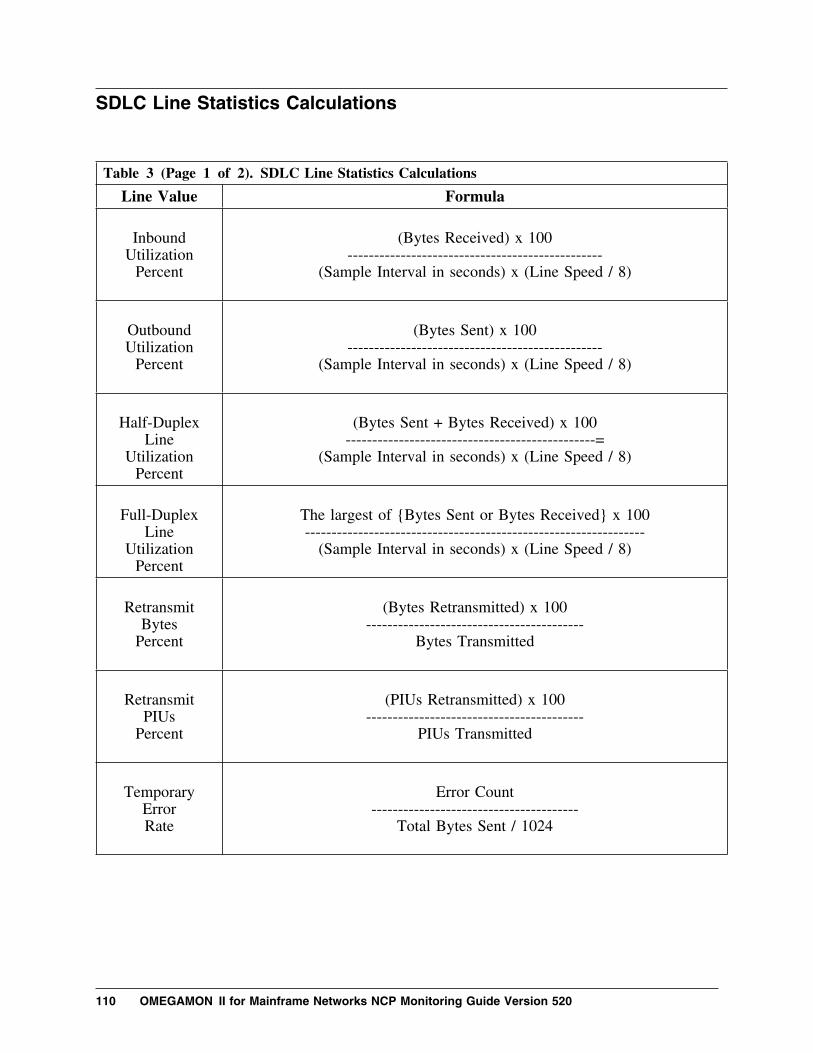
SDLC Line Statistics Calculations
Table 3 (Page 1 of 2). SDLC Line Statistics Calculations
Line Value Formula
Inbound
UtilizationPercent
(Bytes Received) x 100
------------------------------------------------(Sample Interval in seconds) x (Line Speed / 8)
OutboundUtilization
Percent
(Bytes Sent) x 100
------------------------------------------------(Sample Interval in seconds) x (Line Speed / 8)
Half-Duplex
LineUtilization
Percent
(Bytes Sent + Bytes Received) x 100
-----------------------------------------------=(Sample Interval in seconds) x (Line Speed / 8)
Full-Duplex
LineUtilization
Percent
The largest of {Bytes Sent or Bytes Received} x 100----------------------------------------------------------------
(Sample Interval in seconds) x (Line Speed / 8)
Retransmit
BytesPercent
(Bytes Retransmitted) x 100
-----------------------------------------Bytes Transmitted
Retransmit
PIUsPercent
(PIUs Retransmitted) x 100
-----------------------------------------PIUs Transmitted
Temporary
ErrorRate
Error Count
---------------------------------------Total Bytes Sent / 1024
110 OMEGAMON II for Mainframe Networks NCP Monitoring Guide Version 520

Table 3 (Page 2 of 2). SDLC Line Statistics Calculations
Line Value Formula
Negative
PollsPercent
(Total − Positive) x 100------------------------------
Total Polls
High-
PriorityIFramesPercent
(High-Priority IFrames) x 100
-----------------------------------------Total IFrames
Medium-PriorityIFramesPercent
(Medium-Priority IFrames) x 100
-------------------------------------------Total IFrames
Low-
PriorityIFramesPercent
(Low-Priority IFrames) x 100
----------------------------------------Total IFrames
Negative
Polls
Total Polls − Positive Polls
Idle
Detection
If (Bytes Received + Bytes Sent) = 0
Appendix A. Calculations 111

SDLC PU Statistics Calculations
Table 4 (Page 1 of 2). SDLC PU Statistics Calculations
PU Value Formula
Inbound
UtilizationPercent
(Bytes Received) x 100
-------------------------------------------------(Sample Interval in seconds) x (Line Speed / 8)
OutboundUtilization
Percent
(Bytes Sent) x 100
------------------------------------------------(Sample Interval in seconds) x (Line Speed / 8)
Half-Duplex
LineUtilization
Percent
(Bytes Sent + Bytes Received) x 100
-------------------------------------------------(Sample Interval in seconds) x (Line Speed / 8)
Full-Duplex
LineUtilization
Percent
The largest of {Bytes Sent or Bytes Received} x 100------------------------------------------------------------------
(Sample Interval in seconds) x (Line Speed / 8)
Retransmit
BytesPercent
(Bytes Retransmitted) x 100
---------------------------------------Bytes Transmitted
Retransmit
PIUsPercent
(PIUs Retransmitted) x 100
---------------------------------------PIUs Transmitted
Temporary
ErrorRate
Error Count
-----------------------------------Total Bytes Sent / 1024
112 OMEGAMON II for Mainframe Networks NCP Monitoring Guide Version 520

Table 4 (Page 2 of 2). SDLC PU Statistics Calculations
PU Value Formula
Negative
PollsPercent
(Total − Positive) x 100
--------------------------------------Total Polls
High-
PriorityIFramesPercent
(High-Priority IFrames) x 100
-----------------------------------------Total IFrames
Medium-PriorityIFramesPercent
(Medium-Priority IFrames) x 100
-------------------------------------------Total IFrames
Low-
PriorityIFramesPercent
(Low-Priority IFrames) x 100
-----------------------------------------Total IFrames
Negative
Polls
Total Polls − Positive Polls
Idle
Detection
If (Bytes Received + Bytes Sent) = 0
Appendix A. Calculations 113

SDLC LU Statistics Calculations
Table 5. SDLC LU Statistics Calculations
LU Value Formula
Inbound
UtilizationPercent
(Bytes Received) x 100
------------------------------------------------(Sample Interval in seconds) x (Line Speed / 8)
OutboundUtilization
Percent
(Bytes Sent) x 100
------------------------------------------------(Sample Interval in seconds) x (Line Speed / 8)
Half-Duplex
LineUtilization
Percent
(Bytes Sent + Bytes Received) x 100
-------------------------------------------------(Sample Interval in seconds) x (Line Speed / 8)
Full-Duplex
LineUtilization
Percent
The largest of {Bytes Sent or Bytes Received} x 100----------------------------------------------------------------
(Sample Interval in seconds) x (Line Speed / 8)
Bytes perMinute
(Bytes Received + Bytes Sent) x 60---------------------------------------------
Sample Interval in seconds
PIUs perMinute
(PIUs Received + PIUs Sent) x 60-------------------------------------------
Sample Interval in seconds
Idle
Detection
If (Bytes Received + Bytes Sent) = 0
114 OMEGAMON II for Mainframe Networks NCP Monitoring Guide Version 520
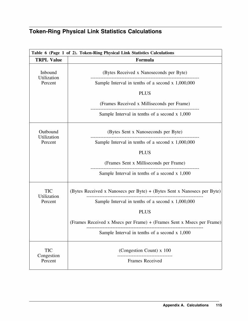
Token-Ring Physical Link Statistics Calculations
Table 6 (Page 1 of 2). Token-Ring Physical Link Statistics Calculations
TRPL Value Formula
Inbound
UtilizationPercent
(Bytes Received x Nanoseconds per Byte)
-------------------------------------------------------------------Sample Interval in tenths of a second x 1,000,000
PLUS
(Frames Received x Milliseconds per Frame)
-------------------------------------------------------------------Sample Interval in tenths of a second x 1,000
OutboundUtilization
Percent
(Bytes Sent x Nanoseconds per Byte)
-------------------------------------------------------------------Sample Interval in tenths of a second x 1,000,000
PLUS
(Frames Sent x Milliseconds per Frame)
-------------------------------------------------------------------Sample Interval in tenths of a second x 1,000
TIC
UtilizationPercent
(Bytes Received x Nanosecs per Byte) + (Bytes Sent x Nanosecs per Byte)
------------------------------------------------------------------------Sample Interval in tenths of a second x 1,000,000
PLUS
(Frames Received x Msecs per Frame) + (Frames Sent x Msecs per Frame)
------------------------------------------------------------------------Sample Interval in tenths of a second x 1,000
TIC
CongestionPercent
(Congestion Count) x 100
----------------------------------Frames Received
Appendix A. Calculations 115

Table 6 (Page 2 of 2). Token-Ring Physical Link Statistics Calculations
TRPL Value Formula
Retransmit
BytesPercent
(Bytes Retransmitted) x 100
----------------------------------------Bytes Transmitted
Retransmit
IFramesPercent
(IFrames Retransmitted) x 100
-------------------------------------------IFrames Transmitted
Bytes perMinute
(Bytes Received + Bytes Sent) x 60-------------------------------------------
Sample Interval in seconds
Frames per
Minute
(Frames Received + Frames Sent) x 60------------------------------------------------
Sample Interval in seconds
IFrames per
Minute
(IFrames Received + IFrames Sent) x 60-------------------------------------------------
Sample Interval in seconds
Idle
Detection
If (Bytes Received + Bytes Sent) = 0
116 OMEGAMON II for Mainframe Networks NCP Monitoring Guide Version 520

Token-Ring Logical Link Statistics Calculations
Table 7 (Page 1 of 2). Token-Ring Logical Link Statistics Calculations
TRLL Value Formula
Inbound
UtilizationPercent
(Bytes Received) x 100
------------------------------------------------(Sample Interval in seconds) x (Line Speed / 8)
OutboundUtilization
Percent
(Bytes Sent) x 100
------------------------------------------------(Sample Interval in seconds) x (Line Speed / 8)
Retransmit
BytesPercent
(Bytes Retransmitted) x 100
----------------------------------------Bytes Transmitted
Retransmit
IFramesPercent
(IFrames Retransmitted) x 100
--------------------------------------------IFrames Transmitted
Reply
TimeoutsPercent
(Reply Timeouts) x 100
---------------------------------------------IFrames Received + Reply Timeouts
Bytes perMinute
(Bytes Received + Bytes Sent) x 60---------------------------------------------
Sample Interval in seconds
Frames per
Minute
(Frames Received + Frames Sent) x 60-----------------------------------------------
Sample Interval in seconds
Appendix A. Calculations 117

Table 7 (Page 2 of 2). Token-Ring Logical Link Statistics Calculations
TRLL Value Formula
IFrames per
Minute
(IFrames Received + IFrames Sent) x 60------------------------------------------------
Sample Interval in seconds
Idle
Detection
If Bytes Received + Bytes Sent = 0
118 OMEGAMON II for Mainframe Networks NCP Monitoring Guide Version 520

X.25 MCH Link Statistics Calculations
Table 8 (Page 1 of 2). X.25 MCH Link Statistics Calculations
Link Value Formula
Inbound
UtilizationPercent
(Bytes Received) x 100
------------------------------------------(Sample Interval in seconds) x (Line Speed / 8)
OutboundUtilization
Percent
(Bytes Sent) x 100
------------------------------------------------(Sample Interval in seconds) x (Line Speed / 8)
Full-Duplex
LineUtilization
Percent
The largest of {Bytes Sent or Bytes Received} x 100----------------------------------------------------------------
(Sample Interval in seconds) x (Line Speed / 8)
Retransmit
BytesPercent
(Bytes Retransmitted) x 100-----------------------------------
Bytes Transmitted
Retransmit
IFramesPercent
(IFrames Retransmitted) x 100-------------------------------------
IFrames Transmitted
ErrorRate
Error Count
---------------------------------------(Total Bytes Sent) / 1024
VC
UtilizationPercent
(VCs in Use) x 100
--------------------------------------Maximum PVCs + SVCs
Appendix A. Calculations 119

Table 8 (Page 2 of 2). X.25 MCH Link Statistics Calculations
Link Value Formula
RNR
FramesSent
Percent
(RNR Frames Sent) x 100
-------------------------------------IFrames Received
RNR
FramesReceivedPercent
(RNR Frames Received) x 100---------------------------------------
IFrames Sent
Inbound
ConnectionsPercent
(Inbound Connections) x 100
----------------------------------------------------------Inbound Connections + Outbound Connections
Outbound
ConnectionPercent
(Outbound Connections) x 100
----------------------------------------------------------Inbound Connections + Outbound Connections
Idle
Detection
If (Bytes Received + Bytes Sent) = 0
120 OMEGAMON II for Mainframe Networks NCP Monitoring Guide Version 520

X.25 VC Statistics Calculations
Table 9 (Page 1 of 2). X.25 VC Statistics Calculations
VC Value Formula
Inbound
UtilizationPercent
(Bytes Received) x 100
------------------------------------------------(Sample Interval in seconds) x (Line Speed / 8)
OutboundUtilization
Percent
(Bytes Sent) x 100
------------------------------------------------(Sample Interval in seconds) x (Line Speed / 8)
Full-Duplex
LineUtilization
Percent
The largest of {Bytes Sent or Bytes Received} x 100------------------------------------------------------------------
(Sample Interval in seconds) x (Line Speed / 8)
Retransmit
BytesPercent
(Bytes Retransmitted) x 100
---------------------------------------Bytes Transmitted
Retransmit
IFramesPercent
(IFrames Retransmitted) x 100
-------------------------------------------IFrames Transmitted
ErrorRate
Error Count
-----------------------------------(Total Bytes Sent) / 1024
Data Packets
Receivedwith D-Bit
Percent
(Data Packets Received with D-Bit) x 100
--------------------------------------------------------Total Data Packets Received
Appendix A. Calculations 121

Table 9 (Page 2 of 2). X.25 VC Statistics Calculations
VC Value Formula
Data Packets
Sentwith D-BIt
Percent
(Data Packets Sent with D-Bit) x 100
---------------------------------------------------Total Data Packets Sent
Packets
with D-BitPercent
(D-Bit Packets Sent + D-Bit Packets Received) x 100
------------------------------------------------------------------------Data Packets Sent + Data Packets Received
Packets
with M-BitPercent
(M-Bit Packets Sent + M-Bit Packets Received) x 100-------------------------------------------------------------------
Data Packets Sent + Data Packets Received
Idle
Detection
If (Bytes Received + Bytes Sent) = 0
122 OMEGAMON II for Mainframe Networks NCP Monitoring Guide Version 520

X.25 LU Statistics Calculations
Table 10. X.25 LU Statistics Calculations
LU Value Formula
Inbound
UtilizationPercent
(Bytes Received) x 100
------------------------------------------------(Sample Interval in seconds) x (Line Speed / 8)
OutboundUtilization
Percent
(Bytes Sent) x 100
------------------------------------------------(Sample Interval in seconds) x (Line Speed / 8)
Full-Duplex
LineUtilization
Percent
The largest of {Bytes Sent or Bytes Received} x 100----------------------------------------------------------------
(Sample Interval in seconds) x (Line Speed / 8)
Bytes perMinute
(Bytes Received + Bytes Sent) x 60---------------------------------------------
Sample Interval in seconds
PIUs perMinute
(PIUs Received + PIUs Sent) x 60-------------------------------------------
Sample Interval in seconds
Idle
Detection
If (Bytes Received + Bytes Sent) = 0
Appendix A. Calculations 123

124 OMEGAMON II for Mainframe Networks NCP Monitoring Guide Version 520

Appendix B.NCP Monitor Navigation from Status Lights
The following chart illustrates navigating through the NCP monitorcomponent when you start from the NCP Status Lights Summary panel.
Appendix B. NCP Monitor Navigation from Status Lights 125

Navigation from Status Lights
NCP ┌──KONDNNND──┐ ┌──KONDN7PD──┐┌─────┐ │ NCP │ S │ NCP │
┌───N│ 1 ├───N│ Resource ├─────N│ Utilization││ └─────┘ │ Summary │ │ Detail ││ S └────────────┘ └────────────┘
│ │ N │ ┌──┴──┐
│ │ RTA │ ┌──KONDN59D──┐ S F19│ └─────┘ S │ TRPL │ ││ ┌──N│ Utilization│ │
│TRPL ┌──KONDNNVD──┐ │ │ Detail │ ││ ┌─────┐ │ TRPL │ │ └────────────┘ │├───N│ 2 ├───N│ Resource ├──┤ ││ └─────┘ │ Summary │ │ ┌──KONDN6PD──┐ ││ └────────────┘ │ S │ TRPL │ │
│ └──N│ Error │ │ │ │ Detail │ │ │ └────────────┘ JF2P │ ┌──KONDNCMD──┐ │
│ NCP │ │ S ┌──KONDN57D──┐ S F19 │ TNSTATs │ │ ┌──N│ TRLL │ │ │ │ │ │ │ Traffic │ │ └────────────┘ │TRLL ┌──KONDNNRD──┐ │ │ Detail │ │
S │ ┌─────┐ │ TRLL │ │ └────────────┘ ││ ├───N│ 3 ├───N│ Resource ├──┤ ││ F22 │ └─────┘ │ Summary │ │ ┌──KONDN58D──┐ │
│ │ └────────────┘ │ │ TRLL │ ││ │ │ S │ Error │ │
J │ └──N│ Detail │ │ ┌────────┐ ┌──KONDNNMD──┐ │ └────────────┘ JF2P │ Main │ │ NCP │ │ │ Status ├───N│ Status ├─────┤│ │ │ Lights │ │ ┌──KONDN5PD──┐ ┌──KONDN53D──┐ S F19 └────────┘ └────────────┘ │ A │ Line │ S │ Line │ │
S │ ┌─────┐ ┌──N│ Utilization├──┬──N│ Utilization│ ││ F4 │ │ RTA │ │ │ Analysis │ │ │ Detail │ ││ │ └──┬──┘ │ S └────────────┘ │ └────────────┘ │
│ │ │ N ├───────────────────┘ │ │ │SDLC J ┌──KONDNNLD──┐ │ ┌──KONDN51D──┐ ┌──KONDN54D──┐ │
J │ ┌─────┐ │ SDLC/BSC │ │ A │ Retransmit │ S │ Error │ J F2P┌──KONDNNAD──┐ ├───N│ 4 ├───N│ Resource ├──┼──N│ Error ├──┬──N│ Detail ││ NCP │ │ └─────┘ │ Summary │ │ │ Analysis │ │ │ │ S F19│ Statistics │ │ └────────────┘ │ S └────────────┘ │ └────────────┘ │
│ Summary │ │ ├───────────────────┘ │ └──────┬─────┘ │ │ ┌──KONDN52D──┐ ┌──KONDN55D──┐ │
│ │ │ A │ Polling │ S │ Polling │ │ │ │ ├──N│ Analysis ├──┬──N│ Detail │ │ J │ │ │ │ │ │ │ │
See │ │ S └────────────┘ │ └────────────┘ J F2P Next │ └───────────────────┘ Page │ │
│ ┌──KONDN5PD──┐ ┌──KONDN53D──┐ S F19│ A │ PU │ S │ PU │ ││ ┌─────┐ ┌──N│ Utilization├──┬──N│ Utilization│ ││ │ RTA │ │ │ Analysis │ │ │ Detail │ ││ └─────┘ │ S └────────────┘ │ └────────────┘ │
│ │ N ├───────────────────┘ │ │PU J ┌──KONDNNSD───┐ │ ┌──KONDN51D──┐ ┌──KONDN54D──┐ │
│ ┌─────┐ │ PU │ │ A │ Retransmit │ S │ Error │ J F2P├──N│ 5 ├───N│ Resource ├──┼──N│ Error ├──┬──N│ Detail ││ └─────┘ │ Summary │ │ │ Analysis │ │ │ │ S F19│ └─────────────┘ │ S └────────────┘ │ └────────────┘ │
│ ├───────────────────┘ │ │ │ ┌──KONDN52D──┐ ┌──KONDN55D──┐ │
│ │ A │ Polling │ S │ Polling │ │ │ ├──N│ Analysis ├──┬──N│ Detail │ │ │ │ │ │ │ │ │ │
│ ┌─────┐ │ S └────────────┘ │ └────────────┘ J F2P│ │ RTA │ └───────────────────┘
│ └─────┘ │ │ N
│LU J ┌──KONDNNUD──┐ ┌──KONDN56D──┐ ┌──KONDARAD──┐│ ┌─────┐ │ LU │ S │ LU │ Goto │ Resource │
Note: └───N│ 6 ├───N│ Resource ├─────N│ Utilization├─────N│ Analysis │ └─────┘ │ Summary │ │ Detail │ │ │ Exceptions and Trends └──────┬─────┘ └────────────┘ └────────────┘ are available on all │ S Goto NCP statistics panels. └───────────────────────────────────────┘
126 OMEGAMON II for Mainframe Networks NCP Monitoring Guide Version 520

Appendix C.NCP Monitor Navigation from Statistics Summary
The following chart illustrates navigating through the NCP monitorcomponent when you start from the NCP Statistics Summary panel.
Appendix C. NCP Monitor Navigation from Statistics Summary 127

Navigation from Statistics Summary
┌─────┐S ┌───────────────────────────────────────────N│ 1 ├──NPrevious
│ └─────┘ Page NCP │ │ ┌──KONDN2GD──┐ ─────┐
│ │ Traffic │ S F2P ││ ┌─┴KONDNNYD──┐ │ │ │
│ │ Errors ├─┘ │ │ S ┌─────┐│ ┌─┴KONDNNWD──┐ │ │ ├────────N│ 2 ├──NPrevious
│ │ List ├─┘ │ │ └─────┘ Page K ├─────N│ of │ J F19 │ │ │ TRPLs ├──────────────┘ TRPLs │ └────────────┘
│ S F21 │ │ │ │ ┌──KONDNNTD──┐ ─────┐
│ │ │ Traffic │ S F2P ││ J F22 ┌─┴KONDN2FD──┐ │ │ │
│ │ Errors ├─┘ │ │ S ┌─────┐ ┌──KONDNCMD──┐ │ ┌─┴KONDN1UD──┐ │ │ ├────────N│ 3 ├──NPrevious │ NCP │ K │ │ List ├─┘ │ │ └─────┘ Page │ TNSTATs │ ├─────N│ of │ J F19 │ │ │ TRLLs │ │ TRLLs ├──────────────┘ └────────────┘ │ └────────────┘
S │ S F21 │ F22 │ │ │ │ │ ┌──KONDN2BD──┐ ─────┐
│ │ │ │ Lo─Priority│ S F2P │J │ │ ┌─┴KONDN2AD──┐ │ │ │
┌──KONDNNAD──┐ │ │ │ Med.─Pri. ├─┘ │ │ │ NCP │ │ │ ┌─┴KONDN1ZD──┐ │ │ ││ Statistics ├──────────────────────┤ │ │ Hi─Priority├─┘ │ │ S ┌─────┐
│ Summary │ │ │ ┌─┴KONDN2HD──┐ │ │ ├──N│ 4 ├──NPrevious └────────────┘ │ │ │ Traffic ├─┘ │ │ └─────┘ Page
S │ J F22 ┌─┴KONDNNOD──┐ │ │ │ L │ │ │ Errors ├─┘ │ ├───────────────────┐ │ F4 │ ┌─┴KONDNNKD──┐ │ │ │ P │ │ K │ │ List ├─┘ J F19 ├──────┐ │ │ ├─────N│ of ├────────────────────┘ │ │ J SDLCs │ │ SDLCs │ │ │ ┌──KONDNNMD──┐ │ └────────────┘ │ │ │ NCP │ │ │ │ │ Status │ │ ┌──────────────────────────────────────────┘ │ │ Lights │ │ │ ┌──KONDN2ED──┐ ─────┐ │└──────┬─────┘ │ │ │ Lo─Priority│ S F2P │ │
│ │ │ ┌─┴KONDN2DD──┐ │ │ │ │ │ │ │ │ Med─Pri. ├─┘ │ │ │ J │ │ ┌─┴KONDN2CD──┐ │ │ │ │
See │ │ │ Hi─Priority├─┘ │ │ S ┌─────┐ │Previous │ │ ┌─┴KONDN2ID──┐ │ │ ├──N│ 5 ├──NPrev. │Page │ │ │ Traffic ├─┘ │ │ └─────┘ Page │
│ │ ┌─┴KONDNNJD──┐ │ │ │ │ │ │ │ Errors ├─┘ │ │ L │
│ │ ┌─┴KONDNNHD──┐ │ │ ├──────┐ │P │ J │ List ├─┘ J F19 │ │ │
├─────N│ of ├────────────────────┘ │ │ PUs │ │ PUs │ │ │ │ └────────────┘ │ │ │ ┌──────────────────────────────────────────┴────────────┘ │ │
│ │ ─────┐ S ┌─────┐ Previous│ │ ┌──KONDN2JD──┐ S F2P │──N│ 6 ├─NPage
│ │ │ Traffic │ │ │ └─────┘ R ┌──KONDARAD──┐│ │ ┌─┴KONDNNQD──┐ │ │ ├─────────────────N│ Resource │
L │ J │ List ├─┘ │ │ E ┌─────┐ │ Analysis │└─────N│ of │ J F19 ├──N│ RTA │ │ │
LUs │ LUs ├─────────┘ └─────┘ └────────────┘ └────────────┘
128 OMEGAMON II for Mainframe Networks NCP Monitoring Guide Version 520

Appendix D.Guide to Candle Customer Support
Introduction
Candle Corporation is committed to producing top-quality software productsand services. To assist you with making effective use of our products inyour business environment, Candle is also committed to providingeasy-to-use, responsive customer support.
Precision, speed, availability, predictability—these terms describe ourproducts and Customer Support services.
Included in this Guide to Candle Customer Support is information about thefollowing:
� Base Maintenance Plan
– Telephone Support
– eSupport
– Severity Levels
– Service-Level Objectives
– Recording and Monitoring Calls for Quality Purposes
– Customer Support Escalations
– Above and Beyond
� Enhanced Support Services
– Assigned Support Center Representative (ASCR)
– Maintenance Assessment Services (MAS)
– Multi-Services Manager (MSM)
� Customer Support Contact Information
– Worldwide Support Telephone and E-mail Information
Appendix D. Guide to Candle Customer Support 129

Base Maintenance Plan
Overview
Candle offers a comprehensive Base Maintenance Plan to ensure that yourealize the greatest value possible from your Candle software investments.We have more than 200 technicians providing support worldwide, committedto being responsive and to providing expedient resolutions to supportrequests. Technicians are available worldwide at all times during the localbusiness day. In the event of an after-hours or weekend emergency, ourcomputerized call management and forwarding system will ensure that atechnician responds to Severity One situations within one hour. Forcustomers outside of North America, after-hours and weekend support isprovided in English language only by Candle Customer Support technicianslocated in the United States.
Telephone Support
Candle provides consistently reliable levels of service—thanks to ourworldwide support network of dedicated experts trained for specific productsand operating systems. You will always work with a professional who trulyunderstands your problem.
We use an online interactive problem management system to log and trackall customer-reported support requests. Your support request receivesimmediate attention by routing the issue to the appropriate technical resource,regardless of geographic location.
Level 0 Support is where your call to Candle Customer Support is firsthandled. Your support request is recorded in our problem managementsystems, then transferred to the appropriate Level 1 support team. Weprovide Level 0 manual interaction with our customers because we supportmore than 170 products. We feel our customers would prefer personalinteraction to a complex VRU or IVR selection menu.
Level 1 Support is the service provided for initial support requests. OurLevel 1 team offers problem determination assistance, problem analysis,problem resolutions, installation assistance, and preventive and correctiveservice information. They also provide product usage assistance.
Level 2 Support is engaged if Level 1 cannot provide a resolution to yourproblem. Our Level 2 technicians are equipped to analyze and reproduceerrors or to determine that an error is not reproducible. Problems that cannotbe resolved by Level 2 are escalated to Candle's Level 3 R&D support team.
130 OMEGAMON II for Mainframe Networks NCP Monitoring Guide Version 520

Level 3 Support is engaged if a problem is identified in Candle productcode. At Level 3, efforts are made to provide error correction, circumventionor notification that a correction or circumvention is not available. Level 3support provides available maintenance modifications and maintenancedelivery to correct appropriate documentation or product code errors.
eSupport
To facilitate the support process, Candle also provides eSupport, anelectronic full-service information and customer support facility, using theWorld Wide Web at www.candle.com/support/. eSupport allows you toopen a new service request and update existing service requests, as well asupdate information in your customer profile. New and updated servicerequests are queued to a support technician for immediate action. And wecan respond to your request electronically or by telephone—it is your choice.
eSupport also contains a continually expanding knowledge base thatcustomers can tap into at any time for self-service access to product andmaintenance information.
The Candle Web site and eSupport can be accessed 24 hours a day, 7 days aweek by using your authorized Candle user ID and password.
Appendix D. Guide to Candle Customer Support 131

Description of Candle Severity Levels
Responses to customer-reported product issues and usage questions areprioritized within Candle according to Severity Code assignment. Customersset their own Severity Levels when contacting a support center. This ensuresthat we respond according to your individual business requirements.
Severity 1, Crisis A crisis affects your ability to conduct business, andno procedural workaround exists. The system orapplication may be down.
Severity 2, High A high-impact problem indicates significant businesseffect to you. The program is usable but severelylimited.
Severity 3, Moderate A moderate-impact problem involves partial,non-critical functionality loss or a reasonableworkaround to the problem. A fix may be providedin a future release.
Severity 4, Low A low-impact problem is a 'how to' or an advisoryquestion.
Severity 5, Enhancement RequestThis is a request for software or documentationenhancement. Our business units review all requestsfor possible incorporation into a future release of theproduct.
132 OMEGAMON II for Mainframe Networks NCP Monitoring Guide Version 520

Candle Service-Level Objectives
Candle has established the following service-level goals by call status.
First Call Time to Answer
All Severities 90% within 1 minute.
Level 1 Response (normal business hours)
Severity 1 90% within 5 minutes
Severity 2—5 90% within 1 hour
Level 2 Response (normal business hours)
Severity 1 Warm transfer
Severity 2 90% within 2 hours
Severity 3—5 90% within 8 hours
Scheduled follow-up (status update)
Severity 1 Hourly or as agreed
Severity 2 Daily or as agreed,
Severity 3—4 Weekly or as agreed
Severity 5 Notification is made when an enhancement is incorporatedinto a generally available product.
When follow-up is scheduled, notification is made when a fix is incorporatedinto a generally available product.
The above information is for guideline purposes only. Candle does notguarantee or warrant the above service levels. This information is valid as ofOctober 1999 and is subject to change without prior notice.
Appendix D. Guide to Candle Customer Support 133

Recording and Monitoring Calls for Quality Purposes
Candle is committed to customer satisfaction. To ensure that our customersreceive high levels of service, quality and professionalism, we'll monitor andpossibly record incoming and outgoing Customer Support calls. Theinformation gleaned from these calls will help us serve you better. If youprefer that your telephone call with Candle Customer Support in NorthAmerica not be monitored or recorded, please advise the representative whenyou call us at (800) 328-1811 or (310) 535-3636.
Customer Support Escalations
Candle Customer Support is committed to achieving high satisfaction ratingsfrom our customers. However, we realize that you may occasionally havesupport issues that need to be escalated to Candle management. In thoseinstances, we offer the following simple escalation procedure:
If you experience dissatisfaction with Candle Customer Support at any time,please escalate your concern by calling the Candle support location closest toyou. Ask to speak to a Customer Support manager. During standardbusiness hours, a Customer Support manager will be available to talk withyou or will return your call. If you elect to hold for a manager, you will beconnected with someone as soon as possible. If you wish a return call,please tell the Candle representative coordinating your call when you will beavailable. After contacting you, the Customer Support manager will developan action plan to resolve your issue. All escalations or complaints receivedabout support issues are logged and tracked to ensure responsiveness andclosure.
Above and Beyond
What differentiates Candle's support services from our competitors? We gothe extra mile by offering the following as part of our Base MaintenancePlan:
� Unlimited multi-language defect, installation and operations support.
� eSupport using the World Wide Web.
� Regularly scheduled product updates and maintenance provided at noadditional charge.
� Over 200 specialized technicians providing expert support for yourCandle products.
134 OMEGAMON II for Mainframe Networks NCP Monitoring Guide Version 520

Enhanced Support Services
Overview
Our Base Maintenance Plan provides a high level of software support in apackages offering. However, in addition to this plan, we have additionalfee-based support services to meet unique customer needs. The following aresome examples of our added-value support services.
Assigned Support Center Representative Services (ASCR)
� An assigned focal point for managing support escalation needs.� Proactive notification of available software fixes.� Proactive notification of product version updates.� Weekly conference calls with your ASCR to review active problem
records.� Monthly performance reviews of Candle Customer Support service levels.� Optional on-site visits (extra charges may apply).
Maintenance Assessment Service (MAS)
� On-site assessment services.� Advice about product maintenance and implementation.� Training your staff to develop efficient and focused procedures to reduce
overall cost of ownership of your Candle software products.� Analysis of your Candle product environment: versions, updates, code
correction history, incident history and product configurations.� Reviews to ensure that purchased Candle products and solutions are used
effectively.
Multi-Services Manager (MSM)
Multi-Services Manager provides highly valued services to customersrequiring on-site full time expertise to complement their technical resources.
� Dedicated on-site Candle resource (6 months of one year) at your site tohelp ensure maximum use and effectiveness of your Candle products.
� Liaison for all Candle product support activities, coordination andassistance with implementation of all product updates and maintenancereleases.
� Works with your staff to understand business needs and systemsrequirements.
� Possesses technical and systems management skills to enhance yourstaff's knowledge and expertise.
� Other projects as defined in Statement of Work for MSM services.
Appendix D. Guide to Candle Customer Support 135

Customer Support Contact Information
Worldwide Support Telephone and E-mail Information
To contact Customer Support, the current list of telephone numbers ande-mail addresses can be found on the Candle Web site:www.candle.com/support/.
Select Support Contacts from the list on the left of the page.
136 OMEGAMON II for Mainframe Networks NCP Monitoring Guide Version 520

Index
A
activation, LU 67administrator functions
monitoring options 96NCP performance 95
Adobe portable document format 12audiences 30autostart, NCP 77
B
binary synchronous communicationSee BSC line
BSC line 45See also SDLC linedefault options 78status panel 45
buffers 40, 41bytes, token-ring logical link 52
C
calculations 107–123case studies
line capacity 103line problem 101LU reporting poor response time 99NCP storage shortage 105
CCU 25buffers 40, 41utilization 40, 41
changing options, NCPspecific resource 90subordinate resources 90
channelqueues 40utilization 41
channel adapter lines 45
cluster controllerSee PU
collection interval, NCP 77collector 28conditions, connected NCP resources 38configuration data
NCP 41SDLC line 47VTAM 41
connects, token-ring physical link 49conventions, documentation 13copying options, NCP 91critical thresholds, performance objectives 73current settings, NCP 89customer support 129
D
data sources 28default options
LUs 79NCPs 77overriding, NCP 89PUs 79SDLC/BSC lines 78token-ring logical links 80token-ring physical links 80
definition, NCP 25deleting NCPs, Site Monitor List 94determining settings, NCP 96documentation conventions 13documentation set 15dynamic configuration 29, 85
E
errorsPU 58token-ring logical link 54
examplesSee case studies
exceptions 34monitoring options 72
Index 137

exception/trend recording, NCP 77
F
framesPU 58SDLC line 45token-ring logical link 52token-ring physical link 51
function keys 32NCP options 83
H
hierarchy of NCP resources 75
I
IFrames, token-ring physical link 51introduction 23–34
K
KONRRT dataset 28KONSRC dataset 28
L
line 43–56See also SDLC lineLU utilization 64multi-drop 98panels 44PU utilization 58resources supported 32selection 44
line-type default, NCP 77link
See token-ringLU 63–69
default options 79line utilization 64panels 64queue length 68rates 64, 68resource analysis 64, 67
LU (continued)resource summary 68response time toggle 64response time, case study 99status panel 64utilization 68VTAM configuration data 68
M
main status light 36monitor/collect option, NCP 77monitoring options 71–96
administrator authority 72menu 74NCP performance 75–96restrictions 72
monitoring scope, recommended 98multi-drop lines 98
N
navigation 32navigation charts 126, 128NCP
autostart 77changing options
specific resource 90subordinate resources 90
collection interval 77collector 85copying options 91default options 77
See also default optionsdynamic configuration 85function keys, options 83hierarchy of resources 75line-type default 77monitor/collect 77monitoring options 75–96product administrator functions 95resetting options 92resource types 86sampling interval 77settings determination 96Site Monitor List 84
deleting NCPs 94listing/unlisting resources 86sorting/filtering 88
138 OMEGAMON II for Mainframe Networks NCP Monitoring Guide Version 520
NCP (continued)start level 77start monitoring 92start options 77stop monitoring 94viewing current settings 89
NCP-level resources 35–41NDF source library 28Network Control Program
See NCPnon-productive polls
PU 58SDLC line 45
NPALU 28, 85
O
overriding default NCP options 89
P
pacing, LU 67physical unit
See PUportable document format, Adobe 12positive polling, SDLC line 45problems detected 31product administrator functions, NCP 95PU 57–61
default options 79performance statistics 58resource summary 59status panel 58VTAM configuration data 59
Q
queue lengthLU 68token-ring logical link 52, 54token-ring physical link 49
R
ratesLU 64, 68token-ring logical link 54token-ring physical link 49
recommended monitoring scope 98resetting options, NCP 92resource analysis, LU 64, 67
activation 67pacing 67sessions 67state 67
Resource Resolution TableSee RRT
resource summaryLU 68NCP 41PU 59SDLC line 47token-ring logical link 54token-ring physical link 51
resources, NCPhierarchy 75monitored 27types 86
response time, LU 64retransmissions, token-ring logical link 53, 54RRT 28, 85
S
sample interval, TIC3 48samples
See case studiesscenarios 97–106
See also case studiesscope, recommended monitoring 98SDLC line
additional line capacity, case study 103default options 78identifying line problem, case study 101performance statistics 45resource summary 47status panel 45VTAM configuration data 47
selecting line type 44session, LU 67
Index 139
settingglobal defaults 72thresholds 72
settings determination, NCP 96shortage, storage 105Site Monitor List, NCP 84
deleting NCPs 94listing/unlisting resources 86sorting/filtering 88
slowdown 40, 41start
level 77NCP monitoring 92options 77
statisticscalculations 107–123PU performance 58SDLC line performance 45summary 40token-ring logical link performance 52, 53,
54token-ring physical link performance 49, 51
status lightdetermination 73main 31NCP resources 38
status panelLU 64PU 58SDLC/BSC line 45token-ring logical link 52token-ring physical link 49
stop monitoring 94stoppingstorage 105subordinate resources, changing options 90symbols, use of 14synchronous data link control
See SDLC line
T
terminalSee LU
thresholds, NCP performance 75–96TIC 27
token-ring physical link 49utilization 49
TIC3 sample interval 48timeouts, token-ring logical link 54toggles 32token-ring
logical linkdefault options 80performance statistics 52, 53, 54resource summary 54status panel 52VTAM configuration data 54
physical linkdefault options 80performance statistics 49, 51resource summary 51status panel 49VTAM configuration data 51
Token-Ring Interface CouplerSee TIC
topology table 29, 85traffic
inbound, token-ring physical link 51outbound, token-ring physical link 51PU 58SDLC line 45token-ring logical link 53
trends 33TRLL
See token-ring logical linkTRPL
See token-ring physical link
U
utilizationLU 64, 68PU 58SDLC line 45, 47token-ring logical link 54token-ring physical link 51
V
varying views 33viewing current settings, NCP 89VTAM configuration data
LU 68NCP 41PU 59SDLC line 47
140 OMEGAMON II for Mainframe Networks NCP Monitoring Guide Version 520

VTAM configuration data (continued)token-ring logical link 54token-ring physical link 51
W
warning thresholds, performance objectives 73what's new 16
Index 141
