ncdot noise procedures manual draft 08-18-11 procedures... · revisions sheet no. total sheets ......
TRANSCRIPT

APPENDIX H
NOISE WALL STANDARD DRAWINGS AND SPECIAL PROVISIONS

NOISE WALL STANDARD DRAWINGS

NO. NO.BY: BY:DATE: DATE:
REVISIONS SHEET NO.
TOTALSHEETS
STATE OF NORTH CAROLINA
RALEIGH
STATION:
COUNTY
PROJECT NO.
DEPARTMENT OF TRANSPORTATION
12
3
4
1’’
UPPER PANEL BOTTOM PANEL
BILL OF MATERIAL
FOR BID PURPOSES ONLY.
QUANTITIES PROVIDED ARE APPROXIMATE AND ARE
CHECKED BY :
DATE :
DATE :
ASSEMBLED BY :
SECTION THROUGH PRECAST PANELS
SHEET OF
FORM FACE
1"
4"
2" 2"
4"
1"
4"
2" 2"4"
BOLSTERS (TYP)
1 �" BEAM
4"
MODIFIED PANEL DETAIL
BENT STEEL PLATE
�" THICK
FACE
ROADWAY
�"
MIN.
3"
(USE ONLY FOR TURNS 15° OR LESS, CONCAVE TOWARD ROADWAY) (USE ONLY FOR TURNS 15° OR LESS, CONVEX TOWARD ROADWAY)
4"
STEEL PILE
2"
‘‘V’’ BARS
‘‘V’’ BARS
STEEL PLATE
�" X 7"
L 6 X 6 X �
‘‘H’’ BAR
‘‘H’’ BAR
SOUND BARRIER WALL S.F.
2 �"
FORM FACE
BOLSTERS (TYP)
1 �" BEAM
(FOR GREATER THAN 15° TURNS, CONCAVE TOWARD ROADWAY) (FOR GREATER THAN 15° TURNS, CONVEX TOWARD ROADWAY)
(USE ONLY FOR TURNS 15° OR LESS, CONVEX TOWARD ROADWAY)
TYPICAL WALL TURN DETAILTYPICAL WALL TURN DETAIL TYPICAL WALL TURN DETAILTYPICAL WALL TURN DETAIL
PANEL
CONCRETE
H2
H3
H4
4’-0"
5’-0"
6’-0"
BAR SIZE TYPE LENGTH
STR
STR
STR
BAR SIZE TYPE LENGTH
STR
STR
STR#4
#4
#4V2
V3
V4
3’-8"
4’-8"
5’-8"
HEIGHT
PANELHORIZONTAL VERTICAL
BAR TYPES
CONCRETE
CLASS AA
NO. NO.C.Y.
1.09
0.91
0.72 15 37
47
57
15
15
14’-4"
14’-4"
14’-4"
H13’-0" STR STR#4V1 2’-8"0.54 271514’-4"
WEIGHT (lb) WEIGHT (lb)
QUANTITIES FOR ONE PRECAST PANEL (FOR 15’-0" PILE SPACING)
H1
H2
2’-0"
3’-0"
BAR SIZE TYPE LENGTH
STR
STR
BAR SIZE TYPE LENGTH
STR
STR#4
#4V1
V2
1’-8"
2’-8"
HEIGHT
PANELHORIZONTAL VERTICAL
BAR TYPES
CONCRETE
CLASS AA
NO. NO.C.Y.
0.36
0.24 10 11
1810
9’-4"
WEIGHT (lb) WEIGHT (lb)
QUANTITIES FOR ONE PRECAST PANEL (FOR 10’-0" PILE SPACING)
H34’-0" STR STR#4V3 3’-8"0.48 10 24
9’-4"
9’-4"
4"
DRAWN BY : JAD 5/01
CHECKED BY : RDR 5/01
3
5
#4
#4
#4 31
19
#4
#4
#4
#4
& �" ~ H.S. BOLT
�" X 1�" SLOT IN PLATE
�" ~ HOLE IN PILE,
{ �" X 1�" SLOT IN ANGLE,
#4 ‘‘V’’ BARS @ 1’-0" CTS.4" 4"
‘‘H’’ BAR
‘‘H’’ BAR
#4 ‘‘V’’ BARS @ 1’-0" CTS.
OF UPPER PRECAST PANELSFRONT ELEVATION
OF BOTTOM PRECAST PANELFRONT ELEVATION
9’-8" OR 14’-8" PANEL LENGTH
4 25
9’-8" OR 14’-8" PANEL LENGTH
DETAIL ‘‘B’’
(TYP.)
L 6 X 6 X �
SEE DETAIL ‘‘B’’
#5 S1 BAR
S1
BAR SIZE TYPE LENGTHNO.
1’-6"
WEIGHT (lb)
4 #5 61
BAR TYPE
1
10 �’’
SEE DETAIL ‘‘B’’
L 6 X 6 X �
ROADWAY FACE
ROADWAY FACE
1’-
6"
L 6 X 6 X �
PANEL
CONCRETE
STEEL PILES
HP 12
{ W 12 OR
(TYP. EACH PILE)
& �" ~ H.S. BOLT
�" ~ HOLE IN PILE
{ �" X 1�" SLOT IN ANGLE,
ROADWAY FACE
ROADWAY FACE
1’-
6"
BENT STEEL PLATE
�" THICK PANEL DETAIL)
PANEL (SEE MODIFIED
MODIFIED CONCRETE
FACE
ROADWAY
MIN.3"
STEEL PILE
L 6 X 6 X �
L 6 X 6 X �
PANEL
CONCRETE
PANEL
CONCRETE
(TYP. EACH PILE)
& �" ~ H.S. BOLT
�" ~ HOLE IN PILE
{ �" X 1�" SLOT IN ANGLE,
STEEL PILES
HP 12
{ W 12 OR
& �" ~ H.S. BOLT
�" X 1�" SLOT IN PLATE
�" ~ HOLE IN PILE,
{ �" X 1�" SLOT IN ANGLE,
ONE BOTTOM PANELADDITIONAL BARS FOR
(TYP.)
1 �’’ DETAILS
SOUND BARRIER WALL
STD. NO. SBW5
STANDARD
EXCAVATION
FOR PILE
3’-0" ~ HOLE EXCAVATION
FOR PILE
2’-6" ~ HOLE
EXCAVATION
FOR PILE
3’-0" ~ HOLE
EXCAVATION
FOR PILE
2’-6" ~ HOLE
REV. 5/1/06R KMM/GM
10 �
’’
1’-3’’
3’’
4’’
(STEEL PILES)
6
7
8
48
57
67
77REV. 10/1/11 MAA/GM
FO
R 10’-
0"
PI
LE
SP
ACI
NG
#4 ‘‘
H’’ B
AR
S
@ 1’-
0"
CT
S.
FO
R 15’-
0"
PI
LE
SP
ACI
NG
#4 ‘‘
H’’ B
AR
S
@ 9"
CT
S.
FO
R 10’-
0"
PI
LE
SP
ACI
NG
#4 ‘‘
H’’ B
AR
S
@ 1’-
0"
CT
S.
FO
R 15’-
0"
PI
LE
SP
ACI
NG
#4 ‘‘
H’’ B
AR
S
@ 9"
CT
S.
5
REV. 1/15/14 RWW/TMG SIGNATURES COMPLETED
FINAL UNLESS ALL
DOCUMENT NOT CONSIDERED

PLAN
EXISTING
GROUND
D
A A
ROADWAY FACE
2" 2"
SECTION B-B
ANGLE DETAIL
B
B
PRECAST CONCRETE PANEL
CONNECTION DETAIL
FACE
ROADWAY
GROUND
EXISTING
CHECKED BY :
DATE :
DATE :
ASSEMBLED BY :
ELEVATION
DRAWN BY : JAD 5/01
SECTION A-A
{ STEEL PILE { STEEL PILE
STEEL PILES
@ 2’-
0"
CT
S.
�" �
H.S.
BO
LT
S
&
L 6
X 6
X �
SO
UN
D
BA
RRI
ER
WA
LL
HEI
GH
T
EM
BE
DM
EN
T
6"
MI
NI
MU
M
1’-6" MAX.
6" MIN.
1’-6" MAX.
6" MIN.
NOTES
CHECKED BY : RDR 5/01
STEEL PILE
ROADWAY FACE
�"
MA
X.
4"
1�
"
STEEL PILE
L 6 X 6 X �
PANEL
CONCRETE
STOP (TYP.)
LAGGING
L 6 X 6 X �’’
STOP (TYP.)
LAGGING
L 6 X 6 X �’’
�’’
9’’
SECTION X-X
�"
�"
1 �
’’
MA
X.
(TY
P.)
(TYP.)
�’’
�’’
X X
8"
L 6 X 6 X �’’
TYP.
TYP.
STD. NO. SBW4
SOUND BARRIER WALL
STANDARD
(TYP.)
CONCRETE
CLASS A
PI
LE
EX
CA
VA
TI
ON
DE
PT
HS
‘‘D’’ - S
EE
TA
BL
E
FO
R
FOR PILE EXCAVATION
2’-6" ~ OR 3’-0" ~ HOLE
FOR PILE EXCAVATION
2’-6" ~ OR 3’-0" ~ HOLE
NO. NO.BY: BY:DATE: DATE:
REVISIONS SHEET NO.
TOTALSHEETS
STATE OF NORTH CAROLINA
RALEIGH
STATION:
COUNTY
PROJECT NO.
DEPARTMENT OF TRANSPORTATION
12
3
4
SHEET OF
BOTTOM OF HOLE
PILE TIP &
1’-
0’’
�"
(STEEL PILES)
r
r
15’ H 20’
H 15’
r
20’ H 25’
r
25’ H 29’
r
r
15’ H 20’
H 15’
r
20’ H 25’
r
25’ H 29’
HEIGHT ( H )
MAXIMUM WALL
STEEL PILES
MINIMUM W SIZE
STEEL PILES
MINIMUM HP SIZEPILE SPACING
10’-0"
15’-0"
W 14 X 48
W 12 X 40
HP 14 X 73
HP 12 X 53
DESIGN WIND PRESSURE = 40 PSF
STEEL PILES
20’-0"
r
r
15’ H 20’
H 15’
r
20’ H 25’
r25’ H 29’
W 14 X 48
W 12 X 40
HP 14 X 73
HP 12 X 53
W 14 X 48
W 12 X 40
HP 14 X 117
HP 14 X 73
HP 12 X 53
W 14 X 48
W 12 X 45
HP 14 X 73
HP 12 X 53
W 14 X 61
W 12 X 53
HP 14 X 73
HP 12 X 53
W 14 X 61
W 12 X 58
HP 14 X 73
HP 12 X 63
W 14 X 61
W 12 X 65
HP 14 X 73
HP 12 X 53
W 14 X 90
W 12 X 72
HP 14 X 73
HP 12 X 74
W 14 X 90
W 12 X 96HP 14 X 89
W 14 X 90
W 12 X 87HP 14 X 73
W 14 X 90
W 12 X 120HP 14 X 89
W 14 X 109
W 12 X 152
STOP (TYP.)
LAGGING
L 6 X 6 X �’’
(TYP.)
�’’ STIFFENER }
STEEL PILE
WEB OF
REV. 10/1/11 MAA/GM
10’-0", 15’-0" OR 20’-0" PILE SPACING
9’-8", 14’-8" OR 19’-8" PANEL LENGTH
REV. 1/15/14 RWW/TMG
TYP.
1�" SLOT
{ �" X
HOLE
{ �" ~
STOP (TYP.)
LAGGING
L 6 X 6 X �’’
�" ~ H.S. BOLT
HOLE IN PILE,
IN ANGLE, �" ~
{ �" X 1�" SLOT
} (TYP.)
STIFFENER
{ �"
REV. 9/26/14 MAA/TMG
ROADWAY PLANS.
FOR SOUND BARRIER WALL STATIONS, OFFSETS, AND WALL ENVELOPE, SEE
DO NOT SPLICE STEEL PILES.
VENDER SHALL BE USED.
20’-0" PILE SPACING, PANELS DESIGNED AND MANUFACTURED BY A THIRD PARTY
CONCRETE PANELS MAY BE USED WITH THE 10’-0" AND 15’-0" PILE SPACING. FOR
EITHER 2’-6" OR 3’-0" DIAMETER HOLES FOR PILE EXCAVATION. STANDARD PRECAST
AT THE CONTRACTOR’S OPTION, USE 10’-0", 15’-0", OR 20-’0" PILE SPACINGS, AND
DIAMETER HOLE FOR PILE EXCAVATION, USE ONLY W12 OR HP12 PILES, AS SHOWN.
SMALLER THAN W12 OR HP12 ARE NOT PERMITTED. AT TURNS WITH A 3’-0"
THE MINIMUM PILE SIZE REQUIRED IN THE ‘‘STEEL PILES’’ TABLE. PILES
AT THE CONTRACTOR’S OPTION, USE EITHER ‘W’ OR ‘HP’ PILES THAT SATISFY
THE STEEL PILE.
PROVIDE PLATES AND ANGLES TO SECURE PANELS 6" LONG AS MEASURED ALONG
SPECIFICATIONS.
BACKFILL, IN ACCORDANCE WITH ARTICLE 1000-4 OF THE STANDARD
USE CLASS AA FOR PANELS AND CLASS A CONCRETE PILE EXCAVATION
OF THE BOTTOM PANEL.
ADJUST PILE EXCAVATION ELEVATIONS TO MAINTAIN 6" MINIMUM EMBEDMENT
PANEL IN LIEU OF LAGGING STOPS.
GROUT BETWEEN THE FLANGES OF THE STEEL PILES TO SUPPORT THE BOTTOM
AT THE CONTRACTOR’S OPTION, USE AN APPROVED NON-SHRINK NON-METALLIC
TO ENSURE SUFFICIENT CLEARANCE IS AVAILABLE.
VERIFY THE LOCATION OF UNDERGROUND UTILITIES BEFORE DRILLING HOLES
SPECIFICATIONS.
GALVANIZATION IN ACCORDANCE WITH ARTICLE 1076-7 OF THE STANDARD
WITH SECTION 1076 OF THE STANDARD SPECIFICATIONS. REPAIR ANY DAMAGED
PILES, ANGLES, LAGGING STOPS, BOLTS, NUTS, AND WASHERS IN ACCORDANCE
OF AASHTO M270, GRADE 50. GALVANIZE ALL STEEL COMPONENTS INCLUDING
USE STEEL PILES, ANGLES, AND LAGGING STOPS MEETING THE REQUIREMENTS
PROVIDE PANELS WITH A FLAT BOTTOM.
ROADWAY PLANS.
CONSTRUCT SOUND BARRIER WALL TO LINES AND GRADES SHOWN ON THE
FOR SOUND BARRIER WALL, SEE SPECIAL PROVISIONS.
SIGNATURES COMPLETED
FINAL UNLESS ALL
DOCUMENT NOT CONSIDERED
10’-0"
15’-0"
20’-0"
WALL HEIGHT
WALL # FROM : STA.
TO : STA.
PILE SPACING
10’-0"
15’-0"
20’-0"
WALL HEIGHT
PILE SPACING
10’-0"
15’-0"
20’-0"
WALL HEIGHT
WALL # FROM : STA.
TO : STA.
PILE SPACING
10’-0"
15’-0"
20’-0"
WALL HEIGHT
PILE SPACING
10’-0"
15’-0"
20’-0"
WALL HEIGHT
WALL # FROM : STA.
TO : STA.
PILE SPACING
10’-0"
15’-0"
20’-0"
WALL HEIGHT
PILE SPACING
- - -
- - -
- - -
- - -
- - -
- - -
- - -
- - -
- - -
- - -
- - -
- - -
- - -
- - -
- - -
- - -
- - -
- - -
H < 15’ 15’ < H < 20’ 20’ < H < 25’
H < 15’ 15’ < H < 20’ 20’ < H < 25’
H < 15’ 15’ < H < 20’ 20’ < H < 25’
H < 15’ 15’ < H < 20’ 20’ < H < 25’
H < 15’ 15’ < H < 20’ 20’ < H < 25’
H < 15’ 15’ < H < 20’ 20’ < H < 25’
HOLE
2’-6" ~
HOLE
3’-0" ~
HOLE
2’-6" ~
HOLE
3’-0" ~
HOLE
2’-6" ~
HOLE
3’-0" ~
PILE EXCAVATION DEPTH ‘‘D’’

0.700L
0.300L
L THRU 50’
0.207L
0.207L
0.586L
L 51’ THRU 60
’
ONE POINT PICK - UP
PICK - UP POINTS
TWO POINT PICK - UP
LENGTH ONE PICK-UP POINT TWO PICK-UP POINT
0.300L 0.700L 0.207L 0.586L
3.93
4.70
5.49
6.28
7.05
7.84
8.63
9.42
PI
LE
LE
NG
TH
STANDARD
NOTES
ELEVATION
f c
CHECKED BY :
DATE :
DATE :
ASSEMBLED BY :
CHECKED BY : GM 6/11
1’’
1’’
7’-6’’
9’-0’’
11’-4�’’
17’-6’’
21’-0’’
10’-6’’
12’-0’’
13’-6’’
15’-0’’ 35’-0’’
31’-6’’
28’-0’’
24’-6’’
35’-2’’12’-5’’
32’-3’’
25’-0’’
30’-0’’
35’-0’’
40’-0’’
45’-0’’
50’-0’’
55’-0’’
60’-0’’
STD. NO. SBW3
NO. NO.BY: BY:DATE: DATE:
REVISIONS SHEET NO.
TOTALSHEETS
STATE OF NORTH CAROLINA
RALEIGH
STATION:
COUNTY
PROJECT NO.
DEPARTMENT OF TRANSPORTATION
12
3
4
SHEET OF
DETAILS
SOUND BARRIER WALL
1’-6’’
5"
1’-6"
QUANTITIES FOR ONE PRECAST CONCRETE PILE
1’-
6"
DRAWN BY : MAA 6/11 ADDED 8/31/11
1.56
2.35
3.14
3’-0’’
4’-6’’ 10’-6’’
14’-0’’
10’-0’’
15’-0’’
20’-0’’
7’-0’’
6’-0’’
#3 ‘‘
S’’ B
AR
S
@ 1’-
4"
CT
S.
PILE DETAIL
1’-
6"
4"
1’-6"
1’-
6"
3" 3"
1’-6"
1�" 1�"
TYPE - IITYPE - I
TYPE - III TYPE - III (ALT.)
ALL BAR DIMENSIONS ARE OUT TO OUT.
HK. HK.
BAR TYPES
1’-
3"
1’-3"5" 5"
4"
5" 5"
5" 5"
10"
9"
S1
S3
S6
HK.
HK.
TONS
PILE WT.
APPROX.
#3 S3
#3 S4
#3 S5
#3 S1
#3 S2
1�"
6�"
#3 S6
#3 S7
#3 S8
HK.
UP
UP
7"
5"
S2
S7
4"
4"
HK.
6�" 6�"
1�"
5"
1’-6"
1’-
6"
#3 S2
6�" 6�"
1�"
5�"6�" 7�"
EA. FACE
4-VERT. BARS
EA. FACE
4-VERT. BARS
3-VERT. BARS 3-VERT. BARS
4-VERT. BARS
BARS
4-VERT.
CL.
1�
" C
L.
CL.CL.
CL.
1�
" C
L.
1�
" C
L.
1�
" C
L.
1�
" C
L.
7�" R
AD.
HK.
4"
HK.
1’-
3"
4"
ALL CORNERS TO BE CHAMFERED 1".
THE SLIP-FORM METHOD OF CASTING PILES WILL NOT BE PERMITTED.
POINTS TO BE INDICATED WITH A BLACK MARK 2" WIDE.
WHERE CAST-IN-PLACE LIFTING DEVICES ARE NOT USED, PICK-UP
REPAIRED SUCH THAT THE APPEARANCE OF THE PILE IS UNIFORM.
AFTER ATTACHMENTS HAVE BEEN REMOVED, OPENINGS SHALL BE
PATCHING MATERIAL SHALL BE DETAILED IN SHOP DRAWINGS.
PROPOSED DEVICES FOR LIFTING PILES, RECESS DETAILS, AND
CONCRETE DESIGN DATA : ’ = 5,000 PSI
6�" 3"
1�
" C
L.
6�
"
6�" 4"
3�" 3�"
6�
"8�
"
6�"
6"
5" 7�"
10�"
6"
6"
1’-3"5"
#3 S1
#3 S1
#3 S1
#3 S1
6�
"6�
"
S4 S5
S8
BAR
#4 ‘‘V’’
#4 ‘‘V’’ BAR
BAR
#4 ‘‘V’’
7�
"
5"
FOR VERTICAL BAR PILE REINFORCING, SEE SHEET 1 OF 3
REV. 1 /15/14 RWW/TMGSIGNATURES COMPLETED
FINAL UNLESS ALL
DOCUMENT NOT CONSIDERED

NO. NO.BY: BY:DATE: DATE:
REVISIONS SHEET NO.
TOTALSHEETS
STATE OF NORTH CAROLINA
RALEIGH
STATION:
COUNTY
PROJECT NO.
DEPARTMENT OF TRANSPORTATION
12
3
4
CHECKED BY :
DATE :
DATE :
ASSEMBLED BY :
SHEET OF
‘‘H’’ BAR
‘‘H’’ BAR
H2
H3
H4
4’-0"
5’-0"
6’-0"
BAR SIZE TYPE LENGTH
STR
STR
STR
BAR SIZE TYPE LENGTH
STR
STR
STR#4
#4
#4V2
V3
V4
3’-8"
4’-8"
5’-8"
HEIGHT
PANELHORIZONTAL VERTICAL
BAR TYPES
CONCRETE
CLASS AA
NO. NO.C.Y.
1.04
0.86
0.69 16 39
50
61
16
16
13’-8"
13’-8"
13’-8"
H13’-0" STR STR#4V1 2’-8"0.52 291613’-8"
WEIGHT (lb) WEIGHT (lb)
QUANTITIES FOR ONE PRECAST PANEL (FOR 15’-0" PILE SPACING)
H1
H2
2’-0"
3’-0"
BAR SIZE TYPE LENGTH
STR
STR
BAR SIZE TYPE LENGTH
STR
STR#4
#4V1
V2
1’-8"
2’-8"
HEIGHT
PANELHORIZONTAL VERTICAL
BAR TYPES
CONCRETE
CLASS AA
NO. NO.C.Y.
0.33
0.22 11 12
2011
8’-8"
WEIGHT (lb) WEIGHT (lb)
QUANTITIES FOR ONE PRECAST PANEL (FOR 10’-0" PILE SPACING)
H34’-0" STR STR#4V3 3’-8"0.44 11 27
8’-8"
8’-8"
CHECKED BY : GM 6/11
3
5
#4
#4
#4 29
17
#4
#4
#4
#4
#4 ‘‘V’’ BARS @ 1’-0" CTS.
‘‘H’’ BAR
‘‘H’’ BAR
#4 ‘‘V’’ BARS @ 1’-0" CTS.
OF UPPER PRECAST PANELSFRONT ELEVATION
OF BOTTOM PRECAST PANELFRONT ELEVATION
4 23
SEE DETAIL ‘‘B’’
S1
BAR SIZE TYPE LENGTHNO.
1’-6"
WEIGHT (lb)
4 #5 61
BAR TYPE
1
10 �’’
ONE BOTTOM PANELADDITIONAL BARS FOR
DETAILS
SOUND BARRIER WALL
STD. NO. SBW2
STANDARD
10 �
’’
1’-3’’
3’’
DRAWN BY : MAA 6/11ADDED 8/31/11
CONCRETE SHIM BLOCK
À BEARING PAD
�"
4"
7�
"
BEARING PAD
H = 3", 6" or 1’-0"
DEPTH OF SHIM BLOCK
{ �" ~ PVC PIPE FULL
4�" 4�"
9"
8"
8"
H
9"
H
4"
4"
PLAN
ELEVATION END
2"
4"
2"
2" 4" 2"
2" 2"
AT TOP OF PILE
LIFTING INSERT
�"
�"
1’-6"
4�
"
6"
1’-
6"
6"
4" 10" 4"
6"
6"
1’-6"
4"
6"
1’-
6"
6"
�"
�"
4�
"
1’-2"
�"
�"
4�
"
6"
1’-
6"
6"
6"
4"
9"
1’-2"
1’-6"
�"
�"
4�
"
6"
1’-
6"
6"
6"
4" 1’-2"
1’-6"
AT TOP OF PILE
LIFTING INSERT
AT TOP OF PILE
LIFTING INSERT
AT TOP OF PILE
LIFTING INSERT
9"
PILE DETAIL
BEARING DETAILS
ELASTOMERIC
1’’
UPPER PANEL BOTTOM PANEL
SECTION THROUGH PRECAST PANELS
FORM FACE
1"
4"
2" 2"
4"
1"
4"
2" 2"
BOLSTERS (TYP)
1 �" BEAM
‘‘V’’ BARS
‘‘V’’ BARS
FORM FACE
BOLSTERS (TYP)
1 �" BEAM
4"
SEE DETAIL ‘‘B’’
L 6 X 6 X �
4’’
DETAIL ‘‘B’’
(TYP.)
L 6 X 6 X �
#5 S1 BAR
(TYP.)
1 �’’
�"
4�
"
�"
�"
4�
"
�"
TYPE - I TYPE - II
TYPE - III TYPE - III (ALT.)(AREA = 1.9444 SQ. FT.) (AREA = 2.0903 SQ. FT.)
(AREA = 1.8336 SQ. FT.) (AREA = 1.7163 SQ. FT.)
9"9"
9"
9"
9"9"
9"
9"
30°-00’-
00"
30°-00’-
00"
9"
9"
9" 9"
9"
9"
9" 9"
5"
9"
RA
D.
9"
RA
D.
5"
4" 4" 4"4"2" 2"
(ALL CORNERS TO BE CHAMFERED 1")
BE 50 DUROMETER HARDNESS.
ELASTOMER IN BEARINGS SHALL
9’-0" OR 14’-0" PANEL LENGTH 9’-0" OR 14’-0" PANEL LENGTH
5
6
7
8
46
55
64
73
FO
R 15’-
0"
PI
LE
SP
ACI
NG
#4 ‘‘
H’’ B
AR
S
@ 9"
CT
S.
FO
R 10’-
0"
PI
LE
SP
ACI
NG
#4 ‘‘
H’’ B
AR
S
@ 1’-
0"
CT
S.
FO
R 10’-
0"
PI
LE
SP
ACI
NG
#4 ‘‘
H’’ B
AR
S
@ 1’-
0"
CT
S.
FO
R 15’-
0"
PI
LE
SP
ACI
NG
#4 ‘‘
H’’ B
AR
S
@ 9"
CT
S.
REV. 1/15/14 RWW/TMG
SIGNATURES COMPLETED
FINAL UNLESS ALL
DOCUMENT NOT CONSIDERED

SOUND BARRIER WALL S.F.
SECTION A-A
A
A
GROUND
EXISTING
CHECKED BY :
DATE :
DATE :
ASSEMBLED BY :
ELEVATION
DRAWN BY : MAA 6/11
{ CONCRETE PILE
SO
UN
D
BA
RRI
ER
WA
LL
HEI
GH
T
EM
BE
DM
EN
T
6"
MI
NI
MU
M
NOTES
CHECKED BY : GM 6/11
STD. NO. SBW1
SOUND BARRIER WALL
STANDARD
(TYP.)
CONCRETE
CLASS A
PI
LE
EX
CA
VA
TI
ON
DE
PT
HS
‘‘D’’ - S
EE
TA
BL
E
FO
R
NO. NO.BY: BY:DATE: DATE:
REVISIONS SHEET NO.
TOTALSHEETS
STATE OF NORTH CAROLINA
RALEIGH
STATION:
COUNTY
PROJECT NO.
DEPARTMENT OF TRANSPORTATION
12
3
4
SHEET OF
BOTTOM OF HOLE
PILE TIP &
{ CONCRETE PILE
PILE EXCAVATION
3’-0" ~ HOLE FOR
BRG. PAD
ELASTOMERIC
GROUND
EXISTING
CONCRETE PILE
BRG. PAD
ELASTOMERIC
ADDED 10/1/11
(TYP.)
SHIM BLOCK
CONCRETE
(TYP.)
SHIM BLOCK
CONCRETE
6" 6"
1’-6
"
1’-6"
EXCAVATION
FOR PILE
3’-0" ~ HOLE
PANEL
CONCRETE
CONCRETE PILE
PANEL
CONCRETE
TYPICAL WALL TURN DETAILS
15° TO 45° TURNS 0° TO 15° TURNS
CONCRETE PILE
EXCAVATION
FOR PILE
3’-0" ~ HOLE
SHIM BLOCK
CONCRETE
SHIM BLOCK
CONCRETE
PANEL
CONCRETE
ROD (TYP.)
1" ~ BACKER
{ PILE
{ PRECAST PANEL
PANEL
PRECAST
PILE
CONCRETE
(PILE TYPE III) (PILE TYPE I)
PILE
{ CONCRETE
PILE
{ CONCRETE
(MAX.)
7°-30’-00"
FOR WALL TURNPILE ROTATION LIMIT
10’-0", 15’-0" OR 20’-0’’ PILE SPACING
9’-0", 14’-0" OR 19’-0’’ PANEL LENGTH
(ROTATE THE CONCRETE PILE |7°-30’-00" TO ACCOMMODATE WALL TURN.)
HEIGHT ( H )
MAXIMUM WALLPILE SPACING
rH 25’
10’-0"
15’-0"
REINFORCING STEEL
VERTICALTIES
#3 @ 1’-4" CTS.
HEIGHT ( H )
MAXIMUM WALLPILE SPACING
rH 25’
10’-0"
15’-0"
REINFORCING STEEL
VERTICALTIES
#3 @ 1’-4" CTS.4 - #9 LONG FACE
3 - #9 SHORT FACE
HEIGHT ( H )
MAXIMUM WALLPILE SPACING
rH 25’
10’-0"
15’-0"
REINFORCING STEEL
VERTICAL
4 - #6 EA. FACE
TIES
#3 @ 1’-4" CTS.
HEIGHT ( H )
MAXIMUM WALLPILE SPACING
rH 25’
10’-0"
15’-0"
REINFORCING STEEL
VERTICALTIES
#3 @ 1’-4" CTS.
PILE TYPE I
PILE TYPE II
PILE TYPE III
PILE TYPE III ALT.
r
r
20’ H 25’
H 20’ 4 - #8 EA. FACE #3 @ 1’-4" CTS.
#3 @ 1’-4" CTS. r
r
20’ H 25’
H 20’ #3 @ 1’-4" CTS.
#3 @ 1’-4" CTS.
r
r
20’ H 25’
H 20’ #3 @ 1’-4" CTS.
#3 @ 1’-4" CTS.r
r
20’ H 25’
H 20’ 4 - #6 EA. FACE #3 @ 1’-4" CTS.
#3 @ 1’-4" CTS.
4 - #8 EA. FACE
4 - #10 EA. FACE
4 - #7 EA. FACE
4 - #11 LONG FACE
3 - #11 SHORT FACE
4 - #9 LONG FACE
3 - #9 SHORT FACE
4 - #9 LONG FACE
3 - #9 SHORT FACE
4 - #9 LONG FACE
3 - #9 SHORT FACE
4 - #11 LONG FACE
3 - #11 SHORT FACE
r
r
20’ H 25’
H 20’ 4 - #9 EA. FACE #3 @ 1’-4" CTS.
#3 @ 1’-4" CTS.
rH 20’ #3 @ 1’-4" CTS.
4 - #11 EA. FACE
rH 20’ #3 @ 1’-4" CTS.
r
r
20’ H 25’
H 20’ 4 - #6 EA. FACE #3 @ 1’-4" CTS.
#3 @ 1’-4" CTS.4 - #8 EA. FACE
20’-0"
20’-0"
20’-0"
20’-0"
4 - #10 LONG FACE
3 - #10 SHORT FACE
4 - #10 LONG FACE
3 - #10 SHORT FACE
DESIGN WIND PRESSURE = 40 PSF
PILE REINFORCING STEEL
REV. 1/15/14 RWW/TMG
FOR FALSEWORK AND FORMWORK, SEE SPECIAL PROVISIONS.
FOR SUBMITTAL OF WORKING DRAWINGS, SEE SPECIAL PROVISIONS.
CONFORMS WITH ARTICLE 1028-3 OF THE STANDARD SPECIFICATIONS.
PANELS. SET AND SEAL THE BACKER ROD IN PLACE WITH SEALANT THAT
PLACE 1" ~ BACKER RODS FULL HEIGHT ON EACH SIDE OF THE PRECAST
ROADWAY PLANS.
FOR SOUND BARRIER WALL STATIONS, OFFSETS, AND WALL ENVELOPE, SEE
MANUFACTURED BY A THIRD PARTY VENDER SHALL BE USED.
15’-0" PILE SPACING. FOR 20’-0" PILE SPACING, PANELS DESIGNED AND
STANDARD PRECAST CONCRETE PANELS MAY BE USED WITH THE 10’-0" AND
AT THE CONTRACTOR’S OPTION, USE 10’-0", 15’-0", OR 20’-0" PILE SPACINGS.
SPECIFICATIONS.
BACKFILL, IN ACCORDANCE WITH ARTICLE 1000-4 OF THE STANDARD
USE CLASS AA FOR PANELS AND CLASS A CONCRETE PILE EXCAVATION
EMBEDMENT OF THE BOTTOM PANEL.
ADJUST PILE EXCAVATION ELEVATIONS TO MAINTAIN 6" MINIMUM
HOLES TO ENSURE SUFFICIENT CLEARANCE IS AVAILABLE.
VERIFY THE LOCATION OF UNDERGROUND UTILITIES BEFORE DRILLING
PROVIDE PANELS WITH A FLAT BOTTOM.
THE ROADWAY PLANS.
CONSTRUCT SOUND BARRIER WALL TO LINES AND GRADES SHOWN ON
FOR SOUND BARRIER WALL, SEE SPECIAL PROVISIONS.PILE EXCAVATION DEPTHS ‘‘D’’
REV. 9/26/14 MAA/TMG
FOR BID PURPOSES ONLY.
QUANTITIES PROVIDED ARE APPROXIMATE AND ARE
BILL OF MATERIAL
SIGNATURES COMPLETED
FINAL UNLESS ALL
DOCUMENT NOT CONSIDERED
10’-0"
15’-0"
20’-0"
WALL HEIGHT
WALL # FROM : STA.
TO : STA.
PILE SPACING
HOLE
3’-0" ~
H < 15’ 15’ < H < 20’ 20’ < H < 25’
-
-
-
-
-
-
-
-
-
10’-0"
15’-0"
20’-0"
WALL HEIGHT
WALL # FROM : STA.
TO : STA.
PILE SPACING
HOLE
3’-0" ~
H < 15’ 15’ < H < 20’ 20’ < H < 25’
-
-
-
-
-
-
-
-
-
10’-0"
15’-0"
20’-0"
WALL HEIGHT
WALL # FROM : STA.
TO : STA.
PILE SPACING
HOLE
3’-0" ~
H < 15’ 15’ < H < 20’ 20’ < H < 25’
-
-
-
-
-
-
-
-
-
PILE PANEL NOISE WALL DESIGN

Pile Panel Sound Barrier Wall Design Exposure Wall Height Wind Pressure
Category (ft) (psf) P(D.L.+ I.L.) (kips) V(W.L.) (kips) M(W.L.) (k-ft)
0 < h <= 14 12 0.056 hs 0.012 hs 0.012 hs(h/2+d)
14 < h <= 29 17 0.056 hs 0.168 s + 0.017 s(h-14) 0.168 s(d+7) + 0.017 s(h-14)(h/2+d+7)
0 < h <= 14 20 0.056 hs 0.020 hs 0.020 hs(h/2+d)
14 < h <= 29 25 0.056 hs 0.280 s + 0.025 s(h-14) 0.280 s(d+7) + 0.025 s(h-14)(h/2+d+7)
0 < h <= 14 34 #4 @ 1'-0" (10' pile spacing) 0.056 hs 0.034 hs 0.034 hs(h/2+d)
14 < h <= 29 42 #4 @ 9" (15' pile spacing) 0.056 hs 0.476 s + 0.042 s(h-14) 0.476 s(d+7) + 0.042 s(h-14)(h/2+d+7)
0 < h <= 14 62 #4 @ 1'-0" (10' pile spacing) 0.056 hs 0.062 hs 0.062 hs(h/2+d)
14 < h <= 29 71 #4 @ 6" (15' pile spacing) 0.056 hs 0.868 s + 0.071 s(h-14) 0.868 s(d+7) + 0.071 s(h-14)(h/2+d+7)
D. L. = weight of 4" precast concrete panels h = maximum wall height (ft)
I. L. = ice and snow loads for panels ( 3 psf) s = pile spacing (ft)
W. L. = wind loads d = distance from the top of the drilled pier concrete to the
elevation required to support the bottom panel (ft)
FIGU
RE
12 - 37
D
Soil Loads"H" Bar Requirements
#4 @ 1'-0"
#4 @ 1'-0"
A
B
C

Exposure Wind Pressure
Category (kpa) P(D.L. + I.L) (KN) V(W.L.) (KN) M(W.L.) (KN-m)
0 < h <= 4.270 0.575 2.681 hs 0.575 hs 0.575 hs(h/2+d)
4.270 < h <= 8.840 0.814 2.681 hs 2.454 s + 0.814 s(h-4.267) 2.454 s(d+2.134) + 0.814 s(h-4.267)(h/2+d+2.134)
0 < h <= 4.270 0.958 2.681 hs 0.958 hs 0.958 hs(h/2+d)
4.270 < h <= 8.840 1.197 2.681 hs 4.088 s + 1.197 s(h-4.267) 4.088 s(d+2.134) + 1.197 s(h-4.267)(h/2+d+2.134)
0 < h <= 4.270 1.628 #13 @ 300mm (3.1m pile spacing) 2.681 hs 1.628 hs 1.628 hs(h/2+d)
4.270 < h <= 8.840 2.011 #13 @ 225mm (4.6m pile spacing) 2.681 hs 6.947 s + 2.011 s(h-4.267) 6.947 s(d+2.134) + 2.011 s(h-4.267)(h/2+d+2.134)
0 < h <= 4.270 2.969 #13 @ 300mm (3.1m pile spacing) 2.681 hs 2.969 hs 2.969 hs(h/2+d)
4.270 < h <= 8.840 3.400 #13 @ 150mm (4.6m pile spacing) 2.681 hs 12.669 s + 3.400 s(h-4.267) 12.669 s(d+2.134) + 3.400 s(h-4.267)(h/2+d+2.134)
D. L. = weight of 102mm precast concrete panels h = maximum wall height (m)
I. L. = ice and snow loads for panels ( 0.144 kpa) s = pile spacing (m)
W. L. = wind loads d = distance from the top of the drilled pier concrete to the
elevation required to support the bottom panel (m)
A
B
FIGU
RE
12 - 37 M
C
D
Pile Panel Sound Barrier Wall Design
#13 @ 300mm
Soil Loads"H" Bar Requirements
Wall Height
(m)
#13 @ 300mm

EXPOSURE CATEGORIES FOR NOISE WALLS

FIG
UR
E 1
2 - 3
6
EXPOSURE CATERGORIES FOR SOUND BARRIER WALL
YADKINFORSYTH
GUILFORD
DAVIDSON
RANDOLPH
ROWAN
DAVIE
DU
RH
AMO
RA
NG
E
AL
AM
AN
CE
CUMBERLAND
ROBESON
DUPLIN
NASH
PENDER
HANOVER
CABARRUSSTANLY
UNION ANSON
MO
NTG
OM
ERY
CHATHAM
LEE
MOORE
SCOTLAND
HOKE
BLADEN
COLUMBUS
BRUNSWICK
WAYNE
LENOIR
GREEN
PITT
EDGECOMBE
MARTIN
ONSLOW
JONES
CRAVEN
BERTIE
DARE
FRANKLIN
HARNETT
SAMPSON
JOHNSTON
WILSONWAKE
JACKSON
TR
AN
SYLV
AN
IA
HAYWOOD
BUNCOMBE
HENDERSON
POLK
YANCEY
BURKE
GASTON
CATAWBA
IREDELLALEXANDER
WILKES
CALDWELL
AVERY
MIT
CH
EL
L
MADISON
WATAUGA
ASHEALLEGHANY
SURRY STOKES ROCKINGHAM CASWELL PERSON
GR
AN
VIL
LE
VANCE
WARREN
NORTHAMPTON
HALIFAX
HERTFORD
GATES
WASHINGTON
HYDE
PAMLICO
BEAUFORT
TYRRELL
PASQ
UO
TA
NK
CA
MD
EN
CHEROKEE
CLAY
MACON
GRAHAM
SWAIN
CLEVELAND
CU
RRIT
UCK
PERQ
UIM
AN
S
MEC
KLEN
BU
RG
LINCOLN
CHOWAN
RIC
HM
ON
D
COUNTY LINE
CARTERET
RUTHERFORD
MCDOWELL
EXPOSURE
CATEGORY D
EXPOSURE
CATEGORY CNORTH CAROLINA
SOUND BARRIER EXPOSURE
CATEGORY MAP
EXPOSURE CATEGORY B
(OR EXPOSURE CATEGORY A,
SEE NOTE)
NOTE: EXPOSURE CATEGORY A PERTAINS TO URBAN AREAS WITH MULTIPLE OBSTRUCTIONS

NOISE WALL / RETAINING WALL CLEARANCE REQUIREMENT


Structure Design Manual – Noise Walls
STRUCTURE DESIGN - DESIGN MANUAL CHAPTER 12
________________________________________________________________ MISCELLANEOUS
12-18
If a junction box is required to accept the drainage from the system, coordinate
with the Roadway Design Unit to locate the junction box. Place the following
note on the plans:
See Roadway Plans for details and pay item for junction box at approximate
Station _______.
__________________________________________________________________
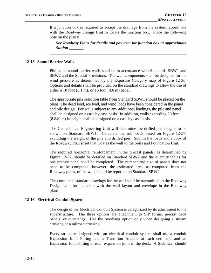
12-15 Sound Barrier Walls
Pile panel sound barrier walls shall be in accordance with Standards SBW1 and
SBW2 and the Special Provisions. The wall components shall be designed for the
wind pressure as determined by the Exposure Category map of Figure 12-36.
Options and details shall be provided on the standard drawings to allow the use of
either a 10 foot (3.1 m), or 15 foot (4.6 m) panel.
The appropriate pile selection table from Standard SBW1 should be placed on the
plans. The dead load, ice load, and wind loads have been considered in the panel
and pile design. For walls subject to any additional loadings, the pile and panel
shall be designed on a case by case basis. In addition, walls exceeding 29 feet
(8.840 m) in height shall be designed on a case by case basis.
The Geotechnical Engineering Unit will determine the drilled pier lengths to be
shown on Standard SBW1. Calculate the soil loads based on Figure 12-37,
excluding the weight of the pile and drilled pier. Submit the loads and a copy of
the Roadway Plan sheet that locates the wall to the Soils and Foundation Unit.
The required horizontal reinforcement in the precast panels, as determined by
Figure 12-37, should be detailed on Standard SBW2 and the quantity tables for
one precast panel shall be completed. The number and size of panels does not
need to be computed; however, the estimated area, as computed from the
Roadway plans, of the wall should be reported on Standard SBW2.
The completed standard drawings for the wall shall be transmitted to the Roadway
Design Unit for inclusion with the wall layout and envelope in the Roadway
plans.
12-16 Electrical Conduit System
The design of the Electrical Conduit System is categorized by its attachment to the
superstructure. The three options are attachment to SIP forms, precast deck
panels, or overhangs. Use the overhang option only when designing a stream
crossing or a railroad crossing.
Every structure designed with an electrical conduit system shall use a conduit
Expansion Joint Fitting and a Transition Adapter at each end bent and an
Expansion Joint Fitting at each expansion joint in the deck. A Stabilizer should

STRUCTURE DESIGN MANUAL CHAPTER 1
________________________________________________________________ PLAN PREPARATION
1–3
Substructure sheets show the layout of the end bents and bents in plan and elevation. See
Section 7 for detailed information.
1.3.6 Culverts
Culverts are structures typically used for short span stream crossings.
Culvert sheets show the culvert layout, plan and elevation views and a section through the
culvert barrel showing the reinforcing steel. Standard culvert wing walls are used whenever
possible. See Chapter 9 for detailed information.
1.3.7 Walls
Walls are typically designed to function as earth retaining structures or sound barriers.
1.3.7.1 Earth Retaining
The Roadway Design Unit establishes the location and limits of retaining walls. The
Geotechnical Engineering Unit recommends the earth retaining system which will be
employed and prepares the retaining wall plans. The plans typically show a plan view,
typical sections, details, notes and an elevation or profile view (wall envelope) of each wall.
Coordinate with the Geotechnical Engineering Unit to include retaining wall plans in the
structure plans, except when walls are the only structures on the project. In that case, the
Geotechnical Unit will coordinate with the Roadway Design Unit to include retaining wall
plans in the roadway plans.
1.3.7.2 Sound Barrier
The Roadway Design Unit establishes the location and limits of sound barrier walls. The
Structures Management Unit is responsible for preparing sound barrier wall plans. Use the
Sound Barrier Wall (SBW) standard drawings to prepare the plans. The Roadway Design
Unit will prepare the wall envelope, which is similar to that for retaining walls. The
Geotechnical Engineering Unit will provide sound barrier wall foundation
recommendations.
Coordinate with the Roadway Design and Geotechnical Engineering Units to include sound
barrier wall plans in the structure plans, except when walls are the only structures on the
project. In that case, coordinate with the Roadway Design Unit to include wall plans in the
roadway plans.

STANDARD NOISE WALL FOUNDATIONS

STATE OF NORTH CAROLINA
DEPARTMENT OF TRANSPORTATION BEVERLY EAVES PERDUE EUGENE A. CONTI, JR.
GOVERNOR SECRETARY
MAILING ADDRESS: NC DEPARTMENT OF TRANSPORTATION
GEOTECHNICAL ENGINEERING UNIT 1589 MAIL SERVICE CENTER RALEIGH NC 27699-1589
TELEPHONE: 919-707-6850 Fax: 919-250-4237
www.ncdot.gov/doh/preconstruct/highway/geotech
LOCATION: CENTURY CENTER COMPLEX
ENTRANCE B-2 1020 BIRCH RIDGE DRIVE
RALEIGH NC 27610
August 23, 2012 MEMORANDUM TO: Allen Raynor, P.E.
Assistant State Structures Engineer
Mohammed Mulla, P.E., C.P.M. Contracts and Statewide Services Manager
K. J. Kim, Ph.D., P.E. Eastern Regional Geotechnical Manager
John Pilipchuk, L.G., P.E. Western Regional Geotechnical Manager
FROM: Njoroge Wainaina, P.E. State Geotechnical Engineer SUBJECT: Standard Sound Barrier Wall Foundations The Technical Support Group of the Support Services Section of the Geotechnical Engineering Unit (GEU) has completed the new standard sound barrier wall foundations based on the 6th Edition of the AASHTO LRFD Bridge Design Specifications. These standard foundations update the current sound barrier wall foundation design from ASD to LRFD in accordance with new Section 15 entitled “Design of Sound Barriers” of the AASHTO LRFD specifications. Even though the Structures Management Unit (SMU) standard sound barrier wall panels are designed for 10 ft and 15 ft pile spacing, the standard sound barrier wall foundations are designed for variable pile spacing to allow for alternate panel types. The new standard sound barrier wall foundation tables are based on the following soil parameters, groundwater elevation and geometry.
• Friction angle (ϕ) = 30° or 34°, cohesion (c) = 0 psf and unit weight (γ) = 120 pcf, • Groundwater elevation below finished grade, • Front slope/finished grade 2:1 (H:V) or flatter, • Pile spacing ≤ 20 ft, • Wall height ≤ 25 ft and • Hole diameter = 36" or 30".
The standard foundation tables are also based on an assumed wind pressure of 40 psf per SMU. The SMU should incorporate the standard foundation tables into sound barrier wall plans as recommended by the GEU unless the standard sound barrier wall foundations are not applicable

August 23, 2012 Allen Raynor, P.E. Mohammed Mulla, P.E., C.P.M. K. J. Kim, Ph.D., P.E. John Pilipchuk, L.G., P.E. Page 2
MAILING ADDRESS: NC DEPARTMENT OF TRANSPORTATION
GEOTECHNICAL ENGINEERING UNIT 1589 MAIL SERVICE CENTER RALEIGH NC 27699-1589
TELEPHONE: 919-707-6850 Fax: 919-250-4237
www.ncdot.gov/doh/preconstruct/highway/geotech
LOCATION: CENTURY CENTER COMPLEX
ENTRANCE B-2 1020 BIRCH RIDGE DRIVE
RALEIGH NC 27610
and a site specific foundation design is required. The new standard sound barrier wall foundation tables and sound barrier wall foundation recommendations form memo are attached to this memorandum for your reference. If there are any questions, please contact Scott Hidden, P.E. at (919) 707-6856. Attachments: Standard Sound Barrier Wall Foundation Tables Sound Barrier Wall Foundation Recommendations Form Memo cc: Greg Smith, P.E., Traffic Noise & Air Quality Group Leader
Rodger Rochelle, P.E., Transportation Program Management Director Mike Robinson, P.E., State Bridge Construction Engineer

August 23, 2012 Allen Raynor, P.E. Mohammed Mulla, P.E., C.P.M. K. J. Kim, Ph.D., P.E. John Pilipchuk, L.G., P.E. Page 3
MAILING ADDRESS: NC DEPARTMENT OF TRANSPORTATION
GEOTECHNICAL ENGINEERING UNIT 1589 MAIL SERVICE CENTER RALEIGH NC 27699-1589
TELEPHONE: 919-707-6850 Fax: 919-250-4237
www.ncdot.gov/doh/preconstruct/highway/geotech
LOCATION: CENTURY CENTER COMPLEX
ENTRANCE B-2 1020 BIRCH RIDGE DRIVE
RALEIGH NC 27610
STANDARD SOUND BARRIER WALL FOUNDATION TABLES
(Pile Excavation Depths, “D” (ft) for 36" Dia. Hole; Add 1 ft to D for 30" Dia. Hole) Sound Barrier Wall Foundation Table No. 1 (𝜙 = 30°, c = 0 psf, 𝛾 = 120 pcf, groundwater between finished grade and bottom of hole with front slope/finished grade 6:1 or flatter or groundwater below bottom of hole with front slope/finished grade 2:1 or flatter and steeper than 3:1) –
Pile Spacing (S)
Wall Height (H) H ≤ 15 ft 15 ft < H ≤ 20 ft 20 ft < H ≤ 25 ft
S ≤ 10 ft 10 12 13 10 ft < S ≤ 15 ft 11 13 16 15 ft < S ≤ 20 ft 12 15 18
Sound Barrier Wall Foundation Table No. 2 (𝜙 = 30°, c = 0 psf, 𝛾 = 120 pcf, groundwater below bottom of hole with front slope/finished grade 3:1 or flatter and steeper than 6:1) –
Pile Spacing (S)
Wall Height (H) H ≤ 15 ft 15 ft < H ≤ 20 ft 20 ft < H ≤ 25 ft
S ≤ 10 ft 8 10 11 10 ft < S ≤ 15 ft 9 11 13 15 ft < S ≤ 20 ft 10 13 15
Sound Barrier Wall Foundation Table No. 3 (𝜙 = 30°, c = 0 psf, 𝛾 = 120 pcf, groundwater below bottom of hole with front slope/finished grade 6:1 or flatter) –
Pile Spacing (S)
Wall Height (H) H ≤ 15 ft 15 ft < H ≤ 20 ft 20 ft < H ≤ 25 ft
S ≤ 10 ft 7 9 10 10 ft < S ≤ 15 ft 8 10 12 15 ft < S ≤ 20 ft 9 11 13
Sound Barrier Wall Foundation Table No. 4 (𝜙 = 34°, c = 0 psf, 𝛾 = 120 pcf, groundwater between finished grade and bottom of hole with front slope/finished grade 6:1 or flatter or groundwater below bottom of hole with front slope/finished grade 2:1 or flatter and steeper than 3:1) –
Pile Spacing (S)
Wall Height (H) H ≤ 15 ft 15 ft < H ≤ 20 ft 20 ft < H ≤ 25 ft
S ≤ 10 ft 9 11 12 10 ft < S ≤ 15 ft 10 12 14 15 ft < S ≤ 20 ft 11 13 16
Sound Barrier Wall Foundation Table No. 5 (𝜙 = 34°, c = 0 psf, 𝛾 = 120 pcf, groundwater below bottom of hole with front slope/finished grade 3:1 or flatter and steeper than 6:1) –
Pile Spacing (S)
Wall Height (H) H ≤ 15 ft 15 ft < H ≤ 20 ft 20 ft < H ≤ 25 ft
S ≤ 10 ft 8 9 10 10 ft < S ≤ 15 ft 8 10 12 15 ft < S ≤ 20 ft 9 11 13
Sound Barrier Wall Foundation Table No. 6 (𝜙 = 34°, c = 0 psf, 𝛾 = 120 pcf, groundwater below bottom of hole with front slope/finished grade 6:1 or flatter) –
Pile Spacing (S)
Wall Height (H) H ≤ 15 ft 15 ft < H ≤ 20 ft 20 ft < H ≤ 25 ft
S ≤ 10 ft 7 8 9 10 ft < S ≤ 15 ft 7 9 11 15 ft < S ≤ 20 ft 8 10 12

NOISE WALL FOUNDATIONS RECOMMENDATIONS MEMO TEMPLATE

November 9, 2015 MEMORANDUM TO: Rick Nelson, P.E. Assistant State Structures Engineer ATTENTION: Structures Project Engineer, P.E. Structures Management Project Engineer FROM: John L. Pilipchuk, L.G., P.E. State Geotechnical Engineer STATE PROJECT: WBS El. # (TIP #) F. A. PROJECT: N/A COUNTY: County DESCRIPTION: Description SUBJECT: Sound Barrier Wall Foundation Recommendations The Geotechnical Engineering Unit (GEU) has received the following proposed sound barrier wall locations for the referenced project and recommends the following standard sound barrier wall foundation tables as shown:
Sound Barrier Wall No.
Begin Station & Offset
End Station & Offset
Standard Sound Barrier Wall Foundation Table No.
No. 1, 2, etc. 1, 2, 3, 4, 5 or 6 No. 1, 2, etc. 1, 2, 3, 4, 5 or 6
(List all sound barrier wall locations in table. Break up sound barrier walls into sections by station as needed for variable subsurface conditions and geometry. The standard sound barrier wall foundation tables are based on 36" dia. holes. For 30" dia. holes, add 1 ft to pile excavation depths (D) in standard foundation tables. The GEU recommends including the Continuous Flight Auger Piles for Sound Barrier Walls provision in the contract for the referenced project. (Optional) Please contact Primary Contact Name or Secondary Contact Name at Contact Telephone # if there are any questions concerning this memorandum.
State of North Carolina | Department of Transportation | Geotechnical Engineering Unit 1020 Birch Ridge Drive | 1589 Mail Service Center | Raleigh, NC 27699-1589
919 707 6850

November 9, 2015 WBS El. # (TIP #) Page 2
Design Engineer Name Design Engineer Title JLP/Design Engineer Initials Attachment: Continuous Flight Auger Piles for Sound Barrier Walls Provision (Optional)
PE #

PSP031 Noise Wall

SOUND BARRIER WALL (6-19-15)
1.0 DESCRIPTION
This work consists of furnishing precast panels, structural steel, concrete, and all other materials; handling, transporting, fabricating, galvanizing, and storing materials; furnishing erection drawings, pile excavation, backfilling, erecting and installing the sound barrier wall members and all other materials as required by the plans, Standard Specifications and this Special Provision.
The Standard Plans allow a pile spacing of 10, 15 or 20 feet. Pile spacing greater than 15 feet will not be allowed for standard precast concrete panels. Provide consistent pile spacing the entire length of the wall. Use odd pile spacing, if necessary, only at the ends of the wall and at turning points as approved by the Engineer.
A maximum one foot drop or rise in elevation between wall sections is permitted. Elevation changes greater than one foot, if necessary, will be allowed only at the end of the wall. Top of wall elevation changes that result in a jagged appearance will not be allowed.
2.0 ALTERNATE PILE SPACING FOR STANDARD PRECAST PANELS
As an alternate, the Contractor may submit plans for pile spacing greater than 10 feet and less than 15 feet for review and approval. The excavated diameter, excavation depth and reinforcing steel shall be equal to the amount shown on the existing plans for the 15 feet pile spacing. A variance in the reinforcing steel will be allowed for the length of horizontal and number of vertical reinforcement bars in the precast panel for the alternate pile spacing.
Submit two sets of detailed plans for review. Include all details in the plans, including the size and spacing of required reinforcement necessary to fabricate the precast panels. Have a North Carolina Registered Professional Engineer check, seal and date the plans. After the plans are reviewed and, if necessary, the corrections made, submit one set of reproducible tracings on 22” x 34” sheets to become part of the contract plans.
3.0 ALTERNATE WALL TYPE
Walls that have been assigned “Approved” or “Approved for Provisional Use” status by the Product Evaluation Program will be considered for substitution to the detailed Standard Sound Barrier Wall only when noted on the plans. Alternate wall types, piles and pile spacing must meet the design and construction requirements of the project. Pile spacing greater than 20 feet will not be permitted. Alternate pile and wall structural stability and connection details shall conform to the current edition of the AASHTO LRFD Bridge Design Specifications.
Prior to submittal of Working Drawings, as described herein, submit a copy of the signed NCDOT Product Status Notification Letter and two sets of preliminary plans for review and approval. Include material specifications for all components. Once preliminary plans
1

are approved, submit Working Drawings in accordance with all applicable portions of the requirements herein, including details necessary to fabricate and construct the proposed alternate.
Have a North Carolina Registered Professional Engineer check, seal and date the plans and, when requested, calculations. After the plans are reviewed and, if necessary, corrections made, submit one set of reproducible tracings on 22” x 34” sheets to become part of the contract plans.
4.0 MATERIALS AND FABRICATION OF STANDARD PRECAST PANELS
Provide materials and fabricate members in accordance with the requirements of Division 10 of the Standard Specifications for Roads and Structures.
Provide precast panels that are 4 inches ± ¼ inch thick with an exposed aggregate finish on one face. The panel face with the aggregate finish shall be installed facing the roadway. The depth of the exposure is required to range from 0 to ¼ inch. Furnish three 12" x 12" samples for approval which establish the acceptable variations in color, texture, and uniformity. After the color, texture, and uniformity of the furnished samples are approved, produce a full scale panel unit meeting design requirements. This mock-up and the furnished samples establish the standard quality for determining acceptance of the panels. When producing the final installed panels, use fine and coarse aggregate, retarder, and cement from the same source as those used in the approved sample panels.
5.0 CONSTRUCTION METHODS
Complete the final survey of existing ground profile after clearing the wall area but prior to submitting any working drawings. Submit the final groundline survey with the working drawings.
If the Department is responsible for the survey, the Engineer field verifies the existing ground profile along the sound barrier wall. Contact the Engineer to obtain the survey information. Otherwise, complete the existing ground survey prior to submittal of working drawings.
Excavate holes with the diameters shown on the plans. Perform pile excavation to the depths shown on the plans and install piles as shown on the plans or in the accepted submittals with a tolerance of 1/2 inch per foot from vertical. Backfill excavations with concrete after placing piles.
A. Pile Excavation
Use equipment of adequate capacity and capable of drilling through soil and non-soil including rock, boulders, debris, man-made objects and any other materials encountered. Blasting is not permitted to advance the excavation. Blasting for core removal is only permitted when approved by the Engineer. Dispose of drilling spoils in accordance with Section 802 of the Standard Specifications and as directed by the
2

Engineer. Drilling spoils consist of all excavated material including water removed from the excavation either by pumping or drilling tools.
If unstable, caving or sloughing soils are anticipated or encountered, stabilize excavations with either slurry or steel casing. When using slurry, submit slurry details including product information, manufacturer’s recommendations for use, slurry equipment information and written approval from the slurry supplier that the mixing water is acceptable before beginning drilling. When using steel casing, use either the sectional type or one continuous corrugated or non-corrugated piece. Steel casings should consist of clean watertight steel of ample strength to withstand handling and driving stresses and the pressures imposed by concrete, earth or backfill. Use steel casings with an outside diameter equal to the hole size and a minimum wall thickness of 1/4 inch.
B. Concrete Placement
Before placing concrete, center and support the pile in the excavation and check the water inflow rate in the excavation after any pumps have been removed. If the inflow rate is less than 6 inches per half hour, remove any water and free fall the concrete into the excavation. Ensure that concrete flows completely around the pile. If the water inflow rate is greater than 6 inches per half hour, propose a concrete placement procedure to the Engineer. The Engineer shall approve the concrete placement procedure before placing concrete.
Fill the excavation with Class A concrete in accordance with Section 1000 of the Standard Specifications except as modified herein. Provide concrete with a slump of 6 to 8 inches. Use an approved high-range water reducer to achieve this slump. Place concrete in a continuous manner and remove all casings.
6.0 WORKING DRAWINGS
Submit casting drawings for the precast face panels for approval in accordance with Article 1077-2 of the Standard Specifications prior to casting. Show the inserts, method of handling, and support details used for transportation on casting drawings. Submit metalwork fabrication drawings for approval prior to fabrication of steel wall components. Submit an erection plan and concrete face panel placing plan, including location of various heights of panels, for review and acceptance prior to fabrication of metalwork. Submit five sets of detail drawings.
7.0 METHOD OF MEASUREMENT
The quantity of sound barrier wall to be paid will be the actual square feet of completed and accepted wall. In any individual section of sound barrier wall or in comparably dimensioned sections, the wall height is from the bottom of the bottom panel to the top of the top panel and the width is the distance between the centerline of the piles at the ends of the section. Include the full width of the piles at the ends of the wall.
3

8.0 BASIS OF PAYMENT
The quantity of sound barrier wall, measured as provided above, will be paid for at the contract unit price bid per square foot for “Sound Barrier Wall”.
The unit price bid per square foot will be full compensation for all work covered by this Special Provision including, but not limited to, furnishing precast panels, steel or concrete piles, miscellaneous structural steel, concrete, and all other materials; handling, transporting, fabricating, galvanizing, and storing materials; furnishing erection drawings, backfilling, pile excavation including any casing or slurry, and erecting and installing the sound barrier wall members.
Payment will be made under:
Sound Barrier Wall .................................................................................. Square Foot
4