nc bsi tool esigner - blanking systems1 bsi tool designer program user manual 1—2 working in...
TRANSCRIPT

Wor
k in
pro
gres
s fo
r In
form
atio
nal P
urpo
ses
Onl
y. R
epro
duct
ion
Pro
hibi
ted
with
out t
he E
xpre
ss W
ritte
n P
erm
issi
on o
f the
Pub
lishe
r—B
lank
ing
Sys
tem
s, In
c.
Version 0.9Note, this is a draft manual only, not the final copy.
This version may not reflect recent enhancements to the software.
BLANKING SYSTEMS, INC.
BLANKING DESIGN PROGRAMBSI TOOL DESIGNER
TM
USER’S MANUALUSER’S MANUAL
BLANKING SYSTEMS, INC.TEL 262 377-3591 • FAX 262 387-12021058 Overland CourtGrafton, WI 53024-1194 • USABSI

Wor
k in
pro
gres
s fo
r In
form
atio
nal P
urpo
ses
Onl
y. R
epro
duct
ion
Pro
hibi
ted
with
out t
he E
xpre
ss W
ritte
n P
erm
issi
on o
f the
Pub
lishe
r—B
lank
ing
Sys
tem
s, In
c.
BSI Tool DesignerCopyright and Trademark Information
Conceived & Distributed by:
BLANKING SYSTEMS, INC.1058 Overland CrtGrafton, WI 53024-1194 • USATEL 262 377-3591 • FAX 262 387-1202
BSI Tool Designer™ and BSI-TD™ are trademarks of Blanking Systems, Inc., all rightsreserved.
The BSI Tool Designer program is © copyright Blanking Systems, Inc., 2002 onward, allrights reserved. The software and documentation are licensed to the user as per licenserestrictions distributed with the software and the copyright remains with Blanking Systems,Inc. No duplication of the software other than for internal archival data protection backuppurposes is permitted. Duplication and “sharing” of software is expressly prohibited and maybe a violation of copyright and software protection laws.
This documentation is © copyright Blanking Systems, Inc., 2002 onward, all rights reserved.No duplication in any form, print, electronic, or otherwise is permitted without the expresswritten consent of the copyright owner, Blanking Systems, Inc.
Programming by:
ENGINEERING DESIGN AUTOMATION , INC.TEL 360 398-1319 • FAX 360 398-1320234 Kelly RoadBellingham, WA 98226 • USAEMAIL [email protected] http://www.edainc.net/

Wor
k in
pro
gres
s fo
r In
form
atio
nal P
urpo
ses
Onl
y. R
epro
duct
ion
Pro
hibi
ted
with
out t
he E
xpre
ss W
ritte
n P
erm
issi
on o
f the
Pub
lishe
r—B
lank
ing
Sys
tem
s, In
c.TABLE OF CONTENTS
CHAPTER 1Blanking Automation . . . . . . . . . . . . . . . . . . . . . . . . . . . . . . . . . . . . . . . . . 1-2Preface . . . . . . . . . . . . . . . . . . . . . . . . . . . . . . . . . . . . . . . . . 1-3System Requirements . . . . . . . . . . . . . . . . . . . . . . . . . . . . . . . . . . . . . . . . . 1-4Installation . . . . . . . . . . . . . . . . . . . . . . . . . . . . . . . . . . . . . . . . . 1-5Program Basics . . . . . . . . . . . . . . . . . . . . . . . . . . . . . . . . . . . . . . . . . 1-8Bender Software . . . . . . . . . . . . . . . . . . . . . . . . . . . . . . . . . . . . . . . . . 1-9Terms and Program Layout . . . . . . . . . . . . . . . . . . . . . . . . . . . . . . . . . . . . . . . . . 1-10Tool Bar Functions Chart . . . . . . . . . . . . . . . . . . . . . . . . . . . . . . . . . . . . . . . . . 1-14
CHAPTER 2Overview of Blanking Systems . . . . . . . . . . . . . . . . . . . . . . . . . . . . . . . . . . . . . . . . . 2-2Getting Started . . . . . . . . . . . . . . . . . . . . . . . . . . . . . . . . . . . . . . . . . 2-3Backups . . . . . . . . . . . . . . . . . . . . . . . . . . . . . . . . . . . . . . . . . 2-6Document Properties . . . . . . . . . . . . . . . . . . . . . . . . . . . . . . . . . . . . . . . . . 2-6Opening & Saving Documents . . . . . . . . . . . . . . . . . . . . . . . . . . . . . . . . . . . . . . . . . 2-7
CHAPTER 3CAD Functions . . . . . . . . . . . . . . . . . . . . . . . . . . . . . . . . . . . . . . . . . 3-2 Changing Views . . . . . . . . . . . . . . . . . . . . . . . . . . . . . . . . . . . . . . . . . 3-3 Snap Functions . . . . . . . . . . . . . . . . . . . . . . . . . . . . . . . . . . . . . . . . . 3-4 Distance, & List Functions . . . . . . . . . . . . . . . . . . . . . . . . . . . . . . . . . . . . . . . . . 3-5 Editing Components . . . . . . . . . . . . . . . . . . . . . . . . . . . . . . . . . . . . . . . . . 3-6
CHAPTER 4Creating Blanking Tools . . . . . . . . . . . . . . . . . . . . . . . . . . . . . . . . . . . . . . . . . 4-2Lower Tool Frame Group . . . . . . . . . . . . . . . . . . . . . . . . . . . . . . . . . . . . . . . . . 4-4Lower Tool Grid Group . . . . . . . . . . . . . . . . . . . . . . . . . . . . . . . . . . . . . . . . . 4-7Standard & Bent Grid Bars . . . . . . . . . . . . . . . . . . . . . . . . . . . . . . . . . . . . . . . . . 4-9Partial Grid bars . . . . . . . . . . . . . . . . . . . . . . . . . . . . . . . . . . . . . . . . . 4-11Lower Tool Grid Attachments . . . . . . . . . . . . . . . . . . . . . . . . . . . . . . . . . . . . . . . . . 4-12Lower Tool Frame Attachments . . . . . . . . . . . . . . . . . . . . . . . . . . . . . . . . . . . . . . . . . 4-13Lower Tool Board Group . . . . . . . . . . . . . . . . . . . . . . . . . . . . . . . . . . . . . . . . . 4-15Drop Guide Joggers, Upper Tool Board . . . . . . . . . . . . . . . . . . . . . . . . . . . . . . . . . . . . . . . . . 4-16Presser Rails . . . . . . . . . . . . . . . . . . . . . . . . . . . . . . . . . . . . . . . . . 4-20
CHAPTER 5Program Output . . . . . . . . . . . . . . . . . . . . . . . . . . . . . . . . . . . . . . . . . 5-2Emailing Files . . . . . . . . . . . . . . . . . . . . . . . . . . . . . . . . . . . . . . . . . 5-4
APPENDIXGlossary of Blanking Terms . . . . . . . . . . . . . . . . . . . . . . . . . . . . . . . . . . . . . . . . . A-2Icon/Keyboard Equivalents . . . . . . . . . . . . . . . . . . . . . . . . . . . . . . . . . . . . . . . . . A-6
INDEXIndex . . . . . . . . . . . . . . . . . . . . . . . . . . . . . . . . . . . . . . . . . I-2

1
BSI TOOL DESIGNER PROGRAM USER MANUAL 1–1
Wor
king
in P
rogr
ess
for
Info
rmat
iona
l Pur
pose
s O
nly.
Rep
rodu
ctio
n P
rohi
bite
d w
ithou
t the
Exp
ress
Writ
ten
Per
mis
sion
of t
he P
ublis
her—
Bla
nkin
g S
yste
ms,
Inc.
CHAPTER
BLANKING AUTOMATION
PREFACE
INSTALLATION
PROGRAM BASICS
TOOLBAR ICONS
1
BSI TOOL DESIGNER PROGRAM USER MANUAL 1–2
Wor
king
in P
rogr
ess
for
Info
rmat
iona
l Pur
pose
s O
nly.
Rep
rodu
ctio
n P
rohi
bite
d w
ithou
t the
Exp
ress
Writ
ten
Per
mis
sion
of t
he P
ublis
her—
Bla
nkin
g S
yste
ms,
Inc.
THE BENEFITSOF BSI-TDSOFTWARE
AUTOMATION
BLANKING AUTOMATIONA Revolution in Design, Setup, and Repeatabilityfor Blanking Stations
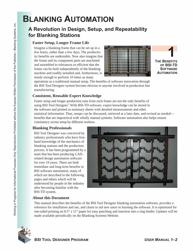
Faster Setup, Longer Frame LifeImagine a blanking frame that can be set up in afew hours, rather than a few days. The productiv-ity benefits are undeniable. Now also imagine thatthe frame and its component parts are machinedand assembled to tolerances so efficient that theframe can be built independently of the blankingmachine and readily installed and, furthermore, issturdy enough to perform 10 times as manyoperations as a traditional manual setup. The benefits of software innovation throughthe BSI Tool Designer system become obvious to anyone involved in production linemanufacturing.
Consistent, Reusable Expert KnowledgeFaster setup and longer production runs from each frame are not the only benefits ofusing BSI Tool Designer™. With BSI-TD software, expert knowledge can be stored inthe software and printed as summary sheets with detailed measurements and otherstatistical information. Thus, setups can be discussed, retrieved at a later date, and revised as needed—benefits that are impractical with wholly manual systems. Software automation also helps ensureconsistency across setup by different workers.
Blanking ProfessionalsBSI Tool Designer was conceived byindustry professionals who have first-hand knowledge of the mechanics ofblanking stations and the productionprocess. It has been programmed by ateam that has been producing CAD-related design automation softwarefor over 19 years. There are bothimmediate and long-term benefits inBSI software automation, many ofwhich are described in the followingpages and others which will beunderstood by people in the industryafter becoming familiar with theBSI-TD system.
About this DocumentThis manual describes the benefits of the BSI Tool Designer blanking automation software, provides areference for installation and use, and charts to aid new users in learning the software. It is optimized forone-sided printing on 8.5” x 11” paper for easy punching and insertion into a ring binder. Updates will bemade available periodically on the Blanking Systems Website.

1
BSI TOOL DESIGNER PROGRAM USER MANUAL 1–3
Wor
king
in P
rogr
ess
for
Info
rmat
iona
l Pur
pose
s O
nly.
Rep
rodu
ctio
n P
rohi
bite
d w
ithou
t the
Exp
ress
Writ
ten
Per
mis
sion
of t
he P
ublis
her—
Bla
nkin
g S
yste
ms,
Inc.
PREFACEIntroduction
A blanking system is a production line innovation that automates volume blankpunching processes for a wide variety of products.
Blanking is a step in the die-cutting process in which predefined patterns arepunched from a die-perforated material as it passes through the blanking station.Whether the blanking stencil is simple or complex, with single or multiple similar ordissimilar shapes, the initial setup of the station for maximum efficiency is the key torunning production jobs and controlling individual job costs and overall plantoperations. Thus, it is economically important to set up the blanking system well thefirst time, with good structural balance of the mechanical parts to support and punchmaterials. From a plant efficiency standpoint, it’s best to run the job with as fewchanges to the machine setup as possible. Working out the parameters in advance canhelp accomplish this goal.
The Importance of Software AutomationBlanking Station ConfigurationA blanking station has a number of structural elements including the frame, grid bars,tool board, pushers, etc. These can be arranged in different ways for a particularproject. Whether the configuration is practical is difficult to determine before it has been seen and tested.If the desired result isn’t achieved the first time, the mechanical parts can be moved and realigned but,with a complex pattern, this is a time-consuming and expensive process.
Software streamlines the design and setup of the blanking station by modeling the parts visually andmathematically before the blanking system is physically configured. Through software, a user can trydifferent positions and patterns before mechanically adjusting the blanking machine or fabricating thetool board stencils. Tooling accuracy is also improved.
Design AutomationDesign automation is the essence of the BSI Tool Designer (BSI-TD) software. It expedites and en-hances the blanking design process in ways that are impossible through reconfiguration of the physicalmechanisms of the machine alone. There are many advantages to using the BSI-TD software system:
• When blanking designs are executed through software, the blanking machine is freed up to processexisting jobs. As a job is running on the physical machine, software blanking configurations forfuture projects can be set up, ready to go when the machine is free.
• Specialists and supervisors can readily discuss the configuration with blanking designers before thedesign is mechanically implemented. Printouts of parts lists, summaries, and the visual configurationof the blanking setup facilitate this process.
• The flexible positioning and repositioning of joggers, grid bars, and other typical part componentsrelated to the frame can be displayed and stored in a computer file as a “blueprint”. The stored filecan then be used to rerun the job at a later date or as a timesaving template if similar jobs arerequested that might require only minor revisions to existing blanking files.
• The design of the grid bar configuration or tool board support structures and their setup takes on anew dimension when carried out with blanking design software. Some setups can be quite complex.BSI-TD automation software readily enables different tool design support structures and stencilscenarios to be explored within the software or printed for later consultation and selection, beforesetting up the actual machine. It also results in sturdier frame setups that last longer.
INTRODUCTION
BLANKINGSTATION
CONFIGURATION
DESIGNAUTOMATION

1
BSI TOOL DESIGNER PROGRAM USER MANUAL 1–4
Wor
king
in P
rogr
ess
for
Info
rmat
iona
l Pur
pose
s O
nly.
Rep
rodu
ctio
n P
rohi
bite
d w
ithou
t the
Exp
ress
Writ
ten
Per
mis
sion
of t
he P
ublis
her—
Bla
nkin
g S
yste
ms,
Inc.
• The creation of mathematically accurate templates for tool boards is assured asthe designs are stored as computer files that can be downloaded directly to alaser board cutting machine for accurate implementation.
Thus, BSI-TD takes blanking systems to a new level of productivity by automatingthe design process on a computer workstation and thus freeing up expensive blankingmachine time. It also maintains checks and balances on the user’s progress byreporting on the process as the blanking configuration is designed. Examples ofinformation that is supplied to the user that would not be conveyed by a mechanicalsetup alone include:
• Measurement statistics. Distance and positional statistics may be displayed onthe screen, or in some cases, printed at the user’s discretion.
• Interactive problem reporting. In many cases, the software provides warningswhen the user tries to insert inappropriate parts or combinations of parts, orworks outside the active region, or tries to insert parts in the wrong order.
• Interactive error reporting. The software often provides immediate error report-ing feedback, informing the user that he or she has raised inappropriate dimen-sions, positions, or attributes.
Thus, software blanking setup and tool board stencil design and manufacture can besignificantly enhanced with design automation software. BSI-TD adds an extradimension of expert-level knowledge that cannot be realized with mechanical-onlysystems. It improves consistency across different operators and can even improve theskills and knowledge of the blanking designer who uses the software by interactivelyreporting on individual setup parameters as the setup is designed.
Contents of the BSI Tool Designer ManualThis manual introduces the BSI-TD software and explains installation, system requirements, interfaceconventions, and operating parameters to give the user an example of a real-life blanking design project.Commonly-used commands are listed in the Appendix and the Index gives a quick reference to specifictopics.
Intended Users and User InteractionThe BSI-TD software and manual is designed for use by anyone with basic computer skills and a basicunderstanding of blanking frame design, setup, and production. Familiarity with CAD-type softwareprograms is also beneficial.
Getting StartedIt is recommended that the user read through the entire manual once. Then install the software and workthrough the short examples to become familiar with the software’s interface and capabilities. Thereafter,the manual can be used as a reference and refresher as the user becomes conversant with the program. Itmay be helpful to photocopy the keyboard shortcuts in the Appendix onto card stock to put next to thecomputer until common commands become familiar.
System RequirementsTool Designer can run on Windows-based computers, but will perform better on Windows XP and 2000systems. Minimum requirements are 500 MHz/256 MB RAM, but 2 Gigabyte/512 MB systems willprovide enhanced performance. Tool Designer works well in conjunction with die layout software thatcreates DDES files for carton stencil layouts.
MANUALCONTENTS
INTENDEDUSERS
GETTINGSTARTED
SYSTEMREQUIREMENTS

1
BSI TOOL DESIGNER PROGRAM USER MANUAL 1–5
Wor
king
in P
rogr
ess
for
Info
rmat
iona
l Pur
pose
s O
nly.
Rep
rodu
ctio
n P
rohi
bite
d w
ithou
t the
Exp
ress
Writ
ten
Per
mis
sion
of t
he P
ublis
her—
Bla
nkin
g S
yste
ms,
Inc.
INSTALLATIONInstallation is straightforward, with an install utility included on the CD to facilitatethe process. If you are downloading ToolDesigner from the Web, follow the stepssummarized below. Both processes are the same once you can access the installutility on your desktop.
A. Web Installation1. Make sure your chosen Web browser is running and your password is handy Ifyou don’t have an assigned password, you can apply through the Web site as de-scribed below.
2. In either case, point your browser to the BSI Website located athttp://www.blankingsystems.com/ . You may wish to look around the site to familiar-ize yourself with information related to the program, including bulletins, updates,links to related sites, etc.
3. From the Blanking Systems home page, select Products in thetop menu bar then click on the icon labeled BSI Tool DesignerSoftware downloads to go to http://www.blankingsystems.com/AboutDownloads.aspx (note that file and directory names in thebrowser are case sensitive). The downloads information pageincludes notes about the current version of Tool Designer, a down-loadable PDF version of the manual, and a link to the BSI video.When you are ready to continue, click on the Go to Downloads link.
4. The downloads page will prompt you foryour email address and password. The passwordis provided by Blanking Systems and enables youto download a fully functional trial version thatyou may use for 60 days. If you don’t have a
INSTALLATION

1
BSI TOOL DESIGNER PROGRAM USER MANUAL 1–6
Wor
king
in P
rogr
ess
for
Info
rmat
iona
l Pur
pose
s O
nly.
Rep
rodu
ctio
n P
rohi
bite
d w
ithou
t the
Exp
ress
Writ
ten
Per
mis
sion
of t
he P
ublis
her—
Bla
nkin
g S
yste
ms,
Inc.
password, click the password application link. This takesyou to a form where you can fill out your name andaddress to request a password.
5. After typing your email address and password, pressthe Login button and download Tool Designer to yourlocal computer. From this point on, except for insertingthe CD, the installation instructions for Web Installationand CD Installation are the same.
B. CD Installation1. Insert the Tool Designer compact disc in your CD drive. It is advisable to close
all other applications before continuing.
2. When the CD install icon appears, double-click it. An information boxwill appear, followed by the Welcome box (cancel and relaunch if youstill have other programs running). Read the instructions in the win-dow, then click Next > to move on.
3. Tool Designer specifies a default Destination Folder, if this folder isappropriate, click Next >, if not, use Browse... to select another folder.
4. A dialog box will prompt you to specify a Program Manager group. This estab-lishes the Program Group from which Tool Designer runs via Windows’s startmenu. In the example below, the CAD group was selected as the destination.
5. When installation is finished, you will be informed of its success and promptedto press Finish > to exit the installation utility. If you have difficulty installing the software, makesure the folder permissions are set properly. If you don’t have authority to install the software onyour local machine, consult your system administrator for assistance.
WEB & CDINSTALLATION
1
2 3 4
5

1
BSI TOOL DESIGNER PROGRAM USER MANUAL 1–7
Wor
king
in P
rogr
ess
for
Info
rmat
iona
l Pur
pose
s O
nly.
Rep
rodu
ctio
n P
rohi
bite
d w
ithou
t the
Exp
ress
Writ
ten
Per
mis
sion
of t
he P
ublis
her—
Bla
nkin
g S
yste
ms,
Inc.
C. Registering the Trial VersionWhen you have tried Tool Designer and aresatisfied that you want to purchase the product,you will need an authorization code from BSI toupgrade the trial copy to a registered copy.
To do this, run Tool Designer and selectHelp>Run Authorization Program. You willbe warned that any currently loaded drawing projects will be lost. If you need to savethe project before entering the authorization code, select No to exit. Then save theproject and run the authorization utility again.
The authorization utility will warn you that drawing changes will be lost if theyhave not been saved before entering the authorization code. If necessary, exit,save changes, then run the utility again. When you are ready, select Yes toadvance to the next window. Here you can add or change the organizationname and enter the authorization code. It is important that you enter theauthorization correctly or the software will exit upon opening and you may haveto download another trial version.
If you are communicating with BSI by phone, it is advisable to run the programafter entering the authorization before ringing off, to make sure a validauthorization was used before ringing off. If, for any reason, the program doesnot run or you receive an error message stating that the code is invalid, it willbe best to sort out the problem right away. When you are ready to proceed,click OK to re-enter the correct code. When the code has been successfullyentered, run the Tool Designer software.
Once a valid authorization has been entered, Tool Designer will stop counting down the days until thetrial expires and will run without the Trial Version notice.
Note: A USB hardware lock will be shipped to customers who purchase the BSI software. You can stilldownload and test drive the trial version prior to registering the product and USB lock.
REGISTERINGTHE TRIAL
VERSION
1
BSI TOOL DESIGNER PROGRAM USER MANUAL 1–8
Wor
king
in P
rogr
ess
for
Info
rmat
iona
l Pur
pose
s O
nly.
Rep
rodu
ctio
n P
rohi
bite
d w
ithou
t the
Exp
ress
Writ
ten
Per
mis
sion
of t
he P
ublis
her—
Bla
nkin
g S
yste
ms,
Inc.
PROGRAM BASICSWhat is BSI Tool Designer?
BSI Tool Designer (BSI-TD) is a specialized CAD-based application that makes iteasy to manipulate files created by die-layout design programs. With BSI-TD, a usercan readily create a blanking tool based upon a specific die-layout file.
More than just a design and parts assembly program, the BSI-TD program creates aCAD drawing and bending instructions for grid bars and presser rails and generatesoutput files for laser and CNC router machines. It keeps track of all the componentsused to design the blanking tool (and their pricing) and further provides a PartSummary Report that lists all drawing components and their total cost.
This section introduces the basic concepts associated with Tool Designer. When youare ready to use the software, turn to the Getting Started section in Chapter 2.
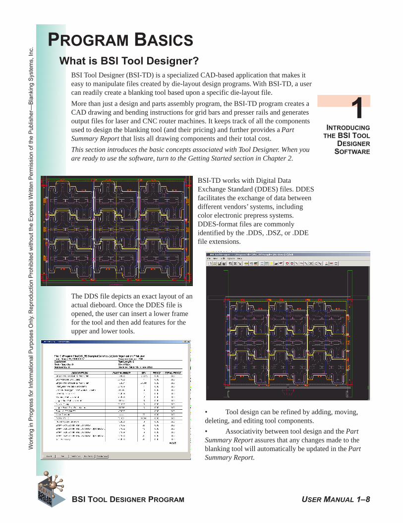
BSI-TD works with Digital DataExchange Standard (DDES) files. DDESfacilitates the exchange of data betweendifferent vendors’ systems, includingcolor electronic prepress systems.DDES-format files are commonlyidentified by the .DDS, .DSZ, or .DDEfile extensions.
The DDS file depicts an exact layout of anactual dieboard. Once the DDES file isopened, the user can insert a lower framefor the tool and then add features for theupper and lower tools.
• Tool design can be refined by adding, moving,deleting, and editing tool components.
• Associativity between tool design and the PartSummary Report assures that any changes made to theblanking tool will automatically be updated in the PartSummary Report.
INTRODUCINGTHE BSI TOOL
DESIGNERSOFTWARE
1
BSI TOOL DESIGNER PROGRAM USER MANUAL 1–9
Wor
king
in P
rogr
ess
for
Info
rmat
iona
l Pur
pose
s O
nly.
Rep
rodu
ctio
n P
rohi
bite
d w
ithou
t the
Exp
ress
Writ
ten
Per
mis
sion
of t
he P
ublis
her—
Bla
nkin
g S
yste
ms,
Inc.
EXPORTING TOBENDER
SOFTWARE
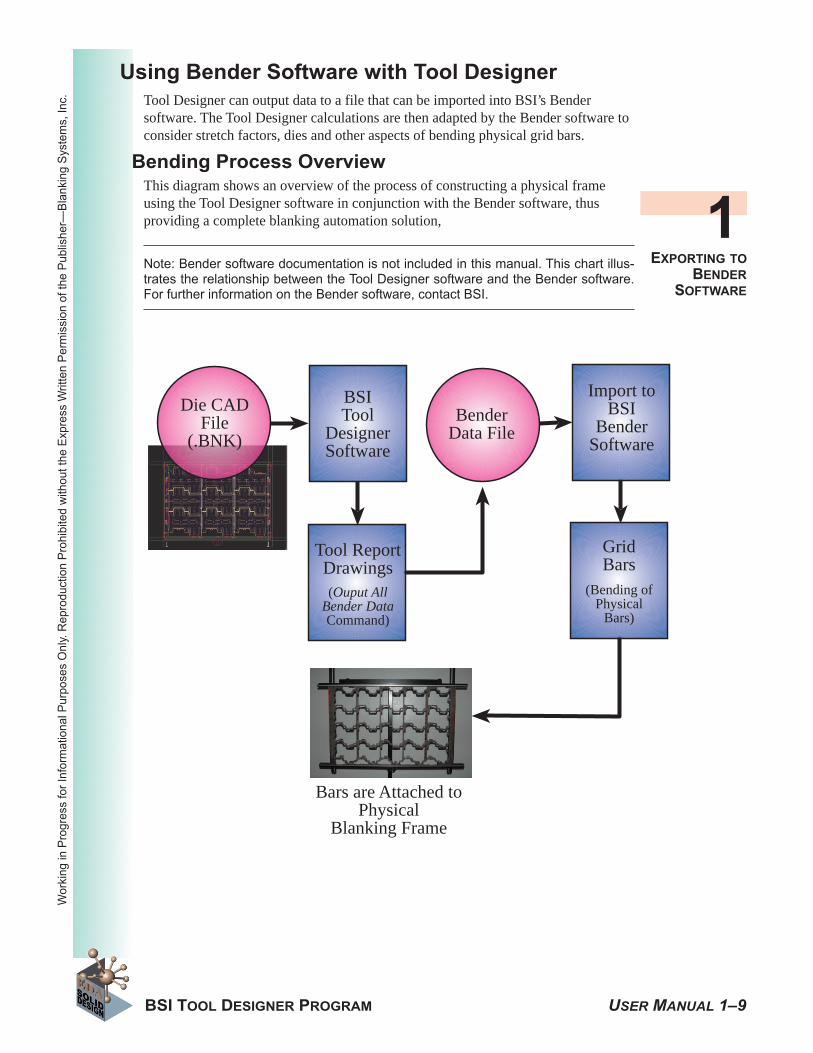
Using Bender Software with Tool DesignerTool Designer can output data to a file that can be imported into BSI’s Bendersoftware. The Tool Designer calculations are then adapted by the Bender software toconsider stretch factors, dies and other aspects of bending physical grid bars.
Bending Process OverviewThis diagram shows an overview of the process of constructing a physical frameusing the Tool Designer software in conjunction with the Bender software, thusproviding a complete blanking automation solution,
Note: Bender software documentation is not included in this manual. This chart illus-trates the relationship between the Tool Designer software and the Bender software.For further information on the Bender software, contact BSI.
Die CADFile
(.BNK)
BSITool
DesignerSoftware
Tool ReportDrawings(Ouput All
Bender DataCommand)
Import toBSI
BenderSoftware
GridBars
(Bending ofPhysical
Bars)
BenderData File
Bars are Attached toPhysical
Blanking Frame

1
BSI TOOL DESIGNER PROGRAM USER MANUAL 1–10
Wor
king
in P
rogr
ess
for
Info
rmat
iona
l Pur
pose
s O
nly.
Rep
rodu
ctio
n P
rohi
bite
d w
ithou
t the
Exp
ress
Writ
ten
Per
mis
sion
of t
he P
ublis
her—
Bla
nkin
g S
yste
ms,
Inc.
BSI-TD TERMS AND LAYOUTThis section describes BSI-TD’s practical, intuitive layout and basic terms related tothe program. More detailed concepts and interactive capabilities are explained inlater chapters. Chapter 2, for example, will take you through the basic program steps.
BSI-TD’s graphical interface displays information about drawing files and lets theuser interact with the program with a mouse or other pointing/selection tool tochange settings and access drawing manipulation functions.
IntroductionThere are three basic categories of information provided in a BSI-TD window:
A. Information and Status DisplaysB. Interactive Buttons and ToolsC. The Drawing View
Note: In the context of the BSI-TD program, the term item[s] usually refers to lines,arcs, or circles and parts or components are objects (clamps, joggers, etc.) that com-prise the blanking tool.
A. Information and Status DisplaysThe status, function, or format of a command or file is displayed by the applicationin designated regions such as the title bar, status bar, or mouse text box (these areillustrated in Section C. Drawing View). Status displays cannot be directly modified by the user.
B. Interactive Buttons and ToolsA variety of powerful drawing manipulation tools enables the user to change program settings anddrawing parameters and to load or save files. Interactive interface options include: a) drop-down menus,b) buttons, c) selectable components from the parts bar, and d) context-sensitive right-mouse popupmenus.
Functions can be selected as desired using the input device from either the drop-down menu or equiva-lent icons in the tool bar menu. For convenience and speed, some menu functions can also be accessedwith keyboard shortcuts.
Note: Mouse text provides quick help when you are learning to use BSI-TD. It is a status display associatedwith specific parts, interactive buttons, or tools.
To view mouse text for a button on the toolbar (e.g., the Components tool icon), hover the pointer over theregion of interest without clicking (left diagram). The cursor will change to a tool tip and a popup informationbox will appear (right diagram), identifying the part with a name that is similar to that used in the drop-downmenu. Mouse text is usually brief, but sometimes includes extra information, such as instructions on how tocomplete a particular command (e.g., filleting lines).
BSI-TD TERMS& LAYOUT
INFORMATION &STATUS
DISPLAYS
INTERACTIVEBUTTONS &
TOOLS

1
BSI TOOL DESIGNER PROGRAM USER MANUAL 1–11
Wor
king
in P
rogr
ess
for
Info
rmat
iona
l Pur
pose
s O
nly.
Rep
rodu
ctio
n P
rohi
bite
d w
ithou
t the
Exp
ress
Writ
ten
Per
mis
sion
of t
he P
ublis
her—
Bla
nkin
g S
yste
ms,
Inc.
Right-Mouse Button MenusWhether you are placing, deleting, or editing parts, or just changing views in the ToolDesigner document, you always have access to appropriate tools and commandsfrom the right-mouse menu. The right-mouse menus are separate from the drop-down menus along the top of the BSI-TD window. They appear near the cursor whenthe right mouse button is clicked. View manipulation, snap control, and context-sensitive component operations can be accomplished with right-mouse menu com-mands.
A popup menu (and any associated submenus) will appear near the cursor when theright-mouse button is clicked in the graphics window. This provides easy access to functionsassociated with the current selected component (which is usually highlighted). Functionsthat are not currently active (as when no drawing is loaded) will be ghosted (dimmed).
C. Drawing ViewThe drawing display region shows the user the structure and form of blanking files (identified with the.BNK file extension) and enables drawing parameters to be changed. The display region for the drawingfiles is similar to that of popular CAD programs except that the window is used to drop in predefinedparts from the Part Selection Bar, rather than creating components from scratch.
1. Title Bar2. Menu Bar3. Tool Bar4. Graphics Window
5. Crosshair Cursor
1. Status Bar
7. Part Selection Bar
7a.Parts Grouping Drop-down List
7b.Part Selection Window
BSI-TD has a graphical interface that includes status regions, interactive drop-down menus,tool icons, a drawing display region, and a location/selection cursor.
The above diagram shows the basic layout of the BSI-TD program, with introductory descriptions of theindividual regions. More in-depth discussions of program capabilities are included in later chapters.
RIGHT MOUSEMENUS
DRAWING VIEW

1
BSI TOOL DESIGNER PROGRAM USER MANUAL 1–12
Wor
king
in P
rogr
ess
for
Info
rmat
iona
l Pur
pose
s O
nly.
Rep
rodu
ctio
n P
rohi
bite
d w
ithou
t the
Exp
ress
Writ
ten
Per
mis
sion
of t
he P
ublis
her—
Bla
nkin
g S
yste
ms,
Inc.
There are status and interactive regions of interest in the top left corner of the BSI-TDprogram window, in particular, the Title Bar, Menu Bar, Tool Bar, and Graphics Window.
1. Title BarThe title bar is a status bar that provides basic information about the window inwhich the BSI-TD application is running, including the file name and path of thecurrently active blanking file.
2. Menu BarThe menu bar includes interactive drop-down menus for selecting and executinggeneral program function commands. You can modify snap settings, views, andprogram settings from the menus (and their keyboard equivalents).
3. Tool BarThe tool bar enables the user to manipulate view and file management functions. It isaccessed through a set of buttons (represented by icons) that can be clicked with apointing device (if you are unsure of the function of a tool bar icon, you can use the mouse-text helpfunction described on the previous page to view a short description).
Tool bar icons are functionally grouped to correspond as closely as possible with the equivalent menuitems. The handy Toolbar Icons chart in the Appendix lists all the tool bar functions and their menu andkeyboard equivalents.
4. Graphics WindowThe graphics display, the largest region in the BSI-TD window, is a visual representation of the blankingfile. It has a dual function as a display window and an interactive window, in which all parts are added,deleted, and edited. Items in the graphics window can be viewed, added or deleted, queried, panned,enlarged, or reduced with zoom functions. They can also be printed.
4. Graphics Window
5. Crosshair Cursor
1. Title Bar2. Menu Bar3. Tool Bar4. Graphics Window
5. Crosshair Cursor
7. Part Selection Bar
7a.Parts Grouping Drop-down List
TITLE, MENU, &TOOL BARS
GRAPHICSWINDOW
1
BSI TOOL DESIGNER PROGRAM USER MANUAL 1–13
Wor
king
in P
rogr
ess
for
Info
rmat
iona
l Pur
pose
s O
nly.
Rep
rodu
ctio
n P
rohi
bite
d w
ithou
t the
Exp
ress
Writ
ten
Per
mis
sion
of t
he P
ublis
her—
Bla
nkin
g S
yste
ms,
Inc.
3. Tool Bar4. Graphics Window
5. Crosshair Cursor
7. Part Selection Bar
7a.Parts Grouping Drop-down List
7b.Part Selection Window
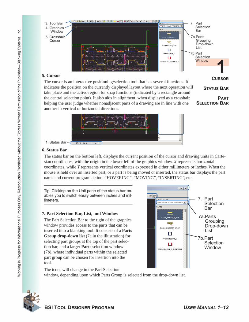
5. CursorThe cursor is an interactive positioning/selection tool that has several functions. Itindicates the position on the currently displayed layout where the next operation willtake place and the active region for snap functions (indicated by a rectangle aroundthe central selection point). It also aids in alignment, when displayed as a crosshair,helping the user judge whether nonadjacent parts of a drawing are in line with oneanother in vertical or horizontal directions.
1. Status Bar
6. Status BarThe status bar on the bottom left, displays the current position of the cursor and drawing units in Carte-sian coordinates, with the origin in the lower left of the graphics window. X represents horizontalcoordinates, while Y represents vertical coordinates expressed in either millimeters or inches. When themouse is held over an inserted part, or a part is being moved or inserted, the status bar displays the partname and current program action: “HOVERING”, “MOVING”, “INSERTING”, etc.
Tip: Clicking on the Unit pane of the status bar en-ables you to switch easily between inches and mil-limeters.
7. Part Selection Bar, List, and WindowThe Part Selection Bar to the right of the graphicswindow provides access to the parts that can beinserted into a blanking tool. It consists of a PartsGroup drop-down list (7a in the illustration) forselecting part groups at the top of the part selec-tion bar, and a larger Parts selection window(7b), where individual parts within the selectedpart group can be chosen for insertion into thetool.
The icons will change in the Part Selectionwindow, depending upon which Parts Group is selected from the drop-down list.
7. Part Selection Bar
7a.Parts Grouping Drop-down List
7b.Part Selection Window
CURSOR
STATUS BAR
PARTSELECTION BAR

1
BSI TOOL DESIGNER PROGRAM USER MANUAL 1–14
Wor
king
in P
rogr
ess
for
Info
rmat
iona
l Pur
pose
s O
nly.
Rep
rodu
ctio
n P
rohi
bite
d w
ithou
t the
Exp
ress
Writ
ten
Per
mis
sion
of t
he P
ublis
her—
Bla
nkin
g S
yste
ms,
Inc.
To o l B a r I c o n F u n c t i o n sIcon Tool/Menu Name Function/Description
New Tool Designer Document Starts a new tool design document from an existingDDES file. Only files with the .DDS, .DDE, and.DS2 extensions are displayed.
Open Tool Designer Document Opens an existing tool design document. Only“blanking” files with the .BNK extension aredisplayed.
Save Saves the tool design document as a blanking file. Ifit is a new design, the program will prompt for afilename. If you wish to save under a different filename, select File>Save As... from the drop-downmenu.
------------------------------------------------
Print... Prints the current view of the tool design documentthrough the Windows printer dialog. Summary orlayout printing options are available in the Filedrop-down menu.
Zoom Window Zooms into the region of the drawing specified byclicking and dragging the cursor from the top left tothe bottom right of the desired region (or viceversa).
Zoom Extents Zooms out to display the full extents of the ToolDesign document.
Pan Shifts a drawing within the display region withrespect to the display window margins by dragging a line with the cursorin the direction of the shift. This enables portions of the drawing beyondthe current visible window to be viewed.
------------------------------------------------
Distance Activates the Distance command for measuring distances between twopoints. The cursor is used to select the desired endpoints (a line will bedisplayed indicating the selection). Using snap settings improvesaccuracy for distance measurements
List Displays item information for any line or arc selected with the mouse.The selected item will be highlighted.
Components Opens the Components dialog, where drawing components are displayedin a tree structure and can be turned on and off. Line types and colors canbe changed here, as well.
------------------------------------------------
Carton Layout Toggle Hides or shows the carton layout.
Lower Tool Frame Toggle Hides or shows the Lower Tool Frame.
Lower Tool Grid Toggle Hides or shows the Lower Tool Grid.
Lower Tool Board Hides or shows the Lower Tool Board and its components.
Upper Tool Board Hides or shows the Upper Tool Board and its components.------------------------------------------------
TOOL BARICONS & THEIR
FUNCTIONS
File
Print/View
Tools
Hide/ViewToggles
Continued ...

1
BSI TOOL DESIGNER PROGRAM USER MANUAL 1–15
Wor
king
in P
rogr
ess
for
Info
rmat
iona
l Pur
pose
s O
nly.
Rep
rodu
ctio
n P
rohi
bite
d w
ithou
t the
Exp
ress
Writ
ten
Per
mis
sion
of t
he P
ublis
her—
Bla
nkin
g S
yste
ms,
Inc.
To o l B a r I c o n F u n c t i o n s, continuedIcon Tool/Menu Name Function/Description
Quadrant Snap Snaps to predefined 0°, 45°, 90°, 135°, 180°, 225°,270°, and 315° angles on circles and arcs.
Center Snap Snaps to the center point of circles and arcs.
End Snap Snaps to the end points of lines.
Distance From End Snap Snaps to a user-specified distance from the end pointof a line.
Mid Snap Snaps to the midpoint of a line or arc.
Intersection Snap Snaps to the intersection point between two lines,arcs, or circles that physically intersect.
Virtual Snap Snaps to one or two intersections between objects,even if they don’t physically meet.
Nearest Snap Snaps to the nearest point on a line, arc, or circle.------------------------------------------------
The following snaps work in conjunction with certain other snaps in the above list.
Ortho Snap Orthogonal (vertical or horizontal) snap, from apreviously selected point.
Perpendicular Offset Snap Snaps to a specified offset perpendicular to theselected line, arc, or circle. The offset can be changedby right-clicking the drop-down menu and selecting“Fix Offsets”.
Midway Between Snap Snaps to a point halfway between two previously selected points.
Note: A full chart with keyboard equivalents is included in the Appendix.
TOOL BARICONS & THEIR
FUNCTIONS
Snaps

2
BSI TOOL DESIGNER PROGRAM USER MANUAL 2–1
Wor
k in
Pro
gres
s fo
r In
form
atio
nal P
urpo
ses
Onl
y. R
epro
duct
ion
Pro
hibi
ted
with
out t
he E
xpre
ss W
ritte
n P
erm
issi
on o
f the
Pub
lishe
r—B
lank
ing
Sys
tem
s, In
c.
CHAPTER
OVERVIEW OF BLANKING
GETTING STARTED
BACKUPS
DOCUMENT PROPERTIES
OPENING & SAVING DOCUMENTS

2
BSI TOOL DESIGNER PROGRAM USER MANUAL 2–2
Wor
k in
Pro
gres
s fo
r In
form
atio
nal P
urpo
ses
Onl
y. R
epro
duct
ion
Pro
hibi
ted
with
out t
he E
xpre
ss W
ritte
n P
erm
issi
on o
f the
Pub
lishe
r—B
lank
ing
Sys
tem
s, In
c.
OVERVIEWThe Blanking Station
What is Blanking?Blanking is a step in a production line process. A “blank” component that is to befurther processed, is punched out of a sheet of blanking material (e.g., card stock)after it has been perforated in a die-cutting operation. For example, at a currencymint, a coin blank is punched from a sheet of metal and then embossed with text andimages to produce a coin. Similarly, at a carton plant, a box blank is punched from asheet of cardboard and then folded to produce a box. If the box is small, severalblanks may be punched from a single sheet. The size and shape of the box and thestructural strength of the material determines how many blanks can be combined onone sheet (and in one punching operation).
The BSI Tool Designer software can greatly facilitate frame setup, componentspositioning, and stencil design to optimize the process of mass production cartonpunching (blanking).
The Blanking ProcessThe process of manually punching out a blank can be arduous and time-consuming.The advantage of a blanking station, used in conjunction with a die-cutting system, isthat the punching and pulling process is automated and need not be performedindividually by manual labor. Optical sensors called photocells can monitor thestacks of punched blanks and swords can be used with palette operation. Both ofthese mechanical systems are predefined in the software and can be positioned priorto frame setup. The frame, grid bars, and tool boards similarly are modeled insoftware and can readily be visualized and positioned or repositioned as desired,before assembling the physical frame.
Setting Up the Frame and ComponentsEven with a blanking station, the process ofcreating and calibrating the frame, and produc-ing and positioning the female and male toolboards, is time-consuming and difficult, requir-ing professional expertise, patience, and preci-sion.
Blanking software enables many of theseaspects to be modeled before the boards are cutand the frame set up on the machine. Thisresults in less waste and sturdier frames built tomore exacting standards and makes it possibleto assemble and accurately adjust the framecomponents apart from the machine, thusfreeing the equipment for current jobs. Longer production runs are possible with sturdier frames and theframes may be stored for future runs. Sturdier frames are also achieved by using the components sup-plied by BSI.
WHAT ISBLANKING ?
THE BLANKINGPROCESS
SETTING UPTHE BLANKING
FRAME &COMPONENTS

2
BSI TOOL DESIGNER PROGRAM USER MANUAL 2–3
Wor
k in
Pro
gres
s fo
r In
form
atio
nal P
urpo
ses
Onl
y. R
epro
duct
ion
Pro
hibi
ted
with
out t
he E
xpre
ss W
ritte
n P
erm
issi
on o
f the
Pub
lishe
r—B
lank
ing
Sys
tem
s, In
c.
GETTING STARTEDIntroduction
Before beginning a new set of blanking designs, adjust the global program settings tosuit the needs of your project. This establishes consistent parameters for relateddrawings and you won’t have to change commonly used drawing settings later.Setting up the program preferences will help you familiarize yourself with theBSI-TD interface and its capabilities.
Setting the General PreferencesWith BSI Tool Designer software, you can customize theprogram’s functionality to suit your needs. To set programpreferences and defaults, select Options>General Preferencesfrom the main menu bar to bring up the Preferences dialog. InGeneral Preferences you can adjust thefollowing settings:
A. Units/ToleranceB. Arc ResolutionC. Component PricingD. OtherE. Bender Data TolerancesF. DDES Output
A selection box will be displayed with available categories listed on the left. Thefunctions and measurements that are available on the right will change, dependingupon the category selected.
Preferences for individual categories may be changed by following the instructionsbelow. When you have set up your preferences, click OK to accept changes, Cancel to discard changes,or Defaults to return to the original program defaults.
A. Category: Units/ToleranceYou can select and set units, tolerances, and perpendicular offset values. The values are displayed andentered in the boxes to the right of the general categories as follows:
1. Units: Select millimeters (mm) orinches (inch) using the Units drop-downbox to set the scale for drawing units.
2. Tolerance: Set the tolerance value (thedistance between two elements beforeintersecting), and how close the mousecan get to an element before “touching”it). Enter a new value by typing it intothe input box. The tolerance is set as afloating point decimal value.
3. Perpendiculat Offsets: This is a list offixed offset values that will be snappedto during operations when Perpendicu-lar Offsets is used. To remove a value from the list, select the value to deleteand click the Delete button. To add a value, click the Add button and add anew value in the popup dialog box. The new value will be added to the list inthe order of low-to-high values, ranging from top to bottom.
INTRODUCTION
SETTINGPREFERENCES
UNITS/TOLERANCE

2
BSI TOOL DESIGNER PROGRAM USER MANUAL 2–4
Wor
k in
Pro
gres
s fo
r In
form
atio
nal P
urpo
ses
Onl
y. R
epro
duct
ion
Pro
hibi
ted
with
out t
he E
xpre
ss W
ritte
n P
erm
issi
on o
f the
Pub
lishe
r—B
lank
ing
Sys
tem
s, In
c.4. Aperture Size of Cursor: This enables you to change the size of the box
that is displayed at the center of the crosshairs cursor. The size is related tothe distance the cursor can be to a line or arc before the cursor snaps to theitem. Enter a number in pixels (addressable units on your display device).
5. Bendable C-Rail Radius: This is the radius (expressed in drawing units)that is used when bending the Bendable C-Rail. Materials compress anddecompress to different extents when they are bent, which may necessitatea change in the bend radius, depending upon the material. Once a value fora particular material has been determined and entered, it rarely needs to bechanged.
6. Bridge Depth: Indentations are usually bridged with a small unpunched/uncut section to prevent pushers or other punched/cut materials from fallingaway from the main piece prior to final separation. The bridge depth is thedistance that a bridge extends from the edge.
7. CNC Corner Relief Angle Threshold: When cutting with a laser, a veryfine precise cut is created. However, mechanically routing or cutting a boardwill leave a kerf (a small “cut” channel). Alas, corners greater than a certainangle will be imprecise where the tool has to change directions, and mayneed to be drilled first. This becomes less of a problem at broader angles.The angle threshold is the point at which the CNC_CORNER_RELIEF canbe inserted to compensate for this problem. Any angle below this thresholdis ignored.
B. Bender Data TolerancesThe values of the Bender Data Tolerances are used to determine when two or moregrid bars are identical, when Bender Data is output via the File>Output All BenderData... drop-down menu.
Two grid bars are considered identical when all of the followingcriteria are met:
a. Overall Length of Bar: Values for both bars are within thespecified length of each other.
b. Bend Point Distance: The center of each Bend of each Baris within the specified tolerance.
c. Bend Radius: The radius of each Bend of each Bar iswithin the specified tolerance.
d. Bend Angle (degrees): The angle of each Bend of each Baris within the specified number of degrees.
C. DDES OutputIn the DDES Output category, the DDES Output Typespecifies whether the Upper and Lower Boards are to be cutwith a laser or with a CNC routing tool.
When “Laser” is selected, the width (diameter) of the laseris specified. This width is the width of the material that isburned away during cutting.
The edges and holes are exactly poisitioned during boarddesign. To laser-cut those edges/holes accurately, however,the laser must be offset by half the laser beam’s width. This offset need only be considered when output-ting a DDES file from the File menu for the Upper or Lower Boards, or for the Bar Positioning Tool.
BENDER DATATOLERANCES
DDES OUTPUT
2
BSI TOOL DESIGNER PROGRAM USER MANUAL 2–5
Wor
k in
Pro
gres
s fo
r In
form
atio
nal P
urpo
ses
Onl
y. R
epro
duct
ion
Pro
hibi
ted
with
out t
he E
xpre
ss W
ritte
n P
erm
issi
on o
f the
Pub
lishe
r—B
lank
ing
Sys
tem
s, In
c.
ARCRESOLUTION
COMPONENTPRICING
With a CNC router, the cutting tool will cut right on the edge, so the lines/arcs thatare output to the DDES file are not compensated.
DDES Ouptut Size for Screw HolesThis enables the standard 3, 4, and 5mm screwholes and the presser screw holes tobe output with a different diameter. If laser compensation is enabled, then it isapplied to these specified diameters.
• For the 3, 4, and 5mm screw holes, these values are typically made larger toprevent the screw threads from gripping the Board when attaching a Jogger.
• For the Presser Clip screw hole, the value is made smaller so that the screwanchors firmly into the board.
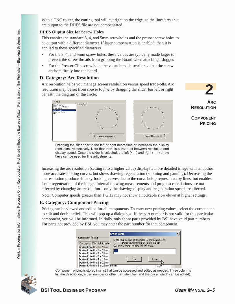
D. Category: Arc ResolutionArc resolution helps you manage screen resolultion versus speed trade-offs. Arcresolution may be set from coarse to fine by dragging the slider bar left or rightbeneath the diagram of the circle.
Dragging the slider bar to the left or right decreases or increases the displayresolution, respectively. Note that there is a trade-off between resolution anddisplay speed. Once the slider is selected, the left (<—) and right (—>) arrowkeys can be used for fine adjustments.
Increasing the arc resolution (setting it to a higher value) displays a more detailed image with smoother,more accurate-looking curves, but slows drawing regeneration (zooming and panning). Decreasing thearc resolution produces blocky-looking curves due to the curve being represented by lines, but enablesfaster regeneration of the image. Internal drawing measurements and program calculations are notaffected by changing arc resolution—only the drawing display and regeneration speed are affected.
Note: Computer speeds greater than 1 GHz may not show a noticable slow-down at higher settings.
E. Category: Component PricingPricing can be viewed and edited for all components. To enter new pricing values, select the componentto edit and double-click. This will pop up a dialog box. If the part number is not valid for this particularcomponent, you will be informed. Initially, only those parts provided by BSI have valid part numbers.For parts not provided by BSI, you may enter the part number for that component.
Component pricing is stored in a list that can be accessed and edited as needed. Three columnslist the description, a part number or other part identifier, and the price (which can be edited).

2
BSI TOOL DESIGNER PROGRAM USER MANUAL 2–6
Wor
k in
Pro
gres
s fo
r In
form
atio
nal P
urpo
ses
Onl
y. R
epro
duct
ion
Pro
hibi
ted
with
out t
he E
xpre
ss W
ritte
n P
erm
issi
on o
f the
Pub
lishe
r—B
lank
ing
Sys
tem
s, In
c.For a valid component, type the new price in dollars and cents and click OK to acceptthe value or Cancel to exit the dialog.
Note, a pricing file must be obtained from BSI and installed via the Options->InstallNew Pricing File selection in order to use current pricing info for BSI components.
F. OtherWhen the Always On Top box is checked, the BSI-TD program window will alwaysstay open on top of other windows.
BACKUPSIt is important to save your work regularly in case of disk problems, power surges, or other events thatcan compromise file integrity. To prevent data loss in the event of a system crash while you are workingin the BSI-TD program, an automatic backup file is created, containing all changes up to the commandthat was active at the time of the crash (note that this may not be sufficient for data recovery if a harddrive failure occurs, so good backup policies should still be practiced).
The BSI-TD backup file is automatically restored the next time BSI-TD is started. However, the name ofthe design is lost and the file will need to be renamed when saved. Note that the OLE document proper-ties (discussed below) are also lost when a backup file is restored. This isstill preferable to losing the file.
DOCUMENT PROPERTIESThe OLE document properties can be set by selecting Options >DocumentProperties from the menu bar. You can insert whatever information isrelevant to the project, but typically the company/author, title of the project,and any project comments are entered. The information is for your use anddoes not affect the operation of the BSI-TD program.
OTHER
BACKUPS
DOCUMENTPROPERTIES

2
BSI TOOL DESIGNER PROGRAM USER MANUAL 2–7
Wor
k in
Pro
gres
s fo
r In
form
atio
nal P
urpo
ses
Onl
y. R
epro
duct
ion
Pro
hibi
ted
with
out t
he E
xpre
ss W
ritte
n P
erm
issi
on o
f the
Pub
lishe
r—B
lank
ing
Sys
tem
s, In
c.
OPENING AND SAVING
BSI-TD DOCUMENTSBSI-TD uses standard methods for opening and saving new orrevised documents, including convenient icon, menu, andkeyboard options.
In general, a DDES file serves as a starting point for creating anew blanking file as this DDES file is typically a predesignedcarton layout created by another program (e.g., Artios). When anew document is to be created, the file dialog box will display files with the .DDS,.DS2, and .DDE extensions. When an existing document is to be selected, files withthe .BNK file extension will be displayed. This process is described in more detailbelow.
A. Creating New DocumentsThere are four ways to create a new tool designer document:
• Click the New Document icon button on the toolbar.
• Select File >New Tool Designer Document from the main menu bar.
• Type Ctrl+N from the keyboard.
• If the program is NOT running, you can open an existing .DDS/.DDS2/.DDE filefrom Windows Explorer. When creating a new document, a dialog box will display alist of files.
1. Select the DDES (.DDS) file that will be used to design a new blanking tool.The DDS file is an exact layout of the actual dieboard. When the Rememberthis folder box (upper right) is checked, the program will look for files in thesame location the next time a New, Open, or Save As command is used.
2. Hovering the mouse pointer over the file name in the dialog list providesinformation about the file type and size. Clicking the other mouse buttonactivates a popup menu with file-related functions (whether it’s the left or
CREATING &OPENING NEW
DOCUMENTS

2
BSI TOOL DESIGNER PROGRAM USER MANUAL 2–8
Wor
k in
Pro
gres
s fo
r In
form
atio
nal P
urpo
ses
Onl
y. R
epro
duct
ion
Pro
hibi
ted
with
out t
he E
xpre
ss W
ritte
n P
erm
issi
on o
f the
Pub
lishe
r—B
lank
ing
Sys
tem
s, In
c.right mouse button depends upon your Windows Explorer settings).
3. When the file opens, you will be prompted to set die information for thissession in the Set Die Info dialog. The Machine Type may be selected fromthe drop-down menu. Other settings can be set by clicking the appropriateradio buttons or input boxes.When Die Info parameters have been set, click Next >, or Cancel to discardthe settings. Defaults may be restored by clicking Defaults (note, the Next >button will be an OK button when invoked from the Options->DieInfomenu).
WARNING! You must enter the correct tool type in the Die Info dialog box. Although Die Info can be editedat any point during the design session, changing the tool type will delete all components that have beenadded to the tool. If you unintentionally change to the wrong Grid Tool setting, click Cancel and start again.
4. After selecting Next >, the program will prompt you to set job information forthis document. The Set Job Info dialog stores all the data about the job(Cutting Size is imported from the extents chosen when the frame wasinserted). This data will appear on the Part Summary Report and can beedited at any time during the design session by selecting Options >Job Info.
CREATING &OPENING NEW
DOCUMENTS

2
BSI TOOL DESIGNER PROGRAM USER MANUAL 2–9
Wor
k in
Pro
gres
s fo
r In
form
atio
nal P
urpo
ses
Onl
y. R
epro
duct
ion
Pro
hibi
ted
with
out t
he E
xpre
ss W
ritte
n P
erm
issi
on o
f the
Pub
lishe
r—B
lank
ing
Sys
tem
s, In
c.
Note, if you enter invalid values, an alert will be displayed. You must entervalid values before you can continue.
5. When you are satisfied with your settings, click the Finish button, orCancel to discard changes. The < Back button returns you to the previousdialog.
Note, when invoked from Options >JobInfo, there is no < Back button andthe Next > button becomes OK .
B. Opening Existing DocumentsOnce you have created one or more blanking files, the Open function can be used to load files forviewing or editing.
There are four ways to open an existing Tool Designer document:
• Click the Open icon button on the toolbar.
• Select File >Open Tool Designer Document (.BNK file format) from the main menu bar.
• Type Ctrl+O from the keyboard.
• If the program is not running, open the file from Windows Explorer.
Note, if an edited project is currently loaded in the drawing window, a dialog will be displayed askingwhether you would like to save the current file. There are three options in this dialog: Yes, No, andCancel.
a. Yes: To save the file, select Yes. A file dialog box will open that lists thecurrently available blanking files and provides a box for typing in a uniquefile name for saving the current file. If you click Cancel at this point, theprogram assumes you don’t want to save the existing file and presents theOpen BSI Tool Designer Layout dialog with a list of available files that canbe loaded (at this point you can still cancel to retain the existing file).Select the file to open by clicking on the file name. If you are unsure of thename of the desired drawing file to open, click on a file in the list and its
OPENINGEXISTING
DOCUMENTS
2
BSI TOOL DESIGNER PROGRAM USER MANUAL 2–10
Wor
k in
Pro
gres
s fo
r In
form
atio
nal P
urpo
ses
Onl
y. R
epro
duct
ion
Pro
hibi
ted
with
out t
he E
xpre
ss W
ritte
n P
erm
issi
on o
f the
Pub
lishe
r—B
lank
ing
Sys
tem
s, In
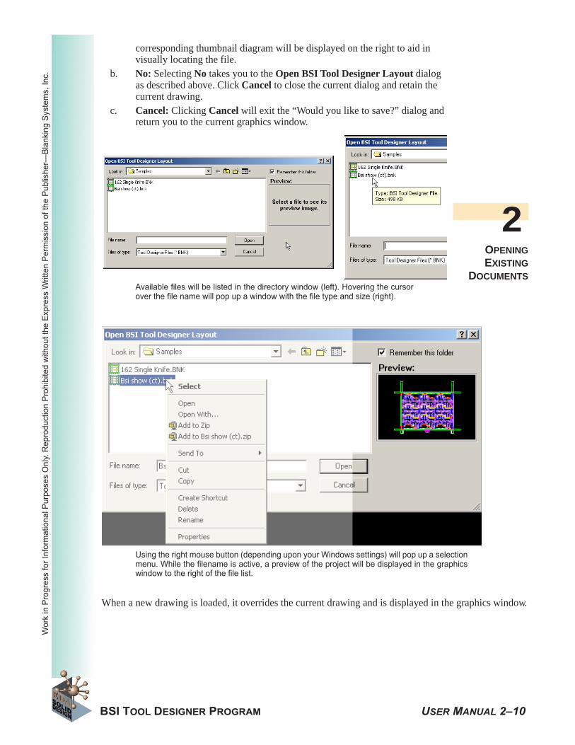
c.corresponding thumbnail diagram will be displayed on the right to aid invisually locating the file.
b. No: Selecting No takes you to the Open BSI Tool Designer Layout dialogas described above. Click Cancel to close the current dialog and retain thecurrent drawing.
c. Cancel: Clicking Cancel will exit the “Would you like to save?” dialog andreturn you to the current graphics window.
Available files will be listed in the directory window (left). Hovering the cursorover the file name will pop up a window with the file type and size (right).
Using the right mouse button (depending upon your Windows settings) will pop up a selectionmenu. While the filename is active, a preview of the project will be displayed in the graphicswindow to the right of the file list.
When a new drawing is loaded, it overrides the current drawing and is displayed in the graphics window.
OPENINGEXISTING
DOCUMENTS

2
BSI TOOL DESIGNER PROGRAM USER MANUAL 2–11
Wor
k in
Pro
gres
s fo
r In
form
atio
nal P
urpo
ses
Onl
y. R
epro
duct
ion
Pro
hibi
ted
with
out t
he E
xpre
ss W
ritte
n P
erm
issi
on o
f the
Pub
lishe
r—B
lank
ing
Sys
tem
s, In
c.C. Saving a Tool Designer DocumentThere are three ways to save the currently open file in .BNK format as a new file if ithas just been created for the first time, or to save changes in a file and overwrite anexisting file of the same name:
• Click the Save icon button on the toolbar.
• Select File >Save from the main menu bar.
• Type Ctrl+S from the keyboard.
If you wish to save an edited file without overwriting an existing file, select the SaveAs... option from the menu. This will bring up a dialog so you can select a newdirectory or file name as desired.
The Save As... dialog displays a list of files on the currently selected directoryand a File name: box for entering a new file name. You can change directoriesto save a different file under the same file name as the previous version orselect a new file name.
When Save As... is selected, the program allows you to change the file name and itssave location before saving. If there are no changes, click the Save button and clickYes if asked if you want to replace the older version of that file.
Note: If this is another tool, you may wish to save under a different name to avoid overwriting the previousfile. Using a different filename, periodically, is also a precaution in the event of a disk failure or file corrup-tion. You should always back up your files regularly but saving under incremental filenames, e.g., myfile1.bnk,myfile2.bnk, can also reduce the possibility of data loss.
SAVINGDOCUMENTS

3
BSI TOOL DESIGNER PROGRAM USER MANUAL 3–1
Wor
k in
Pro
gres
s fo
r In
form
atio
nal P
urpo
ses
Onl
y. R
epro
duct
ion
Pro
hibi
ted
with
out t
he E
xpre
ss W
ritte
n P
erm
issi
on o
f the
Pub
lishe
r—B
lank
ing
Sys
tem
s, In
c.
CHAPTER
CAD FUNCTIONS
VIEWING & MEASURING
COMPONENTS ORGANIZATION

3
BSI TOOL DESIGNER PROGRAM USER MANUAL 3–2
Wor
k in
Pro
gres
s fo
r In
form
atio
nal P
urpo
ses
Onl
y. R
epro
duct
ion
Pro
hibi
ted
with
out t
he E
xpre
ss W
ritte
n P
erm
issi
on o
f the
Pub
lishe
r—B
lank
ing
Sys
tem
s, In
c.
CADFUNCTIONS
CAD FUNCTIONSIntroduction
The BSI-TD program’s CAD functionality was developed specifically to facilitatethe design and layout of blanking tools. The BSI-TD program is not intended toduplicate all the functions of regular CAD programs. However, it uses some basicconventions that will be familiar to CAD users, such as viewing, copying, andmoving drawing elements, and changing views (zoom in, zoom out, pan).
In addition to these basic display and drawing manipulations functions, BSI-TDincludes features such as automated error checking of tool layouts. It also providessoftware guidance in the form of insertion wizards that improve both the productivityof the tool designer and the quality of the designed blanking tool.
Basic FunctionsBSI-TD’s basic functions are as follows:
A. Pan and View - functions for controlling which portions of the drawing aredisplayed in the graphics window.
B. Snap - filters for controlling the sensitivity of the mouse and what will beselected.
C. Distance - a function for determining and displaying the distance betweenselected points
D. List - a function that inventories the basic properties of an item.E. Editing Drawing Components - a list of drawing components, organized as a
tree structure, that facilitates the editing of line color and line types. You canalso collapse or expand the tree list to view relevant parts of the list, anddelete components, as desired.
These functions are described in more detail in this chapter.

3
BSI TOOL DESIGNER PROGRAM USER MANUAL 3–3
Wor
k in
Pro
gres
s fo
r In
form
atio
nal P
urpo
ses
Onl
y. R
epro
duct
ion
Pro
hibi
ted
with
out t
he E
xpre
ss W
ritte
n P
erm
issi
on o
f the
Pub
lishe
r—B
lank
ing
Sys
tem
s, In
c.A. Changing ViewsView FunctionsWith BSI-TD you can set the drawing display zoom and pan levels forcomfortable viewing. Zooming in shows details more clearly, whilezooming out reveals “the big picture” to show the full extent of thedrawing. Panning lets you scroll around a zoomed window to portionsof the drawing that are of immediate interest that may be beyondcurrent screen extents.
Although all view-changing commands can be selected from the Viewmenu on the drop-down menu bar, getting around in the BSI-TDprogram will be quicker and easier if you learn keyboard and mouse shortcuts (forconvenience, keyboard shortcuts are listed in the View menu next to the commands).
Command Keyboard FunctionShortcut
Zoom Window Ctrl+W Zooms into a portion of the view that you selectby creating a bounding box.1. Click the cursor to designate one corner ofthe zoom box.2. Move the cursor diagonally to the oppositecorner of the box and click again. The drawingwill be proportionally enlarged to fit the size ofthe zoom box.
Zoom Extents [spacebar] Rescales the view so the entire drawing is sizedso it is visible in the graphics window.
Zoom In 2X PgDn Rescales and enlarges the current view to twiceits current size (portions outside the currentvisible area can be “scrolled to” with the Pancommand).
Zoom Out .5X PgUp Rescales and reduces the current view to one-half its current size, providing margins aroundthe drawing. When zooming out from extents,margins will be provided around the drawing.
Pan [arrow keys] Moves the drawing in the specified direction.1. Click the left-mouse button and move the cursor in the directionyou wish to “pull” the drawing. A yellow line will show thedirection and distance the drawing will be panned.2. Click again to complete the pan.
Mouse Zoom If you have a mouse with a wheel, you can use it to zoom in andout of the drawing. The center point of the zoom is centered on themouse position.
Mouse Pan The middle button on a three-button mouse can be double-clickedso the selected point in the drawing will follow/pan with themouse. Double-click to end panning.
Note: To control the speed of drawing regeneration, you can reduce or increase the resolution of arcs. ClickOptions>General Preferences>Arc Resolution and drag the slider bar left to decrease arc resolutionand increase drawing regeneration speed, or right to increase resolution.
CHANGINGVIEWS
ZOOM & PANFUNCTIONS
3
BSI TOOL DESIGNER PROGRAM USER MANUAL 3–4
Wor
k in
Pro
gres
s fo
r In
form
atio
nal P
urpo
ses
Onl
y. R
epro
duct
ion
Pro
hibi
ted
with
out t
he E
xpre
ss W
ritte
n P
erm
issi
on o
f the
Pub
lishe
r—B
lank
ing
Sys
tem
s, In
c.B. Using the Snap FunctionsThe Snap MenuSnap functions control which items the mouse will select. Snap is enabled or dis-abled depending upon which snap modes are set. The mouse pointer “snaps to” anitem or location if one or more snap functions is active.
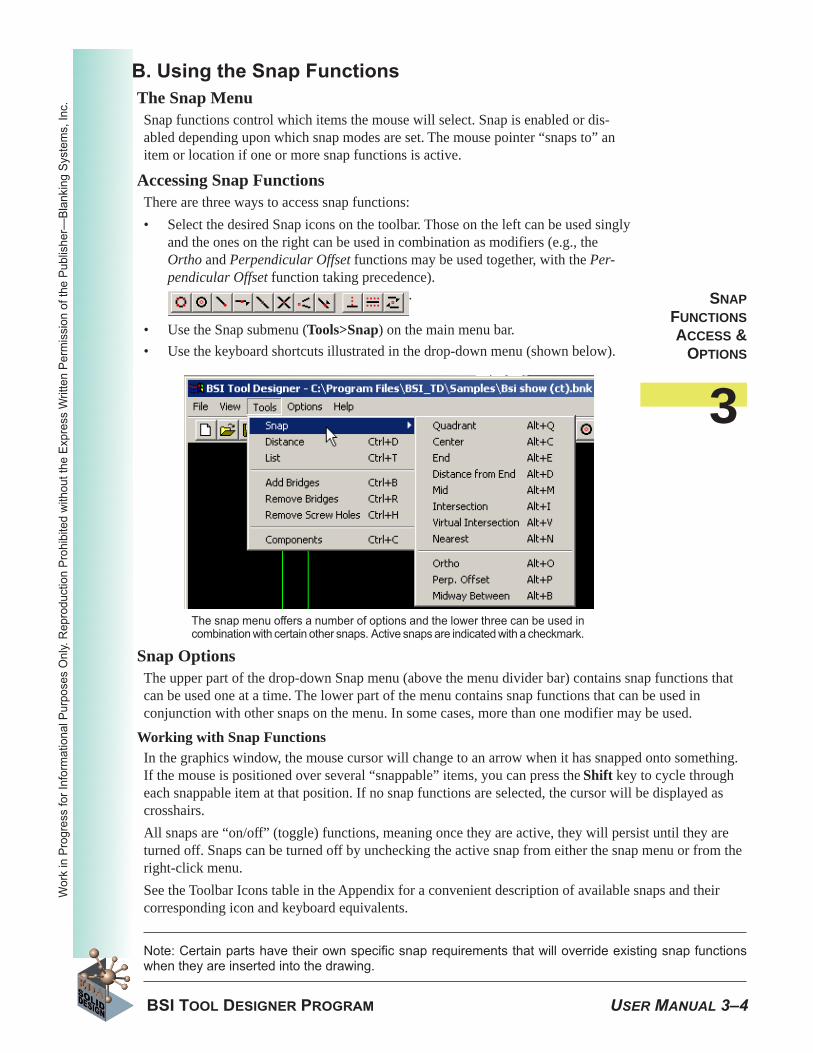
Accessing Snap FunctionsThere are three ways to access snap functions:
• Select the desired Snap icons on the toolbar. Those on the left can be used singlyand the ones on the right can be used in combination as modifiers (e.g., theOrtho and Perpendicular Offset functions may be used together, with the Per-pendicular Offset function taking precedence).
.
• Use the Snap submenu (Tools>Snap) on the main menu bar.
• Use the keyboard shortcuts illustrated in the drop-down menu (shown below).
The snap menu offers a number of options and the lower three can be used incombination with certain other snaps. Active snaps are indicated with a checkmark.
Snap OptionsThe upper part of the drop-down Snap menu (above the menu divider bar) contains snap functions thatcan be used one at a time. The lower part of the menu contains snap functions that can be used inconjunction with other snaps on the menu. In some cases, more than one modifier may be used.
Working with Snap FunctionsIn the graphics window, the mouse cursor will change to an arrow when it has snapped onto something.If the mouse is positioned over several “snappable” items, you can press the Shift key to cycle througheach snappable item at that position. If no snap functions are selected, the cursor will be displayed ascrosshairs.
All snaps are “on/off” (toggle) functions, meaning once they are active, they will persist until they areturned off. Snaps can be turned off by unchecking the active snap from either the snap menu or from theright-click menu.
See the Toolbar Icons table in the Appendix for a convenient description of available snaps and theircorresponding icon and keyboard equivalents.
Note: Certain parts have their own specific snap requirements that will override existing snap functionswhen they are inserted into the drawing.
SNAPFUNCTIONSACCESS &
OPTIONS

3
BSI TOOL DESIGNER PROGRAM USER MANUAL 3–5
Wor
k in
Pro
gres
s fo
r In
form
atio
nal P
urpo
ses
Onl
y. R
epro
duct
ion
Pro
hibi
ted
with
out t
he E
xpre
ss W
ritte
n P
erm
issi
on o
f the
Pub
lishe
r—B
lank
ing
Sys
tem
s, In
c.C. Using the Distance Function
The Distance function calculates and displays the distance between two selectedpoints. It can be accessed in the following ways:
1. Click the Distance button on the toolbar.
2. Select Tools >Distance on the menu bar.3. Use Ctrl+D from the keyboard.
Select two endpoints with the cursor. An information box will appear, listing thedistance in selected units are (in millimeters or inches). To ensure accuracy whenselecting points for measurement, use snap functions while using the Distancecommand.
The Distance function calculates and displays the distance between two selectedpoints. If the Distance function is accessed when the Perpendicular Offset snapfunction is active, a popup information box listing the offset value will bedisplayed.
D. Using the List FunctionThe List function describes the basic properties of a selected line, arc, or circle. This function can beaccessed in the following ways:
1. Click the List button on the toolbar strip.
2. Select Tools >List on the drop-down menu.3. Type Ctrl+T on the keyboard.
When the List command is active, click any line or arc in the document to view its properties. A listinformation box will be displayed with a number of attributes, depending upon the type of item selected.
These examples show two different types of Tools (Line and Arc) and their properties. Thenumber and type of properties will depend upon what kind of item is selected.
DISTANCEFUNCTION
LIST FUNCTION

3
BSI TOOL DESIGNER PROGRAM USER MANUAL 3–6
Wor
k in
Pro
gres
s fo
r In
form
atio
nal P
urpo
ses
Onl
y. R
epro
duct
ion
Pro
hibi
ted
with
out t
he E
xpre
ss W
ritte
n P
erm
issi
on o
f the
Pub
lishe
r—B
lank
ing
Sys
tem
s, In
c.Available list properties (not all of which are relevant to all items) include:
• TYPE: An arc or a line (a circle is a 360° arc).
• COMPONENT: A drawing layer (Knife, Crease, Photocell, Right Frame,Centerline Bracket, etc.).
• SUB-COMPONENT OF: The parent object of this component.
• LENGTH: The length of a line segment or arc or the circumference of a circle.
• START: x and y coordinates of a start point.
• END: x and y coordinates of an end point. Note: START and END are the sameif the arc is a circle.
• ANGLE: The angle of a line segment form its START point.
• CENTER: x and y coordinates of an arc center point.
• RADIUS: The radius of an arc.
• START ANGLE: The angle of the start point of an arc from its center point.
• END ANGLE: The angle of the end point of an arc from its center point.
Note: Start, End, and Angle properties all reflect the way the line segment or arc wasoriginally drawn. For example, the angle of a vertical line could be listed as 90° or 270°,depending upon the way it was drawn in the original DDES file.
Note also: Circles have an angle of 360° and the End angle is always 360° greater thanthe Start angle. A circle may start at any angle, depending upon how it was defined inthe DDES file.
E. Editing ComponentsThe Components function lets you delete drawing components and edittheir visibility. It can be accessed in the following ways:
1. Select Tools >Components from the main menu bar.
2. Click the Components button from the toolbar.
3. Type Ctrl-C from the keyboard.
The Components DialogThe Components dialog has a folding tree structure that displays allcomponents in the currently open drawing, grouping them by type. Thetree can be expanded or collapsed by clicking on the plus/minus boxes nextto each level. Linetype and color may also be edited here for most drawingcomponents. The icons in the tree relate to different aspects of the compo-nents as follows:
Blue Dots: Indicates a class under which components and/or guidelines and/or additional classes can be grouped. It contains the structure of the tree andits subcomponents. The user cannot directly create this class, but can controlits visibility, including sublevels.
Blue Stars: Represents drawing construction guides (center lines, extents,etc.) that are added automatically by the program when components areinserted from the Parts Bar list.
Individualized Icons: These icons represent the different drawing compo-nents added by the user. If there is more than one component of a particularkind in the same branch of the tree, only one icon for that type of componentwill be displayed.
THE LISTFUNCTION
EDITINGCOMPONENTS

3
BSI TOOL DESIGNER PROGRAM USER MANUAL 3–7
Wor
k in
Pro
gres
s fo
r In
form
atio
nal P
urpo
ses
Onl
y. R
epro
duct
ion
Pro
hibi
ted
with
out t
he E
xpre
ss W
ritte
n P
erm
issi
on o
f the
Pub
lishe
r—B
lank
ing
Sys
tem
s, In
c.The Component Tree Structure and Individual Components
The Components are displayed hierarchically, with dots, stars and iconsrepresenting classes and components in a folding tree structure. Individual itemsmay be selected and edited and the tree structure can be expanded or collapsedas needed by clicking on the minus (-) or plus (+) signs next to each list.
i. Editing Visibility1. From the tree, select the component to
be changed.2. Check (or uncheck) the Visible box.
When the box is checked, the compo-nent will be visible; when unchecked,the component will not be visible. Thedrawing will be dynamically updatedin the graphics area as the box ischecked or un-checked.Note: Making an item invisible will also hide all sub-components of that item.
ii. Editing Line Color1. From the tree, select the component to be changed. It will become high-
lighted.2. Click the color swatch next to Line Color.3. Select a new color from the dialog box that appears.
iii. Editing Line Type1. From the tree, select the component to be
changed. It will become highlighted (linetype cannot be changed for componentsidentified with a dot).
2. Click on the Line Type drop-down list.3. Select a new line type from the drop-down
list.Note: Changing visibility, line color, or linetype only affects the current document.
COMPONENTSTRUCTURE
EDITINGCOMPONENTS

3
BSI TOOL DESIGNER PROGRAM USER MANUAL 3–8
Wor
k in
Pro
gres
s fo
r In
form
atio
nal P
urpo
ses
Onl
y. R
epro
duct
ion
Pro
hibi
ted
with
out t
he E
xpre
ss W
ritte
n P
erm
issi
on o
f the
Pub
lishe
r—B
lank
ing
Sys
tem
s, In
c.iv. Deleting a Component
1. From the folding layer tree on the left, select the layer to be deleted. TheLayer will become highlighted and, if the component can be deleted, a deletebutton will appear.
WARNING!! The Delete button will delete ALL items that are found for the selectedcomponent, including ALL subitems of the selected component. The Delete Layercommand cannot be undone, so be careful to use it only when the entire componentstructure should be deleted. DO NOT use this command if you only wish to delete oneinstance of an item within a particular component (see Chapter 4 - Deleting Compo-nents). If you make unintentional changes, click Cancel and start again.
DELETINGCOMPONENTS

4
BSI TOOL DESIGNER PROGRAM USER MANUAL 4–1
Wor
k in
Pro
gres
s fo
r In
form
atio
nal P
urpo
ses
Onl
y. R
epro
duct
ion
Pro
hibi
ted
with
out t
he E
xpre
ss W
ritte
n P
erm
issi
on o
f the
Pub
lishe
r—B
lank
ing
Sys
tem
s, In
c.
CHAPTER
CREATING BLANKING TOOLS
FRAMES, TOOL BOARDS &ATTACHMENTS

4
BSI TOOL DESIGNER PROGRAM USER MANUAL 4–2
Wor
k in
Pro
gres
s fo
r In
form
atio
nal P
urpo
ses
Onl
y. R
epro
duct
ion
Pro
hibi
ted
with
out t
he E
xpre
ss W
ritte
n P
erm
issi
on o
f the
Pub
lishe
r—B
lank
ing
Sys
tem
s, In
c.
CREATINGBLANKING
TOOLS
PARTSINSERTION
BASICS
CREATING BLANKING TOOLSComponent Parts Introduction
The BSI Tool Designer software assists you in inserting and editing each componentin the blanking tool. The program provides you with wizards that assemble thenecessary information to insert a part, and uses Mouse Text and various warningmessages to instruct you on where, when, and how to insert or edit the part.
Immediately below are general instructions on inserting components into the blankingtool. For step-by-step instructions for how to insert and edit each component in theBSI-TD program, please consult the appropriate section in the following pages.
Part Insertion BasicsIn general, the part insertion process consists of loading a base DDES carton file thatis to be turned into a blanking tool file, or by loading an existing blanking file to bemodified. Once a file is loaded, parts may be inserted, deleted, or edited as needed.
7. Part Selection Bar
7a.Parts Grouping Drop-down List
7b.Part Selection Window
As introduced earlier in this reference, the Part Selection Bar is located on theright edge of the BSI-TD program window. Parts groups are selectable from adrop-down menu at the top, and parts associated with a particular Parts Groupare selectable from icons in the vertical box beneath the Parts Group list.
Different part icons (photocells, grid bars, front clamps, etc.) will be available in the Part SelectionBar, depending upon which Parts Group is selected from the drop-down list. The programdefaults to the Lower Tool Frame group (shown left) because the LOWER_TOOL_FRAMEpart is an essential structural element supporting other components in the blanking setup.
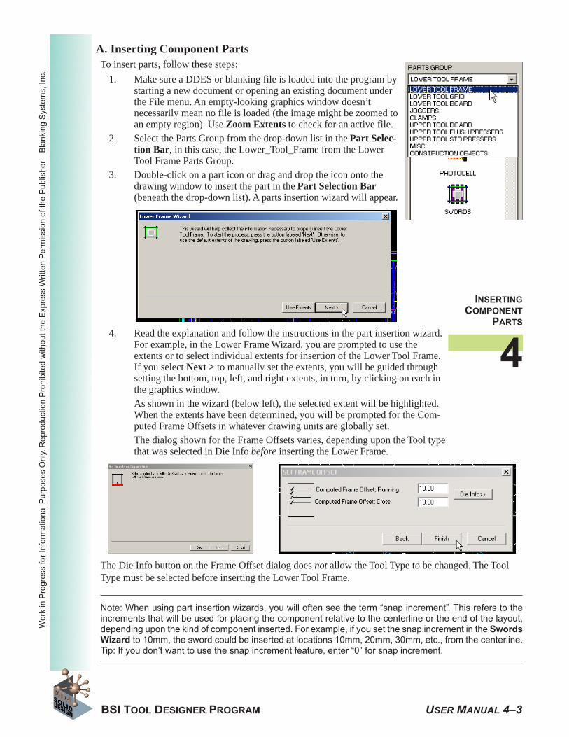
4
BSI TOOL DESIGNER PROGRAM USER MANUAL 4–3
Wor
k in
Pro
gres
s fo
r In
form
atio
nal P
urpo
ses
Onl
y. R
epro
duct
ion
Pro
hibi
ted
with
out t
he E
xpre
ss W
ritte
n P
erm
issi
on o
f the
Pub
lishe
r—B
lank
ing
Sys
tem
s, In
c.A. Inserting Component PartsTo insert parts, follow these steps:
1. Make sure a DDES or blanking file is loaded into the program bystarting a new document or opening an existing document underthe File menu. An empty-looking graphics window doesn’tnecessarily mean no file is loaded (the image might be zoomed toan empty region). Use Zoom Extents to check for an active file.
2. Select the Parts Group from the drop-down list in the Part Selec-tion Bar, in this case, the Lower_Tool_Frame from the LowerTool Frame Parts Group.
3. Double-click on a part icon or drag and drop the icon onto thedrawing window to insert the part in the Part Selection Bar(beneath the drop-down list). A parts insertion wizard will appear.
4. Read the explanation and follow the instructions in the part insertion wizard.For example, in the Lower Frame Wizard, you are prompted to use theextents or to select individual extents for insertion of the Lower Tool Frame.If you select Next > to manually set the extents, you will be guided throughsetting the bottom, top, left, and right extents, in turn, by clicking on each inthe graphics window.As shown in the wizard (below left), the selected extent will be highlighted.When the extents have been determined, you will be prompted for the Com-puted Frame Offsets in whatever drawing units are globally set.The dialog shown for the Frame Offsets varies, depending upon the Tool typethat was selected in Die Info before inserting the Lower Frame.
The Die Info button on the Frame Offset dialog does not allow the Tool Type to be changed. The ToolType must be selected before inserting the Lower Tool Frame.
Note: When using part insertion wizards, you will often see the term “snap increment”. This refers to theincrements that will be used for placing the component relative to the centerline or the end of the layout,depending upon the kind of component inserted. For example, if you set the snap increment in the SwordsWizard to 10mm, the sword could be inserted at locations 10mm, 20mm, 30mm, etc., from the centerline.Tip: If you don’t want to use the snap increment feature, enter “0” for snap increment.
INSERTINGCOMPONENT
PARTS
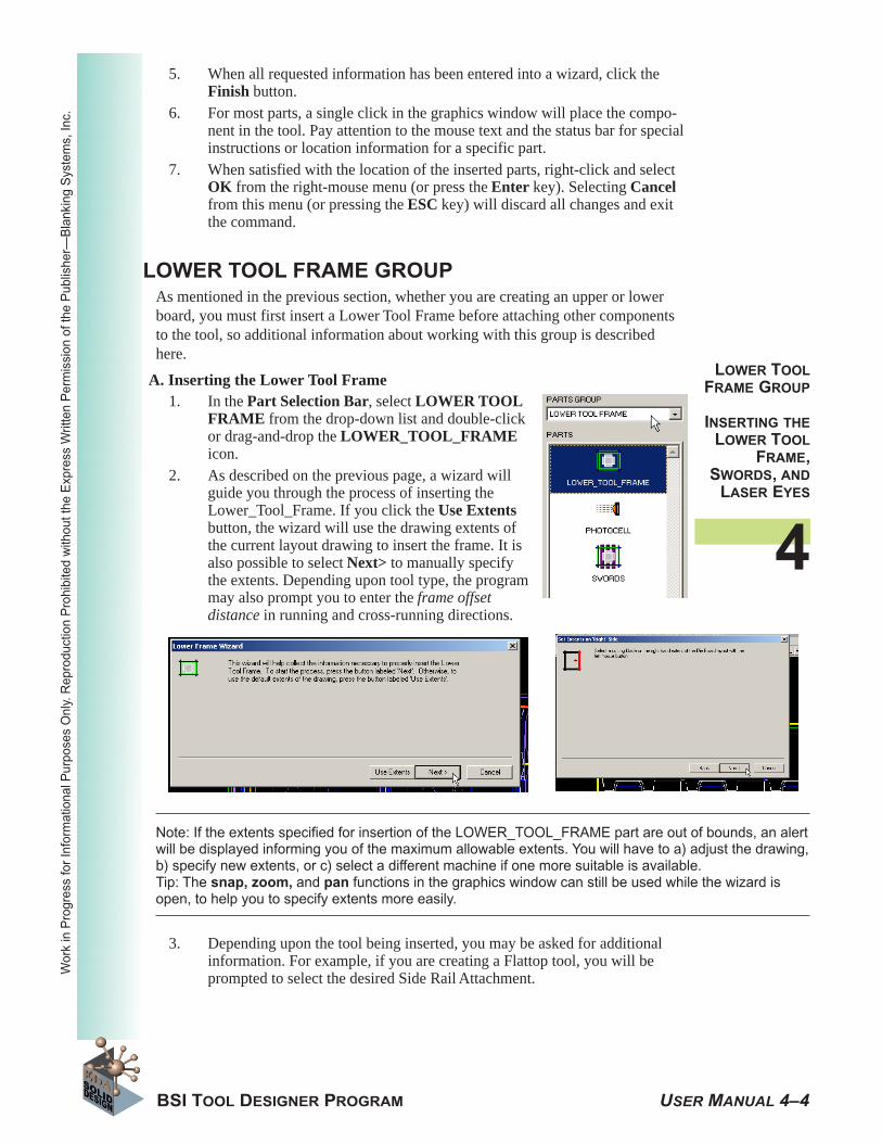
4
BSI TOOL DESIGNER PROGRAM USER MANUAL 4–4
Wor
k in
Pro
gres
s fo
r In
form
atio
nal P
urpo
ses
Onl
y. R
epro
duct
ion
Pro
hibi
ted
with
out t
he E
xpre
ss W
ritte
n P
erm
issi
on o
f the
Pub
lishe
r—B
lank
ing
Sys
tem
s, In
c.5. When all requested information has been entered into a wizard, click the
Finish button.6. For most parts, a single click in the graphics window will place the compo-
nent in the tool. Pay attention to the mouse text and the status bar for specialinstructions or location information for a specific part.
7. When satisfied with the location of the inserted parts, right-click and selectOK from the right-mouse menu (or press the Enter key). Selecting Cancelfrom this menu (or pressing the ESC key) will discard all changes and exitthe command.
LOWER TOOL FRAME GROUPAs mentioned in the previous section, whether you are creating an upper or lowerboard, you must first insert a Lower Tool Frame before attaching other componentsto the tool, so additional information about working with this group is describedhere.
A. Inserting the Lower Tool Frame1. In the Part Selection Bar, select LOWER TOOL
FRAME from the drop-down list and double-clickor drag-and-drop the LOWER_TOOL_FRAMEicon.
2. As described on the previous page, a wizard willguide you through the process of inserting theLower_Tool_Frame. If you click the Use Extentsbutton, the wizard will use the drawing extents ofthe current layout drawing to insert the frame. It isalso possible to select Next> to manually specifythe extents. Depending upon tool type, the programmay also prompt you to enter the frame offsetdistance in running and cross-running directions.
Note: If the extents specified for insertion of the LOWER_TOOL_FRAME part are out of bounds, an alertwill be displayed informing you of the maximum allowable extents. You will have to a) adjust the drawing,b) specify new extents, or c) select a different machine if one more suitable is available.Tip: The snap, zoom, and pan functions in the graphics window can still be used while the wizard isopen, to help you to specify extents more easily.
3. Depending upon the tool being inserted, you may be asked for additionalinformation. For example, if you are creating a Flattop tool, you will beprompted to select the desired Side Rail Attachment.
LOWER TOOLFRAME GROUP
INSERTING THELOWER TOOL
FRAME,SWORDS, AND
LASER EYES

4
BSI TOOL DESIGNER PROGRAM USER MANUAL 4–5
Wor
k in
Pro
gres
s fo
r In
form
atio
nal P
urpo
ses
Onl
y. R
epro
duct
ion
Pro
hibi
ted
with
out t
he E
xpre
ss W
ritte
n P
erm
issi
on o
f the
Pub
lishe
r—B
lank
ing
Sys
tem
s, In
c.
The Lower Tool Frame provides the structure within which to create a blankingtool. Zoom Extents to see the Lower Tool Frame when it has been added to thebase DDES file (right).
B. Inserting Photocells and SwordsThe other two main types of parts within the Lower Tool Frame Group are Photocellsand Swords. A photocell is an optical stack sensor and a sword is a palette part.
1. Double-click or drag-and-drop either the PHOTOCELL or SWORDS iconin the Lower Tool Frame group.
2a. If inserting a Photocell, a wizard will prompt you for beam width and snapincrements. Snap increments are measured relative to the minimum positionin which they can be placed for the selected machine type.Note: For Phototocells, if a Flattop Tool with Premade Support Rails wasselected, the position of the Photocell is fixed for predefined positions, asdetermined by machine type.
2b. If inserting a Sword, a wizard will prompt you for sword width and snapincrements. Snap increments will be measured relative to the center line.
3. Click Finish. Now, as you move the cursor in the graphics area, you will seedots or lines indicating the position of the part as it will be inserted. To furtherguide you, the mouse text displays information about the nearest snap incre-ment.
4. Click to insert the component at the location indicated by the mouse text.Error messages will appear if there is a problem with the selected location.
LOWER TOOLFRAME BEFORE
& AFTER
INSERTINGPHOTOCELLS &
SWORDS

4
BSI TOOL DESIGNER PROGRAM USER MANUAL 4–6
Wor
k in
Pro
gres
s fo
r In
form
atio
nal P
urpo
ses
Onl
y. R
epro
duct
ion
Pro
hibi
ted
with
out t
he E
xpre
ss W
ritte
n P
erm
issi
on o
f the
Pub
lishe
r—B
lank
ing
Sys
tem
s, In
c.5. Continue adding photocells or swords until they
have all been inserted.6. Some component properties can be changed from a
popup menu, so that the wizard doesn’t have to bereinvoked.
7. To keep changes, right-click to activate the right-mouse menu and select OK or press the Enter key. To discardchanges, right-click and select Cancel or press the ESC key.
C. Moving ComponentsOnce inserted, the location of some Lower Tool Frame components(Photocell, Sword) can be changed with the Move command.
Note: Lower Tool Frames are fixed and cannot be moved. You can insert a new lowerframe by following the steps on the previous page but, re-inserting the frame will deleteall inserted parts in the tool designer document.
1. Right-click inside the part to be moved. It will be highlighted in yellow inthe graphics area and the right-mouse menu will appear.
2. On the right-mouse menu, you will see the name of the part you selected.Available commands for this part will be displayed in a submenu associatedwith the part and the selected part will be highlighted in red.
3. Select Move from the submenu.4. As you move the cursor in the graphics area, the mouse text will display the
position of the part being moved (as shown on the previous page), and thestatus bar will display the active command. A single click will select the newlocation of the part, and can be repeated to select a different location. Usesnap functions to accurately insert the part in its new location.
5. When satisfied with the new part location,right-click and select OK to save changes,or select Cancel to discard changes andexit the command.
D. Deleting ComponentsThe Lower Tool Frame can only be deleted by re-inserting the Lower Tool Frame or by changingthe machine type (note that this will also delete allassociated parts). In normal use, the Lower ToolFrame would never be deleted. However, indi-vidual parts may be deleted as follows:
1. Select the Sword or Photocell to be deleted by right-clicking inside it. It willbe highlighted in yellow in the graphics area and the right mouse menu willappear. If the mouse hovers over two parts when the selection is made, bothparts will appear on the right mouse menu.
2. Select the part you wish to delete from the menu. It will become highlightedin red in the graphics area and a submenu will open. Unselected parts willremain highlighted in yellow, if there is more than one part.
3. Select Delete from the submenu.
Note: When right-clicking over multiple components, the name of each component appears in the popup-menu. The component selected in the menu is highlighted in red, the others in yellow. Make sure it is thered component that you intend to delete, as this action cannot be undone.
MOVINGCOMPONENTS
DELETINGCOMPONENTS
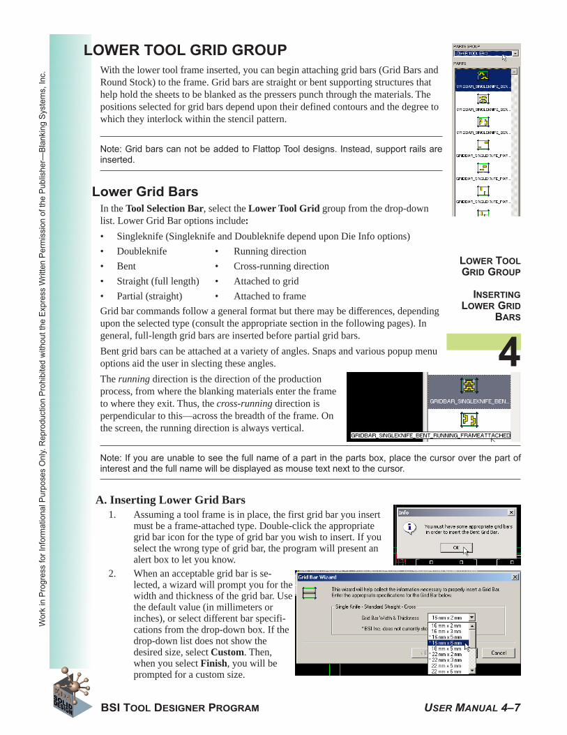
4
BSI TOOL DESIGNER PROGRAM USER MANUAL 4–7
Wor
k in
Pro
gres
s fo
r In
form
atio
nal P
urpo
ses
Onl
y. R
epro
duct
ion
Pro
hibi
ted
with
out t
he E
xpre
ss W
ritte
n P
erm
issi
on o
f the
Pub
lishe
r—B
lank
ing
Sys
tem
s, In
c.LOWER TOOL GRID GROUP
With the lower tool frame inserted, you can begin attaching grid bars (Grid Bars andRound Stock) to the frame. Grid bars are straight or bent supporting structures thathelp hold the sheets to be blanked as the pressers punch through the materials. Thepositions selected for grid bars depend upon their defined contours and the degree towhich they interlock within the stencil pattern.
Note: Grid bars can not be added to Flattop Tool designs. Instead, support rails areinserted.
Lower Grid BarsIn the Tool Selection Bar, select the Lower Tool Grid group from the drop-downlist. Lower Grid Bar options include:
• Singleknife (Singleknife and Doubleknife depend upon Die Info options)
• Doubleknife • Running direction
• Bent • Cross-running direction
• Straight (full length) • Attached to grid
• Partial (straight) • Attached to frame
Grid bar commands follow a general format but there may be differences, dependingupon the selected type (consult the appropriate section in the following pages). Ingeneral, full-length grid bars are inserted before partial grid bars.
Bent grid bars can be attached at a variety of angles. Snaps and various popup menuoptions aid the user in slecting these angles.
The running direction is the direction of the productionprocess, from where the blanking materials enter the frameto where they exit. Thus, the cross-running direction isperpendicular to this—across the breadth of the frame. Onthe screen, the running direction is always vertical.
Note: If you are unable to see the full name of a part in the parts box, place the cursor over the part ofinterest and the full name will be displayed as mouse text next to the cursor.
A. Inserting Lower Grid Bars1. Assuming a tool frame is in place, the first grid bar you insert
must be a frame-attached type. Double-click the appropriategrid bar icon for the type of grid bar you wish to insert. If youselect the wrong type of grid bar, the program will present analert box to let you know.
2. When an acceptable grid bar is se-lected, a wizard will prompt you for thewidth and thickness of the grid bar. Usethe default value (in millimeters orinches), or select different bar specifi-cations from the drop-down box. If thedrop-down list does not show thedesired size, select Custom. Then,when you select Finish, you will beprompted for a custom size.
LOWER TOOLGRID GROUP
INSERTINGLOWER GRID
BARS

4
BSI TOOL DESIGNER PROGRAM USER MANUAL 4–8
Wor
k in
Pro
gres
s fo
r In
form
atio
nal P
urpo
ses
Onl
y. R
epro
duct
ion
Pro
hibi
ted
with
out t
he E
xpre
ss W
ritte
n P
erm
issi
on o
f the
Pub
lishe
r—B
lank
ing
Sys
tem
s, In
c.3. Click Finish. A grid bar can now be inserted, snapping automatically to
either the frame or the grid bar closest to the mouse cursor, depending on thetype of grid bar to be inserted.
4. Click to select the insertion and termination points of the grid bar. Theindicated positions will be highlighted in yellow. If you attempt to insert agridbar in an inappropriate location, an error message will be displayed.
When inserting grid bars, the right-click menu displaysadditional commands to aid in placing the grid bar. If Stick toRail is selected, for example, the highlighted grid bar will beanchored to the associated rail. When satisfied with the gridbar placement, select OK to accept or Cancel to discard.
To help you keep track, information about coordinates and thetype of active grid bar part are displayed below the graphicswindow. The right-click menu provides different options, depending upon which typeof grid bar is selected (below left).
Grid bar insertion assumes the user has some knowledge of blanking mechanics. How-ever, there are some checks and balances built into the program to help prevent mis-takes. For example, if a grid bar passes through a corner bracket, an error messagewill be displayed when you attempt to click OK.
B. Deleting Lower Grid BarsGrid bars can be removed by right-clicking inside a grid bar and select-ing [Grid Bar Name] >Delete from the right-click menu.
C. Displaying Grid Bar GeometryTo view the grid bar geometry for a particular grid bar after it has beeninserted, right-click inside the bar, then select [Grid Bar Name] >ShowGrid Bar Geometry from the mouse menu. This letsyou view the geometry and, if you wish, print a reportshowing the grid bar, its type and location, totallength, and the position and angle of each Bend.
Even if you don’t plan to print the geometry, configurethe paper orientation and other parameters in the printmenu to set up the screen display. Then, when youclick OK , the grid bar geometry will be summarizedwith a diagram and statistics. For bent grid bars, thesummary also lists the number of bends, the length ofeach straight section, bend angles, and the radius ofcurvature for each bend.
If you are satisfied with the geometry and the informa-tion displayed, you can select Print to create a hardcopy or Cancel to return to the drawing.
INSERTINGLOWER GRID
BARS
DELETING GRIDBARS
DISPLAYINGGRID BAR
GEOMETRY

4
BSI TOOL DESIGNER PROGRAM USER MANUAL 4–9
Wor
k in
Pro
gres
s fo
r In
form
atio
nal P
urpo
ses
Onl
y. R
epro
duct
ion
Pro
hibi
ted
with
out t
he E
xpre
ss W
ritte
n P
erm
issi
on o
f the
Pub
lishe
r—B
lank
ing
Sys
tem
s, In
c.Standard Grid Bars
Standard grid bars extend all the way across the layout, attaching automatically toeither side of the frame. There are both cross-running and running types. Standardbars are usually inserted before other attached-type grid bars.
Note: Parts are organized in the parts box in roughly the order in which a new Toolwould be built. Thus, the Lower Tool Frame is first, while the insertion of Upper ToolPressers is generally last.
A. Inserting Standard Grid Bars1. Double-click the grid bar icon for the standard grid bar you wish to insert
and enter bar specifications into the wizard.2. Click to insert a grid bar. Use the snap functions while inserting the grid bars
to accurately insert the bar.3. Continue inserting standard grid bars until all have been inserted.4. To keep changes, right-click and select OK . To discard changes, right-click
and select Cancel.
B. Moving Standard Grid Bars1. Select the standard grid bar to be moved by right clicking inside it, then
select [Grid Bar Name ]>Move.2. The grid bar will follow the cursor until you click to select the new location.
If satisfied with the new location, right-click and select OK ; otherwise clickto select a different grid bar location. To exit and discard changes, right-clickCancel and the position of the bar will revert to the previous location.
Bent Grid BarsBent grid bars can be placed within the frame to create a complex support structurefor multiple interlocking stencil shapes on a single blanking sheet. Different types ofbent grid bars are available:
Frame attached: One end of the bar will be inserted attached to the frame. Themouse pointer will move the highlighted current location of the bar, which willextend from the frame to the center on whichever side of the frame the cursor is located. The terminatingend of the bar can be on the frame or at another grid bar. There are both cross-running and running types.
Grid attached: One end of the bar will be inserted, attached to the nearest grid bar. The mouse pointerwill move the highlighted grid bar in relation to other grid bars that are already in place.
A. Inserting Bent Grid Bars1. Double-click the GRIDBAR_[TYPE] icon for the bent grid bar part you
wish to insert.2. If the grid bar is not snapped to the correct frame or grid in the graphics area,
move the cursor closer to the desired origin until the grid bar snaps to thecorrect item. If you have difficulty keeping the grid bar from “jumping” fromone frame or grid to another, right-click and select Fix Stick Line. Optionsinclude Stick to Rail, Stick to Grid Bar Segment, or Stick to Grid BarPoint. These commands fix the element to which the grid bar will snap andcan be turned on and off by checking and unchecking the desired Fix com-mand from the right-click menu.
INSERTING,DELETING, &
MOVING GRIDBARS
BENT GRIDBARS

4
BSI TOOL DESIGNER PROGRAM USER MANUAL 4–10
Wor
k in
Pro
gres
s fo
r In
form
atio
nal P
urpo
ses
Onl
y. R
epro
duct
ion
Pro
hibi
ted
with
out t
he E
xpre
ss W
ritte
n P
erm
issi
on o
f the
Pub
lishe
r—B
lank
ing
Sys
tem
s, In
c.3. To change the bend radius while inserting the grid bar, select
Change Bend Radius from the right-click menu (the currentbend radius will be listed in parentheses). You will be promptedto enter a new value for bend radius in the dialog box. The bendradius can be changed at any time while inserting bent bars and asingle bent bar can have multiple bend radii.
4. Click to fix the first bend location. Snap functions can be turnedon and off and should be used in selecting the correctbend points. To undo the last selected bend location,right-click and select Undo Last Segment.
5. Continue selecting bend points until the bent bar isfinished.
6. Grid bars will automatically end at all four sides ofthe frame. If you want to add a part at another gridbar, right-click and select Snap to Nearest Grid Bar from theavailable options.
7. To keep changes, right-click and select OK . To discardchanges, right-click and select Cancel.
B. Copying Bent Grid BarsThe copy function enables the user to quickly replicate a bent grid bar shapethroughout the layout pattern without re-creating the same shape by hand. Bent gridbars, which have a more complex geometry, are the only type of grid bar that can becopied in this manner. To copy bent grid bars:
1. Select the bent grid bar to be copied by right-clicking inside it and selecting[Grid Bar name] >Copy from the right-click menu.
2. The mouse text will prompt you to select the base copy piece. The basecopy piece is a line or arc used to locate the copied bar in the pattern. Selecta line or arc that occurs in the pattern where theoriginal grid bar is, as well as in the destinationpatterns to which the grid bar will be copied.
3. The base copy piece will be highlighted in yellowand the mouse text will prompt you to select thedestination piece. The destination piece shouldbe identical to the base copy piece, but located ina different instance of the pattern. Click to choosea destination piece, and the grid bar will be copiedrelative to that destination piece.
4. Continue copying the grid bar by selecting destination pieces.5. To keep changes, right-click and select OK . To discard changes, select
Cancel.
C. Extending and Trimming Bent Grid BarsExtending and trimming bent grid bars is often necessary after copying and pasting. The ends of the bentgrid bars can be extended or trimmed as needed(this command is only available for bent grid bars).
1. Right-click inside the grid bar to betrimmed/extended and select[Grid Bar Name] >Extend/Trim GridBar from the right-click menu. Theselected grid bar will be outlined in red.
INSERTING ©ING BENT
GRID BARS

4
BSI TOOL DESIGNER PROGRAM USER MANUAL 4–11
Wor
k in
Pro
gres
s fo
r In
form
atio
nal P
urpo
ses
Onl
y. R
epro
duct
ion
Pro
hibi
ted
with
out t
he E
xpre
ss W
ritte
n P
erm
issi
on o
f the
Pub
lishe
r—B
lank
ing
Sys
tem
s, In
c.2a. To extend the ends of the grid bar, hover the mouse cursor over the item to
which you want to extend the end of the grid bar. A highlighted red line willextend from one end of the grid bar to your cursor, demonstrating how theextended bar will look. Click to extend the grid bar to this point, or select adifferent line to which to extend the grid bar.
2b. To trim the ends of the grid bar, hover the cursor on the line that you want totrim the grid bar with. A highlighted red line will display how the trimmedbar will look. Click to select the trim line.
3. Repeat the previous step for the other side of the bar. It is possible to trimone end of the bar and extend the other.
IMPORTANT! If you do not wish to trim or extend one side of the grid bar, click on theline that the end is currently attached to, indicating there is no change. When the sec-ond selection has been made, the bar will be trimmed or extended as specified.
Partial Grid BarsPartial grid bars are those that do not extend all the way across the frame layout.There are cross-running and running types, as well as frame-attached and grid-attached.
A. Inserting Partial Grid Bars1. Double-click the grid bar part icon for the partial gridbar to be inserted. The
grid bar wizard will prompt for bar specifications. Select the desired dimen-sions setting and click Finish.
2. Position the cursor at the desired insertion point on the tool board. Thepartial grid bar will follow the cursor and be highlighted in yellow. As youwill see, the program provides some guidance by positioning the grid barrelative to center and to the structure to which it is attached. If the grid bardoes not snap to the correct frame or grid in the graphics area, move thecursor closer to desired origination point until the grid bar snaps to the correctframe or grid.
3. Click the location where the end of thegrid bar will be located. If you havedifficulty keeping the grid bar “stuck” tothe correct frame or grid while selectingthis point, right-click Stick to Rail,Stick to Grid Bar Segment, or Stick toGrid Bar Point . These commands canbe turned on and off from the right-clickmenu and “fix” the element to which thegrid bar sticks. Use snap functions for accuracy.
4. Continue adding new bars by repeating steps 2 and 3.5. To keep changes, right-click and select OK . To discard, select Cancel.
EXTENDING &TRIMMING BENT
GRID BARS
INSERTINGPARTIAL GRID
BARS
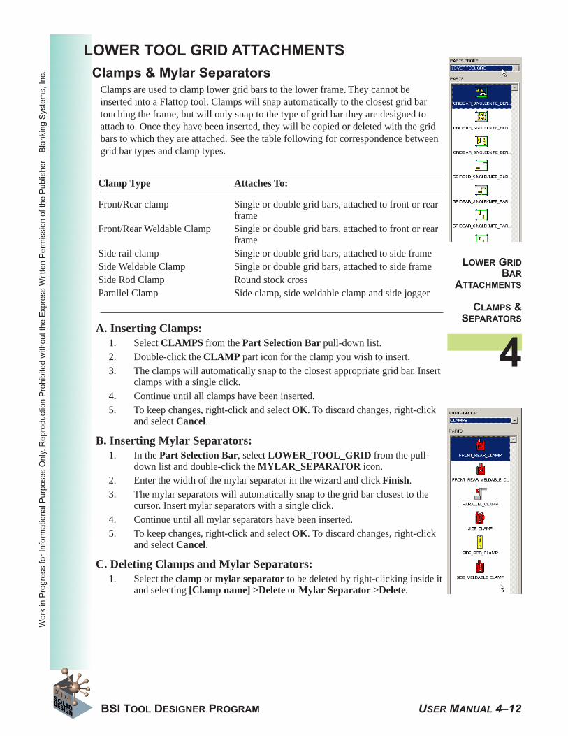
4
BSI TOOL DESIGNER PROGRAM USER MANUAL 4–12
Wor
k in
Pro
gres
s fo
r In
form
atio
nal P
urpo
ses
Onl
y. R
epro
duct
ion
Pro
hibi
ted
with
out t
he E
xpre
ss W
ritte
n P
erm
issi
on o
f the
Pub
lishe
r—B
lank
ing
Sys
tem
s, In
c.LOWER TOOL GRID ATTACHMENTS
Clamps & Mylar SeparatorsClamps are used to clamp lower grid bars to the lower frame. They cannot beinserted into a Flattop tool. Clamps will snap automatically to the closest grid bartouching the frame, but will only snap to the type of grid bar they are designed toattach to. Once they have been inserted, they will be copied or deleted with the gridbars to which they are attached. See the table following for correspondence betweengrid bar types and clamp types.
Clamp Type Attaches To:
Front/Rear clamp Single or double grid bars, attached to front or rearframe
Front/Rear Weldable Clamp Single or double grid bars, attached to front or rearframe
Side rail clamp Single or double grid bars, attached to side frameSide Weldable Clamp Single or double grid bars, attached to side frameSide Rod Clamp Round stock crossParallel Clamp Side clamp, side weldable clamp and side jogger
A. Inserting Clamps:1. Select CLAMPS from the Part Selection Bar pull-down list.2. Double-click the CLAMP part icon for the clamp you wish to insert.3. The clamps will automatically snap to the closest appropriate grid bar. Insert
clamps with a single click.4. Continue until all clamps have been inserted.5. To keep changes, right-click and select OK . To discard changes, right-click
and select Cancel.
B. Inserting Mylar Separators:1. In the Part Selection Bar, select LOWER_TOOL_GRID from the pull-
down list and double-click the MYLAR_SEPARATOR icon.2. Enter the width of the mylar separator in the wizard and click Finish.3. The mylar separators will automatically snap to the grid bar closest to the
cursor. Insert mylar separators with a single click.4. Continue until all mylar separators have been inserted.5. To keep changes, right-click and select OK . To discard changes, right-click
and select Cancel.
C. Deleting Clamps and Mylar Separators:1. Select the clamp or mylar separator to be deleted by right-clicking inside it
and selecting [Clamp name] >Delete or Mylar Separator >Delete.
LOWER GRIDBAR
ATTACHMENTS
CLAMPS &SEPARATORS

4
BSI TOOL DESIGNER PROGRAM USER MANUAL 4–13
Wor
k in
Pro
gres
s fo
r In
form
atio
nal P
urpo
ses
Onl
y. R
epro
duct
ion
Pro
hibi
ted
with
out t
he E
xpre
ss W
ritte
n P
erm
issi
on o
f the
Pub
lishe
r—B
lank
ing
Sys
tem
s, In
c.LOWER TOOL FRAME ATTACHMENTS
JOGGERSOnce a Lower Tool Frame has been inserted, lower frame attachments can be addedto the tool. For example, joggers may be placed at intervals just within the outerframe to aid in aligning blanking materials as they pass through the station, using theframe as a rail.
There are jogger parts available in the Joggers Parts Group: front/rear, and side.Since joggers that are attached to the frame may need to be repositioned from time-to-time, to accommodate the positions of other components that may need to beinserted later, they can be readily moved or deleted.
A. Inserting Joggers1. From the Part Selection Bar drop-down list, select JOGGERS.2. Double-click the icon in the Part Selection Bar that represents the jogger
you wish to insert. Joggers are attached around the edges of the lower frame.3. In the insertion wizard, enter a snap increment value, or accept the default.
Snap increments are measured with respect to the centerline of the extentsfor Front/Rear Joggers, and to the Front Extents for Side Joggers.
4. As you move the cursor around to different positions on the drawing in thegraphics window, location information will be displayed with mouse text. Thejogger to be inserted will be slightly lighter (behind the lines) than the in-serted joggers, to help you distinguish between the two. The jogger willautomatically snap to the lower frame piece for which the part was designed,and can be inserted with a single click. Joggers can be inserted simultaneouslyon the top and bottom or the left and right sides, if the “Auto-Insert OppositeJogger” option is checked in the wizard.If you accidentally insert a jogger, you can move or delete it (it’s usuallyeasier to make adjustments after you have finished inserting the joggers).
Note: The jogger is inserted by its left-hand edge from the point of view of the inside of the frame. Also notethat the Front Trim Board (in the Lower Tool Board Parts Group) must be present before side joggers canbe inserted.
LOWER TOOLFRAME
ATTACHMENTS
INSERTINGJOGGERS

4
BSI TOOL DESIGNER PROGRAM USER MANUAL 4–14
Wor
k in
Pro
gres
s fo
r In
form
atio
nal P
urpo
ses
Onl
y. R
epro
duct
ion
Pro
hibi
ted
with
out t
he E
xpre
ss W
ritte
n P
erm
issi
on o
f the
Pub
lishe
r—B
lank
ing
Sys
tem
s, In
c.5. If you attempt to insert the jogger at an inappropriate
position, an error message will be displayed informingyou of the problem and identifying the part with whichthe Jogger collided.
6. Continue inserting joggers until all joggers for that framepiece have been inserted.
7. To keep changes, right-click to bring up the right-mouse menu and selectOK . To discard changes, right-click and select Cancel.
B. Moving and Deleting JoggersIt may be necessary to adjust or remove joggers after their initial insertion. To moveor delete joggers:
1. Select the jogger to be moved by right-clicking inside the inserted part. The rightmouse menu will appear. If the cursor waspositioned over more than one part, the partswill be listed. Select the jogger part; when thesubmenu appears, select[Jogger Name] >Move.
2. As you move the cursor to a new location, thepart icon will move as well, with offset infor-mation displayed as mouse text to aid in posi-tioning. For reference, the original joggerlocation remains visible until you have chosenthe new location.Click to select the new location for the jogger.If satisfied with the new location, right-clickto activate the right-mouse menu and selectOK to accept the change; otherwise click theleft mouse button to exit the right-mousemenu and select a different location. Todiscard changes, right-click and select Cancel.
3. Deleting a jogger is a similar process, exceptthat you don’t have to click OK to accept thechange; the jogger will be immediatelydeleted. Right-click inside the jogger to bedeleted and select [Jogger Name] >Delete.
INSERTINGJOGGERS
MOVING &DELETINGJOGGERS

4
BSI TOOL DESIGNER PROGRAM USER MANUAL 4–15
Wor
k in
Pro
gres
s fo
r In
form
atio
nal P
urpo
ses
Onl
y. R
epro
duct
ion
Pro
hibi
ted
with
out t
he E
xpre
ss W
ritte
n P
erm
issi
on o
f the
Pub
lishe
r—B
lank
ing
Sys
tem
s, In
c.LOWER TOOL BOARD GROUP
To begin designing a lower board, select the LOWER TOOL BOARD group fromthe Part Selection Bar drop-down list. The lower frame must already have beeninserted. The components in the Lower Tool Board group can only be used with aFlattop Tool or a Combo Tool, as the Grid Tool doesn’t have a lower board.
Flattop Board or Combo BoardA. Inserting a Flattop or Combo Tool Board Hole
1. Double-click the FLATTOP_BOARD or COMBO_TOOL_BOARD icon inthe Parts window and click Finish in the wizard.
2. The mouse text will prompt you to select the items to offset. You must selectat least two lines/arcs. If an invalid location is selected, an alert will bedisplayed. If the selected items don’t intersect, you will be asked if you wantto create a line intersecting these parts. Answer Yes to create a line, No toselect another item.
3. Continue until a Combo Tool Board or Flattop Board Hole is formed. If atany time you need to cancel, select Cancel from the right-mouse menu. Tokeep inserted items, right-click and select OK .
B. Deleting a Flattop or Combo Board Hole1. To delete a Flattop or Combo Tool Board Hole after insertion, select the hole
by right-clicking within the hole. The popup menu will list any relevant partsand they will be highlighted in the graphics window. Select the part/hole ofinterest and select Delete from the popup menu.
C. Copying a Flattop or Combo Board Hole1. To copy a Flattop or Combo Tool Board Hole after insertion, right-click
within the hole and select Copy from the menu.2. Select the base copy piece (similar to copying a grid bar)3. Use the cursor to select the destination piece for the hole and select OK to
keep changes. To discard changes right-click and select Cancel.
LOWER TOOLBOARD GROUP
INSERTING,DELETING &
COPYING AFLATTOP OR
COMBO BOARDHOLE

4
BSI TOOL DESIGNER PROGRAM USER MANUAL 4–16
Wor
k in
Pro
gres
s fo
r In
form
atio
nal P
urpo
ses
Onl
y. R
epro
duct
ion
Pro
hibi
ted
with
out t
he E
xpre
ss W
ritte
n P
erm
issi
on o
f the
Pub
lishe
r—B
lank
ing
Sys
tem
s, In
c.Drop Guide Joggers
Drop Guide Joggers are components that aid in materials alignment. Joggers may beplaced around Board Holes. They can be repositioned as needed for different job runsif that position conflicts with a part that is added later.
A. Inserting a Drop Guide Jogger1. Double-click the JOGGER_DROP_GUIDE icon in the Parts window and set
the options in the jogger wizard for offset, size, and type. Click Finish andinsert the part.
2. The jogger will automati-cally snap to the closestedge of a Flattop orCombo Board Hole. Theangle will automaticallyadjust so that the joggeris parallel to the hole. Ifthe position is invalid,you will be alerted. TheStick to Side of Boardoption may be selected, ifdesired. When you are satisfied with the position of the part, click and selectOK (or Cancel to abort).
B. Deleting a Drop Guide Jogger1. To delete a Drop Guide Jogger after insertion, select the part by right-
clicking and selecting Delete from the popup menu.
C. Moving a Drop Guide Jogger1. To move a Drop Guide Jogger after insertion, right-click the part and select
the Move option from the menu.2. Use the cursor to select the new location for the part andselect OK to keep
changes. To discard changes right-click and select Cancel.
Upper Tool Board Parts GroupTo begin designing the upper tool board, select UPPER TOOL BOARD from theParts Group drop-down list.
Note: All the parts included in the Upper Tool Board group can be deleted using thesteps below. For specific instructions about how to insert or edit a part, please consultthe appropriate section in the following pages.
A. Deleting Upper Tool Components1. Right-click inside the component you wish to delete.2. Select [Component Name] >Delete.
Male Pusher BoardThe male pusher board must be inserted before any other upper tool group parts canbe added. The first time you insert a Male Pusher Board, the Upper Tool Board willalso be inserted.
INSERTING,DELETING &
MOVINGJOGGER DROP
GUIDES
UPPER TOOLBOARD

4
BSI TOOL DESIGNER PROGRAM USER MANUAL 4–17
Wor
k in
Pro
gres
s fo
r In
form
atio
nal P
urpo
ses
Onl
y. R
epro
duct
ion
Pro
hibi
ted
with
out t
he E
xpre
ss W
ritte
n P
erm
issi
on o
f the
Pub
lishe
r—B
lank
ing
Sys
tem
s, In
c.A. Inserting the Male Pusher Board
1. Double-click theMALE_PUSHER_BOARDicon.
2. The wizard for the MalePusher Board enables you tospecify the size of the UpperBoard and its position,relative to the first knifeposition. Selecting Finishwill either insert or change it,if it was previously inserted.
3. The next step is creating theoutline of a male pusher. Themouse text will prompt youto select a line from whichthe first edge of the malepusher will be offset. (Themost commonly selectedlines are the carton’s knifelines.) Click to select the offset line.
4. From the Fix Offset menu, you can select which offset value to use., if thedefault offset is inappropriate This command can be turned off byunchecking the active offset on the Fix Offset menu. The program willremember the Fix Offset value you selected the next time you initiate acommand that requires an offset. If you do not see the offset value you wishto use listed on the Fix Offset menu, you can edit the menu from the Op-tions menu, General Preferences>Tolerance/Units, Perpendicular Offset.
5. Continue selecting pieces to offset until you have outlined a male pusherwithin a Flattop or Combo Board hole. Right-click and select Finish thisPusher.
6. Draw more male pushers, as needed. Right-Click OK to save changes, ordiscard changes by right-clicking Cancel.
Note: A male pusher must be completely inside a Flattop or Combo Board Hole or it will be invalid (and thuscan’t be inserted).
B. Copying Male PushersThe copy function is used to quickly reproduce finished male pushers for identical shapes in the layout.
Tip: Add all the components that are attached to the male pushers, such as Air Holes, Male PusherStandoffs, and Wood Standoffs before copying the male pusher. These components will be copied alongwith the Male Pusher to its new location. If any fillets need to be added, do so before copying the malepusher.
1. Right-click inside the male pusher to be copied and select MalePusher>Copy.
2. The mouse text will prompt you to select the base copy piece. The base copypiece is a line or arc that can be used to locate the copied board hole in thepattern. Select a line or arc that occurs in the pattern where the original pusher
INSERTING,COPYING &
FILLETINGMALE PUSHERS
Base copy piece
Destinationpiece
Original MalePusher
Copied Male Pusher

4
BSI TOOL DESIGNER PROGRAM USER MANUAL 4–18
Wor
k in
Pro
gres
s fo
r In
form
atio
nal P
urpo
ses
Onl
y. R
epro
duct
ion
Pro
hibi
ted
with
out t
he E
xpre
ss W
ritte
n P
erm
issi
on o
f the
Pub
lishe
r—B
lank
ing
Sys
tem
s, In
c.is, as well as in the patterns where you are going to copy the pusher. Click toselect the base copy piece.
3. The mouse text will then prompt you to select the destination piece. Thedestination piece locates the pusher in its new location, and should beidentical to the base copy piece. Click to select the destination piece, and thepusher will be copied. Continue pasting the pusher by selecting similardestination pieces elsewhere in the layout.
4. To keep changes, right-click and select OK . To discard changes, right-clickand select Cancel.
C. Filleting Male PushersThe fillet function is used to fillet the cornersof completed male pushers.
1. Right-click inside the male pusherwhose corners will be filleted, andselect Male Pusher>Add Fillet.
2. Click to select the first and secondpieces of the corner to be filleted.Selected pieces will be highlighted inyellow.
3. Enter the radius of the fillet to beinserted, or accept the default value. To select different pieces to fillet, clickthe Cancel button; otherwise, click OK .
4. Continue selecting lines to fillet until all fillets have been inserted.5. Use the popup menu to select a different fillet radius.6. To keep changes, right-click and select OK . To discard changes, right-click
and select Cancel.
D. Output the Male Pusher as DDES or GCode1. To output the male pushers for the Upper Board as DDES or GCode format
files, right-click inside any male pusher, and select Male Pusher>OutputDDES or GCode for Upper Tool Board.
2. Enter the file name and location for the output file, and click Save.
Note: The entire Upper Tool Board is output, not just the selected pusher.
E. Output the Lower Tool Board as DDES or GCode1. To output the male pushers for the lower board in DDES or GCode format,
right-click inside any male pusher, and select Male Pusher>Output DDESor GCode for Lower Board.
2. Enter file name and location for the output file, and click Save.
Note: The entire Lower Board is output, not just the selected pusher.
F. Changing Male Pusher Line OffsetThis function enables you to change the offset between the knife line and the male pusher after the malepusher has been inserted.
COPYING &FILLETING
MALE PUSHERS
OUTPUT TODDES OR
GCODE
MALE PUSHERATTRIBUTES

4
BSI TOOL DESIGNER PROGRAM USER MANUAL 4–19
Wor
k in
Pro
gres
s fo
r In
form
atio
nal P
urpo
ses
Onl
y. R
epro
duct
ion
Pro
hibi
ted
with
out t
he E
xpre
ss W
ritte
n P
erm
issi
on o
f the
Pub
lishe
r—B
lank
ing
Sys
tem
s, In
c.1. Select the pusher whose offsets will be changed, and right-click Male
Pusher>Change Line Offset.2. Click to select the pusher line whose offset will be changed.3. Moving the cursor will change the offset of the selected line. Mouse text will
display the current offset of the line.4. Click to select the new offset indicated by the mouse text.5. Right-click and use the Fix Offsets option on the popup menu to change the
offset.
6. To keep changes, right-click and select OK . To discard changes, right-clickand select Cancel.
G. Male Pusher Air HolesThe Male Pusher Air Holes can only be added inside a male pusher.
Note that Air Holes must be entirely inside the outline of the Male Pusher.
1. Double click the MALE_PUSHER_AIR_HOLE icon.2. You will be prompted for the dimensions of the rectangular air hole that will
be inserted.3. Insert air holes in the male pusher by single clicking on the locations where
the holes will be located. Air holes are a part of the pusher and will becopied and deleted along with the pusher, as well as being output as DDESor GCode, whenever the Upper or Lower Board is output.
4. Continue adding air holes until all airholes have been inserted.5. To keep changes, right-click and select OK . To discard changes, right-click
and select Cancel.
H. Male Pusher StandoffMale pusher standoff must also be inserted entirely inside the outline of the male pusher.
1. Double click MALE_PUSHER_STANDOFF icon and click Finish.2. Enter the radius of the standoff’s hole.
Note that a large circular air hole can be simulated by inserting a spacer of the appropriate radius.
3. Insert standoffs by clicking the mouse. Standoffs are a part of the male pusherand will be copied, deleted, and output as DDES or GCode along with themale pusher.
I. Wood StandoffThis is similar to the Male Pusher Standoff except that it is rectangularly shaped.
MALE PUSHERAND WOODSTANDOFFS
DELETINGPRESSER
RAILS, RAILGEOMETRY

4
BSI TOOL DESIGNER PROGRAM USER MANUAL 4–20
Wor
k in
Pro
gres
s fo
r In
form
atio
nal P
urpo
ses
Onl
y. R
epro
duct
ion
Pro
hibi
ted
with
out t
he E
xpre
ss W
ritte
n P
erm
issi
on o
f the
Pub
lishe
r—B
lank
ing
Sys
tem
s, In
c.
PRESSER RAILSThere are two groups of presser rails: 1. Standard Pressers (Std) and 2. Flush Press-ers, each of which is related to its own set of pressers.
Below are general instructions for standard presser rail commands. Depending onwhether you are inserting a straight or bent presser rail, please consult the appropri-ate section in the following paragraphs for specific instructions on that type ofPresser Rail.
A. Deleting Presser RailsAll presser rails can be deleted by right-clicking inside the rail to be deleted, thenselecting [Presser Rail Name]>Delete from the right-click menu.
B. Showing Presser Rail GeometryTo see the rail and bend specifications for a particular presser rail, right-click insidethe rail, then select [Presser Rail]>Show Presser Rail Geometry from the right-click menu. This report shows the presser rail, its type and location, and its totallength. For bent presser rails, it also lists the number of bends, the length of eachstraight section, bend angles, and the radius of curvature and bend point for eachbend.
The bend point for bent rails is the distance from the start of the rail at which a maletool must be positioned to bend the rail.
The following buttons are in the Presser Rail Geometry window.
OK .............................................Closes the report window.Print...........................................Prints the bend report for the selected rail.Print All .....................................Prints bend reports of all grid bars and presser
rails in the documentFont Size Up .............................Increases report’s font sizeFont Size Down.........................Decreases report’s font size
Straight Presser RailsA. Inserting Straight Presser Rails
1. Double click the PRESSER_RAIL icon for the typeof presser rail you wish to insert. Click the Finishbutton.
Note: All standard presser rails are straight except for theTR-250S.
2. You will be prompted to select the starting Y loca-tion. This will set the first construction line for thepresser rail.
3. You will then be prompted to select the ending Ylocation. This will set the second construction line.The presser rail will be bounded between these twoconstruction lines.
4. If the presser rail is not snapped to the correct con-struction line, move the cursor closer to desired
DELETINGPRESSER RAILS
PRESSER RAILGEOMETRY
INSERTINGSTRAIGHT
PRESSER RAILS
Ending Y location
Presser Rail(between twoconstructionlines)
Starting Y location(First constructionline)

4
BSI TOOL DESIGNER PROGRAM USER MANUAL 4–21
Wor
k in
Pro
gres
s fo
r In
form
atio
nal P
urpo
ses
Onl
y. R
epro
duct
ion
Pro
hibi
ted
with
out t
he E
xpre
ss W
ritte
n P
erm
issi
on o
f the
Pub
lishe
r—B
lank
ing
Sys
tem
s, In
c.origination point. You may need to right-click and select Fix Stick Lineonce the rail is snapped to the correct construction line. This command“sticks” the rail to the correct line, and can be turned on and off from theright-click menu.
5. To insert presser rails, select the rail location with a single click. Use snapfunctions to ensure accurate insertion.
6. To keep changes, right-click and select OK . To discard changes, right-clickand select Cancel.
B. Moving Straight Presser Rails1. Select the straight presser rail to be moved by right-clicking inside it and
selecting [Straight Presser Rail Name] >Move.2. Click to select the new location for the presser rail. If satisfied with the new
location, right-click OK , otherwise select a different location. To exit thecommand and discard changes, right-click Cancel.
Note: When a presser rail is moved, any attached pressers are also moved.
Bent Presser RailsA. Inserting Bent Presser Rails
1. Double-click the PRESSER_RAIL icon for the type of bent presser rail youwish to insert. Click the Finish button.
Note: Only the TR-250S rail allows bends to be added.
2. You will be prompted to select the starting Y location. This will set the firstconstruction line for the presser rail.
3. You will then be prompted to select the ending Y location. Thiswill set the second construction line. The presser rail will initiallybe bounded between these two construction lines, although thebends will allow the rail to extend beyond these bounds.
4. If the presser rail is not snapped to the correct construction line,move the cursor closer to desired origination point. You may needto right-click and select Fix Stick Line once the rail is snapped tothe correct construction line. This command “sticks” the rail to thecorrect line, and can be turned on and off from the right-click menu.
5. The BSI-TD program enables you to reset the bend radius at anytime while inserting the presser rail. Select Change bend radiusfrom the right-click menu (the current bend radius will be listed inparentheses) and enter a new value for the bend radius in the dialogbox. A single bent rail can have multiple bend radii.
6. Click to set the bend locations of the bent rail. Snap functions can be turnedon and off and should be used to assist in selecting the correct bend points. Toundo the last selected bend location, right-click and select Undo last seg-ment.
7. To keep changes, right-click and select OK . To discard changes, right-clickand select Cancel.
MOVINGSTRAIGHT
PRESSER RAILS
INSERTINGBENT PRESSER
RAILS

4
BSI TOOL DESIGNER PROGRAM USER MANUAL 4–22
Wor
k in
Pro
gres
s fo
r In
form
atio
nal P
urpo
ses
Onl
y. R
epro
duct
ion
Pro
hibi
ted
with
out t
he E
xpre
ss W
ritte
n P
erm
issi
on o
f the
Pub
lishe
r—B
lank
ing
Sys
tem
s, In
c.B. Copying and Pasting Bent Presser RailsThe copy function allows the user to quickly replicate a bent presser rail shapethroughout the layout pattern without re-creating the same shape by hand. Bentpresser rails are the only type of presser rail that can be copied.
Note: Pressers can be added to the rail before it is copied, as they will be copied alongwith the rail.
1. Select the bent presser rail to be copied by right-clicking inside it, selecting[Presser Rail name]>Copy from the right-click menu.
2. The mouse text will prompt you to select the base copy piece. The basecopy piece is a line or arc used to locate the copied rail in the pattern. Selecta line or arc that occurs in the pattern where the original presser rail is, aswell as in the patterns where you are going to copy the presser rail to.
3. The base copy piece will be highlighted in yellow, and the mouse text willprompt you to select the destination piece. The destination piece should beidentical to the base copy piece, but located in a different instance of thepattern. Click to choose a destination piece, and the presser rail will becopied relative to that destination piece.
4. Continue copying the presser rail by selecting destination pieces.5. To keep changes, right-click and select OK . To discard changes, select
Cancel.
C. Trimming and Extending Bent Presser RailsTrimming and extending bent presser rails is often necessary after copying andpasting. This command is only available for bent presser rails. It is possible to trimone end of the rail while extending the other end.
1. Right-click inside the presser rail to be trimmed/extended, and select[Presser Rail Name], Extend/Trim Presser Rail from the right-click menu.The selected presser rail will becomeoutlined in red.
2. Move the mouse cursor around in thegraphics area to determine which end of thepresser rail is being trimmed/extended first.
3a. To extend the end of the presser rail, hoverthe mouse cursor close the item to which youwant to extend the end of the rail. A high-lighted red line will extend from one end ofthe rail to your cursor, demonstrating how theextended rail will look. Click to extend thepresser rail to this point, or select a differentline to which to extend the presser rail.
3b. To trim the ends of the presser rail, hover thecursor on the line with which you want to trimthe presser rail. A highlighted red line will display how the trimmed rail willlook. Click to select the trim line.
4. Repeat the previous step for the other side of the rail. When the secondselection has been made, the rail will be trimmed or extended as specified.
IMPORTANT! Even if you do NOT wish to trim or extend one side of the presser rail, you must still click onthe line to which the end is currently attached, indicating there is no change.
COPYING,PASTING,
TRIMMING &EXTENDING
BENT PRESSERRAILS
Click ontrim line

4
BSI TOOL DESIGNER PROGRAM USER MANUAL 4–23
Wor
k in
Pro
gres
s fo
r In
form
atio
nal P
urpo
ses
Onl
y. R
epro
duct
ion
Pro
hibi
ted
with
out t
he E
xpre
ss W
ritte
n P
erm
issi
on o
f the
Pub
lishe
r—B
lank
ing
Sys
tem
s, In
c.
FLUSHPRESSERS & C
PRESSER RAILS
Pressers: Hole, Slotted, and Spot PressersHole Pressers and Slotted Pressers are attached to the standard presser rails and canonly be added after some presser rails have been inserted. When these rails aremoved or deleted, all the attached pressers will also be moved or deleted. Spotpressers are used by themselves in tight places where an entire presser rail will notfit. They are not attached to the presser rails and can be inserted before any rails areinserted.
A. Inserting Pressers1. Double-click the icon in the Part Selection Bar that represents the presser
you wish to insert.2. In the insertion wizard, select the orientation of the pressers to be inserted.
See below how the orientation affects the placement of the pressers in thelayout drawing.
3. Hole and slotted pressers will automatically snap to the presser rail closest tothe cursor. All presser types can be inserted with a single click at the locationwhere the presser will be located.
4. To keep changes, right-click and select OK . To discard changes, right-clickand select Cancel.
B. Moving and Deleting Pressers1. Select the presser to be moved by right clicking inside it and selecting
[Presser Name] >Move.2. Click to select the new location for the presser. If satisfied with new loca-
tion, right-click OK ; otherwise click a different location. To exit the com-mand and discard changes, right-click Cancel.
3. Pressers can be deleted one at a time by right-clicking inside the presser tobe deleted and selecting [Presser Name] >Delete.
Flush Pressers and C Presser RailsFlush pressers and flush presser rails are very similar in operation to the standard pressers and rails.

5
BSI TOOL DESIGNER PROGRAM USER MANUAL 5–1
Wor
k in
Pro
gres
s fo
r In
form
atio
nal P
urpo
ses
Onl
y. R
epro
duct
ion
Pro
hibi
ted
with
out t
he E
xpre
ss W
ritte
n P
erm
issi
on o
f the
Pub
lishe
r—B
lank
ing
Sys
tem
s, In
c.
CHAPTER
PROGRAM OUTPUT
EMAILING FILES

5
BSI TOOL DESIGNER PROGRAM USER MANUAL 5–2
Wor
k in
Pro
gres
s fo
r In
form
atio
nal P
urpo
ses
Onl
y. R
epro
duct
ion
Pro
hibi
ted
with
out t
he E
xpre
ss W
ritte
n P
erm
issi
on o
f the
Pub
lishe
r—B
lank
ing
Sys
tem
s, In
c.
VIEWING &EDITING THE
PARTSSUMMARY
REPORT
PROGRAM OUTPUTPARTS SUMMARY REPORT
The BSI-TD program keeps tracks of all components that have been used in thedesign of the blanking tool and assembles this information into a Parts SummaryReport. The Parts Summary Report consists of a header containing job informationon customers and order quantity, as well as a list of all the components used in theTool Designer Document, including their quantity and price, and the total calculatedprice for the tool components.
Note: The latest Pricing File from BSI must be installed to reflect accurate pricing.
A. Viewing the Parts Summary ReportThe Parts Summary Report can be accessed by selecting File >Parts Summary from the drop-downmenu bar. Set desired viewing/printing parameters.
B. Editing the Parts Summary ReportThe report font can be enlarged or reduced by clicking the Font Size Up or Font Size Down buttons,and the entire report can be printed by clicking the Print button.
The components listed in this report reflect what exists in the Tool Designer document, and the reportwill be automatically updated as parts are added or removed. The actual text of the Parts SummaryReport cannot be edited from this screen. Editing can be performed as follows:
• Component Pricing: Prices of parts can be updated by selecting Options >General Preferences onthe drop-down menu bar, and then clicking the Component Pricing tab or by installing a newpricing file.

5
BSI TOOL DESIGNER PROGRAM USER MANUAL 5–3
Wor
k in
Pro
gres
s fo
r In
form
atio
nal P
urpo
ses
Onl
y. R
epro
duct
ion
Pro
hibi
ted
with
out t
he E
xpre
ss W
ritte
n P
erm
issi
on o
f the
Pub
lishe
r—B
lank
ing
Sys
tem
s, In
c.• Header information such as Customer and Order Quantity can be edited by
selecting Options >Job Info from the drop-down menu bar.
Data from the BSI-TD program can be exported in Microsoft Excel format andviewed with Excel or an Excel-compatible veiwer.
Special pricing of parts: When there is special pricing of components, such asmarkups or discounts, click the Send to Excel button. The data in the Parts Sum-mary will then be exported to an Excel spreadsheet, where special pricing can be entered into theMarkup/Discount column of the report. The total will be re-calculated automatically. Rename and savethis file using the File >Save As command.
NOTE: The Excel version of the Parts Summary Report will NOT update automatically to reflect compo-nent changes in the Tool Designer document. If changes are made to the document, you must create anew Excel-format report using the steps above.
PARTSSUMMARY
REPORT

5
BSI TOOL DESIGNER PROGRAM USER MANUAL 5–4
Wor
k in
Pro
gres
s fo
r In
form
atio
nal P
urpo
ses
Onl
y. R
epro
duct
ion
Pro
hibi
ted
with
out t
he E
xpre
ss W
ritte
n P
erm
issi
on o
f the
Pub
lishe
r—B
lank
ing
Sys
tem
s, In
c.EMAILING BSI-TD FILES
The BSI-TD program makes it almost effortless to send your Tool Designer files viaelectronic mail. The Send To command on the File menu automatically launchesyour default email software and attaches the currently open tool designer file to anew email message. Make sure you are connected to a network, then use this featureto email your finished blanking tool design file to your local parts supplier.
Note: .BNK files can be quite large, depending upon the number of components theycontain. Therefore, you should consider using a compression program like WinZip toreduce the amount of data that will be sent via email. If the recipients cannot take emailattachments (because of spam, viruses, or file size limitations), ask if they have an FTPsite to which the file can be uploaded. Or, alternately, if your organization has an FTPsite, upload the file to the site, create a link to the file, and then email the link to therecipient so he or she can download the file directly.
EMAILING BSI-TD FILES

A
BSI TOOL DESIGNER PROGRAM USER MANUAL A–1
Wor
k in
Pro
gres
s fo
r In
form
atio
nal P
urpo
ses
Onl
y. R
epro
duct
ion
Pro
hibi
ted
with
out t
he E
xpre
ss W
ritte
n P
erm
issi
on o
f the
Pub
lishe
r—B
lank
ing
Sys
tem
s, In
c.
APPENDIX
GLOSSARY
TABLE OF ICON & KEYBOARD
EQUIVALENTS

A
BSI TOOL DESIGNER PROGRAM USER MANUAL A–2
Wor
k in
Pro
gres
s fo
r In
form
atio
nal P
urpo
ses
Onl
y. R
epro
duct
ion
Pro
hibi
ted
with
out t
he E
xpre
ss W
ritte
n P
erm
issi
on o
f the
Pub
lishe
r—B
lank
ing
Sys
tem
s, In
c.
GLOSSARY OF BLANKING TERMSbend radius The inside radius of a bent part or material. This varies with different materials
and may need to be set for a particular project.bend relief Clearance notch at an end of flange to allow bending without distorting or tearing
adjacent material. A physical structure, such as a notch, that enables a material tobe bent without distorting or damaging material near the bend.
blank 1. The stock from which a product is to be made, such as cardboard or metalsheets. 2. The raw, unfinished product of a stamping/cutting process from whichthe final form of a cut “blank” is made. For example, a blank for a coin would bea round embossed metal token without the embossed patterns. A blank for a boxmight be a cardboard cutout with “wings” that become the sides of the box whenfolded.
blanking, waste The inner or outer portion of a die-cut material, depending upon which part iskept and which is discarded. The inverse of the blank or that which is left overafter the blank has been punched from the blanking sheet.
bow distortion In sheet-shaped fabrication materials, a bowed curve that arises from the grain orother physical properties of the material such that a sheet does not lie completelyflat. Bows occur from intrinsic properties of materials, the weaving or pressing ofthe materials, or from the fabrication process (e.g., moving through rollers) andmay need to be corrected prior to perforating or punching.
burr A sharp, often ragged, raised portion, usually near edges, that can result frompunching, blanking, drilling, and shearing processes. Burrs can be prevented tosome extent by careful design engineering and good equipment, but are inevi-table in some types of fabrication and may be smoothed or removed (deburring)after punching or drilling.
CAD Computer-Aided Drafting, Computer-Aided Design.compound die A die-cutting tool that performs the multiple functions of piercing, forming, and
blanking a part in one combined set of operations.corner radius The outside radius where jointed parts meet.cross cut A cut or row of perforations perpendicular to the grain of the material being cut.dedicated tooling, hard tooling Tooling used in the production of a specific part.dialog A window or “box” designed to interact with the user. Typically a dialog
provides general information or instructions that require a response from theuser. This may be a variety of selections (e.g., radio buttons) or required textinput.
die A tool intended to create a certain shape through punching or shearing throughproduction materials. The die must be sharp enough to do the job quickly andcleanly and robust enough to withstand wear in the case of multiple uses.
die clearance The space or “gutter” between the die punch and the “stencil” through which itpasses. This varies with size and precision, but should be small enough toprovide stability and guidance as the die moves through the hole, yet wideenough to move smoothly without catching against the edge as it passesthrough.
drawing An engineering diagram depicting a component or assembly, which may or maynot include numeric indicators and tolerances and may be accompanied by a textlist of the included components (e.g., a bill of materials).
ductility The capability of a material to bend and flex without fracturing or breaking off.edge bulge A bulge or lip that may occur in some materials when they are pierced or
punched. This is often an undesirable result.face The side of a manufactured product that is presented to the user/customer, often
the side without seams, as in a box or envelope.feature-to-feature The dimension between two features in a part/component.fixture Tooling designed to locate and secure parts in a desired position.
GLOSSARY OFBLANKING
TERMS

A
BSI TOOL DESIGNER PROGRAM USER MANUAL A–3
Wor
k in
Pro
gres
s fo
r In
form
atio
nal P
urpo
ses
Onl
y. R
epro
duct
ion
Pro
hibi
ted
with
out t
he E
xpre
ss W
ritte
n P
erm
issi
on o
f the
Pub
lishe
r—B
lank
ing
Sys
tem
s, In
c.flange A projection incorporated into a part, usually along a rim, that provides stiffness,
prevents unwanted materials from entering, or which facilitates the attachment ofother parts (gaskets, connecting parts, etc.).See also tab.
forming Converting or forming a flat production piece into a three-dimensional object. Inother words, converting a flat sheet of metal into a squared pipe or converting asheet of cardboard into a folded box.
gouge A hole, chipped out area, or undesired partial perforation that is deeper than asurface scratch and may have burrs (ragged raised edges). See burr.
grid bar A supporting structure that helps secure blanking materials so that they do notbend, crinkle, or fall through when punched. The placement of grid bars can besimple or complex, depending upon the materials that are to be punched and theshapes and interlocking of shapes in those materials. See tool board.
grinding Removing burrs, rough cut edges and surface imperfections by friction abrasion.Grinding is the same basic concept as sanding and rough polishing, but the termis more often used in the context of circular abrasion to metals as opposed tolinear or circular abrasion to wood. Grinding may be peformed to a material afterit has been punched and before or after it has been formed.
hard tooling See dedicated tooling.hem A folded edge. The purpose of hemming is to increase structural strength along
edges and to prevent rough edges or fraying, depending upon the materials. Theedges of metal containers are often hemmed.
hold-down marks Pressure indentations or abrasion marks on the edge or surface of a materialresulting from physical contact with equipment in the production process. Hold-down marks can result from grippers, stabilizers, flatteners, or pressers, depend-ing upon the materials the configuration of the production equipment.
hole rollover A usually rounded protrusion that occurs when something is punched. Forexample, driving a spike all the way through a material will generally result insome of the inner material near the surface of the exit hole rolling up and outalong the edge of the pierced hole.
jogger A component that aids in materials alignment. On a printing press, joggers maybe used to straigten up stacks of paper before and/or after they have run throughthe ink press. Jogging facilitates registration and alignment for placement forpalettes. Joggers may be placed on rails so they can be repositioned as neededfor different job runs.
kerf The extra material or “channel” which is bitten away when a mechanical tool(saw, router) is used to cut a hard material. It is important to compensate for thisextra width or groove.
nesting The grouping of palettes or parts with related shapes in order to save stackingspace and/or to increase stability.
nibbles, nibble marks Slight waviness or roughness, especially along edges, of materials thatare punched. The name comes from their tendency to look like little chewmarks. The quantity and character of nibbles may vary (and may increase as therun progresses) depending upon the materials, the length of the run, and theconstruction and tolerances of the frame. Nibbles are usually undesirable andmay be ground, sanded, or otherwise removed after punching.
penetration The depth to which a tool or cutter penetrates through a material. For blanking,penetration must be deep enough to completely free the blanked part from thewaste part. Sometimes partial penetration is desired, as in scoring marks to definea line to be folded. See piercing.
perpendicular 1. At right angles to a reference plane (90°). 2. Normal to a surface (or imaginaryplane), as a straight flagpole is perpendicular or “normal” to the ground.
piercing The punching of holes, slots, and other small openings in a material.pinch trimming Removing excess materials
GLOSSARY OFBLANKING
TERMS

A
BSI TOOL DESIGNER PROGRAM USER MANUAL A–4
Wor
k in
Pro
gres
s fo
r In
form
atio
nal P
urpo
ses
Onl
y. R
epro
duct
ion
Pro
hibi
ted
with
out t
he E
xpre
ss W
ritte
n P
erm
issi
on o
f the
Pub
lishe
r—B
lank
ing
Sys
tem
s, In
c.pressers, presser bars The male portion of a blanking station that moves down through a
female supporting frame with sufficient force to cut cleanly through the rawmaterials sheet. The pressers punch out a blank form which can then be furtherprocessed into boxes, envelopes, coins or other materials that require a basicshape to be cut first before forming or minting. In general, gravity is used to aidthe blanking process to exert force and deal with the punched out blanks andwaste, so the pressers are usually positioned above the supporting frame and passdown through the frame (far enough to fully punch or perforate the workpiece, asdesired) and then rebound to the starting position.In blanking, the pusher passes through the female frame, while the pressers holdthe scrap material.
pull-down area A region bounding the penetrating edge of a punch where the punched materialyields in the direction of the force applied, creates a slight lip or roll.
punch press A machine that provides compression force for the shaping of materials such asmaterials that have been “blanked” in preparation for the next step in fabrication.
punch side The surface/side through which a punch first enters, which usually has a cleaneredge than the surface/side through which it exits.
rail A supporting structure, usually along an edge, for holding parts associated withthe frame and other components. A rail is designed so that some parts can be slidalong the rail as a guide and thus, the rail may include tick marks or numberedrulers to assist in positioning. There may even be deeper indentations in a rail forother parts to “lock in” to position, depending upon the part and the intendedpurpose.
run-out flange A protruding lip on a formed part that is intended to absorb accumulated toler-ances that result from multiple forming operations.
scrap, waste The unused or unusable portions of a punched material, as in chad frompunchcards, the outer edge of a sheet of carboard from a punched box blank, orthe inner portion of a punched out frame. The punched out parts are not alwayswaste. For example, when punching out holes to create a female toolboard, thepunched out parts can be used to form the corresponding male pusher bars. Scrapis those portions that are not used.
shear To apply cutting force perpendicular to a material such that it yields to the forceand breaks.
slide forming A volume stamping processing in which a machine with more than one slide isdesigned to sequentially perform multiple operations (e.g., blanking andforming).
slug A small cutout piece of scrap, such as a hole for a socket in a punched metalenclosure for an electrical box or the bullet-shaped core of punched-outcylinder.
slug marks Marks and irregularities along a surface where slug scrap from a punchingoperation has indented into the surface.
spring back In elastic materials, a slight rebounding characteristic of the material afterflattening, bending, or punching.
stiffening rib A protruding element in a workpiece (usually metal) that is incorporated intothe material to increase rigidity.
stripper A device for securing a workpiece as it is being punched. Stripper marks areindentations in the workpiece resulting from stripper pressure.
stripping Removing the tooling from a workpiece after punching or other operations inwhich the piece has been supported or secured.
tab A small angle-bent flange. See flange.tolerance The amount to which a material or process may vary from specifications and still
be effective for its intended purpose. A knowledge of the materials and processesinvolved with an accurate estimate of tolerances can make the difference betweena frame that lasts for 20,000 punches or for 2 million punches.
GLOSSARY OFBLANKING
TERMS

A
BSI TOOL DESIGNER PROGRAM USER MANUAL A–5
Wor
k in
Pro
gres
s fo
r In
form
atio
nal P
urpo
ses
Onl
y. R
epro
duct
ion
Pro
hibi
ted
with
out t
he E
xpre
ss W
ritte
n P
erm
issi
on o
f the
Pub
lishe
r—B
lank
ing
Sys
tem
s, In
c.tool board A supporting structure that provides shape and support for materials to be
punched to create fabrication blanks (e.g., box blanks to be folded into boxes).Tool boards are typically female (with holes matching the shapes of the blanks tobe punched) and male (with pressers matching the holes in the female tool board,but slightly smaller so they punch readily through the female board).
web, webbing Material that may hang or cling between two proximate edges, especially afterpunching or forming. Webbing can occur if materials are incompletely punchedor if the materials are reasonably flexible with a long grain (such as fabric, sometypes of paper, etc.)

A
BSI TOOL DESIGNER PROGRAM USER MANUAL A–6
Wor
k in
Pro
gres
s fo
r In
form
atio
nal P
urpo
ses
Onl
y. R
epro
duct
ion
Pro
hibi
ted
with
out t
he E
xpre
ss W
ritte
n P
erm
issi
on o
f the
Pub
lishe
r—B
lank
ing
Sys
tem
s, In
c.Tool Bar Icons, Equivalents, and Funct ions
Icon Tool Keybrd Menu Name: Function/Description
New Ctrl+N New Tool Designer Document: Starts a new tool design document from anexisting DDES file. Only files with the .DDS/.DS2/.DDE extension aredisplayed.
Open Ctrl+O Open Tool Designer Document: Opens an existing tool design document.Only “blanking” files with the .BNK extension are displayed.
Save Ctrl+S Save: Saves the tool design document as a blanking file. If it is a new design,the program will prompt for a filename. If you wish to save under a differentfile name, select Save As... from the drop-down menu.
Print Ctrl+P Print...: Prints the currently open tool design document in Zoom Extents viewwith the selected printer driver. Other print options are available in the drop-down menu.
------------------------------------------------
Zoom Window Ctrl+W Zoom Window: Zooms into the region of the drawing specified by clickingand dragging the cursor from the top left to the bottom right of the desiredregion (or vice versa).
Zoom Extents spacebarZoom Extents: Zooms out to display the full extents of the tool designdocument.
Pan Pan: Shifts a drawing within the display region with respect to the displaywindow margins by dragging a line with the cursor in the direction of the shift.This enables portions of the drawing beyond the current visible window to beviewed.
------------------------------------------------
Distance Ctrl+D Distance: Activates the Distance command for measuring distances betweentwo points. The cursor is used to select the desired end points (a line will bedisplayed indicating the selection).
List Ctrl+L List: Displays item information for any line or arc selectedwith the mouse. The selected item will be highlighted.
Components Ctrl+C Components: Opens the Components dialog, wheredrawing components are displayed in a tree structure andcan be turned on and off. Line types and colors can bechanged here, as well (on a per-drawing basis).
------------------------------------------------
Carton Toggle F5 Carton Layout Toggle: Hides or shows the carton layout.
Lower Toggle F6 Lower Tool Frame Toggle: Hides or shows the Lower ToolFrame.
Grid Toggle F7 Lower Tool Grid Toggle: Hides or shows the Lower ToolGrid.
Lower Board F8 Lower Tool Board Toggle: Hides or shows the Lower Tool Board and itscomponents.
Upper Board F9 Upper Tool Board Toggle: Hides or shows the Upper Tool Board and itscomponents.
------------------------------------------------
TOOL BARICONS,
EQUIVALENTS,& FUNCTIONS
File
View
Tools
VisibilityToggles

A
BSI TOOL DESIGNER PROGRAM USER MANUAL A–7
Wor
k in
Pro
gres
s fo
r In
form
atio
nal P
urpo
ses
Onl
y. R
epro
duct
ion
Pro
hibi
ted
with
out t
he E
xpre
ss W
ritte
n P
erm
issi
on o
f the
Pub
lishe
r—B
lank
ing
Sys
tem
s, In
c.Tool Bar Icons, Equivalents, and Functions, continued
Icon Tool Keybrd Menu Name: Function/Description
Quadrant Alt+Q Quadrant Snap: Snaps to predefined 0°, 45°, 90°,135°, 180°, 225°, 270°, and315° angles on circles and arcs.
Center Alt+C Center Snap: Snaps to the center point of circles and arcs.
End Alt+E End Snap: Snaps to the end points of lines.
Distance/End Alt+D Distance From End Snap: Snaps to a user-specified distance from the endpoint of a line.
Mid Alt+M Mid Snap: Snaps to the midpoint of a line or arc.
Intersection Alt+I Intersection Snap: Snaps to the intersection point between two lines, arcs, orcircles that physically intersect.
Virtual Snap Alt-V Virtual Snap: Snaps to one or two intersections between objects, even if theydon’t physically meet.
Nearest Alt+N Nearest Snap: Snaps to the nearest point on a line, arc, or circle.
Ortho Alt+O Ortho Snap: Orthogonal (vertical or horizontal) snap from a previouslyselected point.
Perp. Offset Alt+P Perpendicular Offset Snap: Snaps to a specified offset perpendicular to theselected line, arc, or circle. The offset can be changed by right-clicking thedrop-down menu and selecting “Fix Offsets”.
Midway Alt+B Midway Between Snap: Snaps to a point halfway between two previouslyselected points.
Note: There are additional functions in the drop-down menu that do not have icon or keyboard equivalents.
SnapTools

BSI TOOL DESIGNER PROGRAM USER MANUAL INDEX–1
Wor
king
in P
rogr
ess
for
Info
rmat
iona
l Pur
pose
s O
nly.
Rep
rodu
ctio
n P
rohi
bite
d w
ithou
t the
Exp
ress
Writ
ten
Per
mis
sion
of t
he P
ublis
her—
Bla
nkin
g S
yste
ms,
Inc.
ICHAPTER
INDEX

BSI TOOL DESIGNER PROGRAM USER MANUAL INDEX–2
Wor
king
in P
rogr
ess
for
Info
rmat
iona
l Pur
pose
s O
nly.
Rep
rodu
ctio
n P
rohi
bite
d w
ithou
t the
Exp
ress
Writ
ten
Per
mis
sion
of t
he P
ublis
her—
Bla
nkin
g S
yste
ms,
Inc.
I
Index
Symbols.BNK 1-11, 1-14, 2-7,2-11, 5-4.DDE 1-8, 1-14, 2-7.DDS 1-8, 1-14, 2-7.DS2 1-14, 2-7.DSZ 1-8
Aaccuracy 1-14active file 4-3active region 1-13addressable units 2-4air hole 4-19air holes 4-17aligning blanking materials 4-13alignment 1-13Always On Top 2-6ANGLE 3-6angle 2-4, 4-8angle threshold 2-4Aperture Size of Cursor 2-4arc 1-14, 3-5, 4-17,4-22Arc Resolution 2-3, 2-5arcs 1-10, 1-15arrow keys 3-3Artios 2-7attached pressers 4-23Attached to frame 4-7Attached to grid 4-7authorization code 1-7authorization utility 1-7automated error checking 3-2automatic backup 2-6automation 1-2available categories 2-3
Bbackup file 2-6backup policies 2-6Backups 2-6Bar Positioning Tool 2-4bar specifications 4-7base copy 4-17base copy piece 4-17Basic Functions 3-2basic layout 1-11basic program steps 1-10basic properties 3-2beam width 4-5
Bend Angle 2-4Bend Point Distance 2-4Bend Radius 2-4bend radius 2-4, 4-10Bendable C-Rail 2-4Bendable C-Rail Radius 2-4Bender Data 2-4Bender Data Tolerances 2-3,2-4bending instructions 1-8bends 4-21Bent 4-7bent bar 4-10Bent Grid Bars 4-9bent grid bars 4-10
extending bent grid barstrimming bent grid bars 4-10
bent presser rail 4-20,4-22Bent Presser Rails 4-21bent presser rails 4-22blank punching 1-3Blanking Automation 1-2blanking file 1-12, 2-7, 4-3blanking files 1-11, 2-9blanking frame 1-2blanking machine 1-2blanking material 2-2blanking materials 4-7blanking mechanics 4-8Blanking Process 2-2blanking sheet 4-9Blanking Station 2-2blanking station 1-3, 2-2Blanking Station Configuration 1-3blanking stencil 1-3blanking tool 1-8, 1-10, 1-13, 3-2, 4-2, 5-2blanking tool design file 5-4blanking tool file 4-2Blue Dots 3-6Blue Stars 3-6board design 2-4board hole 4-17board holes 4-16box blank 2-2Bridge Depth 2-4bridge depth 2-4BSI Tool Designer 1-2, 2-2BSI Website 1-5BSI-TD 4-2BSI-TD interface 2-3BSI-TD 1-10, 1-11, 2-6, 5-2BSI-TD window 1-12buttons 1-10

BSI TOOL DESIGNER PROGRAM USER MANUAL INDEX–3
Wor
king
in P
rogr
ess
for
Info
rmat
iona
l Pur
pose
s O
nly.
Rep
rodu
ctio
n P
rohi
bite
d w
ithou
t the
Exp
ress
Writ
ten
Per
mis
sion
of t
he P
ublis
her—
Bla
nkin
g S
yste
ms,
Inc.
I
CC presser rails 4-23CAD 1-2, 1-4, 1-6, 1-8, 1-11, 3-2CAD Functions 3-1calibrating 2-2Cartesian coordinates 1-13carton layout 1-14, 2-7Carton Layout Toggle 1-14carton punching 2-2Category: Units/Tolerance 2-3CD 1-6CENTER 3-6center poin 3-6center point 1-15, 3-6Center Snap 1-15centerline of the extents 4-13Change Bend Radius 4-10change bend radius 4-21Changing Views 3-3changing views 3-2circle 2-5, 3-5, 3-6circles 1-10, 1-15Clamps 4-12CNC Corner Relief Angle Threshold 2-4CNC router machines 1-8CNC routing tool 2-4CNC_CORNER_RELIEF 2-4collapse 3-2color electronic prepress 1-8Combo Tool 4-15COMBO_TOOL_BOARD 4-15compact disc 1-6COMPONENT 3-6component 2-2, 4-5Component Pricing 2-3,2-5component pricing 5-2component structure 3-8Components 1-14components 3-6Components dialog 3-6Components Organization 3-1components positioning 2-2compress 2-4Computed Frame Offsets 4-3construction line 4-20, 4-21context-sensitive component operations 1-11context-sensitive menus 1-10copying 3-2copying a Flattop or Combo Board Hole 4-15Copying Bent Grid Bars 4-10copying bent presser rails 4-22corner bracket 4-8cost 1-8crash 2-6Creating Blanking Tools 4-2Creating New Documents 2-7
criteria 2-4cross-running 4-9Cross-running direction 4-7cross-running direction 4-4crosshair 1-13crosshairs 2-4Ctrl+D 3-5Ctrl+O 2-9Ctrl+S 2-11Ctrl+T 3-5Ctrl+W 3-3Ctrl-C 3-6Cursor 1-13cursor 1-11, 1-13, 1-14,2-4, 3-3, 3-4, 4-20curves 2-5cutting 2-4
Ddata loss 2-6DDES 1-8, 1-14,2-4, 4-2, 4-3, 4-5, 4-18, 4-19DDES file 2-4, 2-7, 3-6DDES files 1-4DDES Output 2-3DDS 1-8decompress 2-4defaults 2-3delete 3-8deleting a Combo Board Hole 4-15deleting a Drop Guide Jogger 4-16deleting a Flattop Board Hole 4-15deleting joggers 4-14deleting presser rails 4-20deleting pressers 4-23deleting Upper Tool components 4-16Design Automation 1-3design process 1-4Destination Folder 1-6destination piece 4-10, 4-18,4-22dialog box 3-7die layout software 1-4die-cutting 1-3, 2-2die-cutting system 2-2die-layout design programs 1-8dieboard 1-8, 2-7DieInfo 2-8Digital Data Exchange Standard 1-8dimensions 1-4discounts 5-3disk failure 2-11display device 2-4display region 1-11, 1-14display resolution 2-5display speed 2-5display window 1-12

BSI TOOL DESIGNER PROGRAM USER MANUAL INDEX–4
Wor
king
in P
rogr
ess
for
Info
rmat
iona
l Pur
pose
s O
nly.
Rep
rodu
ctio
n P
rohi
bite
d w
ithou
t the
Exp
ress
Writ
ten
Per
mis
sion
of t
he P
ublis
her—
Bla
nkin
g S
yste
ms,
Inc.
I
Distance 1-14distance 3-2Distance From End Snap 1-15Distance Function 3-5dots 4-5Doubleknife 4-7downloads 1-5drawing components 1-14, 3-2drawing display 2-5, 3-3drawing display region 1-11drawing elements 3-2drawing layer 3-6drawing manipulation tools 1-10drawing parameters 1-11drawing units 2-3,2-4Drawing View 1-10, 1-11drawing window 2-9Drop Guide Jogger 4-16Drop Guide Joggers 4-16drop-down box 2-3drop-down list 3-7drop-down menu 1-10, 1-14, 1-15, 2-4, 3-3, 3-4, 3-
5, 4-2drop-down menus 1-10
EEditing Components 3-6editing the Parts Summary Report 5-2email software 5-4Emailing Files 5-1END 3-6END ANGLE 3-6end point 1-15End Snap 1-15ending Y location 4-20,4-21Excel 5-3expand 3-2expert-level knowledge 1-4expiry 1-7Explorer 2-7extended rail 4-22extending bent presser rails 4-22extents 3-3, 4-4
Ffile corruption 2-11file dialog box 2-7file management 1-12File menu 2-4, 4-3, 5-4filleting 1-10filleting male pushers 4-18fine adjustments 2-5Fix 4-9
Fix Offset 4-17Fix Offsets 1-15Fix Stick Line 4-9, 4-21Flattop Tool 4-15Flattop tool 4-4, 4-12FLATTOP_BOARD 4-15floating point 2-3flush pressers 4-20,4-23folding tree structure 3-6frame 1-3, 2-2, 4-7, 4-11, 4-12, 4-13frame attached 4-9Frame Life 1-2frame offset distance 4-4frame setup 2-2frame-attached 4-7, 4-11frames 2-2front clamps 4-2Front Trim Board 4-13Front/Rear clamp 4-12Front/Rear Weldable Clamp 4-12FTP 5-4FTP site 5-4full-length grid bars 4-7functions 2-3
GGCode 4-18, 4-19General Preferences 2-3geometry 4-8, 4-10ghosted 1-11graphical interface 1-11graphics area 4-22Graphics Window 1-12graphics window 3-2, 3-4, 4-4, 4-13grid attached 4-9grid bar 1-3, 1-8, 2-2, 4-2, 4-7grid bar configuration 1-3grid bar part icon 4-11grid bar wizard 4-11grid bars 2-4Grid Tool setting 2-8grid-attached 4-11
Hhard drive failure 2-6help function 1-12hierarchical 3-7highlight 4-6Hole, Slotted, and Spot Pressers 4-23horizontal coordinates 1-13
Iicon 2-7

BSI TOOL DESIGNER PROGRAM USER MANUAL INDEX–5
Wor
king
in P
rogr
ess
for
Info
rmat
iona
l Pur
pose
s O
nly.
Rep
rodu
ctio
n P
rohi
bite
d w
ithou
t the
Exp
ress
Writ
ten
Per
mis
sion
of t
he P
ublis
her—
Bla
nkin
g S
yste
ms,
Inc.
I
icons 1-10inches 1-13, 2-3Individualized Icons 3-6Information and Status Displays 1-10input box 2-3input boxes 2-8input device 1-10insert 4-3inserting bent bars 4-10inserting bent presser rails 4-21inserting clamps 4-12Inserting Joggers 4-13inserting mylar separators 4-12inserting pressers 4-23inserting straight presser rails 4-20insertion point 4-11insertion wizard 4-3,4-23insertion wizards 3-2Installation 1-5installation 1-4interactive buttons 1-10Interactive Buttons and Tools 1-10interactive capabilities 1-10interactive drop-down menus 1-11, 1-12interactive error reporting 1-4interactive interface options 1-10interactive problem reporting 1-4interactive reporting 1-4interactive window 1-12interface conventions 1-4intersection point 1-15Intersection Snap 1-15Introduction 1-10, 2-3invisible 3-7
Jjob information 2-8, 5-2jogger 1-3, 2-5, 4-13Joggers 4-13joggers 4-13
Kkerf 2-4keyboard 2-7keyboard equivalents 1-15keyboard shortcuts 1-4, 1-10, 3-4
Llaser 1-8,2-4laser beam 2-4laser board cutting machine 1-4layout 1-13layout drawing 4-23
layout pattern 4-22LENGTH 3-6line 1-14, 3-5, 4-17,4-22line color 3-2line segment 3-6line types 3-2lines 1-10, 1-15, 2-5List 1-13, 1-14list 3-2List Function 3-5load files 2-9location/selection cursor 1-11lower board 2-4lower frame 1-8lower grid bars 4-12Lower Tool Board 1-14LOWER TOOL BOARD GROUP 4-15Lower Tool Frame 1-14, 4-4, 4-6, 4-13LOWER TOOL FRAME ATTACHMENTS 4-13Lower Tool Frame Group 4-5Lower Tool Frame Toggle 1-14Lower Tool Grid 1-14LOWER TOOL GRID ATTACHMENTS 4-12Lower Tool Grid Toggle 1-14LOWER_TOOL_FRAME 4-2Lower_Tool_Frame 4-3LOWER_TOOL_GRID 4-12
MMachine Type 2-8machine type 4-6main menu bar 2-7,2-11, 3-4, 3-6male pusher 4-17Male Pusher Air Holes 4-19Male Pusher Board 4-16Male Pusher Line Offs 4-18Male Pusher Standoff 4-19male pusher standoffs 4-17manual 1-5margins 3-3Markup/Discount column 5-3markups 5-3mass production 2-2materials alignment 4-16maximum allowable extents 4-4measurement statistics 1-4measurements 2-3measuring distances 1-14menu 2-7Menu Bar 1-12menus 1-11Microsoft Excel 5-3Mid Snap 1-15midpoint 1-15

BSI TOOL DESIGNER PROGRAM USER MANUAL INDEX–6
Wor
king
in P
rogr
ess
for
Info
rmat
iona
l Pur
pose
s O
nly.
Rep
rodu
ctio
n P
rohi
bite
d w
ithou
t the
Exp
ress
Writ
ten
Per
mis
sion
of t
he P
ublis
her—
Bla
nkin
g S
yste
ms,
Inc.
I
Midway Between Snap 1-15millimeters 1-13, 2-3modeling 1-3modifiers 3-4mouse cursor 3-4, 4-11, 4-22mouse menu 4-8mouse pointer 2-7, 4-9mouse shortcuts 3-3mouse text 1-10, 4-10, 4-17,4-22Mouse Zoom 3-3moving 3-2moving a Drop Guide Jogger 4-16Moving Components 4-6moving joggers 4-14moving pressers 4-23moving straight presser rails 4-21Mylar Separators 4-12MYLAR_SEPARATOR 4-12
Nnearest point 1-15Nearest Snap 1-15network 5-4new blanking tool 2-7New Document icon 2-7New Tool Designer Document 1-14
OOLE document properties 2-6Open function 2-9Open Tool Designer Document 1-14opening 2-7Opening Existing Documents 2-9optical sensors 2-2optical stack sensor 4-5Options menu 4-17Options->Install New Pricing File 2-6Ortho Snap 1-15Other 2-3,2-6ouse Pan 3-3out of bounds 4-4output files 1-8Overall Length of Bar 2-4Overview 2-2
Ppalette operation 2-2palette part 4-5Pan 1-14, 3-3pan 3-2, 3-3, 4-4paper orientation 4-8Parallel Clamp 4-12parameters 2-3
part group 1-13part insertion 4-2part insertion wizard 4-3Part Selection Bar 1-11,1-13, 4-2, 4-13, 4-23Part Selection window 1-13Part Summary Report 1-8, 2-8Partial 4-7Partial Grid Bars 4-11partial grid bars 4-7partial gridbar 4-11parts 1-10Parts Group 4-2parts list 1-3Parts Summary Report 5-2parts summary report 5-2password 1-5pasting bent presser rails 4-22pattern 4-10, 4-17PDF 1-5perforated 2-2permissions 1-6Perpendicular Offset 3-5, 4-17perpendicular offset 1-15Perpendicular Offset Snap 1-15Perpendiculat Offsets 2-3PgDn 3-3PgUp 3-3photocell 4-5, 4-6photocells 2-2, 4-2physical frame 2-2pixels 2-4plus/minus boxes 3-6pointer 1-10pointing device 1-12popup information box 1-10popup menu 1-11, 2-7popup menu options 4-7position 4-6, 4-8power surges 2-6Preferences 2-3preferences 2-3presser 4-7,4-23presser clip 2-5presser rail 1-8, 4-20, 4-21presser rail commands 4-20presser rail geometry 4-20Presser Rails 4-20PRESSER_RAIL 4-20,4-21pricing 2-5Pricing File 5-2pricing of components 5-3Print 1-14printing 1-12production line 2-2

BSI TOOL DESIGNER PROGRAM USER MANUAL INDEX–7
Wor
king
in P
rogr
ess
for
Info
rmat
iona
l Pur
pose
s O
nly.
Rep
rodu
ctio
n P
rohi
bite
d w
ithou
t the
Exp
ress
Writ
ten
Per
mis
sion
of t
he P
ublis
her—
Bla
nkin
g S
yste
ms,
Inc.
I
production runs 2-2Program Manager group 1-6Program Output 5-1program settings 1-12program window 2-6, 4-2pull-down lis 4-12punching 2-2pusher 1-3, 4-17pushers 2-4
QQuadrant Snap 1-15
Rradio buttons 2-8RADIUS 3-6radius 2-4, 3-6, 4-19rail 4-13regeneration speed 2-5regions 1-11registered copy 1-7right-click menu 3-4right-mouse 1-10right-mouse button 1-11right-mouse menu 1-11, 4-6, 4-14rint menu 4-8round stock 4-7routing 2-4running 4-9Running direction 4-7running direction 4-4
SSave 1-14Save As 2-11Save icon 2-11saving 2-7Saving a Tool Designer Document 2-11scale 2-3screen display 4-8screen resolultion 2-5screw hole 2-5screw holes 2-5selectable components 1-10selected point 1-15selected points 3-5selection tool 1-13Send To command 5-4Send to Excel 5-3sensitivity of the mouse 3-2separation 2-4set die information 2-8Set Job Info 2-8
Setting Up the Frame and Component 2-2sheet 2-2side joggers 4-13Side Rail Attachment 4-4Side rail clamp 4-12Side Rod Clamp 4-12Side Weldable Clamp 4-12Singleknife 4-7slider bar 2-5snap 1-15, 3-2, 4-4snap control 1-11Snap Functions 3-4snap functions 1-13, 4-11, 4-21snap increment 4-3, 4-5snap increment value 4-13Snap Menu 3-4snap menu 3-4snap options 3-4snap settings 1-12, 1-14Snap to Nearest Grid Bar 4-10spacebar 3-3speed 2-5spot pressers 4-23spreadsheet 5-3Standard Grid Bars 4-9standard presser rails 4-23standard pressers 4-20,4-23START 3-6START ANGLE 3-6start point 3-6starting Y location 4-20,4-21Status Bar 1-13status bar 1-12status display 1-10status regions 1-11stencil design 2-2stencil pattern 4-7stencil scenarios 1-3stencil shapes 4-9Stick to Grid Bar Point 4-9, 4-11Stick to Grid Bar Segment 4-9, 4-11Stick to Rail 4-8, 4-9, 4-11Stick to Side of Board 4-16Straight 4-7straight presser 4-20straight presser rail 4-21Straight Presser Rails 4-20structural strength 2-2sturdier frames 2-2SUB-COMPONENT OF 3-6summary 1-3summary sheets 1-2supplier 5-4support rails 4-7support structure 4-9

BSI TOOL DESIGNER PROGRAM USER MANUAL INDEX–8
Wor
king
in P
rogr
ess
for
Info
rmat
iona
l Pur
pose
s O
nly.
Rep
rodu
ctio
n P
rohi
bite
d w
ithou
t the
Exp
ress
Writ
ten
Per
mis
sion
of t
he P
ublis
her—
Bla
nkin
g S
yste
ms,
Inc.
I
sword 4-5, 4-6swords 2-2system administrator 1-6system crash 2-6system requirements 1-4
TTitle Bar 1-12Tolerance 2-3tolerance value 2-3tolerances 1-2Tool Bar 1-12Tool Bar Icon Functions 1-14tool bar menu 1-10tool board 1-3, 2-2tool board stencil design 1-4tool board support structures 1-3tool boards 2-2tool components 1-8, 5-2tool design 1-8Tool Designer 5-3tool icons 1-11tool layouts 3-2tool tip 1-10toolbar 1-10, 2-7, 3-4, 3-6Toolbar Icons chart 1-12Toolbar Icons table 3-4toolbar strip 3-5tools 1-10total calculated price 5-2TR-250S 4-20TR-250S 4-21trade-offs 2-5tree structure 1-14, 3-2Trial Version 1-7trial version 1-5trim 4-22trimming bent presser rails 4-22TYPE 3-6
UUndo Last Segment 4-10Undo last segment 4-21Units 2-3Units/Tolerance 2-3unpunched/uncut 2-4updates 1-5upgrade 1-7upper board 2-4UPPER TOOL BOARD 4-16Upper Tool Board 1-14, 4-16
Vvalid authorization 1-7vertical box 4-2vertical coordinates 1-13vertical line 3-6video 1-5view 3-2, 3-3View Functions 3-3view-changing commands 3-3viewing 3-2Viewing & Measuring 3-1viewing the Parts Summary Report 5-2views 1-12Virtual Snap 1-15viruses 5-4
Wwarning messages 4-2Web 1-5Web browser
browser 1-5Welcome box 1-6Window 1-13Windows 1-6windows 2-6Windows Explorer 2-8, 2-9Windows/Win2k 1-4WinZip 5-4wizard 4-2wizards 3-2Wood Standoff 4-19wood standoffs 4-17
Xx and y coordinates 3-6xpert knowledge 1-2
Zzoom 1-12, 3-3, 4-4zoom box 3-3Zoom Extents 1-14, 3-3zoom extents 4-3Zoom In 2X 3-3Zoom Out .5X 3-3Zoom Window 1-14, 3-3