naylor catalog page 1 - naylorpipe.com · structural steel (astm a-252) physical requirements grade...
TRANSCRIPT

NAYLORSpiralweld PIPE SYSTEMS
The Complete Line ofSpiral Buttweld Pipe and Lockseam Spiralweld Pipe
Fittings • Flanges • Couplings • Fabrications • Coatings • LiningsChicago, Illinois • Phone: 773.721.9400 • Fax: 773.721.9494

Naylor Spiral Buttweld Pipe is manufactured in accordancewith ASTM A-139; ASTM A-252, and AWWA C200. It is made from steel strip on automatic equipment designed byNaylor that forms, sizes and completes the manufacture; first,by a sound initial penetrating weld, then followed by a secondweld along the outside spiral seam. Each length of completedNaylor Spiral Buttweld Pipe is carefully inspected, and whereservice conditions require, a hydrostatic test is given to ASTMrequirements as shown on pages 3, 4 and 5.
Naylor Spiral Buttweld Pipe is produced in a number of gradesof steel to give users a choice of piping to meet their specificneeds. From this selection of steels, a complete system can bedeveloped for handling such diverse applications as abrasion-resistant service, corrosion-resistant piping, constructionpurposes and general industrial uses. In addition to the steelsshown, other alloys can be furnished to meet your servicerequirements. If a size is required that is not listed, it can bemade to your order. Standard sizes and wall thicknesses areshown on pages 3, 4 and 5.
EXACT LENGTHSNaylor Spiral Buttweld can be furnished in industrial standardlengths of 20’0”; line pipe standard lengths of 40’0”, 50’0” and60’0”; and structural lengths up to 100’0”. All piping can becut to any required length to tolerance of plus-or-minus 1/8”.
STRUCTURAL STRENGTHNaylor Spiral Buttweld Pipe features two welds along the spiralseam. This creates a pipe structure in which the weld is as strongor stronger than the parent metal.
UNIFORM WALLBecause thickness tolerances of steel strip are governed by the standardsestablished by the American Iron and Steel Institute, uniform wallthicknesses are assured. This minimizes irregularities which couldcause uneven wear.
ACCURATE DIAMETERThe Naylor manufacturing process creates a pipe that maintainsan accurate diameter throughout its length. The uniformity ofthe pipe ends speeds connections, whether mechanically coupledor welded.
NAYLOR
SPIRAL
BUTTWELD
PIPE
2
INSPECTION AND TESTINGEvery length of Naylor pipe is inspected and where required istested to the hydrostatic mill test pressure specified in theapplicable ASTM specification.
ECONOMYNaylor Spiral Buttweld Pipe is manufactured in a wide rangeof wall thicknesses. The fact that this pipe is available inlighter weights than other pipe makes it possible to savemoney, not only on the initial cost, but also in transportation,handling and installation. It means that by sizing the diameterof the pipe to the exact requirements, with exact lengths andfactory-sized ends, the greatest economies can be realized.
STEEL ANALYSESNaylor Spiral Buttweld Pipe is offered as standard ingrades of steel as shown. Variations from these analysesare also available to meet your specific applications.
BASIC CARBON STEEL (ASTM A-139)Carbon .30 Max.Manganese 1.0 Max.Phosphorus .035 Max.Sulphur .035 Max.
ABRASION-RESISTANT STEELCarbon .30-.35Manganese 1.00-1.50Phosphorus. .008-.025Sulphur .020-.035Silicon .035 Max.
STRUCTURAL STEEL (ASTM A-252)Physical Requirements Grade 2 Grade 3Tensile Strength Min. 60,000 p.s.i. 66,000 p.s.i.Yield Point Min. 35,000 p.s.i. 45,000 p.s.i.
WEATHERING STEEL (ASTM A-588)
OTHER STEELS AVAILABLENaylor also offers steel grades suitable for your specificapplications, including copper bearing, low-alloy highstrength steels, as well as grades alloyed to meet yourexact requirements.
NAYLOR PIPEFOR OVER 85 YEARS, WE HAVE BEEN
AVAILABLE TO MEET YOUR NEEDS
WITH TOP QUALITY PRODUCTS AND
ON TIME SHIPMENTS OF
SPIRALWELD PIPE SYSTEMS.

SizeInches
6O.D.
6I.D.
.134 8.40 701 842 982 2805
.187 11.62 997 1197 1396 3989
.134 8.79 670 804 938 2680
.187 12.37 935 1122 1309 3739
65⁄8O.D.
.134 9.30 632 759 885 2529
.187 12.87 897 1077 1256 3590
8O.D.
.134 11.27 520 624 728 2080
.187 15.62 736 883 1030 2943
8I.D.
.134 11.65 503 603 704 2010
.187 16.37 701 841 982 2805
85⁄8O.D.
9O.D.
.134 12.16 481 577 673 1924
.187 16.87 680 816 952 2720
.134 12.70 460 552 645 1842
.187 17.62 650 780 911 2601
.250 23.38 882 1059 1235 3529
9I.D.
.134 13.08 447 536 625 1787
.187 18.37 623 748 873 2493
.250 24.72 833 1000 1167 3333
95⁄8O.D.
.134 13.60 430 516 601 1718
.187 18.87 606 728 849 2426
.250 25.06 822 986 1151 3288
10O.D.
.134 14.13 413 496 578 1652
.187 19.62 583 699 816 2331
.250 26.06 789 947 1105 3158
10I.D.
.134 14.52 402 482 563 1608
.187 20.37 561 673 785 2244
.250 27.39 750 900 1050 3000
103⁄4O.D.
.134 15.21 384 460 537 1534
.179 20.23 517 620 723 2067
.187 21.12 541 649 757 2163
.250 28.06 732 878 1024 2927
11O.D.
.134 15.57 375 449 524 1498
.179 20.71 505 606 706 2018
.187 21.62 528 634 739 2112
.250 28.73 714 857 1000 2857
11I.D.
.134 15.95 365 439 512 1462
.179 21.39 488 586 683 1953
.187 22.37 510 612 714 2040
.250 30.07 682 818 955 2727
12O.D.
.134 17.00 343 411 480 1371
.179 22.62 461 554 646 1845
.187 23.61 483 579 676 1930
.250 31.40 652 783 913 2609
.312 39.04 824 989 1154 3297
WallThickness
Inches
Weightof PipeLbs./Ft.
WorkingPressure
P.S.I.S=15,000
INTERNAL PRESSURE
Minimum Mill Test P.S.I. À
Grade AS=18,000
Grade BS=21,000
Approx.BurstingPressure
P.S.I.S=60,000
SizeInches
12I.D.
123⁄4O.D.
.134 17.38 335 402 469 1340
.179 23.30 448 537 627 1790
.187 24.36 467 561 654 1870
.250 32.74 625 750 875 2500
.312 41.13 781 938 1094 3125
.134 18.07 322 386 451 1288
.179 24.06 433 520 607 1733
.187 25.11 453 544 635 1813
.250 33.41 612 735 857 2449
.312 41.55 773 928 1082 3093
14O.D.
.134 19.86 293 351 410 1171
.187 27.61 412 494 576 1647
.250 36.75 556 667 778 2222
.312 45.73 701 841 981 2804
.375 54.62 849 1019 1189 3396
14I.D.
.134 20.25 287 345 402 1149
.187 28.36 401 481 561 1603
.250 38.08 536 643 750 2143
.312 47.81 670 804 938 2679
.375 57.63 804 964 1125 3214
16O.D.
.134 22.73 256 307 358 1022
.187 31.61 359 431 503 1436
.250 42.09 484 581 677 1935
.312 52.41 610 732 854 2439
.375 62.64 738 885 1033 2951
16I.D.
.134 23.11 251 302 352 1005
.187 32.36 351 421 491 1402
.250 43.43 469 563 656 1875
.312 54.49 586 703 820 2344
.375 65.64 703 844 984 2813
18O.D.
.134 25.59 227 272 317 907
.187 35.61 318 382 446 1273
.250 47.44 429 514 600 1714
.312 59.09 540 647 755 2158
.375 70.66 652 783 913 2609
18I.D.
20O.D.
20I.D.
.134 25.98 223 268 313 893
.187 36.36 312 374 436 1247
.250 48.77 417 500 583 1667
.312 61.18 521 625 729 2083
.375 73.66 625 750 875 2500
.134 28.46 204 244 285 815
.187 39.61 286 343 400 1143
.250 52.78 385 462 538 1538
.312 65.77 484 581 677 1935
.375 78.67 584 701 818 2338
.134 28.84 201 241 281 804
.187 40.36 280 337 393 1122
.250 54.12 375 450 525 1500
.312 67.86 469 563 656 1875
.375 81.68 563 675 788 2250
WallThickness
Inches
Weightof PipeLbs./Ft.
INTERNAL PRESSURE
Minimum Mill Test P.S.I. À
Grade AS=18,000
Grade BS=21,000
Approx.BurstingPressure
P.S.I.S=60,000
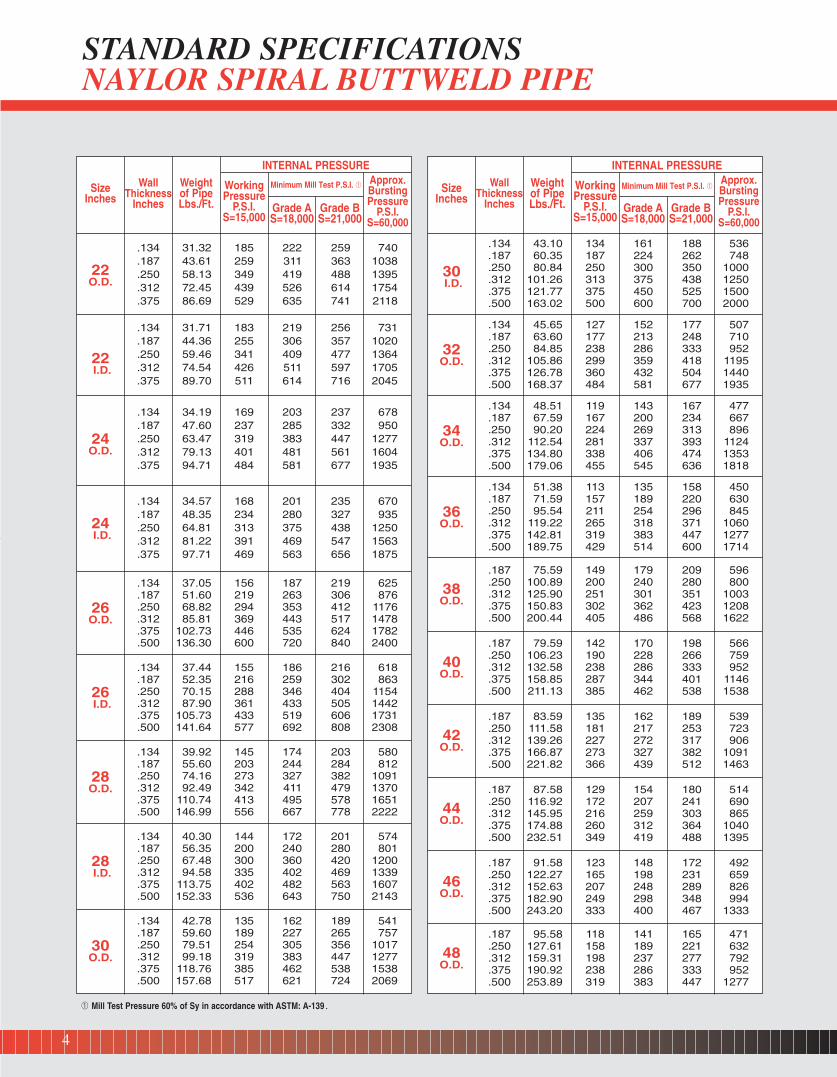
STANDARD SPECIFICATIONSNAYLOR SPIRAL BUTTWELD PIPE
À Mill Test Pressure 60% of Sy in accordance with ASTM: A-139.
3
WorkingPressure
P.S.I.S=15,000
SizeInches
22O.D.
22I.D.
.134 31.32 185 222 259 740
.187 43.61 259 311 363 1038
.250 58.13 349 419 488 1395
.312 72.45 439 526 614 1754
.375 86.69 529 635 741 2118
.134 31.71 183 219 256 731
.187 44.36 255 306 357 1020
.250 59.46 341 409 477 1364
.312 74.54 426 511 597 1705
.375 89.70 511 614 716 2045
24O.D.
.134 34.19 169 203 237 678
.187 47.60 237 285 332 950
.250 63.47 319 383 447 1277
.312 79.13 401 481 561 1604
.375 94.71 484 581 677 1935
24I.D.
.134 34.57 168 201 235 670
.187 48.35 234 280 327 935
.250 64.81 313 375 438 1250
.312 81.22 391 469 547 1563
.375 97.71 469 563 656 1875
26O.D.
.134 37.05 156 187 219 625
.187 51.60 219 263 306 876
.250 68.82 294 353 412 1176
.312 85.81 369 443 517 1478
.375 102.73 446 535 624 1782
.500 136.30 600 720 840 2400
26I.D.
.134 37.44 155 186 216 618
.187 52.35 216 259 302 863
.250 70.15 288 346 404 1154
.312 87.90 361 433 505 1442
.375 105.73 433 519 606 1731
.500 141.64 577 692 808 2308
28O.D.
.134 39.92 145 174 203 580
.187 55.60 203 244 284 812
.250 74.16 273 327 382 1091
.312 92.49 342 411 479 1370
.375 110.74 413 495 578 1651
.500 146.99 556 667 778 2222
28I.D.
.134 40.30 144 172 201 574
.187 56.35 200 240 280 801
.250 67.48 300 360 420 1200
.312 94.58 335 402 469 1339
.375 113.75 402 482 563 1607
.500 152.33 536 643 750 2143
30O.D.
.134 42.78 135 162 189 541
.187 59.60 189 227 265 757
.250 79.51 254 305 356 1017
.312 99.18 319 383 447 1277
.375 118.76 385 462 538 1538
.500 157.68 517 621 724 2069
WallThickness
Inches
Weightof PipeLbs./Ft.
WorkingPressure
P.S.I.S=15,000
INTERNAL PRESSURE
Minimum Mill Test P.S.I. À
Grade AS=18,000
Grade BS=21,000
Approx.BurstingPressure
P.S.I.S=60,000
SizeInches
30I.D.
32O.D.
.134 43.10 134 161 188 536
.187 60.35 187 224 262 748
.250 80.84 250 300 350 1000
.312 101.26 313 375 438 1250
.375 121.77 375 450 525 1500
.500 163.02 500 600 700 2000
.134 45.65 127 152 177 507
.187 63.60 177 213 248 710
.250 84.85 238 286 333 952
.312 105.86 299 359 418 1195
.375 126.78 360 432 504 1440
.500 168.37 484 581 677 1935
34O.D.
.134 48.51 119 143 167 477
.187 67.59 167 200 234 667
.250 90.20 224 269 313 896
.312 112.54 281 337 393 1124
.375 134.80 338 406 474 1353
.500 179.06 455 545 636 1818
36O.D.
38O.D.
.134 51.38 113 135 158 450
.187 71.59 157 189 220 630
.250 95.54 211 254 296 845
.312 119.22 265 318 371 1060
.375 142.81 319 383 447 1277
.500 189.75 429 514 600 1714
.187 75.59 149 179 209 596
.250 100.89 200 240 280 800
.312 125.90 251 301 351 1003
.375 150.83 302 362 423 1208
.500 200.44 405 486 568 1622
40O.D.
.187 79.59 142 170 198 566
.250 106.23 190 228 266 759
.312 132.58 238 286 333 952
.375 158.85 287 344 401 1146
.500 211.13 385 462 538 1538
42O.D.
.187 83.59 135 162 189 539
.250 111.58 181 217 253 723
.312 139.26 227 272 317 906
.375 166.87 273 327 382 1091
.500 221.82 366 439 512 1463
44O.D.
.187 87.58 129 154 180 514
.250 116.92 172 207 241 690
.312 145.95 216 259 303 865
.375 174.88 260 312 364 1040
.500 232.51 349 419 488 1395
46O.D.
.187 91.58 123 148 172 492
.250 122.27 165 198 231 659
.312 152.63 207 248 289 826
.375 182.90 249 298 348 994
.500 243.20 333 400 467 1333
48O.D.
.187 95.58 118 141 165 471
.250 127.61 158 189 221 632
.312 159.31 198 237 277 792
.375 190.92 238 286 333 952
.500 253.89 319 383 447 1277
WallThickness
Inches
Weightof PipeLbs./Ft.
WorkingPressure
P.S.I.S=15,000
INTERNAL PRESSURE
Minimum Mill Test P.S.I. À
Grade AS=18,000
Grade BS=21,000
Approx.BurstingPressure
P.S.I.S=60,000
STANDARD SPECIFICATIONS NAYLOR SPIRAL BUTTWELD PIPE
À Mill Test Pressure 60% of Sy in accordance with ASTM: A-139.
4

SizeInches
50O.D.
52O.D.
.250 132.96 152 182 212 606
.312 165.99 190 228 266 759
.375 198.94 228 274 320 914
.500 264.58 306 367 429 1224
.250 138.30 146 175 204 583
.312 172.67 182 219 255 730
.375 206.95 220 263 307 878
.500 275.27 294 353 412 1176
54O.D.
.250 143.65 140 168 196 561
.312 179.35 176 211 246 703
.375 214.97 211 254 296 845
.500 285.96 283 340 396 1132
56O.D.
.250 148.99 135 162 189 541
.312 186.03 169 203 237 677
.375 222.99 204 244 285 814
.500 296.65 273 327 382 1091
58O.D.
.250 154.34 130 157 183 522
.312 192.71 163 196 229 654
.375 231.01 197 236 275 786
.500 307.34 263 316 368 1053
60O.D.
.250 159.68 126 151 176 504
.312 199.40 158 189 221 632
.375 239.03 190 228 266 759
.500 318.03 254 305 356 1017
62O.D.
.250 165.03 122 146 171 488
.312 206.08 153 183 214 611
.375 247.04 184 220 257 735
.500 328.72 246 295 344 984
64O.D.
.250 170.37 118 142 165 472
.312 212.76 148 178 207 592
.375 255.06 178 213 249 711
.500 339.41 238 286 333 952
66O.D.
.250 175.72 115 137 160 458
.312 219.44 143 172 201 574
.375 263.08 172 207 241 690
.500 350.10 231 277 323 923
68O.D.
.250 181.06 111 133 156 444
.312 226.12 139 167 195 557
.375 271.10 167 201 234 669
.500 360.79 224 269 313 896
70O.D.
.250 186.41 108 129 151 432
.312 232.80 135 162 189 541
.375 279.11 162 195 227 650
.500 371.48 217 261 304 870
72O.D.
.250 191.75 105 126 147 420
.312 239.48 131 158 184 525
.375 287.13 158 189 221 632
.500 382.17 211 254 296 845
74O.D.
.250 196.91 101 122 143 405
.312 245.54 126 153 179 506
.375 294.87 152 184 215 608
.500 393.16 203 247 288 811
WallThickness
Inches
Weightof PipeLbs./Ft.
WorkingPressure
P.S.I.S=15,000
INTERNAL PRESSURE
Minimum Mill Test P.S.I. À
Grade AS=18,000
Grade BS=21,000
Approx.BurstingPressure
P.S.I.S=60,000
SizeInches
76O.D.
78O.D.
.250 202.25 99 118 138 395
.312 252.20 123 148 172 493
.375 302.95 148 178 207 592
.500 403.17 197 237 276 789
.250 207.59 96 115 135 385
.312 258.87 120 144 168 480
.375 310.97 144 173 202 577
.500 413.85 192 231 269 769
80O.D.
.250 212.93 94 113 131 375
.312 265.53 117 140 164 468
.375 318.98 141 169 197 563
.500 424.53 188 225 263 750
82O.D.
.312 272.20 114 137 160 457
.375 326.99 137 165 192 549
.500 435.21 183 220 256 732
84O.D.
.312 278.86 111 134 156 446
.375 335.00 134 161 188 536
.500 445.89 179 214 250 714
86O.D.
.312 285.53 109 131 152 435
.375 343.01 131 157 183 523
.500 456.57 174 209 244 698
88O.D.
.312 292.19 106 128 149 425
.375 351.03 128 153 179 511
.500 467.25 170 205 239 682
90O.D.
.312 298.85 104 125 146 416
.375 359.04 125 150 175 500
.500 477.93 167 200 233 667
92O.D.
.312 305.52 102 122 142 407
.375 367.05 122 147 171 489
.500 488.61 163 196 228 652
94O.D.
.312 312.18 100 119 139 398
.375 375.31 120 144 168 479
.500 499.29 160 191 223 638
96O.D.
.312 318.85 98 117 137 390
.375 383.07 117 141 164 469
.500 509.97 156 188 219 625
WallThickness
Inches
Weightof PipeLbs./Ft.
WorkingPressure
P.S.I.S=15,000
INTERNAL PRESSURE
Minimum Mill Test P.S.I. À
Grade AS=18,000
Grade BS=21,000
Approx.BurstingPressure
P.S.I.S=60,000
À Mill Test Pressure 60% of Sy in accordance with ASTM: A-139.
Notes:Please call for diameters and wall thicknesses other than those shown.
Collapse pressures and recommended span data available on request.All pressures in pounds per square inch.
Above 40” diameter, certain test pressures are reduced in heavy wallthickness to conform with testing equipment capacity.
STANDARD SPECIFICATIONS NAYLOR SPIRAL BUTTWELD PIPE
5

NAYLOR PIPEPILING
Inches
mm
10”254mm
103⁄4”273mm
123⁄4”324mm
16”406mm
12”305mm
14”356mm
18”457mm
20”508mm
18.8
20.2
22.6
24.0
26.4
30.2
34.1
37.9
19.7
21.2
23.7
25.2
27.7
31.7
35.8
39.8
21.2
22.9
25.6
27.2
29.9
34.2
38.6
42.9
21.9
23.5
26.3
28.0
30.8
35.2
39.7
44.2
22.9
24.6
27.6
29.3
32.2
36.9
41.6
46.3
24.0
25.8
28.9
30.8
33.8
38.7
43.7
48.6
26.0
28.0
31.4
33.4
36.7
42.1
47.4
52.7
N/A
N/A
35.2
37.4
41.2
47.2
53.2
59.2
N/A
N/A
38.9
41.4
45.6
52.3
58.9
65.6
N/A
N/A
N/A
49.6
54.6
62.6
70.6
78.6
NAYLOR STANDARD PILING SIZES(Weights per foot in pounds)
0.179
4.55
0.188
4.78
0.203
5.66
0.209
5.31
0.219
5.56
0.230
5.84
0.250
6.35
0.281
7.14
0.312
7.92
0.375
9.53
Your direct call to Naylor’s Chicago plant will give you personalized service including:
r Competitive Pricing r 100% domestic steel r Exact lengthsr Attached or loose end plates r Conical points, chill & splice rings as required
r In-plant inspection r Certification with the shipment r Prompt availability and on time delivery of test and production pile
Other sizes and wall thicknesses are available upon request.
6
OUTSIDE
DIAMETER
WALL THICKNESS

NAYLOR PIPE...SINCE 1925
While other pipe manufacturers have come and gone, Naylor continues to grow and prosper, concentrating on what it does best...
the manufacture of spiralweld pipe.
7

Naylor Lockseam Spiralweld steel pipe is manufactured instrict accordance with ASTM A-211. The standards set forthin this specification are closely adhered to in every phase ofproduction. Quality control is maintained by careful inspec-tion throughout. This is your assurance that Naylor pipeequals or exceeds the ASTM specification in every respect.
EXCLUSIVE STRUCTURENaylor Lockseam Spiralweld Pipe is formed from strip whichis lockseamed over an internal mandrel. This process createsan accurate tubular structure before it is welded. Thus, thelockseam carries the load and relieves the weld of stressesencountered when the pipe is in service. After the lockseam-ing operation, the pipe is welded by completely automaticmethods which insure a weld that is as strong as the parentmetal. Every length of Naylor Lockseam Spiralweld Pipe isinspected and tested to the hydrostatic mill test pressuresshown in the tables on the opposite page.
NAYLOR
LOCKSEAM
SPIRALWELD
PIPE
STRENGTHNaylor Lockseam Spiralweld Pipe provides greater overallstrength than other steel pipe of the same wall thickness--undercrushing loads, compression, collapse, and beam load at sup-ports. This greater strength--combined with the ability of thelockseam spiralweld to absorb shock loads, stresses andstrains--makes it possible for Naylor Lockseam SpiralweldPipe to handle jobs normally requiring heavier wall pipe.
SAFETYNaylor Lockseam Spiralweld Pipe incorporates a safety factorfound in no other pipe. When strains are put on the line, the“heel” of the lockseam moves minutely, shortening or length-ening the pipe. Because the “heel” is in spiral form, it acts asa continuous expansion joint throughout the line. It absorbsshock loads and vibration, often destructive to a weld on arigid structure. It cushions expansion and contraction undervarying changes of pressure, temperature and ground stress. Itprotects both pipe and coupling medium. This factor of “give”is of major importance in pipe line construction because itassures closer conformity to topographical conditions withoutany sacrifice of strength.
ACCURATE DIAMETERNaylor Lockseam Spiralweld Pipe is formed under tension ona lathe-turned mandrel, which assures a perfectly-round pipeof accurate diameter. The lockseam structure provides rein-forced strength to preserve the original true cylindrical form intransportation, installation and service. With ends that alwaysmatch correctly and this adherence to accurate diameter,Naylor Lockseam Spiralweld Pipe reduces the time required tomake connections, whether mechanically coupled or welded.
UNIFORM WALL THICKNESSNaylor pipe is manufactured from strip or sheet steel whichassures uniform wall thickness. Thickness tolerances are gov-erned by the standards established by the American Iron andSteel Institute.
EXACT LENGTHSNaylor Lockseam Spiralweld Pipe can be furnished in anydesired cut length up to and including 40’0”. While standardlengths are 20’0”, 30’0” or 40’0”, the piping can be cut to anyrequired length, to tolerance of plus-or-minus 1/8”.
STANDARD WEIGHT ENDSNaylor pioneered the development of lightweight pipe com-bined with standard weight ends. Thus, the advantage of lightweight pipe is realized and combined with standard fittingsand equipment common to industry.
ECONOMYNaylor Lockseam Spiralweld Pipe saves time, material andmoney for users. Its structure permits use on jobs normallyrequiring heavier-wall pipe. The relatively light weightreduces transportation, handling and installation costs as wellas the initial investment. High salvage and re-use value areassured by the accurate diameter and true cylindrical formwhich results from the lockseam spiralweld structure.
8

.08-.25
.30-.90.04 Max..04 Max..10 Max.
.08 Max.2.00 Max.1.00 Max.
18.00-20.008.00-12.00
.08 Max.2.00 Max.1.00 Max.
16.00-18.0010.00-14.00
2.00-3.00
À In accord with ASTM 211 using A570 Grade “A” Steel.Á Collapse pressures shown are for 6 pipe diameter lengths. Collapse pressure on longer lengths will be lower. Assume pipe bearing on 120˚ saddle supports.
STANDARD SPECIFICATIONSNAYLOR LOCKSEAM SPIRALWELD PIPE
Extra Low Carbon (ELC) grades and other analyses arealso available.
BASIC CARBON STEEL (ASTM A-570)Carbon ...................................................Manganese ...................................................Phosphorus ...................................................Sulphur ...................................................Silicon ...................................................
STAINLESS STEELType 304:Carbon ...................................................Manganese ...................................................Silicon ...................................................Chromium ...................................................Nickel ...................................................
Type 316:Carbon ...................................................Manganese ...................................................Silicon ...................................................Chromium ...................................................Nickel ...................................................Molybdenum ...................................................
STEEL ANALYSESUnless otherwise specified, Naylor LockseamSpiralweld Pipe is furnished in basic carbon steel. Forapplication where a high strength steel with superiorabrasion and corrosion resistance is desirable, this pipeis available in stainless steel to meet specific require-ments. The following are typical analyses of materials.
9
InsideDiameterInches
Wall ThicknessDecimalInches
Weightof Pipelbs./Ft.
OverallDiameter
Lockseam
RecommendedMax. Span
Pipe Filled withWater—Feet
Â
Mill TestPressure P.S.I.
Grade AS=20,000 #
À
WorkingPressure P.S.I.
S=12,500#
Approx.Bursting
Pressure P.S.I.S=50,000#
ExternalCollapsePressure
P.S.I.Á
45
6
.074 3.96 4.5976 16.6 740 467 1866 550.0
.074 4.74 5.5976 18.4 592 373 1492 375.0
.074 5.57 6.5976 20.0 493 311 1244 248.0
.104 7.94 6.8368 21.6 693 435 1740 479.0
.134 10.42 7.0760 22.8 893 562 2248 777.0
8
10
.074 7.22 8.5976 22.6 370 234 934 142.6
.104 10.23 8.8368 24.6 520 326 1304 273.7
.134 13.20 9.0760 26.1 670 422 1688 445.4
.074 9.00 10.5976 24.8 296 187 746 91.9
.104 12.74 10.8368 27.0 416 261 1042 176.8
.134 16.45 11.0760 28.8 536 337 1348 287.3
.164 20.40 11.3152 30.1 656 412 1646 428.4
12.074 10.72 12.5976 26.6 247 156 622 71.6.104 14.85 12.8368 29.2 347 217 868 124.4.134 19.10 13.0760 31.2 447 282 1126 200.6.164 23.90 13.3152 32.8 547 343 1372 299.2
131⁄4.074 11.82 13.8476 25.6 223 141 564 56.8.104 16.39 14.0868 30.4 314 197 788 102.5.134 21.08 14.3260 32.5 405 255 1018 167.9.164 26.35 14.5652 34.2 495 311 1242 248.2
14.074 12.50 14.5976 24.6 211 134 534 49.8.104 17.31 14.8368 31.1 297 186 744 91.9.134 22.25 15.0760 33.3 383 241 964 150.7.164 27.82 15.3152 35.0 469 294 1176 219.3
151⁄4.074 13.74 15.8476 22.6 194 123 490 40.9.104 19.03 16.0868 32.2 273 171 684 77.5.134 24.21 16.3260 34.4 351 222 886 127.3.164 30.28 16.5652 36.2 430 270 1080 187.0
16.074 14.42 16.5976 21.3 185 117 466 36.4.104 19.96 16.8368 32.5 260 163 652 70.7.134 25.41 17.0760 35.2 335 211 844 115.9.164 31.75 17.3152 37.0 410 258 1030 170.0
171⁄4.074 15.68 17.8476 18.9 172 108 432 30.5.104 21.51 18.0868 30.6 241 151 604 60.8.134 27.37 18.3260 36.2 311 196 782 99.9.164 34.19 18.5652 38.2 380 239 954 148.5
18.074 16.35 18.5976 18.3 164 105 420 27.6.104 22.43 18.8368 29.5 231 145 580 55.9.134 28.55 19.0760 36.9 298 188 750 91.9.164 35.66 19.3152 38.9 364 229 914 136.3
191⁄4.074 17.50 19.8476 16.8 154 97 388 23.6.104 23.98 20.0868 27.9 216 136 542 48.9.134 30.52 20.3260 37.1 278 175 700 80.5.164 38.12 20.5652 40.0 341 214 856 119.5
20.074 18.17 20.5976 15.7 148 94 374 21.5.104 24.91 20.8368 26.5 208 131 522 45.3.134 31.69 21.0760 35.9 268 169 676 74.6.164 39.60 21.3152 40.5 328 206 822 110.8
211⁄4.074 19.30 21.8476 14.2 139 88 352 18.7.104 26.46 22.0868 24.7 196 123 492 40.2.134 33.66 22.3260 34.2 252 159 636 66.2.164 42.06 22.5652 41.5 309 194 774 98.4
231⁄8.074 21.01 23.7226 12.4 128 81 324 15.3.104 28.78 23.9618 22.1 179 113 452 33.8.134 36.61 24.2010 31.6 231 146 584 55.9.164 45.74 24.4402 39.7 283 178 712 83.3
24.074 21.80 24.5976 11.5 123 78 312 14.0.104 29.87 24.8368 21.0 173 109 434 31.0.134 37.99 25.0760 30.3 223 141 562 52.0.164 47.44 25.3152 38.6 273 172 686 77.3
26.074 23.59 26.5976 9.9 114 72 288 11.5.104 32.34 26.8368 18.6 160 101 402 25.7.134 41.14 27.0760 27.4 206 130 518 44.5.164 51.37 27.3152 36.1 252 159 634 66.1
28.074 25.42 28.5976 8.6 106 67 268 9.7.104 34.81 28.8368 16.5 149 94 374 21.6.134 44.28 29.0760 25.2 191 121 481 38.2.164 55.30 29.3152 33.4 234 147 588 57.1
30.074 27.23 30.5976 7.5 99 62 248 8.2.104 37.29 30.8368 14.6 138 87 348 18.3.134 47.23 31.0760 22.8 179 113 450 33.1.164 59.23 31.3152 30.9 218 138 550 49.8

NAYLORCONVENTIONAL WEDGELOCK COUPLINGS
Built in one piece with gasket already in place,Naylor Wedgelock Couplings provide thefastest and easiest way to connect grooved endor shoulder end pipe.
They provide a simple yet positive connectionthat is anchored to the end of the pipe and willnot allow the line to separate or pull apart. Ahammer is the only tool required to connect ordisconnect them. A joint can be made up withonly one side of the pipeline in the open.Since the Wedgelock takes up little more
space than the diameter of the pipe itself, theline can hug the wall in tunnels, mines, orwherever space is limited.
Wedgelock Couplings are designed to providea small degree of deflection in each joint. Thisdesign allows for expansion and contraction,and replacement of joints can be made at anypoint without disturbing the balance of the line.The couplings also permit a number of lengthsto be rotated, when desired, without disturbingthe balance of the line.
Standard One-Piece,Positive Type Couplings
for Speed, Simplicity and Economy
of Connection onSpiral Buttweld and
Lockseam Spiralweld Pipe
HEAVY DUTY WEDGELOCK COUPLINGThe Naylor Heavy Duty Wedgelock Coupling was designed for use withboth Naylor Lockseam and Spiral Buttweld Piping Systems. This cou-pling, when used with exact Naylor sized ends, enables you to selectthe proper combination of diameter and wall thickness to fit your exact requirements.Use of this coupling is well-suited on such applications as hydraulicking,water supply lines, dredging, sludge lines and air lines.Figure 1 shows the standard accurately-sized Naylor grooved ends buttwelded to the pipe.Figure 1SB shows the slip-over type end which is preferred for use inabrasive service where the pipe is subject to excessive wear. The slip-over end can be a standard grooved end or the less expensive bandtype end as illustrated.
LOW PRESSURE WEDGELOCK COUPLINGNaylor offers the Low-pressure Wedgelock Coupling to meet the need for a fast,positive type coupling method in ventilating lines and similar low-pressure service on either lockseam spiralweld or spiral buttweld pipe.Figure 2 shows the 3/8” Square Shoulder End which is the conventionalend preparation for the Low-pressure Wedgelock Coupling. Figure 2Ashows the alternate grooved end.
To open one-piece coupling, drive wedge into two parallel lugs.
1 Slip coupling over pipeand put next section of pipe in place.
2 Drive out opening wedgeso coupling snaps into placeon grooved ends of pipe.
3 Drive wedge home into thethree lugs on coupling.Nothing so simple...nothingso fast.
4
FOUR SIMPLE STEPS SPEED CONNECTIONS WITH STANDARD WEDGELOCK COUPLINGS
Fig. 1
Fig. 1SB
Fig. 2A
Fig. 2
10

NAYLOR HINGED WEDGELOCK COUPLINGS
HINGED HEAVY-DUTYWEDGELOCK COUPLING
The Naylor Heavy-Duty Hinged Wedgelock Coupling shown inFigure 1H is a variation of the Naylor standard one-piece heavy-dutycoupling and offers additional advantages for both permanent andtemporary lines. While retaining the simplicity and speed of the standardWedgelock, the hinged coupling introduces greater flexibility to broadenthe use of this versatile connection. The continuous ring gasket provides theseal to withstand the stresses and strains of expansion and contraction inprolonged service. The hinged design and ease of operation offer usersthe opportunity to replace uniform pipe lengths and/or rotate a number oflengths without disturbing the balance of the line.
HINGED HIGH PRESSUREWEDGELOCK COUPLING
For use with Naylor Spiral Buttweld ventilating lines, thisvariation of the Naylor Hinged Wedgelock Couplingmeets the requirements for an inexpensive yet air-tightconnector. This quick-connecting and versatile couplingis available in sizes to 72”. The multiple hinge designwith a one-piece ring gasket provides the leak-tight positive connection.
HINGED INTERMEDIATE PRESSUREWEDGELOCK VENTILATING
COUPLING
Lubricate pipe ends withwater soluble lubricantand slide gasket over onepipe end.
1 Bring pipe sections together andslide gasket over the joint.Lubricate outside of gasket withwater soluble lubricant.
2 Fit housing over gasket andclose coupling into groovedends of pipe.
3 Insert wedge into the threelugs on coupling and drive ithome with a hammer.
4
EASY-TO-INSTALL HINGED WEDGELOCK COUPLINGS
The Naylor Extra-Heavy-Duty Hinged WedgelockCoupling is similar to Figure 1H and is designed toaccommodate higher pressure applications and providean efficient coupling for larger diameter lines. Accuratelysized ends and gaskets, combined with a heavier crosssection coupling channel extend the size and pressurerange of this effective, economical connector.
11
Fig. 1HFig. 2H
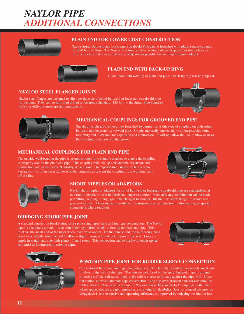
NAYLOR PIPEADDITIONAL CONNECTIONS
PLAIN END FOR LOWER COST CONSTRUCTIONNaylor Spiral Buttweld and Lockseam Spiralweld Pipe can be furnished with plain, square-cut endsfor field butt welding. The Naylor structure provides accurate diameter, preserves true cylindricalform, with ends that always match correctly, makes possible the welding of plain-end pipe.
PLAIN END WITH BACK-UP RINGTo facilitate field welding of plain-end pipe, a back-up ring can be supplied.
Naylor short nipples or adaptors for spiral buttweld or lockseam spiralweld pipe are standardized atone foot in length, but can be furnished longer or shorter. Practically any combination can be made,permitting coupling of any type to be changed to another. Illustrations show flange-to-groove andgroove-to-thread. Other units are available to transpose to any connection in this section, or specialconnections where required.
PONTOON PIPE JOINT FOR RUBBER SLEEVE CONNECTION
NAYLOR STEEL FLANGED JOINTSNaylor steel flanges are designed to slip over the ends of spiral buttweld or lockseam spiralweld pipefor welding. They can be furnished drilled to American Standard (125 lb.), to the Spiral Pipe Standard(SPS), or drilled to meet special requirements.
Conventional half-oval band type pontoon pipe joint. These half-ovals are accurately sized and fit close to the wall of the pipe. The outside weld bead on the spiral buttweld pipe is ground smooth a sufficient distance to allow the rubber sleeve to fit snug against the pipe wall. Upper illustration shows an alternate type construction using slip-over grooved ends for retaining the rubber sleeves. This permits the use of Naylor Heavy-Duty Wedgelock couplings in the line where rubber sleeves are not required at every joint for flexibility. Cost is reduced because theWedgelock is less expensive and operating efficiency is improved by reducing the friction loss.
DREDGING SHORE PIPE JOINTA standard connection for dredging shore pipe using taper band and lug type construction. The Naylortaper is accurately shrunk to size either from cylindrical stock or directly on plain end pipe. Thisthickens the small end of the taper where most wear occurs. On the female end, the reinforcing bandis set back slightly from the end to allow a slight flaring action which improves the seal. Lugs areample in weight and size with plenty of hand room. This connection can be used with either spiralbuttweld or lockseam spiralweld pipe.
SHORT NIPPLES OR ADAPTORS
The outside weld bead on the pipe is ground smooth for a suitable distance to enable the couplingto properly seat on the plain end pipe. This coupling will take up considerable expansion and contraction, and permit some flexibility at each joint. On exposed lines subject to temperaturevariations, it is often necessary to provide harnesses to prevent the coupling from working itselfoff the line.
Standard weight grooved ends are furnished to permit use of this type of coupling on both spiral buttweld and lockseam spiralweld pipe. Simple and easily connected, this joint provides some flexibility and allowance for expansion and contraction. It will not allow the line to blow apart as the coupling is anchored in the groove.
MECHANICAL COUPLINGS FOR PLAIN END PIPE
MECHANICAL COUPLINGS FOR GROOVED END PIPE
12
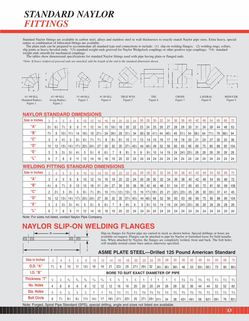
Standard Naylor fittings are available in carbon steel, alloys and stainless steel in wall thicknesses to exactly match Naylor pipe sizes. Extra heavy, specialradius or combination of fabricated fittings are available.
The plain ends can be prepared to accommodate all standard type end connections to include: (1) slip-on welding flanges; (2) welding rings, collars,slip joints or heavy beveled ends; *(3) standard weight ends grooved for Naylor Wedgelock couplings or other positive type couplings; *(4) standard weight ends smooth for mechanical couplings.
The tables show dimensional specifications for standard Naylor fittings used with pipe having plain or flanged ends.
*Note: If heavy reinforced grooved ends are attached, add the length of the end to the standard dimension shown.
NAYLOR SLIP-ON WELDING FLANGESSlip-on flanges for Naylor pipe are carried in stock as shown below. Special drillings or bores are available on request. Flanges can be attached to pipe by Naylor or furnished loose for field installa-tion. When attached by Naylor, the flanges are completely welded, front and back. The bolt holeswill straddle normal center lines unless otherwise specified.
Size in Inches
“A”
“B”
“C”
“D”
“E”
“L”
3 4 5 6 8 10 12 14 16 18 20 22 24
51⁄2 61⁄2 71⁄2 8 9 11 12 14 15 161⁄2 18 20 22
73⁄4 9 101⁄4 111⁄2 14 161⁄2 19 211⁄2 24 261⁄2 29 311⁄2 34
3 4 41⁄2 5 51⁄2 61⁄2 71⁄2 71⁄2 8 81⁄2 91⁄2 10 11
10 12 131⁄2 141⁄2 171⁄2 201⁄2 241⁄2 27 30 32 35 371⁄2 401⁄2
3 3 31⁄2 31⁄2 41⁄2 5 51⁄2 6 61⁄2 7 8 81⁄2 9
6 7 8 9 11 12 14 16 18 19 20 22 24
26 28 30 32 34 36 38 40 42 48 54 60 66 72
23 24 25 26 27 28 29 30 31 34 39 44 48 53
361⁄2 39 411⁄2 44 461⁄2 49 511⁄2 54 561⁄2 64 711⁄2 79 861⁄2 94
13 14 15 16 17 18 19 20 21 24 27 30 33 36
44 461⁄2 49 52 56 60 63 66 69 75 80 88 95 104
9 91⁄2 10 14 19 24 243⁄4 251⁄2 26 26 26 26 28 28
24 24 24 24 24 24 24 24 24 24 24 24 24 24
Size in Inches
“A”
“B”
“C”
“D”
“E”
“L”
3 4 5 6 8 10 12 14 16 18 20 22 24
3 4 5 6 8 10 12 14 16 18 20 22 24
41⁄2 6 71⁄2 9 12 15 18 21 24 27 30 33 36
2 21⁄2 3 33⁄4 5 61⁄4 71⁄2 83⁄4 10 111⁄4 121⁄2 131⁄2 15
10 12 131⁄2 141⁄2 171⁄2 201⁄2 241⁄2 27 30 32 35 371⁄2 401⁄2
3 3 31⁄2 31⁄2 41⁄2 5 51⁄2 6 61⁄2 7 8 81⁄2 9
6 7 8 9 11 12 14 16 18 19 20 22 24
26 28 30 32 34 36 38 40 42 48 54 60 66 72
26 28 30 32 34 36 38 40 42 48 54 60 66 72
39 42 45 48 51 54 57 60 63 72 81 90 99 108
16 171⁄4 181⁄2 20 21 221⁄4 231⁄2 25 26 30 331⁄2 37 41 45
44 461⁄2 49 52 56 60 63 66 69 75 80 88 95 104
9 91⁄2 10 14 19 24 243⁄4 251⁄2 26 26 26 26 28 28
24 24 24 24 24 24 24 24 24 24 24 24 24 24
Size in Inches
O.D. “A”
I.D. “B”
Thickness “T”
No. Holes
Dia. Holes
Bolt Circle
3 4 5 6 8 10 12 14 16 18 20 22 24
71⁄2 9 10 11 131⁄2 16 19 21 231⁄2 25 271⁄2 291⁄2 32
BORE TO SUIT EXACT DIAMETER OF PIPE
1⁄2 1⁄2 9⁄169⁄16
9⁄1611⁄16
11⁄163⁄4 3⁄4 3⁄4 3⁄4 1 1
4 8 8 8 8 12 12 12 16 16 20 20 203⁄4 3⁄4 7⁄8 7⁄8 7⁄8 1 1 11⁄8 11⁄8 11⁄4 11⁄4 13⁄8 13⁄8
6 71⁄2 81⁄2 91⁄2 113⁄4 141⁄4 17 183⁄4 211⁄4 223⁄4 25 271⁄4 291⁄2
26 28 30 36 42 48 54 60 66 72
341⁄4 361⁄2 383⁄4 46 53 591⁄2 661⁄4 73 80 861⁄2
1 1 1 11⁄8 11⁄4 13⁄8 13⁄8 11⁄2 11⁄2 11⁄2
24 28 28 32 36 44 44 52 52 60
13⁄8 13⁄8 13⁄8 15⁄8 15⁄8 15⁄8 17⁄8 17⁄8 17⁄8 17⁄8
313⁄4 34 36 423⁄4 491⁄2 56 623⁄4 691⁄4 76 821⁄2
NAYLOR STANDARD DIMENSIONS
WELDING FITTING STANDARD DIMENSIONS
ASME PLATE STEEL—Drilled 125 Pound American Standard
Note: Forged, Spiral Pipe Standard (SPS), special drilling, angle and sizes not listed are available.
Note: For sizes not listed, contact Naylor Pipe Company.
61o-90o ELL(Standard Radius)
Figure 1
61o-90o ELL(Long Radius)
Figure 2
31o-60o ELLFigure 3
0o-30o ELLFigure 4
TRUE WYEFigure 5
TEEFigure 6
CROSSFigure 7
LATERALFigure 8
REDUCERFigure 9
13
STANDARD NAYLOR FITTINGS
TA
B

CONSTRUCTIONTemporary or permanent lines for high and low-pressure air; high and low-pressure water; ventilating lines; cement placing; hydraulic sluicing;de-watering and drainage; well-point headers; exhaustand intake; foundation piling; caissons and tank supports.
MINING AND QUARRYINGWater pipe; high and low-pressure air lines; ventilat-ing pipe; tailings or slurry pipe lines; sand, gravel andother product lines.
DREDGINGAvailable in abrasion resistant steel. Shore pipe; pontoon pipe; intake and discharge pipe; sand andgravel conveying lines. All types of dredging connections.
MATERIALS HANDLINGSand, gravel, product and material handling lines;wash water lines; slurry and tailings pipe; rubber-lined pipe; sludge lines; fly ash disposal pipe; pneumatic conveyors.
POLLUTION CONTROLFiltration plant piping; waste water lines; air purification pipe; sludge disposal systems.
SEWAGE DISPOSALForce mains, sludge lines; disposal plant aeration piping; siphons; temporary sewer by-pass lines.
PAPER MILLSStock lines; pulp lines; vacuum lines; white waterlines; hot and cold water lines; condensate lines; ventilating pipe; exhaust steam; compressed air lines;pneumatic conveying lines; bark, chips and trim disposal.
AGRICULTURESurface and underground main lines for irrigation;water-well casing; water supply and de-watering.
INDUSTRIAL PLANTSHigh and low-pressure air; water supply; ventilatinglines; gas piping and manifolds; diesel exhaust and in-take, low-pressure steam lines; cooling tower piping, drainage lines; spray pond piping; bridgecrossings.
PRODUCT COMPONENTSPipe sections furnished as component parts of manufactured products; such as portable grain conveyors, tanks, containers, manifolds, and structural members.
FABRICATIONSStandard fittings and all types of connections areavailable from stock for standard piping layouts.Precision fabrications to meet specifications for special or complex layouts are available.
14
NAYLOR SPIRALWELD PIPE APPLICATIONS

15
NAYLOR LOCKSEAMSPIRALWELD PIPE(ASTM A-211)
Sizes:4” to 30” in diameter
Thicknesses:14 gauge (.074) to 8 gauge (.164)
Lengths:40’0” line pipe standard20’0” industrial standardCut to exact specified lengths
NAYLOR SPIRALBUTTWELD PIPE(ASTM A-139)
Sizes:6” to 96” in diameter
Thicknesses:10 gauge (.134) to 1/2” (.500)
Lengths:Pipe cut to exact specified lengthsor 20’0” industrial standard,40’0”, 50’0”, 60’0” line pipestandard. Structural piping upto 100’0” long.
Supplemental Information Required For Ordering Naylor Pipe
Service:State operating conditionsMaterial being conveyedTemperature rangePressure -- positive or vacuumLocation -- If above ground, statewhether suspended or supported.If below ground, give depth andtype of fill.
Coatings:Standard black mill coating
Outside only or inside and outRed Iron Oxide
Outside only or inside and outGalvanizedEpoxy type coatingsFusion Bond EpoxyOther Coatings Available
Fabrications:All types of pipe and fitting fabrications, regardless of complexity, built to meet exactdesign specifications.
Linings:Rubber CementPlastic BasaltSynthetic Resin CeramicEpoxy Polyurethane
Fittings: A complete line of welded steelfittings, standard or special. See page 13.
Flanges: ASME Plate Steel Special PlatesSPS Plate Steel ForgingsSee page 13.
Connections:All types of connections availableincluding one-piece positive typeNaylor Wedgelock coupling. See pages 10, 11 and 12.
NAYLOR PIPEORDERING GUIDE
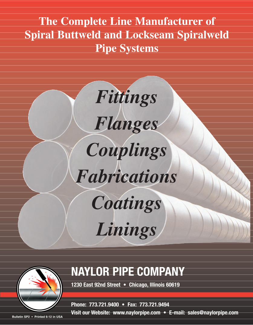
NAYLOR PIPE COMPANY1230 East 92nd Street • Chicago, Illinois 60619
The Complete Line Manufacturer of Spiral Buttweld and Lockseam Spiralweld
Pipe Systems
Phone: 773.721.9400 • Fax: 773.721.9494Visit our Website: www.naylorpipe.com • E-mail: [email protected]
FittingsFlanges
CouplingsFabrications
CoatingsLinings
Bulletin SP2 • Printed 6-12 in USA