navigating using radar - nbpss.on.ca · navigating using radar ... colour displays have a distinct...
TRANSCRIPT

Navigating using Radar
6.0 The Radar display
From an operator’s point of view, all of the foregoing discussion is window dressing if the display function of the radar cannot present all of the gathered information in a logical, easy to interpret, visual display.
6.1 Display types
All of the readily available radar sets that fall into the small marine category use raster scan technology to present the radar picture. Early radar sets used mechanically driven Plan Position Indicator (PPI) CRTs to match the scan of the antenna and thus draw the actual picture. Modern displays apply digital processing to transform the ”rotating” analogue data from the receiver into a TV-like format. Each row of information is drawn across the display surface from left to right, and, from top to bottom. This is called a raster scan. To do this, the face of the display is divided into a series of rows and columns, made up of individually addressable locations in the display memory of the unit, like a computer monitor. The display is usually rotated into a vertical “portrait” orientation.
These individually addressable locations are called pixels, which is short for addressable picture[pix] elements[els]. They determine the overall definition and clarity of the displayed data. A “640 deep x 480 wide” display has 640 rows, each with 480 pixels, for a total amount of 307 200 individually addressable locations in the display memory, and thus, on the display surface.
A “ 320 x 240” display has 76 800 of these addressable locations. Therefore it has only one fourth of the picture definition and subsequent clarity of the first display type. The display circuitry manipulates the incoming information and then inserts the radar data into the appropriate location as it is passed to it from the receiver. The display can overlay other information such as text, or data from other sources such as a connected GPS, etc., as long as compatibility exists between the devices.
Page 47

Navigating using Radar
Figure 6.1 7" LCD 320 x 240 Radar display with directional rocker
The two currently available types of display faces are the Liquid Crystal Display (LCD), Figure 6.1, and the Cathode Ray Tube (CRT), Figure 6.2. The LCD unit has the distinct advantages of low power consumption and better moisture resistance, but it has limited readability in direct sunlight or other bright lighting conditions. The CRT unit has the advantages of having much higher definition, and a more easily read, clearer picture. However, the definite disadvantages of a CRT unit are its heat generation and its hunger for power.
Page 48
Navigating using Radar
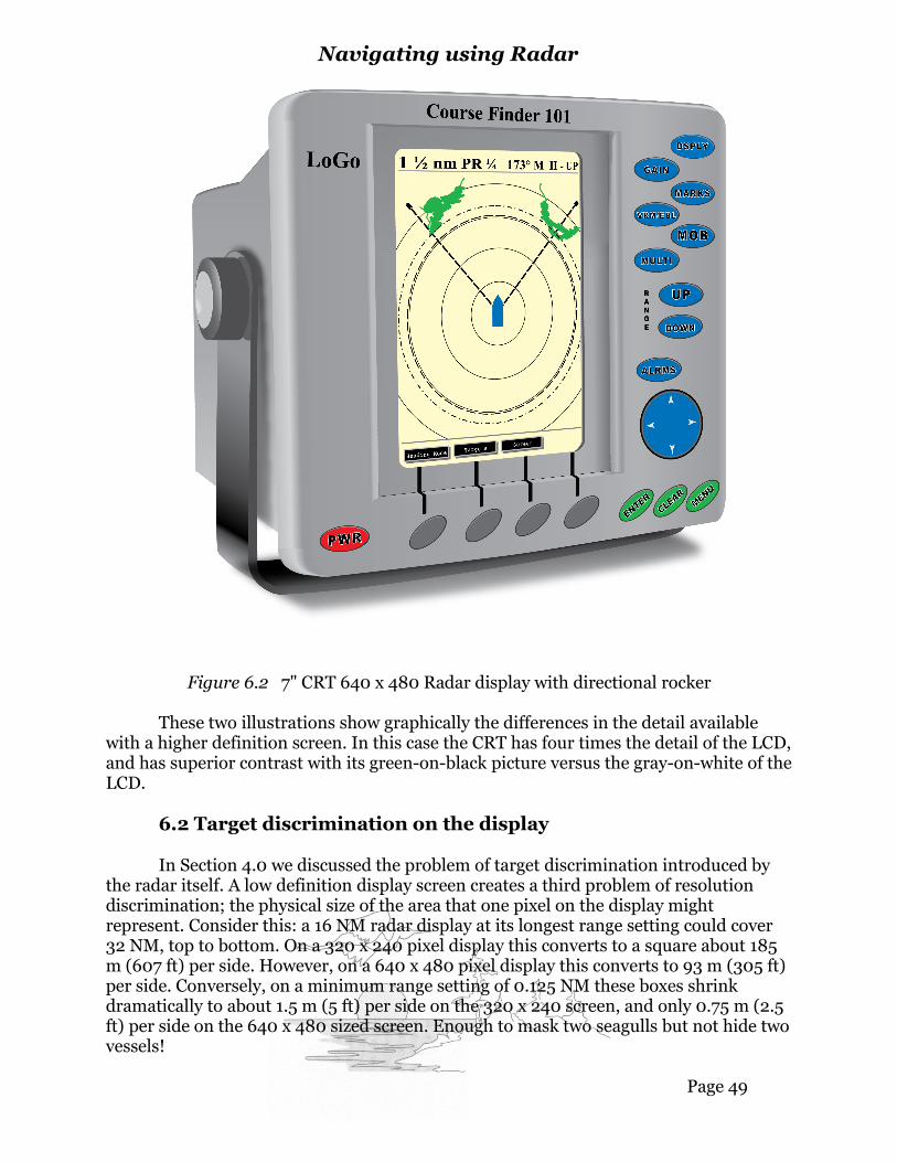
Figure 6.2 7" CRT 640 x 480 Radar display with directional rocker
These two illustrations show graphically the differences in the detail available with a higher definition screen. In this case the CRT has four times the detail of the LCD, and has superior contrast with its green-on-black picture versus the gray-on-white of the LCD.
6.2 Target discrimination on the display
In Section 4.0 we discussed the problem of target discrimination introduced by the radar itself. A low definition display screen creates a third problem of resolution discrimination; the physical size of the area that one pixel on the display might represent. Consider this: a 16 NM radar display at its longest range setting could cover 32 NM, top to bottom. On a 320 x 240 pixel display this converts to a square about 185 m (607 ft) per side. However, on a 640 x 480 pixel display this converts to 93 m (305 ft) per side. Conversely, on a minimum range setting of 0.125 NM these boxes shrink dramatically to about 1.5 m (5 ft) per side on the 320 x 240 screen, and only 0.75 m (2.5 ft) per side on the 640 x 480 sized screen. Enough to mask two seagulls but not hide two vessels!
Page 49

Navigating using Radar
6.3 Colour displays
Some models of recreational radar use colour CRT displays. However, production costs for high contrast, high definition colour LCD panels are steadily decreasing to meet the growing demand for digital personal computer monitors and TVs. This is allowing colour LCD panels to steadily displace the monotone CRT and lower definition LCD radar displays.
Colour displays have a distinct advantage in the presentation of the radar picture. The receiver can easily pass an indication of the signal strength of the received echo to the display processor. This would allow a colour value to be assigned to each pixel indicating this to the operator. Imagine how much easier it would be to read the display if echoes were displayed from very weak to very strong using, perhaps, red, yellow, blue, and green!
6.4 Digital display processing
Thanks to digital processing, the basic radar picture can be enhanced without losing the integrity of the received data. For instance, not only can the various range changes be rapidly displayed, with suitable range marks, but the relative location of the vessel itself, shown on the display, can also be offset to allow the operator to look towards a particular area of interest.
6.4.1 Movable range markers and bearing lines
The real advantage of this digital flexibility is its ability to superimpose an operator-controllable azimuth indicator called the Electronic Bearing Line (EBL) and its complementary Variable Range Marker (VRM). These lines or rings can be moved across the screen using either a directional rocker switch or a trackball. The azimuth drawn by the EBL and the range of the VRM ring are displayed, with great accuracy, in one of the text areas of the display (see Figure 6.3 overleaf). Some models combine both of these functions into a trackball-controlled cursor. The cross–shaped cursor icon can be “rolled” into place over the point of interest. The azimuth and range from origin to the cursor position is then shown in a text window on the display screen. These features are much more precise than the trusty old grease pencil that we once used!
Page 50

Navigating using Radar
Figure 6.3 EBL, VRM and radar target trails
As technology sprints ahead, more standard features are appearing with each generation of manufacturer’s displays. Two EBLs are now offered on many models, and the origin of one, or both, can be moved to any location on the display to obtain accurate bearings between any two points in the display area. The VRM associated with the EBL can then be moved along the offset bearing line and an accurate range between these two offset points can be immediately measured. This feature is a great benefit to the navigator.
Page 51

Navigating using Radar
6.4.2 Target trails
The classic attribute of a target moving across the screen, leaving a slowly fading trail behind it, disappeared with the demise of the mechanical PPI CRT and its long-persistence phosphor coating. This feature is now provided electronically and can be selected, with the displayed trail lengthened or shortened, at the operator’s pleasure, as illustrated in Figure 6.3 above. These trails or wakes provide key information at a glance: relative movement, direction of travel, and opening or closing speed. This feature should never be switched off.
6.4.3 Guard zones
Two other common features to aid the watchkeeper are the Guard Zone and the Intermittent or Sleep modes of operation. A Guard Zone can be set up using the EBL control to indicate the desired arc, by start and stop azimuths, with the desired depth of zone inserted, using the VRM to set the start and stop ranges.
When activated, any consistent targets entering the zone will trigger an audible alarm, hopefully bringing the watchkeeper’s attention to the display (see Figure 6.4 on the next page). Depending upon the system manufacturer, these zones can be activated for targets inbound to, or outbound from, the zone. This is a good safety feature as it allows the guard zone to be set so that large fast targets will trigger the alarm on the outer edge of the zone, while smaller weaker targets trip the closer, inner boundary. Guard zones can be extended to 360º around the vessel, if so desired.
This feature can be tricky to set up and monitor in heavy seas, due to sea clutter causing false alarms. The Guard Zone feature will not work effectively if the outer perimeters of the zone are set up beyond the reasonable pickup range of desired targets.
Page 52

Navigating using Radar
Figure 6.4 Guard zones
6.5 Intermittent operation
The Intermittent, Timed Transmit or Sleep mode is intended to allow the radar to automatically go into standby operation for user-selected periods of time, then reactivate the transmitter for selected periods of time. Manufacturers have slightly different methods of controlling this feature, by time, or by sweeps of the antenna, but they all have the same end result. As well, this feature can extend precious battery power.
Page 53

Navigating using Radar
6.6 Night operation
A useful feature for night use on LCD displays is their ability to invert the display colours or shades. The screen background becomes dark and the radar returns show light. This is more like a traditional radar display. A dim, red backlight on some models reduces the brilliance of the light from the display surface, thus helping the retention of the watchkeeper’s night vision while still providing good radar intelligence.
Text displays across the top and/or the bottom of the display area provide the operator with pertinent information, for example, the relative bearing and range at which the VRM and EBL lines have been set. Radar sets now come with the ability to accept inputs from external devices.
6.7 External inputs
6.7.1 GPS and fluxgate compass inputs
The most popular extra input is GPS. When these two devices are properly interfaced, the geographic location of the GPS antenna is displayed in the text area of the radar display. Adding an input from a compatible fluxgate compass allows the display of the ship’s heading, as well as allowing the operator to change the radar picture display from the classic “ Heading up” to “ Course up”, “ North up - True”, or “ North up - Magnetic”.
Once compass information is also available, the next GPS waypoint, or series of waypoints in a GPS route, can be overlaid with accuracy, onto the radar display. This representation known as the “lollipop” on most displays because of its appearance. A line is displayed on the screen from the last waypoint to the next, with the next waypoint location shown inside a circle, the lollipop!
Page 54

Navigating using Radar
Figure 6.5 GPS waypoint “lollipop”
With the desired GPS course line between waypoints overlaid on the radar display, the navigator and/or helmsman has a visual reference as to whether or not the boat is on its projected course, off course to port or starboard, and by how much (i.e. Cross Track Error (XTE)).
6.7.2 Chart information display
Lastly, for our purposes, a highly integrated system can display chart information. Some systems are able to overlay the radar returns onto a graphic display of the chart. This capability is not available on models which show the radar picture in a separate window on the same display screen. The composite display feature is becoming more common and is now available on computer displays that accept inputs from the radar control/display unit.
Note 1: The faces of some LCD or CRT displays have an additional glass or hard plastic protective surface that allows the use of grease pencils or other graphic marker pens, without the risk of damaging the actual display surfaces. Commercial level displays usually have an extra reflective surface that does permit the use of marker pens and pencils.
Note 2: With the reintroduction of LORAN-C equipment, the routes and waypoints from a capable LORAN-C unit can also be overlaid on the radar screen.
Page 55

Navigating using Radar
6.8 Summary
There are three types of physical displays: the classic CRT, the most common grayscale LCD, and the increasingly available colour displays, both CRT and LCD.
All of these radar displays use digital technology to present the received radar data, and can superimpose line, outline, and text information on the display screen.
The clarity, definition, and resolution of each display depends upon the number of pixels the display can present. A 640 x 480 display surface has four times the information detail shown than a 320 x 240 surface.
A well-designed colour display has a multiplier effect upon the data shown, by adding as many as four intelligent (colour) values to each of the pixels displayed.
Azimuth lines and range circles are accurately superimposed on the radar displays.
Next - Atmospheric and weather effects
The real usefulness of a radar set is its ability to provide us with information about hidden objects and obstacles around us. Obviously, this is not as useful when we are looking at a clear horizon around our boat. It becomes a different story in the pitch dark with zero visibility, compounded by foul weather. In these conditions the weather can also affect the radar, reducing its sensitivity and ability to see clearly. In the next segment we will look at some of these weather and atmospheric phenomena.
Page 56