navedtra_14014_airman
DESCRIPTION
Presents an overview of naval aviation and includes subject matter coverage of the following: mission and history of naval aviation; organization of naval aviation; principles of flight; aircraft construction; aircraft hardware; aircraft power plants; aircraft avionics; ordnance; support equipment, line operations and safety; aircrew survival equipment; and crash rescue and fire fighting.TRANSCRIPT

AIRMANNAVEDTRA 14014
NONRESIDENTTRAININGCOURSE
July 2000
DISTRIBUTION STATEMENT A: Approved for public release; distribution is unlimited.

Although the words “he,” “him,” and“his” are used sparingly in this course toenhance communication, they are notintended to be gender driven or to affront ordiscriminate against anyone.
DISTRIBUTION STATEMENT A: Approved for public release; distribution is unlimited.

PREFACE
By enrolling in this self-study course, you have demonstrated a desire to improve yourself and theNavy. Remember, however, this self-study course is only one part of the total Navy trainingprogram. Practical experience, schools, selected reading, and your desire to succeed are alsonecessary to successfully round out a fully meaningful training program.
THE COURSE: This self-study course is organized into subject matter areas, each containinglearning objectives to help you determine what you should learn along with text and illustrationsto help you understand the information. The subject matter reflects day-to-day requirements andexperiences of personnel in the rating or skill area. It also reflects guidance provided by EnlistedCommunity Managers (ECMs) and other senior personnel, technical references, instructions,etc., and either the occupational or naval standards, which are listed in the Manual of NavyEnlisted Manpower Personnel Classifications and Occupational Standards, NAVPERS 18068.
THE QUESTIONS: The questions that appear in this course are designed to help youunderstand the material in the text.
VALUE: In completing this course, you will improve your military and professional knowledge.Importantly, it can also help you study for the Navy-wide advancement in rate examination. Ifyou are studying and discover a reference in the text to another publication for furtherinformation, look it up.
2000 Edition Prepared byAMSC(AW/NAC) Archie Manning
Reissued on March 2001 to correctminor discrepancies or update
information. No significant changeshave been made to content.
Published byNAVAL EDUCATION AND TRAINING
PROFESSIONAL DEVELOPMENTAND TECHNOLOGY CENTER
i
NAVSUP Logistics Tracking Number504-LP-022-40500

ii
Sailor’s Creed
“I am a United States Sailor.
I will support and defend theConstitution of the United States ofAmerica and I will obey the ordersof those appointed over me.
I represent the fighting spirit of theNavy and those who have gonebefore me to defend freedom anddemocracy around the world.
I proudly serve my country’s Navycombat team with honor, courageand commitment.
I am committed to excellence andthe fair treatment of all.”

TABLE OF CONTENTS
APPENDIX
iii
CHAPTER PAGE
INDEX ........................................................................................................................... INDEX-1
1. Mission and History of Naval Aviation.................................................................. 1-1
2. Organization of Naval Aviation............................................................................. 2-1
3. Principles of Flight................................................................................................ 3-1
4. Aircraft Basic Construction ................................................................................... 4-1
5. Aircraft Hardware ................................................................................................. 5-1
6. Aircraft Power Plants ............................................................................................ 6-1
7. Aircraft Avionics................................................................................................... 7-1
8. Aircraft Ordnance.................................................................................................. 8-1
9. Support Equipment................................................................................................ 9-1
10. Line Operations and Safety.................................................................................... 10-1
11. Aircrew Survival Equipment ................................................................................. 11-1
12. Crash Rescue and Fire Fighting ............................................................................. 12-1
I. Glossary............................................................................................................. AI-1
II. References Used to Develop the TRAMAN........................................................ AII-1
III. Answers to Embedded Questions........................................................................ AIII-1

INSTRUCTIONS FOR TAKING THE COURSE
ASSIGNMENTS
The text pages that you are to study are listed at thebeginning of each assignment. Study these pagescarefully before attempting to answer the questions.Pay close attention to tables and illustrations and readthe learning objectives. The learning objectives statewhat you should be able to do after studying thematerial. Answering the questions correctly helps youaccomplish the objectives.
SELECTING YOUR ANSWERS
Read each question carefully, then select the BESTanswer. You may refer freely to the text. The answersmust be the result of your own work and decisions. Youare prohibited from referring to or copying the answersof others and from giving answers to anyone else takingthe course.
SUBMITTING YOUR ASSIGNMENTS
To have your assignments graded, you must be enrolledin the course with the Nonresident Training CourseAdministration Branch at the Naval Education andTraining Professional Development and TechnologyCenter (NETPDTC). Following enrollment, there aretwo ways of having your assignments graded: (1) usethe Internet to submit your assignments as youcomplete them, or (2) send all the assignments at onetime by mail to NETPDTC.
Grading on the Internet: Advantages to Internetgrading are:
• you may submit your answers as soon as youcomplete an assignment, and
• you get your results faster; usually by the nextworking day (approximately 24 hours).
In addition to receiving grade results for eachassignment, you will receive course completionconfirmation once you have completed all the
assignments. To submit your assignment answers viathe Internet, go to:
http://courses.cnet.navy.mil
Grading by Mail: When you submit answer sheets bymail, send all of your assignments at one time. Do NOTsubmit individual answer sheets for grading. Mail all ofyour assignments in an envelope, which you eitherprovide yourself or obtain from your nearestEducational Services Officer (ESO). Submit answersheets to:
COMMANDING OFFICERNETPDTC N3316490 SAUFLEY FIELD ROADPENSACOLA FL 32559-5000
Answer Sheets:All courses include one "scannable"answer sheet for each assignment. These answer sheetsare preprinted with your SSN, name, assignmentnumber, and course number. Explanations forcompleting the answer sheets are on the answer sheet.
Do not use answer sheet reproductions:Use only theoriginal answer sheets that we provide—reproductionswill not work with our scanning equipment and cannotbe processed.
Follow the instructions for marking your answers onthe answer sheet. Be sure that blocks 1, 2, and 3 arefilled in correctly. This information is necessary foryour course to be properly processed and for you toreceive credit for your work.
COMPLETION TIME
Courses must be completed within 12 months from thedate of enrollment. This includes time required toresubmit failed assignments.
iv

PASS/FAIL ASSIGNMENT PROCEDURES
If your overall course score is 3.2 or higher, you willpass the course and wil l not be required to resubmitassignments. Onceyour assignmentshavebeen gradedyou wil l receive course completion confirmation.
If you receive less than a 3.2 on any assignment andyour overall course score is below 3.2, you wil l begiven the opportunity to resubmit failed assignments.You may resubmit failed assignments only once.Internet students wil l receive notification when theyhave failed an assignment—they may then resubmitfailed assignments on the web site. Internet studentsmay view and print results for failed assignments fromtheweb site. Studentswho submit by mail wil l receivea failing result letter and a new answer sheet forresubmission of each failed assignment.
COMPLETIO N CONFIRMATION
After successfully completing this course, you willreceive a letter of completion.
ERRATA
Errata are used to correct minor errors or deleteobsolete information in a course. Errata may also beused to provide instructions to the student. If a coursehasanerrata, it wil l beincludedasthefirst page(s) afterthe front cover. Errata for all courses can be accessedand viewed/downloaded at:
http://www. advancement.cnet.navy.mil
STUDENT FEEDBACK QUESTIONS
We value your suggestions, questions, and criticismson our courses. If you would like to communicatewithusregarding thiscourse, weencourageyou, if possible,to use e-mail. If you write or fax, please use a copy ofthe Student Comment form that follows this page.
For subject matter questions:
E-mail: [email protected]: Comm: (850) 452-1001, Ext 1714
DSN: 922-1001, Ext 1714FAX: (850) 452-1370(Do not fax answer sheets.)
Address: COMMANDING OFFICERNETPDTC (CODE N315)6490 SAUFLEY FIELD ROADPENSACOLA FL 32509-5237
For enrollment, shipping, grading, or completionletter questions
E-mail: [email protected]: Toll Free: 877-264-8583
Comm: (850) 452-1511/1181/1859DSN: 922-1511/1181/1859FAX: (850) 452-1370(Do not fax answer sheets.)
Address: COMMANDING OFFICERNETPDTC (CODE N331)6490 SAUFLEY FIELD ROADPENSACOLA FL 32559-5000
NAVA L RESERVE RETIREMEN T CREDIT
If you are a member of the Naval Reserve, you willreceive retirement points if you are authorized toreceive them under current directives governingretirement of Naval Reserve personnel. For NavalReserve retirement, this course is evaluated at 18points. Thesepointswil l becredited inunitsasfollows:Unit 1: 12 points upon satisfactory completion ofAssignments 1 thru 8. Unit 2 : 6 points uponsatisfactory completion of Assignments 9 thru 12.(Refer to Administrative Procedures for NavalReservists on Inactive Duty, BUPERSINST 1001.39,for more information about retirement points.)
v

COURSE OBJECTIVES
When you complete this course you will be familiarwith the mission and history of naval aviation as well asthe organization of naval aviation. You will also haveknowledge of the principles of flight, aircraft con-struction, aircraft hardware and power plants, aircraftavionics and ordnance, support equipment, lineoperations and safety, aircrew survival equipment, andcrash rescue and fire fighting.
vi

Student Comments
NETPDTC 1550/41 (Rev 4-00)
vii
Privacy Act Statement: Under authority of Title 5, USC 301, information regarding your military status isrequested in processing your comments and in preparing a reply. This information will not be divulged withoutwritten authorization to anyone other than those within DOD for official use in determining performance.
Course Title: Airman
NAVEDTRA: 14014 Date:
We need some information about you:
Rate/Rank and Name: SSN: Command/Unit
Street Address: City: State/FPO: Zip
Your comments, suggestions, etc.:


CHAPTER 1
MISSION AND HISTORY OF NAVAL AVIATION
INTRODUCTION
Today's naval aircraft have come a long way fromthe Wright Brothers' flying machine. These modernand complex aircraft require a maintenance team that isfar superior to those of the past. You have now joinedthis proud team.
You, the Airman Apprentice, will get a basicintroduction to naval aviation from this trainingmanual. In theAirmanmanual, you will learn about thehistory and organization of naval aviation; the design ofan aircraft, its systems, line operations, and supportequipment requirements; and aviation safety, rescue,crash, and fire fighting.
In this chapter, you will read about some of thehistoric events of naval aviation. Also, you will beintroduced to the Airman rate and different aviationratings in the Navy. You will find out about your dutiesas an Airman. Leadership and training are going tobecome an everyday part of your life while you are inthe Navy. With your basic naval training completed,you have a chance to experience some of the other typesof training available to you. Leadership is an importantaspect of any military organization. Leadership andteamwork go hand-in-hand, starting right here in theAirman rate.
THE MISSION OF NAVALAVIATION
LEARNING OBJECTIVE : Identify theoverall mission of naval aviation.
Other countries look upon the United States as theleader of the free world. This accomplishment comespartly through our military strength achieved throughsea power. The ability to fight in World War II, theKorean War, and the Vietnam War came directly fromthe Navy's sea power.
The mission of naval aviation is to support ournaval forces. This support helps keep vital sea lanesopen and denies their use to enemy forces in time ofwar. To accomplish this task, naval aviation has aprimary function. The primary function of navalaviation is to closely coordinate with other naval forces
in maintaining command of the seas. Accomplishingthis task takes five basic operations:
1. Eyes and ears of the fleet. Naval aviation hasover-the-horizon surveillance equipment that providesvital information to our task force operation.
2. Protection against submarine attack. Anti-submarine warfare operations go on continuously forthe task force and along our country's shoreline. Thistype of mission includes hunter/killer operations to besure of task force protection and to keep our coastalwaterways safe.
3. Aid and support operations during amphibiouslandings. From the beginning to the end of theoperations, support occurs with a variety of firepower.Providing air cover and support is an importantfunction of naval aviation in modern, technical warfare.
4. Rapid logistic support for ground forces.Logistic support aircraft strongly support the mobilityof the ground forces. Providing logistic support aircraftis another required function of naval aviation.
5. Search and rescue operations. During seamissions, the possibility of a downed aircraft or manoverboard always exists. Search and rescue helpsreduce the number of lives lost.
As you can see, naval aviation plays many criticalroles in the support of the Navy's mission. The overallmission of the United States Navy depends on the useof highly complex aircraft.
Q1-1. What is the mission and primary function ofnaval aviation?
THE HISTORY OF NAVAL AVIATION
LEARNING OBJECTIVE : Recognize someof the important events in naval aviation.
The Navy's interest in airplanes as a naval weapondates back to 1898. Several naval officers becamemembers of an interservice board. Their job was toobserve and investigate the military possibilities of thenew flying machine. In 1908 and 1909, naval officerobservers were present at the public demonstrationsstaged by the Wright brothers.
1-1

The following paragraphs chart the history of navalaviation from 1910 to the present.
1910
The first successful launch of a aircraft from a shipwas made by Eugene Ely, who flew a Curtiss biplanefrom a specially built 83-foot wooden platform on theforecastle of the cruiser Birmingham. See figure 1-1.
1911
On 8 May 1911, the Navy purchased its firstaircraft from Glenn Curtiss�the A-1 Triad. This dateof purchase became the official birthday of navalaviation. The Wright brothers soon sold the Navyanother aircraft. Curtiss and the Wrights agreed to traina pilot and a mechanic.
Eugene Ely landed on a 120-foot wooden platformbuilt on the after turret of the Pennsylvania (fig. 1-2).Then, Ely launched from the wooden platform and flewback to shore. The day of the "aircraft carrier" hadarrived. By the end of 1911, the U.S. Navy had threeaircraft, four pilots, and one naval air station located atGreenbury Point, near Annapolis, Maryland. Thestation eventually moved to North Island, California.Later, the Naval Aeronautic Station, Pensacola,
Florida, was established and became the primarytraining facility for all naval aviators and enlistedaircrew personnel.
1917
When the U.S. declared war on Germany on 6 April1917, naval aviation had 48 officers and 239 enlistedmen. There were 54 aircraft, 1 airship, 3 balloons, and 1naval air station. By the end of WWI, naval aviation had6,716 officers, 30,693 enlisted men, 252 land air craft,and 1,865 flying boats and seaplanes. Naval aviationhad grown enormously and was well on its way.
1922
The converted collier ship Jupiter (AC-3) wasrenamed USS Langley and commissioned. It becamethe first official aircraft carrier (CV-1) supportingfighter and torpedo bomber squadrons. See figure 1-3.
1940s
Five more aircraft carriers joined the carrier taskforce before the outbreak of World War II.
1941. The U.S. Congress declared a state of warwith Japan. During World War II, the F-6F Hellcat,
1-2
ANF0101
Figure 1-1.—Eugene Ely in the first takeoff from a ship, November 14, 1910.

F-4U Corsair, SB-2C Helldiver, and TBM Avengerwere carrier based. Patrol aircraft consisted of thePBY/PBM Mariner, PB-4Y, and PVVenturaaircraft.The R-4DSkytrainwas used for transport and cargo.
Naval aviation strength was 5,233 aircraft, 5,900Navy and Marine Corps pilots, and 21,678 enlistedmen.
1942. TheBattle of Coral Seacaused the Japaneseto abandon their attempt to land at Port Moresby.Carrier-based aircraft attacked the Japanese task forceand their landing forces. This was the first major battlewithout opposing ships making contact.
TheBattle of Midway was the turning point of thewar in the Pacific. Japan suffered heavy losses to their
1-3
ANF0102
Figure 1-2.—Ely in Curtiss byplane comes aboard the USS Pennsylvania in the first shipboard landing on January 18, 1911.
ANF0103
Figure 1-3.—The first Naval aircraft carrier USS Langley (CV-1).

surface force, their aircraft, and experienced aircraftpilots.
Five carriers took part in theBattle ofGuadalcanal. Carrier-based aircraft flew interceptorpatrols, offensive missions against shipping, and closeair support for ground forces until the island wassecured.
1943. U.S. Navy enters the helicopter field ofaviation by purchasing helicopters from U.S. Army.Also, the Navy purchased a helicopter manufactured toNavy specifications from the Sikorsky HelicopterCompany—the YR-4B. Westinghouse developed thefirst turbojet engine (19A) for the Navy.
1948. The Navy commissioned its first helicoptersquadron—the HU-1, and the first carrier landing wasmade by a U.S. Navy jet (the FJ-1Fury lands aboard theUSSBoxer).
1949. The first use of a pilot ejection seat for anemergency escape was made from an F2H-1Banshee.Also, a new fighter aircraft was added to the Navyinventory (the F9F-2/5Panther), and was manufacturedby Grumman Aircraft Company.
1950s
Carrier aircraft went into action in the Koreanconflict, which ended July 27, 1953.
1953. Naval aircraft conducted initiation testoperations aboard the Navy's first angled deck carrier,the USSAntietam.
1954.Guided, air-to-air and air-to-surface missileswere perfected and placed into operation. The Polaris,Sidewinder, Sparrow, and Petrel missiles becamestandard equipment.
1957. The first successful Automatic LandingSystem test was done on the USSAntietam. It wasdesigned to bring planes aboard the ship in all weatherwithout help from the pilot. Also, the first F8U-1Crusader was delivered to the fleet. The firstoperationally equipped jet plane in history to fly fasterthan 1,000 mph.
1959. Four naval aviators were selected asprospective astronauts under ProjectMercury—aprogram of space exploration and manned orbitalflight. The Sikorsky HSS-2 amphibious, all weather,antisubmarine helicopter made its first flight.
1960s
Naval Aviation was approaching its goldenanniversary, and support of the space program wasmade a priority as manned orbital flight became areality. Also, recovering space vehicles became one ofthe Navy's responsibilities. A carrier recovery ship,carrier-based helicopters, and specially trained crewscarried out this mission.
1961. The United States becomes officiallyinvolved in the Vietnam conflict. Naval aviator, Alan B.Shepard Jr., became the first American to go into spaceby completing a flight reaching 116 miles high and 302miles down range before recovery by a Navy HUS-1helicopter and the USSLake Champlain.Also, theworlds first nuclear-powered aircraft carrier, the USSEnterprise(CVAN-65), was commissioned.
1962.The Naval Aviation Museum was establishedat the Naval Air Station, Pensacola, Florida, by theSecretary of the Navy.
1964. Vertical replenishment by helicopters andpicking up stores and delivering them to other surfacecombat ships began with the commissioning of thecombat stores ship USSMars (AFS-1).
1965. The United States is fully involved in theVietnam conflict. Seventh fleet air units beginoperationRolling Thunder,a systematic bombing ofmilitary targets throughout North Vietnam waged byland and sea based A-4Skyhawks, F-4 Fanthoms, A-6Intruders, and A-7Corsair aircraft.
1967.Fire broke out on the flight deck of the USSForrestal (CV-59) and soon spread below decksigniting bombs and ammunition. Heroic efforts broughtthe fire under control but damage to the ship and aircraftwas severe. These were 132 dead, 62 injured, and twomissing and presumed dead. Also, the AircraftIntermediate Maintenance Department (AIMD) wasestablished by the Chief of Naval Operations (CNO) onall operating aircraft carriers except the one operatingwith the Naval Air Training Command.
1969. Apollo 11 lands on the moon with navalaviator Neil Armstrong; Edwin Aldrin, USAF: andMichael Collins, USAF. Armstrong and Aldrin walkedon the moon 20 and 21 July.
1970s
Naval aviation beginning its seventh decadeheavily embroiled with Vietnam and a growing crisis inthe Middle East re-emphasized the importance of theU.S. Navy to keep the sea lanes open. This required the
1-4

reliability of established and upgraded weaponssystems and materials.
1971.Navy takes delivery of the AV-8Harrier, afixed wing, vertical takeoff and landing (V/STOL) jetaircraft used for combat, and the EA-6BProwler, thenewest carrier-based sophisticated electronic warfareaircraft. The Navy also received the new CH-53ASeaStallion, a helicopter devoted exclusively to minecountermeasures. By towing specially designedmagnetic and acoustical equipment, the CH-53 locatesand activates enemy mines.
1972. The Navy receives its first new fighteraircraft in 14 years, the F-14Tomcat, which replaces theaging McDonnell Douglas F-4Phantom II. The warcontinued in Vietnam. Navy and Marine Corps pilotswere being rescued, over land and at sea, by Search andRescue (SAR) helicopter crews.
1973.The Vietnam cease-fire was announced, andU.S. forces start to withdraw. The Navy lost 529fixed-wing aircraft and 13 helicopters, and the MarineCorps lost 193 fixed-wing aircraft and 270 helicoptersin enemy actions. OperationHomecomingbegins,which provides for the repatriation of prisoners of war(POWs). TheBlue Angelsbecame the Navy FlightDemonstration Squadron, located at Naval Air Station,Pensacola, Florida.
1974.The Navy receives its new highly advanced,carrier-qualified, jet powered, turbofan S-3Vikingantisubmarine warfare aircraft that works in tandemwith the SH-3Sea Kingand SH-2Seaspritehelicoptersin locating and tracking submarines.
1976.The Navy's last operational HU-16Albatrossseaplane, S-2Tracker antisubmarine warfare, andC-117Douglas DC-3transport aircraft were strickenfrom service. All arrived or departed NAS Pensacola,Florida, and can be found at the Naval AviationMuseum, Pensacola, Florida, or Davis Monthan AirForce Base, Arizona, the boneyard for obsolete militaryaircraft.
1979.Navy carrier forces and air wings respondedto five crisis situations around the world. USSConstellationto a conflict between North and SouthYemen; USSSaipanduring the Nicaraguan turmoil;USSNassauinvolved in response to Russian combattroops in Cuba; USSKitty Hawkon alert in Korea; USSKitty Hawk and USSMidway conduct contingenceoperations during the Iranian hostage crisis.
1980s
As Naval Aviation approaches its "DiamondAnniversary" decade, war erupts between Iraq and Iranas U.S. carrier forces maintain their deployment cyclesin support of the Iranian crisis in the Arabian Sea,provide humanitarian support to Cuban refugees in theCaribbean, and defense capabilities for the PanamaCanal. An increase in new technology and researchproduce new versions of the F/A-18Hornet, SH-60Seahawk, OV-10Bronco, MH-53 Sea Stallion, and theV-22 Osprey, a fixed-wing, tilt-rotor aircraft.
1981. The first flight of the Space Shuttle(Columbia), with an all-Navy crew, launched fromCape Canaveral, Florida.
1983. Combat amphibious assault operationscommence on the island of Grenada. Navy and MarineCorps air support was provided by Carrier Air Wing Six(CVW-6) aboard USSIndependence.
1986.Naval aviation celebrates its 75th anniversarywhile U.S. carrier forces attack Libyan targets withHARM, Harpoon, and Shrike missiles. The F-14Tomcat, F-18 Hornet, and A-6 Intruder aircraftconducted low-level bombing and fighter support forthe operation.
1988. Helicopter Squadron (HCS-5) wasestablished. The first of its kind, with a primary missionof combat search and rescue (strike rescue) and specialwarfare support. It operates the HH-60Seahawk.
1990s
This decade begins with a "new world" order. Thecollapse of the Soviet Union left the United States asthe world's only superpower. In the Middle East, Iraqinvades Kuwait, a massive armada of U.S. Naval andAllied Forces converge on the region in support of"Operations Desert Shield and Desert Storm."
1991. The Navy launches massive aerial attackswith Tomahawk cruise missiles at predeterminedtargets in Iraq and Kuwait. U.S. Naval, Marine Corps,Air Force, and Allied aircraft of all types made a quickand decisive blow to the Iraqi ground and air forces,resulting in the liberation of Kuwait and the end of thePersian Gulf War.
1992.The USSLexington, the Navy's unsinkable"Blue Ghost" of World War II, was decommissionedand turned into a memorial museum ship. The Navytakes delivery of its newest training aircraft, the T-45Goshawk,which will replace the aging T-2BuckeyeandTA-4 Skyhawk.
1-5

1993. Secretary of Defense lifted the ban oncombat flights for women and allows assignments oncombat vessels. U.S. Naval surface and air forcesmaintain a vigilant presence in the Persian Gulf insupport the United Nations Security Counsels "No-Fly"zone over Iraq.
1994. The first of many "female" naval aviatorssuccessfully pass fleet carrier qualifications in combataircraft. The USSEisenhowerbecomes the first combatship to receive permanently assigned women.
1995. The first female Naval Aviator goes intospace, and the F-117AStealth fighter/bomber isoperational. The entire U.S. Armed Services hasregionalized and downsized, and U.S. forces maintainsupport for operations in Bosnia and other areas of theworld. New technology and the national interest willdetermine the future of the Navy, and Naval Aviationwill always have a major role.
Q1-2. The Navy purchased its first aircraft fromwhat company on what date?
Q1-3. Who was the first Naval Aviator to fly intospace?
Q1-4. What year did the Secretary of Defense lift theband allowing women into combat roles?
THE AIRMAN RATE
LEARNING OBJECTIVES : Identify thegrowth of the Airman rate from the beginningof the rate to the present day. Identify theaviation general ratings and those generalratings that include service ratings, andrecognize the duties of these ratings.Recognize the general principles of goodleadership as they apply to the Airman.
During the early years of naval aviation, enlistedpersonnel came from similar surface ratings in theNavy. The first requirement was for aircraft mechanics.Personnel came from the Machinist's Mate rating andbecame Machinist's Mate (Aviation). Later, this ratingbecame the Aviation Machinist's Mate (AMM) rating.
Special training was necessary during World WarII. These specialties became part of a basic rating.There were several specialties that became part of theAviation Machinist's Mate (AMM) rating.
In 1948, there was a major change in the aviationrating structure. The Airman rate came into being. Thetitles and/or initials of some aviation ratings changed.For example, the initials for the Aviation Machinist's
Mate rating changed from AMM to AD. The specialtiesmoved to the basic AD rating or other basic ratings. Theletter D in the Aviation Machinist's Mate initials (AD)avoids confusion with the Aviation StructuralMechanic (AM). Personnel in the AMMC, AMMF,AMMP, and AMMT specialties became ADs.
The AMMHs became a part of the Aviation Struc-tural Mechanic (AM) rating. The AMMIs became apartof the Aviation Electrician's Mate (AE) rating. Manyother titles and changes to ratings occurred at that time.
New ratings were established after 1948. They arethe Aviation Maintenance Administrationman, Avia-tion Support Equipment Technician, Aviation Antisub-marine Warfare Operator, and Aviation AntisubmarineWarfare Technician. In 1958, additional E-8 and E-9paygrades (senior and master chief) were established.
During this period, the title of the Airman rate hasnot changed. The advancement of aviation has causedthe requirements of the rate to change. Therequirements will continue to change in the future. Youcan find the requirements for all ratings in theManualof Navy Enlisted Manpower and PersonnelClassifications and Occupational Standards,NAVPERS 18068.
AVIATION RATINGS
A basic knowledge of the duties and skills of theAirman rate is necessary. You can obtain thisknowledge either at a service school or by experienceand self-study.
The general aviation ratings identify personnelfrom paygrades E-4 through E-9. Exceptions do existwhere a general rating begins and/or ends at otherpaygrades. An example of a general rating that does nothave any service ratings is the Aviation Ordnanceman(AO) rating. An example of a general rating that beginsat paygrade E-6 instead of E-4 is the Aviation SupportEquipment Technician (AS) rating.
The aviation service ratings, subdivisions of ageneral rating, require specialized training within thatgeneral rating. For example, the Aviation Boatswain'sMate (AB) rating has three service ratings (ABE)(ABF) and (ABH). The Aviation Structural Mechanic(AM) rating has three service ratings (AME) (AMH)and (AMS). These service ratings begin at paygradeE-4.
The aviation ratings career progression paths areshown in figure 1-4.
1-6

1-7
AEROGRAPHER'S MATE
AIR TRAFFIC CONTROLLER
AIRCREW SURVIVALEQUIPMENTMAN
AVIATION WARFARESYSTEMS OPERATOR
AVIATION BOATSWAIN'SMATE
AVIATION ELECTRICIAN'SMATE
AVIATION ELECTRONICSTECHNICIAN
AVIATION MACHINIST'SMATE
AVIATION MAINTENANCEADMINISTRATIONMAN
AVIATIONORDNANCEMAN
AVIATIONSTOREKEEPER
AVIATION STRUCTURALMECHANIC
AVIATION SUPPORTEQUIPMENT TECHNICIAN
PHOTOGRAPHER'SMATE
RATING TITLE E-4 E-5 E-6 E-7 E-8 E-9
AG3 AG2 AG1 AGC AGCS AGCM
AC3 AC2 AC1 ACC ACCS ACCM
PR3 PR2 PR1 PRC PRCS PRCM
AW3 AW2 AW1 AWC AWCS AWCM
ABE3ABF3ABH3
ABE2ABF2ABH2
ABE1ABF1ABH1
ABECABFCABHC
ABCS ABCM
AE3 AE2 AE1 AEC AECS AVCM
AT3AT3(O)
(I) AT2AT2(O)
(I) AT1AT1(O)
(I) ATCATC(O)
(I)AVCM
ATCSATCS(O)
(I)
AD3 AD2 AD1 ADC ADCS AFCM
AZ3 AZ2 AZ1 AZC AZCS AZCM
AO3 AO2 AO1 AOC AOCS AOCM
AK3 AK2 AK1 AKC AKCS AKCM
AME3AMH3AMS3
AME2AMH2AMS2
AME1AMH1AMS1
AMECAMHCAMSC
AMCS AFCM
ASE3
ASM3
ASE2
ASM2AS1 ASC ASCS ASCM
PH3 PH2 PH1 PHC PHCS PHCM
ANF0104
Figure 1-4.—Paths of advancement for enlisted personnel.

DESCRIPTION OF AVIATIONRATINGS
The following paragraphs contain a description ofeach aviation rating.
Aerographer's Mate (AG)
A description of the AG rating includes thefollowing:
! Observe, collect, record, and analyzemeteorological and oceanographic data.
! Make visual and instrumental observations ofweather and sea conditions.
! Operate meteorological satellite receivers andinterpret and apply satellite data.
! Interpret meteorological and oceanographiccodes and enter data on appropriate charts.
! Operate ancillary computer equipment for theprocessing, dissemination, and display ofenvironmental data.
! Perform preventive maintenance onmeteorological and oceanographic equipment.
! Prepare warnings of severe and hazardousweather and sea conditions.
! Forecast meteorological and oceanographicconditions.
! Prepare and present briefings concerningcurrent and predicted environmentalconditions and their effect on operations.
Air Traffic Controller (AC)
A description of the AC rating includes thefollowing:
! Perform air traffic control duties in air controltowers, radar air traffic control facilities, andair operations offices ashore and afloat.
! Operate radiotelephones, light signals andsystems, and direct aircraft under Visual FlightRules (VFR) and Instrument Flight Rules(IFR) conditions.
! Operate surveillance radar, precision radar, andidentification equipment (IFF).
! Operate ground- and carrier-controlled ap-proach systems.
! Assist pilots in the preparation and processingof flight plans and clearances.
! Maintain current flight-planning informationand reference materials.
Aircrew Survival Equipmentman (PR)
A description of the PR rating includes thefollowing:
! Inspect, maintain, and repair parachutes, sur-vival equipment, and flight and protectiveclothing and equipment.
! Pack and rig parachutes.
! Pack and equip life rafts.
! Repair and test oxygen regulators and liquidoxygen converters removed from aircraft.
! Fit and maintain oxygen masks, flight clothing,antiexposure suits, and anti-G suits.
! Operate and maintain carbon dioxide transferand recharge equipment.
! Conduct inspects of survival equipment;supervise operation of parachute lofts andsurvival equipment work centers.
Aviation Warfare Systems Operator (AW)
The AW rating consists of three service ratings, E-4through E-6 paygrades. These ratings are the AWA(Acoustic), the AWH (Helicopter), and the AWN(Nonacoustic) ratings. A description of these ratings isas follows:
! Perform general flight crew duties.
! Operate ASW sensor systems to extract,analyze, and classify data obtained.
! Perform specified preflight, inflight, andpostflight diagnostic functions, using manualtechniques, built-in test equipment (BITE), andcomputer routines to isolate faults andoptimize system performance.
! Operate tactical support center systems toanalyze and classify ASW data.
! Assist in aircrew briefing and debriefing.
! Provide database information to the tacticalcommander for use in prescribing missionobjectives and tactics.
1-8

Aviation Boatswain's Mate (AB)
The AB rating is made up of the three serviceratings, E-4 through E-7 paygrades. These ratings arethe ABE, ABF, and the ABH ratings.
AVIATION BOATSWAIN'S MATE,LAUNCHING AND RECOVERY EQUIPMENT(ABE).—A description of the ABE rating includes thefollowing:
! Operate, maintain, and perform organizationmaintenance on hydraulic and steam catapults,barricades, arresting gear, arresting gearengines, and associated equipment ashore andafloat.
! Operate catapult launch and retract panels,consoles, firing panels, water brakes, chrono-graphs, blast deflectors, and cooling panels.
! Rig, inspect, proof-load cables and fittings, andpour wire rope sockets.
! Perform aircraft-handling duties related to theoperation of aircraft launching and recoveryequipment.
AVIATION BOATSWAIN'S MATE, FUELS(ABF).—A description of the ABF rating includes thefollowing:
! Operate, maintain, and perform organizationalmaintenance on aviation fueling andlubricating oil systems in CVs (aircraftcarriers), LPHs (amphibious assault ships), andLPDs (amphibious transport docks), includingaviation fuel and lubricating oil service stationsand pump rooms, piping, valves, pumps, tanks,and portable equipment related to the fuelsystem.
! Operate, maintain, and repair valves and pipingof purging and protective systems within theair department spaces aboard ship.
! Supervise the operation and servicing of fuelfarms, and equipment associated with the fuel-ing and defueling of aircraft ashore and afloat.
! Operate and service motorized fuelingequipment.
! Maintain fuel quality surveillance and controlin aviation fuel systems ashore and afloat.
! Train, direct, and supervise fire-fighting crews,fire rescue teams, and damage control parties inassigned fuel and lubricating oil spaces.
! Observe and enforce fuel-handling safetyprecautions.
AVIATION BOATSWAIN'S MATE, AIR-CRAFT HANDLING (ABH).— A description of theABH rating includes the following:
! Direct the movement and spotting of aircraftashore and float.
! Operate, maintain, and perform organizationalmaintenance on ground-handling equipmentused for moving and hoisting of aircraft ashoreand afloat.
! Supervise the securing of aircraft andequipment.
! Perform crash rescue, fire fighting, crashremoval, and damage control duties.
! Perform duties in connection with launchingand recovery of aircraft.
Aviation Electrician's Mate (AE)
A description of the AE rating includes thefollowing:
! Maintain electrical and instrument systems,including power generation, conversion, anddistribution systems, aircraft batteries, interiorand exterior lighting.
! Maintain electrical control systems of aircraft,including hydraulic, landing gear, flightcontrol, utility, power plant and relatedsystems.
! Maintain instrument electrical systems, such asaircraft engine, flight, and noninstrument-typeindicating and warning systems to includeautomatic flight control and stabilizationsystems, aircraft compass systems, attitudereference systems, and inertial navigationsystems.
Aviation Electronic Technician, AT(I) andAT(O)
A description of both AT ratings include thefollowing:
! AT(I) performs intermediate-level preventiveand corrective maintenance on aviationelectronic components supported byconventional and automatic test equipment,including repair of weapons replaceable
1-9

assemblies and shop replaceable assemblies.AT(I) also performs microminiature com-ponent repair and test equipment qualificationand associated test bench preventive andcorrective maintenance.
! AT(O) performs organizational-level pre-ventive and corrective maintenance on aviationelectronics systems to include communica-tions, radar, navigation, antisubmarine warfaresensors, electronic warfare, data link, firecontrol, tactical displays, and associatedequipment.
Aviation Machinist's Mate (AD)
A description of the AD rating includes thefollowing:
! Maintain aircraft engines and their relatedsystems, including induction, cooling, fuel, oil,compression, combustion, turbine, gas tur-bine compressor, exhaust, and propellersystems.
! Preflight aircraft.
! Conduct inspections on engine and engine-related systems.
! Field-test and adjust engine components,including fuel controls, pumps, valves, andregulators.
! Remove, repair, and replace compressor andturbine blades and combustion chamber liners.
! Preserve and depreserve engines, engineaccessories, and components.
! Supervise engine work centers.
Aviation Maintenance Administrationman(AZ)
A description of the AZ rating includes thefollowing:
! Perform administrative, managerial, andclerical duties required in implementing andsupporting the Naval Aviation MaintenanceProgram (NAMP).
! Plan, program, and coordinate scheduled andunscheduled maintenance tasks and theincorporation of changes and modifications toaircraft and equipment.
! Set up and maintain status boards.
! Collect, compile, analyze, and record datapertaining to the history, operation, main-tenance, configuration, receipt, and transfer ofnaval aircraft and related aeronauticalequipment.
! Prepare reports and correspondence.
! Determine requirements for the requisition,control, and issue of change kits.
! Requisition departmental instructions, forms,and technical data.
! Organize, maintain, and operate technicallibraries.
! Perform other duties as required when attachedto organizational, intermediate, and depotmaintenance activities or aviation staff com-mands.
Aviation Ordnanceman (AO)
A description of the AO rating includes thefollowing:
! Inspect, maintain, and repair armamentequipment, including aircraft guns, gunaccessories, noncomputing gunsights, aerial-towed target equipment, and handlingequipment; and aviation ordnance equipment,including ammunition suspension, release,launching, and arming equipment.
! Store, maintain, assemble, load, and fuzeaviation ammunition.
! Load nuclear weapons and aerial mines andtorpedoes.
! Load supplementary stores.
! Assemble, test, load, and maintain air-launchguided missiles.
! Operate small arms ranges.
! Supervise the operation of armories, aviationordnance shops, and aviation ammunitionstorage facilities.
Aviation Storekeeper (AK)
A description of the AK rating includes thefollowing:
! Receive, identify, store, and issue aviationsupplies, spare parts, and stocks of technicalaviation items.
1-10

! Confirm shipments and make reports ofexcesses, shortages, or damages.
! Classify and stow materials, using the requiredprotective measures.
! Pack, tag, and inspect equipment and parts.
! Conduct inventories.
! Prepare and maintain records pertaining tostock control and issuance of aviationequipment and materials.
! Process allowance changes, validate re-quirements, and monitor supply requests.
! Maintain control of status and location ofrepairable components and retrogradecomponents.
Aviation Structural Mechanic (AM)
The AM rating consists of three service ratings, E-4through E-7 paygrades. These ratings are the AME,AMH, and the AMS ratings.
AVIATION STRUCTURAL MECHANIC,SAFETY EQUIPMENT (AME).— A description ofthe AME rating includes the following:
! Maintain safety belts, shoulder harnesses, andintegrated flight harnesses in aircraft; inertiareels; seat and canopy ejection systems;gaseous and liquid oxygen systems; lift raftejection systems; fire-extinguishing systems,excluding fire detection systems; portable fireextinguishers; emergency egress systems;air-conditioning, heating, cabin and cockpitpressurization, ventilating, and anti-G systems;visual improvement systems; other utilitysystems; and associated lines, fittings, rigging,valves, and control mechanisms.
! Replenish liquid and gaseous oxygen systems.
! Remove and install oxygen system valves,gauges, converters, and regulators.
! Inspect, remove, install, and rig ejection seats,shoulder harnesses, lap belts, and face-curtainmechanisms.
! Inspect, remove, install, and adjust firingmechanisms and cartridges for ejection seats,lap belts, and canopies.
! Operate and maintain liquid nitrogen andliquid and gaseous oxygen shop transfer andrecharge equipment.
! Perform preflight, postflight, and otherperiodic aircraft inspections.
AVIATION STRUCTURAL MECHANIC,HYDRAULICS (AMH).— A description of the AMHrating includes the following:
! Maintain hydraulic systems, including mainand auxiliary power systems and unit actuatingsubsystems; landing gear, excluding wheelsand tires; brakes; and related pneumaticsystems, including reservoir pressurization,emergency actuating systems, and associatedpumps, valves, regulators, actuating cylinders,lines, and fittings.
! Service pressure accumulators, emergency airbottles, oleo struts, reservoirs, and masterbrake cylinders.
! Inspect, remove, and replace components ofhydraulic systems.
! Bleed hydraulic systems.
! Adjust brakes, and replace linings and pucks.
! Replace gaskets, packing, and wipers inhydraulic components.
! Perform daily, preflight, postflight, and otheraircraft inspections.
AVIATION STRUCTURAL MECHANIC,STRUCTURES (AMS).—A description of the AMSrating includes the following:
! Maintain aircraft fuselages, wings, fixed andmovable surfaces, airfoils, empennages, seats(except ejection seats), wheels and tires andtheir components, controls, and mechanisms.
! Remove, install, and rig flight control surfaces.
! Fabricate and assemble metal parts, and makeminor repairs to aircraft skin.
! Install rivets and metal fasteners.
! Build up wheels and tires.
! Paint.
! Perform dye penetrant inspections.
! Perform daily, preflight, postflight, and otheraircraft inspections.
Aviation Support Equipment Technician (AS)
A description of the AS rating includes thefollowing:
1-11

! Service, test, and perform organizational- andintermediate-level maintenance and repair ofautomotive electrical systems in mobile andself-propelled aviation support equipment andaviation armament-handling equipment. Thisincludes generating, starting, lighting, andignition systems; electrical components andwiring in auxiliary electrical power units usedin servicing aircraft; electrical control systemsin gas turbine compressor units andair-conditioning systems; and electrical andelectronic circuits and components in generalaircraft-servicing equipment.
! Service and maintain storage batteries.
! Perform maintenance inspections of aviationsupport equipment.
! Service, test, maintain, and repair gasoline anddiesel engines and associated automotivesystems, hydraulic systems, pneumaticsystems, and structural components in mobileand self-propelled aviation support equipment.
! Maintain gas turbine compressor units andair-conditioning systems used in servicingaircraft.
! Maintain and operate gas turbine compressorunit test stands.
! Maintain hydraulic test and service equipment,air compressors, jacks, workstands, andassociated equipment.
! Perform body and fender metalwork andpainting.
! Weld, braze, solder, cut, shape, and patchmetal.
! Adjust and repair brake systems.
! Inspect and replace tires and tubes.
! Operate hydraulic test stands.
Photographer's Mate (PH)
A description of the PH rating includes thefollowing:
! Inspect and maintain cameras and cameracontrol equipment, laboratory equipment, andrelated photographic equipment andaccessories.
! Accomplish photographic work required bythe naval service.
! Record actual and simulated battle operations.
! Make pictorial records of historic andnewsworthy events aboard ship and ashore.
! Expose and process light-sensitive negativeand positive material.
! Arrange, compose, and illuminate photo-graphic subjects
! Make finished prints, mosaics, and stripphotographs.
! Maintain associated photographic files,records, and supplies.
AIRMAN DUTIES
The five major duties you will perform as anAirman are as follows:
1. Maintain support equipment, compartments,and buildings.
2. Stand security watches.
3. Move aircraft.
4. Participate in working parties.
5. Perform routine duties involved in theoperation of a naval aviation activity afloat orashore.
You will probably have to perform some duties thatdon't fall into any of the above categories. However,these five duties cover the majority of the tasks you willhave to perform.
It's only natural that your first duties will berelatively basic and routine. As you gain knowledgeand skill, you will earn more complex responsibilities.You may become a member of the line maintenancecrew. At first, you will probably chock the aircraft'swheels and tie the aircraft down at the end of the flyingday. Later, you get more responsible jobs to handle onthe line, such as giving taxi signals to pilots, refuelingaircraft, and inspecting aircraft. Your job may behelping petty officers with certain phases of aircraft linemaintenance. The way you perform your job will have adirect bearing on how soon you will receive moreadvanced assignments. Learn everything you can abouteach job. Ask questions and observe how qualifiedpersonnel accomplished things.
Sometimes you may think there are no other jobpossibilities for the Airman except washing aircraft,standing watches, and cleaning spaces. This type ofwork is necessary, and all personnel do it at sometime.
1-12

Your own efforts will determine your readiness forother jobs. The Navy needs well-trained personnel, sowork in an inspired manner regardless of your chosenrating.
Likewise, when you get aboard ship, you will prob-ably think that your job is only moving aircraft fromone spot to another. As with your work ashore, you willhave more responsible jobs as you learn your duties afloat.
ASSIGNMENTS
As an Airman Recruit, you will work in one of themore progressive areas of the naval service—navalaviation.
As an Airman Apprentice or Airman, you canexpect various assignments. Your job may be on anaircraft carrier as ship's company, where you will workin a variety of jobs. You may work in an operatingcarrier squadron. Carrier squadrons are shore based, butwhen the air wing goes aboard a carrier, the squadronwill accompany it. You may work in a patrol squadron.Patrol squadrons are on naval air stations in the UnitedStates and deploy to overseas bases. You may also workin a training squadron. Your assignment could be withfixed-wing or rotary-wing aircraft.
Shore assignments include naval air stations, navalair facilities, or aircraft intermediate maintenancedepartments. There are other billet possibilities for theAirman, but those are the major ones. The teamassignment is not the important thing. The importantthing is to become an integral part of the team. Alwaysdo your best to make your team the Navy's finest.
LEADERSHIP
In the Navy, leadership begins early. As an AirmanRecruit or Airman Apprentice, you have a limitedleadership role. However, you should begin to find outthe principles of good leadership. For you to performyour responsibilities as a petty officer, you must displaythe qualities of good leadership. Why not learn as muchas possible about leadership now. Leadership islearned. Those who have become Navy leaders havedone so through the application of the principles ofleadership from an early age.
This training manual does not present an extendedleadership course. However, you will find some of thegeneral principles of leadership in the followingparagraphs. If you wish to read more about this subject,refer to Basic Military Requirements, NAVEDTRA12018, andMilitary Requirements for Petty Officer
Third Class, NAVEDTRA 12044. Both of thesetraining manuals contain information about leadership.
Military Requirements for Petty Officer ThirdClass,NAVEDTRA 12044, is primarily for personnelwho are preparing for petty officer third class. You maywish to study it to get a head start in leadership training.TheBibliography for Advancement Examination Study,NAVEDTRA 10052, provides titles and sections ofpublications you should study when preparing for theexamination. No single publication can give you all theinformation you need. Your divisional training pettyofficer or the Educational Services Office (ESO) willassist you.
A thorough knowledge of the work a person isdoing is a decided advantage to the prospective leader.It is important that you learn everything you can aboutthe rate requirements of an Airman. You may findyourself in a position where your shipmates come toyou for assistance with a problem. When you are able tohelp with their problems (without embarrassing them),you are on your way to becoming a leader.
You may even be able to do the right thingsautomatically. In this case, it will be a relatively easyjob for you to become the type of leader the Navyneeds. However, as stated previously, leadership islearned. If you have to think about how you areconducting yourself when giving help, you are normal.
Q1-5. The initial Machinist Mate (Aviation) ratecame from what rating?
Q1-6. Major changes to the aviation ratingsstructure took place in what year?
Q1-7. What manual lists the requirements for allaviation ratings?
Q1-8. What general rating begins at paygrade E-6instead of E-4?
Q1-9. What are aviation service ratings?
Q1-10. What officer or office should you contact forassistance in finding the publications youneed to study for advancement?
SUMMARY
The history and mission of naval aviation tells of itsimportance, both yesterday and today. By learningabout what happened in the past, you gain insight intotoday's world of naval aviation. Further, knowingyesterday's role of naval aviation will help you knowwhat is expected of you as you work in the aviationfield.
1-13

1-14
(THIS PAGE IS INTENTIONALLY LEFT BLANK.)

ASSIGNMENT 1
Textbook Assignment: "Mission and History of Naval Aviation," chapter 1, pages 1-1 through 1-13.
1-1. Leadership and what other element are now apart of your everyday life in the Navy?
1. Training2. Motivation3. Maintenance4. Organization
1-2. What attribute is the most important aspect ofa military organization?
1. Size2. Leadership3. Mobility4. Teamwork
1-3. The mission of the United States Navy is toguard and ensure which of the following taskis accomplished?
1. Every ocean has a large naval fleet todefend it
2. The use of the sea lanes is denied to ourenemies during peacetime
3. Sea lanes of the world are kept open andsafe
4. Our Navy's surface ships guard aircraftcarriers
1-4. What is the primary function of naval avia-tion?
1. To supply the fleet with aircraft fordeployment on aircraft carriers
2. To provide the fleet with aircraft pilotsand aircrewman
3. To coordinate with other armed forces inmaintaining command of the seas
4. To support amphibious landing opera-tions
1-5. What total number of basic operations arethere in the primary function of navalaviation?
1. Five2. Six3. Seven4. Eight
1-6. In addition to open ocean protection, navalaviation also provides task force protection tokeep our coastal waterways safe?
1. True2. False
1-7. What is the final basic operation in main-taining command of the seas?
1. Scouting the forward area2. Antisubmarine warfare3. Search and rescue4. Logistic support
1-8. In what year was the Navy first interested inairplanes as a naval weapon?
1. 18882. 18983. 19104. 1911
1-9. Who staged the first demonstration of the newflying machine?
1. Glenn brothers2. Wright brothers3. Ely brothers4. Curtiss brothers
1-10. Eugene Ely first flew a biplane from a woodenplatform off of what ship?
1. USSPennsylvania2. USSLangley3. USSBirmingham4. USSJupiter
1-11. The Navy purchased its first aircraft on whatdate?
1. June 14, 19102. October 30, 19113. May 8, 19114. April 21, 1898
1-15

1-12. At the end of 1911, what total number ofaircraft did the Navy have?
1. One2. Two3. Three4. Four
1-13. What was the name of the first aircraft carriercommissioned?
1. USSPennsylvania2. USSJupiter3. USSLangley4. USSBirmingham
1-14. What major battle in 1942 was the first ofopposing ships NOT making contact witheach other?
1. Midway2. Coral Sea3. Guadalcanal4. Iwo Jima
1-15. On 16 October 1943, the Navy accepted itsfirst helicopter. What designation wasassigned to that helicopter?
1. F6F2. YR-4B3. PB4Y4. TBM
1-16. The Westinghouse 19A jet engine wasdeveloped for the Navy in what year?
1. 19432. 19533. 19634. 1973
1-17. On March 1948, the Navy's first jet carrierlanding was made on what aircraft carrier?
1. USSLexington2. USSSaratoga3. USSLangley4. USSBoxer
1-18. In what year was the first use of a pilotejection seat used for emergency escape?
1. 19432. 19453. 19494. 1951
1-19. What was the name of the Navy's first angleddeck aircraft carrier?
1. USSPennsylvania2. USSLangley3. USSLexington4. USSAntietam
1-20. What was the first operationally equipped jetplane in history to fly faster than 1,000 mph?
1. F8U-1Crusader2. F9F-2/5Panther3. FJ-1Fury4. F2H-1Banshee
1-21. In 1959, four naval aviators were selected asprospective astronauts for what spaceproject?
1. Gemini2. Saturn3. Apollo4. Mercury
1-22. Who was the first American and naval aviatorto go into space?
1. Neal Armstrong2. Alan B. Shepard Jr.3. Edwin Aldrin4. Michael Collins
1-23. What was the name of the worlds firstnuclear-powered aircraft carrier?
1. USSCoral Sea2. USSForrestal3. USSEnterprise4. USSNimitz
1-24. In 1962, the Naval Aviation Museum wasestablished by the Secretary of the Navy andis located in what city?
1. Washington, DC2. Philadelphia, PA3. Pensacola, FL4. San Diego, CA
1-25. Vertical replenishment by helicopters andpicking up and delivering stores to othersurface combat surface ships began with thecommissioning of the USSMars in whatyear?
1. 19422. 19563. 19644. 1962
1-16

1-26. Who established the Aircraft IntermediateMaintenance Department (AIMD) on alloperating aircraft carriers in 1967?
1. Secretary of the Navy2. Secretary of Defense3. Chief of Naval Operations4. President of the United States
1-27. In 1971, the Navy received the new CH-53ASea Stallionhelicopter. This helicopter isdevoted exclusively to what mission?
1. Mine countermeasures2. Heavy-lift vertical replenishment3. Search and rescue operations4. Combat troop transport
1-28. What do the S-3Viking, SH-3Sea King, andSH-2Seaspritehave in common?
1. All are helicopters2. Their mission is to locate and track sub-
marines3. They are used for troop transport4. They are built by the same aircraft man-
ufacturer
1-29. What is the name of the first Space Shuttle tofly with an all-Navy crew?
1. America2. Enterprise3. Challenger4. Columbia
1-30. In what year did Naval Aviation celebrate its75th anniversary?
1. 19792. 19813. 19834. 1986
1-31. What name was given to the U.S. military andAllied Forces operation in the Middle Eastinvolving the invasion of Kuwait by Iraq in1990?
1. Operation Provide Comfort2. Operation Desert Fox3. Operation Iron Eagle4. Operation Desert Shield and Desert
Storm
1-32. In what year did the Secretary of Defense liftthe band allowing women into combat rolesand combat ship assignments?
1. 19912. 19923. 19934. 1994
1-33. What was the first combat ship to receivepermanently assigned women?
1. USSNimitz2. USSEisenhower3. USSStennis4. USSWashington
1-34. What is the primary mission of the F-117AStealthaircraft?
1. Fighter/bomber2. Reconnaissance3. Strike/attack4. Antisubmarine warfare
1-35. The first requirement for an enlisted rating inaviation pertained to what type of work?
1. Mechanics2. Electrical3. Radio4. Ordnance
1-36. In what year was the Airman rate established?
1. 19112. 19423. 19484. 1958
1-37. In what year was the paygrades E-8 and E-9(senior and master chief petty officer)established?
1. 19112. 19423. 19484. 1958
1-38. The general aviation ratings identify person-nel from what paygrades?
1. E-4 through E-92. E-5 through E-73. E-1 through E-64. E-7 through E-9
1-17

1-39. Into what total number of service ratings isthe Aviation Boatswain's Mate (AB) divided?
1. One2. Two3. Three4. Four
1-40. What rating makes visual and instrumentalobservations of weather and sea conditions?
1. AX2. AG3. AW4. AS
1-41. What rating packs and rigs parachutes and liferafts?
1. PR2. AW3. AD4. AT
1-42. What rating operates tactical support centersystems to analyze and classify data?
1. AG2. AK3. AZ4. AW
1-43. The ABF rating operates, maintains, andperforms maintenance on aviation fuelingand lubricating oil systems?
1. True2. False
1-44. The ABH rating is responsible for performingwhich of the following tasks?
1. Operate aviation fueling systems2. Operate catapult launch and retract
panels3. Direct the movement and spotting of
aircraft4. Rig, inspects, and proof-load cables and
fittings
1-45. What rating is responsible for performingmicrominiature repair?
1. AT(O)2. AT(I)3. AE4. ET
1-46. Which of the following ratings maintainsaircraft engines and related systems?
1. AD2. AE3. AO4. AS
1-47. Which of the following tasks is NOT aresponsibility of the AZ rating?
1. Maintain aircraft status boards2. Operate technical libraries3. Prepare reports and correspondence4. Identify, store, and issue aviation
supplies and spare parts
1-48. What rating is responsible for inspecting,maintaining, and repairing armament equip-ment?
1. AA2. AG3. AO4. AM
1-49. The AM rating consists of how many serviceratings?
1. One2. Two3. Three4. Four
1-50. What rating maintains aircraft hydraulicsystems?
1. AMS2. AME3. AS4. AMH
1-51. Removing, installing, and rigging the flightcontrol surfaces on a naval aircraft is theresponsibility of what rating?
1. AMS2. AS3. AMH4. AME
1-52. What rating maintains and repairs gasolineengines and associated automotive systems?
1. AMS2. AS3. AMH4. AME
1-18

1-53. Which of the following ratings is responsiblefor accomplishing photographic workrequired by the naval service?
1. PH2. AK3. PR4. AW
1-54. As a member of a line maintenance crew,what are your first duties as an Airman?
1. Move aircraft2. Participate in working parties3. Stand security watches4. All of the above
1-55. To what training manual(s) should you referto study general principles of leadership?
1. Military Requirements for Petty OfficerThird Class, NAVEDTRA 12044
2. Basic Military Requirements,NAVEDTRA 12018
3. Both 1 and 2 above4. Blue Jackets Manual
1-56. Which of the following manuals should youuse to find information about the minimumperformance task you should be able to dobefore you can be considered for advance-ment?
1. List of Training Manuals and Cor-respondence Courses, NAVEDTRA10061
2. Manual of Navy Enlisted Manpowerand Personnel Classifications and Oc-cupational Standards, NAVPERS18086
3. Bibliography for Advancement Exam-ination Study, NAVEDTRA 10052
4. Basic Military Requirements,NAVED-TRA 12018
1-19


CHAPTER 2
ORGANIZATION OF NAVAL AVIATION
INTRODUCTION
You first learned about Navy organization in recruittraining. Here, we deal primarily with the organizationof naval aviation. You will become familiar with theoverall picture of the organization of naval aviation.This knowledge will help you understand theimportance of your job as an Airman.
Naval aviation starts with the Secretary of theNavy, who is head of the Navy Department. The NavyDepartment is under the cabinet post of the Secretary ofDefense. The training manualBasic MilitaryRequirements, NAVEDTRA 12018, covers theorganization of the Navy Department.
Figure 2-1 shows the operational organization fornaval aviation. The Chief of Naval Operations (CNO) isthe head of the military part of the Navy Department.He/she is usually the senior naval military officer in theDepartment.
An organization does not remain static. Missionsdiffer and change. Various missions and tasks influencethe organization of a particular squadron, station, orship.
Whether you are assigned to a shore duty orshipboard billet, you are part of a division. There is adivision officer in charge. The division officer isresponsible for training personnel within the division.He/she makes sure that command policies are carriedout. The division officer is responsible for seeing thatthe jobs assigned to the division are completed on time.You will probably be assigned to a smaller group calleda crew. A senior petty officer is in charge of the crew.These petty officers will help you with your on-the-joband in-service training.
NAVAL AVIATION CHAIN OFCOMMAND
LEARNING OBJECTIVE: Recognize thenaval aviation chain of command and yourposition within the chain.
Every organization in the Navy has a chain ofcommand. Figure 2-1 shows a typical chain ofcommand. The commanding officer of a squadron or
ship must report to a superior officer. That superiorofficer must report to a superior, and this procedure isrepeated all the way up to the CNO. You have a chain ofcommand to follow. You report to your crew leader orsupervisor. The crew leader or supervisor reports to the
2-1
ANF0201
COMMANDER WING ATLANTIC(CDRWINGLANT)
OR
CARRIER, WING, PATROL,HELICOPTER
O OO
COMMANDER WING PACIFIC(CDRWINGPAC)
OR
CARRIER, WING, PATROL,HELICOPTER
O OO
CHIEF OF NAVALOPERATIONS
(CNO)
O O OO
COMMANDER IN CHIEFU.S. PACIFIC FLEET
(CINCPAC)
O O OO
COMMANDER IN CHIEFU.S. ATLANTIC FLEET
(CINCLANT)
O O OO
COMMANDER NAVAL AIRFORCES U.S. PACIFIC
FLEET(COMNAVAIRPAC)
O O O
COMMANDER NAVAL AIRFORCES U.S. ATLANTIC
FLEET(COMNAVAIRLANT)
O O O
FUNCTIONAL WINGCOMMANDER
CAPT(CDRWING)
FUNCTIONAL WINGCOMMANDER
CAPT(CDRWING)
TYPE SQUADRONCOMMANDER
VA HSL VQVAW VR VPVS VF VCHS VRCHC VXHM VAQ
TYPE SQUADRONCOMMANDER
VA HSL VQVAW VR VPVS VCHS VRCHC VXHM VAQ
NOTE: STARS DENOTE FLAG RANK
Figure 2-1.—Organizational chart of naval aviation.

branch or division chief petty officer. The branch ordivision chief reports to the division officer. Normally,all matters concerning you are handled at the divisionlevel. Matters of extreme importance should go to yourdepartment head. From the department head, the chaingoes to the executive officer, and finally to thecommanding officer. This chain of command couldchange some from command to command, butbasically it will remain the same.
The chain of command serves many purposes in theaccomplishment of the Navy's mission. The chain ofcommand provides direction in the assignment ofduties. Communication is the key word in the chain ofcommand. Communication must flow in bothdirections, up and down the chain of command. A goodchain of command provides a way to solvework-related problems.
Q2-1. What is the purpose of the chain of command?
NAVAL AIR STATION (NAS)ORGANIZATION
LEARNING OBJECTIVE: Identify theorganizational structure of a naval air stationand recognize the responsibilities within theorganizational structure of these activities.
There are several activities devoted to navalaviation. Certain stations provide facilities forequipping, supplying, repairing, and maintainingaircraft. Others provide specialized training to flightand ground personnel.
You have already had duty at the Recruit TrainingCommand. In this section, you will learn about thebasic organization of a naval air station that you will seeduring your naval career. It should show you that thereare many duties to be performed. You can strike for anyone of the aviation ratings found on a naval air station.The organization of a naval air station is similar to thatof a squadron or a carrier, but it is much more extensive.
The mission of a naval air station is to provideservice and support to the fleet. A naval air stationcarries out its mission through several functions.
! It supports operating aircraft and squadronsassigned to the naval air station.
! It also supports any transient aircraft that landat the naval air station.
! It provides air traffic control to all aircraftflying in its controlled air space.
Naval air station and squadron personnel performorganizational-level maintenance on their assignedaircraft. The naval air station also has the responsibilityfor providing intermediate-level maintenance. This is ahigher level of maintenance work done on aircraft.Some naval air stations provide depot-levelmaintenance. This is the highest level of maintenancefor naval aircraft.
Providing training is another function of a naval airstation. Some naval air stations provide one or moretypes of flight training. There are three types of flighttraining—preflight, basic, and advanced flight training.These three types of flight training apply to navalofficer aviators and to enlisted aircrew personnel.
Some naval air stations provide the FleetReadiness/Replacement Aviation Maintenance Pro-gram (FRAMP). FRAMP provides formal and on thejob (OJT) maintenance training for the type of aircraftand the support equipment used on that aircraft.
Not all naval air stations do everything you willread about here. Some can handle all phases of training.Others may handle only the maintenance phase. Thesize of naval air stations varies according to theirfunctions. However, all naval air stations provideservice and support to the fleet.
Figure 2-2 shows the organization of a typical navalair station. The commanding officer (CO) isresponsible for the safety, well-being, and efficiency ofthe command.
The commanding officer and executive officer haveseveral special assistants. They are the legal officer, theservice information officer, the chaplain, the aviationsafety officer, the management engineer, and thegeneral safety officer.
ADMINISTRATION DEPARTMENT
The administration department is responsible forproviding administrative services for the station. Theseservices include mail distribution, communications,and maintenance of personnel files. The divisionswithin the administration department include theadministrative, communications, personnel administra-tive support services (PASS), mess, special services,and family services divisions.
COMPTROLLER DEPARTMENT
The head of the comptroller department assists thecommanding officer and the executive officer. He/sheadvises the station budget board, the department heads,
2-2

and other levels of station management. Thecomptroller assists in planning, organizing, directing,and executing financial matters that affect the station.In this capacity, the comptroller provides technicalguidance, coordination, and advice in budget control.He/she recommends allocations of civilian personnel todepartments and programs. The comptroller developsand monitors data collection systems for programperformance analysis and progress reporting. He/shealso provides accounting and disbursing services.
HUMAN RESOURCES OFFICE (HRO)
The human resources office is headed by a navalofficer or a civilian personnel officer. He/she is assistedby civilian experts on employment, wage, andclassification. Employee relations and services are alsohandled in this office.
SECURITY DEPARTMENT
The security department consists of the policeguard or marine guard, shore patrol, fire, brig, andadministrative divisions. The department is responsible
for maintaining the security of the station to preventsabotage, espionage, theft, fire, or other hostile acts.The functions of the department include internalsecurity, investigation, training, and coordination foroff-station shore patrol activity.
AIR OPERATIONS DEPARTMENT
The air operations department is responsible forproviding and operating the airfield. This departmentprovides services to support aircraft operations, whichinclude station, squadron, and transient aircraft (bothmilitary and civilian) support. The air operationsdepartment is also responsible for providing air trafficcontrol in the air facility assigned to them. They collect,analyze, and report weather data, schedule flights, andupdate other important information. The departmentperforms organizational maintenance for assignedaircraft, performs flight line services for transientaircraft, and operates firing ranges. Other servicesprovided by the air operations department includeground electronics maintenance, photographic, andadministrative functions within the department.
2-3
ANF0202
NAVAL AIR STATION
COMMANDING OFFICEREXECUTIVE OFFICER
LEGAL OFFICERSERVICE INFORMATION OFFICERCHAPLAINAVIATION SAFETY OFFICERMANAGEMENT ENGINEERGENERAL SAFETY OFFICER
SPECIAL ASSISTANTS
ADMINISTRATIONDEPARTMENT
AIRCRAFTINTERMEDIATEMAINTENANCEDEPARTMENT
COMPTROLLERDEPARTMENT
DENTALDEPARTMENT
MEDICALDEPARTMENT
SECURITYDEPARTMENT
HUMANRESOURCES
OFFICE
SUPPLY(SUPPLY & FISCAL)
DEPARTMENT
AIROPERATIONSDEPARTMENT
PUBLIC WORKSDEPARTMENT
WEAPONSDEPARTMENT
Figure 2-2.—Organizational chart of a naval air station.

NOTE: The aircraft maintenance division isresponsible for organizational-level maintenance ofassigned and transient aircraft. The organization of thisdivision is similar to that of a squadron, which isdiscussed later in this chapter.
SUPPLY DEPARTMENT
The supply department is headed by the seniorsupply corps officer. The department is responsible forthe logistic support of the naval air station and allactivities on the station. The supply officer andassistants have the responsibility for issuing all fuel andoils. Responsibilities extend to issuing aircraft partsand support equipment. The supply department alsooperates the general mess.
PUBLIC WORKS DEPARTMENT
The public works department is headed by a civilengineer corps officer. The officer in this position isresponsible for the minor construction, maintenance,and operation of all public works and utilities. Thisdepartment consists of utilities, maintenance,transportation, engineering, maintenance control, andadministrative divisions. The department is staffed byboth naval and civilian personnel.
WEAPONS DEPARTMENT
The weapons department is headed by a weaponsofficer. The department is responsible for the care,handling, stowage, accountability, and issuance ofaviation ordnance, ammunition, and pyrotechnics. Thedepartment is also responsible for the maintenance ofmagazines, armories, and the equipment associatedwith ordnance.
DENTAL DEPARTMENT
The dental department is responsible for the oralhealth of all station military personnel. The seniordental officer performs dental examinations and doesother dental work. He/she is assisted by dental officersand dental technicians.
MEDICAL DEPARTMENT
The medical officer is responsible for allhealth-related problems on the base. This includesprevention and control of disease and treatment of thesick or injured. The medical officer is informed of allmatters regarding hygiene, sanitation, and epidemics.
The medical officer also advises the commandingofficer in matters affecting the health and physicalfitness of personnel. A flight surgeon, under thedirection of the medical officer, takes care of allaviation medicine. The medical department is alsoresponsible for the medical care of dependents ofmilitary personnel.
AIRCRAFT INTERMEDIATEMAINTENANCE DEPARTMENT (AIMD)
The primary function of the aircraft intermediatemaintenance department (AIMD) is to performintermediate-level maintenance. It supports stationaircraft, tenant squadrons, and special units.
NOTE: Naval aircraft maintenance is divided intothree levels—organizational, intermediate, and depot.Organizational maintenance is work performed byoperating units, such as a squadron, on a day-to-daybasis. This work consists of inspecting, servicing,lubricating, adjusting, and replacing parts, minorassemblies, and subassemblies.Intermediatemaintenance is work performed at centrally locatedfacilities, such as an AIMD, in support of operatingunits. This work consists of calibration, repair, orreplacement of damaged or unserviceable parts,components, or assemblies; limited manufacture ofparts; and technical assistance.Depot maintenanceisperformed at large industrial-type facilities, such as aNaval Aviation Depot (NADEP), and includes majoroverhaul and major repair or modifications of aircraft,components, and equipment, and the manufacture ofparts.
The aircraft intermediate maintenance departmentis broken down into divisions, as shown in figure 2-3. Abrief description of each is provided in the followingparagraphs.
Quality Assurance/Analysis (QA/A)
QA/A is staffed with a relatively small group ofhighly skilled personnel. These permanently assignedpersonnel are responsible for conducting and managingthe QA/A programs of the department. Themaintenance personnel assigned to QA/A are known asquality assurance representatives (QARs). A dataanalyst is assigned to QA/A. His/her purpose is to getmore efficient use of the information collected by theaviation maintenance data system (MDS). The primaryduty of the data analyst is to perform all MDS functionsof QA/A. The QA/A division also maintains thetechnical library.
2-4

The QA concept is basically that of preventingdefects. The concept takes in all events from the start ofthe maintenance operation to its completion. Qualityassurance is the responsibility ofall maintenancepersonnel. The achievement of QA depends onprevention, knowledge, and special skills.
Administration Division
The administration division provides clerical andadministrative services for the AIMD department. Theadministration division maintains, controls, andestablishes a central reporting and record-keeping filesystem for all maintenance reports and correspondence.The safeguarding and distributing of personal mail to
department personnel is another function of theadministration division.
Manpower, Personnel, and TrainingCoordinator
The manpower, personnel, and training coordinatorwill normally be a senior enlisted (E-9) person. Thecoordinator ensures that all divisions in AIMD areconducting training sessions to improve the quality ofperformance. He/she also ensures promotionalopportunities are available for the assigned personnel.The coordinator directs periodic inspections ofassigned work spaces and personnel.
2-5
Anf0203
ASSISTANT AIRCRAFT INTERMEDIATEMAINTENANCE OFFICER
AIRCRAFT INTERMEDIATEMAINTENANCE OFFICER
MANPOWER, PERSONNEL& TRAINING
COORDINATOR(NOTE 2)
ADMINISTRATIONMAINTENANCE/
MATERIALCONTROL
SUPPLYDEPARTMENT
MATERIALCONTROL
PRODUCTIONCONTROL
OMD(NOTE 1)
POWERPLANTS
AIRFRAMES AVIONICSARMAMENTEQUIPMENT
AVIATIONLIFE SUPPORT
EQUIPMENT
SUPPORTEQUIPMENT
QUALITYASSURANCE/
ANALYSIS
(NO
TE
3)
Breakdown beyond the basic divisions are not illustrated because of the variety of branches possible.Activities will be required to establish the necessary branches in accordance with their individualrequirements. Volume V, Appendix D will be used as a guide to establish branches/work centers withinthe respective divisions. Branches should be established only when more than one work center isinvolved, for example, Jet Engine Branch with work centers forJ79 engine and J52 engine.
NOTE 1: When specific authority has been granted to combine the operations maintenance division (OMD)and IMA, an organizational maintenance division will be established.
NOTE 2: For AIMDs not large enough to rate the E-9 billet associated with this function, and in thosecases where full E-9 and E-8 manning is not available, this separate organizational positionis not required.
NOTE 3: Direct authority for production matters only.
Figure 2-3.—Aircraft intermediate-level maintenance department (ashore) organizational chart.

Maintenance Material Control
Maintenance material control is the heart of theAIMD. It is tasked with the accomplishment of theoverall production effort. It is responsible for repairingaircraft and related support equipment at theintermediate level of maintenance. There are twocontrol centers under maintenance materialcontrol—production control and material control.
PRODUCTION CONTROL .—Production con-trol schedules workloads and coordinates production. Itensures the efficient movement of all aircraft or partsthrough the AIMD activity. Production control ensuresmaximum use of personnel and material resources.Production control has many functions in an AIMD, butits main responsibility is to manage resourcesefficiently.
MATERIAL CONTROL .—Material controlwithin a maintenance organization is responsible forparts and material used in the activity. Material controlensures that parts and materials are ordered andreceived. Once parts or material are received, they arerouted to the applicable work centers and are notallowed to accumulate.
Supply
The supply support center (SSC) of an AIMD isresponsible for receiving all parts and materialsordered. SSC prepares the requisitions and picks up anddelivers the material to the various AIMD work centers.If maintenance is being performed 24 hours a day, thesupply support center will be open 24 hours a day. Thisallows for a quick response to the work centers'material needs.
Organizational/Operations MaintenanceDivision (OMD)
An organizationalmaintenance division (OMD) isnormally established in an AIMD. Specific authorityhas to be granted to combine the organizationalmaintenance divisions and the intermediatemaintenance activities on board a naval air station. Notall AIMDs will have an organizational maintenancedivision. An operations maintenance division isnormally established when there is four or less aircraftassigned. OMDs on board a naval air station areresponsible for all organizational-level maintenancethat must be performed to their assigned aircraft.
Power Plants Division
The power plants division performs all of thethree-degree gas turbine engine repairs. Thethree-degree repair program is divided into first-degreerepair, second-degree repair, and third-degree repair.The program covers all gas turbine engines, theiraccessories, and components. This includes aircraftengines, auxiliary power units, and airborne or groundstarting units.
Airframes Division
The airframes division has responsibilitiesassociated with the Hydraulic Fluid ContaminationControl Program. The division fabricates and testshoses, tubes, and sheet metal parts for aircraft structuralcomponents. The division is responsible for therecertification of aeronautical equipment welders. Thedivision is responsible for nondestructive inspection(NDI), aircraft tire/wheel maintenance safety, andcorrosion prevention/control programs.
Avionics Division
The avionics division tests and repairs electricaland electronics system components. The division isresponsible for calibration of precision measuringequipment (PME) and for ensuring that personnelperforming calibrations are qualified and trained.Corrosion prevention/control of avionics equipment,maintenance, and the safety of aircraft batteries are alsothe responsibility of the avionics division.
Armament Equipment Division
The armament equipment division is responsiblefor testing and repairing airborne weapon systems. Thisincludes calibrations, cleaning, corrosion control,preservation, and storage programs.
Aviation Life Support Equipment Division
The aviation life support equipment division isresponsible for the Aviator's Breathing Oxygen (ABO)program, which includes surveillance, contamination,and handling. The division is responsible for themaintenance of the egress, air-conditioning, andpressurization systems. Survival equipment for theaircraft and aircrew is another function of the division'sresponsibilities.
2-6

Support Equipment (SE) Division
The SE division supplies aircraft supportequipment to all organizational-level activities on thenaval air station. This division performs major repairand periodic inspection and maintenance of all aviationsupport equipment.
NOTE: Aviation support equipment includes, butis not limited to, such items as test stands, workstands,mobile electric power plants, pneumatic and hydraulicservicing equipment, and avionics test equipment.
Q2-2. What is the primary mission of a naval airstation?
Q2-3. What officer is responsible for the safety, wellbeing, and efficiency of the command?
Q2-4. On a naval air station, what department isresponsible for providing and operating theairfield?
Q2-5. What are three primary responsibilities of thesupply department?
Q2-6. What are the three levels of aircraftmaintenance?
Q2-7. What is the basic concept of qualityassurance (QA)?
Q2-8. What are the two control centers in themaintenance material control division?
Q2-9. What division performs all of the three-degree gas turbine engine repairs?
NAVAL AIR FACILITIES AND NAVALAVIATION DEPOTS
LEARNING OBJECTIVE: Identify thefunctions of naval air facilities and navalaviation depots.
A naval air facility (NAF) performs maintenancefunctions on aircraft and support equipment assigned tothat command. These functions sometimes includeorganizational- and intermediate-level maintenance.Naval air facilities are normally smaller than a naval airstation. Naval air facilities arenot equipped to handlelarge numbers of aircraft.
A naval aviation depot (NADEP) maintains andoperates facilities for a complete range of depot-levelrework operations to include designated weaponssystems, accessories, and equipment. The depotmanufactures parts and assemblies as required. It alsoprovides engineering services in the development of
changes to hardware design. The depot furnishestechnical and other professional services on aircraftmaintenance and logistic problems. They also performother levels of aircraft maintenance for eligibleactivities when requested. The facility performs otherfunctions as the Commander, Naval Air SystemsCommand may direct.
Q2-10. In what respect does a naval air facility(NAF) differ from a naval air station?
SQUADRONS
LEARNING OBJECTIVE: Identify the fourbasic types of squadrons, to include theorganization within the squadron and thesquadron mission; and recognize theresponsibilities of squadron personnel andidentify the function of squadron departments.
Squadrons are designated by the purpose theyserve. You should be familiar with the various types,classes, and missions of each type of squadron.
TYPES OF SQUADRONS
There are four basic types of squadrons—carrier,patrol, composite, and noncombatant. In this section,you will learn about squadron missions and the primaryaircraft that operates within a specific squadron.
Carrier Squadrons
There are five types of carrier squadrons. They arefighter, attack, strike/fighter, antisubmarine, andairborne early-warning squadrons.
Fighter squadrons (VFs)are used against aircraftand ground installations to defend surface units. Theyescort attack aircraft, and give close air support tolanding forces. These squadrons combine maximumfirepower and speed. The F-14Tomcatis the primaryaircraft assigned to a fighter squadron.
Attack squadrons (VAs)are employed for variousmissions including enemy attack, search, bombing,mining, and torpedo warfare. Aircraft assigned to anattack squadron may be the multipurpose F-18Hornet.
Strike fighter squadrons (VFAs) are employedfor both fighter and attack missions. The F/A-18Hornetaircraft are assigned to strike fighter squadrons.
Antisubmarine squadrons (VS, HS, and HSL)include both fixed-wing aircraft (VS) and helicopters(HS and HSL). Their primary mission includes
2-7

Antisubmarine Warfare (ASW) search and attack ofenemy submarines, supply convoy coverage, andantisurface surveillance and targeting. Their secondarymission provides search and rescue (SAR), verticalreplenishment (VERREP), and medical evacuation(MEDIVAC). Aircraft assigned to a VS squadroninclude the S-3Viking. Helicopters assigned to HSsquadrons include the SH-60Sea HawkMk III, whichincludes the Light Airborne Multipurpose System(LAMPS).
Airborne early-warning squadrons (VAWs) arecarrier-based squadrons that provide early warningagainst submarines, weather, missiles, shipping, andaircraft. Aircraft assigned to an early-warning squadroninclude the E-2Hawkeye.
Patrol Squadrons
Patrol squadrons (VPs)consist of aircraft that areland based and operate singly over land and sea areas.These squadrons are designed primarily forantisubmarine warfare (ASW), reconnaissance, andmining. Aircraft assigned to a patrol squadron includethe P-3Orion.
Composite Squadrons
Composite (utility) squadrons (VC and HC)include both fixed-wing aircraft (VC) and helicopters(HC). VC squadrons perform duties such as adversary,simulation, and target towing. HC squadrons performduties such as ship's plane-guard, search and rescue(SAR), medical evacuation (MEDIVAC), verticalreplenishment (VETREP), cargo and mail delivery, andtroop and personnel transfer. Aircraft assigned to utilitysquadrons include the A-4SkyHawk, SH-3 Sea King,H-46Sea Knight,or the H-53Sea Stallion.
Noncombatant Squadrons
There are three types of noncombatant squadrons.They are the development, tactical, and trainingsquadrons.
Development squadronsinclude both fixed-wingaircraft (VX) and rotary-wing aircraft (helicopters)(HX). The mission of a development squadron is to testand evaluate fixed-wing and rotary-wing aircraft andtheir equipment. This type of squadron closes the gapbetween the experimental stages and the operationaluse of the new aircraft and its equipment. All types ofaircraft that require testing and evaluation are assignedto these squadrons.
Tactical support squadrons (VRs and VRCs)provide for long-distance transfer of personnel andsupplies (logistic support). Aircraft assigned to atactical support squadron include the C-130Hercules,C-9Skytrain, C-2Greyhound, and VS-3Viking.
Training squadrons are designated VT and HT.The mission of a training squadron is to provide basic,advanced, operational, and refresher-type flighttraining. They cover both fixed-wing and rotary-wingaircraft. Some aircraft assigned to a training squadroninclude the, T-2 Buckeye, T-34 Mentor, C-12 Kingair,T-45Goshawk, and various training helicopters.
ORGANIZATION OF A SQUADRON
The operating squadrons have a commandingofficer assisted by an executive officer, departmentheads, division officers, maintenance officers, andenlisted personnel. You should know the organizationof your squadron. Recognize your commanding officerand display the courtesy required by military etiquette.Know your division officer and your responsibilities tothat position. Know your chief petty officers and otherrated personnel in your division. They should be yourbiggest help in your professional advancement. Knowyour part in your own organization. Now, let's take alook at a typical squadron organization, starting withthe commanding officer.
Commanding Officer (CO)
The CO is the senior naval officer in the squadron.He/she is known as the squadron commander. Thecommanding officer has the duties and responsibilitiesas outlined inU.S. Navy Regulations. These duties andresponsibilities include morale, discipline, readiness,and efficiency. The CO issues operational andemployment orders to the entire squadron. Theexecutive officer, department heads, and other officersand personnel fall under the commanding officer. Seefigure 2-4. The commanding officer is responsible forthe operational readiness of the squadron.
The squadron safety officer works directly underthe commanding officer. The safety officer'sresponsibility is to ensure the squadron follows allpertinent safety orders. The squadron safety officer is amember of the squadron aircraft accident board. He/sheserves as crash investigator of all crashes occurringwithin the squadron.
2-8

Executive Officer (XO)
The XO is the second senior naval aviator in thesquadron. He/she is the direct representative of the CO,whose duties are prescribed inU.S. Navy Regulations.The XO is assisted by various department heads, whoseduties vary according to their designated mission andtasks. The executive officer assures that the squadron isadministered properly and the squadron commander'sorders are carried out.
Maintenance Officer (MO)
The MO has administrative control over the main-tenance department and is responsible to the CO foraccomplishing the squadron mission. The maintenanceofficer establishes procedures and delegates authorityto subordinates. The MO reviews the decisions andactions of subordinates and controls personnel assignedto divisions within the department. The MO is assistedby the assistant maintenance officer (AMO).
Maintenance Material Control Officer(MMCO)
This officer is responsible for the production effortof the department. The maintenance material controlofficer (MMCO) plans, schedules, and supervises allactivities of the production divisions. The MMCO isresponsible for obtaining all supplies needed to supportthe squadron workload and keeping related records.
Aircraft Squadron Departments
All aircraft squadrons have an administrativedepartment and a safety department. Most squadronsalso have an operations department and a maintenancedepartment. Some squadrons have one or moredepartments in addition to the four already mentioned.
Based upon the mission of the squadron, there may be atraining, photographic, or intelligence department. Adepartment head reports to the commanding officer,and is responsible for the operational readiness of thedepartment. Department heads are responsible fororganizing and training within the department.Operation, planning, security, safety, cleanliness ofareas assigned, and records and reports are some of thedepartment head responsibilities.
OPERATIONS DEPARTMENT .—The opera-tions department (OPS) is responsible for theoperational readiness and tactical efficiency of thesquadron. Normally, the operations departmentconsists of the logs and records, schedules, training,communications, and navigation divisions.
ADMINISTRATIVE DEPARTMENT .—Theadministrative department (ADMIN) is responsible forall the administrative duties within the squadron. Thisdepartment takes care of official correspondence,personnel records, and directives. The personnel office,educational services office, public affairs office, andlegal office are all part of the administrativedepartment. The first lieutenant and command careercounselor work as members of this department.
SAFETY DEPARTMENT .—The safety depart-ment is responsible for all matters concerning thesquadron's safety program. Generally, this departmentis divided into the ground safety, aviation safety, andNATOPS divisions. The NATOPS division isresponsible for ensuring that standardized proceduresare followed in operating the squadron's aircraft.
MAINTENANCE DEPARTMENT .—The main-tenance department is responsible for the overallmaintenance of the squadron's aircraft. Themaintenance department is usually divided into sixareas. They are maintenance/material control, qual-ity assurance/analysis, maintenance administration,
2-9
ANF0204
COMMANDING OFFICER
EXECUTIVE OFFICER
AIR OPERATIONSDEPARTMENT
SAFETYDEPARTMENT
ADDITIONALDEPARTMENTS
ADMINISTRATIVEDEPARTMENT
MAINTENANCEDEPARTMENT
Figure 2-4.—Typical aircraft squadron organizational chart.

aircraft, avionics/armament, and line divisions. Seefigure 2-5.
Maintenance Administration.—This sectionprovides administrative and clerical services for theaircraft maintenance department.
Quality Assurance/Analysis.—The quality as-surance/analysis (QA/A) section inspects the work ofthe maintenance department. QA/A ensures thatmaintenance performed on aircraft, engines,accessories, and equipment is done according to currentNavy standards.
The quality analysis (QA) section collects andreviews maintenance data. QA collects sourcedocuments prepared by shop personnel and delivers thedocuments to data processing for computer input. Theanalysis petty officer receives the results frommachine-produced reports. The reports are used todevelop statistical charts, graphs, and reports, which themaintenance officer and other management personneluse.
Maintenance Control.—Maintenance control isthe heart of the aircraft maintenance department.Maintenance control is responsible for planning andscheduling the daily, weekly, and monthly workloadsfor the entire maintenance department.
Material Control .—Material control is respon-sible for ordering and receiving all aircraft parts andmaterials needed to support the maintenancedepartment. Material control is also responsible forkeeping the records involved in obtaining suchmaterial.
Types of Divisions
There are four basic types of divisions within asquadron. They are the target, aircraft,avionics/armament, and line divisions.
TARGET DIVISION .—The CO establishes atarget division when extensive operation andmaintenance of aerial or surface targets are needed.
2-10
ANF0205
MAINTENANCE OFFICER
MAINTENANCE MATERIAL CONTROL OFFICERQUAL. ASSURANCE/ANALYSIS
MAINT. CONTROL
TARGETDIVISION(NOTE 1)
AIRCRAFT DIVISION
MATERIAL CONTROL
AVIONICS/ARMAMENT DIVISION LINE DIVISION
POWER PLANTS BRANCH
AIRFRAMES BRANCH
AVIATION LIFE SUPPORTSYSTEMS BRANCH
INSPECTION BRANCH
ELECTRONICS BRANCH
ELECTRICAL/INSTRUMENT BRANCH
RECONNAISSANCE/PHOTO BRANCH
ARMAMENT BRANCH
PLANE CAPTAINS BRANCH
TROUBLESHOOTERS BRANCH
SUPPORT EQUIPMENT BRANCH(NOTE 2)
NOTE 1: When responsibilities relative to the operation and maintenance of aerial orsurface targets are extensive, the CO will establish a Target Division.
NOTE 2: When responsibilities relative to operation and maintenance of SE are extensive,the CO will establish an SE Branch under the line division.
Figure 2-5.—Squadron aircraft maintenance department organizational chart.

AIRCRAFT DIVISION .—The aircraft divisionsupervises, coordinates, and completes scheduled andunscheduled maintenance. It also performs inspectionsin the areas of power plants, airframes, and aircrewpersonnel protective/survival equipment. The aircraftproduction branches are located within the aircraftdivision. They are the power plants, airframes, aviationlife support equipment, and inspection branches.
AVIONICS/ARMAMENT DIVISION .—Theavionics/armament division maintains the electronic,electrical instrument, fire control, reconnaissance/photo, and ordnance portion of the aircraft.
The avionics/armament production branches arelocated within the avionics/armament division. Theyare the electronics, electrical/instrument, reconnais-sance/photo, and armament branches.
LINE DIVISION .—The line division performsscheduled and unscheduled maintenance work on theaircraft. This responsibility includes preflight,turnaround, daily and post-flight inspections, servicingas well as troubleshooting discrepancies.
The correction of aircraft discrepancies occurs onthe line, providing the job does not require the removalof major assemblies. The ground handling of the squad-ron's aircraft is a function of the line division. The planecaptain assignment/qualification program is adminis-tered by and is a responsibility of the line division.
The line division is responsible for the squadronssupport equipment. This includes preoperation,postoperation, and daily inspections, as well asservicing and maintenance of the support equipment.Daily maintenance requirements cards (MRCs) areprovided for each major type of support equipmentused by the squadron. The MRCs set forth theminimum daily inspection required for each piece ofsupport equipment.
The foreign object damage (FOD) prevention, fuel,oil, hydraulic fluid and oxygen surveillance programsare the responsibility of the line division.
The plane captains, troubleshooters, and supportequipment branches are located within the linedivision.
Q2-11. What are the four basic types of squadrons?
Q2-12. What are the five types of carrier squadrons?
Q2-13. What are the three types of noncombatantsquadrons?
Q2-14. What types of aircraft are assigned to adevelopment squadron?
Q2-15. What is the primary mission of a tacticalsupport squadron?
Q2-16. What officer is responsible for the operationalreadiness of a squadron?
Q2-17. What officer plans, schedules, and supervisesall activities of the production divisions?
Q2-18. What are the four basic departments thatmake up an aircraft squadron?
Q2-19. What are the four basic types of divisionswithin a squadron?
AIRCRAFT CARRIER ORGANIZATION
LEARNING OBJECTIVE: Identify thepurpose of the aircraft carrier and recognize itsorganization; recognize the function of thevarious organizations on an aircraft carrier.
The purpose of aircraft carriers is to maintain theaircraft at sea. Their operation is mobile andindependent of land facilities. These operations includenaval air defensive and offensive missions. The types ofaircraft aboard a carrier vary from turboprop aircraft tohigh-performance jets. To maintain and operate theseaircraft, carriers are equipped with many well-knownspecial features. These features include the flight deck,hangar deck, elevators, arresting gear, and catapultsystems.
You should know something of the organization ofthe carrier to better understand your relationship to thecarrier's mission. You should also recognize thecommanding officer of your carrier and knowsomething about the responsibilities of that position. Inaddition to being a line officer qualified for command atsea, the commanding officer must be a naval aviator.The commanding officer is directly responsible for theship's efficient performance of assigned tactical duties.The commanding officer is also responsible for thepersonnel assigned to his command. Responsibilitiesinclude welfare, morale, training, discipline, militaryetiquette, customs, and daily routines. Commandingofficers have duties that are so extensive they cannot
2-11

personally attend to all the details involved. Figure 2-6shows the standard aircraft carrier organization.
The executive officer aboard a carrier assists thecaptain the same as the executive officer of a squadronhelps the squadron's commanding officer. Theexecutive officer, the operations officer, and the airofficer also must be qualified naval aviators.
CARRIER AIR WING
Carrier air wings consist of squadrons assigned bythe Chief of Naval Operations (CNO). The air wing isunder the command of an air wing commander. Airwing commanders report for duty to the commandingofficer of the parent carrier. They have tacticalcommand of their wings during wing operations. Whenship-based, the air wing commander exercises therights conferred byU.S. Navy Regulationson heads ofdepartments. The air wing commander also hasresponsibilities similar to that of a department head.These responsibilities include internal administrationof air wing personnel and material upkeep of assignedspaces and aircraft. In matters concerning airdepartment functions, the air wing commander acts
under the direction of the air department officer. Underthe direction of the operations officer, the commandercooperates in matters concerning operationsdepartment functions. Air wings, squadrons, and unitsare established aboard CV and CVN, LPH, LHA, andLHD types of ships. See figure 2-7.
Under the carrier commanding officer and the airwing commander, squadron commanding officersmaintain the squadron organization. See figure 2-8.
OPERATIONS DEPARTMENT
The operations department has the responsibility ofair operations and the combat information center (CIC).The allied divisions, including air intelligence,photography, meteorology, lookout, recognition, andair plot are added responsibilities. These sections makeup the OA and OI divisions to which you, as a striker,may be assigned.
AIR DEPARTMENT
The carrier air department is organized intodivisions that are responsible for landing and launchingoperations. They also handle and service aircraft, and
2-12
ANF0206
COMMANDINGOFFICER
EXECUTIVEOFFICER
ADMINISTRATIVE OFFICERPERSONNEL OFFICEREDUCATIONAL OFFICERSHIP'S SECRETARYCHAPLAINPUBLIC INFO OFFICERCHIEF MASTER-AT-ARMSBAND
AIR WINGOR GROUP
WHENEMBARKED
AIRDEPT.
ENGINEERINGDEPT.
NAVIGATIONDEPT.
MEDICALDEPT.
AIRCRAFTINTERMEDIATEMAINTENANCEDEPARTMENT
OPERATIONSDEPT.
WEAPONSDEPT.
SUPPLYDEPT.
DENTALDEPT.
Figure 2-6.—Typical aircraft carrier organizational chart.

maintain the equipment necessary for these functions.Air department personnel are ship's company, and thedepartment is a permanent shipboard activity.
Divisions within the air department may vary fromship to ship, but each one follows a broad generalpattern. The maximum number of divisions is normally
2-13
AIRCRAFT CARRIER (CV)
AMPHIBIOUS ASSAULT SHIP (LPH)
AMPHIBIOUS ASSAULT SHIP (LHA) ANF0207
Figure 2-7.—Typical aviation-type ships.

four in peacetime and seven in wartime. These aregrouped according to the major functions of aircrafthandling and aircraft maintenance. Divisiondesignation and responsible officers are shown infigure 2-9.
The principal duties and responsibilities of eachdivision are discussed in the following paragraphs:
V-1 Division
The flight deck division is responsible for thehandling of all aircraft on the flight deck. This includes
2-14
ANF0208
AIR WING
AIR WING COMMANDER
AIR WING STAFF
OPERATIONS AND SAFETY OFF.AIR INTELLIGENCE OFFICERFLIGHT SURGEONAIRCRAFT MAINTENANCE OFF.ELECTRONICS MAINT. OFFICERADMINISTRATION AND PERSONNELLANDING SIGNAL OFFICER
FIGHTERSQUADRON
VISUAL(VF)
FIGHTERSQUADRON
ALL WEATHER(VF)
ATTACKSQUADRON
JET(VA)
ATTACKSQUADRON
JET(VA)
ANTISUB-MARINE(HS) (VS)
AIRCRAFTDETACHMENTS*
*Detachment of aircraft configured for special purposes such as: PHOTO RECONNAISSANCEAIRBORNE EARLY WARNINGNIGHT ATTACKHELICOPTER SEA-AIR RESCUE
Figure 2-8.—Administrative organization of a typical CV air wing.
ANF0209
AIR DEPARTMENT
AIR OFFICER
ASSISTANT AIR OFFICER
AIRCRAFT HANDLING GROUP
AIRCRAFT HANDLINGOFFICER
CATAPULT AND
ARRESTING
GEAR OFFICER
V-2 DIVISION
AIRCRAFT
CRASH AND
SALVAGE
OFFICER
ASSISTANT
CATAPULT AND
ARRESTING
GEAR OFFICER
AVIATION
FUELS
OFFICER
V-4 DIVISION
FLIGHT DECK
OFFICER
V-1 DIVISION
HANGAR DECK
OFFICER
V-3 DIVISION
AIRTRAINING ASSISTANT
(I) AIRADMINISTRATIVE
ASSISTANT
(I)
Figure 2-9.—Administrative organization of an air department.

spotting and directing aircraft and operatingaircraft-handling equipment, such as tractors andcranes. Also included in this division is the aircraftcrash, fire, and rescue party. This crew is under thedirection of the aircraft crash and salvage officer. Theyare responsible for flight deck fire fighting, rescue,clearing flight deck crashes, and maintaining crash andfire-fighting equipment.
V-2 Division
Personnel in thecatapult and arresting geardivision are usually assigned to one of two crews. Thecatapult crew is charged with the operation andmaintenance of all catapult machinery. The arrestinggear crew is responsible for the operation andmaintenance of the arresting gear and barricadeequipment. Occasionally, the catapult and arrestinggear crews assist in clearing flight deck crashes.
V-3 Division
The hangar deck division is charged with thehandling of all aircraft on the hangar deck. Otherresponsibilities include operation of aircraft elevators,hangar bay doors, and roller curtains. They alsomaintain assigned fire-fighting equipment, such assprinkler systems, water curtains, and foam monitors.Certain personnel from the V-3 division are assigned tothe conflagration (fire) control stations on the hangardeck. Repair 1A (hangar deck forward) is operated bypersonnel from the V-3 division.
V-4 Division
The aviation fuels division is charged with theoperation and upkeep of the carrier aviation fuel andlube oil transfer system. This also includes the inert gasproducer and distribution systems (when installed).They service embarked aircraft with clean,uncontaminated fuel, and replenish the ship's supply ofaviation fuel and lube oil.
WEAPONS DEPARTMENT
In general, the weapons department is responsiblefor the requisition, receipt, inspection, unpackage,inventory, account for, store, assemble and process forshipment of the following weapons: air/surface andsub-surface missiles, bombs, rockets, and components,including aircraft guns and accessories, ammunitionhandling equipment, and aircraft arming, suspension,launch and release equipment. The weapons
department is also responsible for loading and fusingaviation ammunition, and maintaining shipboardweapons elevators, magazines, sprinkler systems, andammunition storage facilities.
ENGINEERING DEPARTMENT
The engineering department is responsible for allmachinery, propulsion, ventilation, water supply,piping systems, electrical systems, and electronicdevices on board the ship.
NAVIGATION DEPARTMENT
The navigation department is responsible to thecommanding officer for the safe navigation and pilotingof the aircraft carrier. This department also trains deckwatch officers, orders navigational equipment for theship, and provides for its upkeep.
SUPPLY DEPARTMENT
The supply department handles such matters asordering, receiving, storing, issuing, and accounting forall supplies needed for the ship's operation.
MEDICAL DEPARTMENT
The medical department is responsible formaintaining the health of all personnel and advising thecommanding officer in matters of sanitation andhygiene.
DENTAL DEPARTMENT
The senior dental officer is responsible for thedental care and oral hygiene of the personnelaboard.
AIRCRAFT INTERMEDIATEMAINTENANCE DEPARTMENT(AFLOAT)
To improve fleet readiness, the Chief of NavalOperations established an aircraft intermediatemaintenance department (AIMD) on aircraft carriers.The AIMD assumes the entire responsibility for theintermediate maintenance effort on the carrier.Therefore, relieving the air wing commander of theresponsibility of providing O- and I-level maintenancefor aircraft assigned.
AIMDs are organized in a manner similar toshore-based aviation maintenance departments. See
2-15

figure 2-10. Some personnel are permanently assignedto the AIMD, and some are temporarily assigned fromthe squadrons embarked on the carrier. The temporarilyassigned personnel accompany their squadrons whenthe squadrons disembark to be based ashore.
Q2-20. In addition to being a line officer qualified forcommand at sea, the commanding officer ofan aircraft carrier must have what otherqualification?
Q2-21. In peacetime, what is the maximum number ofdivisions normally assigned to the airdepartment?
Q2-22. What division is responsible for handling allaircraft on the flight deck?
Q2-23. What division is responsible for upkeep of thecarrier aviation fuel and lube oil transfersystem?
Q2-24. What department trains deck watch officers,orders navigational equipment for the ship,and provides for its upkeep?
Q2-25. What department on an aircraft carrier isentirely responsible for all intermediate-levelaircraft maintenance?
CARRIER DIVISIONS
LEARNING OBJECTIVE: Recognize thebroad purpose of the aircraft carrier within aNavy task force.
Now you know the basic organization of a carrier.This knowledge allows you to understand how yourcarrier fits in the total organization of the Navy. If morethan one carrier is operating with a Navy task force,your carrier is a part of a carrier division (CARDIV).The commander of a carrier division is usually anadmiral, who is assisted by a staff of highly qualifiedofficers and administrative personnel.
The carrier division will be a part of either theNaval Air Force, U.S. Atlantic Fleet or the U.S. PacificFleet. A carrier division operating with the AtlanticFleet will receive orders from the Commander, NavalAir Force, U.S. Atlantic Fleet (COMNAVAIRLANT).If the carrier operates with the Pacific forces, orderswill come from the Commander, Naval Air Force, U.S.Pacific Fleet (COMNAVAIRPAC). COMNAV-AIRLANT is directed by the Commander in Chief,U.S. Atlantic Fleet (CINCLANTFLT). COMNAV-AIRPAC is directed by the Commander in Chief, U.S.Pacific Fleet (CINCPACFLT). CINCLANTFLT and
2-16
ANF0210
AIRCRAFT INTERMEDIATEMAINTENANCE OFFICER
QUALITY ASSURANCE/ANALYSIS
MAINTENANCEADMINISTRATION
MANPOWER, PERSONNEL &TRAINING COORDINATOR (NOTE 1)
SUPPLYPRODUCTION/
MATERIAL CONTROL
GENERAL MAINTENANCEDIVISION
SE MAINTENANCEDIVISION
ORG. MAINTENANCESHIP'S A/C
POWERPLANTS
AIRFRAMESAVIATION LIFE
SUPPORT EQUIP.
AVIONICSARMAMENTEQUIPMENT
NOTE 1 :AUTHORIZEDFOR CVs ONLY
Figure 2-10.—Aircraft intermediate-level maintenance department (afloat) organizational chart.

CINCPACFLT are directly under the Chief of NavalOperations (CNO). The CNO is the Navy representa-tive for the Joint Chiefs of Staff. They have theresponsibility for the protection of the United States.
Q2-26. The commander of a carrier division isusually an officer of what rank?
Q2-27. Who is the Navy representative for the JointChiefs of Staff?
TYPICAL CARRIER SCHEDULE
LEARNING OBJECTIVE: Identify thepurpose of the carrier schedule.
A carrier needs periodic repair and refitting. Thetime scheduled for this work is called a yard period. In aNavy shipyard, the carrier is repaired and any change ormodernization is done. Included are rearrangement ofcompartments, repair of machinery, and installation ofnew systems. At this time, required supplies and spareparts are loaded aboard for both the carrier and itssupported squadrons.
The carrier then takes several shakedown andtraining cruises. During the shakedown cruises, thecarrier is checked for satisfactory operation ofmachinery, equipment, and systems. A return to theshipyard may be needed to correct discrepancies.During the training cruises, the squadron's and ship'spersonnel are trained in operations and proceduresnecessary to complete the ship's mission.
The carrier proceeds to its patrol area and conductsoperations according to its mission. Supplies areprovided by supply ships by underway replenishment(UNREP), carrier onboard delivery (COD) aircraft, orby vertical replenishment (VERTREP) helicoptersquadron's. The carrier usually takes a breather one ormore times during this deployment period. This breakallows personnel to go on liberty in foreign countries,and bring supplies on board that are difficult to get atsea.
After the deployment period, the carrier returns toits homeport for refitting. Each return to home port doesnot involve a yard period. While the carrier is homeported, the squadrons that were aboard are basedashore. While the carrier is being refitted andre-supplied during home port periods, personnel aretransferred and new personnel are trained. The carrier isnow ready for deployment.
Q2-28. Define a "yard" period as it relates to anaircraft carrier.
Q2-29. How are aircraft carriers supplied withprovisions during deployment?
DESIGNATION AND TYPES OF NAVALAIRCRAFT
LEARNING OBJECTIVE: Identify navalaircraft designations and the major fleetaircraft.
The present system of designating naval aircraftwas initiated in late 1962. This system applies to all U.S.military aircraft. All the aircraft designations have onething in common—a hyphen. The letter just before thehyphen specifies the basic mission, or type, of aircraft.The basic mission letters are as follows:
A—AttackB—BomberC—TransportE—Special electronic installationF—FighterH—HelicopterK—TankerO—ObservationP—PatrolR—ReconnaissanceS—AntisubmarineT—TrainerU—UtilityV—VTOL and STOLX—Research
If the aircraft has been modified from its originalmission, a letter in front of the basic mission letterindicates its modified mission. Mission modificationletters are as follows:
A—AttackC—TransportD—Director (for controlling drone aircraft or
missiles)E—Special electronic installationH—Search/rescueK—TankerL—Cold-weather aircraft (for Arctic or Antarctic
operations)M—Mine countermeasuresO—ObservationP—PatrolQ—DroneR—ReconnaissanceS—AntisubmarineT—TrainerU—UtilityV—StaffW—Weather
All the aircraft designations have one thing incommon—a hyphen; for example, the F/A-18EHornet
2-17

has a multipurpose role. The first letter(s) identify itsmission. A number after the hyphen specifies the designnumber of the aircraft. A letter other than A (A being theoriginal design) after the design number shows a changein the original design. For example, in F/A-18E, the Fmeans fighter and A means attack aircraft. Its designnumber is 18, and it has been modified four times,represented by the E (fifth letter of the alphabet).Another example is the A-6A. When it is modified toperform early-warning missions, it then becomes the
EA-6B Prowler because of the special electronicinstallation required for such missions.
If both the special-use letter and the modifiedmission letter apply to the same aircraft, the special-useletter comes first. For example, YEP-3E refers to aprototype (Y), early warning (E), patrol aircraft (P),design number 3, and the design has been modified fourtimes.
Table 2-1 gives the basic mission, design number,manufacturer, and popular name of most naval aircraft.
2-18
BASIC MISSION ANDDESIGN NUMBER
CONTRACTOR/MANUFACTURER POPULAR NAME
AV-8 McDonnell-Douglas Harrier
C-2 Grumman Greyhound
C-9 McDonnell-Douglas Skytrain II
C-12 Beechcraft Kingair
C-20 Gulfstream-Aerospace Gulfstream
C-130 Lockheed Hercules
E-2 Grumman Hawkeye
E-6 Boeing Mercury
EA-6 Grumman Prowler
F-14 Grumman Tomcat
F/A-18 McDonnell-Douglas Hornet
P-3 Lockheed Orion
S-3 Lockheed Viking
T-2 North American Buckeye
T-34 Beech Mentor
T-45 McDonnell-Douglas Goshawk
OV-10 North American Bronco
HH-1 Bell Iroquois/Huey
AH-1 Bell Corbra
SH-2 Kaman Seasprite
SH-3 Sikorsky Sea King
CH-46 Boeing-Vertol Sea Knight
H-57 Bell Jet Ranger
SH-60 Sikorsky Sea Hawk
RH-53 Sikorsky Sea Stallion
V-22 Bell-Boeing Osprey
Table 2-1.—Naval Aircraft Identification, Manufacturers and Names

The Navy has aircraft of each major type. This includesfighter, attack, patrol, and ASW that are far superior tothose flown in the past. As you read the rest of thissection, refer to figures 2-11 and 2-12, which showsome of the aircraft currently in the Navy inventory.The Navy is constantly seeking better and moreadvanced aircraft operational capabilities.Manufacturers are aware of this and are constantlydeveloping products to meet these demands. Somecombat aircraft are described in the followingparagraphs.
MCDONNELL-DOUGLAS HORNET, F/A-18
The F/A-18 is a twin-jet-engine aircraft designedfor all-weather fighter escort and light attack. The
Hornet is capable of catapult launch and arrestedlandings for carrier operations.
The crew consists of a pilot on the F/A-18 modelaircraft, and a pilot and student on the TF/A-18 modelaircraft. TheHornetis powered by two General ElectricF404-GE-400 engines. Each jet engine is rated in the16,000 pounds of thrust class. The F/A-18 has in-flightrefueling capability, and it can carry three external fueltanks for additional range.
The Hornet has nine weapon stations. Two arewing-tip stations for Sidewinders, and two outboardwing stations for fuel tanks or air-to-ground weapons.There are two nacelle fuselage stations for Sparrows orsensor pods, and two inboard wing stations for fuel
2-19
F/A-18 HORNET
F-14 TOMCAT
EA-6B PROWLER
AV-8A HARRIER
P-3 ORION
S-3 VIKINGE-2C HAWKEYE
T-45 GOSHAWK C-9 SKYTRAIN II ANF0211
Figure 2-11.—Representative types of fixed-wing aircraft.

tanks or air-to-ground weapons. Also, there is onecenterline station for fuel or air-to-ground weapons.The internal M61A1 (20-mm) gun is mounted in thenose.
GRUMMAN TOMCAT, F-14
The F-14 is a twin-engine fighter designed foraircraft carrier operations. It provides the carrier taskforce with its first-line offense and defense against
enemy air threat. The crew consists of a pilot and aradar intercept officer.
The F-14 carries six long range AIM-54A Phoenixmissiles that can be guided against six separate threataircraft at long range, which is controlled by the F-14sAWG-9 weapons system. Sparrow missiles are carriedfor medium-range combat. Sidewinders and oneM61A1 gun (20-mm) are available for close-rangeaerial combat. TheTomcat'svariable swept wings give
2-20
H-57 JET RANGER
V-22 OSPREY
SH-2 SEASPRITE
UH-46 SEA KNIGHT
AH-1W SUPER COBRA
UH-1N HUEY
SH-60B SEAHAWK H-53 SUPER STALLION
H-3 SEA KING
ANF0212
Figure 2-12.—Representative types of rotary-wing naval helicopters.

it a combat maneuverability that could not have beenachieved with a "standard" fixed platform wing. Theaircraft is powered by two Pratt and WhitneyTF30-P-412 engines with afterburners.
GRUMMAN PROWLER, EA-6
The EA-6Prowlerwas designed to compliment theNavy's defenses in today's electronic warfareenvironment for carrier and advanced base operations.With a crew of four, a pilot and three electroniccountermeasures officers (ECMOs), this long-range,all-weather-capable aircraft has the ability to intercept,analyze, and effectively jam and neutralize hostileradar.
The EA-6 is powered by two Pratt and WhitneyJ52-P-408 turbojet engines, and it has a combat rangeof 2,083 nautical miles and a maximum speed at sealevel of 651 mph. It can carry electroniccountermeasure (ECM) pods, external fuel cells, andstores to support strike aircraft, ships, and groundtroops.
MCDONNELL DOUGLAS HARRIER II, AV-8
TheHarrier is one of today's truly unique and mostwidely known military aircraft. The only fixed-wing,vertical short takeoff and landing (V/STOL) aircraft inthe free world. The original design was based on aFrench engine concept, adopted and improved upon bythe British. The U.S. Navy and Marine Corps showed amajor interest in theHarrier for day or night attack andclose troop ground support missions.
With a crew of one pilot, it is powered by oneRolls-Royce Pegasus F-402-RR-404 vectored thrustturbofan engine. Its movable engine exhaust nozzlesgives it the capability of vertical flight. Ordnance wingmounts carry 500 or 1,000 pound bombs, and underbelly pod-mounted, high-speed machine guns. ForwardLooking Infrared Radar (FLIR) and Night VisionGoggles (NVGs) are some of theHarrier's war-fightingcapabilities.
LOCKHEED ORION, P-3
The P-3Orion is a land-based ASW aircraft. Itrepresents advancements stemming from the Navy'santisubmarine research and development program overthe last several years.
It is the world's most complete airborneantisubmarine detection system. The C model has anew data processing system. It uses a high-speed digital
computer for obtaining information from both theaircraft's submarine detection sensors and a memorybank. The system display provides a readout of tacticalASW detection information to the operator.
It is powered by four Allison turboprop engines.The cabin is air-conditioned, pressurized, and equippedwith bunks and a galley. Normally, a crew of 10 isneeded for ASW operations. Included in its armamentare depth charges, torpedoes, and rockets.
LOCKHEED VIKING, S-3
The S-3 is the newest ASW aircraft in the Navy. Itis equipped with infrared sensors for night operation.Its digitally computerized sensors include a highresolution radar. It also has a magnetic anomalydetection (MAD) gear in its tail section. MADequipment detects metal objects by monitoringdisturbances of the earth's magnetic field.
The pressurized S-3 can search for subs from35,000 feet at speeds over 300 knots. Its two turbofanengines are also efficient at low altitudes and lowspeeds.
GRUMMAN HAWKEYE, E-2
The Hawkeyewas designed with one primarymission in mind: patrolling the skies to detectimpending attack by hostile aircraft, missiles or seaforces. Capable of all-weather carrier operations, theHawkeye provides strike and traffic control, areasurveillance, search and rescue guidance, navigationalassistance and communications relay. With its 24-footrevolving radar dish and sophisticated electronicequipment it can track, detect or direct targets within athree-million-cubic-mile area.
TheHawkeyehas a five-man crew, two pilots andthree equipment operators. It is powered by two AllisonT56-A-422 turboprop engines and has a speed of 630mph.
SIKORSKY SEA KING, SH-3
The SH-3 is a twin-engine helicopter. It's usedprimarily for antisubmarine warfare, but it is used alsofor sea/air rescue and transportation.
The crew consists of a pilot, copilot, sonar operator,and a relief sonar operator. Designed for land andcarrier ASW operations, the A-model incorporates anautomatic folding pylon. In addition to the sonardetection equipment, it is equipped with an automatic
2-21

hovering device. It is capable of water landing andtakeoff.
Distinguishing features include a hull-shapedfuselage and outrigger sponson's, into which the mainlanding gear retracts.
A fixed horizontal stabilizer is installed on theupper right side of the pylon, and two General Electricgas turboshaft engines are mounted side by side abovethe fuselage and forward of the rotor head.
SIKORSKY SEA HAWK, H-60
TheSea Hawk, better known as the LAMPS (LightAirborne Multipurpose System) helicopter providesall-weather capability for detection, classification,localization, and interdiction of ships and submarines.Secondary missions include; search and rescue,medical evacuation, vertical replenishment, specialwarfare support and communications relay.
It has a crew of four, two pilots and two enlistedaircrew, and is powered by two General ElectricT700-GE-401 engines. Different variants of theSeaHawk enable it to perform ASW, logistic, weaponsdelivery or troop transport missions.
SIKORSKY SUPER STALLION, H -53
The Super Stallion'sprimary mission is to movecargo and equipment with a secondary role of trooptransfer during amphibious assault operations. Withtwo versions, utility and mine countermeasures, thisheavy lift helicopter is one of the free worlds largest andmost powerful. It has a crew of three, powered by threeGeneral Electric T64-GE-416 engines, seven mainrotor blades, and weighs 73,500 maximum loaded. TheSuper Stallioncan refuel in flight, has accommodations
for 38 combat-equipped troops or 24 litter patients, andcan lift over 16 tons.
BOEING-VERTOL SEA KNIGHT, H-46
The H-46 has a tandem rotor configuration, whichsets it apart from the single rotor design. TheSeaKnight is a medium lift cargo and troop transporthelicopter that has been the workhorse for the Navy andMarine Corps for decades. Numerous modificationsand upgrades, increased fuel capacity, fiber glass rotorblades, rescue hoist, 10,000-pound external cargoloading provisions, automatic blade fold, guns andarmor are just a few of the improvements.
Powered by two General Electric T58-GE-16turboshaft engines, theSea Knightcan reach speeds of166 mph, weighs 23,300 pounds fully loaded, and has acrew of three—two pilots and one crewman.
Q2-30. In what year was the present naval AircraftIdentification System initiated?
Q2-31. In the aircraft designation F/A-18E, whatdoes the letter "F" specify?
Q2-32. In the aircraft designation F/A-18E, whatdoes the letter "E" represent?
Q2-33. What contractor manufacturers the SV-22Osprey?
SUMMARY
In this chapter, you have learned about navalaviation organization and the types of aircraft found insquadrons and on naval air stations. You have alsolearned about squadron organization and the types ofduties you might be assigned within a squadron.
2-22

ASSIGNMENT 2
Textbook Assignment: "Organization of Naval Aviation," chapter 2, pages 2-1 through 2-22.
2-1. What person is the head of the Navy Depart-ment?
1. The CNO2. The DCNO3. The Secretary of Defense4. The Secretary of the Navy
2-2. The Navy Department falls under the author-ity of a cabinet post. This cabinet post ismanned by what person?
1. Secretary of the Interior2. Secretary of the Navy3. Secretary of Defense4. Secretary of the Treasury
2-3. What person is the immediate head of themilitary part of the Navy Department?
1. President2. Secretary of the Navy3. Chief of Naval Department4. Chief of Naval Operations
2-4. When used properly, the chain of commandserves which of the following purposes?
1. It provides direction in the assignment ofduties
2. It provides a path of communication3. It ensures efficiency in solving work- re-
lated problems4. All of the above
2-5. Naval air stations provide which of the fol-lowing services?
1. Supply2. Repair3. Specialized training4. All of the above
2-6. The naval air station has the responsibility forproviding what type of maintenance?
1. Organizational level2. Intermediate level3. Depot level (where available)4. All of the above
2-7. Flight training provided by naval air stationsconsists of what three types?
1. Basic, preflight, and daily2. Preflight, basic, and advanced3. Daily, basic, and advanced4. Preflight, daily, and advanced
2-8. A FRAMP provides which of the followingtypes of training?
1. Specific type aircraft maintenance train-ing only
2. Specific support equipment training only3. Specific type aircraft maintenance train-
ing and specific support equipment train-ing
4. Depot-level maintenance training
2-9. Typical naval air stations are divided primar-ily into what type of organizations?
1. Crews2. Units3. Divisions4. Departments
2-10. Which of the following individuals is NOT aspecial assistant to the CO/XO of a naval airstation?
1. The chaplain2. The quality assurance officer3. The general safety officer4. The aviation safety officer
2-11. The distribution and collection of mail,duplicating and clerical services, and controlof registered publications are the functions ofwhat department?
1. Administration2. Operations3. Comptroller4. Security
2-12. What department is responsible for the con-duct of the military recreational program?
1. Personnel Department2. Administration Department3. Supply Department4. Public Works Department
2-23
2-13. Advising the commanding officer in plan-ning, organizing, directing, and executing asound financial system that will contribute tothe efficient, economical, and effectivemanagement of the station is a function ofwhat department?
1. Supply2. Finance3. Comptroller4. Administration
2-14. The administration of air traffic control is afunction of what department?
1. Air operations2. Security3. Public works4. Administration
2-15. What department is responsible for the logis-tic support of the naval air station and itstenant commands?
1. Supply2. Finance3. Comptroller4. Administration
2-16. What department is responsible for minorconstruction and building maintenanceaboard a naval air station?
1. Supply2. Administration3. Air operations4. Public works
2-17. Transportation aboard a naval air station isprovided by what department?
1. Supply2. Operations3. Public works4. Transportation
2-18. The issuance of aviation ordnance is a func-tion of what department?
1. Weapons2. Security3. Air operations4. Administration
2-19. Under the direction of the medical officer,which of the following persons oversees allmatters pertaining to aviation medicine?
1. Emergency room physician2. Flight surgeon3. Dental officer4. Hospital Corpsman
2-20. Naval aircraft maintenance is divided intohow many levels?
1. One2. Two3. Three4. Four
2-21. Inspecting and adjustment of aircraft parts areperformed at what maintenance level?
1. Organizational2. Intermediate3. Depot4. Moderate
2-22. Major overhaul and repair of aircraft isperformed at what activity?
1. Aircraft squadron2. Aircraft Intermediate Maintenance De-
partment (AIMD)3. Air station public works4. Naval Aviation Depot (NADEP)
2-23. Calibration, testing, and repair of aircraftcomponents are performed at what facility?
1. Organizational Maintenance Division(OMD)
2. Aircraft Intermediate Maintenance De-partment (AIMD)
3. Naval Aviation Depot (NADEP)4. Moderate Level Repair Facility (MLRF)
2-24. What division of the aircraft maintenancedepartment maintains the technical library?
1. Analysis2. Administration3. Quality assurance/analysis4. Support equipment
2-25. What division provides clerical services forthe AIMD?
1. Administration2. Maintenance material control3. Quality assurance/analysis4. Supply
2-26. Scheduling workloads to ensure the efficientmovement of all aircraft and parts through theAIMD is the responsibility of what branch?
1. Material control2. Production control3. Supply4. Quality assurance
2-24

2-27. An operations maintenance division is nor-mally established at a naval air station thathasat least what number of aircraft assigned?
1. Seven2. Six3. Five4. Four
2-28. The aircraft gas turbine engine program isdivided into how many degrees of repair?
1. One2. Two3. Three4. Four
2-29. What division is responsible for the aircrafttire/wheel maintenanceand safety program?
1. Airframes division2. Support equipment division3. Tire/wheel division4. Linedivision
2-30. What division is responsible for the cal-ibration of precision measuring equipment(PME)?
1. Electrical repair division2. Electronic systems division3. Avionics division4. Power plants division
2-31. Aircraft air-conditioning and pressurizationsystem maintenance is performed by whatdivision?
1. Aviation lif esupport equipment division2. Airframes division3. Aviation support equipment division4. Ai r-conditioning/pressurization division
2-32. Which of the following organizations isnormally smaller than anaval air station?
1. TheNaval Aviation Logistics Center2. TheNaval Test Center3. TheNaval Ai r Facility4. TheNaval Station
2-33. What maintenance activity manufacturesparts and assemblies and providesengineering services?
1. TheNaval Ai r Facility2. TheOrganizational maintenanceFacility3. TheNaval Aviation Depot4. The Aircraft Intermediate Maintenance
Facility
2-34. Which of the following squadrons are basictypesquadrons?
1. Carrier only2. Patrol only3. Compositeand noncombatant only4. Carrier, patrol, composite, and noncom-
batant
2-35. What type of squadron is employed for var-ious missions that include enemy attack,search, bombing, mining, and torpedowarfare?
1. Fighter2. Attack3. Bomber4. Early warning
2-36. What type of carrier squadron uses bothfixed-wing aircraft and helicopters for searchand attack of enemy submarines?
1. Attack2. Composite3. Airborneearly warning4. Antisubmarine
2-37. Whichof thefollowing typesof squadronshasthe responsibility for themining of waters?
1. Antisubmarine2. Composite3. Patrol4. Tactical
2-38. Target towing is one of the functions of whattypeof squadron?
1. Composite2. Patrol3. Tactical support4. Noncombatant
2-39. What type of squadron provides logisticalsupport?
1. Tactical2. Patrol3. Composite4. Attack
2-40. A member of a squadron should receive thegreatest amount of help for professionaladvancement from which of the followingofficers?
1. Division officer2. Chief petty officer3. Education officer4. Maintenance officer
2-25

2-41. Operational readiness of a squadron is theresponsibility of what officer?
1. Commanding officer2. Operations officer3. Executive officer4. Flight officer
2-42. Ensuring that the orders of a squadron’scommanding officer are carried out is thedirect responsibility of what person?
1. Crew chief2. Department head3. Executive officer4. Division officer
2-43. In the maintenance department, which of thefollowing officers has the responsibility forplanning, scheduling, and supervising allactivities for the production divisions?
1. Quality assurance/analysis officer2. Maintenance material control officer3. Assistant maintenance officer4. Maintenance officer
2-44. What department is responsible for theoperational readiness and tactical efficiencyof the squadron?
1. Administration2. Maintenance3. Operations4. Safety
2-45. In a squadron, what division inspects the workto ensure that repair work on aircraft,engines, accessories, and equipment has beendone correctly?
1. Aircraft2. Line3. Safety4. Quality assurance/analysis
2-46. Supervising, coordinating, and completingscheduled maintenance is the responsibilityof what division?
1. Maintenance control2. Avionics3. Safety4. Aircraft
2-47. Performing preflight, turnaround, daily, andpostflight inspections is the responsibility ofwhat division?
1. Line2. Avionics3. Safety4. Aircraft
2-48. Maintaining custody of a squadron’s supportequipment is the responsibility of whatdivision?
1. Line2. Avionics3. Safety4. Aircraft
2-49. Management of the Foreign Object Damage(FOD) program is the responsibility of whatdivision?
1. Line2. Avionics3. Aircraft4. Quality assurance/analysis
2-50. Welfare and morale of personnel aboard acarrier are the direct responsibility of whatperson?
1. Welfare officer2. Senior chaplain3. Executive officer4. Commanding officer
2-51. In a carrier air wing, what officer has theresponsibility for maintaining the squadronorganization?
1. The air wing commander2. The chief of naval operations3. The ship’s commanding officer4. The squadron commanding officer
2-52. What department is responsible for the com-bat information center?
1. Air2. Operations3. Maintenance4. Administration
2-53. What is the maximum number of divisionsnormally established within the air de-partment?
1. Four in both wartime and peacetime2. Seven in both wartime and peacetime3. Four in wartime and seven in peacetime4. Four in peacetime and seven in wartime
2-26

2-54. The aircraft crash, fire, and rescue party isincluded in which of the following divisions?
1. V-12. V-23. V-34. V-4
2-55. What division is charged with the operationand maintenance of catapults and arrestinggear on an aircraft carrier?
1. V-12. V-23. V-34. V-4
2-56. The V-3 division is responsible for whatfunction on an aircraft carrier?
1. Aircraft maintenance2. Catapult and arresting gear3. Aviation fuels4. Aircraft on the hangar deck
2-57. What division is charged with the operationand upkeep of the aircraft carrier's aviationfuel and oil transfer system?
1. V-12. V-23. V-34. V-4
2-58. The care and maintenance of all machinery,piping systems, and electrical devices are theresponsibility of what department on theship?
1. Supply2. Weapons3. Engineering4. Air operations
2-59. The aircraft intermediate maintenance de-partment (afloat) is organized in a similarmanner to which of the following shore-based activities?
1. The supply department2. The aircraft maintenance division3. The operations maintenance department4. The aviation maintenance department
2-60. An aircraft intermediate maintenance de-partment (afloat) is manned with what type ofpersonnel?
1. Permanently assigned maintenance per-sonnel only
2. Temporarily assigned personnel from em-barked squadrons only
3. Permanently assigned maintenance per-sonnel and temporarily assigned per-sonnel from embarked squadrons
4. Civilians
2-61. The designation of the basic mission of an air-craft is indicated by what means?
1. A letter only2. A letter followed by a number3. A number only4. A number followed by a letter
2-62. What is the letter identifier for the aircraftmission of transport?
1. U2. T3. C4. S
2-63. In an aircraft designation, what is the basicaircraft mission for the letter "K"?
1. Research2. Tanker3. Transport4. Observation
2-64. What is the letter identifier for the aircraftmission of antisubmarine?
1. R2. H3. A4. S
2-65. What type of aircraft does the aircraft missionmodification letter "Q" identify?
1. Drone2. Cold weather3. Patrol4. Utility
2-66. An aircraft designated for “staff” has whatmission modification letter?
1. E2. V3. S4. O
2-27

2-67. What is the mission modification letter in theF/A18-EHornet?
1. F/A2. E3. A4. F
2-68. To indicate a change in the original design ofa aircraft, which of the following letters canNOT be used?
1. A2. B3. C4. D
2-69. What does "E" in the aircraft designationEA-6A mean?
1. Attack2. Design3. Modified once4. Modified with a special electronic in-
stallation
2-70. Refer to Table 2-1 of your text. TheOspreyaircraft was made by what manufacturer?
1. McDonald-Douglas2. Bell-Boeing3. Lockheed4. Grumman
2-71. What gives theTomcataircraft its excellentcombat maneuvering capability?
1. Twin engines with afterburners2. Variable swept wings3. Six long-range missiles4. Advanced hydraulic system
2-72. What feature makes the AV-8Harrier uniqueamong today’s modern combat aircraft?
1. Vertical short takeoff and landing cap-abilities
2. High-speed digital computer data pro-cessing system
3. Electronic countermeasures equipment4. High altitude capabilities
2-73. Which of the following ASW aircraft isequipped with infrared sensors for nightoperations?
1. A-32. H-33. P-34. S-3
2-74. What helicopter provides all-weather cap-ability for detection, classification, localiza-tion, and interdiction of ships andsubmarines?
1. H-32. H-463. H-534. H-60
2-75. What helicopter has a tandem rotor system?
1. H-32. H-463. H-534. H-60
2-28

CHAPTER 3
PRINCIPLES OF FLIGHT
INTRODUCTION
Man has always wanted to fly. Legends from thevery earliest times bear witness to this wish. Perhapsthe most famous of these legends is the Greek mythabout a father and son who flew with wings made ofwax and feathers. It was not, however, until thesuccessful flight by the Wright bothers at Kitty Hawk,North Carolina, that the dream of flying became areality. Since the flight at Kitty Hawk, aircraft designershave spent much time and effort in developing that firstcrude flying machine into the modern aircraft of today.To understand the principles of flight, you must firstbecome familiar with the physical laws affectingaerodynamics.
PHYSICAL LAWS AFFECTINGAERODYNAMICS
LEARNING OBJECTIVE: Identify thephysical laws of aerodynamics to includeNewton's laws of motion and the Bernoulliprinciple.
Aerodynamics is the study of the forces that let anaircraft fly. You should carefully study the principlescovered here. Whether your job is to fly the aircraftand/or to maintain it, you should know why and how anaircraft flies. Knowing why and how lets you carry outyour duties more effectively.
LAWS OF MOTION
Motion is the act or process of changing place orposition. Simply put, motion is movement. An objectmay be in motion in relation to one object andmotionless in relation to another. For example, aperson sitting in an aircraft flying at 200 mph is at restor motionless in relation to the aircraft. However, theperson is in motion in relation to the air or the earth. Airhas no force or power other than pressure when it'smotionless. When air is moving, its force becomesapparent. A moving object in motionless air has a forceexerted on it as a result of its own motion. It makes nodifference in the effect whether an object is moving inrelation to the air or the air is moving in relation to theobject. The following information explains some basiclaws of motion.
Newton's First Law of Motion
According to Newton's first law of motion (inertia),an object at rest will remain at rest, or an object inmotion will continue in motion at the same speed and inthe same direction, until an outside force acts on it. Foran aircraft to taxi or fly, a force must be applied to it. Itwould remain at rest without an outside force. Once theaircraft is moving, another force must act on it to bringit to a stop. It would continue in motion without anoutside force. This willingness of an object to remain atrest or to continue in motion is referred to asinertia.
Newton's Second Law of Motion
The second law of motion (force) states that if aobject moving with uniform speed is acted upon by anexternal force, the change of motion (acceleration) willbe directly proportional to the amount of force andinversely proportional to the mass of the object beingmoved. The motion will take place in the direction inwhich the force acts. Simply stated, this means that anobject being pushed by 10 pounds of force will travelfaster than it would if it were pushed by 5 pounds offorce. A heavier object will accelerate more slowly thana lighter object when an equal force is applied.
Newton's Third Law of Motion
The third law of motion (action and reaction) statesthat for every action (force) there is an equal andopposite reaction (force). This law can be demonstratedwith a balloon. If you inflate a balloon with air andrelease it without securing the neck, as the air isexpelled the balloon moves in the opposite direction ofthe air rushing out of it. Figure 3-1 shows this law ofmotion.
3-1
Figure 3-1.—Newton's third law of motion.

BERNOULLI'S PRINCIPLE
Bernoulli's principle (fig. 3-2) states that when afluid flowing through a tube reaches a constriction ornarrowing of the tube, the speed of the fluid passingthrough the constriction is increased and its pressure isdecreased.
Q3-1. The willingness of an object to stay at restbecause of inertia is described by which ofNewton's laws of motion?
Q3-2. A heavy object will accelerate more slowlythan a light object when an equal amount offorce is applied. Which of Newton's lawsdescribes this statement?
Q3-3. If you blow up a balloon and then release it, itwill move in what direction?
Q3-4. When fluid reaches a narrow part of a tube, itsspeed increase and its pressure is decreased.What law does this statement describe?
THE AIRFOIL
LEARNING OBJECTIVE: Recognize theterms used to describe the various parts of anairfoil section and the terms used in explainingthe airflow lift generation.
An airfoil is defined as that part of an aircraft thatproduces lift or any other desirable aerodynamic effectas it passes through the air. The wings and the propeller
blades of a fixed-wing aircraft and the rotor blades of ahelicopter are examples of airfoils.
AIRFOIL TERMINOLOGY
The shape of an airfoil and its relationship to theairstream are important. The following are commonterms that you should understand before you learnabout airfoils.
Leading edge The front edge or surface of theairfoil (fig. 3-3).
Trailing edge The rear edge or surface of theairfoil (fig. 3-3).
Chord line An imaginary straight line fromthe leading edge to the trailingedge of an airfoil (fig. 3-3).
Camber The curve or departure from astraight line (chord line) from theleading to the trailing edge of theairfoil (fig. 3-3).
Relative wind The direction of the airstream inrelation to the airfoil (fig. 3-4).
Angle of attack The angle between the chord lineand the relative wind (fig. 3-4).
AIRFLOW AROUND AN AIRFOIL
The generation of lift by an airfoil depends on theairfoil's being able to create a special airflow in theairstream. This airflow develops the lifting pressureover the airfoil surface. The effect is shown in figure3-5, which shows the relationship between lift andBernoulli's principle. As the relative wind strikes theleading edge of the airfoil, the flow of air is split. Aportion of the relative wind is deflected upward and aft,and the rest is deflected downward and aft. Since the
3-2
Figure 3-2.—Bernoulli's principle. Figure 3-3.—Airfoil terminology.

upper surface of the airfoil has camber to it, the flowover its surface is disrupted. This disruption causes awavelike effect to the airflow. The lower surface of theairfoil is relatively flat. The airflow across its surfaceisn't disrupted. Lift is accomplished by this differencein the airflow across the airfoil.
The shaded area of figure 3-5 shows a low-pressurearea on the airfoil's upper surface. This low-pressurearea is caused by the air that is disrupted by the camberof the airfoil, and it is the key to lift. There is lesspressure on the top surface of the airfoil than there is onthe lower surface. The air pressure pushes upward o thelower surface. This difference in pressure causes theairfoil to rise.Now, you know that lift is developed bythe difference between the air pressure on the upperand lower surfaces of the airfoil.As long as there isless pressure on the upper surface and more pressure onthe lower surface of an airfoil, an aircraft has lift. Lift isone of the forces affecting flight.
Q3-5. What happens when the relative wind strikesthe leading edge of an airfoil?
Q3-6. Describe how lift is developed.
FORCESAFFECTIN G FLIGHT
LEARNING OBJECTIVE: Recognize thefour primary forces acting on an aircraft.
An aircraft in flight is in the center of a continuousbattle of forces. The conflict of these forces is the key toall maneuvers performed in the air. There is nothingmysterious about these forces—they are definite andknown. The direction in which each acts can becalculated. The aircraft is designed to take advantage ofeach force. These forces are lift, weight, thrust, anddrag.
LIFT
Lift is the force that acts in an upward direction tosupport the aircraft in the air. It counteracts the effectsof weight. Lift must be greater than or equal to weight ifflight is to be sustained.
WEIGHT
Weight is the force of gravity acting downward onthe aircraft and everything in the aircraft, such as crew,fuel, and cargo.
THRUST
Thrust is the force developed by the aircraft'sengine. It acts in the forward direction. Thrust must begreater than or equal to the effects of drag for flight tobegin or to be sustained.
3-3
Figure 3-4.—Angle of attack.
Figure 3-5.—Airflow across an airfoil.

DRAG
Drag is the force that tends to hold an aircraft back.Drag is caused by the disruption of the airflow about thewings, fuselage (body), and all protruding objects onthe aircraft. Drag resists motion as it acts parallel and inthe opposite direction in relation to the relative wind.Figure 3-6 shows the direction in which each of theseforces acts in relation to an aircraft.
Up to this point, you have learned the physical lawsof aerodynamics, airfoils, and the forces affectingflight. To fully understand flight, you must learn aboutthe rotational axes of an aircraft.
Q3-7. What are the four forces that affect flight?
ROTATIONAL AXES
LEARNING OBJECTIVE: Identify thethree axes of rotation and the terms relative tothe aircraft's rotation about these axes.
Any vehicle, such as a ship, a car, or an aircraft, iscapable of making three primary movements (roll,pitch, and yaw). The vehicle has three rotational axesthat are perpendicular (90 degrees) to each other. Theseaxes are referred to by their direction—longitudinal,lateral, and vertical. Perhaps the most descriptivereference is by what action takes place about a givenaxis or pivot point—roll, pitch, and yaw.
LONGITUDINAL AXIS
The longitudinal axis is the pivot point about whichan aircraft rolls. The movement associated with roll isbest described as the movement of the wing tips (one upand the other down). Figure 3-7 shows this movement.This axis runs fore and aft through the length (nose totail) of the aircraft. This axis is parallel to the primarydirection of the aircraft. The primary direction of afixed-wing aircraft is always forward. Figure 3-8 showsthe longitudinal axis.
LATERAL AXIS
The lateral axis is the pivot point about which theaircraft pitches. Pitch can best be described as the upand down motion of the nose of the aircraft. Figure 3-7shows this movement. The pitch axis runs from the leftto the right of the aircraft (wing tip to wing tip). It isperpendicular to and intersects the roll axis. Figure 3-8shows the pitch axis and its relationship to the roll axis.
VERTICAL AXIS
The vertical axis runs from the top to the bottom ofan aircraft. It runs perpendicular to both the roll andpitch axes. The movement associated with this axis isyaw. Yaw is best described as the change in aircraftheading to the right or left of the primary direction of anaircraft. Figure 3-7 shows this movement. Assume youare walking from your work space to an aircraft located100 feet away. You are trying to walk there in a straightline but are unable to do so because there is a strongwind blowing you off course to your right. Thismovement to the right is yaw. The yaw axis is shown infigure 3-8.
Q3-8. Any vehicle (ship, car, or aircraft) is capableof making what three primary movements?
FIXED-WING AND ROTARY-WINGAIRCRAFT
LEARNING OBJECTIVE: Recognize thedifference in aerodynamic principles that applyto fixed- and rotary-wing aircraft.
A fixed-wing aircraft depends on forward motionfor lift. A rotary-wing aircraft depends on rotatingairfoils for lift. The airfoil sections of a fixed-wingaircraft aren't symmetrical. The rotor blades of ahelicopter are symmetrical. These differences areimportant to you if you're to understand aerodynamicprinciples.
3-4
Figure 3-6.—Forces affecting flight.

3-5
Figure 3-7.—Motion about the axes.
Figure 3-8.—Axes of an aircraft.

FIXED-WING AIRCRAFT
You have learned about the physical laws andforces that affect flight, the airfoil, and the rotationalaxes of an aircraft. Now, let's apply these principles to afixed-wing aircraft in flight. First, motion must exist.Motion is provided by the thrust developed by theengine of the aircraft. This is accomplished by the forceexerted by the exhaust gases of a jet aircraft or by theaction of the propeller blades on a propeller-drivenaircraft. The thrust overcomes the force of inertia and,as the fixed-wing aircraft accelerates, the air flows bythe wings. The relative wind striking the leading edgeof the wings is split and flows across the upper andlower surfaces. The camber of the upper surface acts asa constriction, which speeds up the airflow and reducesthe pressure of the air. The lower surface, beingrelatively flat, doesn't affect the speed or pressure of theair. There is lower air pressure on the upper surface ofthe wing than on the lower surface. The fixed-wingaircraft is lifted into the air.
Now that the aircraft is safely in the air, rotationalaxes come into play. If the nose of the aircraft is raised,the angle of attack changes. Changing the angle ofattack causes the aircraft to pivot on its lateral or pitchaxis. If you lower the right wing of the aircraft, the leftwing rises. The aircraft moves about its longitudinal orroll axis. Assume that the aircraft is in a straight andlevel flight. There is a strong wind striking the aircraft'snose on the left side, pushing the nose to the right. Thiscauses the tail of the aircraft to move to the left, and theaircraft is pivoting on its vertical or yaw axis. All ofthese forces are necessary for flight to begin or besustained.
ROTARY-WING AIRCRAFT(HELICOPTERS)
The same basic aerodynamic principles you readabout earlier in this chapter apply to rotary-wingaircraft. The main difference between fixed-wing androtary-wing aircraft is the way lift is achieved.
Lift
The fixed-wing aircraft gets its lift from a fixedairfoil surface. The helicopter gets lift from rotatingairfoils calledrotor blades. The wordhelicoptercomesfrom the Greek words meaninghelical wingor rotatingwing. A helicopter uses two or more engine-drivenrotors from which it gets lift and propulsion.
The helicopter's airfoils are the rotor blades. Theairfoils of a helicopter are perfectly symmetrical. Thismeans that the upper and lower surfaces are shaped thesame. This fact is one of the major differences betweenthe fixed-wing aircraft's airfoil and the helicopter'sairfoil. A fixed-wing aircraft's airfoil has a greatercamber on the upper surface than on the lower surface.The helicopter's airfoil camber is the same on bothsurfaces (fig. 3-9). The symmetrical airfoil is used onthe helicopter because the center of pressure across itssurface is fixed. On the fixed-wing airfoil, the center ofpressure moves fore and aft, along the chordline, withchanges in the angle of attack (fig. 3-9). If this type ofairfoil were used on a rotary-wing aircraft, it wouldcause the rotor blades to jump around (dive and climb)uncontrollably. With the symmetrical airfoil, thisundesirable effect is removed. The airfoil, whenrotated, travels smoothly through the air.
The main rotor of a helicopter consists of two ormore rotor blades. Lift is accomplished by rotating theblades through the air at a high rate of speed. Lift maybe changed by increasing the angle of attack or pitch ofthe rotor blades. When the rotor is turning and theblades are at zero angle (flat pitch), no lift is developed.This feature provides the pilot with complete control ofthe lift developed by the rotor blades.
Directional Control
A pilot controls the direction of flight of thehelicopter by tilting the main rotor. If the rotor is tiltedforward, the force developed by the rotor is directeddownward and aft. Now, apply Newton's third law ofmotion (action and reaction). Lift will be developed inan upward and forward direction, and the helicopterwill tend to rise and move forward. From this example,
3-6
Figure 3-9.—Center of pressure.

you should realize that a pilot can move a helicopterforward or rearward, or to the right or left, simply bytilting the main rotor in the desired direction.
Look at figure 3-10. This points out another majordifference between fixed-wing and rotary-wingaircraft. The fixed-wing aircraft can't move up or downor right or left without forward movement. Remember,a fixed-wing aircraft's primary direction is forward.However, a helicopter can move in any direction, withor without forward movement.
Hovering
Hovering is defined as maintaining a positionabove a fixed spot on the ground. A helicopter has theability to remain in one spot in the air with little or nomovement in any direction. This is done by equalizingall the forces acting on the helicopters (lift, drag,weight, and thrust). This action also allows a helicopter
to take off or land without a runway. This is anotheradvantage the rotary-wing aircraft has over thefixed-wing aircraft.
Torque Reaction
As the helicopter's main rotor turns in onedirection, the body (fuselage) of the helicopter tends torotate in the opposite direction (Newton's third law).This is known astorque reaction. In a single main rotorhelicopter, the usual way of getting rid of torquereaction is by using a tail rotor (anti-torque rotor). Thisrotor is mounted vertically on the outer portion of thehelicopter's tail section. See figure 3-11. The tail rotorproduces thrust in the opposite direction of the torquereaction developed by the main rotor. Figure 3-11shows the manner in which torque reaction iseliminated in a single main rotor helicopter.
Q3-9. How does the pilot change the angle of attackon (a) an airplane and (b) a helicopter?
Q3-10. What is the main difference between ahelicopter and an airplane?
Q3-11. What maneuver can a helicopter perform thatan airplane cannot?
SUMMARY
In this chapter, you have been introduced to theprinciples of flight. You have learned about theprinciples of flight for fixed-wing and rotary-wingaircraft.
3-7
Figure 3-10.—Directional flight attitudes. Figure 3-11.—Torque reaction.

3-8
(THIS PAGE IS INTENTIONALLY LEFT BLANK.)

ASSIGNMENT 3
Textbook Assignment: "Principles of Flight," chapter 3, pages 3-1 through 3-7.
3-1. The study of the forces that enable an aircraft tofly is referred to by what term?
1. Thermodynamics2. Aerodynamics3. Hydrodynamics4. General dynamics
3-2. Which of the following is a definition of mo-tion?
1. The act or process of changing place orposition
2. The act or process of achieving inertia3. The overcoming of force4. The resistance to force
3-3. Which of the following terms refers to New-ton's first law of motion?
1. Force2. Action and reaction3. Inertia4. Gravity
3-4. Thrust must overcome inertia before an aircraftcan fly. This is an example of which of thefollowing laws of motion?
1. Newton's first law2. Newton's second law3. Newton's third law
3-5. Newton's law of inertia applies to bodies thatare affected in which of the following ways?
1. Those that are at rest only2. Those moving in a straight line at a
uniform speed only3. Those at rest and moving at a uniform
speed in a straight line4. The willingness of an object to remain at
rest or continue in motion
3-6. What law of motion is the "force" law?
1. Newton's first law2. Newton's second law3. Newton's third law
3-7. The fact that "for every action there is an equaland opposite reaction" is discussed in which ofNewton's laws of motion?
1. First2. Second3. Third
IN ANSWERING QUESTIONS 3-8 AND 3-9,REFER TO FIGURE 3-2(B) IN THE TEXT.
3-8. At what location is the area of least pressure?
1. To the left of the airfoil2. To the right of the airfoil3. Beneath the airfoil4. Over the airfoil
3-9. At what location is the area of increased flow?
1. Over the airfoil2. Under the airfoil3. To the left of the airfoil4. To the right of the airfoil
3-10. According to Bernoulli's principle, whathappens to the speed and pressure of a fluidflowing through a tube when the fluid reachesa constriction?
1. The speed and pressure of the fluid in-creases
2. The speed and pressure of the fluid de-creases
3. The speed decreases and the pressure in-creases
4. The speed increases and the pressure de-creases
3-11. Which of the following components are clas-sified as airfoils?
1. The wings of an aircraft2. The rotor blades of a helicopter3. The propeller blades of a turboprop air-
craft4. All of the above
3-12. What is the front edge or surface of an airfoil?
1. Chamber2. Chord line3. Leading edge4. Trailing edge
3-9

3-13. What is an imaginary straight line from theleading edge to the trailing edge of an airfoil?
1. Camber2. Chord line3. Span4. Angle of attack
3-14. Which of the following terms identifies therear edge or surface of the airfoil?
1. Span line2. Retreating edge3. Chord line4. Trailing edge
3-15. What is the curve or departure from a straightline from the leading edge to the trailing edgeof the airfoil?
1. Camber2. Chord line3. Angle of attack4. The angle of incident
3-16. What term is used to describe the direction ofthe airstream in relation to the airfoil?
1. Angle of attack2. Directional heading3. Relative wind4. Chord line
3-17. What is the angle between the chord line andthe relative wind called?
1. The angle of attack2. The resultant angle3. The control angle4. The angle of incidence
3-18. The generation of lift by an airfoil is dependentupon which of the following factors?
1. The shape of the airfoil's cord2. The airfoil being able to create circulation
in the airstream3. The airfoil being able to develop lifting
pressure over the airfoil surface4. Both 2 and 3 above
3-19. As the relative wind strikes the leading edge ofan airfoil, the flow of air is split. What part ofthe airfoil creates the low pressure area on theairfoil's surface?
1. The camber of the airfoil's upper surface2. The camber of the airfoil's lower surface3. The trailing edge of the airfoil4. The leading edge of the airfoil
3-20. What speed or pressure causes most of the liftof an airfoil?
1. The speed of the air striking the front ofthe airfoil
2. The difference in air pressure on the upperand lower surfaces of the airfoil
3. The increase in pressure over the airfoil4. The decrease in pressure over the airfoil
3-21. What is the force that is created by an airfoil?
1. Lift2. Drag3. Gravity4. Thrust
3-22. What force overcomes gravity?
1. Drag2. Lift3. Thrust4. Weight
3-23. What is the force that holds an aircraft to theground?
1. Lift2. Drag3. Gravity4. Thrust
3-24. What is the force that is created by a propeller,jet engine, or helicopter rotor?
1. Lift2. Drag3. Gravity4. Thrust
3-25. What force overcomes drag?
1. Lift2. Thrust3. Weight4. Momentum
3-26. What is the force that acts against an aircraft inflight?
1. Lift2. Drag3. Gravity4. Thrust
3-27. Aircraft drag acts in what direction in relationto the relative wind?
1. Parallel and in the same direction2. Parallel and in the opposite direction3. Perpendicular in the same direction4. iPerpendicular and in the opposite direc-
tion
3-10

3-28. During flight, if the aircraft's lift force andweight force are equal and the thrust force isgreater than the drag force, what will happen?
1. The aircraft will lose altitude and losespeed
2. The aircraft will lose altitude and gainspeed
3. The aircraft will maintain its altitude andlose speed
4. The aircraft will maintain its altitude andgain speed
3-29. Which of the following forces counteracts for-ward motion of the aircraft?
1. Weight2. Lift3. Drag4. Thrust
3-30. What axis is the pivot point about which anaircraft rolls?
1. Longitudinal2. Lateral3. Vertical4. Horizontal
3-31. What movement of an aircraft is associatedwith roll?
1. The up and down movement of the wingtips
2. The left and right movement of the air-craft's nose
3. The up and down movement of the air-craft's nose
4. The fore and aft movement of the wings
3-32. What axes runs fore and aft through the lengthof the aircraft?
1. Longitudinal2. Diagonal3. Horizontal4. Lateral
3-33. What axes is the pivot point about which anaircraft pitches?
1. Longitudinal2. Lateral3. Vertical4. Horizontal
3-34. What movement of an aircraft is associatedwith pitch?
1. The up and down movement of the wingtips
2. The left and right movement of the air-craft's nose
3. The up and down movement of the air-craft's nose
4. The fore and aft movement of the wings
3-35. What axes runs from the left to the right (wingtip to wing tip) through the width of anaircraft?
1. Pitch2. Longitudinal3. Vertical4. Diagonal
3-36. What axes is the pivot point about which anaircraft yaws?
1. Longitudinal2. Lateral3. Vertical4. Horizontal
3-37. What axes runs from the top to the bottom of anaircraft?
1. Diagonal2. Longitudinal3. Lateral4. Vertical
3-38. What movement of an aircraft is associatedwith yaw?
1. The up and down movement of the wingtips
2. The up and down movement of an air-craft's nose
3. The left and right movement of an air-craft's nose
4. The fore and aft movement of an aircraft'snose
3-39. What force is developed by the engine of anaircraft to provide motion?
1. Lift2. Drag3. Gravity4. Thrust
3-11

3-40. When an aircraft in flight increases its angle ofattack, which of the following actions isaccomplished?
1. The aircraft pivots on its longitudinal axis2. The aircraft pivots on its lateral axis3. The aircraft will turn to the right4. The aircraft will turn to the left
3-41. When an aircraft in flight encounters a stronggusty, quartering wind on its nose, it tends todrift off course. On what axis does the aircraftpivot when this action occurs?
1. The pitch axis2. The yaw axis3. The lateral axis4. The longitudinal axis
3-42. The main difference between fixed-wingaircraft and rotary-wing aircraft is the way inwhich lift is achieved.
1. True2. False
3-43. A helicopter uses two or more engine-drivenrotors for lift and propulsion.
1. True2. False
3-44. What is a symmetrical airfoil?
1. An airfoil that has a greater camber on theupper surface than on the lower surface
2. An airfoil that has less camber on theupper surface than on the lower surface
3. An airfoil that has a variable center ofpressure
4. An airfoil that has a fixed center ofpressure
3-45. On an unsymmetrical airfoil, in what directiondoes the center of pressure move when theangle of attack changes?
1. Forward only2. Rearward only3. Fore and aft4. Inboard and outboard
3-46. What does a shifting center of pressure do to arotor blade?
1. It causes it to move fore and aft un- con-trollably
2. It causes it to move up and down un- con-trollably
3. It causes the pitch of the blades to stabi-lize
4. It causes increased lift capabilities
3-47. By what means is lift controlled in a helicop-ter?
1. By increasing and decreasing the enginespeed
2. By increasing and decreasing the rotorspeed
3. By increasing the pitch or angle of attackof the rotor blades
3-48. What term is used when a helicopters mainrotor is turning and no lift is being producedby the rotor blades?
1. Angle of attack2. Ground idle3. Zero thrust4. Flat pitch
3-49. Directional control of a helicopter is achievedby what means?
1. By tilting the helicopter in the desireddirection
2. By tilting the main rotor in the desireddirection
3. By increasing the pitch of the tail rotorblades
4. By decreasing the pitch of the tail rotorblades
3-50. By what means is hovering achieved in a hel-icopter?
1. By equalizing lift and drag only2. By equalizing lift and thrust only3. By equalizing thrust and weight only4. By equalizing lift, drag, thrust, and weight
3-51. As the helicopter's rotor turns in one direction,the body of the helicopter tends to rotate in theopposite direction. What law or principleexplains this action?
1. Newton's third law2. Newton's second law3. Newton's principle4. Bernoulli's principle
3-12

3-52. What is the purpose of a tail rotor on a singlemain rotor helicopter?
1. Recognizing torque2. Reducing vibration3. Compensating for thrust4. Eliminating torque reaction
3-53. In what direction does a tail rotor system pro-duce thrust to compensate for the torquereaction developed by the main rotor?
1. Opposite2. Same3. Vertical4. Radial
3-13


CHAPTER 4
AIRCRAFT BASIC CONSTRUCTION
INTRODUCTION
Naval aircraft are built to meet certain specifiedrequirements. These requirements must be selected sothey can be built into one aircraft. It is not possible forone aircraft to possess all characteristics; just as it isn'tpossible for an aircraft to have the comfort of apassenger transport and the maneuverability of afighter. The type and class of the aircraft determine howstrong it must be built. A Navy fighter must be fast,maneuverable, and equipped for attack and defense. Tomeet these requirements, the aircraft is highly poweredand has a very strong structure.
The airframe of a fixed-wing aircraft consists of thefollowing five major units:
1. Fuselage
2. Wings
3. Stabilizers
4. Flight controls surfaces
5. Landing gear
A rotary-wing aircraft consists of the followingfour major units:
1. Fuselage
2. Landing gear
3. Main rotor assembly
4. Tail rotor assembly
You need to be familiar with the terms used foraircraft construction to work in an aviation rating.
STRUCTURAL STRESS
LEARNING OBJECTIVE: Identify the fivebasic stresses acting on an aircraft.
The primary factors to consider in aircraftstructures are strength, weight, and reliability. Thesefactors determine the requirements to be met by anymaterial used to construct or repair the aircraft.Airframes must be strong and light in weight. Anaircraft built so heavy that it couldn't support more thana few hundred pounds of additional weight would be
useless. All materials used to construct an aircraft mustbe reliable. Reliability minimizes the possibility ofdangerous and unexpected failures.
Many forces and structural stresses act on anaircraft when it is flying and when it is static. When it isstatic, the force of gravity produces weight, which issupported by the landing gear. The landing gear absorbsthe forces imposed on the aircraft by takeoffs andlandings.
During flight, any maneuver that causesacceleration or deceleration increases the forces andstresses on the wings and fuselage.
Stresses on the wings, fuselage, and landing gear ofaircraft are tension, compression, shear, bending, andtorsion. These stresses are absorbed by each componentof the wing structure and transmitted to the fuselagestructure. The empennage (tail section) absorbs thesame stresses and transmits them to the fuselage. Thesestresses are known asloads, and the study of loads iscalled a stress analysis.Stresses are analyzed andconsidered when an aircraft is designed. The stressesacting on an aircraft are shown in figure 4-1.
TENSION
Tension (fig. 4-1, view A) is defined aspull. It is thestress of stretching an object or pulling at its ends.Tension is the resistance to pulling apart or stretchingproduced by two forces pulling in opposite directionsalong the same straight line. For example, an elevatorcontrol cable is in additional tension when the pilotmoves the control column.
COMPRESSION
If forces acting on an aircraft move toward eachother to squeeze the material, the stress is calledcompression. Compression (fig. 4-1, view B) is theopposite of tension. Tension ispull , and compression ispush. Compression is the resistance to crushingproduced by two forces pushing toward each other inthe same straight line. For example, when an airplane ison the ground, the landing gear struts are under aconstant compression stress.
4-1

SHEAR
Cutting a piece of paper with scissors is an exampleof a shearing action. In an aircraft structure, shear (fig.4-1, view D) is a stress exerted when two pieces offastened material tend to separate. Shear stress is theoutcome of sliding one part over the other in oppositedirections. The rivets and bolts of an aircraft experienceboth shear and tension stresses.
BENDING
Bending (fig. 4-1, view E) is a combination oftension and compression. For example, when bending apiece of tubing, the upper portion stretches (tension)and the lower portion crushes together (compression).The wing spars of an aircraft in flight are subject tobending stresses.
TORSION
Torsional (fig. 4-1, view C) stresses result from atwisting force. When you wring out a chamois skin, youare putting it under torsion. Torsion is produced in anengine crankshaft while the engine is running. Forcesthat produce torsional stress also produce torque.
VARYING STRESS
All structural members of an aircraft are subject toone or more stresses. Sometimes a structural memberhas alternate stresses; for example, it is under
compression one instant and under tension the next.The strength of aircraft materials must be great enoughto withstand maximum force of varying stresses.
SPECIFIC ACTION OF STRESSES
You need to understand the stresses encountered onthe main parts of an aircraft. A knowledge of the basicstresses on aircraft structures will help you understandwhy aircraft are built the way they are. The fuselage ofan aircraft is subject the fives types of stress—torsion,bending, tension, shear, and compression.
Torsional stress in a fuselage is created in severalways. For example, torsional stress is encountered inengine torque on turboprop aircraft. Engine torquetends to rotate the aircraft in the direction opposite tothe direction the propeller is turning. This force createsa torsional stress in the fuselage. Figure 4-2 shows theeffect of the rotating propellers. Also, torsional stresson the fuselage is created by the action of the aileronswhen the aircraft is maneuvered.
When an aircraft is on the ground, there is abending force on the fuselage. This force occursbecause of the weight of the aircraft. Bending increaseswhen the aircraft makes a carrier landing. This bendingaction creates a tension stress on the lower skin of thefuselage and a compression stress on the top skin.Bending action is shown in figure 4-3. These stressesare transmitted to the fuselage when the aircraft is inflight. Bending occurs because of the reaction of theairflow against the wings and empennage. When the
4-2
Figure 4-1.—Five stresses acting on an aircraft.

aircraft is in flight, lift forces act upward against thewings, tending to bend them upward. The wings areprevented from folding over the fuselage by theresisting strength of the wing structure. The bendingaction creates a tension stress on the bottom of thewings and a compression stress on the top of the wings.
Q4-1. The resistance to pulling apart or stretchingproduced by two forces pulling in oppositedirections along the same straight lines isdefined by what term?
Q4-2. The resistance to crushing produced by twoforces pushing toward each other in the samestraight line is defined by what term?
Q4-3. Define the term shear as it relates to anaircraft structure.
Q4-4. Define the term bending.
Q4-5. Define the term torsion.
CONSTRUCTION MATERIALS
LEARNING OBJECTIVE: Identify thevarious types of metallic and nonmetallicmaterials used in aircraft construction.
An aircraft must be constructed of materials thatare both light and strong. Early aircraft were made ofwood. Lightweight metal alloys with a strength greaterthan wood were developed and used on later aircraft.Materials currently used in aircraft construction areclassified as either metallic materials or nonmetallicmaterials.
4-3
TORSIONALSTRESS
PROPELLERROTATION
ANfO4O2
Figure 4-2.—Engine torque creates torsion stress in aircraft fuselages.
COMPRESSION
TENSIONANf0403
Figure 4-3.—Bending action occurring during carrier landing.

METALLIC MATERIALS
The most common metals used in aircraftconstruction are aluminum, magnesium, titanium,steel, and their alloys.
Aluminum
Aluminum alloys are widely used in modernaircraft construction. Aluminum alloys are valuablebecause they have a high strength-to-weight ratio.Aluminum alloys are corrosion resistant andcomparatively easy to fabricate. The outstandingcharacteristic of aluminum is its lightweight.
Magnesium
Magnesium is the world's lightest structural metal.It is a silvery-white material that weighs two-thirds asmuch as aluminum. Magnesium is used to makehelicopters. Magnesium's low resistance to corrosionhas limited its use in conventional aircraft.
Titanium
Titanium is a lightweight, strong, corrosion-resistant metal. Recent developments make titaniumideal for applications where aluminum alloys are tooweak and stainless steel is too heavy. Additionally,titanium is unaffected by long exposure to seawater andmarine atmosphere.
Alloys
An alloy is composed of two or more metals. Themetal present in the alloy in the largest amount is calledthebase metal. All other metals added to the base metalare called alloying elements. Adding the alloyingelements may result in a change in the properties of thebase metal. For example, pure aluminum is relativelysoft and weak. However, adding small amounts orcopper, manganese, and magnesium will increasealuminum's strength many times. Heat treatment canincrease or decrease an alloy's strength and hardness.Alloys are important to the aircraft industry. Theyprovide materials with properties that pure metals donot possess.
Steel Alloys
Alloy steels used in aircraft construction have greatstrength, more so than other fields of engineering wouldrequire. These materials must withstand the forces that
occur on today's modern aircraft. These steels containsmall percentages of carbon, nickel, chromium,vanadium, and molybdenum. High-tensile steels willstand stress of 50 to 150 tons per square inch withoutfailing. Such steels are made into tubes, rods, and wires.
Another type of steel used extensively is stainlesssteel. Stainless steel resists corrosion and is particularlyvaluable for use in or near water.
NONMETALLIC MATERIALS
In addition to metals, various types of plasticmaterials are found in aircraft construction. Some ofthese plastics include transparent plastic, reinforcedplastic, composite, and carbon-fiber materials.
Transparent Plastic
Transparent plastic is used in canopies,windshields, and other transparent enclosures. Youneed to handle transparent plastic surfaces carefullybecause they are relatively soft and scratch easily. Atapproximately 225°F, transparent plastic becomes softand pliable.
Reinforced Plastic
Reinforced plastic is used in the construction ofradomes, wingtips, stabilizer tips, antenna covers, andflight controls. Reinforced plastic has a highstrength-to-weight ratio and is resistant to mildew androt. Because it is easy to fabricate, it is equally suitablefor other parts of the aircraft.
Reinforced plastic is a sandwich-type material (fig.4-4). It is made up of two outer facings and a centerlayer. The facings are made up of several layers of glasscloth, bonded together with a liquid resin. The corematerial (center layer) consists of a honeycomb
4-4
HONEYCOMBCORE
FACINGS
(MULTIPLE LAYERS OF GLASS CLOTH)
Anf0404
Figure 4-4.—Reinforced plastic.

structure made of glass cloth. Reinforced plastic isfabricated into a variety of cell sizes.
Composite and Carbon FiberMaterials
High-performance aircraft require an extra highstrength-to-weight ratio material. Fabrication ofcomposite materials satisfies this special requirement.Composite materials are constructed by using severallayers of bonding materials (graphite epoxy or boronepoxy). These materials are mechanically fastened toconventional substructures. Another type of compositeconstruction consists of thin graphite epoxy skinsbonded to an aluminum honeycomb core. Carbon fiberis extremely strong, thin fiber made by heatingsynthetic fibers, such as rayon, until charred, and thenlayering in cross sections.
Q4-6. Materials currently used in aircraft construc-tion are classified as what type of materials?
Q4-7. What are the most common metallic materialsused in aircraft construction?
Q4-8. What are the nonmetallic materials used inaircraft construction?
FIXED-WING AIRCRAFT
LEARNING OBJECTIVE: Identify theconstruction features of the fixed-wing aircraftand identify the primary, secondary, andauxiliary flight control surfaces.
The principal structural units of a fixed-wingaircraft are the fuselage, wings, stabilizers, flightcontrol surfaces, and landing gear. Figure 4-5 showsthese units of a naval aircraft.
NOTE: The termsleft or right used in relation toany of the structural units refer to the right or left handof the pilot seated in the cockpit.
FUSELAGE
The fuselage is the main structure, or body, of theaircraft. It provides space for personnel, cargo,controls, and most of the accessories. The power plant,wings, stabilizers, and landing gear are attached to it.
4-5
ENGINENACELLE
HORIZONTALSTABILIZER
MAINLANDING
GEAR
WING
NOSELANDING
GEAR
RADOME
CANOPY
AILERON
LEADINGEDGE
OF WING
FLAP
ENGINEEXHAUST
RUDDERENGINE
EXHAUST
VERTICALSTABILIZER
(FIN)
ENGINEAIR INLETFAIRING
ELEVATOR
COCKPIT
ANf0405
Figure 4-5.—Principal structural units on an F-14 aircraft.

There are two general types of fuselageconstruction—welded steel truss and monocoquedesigns. The welded steel truss was used in smallerNavy aircraft, and it is still being used in somehelicopters.
The monocoque design relies largely on thestrength of the skin, or covering, to carry various loads.The monocoque design may be divided into threeclasses—monocoque, semimonocoque, and reinforcedshell.
! The true monocoque construction usesformers, frame assemblies, and bulkheads togive shape to the fuselage. However, the skincarries the primary stresses. Since no bracingmembers are present, the skin must be strongenough to keep the fuselage rigid. The biggestproblem in monocoque construction ismaintaining enough strength while keeping theweight within limits.
! Semimonocoque design overcomes thestrength-to-weight problem of monocoqueconstruction. See figure 4-6. In addition tohaving formers, frame assemblies, andbulkheads, the semimonocoque constructionhas the skin reinforced by longitudinalmembers.
! The reinforced shell has the skin reinforced bya complete framework of structural members.Different portions of the same fuselage maybelong to any one of the three classes. Most are
considered to be of semimonocoque-typeconstruction.
The semimonocoque fuselage is constructedprimarily of aluminum alloy, although steel andtitanium are found in high-temperature areas. Primarybending loads are taken by the longerons, whichusually extend across several points of support. Thelongerons are supplemented by other longitudinalmembers known asstringers. Stringers are morenumerous and lightweight than longerons.
The vertical structural members are referred to asbulkheads, frames, and formers. The heavier verticalmembers are located at intervals to allow forconcentrated loads. These members are also found atpoints where fittings are used to attach other units, suchas the wings and stabilizers.
The stringers are smaller and lighter than longeronsand serve as fill-ins. They have some rigidity but arechiefly used for giving shape and for attachment ofskin. The strong, heavy longerons hold the bulkheadsand formers. The bulkheads and formers hold thestringers. All of these join together to form a rigidfuselage framework. Stringers and longerons preventtension and compression stresses from bending thefuselage.
The skin is attached to the longerons, bulkheads,and other structural members and carries part of theload. The fuselage skin thickness varies with the loadcarried and the stresses sustained at particular loca-tion.
4-6
ANf0406
Figure 4-6.—Semimonocoque fuselage construction.

There are a number of advantages in using thesemimonocoque fuselage.
! The bulkhead, frames, stringers, and longeronsaid in the design and construction of astreamlined fuselage. They add to the strengthand rigidity of the structure.
! The main advantage of the semimonocoqueconstruction is that it depends on manystructural members for strength and rigidity.Because of its stressed skin construction, a
semimonocoque fuselage can withstanddamage and still be strong enough to holdtogether.
Points on the fuselage are located by stationnumbers. Station 0 is usually located at or near the noseof the aircraft. The other stations are located atmeasured distances (in inches) aft of station 0. Atypical station diagram is shown in figure 4-7. On thisparticular aircraft, fuselage station (FS) 0 is located93.0 inches forward of the nose.
4-7
400
380
360
340
320
300
280
260
240
220
200
180
160
140
120
100
80
60
40
20
0
20
40
60
80
100
120
140
160
180
200
220
240
260
280
300
320
340
360
380
400
0 50 100 150 200 250 300 350 400 450 500 550 600 650 700 750 800 850
ARRESTING HOOKFULLY EXTENDED
STATICGROUND
LINE
FS - FUSELAGESTATION
WS - WINGSTATION
ANfO407
AIRCRAFT STATIONS
WS
20 WINGUNSWEPT
o
68WING
SWEPT
o
75 WINGOVERSWEPT
o
Figure 4-7.—Fuselage station diagram of an F-14 aircraft.

WINGS
Wings develop the major portion of the lift of aheavier-than-air aircraft. Wing structures carry some ofthe heavier loads found in the aircraft structure. Theparticular design of a wing depends on many factors,such as the size, weight, speed, rate of climb, and use ofthe aircraft. The wing must be constructed so that itholds its aerodynamics shape under the extremestresses of combat maneuvers or wing loading.
Wing construction is similar in most modernaircraft. In its simplest form, the wing is a frameworkmade up of spars and ribs and covered with metal. Theconstruction of an aircraft wing is shown in figure 4-8.
Spars are the main structural members of the wing.They extend from the fuselage to the tip of the wing. Allthe load carried by the wing is taken up by the spars.The spars are designed to have great bending strength.Ribs give the wing section its shape, and they transmitthe air load from the wing covering to the spars. Ribsextend from the leading edge to the trailing edge of thewing.
In addition to the main spars, some wings have afalse spar to support the ailerons and flaps. Mostaircraft wings have a removable tip, which streamlinesthe outer end of the wing.
Most Navy aircraft are designed with a wingreferred to as awet wing. This term describes the wing
that is constructed so it can be used as a fuel cell. Thewet wing is sealed with a fuel-resistant compound as itis built. The wing holds fuel without the usual rubbercells or tanks.
The wings of most naval aircraft are of all metal,full cantilever construction. Often, they may be foldedfor carrier use. A full cantilever wing structure is verystrong. The wing can be fastened to the fuselagewithout the use of external bracing, such as wires orstruts.
A complete wing assembly consists of the surfaceproviding lift for the support of the aircraft. It alsoprovides the necessary flight control surfaces.
NOTE: The flight control surfaces on a simplewing may include only ailerons and trailing edge flaps.The more complex aircraft may have a variety ofdevices, such as leading edge flaps, slats, spoilers, andspeed brakes.
Various points on the wing are located by wingstation numbers (fig. 4-7). Wing station (WS) 0 islocated at the centerline of the fuselage, and all wingstations are measured (right or left) from this point (ininches).
STABILIZERS
The stabilizing surfaces of an aircraft consist ofvertical and horizontal airfoils. They are called the
4-8
TRAILING EDGE
RIBS
SPARS
LEADING EDGE
ANf0408
Figure 4-8.—Two-spar wing construction.

vertical stabilizer (or fin) and horizontal stabilizer.These two airfoils, along with the rudder and elevators,form the tail section. For inspection and maintenancepurposes, the entire tail section is considered a singleunit called theempennage.
The main purpose of stabilizers is to keep theaircraft in straight-and-level flight. The verticalstabilizer maintains the stability of he aircraft about itsvertical axis (fig. 4-9). This is known asdirectionalstability. The vertical stabilizer usually serves as thebase to which the rudder is attached. The horizontalstabilizer provides stability of the aircraft about itslateral axis. This is known aslongitudinal stability. Thehorizontal stabilizer usually serves as the base to whichthe elevators are attached. On many newer,high-performance aircraft, the entire vertical and/orhorizontal stabilizer is a movable airfoil. Without themovable airfoil, the flight control surfaces would losetheir effectiveness at extremely high altitudes.
Stabilizer construction is similar to wingconstruction. For greater strength, especially in thethinner airfoil sections typical of trailing edges, ahoneycomb-type construction is used. Some largercarrier-type aircraft have vertical stabilizers that arefolded hydraulically to aid aircraft movement aboardaircraft carriers.
FLIGHT CONTROL SURFACES
Flight control surfaces are hinged (movable)airfoils designed to change the attitude of the aircraftduring flight. These surfaces are divided into threegroups—primary, secondary, and auxiliary.
Primary Group
The primary group of flight control surfacesincludes ailerons, elevators, and rudders. The aileronsattach to the trailing edge of the wings. They control therolling (or banking) motion of the aircraft. This actionis known aslongitudinal control.
The elevators are attached to the horizontalstabilizer and control the climb or descent (pitchingmotion) of the aircraft. This action is known aslateralcontrol.
The rudder is attached to the vertical stabilizer. Itdetermines the horizontal flight (turning or yawingmotion) of the aircraft. This action is known asdirectional control.
The ailerons and elevators are operated from thecockpit by a control stick on single-engine aircraft. Ayoke and wheel assembly operates the ailerons andelevators on multiengine aircraft, such as transport and
4-9
ANf0409
YAW
PITCH
ROLL
VERTICAL AXIS
LATERAL AXIS
LONGITUDINAL AXIS
Figure 4-9.—Axes and fundamental movements of the aircraft.

patrol aircraft. The rudder is operated by foot pedals onall types of aircraft.
Secondary Group
The secondary group includes the trim tabs andspring tabs. Trim tabs are small airfoils recessed intothe trailing edges of the primary control surface. Eachtrim tab hinges to its parent primary control surface, butoperates by an independent control. Trim tabs let thepilot trim out an unbalanced condition without exertingpressure on the primary controls.
Spring tabs are similar in appearance to trim tabsbut serve an entirely different purpose. Spring tabs areused for the same purpose as hydraulic actuators. Theyaid the pilot in moving a larger control surface, such asthe ailerons and elevators.
Auxiliary Group
The auxiliary group includes the wing flaps,spoilers, speed brakes, and slats.
WING FLAPS.—Wing flaps give the aircraftextra lift. Their purpose is to reduce the landing speed.Reducing the landing speed shortens the length of thelanding rollout. Flaps help the pilot land in small orobstructed areas by increasing the glide angle withoutgreatly increasing the approach speed. The use of flapsduring takeoff serves to reduce the length of the takeoffrun.
Some flaps hinge to the lower trailing edges of thewings inboard of the ailerons. Leading edge flaps areused on the F-14Tomcatand F/A-18Hornet. Fourtypes of flaps are shown in figure 4-10. Theplain flapforms the trailing edge of the airfoil when the flap is inthe up position. In thesplit flap , the trailing edge of theairfoil is split, and the lower half is hinged and lowers toform the flap. Thefowler flap operates on rollers andtracks, causing the lower surface of the wing to roll outand then extend downward. Theleading edge flapoperates like the plain flap. It is hinged on the bottomside. When actuated, the leading edge of the wingactually extends in a downward direction to increasethe camber of the wing. Landing flaps are used inconjunction with other types of flaps.
SPOILERS.—Spoilers are used to decrease winglift. The specific design, function, and use vary withdifferent aircraft. On some aircraft, the spoilers are longnarrow surfaces, hinged at their leading edge to the
upper surfaces of the wings. In the retracted position,they are flush with the wing skin. In the raised position,they greatly reduce wing lift by destroying the smoothflow of air over the wing surface.
SPEED BRAKES.—Speed brakes are movablecontrol surfaces used for reducing the speed of theaircraft. Some manufacturers refer to them asdivebrakes; others refer to them asdive flaps. On someaircraft, they're hinged to the sides or bottom of thefuselage. Regardless of their location, speed brakesserve the same purpose—to keep the airspeed frombuilding too high when the aircraft dives. Speed brakesslow the aircraft's speed before it lands.
SLATS.—Slats are movable control surfaces thatattach to the leading edge of the wing. When the slat isretracted, it forms the leading edge of the wing. Whenthe slat is open (extended forward), a slot is createdbetween the slat and the wing leading edge.High-energy air is introduced into the boundary layerover the top of the wing. At low airspeeds, this actionimproves the lateral control handling characteristics.This allows the aircraft to be controlled at airspeedsbelow normal landing speed. The high-energy air thatflows over the top of the wing is known asboundarylayer control air. Boundary layer control is intendedprimarily for use during operations from carriers.Boundary layer control air aids in catapult takeoffs andarrested landings. Boundary control air can also beaccomplished by directing high-pressure engine bleedair across the top of the wing or flap surface.
4-10
SPLIT FLAP
LEADING EDGE FLAP
PLAIN FLAP
FOWLER FLAP
ANf0410
Figure 4-10.—Types of flaps.

FLIGHT CONTROL MECHANISMS
The termflight control refers to the linkage thatconnects the control(s) in the cockpit with the flightcontrol surfaces. There are several types of flightcontrols in naval aircraft; some are manually operatedwhile others are power operated.
Manually operated flight control mechanisms arefurther divided into three groups—cable operated,push-pull tube operated, and torque tube operated.Some systems may combine two or more of these types.
In themanually operated cable system, cables areconnected from the control in the cockpit to a bell crankor sector. The bell crank is connected to the controlsurface. Movement of the cockpit controls transfersforce through the cable to the bell crank, which movesthe control surface.
In apush-pull tube system, metal push-pull tubes(or rods) are used as a substitute for the cables (fig.4-11). Push-pull tubes get their name from the way theytransmit force.
In thetorque tube system, metal tubes (rods) withgears at the ends of the tubes are used. Motion istransmitted by rotating the tubes and gears.
On all high-performance aircraft, the controlsurfaces have great pressure exerted on them. At highairspeed, it is physically impossible for the pilot tomove the controls manually. As a result,power-operated control mechanisms are used. In apower-operated system, a hydraulic actuator (cylinder)is located within the linkage to assist the pilot inmoving the control surface.
A typical flight control mechanism is shown infigure 4-12. This is the elevator control of a lightweighttrainer-type aircraft. It consists of a combination ofpush-pull tubes and cables.
The control sticks in the system shown in figure4-12 are connected to the forward sector by push-pulltubes. The forward sector is connected to the aft (rear )sector by means of cable assemblies. The aft sector isconnected to the flight control by another push-pulltube assembly.
LANDING GEAR
Before World War II, aircraft were made with theirmain landing gear located behind the center of gravity.An auxiliary gear under the fuselage nose was added.This arrangement became known as thetricycle type oflanding gear. Nearly all present-day Navy aircraft areequipped with tricycle landing gear. The tricycle gearhas the following advantages over older landing gear:
! More stable in motion on the ground
! Maintains the fuselage in a level position
! Increases the pilot's visibility and control
! Makes landing easier, especially in cross winds
4-11
ANf0411
Figure 4-11.—Push-pull tube assembly.
ANf0412
Figure 4-12.—Typical flight control mechanism.

The landing gear system (fig. 4-13) consists ofthree retractable landing gear assemblies. Each mainlanding gear has a conventional air-oil shock strut, awheel brake assembly, and a wheel and tire assembly.The nose landing gear has a conventional air-oil shockstrut, a shimmy damper, and a wheel and tire assembly.
The shock strut is designed to absorb the shock thatwould otherwise be transmitted to the airframe duringlanding, taxiing, and takeoff. The air-oil strut is used onall naval aircraft. This type of strut has two telescopingcylinders filled with hydraulic fluid and compressed airor nitrogen. Figure 4-14 shows the internal constructionof one type of air-oil shock strut.
The main landing gear is equipped with brakes forstopping the aircraft and assisting the pilot in steeringthe aircraft on the ground.
The nose gear of most aircraft can be steered fromthe cockpit. This provides greater ease and safety on therunway when landing and taking off and on the taxiwayin taxiing.
ARRESTING GEAR
A carrier-type aircraft is equipped with an arrestinghook for stopping the aircraft when it lands on thecarrier. The arresting gear has an extendible hook andthe mechanical, hydraulic, and pneumatic equipmentnecessary for hook operation. See figure 4-15. Thearresting hook on most aircraft releases mechanically,lowers pneumatically, and raises hydraulically.
The hook hinges from the structure under the rearof the aircraft. A snubber meters hydraulic fluid andworks in conjunction with nitrogen pressure. The
4-12
ACTUATING
CYLINDER
DOWNLOCK
CYLINDER
FROM
COMBINED
SYSTEM
LANDING
GEAR
SELECTOR
VALVE
DOOR AND
DOORLATCH
CYLINDERS
UPLOCK
CYLINDER
DOOR
CYLINDER
DOWNLOCK
CYLINDER
RETRACTING
CYLINDER
MAIN GEAR
TO LEFT
MAIN GEAR
NOSE GEAR
NOTE
TIMER VALVES ARE USEDIN MAIN GEAR SYSTEM TOCONTROL PROPER SEQUENCE.
Anf0413
Figure 4-13.—Typical landing gear system.
ANf0414
TOWING EYE
TORQUEARMS
METERING PIN
INNERCYLINDER(PISTON)
AIR VALVE
WHEEL AXLE
ORIFICE PLATE
ORIFICE
OUTERCYLINDER
Figure 4-14.—Internal construction of a shock strut.

snubber holds the hook down and prevents it frombouncing when it strikes the carrier deck.
CATAPULT EQUIPMENT
Carrier aircraft have built-in equipment forcatapulting off the aircraft carrier. Older aircraft hadhooks on the airframe that attached to the cable bridle.The bridle hooks the aircraft to the ship's catapult.Newer aircraft have a launch bar built into the noselanding gear assembly. See figure 4-16. The holdbackassembly allows the aircraft to be secured to the carrierdeck for full-power turnup of the engine prior totakeoff. For nose gear equipment, a track attaches to thedeck to guide the nosewheel into position. The track hasprovisions for attaching the nose gear to the catapultshuttle and for holdback.
NOTE: The holdback tension bar separates whenthe catapult is fired, allowing the aircraft to be launchedwith the engine at full power.
Q4-9. In fuselage construction, what are the threeclasses of monocoque design?
Q4-10. Points on the fuselage are located by whatmethod?
Q4-11. In an aircraft, what are the main structuralmembers of the wing?
Q4-12. What does the term “wet wing” mean?
Q4-13. The stabilizing surfaces of an aircraft consistof what two airfoils?
Q4-14. What are the three groups of flight controlsurfaces?
Q4-15. What is the purpose of speed brakes on anaircraft?
Q4-16. Most present-day Navy aircraft are equippedwith what type of landing gear?
ROTARY-WING AIRCRAFT
LEARNING OBJECTIVE: Identify theconstruction features of the rotary-wingaircraft and recognize the fundamentaldifferences between rotary-wing andfixed-wing aircraft.
Within the past 20 years, helicopters have become areality, and are found throughout the world. Theyperform countless tasks suited to their uniquecapabilities.
A helicopter has one or more power-drivenhorizontal airscrews (rotors) to develop lift andpropulsion. If a single main rotor is used, it is necessaryto employ a means to counteract torque. If more thanone main rotor (or tandem) is used, torque is eliminatedby turning each main rotor in opposite directions.
The fundamental advantage the helicopter has overfixed-wing aircraft is that lift and control areindependent of forward speed. A helicopter can flyforward, backward, or sideways, or it can remain instationary flight (hover) above the ground. No runwayis required for a helicopter to take off or land. Forexample, the roof of an office building is an adequatelanding area. The helicopter is considered a safe aircraftbecause the takeoff and landing speed is zero, and it hasautorotational capabilities. This allows a controlleddescent with rotors turning in case of engine failure inflight.
FUSELAGE
Like the fuselage of a fixed-wing aircraft, thehelicopter fuselage may be welded truss or some formof monocoque construction. Many Navy helicopters areof the monocoque design.
4-13
ANf0415
Figure 4-15.—Arresting gear installation.

4-14
CATAPULTSHUTTLE
CATAPULTTRACK
CABLEGUIDE
AIRCRAFT CATAPULTBRIDLE HOOKS
BRIDLE ARRESTERLANYARD
FUSELAGE
SLIDE LANYARD
CATAPULTBRIDLE
BLASTSCREEN
CATAPULTHOLDBACKPENDANT
CATAPULTPENDANT
ARRESTERBUNGEE
SLIDELANYARD
CATAPULTBRIDLE
CATAPULTSHUTTLE BRIDLE
ARRESTERLANYARD
CLEATLINK
DECK CLEAT
CATAPULT HOLDBACKPENDANT
AIRCRAFT CATAPULTHOLDBACK FITTING
TENSIONBAR
ANf0416
(A)
(B)
Figure 4-16.—Aircraft catapult equipment.

A typical Navy helicopter, the H-60, is shown infigure 4-17. Some of its features include a single mainrotor, twin engine, tractor-type canted tail rotor,controllable stabilizer, fixed landing gear, rescue hoist,external cargo hook, and weapons pylons. The fuselageconsists of the entire airframe, sometimes known as thebody group.
The body group is an all-metal semimonocoqueconstruction. It consists of an aluminum and titaniumskin over a reinforced aluminum frame.
LANDING GEAR GROUP
The landing gear group includes all the equipmentnecessary to support the helicopter when it is not inflight. There are several types of landing gear onhelicopters—conventional fixed (skid type),retractable, and nonretractable.
Main Landing Gear
The H-60's nonretracting main landing gearconsists of two single axle, air/oil type of shock-strutassemblies that mount to the fuselage. Each is equippedwith tubeless tires, hydraulic disc brakes, tie-down
rings, drag braces, and safety switches. They are part ofthe lower end of the shock strut piston.
Tail Landing Gear
The H-60's tail landing gear is a nonretracting, dualwheel, 360-degree swiveling type. It is equipped withtubeless tires, tie-down ring, shimmy damper,tail-wheel lock, and an air/oil shock-strut, which servesas an aft touchdown point for the pilots to cushion thelanding shock.
MAIN ROTOR ASSEMBLY
The main rotor (rotor wing) and rotor head (hubassembly) are identical in theory of flight but differ inengineering or design. They are covered here becausetheir functions are closely related. The power plant,transmission, drive-train, hydraulic flight control, androtor systems all work together. Neither has a functionwithout the other.
Rotary Wing
The main rotor on the H-60 (fig. 4-17) has fouridentical wing blades. Other types of helicopters may
4-15
Anf0417
Figure 4-17.—H-60 helicopter.

have two, four, five, six, or seven blades. Figure 4-18shows some typical rotor blades.
Rotary-wing blades are made of titanium,aluminum alloys, fiber glass, graphite, honeycombcore, nickel, and steel. Each has a nitrogen-filled,pressurized, hollow internal spar, which runs the lengthof the blade. The cuff provides the attachment of theblade to the rotor hub. A titanium abrasion strip coversthe entire leading edge of the spar from the cuff end tothe removable blade tip faring. This extends the life ofthe rotor blade.
The examples shown in figure 4-18 show otherfeatures—trim tabs, deicing protection, balancemarkings, and construction.
Main Rotor Head/Hub Assembly
The rotor head is fully articulating and is rotated bytorque from the engines through the drive train and
main gearbox or transmission. The flight controls andhydraulic servos transmit movements to the rotorblades. The principal components of the rotor head arethe hub and swashplate assemblies (fig. 4-19). Thehubis one piece, made of titanium and sits on top of therotor mast. Attaching components are the sleeve andspindles, blade fold components, vibration absorber,bearings, blade dampers, pitch change horns,adjustable pitch control rods, blade fold hinges, balanceweights, antiflapping and droop stops, and faring.
Theswashplateconsists of a rotating disc (upper),stationary (lower) portion with a scissors and sleeveassembly separated by a bearing. The swashplate ispermitted to slide on the main rotor vertical driveshaftand mounts on top the main transmission. The entireassembly can tilt in any direction following the motionof the flight controls.
The hydraulic servo cylinders, swashplate, andadjustable pitch control rods permit movement of the
4-16
DEICECONNECTION ABRASION STRIP
BALANCE STRIP
TRIM TABS
TIP CAP
ANTI-CHAFESTRIP
BLADE CUFF
BLADE INSPECTIONINDICATOR
CUFF
ROOT POCKET
ICE GUARD
SPAR
SPAR ABRASIONSTRIP
TIP CAP
POCKET IDENTIFICATION
ANf0418
12
34
56
78
910
1112
1314
1516
1718
1920
2122
23
Figure 4-18.—Types of main rotor blades.

flight controls to be transmitted to the rotary-wingblades. The sleeve and spindle and blade dampers allowlimited movement of the blades in relation to the hub.These movements are known aslead, lag, andflap.
! Lead occurs during slowing of the drivemechanism when the blades have a tendency toremain in motion.
! Lag is the opposite of lead and occurs duringacceleration when the blade has been at restand tends to remain at rest.
! Flap is the tendency of the blade to rise withhigh-lift demands as it tries to screw itselfupward into the air.
Antiflapping stops and droop stops restrict flappingand conning motion of the rotary-wing head and bladesat low rotor rpm when slowing or stopping.
TAIL ROTOR GROUP
The directional control and antitorque action of thehelicopter is provided by the tail rotor group. See
4-17
BLADE FOLDACTUATOR
FAIRING BIFILAR
DAMPER
PITCH LOCKACTUATOR
ROTOR HUB
FOLDHINGE
SPINDLEASSEMBLY
BLADELOCKPINPULLERS
ROTATING SCISSORS
LOWER PRESSURE PLATE
SWASHPLATEPITCH CONTROLROD
PITCH CHANGEHORN
ANf0119
ROTOR HEADBALANCEWEIGHTS
Figure 4-19.—Main rotor head/hub assembly.

figure 4-20. These components are similar in functionto the main rotor.
Pylon
The pylon, shown in figure 4-20, attaches on theaircraft to the main fuselage by hinge fittings. Thesehinge fittings serve as the pivot point for the pylon tofold along the fuselage. Folding the pylon reduces theoverall length of the helicopter, which helps forconfined shipboard handling.
The pylon houses the intermediate and tail rotorgearboxes, tail rotor drive shaft, cover, tail bumper,position/anticollision lights, hydraulic servos, flightcontrol push-pull tubes/cables/bell cranks, stabilizer/elevator flight control surface, some antennas, androtary rudder assembly.
Rotary Rudder Head
The rudder head can be located on either side of thepylon, depending on the type of aircraft, and includes
such items as the hub, spindle, pitch control beam, pitchchange links, bearings, and tail rotor blades.
Change in blade pitch is accomplished through thepitch change shaft that moves through the horizontalshaft of the tail gearbox, which drives the rotary rudderassembly. As the shaft moves inward toward the tailgearbox, pitch of the blade is decreased. As the shaftmoves outward from the tail gearbox, pitch of the bladeis increased. The pitch control beam is connected bylinks to the forked brackets on the blade sleeves.
Rotary Rudder Blades
Like the blades on a main rotor head, the bladesfound on a rotary rudder head may differ, depending onthe type of aircraft. Tail rotor blades may consist of thefollowing components:
! Aluminum alloy, graphite composite, ortitanium spar
! Aluminum pocket and skin with honeycombcore or cross-ply fiber glass exterior
! Aluminum or graphite composite tip cap
4-18
PITCH CHANGE LINK
ROTARY RUDDER BLADE
SPINDLE
ROTARY RUDDER HUB
PITCH CONTROL BEAMPYLON
TAIL ROTORGEAR BOX
ANf0420
Figure 4-20.—Tail rotor group.

! Aluminum trailing edge cap
! Aluminum or polyurethane and nickel abrasionleading edge strip
Additionally, rotary rudder blades may havedeicing provisions, such as electrothermal blankets thatare bonded into the blade's leading edge. or a neopreneanti-icing guard embedded with electrical heatingelements.
Q4-17. What is the main advantage of rotary-wingaircraft over fixed-wing aircraft?
Q4-18. What are the three types of landing gear usedon helicopters?
Q4-19. The directional control and antitorque actionof the helicopter is provided by what group?
AIRCRAFT HYDRAULIC SYSTEMS
LEARNING OBJECTIVE: Identify thecomponents of aircraft hydraulic systems andrecognize their functions.
The aircraft hydraulic systems found on most navalaircraft perform many functions. Some systemsoperated by hydraulics are flight controls, landing gear,speed brakes, fixed-wing and rotary-wing foldingmechanisms, auxiliary systems, and wheel brakes.
Hydraulics has many advantages as a power sourcefor operating these units on aircraft.
! Hydraulics combine the advantages oflightweight, ease of installation, simplificationof inspection, and minimum maintenancerequirements.
! Hydraulics operation is almost 100-percentefficient, with only a negligible loss due tofluid friction.
However, there are some disadvantages to usinghydraulics.
! The possibility of leakage, both internal andexternal, may cause the complete system tobecome inoperative.
! Contamination by foreign matter in the systemcan cause malfunction of any unit. Cleanlinessin hydraulics cannot be overemphasized.
COMPONENTS OF A BASIC SYSTEM
Basically, any hydraulic system contains thefollowing units:
! A reservoir to hold a supply of hydraulic fluid
! A pump to provide a flow of fluid
! Tubing to transmit the fluid
! A selector valveto direct the flow of fluid
! An actuating unit to convert the fluid pressureinto useful work
A simple system using these essential units isshown in figure 4-21.
You can trace the flow of fluid from the reservoirthrough the pump to the selector valve. In figure 4-21,the flow of fluid created by the pump flows through thevalve to the right end of the actuating cylinder. Fluidpressure forces the piston to the left. At the same time,the fluid that is on the left of the piston is forced out. Itgoes up through the selector valve and back to thereservoir through the return line.
When the selector valve is moved to the positionindicated by the dotted lines, the fluid from the pumpflows to the left side of the actuating cylinder.Movement of the piston can be stopped at any timesimply by moving the selector valve to neutral. Whenthe selector valve is in this position, all four ports areclosed, and pressure is trapped in both working lines.
4-19
ANF0421
PRESSURELINE
SELECTOR VALVEIN "DOWN"POSITION
RETURNLINE
SELECTOR VALVEIN "UP"
POSITION
WORKINGLINES
HANDPUMP
ACTUATINGUNIT
RESERVOIR
Figure 4-21.—Basic hydraulic system, hand pump operated.

Figure 4-22 shows a basic system with the additionof a power-driven pump and other essentialcomponents. These components are the filter, pressureregulator, accumulator, pressure gauge, relief valve,and two check valves. The function of thesecomponents is described below.
The filter (fig. 4-22) removes foreign particlesfrom the fluid, preventing moisture, dust, grit, and otherundesirable matter from entering the system.
The pressure regulator (fig. 4-22) unloads orrelieves the power-driven pump when the desiredpressure in the system is reached. Therefore, it is oftenreferred to as anunloading valve. With none of theactuating units operating, the pressure in the linebetween the pump and selector valve builds up to thedesired point. A valve in the pressure regulatorautomatically opens and fluid is bypassed back to thereservoir. (The bypass line is shown in figure 4-22,leading from the pressure regulator to the return line.)
NOTE: Many aircraft hydraulic systems do notuse a pressure regulator. These systems use a pump that
automatically adjusts to supply the proper volume offluid as needed.
Theaccumulator serves a twofold purpose.
1. It serves as a cushion or shock absorber bymaintaining an even pressure in the system.
2. It stores enough fluid under pressure to providefor emergency operation of certain actuatingunits.
The accumulator is designed with a compressed-airchamber separated from the fluid by a flexiblediaphragm, or a removable piston.
The pressure gauge indicates the amount ofpressure in the system.
The relief valve is a safety valve installed in thesystem. When fluid is bypassed through the valve to thereturn line, it returns to the reservoir. This actionprevents excessive pressure in the system.
Check valves allow the flow of fluid in onedirection only. There are numerous check valvesinstalled at various points in the lines of all aircrafthydraulic systems. A careful study of figure 4-22 showswhy the two check valves are necessary in this system.One check valve prevents power pump pressure fromentering the hand-pump line. The other valve preventshand-pump pressure from being directed to theaccumulator.
HYDRAULIC CONTAMINATION
Hydraulic contamination is defined asforeignmaterial in the hydraulic system of an aircraft. Foreignmaterial might be grit, sand, dirt, dust, rust, water, orany other substance that is not soluble in the hydraulicfluid.
There are two basic ways to contaminate ahydraulic system. One is to inject particles, and theother is to intermix fluids, including water.
Particle contamination in a system may beself-generated through normal wear of systemcomponents. It is the injection of contaminants fromoutside that usually causes the most trouble. Regardlessof its origin, any form of contamination in the hydraulicsystem will slow performance. In extreme cases, itseriously affects safety.
A single grain of sand or grit can cause internalfailure of a hydraulic component. Usually, this type ofcontamination comes from poor servicing andfluid-handling procedures. For this reason, the highest
4-20
ANf0422
1. Reservoir2. Power pump3. Filter4. Pressure regulator5. Accumulator6. Check valves
7. Hand pump8. Pressure gauge9. Relief valve
10. Selector valve11. Actuating unit
Figure 4-22.—Basic hydraulic system with addition of powerpump.

level of cleanliness must be maintained when workingon hydraulic components.
Only approved fill stand units are used to servicenaval aircraft hydraulic systems. By following a fewbasic rules, you can service hydraulic systems safelyand keep contamination to a minimum.
! Never use fluid that has been left open for anundetermined period of time. Hydraulic fluidthat is exposed to air will absorb dust and dirt.
! Never pour fluid from one container intoanother.
! Use only approved servicing units for thespecific aircraft.
! Maintain hydraulic fluid-handling equipmentin a high state of cleanliness.
! Always make sure you use the correcthydraulic fluid.
Contamination of the hydraulic system may becaused by wear or failure of hydraulic components andseals. This type of contamination is usually foundthrough filter inspection and fluid analysis. Continuedoperation of a contaminated system may causemalfunctioning or early failure of hydrauliccomponents.
Q4-20. What are two disadvantages of a hydraulicsystem?
Q4-21. On a basic hydraulic system, what is thepurpose of the selector valve?
Q4-22. On a basic hydraulic system, what is thepurpose of the actuating unit?
Q4-23. Define hydraulic contamination.
PNEUMATIC SYSTEMS
LEARNING OBJECTIVE: Identify thecomponents of aircraft pneumatic systems andrecognize their functions.
There are two types of pneumatic systems currentlyused in naval aircraft. One type uses storage bottles foran air source, and the other has its own air compressor.
Generally, the storage bottle system is used only foremergency operation. See figure 4-23. This system hasan air bottle, a control valve in the cockpit for releasingthe contents of the cylinders, and a ground charge(filler) valve. The storage bottle must be filled withcompressed air or nitrogen prior to flight. Air storagecylinder pneumatic systems are in use for emergency
brakes, emergency landing gear extension, emergencyflap extension, and for canopy release mechanisms.
When the control valve is properly positioned, thecompressed air in the storage bottle is routed throughthe shuttle valve to the actuating cylinder.
NOTE: The shuttle valve is a pressure-operatedvalve that separates the normal hydraulic system fromthe emergency pneumatic system. When the controlhandle is returned to the normal position, the airpressure in the lines is vented overboard through thevent port of the control valve.
The other type of pneumatic system in use has itsown air compressor. It also has other equipmentnecessary to maintain an adequate supply ofcompressed air during flight. Most systems of this typemust be serviced on the ground prior to flight. The air
4-21
ANf0423
Figure 4-23.—Emergency pneumatic system.

compressor used in most aircraft is driven by ahydraulic motor. Aircraft that have an air compressoruse the compressed air for normal and emergencysystem operation.
Q4-24. What are the two types of pneumatic systemscurrently used in naval aircraft?
SUMMARY
In this chapter, you have learned about aircraftconstruction and the materials used in construction.You have also learned about the features and materialsused to absorb stress on both fixed-wing androtary-wing aircraft.
4-22

ASSIGNMENT 4
Textbook Assignment: "Aircraft Basic Construction," chapter 4, pages 4-1 through 4-22.
4-1. What are the most important factors in aircraftconstruction?
1. Lightness and strength2. Strength, weight, and reliability3. Maneuverability and speed4. Speed, strength, and weight
4-2. The weight of the aircraft is primarily a productof what force?
1. Lift2. Thrust3. Gravity4. Drag
4-3. All stresses imposed on the aircraft wings aretransmitted to what area?
1. The fuselage structure2. The outer layer or shield of the wings3. The surrounding atmosphere4. The stress releaser plugs
4-4. A study of each load or stress that is imposedon an aircraft is known by what term?
1. Load and stress configuration2. Load and stress reaction3. Dynamic analysis4. Stress analysis
4-5. Load and stress imposed upon an aircraft mustfirst be analyzed when the aircraft is in whatstage of the manufacturing cycle?
1. Final assembly2. Design3. Initial flight test4. Acceptance by Navy
4-6. What aircraft stress results from squeezing of amaterial?
1. Compression2. Tension3. Torsion4. Bending
4-7. What aircraft stress results from two fastenedmaterials that tend to separate?
1. Tension2. Bending3. Torsional4. Shear
4-8. What aircraft stress results from a twistingforce?
1. Compression2. Bending3. Torsional4. Shear
4-9. A reaction to engine torque creates what typeof stress in an aircraft fuselage?
1. Bending2. Tension3. Compression4. Torsional
4-10. What primary force is at work on the fuselagewhen an aircraft is at rest?
1. Torsion2. Tension3. Bending4. Compression
4-11. What is the result of the action of lift forcesagainst the wings of an aircraft in flight?
1. Tension on the bottom and compression onthe top
2. Compression on both the bottom and top3. Tension on both the bottom and top4. Compression on the bottom and tension on
the top
4-12. Wings of an aircraft in flight are under whatprimary force?
1. Torsional2. Compression3. Bending4. Tension
4-13. Which of the following metals are used inmodern aircraft construction?
1. Aluminum and magnesium2. Titanium and steel3. Alloys4. All of the above
4-23

4-14. Instead of pure aluminum, an aircraft builderuses aluminum alloys to get what desiredresult?
1. Stronger end product2. More conductive metal3. Less conductive metal4. Softer end product
4-15. What is the main disadvantage of the use ofmagnesium in aircraft construction?
1. Weight2. Strength3. Hardness4. Low resistance to corrosion
4-16. Which of the following alloys or metals isparticularly valuable for use in or near saltwater?
1. Magnesium2. Titanium3. Carbon steel4. Pure aluminum
4-17. Transparent plastic becomes soft and pliable atapproximately what minimum temperature?
1. 200°F2. 225°F3. 250°F4. 275°F
4-18. What is the main advantage of reinforcedplastic?
1. It has high strength-to-weight ratio2. Its resistance to mildew and rot3. Its ease of fabrication4. All of the above
4-19. When several layers of bonding materials areused together and then mechanically fastenedto conventional substructures, it is known aswhat type of construction?
1. Fiber glass2. Composite3. Metallic4. Honeycomb core
4-20. The termsright or left used in relation to any ofthe structural units refer to the right or left handof the pilot seated in the cockpit.
1. True2. False
4-21. What is the main structure of an aircraft?
1. Engine2. Wings3. Fuselage4. Tail
4-22. In the monocoque design, the main stress on anairplane is carried by what structural unit(s)?
1. Skin2. Formers3. Frame assemblies4. Bulkheads
4-23. What is the main purpose of stringers in thesemimonocoque design?
1. To add length to the frame2. To carry concentrated loads3. For attachment of the wings4. For shape and attachment of the skin
4-24. What type of skin construction can withstandconsiderable damage and still hold together?
1. Semimonocoque2. Monocoque3. Plastic-impregnated4. Wood-impregnated
4-25. Where is fuselage station 0 (zero) of an aircraftusually located?
1. Center of fuselage2. Tail of aircraft3. Nose of aircraft4. Pilot's location
4-26. What is the unit of measurement in the station'snumbering system?
1. Centimeters2. Feet3. Meters4. Inches
4-27. Wings on an aircraft are designed for which ofthe following purposes?
1. Lift2. Steering3. Cutting through the air4. Balancing the aircraft
4-28. What are the main structural members of thewing?
1. Beams2. Ribs3. Spars4. Wires
4-24

4-29. The spars are designed with extra strength tocombat which of the following forces?
1. Torsion2. Bending3. Tension4. Compression
4-30. What parts of an aircraft wing transmit the loadfrom the skin covering to the spars?
1. Formers2. Stringers3. False spars4. Ribs
4-31. What is the purpose of the false spar in someaircraft wings?
1. To support the ailerons and flaps2. To give the wings bending strength3. To help transmit the air load from the wing4. To help carry the load
4-32. The termwet wing is used to describe whatconstruction feature?
1. How water drains from the surface2. Fuel cells installed in the wing3. How water is used to balance the wing4. Oil tanks installed in the wing
4-33. The flight control surfaces on a simple winginclude what controls?
1. Edge flaps and ailerons2. Trailing and leading edge flaps3. Ailerons and leading edge flaps4. Ailerons and trailing edge flaps
4-34. The empennage of the aircraft consists ofwhich of the following sections?
1. Wings and tail2. Speed brakes, spoilers, and flaps3. Vertical and horizontal stabilizers, rudder,
and elevators4. Ribs, spars, and skin
4-35. What is the primary function of the stabilizers?
1. To provide drag for the aircraft2. To control the direction of flight3. To balance the weight of the wings4. To keep the aircraft flying straight and
level
4-36. What surfaces maintain directional stability inan aircraft?
1. The rudder2. The elevators3. The vertical stabilizer4. The horizontal stabilizer
4-37. What are the three groups of flight controlsurfaces?
1. Main, ancillary, and optional2. Primary, secondary, and optional3. Primary, secondary, and auxiliary4. Primary, secondary, and tertiary
4-38. Ailerons, elevators, and rudders make up whatgroup of aircraft control surfaces?
1. Primary2. Auxiliary3. Optional4. Secondary
4-39. The ailerons control what motion of theaircraft?
1. Pitch2. Roll3. Yaw4. Skid
4-40. Elevators are used to control what aspects offlight?
1. Motion about the vertical axis2. Motion about the lateral axis3. Forward flight4. Landing or takeoff
4-41. Where are the elevator control surfaceslocated?
1. Trailing edge of the wings2. Horizontal stabilizer3. Lower surface of the fuselage4. Vertical stabilizer
4-42. Where are the rudder control surfaces located?
1. Trailing edge of the wings2. Horizontal stabilizer3. Lower surfaces of the fuselage4. Vertical stabilizer
4-43. What assembly operates the ailerons andelevators on a multiengine fixed–wing aircraft?
1. Yoke and wheel assembly2. Control stick assembly3. Stock and shaft assembly4. Steering and shaft assembly
4-25

4-44. What is the purpose of trim tabs?
1. To maneuver the aircraft2. To reduce landing speed3. To maintain aircraft balance4. To move the primary control surfaces
4-45. What is the purpose of the spring tabs?
1. To steer the aircraft2. To aid in moving larger surfaces3. To trim out unbalanced conditions4. To secure removable panels
4-46. Which of the following auxiliary flight controlsurfaces are used for the purpose of shorteningthe landing and takeoff runs?
1. Slats2. Spoilers3. Wing flaps4. Speed brakes
4-47. What is the purpose of spoilers?
1. To increase wing lift2. To decrease wing lift3. To increase aircraft speed4. To decrease aircraft speed
4-48. Speed brakes are designed to slow down theaircraft during which of the followingoperations?
1. Takeoffs and landings2. Skids and ascents3. Dives and preparations for landing4. Turn and banks
4-49. What auxiliary control surfaces affect theboundary layer over the top of the wing?
1. Flaps2. Spoilers3. Speed brakes4. Slats
4-50. The three general types of manually operatedflight control mechanisms does NOT includewhich of the following types?
1. Cable operated2. Torque tube operated3. Bell crank operated4. Push-pull tube operated
4-51. What power-oriented device moves the controlsurface in high-performance aircraft?
1. Pneumatic actuator2. Hydraulic cylinder3. Hydraulic booster4. Pneumatic booster
4-52. What type of landing gear is designed with themain landing gear located behind the center ofgravity and the auxiliary landing gear under thenose of the aircraft?
1. Bicycle gear2. Tricycle gear3. Conventional gear4. Protective skid
4-53. Shock encountered in landing, taxiing, andtakeoff of all naval aircraft is absorbed by whatagent(s) or component in shock struts?
1. Nitrogen only2. Hydraulic fluid only3. Nitrogen and hydraulic fluid4. Springs
4-54. By what means is the arresting hook of anaircraft released, lowered, and raised?
1. It is released mechanically, loweredhydraulically, and raised pneumatically
2. It is released mechanically, loweredpneumatically, and raised hydraulically
3. It is released hydraulically, loweredmechanically, and raised pneumatically
4. It is released pneumatically, loweredhydraulically, and raised mechanically
4-55. What mechanism is used to hold the arrestinghook in the down position?
1. Springs only2. Snubber only3. Springs and snubber4. Mechanical fingers
4-56. When an aircraft is catapulted from an aircraftcarrier, the holdback assembly is used for whatpurpose?
1. To connect the bridle to the aircraft2. To direct the exhaust upward3. To secure the aircraft to the deck4. To keep the nosewheel straight
4-57. When an aircraft is catapulted from an aircraftcarrier, the holdback tension bar separateswhen what other action occurs?
1. The catapult fires2. The maintenance person releases a handle3. The tail hook is lowered4. The pilot releases a handle
4-26

4-58. The fuselage of the H-60 helicopter is of whattype of construction?
1. Graphite monocoque2. All–metal semimonocoque3. Reinforced carbon shell4. Welded steel truss
4-59. What type of main landing gear is mounted onthe H–60 helicopter?
1. Retractable2. Fixed–skid type3. Nonretractable4. Conventional fixed
4-60. What assembly provides attachment of themain rotor blade to the rotor hub?
1. Cuff2. Spar3. Root end4. Tip cap
4-61. The hub and swashplate of a helicopter are theprincipal components of what unit(s)?
1. Tail rotor2. Droop restrainers3. Rotary head4. Antiflapping restrainers
4-62. The movements of the flight controls aretransmitted to the rotary wing by the action ofwhat components?
1. Hinges and rotating scissors2. Sleeve spindles and antiflapping
restrainers3. Damper positioners and stationary scissors4. Hydraulic servo cylinders, swashplate, and
pitch control rods
4-63. Change in rotary rudder head pitch is increasedas the pitch change shaft is moved in whatdirection?
1. Up2. Down3. Inward4. Outward
4-64. The efficiency of hydraulic operation isapproximately what percent?
1. 100%2. 95%3. 85%4. 75%
4-65. Which of the following is a disadvantage of thehydraulic system as a power source for aircraftcontrol units?
1. Extensive maintenance requirements2. Possibility of internal and external leakage3. Loss of efficiency due to friction4. Heavy weight
IN ANSWERING QUESTIONS 4-66 THROUGH4-68, REFER TO FIGURE 4-22 IN THE TEXT.
4-66. What component is often referred to as anunloading valve?
1. Pressure regulator2. Check valve3. Selector valve4. Actuating unit
4-67. What component maintains an even pressure inthe hydraulic system and acts as an emergencysource for operating certain actuating units?
1. Power pump2. Accumulator3. Pressure gauge4. Selector valve
4-68. Check valves are used in a hydraulic system forwhat purpose?
1. To bleed off pressure2. To stop the flow of fluid3. To allow one direction of flow only4. To bypass filter element
4-69. Foreign material in the hydraulic system of anaircraft is defined as hydraulic contamination.
1. True2. False
4-70. What source of hydraulic contaminationusually causes the most trouble?
1. Poor servicing2. Self-generated3. Normal wear4. Manufactured
4-71. Which of the following rules is/are basic toaircraft hydraulic servicing?
1. Never use fluid from a container that hasbeen left open
2. Use only approved servicing units3. Always maintain a high state of cleanliness4. All of the above
4-27

4-72. What, if anything, would the continuedoperation of a contaminated hydraulic systemcause?
1. Normal wear2. Early failure3. Late failure4. Nothing, if only used for a short time
4-73. Prior to flight, the air storage bottles for theemergency pneumatic system are filled withwhat gas?
1. Carbon dioxide2. Oxygen3. Hydrogen4. Nitrogen
4-74. The shuttle valve is used for what purpose?
1. To transfer pneumatic pressure2. To transfer hydraulic pressure3. To direct fluid back to accumulator4. To separate normal systems from
emergency pneumatic systems
4-75. By what means are the air compressors in mostaircraft driven?
1. Electric motor2. Hydraulic motor3. Electrohydraulic motor4. Electropneumatic motor
4-28

CHAPTER 5
AIRCRAFT HARDWARE
INTRODUCTION
The importance of aircraft hardware is oftenoverlooked because of the small size of most items.However, the safe and efficient operation of any aircraftdepends upon the correct selection and use of aircrafthardware. This chapter discusses the various types ofthreaded fasteners, quick-release fasteners, rivets,electrical hardware, and other miscellaneous hardware.You must make sure that items of aircraft hardwareremain tightly secured in the aircraft. Therefore, wewill discuss proper safetying methods in this chapter.
Aircraft hardware is identified for use by itsspecification number or trade name. Threaded fastenersand rivets are identified by Air Force-Navy (AN),National Aircraft Standard (NAS), and MilitaryStandard (MS) numbers. Quick-release fasteners areidentified by factory trade names and size designations.
When aircraft hardware is ordered from supply, thespecification numbers and the factory part numbers arechanged into stock numbers (SN). This change isidentified by using a part-number cross-referenceindex.
Q5-1. How is aircraft hardware identified for use?
THREADED FASTENERS
LEARNING OBJECTIVE: Identify com-mon types of threaded fasteners and themethods used to properly install and safetythem.
In modern aircraft construction, thousands of rivetsare used, but many parts require frequent dismantlingor replacement. It is more practical for you to use someform of threaded fastener. Some joints require greaterstrength and rigidity than can be provided by riveting.We use various types of bolts, screws, and nuts to solvethis problem.
Bolts and screws are similar in that both have ahead at one end and a screw thread at the other.
However, there are several differences between them.The threaded end of a bolt is always relatively blunt. Ascrew may be either blunt or pointed. The threaded endof a bolt must be screwed into a nut. The threaded endof the screw may fit into a nut or directly into thematerial being secured. A bolt has a fairly shortthreaded section and a comparatively long grip length(the unthreaded part). A screw may have a longerthreaded section and no clearly defined grip length. Abolt assembly is generally tightened by turning a nut.The bolt head may or may not be designed to be turned.A screw is always designed to be turned by its head.Another minor difference between a screw and a bolt isthat a screw is usually made of lower strengthmaterials.
Threads on aircraft bolts and screws are of theAmerican National Aircraft Standard type. Thisstandard contains two series of threads—nationalcoarse (NC) and national fine (NF). Most aircraftthreads are of the NF series.
Bolts and screws may have right- or left-handthreads. A right-hand thread advances into engagementwhen turned clockwise. A left-hand thread advancesinto engagement when turned counterclockwise.
AIRCRAFT BOLTS
Many types of bolts are used in modern aircraft,and each type is used to fasten something in place.Before discussing some of these types, it might behelpful if we list and explain some commonly used boltterms. You should know the names of bolt parts and beaware of the bolt dimensions that must be considered inselecting a bolt.
The three principal parts of a bolt are thehead,grip, andthreads, as shown in figure 5-1. Two of theseparts might be well known to you, but perhaps grip is anunfamiliar term. The grip is the unthreaded part of thebolt shaft. It extends from the threads to the bottom ofthe bolt head. The head is the larger diameter of the boltand may be one of many shapes or designs.
5-1

To choose the correct replacement for anunserviceable bolt, you must consider the length of thebolt. As shown in figure 5-1, the bolt length is thedistance from the tip of the threaded end to the head ofthe bolt. Correct length selection is indicated when thebolt extends through the nut at least two full threads.See figure 5-2. If the bolt is too short, it will not extendout of the bolt hole far enough for the nut to be securelyfastened. If it is too long, it may extend so far that itinterferes with the movement of nearby parts.
In addition, if a bolt is too long or too short, its gripwill usually be the wrong length. As shown in figure5-2, the grip length should be approximately the sameas the thickness of the material to be fastened. If thegrip is too short, the threads of the bolt will extend intothe bolt hole. The bolt may act like a reamer when thematerial is vibrating. To prevent this, make certain thatno more than two threads extend into the bolt hole.Also, make certain that any threads that enter the bolthole extend only into the thicker member that is beingfastened. If the grip is too long, the nut will run out ofthreads before it can be tightened. In this event, a boltwith a shorter grip should be used. If the bolt gripextends only a short distance through the hole, a washermay be used.
A second bolt dimension that must be considered isdiameter. As shown in figure 5-1, the diameter of thebolt is the thickness of its shaft.
The results of using a wrong diameter bolt shouldbe obvious. If the bolt is too big, it cannot enter the bolthole. If the diameter is too small, the bolt has too muchplay in the bolt hole.
The third and fourth bolt dimensions that should beconsidered when you choose a bolt replacement arehead thickness and width. If the head is too thin or toonarrow, it might not be strong enough to bear the loadimposed on it. If the head is too thick or too wide, it
might extend so far that it interferes with the movementof adjacent parts.
AN bolts come in three head styles—hex head,clevis, and eyebolt. NAS bolts are available in
5-2
ANF0502
BOLT GRIP LENGTH CORRECT
BOLT GRIP LENGTH TOO SHORT
BOLT GRIP LENGTH TOO LONGFigure 5-2.—Correct and incorrect grip lengths.
ANF0501
DIAMETER
LENGTH
THREADS GRIP
HEADWIDTH
HEADTHICKNESS
Figure 5-1.—Bolt terms and dimensions.

countersunk, internal wrenching, and hex head styles.MS bolts come in internal wrenching and hex headstyles. Head markings indicate the material of whichstandard bolts are made. Head markings may indicate ifthe bolt is classified as a close-tolerance bolt. See figure5-3. Additional information, such as bolt diameter, boltlength, and grip length, may be obtained from the boltpart number.
SCREWS
The most common threaded fastener used inaircraft construction is the screw. The three most usedtypes are the machine screw, structural screw, and theself-tapping screw, as shown in figure 5-4. Figure 5-4also shows the three head slots—straight, Phillips, andReed and Prince.
Structural Screws
Structural screws are used for assembly ofstructural parts, as are structural bolts. They are madeof alloy steel and are properly heat-treated. Structuralscrews have a definite grip length and the same shearand tensile strengths as the equivalent size bolt. Theydiffer from structural bolts only in the type of head.
5-3
ANF0503
COUNTERSUNK HEAD BOLT
INTERNAL WRENCHING BOLTDRILLED HEX HEAD BOLT
CLEVIS BOLT
EYEBOLT
CLOSETOLERANCE(STEEL ORALUMINUM
ALLOY)
ALUMINUMALLOY
(62,000 P.S.I.)
CORROSIONRESISTANT
STEEL(125,000 P.S.I.)
STEEL125,000 P.S.I)
STEEL(150,000 P.S.I.)
HEAD MARKINGS
Figure 5-3.—Types of bolts and bolt head markings.
ANF0504
MACHINE SCREWSTRUCTURAL SCREW SELF-TAPPING
SCREW
PHILLIPS HEAD REED ANDPRICE HEAD
Figure 5-4.—Screws.

These screws are available in countersunk head, roundhead, and brazier head types. See figure 5-5.
Machine Screws
The commonly used machine screws are the roundhead, flat head, fillister head, pan head, truss head, andsocket head types.
Self-Tapping Screws
A self-tapping screw is one that cuts its owninternal threads as it is turned into the hole.Self-tapping screws may be used only in comparativelysoft metals and materials. Self-tapping screws may befurther divided into two classes or groups—machineself-tapping screws and sheet metal self-tappingscrews.
Machine self-tapping screws are usually used forattaching removable parts, such as nameplates, tocastings. The threads of the screw cut mating threads in
the casting after a hole has been predrilled undersize.Sheet metal self-tapping screws are used for suchpurposes as temporarily attaching sheet metal in placefor riveting. Sheet metal self-tapping screws may beused to permanently assemble nonstructural unitswhere it is necessary to insert screws in difficult to getto areas.
CAUTION
Self-tapping screws should never be used toreplace standard screws, nuts, or rivets originallyused in the structure.
Setscrews
Setscrews are used to position and hold com-ponents in place, such as gears on a shaft. Setscrews areavailable with many different point styles. They areclassified as hexagon-socket and fluted-socket headlesssetscrews.
NUTS
Aircraft nuts may be divided into two generalgroups—nonself-locking and self-locking nuts.Nonself-locking nuts are those that must be safetied byexternal locking devices, such as cotter pins, safetywire, or locknuts. The locking feature is an integral partof self-locking nuts.
Nonself-locking Nuts
The most common of the nonself-locking nuts arethe castle nut, the plain hex nut, the castellated shearnut, and the wing nut. Figure 5-6 shows thesenonself-locking nuts.
5-4
ANF0505
COUNTERSUNKHEAD GRIP
GRIP
GRIP
LENGTH
LENGTH
LENGTH
ROUNDHEAD
BRAZIERHEAD
Figure 5-5.—Structural screws.ANF0506
CASTLE NUT PLAIN HEX NUT
CASTELLATEDSHEAR NUT
WING NUT
Figure 5-6.—Nonself-locking nuts.

Castle nuts are used with drilled-shank ANhex-head bolts, clevis bolts, or studs. They are designedto accept a cotter pin or lockwire for safetying.
Castellated shear nuts are used on such parts asdrilled clevis bolts and threaded taper pins. They arenormally subjected to shearing stress only. They mustnot be used in installations where tension stresses areencountered.
Plain hex nuts have limited use on aircraftstructures. They require an auxiliary locking devicesuch as a check nut or a lock washer.
Wing nuts are used where the desired tightness canbe obtained by the fingers and where the assembly isfrequently removed. Wing nuts are commonly used onbattery connections.
Self-Locking Nuts
Self-locking nuts provide tight connections thatwill not loosen under vibrations. Self-locking nuts
approved for use on aircraft meet critical specificationsas to strength, corrosion resistance, and heat-resistanttemperatures. New self-locking nuts must be used eachtime components are installed in critical areasthroughout the entire aircraft. Self-locking nuts arefound on all flight, engine, and fuel control linkage andattachments. There are two general types ofself-locking nuts. They are the all-metal nuts and themetal nuts with a nonmetallic insert to provide thelocking action. The Boots aircraft nut and the Flexlocnut are examples of the all-metal type. See figure 5-7.The elastic stop and the nonmetallic insert lock nut areexamples of the nonmetallic insert type. All-metalself-locking nuts are constructed either of two ways.The threads in the load-carrying portion of the nut thatis out of phase with the threads in the locking portion isone way. The second way is with a saw-cut top portionwith a pinched-in thread. The locking action of thesetypes depends upon the resiliency of the metal.
5-5
ANF0507
BOOTS AIRCRAFT NUT FLEXLOC NUT
NONMETALIC-INSERT
LOCK NUT
ELASTICSTOP NUT
ELASTIC TWO-LUGANCHOR NUT
BOOTS AIRCRAFT CHANNEL ASSEMBLY
ELASTIC STOP NUT CHANNEL ASSEMBLY
Figure 5-7.—Self-locking nuts.

The elastic stop nut is constructed with anonmetallic (nylon) insert, which is designed to lockthe nut in place. The insert is unthreaded and has asmaller diameter than the inside diameter of the nut.
Self-locking nuts are generally suitable for reuse innoncritical applications provided the threads have notbeen damaged. If the locking material has not beendamaged or permanently distorted, it can be reused.
NOTE: If any doubt exists about the condition of anut, use a new one!
When you anchor lightweight parts, the sheetspring nut may be used. See figure 5-8. Applicationsinclude supporting line clamps, electrical equipment,and small access doors. It is made of sheet spring steeland is cut so as to have two flaps. The ends of theseflaps are notched to form a hole that is somewhatsmaller in diameter than the screw used. The sheetspring nut has a definite arch that tends to flatten out asthe screw pulls the flaps in toward the threads. Thisflattening action forces the flaps of the nut tightly intothe threads of the screw. The springiness of the sheetspring nut pushes upward on the screw threads, bindingthem and locking the screw in place. With the sheetspring nut, either a standard or a sheet metalself-tapping screw is used.
INSTALLATION OF NUTS AND BOLTS
You must be certain that each bolt is made of thecorrect material. Examine the markings on the head todetermine whether a bolt is steel or aluminum alloy.
It is of extreme importance to use like bolts inreplacement. In every case, refer to the applicablemaintenance instruction manual and illustrated partsbreakdown.
Be sure that washers are used under the heads ofboth bolts and nuts unless their omission is specified. Awasher guards against mechanical damage to thematerial being bolted and prevents corrosion of thestructural members. An aluminum alloy washer may beused under the head and nut of a steel bolt securingaluminum alloy or magnesium alloy members.Corrosion will attack the washer rather than themembers. Steel washers should be used when joiningsteel members with steel bolts.
Whenever possible, the bolt should be placed withthe head on top or in the forward position. Thispositioning helps prevent the bolt from slipping out ifthe nut is accidentally lost.
Make sure that the bolt grip length is correct.Generally speaking, the grip length should equal thethickness of the material being bolted together. Notmore than one thread should bear on the material, andthe shank should not protrude too far through the nut.Figure 5-2 shows examples of correct and incorrect griplength.
Application of Torque
Torque is the amount of twisting force appliedwhen you are tightening a nut. If torque values arespecified in the appropriate manual, a torque wrenchmust be used. Regardless of whether torque values arespecified or not, all nuts in a particular installation mustbe tightened a like amount. This permits each bolt in agroup to carry its share of the load. It is a good practiceto use a torque wrench in all applications.
Safetying of Nuts and Bolts
It is very important that all nuts except theself-locking type be safetied after installation. Thisprevents nuts from loosening in flight because ofvibration. Methods of safetying are discussed later inthis chapter.
Q5-2. What are the three principal parts of a bolt?
Q5-3. What are the three most commonly usedscrews in aircraft construction?
Q5-4. What general group of aircraft nuts requirean external locking device, such as cotterpins, safety wire, or locknuts?
5-6
ANF0508
TOP VIEW SIDE VIEW
STARTING POSITION DOUBLE-LOCKEDPOSITION
INWARDTHREAD
LOCK
A B
C D
Figure 5-8.—Sheet spring nut.

Q5-5. What is the purpose of placing a washerunder the head of a bolt?
TURNLOCK FASTENERS
LEARNING OBJECTIVE: Recognize thethree common types of turnlock fasteners(quick-action panel fasteners) and how theyoperate.
Turnlock fasteners are used to secure plates, doors,and panels that require frequent removal for inspectionand servicing. Turnlock fasteners are also referred to asquick-action panel fasteners. These fasteners areavailable in several different styles and are usuallyreferred to by the manufacturer's trade name. Some ofthe most common are the Camloc, Airloc, and Dzus.
CAMLOC FASTENERS
The Camloc 4002 series fastener consists of fourprincipal parts—receptacle, grommet, retaining ring,and stud assembly. See figure 5-9. The receptacleconsists of an aluminum alloy forging mounted in astamped sheet metal base. The receptacle assembly isriveted to the access door frame, which is attached tothe structure of the aircraft. The grommet is a sheetmetal ring held in the access panel by the retaining ring.Grommets are available in two types—the flush typeand the protruding type. In addition to serving as thegrommet for the hole in the access panel, it also holdsthe stud assembly. The stud assembly consists of a stud,cross pin, spring, and spring cup. The assembly isdesigned so that it can be quickly inserted into thegrommet by compression of the spring. Once installedin the grommet, the stud assembly cannot be removedunless the spring is again compressed.
5-7
OUTER MEMBER
STUD ASSEMBLY
GROMMET
GROMMETRETAINING
RING
RIVET
INNERMEMBER
RECEPTACLE STUDRETAINING
RING
OUTER MEMBER
STUD ASSEMBLY
GROMMET
GROMMETRETAINING
RING
INNERMEMBER
RECTACLE
STUD ASSEMBLY
FLUSH ORPROTRUDING
GROMMET
GROMMETRETAINING
RING
STUD RETAININGRING (USED ON
SOME FASTENERS)
RECEPTACLE
PROTRUDING TYPE INSTALLATION
FLUSH TYPE INSTALLATION
RIVET
ANF0509
Figure 5-9.—Camloc 4002 series fastener.

The Camloc high-stress panel fastener, shown infigure 5-10, is a high-strength, quick-release,rotary-type fastener. It may be used on flat or curved,inside or outside panels. The fastener may have either aflush or protruding stud. The studs are held in the panelwith flat or cone-shaped washers. The latter being usedwith flush fasteners in dimpled holes. This fastener maybe distinguished from screws by the deep No. 2 Phillipsrecess in the stud head and by the bushing in which thestud is installed.
AIRLOCK FASTENERS
Figure 5-11 shows the parts that make up an Airlocfastener. Similar to the Camloc fastener, the Airlocfastener consists of a receptacle, stud, and cross pin.The stud is attached to the access panel and is held inplace by the cross pin. The receptacle is riveted to theaccess panel frame.
Two types of Airloc receptacles are available—thefixed type (view A) and the floating type (view B). Thefloating type makes for easier alignment of the stud in
the receptacle. Several types of studs are also available.In each instance the stud and cross pin come as separateunits so that the stud may be easily installed in theaccess panel.
DZUS FASTENERS
Dzus fasteners are available in two types. One is thelight-duty type, used on box covers, access hole covers,and lightweight fairing. The second is the heavy-dutytype, which is used on cowling and heavy fairing. Themain difference between the two types of Dzusfasteners is a grommet, used with the heavy-dutyfasteners. Otherwise their construction features areabout the same.
Figure 5-12 shows the parts making up a light-dutyDzus fastener. Notice that they include a spring and astud. The spring is made of cadmium-plated steel musicwire and is usually riveted to an aircraft structuralmember. The stud comes in a number of designs (asshown in views A, B, and C) and mounts in a dimpledhole in the cover assembly.
5-8
ANF0510
1
2
3
4
5
10
6
2 6 7
8
9
5
10
1. TENSION SPRING2. STUD ASSEMBLY3. RETAINING RING4. RETAINING RING
5. RECEPTACLE ASSEMBLY6. RECEPTACLE ATTACHING RIVETS7. OUTER SKIN8. INNER SKIN
9. INSERT10. COVER
Figure 5-10.—Camloc high-stress panel fastener.

5-9
ANF0511
FIXED TYPE
(A) FLOATING TYPE
(B)
CROSSPIN
RECEPTACLE
PANEL STUD
Figure 5-11.—Airloc fastener.
ANF0512
FLUSHTYPE
OVALTYPE
WINGTYPE
STUD
DIMPLEDHOLE
COVERASSEMBLY
SPRING
A
B
C
Figure 5-12.—Dzus fastener.

Position the panel or plate on the aircraft beforesecuring it in place. The spring riveted to the structuralmember enters the hollow center of the stud, which isretained in the plate or panel. Then, when the stud isturned about one-fourth turn, the curved jaws of thestud slip over the spring and compress it. The resultingtension locks the stud in place, thereby securing thepanel or plate.
Q5-6. What are the three most common types ofturnlock fasteners?
RIVETS
LEARNING OBJECTIVE: Identify thesolid rivets, blind rivets, and rivnuts commonlyused in aircraft construction.
There are hundreds of thousands of rivets in theairframe of a modern aircraft. This is an indication ofhow important rivets are in the construction of aircraft.A glance at any aircraft will disclose the thousands ofrivets in the outer skin alone. In addition to being usedin the skin, rivets are used in joining spar and ribsections. They are also used for securing fittings tovarious parts of the aircraft, and for fastening bracingmembers and other parts together. Rivets that aresatisfactory for one part of the aircraft are oftenunsatisfactory for another part.
Two of the major types of rivets used in aircraftconstruction are the solid rivet and the blind rivet. Thesolid rivet must be driven with a bucking bar. The blindrivet is installed when a bucking bar cannot be used.
SOLID RIVETS
Solid rivets are classified by their head shape, size,and the material from which they are manufactured.Rivet head shapes and their identifying code numbersare shown in figure 5-13. The prefix MS identifieshardware under the control of the Department ofDefense and that the item conforms to militarystandards. The prefix AN identifies specifications that
are developed and issued under joint authority of theAir Force and the Navy. Solid rivets have five differenthead shapes. They are the round head, flat head,countersunk head, brazier head, and universal headrivets.
Round Head Rivets
Round head rivets are used on internal structureswhere strength is the major factor and streamlining isnot important.
Flat Head Rivets
Flat head rivets, like round head rivets, are used inthe assembly of internal structures where maximumstrength is required. They are used where interferenceof nearby members does not permit the use of roundhead rivets.
Countersunk Head Rivets
Countersunk head rivets, often referred to as flushrivets, are used where streamlining is important. Oncombat aircraft practically all external surfaces areflush riveted. Countersunk head rivets are obtainablewith heads having an inclined angle of 78 and 100degrees. The 100-degree angle rivet is the mostcommonly used type.
Brazier Head Rivets
Brazier head rivets offer only slight resistance tothe airflow and are used frequently on external surfaces,especially on noncombat-type aircraft.
Universal Head Rivets
Universal head rivets are similar to brazier headrivets. They should be used in place of all otherprotruding-head rivets when existing stocks aredepleted.
BLIND RIVETS
There are many places on an aircraft where accessto both sides of a riveted structural part is impossible.When attaching many nonstructural parts, the fullstrength of solid-shank rivets is not necessary and theiruse adds extra weight. For use in such places, rivetshave been designed that can be formed from theoutside. They are lighter than solid-shank rivets but areamply strong. Such rivets are referred to as blind rivets
5-10
ANF0513
MS20470UNIVERSAL
AN 430ROUND
AN 456BRAZIER
MS20426COUNTER-
SUNK
AN 442FLAT
Figure 5-13.—Rivet head shapes and code numbers.

or self-plugging because of the self-heading feature.Figure 5-14 shows a general type of blind rivet.
RIVNUTS
The rivnut is a hollow aluminum rivet that iscounterbored and threaded on the inside. The rivet isinstalled with the aid of a special tool. Rivnuts are usedprimarily as a nut plate. They may be used as rivets insecondary structures such as instruments, brackets, andsoundproofing materials. After rivnuts are installed,accessories can be fastened in place with screws.
Rivnuts are manufactured in two head styles,countersunk and flat, and in two shank designs, openand closed ends. See figure 5-15.
Open-end rivnuts are the most widely used. Theyare preferred in place of the closed-end type. However,in sealed flotation or pressurized compartments, theclosed-end rivnutmust be used.
Further information concerning rivets may befound in Aviation Structural Mechanic (H&S) 3 & 2,NAVEDTRA 12338.
Q5-7. What are the two major types of rivets used inaircraft construction?
Q5-8. What type of rivets are used wherestreamlining is important?
MISCELLANEOUS FASTENERS
LEARNING OBJECTIVE: Recognize themiscellaneous fastener used to fasten specialpurpose units.
Some fasteners cannot be classified as rivets,turnlocks, or threaded fasteners. Included in thiscategory are snap rings, turnbuckles, taper pins, flathead pins, and flexible connector/clamps.
SNAP RINGS
A snap ring is a ring of metal, either round or flat incross section, that is tempered to have springlike action.This springlike action holds the snap ring firmly seatedin a groove. The external types are designed to fit in agroove around the outside of a shaft or cylinder. Theinternal types fit in a groove inside a cylinder. A specialtype of pliers is made to install each type of snap ring.Snap rings may be reused as long as they retain theirshape and springlike action.
TURNBUCKLES
A turnbuckle is a mechanical screw deviceconsisting of two threaded terminals and a threadedbarrel. Figure 5-16 shows a typical turnbuckleassembly.
5-11
ANF0514
LOCKINGCOLLAR
NOTESHEET
GAP
LOCKINGCOLLAR
INSERTED
(A)INSTALLED
(B)
Figure 5-14.—Self-plugging rivet (mechanical lock).
ANF0515
COUNTERSUNKFLAT HEAD
OPENEND CLOSED
ENDCLOSED
END
OPENEND
Figure 5-15.—Sectional view of rivnut showing head and enddesigns.
ANF0516
L (THREDS FLUSH WITH ENDS OF BARREL)
BARRELSWAGING TERMINAL
PINEYE
Figure 5-16.—Typical turnbuckle assembly.

Turnbuckles are fitted in the cable assembly for thepurpose of making minor adjustments in cable lengthand for adjusting cable tension. One of the terminalshas right-hand threads and the other has left-handthreads. The barrel has matching right- and left-handinternal threads. The end of the barrel with the left-handthreads can usually be identified by a groove or knurlaround that end.
When installing a turnbuckle in a control system, itis necessary to screw both of the terminals an equalnumber of turns into the barrel. It is also essential thatyou screw both turnbuckle terminals into the barreluntil not more than three threads are exposed.
After you adjust a turnbuckle properly, it must besafetied. We will discuss the methods of safetyingturnbuckles later in this chapter.
TAPER PINS
Taper pins are used in joints that carry shear loadsand where the absence of clearance is essential. Seefigure 5-17. The threaded taper pin is used with a taperpin washer and a shear nut if the taper pin is drilled. Usea self-locking nut if the taper pin is undrilled. When ashear nut is used with the threaded taper pin andwasher, the nut is secured with a cotter pin.
FLAT HEAD PINS
The flat head pin is used with tie-rod terminals orsecondary controls, which do not operate continuously.The flat head pin should be secured with a cotter pin.The pin is normally installed with the head up. Seefigure 5-17, view C. This precaution is taken tomaintain the flat head pin in the installed position incase of cotter pin failure.
FLEXIBLE CONNECTORS/CLAMPS
Some of the most commonly used clamps areshown in figure 5-18. When installing a hose betweentwo duct sections, the gap between the duct ends shouldbe one-eighth inch minimum to three-fourths inchmaximum. When you install the clamps on theconnection, the clamp should be one-fourth inchminimum from the end of the connector. Misalignmentbetween the ducting ends should not exceed one-eighthinch maximum.
Marman type clamps, commonly used in ductingsystems, should be tightened to the torque valueindicated on the coupling. Use the torque value asspecified on the clamp or in the applicable maintenanceinstruction manual.
Q5-9. What are five fasteners that are included inthe category of miscellaneous fasteners?
AIRCRAFT ELECTRICAL SYSTEMHARDWARE
LEARNING OBJECTIVE: Identify thespecial hardware found in an aircraft'selectrical system.
An important part of aircraft electrical maintenanceis determining the correct type of electrical hardwarefor a given job. You must become familiar with wireand cable, connectors, terminals, and bonding.
5-12
ANF0517
STATIONARYMEMBER
STATIONARYMEMBER
PLAINTAPER
PIN
MOVABLEMEMBER
MOVABLEMEMBER
COTTERPIN
COTTERPIN
CASTELLATEDNUT
TAPERPIN
WASHER
THREADTAPER
PIN
FLATHEADPIN
WASHER
A. PLAIN TAPER PIN INSTALLED
B. THREADED TAPER PIN INSTALLED
C. FLAT HEAD PIN INSTALL
Figure 5-17.—Types of aircraft pins.

WIRE AND CABLE
For purposes of electrical installations, a wire isdescribed as a stranded conductor covered with aninsulating material. The termcable, as used in aircraftelectrical installations, includes the following:
! Two or more insulated conductors contained inthe same jacket (multiconductor cable)
! Two or more insulated conductors twistedtogether (twisted pair)
! One or more insulated conductors covered witha metallic braided shield (shielded cable)
! A single insulated conductor with a metallicbraided outer conductor (RF cable)
For wire replacement work, the aircraftmaintenance instruction manual should be consultedfirst. The manual normally lists the wire used in a givenaircraft.
CONNECTORS
Connectors are devices attached to the ends ofcables and sets of wires to make them easier to connectand disconnect. Each connector consists of a plugassembly and a receptacle assembly. The two
5-13
ANF0518
MARMAN BAND CLAMP
MARMAN BAND CLAMPS TOBE USED IN TIGHT AREAS
AN737 BAND CLAMP FORSTANDARD INSTALLATIONS
AN737 BAND CLAMP
1/8 - INCH MAXIMUM MISALIGNMENT
1/8 INCH MINIMUM3/4 INCH MAXIMUM
1/4 INCH MINIMUM
Figure 5-18.—Flexible line connectors.

assemblies are coupled by means of a coupling nut.Each consists of an aluminum shell containing aninsulating insert that holds the current-carryingcontacts. The plug is usually attached to the cable end,and is the part of the connector on which the couplingnut is mounted. The receptacle is the half of theconnector to which the plug is connected. It is usuallymounted on a part of the equipment. One type ofconnector commonly used in aircraft electrical systemsis shown in figure 5-19.
TERMINALS
Since most aircraft wires are stranded, it isnecessary to use terminal lugs to hold the strandstogether. This allows a means of fastening the wires toterminal studs. The terminals used in electrical wiringare either of the soldered or crimped type. Terminalsused in repair work must be of the size and typespecified in the applicable maintenance instructionmanual. The crimped-type terminals are generallyrecommended for use on naval aircraft. Soldered-typeterminals are usually used in emergencies only.
The basic types of solderless terminals are shownin figure 5-20. They are the straight, right angle, flag,and splice types. There are variations of these types.
BONDING
When you connect all the metal parts of an aircraftto complete an electrical unit, it is called bonding.Bonding connections are made of screws, nuts,washers, clamps, and bonding jumpers. Figure 5-21shows a typical bonding link installation.
An aircraft can become highly charged with staticelectricity while in flight. If the aircraft is improperlybonded, all metal parts do not have the same amount ofstatic charge. A difference of potential exists betweenthe various metal surfaces. If the resistance betweeninsulated metal surfaces is great enough, charges canaccumulate. The potential difference could becomehigh enough to cause a spark. This constitutes a firehazard and also causes radio interference. If lightingstrikes an aircraft, a good conducting path for heavycurrent is necessary to minimize severe arcing andsparks.
Bonding also provides the necessary low-resistance return path for single-wire electricalsystems. This low-resistance path provides a means ofbringing the entire aircraft to the earth's potential whenit is grounded.
5-14
ANF0519
RECEPTACLEASSEMBLY
COUPLINGNUT
PLUG SOCKETASSEMBLY
Figure 5-19.—Connector assembly.
ANF0520
TOUGUE
BARREL
TERMINALHOLE
STRAIGHTRIGHT ANGLE
FLAGSPLICE
Figure 5-20.—Basic types of solderless terminals.
ANF0521
Figure 5-21.—Typical bonding link installation.

When you perform an inspection, both bondingconnections and safetying devices must be inspectedwith great care.
Q5-10. What manual should you consult to findcorrect replacement wires for a givenaircraft?
SAFETY METHODS
LEARNING OBJECTIVE: Recognize theprocedures for the safetying of fasteners andelectrical system hardware.
Safetying is a process of securing all aircraft bolts,nuts, capscrews, studs, and other fasteners. Safetyingprevents the fasteners from working loose due tovibration. Loose bolts, nuts, or screws can ruin enginesor cause parts of the aircraft to drop off. To carry out aninspection on an aircraft, you must be familiar with thevarious methods of safetying. Careless safetying is asure road to disaster. Always use the proper method forsafetying. Always safety a part you have just unsafetiedbefore going on to the next item of inspection. You
should always inspect for proper safetying throughoutthe area in which you are working.
There are various methods of safetying aircraftparts. The most widely used methods are safety wire,cotter pins, lock washers, snap rings, and special nuts.Some of these nuts and washers have been describedpreviously in this chapter.
SAFETY WIRING
Safety wiring is the most positive and satisfactorymethod of safetying. It is a method of wiring togethertwo or more units. Any tendency of one unit to loosen iscounteracted by the tightening of the wire.
Nuts, Bolts, and Screws
Nuts, bolts, and screws are safety wired by thesingle-wire double-twist method. This method is themost common method of safety wiring. A single-wiremay be used on small screws in close spaces, closedelectrical systems, and in places difficult to reach.
Figure 5-22 illustrates the following steps requiredto install a standard double-twist safety wire for twobolts with right-hand threads.
5-15
ANF0522
STEP 1 STEP 2STEP 3 STEP 4
STEP 5 STEP 6
STEP 7
STEP 8
STEP 9STEP 10
Figure 5-22.—Standard double-twist safety wire installation procedures.

Step 1. Assemble the unit. Torque the bolts andcarefully align the safety wire holes.
Step 2. Insert the proper size wire through thehole in the first bolt.
Step 3. Bend the left end of the wire clockwisearound the bolt head andunder the other end of thewire.
Step 4. Pull the loop tight against the bolt head.Grasp both ends of the wire. Twist them in a clockwisedirection until the end of the braid is just short of thesecond bolt.
Step 5. Check to ensure that the loop is stilltightly in place around the first bolt head. Grasp thewire with pliers just beyond the end of the braid. Whileholding it taut, twist it in a clockwise direction until thebraid is stiff.
NOTE: The braid must be tight enough to resistfriction or vibration wear, but should not beovertightened.
Step 6. Insert the upper end of the safety wirethrough the hole in the second bolt. Pull the braid untilit is taut.
Step 7. Bring the other end of the wire counter-clockwise around the bolt head andunder theprotruding wire end.
Step 8. Tighten the loop and braid the wire ends ina counterclockwise direction. Grasp the wire with thepliers just beyond the end of the braid and twist in acounterclockwise direction until the braid is stiff. Makesure you keep the wire under tension.
Step 9. With a final twisting motion, bend thebraid to the right and against the head of the bolt.
Step 10. Cut the braid, being careful that betweenthree and six full twists still remain. Avoid sharpprojecting ends.
Figure 5-23 shows various methods commonlyused in safety wiring nuts, bolts, and screws. Examples1, 2, and 5 of figure 5-23 show the proper method ofsafety wiring bolts, screws, square head plugs, andsimilar parts when wired in pairs. Examples 6 and 7show a single-threaded component wired to a housingor lug. Example 3 shows several components wired inseries. Example 4 shows the proper method of wiringcastellated nuts and studs. Note that there is no looparound the nut. Example 8 shows several componentsin a closely spaced, closed geometrical pattern, usingthe single-wire method.
When drilled-head bolts, screws, or other parts aregrouped together, they are more conveniently safetywired to each other in a series rather than individually.The number of nuts, bolts, or screws that may be safetywired together depends on the application. Forinstance, when you are safety wiring widely spacedbolts by the double-twist method, a group of threeshould be the maximum number in a series.
When you are safety wiring closely spaced bolts,the number that can be safety wired by a 24-inch lengthof wire is the maximum in a series. The wire is arrangedin such a manner that if the bolt or screw begins toloosen, the force applied to the wire is in the tighteningdirection.
5-16
ANF0523
1 2
3
4 5
6 7
8Figure 5-23.—Safety wiring methods.

Torque all parts to the recommended values, andalign holes before you attempt to proceed with thesafetying operation. Never overtorque or loosen atorqued nut to align safety wire holes.
Oil Caps, Drain Cocks, andValves
These units are safety wired as shown in figure5-24. In the case of the oil cap, the wire is anchored toan adjacent fillister head screw. This system applies toany other unit that must be safety wired individually.Ordinarily, anchorage lips are conveniently locatednear these individual parts. When this provision is notmade, the safety wire is fastened to some adjacent partof the assembly.
Electrical Connectors
Under conditions of severe vibration, the couplingnut of a connector may vibrate loose. With sufficientvibration, the connector could come apart. When thisoccurs, the circuit carried by the cable opens. Theproper protective measure to prevent this occurrence isby safety wiring, as shown in figure 5-25. The safetywire should be as short as practicable. It must beinstalled in such a manner that the pull on the wire is inthe direction that tightens the nut on the plug.
Turnbuckles
After you adjust a turnbuckle properly, safety it.There are several methods of safetying turnbuckles.Only two of these methods have been adopted by themilitary services. These methods are shown in views
5-17
ANF0523
OIL CAPSDRAIN COCKS
VALVES
NOTE:THE SAFETY WIRE ISSHOWN INSTALLEDFOR RIGHT-HANDTHREADS. THE SAFETYWIRE IS ROUTED IN THEOPPOSITE DIRECTIONFOR LEFT-HAND THREADS.
Figure 5-24.—Safety wiring oil caps, drain cocks, and valves.
ANF0525
RECEPTACLE
BULKHEADOR
PLATESTANDARD FILLISTER
HEAD SCREW(DRILLED HEAD)
PLUG
ADAPTER
Figure 5-25.—Safety wiring attachment for plug connectors.

(A) and (B) of figure 5-26. The clip-locking method isused only on the most modern aircraft. An example ofan aircraft using this method is the EA-6B. Theseaircraft use a turnbuckle that is designed for use withthe wire clip. The older type of aircraft still use theturnbuckles that require the wire-wrapping method.
Detailed instructions for using both the clip-locking and the wire-wrapping methods of safetying
turnbuckles can be found inAviation StructuralMechanic (H&S) 3 & 2, NAVEDTRA 12338.
GENERAL SAFETY WIRINGRULES
When you use the safety wire method of safetying,follow these general rules:
5-18
ANF0526
STRAIGHTENDHOOK
SHOULDER
HOOKLIP
LOOPENDHOOK
LOOP
HOOKEND
LOCK CLIP, NAS 651
DIRECTION OF PULL FOR INSPECTION
LOCKWIRETURNBUCKLE FORK
AN161 OR AN162
TURNBUCKLEBARREL AN155
4 TURNSWRAP CABLE
4 TURNSWRAP
TURNBUCKLEEYE AN170 THIMBLE
AN100
SWAGED TERMINALAN666 OR AN669
4 TURNSWRAP
LOCKWIRE
(A)
(B)
Figure 5-26.—Safetying turnbuckles. (A) Clip-locking method; (B) wire-wrapping method.

1. A pigtail of one-fourth to one-half inch (threeto six twists) should be made at the end of the wiring.This pigtail must be bent back or under to prevent itfrom becoming a snag.
2. The safety wire must be new upon eachapplication.
3. When you secure castellated nuts with safetywire, tighten the nut to the low side of the selectedtorque range, unless otherwise specified. If necessary,continue tightening until a slot aligns with the hole.
4. All safety wires must be tight after installation,but not under such tension that normal handling orvibration will break the wire.
5. Apply the wire so that all pull exerted by thewire tends to tighten the nut.
6. Twists should be tight and even, and the wirebetween the nuts should be as taut as possible withoutbeing overtwisted.
COTTER PINS
Use cotter pins to secure bolts, screws, nuts, andpins. Some cotter pins are made of low-carbon steel,while others consist of stainless steel, and thus are moreresistant to corrosion. Use stainless steel cotter pins inlocations where nonmagnetic material is required.Regardless of shape or material, use all cotter pins forthe same general purpose—safetying. Figure 5-27shows three types of cotter pins and how their size isdetermined.
NOTE: Whenever uneven-prong cotter pins areused, the length measurement is to the end of theshorter prong.
Cotter pin installation is shown in figure 5-28. Usecastellated nuts with bolts that have been drilled forcotter pins. Use stainless steel cotter pins. The cotterpin should fit neatly into the hole, with very littlesideplay. The following general rules apply to cotter pinsafetying:
! Do not bend the prong over the bolt end beyondthe bolt diameter. (Cut it off if necessary.)
! Do not bend the prong down against the surfaceof the washer. (Again, cut it off if necessary.)
! Do not extend the prongs outward from thesides of the nut if you use the optionalwraparound method.
! Bend all prongs over a reasonable radius.Sharp angled bends invite breakage. Tap theprongs lightly with a mallet to bend them.
Q5-11. What is the purpose of safetying aircrafthardware?
Q5-12. What is the most common method of safetywiring?
Q5-13. What are the two methods of safetyingturnbuckles used by the military services?
Q5-14. What type of cotter pin should you use whennonmagnetic material is required?
WASHERS
LEARNING OBJECTIVE: Recognize thetwo primary functions of washers as used inaircraft/engine construction.
Washers used in aircraft structures may be groupedinto three general classes—plain, lock washers, and
5-19
ANF0527
UNEVENPONG
OPTIONAL
DIAMETER
LENGTH
Figure 5-27.—Types of cotter pins.
ANF0528PREFERREDOPTIONAL
Figure 5-28.—Cotter pin installations.

special washers. Figure 5-29 shows some of the mostcommonly used types.
PLAIN WASHERS
Plain washers are widely used under AN hex nutsto provide a smooth bearing surface. They act as a shimin obtaining the correct relationship between thethreads of a bolt and the nut. They also aid in adjustingthe position of castellated nuts with respect to drilledcotter pin holes in bolts. Plain washers are also usedunder lock washers to prevent damage to surfaces ofsoft material.
LOCK WASHERS
Lock washers are used whenever the self-lockingor castellated type nut is not used. Sufficient friction isprovided by the spring action of the washer to preventloosening of the nut because of vibration. Lock washers
must not be used as part of a fastener for primary orsecondary structures.
Star Lock Washers
The star lock or shakeproof washer is a roundwasher made of hardened and tempered carbon steel,stainless steel, or Monel. This washer can have eitherinternal or external teeth. Each tooth is twisted, oneedge up and one edge down. The top edge bites into thenut or bolt and the bottom edge bites into the workingsurface. It depends on spring action for its lockingfeature. This washer can be used only once because theteeth become somewhat compressed after being used.
Tab Lock Washers
Tab lock washers are round washers designed withtabs or lips that are bent across the sides of a hex nut orbolt to lock the nut in place. There are various methodsof securing the tab lock washer to prevent it fromturning, such as an external tab bent downward 90degrees into a small hole in the face of the unit, anexternal tab that fits a keyed bolt, or two or more tablock washers connected by a bar. Tab lock washers canwithstand higher heat than other methods of safetying,and can be used safely under high vibration conditions.Tab lock washers should be used only once because thetab tends to crystallize when bent a second time.
SPECIAL WASHERS
Special washers such as ball seat and socketwashers and taper pin washers are designed for specialapplications.
Q5-15. Washers used in aircraft structures aregrouped into what three general classes?
SUMMARY
In this chapter you have been introduced to thevarious types of aircraft hardware used in naval aircraftand the procedures for maintaining their security. It isessential that the correct hardware be used at all timesfor the safe and efficient operation of naval aircraft.
5-20
ANF0529
PLAN BALL SEAT& SOCKET
TAPER PIN
SPECIAL WASHERS
TAB LOCK WASHER STAR LOCK WASHER
Figure 5-29.—Various types of washers.

ASSIGNMENT 5
Textbook Assignment: "Aircraft Hardware," chapter 5, pages 5-1 through 5-20.
5-1. Rivets and threaded fasteners are identified bywhich of the following prefixes?
1. AN2. MS3. NAS4. Al l of theabove
5-2. For procurement of aircraft hardware fromsupply, the specification number and factorypart number areconverted to what numbers?
1. Standard numbers2. Ai r Force-Navy numbers3. Stock numbers4. Cross-referencenumbers
5-3. Most aircraft bolts are of what type seriesthread?
1. AmericanNational Aircraft Standard(NS)2. National coarse (NC)3. National fine (NF)4. National good (NG)
5-4. What is thegrip of abolt?
1. Theshank area2. The threaded area3. Theunthreaded part of thebolt shaft4. The area from the top of the bolt head to
thebottom of the threads
5-5. If an aircraft bolt becomes unserviceable, youmust consider which of the following boltdimensions for its replacement?
1. Length2. Diameter3. Head thickness and width4. Each of theabove
5-6. What relationshould thegrip lengthhaveto thematerials being bolted together?
1. It should be less than the diameter of thebolt
2. It should be less than the thickness of thebolted materials
3. It should be equal to the thickness of thebolted materials
4. It should be greater than the thickness ofthebolted materials
5-7. AN bolts come in what total number of headstyles?
1. Five2. Two3. Three4. Four
5-8. What head style is common to AN, NAS, andMSaircraft bolts?
1. Countersunk2. Hex head3. Internal wrenching4. Clevis
5-9. What marking or bolt dimension indicates thematerial of which standard boltsaremade, andif it is aclose-tolerancebolt?
1. Bolt diameter2. Bolt length3. Head marking4. Grip length marking
5-10. What are themain types of screws?
1. Machine, structural, and self-tapping2. Structural, self-tapping, and fillister head3. Reed and Prince, Phillips, and common4. Brazier head, round head, and common
5-11. What type of screw is used to assemblestructural parts?
1. Machine2. Structural3. Self-tapping4. Fillister head
5-12. What material is used to make structuralscrews?
1. Aluminum alloy2. Corrosion resistant steel3. All oy steel4. Low-carbon steel
5-13. What type of screw is normally used to attachnameplates to castings?
1. Sheet metal self-tapping2. Machineself-tapping3. Standard4. General purpose
5-21

5-14. Which, if any, of the following fasteners maybe replaced by self-tapping screws?
1. Standard screws2. Standard nuts3. Standard bolts4. None of the above
5-15. Which of the following screws are used to holdgears on a shaft?
1. Structural screws2. Machine screws3. Self-tapping screws4. Setscrews
5-16. What nonself-locking nut is used with adrilled-shank AN hex head bolt?
1. Castellated shear nut2. Castle nut3. Plain nut4. Wing nut
5-17. Plain hex nuts are NOT used to a great extenton aircraft structures for which of the followingreasons?
1. They require auxiliary safety lockingdevices
2. They cannot withstand very large tensionalloads
3. They are not designed to accommodatecotter pins or safety wire
5-18. What type of nut is commonly used on batteryconnections?
1. Wing nut2. Plain nut3. Castle nut4. Castellated shear nut
5-19. Which of the following nuts, when used toprovide a tight connection, will not loosenunder vibration?
1. Self-locking nuts2. Castellated shear nuts3. Wingnuts4. Plain checknuts
5-20. What are the two general types of self-lockingnuts?
1. Boots and Flexloc2. Elastic stop and nonelastic stop3. All-metal and nonmetallic insert4. Flexloc and nonmetallic insert
5-21. Which of the following is a nonmetallic type ofself-locking nut?
1. Elastic stop2. Camloc3. Flexloc4. Boots
5-22. Access panels are usually secured to theaircraft by what type of screws or fasteners?
1. Machine screws2. Structural screws3. Self-tapping fasteners4. Turnlock fasteners
5-23. Which of the following common fasteners isreferred to as a Turnlock fastener?
1. Dzus2. Camloc3. Airloc4. Each of the above
5-24. Which of the following parts of a Camlocfastener are secured to the access door?
1. Stud and grommet only2. Stud and receptacle only3. Grommet and receptacle only4. Stud, grommet, and receptacle
5-25. What is the difference between Camlochigh-stress panel fasteners and screws?
1. The deep No. 2 Phillips recess in the studhead
2. The bushing in which the stud is installed3. Both 1 and 2 above4. The deep Reed and Prince recess in the
stud head
5-26. To remove an Airloc stud from a panel, youshould take what action?
1. Remove the cross pin2. Remove the grommet3. Remove the snap ring4. Saw it into two pieces
5-27. Which of the following is a component of aheavy duty Dzus fastener but not of a light dutyone?
1. Stud2. Spring3. Grommet4. Receptacle
5-22

5-28. Which of the following major types of rivetsare used in aircraft construction?
1. Standard and Special2. Special and Blind3. Roundhead and Special4. Blind and Solid
5-29. Which of the following rivets is used wherestreamlining is important?
1. Universal head2. Round head3. Flat head4. Countersunk head
5-30. Blind rivets are so named for what reason?
1. Limited space does not allow for a buckingbar
2. They are self-heading3. They are lighter than solid shank rivets4. They retain the stem in position by friction
5-31. What are two head styles for Rivnuts?
1. Flathead and countersunk2. Brazier and countersunk3. Flathead and universal4. Countersunk and universal
5-32. Which of the following types of Rivnuts is usedon sealed flotation or pressurizedcompartments?
1. Open-end2. Closed-end3. Externally threaded4. Groove shanked
5-33. A snap ring is a ring of metal with spring-likeaction that can be reused as long as it retains itsshape.
1. True2. False
5-34. What is the purpose of the right- and left-handthreads in a turnbuckle barrel?
1. To obtain correct cable tension and to makeminor changes in cable length
2. To obtain correct cable tension and tolocate the barrel accurately along the cablelength
3. To make minor changes in cable tensionand to locate the barrel accurately alongthe cable length
4. To ensure that one terminal is payed outand the other payed in at the same rate
5-35. A flat head pin used in a tie-rod terminal shouldbe secured with what device?
1. Safety wire2. A cotter pin3. A self-locking nut4. A sheet spring nut
5-36. When you are installing a hose between twoduct sections, what is the maximum allowabledistance between the duct ends?
1. 1/2 inch2. 5/8 inch3. 3/4 inch4. 13/16 inch
5-37. If the correct torque value is not specified onthe clamp, which of the following publicationsshould you consult?
1. NATOPS manual2. IPB3. Maintenance instructions manual4. General structural repair manual
5-38. What type of wire is used for electricalinstallations in aircraft maintenance?
1. Twisted2. Multiconductor3. Braided4. Stranded conductor
5-39. What type of cable has two or more insulatedconductors in the same jacket?
1. RF cable2. Shielded cable3. Twisted cable4. Multiconductor cable
5-40. What type of cable has two or more insulatedconductors twisted together?
1. RF cable2. Shielded cable3. Twisted cable4. Multiconductor cable
5-41. What type of cable has a single insulatedconductor with a metallic braided outerconductor?
1. RF cable2. Shielded cable3. Twisted cable4. Multiconductor cable
5-23

5-42. The part of a connector that is usually mountedon a part of the equipment is known as whatunit?
1. Plug2. Terminal3. Coupling nut4. Receptacle
5-43. Aircraft wires are fastened to studs by whatmeans?
1. Wrapping2. Terminal lugs3. Bonding4. Twisting
5-44. What does the term "safetying" mean?
1. Permanently locking all aircraft nuts andbolts
2. Checking the aircraft for structuralweaknesses
3. Securing aircraft fasteners so they will notwork loose
4. Thoroughly inspecting all aircraftfasteners
5-45. What is the most common method of safetywiring?
1. The single-wire, double-twist method2. The single-twist method3. The clip-locking method4. The wire-wrapping method
5-46. What safety wiring method should be used inplaces that are hard to reach?
1. The single-wire method2. The double-wire method3. The clip-locking method4. The wire-wrapping method
IN ANSWERING QUESTIONS 5-47 THROUGH5-50, REFER TO FIGURE 5-23 IN THE TEXT.
5-47. What examples in the figure show asingle-threaded part wired to a housing or lug?
1. 1 and 22. 2 and 33. 4 and 54. 6 and 7
5-48. What example in the figure shows the correctway to wire several parts in series?
1. 12. 23. 34. 4
5-49. What example in the figure shows the properway to wire castellated nuts and studs?
1. 12. 23. 34. 4
5-50. What example in the figure shows the properway to safety wire parts in a closely spaced,closed geometrical pattern with the single-wiremethod?
1. 82. 73. 64. 5
5-51. When six widely spaced bolts are being safetywired by the double-twist method, whatprocedure should you follow?
1. A group of three should be the maximumnumber safety wired in one series
2. All six should be safety wired in one series3. They should be safety wired individually4. The number that can be safety wired by a
24-inch length of wire should be themaximum number in a series
5-52. When safety wiring closely spaced bolts, whatis the longest wire you can use to safety wirethe most bolts in a series?
1. 30 inch2. 24 inch3. 18 inch4. 12 inch
5-53. What method is used to safety wire turnbuckleson modern aircraft?
1. Single-wire method2. Clip-locking method3. Double-twist method4. Wire-wrapping method
5-54. What method is used to safety wire turnbuckleson older types of aircraft?
1. Clip-locking method2. Single-wire method3. Double-twist method4. Wire-wrapping method
5-24

5-55. What total number of twists should be in apigtail that is one-half-inch long?
1. Six to eight2. Five to seven3. Three to six4. Four to five
5-56. Safety wire is installed properly if you observewhich of the following actions?
1. The tension of the wire tends to tighten thebolt or nut
2. The tension of the wire tends to loosen thebolt or nut
3. The wire is as tight as possible4. The wire has 5 turns per inch
5-57. What are the general classes of washers used inaircraft structures?
1. Plain, complex, and special2. Plain, lock washer, and special3. Castellated, castle, and plain4. Castellated, lock, and plain
5-58. Lock washers are used with what type of nuts?
1. Castle2. Plain hex3. Elastic stop4. Castellated shear
5-59. A star washer may be used what total numberof times?
1. One2. Two3. Three4. Four
5-60. What safetying device should be selected if itwill be subjected to extreme heat and highvibration?
1. Cotter pins2. Snap rings3. Tab lock washers4. Safety wire
5-61. Tab washers may be used what total number oftimes?
1. One2. Two3. Three4. Four
5-62. What type of washers are widely used underAN hex nuts to provide a smooth bearingsurface?
1. Special washers2. Star lock washers3. Plain washers4. Tab lock washers
5-63. What class of washer is used under lockwashers to prevent damage to surfaces of softmaterial?
1. Special2. Castle3. Complex4. Plain
5-25


CHAPTER 6
AIRCRAFT POWER PLANTS
INTRODUCTION
All naval aircraft are engine driven. The earlyengines were all reciprocating engines. Today, almostall are jet propulsion engines. Therefore, this chaptercovers only jet propulsion engines.
The jet propulsion principle is the basic concept forthe gas turbine engine. This principle is not a newconcept. Sea creatures use jet propulsion to propelthemselves through the water. The Egyptians built thefirst reaction engine around 250 BC. Between 1700 and1930, technical achievements in engineering,manufacturing, and metallurgy made the reactionprinciple applicable to the development of the gasturbine engine for jet propulsion. In 1939, the Germansflew the first aircraft powered by a gas turbine engine,followed by the British in 1941, and the Americans in1942. During World War II, Germany was the onlynation to fly a gas turbine-propelled aircraft in actualcombat.
There are four types of jet propulsion engines: therocket, the ramjet, the pulsejet, and the gas turbineengine. Of these, the gas turbine engine powers almostall naval aircraft. There are four types of gas turbineengines: the turbojet, the turbofan, the turboprop, andthe turboshaft. The turbojet and turbofan engines usethrust directly. The turboprop and turboshaft enginesuse thrust to deliver torque (turning power) to anairplane propeller or a helicopter rotor. Regardless ofthe type, the purpose of an engine is to develop thrust.This chapter will give you basic information on jetpropulsion engines.
JET PROPULSION ENGINES
LEARNING OBJECTIVE : Recognize thebasic operating principles for the four types ofjet propulsion engines, and identify thecomponents and functions of each type ofengine.
A jet propulsion engine projects a column of air tothe rear at extremely high speeds. The resulting thrustpushes the aircraft in the opposite (or forward)direction. Jet propulsion engines are grouped into fourmain types:
1. Rocket. These are jet propulsion systems thatdo not use atmospheric air.
2. Ramjet. The ramjet operates as a continuousthermal duct or athodyd.
3. Pulsejet. The pulsejet operates as anintermittent impulse duct.
4. Gas turbine. The gas turbine engine operates asa continuous turbine-compressor unit.
ROCKET ENGINES
The rocket uses a form of jet propulsion that differsin basic ways from thermal gas turbine systems. Therocket does not draw air from the outside to fuel thecombustion process. It carries with it both the fuel andthe oxidizer for combustion. This is a disadvantage foratmospheric flight, but it is the only way at present tofuel flight outside the earth's atmosphere. The rocket isa true jet reaction unit. A brief examination of itsfunctions clarifies the reaction principle by which allthermal jet units operate.
If you burn a hydrocarbon (compound containingonly hydrogen and carbon) in a closed container (fig.6-1), the heat of the burning fuel is released, causing thetrapped gases to expand rapidly. Because the containerhas a closed volume, the temperature and pressure risesand is uniformly distributed (balanced) in all directions.Since the force of the rising pressure cannot be releasedand is balanced, the container does not move.
6-1
Figure 6-1.—Combustion in a closed container.

When you burn fuel in a container that has anopening (or nozzle) at one end, expanding gases rushout of the nozzle at a high velocity, as shown in figure6-2. Releasing internal pressure at the nozzle end of thecontainer leaves an unbalanced pressure at the otherend.The released pressure moves the container inthe direction opposite to that of the escaping gases.This is the basic operating principle for all jetengines. Obviously, propulsion depends solely oninternal conditions. The container does not "pushagainst" external air. In fact, a complete vacuum wouldproduce even greater force.
The jet propulsion engine operates like a toyballoon. Newton's third law of motion explains thisoperation. This law states "for every acting force thereis an equal and opposite reacting force." Inflate aballoon. The air pressure inside the balloon, which isstretching the skin, is greater than the pressure outsidethe balloon. If the stem is tied closed, the inside airpushes in all directions and the balloon will not move.Place the balloon in a vacuum and release the stem. Theescaping air has nothing to push against, but the balloonwill move in a direction away from the stem, just as itdoes in a normal atmosphere.
Releasing the stem removes a section of skin on theside of the balloon against which the air has beenpushing. On the side directly opposite the stem,however, the air continues to push on an equal area ofskin. The continued push of air on this area causes theballoon to move in the direction away from the stem.
Theacting forcethat Newton's third law refers to isthe acceleration of the escaping air from the rear of the
balloon. The reaction to this acceleration is a force inthe opposite direction. In addition, the amount of forceacting on the balloon is the product of the mass of airbeing accelerated times the acceleration of that air.Since the forces always occur in pairs, we can say that ifa certain force is needed to accelerate a mass rearward,the reaction to this force is thrust in the oppositedirection (force = thrust, as shown in figure 6-3).
RAMJET ENGINES
The ramjet is often described as a flying stovepipe.It is the simplest of all power plants that useatmospheric air to support combustion.
A ramjet is an appropriately shaped duct, tapered atboth ends, in which fuel is injected and burned at aconstant pressure, as shown in figure 6-4. Except for thepossibility of fuel pumps or other accessories, there areno moving parts.
The air inlet diffuser of the ramjet engine isdesigned to convert the velocity energy of the enteringair into static pressure. This is commonly known asram. During the inlet process, fuel is injected into theairstream, where it is well mixed with the air so that itwill burn readily. At about the point of highest pressurein the engine, combustion is initiated and the fuel-airmixture is burned. The gases of combustion and theheated air expand, thus air is ejected from the exitnozzle at a much higher velocity than it had when itentered the engine. This change in the velocity of theentering and departing air results in the thrust.
PULSEJET ENGINES
The pulsejet engine is a member of the athodyd(aero-thermodynamic-duct) family, since it does nothave a compressor or a turbine.
The pulsejet engine differs from the ramjet in thatthe inlet duct is sealed with a disc that incorporatesflapper valves. The purpose of the flapper valves is toprovide the required air intake system, seal thehigh-pressure gases in the combustion chamber, andprevent their escape out the inlet duct during thecombustion cycle. A pulsejet engine consistsessentially of a diffuser, an air valve bank (automatic or
6-2
Figure 6-2.—Principle of jet propulsion.

6-3
Figure 6-3.—Balloon as a jet engine.
Figure 6-4.—The ramjet engine.

mechanical), a combustion chamber, and a tailpipe orexit nozzle, as shown in figure 6-5.
While the ramjet will deliver no static thrust, thepulsejet engine can produce static thrust. However, thethrust developed under static conditions is not sufficientto enable a pulsejet aircraft or guided missile to take offunder its own power, at least not on conventionalrunways. Consequently, missiles or other devicespowered by pulsejet engines must be boosted toself-sustaining flight speeds by catapults or rockets.
Possible applications for the pulsejet engine, otherthan for powering pilotless military weapons, includeflight research, powering helicopters by attaching smallpulsejet engines to the rotor blade tips, and emergencypower plants for small aircraft and gliders.
GAS TURBINE ENGINES
As stated earlier, there are four types of gas turbineengines: turbojet, turboprop, turboshaft, and turbofan.Each of these engines is briefly discussed in thefollowing paragraphs.
Turbojet Engines
There are over 40 different Navy models of theturbojet engine. The A-6 and T-2 are examples ofaircraft that use this direct thrust engine. The turbojetengine consists of five major components: an inletduct, a compressor, a combustion chamber (orchambers), a turbine (or turbines), and an exhaust coneassembly, as shown in figure 6-6.
INLET DUCT .—The inlet duct is an opening inthe front of the aircraft that allows outside (ambient) airto enter the engine. The compressor compresses theincoming air and delivers it to the combustion (orburner) section. In the combustion chamber, fuel issprayed into and mixed with the compressed air. Anigniter then ignites the fuel-air mixture. The burningmixture continues to burn in the presence of the properfuel-air mixture. The fuel-air mixture burns at arelatively constant pressure. Only about 25 percent ofthe air is used in the combustion process. The rest of theair (75 percent) is mixed with the combustion products(exhaust) for cooling before the gases enter the turbinesection.
The turbine section extracts and uses a majorportion of the energy in the gas stream to turn thecompressor and accessories. After leaving the turbine,the remaining pressure forces the hot gases through theengine exhaust duct at very high speeds. The air that
6-4
Figure 6-5.—The pulsejet engine.
Figure 6-6.—Five major components of the turbojet.

entered the inlet is now expelled at a much higher speedthan when it entered. This causes the engine thrust.
COMPRESSOR.—The axial-flow compressor ismade up of a series of rotating blades and a row ofstationary stator vanes, as shown in figure 6-7. A row ofrotating blades and stator vanes is called a stage. Theentire compressor is made up of a series of alternatingrotor blade and stator vane stages.
You recall that the compressor provideshigh-pressure air to the combustion chamber (orchambers). The compressor delivers outside air(ambient) to the inlet section and passes this air throughthe inlet guide vanes. In turn, the inlet guide vanesdeflect the air in the direction of compressor rotation.The rotating blades arrest the airflow and pass it to a setof stationary stator vanes. The air is again deflected andpicked up by another set of rotating blades, and so onthrough the compressor. The pressure of the airincreases each time it passes through a set of rotors andstators because the areas of the rotors and stators getsmaller, as shown in figure 6-8.
One development in the axial-flow engine is thesplit spoolcompressor. This compressor (fig. 6-9) usestwo rotors of nine and seven stages, respectively. Anassigned wheel drives each rotor of the axial three-stage
turbine assembly. This configuration makes possiblehigh compressor pressure ratios, which are necessaryfor efficient high-altitude operations.
Another development was necessary to eliminatecompressor stall in turbojet engines. The axialcompressor, especially with fixed blading, was subjectto stalling. Compressor stall was normally caused by abreakdown of the airflow through a few stages of thecompressor. Compressor stall could progress until thecomplete unit stalled.
There are two methods to eliminate compressorstall. The compressor bleed-air system and the variablevane system. The compressor bleed-air system bleedsoff approximately 10 percent of the front compressordischarge air. It reduces the amount of air available tothe rear compressor. This provides a surge-freeoperation throughout the critical speeds of the engine.The variable vane system changes the position of theinlet guide vanes and the stator vanes to avoidcompressor stall. This action maintains the velocity ofthe air (and the angle at which it strikes the blades)within acceptable limits for low airflow conditions. Italso permits high airflow with a minimum ofrestriction.
6-5
Figure 6-7.—Stator and rotor components of an axial-flowcompressor.
Figure 6-8.—Five-stage compressor.
Figure 6-9.—Dual rotor turbine for split spool compressor.

COMBUSTION CHAMBER .—The efficiencyand performance of a turbine power unit depend on thetype of combustion system used. The basicrequirements for a satisfactory system are a high rate ofburning, minimum pressure drop, small bulk, and lightweight. The system must be consistent in operationover a wide range of loads and altitudes, with notendency to flood with fuel or suffercombustionblowout. Combustion blowout is a flame failure, and itis primarily a problem in high-altitude operation.Starting must be easy and positive, both on the groundand in the air. Combustion must be complete to avoidformation of carbon deposits.
Fuel enters the front of the burner as an atomizedspray or in a prevaporized form. Air flows in around thefuel nozzle and through the first row of combustion airholes in the liner. Air near the burner nozzle stays closeto the front liner wall for cooling and cleaningpurposes. Air entering through opposing liner holesmixes rapidly with the fuel to form a combustiblemixture. Air entering the forward section of the linerrecirculates and moves upstream against the fuel spray.During combustion, this action permits rapid mixingand prevents flame blowout by forming a low-velocity
stabilization zone. This zone acts as a continuous pilotfor the rest of the burner. Air entering the downstreampart of the liner provides the correct mixture forcombustion. This air also creates the intense turbulencenecessary for mixing the fuel and air and fortransferring energy from the burned to the unburnedgases.
Since an engine usually has two igniter plugs, crossignition tubes are necessary in the can and can-annulartypes of burners. These tubes allow burning to start inthe other cans or inner liners. Axial-flow engines useeither an annular or the can-annular (fig. 6-10) type ofcombustion chamber. The igniter plug is usuallylocated in the upstream reverse flow region of theburner. After ignition, the flame quickly spreads to theprimary (combustion) zone. This zone contains thecorrect proportion of air to completely burn the fuel. Ifall the air flowing through the engine were mixed withthe fuel at this point, the mixture would be outside thecombustion limits for the fuel normally used.Therefore, only about one-third to one-half of the air isallowed to enter the combustion zone of the burner.About 25 percent of the air actually takes part in thecombustion process.
6-6
Figure 6-10.—Can-annular combustion chamber components and arrangements.

Gases that result from the combustion process havetemperatures of approximately 3,500<F (1,900<C).Before entering the turbine, these gases must be cooledto about half this value. The design of the turbine andthe materials used in its makeup determine thetemperature to which the gases must be cooled.Secondary air, which enters through a set of relativelylarge holes located toward the rear of the liner, dilutesand cools the hot gases. The liner must also beprotected from the high temperatures of combustion.This is usually done by cool air introduced at severaldifferent places along the liner. The cool air forms aninsulating blanket between the hot gases and the metalwalls, as shown in figure 6-11.
TURBINE .—The turbine assembly drives thecompressor and accessories by extracting some of theenergy and pressure from the combustion gases. In atypical jet engine, about 75 percent of the powerproduced internally is used to drive the compressor.
The remaining 25 percent produces the necessarythrust.
The turbine consists of a nozzle assembly and arotating blade assembly. The hot gases from thecombustion chamber flow through the turbine nozzleassembly and are directed against the rotating turbinedisk blades. The rotating blade assembly (turbine rotor)is made up of a steel shaft and disk. High-temperaturealloy blades are locked into grooves cut in the peripheryof the disk. The entire turbine rotor is statically anddynamically balanced. In some units, the turbinecompressor rotors are mounted on the same shaft. Inother units they are mounted on separate shafts that areconnected during assembly.
The nozzle assembly consists of the nozzle guidevanes and the stator ring/shroud ring, as shown in figure6-12. The guide vanes are made up of high-temperaturealloy. They are fitted into or welded to the statorring/shroud.
6-7
Figure 6-11.—Airflow through a can-annular chamber.
Figure 6-12.—Turbine rotor and nozzle.

EXHAUST CONE ASSEMBLY .—The exhaustcone (fig. 6-13), attached to the rear of the turbineassembly, is a tapered, cylinder-shaped outlet for the
gases. The cone eliminates turbulence in the emergingjet, thereby giving maximum velocity.
The inner cone is usually attached to the outer coneby streamlined vanes called brace assemblies. Theexhaust cone itself is usually made of stainless steelsheets, reinforced at each end with stainless steelflanges. As much heat energy as possible is kept withinthe exhaust cone. A covering of layers of aluminum foilor other material acts as insulation for the cone.
Turboprop Engines
There are numerous models of the turbopropengine. The P-3 and E-2 aircraft are examples ofaircraft that use turboprop engines.
The turboprop engine was developed to provide thepower requirements for aircraft of greater size, carryingcapacity, range, and speed. The turboprop engine iscapable of developing 2 1/2 horsepower per pound ofweight.
The turboprop converts most of its gas-energy intomechanical power to drive the compressor, accessories,and a propeller. The additional turbine stages needed todrive the extra load of a propeller create thelow-pressure, low-velocity gas stream. A small amountof jet thrust is obtained from this gas stream.
The turboprop engine (fig. 6-14) consists of threemajor assemblies: the power section, the torquemeterassembly, and the reduction gear assembly. Thepropeller assembly mounts on the reduction gearassembly to provide aircraft thrust.
6-8
Figure 6-13.—Typical exhaust cone assembly.
Figure 6-14.—T56 turboprop engine.

POWER SECTION.—The power sectionconsists of an axial-flow compressor, a combustionchamber, a multi-stage turbine, and an exhaust section.The last two stages of the turbine are used to drive thepropeller using the torquemeter assembly and thereduction gear assembly.
TORQUEMETER ASSEMBLY .—The torque-meter assembly electronically measures the torsionaldeflection (twist). Torsional deflection occurs in thepower transmitting shaft that connects the powersection to the reduction gear assembly. This torsionaldeflection is recorded as horsepower.
REDUCTION GEAR ASSEMBLY .—Thereduction gear assembly reduces the engine rpm withinthe range of efficient propeller rpm. The ratio on someinstallations is as high as 12 or 13 to 1. This largereduction ratio is necessary because the gas turbinemust operate at a very high rpm to produce power
efficiently. This engine operates at a constant rpm. Thepropeller blade angle changes for an increase ordecrease in power while the engine rpm remains thesame.
The typical propeller assembly for a turbopropengine (fig. 6-15) consists of a front and rear spinnerassembly, a hub-mounted bulkhead assembly, the domeassembly, four blades, an afterbody fairing assembly,and a propeller control assembly. The propellerassembly converts the power developed by the engineinto thrust as efficiently as possible under all operatingconditions.
Turboshaft Engines
There are many different models of this type ofengine. The H-46 and H-53 helicopters are examples ofaircraft that use this engine.
6-9
Figure 6-15.—Propeller assembly and associated parts.

6-10
Figure 6-16.—Turboshaft gas turbine engine.

Turboshaft engines have a high power-to-weightratio and are widely used in helicopters. Figure 6-16shows a typical turboshaft engine.
This engine is an axial-flow turboshaft engineincorporating the free turbine principle. It is comprisedof a compressor, combustor, gas generator turbine, andpower turbine. The engine is equipped with a controlsystem that modulates fuel flow to maintain constantpower turbine output speed for a given speed selectorsetting in the governed range. This system maintainsthe selected speed by automatically changing the fuelflow to increase or decrease gas generator speed. Thepilot determines the speed by positioning the powerlever. The control system provides automatic protec-tion against compressor stall, turbine overtemperature,overspeed of either turbine assembly, and combustionflameout.
An emergency throttle system is provided for use incase of fuel control failure. A starter, mounted at thenose of the engine, drives the gas generator rotor andengine accessories for engine starting. The engine isinstalled with its nose facing forward and supported byengine mounts bolted to the aircraft fuselage. Air issupplied to the engine through the inlet air duct, locatedinside the right-hand side door of the center nacelle. Analternate air door is attached to the duct by a hinge. Airis supplied through the alternate air door when aninsufficient amount of air comes into the enginethrough the main air duct. The engine is installed so thatwith the nacelle removed, all accessories andcomponents can be easily reached and maintained.
Turbofan Engines
There are also many different models of this type ofengine. The S-3, AV-8, and F/A-18 are examples ofaircraft that use this engine.
The turbofan engine (fig. 6-17) is similar to theturboprop, except a fan replaces the turboproppropeller. One basic operational difference between thetwo engines is the airflow. The fan is inside a cowling,and as a result the airflow through the fan is unaffectedby the aircraft's speed. These factors eliminate loss ofoperational efficiency at high speeds, which limits themaximum airspeed of propeller-driven (turboprop)aircraft.
The turbofan engine has a duct-enclosed fanmounted at the front or rear of the engine. The fan runsat the same speed as the compressor, or it may bemechanically geared down. An independent turbine
located to the rear of the compressor drive turbine mayalso drive the fan.
The fan draws in more air than the compressor of aturbojet engine because of the larger area of the inlet.Because the larger amount of air is compressed andaccelerated by the fan, the air completely bypasses theburner and turbine sections of the engine and exitsthrough the fan exit ducts. Since the air is not heated byburning fuel to obtain thrust, the turbofan engine haslower fuel consumption. To develop thrust, the turbofanengine accelerates a large amount of air at a relativelylow velocity, which improves its propulsion efficiency.
Compared to the turbojet, the turbofan engine has alow engine noise level. The low noise level results fromthe lower gas velocity as it exits the engine tailpipe.One reason for the decreased velocity is an additionalturbine stage in the engine. This additional turbinestage extracts power from the exhaust gases to drive thefan.
The aircraft powered by a turbofan engine has ashorter takeoff distance and produces more thrustduring climb than a turbojet of approximately the samesize. This extra thrust allows the turbofan aircraft totake off at a much higher gross weight.
Gas Turbine Engine Component Controls,Systems, And Sections
In addition to the five major components discussedas part of the turbojet engine, there are numerouscontrols, systems, and sections that are common to allfour types of gas turbine engines. Among the moreimportant of these are the fuel control, lubricationsystem, ignition system, and accessory section.
FUEL CONTROL.— Depending upon the type ofengine and the performance expected of it, fuel controlsmay vary in complexity. They may range from simplevalves to automatic computing controls containinghundreds of intricate, highly machined parts.
The pilot of a gas turbine powered aircraft does notdirectly control the engine. The pilot's relation to thepower plant corresponds to that of the bridge officer ona ship. The bridge officer obtains engine response byrelaying orders to an engineer below deck, who, in turn,actually moves the throttle of the engine.
Modern fuel controls are divided into two basicgroups, hydromechanical and electronic. The controlssense some or all of the following engine operatingvariables:
1. Pilot's demands (throttle position)
6-11

6-12
Figure 6-17.—Turbofan engine.

2. Compressor inlet temperature
3. Compressor discharge pressure
4. Burner pressure
5. Compressor inlet pressure
6. RPM
7. Turbine temperature
The more sophisticated fuel controls sense even moreoperating variables.
The fuel control is theheart of the gas turbineengine fuel system. This complex device schedules fuelflow to the engine combustion chamber. Itautomatically provides fuel flow as dictated by theoperating conditions of the engine (temperature,pressures, altitude, throttle position, etc.).
The fuel control combines the inputs of throttleposition, compressor discharge pressure, compressorinlet temperature, and engine speed to produce the fuelflow to operate the engine. The fuel control governs theengine speed by controlling fuel flow. Fuel flowvariations are limited to ensure fast stall-freeacceleration and deceleration. During throttle bursts,the fuel control also postpones the initiation of theafterburner operation (if installed) to achieve the fastestpossible acceleration.
LUBRICATION SYSTEM .—The oil lubricationsystems of modern gas turbine engines vary in designand plumbing. However, most systems have units thatperform similar functions. In a majority of cases, apressure pump or system furnishes oil to lubricate andcool several parts of the engine. A scavenging systemreturns the oil to the tank for reuse. Overheating is aproblem in gas turbine engines. Overheating is moresevere after the engine stops than while it is running.Oil flow, which normally cools the bearings, stops. Theheat stored in the turbine wheel now raises thetemperature of the bearings much higher than when theengine was running. The oil moves heat away fromthese bearings to prevent overheating. Most systemsinclude a heat exchanger to cool the oil. Many systemshave pressurized sumps and a pressurized oil tank. Thisequipment ensures a constant head pressure to thepressure lubrication pump to prevent pump cavitationat high altitudes.
Oil consumption is relatively low in a gas turbineengine compared to a piston-type engine. Oilconsumption in the turbine engine primarily depends
upon the efficiency of the seals. However, oil can belost through internal leakage, and, in some engines, bymalfunctioning of the pressurizing or venting system.Oil sealing is very important in a jet engine. Anywetting of the blades or vanes by oil vapor causesaccumulation of dust or dirt. Since oil consumption isso low, oil tanks are made small to decrease weight andstorage problems.
The main parts of the turbine requiring lubricationand cooling are the main bearings and accessory drivegears. Therefore, lubrication of the gas turbine engineis simple. In some engines the oil operates theservomechanism of fuel controls and controls theposition of the variable-area exhaust nozzle vanes.
Because each engine bearing gets its oil from ametered or calibrated opening, the lubrication system isknown as the calibrated type. With few exceptions, thelubricating system is of the dry sump design. Thisdesign carries the bulk of the oil in an airframe orengine-supplied separate tank. In the wet sump system,the oil is carried in the engine itself. All gas turbineengine lubrication systems normally use synthetic oil.
Figure 6-18 shows components that usually makeup the dry sump oil system of a gas turbine engine.
IGNITION SYSTEM .—Modern gas turbineengines use high voltage and a spark of high heatintensity. The high-energy, capacitor-discharge type ofignition system provides both high voltage and anexceptionally hot spark. This system assures ignition ofthe fuel-air mixture at high altitudes.
There are two types of capacitor discharge ignitionsystems. The high-voltage and the low-voltage systemswith dc or ac input. The high-voltage system produces adouble spark. The double spark is a high-voltage com-ponent. This component ionizes (makes conductive)the gap between the igniter plug electrodes so that thehigh- energy, low-voltage component may follow. Inthe low-voltage system, the spark is similar to the high-voltage system, but uses a self-ionizing igniter plug.
WARNING
Because of the high power in these ignitionsystems, you must be careful to prevent a lethalelectrical shock from capacitors. Always avoidcontact with leads, connections, and componentsuntil the capacitors have been grounded and arefully discharged.
6-13

6-14
Figure 6-18.—Dry sump oil system.

Figure 6-19 shows a typical spark igniter.
ACCESSORY SECTION.—The accessorysection of the gas turbine engine is usually mountedbeneath the compressor section. This section containsan accessory drive gearbox, a housing (case), andprovisions for mounting the engine-driven accessories(constant speed drive transmission, fuel and oil pumps,and electrical and tachometer generators, etc.). In gasturbine engines with air turbine starters, the starter ismounted on the forward face of the accessory gearbox.The accessory gearbox also includes many of the gasturbine engine's internal lubrication systemcomponents.
Q6-1. What are the four types of jet propulsionengines?
Q6-2. Describe the basic operating principle for alljet engines.
Q6-3. The law that states "for every acting forcethere is an equal and opposite reacting force"
describes how air escaping from the rear of aballoon propels the balloon in the oppositedirection. What law does this illustrate?
Q6-4. What is the simplest power plant that usesatmospheric air to support combustion?
Q6-5. What jet engine doesn't have either acompressor or a turbine and can't take offunder its own power?
Q6-6. What are the four types of gas turbineengines?
Q6-7. What are the five major components of aturbojet?
Q6-8. What are the three major assemblies of theturboprop engine?
Q6-9. Turboshaft engines are normally found onwhat type of aircraft?
6-15
Figure 6-19.—Spark igniter.

Q6-10. What is the major difference between aturboshaft and a turbofan engine?
Q6-11. What is theheart of the gas turbine fuelsystem?
Q6-12. List some of the engine-operating variablesthat are sensed by modern fuel controls.
Q6-13. What are the two main parts of a turbine thatneed lubrication?
Q6-14. In most lubricating systems, a pressure pumpor system provides oil that lubricates andcools. What system returns the oil to the tankfor reuse?
Q6-15. What is the difference between low- and high-voltage capacitor discharge ignitionsystems?
Q6-16. Where is the accessory section of the gasturbine engine usually mounted?
THE BRAYTON CYCLE
LEARNING OBJECTIVE : Recognize theBrayton cycle and its application to gas turbineand jet engines.
A cycle is a process that begins with certainconditions and ends with those same conditions. TheBrayton Cycle is illustrated in figure 6-20. Note that inthe gas turbine engine, each cycle is not only performedcontinuously, but also by a separate componentdesigned for its particular function.
Since all of the events are going on continuously,we can say that all gas turbine engines work on an opencycle. Figure 6-20 compares the cycles of operation of apiston-type (reciprocating) engine and a gas turbineengine. The piston-type engine produces power byintermittent combustion. The gas turbine engineproduces power continuously.
Q6-17. What is the Brayton cycle?
ENGINE IDENTIFICATION
LEARNING OBJECTIVE : Identify the twoengine designation systems to includesymbols, numbers, indicators, and specialdesignators.
Presently two engine designation systems identifyaircraft power plants. One system is described in Air
6-16
Figure 6-20.—A comparison of turbojet and reciprocating engine cycles.

Force-Navy Aeronautical (ANA) Bulletin No. 306M.The other system, MIL-STD-1812 designation system,includes all newly developed (Air Force, Army, andNavy) gas turbine engines.
These designation systems use standard symbols torepresent the types and models of engines now used inmilitary aircraft.
ANA BULLETIN NO. 306M DESIGNATIONSYSTEM
The following paragraph describes the ANABulletin No. 306M designation system. This system
has no provisions for Army designation. T56-A-14 isan example of this systems designation number.
Type Symbols
The first part of the designation system is a letter(or letters) that indicates each basic engine type. Table6-1 shows the letter symbols that identify engine types.
A number follows the first letter symbol. The usingarmed service assigns the number used in conjunctionwith the letter symbol as follows:
! The number 30 for the Navy. The Navy haseven numbers.
! The number 31 for the Air Force. The AirForce has odd numbers.
The designation of odd or even numbers does notrestrict the use of the engine to the sponsoring service.Aircraft engines, regardless of type designation, areused by various services, depending on theirapplicability for a particular aircraft. In some instances,engines are made interchangeable for a particularairframe.
Manufacturer's Symbol
The second part of the designation is a dash and aletter symbol that indicates the engine manufacturer.Some of the manufacturers are listed in table 6-2.
6-17
SYMBOL ENGINE TYPE
R Internal combustion, air-cooled,radial engine (reciprocating)
J Aviation gas turbine (turbojetengine)
T Aviation gas turbine (turboprop andturboshaft engines)
TF Turbofan engine
PJ Pulsejet engine
RJ Ramjet engine
Table 6-1.—Aircraft Letter Symbols and Engine Types
MANUFACTURERSYMBOL
MANUFACTURER
AD Allison Division, General Motors Corp.
BA Bell Aircraft Company
CA Continental Aviation and Engineering Corp.
CP United Aircraft of Canada Ltd.
GA AiResearch Division, Garrett Corp.
GE General Electric Company
LA Lockheed Aircraft Company
LD Lycoming Division, Avco Corp.
MD McDonald-Douglas, Aircraft Company
PW Pratt and Whitney Aircraft Division, United Aircraft Corp.
RR Rolls Royce, Ltd.
WA Curtis-Wright Corp
WE Westinghouse Electric Company
Table 6-2.—Engine Manufacturers

Special manufacturer's symbols may be assignedwhen two manufacturers are jointly producing anengine. In these instances, the manufacturer's symbol isone letter from each of the manufacturers' symbols.
Model Numbers
The third part of the designation is a dash and anumber indicating the model number.
! Navy numbers begin with 2, and they continuewith consecutive even numbers. All evenmodel numbers are assigned to enginesapproved by the Naval Air Systems Command.
! Air Force numbers begin with 1 and continuewith consecutive odd numbers.
Each engine design has only one type and modeldesignation for both the Air Force and Navy. Forexample, the Navy may wish to use an engine that hasAir Force-approved type and model numbers. TheNavy may use those numbers without change, providedthere are no engine changes. If the Air Force wants touse a Navy-approved type engine, but requires minorengine production changes, the Air Force must use theNavy type designation. The Air Force then assigns itsown model designation (which begins with the number1 and progresses with consecutive odd numbers) to themodified engine, regardless of the Navy model number.This model number is actually a modification number.It tells which service made the last production changeto the engine for a particular aircraft application.
Special Designations
The letter X or Y preceding the basic designationsignifies a special designation.
The prefix letter X is a basic engine designationsignifying the experimental and service test of aparticular engine. This prefix letter is removed aftertests prove the engine can perform as it should under alloperating conditions.
The prefix letter Y indicates a Restricted Servicedesignation. It indicates that the engine will not, or isnot expected to, perform satisfactorily under alloperating conditions. It is applied to an engine with aspecific function or that has completed a 150-hourqualification test only. Upon satisfactorily completingthe qualification testing, the Y designation is dropped.
The engine is then approved for installation in aproduction aircraft.
The following is an example of a complete ANABulletin No. 306M engine designation number:
T56-A-14
! T—Turboprop
! 56—Navy developed
! A—Allison
! 14—Navy model
The ANA Bulletin No. 306M designation system iseffective until each engine manufactured before theintroduction of MIL-STD-1812 is modified or deletedfrom service.
MIL-STD-1812 DESIGNATION SYSTEM
This engine designation system is made up ofthree-digit numerals and model numbers. It is used onall newly developed gas turbine engines. Existingengines receive a new three-digit model numberwhenever there are major changes in engineconfiguration or design. In most instances the oldtwo-digit indicator will be retained. TheMIL-STD-1812 engine designation system applies toall the armed services—Air Force, Navy, and the Army.
The complete designation system has threeparts—the type indicator, the manufacturer's indicator,and the model indicator. Special designations in thissystem are the same as those discussed under the ANABulletin No. 306M system (X or Y preceding the basicdesignation).
Type Indicator
The first part is the type indicator. It consists of thetype letter symbol and the type numeral. Letter typesymbols are shown in table 6-3:
Table 6-3.—Engine Type Indicator
INDICATOR ENGINE TYPE
J Turbojet
T Turboprop/Turboshaft
F Turbofan
6-18

The type numerals and type letter symbol areassigned consecutively by each of the services. Thenumerals begin as follows:
! 100—Air Force
! 400—Navy
! 700—Army
Model Indicator
The third part is the model indicator. It is a dash anda model number, or a dash and a model number with asuffix letter.
Each configuration of the engine has an assignedmodel number. Each of the services assigns a block ofnumbers that are used consecutively.
! 100—Air Force
! 400—Navy
! 700—Army
NOTE: If one service uses another services'designated engines, the designation remains the sameunless a model change is required. Only in this case willthe model indicator change to indicate the engine hasbeen modified.
F401-PW-400 is an example of a MIL-STD-1812engine designation.
! F Turbofan
! 401 Second Navy turbofan in designationsystem
! PW Pratt and Whitney Aircraft Division,United Aircraft Corporation
! 400 First Navy model of this particularengine
Q6-18. What are the two engine designation systemsused to identify aircraft power plants?
Q6-19. What does the letter X or Y preceding thebasic designation signify?
Q6-20. What are the three parts of theMIL-STD-1812 designation system?
Q6-21. F401-PW-400 is an example of what enginedesignation system?
POWER PLANT SAFETYPRECAUTIONS
LEARNING OBJECTIVE : Recognizepower plant safety precautions that apply to theintake ducts, exhaust area, and engine noise.
Operational readiness of a maximum number ofaircraft power plants is necessary if naval aviation is tosuccessfully perform its mission. Keeping aircraft andpower plants in top operating condition is the principalfunction of naval aviation maintenance personnel. Thismaintenance work must be performed without injury topersonnel.
Every person connected with power plantmaintenance is responsible for discovering andeliminating unsafe work practices. In the followingsection, we will discuss a few standard safetyprecautions. You must follow these precautions toprevent injury to yourself or others working on or nearaircraft jet engines.
INTAKE DUCTS
The air intake ducts of operating jet engines are anextreme hazard to personnel working near the aircraft.Ducts are also a hazard to the engine itself if the areaaround the front of the aircraft is not kept clear ofdebris. The air intake duct develops enough suction topull an individual, or hats, eye glasses, etc., into theintake. The hazard is obviously greatest duringmaximum power settings. Protective screens for theducts are part of the aircraft's ground-handlingequipment. These screens must be installed prior to allmaintenance turnups.
EXHAUST AREA
Jet engine exhausts create many hazards topersonnel. The two most serious hazards are the hightemperature and the high velocity of the exhaust gasesfrom the tailpipe. High temperatures are present severalhundred feet from the tailpipe. The closer you get to theaircraft, the higher the exhaust temperatures and thegreater the danger.
When a jet engine is starting, sometimes excessfuel will accumulate in the tailpipe. When this fuelignites, long flames shoot out of the tailpipe at veryhigh velocity. You will want to stay clear of this dangerat all times.
6-19

ENGINE NOISE
Jet engine noise can cause temporary or permanenthearing loss. Hearing loss occurs when yourunprotected ear is exposed to high sound intensities forexcessive periods of time. The higher the sound level,the less time it takes to damage your hearing. Withoutear protection, persons exposed to sound intensitiesabove 140 dB (decibels) for any length of time maysuffer serious hearing damage. You must wear properear protection at all times. You should weardoublehearing protection when working around turningaircraft.
As an Airman, you must be familiar with allaircraft general safety precautions as well as those
peculiar to your squadron. The life you save may beyour own.
Q6-22. What device must be installed before allmaintenance turnups?
Q6-23. List the two most serious hazards whenworking around engine exhausts?
Q6-24. Why should you wear ear protectors whenworking around jet engines?
SUMMARY
In this chapter, you have been introduced to jet andgas turbine engines. You have learned basic operatingprinciples and how various parts of these enginesoperate.
6-20

ASSIGNMENT 6
Textbook Assignment: "Aircraft Power Plants," chapter 6, pages 6-1 through 6-20.
6-1. In 250 B.C., the first reaction engine was builtby what group of people?
1. Romans2. Egyptians3. Greeks4. Babylonians
6-2. Naval aircraft jet propulsion engines may beidentified by what total number of categories?
1. One2. Two3. Three4. Four
6-3. The gas turbine engine powers almost all Navyaircraft.
1. True2. False
6-4. Rocket engines carry their own oxidizer forcombustion for what primary reason?
1. For travel above the atmosphere2. For travel within the atmosphere3. To take the place of hydrogen4. To take the place of carbon
6-5. Jet propulsion engine operations can be ex-plained by which of the following laws ofmotion?
1. Newton's first2. Newton's second3. Newton's third4. Newton's fourth
6-6. When the stem of an inflated balloon is re-leased, what action causes the balloon to moveforward?
1. The force of the escaping air2. The low-pressure area against the front of
the balloon3. The pressure from inside the balloon
pushing against the outside air4. The pressure of the air on the inside of the
balloon directly opposite the open stem
6-7. A basic gas turbine engine consists of whattotal number of major sections?
1. Six2. Five3. Three4. Four
6-8. Most of the air taken into the combustionchamber of a jet engine is used for whatpurpose?
1. Compression2. Propulsion3. Combustion4. Cooling
6-9. A compressor stage consists of what row(s) ofblades or vanes?
1. Rotating blades only2. Stator vanes only3. Rotating blades and stator vanes4. Three or more rows of rotating blades and
stator vanes
6-10. In a compressor, the air pressure increases eachtime it passes through a set of rotors and statorsfor which of the following reasons?
1. The areas of the rotors and stators getslarger
2. The areas of the rotors and stators getssmaller
3. The spool area of the stators increases4. The spool area of the rotors increases
6-11. Since the initial appearance of the split-spoolcompressor engine, the potential thrust oftoday's engines has been boosted considerably.These compressors are driven individually bywhat means?
1. The turbine assembly2. Separate wheels of the turbine assembly3. The rotor assembly4. The stator assembly
6-21

6-12. Compressor stalls may be eliminated by usingwhich of the following systems?
1. Rotor vane and stator vane system2. Inlet guide vane and stator vane system3. Front and rear compressor system4. Compressor bleed-air system and variable
vane system
6-13. Which of the following is NOT a basicrequirement for a satisfactory and efficientcombustion chamber system?
1. Light weight2. A minimum pressure drop3. A high rate of burning4. Can-annular design
6-14. Fuel is introduced into the combustionchamber at what location?
1. Back of the combustion chamber2. Top of the combustion chamber3. Front of the combustion chamber4. Bottom of the combustion chamber
6-15. A gas turbine engine normally has provisionsfor what total number of igniter plugs in thecombustion chamber?
1. One2. Two3. Three4. Four
6-16. The flame from the chambers containing theigniter plugs is spread to the remainingchambers through what design feature?
1. Guide vanes2. Drilled holes3. Flame tubes/cross ignition tubes4. Louvers
6-17. What percent of the air in the combustionchamber actually takes part in the combustionprocess?
1. 25%2. 35%3. 45%4. 55%
6-18. Secondary air is used in the combustionchamber for what purpose?
1. To dilute and cool the hot gases2. To help the combustion process3. To drive the compressor4. To drive the turbine
6-19. What function does the turbine assemblyserve?
1. It develops exhaust gas power2. It reduces the speed of the compressor3. It increases the turbine gas temperatures4. It drives the compressor
6-20. The flowing gases from the combustionchamber of a turbojet engine act directlyagainst what engine component?
1. Impeller2. Compressor3. Turbine disk blades4. Auxiliary equipment
6-21. Turbine blades are normally made from whatmaterial alloy?
1. Copper2. Aluminum3. Magnesium4. Steel
6-22. What is the function of the inner cone in theexhaust section?
1. To eliminate exhaust gas turbulence2. To direct air to the outer exhaust cone3. To give support to the exit guide vanes4. To cool the turbine wheel
6-23. The inner cone is attached to the outer cone bywhat means?
1. Copper alloy tubes2. Streamlined vanes called brace assemblies3. Stainless steel sheets4. Tapered cylinder-shaped brackets
6-24. The exhaust cone is made from what material?
1. Aluminum alloy2. Stainless steel sheets3. High-temperature alloy4. Low-temperature alloy
6-25. What material is used to insulate the cone?
1. High-temperature alloy2. Copper sheets3. Aluminum alloy sheets4. Aluminum foil
6-26. The turboprop engine is capable of developingwhat maximum horsepower per pound ofweight?
1. 1/2 hp2. 1 1/2 hp3. 2 hp4. 2 1/2 hp
6-22

6-27. A turboprop engine has what total number ofmajor assemblies?
1. One2. Two3. Three4. Four
6-28. What component of the power section of aturboprop engine provides the power thatdrives the propeller?
1. Turbine2. Combustion chamber3. Compressor4. Exhaust
6-29. Torsional deflection in a turboprop engine is anindication of what variable?
1. Temperature2. Horsepower3. Pressure4. Rpm
6-30. What is the function of the reduction gearassembly?
1. To change the propeller blade angle to avariable rpm
2. To provide a constant rpm unit forpropeller operation
3. To reduce the engine rpm to within therange of efficient propeller rpm
4. To provide higher propeller rpm than theengine provides
6-31. What is the basic function of the propellerassembly?
1. To efficiently develop thrust2. To drive the reduction gearbox assembly3. To drive the compressor section4. To efficiently develop rpm
6-32. Turboshaft engines are currently being used onwhich of the following types of aircraft?
1. Fighters2. Attack3. Transport4. Helicopters
6-33. Which of the following types of gas turbineengines operates on the free turbine principle?
1. Turboprop2. Turboshaft3. Turbofan4. Turbojet
6-34. During all operations of the turboshaft engine,automatic protection is provided for which ofthe following malfunctions?
1. Turbine overspeed, compressor stall,combustion flame-out, and turbineovertemperature
2. Compressor overspeed, turbine stall,turbine overtemperature, and combustionflame-out
3. Combustion flame-out, turbine undertemperature, turbine overspeed, andcompressor stall
4. Turbine underspeed, compressor stall,combustion flame-out, and turbineovertemperature
6-35. Operation of the turbofan engine is similar towhich of the following gas turbine engines?
1. Turboshaft2. Turbojet3. Turboprop4. Turbopulse
6-36. The turbofan engine has a low rate of fuelconsumption.
1. True2. False
6-37. A turbofan powered aircraft that isapproximately the same size as a turbojetaircraft is capable of accomplishing which ofthe following tasks?
1. Handling higher gross weight at takeoff2. Producing more thrust during climb3. Using shorter takeoff distance4. Each of the above
6-38. What factor causes the low noise level of theturbofan engine?
1. The enclosed fan, which is driven at theengine's speed
2. The high velocity of compressed air thatpasses through the burner and turbinesections
3. The increased thrust from the use of theafterburner
4. The low gas velocity coming out of thetailpipe
6-39. What are the two basic groups of modern fuelcontrol systems?
1. Pneumatic and pressure2. Hydromechanical and electronic3. Automatic and manual4. Pressure and mechanical
6-23

6-40. What is considered to be the "heart" of a gasturbine engine fuel system?
1. Fuel control2. Fuel cell pumps3. Fuel cross-feed valves4. Fuel shutoff valve
6-41. Which of the following inputs does the fuelcontrol system combine to operate a gasturbine engine?
1. Fuel flow, compressor pressure, turbinespeed, and temperature
2. Combustion, ignition, altitude, fuel flow,and acceleration
3. Engine speed, altitude, exhausttemperature, and throttle position
4. Throttle position, compressor dischargepressure, engine speed, and compressorinlet temperature
6-42. What lubrication system returns engine oilback to the oil tank for reuse?
1. Pressure pump system2. Wet sump system3. Scavenge system4. Pressurized sump system
6-43. The purpose of a pressurized oil tank in thelubricating system of a gas turbine engine is toprevent pump cavitation under what condition?
1. High altitude2. Engine start3. Low altitude4. Engine stop
6-44. The lubricating system used on a gas turbineengine is, with few exceptions, always the drysump design.
1. True2. False
6-45. What type of oil is used in all gas turbineengine lubrication systems?
1. Synthetic oil2. Petroleum-based oil3. Animal fat-based oil4. Mineral-based oil
6-46. What type of ignition system has beenuniversally accepted for use in a gas turbineengine?
1. Low spark, capacitor2. High capacitor, low spark3. High energy, capacitor4. Low capacitor, low energy
6-47. To avoid a lethal electrical shock from theignition system, which of the followingcomponents must be grounded beforemaintenance work can be started?
1. Resistors2. Igniter plugs3. Spark plugs4. Capacitors
6-48. The accessory section is usually mounted towhat section on a gas turbine engine?
1. Turbine section2. Combustion section3. Compressor section4. Exhaust section
6-49. The term used to describe a process that beginswith certain conditions and ends with thosesame conditions is known as "Brayton Cycle."
1. True2. False
6-50. The MIL-STD-1812 designation system has noprovision for what branch of the armed forces?
1. Navy2. Army3. Air Force4. Coast Guard
IN ANSWERING QUESTIONS 6-51 THROUGH6-53, REFER TO TABLE 6-1.
6-51. What aircraft letter symbol identifies a turbojetengine?
1. RJ2. R3. J4. T
6-52. What aircraft letter symbol identifies aturboshaft engine?
1. R2. J3. T4. TF
6-53. What aircraft letter symbol identifies aturbofan engine?
1. R2. J3. T4. TF
6-24

6-54. Following the first letter symbol identifying theengine type, a number appears to identify theservice that uses the engine(s). Which of thefollowing numbers represents an Air Forceengine?
1. 202. 303. 314. 40
IN ANSWERING QUESTIONS 6-55 THROUGH6-58, REFER TO TABLE 6-2 IN THE TEXT.
6-55. The manufacturer's symbol BA identifieswhich aircraft engine manufacturer?
1. Allison Division, General MotorsCorporation
2. General Electric Company3. Bell Aircraft Company4. McDonald–Douglas Aircraft Company
6-56. What engine manufacturer's symbol identifiesthe Lockheed Aircraft Company?
1. LA2. LD3. AD4. GA
6-57. The manufacturer's symbol PW identifieswhich aircraft engine manufacturer?
1. Rolls Royce, Ltd.2. Westinghouse Electric Company3. AiResearch Division, Garrett Corporation4. Pratt and Whitney Aircraft Division
6-58. What engine manufacturer's symbol identifiesthe Curtis-Wright Corporation?
1. WE2. WA3. PW4. MD
6-59. When two manufacturers' are jointly producingan engine, the symbol is one letter from eachmanufacturer's symbols.
1. True2. False
6-60. The third part or section of the enginedesignation consists of a dash and a numberindicating the model number. The Navy modelnumber begins with 2 and continues withconsecutive even numbers.
1. True2. False
6-61. Under special engine designations, what prefixletter is assigned to experimental and servicetest engines?
1. W2. X3. Y4. Z
6-62. Under special engine designations, what prefixletter is assigned to restricted service engines?
1. W2. X3. Y4. Z
6-63. Normally the restricted service designation foran engine is dropped after completion of whattotal number of qualifying test hours?
1. 50 hr2. 100 hr3. 150 hr4. 200 hr
6-64. The MIL-STD-1812 engine designationsystem is made up of what total number ofparts or sections?
1. One2. Two3. Three4. Four
6-65. The Air Force, Navy, and Army are assigned ablock of engine configuration model numbersthat are used consecutively.
1. True2. False
6-66. What series or block of engine configurationmodel numbers are assigned to the Navy?
1. 1002. 4003. 700
6-67. Which of the following characters identifiesthe type of engine in the designation numberF401–PW–400?
1. F2. 4013. PW4. 400
6-25

6-68. Which of the following characters identifiesthe engine manufacturer in the designationnumber F401–PW–400?
1. F2. 4013. PW4. 400
6-69. Which of the following personnel is/areresponsible for trying to discover and eliminateunsafe work practices?
1. Commanding officer2. Maintenance officer3. Work center supervisor4. All hands
6-70. The greatest hazard of working near the aircraftintake ducts occurs during which of thefollowing operations?
1. Engine start2. Engine stop3. Maximum power4. Minimum power
6-71. Serious hearing damage may occur tounprotected ears if the dB (decibel) level isgreater than what maximum level?
1. 140 dB2. 120 dB3. 110 dB4. 100 dB
6-26

CHAPTER 7
AIRCRAFT AVIONICS
INTRODUCTION
Modern naval aircraft have a wide variety ofmissions. The electronic equipment these aircraft carryenables them to perform these missions. We refer to thisequipment as aviation electronics (avionics). Thepurpose of this chapter is to familiarize you with themost widely used avionics in the Navy.
Aircraft have two primary sources of electricalenergy. The first is the generator, which convertsmechanical energy into electrical energy. The second isthe battery, which converts chemical energy intoelectrical energy. The generator is the main source andthe battery is the auxiliary source. The AviationElectrician's Mate (AE) rating maintains aircraftelectrical systems.
AIRCRAFT STORAGEBATTERIES
LEARNING OBJECTIVE : Identify thebasic operating principles and safetyprecautions for working around aircraftbatteries.
The aircraft storage battery provides a reservesource of electrical power for selected electricalsystems. During normal aircraft operation, thegenerator maintains the battery in a charged state.
Batteries can be dangerous; therefore, you need touse extreme care when working around them. Maintainthe batteries in perfect condition. Batteries are theemergency power source for the aircraft. Do not use thebatteries for starting engines or servicing equipment ifanother source of power is available. Unnecessaryusage will shorten the battery life and decrease thepower available for emergency operation. Batteries alsorequire a great deal of care because of the unusualconditions under which they operate. Therefore,batteries are usually shielded by enclosing them in agrounded, metal-covered housing, as shown in figure7-1.
Most aircraft batteries use a quick-disconnectreceptacle and plug, as shown in figure 7-1. This unit isa heavy-duty connector with a handle attached to athreaded post. You can disconnect the battery cables
from the battery posts simply by turning the handle andpulling the quick-disconnect unit.
LEAD-ACID BATTERY
Fundamentally, there is no difference between thelead-acid aircraft battery and the lead-acid automobilebattery. Both have lead plates in a solution of sulfuricacid and water (electrolyte). Both operate on the samebasic principles. The lead-acid battery consists of cellsconnected in series. Each cell contains positive platesof lead peroxide and negative plates of spongy lead.
NICKEL-CADMIUM BATTERY
The nickel-cadmium battery gets its name from thecomposition of its plates: nickel oxide on the positiveplate and metallic cadmium on the negative plates. Theelectrolyte consists of potassium hydroxide and water.The fundamental unit of the nickel-cadmium aircraftstorage battery is the cell. The sintered-plate
7-1
1
3
2
7
9
12
8
10
11
13 14
4
6
5
ANF0701
1. Metal cover
2. Fillercap and vent plug3. Cell connectors
4. Metal container
5. Vent
6. Quick-disconnect
receptacle and plug
7. Vent
8. Cell container
9. Positive plate group strap
10. Plate
11. Plate supports
12. Negative plate group
strap
13. Separators
14. Cells
Figure 7-1.—Typical aircraft lead-acid storage battery.

nickel-cadmium cells used in the battery consist of twobasic types–vented and sealed cells. Most naval aircraftnickel-cadmium storage batteries employ rectangularvented-type cells. Sealed cells have limitedapplications and come in both the rectangular andcylindrical types.
BATTERY SAFETY PRECAUTIONS
The principal hazard in working with lead-acidbatteries is acid burns when you are refilling orhandling them. You can prevent getting burned bywearing eyeshields, rubber gloves, rubber aprons, andrubber boots with nonslip soles. Rubber boots andaprons are only needed when you are refilling batteries.You should wear eyeshields whenever you are workingaround batteries. Eyeshields will prevent acid burns toyour eyes. Wood slat floorboards, in good condition,will help prevent slips and falls. Additionally, electricshock from the high-voltage side of chargingequipment is reduced.
Another hazard of working with batteries is thechance of an explosion. Hydrogen gas, a highexplosive, collects while batteries are charging and cancause an explosion during battery charging. This isespecially true when using the accelerated chargingmethod. The charging rate should be held to a point thatprevents the rapid release of hydrogen gas. Follow themanufacturers' recommendations for the chargingrates. Be careful to prevent short circuits while batteriesare being charged, tested, or handled. A spark from ashorted circuit could easily ignite the explosive gases.This danger is also true for personnel performingaircraft maintenance near batteries. Open flames orsmoking are not permitted in the battery charging room.Use a shop exhaust system to remove the gases.
Use extreme caution when you are installing orremoving an aircraft battery. Batteries are heavy fortheir size and awkward to handle. These characteristicsrequire the use of proper safety precautions.
Aircraft batteries may overheat because of internalshorting or thermal runaway. In either case, anoverheated battery causes a hazardous condition. Whenan overheated battery is detected, crash crew personnelshould open the battery compartment and check for thefollowing conditions:
! Flame—If present, use CO2 extinguisher.
! No flame—If smoke, fumes, or electrolyte iscoming from the battery or vent tubes, spray
the battery with low-velocity water fog. Thiswill lower the battery temperature.
WARNING
CO2 is a good fire-extinguishing agent once afire has started. Never spray CO2 from a portable fireextinguisher into a battery compartment for coolingor to displace explosive gases. The static electricitygenerated by the discharge of the extinguisher couldexplode the gases trapped in the batterycompartment.
Following a visual check, allow crash crewpersonnel to remove the battery. If additional batterycooling is required, use low-velocity water fog.
You may use the above procedures on all types ofaircraft batteries installed in all types of aircraft.
CAUTION
If acid or electrolyte from a lead-acid batterytouches your skin or eyes, flush the affected areawith large quantities of fresh water. Reportimmediately for medical examination and treatment.
CAUTION
If the electrolyte from a nickel-cadmium(NICAD) battery touches your skin or eyes, flush theaffected area thoroughly with large quantities offresh water. Neutralize with vinegar or a weaksolution (3%) of boric acid. Report immediately formedical examination and treatment.
Q7-1. What are the two primary sources ofelectrical energy for an aircraft?
Q7-2. During normal aircraft operation, whatcomponent maintains the battery in a chargedstate?
Q7-3. What are the principal hazards of workingwith batteries?
Q7-4. What can cause aircraft batteries tooverheat?
Q7-5. What should you do if acid or electrolyte froma lead acid battery comes in contact with yourskin?
Q7-6. What are the two ways to neutralizeelectrolyte from a nickel-cadmium (NICAD)battery if it contacts your skin?
7-2

ALTERNATING CURRENT (AC)SYSTEMS
LEARNING OBJECTIVES : Identify thebasic purpose and operating principles foraircraft ac electrical systems. Identify thepurpose of gyroscopes. Identify navigationalinstruments and recognize their purpose.
As you just learned, energy for operating mostelectrical equipment in an aircraft depends primarily onenergy supplied by a generator. A generator convertsmechanical energy into electrical energy. Generatorsthat produce ac are calledac generatorsor alternators.Most naval aircraft use ac electrical systems as theprimary source of power. Most equipment aboard is acpowered. The few requirements that remain for directcurrent (dc) are normally supplied by a system ofrectifiers. A rectifier converts ac power to dc power.Auxiliary power units (APUs), discussed later in thischapter, provide ground service and emergency power.(See Navy Electricity and Electronics Training Series(NEETS), Module 5, NAVEDTRA 172-05-00-79, fordetailed information on the construction and operationof ac generators and motors. Module 5 also discussesthe principles of rectification and voltage regulation.)
EMERGENCY ELECTRICAL POWER
For many years, the storage battery was the onlysource of emergency electrical power. Recentadvancements in avionics equipment have causedemergency electrical loads to exceed the capability ofstorage batteries. Also, the aircraft storage battery withits highly corrosive electrolyte damages precisionequipment and precious metals used in today's aircraft.For these reasons, there are new methods of providingemergency electrical power.
EMERGENCY POWER GENERATORS
Many jet aircraft have emergency generators.These generators provide emergency electrical powerin the event of main electrical power failure.
In some aircraft, a power package positioned out-side the aircraft provides emergency electrical power.When required, the pilot operates a lever that causes thepackage to stick out into the airflow. The ram-air effectof the airflow provides the turning power for a turbine.The turbine, in turn, rotates the generator's armature(fig. 7-2) that produces the electrical power.
7-3
EMERGENCY GENERATOR
TURBINE BLADES
DRIVEUNIT
(B)(A) ANF0702
Figure 7-2.—(A) Emergency generator; (B) emergency generator installation.

AIRBORNE AUXILIARY POWER UNITS (APU)
Most larger aircraft use APUs. These power unitsfurnish electrical power when engine-driven generatorsare not operating or when external power is notavailable. The power output from the APU supplies aconstant voltage at a constant frequency. The APU doesnot depend on engine rpm.
Most units use a gas turbine (fig. 7-3) to drive thegenerator. The gas turbine provides compressed air forair conditioning and pneumatic engine starting. Thismakes the aircraft independent of the need for groundpower units to carry out its mission.
CARRIER AIRCRAFT ELECTRICAL POWERSERVICING SYSTEM
The deck-edge electrical power system on aircraftcarriers provides servicing power to aircraft.Twenty-eight volt dc power is supplied by rectified ac orby motor-generators. Ac generators usually supply the400-hertz, three-phase, ac servicing voltage. Figure 7-4shows an electrical power service system found onmodern carriers. Power is supplied by service outletslocated at the edge of the flight deck or from recesses inthe flight deck. Additionally, receptacles are locatedthroughout the hanger bay. All systems have standardremote control switches, service outlet boxes, and
7-4
APU GENERATORMOUNTING PAD
ANF0703
Figure 7-3.—Gas turbine power plant unit.

7-5
400 CYCLE AIRCRAFT SERVICE
100 AMP A.C. OUTLET
35 AMP A.C. OUTLET
28.5 D.C. HELO SERVICE
AV. GAS FUELING STATION
I.C. SAISAC & SNAIAS
PORT
ELEV# 4
ELEV# 3
ELEV# 2
ELEV#1
FOWARD
FLIGHT DECKAFT
STBD
PORTELEV
# 4
ELEV# 3
ELEV# 2
ELEV# 1
STBD
AFT
FOWARD
HANGAR BAY# 1
HANGAR BAY# 2
ANF0704
LEGEND
Figure 7-4.—Carrier aircraft servicing system.

power cables. Figure 7-5 shows typical deck-edgeelectrical installations.
The dc service cable is oval-shaped and containsthree female pins that mate to male pins on the aircraft.The ac service cable is rectangular-shaped and containssix female pins that mate to male pins on the aircraft.
Use the following safety precautions when youwork with deck-edge electrical power systems:
! Use care when you are connecting the heavycables to the aircraft. Damage to the aircraftpower receptacles may result if too little slackis left in the cables.
! Be sure that the remote switches are turned offprior to connecting or disconnecting servicecables to the aircraft.
! The flush deck outlets often get water in thembecause of rain or heavy seas. Do not use theseoutlets if water is present. You will getshocked.
PITOT-STATIC SYSTEM
The Aviation Electrician's Mate (AE) ratingmaintains the pitot-static system and most aircraftinstruments. The pitot-static system in an aircraftincludes some of the instruments that operate on theprinciple of the barometer. It consists of a pitot-statictube and three indicators, all connected with tubing thatcarries air. The three indicators are the altimeter, theairspeed and Mach number indicator, and therate-of-climb indicator. The airspeed indicator displaysthe speed of the aircraft. The altimeter displays thealtitude of the aircraft. The rate-of-climb indicatorshows how fast the aircraft is climbing or descending.Each instrument operates on air taken from outside theaircraft during flight. The relationship between thepitot-static tube, the airspeed indicator, the altimeter,and the rate-of-climb indicator is shown in figure 7-6.
The pitot tube is mounted on the outside of theaircraft at a point where the air is least likely to beturbulent. It points in a forward direction parallel to theaircraft's line of flight. One general type of airspeed tubemounts on a mast extending below the nose of thefuselage. Another is on a boom extending forward of theleading edge of the wing. Although there is a slightdifference in their construction, their operation is thesame.
Static means stationary or not changing. The staticport introduces outside air, at its normal outsideatmospheric pressure, as though the aircraft werestanding still in the air. The static line applies thisoutside air to the airspeed indicator, the altimeter, andthe rate-of-climb indicator.
7-6
A
B
CANF0705
Figure 7-5.—Typical deck-edge electrical installations. (A)Hangar deck; (B) catwalk; (C) flush deck.

The tube or line from the pitot tube to the airspeedindicator applies the pressure of the outside air to theindicator. The indicator is calibrated so various airpressures cause different readings on the dial. Theindicator interprets air pressure from the pitot tube andreflects airspeed in knots.
When working on or around the pitot tube or staticports, do not obstruct the openings. Obstructedopenings restrict the supply of air to the indicators andcause false readings.
CAUTION
Severe burns may result from touching a pitottube with the pitot tube heaters on. Be sure the pitottube heaters are off before installing protectivecovers.
Altimeter
The altimeter (fig. 7-7) shows the height of theaircraft above sea level. The face of the instrument is
calibrated so the counter/pointer displays the correctaltitude of the aircraft.
7-7
TO FUSEOR CIRCUIT BREAKER
IMPACT(PITOT)
PRESSURE
PITOT-BLACKSTATIC-BLACK/LT GREEN
COLOR CODE
RATE OFCLIMB
AIR SPEED
ALTIMETER
ANF0706
STATIC PRESSURE
Figure 7-6.—Pressure measuring instruments.
ANF0707
Figure 7-7.—Counter/pointer altimeter.

Airspeed and Mach Number Indicator
The airspeed and mach number indicator (fig. 7-8)displays the speed of the aircraft in relation to the air inwhich it is flying. In some instances, the speed of anaircraft is shown in Mach numbers. The Mach numberof any moving body is its speed compared to the speedof sound in the surrounding medium (local speed). Forexample, if an aircraft is flying at a speed equal toone-half the local speed of sound, it is flying at Mach0.5. If it moves at twice the local speed of sound, itsspeed is at Mach 2.
Rate-of-Climb Indicator
The rate-of-climb indicator (fig. 7-9) shows the rateat which an aircraft is climbing or descending. The caseof a climb indicator is airtight except for a smallconnection through a restricted passage to the staticline. Changes in atmospheric pressure move theoperating mechanism that displays the rate of change.This change occurs only when the aircraft is ascendingor descending. When the aircraft ceases to climb ordive, the airflow through the metering units equalizesand the pointer returns to zero.
PRESSURE INDICATING GAUGES
Electrical signals from a pressure transmitteractivate a variety of aircraft instrument systems.Electrically activated instruments are usually in theform of small voltmeters with calibrated dials. Thesedials are calibrated to display a variety of conditionssuch as oil pressure, fuel pressure, and hydraulicpressure.
Oil Pressure Indicator
Oil pressure instruments (fig. 7-10) show thepressure of the oil. Drops in oil pressure (below normalconditions) signal possible engine failure caused bylack of oil.
Fuel Pressure Indicator
The fuel pressure indicator provides a check on theoperation of the fuel system. It shows if fuel is beingsupplied steadily under the correct operating pressure.
Hydraulic Pressure Indicator
The pressures of hydraulic systems vary fordifferent models of aircraft. In most pressure systems,
7-8
ANF0710
Figure 7-10.—Oil pressure indicator.
ANF0709
Figure 7-9.—Rate-of-climb indicator.
INDEX ADJUSTING KNOB
MACH LIMIT INDEX AIRSPEED INDEX
ANF0708
Figure 7-8.—Airspeed and Mach number indicator.

the gauges register from 0 to 3,000 psi. Figure 7-11shows the hydraulic pressure indicator of a late modelnaval aircraft. The indicator provides a continuouspressure reading on the number 1 and number 2 flightcontrol systems. The pressure indicator contains twosynchros mechanically attached to two separatepointers. The pointers show the pressure in eachsystem.
ENGINE INSTRUMENTS
To properly operate an aircraft, the pilot mustmonitor many engine instruments. Among these aretemperature indicators, the tachometer, the fuelquantity indicator, and the vertical scale indicator.
Turbine Inlet Temperature Indicator
A turbine inlet temperature indicator (fig. 7-12)provides a visual display of the temperature of gasesentering the turbine. Dual-unit thermocouples installedin the inlet casing measure the temperature of eachinlet. The indicator scale is calibrated in degreesCelsius (EC) from 0 to 12 (times 100). The digitalindicator reads from 0 to 1,200EC, in 2-degreeincrements.
Exhaust Gas Temperature Indicator
The exhaust gas temperature indicator provides avisual display of the engine's exhaust gases as theyleave the turbine unit. A typical exhaust gastemperature indicating system for a modern naval jetaircraft is shown in figure 7-13.
7-9
SYSTEM 1 SYSTEM 2
ANF0711
Figure 7-11.—Hydraulic pressure indicator.
ANF0712
Figure 7-12.—Turbine inlet temperature indicator.
AMP
CR
AL
D
A
CESSENTIAL115V A-C BUS
TURBINE OUTLETCIRCUIT BREAKER
CHROMEL(WHITE)
ALUMEL(GREEN)
DUALTHERMOCOUPLE
INDICATOR
ANF0713
Figure 7-13.—Exhaust gas temperature indicating system.

Tachometer
The tachometer (fig. 7-14) is an instrument forshowing the speed of the power section of a gas turbineengine. A small alternator or generator attached to theengine's accessory section produces a voltageproportional to the speed of the power section. Thisvoltage powers the pointer on the tachometer andregisters the percent of rpm being developed.
A dual tachometer is used in turbojet andmultiengine aircraft.
Fuel Quantity Indicator
The fuel quantity indicator (fig. 7-15) is acapacitor-type gauge system. An electronicfuel-measuring device displays fuel quantity in pounds.The dial of the indicator is calibrated from 0 to 6 (times1,000) with line increments every 100 pounds.
Vertical Scale Indicator
On most new model naval aircraft, radial dialindicators have been replaced by vertical scaleindicators. The vertical scale indicator is used to showengine performance data, fuel flow, engine speed,exhaust gas temperatures, and accelerometer readings.Vertical scale indicators are compact, lightweight, andeasily read. Figure 7-16 shows a few examples of thevertical scale indicators now in use.
GYROSCOPES
If not for using the properties of a spinning wheel,precise navigation and instrument flying would be verydifficult. Two very important instruments that use theproperties of a gyroscope are the attitude indicator andthe turn and bank indicator.
Attitude Indicator
A pilot determines aircraft attitude by referring tothe horizon. Often, the horizon is not visible. When it isdark, overcast, smoky, or dusty, you cannot see to usethe earth's horizon as a reference. When one or more ofthese conditions exists, the pilot refers to the attitudeindicator. The attitude indicator is also known as avertical gyro indicator (VGI), artificial horizon, or gyrohorizon. Attitude indicators show the pilot the relativeposition of the aircraft compared to the earth's horizon.
Attitude indicators may be different in size andappearance, but they all have the same components andpresent the same basic information. As shown in figure7-17, a miniature aircraft represents the nose (pitch)and wing (bank) attitude of the aircraft with respect tothe earth's horizon. A band on the face of the indicatorshows the degree of bank. The sphere is shaded light onthe upper half and dark on the lower half to show thedifference between sky and ground. The calibrationmarks on the sphere show degrees of pitch. Eachindicator has a pitch trim adjustment so the pilot cancenter the horizon as necessary.
7-10
ANF0714
Figure 7-14.—Tachometer, jet engine type.
ANF0715
Figure 7-15.—Fuel quantity indicator.

7-11
(A) (B) (D)
(E) (F) (G)
( )C
ANF0716
L R
11
10
9
8
7
6
0
RPM% X 10
L R
12
13
14
0
6
7
8
9
10
11
TITC X 100
O
AOAUNITS
30
20
10
0
O
F
F
O
F
F
1
2
3
5L R
10
FF
4FF
L R
11
10
9
8
7
6
0
RPM% X 10
L R
12
13
14
0
6
7
8
9
10
11
TITC X 100
O
AOAUNITS
30
20
10
0
O
F
F
O
F
F
1
2
3
5L R
10
FF
4FF
Figure 7-16.—Vertical scale indicators. (A) Fuel flow indicator; (B) tachometer rpm indiator; (C) turbine inlet temperature indicator;(D) angle-of-attack indicator; (E) gas generator speed indicator; (F) interturbine temperature indicator; (G) fan speedindicator.

Turn and Bank Indicator
The turn and bank indicator (fig. 7-18) shows thecorrect execution of a turn and bank. It also shows thelateral attitude of the aircraft in straight flight.
A turn and bank indicator is really two instrumentsmounted as a single unit. The turn indicator is a gyromounted in a frame that is pivoted to turn on alongitudinal axis. The direction of a turn is shown onthe dial by a pointer. The distance the pointer moves tothe right or left is proportional to the rate of the turn.
The other half of the instrument, the bank indicator,is not a gyro instrument. It consists of a glass ball thatmoves in a curved glass tube filled with a liquid,consisting of 50% alcohol and 50% glycerin. The tube
7-12
15 RIGHT TURN10 NOSE UP
30 LEFT TURN6 NOSE DOWN
GYRO REMAINS CONSTANTLY UPRIGHTDURING MANEUVERS; AIRCRAFT
REVOLVES AND PITCHESAROUND AND ABOUT THE GYRO
O
O
O
O
ANF0717
SPHERE
Figure 7-17.—Roll and pitch indications.
ANF0718
Figure 7-18.—Turn and bank indicator.

is mounted horizontally below the center of the dial, asshown in figure 7-18.
When the pilot is executing a properly banked turn,the ball stays in the center position. If the ball movesfrom the center position, it shows the aircraft is slippingto the inside or the outside of the turn. Centrifugal forceand gravity determine the position in which the ballrests.
NAVIGATIONAL INSTRUMENTS
The following navigational instruments direct,plot, and control the course or position of aircraft.
Magnetic (Standby) Compass
A direct-reading magnetic compass (fig. 7-19) ismounted on the instrument panel. The face of thecompass is read like the dial of a gauge.
Gyro Compass
The gyro compass is used in many naval aircraft.The system provides an accurate indication of aircraftheadings through 360E of azimuth.
Horizontal Situation Indicator
The newest naval aircraft use the horizontalsituation indicator (fig. 7-20). It shows the pilot thenavigational situation of the aircraft.
Q7-7. Generators that produce alternating current(ac) for aircraft are known as what type ofgenerators?
Q7-8. Most naval aircraft use what type of system astheir primary source of power?
Q7-9. What is the purpose of airborne auxiliarypower units (APUs)?
Q7-10. The pitot-static consists of a pitot-static tubeand three indicators. What are the threeindicators?
Q7-11. What is the function of the altimeter?
Q7-12. Define the Mach number of any moving body.
Q7-13. What information does the attitude indicatorprovide to the pilot?
Q7-14. What information does the turn and bankindicator provide to the pilot?
Q7-15. What are the three navigational instrumentsthat direct, plot, and control the course orposition of an aircraft?
COMMUNICATIONSAND NAVIGATION
EQUIPMENT
LEARNING OBJECTIVES : Recognize thegeneral characteristics and uses ofcommunications and navigation equipment.Identify the basic purposes of navigationalsystems and equipment to include TACAN,Global Positioning System (GPS), andnavigation computer systems.
This section presents information on airborne usesof radio communications and navigation. Radioequipment does not require interconnecting wiresbetween the sending and receiving stations. It is the
7-13
LUBBERLINE
COMPASSCARD
ANF0719
Figure 7-19.—Magnetic (standby) compass.
MILES
TAS
GS
877
CPR
TCN
HDGSET
CRSSET
LF
UHF
TCN
COURSE
TRU
MAG
050
ANF0720
Figure 7-20.—Horizontal situation indicator.

only practical means of communicating with movingvehicles, such as ships or aircraft. Also, radiocommunication can span great distances in any or alldirections. It is the most practical system to use forsending information to many points, as in broadcastingto large numbers of ships or aircraft.
Modern aircraft use radio equipment asnavigational aids. Navigation aids consist of manytypes and are of varying complexity. They range fromsimple radio direction finders to complex navigationalsystems. Some systems use computers and otheradvanced electronic equipment to solve navigationalproblems automatically. The Aviation ElectronicsTechnician (AT) rating normally maintainscommunications and navigational equipment.
AIRBORNE COMMUNICATIONSEQUIPMENT
Several means of radio communications are in usetoday. Some of these radio communications methodsare:
! Radiotelegraphy—The transmission ofintelligible coded radio-frequency waves asMorse code.
! Radiotelephony—The transmission of soundintelligence (voice, music, or tones) bycontinuous radio-frequency waves.
! Radiofacsimile—The transmission of stillimages (weather maps, photographs, sketches,and so forth) over a radio-frequency channel.
! Radioteletype—The transmission of typewrit-ten messages over a radio-frequency channel.
! Radiotelevision—The transmission of a rapidsuccession of images (still or moving) over aradio-frequency channel.
Airborne communications equipment usually con-sists of equipment that can use either or both radio-telegraphy or radiotelephony. Radiotelegraphy andradiotelephony are called Morse code and continuouswave (CW) voice communications, respectively.
Long-range Communications
Airborne long-range communications setsnormally operate in a band of frequencies from about 3MHz to 30 MHz. Frequencies within this band arecalled the HF or high-frequency band. Radiofrequencies within this band have characteristics thatmake them highly useful. The radiated waves
transmitted along the surface of the earth bend aroundobjects in its path. In addition, radio waves that aretransmitted skyward bounce off the ionosphere andreturn to earth at extreme distances from thetransmitting station. This allows the waves to travelextremely long distances.
Most long-range communications sets are designedfor both voice and CW (Morse code) operation. It isoften necessary to have a long antenna for long-rangecommunications. A weighted antenna wire (trailingwire antenna) is installed in some large aircraft. Thewire is reeled out to provide an antenna of the desiredlength.
Short-range Communications
Short-range airborne communications sets operatein the frequency range from about 30 MHz to 3 GHz.The lower portion of this band is thevery-high-frequency (VHF) band; the higher portion isthe ultra-high-frequency (UHF) band. The VHF/UHFfrequency bands have transmission characteristics thatdiffer from those frequencies in the HF band. Radiowaves transmitted at these frequencies travel in astraight line. This limits the transmission toline-of-sight. VHF/UHF communications sets arecalled line-of-sight communications sets. Radio wavesat these frequencies normally do not return to earth.Therefore, VHF/UHF transceivers are mainly used forair-to-air and air-to-ground contact in close rangeoperations. Landings and takeoffs are typical situationsusing air-to-ground VHF/UHF transmissions.
Special situations exist where VHF/UHFequipment is involved in long-distance com-munications. An example of this is the network ofremote-controlled transceivers installed along theairways system in the United States. Pilots of aircrafttraveling the airways can talk directly to controllers indistant aviation activities. A system of telephone linesand relay stations connect the remote transceiver sites.The radio part of the transmission takes place over arelatively short distance.
NAVIGATIONAL EQUIPMENT
Modern naval aircraft use a lot of navigationalequipment. Radio receivers and transmitters are used tohandle signals that determine bearing and/or distance.The tactical air navigation (TACAN) system, GlobalPositioning system (GPS), and navigation computersystems are discussed briefly in the followingparagraphs.
7-14

Tactical Air Navigation (TACAN) System
TACAN is a radio navigational set that providesslant range and relative bearing to a transmitting ground(surface) station. It has Distance Measuring Equipment(DME) that provides continuous slant rangeinformation. The Bearing Distance Heading Indicator(BDHI) provides a visual indication of the navigationalsituation for that aircraft.
Global Positioning System (GPS)
The Global Positioning System (GPS) is aspace-based radio position and navigation systemdesigned to provide highly accurate three-dimensionalposition, velocity, and time data to suitably equippedaircraft anywhere on or near the earth. The SatelliteVehicle (SV) consists of 24 operational satellites in sixcircular orbits (10,900 nmi) above the earth at aninclination angle of 55E with a 12-hour period. Thesatellites are spaced in orbit so that at any given time aminimum of four satellites will be in view to usersanywhere in the world.
The GPS Navigation Set receives and processes SVsignals, combines them with air data information, andthen calculates and displays the aircraft position fornavigation. The information includes present aircraftposition, course information, distance and time towaypoint and desired track, along with other navigationinformation. GPS consists of three independentsegments—the satellite segment, ground segment, andthe user segment.
Navigation Computers
A new and complex group of electronicnavigational equipment is now in use in naval aviation.This equipment does not use a radio receiver as thebasic component. Included in this group arenavigational computers, Doppler navigationequipment, and inertial navigation equipment.
NAVIGATIONAL COMPUTERS. —One of thenavigational aids now in use is a latitude and longitudetype of airborne computer system. This system canmake the following computations during flight:
! The latitude and longitude of the presentposition of the aircraft. This information iscontinually displayed on the pilot's console.
! The aircraft ground track angle, relative to trueheading.
! The distance from the present position of theaircraft to a preset target or base, as selected onthe control panel.
! The bearing of the preset target or base, asselected, relative to true heading.
The computer is an analog-type computer. Itincludes a group of servomechanisms that receivenavigational information and, by solving trigonometricequations, produces output information. Data inputconsists of the following:
! Compass heading
! True airspeed
! Magnetic variation
! Windspeed
! Base position latitude and longitude (usuallythe starting position)
! Target position latitude and longitude
! Aircraft's latitude and longitude (if notidentical to base)
The magnetic compass and the true airspeedtransmitter automatically furnish compass heading andtrue airspeed. The remaining inputs are set manually bycontrol knobs on the counter-control panel. The com-puter sections continuously reposition the POSITION-LATITUDE and LONGITUDE counters to show theaircraft's present position and/or the intended target'sposition.
DOPPLER NAVIGATION EQUIPMENT. —Doppler navigation is based on a radar wave trans-mission beamed toward the earth behind the aircraft.This radar does not sense range and bearing (direc-tion) as ordinary search radar does. Instead it uses acontinuous wave (CW) transmission to measure theground-speed and drift angle of the aircraft. The Dop-pler navigation system operates anywhere. It is rela-tively unaffected by weather conditions, and is inde-pendent of ground-based navigation aids. This permitsan aircraft crew to compute an aircraft's track. The trackis projected on the ground from any known position(usually the position of takeoff) to any position desired.Therefore, long-distance navigation is possible.
INERTIAL NAVIGATION EQUIPMENT. —An inertial navigation system (INS) is an automatic aidto navigation that is independent of outside references.An INS is a portion of the overall tactical system thatprovides accurate velocity, attitude, and heading data toa digital data processing system. This overall systempermits accurate weapons delivery. To functionproperly, the system must be aligned with reference toinitial conditions of altitude, latitude, and longitude.
7-15

The aircraft gyros, accelerometers, synchros, servos,and computers continually monitor aircraft heading,attitude, and horizontal and vertical velocities. Anychange in the aircraft's latitude, longitude, or altitudeinvolves a change in its speed or direction of motion.The inertia of extremely sensitive accelerometersresists these changes. This resistance is measured andrecorded by the synchros, servos, and computers. Thecomputers continually recalculate the movement of theaircraft based on the latest changes recorded by theaccelerometers. The computers use these calculationsto provide a constantly updated readout of the aircraft'sgeographical position. When used with Doppler radar,an INS greatly improves overall system accuracy.
Q7-16. Define the radio communication methodknown as “radiotelegraphy.”
Q7-17. Define the radio communication methodknown as “radiotelephony.”
Q7-18. Airborne long-range communications setsnormally operate in a band of what frequencyrange?
Q7-19. Airborne short-range communications setsoperate in what frequency range?
Q7-20. What is the primary navigational aid used bythe Navy for carrier-based aircraft?
Q7-21. The Global Positioning System (GPS) is aspace-based radio position and navigationsystem designed to provide what type ofinformation?
Q7-22. The GPS Satellite Vehicle consists of howmany operational satellites?
Q7-23. Doppler radar uses what type of transmissionto measure the ground speed and drift angleof the aircraft?
RADAR
LEARNING OBJECTIVE : Recognize theoperating principles, types, and uses of radar.
The acronymradar means RAdio Detection AndRanging. Radar is a radio device used to detect objectsat distances much greater than is visually possible.Detectable objects include aircraft, ships, land areas,clouds, and storms. In addition to detecting theseobjects, the radar shows their range and relativeposition.
Radar was shrouded in secrecy all through WorldWar II. It was one of our most important offensive anddefensive weapons systems. Today, radar is used inmost types of aircraft, and plays a major role in themission of naval aviation. Modern developments haveled to many specialized types of radar; however, thebasic principle upon which it functions is simply echowaves.
ECHO PRINCIPLES
Radar works on the echo principle, as shown infigure 7-21. If a person shouts toward a cliff, in a fewseconds the voice returns as an echo. If a radio wave issent towards a cliff from a radio transmitter through anantenna, it would echo and return to be picked upthrough the antenna and sent to the radio receiver.
Sound waves travel about 1,100 feet per second,while radio waves travel at the speed of light (about
7-16
TRANSMITTER-RECEIVER
ANF0721
Figure 7-21.—Reflection of sound and radio waves.

186,000 miles per second). By knowing the speeds ofthese waves and the time it takes them to return as anecho, you can measure distance.
Voice echo has been used to measure distanceacross canyons and the distance of icebergs from ships,as shown in figure 7-22. If it requires 6 seconds for asound wave to reach an iceberg and return, the totaldistance traveled by the wave is 6,600 feet. The actualdistance to the iceberg is only 3,300 feet. It requires
only one-half the time, or 3 seconds, for the sound toreach the iceberg. Therefore, the iceberg is 1,100 × 3 or3,300 feet away. Mathematically, the distance to theobject is one-half the product of the velocity multipliedby the time in seconds. In this case, the velocity (1,100)is multiplied by the time in seconds (6). This divided by2 equals 3,300 feet—the distance to the object.
Radar measures the distance to an object in muchthe same manner as the echo. (See fig. 7-23.) However,
7-17
SOUND TRAVELS 1100 FEET PER SECOND
6 SECONDS TOICEBERG AND BACK
3 SECONDS OUT3 SECONDS BACK
DISTANCE3X1100=3300 FEET
3300FEET
ANF0722
Figure 7-22.—Using voice echo to measure distance.
EMITTING PULSE
TRANSMIT TIME
TARGET AT-20
MICROSECONDS
NEXT TRANSMITPULSE
1.6 MILESANF0723
Figure 7-23.—Radar pulse detection.

radio waves travel much faster than sound waves.Radio waves travel about 330 yards in a millionth of asecond. Therefore, the times involved in radar rangingare much shorter than for sound ranging.
APPLICATIONS OF RADAR
Radar was originally devised as an instrument todetect approaching ships or aircraft. Practice andexperience in reading the scope soon showed that radarcould do much more. By plotting successive positionsof enemy ships and aircraft, you could determine theircourse and speed. Further experience made it possibleto determine whether the target was a battleship,destroyer, aircraft, or a group of targets. Also, anaircraft's altitude could be determined.
Use in Tactical Air Control
Both airborne and shipboard radar is a major link inan operational system. It directs fighter aircraft to afavorable position for intercepting enemy aircraft. Theair control officer can determine the number of fightersso they can successfully attack and destroy the enemy.
Airborne early warning (AEW) aircraft, equippedwith high-powered radars, are used in tactical aircontrol. These aircraft extend the range of air controlradar by operating in areas outside the range of theshipboard or land-based radar. The AviationElectronics Technician (AT) rating maintains AEWequipment.
Use in Fire Control
The highly directional characteristics of radarmake it suited for directing fire control systems.Focusing the radar energy into a narrow beam enables itto display target position with a high degree ofaccuracy. At the same time, it also displays target range.
The primary purpose of fire control radar is todetermine the correct position and attitude the aircraftshould be in to hit the specified target. Radar, in its earlystages of development, was useful as an aid to thehuman eye under poor visibility conditions. It alsoprovided a more accurate and faster means of rangemeasurement. Presently, it provides a faster and moreaccurate method of directing fire control than ishumanly possible. This feature is extremely importantconsidering the high speeds of today's aircraft andmissiles. The time available to launch an interceptweapon effectively is measured in fractions of a second.
IDENTIFICATION FRIEND OR FOE (IFF)
The problem of distinguishing friend from foe inwarfare has increased because of the increased speed ofaircraft and ships. Radar can detect both sea and airtargets at long range. However, it displays both friendand enemy similarly on the scope. It is not practical towait until the target has been visually identified to beginpreparing for battle.
A method other than visual recognition must beused for early identification of the target. IFF is anelectronic system that allows a friendly craft to identifyitself automatically before approaching near enough tothreaten the security of other naval units.
A transponder in the friendly aircraft receives aradio-wave challenge (interrogation). The transpondertransmits a response to a proper challenge, as shown infigure 7-24. Upon receiving the proper challenge, thetransponder automatically transmits a coded reply,which tells the challenger that a friend has beenchallenged. The transponder stays in a standbycondition and transmits only when the proper challengeis received. The challenger's receiver accepts the replyof the challenged target and presents the replies on anindicator.
All operational aircraft and ships of the armedforces carry transponders to give their identity whenchallenged. For operations involving only friendly
7-18
MODE 1REPLY
UNFRIENDLYOR UNEQUIPPED
CRAFT
EMERGENCY REPLYMODE 1, 2 OR 3/A
1/P REPLYMODE 1, 2 OR 3/A
MODE 3/AREPLY
RADAR ECHO
MODE 2REPLY
ANF0724
Figure 7-24.—Typical surface radar PPI composite displayshowing several IFF responses.

aircraft, it is important for air traffic control to know notonly their location but their identity. The SelectiveIdentification Feature (SIF) was developed to expandthe IFF system. This increases its flexibility through amultiple-code transponder reply. By such means,selective and individual identification of aircraft ispossible, with the following results:
! Ground control of friendly aircraft
! Operational flexibility in the identificationprocess
! A measure of additional security inidentification
ELECTRONIC COUNTERMEASURES
A basic rule of warfare is that for each weapon usedby one side, a counter-weapon will be developed by theother side. This rule is clearly seen in the developmentand use of electronic countermeasures (ECM). Theobjective of ECM is to gather intelligence from theenemy's electronic devices and make the devicesineffective. Electronic countermeasures consist of twogeneral types of actions—passive and active.
Passive
Passive ECM operations are those that cannot bedirectly detected by the enemy. These include searchoperations where enemy radar transmitters aredetected, located, and as many of the signalcharacteristics as possible are determined. Forexample, ECM can detect a radar pulse transmission at1 1/2 times the distance the radar return can detect atarget. The signal characteristics determine if the radaris used for search, navigation, or fire control. Passivecountermeasures also include evasive tactics taken toavoid detection and methods of controlling theradiations from friendly equipment. Such measuresprevent the enemy from using the signals for homing,direction finding, or any other purpose.
Active
Active ECM operations are actions that the enemycan detect. Active operations prevent effective use ofthe enemy's equipment. Electronic jamming interfereswith enemy radar and communications. Active radarnonelectronic jamming is done by releasing strips ofmetallic foil (chaff or window) from aircraft. Thefalling strips cause many false targets or cause theenemy scope to cover with clutter that can mask targetsfrom search and fire control radars.
Q7-24. What is the meaning of the acronym radar?
Q7-25. A radar is a device used to detect objects atdistances greater than the eye can see by theuse of what basic principle?
Q7-26. Sound waves travel how many feet persecond?
Q7-27. A system that allows a friendly aircraft toidentify itself automatically beforeapproaching near enough to threaten othernaval units is known as what type of system?
Q7-28. What are the objectives of electroniccountermeasures?
ANTISUBMARINE WARFAREEQUIPMENT (ASW)
LEARNING OBJECTIVE : Identify thepurpose and uses of antisubmarine warfareequipment to include sonobuoys and magneticanomaly detection equipment.
A major problem for the Navy is the detection ofenemy submarines. Submarine detection devicesinclude (SOund NAvigation Ranging (sonar),sonobuoys, and Magnetic Anomaly Detection (MAD)equipment. Surface ships, submarines, and harbordefense installations use sonar equipment. Aircraft useMAD equipment.
SONOBUOYS
The sonobuoy is an expendable electronic listeningdevice dropped into water from carrier-based andland-based patrol aircraft. The sonobuoy detectsunderwater sounds and transmits these sounds toaircraft.
A surfaced or snorkeling submarine is not likely tobe detected by an aircraft's radar. The reason is thesubmarine's ECM detects the aircraft's radar at a greaterdistance than the aircraft can detect the submarine. Thesonobuoy helps solve the submarine detection problem.The sonobuoy, housed in a cylindrically shaped tube, isdesigned to float upright in the water. Upon beingdropped from an aircraft, the sonobuoy, stabilized bysmall blades, enters the water in an upright position.Upon striking the water, the stabilizing blades eject anda small transmitting antenna erects itself. The impactalso causes the release of a hydrophone (underwatermicrophone). This underwater listening deviceconnects to the end of a cable that permits it to sink to apredetermined depth. The hydrophone receives
7-19

underwater sounds and transmits them to themonitoring receiver in the aircraft. By droppingsonobuoys in a pattern over a large ocean area, theairborne sonobuoy receiver operator can determine theapproximate location of a submarine. Often its courseand speed can also be determined. These methods ofdetection are passive, and therefore give the aircraft anadvantage. Other passive and active tactics usesonobuoys to localize the submarine to a point whereattack by airborne weapons is possible.
The sonobuoy continues to float and gatherinformation until a seawater soluble plug dissolves andlets the sonobuoy flood and sink. This action removesan obstruction in the water and permits the frequency ofthat sonobuoy to be used by another.
MAGNETIC ANOMALY DETECTION(MAD)
Another method of localizing a submergedsubmarine is by using MAD equipment. Thisequipment uses the principle that a metallic submarinedisturbs the magnetic lines of force of the earth.
Light, radar, or sound energy cannot pass from airinto water and return to the air in any degree that isusable for airborne detection. However, lines of force ina magnetic field can make this change. Therefore, asubmarine lying beneath the ocean's surface causes adistortion (anomaly) in the earth's magnetic field. Thedistortion can be detected from a position in the airabove the submarine. Detection of this anomaly is thefunction of MAD equipment.
Figure 7-25, view A, shows the angular direction atwhich natural lines of magnetic force enter and leavethe surface of the earth. View B represents an area ofundisturbed natural magnetic strength. In views C andD, the submarine's magnetic field distorts the naturalfield. The density of the natural field is decreased inview C and increased in view D.
The MAD equipment in the aircraft allows theoperator to search selected areas of ocean immediatelyand accurately. Upon detecting and evaluating apossible enemy, the operator relays the information tosurface and airborne forces. Aviation AntisubmarineWarfare Operator (AW) ratings operate ASWequipment.
7-20
NEARTH
EQUATOR
S
(A)
(B) (D)C( )
ASW AIRCRAFT WITH MAD
ANF0725
Figure 7-25.—Simplified comparison of natural field density and submarine anomaly.

Q7-29. What is the function of a sonobuoy?
Q7-30. Detection of changes in the earth's magneticfield describes what antisubmarine warfareequipment's basic operating principle?
SUMMARY
In this chapter, you have learned about some of theavionics equipment that is used in modern aircraft. Youalso learned about the purpose of batteries and their useaboard ships, ac electrical systems, and aircraft gauges.
7-21

7-22
(THIS PAGE IS INTENTIONALLY LEFT BLANK.)

ASSIGNMENT 7
Textbook Assignment: "Aircraft Avionics," chapter 7, pages 7-1 through 7-21.
7-1. What is an aircraft's first source of electricalenergy?
1. Battery2. Generator3. Emergency generator
7-2. Which of thefollowing statementsisNOT trueconcerning aircraft batteries?
1. It is important to keep their weight to aminimum
2. They require agreat deal of care3. They usually havea largecapacity4. They are usually enclosed in a grounded,
metal-covered housing
7-3. The positive plates of a lead-acid battery aremadeof what material?
1. Lead peroxide2. Spongy lead3. Sulfuric acid fiber4. Water impregnated composite
7-4. Wheredoesthenickel-cadmium battery get itsname from?
1. Thecomposition of its plates2. The typeof electrolyte in thecase3. Theconstruction of the terminal post4. The rectangular typecells
7-5. What istheprincipal hazard inconnectionwiththe use of lead-acid batteries?
1. Fire2. Explosion3. Suffocation4. Acid burns
7-6. The manufacturer determines the correctcharging rates for aircraft batteries.
1. True2. False
7-7. What does the term "thermal runaway" in-dicateconcerning aircraft batteries?
1. Thebattery has been overcharged2. Thebattery has been rapidly cooled3. Thebattery isinternally shortedbecauseof
overheating4. Thebattery has been totally discharged
7-8. CO2 should NEVER besprayed in theaircraftbattery compartment to effect cooling ordisplaceexplosivegases.
1. True2. False
7-9. What is thepurposeof rectifiers?
1. Converts ac to dc2. Converts dc to ac3. Converts mechanical to electrical energy4. Converts electrical to mechanical energy
7-10. Emergency power generators are used toprovide power when the engine-drivengenerators fail.
1. True2. False
7-11. Auxiliary power units are used to furnishelectrical power when which of the followingproblems occur?
1. Engine-drivengeneratorsarenot operating2. External power is not available3. Theengine-driven generator fails4. Each of theabove
7-12. What rating maintains thepitot-static system?
1. AT2. AE3. AX4. AQ
7-13. What three aircraft instruments operate off ofthepitot-static system?
1. Airspeed indicator, engine rpm, andaltimeter
2. Rate-of-climb indicator, airspeed indica-tor, and altimeter
3. Engine oil indicator, engine rpm, andcompressor speed indicator
4. Oxygen, air-conditioning, and heatingsystems instruments
7-14. What does the air speed indicator interpretfrom thepitot tube?
1. Altitude2. Ai r density3. Ai r flow4. Ai r pressure
7-23

7-15. What precaution(s) must be observed whileworking around a pitot tube system?
1. Avoid touching the tubes when the heatersare on
2. Do not obstruct the openings3. Be sure the tube heaters are off before
installing protective covers4. Each of the above
IN ANSWERING QUESTION 7-16, REFER TOFIGURE 7-7 IN THE TEXT.
7-16. The altimeter indicates what altitude in feet?
1. 1002. 4013. 4,1004. 40,100
7-17. An aircraft flying at 0.5 Mach is flying at whatspeed?
1. One and one-half the speed of sound2. Twice the speed of sound3. Twice the local speed of sound4. One-half the local speed of sound
7-18. An aircraft flying level at 30,000 feet wouldindicate which of the following numbers on therate-of-climb indicator?
1. 02. 203. 304. 40
IN ANSWERING QUESTION 7-19, REFER TOFIGURE 7-11 IN THE TEXT.
7-19. What does the hydraulic pressure gaugeindicate?
1. 0 to 5,000 psi for one system2. 0 to 5,000 psi for two systems3. 0 to 3,000 psi for one system4. 0 to 3,000 psi for two systems
7-20. At what location are the thermocouples for anexhaust gas temperature system?
1. The instrument panel2. The circuit breaker panel3. The inlet casing4. The aircraft frame
7-21. What engine component is the exhaust gasestemperature measured from?
1. Compressor2. Tail pipe3. Engine inlet4. Turbine
7-22. The fuel quantity indicator displays the aircraftfuel load in what measurement?
1. Pounds2. Gallons3. Liters4. Quarts
7-23. Which of the following factors makes thevertical scale indicator more advantageousthan the radial dial indicator on Navy aircraft?
1. It is compact2. It is light in weight3. It is easy to read4. Each of the above
7-24. Which of the following indicators works on theprinciple of a gyroscope?
1. Fuel quantity indicator2. Attitude indicator3. Hydraulic pressure indicator4. Rpm indicator
7-25. What instrument shows the pilot the relativeposition of the aircraft compared to the earth’shorizon?
1. Turn and Bank indicator2. Altitude indicator3. Horizontal situation indicator4. Attitude indicator
7-26. A turn and bank indicator is really twoinstruments mounted as a single unit.
1. True2. False
7-27. Using the turn and bank indicator, a pilotmaking a properly banked turn to the rightwould see the ball move to what position on theindicator?
1. Left only2. Right only3. Center4. Left and then right
7-28. A gyro compass provides an accurate,stabilized indication of aircraft headingthrough what total number of degrees ofazimuth?
1. 30°2. 60°3. 90°4. 360°
7-24

7-29. The horizontal situation indicator gives whatinformation to the pilot?
1. Direct heading2. Rate of descent3. Navigational situation of the aircraft4. Aircraft attitude
7-30. What are the two major uses of airborneradios?
1. Communications and detection2. Communications and navigation3. Navigation and detection4. Detection and ranging
7-31. What rating normally maintains communica-tions and navigational equipment?
1. AC2. AE3. AT4. AW
7-32. What means of radio communicationstransmits a rapid succession of images (still ormoving) over a radio-frequency channel?
1. Radiofacsimile2. Radioteletype3. Radiotelephony4. Radiotelevision
7-33. Long-range airborne communications setsoperate in what band of frequencies?
1. From 3 to 30 kilohertz2. From 3 to 30 megahertz3. From 30 to 300 megahertz4. From 30 to 300 kilohertz
7-34. What is the frequency band of short-rangeVHF/UHF communication sets?
1. 30 megahertz to 3 gigahertz2. 300 kilohertz to 3 megahertz3. 30 kilohertz to 300 kilohertz4. 30 gigahertz to 300 gigahertz
7-35. VHF/UHF communication sets are calledline-of-sight communication sets.
1. True2. False
7-36. What is the primary navigational aid forcarrier-based aircraft?
1. Loran2. Omega3. Dead reckoning4. TACAN
7-37. The main advantage of GPS over LORANnavigation is that GPS navigation provideshighly accurate three-dimensional position,velocity, and time data.
1. True2. False
7-38. Which of the following computations is madeby navigational computers?
1. Aircraft ground track angle2. Bearing to target3. Distance to target4. Each of the above
7-39. What does Doppler radar measure?
1. Ground speed only2. Drift angle only3. Ground speed and drift angle4. Latitude and longitude
7-40. The inertial navigation system is an automaticaid to navigation that is independent of outsidereferences.
1. True2. False
7-41. Which of the following data does the inertialnavigational system (INS) provide to theoverall tactical system?
1. Accurate velocity2. Attitude3. Heading data4. Each of the above
7-42. Upon what principle does radar work?
1. Ranging2. Detection3. Echo4. Radio
7-43. Radio waves travel at what speed?
1. 1,100 feet per second2. 1,100 miles per hour3. 186,000 miles per hour4. 186,000 miles per second
7-44. If it takes 6 seconds for a sound wave to travelto an object and return, what is the distance ofthe object?
1. 1,100 feet2. 2,200 feet3. 3,300 feet4. 6,600 feet
7-25

7-45. Radio waves travel much faster than soundwaves?
1. True2. False
7-46. What rating normally maintains AEWequipment?
1. AT2. AE3. AQ4. AW
7-47. What characteristics make radar suitable fordirecting fire control radar systems?
1. Range measurement2. Target display3. Narrow focused radar beam4. All of the above
7-48. What is the purpose of IFF?
1. Fire control2. Navigation3. Early warning4. Distinguishing friend from foe
7-49. Selective Identification Feature (SIF) wasdeveloped to expand the IFF system.
1. True2. False
7-50. What are the two types of electroniccountermeasures?
1. Active and passive2. Active and progressive3. Passive and collective4. Passive and interceptor
7-51. What type of ECM uses jamming?
1. Passive only2. Active only3. Passive and active4. Passive and progressive
7-52. Which of the following detection devices isused to detect submarines?
1. Sonar2. Sonobuoy3. Magnetic Anomaly Detection (MAD)
equipment4. Each of the above
7-53. Which of the following statements is NOT trueconcerning sonobuoys?
1. They are dropped from carrier-basedaircraft
2. They are dropped from land-based aircraft3. They are expendable4. They are nonexpendable
7-54. Upon what principle does MAD operate?
1. Light2. Radar3. Sound4. Magnetic field
7-55. What rating operates ASW equipment?
1. AE2. AT3. AQ4. AW
7-26

CHAPTER 8
AIRCRAFT ORDNANCE
INTRODUCTION
As an Airman, you might be assigned to thearmament branch of an aircraft squadron, the weaponsdepartment of a naval air station, or an aircraft carrier.Regardless of where you are assigned, you will workaround aircraft armament systems and variousassociated weapons.
Aviation Ordnancemen (AOs) handle aircraftordnance. They work with aircraft guns andpyrotechnics. They also maintain bombs, rockets,missiles, mines and torpedoes. They maintain theaircraft weapons releasing and launching equipmentnecessary for disbursing such items. AOs are familiarwith the safety precautions for working with suchmaterial. Personnel directly involved in ordnancehandling must be qualified and/or certified according tothe Navy's current qualification/certification program.
You may not be assigned in an area that requiresdirect contact with ordnance. You must still be familiarwith the basic characteristics of ordnance and hazardspeculiar to aircraft ordnance.
GENERAL TERMINOLOGY ANDDEFINITIONS
LEARNING OBJECTIVE : Recognizecommon terms and definitions associatedwith aircraft ordnance.
AOs use special terminology on the job. Tounderstand this chapter, you should know these terms.A few of the more common terms and definitions are asfollows:
Ordnance. Military material (such as combatweapons of all kinds) with ammunition and equipmentrequired for its use. Ordnance includes everything thatmakes up a ships or aircraft's armament. This includesguns, ammunition, and all equipment needed to control,operate, and support the weapons.
Propellant. The material that provides the energyfor propelling a projectile. Specifically an explosivecharge for propelling a bullet, shell, or the like. It mayalso be a fuel, either solid or liquid, for propelling arocket or missile.
Pyrotechnics. Ammunition containing composi-tions that produce illumination. Examples are coloredlights or smoke for marking or signaling, or incendiaryeffects of smoke screens.
Ammunition. A device charged with explosives,propellants, pyrotechnics, initiating composition, orchemical material.
Bomb-type ammunition. Bomb-type ammunition ischaracterized by a large high-explosive charge-to-weight ratio. Examples are aircraft bombs, mines, andwarheads used in guided missiles and rockets. Thisammunition has destructive blast effect at or near thetarget.
Cartridge-activated device (CAD). Explosive-loaded devices designed to provide the means ofreleasing or harnessing potential cartridge energy toinitiate a function or a special-purpose action. Aircraftequipment, such as ejection seats, canopy ejectionsystems, aircraft bomb racks, and launchers, use CADs.
Chemical ammunition. Chemical ammunitionconsists of a variety of items that depend upon achemical filling for its effect rather than uponexplosives or shrapnel. An explosive or ignitionelement must activate this ammunition.
Inert ordnance. Actual size ammunition items withworking mechanisms used for training exercises buthaving no explosive materials.
Guided missile. An unmanned vehicle designed asa weapon that travels above the surface of the earth.This vehicle follows a course or trajectory that is guidedby an automatic or remotely controlled mechanismwithin the vehicle.
Incendiary. A chemical used to ignite combustiblesubstances.
Practice/training ammunition. An ammunitionitem that looks and acts just like the service item. It maybe a modification of a service (tactical) item orsomething designed specifically for practice. Used intraining associated with all types of ordnance. Practiceammunition may either be expendable or recoverable,depending upon the device involved.
8-1

Service ammunition. Ammunition for combat use.This ammunition is approved for service use. Itcontains explosives, pyrotechnics, or chemical agentfiller. The propellant, if required, is of service orreduced charge weight. Service ammunition is alsocalledtactical ammunition.
Warhead. The part of ammunition containing thematerials intended to inflict damage. The explosives inwarheads are called thepayload.
Airborne stores. Items that are NOT normallyseparated from the aircraft in flight. A partial list ofthese items includes tanks, pods, and non-expendabletraining weapons. Targets, racks, launchers, adapters,and detachable pylons are also included.
Q8-1. What aircraft equipment uses cartridge-active devices (CADs)?
Q8-2. Define the term incendiary.
Q8-3. What are airborne stores?
THE FUNDAMENTALSOF EXPLOSIVES
LEARNING OBJECTIVE : Recognizethe fundamental concepts of explosives,the potential hazards associated withweapons, and the identification andmarking of ammunition.
You should know the difference between anexplosive and an explosion. An explosive is a materialthat is capable of producing an explosion by its ownenergy.
There are many definitions of an explosion. Dr.Tenney L. Davis gave us the only simple definition: anexplosion is "a loud noise and the sudden going away ofthings from the place where they have been." Anotherdefinition states "an explosion is a rapid and violentrelease of energy, not necessarily involving anexplosive substance." For example, in the explosion ofa boiler, the water is not an explosive substance.
In this chapter, an explosion is defined as "achemical decomposition or transformation, with thegrowth of heat and the formation of decompositionproducts, sometimes producing gas." All explosives inmilitary use produce gas, so this definition is correct,though a chemist might not agree.
If ammunition is to function at the time and placedesired, you must use the right type of explosives. Eachhas a role, either as a propellant or as a bursting charge.
Explosives suitable for one purpose may be entirelyunsatisfactory for another. For example, the explosiveused to burst forged steel projectiles is unsuitable forejecting and propelling the projectile. Normally, themore sensitive the explosive, the smaller the amountused. Similarly, the explosives used in initiators, suchas primers and fuzes, are so sensitive to shock that onlya small quantity can be used safely.
HIGH AND LOW EXPLOSIVES
There are two general classes of militaryexplosives—high explosives and low explosives. Eachis classified according to its rate of decomposition.High and low explosives may be further classified bytheir reaction, composition, or service use. However,only the two general classes, high and low, are coveredin this chapter.
High Explosives
High explosives are usually nitration products oforganic substances. They may contain nitrogen andinorganic substances or mixtures of both. A highexplosive may be a pure compound or a mixture ofseveral compounds. Additives, such as powderedmetals, plasticizing oils, or waxes, provide desiredstability and performance characteristics.
A high explosive is characterized by extremely fastdecomposition called detonation. A high explosivedetonates almost instantaneously. The detonation issimilar to a very rapid combustion or a rupture andrearrangement of the molecules themselves. In eithercase, gaseous and solid products are produced. Thedisruptive effect of the reaction makes some explosivesvaluable as a bursting charge. This bursting effectprevents its use in ammunition and gun systemsbecause the gas pressures formed could burst the barrelof a weapon.
Low explosives
Low explosives are mostly solid combustiblematerials that decompose rapidly but do not normallyexplode. This action is calleddeflagration. Uponignition and decomposition, gas pressures develop topropel something in a definite direction. Ammunition,gun systems, and some missiles use this type ofexplosive. The rate of burning is an importantcharacteristic, which depends on such factors ascombustion gas pressure, grain size and form, andcomposition. Under certain conditions, low explosivesmay react in the same manner as high explosives andexplode.
8-2

ORDNANCE IDENTIFICATION ANDMARKING
Identification of ammunition is extremelyimportant when handling ordnance. Identificationprovides working/safety information, such as service(live)/nonservice (training) ammunition, class ofexplosives, and color codes representing the explosivehazards. Identification also provides administrativeinformation, such as mark, modification, and lotnumbers.
Color codes contain the most importantinformation of the identification system! Color codesidentify the explosive hazards contained within theordnance. Regardless of your rating, you will workaround ordnance-handling crews. Therefore, youshould be familiar with the color code identification ofordnance.
Table 8-1 gives the color codes used to identify thehazards contained in ordnance. It also gives themeaning for each color code. These colors are normallypainted on the ordnance during manufacturing. Thecolors may be stripes painted around the body or downthe side of the item.
You can use the color codes shown in table 8-1 toidentify ordnance explosive hazards. For example, youare approaching an aircraft and there is a bomb loadedon a wing station. The bomb is painted an olive drab(overall) color and has a yellow band painted aroundthe nose. The olive drab color has no identificationcolor-coding significance; but, the yellow band meansthat the bomb contains high explosives. Anotherexample is a missile. A missile is painted white with ayellow band around the warhead section and a brownband around the rocket motor section. The white coloron a missile has no identification color-codingsignificance. The yellow band means that the warheadcontains high explosives. The brown band means thatthe rocket motor contains low explosives.
Knowing the color codes and the type of ordnanceloaded on the aircraft give you vital information in anemergency such as a fire. For example, an aircraftloaded with ordnance is engulfed in a fire. All theordnance on the aircraft is a light blue color with no
other identification color codes visible. From thisvisual information, you can determine that none of theordnance contains explosives. Thus, the fire can befought much closer to the aircraft than if the ordnancecontained high explosives.
Q8-4. What is the difference between an explosiveand an explosion?
Q8-5. What are the two general classes of militaryexplosives?
Q8-6. High explosives are not used in ammunitionand gun systems for what reason?
Q8-7. Define low explosives.
Q8-8. What type of information is provided byordnance identification?
Q8-9. In the ordnance identification system, thecolor codes provide what information?
AIRCRAFT WEAPONS ANDAMMUNITION
LEARNING OBJECTIVE : Identify thetypes, uses, and basic characteristics ofaircraft weapons and ammunition.
Aircraft weapons and ammunition are designed toreduce and/or neutralize an enemy's war potential.Several different types are discussed in the followingtext.
AIRCRAFT BOMB-TYPE AMMUNITION
Bomb-type ammunition is carried either in thebomb bay of an aircraft or externally on the wing orfuselage stations. Because of safety requirements,some bomb-type ammunition is shipped and stowedwithout the fuzes or arming assemblies. Ordnancemenmust assemble these types of ammunition before theyare used. Other types, such as cluster bomb units(CBUs), are shipped and stowed as completeassemblies.
Only the general characteristics and basicprinciples of operation for bomb-type ammunition andassociated components are discussed in this chapter.
8-3

8-4
COLOR INTERPRETATION
Yellow (1) Identifies high explosives
(2) Indicates the presence of explosive, either(a) sufficient to cause the ammunition to function as a high explosive, or(b) particularly hazardous to the user
Brown (1) Identifies rocket motors
(2) Indicates the presence of explosive, either(a) sufficient to cause the ammunition to function as a low explosive, or(b) particularly hazardous to the user
*Gray (1) Identifies ammunition that contains irritant or toxic agents when used asan overall body color, except for underwater ordnance.
Gray with redband(s)
(1) Indicates the ammunition contains an irritant (harassing) agent.
Gray with darkgreen band(s)
(1) Indicates the ammunition contains a toxic agent.
*Black (1) Identifies armor-defeating ammunition, except on underwater ordnance.
Silver/aluminum (1) Identifies countermeasures ammunition.
Light green (1) Identifies smoke or marker ammunition.
Light red (1) Identifies incendiary ammunition or indicates the presence of highlyflammable material.
White (1) Identifies illuminating ammunition or ammunition producing a coloredlight, except for underwater ordnance, guided missiles, and rocketmotors.
Light blue (1) Identifies ammunition used for training or firing practice.
*Orange (1) Identifies ammunition used for tracking or recovery.
Bronze (1) Identifies dummy/drill/inert ammunition used for handling and loadingtraining.
Nonsignificant Colors
Olive drab (1) All ammunition items.
Black (1) For lettering
White (1) For lettering
(2) For guided missiles and rocket motors.
*NOTES: The following colors, when applied as stated, haveno identification color codingsignificance:
1. The colorsgray, orange, black, white, brick red , or greenon underwater ordnance, such asmines and torpedoes, and the color white on guided missiles or rockets.
2. The colorsblack andwhite, when used for lettering.3. The colorwhite when used in diamond-shaped figures on ammunition.
Table 8-1.—Ammunition Color Codes

MK 80 (SERIES) GENERAL-PURPOSE BOMBS
The Mk 80 (series) low-drag, general-purpose(LDGP) bomb (fig. 8-1) is used in aircraft bombingoperations. The case (bomb body) is aerodynamicallydesigned and relatively light. Only 45 percent of thebomb's total weight consists of explosives.
The basic difference between the bombs shown infigure 8-1 is their size and weight. Unless otherwiseindicated, the following details of the Mk 80 (series)
LDGP bomb will be applicable to all the bombs listedin figure 8-1.
A complete bomb consists of all the componentsand accessories necessary for the bomb to function inthe manner intended. Sensitive or fragile components,such as fuzes and adapter boosters, are packedseparately and assembled to the bomb before it is used.The components of a typical LDGP bomb are asfollows:
8-5
BOMB BODY
SUSPENSION LUG(TYPICAL)
ELECTRICAL FUZINGWELL (TYPICAL)
HANDLING LUGWELL (TYPICAL)
SUSPENSION LUG(TYPICAL)
SNAKEYE FINASSEMBLY
CONICAL FINASSEMBLY
ELECTRICAL FUZINGWELL (MODS 6 & 7)
ELECTRICALFUZING WELL(EXCEPT MODS 6 & 7)
BOMB BODY
MK 82
MK 83
MK 84
ANF0801
Figure 8-1.—Mk 80/BLU series bombs.

! Bomb body
! Suspending lugs
! Fuzing
! Fin assemblies
Bomb Body
The bomb body (fig. 8-1) is a metal container thatcontains the high explosive charge. There is a threadedcavity in both the nose and tail of the bomb body thatallows the various fuzing applications. The bomb bodyalso has threaded cavities for the installation ofsuspension and/or hoisting lugs. The rear chargingtube, forward charging tube, charging receptacle, andcharging receptacle plug are installed in the bomb bodyduring the manufacturing process. These are used withvarious fuzing operations.
Suspending Lugs
Suspension lugs (fig. 8-1) are used for attaching theassembled bomb to the aircraft's suspension andreleasing equipment. The lugs screw into the bombbody in pairs. They are spaced either 14 or 30 inchesapart, depending on the size of bomb. During loading,the lugs engage the bomb rack suspension hooks,securing the bomb to the aircraft.
Fuzing
There are various fuzing combinations for thebomb body, depending on tactical requirements. Fuzesare divided into two broad categories—mechanical andelectrical. Mechanical and electrical fuzes can beinstalled in either the nose and/or tail of the bomb body.These fuzes are maintained in a safe condition by theinsertion of a safety cotter pin or arming wire throughthe arming vane and the fuze body. Mechanical fuzesare activated by means of an arming wire or lanyard, orby electrical energy transferred from theaircraft-carried equipment to the fuze as the weapon isreleased from the aircraft. When the mechanicallyfuzed weapon is released and falls away from theaircraft, the arming wire is pulled from the armingvane. This allows the arming vane to rotate in theairstream, arming the fuze. For emergency or othertactical reasons, the pilot has the option of permittingthe arming wire to fall with the weapon. When the pilotuses this option, the arming vane can't rotate.Therefore, the weapon remains in an unarmedcondition. When an electrically fuzed weapon isreleased from the aircraft, it receives the necessaryelectrical voltage signal from the aircraft firing circuitsto arm the fuze.
Fin Assemblies
Fin assemblies provide bomb stability and cause itto fall in a smooth, definite curve to the target.
The conical fin (fig. 8-1) is used for the unretardedmode of delivery. The Snakeye fin assembly is used foreither the low drag, unretarded (fig. 8-2, view A) orhigh drag retarded (fig. 8-2, view B) mode of delivery.Low-level bombing requires the retarded mode ofdelivery. The aircraft and the weapon are traveling atthe same speed at the time of weapon release. Thismeans the weapon and the aircraft will arrive at thetarget together, which could result in explosion damageto the aircraft. Therefore, use of the retarded mode ofdelivery retards (slows down) the weapon so theweapon gets to the target after the aircraft has passes.The explosion occurs after the aircraft passes the target.
Mk 80 series LDGP bombs are painted an olivedrab color overall. A single or double yellow bandpainted around the nose of the bomb body identifies ahigh-explosive hazard. The double yellow bandsindicate that the bomb body is thermally protected. Thisprotection increases the weapon'scook off time if theweapon is engulfed by fire.
PRACTICE BOMBS
Practice bombs display the same ballisticproperties as service-type bombs; however, theycontain no explosive filler. Therefore, practice bombsare safer to use when training new or inexperiencedpilots and ground handling crews. Practice bombs areinexpensive and can be used in more target locations.
There are two types of practice bombs—full-scaleand subcaliber.Full-scalepractice bombs are about thesame size and weight as service bombs.Subcaliberpractice bombs are much smaller than the servicebombs they simulate.
Full-Scale Practice Bombs
The full-scale practice bombs are the Mk 82, 83,and 84 series LDGP inert bombs. Each bomb can beconfigured with the same components, such as fuzes,fins, and suspension lugs that are used with servicebombs. The Mk 80 series practice bombs have anoverall blue exterior or an olive drab exterior. Mk 80series bombs also have a blue band around their noseand the word INERT in 1-inch letters on the exteriorbomb body.
Subcaliber Practice Bombs
There are two types of subcaliber practicebombs—the Mk 76 Mod 5 and the BDU-48/B.
8-6

8-7
FIN RELEASEWIRE
GUIDE TUBE
FIN RELEASE BAND
BLADE
CLEVIS
SLEEVE
PLUNGER
SUPPORT
COLLAR
LINK
NOSE FUZE
BRETARDED
AUNRETARDED
ANF0802
Figure 8-2.—Mk 82 LDGP bomb configured with a Snakeye fin assembly.

Although both are used for practice, each is quitedifferent in design and appearance.
MK 76 MOD 5 .—The 25-pound, solid metal-cast,Mk 76 Mod 5 practice bomb (fig. 8-3) has ateardrop-shaped body. It is centrally bored to permit theinsertion of a practice bomb signal cartridge. The afterbody, covering the tail tube, is crimped to the bombbody and has welded-on conical tail fins. The bomb hassingle-lug suspension and is painted blue withidentification nomenclature s stenciled in white letterson the body. The Mk 76 Mod 5 subcaliber practicebomb is specifically designed to simulate unretardedweapon delivery.
BDU-48/B.—The 10-pound BDU-48/B practicebomb (fig. 8-4) is a thin-cased cylindrical bomb used tosimulate retarded weapon delivery. The bomb iscomposed of the bomb body with a bore tube for theinstallation of a single cartridge, a spring-loadedretractable suspension lug, firing device, and box-typefin assembly. The bomb is painted blue withidentification nomenclature stenciled in white letters onthe body.
CLUSTER BOMB UNITS (CBUs)
Cluster bomb units (CBUs) are weapons that carryand dispense small bomblets over a large target area.These weapons are designed to destroy material and
8-8
INNER CAVITY/CARTRIDGE CHAMBER
LUG
BOMB BODY
RETAINING COTTER PIN
FIRING PINHEAD MK-1
AFT BODY ASSY
FIN ASSY
ANF0803
Figure 8-3.—Mk 76 Mod 5 practice bomb.
COTTER PIN
BODY ASSEMBLYSUSPENSION LUG
SIGNAL CARTRIDGE
TENSION SPRING
FIN
FIRING PINASSEMBLY
ANF0804
Figure 8-4.—BDU-48/B practice bomb.

personnel targets. The most commonly used types arediscussed in this section.
Antitank Bomb Cluster and Antipersonnel/Antimaterial Bomb Cluster
The antitank bomb cluster Mk 20 Mods and theantipersonnel/antimaterial bomb cluster CBU-59/B(fig. 8-5) are air-launched, conventional free-fallweapons. The Mk 20 Mods are used against armoredvehicles. The CBU-59/B is used against light materialand personnel targets.
The Mk 20 Mods and CBU-59/B CBUs aredelivered to the fleet completely assembled. Fuzes,suspension lugs, arming wires, wire extractors, and allother necessary components have been installed.
The only difference between the Mk 20 Mods andthe CBU-59/B CBUs is the type of bomb/bombletscontained inside the dispenser. The Mk 20 CBU weighs490 pounds and contains 247 Mk 118 antitank bombs.
The CBU-59/B weighs 750 pounds and contains 717BLU-77/B target discriminating shape-charge airburstbomblets.
When either the Mk 20 Mods or the CBU-59/BCBU is released from the aircraft, the fuze arming wireand the fin release wire is withdrawn from the fuze,allowing the fuze to function after the preset delay.Functioning of the fuze initiates a linear-shaped chargein the dispenser. This, in turn, cuts the dispenser case inhalf, dispersing the bombs/bomblets in the air.
Both CBUs are painted white with a yellow bandon the dispenser body, indicating a high-explosivehazard.
Guided Bombs Unit (GBU)
GBU-12, GBU-16, and GBU-10 are Mk 82, Mk 83,and Mk 84 bombs that are actually low-drag,general-purpose (LDGP) bombs modified to detect atarget illuminated by a laser beam (fig. 8-6). LDGP
8-9
ANF0805
CENTER OF BALANCE
Figure 8-5.—Mk 20 Mods antitank bomb cluster and CBU-59/B antipersonnel/antimaterial bomb cluster.
DETECTOR
COMPUTER
GUIDANCEFIN
CONTROLSECTION
FORWARDADAPTERASSEMBLY
WARHEAD
ELECTRICFUZE CHARGINGRECEPTACLE
GUIDANCE UNIT BOMB BODY WING ASSEMBLY
ANF0806
Figure 8-6.—Typical guided bomb unit.

bombs are converted into GBUs by the attachment of aguided bomb unit kit. Each guided bomb unit kitcontains a computer-control group (CCG) and anairfoil group (wing assembly and guidance fins).
The CCG mounts on the nose of the bomb body.This precludes the use of nose fuzing. The CCG detectsand guides on a laser-illuminated target. It providesweapon guidance signals to the movable guidance finsto guide the weapon to the target. An electrical fuzeinstalled in the tail of the bomb detonates the bomb atthe proper time.
Except for the glass nose of the CCG, allcomponents are painted olive drab. The bomb body hasstandard LDGP markings. A single or double yellowband around the nose of the bomb body indicates ahigh-explosive hazard.
Mines
The Mk 62, Mk 63, and Mk 64 mines are allmodular, influence-actuated bottom mines. They areused against submarines and surface targets. The minesare upgraded by installation of the Mk 130 conversionkit and Mk 130 battery and flight gear.
The Mk 65 Quickstrike mine (fig. 8-7) is a2,000-pound, air-laid, all modular, influence-actuated,bottom mine. The Mk 65 is used against submarinesand surface targets. The Mk 65 consists of a mine case,
a Mk 45 safety device arming group with a Mk 2arming device, a Mk 57 target detecting device, and aMk 7 tail assembly.
Q8-10. What are the four components of the Mk 80series bombs?
Q8-11. What are the two types of practice bombs usedto train new or inexperienced pilots andground crew?
Q8-12. What are two types of cluster bombs used bythe Navy?
AIR-LAUNCHED WEAPONS
LEARNING OBJECTIVE : Identify thetypes, uses, and basic characteristics ofair-launched weapons.
Air-launched weapons are designed to be either railor ejection launched. In the case of airborne rockets,they are fired from launchers suspended on the parentrack of Navy aircraft. Underwater weapons, such asair-laid mines and torpedoes, are suspended from theparent rack and bomb bays of aircraft, and are designedto destroy enemy submarines and surface ships.
Air-launched weapons provide a defensive oroffensive capability against enemy aircraft, combatantships, ground radar installations, armored vehicles, andcruise missiles. Some of the various types of airborne
8-10
NOSEFAIRING
MINE CASE
SUSPENSION LUGS
SAFETY ANDARMING GROUP
TAIL SECTION ASSEMBLY
ANf0807
Figure 8-7.—Mk 65 Quickstrike mine.

rockets, guided missiles, and underwater weapons usedby the Navy are discussed in the following text.
AIRBORNE ROCKETS
The Navy uses two types of rockets—the 2.75-inchMighty Mouse and the 5.0-inch Zuni. The 2.75standard folding-fin aircraft rocket (FFAR) motor (fig.8-8, view A) uses a standard nozzle insert. Thelow-speed FFAR rocket motor (fig. 8-8, view B) uses ascarfed nozzle insert. When the low-speed rocket isfired, the scarfed nozzle insert causes the rocket to spinduring flight. This spin enables the rocket to be firedfrom a slow-flying aircraft, such as a helicopter, andstill maintain trajectory to the target.
In early development, both the Mighty Mouse andthe Zuni were used against both air and ground targets.However, with the introduction of modern missiletechnology, rockets are now used primarily againstground targets. The Mighty Mouse is fired in largenumbers. It is carried in rocket launchers with acapacity of 7 or 19 rockets. The Zuni, which carries amuch larger explosive payload than the Mighty Mouse,is carried in rocket launchers with a capacity of fourrockets. Both the Mighty Mouse and the Zuni are firedeither singularly, in pairs, or in ripple salvo.
AIR-LAUNCHED GUIDED MISSILES
A guided missile is defined as "a self-propelledobject that automatically alters its direction of flight inresponse to signals received from outside sources."Guided missiles are equipped for, and usually carry,high-explosive charges. They have the means to
explode on contact or in near proximity of a target. Themajority of guided missiles used in the Navy areessentially rockets that can maneuver while in flightand make course corrections to intercept the target.
Guided missiles are classified according to theirrange, speed, and launch environment, mission, andvehicle type. Long-range guided missiles can usuallytravel at least 100 miles. Short-range guided missilesusually do not exceed the range capabilities oflong-range guns. Between these extremes the Navy hasan arsenal of medium or extended-range guidedmissiles.
Guided missile speed is expressed in Machnumbers. The Mach number"is the ratio of the speed ofan object to the speed of sound in the medium throughwhich the object is moving."Therefore, an objectmoving at sonic speed is traveling at Mach 1. In airunder standard atmospheric conditions, sonic speed is766 miles per hour. Guided missiles are classifiedaccording to speed as follows:
1. Subsonic—up to Mach 0.8,
2. Transonic—Mach 0.8 to Mach 1.2,
3. Supersonic—Mach 1.2 to Mach 5.0, and
4. Hypersonic—above Mach 5.0.
The speed of the launching aircraft is added to the speedof the missile. Therefore, if a missile's speed is Mach2.5 and the aircraft's speed, at the time of missilelaunch, is Mach 2.0, the missile would be traveling atMach 4.5.
8-11
MOTOR TUBE
NOZZLE INSERT
FIN
STANDARD NOZZLE
FIN
SCARFED NOZZLE
NOZZLE INSERT
MOTOR TUBE
(A) (B)ANF0808
Figure 8-8.—Nozzle and fin assemblies. (A) standard nozzle; (B) scarfed nozzle.

The Department of Defense has established amissile and rocket designation system. The designationof every guided missile includes letters that show thefollowing information:
1. The environment from which the missile islaunched
2. The primary mission of the missile
3. The type of missile
The letters of the basic designator and their meaning arelisted in table 8-2.
Examples of common guided missile designatorsare as follows:
8-12
FIRST LETTER DESIGNATINGLAUNCH ENVIRONMENT
A AirB MultipleC Coffin
F IndividualM MobileP Soft padU UnderwaterR Ship
DESCRIPTION
Air launchedCapable of being launched from more than one environmentStored horizontally or at least less than 45° angle in a protectiveenclosure and launched from the groundCarried and launched by one manLaunched from a ground vehicle or movable platformsPartially or non-protected in storage and launched from the groundLaunched from a submarine or other underwater deviceLaunched from surface vessel, such as a ship or barge
SECOND LETTER DESIGNATINGMISSION SYMBOL
D Decoy
E Special electronic
G Surface attackI Intercept aerialQ DroneT TrainingU Underwater attack
W Weather
DESCRIPTION
Vehicles designed or modified to confuse, deceive, or divert enemydefenses by simulating an attack vehicleVehicles designed or modified with electronics equipment orcommunications, countermeasures, electronic relay missionsVehicles designed to destroy enemy land or sea targetsVehicles designed to intercept aerial targets in defensive rolesVehicles designed for reconnaissance or surveillanceVehicles designed or permanently modified for training purposesVehicles designed to destroy enemy submarines or other underwatertargets or to detonate underwaterVehicles designed to observe, record, or relay data pertaining tometeorological phenomena
THIRD LETTER DESIGNATINGVEHICLE TYPE SYMBOL
M Guided missile
R Rocket
N Probe
DESCRIPTION
An unmanned, self-propelled vehicle with remote or internal trajectoryguidanceA self-propelled vehicle whose flight trajectory cannot be altered afterlaunchA non-orbital instrumented vehicle to monitor and transmitenvironmental information
NOTE: The designation listed in the table covers all the guided missiles and rockets used within the Department ofDefense. Therefore, all designations listed might not be used by the Navy.
Table 8-2.—Guided Missile and Rocket Designations

BASICDESIGNATION MEANING
AGM Air-launched, surface-attackguided missile
AIM Air-launched, intercept-aerialguided missile
ATM Air-launched, training guidedmissile
RIM Ship-launched,intercept-aerial guided missile
The basic designators are followed by a designnumber; this may be followed by a modificationsymbol of consecutive letters. A designation ofAGM-45C is identified as follows:
A—Air-launched
G—Surface-attack
M—Guided missile
45—Forty-fifth missile design
C—Third revision of the forty-fifth design
Most guided missiles are given popular names,such as Sparrow, Sidewinder, Harpoon, and HARM.These names are kept regardless of later modificationsto the original missile.
The external surfaces of all Navy guided missiles(except radomes and antenna items) are painted white.The color white has no identification color-codingsignificance when used on guided missiles. There arethree significant color codes used on guidedmissiles—yellow, brown, and blue. These color codesindicate the explosive hazard contained within themissile component.
Guided missiles are made up of a series ofsubassemblies (fig. 8-9 and fig. 8-10). Thesubassemblies, related by function, form a majorsection of the overall missile. These sections operate asystem such as guidance, control, armament (warheadand fuzing), or propulsion. The major sections arecarefully connected to form the complete missileassembly. The arrangement of major sections in themissile assembly varies in missiles, depending onmissile type.
8-13
IR DOME
GUIDANCE-CONTROLGROUP
TARGETDETECTINGDEVICE
WARHEAD
ROCKETMOTOR
WINGS
ANF0809
FINS
Figure 8-9.—Typical air-to-air guided missile.
GUIDANCE SECTION
ARMAMENT SECTION
WING
PROPULSION SECTION
FIN
CONTROL SECTION
ANF0810
Figure 8-10.—Typical air-to-surface guided missile.

Several of the guided missiles now in use by theNavy are discussed briefly in the following paragraphs.
Sparrow III
The AIM-7F Sparrow III guided missile (fig. 8-11)is a medium-range, all weather, supersonic, air-to-airmissile. It is designed to be rail or ejection launchedfrom an interceptor aircraft. The tactical mission of themissile is to intercept and destroy enemy aircraft in allweather environments. It is launched from the F-14Tomcat and F/A-18 Hornet aircraft. Excluding theradome, the missile body is made of four sectionaltubular shells that house the four major functional
components. The four major functional components arethe target seeker, flight control, warhead, and rocketmotor. The missile is 12 feet (142 inches) long, 8 inchesin diameter, and weighs 510 pounds.
Harpoon
The AGM-84A-1 Harpoon surface-attack guidedmissile (fig. 8-12) is an all-weather, air-launch, antishipattack weapon. It is launched from the P-3Orion andS-3Vikingaircraft. The missile consists of the guidancesection, warhead section, sustainer section, andboat-tail section. It also contains wings and control fins.
8-14
RADOMETARGETSEEKER
FLIGHTCONTROL ROCKET MOTOR
WAVEGUIDE(FORWARDSECTION)
WIRINGHARNESS
WARHEAD
FORWARDFIN (4)
AFT FIN (4)
WAVEGUIDE(AFT SECTION)
ANF0811
Figure 8-11.—AIM-7F Sparrow III guided missile.
GUIDANCESECTION
WARHEAD SECTION/INERTWARHEAD SECTION
SUSTAINERSECTION
CONTROLSECTION
ANF0812
Figure 8-12.—AGM-84A-1 Harpoon guided missile.

The missile has a low-level cruise trajectory withover-the-horizon range, making it less susceptible toradar detection. It uses active guidance and hascounter-countermeasure capability. The missile is12 1/2 feet (151 inches) long and weighs 1,144 pounds.
Sidewinder
The AIM-9M Sidewinder guided missile (fig. 8-13)is a short-range, supersonic, air-to-air weapon. It haspassive infrared target detection, proportionalnavigation guidance, and a torque-balance controlsystem. The Sidewinder is comprised of five majorcomponents. These are the guidance and controlsection, the target detector section, the safety-armingdevice, the warhead section, and the rocket motorsection. The missile is capable of being launched fromthe F-14Tomcatand F/A-18Hornetaircraft. The onlyassembly required at fleet level is the installation of thewings and control fins. The Sidewinder is 9 1/2 feet(113 inches) long, 5 inches in diameter, and weighs 190pounds.
Phoenix
The AIM-54C/D Phoenix (fig. 8-14) is an air-to-airguided missile. It employs active, semi-active, andpassive homing capabilities. The Phoenix is along-range air intercept missile launched from the F-14Tomcat aircraft. The missile may be launched inmultiple missile attacks against groups of aircraft or asingle aircraft. A maximum of six AIM-54C/D missilescan be launched from a single aircraft withsimultaneous guidance against widely separatedtargets. In addition, the missile has dogfight, electroniccounter-countermeasures, and anti-cruise missilecapabilities.
The Phoenix consists of the guidance section, thearmament section, the propulsion section, and thecontrol section. The only assembly required at fleetlevel is the installation of wing and fin assemblies. Themissile is 13 feet (156 inches) long, 15 inches indiameter, and weighs 1,020 pounds.
8-15
ANF0813
Figure 8-13.—AIM-9M Sidewinder guided missile.
GUIDANCE ARMAMENT PROPULSION CONTROL
WINGSELECTRICAL
CONNECTOR FFINS
RADOME ANF0814
Figure 8-14.—AIM-54C/D Phoenix guided missile.

Maverick
The AGM-65E (laser) and AGM-65F (infrared)(fig. 8-15) are guided, rocket-propelled, air-to-groundmissiles that are designed for use against fortifiedground installations, armored vehicles, and surface
combatants. The Maverick consists of two majorsections—the guidance and control section and thecenter/aft section. The Maverick is compatible with theAV-8 Harrier and F/A-18Hornet aircraft. The onlyassembly required at fleet level is the installation of thefins.
8-16
DOME COVERACTUATOR
FORWARD SECTION
SAF
WING
HAS
GUIDANCEFIN
CONTROL UNIT
ANF0815
Figure 8-15.—AGM-65E/F Maverick guided missile.
SEEKERSECTION
CANARD
WARHEAD/EXERCISESECTION
NAVIGATIONCONTROLSECTION
WING MOTORSECTION
ANF0816
Figure 8-16.—AGM-119B Penguin guided missile.

Penguin
The AGM-119B Penguin (fig. 8-16) is ashort-to-medium range, inertialy guided, infraredterminal homing, air-to-surface missile. It is usedagainst ships and surfaced submarines. The Penguinconsists of the following components—a seeker,navigation and control section, warhead, rocket motor,four folding wings, and four canards. The missile isdesigned to be launched from helicopters at low speedsand low altitudes.
High-Speed Antiradiation Missile (HARM)
The AGM-88A HARM (fig. 8-17) is a supersonic,terminal homing, air-to-ground missile. It is usedprimarily against ground radar installations, and it hasthe capability of selecting a single target from a numberof targets in the environment. The missile has fourmajor sections—guidance, control, warhead, androcket motor. It is capable of being launched from theF/A-18Hornetaircraft.
Advanced Medium Range Air-to-Air Missile(AMRAAM)
The AIM-120 (AMRAAM ) missile is an advancedmissile system (fig. 8-18) that provides significantperformance and reliability improvements over theexisting Sparrow missile. The AMRAAM is anall-weather, radar-guided missile. It provides fighteraircraft with precision medium-range attack againstairborne targets. The missile is divided into four majorsections: guidance, warhead, propulsion, and control.The missile can be launched from the F-14 and F/A-18aircraft.
Walleye Guided Weapon
The Walleye guided weapon does not contain apropulsion system as do other guided missiles. It isclassified as a missile because it has a guidance system,a control system, and externally mounted controlsurfaces.
8-17
SEEKERSECTION
WARHEAD CONTROLSECTION
ROCKET MOTOR
ANF0817
Figure 8-17.—AGM-88A HARM guided missile.
BATTERYASSEMBLY
SEEKER ANDSERVO ASSEMBLIES
TRANSMITTERECU ASSEMBLY
TDD ASSEMBLY
WARHEAD
AFD
ROCKETMOTOR
ACTUATIONSYSTEM
AFT LAUNCHHOOK
CENTERLAUNCH HOOK
MISSILEUMBILICAL
FORWARD LAUNCHHOOK
ELECTRONICSASSEMBLY
ANF0818
Figure 8-18.—AIM-120 (AMRAAM) guided missile.

The Walleye (fig. 8-19) is a self-contained,self-guided, high explosive weapon. It is grouped intothree basic series of weapons—Walleye I (small-scale,1,000 pounds), Walleye II (large-scale, 2,000 pounds),and Walleye II Extended Range Data Link (ERDL).
UNDERWATER WEAPONS
Since World War II, the Navy has placed majoremphasis on the development of air-launched torpedoesand air-laid mines. These weapons incorporatecomponents so sensitive that their operation isprotected as classified information. Therefore, theunclassified information we can provide on theseweapons is limited.
Torpedoes
The Mk 46 torpedo is the primary weapon used inantisubmarine warfare (ASW). It is designed to searchfor, detect, attack, and destroy submarines. The torpedocan be assembled into exercise configurations, and itcan be used for training.
The tactical torpedo consists of a nose section,warhead, control group, long fuel tank, and after-body.The physical characteristics (such as weight, length,and other features) vary with the configuration and thelaunch accessories attached. The Mk 46 torpedo can beconfigured with aircraft launch accessories for eitherhelicopter or fixed-wing aircraft launching.
Aircraft-Laid Mines
Naval mines may be used in either offensive ordefensive mining operations. In either case, the primaryobjective is to defend or control straits, port
approaches, convoy anchorage, and seaward coastalbarriers.
Aircraft mine delivery has been the principalmethod for large-scale mining attacks into enemycoastal and port areas. Mines that are delivered byaircraft are usually carried and dropped in much thesame manner as bombs. Mines have different ballisticflight paths than bombs. Air-laid mines usually requireparachutes.
Q8-13. What are the two types of rockets used by theNavy?
Q8-14. Long-range guided missiles can usually travelat least what distance?
Q8-15. Define the term Mach number.
Q8-16. Guided missiles are classified according tospeed. What are the four classifications?
Q8-17. What are the three significant color codesused on guided missiles?
Q8-18. Walleye guided weapons differ from otherguided missiles in what way?
Q8-19. What are the basic underwater weapons usedby the Navy?
20-MM AUTOMATICAIRCRAFT GUNS
LEARNING OBJECTIVE : Identify thebasic operation, characteristics, andcomponents of the 20-mm automaticaircraft gun.
8-18
PROTECTIVENOSESHROUD
GUIDANCE WARHEAD CONTROL
CLAMP
WING
FIN
RAT PROPELLER
RATPROTECTIVECOVER
CLAMP
ELECTRICAL CONNECTORAND TEAR STRIP
EJECTOR PAD
ANF0819
Figure 8-19.—Typical Walleye guided weapon.

Aircraft gun systems have changed significantlyover the years. The Navy's high-speed, computer-controlled gun systems are almost futuristic whencompared to the mounted machine guns used on thebiplanes of the early 1900's. The old Mk 12, 20-mmaircraft gun installed in the A-4 aircraft and operated bya gas-blowback system is primitive by today'sstandards. Today's gun systems must meet demandingperformance requirements and provide the firepowerneeded to penetrate and destroy advanced enemytargets. The M61A1, 20-mm automatic gun system isthe most widely used gun system in Navy aircraft.
The M61A1 20-mm automatic aircraft gun (fig.8-20) is a six-barrel rotary-action mechanism based onthe early Gattling gun. It is a revolving cluster of barrelsfired once per each revolution. The gun is hydraulicallydriven and electrically controlled by the aircraft'sweapons control systems. The gun is capable of firing4,000 to 7,200 rounds of M50 (series) ammunition perminute. As installed in Navy aircraft, the gun has twopilot-selectable firing rates of 4,000 (gun low) or 6,000(gun high) rounds per minute.
Ammunition is supplied to the gun by theammunition handling and storage system. The systemis an endless conveyor belt (closed loop). Ammunitionis transported from the ammunition drum to the gun,and expended casings and unfired rounds are returnedto the drum. Although the component's physicallocation may vary between gun installations, the
function and operation of the system are basically thesame.
Q8-20. What is the most widely used gun system inNavy aircraft?
SIGNALING, MARKING, ANDILLUMINATION DEVICES
LEARNING OBJECTIVE : Identify thetypes, uses, and basic characteristics ofsignaling, marking, and illuminationdevices.
Signaling, marking, and illumination devices areused by the Navy for various purposes. Some are usedas signals by downed aircraft, while others are launchedby aircraft.
PYROTECHNICS
Pyrotechnics are "fireworks adapted to militaryuse." The wordpyrotechnymeans "the art of fire."Pyrotechnics are items that produce their effect byburning and are consumed in the process. As used in themilitary, pyrotechnics are burning items that produce abright light for illumination. They also produce coloredlights or signaling smoke. All of the pyrotechnicdevices described here contain combustible chemicals,which when ignited produce a flame, flash, smoke, or acombination of these effects. Because of the manypyrotechnics available, only those items that an Airmanmay see on a routine basis are covered.
8-19
COUPLINGCLAMP
END PLATE
HOUSINGCOVER
HOUSINGCOVER PIN
HOUSINGASSEMBLY
FIRINGCONTACT
RECOILADAPTER
MID-BARRELCLAMP
BARREL
MUZZLE CLAMP
GUIDE BAR
CLEARINGSECTOR
CLEARINGSOLENOID
VIEW A
VIEW A
INDEXINGPIN
ANF0820
Figure 8-20.—M61A1 20-mm automatic aircraft gun.

HAND-HELD SIGNALING DEVICES
Hand-held signaling devices are used for signalingor for reference point marking for downed aircrew andpersonnel in distress over land or at sea.
Mk 124 Mod 0 Marine Smoke andIllumination Signal
The Mk 124 Mod 0 marine smoke and illuminationsignal (fig. 8-21) is used for either day or night
8-20
IGNITER FIRECRACKER FUSESMOKE CANDLE
PROTECTIVE CAP
IGNITERPRIMERFLARE CANDLE
QUICKMATCH
PRIMERPROTECTIVE CAP
ANF0821
Figure 8-21.—Mk 124 Mod 0 marine smoke and illumination signal.
BANDOLEER
FIRING SLOTSAFETY SLOT
POLYPROPYLENECORD 48” LONG TRIGGER SCREW
SLOT
EYE BOLT
SPRING FIRING PIN
BODY
BLACK CUP CASE CAP
SPACERS
FLARECOMPOSITION
FIRST FIRECOMPOSITION
PRIMERM 42G
PROJECTOR, SIGNAL SURFACEMK 31 MOD 0 ANF0822
SIGNAL, HAND FIREDMK 80 MOD 0
PLUG CAP
Figure 8-22.—Mk 79 Mod 0 illumination signal kit.
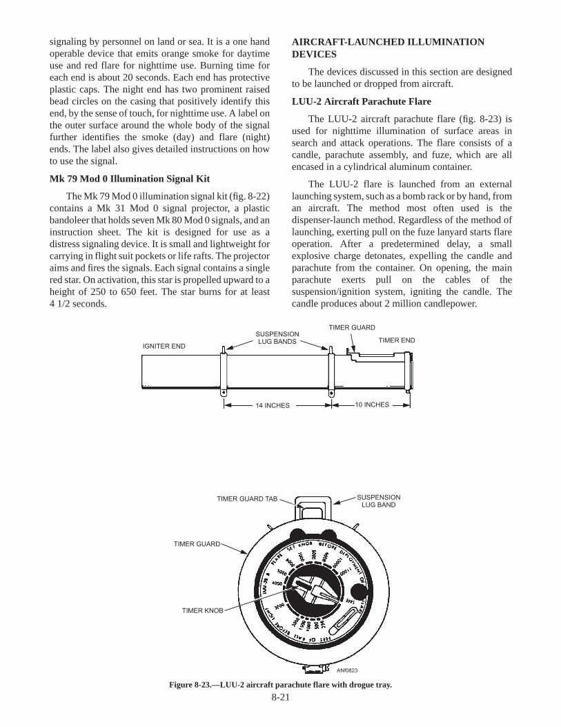
signaling by personnel on land or sea. It is a one handoperable device that emits orange smoke for daytimeuse and red flare for nighttime use. Burning time foreach end is about 20 seconds. Each end has protectiveplastic caps. The night end has two prominent raisedbead circles on the casing that positively identify thisend, by the sense of touch, for nighttime use. A label onthe outer surface around the whole body of the signalfurther identifies the smoke (day) and flare (night)ends. The label also gives detailed instructions on howto use the signal.
Mk 79 Mod 0 Illumination Signal Kit
The Mk 79 Mod 0 illumination signal kit (fig. 8-22)contains a Mk 31 Mod 0 signal projector, a plasticbandoleer that holds seven Mk 80 Mod 0 signals, and aninstruction sheet. The kit is designed for use as adistress signaling device. It is small and lightweight forcarrying in flight suit pockets or life rafts. The projectoraims and fires the signals. Each signal contains a singlered star. On activation, this star is propelled upward to aheight of 250 to 650 feet. The star burns for at least4 1/2 seconds.
AIRCRAFT-LAUNCHED ILLUMINATIONDEVICES
The devices discussed in this section are designedto be launched or dropped from aircraft.
LUU-2 Aircraft Parachute Flare
The LUU-2 aircraft parachute flare (fig. 8-23) isused for nighttime illumination of surface areas insearch and attack operations. The flare consists of acandle, parachute assembly, and fuze, which are allencased in a cylindrical aluminum container.
The LUU-2 flare is launched from an externallaunching system, such as a bomb rack or by hand, froman aircraft. The method most often used is thedispenser-launch method. Regardless of the method oflaunching, exerting pull on the fuze lanyard starts flareoperation. After a predetermined delay, a smallexplosive charge detonates, expelling the candle andparachute from the container. On opening, the mainparachute exerts pull on the cables of thesuspension/ignition system, igniting the candle. Thecandle produces about 2 million candlepower.
8-21
IGNITER END
SUSPENSIONLUG BANDS
TIMER GUARD
TIMER END
TIMER GUARD TAB SUSPENSIONLUG BAND
TIMER GUARD
TIMER KNOB
14 INCHES 10 INCHES
ANf0823
Figure 8-23.—LUU-2 aircraft parachute flare with drogue tray.

Mk 25 Marine Location Marker
The Mk 25 marine location marker (fig. 8-24) islaunched from aircraft or surface craft. It is primarilylaunched from aircraft to provide day or night referencepoints in marking the course of enemy submarines. It issuitable for any type of sea-surface reference-pointmarking that calls for both smoke and flame for 10 to 20minutes.
Mk 58 Mod 1 Marine Location Marker
The Mk 58 Mod 1 marine location marker (fig.8-25) is used for long burning, smoke and flamereference-point marking on the ocean's surface. Inaddition to being used for antisubmarine warfare, it isalso used for search and rescue operations. It is alsoused for man-overboard markings and to provide atarget for practice bombing at sea. This markerproduces a yellow flame and white smoke for 40 to 60minutes. The marker is visible from an aircraft for atleast 3 miles under normal operating conditions.
Q8-21. Define pyrotechnics as used in the military.
Q8-22. What are the two hand-held signaling devicesused by downed aircrew and personnel indistress over land or at sea?
Q8-23. The Mk 25 Mod 0 aircraft parachute flare isused for what purpose?
Q8-24. The Mk 58 Mod 1 Marine location marker isused for what purpose?
CARTRIDGES ANDCARTRIDGE-ACTUATED DEVICES
(CADs)
LEARNING OBJECTIVE : Identify thetypes, uses, and basic characteristics ofcartridges and cartridge-activated de-vices.
With the advent of the high-performance jetaircraft, aviation relies more and more on CADs. CADsare small explosive-filled cartridges used to fire otherexplosives or release mechanisms. CADs provide highreliability and easy maintenance. The cartridgesundergo rigid quality control throughout design andmanufacture. Their actual performance isdependable only when they have been properlyhandled and installed. In a personnel escape system,the CAD must work perfectly the first time.Malfunction of a device or failure to fire when neededusually results in injury or death to the pilot and/or crewmembers. Escape operations performed by cartridges
and CADs are canopy removal, seat ejection, streamingof ejection seat drogue chutes, and parachute opening.
It is not possible to discuss all the cartridges andCADs in this TRAMAN. Therefore, a few representa-tive cartridge systems are briefly discussed.
PERSONNEL ESCAPE DEVICECARTRIDGES
High-speed aircraft have many designs, specialcontrol features, and space limitations. As a result, asequence of emergency operations must be carried outbefore it is possible for pilot and/or crew members toescape. CADs allow several operations to be performedconcurrently (at the same time), or in rapid sequence, to
8-22
VALVE PLUG
STARTER MIX
OUTER TUBE
CHIMNEY
PYROTECHNICCOMPOSITION
SEA WATERACTIVATEDBATTERY
BASE
COVER
G-RING
RETAINERRING
ELECTRIC SQUIB
3.080 DIA. MAX.
VIEW A
ARROW
BASE PLUG
NOTCH
18.54MAX
O
2.976 DIA. MAX.
ANF0824
360 CRIMP
A
Figure 8-24.—Mk 25 marine location marker.

ensure personnel escape. Personnel in the AME ratingusually install cartridges and CADs used in personnelescape systems.
IMPULSE AND DELAY CARTRIDGES
Impulse cartridges are used as power sources inaircraft stores release and ejection systems. Thecartridges provide a force to free or eject a store awayfrom the aircraft or to operate other devices.
The impulse cartridge (fig. 8-26) contains anelectric primer, a booster, and a main charge. When thecartridge is fired, gas pressure moves a piston andunlocking linkage, freeing and/or ejecting the storefrom the rack.
CCU-45/B Impulse Cartridge
The CCU-45/B impulse cartridge (fig. 8-27) is usedprimarily for release and ejection of stores from anaircraft in flight.
8-23
ADHESIVE FOIL DISKS
PULL RING
CHIMNEY CAPSELECTRIC SQUIB
STARTER COMPOSITION
STARTER PELLET
PYROTECHNIC CANDLES
TRANSFER FUSE
POLYURETHANE FOAM
WATER-ACTIVATED BATTERY
PROTECTIVE COVER
ANF0825
Figure 8-25.—Mk 58 Mod 1 marine location marker.
BOOSTERCHARGE
CASECLOSURE
DISC
MAINCHARGE
DISCPRIMER
ANF0826
MK 37 MOD 0
Figure 8-26.—Typical impulse cartridge used in personnelescape systems.
IGNITIONELEMENT
CASE
BUSHING
ELECTRODE MAIN CHARGE
CUP CLOSUREASSEMBLY
Anf0827
Figure 8-27.—Impulse cartridge CCU-45/B (sectioned).

Mk 19 Mod 0 Impulse Cartridge
The Mk 19 Mod 0 impulse cartridge (fig. 8-28) is abackup cartridge. It is normally used for the emergencyjettison/release of stores loaded on an aircraft duringflight. This cartridge is fired after an attempt has beenmade to fire the primary cartridges.
MISCELLANEOUS CARTRIDGES
Miscellaneous cartridges include cable cutters,explosive bolts, and fire extinguishers.
Mk 97 Mod 0 Impulse Cartridge
The Mk 97 Mod 0 impulse cartridge (fig. 8-29) isused as a power source to actuate a helicopter cablecutter to cut a chain/cable in an emergency.
Mk 1 Mod 3 Impulse Cartridge
The Mk 1 Mod 3 impulse cartridge (fig. 8-30) isused primarily to actuate a refueling hose guillotine inan emergency.
Aircraft Fire-Extinguisher Cartridge
In the event of fire, the aircraft fire extinguishercartridges start the release of fire-extinguishing agentsinto the area surrounding an aircraft engine.
Q8-25. What are some of the escape operationsperformed by cartridges and CADs?
Q8-26. Personnel in what rating usually installcartridges and CADs used in personnelescape systems?
Q8-27. Cartridges that are used for cable cutters,explosive bolts, and fire extinguishers areknown as what type of cartridges?
AIRCRAFT WEAPONS SUSPENSIONAND RELEASING EQUIPMENT
LEARNING OBJECTIVE : Identify thetypes, uses, and basic characteristics ofaircraft weapons suspension andreleasing equipment.
Naval combat aircraft and weapons use highlycomplex suspension, arming, and releasing devices.The majority of these devices are electronicallyoperated and are part of the aircraft's electrical circuits.The devices are activated by a hand switch orautomatically through a circuit-closing device in thesystem. Manual operation is possible, if needed.
Current suspension, arming, and releasing devicesfor aircraft require the use of associated electrical gear.This gear times the release of stores and rack selectors
8-24
IGNITIONELEMENT
MAIN CHARGE(8 PIECES BY COUNT)
INSULATOR
PLUGBODY
DISC
MK 19 MOD 0
ANF0828
Figure 8-28.—Typical impulse cartridge used in bomb racks,launchers, and dispensers.
CASE
PRIMER
PROPELLANT
CLOSUREDISC
ANF0829
Figure 8-29.—Mk 97 Mod 0 impulse cartridge.
WASHER
BUSHING
ELECTRODECASE
SECONDARYCHARGE
IGNITION CUP
BOOSTERCHARGE
MAIN CHARGE
COVER
CAP
PLASTICCAP
CUP
CUPANF0830
Figure 8-30.—Mk 1 Mod 3 impulse cartridge (sectioned).

to control the pattern of store releases. Other unitspreselect the desired arming of bomb fuzes. Eachserves a definite purpose in accurately deliveringweapons against the enemy.
The Navy uses a wide variety of suspensionequipment. Suspension equipment is designed toaccommodate a certain maximum weight. Thestructural strength of the aircraft determines themaximum weight that may be suspended. The aircraftweight capacity per rack is usually less than rack designcapability.
Several representative types of suspension andreleasing equipment are discussed briefly in thefollowing text.
BOMB RACKS
Aircraft bombs, torpedoes, mines, and other storesare suspended either internally or externally by bombracks. Bomb racks carry, arm, and release these stores.
The BRU-14 (series) bomb rack (fig. 8-31)suspends and releases conventional and nuclearweapons/stores weighing up to 2,200 pounds with a14-inch suspension. In certain applications, adapterassemblies are added to increase the suspensioncapacity to 30 inches.
When a weapon/store is loaded onto the bomb rack,the suspension lugs on the weapon/store engage the
heel of the bomb rack suspension hooks. This causesthe hooks to pivot up and engage the suspension lugs.The hooks are held in the closed position by sears.When the pilot initiates bomb release, an electricalsignal is routed through the weapon system circuits tothe bomb rack. This signal activates a solenoid thatactivates the release linkage in the bomb rack. Thiscauses the suspension hooks to open, letting theweapon/store fall away from the aircraft. The BRU-14has a CAD backup release method if the primarymethod fails. When the CAD is fired, the releaselinkage frees the weapon/store.
BOMB EJECTOR RACKS
Bomb ejector racks differ from standard bombracks. Ejection racks use electrically fired impulsecartridges to open the suspension hook linkage andeject the weapon/store. When in flight, a vacuum can becreated under the fuselage and wings of the aircraft. Insome cases, this vacuum will prevent the releasedweapon/store from entering the airstream and falling tothe target. Physical contact between the weapon/storeand the aircraft structure may result. This could causedamage to or loss of the aircraft. Bomb ejector rackseject the weapon/store from the bomb rack withsufficient force to overcome this vacuum and ensure asafe release.
8-25
ARMING UNITS
BELLCRANK
LINEAR ELECTRO-MECHNICALACTUATOR (LEMA)
COCKINGKNOB
AUXILIARY UNLOCKASSEMBLY (IFOBRL)
IN-FLIGHT OPERABLE BOMB RACK LOCK (IFOBRL)
ELECTROMECHANICALACTUATOR (IFOBRL)
MANUAL ACTIVATIONKNOB (IFOBRL)
LOCKBAR(IFOBRL)
SECONDARY RELEASEASSEMBLY
STORE SUSPENSION HOOKS
ANF0831
Figure 8-31.—BRU-14 (series) aircraft bomb rack.

The BRU-11A/B bomb ejector rack (fig. 8-32) hasfour suspension hooks. Two of these hooks are spaced14 inches apart and two are spaced 30 inches apart.These hooks carry weapons/stores weighing up to4,000 pounds. The rack has electrical connections,mechanical and electrical arming units, ejectioncomponents, and mechanical linkage for safelysuspending and ejecting weapons/stores.
When the pilot fires the impulse cartridges, theresulting gas pressure unlocks the suspension hooks.The gas pressure simultaneously causes the ejectionpiston and ejector foot tokick the weapon/store awayfrom the aircraft. The BRU-11A/B has a secondaryweapons/stores jettison release if the primary systemfails. The secondary release also uses an impulsecartridge to unlock the suspension hooks, but it does noteject the weapon/store.
8-26
FWD
FWD
ANF0832
Figure 8-32.—BRU-11A/B bomb ejector rack.
LATCHING BLOCK
RELEASE LEVER IN LATCHED POSITION(AFT POSITION)
COCKING LEVER(FORWARD POSITION)
HOOK
HOOK OPENING SPRING
HOOK LINK IN AFTPOSITION
LATCHING LEVERSUPPORTED
LATCHING LEVERENGAGED
ANF0833
Figure 8-33.—Mk 8 Mod 5 bomb shackle.

BOMB SHACKLES
The Mk 8 Mod 5 bomb shackle (fig. 8-33) is theonly bomb shackle now in use. It is used on helicopters.The shackle is used to suspend and release mines ortorpedoes that weigh from 100 to a maximum of 1,500pounds. The shackle has suspension hooks spaced 14inches apart, center to center. It has no integralprovision for electrical release, electrical arming, ormechanical arming. Electrical release of the shackle ispossible by attaching an electrical release unit to theshackle structure. Weapons may be mechanicallyarmed by attaching arming solenoids to the shackle orto the aircraft structure.
DISPENSERS AND EJECTORS
Dispensers and ejectors are used during tacticalsituations to give an aircraft added offensive anddefensive capabilities. These units are usuallydetachable and suspended from other installedsuspension equipment, or they are mounted directly tothe aircraft. They are used to suspend and releaseordnance, such as aircraft parachute flares, chaff, anddecoy flares.
SUU-25F/A Flare Dispenser
The SUU-25F/A flare dispenser (fig. 8-34) iscapable of suspending and launching eight LUU-2B/B
8-27
ANF0834
Figure 8-34.—SUU-25F/A flare dispenser.

aircraft parachute flares. The SUU-25F/A dispenser ismade up of four aluminum tubes housed in a supportingframe and covered with aluminum skin. Each tube isloaded with a pair of flares configured with a flareadapter kit. The dispenser allows the flares to be ejectedone at a time, thereby doubling the mission capabilityover previous models. Each tube has two flares. Theforward bulkhead (A) of the dispenser has breechassemblies for eight impulse cartridges (one for eachflare). Four aft retaining links (B) attached to the rearbulkhead keeps the aft flares in the dispenser tubes untilthey are ejected.
When initiated by the pilot, the impulse cartridge inthe number 1 breech will be fired. The resulting gas
pressure is routed into the launcher tube. Gas pressurebuildup will be sufficient enough to force the flare aftand shear the aft retaining lock shear pin, allowing asingle flare to be ejected from the launcher tube. Astepper switch automatically steps the firing circuit inthe dispenser to the next tube. Each subsequentactivation of the firing circuit steps the stepper switchand repeats the process for the remaining tubes.
AN/ALE-29A Countermeasures ChaffDispensing Set
The AN/ALE-29A countermeasures chaffdispensing set (chaff dispenser) (fig. 8-35) is anelectronic device installed in most Navy combataircraft. The chaff dispenser ejects cartridge-loadedconfigurations of Mk 46 or MJU-8/B decoy flares andRR-129 or RR-144 chaff.
Decoy flares are used during evasive maneuversagainst heat-seeking missiles. Chaff rounds consist ofextremely fine shredded metal strips in a cylindricalmetal container. When ejected, the metal strips cause ajamming effect against ground-controlled radarinstallations or radar-controlled missiles.
GUIDED MISSILE LAUNCHERS
A guided missile launcher provides mechanicaland electrical means of suspending and air launching aguided missile from an aircraft. The launcher eitherejects the missile or the missile leaves the launcher railsunder its own power. Each of these type launchers isdiscussed briefly in the following text.
8-28
USE TAPERED ENDTO PRESS OUTFIRED UNITS
TL-762/ALM-70 CHAFFSLEEVE EXTRACTOR
USE BLUNT ENDTO PRESS OUTUNFIRED UNITS
PLASTICBLOCK
CARTRIDGERETAINER
PLASTIC SLEEVE
CHAFF/FLARELIMIT
PRINTEDCIRCUIT BOARD
CAPTIVESCREWS
ANF0835
Figure 8-35.—AN/ALE-29A countermeasures chaffdispensing set.
POWER SUPPLY MECHANISM NITROGEN RECEIVER
DETENTS, STRIKER POINTS,
AND SNUBBERS
HOUSING ASSEMBLY
SAFETY PIN/
DETENT WRENCH
DETENT HOLD-
DOWN PINFIN RETAINER
SPRING
ANF0836
Figure 8-36.—LAU-7/A (series) guided missile launcher.

LAU-7/A Guided Missile Launcher
The LAU-7/A (series) guided missile launcher (fig.8-36) is a reusable launcher system for use with AIM-9Sidewinder missiles. The launcher has four majorassemblies—the housing assembly, the nitrogenreceiver assembly, the mechanism assembly, and thepower supply.
LAU-92/A Guided Missile Launcher
The LAU-92/A guided missile launcher (fig. 8-37)is a self-contained, gas operating mechanism. It carries,retains, and ejection-launches the Sparrow III missile.
Launcher unlocking and ejection force is suppliedby two Mk 124 Mod 0 impulse cartridges installed inthe breeches. The cartridges are ignited by an electricalimpulse from the aircraft firing circuits.
AIRCRAFT ROCKET LAUNCHERS
Aircraft rocket launchers (rocket pods) are aplatform from which airborne rockets can be fired.Rocket pods contain rocket motors and, in some cases,completely assembled rounds. Each may use the samecontainer from manufacture, through stowage, to finalfiring.
Aircraft rocket launchers are classified as either2.75-inch (fig. 8-38, view A) or 5.0-inch (fig. 8-38,
view B) and either reusable or non-reusable. Metallauncher tubes are reusable. Paper launcher tubes aredesigned for onetime use only, and are jettisoned by thepilot after use.
The 2.75-inch rocket launchers now in use are theLAU-61/A (19 shot), LAU-68/A (7 shot), and theLAU-69/A (19 shot). The 5.0-inch rocket launchers arethe LAU-10 series (4 shot).
Q8-28. What is the purpose of ordnance suspensionand releasing equipment?
Q8-29. What is the purpose of bomb racks?
Q8-30. The Mk 8 Mod 5 bomb shackle is used on whattype of aircraft?
Q8-31. What is the purpose of dispenser and ejectorequipment?
Q8-32. What guided missile launcher is used with theAIM-9 Sidewinder missile?
SUMMARY
In this chapter, you have identified the differenttypes of ammunition, materials, operation, and hazardsassociated with aircraft ordnance. You have alsobecome familiar with some of the responsibilities of theAviation Ordnanceman.
8-29
HOISTASSEMBLY
OPERATINGLEVER
BREECHES
UMBILICAL
FAIRING
ANF0837
LOCKHANDLE
Figure 8-37.—LAU-92/A guided missile launcher.

8-30
A
B
2.75-INCH
5.0-INCH
ANF0838
Figure 8-38.—Typical airborne rocket launcher configurations.

ASSIGNMENT 8
Textbook Assignment: "Aircraft Ordnance," chapter 8, pages 8-1 through 8-30.
8-1. Which of the following types of ammunition isused to produce illumination?
1. Propellant2. Incendiary3. Pyrotechnics4. Illumination
8-2. What type of ammunition is characterized by alarge high-explosive charge-to-weight ratio?
1. Cartridge-actuated device2. Incendiary3. Bomb-type ammunition4. Inert ordnance
8-3. Which of the following devices is an explo-sive-loaded device designed to provide themeans of releasing potential energy to initiate afunction or a special-purpose action?
1. Cartridge-actuated device2. Incendiary3. Bomb-type ammunition4. Inert ordnance
8-4. What actual size ammunition items with work-ing mechanisms are used for training exercisesbut have no explosive materials?
1. Cartridge-actuated device2. Incendiary3. Bomb-type ammunition4. Inert ordnance
8-5. What type of ammunition uses a chemical pri-marily for igniting combustible substances?
1. Cartridge-actuated device2. Incendiary3. Bomb-type ammunition4. Inert ordnance
8-6. Ammunition intended for combat rather thanfor training has what classification?
1. Airborne stores2. Propellants3. Incendiaries4. Service ammunition
8-7. TheWarheadis the part of the ammunitioncontaining the materials intended to inflictdamage. What are the explosives in thewarhead called?1. Stores2. Payload3. Expendables4. Components
8-8. An explosive is a material that is capable ofproducing an explosion by its own energy.1. True2. False
8-9. What are the two general classes of militaryexplosives?
1. Explosive and nonexplosive2. High and low explosives3. Incendiary and burster explosives4. Chemical and detonating explosives
8-10. Which of the following additives may be addedto high explosives to provide desired stabilityand performance characteristics?1. Powdered metals2. Oils3. Waxes4. All the above
8-11. Which of the following explosives ischaracterized by the extremely fastdecomposition called "detonation"?1. High explosive2. Low explosive3. Initiating explosive4. Auxiliary explosive
8-12. The decomposition of low explosives is knownas what type of decomposition?
1. Detonation2. Explosion3. Deflagration4. Combustion
8-13. Proper identification of ammunition provideswhich of the following types of information?
1. Service (live) ammunition2. Nonservice (training) ammunition3. Class of explosives4. Each of the above
8-31

8-14. What is the most important means ofidentifying explosive hazards contained withinordnance?
1. Safety information sheets2. Color codes3. Manufacturer’s assembly card4. Ordnance manual
IN ANSWERING QUESTIONS 8-15 THROUGH8-18, REFER TO TABLE 8-1 IN YOUR TRAININGMANUAL.
8-15. Which of the following color codes identifieshigh explosives and indicates the presence ofexplosives either sufficient to cause theammunition to function as a high explosive orparticularly hazardous to the user?
1. Yellow2. Brown3. Red4. Silver
8-16. Which of the following color codes identifiesarmor-defeating ammunition except onunderwater ordnance?
1. Yellow2. Brown3. Red4. Black
8-17. Which of the following color codes identifiesincendiary ammunition or indicates thepresence of highly flammable material?
1. Light blue2. Light red3. Light green4. Light orange
8-18. Which of the following color codes identifiesammunition used for training or firingpractice?
1. Light green2. White3. Light blue4. Gray
8-19. Some bomb-type ammunition is shipped andstowed without the fuzes or arming assembliesand associated components installed for whichof the following reasons?
1. Physical size of the weapon2. To meet safety requirements3. To simplify handling requirements4. To provide required training
8-20. Approximately what percent of a Mk 80general-purpose bomb's total weight is made ofexplosives?
1. 25%2. 35%3. 45%4. 55%
8-21. By what means is the spacing of the suspensionlugs used with general-purpose bombsdetermined?
1. The configuration of the aircraft's bombrack
2. The size of the bomb3. The assembly supervisor4. The weapons handling officer
8-22. Bomb fuzes are divided into what twocategories?
1. Explosion and detonation2. Deflagration and combustion3. Mechanical and electrical4. Initiating and auxiliary
8-23. What part of the bomb causes ageneral-purpose bomb to fall in a smooth,stable, and definite curve to the target?
1. Stabilizer2. Target detector3. Fin assembly4. Bomb casing
8-24. What is the preferred mode of delivery forlow-level bombing to prevent damage to theaircraft?
1. Retarded2. Unretarded3. Mechanical4. Restricted
8-25. What is the primary purpose of practicebombs?
1. To simulate different ballistic properties asthose of service-type bombs
2. To provide optimum safety during thetraining of new or inexperienced pilots andground handling crews
3. To provide low cost training and to providean increase in available target locations
4. To provide for the training of experiencedpilots and ground handling crews
8-32

8-26. A Mk 80 series bomb with a blue band aroundthe nose is classified as what type of bomb?
1. Full-scale practice2. Subcaliber practice3. Service4. Nonrestricted use
8-27. Which of the following types of bombs is/areclassified as subcaliber practice bombs?
1. Mk 82 Mod 32. BDU-48/B3. Mk 76 Mod 54. Both 2 and 3 above
8-28. What type of weapons carry and dispensesmall bomblets over a target area?
1. Laser guided bombs2. General purpose bombs3. Cluster bomb units4. Full-scale bombs
8-29. The CBU-59/B contains bomblets of(a) what quantity and (b) what type?
1. (a) 717 (b) BLU-77/B2. (a) 717 (b) Mk 1183. (a) 247 (b) BLU-77/B4. (a) 247 (b) Mk 110
8-30. Laser-guided bombs are modified from whattypes of general-purpose bombs?
1. Mk 822. Mk 833. Mk 844. All of the above
8-31. Where is the computer-control group mountedon a converted low-drag general-purposebomb?
1. Conical fin assembly2. Nose of the bomb body3. Inside the bomb casing4. Exterior mounting stanchion
8-32. How many assemblies make up the Mk 65Quickstrike mine?
1. One2. Two3. Three4. Four
8-33. Which of the following components enables arocket to spin when fired from a slow-flyingaircraft?
1. Nozzle2. Folding fins3. Scarfed nozzle insert4. Stabilizer rod
8-34. What is the rocket launcher capacity for theMighty Mouse weapons system?
1. 7 or 19 rockets2. 4 or 12 rockets3. 6 or 18 rockets4. 5 or 16 rockets
8-35. Guided missiles are classified according towhat characteristics?
1. Speed, launch environment, mission,vehicle type, and weight
2. Speed, launch environment, mission,range, and vehicle type
3. Speed, launch environment, mission,range, and weight
4. Speed, mission, range, vehicle type, andweight
8-36. At what speed is an object traveling in air at766 miles per hour (Mach 1) under standardatmospheric conditions?
1. Subsonic2. Transonic3. Supersonic4. Hypersonic
8-37. When a guided missile with a speed of Mach2.5 is launched from an aircraft traveling at aspeed of Mach 2.0, the missile will reach whatspeed?
1. Mach 0.52. Mach 2.53. Mach 4.54. Mach 5.5
IN ANSWERING QUESTIONS 8-38 AND 8-39,REFER TO TABLE 8-2 IN YOUR TEXT.
8-38. In the first letter designation for launchingguided missiles and rockets, what lettersignifies multiple launch environments?
1. A2. B3. C4. D
8-33

8-39. In the second letter designation for the missionof guided missiles and rockets, what does theletter E signify?
1. Surface attack2. Intercept aerial3. Decoy4. Special electronic
8-40. In the basic missile designation of theAGM-65E, what does the number signify?1. Missile design2. Mach speed3. Modification4. Model
8-41. What are the three significant color codes usedon guided missiles?
1. White, brown, and blue2. White, brown, and yellow3. Red, brown, and blue4. Yellow, brown, and blue
8-42. What is the tactical mission of the AIM-7FSparrow III guided missile?
1. To destroy enemy ships2. To destroy enemy ground radar
installations3. To intercept and destroy enemy aircraft4. To destroy enemy fortified installations
8-43. The AGM-84A-1 Harpoon guided missile is anall-weather, air-launch, antiship attack weaponand is launched from which of the followingaircraft?
1. F-15 and F-162. F-14 and AV-83. F/A-18 and EA-64. S-3 and P-3
8-44. The AIM-9L Sidewinder guided missile iscomprised of what total number of majorsections?
1. Five2. Two3. Three4. Four
8-45. What maximum number of Phoenix missilesmay be launched from a single aircraft withsimultaneous guidance against widelyseparated targets?
1. Eight2. Two3. Six4. Four
8-46. The AGM-65E Maverick guided missile useswhat type of guidance?
1. Infrared2. Laser3. Homing4. Heat-seeking
8-47. The AGM-65E/F guided missile is employedagainst what type of targets?
1. Microwave electromagnetic energy2. Armored vehicles and fortified bunkers3. Fortified ground installations, armored
vehicles, and surface combatants4. Ground personnel, bunkers, tanks, and
artillery positions
8-48. What short-to-medium range guided missile isdesigned to be launched from helicopters atlow air speeds and altitudes?
1. AGM-119B Penguin2. AGM-88A HARM3. AGM-65E/F Maverick4. AGM-78E Standard
8-49. The AIM-120 AMRAAM is an advancedmissile system and offers performanceimprovements over which of the followingmissiles?
1. Shrike2. Sidewinder3. Maverick4. Sparrow
8-50. The Walleye guided weapon employs which, ifany, of the following propulsion systems?
1. Double-base solid propellant2. Liquid rocket motor3. Single-base gas propellant4. None of the above
8-51. What are the primary weapons used inantisubmarine warfare (ASW)?
1. Aircraft laid mines2. Mk 54 depth bombs3. Mk 46 torpedoes4. Subsurface guided missiles
8-52. Where are naval mines used?
1. In enemy harbors and ports2. In offensive mining operations only3. In defensive mining operations only4. In offensive and defensive mining
operations
8-34

8-53. How is the M61A1 20-mm automatic aircraftgun (a) driven and (b) controlled?
1. (a) Gas blowback (b) Fire2. (a) Hydraulically (b) Electrically3. (a) Pneumatically (b) Manually4. (a) Gas blowback (b) Hydraulically
8-54. What is the firing rate of the M61A1 20-mmgun as installed in Navy aircraft?
1. 4,000 (gun low) and 6,000 (gun high)rounds per minute
2. 2,000 (gun low) and 4,000 (gun high)rounds per minute
3. 5,000 rounds per minute4. 7,200 rounds per minute
8-55. By what means is the night end of the Mk 124Mod 0 marine smoke and illumination signalidentified?
1. By color2. By the raised beads on the casing3. By the D-ring located on the ignition
lanyard4. By the larger sized end ring
8-56. What number of signal flares is contained inthe Mk 79 Mod 0 illumination signal kit?
1. 42. 53. 64. 7
8-57. By which of the following methods can theLUU-2 aircraft parachute flare be launched?
1. By hand2. From a bomb rack3. Dispenser-launched4. Each of the above
8-58. What is the primary purpose of the Mk 25marine location marker?
1. As a distress signal for downed aircrewpersonnel
2. Antisubmarine warfare operations3. To illuminate target areas4. As a channel marker
8-59. The Mk 58 Mod 1 marine location markerproduces yellow flame and white smoke for (a)a minimum of and (b) a maximum of howmany minutes?
1. (a) 15 (b) 302. (a) 30 (b) 453. (a) 40 (b) 604. (a) 45 (b) 80
8-60. Which of the following functions is performedby cartridges and CADs in personnel escapedevices?
1. Removal of cockpit canopies2. Ejection of seats3. Streaming of ejection seat drogue chutes4. Each of the above
8-61. Which of the following ratings is normallyresponsible for the installation of cartridgesand CADs as used in personnel escapesystems?
1. AO2. AME3. AT4. AD
8-62. What is the primary use of the CCU-45/Bimpulse cartridge?
1. To remove cockpit canopies2. To eject seats3. To release and eject stores from an aircraft
in flight4. To eject and deploy seat drogue chutes
8-63. Which of the following impulse cartridgesis/are classified as miscellaneous cartridges?
1. Mk 19 Mod 02. Mk 97 Mod 03. Mk 1 Mod 34. Both 2 and 3 above
8-64. Aircraft weapons suspension and releasingequipment is generally operated by whatmeans?
1. Hydraulic and pneumatic2. Electronic and manual3. Hydraulic and electrical4. Hydraulic and mechanical
8-65. What is the function of bomb racks?
1. To carry stores2. To arm stores3. To release stores4. Each of the above
8-66. How do bomb ejector racks differ from bombracks?
1. Bomb ejector racks are designed to carrymore weight
2. Bomb ejector racks are designed to carryless weight
3. Bomb ejector racks use electrically firedimpulse cartridges
4. Bomb racks use electrically fired impulsecartridges
8-35

8-67. The BRU-11A/B bomb ejector rack provides(a) how many suspension hooks and (b) arespaced how far apart?
1. (a) Four(b) two 14 inches apart and two
30 inches apart2. (a) Two
(b) 30 inches3. (a) Two
(b) 14 inches4. (a) Four
(b) two 14 inches apart and two28 inches apart
8-68. The Mk 8 Mod 5 bomb shackle is used onwhich of the following types of aircraft?
1. Fighter2. Attack3. Helicopter4. Patrol
8-69. The SUU-25F/A flare dispenser provides thecapability for suspending and launching whattotal number of LUU-2B/B aircraft parachuteflares?
1. Eight2. Two3. Six4. Four
8-70. The AN/ALE-29A countermeasures chaffdispensing set is capable of cartridge ejectingwhich of the following load configurations?
1. Mk 46 or MJU-8/B decoy flares2. RR-129 or RR-144 chaff3. Both 1 and 2 above4. Mk 50 decoy flares or RR-142 chaff
8-71. What is the primary purpose of decoy flares?
1. Used during evasive maneuvers againstheat-seeking missiles
2. Causes a jamming effect against ground-controlled radar installations
3. Interrupts enemy aircraft radar trackingsystems
4. Used for training purposes only
8-72. The LAU-7/A guided missile launcherprovides a complete launching system forwhich of the following guided missiles?
1. Sidewinder2. Harpoon3. Sparrow III4. Phoenix
8-73. The LAU-92/A guided missile launcher iscapable of carrying, retaining, andejection-launching which of the followingmissiles?
1. Harpoon2. Sparrow III3. Maverick4. Shrike
8-74. Which of the following designations is aclassification of rocket launchers?
1. 2.75-inch or 5.0-inch2. Reusable3. Nonreusable4. Each of the above
8-75. How many shots does the LAU-10 seriesrocket launcher provide?
1. 42. 73. 194. 21
8-36

CHAPTER 9
SUPPORT EQUIPMENT
INTRODUCTION
This chapter identifies support equipment (SE)used to handle, service, load, test, and maintain aircraft.As an Airman Apprentice, you will be required tooperate SE. Some SE is used both ashore and afloat,while other SE is used only ashore or only afloat. TheSE division of the AIMD is tasked with maintainingSE. Principal users of SE are the squadron linedivision, the base operations line division, and the airdepartment aboard aircraft carriers.
TYPES OF EQUIPMENT
LEARNING OBJECTIVE : Identify thepurpose and function of the types of supportequipment, to include operation, maintenance,hazards, and carrier air and shore-basedoperations.
There are two types of support equipment—aircrafthandling equipment and aircraft servicing equipment.The following text discusses these various types ofsupport equipment.
HANDLING EQUIPMENT
Aircraft handling equipment consists of towtractors; crash and salvage equipment, to includefire-fighting vehicles and maintenance cranes; forklifttrucks; and flight deck scrubbers.
Tow Tractors
Various tow tractors in the Navy inventory arediscussed in the following text.
A/S32A-30 AIRCRAFT GROUND SUPPORTEQUIPMENT TOWING TRACTOR .—TheA/S32A-30 tow tractor (fig. 9-1) is a 6-cylinder,gasoline-powered, four-wheel, heavy-duty vehicle witha three-speed transmission. The tractor frame is awelded steel one-piece unit. It is equipped withhydraulically actuated front disc brakes and drum-typebrakes on the rear wheels. A hydraulically assistedsteering unit provides steering to the front wheels. Thetractor employs a 12-volt electrical system to supplypower for lighting, starting, horn, and instrumentoperation. It comes equipped with two seats—onedriver and one passenger—mirrors, front and reartowing couplers (pintles), tie-down fittings and lifting
attachments. It can be fitted with a fully enclosed cab. Itis designed to tow aircraft servicing equipment, workstands, and armament handling equipment.
A/S32A-30A AIRCRAFT GROUND SUPPORTEQUIPMENT TOWING TRACTOR .—TheA/S32A-30A tow tractor (fig. 9-2) is a 4-cylinder,diesel engine, (dual wheel) rear-wheel-drive tractorwith a 40,000-pound towing capacity. It comes with athree-speed automatic transmission, hydraulic brakeson front and rear wheels, conventional power steeringwith power assist to the front wheels, and employs aconventional 12-volt electrical system with battery andalternator to supply power for the lights, horn, startermotor, ignition, and instruments.
9-1
ANF0901
Figure 9-1.—A/S32A-30 aircraft ground support equipmenttowing tractor.

The tractor frame is a welded steel one-piece unitthat is cross-braced to prevent misalignment. It also hasfront and rear towing couplers (pintles), tie-down andlifting attachments, and exterior lighting. The weldedsteel cab encloses the driver and one passenger seat,supports two flush-mounted doors with sliding glasswindows, mirrors, front and rear windshield wipers,and dome light.
A/S32A-31A AIRCRAFT TOWING TRAC-TOR.—The A/S32A-31A aircraft towing tractor (fig.9-3) is designed for towing aircraft aboard ship. Thedrive system consists of a three-cylinder diesel engine,
automatic transmission, and rear wheel drive with dualwheels. Front wheel steering is power assisted and hasseating for the driver only. Service brakes arehydraulic, power operated, wet disc type with amechanical hand brake for the rear wheels. A 24-volt
9-2
ANF0902
Figure 9-2.—A/S32A-30A aircraft ground support equipmenttowing tractor.
ANF0903
Figure 9-3.—A/S32A-31A aircraft towing tractor.
ANF0904
Figure 9-4.—A/S32A-32 aircraft towing tractor.
ANF0905
Figure 9-5.—A/S32A-37 aircraft towing tractor.

electrical system provides starting, lighting, andinstrumentation. Front and rear mounted pintles areused for aircraft towing. A universal jet-engine startunit mounts to the rear of the tractor.
A/S32A-32 AIRCRAFT TOWING TRAC-TOR.—The A/S32A-32 Aircraft Towing Tractor (fig.9-4), also called "The Spotting Dolly," is designed totow, turn, and position aircraft within the confines of anaircraft carrier hangar deck. It is powered by athree-cylinder diesel engine, which drives two mainhydraulic pumps. The hydraulic pumps supply fluid todrive motors that turn two open-chain reduction drivesvia two gearboxes at each main wheel, which operatesindependently. A mechanical wheel clutch handle isused to engage or disengage the drive wheels, enablingthe tractor to pivot on a caster wheel around its centerwithin a zero turning radius. A Joystick Control, next tothe operator's seat, is an electromechanical device usedto control the speed and direction of the spotting dolly'smovement. The lift cylinder, which raises and lowersthe lifting arms, and two spread cylinders, which keepthe arms pinned against the aircraft nose gear, arepowered by an auxiliary hydraulic pump. Several pairs
of axle pins that engage both sides of the nosewheel arecarried on the tractor and fit a variety of aircraft.
A/S32A-37 AIRCRAFT TOWING TRAC-TOR.—The A/S32A-37 aircraft towing tractor (fig.9-5) is an inline, 6-cylinder, diesel-powered,liquid-cooled, 4-wheel drive vehicle used to moveheavy, shore-based aircraft. The full power shifttransmission has six forward and three reverse speeds.The tractor's front wheels are steered by two hydrauliccylinders, and all wheels are equipped withhydraulically powered disc brakes. A two-seat, heated,enclosed cab with removable doors is provided foroperator comfort in all weather. Two 12-volt batteries,24-volt alternator, electrical system provides power forlighting, instrumentation, control panels, starter motor,transmission control, switches, wiper/washer motor,and heater/defroster. The tractor is capable of 35,000pounds of drawbar pull with the traction ballast kitinstalled.
A/S32A-42 AIRCRAFT MID-RANGE TOWVEHICLE.— The A/S32A-42 aircraft mid-range towvehicle (fig. 9-6) is a 4-cylinder, diesel-powered,
9-3
ANF0906
JACK STANDLOCATION
(ON FRAME)
JACK STANDLOCATION
(ON FRAME)
LIFT/TIE-DOWN
LOCATION
LIFT/TIE-DOWN
LOCATIONS
LIFT/TIE-DOWN
LOCATION
Figure 9-6.—A/S32A-42 aircraft mid-range tow vehicle.

3-speed automatic transmission, liquid cooled,rear-wheel-drive tractor designed for towing aircraftweighing up to 100,000 pounds. The frame is awelded-steel one-piece unit, with cross brace, powerassisted front wheel steering, hydraulic boost powerdisc brakes, and a conventional 12-volt electricalsystem, with alternator, to supply power for the lightsand accessories, horn, starter motor, ignition, andinstruments. Front and rear tow couplers (pintles) andtie-down attachments are provided.
Crash and Salvage Equipment
Various salvage and maintenance cranes,fire-fighting vehicles, and Twinned Agent Unit(TAU-2H) extinguishers are discussed in the followingtext.
A/S32A-35A (CVCC) AIRCRAFT CRASHHANDLING AND SALVAGE CRANE .—TheA/S32A-35A aircraft crash handling and salvage crane(fig. 9-7) is a self-propelled, four-wheel drive,six-cylinder, liquid-cooled, turbocharged, dieselelectric-powered vehicle mounted on six pneumaticrubber tires. The ac generator is directly coupled to theengine and provides power to the drive motors,luff/hoist winch motor, auxiliary hoist/counterweightwench motor and motor control systems. A hydraulic
pump is directly coupled to the engine and providesfluid flow for steering, self-adjusting service brakes,and winch brake control. Vehicle steering isaccomplished by hydraulic cylinders, which connect tothe rear axle and main frame. The front and rear axlespivot in opposite directions, allowing significantturning capability. The crane main hoist has a static liftcapacity of 75,000 pounds and the crane auxiliary hoisthas a lift capacity of 10,000 pounds.
The crane is capable of operating aboard ship ininclement weather. It is designed to be stowed on theflight deck of an aircraft carrier, where it will beexposed to extreme weather and corrosive conditions.In service, the crane will lift crashed/damaged aircraftfrom various locations and attitudes and move loads ona rolling and pitching ship to a safe parking zone on theflight deck.
A/S32A–36A (AACC) AIRCRAFT CRASHHANDLING AND SALVAGE CRANE.— TheA/S32A-36A aircraft crash handling and salvage crane(fig. 9-8) is a six-wheel, four-wheel drive,liquid-cooled, turbocharged, diesel, electric-powered,self-propelled vehicle. Steering is hydraulicallycontrolled via the front and rear wheels. Mid and rearaxle drive motors provide traction power and has a
9-4
ANF0907
Figure 9-7.—A/S32A-35A (CVCC) aircraft crash handling and salvage crane.

six-wheel, self-adjusting air/hydraulic brake systemincorporated. Rear and mid dc electric drive motorsprovide power for crane travel, while a separate dcelectric motor provides power to the main hoist controlor boom luff control. The crane has a maximum liftcapability of 70,000 pounds and can be operated fromthe cab or by a remote pendant control.
The crane is capable of operating aboard ship ininclement weather. It is designed to be stowed on theflight deck of an aircraft amphibious assault ship,where it will be exposed to extreme open-sea weatherconditions and the corrosive effects of a saltwateratmosphere. In service, the crane will liftcrashed/damaged aircraft from various locations andattitudes and move loads on a rolling and pitching shipto a safe parking zone on the flight deck.
A/S32P-25 SHIPBOARD FIRE-FIGHTINGVEHICLE .—The P-25 shipboard fire-fighting vehicle(figs. 9-9 and 9-10) is a four-wheel (two-wheel drive),six-cylinder, turbocharged, liquid-cooled, 24-volt,diesel-powered vehicle with a hydrostatic drive system
that transmits power to the rear wheels. Steering ispreformed by a single hydraulic cylinder and tie-rodassembly that controls the front wheels. Dynamicvehicle braking is provided by the hydrostatic drivesystem. When the accelerator is released, the brakesautomatically engage. Separate tanks within thevehicle chassis carry 750 gallons of water and 55gallons of AFFF (Aqueous Film-Forming Foam).Three 20-pound fire extinguishers containing Halon1211 (halogenated extinguishing agent) are stored onthe right side of the vehicle. One nursing lineconnection on each side of the vehicle provides AFFFmixture from the ship's system directly to the vehicle'swater pump.
The vehicle has seating for a crew of two. Thedriver compartment is located at the left forward end ofthe vehicle and contains the main control panel foractivating the fire-fighting systems. AFFF can besprayed from both the forward turret nozzle andhandline hose reel nozzle. These nozzles operateindependently and can be used simultaneously to makethis vehicle ready for fire-fighting duty.
9-5
ANF0908
Figure 9-8.—A/S32A-36A (AACC) amphibious assault ship crane.

9-6
ANF0909
AFFF HYDRAULICTANK ACCESS DOOR
TOP ENGINEACCESS PANELS
COOLANTRECOVERY BOTTLE
ACCESS DOOR
NURSINGCONNECTION
FUELFILL
FUELTANK
FOAM-FILLEDTIRES
DRIVER’SSTATIONTIEDOWNS
LOWERPROPORTIONINGSYSTEM ACCESS
FIREFIGHTER’SSTATION
WATER TANKFILL
BRAKE RELEASEHAND PUMP
ANF0909
AFFF HYDRAULICTANK ACCESS DOOR
TOP ENGINEACCESS PANELS
COOLANTRECOVERY BOTTLE
ACCESS DOOR
NURSINGCONNECTION
FUELFILL
FUELTANK
FOAM-FILLEDTIRES
DRIVER’SSTATIONTIEDOWNS
LOWERPROPORTIONINGSYSTEM ACCESS
FIREFIGHTER’SSTATION
WATER TANKFILL
BRAKE RELEASEHAND PUMP
Figure 9-9.—A/S32P-25 shipboard fire-fighting and rescue vehicle—major assemblies and components (left side).
ANF0910
UPPERPROPORTIONINGSYSTEM ACCESS
MAINCONTROL
PANEL
TURRET
PORTABLEHALON
BOTTLES (3)
HANDLINEHOSE REEL
AFFFTANK FILL
WATER TANK FILL(QUICK FILL)
NURSINGCONNECTION
RIGHT SIDEENGINE ACCESS
DOOR
FILTERACCESS
DOOR
TIEDOWNS
REARENGINEACCESS
DOOR
KNEELPLATE
DIESELENGINE
COMPARTMENT
HYDRAULICTANK FILL (2)
EXHAUST
LIFTING/TIEDOWN
BATTERIES
Figure 9-10.—A/S32P-25 shipboard fire-fighting and rescue vehicle—major assemblies and components (right side).

TWINNED AGENT UNIT (TAU-2H) .—TheTwinned Agent Unit (TAU-2H) extinguisher (fig. 9-11)is a dual-agent apparatus that is designed primarily forextinguishing class B fires and is employed aboard shipand shore facilities normally located at hot refuelingsites, or it can be vehicle-mounted. The TAU-2H is aself-contained unit with a framework with two agenttanks—one containing 86 gallons of AFFF premixed
solution and the other containing 200 pounds of Halon1211. The system permits use of the fire-fighting agentseither separately or simultaneously. The TAU-2Hemploys a noncollapsible dual hose line encased in afire-resistant cotton jacket. The twinned hose line isnormally stowed in a rack or mounted on a reel. Thefire-extinguishing agents are propelled by nitrogen,which is supplied by one 2700 psi pressurized cylinderthat is regulated to 200 psi and mounted on theframework. The twinned nozzles on the handline expelthe fire-fighting agents. The Halon nozzle is equippedwith a low-reaction discharge tip. The AFFF nozzle isequipped with an aspirating tip. Duel pistol griphandles and triggers operate the shutoff valves.Extinguishment is obtained by applying agents in asweeping motion, using the chemical agent Halon 1211to gain initial extinguishment, followed by applicationof AFFF to blanket the combustible liquid and precludereignition.
A/S32M-14, 8 1/2 TON AIRCRAFT MAIN-TENANCE CRANE .—The A/S32M-14, 8 1/2 tonaircraft maintenance crane (fig. 9-12) is a four-wheel
9-7
ANF0911
Figure 9-11.—TAU-2H twinned agent unit.
ANF0912
LEGEND
1. BOOM2. WINCH3. ENGINE/TRANSMISSION4. OUTRIGGERS5. HYDRAULIC TANK6. CAB/CONTROL PANEL7. LIFT CYLINDER8. AERIAL BUCKET
1
4
6
7
2
3
4
5
8
Figure 9-12.—A/S32M-14, 8 1/2 ton aircraft maintenance crane.

drive, four-wheel steering, four-cylinder, dieselpowered vehicle with a main transmission, drive axles,and a hydraulic craning circuit. The hydraulic craningcircuit consists of a hydraulic pump and motors, valves,cylinders, piping, and a superstructure that revolves360 degrees and can lift and move loads from onelocation to another. A 24-volt electrical circuit providespower for starting, lighting, instrumentation, andelectrohydraulics. The crane's primary purpose is toremove and replace aircraft components in support ofscheduled and unscheduled maintenance. This includesengines, transmissions, propellers, engine modules,and rotor blades.
Forklift Truck
The forklift truck (fig. 9-13) is a cantilever-typeindustrial truck, either gasoline, diesel (shipboard use),or electrically operated, and is used in the handling andlifting of palletized unit loads. It contains verticaluprights and an elevator backplate equipped with twoor more forks of sufficient length and thickness forlifting pallets. The forklift truck is probably the mostwidely used power-driven piece of material-handlingequipment for palletized loads aboard ship and in Navyindustrial supply warehouses. When not on a hardsurface, a forklift truck should have pneumatic tires tooperate efficiently. Public works maintains forklifts on
shore stations. Aboard carriers, the support equipmentdivision of AIMD performs the maintenance.
Flight Deck Scrubber
The fight deck scrubber (fig. 9-14) is designed tospray a cleaning solution onto the flight and hangardecks, scrub the deck, and recover the residual solutionand debris for disposal. It consists of the debris hopperhousing, two opposed rotation cylindrical brushes, asolution and recovery tank, and a vacuum recoverysystem and rear squeegee. Those are mounted on adriver-operated, four-cylinder, two-wheel drive, dieselengine power drive train. The purpose of having flightdeck scrubbers aboard ship is to achieve and maintain ahigh degree of deck cleanliness, which contributes to areduction of aircraft engine Foreign Object Damage(FOD) and provides better traction, thereby improvingpersonal safety during flight operations.
SERVICING EQUIPMENT
Servicing equipment provides compressednitrogen or air, electrical and hydraulic power, andair-conditioning for aircraft functions while the aircraftis on the ground. Mobile electrical power plants(MEPPs) supply electrical power for aircraft testingand maintenance and operate on shore stations andaboard aircraft carriers. MEPPs have high
9-8
ANF0913
Figure 9-13.—Forklift truck.

maneuverability and mobility. On shore stations,MEPPs may be self-propelled or trailer-mounted andrequire towing. The following text describes some ofthe servicing units you will see in the aviationcommunity.
NC-2A Mobile Electric Power Plant (MEPP)
The NC-2A (fig. 9-15) is designed primarily for useaboard aircraft carriers. It is a four-wheel, self-propelled, three-cylinder diesel-engine-poweredservice unit. The three-cylinder engine drives the ac
9-9
ANF0914
AB C
D
G
J
I
HA. Steering wheelB. Instrument panelC. Solution tank
D. Rear squeegeeE. Recovery tankF. Clean-out door
G. Articulated jointH. Side squeegeeI. Head pivotJ. Debris trough release lever
Figure 9-14.—Model 550DN flight deck scrubber.
ANF0915
Figure 9-15.—NC-2A mobile electric power plant.

and dc generators through a speed increasingtransmission. The front axle is driven by a 28-volt dc,reversible, variable speed motor and steered by the tworear wheels, and is easy to maneuver in congestedareas. The ac and dc power cables are stored in acompartment near the driver. They deliver115/200-volt, 3-phase, 400-hertz ac, and 28 volts of dcto the aircraft. All controls, both propulsion andelectrical power, are located on three panels located infront and to the right of the operator's seat. The MEPP isdesigned for air transport and is provided with tie-downrings and forklift channels.
NC-8A Mobile Electric Power Plant (MEPP)
The NC-8A (fig. 9-16) is a four-wheel, electricallypropelled, front-wheel steering, rear-wheel drive,
four-cylinder, liquid-cooled, diesel-engine-poweredservice unit. It provides 115/200-volt, 3-phase,400-hertz ac and 28 volts of dc electrical power forstarting, servicing, and maintenance of rotary andfixed-wing aircraft. The ac and dc power cables arelocated and stored on spring-loaded reels in acompartment in the rear of the vehicle. All propulsionand electrical controls are located on two panels in thedriver's compartment. This MEPP is used primarily onshore stations, but it can also be operated aboard ship.
NC-10C Mobile Electric Power Plant (MEPP)
The NC-10C (fig. 9-17) is a trailer-mounted,self-contained power plant designed for shore-basedfacilities. It supplies electrical power for servicing,starting, and maintaining aircraft. The six-cylinder,
9-10
ANF0916
Figure 9-16.—NC-8A mobile electric power plant.
ANF0917
Figure 9-17.—NC-10C mobile electric power plant.

two-cycle, water-cooled, diesel engine andcomponents, ac and dc generators, are enclosed in aremovable steel housing. The ac and dc power cablesare stored on spring-loaded reels next to the controlpanel and deliver 115/200-volt, 3-phase, 400-hertz acand 28-volt dc electrical power. A tow bar for towingand steering, tie-down rings, fire extinguisher, hingeddoors for operation, and manual hand brake areprovided.
MMG-1A Mobile Electric Power Plant (MEPP)
The MMG-1A (fig. 9-18) is a small, compact,trailer-mounted, electric motor-driven generator set. Itprovides 155/200-volt, 3-phase, 400-hertz ac power,
and 28-volt dc power for aircraft maintenance,calibration, and support. Operation of the unit requiresa 3-phase, 60-hertz, 220- or 440-volt external powersource. The 30-foot input and output cables are stowedin compartments in the rear and left front side of theunit. It is used both aboard ship and ashore. The MEPPis not self-propelled and must be towed or manuallymoved. The 4-wheel trailer is equipped with tie-downrings, pneumatic tires, a mechanical hand brake, and atow bar for towing and steering.
A/M47A-4 Jet Aircraft Start Unit
The A/M47A-4 jet aircraft start unit (fig. 9-19) is a4-wheel, trailer-mounted, transportable gas turbine air
9-11
ANF0918
Figure 9-18.—MMG-1A mobile electric power plant.
ANF0919
Figure 9-19.—A/M47A-4 trailer-mounted jet aircraft start unit.

compressor (GTC) used to provide air and electricalpower for starting aircraft jet engines. The start unitcontains all the components and fuel supply necessaryfor independent operation. The start unit requiresmanual start initiation/stop and manual air selection.Once started, an engine control system regulates start,acceleration, and engine operation. Air start hoses andelectrical cables are provided. This unit is used aboardshore stations.
A/S47A-1 Jet Aircraft Start Unit
The A/S47A-1 jet aircraft start unit (fig. 9-20) is atractor-mounted, self-contained, mobile aircraft turbineengine air start unit. The air start unit enclosure consistsof a control panel, enclosure assembly, gas turbine aircompressor (GTC), stowage rack for the air start hose,and turbine support and mounting assembly. Except forfuel and electrical power (supplied by the tractor), theenclosure contains all systems necessary for gas turbineengine operation. This unit is used aboard ship and onshore stations.
WARNINGHot exhaust from a jet aircraft start unit is a
serious hazard when operating in close proximityto aircraft, aircraft components, fuel, weapons,equipment, and personnel.
You must take extra special precautions as to wherea gas turbine compressor (GTC) is positioned during
operation, especially aboard ship where aircraft areparked closely together. High volume air pressure,extreme exhaust temperatures, jet intake suction, highnoise levels, and unqualified operator's are all potentialhazards.
A/M27T-5 Hydraulic Portable Power Supply
The A/M27T-5 hydraulic portable power supply(fig. 9-21) is a self-contained, single-system, hydraulicpumping unit powered by a three-cylinder, two-cycle,diesel engine with a rated capacity of 20 gpm at 3,000psi and 10 gpm at 5,000 psi. During normal operationthe diesel engine runs at speeds up to 2,500 rpm. TheA/M27T-5 engine operates on JP-5 (jet fuel) or dieselfuel, and the hydraulic reservoir holds 20 gallons.Pressure and return hydraulic hoses, a tow bar, tie-downrings, and a manual hand brake are provided.
A/M27T-7 Hydraulic Portable Power Supply
The A/M27T-7 hydraulic portable power supply(fig. 9-22) is similar in operation to the A/M27T-5except for its source of power. The A/M27T-7 ispowered by a 50 horsepower electric motor. A 50-footpower cable is provided for connection to an external440-volt, 3-phase, 60-hertz power source and can be setup to operate on a 220-volt source. The hydraulicreservoir holds 16 gallons and is equipped with a fluidlevel sight gauge. Pressure and return hydraulic hoses, atow bar, tie-down rings, and a manual hand brake areprovided.
9-12
ANF0920
Figure 9-20.—A/S47A-1 tractor-mounted jet aircraft start unit.

9-13
ANF0921
Figure 9-21.—A/M27T-5 hydraulic portable power supply.
ANF0922
Figure 9-22.—A/M27T-7 hydraulic portable power supply.

A/U26U-1 Oxygen Servicing Unit
The A/U26U-1 oxygen-servicing unit (fig. 9-23) isused to replenish oxygen storage cylinders andemergency bailout oxygen systems, which are installedin aircraft. The trailer has two fixed wheels and aretractable, rotatable caster wheel for movement byhand or towed by a tow tractor. The unit contains anitrogen module, oxygen module, and three cylindersof gas. Two cylinders of nitrogen are used to drive theboost pump and one cylinder of oxygen is used forservicing. The modules contain the gas pressure andflow controls, boost pump, connectors, and safetydevices within a protective case.
A/M26U-4 (NAN-4) Nitrogen Servicing Unit
The A/M26U-4 (NAN-4) nitrogen-servicing unit(fig. 9-24) provides a mobile source of compressednitrogen to recharge aircraft nitrogen systems. Itconsists of a welded steel frame, two-wheel axle, afront retractable caster wheel, draw bar coupler ring fortowing, tool and storage boxes, six compressed gascylinders, and a manual hand brake. Nitrogen underpressure is transferred from the NAN-4 to the aircraftthrough a series of gauges, valves, manifold, filters,pressure regulator, and hoses. It is equipped with aboost pump that is capable of boosting nitrogen supplypressure up to a maximum of 3,500 psi.
9-14
ANF0923
Figure 9-23.—A/U26U-1 oxygen servicing unit.
ANF0924
Figure 9-24.—A/M26U-4 (NAN-4) nitrogen servicing unit.

TMU 70/M Oxygen Storage Tank
The TMU 70/M (fig. 9-25) is a completelyself-contained unit composed of three majorcomponents: a 50-gallon storage tank, a 15-litertransfer tank, and a system of transfer lines and controlvalves. The three components are permanentlymounted on a portable three-wheel trailer. The trailer isequipped with a manually operated parking brakesystem and retractable caster wheel. The storage andtransfer tanks have liquid level, pressure gauges, andpressure relief devices.
Mobile Air-Conditioning Units
Most modern aircraft are crammed with electronicequipment that generates tremendous amounts of heatand makes air conditioning a requirement in the air and
on the ground. Air conditioning is normally providedby an onboard system, but the aircraft engines must beoperating for the system to work. When on the ground,electronic equipment must run for long periods of timefor maintenance, testing, or calibration. Therefore,some other means of air conditioning is needed, andthat is the purpose of mobile air-conditioning units.
A/M32C-17 AIR-CONDITIONER .—The A/M32C-17 air-conditioner (fig. 9-26) is a mobile, four-wheel,trailer-mounted, self-contained, six- cylinder dieselpowered unit that provides filtered air for cooling,dehumidifying, or ventilating of aircraft electronicequipment or cockpit/cabin areas during groundmaintenance. The air-conditioning components arecontained in a metal panel housing and assembled intoa refrigeration system, a ventilation system, a hydraulic
9-15
ANF0925
Figure 9-25.—TMU 70/M low-loss, closed-loop, liquid oxygen storage tank.
ANF0926
Figure 9-26.—A/M32C-17 air-conditioner.

9-16
ANF0927
Figure 9-27.—A/M32C-21 air-conditioner.
ANF0928
VIEW(A). AIRCRAFT AXLE JACKS
VIEW(B). AIRCRAFT TRIPOD JACKS
Figure 9-28.—Hydraulic jacks, (A) Aircraft axle jacks; (B) Aircraft tripod jacks.

system, and associated sensing and controlcomponents. The trailer has towing and steeringcapabilities and its own braking system. A collapsibleair ducting hose connects to the aircraft and providesconditioned air.
A/M32C-21 AIR CONDITIONER .—TheA/M32C-21 air-conditioner (fig. 9-27) is a mobile,four-wheel, trailer-mounted, electrically powered,self-contained unit powered by a 30-horsepower,440-volt, 3-phase, 60-hertz ac electric motor that is anintegral part of the six-cylinder reciprocating typecompressor. A 30- to 50-foot external power cable, a30-foot collapsible duct hose for aircraft connection, acollapsible tow bar for towing and steering, tie-downrings, and a manual parking brake are provided.
Hydraulic Jacks
Hydraulic jacks are frequently used in aircraftmaintenance. Maintenance of the tires, wheels, brakes,and struts requires part or all of the aircraft to be liftedoff the deck. The entire aircraft must be lifted off thedeck to perform operational testing of the landing gear.
Different types and sizes of hydraulic jacks areneeded. Some typical hydraulic jacks are described inthe following paragraphs. The basic types areillustrated in figure 9-28.
AIRCRAFT AXLE JACKS .—The aircraft axlejack (fig. 9-28, view A) is a portable, self-contained,
hydraulically operated unit. These jacks are used toraise the landing gear wheels off the deck to performmaintenance operations. The lift, a component of thebase of the jacks, consists of three rams and an outercylinder. A rectangular tank welded to the base formsthe fluid reservoir.
AIRCRAFT TRIPOD JACKS .—The aircrafttripod jack (fig. 9-28, view B) is a portable,self-contained, hydraulically operated jack. Thesejacks are used for raising the wing, nose, or tail of anaircraft. When used in sufficient numbers and at therequired jacking points, this jack can lift the completeaircraft off the deck. The jack consists of three mainassemblies—a hydraulic cylinder, a tubular steel tripodleg structure with caster wheels, and a hydraulic pumpassembly. The cylinder and ram are raised by manuallyoperating the hydraulic pump.
Maintenance Platforms
Performing maintenance on aircraft does notalways occur at ground level and often requires the useof a maintenance platform. There are several differentmodels to use depending on type of aircraft, themaintenance requirement, and location. Two commonmaintenance platforms are the B-2 maintenanceplatform and the B-4 maintenance platform.
B-2 MAINTENANCE PLATFORM .—The B-2maintenance platform (fig. 9-29) is a fixed height,
9-17
ANF0929
HYDRAULICCYLINDER
BARRELLOCK
BARRELGROOVES
HYDRAULICRESERVOIR
TOWBAR
JACKSCREW
HYDRAULICPUMPS
HYDRAULICLINES
Figure 9-29.—B-2 maintenance platform.

10-foot lower structure, a variable height upperstructure, and a manual pump actuated hydraulicsystem for raising and lowering the upper structure.The upper structure includes a work platform withguardrails and steps with handrails. The lower structureincludes fixed steps and handrails, a towbar, and fourfree-swivel caster wheels with safety locking devices,four immobilizing jacks, and a hydraulic pump, lines,and reservoir. The height range for the B-2 workplatform is from 13 feet to 20 feet, and it has a weightbearing capacity of 600 pounds.
B-4 MAINTENANCE PLATFORM .—The B-4maintenance platform (fig. 9-30) is a moveable,hydraulically operated, adjustable platform with aladder assembly. Four free-swivel caster wheels, eachhaving a foot-lever actuated mechanical brake andswivel lock mechanism, are included. The platform isequipped with safety guardrails, handrails for theladder, two safety lock pins, which are inserted into theframe to lock the extension scissors of the platform. Ahydraulic hand pump with reservoir is provided forraising and lowering the platform. The adjustableheight range for the B-4 work platform is from 3 to 7feet and a weight bearing capacity of 600 pounds.
Q9-1. What are the two types of support equipment?
Q9-2. The primary function of the A/S32A-30 towtractor is to tow what aircraft or equipment?
Q9-3. What tow tractor is designed for towing air-craft aboard ship?
Q9-4. What type of tow tractor is designed to tow,turn, and position aircraft within the confines
of an aircraft carrier hangar deck and is oftencalled "The Spotting Dolly"?
Q9-5. What aircraft crash handling and salvagecrane is used on amphibious assault ships?
Q9-6. Aboard ship, what is the primary fire-fightingand rescue vehicle?
Q9-7. What fire-fighting agents are contained in thetwinned agent unit (TAU-2H)?
Q9-8. What activity is tasked with maintenance offorklifts aboard naval stations?
Q9-9. What mobile electric power plant is designedprimarily for use on aircraft carriers?
Q9-10. What type of motor propels the NC-8A mobileelectric power plant?
Q9-11. What is the danger associated with operatingthe NC-8A or NC-10C when aircraft areserviced?
Q9-12. The A/M47A-4 jet aircraft start unit provideswhat support for starting aircraft?
Q9-13. What are some of the dangers associated withoperating a jet aircraft start unit?
Q9-14. The A/M27T-5 is used to service what aircraftsystem?
Q9-15. How many nitrogen gas cylinders are mountedon the A/M26U-4 (NAN-4) servicing unit?
Q9-16. What are the major components on the TMU70/M oxygen storage tank?
Q9-17. What is the purpose of having mobile air-conditioning units?
Q9-18. What type of aircraft jack is used to raise theentire aircraft off the deck?
Q9-19. What is the weight bearing capacity of the B-4maintenance platform?
MAINTENANCE REQUIREMENTS
LEARNING OBJECTIVE: Identify thepurpose for support equipment preoperationalmaintenance and the requirements for supportequipment training, licensing, and misuse/abuse.
You, as an Airman Apprentice, are not responsiblefor maintaining support equipment, unless you arestriking for Aviation Support Equipment Technician.You will, however, be required to operate support
9-18
SAFETYRAILS
LOCKPINS
PARKINGBRAKES
ANF0930
Figure 9-30.—B-4 maintenance platform.

equipment and perform preoperational maintenance.Preoperational maintenance is like checking yourautomobile before you drive it; that is, checking youroil, tire pressure, battery, radiator, and so forth.
The point is, if the support equipment unit hasdeveloped a problem, return it to the support equipmentshop. Let the technicians work on it. They have had thetraining. Most support equipment is dangerous. TheMEPPs, for instance, produce 1,000 amps, which ismore than enough to electrocute you. Hydraulic unitshave working pressures as high as 5,000 psi. You do theoperating and leave the maintenance to the technicians.
The three levels of naval aviation maintenance areorganizational, intermediate, and depot. Organizationalmaintenance is the general upkeep of aircraft that ispreformed by aviation squadrons. Intermediatemaintenance is performed at AIMDs, and includescomponent inspection, disassembly, repair, reassembly,testing, and fabrication. Depot-level maintenance isnormally the complete repair of the entire aircraft andsystems. You will most likely be concerned with theorganizational level.
PREOPERATIONAL MAINTENANCE
Preoperational maintenance is performed byorganizational and intermediate maintenancepersonnel. A preoperational card is used to inspectsupport equipment prior to its use. All supportequipment you operate will have a preoperational cardspecific to the type of equipment. The card is easy touse and must be completed in the numerical sequence,and it must be accomplished prior to the first use of theday and any use thereafter. All types of supportequipment require a preoperational check before eachuse. The preoperational card does not state how torepair, make adjustments, or correct defectiveconditions. These functions are performed in AIMD.
QUALIFICATIONS FOR OPERATING SE
As a direct result of support equipment accidents,the Navy established a Support Equipment OperatorTraining and Licensing Program. The purpose of theprogram is to make sure you receive effective trainingin the safe and efficient operation of specific aircraftsupport equipment, as prescribed in the Naval AviationMaintenance Program (NAMP), OPNAVINST 4790.2(series). You cannot, without great risk, properly orsafely move, secure, service, or maintain an aircraftusing support equipment unless you are completely
trained and qualified on both the support equipmentand the aircraft.
Training
The SE Operator Training and Licensing Programhas two distinct parts—Phase 1 and Phase 2. Phase 1covers the support equipment, and Phase 2 covers theoperation or use of the support equipment on a specifictype of aircraft. You get your Phase 1 training from ASratings at the support equipment school sponsored byAIMD. This school covers daily pre/post operationalinspections, safety, appropriate gear, and operatingprocedures on each specific type of equipment. Phase 2training is handled by your own squadron or unit.Usually, the program is managed by the line divisionand monitored by quality assurance (QA). This ispractical on-the-job training, relating what you learn insupport equipment school with actual aircraft handling,servicing, or maintenance. While in Phase 2 training,you are under the direct supervision of a qualified andlicensed operator of the support equipment you areusing.
Licensing
Once you complete training, you are eligible for aUSN Aviation Support Equipment Operator's License(OPNAV 4790/102), commonly known as a "yellowlicense." This license is required to check out certaintypes of support equipment from the AIMD supportequipment division and/or to operate the supportequipment. When you complete Phase 1, a certificate ofcompletion is issued to your unit. It certifiescompletion of Phase 1 trainingonly and does notauthorize you to operate any given piece of supportequipment. When you complete Phase 2 training inyour unit, you are issued your "yellow license," whichis signed by your commanding officer (or the aircraftmaintenance officer if he/she is so authorized in writingby the commanding officer). Your "yellow license" isgood for 3 years from the date issued for each specifictype of support equipment and aircraft. After 3 yearsyou must requalify. If you transfer to a new outfit withdifferent types of aircraft, your license is not valid. Youmust requalify under Phase 2 training for the new typesof aircraft and be issued a new license.
Misuse/Abuse
Your commanding officer has the responsibility torevoke your yellow license under the followingconditions:
9-19

• You display unsafe operator habits orbehavioral traits that constitute unsafe orabusive use of support equipment.
• Your State Motor Vehicle Operator's Licensebecomes invalid (applies to self-propelledsupport equipment only).
• You intentionally misuse or abuse supportequipment. Once your yellow license has beenrevoked, you must go through the entire Phase1 and Phase 2 training to requalify for a newlicense.
Local misuse or abuse forms are generallyavailable and may be submitted by anyone witnessingmisuse or abuse regardless of the command to whichthe person is attached. It is common practice aboardstations for the support equipment division to haveroving patrols to observe and report misuse, abuse, anddiscrepancies in all areas and spaces where supportequipment is used. Reports can, and do, result indisciplinary action for improper operation, negligence,or vandalism.
NOTE: For additional information concerningsupport equipment (SE) training, licensing, andmisuse/abuse, refer to Naval Aviation MaintenanceProgram (NAMP), OPNAVINST 4790.2 (series).
Q9-20. What is the purpose of a preoperational cardfor support equipment?
Q9-21. What total number of phases are there in theSupport Equipment Training and LicensingProgram?
Q9-22. What division is normally responsible forphase 2 training of support equipment?
Q9-23. How long is your support equipment "yellowlicense" good for from date of issue?
Q9-24. Who must sign your "yellow license" beforeyou are allowed to operate supportequipment?
Q9-25. Who can submit a misuse/abuse report?
Q9-26. What instruction contains all the informationconcerning support equipment (SE) training,licensing, and misuse/abuse?
SUMMARY
In this chapter you have identified the purpose andfunction of different types of support equipment,handling and servicing equipment, maintenancerequirements, preoperational inspections, and therequirements for support equipment training, licensing,and misuse/abuse.
9-20

ASSIGNMENT 9
Textbook Assignment: "Support Equipment," chapter 9, pages 9-1 through 9-20.
9-1. Which of the following departments aboardship are principal users of support equipment?
1. Deck2. Operations3. Air4. Supply
9-2. The Navy uses how many general types ofsupport equipment?
1. One2. Two3. Three4. Four
9-3. Which of the following tow tractors is de-signed for towing aircraft servicing equipment,work stands, and armament handlingequipment?
1. A/S32A-302. A/S23A-30A3. A/S32A-314. A/S32A-31A
9-4. What is the towing capacity of the A/S32A-30A tow tractor?
1. 10,000 pounds2. 20,000 pounds3. 30,000 pounds4. 40,000 pounds
9-5. Which of the following tow tractors is de-signed for towing aircraft aboard ship?
1. A/S32A-302. A/S23A-30A3. A/S32A-314. A/S32A-31A
9-6. What is another name for the A/S32A-32 towtractor?
1. "Big Bertha"2. "Spotting Dolly"3. "Joystick"4. "Grappler"
9-7. Which of the following features of the A/S32A-32 tow tractor is NOT found on othertractors?
1. A diesel engine2. Pintle hook3. Lifting arms4. A drivers seat
9-8. What is the towing capacity of the A/S32A-42mid-range tow vehicle?
1. 25,000 pounds2. 50,000 pounds3. 75,000 pounds4. 100,000 pounds
9-9. Which of the following letter identifiers applyto the aircraft carrier crash handling andsalvage crane?
1. CVCC2. AACC3. AVCC4. AVCA
9-10. Which of the following letter identifiers applyto an amphibious assault ship crash handlingand salvage crane?
1. CVCC2. AACC3. AVCC4. CVCA
9-11. What component provides dynamic vehiclebraking on the A/S32P-25 shipboard fire-fighting vehicle?
1. Hydrostatic drive system2. Hydraulic reservoir3. Pneumatic pump4. Brake master cylinder
9-12. Which of the following fire-fighting agents arecarried on the A/S32P-25 shipboard fire-fighting vehicle?
1. CO2 and PKP2. AFFF and CO23. AFFF and Halon 12114. Water and AFFF
9-21

9-13. What class of fire is the Twinned Agent Unit(TAU-2H) primarily designed to extinguish?
1. Class A2. Class B3. Class C4. Class D
9-14. What propels the fire-extinguishing agents onthe Twinned Agent Unit (TAU-2H)?
1. Carbon dioxide2. Oxygen3. Compressed air4. Nitrogen
9-15. How many degrees of rotation is provided forthe superstructure on the A/S32M-14 aircraftmaintenance crane?
1. 180°2. 270°3. 360°4. 375°
9-16. Which of the following activities is tasked withmaintenance of forklifts aboard a navalstation?
1. Supply department2. Base operations3. Public works4. AIMD
9-17. When operating the flight deck scrubber, howdo you recover the solution and debris?
1. Rotating cylindrical brushes2. Vacuum recovery system3. Rear squeegee4. Debris hopper
9-18. The purpose of servicing equipment is toprovide compressed nitrogen or air, electricaland hydraulic power, and air-conditioning foraircraft functions while the aircraft is on theground.
1. True2. False
9-19. Which of the following electrical power plantsis designed primarily for use aboard aircraftcarriers?
1. MMG-1A2. NC-8A3. NC-2A4. NC-10C
9-20. Which of the following mobile or trailermounted electrical power plants deliver115/200-volt, 3-phase, 400-hertz ac and28 volts of dc power?
1. NC-2A2. NC-8A3. NC-10C4. Each of the above
9-21. Which of the following types of motors orengines propel the NC-8A?
1. Electric motor2. Gasoline engine3. Diesel engine4. Hydraulic motor
9-22. Where are the ac and dc electrical cables storedon the NC-10C?
1. On two flaking hooks at the rear of the unit2. Spring-loaded reels next to the control
panel3. In a wire mesh cage on top of the
removable cowling4. Inside a hinged door compartment at the
front of the unit
9-23. Which of the following mobile electric powerplants is/are equipped with a tow bar for towingand steering?
1. NC-2A2. NC-10C only3. MMG-1A only4. NC-10C and MMG-1A
9-24. What does the A/M47A-4 jet aircraft start unitprovide for starting jet aircraft engines?
1. Fuel and compressed air2. Hydraulic pressure and electrical power3. Compressed air and electrical power4. Fuel and hydraulic pressure
9-25. Which of the following hazards is associatedwith the operation of a gas turbine compressor(GTC)?
1. High volume air pressure and extremeexhaust temperatures
2. Jet intake suction and high noise levels3. Unqualified operators4. Each of the above
9-26. What aircraft system is serviced using theA/M27T-5?
1. Pneumatic2. Nitrogen3. Hydraulic4. Oxygen
9-22

9-27. What is the rated capacity of the A/M27T-5hydraulic portable power supply?
1. 10 gpm at 2,000 psi and 20 gpm at 3,000psi
2. 20 gpm at 3,000 psi and 10 gpm at 5,000psi
3. 30 gpm at 4,000 psi and 5 gpm at 5,000 psi4. 25 gpm at 2,500 psi and 5 gpm at 6,000 psi
9-28. The A/M27T-5 hydraulic portable powersupply is powered by a diesel engine.
1. True2. False
9-29. The A/M27T-7 hydraulic portable powersupply is powered by an electric motor.
1. True2. False
9-30. On the A/U26U-1 oxygen servicing unit, howmany cylinders of nitrogen are used to drive theboost pump?
1. One2. Two3. Three4. Four
9-31. How many nitrogen cylinders are mounted onthe A/M26U-4 (NAN-4)?
1. Two2. Four3. Six4. Eight
9-32. What is the maximum nitrogen supply boostpump pressure on the NAN-4?
1. 2,500 psi2. 3,500 psi3. 4,500 psi4. 5,500 psi
9-33. What are the major components on the TMU70/M oxygen storage tank?
1. Control valves, storage tank, and transfertank
2. Gas cylinders, control valves, and transfertank
3. Control valves, storage tank, and pump4. Storage tank, control box, and pump
9-34. What is the purpose of using mobileair-conditioning units?
1. Cooling and ventilating aircraft electronicequipment
2. Dehumidifying the cockpit and cabinduring ground maintenance
3. Alleviate the need for running the aircraftengines for long periods of time
4. Each of the above
9-35. How many systems are contained in theA/M32C-17 mobile air-conditioner?
1. One2. Two3. Three4. Four
9-36. The A/M32C-21 mobile air-conditioner ispowered by what source?
1. Electric motor2. Diesel engine3. Gasoline engine4. External power
9-37. Which of the following aircraft jacks is used toraise the landing gear wheels off the deck toperform maintenance operations?
1. Tripod jack2. Axle jack3. Fixed height jack4. Pneumatic jack
9-38. Which of the following aircraft jacks is usedfor raising the wing, nose, or tail of an aircraft?
1. Tripod jack2. Axle jack3. Fixed height jack4. Pneumatic jack
9-39. What operates the variable height upperstructure on the B-2 maintenance platform?
1. Mechanical scissors2. Telescopic cylinders3. Manual pump-actuated hydraulic system4. Immobilizing jacks
9-40. What is the weight bearing capacity of the B-4maintenance platform?
1. 200 pounds2. 400 pounds3. 600 pounds4. 800 pounds
9-23

9-41. As an Airman Apprentice, you are notresponsible for maintaining support equipmentunless you are striking for Aviation SupportEquipment Technician.
1. True2. False
9-42. Which of the following dangers are associatedwith operating a MEPP?
1. High fluid pressure2. High voltage3. Hot exhaust temperatures4. Intake suction
9-43. What total number of levels of maintenance areavailable in naval aviation?
1. One2. Two3. Three4. Four
9-44. What level of aircraft maintenance isresponsible for component inspection,disassembly, repair, reassembly, testing, andfabrication?
1. Organizational2. Intermediate3. Depot
9-45. Which of the following publications must youuse to inspect support equipment prior to itsuse?
1. Maintenance manual2. Operations manual3. Maintenance requirements card4. Preoperational card
9-46. How often must a preoperational card be usedwhen inspecting support equipment?
1. First thing in the morning only2. Every other day if the equipment has not
been used3. Prior to the first use of the day and any use
thereafter4. At the end of the day
9-47. Which, if any, of the following functions willbe stated on the preoperational card?
1. How to make a minor repair2. Make adjustments3. Correct defective conditions4. None of the above
9-48. What publication governs the SupportEquipment Operator Training and LicensingProgram?
1. Naval Aviation Maintenance Program(NAMP), OPNAVINST 4790.2
2. Aviation Support Equipment Technician 3& 2, Vols. 1 & 2, NAVEDTRA 12385
3. Aviation Support Equipment BasicHandling and Safety Manual, NAVAIR00-80T-96
4. Aviation Support Equipment GeneralOperating Procedures Manual, NAVAIR17-1-128
9-49. What total number of training phases are therein the Support Equipment Operator Trainingand Licensing Program?
1. One2. Two3. Three4. Four
9-50. Where would you receive support equipmentphase 1 training?
1. Aboard ship2. Squadron3. AIMD sponsored school4. Support equipment "A" school
9-51. Which of the following divisions has theresponsibility for monitoring the SupportEquipment Operator Training and LicensingProgram?
1. Quality assurance2. Line3. Support equipment4. Maintenance
9-52. What is the Support Equipment Operator’sLicense commonly known as?
1. White license2. SE card3. Yellow license4. Operator’s license
9-53. Completion of support equipment Phase 1training at an AIMD-sponsored school certifiescompletion of Phase 1 training only and doesnot authorize you to operate any given piece ofsupport equipment.
1. True2. False
9-24

9-54. Which of the following persons authorizes andsigns your "yellow license" upon completionof Phase 2 training?
1. Commanding officer only2. Maintenance officer only3. Commanding officer or maintenance
officer4. Quality Assurance Officer
9-55. From the date of issue, your yellow license isgood for what total number of years?
1. One2. Two3. Three4. Four
9-56. Upon witnessing a support equipment misuseor abuse violation, which of the followingpersonnel may submit a misuse and abuseform?
1. Maintenance officer2. Supply officer3. Chief petty officer4. Anyone witnessing misuse or abuse
9-25


CHAPTER 10
LINE OPERATIONS AND SAFETY
INTRODUCTION
One of the busiest, most important and dangerousdivisions in a squadron is the line division. Uponreporting to a squadron, no matter your rate orpaygrade, you may be assigned to the line division. Asan Airman, or third class petty officer, you may becomea plane captain. A plane captain has manyresponsibilities in flight operations and the day-to-daymaintenance and upkeep of modern aircraft. You willbe required to operate support equipment (SE), handle,secure, and service aircraft. You must also be aware ofthe related safety precautions to reduce personal injury,aircraft and equipment damage, and prevent a loss ofoperational readiness due to ground accidents. Thischapter outlines some of these crucial factors.
OPERATING EQUIPMENT AROUNDAIRCRAFT
LEARNING OBJECTIVE : Identify theproper procedures for operating groundsupport equipment near or around aircraft, thesafety precautions and hazards involved, andsupport equipment color identification.
When mobile equipment is used around aircraft,certain operating techniques, handling procedures, andsafety precautions are followed to reduce the number ofaccidents, to prevent damage to aircraft and equipment,and to ensure the safety of personnel. The followingoperating techniques and handling procedures shouldbe followed:
! Vehicles should not pass under any part of aparked aircraft. Where such passing isabsolutely necessary, the vehicle must come toa complete stop and, before proceeding, avisual check must be made to ensure thatsufficient clearance exists.
! Vehicles carrying passengers must stop only atthe boarding entrance and clear of aircraftwhile loading or unloading passengers.
! Riding on fenders, hoods, running boards, orany place not intended for passengers is strictlyprohibited.
! Personnel involved in the towing of aircraftmust be alert and exercise extreme care.
! Tractor drivers must always maintain a safedistance from parked aircraft and be on thealert for movements of other aircraft.
! Motorized vehicles used to service aircraft orthose used near aircraft must be driven orparked adjacent to aircraft so that inadvertentmovement of the vehicle will not result in acollision.
! When aircraft are serviced, all refuelingvehicles should be parked forward of theaircraft and parallel to the wing. The refuelingvehicle should be parked at a point as distantfrom the aircraft as the length of hose permits,and preferably to the windward (upwind) sideof the aircraft.
! If it is necessary to park near a parked aircraft,the hand brake of a motorized vehicle must beset and the ignition turned off. If the servicebeing rendered requires running the motor, themotorized vehicle must be manned.
! The speed limit for operating vehicles onairfields in the vicinity of aircraft and hangars(50 feet) is 5 mph.
! On runways, taxiways, parking areas, ramps,and work areas, the speed limit is 10 mph.
! When aircraft are towed, the towing speedshouldnever be faster than the slowest personcan walk or exceed 5 miles per hour.
! Sudden starts and stops must be avoided.Extreme caution must be exercised when anaircraft is towed over unprepared surfaces orinto or through a congested area.
HAZARDS OF SUPPORT EQUIPMENT (SE)
Tow tractors, electrical power units, hydraulicjennys, jet aircraft start units, air conditioners, nitrogencarts, work stands, jacks, floodlight carts and utilityvehicles are mostly big, heavy, clumsy, noisy, and
10-1

dangerous. You should always be aware of thefollowing SE hazards.
! Smoking or having an open flame around ornear aircraft and fueling equipment is strictlyprohibited .
! Never operate support equipment that you arenot licensed and qualified to operate.
! High voltage can zap you and aircraft electricsystems without warning.
! High pressure air or hydraulics can blow uphoses, equipment, aircraft systems, orpersonnel.
! Contamination, (water, dirt, grease, oil, trash,FOD) when introduced to the wrong system,can ruin an aircraft, support equipment, orinjure personnel.
! Unfamiliar controls on support equipment cancause you to go in directions you didn't intend.
! Cables and hoses hooked up to aircraftincorrectly or when they shouldn't be.
! Avoid breathing fuel vapors and noxious gasesthat can make you sick or kill you.
! Defective, nonstandard, or jury-rigged hoses,cables, plugs, and devices that can kill you ordamage an aircraft.
! Avoid loud noises by wearing appropriatehearing protection.
! Driver's seats that restrict visibility can causeyou to run over people, equipment, or aircraft.
! Crankcases and radiators ruin an engine whenthey run dry.
! Jacks or work stands that collapse because ofneglect or improper use can spoil your day.
COLOR MARKINGS OF EQUIPMENT
All handling and servicing equipment used aroundaircraft have standard colors and markings. This isnecessary so that the equipment and markings can beseen easily by pilots taking off, landing, or taxiing inaircraft, or by tower operators. These colors andmarkings identify the equipment as being authorizedfor use around aircraft on flight decks, hanger bays,parking ramps, taxiways, and runways. Most supportequipment (SE) is painted yellow and/or white withreflective tape strips on the corners. The front and rearbumpers are painted with alternate black and yellow
stripes at a 45-degree angle. Danger areas, such asintakes/exhaust and front/rear pintels for attaching towbars, are painted red.
Q10-1. What is the maximum aircraft towing speed?
Q10-2. What color is support equipment painted?
AIR OPERATIONS ABOARD ACARRIER
LEARNING OBJECTIVE : Recognizeaircraft handling activities to include signaling,spotting, launching, landing, securing, andgeneral safety precautions on board aircraftcarriers (CVs/CVNs).
The combined efforts of officers and crewmen arenecessary to conduct effective air operations on anaircraft carrier. There are those who have prepared theplans, briefed the pilots, plotted the weather, and fueledand armed the aircraft. There are others who assist inlaunching and landing the aircraft. After the aircrafthave returned, there are still others who check theresults, debrief with the pilots, interpret thephotographic findings, and refuel and rearm inpreparation for the next flight. The efficient andcoordinated efforts of all persons concerned are of vitalimportance to the success of the operation.
As part of this team, personnel whose dutiesrequire them to work on the flight deck must wear theproper flight deck uniform. All personnel must wear acranial impact helmet with liner, goggles, and soundattenuators (fig. 10-1). Personnel who work on theflight deck must also wear long sleeve jerseys andtrousers, flight deck shoes, an inflatable life preserveroutfitted with distress light marker, sea dye marker, anda secured whistle (fig. 10-2). All personnel assignedflight quarters stations on or above the hangar decklevel must wear this uniform as described in table 10-1.Notice the different colors identifying differentassignments or jobs.
PLANE-HANDLING CREWS
The V-1 division is responsible for handlingaircraft on the flight deck, and the V-3 division ischarged with this responsibility for the hangar deck.The personnel, other than plane directors, assigned tohandling crews are usually Airmen from thesedivisions.
A complete handling crew normally consists of adirector, crew leader, one safety man, and six to tenAirmen. The director is usually an ABH, and is the only
10-2

petty officer in the crew. He is responsible for the crewand directs them in the movement of aircraft.
The crew leader acts as the director's assistant, andis in charge of the crew in the absence of the director.
Crew members are stationed near the wing tips onthe opposite side of the aircraft and act as wing walkers.One crew member is referred to as the safety man. It ishis/her duty to keep the director informed about thesafety of the aircraft and to prevent accidental damageand personal injury.
Two of the crew members serve as chockmen. Theytend the chocks, removing them and chocking theaircraft when the director gives the signal.
When aircraft are moved on the hangar deck,directors must make sure they do not hit bulkheads,hangar deck fixtures, support equipment, or otheraircraft. The handling crew safety men are in the bestposition to prevent collisions of this sort.
It is the plane director's responsibility to keep thecrew thoroughly informed about safety precautions forhandling aircraft. Each crew member must knowhis/her responsibility as an individual and as a memberof the plane-handling crew. A good plane director mustbe able to obtain maximum efficiency from his/hercrew.
When aircraft are being moved on the flight deck orhangar bay by handling crews, verbal orders (with orwithout radio headsets), hand signals, and whistles areused in giving directions. You must remember that thenoise level on an operating carrier during landing andlaunching operations is very high. All verbal ordersmust be given in a loud and clear manner. Indistinctdirections or orders may lead to costly accidents. Whena high noise level can cause misunderstanding, theplane director must make sure that directions areunderstood by some form of return signal from hiscrewmen.
In most cases the aircraft cockpit is manned duringa move. This person acts as a brake rider, andonlyqualified personnel are allowed to perform this task.When moving an aircraft by pushing, handling crewsmust know the proper positions for pushing to preventdamage to the aircraft. Crews must also know thecorrect use of handling equipment and the proper use ofaircraft securing equipment.
LAUNCHING PROCEDURE
As soon as the flight requirements for a launch areknown, the aircraft handling officer holds a briefing,which is attended by key flight deck personnel,including flight directors, spotters, catapult and
10-3
HELMET AURAL SOUNDPROTECTOR (TYP)
PROTECTIVEGOGGLES
CRANIALIMPACT(BACK)
CRANIALIMPACT(FRONT)
CLOTHLINER
ANf1001
Figure 10-1.—Cranial helmet assembly.

10-4
DISTRESSSIGNALPOUCH
REFLECTIVEMATERIAL
(TYP 2 PLACES)
IDENTIFICATIONLABEL
ORAL INFLATIONTUBE KEEPER
INFLATIONASSEMBLY
PROTECTIVEFLAP
DISTRESSLIGHT MARKER
(SDU-5/E)
WHISTLE
ADJUSTMENT STRAP(TYP 2 PLACES)
BLADDERASSEMBLY
(SEE DETAIL A)
INFLATIONASSEMBLY
KEEPERWEBBING
DYE MARKERPOUCH ASSEMBLY
DYE MARKER
ORAL INFLATIONTUBE AND VALVE
BLADDER ASSEMBLY
RELIEF VALVEDIAPHRAGM
HOOK TAPE
2-12 GRAMCARBON DIOXIDE
CYLINDERS
LANYARD
INFLATIONASSEMBLY
ANf1002
Figure 10-2.—Mk 1 inflatable life preserver.

10-5
Aircraft handling crew and chock men
Aircraft handling officers and plane
directors
Arresting gear crew
Aviation fuels crew
Cargo handling personnel
Catapult and arresting gear officers
Catapult crew
Catapult safety observer (ICCS)
Crash and salvage crews
Elevator operators
Explosive ordnance disposal (EOD)
GSE troubleshooter
Helicopter LSE
Helicopter plane captain
Hook runner
Landing signal officer
Leading petty officers:
Line
Maintenance
Quality assurance
Squadron plane inspector
LOX crew
Maintenance crews
Medical
Messengers and telephone talkers
Ordnance
Photographers
Plane captains
Safety
Supply VERTREP coordinator
Tractor driver
Tractor King
Transfer officer
Blue
Yellow
Green
Purple
White
Green
Green
Green
Red
White
Red
Green
Red
Red
Green
None
Green
Green
Brown
Green
White
Green
White
White
Red
Green
Brown
White
White
Blue
Blue
White
Blue
Yellow
Green
Purple
Green
Yellow
Green
(Note 4)
Red
Blue
Red
Green
Green
Brown
Green
White
Brown
Green
White
White
White
Green
White
Blue
Red
Green
Brown
White
Green
Blue
(Note 5)
White
Crew number
Billet title—crew number
A
F
"SUPPLY"/"POSTAL" as appropriate
Billet title
C
Billet title
Crash/Salvage
E
"EOD" in black
"GSE"
H
H
A
LSO
Squadron designator and "Line CPO"
Squadron designator plus "Maint. CPO"
Squadron designator and "QA"
Black and white checkerboard pattern and
squadron designator
LOX
Black stripe and squadron designator
Red cross
T
3-inch black stripe and squadron
designator/ships billet title
P
Squadron designator
"SAFETY"
"SUPPLY COORDINATOR"
Tractor
TK
"TRANSFER OFFICER"
NOTE1. Only officers charged with the actual control or direction of aircraft movements on the flight or hanger decks shall
wear yellow jerseys. Officers in charge of a detail such as aviation fuels, ordnance, and maintenance shall wear ahelmet and jersey corresponding in color to that of their respective detail, with their billet title on the jersey andflotation vest.
2. Helmets for the following personnel shall be marked with three reflective international orange stripes, 1-inchwide, evenly spaced, running fore and aft:a. All air department officers.b. Air department chief petty officers and leading petty officers.c. EOD team members.d. All ordnance officers and gunners.e. Ordnance handling officer and air gunner.
3. Helmets for all other personnel shall be marked with a 6-inch square (or equivalent) of white reflective tape onthe back shell and a 3-inch by 6-inch (or equivalent) of white reflective tape on the front shell. Landing signalofficers are not required to wear helmets or sound attenuators when engaged in aircraft control.
4. New requirement for ICCS is green jersey and yellow vest.5. Yellow jersey/blue flotation vest.
Table 10-1.—Authorized Flight Quarters Clothing

arresting gear, and crash and salvage personnel.Specific launch procedures and sequences are given,the disposition of aircraft that go down is determined,and the directors and spotters are informed about theirspecific part in the operation. After the briefing,directors inform their crews of the details of the launch,and the aircraft are spotted on the flight deck.
Details of the recovery are included in the nextlaunch briefing, and crews must always be aware thatthe need for a ready deck could arise at any timebecause of an emergency situation. Since most aircraftare jets, they are catapulted. Aircraft are spotted as totype, mission, and what catapult is to be used to ensurean even, continuous flow to the catapults. Conventional(reciprocating and turboprop) aircraft can be eithercatapulted or deck launched. The search and rescuehelicopter is normally the first aircraft launched and thelast to be recovered.
Flight quarters are usually sounded 1 to 2 hoursbefore the launch time. The flight deck becomes veryactive. All Air Department personnel engage in aforeign object damage (FOD) walkdown. Thewalkdown finds things (nuts, bolts, safety wire, andgeneral trash) that could be sucked into an aircraft'sengine or blown by exhaust that could cause seriousdamage or injury. Plane captains single up on aircrafttie-down chains. Arming crews load aircraft with theappropriate armament. Fueling crews check aircraft forloads. Catapult and arresting gear crews check theirmachinery and equipment. Plane-handling crews makelast minute respots and check tow tractors and otherplane-handling equipment. Crash and salvage (C/S) ismanned 24 hours a day. They break out the equipmentthe day the vessel gets under way with aircraft aboard.The only requirement of the crash and salvage crewthereafter is to inventory and check out the gear.
Approximately 30 minutes before launch time,flight crews perform their final checks to start theengines upon the signal from primary fly control(PRI-FLY). Flight deck control coordinates groundcrews to provide the aircraft with air conditioning,electrical power ,engine start high-pressure air, move orrespot aircraft as required, and manage all aircraftsecuring equipment. Once complete, the first launchaircraft are started.
DANGER
Beware of jet blast, props, and rotors.
DIRECTING TAXIING AIRCRAFT
During flight operations, the speed with whichaircraft can be launched and recovered depends largelyupon the efficiency of the plane directors. Whenlaunching, aircraft must be moved out of the spottingarea and positioned on a catapult or takeoff spot, oftencoming within inches of the flight deck or otheraircraft. Under these conditions, mistakes prove costly.When an aircraft lands, it must be released from thearresting gear, moved forward, and spotted to makeroom for the next aircraft landing.
Three important rules for you to remember indirecting taxiing aircraft are as follows:
1. Make sure the pilot can see the signals. Thestandard position for the director is slightly ahead of theaircraft and in line with the left wing tip, but theposition may have to be adjusted aboard a carrier. Afoolproof test is "if you can see the pilot's eyes, the pilotcan see your signals."
2. The person being signaled must know andunderstand the signals and use them in a precisemanner. Indistinct signals or poor execution of signalswill lead to casualties.
3. When taxiing an aircraft, you must takeextreme caution to prevent personnel from beingcaught in the jet blast exhaust and being severelyburned or blown overboard. Other aircraft and/orsupport equipment could suffer a similar fate.
As the carrier turns into the wind, you must havecoordination between primary flight control(PRI-FLY), which gives the catapult officer the signalto launch, flight deck control for the movement of allaircraft, and the bridge that gives permission tocommence the launch.
NOTE: Primary flight control (PRI-FLY) hascontrol for all flight deck lighting, landing spotlighting, flight deck floodlights, the stabilized glideslope indicator (SGSI), and the flight deck rotarybeacon.
When the flight deck is readied (equipment,lighting, personnel, etc.) and all final checks arepreformed, the proper signals and communications aregiven for launch by primary flight control. Then, thecatapult officer launches an aircraft from the catapult,then another, giving only sufficient time for the firstaircraft to clear the bow of the ship. As the catapultofficer launches an aircraft, the directors move anotheraircraft into the launch position. The sequence of time
10-6

intervals between aircraft being launched ispredetermined and reflects case 1, 2, or 3 launch.Normally, intervals are as close as 30 seconds or withina safe launch sequence. This procedure, alternatingbetween the catapults (2, 3, or 4), is continued until alljet aircraft are airborne. Conventional aircraft may becatapulted or deck launched, depending on theoperational situation. In this manner, an entire deckloadof aircraft can be launched in a matter of minutes.
LANDING PROCEDURE
Landing aircraft on a carrier is one of the mostdangerous operations performed. All hands notinvolved in landing operations are ordered to clear theflight deck, catwalks, and guntubs. Personnel whoseduties require that they be in exposed places must keepalert and watch incoming aircraft so they can get clearin case of an abnormal or emergency landing.
WARNING
Personnel should not turn their backs onlanding aircraft or aircraft taxiing out of thearresting gear.
Before the aircraft landing, the flight deck aft ischecked by the arresting gear officer to ensure thefollowing:
! Catapult gear is clear of the landing area.
! The shuttle is retracted and the cover is in placeon the No. 3 catapult.
! Sheaves are up in the aircraft area.
! The Fresnel Lens Optical Landing System(FLOLS) is turned on, or the manuallyoperated visual landing system (MOVLAS) isrigged in its place.
! The barricade hatch is clear, and a tractor ishooked to the stored barricade if it is needed.
! The green rotating beacon at the aft end of theisland is turned on.
! The aircraft are clear of the fouled deck line.
! The arresting gear crews are manned and ready.
! The landing signal officer's (LSO) platform ismanned and ready.
! The gear is set for the first aircraft. (Therecovery officer then calls, "Gear manned andready; need a green light from the PRI-FLY.")
NOTE: Aircraft carriers with an angled deckelevator also have to be checked for the followingitems:
1. The stanchions are all the way down.
2. The removable coamings are stored.
3. The aircraft elevators are up and in the lockedposition.
The ship is then turned into the wind, and the airofficer switches the aft rotating beacon from red togreen, giving the pilot the signal to begin landingoperations.
The aircraft enters a standard traffic pattern for thelanding approach. The landing signal officer (LSO)stationed portside aft on the flight deck monitors ordirects the pilot in the final approach. By using varioussignals or radio voice communications, the LSOcorrects any discrepancy in the aircraft's speed, altitude,and attitude. If the aircraft is in the proper position, theLSO gives the pilot (propeller-type aircraft) a "cut."The "cut" signal can be a hand signal, a light signal, aradio transmission, or a combination of any two ofthese signals. The pilot then flies the aircraft onto thedeck. If, on approaching the flight deck, the aircraft isnot in the proper position, the pilot is given aWAVE-OFF by the LSO. This means that the pilotmust again enter the traffic pattern and make a newapproach.
The Fresnel Lens Optical Landing System(FLOLS) is a major improvement in carrier aviation.This system places the major control of the aircraft inthe hands of one person (the pilot) instead of two. It alsogives the pilot quicker, more certain awareness of errorsin his/her approach.
Using the FLOLS, the aircraft enters a standardtraffic pattern for the landing approach. The FLOLSprovides continuous glide path information to the pilot.Propeller-type aircraft are given a "cut" signal by lightor voice radio by the LSO. The pilot must maintaincorrect airspeed and line up the center line of thelanding area.
If the aircraft is not on the glide path or the deck isfoul, the LSO flashes the WAVE-OFF light located onthe FLOLS. The wave-off is mandatory, and the pilotmust again enter the traffic pattern and make a newapproach.
If a jet aircraft makes a good approach and the deckis clear, no signal is given by the LSO. The aircraftcontinues on the glide path with power on until it
10-7

contacts the deck and comes to a complete stop. If theaircraft is not arrested, it continues toward the end ofthe angled deck. The pilot must again enter the trafficpattern for another approach. (This is referred to as a"bolter.")
After an aircraft has engaged a cross-deck pendant(cable) and comes to a complete stop, the gear puller, adirector assigned to direct aircraft from the landingarea, gives the signal to either raise the hook or to pullthe aircraft backwards. This allows the gear puller tohave sufficient slack on the cross-deck pendant so hecan safely raise the tailhook. In the event the tailhookcannot be raised, the crash and salvage crew may eitherfree the cable or manually raise the hook. The hookrunner acts as a safety check and displays theemergency hold signal directed to the arresting gearconsole operator.
When the aircraft is free of the cross-deck pendant,the director taxies the aircraft clear of the landing area;the deck is then readied for another landing. Analternating red and white striped line that runs thelength of the flight deck, known as thefoul lineor safeparking line, separates this area from the rest of thedeck. The fly one director then taxies the aircraft to aposition so the nose of the aircraft is pointed over theside, and then stops the aircraft.
The director then ensures that the area directly infront of the aircraft is clear of personnel and of otheraircraft. He/she then turns the aircraft over to theordnance crew for disarming. He/she displays a holdsignal to the pilot with one hand and points to theordnance director with the other. Once the disarming isaccomplished, the V-1 director then directs the aircraftfor parking or to be spotted.
SPOTTING AIRCRAFT
Most carriers have a basic spotting order. Thisspotting order varies from carrier to carrier to suit theflight-deck layout. After the aircraft is spotted,chocked, and secured, the plane captain takes over fromthe pilot. The plane captain stays with the aircraft untilit is parked in its final spot.
Certain aircraft must be spotted in a specificlocation to permit servicing, loading of ammunition,starting, fueling, maintenance, and so forth. For certain
large aircraft, the spotting location must not interferewith the movement of other aircraft or launching orrecovery operations. This process is repeated until allaircraft have landed.
After all aircraft have landed, the flight deck isrespotted by the handling crews for the next launch.Tow tractors are used to move the aircraft around theflight deck when taxiing cannot be done. When therefueling, servicing, rearming, or any minormaintenance is completed, the carrier is again ready tolaunch aircraft. The entire procedure from launch tolanding and respotting takes about 90 minutes.
EMERGENCY RECOVERY EQUIPMENT
Barricades (fig. 10-3) are that part of the emergencyrecovery equipment used for the emergency arrestment(stopping) of an aircraft that cannot make a normal(pendant) arrested landing. Barricades are used whenaircraft have battle damage, tailhook failure, or someother mechanical failure. The barricade has expandablenylon webbing that is stretched across the flight deckbetween port and starboard stanchions, which includeramp plates and deck cables.
During the aircraft arrestment, when the aircraftcontacts the barricade, the wings engage the nylonwebbing, which transmits the arresting force to thebarricade engine below deck and stops the aircraftsafely.
The V-1 division works in conjunction with the V-2division in the initial preparations of the barricade.They set down the deck plates and ensure that they arelocked in place, pull out the webbing, and direct allhands in this process.
Q10-3. What division is responsible for handlingaircraft on the flight deck?
Q10-4. What is the purpose of a "FOD walkdown"?
Q10-5. What is the alternating red and white stripedline that runs the length of the flight deckcalled?
Q10-6. What is the purpose of a barricade?
AIRCRAFT HANDLING SIGNALS
LEARNING OBJECTIVE : Recognize air-craft handling signals aboard ship.
10-8

The aircraft-handling signals discussed in thissection (fig. 10-4) are used by all aviation branches ofthe United States Armed Forces.
You, the beginner, must first learn (memorize)these signals thoroughly. Then, you must practice thesesignals to ensure precise execution. If you drop one armto indicate application of a brake on a turn, snap the armout briskly. If you stretch your arms out in rendering asignal, open them wide. When practical, keep thehands well separated. It is better to exaggerate a signalthan to make it in such a manner that it may bemisinterpreted.
NOTE: The "emergency stop" signal ismandatory. All other director hand signals are advisorywhen directing aircraft.
Aboard carriers, the "emergency stop" signal isused more frequently than on shore stations. You mustremember that this signal is meant for emergenciesonly. Do not use it as a routine stop signal. It issometimes necessary for the director to give a "comeahead slowly" signal in close quarters. The directorshould execute this signal by alternately giving thestandard "come ahead" signal (with slow movement ofthe arms, followed by the stop signal).
10-9
ENGAGING STRAPS
THREE WEBBINGASSEMBLIES
(MODIFIED 91’ ASSEMBLIESREGULAR 108’ ASSEMBLIES,OR A MIXSTURE OF EACH)
MULTIPLERELEASESTRAPS
UPPER TENSIONINGPENDANT
(DECK GEAR)
HOLDDOWN
DECK RAMP
EXTENSION LOOP
DECK CABLE
RING TYPECOUPLING
EXTENSIONPENDANT
LOWER TENSIONINGPENDANT
(DECK GEAR)
ANf1003
Figure 10-3.—Typical barricade in the ready position.

10-10
ANf1004a
SIGNAL DAY NIGHT REMARKS
1
2
3
4
AFFIRMATIVE (ALL CLEAR)
NEGATIVE (NOT CLEAR)
PROCEED TO NEXTMARSHALER
THIS WAY
Arms above head invertical position withpalms facing inward.
Hand raised, thumb up. Same as day signal withaddition of wands.
Conforms to ICAOsignal.
Conforms to ICAOsignal.
Conforms to ICAOsignal.
Arm held out, handbelow waist level, thumbturned downwards.
Same as day signal withaddition of wands.
Same as day signal withaddition of wands.
Same as day signal withaddition of wands.
Right or left arm Down,other arm moved acrossthe body and extendedto indicate direction tonext marshal.
Figure 10-4.—General aircraft-handling signals (sheet 1).

10-11
Same as day signal withaddition of wands.
Conforms to ICAO signal.
Same as day signal withaddition of wands
Same as day signal withaddition of wands
Same as day signal withaddition of wands
SLOW DOWN
TURN TO LEFT
TURN TO RIGHT
MOVE AHEAD
8
6
7
5 Arms down with palmstowards ground, thenmoved up and downseveral times.
Extend right armhorizontally, left arm isrepeatedly movedupward. Speed of armmovement indicating rateof turn.
Extend left armhorizontally, right arm isrepeatedly movedupward. Speed of armmovement indicating rateof turn.
SIGNAL DAY NIGHT REMARKS
1. Clench fist (day), ordown-turned wand (night),means for pilot to lockindicated brake.
1. Clench fist (day), ordown-turned wand (night),means for pilot to lockindicated brake.
2. Also used for spotturns airborne aircraft.Conforms to ICAO signal.
2. Also used for spotturns airborne aircraft.Conforms to ICAO signal.
Arm extended frombody and held horizontalto shoulders with handsup-raised and above eyelevel, palms facingbackwards. Executebeckoning arm motionangled backward.Rapidity indicates speeddesired of aircraft.
ANf1004b
Figure 10-4.—General aircraft-handling signals (sheet 2).

10-12
Same as day signal withaddition of wands.
Conforms to ICAO signal.
Conforms to ICAO signal.
Same as day signal withaddition of wands.
Same as day signal withaddition of wands
STOP
BRAKES
MOVE BACK (ALSO USEDTO PULL BACK AIRCRAFT
UTILIZING ARRESTING WIRE)
TURNS WHILE BACKING(TAIL TO LEFT)
12
10
11
9
SIGNAL DAY NIGHT REMARKS
ANf1004c
Arms crossed above thehead, palms facingforward.
Arms by sides, palmsfacing forward, sweptforward and upwardrepeatedly to shoulderheight.
Point right arm down andleft arm brought fromoverhead, verticalposition to horizontalposition repeating leftarm movement.
ON - Arms above head,open palms and fingersraised with palms towardaircraft, then fist closed.
OFF - Reverse of above.
ON - Arms above head,then wands crossed.
OFF - Crossed wands,then uncrossed.
Figure 10-4.—General aircraft-handling signals (sheet 3).

10-13
Same as day signal withaddition of wands.
Conforms to ICAO signal.
Conforms to ICAO signal.
Same as day signal withaddition of wands.
Same as day signal withaddition of wands.
TURNS WHILE BACKING(TAIL TO RIGHT)
CLEARANCE FOR PER-SONNEL TO APPROACH
AIRCRAFT
PERSONNELAPPROACHING THE
AIRCRAFT
INSERT CHOCKS
16
14
15
13
SIGNAL DAY NIGHT REMARKS
ANf1004d
Point left arm down andright arm brought fromoverhead, verticalposition to horizontalforward position,repeating right armmovement.
A beckoning motion withright hand at eye level.
Left hand raisedvertically overhead, palmtowards aircraft. Theother hand indicates topersonnel concerned andgestures towards aircraft.
Arms down, fists closed,thumbs extendedinwards, swing armsfrom extended positioninwards.
Figure 10-4.—General aircraft-handling signals (sheet 4).

10-14
Same as day signal withaddition of wands.
Conforms to ICAO signal.
Same as day signal withaddition of wands.
REMOVE CHOCKS
INSTALL DOWN LOCKS/UNDERCARRIAGE PINS
REMOVE DOWN LOCKS/UNDERCARRIAGE PINS
CONNECT GROUNDELECTRICAL POWER
SUPPLY
20
18
19
17
SIGNAL DAY NIGHT REMARKS
ANf1004e
Arms down, fists closed,thumbs extendedoutwards, swing armsoutwards.
With arms above head,the right hand clasps leftforearm and the left fist isclenched.
Similar to the day signalexcept the right wand isplaced against leftforearm. The wand in theleft hand is held vertical.
With arms and hands in“install down locks”position, the right handunclasps the left forearm.
Similar to the day signalexcept with the additionof wands.
Hands above head, leftfist partially clenched,right hand moved indirection of left hand withfirst two fingers extendedand inserted into circlemade by fingers of theleft hand.
Same signal for air startunit except using twofingers (day).
Figure 10-4.—General aircraft-handling signals (sheet 5).

10-15
Same as day signal withaddition of wands.
Conforms to ICAO signal.
Conforms to ICAO signal.
Same as day signal withaddition of wands.
Same as day signal withaddition of wands.
DISCONNECT GROUNDELECTRIC POWER
SUPPLY
START ENGINE(S)
SLOW DOWN ENGINE(S)ON INDICATED SIDE
CUT ENGINE(S)
24
22
23
21
SIGNAL DAY NIGHT REMARKS
ANf1004f
Similar to the day signalexcept that the wand inthe left hand will beflashed to indicate theengine to be started.
Hands above head, leftfist partially clenched,right hand moved awayfrom the left hand, with-drawing first two fingersfrom circle made by fingersof the left hand.
Left hand overhead withappropriate number offingers extended, toindicate the number ofthe engine to be started,and circular motion ofright hand at head level.
Arms down with palmstoward ground, theneither right or left armwaved up and downindicating that left orright side enginesrespectively should beslowed down.
Either arm and hand levelwith shoulder, handmoving across the throat,palm down. Hand ismoved sideways, armremaining bent. Otherarm pointing to engine.
Same signal for air startunit except using twofingers (day).
Figure 10-4.—General aircraft-handling signals (sheet 6).

10-16
Same as day signal withaddition of wands.
Same as day signal withaddition of wands.
Same as day signal withaddition of wands
Same as day signal withaddition of wands
LOCK TAIL WHEEL
UNLOCK TAIL WHEEL
FOLD WINGS/HELICOPTER BLADES
SPREAD WINGS/HELICOPTER BLADES
28
26
27
25
SIGNAL DAY NIGHT REMARKS
ANf1004g
Hands togetheroverhead, opened fromthe wrists in a V , thenclosed suddenly.
Hands overhead, palmstogether, then handsopened from the wrists tofor a V, wristsremaining together.
Arms straight out atsides, then swept forwardand hugged aroundshoulders.
Arms hugged aroundshoulders, the sweptstraight out to the sides.
Figure 10-4.—General aircraft-handling signals (sheet 7).

10-17
Same as day signal withaddition of wands.
Same as day signal withaddition of wands.
Same as day signal withaddition of wands
Same as day signal withaddition of wands
LOCK WINGS/HELICOPTER BLADES
OPEN WEAPONS BAY(S)DOOR(S)
CLOSE WEAPON BAY(S)DOOR(S)
TAKE OFF
32
30
31
29
SIGNAL DAY NIGHT REMARKS
ANf1004h
Hit right elbow withpalm of left hand.
Body bent forward at thewaist, hands held withfingertips touching infront of body and elbowsbent at approximately45%, then arms swingdownward and outward.
Body bent forward at thewaist and arms extendedhorizontally, then armsswing downward and inuntil fingertips touch infront of the body withelbows bent atapproximately 45%.
Director conceals lefthand and makes circularmotion of right hand overhead in horizontal planeending in a throwingmotion of arm towardsdirection of takeoff.
Figure 10-4.—General aircraft-handling signals (sheet 8).

10-18
Same, except with wands.
Same as day signal withaddition of wands.
Same as day signal withaddition of wands.
Same as day signal withaddition of wands.
FIRE
ENGAGE NOSEGEARSTEERING
DISENGAGE NOSEGEARSTEERING
LOWER WING FLAPS
36
34
35
33
SIGNAL DAY NIGHT REMARKS
ANf1004i
Describes large figureeight with one hand andpoint to the fire areawith the other hand.
Point to nose with indexfinger while indicatingdirection of turn withother index finger.
Point to nose with indexfinger, lateral wave withopen palm of other handat shoulder height.
Hands in front, palmstogether horizontally thenopened from the wristcrocodile-mouth fashion.
Signal is meant forinformation only. Pilotshould be given a cutengine or continuousturnup signal, asappropriate.
Figure 10-4.—General aircraft-handling signals (sheet 9).

10-19
Same as day signal withaddition of wands.
Same as day signal withaddition of wands.
Same as day signal withaddition of wands.
Same as day signal withaddition of wands.
RAISE WING FLAPS
DOWN HOOK
UP HOOK
OPEN AIR BRAKES
40
38
39
37
SIGNAL DAY NIGHT REMARKS
ANf1004j
Hands in frontvertically, with palmsopen from the wrists,then suddenly closed.
Right fist , thumbextended downward,lowered suddenly tomeet horizontal palmof left hand.
Right fist , thumbextended upward, raisedsuddenly to meet horizontalpalm of left hand.
Hands in front, palmstogether horizontally. Thenopened from the wristscrocodile-mouth fashion.
Figure 10-4.—General aircraft-handling signals (sheet 10).

10-20
Same as day signal withaddition of wands.
Same as day signal withaddition of wands.
Same as day signal withaddition of wands.
Same as day signal withaddition of wands.
CLOSE AIR BRAKES
TILLER BAR/STEERINGARM IN PLACE
REMOVE TIEDOWNS(director)
INSTALL TIEDOWNS(director)
44
42
43
41
SIGNAL DAY NIGHT REMARKS
ANf1004k
Hands in fronthorizontally, with palmsopen from the wrists,then suddenly closed.
Hold nose with left hand,right hand movinghorizontally at waist level.
a. Affirmative signalimmediately followingmeans: MAN IS TENDINGBAR.
b. A negative signalimmediately followingmeans: NO ONETENDING BAR.
To tiedown crew: Makeswiping motion down leftarm with right hand.
To tiedown crew: Rotateshands in a circleperpendicular to and infront of his body.
Figure 10-4.—General aircraft-handling signals (sheet 11).

10-21
Same as day except withwands.
Same as day.
Same as day except withwands.
Makes circular motionwith hand held light.
TIEDOWNS IN PLACE(director)
ENGINE RUNUP (pilot)
HOT BRAKES
BRAKE FAILURE (tail-hook equiped aircraft)
(pilot)
48
46
47
45
SIGNAL DAY NIGHT REMARKS
ANf1004l
Same signal as “installtiedown,” followed bythumbs up.
Makes rapid fanningmotion with one hand infront of face and pointsto wheel with other hand.
Pilot drops tailhook andturns on external lightsas an emergency signalto the director and deckcrew.
Moves forefinger in acircular motion in view ofdirector to indicate thathe is ready to run upengines.
Director responds withsame signal (wand atnight) to indicate “clearto run up.”
Pilot also informs towervia radio.
Figure 10-4.—General aircraft-handling signals (sheet 12).

10-22
Same as day except withwands.
Same as day except withwands.
LIGHTS
I HAVE COMMAND
OPEN COWL FLAPS
CONNECT/DISCONNECTAIR STARTING UNIT
52
50
51
49
SIGNAL DAY NIGHT REMARKS
ANf1004m
Points to eyes with twofingers to signal “lightson.”
Hold hands against sideof head; then open handsby moving thumbsforward and outward.
Hold one hand open,motionless and highabove head, with palmforward.
When lights are alreadyon, same signal is usedto signal “lights off.”
Same as connect/disconnect ground“electrical power supply.”except using one finger(day). (See signals 20 and21.)
Flashing wands.
Figure10-4.—General aircraft-handlin g signals (sheet 13).

10-23
Same as day except withwands.
Same as day except withwands.
Same except with wandheld vertically.
Same as day except withwands.
START AIRCRAFTAUXILIARY POWER UNIT
STOP AIRCRAFTAUXILIARY POWER UNIT
GROUND REFUELING, IN-TERNAL TANKS ONLY,
NO EXTERNAL POWER(ground crewman)
GROUND REFUELINGALL TANKS, NO
EXTERNAL POWER(ground crewman)
56
54
55
53
SIGNAL DAY NIGHT REMARKS
ANf1004n
Points to power unitexhaust with left handindex finger; moves righthand in horizontal circle,index and middle fingerpointing downward.
Extends arm in front ofbody and makes a widecircular wiping motion;then brings thumb tomouth as if drinkingfrom a glass.
Makes “throat cutting”action with left hand;moves right hand inhorizontal circle, indexand middle fingerspointing downward.
Pilot extends air refuelingprobe and sets switchesfor fueling internal tanksonly.
Pilot extends air refuelingprobe and sets switchesfor fueling all tanks.
Makes a circular motionas if rubbing stomachwith palm of hand; thenbrings thumb to mouthas if drinking from aglass.
Figure 10-4.—General aircraft-handling signals (sheet 14).

10-24
Same as day except withwands.
Same as day except withwand.
Similar to day signalexcept that wand inleft hand will beflashed to indicatethe number of theaffected engine.
EXTEND/RETRACT AIRREFUELING PROBE OR
RAM AIR TURBINE
NEED AIRCRAFTSTARTING UNIT
AIR WATER INJECTION (AV-8)
FUEL DISCHARGEDURING START
59
57
SIGNAL DAY NIGHT REMARKS
ANf1004o
TO EXTEND: Extendarm straight ahead,fist clenched; swingarm 90% side. Useleft or right armaccording to locationof probe.
TO RETRACT: Use thereverse of the EXTENDsignal
Left arm raised aboveshoulder with numberof fingers extended toindicate affectedengine; right handdescribes a pendulummotion between waistand knees.
Extend arms out frombody (curvedupwards) and rotatearms in a clockwise/counterclockwisemotion.
Day - Pilotacknowledges bysalute.
Night - Pilotacknowledges byturning on light tosteady dim.
Signal is forinformation only;pilot should be givencut engine orcontinuous turnupsignal, as appropriate.
Give FINAL TURNUPsignal. Chapter 4 (No.9). Wait 2 or 3 secondswhile pilot turns upmilitary rated thrustand checksinstruments. Then,hold open handtoward pilot, fingersextended vertically.
60
58
Pilot actuates probeon signal.
Same except holdGREEN wandvertically and moveup and down.
to
Figure 10-4.—General aircraft-handling signals (sheet 15).

10-25
Same as day signalwith addition of wands.
Hold RED andGREEN wands atchest level, rotatingthe green wand in ahorizontal circle.
Same as day exceptpoint amber wand.
ENGINE THRUST CHECK (AV-8)
VTO (AV-8)
COD RAMP: OPEN/CLOSE
PASS CONTROL
63
61
SIGNAL DAY NIGHT REMARKS
ANf1004p
Extend arm overhead,forefinger pointing up.Hesitate, then rotatehand rapidly in ahorizontal circle.
With both armsshoulder height, pointin direction of personreceiving control.
Arms extendedhorizontally sidewaysbeckoning upwards,with palms turned up.
Ramps shall not comedown until deck crewacknowledges pilotsignal.
Used by U.S. Navypersonnel. Not aNATO signal.
One hand held in hold,the other finger andthumb extended butnot touching; thenbring fingers andthumb togetherseveral times. Pilotwill respond withsame signal.
64
62
Signal is optional,given at request ofpilot. Also can beused for deck launch.
Two wands used insame manner.
DAYNIGHT
Figure 10-4.—General aircraft-handling signals (sheet 16).

During night operations, the plane director usestwo lighted taxi guidance wands (fig. 10-5) in givinghandling signals.
During night flight operations, only the prescribedsignal wands may be used, and then only by authorizedpersonnel. The wands are different colors and/or shapesfor the personnel designated to use them. The differentcolors and/or shapes of the cones on the wands are asafety factor. The colors/shapes prevent personnel frommisinterpreting a signal that could cause damage to theaircraft or injury to personnel. Table 10-2 lists thepersonnel authorized to use wands by wand color, thenumber of wands, and the type. Other personnel that areinvolved in night flight operations must use a standardflashlight with a red filter.
Wands are used at night in the same way that handsare used for day signaling. Night signals that differfrom day signals are also shown in figure 10-4.
In operations requiring taxiing of aircraft, directorsare usually stationed at intervals of 50 to 100 feet alongthe flight deck. The director must be in a position thatwill give the pilot an unobstructed view of the signals.The usual stance of an experienced director ready to
take over control of an aircraft is with one arm highoverhead and palm inward. This not only aids the pilotin recognizing the director, but it also puts the directorin a position to render practically any taxi signal with aminimum of movement. The director retains control ofthe aircraft only while it is in his control area. He thenpasses control to the next director in line on the deck.For more information on aircraft hand signals refer toNAVAIR-00-80T-113, Aircraft Signals NATOPSManual.
Q10-7. What hand signal is mandatory whendirecting fixed-wing aircraft?
Q10-8. When taxiing aircraft, directors are usuallystationed at what intervals of distance alongthe flight deck?
SECURING AIRCRAFT ABOARDCARRIERS
LEARNING OBJECTIVE : Recognize theimportance of securing aircraft and supportequipment, the weather conditions that affectsecuring arrangements, and the aircrafthandling accessories required.
In general, securing aircraft and mobile supportequipment is relative on all naval aviation ships.CV/(N) carriers embark mostly fixed-wing jet,turboprop, and helicopter aircraft. LHD, LHA, LPH,and LPD class amphibious assault ships embarkvertical short takeoff and landing (V/STOL) aircraft,such as the V-22Osprey, AV-8 Harrier, and a variety ofhelicopters. This section does not differentiate betweenthe different types of ships.
The importance of properly securing and handlingaircraft and mobile support equipment (SE) aboardcarriers cannot be overstressed. It is of the utmostimportance that they are secured in a manner thatprevents fore and aft and athwartship (side to side)movement. The reasons for this are threefold:
1. The pitch and roll of the ship, caused by heavyseas.
2. The list of the ship, caused by maneuvering,particularly when making high-speed turns.
3. Aircraft are parked on the flight and hangardecks with a minimum of clearance between them.
Adjustable chock assemblies are used to block themain landing gear of all aircraft and wheels on supportequipment. The chocks should be in position at alltimes when the aircraft is not being moved and support
10-26
TAPE
TAPETAPE
DIFFUSER
DIFFUSER
BULB
TYPE “C” DRY CELLS
FILTER ASSEMBLY(COLOR ASREQUIRED)
WAND CASEASSEMBLY
WAND CASEASSEMBLY
STUBBY
STANDARD
ANf1005
Figure 10-5.—Taxi guidance wand.

equipment is not being driven. They should be removedonly upon command from a plane director. Both endsof the chock should be snugly against the wheel withthe adjustable end toward the rear of the plane. Thisensures easy removal when engines are turning up andthe wheel is set hard against the forward end of thechock.
NOTE: You should exercise caution when usingwheel chocks. If aircraft chocks are not loosened duringfueling operations, they will be close to impossible toremove after the aircraft is fueled because of the addedweight. The opposite occurs when the aircraft isdefueled; chocks must then be tightened.
Fittings are provided on all aircraft for attachingtie-downs. These fittings are usually located on each ofthe landing gear struts. On some aircraft additionalfittings may be found on the fuselage. In allcircumstances, tie-down chains are attached to each ofthese points when the aircraft is being secured.
Tie-down assemblies are used to secure aircraft andsupport equipment aboard carriers. These assembliesare equipped with attachments for deck fittings (padeye). Deck fittings are provided on both the flight and
hangar decks for securing aircraft. Methods of securingaircraft or support equipment and the quantity oftie-down assemblies will vary, depending upon the typeof aircraft, equipment, scheduled operations, andweather conditions.
NORMAL WEATHER CONDITIONS
In general, the following procedures apply whensecuring aircraft under normal conditions:
1. Plane captains of landing aircraft stand by withtie-downs on the flight deck in a designated area. Theyjoin their aircraft as they are being parked. If an aircraftis moved to the hangar bay below, its plane captainshould board the elevator with it if he can do so safely.
2. Aircraft-handling crews stand by in adesignated area during recoveries and act as chockmenwhile aircraft are being taxied and parked. They put onthe initial tie-downs and are assisted by the planecaptain when possible.
3. When the aircraft reaches the final spot, thedirector will signal the pilot of the aircraft to lower itstailhook. This automatically straightens the nosewheel
10-27
PERSONNEL COLOR NO TYPE*
Aviation Fuels Checker Amber 1 Stubby
Catapult Hookup Petty Officer White 1 Stubby
Catapult Safety Observer (ICCS) Red 1 Standard
Green 1 Standard
Flight Deck Officer and Aircraft
Directors
Amber 2 Standard
Hook Runner Red 1 Stubby
Launching and Arresting Gear
Officer/Helicopter LSE/LSO
Red 1 Standard
Green 1 Standard
Ordnance Arming Crew Red 1 Stubby
Banded**
Ordnance Arming/Safety Supervisor Red 2 Standard
Banded***
Plane Captain Blue 2 Standard
Squadron Aircraft Inspector Blue 1 Stubby
* Standard and stubby denote cone shape. Standard denotes full length cones; stubby is a modified
cone providing 3 inches of lighted cone. Any suitable battery and switch housing is authorized if
cone is brightly lighted. All signal wands/flashlights must be equipped with heat-shrinkable
sleeving to prevent possible cone separation.
** One 3/4 inch band on the cone (plastic electrician's tape is recommended).
*** Two 3/4 inch bands spaced equidistant on the cone (plastic electrician's tape is recommended).
Table 10-2.—Taxi Signal Wand Identification

to center. Some aircraft must have the nosewheelaligned to center manually.
4. The plane captain connects the ground wireand installs wing fold jury struts, parking harness andbatten boards, engine and cockpit covers, andtie-downs needed other than the initial tie-downs put onby the aircraft-handling crews.
Detailed procedures for securing a specific aircraftare found in the maintenance instruction manual(MIM) for that aircraft.
HEAVY WEATHER PROCEDURES
The procedure for securing aircraft during heavyweather differs very little from that used in normalweather. The main difference is that more tie-downs areused. All flight control surfaces are secured withbattens, and controls inside the aircraft are secured.Figure 10-6 shows the heavy weather tie-downarrangement for an aircraft.
When extremely heavy weather is anticipated, asmany aircraft as possible are spotted on the hangardeck. The remainder are spotted in the fly 2 (center) andfly 3 (aft) areas of the flight deck. Avoid securingaircraft athwartship and in the heavy weather spot.Aircraft remaining on the flight deck should be spottedinboard along either side of the center line of the deck.Leave a clear area around the perimeter of the flight
deck. If possible, spread the wings on the aircraft thatare spotted on the flight deck. For special instructionson securing an individual aircraft, refer to the aircraft'sspecific maintenance manual.
When the ship is not at flight quarters or duringheavy weather conditions, the Air Department isrequired to maintain a security/integrity watch on theflight deck and hangar deck to ensure that each aircraftremains properly secured. The watch must beespecially alert for loose or broken jury struts,tie-downs, battens, chocks, engine intake/exhaust andcanopy covers, any leakage, or hazardous conditions.Extreme caution is necessary when you handle aircraftin heavy weather.
COLD WEATHER PROCEDURES
Handling aircraft during cold weather operations isextremely difficult. Keep as many aircraft on the hangardeck as is possible during extremely cold weather.Keep the flight deck clear of ice and snow.
The following methods, gear, and equipment forsnow and ice removal are often used:
1. Mobile equipment removal—some aircraft towtractors may be fitted with snowplow blades or withrattan or wire rotary brushes.
2. Manual removal—conventional methodsinclude brooms, crowbars, shovels, wooden mallets,
10-28
ANf1006
0
4
86
75
3
1
11
2
9
10
Figure 10-6.—Heavy weather aircraft tie-down.

and scrapers. Use compressed air to blow snow frompockets. Use firemain water at 100 psi and steam lancesfor undercutting ice. Use deck scrapers and auxiliaryhot-air heaters to clear flight-deck equipment, such aswires, sheaves, arresting gear, and elevators, of ice.
Use normal deck procedures in cold weather, butconsiderably more time is required because of theexcessive hazards involved. Use battens on controlsurfaces. Jury struts and cockpit covers arerecommended. Tie-down the controls inside the aircraftto eliminate the chance of movement of outer controlsurfaces. Aircraft on ice or snow should always bemoved slowly. Avoid using the brakes as much aspossible when turning aircraft.
CAUTION
In severe cold weather environments, do notlock the canopies of aircraft parked in the landingarea. Canopies will freeze "closed" and preventbrake rider protection.
AIRCRAFT-HANDLINGACCESSORIES
In addition to self-powered equipment, severalimportant handling accessories are required for safeand efficient handling of aircraft. These accessories arediscussed in the following text.
Aircraft Wheel Chocks
Several types of aircraft wheel chocks are used bythe Navy. Of these, the NWC-4/NWC-5 polyurethaneuniversal wheel chock (fig. 10-7) is the most common,particularly aboard aircraft carriers. On shore stationsyou will find two polyurethane or wooden blocksjoined by nylon or manila line with different lengths toaccommodate different aircraft wheels sizes. Fig. 10-8shows a wheel chock installed.
10-29
BAR
RELEASE PIN
ADJUSTABLEBLOCK
FIXED BLOCK
ANf1007
Figure 10-7.—NWC-4/5 universal wheel chock.
Anf1008
Figure 10-8.—NWC-4/5 universal wheel chock installed.

TD-1A and TD-1B Tie-Down Assemblies
The quick-release TD-1A and TD-1B tie-downchain assemblies (fig. 10-9) are now used almostexclusively aboard ship and ashore. These assembliesconsist of a locking and release mechanism, tensionbar, adjustable tension nut, and a chain, each with ahook at one end. Figure 10-10 shows a close-up of theproper installation. Both assemblies are available intwo different lengths, 9 foot and 14 foot, and are fullyadjustable from a foot and a half to full extension.
A/B Tie-Down Assembly
This tie-down is called the (Aero) full-powertie-down assembly (fig. 10-11). It is commonly called
10-30
TENSIONINGUNIT
LARGERRADIUSED END
RELEASE LEVERTENSION
BAR
S-HOOK
OVERSIZE LINK
TD-1A
TD-1B
ANf1009
Figure 10-9.—TD-1A and TD-1B chain-type tie-downassemblies.
INCORRECT ASSEMBLY
CORRECT ASSEMBLY
RELEASELEVER
TENSIONBAR
TENSIONINGNUT
HOOK END
HOOK END
FREEEND
FREEEND
1. CORRECT INSTALLATION OF HOOK
2. INCORRECT INSTALLATION OF HOOK
ANf1010
FREE ENDOF CHAIN
Figure 10-10.—Close-up showing proper installation of the TD-1A assembly.

the A/B (afterburner) tie-down. It consists of a deckattachment fitting, a safety lock retainer, a chain, and acoupler that fits the aircraft holdback fitting.
This assembly has a working load of 30,000pounds. It weighs about 102 pounds and has noadjustments to lengthen or shorten it. It can be modifiedby joining two tie-downs together with a dummy linkfor aircraft requiring it.
A newer version of the A/B tie-down, called theMXU-657/W aircraft restraint, has a different deckattachment fitting, and is shown in figure 10-12.Otherwise, it is identical.
Special high-strength deck fittings are installedaboard ships and at shore stations in designated engine
run-up areas. Specific A/B tie-down instructions foreach type of aircraft are contained in the specificmaintenance instruction manual (MIM).
Aircraft Tow Bars
Two general classes of tow bars are used in navalaviation—those adaptable to only one type of aircraftand those adaptable to more than one type.
The universal aircraft tow bar, Model ALBAR(Adjustable Length Towbar) (fig. 10-13) is the type oftow bar most commonly used by the Navy today. It isavailable in four different models and lengths. It is usedto tow and position aircraft weighing up to 90,000pounds. The ALBAR is designed for towing aircraftthat have nose or tailwheel axle holes, or fuselage or
10-31
WELDEDCHAIN
DECK FITTINGASSEMBLY
4 BAR DOG LOCKINGCOLLAR
ROD
STUD
YOKE
5 BAR DOG
LOCKRETAINER
ATTACHMENTCABLE
TENSION BAR
JAM NUTSHOLDBACK
FITTING ASSEMBLY
STUD
ANf1011
Figure 10-11.—Aero full power tie-down assembly.
TENSION BARASSEMBLY TENSION BAR
CHAIN
HAMMERLOKLINK JAM NUTS
YOKE
STUD
LOCKING PIN
LINK
DECK ATTACHMENTFITTING
ANf1012
Figure 10-12.—MXU-657/W aircraft restraint.
ANF1013
LOCKING PIN
FID
AXLEPIN
CHAIN
QUICKRELEASE
PIN
TENSIONINGKNOB
Figure 10-13.—ALBAR universal aircraft tow bar.

landing gear tow rings (fig. 10-14), and it can beconfigured to accommodate different aircraft.
CAUTION
Before you attempt to tow an aircraft, be surethat the tow bar tensioning chain is undermaximum tension when the axle pins are used.When using the tow hooks, ensure the lockingpins are closed.
For more information on handling accessories,refer to NAVAIR 00-80T-96, Support EquipmentCommon, Basic Handling and Safety Manual, or forany given aircraft, refer to the "General Informationand Servicing" section of the MIM.
Q10-9. What is used to block aircraft main landinggear and support equipment wheels?
Q10-10. Detailed procedures for securing a specificaircraft can be found in what publication?
Q10-11. When the ship is not at flight quarters, who isresponsible for maintaining aircraft securityor integrity watches?
Q10-12. What is the purpose of an ALBAR?
GENERAL FLIGHT DECK SAFETYPRECAUTIONS
LEARNING OBJECTIVE : Identify thesafety precaution to be followed whilehandling aircraft aboard a carrier and thepersons responsible for safety.
The ship's commanding officer is responsible at alltimes for the safety of embarked aircraft and personnel.The commanding officer or officer in charge of theaircraft squadron/detachment and the pilots ofindividual aircraft are directly responsible for the safetyof assigned aircraft and personnel. Ultimately, safety isthe responsibility of all hands.
Nearly all aircraft-handling accidents/incidents orpersonal injury/death are the result of poor training andsupervision, lack of awareness, and/or disregard ofhandling instructions.
Some of the safety precautions that could preventdangerous and costly accidents during flight operationsaboard carriers are as follows:
1. Never operate or allow personnel under yoursupervision to operate any machinery or equipmentwhen not thoroughly checked out and qualified on allsafety and operating instructions.
2. The deck is consideredfoul any timeunauthorized personnel are in or around aircraft parkedin the safe-parking area aft of the island.
3. While flight operations are being conducted,no personnel except those authorized and required maybe in the catwalks, guntubs, on the flight deck, in thecatapult or arresting gear engine rooms, or PLAT/lensroom without the express permission of the air officer.
4. Personnel should never stand or otherwiseblock entrances to the island structure or exits leadingoff the catwalks.
5. Personnel should not turn their backs onaircraft landing or taxiing out of the arresting gear.
10-32
ANf1014
Figure 10-14.—Tow bar attachment.

6. While taxiing aircraft out of the arresting gear,directors must be aware of the activities of the hookrunner, tiller-bar man, and the wing walkers.
7. While directing aircraft, the director must be inplain view of the pilot at all times. If the pilot loses sightof his director, he must STOP immediately.
8. No director should give signals to a pilot who isbeing controlled by another director EXCEPT in anattempt to avert an accident.
9. Never allow yourself to become complacent tothe point of permitting unsafe conditions to exist.Complacency is one of the major causes of aircraftaccidents/incidents in handling aircraft.
10. Make sure that the brakes are manned beforeyou move an aircraft.
NOTE: If an aircraft with inoperative brakes is to berespotted, the cockpit mustNOT be manned, and thechockmen must be in position to chock the main wheelsinstantly when ordered.
11. Use the proper tow bar for the aircraft that isbeing moved.
12. Use wing and tail walkers in all movements.
13. Use chockmen at all times in case the aircraft isto be stopped without brakes or in the instance wherebrakes fail. Use chockmen when you back an aircraft tothe deck-edge spots.
14. Never move an aircraft when there is doubt asto clearance.
15. Watch for unexpected ship movement that mayhave a bearing on aircraft being moved.
16. Be extremely cautious when you handleaircraft on and off of elevators. There is always thedanger of losing one over the side because they are atthe extreme edge of the deck.
17. Make sure the elevator is in the full up or downposition before you move an aircraft on or off it.
18. Because of the small confines of the hangardeck, it is of the utmost importance that aircraft bemoved with extreme caution. Ensure that hydraulicbrake fluid pressure is available and is sufficient tosafely accomplish the handling operation.
19. Handling of other equipment around aircraftshould always be performed with utmost care.
20. Unlock the nose or tail wheel (if applicable)before you move an aircraft.
21. Be particularly careful when you move a jetthat has been started. Ensure that all personnel are clearof the intake and jet blast.
22. Stay clear of the launching and landing areasunless you are part of that operation.
23. Stay alert when you are working aroundaircraft. There is never room for carelessness,daydreaming, or skylarking on the flight deck.
24. Keep constant vigilance for coworkers. Thishelps to avoid accidents.
25. Ensure that aircraft wheel chocks and tie-downchains are always used whenever an aircraft is not beingmoved.
26. Always wear articles of flight-deck clothing inthe following manner:
! Helmets on and buckled, goggles downover eyes.
! Flight-deck jerseys on with sleeves rolleddown.
! Life vest on and fastened.
! Wear safety shoes.
27. Be alert for slick deck areas. Clean spillagefrom the deck as soon as possible.
28. Aircraft with wings folded are not to bespotted, towed, or taxied immediately behind a jet blastdeflector when another aircraft is at high-power turnupon the catapult.
29. You must strictly observe all safety precautionswhen working around aircraft equipped with anejection seat. Accidental actuation of the firingmechanism can result in death or serious injury toanyone in the cockpit area.
30. Beware of jet blast, props, and rotors.
Q10-13. Who is ultimately responsible for safety?
Q10-14. When an aircraft is being towed with inopera-tive brakes, should the cockpit be manned?
AIRCRAFT HANDLINGOPERATIONS ASHORE
LEARNING OBJECTIVE : Recognize air-craft handling operations ashore, includingspotting, securing, and operating vehicles onflight lines and around aircraft. Identify thehazards associated with working aroundaircraft.
10-33

The methods and procedures for handling aircraftashore are similar to those afloat. When an air wing orsquadron is shore based, it operates on air stations thathave paved spotting areas. The area where a particulargroup of aircraft is spotted or parked is referred to as"the line." Aircraft are spotted on the line for servicing,loading, maintenance, and checking for operationalreadiness. It is the responsibility of the personnelassigned to the line crew to direct and spot the aircraft.
The line is spotted following the flight scheduleinstructions. Aircraft must be spotted for engine turnup,taxiing, or towing without endangering other aircraft onthe line.
In directing an aircraft that is taxiing from the line,the director should remain in control of the aircraft untilit is clear of other aircraft or obstructions in the spottingarea. Incoming aircraft should be met at the edge of thespotting area and directed to the appropriate spot.
Transient aircraft often require assistance in taxiingfrom the runway to the spotting area. An appropriatevehicle that has the words "follow me" displayed inlarge letters is used. The vehicle meets the aircraft at theend of the runway or an intersection to the runway andleads it to the spotting area or flight line.
Personnel assigned to flight line duty shouldprepare for possible emergencies by becomingthoroughly familiar with the various types offire-fighting equipment available on the line. They mustknow their location and capabilities and ensure, byfrequent inspection, that they are always ready for use.
The use of standard color-coded fire extinguisherspromotes greater safety and lessens the chances oferror, confusion, or inaction in time of emergency.Coding distinguishes flight-line fire extinguishers frombuilding fire equipment.
The type of extinguisher, together with the class offire it extinguishes, must be painted on a 6-inch colorband. The letters are black and at least 1 inch in height.
The 6-inch band around the top of the extinguishershould be painted as follows:
Carbon Dioxide (CO2)..…Yellow
AFFF Type.........…………Silver or white
Purple K Powder........……Purple
Halon..................…………Fluorescent yellow
Carts for handling the 50-pound extinguisherbottles should be painted the same color as theextinguisher band. The containers or holders for the
other fire extinguishers located on the line may also bepainted the same color as the extinguisher band.
MULTIENGINE AIRCRAFT HANDLING
Because each type of multiengine aircraft requiresslightly different handling procedures, this discussionis limited to general handling procedures. Specifichandling procedures for specific aircraft may be foundin the "General Information and Servicing" section ofthe MIM.
Many multiengine aircraft have a means of steeringthe nosewheel from the cockpit. While this providesmore effective control when the aircraft is taxied, it alsolimits the radius of turns. When an aircraft equippedwith cockpit steering is being directed, allow sufficientspace as a turn is being made. The nosewheel steeringsystem should be disengaged, if possible, when anaircraft is towed by the nosewheel.
Special towing equipment is provided for each typeof multiengine aircraft. This consists of a nosewheeltowing and steering bar for forward towing and a maingear tow bar or adapter for aft towing. The nosewheelbar is used to steer the aircraft when towing it from aft.
Large aircraft should be towed slowly andcarefully. Sudden starts, stops, and turns must beavoided. When an aircraft is towed, the brakes shouldbe engaged only in an emergency. If a quick stop isnecessary, the brakes of the tractor and aircraft shouldbe applied at the same time (the aircraft move directorcoordinates this action by blowing a whistle).
In addition to the above handling instructions, thefollowing safety precautions should be observed:
1. During towing operations, have a qualifiedoperator in the pilot's seat to operate the brakes whennecessary. Ensure that there is sufficient hydraulicpressure for brake operation.
2. When aircraft are moved in close spaces, a taxidirector and sufficient walkers should be placed toprovide centralized control and to ensure clearance ofobstructions.
3. If the aircraft is equipped with a tail wheel,unlock the tail wheel before the aircraft is moved.
4. Ensure that the landing gear safety lockpins ordown locks are installed before the aircraft is towed.
5. Do not turn the nosewheel beyond thenosewheel turn limits. Structural damage will result.
10-34

SECURING AIRCRAFT ASHORE
The parking areas on air stations are usuallyequipped with tie-down pad eyes, which are sunk intothe surface of the concrete aprons on the "line." Oneend of the tie-down chains or securing line assembliesare attached to the aircraft tie-down fittings, and theother end is secured to the pad eyes and properlyadjusted.
CAUTION
When you are securing aircraft with manilaline, leave sufficient slack for shrinkage thatoccurs when the line becomes wet.
NOTE: Most aircraft are equipped with their ownspecial securing accessory equipment, such as intake,exhaust, canopy, and external flight instrument covers,propeller or rotor blade restraints and tie-downs, flightcontrol and landing gear lock pins, etc.
The fundamental rules for securing aircraft ashoreare as follows:
1. Direct or locate the aircraft to a protected spot.
2. Park the aircraft into the wind if possible.
3. Place chocks both in front of and behind eachmain landing gear wheel.
4. Ground the aircraft.
5. Place all controls in neutral position and lockor secure.
6. Tie the aircraft down.
7. Install the protective covers.
8. Secure propellers and rotor blades as required
9. Ensure brakes are set.
CAUTION
Do not install intake or exhaust engine coverswhen the engine is hot.
When high winds threaten, move the aircraft insidethe hangar if possible. If not, ensure tie-downs or linesand anchorages are doubled and control surfaces aresecured with battens.
Multiengine aircraft are usually tied down at sixpoints. These points are the landing gear, the tail, andeach wing. Detailed information concerning securing aparticular aircraft may be found in the "GeneralInformation and Servicing" section of the MIM.
Q10-15. On air stations ashore, what is the area calledwhere a particular group of aircraft is spottedor parked?
Q10-16. What is the purpose of color coding flight linefire extinguishers?
Q10-17. Why should sufficient slack be left in manilaline when used for securing aircraft?
HELICOPTER HANDLING
LEARNING OBJECTIVE : Recognizehelicopter handling signals, activities, securingprocedures, and general safety precautions.
Helicopters are used on CV/(N)/LHD/LHA/LPH/LPD type vessels. They are also used on destroyers, fastfrigates, replenishing ships, cruisers, and, of course,shore stations. There are areas that differ betweenhandling fixed-wing aircraft and helicopters. Uniqueflight characteristics and aircraft operation requirespecial handling procedures.
HELICOPTER TIE-DOWN AND SECURINGPROCEDURES
With the exception of the main rotor bladetie-downs, helicopter tie-downs and securingprocedures are similar to those for conventionalfixed-wing aircraft.
Tie-downs for the main rotor blades are used toprevent damage that might be caused by gusty andturbulent wind conditions when the blades are in aspread position. This type of tie-down usually consistsof a canvas boot with an attached length of manila line;however, some helicopter rotor blades have specialfittings and attachment accessories to accomplish thistask.
The canvas boot is placed over the tip of the rotorblade, and the boot line is then secured either to a deckfitting or to an aircraft fitting on the helicopter itself.
NOTE: Rotor blade securing lines should be tautenough to hold the blades without applying excessivebending force. Check lines for security and shrinkagewhen wet, and readjust lines when required.
10-35

An example of a helicopter tie-down configurationis given in figure 10-15. Always consult the applicableMIMs "General Information and Servicing" section fordetailed securing instructions for a specific type ofhelicopter.
HAND SIGNALS
Hand signals shown in figure 10-16 are used whenhelicopters are directed. As you can see, they differgreatly from fixed-wing aircraft. The director, called aLanding Signalman Enlisted (LSE), is normallystationed on a 45-degree bearing to the portside of thehelicopter if the pilot in control is in the left seat, and tothe starboard side if the pilot in control is in the rightseat. When you are acting as LSE, you should positionyourself upwind of the area in which the helicopter is tobe launched and in a similar position for a landing.
NOTE: Helicopter hand signals "wave-off" and"hold" are mandatory; all others are advisory in naturewhen directing aircraft.
HELICOPTER FLIGHTOPERATIONS
Carrier flight decks and air station runways ortaxiways have marked helicopter landing areas that arecontrolled by Pry-Fly (afloat) and the control tower(ashore) for helicopter takeoff and landings. See figures10-17 and 10-18.
The LSE, under the supervision of the air officer, isresponsible for visually signaling to the helicopter, thusassisting the pilot in making a safe takeoff and/orlanding on the ship. He or she is responsible fordirecting the pilot to the desired deck spot and forensuring general safety conditions of the flight deck, toinclude control of the flight deck crew.
Flight deck operations with rotors engaged areparticularly hazardous to personnel. The tail rotor ofsome helicopters revolves in a vertical plane fairly closeto the deck. In addition, the possibility always existsthat the main rotor blades may strike the deck duringengagement or disengagement of the rotor system dueto the wind being out of perimeters or hurling pieces ofdebris. Because of this hazard, flight deck personnelshould be kept to the minimum needed for theoperation.
CAUTION
Aircraft engines, auxiliary power plant starts,blade spread/fold, and rotor engagement must notbe accomplished in wind conditions exceedingthe individual aircraft's NATOPS limitations.
Once the proper commands (table 10-3) are givento the flight deck officer and the flight deck lighting hasbeen activated from Pry-Fly (table 10-4), the LSEsupervises and is responsible for, but not limited to, thefollowing:
10-36
RELEASE LINE FORNORCO BLADE LOCK
ANf1015MOORING LINES(TYPICAL)
45
A
A
O
Figure 10-15.—Tie-down configuration (CH-53A/D).

10-37
SIGNAL DAY NIGHT REMARKS
Marshaler stands witharms raised verticallyabove head and facingtoward the point wherethe aircraft is to land.The arms are loweredrepeatedly from avertical to a horizontalposition, stopping finallyin the horizontal position.
Same as day signal withaddition of wands.
Same as day signal withaddition of wands.
Same as day signal withaddition of wands.
Same as day signal withaddition of wands.
Conforms to ICAOsignal.
Conforms to ICAOsignal.
Conforms to ICAOsignal.
Arms extendedhorizontally sidewaysbeckoning upwards, withpalms turned up. Speedof movement indicatesrate of ascent.
Arms extendedhorizontally sidewaysbeckoning downwards,with palms turned down.Speed of movementindicates rate of descent.
Arms extendedhorizontally sideways,palms downward.
LANDING DIRECTION
MOVE UPWARD
HOVER
MOVE DOWNWARD
4
3
2
1
ANf1016a
Figure10-16.—Helicopter hand signals (page 1 of 11).

10-38
SIGNAL DAY NIGHT REMARKS
Right arm extendedhorizontally sideways indirection of movementand other arm swungover the head in samedirection, in a repeatingmovement.
Same as day signal withaddition of wands.
Same as day signal withaddition of wands.
Same as day signal withaddition of wands.
Same as day signal withaddition of wands.
Signal is mandatory.
Left arm extendedhorizontally sideways indirection of movementand other arm swungover the head in thesame direction, in arepeating movement.
Waving of arms over thehead.
When aircraftapproaches director withlanding gear retracted,marshaler gives signalby side view of acranking circular motionof the hands.
MOVE TO LEFT
MOVE TO RIGHT
LOWER WHEELS
WAVE OFF
8
7
6
5
ANf1016b
Figure10-16.—Helicopter hand signals (page 2 of 11).

10-39
SIGNAL DAY NIGHT REMARKS
Arms crossed andextended downwards infront of the body.
Same as day signal withaddition of wands.
Conforms to ICAOsignal.
Same as day signal withaddition of wands.
Same as day signal withaddition of wands.
Same as day signal withaddition of wands.
When rotor starts to “rundown” marshaler standswith both hands raisedabove head, fists closed,thumbs pointing out.
Left hand above head,right hand pointing toindividual boots forremoval.
When droop stops, go in,marshaler turns thumbsinwards.
LAND
DROOP STOPS OUT
DROOP STOPS IN
REMOVE BLADETIEDOWNS
12
11
10
9
ANf1016c
Figure10-16.—Helicopter hand signals (page 3 of 11).

10-40
SIGNAL DAY NIGHT REMARKS
Circular motion inhorizontal plane withright hand above head.
Same as day signal withaddition of wands.
Same as day signal withaddition of wands.
Same as day signal withaddition of wands.
Same as day signal withaddition of wands.
Rope climbing motionwith hands.
Bend left armhorizontally acrosschest with fist clenched,palm downward; openright hand pointed upvertically to center ofleft fist.
Left arm extendedforward horizontally, fistclenched, with right handmaking verticalpendulum movementwith fist clenched.
ENGAGE ROTOR(S)
HOOK UP LOAD
RELEASE LOAD
LOAD HAS NOT BEENRELEASED
16
15
14
13
ANf1016d
Figure10-16.—Helicopter hand signals (page 4 of 11).

10-41
SIGNAL DAY NIGHT REMARKS
Left arm horizontal infront of body, fistclenched, right handwith palm turnedupwards, making upwardmotion.
Left arm horizontal infront of body, fistclenched, right handwith palm turneddownwards, makingdownnward motion.
Same as day signal withaddition of wands.
Same as day signal withaddition of wands.
Same as day signal withaddition of wands.
Same as day signal withaddition of wands.
Bend elbow acrosschest, palm downward.Extend arm outward tohorizontal position,keeping palm open andfacing down.
Right arm extendedforward horizontally,fist clenched, left armmaking horizontalslicing movementsbelow the right fist,palm downward.
WINCH UP
WINCH DOWN
CUT CABLE
SPREAD PYLON
20
19
18
17
ANf1016e
Figure10-16.—Helicopter hand signals (page 5 of 11).

10-42
SIGNAL DAY NIGHT REMARKS
Extend right armhorizontally, palmdownward. Bend armkeeping palm down.
Same as day signal withaddition of wands.
Same except use redlens flashlight.
Helicopter crew membermakes circular motionwith red lens flashlight.
Helicopter crew membermakes circular motionwith right hand.
Helicopter crew memberbrings thumb to mouthas if drinking from glass.
Ship’s fuel crew memberholds green wandvertically over red wand.
Ship’s fuel crew memberholds green devicevertically over reddevice.
RED
GREEN
FOLD PYLON
I DESIRE HIFR/FUEL
COMMENCE FUELING
AM PUMP FUELING
24
23
22
21
ANf1016f
Figure10-16.—Helicopter hand signals (page 6 of 11).

10-43
SIGNAL DAY NIGHT REMARKS
Helicopter crew membermakes vertical motionof red lens flashlight.
LSE/director makeswaveoff signal withwands.
Signal is mandatory.LSE/director makeswaveoff signal.
Helicopter crew membermakes horizontal motionof red lens flashlight.
Helicopter crew membermakes horizontal cuttingmotion of right handacross throat.
Helicopter crew membermakes vertical motionof hand.
Ship’s fuel crew memberholds red wand verticallyover green wand.
Ship’s fuel crew memberholds red device overgreen device.
CEASE FUELING
HAVE CEASEDPUMPING FUEL
DESIRE TO MOVEOVER DECK ANDRETURN HOSE
EXECUTE EMERGENCYBREAKAWAY
28
27
26
25
ANf1016g
RED
GREEN
Figure10-16.—Helicopter hand signals (page 7 of 11).

10-44
SIGNAL DAY NIGHT REMARKS
Rotates one wand atchest level; holds otherwand above head.
Places running andformation lights onSTEADY DIM. May givethumbs up signal byturning on flashlight orother moveable lightsand moving it up anddown.
Gives thumbs up signalat eye level. Aircraft lightsSTEADY BRIGHT.
Turns on flashlight ormoveable light andmoves it in a circleperpendicular to thedeck.
Moves hand in a circleperpendicular to thedeck; follows with athumbs up signal.Signify by number offingers, engine to bestarted
FACES FLY CONTROL:Holds left fist abovehead; gives circularmotion of right handabove head, index fingerextended.
Same as day exceptholds red light in hand.Aircraft lights FLASHINGDIM.
At night, aircraftlights should be onFLASHING DIMuntil aircraft isdeclared up andready for takeoff bythe pilot.
The air officer shallsignal authority toengage rotors byilluminating ayellow rotatingbeacon.
Moves hand inhorizontal circle at eyelevel, index fingerextended. Aircraft lightsFLASHING BRIGHT.
READY TOSTART ENGINE
(pilot)
READY TO ENGAGEROTORS (pilot)
READY TO ENGAGEROTORS (LSE)
READY FOR TAKEOFF(pilot)
32
31
30
29
ANf1016h
Figure10-16.—Helicopter hand signals (page 8 of 11).

10-45
SIGNAL DAY NIGHT REMARKS
Using hand held light orflashlight, gives on/offsignals at 1-secondintervals.
Moves hand held light orflashlight at eye level in ahorizontal planealternately inwards fromeach side.
Swings arms together,thumbs extendedinwards. In single pilotedaircraft, pilot may swingone arm alternately fromeach side, thumbextended inwards.
Signal not required.Pilot’s STEADY DIMindicates readiness toFly Control.
The air officer shallsignal authority forlaunch ofhelicopters byilluminating a greenrotating beacon inaddition to therotating yellowbeacon.
FACES FLY CONTROL.Holds right thumb up ateye level; holds left fistat eye level.
Swings arms apart,thumbs extendedoutwards.
Same as day except withaddition of wands.
To tiedown crew: Makeswiping motion down leftarm with right hand.
READY FOR TAKEOFF(LSE)
REMOVE TIEDOWNS(LSE)
REMOVE CHOCKS ANDTIEDOWNS(pilot)
INSERT CHOCKS ANDTIEDOWNS (pilot)
36
35
34
33
ANf1016i
Figure10-16.—Helicopter hand signals (page 9 of 11).

10-46
SIGNAL DAY NIGHT REMARKS
Arms extended, makeshort up and downchopping action,alternating hands.
Same as day exceptilluminates tiedown withamber flashlight.
Give “hold” signalas soon as firsttiedown is attached.
Give “hold” signalas soon as firsttiedown is attached.
Stands in full view ofpilot and LSE and holdstiedown and chocksextended to side.
Holds left fist abovehead; makes throatcutting action with righthand.
Same as day except withamber wands.
Same as day except withamber wands.
Same as day except withamber wands.
To tiedown crew:Rotates hands in circleperpendicular to and infront of his body.
TIEDOWNS REMOVED(deck crew)
INSTALL TIEDOWNS(LSE)
DISENGAGE ROTORS(LSE)
HOOK NOT DOWN/UP
40
39
38
37
ANf1016j
Figure10-16.—Helicopter hand signals (page 10 of 11).
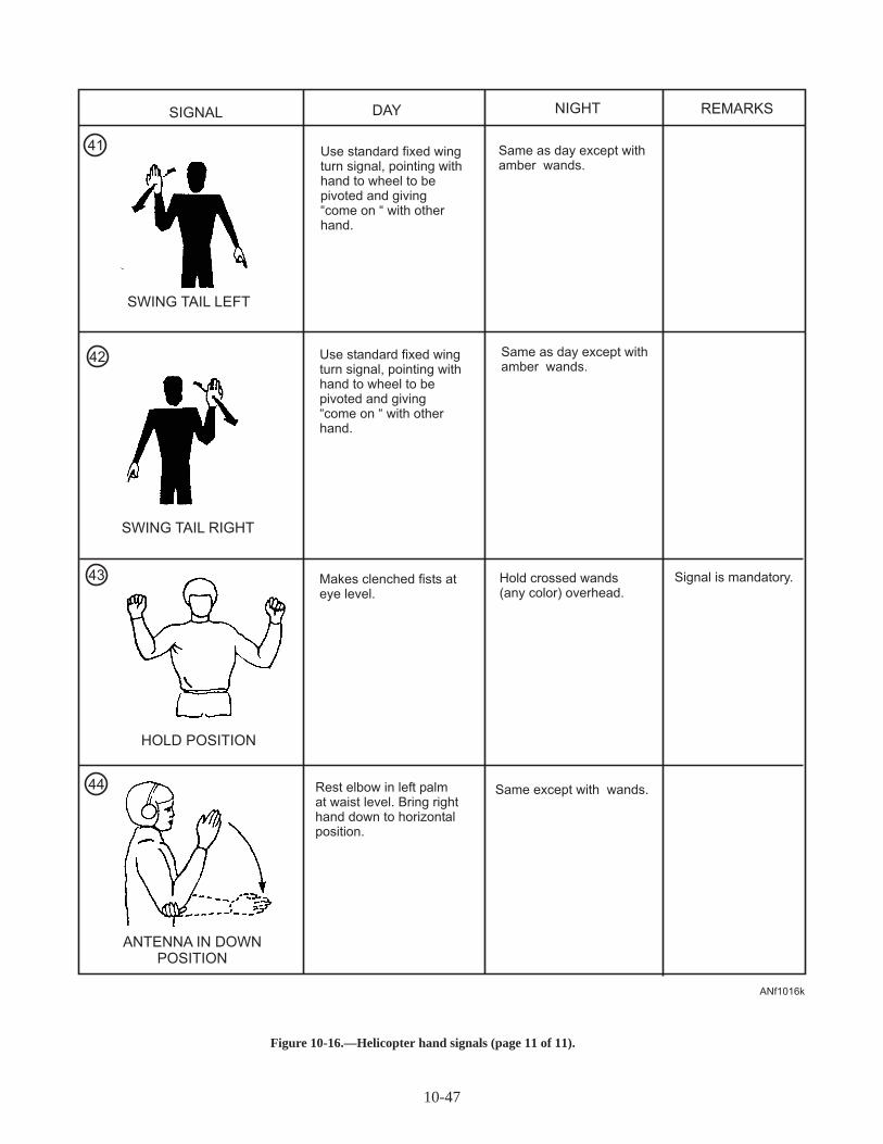
10-47
SIGNAL DAY NIGHT REMARKS
Rest elbow in left palmat waist level. Bring righthand down to horizontalposition.
Signal is mandatory.
Use standard fixed wingturn signal, pointing withhand to wheel to bepivoted and giving“come on “ with otherhand.
Use standard fixed wingturn signal, pointing withhand to wheel to bepivoted and giving“come on “ with otherhand.
Makes clenched fists ateye level.
Same as day except withamber wands.
Same as day except withamber wands.
Hold crossed wands(any color) overhead.
Same except with wands.
SWING TAIL LEFT
SWING TAIL RIGHT
HOLD POSITION
ANTENNA IN DOWNPOSITION
44
43
42
41
ANf1016k
Figure10-16.—Helicopter hand signals (page 11 of 11).

! Launch and recovery operations
! Chocks and tie-downs (as required)
! Fire bottle and guard (posted)
! Auxiliary power plant start/shut down
! Clearances around the aircraft
! Rotor blade spread/fold
! Engine start/shut down
! Rotor engagement/disengagement
! The movement of all personnel around theaircraft when loading or unloading troops,cargo, or fueling
! All other activities around the launch orlanding area
! External material condition and security of theaircraft
For detailed information on shipboard V/STOLaircraft operating procedures, you should refer to theNaval Warfare Publication Shipboard V/STOL Air-craft Operating Procedures, NWP-63-1; the
LHD/LHA/LPH/LPD NATOPS Manual, NAVAIR00-80T-106; and theShipboard Helicopter OperatingProcedures, NWP-42, latest revision.
HELICOPTER SAFETYPRECAUTIONS
During aircraft operations afloat or ashore, thefollowing helicopter safety precautions should beobserved:
! Do not approach or depart a helicopter withoutdirection from the LSE.
! Do not approach or depart a helicopter whilethe rotors are being engaged or disengaged.
! Helicopters shouldnot be taxiied on the flightdeck.
! Helicopters shouldnot be towed or pushedwhile the rotors are engaged.
! Helicopters should not be launched orrecovered and rotors shouldnot engaged ordisengaged while the ship is in a turn or thewind is out of parameters.
10-48
FORE/AFT CENTERLINE OFALL HELICOPTERS ARE TO
BE IN LINE WITH THEFORE/AFT LINE
NOSEWHEEL SPOT FOR H-53(OMITTED FROM SPOTS 1
AND 4, AND SPOT 3A ON LPH)
NOSEWHEEL SPOT FOR H-46(OMITTED FROM LHA SPOT 3A)
MAIN WHEEL SPOTS FORBOTH H-46 AND H-53 (OMITTED
FROM LHA SPOT 3A)
H-1 SKID TOE ONTHE ATHWARTSHIP
LINE, H-2, H-3AND H-60 NOSE
OVER THEATHWARTSHIP
LINE.
ANf1017
Figure 10-17.—Shipboard helicopter landing spot (typical).

! A helicopter shouldnot be flown over anyother aircraft during takeoff and landing.
! Never approach a tail rotor type helicopterfrom the rear while the rotors are turning.
! Personnel required to be in the area ofoperating helicopters should exercise extremecaution and observe the signals or directionsfrom the aircraft director.
Q10-18. What is the purpose of helicopter rotor bladetie-downs?
Q10-19. What are the two mandatory helicopter handsignals?
Q10-20. Who is responsible for directing the pilot tothe desired deck spot and for ensuringgeneral safety conditions of the flight deck?
10-49
C
C
C
D
E
IDENTIFICATIONMARKING
PERIMETERMARKING
DIMENSIONS
A = 0.6F BUT 60’ MAXB = 0.5A
HELIPAD SIZE(F)
PATTERN LINEWIDTH (C)
PERIMETER EDGEWIDTH (D)
CORNER EDGELENGTH (E)
COLOR: RETROREFLECTIVE AVIATION SURFACE WHITE, EXCEPT HELIPADS FOR DAY OPERATIONSONLY MAY BE NONRETROREFLECTIVE WHITE.
80’ - 99’100’ - 150’
5’6’
24”30”
10’ (TYP)12’ (TYP)
ANf1018
F A
B
B
F
Figure 10-18.—Air station helipad identification and perimeter markings.

Table 10-4.—Deck Status Lights/Rotating Beacon Signals forHelicopter Operations
EVOLUTION DECK STATUS LIGHTS/ROTATING BEACON SIGNAL
Start Engines Red
Engage Rotors Amber
Launch Green
Recovery Green
Disengage Rotors Amber
Shutdown Red
Q10-21. What color should the deck status lights/rotating beacon signal be to engage rotors?
Q10-22. Is it permissible to taxi a helicopter on theflight deck?
SUMMARY
In this chapter you have learned about operating SEaround aircraft, afloat and ashore aircraft operations,handling and securing procedures, hand signals,aircraft handling accessories, and the related safetyprocedures and requirements.
10-50
EVOLUTION COMMAND DISPLAY MEANING (HELO) MEANING (AV-8)
1. Prepare to
start engines
Check chocks,
chains, tie-downs,
fire bottles, and all
loose gear about the
flight deck. Helmets
buckled, goggles
down, start
APP/GTS on
LSE/director signal.
Red signal in
flight deck area
Verify starting wind
limitations chocks and
tie-downs in place.
Boots removed and
stowed. Secure all
loose gear. Man fire
extinguishers.
Intake blanks clear
GTS wind limits met,
chocks, tie-downs in
place, loose gear
secured. Man fire
extinguishers.
2. Start engines Start engines Red signal in
flight deck area
Authority for responsible flight deck personnel to
signal for starting engines. Ship not ready for
flight operations.
3. Engage/
disengage
rotors
Stand clear of rotors
(20 second pause) -
engage/disengage
rotors
Amber signal in
flight deck area
Ship is ready for the
pilot to engage rotors.
Authority for
responsible flight deck
personnel to signal for
engaging rotors when
the immediate area is
cleared. Ship not ready
for flight operations.
Squadron personnel
conduct poststart
checks (i.e., controls)
clear exhaust areas.
4. Removal of
tie-downs
Remove all
tie-downs
Not applicable
Note: Emcon
(Red,
Green,
Red)
Remove tie-downs from aircraft and show to
pilot. LSE points to tie-downs and shows one
finger to the pilot for each tie-down removed.
5. Launch Launch aircraft Green signal in
flight deck area
Ship is ready in all respects for flight operation.
Authority for responsible flight deck personnel to
launch aircraft when pilot is ready and tie-downs
and chocks have been removed.
6. Aircraft
approaching
Standby to recover
aircraft, spot _____.
Red signal in
flight deck area
Prepare designated landing area to land aircraft.
Ship not ready to recover aircraft.
7. Recover Land aircraft Green signal in
flight deck area
Ship is ready in all respects to land aircraft.
NOTE: Flight deck rotating beacon signals are for Pri-Fly control of flight deck operations only. These lights are
not to be interpreted by pilots as clearance/denial for any evolution.
Table 10-3.—Flight Deck Commands

ASSIGNMENT 10
Textbook Assignment: "Line Operations and Safety," chapter 10, pages 10-1 through 10-50.
10-1. What is one of the busiest, most important anddangerous divisions in a squadron?
1. Line2. Ordnance3. Maintenance4. Supply
10-2. When fueling an aircraft ashore, the refuelingvehicle should be parked in what position?
1. Downwind side headed away from theaircraft
2. Behind the aircraft wing after enginecooling
3. Perpendicular to the aircraft close to thefueling point
4. Forward of the aircraft and parallel to thewing
10-3. What is the maximum speed limit for vehiclesoperating on airfields within 50 feet of aircraftand hangars?
1. 2 miles per hour2. 5 miles per hour3. 10 miles per hour4. 12 miles per hour
10-4. What is the speed limit for vehicles operatingon runways, taxiways, parking areas, ramps,and work areas?
1. 5 miles per hour2. 10 miles per hour3. 15 miles per hour4. 20 miles per hour
10-5. When aircraft are towed, the towing speedshould NEVER be faster than the slowestperson can walk or exceed 5 miles per hour.
1. True2. False
10-6. What method is used to identify handling andservicing equipment used around aircraft?
1. Identification plates2. Placards and reflective tape3. 12-inch black letters4. Colors and markings
10-7. What color is most support equipment painted?
1. Yellow only2. Black and yellow3. Yellow and white4. Red and white
10-8. On support equipment, the danger areas, suchas intakes or exhausts, are painted what color?
1. Yellow2. Red3. White4. Black
10-9. What is the minimum protective clothing re-quired for all personnel to wear while workingon the flight deck?
1. Cranial impact helmet, goggles, and soundattenuators
2. Long sleeve jerseys and trousers with steeltoe flight deck boots
3. Inflatable life preserver with distress lightmarker, sea dye marker, and whistle
4. All of the above
10-10. Which division is responsible for handlingaircraft on the flight deck?
1. V-1 division2. V-2 division3. V-3 division4. V-4 division
10-11. Which division is responsible for handlingaircraft in the hangar bay?
1. V-1 division2. V-2 division3. V-3 division4. V-4 division
10-12. In addition to the director, crew leader, andsafetyman, how many Airmen are normallyassigned to complete the aircraft handlingcrew?
1. Two to five2. Four to seven3. Six to ten4. Eight to eleven
10-51

10-13. In an aircraft handling crew, what member isthe only petty officer assigned to the crew?
1. Director2. Crew leader3. Safetyman4. Chockman
10-14. What member in the aircraft handling crew isresponsible for informing the director aboutthe safety of the aircraft and to preventaccidental damage and personal injury?
1. Crew leader2. Safetyman3. Tractor driver4. Wing walker
10-15. When aircraft are being moved on the flightdeck or hangar bay by handling crews, whatmethod is used to give directions?
1. Radio headsets2. Hand signals3. Whistles4. All of the above
10-16. Once the requirements for an aircraft launchare known, which of the following officersholds a brief with all the key flight deckpersonnel?
1. Catapult officer2. Flight deck officer3. Aircraft handling officer4. Flight deck safety officer
10-17. What color cranial, jersey, and floatation vestidentifies aircraft handling officers and planedirectors?
1. Green2. Yellow3. Blue4. Purple
10-18. Aircraft are assigned a spotting sequence forlaunch based on what criteria?
1. Aircraft type, mission, and catapult2. The pilot’s seniority3. The aircraft’s bureau (side) number4. The aircraft’s fuel load
10-19. When aircraft launching begins, what typeaircraft is normally launched first?
1. Turboprop2. Jets3. Rescue helicopter4. Reciprocating engine
10-20. What is the purpose of a foreign object damage(FOD) walkdown?
1. To check all aircraft engines for loose gear2. To pick up all debris from the deck3. To ensure all support equipment is secured
and inspected for damage4. To check all aircraft tires for embedded
objects
10-21. How many hours a day is crash and salvagemanned and ready aboard ship?
1. During flight operations only2. During an aircraft crash or fire only3. When directed by the air boss4. 24 hours a day
10-22. Which of the following rules is extremelyimportant to remember while directing taxiingaircraft?
1. Ensure the pilot can see the signals beinggiven
2. The person being signaled mustthoroughly understand the signal
3. Exercise extreme caution to preventpersonnel from being caught in the jet blast
4. Each of the above
10-23. Who is responsible for the movement of allaircraft on the flight deck?
1. Primary flight control (PRI-FLY)2. Flight deck control3. The air boss4. The mini boss
10-24. Who has control of all flight deck lighting,landing spot lighting, flight deck floodlights,and the flight deck rotary beacon?
1. The landing signal officer’s platform2. Flight deck control3. Primary flight control (PRI-FLY)4. The engineering department
10-25. Which of the following personnel isresponsible for launching aircraft?
1. Flight deck officer2. Catapult officer3. Air boss4. Commanding officer
10-26. Which of the following personnel ensures thatthe aft flight deck is ready for landing aircraft?
1. Arresting gear officer2. Air boss3. Flight deck officer4. Catapult officer
10-52

10-27. Which of the following personnel monitors ordirects the pilot in the final approach to theship?
1. Air traffic controller2. Air officer3. Recovery officer4. Landing signal officer
10-28. What system provides continuous glide pathinformation and places major control of theaircraft in the hands of the pilot?
1. Air traffic control radar2. Frensel Lens Optical Landing System
(FLOLS)3. Aircraft Automatic Landing System
(AALS)4. Manually Operated Visual Landing
System (MOVLAS)
10-29. When an aircraft fails to hook on an arrestinggear cable and is required to enter the trafficpattern again, the action is known by whatterm?
1. Wave-off2. Miss3. Bolter4. Skip
10-30. What method is used to release the arrestingcable from the aircraft tailhook if the cabledoes not fall free normally?
1. Pull the aircraft backwards2. Disconnect the tailhook3. Turn the aircraft4. Disconnect the cable
10-31. What is the name of the alternating red andwhite striped line that runs the length of theflight deck?
1. Center line2. Landing lineup line3. Lubber line4. Foul line
10-32. What is used to recover aircraft that cannotmake a normal arrested landing?
1. Barricade2. Parachute3. Pendant4. Cables
10-33. What division works in conjunction with theV-2 division in the initial preparation of thebarricade?
1. V-1 division2. V-3 division3. V-4 division
10-34. What aircraft director hand signal is mandatoryat all times?
1. Emergency stop2. Takeoff3. Landing4. Fold wings
IN ANSWERING QUESTIONS 10-35 AND 10-36,REFER TO FIGURE 10-4 (SHEETS 1 THROUGH16).
10-35. When the director gives the hand signal "Armscrossed above the head, palms facing forward,"which of the following signals is he/shegiving?
1. "This way"2. "Slow down"3. "Stop"4. "Brakes (on/off)"
10-36. When the director gives the hand signal "Pointright arm downward, left arm is repeatedlymoved upward and backward," which of thefollowing signals is he/she giving?
1. "Turn right"2. "Turn left"3. "Proceed to next director"4. "Clear for takeoff"
10-37. During night operations, what instruments areused by directors for taxiing signals?
1. Handheld radios2. Beacons3. Wands4. Chemical light sticks
10-38. At what intervals are the aircraft directorsusually positioned along the flight deck duringoperations that require taxiing of aircraft?
1. 5 to 10 ft2. 20 to 40 ft3. 50 to 100 ft4. 100 to 200 ft
10-53

10-39. What class of ships embarks vertical, shorttakeoff and landing (V/STOL) aircraft?
1. LHD2. LHA3. LPH4. Each of the above
10-40. For which of the following reasons are aircraftsecured by chocks and chains at all times whenaboard ship?
1. Because heavy seas make the ship pitchand roll
2. Because of the list of the ship caused bymaneuvering
3. Because of the close proximity of theaircraft on the flight deck and hangar bay
4. Each of the above
IN ANSWERING QUESTIONS 10-41 AND 10-42,REFER TO TABLE 10-2 IN THE TEXT.
10-41. What color wands are used by aircraft directorsduring night operations?
1. White2. Amber3. Blue4. Green
10-42. What color wands are used by plane captainsduring night operations?
1. Amber2. Red3. White4. Blue
10-43. For what reason should aircraft wheel chocksbe loosened during fueling operations?
1. They will be difficult to remove because ofthe added weight
2. A snug fit is not required during fueling3. The chocks can be removed quickly if an
emergency occurs4. Because the tie-down chains will not
prevent the aircraft from moving
10-44. Which of the following attachments areinstalled on the flight deck and hangar bay forthe attachment of tie-down chain assemblies?
1. Anchor points2. Scuppers3. Pad eyes4. Tie downs
10-45. When you secure aircraft in heavy weather,how will the procedures differ from that ofnormal weather conditions?
1. The aircraft are parked further apart2. More tie-down chains are used3. The security watch is doubled4. The brake rider remains in the cockpit
10-46. Which department is responsible formaintaining a security/integrity watch on theflight deck and hangar bay to ensure all aircraftremain properly secured?
1. Operations department2. Security department3. Deck department4. Air department
10-47. In severe cold weather environments, aircraftcanopies should not be locked in the landingarea because they will freeze "closed" andprevent brake rider protection.
1. True2. False
10-48. What is the most common type of aircraftwheel chocks used aboard aircraft carriers?
1. The NWC-32. Model 1509AS300-13. The NWC-4 and NWC-54. Model 1509AS300-5
10-49. What are the two available lengths of theTD-1A and TD-1B tie-down chain assemblies?
1. 5 and 10 ft2. 9 and 14 ft3. 10 and 15 ft4. 20 and 25 ft
10-50. What is the working load of the Aero fullpower tie-down assembly?
1. 10,000 pounds2. 20,000 pounds3. 30,000 pounds4. 40,000 pounds
10-51. How many general classes of tow bars are usedin naval aviation?
1. One2. Two3. Three4. Four
10-54

10-52. What is the weight towing capacity of theuniversal aircraft tow bar, Model ALBAR(adjustable length tow bar)?
1. 60,000 pounds2. 70,000 pounds3. 80,000 pounds4. 90,000 pounds
10-53. Who is responsible at all times for the safety ofembarked aircraft and personnel aboard ship?
1. Commanding officer2. Air officer3. Safety officer4. Operations officer
10-54. What term is used when the flight deck hasunauthorized personnel in or around aircraftparked in the safe-parking area aft of theisland?
1. Dirty2. Foul3. Secured4. Skunk
10-55. While taxiing the aircraft, what must the pilotdo if he/she loses sight of the director?
1. Contact the tower2. Continue to the next director3. Stop immediately4. Continue taxiing and wait for instructions
10-56. If an aircraft with inoperative brakes is to betowed and respotted, the cockpit must NOT bemanned, and the chockman must be in positionto chock the main wheels instantly whenordered.
1. True2. False
10-57. When squadron aircraft are shore based, thearea where a group of aircraft is spotted orparked is referred to as
1. the parking area2. the ramp3. the line4. the hole
10-58. Which of the following personnel has theresponsibility to direct and spot aircraftashore?
1. Maintenance crew2. Phase crew3. Operations crew4. Line crew
10-59. Upon landing ashore and clearing the runway,the pilot will be assisted to the line for parkingby what means?
1. An aircraft director2. A "follow me" vehicle3. The control tower4. A tow tractor
10-60. What method is used to distinguish flight linefire extinguishers from building fire-fightingequipment?
1. The size of container2. 6-inch black letters3. Color codes4. Length of hose
10-61. What color is the 6-inch band around the top ofa fire extinguisher on the line painted toidentify carbon dioxide (CO2)?
1. Yellow2. Silver or white3. Purple4. Blue
10-62. What color is the 6-inch band around the top ofa fire extinguisher on the flight line painted toidentify Halon?
1. Blue2. Silver or white3. Purple4. Fluorescent yellow
10-63. What is a disadvantage of a multiengineaircraft equipped with nosewheel steering?
1. It limits the turning radius2. It is unable to back up in a straight line3. It increases the turning radius4. It has to be parked using a tow tractor
10-64. What signal is given by the move director tohave the brakes of the aircraft and tow tractorapplied simultaneously in case of anemergency?
1. Waving arms above head2. Blowing a whistle3. Yelling, "stop"4. Arms above head, clinched fists
10-65. What aircraft safety equipment should beinstalled before the aircraft is towed?
1. Engine intake covers2. Grounding straps3. Control surface battens4. Landing gear safety lockpins
10-55

10-66. What, if anything, will occur if an aircraftnosewheel is turned beyond its limits whiletowing?
1. Structural damage will occur2. The nosewheel tire will be damaged3. The landing gear strut will collapse4. Nothing, this is a common procedure
10-67. Why should you leave sufficient slack in theline when securing an aircraft with manilaline?
1. To prevent damage to the tie-down pointsduring wind gusts
2. To make it easier to untie the knots3. To prevent structural damage to the wings4. To allow for shrinkage that occurs when
the line becomes wet
10-68. Multiengine aircraft are usually tied down atsix points.
1. True2. False
10-69. Which of the following helicopter hand signalsis mandatory?
1. Wave-off only2. Hold only3. Wave-off and hold4. Hover
10-70. What is the name of the director that isresponsible for visually signaling to thehelicopter?
1. Landing signal enlisted (LSE)2. Landing signal officer (LSO)3. Signalman4. Flight deck leading petty officer
IN ANSWERING QUESTIONS 10-71 AND 10-72,REFER TO FIGURE 10-16 (SHEETS 1 THROUGH11).
10-71. When the director gives the hand signal "Armsextended horizontally sideways, palmsdownward," which of the following signals ishe/she giving?
1. Hover2. Land3. Move downward4. Move upward
10-72. When the director gives the hand signal "Acircular motion in horizontal plane with righthand above head," which of the followingsignals is he/she giving?
1. Lower wheels2. Engage rotors3. Clear for takeoff4. Engine fire
10-73. Helicopters should NEVER be taxiied on theflight deck of a ship.
1. True2. False
10-74. What color light is displayed from the flightdeck rotary beacon that indicates the ship isready for the pilot to engage rotors?
1. Red2. Green3. Amber4. White
10-56

CHAPTER 11
AIRCREW SURVIVAL EQUIPMENT
INTRODUCTION
Emergency conditions arise quickly and leave littleor no time for preparation. You must know whatsurvival equipment is available and how to use it beforethe need arises.
You can receive aircrew survival training in anumber of places. The first place is the aviator'sequipment shop, commonly called the "parachute loft"or just the "paraloft." There you will meet the personnelthat rig, pack, inspect, and maintain all Navy survivalequipment. These personnel are members of theAircrew Survival Equipmentman rating, and arecommonly called "parachute riggers." In the parachuteloft, you can get first-hand information on the differentitems that are covered in this chapter.
The next place is in Flight Physiology. There youwill find the medical people who are responsible forsurvival training. You may have an opportunity to see oreven take a ride in the pressure chamber. The pressurechamber allows you to use oxygen equipment under theatmospheric pressure conditions encountered at highaltitudes, and to see how your body reacts to thosechanges.
The multiplace egress device is used in many areas.This device is used to simulate the problems involved inditching an aircraft at sea, day or night. This trainingteaches you how to escape from a sinking aircraft andhow to use inflatable life rafts and life preservers.
FLIGHT CLOTHING
LEARNING OBJECTIVE : Identify thetypes, characteristics, and uses of flightclothing.
Naval aircrew protective equipment is designed tomeet the extreme stresses of a combat environment. Italso provides fire protection, camouflage, and hasdesign features for escape and evasion. The wide rangeof environmental conditions in which aircraft mustoperate requires a compromise between comfort andthe high level of protection needed. Protection is thefirst priority. Postcrash fire and cold water exposure aretwo critical areas where the survival requirements aremore important than maintaining the best cockpit
flying conditions. Flight clothing is designed tominimize injury from these hazards.
Aircrew personal protective equipment, such asflight clothing, plays an important role in the safety andsurvival of pilots and aircrewmen. It protects personnelfrom the elements and provides adequate comfort forefficient mission performance. The primary purpose offlight clothing and equipment is to protect you from avariety of hazards. No single item of clothing orequipment can cover all the potential requirements. TheNavy uses both general flight gear and specializedprotective equipment for protection and comfort in coldand hot climates. General flight gear consists of flightcoveralls, boots, gloves, etc.; specialized protectiveequipment consists of anti-g protection coveralls andantiexposure equipment.
FLIGHT COVERALLS (SUMMERWEIGHT)
The summer weight flight coverall (fig. 11-1),which comes in two colors (sage green and blue), is aone-piece suit made from Aramid cloth. Aramid clothis a high-temperature resistant, flame retardant, andnonabsorbent synthetic fabric commonly calledNomex. The fabric is lightweight and does not burn, butit begins to char at 700° to 800°F. The suit is fitted bysize, easy to put on, has ample pocket space, and iswash and wear.
FLIGHT COVERALLS (COLD WEATHER)
The cold weather flight coverall is a one-piecelined coverall similar to the summer-weight flight suit.The outer layer is a fire–resistant aramid twill with aninner layer of aramid microfiber thermal insulation.The coverall is sized and belted, has a concealed hoodin the collar, has ample pocket space, and is wash andwear. The coverall has adjustable sleeve cuffs, frontclosure and leg zippers make it easy to get in to andprovide a snug fit. The coverall is available in 24 sizesand may be worn instead of the summer flight suit whenconditions warrant.
FLIGHT BOOTS
Flight boots are designed to protect your feet fromhigh impact forces, such as crushing or piercing. Theboots are water resistant.
11-1

The upper boot is constructed of black,high-quality calfskin or cattlehide and is lined with soft,full-grain cattlehide glove leather. The boot is 8 incheshigh when fully laced, and is available in normal shoesizes. The traction tread soles and heels are made ofnonslip, nonmarking, jet-fuel-resistant rubber. Thesteel box toe is constructed of cold-rolled carbon steelto provide safety through greater compressionresistance.
FLIGHT GLOVES
The fire-resistant flight gloves provide protectionin the event of fire in the aircraft. The flight gloves aresnug fitting to allow maximum finger movement andsense of touch. The gloves do not interfere withoperation of the aircraft or use of survival equipment.The gloves are constructed of soft gray cabretta leatherand a stretchable, sage green, Aramid (Nomex) fabric.
The fabric (top) portion of the glove does not melt andwill not support combustion. The leather palm andfinger portions of the glove provide a nonslip surfaceeven when wet.
HELMETS
The type of aircraft you are in dictates whether ornot you have to wear a protective helmet. Fighters,attack planes, and helicopters usually require you towear a protective helmet throughout all flightoperations. Other aircraft may require you to wear ahelmet only during takeoffs and landings.
The helmet is part of a pilot's protective equipment.Maintenance and upkeep is the responsibility of theAircrew Survival Equipmentman. There are severaldifferent types of helmets. Each has its own specificfunction. Some types of helmets can be changed ormodified to meet certain requirements for specificaircraft and mission. The HGU series helmets arediscussed in the following text.
The HGU–68(V)/P series helmets (fig. 11-2) aredesigned for all tactical fixed-wing aircraft applica-tions. They are lightweight and provide face, eye,hearing, and head protection when properly assembledand fitted to the person. The helmet assembly housesthe visor, liner, and communications headset. Some
11-2
ANf1101
Figure 11-1.—Summer flight coverall.
ANf1102
Figure 11-2.—HGU-68(V)/P helmet assembly.

helmets have specialized features, such as the VisualTarget Acquisition System (VTAS), Night VisionGoggle (NVG) assemblies, laser protective lenses,sonar operator binaural cables, and boom microphones.
The HGU–84/P series helmet (fig. 11-3) isdesignated for used by all helicopter aircrew members.Helmet assemblies feature a lightweight shellconstructed of a multi–layer mixed composite ofgraphite fabric and ballistic nylon fabric, an inner foamliner, three integrated visor assemblies (Neutral, Clear,and Laser Eye Protective), communication cord set,boom microphone, earphones, and a integratedchin/nape strap. The helmet provides maximum face,eye, ear and head protection and comfort when properlyfitted to the wearer. The HGU–84/P helmet is availablein four sizes, (M, LG, XLG, XLG wide) and can also befitted with specialized features for aircraft or mission.
ANTI-G COVERALLS
When in flight, the body can have trouble adjustingto stresses produced by rapid changing of speed ordirection. In situations such as seat ejection, ditching,or parachute opening shock, the short duration of theexcessive force has little effect on the body. However,changing the direction of flight produces stress forcesequal to several times the normal pull of gravity formuch longer periods of time. These longer durationforces can have dangerous effects.
At 5 g's (5 times the force of gravity), theaircrewman's body is exposed to a force that increasesits weight 5 times. This increased weight has manyeffects. Your body is pushed down into your seat. Yourarms and legs feel like lead, and operation of equipmentbecomes more difficult. The extra weight on yourinternal organs causes stomach and chest pain. Mostimportant, however, is the effect on your circulatorysystem.
At 5 g's, your heart cannot pump enough blood toyour head. When this happens, you will pass out.Wearing anti-g coveralls will help prevent this fromhappening.
The Navy uses two models of anti-g coveralls(commonly called "G" suits). These coveralls provideprotection against blacking out, loss of vision, andlowered mental efficiency caused by high g-forcesexperienced in high-performance aircraft. Figure 11-4shows a typical anti-g coverall.
Anti-g coveralls compress your legs and stomach toprevent blood from pooling in your lower body. Thisincreases your stress tolerance an average of about 2g's. Without an anti-g coverall, you may be able towithstand about 4.5 to 5.5 g's without losing vision orblacking out. With a coverall, you can withstand 6.0 to7.0 g's. This protection is available only for sustainedaccelerations of 4 to 5 seconds. Anti-g equipment doesnot offer protection in snap maneuvers where 10 to 12g's are applied in about 1 second. Such extreme forcesfor a short time are not as harmful to the body as arelesser forces sustained for a longer time.
11-3
ANf1103
Figure 11-3.—HGU–84/P series helmet.
ANf1104
Figure 11-4.—Cutaway anti-g coverall.

ANTIEXPOSURE COVERALL
Antiexposure coveralls are composed of severalgarments that protect you against exposure in coldwater. The two main coveralls are the constant-wearand the quick-donning. The constant-wear suit consistsof a waterproof outer garment worn over a ventilationliner and/or cold weather underwear. Constant-wearcoveralls provide additional protection from coldtemperatures.
The quick-donning antiexposure coverall is carriedin the aircraft and donned only in case of emergency. Itconsists of a waterproof outer garment equipped withpermanently attached boots and wrist and neck seals.An inflatable hood and antiexposure mittens are stowedin the pockets. In case of emergency, the coverall isdonned over the regular flight clothing (fig. 11-5).
Either the continuous-wear or quick-donningantiexposure coverall is provided for flight personneland passengers when there is a significant risk of
crashing in the water, and when any of the followingconditions exist:
1. The water temperature is 50°F or below.
2. The outside air temperature (OAT) is 32°F(wind chill factor corrected) or below.
If the water temperature is between 50° and 60°F,the commanding officer of the unit concerned considersthe following search and rescue (SAR) factors todetermine if antiexposure coveralls should be worn:
1. The maximum probable rescue time. Thisshould be a function of mission distance, SARequipment, and SAR location.
2. The lowest temperatures that will occur in themission area during the time period of the flight.
When water temperature is below 60°F andantiexposure coveralls are not required, the flightequipment must include antiexposure and high-
11-4
SILVERREFLECTIVE
TAPE
RED-ORANGEREFLECTIVE
TAPE
ANKLE CINCH
MITTEN/GLOVEASSEMBLY
WAISTCINCH
REFLECTIVETAPEFACE
FLAP
HELICOPTERHOISTSTRAP
WRISTCINCH
ANf1105
Figure 11-5.—Quick-donning antiexposure coverall.
HARNESS
PACK
SUSPENSIONLINES
CANOPY
PILOT CHUTE
ANf1106
Figure 11-6.—Five major components of a Navy parachute.

temperature resistant undergarments. Wearing doublelayers of these undergarments can significantlyimprove your antiexposure protection.
Q11-1. What is the primary purpose of flight clothingand equipment?
Q11-2. What type of helmet is designed for use byhelicopter aircrews?
Q11-3. What is the purpose of the anti-g coverallsuit?
PARACHUTES
LEARNING OBJECTIVE : Identify thetypes, characteristics, and basic operatingprocedures for Navy parachutes.
A parachute consists of five major parts—theharness, container, suspension lines, canopy, and pilotchute (fig. 11-6). The harness is an arrangement ofnylon webbing and metal fittings. It is designed to holdthe parachute securely to the wearer and provide a seat
or sling during descent. The container encloses the pilotchute, canopy, and suspension lines. The suspensionlines are made of nylon and join the canopy to theharness. The canopy is a large round area of cloth that,when inflated, slows the descent of a falling body. Thepilot chute is a small parachute attached to the top of thecanopy. When the ripcord is pulled, the pilot chutedeploys and helps deploy the main canopy andsuspension lines.
There are three basic types of Navy parachutes—the Navy back (NB), the Navy chest (NC), and theNavy ejection system (NES).
The NB and NC parachutes are used in aircraft thatdo not have ejection seat systems. The NES is used inejection seat aircraft.
NES PARACHUTE
The NES parachute assembly (fig. 11-7) is usedonly with ejection seat equipped aircraft. The assemblyis equipped with a 28-foot canopy. The canopy is
11-5
LUMBAR PAD ASSEMBLY(S 3 AIRCRAFT APPLICATIONONLY)
AFTERACC 446
FRONT VIEWANf1107
Figure 11-7.—Personnel Parachute Assembly, NES-12.

attached to the aircrewman by lift webs connected to atorso harness. This torso harness is part of the shoulderharness restraint system. The restraint system is part ofthe ejection seat emergency egress system.
Upon ejection, there are two methods for deployingthe parachute. One ejection method is for seats to useexplosive cartridge-actuated projectiles to withdrawand deploy the parachute. The other way is for seats totrip an automatic parachute opening device when theejection sequence separates the occupant from theejection seat.
The automatic opening device pulls the ripcordpins, which releases the pilot parachute. The pilotparachute, in turn, pulls the main canopy andsuspension lines from the container. When full stretchof the suspension lines is attained, a spreading gunattached to the hem of the canopy explodes. Theexplosion fires 14 projectiles in a centrifugal pattern,which accelerates the parachute opening.
PARACHUTE HARNESSES
A parachute harness secures the parachute to thewearer and provides support during the opening shockand descent. The harnesses used by the Navy are thestandard quick-fit (used with the NB and NCparachutes) and the integrated torso harness suit (usedwith the NES parachute).
There are two types of standard quick-fitharness—the back type (NB) and the chest type (NC).The NB type consists of a main sling, lift webs, legstraps, a horizontal back strap, a diagonal back strap,and a chest strap combined into one unit. The lift websare the attaching points where the parachute suspensionlines are attached to the parachute canopy.
The chest type consists of the same components asthose of the back parachute. The difference between thechest and the back harness is that the lift webs of thechest harness may be connected to or disconnectedfrom the main sling. This allows you to remove thechest parachute while wearing the parachute harness.
The Integrated Torso Harness Suit
The integrated torso harness suit (fig. 11-8)contains the parachute harness, lap belt assembly, andshoulder restraint harness. The suit provides mobilitywhile restraining the wearer to the seat duringemergency conditions. It also serves as a parachuteharness during an aircraft ejection.
The suit consists of a nylon webbing harnessencased in nylon fabric. It is a sleeveless, legless, torso
garment. Shoulder restraint adjustable straps withquick-release fittings are for attachment of an NESparachute assembly. A lap belt and quick-releaseadapter are attached to the lap belt alignment webbing.The lap belt assembly is used to attach a survival kit. Awebbing belt at the waist area is used to attach a lifepreserver if the survival vest is not used. A zipperlocated in the front closes the suit. An adjustable cheststrap provides for the final chest adjustment. The strapis secured by a friction adapter and hook-and-pile tape(Velcro). A gated D-ring is attached to the rightshoulder adjustable strap near the quick-release fitting.The D-ring is used to attach a helicopter rescue hook.
Parachute Container
The parachute container holds and protects thepilot chute, main canopy, and suspension lines. Thereare many container designs. Each design is unique to itsspecific aircraft egress system. Containers are eithermade from nylon fabric or a contoured plastic frameenclosed in a nylon cover.
11-6
ANf1108
Figure 11-8.—Torso harness suit.

Suspension Lines
Suspension lines are the lines that connect theparachute canopy to the parachute harness. Thesuspension lines form a net or skeleton for the canopy.This skeleton absorbs much of the parachute openingshock. Suspension lines are made of nylon and are usedon all main canopies. Suspension lines consist of anouter covering and several inner cords called the core.The core provides the greater portion of the strength ofthe suspension lines. The suspension lines runcontinuously between connector links on either side ofthe canopy.
Canopy
The 28-foot, rip-stop nylon parachute canopy (fig.11-9) is commonly used in Navy parachutes. Thecanopy has 28 sides and a diameter of 28 feet. Each sideis called a gore and is made up of four sections of fabric.
This parachute has the following characteristics:
• Each gore section is identified by the letters A,B, C, and D, starting with the bottom section.
• Each section is cut at a 45-degree angle to thecenter line of the gore. This is called "biasconstruction," and it provides maximum strength andelasticity.
• The suspension lines are enclosed in the channelproduced by the stitches of the radial seams.
• A vent opening in the top of the parachute acts asa relief valve and relieves the high internal pressurewithin the parachute at the instant of opening. Withoutthis vent, an opening at high speed could tear thecanopy.
• The canopy is manufactured in four coloredsections of fabric to aid a downed crewman in eitherconcealing or signaling his location. The four colors arewhite, orange, tan, and green.
11-7
BEFORE ASSEMBLING SUSPENSION LINES
LENGTH OF SUSPENSION LINES ACROSS
VENT SHALL BE 17" WHEN LINE IS UNDER
TENSION SPECIFIED FOR MARKING
CEN
TERLIN
EO
FSU
SPENSIO
NLIN
E
CE
NTE
RLIN
EO
FG
OR
E
A-PANEL
OR NO. 1
SECTION
OUTSIDE OF HEM AFTER FOLDING
SEW FABRIC TO EACH CORD ONZIG-ZAG MACHINE AS INDICATED
ALLOW 1/2 PUCKERIN FABRIC BETWEENZIG-ZAG STITCHING
DIRECTION OF
WARP PARALLEL
TO DIAGONAL SEAM
DIAGONAL SEAM
18" DIA.
D
4
C
OR
NO.3
B-PANEL
OR NO.2
SECTION
ANf1109
45
45
Figure 11-9.—The 28-foot ripstop canopy.

Pilot Chute
The purpose of the pilot chute is to help deploy themain parachute. The vane-type pilot chute (fig. 11-10)is a small spring-loaded chute. It is held in acompressed state by the closing feature of the parachutecontainer. When released from the container, the coilspring will eject the pilot chute into the airstream. Thepilot chute canopy inflates and pulls the main parachutecanopy and suspension lines from the container.
PARACHUTE HANDLING ANDCARE
Anyone whose life has been saved by using aparachute needs no motivation when it comes to takingcare of parachutes. Parachutes may seem cumbersomeat times, but their bulk should serve as a reminder tothose who handle them that the parachute is a lifesavinginstrument. The following is a list of handlingprecautions designed to guide you in the proper ways ofcaring for a parachute.
1. Do not carry a parachute by its ripcord handleor the lift webs.
2. Keep actuating lanyards for cartridge-actuating devices well protected.
3. Keep parachutes dry and away from all sourcesof moisture.
4. Keep parachutes away from extreme heat, suchas heaters or radiators.
5. Do not drop a parachute.
6. Do not step on a parachute.
7. Keep parachutes clean. Protect them fromcontact with oil, grease, dirt, acids, and otherdestructive elements. Acids of any kind, even in weaksolutions, are extremely harmful to fabrics. Spillagefrom aircraft storage batteries often contaminates areasof the deck. This harmful condition has many ways ofbeing transmitted to a parachute. Report immediatelyany discrepancy noted on the exterior of a parachute.
WARNING
Never hide or attempt to rearrange webbings,material, or actuating lanyards that are disarrangedby careless handling. The life you save by reportingthese discrepancies might be your own.
Q11-4. What are the three basic types of navyparachutes?
Q11-5. What secures the parachute to the wearer?
Q11-6. Which parachute harness has a gated D-ringattached for helicopter rescue?
Q11-7. What is the purpose of a pilot chute?
11-8
TUBULAR WEBBINGREINFORCEMENT
CONE
SPRING CASING
SPRING
VANES
GORES
CROWN
GROMMET
PILOT CHUTE
RIP STOP NYLONPARACHUTE CLOTHUSED THROUGHOUT
ANf1110
Figure 11-10.—Vane-type pilot chute.

LIFE PRESERVERS
LEARNING OBJECTIVE : Identifytypes of life preservers and associatedsurvival equipment.
Life preservers are worn by personnel on overwaterflights and by flight deck personnel. The life preserversfunction is to keep you afloat until you can reach a raftor until a rescue team arrives. To prevent malfunction,you must have proper inspection, maintenance, andhandling of life preservers.
Life preservers are safe, comfortable, and easy towear. They provide enough buoyancy to support you ifyou have to bail out, ditch from an aircraft, or fall off theship into the water. Life preservers are rapidly inflated
with a compressed CO2 cartridge. If this fails, they alsohave an oral inflation device. Accessory survival itemsmay be attached, depending upon the type of preserver.
You must be familiar with the donning, fitting, care,and operation of your life preserver. If you have to ejector ditch, you may spend several minutes or several daysin the water. A properly inflated preserver will help youto survive. When you are rescued or reach your raft,keep the life preserver on and inflated in case the raftcapsizes or deflates.
LIFE PRESERVER PASSENGER (LPP)
The LPP assembly (fig. 11-11) is used by combathelicopter crews and passengers. The assembly con-sists of a single-compartment yoke-type flotation
11-9
DISTRESS SIGNAL LIGHT
LIGHTCHANNEL
COVER
ORAL INFLATIONTUBE
WHISTLE
CARBON DIOXIDECARTRIDGE
BELT
DYE MARKER
LANYARD
INFLATION VALVE
INFLATIONASSEMBLYCOVER
SHARK REPELLENT
DISTRESS SIGNAL LIGHT BATTERY
INSPECTIONRECORD PATCH
POUCH
LIFELINE
ADJUSTMENT TAPE
STORAGE CONTAINER
REARFRONT
ANf1111
FLOTATION CELL
Figure 11-11.—LPP assembly.

bladder, a pouch and belt assembly, a toggle assembly,a CO2 inflation assembly, an oral inflation tubeassembly, and a storage container.
Floatation Assembly
The flotation assembly is constructed ofpolychloroprene-coated nylon cloth. It has an oralinflation tube, a whistle pocket, and a belt loop.
Pouch and Belt Assembly
The pouch and belt assembly consists of arubber-coated nylon cloth pouch and an adjustable belt.The pouch contains the flotation assembly and thesurvival items. The belt consists of a 53-inch piece ofwebbing, an adjustable buckle and clasp, a toggleassembly, and a toggle assembly pocket. The beltattaches the flotation assembly and pouch to the wearer.
Toggle Assembly
The toggle assembly consists of a wooden toggleand line. The toggle assembly is used to securesurvivors together while they are in the water.
Inflation Assembly
The LPP inflation assembly consists of a CO2cartridge and an inflation valve. The inflation assemblyis connected to the valve stem on the front of the
flotation assembly. The valve stem is equipped with acheck valve that prevents leakage.
Storage Container
The storage container is used to store the lifepreserver assembly when it is not in use. The storagecontainer has donning instructions printed on it. For anexample of these instructions, refer to figure 11-12.
Survival Items
The following survival items are provided with theLPP.
WHISTLE . The signaling whistle is used to attractthe attention of rescue ships or personnel in foggyweather or at night.
DISTRESS SIGNAL LIGHT . The distress signallight (fig. 11-13) is water activated. It is used to attractthe attention of SAR aircraft, ships, or ground rescue
11-10
1. REMOVE PRESERVER FROMPOUCH.
2. FASTEN BELT ADAPTERS INFRONT WITH POUCH IN REAR.
3. ADJUST BELT TO SIZE, SECUREEXCESS BELT BY MATINGHOOK AND PILE TAPE.
4. ROTATE POUCH TO FRONT ANDREADJUST BELT.
5. OPEN SNAP FASTENERS ONPOUCH AND UNFOLD LIFEPRESERVER.
6. PLACE DEFLATED PRESERVEROVER HEAD.
7. LIFT LOWER END OF PRESERVEROUT OF POUCH.
8. INFLATE PRESERVER BY PULLINGTOGGLE DOWN.
POUCH
HOOK AND PILETAPE
SNAPFASTENER
TOGGLEANf1112
Figure 11-12.—LPP donning procedures.
ANf1113
PULLTO
LIGHT
Figure 11-13.—Distress signal light.
SEADYE MARKER
TO RELEASE DYEPULL TAB
VENT
ANf1114
Figure 11-14.—Dye marker.

parties. The light emits a constant, high-intensity lightthat is visible for many miles, and it has an operationallife of 8 continuous hours. The light is a small, compactunit consisting of a lens, connector wire, andpowerpack. The light is attached near the top right sideof the flotation assembly to provide maximumvisibility. The powerpack hangs below the light toensure contact with water. To activate the powerpack,pull the "pull to light" plug.
DYE MARKER . The dye marker (fig. 11-14) is achemical that turns water brilliant green. It is used toattract the attention of rescue aircraft. The dye staysstrongly visible for 20 to 30 minutes and may cease tobe a good target after an hour, depending on sea stateand ocean current. It is visible at an approximatedistance of 11 miles at 3,000 feet altitude. If rapiddispersion of dye is desired, agitate the container in thewater. To open the dye marker, grasp the material at thetop of the packet between the fingers and the palm ofthe hand. Tear the pull tab.
LIFE PRESERVER UNIT (LPU)
The LPU assembly (fig. 11-15) is used by navalaircraft crew members. It is designed as aconstant-wear item for use with and attached to theSV-2 series survival vest. It will not interfere withremoval of the quick-fit parachute harness. Theassembly consists of a two-chambered flotationassembly, a casing assembly, and optional survivalitems and pouches.
Flotation Assembly
The flotation assembly (fig. 11-16) is constructedof polychloroprene-coated nylon cloth and consists oftwo independent flotation chambers sewn together atthe collar. These chambers are inflated by CO2 inflationassemblies or by the oral inflation tubes on each waistlobe.
Each waist lobe is equipped with an attachmentpatch used for securing the casing assembly. The right
11-11
ANf1115
Figure 11-15.—LPU life preserver assembly.
CO INFLATIONASSEMBLY2
ORAL INFLATIONTUBE
SURVIVAL ITEMPOUCH
FLOTATIONASSEMBLY
WAIST LOBESNAP HOOK
ANf1116
Figure 11-16.—Flotation assembly (inflated).

waist lobe is equipped with a snap hook. The left lobe isequipped with a D-ring. The snap hook and D-ring areused to secure the waist lobes together after inflation.Each collar lobe is equipped with a snap hook forattachment to the survival vest.
Casing Assembly
The casing assembly is constructed ofrubber-coated nylon cloth and protects the flotationassembly. The casing assembly consists of theadjustable casing, an adjustable webbing belt, and thefront connector assembly. The webbing belt keeperloops retain the webbing belt. They also allowattachment of the survival vest around the wearer'swaist.
Survival Item Pouches
The survival item pouches attach to the lowercasing assembly with snap hooks. The pouches containtwo dye markers and two Mk 13 Mod 0 or the Mk 124(day/night) distress signal flares. Carrying the survivalitem pouches is optional; however, when the pouchesare not used, the dye markers and flares will becontained in the SV-2 series survival vest.
FLIGHT DECK INFLATABLE LIFEPRESERVER
The flight deck inflatable life preserver (fig. 11-17)is NOT a piece of aviation survival equipment. It mustNEVER be substituted for an LPP or LPU lifepreserver. The flight deck inflatable life preserver isworn by all flight deck, aviation maintenance, andordnance personnel. This preserver is mandatory flightdeck safety equipment.
The flight deck inflatable life preserver is atwo-piece unit that consists of a single-compartmentinflatable bladder and a cloth outer garment.
The inflatable bladder is inflated by pulling thetoggled lanyard that is attached to a dual CO2 inflationassembly or by an oral inflation tube. Overinflation isprevented by a pressure-relief valve diaphragm. Thebladder will support 29 pounds of buoyancy.
The cloth outer garment is constructed of cottonfabric. It is available in a variety of colors used toidentify the carrier/flight deck personnel occupationalfields. Cloth reflective tape is sewn to each shoulderarea to aid in the location of a wearer at night. Each vestis equipped with pouches that contain a distress lightmarker, whistle, and sea dye marker.
The shipboard Planned Maintenance System(PMS) contains maintenance and inspectionrequirements for the flight deck inflatable lifepreserver.
Q11-8. How many ways can the LPP life preserver beinflated?
Q11-9. How many pounds of buoyancy will the flightdeck life preserver support?
Q11-10. What is the purpose of the different colors forthe flight deck life preserver?
LIFE RAFTS
LEARNING OBJECTIVE : Identify thetypes of life rafts and common survival kititems.
Naval aircraft that make operational flights overwater are required to carry enough life rafts to carry allthe assigned crew plus passengers. Life rafts aremanufactured in various sizes and configurations tomeet the demands of all types of aircraft.
Pneumatic life rafts are compact assemblies thatcan be stowed in a small area. They should be stowed sothey are easy to get to, preferably near an emergencyexit. Never stow a life raft under other equipment orcargo or near batteries. Protect them from sources ofheat such as heaters, engines, auxiliary power units, andelectronic tubes.
If the aircraft flight manual designates a storageplace for rafts, this space should be used. Wheneverpossible, stow rafts in the same places in all aircraft ofthe same model. This allows new crewmen to know thelocation of the rafts, and thus avoid confusion in theevent of a ditching situation.
11-12
ORALINFLATION
TUBE
ANf1117
REFLECTIVETAPE
COINFLATIONASSEMBLY
2
SEADYE
MARKER
DYE
STROBELIGHT
Figure 11-17.—Flight deck life preserver.

Life rafts are constructed of various types ofrubberized, rubber-coated, rubber-impregnated, ornylon cloth.
Life rafts can be damaged by abuse. However,when afloat at sea, rafts are surprisingly strong,durable, and stable. The Aircrew SurvivalEquipmentman (PR) is responsible for inspecting,packing, and maintaining life rafts and relatedequipment carried in an aircraft.
ONE-MAN LIFE RAFT
The one-man life raft (fig. 11-18) is a singlecompartment flotation tube with a non-inflatable floorused with various soft and hard types of survival kits.This life raft is intended for use by aircrew membersforced down at sea; however, it can also be used whenforced down over land for fording down rivers andstreams or as a shelter.
Emergency survival equipment is provided with thelife raft when it is used with the rigid seat survival kit(RSSK) in a parachute/ejection seat egress system.
The life raft can be inflated manually orautomatically. The survivor can pull the CO2 inflationassembly actuating lanyard or the raft willautomatically inflate when it is released from theRSSK. You may top off inflation by using the oralinflation tube.
One-Man Life Raft Container
The one-man life raft container is designed so thatthe life raft and survival items can be secured to theparachute and ejection seat system. This container iscalled a rigid seat survival kit (RSSK).
The RSSK (fig. 11-19) is a two-part container. Ithas a separating type hinge and a release handleassembly that secures the two containers. The upper
11-13
ORAL INFLATIONTUBE POCKET
BOARDING HANDLE (5 PLACES)
ORAL INFLATION TUBE
SEA ANCHOR POCKET
WEATHERSHIELD
SEA ANCHOR
ACTUATING LANYARD
CARBON DIOXIDECYLINDER
ANf1118
Figure 11-18.—One-man life raft assembly.
RELEASEHANDLE
LOWERHALF
SURVIVALEQUIPMENTCONTAINER
ONE-MANLIFERAFT
MANUAL OXYGENRELEASE
EMERGENCYOXYGEN UNIT
DROPLANYARD
UPPERHALF
ANf1119
Figure 11-19.—Rigid seat survival kit (RSSK).

half of the container houses an emergency oxygensystem and incorporates the lap belt retentionassembly. The lower half contains the one-man life raftand survival equipment container. The life raft isreleased, during parachute descent, by pulling therelease handle. The lower half of the container dropsaway under the weight of the raft and equipment. Adrop lanyard is attached between the upper and lowercontainers. The lanyard automatically inflates the raftand equipment to the upper container. The upper half ofthe RSSK stays attached to the survivor.
Survival Items
The life raft and many of the survival itemssupplied in the RSSK (table 11-1) have already beendescribed. Only those items that have not been coveredare described in the following paragraphs.
Table 11-1.—Life Raft and Survival Kit Items
DESCRIPTIONQUANTITYREQUIRED
Dye MarkerDistress Signal (Day/Night)
Mk 124 Mod 0Survival Radio or BeaconCode CardCanned Water 10 oz.Opener, Can, HandNylon Cord, Type I, 50-FootSRU-31/P KitBailing SpongeSpace Blanket 3 oz.
22
11111111
BAILING SPONGE.— The bailing sponge maybe used to catch rainwater, to bail a raft, for personalhygiene, and for other purposes under survivalconditions.
NYLON CORD.—The 50-foot length of110-pound test nylon cord is provided for securingitems to the raft and for a fishing line.
COMBAT CASUALTY (SPACE) BLAN-KET. —The space blanket (fig. 11-20) is 84 inches longby 56 inches wide and weighs 3 ounces. The blanketsare either orange/silver or olive drab/silver colored.
The blankets are made of aluminized plastic. Theyprovide warmth and protection against the elements,provide signaling capabilities, and some radarreflectivity.
GROUND/AIR EMERGENCY CODE CARD.—The GND/AIR emergency code card (fig. 11-21)contains aircraft distress signals, aircraftacknowledgments, display signals, and body signals.Use these signals if communications equipment is notoperable, no communication equipment is available, orif radio silence is required.
MULTIPLACE LIFE RAFTS
When the crew and passenger capacity of anaircraft make the one-man life raft impractical,multiplace life rafts have been provided. The CO2inflated multiplace rafts are made in four sizes. Theyare equipped with provisions to support 4, 7, 12, or 20people for 24 hours.
Multiplace life rafts are stowed in the wing, enginenacelle, and outside fuselage compartments. They areautomatically inflated and ejected when thecompartment door is released. The life raft is tied to theaircraft by a breakable painter line. Droppable life raftsare carried inside the aircraft. They are inflated onlyafter being removed or dropped from the aircraft. Toinflate the life raft, pull the inflation assembly actuatinghandle located on one end of the carrying case.
The 4-, 7-, and 12-man life rafts are similar indesign. Only the 7-man and the 20-man rafts will bediscussed in the following paragraphs.
11-14
ANf1120
NSN 7210-00-935-6666
Blanket, Combat, Casualty (56" x 96")
SPACE brand NORTON Metallized Products Division
37 East St., Winchester, Mass. 01890
1. Remove and open to full 96" length.
2. Tuck approximately 12" underside of user.
3. Continue to spread, tucking sides in to
provide warmth and waterproofness.
4. If excessively windy, the blanket may be
held in place with adhesive tape.
Figure 11-20.—Combat casualty (space) blanket.

11-15
Have abandoned plane.LAND - Walking this direction.SEA - Drifting.
LIFE RAFT PAULIN SIGNALS
NOTE - Solid lines = blue. Dotted lines = yellow.
The pilot of the rescue plane will answer your messages either bydropping a note or by dipping the nose of his plane for the affirma-tive (yes) and fishtailing his plane for the negative (no).
LAND - Need quinine oratabrine.
SEA - Need sun cover.
LAND - Need warmclothing.
SEA - Need exposuresuit or clothing shown.
LAND and SEA - Planeis flyable. Need tools.
SEA - Need equipmentas indicated. Signalsfollow.
LAND - Need gas andoil. Plane is flyable.
LAND and SEA - Needmedical attention.
LAND and SEA - Needfirst aid supplies.
LAND and SEA - Needfood and water.
LAND - Indicate direc-tion nearest habitation.
SEA - Indicate direc-tion of rescue craft.
LAND - Should we waitfor rescue plane?
SEA - Notify rescueagency of my position.
LAND and SEA - O.K.to land. Arrow showslanding direction.
LAND and SEA - Donot attempt landing.
BODY SIGNALS
Need medical assistance - Urgent. Lie prone. Do not attempt to landhere.
Land here. (Point indirection of landing.)
All O.K. Do not wait. Can proceed shortly -Wait if practicable.
Our receiver is operating. Use drop message.
Need mechanical helpor parts - Long delay.
Pick us up - Planeabandoned.
Affirmative (Yes) Negative (No)
ANf1121
Figure 11-21.—The GND/AIR emergency code card.

The Seven-Man Life Raft
This life raft (fig. 11-22) consists of atwo-compartment main tube, an inflatable seat, anon-inflatable floor, and a sea anchor. The CO2inflation assembly inflates the two main tubes. Alifeline and a combination supply pocket and bailer areattached to one of the main tubes. A righting line and anaccessory container securing line are attached to thelifeline. Survival items are stowed in the accessorycontainer (table 11-2) and in the supply pocket andbailer (table 11-3). Boarding handles and rightinghandles are attached to the main tube and floor.
Table 11-2.—Seven-Man Life Raft Accessory Equipment
COMPONENT OR SURVIVALITEM
QUANTITYREQUIRED
Packed in Accessory Container
Dye MarkerDistress Signal (Day/Night)
Mk 124 Mod 0Water Storage BagCanned Water (10 oz.)Opener, Can, HandFirst Aid KitSunburn OintmentRationsBailing SpongeHand PumpSpace Blanket (12 oz.)
46
371117111
Table 11-3.—Seven-Man Life Raft Supply Pocket SurvivalItems
COMPONENT OR SURVIVALITEM
QUANTITYREQUIRED
Packed in Supply Pocket:
Flare GunSignal Light (Strobe)Signal Light (Steady Burning)Signal MirrorSurvival Radio or
Beacon and BatteryCode CardWhistleCompassPocket KnifeNylon Cord, Type I, 50-foot
11111
11111
The Twenty-Man Life Raft
The 20-man life raft (fig. 11-23) consists of twosingle-compartment circular tubes connected by anequalizer tube, a non-inflatable floor suspendedbetween the circular tubes, and a boarding ramppermanently attached to each tube. The floor has abuilt-in inflatable floor support. A sea anchor, used toretard drifting, is stowed in a pocket at the junction ofthe circular tubes. An inner lifeline, boarding handles, aheaving line, and accessory equipment are alsoprovided, as shown in table 11-4.
11-16
COMBINATION SUPPLYPOCKET AND BAILER BOARDING HANDLE
3 PLACES
SUPPLY POCKET
INFLATABLESEATPAINTER LINE
(INBOARD STOWEDRAFTS ONLY)
TOPPING-OFF VALVE3-PLACES
RIGHTING LINE
LIFE LINE
ACCESSORYCONTAINER
RIGHTING HANDLE3 PLACES
ACCESSORY CONTAINERSECURING LINE
MORSE CODE
CO INFLATION ASSEMBLY2
INSTRUCTION TAG
ANf1122
SEAANCHOR
Figure 11-22.—Seven-man life raft assembly, parts nomenclature.

Table 11-4.—Twenty-Man Life Raft Accessory Equipment
COMPONENT ORSURVIVAL ITEM
QUANTITYREQUIRED
Signal MirrorDye MarkerWhistleCode CardDistress Signal (Day/Night)
Mk 124 Mod 0Space Blanket (12 oz.)First Aid KitSunburn OintmentRationsWater Storage BagCanned Water (10 oz.)Opener, Can, HandCompassPocket KnifeHand PumpNylon Cord, Type I, 50-footBailing SpongeSurvival Radio or
Beacon and BatteryFlare GunSignal Light (Strobe)Signal Light (Steady Burning)Sealing Clamp
161110
313207202111121
2112
A unique design feature of the 20-man life raft isthat it is always right-side-up after inflation. The
inflation assembly inflates the circular tubes andboarding ramps only. Topping-off valves are located oneach side of the circular tubes and on each side of thefloor support.
Q11-11. Where is the one-man life raft located inejection seat systems?
Q11-12. How many sizes are there for the multiplacelife raft?
Q11-13. Which multiplace life raft is always right sideup when inflated?
PERSONAL SURVIVAL EQUIPMENT
LEARNING OBJECTIVE : Identifyitems of personal survival equipment andtheir uses.
When an aircrewman leaves his aircraft underemergency conditions, survival items provide a meansof sustaining life. They also provide a means ofattracting the attention of rescuers and, if necessary, ofevading the enemy.
Survival items are packed in life rafts anddroppable kits or packed and carried by the aircrewmanon his/her person.
As a possible aircrewman, you need to know whatsurvival items are available and how to use them. Somesurvival items have already been covered in the life raftand life preserver sections of this chapter. Thefollowing survival items are normally carried by theaircrewman on his/her person.
11-17
* BOARDING HANDLE17 PLACES
Anf1123
CARBON DIOXIDECYLINDER
UPPER TUBETOPPING-OFF
VALVE2 PLACES
* INNER LIFELINE
* OPERATINGINSTRUCTION
PATCH
* HEAVING LINE
TIED TO SURVIVORHOLDING HANDLE
* FLOOR SUPPORTTOPPING-OFF
VALVE MORSECODE
PAINTER LINE (RAFTS STORED INBOARD ONLY)
FLOOR SUPPORTTUBE
LOWER TUBE TOPPING-OFFVALVE2 PLACES
BOARDING RAMP2 PLACES
** SURVIVOR HOLDINGHANDLE
22 PLACES
LOWERTUBE
UPPERTUBE
* TYPICAL BOTH SIDES** OLD MK 20'S DO NOT HAVE SURVIVORS
HOLDING HANDLES, BUT A LIFE LINE.
SEA ANCHOR
Figure 11-23.—Twenty-man life raft assembly parts nomenclature.

SURVIVAL VEST (SV-2 SERIES)
The survival vest (fig. 11-24) is designed to providepocket storage for survival items. It providesattachment places for a life preserver and achest-mounted oxygen regulator. It does not interferewith use of either the quick-fitting or integrated-typeparachute harness.
The survival vest is made of nylon cloth. Anadjustable harness, shoulder and leg straps, and anentrance zipper secure the vest to the crewman. Ahelicopter rescue strap is attached to all survival veststhat are worn without an integrated torso suit. Whenrequired, a chest-mounted oxygen regulator is locatedinside a pocket secured to the vest by hook-and-piletape (Velcro). The survival vest and the survival itemsare shown in figure 11-24 and figure 11-25. Survivalitems not previously discussed are discussed in thefollowing paragraphs.
Service Pistol
The service pistol is worn only when missionrequirements warrant its use.
Sheath Knife
The 5-inch sheath knife is carried as a general-purpose survival tool. It should be kept clean and sharp.
Individual Survival Kit
The individual survival kit (fig. 11-25) is a two-partkit. It is used to provide medical (Packet 1) and generalsurvival (Packet 2) equipment for a downedaircrewman for about 24 hours.
NOTE: This kit may be omitted from the survivalvest when the kit is included in the aircraft survival kit.
Mk 79 Mod 0 Illumination Signal Kit
The signal kit (fig. 11-26) is used for day and nightsignaling to attract the attention of SAR (search andrescue) aircraft or ground rescue parties. The signal kitconsists of a hand-held pencil-type launcher (Mk 31),seven (Mk 80) star flare cartridges that screw into thelauncher and a bandoleer for storing the flares. Eachflare has a minimum burn duration of about 4 1/2seconds and can be launched up to 250 feet producing a12,000 candlepower red star.
Signaling Mirror
The emergency signaling mirror consists of analuminized reflecting mirror glass, a back cover glass,and a sighting device. Personnel can use it to attract theattention of passing aircraft or ships. It reflects lighteither in sunlight or in hazy weather. Mirror reflectionscan be seen at distances three to five times farther than a
11-18
ANf1124
SURVIVAL KNIFESHEATH & FLARE
GUN POCKET
OXYGENREGULATOR
& HOSERETENTION
ATTACHMENTSTRAP (TYP)
LEFT HARNESS
WHISTLEPOCKET
EMERGENCYSIGNAL MIRROR
HOLSTER
AMMUNITIONKEEPER SUPPORT
SRU-31/PPOCKET
RIGHT HARNESS
AMMUNITIONKEEPER
SUPPORT
SRU-31/PPOCKET
DISTRESSSIGNALLIGHT
HOOKBLADEKNIFE
RADIOPOCKET
FLASHLIGHTRETAINER
(AFTER ACC 436)
KEEPER(TYP)
LEG STRAP(TYP)
RIGHT HANDPOCKET COVER
LIFE PRESERVERATTACHMENT BAND
(TYP)
ELASTICSTRAPS
(TYP)
PILETAPE
LEFT HANDPOCKET COVER
RETAINING LINE(TYP)
OXYGEN HOSESECURING TAB
SECURING BELT (TYP)(LIFE PRESERVER)
Figure 11-24.—Survival vest (SV-2 series).

life raft can be sighted at sea. On a clear sunny day, themirror reflects the equivalent of 8 million candlepower.Flashes from this mirror have been seen from a distanceof 40 miles.
Figure 11-27 shows the operation of the signalingmirror. Past experience shows that personnel may havedifficulty using the mirror in a bobbing raft at sea.
11-19
SOAP
INSECTREPELLENT
WATERRECEPTACLE
SURGICALTAPE
WATER PURETABLETS
BANDAGE(ELASTIC)
BACITRACIN(EYE OINTMENT)
BANDAIDS
ANTI-DIARRHEA
PAIN KILLER (ASPIRIN)
WATER BAG(1 QUART)
COMPASS(WRIST)
TINDER
CHICLETS
SIGNAL PANEL
MIRROR
RAZOR KNIFE
TWEEZER & PINS
MOSQUITO HEADNET& MITTENS
CHARMS
ENERJETS
METAL MATCH
FLASHGUARDS(RED & BLUE)
PACKET 2PACKET 1
ANf1125
INSTRUCTIONCARD
Figure 11-25.—Individual survival kit.
PLASTIC BANDOLIER
HAND FIREDSIGNAL
SIGNAL PROJECTORANGULAR SLOT
HAND FIRED SIGNAL
NOTE: FOR USE WHENBANDOLIER IS NOT USED
PROTECTIVE CAP
LANYARD(60 INCHESLONG)
TRIGGER SCREW
ANf1126
Figure 11-26.—Mk 79 Mod 0 illumination signal kit.
Reflect sunlight from mirror onto a nearbysurface. (raft, hand, etc.)
(A)
(B)
(C)
ANf1127
Slowly bring mirror to eye leveland look through sighting hole.A bright light spot will be visible.This is the aim indicator.
Hold mirror close to the eye andslowly turn and manipulate it sothat the bright light spot is onthe target.
Figure 11-27.—Operation of signaling mirror.

Practice signaling with the mirror on the ground is partof a good training program for flight crews. Practicewill enhance rescue chances.
Water Bottle
The water bottle contains 4 ounces of drinkingwater. Drink this water only to quench an extremedesire for water. Refill the bottle with fresh water every30 days.
NOTE: When canned water is in the aircraftsurvival kit, the water bottle may be omitted from thesurvival kit.
Mk 13 Mod 0 Marine Smoke andIllumination Signal
The Mk 13 signal (fig. 11-28) is used to attract theattention of SAR aircraft and to give pickup aircraftwind drift direction. One end is for night use; the other
11-20
NIGHTIDENTIFICATION
BEADS
PULLRING
NYLON CORD
FIRST FIRE PELLET
FLAMECOMPOSITION
INSULATOR
SMOKECOMPOSITION FELT PAD
FIRST FIRECOMPOSITION
PLASTICCAP
PULLRING
NYLONCORD
PULL WIREIGNITER
FIRECRACKERFUSE
PULL WIREIGNITERPLASTIC
CAPWASHER
5.37
MK 13 MOD O SIGNAL
MK 124 MOD O SIGNAL
PRIMER
PROTECTIVECAP
QUICKMATCH FLARE CANDLE
PRIMERIGNITER
PROTECTIVECAP
SMOKE CANDLEFIRECRACKER FUSEIGNITER
ANf1128
Figure 11-28.—Mk 13 and Mk 124 Mod 0 marine smoke and illumination signals.

end is for day use. The night end produces a red flame;the day end produces orange smoke. Each end burns forabout 20 seconds. The night end has bumps around itsouter edge, approximately one-quarter inch from theend. This identifies it as the night use end. Follow theinstructions printed on the signal.
Mk 124 Mod 0 Marine Smoke andIllumination Signal
The Mk 124 Mod 0 marine smoke and illuminationsignal (fig. 11-28) is also used for either day or nightsignaling by personnel on land or sea. It is a ONE handoperable device that emits orange smoke for daytimeuse and red flare for nighttime use. Burning time foreach end is about 20 seconds. Each end has protectiveplastic caps. The night end has two prominent raisedbead circles on the casing to positively identify this end,by the sense of touch, for nighttime use. A label on theouter surface around the whole body of the signalfurther identifies the smoke (day) and flare (night) ends.The label also gives detailed instructions on how to usethe signal.
Distress Marker Light (Strobe)
The battery-operated strobe light (fig. 11-29) emitsa high-intensity white flashing light 40 to 60 times perminute. The light is visible at great distances and isused to attract the attention of SAR aircraft, ships, orground rescue parties. It is located in a pouch attachedto the personal flight deck inflatable life preserver andother rescue kits. An infrared filter lens and a blue flashguard lens are provided in the individual survival kit forsignaling in combat areas.
SURVIVAL RADIOS AND BEACONS
There are several types and models of survivalradios and beacons that are carried on personnel, in
aircraft, or stowed inside life rafts. Radios and beaconsare used for different purposes. Radios are used toestablish two-way communication, on one or morechannels, between aircrew and rescue personnel.Beacons transmit only a swept tone signal for searchand rescue (SAR) parties to home in on. Radios andbeacons are sometimes combined into one system.
Instructions for use of survival radios and beaconsare on instruction plates as part of the equipment.
Q11-14. How many parts are there to the individualsurvival kit?
Q11-15. How many flares are contained in the Mk 79Mod 0 Illumination kit?
Q11-16. What hand-held signaling device produces anorange smoke?
RESCUE
LEARNING OBJECTIVE : Identifyitems of land and sea rescue equipmentand their uses.
Land and sea rescue starts when a distress isreported or when a reporting point or arrival time isexceeded. Both military and civilian authorities mayreact to an emergency. This is called search and rescue(SAR).
Search and rescue craft could be anything from aship, boat, or fixed-wing aircraft to a fully equippedrescue helicopter with rescue swimmer. The method ofsearching and rescuing personnel depends on a greatmany factors, such as location, time, environment,equipment, and personnel. Ditching or bailout oftenoccurs a great distance from a rescue craft. When thishappens, military aircraft are diverted or launched tothe SAR area.
At sea, fixed-wing aircraft equipped withdroppable life raft kits may arrive at the scene and dropa raft to the survivors until the rescue helicopter orsurface vessel arrives. The SAR life raft providescommunications, medical, and survival items.
RESCUE EQUIPMENT
All naval personnel should be familiar with theequipment used in rescue. The following text discussesrescue equipment and lifting devices that may be used.
Hoisting Cable and Rescue HookAssembly
The primary rescue device used in helicopterrescue is the hoisting cable and double rescue hook
11-21
ANf1129
Figure 11-29.—Distress marker light (strobe).
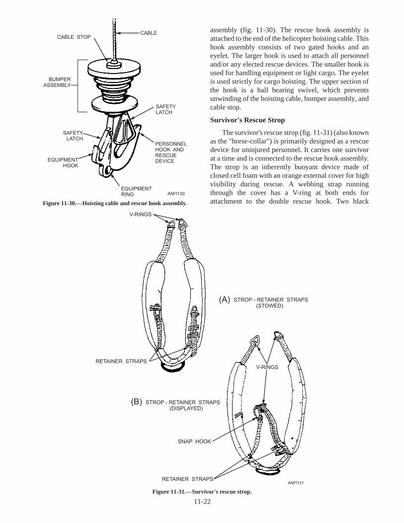
assembly (fig. 11-30). The rescue hook assembly isattached to the end of the helicopter hoisting cable. Thishook assembly consists of two gated hooks and aneyelet. The larger hook is used to attach all personneland/or any elected rescue devices. The smaller hook isused for handling equipment or light cargo. The eyeletis used strictly for cargo hoisting. The upper section ofthe hook is a ball bearing swivel, which preventsunwinding of the hoisting cable, bumper assembly, andcable stop.
Survivor's Rescue Strop
The survivor's rescue strop (fig. 11-31) (also knownas the "horse-collar") is primarily designed as a rescuedevice for uninjured personnel. It carries one survivorat a time and is connected to the rescue hook assembly.The strop is an inherently buoyant device made ofclosed cell foam with an orange external cover for highvisibility during rescue. A webbing strap runningthrough the cover has a V-ring at both ends forattachment to the double rescue hook. Two black
11-22
CABLECABLE STOP
BUMPERASSEMBLY
SAFETYLATCH
EQUIPMENTHOOK
EQUIPMENTRING
PERSONNELHOOK ANDRESCUEDEVICE
SAFETYLATCH
ANf1130
Figure 11-30.—Hoisting cable and rescue hook assembly.
STROP - RETAINER STRAPS(DISPLAYED)
(B)
ANf1131
RETAINER STRAPS
V-RINGS
STROP - RETAINER STRAPS(STOWED)
(A)
SNAP HOOK
RETAINER STRAPS
V-RINGS
Figure 11-31.—Survivor's rescue strop.

retainer straps are incorporated, one with a snap hookand the other with a V-ring. These straps may be lockedaround the survivor's body to ensure stability duringhoisting.
Forest Penetrator
The forest penetrator (fig. 11-32) may be attachedto the rescue hook assembly for land and sea rescueoperations. The unit is bright yellow for high visibility.The forest penetrator is 34 inches long and 8 inches indiameter with the three seats retracted. Each seat isapproximately 12 inches long and is spring loaded inthe retracted position. A spring-loaded retaining latchunder each seat secures the seat in the extendedposition. To release the seat from the extended position,push down on the seat and pull down on the latch. Theseat will then snap back into the retracted position.Three webbing safety straps are provided to securesurvivors. The straps terminate with a yellow fabricmarked TIGHTEN. Yellow webbing tabs, markedPULL OUT, are sewn to the safety straps and extendfrom one of three stowage openings.
Attachment of a flotation collar allows the forestpenetrator to float during air-sea rescue operations. Thecollar is made of bright orange foam rubber for highvisibility. When the flotation collar is installed, thediameter of the penetrator is 9 inches.
Rescue Net
The rescue net (fig. 11-33) is a collapsible, buoyantdevice designed to accommodate two survivors. It isconstructed of a nylon line woven into a net andaluminum tubular frame. A lifting ring for hoisting islocated at the top or upper portion of the net, along withflotation collars and locking support rods. These rodsincorporate sliding sleeves to prevent the net fromcollapsing when it is occupied and to make it easy forstorage when not in use.
SAR MEDIVAC Litter
The SAR MEDIVAC litter (fig. 11-34) is designedfor use in water, shipboard, mountain, and other re-
11-23
ANf1132
(A) (B)Figure 11-32.—(A) Forest penetrator; (B) Forest penetrator with flotation collar installed.

stricted area rescues. It has a low and narrow profile,floats with the patient's head slightly reclined from thevertical, and can be hoisted vertically with its ownslings or horizontally by using standard rescue litterslings (cables) and a trail line assembly. The litter foldsin half and is constructed of stainless steel tubing, thecase and bed of nylon ballistic cloth, the restraint strapsof nylon webbing and (Velcro), and the zippers areheavy duty and noncorrosive. It weighs approximately40 pounds when fully rigged.
SEA RESCUE
Sea rescue operations require preparation andpractice for success. Survivors should take thefollowing actions to aid rescuers:
1. Remove your parachute and get clear of it.
2. Retain your helmet for protection duringhoisting operations.
3. Establish communications by using thesurvival radio. If radio is not available, use signalingdevices.
4. Use a Mk 13 or MK 124 Mod 0 smoke signal toshow direction of surface winds.
5. During night rescue, turn on the strobe orsteady burning signal light.
6. If in a life raft, deploy the sea anchor, and thenget clear of the life raft.
7. Ensure that the rescue device is in the waterbefore you touch it. Static electricity may have built up.
For sea rescues, a SAR crewman will be placed intothe water. The SAR crewman will take control of therescue and attach the survivor(s) to the elected rescuedevice for hoisting.
Q11-17. What does SAR mean?
Q11-18. What is the primary rescue device used inhelicopter rescues?
Q11-19. How many seats are on the forest penetrator?
Q11-20. How many survivors is the rescue netdesigned for?
SUMMARY
In this chapter you have identified aircrew survivalequipment, flight clothing, parachutes, life preservers,life rafts, personal survival equipment, rescueprocedures, and equipment.
11-24
LOWER SUPPORT RIBAND FLOTATION
ANf1133
MIDDLE FRAME FLOTATION
UPPER SUPPORT RIB
UPPER FRAME FLOTATION
LIFTING RING
LOWER SUPPORT RIBAND FLOTATION
MIDDLE FRAME FLOTATION
UPPER SUPPORT RIB
LOWER FRAME FLOTATION
Figure 11-33.—Rescue net.

11-25
ADJUSTABLE CARRYING HARNESS 2 EA
VERTICAL HOISTING SLING
FOOT RESTRAINT ASSEMBLY
LOCKING COUPLERS
LUMBAR SUPPORT PAD
HEAD RESTRAINT
HOISTING CONNECTING CABLE
PATIENT STRAPS
PATIENT IN LITTER
CHEST FLOTATION
1.
2.
3.
4.
5.
6.
7.
8.
9.
10.
8
48
10
7
654
3
9
1 2
ANf1134
1
Figure 11-34.—SAR MEDIVAC litter.

11-26
(THIS PAGE IS INTENTIONALLY LEFT BLANK.)

ASSIGNMENT 11
Textbook Assignment: "Aircrew Survival Equipment," chapter 11, pages 11-1 through 11-25.
11-1. The personnel that rig, pack, and inspectsurvival equipment are commonly calledParachute Riggers. What is the correct title forthis rating?
1. Aircrew Survival Equipmentman (PR)2. Survival Riggers3. Ejection and Survival Technicians4. Aircrew Support Technicians
11-2. Personnel responsible for survival training areassigned to what organization?
1. In the parachute loft2. In air operations3. In Flight Physiology4. In the supply department
11-3. The pressure chamber allows you to useoxygen equipment under the atmosphericpressure conditions encountered at highaltitudes, and to see how your body reacts tothose changes.
1. True2. False
11-4. Which of the following is a design feature ofthe fight clothing used in naval aviation?
1. Fire protection2. Camouflage3. Escape and evasion4. Each of the above
11-5. Summer flying coveralls are fabricated fromwhich of the following types of material?
1. Cotton2. Aramid cloth (Nomex)3. Polyester4. Rayon
11-6. The fabric used in the manufacture of flightcoveralls does NOT burn, but will begin to charat what temperature?
1. 300° to 400°F2. 500° to 600°F3. 700° to 800°F4. 900° to 1,000°F
11-7. Flight gloves are manufactured from which ofthe following types of materials?
1. Soft leather only2. Nomex fabric only3. Soft leather and Aramid (Nomex) fabric4. Nylon twill
11-8. What person is responsible for the upkeep of apilots helmet?
1. Aircrew Survival Equipmentman2. The pilot3. Plane captain4. AME
11-9. What series helmet is designed for all tacticalfixed-wing aircraft?
1. HGU-84/P2. PPH-11/S3. HGU-68(V)/P4. APH-23/V
11-10. What series helmet is designed for allhelicopter aircrew members?
1. HGU-84/P2. PPH-11/S3. HGU-68(V)/P4. APH-23/V
11-11. How many sizes are available for theHGU-84/P flight helmet?
1. One2. Two3. Three4. Four
11-12. What type of protection is available to theaircrewman for excessive "g" forces?
1. Anti-blackout suit2. Anti-g coveralls3. Pressurized cabins4. Full pressure suit
11-13. How many different models of anti-g suits areused by the Navy?
1. One2. Two3. Three4. Four
11-27

11-14. Which of the following symptoms does apersonexperienceduetoexcessive"g" forces?
1. Blacking out2. Loss of vision3. Lower mental efficiency4. Each of theabove
11-15. What "g" range can an aircrewman withstandwithout anti-g protection?
1. 2.2 to 4.2 g's2. 4.5 to 5.5 g's3. 6.0 to 7.0 g's4. 8.0 to 9.0 g's
11-16. The quick donning antiexposure suit comesequipped with which of the following parts?
1. Boots2. Hood3. Mittens4. Each of theabove
11-17. Antiexposure suits are required whenpersonnel are exposed to which of thefollowing conditions?
1. When the water temperature is 50°F orbelow
2. When theoutsideair temperature(OAT) is32°F(windchill factor corrected) or below
3. Both 1and 2above4. When the sum of the air and water
temperatures exceeds 85°F
11-18. When water temperature is between 50° and60°F, what person determines whether anantiexposuresuit wil l beworn?
1. Theaircraft commander2. Thecommanding officer3. Themaintenanceofficer4. The individual
11-19. A personnel parachute consists of how manymajor parts?
1. Three2. Four3. Five4. Six
11-20. How many basic types of parachutes are usedby theNavy?
1. One2. Two3. Three4. Four
11-21. Which of the three basic types of Navyparachutes is used in ejection seat aircraft?
1. NES2. NC3. NB
11-22. What size canopy is used in the NES typeparachute?
1. 12 foot2. 24 foot3. 28 foot4. 32 foot
11-23. Upon pilot ejection, how many methods arethere for deploying theparachute?
1. One2. Two3. Three4. Four
11-24. Which of the following parachute parts pull(s)the main canopy from the container uponejection?
1. Thesuspension lines2. Theautomatic opening device3. The ripcord pins4. Thepilot chute
11-25. What total number of projectiles are installedon aspreading gun?
1. 102. 123. 144. 16
11-26. Which of the following parachute harnesses isused with theNEStypeparachute?
1. Integrated torso2. Back pack3. Quick fit4. Chest pack
11-27. What are the two types of quick-fit harnesses?
1. Torso and back types2. Chest and back types3. Quick-fit type 1and quick-fit type24. Standard and chest types
11-28. What is thepurposeof thegated "D" ring usedon the integrated torso harness?
1. To attach ahelicopter rescuehook2. To secure to the lif e raft3. To attach to another survivor4. To attach to asurvival kit
11-28

11-29. What components connect the parachutecanopy to the parachute harness?
1. Parachute containers2. Integrated torso harnesses3. Rip cord pins4. Suspension lines
11-30. What total number of sections make up a goreon a parachute canopy?
1. One2. Two3. Three4. Four
11-31. How is each gore section of a parachute canopyidentified?
1. By colors2. By numbers3. By letters4. By size
11-32. Most parachute canopies are manufactured indifferent colors. What total number of colorsare used?
1. Two2. Three3. Four4. Five
11-33. Which of the following precautions is a properhandling procedure for a parachute?
1. Do not carry a parachute by its ripcordhandle or lift webs
2. Keep a parachute dry and away from allsources of moisture
3. Do not drop a parachute4. Each of the above
11-34. Acids of any kind, even in weak solutions, areextremely harmful to parachute fabrics.
1. True2. False
11-35. Personnel life preservers are rapidly inflated bywhat means?
1. CO2 cartridge2. Oral inflation tube3. Pneumatic canister4. Nitrogen hose
11-36. How is the distress signal light activated on theLPP series life preserver?
1. A toggle switch2. By water3. A connector wire4. The "pull" lanyard
11-37. Dye markers will be a good target up to whatmaximum amount of time?
1. 20 minutes2. 30 minutes3. 45 minutes4. 60 minutes
11-38. A dye marker can be seen by an aircrewman inan aircraft flying at 3,000 feet for whatapproximate distance?
1. 11 miles2. 22 miles3. 7 miles4. 18 miles
11-39. What type of life preserver is designed forconstant-wear and attaches to the SV-2 seriessurvival vest?
1. LPP2. LPU3. LPA
11-40. What is the purpose of the "D" ring on the lifepreserver unit (LPU) waist lobe?
1. Attach to the helicopter rescue hook2. To secure the waist lobes together3. To attach the life raft to the survivor4. To secure the survival kit
11-41. Which of the following is NOT a piece ofaviation survival equipment?
1. LPU life preserver2. LPP life preserver3. Flight deck inflatable life preserver4. Each of the above
11-42. By what means is overinflation prevented onthe flight deck inflatable life preserver?
1. A pressure-relief valve diaphragm2. An oral inflation tube check valve3. A metered orifice in the CO2 cylinder4. A pressure sensitive blow-out plug
11-29

11-43. How many pounds of buoyancy does thebladder support on the flight deck lifepreserver?
1. 15 pounds2. 21 pounds3. 29 pounds4. 37 pounds
11-44. The outer garment of the flight deck inflatablelife preserver is available in a variety of colorsused to identify the carrier/flight deckpersonnel occupational fields.
1. True2. False
11-45. Where would you find the maintenance andinspection requirements for the flight deckinflatable life preserver?
1. The squadron paraloft maintenance pub-lication
2. The shipboard Planned Maintenance Sys-tem
3. The AME work center4. The quality assurance work center
11-46. Naval aircraft that make operational flightsover water are required to carry enough liferafts to carry all the assigned crew pluspassengers.
1. True2. False
11-47. Which of the following methods is used toautomatically inflate the one-man life raftcontained in the RSSK?
1. The lap belt retention assembly inflates thelife raft
2. The drop lanyard will inflate the raft uponseparation from the RSSK
3. The life raft will inflate upon contact withsalt water
11-48. Which of the following items are contained inthe rigid seat survival kit (RSSK) in aparachute/ejection seat egress system?
1. Emergency oxygen system2. One-man life raft3. Survival equipment container4. Each of the above
11-49. Multiplace life rafts are manufactured in howmany different sizes?
1. Four2. Five3. Six4. Seven
11-50. Multiplace life rafts are equipped withprovisions to support 4, 7, 12, or 20 people forhow many hours?
1. 8 hours2. 12 hours3. 24 hours4. 36 hours
11-51. Which of the following types of life rafts isequipped with boarding ramps?
1. 4-man life raft2. 7-man life raft3. 12-man life raft4. 20-man life raft
11-52. What is a unique design feature of the 20-manlife raft?
1. The shape and color of the raft2. Its floating characteristics in rough seas3. It is always right-side-up after inflation4. It is virtually unsinkable
11-53. What is the length of the sheath knife carriedby the aircrewman while wearing the SV-2series survival vest?
1. 4 inches2. 5 inches3. 6 inches4. 7 inches
11-54. What are the two parts of the individualsurvival kit contained in the SV-2 seriessurvival vest?
1. Emergency and all-purpose2. Survival and evasion packets3. Land and sea packets4. Medical and general survival equipment
11-55. How many Mk 80 star flare cartridges arecontained in the Mk 79 Mod 0 illuminationsignal kit?
1. Five2. Six3. Seven4. Eight
11-30

11-56. A Mk 80 star flare cartridge has a minimumburn duration of 4 1/2 seconds and can belaunched up to how many feet?
1. 100 feet2. 250 feet3. 300 feet4. 450 feet
11-57. Flashesfrom asignaling mirror can beseen upto what total number of miles?
1. 10 miles2. 20 miles3. 40 miles4. 50 miles
11-58. Thewater bottlecarriedby theaircrewmanwillhold what total number of ounces of water?
1. 4 ounces2. 6 ounces3. 10 ounces4. 16 ounces
11-59. What color is the smoke that is emitted fromthe day end of the Mk 124 Mod 0 marinesmokeand illumination signal?
1. White2. Orange3. Red4. Green
11-60. What is the approximate burning time of eachend of the Mk 124 Mod 0 marine smoke andillumination signal?
1. 20 seconds2. 30 seconds3. 45 seconds4. 60 seconds
11-61. How is the night end of the Mk 124 Mod 0marine smoke and illumination signalidentified?
1. Two prominent raised beads2. A largewasher with pull lanyard3. The label under theend cap4. Each of theabove
11-62. The battery operated distress marker strobelight emitsahigh-intensity whiteflashing lightapproximately how many times per minute?
1. 30 to 50 times2. 40 to 60 times3. 70 to 90 times4. 100 to 120 times
11-63. Radios are used to establish two-waycommunication, on one or more channels,between aircrew and rescuepersonnel.
1. True2. False
11-64. What aresomeof the factors to consider whensearching for and rescuing personnel?
1. The location and time2. Theenvironment3. Equipment and personnel4. Al l of theabove
11-65. What is the primary rescue device used inhelicopter rescues?
1. Thehoistingcableanddoublerescuehook2. Thesurvivor’s rescuestrop3. TheSAR medivac litter4. The forest penetrator with floatation
11-66. What is the purpose of the small hook on thedouble rescuehook?
1. For hoisting personnel2. Attachment of a rescuedevice3. Securemedivac litter to theaircraft4. Handling light cargo
11-67. What is the survivor’s rescue strop commonlycalled?
1. Liftin g sling2. Horsecollar3. Hoisting strap4. Rescue ring
11-68. How many "V" rings are incorporated on thesurvivor’s rescuestrop?
1. One2. Two3. Three4. Four
11-69. The forest penetrator can be used for land andsea rescueoperations.
1. True2. False
11-70. How many safety straps are incorporated onthe forest penetrator?
1. One2. Two3. Three4. Four
11-31

11-71. The rescue net is designed to accommodatewhat total number of survivors?
1. One2. Two3. Three4. Four
11-72. What is the approximate weight of a fullyrigged SAR medivac litter?
1. 120 pounds2. 85 pounds3. 40 pounds4. 100 pounds
11-32

CHAPTER 12
CRASH RESCUE AND FIRE FIGHTING
INTRODUCTION
Fire fighting is a highly technical profession. Firefighting in and around crashed aircraft is a highlyspecialized field of fire fighting. An individual willingto become a fire fighter must process the followingqualities: alertness, courage, dedication, agility,physical strength, and the ability to be an exacting teamworker.
The primary duty of the fire fighter is saving life. Ifthere is a fire aboard an aircraft with ordnance on board,there is potential for loss of life. If an ordnancecook-off occurred, the top priority would be to cool offthe ordnance, simultaneously lay a personnel rescuepath, and to extinguish the fire.
During frequent drills and training sessions, it isimportant for you to actually use all equipment,extinguishing agents, and tools so you will learn theircapabilities and limitations.
THE CHEMISTRY OF FIRE
LEARNING OBJECTIVE : Identify the fourelements necessary to produce fire, andrecognize the characteristics associated withthe different classes of fires. Recognize thecharacteristics of the five differentextinguishing agents.
Fire is the most common form of chemicalreaction. The process of fire may be regarded as achemical triangle (fig. 12-1). The three sides consist offuel (combustible matter), heat, and oxygen. Afterextensive research, the presence of a fourth element hasbeen identified. It is the chemical chain reaction(fig.12-2) that takes place in a fire that allows the fire to
12-1
OXYGEN
FUEL
OXYGEN
HEAT
HEAT
NO FIRE
Anf1201
Figure 12-1.—Requirements for combustion.
VAPORFUEL
INCREASED MOLECULECHAIN REACTION
CHAIN REACTION
OXYGEN
ANf1202
A B
Figure 12-2.—Chain reaction.

both sustain itself and grow. This process of fire is nowcalled the "fire tetrahedron." See figure 12-3.
The most common method of controlling orextinguishing a fire is to eliminate one or more of sidesof the tetrahedron. This can be accomplished by thefollowing methods.
1. Smothering—removing the oxygen
2. Cooling—removing the heat
3. Starving—removing the fuel or combustiblematter
There are two terms you need to understand aboutfires. These are thefire pointand theflash point.
The fire point of a substance is the lowesttemperature at which its vapors can be ignited and willcontinue to burn. At this temperature, the vapor willignite spontaneously in the air. Also, substances don'thave to be heated to this ignition temperaturethroughout in order to ignite.
Theflash pointof a substance is the temperature atwhich the substance gives off enough vapors to form anignitable mixture with the air near the substance'ssurface. An ignitable mixture is a mixture within theexplosive range. The mixture is capable of spreading aflame away from the source of ignition when ignited.For example, fuel will spontaneously ignite when aportion of it (or its vapors) is exposed to temperaturesaround 500°F (ignition temperature). It is capable of
being touched off by a match or spark at temperaturesdown to -5°F (fire point). It will also flash across thesurface at temperatures from -5°F down to -45°F (flashpoint). From these examples, you can readily see thatfuel has a low flash point and is easily ignited. Fuel is aconstant fire hazard around aircraft. A spark, heatcaused by friction, or an electrical discharge couldsupply enough heat to cause fuel to flash.
CLASSES OF FIRE
Different types of fires are combated by differentmeans. It is important that you know how to identifythe various types of fires and understand why each typemust be combated in a specific way.
Class A
Class A fires occur in combustible materials, suchas bedding, mattresses, books, cloth, and any matterthat produces an ash. All fires of this class leaveembers, which are likely to rekindle if air comes incontact with them. Class A fires must not be consideredextinguished until the entire mass has been cooledbelow its ignition temperature. Smothering (removingthe oxygen) is not effective for class A fires because itdoes not lower the temperature of the smolderingembers below the surface. The extinguishing agentsmost effective for class A fires are solid water stream,both high- and low-velocity fog, CO2, and waterimmersion.
12-2
FLAMING COMBUSTION AND SURFACE GLOWING COMBUSTIONN
TE
MP
ER
ATU
RE
TEMPERATURE
OXYG
EN
OXYGEN
FUEL
FUEL
NO CHAINREACTION
FUEL IS IN FORM OFINCANDESCENT SOLID
OXYGEN IS ATINTERFACE OFGLOWING FUEL
UNINHIBITEDCHAIN REACTIONOF COMBUSTION
PROCESS
DIFFUSION & CONTINUOUSREIGNITION & AUTOMATICALLY
OBTAINED AT FLAMETEMPERATURE LEVELS
FUEL IS IN FORM OFVAPOR AND GAS
Anf12033
Figure 12-3.—Tetrahedron and fire triangle.

Class B
Class B fires occur with flammable liquidsubstances. Examples of class B fires are gasoline, jetfuels, paints, grease, and any petroleum-based product.These and other combustible substances do not leaveembers or ashes. Class B fires are extinguished byproviding a barrier between the burning substance andoxygen necessary for combustion. Chemical andmechanical foams produce such a barrier and areknown as permanent smothering agents, but their effectis only temporary. The application must be renewed ifthere is any danger of reignition. The extinguishingagents recommended for combating class B fires areCO2, PKP, Halon, and Aqueous Film-Forming Foam(AFFF).
NOTE: Water by itself isNOT recommended foruse on class B fires.
Class C
Class C fires are energized electrical fires that areattacked at prescribed distances by usingnonconductive agents such as CO2 and Halon 1211.The most effective tactic is to de-energize the systemand handle the fire as a class A fire. When fires are notdeep seated, clean agents that pose no cleanup problem,such as Halon 1211 or CO2, are the preferredextinguishing agents.
WARNING
Water in any form, particularly salt water, isdangerous when used on electrical equipment.
Class D
Class D fires are combustible metals, such asmagnesium and titanium. Water in large quantities, ashigh velocity fog, is the recommended extinguishingagent. When water is applied to burning class Dmaterials, there may be small explosions. The firefighter should apply water from a safe distance or frombehind shelter. Metal fires on board ships arecommonly associated with aircraft wheel structures.
EXTINGUISHING AGENTS
There are many materials that may be used asfire-fighting agents. The primary agents discussed inthe following paragraphs are the most extensively usedaboard naval ships.
Water
Water is a cooling agent, and on board ship, the seaprovides an inexhaustible supply. If the surfacetemperature of a fire can be lowered below the fuel'signition temperature, the fire will be extinguished.Water is most efficient when it absorbs enough heat toraise its temperature to 212°F (100°C) or boiling point.At this temperature, the seawater will absorb still moreheat until it changes to steam. The steam carries awaythe heat, which cools the surface temperature.
Water in the form of fog is very effective forfire-fighting purposes. Additionally, water fog canprovide protection to fire fighters from heat. However,the fog must be applied directly to the area to be cooledif its benefits are to be realized.
Water in the form of a straight stream (also calledsolid stream) is used to reach into smoke-filled spacesor areas at a distance from the fire fighter. When astraight stream is needed as an extinguishing agent, itshould be directed into the seat of the fire. Formaximum cooling, the water must come in directcontact with the burning material. A straight stream isbest used to break up and penetrate materials.
Aqueous Film-Forming Foam (AFFF)
AFFF is composed of synthetically producedmaterials similar to liquid detergents. Thesefilm-forming agents are capable of forming watersolution films on the surface of flammable liquids.AFFF concentrate is nontoxic and biodegradable indiluted form. When proportioned with water, AFFFprovides three fire-extinguishing advantages.
1. An aqueous film is formed on the surface of thefuel that prevents the escape of the fuel vapors.
2. The layer effectively excludes oxygen from thefuel surface.
3. The water content of the foam provides acooling effect.
The primary use of AFFF is to extinguish burningflammable or combustible liquid spill fires (class B).AFFF has excellent penetrating characteristics and issuperior to water in extinguishing class A fires.
Carbon Dioxide (CO2)
CO2 is an inert gas and extinguishes fires bysmothering them. CO2 is about 1.5 times heavier thanair, which makes it a suitable extinguishing agent
12-3

because it tends to settle and blanket the fire. CO2 is adry, noncorrosive gas, which is inert when in contactwith most substances and will not leave a residue anddamage machinery or electrical equipment. CO2 is anonconductor of electricity regardless of voltage, andcan be safely used in fighting fires that would presentthe hazard of electric shock.
CO2 extinguishes the fire by diluting anddisplacing its oxygen supply. If gaseous CO2 isdirected into a fire so that sufficient oxygen to supportcombustion is no longer available, the flames will dieout. CO2 has limited cooling capabilities, and may notcool the fuel below its ignition temperature. It is morelikely than other extinguishing agents to allow reflash.Therefore, the fire fighter must remember to stand bywith additional backup extinguishers.
NOTE: CO2 is not an effective extinguishing agentfor fires in materials that produce their own oxygensupply, such as aircraft parachute flares or firesinvolving reactive metals, such as magnesium andtitanium.
Halon 1211
Halon is a halogenated hydrocarbon. Halon 1211,known chemically asbromochlorodifluoromethane,iscolorless and has a sweet smell. Halon attacks the fireby inhibiting the chemical chain reaction. Halondecomposes upon contact with flames or hot surfacesabove 900°F (482°C).
Halon 1211 is used for twin agent (AFFF/Halon1211) applications on board flight and hangar deckmobile fire-fighting equipment. For flight and hangardeck fire-fighting procedures, you should refer toNAVAIR 00-80R-14, NATOPS U.S. Navy AircraftFire-Fighting and Rescue Manual.
Potassium Bicarbonate (Purple-K-Powder or PKP)
Potassium bicarbonate (PKP) is a dry chemicalprincipally used as a fire-fighting agent for flammableliquid fires. When PKP is applied to fire, the drychemical extinguishes the flame by breaking thecombustion chain. PKP does not have coolingcapabilities on fire. PKP is highly effective inextinguishing flammable liquid (class B) fires.Although PKP can be used on electrical (class C) fires,it will leave a residue that may be hard to clean. Also,when combined with moisture, it may corrode or stainthe surfaces it settles on.
PKP does not produce a lasting inert atmosphereabove the surface of a flammable liquid. Therefore, itsuse will not result in permanent extinguishing ifignition sources, such as hot metal surfaces orpersistent electrical arcing, are present. Reflash of thefire will most likely occur. The ingredients used in PKPare nontoxic. However, the discharge of largequantities may cause temporary breathing difficultyand, immediately after the discharge, it may seriouslyinterfere with visibility.
Q12-1. What are the four elements necessary toproduce fire?
Q12-2. What is the "fire point" of a substance?
Q12-3. What is the "flash point" of a substance?
Q12-4. What are the four classes of fire?
Q12-5. What are the primary fire-extinguishingagents used aboard naval ships?
FIRE-FIGHTING EQUIPMENT
LEARNING OBJECTIVE : Recognize thevarious systems and equipment used foraircraft fire-fighting on board ships and shoreactivities.
In assisting the crash fire fighters, you will use veryspecialized equipment. A crash crew must bring itsequipment into action with every pump nozzledelivering at its maximum capacity. Fire-fightingequipment is discussed in the following text.
FIREMAIN SYSTEM
You must get acquainted with the firemain systemthroughout your ship. You should know the location ofthe firemain and the riser piping that carries water to theupper decks. You must be able to identify the plugswhere hoses can be attached to the mains. You mustknow the location of all pumps, valves, and controls inthe vicinity of your duty and berthing stations.
Fireplugs have outlets either 1 1/2 or 2 1/2 inches indiameter. Some plugs are equipped with wye gates thatprovide two outlets, each are 1 1/2 inches in size. Insome cases, a reducing connection is used so that a1 1/2-inch hose can be attached to a 2 1/2-inch outlet.
Connected to the fireplugs and stored in adjacentracks are two lengths of either 1 1/2- or 2 1/2-inchdiameter hose. The 1 1/2-inch hose is used on smallerships and below decks on larger ships. This hose ismade up in 50-foot lengths, with the necessary end
12-4

couplings. All threaded parts of fire hose fittings andcouplings have standard threads and are easy toconnect. Hoses and fittings 1 1/2 inches and belowhave standard pipe threads. Those 2 1/2 inches and overhave standard Navy hose threads.
Two people working together can quickly prepare afire hose. You can do the job alone if you place the hoseon the deck and hold it down with your foot just behindthe fitting. The pressure of your foot will cause themetal fitting on the end of the hose to point upward. Inthis position you can screw in the nozzle or other fitting.
Fire hose is usually located on a bulkhead rack neara fireplug. Nozzles, extensions called applicators, andspanner wrenches are stowed on the bulkhead near thehose. See figure 12-4. When two lines are locatedseparately on the bulkhead, one is connected to thefiremain and the other is left unconnected.
HIGH-CAPACITY AFFF SYSTEMS
An AFFF station consists of a 600-gallon AFFFconcentrate tank, a single-speed injection pump or atwo-speed AFFF pump, electrical controllers, valves,and necessary piping. Saltwater and AFFF flow iscontrolled by hydraulically operated valves, which areactuated by solenoid-operated pilot valves (SOPVs).The SOPVs are activated by electrical switches at user
locations (Pri-Fly, NAVBRIDGE, hose stations, andCON-FLAG stations).
The injection pump system supplies the flush decknozzles on the flight deck, and the deck edge nozzles onCVNs and some CVs. The two-speed pump operates at27 or 65 gpm, depending upon the demand. Thelow-rate output will supply handlines and smallsprinkler systems. High-demand systems, such ashangar bay sprinklers, are served by the high-speedoutput. On selected CVs, the two-speed pump suppliesthe deck edge nozzles.
Hangar Deck AFFF Sprinkler System
The AFFF sprinkler systems are installed in theoverhead of the hangar deck. The sprinkler system isdivided into groups that can be individually actuated.Each group is supplied from two risers—one from aport AFFF injection station and one from a starboardAFFF injection station. Controls to start and stop flowto individual sprinkler groups are located in theconflagration (CONFLAG) stations and along eachside of the hangar deck near the related sprinkler group.
Flight Deck AFFF Extinguishing System
Flight decks have an AFFF fire-fighting system thatconsists of flush-deck, flush-deck cannon-type, anddeck-edge nozzles installed in combination with the
12-5
FIRE PLUG (VALVE)
SPANNER WRENCHES
CLOSED POSITIONOPEN POSITION
(TO INDICATE LEAKAGE)
WYE-GATECONNECTED
TO FIRE PLUG
ALL HOSE SHALL BE A MINIMUMOF 6” OFF THE DECK
ANf1204
Figure 12-4.—Typical fire hose station.

saltwater washdown system. AFFF from theconcentrate tank is injected into the saltwater (injectionpoint is on the 03 level just downstream of the saltwatercontrol valve) via a positive displacement pump,usually 60 gpm. This injection pump serves theflush-deck and cannon-type nozzles. Deck edgenozzles may be served by the AFFF two-speed pumpsystem or single-speed injection pump system.
Controls for the flight deck fixed fire-extinguishingsystem are located in both Pri-Fly and on the navigationbridge. The controls allow for selection of saltwaterAFFF or system shutdown.
AFFF Hose Reel Station
Hangar bay AFFF hose outlets are located port andstarboard near the AFFF injection stations from whichthey are supplied. A push-button control is located
adjacent to each AFFF hose station. The station has a1 1/2-inch hose reel and one 2 1/2-inch hose outlet (fig.12-5).
Flight deck AFFF hose outlets are located incatwalks and near the island. The station has one reel of1 1/2-inch hose and/or one 2 1/2-inch hose outlet or two2 1/2-inch hose outlets with hose and nozzlepreconnected to each outlet. A push-button control,X50J phone circuit box, and E call button are locatednext to each AFFF hose station. There is emergencylighting at each hose reel station. The controls arelocated in Pri-Fly and on the NAVBRIDGE.
PORTABLE FIRE-FIGHTINGEQUIPMENT
As you become more familiar with aircraftfire-fighting tactics and equipment, you will becomemore familiar with the many different types of portableequipment that the fire fighter uses to combat andcontain aircraft fires. Some of the equipment you willuse is discussed in this section.
Vari-Nozzles
Vari-nozzles are used on all AFFF and saltwaterhose lines. Flow rates are 250 gpm for all 2 1/2-inchhose lines. Nozzles on 1 1/2-inch AFFF hoses on flightand hangar decks are the 125 gpm units. Nozzles on the1 1/2-inch saltwater lines and those used with AFFFin-line inductors are 95 gpm models. All nozzle gpmflow rates are based on 100 psi pressure at the nozzleinlet. See figure 12-6.
12-6
Anf1205
Figure 12-5.—AFFF hose reel.
RELEASETO ROTATESPRAYHEAD
Anf1206
Figure 12-6.—Examples of variable-stream fog nozzles.

Hoses
The standard Navy fire hose is a double jacketed,synthetic fiber with a rubber or similar elastomericlining. The outer jacket is impregnated to increase wearresistance. The impregnating material contains anorange colored pigmentation for easy identification.Navy fire hose comes in 50-foot lengths and has amaximum operating pressure of 270 psi. Optimumhose handling occurs between 90 and 150 psi. Pressureabove 150 psi is hazardous because excessive nozzlereaction force may result in loss of nozzle control.
Noncollapsible rubber hose for the AFFF hose reelsystem is available in 3/4-inch and 1 1/2 inch size. Thelength of these hoses varies in size depending uponapplication and location.
Tools
A fire fighter's tool kit should contain the followingtools.
· Large claw tool; small claw tool
· Crowbar
· Parachute knife
· Pliers; screwdriver
· Wrench
· Hacksaw; metal saw
· Chisels
· Flashlight
· Carpenter's hammer; maul
· Bolt cutters
· Notched ax
NAVAIRSYSCOM developed what is called anaircraft tool kit (fig. 12-7) for crash trucks. The stationfire chief must ensure that one of these kits is carried on
12-7
Anf1207
Figure 12-7.—Crash rescue tool kit.

each of the crash trucks assigned to the fire-fightingcrew. The kit consists of a canvas tool roll with pocketsor holders for specified tools. The crash kit containstools for forced entry. Fire fighters use these tools inrescuing occupants trapped in aircraft. The kit containsthree tapered, hard-rubber plugs and three hardwoodplugs. These plugs are used to stop fuel tank leaks.
PROTECTIVE CLOTHING
Aircraft fire-fighting/rescue protective clothing is aprime safety consideration for personnel engaged infire-fighting and rescue work. Aluminized protectiveclothing offers a means of providing protection to firefighters because of its high percentage of reflectivity toradiant heat. Aluminized proximity fabrics have beenadopted for use in the Navy Mishap/Rescue Program. Itis important to point out that these garments are notclassified as entry suits, but are known as proximityclothing to be worn with fire fighter's knee-length bootsthat have safety toes and soles.
Care and Maintenance of Protective Clothing
The heat-reflective ability of aluminized clothingis reduced when the clothing is stained or otherwisesoiled. Therefore, youmust give careful attention thecare and maintenance instructions for protectiveclothing. Some guidelines are as follows:
1. Store clothing on hangers, with suitablehanging space to prevent aluminized fabrics fromcreasing or cracking. If the garment is folded, the foldsshould be loose. Do not sit on a folded garment.
2. Sponge off dirt and soot by using mild soap andwater. Dry aluminum surfaces with a clean cloth. Rubgently to avoid removal of the aluminum.
3. Remove grease stains by using dry-cleaningsolvents. (NOTE: Isopropanol or perchloroethylenewill react with the metal in proximity suits and mayetch the aluminum surface.) Clean the clothing withwater and wipe dry. Allow the garment to hang in aventilated location at room temperature.
4. Remove AFFF by sponging the clothing cleanwith mild soap and water. Hang the garment to dry inthe open or in a place with good circulation. Duringfire-fighting operations, it is not always possible toprevent fire-fighting agents from getting on protectiveclothing. However, aluminized protective clothing thathas been covered or spotted with agents will have lessheat-reflecting ability than the suit normally wouldprovide.
5. Corrosive chemicals will react with thealuminum surface and may etch the metal. Clean theclothing with water and wipe it dry. Allow it to hang ina ventilated location at room temperature.
6. Replace garments when the aluminum wearsoff or when the fabric cracks or tears. Spraying wornclothing with aluminum serves no useful purpose and isa dangerous practice.
Care of Facepiece
The gold-coated facepiece is a heat-reflectiveshield. The facepiece is NOT a sun shield. This itemshould be kept in excellent condition to maintain theradiant-heat-reflective efficiency. When the goldsurface of the facepiece becomes worn, scratched, ormarred, 90 percent of the heat protection is lost, andyou should immediately replace the facepiece. Otherprecautions you should take with facepieces are asfollows:
1. Keep the protective cover in place when youare carrying or storing the hood to minimize damage tothe gold-coated surface. Remove it when using thehood.
2. For adequate protection, replace a worngold-coated facepiece. When wearing the facepiece,make sure the gold surface is on the outside as markedon the edge.
3. Avoid touching or wiping the gold surface asmuch as possible.
4. Clean the facepiece, without removing it fromthe hood, by using a clean, soft cloth with mild soapywater, and then rinse and pat dry.
Q12-6. What size diameter are the fireplug outletsaboard ship?
Q12-7. Where is the AFFF sprinkler system installedon the hangar deck?
Q12-8. What length is a standard Navy fire hose?
Q12-9. What type of protective clothing offersprotection to fire fighters because of its highpercentage of reflectivity to radiant heat?
AIRCRAFT FIRE-FIGHTING ANDRESCUE VEHICLES
LEARNING OBJECTIVE : Recognize thetypes of fire-fighting and rescue vehicles usedaboard ship.
12-8

The Navy uses different types of trucks. The usedepends on the base, type of aircraft assigned, andanticipated types of fires. Some of the trucks used bythe Navy are the Oshkosh T-3000, the P-4A vehicle, theP-19 fire-fighting truck, and the P-25 shipboardfire-fighting truck. Shore-based Twinned Agent Units(TAUs) and Shipboard Twinned Agent Units(SBTAUs) are also used.
OSHKOSH T-3000
The Oshkosh T-3000 (fig.12-8) is a diesel-powered, six-wheeled-drive truck with an automatictransmission. The operator controls consist ofpower-assisted steering, air or mechanical brakes,transmission range selector, and in-cab controls foroperating the fire-fighting system. The water storagetank has a capacity of 3,000 gallons; the AFFFconcentrate tank holds 420 gallons. The roof turret hasa discharge rate of 600 to 1,200 gpm and an infinitelyvariable pattern from straight stream to fully dispersed.The bumper turret is electric joystick controlled withauto-oscillation. The discharge rate is 300 gpm and it isalso variable pattern. Two 15-foot, 1 3/4-inchpreconnected handlines are provided, one per side. The
handlines have a discharge rate of 95 gpm and have apistol grip with variable pattern.
P-4A VEHICLE
The P-4A vehicle (fig. 12-9) is diesel powered withan optional all-wheel drive. It has a six-speed,semiautomatic, power shift transmission. Theoperator's controls has power-assisted steering, air-over-hydraulic power boost brakes, transmission rangeselector, and in-cab controls for operating the vehicle'sfire-fighting systems.
The water storage tank has a capacity of 1,500gallons. The AFFF concentrate pumps (centrifugal) arepowered by the truck engine by means of powerdividers. The concentrate and water are carried to eachof the discharge points in separate lines and are mixedin venturi inductors before discharge. The P-4A isprovided with a manually maneuvered, 750-gpmconstant-flow, variable-stream roof turret.
The P-4A is also provided with a 250-gpm bumperturret mounted in front of the cab and controlledhydraulically from within the cab. The handline ismounted in front center of the vehicle in a compartment
12-9
Anf1208
Figure 12-8.—T-3000 aircraft fire-fighting rescue vehicle.

under the cab. The reel is provided with 150 feet of1 1/4-inch-diameter hose. The handline has a 75 to 100gpm discharge capacity. An air motor provides forpowered rewind. Four 30-pound PKP dry-chemicalfire extinguishers are provided with each vehicle.When both the roof turret (750 gpm) and the bumperturret (250 gpm) are operating, the truck depletes itsself-contained water supply in 1 1/2 minutes.
P-19 FIRE FIGHTINGTRUCK
The P-19 has a diesel-engine-powered, 4 × 4,all-wheel-drive chassis. A single diesel engine powersthe truck drive train and water pump. The fire-fightingsystems of the truck are self-sufficient. No outsidesource for extinguishing agents is needed. The truckcontains its own pressure pumps and fire-fightingequipment. Water, foam, and Halon 1211 are carried intanks built into the truck body. The truck body isinsulated, which prevents heat loss from the truck'sinterior during cold weather. The insulation alsoprovides protection from fire heat.
Water or a combination of water and foam can beused to put out a fire. Agents are delivered through thecab-mounted roof turret, the bumper turret, or thehandline. These can be used alone or at the same time.The Halon system uses its own handline. The chassisdesign allows the truck to operate in all kinds ofweather and on off-road terrain.
The P-19 has a water capacity of 1,000 gallons, andthe foam tank holds 130 gallons. The single-roof turrethas a discharge capacity of 500 gpm, and the bumperturret discharges agent at 250 gpm.
AFFF can be applied by using a 100-foot,1-inch-diameter (60-gpm), reel-mounted handline.Five hundred pounds of Halon 1211 is also available onanother 100-foot-long, 1-inch-diameter, reel-mountedhandline.
A/S32P-25 SHIPBOARD FIRE-FIGHTINGVEHICLE
The P-25 shipboard fire-fighting vehicle (figs.12-10 and 12-11) is a 4-wheel (2-wheel drive), 6
12-10
Anf1209
Figure 12-9.—P-4A aircraft fire-fighting and rescue vehicle.

cylinder, turbocharged, liquid cooled, 24-volt,diesel-powered vehicle, with a hydrostatic drive systemthat transmits power to the rear wheels. Steering ispreformed by a single hydraulic cylinder and tie rodassembly that controls the front wheels. Dynamicvehicle braking is provided by the hydrostatic drivesystem. When the accelerator is released, the brakesautomatically engage. Separate tanks within thevehicle chassis carry 750 gallons of water and 55gallons of AFFF (Aqueous Film-Forming Foam).Three 20-pound fire extinguishers containing HALON1211 (Halogenated Extinguishing Agent) are stored onthe right side of the vehicle. One nursing lineconnection on each side of the vehicle provides AFFFmixture from the ship's system directly to the vehicle'swater pump.
The vehicle has seating for a crew of two. Thedriver compartment is located at the left forward end ofthe vehicle and contains the main control panel foractivating the fire-fighting systems. AFFF can besprayed from both the forward turret nozzle andhandline hose reel nozzle. These nozzles operateindependently and can be used simultaneously to makethis vehicle ready for fire-fighting duty.
TWINNED AGENT UNIT (TAU-2H)
The Twinned Agent Unit (TAU-2H) fireextinguisher is a dual-agent apparatus that is designedprimarily for extinguishing class B fires, and it isemployed aboard ship and at shore facilities. TheTAU-2H is normally located at hot refueling sites, or it
12-11
Anf1210
AFFF HYDRAULICTANK ACCESS DOOR
TOP ENGINEACCESS PANELS
COOLANTRECOVERY BOTTLE
ACCESS DOOR
BRAKE RELEASEHAND PUMP
WATER TANKFILL
FIREFIGHTERSSTATION
LOWERPROPORTIONINGSYSTEM ACCESS
TIEDOWNS
DRIVERSSTATION FOAM FILLED
TIRES
FUEL TANK
FUEL FILL
NURSINGCONNECTION
Figure 12-10.—A/S32P-25 shipboard fire-fighting and rescue vehicle—major assemblies and components (left side).

can be vehicle-mounted. The TAU-2H is aself-contained unit with two agent tanks—onecontaining 86 gallons of AFFF premixed solution andthe other containing 200 pounds of Halon 1211. Thesystem permits use of the fire-fighting agents eitherseparately or simultaneously.
The TAU-2H (fig. 12-12) employs a noncollapsibledual hose line encased in a fire-resistant cotton jacket.The hose line is normally mounted on a reel. Thefire-extinguishing agents are propelled by nitrogensupplied from two pressurized cylinders, which aremounted on the framework. The twinned nozzles onthe handline expel the fire-fighting agents. The Halonnozzle is equipped with a low-reaction discharge tip.The AFFF nozzle is equipped with a aspirating tip.Duel pistol grip handles and triggers operate the shutoffvalves. Extinguishment is obtained by applying agents
in a sweeping motion, using the chemical agent Halon1211 to gain initial extinguishment, followed byapplication of AFFF to blanket the combustible liquidand preclude reignition.
12-12
UPPERPROPORTIONINGSYSTEM ACCESS
TURRET
MAINCONTROL
PANELLIFTING/TIEDOWN
PORTABLEHALON
BOTTLES (3)
HANDLINE HOSE REEL
AFFF TANK FILL
WATER TANK FILL (QUICK FILL)
NURSING CONNECTION
RIGHT SIDEENGINE ACCESS DOOR
BATTERIES
FILTERACCESS DOOR
TIEDOWNS
REAR ENGINEACCESS DOORS
KNEELPLATE
DIESEL ENGINECOMPARTMENT
HYDRAULIC TANKFILL (2)
EXHAUST
ANf1211
Figure 12-11.—A/S32P-25 shipboard fire-fighting and rescue vehicle—major assemblies and components (right side).
ANf1212
Figure 12-12.—TAU-2H twinned agent unit.

Q12-10. What type of aircraft fire-fighting rescuevehicles are used at shore-based activities?
Q12-11. What type of aircraft fire-fighting rescuevehicles are used aboard aircraft carriers?
Q12-12. What type of fire-fighting agents arecontained in the Twinned Agent Unit(TAU-2H)?
AIRCRAFT FIRE HAZARDS
LEARNING OBJECTIVE: Identify thedifferent hazards associated with aircraft fires,and recognize aircraft fluid line identificationmarkings.
Not every crash results in fire. The responsibility ofthe crash fire fighter does not end when fire fails tooccur. Serious actual and potential fire hazards mayhave been created, which you must eliminate orminimize without delay.
The greater the damage to the aircraft, the greaterthe possibility of fuel spillage. A spark or a hot enginepart could ignite fuel vapors and set off a full-fledgedfire. You should take every precaution to guard againstaccidental ignition. Personal laxity or unfamiliaritywith ordinary preventive measures could allow adelayed fire to occur, which could endanger personnel.
FLAMMABLE, HAZARDOUS, AND FIREACCELERATING MATERIALS
Accelerating materials carried on aircraft are ofmajor concern to the aircraft rescue and fire-fightingcrews. Aviation gasoline (AVGAS), jet fuels (JP-4,JP-5, and JP-8), engine oils, oxygen systems, andhydraulic fluids constitute problems in aircraftfire-fighting. Some of these fuels have restrictions as towhere they can be used; for example, JP-4 is prohibitedaboard ship due to its flash point.
CAUTION
Under aircraft crash impact conditionswhere fuel-air mixtures or mists are created, allfuels are easily ignited.
Aviation Gasoline (AVGAS)
The flash point (by closed cup method at sea level)of AVGAS is -50°F (-46°C). The rate of flame spreadhas also been calculated to be between 700 and 800 feetper minute.
JP-4 Fuel
JP-4 jet fuel is a blend of gasoline and kerosene andhas a flash point from -10°F (-23°C). The rate of flamespread has also been calculated to be between 700 and800 feet per minute.
JP-5 Fuel
JP-5 fuel is a kerosene grade with a flash point of140°F (60°C). The rate of flame spread has beencalculated to be in the order of 100 feet per minute. Thelowest flash point considered safe for use aboard navalvessels is 140°F (60°C).
FUEL TANKS
When an aircraft crashes, the impact usuallyruptures the fuel lines and fuel tanks. Ordinarily, all thefuel is not liberated at once. There is a source of fuelthat is supplying the fire either from the rupture in thetank or from the loosened and ruptured fuel lines in theaccessory section of the engine.
The control of the fire around the fuselage sectionunder these conditions presents a very complexproblem. The top portion of the tank is more void ofliquid than any other section of the tank. Because of therestraining cushion of the liquid itself, the explosiveforce will be directed upward instead of downward oron a horizontal plane.
Fuel loads can vary from 30 gallons in smallaircraft to approximately 50,000 gallons in large jetaircraft. Fuel tanks are installed in a variety of placeswithin the aircraft structural framework or as a built-inpart of the wing. Fuel tanks are often carried under thefloor area in the fuselage of helicopters. You shouldrefer toNATOPS U.S. Navy Aircraft Emergency RescueInformation Manual, NAVAIR 00-80R-14-1, for theexact location of fuel tanks on a particular aircraft.Upon severe impact these tanks generally rupture andresult in fire. Many naval aircraft are provided withexternal auxiliary fuel tanks located under the wingsand fuselages.
The aircraft manufacturers conducted a number oftests on external aircraft fuels tanks in which they wereexposed to an enveloping fuel fire. These studies showthat there were no deflagrations. The tanks did melt orrupture, releasing fuel onto the decks. The time to fueltank failure (release of fuel) was dependent on thepercent of fuel in the tank and ranged from 28 secondsfor a 10-percent load to 3 1/2 minutes for a 100-percentload.
12-13

There is so little difference in the heat ofcombustion of the various aircraft hydrocarbon fuelsthat the severity after ignition would be of nosignificance from the "fire safety" point of view. Thefire-fighting and control measures are the same for theentire group of aviation hydrocarbon fuels.
OXYGEN SYSTEMS
Oxygen systems on aircraft can present hazardousconditions to fire fighters during an emergency. Liquidoxygen is a light blue liquid that flows like water and isextremely cold. It boils into gaseous oxygen at -297°F(-147°C) and has an expansion rate of approximately860 to 1. Liquid oxygen is a strong oxidizer, andalthough it is nonflammable, it vigorously supportscombustion.
GENERAL HAZARDS
During aircraft fire-fighting operations personnelare constantly in harms way, from the actualfire-fighting operations to the salvage and clean-upoperations. All components and material in or on theaircraft are considered hazardous to personnel. Thefollowing text discusses a few of the hazards thatpersonnel need to be familiar with.
Anti-icing Fluids
Anti-icing fluids are usually a mixture of about85-percent alcohol and 15-percent glycerin. While notas great as other aircraft hazards, you should rememberthat alcohol used in aircraft anti-icing systems burnswith an almost invisible flame. The best method ofcontrol is by dilution with water.
Class A Combustibles
Class A combustibles in aircraft fires are bestextinguished with AFFF. When aircraft cockpit andinterior finish materials are burned or charred, theyproduce toxic gases. These gases include carbonmonoxide, hydrogen chloride, and hydrogen cyanide.Therefore, it is necessary that fire-fighting and rescuepersonnel who enter an aircraft during a fire sequencebe equipped with a self-contained breathing apparatus.
Ordnance
Naval aircraft carry a wide variety of ordnance insupport of their assigned missions. For moreinformation on the characteristics and cook-off times of
ordnance, refer to chapter 8 of this manual andNATOPS, U.S. Navy Aircraft Firefighting and RescueManual,NAVAIR 00-80R-14, chapter 2.
Flare Dispensers
The SUU-44/SUU-25 flare dispensers carry eightMk 45 or LUU-2 paraflares. When the flares are ejectedfrom the dispenser and the tray separates, they must beconsidered fully armed. Once the tray separates fromthe flare, it ignites a fuse on the Mk 45 flare, which willfire within 5 to 30 seconds. The LUU-2 flare uses asimple mechanical timer instead of an explosive fuse. Ifignited, the Mk 45 or LUU-2 candle should beextinguished by inserting a water applicator tip into theburning end of the candle, applying low-velocity fog.The flare will normally extinguish in less than 30seconds. If a fog applicator is not readily available, analternate method is to have a fully outfitted fire fightercut the shroud lines, pick up the flare by the cold end,jettison it over the side, or remove it to a clear area ifashore.
Batteries
Alkaline or nickel-cadmium batteries may get hotfrom internal shorting or thermal runaway. Theoverheated battery is hazardous to both aircraft andpersonnel. When an overheated battery is detected, thecrash crew should open the battery compartment, checkfor the following conditions, and take the actionindicated:
1. When flame is present, use availableextinguishing agent, such as Halon 1211 or CO2.
WARNING
Halon 1211 or CO2 is an acceptablefire-extinguishing agent once a fire hasdeveloped. CO2 must not be directed into abattery compartment to effect cooling or todisplace explosive gases. Static electricitygenerated by the discharge of the extinguishercould explode hydrogen or oxygen gases trappedin the battery compartment.
2. When the battery is emitting smoke, fumes, orelectrolyte in the absence of flame or fire, make sure thebattery switch in the cockpit is in the OFF position.Remove the quick disconnect from the battery and, ifpossible, move the battery clear of the aircraft. Usewater fog to lower the battery temperature.
12-14

WARNING
When approaching a battery that is in athermal runaway condition, aircraft rescuefire-fighting personnel must work in teams oftwo and must be attired in full protectiveclothing, with extinguishing agent available forinstant use.
COMPOSITE MATERIALS
The following text discusses the advantages anddisadvantages of using composite materials in aircraftconstruction.
WARNING
Inhalation of composite fibers resultingfrom aircraft fires and/or aircraft materialdamage may be harmful to personnel.Respiratory protection must be worn whenpersonnel are exposed to these potential hazards.
Composite Materials Reinforced withCarbon/Graphite Fibers
Composite materials that are reinforced withcarbon/graphite fibers provide superior stiffness, a highstrength-to-weight ratio, and ease of fabrication. As aresult, this material is being used extensively inadvanced aircraft, such as the AV-8Harrier, to replaceheavier metal components. Unfortunately, carbon orgraphite fibers can be released into the atmosphere iftheir epoxy binder burns. Once free, these smalllightweight fibers can be transported up to several milesby air currents and, because of their high electricalconductivity, can damage unprotectedelectrical/electronic equipment.
Until such time as more information is known,aircraft crash and fire-fighting units must attempt toextinguish fires involving carbon-fiber-reinforcedcomposites as quickly as possible and to providemaximum containment of the aircraft debris. Thecontainment and cleanup function is extremelyimportant and must be treated as a special hazardprevention measure. Accordingly, the practices forextinguishing, containment, and cleanup, as stated inparagraph 6.7 ofNATOPS, U.S. Navy AircraftFirefighting and Rescue Manual, NAVAIR 00-80R-14,should be observed when an aircraft crash/fire incident
occurs that involves any aircraft that containcarbon-graphite fiber composites. Any aircraftincident involving fire on these types of aircraft must beconsidered to have potential contamination hazardsuntil positively identified to the contrary.
Composite Materials Reinforced withBoron/Tungsten Fibers
Composite materials reinforced with boron fibersalso provide superior stiffness, a highstrength-to-weight ratio, and ease of fabrication. Thismaterial is being used in advanced aircraft, such as theF-14, F-15, and F-16, to replace heavier metalcomponents. Unfortunately, boron fibers can bereleased if their epoxy binder burns. Boron fibers poseless of a problem to unprotected electrical equipmentthan carbon or graphite fibers, because boron fibers aremuch heavier and are less likely to become airborne.Also, boron fibers are much less electricallyconductive. However, loose boron fibers are stiff andsharp, and thus pose handling problems. Theextinguishing, containment, and cleanup practices forboron fibers are the same as those previously outlinedfor carbon or graphite fibers.
AIRCRAFT FIRE AND PERSONNELHAZARDS
Not every crash results in fire. The responsibility ofthe crash fire fighter does not end when fire fails tooccur. Serious actual and potential fire hazards mayhave been created, which must be eliminated orminimized without delay.
The greater the damage to the aircraft, the greaterthe possibility of fuel spillage. A spark or a hot enginepart could ignite fuel vapors and set off a full-fledgedfire. You must take all precautions to prevent accidentalignition. Personal laxity or unfamiliarity with ordinarypreventive measures can cause a delayed fire, whichcould endanger personnel who would otherwisesurvive a disaster.
Engine Accessory Section
The most common source of crash fires is theengine compartment, particularly the accessorysection. Take steps to prevent ignition of fuel vapors byhot exhaust stacks and collector rings. CO2 dischargedthrough the cooling flaps, air scoop, or inspection doorsis an effective precaution. CO2 will cause no damage tothe engine or its accessories.
12-15

Fuel Spills
Fuel spills can be caused by ruptured fuel lines.These spills should be swept clear of the aircraft. Usewater streams and follow up with a layer of foam to haltvaporization. An aircraft should NEVER be dragged ormoved unnecessarily. There is great danger thatfriction will ignite the fuel.
Selector Valve
You should know the location of the fuel selectorvalve on as many types of aircraft as possible. Insingle-engine aircraft, this valve is usually found on thelower left-hand side of the cockpit. In multiengineaircraft, fuel selector valves for all engines are usuallyfound on one panel. Turn the valve to OFF. It is theprimary fuel cutoff valve. The valve is used to selectvarious fuel tanks. In the OFF position, the valvecompletely separates the source of fuel from the engine.
Battery Switch
Turn the battery switch to OFF. This is the masterelectrical switch. It is the source of all power to theaircraft electrical system when the engine(s) are notrunning. Memorize the location of battery switches soyou can turn the power off rapidly in emergencies.Disconnect the battery, if possible, as detonators andelectrical recognition devices are connected ahead ofthe master switch. Turning the switch off will not stopthe flow of current to these devices.
Armament
Turn gun switches to OFF so there is no chance offiring a gun accidentally. This is one of the first actionstaken by fire fighters to prevent fire at the crash scene.
CAUTION
When fighting a fire on an aircraft known tohave loaded guns aboard, stay out of the areaforward of the guns. If rockets or bombs are inthe aircraft, stay clear of them, keep low to thedeck, and keep the bombs or rockets cool withwater fog or fog foam until they are declaredsafe.
Ejection Seat
The ejection seat is not normally a fire hazard if fireis not already present. The ejection seat should bedisarmed or made safe by qualified personnel. Thegreatest danger from an ejection seat comes duringrescue operations when fire is present.
Hydraulic System
The hydraulic system of a crashed aircraft shouldbe considered a potential hazard. The loss of hydraulicfluid/pressure could cause an unexpected movement ofthe aircraft. The landing gear could collapse or brakescould release, causing injury to personnel.
FLUI D LIN E IDENTIFIC ATION
Many different types of liquids and gases arerequired for the operation of aircraft. These liquids andgases are transmitted through many feet of tubing andflexible hose. Both liquids and gases are called fluids,and tubing and flexible hose are referred to as lines. Theterm"fluid lines" is used in the following discussion.
Each fluid line in an aircraft is identified by bandsof paint or strips of tape around the line near eachfitting. These identifying markers are applied at least
12-16
ANf1213
CONTENTS
IDENTIFICATIONOF FUNCTION
VISUALIDENTIFICATION
MARKING
HAZARD CODE DIRECTIONOF FLOW
PRESSURE
Figure 12-13.—Fluid line identification application.

once in each compartment. Various other informationis also applied to the lines.
In most instances, lines are marked by the use oftape or decals. On lines 4 inches and larger in diameter,steel tags may be used in place of tape or decals. Onlines in engine compartments, where there is apossibility of tapes, decals, or tags being drawn into theengine intake, paint is usually used.
Identification tape codes indicate the function,contents, hazards, direction of flow, and pressure in thefluid line. These tapes are applied according toMIL-STD-1247. This Military Standard was issued tostandardize fluid line identification throughout theDepartment of Defense. Figure 12-13 shows theapplication of these tapes as specified by this standard.
The function of a line is identified by the use of atape. The tape is approximately 1-inch wide, where
words, colors, and geometric symbols are printed.Functional identification markings, as shown inMIL-STD-1247, are the subject of internationalstandardization agreement. The function of the line isprinted in English across the colored portion of thetape. Three-fourths of the total width on the left side ofthe tape has a code color. Non-English-speakingpeople can troubleshoot or maintain the aircraft if theyknow the color code.
The right-hand, one-fourth of the functionalidentification tape contains a geometric symbol that isdifferent for every function. This symbol ensures thatall technicians, whether colorblind ornon-English-speaking will be able to identify the linefunction. Figure 12-14 is a listing of functions and theirassociated colors and identification markings as usedon tapes.
12-17
FUNCTION COLOR SYMBOL
FUEL RED
ROCKET OXIDIZER GREEN, GRAY
ROCKET FUEL RED, GRAY
WATER INJECTION RED, GRAY, RED
LUBRICATION YELLOW
HYDRAULIC BLUE. YELLOW
SOLVENT BLUE, BROWN
PNEUMATIC ORANGE, BLUE
INSTRUMENT AIR ORANGE, GRAY
COOLANT BLUE
BREATHING OXYGEN GREEN
AIR CONDITIONING BROWN, GRAY
MONOPROPELLANT YELLOW, ORANGE
FIRE PROTECTION BROWN
DE-ICING GRAY
ROCKET CATALYST YELLOW, GREEN
COMPRESSED GAS ORANGE
ELECTRICAL CONDUIT BROWN, ORANGE
INERTING ORANGE, GREEN
ANf1214
Figure 12-14.—Functional identification tape data.

The identification of hazard tape shows the hazardassociated with the contents of the line. Tapes used toshow hazards are approximately 1/2-inch wide, withthe abbreviation of the hazard associated with the fluidin the line printed across the tape. There are fourgeneral classes of hazards found in connection withfluid lines.
· Flammable material (FLAM). The hazardmarking FLAM is used to identify all materialsknown as flammables or combustibles.
· Toxic and poisonous materials (TOXIC). Aline identified by the word TOXIC containsmaterials that are extremely hazardous to lifeor health.
· Anesthetics and harmful materials (AAHM).All materials that produce anesthetic vaporsand all liquid chemicals and compounds thatare hazardous to life and property.
· Physically dangerous materials (PHDAN). Aline that carries material that is asphyxiating inconfined areas or is under a dangerous physicalstate of pressure or temperature. For example,the line shown in figure 12-13 is markedPHDAN because the compressed air is under apressure of 3,000 psi.
Table 12-1.—Hazards Associated With Various Fluids andGases
CONTENT HAZARD
Air (under pressure) PHDAN
Alcohol FLAM
Carbon dioxide PHDAN
Freon PHDAN
Gaseous oxygen PHDAN
Liquid nitrogen PHDAN
Liquid oxygen PHDAN
LPG (liquid petroleum gas) FLAM
Nitrogen gas PHDAN
Oils and greases FLAM
JP-5 FLAM
Trichloroethylene AAHM
Q12-13. What aviation jet fuel is prohibited for useaboard ship due to its "flash point"?
Q12-14. What is the preferred fire-fighting agent usedto cool an overheated battery in the absenceof flame or fire?
Q12-15. What is the purpose of functional identifica-tion tape?
AIRCRAFT FIRE-FIGHTING TACTICS
LEARNING OBJECTIVE : Recognize thevarious fire-fighting techniques based upon theexisting emergency conditions.
Aircraft fire-fighting, crash, and rescue techniquesare well defined, but no two fire situations will beidentical. Success will continue to depend on training,planning, leadership, and teamwork by both ship'scompany and air wing personnel. Supervisorypersonnel, fire parties, and squadron personnel shouldtake advantage of every opportunity to drill and acquireknowledge of fixed and mobile fire-fighting equipmentavailable to them. All personnel should becomefamiliar with aircraft configuration, fuel load, weaponsload, and fire-fighting techniques of assigned aircraft.The following text discusses procedures recommendedfor training purposes.
ACCESSORY SECTION, COMPRESSORCOMPARTMENT, OR ENGINECOMPARTMENT OF JETFIXED-WING AND ROTARY-WINGAIRCRAFT
CAUTION
When AFFF is used as the fire suppressionagent on an aircraft fire and the agent is directedat or ingested into the engine or accessorysections, the fire chief or senior fire official mustnotify the maintenance officer of the unitinvolved or, in the case of a transient aircraft, thesupporting facility.
Fires in the accessory section, compressorcompartment, or engine compartment of jet aircraftresult from fuel being introduced into the area betweenthe engine and fuselage, or between the engine andnacelle on engines carried in pods that come intocontact with the heat generated by the engine. Youmust be familiar with these areas to be able to properlyapply extinguishing agents. (For more information,refer to NATOPS, U.S. Navy Aircraft EmergencyRescue Information Manual, NAVAIR 00-80R-14-1.)
12-18

Halon 1211 or CO2 are the extinguishing agentsused on these fires. However, when a fire in an aircraftcannot be extinguished with Halon 1211 or CO2, theuse of AFFF to prevent further damage outweighs thedisadvantages.
Internal Engine Fires
Internal engine fires usually result when residualfuel is dumped into the engine on shutdown. Whenstarting equipment and qualified starting personnel areimmediately available, these fires may be controlled bywindmilling the engine. If this procedure fails or if theequipment and personnel are not available, anextinguishing agent must be directed into the engine.Halon 1211 or CO2 is the primary agent for internalfires. Application of Halon 1211 or CO2 must beaccomplished at a distance so that the Halon 1211 orCO2 enters the fire area in gaseous form.
CAUTION
When CO2 or Halon 1211 is expelleddirectly into an engine, thermal shock mayresult, causing engine damage. High bypassturbofan engines require unique techniques toextinguish engine core fires.
Aircraft Engine Fires
Use the following procedures for extinguishingfires in high bypass turbofan engines:
1. Engine accessory section fire.
a. Halon 1211 or CO2 may be introduced intothe engine accessory section area through the accessdoors located on the aircraft engine cowling.
b. When the fire is under control, one firefighter in full protective clothing (hot suit) will open theengine cowling. An AFFF hand line should be used toprovide fire protection to the fire fighter.
NOTE: A screwdriver may be required to open theengine cowling due to the restrictions of proximitygloves.
2. Engine fire turbine section engine core. Whenthe engine is shutdown, apply Halon 1211 or CO2, andif required AFFF, into the aircraft exhaust section onlyuntil the fire is extinguished.
3. Engine fire in compressor section engine core.
CAUTION
The source of this fire will probably beburning titanium, and can be identified by thesparking effect of this material when it isburning. This fire is potentially destructive andmay possibly burn through the engine casing ifimmediate fire suppression measures are nottaken.
a. Halon 1211 or CO2 may be introduced intothe engine intake, exhaust, or accessory section.
b. When the fire is under control, one firefighter in full protective clothing (hot suit) will open theengine cowling. An AFFF hand line should be used toprovide fire protection to the fire fighter.
c. When the engine cowling is open, applyAFFF to both sides of the engine casing to completeextinguishing and provide additional cooling.
Electrical and Electronic Equipment Fires
In combating electrical fires, you must secure thesource of electrical power. For combating class C fires,Halon 1211 or CO2 is the primary agent, and shouldhave no adverse effect on electrical or electroniccomponents.
WARNING
Halon 1211 may be used in a smallelectronics compartment to make theatmosphere inert, provided fire fighters do notenter the compartment, or enter it with aself-contained breathing apparatus. Do NOT useCO2 to make the atmosphere in an electronicscompartment inert, as it may produce a spark.
TAILPIPE FIRES
When a fire occurs in the tailpipe of an aircraftduring shutdown, the aircraft engine should be startedby authorized personnel in order to attemptextinguishing through exhaust pressures. If thisoperation does not extinguish the fire, the followingshould be performed by the crash crew.
1. Direct fire-extinguishing agents Halon 1211 orCO2 into the tailpipe.
2. If fire is not extinguished by the abovemethods, direct the stream of extinguisher agent intothe intake duct.
12-19

WARNING
Do not stand directly in front of the intakeduct.
HOT BRAKES
During a normal or an emergency landing, thelanding gear is an item of considerable concern. Withthe added weight and landing speeds of modernaircraft, and because of the extreme braking required onshorter runways, overheated brakes and wheels are acommon occurrence. You, as a fire fighter, must have athorough understanding of the hazards created byoverheated brakes, as well as the techniques andequipment used with this type of emergency.
Overheated aircraft wheels and tires present apotential explosion hazard because of built-up airpressure in the tires, which is greatly increased whenfire is present. To avoid endangering the crewsneedlessly, all nonessential personnel should evacuatethe area. The recommended procedure for coolingoverheated wheel, brake, and tire assemblies is to parkthe aircraft in an isolated area and allow the assembliesto cool in the surrounding air. Using cooling agents,such as water, is not recommended unless absolutelynecessary due to increased hazards to personnel nearthe overheated assembly. Most aircraft operatingmanuals for propeller-driven aircraft recommend thatflight crews keep the propeller turning fast enough toprovide an ample cooling airflow. Most major jet,propeller-driven, and turboprop aircraft now havefusible plugs incorporated in the wheel rims. Thesefusible plugs are designed to automatically deflate thetires. (Failure of fusible plugs to function properly hasoccurred.) Releasing the tire pressure reduces thepressure on the wheel, and thus eliminates thepossibility of explosion.
CAUTION
The use of CO2 for rapid cooling of a hotbrake or wheel assembly is extremelydangerous. Explosive fracture may resultbecause of the rapid change in temperature.
When responding to a wheel fire or hot brakes as amember of the emergency crew, you should approachthe wheel with extreme caution in a fore or aft direction,never from the side in line with the axle. Peaktemperatures may not be reached until 15 to 20 minutes
after the aircraft has come to a complete stop. Seefigure 12-15.
WHEEL ASSEMBLY FIRES
The following types of fires and hazards may occuraround an aircraft wheel assembly:
1. The heating of aircraft wheels and tirespresents a potential explosion hazard, which is greatlyincreased when fire is present. The combination ofincreased stress on the brake wheel assembly,additional tire pressure, and the deterioration ofcomponents by heat may cause an explosion. Thisexplosion is likely to propel pieces of the tire and/ormetal through the air at high speeds.
2. Materials that may contribute to wheelassembly fires are grease, hydraulic fluid, bearinglubricants, and tire rubber.
a. Grease and bearing lubricant fires. Whenignited, wheel grease fires can be identified by longflames around the wheel brake/axle assembly. Thesefires are usually small and should be extinguishedquickly with Halon 1211 or water fog.
b. Rubber tires. Rubber from the tires mayignite at temperatures from 500°F (260°C) to 600°F(315°C) and can develop into an extremely hot anddestructive fire. Halon 1211 or water fog should beused as early as possible to extinguish the fire.Reignition may occur if the rubber sustains itsautoignition temperature or if the rubber is abraded andthe fire is deep-seated.
c. A broken hydraulic line may result in themisting of petroleum-based fluids onto a damaged or
12-20
Figure 12-15.—Danger zones and attack zones in combatingwheel fires. (Attack the fire from fore and aft—do notattack from the side).

hot wheel assembly. Upon ignition, misting fluid willaccelerate a fire, resulting in rapid fire growth andexcessive damage to the aircraft if it is not extinguishedrapidly.
WARNING
A broken hydraulic line that causes mistingof petroleum-based fluids around an overheatedbrake assembly can cause a potentiallydangerous and destructive fire. Intermittentapplication of water fog should be used toextinguish this type of wheel assembly fire.Rapid cooling of a hot inflated aircrafttire/wheel assembly presents an explosionhazard. Therefore, fire-fighting personnel mustexercise good judgment and care to preventinjuries. The vaporized products of hydraulicfluid decomposition will cause severe irritationto the eyes and respiratory tract.
The following safety information pertains to allaspects of wheel assembly fire-fighting operations:
· Rapid cooling may cause an explosive failureof a wheel assembly.
· When water fog is used on a wheel assemblyfire, an intermittent application of short bursts(5 to 10 seconds) every 30 seconds should beused.
· The effectiveness of Halon 1211 may beseverely reduced under extremely windyconditions if the Halon cannot be maintainedon the fire source.
· You must take protective measures to preventhydraulic fluid from coming into contact withthe eyes. Seek medical attention immediatelyshould the fluid come in contact with the eyes.
· Positive-pressure, self-contained breathingapparatus must be worn in fighting firesassociated with hydraulic systems.
· Although Halon 1211 may extinguishhydraulic fluid fires, reignition may occurbecause this agent lacks an adequate coolingeffect.
· In a fire, F-14, S-3, and C-5 aircraft withberyllium brakes may produce irritating orpoisonous gases. These gases are toxic, andthey are respiratory and eye irritants.
· Because heat is transferred from the brake tothe wheel, agent application should beconcentrated on the brake area. The primaryobjective is to prevent the fire from spreadingupward into wheel wells, wing, and fuselageareas.
Q12-16. Where should you direct the fire-fightingagent for an internal engine fire?
Q12-17. What is the primary agent used to combatclass C electrical fires?
Q12-18. What is the greatest hazard associated withoverheated aircraft wheels and tires?
Q12-19. In what direction should you approach anaircraft with overheated brakes or a wheelfire?
Q12-20. What are the four materials that usuallycontribute to wheel assembly fires?
SUMMARY
In this chapter, you have learned about aircraftcrash, rescue, and fire-fighting techniques andprocedures. Fire chemistry, fire-fighting agents, andequipment used in dealing with naval aircraft were alsocovered.
12-21

12-22
(THIS PAGE IS INTENTIONALLY LEFT BLANK.)

ASSIGNMENT 12
Textbook Assignment: "Crash Rescue and Fire Fighting," chapter 12, pages 12-1 through 12-21.
12-1. What is the primary duty of a fire fighter?
1. To prevent fire from spreading2. To save lives3. To extinguish fire4. To protect Navy equipment
12-2. There are four elements in the process of fire.The fourth element is a chemical reaction thatallows the fire to sustain itself and grow. Whichof the following terms describes this process?
1. Fire triangle2. Fire cube3. Fire tetrahedron4. Fire matrix
12-3. What is the term used to describe the lowesttemperature at which vapors of a substance canbe ignited and continue to burn?
1. Fire point2. Flash point3. Ignition point4. Spark point
12-4. What is the term used to describe the tempera-ture at which a substance gives off enoughvapors to form an ignitable mixture in the airnear its surface?
1. Fire point2. Flash point3. Ignition point4. Spark point
12-5. At what exposed temperatures will a portion offuel (or its vapors) spontaneously ignite?
1. 200°F2. 300°F3. 400°F4. 500°F
12-6. What class of fires occur in combustible mate-rials, such as bedding, mattresses, books, cloth,and any matter that produces an ash?
1. Class A2. Class B3. Class C4. Class D
12-7. What class of fires occur with flammable liq-uid substances, such as gasoline, jet fuels,paints, grease, and any petroleum-basedproducts?
1. Class A2. Class B3. Class C4. Class D
12-8. What class of fires is associated with electric-ally energized equipment?
1. Class A2. Class B3. Class C4. Class D
12-9. What class of fires is associated with combusti-ble metals, such as magnesium and titanium?
1. Class A2. Class B3. Class C4. Class D
12-10. Water is most efficient when it absorbs enoughheat to raise its temperature to a boiling point,and then changes to steam that carries away theheat, which cools the surface temperature.
1. True2. False
12-11. When proportioned with water, AFFF provideswhich of the following fire-extinguishingadvantages?
1. An aqueous film is formed on the surfaceof the fuel that prevents the escape of thefuel vapors
2. The layer effectively excludes oxygenfrom the fuel surface
3. The water content of the foam provides acooling effect
4. Each of the above
12-23

12-12. What is the primary fire-fighting agent used toextinguish burning flammable or combustibleliquid spill fires?
1. Water2. AFFF3. PKP4. Halon
12-13. By what means does CO2 extinguish a fire?
1. By cooling the fire below its ignitiontemperature
2. By eliminating all heat3. By diluting and displacing its oxygen
supply4. By settling and blanketing the fire
12-14. By what means does Halon 1211 extinguish afire?
1. By cooling the fire below its ignitiontemperature
2. By eliminating all heat3. By settling and blanketing the fire4. By inhibiting the chemical chain reaction
and decomposing upon contact withflames
12-15. What two fire-fighting agents are used in thetwin agent units on board flight and hangardeck mobile fire-fighting equipment?
1. AFFF/Halon 12112. CO2/PKP3. Water/AFFF4. PKP/Halon 1211
12-16. What fire-fighting agent is used for combatingflammable liquid fires?
1. Water fog2. AFFF3. PKP4. CO2
12-17. What is the diameter of fire hoses used onboard naval ships?
1. 1/2 or 1 inch2. 1 1/2 or 2 1/2 inch3. 2 or 3 inch4. 2 1/2 or 3 1/2 inch
12-18. How many gallons of concentrated AFFF arecontained in a high-capacity AFFF station onboard ship?
1. 200 gallons2. 400 gallons3. 600 gallons4. 800 gallons
12-19. Where are the AFFF sprinkler systemsinstalled in the hangar bay aboard ship?
1. In the overhead2. On the hangar deck3. On each bulkhead4. In each CONFLAG station
12-20. Where are the flight deck AFFF fixedfire-fighting system controls located?
1. Primary flight control (Pri-Fly)2. Navigation bridge3. Both 1 and 2 above4. Flight deck control
12-21. Vari-nozzles are used on all AFFF andsaltwater hose lines. All nozzle gallon-per-minute flow rates are based on what psipressure at the nozzle inlet?
1. 100 psi pressure2. 200 psi pressure3. 300 psi pressure4. 400 psi pressure
12-22. What is (a) the length of Navy fire hoses and(b) the maximum operating pressure?
1. (a) 20 feet (b) 100 psi2. (a) 35 feet (b) 225 psi3. (a) 50 feet (b) 270 psi4. (a) 75 feet (b) 340 psi
12-23. Fire hose pressure above 150 psi is hazardousbecause excessive nozzle reaction force mayresult in loss of nozzle control.
1. True2. False
12-24. What is the purpose of the hard-rubber andhardwood plugs contained in the aircraft toolkit?
1. To seal ruptured fire hoses2. To stop fuel tank leaks3. To seal off aircraft intakes4. To wedge open aircraft canopies
12-25. How does aluminized protective clothingprovide protection to fire fighters?
1. Because of its thermal lining2. Because of a positive airflow valve that
cools the wearer3. Due to its high percentage of reflectivity to
radiant heat4. Because of its lightweight fabric con-
struction and ease of mobility
12-24

12-26. How much heat protection is lost when thegold-coated facepiece on the aluminizedproximity suit becomes worn, scratched, ormarred?
1. 25 %2. 40 %3. 65 %4. 90 %
12-27. The Oshkosh T-3000 crash and fire-fightingtruck has a water and AFFF capacity of whattotal number of gallons?
1. 1,000 gallons of water and 220 gallons ofAFFF
2. 2,000 gallons of water and 310 gallons ofAFFF
3. 3,000 gallons of water and 420 gallons ofAFFF
4. 4,000 gallons of water and 510 gallons ofAFFF
12-28. Where is the water and AFFF mixed on theP-4A aircraft fire-fighting vehicle beforedischarge?
1. Mixed in venturi inductors2. It is premixed in the holding tank3. Mixed by the variable-stream roof turret4. Mixed by the AFFF concentrate
centrifugal pumps
12-29. The P-4A aircraft fire-fighting vehicle comesequipped with what total number of 30-poundPKP dry-chemical fire extinguishers?
1. Two2. Five3. Four4. Three
12-30. What fire extinguishing agents are carried onthe P-19 fire-fighting truck?
1. PKP, water, and CO22. Water, foam, and Halon 12113. Halon 1211, PKP, and water4. CO2, Halon 1211, and foam
12-31. Which of the following aircraft fire-fightingvehicles are used aboard ship?
1. P-4A2. P-193. P-254. T-3000
12-32. How are the brakes engaged on the P-25shipboard fire-fighting vehicle?
1. Depress the clutch pedal2. Release the accelerator3. Apply the hydraulic cylinder lever4. Disengage the transmission
12-33. The twinned agent unit (TAU-2H) is primarilydesigned for extinguishing what class of fires?
1. Class A2. Class B3. Class C4. Class D
12-34. The Halon nozzle on the twinned agent unit(TAU-2H) is equipped with what type of tip?
1. High-velocity tip2. Aspirating tip3. Duel orifice tip4. Low-reaction discharge tip
12-35. For what reason is JP-4 jet fuel prohibitedaboard Navy ships?
1. Because of its flash point2. It cannot be mixed with other fuels3. It contaminates the ships fuel systems4. A fuel fire is difficult to extinguish
12-36. What is the calculated rate of flame spread foraviation gasoline (AVGAS) and JP-4 jet fuel?
1. 100 to 300 feet per minute2. 200 to 400 feet per minute3. 700 to 800 feet per minute4. 500 to 900 feet per minute
12-37. What is the lowest flash point of aircraft fuelsthat is considered safe for use aboard navalvessels?
1. 80°F2. 110°F3. 120°F4. 140°F
12-38. The top portion of the fuel tank is more void ofliquid than any other section of the tank. In theevent of an explosion, the liquid itself providesa restraining cushion, which will direct theexplosive force in what direction?
1. Upward2. Downward3. Horizontally4. Diagonally
12-25

12-39. What color is liquid oxygen in an aircraftoxygen system?
1. White2. Light blue3. Yellow4. Light green
12-40. At what temperature does liquid oxygen turn orboil into gaseous oxygen?
1. 212°F2. -32°F3. -297°F4. 121°F
12-41. What is the usual mixture of aircraft anti-icingfluids?
1. 90% alcohol and 10% glycerin2. 75% alcohol and 25% glycerin3. 45% alcohol and 55% glycerin4. 85% alcohol and 15% glycerin
12-42. What fire-extinguishing agent should beapplied to extinguish an ignited Mk 45 orLLU-2 parachute flare?
1. Halon 12112. AFFF3. Low-velocity fog4. PKP
12-43. What fire extinguishing agent should NOT bedirected into a battery compartment to effectcooling or to displace explosive gases becauseof the risk of explosion?
1. CO22. AFFF3. Water fog4. PKP
12-44. What fire-extinguishing agent is used to lowerthe temperature of an aircraft battery that is in athermal runaway condition when no flame orfire is present?
1. CO22. AFFF3. Water fog4. PKP
12-45. Because of the potential hazards to personnel,what additional protection is necessary forpersonnel to combat composite fibers resultingfrom an aircraft fire?
1. More fire party personnel2. Respiratory protection3. Additional proximity suit liner4. Special eyewear
12-46. What advantage(s) does composite materialsreinforced with carbon/graphite fibers providein advanced aircraft construction?
1. Superior stiffness2. High strength-to-weight ratio3. Ease of fabrication4. All of the above
12-47. In composite aircraft construction, boron fiberspose less of a problem to unprotected electricalequipment than carbon or graphite fibers.
1. True2. False
12-48. What area of an aircraft is the most commonsource of aircraft crash fires?
1. Engine compartment2. Landing gear3. Wing fuel tanks4. Ordnance/stores
12-49. How are aircraft fluid lines identified?
1. By the diameter and length of the line2. By the material it is made of3. By etched markings in the center4. By bands of paint or strips of tape around
the line
12-50. On aircraft fluid lines, steel tags can be used inplace of identification tape or decals on lines ofwhat diameter?
1. 1 inch2. 2 inches3. 3 inches4. 4 inches or larger
12-51. What do identification tape codes indicate onaircraft fluid lines?
1. Function and contents2. Hazards and direction of flow3. Pressure in the fluid line4. All of the above
12-52. How many general classes of hazards are foundin connection with fluid lines?
1. One2. Two3. Three4. Four
12-26

12-53. What does the hazard code PHDAN indicateon aircraft lines?
1. Potential electrical danger2. Physically dangerous material3. Anesthetics and harmful materials4. Toxic and poisonous materials
IN ANSWERING QUESTIONS 12-54 AND 12-55,REFER TO TABLE 12-1 IN THE TEXT.
12-54. What is the associated hazard code thatidentifies alcohol?
1. FLAM2. AAHM3. PHDAN4. TOXIC
12-55. What is the associated hazard code thatidentifies trichloroethylene?
1. FLAM2. AAHM3. PHDAN4. TOXIC
12-56. The success of aircraft fire-fighting, crash, andrescue techniques will continue to depend onwhich of the following factors?
1. Training2. Leadership3. Teamwork4. Each of the above
12-57. What person must be informed when AFFF isused as the fire suppression agent on an aircraftfire and the agent is directed at or ingested intothe engine or accessory section?
1. The commanding officer2. The senior fire official on board ship3. The maintenance officer of the unit
involved4. The squadron quality assurance officer
12-58. In addition to the use of fire-extinguishingagents, what other method may be used tocontrol internal aircraft engine fires?
1. Installing the engine intake covers2. Windmilling the engine3. Turn the aircraft into the wind4. Let the fire burn itself out
12-59. When CO2 or Halon 1211 is expelled directlyinto an engine that is hot or has an internal fire,which of the following conditions could occur?
1. Thermal shock2. An explosion3. Produce toxic fumes4. Thermal runaway
12-60. In what area would you introduce fire-extinguishing agents to put out a fire in theengine accessory section area?
1. Access doors on the engine cowling2. The engine intake3. The engine exhaust section4. The compressor section
12-61. How can burning titanium be identified?
1. By the color of the smoke2. By the smell produced3. By the sparking effect of the material4. By the large amount of ashes produced
12-62. When combating class C electrical fires, whatis the first thing you should do?
1. Charge all fire hoses to maximum pressure2. Secure the source of electrical power3. Post a fire security watch4. Ensure a nonconductive rubber mat is
placed on the deck for personnel protection
12-63. CO2 should NOT be used to make theatmosphere in an electronics compartmentinert for which of the following reasons?
1. The possibility of suffocation2. It may cause damage to the electrical
components3. It may produce a spark
12-64. When a fire occurs in the tailpipe of an aircraftduring shutdown, the aircraft engine should bestarted in order to attempt extinguishingthrough exhaust pressures.
1. True2. False
12-27

12-65. What is the recommended procedure forcooling overheated wheel, brake, and tire as-semblies?
1. Direct a steady stream of water at the as-semblies
2. Apply water fog to cool the brakes3. Discharge short burst of CO2 at the as-
semblies4. Allow assemblies to cool in the surround-
ing air
12-66. What is the purpose of fusible plugsincorporated in aircraft wheel rim assemblies?
1. Automatically deflates the tire2. Reduces the pressure on the wheel3. Eliminates the possibility of explosion4. All of the above
12-67. When responding to a wheel fire or hot brakes,in what direction should personnel approachthe wheel assembly?
1. In a fore or aft direction of the wheel2. Side to side in line with the axle3. Diagonally with the landing gear4. Any direction is approved to fight the fire
12-68. Which of the following materials may con-tribute to wheel assembly fires?
1. Grease2. Tire rubber3. Hydraulic fluid4. Each of the above
12-69. At what temperatures may aircraft tires ignite?
1. 200°F to 400°F2. 500°F to 600°F3. 700°F to 800°F4. 900°F to 1000°F
12-70. What is the danger in combating wheelassembly fires on aircraft with berylliumbrakes installed?
1. They may produce irritating or poisonousgases
2. They burn out of control3. The brake temperature cannot be measured4. The heat is not transferred to the wheel
12-28

APPENDIX I
GLOSSARY
ABOARD—In or on a ship, aircraft, or other means oftransportation.
ABORT—To cut short or break off an action,operation, or procedure with an aircraft, guidedmissile, or the like, especially because ofequipment failure; for example, to abort a mission.
ACCELERATION —A change in the velocity of abody, or the rate of such change with respect tospeed or direction.
ACCESSORY—A part, subassembly, or assemblydesigned for use in conjunction with or tosupplement another assembly or unit. Forexample, the fuel control is an accessory for aturbojet engine.
AERODYNAMICS —The science that deals with themotion of air and other gaseous fluids and theforces acting on bodies in motion relative to suchfluids.
AFFF—An aqueous film-forming foam; also known aslight water.
AFT—Towards the rear of the ship, aircraft, or otherobject.
AILERON —A movable control surface or device.One of pair located in or attached to the wings onboth sides of an aircraft. The primary purpose is tocontrol the aircraft laterally or in a roll by creatingunequal or opposing lifting forces on opposite sidesof the aircraft.
AIMD —Avaition Intermediate Maintenance Depart-ment.
AIRFOIL —A structure or body, such as an aircraftwing or propeller blade, designed to providelift/thrust when in motion relative to thesurrounding air.
AIRSPEED—The speed of an aircraft, missile, rocket,or the like, relative to the air through which it flies.
ALTIMETER —An instrument for measuring altitude.It uses the change in atmospheric pressure withaltitude to indicate the approximate elevationabove a given point.
AMBIENT —Surrounding; adjacent to; next to. Forexample, ambient conditions are physical condi-tions of the immediate area such as ambient tem-perature, ambient humidity, ambient pressure, etc.
ANGLE OF ATTACK —The angle at which a body,such as an airfoil or fuselage, meets a flow or air.
ANTI-ICING —The prevention of ice formation uponan aircraft's surface or engines.
APRON—An area, ordinarily paved, for parking orhandling aircraft.
ASCEND—To move or rise upward.
ASW—Antisubmarine warfare.
ATMOSPHERE—The body of air surrounding theearth. The atmospheric pressure at sea level is 14.7psi.
ATTITUDE —The position or orientation of anaircraft, either in motion or at rest, as determinedby the relationship between its axes and somereference line or plane or some fixed system ofreference axes.
AUTOMATIC PILOT —A device or system thatautomatically controls the flight of an aircraft orguided missile.
AVGAS—Aviation gasoline for reciprocating engines.
AVIONICS —Electronics as applied to aviation.
AXIS—An imaginary line that passes through a body,about which the body rotates or may be assumed torotate. For example, the horizontal axis, the lateralaxis, and the longitudinal axis about which anaircraft rotates.
BERNOULLI'S PRINCIPLE —If a fluid flowingthrough a tube reaches a constriction, or narrowingof the tube, the velocity of fluid flowing through theconstruction increases and the pressure decreases.
CANTED DECK —The area of an aircraft carrierflight deck that is at an angle to the center line of theship. The canted deck permits aircraft to be parkedout of the way of landing aircraft.
AI-1

CANOPY—A covering; for example, a cockpitcanopy is a transparent covering for a cockpit.
CELSIUS—The temperature scale using the freezingpoint as zero and the boiling point as 100, with 100equal divisions between, called degrees. A readingis usually written in the abbreviated form, forexample, 75 C. This scale was formerly known asthe Centigrade scale, but was renamed Celsius inrecognition of Andrew Celsius, the Swedishastronomer who devised the scale.
COCKPIT —A compartment in the top of an aircraftfuselage for the pilot and other crew members.
COWLING —A removable cover or housing placedover or around an aircraft component or section,especially an engine.
DE-ICING —The breaking off or melting of ice fromaircraft surfaces, or fuel induction systems.
DENSITY—The weight per unit volume of asubstance.
DESCENT—Relative to an aircraft, to come down,under control, from a higher to a lower altitude.
DYE MARKER —A substance that, when placed inwater, spreads out and colors the waterimmediately to make a spot readily visible from theair.
ELEVATOR —As applied to aircraft, a control surface,usually hinged to a horizontal stabilizer, that is usedto control the aircraft about its lateral axis. Asapplied to aircraft carriers, elevators are used tomove aircraft between the flight deck and hangerdeck.
EMPENNAGE—The tail section of an aircraft,including the stabilizing and control surfaces.
ENERGY—The ability or capacity to do work.
ETA—Estimated time of arrival.
FACE CURTAIN —A sheet of heavy fabric, installedabove an ejection seat, that is pulled down to triggerthe ejection seat and to protect the pilot or crewmember's face against wind blast.
FAIRING —A part or structure that has a smooth,streamlined outline, used to cover a nonstreamlinedobject.
FLAP—The tendency of a blade to rise with high-liftdemands as it tries to screw itself upward into theair.
FLASH POINT —The temperature at which asubstance, such as oil or fuel, will give off a vaporthat will flash or burn momentarily when ignited.
FLIGHT CONTROL MECHANISM —The linkagethat connects the control(s) in the cockpit with theflight control surface(s).
FORCE—The action of one body on another tendingto change the state of motion of a body acted upon.Force is usually expressed in pounds.
FUSELAGE—The main or central structure of anaircraft that carries the crew, passengers, or otherload.
HORSEPOWER—A unit of power equal to the powernecessary to raise 33,000 pounds one foot in 1minute.
HUMIDITY —Moisture or water vapor in the air.
HYDRAULICS —The branch of mechanics that dealswith the action or use of liquids forced throughtubes and orifices under pressure to operate variousmechanics.
INERTIA —The tendency of a body at rest to remain atrest, and a body in motion to continue to move at aconstant speed along a straight line, unless the bodyis acted upon in either case by an unbalanced force.
JETTISON—To throw or dump overboard. Forexample, to drop or eject fuel, tanks, or gear froman aircraft to lighten the load for emergency action.
LAG —The tendency of rotor blades to remain at restduring acceleration.
LANDING GEAR —The components of an aircraftthat support and provide mobility foe the aircraft onland, water, or other surfaces.
LAUNCH —To release or send forth. For example, tolaunch aircraft from an aircraft carrier.
LEAD —The tendency of rotor blades to remain inmotion during deceleration.
LEADING EDGE —The forward edge of an airfoilthat normally meets the air first.
LONGERON—A main structural member along thelength of an airplane body, to fuselage.
LONGITUDINAL —The lengthwise dimension; forexample, the longitudinal axis of an aircraft runslengthwise from the nose to the tail.
MIM —Maintenance Instruction Manual.
AI-2

MONOCOQUE—An aircraft structure in which thestressed outer skin carries all or a major portion ofthe torsional and bending stress.
NACELLE —A streamlined structure, housing, orcompartment on an aircraft; for example a housingfor a engine.
NAMP—The Naval Aviation Maintenance Program.
NBC—Nuclear Biological Chemical.
PITCH —The rotational movement of an aircraft aboutits lateral axis.
PRESSURE—The amount of force distributed overeach unit of area. Pressure is expressed in poundsper square inch (psi).
PYLON—A structure or strut that supports an enginepod, external tank, etc., on an aircraft.
RADAR—A device that uses reflected radio waves forthe detection of objects.
RADOME —A dome housing for a radar antenna on anaircraft.
RAM AIR —Air forced into an air intake or duct by themotion of the intake or duct through the air.
RPM—Revolutions per minute.
RUDDER—An upright control surface that isdeflected to control yawing movement about thevertical axis of an aircraft.
SELECTOR VALVE —A valve used to control theflow of fluid to a particular mechanism, as in ahydraulic system.
SE—Support equipment. All of the equipment on theground needed to support aircraft in a state ofreadiness for flight.
SERVICING —The refilling of an aircraft withconsumables such as fuel, oil, and compressed
gases to predetermined levels, pressures,quantities, or weights.
SLIPSTREAM —The stream of air driven backwardby a rotating propeller.
SPECIFIC GRAVITY —The ratio of the weight of agiven volume of a substance to the weight of anequal volume of some standard substance, such aswater.
STRUT—A type of supporting brace; a rigid memberor assembly that bears compression loads, tensionloads, or both, such as a landing gear to transmit theload from the fuselage of the aircraft.
TAB—A small auxiliary airfoil set into the trailingedge of an aircraft control surface and used to trimor to move, or assist in moving, the larger surface.
TENSION—A force or pressure that exerts a pull orresistance.
THRUST—The forward-direction pushing or pullingforce developed by an aircraft engine or rocketengine.
TORQUE—A turning or twisting force.
TRAILING EDGE —The aft edge of an airfoil. Theedge over which the airflow normally passes last.
VELOCITY —The rate of motion in a particulardirection.
VISCOSITY —The internal resistance of a liquid thattends to prevent it from flowing.
WAVE OFF —An act or instance of refusing an aircraftpermission to land in an approach, requiringanother attempt. Also, the signal given an aircraftin such refusal.
YAW —The rotational movement of an aircraft aboutits vertical axis.
AI-3


APPENDIX II
REFERENCES USED TO DEVELOPTHE NONRESIDENT TRAINING
COURSE
Although the following references were current when this course waspublished, their continued currency cannot be assured. When consulting thesereferences, keep in mind that they may have been revised to reflect newtechnology or revised methods, practices, or procedures. Therefore, you need toensure that you are studying the latest references.
Chapter 1
Basic Military Requirements,NAVEDTRA 12018, Naval Education and TrainingProfessional Development and Technology Center, Pensacola, Florida, September1999.
United States Naval Aviation 1910-1995, Naval Historical Center, Department of the Navy,Washington, D.C., 1997.
Manual of Navy Enlisted Manpower and Personnel Classification and OccupationalStandards,NAVPERS 18068-F, Department of the Navy, Bureau of Naval Personnel,Washington, D.C., October 1998.
Chapter 2
Basic Military Requirements,NAVEDTRA 12018, Naval Education and TrainingProfessional Development and Technology Center, Pensacola, Florida, September1999.
Naval Aviation Maintenance Program (NAMP),OPNAVINST 4790.2 series, Naval AirSystems Command, Patuxent River, MD, February 1998.
Aviation Maintenance Ratings,NAVEDTRA 12017, Naval Education and TrainingProfessional Development and Technology Center, Pensacola, Florida, August 1997.
Chapter 3
United States Naval Aviation 1910-1995, Naval Historical Center, Department of the Navy,Washington, D.C., 1997.
Fundamentals of Aviation and Space Technology,Institute of Aviation, University of Illinois,Savoy, IL, 1974.
Chapter 4
Aviation Structural Mechanic (H & S) 3 & 2, NAVEDTRA 12338, Naval Education andTraining Program Management Support Activity, Pensacola, Florida, July 1993. *
General Manual for Structural Repair,NAVAIR 01-1A-1, Naval Air Technical ServicesFacility, Philadelphia, PA, September 1991.
AII-1

Chapter 5
Aviation Structural Mechanic (H & S) 3 & 2, NAVEDTRA 12338, Naval Education andTraining Program Management Support Activity, Pensacola, Florida, July 1993. *
Chapter 6
Aviation Machinist’s Mate 3 & 2,NAVEDTRA 12300, Naval Education and TrainingProgram Management Support Activity, Pensacola, Florida, September 1991. *
Chapter 7
Aviation Electronics Technician 1 (Organizational),NAVEDTRA 12331, Naval Educationand Training Program Management Support Activity, Pensacola, Florida, June 1993. *
Chapter 8
Aviation Ordnanceman 3, 2, & 1,NAVEDTRA 12309, Naval Education and TrainingProgram Management Support Activity, Pensacola, Florida, April 1996. *
Chapter 9
Aviation Support Equipment Technician 3 & 2, Volumes 1 & 2,NAVEDTRA 12385, NavalEducation and Training Professional Development and Technology Center, Pensacola,Florida, September 1998.
Naval Aviation Maintenance Program (NAMP),OPNAVINST 4790.2 series, Naval AirSystems Command, Patuxent River, MD, February 1998.
Chapter 10
Aviation Boatswain's MateH 3 & 2, NAVEDTRA 12368, Naval Education and TrainingProgram Management Support Activity, Pensacola, Florida, April 1994. *
Aviation Maintenance Ratings,NAVEDTRA 12017, Naval Education and TrainingProfessional Development and Technology Center, Pensacola, Florida, August 1997.
U.S. Navy Support Equipment Common, Basic Handling and Safety Manual,NAVAIR00-80T-96, April 1996.
Aircraft Signals, NATOPS Manual,NAVAIR 00-80T-113, Naval Air Systems Command,October 1997.
CV NATOPS Manual, NAVAIR 00-80T-105,Naval Air Systems Command, November 1995.
LHD/LHA/LPD NATOPS Manual, NAVAIR 00-80T-106,Naval Air Systems Command,August 1994.
Chapter 11
Aircrew Survival Equipmentman 3 & 2,NAVEDTRA 10380, Naval Education and TrainingProgram Management Support Activity, Pensacola, Florida, March 1990. *
Naval Search and Rescue (SAR) Manual,Naval Warfare Publication (NWP 3-50.1), February1996.
Aviation-Crew Systems, RESCUE and SURVIVAL EQUIPMENT, Technical ManualNAVAIR 13-1-6.5, January 1998.
AII-2

Chapter 12
Aviation Boatswain's Mate H 3 & 2, NAVEDTRA 12368, Naval Education and TrainingProgram Management Support Activity, Pensacola, Florida, April 1994. *
Aircraft Fire-fighting and RescueManual, NATOPS, U.S. Navy, NAVAIR 00-80R-14, NavalSeaSystems Command, 1994.
Surface Ship Fire-fighting, NSTM S9086-S3-STM-010/CH-555, Volume 1, Naval SeaSystems Command, 1996.
__________________________
* Effective 01 October 1996, the Naval Education and Training Program ManagementSupport Activity (NETPMSA) became the Naval Education and Training ProfessionalDevelopment and Technology Center (NETPDTC).
AII-3


APPENDIX III
ANSWERS TO EMBEDDED QUESTIONSCHAPTERS 1 THROUGH 12
CHAPTER 1
A1-1. The mission and function of naval aviation is to support our naval forces and toclosely coordinate with other naval forces in maintaining command of the seas.
A1-2. The Navy purchased its first aircraft from Glenn Curtiss on 8 May 1911.
A1-3. Naval Aviator CDR Alan B. Shepard Jr.
A1-4. The band was lifted in 1993.
A1-5. The initial Machinist Mate (Aviation) rating came from the Machinist Mate rating.
A1-6. Major changes to the enlisted aviation structure took place in 1948.
A1-7. The Manual of Navy Enlisted Manpower and Personnel Classification and Oc-cupational Standards.
A1-8. The Aviation Support Equipment Technician rating.
A1-9. Aviation service ratings are subdivisions of a general rating that require special-ized training within that general rating.
A1-10. Your division training petty officer or the Education Services Office.
CHAPTER 2
A2-1. It provides direction in the assignment of duties.
A2-2. To provide service and support to the fleet.
A2-3. The commanding officer.
A2-4. The air operations department.
A2-5. Issuing all fuels and oils, issuing aircraft parts and support equipment, and oper-ating the general mess.
A2-6. Organizational, intermediate, and depot.
A2-7. The basic concept of quality assurance (QA) is preventing defects.
A2-8. Production control and material control.
A2-9. The power plants division.
A2-10. A naval air facility (NAF) is smaller and is not equipped to handle large numbersof aircraft?
A2-11. Carrier, patrol, composite, and noncombatant.
A2-12. Fighter, attack, strike/fighter, antisubmarine, and airborne early warning squad-rons.
A2-13. Development, tactical, and training squadrons.
A2-14. Any type of aircraft that requires testing and evaluation.
A2-15. To provide long distance transfer of personnel and supplies.
AIII-1

A2-16. The commanding officer.
A2-17. The maintenance material control officer (MMCO).
A2-18. Administrative department, safety department, operations department, and main-tenance department.
A2-19. Target, aircraft, avionics/armament, and line divisions.
A2-20. The commanding officer must be a naval aviator.
A2-21. Four divisions during peace time.
A2-22. The V-1 flight deck division.
A2-23. The V-4 aviation fuels division.
A2-24. The navigation department.
A2-25. The aircraft Intermediate Maintenance Department (AIMD).
A2-26. An admiral.
A2-27. The Chief of Naval Operations (CNO).
A2-28. A "yard" period is the time scheduled for periodic repair and refitting of an aircraftcarrier.
A2-29. Underway replenishment by supply ships, carrier onboard delivery aircraft, or byvertical replenishment helicopter squadrons.
A2-30. 1962.
A2-31. Fighter.
A2-32. The aircraft has been modified four times.
A2-33. Bell-Boeing.
CHAPTER 3
A3-1. Newton's first law of motion, which describes an object's willingness to stay at restbecause of inertia.
A3-2. Newton's second law of motion, which describes the reason why, when equal forceis applied, a heavy object accelerates slower than a light object.
A3-3. If you inflate a balloon and then release it (without tying the neck), it will move op-posite the direction of the escaping air (Newton's third law of motion).
A3-4. Bernoulli's principle states that "as fluid reaches a narrow or constricting part of atube, its speed increases and its pressure decreases."
A3-5. The flow of air is split.
A3-6. Lift is developed by the difference in air pressure on the upper and lower surfacesof an airfoil. As long as there is less pressure on the upper surface than on thelower surface, an aircraft will have lift.
A3-7. The four forces that affect flight are lift, weight, thrust, and drag.
A3-8. Roll, pitch, and yaw.
A3-9. (a) An airplane's angle of attack is changed by raising the nose.
(b) A helicopter's angle of attack is changed by increasing the pitch of the rotorblades.
AIII-2

A3-10. The main difference between a helicopter and an airplane is the way lift isachieved.
A3-11. A helicopter can hover.
CHAPTER 4
A4-1. Tension.
A4-2. Compression.
A4-3. Shear is a stress exerted when two pieces of fastened material tend to separate.
A4-4. Bending is a combination of tension and compression.
A4-5. Torsion is the result of a twisting force.
A4-6. Metallic or nonmetallic materials.
A4-7. Aluminum, magnesium, titanium, steel, and their alloys.
A4-8. Transparent plastics, reinforced plastics, and composite materials.
A4-9. Monocoque, semimonocoque, and reinforced shell.
A4-10. Points on the fuselage are located by station numbers, at measured distances.
A4-11. The spars are the main structural members of the wing.
A4-12. "Wet wing" describes the wing that is constructed so it can be used as a fuel cell.
A4-13. Vertical stabilizer and horizontal stabilizer.
A4-14. Primary, secondary, and auxiliary.
A4-15. The purpose of speed brakes is to keep the airspeed from building too high when theaircraft dives and to slow the aircraft's speed before it lands.
A4-16. The tricycle type of landing gear.
A4-17. The main advantage of rotary-wing aircraft is that lift and control are independentof forward speed; rotary-wing aircraft can fly forward, backward, sideways, orhover above the ground.
A4-18. Conventional fixed (skid type), retractable, and nonretractable.
A4-19. The tail rotor group.
A4-20. The possibility of leakage and contamination by foreign matter.
A4-21. The selector valve directs the flow of fluid.
A4-22. The actuating unit converts the fluid pressure into useful work.
A4-23. Hydraulic contamination is defined as foreign material in the hydraulic system ofan aircraft.
A4-24. The two types of pneumatic systems are the storage bottle type and the type that hasits own air compressor.
CHAPTER 5
A5-1. By its specification number or trade name.
A5-2. The head, grip, and threads.
A5-3. Machine screw, structural screw, and self-tapping screw.
A5-4. Nonself-locking nuts.
AIII-3

A5-5. A washer guards against mechanical damage to the material being bolted and pre-vents corrosion of the structural members.
A5-6. Camloc, Airloc, and Dzus.
A5-7. Solid rivets and blind rivets.
A5-8. Countersunk head or flush rivets.
A5-9. Snap rings, turnbuckles, taper pins, flat head pins, and flexible connectors/clamps.
A5-10. Maintenance Instruction Manual (MIM).
A5-11. Safetying prevents aircraft hardware and fasteners from working loose due to vi-bration.
A5-12. The single-wire, double-twist method.
A5-13. Clip-locking method and wire-wrapping method.
A5-14. Stainless steel cotter pins.
A5-15. Plain, lock washers, and special washers.
CHAPTER 6
A6-1. The four types of jet propulsion engines are the rocket, ramjet, pulsejet, and gasturbine engines.
A6-2. Burning fuel in a container that has an opening at one end causes the expandinggases to rush out of the nozzle at a high velocity, which leaves an unbalancedpressure at the other end. This pressure moves the container in the directionopposite to that of the escaping gases.
A6-3. Newton's Third law, which states that "for every acting force there is an equal andopposite reacting force."
A6-4. The ramjet is the simplest power plant that uses atmospheric air to support com-bustion.
A6-5. The pulsejet doesn't have a compressor or a turbine. It can't take off under its ownpower.
A6-6. The four types of turbine engines are the turbojet, turboprop, turboshaft, and tur-bofan engines.
A6-7. Inlet duct, compressor, combustion chamber, turbine, and exhaust cone assembly.
A6-8. The power section, the torquemeter assembly, and the reduction gear assembly.
A6-9. Normally, helicopters have turboshaft engines.
A6-10. The major difference between a turboshaft and turbofan engine is the airflow.
A6-11. The heart of the gas turbine engine fuel system is the fuel control.
A6-12. Some of the engine operating variables that are sensed by modern fuel controlsinclude the following: pilots' demands, compressor inlet temperature, compressordischarge pressure, burner pressure, compressor inlet pressure, rpm, and turbinetemperature.
A6-13. The main bearings and accessory drive gears.
A6-14. A scavenging system returns oil to the tank for reuse.
A6-15. The high-voltage system produces a double spark, which ionizes the gap betweenthe igniter plug electrodes so the high-energy, low-voltage component may follow.
AIII-4

In the low-voltage system, the spark is like the high-voltage system, but it has aself-ionizing igniter plug.
A6-16. The accessory section of the gas turbine engine is usually mounted beneath thecompressor section.
A6-17. The Brayton cycle is a process that begins with certain conditions and ends withthose same conditions.
A6-18. ANA Bulletin No. 306M designation system and MIL-STD-1812 designation sys-tem.
A6-19. A special designation, such as experimental or restricted service.
A6-20. The type indicator, the manufacturer's indicator, and the model indicator.
A6-21. MIL-STD-1812 system.
A6-22. Before any maintenance turnups are conducted, personnel MUST install protectivescreens for all ducts.
A6-23. The two most serious hazards that you face when working around engine exhaustsare high temperatures and high velocity of gases exiting tailpipes.
A6-24. When you work around jet engines, you should always wear protectors to avoidhearing loss.
CHAPTER 7
A7-1. The generator and the battery.
A7-2. The generator.
A7-3. Acid burns and explosions.
A7-4. Internal shorting or thermal runaway.
A7-5. Flush the area with large quantities of fresh water and seek medical attention im-mediately.
A7-6. Flush the affected area with large quantities of fresh water. Neutralize with vinegaror a 5-percent solution of acetic acid, and seek medical attention immediately.
A7-7. Ac generators or alternators.
A7-8. An ac electrical system.
A7-9. These power units furnish electrical power when engine-driven generators are notoperating or when external power is not available.
A7-10. The altimeter, the airspeed and Mach number indicator, and the rate-of-climb in-dicator.
A7-11. It displays the correct altitude of the aircraft.
A7-12. Its speed compared to the speed of sound in the surrounding medium (local speed).
A7-13. The relative position of the aircraft compared to the earth's horizon.
A7-14. It shows the correct execution of a turn and bank as well as the lateral attitude ofthe aircraft in straight flight.
A7-15. The magnetic (standby) compass, the gyro compass, and the horizontal situationindicator.
A7-16. The transmission of intelligible coded radio-frequency waves as Morse Code.
AIII-5

A7-17. The transmission of sound intelligence (voice, music, or tones) by continuousradio-frequency waves.
A7-18. From 3,000 to 30,000 kilohertz.
A7-19. 100 to 400 megahertz.
A7-20. The Tactical Air Navigation System (TACAN).
A7-21. GPS provides highly accurate three-dimensional position, velocity, and time datato suitably equipped aircraft anywhere on or near the earth.
A7-22. 24 satellites.
A7-23. A continuous carrier wave (CW) transmission.
A7-24. RAdio Detection And Ranging.
A7-25. Echo waves.
A7-26. 1100 feet per second.
A7-27. IFF (Identification Friend or Foe)
A7-28. Gather intelligence from enemy electronic devices and make them ineffective.
A7-29. To detect underwater sounds and transmit these sounds to aircraft.
A7-30. Magnetic Anomaly Detection (MAD).
CHAPTER 8
A8-1. Ejection seats, canopy ejection systems, aircraft bomb racks, and launchers.
A8-2. A chemical used to ignite combustible substances.
A8-3. Items that are NOT normally separated from the aircraft in flight.
A8-4. An explosive is a material that is capable of producing an explosion by its ownenergy.
A8-5. High explosives and low explosives.
A8-6. The bursting effect prevents its use in ammunition and gun systems because the gaspressure formed could burst the barrel of a weapon.
A8-7. Low explosives are solid combustible materials that decompose rapidly but do notnormally explode.
A8-8. Ordnance identification provides working and safety information, such as service/nonservice ammunition, class of explosives, and color codes representing theexplosive hazards.
A8-9. Color codes identify the explosive hazards within the ordnance.
A8-10. Bomb body, suspending lugs, fuzing, and fin assemblies.
A8-11. Full scale and sub-caliber practice bombs.
A8-12. Antitank bomb cluster and antipersonnel/anti-material bomb cluster.
A8-13. The Mighty Mouse and the Zuni rockets.
A8-14. At least 100 miles.
A8-15. The Mach number is "the ratio of the speed of an object to the speed of sound in themedium through which the object is moving."
A8-16. Subsonic, transonic, supersonic, and hypersonic.
AIII-6

A8-17. Yellow, brown, and blue.
A8-18. The Walleye guided weapon does not have a propulsion system.
A8-19. Torpedoes and air-laid mines.
A8-20. The M61A1, 20-mm automatic gun system.
A8-21. Pyrotechnics are burning items that produce a bright light for illumination.
A8-22. The Mk 124 Mod 0 Marine smoke and illumination signal and the Mk 79 Mod Oillumination signal kit.
A8-23. For marking day or night reference points to plot the course or enemy submarines.
A8-24. For long-burning, smoke and flame reference-point marking on the ocean surface.
A8-25. Aircraft canopy removal, seat ejection, seat ejection drogue chute, and parachuteopenings.
A8-26. The AME rating.
A8-27. Miscellaneous cartridges.
A8-28. They suspend, arm, and release ordnance for accurate delivery of weapons againstthe enemy.
A8-29. Bomb racks carry, arm, and release stores.
A8-30. Helicopters.
A8-31. They are used during tactical situations to give an aircraft added offensive anddefensive capabilities.
A8-32. The LAU-7/A guided missile launcher.
CHAPTER 9
A9-1. Aircraft handling equipment and servicing equipment.
A9-2. Aircraft servicing equipment, maintenance platforms, and armament handlingequipment.
A9-3. The A/S32A-31A tow tractor.
A9-4. The A/S32A-32 aircraft towing tractor.
A9-5. The A/S32A-36A crane.
A9-6. The A/S32P-25 vehicle.
A9-7. Aqueous Film-Forming Foam (AFFF) and Halon 1211.
A9-8. Public works department.
A9-9. The NC-2A MEPP.
A9-10. An electric motor.
A9-11. High voltage.
A9-12. Air and electrical power.
A9-13. High-volume air pressure, extreme exhaust temperatures, jet intake suction, andhigh noise levels.
A9-14. Hydraulic systems.
A9-15. Six cylinders.
AIII-7

A9-16. Storage tank, transfer tank, control valves, and transfer lines.
A9-17. For cooling the interior of aircraft and electronic components for maintenance,testing, or calibration for long periods of time.
A9-18. Aircraft tripod jacks.
A9-19. 600 pounds.
A9-20. It is used to inspect support equipment prior to its use.
A9-21. Two.
A9-22. The line division.
A9-23. 3 years.
A9-24. The commanding officer or his/her designated (in writing) representative.
A9-25. Anyone witnessing the misuse or abuse of support equipment.
A9-26. Naval Aviation Maintenance Program (NAMP), OPNAVINST 4790.2 (series).
CHAPTER 10
A10-1. 5 mph.
A10-2. Yellow and/or white.
A10-3. V-1 division.
A10-4. To find things, such as nuts, bolts, safety wire, and general trash, that could besucked into an aircraft's engine or blown about by exhaust that could causeserious damage to the aircraft or cause personnel injury.
A10-5. The "foul line" or "safe parking line."
A10-6. To provide a means for arresting (stopping) aircraft in an emergency.
A10-7. The "emergency stop" signal.
A10-8. 50 to 100 feet.
A10-9. Adjustable chock assemblies.
A10-10. The maintenance instruction manual (MIM) for the specific aircraft.
A10-11. The Air Department.
A10-12. It is used to tow a variety of aircraft.
A10-13. All hands.
A10-14. No, the aircraft should not be manned.
A10-15. The line.
A10-16. Color coding distinguishes flight-line fire extinguishers from building fire equip-ment.
A10-17. It allows for shrinkage when the line becomes wet.
A10-18. To prevent rotor blade damage during gusty or turbulent wind conditions.
A10-19. Wave-off and hold.
A10-20. The LSE (Landing Signalman Enlisted).
A10-21. Amber.
AIII-8

A10-22. No, this should be avoided.
CHAPTER 11
A11-1. Protects personnel from a variety of hazards.
A11-2. The HGU–84/P series helmet.
A11-3. It compresses the body to prevent blood from pooling in the lower parts.
A11-4. The Navy Back (NB), Navy Chest (NC), and Navy Ejection System (NES).
A11-5. The parachute harness.
A11-6. The torso harness suit.
A11-7. It helps deploy the main parachute.
A11-8. Two, automatic and manual inflation.
A11-9. 29 pounds.
A11-10. Identifies occupational fields.
A11-11. Inside the Rigid Seat Survival Kit (RSSK).
A11-12. Four.
A11-13. 20-man life raft.
A11-14. Two, medical and general.
A11-15. Seven.
A11-16. The Mk 13 or Mk 124 Mod 0 Marine Smoke and Illumination Signal Flare.
A11-17. Search and Rescue.
A11-18. Hoist cable and double rescue hook.
A11-19. Three.
A11-20. Two.
CHAPTER 12
A12-1. Fuel (combustible matter), heat, oxygen and chemical reaction.
A12-2. The "fire point" of a substance is the lowest temperature at which its vapors can beignited and will continue to burn.
A12-3. The "flash point" of a substance is the temperature at which the substance gives offenough vapors to form an ignitable mixture with an explosive range that is capableof spreading a flame away from the source.
A12-4. Classes: A, B, C, and D.
A12-5. Water, AFFF, CO2, Halon 1211, and PKP.
A12-6. 1 1/2 or 2 1/2 inches.
A12-7. AFFF sprinkler systems are installed in the overhead on the hanger deck.
A12-8. A standard Navy fire hose comes in 50-foot lengths.
A12-9. Aluminized protective clothing.
A12-10. The Oshkosh T-3000, P-4A, P-19, and Twinned Agent Unit (TAUs).
A12-11. A/S32P-25 fire-fighting vehicle and Twinned Agent Unit TAU-2H.
AIII-9

A12-12. AFFF premixed solution and a dry chemical agent.
A12-13. JP-4 jet fuel.
A12-14. Use water fog to lower battery temperature.
A12-15. Identifies hazards associated with the contents of the line.
A12-16. Through the engine air intake.
A12-17. Halon 1211 or CO2.
A12-18. An explosion hazard.
A12-19. Fore and aft.
A12-20. Grease, hydraulic fluid, bearing lubricants, and tire rubber.
AIII-10

INDEX
AAdvancement and eligibility requirements, 1-15 to
1-17Aerodynamics, physical laws affecting, 3-1 to 3-2Aerographer's Mate (AG), 1-6Air Traffic Controller (AC), 1-6 to 1-7Aircraft aboard carriers, securing, 9-38 to 9-44Aircraft avionics, 7-1 to 7-21
aircraft storage batteries, 7-1 to 7-2battery safety precautions, 7-2lead-acid battery, 7-2
alternating current (ac) systems, 7-3 to 7-13airborne auxiliary power units (APU), 7-4carrier aircraft electrical powerservicing system, 7-4 to 7-6emergency electrical power, 7-3emergency power generators, 7-3engine instruments, 7-9 to 7-11
exhaust gas temperature indicator, 7-9 to7-10
fuel quantity indicator, 7-10tachometer, 7-10turbine inlet temperatureindicator, 7-9vertical scale indicator, 7-10 to 7-11
gyroscopes, 7-12 to 7-13altitude indicator, 7-12 to 7-13turn and bank indicator, 7-13
navigational instruments, 7-13gyro compass, 7-13horizontal situation indicator, 7-13magnetic (standby) compass, 7-13
pitot-static system, 7-6 to 7-9airspeed and mach number indicator, 7-8altimeter, 7-8rate of climb, 7-8 to 7-9
pressure indicating gauges, 7-9fuel pressure indicator, 7-9hydraulic pressure indicator, 7-9oil pressure indicator, 7-9
antisubmarine warfare equipment (ASW),7-20 to 7-21
magnetic anomaly detection (MAD),7-20 to 7-21
sonobuoys, 7-20communications and navigation equipment,
7-14 to 7-20airborne communications equipment,
7-14 to 7-15long-range communications, 7-14short-range communications, 7-14
to 7-15navigational equipment, 7-15 to 7-17
long-range navigation (loran), 7-15navigational computers, 7-15 to
7-17tactical air navigation system
(TACAN), 7-15
Aircraft avionics—Continuedradar, 7-17 to 7-20
applications of radar, 7-18 to 7-19use in fire control, 7-18 to 7-19use in tactical air control, 7-18
echo principles, 7-17 to 7-18electronic countermeasures, 7-19 to 7-20
active, 7-20passive, 7-19 to 7-20
identification friend or foe (1FF), 7-19Aircraft basic construction, 4-1 to 4-22
aircraft hydraulic systems, 4-19 to 4-21components of a basic system, 4-19 to 4-20hydraulic contamination, 4-20 to 4-21
fixed-wing aircraft, 4-5 to 4-15arresting gear, 4-13catapult equipment, 4-13 to 4-15flight control mechanisms, 4-11 to 4-12flight control surfaces, 4-9 to 4-11
auxiliary group, 4-10 to 4-11primary group, 4-9 to 4-10secondary group, 4-10
fuselage, 4-5 to 4-7landing gear, 4-12 to 4-13stabilizers, 4-9wings, 4-8 to 4-9
materials of construction, 4-4 to 4-5metallic materials, 4-4nonmetallic materials, 4-4 to 4-5
pneumatic systems, 4-21 to 4-22rotary-wing aircraft, 4-15 to 4-19
fuselage, 4-16landing gear group, 4-16
tail landing gear, 4-16main rotor assembly, 4-17 to 4-18
rotor head, 4-17 to 4-18rotary wing, 4-17
tail rotor group, 4-18 to 4-19rotary rudder blades, 4-18 to 4-19rotary rudder head, 4-18pylon, 4-18
structural stress, 4-1 to 4-4bending, 4-2compression, 4-2shear, 4-2specific action of stresses, 4-2 to 4-4tension, 4-1torsion, 4-2varying stress, 4-2
Aircraft carrier, organization of an, 2-11 to 2-16air department, 2-14 to 2-15aircraft intermediate maintenance department
(afloat), 2-16carrier air wing, 2-12 to 2-14dental department, 2-16engineering department, 2-15medical department, 2-16navigation department, 2-15
INDEX-1

Aircraft carrier, organization of an—Continuedoperations department, 2-14supply department, 2-16weapons department, 2-15
Aircraft handling, air station, 10-33Aircraft hardware, 5-1 to 5-22
aircraft electrical system hardware, 5-14 to 5-16bonding, 5-16connectors, 5-15terminals, 5-15 to 5-16wire and cable, 5-15
miscellaneous fasteners, 5-12 to 5-14flat head pins, 5-13flexible connectors/clamps, 5-14snap rings, 5-12taper pins, 5-13turnbuckles, 5-12
rivets, 5-10 to 5-12blind rivets, 5-11rivnuts, 5-12solid rivets, 5-11
brazier head rivets, 5-11countersunk head rivets, 5-11flat head rivets, 5-11round head rivets, 5-11universal head rivets, 5-11
safety methods, 5-16 to 5-21cotter pins, 5-21general safety wiring rules, 5-19 to 5-21safety wiring, 5-16 to 5-19
electrical connectors, 5-18nuts, bolts and screws, 5-16 to 5-18oil caps, drain cocks and valves, 5-18turnbuckles, 5-18 to 5-19
threaded fasteners, 5-1 to 5-7aircraft bolts, 5-1 to 5-3installation of nuts and bolts, 5-7
application of torque, 5-7safetying of nuts and bolts, 5-7
nuts, 5-5 to 5-7nonself-locking nuts, 5-5self-locking nuts, 5-5 to 5-7
screws, 5-3 to 5-4machine screws, 5-4self-tapping screws, 5-4setscrews, 5-4structural screws, 5-4
turnlock fasteners, 5-7 to 5-10Airloc fasteners, 5-9 to 5-10Camloc fasteners, 5-9Dzus fasteners, 5-10
washers, 5-21 to 5-22lock washers, 5-22plain washers, 5-22special washers, 5-22
star lock washers, 5-22tab lock washers, 5-22
Aircraft ordnance, 8-1 to 8-30aircraft weapons and ammunition, 8-3 to 8-10
20-mm automatic aircraft guns, 8-18airborne rockets, 8-11aircraft bomb-type ammunition, 8-3
Aircraft ordnance—Continuedair launched guided missiles, 8-11
Advanced Medium Range Air-to-AirMissile (AMRAAM), 8-17
Harpoon, 8-14High-Speed Antiradiation Missile
(HARM), 8-17Maverick, 8-16Penguin, 8-17Phoenix, 8-15Sidewinder, 8-15Sparrow III, 8-14Walleye guided weapon, 8-17
Mk 80 (series) general-purpose bombs, 8-5Cluster Bomb Units (CBUs)
antitank bomb cluster andantipersonnel/antimaterial bombcluster
laser guided bombs, 8-9practice bombs, 8-6 to 8-8
full-scale practice bombs, 8-6subcaliber practice bombs, 8-6bomb body, 8-6suspending lugs, 8-6fuzing, 8-6
pyrotechnics, 8-19 to 8-22LUU-2 aircraft parachute flare, 8-21Mk 124 Mod 0 marine smoke and
illumination signal, 8-20Mk 25 marine location marker, 8-22Mk 58 Mod 1 marine location marker,
8-22Mk 79 Mod 0 illumination signal kit,
8-21underwater weapons, 8-18
aircraft laid mines, 8-18torpedoes, 8-18
aircraft weapons suspension and releasingequipment, 8-24 to 8-30
aircraft rocket launchers, 8-29bomb ejector racks, 8-25bomb racks, 8-25bomb shackles, 8-27dispensers and ejectors, 8-31
AN/ALE-29A countermeasureschaff dispensing set, 8-28
SUU-25F/A flare dispenser, 8-27guided missile launchers, 8-28
LAU-7/A guided missile launcher,8-29
LAU-92/A guided missile launcher,8-29
cartridges and cartridge-actuated devices(CADs), 8-22 to 8-24
impulse and delay cartridges, 8-23CCU-45/B impulse cartridgeMk 19 Mod 0 impulse cartridge,
8-24miscellaneous cartridges, 8-24
Mk 97 Mod 0 impulse cartridge,8-24
INDEX-2

Aircraft ordnance—ContinuedMk 1 Mod 3 impulse cartridge,
8-24aircraft fire-extinguisher cartridge,
8-24personnel escape device cartridges, 8-24
fundamentals of explosives, the, 8-2 to 8-3high and low explosives, 8-2 to 8-3identification and marking of ordnance,
8-3general terminology and definitions, 8-1 to
8-2Aircraft power plants, 6-1 to 6-19
engine identification, 6-16 to 6-19ANA Bulletin No. 306M designation system,
6-16 to 6-18manufacturer's symbol, 6-16model numbers, 6-16 to 6-17special designations, 6-17 to 6-18type symbols, 6-16
MIL-STD-1812 designation system, 6-18manufacturer's symbol, 6-18model indicator, 6-18type indicator, 6-18
power plant safety precautions, 6-19engine noise, 6-19exhaust area, 6-19intake ducts, 6-19
principles of operation, 6-1 to 6-16Brayton cycle, the, 6-15 to 6-16component controls, systems, and sections,
6-12 to 6-15accessory section, 6-15fuel control, 6-12 to 6-13ignition system, 6-13 to 6-15lubrication system, 6-13
jet propulsion engines, 6-1 to 6-12gas turbine engines, 6-5 to 6-12pulsejet engines, 6-4 to 6-5ramjet engines, 6-2 to 6-4rocket engines, 6-1 to 6-2
Aircrew survival equipment, 11-1 to 11-25flight clothing, 11-1 to 11-5
antiexposure coverall, 11-4anti-g coveralls, 11-3flight boots, 11-1flight coveralls (cold weather), 11-1flight coveralls (summer weight), 11-1flight gloves, 11-2helmet, 10-2 to 10-3
cloth helmet assembly, the (cranialprotector), 10-3
HGU-68(V)/P helmet, 11-2HGU-84/P helmet, 11-3
life preservers, 11-9 to 11-12flight deck inflatable life preserver, 11-12life preserver passenger (LPP), 11-9
flotation assembly, 11-10inflation assembly, 11-10pouch and belt assembly, 11-10storage container, 11-10survival items, 11-10
Aircraft survival equipment—Continuedtoggle assembly, 11-10
life preserver unit (LPU), 11-11casing assembly, 11-12flotation assembly, 11-11survival item pouches, 11-19 to 11-21
multiplace life rafts, 11-14 to11-17seven-man life raft, the, 11-16twenty-man life raft, the, 11-16
one-man life raft, 11-13one-man life raft container, 11-13survival items, 11-14 to11-17
parachutes, 11-5 to 11-8NES parachute, 11-5parachute handling and care, 11-8parachute harnesses, 11-6
canopy, 11-7integrated torso harness suit, the,
11-6parachute container, 11-6pilot chute, 11-8suspension lines, 11-7
personal survival equipment, 11-17survival radios and beacons, 11-21survival vest 11-18
distress marker light (strobe), 11-21individual survival kit, 11-18Mk-13 Mod 0 marine smoke and
illumination signal, 11-20Mk 79 Mod 0 illumination signal
kit, 11-19MK-124 Mod 0 marine smoke and
illumination signal, 11-21service pistol, 11-18sheath knife, 11-18signaling mirror, 11-18water bottle, 11-20
rescue, 11-21 to 11-25rescue equipment, 11-21
forest penetrator, 11-23gated D-ring, 11-6helicopter rescue strap, 11-22hoisting cable and rescue hook
assembly, 11-21medivac litter, 11-23rescue net, 11-23survivors rescue strop, 11-22
sea resuce, 11-24Aircrew Survival Equipmentman, (PR), 1-8Airfield danger areas, standard markings for, 11-25Airfoil, the 3-2 to 3-3Airman duties, 1-13Airman rate, history of the, 1-5Aviation Antisubmarine Warfare SystemsOperator (AW), 1-8Aviation Boatswain's Mate, Aircraft Handling (ABH),
1-9Aviation Boatswain's Mate, Fuels (ABF), 1-9Aviation Electrician's Mate (AE), 1-9Aviation Electronics Technician (AT) O&I, 1-9Aviation Machinist's Mate (AD), 1-10Aviation Maintenance Administrationman, (AZ), 1-10
INDEX-3

Aviation Ordnanceman (AO), 1-10Aviation ratings, 1-6
aviation general ratings, 1-6aviation service ratings, 1-6
Aviation Storekeeper (AK), 1-10 to 1-11Aviation Structural Mechanic (AM), 1-11 to 1-12Aviation Structural Mechanic, Hydraulics (AMH),
1-11Aviation Structural Mechanic, Structures (AMS),
1-11 to 1-12Aviation Support Equipment Technician (AS), 1-12
B
Batteries, aircraft storage, 7-1 to 7-2battery safety precautions, 7-2battery (lead-acid), 7-1battery (nickel-cadmium), 7-1
Boeing-Vertol Sea Knight, H-46Bolts, aircraft, 5-1 to 5-3Bomb, body, 8-6Bomb, fin assemblies, 8-6Bomb, fuzing, 8-6Bomb, suspending lugs, 8-6Bomb ejector rack, 8-25 to 8-26Bomb rack, 8-25 to 8-26Bomb shackles, 8-27Bomb-type ammunition, aircraft, 8-3Bombs, Mk 80 (series) general-purpose, 8-5Bombs, personnel and material, 8-9Bombs, practice, 8-6
full-scale practice bombs, 8-6subcaliber practice bombs, 8-6
Boots, flight, 11-1Brayton cycle, the, 6-15 to 6-16B-2 maintenance platform, 9-17B-4 maintenance platform, 9-18
C
CADs (cartridges and cartridge-actuated devices),8-24
Career planning, 1-17Carrier divisions, 2-16 to 2-17Cartridges miscellaneous, 8-24Catapult launching, 9-37 to 9-38Chain of command, naval aviation, 2-1Chemicals, dry, 11-16 to 11-17Cloth helmet assembly, the (cranial protector), 10-3CO2 fire extinguisher, 11-15 to 11-16Communications and navigation equipment, 7-13Computers, navigation, 7-15 to 7-17Cotter pins, 5-21Coverall, antiexposure, 11-1Coveralls, anti-g, 11-3Cranes, crash and salvage, 9-4Cranes, maintenance, 9-7Crash rescue and fire fighting, 12-1 to 12-21
classes of fire, 12-2 to 12-3class A, 12-2class B, 12-3class C, 12-3
Crash rescue and fire fighting—Continuedclass D, 12-3chemistry of fire, 12-1 to 12-2extinguishing agents, 12-3 to 12-4
carbon dioxide, 12-3 to 12-4chemical foam (AFFF), 12-3chemical/mechanical foam (protein
type), 12-3dry chemical (PKP), 12-4Halon 1211, 12-4water, 12-3
fire-fighting equipment, 12-6aircraft fire-fighting and rescue trucks, 12-6
to 12-12firemain system aboard ship, 12-4 to 12-6mobile maintenance cranes, 9-7Oshkosh T-3000 fire-fighting truck, 12-9
P-4A truck, 12-9 to12-10P-19 truck, 12-10P-25 truck 12-10 to 12-11
protective clothing, 12-8tools, 12-7
fire-fighting techniques, 12-18 to 12-21aircraft fire hazards, 12-18 to 12-21
armament, 12-16battery switch, 12-16engine accessory section, 12-15ejection seat, 12-16fuel spills, 12-16hydraulic system, 12-16selector valve, 12-16ordnance stores, 12-14CO2 fire extinguisher, 12-3 to 12-4dry chemicals, 12-4vehicle-mounted twin agent unit, 12-11
to 12-12wheel fires, 12-20 to 12-21
fluid line identification, 12-16line safety precautions, 10-1 to 10-50
color and marking of equipment, 12-2hot brakes, 12-20seat-ejection mechanisms and
power-operated canopies, 12-16operating vehicles on airfields, 10-1
driver/operator training, 9-19safety precautions, 10-1standard markings for airfield danger areas,
10-48 to 10-50safety precautions, 12-13types and identifying characteristics of
various fuels, 12-13Crash and salvage equipment, 9-4
A/S32A-35A (CVCC) aircraft crash and salvagecrane, 9-4
A/S32A-36A (CVCC) aircraft crash and salvagecrane, 9-4
D
Designations, guided missile and rocket, 8-12Dispensers and ejectors, 8-27Directing taxiing aircraft, 10-6
INDEX-4

E
Echo principles, 7-17 to 7-18Electrical power, emergency, 7-3Electrical system hardware, aircraft, 5-14 to 5-16Electronic countermeasures, 7-19 to 7-20Emergency recovery equipment, 10-8Engine identification, 6-16 to 6-19Engine instruments, 7-9 to 7-1 1Equipment color and marking of, 10-2Equipment, types of, 9-1 to 9-20
handling equipment, 9-1 to 9-5servicing equipment, 9-8
Exhaust gas temperature indicator, 7-9 to 7-10Explosives, high and low, 8-2Explosives, the fundamentals of, 8-2Extinguishing agents, 11-2 to 11-4
carbon dioxide, 12-3chemical foam (AFFF), 12-3chemical/mechnaical foam (protein type), 12-3dry chemical (PKP), 12-4Halon 12-11, 12-4water, 12-3
F
Fasteners, threaded, 5-1 to 5-7Fire, chemistry of, 12-1Fire hazards, aircraft, 12-13Fire-extinguisher cartridge, aircraft, 8-24Fire-fighting and rescue trucks, aircraft, 12-10Fire fighting equipment, 12-5 to 12-12Fire fighting techniques, 12-13 to 12-19Firemain system aboard ship, 12-5 to 12-6Fixed wing aircraft, 3-6, 4-5 to 4-15Flat head pins 5-13Flexible connectors/clamps, 5-14Flight clothing, 10-1 to 10-6Flight coveralls (intermediate weight), 10-2Flight coveralls (summer weight), 10-2Flight, forces affecting, 3-3 to 3-4
drag, 3-4lift, 3-4thrust, 3-4weight, 3-4
Flotation assembly, 10-12Fluid line identification, 12-16Forest penetrator, 11-23Forklift truck, 9-8Fuel pressure indicator, 7-9Fuel quantity indicator, 7-10Fuels, types and identifying characteristics of various,
12-13
G
Gas turbine enclosure, 9-5Gas turbine engines, 6-5 to 6-12Gated D-ring, 11-6Global positioning system (GPS), 7-15Glossary, AI-1 to AI-4Gloves, flight, 11-2
Grumman Hawkeye, E-2, 2-21Grumman Prowler, EA-6, 2-21Grumman Tomcat, F-14, 2-20Guided missile and rocket designations, 8-12Guided missile launchers, 8-28Guided missiles, air-launched, 8-11
Advanced Medium Range Air-to-Air Missile(AMRAAM), 8-17
Harpoon, 8-14High-Speed Antiradiation Missile (HARM), 8-17Maverick, 8-16Penguin, 8-17Phoenix, 8-15Sidewinder, 8-15Sparrow III, 8-14Walleye guided weapon, 8-17
Guns, 20-mm automatic aircraft, 8-18Gyro compass, 7-13Gyroscopes, 7-12 to 7-13
H
Hand signals, 10-10 to 10-25 and 10-37 to 10-47HARM (High-Speed Antiradiation Missile), 8-17Helicopter handling, 10-35Helicopter rescue strap, 11-22Helmet(s), 11-2 to 11-3Horizontal situation indicator, 7-13Hydraulic jacks, 9-17Hydraulic pressure indicator, 7-9Hydraulic systems, aircraft, 4-19 to 4-21Hydraulic portable power supply, 9-12
I
IFF (identification friend or foe), 7-19Illumination devices, aircraft-launched, 8-21Illumination devices, hand-held, 8-20Impulse and delay cartridges, 8-25 to 8-26
J
Jet propulsion engines, 6-1 to 6-12gas turbine engines, 6-5 to 6-12pulsejet engines, 6-4 to 6-5ramjet engines, 6-2 to 6-4rocket engines, 6-1 to 6-2
L
Landing gear, fixed-wing aircraft, 4-12 to 4-13Landing gear group, rotary-wing aircraft, 4-16Laser guided bombs, 8-9Leadership, 1-17Life preserver, flight deck inflatable, 11-12Life preserver passenger (LPP), 11-9Life preserver unit (LPU), 11-11Life rafts, 11-16 to 11-20
multiplace life rafts, 11-14one-man life raft, 11-113
Lockheed Orion, P-3, 2-21
INDEX-5

Lockheed Viking, S-3, 2-21Loran (long-range navigation), 7-15
M
MAD (magnetic anomaly detection), 7-20 to 7-21Magnetic (standby) compass, 7-13Maintenance requirements, 9-18Maintenance platforms, 9-17 to 9-18McDonnell-Douglas Harrier II, AV-8, 2-21McDonnell-Douglas Hornet, F/A-18, 2-19Metallic materials, 4-4Mines, aircraft laid, 8-10
Mk 62, influence-actuated, bottomMk 63, influence-actuated, bottomMk 64, influence-actuated, bottomMk 65, quickstrike
Mission and history of naval aviation, 1-1 to 1-17advancement and eligibility requirements, 1-15 to
1-17advancement advantages, 1-16 to 1-17
career planning, 1-17consider your aptitudes, 1-17learn about the rating, 1-17
military and professional requirements, 1-15to 1-16
sources of information, 1-16training manuals, 1-16
studying for advancement, 1-16airman duties, 1-13assignments, 1-13aviation ratings, 1-6
aviation general ratings, 1-6aviation service ratings, 1-6
description of aviation ratings, 1-6 to 1-12Aerographer's Mate (AG), 1-6Air Traffic Controller (AC), 1-6 to 1-7Aircrew Survival Equipmentman (PR), 1-8Aviation Antisubmarine Warfare Systems
Operator (AW), 1-8Aviation Boatswain's Mate (AB), 1-8 to 1-9
Aviation Boatswain's Mate, AircraftHandling (ABH), 1-9
Aviation Boatswain's Mate, Fuels(ABF), 1-9
Aviation Electrician's Mate (AE), 1-9Aviation Electronics Technician (AT), O&I
1-9Aviation Machinist's Mate (AD), 1-10Aviation Maintenance Administrationman
(AZ), 1-10Aviation Ordnanceman (AO), 1-10Aviation Storekeeper (AK), 1-10 to 1-11
Aviation Structural Mechanic (AM),1-11 to 1-12
Aviation Structural Mechanic,Hydraulics (AMH), 1-11
Aviation Structural Mechanic,Safety Equipment (AME), 1-11
Aviation Structural Mechanic,Structures (AMS), 1-11 to 1-12
Mission and history of naval aviation—ContinuedAviation Support Equipment Technician
(AS), 1-12Photographer's Mate (PH), 1-12
history of naval aviation, 1-2 to 1-5historic events of naval aviation, 1-2 to
1-4major naval aviation battles, 1-4 to 1-5
history of the airman rate, 1-5leadership, 1-17Navy schools, 1-14Navy training courses, 1-15training, 1-13 to 1-14
Motion, laws of, 3-1 to 3-2Newton's first law of motion, 3-1Newton's second law of motion, 3-1Newton's third law of motion, 3-2
Multiengine aircraft handling, 10-34
N
Naval air facility, 2-7Naval air station (NAS) organization, 2-2 to 2-7
administration department, 2-3air operations department, 2-4
aircraft intermediate maintenance department(AIMD), 2-5 to 2-7
comptroller department, 2-3 to 2-4consolidated civilian personnel office, 2-4dental department, 2-4medical department, 2-4public works department, 2-4security department, 2-4supply department, 2-4weapons department, 2-4
Naval aviation depots, 2-7Naval aviation, history of, 1-2 to 1-5
historic events of naval aviation, 1-2 to 1-4major naval aviation battles, 1-4 to 1-5
Naval aviation, the mission of, 1-1 to 1-2Navigational instruments, 7-13NES parachute, 11-5Nitrogen service unit (NAN-4), 9-14Nonmetallic materials, 4-4Nuts, 5-5 to 5-7
nonself-locking nuts, 5-5self-locking nuts, 5-5 to 5-7
Nuts and bolts, installation of, 5-7
O
Oil pressure indicator, 7-9Ordnance, aircraft, 8-1 to 8-30Ordnance, identification and marking of, 8-12Organization of naval aviation, 2-1 to 2-22
designation and types of naval aircraft, 2-17 to2-22
naval aviation chain of command, 2-1naval aviation establishments, 2-2 to 2-17
carrier divisions, 2-16 to 2-17naval air facility, 2-7
INDEX-6

Organization of naval aviation—Continuednaval air station (NAS) organization, 2-2 to
2-7administration department, 2-3air operations department, 2-4aircraft intermediate maintenance
department (AIMD), 2-5 to 2-7comptroller department, 2-3 to 2-4consolidated civilian personnel office,
2-4dental department, 2-4medical department, 2-4public works department, 2-4security department, 2-4supply department, 2-4weapons department, 2-4
naval aviation depots, 2-7organization of a squadron, 2-8 to 2-11
aircraft squadron departments, 2-9 to2-10
commanding officer (CO), 2-8executive officer (XO), 2-8 to 2-9maintenance administration, 2-11maintenance/material control officer,
2-10maintenance officer, 2-10quality assurance/analysis, 2-11types of divisions, 2-11
organization of an aircraft carrier, 2-1l to2-16
air department, 2-14 to 2-15aircraft intermediate maintenance
department (afloat), 2-16carrier air wing, 2-12 to 2-14dental department, 2-16engineering department, 2-15medical department, 2-16navigation department, 2-15operations department, 2-14supply department, 2-16weapons department, 2-15
types of squadrons, 2-7 to 2-8carrier squadrons, 2-7 to 2-8composite squadrons, 2-8noncombatant squadrons, 2-8patrol squadrons, 2-8
typical carrier schedule, 2-17Oxygen servicing unit, 9-14
PParachute container, 11-6Parachute handling and care, 11-8Parachute harnesses, 11-6Parachutes, 11-5 to 11-8Personnel escape device cartridges, 8-22Photographer's Mate (PH), 1-12Pilot chute, 11-8Pitot-static system, 7-6 to 7-9
airspeed and mach number indicator, 7-8altimeter, 7-8rate of climb, 7-8 to 7-9
Plane-handling crews, 10-2
Pneumatic systems, 4-21 to 4-22Pouch and belt assembly, 11-10Power generators, emergency, 7-3Principles of flight, 3-1 to 3-8
airfoil, the, 3-2 to 3-3airflow around an airfoil, 3-3airfoil terminology, 3-2
fixed-wing and rotary-wing aircraft, 2-17fixed-wing aircraft, 2-17 to 2-21rotary-wing aircraft (helicopters), 2-21 to
2-22directional control, 3-7hovering, 3-7lift, 3-6 to 3-7torque reaction, 3-8
forces affecting flight, 3-3 to 3-4drag, 3-4lift, 3-4thrust, 3-4weight, 3-4
physical laws affecting aerodynamics, 3-1 to 3-2Bernoulle's principle, 3-2laws of motion, 3-i to 3-2
Newton's first law of motion, 3-1Newton's second law of motion, 3-1Newton's third law of motion, 3-2
rotational axes, 3-4 to 3-6lateral axis, 3-4longitudinal axis, 3-4vertical axis, 3-4 to 3-6
Protective clothing, 12-8Pulsejet engines, 6-4 to 6-5Pyrotechnics, 8-19 to 8-22
R
Radar, 7-17 to 7-20Radios and beacons, survival, 11-21Ramjet engines, 6-2 to 6-4References, AII-1 to AII-3Rescue, sea, 11-21 to 11-25Rescue equipment, 11-21Rivets, blind, 5-11Rivets, solid, 5-11
brazier head rivets, 5-11countersunk head rivets, 5-11flat head rivets, 5-l1round head rivets, 5-11universal head rivets, 5-11
Rivnuts, 5-12Rocket engines, 6-i to 6-2Rocket launchers, aircraft, 8-29Rockets, airborne, 8-11Rotary-wing aircraft (helicopters), 2-20 to 2-22Rotational axes, 3-4 to 3-6
lateral axis, 3-4longitudinal axis, 3-4vertical axis, 3-4 to 3-6
Rotor head, 4-17 to 4-18
INDEX-7

S
Safety precautions, line, 10-48Safety precautions, power plant, 6-19Schedule, typical carrier, 2-17Schools, Navy, 1-14Screws, 5-3 to 5-4
self-tapping screws, 5-4setscrews, 5-4structural screws, 5-4
Seat-ejection mechanisms and power-operatedcanopies, 8-22
Shipboard fire-fighting vehicle, A/S32P-25, 9-5Sikorsky Sea King, H-3, 2-21Sikorsky Sea Hawk, H-60, 2-22Sikorsky Super Stallion, H-53, 2-22Snap rings, 5-12Sonobuoys, 7-20Spotting aircraft, 10-8Squadron, organization of a, 2-8 to 2-11
aircraft squadron departments, 2-9 to 2-10commanding officer (CO), 2-8executive officer (XO), 2-8 to 2-9maintenance administration, 2-1lmaintenance/material control officer, 2-10maintenance officer, 2-10quality assurance analysis, 2-l1types of divisions, 2-11
Squadrons, types of, 2-7 to 2-8carrier squadrons, 2-7 to 2-8composite squadrons, 2-8patrol squadrons, 2-8
Standard Antiradiation Missile (ARM), 8-19Structural stress, 4-i to 4-4
bending, 4-2compression, 4-2shear, 4-2tension, 4-1torsion, 4-2varying stress, 4-2
Support equipment, hazards of, 10-1 to 10-2Support equipment ,9-1 to 9-20
aircraft handling, 10-1air station aircraft handling, 10-33catapult launching, 10-3
aircraft towing, 10-31recovery, 10-7
general safety precautions for handlingaircraft aboard carriers, 10-32
helicopter handling, 10-35helicopter tie-down and securing
procedures, 10-35multiengine aircraft handling 10-34
aircraft fittings, 10-47securing aircraft ashore, 10-26
securing aircraft aboard carriers, 10-26aircraft-handling accessories, 10-29cold weather procedures, 10-28heavy weather procedures, 10-28normal weather conditions, 10-27
spotting aircraft, 10-8air operations aboard a carrier, 10-2
landing procedure, 10-7
Support equipment—Continuedlaunching procedure, 10-3plane-handling crews, 10-2
aircraft handling accessories, 10-29aircraft handling equipment, 9-1
A/S 32A-30 aircraft support equipmenttowing tractor, 9-1
A/S 32A-30A tow tractor, 9-1A/S 32A-31 tow tractor, 9-2A/S 32A-32 tow tractor, 9-2A/S32A-37 tow tractor, 9-3A/S32A-42 tow tractor, 9-3A/S32A-35A (CVCC) aircraft crash and
salvage crane, 9-4A/S32A-36A (CVCC) aircraft crash and
salvage crane, 9-4hazards of SE, 10-1 to 10-2maintenance requirements, 9-18
periodic maintenance, 9-18preoperational maintenance, 9-19qualifications for operating SE,
9-19operating equipment around aircraft,
10-33servicing equipment, 9-8
A/M47A-4 jet aircraft start unit,9-11
A/S47A-1 jet aircraft start unit,9-12
A/M27T-5 hydraulic portablepower supply, 9-12
A/M27T-7 hydraulic portablepower supply, 9-12
A/M 26U-4 (NAN-4) nitrogenservicing unit, 9-14
A/M32C-17 air-conditioner, 9-15A/M32C-21 air-conditioner, 9-17A/U26U-1 oxygen servicing unit,
9-14gas turbine enclosure, 9-12hydraulic jacks, 9-17MMG-1A mobile electric power
plant, 9-11NC-2A mobile electric power plant,
9-9NC-8A mobile electric power plant,
9-10NC-10C mobile electric power
plant,9-10TMU 70/M oxygen storage tank,
9-15Survival equipment, personal, 11-17 to 11-21
T
TACAN (tactical air navigation system), 7-15Tachometer, 7-10Tail rotor group, 4-18 to 4-19
pylon, 4-18rotary rudder blades, 4-18 to 4-19rotary rudder head, 4-18
INDEX-8

Taper pins, 5-13Terminology and definitions, 8-1 to 8-2Torpedoes, 8-20Tractors, 9-1Training, 1-13 to 1-14Training courses, Navy, 1-15Training, driver/operator, 9-19Turbine inlet temperature indicator, 7-9Turn and bank indicator, 7-12 to 7-13Turnbuckles, 5-12Turnlock fasteners, 5-7 to 5-10
Airlock fasteners, 5-9 to 5-10Camloc fasteners, 5-9Dzus fasteners, 5-10
U
Underwater weapons, 8-18
V
Vertical axis, 3-4Vertical scale indicator, 7-10 to 7-1 1
W
Walleye guided weapon, 8-17Washers, 5-21 to 5-22
lock washers, 5-22plain washers, 5-22special washers, 5-22star lock washers, 5-22tab lock washers, 5-22
Weapons and ammunition, aircraft, 8-1 to 8-30Wiring rules, general safety, 5-19 to 5-21
INDEX-9
