navedtra 14040a blueprint reading and...
TRANSCRIPT
Blueprint Reading and Sketching
NAVEDTRA 14040A
NONRESIDENTTRAININGCOURSE
September 2015
Notice: Naval Education and Training Professional Development and Technology Center (NETPDTC) is no longer responsible for the content accuracy of the Nonresident Training Courses (NRTCs).
For content issues, contact the servicing Center of Excellence: Surface Warfare Officers School Command (SWOS) at (757) 444-5332 or DSN 564-5332.
DISTRIBUTION STATEMENT A: Approved for public release; distribution is unlimited.

i
PREFACEBy obtaining this rate training manual, you have demonstrated a desire to improve yourself and the Navy. Remember, however, this manual is only one part of the total Navy training program. Practical experience, schools, selected reading, and your desire to succeed are also necessary to successfully round out a fully meaningful training program.THE MANUAL: This manual is organized into subject matter areas, each containing learning objectives to help you determine what you should learn, along with text and illustrations to help you understand the information. The subject matter reflects day-to-day requirements and experiences of personnel in the rating or skill area. It also reflects guidance provided by Enlisted Community Managers (ECMs) and other senior personnel, technical references, instructions, etc., and either the occupational or naval standards that are listed in the Manual of Navy Enlisted Manpower and Personnel Classifications and Occupational Standards, NAVPERS 18068(series).THE QUESTIONS: The questions that appear in this manual are designed to help you understand the material in the text. The answers for the end of chapter questions are located in the appendixes.THE EVALUATION: The end of book evaluation is available on Navy Knowledge Online. The evaluation serves as proof of your knowledge of the entire contents of this NRTC. When you achieve a passing score of 70 percent, your electronic training jacket will automatically be updated.THE INTERACTIVITY: This manual contains interactive animations and graphics. They are available throughout the course and provide additional insight to the operation of equipment and processes. For the clearest view of the images, animations, and videos embedded in this interactive rate training manual, adjust your monitor to its maximum resolution setting.VALUE: In completing this manual, you will improve your military and professional knowledge. Importantly, it can also help you study for the Navy-wide advancement in rate examination. If you are studying and discover a reference in the text to another publication for further information, look it up.
September 2015 Edition Prepared by
LT Ervin HenleyHTC (SW) Benjamin BatesHTC (SW) Charles Menken
Mrs. Delphine JacksonMrs. Debra Harrison-Youngs
NAVSUP Logistics Tracking Number0504-LP-114-1724

ii
NAVEDTRA 14040A COPYRIGHT MATERIAL
Copyright material within this document has been identified and approved and is listed below.
Copyright Owner Date Chapter Pages Remarks

iii
iv
TABLE OF CONTENTSCHAPTER PAGE1. Blueprints .......................................................................................................... 1-12. Technical Sketching .......................................................................................... 2-13. Projections and Views....................................................................................... 3-14. Machine Drawings............................................................................................. 4-15. Piping Systems ................................................................................................. 5-16. Electrical and Electronics Prints ........................................................................ 6-17. Architectural and Structural Steel Drawings ...................................................... 7-18. Developments and Intersections ....................................................................... 8-1
APPENDIXESI. Glossary ........................................................................................................... AI-1II. Graphic Symbols for Aircraft Hydraulic and Pneumatic Systems .................... AII-1III. Graphic Symbols for Electrical and Electronics Diagrams.............................. AIII-1IV. References.....................................................................................................AIV-1V. Answers to End of Chapter Questions ............................................................AV-1
Index ................................................................................................................... Index 1
1-1
CHAPTER 1
BLUEPRINTSBlueprints (prints) are copies of mechanical or other types of technical drawings. The term blueprintreading means interpreting ideas expressed by others on drawings, whether or not the drawings are actually blueprints. Drawing or sketching is the universal language used by engineers, technicians, and skilled craftsmen. Drawings need to convey all the necessary information to the person who will make or assemble the object in the drawing. Blueprints show the construction details of parts, machines, ships, aircraft, buildings, bridges, roads, and so forth.
LEARNING OBJECTIVESWhen you have completed this chapter, you will be able to do the following:
1. Identify a blueprint.2. Determine how blueprints are produced.3. Identify the information contained in blueprints.4. Explain the proper filing of blueprints.
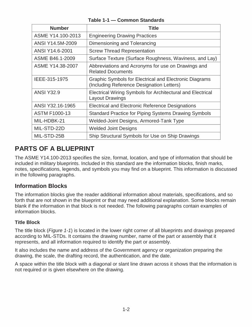
BLUEPRINT PRODUCTIONOriginal drawings are drawn, or traced, directly on translucent tracing paper or cloth using black waterproof India ink, a pencil, or computer-aided drafting (CAD) systems. The original drawing is a tracing or master copy. These copies are rarely, if ever, sent to a shop or site. Instead, copies of the tracings are given to persons or offices where needed. Tracings that are properly handled and stored will last indefinitely.The term blueprint is used loosely to describe copies of original drawings or tracings. One of the firstprocesses developed to duplicate tracings produced white lines on a blue background; hence the term blueprint. Today, however, other methods produce prints of different colors. The colors may be brown, black, gray, or maroon. The differences are in the types of paper and developing processes used.A patented paper identified as black and white (BW) paper produces prints with black lines on a white background. The diazo, or ammonia process, produces prints with either black, blue, or maroon lines on a white background.Another type of duplicating process rarely used to reproduce working drawings is the photostatic process, in which a large camera reduces or enlarges a tracing or drawing. The photostat has white lines on a dark background. Businesses use this process to incorporate reduced-size drawings into reports or records.The standards and procedures prescribed for military drawings and blueprints are stated in militarystandards (MIL-STDs), military handbooks (MIL-HDBKs), American National Standards Institute (ANSI) standards, American Society of Mechanical Engineers (ASME), and the Institute of Electrical and Electronics Engineers (IEEE). The acquisition streamlining and standardization information system (ASSIST) Web site lists these standards. A list containing common standards, listed by number and title, that concern engineering drawings and blueprints are illustrated in Table 1-1.
1-2
Table 1-1 — Common StandardsNumber Title
ASME Y14.100-2013 Engineering Drawing PracticesANSI Y14.5M-2009 Dimensioning and TolerancingANSI Y14.6-2001 Screw Thread RepresentationASME B46.1-2009 Surface Texture (Surface Roughness, Waviness, and Lay)ASME Y14.38-2007 Abbreviations and Acronyms for use on Drawings and
Related DocumentsIEEE-315-1975 Graphic Symbols for Electrical and Electronic Diagrams
(Including Reference Designation Letters)ANSI Y32.9 Electrical Wiring Symbols for Architectural and Electrical
Layout DrawingsANSI Y32.16-1965 Electrical and Electronic Reference DesignationsASTM F1000-13 Standard Practice for Piping Systems Drawing SymbolsMIL-HDBK-21 Welded-Joint Designs, Armored-Tank TypeMIL-STD-22D Welded Joint DesignsMIL-STD-25B Ship Structural Symbols for Use on Ship Drawings
PARTS OF A BLUEPRINTThe ASME Y14.100-2013 specifies the size, format, location, and type of information that should beincluded in military blueprints. Included in this standard are the information blocks, finish marks, notes, specifications, legends, and symbols you may find on a blueprint. This information is discussed in the following paragraphs.
Information BlocksThe information blocks give the reader additional information about materials, specifications, and so forth that are not shown in the blueprint or that may need additional explanation. Some blocks remainblank if the information in that block is not needed. The following paragraphs contain examples of information blocks.
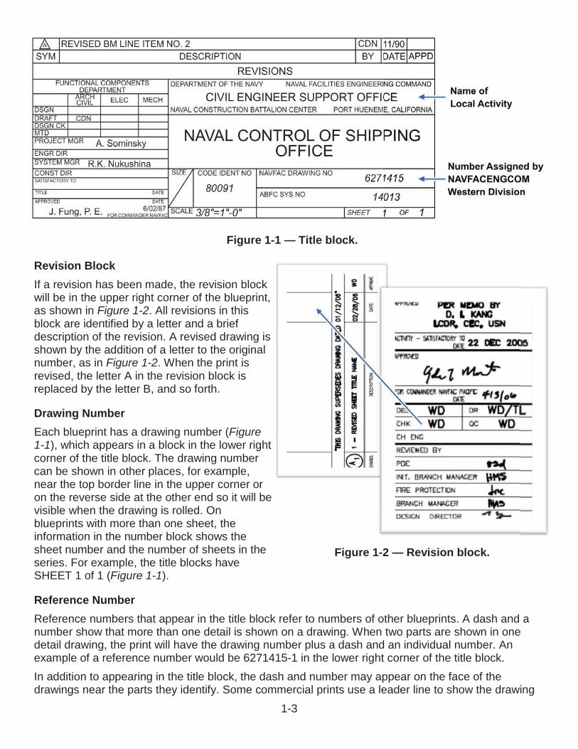
Title BlockThe title block (Figure 1-1) is located in the lower right corner of all blueprints and drawings prepared according to MIL-STDs. It contains the drawing number, name of the part or assembly that it represents, and all information required to identify the part or assembly.It also includes the name and address of the Government agency or organization preparing the drawing, the scale, the drafting record, the authentication, and the date.A space within the title block with a diagonal or slant line drawn across it shows that the information is not required or is given elsewhere on the drawing.
1-3
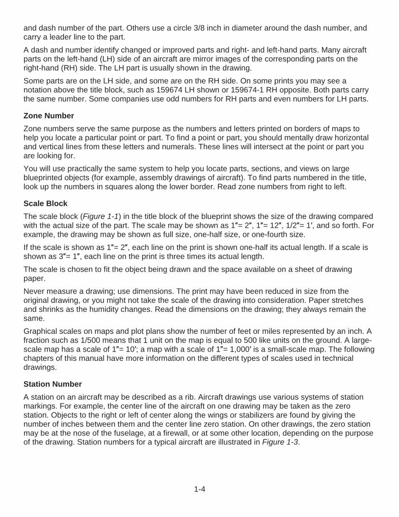
Revision BlockIf a revision has been made, the revision block will be in the upper right corner of the blueprint, as shown in Figure 1-2. All revisions in this block are identified by a letter and a brief description of the revision. A revised drawing is shown by the addition of a letter to the original number, as in Figure 1-2. When the print is revised, the letter A in the revision block isreplaced by the letter B, and so forth.
Drawing NumberEach blueprint has a drawing number (Figure1-1), which appears in a block in the lower right corner of the title block. The drawing number can be shown in other places, for example, near the top border line in the upper corner or on the reverse side at the other end so it will be visible when the drawing is rolled. On blueprints with more than one sheet, theinformation in the number block shows the sheet number and the number of sheets in the series. For example, the title blocks have SHEET 1 of 1 (Figure 1-1).
Reference NumberReference numbers that appear in the title block refer to numbers of other blueprints. A dash and anumber show that more than one detail is shown on a drawing. When two parts are shown in one detail drawing, the print will have the drawing number plus a dash and an individual number. An example of a reference number would be 6271415-1 in the lower right corner of the title block. In addition to appearing in the title block, the dash and number may appear on the face of the drawings near the parts they identify. Some commercial prints use a leader line to show the drawing
Figure 1-1 — Title block.
Figure 1-2 — Revision block.
1-4
and dash number of the part. Others use a circle 3/8 inch in diameter around the dash number, and carry a leader line to the part.A dash and number identify changed or improved parts and right- and left-hand parts. Many aircraftparts on the left-hand (LH) side of an aircraft are mirror images of the corresponding parts on the right-hand (RH) side. The LH part is usually shown in the drawing.Some parts are on the LH side, and some are on the RH side. On some prints you may see a notation above the title block, such as 159674 LH shown or 159674-1 RH opposite. Both parts carry the same number. Some companies use odd numbers for RH parts and even numbers for LH parts.
Zone NumberZone numbers serve the same purpose as the numbers and letters printed on borders of maps to help you locate a particular point or part. To find a point or part, you should mentally draw horizontal and vertical lines from these letters and numerals. These lines will intersect at the point or part you are looking for.You will use practically the same system to help you locate parts, sections, and views on largeblueprinted objects (for example, assembly drawings of aircraft). To find parts numbered in the title, look up the numbers in squares along the lower border. Read zone numbers from right to left.
Scale BlockThe scale block (Figure 1-1) in the title block of the blueprint shows the size of the drawing compared with the actual size of the part. The scale may be shown as 1 = 2 , 1 = 12 , 1/2 = 1 , and so forth. For example, the drawing may be shown as full size, one-half size, or one-fourth size.If the scale is shown as 1 = 2 each line on the print is shown one-half its actual length. If a scale isshown as 3 = 1 each line on the print is three times its actual length.The scale is chosen to fit the object being drawn and the space available on a sheet of drawing paper.Never measure a drawing; use dimensions. The print may have been reduced in size from the original drawing, or you might not take the scale of the drawing into consideration. Paper stretches and shrinks as the humidity changes. Read the dimensions on the drawing; they always remain the same.Graphical scales on maps and plot plans show the number of feet or miles represented by an inch. Afraction such as 1/500 means that 1 unit on the map is equal to 500 like units on the ground. A large-scale map has a scale of 1 = 10 ; a map with a scale of 1 = 1,000 is a small-scale map. The followingchapters of this manual have more information on the different types of scales used in technical drawings.
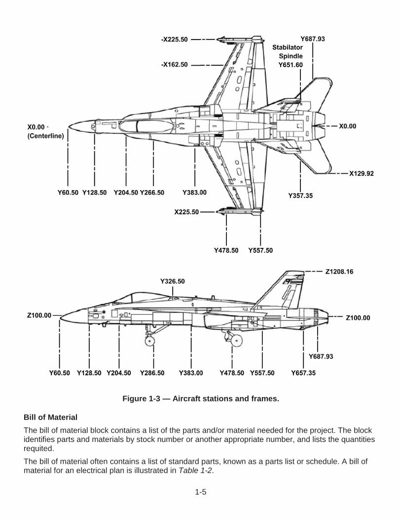
Station NumberA station on an aircraft may be described as a rib. Aircraft drawings use various systems of station markings. For example, the center line of the aircraft on one drawing may be taken as the zerostation. Objects to the right or left of center along the wings or stabilizers are found by giving the number of inches between them and the center line zero station. On other drawings, the zero station may be at the nose of the fuselage, at a firewall, or at some other location, depending on the purpose of the drawing. Station numbers for a typical aircraft are illustrated in Figure 1-3.
1-5
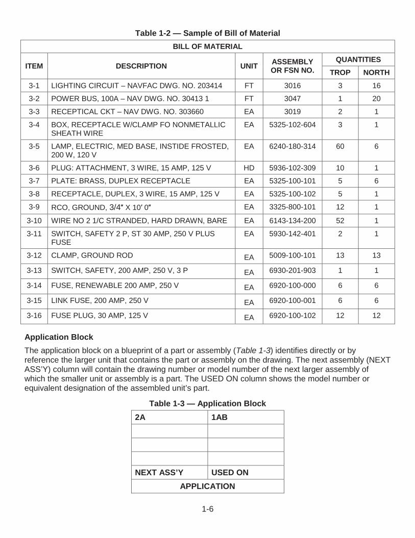
Bill of MaterialThe bill of material block contains a list of the parts and/or material needed for the project. The blockidentifies parts and materials by stock number or another appropriate number, and lists the quantities requited.The bill of material often contains a list of standard parts, known as a parts list or schedule. A bill of material for an electrical plan is illustrated in Table 1-2.
Figure 1-3 — Aircraft stations and frames.
1-6
Table 1-2 — Sample of Bill of MaterialBILL OF MATERIAL
ITEM DESCRIPTION UNIT ASSEMBLY OR FSN NO.
QUANTITIESTROP NORTH
3-1 LIGHTING CIRCUIT – NAVFAC DWG. NO. 203414 FT 3016 3 16
3-2 POWER BUS, 100A – NAV DWG. NO. 30413 1 FT 3047 1 20
3-3 RECEPTICAL CKT – NAV DWG. NO. 303660 EA 3019 2 1
3-4 BOX, RECEPTACLE W/CLAMP FO NONMETALLIC SHEATH WIRE
EA 5325-102-604 3 1
3-5 LAMP, ELECTRIC, MED BASE, INSTIDE FROSTED, 200 W, 120 V
EA 6240-180-314 60 6
3-6 PLUG: ATTACHMENT, 3 WIRE, 15 AMP, 125 V HD 5936-102-309 10 1
3-7 PLATE: BRASS, DUPLEX RECEPTACLE EA 5325-100-101 5 6
3-8 RECEPTACLE, DUPLEX, 3 WIRE, 15 AMP, 125 V EA 5325-100-102 5 1
3-9 RCO, GROUND, 3/4 X 10 0 EA 3325-800-101 12 1
3-10 WIRE NO 2 1/C STRANDED, HARD DRAWN, BARE EA 6143-134-200 52 1
3-11 SWITCH, SAFETY 2 P, ST 30 AMP, 250 V PLUS FUSE
EA 5930-142-401 2 1
3-12 CLAMP, GROUND ROD EA 5009-100-101 13 13
3-13 SWITCH, SAFETY, 200 AMP, 250 V, 3 P EA 6930-201-903 1 1
3-14 FUSE, RENEWABLE 200 AMP, 250 V EA 6920-100-000 6 6
3-15 LINK FUSE, 200 AMP, 250 V EA 6920-100-001 6 6
3-16 FUSE PLUG, 30 AMP, 125 V EA 6920-100-102 12 12
Application BlockThe application block on a blueprint of a part or assembly (Table 1-3) identifies directly or by reference the larger unit that contains the part or assembly on the drawing. The next assembly (NEXT ASS’Y) column will contain the drawing number or model number of the next larger assembly of which the smaller unit or assembly is a part. The USED ON column shows the model number or equivalent designation of the assembled unit’s part.
Table 1-3 — Application Block2A 1AB
NEXT ASS’Y USED ONAPPLICATION
1-7
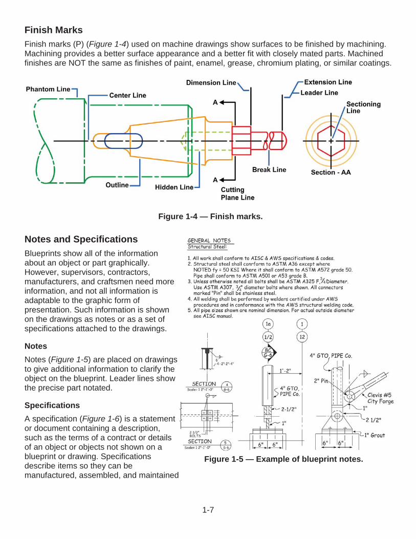
Finish MarksFinish marks (P) (Figure 1-4) used on machine drawings show surfaces to be finished by machining.Machining provides a better surface appearance and a better fit with closely mated parts. Machined finishes are NOT the same as finishes of paint, enamel, grease, chromium plating, or similar coatings.
Notes and SpecificationsBlueprints show all of the information about an object or part graphically. However, supervisors, contractors, manufacturers, and craftsmen need more information, and not all information is adaptable to the graphic form of presentation. Such information is shown on the drawings as notes or as a set of specifications attached to the drawings.
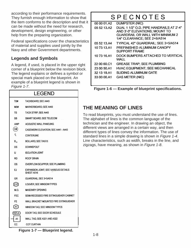
NotesNotes (Figure 1-5) are placed on drawings to give additional information to clarify the object on the blueprint. Leader lines show the precise part notated.
SpecificationsA specification (Figure 1-6) is a statement or document containing a description, such as the terms of a contract or details of an object or objects not shown on a blueprint or drawing. Specifications describe items so they can be manufactured, assembled, and maintained
Figure 1-4 — Finish marks.
Figure 1-5 — Example of blueprint notes.
1-8
according to their performance requirements.They furnish enough information to show thatthe item conforms to the description and that it can be made without the need for research, development, design engineering, or other help from the preparing organization.Federal specifications cover the characteristics of material and supplies used jointly by the Navy and other Government departments.
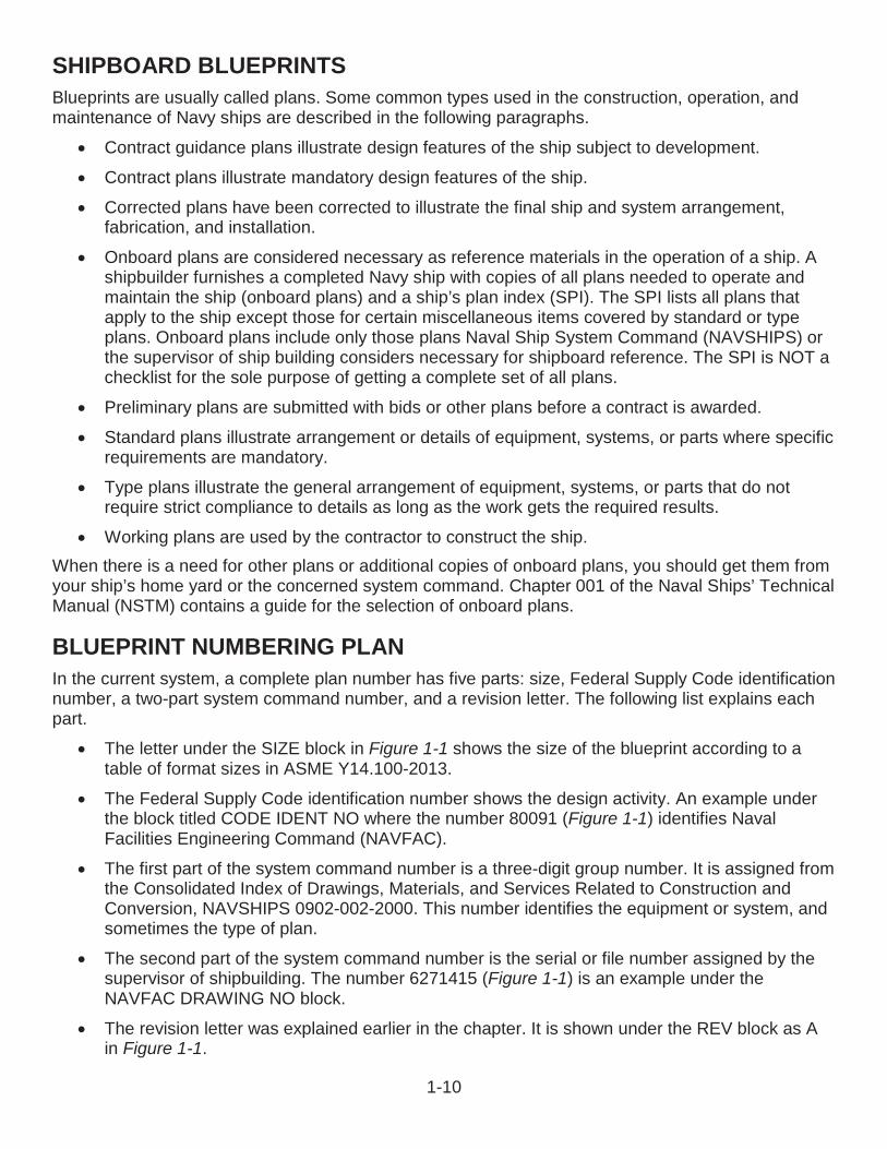
Legends and SymbolsA legend, if used, is placed in the upper rightcorner of a blueprint below the revision block. The legend explains or defines a symbol or special mark placed on the blueprint. Anexample of a blueprint legend is shown in Figure 1-7.
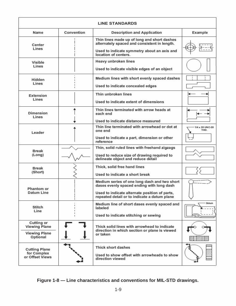
THE MEANING OF LINESTo read blueprints, you must understand the use of lines. The alphabet of lines is the common language of the technician and the engineer. In drawing an object, the different views are arranged in a certain way, and then different types of lines convey the information. The use of standard lines in a simple drawing is shown in Figure 1-4.Line characteristics, such as width, breaks in the line, and zigzags, have meaning, as shown in Figure 1-8.
Figure 1-6 — Example of blueprint specifications.
Figure 1-7 — Blueprint legend.
1-9
Figure 1-8 — Line characteristics and conventions for MIL-STD drawings.
1-10
SHIPBOARD BLUEPRINTSBlueprints are usually called plans. Some common types used in the construction, operation, and maintenance of Navy ships are described in the following paragraphs.
Contract guidance plans illustrate design features of the ship subject to development.
Contract plans illustrate mandatory design features of the ship.
Corrected plans have been corrected to illustrate the final ship and system arrangement,fabrication, and installation.
Onboard plans are considered necessary as reference materials in the operation of a ship. A shipbuilder furnishes a completed Navy ship with copies of all plans needed to operate and maintain the ship (onboard plans) and a ship’s plan index (SPI). The SPI lists all plans that apply to the ship except those for certain miscellaneous items covered by standard or type plans. Onboard plans include only those plans Naval Ship System Command (NAVSHIPS) or the supervisor of ship building considers necessary for shipboard reference. The SPI is NOT a checklist for the sole purpose of getting a complete set of all plans.
Preliminary plans are submitted with bids or other plans before a contract is awarded.
Standard plans illustrate arrangement or details of equipment, systems, or parts where specific requirements are mandatory.
Type plans illustrate the general arrangement of equipment, systems, or parts that do not require strict compliance to details as long as the work gets the required results.
Working plans are used by the contractor to construct the ship.When there is a need for other plans or additional copies of onboard plans, you should get them fromyour ship’s home yard or the concerned system command. Chapter 001 of the Naval Ships’ Technical Manual (NSTM) contains a guide for the selection of onboard plans.
BLUEPRINT NUMBERING PLANIn the current system, a complete plan number has five parts: size, Federal Supply Code identification number, a two-part system command number, and a revision letter. The following list explains each part.
The letter under the SIZE block in Figure 1-1 shows the size of the blueprint according to atable of format sizes in ASME Y14.100-2013.
The Federal Supply Code identification number shows the design activity. An example under the block titled CODE IDENT NO where the number 80091 (Figure 1-1) identifies Naval Facilities Engineering Command (NAVFAC).
The first part of the system command number is a three-digit group number. It is assigned from the Consolidated Index of Drawings, Materials, and Services Related to Construction and Conversion, NAVSHIPS 0902-002-2000. This number identifies the equipment or system, andsometimes the type of plan.
The second part of the system command number is the serial or file number assigned by the supervisor of shipbuilding. The number 6271415 (Figure 1-1) is an example under the NAVFAC DRAWING NO block.
The revision letter was explained earlier in the chapter. It is shown under the REV block as A in Figure 1-1.
1-11
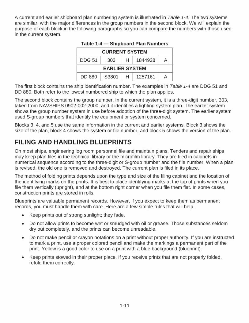
A current and earlier shipboard plan numbering system is illustrated in Table 1-4. The two systems are similar, with the major differences in the group numbers in the second block. We will explain the purpose of each block in the following paragraphs so you can compare the numbers with those used in the current system.
Table 1-4 — Shipboard Plan NumbersCURRENT SYSTEM
DDG 51 303 H 1844928 A
EARLIER SYSTEMDD 880 S3801 H 1257161 A
The first block contains the ship identification number. The examples in Table 1-4 are DDG 51 and DD 880. Both refer to the lowest numbered ship to which the plan applies.The second block contains the group number. In the current system, it is a three-digit number, 303,taken from NAVSHIPS 0902-002-2000, and it identifies a lighting system plan. The earlier systemshows the group number system in use before adoption of the three-digit system. The earlier systemused S-group numbers that identify the equipment or system concerned. Blocks 3, 4, and 5 use the same information in the current and earlier systems. Block 3 shows the size of the plan, block 4 shows the system or file number, and block 5 shows the version of the plan.
FILING AND HANDLING BLUEPRINTSOn most ships, engineering log room personnel file and maintain plans. Tenders and repair ships may keep plan files in the technical library or the microfilm library. They are filed in cabinets in numerical sequence according to the three-digit or S-group number and the file number. When a plan is revised, the old one is removed and destroyed. The current plan is filed in its place.The method of folding prints depends upon the type and size of the filing cabinet and the location ofthe identifying marks on the prints. It is best to place identifying marks at the top of prints when youfile them vertically (upright), and at the bottom right corner when you file them flat. In some cases,construction prints are stored in rolls.Blueprints are valuable permanent records. However, if you expect to keep them as permanent records, you must handle them with care. Here are a few simple rules that will help.
Keep prints out of strong sunlight; they fade.
Do not allow prints to become wet or smudged with oil or grease. Those substances seldom dry out completely, and the prints can become unreadable.
Do not make pencil or crayon notations on a print without proper authority. If you are instructed to mark a print, use a proper colored pencil and make the markings a permanent part of the print. Yellow is a good color to use on a print with a blue background (blueprint).
Keep prints stowed in their proper place. If you receive prints that are not properly folded, refold them correctly.

1-12
End of Chapter 1Blueprints
Review Questions1-1. What term describes interpreting ideas expressed by others on drawings?
A. Blueprint readingB. DesignC. DiagramD. Schematic
1-2. If tracings are handled properly, how long will they last?
A. 30 daysB. 6 monthsC. 5 yearsD. Indefinitely
1-3. What term describes the process in which a large camera reduces or enlarges a tracing of adrawing?
A. Carbon copyB. DuplicateC. PhotocopyD. Photostatic
1-4. What Web site lists military standards and American National Standards Institute standards?
A. Acquisition Streamlining and Standardization Information SystemB. Commander, Naval Sea Systems CommandC. International Society of EngineersD. Society of Electrical Engineers
1-5. What standard describes the abbreviations and acronyms for use on drawings and related documents?
A. ANSI Y32.9B. ASME Y14.100-2013C. ASME Y14.38-2007D. IEEE-315-1975
1-6. What standard describes the electrical wiring symbols for architectural and electrical layout drawings?
A. ANSI Y32.9B. ASME Y14.100-2013C. ASME Y14.38-2007D. IEEE-315-1975
1-13
1-7. What standard specifies the size, format, location, and type of information that should be included in military blueprints?
A. ANSI Y32.9B. ASME Y14.100-2013C. ASME Y14.38-2007D. IEEE-315-1975
1-8. In what corner is the title block of all blueprints and drawings prepared according to military standards?
A. Lower leftB. Lower rightC. Upper leftD. Upper right
1-9. When a drawing is revised, what character is added to the original number?
A. A pound signB. A slash mark with a numberC. A dash with a numberD. A letter
1-10. What number is added to the blueprint to help locate a particular point or part?
A. DrawingB. ReferenceC. RevisionD. Zone
1-11. A station number is used in what type of drawing?
A. AircraftB. BuildingC. ParkD. Topical
1-12. What information block on a blueprint contains a list of the parts and/or materials needed for the project?
A. ApplicationB. Bill of materialC. LegendD. Title
1-14
1-13. What part of the blueprint provides additional information to clarify the object on the blueprint?
A. Finish marksB. NoteC. SpecificationD. Symbol
1-14. What type of plan is submitted with a bid or other plans before a contract is awarded?
A. StandardB. CorrectedC. PreliminaryD. Working
1-15. What type of plan illustrates the arrangement or details of equipment, systems, or parts where specific requirements are mandatory?
A. CorrectedB. PreliminaryC. StandardD. Working
1-16. The current blueprint number plan includes the size, Federal Supply Code identification number and what other part?
A. Reference scaleB. Revision letterC. Title blockD. Unit identification code
1-17. The difference between the current and earlier shipboard plan number system is the group of numbers in what block?
A. 1B. 2C. 3D. 4
1-18. On most ships, what personnel file and maintain the plans?
A. SupplyB. Microfilm librarianC. Engineering log roomD. Technical librarian

1-15
1-19. What action will occur if the prints are exposed to strong sunlight?
A. Prints will fadeB. Prints will wrinkleC. Prints will become unreadableD. White lines will become brighter
1-20. What color is good to use on a print with blue background?
A. BlackB. OrangeC. RedD. Yellow

1-16
RATE TRAINING MANUAL – User UpdateSWOS makes every effort to keep their manuals up-to-date and free of technical errors. We appreciate your help in this process. If you have an idea for improving this manual, or if you find an error, a typographical mistake, or an inaccuracy in SWOS manuals, please write or e-mail us, using this form or a photocopy. Be sure to include the exact chapter number, topic, detailed description, and correction, if applicable. Your input will be brought to the attention of the Technical Review Committee. Thank you for your assistance.Write: SWOS Project Manager
1534 Piersey Street Suite 321Norfolk, VA 23511-2613COMM: (757) 444-5332DSN: 564-5332
E-mail: Refer to the SWOS Norfolk page on the NKO Web page for current contact information.
Rate____ Course Name_____________________________________________
Revision Date__________ Chapter Number____ Page Number(s)____________
Description _____________________________________________________________________________________________________________________________________________________________________________________________
(Optional) Correction _____________________________________________________________________________________________________________________________________________________________________________________________
(Optional) Your Name and Address _____________________________________________________________________________________________________________________________________________________________________________________________

CHAPTER 2
TECHNICAL SKETCHINGThe ability to make quick, accurate sketches is a valuable advantage that helps you convey technical information or ideas to others. A sketch may be of an object, an idea of something you are thinking about, or a combination of both. Most of us think of a sketch as a freehand drawing, which is not always the case. You may sketch on graph paper to take advantage of the lined squares, or you may sketch on plain paper with or without the help of drawing aids.There is no military standard (MIL-STD) for technical sketching. You may draw pictorial sketches that look like the object, or you may make an orthographic sketch showing different views, which we will cover in following chapters.In this chapter, we will discuss the basics of freehand sketching and lettering, drafting, and computer-aided drafting (CAD). We will also explain how CAD works with the newer computer numerical control (CNC) systems used in machining.
LEARNING OBJECTIVESWhen you have completed this chapter, you will be able to do the following:
1. Identify the instruments used in technical sketching.2. Recognize the types of lines used in technical sketching.3. Identify basic CAD.4. Determine CNC design techniques used in machining.
SKETCHING INSTRUMENTSFreehand sketching requires few tools. If you have a pencil and a scrap piece of paper handy, you are ready to begin. However, technical sketching usually calls for instruments that are a little more specialized, and we will discuss some of the more common ones in the following paragraphs.
Pencils and LeadsTwo types of pencils are used in drafting: wooden and mechanical. The mechanical type is actually a lead holder and may be used with leads of different hardness or softness.There are a number of different drawing media and types of reproduction and they require different kinds of pencil leads. Pencil manufacturers market three types that are used to prepare engineering drawings; graphite, plastic, and plastic-graphite.Graphite lead is the conventional type we have used for years. It is made of graphite, clay, and resin and it is available in a variety of grades or hardness. Drafting pencils are graded according to the relative hardness. A soft pencil is designated by the letter B, a hard pencil by the letter H. Figure 2-1shows 17 common grades of drafting pencils from 6B (the softest and the one that produces the thickest line) to 9H (the hardest and one that produces a thin, gray line).You will notice that the diameters of the lead vary. This feature adds strength to the softer grades. As a result, softer grades are thicker and produce broader lines, while harder grades are smaller and produce thinner lines. Unfortunately, manufacturers of pencils have not established uniformity in
2-1
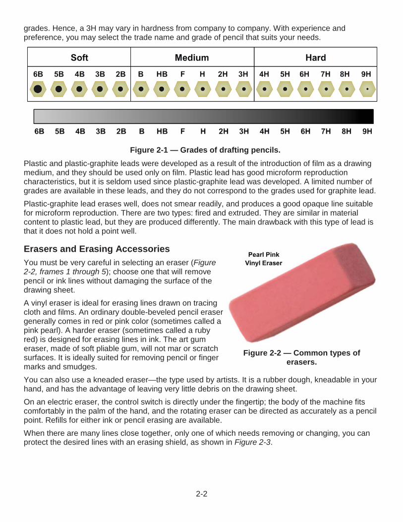
grades. Hence, a 3H may vary in hardness from company to company. With experience and preference, you may select the trade name and grade of pencil that suits your needs.
Plastic and plastic-graphite leads were developed as a result of the introduction of film as a drawingmedium, and they should be used only on film. Plastic lead has good microform reproduction characteristics, but it is seldom used since plastic-graphite lead was developed. A limited number of grades are available in these leads, and they do not correspond to the grades used for graphite lead.Plastic-graphite lead erases well, does not smear readily, and produces a good opaque line suitable for microform reproduction. There are two types: fired and extruded. They are similar in material content to plastic lead, but they are produced differently. The main drawback with this type of lead is that it does not hold a point well.
Erasers and Erasing AccessoriesYou must be very careful in selecting an eraser (Figure 2-2, frames 1 through 5); choose one that will remove pencil or ink lines without damaging the surface of the drawing sheet.A vinyl eraser is ideal for erasing lines drawn on tracing cloth and films. An ordinary double-beveled pencil eraser generally comes in red or pink color (sometimes called a pink pearl). A harder eraser (sometimes called a ruby red) is designed for erasing lines in ink. The art gum eraser, made of soft pliable gum, will not mar or scratch surfaces. It is ideally suited for removing pencil or finger marks and smudges.You can also use a kneaded eraser—the type used by artists. It is a rubber dough, kneadable in your hand, and has the advantage of leaving very little debris on the drawing sheet.On an electric eraser, the control switch is directly under the fingertip; the body of the machine fits comfortably in the palm of the hand, and the rotating eraser can be directed as accurately as a pencil point. Refills for either ink or pencil erasing are available.When there are many lines close together, only one of which needs removing or changing, you can protect the desired lines with an erasing shield, as shown in Figure 2-3.
Figure 2-1 — Grades of drafting pencils.
Figure 2-2 — Common types of erasers.
2-2
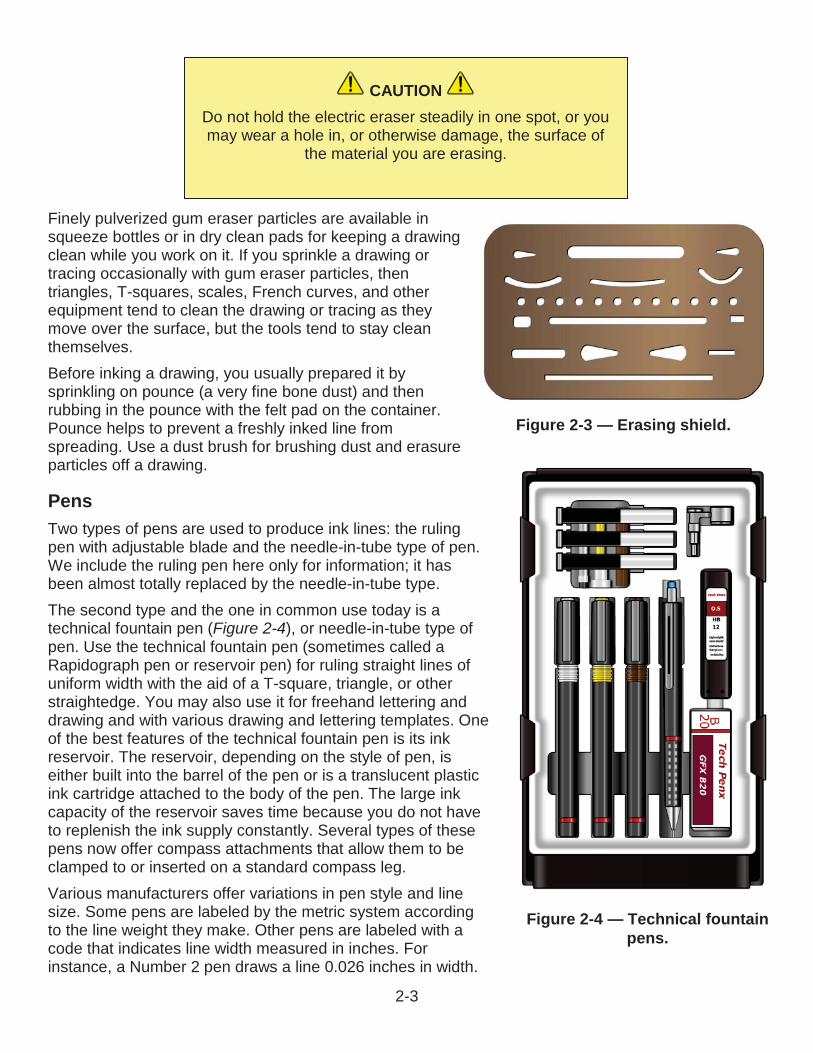
Finely pulverized gum eraser particles are available in squeeze bottles or in dry clean pads for keeping a drawing clean while you work on it. If you sprinkle a drawing or tracing occasionally with gum eraser particles, then triangles, T-squares, scales, French curves, and other equipment tend to clean the drawing or tracing as they move over the surface, but the tools tend to stay clean themselves. Before inking a drawing, you usually prepared it by sprinkling on pounce (a very fine bone dust) and then rubbing in the pounce with the felt pad on the container. Pounce helps to prevent a freshly inked line from spreading. Use a dust brush for brushing dust and erasure particles off a drawing.
PensTwo types of pens are used to produce ink lines: the ruling pen with adjustable blade and the needle-in-tube type of pen. We include the ruling pen here only for information; it has been almost totally replaced by the needle-in-tube type.The second type and the one in common use today is a technical fountain pen (Figure 2-4), or needle-in-tube type ofpen. Use the technical fountain pen (sometimes called a Rapidograph pen or reservoir pen) for ruling straight lines of uniform width with the aid of a T-square, triangle, or other straightedge. You may also use it for freehand lettering and drawing and with various drawing and lettering templates. One of the best features of the technical fountain pen is its ink reservoir. The reservoir, depending on the style of pen, is either built into the barrel of the pen or is a translucent plastic ink cartridge attached to the body of the pen. The large ink capacity of the reservoir saves time because you do not have to replenish the ink supply constantly. Several types of these pens now offer compass attachments that allow them to be clamped to or inserted on a standard compass leg.Various manufacturers offer variations in pen style and line size. Some pens are labeled by the metric system according to the line weight they make. Other pens are labeled with a code that indicates line width measured in inches. For instance, a Number 2 pen draws a line 0.026 inches in width.
CAUTIONDo not hold the electric eraser steadily in one spot, or you may wear a hole in, or otherwise damage, the surface of
the material you are erasing.
Figure 2-3 — Erasing shield.
Figure 2-4 — Technical fountain pens.
2-3
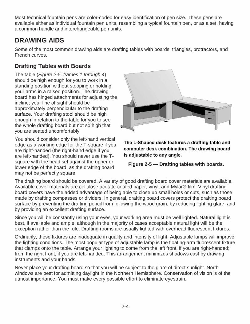
Most technical fountain pens are color-coded for easy identification of pen size. These pens are available either as individual fountain pen units, resembling a typical fountain pen, or as a set, having a common handle and interchangeable pen units.
DRAWING AIDSSome of the most common drawing aids are drafting tables with boards, triangles, protractors, and French curves.
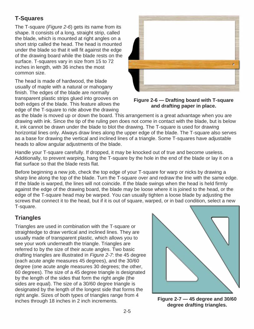
Drafting Tables with BoardsThe table (Figure 2-5, frames 1 through 4)should be high enough for you to work in a standing position without stooping or holding your arms in a raised position. The drawing board has hinged attachments for adjusting the incline; your line of sight should be approximately perpendicular to the drafting surface. Your drafting stool should be high enough in relation to the table for you to see the whole drafting board but not so high that you are seated uncomfortably.You should consider only the left-hand vertical edge as a working edge for the T-square if you are right-handed (the right-hand edge if you are left-handed). You should never use the T-square with the head set against the upper or lower edge of the board, as the drafting board may not be perfectly square.The drafting board should be covered. A variety of good drafting board cover materials are available. Available cover materials are cellulose acetate-coated paper, vinyl, and Mylar® film. Vinyl drafting board covers have the added advantage of being able to close up small holes or cuts, such as those made by drafting compasses or dividers. In general, drafting board covers protect the drafting board surface by preventing the drafting pencil from following the wood grain, by reducing lighting glare, and by providing an excellent drafting surface.Since you will be constantly using your eyes, your working area must be well lighted. Natural light is best, if available and ample; although in the majority of cases acceptable natural light will be the exception rather than the rule. Drafting rooms are usually lighted with overhead fluorescent fixtures.Ordinarily, these fixtures are inadequate in quality and intensity of light. Adjustable lamps will improve the lighting conditions. The most popular type of adjustable lamp is the floating-arm fluorescent fixture that clamps onto the table. Arrange your lighting to come from the left front, if you are right-handed; from the right front, if you are left-handed. This arrangement minimizes shadows cast by drawing instruments and your hands.Never place your drafting board so that you will be subject to the glare of direct sunlight. North windows are best for admitting daylight in the Northern Hemisphere. Conservation of vision is of the utmost importance. You must make every possible effort to eliminate eyestrain.
Figure 2-5 — Drafting tables with boards.
2-4
T-SquaresThe T-square (Figure 2-6) gets its name from its shape. It consists of a long, straight strip, called the blade, which is mounted at right angles on a short strip called the head. The head is mounted under the blade so that it will fit against the edge of the drawing board while the blade rests on the surface. T-squares vary in size from 15 to 72 inches in length, with 36 inches the most common size.The head is made of hardwood, the blade usually of maple with a natural or mahogany finish. The edges of the blade are normally transparent plastic strips glued into grooves on both edges of the blade. This feature allows the edge of the T-square to ride above the drawing as the blade is moved up or down the board. This arrangement is a great advantage when you are drawing with ink. Since the tip of the ruling pen does not come in contact with the blade, but is below it, ink cannot be drawn under the blade to blot the drawing. The T-square is used for drawing horizontal lines only. Always draw lines along the upper edge of the blade. The T-square also serves as a base for drawing the vertical and inclined lines of a triangle. Some T-squares have adjustable heads to allow angular adjustments of the blade.Handle your T-square carefully. If dropped, it may be knocked out of true and become useless. Additionally, to prevent warping, hang the T-square by the hole in the end of the blade or lay it on a flat surface so that the blade rests flat.Before beginning a new job, check the top edge of your T-square for warp or nicks by drawing a sharp line along the top of the blade. Turn the T-square over and redraw the line with the same edge. If the blade is warped, the lines will not coincide. If the blade swings when the head is held firmly against the edge of the drawing board, the blade may be loose where it is joined to the head, or the edge of the T-square head may be warped. You can usually tighten a loose blade by adjusting the screws that connect it to the head, but if it is out of square, warped, or in bad condition, select a new T-square.
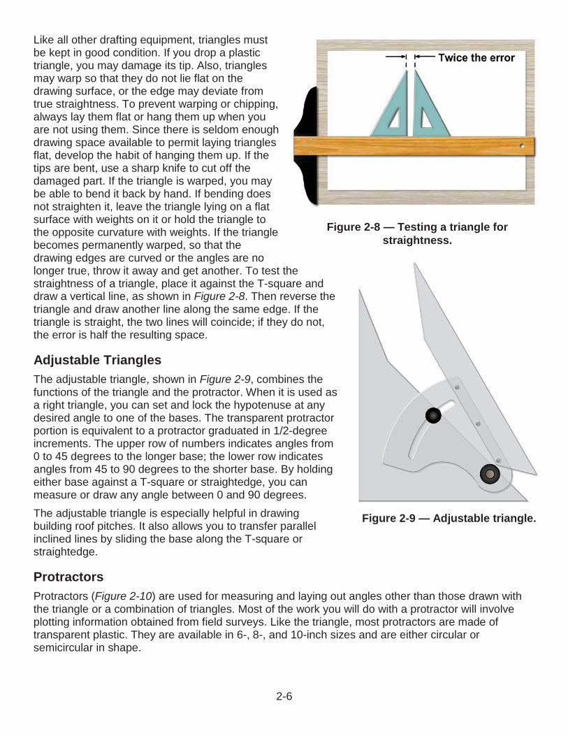
TrianglesTriangles are used in combination with the T-square or straightedge to draw vertical and inclined lines. They are usually made of transparent plastic, which allows you to see your work underneath the triangle. Triangles are referred to by the size of their acute angles. Two basic drafting triangles are illustrated in Figure 2-7: the 45 degree(each acute angle measures 45 degrees), and the 30/60degree (one acute angle measures 30 degrees; the other, 60 degrees). The size of a 45 degree triangle is designated by the length of the sides that form the right angle (the sides are equal). The size of a 30/60 degree triangle is designated by the length of the longest side that forms the right angle. Sizes of both types of triangles range from 4inches through 18 inches in 2 inch increments.
Figure 2-6 — Drafting board with T-square and drafting paper in place.
Figure 2-7 — 45 degree and 30/60degree drafting triangles.
2-5
Like all other drafting equipment, triangles must be kept in good condition. If you drop a plastic triangle, you may damage its tip. Also, triangles may warp so that they do not lie flat on the drawing surface, or the edge may deviate from true straightness. To prevent warping or chipping, always lay them flat or hang them up when you are not using them. Since there is seldom enough drawing space available to permit laying triangles flat, develop the habit of hanging them up. If the tips are bent, use a sharp knife to cut off the damaged part. If the triangle is warped, you may be able to bend it back by hand. If bending does not straighten it, leave the triangle lying on a flat surface with weights on it or hold the triangle to the opposite curvature with weights. If the triangle becomes permanently warped, so that the drawing edges are curved or the angles are no longer true, throw it away and get another. To test the straightness of a triangle, place it against the T-square and draw a vertical line, as shown in Figure 2-8. Then reverse the triangle and draw another line along the same edge. If the triangle is straight, the two lines will coincide; if they do not, the error is half the resulting space.
Adjustable TrianglesThe adjustable triangle, shown in Figure 2-9, combines the functions of the triangle and the protractor. When it is used as a right triangle, you can set and lock the hypotenuse at any desired angle to one of the bases. The transparent protractor portion is equivalent to a protractor graduated in 1/2-degree increments. The upper row of numbers indicates angles from 0 to 45 degrees to the longer base; the lower row indicates angles from 45 to 90 degrees to the shorter base. By holding either base against a T-square or straightedge, you can measure or draw any angle between 0 and 90 degrees.The adjustable triangle is especially helpful in drawing building roof pitches. It also allows you to transfer parallel inclined lines by sliding the base along the T-square or straightedge.
ProtractorsProtractors (Figure 2-10) are used for measuring and laying out angles other than those drawn with the triangle or a combination of triangles. Most of the work you will do with a protractor will involve plotting information obtained from field surveys. Like the triangle, most protractors are made of transparent plastic. They are available in 6-, 8-, and 10-inch sizes and are either circular or semicircular in shape.
Figure 2-8 — Testing a triangle for straightness.
Figure 2-9 — Adjustable triangle.
2-6
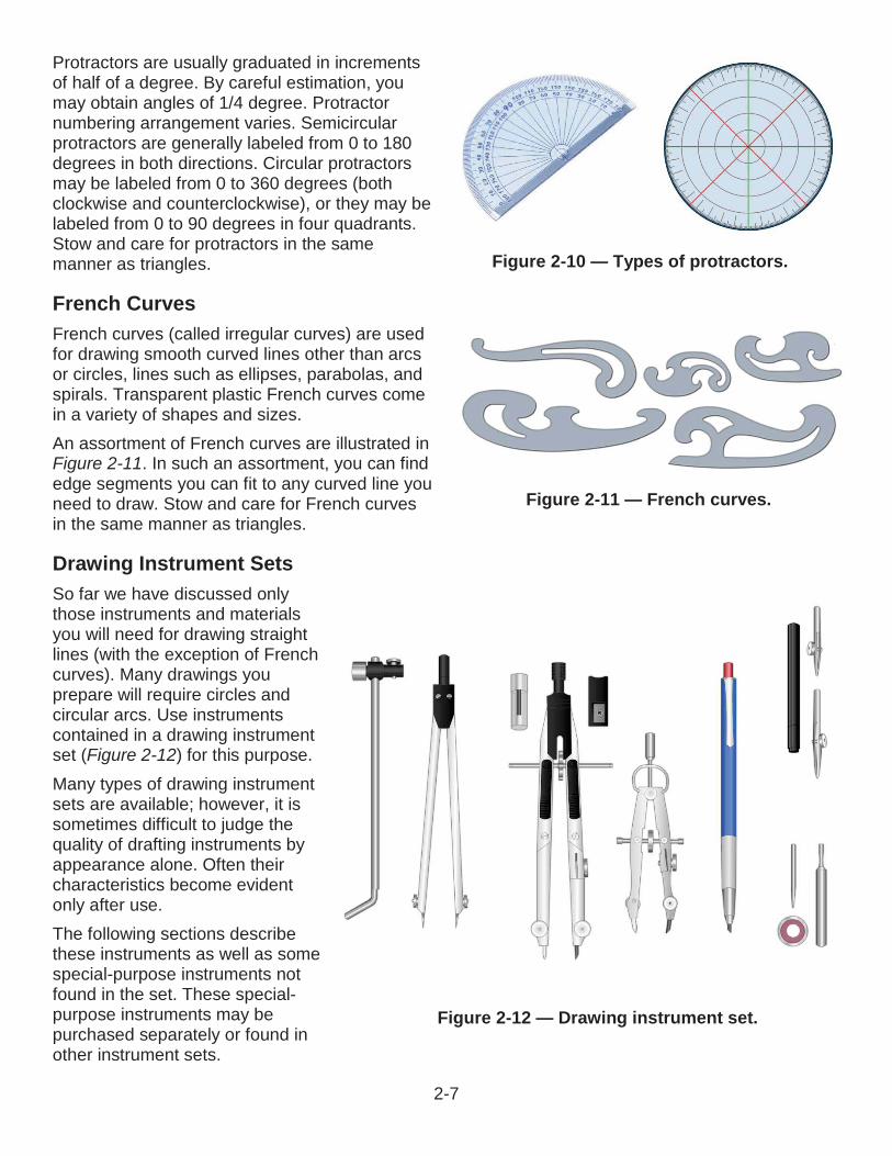
Protractors are usually graduated in increments of half of a degree. By careful estimation, you may obtain angles of 1/4 degree. Protractor numbering arrangement varies. Semicircular protractors are generally labeled from 0 to 180degrees in both directions. Circular protractors may be labeled from 0 to 360 degrees (both clockwise and counterclockwise), or they may be labeled from 0 to 90 degrees in four quadrants. Stow and care for protractors in the same manner as triangles.
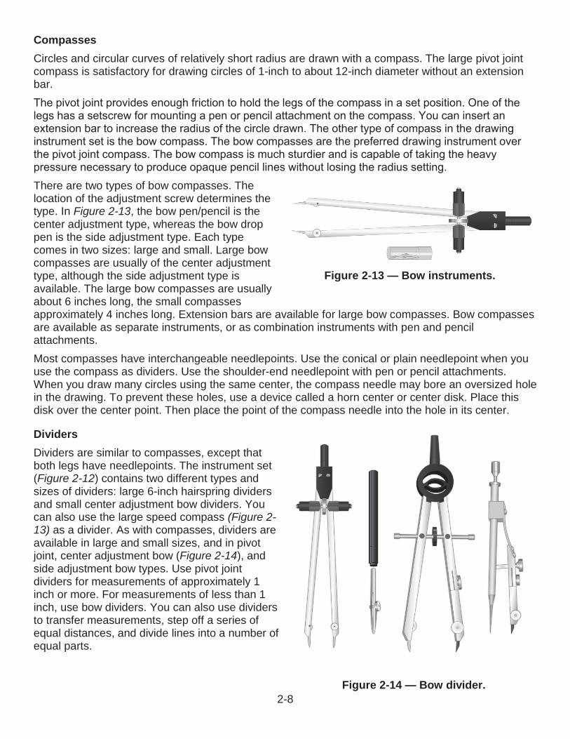
French CurvesFrench curves (called irregular curves) are used for drawing smooth curved lines other than arcs or circles, lines such as ellipses, parabolas, and spirals. Transparent plastic French curves come in a variety of shapes and sizes.An assortment of French curves are illustrated in Figure 2-11. In such an assortment, you can find edge segments you can fit to any curved line you need to draw. Stow and care for French curves in the same manner as triangles.
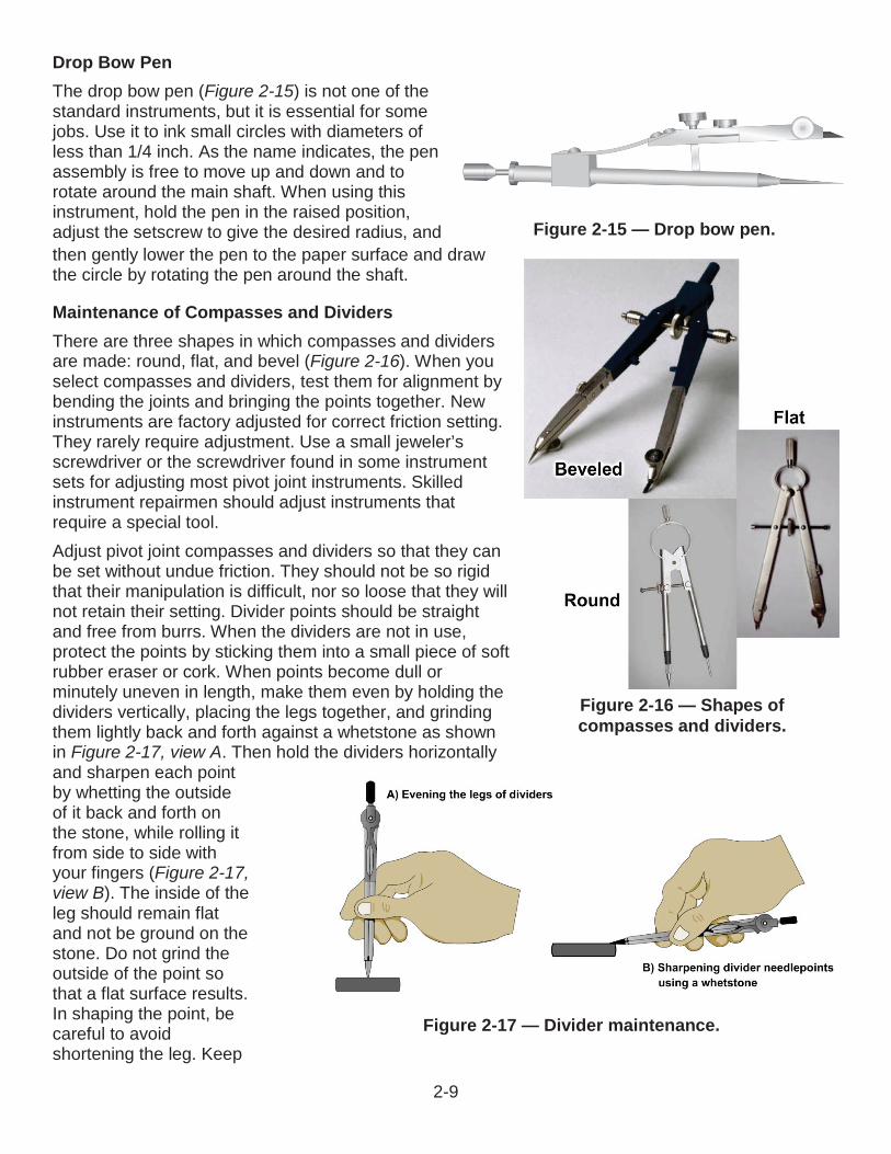
Drawing Instrument SetsSo far we have discussed only those instruments and materials you will need for drawing straight lines (with the exception of Frenchcurves). Many drawings you prepare will require circles and circular arcs. Use instruments contained in a drawing instrument set (Figure 2-12) for this purpose.Many types of drawing instrument sets are available; however, it is sometimes difficult to judge the quality of drafting instruments by appearance alone. Often their characteristics become evident only after use.The following sections describe these instruments as well as some special-purpose instruments not found in the set. These special-purpose instruments may be purchased separately or found in other instrument sets.
Figure 2-10 — Types of protractors.
Figure 2-11 — French curves.
Figure 2-12 — Drawing instrument set.
2-7
CompassesCircles and circular curves of relatively short radius are drawn with a compass. The large pivot joint compass is satisfactory for drawing circles of 1-inch to about 12-inch diameter without an extension bar.
There are two types of bow compasses. The location of the adjustment screw determines the type. In Figure 2-13, the bow pen/pencil is the center adjustment type, whereas the bow drop pen is the side adjustment type. Each type comes in two sizes: large and small. Large bow compasses are usually of the center adjustment type, although the side adjustment type is available. The large bow compasses are usually about 6 inches long, the small compasses approximately 4 inches long. Extension bars are available for large bow compasses. Bow compasses are available as separate instruments, or as combination instruments with pen and pencil attachments.Most compasses have interchangeable needlepoints. Use the conical or plain needlepoint when you use the compass as dividers. Use the shoulder-end needlepoint with pen or pencil attachments. When you draw many circles using the same center, the compass needle may bore an oversized hole in the drawing. To prevent these holes, use a device called a horn center or center disk. Place this disk over the center point. Then place the point of the compass needle into the hole in its center.
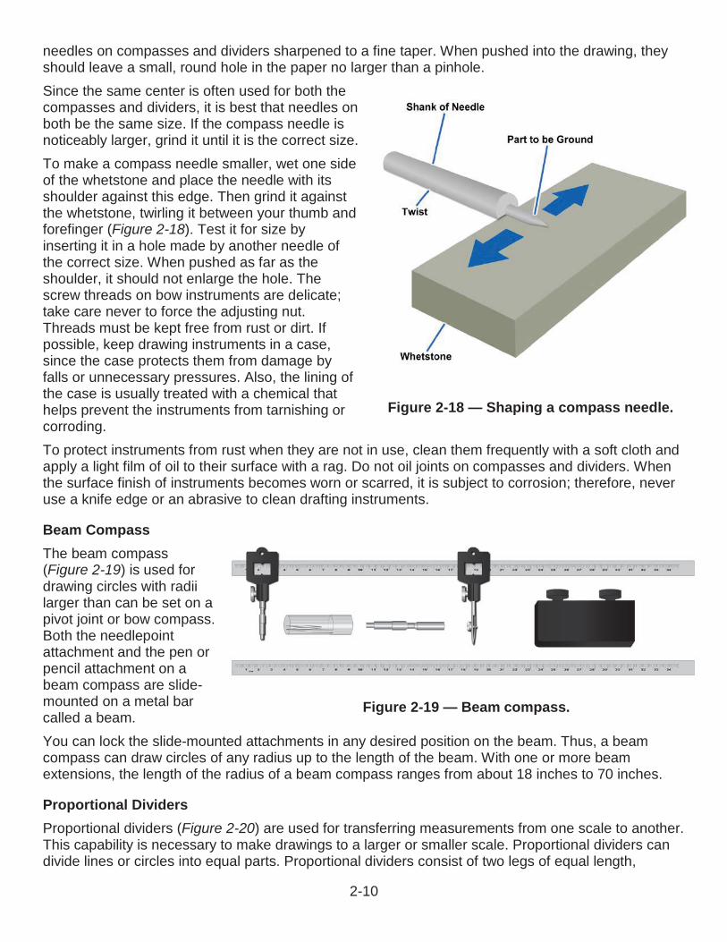
DividersDividers are similar to compasses, except that both legs have needlepoints. The instrument set (Figure 2-12) contains two different types and sizes of dividers: large 6-inch hairspring dividers and small center adjustment bow dividers. You can also use the large speed compass (Figure 2-13) as a divider. As with compasses, dividers areavailable in large and small sizes, and in pivot joint, center adjustment bow (Figure 2-14), and side adjustment bow types. Use pivot joint dividers for measurements of approximately 1inch or more. For measurements of less than 1 inch, use bow dividers. You can also use dividers to transfer measurements, step off a series of equal distances, and divide lines into a number of equal parts.
Figure 2-14 — Bow divider.
Figure 2-13 — Bow instruments.
2-8
Drop Bow PenThe drop bow pen (Figure 2-15) is not one of the standard instruments, but it is essential for some jobs. Use it to ink small circles with diameters of less than 1/4 inch. As the name indicates, the pen assembly is free to move up and down and to rotate around the main shaft. When using this instrument, hold the pen in the raised position, adjust the setscrew to give the desired radius, and then gently lower the pen to the paper surface and draw the circle by rotating the pen around the shaft.
Maintenance of Compasses and DividersThere are three shapes in which compasses and dividers are made: round, flat, and bevel (Figure 2-16). When you select compasses and dividers, test them for alignment by bending the joints and bringing the points together. New instruments are factory adjusted for correct friction setting. They rarely require adjustment. Use a small jeweler’s screwdriver or the screwdriver found in some instrument sets for adjusting most pivot joint instruments. Skilled instrument repairmen should adjust instruments that require a special tool.Adjust pivot joint compasses and dividers so that they can be set without undue friction. They should not be so rigid that their manipulation is difficult, nor so loose that they willnot retain their setting. Divider points should be straight and free from burrs. When the dividers are not in use,protect the points by sticking them into a small piece of soft rubber eraser or cork. When points become dull or minutely uneven in length, make them even by holding thedividers vertically, placing the legs together, and grinding them lightly back and forth against a whetstone as shown in Figure 2-17, view A. Then hold the dividers horizontally and sharpen each point by whetting the outside of it back and forth on the stone, while rolling it from side to side with your fingers (Figure 2-17,view B). The inside of the leg should remain flat and not be ground on the stone. Do not grind the outside of the point so that a flat surface results. In shaping the point, be careful to avoid shortening the leg. Keep
Figure 2-15 — Drop bow pen.
Figure 2-16 — Shapes of compasses and dividers.
Figure 2-17 — Divider maintenance.
2-9
needles on compasses and dividers sharpened to a fine taper. When pushed into the drawing, they should leave a small, round hole in the paper no larger than a pinhole.Since the same center is often used for both the compasses and dividers, it is best that needles on both be the same size. If the compass needle is noticeably larger, grind it until it is the correct size.To make a compass needle smaller, wet one side of the whetstone and place the needle with its shoulder against this edge. Then grind it against the whetstone, twirling it between your thumb and forefinger (Figure 2-18). Test it for size by inserting it in a hole made by another needle of the correct size. When pushed as far as the shoulder, it should not enlarge the hole. The screw threads on bow instruments are delicate;take care never to force the adjusting nut. Threads must be kept free from rust or dirt. Ifpossible, keep drawing instruments in a case, since the case protects them from damage by falls or unnecessary pressures. Also, the lining of the case is usually treated with a chemical that helps prevent the instruments from tarnishing orcorroding.To protect instruments from rust when they are not in use, clean them frequently with a soft cloth and apply a light film of oil to their surface with a rag. Do not oil joints on compasses and dividers. When the surface finish of instruments becomes worn or scarred, it is subject to corrosion; therefore, never use a knife edge or an abrasive to clean drafting instruments.
Beam CompassThe beam compass(Figure 2-19) is used for drawing circles with radii larger than can be set on a pivot joint or bow compass. Both the needlepoint attachment and the pen or pencil attachment on a beam compass are slide-mounted on a metal bar called a beam.You can lock the slide-mounted attachments in any desired position on the beam. Thus, a beam compass can draw circles of any radius up to the length of the beam. With one or more beam extensions, the length of the radius of a beam compass ranges from about 18 inches to 70 inches.
Proportional DividersProportional dividers (Figure 2-20) are used for transferring measurements from one scale to another. This capability is necessary to make drawings to a larger or smaller scale. Proportional dividers can divide lines or circles into equal parts. Proportional dividers consist of two legs of equal length,
Figure 2-18 — Shaping a compass needle.
Figure 2-19 — Beam compass.
2-10
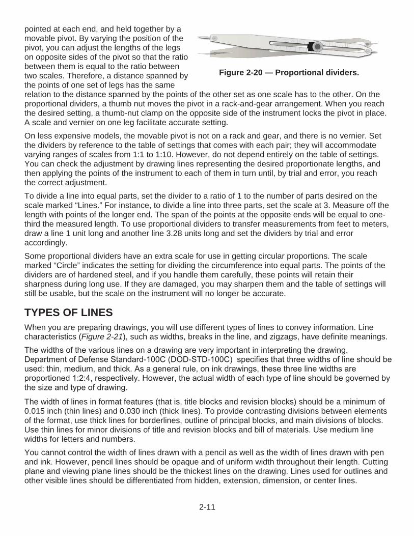
pointed at each end, and held together by a movable pivot. By varying the position of the pivot, you can adjust the lengths of the legs on opposite sides of the pivot so that the ratio between them is equal to the ratio between two scales. Therefore, a distance spanned by the points of one set of legs has the same relation to the distance spanned by the points of the other set as one scale has to the other. On the proportional dividers, a thumb nut moves the pivot in a rack-and-gear arrangement. When you reach the desired setting, a thumb-nut clamp on the opposite side of the instrument locks the pivot in place. A scale and vernier on one leg facilitate accurate setting.On less expensive models, the movable pivot is not on a rack and gear, and there is no vernier. Set the dividers by reference to the table of settings that comes with each pair; they will accommodate varying ranges of scales from 1:1 to 1:10. However, do not depend entirely on the table of settings. You can check the adjustment by drawing lines representing the desired proportionate lengths, and then applying the points of the instrument to each of them in turn until, by trial and error, you reach the correct adjustment.To divide a line into equal parts, set the divider to a ratio of 1 to the number of parts desired on the scale marked “Lines.” For instance, to divide a line into three parts, set the scale at 3. Measure off the length with points of the longer end. The span of the points at the opposite ends will be equal to one-third the measured length. To use proportional dividers to transfer measurements from feet to meters, draw a line 1 unit long and another line 3.28 units long and set the dividers by trial and error accordingly.Some proportional dividers have an extra scale for use in getting circular proportions. The scale marked “Circle” indicates the setting for dividing the circumference into equal parts. The points of the dividers are of hardened steel, and if you handle them carefully, these points will retain their sharpness during long use. If they are damaged, you may sharpen them and the table of settings will still be usable, but the scale on the instrument will no longer be accurate.
TYPES OF LINESWhen you are preparing drawings, you will use different types of lines to convey information. Line characteristics (Figure 2-21), such as widths, breaks in the line, and zigzags, have definite meanings.
The width of lines in format features (that is, title blocks and revision blocks) should be a minimum of 0.015 inch (thin lines) and 0.030 inch (thick lines). To provide contrasting divisions between elements of the format, use thick lines for borderlines, outline of principal blocks, and main divisions of blocks. Use thin lines for minor divisions of title and revision blocks and bill of materials. Use medium line widths for letters and numbers.You cannot control the width of lines drawn with a pencil as well as the width of lines drawn with pen and ink. However, pencil lines should be opaque and of uniform width throughout their length. Cutting plane and viewing plane lines should be the thickest lines on the drawing. Lines used for outlines and other visible lines should be differentiated from hidden, extension, dimension, or center lines.
Figure 2-20 — Proportional dividers.
2-11
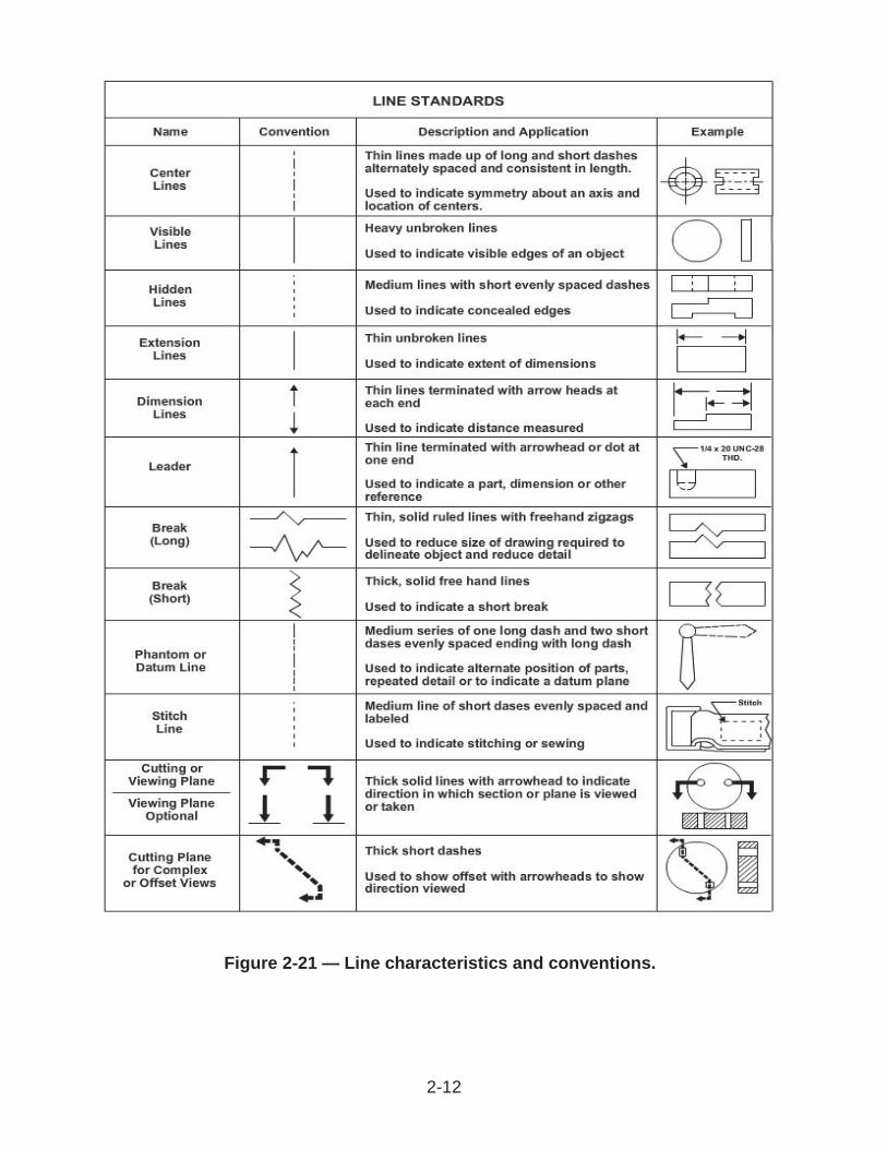
Figure 2-21 — Line characteristics and conventions.
2-12
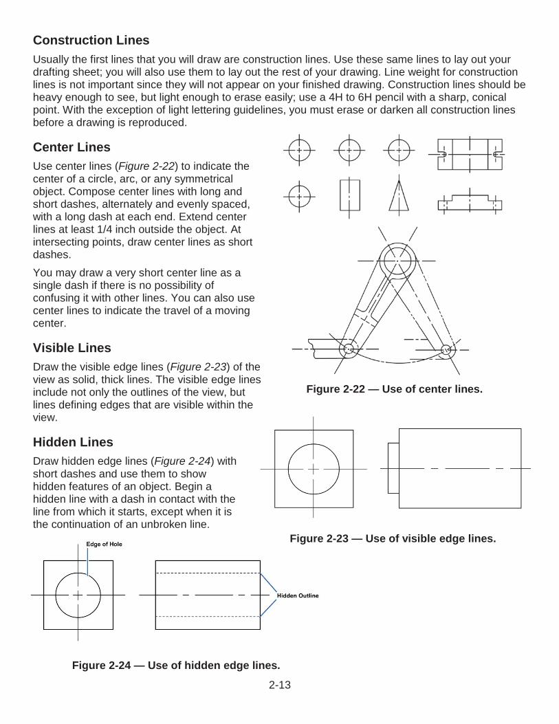
Figure 2-24 — Use of hidden edge lines.
Figure 2-23 — Use of visible edge lines.
Figure 2-22 — Use of center lines.
Construction LinesUsually the first lines that you will draw are construction lines. Use these same lines to lay out your drafting sheet; you will also use them to lay out the rest of your drawing. Line weight for construction lines is not important since they will not appear on your finished drawing. Construction lines should be heavy enough to see, but light enough to erase easily; use a 4H to 6H pencil with a sharp, conical point. With the exception of light lettering guidelines, you must erase or darken all construction lines before a drawing is reproduced.
Center LinesUse center lines (Figure 2-22) to indicate thecenter of a circle, arc, or any symmetrical object. Compose center lines with long and short dashes, alternately and evenly spaced,with a long dash at each end. Extend center lines at least 1/4 inch outside the object. Atintersecting points, draw center lines as short dashes. You may draw a very short center line as a single dash if there is no possibility of confusing it with other lines. You can also use center lines to indicate the travel of a moving center.
Visible LinesDraw the visible edge lines (Figure 2-23) of the view as solid, thick lines. The visible edge linesinclude not only the outlines of the view, but lines defining edges that are visible within the view.
Hidden LinesDraw hidden edge lines (Figure 2-24) with short dashes and use them to show hidden features of an object. Begin a hidden line with a dash in contact with the line from which it starts, except when it is the continuation of an unbroken line.
2-13
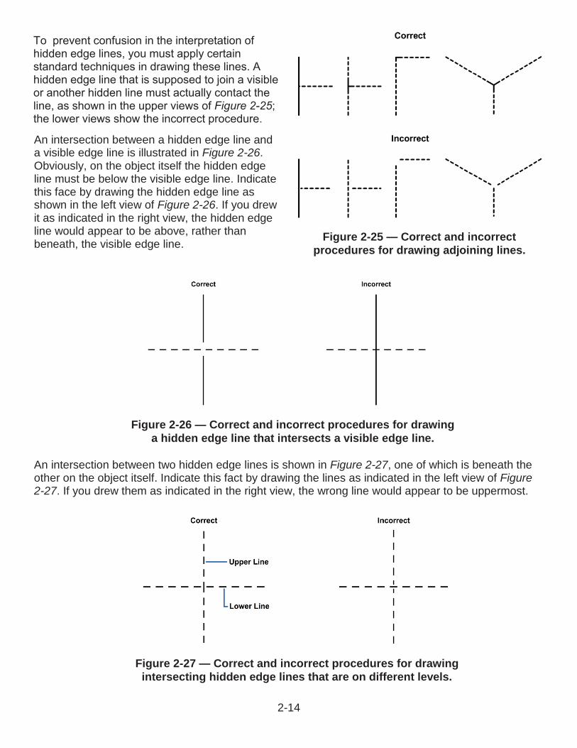
An intersection between a hidden edge line and a visible edge line is illustrated in Figure 2-26.Obviously, on the object itself the hidden edge line must be below the visible edge line. Indicate this face by drawing the hidden edge line as shown in the left view of Figure 2-26. If you drew it as indicated in the right view, the hidden edge line would appear to be above, rather than beneath, the visible edge line.
An intersection between two hidden edge lines is shown in Figure 2-27, one of which is beneath the other on the object itself. Indicate this fact by drawing the lines as indicated in the left view of Figure 2-27. If you drew them as indicated in the right view, the wrong line would appear to be uppermost.
Figure 2-25 — Correct and incorrect procedures for drawing adjoining lines.
Figure 2-26 — Correct and incorrect procedures for drawing a hidden edge line that intersects a visible edge line.
Figure 2-27 — Correct and incorrect procedures for drawing intersecting hidden edge lines that are on different levels.
2-14
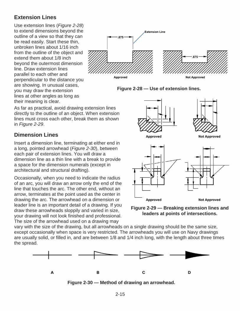
Figure 2-30 — Method of drawing an arrowhead.
Extension LinesUse extension lines (Figure 2-28) to extend dimensions beyond the outline of a view so that they can be read easily. Start these thin, unbroken lines about 1/16 inch from the outline of the object and extend them about 1/8 inch beyond the outermost dimension line. Draw extension lines parallel to each other and perpendicular to the distance you are showing. In unusual cases, you may draw the extension lines at other angles as long as their meaning is clear.As far as practical, avoid drawing extension lines directly to the outline of an object. When extension lines must cross each other, break them as shown in Figure 2-29.
Dimension LinesInsert a dimension line, terminating at either end in a long, pointed arrowhead (Figure 2-30), between each pair of extension lines. You will draw a dimension line as a thin line with a break to provide a space for the dimension numerals (except in architectural and structural drafting).Occasionally, when you need to indicate the radius of an arc, you will draw an arrow only the end of the line that touches the arc. The other end, without an arrow, terminates at the point used as the center in drawing the arc. The arrowhead on a dimension or leader line is an important detail of a drawing. If you draw these arrowheads sloppily and varied in size, your drawing will not look finished and professional. The size of the arrowhead used on a drawing may vary with the size of the drawing, but all arrowheads on a single drawing should be the same size, except occasionally when space is very restricted. The arrowheads you will use on Navy drawings are usually solid, or filled in, and are between 1/8 and 1/4 inch long, with the length about three times the spread.
Figure 2-28 — Use of extension lines.
Figure 2-29 — Breaking extension lines and leaders at points of intersections.
2-15
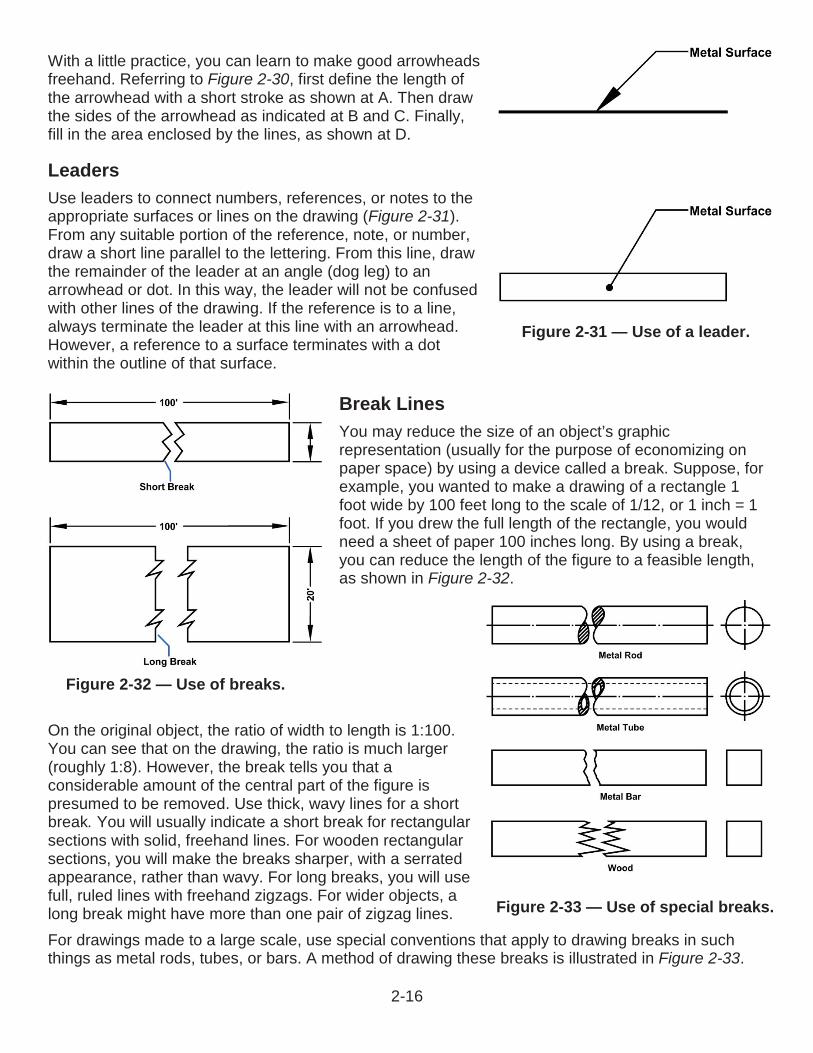
Figure 2-31 — Use of a leader.
Figure 2-32 — Use of breaks.
Figure 2-33 — Use of special breaks.
With a little practice, you can learn to make good arrowheads freehand. Referring to Figure 2-30, first define the length of the arrowhead with a short stroke as shown at A. Then draw the sides of the arrowhead as indicated at B and C. Finally, fill in the area enclosed by the lines, as shown at D.
LeadersUse leaders to connect numbers, references, or notes to the appropriate surfaces or lines on the drawing (Figure 2-31).From any suitable portion of the reference, note, or number, draw a short line parallel to the lettering. From this line, draw the remainder of the leader at an angle (dog leg) to an arrowhead or dot. In this way, the leader will not be confused with other lines of the drawing. If the reference is to a line, always terminate the leader at this line with an arrowhead.However, a reference to a surface terminates with a dot within the outline of that surface.
Break LinesYou may reduce the size of an object’s graphic representation (usually for the purpose of economizing on paper space) by using a device called a break. Suppose, for example, you wanted to make a drawing of a rectangle 1 foot wide by 100 feet long to the scale of 1/12, or 1 inch = 1 foot. If you drew the full length of the rectangle, you would need a sheet of paper 100 inches long. By using a break, you can reduce the length of the figure to a feasible length, as shown in Figure 2-32.
On the original object, the ratio of width to length is 1:100. You can see that on the drawing, the ratio is much larger (roughly 1:8). However, the break tells you that a considerable amount of the central part of the figure is presumed to be removed. Use thick, wavy lines for a short break. You will usually indicate a short break for rectangular sections with solid, freehand lines. For wooden rectangular sections, you will make the breaks sharper, with a serrated appearance, rather than wavy. For long breaks, you will use full, ruled lines with freehand zigzags. For wider objects, a long break might have more than one pair of zigzag lines.For drawings made to a large scale, use special conventions that apply to drawing breaks in such things as metal rods, tubes, or bars. A method of drawing these breaks is illustrated in Figure 2-33.
2-16
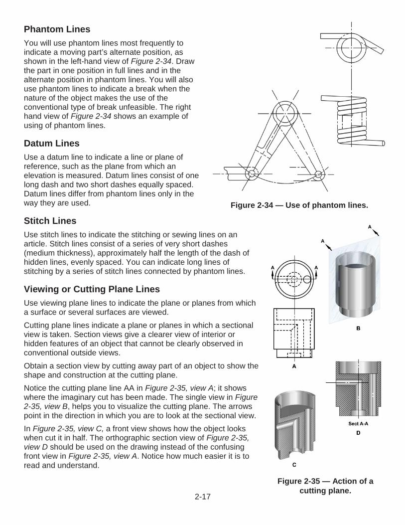
Phantom LinesYou will use phantom lines most frequently to indicate a moving part’s alternate position, as shown in the left-hand view of Figure 2-34. Draw the part in one position in full lines and in the alternate position in phantom lines. You will also use phantom lines to indicate a break when the nature of the object makes the use of the conventional type of break unfeasible. The right hand view of Figure 2-34 shows an example of using of phantom lines.
Datum LinesUse a datum line to indicate a line or plane of reference, such as the plane from which an elevation is measured. Datum lines consist of one long dash and two short dashes equally spaced. Datum lines differ from phantom lines only in the way they are used.
Stitch LinesUse stitch lines to indicate the stitching or sewing lines on an article. Stitch lines consist of a series of very short dashes(medium thickness), approximately half the length of the dash of hidden lines, evenly spaced. You can indicate long lines of stitching by a series of stitch lines connected by phantom lines.
Viewing or Cutting Plane LinesUse viewing plane lines to indicate the plane or planes from which a surface or several surfaces are viewed.Cutting plane lines indicate a plane or planes in which a sectional view is taken. Section views give a clearer view of interior or hidden features of an object that cannot be clearly observed in conventional outside views.Obtain a section view by cutting away part of an object to show the shape and construction at the cutting plane.Notice the cutting plane line AA in Figure 2-35, view A; it shows where the imaginary cut has been made. The single view in Figure 2-35, view B, helps you to visualize the cutting plane. The arrows point in the direction in which you are to look at the sectional view.In Figure 2-35, view C, a front view shows how the object looks when cut it in half. The orthographic section view of Figure 2-35,view D should be used on the drawing instead of the confusing front view in Figure 2-35, view A. Notice how much easier it is to read and understand.
Figure 2-34 — Use of phantom lines.
Figure 2-35 — Action of a cutting plane.
2-17
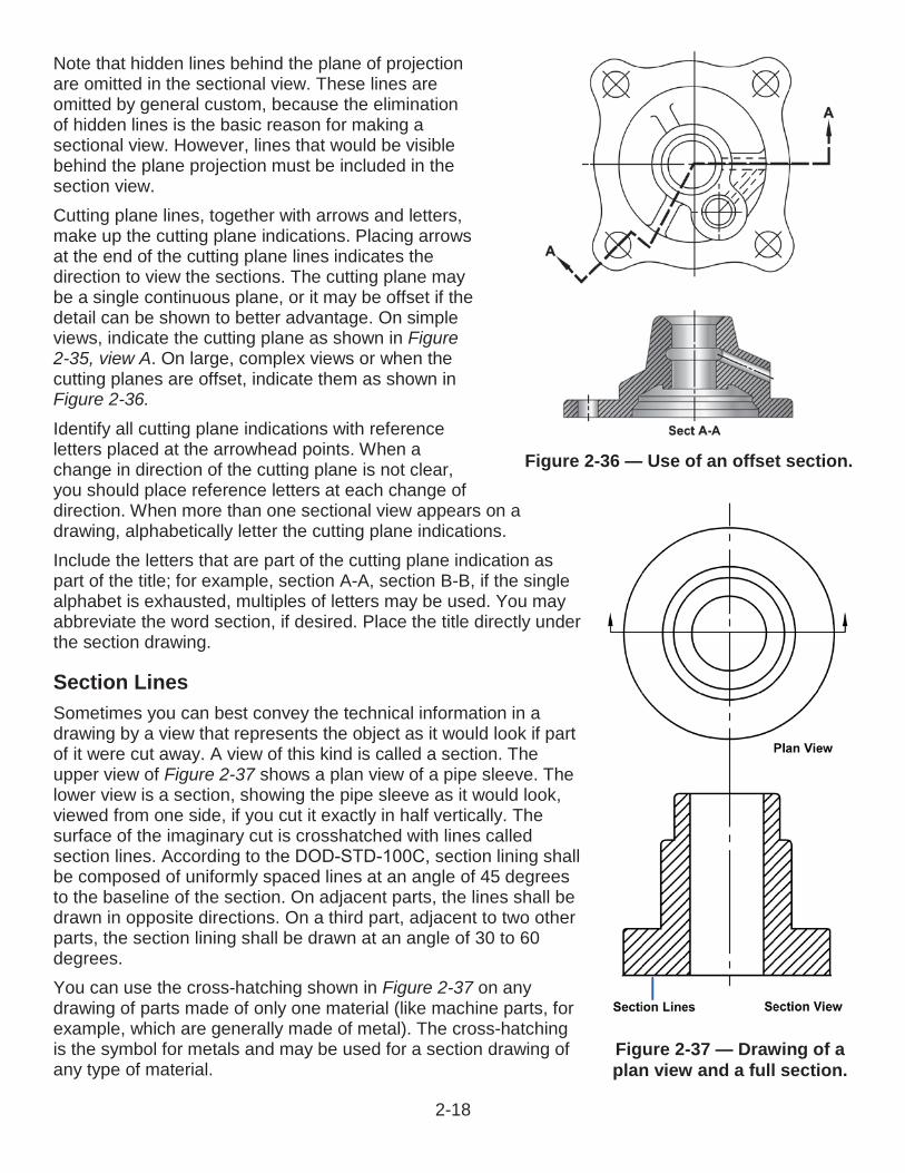
Note that hidden lines behind the plane of projection are omitted in the sectional view. These lines are omitted by general custom, because the elimination of hidden lines is the basic reason for making a sectional view. However, lines that would be visible behind the plane projection must be included in the section view.Cutting plane lines, together with arrows and letters, make up the cutting plane indications. Placing arrows at the end of the cutting plane lines indicates the direction to view the sections. The cutting plane may be a single continuous plane, or it may be offset if the detail can be shown to better advantage. On simple views, indicate the cutting plane as shown in Figure 2-35, view A. On large, complex views or when the cutting planes are offset, indicate them as shown in Figure 2-36.
Identify all cutting plane indications with reference letters placed at the arrowhead points. When a change in direction of the cutting plane is not clear, you should place reference letters at each change of direction. When more than one sectional view appears on a drawing, alphabetically letter the cutting plane indications.Include the letters that are part of the cutting plane indication as part of the title; for example, section A-A, section B-B, if the single alphabet is exhausted, multiples of letters may be used. You may abbreviate the word section, if desired. Place the title directly under the section drawing.
Section LinesSometimes you can best convey the technical information in adrawing by a view that represents the object as it would look if partof it were cut away. A view of this kind is called a section. The upper view of Figure 2-37 shows a plan view of a pipe sleeve. The lower view is a section, showing the pipe sleeve as it would look,viewed from one side, if you cut it exactly in half vertically. Thesurface of the imaginary cut is crosshatched with lines calledsection lines. According to the section lining shallbe composed of uniformly spaced lines at an angle of 45 degreesto the baseline of the section. On adjacent parts, the lines shall be drawn in opposite directions. On a third part, adjacent to two other parts, the section lining shall be drawn at an angle of 30 to 60degrees.You can use the cross-hatching shown in Figure 2-37 on any drawing of parts made of only one material (like machine parts, for example, which are generally made of metal). The cross-hatching is the symbol for metals and may be used for a section drawing of any type of material.
Figure 2-36 — Use of an offset section.
Figure 2-37 — Drawing of a plan view and a full section.
2-18
A section like the one shown in Figure 2-37, which goes all the way through and divides the object into halves, is called a full section. If the section showed the sleeve as it would look if cut vertically into unequal parts, or cut only part way through, it would be a partial section. If the cut followed one vertical line part of the way down and then was offset to a different line, it would be an offset section.
Match LinesUse match lines when an object is too large to fit on a single drawing sheet and must be continued on another sheet. Identify the points where the object stops on one sheet and continues on the next sheet with corresponding match lines.Match lines are medium weight lines labeled with the words match line and referenced to the sheet that has the corresponding match line. Examples of construction drawings that may require match lines are maps and road plans where the length is much greater than the width and reducing the size of the drawing to fit a single sheet is impractical.
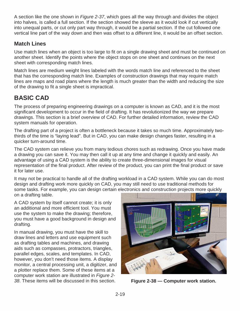
BASIC CADThe process of preparing engineering drawings on a computer is known as CAD, and it is the most significant development to occur in the field of drafting. It has revolutionized the way we prepare drawings. This section is a brief overview of CAD. For further detailed information, review the CAD system manuals for operation.The drafting part of a project is often a bottleneck because it takes so much time. Approximately two-thirds of the time is “laying lead”. But in CAD, you can make design changes faster, resulting in a quicker turn-around time.The CAD system can relieve you from many tedious chores such as redrawing. Once you have made a drawing you can save it. You may then call it up at any time and change it quickly and easily. An advantage of using a CAD system is the ability to create three-dimensional images for visual representation of the final product. After review of the product, you can print the final product or saveit for later use.It may not be practical to handle all of the drafting workload in a CAD system. While you can do mostdesign and drafting work more quickly on CAD, you may still need to use traditional methods for some tasks. For example, you can design certain electronics and construction projects more quickly on a drafting table.A CAD system by itself cannot create; it is onlyan additional and more efficient tool. You must use the system to make the drawing; therefore, you must have a good background in design and drafting.In manual drawing, you must have the skill todraw lines and letters and use equipment such as drafting tables and machines, and drawingaids such as compasses, protractors, triangles, parallel edges, scales, and templates. In CAD, however, you don’t need those items. A displaymonitor, a central processing unit, a digitizer, and a plotter replace them. Some of these items at a computer work station are illustrated in Figure 2-38. These items will be discussed in this section. Figure 2-38 — Computer work station.
2-19
Generating Drawings in CADA CAD computer contains a drafting program that is a set of detailed instructions for the computer. When you open the program, the monitor displays each function or instruction you must follow to make a drawing. The program includes templates that can get you started drawing quickly. When working in the program, you can create a customized template where settings, size, and units of measurement can be set and used for multiple projects.The CAD programs available to you contain all of the symbols used in mechanical, electrical, orarchitectural drawing. You will use the keyboard and/or mouse to call up the drafting symbols you need. Examples are characters, grid patterns, and types of lines. When you select the symbols you want on the monitor, you will order the computer to size, rotate, enlarge, or reduce them, and positionthem on the monitor to produce the image you want.The computer also serves as a filing system for any drawing symbols or completed drawings stored electronically. You can call up this information any time and copy it or revise it to produce a differentsymbol or drawing.In the following paragraphs, we will discuss theother parts of a CAD system; the digitizer, plotter, and printer.
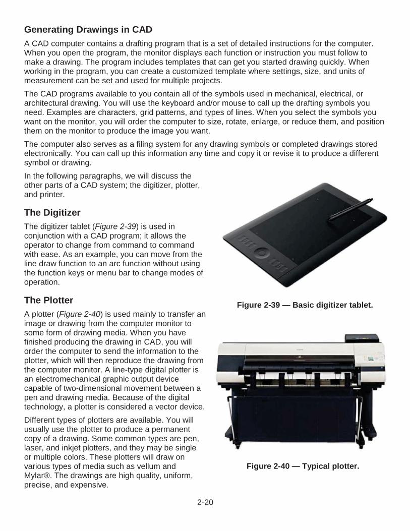
The DigitizerThe digitizer tablet (Figure 2-39) is used in conjunction with a CAD program; it allows the operator to change from command to command with ease. As an example, you can move from the line draw function to an arc function without using the function keys or menu bar to change modes of operation.
The PlotterA plotter (Figure 2-40) is used mainly to transfer animage or drawing from the computer monitor to some form of drawing media. When you have finished producing the drawing in CAD, you will order the computer to send the information to the plotter, which will then reproduce the drawing from the computer monitor. A line-type digital plotter is an electromechanical graphic output device capable of two-dimensional movement between a pen and drawing media. Because of the digital technology, a plotter is considered a vector device.Different types of plotters are available. You will usually use the plotter to produce a permanent copy of a drawing. Some common types are pen, laser, and inkjet plotters, and they may be single or multiple colors. These plotters will draw on various types of media such as vellum andMylar®. The drawings are high quality, uniform,precise, and expensive.
Figure 2-39 — Basic digitizer tablet.
Figure 2-40 — Typical plotter.
2-20
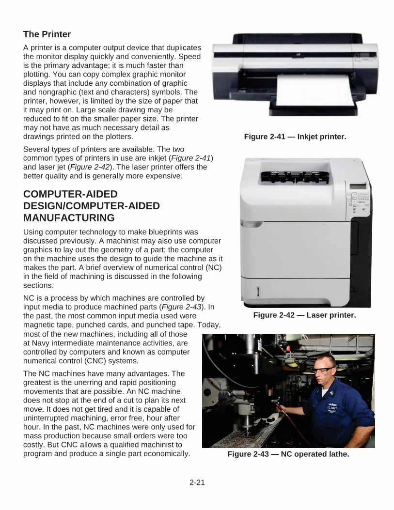
Figure 2-41 — Inkjet printer.
Figure 2-42 — Laser printer.
Figure 2-43 — NC operated lathe.
The PrinterA printer is a computer output device that duplicates the monitor display quickly and conveniently. Speed is the primary advantage; it is much faster than plotting. You can copy complex graphic monitordisplays that include any combination of graphic and nongraphic (text and characters) symbols. The printer, however, is limited by the size of paper that it may print on. Large scale drawing may be reduced to fit on the smaller paper size. The printer may not have as much necessary detail as drawings printed on the plotters.Several types of printers are available. The twocommon types of printers in use are inkjet (Figure 2-41)and laser jet (Figure 2-42). The laser printer offers the better quality and is generally more expensive.
COMPUTER-AIDEDDESIGN/COMPUTER-AIDEDMANUFACTURINGUsing computer technology to make blueprints was discussed previously. A machinist may also use computer graphics to lay out the geometry of a part; the computer on the machine uses the design to guide the machine as itmakes the part. A brief overview of numerical control (NC) in the field of machining is discussed in the following sections.NC is a process by which machines are controlled by input media to produce machined parts (Figure 2-43). In the past, the most common input media used weremagnetic tape, punched cards, and punched tape. Today, most of the new machines, including all of those at Navy intermediate maintenance activities, arecontrolled by computers and known as computernumerical control (CNC) systems.The NC machines have many advantages. The greatest is the unerring and rapid positioning movements that are possible. An NC machine does not stop at the end of a cut to plan its next move. It does not get tired and it is capable of uninterrupted machining, error free, hour after hour. In the past, NC machines were only used for mass production because small orders were toocostly. But CNC allows a qualified machinist toprogram and produce a single part economically.
2-21
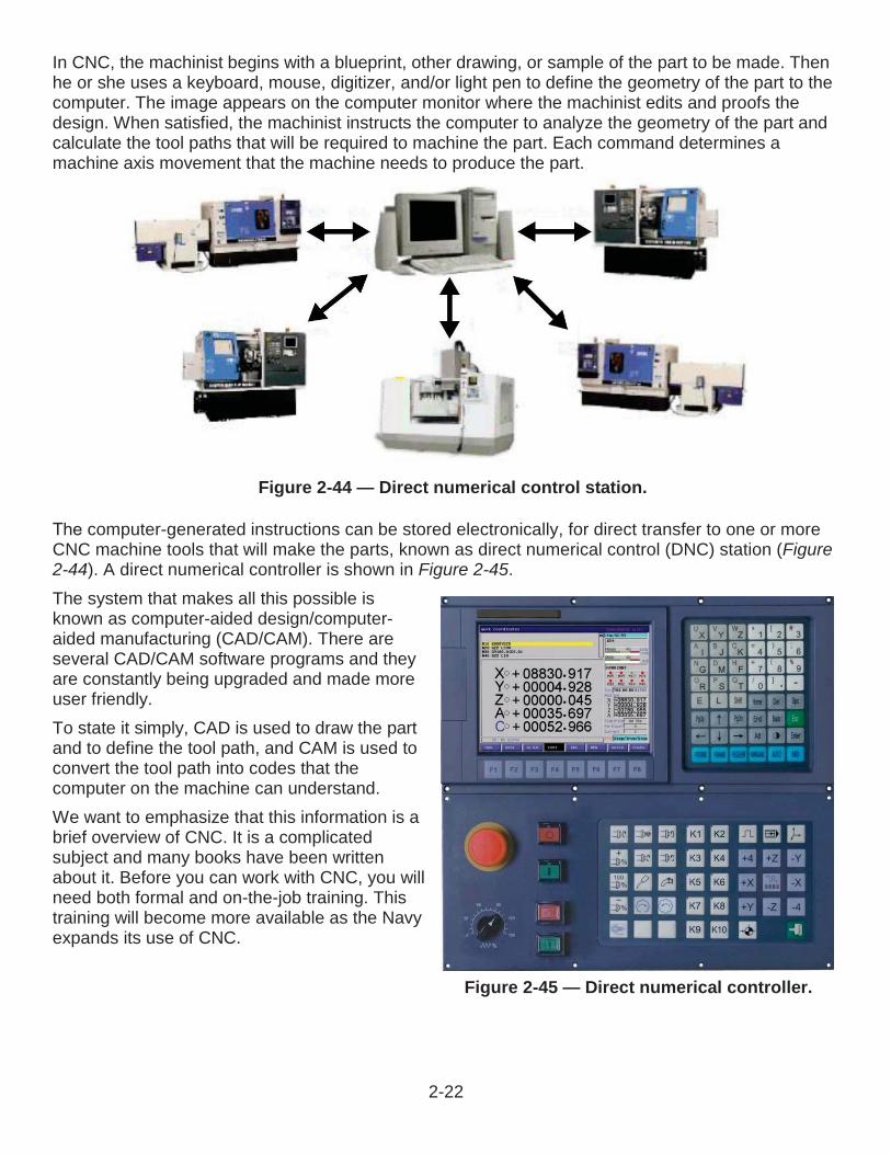
Figure 2-44 — Direct numerical control station.
Figure 2-45 — Direct numerical controller.
In CNC, the machinist begins with a blueprint, other drawing, or sample of the part to be made. Then he or she uses a keyboard, mouse, digitizer, and/or light pen to define the geometry of the part to the computer. The image appears on the computer monitor where the machinist edits and proofs the design. When satisfied, the machinist instructs the computer to analyze the geometry of the part and calculate the tool paths that will be required to machine the part. Each command determines a machine axis movement that the machine needs to produce the part.
computer-generated instructions can be stored electronically, for direct transfer to one or moreCNC machine tools that will make the parts, known as direct numerical control (DNC) station (Figure2-44). A direct numerical controller is shown in Figure 2-45.The system that makes all this possible is known as computer-aided design/computer-aided manufacturing (CAD/CAM). There are several CAD/CAM software programs and they are constantly being upgraded and made more user friendly.To state it simply, CAD is used to draw the partand to define the tool path, and CAM is used to convert the tool path into codes that the computer on the machine can understand.We want to emphasize that this information is a brief overview of CNC. It is a complicated subject and many books have been written about it. Before you can work with CNC, you will need both formal and on-the-job training. This training will become more available as the Navy expands its use of CNC.
2-22
End of Chapter 2
Technical SketchingReview Questions2-1. What two types of pencils are used in drafting?
A. Electric and mechanicalB. Electric and plasticC. Wooden and electricD. Wooden and mechanical
2-2. What three types of pencils do manufacturers market for use in engineering drawings?
A. Graphite, plastic, and plastic-graphiteB. Graphite, resin, and greaseC. Grease, carbon, and carbon-greaseD. Wax, grease, and wax-grease
2-3. What feature adds strength to the softer grades of lead?
A. DiameterB. Extra resinC. Heat treatmentD. Length of lead
2-4. What type of eraser is ideal for erasing lines drawn on tracing cloth and films?
A. Art gumB. VinylC. PlasticD. Kneaded
2-5. What type of eraser is ideal for erasing lines drawn in ink?
A. Art gumB. KneadedC. Ruby redD. Pink pearl
2-6. What type of pen is commonly used in technical sketching today?
A. Fine tip Sharpie penB. Medium ball pointC. Quill and inkD. Technical fountain pen
2-23
2-7. Some of the most common drawing aids are drafting tables with boards, triangles, and what other device?
A. CompassB. French bellC. ProtractorD. Spanish marker
2-8. The drafting table should be high enough for you to work in which of the following positions?
A. ProneB. StandingC. KneelingD. Squatting
2-9. Which of the following types of lighting is best for the working area?
A. NaturalB. FluorescentC. IncandescentD. Light emitting diodes
2-10. With which of the following degree ranges are protractors generally labeled?
A. 0 to 45B. 0 to 60C. 0 to 90D. 0 to 180
2-11. Which of the following drawing aids assist in drawing lines such as ellipses, parabolas, and spirals?
A. Adjustable triangleB. Circular protractorC. French curveD. Semicircle protractor
2-12. Circles and circular curves of relatively short radius are drawn with what drawing instrument?
A. CompassB. DividerC. Proportional dividerD. Protractor
2-13. Which of the following lines include the outline and defining edges of the view?
A. CenterB. VisibleC. DimensionD. Hidden
2-24
2-14. Which of the following lines extends the dimensions beyond the outline of the view?
A. BreakB. DimensionC. ExtensionD. Leader
2-15. Which of the following lines connects numbers, references, or notes to the appropriate surfaces or lines on the drawing?
A. BreakB. DimensionC. ExtensionD. Leader
2-16. Which of the following lines is used for the purpose of economizing paper space?
A. BreakB. DimensionC. ExtensionD. Leader
2-17. Which of the following lines is used to represent an object as if part of it was cut away?
A. DatumB. SectionC. MatchD. Phantom
2-18. What term describes the process of preparing engineering drawings on a computer?
A. Common-assistance draftingB. Common-assistance sketchingC. Computer-aided draftingD. Computer-assisted drawing
2-19. An advantage of using a computer-aided drafting system is creating what type of images?
A. AnimatedB. ColoredC. Three-dimensionalD. High-definition
2-20. What two types of printers are used in computer-aided design?
A. Dot matrix and laser jetB. Dot matrix and light emitting diodeC. Inkjet and dot matrixD. Inkjet and laser jet
2-25

2-21. What term describes the process by which machines are controlled by input media to produce machined parts?
A. Computer draftingB. Numerical controlC. Computer-aided designD. Dot matrix
2-26

RATE TRAINING MANUAL – User Update SWOS makes every effort to keep their manuals up-to-date and free of technical errors. We appreciate your help in this process. If you have an idea for improving this manual, or if you find an error, a typographical mistake, or an inaccuracy in SWOS manuals, please write or e-mail us, using this form or a photocopy. Be sure to include the exact chapter number, topic, detailed description, and correction, if applicable. Your input will be brought to the attention of the Technical Review Committee. Thank you for your assistance.Write: SWOS Project Manager
1534 Piersey Street Suite 321Norfolk, VA 23511-2613COMM: (757) 444-5332DSN: 564-5332
E-mail: Refer to the SWOS Norfolk page on the NKO Web page for current contact information.
Rate____ Course Name_____________________________________________
Revision Date__________ Chapter Number____ Page Number(s)____________
Description_____________________________________________________________________________________________________________________________________________________________________________________________
(Optional) Correction_____________________________________________________________________________________________________________________________________________________________________________________________
(Optional) Your Name and Address_____________________________________________________________________________________________________________________________________________________________________________________________
2-27
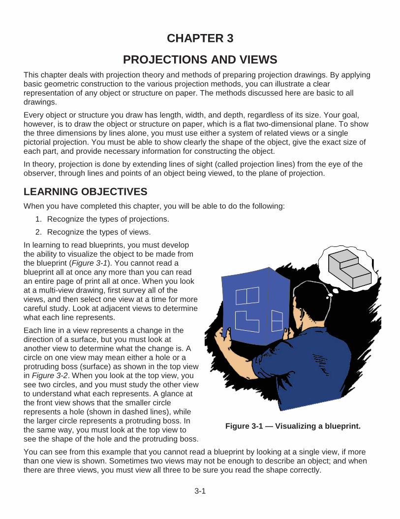
3-1
CHAPTER 3
PROJECTIONS AND VIEWSThis chapter deals with projection theory and methods of preparing projection drawings. By applying basic geometric construction to the various projection methods, you can illustrate a clear representation of any object or structure on paper. The methods discussed here are basic to all drawings.Every object or structure you draw has length, width, and depth, regardless of its size. Your goal, however, is to draw the object or structure on paper, which is a flat two-dimensional plane. To show the three dimensions by lines alone, you must use either a system of related views or a single pictorial projection. You must be able to show clearly the shape of the object, give the exact size of each part, and provide necessary information for constructing the object.In theory, projection is done by extending lines of sight (called projection lines) from the eye of the observer, through lines and points of an object being viewed, to the plane of projection.
LEARNING OBJECTIVESWhen you have completed this chapter, you will be able to do the following:
1. Recognize the types of projections.2. Recognize the types of views.
In learning to read blueprints, you must developthe ability to visualize the object to be made from the blueprint (Figure 3-1). You cannot read a blueprint all at once any more than you can read an entire page of print all at once. When you look at a multi-view drawing, first survey all of the views, and then select one view at a time for more careful study. Look at adjacent views to determine what each line represents.Each line in a view represents a change in thedirection of a surface, but you must look at another view to determine what the change is. A circle on one view may mean either a hole or a protruding boss (surface) as shown in the top view in Figure 3-2. When you look at the top view, you see two circles, and you must study the other view to understand what each represents. A glance at the front view shows that the smaller circle represents a hole (shown in dashed lines), while the larger circle represents a protruding boss. In the same way, you must look at the top view to see the shape of the hole and the protruding boss.You can see from this example that you cannot read a blueprint by looking at a single view, if morethan one view is shown. Sometimes two views may not be enough to describe an object; and when there are three views, you must view all three to be sure you read the shape correctly.
Figure 3-1 — Visualizing a blueprint.
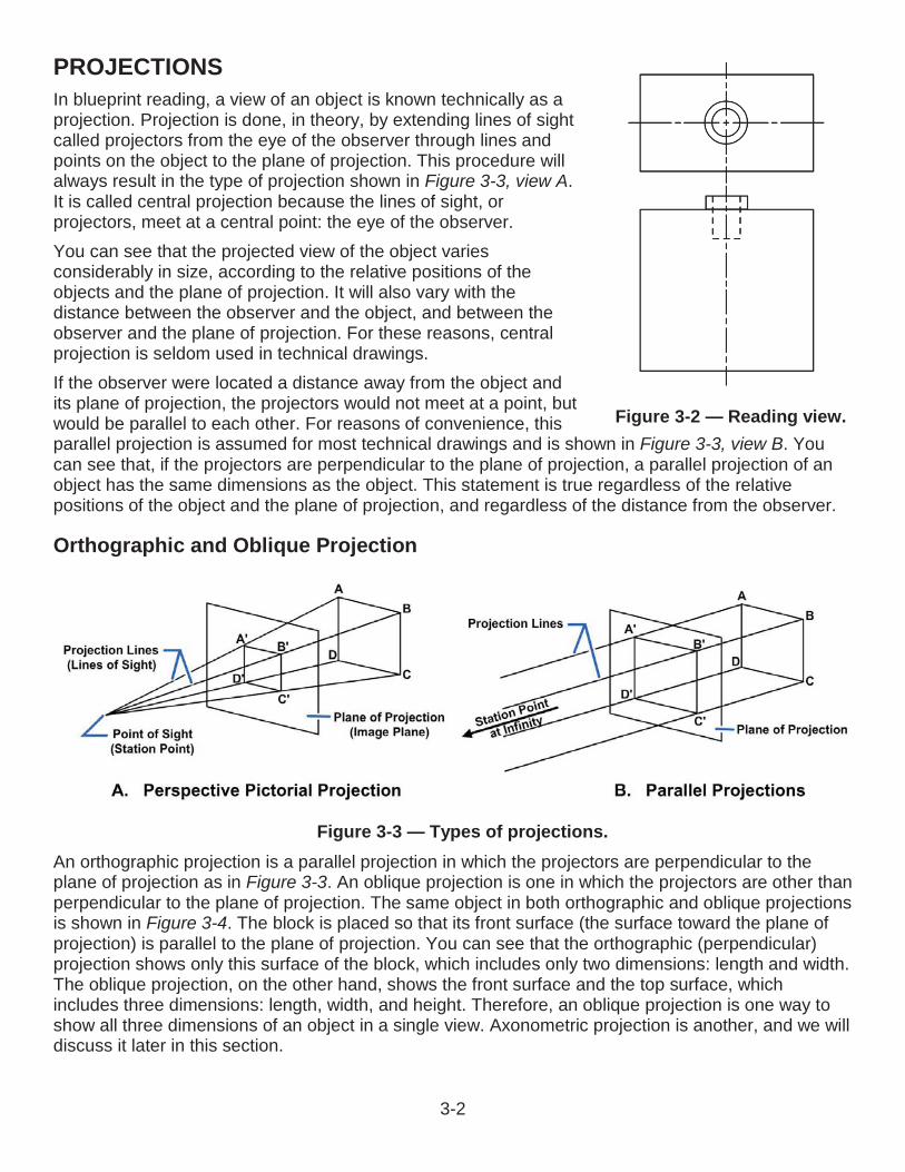
3-2
Figure 3-3 — Types of projections.
PROJECTIONS In blueprint reading, a view of an object is known technically as a projection. Projection is done, in theory, by extending lines of sight called projectors from the eye of the observer through lines and points on the object to the plane of projection. This procedure will always result in the type of projection shown in Figure 3-3, view A.It is called central projection because the lines of sight, or projectors, meet at a central point: the eye of the observer.You can see that the projected view of the object varies considerably in size, according to the relative positions of the objects and the plane of projection. It will also vary with the distance between the observer and the object, and between the observer and the plane of projection. For these reasons, central projection is seldom used in technical drawings.If the observer were located a distance away from the object and its plane of projection, the projectors would not meet at a point, but would be parallel to each other. For reasons of convenience, this parallel projection is assumed for most technical drawings and is shown in Figure 3-3, view B. You can see that, if the projectors are perpendicular to the plane of projection, a parallel projection of an object has the same dimensions as the object. This statement is true regardless of the relative positions of the object and the plane of projection, and regardless of the distance from the observer.
Orthographic and Oblique Projection
An orthographic projection is a parallel projection in which the projectors are perpendicular to the plane of projection as in Figure 3-3. An oblique projection is one in which the projectors are other thanperpendicular to the plane of projection. The same object in both orthographic and oblique projectionsis shown in Figure 3-4. The block is placed so that its front surface (the surface toward the plane ofprojection) is parallel to the plane of projection. You can see that the orthographic (perpendicular)projection shows only this surface of the block, which includes only two dimensions: length and width. The oblique projection, on the other hand, shows the front surface and the top surface, which includes three dimensions: length, width, and height. Therefore, an oblique projection is one way to show all three dimensions of an object in a single view. Axonometric projection is another, and we will discuss it later in this section.
Figure 3-2 — Reading view.
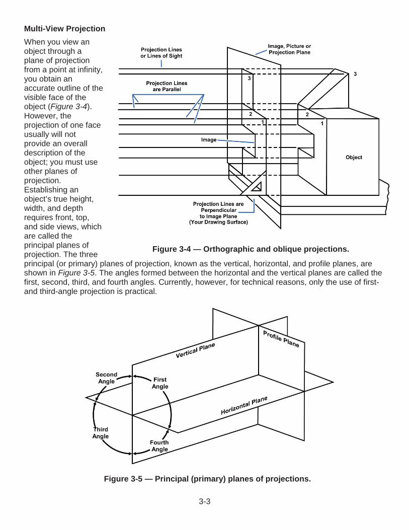
3-3
Multi-View ProjectionWhen you view an object through a plane of projection from a point at infinity, you obtain an accurate outline of the visible face of the object (Figure 3-4). However, the projection of one face usually will not provide an overall description of the object; you must use other planes of projection. Establishing an object’s true height, width, and depth requires front, top, and side views, which are called the principal planes of projection. The three principal (or primary) planes of projection, known as the vertical, horizontal, and profile planes, are shown in Figure 3-5. The angles formed between the horizontal and the vertical planes are called the first, second, third, and fourth angles. Currently, however, for technical reasons, only the use of first-and third-angle projection is practical.
Figure 3-4 — Orthographic and oblique projections.
Figure 3-5 — Principal (primary) planes of projections.

3-4
First-Angle ProjectionAn example of first-angle projection using a cube is illustrated in Figure 3-6. The front of the cube is facing toward the vertical plane of projection. As you can see, you get a front view on the vertical plane, a left side view on the profile plane, and a top view on the horizontal plane.Now, to put these views on a sheet of drafting paper, you must put them all into the same plane. Presume that the vertical plane of projection is already in the plane of the paper. To get the other two views into the same plane, rotate the profile plane counterclockwise and the horizontal plane clockwise. The projection now appears as shown in Figure 3-7.In common European drafting practice, this first-angle projection arrangement of views is considered satisfactory. In the United States, it is considered illogical because the top view is below the front view; because the right side of the object, as shown in the front view, is toward the left side view of the object; and because the bottom of the object, as shown in the front view, is toward the top view of the object. For these and other reasons, first-angle projection is not commonly used in the United States.
Third-Angle ProjectionIn a third-angle projection of a cube (Figure 3-8), you get a front view on the vertical plane, a right side view on the profile plane, and a top view on the horizontal plane.The first view, the vertical plane, is already in the plane of your drawing paper. To get the other two views onto the same plane, rotate them both clockwise. A third-angle projection of an object brought into a single plane is shown in Figure 3-9. The top view is above the front view; the right side of the object, as shown in the front view, is toward the right side view; and the top, as shown in the front view, is toward the top view.The following sentences describe the basic procedures of the method used to make the third-angle projection shown in Figure 3-9. Draw a horizontal line AB and a vertical line CD, intersecting at O (Figure 3-10). AB represents the joint between the
Figure 3-6 — First-angle projections.
Figure 3-7 — First-angle projection brought into a single pane.
Figure 3-8 — Example of a third-angle projection.
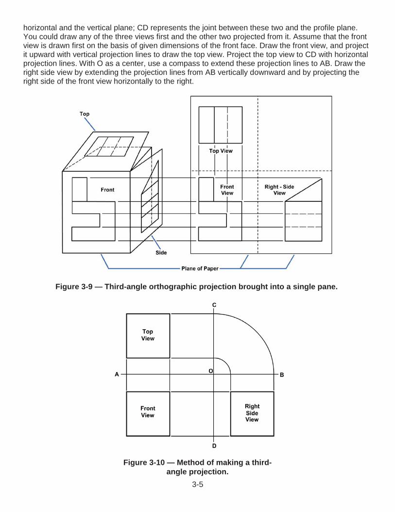
3-5
horizontal and the vertical plane; CD represents the joint between these two and the profile plane. You could draw any of the three views first and the other two projected from it. Assume that the front view is drawn first on the basis of given dimensions of the front face. Draw the front view, and project it upward with vertical projection lines to draw the top view. Project the top view to CD with horizontal projection lines. With O as a center, use a compass to extend these projection lines to AB. Draw the right side view by extending the projection lines from AB vertically downward and by projecting the right side of the front view horizontally to the right.
Figure 3-10 — Method of making a third-angle projection.
Figure 3-9 — Third-angle orthographic projection brought into a single pane.
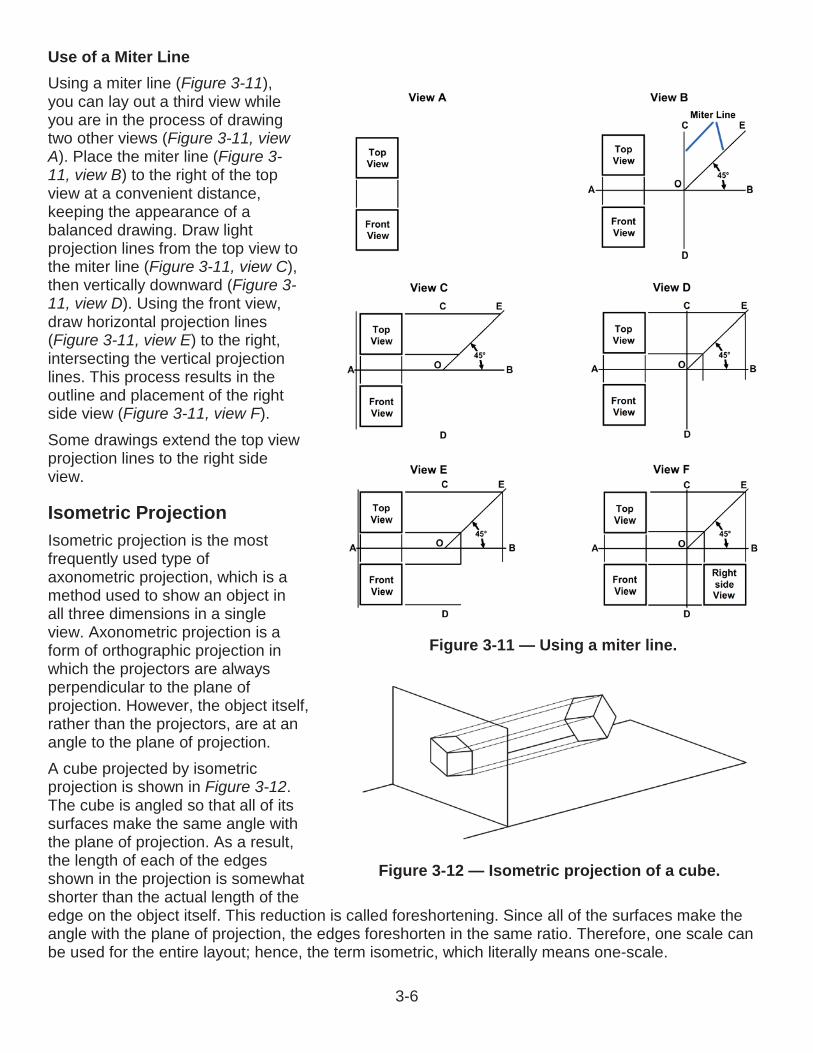
3-6
Use of a Miter LineUsing a miter line (Figure 3-11), you can lay out a third view while you are in the process of drawing two other views (Figure 3-11, view A). Place the miter line (Figure 3-11, view B) to the right of the top view at a convenient distance, keeping the appearance of a balanced drawing. Draw light projection lines from the top view to the miter line (Figure 3-11, view C), then vertically downward (Figure 3-11, view D). Using the front view,draw horizontal projection lines (Figure 3-11, view E) to the right, intersecting the vertical projection lines. This process results in the outline and placement of the right side view (Figure 3-11, view F).Some drawings extend the top view projection lines to the right side view.
Isometric ProjectionIsometric projection is the most frequently used type of axonometric projection, which is a method used to show an object in all three dimensions in a single view. Axonometric projection is a form of orthographic projection in which the projectors are always perpendicular to the plane of projection. However, the object itself, rather than the projectors, are at an angle to the plane of projection.A cube projected by isometricprojection is shown in Figure 3-12.The cube is angled so that all of its surfaces make the same angle with the plane of projection. As a result, the length of each of the edges shown in the projection is somewhat shorter than the actual length of the edge on the object itself. This reduction is called foreshortening. Since all of the surfaces make the angle with the plane of projection, the edges foreshorten in the same ratio. Therefore, one scale can be used for the entire layout; hence, the term isometric, which literally means one-scale.
Figure 3-12 — Isometric projection of a cube.
Figure 3-11 — Using a miter line.
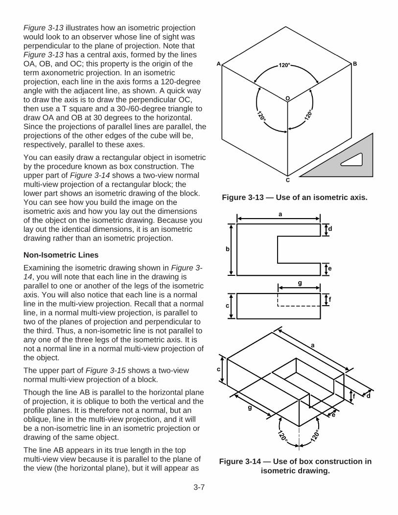
3-7
Figure 3-13 illustrates how an isometric projection would look to an observer whose line of sight was perpendicular to the plane of projection. Note that Figure 3-13 has a central axis, formed by the lines OA, OB, and OC; this property is the origin of the term axonometric projection. In an isometric projection, each line in the axis forms a 120-degreeangle with the adjacent line, as shown. A quick way to draw the axis is to draw the perpendicular OC, then use a T square and a 30-/60-degree triangle to draw OA and OB at 30 degrees to the horizontal. Since the projections of parallel lines are parallel, the projections of the other edges of the cube will be, respectively, parallel to these axes.You can easily draw a rectangular object in isometric by the procedure known as box construction. The upper part of Figure 3-14 shows a two-view normal multi-view projection of a rectangular block; the lower part shows an isometric drawing of the block. You can see how you build the image on the isometric axis and how you lay out the dimensions of the object on the isometric drawing. Because you lay out the identical dimensions, it is an isometric drawing rather than an isometric projection.
Non-Isometric LinesExamining the isometric drawing shown in Figure 3-14, you will note that each line in the drawing is parallel to one or another of the legs of the isometric axis. You will also notice that each line is a normal line in the multi-view projection. Recall that a normal line, in a normal multi-view projection, is parallel to two of the planes of projection and perpendicular to the third. Thus, a non-isometric line is not parallel to any one of the three legs of the isometric axis. It is not a normal line in a normal multi-view projection of the object.The upper part of Figure 3-15 shows a two-view normal multi-view projection of a block.Though the line AB is parallel to the horizontal plane of projection, it is oblique to both the vertical and the profile planes. It is therefore not a normal, but an oblique, line in the multi-view projection, and it will be a non-isometric line in an isometric projection or drawing of the same object.The line AB appears in its true length in the top multi-view view because it is parallel to the plane of the view (the horizontal plane), but it will appear as
Figure 3-13 — Use of an isometric axis.
Figure 3-14 — Use of box construction in isometric drawing.
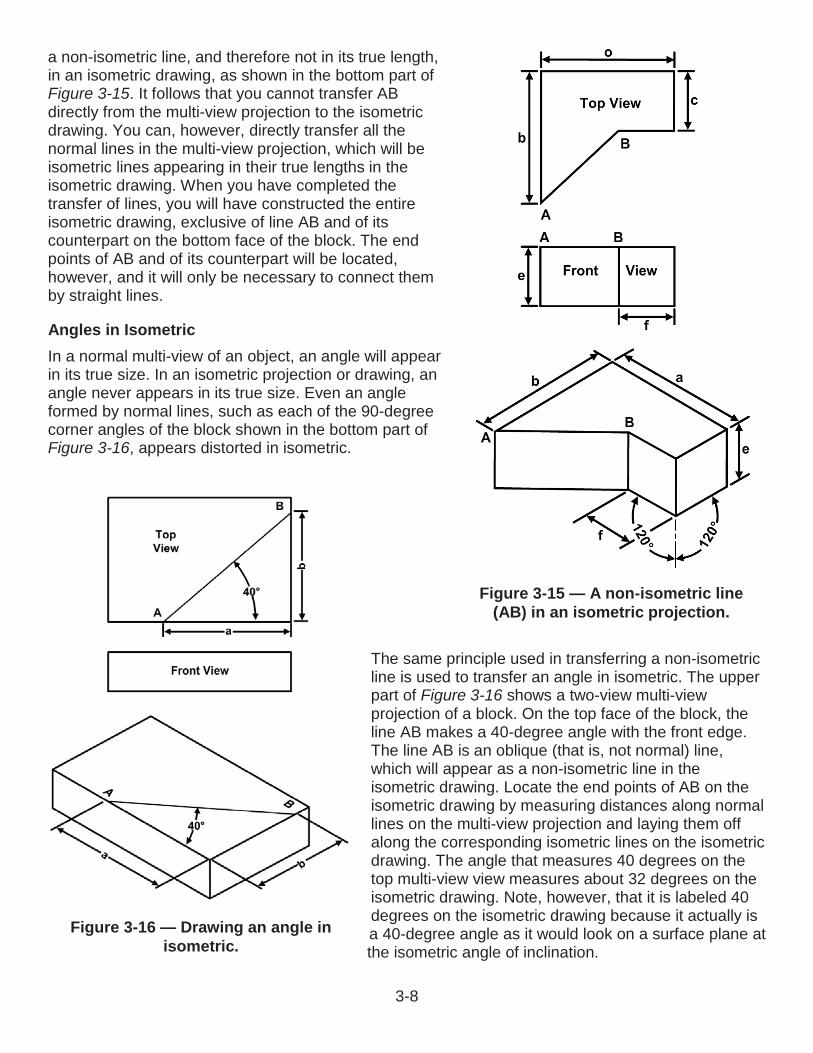
3-8
Figure 3-16 — Drawing an angle in isometric.
a non-isometric line, and therefore not in its true length, in an isometric drawing, as shown in the bottom part of Figure 3-15. It follows that you cannot transfer AB directly from the multi-view projection to the isometric drawing. You can, however, directly transfer all the normal lines in the multi-view projection, which will beisometric lines appearing in their true lengths in theisometric drawing. When you have completed the transfer of lines, you will have constructed the entireisometric drawing, exclusive of line AB and of its counterpart on the bottom face of the block. The end points of AB and of its counterpart will be located, however, and it will only be necessary to connect them by straight lines.
Angles in IsometricIn a normal multi-view of an object, an angle will appear in its true size. In an isometric projection or drawing, an angle never appears in its true size. Even an angle formed by normal lines, such as each of the 90-degreecorner angles of the block shown in the bottom part of Figure 3-16, appears distorted in isometric.
The same principle used in transferring a non-isometric line is used to transfer an angle in isometric. The upper part of Figure 3-16 shows a two-view multi-view projection of a block. On the top face of the block, the line AB makes a 40-degree angle with the front edge. The line AB is an oblique (that is, not normal) line, which will appear as a non-isometric line in the isometric drawing. Locate the end points of AB on the isometric drawing by measuring distances along normal lines on the multi-view projection and laying them off along the corresponding isometric lines on the isometric drawing. The angle that measures 40 degrees on the top multi-view view measures about 32 degrees on the isometric drawing. Note, however, that it is labeled 40 degrees on the isometric drawing because it actually is a 40-degree angle as it would look on a surface plane at the isometric angle of inclination.
Figure 3-15 — A non-isometric line (AB) in an isometric projection.
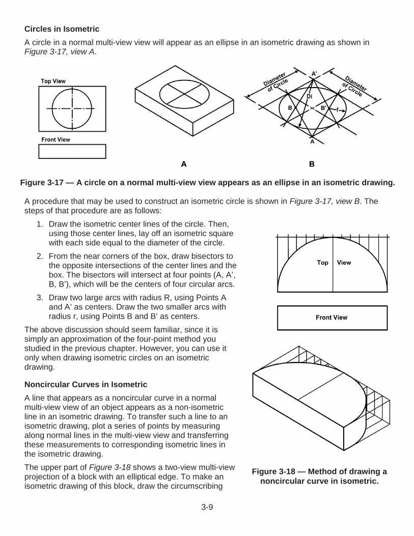
3-9
Figure 3-17 — A circle on a normal multi-view view appears as an ellipse in an isometric drawing.
Circles in IsometricA circle in a normal multi-view view will appear as an ellipse in an isometric drawing as shown in Figure 3-17, view A.
A procedure that may be used to construct an isometric circle is shown in Figure 3-17, view B. The steps of that procedure are as follows:
1. Draw the isometric center lines of the circle. Then, using those center lines, lay off an isometric square with each side equal to the diameter of the circle.
2. From the near corners of the box, draw bisectors to the opposite intersections of the center lines and the box. The bisectors will intersect at four points (A, A’, B, B’), which will be the centers of four circular arcs.
3. Draw two large arcs with radius R, using Points A and A’ as centers. Draw the two smaller arcs with radius r, using Points B and B’ as centers.
The above discussion should seem familiar, since it is simply an approximation of the four-point method you studied in the previous chapter. However, you can use it only when drawing isometric circles on an isometric drawing.
Noncircular Curves in IsometricA line that appears as a noncircular curve in a normal multi-view view of an object appears as a non-isometric line in an isometric drawing. To transfer such a line to an isometric drawing, plot a series of points by measuring along normal lines in the multi-view view and transferring these measurements to corresponding isometric lines in the isometric drawing.The upper part of Figure 3-18 shows a two-view multi-viewprojection of a block with an elliptical edge. To make an isometric drawing of this block, draw the circumscribing
Figure 3-18 — Method of drawing a noncircular curve in isometric.
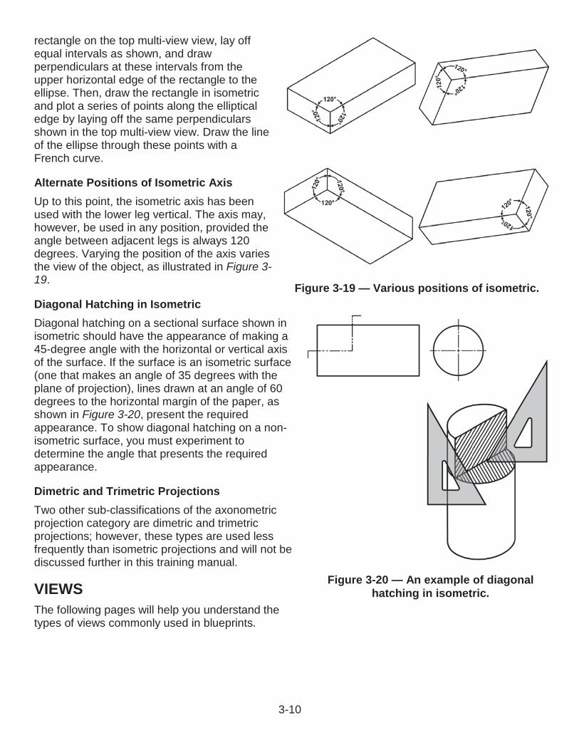
3-10
rectangle on the top multi-view view, lay off equal intervals as shown, and draw perpendiculars at these intervals from the upper horizontal edge of the rectangle to the ellipse. Then, draw the rectangle in isometric and plot a series of points along the elliptical edge by laying off the same perpendiculars shown in the top multi-view view. Draw the line of the ellipse through these points with a French curve.
Alternate Positions of Isometric AxisUp to this point, the isometric axis has been used with the lower leg vertical. The axis may, however, be used in any position, provided the angle between adjacent legs is always 120 degrees. Varying the position of the axis varies the view of the object, as illustrated in Figure 3-19.
Diagonal Hatching in IsometricDiagonal hatching on a sectional surface shown in isometric should have the appearance of making a 45-degree angle with the horizontal or vertical axis of the surface. If the surface is an isometric surface (one that makes an angle of 35 degrees with the plane of projection), lines drawn at an angle of 60 degrees to the horizontal margin of the paper, as shown in Figure 3-20, present the required appearance. To show diagonal hatching on a non-isometric surface, you must experiment to determine the angle that presents the requiredappearance.
Dimetric and Trimetric ProjectionsTwo other sub-classifications of the axonometric projection category are dimetric and trimetric projections; however, these types are used less frequently than isometric projections and will not be discussed further in this training manual.
VIEWSThe following pages will help you understand thetypes of views commonly used in blueprints.
Figure 3-19 — Various positions of isometric.
Figure 3-20 — An example of diagonal hatching in isometric.
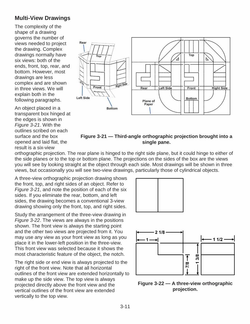
3-11
Multi-View DrawingsThe complexity of the shape of a drawing governs the number of views needed to project the drawing. Complex drawings normally have six views: both of theends, front, top, rear, and bottom. However, mostdrawings are less complex and are shown in three views. We will explain both in the following paragraphs.An object placed in a transparent box hinged at the edges is shown in Figure 3-21. With the outlines scribed on each surface and the box opened and laid flat, the result is a six-view orthographic projection. The rear plane is hinged to the right side plane, but it could hinge to either of the side planes or to the top or bottom plane. The projections on the sides of the box are the views you will see by looking straight at the object through each side. Most drawings will be shown in three views, but occasionally you will see two-view drawings, particularly those of cylindrical objects.A three-view orthographic projection drawing shows the front, top, and right sides of an object. Refer to Figure 3-21, and note the position of each of the six sides. If you eliminate the rear, bottom, and leftsides, the drawing becomes a conventional 3-viewdrawing showing only the front, top, and right sides.Study the arrangement of the three-view drawing in Figure 3-22. The views are always in the positionsshown. The front view is always the starting point and the other two views are projected from it. You may use any view as your front view as long as you place it in the lower-left position in the three-view. This front view was selected because it shows the most characteristic feature of the object, the notch.The right side or end view is always projected to the right of the front view. Note that all horizontaloutlines of the front view are extended horizontally tomake up the side view. The top view is alwaysprojected directly above the front view and the vertical outlines of the front view are extended vertically to the top view.
Figure 3-21 — Third-angle orthographic projection brought into a single pane.
Figure 3-22 — A three-view orthographic projection.
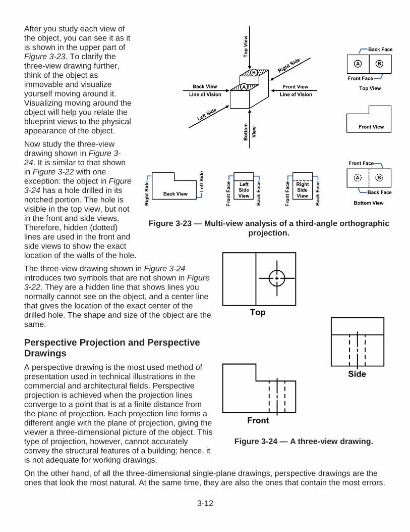
3-12
Figure 3-24 — A three-view drawing.
After you study each view of the object, you can see it as it is shown in the upper part of Figure 3-23. To clarify the three-view drawing further, think of the object as immovable and visualize yourself moving around it. Visualizing moving around the object will help you relate theblueprint views to the physical appearance of the object.Now study the three-view drawing shown in Figure 3-24. It is similar to that shown in Figure 3-22 with one exception: the object in Figure 3-24 has a hole drilled in its notched portion. The hole is visible in the top view, but not in the front and side views.Therefore, hidden (dotted) lines are used in the front and side views to show the exact location of the walls of the hole.The three-view drawing shown in Figure 3-24introduces two symbols that are not shown in Figure3-22. They are a hidden line that shows lines you normally cannot see on the object, and a center line that gives the location of the exact center of the drilled hole. The shape and size of the object are the same.
Perspective Projection and Perspective DrawingsA perspective drawing is the most used method of presentation used in technical illustrations in the commercial and architectural fields. Perspective projection is achieved when the projection lines converge to a point that is at a finite distance from the plane of projection. Each projection line forms a different angle with the plane of projection, giving the viewer a three-dimensional picture of the object. This type of projection, however, cannot accurately convey the structural features of a building; hence, it is not adequate for working drawings.On the other hand, of all the three-dimensional single-plane drawings, perspective drawings are the ones that look the most natural. At the same time, they are also the ones that contain the most errors.
Figure 3-23 — Multi-view analysis of a third-angle orthographic projection.

3-13
Lines that have the same length on the object have different lengths on the drawing. No single line or angle on the drawing has a length or size that has any known relationship to its true length or size when projected through perspective projections.Perspective drawing (Figure 3-25) is used only in drawings of an illustrative nature, in which an object is deliberately made to appear the way it looks to the human eye. Most of the drawings you prepare will be drawings in which accuracy, rather than eye appearance, is the chief consideration. Consequently, you will not be concerned much with perspective drawing.
Special ViewsIn many complex objects it is often difficult to show true size and shapes orthographically. Therefore, other views provide engineers and craftsmen with a clear picture of the object to be constructed. Among these are a number of special views, some of which we will discuss in the following paragraphs.
Auxiliary ViewsIn theory, there are only three regular planes of projection: the vertical, the horizontal, and the profile. Actually, presume that each of these views is doubled; there is, for example, one vertical plane for a front view and another for a back view.Assume, then, a total of six regular planes of projection. A projection on any one of the six is a regular view. A projection NOT on one of the regular six is an auxiliary view.The basic rule of dimensioning requires that you dimension a line only in the view in which its true length is projected and that you dimension a plane with its details only in the view in which its true shape is represented. To satisfy this rule, create an imaginary plane that is parallel with the line or surface we want to project in its true shape. A plane of this kind that is not one of the regular planes is called an auxiliary plane.In the upper left of Figure 3-26,the base of the single-view projection of a triangular block
Figure 3-25 — A perspective drawing.
Figure 3-26 — A line oblique to all planes of projection is foreshortened in all views.
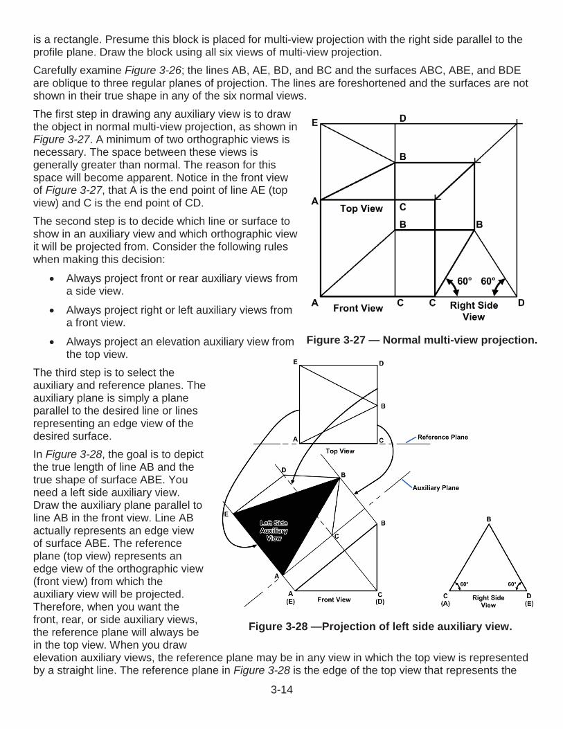
3-14
is a rectangle. Presume this block is placed for multi-view projection with the right side parallel to the profile plane. Draw the block using all six views of multi-view projection.Carefully examine Figure 3-26; the lines AB, AE, BD, and BC and the surfaces ABC, ABE, and BDE are oblique to three regular planes of projection. The lines are foreshortened and the surfaces are not shown in their true shape in any of the six normal views.The first step in drawing any auxiliary view is to draw the object in normal multi-view projection, as shown in Figure 3-27. A minimum of two orthographic views is necessary. The space between these views is generally greater than normal. The reason for thisspace will become apparent. Notice in the front view of Figure 3-27, that A is the end point of line AE (top view) and C is the end point of CD.The second step is to decide which line or surface to show in an auxiliary view and which orthographic view it will be projected from. Consider the following ruleswhen making this decision:
Always project front or rear auxiliary views from a side view.
Always project right or left auxiliary views from a front view.
Always project an elevation auxiliary view from the top view.
The third step is to select the auxiliary and reference planes. The auxiliary plane is simply a plane parallel to the desired line or lines representing an edge view of the desired surface.In Figure 3-28, the goal is to depict the true length of line AB and the true shape of surface ABE. You need a left side auxiliary view. Draw the auxiliary plane parallel to line AB in the front view. Line AB actually represents an edge view of surface ABE. The reference plane (top view) represents an edge view of the orthographic view (front view) from which the auxiliary view will be projected. Therefore, when you want the front, rear, or side auxiliary views, the reference plane will always be in the top view. When you draw elevation auxiliary views, the reference plane may be in any view in which the top view is represented by a straight line. The reference plane in Figure 3-28 is the edge of the top view that represents the
Figure 3-27 — Normal multi-view projection.
Figure 3-28 —Projection of left side auxiliary view.
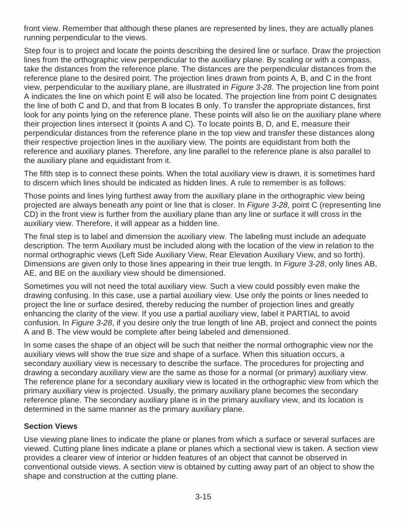
3-15
front view. Remember that although these planes are represented by lines, they are actually planes running perpendicular to the views.Step four is to project and locate the points describing the desired line or surface. Draw the projection lines from the orthographic view perpendicular to the auxiliary plane. By scaling or with a compass, take the distances from the reference plane. The distances are the perpendicular distances from the reference plane to the desired point. The projection lines drawn from points A, B, and C in the front view, perpendicular to the auxiliary plane, are illustrated in Figure 3-28. The projection line from point A indicates the line on which point E will also be located. The projection line from point C designates the line of both C and D, and that from B locates B only. To transfer the appropriate distances, first look for any points lying on the reference plane. These points will also lie on the auxiliary plane where their projection lines intersect it (points A and C). To locate points B, D, and E, measure their perpendicular distances from the reference plane in the top view and transfer these distances along their respective projection lines in the auxiliary view. The points are equidistant from both the reference and auxiliary planes. Therefore, any line parallel to the reference plane is also parallel to the auxiliary plane and equidistant from it.The fifth step is to connect these points. When the total auxiliary view is drawn, it is sometimes hard to discern which lines should be indicated as hidden lines. A rule to remember is as follows:Those points and lines lying furthest away from the auxiliary plane in the orthographic view beingprojected are always beneath any point or line that is closer. In Figure 3-28, point C (representing line CD) in the front view is further from the auxiliary plane than any line or surface it will cross in the auxiliary view. Therefore, it will appear as a hidden line.The final step is to label and dimension the auxiliary view. The labeling must include an adequate description. The term Auxiliary must be included along with the location of the view in relation to the normal orthographic views (Left Side Auxiliary View, Rear Elevation Auxiliary View, and so forth). Dimensions are given only to those lines appearing in their true length. In Figure 3-28, only lines AB, AE, and BE on the auxiliary view should be dimensioned.Sometimes you will not need the total auxiliary view. Such a view could possibly even make the drawing confusing. In this case, use a partial auxiliary view. Use only the points or lines needed to project the line or surface desired, thereby reducing the number of projection lines and greatly enhancing the clarity of the view. If you use a partial auxiliary view, label it PARTIAL to avoid confusion. In Figure 3-28, if you desire only the true length of line AB, project and connect the points A and B. The view would be complete after being labeled and dimensioned.In some cases the shape of an object will be such that neither the normal orthographic view nor the auxiliary views will show the true size and shape of a surface. When this situation occurs, a secondary auxiliary view is necessary to describe the surface. The procedures for projecting and drawing a secondary auxiliary view are the same as those for a normal (or primary) auxiliary view. The reference plane for a secondary auxiliary view is located in the orthographic view from which the primary auxiliary view is projected. Usually, the primary auxiliary plane becomes the secondary reference plane. The secondary auxiliary plane is in the primary auxiliary view, and its location is determined in the same manner as the primary auxiliary plane.
Section ViewsUse viewing plane lines to indicate the plane or planes from which a surface or several surfaces are viewed. Cutting plane lines indicate a plane or planes which a sectional view is taken. A section view provides a clearer view of interior or hidden features of an object that cannot be observed in conventional outside views. A section view is obtained by cutting away part of an object to show the shape and construction at the cutting plane.
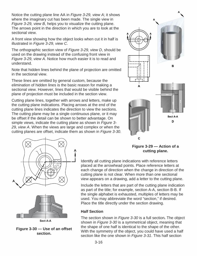
3-16
Figure 3-29 — Action of a cutting plane.
Notice the cutting plane line AA in Figure 3-29, view A; it shows where the imaginary cut has been made. The single view in Figure 3-29, view B, helps you to visualize the cutting plane. The arrows point in the direction in which you are to look at the sectional view.A front view showing how the object looks when cut it in half is illustrated in Figure 3-29, view C.The orthographic section view of Figure 3-29, view D, should be used on the drawing instead of the confusing front view in Figure 3-29, view A. Notice how much easier it is to read and understand.Note that hidden lines behind the plane of projection are omitted in the sectional view.These lines are omitted by general custom, because the elimination of hidden lines is the basic reason for making a sectional view. However, lines that would be visible behind the plane of projection must be included in the section view.Cutting plane lines, together with arrows and letters, make up the cutting plane indications. Placing arrows at the end of the cutting plane lines indicates the direction to view the sections. The cutting plane may be a single continuous plane, or it may be offset if the detail can be shown to better advantage. On simple views, indicate the cutting plane as shown in Figure 3-29, view A. When the views are large and complex or when the cutting planes are offset, indicate them as shown in Figure 3-30.
Identify all cutting plane indications with reference letters placed at the arrowhead points. Place reference letters at each change of direction when the change in direction of the cutting plane is not clear. When more than one sectional view appears on a drawing, add a letter to the cutting plane.Include the letters that are part of the cutting plane indication as part of the title; for example, section A-A, section B-B. If the single alphabet is exhausted, multiples of letters may be used. You may abbreviate the word “section,” if desired. Place the title directly under the section drawing.
Half SectionThe section shown in Figure 3-30 is a full section. The object shown in Figure 3-30 is a symmetrical object, meaning that the shape of one half is identical to the shape of the other. With the symmetry of the object, you could have used a half section like the one shown in Figure 3-31. This half section
Figure 3-30 — Use of an offset section.
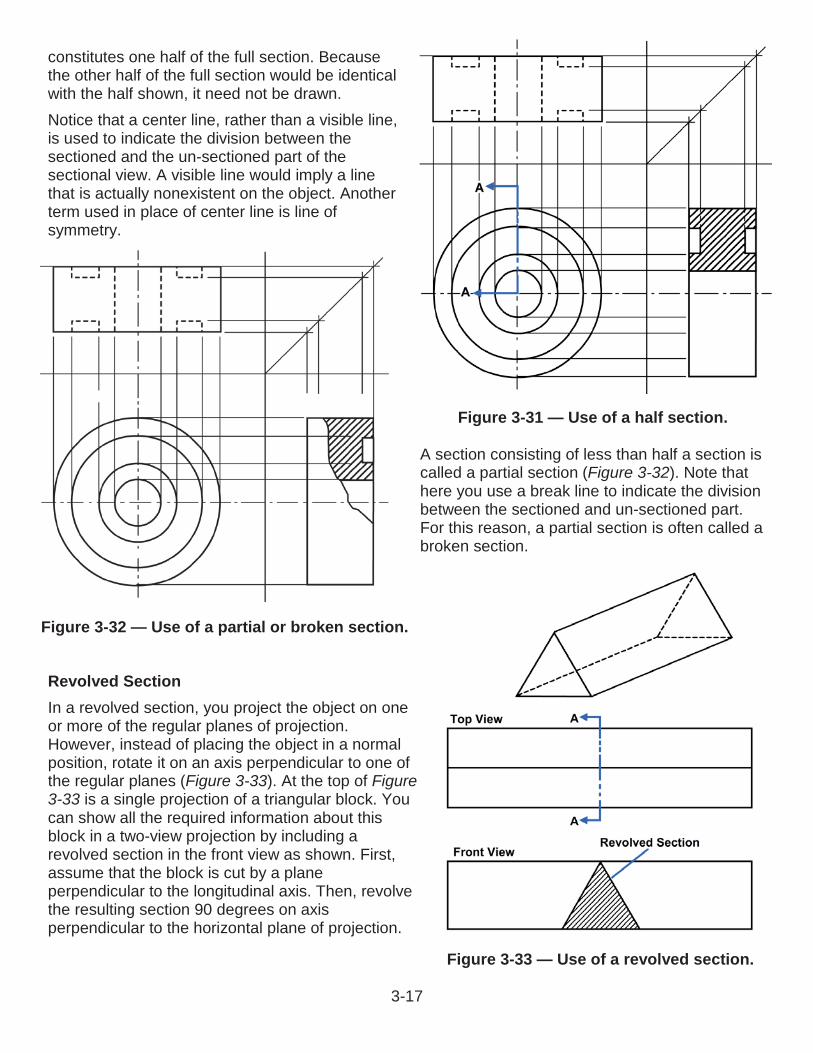
3-17
constitutes one half of the full section. Because the other half of the full section would be identical with the half shown, it need not be drawn. Notice that a center line, rather than a visible line, is used to indicate the division between the sectioned and the un-sectioned part of the sectional view. A visible line would imply a line that is actually nonexistent on the object. Another term used in place of center line is line of symmetry.
A section consisting of less than half a section is called a partial section (Figure 3-32). Note that here you use a break line to indicate the division between the sectioned and un-sectioned part.For this reason, a partial section is often called a broken section.
Revolved SectionIn a revolved section, you project the object on one or more of the regular planes of projection. However, instead of placing the object in a normal position, rotate it on an axis perpendicular to one of the regular planes (Figure 3-33). At the top of Figure3-33 is a single projection of a triangular block. You can show all the required information about this block in a two-view projection by including a revolved section in the front view as shown. First, assume that the block is cut by a plane perpendicular to the longitudinal axis. Then, revolve the resulting section 90 degrees on axis perpendicular to the horizontal plane of projection.
Figure 3-31 — Use of a half section.
Figure 3-32 — Use of a partial or broken section.
Figure 3-33 — Use of a revolved section.
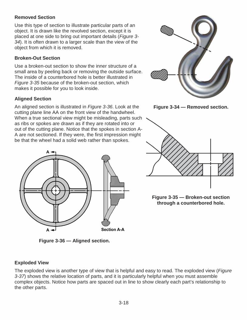
3-18
Removed SectionUse this type of section to illustrate particular parts of an object. It is drawn like the revolved section, except it is placed at one side to bring out important details (Figure 3-34). It is often drawn to a larger scale than the view of the object from which it is removed.
Broken-Out SectionUse a broken-out section to show the inner structure of a small area by peeling back or removing the outside surface.The inside of a counterbored hole is better illustrated in Figure 3-35 because of the broken-out section, which makes it possible for you to look inside.
Aligned SectionAn aligned section is illustrated in Figure 3-36. Look at the cutting plane line AA on the front view of the handwheel. When a true sectional view might be misleading, parts such as ribs or spokes are drawn as if they are rotated into or out of the cutting plane. Notice that the spokes in section A-A are not sectioned. If they were, the first impression might be that the wheel had a solid web rather than spokes.
Exploded ViewThe exploded view is another type of view that is helpful and easy to read. The exploded view (Figure3-37) shows the relative location of parts, and it is particularly helpful when you must assemble complex objects. Notice how parts are spaced out in line to show clearly each part’s relationship to the other parts.
Figure 3-34 — Removed section.
Figure 3-35 — Broken-out section through a counterbored hole.
Figure 3-36 — Aligned section.
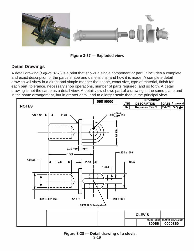
3-19Figure 3-38 — Detail drawing of a clevis.
Detail DrawingsA detail drawing (Figure 3-38) is a print that shows a single component or part. It includes a complete and exact description of the part’s shape and dimensions, and how it is made. A complete detail drawing will show in a direct and simple manner the shape, exact size, type of material, finish for each part, tolerance, necessary shop operations, number of parts required, and so forth. A detail drawing is not the same as a detail view. A detail view shows part of a drawing in the same plane and in the same arrangement, but in greater detail and to a larger scale than in the principal view.
Figure 3-37 — Exploded view.
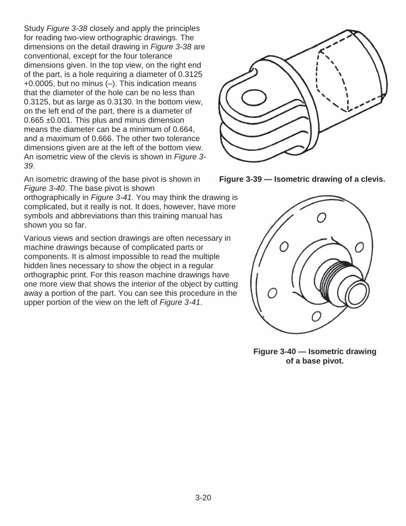
3-20
Study Figure 3-38 closely and apply the principles for reading two-view orthographic drawings. The dimensions on the detail drawing in Figure 3-38 are conventional, except for the four tolerance dimensions given. In the top view, on the right end of the part, is a hole requiring a diameter of 0.3125 +0.0005, but no minus (–). This indication means that the diameter of the hole can be no less than 0.3125, but as large as 0.3130. In the bottom view, on the left end of the part, there is a diameter of 0.665 ±0.001. This plus and minus dimensionmeans the diameter can be a minimum of 0.664, and a maximum of 0.666. The other two tolerance dimensions given are at the left of the bottom view. An isometric view of the clevis is shown in Figure 3-39.An isometric drawing of the base pivot is shown in Figure 3-40. The base pivot is shownorthographically in Figure 3-41. You may think the drawing is complicated, but it really is not. It does, however, have more symbols and abbreviations than this training manual has shown you so far.Various views and section drawings are often necessary in machine drawings because of complicated parts or components. It is almost impossible to read the multiple hidden lines necessary to show the object in a regular orthographic print. For this reason machine drawings have one more view that shows the interior of the object by cutting away a portion of the part. You can see this procedure in the upper portion of the view on the left of Figure 3-41.
Figure 3-39 — Isometric drawing of a clevis.
Figure 3-40 — Isometric drawing of a base pivot.
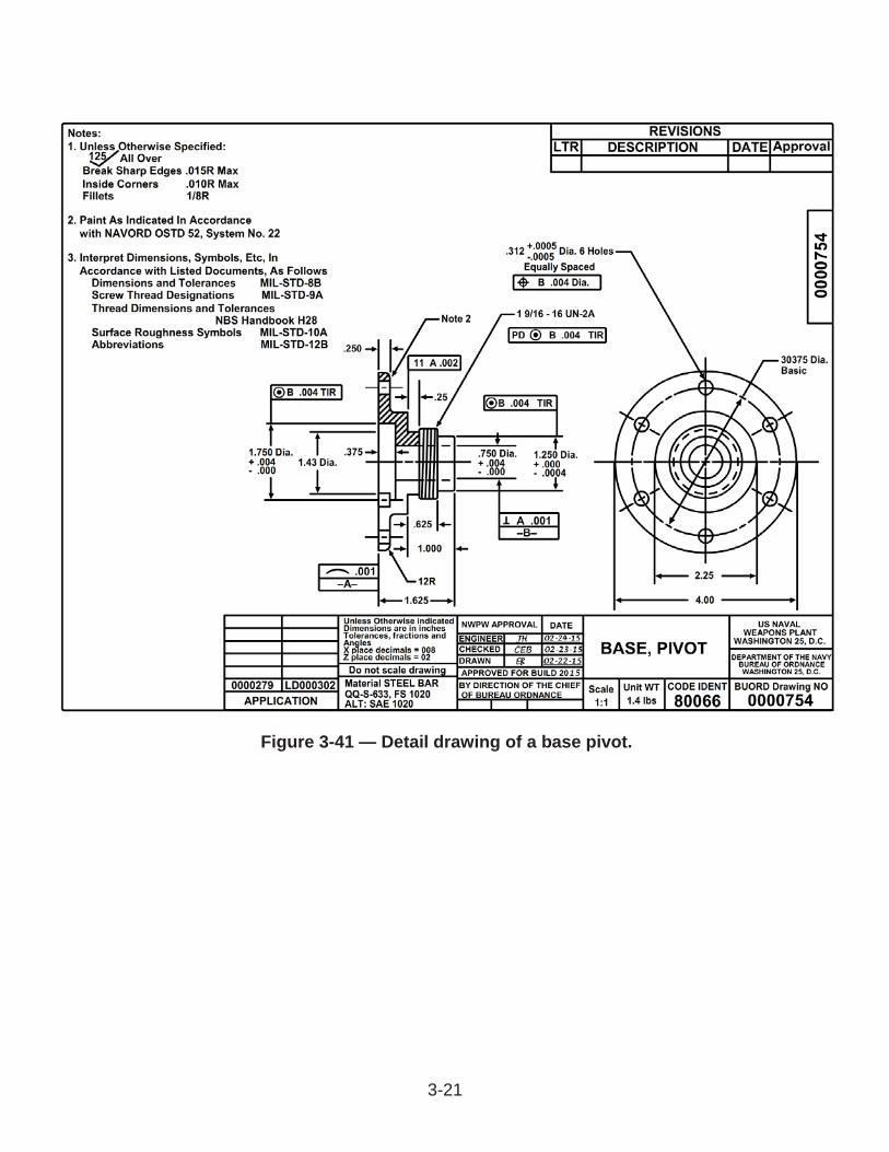
3-21
Figure 3-41 — Detail drawing of a base pivot.
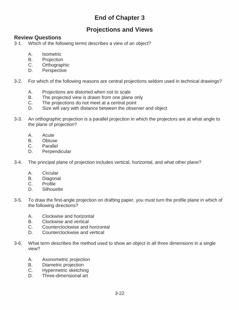
3-22
End of Chapter 3
Projections and ViewsReview Questions3-1. Which of the following terms describes a view of an object?
A. IsometricB. ProjectionC. OrthographicD. Perspective
3-2. For which of the following reasons are central projections seldom used in technical drawings?
A. Projections are distorted when not to scaleB. The projected view is drawn from one plane onlyC. The projections do not meet at a central pointD. Size will vary with distance between the observer and object
3-3. An orthographic projection is a parallel projection in which the projectors are at what angle to the plane of projection?
A. AcuteB. ObtuseC. ParallelD. Perpendicular
3-4. The principal plane of projection includes vertical, horizontal, and what other plane?
A. CircularB. DiagonalC. ProfileD. Silhouette
3-5. To draw the first-angle projection on drafting paper, you must turn the profile plane in which of the following directions?
A. Clockwise and horizontalB. Clockwise and verticalC. Counterclockwise and horizontalD. Counterclockwise and vertical
3-6. What term describes the method used to show an object in all three dimensions in a single view?
A. Axonometric projectionB. Diametric projectionC. Hypermetric sketchingD. Three-dimensional art
3-23
3-7. What term describes drawing a rectangular object in isometric?
A. Box constructionB. Line artC. Rectangular projectionD. Text box
3-8. A circle will appear as what shape in an isometric drawing?
A. CrescentB. EllipseC. SquareD. Triangle
3-9. Diagonal hatching should have the appearance of what angle with the horizontal and vertical axis, in degrees?
A. 15B. 30C. 45D. 60
3-10. What characteristic governs the number of views needed to project the drawing?
A. Complexity of the shapeB. Military specificationsC. Number of required dimensionsD. Number of sides
3-11. What type of drawing is deliberately made to appear the way it looks to the human eye?
A. DetailB. IsometricC. PerspectiveD. Special
3-12. What special view gives a clearer view of interior or hidden features?
A. Broken-outB. RemovedC. RevolvedD. Section
3-13. What special view rotates the object on an axis perpendicular to one of the planes?
A. Broken-outB. RemovedC. RevolvedD. Section

3-24
3-14. What special view is used to illustrate particular parts of an object?
A. Broken-outB. RemovedC. RevolvedD. Section
3-15. What type of drawing shows a complete and exact description of a single component or part?
A. DetailB. IsometricC. Multi-viewD. Projection

3-25
RATE TRAINING MANUAL – User UpdateSWOS makes every effort to keep their manuals up-to-date and free of technical errors. We appreciate your help in this process. If you have an idea for improving this manual, or if you find an error, a typographical mistake, or an inaccuracy in SWOS manuals, please write or e-mail us, using this form or a photocopy. Be sure to include the exact chapter number, topic, detailed description, and correction, if applicable. Your input will be brought to the attention of the Technical Review Committee. Thank you for your assistance.Write: SWOS Project Manager
1534 Piersey Street Suite 321Norfolk, VA 23511-2613COMM: (757) 444-5332DSN: 564-5332
E-mail: Refer to the SWOS Norfolk page on the NKO Web page for current contact information.
Rate____ Course Name_____________________________________________
Revision Date__________ Chapter Number____ Page Number(s)____________
Description _____________________________________________________________________________________________________________________________________________________________________________________________
(Optional) Correction _____________________________________________________________________________________________________________________________________________________________________________________________
(Optional) Your Name and Address _____________________________________________________________________________________________________________________________________________________________________________________________
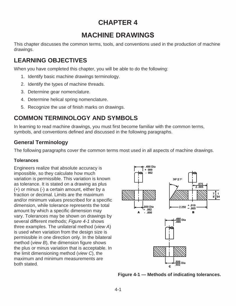
CHAPTER 4
MACHINE DRAWINGThis chapter discusses the common terms, tools, and conventions used in the production of machine drawings.
LEARNING OBJECTIVESWhen you have completed this chapter, you will be able to do the following:
1. Identify basic machine drawings terminology.2. Identify the types of machine threads.3. Determine gear nomenclature.4. Determine helical spring nomenclature.5. Recognize the use of finish marks on drawings.
COMMON TERMINOLOGY AND SYMBOLSIn learning to read machine drawings, you must first become familiar with the common terms, symbols, and conventions defined and discussed in the following paragraphs.
General TerminologyThe following paragraphs cover the common terms most used in all aspects of machine drawings.
TolerancesEngineers realize that absolute accuracy isimpossible, so they calculate how much variation is permissible. This variation is known as tolerance. It is stated on a drawing as plus(+) or minus (-) a certain amount, either by a fraction or decimal. Limits are the maximum and/or minimum values prescribed for a specific dimension, while tolerance represents the totalamount by which a specific dimension may vary. Tolerances may be shown on drawings by several different methods; Figure 4-1 shows three examples. The unilateral method (view A)is used when variation from the design size is permissible in one direction only. In the bilateral method (view B), the dimension figure shows the plus or minus variation that is acceptable. Inthe limit dimensioning method (view C), the maximum and minimum measurements are both stated.
Figure 4-1 — Methods of indicating tolerances.
4-1
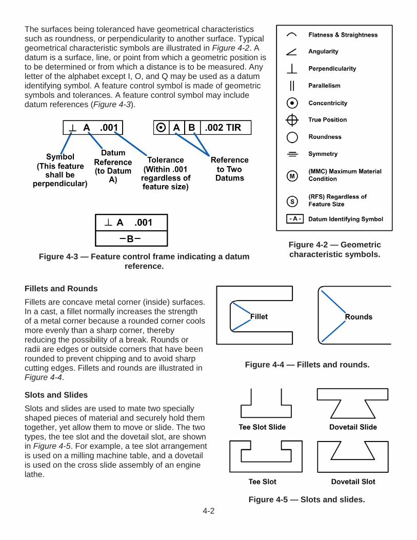
The surfaces being toleranced have geometrical characteristics such as roundness, or perpendicularity to another surface. Typical geometrical characteristic symbols are illustrated in Figure 4-2. Adatum is a surface, line, or point from which a geometric position is to be determined or from which a distance is to be measured. Any letter of the alphabet except I, O, and Q may be used as a datum identifying symbol. A feature control symbol is made of geometric symbols and tolerances. A feature control symbol may include datum references (Figure 4-3).
Fillets and RoundsFillets are concave metal corner (inside) surfaces.In a cast, a fillet normally increases the strength of a metal corner because a rounded corner cools more evenly than a sharp corner, thereby reducing the possibility of a break. Rounds or radii are edges or outside corners that have been rounded to prevent chipping and to avoid sharp cutting edges. Fillets and rounds are illustrated inFigure 4-4.
Slots and SlidesSlots and slides are used to mate two speciallyshaped pieces of material and securely hold themtogether, yet allow them to move or slide. The two types, the tee slot and the dovetail slot, are shown in Figure 4-5. For example, a tee slot arrangement is used on a milling machine table, and a dovetail is used on the cross slide assembly of an engine lathe.
Figure 4-2 — Geometric characteristic symbols. Figure 4-3 — Feature control frame indicating a datum
reference.
Figure 4-4 — Fillets and rounds.
Figure 4-5 — Slots and slides.4-2
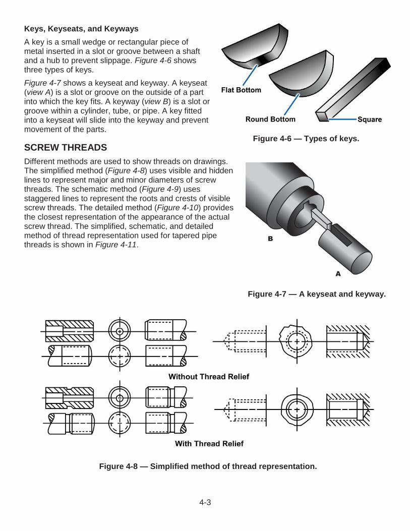
Keys, Keyseats, and KeywaysA key is a small wedge or rectangular piece of metal inserted in a slot or groove between a shaft and a hub to prevent slippage. Figure 4-6 shows three types of keys.Figure 4-7 shows a keyseat and keyway. A keyseat(view A) is a slot or groove on the outside of a part into which the key fits. A keyway (view B) is a slot or groove within a cylinder, tube, or pipe. A key fitted into a keyseat will slide into the keyway and prevent movement of the parts.
SCREW THREADSDifferent methods are used to show threads on drawings.The simplified method (Figure 4-8) uses visible and hidden lines to represent major and minor diameters of screw threads. The schematic method (Figure 4-9) uses staggered lines to represent the roots and crests of visible screw threads. The detailed method (Figure 4-10) provides the closest representation of the appearance of the actual screw thread. The simplified, schematic, and detailed method of thread representation used for tapered pipe threads is shown in Figure 4-11.
Figure 4-6 — Types of keys.
Figure 4-7 — A keyseat and keyway.
4-3
Figure 4-8 — Simplified method of thread representation.
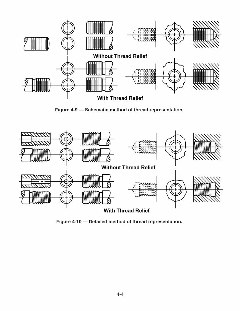
Figure 4-9 — Schematic method of thread representation.
Figure 4-10 — Detailed method of thread representation.
4-4
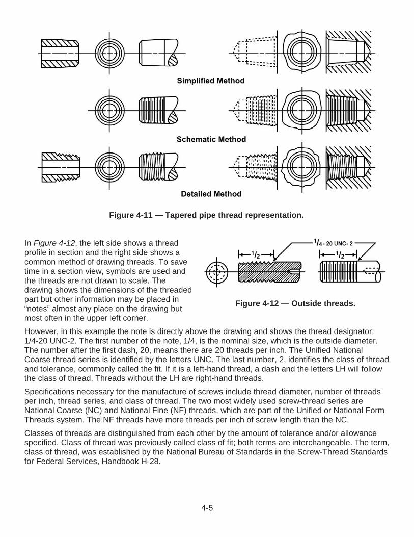
Figure 4-11 — Tapered pipe thread representation.
Figure 4-12 — Outside threads.
In Figure 4-12, the left side shows a thread profile in section and the right side shows a common method of drawing threads. To save time in a section view, symbols are used and the threads are not drawn to scale. The drawing shows the dimensions of the threaded part but other information may be placed in “notes” almost any place on the drawing but most often in the upper left corner.However, in this example the note is directly above the drawing and shows the thread designator:1/4-20 UNC-2. The first number of the note, 1/4, is the nominal size, which is the outside diameter. The number after the first dash, 20, means there are 20 threads per inch. The Unified National Coarse thread series is identified by the letters UNC. The last number, 2, identifies the class of threadand tolerance, commonly called the fit. If it is a left-hand thread, a dash and the letters LH will followthe class of thread. Threads without the LH are right-hand threads.Specifications necessary for the manufacture of screws include thread diameter, number of threads per inch, thread series, and class of thread. The two most widely used screw-thread series are National Coarse (NC) and National Fine (NF) threads, which are part of the Unified or National Form Threads system. The NF threads have more threads per inch of screw length than the NC.Classes of threads are distinguished from each other by the amount of tolerance and/or allowance specified. Class of thread was previously called class of fit; both terms are interchangeable. The term, class of thread, was established by the National Bureau of Standards in the Screw-Thread Standards for Federal Services, Handbook H-28.
4-5
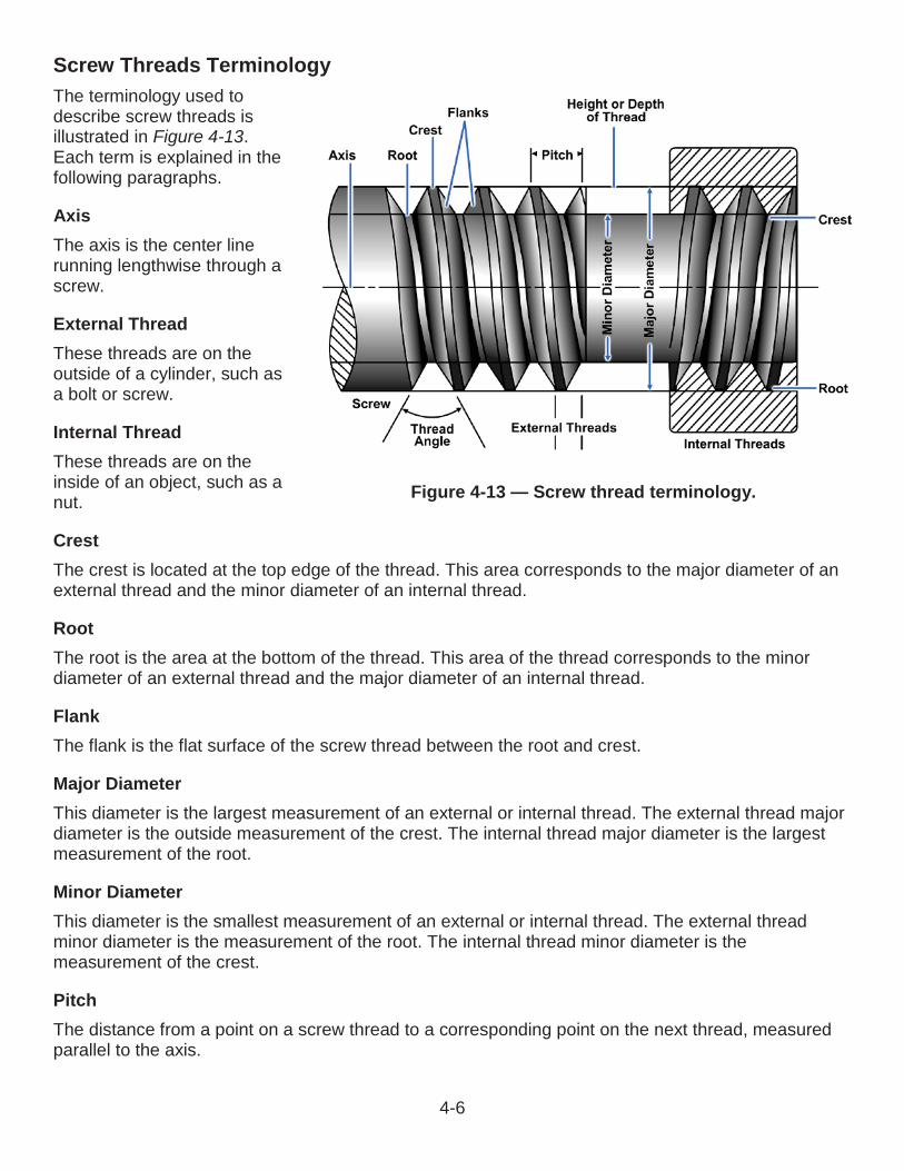
Screw Threads TerminologyThe terminology used to describe screw threads is illustrated in Figure 4-13.Each term is explained in thefollowing paragraphs.
AxisThe axis is the center line running lengthwise through a screw.
External ThreadThese threads are on the outside of a cylinder, such as a bolt or screw.
Internal ThreadThese threads are on the inside of an object, such as a nut.
CrestThe crest is located at the top edge of the thread. This area corresponds to the major diameter of an external thread and the minor diameter of an internal thread.
RootThe root is the area at the bottom of the thread. This area of the thread corresponds to the minor diameter of an external thread and the major diameter of an internal thread.
FlankThe flank is the flat surface of the screw thread between the root and crest.
Major DiameterThis diameter is the largest measurement of an external or internal thread. The external thread major diameter is the outside measurement of the crest. The internal thread major diameter is the largest measurement of the root.
Minor DiameterThis diameter is the smallest measurement of an external or internal thread. The external thread minor diameter is the measurement of the root. The internal thread minor diameter is the measurement of the crest.
PitchThe distance from a point on a screw thread to a corresponding point on the next thread, measured parallel to the axis.
Figure 4-13 — Screw thread terminology.
4-6
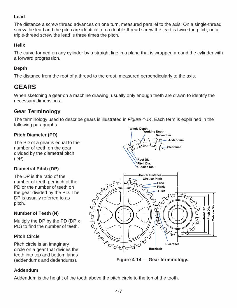
LeadThe distance a screw thread advances on one turn, measured parallel to the axis. On a single-thread screw the lead and the pitch are identical; on a double-thread screw the lead is twice the pitch; on atriple-thread screw the lead is three times the pitch.
HelixThe curve formed on any cylinder by a straight line in a plane that is wrapped around the cylinder with a forward progression.
DepthThe distance from the root of a thread to the crest, measured perpendicularly to the axis.
GEARSWhen sketching a gear on a machine drawing, usually only enough teeth are drawn to identify the necessary dimensions.
Gear TerminologyThe terminology used to describe gears is illustrated in Figure 4-14. Each term is explained in the following paragraphs.
Pitch Diameter (PD)The PD of a gear is equal to the number of teeth on the geardivided by the diametral pitch(DP).
Diametral Pitch (DP)The DP is the ratio of the number of teeth per inch of the PD or the number of teeth onthe gear divided by the PD. The DP is usually referred to as pitch.
Number of Teeth (N)Multiply the DP by the PD (DP x PD) to find the number of teeth.
Pitch CirclePitch circle is an imaginarycircle on a gear that divides the teeth into top and bottom lands (addendums and dedendums).
AddendumAddendum is the height of the tooth above the pitch circle to the top of the tooth.
Figure 4-14 — Gear terminology.
4-7