navcan installation manual final 131022 - itech gps | installation manual 2 ... certification in...
TRANSCRIPT
NavCANInstallation Manual
navmanwireless.com

NavCAN | Installation Manual
2
Disclaimer It is the Owner’s sole responsibility to install and use the NavCAN (the Product) in a manner that will not cause accidents, personal injury or property damage. For the purpose of this notice, “Owner”, “you” and “your” means the party (including any person authorized by that party to use and/or install the Product) that has either: (a) purchased the Product; or (b) leased the Product from Navman Wireless or its related companies. The Owner of this Product is solely responsible for observing safe driving practices. The choice, location and installation of all components of the Product is critical. If installation is not correct, the Product may not perform at its designed potential or specifications. Ensure that any mounting holes that need to be cut in the vehicle will not weaken the vehicle structure or compromise the safety of the vehicle or its occupants. If in doubt, consult the vehicle manufacturer, or your Navman Wireless dealer. TO THE MAXIMUM EXTENT PERMITTED BY LAW, ALL REPRESENTATIONS AND WARRANTIES (EXCEPT ANY WHICH MAY NOT LAWFULLY BE EXCLUDED) ARE, EXPRESSLY EXCLUDED, INCLUDING WITHOUT PREJUDICE TO THE, GENERALITY OF THE FOREGOING, THE IMPLIED WARRANTIES OR MERCHANTABILITY AND FITNESS FOR A PARTICULAR PURPOSE. TO THE MAXIMUM EXTENT PERMITTED BY LAW NAVMAN WIRELESS DISCLAIMS ALL LIABILITY ARISING OUT OF OR IN CONNECTION WITH THE PRODUCT (INCLUDING ANY USE OF THIS PRODUCT IN A WAY THAT MAY CAUSE ACCIDENTS, DAMAGE OR VIOLATE THE LAW). As Navman Wireless is continuously improving this Product, Navman Wireless may make changes to the Product at any time which may not be reflected in this document. Please contact your nearest Navman Wireless office if you require any further assistance.
NAVMAN WIRELESS DISCLAIMS ALL LIABILITY FOR ANY USE OF THIS PRODUCT IN A WAY THAT MAY
CAUSE ACCIDENTS, DAMAGE OR VIOLATE THE LAW.
Copyright © 2013 Navman Wireless Holdings L. P. Navman Wireless is a registered trademark of Navman Wireless Holdings L. P. All rights reserved. All other trademarks and registrations are the property of their respective owners.
NavCAN | Installation Manual
3
Contents
Disclaimer ...................................................................................................................................... 2
1 Introduction .......................................................................................................................... 4 1.1 Overview ........................................................................................................................ 4 1.2 Audience ........................................................................................................................ 4
2 NavCAN Hardware ................................................................................................................ 5 2.1 Box Contents................................................................................................................... 5 2.2 Other Components Required ............................................................................................. 5
3 Installation ............................................................................................................................ 6 3.1 Choose the Mounting Location .......................................................................................... 6 3.2 Before You Start .............................................................................................................. 6 3.3 Install the NavCAN ........................................................................................................... 6
4 Wiring .................................................................................................................................... 7 4.1 Standard NavCAN Connections .......................................................................................... 7 4.2 Auxiliary Power Cable (Optional)........................................................................................ 8 4.3 Additional Input Options for the NavCAN 2 ......................................................................... 9 4.4 Install Options into the NavCAN Connector ........................................................................ 12 4.5 Connect the DatacliQ to the Vehicle’s Data Network............................................................ 13 4.6 Connect to the K-Line Tachograph Interface ...................................................................... 16 4.7 Connect to J1708 ............................................................................................................ 17 4.8 Installation Instructions ................................................................................................... 17
5 PPO-200 .............................................................................................................................. 19
6 Configuration ...................................................................................................................... 20 6.1 DCF files ........................................................................................................................ 20 6.2 Updating DCF files .......................................................................................................... 21
7 Troubleshooting .................................................................................................................. 24 7.1 LEDs ............................................................................................................................. 24 7.2 PP0-200......................................................................................................................... 24 7.3 MDT / M-Nav ................................................................................................................. 24 7.4 Tachograph.................................................................................................................... 25
8 Re-installation on a different vehicle.................................................................................. 26
9 Training ............................................................................................................................... 27
10 Parts List ............................................................................................................................. 28
11 Specifications ...................................................................................................................... 29
12 Contacts .............................................................................................................................. 30
NavCAN | Installation Manual
4
1 Introduction
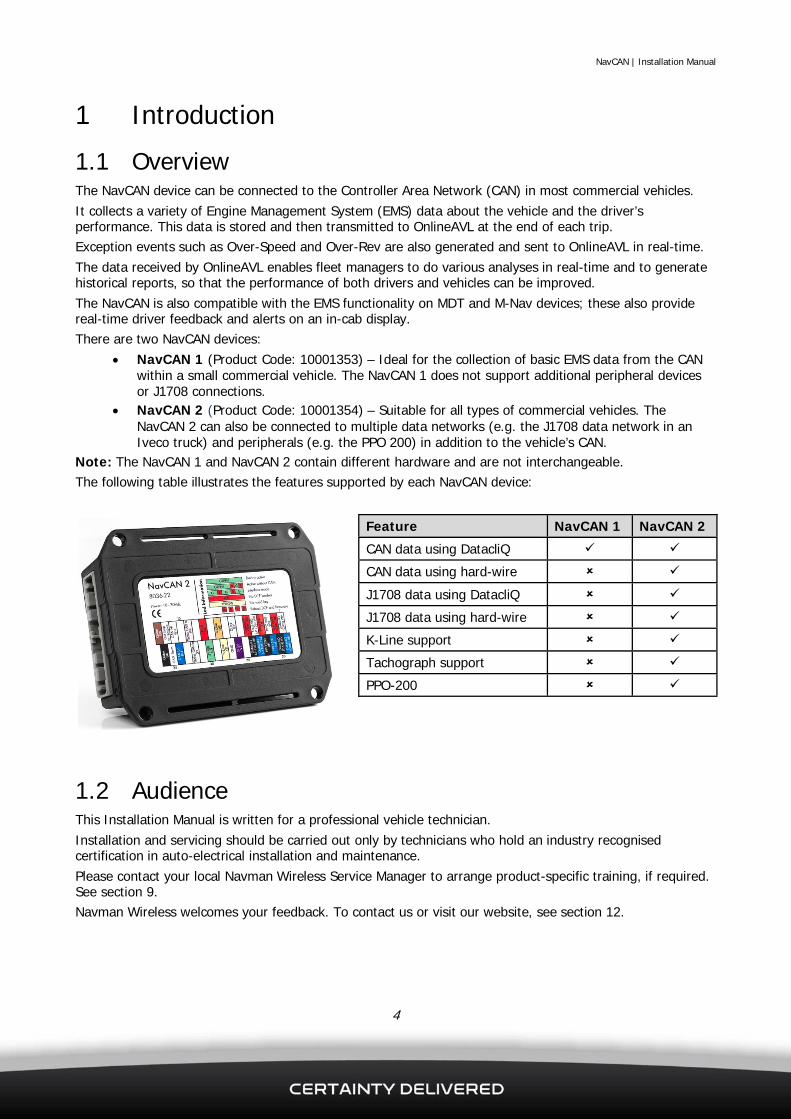
1.1 Overview The NavCAN device can be connected to the Controller Area Network (CAN) in most commercial vehicles. It collects a variety of Engine Management System (EMS) data about the vehicle and the driver’s performance. This data is stored and then transmitted to OnlineAVL at the end of each trip. Exception events such as Over-Speed and Over-Rev are also generated and sent to OnlineAVL in real-time. The data received by OnlineAVL enables fleet managers to do various analyses in real-time and to generate historical reports, so that the performance of both drivers and vehicles can be improved. The NavCAN is also compatible with the EMS functionality on MDT and M-Nav devices; these also provide real-time driver feedback and alerts on an in-cab display. There are two NavCAN devices:
NavCAN 1 (Product Code: 10001353) – Ideal for the collection of basic EMS data from the CAN within a small commercial vehicle. The NavCAN 1 does not support additional peripheral devices or J1708 connections.
NavCAN 2 (Product Code: 10001354) – Suitable for all types of commercial vehicles. The NavCAN 2 can also be connected to multiple data networks (e.g. the J1708 data network in an Iveco truck) and peripherals (e.g. the PPO 200) in addition to the vehicle’s CAN.
Note: The NavCAN 1 and NavCAN 2 contain different hardware and are not interchangeable. The following table illustrates the features supported by each NavCAN device:
Feature NavCAN 1 NavCAN 2
CAN data using DatacliQ
CAN data using hard-wire
J1708 data using DatacliQ
J1708 data using hard-wire
K-Line support
Tachograph support
PPO-200
1.2 Audience This Installation Manual is written for a professional vehicle technician. Installation and servicing should be carried out only by technicians who hold an industry recognised certification in auto-electrical installation and maintenance. Please contact your local Navman Wireless Service Manager to arrange product-specific training, if required. See section 9. Navman Wireless welcomes your feedback. To contact us or visit our website, see section 12.

NavCAN | Installation Manual
5
2 NavCAN Hardware
2.1 Box Contents The NavCAN 1 and NavCAN 2 devices are shipped in boxes containing 15 units. Wiring looms are shipped separately. See section 4 for device- and installation-specific wiring loom options.
2.2 Other Components Required You also need the following components before starting the installation:
NavCAN wiring loom, Squarell Installation Instructions, MDT / M-Nav for diagnostics and testing, Any additional looms / accessories specified on the order.
Contact your Navman Wireless Support Team for advice on the best choices for your type of installation and for ordering information, if necessary.

NavCAN | Installation Manual
6
3 Installation
3.1 Choose the Mounting Location The NavCAN installation is considered to be permanent as the firmware can be updated without removing the NavCAN device from the vehicle. The installation location must:
Be a rigid surface where the NavCAN device can be secured firmly, Be dry, Allow PPO/Tacho or other peripheral device connections, Allow the diagnostic LED on the NavCAN device to be seen by a vehicle technician, Not be subject to excessive vibration or excessive heat, Not be visible the driver.
The final orientation of the NavCAN device after installation is not important. The following locations within the vehicle may be suitable:
Inside or underneath the dash, In the boot/trunk area.
3.2 Before You Start Check that all the cables are long enough to reach between the chosen mounting location, the Qube, and the vehicle’s CAN wiring BEFORE you install the NavCAN device.
3.3 Install the NavCAN CAUTION Ensure that any mounting holes that need to be cut in the vehicle will not weaken the vehicle structure or compromise the safety of the vehicle or its occupants. If in doubt, consult the vehicle manufacturer. If mounting holes are required, use grommets to ensure that the vehicle remains waterproof.
Mount the NavCAN device securely on the vehicle using four self-tapping screws and washers (not provided) through the corner holes in the mounting rails. Alternatively, secure the NavCAN device to the vehicle with cable ties (not provided) through the cable tie slots in the mounting rails.

NavCAN | Installation Manual
7
4 Wiring CAUTION Ensure that any connection to the vehicle’s wiring system does not interfere with the operation of the vehicle or with any of the vehicle’s safety systems. If in doubt, consult the vehicle manufacturer. Make power connections only to the vehicle manufacturer’s approved points. Use insulation tape to insulate any bare wires that are not connected. Wiring the unit incorrectly or leaving any bare wires exposed may result in electrical damage to the NavCAN device or the vehicle’s wiring.
4.1 Standard NavCAN Connections Ensure that all cables are:
Tidy and secure, and do not present a hazard to the vehicle's occupants, Protected from chaffing on sharp edges, Connected to vehicle manufacturer’s approved points, Located where they will not be damaged.
Two wiring loom options are available for NavCAN devices, depending on the type of Qube being used:
Qube 3 Qube 4 / 5
Navman Part Number: 10001392 Description: NavCAN Cable V1 Termination: Qube 3 RJ45 (male) plug
Navman Part Number: 10001401 Description: NavCAN Cable V2 Termination: Qube 4/5 10-way Molex plug
Wiring for the Qube 3 variant: 1. Connect the RJ45 (male) plug to the port that is configured for EMS. 2. Connect the DatacliQ to the vehicle’s CAN bus (see section 4.5). 3. Connect the 36 pin connector to the NavCAN device.

NavCAN | Installation Manual
8
Wiring for the Qube 4 / 5 variant: 1. Connect the Molex plug to the 10-Pin ConEX port on the Qube. 2. Connect the DatacliQ to the vehicle CAN bus (see section 4.5). 3. Connect the Black wire to Ground. 4. Connect the Brown wire to +12 V / +24 V permanent supply (fuse with 1 A). 5. Connect the 36 pin connector to the NavCAN device.
4.2 Auxiliary Power Cable (Optional) If the NavCAN device will be used with a Qube 3 and an M-Nav, we recommend using the Auxiliary Power Cable (Navman Part Number: 10001416). The Auxiliary Power Cable allows the NavCAN device to use power directly from the vehicle without affecting the power that is available to the M-Nav device. Connect the Auxiliary Power Cable as follows:
Description Connect To
RJ45 Male Port used for EMS on the Serial Port Expander
RJ45 Female RJ45 Male plug on the NavCAN (Qube 3) wiring loom
Molex Plug Male Qube 3 power connector
Molex Plug Female Qube 3 power wiring loom
NavCAN | Installation Manual
9
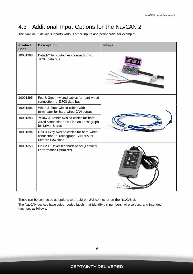
4.3 Additional Input Options for the NavCAN 2 The NavCAN 2 device supports various other inputs and peripherals, for example:
Product Code
Description Image
10001398 DatacliQ for contactless connection to J1708 data bus
10001395 Red & Green twisted cables for hard-wired connection to J1708 data bus
10001396 White & Blue twisted cables with terminator for hard-wired CAN output
10001393 Yellow & Amber twisted cables for hard-wired connection to K-Line on Tachograph for Driver Status
10001394 Pink & Grey twisted cables for hard-wired connection to Tachograph CAN bus for Remote Download
10001355 PPO-200 Driver feedback panel (Personal Performance Optimiser)
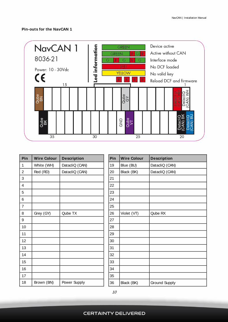
These can be connected as options to the 32 pin JAE connector on the NavCAN 2. The NavCAN devices have colour-coded labels that identify pin numbers, wire colours, and intended function, as follows:
NavCAN | Installation Manual
10
Pin-outs for the NavCAN 1
Pin Wire Colour Description Pin Wire Colour Description
1 White (WH) DatacliQ (CAN) 19 Blue (BU) DatacliQ (CAN)
2 Red (RD) DatacliQ (CAN) 20 Black (BK) DatacliQ (CAN) 3 21
4 22
5 23
6 24
7 25
8 Grey (GY) Qube TX 26 Violet (VT) Qube RX
9 27
10 28
11 29
12 30
13 31
14 32
15 33
16 34
17 35
18 Brown (BN) Power Supply 36 Black (BK) Ground Supply

NavCAN | Installation Manual
11
Pin-outs for the NavCAN 2
Pin Wire Colour Description Pin Wire Colour Description
1 White (WH) DatacliQ (CAN) 19 Blue (BU) DatacliQ (CAN) 2 Red (RD) DatacliQ (CAN) 20 Black (BK) DatacliQ (CAN) 3 White (WH) PPO-200 21 Blue (BU) PPO-200 4 Red (RD) PPO-200 22 Black (BK) PPO-200 5 White (WH) DatacliQ (J1708) 23 Blue (BU) DatacliQ (J1708) 6 Red (RD) DatacliQ (J1708) 24 Black (BK) DatacliQ (J1708)
7 25
8 Grey (GY) Qube TX 26 Violet (VT) Qube RX 9 27
10 Orange (OG) K-Line 28 Yellow (YE) K-Line (Secondary) 11 29
12 Red (RD) J1708+ Hardwire 30 Green (GR) J1708- Hardwire 13 31
14 Pink (PK) Tachograph CAN Hi 32 Grey (GY) Tachograph CAN Lo 15 33
16 White (WH) CAN Hi Hardwire 34 Blue (BU) CAN Lo Hardwire (Output) 17 CAN Terminator loop – cut to remove 35 CAN Terminator loop – cut to remove
18 Brown (BN) Power Supply 36 Black (BK) Ground Supply

NavCAN | Installation Manual
12
4.4 Install Options into the NavCAN Connector Tip: When installing cables with multiple pins, line up all the pins in the correct holes in the connector before clicking them into place.
1. Use the corner of the Squarell Extraction Tool (8910-ET) or a small flat blade to lift the black locking clip on the rear of the 36 pin NavCAN connector. Lift both sides of the black locking clip, so that it protrudes approximately 1 mm from the grey housing.
2. Insert the cables into the correct pin sockets in the grey housing.(See section 4.3 for the pin assignments.) The pins must face down, with the crimped part of the pin on the bottom and the smooth side of the pin on the top. When you push the pins into place correctly you will hear a click, and the newly-inserted pins will be flush in the front of the connector alongside the other existing pins.
3. Push the black locking clip on the rear of the NavCAN connector back into place. (If the locking clip is not flush with the grey connector housing, make sure that all of the pins are pushed fully into place, then try again.)

NavCAN | Installation Manual
13
4.5 Connect the DatacliQ to the Vehicle’s Data Network 4.5.1 Install the DatacliQ Connector The DatacliQ connector is designed to provide a contactless connection to the vehicle’s data bus, avoiding the need for a soldered connection. However, on some vehicles it is not possible to provide a contactless connection because the data bus wires are too thick, too thin, or too close together. In these situations, create a CANbus stub as described in Section 4.5.2. Note: This manual refers to the DatacliQ connector but the connection information provided in this manual also applies to other connectors.
IMPORTANT The DatacliQ connector must be installed at least 5 mm away from a Ground source; for example, a metal bulkhead, chassis, or anti-roll bar. This example shows a connector installed in the wrong location.
IMPORTANT NOTES
1. Always follow the instructions in the Squarell Installation Manual. This manual has a written description and clearly shows the correct wire colours and their locations, as shown in this example:
NavCAN | Installation Manual
14
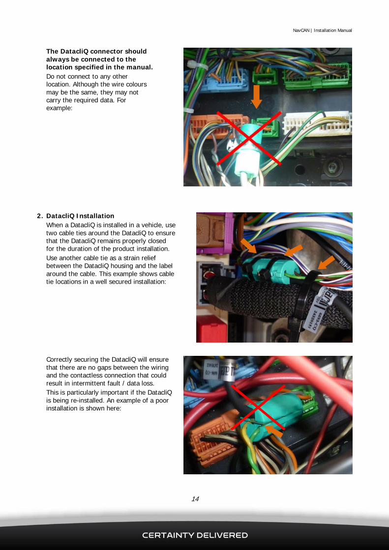
The DatacliQ connector should always be connected to the location specified in the manual. Do not connect to any other location. Although the wire colours may be the same, they may not carry the required data. For example:
2. DatacliQ Installation When a DatacliQ is installed in a vehicle, use two cable ties around the DatacliQ to ensure that the DatacliQ remains properly closed for the duration of the product installation. Use another cable tie as a strain relief between the DatacliQ housing and the label around the cable. This example shows cable tie locations in a well secured installation:
Correctly securing the DatacliQ will ensure that there are no gaps between the wiring and the contactless connection that could result in intermittent fault / data loss. This is particularly important if the DatacliQ is being re-installed. An example of a poor installation is shown here:

NavCAN | Installation Manual
15
4.5.2 Create a CANbus Stub (Optional)
1. Use two pieces of flex cable with an appropriate gauge to work with the DatacliQ connector; for example, 18 AWG. (See section 4.3 for examples of suitable cable options.) Each piece of flex cable should be approximately 10 cms in length.
2. Carefully solder the two short wires to the original data bus wiring. Take care not to cut or damage the existing data bus wiring. Insulate the soldered connections using fibre tape or electrical insulation tape.
3. Connect the DatacliQ connector to the new CANbus stub. Position the High wire and Low wire in the corresponding tracks of the DatacliQ connector. (The High track is always closest to the DatacliQ connector’s hinge.) Close the DatacliQ connector so that the three locking tabs close into place. Note: The DatacliQ connector is designed to close once only. Check that you have positioned the wires before you close the DatacliQ connector.
4. When a DatacliQ connector is installed in a vehicle, use two cable ties around the DatacliQ connector to ensure that it remains closed properly for the duration of the installation. Use a third cable tie as a strain relief between the DatacliQ housing and the label around the cable. This example shows the three cable tie locations in a well secured installation. Correctly securing the DatacliQ will ensure that there are no gaps between the wiring and the contactless connection that could result in intermittent fault / data loss. This is particularly important if the DatacliQ is being re-installed.
NavCAN | Installation Manual
16
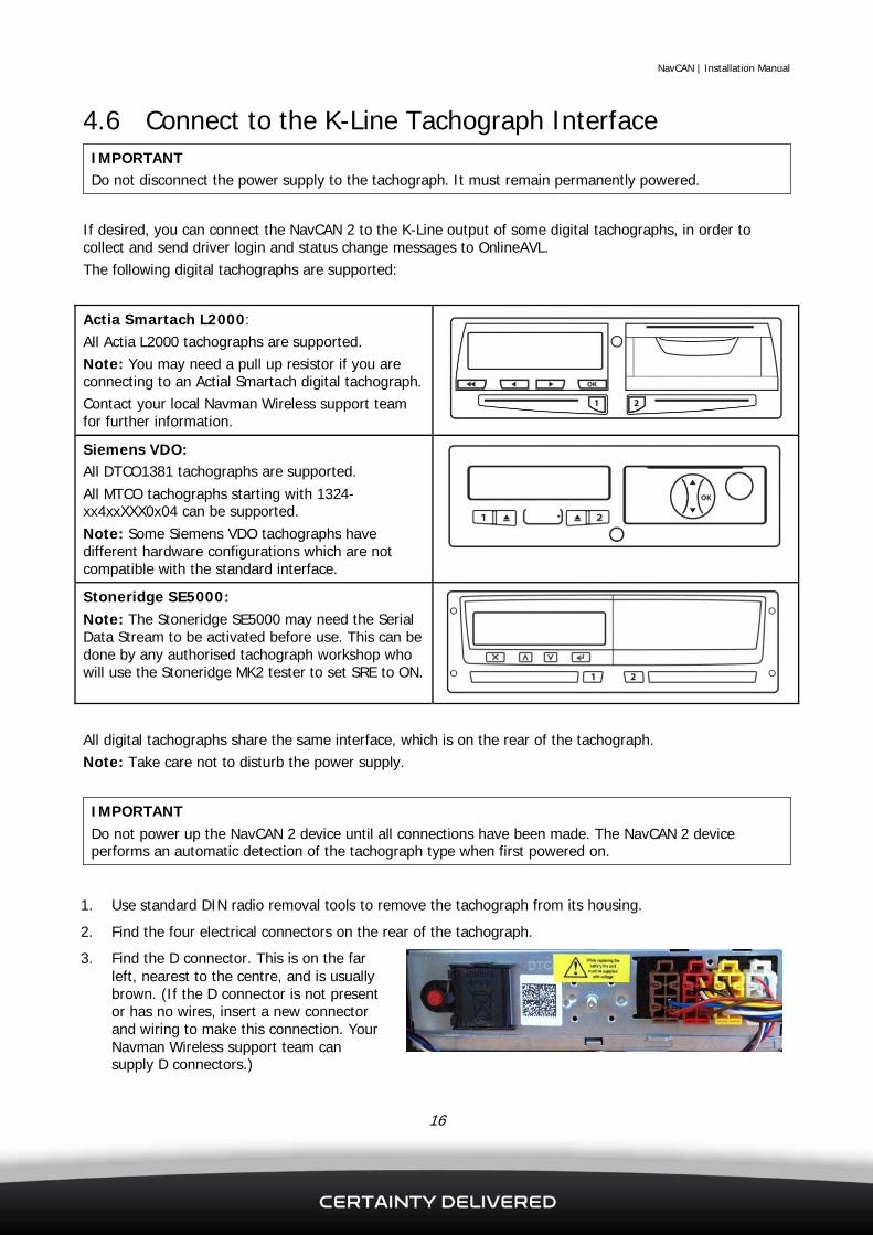
4.6 Connect to the K-Line Tachograph Interface IMPORTANT Do not disconnect the power supply to the tachograph. It must remain permanently powered.
If desired, you can connect the NavCAN 2 to the K-Line output of some digital tachographs, in order to collect and send driver login and status change messages to OnlineAVL. The following digital tachographs are supported:
Actia Smartach L2000: All Actia L2000 tachographs are supported. Note: You may need a pull up resistor if you are connecting to an Actial Smartach digital tachograph. Contact your local Navman Wireless support team for further information.
Siemens VDO: All DTCO1381 tachographs are supported. All MTCO tachographs starting with 1324-xx4xxXXX0x04 can be supported. Note: Some Siemens VDO tachographs have different hardware configurations which are not compatible with the standard interface.
Stoneridge SE5000: Note: The Stoneridge SE5000 may need the Serial Data Stream to be activated before use. This can be done by any authorised tachograph workshop who will use the Stoneridge MK2 tester to set SRE to ON.
All digital tachographs share the same interface, which is on the rear of the tachograph. Note: Take care not to disturb the power supply.
IMPORTANT Do not power up the NavCAN 2 device until all connections have been made. The NavCAN 2 device performs an automatic detection of the tachograph type when first powered on.
1. Use standard DIN radio removal tools to remove the tachograph from its housing.
2. Find the four electrical connectors on the rear of the tachograph.
3. Find the D connector. This is on the far left, nearest to the centre, and is usually brown. (If the D connector is not present or has no wires, insert a new connector and wiring to make this connection. Your Navman Wireless support team can supply D connectors.)

NavCAN | Installation Manual
17
4. Connect the K-Line cable (Product code 10001393, see section 4.3) to the 36-Pin NavCAN connector. Note: The Yellow wire is not used and remains unconnected at the Tachograph end.
5. Using the Orange wire, create a soldered connection to pin D8 on the rear of the tachograph. Insulate the connection.
4.7 Connect to J1708 Note: The NavCAN 1 does not support connection to J1708. The DatacliQ connector supplied with the main wiring loom (shipped with the NavCAN devices) works only with CAN. However, the data network in some vehicles uses J1708 rather than CAN. The Squarell Installation Instructions will specify if a J1708 connection is required along with wiring details. In these situations, make a J1708 connection using one of the following methods: J1708 Receive data only: Make a J1708 connection by installing an additional DatacliQ contactless connector: 1. Connect the DatacliQ connector over the J1708+ and J1708- wires (see the Squarell Installation
Instructions). 2. Always place J1708+ in the High track of the DatacliQ connector, and always place J1708- in the Low
track. (The High track is always closest to the DatacliQ connector’s hinge.) J1708 Receive and send data: Make a J1708 connection by installing the hard-wire option (see section 4.3, Product Code: 10001395). 1. Connect the Red wire to Pin 12 in the NavCAN connector and to the J1708+ wire (see the Squarell
Installation Instructions). 2. Connect the Green wire to Pin 30 on the NavCAN connector and to the J1708– wire (see the Squarell
Installation Instructions).
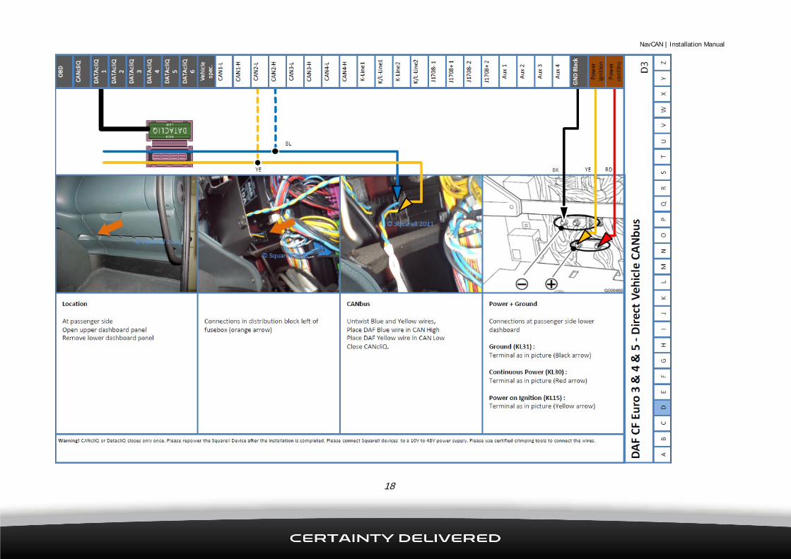
4.8 Installation Instructions An Installation Manual is available for each vehicle that is supported by the NavCAN device. Contact your local Navman Wireless support team for details about supported vehicles and copies of the Installation Manuals. The Installation Manual shows the location of the data bus wiring in the vehicle. It also shows which wires to use in the DatacliQ connector and how the NavCAN connects to the Qube.
NavCAN | Installation Manual
18

NavCAN | Installation Manual
19
5 PPO-200 The PPO-200 is an intelligent in-vehicle display that works on every supported vehicle type (assuming that a NavCAN 2 is installed). It can help a driver to improve their skill by providing visual and audible notifications on several performance indicators. To install the PPO-200: 1. Choose a flat mounting location which is clearly visible to the driver; for example, a vertical piece of
dashboard which faces the driver. 2. Clean the mounting location with an alcohol wipe. 3. Mount the PPO200 securely, using the double-sided sticky pad in each corner to attach it to the chosen
location. 4. Feed the wire through the dashboard to the location where the NavCAN 2 is installed. 5. Insert the pins into the NavCAN connector as described in section 4.4:
NavCAN Pin Wire Colour
3 White (WH)
4 Red (RD)
21 Blue (BU)
22 Black (BK)
6. Turn the vehicle ignition ON. The LEDs on the PPO-200 illuminate to confirm communication with the
NavCAN 2.

NavCAN | Installation Manual
20
6 Configuration
6.1 DCF files All NavCAN devices contain a DCF (Device Configuration File) which allows them to understand the traffic on the vehicle data network(s). Most vehicles have their own proprietary protocol (language) for communications between different components on the vehicle’s network. The DCF puts these languages into a format which can be used by the OnlineAVL solution. When NavCAN devices are shipped to customers / installers, they may have been configured by the Navman Wireless Support Team for the specific vehicle type. However, if the vehicle type is unknown (or is another vehicle is substituted), the engineer may need to update the DCF to the appropriate version, as explained in section 6.2. As default, all NavCAN devices ship with the ‘Reset’ DCF. This is the factory default configuration which blanks any stored settings and readies the NavCAN for a new configuration. Several other DCFs are available for the NavCAN; see the DCF Selection Matrix for information about which DCF to use. Contact your local Navman Wireless Support Team for a copy of the DCF Selection Matrix. DCF files are named using the following format:
Note: NavCAN devices work only with DCFs that begin NAM-8000- (as shown above).

NavCAN | Installation Manual
21
6.2 Updating DCF files Device Configuration Files (DCFs) can be updated using the Squarell iUpload software. iUpload is a program which is installed on a Windows PC and works together with the Squarell server to allow the updating of devices to supported DCF and firmware versions. To update a DCF file you will need:
A copy of iUpload - download from http://www.squarell.com/en/Support/Technical_Downloads/ A username and password for iUpload A NavCAN upload cable with power supply (Part Code 6698-SU).
Contact your local Navman Wireless Support Team for a username and password, and a NavCAN upload cable if needed. To update a DCF: 1. Enter your username and password into iUpload then click Save.
2. Connect the NavCAN upload cable:
Description Connect To
DB9 Female RS232 Connector RS232 port on PC
Power (Black with White trace) +12v / +24v
Ground (Black) Ground

NavCAN | Installation Manual
22
3. Click Synchronise Tasks to download all of the latest files (to which you have access) from the Squarell server, and any tasks scheduled to you by a Navman Wireless Administrator.
4. Click Read Devices. This detects any devices that are connected and populates the ‘Devices connected’
list:
5. Double-click the serial number to open the ‘iUpload – Task’ screen. 6. Click the DCF drop-down box and select the required DCF file then click Ok.
Important: Do not make any changes to the Firmware drop-down box. Unauthorised changes can make the device unusable.
NavCAN | Installation Manual
23
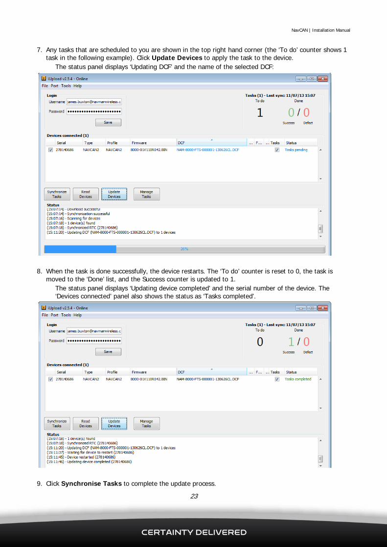
7. Any tasks that are scheduled to you are shown in the top right hand corner (the ‘To do’ counter shows 1 task in the following example). Click Update Devices to apply the task to the device.
The status panel displays ‘Updating DCF’ and the name of the selected DCF:
8. When the task is done successfully, the device restarts. The ‘To do’ counter is reset to 0, the task is
moved to the ‘Done’ list, and the Success counter is updated to 1. The status panel displays ‘Updating device completed’ and the serial number of the device. The ‘Devices connected’ panel also shows the status as ‘Tasks completed’.
9. Click Synchronise Tasks to complete the update process.
NavCAN | Installation Manual
24
7 Troubleshooting
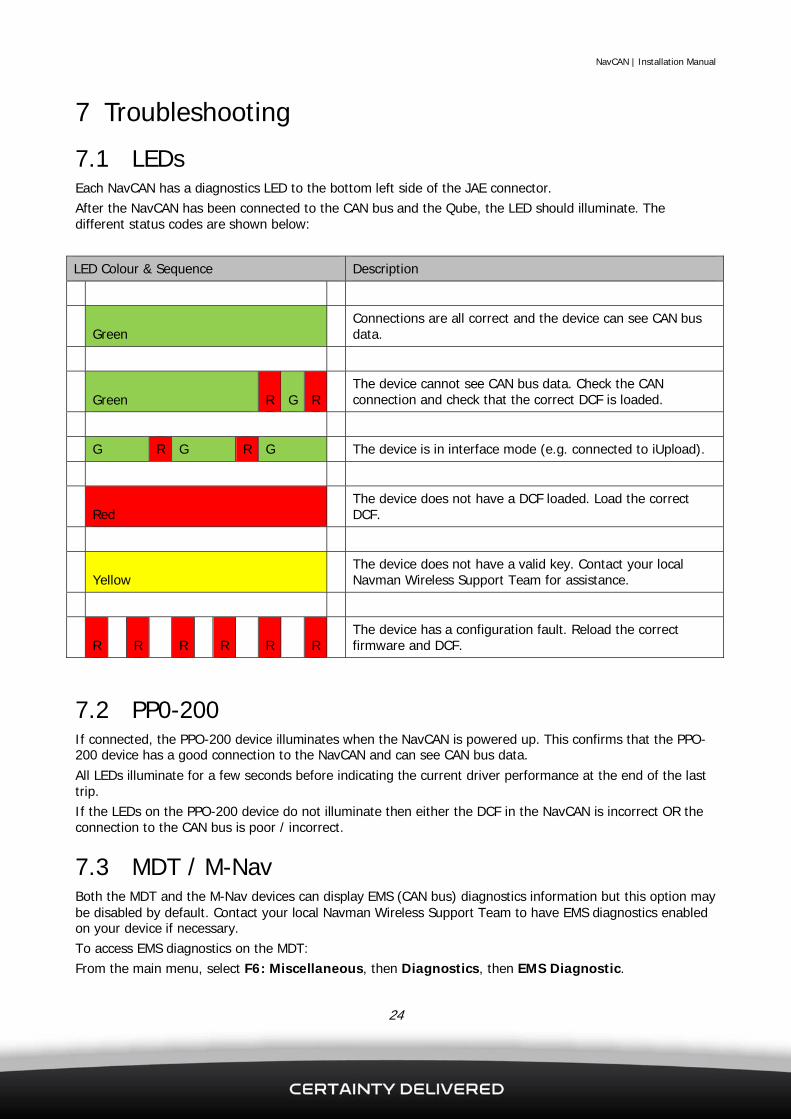
7.1 LEDs Each NavCAN has a diagnostics LED to the bottom left side of the JAE connector. After the NavCAN has been connected to the CAN bus and the Qube, the LED should illuminate. The different status codes are shown below:
LED Colour & Sequence Description
Green Connections are all correct and the device can see CAN bus data.
Green R G R The device cannot see CAN bus data. Check the CAN connection and check that the correct DCF is loaded.
G R G R G The device is in interface mode (e.g. connected to iUpload).
Red The device does not have a DCF loaded. Load the correct DCF.
Yellow The device does not have a valid key. Contact your local Navman Wireless Support Team for assistance.
R R R R R R The device has a configuration fault. Reload the correct firmware and DCF.
7.2 PP0-200 If connected, the PPO-200 device illuminates when the NavCAN is powered up. This confirms that the PPO-200 device has a good connection to the NavCAN and can see CAN bus data. All LEDs illuminate for a few seconds before indicating the current driver performance at the end of the last trip. If the LEDs on the PPO-200 device do not illuminate then either the DCF in the NavCAN is incorrect OR the connection to the CAN bus is poor / incorrect.
7.3 MDT / M-Nav Both the MDT and the M-Nav devices can display EMS (CAN bus) diagnostics information but this option may be disabled by default. Contact your local Navman Wireless Support Team to have EMS diagnostics enabled on your device if necessary. To access EMS diagnostics on the MDT: From the main menu, select F6: Miscellaneous, then Diagnostics, then EMS Diagnostic.
NavCAN | Installation Manual
25
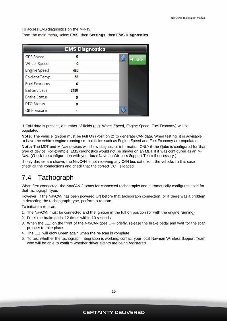
To access EMS diagnostics on the M-Nav: From the main menu, select EMS, then Settings, then EMS Diagnostics.
If CAN data is present, a number of fields (e.g. Wheel Speed, Engine Speed, Fuel Economy) will be populated. Note: The vehicle ignition must be Full On (Position 2) to generate CAN data. When testing, it is advisable to have the vehicle engine running so that fields such as Engine Speed and Fuel Economy are populated. Note: The MDT and M-Nav devices will show diagnostics information ONLY if the Qube is configured for that type of device. For example, EMS diagnostics would not be shown on an MDT if it was configured as an M-Nav. (Check the configuration with your local Navman Wireless Support Team if necessary.) If only dashes are shown, the NavCAN is not receiving any CAN bus data from the vehicle. In this case, check all the connections and check that the correct DCF is loaded.
7.4 Tachograph When first connected, the NavCAN 2 scans for connected tachographs and automatically configures itself for that tachograph type. However, if the NavCAN has been powered ON before that tachograph connection, or if there was a problem in detecting the tachopgraph type, perform a re-scan. To initiate a re-scan: 1. The NavCAN must be connected and the ignition in the full on position (or with the engine running) 2. Press the brake pedal 12 times within 10 seconds. 3. When the LED on the front of the NavCAN goes OFF briefly, release the brake pedal and wait for the scan
process to take place. 4. The LED will glow Green again when the re-scan is complete. 5. To test whether the tachograph integration is working, contact your local Navman Wireless Support Team
who will be able to confirm whether driver events are being registered.

NavCAN | Installation Manual
26
8 Re-installation on a different vehicle
IMPORTANT It is essential to reset a NavCAN device to the factory default settings before installing it in a new vehicle. If a NavCAN device is not reset and is installed into a different vehicle, the vehicle data may be inaccurate or anomalous because some calculations may use stored values from the previous vehicle.
After installation, the NavCAN device begins to store vehicle values such as engine hours and odometer readings. These stored values are specific to the vehicle in which the NavCAN device is installed. Calculations for items (such as fuel economy) may be based on these stored values. The stored values are also used in scenarios where this data is not present on the vehicle CAN and the NavCAN device is required to calculate the data. Therefore, a NavCAN device must be reset to the factory default settings before it is re-installed in a different vehicle, even if the new vehicle is the same model. To restore a NavCAN device to the factory default settings: 1. Load the following DCF file: NAM_RESET.DCF. (See section 6.2 for more information if necessary). 2. Load the DCF which is appropriate to the new vehicle.

NavCAN | Installation Manual
27
9 Training Vehicle electronics can be complex. Any interruption or incorrect connection to the vehicle CAN bus system can potentially cause ECU errors or even component failure. Navman Wireless recommend that all engineers performing installation and service work on NavCAN devices have appropriate training and use the correct equipment to diagnose and upgrade equipment. Navman Wireless has developed a one day training course specifically focused on the CAN bus, and installation and servicing of NavCAN equipment. It covers:
CAN bus principles, NavCAN hardware, Installation and wiring, NavCAN servicing and upgrades, Troubleshooting.
The training course ends with a short multiple-choice exam and engineers who pass receive a certification. The certified engineers also receive:
A user account and software to assist with servicing and upgrading NavCAN devices, Free helpdesk support, Access to installation manuals, updates, fixes, and technical information, Programming hardware.
Some Navman Wireless regions may require engineers to be certified for NavCAN installation before they can be authorised to install and/or service NavCAN hardware. Contact your local Navman Wireless Support Team for more information about the training course.

NavCAN | Installation Manual
28
10 Parts List A list of available parts for the NavCAN 1 and NavCAN 2 is shown below. Contact your local Navman Wireless Support Team for information about pricing and availability.
Product Code Description
10001353 NavCAN 1
10001354 NavCAN 2
10001392 NavCAN wiring loom for Qube 3
10001401 NavCAN wiring loom for Qube 4/5
10001416 Auxiliary power cable
10001397 DatacliQ for CAN bus (ID181)
10001398 DatacliQ for J1708 (ID280)
10001393 Wires for K-Line (Yellow/Amber)
10001394 Wires for Remote Tacho Download (Pink/Grey)
10001395 Wires for J1708 (Red/Green)
10001396 Wires for CAN bus 1 (White/Blue)
10001355 PPO-200 (Driver Awareness Panel)
8600-TL Termination loop for CAN bus 1
6698-SU NavCAN upload cable
8910-ET Pin extraction tool for JAE connector

NavCAN | Installation Manual
29
11 Specifications Physical
Weight: 170 g Material: Nylon Black 6/6
Power Supply Nominal operating voltage: 12 or 24 V
vehicle supplies Minimum operating voltage: 10 V DC Maximum operating voltage: 30 V DC
Typical Current Consumption @ 12 V DC Sleep State, Awake on CAN: 24 mA Running with no external load: 60 mA Running with 300 mA external load on
external 5 V: 220 mA (CAN/RS232 drivers ON)
Typical Current Consumption @ 24 V DC Sleep State, Awake on CAN: 12 mA Running with no external load: 30 mA Running with 300 mA external load on
external 5 V: 110 mA (CAN/RS232 drivers ON)
Qube Communications 1 x RS232
Environmental Storage Temperature: -40 to +90°C
(-40 to +194°F) Operational Temperature: -40 to +85°C
(-40 to +185°F)
CAN Bus Characteristics Baud rate: Selectable (10 – 1000
kBit/sec) Protocols CAN: Selectable (J1939 /
Layer 2 / Proprietary vehicle protocols) Hardware protocol: CAN V 2.0a, CAN V
2.0b Default device address: 240
J1708 Characteristics Baud rate: 9600 bps Protocols: J1587 / J1922 / Proprietary
vehicle protocols K-Line Characteristics
Baud rate: 1200 – 20,000 bps Protocols: DCF configurable, ISO 9141
(Fakra) / ISO 9141-2 (OBDII/CARB) / ISO 14230-2 (KWP 2000) / ISO 14230S (Swedish)
Initialisation: Slow / Fast Message timing: Configurable, with
extended response time

NavCAN | Installation Manual
30
12 Contacts Navman Wireless UK Innovation Centre 2, Keele University Science Park, Staffordshire, ST5 5NH, UK Tel: +44 (0) 1782 55 79 50 Fax: +44 (0) 1782 55 79 79 Email: [email protected] Website: www.navmanwireless.co.uk
Navman Wireless USA 2701 Patriot Boulevard, Suite 150 Glenview, IL 60026, USA Tel: +1 (866) 527-9896 Fax: +1 (847) 729-5988 Email: [email protected] Website: www.navmanwireless.com
Navman Wireless Australia Ground Floor, 16 Giffnock Avenue Macquarie Park NSW 2113, Sydney, Australia Tel: +61 2 9886 8500 Fax: +61 2 9887 2481 Email: [email protected] Website: www.navmanwireless.com.au
Navman Wireless NZ 7-11 Kawana Street, Northcote, PO Box 340-184, Birkenhead 0746 Auckland, New Zealand Tel: 0800 GPS FLEET (0800 477 353) Email: [email protected] Website: www.navmanwireless.co.nz
Navman Wireless Scandinavia Kometvej 10, DK-6230 Rødekro, Danmark Tel: Danmark: +45 70 269 732 Tel: Sweden: +46 8 559 21 916 Tel: Finland: +35 89 2316 3595
Navman Wireless de México Calzada San Pedro #100, Col. del Valle, Pedro Garza García, Nuevo Léon. CP 66220, México Teléfono: +52(81) 8248.4600 ext 1001 Email: [email protected] Website: www.navmanwireless.com.mx
Navman Wireless Taiwan #3, 25Fl., No.508, Sec.5 Zhongxiao E. Rd, Dist. Taipei 110, 11083, Taiwan Tel: +886 0 2 2728 2818 Fax: +886 0 2 2728 2816 Email: [email protected] Website: www.navmanwireless.com.au
Navman Wireless China #911, No. 83, New Town Center, Loushanguan Rd, Changning District, Shanghai, 200336, China Tel: +86 0 21 3218 1056 Fax: + 86 0 21 3218 1052 Email: [email protected] Website: www.navmanwireless.cn
Navman Wireless Italy Via Rudone 23rd, Rovato 25,038, Italia Tel: +39 030 615 6468 Website: www.navmanwirelessitaly.it
NavCAN Installation Manual (October 2013)