naval open architecture machinery control systems for … · naval open architecture machinery...
TRANSCRIPT

1
John Mochulski and Rich Malina
Naval Open Architecture Machinery Control Systems
for Next Generation Integrated Power Systems
Abstract
The Office of Naval Research has initiated the Compact
Power Conversion Technologies Program (Compact
Power) to speed the development of more
compact/higher power density power conversion
technology to support the long term goals of Next
Generation Integrated Power Systems (NGIPS), and to
progress the development of next generation power
management controls to supervise the operation of these
systems throughout the ship.
These next generation systems will require networked
Compact Power conversion modules with agile
embedded controls, which will participate in a multitude
of prioritized local and distributed control strategies.
These strategies range from converter control and system
protection at the power interface level, to power quality
and stability control with fault detection, isolation and
recovery at the device level, and then up to mission-
profile specific power distribution and reserve capacity
alignment with flexible load planning and scheduling at
the system level.
A collaborative product-line vision will drive the
development of NGIPS and Compact Power controls,
incorporating guidance regarding best practices and
emerging standards-based technologies. Key elements in
this vision include the IEEE 1676 guidance for high
power electronic converters, the IEC 16850 process bus
standard and other best-in-class and emerging
technologies for Naval Open Architecture (NOA)
Machinery Control Systems (MCSs). This paper
discusses the driving forces behind and advancing vision
of the emerging NOA MCS needed to support NGIPS.
Introduction
The need for agile power management and improved
machinery control system software on naval ships is
more important than ever given the diverse range of
advanced sensors and weapon systems increasing the
demand for electric power on both new ship platforms
and legacy platforms being modernized. At the same
time, the technology solutions for power management in
the industrial automation industry and the commercial
power utility industry are adapting to meet a host of
emerging Smart Grid standards. This paper describes
the state-of-the-art of control system technology
applicable to Compact Power and NGIPS to help focus
the development of embedded power conversion
software and associated interfaces with the supervisory
level applications as part of a future NOA MCS product-
line vision. This vision includes the application of Smart
Grid and Microgrid standards related to Power
Electronics controls to address the integration of new
power management software on future warships.
The paper begins with (1) a background discussion of
NGIPS and the control system challenges it poses,
followed by (2) a detailed discussion of best practices,
emerging standards and emerging technology driving the
vision for next generation machinery control systems.
Finally, it provides (3) a more focused vision of how
NOA MCS could be applied directly to the control
system challenges of NGIPS, NGIPS Compact Power
Conversion Modules, and NGIPS Power Management
Controllers.
This paper also hopes to educate interested readers
regarding state-of-the-art machinery control systems and
to contribute to the process of developing outstanding
machinery controls systems for NGIPS and other U.S.
Navy applications.
NGIPS Background
Several independent factors have driven the evolution of
naval surface ships towards larger power generation
requirements and the use of electrical propulsion
systems. These factors include:
An increased need for energy efficiency, when
operating in low to medium speed ranges,
An increased need for power to support emerging
high energy weapons and mission systems
technologies,
And many independent advantages of using an
electrical drive system, including:
o The ability to eliminate a great deal of heavy
machinery, including reduction gears, shafting,
Approved for public release; distribution is unlimited.
Report Documentation Page Form ApprovedOMB No. 0704-0188
Public reporting burden for the collection of information is estimated to average 1 hour per response, including the time for reviewing instructions, searching existing data sources, gathering andmaintaining the data needed, and completing and reviewing the collection of information. Send comments regarding this burden estimate or any other aspect of this collection of information,including suggestions for reducing this burden, to Washington Headquarters Services, Directorate for Information Operations and Reports, 1215 Jefferson Davis Highway, Suite 1204, ArlingtonVA 22202-4302. Respondents should be aware that notwithstanding any other provision of law, no person shall be subject to a penalty for failing to comply with a collection of information if itdoes not display a currently valid OMB control number.
1. REPORT DATE MAY 2012 2. REPORT TYPE
3. DATES COVERED 00-00-2012 to 00-00-2012
4. TITLE AND SUBTITLE Naval Open Architecture Machinery Control Systems for NextGeneration Integrated Power Systems
5a. CONTRACT NUMBER
5b. GRANT NUMBER
5c. PROGRAM ELEMENT NUMBER
6. AUTHOR(S) 5d. PROJECT NUMBER
5e. TASK NUMBER
5f. WORK UNIT NUMBER
7. PERFORMING ORGANIZATION NAME(S) AND ADDRESS(ES) NAVSSES,Washington Navy Yard,DC, 20376
8. PERFORMING ORGANIZATIONREPORT NUMBER
9. SPONSORING/MONITORING AGENCY NAME(S) AND ADDRESS(ES) 10. SPONSOR/MONITOR’S ACRONYM(S)
11. SPONSOR/MONITOR’S REPORT NUMBER(S)
12. DISTRIBUTION/AVAILABILITY STATEMENT Approved for public release; distribution unlimited
13. SUPPLEMENTARY NOTES Presented at the Electric Machines Technology Symposium (EMTS) 2012, MAY 23-24 2012, Philadelphia, PA
14. ABSTRACT
15. SUBJECT TERMS
16. SECURITY CLASSIFICATION OF: 17. LIMITATION OF ABSTRACT Same as
Report (SAR)
18. NUMBEROF PAGES
33
19a. NAME OFRESPONSIBLE PERSON
a. REPORT unclassified
b. ABSTRACT unclassified
c. THIS PAGE unclassified
Standard Form 298 (Rev. 8-98) Prescribed by ANSI Std Z39-18
2
and controllable pitch propellers,
o The ability to redistribute propulsion system
machinery to improve space utilization and ship
survivability,
o The ability to provide high levels of starting
torque, useful for ice-breaking in cold seas,
o And the ability to use emerging podded propulsor
systems to increase ship maneuverability and
dynamic positioning capability, and to support
advanced ship hull designs.
For both new ship classes and for the modernization of
existing classes, these factors have driven ship designers
to integrate their propulsion plant and electric plant
together into a Next Generation Integrated Power
System (NGIPS), which must operate under complex,
interactive, mission-dependent real-time protection and
control conditions and constraint.
The move toward NGIPS generates complex
requirements for its Machinery Control System (MCS).
These requirements range from hard real-time response
requirements for equipment protection and control, to
orchestrated distributed alignment requirements for
changeovers in response to:
Overall mission profile selections, establishing the
NGIPS governing strategy for overall economy,
perhaps during loitering or transit, or for
maximum reserve power availability, during
strategic engagement or combat,
More specific power and propulsion profile
selections, selecting generator and distribution
alignments, rolling reserve targets and start and
stop staging,
Dynamically changing bridge lever commands, in
response to pilot house orders,
Dynamically changing ship loads, in response to
mission and weapons systems and ship's crew
activities,
And in response to internally detected faults,
which may require immediate fault isolation and
controllable load reductions, followed by
automatic reconfiguration and load recovery.
A short review of Integrated Power System basics will
help to better illuminate these control system
requirements.
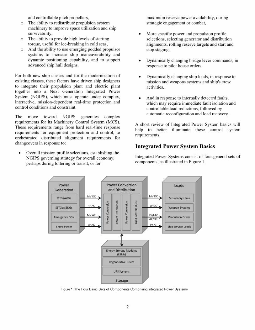
Integrated Power System Basics
Integrated Power Systems consist of four general sets of
components, as illustrated in Figure 1.
Storage
PowerGeneration
Power Conversionand Distribution
Loads
SSTGs/SSDGs
MTGs/ATGs
Energy Storage Modules (ESMs)
Regenerative Drives
Ship Service Loads
Propulsion Drives
Mission Systems
Emergency DGs
Shore Power
Weapon Systems
Po
wer
Dis
trib
uti
on
Po
wer
Co
nve
rsio
n
Load
Cen
ters
(LC
s)
Po
wer
Co
nve
rsio
n
MV DC
HF AC
MV AC
LV AC
MV DC
LV DC
LV AC
LV/MVAC/DC
UPS Systems
Figure 1: The Four Basic Sets of Components Comprising Integrated Power Systems

3
The first set of components is the Generator set, which
typically consists of a prime mover, such as a diesel
engine, gas turbine or steam turbine and its associated
electrical generator. In ship's with dedicated propulsion
equipment, the generator sets may only provide ship
service power, and typically generate low voltage, 60
Hz, three phase, 450 VAC, but higher generator
frequencies and voltages reduce equipment sizes and
power distribution losses at constant power delivery.
Consequently, current and next generation Integrated
Power Systems may employ medium voltage (e.g. 4,160
V-13.8 kV) or higher frequency (200-400 Hz)
generators1.
The second set of components is the Conversion and
Distribution set, which consists of switchboards and of
power conversion and filtering equipment. Generator
power is typically converted to one or more ship
distribution levels, and then later converted to specific
voltages, frequencies and quality levels needed by
individual loads or load centers. In ship's with dedicated
propulsion equipment, ship service designs often
generate and distribute power at 450 VAC and 60 Hz,
providing commonality with many building power
systems. In order to improve power densities, designs
are being driven to higher voltage and/or frequency
levels, as previously discussed. In addition, new mission
systems and propulsion drives have increased the variety
of power delivery requirements for NGIPS. This has
created the need for flexible power conversion modules
that can source a wide variety of input power types and
deliver a wide variety of load types.
The third set of components, the Loads set, includes the
variable speed drives for the propulsion motors in the
case of NGIPS. Many of the so-called "hotel" loads
aboard ship consume power at standard power system
levels: 450 VAC/60 Hz three phase, 220 VAC/60 Hz
three phase, or 110 VAC/60 Hz. A variety of mission
systems consume power at more unusual DC levels,
while commercial variable speed drives for the
propulsion motors typically consume power at either 450
VAC/60 Hz or 4,160-13,800VAC/60 Hz. Power is
typically distributed to the propulsion drives at the
highest available voltage, directly from generator switch
boards with minimal conversion, to reduce the necessary
size of and power losses associated with other
conversion and distribution equipment.
The final set of components is the Storage set, whose
components interact bi-directionally with the NGIPS,
acting as a load when charging, spinning up or
delivering power, and acting as a power source when
discharging, spinning down, or regeneratively braking.
Uninterruptable Power Supply (UPS) systems are the
most common and traditional storage component, but
other next generation energy storage module
technologies are under development, which may be
needed to support future missions and weapons systems.
In addition, bidirectional variable speed drives that feed
power back into the NGIPS when braking may also be
used in future ship classes or modernizations.
Power Electronics as Building Blocks
As generator size and output power flexibility increases,
and at the same time, as ship loads become more diverse
and complex, power conversion becomes one of the key
enabling technologies needed to support NGIPS.
Fortunately, the emergence of high power electronic
conversion modules has provided this key capability.
Electronic power converters play critical roles
throughout the Navy's NGIPS vision. Traditional
Power Conversion Module (PCM)
Thermal Dissipation
Optionally Rectify/ Filter/Isolate/Boost/
Buck
PowerSwitchingModule
Optionally Rectify/Filter/Isolate/Boost/
Buck
Conversion Control Interface
Figure 2: A Generic Power Conversion Module Block Diagram
4
methods of power conversion, including step-up and
step-down transformers and rectifier bridge circuits,
have been supplemented by the development of
electronic switching module designs, which can perform
DC-to-DC, DC-to-AC, AC-to-DC and AC-to-AC power
conversion using power switching modules, as shown in
Figure 2.
At the core of the converter lies the power switching
module. The switching module turns transistors on and
off at high frequencies at precise intervals in order to
control the output wave form, voltage and frequency.
When designing the converter, various types of power
switching transistors are used based on the application's
frequency, voltage and power requirements.
These modules typically rectify and stabilize incoming
power into an internal DC form, and then re-chop the
stabilized DC power into the output power using
feedback controlled switch modulation control.
Synchronized Pulse Width Modulation (SPWM) is a
common technique used to generate AC output power
synchronized to an external bus. The switching module
actually generates fixed magnitude positive and negative
pulses of varying width, which simulate a sinusoidal one
or three phase AC wave form. Similarly, the switching
module can employ pulse width modulated on-off
"chopping" of the internal DC power source to feed
Buck, Boost or Buck-Boost output circuits in order to
generate DC output power at controlled voltage levels.
When the converters must be bidirectional, the input
sections must be able to rectify and stabilize power when
it is flowing in, and must be able to perform controlled
switching when the power is flowing out. Diodes are
generally used to seamlessly change the behavior of the
reversible section based on the instantaneous direction of
power flow.
To enable the development of power electronic
conversion modules for NGIPS and other programs, the
U.S. Navy, through the Office of Naval Research
(ONR), has co-sponsored the Advanced Electrical Power
Systems (AEPS) program, previously known as the
Power Electronic Building Blocks (PEBB) program2.
ONR hopes to encourage the commercialization of
standardized, affordable power conversion components
that satisfy the requirements of both the commercial and
the defense markets.
Key large volume commercial markets that use power
electronic conversion modules include:
Consumer and Office Electronics
o Inverters (12/24 VDC to 115/220 VAC 60/50
Hz)
o Power Supplies (115/220 VAC 50/60 Hz to 1.5-
24 VDC)
o Uninterruptable Power Supplies (UPS)
Automobiles and Trucks
o Electrical Drive Power Control Modules
o Hybrid Electric Drive Power Control Modules
Industrial and Commercial Power and Control
Systems
o Electronic Power Conditioners and Filters
o Inverters (DC to AC, 1 or 3 Phase, 50/60/400
Hz)
o Power Supplies (AC to DC, DC to DC)
o Uninterruptable Power Supplies (Commercial
and Facility UPS)
o Variable Speed Drives (DC and AC to Variable
Frequency AC)
Marine Systems
o Auxiliary Propulsor Drives
o Variable Speed Auxiliary Drives
o Variable Speed Propulsion Drives
Alternative Power Generation/Microgrid Systems
o Fuel Cell Systems (DC-to-AC systems)
o Grid-Tied and Multiple Feed Inverters (DC-to-
AC and AC-to-AC systems)
o Hydro and Wind Turbines (Intermittent and
variable frequency AC to AC converters)
o Solar/Photovoltaic Power (DC-to-AC
converters)
Electric Utility Systems
o Flexible AC Transmission Systems (FACTS)
o Step-Up and Step-Down Converters for High
Voltage Direct Current (HVDC) Transmission
Systems
Zonal Electrical Distribution Systems
For NGIPS, multifunction electronic Power Conversion
Modules (PCMs) are used to adapt ship service
distribution systems to support higher power generation
requirements and more diverse loads including
propulsion, mission and weapons systems. In the past,
electrical power distribution systems on U.S. Navy ships
have always been designed to provide high reliability for
vital loads, and more recent ship designs have utilized a
Zonal Electrical Distribution System (ZEDS), to provide
enhanced survivability during and after equipment
casualties. For NGIPS, the zonal distribution model was
adopted. Figure 3 illustrates a zonal distribution system,
for discussion purposes3.

5
With zonal distribution, the ship is separated into distinct
electrical distribution zones along existing watertight
boundaries. The zones are inter-connected via two
longitudinal power distribution busses, with one bus
typically running along the starboard side of the ship,
and the other bus typically running along the port side.
Each zone can import or export power from adjacent
zones on the longitudinal bus, or it can isolate itself from
adjacent zones using its Power Distribution Module
(PDM).
Zones that contain generator sets can also convert power
to the distribution voltage, using a Power Conversion
Module (PCM), and then feed power to either of the two
longitudinal busses using a PDM. Some systems may
also support cross-tying the busses using the generator
PDM or using another PDM dedicated for this purpose.
In many designs, PDMs may simply be switchboards
with their associated integrated controls, or they may be
switchboard components integrated into a collocated
PCM.
Within each zone, either in-zone or imported power
received from the longitudinal busses is fed to one or
more Power Conversion Modules (PCMs), to service
vital and non-vital loads and load centers located
throughout the zone. In addition, zones may contain
Energy Storage Modules (ESMs), which store power and
can provide emergency power during periods of power
loss or unintended zone isolation. Typically, zones will
contain several PCMs providing redundant sourcing for
vital loads via Automatic Bus Transfer (ABT) switches
or via DC auctioneering diodes. In addition, for some
designs, the distribution modules may be integrated with
PDM
PDM
PCM/PDM
ESM
P C M
GEN SET
PDM
PDM
P C M
ESM
PDM
PDM
PDM/PCM
ESM
P C M
GEN SET
PDM
PDM
PCM/PDM
ESM
P C M
GEN SET
PDM
PDM
P C M
ESM
ZONE 1ZONE 2ZONE 3ZONE 4ZONE 5
ZONE 1ZONE 2ZONE 3ZONE 4ZONE 5
Figure 3: A Notional Zonal Electrical Distribution System
Figure 4: A Notional NGIPS One-Line Diagram
6
the conversion modules.
When zonal distribution is combined into an Integrated
Power System, the Main Propulsion Variable Speed
Drives (VSDs) and Motors (M) become major loads that
are often directly attached to the Generator (G)
switchboards as shown in the form of an electrical one-
line diagram, Figure 4.
This diagram separates the higher voltage generation and
propulsion system from the rest of the ship service
distribution system, and only depicts one distribution
zone, which contains a shore power receptacle.
In some ways, the top portion of the diagram is
analogous to a traditional propulsion plant, with the
generator, variable speed drive, motor and fixed pitch
propeller, replacing the traditional reduction gear,
shafting and controllable pitch propeller. The electrical
system also adds the benefits of (1) a cross-connect
gearbox, allowing one prime mover to move both
propellers, and (2) a reversing gear if the variable speed
drive is reversible.
Future Directions and Control Challenges
of Next Generation Systems
Traditional naval electric plant designs have borrowed
extensively from products sold to commercial markets
and from commercial ship designs to reduce Non-
Recurring Engineering (NRE) costs and associated
development risk. Generator sets and their controls that
were similar in capacity and design to emergency diesel
generators for buildings, such as hospitals, and split
switchboard designs were very similar to designs used
on commercial ships. NGIPS will move naval electric
plant designs away from commercial building designs
towards emerging Smart Grid Substation and Microgrid
designs.
Also, traditional electric plants and propulsion plants
operated more or less independently, and even operating
independently, they still represented the two most
complex machinery control systems aboard ship. With
NGIPS, the electric plant and propulsion system become
fully integrated, with the pilot house lever station
directly raising and lowering electric power generation,
and with the total capacity of the electric plant moving
from the 2-to-10 MW hotel load range, to a 100 MW
plus hotel-plus-propulsion load range. System capacities
have moved from the high end of emergency generators,
where three phase 450 VAC is common, to the low end
of commercial electric power plants, where three phase
13.8 KVAC may be more common.
In addition, zonal distribution systems support a wide
variety of sourcing and distribution alignment options,
which facilitate the rapid reconfiguration and recovery of
the system from equipment casualties. At the same
time, however, this large number of permutations and
combinations makes it absolutely necessary to
thoroughly verify and test automatic fault detection,
isolation and recovery strategies to ensure robust fight-
through-power operations at sea.
Also, to ensure stability, traditional electric plants have
used prioritized load shedding to maintain switchboard
stability. With NGIPS, more advanced stability controls
will be developed that take advantage of controllable
loads, to provide less intrusive and more situationally
aware power plant protection, but these more complex
strategies will also need thorough verification and
validation to ensure electric plant stability.
In addition, traditional mission and weapons systems
seldom have a dramatic impact on the ship service power
demand. Now, with emerging electromagnetic and laser
based weapons systems, weapons systems power
demand are expected to grow from the 500 kW range to
levels in excess of 20 MW. This massive increase in
power demand necessitates improvements in proactive,
mission profile dependent, load planning.
Finally, NGIPS controls are needed to help optimize fuel
consumption during peace keeping loitering and transit
operations, when the ship is operating at low to medium
speeds. Projected savings for operating the plant on
fewer engines at a more efficient operating point can
easily be squandered by choosing NGIPS configurations
with too much power reserve.
In summary, the control challenges facing next
generation systems include:
Ensuring Safe Autonomous Operation throughout
the NGIPS (Protection),
Providing Fault-Tolerant Generation, Distribution,
and Power Management (Fault Tolerance),
Handling Unintentional Islanding and Overload
Scenarios (Fault Detection, Isolation and
Recovery),
Supporting Mission Profile specific Distribution
and Load scheduling (Source, Distribution and
Load Management),
Reducing Electrical Plant Operational Costs
(Economy), and
Creating a cost effective solution from a co-
evolving set of OA equipment (Life Cycle Cost
7
Management).
Many of these topics will be covered in greater detail
later in this paper.
NGIPS Machinery Control Summary
In summary, NGIPS will require a network of power
distribution modules and compact high-power electronic
conversion modules (Compact Power) with agile
embedded controls participating in a multitude of
prioritized local and distributed control strategies. These
flexible PCM building blocks will play multiple roles in
highly survivable NGIPS zonal distribution systems, and
their roles in the system may often be integrated with the
power distribution role for specific ship class designs.
In addition, interacting NGIPS control interfaces must be
developed for PCMs and other participating equipment,
including generator sets, Power Distribution Modules
(PDMs), Energy Storage Modules (ESMs) and
controllable loads. Furthermore, an overall, system
level, power management distributed control application
must be developed to provide overall coordination of
NGIPS operations, including power source alignment
and management, electrical distribution system
alignment and management, controllable load planning
and scheduling, and proactive mission profile specific
supervisory control action.
The remainder of this paper will develop a collaborative
product-line vision that will hopefully help drive the
development of NGIPS and Compact Power machinery
controls. The vision will incorporate guidance regarding
applicable best practices, emerging standards, and other
best-in-class and emerging technologies that will help
create an enabling next generation Machinery Control
System (MCS) to support the needs of NGIPS.
Vision Drivers - Best Practices
To develop a world class vision for next generation
naval machinery control systems, we must start with
current best practices for both machinery control
systems and other closely related automation systems.
The U.S. Navy and the U.S. Department of Defense
provide proven guidance regarding best practices in this
area, including three key practices that strongly impact
the vision for machinery control systems. These three
key practices are:
1. The application of "Naval Open Architecture
(NOA)" principles, as prescribed by the U.S.
Navy's Naval Open Architecture Enterprise Team4,
2. The use of "Product Line Acquisition Strategies",
as recommended by acquisition research
investigations performed by Nickolas Guertin of
the U.S. Navy's Program Executive Office for
Integrated Warfare Systems (PEO IWS) along with
Dr. Paul Clements of the Software Engineering
Institute (SEI) at Carnegie Mellon University5, and
3. The use of "Commonality-based" ship design and
acquisition methods6, as instructed by the Naval
Sea Systems Command (NAVSEA) policy
instruction for commonality of systems,
subsystems, and components.
Each of the key practices is described in detail below.
Naval Open Architecture Principles
According to the "Naval Open Architecture Contract
Guidebook for Program Managers"7, Naval Open
Architecture (NOA) is a combination of business and
technical practices aimed at creating well architected,
modular, portable and interoperable software systems
based on open standards with published interfaces.
When coupled with a well conceived modular design,
the adoption of NOA principles offers the following
advantages:
NOA increases opportunities for innovation by
enabling systems to interface with standards-based
Commercial-Off-The-Shelf (COTS) products and
components, as well as other Navy systems.
NOA increases competition by ensuring inter-
module interfaces within software systems are
published and comply with open standards,
allowing other competitors to interface with,
replace or extend incumbent components, sub-
systems, and systems.
NOA increases opportunities for component,
subsystem and system reuse, by encouraging
modular designs based on standard published
interfaces.
NOA facilitates rapid technology refresh and
insertion, by limiting component and subsystem
coupling, and ensuring key interfaces are
identified up front and are based on open
published standards.
Historically, Machinery Control Systems have been
slowly moving away from proprietary hardware,

8
networks, software and protocols toward a more open
systems approach, but proprietary system configuration
database schemas, proprietary inter-component
application protocols, proprietary control application file
formats, and proprietary Human Machine Interface
(HMI) application file formats still severely limit
Machinery Control System (MCS) application
portability between vendor's systems. The selection and
development of appropriate interface standards is key to
improving MCS application reuse between ship classes
for NGIPS.
Product Line Acquisition Strategies
The second key practice we will explore is the use of a
product line acquisition strategy. The main advantage of
developing and applying a product to serve a particular
function for ship class delivery, over building a special
turn-key system for ship class delivery, is that the
product can be reused again for a different ship class,
with little or no additional Non-Recurring Engineering
(NRE).
This product development perspective is very common
for the vendor community, but it may seem far less
intuitive to view product and product line develop as an
acquisition strategy. However, Nickolas Guertin of the
U.S. Navy's Program Executive Office for Integrated
Warfare Systems (PEO IWS) and Dr. Paul Clements of
the Software Engineering Institute (SEI) at Carnegie
Mellon University explored this paradigm shift, and
concluded that a product line acquisition strategy was
both (1) synergistic with Naval Open Architecture
principles and (2) offered a major opportunity for cost
reduction, quality and capability improvement and risk
reduction for the delivery of Navy systems8.
Guertin and Clements argued that the Navy should view
all of the systems and subsystems they acquired that
performed a specific function as products within product
lines, which could and should be later reapplied across
other ship classes (as they illustrate in Figure 5). Figure 5: Acquisition Evolution Using a Product Line Strategy
9
Guertin and Clements identified three key processes
involved in the product line acquisition approach:
(1) CORE ASSETS: The reuse, refactoring,
development or acquisition of core assets that are
engineered for reuse (e.g. requirements documents,
interface and interchange specifications, software
component libraries and test tools, technical manual
modules, reference designs, processes, management
artifacts, ...),
(2) PRODUCTS: The development or acquisition of
products that incorporate those re‐usable core
assets, and are also engineered for reuse, and
(3) PRODUCT MANAGEMENT: The ongoing
management of a coordinated product development
and delivery plan, which must evolve in scope as it
supports specific ship class programs.
Two key questions should be asked when developing a
product line acquisition strategy. The first is “What
should the long term role be for the Navy?" and the
second is "What should the long term role be for the
suppliers?" These two questions are particularly of
interest for Machinery Control System vendors.
Commonality-based Ship Design
The third and final key practice is the use of
"Commonality-based" ship design and acquisition
methods. As USN CDR Michael Cecere III, Jack
Abbott, USN CDR Michael L. Bosworth, and Tracy
Joseph Valsi described in their 1993 white paper, titled
"Commonality-Based Naval Ship Design, Production &
Figure 5: Acquisition Evolution Using a Product Line Strategy
9
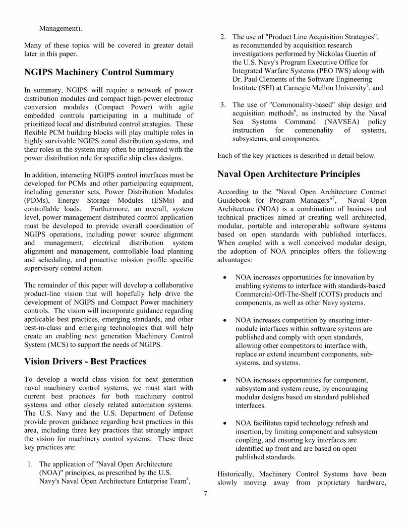
Support"10
, for many years the Navy allowed individual
shipyards to select modules and component parts to use
in their ships (as illustrated on the left in the figure
below). Competing shipyards did not collaborate when
selecting component parts and modules, and as a
consequence, a large number of very similar but
different component parts and modules were used. This
unnecessary variation increased the Navy's costs
throughout the ship's lifecycle, from design and
production, to requirements validation, and finally to
integrated logistics support. Figure 6: A Vision of Increased Commonality
11
The initial vision for increased commonality is shown
above, on the left side of the figure. In this original
vision, which is remarkably similar to the product line
acquisition strategy, common modules that will be
reused across ship classes are fabricated with common
parts, reducing unnecessary variation, and eliminating
replicated.
Since that time, the U.S. Navy's commonality efforts
have grown. On April 6, 2009, Naval Sea Systems
Command (NAVSEA) issued NAVSEA Instruction
4120.8, which established a "NAVSEA Policy for
Commonality of Systems, Subsystems, and
Components"12
. This instruction established a Virtual
Shelf concept along with requirements for its use. The
Shelf has become an online database application that
supports the selection of standard, proven components
for use in new ship designs and modernization going
forward, and has facilitated progress toward
commonality.
Though a great deal of progress has been made,
Machinery Control Systems (MCSs) continue to be a
problematic area for commonality. Jeffrey Cohen of
NAVSSES recently explored commonality in Naval
Machinery Control Systems, and discovered that every
surface ship class in the U.S. Navy had a unique MCS,
and that some ship classes had different systems for
different flights. Cohen concluded that "Non-
standardization abounds", and that MCS commonality
initiatives were warranted13
.
An analogy can be drawn between the current Naval
MCS market situation, and the situation that existed in
the computer market at the dawn of the Personal
Computer (PC) era. Former Intel CEO Andrew Grove,
in his book "Only the Paranoid Survive"14
, described this
transition, as a shift from a vertically integrated
proprietary computer system marketplace, to a new
horizontal computer system marketplace enabled by the
power of de-facto PC standards. To illustrate this
transition, Grove provided an illustration where the
computer industry was modeled as a set of 6 layers,
labeled from bottom to top as:
SALES: IBM
APPLICATIONS: IBM
NETWORKS: IBM
OPERATING SYSTEMS: IBM
Figure 6: A Vision of Increased Commonality
10
COMPUTERS: IBM
CHIPS: IBM
Grove explained that prior to the dawning of the PC
era, each of the leading computer vendors, led by IBM,
had vertically integrated, incompatible product lines,
starting with their proprietary CPU chips, their
proprietary computers, their proprietary operating
systems, and moving on up to their dedicated sales
forces. In addition, the market suffered from vendor
lock-in; once you had purchased an IBM System 370
Main Frame or AS 400 Minicomputer, you were totally
dependent on IBM for all your future needs and
support.
Grove went on to explain, that with the introduction of
the IBM PC and PC AT, including its completely open
Industry Standard Architecture (ISA) reference design,
and the introduction of alternative 8088/8086 and later
80286 and 80386 compatible processing chips, a new
computer industry quickly arose, based on open,
horizontal de-facto standards between each layer.
A multitude of manufacturers competed to make:
SALES: PC Computer and Software Stores
(Best Buy, Circuit City, CompUSA, Egghead,
SoftWarehouse ...)
APPLICATIONS: DOS and Windows application
software (Word Perfect/WinWord, Lotus 123/Excel,
Harvard Graphics/Powerpoint, DBase/Access ...)
NETWORKS: PC hardware compatible network cards
(Ethernet, Arcnet, Token-Ring ...)
OPERATING SYSTEMS: PC hardware compatible
operating systems (DOS, Windows, Linux, OS/2, QNX,
SCO Unix ...)
COMPUTERS: ISA compatible motherboards,
workstations and portables (Compaq, Dell, Gateway,
IBM, Osborne, Gateway, HP ...),
CHIPS: Intel x86 compatible processing chips
(Intel, AMD, IBM, NEC ...)
IBM's decision to develop the PC using other vendors
off-the-shelf parts, then to publish the complete PC
design including the ROM listing in its technical
manual, and then to agree to terms with Microsoft that
didn't restrict them from licensing DOS to other parties
changed the industry forever. The IBM PC reference
design has remained the catalyst for a very competitive
world-wide computer industry for over three decades
now, and has provided an interesting template for the
development and use of other detailed reference designs.
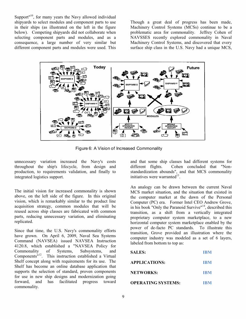
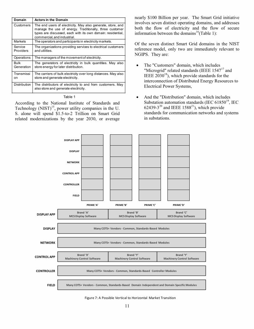
In many ways, the current Naval Machinery Control
System market resembles the old vertical computer
systems market of the late 70's. Once a Machinery
Control System vendor is selected, only their system
participates fully within the architecture, and there is a
strong advantage for controlling the chosen platform,
and for being the incumbent for modernizations (refer to
the left side of Figure 7).
Still it is possible that the introduction of MCS module
commonality along with appropriate standards-based
interface specifications could drive a similar transition in
the Naval Open Architecture Machinery Control System
supplier market, like the right side of the figure above.
Within this new market, the Navy's Virtual Shelf
becomes populated with Common Display Modules,
Common Network Modules, Common Control Modules,
in a variety of form factors, each with certified
compatible replacement and upgrade paths available
from multiple manufacturers. Software and
communication interface standards allow portable
display and control software from multiple vendors to
seamless interoperate within one MCS, fully
participating in the architecture, rather than being limited
to some form of block data exchange. Both the MCS
Framework software and the MCS HMI and Control
Application software are portable and standards based,
enabling complete reuse between platforms. Figure 7: A Possible Vertical to Horizontal Market Transition
Vision Drivers - Emerging Electric Power
Standards
The previous section of this paper discussed key best
practices that should be applied to develop an
outstanding vision for a Naval Machinery Control
System for NGIPS. One of those key practices was to
apply Naval Open Architecture principles, including the
selection of applicable standards. Within the world-wide
electrical power systems community, a massive set of
changes is underway, called Smart Grid.
11
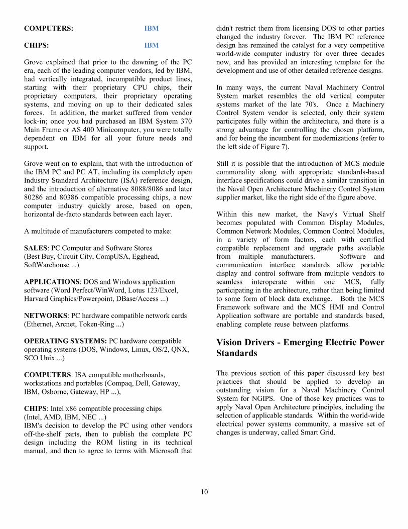
According to the National Institute of Standards and
Technology (NIST)15
, power utility companies in the U.
S. alone will spend $1.5-to-2 Trillion on Smart Grid
related modernizations by the year 2030, or average
nearly $100 Billion per year. The Smart Grid initiative
involves seven distinct operating domains, and addresses
both the flow of electricity and the flow of secure
information between the domains16
(Table 1):
Of the seven distinct Smart Grid domains in the NIST
reference model, only two are immediately relevant to
NGIPS. They are:
The "Customers" domain, which includes
"Microgrid" related standards (IEEE 154717
and
IEEE 203018
), which provide standards for the
interconnection of Distributed Energy Resources to
Electrical Power Systems,
And the "Distribution" domain, which includes
Substation automation standards (IEC 6185019
, IEC
62439-320
and IEEE 158821
), which provide
standards for communication networks and systems
in substations.
FIELD
CONTROLLER
CONTROL APP
NETWORK
DISPLAY
DISPLAY APP
NOTIONAL VERTICAL NAVY MCS MARKET
PRIME ‘A’ PRIME ‘B’ PRIME ‘C’ PRIME ‘D’
Many COTS+ Vendors - Common, Standards-Based Domain Independent and Domain Specific ModulesFIELD
CONTROLLER
CONTROL APP
NETWORK
DISPLAY
DISPLAY APP
Many COTS+ Vendors - Common, Standards-Based Controller Modules
Brand ‘X’Machinery Control Software
Many COTS+ Vendors - Common, Standards-Based Modules
Many COTS+ Vendors - Common, Standards-Based Modules
Brand ‘Y’Machinery Control Software
Brand ‘Y’Machinery Control Software
Brand ‘A’MCS Display Software
Brand ‘B’MCS Display Software
Brand ‘C’MCS Display Software
NOTIONAL HORIZONTAL NAVY OA MCS MARKET
Figure 7: A Possible Vertical to Horizontal Market Transition
Domain Actors in the Domain
Customers The end users of electricity. May also generate, store, andmanage the use of energy. Traditionally, three customertypes are discussed, each with its own domain: residential,
commercial, and industrial.
Markets The operators and participants in electricity markets.
ServiceProviders
The organizations providing services to electrical customersand utilities.
Operations The managers of the movement of electricity.
BulkGeneration
The generators of electricity in bulk quantities. May alsostore energy for later distribution.
Transmission
The carriers of bulk electricity over long distances. May alsostore and generate electricity.
Distribution The distributors of electricity to and from customers. Mayalso store and generate electricity.
Table 1
12
These standards are already driving the development of
new commercial products, such as multiple feed grid-
tied inverters and switchgear control and protection
devices that may become highly relevant to NGIPS in
the near future.
Microgrid Standards
In the past, certain commercial buildings (such as
hospitals) and manufacturing facilities (such as refineries
or chemical plants) contained their own power
generators for either emergency backup service or waste
heat utilization, but these systems rarely had a major
impact on the overall design of electrical power systems,
in general. However, with the growth of distributed
renewable energy resources, such as photovoltaic/solar
systems and wind and hydrodynamic power turbine
systems, and also with the development of laws
requiring utility companies to allow integration of these
systems with their regional electrical power systems, a
newly emerging electrical grid of incumbent electrical
power systems and interconnected distributed electrical
power resources has evolved.
As part of the effort to enable this evolution, the IEEE
Standards Coordinating Committee 21 on Fuel Cells,
Photovoltaics, Dispersed Generation and Energy Storage
has developed the IEEE 1547 Standard, illustrated in
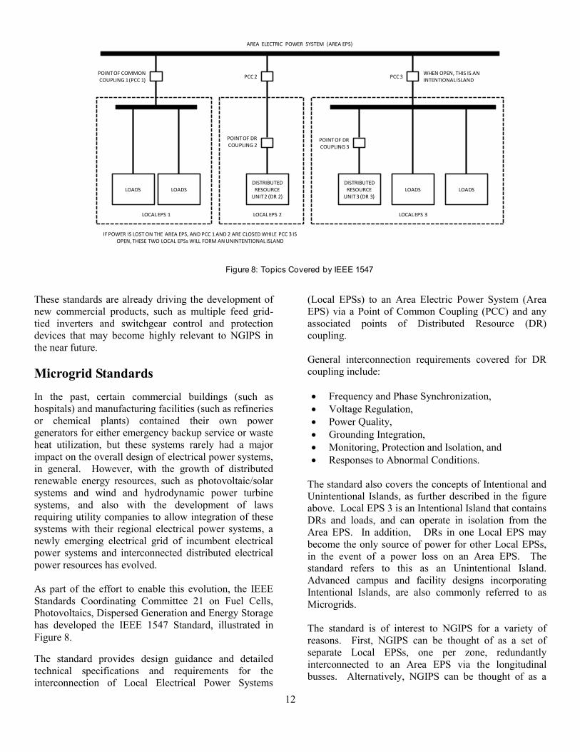
Figure 8. Figure 8: Topics Covered by IEEE 154722
The standard provides design guidance and detailed
technical specifications and requirements for the
interconnection of Local Electrical Power Systems
(Local EPSs) to an Area Electric Power System (Area
EPS) via a Point of Common Coupling (PCC) and any
associated points of Distributed Resource (DR)
coupling.
General interconnection requirements covered for DR
coupling include:
Frequency and Phase Synchronization,
Voltage Regulation,
Power Quality,
Grounding Integration,
Monitoring, Protection and Isolation, and
Responses to Abnormal Conditions.
The standard also covers the concepts of Intentional and
Unintentional Islands, as further described in the figure
above. Local EPS 3 is an Intentional Island that contains
DRs and loads, and can operate in isolation from the
Area EPS. In addition, DRs in one Local EPS may
become the only source of power for other Local EPSs,
in the event of a power loss on an Area EPS. The
standard refers to this as an Unintentional Island.
Advanced campus and facility designs incorporating
Intentional Islands, are also commonly referred to as
Microgrids.
The standard is of interest to NGIPS for a variety of
reasons. First, NGIPS can be thought of as a set of
separate Local EPSs, one per zone, redundantly
interconnected to an Area EPS via the longitudinal
busses. Alternatively, NGIPS can be thought of as a
AREA ELECTRIC POWER SYSTEM (AREA EPS)
LOADS LOADSDISTRIBUTED
RESOURCE UNIT 2 (DR 2)
DISTRIBUTED RESOURCE
UNIT 3 (DR 3)LOADS LOADS
LOCAL EPS 1 LOCAL EPS 2 LOCAL EPS 3
POINT OF COMMON COUPLING 1 (PCC 1)
PCC 2 PCC 3
POINT OF DR COUPLING 2
POINT OF DR COUPLING 3
WHEN OPEN, THIS IS AN INTENTIONAL ISLAND
IF POWER IS LOST ON THE AREA EPS, AND PCC 1 AND 2 ARE CLOSED WHILE PCC 3 ISOPEN, THESE TWO LOCAL EPSs WILL FORM AN UNINTENTIONAL ISLAND
Figure 8: Topics Covered by IEEE 1547

13
complex Microgrid that is periodically interconnected to
the Area EPS via Shore Power breakers. For both cases,
the standard helps provide well researched specifications
and requirements for associated system control and
protection devices.
Second, the standard offers an evolving set of industry
standards that will drive the design of many commercial
products. In particular, the standard addresses
requirements for the "Interconnection System" (see
Figure 9), which may be a conventional generator set
controller, with associated speed governors, voltage
regulators, synchronizers and power control breakers, or
may be a grid-tied power electronics based inverter, for a
solar panel system with an energy storage module. Figure 9: IEEE 1547 Addresses Grid Interconnection
Requirements23
In particular, IEEE Standard 1547-4-2011 - IEEE Guide
for Design, Operation and Integration of Distributed
Resource Island Systems with Electric Power Systems24
,
is of particular interest to NGIPS. The standard
addresses many special considerations, unique to island
systems, including:
Requirements dependent upon the current direction
of power flow,
The use of multiple Points of Common Coupling ,
Reserve margin and load flow stability
requirements when importing or exporting,
The handling of transitions between various island
modes:
1. Area EPS-connected mode,
2. Intentional/Unintentional transitions to Island
mode,
3. Island mode detection and operation,
4. Reconnection mode, when operating in the
correct voltage, frequency and phase angle
windows.
For those of you familiar with naval electric plant
operations, these operating modes may sound very
familiar to many standard naval operations, such as 1.
Shore power-connected mode, 2. Ship’s power modes
with switchboards tied or isolated, 3. Power loss
detection, isolation and recovery, and 4.
Resynchronization for transitions back to shore power or
back to tied switchboards.
In addition to IEEE 1547, IEEE 2030-2011 - IEEE
Guide for Smart Grid Interoperability of Energy
Technology and Information Technology Operation with
the Electric Power System (EPS), End-Use Applications,
and Loads25
provides architectural perspectives and
reference models for the development of system
interoperability requirements for Smart Grid-related
projects, including those involving Microgrids. The
three Interoperability Architecture Perspectives (IAP)
are the Power System IAP (PS-IAP), the
Communications Technology IAP (CT-IAP), and the
Information Technology IAP (IT-IAP). These three
perspectives are used in conjunction with specific Smart
Grid reference models to provide a detailed and common
set of identifiers for power, communication and data
flow paths within the system with associated tools and
maps. Though the methodology carries a steep learning
curve, it may mature into a very valuable framework for
NGIPS.
Substation Automation Standards
In addition to the Smart Grid efforts to safely and
reliably integrate distributed electrical power resources
into existing utility grids to allow expansion of and
innovation within the renewable and smart consumer
energy system segments, there are also efforts aimed at
improving the grid's reliability and fault isolation
capability. For these purposes, substation
modernization is a key focus area.
AREA EPS
DISTRIBUTED RESOURCE (DR) UNIT
LOCAL EPS
PCC
POINT OF DR COUPLING
INTERCONNECTIONSYSTEM
Figure 9: IEEE 1547 Addresses Grid
Interconnection Requirements

14
Within the electrical power system, distribution
substations receive incoming power feeds from one or
more transmission lines, convert the power from
transmission levels to distribution levels, and then feed
the power to one or more distribution lines. Similarly,
transmission substations, receive power from one or
more incoming transmission lines, optionally convert the
power to a different transmission level, and then feed
one or more outgoing transmission lines. Substations
may also contain large banks of capacitors that can be
used to perform power factor control to reduce
transmission line losses, and substations normally
contain switchgear, which is a name given to large
electrical disconnect switches that are designed to
rapidly extinguish electrical arcs when they are opened.
More relevantly, substations also provide fault detection
and isolation capabilities that must occur as fast as
possible to prevent cascading fault propagation to
adjacent parts of the grid.
The Smart Grid committees developed the IEC 61850
standard, titled, "Communication networks and systems
in substations", to drive the modernization of electrical
substations to improve the fault detection, isolation,
external notification and diagnostic identification
capabilities of their control systems26
. The standard
introduced a new substation automation reference model,
as illustrated in Figure 10. Figure 10: IEC 61850 Substation Automation Reference
Model27
The bottom of the figure represents the process level
interface to the high voltage electrical power system
equipment in the switchyard, including current and
voltage transformers and switchgear. In the past, this
equipment would be integrated with protection and
control power relays in control bays inside a control
building protected from the switchyard. IEC 61850
prescribes the development of a dedicated IEC 61850
“Process Bus", which is a new high performance
network architecture that eliminates control relay wiring,
and replaces it with a high bandwidth fiber optic
network based on switched Ethernet technology.
With IEC 61850, the power relay equipment is replaced
by IEC 61850 compatible Intelligent Electronic Devices
(IEDs) that perform protection, control, monitoring,
notification and recording activities, based to meet the
goals of Smart Grid.
For NGIPS the key areas of interest are:
New IEC 61850 "Process Bus" sensors, actuators
and merging units (gateway devices that allow
legacy sensors to communicate with the bus),
New IEC 61850 "Process Bus" communication
switches that implement new high availability
Ethernet communication schemes,
New IEC 61850 Intelligent Electronic Devices
(IEDs), including protection, control and first-out
recording devices,
A suite of standards based communication
protocols, including protocols introduced by IEC
SENSORS ACTUATORS
STATION LEVEL
BAY/UNIT LEVEL
PROCESS LEVEL
HIGH VOLTAGE EQUIPMENT
SENSORS ACTUATORS
PROTECTION CONTROL PROTECTIONCONTROL
PROCESS BUS
STATION BUS
GATEWAYTO SCADA
SUBSTATIONHMI
PROCESS BUS
REMOTE PROCESSINTERFACE UNITS
INTELLIGENT ELECTRONIC DEVICES (IEDs)
Figure 10: IEC 61850 Substation Automation Reference Model
15
61850, and those adopted from other IEEE and IEC
standards.
In particular, the emerging "Process Bus"
communications standards are of special interest, and we
will delve into them in greater depth.
High Availability Automation Networks
Standards
The availability and performance requirements needed
for substation process control and protection drove the
development of two new high availability automation
networks based on fiber-optic switched Ethernet base
technology. The two new high availability standards
were developed by consortium and standardized as IEC
62439-3 - Industrial communication networks - High
availability automation networks - Part 3: Parallel
Redundancy Protocol (PRP) and High-availability
Seamless Redundancy (HSR)28
. The first of these
standards, Parallel Redundancy Protocol, is illustrated in
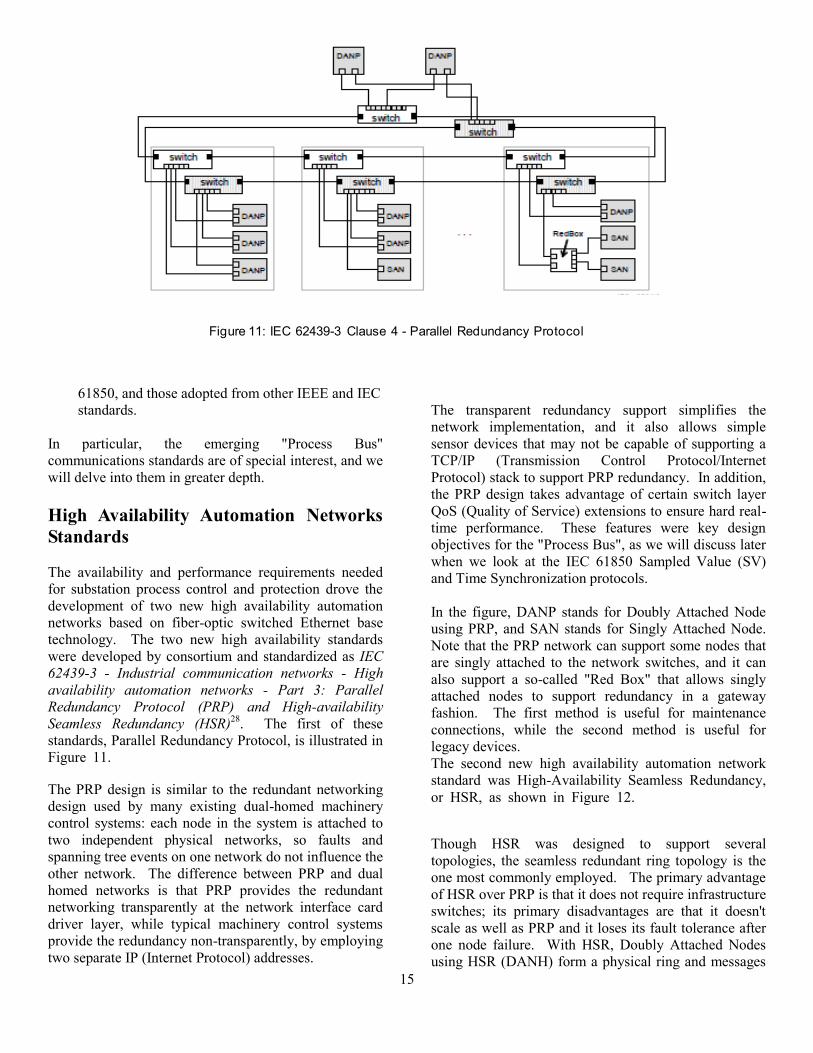
Figure 11.igure 11: IEC 62439-3 Clause 4 - Parallel
Redundancy Protocol29
The PRP design is similar to the redundant networking
design used by many existing dual-homed machinery
control systems: each node in the system is attached to
two independent physical networks, so faults and
spanning tree events on one network do not influence the
other network. The difference between PRP and dual
homed networks is that PRP provides the redundant
networking transparently at the network interface card
driver layer, while typical machinery control systems
provide the redundancy non-transparently, by employing
two separate IP (Internet Protocol) addresses.
The transparent redundancy support simplifies the
network implementation, and it also allows simple
sensor devices that may not be capable of supporting a
TCP/IP (Transmission Control Protocol/Internet
Protocol) stack to support PRP redundancy. In addition,
the PRP design takes advantage of certain switch layer
QoS (Quality of Service) extensions to ensure hard real-
time performance. These features were key design
objectives for the "Process Bus", as we will discuss later
when we look at the IEC 61850 Sampled Value (SV)
and Time Synchronization protocols.
In the figure, DANP stands for Doubly Attached Node
using PRP, and SAN stands for Singly Attached Node.
Note that the PRP network can support some nodes that
are singly attached to the network switches, and it can
also support a so-called "Red Box" that allows singly
attached nodes to support redundancy in a gateway
fashion. The first method is useful for maintenance
connections, while the second method is useful for
legacy devices.
The second new high availability automation network
standard was High-Availability Seamless Redundancy,
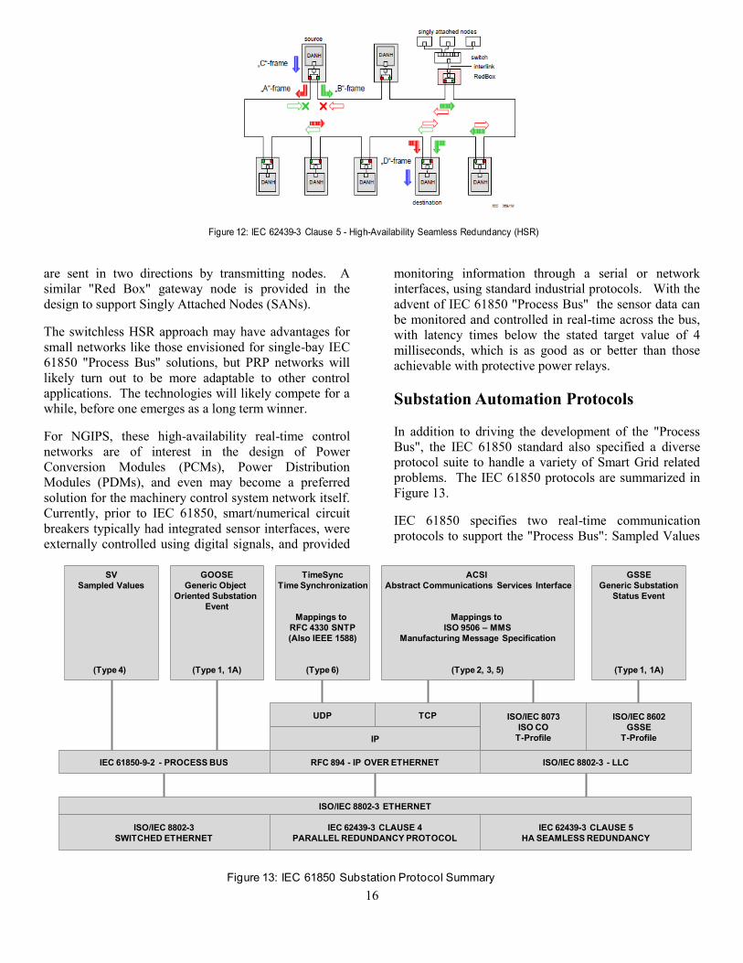
or HSR, as shown in Figure 12.Figure 12: IEC 62439-3 Clause 5 - High-Availability Seamless Redundancy (HSR)
30
Though HSR was designed to support several
topologies, the seamless redundant ring topology is the
one most commonly employed. The primary advantage
of HSR over PRP is that it does not require infrastructure
switches; its primary disadvantages are that it doesn't
scale as well as PRP and it loses its fault tolerance after
one node failure. With HSR, Doubly Attached Nodes
using HSR (DANH) form a physical ring and messages
Figure 11: IEC 62439-3 Clause 4 - Parallel Redundancy Protocol
16
are sent in two directions by transmitting nodes. A
similar "Red Box" gateway node is provided in the
design to support Singly Attached Nodes (SANs).
The switchless HSR approach may have advantages for
small networks like those envisioned for single-bay IEC
61850 "Process Bus" solutions, but PRP networks will
likely turn out to be more adaptable to other control
applications. The technologies will likely compete for a
while, before one emerges as a long term winner.
For NGIPS, these high-availability real-time control
networks are of interest in the design of Power
Conversion Modules (PCMs), Power Distribution
Modules (PDMs), and even may become a preferred
solution for the machinery control system network itself.
Currently, prior to IEC 61850, smart/numerical circuit
breakers typically had integrated sensor interfaces, were
externally controlled using digital signals, and provided
monitoring information through a serial or network
interfaces, using standard industrial protocols. With the
advent of IEC 61850 "Process Bus" the sensor data can
be monitored and controlled in real-time across the bus,
with latency times below the stated target value of 4
milliseconds, which is as good as or better than those
achievable with protective power relays.
Substation Automation Protocols
In addition to driving the development of the "Process
Bus", the IEC 61850 standard also specified a diverse
protocol suite to handle a variety of Smart Grid related
problems. The IEC 61850 protocols are summarized in
Figure 13.
IEC 61850 specifies two real-time communication
protocols to support the "Process Bus": Sampled Values
Figure 12: IEC 62439-3 Clause 5 - High-Availability Seamless Redundancy (HSR)
ISO/IEC 8802-3 - LLC
ISO/IEC 8802-3
SWITCHED ETHERNET
IEC 62439-3 CLAUSE 5
HA SEAMLESS REDUNDANCY
IEC 62439-3 CLAUSE 4
PARALLEL REDUNDANCY PROTOCOL
IP
UDP TCP
TimeSync
Time Synchronization
Mappings to
RFC 4330 SNTP
(Also IEEE 1588)
(Type 6)
ACSI
Abstract Communications Services Interface
Mappings to
ISO 9506 – MMS
Manufacturing Message Specification
(Type 2, 3, 5)
ISO/IEC 8073
ISO CO
T-Profile
IEC 61850-9-2 - PROCESS BUS
ISO/IEC 8602
GSSE
T-Profile
ISO/IEC 8802-3 ETHERNET
RFC 894 - IP OVER ETHERNET
GSSE
Generic Substation
Status Event
(Type 1, 1A)
GOOSE
Generic Object
Oriented Substation
Event
(Type 1, 1A)
SV
Sampled Values
(Type 4)
Figure 13: IEC 61850 Substation Protocol Summary
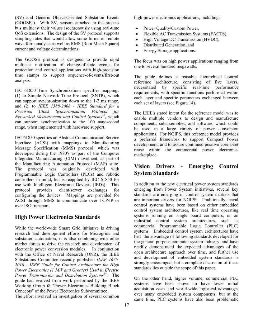
17
(SV) and Generic Object-Oriented Substation Events
(GOOSEs). With SV, sensors attached to the process
bus multicast their values isochronously using real-time
QoS extensions. The design of the SV protocol supports
sampling rates that would allow some forms of remote
wave form analysis as well as RMS (Root Mean Square)
current and voltage determinations.
The GOOSE protocol is designed to provide rapid
multicast notification of change-of-state events for
protection and control applications with high-precision
time stamps to support sequence-of-events/first-out
analysis. Figure 13: IEC 61850 Substation Protocol Summary
31,32
IEC 61850 Time Synchronizations specifies mappings
(1) to Simple Network Time Protocol (SNTP), which
can support synchronization down to the 1-2 ms range,
and (2) to IEEE 1588-2008 - IEEE Standard for a
Precision Clock Synchronization Protocol for
Networked Measurement and Control Systems33
, which
can support synchronization to the 100 nanosecond
range, when implemented with hardware support.
IEC 61850 specifies an Abstract Communication Service
Interface (ACSI) with mappings to Manufacturing
Message Specification (MMS) protocol, which was
developed during the 1980's as part of the Computer
Integrated Manufacturing (CIM) movement, as part of
the Manufacturing Automation Protocol (MAP) suite.
The protocol was originally developed with
Programmable Logic Controllers (PLCs) and robotic
controllers in mind, but is reapplied by IEC 61850 for
use with Intelligent Electronic Devices (IEDs). This
protocol provides client/server exchanges for
configuring the devices. Mappings are provided for
ACSI through MMS to communicate over TCP/IP or
over ISO transport.
High Power Electronics Standards
While the world-wide Smart Grid initiative is driving
research and development efforts for Microgrids and
substation automation, it is also combining with other
market forces to drive the research and development of
electronic power conversion modules. In conjunction
with the Office of Naval Research (ONR), the IEEE
Substations Committee recently published IEEE 1676-
2010 - IEEE Guide for Control Architecture for High
Power Electronics (1 MW and Greater) Used in Electric
Power Transmission and Distribution Systems34
. The
guide had evolved from work performed by the IEEE
Working Group i8 "Power Electronics Building Block
Concepts" of the Power Electronics Subcommittee.
The effort involved an investigation of several common
high-power electronics applications, including:
Power Quality/Custom Power,
Flexible AC Transmission Systems (FACTS),
High Voltage DC Transmission (HVDC),
Distributed Generation, and
Energy Storage applications.
The focus was on high power applications ranging from
one to several hundred megawatts.
The guide defines a reusable hierarchical control
reference architecture, consisting of five layers,
necessitated by specific real-time performance
requirements, with specific functions performed within
each layer and specific parameters exchanged between
each set of layers (see Figure 14).Figure 14: IEEE 1676-
2010 Control Layer Reference Model35
. The IEEE's stated intent for the reference model was to
enable multiple vendors to design and manufacture
components, subassemblies, and software, which could
be used in a large variety of power conversion
applications. For NGIPS, this reference model provides
a preferred framework to support Compact Power
development, and to assure continued positive core asset
reuse within the commercial power electronics
marketplace.
Vision Drivers - Emerging Control
System Standards
In addition to the new electrical power system standards
emerging from Power System initiatives, several key
standards are emerging in control system markets that
are important drivers for NGIPS. Traditionally, naval
control systems have been based on either embedded
control system architectures, like real time operating
systems running on single board computers, or on
industrial control system architectures, such as
commercial Programmable Logic Controller (PLC)
systems. Embedded control system architectures have
had the advantage of following standards developed for
the general purpose computer system industry, and have
readily demonstrated the expected advantages of the
open architecture approach over time, and further use
and development of embedded system standards is
strongly encouraged, but a complete discussion of these
standards lies outside the scope of this paper.
On the other hand, higher volume, commercial PLC
systems have been shown to have lower initial
acquisition costs and world-wide logistical advantages
over many embedded system components, but at the
same time, PLC systems have also been problematic

18
from an open architecture perspective. Several evolving
industrial control system standards are critical for the
effective use of PLC systems to ensure application
portability and life cycle technology migration and
refresh support. Those emerging industrial control
standards are:
IEC 61131-3 - Programmable controllers - Part 3:
Programming languages36
, which provides
language standards for control application
programs written for programmable controllers,
perhaps better known as Programmable Logic
Controllers (PLCs);
IEC 61499-1 - Function blocks - Part 1:
Architecture37
, which provides architectural
models for the implementation of function block
oriented control system applications, and serves as
an umbrella standard for actual standard function
block libraries like Foundation Fieldbus;
IEC 61158 - Industrial communication networks -
Fieldbus specifications38
, which provides
specifications for world recognized industrial
communication networking standards, and
IEC 62541 - OPC Unified Architecture39
, which
provides a platform-independent standard for
control systems integration addressing security,
data access, alarms and conditions, control
program control and historical data access
services.
These evolving international standards provide an initial
foundation for a Naval Open Architecture Machinery
Control System, but their limitations and lack of
maturity are of serious concern, and need to be examined
thoroughly.
Programmable Logic Controller
Standards
According to industry lore, in 1968 in North America,
industrial control manufacturers developed plans for
Programmable Logic Controllers (PLCs) in response to a
Request for Proposal (RFP) from General Motors (GM)
Hydramatic transmission division for a reconfigurable
electronic replacement for hard-wired relay control
systems. Up to that time, GM's assembly line control
systems had been implemented using relay control
components designed using standard electrical drawings
depicting switches, relay coils, and associated relay
contacts. The so-called "Relay Ladder Logic" graphical
programming language for PLCs was created to provide
System Control ≥10ms
Application Control ≈.1ms..1s..
Converter Control ≈10 µ s..10ms
Switching Control ≈ 1.. 10µs
Hardware Control ≈ 0.1.. 1 µ s
From App
From Sys
From Swt
From App
From Cnv
From Hwr
From Cnv
From Swt
Sys-App
App-Cnv
Cnv-Swt
Swt-Hwr
Control layer interfaces and signal direction convention
IEEE Std 1676-2010
IEEE Guide for Control Architecture for High Power Electronics (1MW and Greater)
Used in Electronic Power Transmission and Distribution Systems
8
Copyright ©2011 IEEE. All Rights Reserved
Figure 14: IEEE 1676-2010 Control Layer Reference Model

19
transfer of training for electrical control engineers
familiar with relay control systems. For North America,
GM was a major market leader, and ladder logic became
the preferred language for PLC programming from
virtually all manufacturers.
However in Europe, PLCs evolved in several very
different ways, leading to other programming languages.
In Germany, the first PLC application language was
more of a simplified macro assembly language, and in
France, additional languages were introduced that
represented PLC programs using a higher level
simplified PASCAL-like language or as a flow chart
(GRAFCET). On the Pacific Rim, ideas were studied
and still more variations were developed with similar but
different programming languages.
The PLC became quite popular due to its ability to
replace relay control systems in factory floor
environments. And due its ability to support the online
monitoring and modification of control application
programs while they were running in real-time. This
capability is indispensible when troubleshooting control
applications where the process under control cannot be
halted and restarted without great effort or cost.
Despite the PLC's success, however, the lack of
programming language standards continued to present a
large problem. Large end users strongly urged the
vendor community to standardize PLC programming
languages, and the first major world-wide
standardization effort culminated in the introduction of
IEC 61131-340
(originally IEC 1131). Unfortunately,
this broadly embraced initial standard did little to resolve
any of the PLC programming language portability
issues.
IEC 61131-3 did recognize five distinct programming
languages:
Instruction List (IL), which is similar to macro
assembly language for a virtual machine,
Ladder Diagram (LD), which is the IEC version of
relay ladder logic,
Function Block Diagram (FBD), which is another
way to represent programs in a way that is similar
to IEC-style drawings of logic gates used in
integrated circuit design,
Structured Text (ST), which is a higher level
procedural programming language, and
Sequential Function Chart (SFC), which is a
graphical flow chart representation language with
origins in the aforementioned GRAFCET language.
Unfortunately, the IEC 61131-3 standard did not specify
language or system function call requirements to the
level needed to support application portability. Instead,
it introduced the nebulous concept of “Partial-
Compliance”. The related IEC 61499 standard defines
another function block style programming language that
is more consistent with the model used by continuous
control systems. It also does not ensure portability. A
consortium style standards body headquartered in the
Netherlands and called PLCopen41
is trying to develop a
truly portable language specification, but its efforts have
not influenced the PLC industry leaders to any great
extent. PLCopen does appear to have greater traction in
motion control segment of the marketplace, where
several vendors are adopting its application
programming interface requirements.
The IEC 61131-3 standard is also being extended to
improve object oriented features of the Structured Text
programming language. This effort highlights another
area of concern, which is the lack of coherence between
IEC 61131-3 and any of the world-wide computer
programming language, environment and
communication standards, including ADA, C, C++, C#,
Fortran, Java, POSIX, POSIX sockets, etc.
The three issues for NOA MCS that may be addressed
by IEC 61131-3 over time include:
The Lack of Language Portability Standards, which
is exceptionally poor for the graphical
programming languages: IEC 61131-3 LD, FBD
and SFC and IEC 61499 FB. Source files for these
languages are often kept in proprietary formats with
little or no similarities;
The Lack of System Function Library
Standardization (like POSIX, POSIX sockets),
especially when accessing diagnostic system
functions, time of day clock functions, and network
communication functions; and
The Lack of Integration between PLC
Programming Environments and Software Source
Control and Configuration Management tools,
especially an inability to clearly separate out or
export text based source files.
The IEC 61131-3 Structured Text (ST) language seems
to offer the most portability at this time, and is directly
represented as text, though significant issues still exist
within different vendors. In addition, the use of an
insulating, platform independent, system function library
20
is recommended, rather than directly invoking any
system function calls directly.
Fieldbus Communication Standards
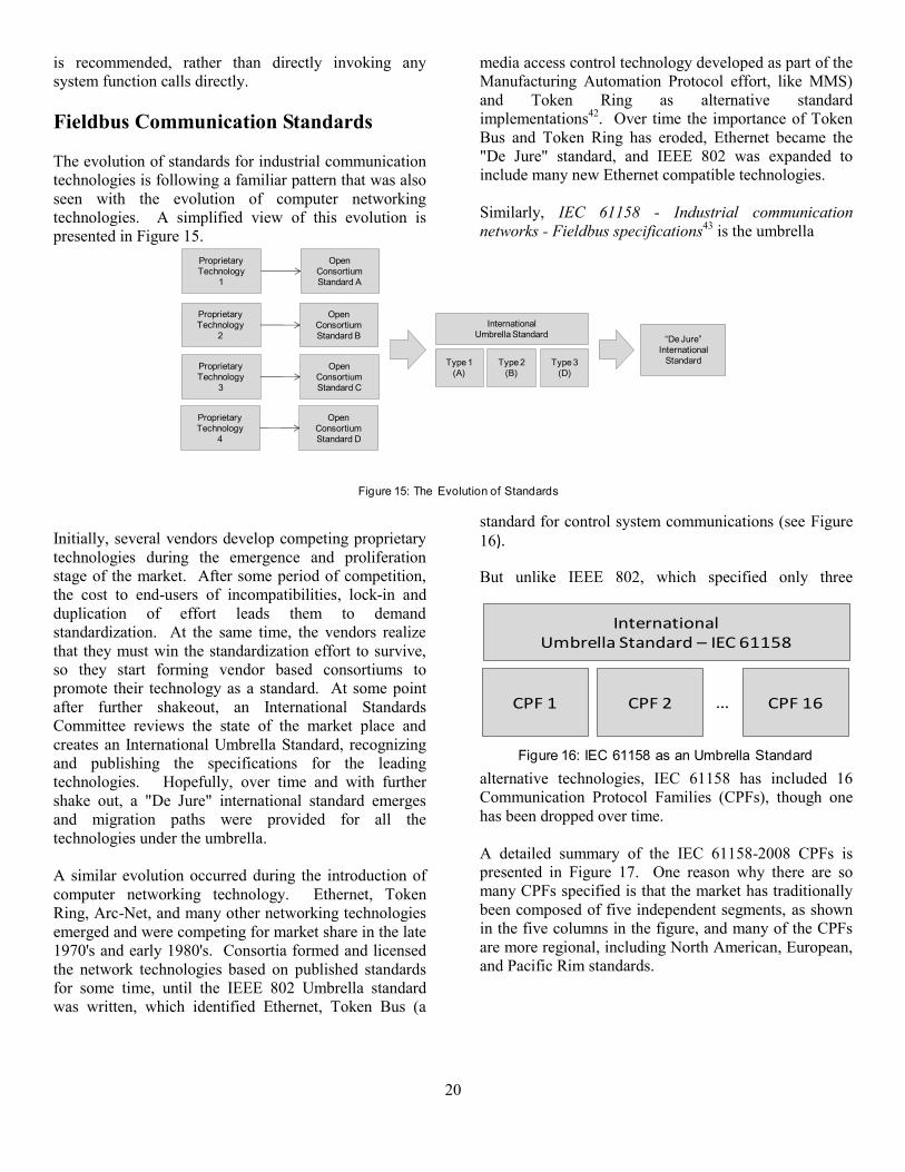
The evolution of standards for industrial communication
technologies is following a familiar pattern that was also
seen with the evolution of computer networking
technologies. A simplified view of this evolution is
presented in Figure 15.
Figure 15: The Evolution of Standards
Initially, several vendors develop competing proprietary
technologies during the emergence and proliferation
stage of the market. After some period of competition,
the cost to end-users of incompatibilities, lock-in and
duplication of effort leads them to demand
standardization. At the same time, the vendors realize
that they must win the standardization effort to survive,
so they start forming vendor based consortiums to
promote their technology as a standard. At some point
after further shakeout, an International Standards
Committee reviews the state of the market place and
creates an International Umbrella Standard, recognizing
and publishing the specifications for the leading
technologies. Hopefully, over time and with further
shake out, a "De Jure" international standard emerges
and migration paths were provided for all the
technologies under the umbrella.
A similar evolution occurred during the introduction of
computer networking technology. Ethernet, Token
Ring, Arc-Net, and many other networking technologies
emerged and were competing for market share in the late
1970's and early 1980's. Consortia formed and licensed
the network technologies based on published standards
for some time, until the IEEE 802 Umbrella standard
was written, which identified Ethernet, Token Bus (a
media access control technology developed as part of the
Manufacturing Automation Protocol effort, like MMS)
and Token Ring as alternative standard
implementations42
. Over time the importance of Token
Bus and Token Ring has eroded, Ethernet became the
"De Jure" standard, and IEEE 802 was expanded to
include many new Ethernet compatible technologies.
Similarly, IEC 61158 - Industrial communication
networks - Fieldbus specifications43
is the umbrella
standard for control system communications (see Figure
16). Figure 16: IEC 61158 as an Umbrella Standard
44
But unlike IEEE 802, which specified only three
alternative technologies, IEC 61158 has included 16
Communication Protocol Families (CPFs), though one
has been dropped over time.
A detailed summary of the IEC 61158-2008 CPFs is
presented in Figure 17. One reason why there are so
many CPFs specified is that the market has traditionally
been composed of five independent segments, as shown
in the five columns in the figure, and many of the CPFs
are more regional, including North American, European,
and Pacific Rim standards.
“De Jure”
International
Standard
International
Umbrella Standard
Type 1
(A)
Type 2
(B)
Type 3
(D)
Proprietary
Technology
1
Open
Consortium
Standard A
Proprietary
Technology
2
Open
Consortium
Standard B
Proprietary
Technology
3
Open
Consortium
Standard C
Proprietary
Technology
4
Open
Consortium
Standard D
Figure 15: The Evolution of Standards
InternationalUmbrella Standard – IEC 61158
CPF 1 CPF 2 CPF 16…
Figure 16: IEC 61158 as an Umbrella Standard

21
Though many of the technologies compete for the
control network segment, only a few compete in the
more specialized segments. Within the control network
segment, there has been a consolidation toward switched
Ethernet based technologies, however, there has been
little shakeout among the competing Ethernet protocols,
and several technologies have introduced extensions to
Ethernet to improve determinism and jitter performance.
These technologies may also be affected by the high
availability PRP and HSR networking technologies
emerging from substation automation. For the control
networking segment, it is best to not become too
dependent on any of these specific protocols, and to try
to use standard Ethernet technology whenever possible.
The second column highlights the market for intelligent
industrial devices, such as a motor controller, where
multi-drop serial interfacing, using the RS-485 or RS-
422 electrical standards is still more cost effective then
Ethernet technologies. For this application, Profibus-DP
and Modbus are the leading technologies that are
commonly used in machinery control systems.
The third column highlights communication
technologies that were developed for very low cost basic
industrial devices, typically as a multi-drop replacement
for digital wiring. These technologies may be of interest
for some design issues, but have not played a major role
in naval machinery control, to date. The last two
columns cover process transmitter networks, focusing on
upgrading existing 4-20ma infrastructure, and
coordinated drive networks, where fast, low jitter
communications were critical for multi-axis motion
control and paper and fiber web processes. Figure 17: IEC 61158 Communication Protocol Family
Summary45
System Interfacing Standards
Prior to the advent of Personal Computers (PCs), Human
Machine Interface (HMI) systems were typically
integrated into control systems using proprietary
technologies provided the control system vendor. These
took the form of operator consoles, for process control
systems, or panel mounted displays, for machine
builders or assembly line systems. The underlying
technologies usually were licensed from general purpose
computer manufacturers or were based on the control
system vendor's proprietary microprocessor systems.
With the advent of the PC, a new product market formed
the PC HMI market. These products provided
distributed control system capabilities at a lower price
point, when used in conjunction with Programmable
Logic Controllers (PLCs). Unfortunately, these products
depended on a myriad of proprietary communication
technologies and protocols (the protocols identified in
IEC 61158 barely scratch the surface), and the burden of
developing these communication interfaces fell to the
IEC 61158-2008
Communication Protocol
Family (CPF)
Control Networks Intelligent Industrial
Devices
Basic Industrial
Devices
(Switches/Buttons)
Process
Transmitters/Smart
Transmitters
Coordinated Drive
Controls/Motion
Controls/CNCs
CPF 1 - Foundation Fieldbus
(Emerson)
Foundation Fieldbus
HSE
Foundation Fieldbus
H1/H2, SP50
CPF 2 - Control and
Information Protocol (CIP)
(Rockwell)
ControlNet,
Ethernet/IP
DeviceNet ControlNet
CPF 3 - Profibus (Siemens) Profibus DP,
Profinet
Profibus DP Profibus PA Profinet
CPF 4 - P-NET P-NET RS232/485,
P-NET on IP
P-NET RS232
CPF 5 - WorldFIP WorldFIP
CPF 6 - InterBus (Phoenix
Contact)
InterBus-S InterBus-S InterBus-S
CPF 7 - Swifnet
CPF 8 - CC-Link (Mitsubishi) CC-Link IE Control,
CC Link IE Field,
CC-Link, CC Link LT,
CC-Link Safety
CPF 9 - HART HART
CPF 10 - Vnet/IP (Yokogawa) Vnet/IP Vnet/IP
CPF 11 - Tcnet (Toshiba) TCnet TCnet
CPF 12 - EtherCAT (ABB) EtherCAT EtherCAT
CPF 13 - Ethernet Powerlink/
CANopen
Ethernet
POWERLINK (EPL)
Ethernet
POWERLINK (EPL)
CPF 14- Ethernet for Plant
Automation (EPA, Kyland/
China)
Eternet for Plant
Automation (EPA)
CPF 15 - Modbus-RTPS Modbus-TCP,
Modbus-RTPS (DDS)
Modbus,
Modbus-TCP
CPF Number 16 - SERCOS SERCOS I, II, III
Industrial Communication/Fieldbus Application Segment
Figure 17: IEC 61158 Communication Protocol Family Summary

22
PC HMI company. Later, process control system
vendors began to port their proprietary HMI systems to
personal computer platforms, and they also desired a
standard way to communicate to the wide of variety of
third party devices that might be encountered in the
typical process control environment.
In 1995, Microsoft began encouraging the development
of vertical market Application Programming Interface
(API) standards based on their Component Object Model
(COM) and Object Linking and Embedding (OLE)
technologies. With Microsoft's help, an industry task
force was assembled to prototype a set of standard APIs
for control system integration. The group later became
known as the OLE for Process Control task force, or
simply the OPC task force. The task force delivered its
first interface standard, OPC Data Access Version 1,
covering server discovery and rendezvous, server
security, data item browsing, and publish and subscribe
data access capabilities in 1996, when the effort shifted
to marketing and sustaining the activity.
The group formed the OPC Foundation, which sold
corporate and end-user memberships, and expanded the
scope of its standard APIs to cover alarms and
conditions and historical data access. The foundation
also developed compliance and interoperability test tools
and sponsored interoperability testing events. The OPC
APIs became widely adopted world, and have been a
great success for both the PC HMI and process control
system markets. The OPC Foundation also started
initiatives aimed at data access across Intranets or the
Internet.
The primary benefit of the OPC APIs was to shift the
burden of development of the communications drivers
from the PC HMI product teams, back to the control
system product vendors. Prior to this shift, every PC
HMI product frequently required updates every time the
control system product vendor introduced a new product
or communications variant. After OPC, the control
system vendor was responsible for updating their OPC
server as part of the control system product update.
Though the OPC APIs were highly successful, they were
tied to Microsoft's proprietary underlying COM
technology, which limited their applicability, and when
Microsoft decided to create their new .NET Common
Language Runtime technology, updates were needed for
the COM based OPC APIs to extend their applicability.
The technical subcommittees within the OPC
Foundation developed a new vision for a next generation
OPC, which they later called OPC Unified Architecture.
Key drivers of the vision were:
To build on the success of the OPC APIs, but to
unify the data access, alarms and conditions, and
historical data access interfaces into a common and
consistent server address space;
To eliminate the dependency of OPC on proprietary
Microsoft technology, by focusing on open
standard communication mechanisms;
To provide mechanisms that would extend OPC's
reach from the personal computer environment to
both embedded systems and internet applications.
In addition, they strove to make OPC Unified
Architecture a true international standard. The result of
this effort is IEC 62541 - OPC Unified Architecture46
, as
summarized in Figure 18.Figure 18: IEC 62541 - OPC
Unified Architecture Overview47
The standard includes an extended security and
communications model, which supports unified versions
of the familiar OPC service domains: server discovery
and rendezvous, item browsing, data access, alarms and
conditions, program control and historical data access.
The extended security model supports optional
public/private key payload signing using the Public Key
Infrastructure (PKI) and AES (Advanced Encryption
Standard) payload encryption. Requests can be encoded
in a compact binary format, for embedded systems, or in
a platform independent XML (eXtensible Markup
Language) format, for web-based systems. Also, the
communications can be based on TCP (Transmission
Control Protocol) for embedded systems, or on SOAP
(Simple Object Access Protocol) XML posted over
HTTP or HTTPS (Hyper-Text Transport Protocol or
Secure Hyper-Text Transport Protocol) for web-based
systems. The OPC Foundation has also provided
compliance testing tools and interoperability workshops,
building momentum from their previous successes.
The OPC Foundation also provides members with a
reference implementation of the protocol stack, and
through the foundation and its tool making members,
stacks are available for ANSI 'C', ANSI C++, C#,
VB.NET and Java.
There are two notable performance deficiencies in OPC
Unified Architecture that impact NOA MCS for NGIPS.
First, the OPC UA always communicates over
client/server sessions, so server communication loads are
not invariant with the number of clients, as they would
be with an isochronous multicast model. Second, the
new OPC standard does not support in-process servers.
The original COM based technology supported in-
process servers that could serve as a minimal wrapping
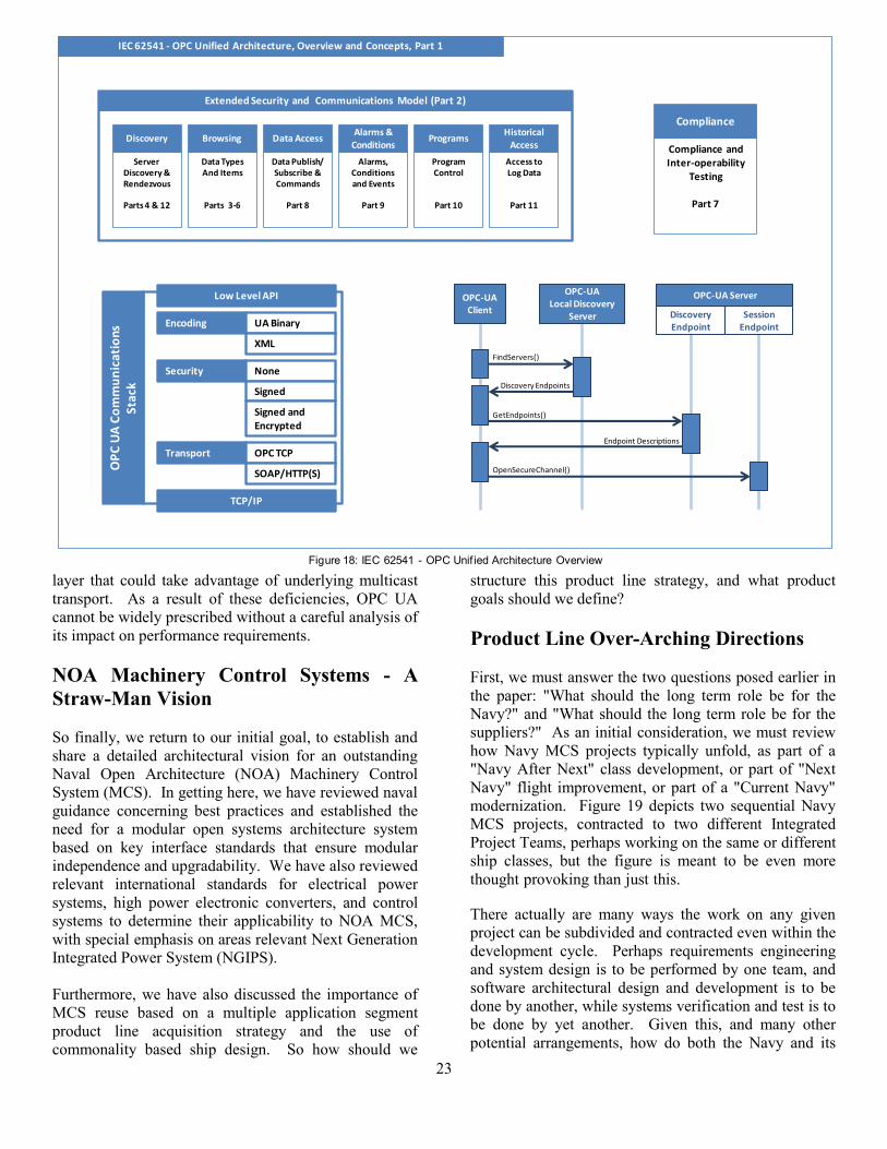
23
layer that could take advantage of underlying multicast
transport. As a result of these deficiencies, OPC UA
cannot be widely prescribed without a careful analysis of
its impact on performance requirements.
NOA Machinery Control Systems - A
Straw-Man Vision
So finally, we return to our initial goal, to establish and
share a detailed architectural vision for an outstanding
Naval Open Architecture (NOA) Machinery Control
System (MCS). In getting here, we have reviewed naval
guidance concerning best practices and established the
need for a modular open systems architecture system
based on key interface standards that ensure modular
independence and upgradability. We have also reviewed
relevant international standards for electrical power
systems, high power electronic converters, and control
systems to determine their applicability to NOA MCS,
with special emphasis on areas relevant Next Generation
Integrated Power System (NGIPS).
Furthermore, we have also discussed the importance of
MCS reuse based on a multiple application segment
product line acquisition strategy and the use of
commonality based ship design. So how should we
structure this product line strategy, and what product
goals should we define?
Product Line Over-Arching Directions
First, we must answer the two questions posed earlier in
the paper: "What should the long term role be for the
Navy?" and "What should the long term role be for the
suppliers?" As an initial consideration, we must review
how Navy MCS projects typically unfold, as part of a
"Navy After Next" class development, or part of "Next
Navy" flight improvement, or part of a "Current Navy"
modernization. Figure 19 depicts two sequential Navy
MCS projects, contracted to two different Integrated
Project Teams, perhaps working on the same or different
ship classes, but the figure is meant to be even more
thought provoking than just this. Figure 19: Applying the
Product Line Approach in the Real World There actually are many ways the work on any given
project can be subdivided and contracted even within the
development cycle. Perhaps requirements engineering
and system design is to be performed by one team, and
software architectural design and development is to be
done by another, while systems verification and test is to
be done by yet another. Given this, and many other
potential arrangements, how do both the Navy and its
Server Discovery & Rendezvous
Parts 4 & 12
Alarms, Conditionsand Events
Part 9
ProgramControl
Part 10
Access to Log Data
Part 11
Extended Security and Communications Model (Part 2)
Data TypesAnd Items
Parts 3-6
Discovery Browsing
Data Publish/ Subscribe & Commands
Part 8
Data AccessAlarms &
ConditionsPrograms
Historical Access
Transport OPC TCP
SOAP/HTTP(S)
Encoding UA Binary
XML
Security None
Signed
Signed and Encrypted
Low Level API
TCP/IP
OP
C U
A C
om
mu
nic
atio
ns
Stac
k Discovery Endpoints
ClientLocal Discovery
ServerDiscoveryEndpoint
SessionEndpoint
OPC-UAClient
OPC-UALocal Discovery
Server
OPC-UA Server
DiscoveryEndpoint
SessionEndpoint
FindServers()
GetEndpoints()
Endpoint Descriptions
OpenSecureChannel()
IEC 62541 - OPC Unified Architecture, Overview and Concepts, Part 1
Compliance and Inter-operability
Testing
Part 7
Compliance
Figure 18: IEC 62541 - OPC Unif ied Architecture Overview

24
suppliers develop core assets and product lines that are
engineered for reuse, that are transferable between MCS
efforts, and that can offer upward compatibility for the
future modernization of past efforts based on the same
product line?
The Navy's product line vision must leverage its core
competencies and assets, while the business
community's product line vision must leverage theirs.
For the Navy, this seems to mean an increased focus on
more prescriptive and reusable core assets and products
for:
Machinery Control System Specification and
Standardization,
Machinery Control System Product and Application
Segment Requirements,
Machinery Control System Interface Designs, and
Machinery Control System Verification and
Validation Testing.
The vision is for the Navy to collaborate with its
suppliers, through cooperative R&D to demonstrate
"proof of concept" solutions and by encouraging
Original Equipment Manufacturers (OEMs) to sign on
by providing access to specifications and draft code.
Pursuant to this goal, the Navy's product line might
include segment specific libraries of portable core assets
for:
Standards Based System Data Formats,
Standards Based Interface Specification Formats,
Standards Based Display System Components and
Systems,
Standards Based Control Application Components
and Systems, and
Standards Based Data Repository and Report
Formats.
In short, the Navy's product line should focus on
providing reusable MCS application assets with
increasing quality control, lower per project Non-
Recurring Engineering (NRE), and increasing levels of
commonality-based MCS design.
At the same time the business community should focus
on providing a scalable and configurable, high
performance, portable, software-based NOA MCS
platform:
That can integrate the Navy's reusable standards-
based product libraries for displays, controls,
subsystem interface specifications, data repositories
and reports,
That can run on Navy's Commonality-based MCS
hardware modules,
That can interface with standard industrial networks
and field buses,
That has a modular open systems architecture with
clear interfaces to support extension and
integration, and
That is based on key best practices, and supports
emerging standards and technologies.
In short, the business community should focus on
providing a world-class modular open MCS platform
that can support standards-based portable Navy product
assets.
Applying the Vision to NGIPS
The general product line vision for Naval Open
Architecture Machinery Control Systems (NOA MCS)
provides a clearer long term goal for machinery control,
Requirements and Design Capture
Product Line Assets
PROJECT „A‟
INTEGRATED PROJECT TEAM
PROJECT „B‟
INTEGRATED PROJECT TEAM
NOA
MCS
V1.0
NOA
MCS
V2.0
Upward
Compatibility
Figure 19: Applying the Product Line Approach in the Real World
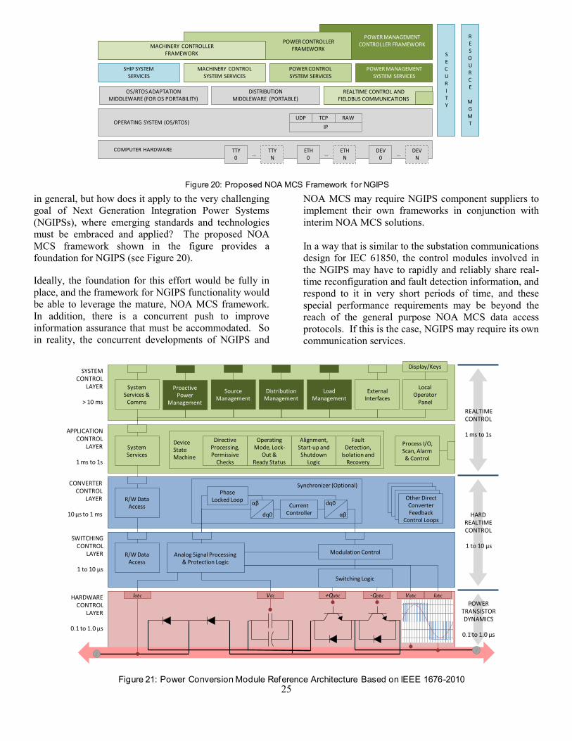
25
in general, but how does it apply to the very challenging
goal of Next Generation Integration Power Systems
(NGIPSs), where emerging standards and technologies
must be embraced and applied? The proposed NOA
MCS framework shown in the figure provides a
foundation for NGIPS (see Figure 20). igure 20: Proposed NOA MCS Framework for NGIPS
Ideally, the foundation for this effort would be fully in
place, and the framework for NGIPS functionality would
be able to leverage the mature, NOA MCS framework.
In addition, there is a concurrent push to improve
information assurance that must be accommodated. So
in reality, the concurrent developments of NGIPS and
NOA MCS may require NGIPS component suppliers to
implement their own frameworks in conjunction with
interim NOA MCS solutions.
In a way that is similar to the substation communications
design for IEC 61850, the control modules involved in
the NGIPS may have to rapidly and reliably share real-
time reconfiguration and fault detection information, and
respond to it in very short periods of time, and these
special performance requirements may be beyond the
reach of the general purpose NOA MCS data access
protocols. If this is the case, NGIPS may require its own
communication services.
Synchronizer (Optional)
DeviceStateMachine
+QabcVdcIabc Vabc-Qabc
Switching Logic
Iabc
Modulation Control
//
dq0
αβ
αβ
dq0
Phase Locked Loop
CurrentController
Analog Signal Processing& Protection Logic
R/W DataAccess
R/W DataAccess
SystemServices
SystemServices &
Comms
HARDWARECONTROL
LAYER
0.1 to 1.0 µs
SWITCHINGCONTROL
LAYER
1 to 10 µs
CONVERTERCONTROL
LAYER
10 µs to 1 ms
APPLICATIONCONTROL
LAYER
1 ms to 1s
SYSTEMCONTROL
LAYER
> 10 ms
Operating Mode, Lock-
Out &Ready Status
Fault Detection,
Isolation and Recovery
DirectiveProcessing,Permissive
Checks
DistributionManagement
SourceManagement
External Interfaces
Alignment, Start-up and Shutdown
Logic
Local Operator
Panel
LoadManagement
Display/Keys
Process I/O, Scan, Alarm & Control
ProactivePower
Management
Other DirectConverterFeedback
Control LoopsHARD
REALTIMECONTROL
1 to 10 µs
REALTIMECONTROL
1 ms to 1s
POWERTRANSISTORDYNAMICS
0.1 to 1.0 µs
Figure 21: Power Conversion Module Reference Architecture Based on IEEE 1676-2010
ETH0
ETHN
…
DISTRIBUTIONMIDDLEWARE (PORTABLE)
OS/RTOS ADAPTATION MIDDLEWARE (FOR OS PORTABILITY)
MACHINERY CONTROLLER FRAMEWORK
MACHINERY CONTROL SYSTEM SERVICES
POWER CONTROL SYSTEM SERVICES
SHIP SYSTEMSERVICES
TTY0
TTYN
…
OPERATING SYSTEM (OS/RTOS)
COMPUTER HARDWARE
UDP
IP
TCP RAW
DEV0
DEVN
…
POWER MANAGEMENT CONTROLLER FRAMEWORKPOWER CONTROLLER
FRAMEWORK
POWER MANAGEMENTSYSTEM SERVICES
SECURITY
REALTIME CONTROL ANDFIELDBUS COMMUNICATIONS
RESOURCE
MGMT
Figure 20: Proposed NOA MCS Framework for NGIPS

26
Additionally, these NGIPS communication services may
be logically broken up into (1) controller services needed
for protection, fault detection and isolation, and fault
recovery, and (2) more proactive control power
management communication services, orchestrating
temporary reconfigurations to support specific mission
objectives. Splitting up the design of these services to
define specific subsets needed for specific classes of
devices may be advantageous.
The general point is that the NOA MCS framework
should not prevent and indeed should support the
addition of dedicated high performance communication
services, when needed. Of course, these new services
should also be defined with published open formats, to
allow collaboration in the supplier community.
Power Conversion Module Architectures
With regards to IEEE 1676-2010 High Power
Electronics reference design, the general purpose NOA
MCS architecture should apply to the application and
system control layers, as illustrated in Figure 21. The
diagram makes a distinction between (1) the real-time
control regime, which can generally be achieved using
general purpose microprocessors and a multitasking real-
time operating system, and (2) the hard real-time regime,
which generally requires dedicated microprocessors or
digital signal processors (DSPs) operating over a known
instruction path length in a hard loop with very limited
external interaction.
The application layer would generally be involved with
converter alignment, directive processing and fault
detection, isolation and recovery. It would also interface
with I/O devices not directly interfaced to the switching
control layer, including circuit breakers used for
converter alignment and isolation, for instance.
The system layer would interface with the NOA MCS
control network, where it should participate with the
NOA MCS service layers, providing diagnostics,
publishing data, receiving directives, and publishing
alarms and events. In addition, the system layer would
interface with any NGIPS specific distributed
communication services. Power conversion modules
may be involved in power source management, when
they used to convert power from generator source power
levels to distribution levels, or they may be involved in
distribution management, when they are integrated with
circuit breakers that are involved in power distribution
alignment and serve the roles of both a PCM and PDM,
or they may be involved in load management, when they
serve the role of a variable speed drive. In addition, the
converter may participate in proactive power
management, performing an orchestrated role in a
mission specific activity.
ConverterControl Layer
HardwareControl Layer
ApplicationControl Layer
SystemControlLayer
IEC 61850Process BusSV/GOOSE
Other SelectedStandardIntefaces
Selected Auxiliary I/O
GeneratorControl Panels
Diesel EngineSpeed
Governors
AutomaticVoltage
Regulators
Control &Protection
Relays
Circuit Breakers/
Switchgear
Current and Voltage Sensors
Other PIUsFull AuthorityDigital Engine
Controllers
Arc/Ground/… Fault Detectors
Meters/Synchronizers
CT, VT & CBMerging Units
Process Interface Units Generator Set Control Devices
Other Controllers &
IEDs
Digital Inputs
Analog Inputs
Digital Outputs
InterposingRelays
Analog Outputs
Other…
IEEE 1588 v2Clock Synch
(e.g. VME, Modbus, Profibus)
Figure 22: Power Conversion Module External Interface Requirements
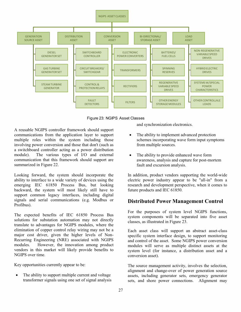
27
A reusable NGIPS controller framework should support
communications from the application layer to support
multiple roles within the system including those
involving power conversion and those that don't (such as
a switchboard controller acting as a power distribution
module). The various types of I/O and external
communication that this framework should support are
summarized in Figure 22.
Looking forward, the system should incorporate the
ability to interface to a wide variety of devices using the
emerging IEC 61850 Process Bus, but looking
backward, the system will most likely still have to
support common legacy interfaces, including digital
signals and serial communications (e.g. Modbus or
Profibus).
The expected benefits of IEC 61850 Process Bus
solutions for substation automation may not directly
translate to advantages for NGIPS modules, where the
elimination of copper control relay wiring may not be a
major cost driver, given the higher levels of Non-
Recurring Engineering (NRE) associated with NGIPS
modules. However, the innovation among product
vendors in this market will likely provide benefits to
NGIPS over time.
Key opportunities currently appear to be:
The ability to support multiple current and voltage
transformer signals using one set of signal analysis
and synchronization electronics.
The ability to implement advanced protection
schemes incorporating wave form input symptoms
from multiple sources.
The ability to provide enhanced wave form
awareness, analysis and capture for post-mortem
fault and excursion analysis.
In addition, product vendors supporting the world-wide
electric power industry appear to be "all-in" from a
research and development perspective, when it comes to
future products and IEC 61850.
Distributed Power Management Control
For the purposes of system level NGIPS functions,
system components will be separated into five asset
classes, as illustrated in Figure 23.
Each asset class will support an abstract asset-class
specific system interface design, to support monitoring
and control of the asset. Some NGIPS power conversion
modules will serve as multiple distinct assets at the
system level (for instance, a distribution asset and a
conversion asset).
The source management activity, involves the selection,
alignment and change-over of power generation source
assets, including generator sets, emergency generator
sets, and shore power connections. Alignment may
NGIPS ASSET CLASSES
GENERATIONSOURCE ASSET
DISTRIBUTIONASSET
CONVERSIONASSET
BI-DIRECTIONAL/STORAGE ASSET
LOADASSET
DIESELGENERATOR SET
GAS TURBINEGENERATOR SET
STEAM TURBINEGENERATOR
SWITCHBOARDCONTROLLER
CIRCUIT BREAKERS/SWITCHGEAR
CONTROL & PROTECTION RELAYS
FAULTDETECTORS
ELECTRONICPOWER CONVERTERS
TRANSFORMERS
BATTERIES/FUEL CELLS
SPINNING RESERVES
REGENERATIVEVARIABLE SPEED
DRIVES
NON-REGENERATIVEVARIABLE SPEED
DRIVES
HYBRID ELECTRICDRIVES
SYSTEMS W/SPECIALPOWER
CHARACTERISTICS
OTHER CONTROLLALELOADS
OTHER ENERGYSTORAGE MODULES
RECTIFIERS
FILTERS
Figure 23: NGIPS Asset Classes

28
include power reserve levels, and automatic start
sequencing set points.
The distribution management activity would primary
involve the selection, alignment, change-over and fault
isolation and recovery strategy alignments of power
distribution and some power conversion assets.
Load planning and scheduling would involve the
alignment and orchestration of smart ship loads to
accomplish objectives to support mission specific power
requirements. These activities would primarily interact
with bi-directional and load assets.
Proactive control, may involve the orchestration of many
NGIPS assets to ensure the availability of resources to
support mission specific objectives.
It may be instructive to map this system level power
management view of NGIPS to a more familiar electric
plant one-line diagram, as shown in Figure 25.
Each of the major components of the one-line diagram
on the left has been labeled with its associated asset
class. The one-line diagram depicts an integrated power
system with two propulsion motors directly connected to
the two primary switchboards, and a zonal electrical
G G G G
M M
VSD VSD
PCM
PCM
PCM
PCM PCM
PCM
ESM
PCM
DIST
STORE
CONV
CONV
CONV
CONV CONV
CON
VCO
NV
GEN
GEN
GEN
GEN
DIST
DIST
LOA
D LOA
D
DISTDIST
Figure 25: Mapping Power Management to a One-Line View
POWER MGMTSYSTEM LEVEL CONTROLLER
SOURCEMANAGEMENT
DISTRIBUTIONMANAGEMENT
LOAD PLANNING& SCHEDULING
PROACTIVECONTROL
Figure 24: Power Management System Level Controller Functions

29
distribution system, but depicts only one zone, which
includes a shore power connection.
A corresponding asset class view of the same one-line
diagram is shown in Figure 26. The control plane
connections are shown in green while some of the power
plane connections are shown in red. With this more
familiar one-line view, source management, distribution
management and load planning and scheduling might
seem more clear, and it becomes more apparent how the
tightly interconnected NGIPS components on the power
plane must form a tightly interconnected, fault tolerant
distributed control system on the control plane.
The definition of NGIPS asset classes and the attempt to
develop asset class specific interfaces represents one of
the key ways in which the plant is being engineered for
reuse with a product line strategy. The goal is to be able
to reuse asset class drivers between projects, along with
most of the core controller modules used to implement
power distribution and power conversion modules.
The higher level, system control may be ship class
design dependent, but at least the communications
design can be reused between ship classes, and efforts
can be focused on the changes in the power generation,
distribution and load center networks.
Conclusions and Next Steps
This paper presented a detailed straw man architectural
vision for the development of Naval Open Architecture
(NOA) Machinery Control Systems (MCSs) with a
special emphasis on the requirements of Next
Generation Integrated Power Systems (NGIPSs). A key
strategy employed in this vision was the use of a product
line acquisition approach, and a careful separation of
roles between the Navy and the supplier business
community. A large set of applicable standards was
reviewed, and used to develop aspects of this vision.
Several specific Navy product line deliverables were
discussed, and key requirements of NOA MCS platforms
were established. These deliverables included:
Reusable Control Application Components and
Specifications;
Reusable Display Application Components and
Specifications;
A Standard Reusable Control Application Database
Format; and
Reusable Data Repository and Report Formats and
Specifications.
These deliverables and requirements were presented as a
"Straw Man", hoping to facilitate more discussion and
critical feedback, in an effort to improve the ideas and
arrive at a much stronger architectural vision down the
LOADCONTROLLER
CONVERSIONCONTROLLER
CONVERSIONCONTROLLER
CONVERSIONCONTROLLLER
CONVERSIONCONTROLLER
DISTRIBUTIONCONTROLLER
DISTRIBUTIONCONTROLLER
POWER MGMTSYSTEM LEVELCONTROLLER
DISTRIBUTIONCONTROLLER
GENERATIONSOURCE
CONTROLLER
GENERATIONSOURCE
CONTROLLER
GENERATIONSOURCE
CONTROLLER
GENERATIONSOURCE
CONTROLLER
DISTRIBUTIONCONTROLLER
LOADCONTROLLER
CO
NV
ERSIO
NC
ON
TRO
LLER
CO
NV
ERSI
ON
CO
NTR
OLL
ER
Figure 26: Mapping Power Management to an Asset Class View
30
road. The next logical step is to start this critical review
process, and to use it to establish a strong shared vision,
and to evaluate incentives for achieving this vision, to
support activity planning.
There are many projected areas of cost savings and
quality improvements that should arise from this effort.
In the area of cost savings, there should be:
Improved requirements reuse and transmission
leading to reduced MCS project rework;
Decreased MCS per project Non-Recurring
Engineering (NRE) due to increased product line
reuse;
Increased commonality-based design, increasing
reuse of logistics-off-the-shelf modules and
reducing life-cycle acquisition and integrated
logistics support costs;
Increased adaptation of MIL-SPECs to be
containers of emerging commercial specifications
and standards, retiring dependence on specialty
manufacturing of components; and
Increased opportunities for rationalization of
systems and cost reductions associated with the
carrier/surface combatant/submarine specification
divide.
In the area of quality improvements, there should be:
Evolving requirements capture and reuse, leading to
higher quality implementations;
Evolving MCS applications and platforms, leading
to higher quality implementations; and
Improved sailor and engineering transfer-of-
training between machinery control systems,
leading to more focused proficiency and ability to
perform.
After strengthening this shared vision and further
evaluating incentives, the remaining steps of the
strategic planning process can be followed: (1)
performing an assessment of the current situation, (2)
contrasting the current situation with the vision to
identify key gaps, and finally, (3) to combine these gaps
with ongoing project activities to define a detailed road
map that can advance us toward our shared vision.
As an immediate next step in advancing this vision, the
Naval Sea System Command (NAVSEA) has issued a
Request for Information (RFI) on behalf of PMS 320
Electric Ships Office (ESO), seeking information from
industry to assist in updating the Next Generation
Integrated Power System (NGIPS) Technology
Development Roadmap issued in November 2007. The
updated road map will reflect potential back fit
applications as well as the Navy’s current shipbuilding
plan.
REFERENCES 1 Doerry, USN CAPT Norbert H., “Next Generation
Integrated Power Systems for the Future Fleet,"
Presented at the Corbin A. McNeill Symposium, United
States Naval Academy, Annapolis, MD, March 30,
2009. 2 Tolbert, L. M., King, T. J., Ozpineci, B., Campbell, J.
B., Muralidharan, G., Rizy, D. T., Sabau, A. S., Zhang,
H., Zhang, W., Yu, X., Huq, H. F., Liu, H., “Power
Electronics for Distributed Energy Systems and
Transmission and Distribution Applications: Assessing
the Technical Needs for Utility Applications,”
ORNL/TM-2005/230, Oak Ridge National
Laboratory, December 2005. 3 Doerry , USN CAPT Norbert H., "Systems
Engineering and Zonal Ship Design," presented at the
ASNE Engineering the Total Ship Symposium, ETS
2006, May 1-2, 2006 4 USN Naval Open Architecture Enterprise Team,
"Naval Open Architecture Contract Guidebook for
Program Managers," Version 2.0 of 30 June 2010. 5 Guertin, N. and Clements, P. “Comparing Acquisition
Strategies: Open Architecture vs. Product Lines” USN
PEO IWS and SEI Carnegie Mellon University, 2010 6 USN Naval Sea Systems Command, “NAVSEA Policy
for Commonality of Systems, Subsystems, and
Components,” USN NAVSEA Instruction 4120.8, April
6, 2009 7 USN Naval Open Architecture Enterprise Team, op cit,
p. 2. 8 Guertin and Clements, op cit, p. 11-12.
9 Guertin, Nickolas, and Clements, Dr. Paul, "Comparing
Acquisition Strategies: Open Architecture vs. Product
Lines," presented to the Naval Postgraduate School,
2010. 10
Cecere III, USN CDR Michael L., Abbott, Jack,
Bosworth, USN CDR Michael L., Valsi, Tracy Joseph,
"Commonality-Based Naval Ship Design, Production &
Support", presented at the National Shipbuilding
Research Program Ship Production Symposium, 1993. 11
ibid, Figure 1, p. 23-3. 12
USN Naval Sea Systems Command, op cit. 13
Cohen, Jeffrey, "Exploring Commonality in Naval
Machinery Control Systems", presented at ASNE
Automation & Controls Symposium, 2010, p. 5. 14
Grove, Andrew S., Only The Paranoid Survive (New
York: Currency Doubleday, 1996)

31
15
Arnold, George W. Eng. Sc. D., "Overview of NIST's
Smart Grid Program", National Institute of Standards
and Technology, May 17, 2011 16
Office of the National Coordinator for Smart Grid
Interoperability, " NIST Special Publication 1108: NIST
Framework and Roadmap for Smart Grid
Interoperability Standards, Release 1.0 ", Table 3-1, p.
32. 17
IEEE 1547-2003, "IEEE Standard for Interconnecting
Distributed Resources with Electric Power Systems",
July 28, 2003 18
IEEE 2030-2011, "IEEE Guide for Smart Grid
Interoperability of Energy Technology and Information
Technology Operation with the Electric Power System
(EPS), End-Use Applications, and Loads", September
10, 2011 19
IEC 61850-SER ed1.0, "Communication networks and
systems in substations - ALL PARTS", September 22,
2011 20
IEC 62439-3 ed1.0, "Industrial communication
networks - High availability automation networks - Part
3: Parallel Redundancy Protocol (PRP) and High-
availability Seamless Redundancy (HSR)", February 25,
2010 21
IEEE 1588-2008, "IEEE Standard for a Precision
Clock Synchronization Protocol for Networked
Measurement and Control Systems", 2008 22
IEEE 1547-2003, op cit. 23
IEEE 1547-2003, op cit. 24
IEEE 1547.4-2011, "IEEE Guide for Design,
Operation, and Integration of Distributed Resource
Island Systems with Electrical Power Systems", 2011 25
IEEE 2030-2011, op cit. 26
IEC 61850-SER ed1.0, op cit. 27
IEC 61850-SER ed1.0, op cit. 28
IEC 62439-3 ed1.0, op cit. 29
IEC 62439-3 ed1.0, op cit, Clause 4. 30
IEC 62439-3 ed1.0, op cit, Clause 5. 31
IEC 61850-SER ed1.0, op cit. 32
IEEE 1588-2008, op cit. 33
IEEE 1588-2008, op cit. 34
IEEE 1676-2010. " IEEE Guide for Control
Architecture for High Power Electronics (1 MW
and Greater) Used in Electric Power Transmission and
Distribution Systems", February 11, 2011. 35
IEEE 1676-2010, op cit, Figure 2. 36
IEC 61131-3 ed2.0, "Programmable controllers - Part
3: Programming languages", January 21, 2003 37
IEC 61499-1 ed1.0, "Function blocks - Part 1:
Architecture", January 1, 2005 38
IEC 61158, "Industrial communication networks -
Fieldbus specifications - ALL PARTS"
39
IEC 62541, "OPC Unified Architecture - ALL
PARTS" 40
IEC 61131-3 ed2.0, op cit. 41
www.plcopen.org. 42
IEEE 802-2001, "IEEE Standard for Local and
Metropolitan Area Networks: Overview and
Architecture", February 7, 2002 43
IEC 61158, "Industrial communication networks -
Fieldbus specifications" 44
IEC/TR 61158-1 ed3.0, "Industrial communication
networks - Fieldbus specifications - Part 1: Overview
and guidance for the IEC 61158 and IEC 61784 series",
August 19, 2010 45
IEC 61158, op cit. 46
IEC 62541, op cit. 47
IEC 62541, op cit.
Acknowledgement
The authors would like to acknowledge and thank Mr.
Joe Borraccini for supporting this work as the ONR
Program Officer for Compact Power under ONR 331,
and the NSWC CD PHL Power Manager Team for
contributing to the evolving concepts summarized in the
paper.
Author Biographies
John Mochulski is the Project Manager for the Compact
Power Program at NAVSSES, working in the
Automation and Control Research and Development
Branch. His experience includes both Industry and
Government lead roles developing a broad range of
large-scale Navy and DoD Information Systems,
Communications Systems, and Information Assurance
products. At L-3 Communications, John was a lead
engineer performing concept design, systems analysis,
and software development on major DoD programs,
including the F-35 Joint Strike Fighter Program. He also
worked on the Navy's future destroyer platform, DD-21,
(now DDG-1000), where he developed the shipboard
network security architecture. Prior to L-3, John worked
for the Naval Air Warfare Center, Aircraft Division,
supporting the development of Navy standard computer
hardware and software for tactical aircraft mission
planning applications. He received his B.S. in Electrical
Engineering from Drexel University in 1984, and a M.S.
in Engineering from Penn State University in 1992.
Rich Malina is the Chief Executive of Metadynamics
Corp., and has served as a Machinery Control System
and Software Development Consultant to Lockheed

32
Martin Marine Systems & Sensors and DRS Power &
Control Technologies on the LCS 1, DDG 51 and DDG
1000 programs. Prior to founding Metadynamics, Rich
was the Vice President of Engineering at Rockwell
Software Inc. (RSI), formerly ICOM Inc., where he led
the development of Human Machine Interface software,
Allen-Bradley Software-based Programmable Logic
Controller (PLC) software, and Allen-Bradley PLC
programming software. Prior to RSI, Rich cofounded
Standard Automation and Control, now Wonderware
West, where Rich ran the software development efforts.
Rich graduated summa cum laude B.S.Ch.E. from the
University of Missouri in 1981.