navair-00-25-403-2005
TRANSCRIPT

NAVAIR 00-25-403 01 July 2005
MANAGEMENT MANUAL
GUIDELINES FOR THE NAVAL AVIATION RELIABILITY-CENTERED MAINTENANCE
PROCESS
This manual supersedes NAVAIR 00-25-403 dated 01 March 2003.
DISTRIBUTION STATEMENT A. - Approved for public release; distribution is unlimited.
PUBLISHED BY DIRECTION OFCOMMANDER, NAVAL AIR SYSTEMS COMMAND
0800LP1046697
NATEC ELECTRONIC MANUAL

NAVAIR 00–25–4032 July 2005
NAVAIR 00–25–403, DATED 1 July 2005, CONTAINS A FEW INCORRECT PAGES. RE-MOVE AND DISCARD PREVIOUSLY PROVIDED PAGES AND REPLACE WITH AT-TACHED PAGES.
PLACE THIS NOTICE SHEET BEHIND MANUAL TITLE PAGE AFTERCOMPLETING REQUIRED ACTION.

NAVAIR 00-25-403 01 July 2005
A
LIST OF EFFECTIVE PAGES
Dates of issue for original and changed pages are indicated below: Original……………0…………….01 July 2005
Insert latest changed pages. Dispose of superseded pages in accordance with applicable regulations.
NOTE: A vertical line or other change symbol in the outer margin of the page indicates the portion of the text affected by the latest change. Changes to illustrations are indicated by miniature pointing hands.
Total number of pages in this manual is 194 consisting of the following:
PAGE NO. #CHG NO
PAGE NO #CHG NO
PAGE NO #CHG NO
Title…………… 0 4-12 Blank……... 0 A-37 – A71……. 0
A…………….… 0 5-1 – 5-11……… 0 A-72 Blank…….. 0
i –v………….… 0 5-12 Blank….….. 0 A-73 – A77…….. 0
1-1 – 1-5……… 0 A-1 – A-30…….. 0 A-78 Blank…….. 0
1-6 Blank……… 0 A-31 Blank…….. 0 A-79…………… 0
2-1 – 2-24……. 0 A-32 – A-33…… 0 A-80 Blank…….. 0
3-1 – 3-39……. 0 A-34 Blank..…… 0 A-81 – A82……. 0
3-40 Blank….… 0 A-35……..…….. 0 B-1 – B-8……….. 0
4-1 – 4-11……. 0 A-36 Blank…….. 0
*Zero (0) in this column indicates an original page

NAVAIR 00-25-403
i
TABLE OF CONTENTS
LIST OF EFFECTIVE PAGES.................................................................................................. A
TABLE OF CONTENTS ..............................................................................................................i
I INTRODUCTION .............................................................................................................. 1-1 1.1 PURPOSE.................................................................................................................... 1-1 1.2 SCOPE ......................................................................................................................... 1-1 1.3 DEFINITIONS............................................................................................................. 1-2 1.4 ACRONYMS............................................................................................................... 1-3 1.5 REFERENCE DOCUMENTS..................................................................................... 1-5
II RCM PROGRAM MANAGEMENT ............................................................................... 2-1 2.1 INTRODUCTION ....................................................................................................... 2-1 2.2 RCM DURING ACQUISITION PHASES ................................................................. 2-2
2.2.1 Prior to Milestone A (Concept & Technology Development)................................. 2-3 2.2.2 Prior to Milestone B (System Development and Demonstration) ............................. 2-4 2.2.3 Prior to Milestone C (Production & Deployment)................................................... 2-4 2.2.4 During Full Rate Production and subsequent (Operations & Support) ................... 2-6
2.3 RCM TEAM ESTABLISHMENT (Management, Analysis, Sustainment) ................ 2-7 2.3.1 RCM Team Composition......................................................................................... 2-7
2.3.1.1 Program Management...................................................................................... 2-7 2.3.1.2 Fleet Support Team.......................................................................................... 2-8 2.3.1.3 Competencies................................................................................................... 2-8 2.3.1.4 Original Equipment Manufacturer (OEM) or Supporting Contractors............ 2-8 2.3.1.5 Equipment Controlling Custodians, Operators, & Maintainers....................... 2-8
2.3.2 Ancillary Support Requirements.............................................................................. 2-9 2.3.3 Knowledge and Skills Requirements ....................................................................... 2-9 2.3.4 Contracting For RCM .............................................................................................. 2-9 2.3.5 Conducting The Analysis....................................................................................... 2-10
2.4 SCOPE OF ANALYSIS ............................................................................................ 2-10 2.4.1 Determining Scope of Analysis ............................................................................. 2-11 2.4.2 Hardware Partitioning............................................................................................ 2-11 2.4.3 Level of Analysis ................................................................................................... 2-12 2.4.4 Hardware Selection................................................................................................ 2-13

NAVAIR 00-25-403
ii
2.4.5 Extent of Analysis.................................................................................................. 2-14 2.5 GROUND RULES AND ASSUMPTIONS .............................................................. 2-15
2.5.1 General Considerations.......................................................................................... 2-15 2.5.2 Failure Modes, Effects, and Criticality Analysis (FMECA).................................. 2-16 2.5.3 Task Analysis......................................................................................................... 2-17
2.6 TRAINING AND CERTIFICATION ....................................................................... 2-17 2.6.1 NAVAIR RCM Training Courses ......................................................................... 2-18
2.6.1.1 RCM Management Overview, Orientation, and Fundamentals Courses... 2-18 2.6.1.2 Propulsion and Power Course Offering ..................................................... 2-18
2.6.2 Data Analysis Training .......................................................................................... 2-18 2.6.3 Other Training Topics............................................................................................ 2-19 2.6.4 Certification ........................................................................................................... 2-19
2.6.4.1 Level 1 ........................................................................................................... 2-19 2.6.4.2 Level 2 ........................................................................................................... 2-20 2.6.4.3 Level 3 ........................................................................................................... 2-20 2.6.4.4 RCM Site Coordinator ................................................................................... 2-21 2.6.4.5 RCM Trainer.................................................................................................. 2-21
2.7 RCM PROGRAM REPORTING .............................................................................. 2-21 2.8 FUNDING REQUIREMENTS.................................................................................. 2-22 2.9 DATA SOURCES ..................................................................................................... 2-22 2.10 RCM PROGRAM METRICS ................................................................................... 2-23 2.11 IMPLEMENTATION OF RESULTS ....................................................................... 2-23 2.12 RCM PROGRAM SUSTAINMENT EFFORTS ...................................................... 2-24
III RCM ANALYSIS PROCESS ....................................................................................... 3-1 3.1 INTRODUCTION ....................................................................................................... 3-1 3.2 FAILURE MODE EFFECTS AND CRITICALITY ANALYSIS.............................. 3-2
3.2.1 Function .................................................................................................................... 3-2 3.2.2 Functional Failure..................................................................................................... 3-4 3.2.3 Compensating Provisions ......................................................................................... 3-4 3.2.4 Failure Mode............................................................................................................. 3-5 3.2.5 Failure Effect ............................................................................................................ 3-6 3.2.6 Failure Detection ...................................................................................................... 3-7 3.2.7 Severity Classifications ............................................................................................ 3-8 3.2.8 Mean Time Between Failure (MTBF)...................................................................... 3-8
3.3 SIGNIFICANT FUNCTION IDENTIFICATION..........................................3-10 3.3.1 Significant Function (SF) Logic ............................................................................. 3-10 3.3.2 SF Logic Questions................................................................................................. 3-11

NAVAIR 00-25-403
iii
3.4 RCM DECISION LOGIC.......................................................................................... 3-12 3.4.1 Failure Consequences ............................................................................................. 3-13 3.4.2 Decision Logic Branches........................................................................................ 3-15
3.5 TASK EVALUATION .............................................................................................. 3-15 3.5.1 Servicing Task ........................................................................................................ 3-15 3.5.2 Lubrication Task..................................................................................................... 3-16 3.5.3 Corrosion Preventive Compounds.......................................................................... 3-16 3.5.4 Servicing/Lubrication Task Cost Analysis ............................................................. 3-16 3.5.5 On Condition Task.................................................................................................. 3-17
3.5.5.1 On Condition Task Development ................................................................... 3-17 3.5.5.2 Identifying the Functional Failure Condition ................................................. 3-18 3.5.5.3 Identifying the Potential Failure Condition .................................................... 3-18 3.5.5.4 Determining the PF Interval............................................................................ 3-19 3.5.5.5 On Condition Task Interval Development...................................................... 3-19 3.5.5.6 On Condition Task Cost Analysis................................................................... 3-21
3.5.6 Hard Time Task ...................................................................................................... 3-21 3.5.6.1 Hard Time Task Development........................................................................ 3-21 3.5.6.2 Wear Out......................................................................................................... 3-22 3.5.6.3 Survival to Wear Out Age............................................................................... 3-22 3.5.6.4 Hard Time Task Interval Development .......................................................... 3-23 3.5.6.5 Hard Time Task Cost Analysis ....................................................................... 3-24
3.5.7 Failure Finding Task............................................................................................... 3-24 3.5.7.1 Failure Finding Task Interval Development ................................................... 3-24 3.5.7.2 Hidden Economic/Operational Failure Modes ............................................... 3-24 3.5.7.3 Failure Finding Task Cost Analysis................................................................ 3-24
3.5.8 No PM..................................................................................................................... 3-25 3.5.8.1 “No PM” Cost Analysis .................................................................................. 3-25
3.5.9 Other Action Warranted ......................................................................................... 3-25 3.5.9.1 “Other Action Warranted” Cost Analysis....................................................... 3-26
3.5.10 Age Exploration (AE)........................................................................................... 3-26 3.5.10.1 AE Task Development.................................................................................. 3-273.5.10.2 AE Tasks for Failure Modes with Safety/Environmental Consequences..... 3-27 3.5.10.3 AE Tasks for Failure Modes with Economic/Operational Consequences.... 3-28 3.5.10.4 AE Sample Quantity ..................................................................................... 3-28 3.5.10.5 AE Task Selection......................................................................................... 3-28
3.6 RCM TASK SELECTION ........................................................................................ 3-29 3.6.1 Basis for Decisions ................................................................................................. 3-29

NAVAIR 00-25-403
iv
3.6.1.1 Cost ................................................................................................................. 3-29 3.6.1.2 Operational Consequences.............................................................................. 3-29 3.6.1.3 Cost Equation Limitations .............................................................................. 3-33
3.7 SPECIAL CONSIDERATIONS................................................................................ 3-34 3.7.1 Prognostics and Health Management (PHM) Systems........................................... 3-34 3.7.2 Combination of Tasks............................................................................................. 3-37 3.7.3 Zonal Inspections and Walkaround Checks ........................................................... 3-373.7.4 Event-Driven Tasks ................................................................................................ 3-37 3.7.5 RCM Audits and Assessments................................................................................ 3-38
IV IMPLEMENTATION OF RCM ANALYSIS RESULTS.......................................... 4-1 4.1 INTRODUCTION ....................................................................................................... 4-1 4.2 PACKAGING PM TASKS.......................................................................................... 4-2
4.2.1 Initial Packaging Strategy......................................................................................... 4-2 4.2.1.1 Step 1 - Lay Out Tasks by Interval and Preliminary Maintenance Level......... 4-2 4.2.1.2 Step 2 - Identify Logical Task Groupings......................................................... 4-4 4.2.1.3 Step 3 – Develop Final Packaging.................................................................... 4-4
4.2.2 Fitting Tasks Into Existing Packages........................................................................ 4-6 4.2.3 Repackaging ............................................................................................................. 4-6 4.2.4 Special Considerations for PHM Driven Tasks ....................................................... 4-6 4.2.5 Environmental Considerations................................................................................. 4-7
4.3 IMPLEMENTATION OF OTHER ACTIONS........................................................... 4-8 4.3.1 Mandatory Action...................................................................................................... 4-8 4.3.2 Desirable Action ....................................................................................................... 4-9
4.4 IMPLEMENTATION OF AE TASKS........................................................................ 4-9 4.5 PERFORMING PM TASKS EARLY....................................................................... 4-10
V SUSTAINMENT OF RCM PROGRAM.......................................................................... 5-1 5.1 INTRODUCTION ....................................................................................................... 5-1 5.2 SUSTAINING THE ANALYSIS................................................................................ 5-2
5.2.1 Top Degrader Analysis ............................................................................................. 5-2 5.2.2 Trend Analysis.......................................................................................................... 5-4 5.2.3 PM Requirements Document Reviews..................................................................... 5-4 5.2.4 Task Packaging Reviews .......................................................................................... 5-5 5.2.5 Fleet Leader Programs.............................................................................................. 5-5 5.2.6 Age Exploration Tasks ............................................................................................. 5-6 5.2.7 Emergent Issues ........................................................................................................ 5-6
5.2.7.1 Problem Assessment ......................................................................................... 5-7

NAVAIR 00-25-403
v
5.2.7.2 Non-RCM Corrective Action.................................................................... 5-7 5.2.7.3 Interim Action.......................................................................................... 5-7 5.2.7.4 RCM Review........................................................................................... 5-7 5.2.7.5 RCM Update ........................................................................................... 5-7 5.2.7.6 Sources of Emergent Issues................................................................... 5-7
5.3 RESULTS OF SUSTAINING EFFORTS ............................................................... 5-8
5.4 ASSESSMENT OF RCM PROGRAM EFFECTIVENESS..................................... 5-9 5.4.1 Cost avoidance ....................................................................................... 5-9 5.4.2 Maintenance Performed........................................................................ 5-10 5.4.3 Operational Readiness ......................................................................... 5-11 5.4.4 Other Parameters ................................................................................. 5-11
APPENDIX A PART 1 – RCM PROGRAM PLAN
1 INTRODUCTION.............................................................................................. A-6
2 BACKGROUND ............................................................................................... A-3
3 SCOPE............................................................................................................. A-6
4 SUSTAINING THE PROGRAM........................................................................ A-6 4.1 GENERAL ........................................................................................................A-6 4.2 DATABASE MANAGEMENT............................................................................A-7
4.2.1 Depot Failure Database..........................................................................A-7 4.2.2 RCM Analysis Databases .......................................................................A-7 4.2.3 RCM History Log ....................................................................................A-7 4.2.4 Maintenance Specification Management ................................................A-7
4.3 GROUND RULES AND ASSUMPTIONS.........................................................A-7 4.3.1 Aircraft Data............................................................................................A-8 4.3.2 Acceptable Probability of Failure ............................................................A-8 4.3.3 Labor Rates ............................................................................................A-9 4.3.4 System Boundaries and Interface Items .................................................A-9 4.3.5 Performance Parameters........................................................................A-9 4.3.6 Analytical Methods................................................................................A-10 4.3.7 Mandated Tasks ...................................................................................A-10
4.4 RCM PROCESS FLOW .................................................................................A-10 4.4.1 Analysis Method ...................................................................................A-13 4.4.2 Data Collection .....................................................................................A-13

NAVAIR 00-25-403
vi
4.4.3 Data Sorting (Potential or Functional)......................................................... A-14 4.4.4 Failure Modes (FMs) .................................................................................. A-15 4.4.5 Potential Failure to Functional Failure (PF) Interval Determination ............ A-15 4.4.6 Wear Out Characteristic Determination ...................................................... A-15 4.4.7 Categorization of Failure in Accordance with Risk Assessment Matrix ..... A-16 4.4.8 Integrated Reliability-Centered Maintenance System (IRCMS) .................. A-18 4.4.9 Task Interval Calculation ........................................................................... A-18 4.4.10 Collection of Cost Data: .............................................................................. A-22 4.4.11 RCM Process Outcomes ............................................................................ A-22 4.4.12 Age Exploration (AE) ................................................................................. A-23
4.4.13 Packaging................................................................................................... A-23 4.5 TASK REVIEW AND APPROVAL .................................................................. A-23
4.5.1 Analyst........................................................................................................ A-23 4.5.2 Fleet Review and Input ............................................................................... A-24
4.5.3 Evaluator and Estimator (E & E) Input........................................................ A-24 4.5.4 Manufacturer’s Input................................................................................... A-24
4.5.5 RCM Team Leader Review ....................................................................... A-24 4.5.6 Lead Logistician Review............................................................................. A-24
4.5.7 Lead Engineer Review .............................................................................. A-25 4.5.8 RCM Team Leader Final Approval ............................................................ A-25
4.6 TASK IMPLEMENTATION ............................................................................. A-25 4.6.1 Implementing a Depot Level Change ........................................................ A-25 4.6.2 Implementation of Organizational or Intermediate Level Changes ............. A-25
4.6.3 Work Unit Code (WUC) Manual Updates .................................................. A-25 4.7 PERFORMANCE MONITORING ..................................................................... A-25 4.7.1 Monitoring Methodology ............................................................................. A-26 4.7.2 Recognition of Undesirable Trends ........................................................... A-26 4.8 REVIEW FREQUENCY..................................................................................... A-27
4.9 DOCUMENTATION AND REPORTING REQUIREMENTS ............................ .A-27 4.10 WORK PRIORITIZATION.................................................................................. A-27 5 RCM TRAINING. ........................................................................................................... A-27 5.1 RCM ANALYSTS AND RCM TEAM LEADERS . .............................................. A-27 5.2 FLEET SUPPORT TEAM LEADERS .............................................................. .A-28 6 TEAM STRUCTURE...................................................................................................... A-28 7 FUNDING REQUIREMENTS.......................................................................................... A-30

NAVAIR 00-25-403
vii
APPENDIX A PART 2 – PROPULSION AND POWER SYSTEM RELIABILITY CENTERED
MAINTENANCE PROGRAM PLAN 1.0 INTRODUCTION............................................................................................ A-39
1.1 PURPOSE ........................................................................................................A-39 1.2 SCOPE. ............................................................................................................A-39 1.3 BACKGROUND................................................................................................A-39 1.4 REFERENCED DOCUMENTS ........................................................................A-40 1.5 CHANGE RECOMMENDATIONS ....................................................................A-42 1.6 LIST OF ACRONYMS...................................................................................... A-42
2.0 RESPONSIBILITIES ..................................................................................... A-47 2.2 [FST ID] FLEET SUPPORT TEAM (FST) [LOCATION]....................................A-47 2.3 NAVAL AIR SYSTEMS COMMAND (NAVAIR) ...............................................A-49 2.4 VENDOR (OEM) OR CONTRACTOR SUPPORT SERVICES (CSS) ..............A-50
3.0 SCOPE OF ANALYSIS.................................................................................. A-51 3.1 INITIAL ANALYSIS GUIDELINES AND STEPS ..............................................A-51 3.2 SUSTAINING ANALYSIS GUIDELINES AND TASKS ................................... A-55
4.0 RCM ANALYSIS GROUND RULES AND ASSUMPTIONS ........................ A-57 4.1 ANALYSIS COVERAGE ..................................................................................A-57 4.2 METHODS FOR PRIORITIZING FAILURE MODES FOR ANALYSIS ............A-58 4.3 ANALYSIS ASSUMPTIONS ............................................................................A-60 4.4 RCM PROGRAM METRICS ............................................................................A-62 4.5 SINGLE INSPECTION EFFECTIVENESS ......................................................A-63 4.6 MINIMUM DETECTABLE FLAW SIZES ..........................................................A-63 4.7 FAILURE MODE EFFECTS AND CRITICALITY ANALYSIS ...........................A-63 4.8 TASK ANALYSIS..............................................................................................A-65 4.9 SUSTAINING TASK PRIORITIES .................................................................. A-65 4.10 DESIGN CHANGES .......................................................................................A-66
5.0 DOCUMENTATION REQUIREMENTS.......................................................... A-66 5.2 INTEGRATED RELIABILITY CENTERED MAINTENANCE
SOFTWARE (IRCMS) .................................................................................... A-66 5.3 AE DATABASE.................................................................................................A-67 5.4 RCM AUDIT LOG .............................................................................................A-67 5.5 QUARTERLY RCM REPORTS ........................................................................A-68

NAVAIR 00-25-403
viii
6.0 RCM PROGRAM EVALUATION ................................................................... A-68
7.0 TRAINING REQUIREMENTS ........................................................................ A-69
8.0 MILESTONE CHART ..................................................................................... A-69
9.0 FUNDING REQUIREMENTS ......................................................................... A-69 Attachment (1) [ACFT ID] Propulsion and Power Systems Attachment (2) RCM Based Maintenance Process Attachment (3) Detailed Information for Calculating [ACFT ID] PPS Metrics Attachment (4) [ACFT ID] PPS Major Intermediate And Depot Preventive Task Interval History And RCM Goals Attachment (5) Example of Quarterly Report Attachment (6) [ACFT ID] PPS RCM POA&M
APPENDIX B
1 INTRODUCTION.............................................................................................. B-2 1.2 ON CONDITION TASK INTERVAL DETERMINATION ............................. B-2
1.2.1 Using Acceptable Probability of Failure and Task Effectiveness ............B-2 1.2.2 Optimizing Task Intervals for Failure Modes with Non-Safety
Consequences.......................................................................................B-4 1.2.3 Methods for Estimating Potential-to-Functional (PF) Interval..................B-5
1.3 HARD TIME TASK INTERVAL DETERMINATION.................................... B-7 1.3.1 Weibull analysis ......................................................................................B-7 1.3.2 Testing ....................................................................................................B-7 1.3.3 Fatigue analyses.....................................................................................B-7 1.3.4 Determining Hard Time Intervals for Non-Safety Related Failures .........B-7
1.4 FAILURE FINDING TASK INTERVAL DETERMINATION......................... B-8

NAVAIR 00-25-403
1-1
SECTION I INTRODUCTION
1.1 PURPOSE Reliability Centered Maintenance (RCM) is an analytical process to determine the appropriate failure management strategies, including PM requirements and other actions that are warranted to ensure safe operations and cost-wise readiness. This process of developing PM requirements, with an auditable documentation package, is based on the reliability of the various components, the severity of the consequences related to safety and mission if failure occurs, and the cost effectiveness of the task. This manual is the primary guidance document for anyone tasked with implementing an RCM program or performing an RCM analysis on Naval Air Systems Command (NAVAIR) managed equipment. It covers the following subjects:
∗ RCM Program Management
∗ RCM Analysis Process
∗ Implementation of Analysis Results, and
∗ RCM Program Sustainment.
NAVAIRINST 4790.20 (series), Reliability-Centered Maintenance Program, states that, "The NAVAIR RCM Program is applicable to all new procurement and in-service aircraft, engines, systems (i.e., weapons, aircrew escape systems, avionics, and electrical systems), and Support Equipment (SE) (i.e., avionics support equipment, non-avionics support equipment, and aircraft launch/recovery equipment) including their modification, during all life cycle phases and levels of maintenance. RCM principles shall be applied (as part of the systems engineering process) to ensure safety and cost-wise readiness through determination of appropriate failure management strategies. These strategies ensure the proper balance of preventive maintenance (PM) tasks, prognostics and diagnostics (i.e., predictive and detective sensing devices), corrective maintenance, operational procedures, maintenance improvements, design changes, and training."
This manual does not attempt to provide the complete background, history, or philosophy of the RCM process. Various books and training courses are available on the RCM philosophy and its development and applications. A good understanding of the underlying tenets of RCM should be obtained before attempting to implement an RCM program.
1.2 SCOPE This manual describes the process used to develop all PM requirements for NAVAIR aircraft, engines, aircrew escape systems, weapon systems, aircraft launch and recovery equipment, and support equipment.

NAVAIR 00-25-403
1-2
1.3 DEFINITIONS
∗ Acceptable Probability of Failure – The probability of a given failure mode occurring during a defined period that a program is willing to accept.
∗ Actual Probability of Failure – The predicted or demonstrated probability of a given failure mode occurring during a defined period in the operating environment.
∗ Age Exploration (AE) – A process used to collect specific data to replace estimated or assumed values that were used during a previous RCM analysis.
∗ Conditional Probability of Failure – The probability that a failure will occur in a specific period provided that the item concerned has survived to the beginning of that period.
∗ Criticality Analysis – A procedure that prioritizes each failure mode identified in the FMEA according to the combined influence of its severity and its probability of occurrence.
∗ End Item – An assembly of hardware elements that is not used to assemble a higher level physical item, and is ready for its intended use.
∗ Failure Consequences – The impact of functional failure (including secondary damage) caused by failure mode(s) based on evidence of failure and adverse effect on Safety, Environment, Operations, and Economics.
∗ Failure Effects – The result of a functional failure on surrounding items, the functional capability of the end item, and hazards to personnel and the environment.
∗ Failure Finding Task – A preventive maintenance task performed at a specified interval to determine whether a hidden failure has occurred.
∗ Failure Mode – A specific physical condition that can result in a particular functional failure.
∗ Failure Mode and Effects Analysis (FMEA) – A process used to determine the function(s) of each item, the functional failures associated with each function, the failure modes that have the potential to cause each functional failure, and the effect and severity of each failure mode.
∗ Failure Mode, Effects and Criticality Analysis (FMECA) – A process which combines a Failure Mode and Effects Analysis (FMEA) and a Criticality Analysis (CA).
∗ Function – An intended purpose of an item as described by a required standard of performance.
∗ Functional Failure – The inability of an item to perform a specific function within specified limits.
∗ Hard Time Task – The scheduled removal of an item, or a restorative action at some specified maximum operating limit to prevent functional failure.

NAVAIR 00-25-403
1-3
∗ Hardware Partition– The logical hierarchical division of an asset into progressively smaller elements to show relationships among systems, subsystems, and components. Also known as Hardware Breakdown.
∗ Hidden Failure – A functional failure whose effects are not apparent to the operating crew under normal circumstances if the failure mode occurs on its own.
∗ Lubrication Task – The periodic application of a lubricant to items that require lubrication for proper operation or to prevent premature functional failures.
∗ Non-significant Function (NSF) – A function whose failure will have no adverse safety, environmental, operational, or economic effects.
∗ On Condition Task – A periodic or continuous inspection designed to detect a potential failure condition and allow correction prior to functional failure.
∗ Other Action – A term used to indicate that some action (other than PM) is either required or desired to most effectively deal with the consequences of a failure mode.
∗ Potential Failure – A definable and detectable condition that indicates that a functional failure will occur.
∗ Preventive Maintenance (PM) – Actions performed prior to functional failure (multiple failures or demand requirements for hidden failures) to achieve the desired level of safety and reliability for an item.
∗ Prognostics and Health Management (PHM) Systems – Diagnostic or prognostic devices and systems that are used to monitor equipment condition and provide indications to the operator or maintainer. These systems may also initiate automatic actions to deal with the condition(s) sensed or predicted.
∗ Servicing Task – The replenishment of consumable materials that are depleted during normal operations.
∗ Severity Classification – A category assigned to a failure mode based on the impacts of its potential effects.
∗ Significant Function (SF) – A function whose failure will have adverse effect with regard to Safety, Environment, Operations, and Economics.
1.4 ACRONYMS ∗ AE Age Exploration ∗ AEB Age Exploration Bulletin ∗ APML Assistant Program Manager for Logistics ∗ APMS&E Assistant Program Manager, Systems and Engineering ∗ BUNO Bureau Number ∗ CBM Condition-Based Maintenance ∗ CMMS Computerized Maintenance Management System

NAVAIR 00-25-403
1-4
∗ COMNAVAIRFOR Commander, Naval Air Forces ∗ CPC Corrosion Preventive Compound ∗ DMMH Direct Maintenance Man-hours ∗ ECA Equipment Condition Analysis ∗ ECP Engineering Change Proposal ∗ EHR Equipment History Record, or Explosive Hazard Report ∗ EI Engineering Investigation ∗ FH Flight Hour ∗ FMEA Failure Modes and Effects Analysis ∗ FMECA Failure Modes, Effects, and Criticality Analysis ∗ FST Fleet Support Team ∗ HMR Hazardous Material Report ∗ IMC Integrated Maintenance Concept ∗ IPT Integrated Program Team ∗ IRCMS Integrated Reliability-Centered Maintenance System ∗ IT Information Technology ∗ MMH Maintenance Man Hours ∗ MRC Maintenance Requirement Card ∗ MTBF Mean Time Between Failure ∗ MTBMA Mean Time Between Maintenance Actions ∗ MTBCA Mean Time Between Corrective Actions ∗ MTTF Mean Time To Failure ∗ NADEP Naval Air Depot ∗ NALCOMIS Naval Aviation Logistics Command Management Information
System ∗ NALDA Naval Aviation Logistics Data Analysis ∗ NAMP Naval Aviation Maintenance Program ∗ NATOPS Naval Air Training and Operating Procedures Standardization
∗ NAVAIR Naval Air Systems Command ∗ NDI Non-destructive Inspection ∗ NMC Not Mission Capable ∗ NOMMP Naval Ordnance Maintenance Management Program ∗ NSF Non-significant Function ∗ OEM Original Equipment Manufacturer

NAVAIR 00-25-403
1-5/(1-6 Blank)
∗ OPNAV Office of the Chief of Naval Operations ∗ P & P Propulsion and Power ∗ PF Potential (failure)-to-Functional (failure) interval ∗ PHM Prognostics and Health Management ∗ PM Preventive Maintenance ∗ PMA Program Manager, Air ∗ PMC Partially Mission Capable ∗ POA&M Plan of Action and Milestones ∗ QDR Quality Deficiency Report ∗ RCM Reliability-Centered Maintenance ∗ SF Significant Function ∗ TPDR Technical Publication Deficiency Report ∗ WUC Work Unit Code
1.5 REFERENCE DOCUMENTS ∗ COMNAVAIRFORINST 4790.2 Naval Aviation Maintenance Program ∗ OPNAVINST 8000.16 Naval Ordnance Maintenance Management
Program ∗ NAVAIRINST 4790.20 Reliability-Centered Maintenance Program ∗ NAVAIRINST 4790.3 Aeronautical Time Cycle Management Program ∗ NAVAIRINST 13120.1 Fixed Wing Aircraft Structural Life Limits ∗ NAVAIRINST 13130.1 Rotary Wing Aircraft Structural Life Limits ∗ MIL-HDBK-217 Reliability Prediction of Electronic Equipment ∗ (SAE) JA1011 Society of Automotive Engineers Evaluation
Criteria for RCM Processes ∗ (SAE) JA1012 Society of Automotive Engineers Guide to the
RCM Standard ∗ DOD Supportability Guide Designing and Assessing Supportability in DoD
Weapon Systems: A Guide to Increased Reliability and Reduced Logistics Footprint of 24 October 2005

THIS PAGE INTENTIONALLY BLANK

NAVAIR 00-25-403
2-1
SECTION II RCM PROGRAM MANAGEMENT
2.1 INTRODUCTION Implementation of an RCM program encompasses much more than just performing RCM analysis. It is a major undertaking that requires significant planning and project management efforts. This section addresses many of the issues that need to be considered prior to implementing an RCM program. Figure 2-1 illustrates the overall RCM program process and highlights the RCM Plan and Hardware Partition blocks covered in this section.
Figure 2-1 RCM Process Map
Output: Guidance to RCM manager, analysts, and other team members
HARDWARE PARTITIONINGEnd item is broken down to the level that the analysis will take place
FMECA Analysis to determine how the analysis item can fail, the effects of those failures, and other failure information
SIGNIFICANT FUNCTION SELECTION Analysis to determine whether the failure of a function has adverse effects on safety, environment, operations, or economics
RCM TASK EVALUATIONAnalysis to determine what options are available that will deal successfully with each mode of failure
Output: Individual analysis items
Output: Information on each reasonably likely failure mode of the analysis item
Output: Identity of functions which are significant enough to warrant further analysis
RCM TASK SELECTIONAnalysis to determine which solution is the most acceptable
Output: The preventive task(s) or other actions that deal most effectively with the failure mode
Output: PM requirements and Identification of when action outside of RCM is warranted
IMPLEMENTATION Things done to apply the output of RCM to the maintenance program
FEEDBACK In-service data and operator/maintainer input
RCM PLAN Plan that describes how the RCMprogram will be developed, implemented, and sustained throughout the equipment’s life

NAVAIR 00-25-403
2-2
As with any large project, substantial up front planning is required for it to be successful. An RCM Program Plan, which is required by NAVAIRINST 4790.20 (series), is the means by which this planning effort is accomplished and recorded. The RCM Program Plan must address, at a minimum, the implementation and sustainment issues discussed in this section. It should also include a Plan of Action and Milestones (POA&M) to outline key events that will occur when a particular activity is started or completed. The plan may also address how an RCM program will interface with other organizational elements, such as system safety, logistics, and human factors groups. The Naval Aviation Maintenance Program (NAMP), COMNAVAIRFORINST 4790.2, and the Naval Ordnance Maintenance Management Program (NOMMP), OPNAVINST 8000.16, offer guidance by establishing standard maintenance policy for aircraft and ordnance respectively. They should be referred to during development and execution of the RCM Program Plan to help create a positive working relationship between the RCM program and the maintenance program. The RCM Program Plan must be updated periodically to reflect changes in program requirements. Examples of RCM Program Plans are shown in Appendix A.
One valuable resource for assisting in the implementation of an RCM program is the NAVAIR RCM Steering Committee. It is made up of RCM experts from several NAVAIR programs that represent various assets such as aircraft, engines, weapon systems, aircraft launch and recovery equipment and support equipment. It provides a forum through which a wide variety of RCM-related subjects are discussed, including the development and refinement of processes and tools used to implement and sustain RCM programs. One objective of the Steering Committee is the exchange of technical information among personnel assigned to perform RCM. Another objective is to work in cooperation with all Navy maintenance organizations, other Department of Defense agencies, academia, industry, and international armed forces and organizations to standardize the RCM procedure and to share information for the benefit of all concerned. The Steering Committee is available to provide assistance to any program tasked with implementing and sustaining an RCM program.
Supplements to this guide may be issued to provide specific additional guidance related to unique equipment or commodities. Recognizing specific competency responsibilities and authority, this additional guidance will provide commodity or competency-unique data, criteria and analysis techniques. Any supplement to this guide should be coordinated with the NAVAIR RCM Steering Committee to ensure it properly supports the general RCM process.
The NAVAIR RCM Steering Committee may be reached via the NAVAIR RCM web site at http://logistics.navair.navy.mil/rcm/.
2.2 RCM DURING ACQUISITION PHASES The guide is written with emphasis on life-cycle application of RCM during the in-service phase of the equipment's life cycle. However, RCM application can and should begin with conceptual design and continue until the retirement of the equipment from service. The effectiveness of equipment from a safety, operational, and cost standpoint can be improved by establishing the RCM program during the early phases of a design and development effort. Using RCM as a part of the design process allows early identification of failure modes that may result in expensive or difficult preventive maintenance action; require design mitigation or elimination; or benefit from introduction of design features such as easy access, PHM technology, easy inspection, interchangeability, or technological advances. RCM activity will be dependent on the program and the Acquisition Program Phase.

NAVAIR 00-25-403
2-3
The DoD Guide “Designing and Assessing Supportability in DoD Weapon Systems: A Guide to Increased Reliability and Reduced Logistics Footprint” of 24 October 2003, provides a template to use in defining and assessing program activities to meet DoD policy requirements throughout the weapon system life cycle. Emphasis is placed on designing for increased reliability and reduced logistics footprint and on providing for effective product support through performance-based logistics (PBL) strategies. The Guide stresses the use of RCM for a system-based methodical approach to determine causes of failure, failure consequences, and to identify the most applicable and effective maintenance task(s). Appropriate use of proactive maintenance technologies embodied in diagnostics and prognostics, integrating on-board and off-board monitoring, testing, data collection, and analysis capabilities are also addressed to significantly enhance system maintainability and overall supportability. These practices include enhanced prognosis/diagnosis techniques, failure trend analysis, electronic portable or point-of-maintenance aids, corrosion mitigation, serial item management, automatic identification technology, and data-driven interactive maintenance training. Ultimately, these practices can increase operational availability and readiness at a reduced cost throughout the weapon system life cycle. The following is provided as guidance for appropriate activity prior to various Acquisition Milestones.
2.2.1 Prior to Milestone A (Concept & Technology Development)
∗ RCM should be identified as an integral function of the Maintenance Planning/Supportability Analysis and Design Interface Activities.
∗ A "functional" failure modes and effects analysis methodology should be established to identify likely failure scenarios that can be mitigated or eliminated through design.
∗ An initial RCM approach to identify strategies for preventive maintenance development and to review lessons learned from current systems should be established. RCM analysis at the "functional" level may be able to identify likely PM strategies and requirements that can be incorporated into the design requirements.
∗ Potential technologies to improve/optimize preventive maintenance and failure management should be identified.
∗ Potential analytical tools, including their required functionality and interfaces, should be identified for evaluation and selection.
∗ RCM concepts should be integral and influential in the maintenance concept development.
∗ Organization responsibilities should be clearly established (both contractor and government) for conduct and assessment of the RCM efforts including any required areas of integration across organizations.
∗ Adequate resources should be identified for RCM efforts, including technology maturation for new initiatives, in subsequent phases.
∗ Design trade-off analyses should consider the effects on preventive maintenance and failure management using RCM concepts.

NAVAIR 00-25-403
2-4
2.2.2 Prior to Milestone B (System Development and Demonstration)
∗ A Baseline Comparison Study of preventive maintenance requirements (using like and similar equipment) should be accomplished to identify opportunities for improvements and to establish preventive maintenance supportability design or performance requirements.
∗ A Use Study should be accomplished to identify any issues and constraints related to performing preventative maintenance in the intended environment.
∗ An initial RCM plan should be developed to ensure cursory RCM design assessments (using likely failure modes and resultant preventive maintenance) are conducted consistent with the design/technology evolution to allow design influence for optimized preventive maintenance and failure management.
∗ The RCM Plan should clearly identify RCM Team members, organizational responsibilities, RCM candidate selection, schedule and resource requirements, supportability design constraints and requirements, ground rules and assumptions, design evaluation and trade-off processes, analysis and documentation methodologies and tools, and establish the framework of the RCM program for the life cycle of the equipment. The RCM plan should identify performance metrics for design influence and maintenance planning related to preventive maintenance and establish feedback mechanisms for results of testing or early prototype fielding efforts.
∗ The preventive maintenance and failure management approach should consider technological advances such as PHM to reduce reliance on physical inspections and calendar-based maintenance; and facilitate opportunistic maintenance. Design trade-off plans and processes should be in place to ensure such technologies are evaluated for life cycle cost effectiveness. Technological advances should be evaluated for any inherent risk that requires mitigation until the maturity can be adequately evaluated.
∗ The RCM handling of safety and environmental consequences should be established and be consistent with established design requirements for system safety and environmental hazards.
∗ Lessons learned from fielded programs (or other programs in development incorporating similar technological advances) should be incorporated into supportability design or performance requirements for preventive maintenance and failure management.
∗ An agreement and approach for development and use of the detailed FMECA data to support both Reliability and Maintainability and Supportability Analysis/RCM requirements should be established.
2.2.3 Prior to Milestone C (Production & Deployment)
∗ The Baseline Comparison Study of preventive maintenance requirements should be updated as the design evolves to identify areas for improvements and to update preventive maintenance supportability design or performance requirements.

NAVAIR 00-25-403
2-5
∗ The Use Study should be updated to identify any issues and constraints related to preventative maintenance in the intended environment as the design evolves and operational basing/deployment and training plans are developed.
∗ An initial "hardware" RCM analysis on the evolving design should be used to influence the design evolution to optimize preventive maintenance and failure management.
∗ The RCM Plan should be updated consistent with the design phase. The RCM analysis effort should be iterative and responsive to design and modification development to ensure a preventive maintenance and failure management program reflective of current configuration and with plans for update consistent with any planned product improvements. The RCM Plan should clearly identify RCM Team members, organizational responsibilities, RCM candidate selection, schedule and resource requirements, supportability design constraints and requirements, ground rules and assumptions, design evaluation and trade-off processes, analysis and documentation methodologies and tools, and establish the framework of the RCM program for the life-cycle of the equipment. Fleet user involvement should be solicited early in the analysis process.
∗ The preventive maintenance and failure management approach should continue to evaluate technological advances such as PHM to reduce reliance on physical inspections and calendar-based maintenance; and facilitate opportunistic maintenance. Trade-off processes should be continued to ensure such technologies are evaluated for life-cycle cost effectiveness. Technological advances with inherent risk should be mitigated and monitored until the maturity can be adequately established.
∗ The RCM handling of safety and environmental consequences should be consistent with established design requirements for system safety and environmental hazards.
∗ An agreement and approach for development and use of the FMECA and early fielding failure data to support System Safety, Reliability and Maintainability, and Supportability Analysis/RCM requirements should be established.
∗ Lessons learned from fielded programs and early fielding feedback (or lessons learned by other programs incorporating similar technological advances) should be incorporated into supportability design or performance requirements, or result in adjustments to preventive maintenance and failure management requirements through update of the RCM analyses.
∗ RCM results should be incorporated into maintenance plans and technical publications. Provisions should be in place to ensure preventive maintenance requirements are not changed without support from an updated RCM analysis.
∗ Resources and plans should be identified for sustainment of the RCM and preventive maintenance/failure management programs for in-service equipment. Meaningful performance metrics should be established or updated to monitor and adjust the RCM results and preventive maintenance requirements. Periodic Fleet reviews should be identified and scheduled following fielding.

NAVAIR 00-25-403
2-6
∗ An Age Exploration program should be established as an integral part of the overall maintenance approach including the maturation of PHM initiatives and incorporation into technical documentation as appropriate. Opportunities for technology and reliability improvements should be identified and funded through appropriate channels.
2.2.4 During Full Rate Production and subsequent (Operations & Support)
∗ The Baseline Comparison Study of preventive maintenance requirements should be updated, as modifications occur, to identify areas for improvements and to establish preventive maintenance supportability design requirements for modifications.
∗ FMECA/RCM updates should be identified and resourced for each modification. Design trade studies should be accomplished as the design or technology evolves for possible introduction of beneficial technologies or changes to the preventive maintenance or failure management approach .
∗ The RCM Plan should be maintained as the program progresses. The RCM analysis effort should be responsive to design modification development to ensure a preventive maintenance and failure management program reflective of current configuration. The RCM Plan should continue to identify current RCM Team members, organizational responsibilities, RCM candidate selection, schedule and resource requirements, supportability design constraints and requirements, ground rules and assumptions, design evaluation and trade-off processes, analysis and documentation methodologies and tools, and sustainment activities for the life cycle of the equipment. Fleet user involvement should be evident throughout the analysis and data collection process.
∗ The preventive maintenance and failure management approach should continue to consider technological advances, such as PHM, to reduce reliance on physical inspections and calendar-based maintenance during modifications. Processes should be in place to identify and consider the cost/benefit of evolving technologies for insertion into the design or maintenance processes.
∗ The RCM handling of safety and environmental consequences should remain consistent with established requirements for system safety and environmental hazards. Safety and environmental issue resolution should include RCM as an integral process.
∗ Lessons learned from similar fielded programs should be periodically reviewed for application to improve preventive maintenance and failure management.
∗ An effective agreement and approach for development, use, and update of the FMECA during modifications and from in-service failure data to support both Reliability and Maintainability and Supportability Analysis/RCM requirements should be in place.
∗ RCM results should be incorporated into maintenance plans and technical publications. Provisions should be in place to ensure preventive maintenance requirements are not changed without support from an updated RCM analysis.

NAVAIR 00-25-403
2-7
∗ Resources and plans should be maintained/updated for sustainment of the RCM and preventive maintenance/failure management programs for the in-service equipment. Performance metrics should be reviewed and updated. The RCM and preventive maintenance requirements should be updated (as necessary) based on the performance metrics. Fleet reviews should continue periodically. The RCM update process should be responsive to fleet inputs and findings.
∗ The Age Exploration program should continue to be integral to the overall maintenance approach, including incorporation into technical documentation as appropriate. Results of Age Exploration should be used to update the RCM and preventive maintenance requirements in a timely manner.
2.3 RCM TEAM ESTABLISHMENT (Management, Analysis, Sustainment) Establishment of an RCM team composed of the proper mix of personnel is paramount for achieving a cost effective life cycle maintenance program. The appropriate RCM team membership ultimately depends on a program’s specific needs and organization. Each competency is responsible for providing individuals that are certified and empowered by the governing competency to provide their competency-unique inputs to the RCM process.
The following managers should collectively identify the team of Government and contractor personnel that will be responsible for developing and implementing the RCM Program Plan, performing the initial RCM analyses, and sustaining the RCM Program:
∗ Program Manager, Air (PMA)
∗ Assistant Program Manager for Logistics (APML)
∗ Assistant Program Manager for Systems and Engineering (APMS&E)
∗ Fleet Support Team (FST) leader
2.3.1 RCM Team Composition RCM team composition and responsibilities may include, but are not limited to, the following personnel and organizations:
2.3.1.1 Program Management
∗ Program Manager - Obtains all funding needed to develop, execute, and sustain the RCM program
∗ Assistant Program Manager, Logistics (APML) - Approves the RCM plan; ensures that failure management strategies and PM requirements are based on RCM in accordance with applicable instructions and that it is correctly integrated into the maintenance planning process
∗ Assistant Program Manager, Systems and Engineering (APMS&E) - Supports engineering requirements necessary to effectively conduct the RCM program
∗ System Safety Engineer – Supports hazard risk analysis
∗ Cost Analysis – Provides required program cost data

NAVAIR 00-25-403
2-8
2.3.1.2 Fleet Support Team
∗ Leader and Sub-team Leaders - Manage assigned RCM team personnel
∗ RCM Implementation Manager - Serves as coordinator and approval authority for RCM analyses as defined within their respective teams
∗ RCM Analysts – Conduct particular RCM analysis efforts as assigned
∗ Reliability and Maintainability, Logistics, and Engineering personnel – Support RCM analysis efforts with supplemental engineers, logisticians, and data analysts
2.3.1.3 Competencies Competencies required by the team to provide data and expertise in their fields may include:
∗ Design Interface and Maintenance Planning
∗ Air Vehicle Design and Integration
∗ Reliability & Maintainability
∗ Air Vehicle Structures
∗ Air Vehicle Systems
∗ Aircrew Systems
∗ Avionics
∗ Propulsion and Power (P&P)
∗ Weapons
∗ Aircraft Launch and Recovery Equipment
∗ Support Equipment
2.3.1.4 Original Equipment Manufacturer (OEM) or Supporting Contractors Original Equipment Manufacturer (OEM) or Supporting Contractors Conduct or support initial and/or sustaining RCM analyses and data collection in accordance with FST/IPT and/or PMA/APML contracts.
2.3.1.5 Equipment Controlling Custodians, Operators, & Maintainers
∗ Provide in-service maintenance data, knowledge, and experience via FST/IPT interviews, data requests, and active participation on RCM analysis teams.
∗ Provide in-service maintenance data via established maintenance data systems (e.g., Naval Aviation Logistics Command Management Information System (NALCOMIS), FST Depot databases)
∗ Provide recommendations for improvements to established maintenance data systems
∗ Provide assessment of maintenance requirements resulting from RCM analysis

NAVAIR 00-25-403
2-9
2.3.2 Ancillary Support Requirements The following personnel may be required for ancillary support, but are not necessarily included in the RCM team composition:
∗ Information Technology (IT) personnel
∗ Budget personnel
∗ Contracts personnel
2.3.3 Knowledge and Skills Requirements RCM team members, either individually or collectively, should possess the following knowledge and skills in order to effectively develop an RCM plan, collect data, conduct and sustain the RCM analyses:
∗ Project Management
∗ RCM decision logic
∗ Reliability, maintainability, maintenance, and logistics data analysis
∗ System supportability analysis
∗ Naval Aviation Maintenance Program (NAMP) policy and procedures
∗ Equipment functions, failures and maintenance processes
∗ Basic computer skills (project management, database development and management)
∗ Statistical techniques
∗ Applicable engineering analysis techniques (e.g., structural analysis, materials analysis)
∗ Contracting
∗ Financial issues
∗ Inspection and equipment condition monitoring techniques (e.g., Prognostics and Health Management (PHM), nondestructive inspection (NDI))
∗ Effective Team Operations and Interpersonal Communications
2.3.4 Contracting For RCM Sometimes it may be necessary to contract for RCM accomplishment by the OEM or support contractors. This decision should be carefully considered to ensure the RCM analysis effort is accomplished and sustained to a level that is satisfactory to the program managers, the FST and equipment operators and maintainers. When contracting for RCM, the statement of work should utilize this guide, or SAE JA1011 and JA1012, to ensure the contractor is proposing a process that is compliant with the tenets of RCM and should reference this manual as guidance or reference. The government activity and personnel responsible for the long-term support and sustainment of the RCM program and the resulting preventive maintenance program should remain involved and provide appropriate expertise in the conduct and review of the analysis efforts. Particularly, there may be a need to ensure appropriate interaction and information is

NAVAIR 00-25-403
2-10
gained from the operators, maintainers, and supporting engineers and logisticians. The deliverables should be scheduled such that appropriate progress is ensured and any problems are identified before investment of resources into follow-on activities. For example, the RCM Plan should be delivered and approved before beginning the analysis effort and the FMECA data should be subject to incremental or in-process reviews to identify issues early in the process. Provisions for support and sustainment should be considered to ensure the format, content and depth of data in any deliverables ensures adequate documentation to support decisions and recommendations for future reference.
2.3.5 Conducting The Analysis Programs may choose to organize their RCM program efforts in various ways. Successful applications of RCM have been obtained from complete organic accomplishment of the analysis and from teaming with OEM's or support contractors. Likewise, RCM has been accomplished successfully by assigning lead analysts responsible for conducting the analysis on assigned equipment and from establishing a team of people who mutually perform the analysis efforts in group settings. If accomplished using lead analysts, each lead analyst must ensure that all elements of the team necessary for successfully conducting the RCM are involved and knowledgeable of RCM in general, and the specific effort in particular. It is particularly important that operators and maintainers are primary participants in the process as they may bring unique information or perspectives that must be considered in developing the maintenance requirements. Likewise, if the analysis is conducted in a group setting, the group leader must ensure that all participants properly provide the data necessary for a complete and comprehensive analysis, and that no one element overshadows the legitimate input of others. Also, when using the group method, methodologies for collecting feedback information and responding to emergent issues that arise between group meetings must be established to ensure the integrity of the RCM-based maintenance program. Whatever method of accomplishment is chosen should be well defined, with any ground rules, in the RCM Plan.
2.4 SCOPE OF ANALYSIS The analysis scope is the extent of the RCM analysis effort to be applied to meet program objectives. It includes the selection of hardware items for analysis; the indenture level at which analysis of the hardware will be performed; and the extent to which each item will be analyzed. The scope of analysis depends on several factors. These include, but are not limited to, the life cycle phase, the quantity, quality, and validity of any prior analyses, the effectiveness of the current maintenance program, and available resources.
The scope of the analysis drives the level of effort. The scope can range from analyzing one or two functions and selected failure modes of an in-service item during the sustaining phase to performing a complete analysis of all functions and failure modes of a new item during its acquisition. There are also many intermediate levels of analysis between the two extremes. These include analyzing high cost or high man-hour drivers, readiness degraders, items with current preventive maintenance (PM) tasks, or any combination of these.
The scope of analysis can vary widely for an item with a significant service history. For an in-service item, the quality and validity of prior analyses, the effectiveness of the current maintenance program, and the resources available will influence the scope. If a previous RCM analysis exists, even if accomplished under different guidelines, it may be used to reduce the

NAVAIR 00-25-403
2-11
workload of an updated analysis. A previous analysis may be used in several ways. Examples include limiting the updated analysis to hardware that has no prior analysis; updating the previous analysis to conform to new processes; to consider application of new inspection or monitoring technology; or as a data source for a complete new analysis. A combination of these may be used to some advantage. A hardware item with limited life remaining may warrant analysis of only a few specific functions. The availability of funding and trained analysts will also be major factors in determining the analysis scope.
The intent of an RCM program for a new item is to ensure that appropriate levels of safety, environmental compliance, mission accomplishment, and economy of operations are achieved. This includes identifying design shortfalls or areas for application of technology such as NDI or PHM that would lead to lower life cycle costs. An appropriate scope of analysis for a new item design is, therefore, one that encompasses the entire item.
When any of the methods described above are used to limit the scope of an analysis, extreme care must be taken to ensure that no safety/environmental or significant operational/economic issues are overlooked.
2.4.1 Determining Scope of Analysis The process for determining the scope of an RCM analysis can be summarized as follows:
∗ Identify program characteristics (e.g., life-cycle stage of end item, status and availability of prior analyses, effectiveness of the current PM program, expectations from the application of RCM)
∗ Identify analysis approach to include:
− Hardware breakdown
− Level of analysis
− Hardware to be analyzed at the selected level
− Extent of analysis for each hardware item selected
2.4.2 Hardware Partitioning A hardware partition is the logical division of an item into progressively smaller elements that are decreasingly complex. Typical hardware partition indenture levels, from the highest to the lowest, are identified as end item, system, subsystem and sub-subsystem (or component). All of these levels need not be defined for a given end item. However, the hardware partition should be carried down to at least the level at which the analysis will be initially performed. Level of analysis is discussed in more detail in section 2.4.3.

NAVAIR 00-25-403
2-12
Clear boundaries of where an item begins and ends must be identified and documented in the RCM Program Plan’s Ground Rules and Assumptions section. For example, when preparing to analyze a hydraulic flight control system, it must be determined where the flight control system ends and where the hydraulic system begins. To make this distinction, the system’s interfaces must be clearly defined and logically established. A typical division of the system would place the actuator with the flight control system and the attaching tubing and connectors as components of the hydraulic system. The ultimate goal of this undertaking is to break down the hardware into units that simplify the task of clearly identifying functions, functional failures and failure modes and to ensure no subsystem or component is overlooked.
The Work Unit Code (WUC) manual is an excellent resource to utilize in partitioning a system for RCM analysis. A WUC breakdown may be useful as is, or it may require some manipulation for more efficient analysis. For example, a landing gear door may be part of the fuselage in a WUC breakdown, but it might be more efficiently analyzed as part of the landing gear system. Other hardware partitioning systems, such as the Logistic Control Number, system diagrams from technical publications, or coding systems used to assign hierarchical divisions of an asset may also provide useful starting points for a hardware partition. One advantage of using the WUC breakdown is that it can be applied directly to the NALCOMIS maintenance data collection system. If some other system is used, it may have to be “mapped” to the WUC system before NALCOMIS maintenance data can be efficiently utilized in the collation of information for RCM analysis. Conversely, system descriptions in technical publications often provide the best breakdown from a functional description perspective. Figure 2-2 illustrates an example of a hardware partition.
2.4.3 Level of Analysis The level of analysis is the indenture level of the hardware at which the analysis will be performed. The optimum level of analysis for a given item of hardware depends on several factors. These factors include whether a complete analysis or a limited analysis will be performed, whether previous analyses exist (and to what level they were performed), and the complexity of the item being analyzed.
HYDRAULICSYSTEM 1B
AIRCRAFT1
SYSTEM1A
SYSTEM1C
GEAR BOX1B3B
CENT PUMP1B3C
HYDRAULICPUMP 1B3D
SUBSYSTEM1B2
HYD PUMPASSY 1B3
SUBSYSTEM1B4
SUBSYSTEM1B1
MOTOR1B3A
PRESSUREREG 1B3E
Figure 2-2 Hardware Partition Block Diagram

NAVAIR 00-25-403
2-13
Careful consideration is required to choose a level of analysis that will identify a manageable number of functions and failure modes. An analysis performed at too high a level will likely become overwhelming as the relationship between functions at the high level and the many failure modes become complicated. As the effort advances from a high level to progressively lower levels, the number of functions and related failure modes identified will multiply. This eventually will have a stifling effect on the analysis. The target level will normally be a level consistent with the likely level of "on-equipment" maintenance. For example, if most maintenance is performed by replacing assemblies, the level of analysis would most likely be such that the functions and failure modes of the sub-systems comprised of these assemblies could be readily defined. This is often referred to as a "sub-system" level analysis.
Relatively simple systems, such as aircraft oxygen systems, can be analyzed at the system level. Complex systems, such as a flight control system or a landing gear system, may be better served if they are analyzed at the subsystem level. This does not apply necessarily in an instance where an analysis has been done at some other indenture level, and the data from that effort will be updated instead of performing a new analysis.
A limited analysis may be performed efficiently at lower levels, such as the assembly or component level, on specific items. If this is the case, plan to approach the analysis in such a way that it allows the effort to be expanded to a full analysis should the need arise. A preferred approach to accomplish this is to identify functions at the system or subsystem level, then analyze only failure modes of selected components within the selected subsystem. This approach may require a little more effort initially, but will save time if or when the complete analysis is performed.
Some hardware may be analyzed at multiple levels to avoid analyzing redundant functions. For example, assume that an aircraft is being analyzed at the subsystem level. Subsystems may include the wing, forward fuselage, center fuselage, and aft fuselage. Rather than analyzing the functions of the paint on each of the subsystems, the paint functions could be analyzed at airframe level while the remaining functions of the aircraft structure could be analyzed at subsystem level (e.g., wing, forward fuselage). Some complex items may also warrant analysis at a lower level. For example, a canopy may be identified as a subassembly of the forward fuselage in the hardware breakdown, but may warrant separate analysis due to the number of distinct functions it has which are clearly apart from the fuselage. Information regarding hardware analysis levels must be identified and documented in the Ground Rules and Assumptions section of the RCM Program Plan.
2.4.4 Hardware Selection Hardware selection is the determination of which hardware items in the hardware breakdown will be analyzed. If a complete analysis will be performed, hardware selection is simply identifying all of the items at the selected level of analysis, minus any items that do not warrant analysis. When considering excluding hardware items from a complete analysis, extreme care and conservative judgment should be used to ensure that no items with a significant impact on safety, environmental compliance, operations, or cost are excluded.
Selecting hardware for a limited scope of analysis will require more consideration. It will be based on the item characteristics and analysis objectives. A limited analysis may be implemented to improve maintenance effectiveness on individual hardware items. For example, analysis may be applied to a number of cost or readiness drivers. In this case, the hardware

NAVAIR 00-25-403
2-14
selected would be those cost or readiness drivers, or higher-level items that contain them depending on the selected level of analysis. Another objective of a limited analysis may be to evaluate current PM requirements. In this case, only hardware items with current PM requirements may be selected. Be aware, in this case, that if all items have not previously been subjected to RCM analysis, the current PM tasks may not be adequate to provide the desired level of safety, environmental compliance, economic, and operational effectiveness for the end item. A limited analysis may also be implemented to evaluate the insertion of new inspection/detection methods for specific hardware items. For a given RCM program, hardware may be selected for any combination of reasons. For any limited analysis, the RCM sustaining program should be established to monitor the performance of the system or end item to identify areas of concern that may not have been subjected to RCM analysis. Regardless of the scope of the initial analysis, an effective RCM program will be sustained such that any additions or changes to the PM requirements will be developed from the results of an RCM analysis. Information regarding hardware selection must be identified and documented in the Ground Rules and Assumptions section of the RCM Program Plan.
2.4.5 Extent of Analysis The extent of analysis is the determination of how much analysis will be performed on each selected hardware item. This is usually accomplished by determining the failure modes or types of failure modes that will be identified and analyzed through RCM analysis. In a complete analysis, all reasonably likely failure modes should be evaluated. The term “reasonably likely” is included to ensure that only those failure modes that meet some established probability of occurrence are included. This is typically accomplished using a system safety hazard severity matrix. This failure mode prioritization may exclude failure modes from the RCM analysis based on their severity and occurrence.
Like the hardware selection process, the extent to which a limited analysis is conducted depends on the item’s characteristics and analysis objectives. If the purpose of a limited analysis is to improve the reliability of an item to reduce cost or increase readiness, the analysis can be limited to the failure modes that are responsible for the high cost or readiness impact. If the objective of the analysis is to review current PM tasks for effectiveness, it may be limited to the failure modes at which the tasks are directed. In any analysis where all failure modes are not analyzed, the best approach is to identify all "reasonably likely" failure modes, but withhold completion of the analysis for those failure modes not selected until resources or priorities dictate. If all "reasonably likely" failure modes are not identified, this should be clearly noted in the analysis, and program managers should be well aware that the PM program might not be optimized for all failure modes. Information regarding the extent of analysis required must be identified and documented in the Ground Rules and Assumptions section of the RCM Program Plan.
When determining the extent to which an analysis should be taken, it is often useful to define sources of failure mode information, such as the following:
∗ Failure modes protected by current PM tasks (e.g., Maintenance Requirement Card (MRC) decks and Depot Level Maintenance specifications)
∗ Failure modes that have not occurred, but are reasonably likely to occur based on the collective experience and judgement of the analysis team (to include input from operators and maintainers).

NAVAIR 00-25-403
2-15
∗ Organizational (O) and Intermediate (I) level failure modes from defect reports (engineering investigations, hazardous material reports, bulletins, and mishap reports)
∗ Depot (D) level in-service failure modes (e.g., temporary engineering instructions, local engineering specifications, and examination and evaluation reports)
∗ O and I level failure modes from maintenance databases (e.g., NALCOMIS or CMMS data)
∗ Failure modes identified in corrosion prone areas
∗ Anecdotal failure modes from interviews with operators and maintainers
∗ High visibility failure modes (e.g., failure modes causing high cost or readiness issues)
∗ Test result failure modes (e.g., failure modes from fatigue tests, component certification)
∗ Failure modes that may benefit from new inspection and detection technology
∗ Safety and safety hidden failure modes identified in schematic, block and reliability diagrams
∗ Failure modes of protective or sensing/detective systems and functions that may not be evident without inspections or checks
∗ Failure modes from failure mode libraries on common equipment types
2.5 GROUND RULES AND ASSUMPTIONS The Ground Rules and Assumptions are a compilation of specific data and information contained in the RCM Program Plan that is considered necessary for conducting RCM analyses. It includes:
∗ Description of operating environment (operating context)
∗ Standard operating procedures
∗ Data sources
∗ Analytical methods
∗ Cost-benefit analysis methods
∗ Analysis approaches to specific types of problems
∗ Default values (e.g., labor rates, equipment usage rates, common material costs)
∗ Acceptable probabilities of failure for system safety failure modes, and
∗ Any other information that may be required to produce consistent and efficient analyses.
2.5.1 General Considerations Considerations for inclusion in the Ground Rules and Assumptions are outlined below:

NAVAIR 00-25-403
2-16
∗ Analysis thresholds (e.g., cost, failure rates, acceptable risks)
∗ Level of analysis
∗ Hardware partitions (including hierarchy and boundaries)
∗ Analysis approach for interface items such as wiring and tubing
∗ Analysis approach for repairs and unique configurations
∗ Methods for dealing with "directed" maintenance tasks (i.e., some PM tasks may be "directed" by higher authority, such as maintenance tasks or intervals prescribed by general series manuals or command instructions, but not supported by RCM analysis. Efforts should be made to resolve these conflicts prior to implementing a task not supported via the RCM process and documented within the applicable analysis.)
∗ Process for addressing items that have a different cognizant engineering activity (such as items used on several platforms)
∗ Methods for prioritizing analysis of failure modes
∗ Defined values for parameters such as labor rates, utilization rates, design life, remaining program life, acceptable probabilities of failure, conversion factors, minimum detectable flaw sizes, and cost information
∗ Sources for defining item nomenclature (e.g., illustrated parts breakdown manuals, maintenance instruction manuals, drawings)
∗ What constitutes “normal duties” for the operator? (e.g., duties such as those found in Naval Air Training and Operating Procedures (NATOPS) checklists)
∗ Procedures for forwarding “Other Action” recommendations from the RCM analysis to appropriate organizational elements
∗ Procedures for consideration of advanced inspection/detection techniques such as PHM or NDI
∗ Procedures for documenting supporting information used during the analysis
2.5.2 Failure Modes, Effects, and Criticality Analysis (FMECA) ∗ Function identification data sources and methodologies
∗ Failure mode identification data sources and methodologies
∗ Mission or usage phases or profiles
∗ Failure detection methods
∗ Mean time between failure (MTBF) data sources and calculation methodologies
∗ Deviations from, clarifications to, or tailoring of current failure mode and effects analyses guidance documents
∗ Severity classification list
∗ Methods for determining criticality (e.g., Risk Hazard Matrix)

NAVAIR 00-25-403
2-17
2.5.3 Task Analysis ∗ Data sources and methodologies for calculating task intervals
∗ Data sources and methodologies for identifying potential to functional failure intervals and wear-out ages
∗ Cost analysis data sources and methodologies
∗ Processes for determination of “Other Action” RCM recommendations
∗ Deviations from, clarifications to, or tailoring of current RCM guiding documents
NOTE: Appendix A provides an examples RCM Program Plans for an aircraft and an engine that contains Ground Rules and Assumptions.
2.6 TRAINING AND CERTIFICATION Training requirements should be defined in the RCM Program Plan. RCM analyses must be performed by properly trained, experienced, and certified personnel to ensure that it is accomplished properly, and that the results can be accepted with confidence. Training should be viewed as an ongoing effort throughout the life of the RCM program, encompassing formal courses as well as on-the-job experience. Training should focus, first, on educating team members to the theory of RCM, followed by its application to real world situations. RCM analysts may acquire the requisite theory from training courses, but it is only after applying that knowledge to real world situations that they become effective team members. All personnel providing significant support to the RCM process should have knowledge and training in the basic RCM concepts.
A period of mentoring is necessary to help analysts, tasked with conducting or leading an analysis effort, transform their theoretical knowledge to the practical skills. During this time, the RCM Implementation Manager or other experienced RCM analyst must provide guidance. The mentor must be closely involved with the work being performed by new analysts, giving feedback and direction as required. As the analyst becomes self-sufficient and proficient in performing the tasks, the mentor’s direct involvement diminishes.
An increasingly widespread use of various statistical methods in a broadening range of disciplines has generated a number of courses that focus on particular analysis techniques used to conduct RCM analyses. These courses offer analysts ways to broaden their understanding and further develop the skills needed.
All RCM program personnel should make every effort to keep up to date and informed of new RCM developments, whether they are derived from Government sources or commercial enterprises. Additionally, the RCM Implementation Manager should identify any training requirements that arise from new RCM developments and inform the appropriate Competency that the training is needed for team members.

NAVAIR 00-25-403
2-18
2.6.1 NAVAIR RCM Training Courses The RCM training provided by NAVAIR is tailored to several levels of knowledge and experience.
2.6.1.1 RCM Management Overview, Orientation, and Fundamentals Courses The RCM Management Brief is normally a two to four hour overview of the RCM process, its benefits, and programmatic considerations. It provides a top-level view of RCM and, as such, it is intended for Program Managers, APML's, APMS&E's, FST leaders, and others who oversee or interface with the development and implementation of an RCM program. It provides a succinct view of RCM and its benefits to the Naval Aviation Community.
RCM Orientation is a minimum requirement for RCM Team members who may not be directly executing the analysis process, but interface or provide support in distinct areas. For example, engineers providing technical support, or maintenance personnel providing historical data may require an Orientation Brief to familiarize them with the RCM process, plans and goals. The Orientation may be accomplished using the Management Overview materials, along with additional information specifically related to the project assigned.
The RCM Fundamentals Course is a three-day offering that gives an initial view of such topics as the RCM philosophy, history, and goals. It introduces students to the basic analysis concepts and terminology that are unique to RCM. The course includes a series of lectures, small-group exercises, and a workshop that provide students with an opportunity to apply their newly learned theory to actual analysis problems. Participants are encouraged to share their knowledge of RCM and relate prior experiences with fellow students. The Integrated Reliability-Centered Maintenance System (IRCMS) software, which most NAVAIR RCM programs will use to document their RCM analyses, is also taught during this course. The course provides an excellent foundation upon which analysts can continue to build their expertise through on-the-job RCM training and experience.
2.6.1.2 Propulsion and Power Course Offering NAVAIR's Propulsion and Power (P&P) community offers a three-day course that introduces the unique aspects of applying an RCM program to P&P items. The course provides a P&P-tailored overview of the various maintenance philosophies, a P&P-oriented RCM program, and the system safety program and its role in RCM. An in-depth discussion is also provided on failure modes, failure distribution curves, and failure intervals. Various methods for establishing RCM metrics, calculating failure distribution curves, and calculating failure intervals recommended for P&P RCM analysis are covered. The last part of the course is an exercise in performing RCM analysis using the information and methods provided in the course.
2.6.2 Data Analysis Training Statistical methods can be used to plot failure distributions, determine probabilities of failure at a given time in the life cycle, and identify optimal task intervals based on safety or economic concerns. Courses are available in basic statistics, Weibull analysis, probabilistic methods, and other analytical techniques from various sources. The RCM Implementation Manager should be well versed in statistical analysis, and ensure that the RCM analysts can use the appropriate methods when required.

NAVAIR 00-25-403
2-19
2.6.3 Other Training Topics The Air Vehicle Structures Competency offers a 10-day course in fatigue and fracture analysis methods and criteria that are applicable to RCM analysis of structural components. Aircraft structural design and certification criteria are reviewed as well.
Courses in fracture mechanics and fatigue and wear characteristics can aid the RCM analyst in determining things such as the PF interval. These courses give the student an indication of what can be looked for in an inspection, as well as how to determine the rate of degradation of an item.
NDI is used to find cracks and other flaws that are too small to be spotted visually, or are otherwise hidden from view. An NDI course should be considered when the RCM analyst needs this background to determine the efficacy of various NDI inspections (eddy current, dye penetrant, etc.) as part of On Condition task development.
Prognostics and Health Management (PHM) Systems technology is relatively new. Specific training and access to experts in this field may be necessary for the RCM program to take advantage of the benefits offered by these systems. Systems or equipment not designed with PHM capabilities in mind may still be able to take advantage of PHM technology through cost-effective design changes or use of monitoring techniques using currently available sensors or performance data.
Since RCM is a team effort, training in project management, team building, effective team operations, presentation and communication skills is beneficial.
2.6.4 Certification The NAVAIR RCM Steering Committee manages the RCM certification program to ensure appropriately qualified individuals accomplish RCM efforts. The Steering Committee, under the authority of NAVAIR 6.7, will designate a Site Coordinator to manage the certification of individuals performing RCM at each site. The following categories of certification apply.
2.6.4.1 Level 1 Level 1 RCM Analyst certification indicates an individual has received a NAVAIR approved RCM Analyst course and be familiar with the contents of this manual. The Level 1 Analyst is not expected to be proficient in conducting or leading RCM analysis efforts. The Level 1 Analyst should perform RCM analyses only in conjunction with a Level 2 Senior Analyst or a Level 3 Implementation Manager. A Level 2 Senior Analyst should review all analyses before being submitted for approval as established by the applicable RCM Plan. Prior to certification, a Level 1 Analyst should meet the following requirements:
Courses:
∗ A NAVAIR-approved RCM Analyst course
Education and experience:
∗ Bachelors degree or equivalent experience related to maintenance, reliability, or safety of NAVAIR systems
∗ Thorough knowledge of this manual

NAVAIR 00-25-403
2-20
Suggested additional training and reading material:
∗ Reliability-Centered Maintenance, Nowlan and Heap, Dolby Access Press, 1978
∗ Reliability-Centered Maintenance (2nd Edition), Moubray, Industrial Press, Inc., 1997
∗ Reliability-Centered Maintenance, Smith, McGraw-Hill, 1993
∗ COMNAVAIRFORINST 4790.2 or 8000.16 series (as applicable)
∗ NAVAIRINST 4790.20 series
∗ SAE JA1011 and JA1012
2.6.4.2 Level 2 Level 2 certification indicates an individual is capable of leading or conducting an analysis effort. A Level 2 Senior Analyst should be capable of explaining and defending the results of any analyses that he or she has led. Level 2 Senior Analysts should submit analyses to the Level 3 Implementation Manager for approval as established by the applicable RCM Plan.
A Level 1 Analyst will be recommended for Level 2 Senior Analyst certification by a Level 3 Implementation Manager upon demonstrating proficiency in performing RCM analyses and meeting the following requirements:
Meet requirements for Level 1 Analyst
Additional experience:
∗ 2 years experience related to maintenance, reliability, or safety of NAVAIR systems
∗ 1 year experience performing RCM
Suggested additional training and reading material:
∗ Statistical Analysis Methods
∗ Reliability Analysis Methods
∗ System Safety Methods
∗ Non-Destructive Inspection Methods
∗ Navy maintenance data systems
2.6.4.3 Level 3 Level 3 certification indicates an individual is well versed, trained, and experienced in RCM methods and applications. A Level 3 RCM Analyst may serve as an Implementation Manager for a RCM program or extensive analysis effort. The Level 3 Analyst should be knowledgeable of the content of the NAVAIR RCM Management Brief, and be capable of presenting an Orientation Brief to members of their assigned RCM Team as required. A Level 3 Analyst will have led or conducted numerous RCM analyses and shall be conversant in all aspects of the RCM process and policy. The Level 3 Analyst is capable of being responsible for planning the overall RCM effort for a program and developing the RCM Plan. The Level 3 Analyst may recommend certification of personnel for Level 1 and Level 2 certification to the RCM Site Coordinator. The RCM Site Coordinator may approve Level 3 certification for Level 2 Analysts that meet the following criteria.

NAVAIR 00-25-403
2-21
Meet requirements for Level 2 Senior Analyst Additional experience:
∗ 3 years experience related to maintenance, reliability, or safety of NAVAIR systems
∗ 2 years experience performing RCM
Suggested additional training and reading material:
∗ NAVAIR Management RCM Overview Brief
∗ NAVAIR Budget Methods
∗ Program Management Methods
∗ Business Case Analysis Methods
∗ NAVAIRINST 4790.33 series
∗ Logistics Support methods
∗ Automated Diagnostic Technologies
2.6.4.4 RCM Site Coordinator The RCM Site Coordinator shall be designated by the NAVAIR RCM Steering Committee, in conjunction with the Logistics Group Site Leader, and will manage the RCM Certification program for the site.
2.6.4.5 RCM Trainer RCM trainers should meet Level 2 Senior Analyst requirements as a minimum, and should additionally be knowledgeable in training methods, have good presentation skills, and should be mentored in at least two classes before leading a training course independently. The NAVAIR RCM Steering Committee Chairman will certify NAVAIR RCM trainers.
2.7 RCM PROGRAM REPORTING Providing the status of RCM-related efforts and accomplishments is important to the RCM Program. The RCM Program Plan should define the reports to be compiled and submitted on a periodic basis to the FST Leader, APML, PMA, and other designated recipients. These reports may include, but are not limited to:
∗ RCM Status - Summary of RCM analyses performed during the reporting period
∗ RCM Cost Avoidance - Summary of cost avoidance calculations associated with the RCM analyses performed
∗ AE Status - Summary of AE inspections, data collected and analyzed during the reporting period, and the resulting changes to the RCM analysis or the maintenance program
∗ Effectiveness metrics - Metrics reflecting maintenance program performance during the reporting period
∗ Resource Status - Summary of resource expenditures against planned requirements
NAVAIR 00-25-403
2-22
If RCM efforts are contracted, appropriate contract data deliverable list (CDRL) items or other deliverable products need to be specified in the contract SOW.
2.8 FUNDING REQUIREMENTS Funding requirements for implementing an RCM program may be divided into two parts, the initial analysis effort and the sustaining effort.
Funding requirements should be consistent with the RCM plan. Consider, for example, the following when estimating funding requirements:
∗ Number of items, functions, and failure modes to be analyzed along with their complexity
∗ Potential benefits to be gained by improvements to the maintenance programs and the equipment to be analyzed
∗ Depth of the analysis to be conducted
∗ Scope of analysis
∗ Data availability
∗ Experience base of the RCM Team
∗ Level of certification/experience and availability of analysts who will lead/conduct the analysis efforts
∗ Timeframe for accomplishing the effort
∗ Status or condition of the FMECA
∗ Contractor versus organic effort
∗ In-service versus new program
Consideration should be given to the availability and stability of the funding, which may cause changes in analysis scope, timeframe, and other elements of the program.
Funding requirements for the initial analysis will be driven, largely, by the scope of analysis, as described in Section 2.5. When establishing the funding requirements for a given RCM program plan, it may be beneficial to draw information from programs that have conducted similar analyses. The NAVAIR RCM Steering Committee may also be consulted to aid in this effort.
2.9 DATA SOURCES Several data sources are useful for RCM purposes. Sources range from fleet maintenance data systems to specific engineering data that are available in the form of design reports, test result reports, and engineering investigation reports. The RCM program plan should identify data sources to be used in the analysis. The Ground Rules and Assumptions section of the RCM plan is used to describe how various data sources can be used to support the different types of analyses that will be encountered during the RCM process.
The RCM Program Plan should be used to identify special data that require additional efforts or resources to obtain. Examples of special data include manufacturer’s proprietary data,

NAVAIR 00-25-403
2-23
production inspection records, vendor’s overhaul and rework data, test reports, engineering studies, drawings, and computer modeling.
2.10 RCM PROGRAM METRICS It is generally accepted that implementation of an RCM program increases the efficiency of a maintenance program. However, quantification of the improvement is necessary to evaluate its success. The RCM program must establish metrics in order to make meaningful assessments. When performing an assessment, care must be taken to attribute only those successes and failures that are directly related to the RCM process.
Established reporting methods are in place for making general assessments of effectiveness of RCM programs for most in-service equipment. These should be described or established in the RCM Plan. These include parameters such as availability, readiness, Mean Time Between Failures (MTBF), Total Ownership Cost (TOC), Direct Maintenance Man-hours per Flight Hour (DMMH/FH), and Mean Time Between Removal (MTBR).
2.11 IMPLEMENTATION OF RESULTS A completed initial RCM analysis will produce a number of recommendations. These include recommendations to allow certain items to operate to failure; recommendations to take some Other Action when warranted (e.g., redesigning items, changing operational or maintenance procedures); and recommendations to implement a variety of PM tasks. Methods for review, approval, and implementation of results should be described in the RCM Plan. Program managers responsible for the items analyzed should be apprised of results, impacts, and benefits prior to implementation.
The process of implementing the results from the RCM analysis fall into two general areas: 1) packaging and incorporating the recommended PM tasks into a preventive maintenance program, and 2) taking steps to address “Other Action Warranted” recommendations. Thought should be given during the planning process as to how these two issues will be addressed.
Each PM task recommendation will have a discrete engineering task interval associated with it. These PM task recommendations must be converted to a coherent maintenance program that produces effective and efficient results. While packaging intervals should not be determined until after all of the analyses are complete, the processes and techniques used to develop the packaged intervals should be identified during the RCM program planning process. Section 4 provides information on packaging processes. Once packaged, the support requirements for the PM tasks must be determined via the maintenance planning process.
Implementation of Other Action Warranted recommendations must be addressed during the RCM program planning process. Most, if not all, Other Action Warranted tasks have specific processes that require attention that falls outside the purview of the RCM program. For example, design changes require implementation through the Engineering Change Proposal process. Any external processes that can be foreseen as possibly requiring RCM analysis data should be addressed during the RCM program planning process and identified in the RCM program plan. Section 4 of this manual provides additional information regarding the implementation of “Other Action” recommendations that result from RCM analyses.

NAVAIR 00-25-403
2-24
2.12 RCM PROGRAM SUSTAINMENT EFFORTS To realize the full benefit of RCM, sustainment of an RCM program after completion of the initial analysis is critical. A one-time analysis will not provide an optimized PM program that can be expected to extend over the life of a hardware program. There are two reasons for this. First, the initial analysis will never be optimized since, in all likelihood, incomplete and inaccurate data and assumptions were used in the decision-making process due to a lack of solid data. The second reason is that the hardware and its operating environment will likely change over time.
An initial analysis is based on the best information available at the time. However, no matter how much data is collected, or how well it is screened and evaluated, some of it will, over time, prove to be inaccurate or incomplete. The initial analysis will also be based on many assumptions, some of which will prove to have been inaccurate. Other assumptions, which were true initially, will become invalid as the hardware progresses through the various stages of its lifecycle.
In addition to the analysis becoming out-dated by changing data and assumptions, the hardware and its operating environment will likely change over time. Hardware will be physically modified to improve performance or to perform entirely new functions. New demands may be placed on equipment. Users may operate equipment differently or in different environments. Unless new equipment is continuously being procured, the average age of a population of equipment will increase. Finally, maintenance practices and available technology may change.
Due to the factors mentioned above, RCM analyses must be updated to address any changes that affect the PM program. These updates should be accomplished as changes occur. The RCM sustainment process shou an to include:
∗ Funding requi
∗ Data requirem
∗ Training requ
∗ FST organizat rogram
Section 5 of this manual properly sustain an RCM
ld be thoroughly defined in a program’s RCM Program Pl
rements
ents
irements
ion, responsibilities, and procedures related to the RCM p
provides detailed descriptions of the types of tasks that are necessary to program.

NAVAIR 00-25-403
SECTION III RCM ANALYSIS PROCESS
3.1 INTRODUCTION This section describes the RCM analysis process. The RCM analysis process (highlighted in black in Figure 3-1) includes performing a Failure Mode, Effects, and Criticality Analysis (FMECA), selecting significant functions, and performing task evaluations and task selections. Figure 3-1 also illustrates where the RCM analysis process fits in the overall RCM program.
Output: Guidance to RCM manager, analysts, and other team members
HARDWARE PARTITIONINGEnd item is broken down to the level that the analysis will take place
FMECA Analysis to determine how the analysis item can fail, the effects of those failures, and other failure information
SIGNIFICANT FUNCTION SELECTION Analysis to determine whether the failure of a function has adverse effects on safety, environment, operations, or economics
RCM TASK EVALUATIONAnalysis to determine what options are available that will d
Output: Individual analysis items
Output: Information on each reasonably likely failure mode of the analysis item
Output: Identity of functions which are significant enough to warrant further analysis
RCM Analysis acceptab
(s) or other vely with
d outside of
IMPLEThings domaintena
Fa
RCM PLAN Plan that describes how the RCM program will be developed, implemented, and sustained throughout the equipment’s life
eal successfully with each mode of failure
TASK SELECTIONto determine which solution is the most le
Output: The preventive taskactions that deal most effectithe failure mode
Output: PM requirements anIdentification of when action RCM is warranted
MENTATIONne to apply the output of RCM to the nce program
EEDBACK In-service data nd operator/maintainer input
3-1
Figure 3-1 RCM Process

NAVAIR 00-25-403
3-2
3.2 FAILURE MODE EFFECTS AND CRITICALITY ANALYSIS
The FMECA is a process used to identify and document the functions, functional failures, failure modes and failure effects of an item. It is used to determine the significance of functional failures in terms of Safety, Environment, Operations, and Economics. It further classifies the severity of each failure effect according to established severity classification criteria, and provides failure rate information. The FMECA starts with a hardware partition as described in section 2.4.2. The partition shows the relationship of each item to other items and to higher or lower levels of indenture.
It is important that, prior to beginning the development of the FMECA, the ground rules and assumptions discussed in section 2.5.2 are established and well understood. It is essential that the mission or usage phases and profiles be described in the RCM Plan so that the FMECA is developed based on a well-defined operational context. It may be that some functions, failures or effects only occur, or occur in a different manner, in certain operational scenarios. The FMECA should clearly indicate when functions, failure modes or effects are dependent on specific circumstances, environments, or mission phases.
3.2.1 Function A function is the intended purpose of an item as described by a required standard of performance. It is not necessarily what the item is capable of doing, as shown in the example below. A complete function description should include any specific performance limits (upper and/or lower bounds).
Although most equipment is designed to perform a specific or single function, many systems may perform multiple functions or have secondary functions. Some functions are "demand" driven, such as an ejection seat, while others operate continuously. Care must be taken to ensure functions are not overlooked, and that the function statement is clear, including any operating context notations.
An example of an item with multiple functions is an aircraft landing gear system. It supports the aircraft ground load. It retracts when the aircraft is airborne. It extends when the aircraft is airborne, prior to landing.
Examples of secondary functions for the landing gear system include the following:
∗ Provide fluid containment
∗ Provide protection from environment damage or exposure
Example of a Function Description A particular application requires a hydraulic pump that is capable ofproviding 3000 psi +/-200 psi. A hydraulic pump that is rated for 4000 psiis chosen for the application. A proper function description would be:
“Provide hydraulic pressure of 3000 psi +/-200 psi”

NAVAIR 00-25-403
∗ Provide warning indicators
∗ Provide steering control for the aircraft
∗ Provide safety or protective features to prevent injury to personnel during ground maintenance
∗ Transfer structural loads to appropriate points of the airframe
Virtually all systems have primary and secondary functions. Secondary functions are often less obvious than the primary function, but may have more severe consequences if they fail. Secondary functions to consider for the system under analysis include:
∗ Fluid Containment
∗ Environmental protection (paint, sealants, covers, etc.)
∗ Indicatio
∗ Controll
∗ Safety o the maintainers, or sometim
∗ Transfer
∗ Aestheti
Functions should nexample, two funct“retract landing gelanding gear". Howwithout significant be limited to the los
Functions that onlyclearly noted. Thefailures and failurescenario or contextusage profiles of thseveral sources sucequipment operatolevel being analyzeoperation and relati
SAE JA1012 provid
ns (visual, audible, tactile)
ing features
r protective features (for the equipment, the operators,es, bystanders)
3-3
of loads or back-up load capability
cs and comfort
ot be combined if failure consequences are different for each function. For ions of an aircraft landing gear system are to “extend landing gear” and to ar.” There may be a tendency to create one function "extends and retracts
ever, if the landing gear fails to extend, the aircraft will not be able to land damage. However, if the landing gear fails to retract, the consequence might s of a mission.
apply during certain operational or mission scenarios or context should be se will require special attention in the RCM analysis. Resulting functional modes can then be identified such that they clearly relate to the appropriate . Reliability and cost values may also require adjustment to account for the e item or function. Information for determining functions can be drawn from h as maintenance and operations manuals, drawings, and discussions with
rs, maintainers, and design engineers. Block diagrams for each indenture d provide both functional and reliability information. They illustrate the
onships of the functional entities involved in the system’s use.
es additional discussion on the development of function statements.

NAVAIR 00-25-403
3-4
3.2.2 Functional Failure A functional failure is defined as the inability of an item to perform a specific function within the specified limits. A functional failure may not necessarily be a complete loss of the function.
Proper functional failure descriptions are based on the function description. Functional failures will likely result in either reduced performance or total loss of the system. Separate functional failures should be listed where the effects of less than total loss of the function are different from total loss.
Information for determining functional failures can be drawn from sources such as maintenance manuals, drawings, and discussions with equipment operators, maintainers, and design engineers. Proper functional failure descriptions include parameters such as upper and lower limits of the failure regime, if different than the function description. SAE JA1012 also provides additional useful discussion of functional failures.
3.2.3 Compensating Provisions Compensating provisions are design provisions or operator actions that circumvent or mitigate the effect of the functional failure. Compensating provisions may include such things as back-up/redundant functions, safety or relief devices, or crew-selected mitigating actions (such as switching to secondary systems following caution/warning indications). The FMECA should include a detailed description of compensating provisions for each functional failure if they exist. Compensating provisions are used to assist in determining the failure effects, severity, and consequences.
Information for determining compensating provisions can be obtained from sources such as maintenance manuals, operator manuals, drawings, and discussions with equipment operators, maintainers, and design engineers.
Examples of a Functional Failure Description The function of a hydraulic pump is to provide 3000 psi +/-200 psi. Inthis example, it is also known that once the hydraulic pressure dropsbelow 1000 psi a certain critical component ceases to function.
Valid functional failures could be:
Pump provides more than 3200 psi
Pump provides between 1000 psi and 2800 psi
Pump provides less than 1000 psi
Pump provides no pressure

NAVAIR 00-25-403
3-5
3.2.4 Failure Mode A failure mode is a specific physical condition that can result in a functional failure. The failure mode statement should include a description of the failure mechanism (e.g., fatigue) in addition to the specific condition whenever possible.
A lot of effort could be expended in imagining all the ways something might fail, however, only failure modes that are “reasonable” should be identified. The RCM program plan’s Ground Rules and Assumptions section should list the methods and data sources for identification of “reasonable” failure modes to avoid unnecessary analysis effort for highly improbable failure modes. Failure mode statements should be as descriptive as possible to eliminate confusion over what the failure mode is and where it occurs, to avoid listing redundant failure modes, to readily relate in-service data to the failure mode, and to aid in the development of the appropriate failure management strategy.
Care should be taken when combining disparate failure modes if their rates of occurrence, effects/consequences, or detection methods/probabilities are different, possibly requiring different failure management strategies or PM tasks/intervals. If failure modes are combined due to their similarities, the resultant failure management strategy (including any required PM), must consider the worst case effects/consequences and combined rate of occurrence which may result in an additional maintenance burden that more than offsets any savings in analysis effort.
Refinement of the failure modes and their descriptions may be required as the analysis proceeds. The analyst can choose to add more failure modes or expound on their descriptions, as necessary, to facilitate the identification of specific inspection and failure detection methods. This could be done, for example, when applying the analysis process to PHM. Excessive detail and unnecessary expansion, without clear benefit, should be avoided as this will only serve to add complexity, cost, and delay to the analysis; possibly introduce failure modes not considered "reasonable"; or result in separate failure management strategies or unnecessary maintenance for failure modes that are essentially identical.
The data available for identifying failure modes will vary depending on whether or not the item has an existing service history. Failure modes for items with an existing service history are determined mainly from operators and maintainers and failure data that have been collected. Descriptive failure data sources such as test reports, engineering investigation reports, hazardous material reports, and depot estimator and evaluator write-ups are useful for determining the failure modes of an item. A review of computerized or "coded" data, such as NALCOMIS malfunction codes, is useful to a lesser degree for identifying specific failure modes since, by design, the data is less descriptive. However, this data may be used to identify the types of failure modes seen in-service such as cracks, wear, etc. It may also be used to validate the failure modes developed from other sources as "reasonable", or aid in developing frequencies of occurrence. Maintainers and operators who have first hand experience with the equipment serve as another very useful source of specific failure data.
Failure mode identification on new designs is more difficult. Failure modes have to be inferred from knowledge of the hardware design, general knowledge of how things fail, and experience with similar equipment in similar applications. Data sources will include technical data (publications, drawings) and failure data sources mentioned above for similar equipment in similar usage. The context in which the equipment is operated should be carefully considered

NAVAIR 00-25-403
3-6
∗ Failure Reporting and Corrective Action System reports
∗ Design drawings and maintenance manuals
∗ Depot artisans, design engineers, fleet support team members, vendors
∗ Generic reliability data from sources such as MIL-HDBK-217, Reliability Prediction of Electronic Equipment
3.2.5 Failure Effect Failure effect is described as the result of a functional failure on surrounding items, the functional capability of the end item, and hazards to personnel and the environment. In other words, it is the impact that a functional failure has on the item under analysis, the surrounding environment (to include equipment and personnel), and the functional capability of the end item. Failure effects should describe any physical damage, including both primary and secondary damage that may occur, and any actions required to restore system function. They should identify the effects on personnel and system safety, the mission, the physical asset(s), and include any unplanned operator or maintainer actions required to restore functional capability. Failure effects should be described as if no PM task is in place to prevent or find the failure.
Failure effects are used in the RCM analysis process to determine the consequences of failures so that appropriate PM tasks may be developed. The consequences of failure adversely impact
Examples of a Proper Failure Mode Description Crack in flange radius due to fatigue. Leaking actuator due to worn seal.
Example of an Improper Failure Mode Description Leaking actuator due to worn seal or cracked housing.
Examples of Failure Effects Descriptions Local Effects: Pump leaks hydraulic fluid
Next Higher Effects: Hydraulic System pressure drops below 1000 psi / degradedflight controls
End Effects: Mission abort, pump repair or replacement required
*********
Local Effects: Actuator does not provide required output force
Next Higher Effects: Loss of flight control surface function
End Effects: Loss of aircraft/crew

NAVAIR 00-25-403
personnel safety, the environment, mission accomplishment, and economics. To determine the consequences of the failure, the analyst must identify the effect that the occurrence of a failure mode has on the end item. An understanding of how the occurrence of failure modes affects each functional level of the hardware is essential for determining their effects on the end item. Often, ef arefully evaluated ased on the usagefailure mwhile desupport ein dorma
Most FMare usual
When apand PHMstate. Fa "demaassumptiemergenExamplesystems. assumptithe appro
Sources reports, laborator
3.2.6 Failure dmodes arby the opare emplthe funct
The metfailure mFailure dgauges), (e.g., vibprocess tand mini
Failure dtechniquoperator proper faimproved
fects vary under different mission/usage phases or profiles and this must be c and documented. In these cases, it may be necessary to list different effects b
3-7
scenario. This information will be used in the RCM process to determine the proper anagement strategy. For example, certain PM or Other Actions may need to occur only ployed on-board an aircraft carrier. Other systems may be dormant for periods (such as quipment, missiles, or weapons) and have different failure management strategies while nt/storage phase than when active or installed.
ECAs identify three levels of failure effects: local, next higher, end item. Three levels ly sufficient for most analyses, but they may be added to or eliminated as required.
plying failure effects to protective devices, monitoring systems, advanced diagnostics systems, consider the protected function as well as the protective function is in a failed
ailure effects for emergency functions that are only activated based on the occurrence of nd event" should be described considering that the event has occurred and this on should be included in the description (e.g., "inability to eject following in-flight cy leading to loss of life" or "inability to extinguish fire causing loss of aircraft"). s may include ejection systems, fire detection systems, or missile "self destruct" These "demand events" should be described in the RCM Plan ground rules and
ons as a mission or usage phase, and the effects carefully documented as applicable to priate phase.
of information for identifying failure effects include maintenance manuals, defect drawings, contact with maintainers, depot artisans, designers, vendors, and materials ies, various test results, and functional block diagrams.
Failure Detection etection is the means by which functional failures become evident and how their failure e identified. Failure detection methods fall into two categories: (1) those that are used erator to detect functional failures or the effects of functional failures; and (2) those that oyed by the maintenance technician to determine which failure mode occurred to cause ional failure.
hods used by the operator to detect functional failures will vary from failure mode to ode due to the different secondary damage that can be caused by each failure mode. etection methods used by the operator include visual warning signals (e.g., lights, audible warning signals (e.g., horns, buzzers, recorded voice), and operational effects ration, smoke, noise, loss of control). This information is used in the RCM analysis o determine if the operator can detect the functional failure under normal circumstances mize intrusive inspections or maintenance actions where possible.
etection methods that depend on maintenance technicians who use troubleshooting es and procedures, are not considered “normal circumstances” when considering detection for RCM analysis. However, these methods are important in developing the ilure management strategy, such as a PM task or Other Action (which could include maintenance procedures or equipment). Examples of such failure mode detection

NAVAIR 00-25-403
3-8
methods include pressure tests, voltage checks, visual inspections, NDI, and PHM systems that isolate failure modes automatically. Again, clear description of these methods will aid the RCM analysis in choosing the most appropriate and least intrusive detection method, minimizing induced from the maintenance activity.
Sources of information for identifying failure detection methods include maintenance manuals, operator manuals, drawings, maintainers, operators, depot artisans, designers, vendors, materials laboratories, various test results, and functional block diagrams.
3.2.7 Severity Classifications Severity classifications are assigned to failure modes based on the impacts of their failure effects at the end item level. Classifying failure modes in this manner provides a primary source for determining the priority under which each should be addressed, and may also be used by the program to establish the acceptable probability level for failure modes based on categories of effects. Historical guidance regarding severity classification has been to review the worst-case effects and assign the Severity Classification on the basis of these effects. While it remains good practice to identify worst-case effects, lesser effects should also be considered and classified, along with the their probability of occurrence, for the best understanding of the potential impact of the failure mode. Often the lesser effects occur with such greater frequency than the worst-case effects that they may need to be considered when choosing the best failure management strategy, or assigning an acceptable probability of failure for the failure mode. For example, a failure mode that has a small probability to cause loss of life might have a high probability to create severe operational or economic effects. Determining a failure management strategy to protect against the safety consequences might overlook a better strategy that also optimizes cost or operational impacts. Also, as discussed in section 3.2.5, it may be necessary to assign different classifications for a single failure mode dependent on operational phase or scenario. A description of the severity classification method adopted by the program should be included in the Ground Rules and Assumptions section of the RCM plan.
3.2.8 Mean Time Between Failure (MTBF) MTBF is a basic measure of reliability and is often defined as the average time a component or system works without failure. Often, the "Time" element in the MTBF used for RCM is replaced by other units appropriate to the failure mode (such as flight hours, operating hours, captive carry hours, or other units with a correlation to the usage/degradation of the item under analysis). Although this appears to be a fairly simple concept, there is tremendous variability in how MTBF’s are determined because they may be used for a multitude of purposes. As a result, it is important to describe how MTBF is used in RCM analysis and to structure its definition accordingly.
In the context of RCM analysis, MTBF is used for 4 purposes:
∗ To determine the need and frequency for non-safety on-condition tasks
∗ To determine the need and frequency for failure finding tasks
∗ To document a relative measure of reliability in the FMECA for use in evaluation of failure management strategies
∗ To prioritize failure modes that may require analysis.

NAVAIR 00-25-403
3-9
Prioritization of analysis can use any reasonable method for determination of MTBF as long as the method is consistently applied, but that is not true for the other 3 purposes.
A prerequisite for determining if PM (or other failure management strategy) is desired is to determine how often failures would occur if PM (or other failure management strategy) were not imposed. Therefore, in RCM context, MTBF is defined as the average time (or other appropriate usage parameter) a component or system operates without failure from a particular failure mode, assuming no actions are taken to prevent that failure mode. In other words, MTBF is the average age of an entire population of assets assuming they were all run to failure, under normal operational conditions, without PM (or other failure management strategy) imposed. As a result, in-service data often cannot be used to directly calculate the MTBF for RCM purposes, because some form of PM may already be in place. In such cases, MTBF values must be estimated based on an understanding of the failure mechanism, its degradation characteristics, and the impacts of the imposed PM (sometimes using data on similar equipment without PM). Therefore, the MTBF values listed in a FMECA should clearly identify the methodologies used, and sources and timeframes for any data used in the calculations.
When MTBF values are calculated from in-service data or vendor/manufacturer data on similar equipment, the values may also need to be adjusted to compensate for differences in equipment design or operational context, in addition to accounting for the influence from existing PM tasks.
Therefore, considerations when using in-service data to calculate MTBF include:
∗ When using NALCOMIS or CMMS data, failures will often have to be divided among several failure modes since failures may be documented in several ways. For example, they may be documented against a higher level assembly, or they may be documented at different locations on the analyzed item, or they may represent several different failure modes within a given malfunction code. Input from maintainers should be solicited to assign reported failures to the most appropriate failure modes.
∗ The occurrence of one failure mode may result in a corrective action that, in turn, prevents the occurrence of another failure mode. For example, if an assembly is removed for repair, often the repair process corrects failure modes or restores the item's condition other than for the failure causing it to be removed. Input from repair sites should be obtained to determine failure modes revealed during repair and the MTBF adjusted accordingly.
∗ In-service data may include the effects of a current or past preventive action. If a current failure mode has a PM task in place, adjustment to the calculated MTBF to account for that PM task is necessary. For example:
− When an On Condition task is in place, in-service data will include both potential failure and functional failure information. Therefore, the unadjusted MTBF considering both potential and functional failures (influenced by potential failures discovered by the On Condition task) will be lower than the MTBF with no PM task in place.
− When a Hard Time task is in place, in-service data will not include failures that would have occurred had the Hard Time task not been performed. Therefore, the unadjusted MTBF will be higher than the MTBF with no PM in place.

NAVAIR 00-25-403
3-10
∗ Items or functions may be dormant for extended periods of time, therefore any failure modes that occur during the dormant period may not become evident until the item is activated, causing the MTBF to appear longer than actual.
The age distribution of the population, the number of items per end item, and the existence of infant mortality (among other factors) may skew the MTBF requiring careful evaluation and appropriate statistical methods. Also, equipment design, operating environment, maintenance process, and other factors change and may impact failure rates over time. The use of MTBF in the RCM process is to project the average time/usage between functional failure caused by a single type of failure mode on each item without PM. Various methods may be appropriate for making this determination dependant on available data and type of equipment. Various reliability guides and studies may be researched if more precise determination of MTBF or failure rates are desired.
3.3 SIGNIFICANT FUNCTION IDENTIFICATION A complex system is made up of a vast number of physical parts and components, each of which is designed to perform a specific function or functions. Failure of any of these may cause the loss of function with the added possibility of incurring secondary damage to other system components, personnel, or the surrounding environment. The consequences that these failures have on the end item (aircraft, weapon system, support equipment, engine, etc.) vary over a wide range. The consequences that result from some failures present threats to safety or the environment, while others affect the operating capability of the end item. Other failures result in, and are confined to, economic impacts. Finally, there are those failures that present no significant consequences at all. Functions whose failures result in safety, environmental, operational or economic consequences are termed “Significant Functions” and are subjected to RCM analysis to determine appropriate failure management strategies.
Since every end item contains both “significant” and “non-significant” functions, some method must be employed to segregate them. The following paragraphs discuss the preferred method for identifying significant functions. However, if a program has a method that is different and unique to its application, then that method can be used. In any case, the method selected for use should be described in the RCM program plan.
3.3.1 Significant Function (SF) Logic The RCM process provides a means through the SF Logic to identify and segregate significant functions and non-significant functions. Figure 3-2, Significant Function Logic Diagram, illustrates the logic used in this process.
∗ Significant Function (SF) – A function whose failure will result in adverse consequences with respect to Safety, Environment, Operations, and Economics.
∗ Non-significant Function (NSF) – A function whose failure will have no adverse safety, environmental, operational, or economic consequences.

NAVAIR 00-25-403
Figure 3-2 Significant Function Selection Logic Diagram
3.3.2 SF Logic Questions
The logic questions asked in the SF Logic diagram apply to every function that has the potential of being e function. Each fun stion in the logic flo egating the need to c c questions evoke a further apossible damage functionsignificasecondarexampleunattachactual sysystem. “Compo
Function
SignificantFunction
Non-SignificantFunction
No
No
YesDoes the loss of function have an adverse effect
on safety or environment?
No
Is the function protected by an existing PMtask? Yes
YesNo
Does the loss of function have an adverseeconomic impact?
YesDoes the loss of function have an adverse effect
on operations?
significant. It is important to understand that an item may have more than onction must be evaluated separately. It must be pointed out that the first quew that evokes a “YES” answer dictates that the function is significant, thus nonsider the remaining logic questions. If, on the other hand, all of the logi
3-11
“NO” answer, then the function is considered non-significant, and, therefore, requires no nalysis. While answering any of these questions, consideration must be given to all effects of failure modes for the function being analyzed. This includes secondary (such as foreign object damage) that may not directly result from the loss of the
. In the case where secondary damage is the only effect that makes a function nt, it may be possible to add a secondary function whose loss results directly in the y damage. The effects of losing this function would then be the secondary damage. For , many hardware components may cause foreign object damage if they become ed from their attach points. The resulting damage may have nothing to do with the stem performance of the component or be much more severe than the loss of the subject This “secondary damage” could be addressed by adding the secondary function: nent xyz maintains secure attachment to the airframe.”

NAVAIR 00-25-403
3-12
∗ Adverse Effect on Safety or Environment? - Does loss of the function or secondary damage caused by a particular failure mode have an adverse effect on operating safety or lead to a serious violation of an environmental standard or regulation? “YES” indicates that the particular function is significant.
∗ Adverse Effect on Operations? – Does the loss of the function or secondary damage have an adverse effect on operations? “YES” indicates that the particular function is significant.
∗ Adverse Economic Impact? – Does the loss of the function or secondary damage have an adverse economical impact? “YES” indicates that the particular function is significant.
∗ Existing PM Task? - Is the function protected by an existing PM task? “YES” indicates that the particular function or secondary damage is significant at this point in the process. Further analysis may determine that the PM task was inappropriately included in the maintenance program. If new hardware is being analyzed, this question may be addressed based on similar items used in similar applications. This effort is simply to identify functions to be analyzed and does not imply that the existing PM task is appropriate or necessary.
The Significant Function Identification process often serves to ensure that all appropriate functions and effects have been included prior to beginning the RCM analysis, vice excluding a large number of functions from consideration. The logic process may reveal existing PM tasks are addressing functions which were overlooked during the development of the FMECA, or it may cause a re-evaluation of the effects. The criteria for eliminating a function from further analysis (no adverse effect on safety, environment, operations, or economics and no existing PM) usually only results in eliminating functions that were somewhat nebulous to begin with.
3.4 RCM DECISION LOGIC The significant functions that were identified and substantiated by the SF Identification Logic undergo further scrutiny as they are subjected to the RCM Decision Logic. The RCM Decision Logic is used to determine the appropriate failure management strategy to accept, eliminate, or lessen the consequences of functional failures. Every functional failure has one or more failure modes, any of which, if allowed to occur, will result in a loss of function. Each of these failure modes must be processed through the Decision Logic to determine whether a PM task should be developed, or if some other action might be warranted. The goal here is to determine the best alternative for either preventing the functional failure altogether, mitigating its consequences to an acceptable level if it does occur, or allowing it to occur and accepting the consequences.
The Decision Logic requires that the following be considered for each failure mode being analyzed:
∗ Consequences of failure (safety, environmental, operational, economical)
∗ Evidence of a functional failure to the operating crews
∗ Evidence of reduced resistance to failure
∗ Age-reliability characteristics of each item

NAVAIR 00-25-403
3-13
∗ Age-reliability characteristics of each item Trade-off analyses comparing various appropriate PM tasks, no PM, or Other Actions for optimum handling of a failure mode
The RCM Decision Logic Diagram, Figure 3-3, and its use will be discussed in the following sections.
3.4.1 Failure Consequences The following three questions in the RCM Decision Logic determine which branch will be used for assessing a particular failure mode to determine if a PM task is necessary or desired:
∗ Is the functional failure, or effect of the failure mode, on its own, evident to the operator while performing normal duties?
∗ Does the occurrence of the failure mode cause a function loss or secondary damage that could have an adverse effect on operating safety or lead to a serious environmental violation?
NOYES
Is the functional failure or effect of the failure mode, on its own, apparent to the operating crew under normal circumstances?
Evident
Does failure mode cause function loss or secondary damage that could have an adverse effect on operating safety or lead to serious environmental violation?
Does hidden failure mode in combination with second failure/event cause function loss or secondary damage that could have an adverse effect on operating safety or lead to serious environmental violation?
Evident Safety/
Environmental
YES Hidden Safety/
Environmental
NOHidden
Economic/ Operational
Analyze Options: S, L, OC, HT, Other Action
Analyze Options: S, L, OC, HT,
No PM,Other Action
Analyze Options: S, L, OC, HT, FF,
No PM,Other Action
Analyze Options: S, L, OC, HT, FF,
Other Action
EvidentEconomic/ Operational
Select BEST OPTION
YES HiddenNO
Figure 3.3 RCM Decision Logic

NAVAIR 00-25-403
3-14
∗ Does the occurrence of the hidden failure mode in combination with a second failure or event cause a function loss or secondary damage that could have an adverse effect on operating safety or lead to a serious environmental violation?
Failure consequence evaluation is a two-step process. First, functional failures are separated into two categories: those that are evident to the operator/operating crew and those that are not. Second, the effects of the failure are evaluated to identify those that affect safety or environmental compliance.
For a functional failure to be classified as “evident,” it must be evident to the operating crew on its own, under normal circumstances. This means that no other failure or event needs to occur to make the functional failure evident, and no special actions or special conditions have to take place, other than those that are part of regular operations. Systems are often designed with visual or audible warning devices to make failures evident. Other failures are evident due strictly to their operational effects, for example, vibration or loss of control. Detecting the failure must not require operator actions other than those considered “normal duties” in order for the failure to be classified as evident. If the operator has to do anything not considered normal procedures to detect a failure (e.g., remove panels during equipment operation), the failure will be classified as “hidden.”
Some functions are normally dormant and only become activated upon occurrence of a "demand event". If the operational capability of these functions is not known until they are called for (i.e., there is no indication that they are in a failed state prior to the "demand event"), then failures are not apparent under normal circumstances and will also be classified as "hidden". Examples include ejection seat functions, emergency devices, and other systems with infrequent use (unless there is an effective built-in test or indication that alerts the operator to their failure prior to demand).
Once functional failures are separated into hidden and evident categories, failure modes that affect safety or environmental compliance are identified. Failures are considered to affect safety if they have an unacceptable probability to unintentionally kill or severely injure someone. In making this determination, consideration must be given to the operating crew, maintenance personnel, bystanders, and any other personnel that could be affected by the failure. Failures are considered to affect environmental compliance if they have an unacceptable probability to cause a serious violation of an environmental standard or regulation. A serious violation would be one that would do significant permanent damage to the environment, or carries penalties (such as fines or criminal prosecution) that could affect the viability of the operating organization or its people.
Evident failures that have adverse impacts on safety or environmental compliance resulting from the loss of function (including any secondary damage that was caused by the occurrence of the failure mode) require action (on-condition task, hard time task, or other action) to avoid unacceptable consequences. If more than one failure management strategy can acceptably satisfy the safety or environmental concern, further analysis is required to choose the best option by factoring economic and operational impacts.
When hidden failures are analyzed, the loss of function and any secondary damage caused by the hidden failure, in combination with a second failure or event (that makes the hidden failure evident), are considered when determining the impact of the failure. Hidden failures that have adverse impacts on safety or environmental compliance when combined with another failure/event (including any secondary damage that was caused by the occurrence of the failure

NAVAIR 00-25-403
3-15
mode) also require action (on condition task, hard time task, failure finding task, or other action) to avoid unacceptable consequences. Note the failure finding task option is unique to hidden failures, since the possibility exists to find and fix the hidden failures and ensure availability, when called upon, to an acceptable level of probability.
Evident and hidden failures that do not affect safety or environmental compliance will require analysis to determine the best failure management strategy by comparing costs and operational impacts of various options.
3.4.2 Decision Logic Branches The Decision Logic consists of the four branches listed below and as illustrated in Figure 3-3:
∗ Evident Safety/Environmental Consequences
∗ Evident Economic/Operational Consequences
∗ Hidden Economic/Operational Consequences
∗ Hidden Safety/Environmental Consequences
All four branches of the Decision Logic tree may evaluate up to four types of PM tasks: Servicing tasks, Lubrication tasks, On Condition tasks, and Hard Time tasks. Two branches, the Hidden Safety/Environmental Consequences and the Hidden Economic/Operational Consequences, may also consider Failure Finding tasks. "No PM " (allowing the failure to occur), is an additional option for Economic/Operational failure modes. These failure management strategy options, along with Other Actions or combinations of options, are compared to determine the most appropriate failure management strategy.
3.5 TASK EVALUATION Task Evaluation is the process used to determine which of several options is best suited to prevent a failure mode from occurring or, if not preventing it, to reduce the consequence of its failure to a level that is acceptable to the program. Each option has unique criteria that determine if the task is appropriate for the failure mode. During conduct of the analysis, all reasonable options should be evaluated for comparison. PM task options are presented in an order that is generally progressive in their impact to operations and economics. Some options may not be appropriate for the failure mode under evaluation, while others may be shown clearly unacceptable in cost or economic impact with only cursory review. It is not the intent of this process to generate analysis effort that is of little value. If it is apparent that a PM task option (such as an On-condition task) offers an acceptable failure management strategy and is clearly superior to other potentially acceptable options (such as a Hard Time task), the analyst should document the basis for that conclusion rather than developing extensive data to support an obvious conclusion. Regardless, the "No PM" option should be defined for comparison, even if only rough estimates of the variables are available.
3.5.1 Servicing Task A Servicing task entails the replenishment of consumables (e.g., fuel, oil, oxygen, and nitrogen) which are depleted during normal operations.
Servicing tasks are scheduled according to need. Servicing tasks do not normally require extensive analysis to determine how often they should be performed. They are typically

NAVAIR 00-25-403
3-16
performed according to the manufacturer’s recommendations or operational needs considering usage, environment, and convenience. Sources of information for determining when to perform Servicing tasks include equipment drawings, Original Equipment Manufacturer (OEM), operator/maintainer inputs and maintenance publications.
There may be occasions where servicing intervals can be determined/extended by more detailed analysis of the time to depletion. However, unless the servicing tasks entail significant maintenance resources or difficulties (such as management of hazardous material or significant disassembly), it is usually sufficient to assign the servicing task a conservative interval at a convenient point in the maintenance program to check and replenish, as necessary.
There may be circumstances where failure modes could be prevented by replacement of consumables (rather than simple replenishment), such as changing out a fluid due to deterioration. These are considered Hard Time tasks, since they entail more than replenishment and should be analyzed using the guidance of section 3.5.6.
3.5.2 Lubrication Task A Lubrication task is the application of a lubricant to components whose design specifies lubrication for proper operation. A Lubrication task is appropriate only if the lubricant to be used is a non-permanent type and needs to be reapplied periodically.
Lubrication tasks are scheduled according to the life expectancy of the lubricant. Similar to servicing tasks, Lubrication tasks are generally inexpensive to perform and therefore, extensive analyses to determine how often they should be done are usually not warranted. Intervals are typically assigned conservatively according to the manufacturer’s recommendations, scheduled with other maintenance for convenience, or driven by other activities such as aircraft wash. Considerations such as usage or environmental exposure may affect the assigned interval for the Lubrication task. Sources of information for intervals for Lubrication tasks include equipment drawings, OEM, maintenance publications, operator/maintainer inputs and the lubricant manufacturer’s data.
There may be occasions where benefit can be gained by more thorough analysis of the deterioration of the lubricant, such as when the lubrication task takes more than nominal time, entails complications such as shutdown of continuously operating equipment or requires hazardous material under limitations on use/exposure. Methods similar to those used to determine Hard Time tasks described in section 3.5.6 would be appropriate for determining lubrication intervals based on rates of deterioration, when justified. If lubrication is applied based on the results of inspecti the on condition methods of section 3.5.5 could be appropriate
3.5.3 Corrosion PreventivMost corrosion preventive compLubrication task, dependent on th
3.5.4 Servicing/LubricatioThe cost of the Servicing/Lubricaother methods of dealing with the
ons for deteriorated conditions, ly utilized.
e Compounds ounds (CPC) can normally be addressed by a Servicing or
e nature of the CPC (i.e., is it replenished or reapplied).
n Task Cost Analysis tion task must be calculated in order to compare this option to failure mode.

NAVAIR 00-25-403
3.5.5 On Condition Task An On Condition task is defined as a periodic or continuous inspection that is designed to detect a potential failure condition and allow correction prior to functional failure. A potential failure is a definable and detectable condition that indicates that a functional failure will occur. In the event that the inspection reveals a potential failure condition, some corrective action must be taken. If the potential failure condition is not present, nothing is done, and the item continues in service until the next inspection. The On Condition task includes only the inspection phase of the maintenance evolution. An On Condition task allows an item to be left in service until a potential failure is detected, thereby maximizing its useful life while minimizing repair costs and the number of spares required. Also, since an On Condition task is normally the least intrusive of the PM task options, the likelihood of inducing damage/failures is reduced. The complexity of On Condition tasks ranges from simple visual inspections to complex non-destructive inspections requiring specialized equipment including imbedded PHM systems.
3.5.5.1
To dev
CSL = Cost Of One SL Task
= (man-hours to perform task) x (cost per man-hour) + cost of materials
On Condition Task Development elop an On Condition task, the following questions must be addressed:
∗ What is the Functional Failure? (This can normally be obtained from the FMECA data, however, additional definition or clarification related to the specific failure mode may be required during development of the On Condition task.)
∗ What is the Potential Failure?
∗ What is the Potential Failure to Functional Failure (PF) interval; is it consistent?
∗ Can a task interval be developed that ensures the probability of failure is at an acceptable level (considering the consequences of the failure mode)?
3-17

NAVAIR 00-25-403
3-18
Figure 3-4 illustrates these questions.
INITIAL
OPERATING AGE
FUNCTIONALFAILURE
POTENTIALFAILURE
PF Interval
CHARACTERISTIC THATWILL INDICATE REDUCEDFUNCTIONAL CPABILITY
DEFINED POTENTIALFAILURE CONDITION DEFINED FUNCTIONAL
FAILURE CONDITION
Inspection Interval
FUNCTIONALCAPABILITY
I I I
TASK INTERVAL FEASIBLE
Figure 3-4 On Condition Task Considerations
3.5.5.2 Identifying the Functional Failure Condition When a function ceases to perform its normal or characteristic action(s) within the acceptable limits specified by the user, a functional failure is said to have occurred. The problem of determining what constitutes a functional failure condition is generally less difficult than defining a potential failure condition. This is because when a function ceases to exist, something tangible and measurable is lost to the operator; whereas, with the potential failure condition, functionality has not been lost, and therefore, is more difficult to define. Functional failures are identified and documented during failure mode and effects analyses, but potential failures are not considered during these processes. However, during conduct of the RCM analysis, it may be nece failure mod ctional failu e may be f that is cons failure condinfoinfo
3.5.5
ThepoteConcurvlong
Thetechchar
ssary to more specifically define the functional failure condition related to a specific e to aid in development of the failure management options. For example, a funre of primary structure may be the inability to support a specific load. The failure modatigue cracking. However, to define the PF interval, the specific crack length idered unacceptable to continue in operation is required to define the functional
ition for the fatigue cracking failure mode. Once determined, it is usually helpful to add thisrmation to the FMECA for future reference. The IRCMS software also requires this rmation for the On Condition task analysis.
.3 Identifying the Potential Failure Condition potential failure condition is a specific and detectable level of degradation. Setting the ntial failure condition as the first detectable indication of degradation will maximize the On dition task interval. Defining the potential failure condition further down on the degradation e, i.e., closer to the functional failure condition, may allow the item to remain in service er, but requires on-condition inspections to be performed more frequently.
potential failure condition that is defined must be consistent with the failure detection nique being proposed. A failure mode may exhibit several different degradation acteristics that can be used to reveal a potential failure condition. For example, several valid

NAVAIR 00-25-403
potential failure indicators for the failure mode “wear” could be considered. Among these include a specific amount of material lost through wear, a level of vibration induced by a worn segment of a rotating component, or the intensity of heat generated by friction associated with wear. When deciding which characteristic to use as an indicator of failure resistance, consider the length and consistency of the PF interval, the availability of measuring equipment and, ultima ten helpful to do a trade-o tiple approaches are deemeof trad
3.5.5.4
Varioulaborabased applicdepend
An AgPF intcannot
The Ofailuredistribrather individlike iteand stias in tHowevintervaevidenPF intconsersevereintervaof degdetect anothe
One mor imband deSectio
3.5.5.5
The pacceptstage.
tely, the cost effectiveness of the resulting On Condition task. It is offf analysis to determine which approach is most effective, when mul
3-19
d acceptable. Various tools and the IRCMS software could be used in doing these kinds e-offs.
Determining the PF Interval s methodologies are available for determining or estimating PF intervals; these include
tory testing, analytical methods, evaluation of in-service data, and engineering judgement on inputs from operators and maintainer, and knowledge of the item’s design and of
ations consisting of similar components. The method used to determine the PF interval s on the nature of the failure mode.
e Exploration (AE) task can be used in many cases to collect the data needed to refine a erval when it is otherwise difficult to do so. If a reasonable and consistent PF interval be determined, then some task other than an On Condition task must be considered.
n Condition task interval is based on the PF interval. A failure mode could have a random mode pattern, and still have a consistent PF interval. It is not the frequency or probability ution of the failure mode that establishes the appropriateness of an On Condition task, but the progression of the failure mode once it begins. It is also important to understand that ual PF intervals will likely vary to some degree from item to item within a population of ms. For example, one item might exhibit a PF interval of 700 hours, another at 920 hours, ll another at 650 hours. When the PF interval is relatively consistent across the population his case, it is easy to establish an interval that applies to every member of the population. er, when individual PF intervals vary widely, it becomes more difficult to establish one l that can be effectively applied to the entire population. For failure modes that result in t safety/environmental or hidden safety/environmental failure consequences, the shortest erval of the range should be selected. The resulting On Condition task interval will appear vative; however, the short PF interval is necessary in order to ensure the protection against failure consequences for all individual items. If an effective lower limit for the PF l cannot be determined, or if the interval is too short for practical application for one type radation indicator, a different degradation indicator may allow a longer interval if it can potential failure at an earlier point in the degradation cycle. If this approach fails, then r type of task should be considered.
ethod of conducting On-condition inspections at very short intervals is through on-board edded PHM sensors and monitoring devices. These devices are becoming more prevalent pendable and may offer advantages in reductions in disassembly and physical inspection. n 3.7.1 discusses use of this technology for performing On Condition inspections.
On Condition Task Interval Development urpose of an On Condition task is to reduce the probability of functional failure to an able level by detecting potential failures before they progress to the functional failure The PM task interval is determined by using some fraction of the PF interval. This

NAVAIR 00-25-403
3-20
fraction will depend on the consequences of failure and the effectiveness of the proposed task. This is discussed in more detail in Appendix B. This concept is represented by the formula:
I = PF/n
Where:
I = Inspection interval
PF = potential failure to functional failure interval
n = number of inspections in the PF interval
For failure modes with safety/environmental consequences, an On Condition task is acceptable if a task and interval can be identified that will reduce the probability of experiencing a functional failure to an acceptable level. For failure modes with hidden safety/environmental consequences, an On Condition task is acceptable if a task and interval can be identified that will reduce the probability of experiencing a multiple failure (or failure on demand for protective functions required upon the occurrence of a demand event) to an acceptable level. The acceptable level(s) of probability will be established by the program team and should be documented in the RCM Program plan. The acceptable level can be one acceptable level of probability for all safety/environmental consequence failure modes, or may vary by failure mode based on Severity codes, operational environments, failure effects, or other factors. It may be that the acceptable probability of failure for a failure mode is dependent on mission assignments (e.g., high-risk missions may accept higher probabilities of failure). Whatever factors and methods are used for establishing the acceptable levels, the proposed task must be expected to achieve the minimum acceptable level, regardless of cost or operational impact.
For some failure modes, the probability of failure may be extremely low for an initial operating period, such that the initial inspection can be delayed. In this case, the on-condition task interval would begin after this initial operating period, sometimes referred to as the "failure-free" period. This becomes the initial inspection interval, with recurring inspections based on the PF interval.
For failures that result in economic/operational consequences, an On Condition task is acceptable if it can be shown to be cost and operationally effective. Cost effectiveness is demonstrated if the projected life cycle costs with the On Condition task in place are less than the projected life cycle costs with No PM. Operational effectiveness is more difficult to demonstrate and may require involvement from the operational community to ensure the resultant probability of failure and any operational impacts from task accomplishment are acceptable. In some applications, operational impacts can be quantified in economic terms allowing a comparison between the On Condition task and No PM to be strictly on the basis of economic impact. If not, the task must be shown to be cost effective as compared to No PM, without imposing any unacceptable operational impacts.
Appendix B provides some proven methods for determining task intervals. Other methods not listed in Appendix B may be determined applicable. The method chosen must be logically and mathematically supportable. For example, it has been shown that "n" (the number of inspections in the PF interval) should not be less than one for the most cost effective On Condition tasks, therefore methods that result in "n" of less than one should be avoided. Selection of methods must also consider accuracy and availability of required data, and the specific failure mechanism being analyzed. Regardless, the method(s) adopted for determining task intervals should be documented in the program’s RCM plan.

NAVAIR 00-25-403
3-21
3.5.5.6 On Condition Task Cost Analysis The cost of the On Condition task must be calculated in order to compare this option to other methods of dealing with the failure mode.
3.5.6 Hard Time Task A Hard Time task is defined as the scheduled removal of an item or a restorative action at some specified maximum age limit to prevent its functional failure. A Hard Time task may be appropriate when a failure mode does not exhibit characteristics that demonstrate a detectable reduction in failure resistance, or allow a PF interval that is long enough to permit an On Condition task. Unlike an On Condition task, which allows corrective action to be performed when a failure is impending, a Hard Time task removes or restores the item at a predetermined age regardless of whether or not failure is impending. After an item is removed by a Hard Time task, it is either reworked or discarded. If it is to be reworked, the item’s acceptable level of failure resistance must be restored, and the item returned to service. If the item is discarded, it is replaced with a new item.
Although items that are to be reworked or discarded are treated differently once removed from service, the hard time limits for both are determined using the same methods. The RCM analysis typically does not make a distinction between rework tasks and discard tasks. How the item is treated after it is removed from service is determined by its design and maintenance philosophy via the maintenance planning process. However, the RCM analyst/team should ensure any proposed rework task deals with the failure mode being analyzed in an adequate manner to restore it to an acceptable level for the next operating interval. Often this means establishing a baseline condition that must be met during the rework process, or may involve replacement of component parts regardless of condition (i.e., parts subject to wear, fatigue, or age degradation). Rework processes that "inspect and repair as necessary" should be evaluated closely as they may not be consistent with the restoration of the equipment to a level of failure resistance sufficient for the next Hard Time interval. If the wear out age after rework is reduced due to the inability to restore the original resistance to failure, it may be necessary to establish different Hard Time intervals for new items as opposed to reworked items. These kinds of approaches will require special handling in the RCM analysis and associated documentation, and should be accomplished under the guidance of personnel well versed in the RCM process and philosophy.
3.5.6.1 Hard Time Task Development
To develop a Hard Time task that can prevent a failure mode from occurring, three questions must be addressed:
∗ What is an identifiable wear out age?
∗ What percentage of items survive to that wear out age?
COC = cost of one inspection (includes cost of material, labor, etc., for inspection, but not repair costs); or (man-hours to perform task) * (cost per man-hour) + cost
of materials

NAVAIR 00-25-403
3-22
∗ Can a task interval be developed that reduces the probability of failure to an acceptable level?
3.5.6.2 Wear Out Wear out is described as an increase in the conditional probability of failure with age. Figure 3-5 shows a curve that exhibits wear out of an item. Some items show a well-defined wear out region, or wear-out age, where a significant increase in the conditional probability of failure occurs. Other items show a steadily increasing conditional probability of failure that may support a hard time limit.
T I M E ( A G E ) W E A R O U T
C O N D I T I O N A L P R O B A B I L I T Y O F F A I L U R E
Figure 3-5 Wear Out Characteristics
3.5.6.3 Survival to Wear Out Age Task intervals for items exhibiting wear out characteristics typically are stated in terms of Life Limits. Two terms are used to distinguish between items having age-related life limits that affect safety and those that impact economics only. The terms are Safe Life Limit and Economic Life Limit.
A Safe Life Limit item must survive to an age below which no failures are expected to occur. This is illustrated by Figure 3-6. Safe Life Limits are imposed only on items whose failure modes have Safety/environmental consequences.
Economic Life Limits are used for items whose failure modes have only Economic/Operational consequences. An Economic Life Limit is warranted for an item if it is cost-effective to remove
Figure 3-6 Safe Life Limit
SAFE LIFE LIMIT
CONDITIONAL PROBABILITY OF FAILURE
AGE

��������������
3-23
ECONOMIC LIFELIMIT
CONDITIONAL PROBABILITY OF FAILURE
AGE
Figure 3–7 Economic Life Limit
it before it fails. Unlike Safe Life Limits, which are set conservatively to avoid all failures, EconomicLife Limits may be set liberally to maximize the item’s useful life and, therefore, may add to the risk of anoccasional failure. Figure 3–7 illustrates the characteristics attributed to Economic Life Limited items.An item with a steadily increasing conditional probability of failure may support an economic life limit,even without a well defined wear out age, if the benefits of restoration to a lower probability of failureexceed the cost.
3.5.6.4 Hard Time Task Interval Development
The task interval chosen for a Hard Time task must ensure that in–service failures are reduced to an ac-ceptable level. Hard Time task intervals are based on wear out age or the age at which it is shown benefi-cial to restore or replace an item to achieve a lower probability of failure.
When safety/environmental consequences are not involved, the resulting Hard Time task must cost lessover the life of the end item than allowing the item to fail in service. For a PM task to be acceptable inpreventing safety/environmental consequence failure modes, the actual probability of failure with thetask in place, must be less than or equal to the acceptable probability of failure. For hidden safety/envi-ronmental consequence failure modes, the actual probability of experiencing a multiple failure (or fail-ure on demand for protective functions required upon the occurrence of some event) must be reduced toan acceptable level. See the discussion on acceptable levels of probability in Section 3.5.5.5. Actualprobability of failure may be determined from a Conditional Probability of Failure Curve such as thoseshown in Figure 3–6 and Figure 3–7 using best available data.
Methods typically used to determine Hard Time task intervals include Weibull analysis, fatigue analysisor tests, manufacturer’s recommended service life, existing effective maintenance task, or engineeringjudgment based on available data, input from operators and maintainers, or similar components in simi-lar applications. Appendix B provides some methods for determining task intervals. Hard Time taskintervals for some airframe structure and structural components are identified by AIR–4.3.3 and docu-mented in NAVAIR instructions 13120.1 and 13130.1 or Service Life Bulletins. The alteration of HardTime task intervals for these components requires AIR–4.3.3 approval. The method(s) adopted for de-termining task intervals should be documented in the program’s RCM plan.

NAVAIR-00-25-403
3-24
3.5.6.5 Hard Time Task Cost Analysis The cost of the hard time task must be calculated in order to compare this option to other methods of dealing with the failure mode.
3.5.7 Failure Finding Task A Failure Finding task is a preventive maintenance task performed at a specified interval to determine whether a hidden failure has occurred. It is normally a scheduled inspection of a hidden function item to find a functional failure that has already occurred, but was not evident to the operating crew, such as emergency and back-up systems. When an item is subject to a functional failure that will not be evident to the operating crew, a scheduled task may be necessary to protect the availability of that function. Since failure-finding tasks are directed at functional failures, it is often possible to determine one task that can protect multiple failure modes. Failures of hidden functions that go undetected increase the exposure to a possible multiple failure or failure of protective functions when the protection is required due to the occurrence of a demand event. Therefore, Failure Finding tasks are used to reduce the probability of multiple failures (or failures on demand) to an acceptable level.
3.5.7.1 Failure Finding Task Interval Development For a Failure Finding task to be acceptable for Hidden Safety/Environmental consequence failure modes, the probability of multiple failure (or failure on demand) with the Failure Finding task in place must be less than or equal to the acceptable probability of failure, Pacc established for the functional failure. See Section 3.5.5.5 for discussion on acceptable levels of probability. The probability of a multiple failure (or failure on demand), Pmf, is the product of the probability of failure of the hidden function and the probability of failure of the function (or the probability of the occurrence of the event) that would make the hidden failure evident. As with the previously discussed tasks, there are various methods of ensuring that the Pmf ≤ Pacc. Appendix B provides some general methods for determining task intervals. The method(s) adopted for determining task intervals should be documented in the program’s RCM plan.
3.5.7.2 Hidden Economic/Operational Failure Modes For a Failure Finding Task to be acceptable for Hidden Economic/Operational consequence failure modes, the method used to evaluate the proposed task must show that the Failure Finding task is cost-effective. Again, the task interval can be determined in a number of ways. The method(s) adopted should be documented in the program’s RCM plan.
3.5.7.3 Failure Finding Task Cost Analysis The cost of the Failure Finding task must be calculated in order to compare this option to other methods of dealing with the failure mode.
CHT = Cost Of One HT = Cost to perform one hard time task (AVDLR or new cost)
= (man-hours to perform task) x (cost per man-hour) + cost of materials

NAVAIR 00-25-403
3-25
3.5.8 No PM If safety/environmental compliance is not involved, not performing PM may be the most appropriate option of dealing with the functional failure. In this case, the item is allowed to remain in operation until it fails. When safety/environmental compliance is involved, however, the functional failure must be prevented. This is accomplished by either performing a PM task, or taking some other action that is warranted.
3.5.8.1 “No PM” Cost Analysis The cost of not doing PM must be calculated in order to compare this option to other methods of dealing with the failure mode.
3.5.9 Other Action Warranted If it is determined that "No PM" is unacceptable and an appropriate PM task cannot be developed that will reduce the consequences of failure to an acceptable level, then some other action must be taken. Several options, such as an item redesign (for example, improvements in reliability, introduction of PHM, or establishing redundant capability), the introduction of operational restrictions, or a change in maintenance procedures, can be applied to mitigate the problem. At times, some other action may be desirable even if a PM task is available. This course of action would be appropriate if a positive return on investment can be demonstrated in terms of, for example, increased equipment availability, reduced cost, or reduced exposure to a hazardous condition.
Finding appropriate and effective "Other Actions" is important to getting the most return from the RCM process. Finding underlying "root causes" and implementing corrective actions or improvements can lead to dramatic changes in the cost of operations, safety, and availability. Various methods have been found effective for conducting root cause analysis to determine appropriate "Other Actions". Involving the maintenance/support, operational, and design communities in the development and evaluation of alternatives is critical to finding underlying drivers to failure modes, frequencies, and effects/consequences and developing appropriate actions. One fairly simple method employed as part of the Lean process improvement techniques is the "5 Whys". This entails identifying a problem and asking "Why?" five times to
CFF = Cost Of One Inspection = cost to perform one Failure Finding inspection.
= (Man-hours to perform task) x (cost per man-hour) + cost of materials
CR = Average Repair Cost. Includes repairing the item and any secondary damage causedby the failure. For a hidden failure, be certain to include the cost of the multiplefailures. For operational consequences, if a cost of lost operations is defined, itshould be included in the average repair cost. See section 3.6.1.2.

NAVAIR 00-25-403
3-26
uncover root causes that may be easier to correct or may need to be addressed before desired improvements can be effectively implemented. The number "5" is not critical but just illustrates the need to get below the initial obvious issues to more systematic causes. In the RCM context, this may entail identifying a failure mode, effect/consequence or frequency, and asking why it occurs, then for each answer further querying the cause of each answer. A simple example is provided as follows:
Why are bearings wearing? Answer: Because they are overheating.
Why? Answer: Because they are getting inadequate lubrication.
Why? Answer: Because the lubrication system has inadequate flow.
Why? Answer: Because its components are often improperly installed/adjusted.
Why? Answer: Because the mechanics have inadequate training and maintenance manuals.
This example illustrates how what may have been perceived as a design problem with the bearing or lubrication system is actually more effectively addressed by improving the training and maintenance documentation available to the mechanics.
3.5.9.1 “Other Action Warranted” Cost Analysis The cost of doing some other action must be calculated in order to compare this option to other methods of dealing with the failure mode.
3.5.10 Age Exploration (AE) Age Exploration is used to collect specific data from actual operational or testing environments to optimize or validate RCM analysis decisions and resulting recommendations. This may include a PM task whose processes, procedures and intervals were developed based on assumptions or conservative estimates, Other Actions taken or recommended based on limited data, or No PM where the consequences of failure are severe. Specific applications and implementation of Age Exploration are discussed in Sections 3.5.5.4, 3.7.1, 4.4, 5.2.6, and 5.3.
AE tasks can range from collecting specific in-service failure data to testing components under laboratory conditions. The RCM analysis process may be used to help assess the potential cost effectiveness and prioritization of AE tasks. A program’s RCM Plan should provide detailed information on how to develop and implement AE tasks.
COA = Development and implementation cost of the “Other Action”

NAVAIR 00-25-403
3-27
3.5.10.1 AE Task Development AE task development involves many facets, each of which is required to collect the data that allows analysts to make informed RCM decisions. AE task development includes, among other things:
∗ Designing the task, including task description, initial inspection interval, task interval, task duration, and sample quantity
∗ Determining the level of maintenance and skills required to collect the data
∗ Performing a cost-benefit analysis to determine if the proposed AE task will be a worthwhile effort
∗ Obtaining permission to implement the task at specific organizational activities
∗ Establishing lines of communication between the analyst and the data collector
Keep in mind that an AE task is usually not part of the regularly scheduled PM program. As such, it may not show up on a maintenance requirement card, unless special provisions are made such as implementing requirements of limited duration. If made part of the overall maintenance program, these tasks should be clearly identified as to their purpose such that the maintenance personnel are aware of the information requirements and ultimate use. In many cases, whether integrated in the maintenance documentation or separately handled,, an AE task is most effectively accomplished in concert with regular maintenance if it can be done without adding an undue burden and disruption to the work being performed. With this in mind, the task should be planned in such a way that it minimizes any added burden. Proper planning of AE tasks will also reduce the impact on downtime.
There will be times when AE tasks and regular maintenance tasks cannot be performed concurrently. When this happens, equipment downtime will be extended by necessity. It is important, therefore, that AE tasks, particularly those that cannot be done concurrently with regular maintenance tasks, be designed as efficiently as possible.
Another area of concern is the demand placed on maintenance resources by the addition of an AE task. Expenditure of resources must be balanced against the potential benefits of the AE task. An AE task should make use of existing support facilities, manpower and skills whenever possible. AE tasks should be designed to eliminate the need for peculiar support equipment and specialized technical training, if possible.
3.5.10.2 AE Tasks for Failure Modes with Safety/Environmental Consequences AE tasks that are designed to collect functional failure data for failure modes with safety/ environmental consequences must be done in such a way to ensure safety/environmental compliance is not compromised. When the data required by an AE task calls for the item under investigation be operated to a functional failure condition that presents a hazard to the operating crew, it may be conducted in a laboratory environment. These tasks, devised as engineering test-to-failure processes, are often accomplished for determining safe life limits on items where Hard Time tasks are being considered, but may also be used to determine PF intervals.

NAVAIR 00-25-403
3-28
Safe life limits may be determined based on statistical analyses, often testing a sample of items to failure. Safe life limits are then established based on some factor below the mean age at which the sampled items failed to ensure the risk of in-service failure is reduced to an acceptable level.
AE tasks can be used to collect data on the reduction of failure resistance or degradation of items that have safety/environmental consequences while the item is in operational use provided that potential failure and functional failure limits have been set. Data may be collected up to the point at which a defined symptom is identified or the item must be removed. For example, an AE task may be used in the operational environment to determine the crack propagation rate for a damage tolerant structure if care is taken to ensure that the item being studied never reaches the functional failure condition. An AE task should never be used in the operational environment to validate the point of functional failure when the failure mode has safety/environmental consequences. AE task data that indicates no failures have occurred up to the time that an item is scheduled for removal is not justification for increasing the removal interval. If the item’s Hard Time removal age is extended based on such evidence, the net effect is a reduction in the safety factor upon which the Hard Time removal was originally established. AE tasks that are accomplished in an operational environment must be implemented with conservative AE inspection intervals to reduce the risks of failure to an acceptable level.
3.5.10.3 AE Tasks for Failure Modes with Economic/Operational Consequences AE tasks that are designed to collect data on items whose loss may have a significant impact on the intended mission or economics are treated differently from those that affect safety/environmental compliance. AE tasks for such items generally can be performed while the equipment is fielded or by routine monitoring of maintenance information systems; thus, controlled laboratory tasks or other off-equipment tasks are not usually required. This type of task may be conducted over a finite period to determine the effectiveness of a Hard Time task by using analytical techniques such as actuarial analyses or allowing the items sampled to fail while in service. It also may be used to evaluate the physical characteristics of equipment, such as observable failure indications, in order to assess the technical feasibility of a PM task or to determine the true consequences of a functional failure to the equipment.
3.5.10.4 AE Sample Quantity The sample quantity is the number of items that will be inspected or tested by the AE task. The sample quantity should be determined by statistical methods to ensure that the data collected is adequate to accurately represent the entire population. Conversely, the sample should be as small as possible to reduce cost and operational impact while maintaining the desired confidence level. Sample quantities are normally determined through statistical analysis techniques such as Hypergeometric, Weibull, or Poisson.
3.5.10.5 AE Task Selection The overall safety, environmental, operational, and economic benefits of an AE task should be determined and documented within the analysis as justification for performing the task.

NAVAIR 00-25-403
3-29
3.6 RCM TASK SELECTION The task evaluation process can produce three types of outputs that form options from which a solution to deal with a failure mode can be generated:
∗ Perform PM (one or more of the various types of tasks. See section 3.7.2 for discussion on combinations of tasks.)
∗ Allow the failure mode to occur, then take corrective action ("No PM" option)
∗ Take some other action, such as redesigning the item or modifying an operational or maintenance procedure
The “best” strategy for dealing with the failure mode is determined by comparing each of the available options with the others. If an option is not immediately available (such as redesign, implementation of new technology, etc.), the analysis should evaluate currently available options for implementation and then compare the chosen option against the potential for further improvement. If the action that is not immediately available is identified as preferred to the options currently available, it should be identified as the desirable option and pursued for later implementation while executing the best immediately available option until then.
3.6.1 Basis for Decisions Remember that at this point in the analysis each option has already been evaluated for the ability to reduce the consequences of failure to an acceptable level. Acceptable options have been identified and quantified. A failure management strategy based on any of the acceptable options will meet the program’s requirements. The best strategy will be determined by the comparing the cost and operational consequences of each acceptable option.
3.6.1.1 Cost There are several ways to compare the cost of each option. The costs of options are typically compared by normalizing them to a common unit such as cost per unit operating hour, cost per flight hour, or cost per cycle. Costs can then be compared directly with one another to assist in making a final decision. Table 3-1 provides methods that can be used in such a manner. These methods are similar to those in the IRCMS software. However, due to the various versions of IRCMS in use and development time in updating IRCMS to incorporate improvements in these methods, the analyst should check the IRCMS version used. Some versions may have slightly different cost equations than those listed here. IRCMS incorporates the ability to insert costs in replacement of its calculated values. A program may decide to use their own set of equations or methods for comparing options, including adopting any differences between the equations below and those in the IRCMS version used. If this is the case, document the method to be used in the RCM Program Plan and in the IRCMS database. Regardless of the method chosen, ensure that the applicability and sensitivity of the method are considered.
3.6.1.2 Operational Consequences At times, the least expensive option will not be the best solution when the operational consequences are taken into consideration. A slightly less expensive option (in terms of direct

NAVAIR 00-25-403
3-30
costs) may have a bigger impact to operations, such as requiring more downtime, and, therefore, may not be as desirable. If the operational impact is considered more important than the additional cost, the more expensive task should be chosen. The program must establish the methodology to be used to balance cost and operational impact. Discussion and review with maintenance and operations personnel is particularly important in evaluating operational impacts and balancing these impacts with direct costs.
The operational impact can sometimes be expressed in terms of added cost, and included in determining the “cost” of the option. At times, this is not feasible, and an operational consequence must be considered separately from cost, often in a more subjective manner. The program’s RCM plan should include additional guidance to assist in making these decisions. A part of these subjective considerations may by the level of intrusion required by the various task options. Tasks that require significant disassembly will generally have a larger cost to perform and operational impact due to the elapsed maintenance time required to perform the task. However, another consideration would be the possibility of inducing failures when performing the task. Although the potential for inducing failures is often not readily quantifiable, tasks which require greater intrusive action should be carefully considered before selection over similarly effective tasks that can be accomplished without disturbing the system.

NAVAIR 00-25-403
3-31
Table 3-1 Cost Equations
Option
Cost Per Unit Operating Time Equations
Service and Lubrication
SLOP = CSL / ISL Where:
SLOP = Service/lubrication task cost per operating time
CSL = Cost Of One SL Task
ISL = Task Interval
On Condition OCOP = ((COC / IOC) *(L - (II-IOC)) / L) + CR / MTBF Where:
OCOP = On-condition task cost per operating time
COC = Cost Of One Inspection (Includes cost of material, labor, etc., for inspection but not repair costs)
L = Item Design Life
II = Initial Inspection Interval = Interval of time until the first inspection
IOC = Task Interval
CR = Average Repair Cost. Average cost of repairing all failures (both potential and functional failures) assuming the inspection is in place. Ensure secondary damage is included, as applicable, and, for hidden functions, include the cost of multiple failures in the functional failure portion of the cost. If operational impact has been converted to "cost", ensure it is included.
NOTE: A large majority of the repair actions should be the repair of potential failures if the inspection and interval are appropriately selected. However, there may be significant costs associated with the remaining functional failures such that they should be considered in the cost evaluation.
MTBF = Mean time between failures (both potential and functional with task in place)

NAVAIR 00-25-403
3-32
Table 3-1 Cost Equations (continued)
Hard Time
HTOP = [CHT (S) + CR (1-S)] / [(S) IHT + (1-S) K IHT]
Where: HTOP = Hard time task cost per operating time
CHT = Cost Of One HT = Cost to perform one hard time task
S = Percent Survive = Percentage of items that survive to the hard time limit
IHT = Task Interval
K = Premature Failure Factor = Average age of premature failures as a percentage of IHT. (Note: K IHT is used to estimate MTTF of premature failures.)
CR = Average Repair Cost. Average cost of repair if HT task is not done and unit fails. Ensure secondary damage is included, and for hidden functions, include the cost of multiple failures. If operational impact has been converted to "cost", ensure it is included.
Failure Finding
FFOP = CFF / IFF + CR / MTBF Where:
FFOP = Failure Finding task cost per operating time
CFF = Cost Of One Inspection = Cost to perform one Failure Finding inspection
IFF = Task Interval
CR = Average Repair Cost. Average cost of repairing the functional failures considering those found by the inspection and those that become evident by multiple failures not prevented. Include operational impact if it has been converted to "cost".
MTBF = Mean time between failures (with task in place)
No PM NOOP = CR / MTBF Where:
NOOP = “No PM” cost per operating time
CR = Average Repair Cost Average cost to repair the functional failure and secondary damage. For hidden functions, include the cost of multiple failures. Include operational impact if it has been converted to "cost".
MTBF = Mean time between failures (with no task in place)
Other Action
OAOP = COA / LR Where:
OAOP = “Other action” cost per operating time
COA = Cost of Other Action. Total cost to develop and implement “Other Action”
LR = Remaining life of system

NAVAIR 00-25-403
3-33
3.6.1.3 Cost Equation Limitations The cost equations in Tables 3-1A and those used in IRCMS are only approximations of actual cost and are based on assumptions that may limit their applicability in specific situations. Careful evaluation of these limitations should be accomplished to ensure applicability of these methods. If other methods are used, ensure the results are documented in the analysis (for IRCMS users, the cost analysis may be overwritten and the memo function may be used).
One of the issues to consider in the use of these equations is the issue of MTBF. The MTBF documented in the FMECA should be determined for a failure mode assuming no PM task is in place and used to establish the cost of the No PM option. The On Condition and Failure Finding cost equations in some versions of IRCMS use the same MTBF to approximate the mean time between corrective actions (MTBCA) with the corresponding task in place, as identified in above equations. Note, for On Condition tasks, the majority of these corrective actions should be addressing potential failures, and for Failure Finding the majority should be correcting hidden failures prior to a multiple failure or demand event. Therefore, using a single MTBF, such as that provided by the FMECA, will introduce some degree of error. In these versions of IRCMS it may be desirable to override the IRCMS result with “off-line” calculations. Version 6.3 and subsequent will allow direct entry of MTBCA related to the task being evaluated, however, if only the MTBF (no task in place) is available, it should be adjusted based on the following considerations to estimate MTBCA:
∗ MTBCA for an item with an On Condition task in place will usually be lower than the MTBF of the same item without a PM task. If the PF interval is relatively short when compared to MTBF, the MTBF and MTBCA should be similar. Otherwise, using the MTBF (with no task in place) as MTBCA may cause the cost equation to significantly underestimate the cost of the failure portion of the cost equation. In these cases, MTBCA should be derived or estimated and used in the cost equation. Factors affecting the MTBCA are the detection probability of the inspection task, the frequency of potential failure on-set, the proposed inspection frequency as compared to the PF interval, and the consistency of the PF interval. If no other information is available, a reasonable approximation of MTBCA may be as follows (assumes potential failures are found at the mid-point of the PF interval, on average):
MTBCA = MTBF-(PF/2)
NOTE:
If it is determined that the MTBF listed in the FMECA was not adjusted to account for an existing On-condition task (i.e., it is really MTBCA), the above equation may be used to estimate the No PM MTBF and update the FMECA as follows: MTBF = MTBCA + (PF/2)
∗ MTBCA for an item with a Failure Finding task in place will usually be higher than the MTBF of the same item without a PM task unless the MTBF is calculated recognizing that the failure is only made evident by a multiple failure or demand event. If the failure finding interval is relatively short when compared to MTBF, the MTBF and MTBCA

NAVAIR 00-25-403
3-34
should be similar. If the failure finding interval is a significant percentage of MTBF thereby increasing the period the function may remain in a failed state prior to detection, using MTBF as MTBCA will cause this cost equation to over estimate the actual cost of the failure. If this over-estimation is not acceptable, the MTBCA should be calculated from field data, or estimated. Factors affecting MTBCA for failure finding will be the detection probability of the proposed task, the ratio between failure on-set and the inspection frequency, and the consistency of the failure frequency. If no other information is available, a reasonable approximation of MTBCA for failure finding task may be (assumes inspections are evenly distributed around the onset of failure, with a high probability of detection):
MTBCA = MTBF + (IFF/2)
If MTBF (with no PM) for the hidden failure considered failures only when becoming exposed by the multiple failure or demand event, then MTBCA will be shorter than MTBF with the same factors at play, recognizing that MTBF was based on the failures being in a failed state for some time prior to recognition and correction. In these cases, a conservative MTBCA should be established, and an Age Exploration tasks considered to establish a better estimate of the actual frequency of corrective actions.
∗ For the "No PM" cost for hidden function items, the MTBF should be the occurrence rate of the functional failure that only becomes evident with a multiple failure or demand event. Therefore the FMECA must be checked to determine the assumptions made in determination of the MTBF entered, and adjusted if needed. If MTBF reflected actual on-set of the individual failure mode, vice the functional failures considering the multiple failure or demand event, this data will be helpful in determining MTBCA as described above and should be retained in the IRMCS memo field.
Another issue with the cost equation is the determination of average repair costs (CR). Recognize that to determine average repair costs, you must factor the frequency of various levels of repair, along with any economic impact from lost operations (if appropriate). For example, if a potential failure costs $1000 to correct on average (considering labor, material, and lost operations) and functional failure costs $100,000 to correct (considering labor, material, and lost operations due to the failure and any secondary damage), you must also factor in the frequency of each. If 95 percent of the corrective actions are potential failures and 5 percent are functional failures in a given timeframe, the average repair cost would be ($1000 x .95) + ($100,000 x .05) or $5950. The CR descriptions in the above equations list the factors to be considered for each task type in determining average repair cost.
3.7 SPECIAL CONSIDERATIONS
3.7.1 Prognostics and Health Management (PHM) Systems Several protective and diagnostic/prognostic devices and systems (termed “PHM systems” throughout this section) are available for integration into an item’s design. Basing performance of maintenance tasks on PHM systems is sometimes referred to as Condition-Based Maintenance (CBM). These systems are often capable of performing PM tasks that traditionally have been

NAVAIR 00-25-403
3-35
done in a physical sense by maintenance personnel. An understanding of the functions and capabilities of PHM systems is necessary to ensure that traditional PM tasks are not developed that replicates their functions. PHM systems, themselves, must be analyzed to reveal failure modes that will possibly require PM tasks. As PHM systems become more prevalent, their value in terms of reducing the time, resources, and costs of performing conventional PM tasks, must be considered. Installing PHM systems to replace conventional PM tasks should be done only after clear benefits in safety, environmental compliance, operations, or cost can be shown. This is true regardless of whether the devices are being applied to new acquisition designs or to in-service equipment. Finally, but no less important, consider the cost of implementing and maintaining the additional PHM system or device. Therefore, PHM or CBM programs must be based on a well-developed RCM analysis.
State of the art PHM systems are capable of detecting potential failure conditions down to the component or sub-element level. They are also able to monitor the progression of chosen failure mode indicators, e.g., heat, vibration, etc., to predict when functional failures will occur. Through automated monitoring, a “prognosis” of the “health” of the component can be made. Item degradation is monitored automatically as it progresses to a defined potential failure condition, at which time some maintenance action is warranted. PHM systems may essentially perform “automatic” on-condition inspections at predefined intervals, which often are extremely short or nearly continuous. They use on-board sensors, algorithms, and diagnostic indicators (or indices) that are sensitive and accurate enough to detect or predict the potential failure condition. The effectiveness of these systems depends, to a large degree, on having a reliable database consisting of similar types of “faults,” which can be used to establish failure progression rates and proper thresholds for setting appropriate alarms or actions.
When developing a FMECA, any PHM system that is used to monitor some aspect of the item undergoing analysis must be considered. This will help ensure that compensating provisions, failure detection methods, and failure effects are properly stated. PHM systems may have failure detection methods or compensating provisions that are different for potential failures than for functional failures; therefore, care must be taken to identify the level of failure being monitored or protected.
In deciding what functions are significant, remember that a PHM system may essentially be performing an automated PM task. When this is the case, ensure that the function protected by the automated inspection or monitoring system is considered for inclusion in the analysis.
When identifying failure consequences, take care that PHM systems (which provide failure detection, indication or prognosis of another system or item) are properly analyzed. Failure of the PHM system, itself, may not be obvious and, therefore, be “hidden.” In essence, a hidden function may be eliminated from one system and added to another system by incorporating a PHM system.
When evaluating servicing and lubrication tasks, keep in mind that some items may have PHM systems, which are designed to automatically provide indications that the monitored consumables need to be replenished. Servicing and lubrication tasks do not require or depend on scheduled events when these systems are installed. PHM technology may also be used to identify the need for lubrication based on sensed or derived information such as vibration, heat generation, speed of actuation, etc. Additionally, newer PHM technology may be used to predict

NAVAIR 00-25-403
3-36
deterioration of corrosion protective and preventive material using corrosion sensors. The functions of these sensors must be included in the RCM analysis with consideration given to what the consequences will be if the sensors fail.
When evaluating on-condition tasks, consider PHM technology and systems that introduce the potential for automated on-condition inspections through on- and off-board devices. An RCM analysis should be performed to determine where and how this technology might be applied to new acquisitions. The analysis can be used to some extent to calculate sensing sensitivities and frequencies, to set potential failure condition values. The functions of PHM systems, themselves, must be considered in the analysis to ensure that the high levels of reliability required to ensure their effectiveness are maintained. Consider also, the need to monitor or validate the effectiveness of these systems during RCM sustainment and Age Exploration task evaluations. This can be done by periodically validating that the assumptions and capabilities of the PHM systems to predict failures are consistent with actual equipment conditions.
PHM systems with on-board sensors are often designed to detect potential failure conditions by performing automated On-Condition inspections. These types of PHM systems could be used under circumstances that preclude the use of conventional On Condition tasks; for example, when PF intervals are too short. The “inspection interval” for the PHM system is the rate at which equipment condition is sensed. The sensing rate can be so fast that it is, for all practical purposes, nearly continuous. For this reason, some PHM systems can instantaneously initiate preventive or protective actions automatically. For example, if a potential failure condition is detected by a PHM system while the equipment is in operation, it may be set to automatically switch to a backup system, thus allowing the operation to continue without interruption. The degraded system can then be replaced after the mission is finished.
PHM systems may be used to automatically track the age or usage of components to promote cost-effective management of Hard Time tasks. In this context, however, they are not sensing degradation, but merely usage. PHM technology can reduce costs by automatically tracking age and triggering replacement or restorative actions. PHM systems can be used to reduce or eliminate the dependence on manual tracking systems or tracking parameters that not are easily tracked, such as actual power-on time. Note that, in this context, the Hard Time task interval still needs to be determined via RCM analysis.
In evaluating Failure-Finding tasks during an RCM analysis, PHM technology may be considered as an alternative to physical inspections where it can be shown effective in reducing costs or offering benefits with regard to safety, environmental compliance, or operations. PHM technology in this context is not sensing degradation, but actual functional failure of the monitored system. When PHM systems are incorporated into the equipment design, they must be included in the FMECA so that their failure modes can be considered for RCM analysis.
Failure modes that are protected by PHM systems are prime candidates for being monitored during the RCM sustainment phase or validated by Age Exploration tasks. There may be a need to validate the assumptions or algorithms used initially to predict equipment condition by comparing them to the actual in-service condition. The methods chosen to conduct validation requirements should be based on factors that include the degree of confidence in the sensing or predictive technology and the consequences that will result if a PHM system fails. Periodic

NAVAIR 00-25-403
3-37
sampling, fleet leader sampling, and trend analyses often can be used effectively to gather this data during the RCM sustainment phase.
3.7.2 Combination of Tasks Sometimes no single task can be found that adequately reduces the probability of failure to an acceptable level. In these cases, it is sometimes possible to combine tasks (usually of differing types) to achieve the desired level of reliability. When considering combinations of tasks, the effectiveness and costs of the tasks must be carefully considered. When considering a combination of tasks as an option, ensure when comparing costs that failures and repairs are adjusted to account for both tasks. For example, if on condition and hard time tasks are combined, the frequency of failures/repairs may be less due to removing items at a specified age (and not subjecting them to failure). Also, the cost of the premature failures for the hard time task should be less due to finding them at a potential failure stage vice at functional failure.
3.7.3 Zonal Inspections and Walkaround Checks In contrast to Servicing and Lubrication tasks, zonal inspections and walkaround checks do not fall within the realm of RCM task definition, as they are not normally targeting specific failure modes, but are used to ensure integrity, uncover unanticipated or accidental damage, or verify readiness for operations. RCM derived inspections can be effectively packaged with zonal inspections or walkaround checks, as long as the required interval for accomplishment can be assured and the requirement for operators and/or maintainers to perform the walkaround and/or zonal checks is well documented and regularly performed. However, if packaged in this manner, there should be clear identification of the failure mode in the inspection requirements to direct the maintainer's attention. Also, the probability of detection should factor in the possibility of missing detectable conditions during a general integrity "quick-look".
In general walkaround checks, and integrity validations are good maintenance practices when implemented on the basis of opportunity requiring minimal additional resources, but care must be taken to ensure they supplement the maintenance program rather than define it. Similarly, zonal inspections are useful when new equipment is introduced and there is little operational data available to accurately define the type and frequency of failures that may occur. However, as operational data is accumulated, defects detected during zonal examinations should be evaluated to determine if specifically directed maintenance is necessary and reliance on zonal inspections should be reduced accordingly.
In reality, no matter how thorough the RCM analysis, unanticipated failures and unforeseen exceptions to failure behavior occur. It is important to evaluate the impact of these events and incorporate appropriate failure management strategies rather than rely on cursory inspections such as walkarounds and zonal inspections. If during the conduct of the RCM analysis it is determined that a zonal inspection or general integrity check would be beneficial (in addition to any RCM task options), these can be documented as Other Actions (and therefore included in IRCMS), as appropriate.
3.7.4 Event-Driven Tasks Another category of maintenance tasks is event-driven tasks, often referred to as "conditional maintenance" requirements. These tasks are the result of exposing equipment to unanticipated
NAVAIR 00-25-403
3-38
loads or extreme usage that may cause the normal failure mechanism to be accelerated to such a degree that it cannot be confidently assumed that RCM derived maintenance requirements are still satisfactory to achieve adequate failure management. Examples, of these types of inspections are tests and checks performed after exposure to extreme conditions such as hard landings, extreme temperatures, potential overloads, excessive vibration, buffeted flight, harsh operations or environment (e.g., overspeeds, abnormally high utilization, long at sea conditions, corrosive material exposure), and unusual weather conditions (e.g., hail, high winds). Sometimes these event driven failure modes can be defined uniquely and intervals determined based on repeated exposures, but often these kinds of tasks or checks are most appropriately handled as Other Actions (and included in IRCMS as such).
3.7.5 RCM Approvals and Assessments The RCM Implementation Manager shall establish a method of review and approval that ensures the RCM methodology is properly and effectively applied, and to maintain an audit trail of RCM recommendations and implemented actions. The RCM approval process shall also ensure resultant failure management policies are consistent with failure modes and associated information. The RCM approval process should be described in the RCM Program Plan.
Examples of areas to highlight during RCM review/approvals include:
∗ Ensure consistency between described failure effects and RCM failure consequence categorization
∗ Ensure proper application of RCM task selection criteria.
∗ Ensure On-Condition tasks are only applied to failure modes that degrade in a way that a potential failure is clearly identifiable (and distinct from functional failure) and has sufficient progression until functional failure for a stable PF interval. Ensure compatibility between the PF and inspection intervals to achieve the desired probability of failure or cost effectiveness. Ensure inspection technique is consistent with potential failure mode identified. Ensure compatibility between maintenance manuals and RCM assumptions (for potential failure conditions and repair actions taken).
∗ Ensure Hard Time tasks are only applied where wear out exists and benefits are clearly shown.
∗ Ensure Failure Finding tasks are only applied to Hidden Function failure modes, and provide clear benefit over other options.
∗ Ensure accuracy and consistency in data used for analysis decisions such as cost data, maintenance/reliability data, and criticality determinations.
In addition to the RCM review/approval process, periodic assessments of RCM programs may be conducted by the associated Program Manager’s team, or by the NAVAIR RCM Steering Committee. Areas that may be included in an assessment include:
∗ Review of the latest approved RCM Plan. Areas of interest include:
Is staffing in place to support the Plan?
Is adequate funding allocated to perform the plan?

NAVAIR 00-25-403
3-39/(3-40 blank)
Are basic program parameters, including ground rules and assumptions adequate?
∗ Are the RCM analyses conducted in accordance with the plan? Are techniques defendable, applicable and are results documented such that decisions are supported and well understood? (The assessment should include review of a sample of analyses of systems that cover the various types of systems analyzed (i.e., structural, mechanical, electrical/electronic, propulsion, etc.) and a variety of senior analysts to ensure correct and consistent approaches are applied.)
∗ Is adequate engineering and logistics support available? Are individuals trained/certified to an appropriate level?
∗ Does the maintenance program as documented in MRCs and specifications reflect the RCM results?
∗ Are methods to update maintenance requirements based on feedback from in-service activities (i.e, age exploration, continuous monitoring, etc.)?
∗ Is there an approach for identifying and prioritizing RCM shortfalls of the maintenance program identified, and are they being addressed to achieve full RCM support for all preventive maintenance requirements in accordance with the approved RCM plan?

THIS PAGE INTENTIONALLY BLANK

NAVAIR 00-25-403 01 July 2005
4-1
SECTION IV IMPLEMENTATION OF RCM ANALYSIS RESULTS
4.1 INTRODUCTION Implementation of an RCM program encompasses much more than just performing analyses. After the RCM task evaluation and selection processes have been accomplished, the resulting outputs must be implemented before the program can receive any benefit from them. The actions required of the outputs from the RCM process will be evident in several forms, including developing PM tasks, redesigning hardware, and modifying operating and maintenance processes and procedures. This section addresses the issues required to implement the results of an RCM analysis. Figure 4-1 illustrates where “implementation” is situated in the overall RCM program.
Figure 4-1 RCM Process Steps
Output: Guidance to RCM manager, analysts, and other team members
HARDWARE BREAKDOWNEnd item is broken down to the level that the analysis will take place
FMECA Analysis to determine how the analysis item can fail, the effects of those failures, and other failure information
SIGNIFICANT FUNCTION SELECTION Analysis to determine whether the failure of a function has adverse effects on safety, environment, operations, or economics
RCM TASK EVALUATIONAnalysis to determine what options are available that will deal successfully with each mode of failure
Output: Individual analysis items
Output: Information on each reasonably likely failure mode of the analysis item
Output: Identity of functions which are significant enough to warrant further analysis
RCM TASK SELECTIONAnalysis to determine which solution is the most acceptable
Output: The preventive task(s) or other actions that deal most effectively with the failure mode
Output: PM requirements and Identification of when action outside of RCM is warranted
IMPLEMENTATIONThings done to apply the output of RCM to the maintenance program
FEEDBACK In-service data and operator/maintainer input
RCM PLAN Plan that describes how the RCM program will be developed, implemented, and sustained throughout the equipment’s life

NAVAIR 00-25-403
4-2
4.2 PACKAGING PM TASKS Once all items within the scope of a project have been analyzed, it is necessary to package the tasks into discreet work packages and intervals. The packaging process is the mechanism by which task frequencies and maintenance levels are adjusted. A PM program that is packaged properly is more cost effective than one that is not.
Prior to any packaging effort, the tasks that were produced from the RCM analyses should be reviewed to verify that they are assigned using the proper metrics. For example, the frequency for inspecting brake lining for wear should be based on a function of use, e.g., brake application, not calendar time.
4.2.1 Initial Packaging Strategy
4.2.1.1 Step 1 - Lay Out Tasks by Interval and Preliminary Maintenance Level Once it has been verified that all maintenance requirements have been analyzed according to the proper metric, it is prudent to structure them along a timeline. It is best to include tasks at all maintenance levels on the same timeline initially since, in effect, it will illustrate where repackaging with another maintenance level is desirable.
In building a timeline, it may be necessary to convert the metrics of some tasks in order to organize them effectively. Alternatively, it may be necessary to create multiple timelines with different metrics. Extreme care should be taken when converting a task from one metric to another since the conversion is usually an approximation. If a safety/environmental related task is converted to another metric, the conversion must be based on the worst-case scenario. For example, assume that the result of an RCM analysis indicates that it is necessary to inspect the bushings in a rudder attachment fitting for wear every 500 flight hours. If the average aircraft usage were 50 hours per month, simple arithmetic would suggest that inspecting for wear every 10 months is acceptable. However, consider the two distributions of aircraft flight hours illustrated in Figure 4-2 and Figure 4-3.

NAVAIR 00-25-403
4-3
0 1 0 2 0 3 0 4 0 5 0 6 0 7 0 8 0 9 0 1 0 0
F lig h t H o u rs p e r M o n th
# of
Airc
raft
Figure 4-2 Narrow Distribution
Although the distributions differ significantly, the average utilization for both is 50 flight hours per month. In the case illustrated in Figure 4-2, an inspection every 10 months may be adequate. This is due to the relatively consistent utilization of aircraft.
Figure 4-3 Wide Distribution
Conversely, in the case illustrated in Figure 4-3, an inspection every 10 months means that many aircraft will significantly exceed the 500 hour requirement and, in the worst case, one aircraft will fly as long as 900 hours between inspections. In this case, a decision to package the inspection based on a calendar interval is clearly one that has the potential of increasing the probability of failure above an acceptable level.
0 1 0 2 0 3 0 4 0 5 0 6 0 7 0 8 0 9 0 1 0 0
F lig h t h o u rs p e r m o n th
# of
Airc
raft

NAVAIR 00-25-403
4-4
4.2.1.2 Step 2 - Identify Logical Task Groupings After the tasks have been laid out on a timeline, identify any natural task groupings that appear to have common inspection intervals, common panel access, and common skill and maintenance levels. Spreadsheets are useful in simplifying this process. Formulating task groupings in this manner will help minimize equipment downtime and reduce the cost of implementing and performing scheduled maintenance. Once the natural groupings have been identified, it is necessary to determine which task(s) are the least flexible in terms of adjustment. In most cases, safety/environmental related tasks dictate where the groups should be packaged. Safety/environmental related tasks can only be performed at intervals that are less than or equal to the interval that was derived from the RCM analysis. Conversely, economic/operational tasks generally can be moved to facilitate desirable packaging. In most cases, optimizing the packaging will offset any loss of efficiency incurred by changing the task interval.
Although not mandatory, it is advisable that packaged intervals be created using multiples of an established base interval. This will help reduce problems in tracking PM tasks by scheduling them to coincide in the proper sequence throughout the entire inspection cycle. Seven days is commonly used as the base interval for tasks designed to address calendar-related failure modes. Hourly inspections are typically done in 50-hour or 100-hour increments. An example of a completed initial packaging effort is illustrated below in Figure 4-4.
Labor Hours at Packaged Intervals
010
2030
405060
7080
90100
Dai
ly
5 ho
ur
10 H
our
7 D
ay
14 d
ay
28 D
ay
56 D
ay
100
Hou
r
200
Hou
r15
0 C
atap
ult
400
Hou
r
365
day
500
Hou
r
800
Hou
r
40 M
onth
80 M
onth
Task Interval
Flee
t Lab
or H
ours
0200
400600
80010001200
14001600
18002000
Depot Labor H
ours
F leet D epot
Figure 4-4 Completed Initial Packaging Effort
4.2.1.3 Step 3 – Develop Final Packaging
After the initial grouping of tasks based on frequency and common factors, it may be beneficial to additionally align tasks into "phases" to package the maintenance requirements into more easily accomplished maintenance events. An example of "phasing" maintenance requirements is as follows:

NAVAIR 00-25-403
4-5
Suppose Tasks 1, 2, and 3 are packaged at 100 hours; 4 and 5 at 200 hours; and 6 through 9 at 400 hours. Without phasing, the maintenance packages might be:
100 hours – Tasks 1,2,3
200 hours – Tasks 1,2,3,4,5
300 hours – Tasks 1,2,3
400 hours – Tasks 1,2,3,4,5,6,7,8,9
500 hours – repeat 100 hours package and continue the above cycle
With phasing, the maintenance package might be:
100 hours – Tasks 1,2,3,4,6
200 hours – Tasks 1,2,3,5,7
300 hours – Tasks 1,2,3,4,8 (note Task 4 is repeated at a 200 hour interval)
400 hours – Tasks 1,2,3,5,9 (note Task 5 is repeated at a 200 hour interval)
500 hours – repeat 100 hours package and continue the above cycle (note Tasks 6 through 9 will be repeated at 400 hour intervals)
The above example is a simplistic example of "Phased Maintenance". Often letter codes are assigned to the primary phases (Phase A = 100 hours, B = 200 hours, C = 300 hours, D = 400 hours), which are then repeated throughout the life of the equipment. In reality, additional considerations such as operational impacts, location/access, skill levels, ability to conduct tasks in parallel, elapsed maintenance time, and resource requirements (such as electrical power, hydraulic power, NDI, post-maintenance checks, support equipment, tools) would be considered in developing the phases, but the benefit of "phasing" is to level out the maintenance requirements to reduce operational impact while still preserving the integrity of the period between inspections. Tasks that cannot be fit into the phased maintenance cycles would be handled as "Special Inspections" and scheduled according to their individual periodicity, considering operational impacts and maintenance efficiencies.
Sometimes tasks may be packaged with other maintenance for convenience. If this is done, the underlying RCM derived interval for the tasks must be reviewed to ensure the convenience- oriented packaging will not result in exceeding the interval and resulting in ineffective maintenance. It may be necessary to add a "not to exceed" interval to a requirement that is packaged for convenience to protect the equipment from exceeding a specified period between tasks. Overuse of "convenience-oriented" packaging could also result in excessive maintenance and reduce the benefits gained from performing the RCM analysis to determine the best maintenance frequencies.
Another fairly new concept is "flexible packaging" where requirements are not fit into fixed packages of maintenance tasks, but instead are accomplished in conjunction with maintenance opportunities or downtime events based on the accumulated usage of each individual item. This concept allows maintenance to be performed uniquely for each end item, and therefore requires significant management oversight or facilitization using automated rulesets and tracking to

NAVAIR 00-25-403
4-6
ensure all maintenance is performed across the population before the RCM-derived tasks intervals. While significant operational and economic advantages are possible, the oversight required to ensure safety is not compromised should be carefully considered before adopting this approach. Development of reliable PHM systems will make this kind of approach more easily accomplished. An additional consideration is the need to reliably predict budget, material, and resource requirements when the maintenance packages and intervals are not fixed.
4.2.2 Fitting Tasks Into Existing Packages For systems with established maintenance programs, it is preferable to package new or updated tasks into the existing maintenance intervals. This tends to minimize, among other things, the impact on maintenance, operational commitments, personnel staffing and training, and publications. However, just as with initial packaging efforts, the impact on task effectiveness must be taken into account when packaging tasks at intervals other than what the RCM analysis recommends.
In many cases, tasks will not fit conveniently into phase maintenance packages, so it is necessary to create special inspections. Examples of special inspections are 7-Day Specials, 14-Day Specials, and 28-Day Specials. If there are large numbers of special inspections, particularly at reasonably long intervals, it may be advisable to revisit the phase interval for a more effective packaging method.
4.2.3 Repackaging An effective RCM program will include a periodic review of the PM task packages with responsible maintainers and operators to verify that the tasks and packaged intervals are appropriate considering the operational and maintenance scenarios for the equipment. Primary focus should be placed on the individual tasks within the packages, concentrating on their effectiveness at achieving the desired levels of reliability. Poor reliability may be an indication that tasks are ineffective or ill timed. Feedback from these reviews should be used to revisit the original analysis for task rationale and update as necessary, or to re-evaluate the packaging strategies.
4.2.4 Special Considerations for PHM Driven Tasks While PHM introduces opportunities for detecting failure modes, tracking usage, or finding failures, it also introduces potential complications for maintenance scheduling. Since the maintenance will be "driven" by an indication from monitoring or sensing devices, it must be well understood what is being monitored or sensed to properly plan maintenance. While this guide is unable to cover all possibilities, the following examples will help to illustrate the special considerations necessary when preventive maintenance is driven by PHM systems.
The PHM system may be performing an on-condition inspection where it is detecting a potential failure condition prior to functional failure. The potential failure condition and the time/usage remaining before functional failure must be well understood. To avoid disruption to operations, it may be possible to establish a "time to correction" once the indication occurs to allow planning for corrective action at a more convenient time than immediately upon the indication.

NAVAIR-00-25-403
4-7
The PHM system may be performing monitoring for a hard time task. The PHM indication of a need for the hard time task should be set to allow time to plan for the task to remove/replace/restore the item, as required, at a convenient maintenance opportunity.
The PHM system may be performing a "failure finding" task. In this case it may not be possible to delay maintenance once the failure is indicated.
Some PHM systems require maintenance personnel to record or download information periodically, run checks, or check outputs. While often done after each usage, some may require longer intervals that must be planned/scheduled. Again, the particular application and parameters must be well understood before deciding on the frequency of these actions.
In all the above examples, once the time for required action is identified, it must be clearly identified in maintenance manuals or programmed into the PHM and maintenance support systems. If possible, the actions should be aligned with the overall preventive maintenance program to avoid unnecessary disruption to operations.
4.2.5 Environmental Considerations
Environmental regulations must be taken into consideration when implementing or modifying maintenance tasks as a result of RCM efforts. New tasks or changes in intervals that result in changes to hazardous material usage or pollutant emissions may require additional authorizations. By adding or increasing the frequency of a maintenance task involving a hazardous material or pollutant emissions, numerous legal ramifications may occur including violations of the National Environmental Policy Act (NEPA), the Clean Air Act, the Clean Water Act, Aerospace National Emissions Standards for Hazardous Air Pollutants (NESHAPs), and various other State, National, or International environmental laws/regulations.
Maintenance related materials that are regulated include, but are not limited to:
∗ Solvents
∗ Sealants
∗ Coatings (Chromated Conversion Coating and Hexavalent Chrome)
∗ Petroleum, Oil, and Lubricants (POL)
∗ NDI Materials
∗ Strip Media - (e.g. Glass Beads)
∗ Brush Cadmium plating
∗ Corrosion control materials Establishing or expanding maintenance capability at facilities where such operations were not previously performed could affect NEPA and may require environmental assessments/ environmental impact statements as well as changes to permits. This most often occurs during

NAVAIR 00-25-403
4-8
establishment of new maintenance programs, such as the Integrated Maintenance Concept (IMC), at operational locations where an increase in procedures such as painting, stripping, and testing could affect the overall environmental quality thus resulting in violations. Failure to comply with environmental law could expose the programs and individuals (including Commanding Officers of the parent and/or tenant commands) to legal action (including possible criminal prosecution).
The following steps are recommended when implementing or modifying maintenance tasks that result in the use of possibly hazardous materials or changes in pollutant emissions.
∗ Review Material Safety Data Sheets (MSDS). If the material is considered hazardous then the Environmental Safety and Occupational Health (ESOH) coordinators or similar personnel shall be consulted.
∗ If in doubt, ESOH coordinators or similar personnel shall be consulted for their evaluation and recommendations.
∗ In the event there is no coordinator assigned, Navy Regional Environmental Coordinators (REC), cognizant materials laboratories, as well as the Lead Maintenance Technology Center - Environment (LMTCE) should be consulted.
Ensure associated handling and disposal costs of the hazardous materials are included in any cost analysis associated with evaluation of the task (including associated repairs), if possible. The costs can be substantial and may affect the determination of frequency or overall cost effectiveness of the failure management strategy.
The web site for the LMTCE (http://www.enviro-navair.navy.mil) is an excellent source for information and contacts for environmental issues.
4.3 IMPLEMENTATION OF OTHER ACTIONS Implementation of “Other Actions” can be divided into two distinct categories: those that require mandatory action and those that are desirable but not urgently required. While the solutions may be similar for each category, the urgency with which they are dealt differs significantly. Implementation of these Other Actions should be done so in accordance with the program’s operating procedures.
4.3.1 Mandatory Action When an RCM analysis indicates that the desired reliability of an asset cannot be achieved with a PM task, and allowing the item to fail is unacceptable, some Other Action must be taken. This is particularly true for failure modes whose occurrence will have an adverse affect on safety or the environment. As discussed previously in Section 3.5.9, several options can be used to correct the deficiency. The options include, among others, an item redesign, the incorporation of operating restrictions, or modifying maintenance procedures.
It may be necessary to quickly alleviate an unacceptable condition for items that are in-service. If this is the case, several possible alternative actions may be identified that can potentially

NAVAIR 00-25-403
correct the problem and achieve the level of reliability required of the item. When the selected alternative action, for example, item redesign, is selected for implementation, and it is determined that it will be a lengthy process, some interim action most likely will be required as a temporary fix. The interim action itself may be one of the options that were determined to be feasible, though less desirable than the primary alternative, but it is one that can be implemented without undue delay. In most cases, the urgency is not as critical for items that have not yet been put into service, so there is more time to implement the desirable primary option.
Final resolution of the appropriate action to be taken must be based on several factors. These include, but are not limited to the cost of the option, the ability to incorporate it, how well it will perform, and the impact it will have on operations. Since the RCM analyst alone will often be unable to make the final determination of the most suitable solution for failure modes requiring Other Action, the RCM Program Implementation Manager will confer with program management representatives to evaluate the problem and select the appropriate options.
4.3.2 Desirable Action Some Other Action might be desirable when a PM task cannot be developed that would reduce the consequences of a functional failure that affects operations or economics, but not safety or the environment. In this case, some Other Action is “desirable,” not mandatory. The primary benefit is an economic or operational improvement. All options should be evaluated through a cost-benefit analysis to determine which one offers the greatest return on investment. Among the issues that must be considered are such things as the cost of the options and the ability to i corporate them in a timely manner. Consideration also must be given to the confidence that e ch option will meet performance expectations and their impacts on operations.
4DaudmaaAt
Tddo
Fwf
na
4-9
.4 IMPLEMENTATION OF AE TASKS ata needed to make informed decisions are often not available when performing an RCM
nalysis. When this is the case, it becomes necessary to make assumptions. The assumptions are sually set conservatively. When PM tasks are developed using these assumptions, they are one so on a conservative basis. This causes the tasks to be less than optimally effective, and, in ost cases, schedules them to be performed more often than necessary. Age exploration tasks
re used to collect specific data from actual operational and test environments to replace the ssumptions that were made during the initial RCM analysis and PM task development efforts. E data may reveal the need to extend, shorten or, in some cases, establish or eliminate PM
asks.
he first step in developing an AE task is to define what information is being sought. The esired data must be defined in as much detail as possible to quantify who should perform the ata collection and by what means the data should be gathered. There are two general categories f such data: data that are currently being collected and data that must be collected.
or data that are currently being collected, it is only necessary to define the frequency at which it ill be reviewed and the duration of the effort. The following methods are typically employed
or this type of AE task:

NAVAIR 00-25-403
4-10
∗ Review data from available sources such as the NALCOMIS/CMMS database or depot overhaul database
∗ Review data for serialized components in equipment history records (EHR) (Direction on the use of an EHR is provided in COMNAVAIRFORINST 4790.2 and NAVAIRINST 4790.3 (series).)
For data that must be collected, it is necessary to set up a task to collect specific data. This includes defining the frequency and duration of the task. The method used to transmit data to the fleet support team or the integrated program team should be defined. The following methods are typically employed for this type of AE task:
∗ Sampling tasks that are carried out in conjunction with D-level maintenance
∗ Data collection through site visits to maintenance activities; verbal communication with maintenance personnel
∗ Age Exploration Bulletins (AEB) - Specific direction for AEBs is given in NAVAIR-00-25-300. This method is used for direct data collection from O-level or contractor maintenance organizations.
Data that are collected via AE tasks should be electronically stored for retrieval and use in future analyses. Digital photographs that illustrate problems or failure data anomalies are extremely beneficial.
4.5 PERFORMING PM TASKS EARLY Sometimes, the need arises to remove items from operation for some reason other than scheduled maintenance. When this occurs it might be advantageous to perform certain PM tasks even though they will be performed sooner than their established task schedule prescribes. Engines, for example, are frequently reworked significantly once they have been removed, regardless of the reason for removal. This is because the cost and operational impact of removing an engine is too high to forgo the immediate opportunity to perform PM tasks that would otherwise require its removal again at some future date. When an item is removed earlier than scheduled, the maintainer must decide whether a specific PM task, or possibly a group of PM tasks, should be performed in conjunction with the unscheduled repair. The operational and economic ramifications of performing the PM tasks early should be considered when making this decision. To assist in making these decisions, programs should establish guidelines for deciding whether performing PM tasks earlier than scheduled would be beneficial. These guidelines should be a part of the overall maintenance planning process. Several programs have established guidelines using, among others, the following techniques:
∗ Survey item operators to determine the minimum operating time that must be remaining between the unscheduled removal and the scheduled removal that will allow operational commitments to be met. If it is determined that less than the required minimum time remains between the two removal actions, then the PM task, or group of PM tasks, should be performed.

NAVAIR 00-25-403
4-11/(4-12 blank)
∗ Determine the total cost of performing the PM tasks, including the cost of removing and replacing the item to gain access to the components being inspected or replaced versus the cost to perform the PM tasks early, i.e., to perform the PM tasks in conjunction with the unscheduled repair – avoiding costs to remove, replace, or gain access. If the percentage of time remaining in the PM interval is less than the percentage reduction of the total PM cost by performing the task early, then the PM task, or group of PM tasks, should be performed.

THIS PAGE INTENTIONALLY BLANK

NAVAIR 00-25-403 01 July 2005
5-1
SECTION V. SUSTAINMENT OF RCM PROGRAM
5.1 INTRODUCTION A failure management strategy and accompanying PM program that is based on the RCM philosophy must be dynamic. This is especially true during the early stages of a new program when it is based on limited information. Maintenance organizations must therefore be prepared to collect, analyze, review and respond to in-service data throughout the operating life of the equipment in order to continually refine the failure management strategy. The procedures and processes used to monitor, analyze, update, and refine the strategy and PM program through RCM analyses will help ensure safe operations and cost-wise readiness. The sustainment approach should be identified in the RCM Program Plan. This dynamic process is depicted in Figure 5-1.
Figure 5-1 RCM Closed Loop Dynamic Process

NAVAIR 00-25-403
5-2
The basis for the decisions made during an RCM analysis change continuously as the program experiences growth and maturity, which is brought about by time, use, modifications, updates, etc. Review and refinement of the PM program must be an ongoing process, requiring organized information systems that provide a means to conduct surveillance of items under actual operating conditions. The information is collected for two purposes. First, it is used to determine what refinements and modifications need to be made to the initial PM program (including task interval adjustments). Secondly, it is used for collecting data to determine the need for taking some other action, such as product improvement or making maintenance /operational changes.
5.2 SUSTAINING THE ANALYSIS The objective of the sustainment process is to continually monitor and optimize the current failure management strategy, delete unnecessary requirements, identify adverse failure trends, address new failure modes, and improve the overall efficiency and effectiveness of the RCM and PM programs. Sustainment efforts should be structured such that the results can be effectively used to support RCM analysis updates. The process of monitoring existing maintenance tasks entails reviewing the many sources of task effectiveness information and maintaining accurate and efficient analysis data. The types of efforts used in the RCM sustainment process include Top Degrader Analyses, Trend Analyses, PM Requirements Document Reviews, Task Packaging Reviews, Fleet Leader programs, Age Exploration (AE) tasks, and handling the day-to-day emergent issues.
5.2.1 Top Degrader Analysis Top degrader ranking indicates which items are having the highest operational or cost impact. Top degrader measurement factors may include the following:
∗ Maintenance man-hours (MMH)
∗ Equipment downtime or Not mission capable (NMC)/Partial mission capable (PMC) rates
∗ Maintenance actions (MA)
∗ Weapon uploads/downloads
∗ Aviation Depot Level Repairable (AVDLR) cost
∗ Consumables cost
∗ Failures
∗ Hazard Reports
∗ Aborts
These parameters are usually normalized to an appropriate operating parameter (such as flight hours) to allow comparison. The identification of top degraders usually entails detailed data analyses, and interface with operators and maintainers. This type of analysis identifies only the current worst performing items, not those that are in the process of degradation. It also does not compare performance to expectations. Some items may appear on a top degrader report because of their nature and use, e.g., tires and brakes. Further analyses of these items may not be necessary. The RCM analyses for items that are deemed problematic should be reviewed and updated as necessary. Figures 5-2 and 5-3 are examples of top degrader reports that were derived from various equipment condition analysis (ECA) reports using NALCOMIS data.

NAVAIR 00-25-403
5-3
DEGRADER RANKING
SUBSYSTEM/ITEM WUC FAILURE
DESCRIPTION MOD
DECRIPTION EXISTING MTBF (FH)
NEW MTBF (FH)
FLEET COST
VERIFIED FAILURES DAY/NITE
O/I HR
O HR
BCM
AVDLR
NMCS
PMCS
FUSELAGE DOORS 1121A 111AA 1115A 1112G 1113G
Worn Airloc fasteners and receptacles resulting in extensive maintenance and TFOAs
Replace the existing Airloc fasteners and receptacles with ones with improved retention
63.24 430 2848 1301 1559
3 / 5 18 9
FUSELAGE HEAT SHIELDS
111AE Cracking resulting in extensive maintenance repair
Redesign increases thickness and remove stress concentrations
101.86 1000 17773 4 / 2 16 9 9
BRU36A BOMB RACK 754CJ Corrosion on numerous components resulting in jamming
Replace with the more reliable F-18 BRU-32 Bomb Rack
58.21 400 6015 3 / 10 23 14
CANOPY OPEN/CLOSE MECHANISM
11267 Worn rollers, latches and mechanism resulting in in-flight openings
Redesign with improved materials and tolerances
121.27 500 18640 8 / 14 14 15
Figure 5-2 Example Top Degrader Analysis
Figure 5-3 Excerpt from Readiness and Cost Degrader Database

NAVAIR 00-25-403
5-4
5.2.2 Trend Analysis A trend analysis provides an indication of systems or components that may be problems currently or in the future. The measurement factors used for trending may be the same as those used for top degraders. When performing trend analyses, however, it is the change in value, rather than the values themselves, which is important. Trend analyses are particularly useful for sustaining RCM because they compare expectations/predictions used during the analysis to actual in-service performance, allowing adjustments and re-analysis when appropriate.
Trend analyses may be performed using statistical measures such as mean and standard deviations to establish performance baselines and comparing current performance levels to established control levels. Performance parameters can then be monitored to identify and investigate the causes of those that exceed the control limits. After the problem has been characterized, the related RCM analysis should be reviewed and updated as necessary. Other corrective action should also be considered, to alleviate the causes of performance deviations. An example of trending analysis is shown in Figure 5-4.
Figure 5-4 Example Top Degrader Trending Analysis
5.2.3 PM Requirements Document Reviews A review of documents that contain PM requirements should be accomplished periodically to reveal outdated maintenance processes, techniques or technologies, or to bring attention to obsolete tools and outdated supplies. Document reviews provide opportunities to update PM requirements that will improve effectiveness or lower lifecycle costs. Examples of opportunities afforded by this type of review include incorporating new non-destructive inspection techniques or applying advanced PHM sensor technology that detects smaller flaws or monitors growth rates allowing longer (or possibly eliminating) periodic inspection intervals. Other examples include replacing older technology
8000.00 -
7000.00 -
6000.00 -
5000.00 -
4000.00 -
3000.00 -
2000.00 -
1000.00 -
0.00 - Apr 98 May 98 Jun 98 Jul 98 Aug 98 Sep 98
FH/VH FH/VF AverageUpper/Lower Control Limits Upper/Lower Inter. Control Limits
SPC Example Flight Hours/ Verified Failure
I I I I I I
NAVAIR 00-25-403
5-5
materials, such as paints or sealants, with less environmentally hazardous or less expensive ones reducing maintenance costs. Issues affecting material selection should be coordinated with and supported by local materials laboratory personnel. Fleet representation should be included in document reviews to address ineffective maintenance tasks and current or emergent issues that have been identified.
The following types of documents should be reviewed: ∗ Maintenance Requirement Cards (MRCs)
∗ Depot Level Maintenance Specifications
∗ Maintenance instruction manuals, (for PM requirements that accompany or rely upon corrective maintenance tasks)
An often overlooked element of an RCM program is the correlation of the assumptions made during the PM program development, and the policies and processes used for corrective maintenance. For example, if a PM task was developed utilizing a potential failure condition that was later identified as acceptable damage requiring no repair or monitoring in the maintenance manual, the task interval developed by the RCM process will be compromised. Another example would be a hard time task developed assuming replacement of a sub-component during the repair/overhaul process, when a subsequent change to the item's maintenance/overhaul process allows the sub-component to be reused. Procedures to ensure review by RCM personnel of changes to maintenance procedures are critical to ensuring these kinds of conflicts are prevented. The methodology and requirements for these reviews should be included in the RCM Program Plan.
5.2.4 Task Packaging Reviews Task packaging is the process of incorporating a number of PM tasks, each of which has a discrete engineering interval, into optimum intervals or opportunities, such as a 550-hour phase inspection or 56-day corrosion cycle. When PM tasks are modified and updated, they are often placed back into the same set of packaged requirements/intervals, with minimal review for optimization. As task changes accumulate or operating/maintenance conditions change, the original set of packaged requirements/intervals may no longer be optimal. Task packaging reviews should be conducted periodically to evaluate the packaged requirements/intervals to ensure that as maintenance tasks are added, deleted, or modified, they remain an effective package in the operating/maintenance environment.
Programs that may have chosen "flexible packaging" concepts are particularly vulnerable to creating significant impacts to the maintenance/operating environment or compromising performance of tasks if close attention to the execution of the tasks is not maintained. Review of the methods, rules, and adherence to underlying periodicity requirements of the PM tasks should be a regular occurrence for these programs.
5.2.5 Fleet Leader Programs A fleet leader program is used to detect the onset of system or component failures that were not expected to occur based on the original reliability predictions. Fleet Leader requirements may be established when the consequences of failure are severe, and experiential data is limited. A more recent example of Fleet Leader inspections may be physical verification of equipment condition protected by PHM systems to ensure the PHM system is properly predicting true equipment condition. The objective of Fleet Leader Programs is to identify specific problem areas and to periodically inspect

NAVAIR 00-25-403
5-6
these areas on one or more “fleet leader,” or most used assets. The fleet leader program may also include specific AE tasks. Appropriate sample sizes should be established to support conclusions desired, based on valid statistical techniques.
Specific requirements for this program should be developed as RCM analyses are completed. Fleet leader inspections should first consider using "opportunity" inspections. For example, FST engineers may participate on a “not to interfere” basis with the first phase inspection of the first one or two aircraft to reach multiples of 1000 flight hours. If the fleet leader task is accomplished in conjunction with depot maintenance, it may be supported by regular visits to the depot line by FST personnel. Fleet Leader inspections may be documented as "Age Exploration" tasks within IRCMS.
5.2.6 Age Exploration Tasks An AE task may be designed and implemented when insufficient data necessitated the use of assumed data during an initial RCM analysis. AE task data are fed back to the analyst for use in updating the RCM analysis. The requirements for AE task become evident during the RCM analysis. AE is covered in detail in Section 3. The RCM Program Plan should provide guidance for implementing AE tasks.
5.2.7 Emergent Issues An RCM program must establish a process to deal with emergent issues and unpredicted events, and determine the appropriate response or corrective action. Emergent issues may need to be analyzed via the RCM process. An example of such a process is shown in Figure 5-5.
Figure 5-5 Example of Process to Address Emergent Issues
PreliminaryAnalysisEmergent Issue
N Y
Non-RCMCorrective Action
Non-RCMCorrective Action
Required?
Y
Interim ActionInterim ActionRequired?
RCM UpdateRequired?
Document Results
RCM Update(Revise PM,
Operational Change,Redesign, etc.)
RCM Review
N
N
Y

NAVAIR 00-25-403
5-7
5.2.7.1 Problem Assessment The cause of the emergent issue needs to be identified. Performing engineering investigations and conducting interviews with maintainers and operators are examples of methods of assessing problems.
5.2.7.2 Non-RCM Corrective Action The emergent issues may be addressed by corrective actions for which an RCM analysis is not required. Technical publication changes and design changes are examples of non-RCM corrective actions.
5.2.7.3 Interim Action The preliminary analysis may sometimes reveal problems that may need immediate attention due to safety concerns or other programmatic requirements. Examples of interim actions include issuing inspection bulletins, applying temporary operational restrictions, and implementing operating safety measures.
5.2.7.4 RCM Review The results produced from reviewing an RCM analysis will be a factor that should be considered in determining a response to that problem. Therefore, it is imperative that an RCM review be part of the overall methodology. The RCM review and update, if necessary, will determine if changes in the failure management strategy or PM requirements are necessary. It will aid in determining if one-time inspections (bulletin), redesigns (ECP), maintenance process changes, or other corrective actions are necessary. Decisions not to update the RCM analysis should be documented for audit purposes. The RCM review should address questions such as the following:
∗ Is the failure mode already covered?
∗ Are the failure consequences correct?
∗ Is the reliability data accurate?
∗ Is the existing task (or requirement for no task) adequate?
∗ Are the related costs accurate?
5.2.7.5 RCM Update The RCM analysis should be updated when new failure modes or failure modes previously thought unlikely to occur are determined to be significant. The existing analysis for a failure mode may also be determined to be incorrect or inadequate. Inadequate analyses can result for any number of reasons, such as revision of mission requirements or changes to operator or maintainer procedures.
5.2.7.6 Sources of Emergent Issues Several sources are available from which emergent issues can be identified. These include, among others, the following:
* Defect Reports – This process historically has been the primary responsibility of maintenance engineering activities. In addition to RCM analyses, other analyses and investigations must be performed. While not formally part of the RCM process, these analyses and investigations are related to the RCM process.

NAVAIR 00-25-403
5-8
* Failures and other problems are reported through various means, each requiring a specific type of response. Examples include requests for engineering investigations (EI), Hazardous Material Reports (HMR), Quality Deficiency Reports (QDR), Technical Publications Deficiency Reports (TPDR), and mishap investigation reports. Specific requirements for each process are provided in COMNAVAIRFORINST 4790.2 (series) and OPNAVINST 8000.16 (series).
* Depot Discrepancy Reports – Defects discovered during Depot level inspections are provided in the form of Depot Level Maintenance discrepancy reports or other reporting processes. All scheduled and unscheduled D-level inspections and rework/overhaul efforts should provide feedback to the RCM process.
* Vendor and Original Equipment Manufacturer (OEM) Discrepancy Reports – All scheduled and unscheduled vendor and OEM inspections and rework or overhaul efforts should provide feedback to the RCM process. Special effort may be required to obtain this data through contractual actions, vendor visits, etc.
* Local Maintenance Requirement Cards (MRC) – In accordance with COMNAVAIRFORINST 4790.2 (series), operating activities are required to submit locally-generated MRCs to FST personnel for assessment. All local MRC recommendations should be justified via the RCM decision logic process before fleet-wide implementation.
* RCM Updates Due to Design Changes – Design changes may be driven by a variety of factors including a redesign decision from the RCM logic. Regardless of whether or not a design change is driven by RCM analysis, a review and update of the analysis may be required. The design change, which may be in the form of a single item change or a major system modification, will be implemented through the ECP process. An assessment of the impact on supportability should be an integral part of the maintenance planning efforts of any proposed design change. RCM analysis reviews or updates should be accomplished as part of the design change process in order to assess any impact on the maintenance program.
* RCM Updates Due to Test Results – Results of tests such as fatigue tests, certification tests, and test performed during item failure investigations may require RCM review and update in much the same manner as in-service failures. Test data may also be used in the course of an RCM review or update that was initiated by some other event.
* If tests are initiated to extend the service life of assets, an RCM analysis update is required to implement the changes resulting from the tests. These results may affect not only the item under test, but might extend to other items if the overall service life of the asset or end item is extended beyond the assumptions made in the original analysis.
5.3 RESULTS OF SUSTAINING EFFORTS The sustaining efforts discussed above may require changes to the RCM analysis resulting in a changed or modified failure management strategy. Possible changes include adjusting maintenance intervals, modifying PM task procedures, and modifying AE tasks. Other changes that might result from these sustaining efforts include, for example, redesign recommendations, maintenance process changes, or operational restrictions.
If it is found that an existing maintenance task is not being performed at the most effective interval, information collected through sustaining efforts may provide the data needed to refine
NAVAIR 00-25-403
5-9
the assumptions that were used to establish the interval during the initial RCM analysis. By applying the new data to the RCM analysis, the PM task interval can be adjusted to improve its effectiveness.
Sustaining efforts may also identify the need to add, delete, or modify PM tasks. This could be, for example, changing an inspection method or material, adding or deleting requirements, or changing the type of PM task altogether, e.g., going from an On Condition inspection to a Hard Time removal. The results should be used to update the RCM analysis to accomplish these changes.
Sustaining efforts may also generate a requirement to modify AE tasks that are in place. The task modification may be as simple as changing the number of samples which will undergo analysis or as complex as rewriting the inspection task and data recording process. An effective RCM program will necessarily impose frequent change to the AE program, such as adding new AE candidates, deleting completed or unproductive tasks, changing sample sizes, or adjusting task intervals.
5.4 ASSESSMENT OF RCM PROGRAM EFFECTIVENESS The essential performance metrics identified in the RCM Program Plan should be monitored to measure the effectiveness of the RCM Program. The RCM analyses should have established the units of performance measurement for the items under evaluation. For example, if an RCM analysis assumes that bearing wear is a function of operating cycles, it would be prudent to track failures or removals as a function of operating cycles during the sustaining analyses.
The feedback from effectiveness assessments can be used to provide justification for the continued application of RCM to appropriate program managers and higher authorities. Examples of effectiveness metrics are cost avoidance, maintenance performed, and operational readiness.
5.4.1 Cost Avoidance Cost avoidance compares the operational cost related to the original maintenance or reliability of an item with the operational cost that result after the application of an RCM analysis. The RCM analysis may offer any of several alternative solutions. For example, it could recommend the addition of a new task or deletion of the existing PM task. Additionally, substantial cost avoidance could be realized by optimizing the existing task by adjusting the interval, modifying the procedure, or recommending a redesign. An example of the documentation used when assessing cost avoidance is shown in Figure 5-6.

NAVAIR 00-25-403
Figure 5- 6 Example of a Cost Avoidance Document
5.4.2 Maintenance Performed The man-hours expended in performing scheduled and unscheduled maintenance may provide an indication of the maintenance program’s effectiveness. Comparison of man-hours consumed prior to implementation of RCM-generated PM tasks with man-hours used afterward may identify opportunities for improving the program.

NAVAIR 00-25-403
5-11/(5-12 Blank)
5.4.3 Operational Readiness The availability of the end item may be an indication of the effectiveness of the RCM-generated maintenance tasks. Items that had been operating without benefit of PM may have required extensive unscheduled (corrective) maintenance, which significantly impacted availability. Other items may have been “over maintained,” also impacting availability. Compare the readiness of the end item before and after implementation of RCM-generated tasks to determine the effectiveness of the changes.
5.4.4 Other Parameters A review of other parameters before and after a change generated by the RCM program may provide an indication of its effectiveness. Some of these parameters may include unscheduled removal rates, abort rates, and BCM rates.

THIS PAGE INTENTIONALLY BLANK

NAVAIR 00-25-403
01 July 2005
A-1
Appendix A EXAMPLE RCM PROGRAM PLANS
The following F/A-XX Aircraft RCM Program Plan and Propulsion and Power System (PPS) RCM Program Plans are provided for examples only, and not to imply every RCM Program Plan should be an exact replication. RCM Programs are of varying complexity and developed for various life cycle phases, and the RCM Program Plan should be tailored as necessary. Some may only require a few pages, while others be quite extensive. Utilize the guidelines of the contained in basic portion of this guide to determine the content required for each program.

NAVAIR 00-25-403
A-2
F/A-XX Aircraft Sustaining Reliability-Centered Maintenance Plan

NAVAIR 00-25-403
A-3
F/A-XX T/M/S
RELIABILITY CENTERED MAINTENANCE PROGRAM PLAN
DATE
Prepared by: _______________________________________ F/A-XX RCM Implementation Manager
NAVAIR Depot
Reviewed by: _______________________________________ RCM Site Coordinator
NAVAIR Depot
Reviewed by: _______________________________________ F/A-XX Fleet Support Team Lead
NAVAIR Depot
Approved by: ________________________________________ F/A-XX Director of Logistics, PMA-123
NAVAIR Patuxent River, MD

NAVAIR 00-25-403
A-4
TABLE OF CONTENTS PART 1 – EXAMPLE RCM PROGRAM PLAN
1 INTRODUCTION.....................................................................................................................A-6
2 BACKGROUND.......................................................................................................................A-6
3 SCOPE ..................................................................................................................................... A-6
4 SUSTAINING THE PROGRAM .............................................................................................A-6
4.1 General ...............................................................................................................................A-6
4.2 Database Management........................................................................................................A-7
4.2.1 Depot Failure Database................................................................................................A-7
4.2.2 RCM Analysis Databases ............................................................................................A-7
4.2.3 RCM History Log ........................................................................................................A-7
4.2.4 Maintenance Specification Management.....................................................................A-7
4.3 Ground Rules And Assumptions ........................................................................................A-7
4.3.1 Aircraft Data ................................................................................................................A-8
4.3.2 Acceptable Probability of Failure ................................................................................A-8
4.3.3 Labor Rates ..................................................................................................................A-9
4.3.4 System Boundaries and Interface Items.......................................................................A-9
4.3.5 Performance Parameters ..............................................................................................A-9
4.3.6 Analytical Methods......................................................................................................A-10
4.3.7 Mandated Tasks ...........................................................................................................A-10
4.4 RCM Process Flow.............................................................................................................A-10
4.4.1 Analysis Method ..........................................................................................................A-13
4.4.2 Data Collection ............................................................................................................A-13
4.4.3 Data Sorting (Potential or Functional).........................................................................A-14
4.4.4 Failure Modes (FMs) ...................................................................................................A-15
4.4.5 Potential Failure to Functional Failure (PF) Interval Determination...........................A-15
4.4.6 Wear Out Characteristic Determination ......................................................................A-15
4.4.7 Categorization of Failure in Accordance with Risk Assessment Matrix.....................A-15
4.4.8 Integrated Reliability-Centered Maintenance System (IRCMS).................................A-18
4.4.9 Task Interval Calculation.............................................................................................A-18

NAVAIR 00-25-403
A-5
4.4.10 Collection of Cost Data:.................................................................................... A-22
4.4.11 RCM Process Outcomes .................................................................................. A-23
4.4.12 Age Exploration (AE) ....................................................................................... A-23
4.4.13 Packaging.......................................................................................................... A-23
4.5 Task Review and Approval .......................................................................................... A-23
4.5.1 Analyst ............................................................................................................. A-23
4.5.2 Fleet Review and Input ..................................................................................... A-24
4.5.3 Evaluator and Estimator (E & E) Input............................................................ A-24
4.5.4 Manufacturer’s Input ....................................................................................... A-24
4.5.5 Lead Logistician Review ................................................................................. A-24
4.5.6 Cognizant Engineer Review ............................................................................. A-24
4.5.7 RCM Team Leader Final Approval .................................................................. A-25
4.6 Task Implementation ................................................................................................... A-25
4.6.1 Implementing a Depot Level Change .............................................................. A-25
4.6.2 Implementation of Organizational or Intermediate Level Changes.................. A-25
4.6.3 Work Unit Code (WUC) Manual Updates........................................................ A-25
4.7 Performance Monitoring............................................................................................... A-25
4.7.1 Monitoring Methodology.................................................................................. A-26
4.7.2 Recognition of Undesirable Trends ................................................................. A-26
4.8 Review Frequency ....................................................................................................... A-27
4.9 Documentation and Reporting Requirements............................................................... A-27
4.10 Work Prioritization ....................................................................................................... A-27
5 RCM Training........................................................................................................................ A-27
5.1 RCM Analysts and RCM Team Leaders ..................................................................... A-27
5.2 Fleet Support Team Leaders ......................................................................................... A-28
6 TEAM STRUCTURE ........................................................................................................... A-28
7 FUNDING REQUIREMENTS ............................................................................................. A-30

NAVAIR 00-25-403
A-6
1 INTRODUCTION
This is an example of an RCM Plan that describes the efforts and processes by which the F/A-XX aircraft systems and equipment will be evaluated and failure management strategies determined and sustained utilizing RCM methods.
2 BACKGROUND
The establishment and sustainment of a Reliability-Centered Maintenance (RCM) program is essential to ensure the safety, readiness and affordability of naval aviation systems. RCM analysis must not be considered a separate, independent effort, but rather a continuous, integrated activity based on sound engineering and logistics principles for making affordable, and effective failure management decisions. RCM is a process to ensure Cost-wise Readiness, and therefore is applicable throughout the entire acquisition life cycle.
3 SCOPE
This RCM Program Plan documents how the United States Navy F/A-XX FST will sustain the maintenance program. This Plan is applicable only to United States Navy F/A-XX aircraft. F/A-XX Foreign Military Sales (FMS) customers may use this Plan at their discretion.
4 SUSTAINING THE PROGRAM
To sustain the F/A-XX Maintenance Program as an accurate reflection of the aircraft’s need for attention, five events are considered primary drivers for an update to the RCM analysis. They are as follows:
• Routine review of existing task processes and intervals with fleet or maintenance personnel.
• Sudden decreases in reliability or increases in man-hours/costs for assets.
• New requirements to address system/equipment failures that have not occurred previously or which reflect a need to update the original the original FMECA/RCM assumptions.
• Addition of new components or modifications to existing components.
• Change in primary mission profiles.
Although the level of effort that is required to address each of these issues might differ, they all require a common RCM process. The RCM process used for the F/A-XX Aircraft is described in the following sections.
4. 1 Ge neral
The F/A-XX Sustaining RCM Program entails a full spectrum of maintenance planning including, but not limited to, database management, RCM process flow, task review and approval, task implementation, reliability monitoring, documentation and reporting, and work prioritization. Each of these subjects is addressed in detail in the following sections.
Although this Plan refers to the redesign and engineering change proposal (ECP) processes, both are beyond the scope of this Plan. References are made only to illustrate how they interface with the

NAVAIR 00-25-403
A-7
RCM process. Refer to NAVAIR 00-25-300 for additional information.
4.2 Database Management
To conduct F/A-XX Sustaining RCM Program properly, it is essential to effectively manage data pertaining to the Program. Much of this data is already managed through databases external to the F/A-XX Program such as Naval Aviation Logistics Data Analysis (NALDA). However, databases unique to the F/A-XX Aircraft Program also must be managed. Each of these databases can be found on the F/A-XX server. A description of each of the databases follows.
4.2.1 Depot Failure Database
This database is a record of defects discovered during Depot Maintenance. It includes data for discrepancies regardless of the action taken to correct the defect or the level of maintenance responsible for repairs. The database uses Microsoft Access software.
4.2.2 RCM Analysis Databases
These databases are all the RCM analyses performed on the F/A-XX Aircraft. It includes records for analyses that resulted in preventive maintenance requirements and for those that did not. The database uses the Integrated Reliability-Centered Maintenance System (IRCMS) software and any previous analyses considered pertinent.
4.2.3 RCM History Log
The RCM History Log serves as a means for tracking changes to the established failure management strategies and preventive maintenance (PM) requirements over time. It identifies not only the factors that led to changes, but also identifies when reviews were performed that did not lead to any changes. It also quantifies the effort expended performing RCM efforts and provides a method of evaluating the effectiveness of the RCM program.
The latest version of IRCMS (see Paragraph 4.4.8) has a built-in capability to mark records as “Historical.” This serves as a log of changes to failure management strategies. The software also provides the ability to record the cost of performing or updating analyses
An RCM history log entry is completed any time an RCM analysis is reviewed, regardless of whether an update is actually performed. The history log is filled out incrementally when the process is initiated, at completion of the RCM review or update, and when updated requirements are incorporated in the PM program.
4.2.4 Maintenance Specification Management
All requirements determined from the RCM analysis process will be passed to the appropriate FST sub-team for completion of the maintenance planning effort to determine logistics resources and update the maintenance manuals or specifications. No changes to preventive maintenance requirements will be made without evaluation via the RCM process.
4.3 Ground Rules And Assumptions
To ensure a consistent approach to carrying out the F/A-XX Sustaining RCM Plan, it is necessary to define the following ground rules and assumptions. Additional ground rules and assumptions maybe required as the analysis efforts proceed. These will be added as necessary.

NAVAIR 00-25-403
A-8
4.3.1 Aircraft Data
Standard information to be used in all RCM analysis for the F/A-XX Aircraft include the following:
Aircraft Design Life: 10,000 Flight Hours
4,500 Arrest Cycles
4,500 Catapult Cycles
Acquisition Cost: $80 million fiscal year 2000 Constant Dollars
Fleet Size: 100 Aircraft
Average Utilization: 45 Flight Hours per Month, 40 Landings per Month
4.3.2 Acceptable Probability of Failure
Acceptable probabilities of failure per flight hour for all F/A-XX systems, assemblies, and components for RCM analysis purposes shall be as defined in Figure 1 as derived from MIL-STD-882. For hidden failures, the acceptable levels from the table shall be considered to apply to the multiple failure (or failure on demand).
Severity Classification
Acceptable Probability of Failure (Pacc)
I .000001
II .00001
III .0001
IV .001
Figure 1. Acceptable Probability of Failure
The numerical values and definitions of severity classification used in Figure 1 are derived from the F/A-XX Hazard/Risk Assessment included later in this document (Figure 4). Severity Classifications are considered equivalent to Hazard Categories of Figure 4. Severity Classifications are defined as follows:
Severity Classification I - Possible death or permanent disability, loss of aircraft, major system loss/secondary damage exceeding $1 million, or significant breach of environmental regulation
Severity Classification II - Possible injury to personnel, primary mission loss, or major system loss/secondary damage between $100,000 and $1 million.
Severity Classification III - Possible minor injury/illness, mission loss, or system loss/ secondary damage between $10,000 and $100,000

NAVAIR 00-25-403
A-9
Severity Classification IV - Unscheduled maintenance or repair, damage below $10,000
Deviation from the values or definitions specified herein shall only be permitted with Program Management concurrence.
4.3.3 Labor Rates
Labor rates used in performing an RCM analysis should be consistent with approved labor rates at the time of the analysis. Labor rates change over time, but their relationship to other costs may remain fairly stable. However, cost and labor rate assumptions should be periodically updated, especially for analysis results on items with significant cost impacts to the program. Changes to analysis results as a result of changing rates should be carefully examined as to return on investment, stability of the rates, and disruption to the total maintenance program (due to changing existing requirements, packaging, etc.) before implementing changes.
4.3.4 System Boundaries and Interface Items
System boundaries define where one analysis item ends and another begins. Interface items are items that do not clearly fall on either side of a system boundary. System boundaries are usually obvious, but may require special consideration in certain cases. In general, system boundaries should be kept consistent with the WUC structure. Deviations from general guidance should be documented in the memo field of IRCMS. The following should be used as additional guidance in determining system boundaries and analyzing interface items:
• Hydraulic or electrical components associated with systems such as flight controls or landing gear should be included with those systems. However, the associated lines, and/or wires that connect those components to the hydraulic or electrical systems should be analyzed with the hydraulic or wiring system respectively. For example, when analyzing a hydraulic actuator that opens a landing gear door, the actuator is analyzed with the landing gear door. The hydraulic lines that go to the actuator are analyzed under the hydraulic system.
• Attaching hardware such as clamps, brackets, and fittings associated with systems components should generally be analyzed as part of the system containing the attached component. Exceptions may include situations where a bracket or fitting is coded with a structural WUC or where the fitting or bracket is an integral part of a structural or other system.
• Wiring will be identified as a separate subsystem in the hardware breakdown and all wiring failure modes should be addressed under the wiring subsystem.
• Failure modes of hoses and tubes should be analyzed under the fuel, hydraulic, or other systems as applicable.
4.3.5 Performance Parameters
• Acceptable Hydraulic Leakage rate – X drops per minute (if no other leakage rate specified)
• Visually detectable crack size – X in

NAVAIR 00-25-403
A-10
• Inspection probability of detection – refer to paragraph 4.4.9.2.1
4.3.6 Analytical Methods
Microsoft Excel worksheets have been developed to assist in determining task intervals. These worksheets and their use are described in the guidance for task interval calculations, section 4.4.9 of this Plan.
4.3.7 Mandated Tasks
Any maintenance task that is mandated by either law or policy shall be subjected to the same RCM process as any other task. If the results of the analysis do not justify the task, supporting documentation including an estimate of the resulting unnecessary cost to the Navy shall be prepared and provided to the Program Manager. Any mandated task that is not justified shall be retained in the F/A-XX Maintenance Specification(s) until the Program Manager provides formal disposition.
4.4 RCM Process Flow
The process used to generate, update, or review RCM analysis for the F/A-XX Aircraft is outlined in Figure 2 and described in the following sections. This process is applicable to all analyses performed for the F/A-XX Aircraft and any of its systems, subsystems, or components. Accordingly, all steps defined by the appropriate flowchart path must be executed in the order prescribed.

NAVAIR 00-25-403
A-11
Need for Analysis
Is there a currenttask to address this
failure mode?
Sort Data- Potential- Functional
DataCollection- EI- NALDA- etc.
Perform TrendAnalysis- Weibell- Actuarial- etc.
Definitions of Potentialand Functional Failure
What is the SeverityClassification?
Is it Safety Related? Collect CostDataIRCMs
Class II
Class I Class III or IV
Yes No
New Data
Failure
Routine
Yes
ConnectA
Categorize Failure inaccordance with RiskAssessmemnt Matrix
Is there an analysisto justify the task?
Yes
ConnectB
Implement AgeExploration task
No Is there an analysisfor this failure mode? No
Yes
No
Design Change

NAVAIR 00-25-403
A-12
ConnectA
Has an AgeExploration task also
been Identified?
ManagementApproval?
ConnectB
No PreventiveMaintenance
Has a Task BeenIdentified?
Is Redesigndesirable?
Yes
No
Engineering ChangeProposal (ECP)
Identify Preliminary Taskand Interval
Yes
No
Yes
No
Yes
Interim
Was there a TaskPreviously?
No
Propose Elimination ofExisting Task
ConnectC
Yes
Is the Failure SafetyRelated No
Yes
No
Redesign
Figure 2. RCM Update Process Flow, Sheet 2

NAVAIR 00-25-403
A-13
Figure 2. RCM Update Process Flow Sheet 3
4.4.1 Analysis Method
Per NAVAIRSYSCOM Instruction 4790.20, all RCM analyses are to be performed in accordance with the guidelines set forth in NAVAIRSYSCOM 00-25-403, Guidelines for the Naval Aviation Reliability Centered Maintenance Process.
The IRCMS software program is the primary tool for performing RCM analysis. The program includes a Failure Mode, Effects and Criticality Analysis (FMECA) module and all the features necessary to document, review, and approve RCM analyses.
4.4.2 Data Collection
To enable the F/A-XX Maintenance Program to remain an accurate reflection of the aircraft’s needs, it is necessary to collect data that identifies how well the existing maintenance program is working and where additional maintenance may be necessary. There are extensive data available through existing preventive and corrective maintenance databases to fulfill this need for information. The following list identifies the primary sources of this data:
Generate MCR/IRACUpdate MaintenancePlans
Fleet Review/InputImplement Change (ICN)
Is the TaskOrganizational or
Depot level?
Internal ReviewInternal Review Manufacturer's Input
O&I LevelD Level
E & E Input
MaintenanceReadiness
Review
Analyst
Standing TeamSignature
MaintenanceReadinessSignature
ConnectC

NAVAIR 00-25-403
A-14
• 3M Maintenance and Material Management
• ASPA Aircraft Service Period Adjustment
• EI Engineering Investigation
• HMR Hazardous Material Report
• NALCOMIS Naval Aviation Logistics Command Management Information System
• NALDA Naval Aviation Logistics Data Analysis
• NAMDRP Naval Aviation Maintenance Discrepancy Reporting Program
• PDMSS Program Depot Maintenance Scheduling System
• DLM Depot Level Maintenance (Organic, OEM, CSS, Depot Report Point (DRP)) to include SDLM, IMC, PMI, PDM
• MRB Material Review Board
• CAWIR Critical Area Wire Inspection Repair
• PWI Periodic Wire Inspection
• Zonal General material condition inspections
• Safety Center Navy wide mishap reports
Execution of F/A-XX Sustaining RCM Program Plan will not require initiation of any new data collection efforts other than those identified in conjunction with Age Exploration (AE) tasks. AE is addressed in Section 4.4.12.
Data collection is essential for RCM analysis to substantiate the need for all maintenance requirements. The data are used to support a clearly documented analysis. It provides the technical justification for each maintenance requirement. In addition, it serves as the backbone for the audit trail for each maintenance requirement and helps to establish the baseline from which adjustments to the maintenance program can be made.
Data are also collected to provide feedback on the effectiveness of the maintenance program through in-service equipment performance, to investigate and correct maintenance related problems, and to identify hardware design and manufacturing deficiencies.
Collection of data is also necessary to document specific resource savings that are achieved through the RCM process. It enables a comparison of cost, manpower, and readiness levels that were achieved by the previous maintenance approach to the revised RCM-justified maintenance strategy.
4.4.3 Data Sorting (Potential or Functional)
To avoid unnecessary maintenance tasks, all data should be sorted to clearly separate potential failures from functional failures as much as practical. Each F/A-XX FST team should develop a detailed list of discrepancies that define whether the failure is a potential failure or a functional failure. During the sorting process, all data should be scrutinized to ensure that data for the failure mode under consideration is used appropriately.

NAVAIR 00-25-403
A-15
failure. During the sorting process, all data should be scrutinized to ensure that data for the failure mode under consideration is used appropriately.
4.4.4 Failure Modes (FMs) Since the F/A-XX Aircraft has been in service for a long time, many failure modes already have preventive maintenance requirements established. At a minimum, an RCM analysis for each of these failure modes is necessary. To ensure that failure modes are not overlooked, analysts must carefully evaluate what condition each of the existing maintenance tasks is designed to detect or prevent. Although most failure modes will already be identified from existing maintenance tasks, the analyst should also identify any other feasible failure modes based on a review of maintenance data, discussion with operators and maintainers, or by a review of equipment characteristics.
4.4.5 Potential Failure to Functional Failure (PF) Interval Determination F/A-XX Aircraft and equipment operators and maintainers are in a prime position to observe how failures occur and should be consulted when determining PF intervals. They should understand that, when establishing PF intervals, the information regarding the rates at which deterioration progresses are as important, if not more so, than how often the failures occur.
For failures that have safety/environmental consequences, it will often be necessary to consult the hardware manufacturer or obtain laboratory data to identify the PF interval.
For a failure mode that is being addressed by an existing effective PM task, the value of the PF interval may be able to be estimated from the results of the existing task.
4.4.6 Wear Out Characteristic Determination If an item that is under evaluation exhibits wear out characteristics, the shape of the wear out curve should be determined if possible. This will help determine the appropriate strategy for addressing the failure mode.
All failure modes will exhibit one of six characteristic conditional probability of failure curves (see Figure 3). The three curves on the left illustrate wear out. Only items that illustrate one of these three curves are likely to benefit from setting a life limit. However, the wear out curve alone does not provide sufficient evidence to determine a valid life limit. In cases where PF intervals are sufficiently long, other, more effective, maintenance tasks may be possible, even for items that illustrate wear out characteristics. Each of the four maintenance tasks discussed in Section 4.4.9 must be evaluated to determine the most effective maintenance strategy.
Life limits should not be assigned to items that produce any of the three (conditional probability of failure) curves shown on the right side in Figure 3. An item conforming to one of these three patterns will not benefit from a life limit because there is no correlation showing an increasing probability of failure as time progresses. Imposition of life limits on items conforming to one of the non-wear out patterns will result in discarding or reworking items unnecessarily. At a minimum, this will result in excessive costs. It may even increase the probability of failure through the introduction of infant mortality.
4.4.7 Categorization of Failure in Accordance with Risk Assessment Matrix The F/A-XX FST developed a Hazard/Risk Assessment Matrix (Figure 4) to categorize and prioritize failures. This matrix should be used to determine the severity classification for all failures. Only hazards that fall into Categories 1 and 2 should be considered to be safety /environmental

NAVAIR 00-25-403
A-16
consequence failures for the purposes of RCM analyses. Category 1 will always be considered to have safety/environmental consequences, while category 2 can fall into either the safety/environmental or operational/economic category. Categories 3 and 4 will not be classified as safety/environmental consequence failure modes.
The acceptable probability of failure for each of the four hazard severity categories is derived from the F/A-XX Hazard/Risk Assessment Matrix. Severity Classification I hazards are considered acceptable if they fall outside the matrix boundaries (< 1/1,000,000) after review. The boundary between the acceptable and undesirable zones determines the acceptable probability of failure for Severity Classification II, III, and IV hazards. For hidden failures, the acceptable levels from the matrix shall be considered to apply to the multiple failure (or failure on demand).
W ear O u t C urves
C onditio nal P robability O f F ailu re
Figure 3. Wear Out Characteristic Curves

NAVAIR 00-25-403
A-17
Severity
Category
Frequency (*)
FREQUENT (A)
> 1 per 1,000 hours
PROBABLE (B)
0.1 to 1 per 10,000 hours
OCCASIONAL (C)
0.1 to 1 per 100,000 hours
REMOTE (D)
.1 to 1 per 1,000,000 hours
IMPROBABLE (E)
< 1 in 1,000,000 hours
CATASTROPHIC (I)
DDeeaatthh oorr PPeerrmmaanneenntt ddiissaabbiilliittyy AAiirrccrraafftt lloossss Major system loss/secondary damage > $1 million
SSiiggnniiffiiccaanntt bbrreeaacchh ooff eennvviirroonnmmeennttaall rreegguullaattiioonn
1 3 5 7 10 **
CRITICAL (II)
Injury to personnel
Primary mission loss
Major system loss/secondary damage> $100,000 (< $1 million)
2 6 8 12 14
MARGINAL (III)
Minor injury/illness
Mission loss
System loss/ secondary damage > $10,000 (< $100,000)
4 9 13 16 17
NEGLIGIBLE (IV)
Unscheduled maintenance or repair
Damage below $10,000
11 15 18 19 20
RISK LEVELS: High
RCM Analysis required to ensure appropriate failure management strategy applied to ensure safety and mission reliability.
Low RCM Analysis may provide benefit; however, consider costs and other program priorities prior to proceeding.
Medium RCM Analysis required, subject to
availability of resources.
∗ Replace hours with numbers of catapults, arrestments, or landings for failures related to these conditions. Change the frequency definition to reflect the ratio between the metric being evaluated and flight hours. See Section 4.3.1 (example, 1 FH = 0.45 catapults, 1 FH = .88 landings)
** Hazards that have frequencies below 1 in 1,000,000 are acceptable regardless of hazard category; however, management review of potentially catastrophic failure modes is required before accepting failure mode as "improbable".
Figure 4. F/A-XX HAZARD/RISK ASSESSMENT MATRIX

NAVAIR 00-25-403
A-18
4.4.8 Integrated Reliability-Centered Maintenance System (IRCMS)
The IRCMS software requires preparation of a FMECA as part of the analysis process. In the event that a valid FMECA already exists for the system or item under evaluation, it will be necessary to enter information from the FMECA into the appropriate fields in the IRCMS database.
Results of the IRCMS analysis are used to determine the need for PM tasks. Any decisions to add, delete, or change existing maintenance tasks must be justified through an RCM analysis and documented in the IRCMS. Maintenance tasks, which are mandated for the F/A-XX Aircraft by organizations that are external to the F/A-XX FST, should be subjected to an RCM analysis and challenged for validity if they cannot be justified. Consequences of implementing mandated tasks that are not RCM-justified should be conveyed to Program Management. Maintenance efforts that are directed for systems e.g., Common Support Equipment, which are not under the cognizance of the F/A-XX FST are the responsibility of the managing authority.
4.4.9 Task Interval Calculation
The assumptions used in performing each RCM analysis shall follow the guidelines set forth here and in Section 4.3 of this Plan. Deviation from these guidelines must be approved and documented in the IRCMS along with the supporting rationale. These guidelines are specific to the F/A-XX program.
Because the IRCMS software does not have built in equations to calculate task intervals, Microsoft Excel worksheets have been developed to assist in this effort. Worksheets for On Condition, Hard Time, and Failure Finding task interval determination are addressed in sections that follow. A worksheet has not been developed for Service and Lubrication tasks since they are usually based on the manufacturer’s recommendation, or service history.
The equations used to perform the interval calculations for each type of task are identified along with the spreadsheet. A description of each equation variable is also provided. The PF interval is discussed in Section 4.4.5.
4.4.9.1 On Condition Task Analyses
On Condition tasks are divided into safety/environmental and operational/economic categories for evaluation. Different worksheets are used depending upon the category being analyzed. Each of these is explained and illustrated in the following sections.
4.4.9.2 Probability of Detecting Failure:
Both the safety/environmental and operational/economic categories of On Condition tasks use the probability of detecting failure in one inspection (θ) to help determine the appropriate inspection interval.
Analysts should ensure that the value of theta (θ) used in the analysis is equal to (or less than) the estimated probability of detecting the failure mode via the task being considered. Any uncertainty should err towards a lower probability of detection since it will ensure necessary inspections are performed.
In the case of nondestructive inspection (NDI), techniques must be certified for the intended use. The Materials Laboratory should be able to provide additional data regarding the reliability of such techniques.

NAVAIR 00-25-403
A-19
4.4.9.3 Safety/Environmental Consequence Failures:
Evaluation of safety/environmental related On Condition tasks require that the actual probability of failure be reduced to less than or equal to the acceptable probability of failure. The formula used to ensure this is as follows:
Where:
t = task interval
n = number of inspections during the PF interval (calculated from “n” equation)
PF = the potential to functional failure interval
Pacc = acceptable probability of failure (from Figure 1) (For hidden failures, the acceptable probability of failure will be higher, based on the probability of the failure/event that makes the hidden failure evident. Therefore Pacc of the hidden failure equals the Pacc from Table 1 (for the multiple failure/demand event) divided by the probability of the protected failure or demand event)
θ = probability of detecting failure in one inspection
This equation is programmed into the On Condition Safety Analysis Worksheet.
To use the worksheet, it is first necessary to determine the value of the PF Interval. Methods for determining this value, if it is not known, are provided elsewhere in this document. MTBF shall not be used as the value of the PF Interval.
4.4.9.4 Operational/Economic Consequence Failures:
Operational/Economic related On Condition tasks are only required to cost less than the failure consequences they are designed to prevent. The formulae used to calculate the optimum cost effective interval are as follows:
Where: t = task interval
PF = the potential to functional failure interval
nPFt =
)1ln(
)1ln(*)(
*
ln
θ
θ
−
−−
−
=
pfnpm
i
CCPF
CMTBF
nn
PFt = and
)1ln(ln
θ−= accP
nand
NAVAIR 00-25-403
A-20
n = number of inspections during the PF interval
MTBF = Mean Time Between Failure
Ci = cost of preventive task
Cnpm = cost of not during preventive maintenance (allowing functional failure to occur, to include cost of lost operations, if defined)
Cpf = cost of correcting potential failure
θ = probability of detecting potential failure in one inspection (assuming it exists)
This equation is programmed into the On Condition Non-Safety Analysis worksheet. To use the worksheet the analyst must first determine or estimate the value of the PF Interval. Discussions of methods to determine this value, if it is not known, are provided in section 4.4.5 of this document.
4.4.9.5 Hard Time Task Analyses
Hard Time tasks are broken into safety/environmental and operational/economic categories for evaluation. Only operational/economic Hard Time tasks can be evaluated using a worksheet.
4.4.9.6 Safety/Environmental Consequence Failures
Operational data for a safety/environmental related failure that is likely to benefit from a Hard Time task is typically unavailable. As a result, task intervals are most often determined either analytically or from laboratory data. Analytical techniques such as Notch Strain Analysis are typically used to predict the safe life for fatigue-related failure of items. A number of techniques, including refinement of previous analytical models and Weibull analysis, can be used to determine safe life if laboratory data is available.
4.4.9.7 Operational/Economic Related Failures
Operational/Economic related Hard Time tasks are only required to cost less than the failure consequences they are designed to prevent. The formula used to ensure this is as follows:
Where: CBR = cost benefit ratio
CBF = cost of rework/replacement before failure
NS = the percent of items that survive to the proposed task interval
t = the proposed task interval
CAF = cost of repair/replacement and collateral damage (if any) after failure
MTBFC
MTTFNtNNCNC
CBRAF
PSS
SAFSBF
])1[())1(()(
−+−×+×
=

NAVAIR 00-25-403
A-21
MTBF = mean time between failure (with no preventive task in place)
MTTFP = mean time to failure of items that fail before the proposed task interval
This equation is programmed into the Hard Time Non-Safety Analysis Worksheet. Tasks that have CBR values of less than 1 are considered cost effective. Since MTTFP may be difficult to obtain, the worksheet provides a reasonable estimate using the estimated percentage of the proposed replacement age premature failures will achieve (on average). Items with infant mortality issues following rework or replacement will generally have a lower percentage. If premature failures are expected to be evenly distributed throughout the period before replacement, 50 percent may be a reasonable estimate for this entry.
4.4.9.8 Failure Finding Task Analyses
Failure-Finding tasks are only performed for hidden failures. A hidden failure is one that is the result of loss of some function that is not exercised as part of normal operations or is not evident to the operator and its failure goes undetected without failure of some other function or the occurrence of an event that demands its functionality. The function that must be lost (or demand event) to cause a hidden failure to become evident is referred to as the protected or evident function. Task interval determination for Failure-Finding tasks is therefore based upon two independent failures. If a failure is solely a result of some other failure, it is not a hidden failure, but rather secondary damage of the initial failure.
Use of the Failure-Finding worksheet requires knowledge of MTBF for both the hidden and protected functions in order to determine task intervals. The Failure-Finding spreadsheet is based on an exponential (random) failure distribution pattern and uses the following iterative equation to determine the appropriate task frequency:
Pacc(t) = PPF(t) x PHF(t) or,
Where: Pacc(t) = Acceptable Probability of Failure over time (t)
PPF(t) = probability of failure of protected function (or probability of demand event) over time (t)
PHF(t) = probability of failure of hidden function over time (t)
t = task interval
MTBFAC = desired mean time between failure for the aircraft
MTBFPF = mean time between failure for the protected function (or mean time between demand event)
MTBFHF = mean time between failure for the hidden function
HFMTBFt
PFMTBFt
ACMTBFt
exee−−−
−−=− 111

NAVAIR 00-25-403
A-22
MTBFAC is determined from the desired Pacc using the Hazard/Risk Matrix of Figure 4, and setting time (t) to 1 FH (or other single event).
4.4.10 Collection of Cost Data:
For Operational/Economic related Severity Class II and Severity Class III and IV hazards, it is necessary to assemble information regarding the cost of maintenance actions. A Cost-Benefit analysis is performed to determine whether a PM task is warranted. Collection of the following logistics data is necessary to perform the analysis:
∗ Cost to Inspect for Failure
∗ Cost to Remove, Replace, Rework or Discard Item Before Failure
∗ Cost to Remove, Replace, Rework or Discard Item After Failure
∗ Skill Level Required to Perform Inspection and/or Repair
4.4.11 RCM Process Outcomes
4.4.11.1 Identification of Preliminary Task and Interval
If the results of RCM analysis indicate that PM is appropriate, a record of the analysis (including the recommended task and task interval) should be prepared and submitted to management for review. This should include the recommended packaging interval for the task.
Pertinent supporting data should be included with the analysis to allow management to properly review the recommendation. Most of this information should be documented in IRCMS. Complete development of all specifications, procedures, required equipment, and personnel is not necessary or recommended at this stage.
4.4.11.2 Redesign or Other Action
If the result of an RCM analysis recommends that redesign or other action is mandatory, the analyst should bring this to the attention of the appropriate team leader. Management will then have to make a decision on how to address the recommendation. In some cases, PM tasks deemed “not recommended” may have to be implemented on a temporary basis until a design change can be incorporated, if they reduce or help mitigate the consequences of failure. In other cases, operational restrictions may be necessary.
4.4.11.3 No Preventive Maintenance
If the result of an RCM analysis recommends that preventive maintenance should not be performed, the analyst should review the applicable maintenance specifications to ensure that a maintenance task is not specified. This is very important because retaining unnecessary maintenance tasks is a waste of time and money, and is potentially damaging to an otherwise stable system.
Failures for which no preventive maintenance has been identified should be monitored for changes in failure rates and repair costs. In the event that either of these parameters changes, the RCM analysis should be revisited to assess whether a task is warranted.

NAVAIR 00-25-403
A-23
4.4.12 Age Exploration (AE)
For the F/A-XX Aircraft, each AE task identified during RCM analysis shall be documented in the Age Exploration Plan. Documentation shall include the following types of information:
∗ Information to be collected
∗ Special skills or equipment required for its collection
∗ Who is responsible for collecting it
∗ How often it is to be collected
∗ How long it will be collected
∗ To whom the information should be provided
4.4.13 Packaging
Since the “ideal” frequency for each maintenance task identified through the RCM process will most likely be different, it is necessary to group tasks into packages of work.
While it is tempting to place newly developed PM tasks requirements within established packages, it should be done only if there are compelling reasons to do so. The cost of performing tasks at some interval other than what is necessary must be weighed against the savings that may be realized by packaging them within existing schedules. In some cases, particularly when the intervals between tasks are long, it may prove more cost effective to establish stand-alone tasks, or consider changing the "packages".
All packaging efforts must ensure that tasks developed to deal with safety/environmental consequences are not deferred beyond the interval projected by the RCM analysis. Task intervals that are extended beyond the recommended interval results in the acceptance of increased risks without appropriate understanding or authorization. Similarly, care must be taken to avoid packaging economic based tasks at intervals that reduce their cost effectiveness.
Prior to submitting any PM task to management for review, a recommendation for packaging should be developed in accordance with the preceding guidelines. Supporting rationale should be provided when there is significant deviation from the task frequency stemming from the RCM analysis.
4.5 Task Review and Approval
4.5.1 Analyst
RCM analysts are responsible for reviewing completed analyses to ensure that justification of any resultant PM tasks is sound. Reviews include recommendation of the task interval and selection of the appropriate PM package for the task. It is also the responsibility of the analyst to update the RCM database and History Log. Upon management’s approval, the analyst is responsible for developing the PM task procedures. This includes informal verification of analysis results and maintenance procedures through collaboration with operators, maintainers, and cognizant engineers to ensure completeness and correct sequencing of the packaged tasks. During this collaboration, it is important to obtain feedback to ensure maintainer "buy-in" of the changes. Any significant issues should be addressed prior to implementation.

NAVAIR 00-25-403
A-24
4.5.2 Fleet Review and Input
Because Fleet personnel perform much of the required aircraft maintenance, it is important to continually interact with them while developing maintenance requirements. This will add value to the analysis and expedite the review process. Regardless of their involvement during the analysis process, Fleet review of proposed maintenance tasks is necessary following the internal review. This review ensures that the necessary skills, equipment, and capability to perform the task(s) exist within the Fleet maintenance environment. Fleet reviewers typically will be aircraft maintenance personnel from squadrons and wings, but aircrew and aircraft type commanders may provide valuable comments.
4.5.3 Evaluator and Estimator (E & E) Input
For changes that affect Depot Level Maintenance, the analyst should solicit E & E input to assist in determining the validity and supportability of the proposed maintenance task. E & E will review and provide input on the level of effort, resources required and procedures necessary to accomplish the maintenance task.
4.5.4 Manufacturer’s Input
As part of the overall review process, the manufacturer should be solicited for comments to a proposed maintenance task or task change. Manufacturer’s input should be solicited in the following areas:
∗ Manufacturer’s specification
∗ Design limitation for item
∗ Maintenance requirements
∗ Future upgrade and design improvements
∗ Item availability and supportability
Comments from the manufacturer should be reviewed by the RCM Analyst and the cognizant FST Engineer for validity and incorporated as necessary.
4.5.5 Lead Logistician Review
Lead Logistician review of all new and revised maintenance tasks is necessary. Lead Logisticians who are cognizant of the asset affected by the maintenance task should review each analysis for the following:
∗ Executability of the maintenance task in the operating environment
∗ Availability of supporting spares, support equipment, manpower/skills, etc.
∗ Impact on support elements such as technical publications, operations and maintenance facilities.
4.5.6 Cognizant Engineer Review
Cognizant Engineer review of all new and revised maintenance tasks is necessary. Engineers who are

NAVAIR 00-25-403
A-25
cognizant of the asset affected by the maintenance task should review each analysis for the following:
∗ Accuracy of the FMECA
∗ All appropriate data was used to support the analysis
∗ Output of the analysis is valid
The Cognizant Engineer should forward all reviewed RCM analysis packages to the RCM Team Leader for final approval and implementation.
4.5.7 RCM Team Leader Final Approval
RCM Team Leader is the final step in the RCM analysis approval process. The RCM Team Leader should review the analysis to ensure correct usage of assumptions and definitions, and for documentation of background information.
The RCM Team Leader shall only authorize tasks for implementation when all of the necessary documentation and prior signatures is provided.
4.6 Task Implementation
4.6.1 Implementing a Depot Level Change
A depot specification revision is used to implement a depot maintenance task change identified through RCM analysis. Upon approval, the specification is distributed for release and sent out to all organization elements affected by the change.
Generation of a Naval message may also be necessary to notify maintenance activities of the change.
4.6.2 Implementation of Organizational or Intermediate Level Changes
Manual Change Releases (MCRs) and Interim Rapid Action Changes (IRACs) are the vehicles used to incorporate changes into the Maintenance Requirements Cards (MRC) deck and Periodic Maintenance Information Cards (PMIC). Periodic update of the MRC deck is performed to formally incorporate MCRs and IRACs. Changes to the Maintenance Information Manuals (MIMs) as a result of RCM analysis are also handled via MCRs and IRACs.
4.6.3 Work Unit Code (WUC) Manual Updates
It is common for maintenance tasks to be identified for which a unique WUC does not exist. While it is not necessary for every task to have its own WUC, it is essential to be able to evaluate how effective the task is at achieving the desired reliability. If the existing WUC Manual does not provide sufficient ability to track task effectiveness, recommended changes to the manual that will allow tracking should be forwarded to the WUC Manager.
4.7 Performance Monitoring
Once changes to the maintenance program have been made, it is essential to monitor the changes to determine if they were successful. Tracking the in-service performance over time will accomplish this requirement. This should be done for each of the items subject to RCM analysis. The metrics most commonly used are MTBF (or a related parameter like MFHBF), Direct Maintenance Man-Hours (DMMH) per flight hour, and removals (for cause) per flight hours. Readiness rates may also be tracked however; readiness has historically shown itself to be less stable than other parameters.

NAVAIR 00-25-403
A-26
Figure 5 illustrates a typical trend chart that will be generated from the tracking effort. As illustrated, trended and individual values will be plotted on the same chart. Additionally, upper and lower control limits will be established to help identify when unusual trends are encountered. Details of how this process is conducted are defined in the sections that follow.
Figure 5. Typical Trend Chart
4.7.1 Monitoring Methodology
To prevent isolated incidents causing sudden inaccurate changes in reliability, a trend line will be projected from the tracked parameter. EXCEL offers several trend line options, but often either the moving average or the polynomial trend lines offer the best fit for forecasting future performance. Using the trend line allows parameters to be effectively monitored while eliminating the sensitivity to single data points. The methodology also allows establishment and refinement of upper and lower boundary limits used to alert analysts to unusual trends.
4.7.1.1 Determining the Trended Value
Since an initial measure of each trended parameter should have been recorded for all RCM analyses, that measure should always be used as the initial value in the trending model. It provides the starting point for the trend analysis while providing a measurement of the existing maintenance concept.
4.7.2 Recognition of Undesirable Trends
Simply recording the measured and trended values over time provides some indication of what direction the trend is moving. While this is useful information, it provides no definitive indication of when corrective action is required. Therefore, boundary limits are constructed to identify unacceptable conditions. When both the measured and trended values overrun the boundaries for two consecutive periods, the cause of the excursion will be investigated. Once the cause has been identified, it may be necessary to redefine the boundaries. Proper construction and revision of the boundaries is detailed in the following section.
4.7.2.1 Upper and Lower Boundaries
Upper and lower boundaries are initially determined by adding the standard deviation to the trended
0.5
0.6
0.7
0.8
0.9
1
1 2 3 4 5 6 7 8 9 10 11 12Month
MFH
BF
Lower limit
Upper limit
Measured
Trended

NAVAIR 00-25-403
A-27
value. The initial standard deviation is calculated using the first twelve values of trended parameter.
4.8 Review Frequency
To enable adverse trends to be identified and addressed promptly, trending data will be updated on a quarterly basis. Because it may not be practical to investigate all excursions, priorities will be established by the RCM Team Leader in conjunction with the cognizant Engineering Team Leaders.
RCM analyses corresponding to the trended data will be reviewed and updated as necessary, based on investigation findings. In general, it will not be necessary to update RCM analysis unless the trending model shows significant improvement or degradation. Unexpected or new failure modes will require a new analysis to be generated.
4.9 Documentation and Reporting Requirements
Documentation of all analysis is performed via data entry into the IRCMS software. Any additional useful information should be included in the memo field provided in the software. In addition to the reports available from IRCMS, the RCM analyst should provide reports to FST team leader concerning negative trends, problem solutions, recommendations, and any new RCM analysis performed.
These reports include, but are not limited to:
∗ RCM Cost Avoidance - Summary of cost avoidance calculations associated with the RCM analyses performed.
∗ AE Status - Summary of AE inspections and data, which was collected and analyzed during the reporting period and the RCM results of those inspections.
∗ Effectiveness metrics - Status of metrics performance during the reporting period.
∗ RCM Status - Summary of RCM analyses performed during the reporting period, i.e., RCM History Log.
4.10 Work Prioritization
Although the full benefits of the F/A-XX RCM Program cannot be realized without analysis of all aircraft systems and their associated functions, budget and personnel limitations prohibit this from being accomplished. As a result, it is important to ensure that the limited resources available are applied to the systems and functions whose risk of failure presents the most imminent danger to the program. Although meticulous application of the RCM philosophy stipulates that it is premature to assess failure consequences before it has been determined what causes them; a risk assessment matrix will help to ensure that available resources are applied sensibly. Accordingly, all efforts will be prioritized using Figure 4 to ensure resources are expended on analyses offering the most opportunity for return.
5 RCM TRAINING
5.1 RCM Analysts and RCM Team Leaders
All analysts and team leaders should be certified to the appropriate level in accordance with the NAVAIR 00-25-403.

NAVAIR 00-25-403
A-28
5.2 Fleet Support Team Leaders
Fleet Support Team (FST) leaders should have received the NAVAIR RCM Management Brief so that they understand the RCM background, philosophy, application, benefits, and limitations. They should also be familiar with NAVAIR RCM policy (NAVAIRINST 4790.20) and NAVAIR 00-25-403, Guidelines for the Naval Aviation Reliability Centered Maintenance Process. Although it would be beneficial, it is not essential that team leaders be trained in the use of the IRCMS software.
6 TEAM STRUCTURE
Sustainment of the F/A-XX RCM-based maintenance program requires active participation from each of the standing teams comprising the FST. A dedicated team that is well versed and experienced in the application of RCM is the most effective means of supporting the maintenance program. The core sustaining RCM team should be comprised of individuals from the avionics, flight systems, airframes, power and propulsion, and electrical systems teams. Figure 6 illustrates the composition and reporting requirements of the sustaining team.
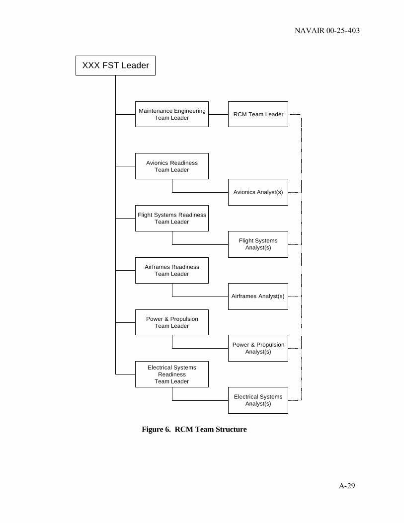
NAVAIR 00-25-403
A- 29
XXX FST Leader
Maintenance EngineeringTeam Leader
Avionics ReadinessTeam Leader
Flight Systems ReadinessTeam Leader
Airframes ReadinessTeam Leader
Power & PropulsionTeam Leader
RCM Team Leader
Avionics Analyst(s)
Flight SystemsAnalyst(s)
Airframes Analyst(s)
Power & PropulsionAnalyst(s)
Electrical SystemsReadiness
Team Leader
Electrical SystemsAnalyst(s)
Figure 6. RCM Team Structure

NAVAIR 00-25-403
A-30
Support from the logistics and documentation teams will be necessary even though they will not be actually performing RCM analysis. Each team within the FST should be prepared to provide the necessary resources to support a dedicated effort.
7 FUNDING REQUIREMENTS
Funding requirements for the F/A-XX RCM Program will be developed and updated annually. For FY __, they are as follows:
Manpower Cost
Organic 10 man-years $1.5 M
CSS 5 man-years $.5M
Materials and Travel $300K
Total 15 man-years $2.3M

THIS PAGE INTENTIONALLY LEFT BLANK

NAVAIR 00-25-403
(A-31 Blank)/A-32
[AIRCRAFT ID] PROPULSION AND POWER SYSTEM (PPS)
RELIABILITY CENTERED MAINTENANCE PROGRAM
PLAN
[FST ID] FST [LOCATION]
INITIAL ISSUE: [DATE]

NAVAIR 00-25-403
A-33

THIS PAGE INTENTIONALLY LEFT BLANK

NAVAIR 00-25-403
A- 35
[ACFT ID] PPS
RELIABILITY CENTERED MAINTENANCE
PROGRAM PLAN & MILESTONE
Prepared by:
Reviewed Approved ([ENGINE ID] RCM Program Approved ([FST ID] FST Site Leader) Approved (Navy PPS RCM Lead Engineer) Approved (RCM SITE Lead, [LOCATION]) Approved (Navy RCM Steering Group Signee) Approved [ENGINE ID] APML

THIS PAGE INTENTIONALLY BLANK

NAVAIR 00-25-403
A-37
TABLE OF CONTENTS 1.0 INTRODUCTION ................................................................................................. A-39 1.1 Purpose ........................................................................................................ A-39 1.2 Scope............................................................................................................. A-39 1.3 Background.................................................................................................... A-39 1.4 Referenced Documents ................................................................................. A-40 1.5 Change Recommendations ........................................................................... A-42 1.6 List of Acronyms ............................................................................................ A-42
2.0 RESPONSIBILITIES ............................................................................................ A-47 2.2 [FST ID] Fleet Support Team (FST) [LOCATION] .........................................A-47 2.3 Naval Air Systems Command (NAVAIR) ....................................................... A-49 2.4 Vendor (OEM) or Contractor Support Services (CSS)................................... A-50
3.0 SCOPE OF ANALYSIS ........................................................................................ A-51 3.1 Initial Analysis Guidelines and Steps ............................................................. A-51 3.2 Sustaining Analysis Guidelines and Tasks .................................................... A-55
4.0 RCM ANALYSIS GROUND RULES AND ASSUMPTIONS ................................ A-57 4.1 Analysis Coverage ......................................................................................... A-57 4.2 Methods for Prioritizing Failure Modes for Analysis ........................................... A-58
4.3 Analysis Assumptions ................................................................................... A-60 4.4 RCM Program Metrics .................................................................................. A-62 4.5 Single Inspection Effectiveness ..................................................................... A-63 4.6 Minimum Detectable Flaw Sizes ................................................................... A-63 4.7 Failure Mode Effects and Criticality Analysis ................................................ A-63 4.8 Task Analysis................................................................................................. A-65 4.9 Sustaining Task Priorities ............................................................................... A-65 4.10 Design Changes ........................................................................................... A-66
5.0 DOCUMENTATION REQUIREMENTS ................................................................ A-66 5.2 Integrated Reliability Centered Maintenance Software (IRCMS) ................... A-66 5.3 AE Database.................................................................................................. A-67 5.4 RCM Audit Log .............................................................................................. A-67 5.5 Quarterly RCM Reports ................................................................................. A-68

NAVAIR 00-25-403
A-38
6.0 RCM PROGRAM EVALUATION ......................................................................... A-68
7.0 TRAINING REQUIREMENTS .............................................................................. A-68
8.0 MILESTONE CHART........................................................................................... A-69
9.0 FUNDING REQUIREMENTS ............................................................................... A-69 Attachment (1) [ACFT ID] Propulsion and Power Systems Attachment (2) RCM Based Maintenance Process Attachment (3) Detailed Information for Calculating [ACFT ID] PPS Metrics
Attachment (4) [ACFT ID] PPS Major Intermediate And Depot Preventive Task Interval History And RCM Goals Attachment (5) Example of Quarterly Report Attachment (6) [ACFT ID] PPS RCM POA&M

NAVAIR 00-25-403
A-39
1.0 INTRODUCTION 1.1 PURPOSE 1.1.1 This plan provides the requirements, procedures, and responsibilities for implementation of an effective and pro-active Reliability Centered Maintenance (RCM)/Age Exploration (AE) Program for [ACFT ID] Propulsion and Power System (PPS). The [ACFT ID] aircraft and aircraft components are covered under a separate plan. The [ACFT ID] PPS consists of [ENGINE ID] engine and [GTS/APU ID] Gas Turbine Starter/Auxiliary Power Unit (GTS/APU). Attachment (1) provides Logistic Control Numbers (LCN) and Work Unit Codes (WUC) for the [ACFT ID] PPS. The purpose this plan is: 1.1.1.1 To develop the appropriate failure management strategy for the Propulsion and Power System (PPS) components through the RCM process, including identification, implementation, and support of any preventive maintenance (PM) requirements to ensure cost-wise readiness. 1.1.1.2 To integrate the RCM analysis process into an overall RCM-Based Maintenance Process (Attachment (2)). 1.1.1.3 To identify various statistical analysis methods to determine appropriate failure management strategies to include any PM tasks. 1.1.2 This plan is not intended to duplicate existing guidelines but to capitalize on resources and processes currently available to Propulsion & Power (P&P) engineers, logisticians, and management, and provide specific information and plans applicable to the [ACFT ID] Propulsion and Power System (PPS). Specific RCM terms or tasks are fully defined in NAVAIR 00-25-403. 1.1.3 An RCM-Based Maintenance Process will provide preventive maintenance updates, substantiate redesign recommendations for the Component Improvement Program (CIP), and identify safety, logistic, maintenance process, and life cycle cost recommendations. This plan is generated in response to the initiatives to improve the [ACFT ID] PPS readiness, reliability, and cost effectiveness.
1.2 SCOPE The RCM/AE Implementation Plan is applicable to the [ACFT ID] PPS and shall be updated as required. It is developed using the guidelines of NAVAIR 00-25-403. 1.3 BACKGROUND 1.3.1 The RCM analysis process is used to develop failure management strategies, considering the design and operational environment of equipment, that ensure effective PM requirements and other actions for a required level of safety and readiness. The process recognizes that sufficient information is often unavailable at the time of analysis to accurately determine the best strategy and PM task intervals. The RCM analysis process allows for the prudent use of best available data and engineering judgment. The RCM/AE program will provide the plans to obtain the information necessary to verify or update those estimates and judgments, where justified. 1.3.2 The RCM/AE program will provide data on the effectiveness of the PM program and focus attention where RCM analysis update may provide cost savings,
NAVAIR 00-25-403
A-40
increased weapon system availability, or increased safety. 1.3.3 The RCM/AE program also assists in substantiating CIP requirements for funding and the continuous evaluation of the failure management strategy by: 1.3.3.1 Application of statistical analysis (Weibull, Log-normal, etc.) methods 1.3.3.2 Documentation of information including data, assumptions, analysis methods and final recommendations 1.3.3.3 Determination of System Safety Hazard Risk Index values 1.3.4 The PM program will be dynamic throughout the remaining [ACFT ID] PPS program life (see paragraph 4.3.2). 1.3.5 As the [ACFT ID] PPS program matures, the RCM/AE program will be structured to capitalize on data from: 1.3.5.1 Maintenance program execution 1.3.5.2 In-service component reliability
1.3.5.3 Operating environment issues and constraints 1.3.5.4 Failure/repair/problem history 1.3.5.5 Readiness degraders 1.3.5.6 High cost drivers.
1.3.6 The Reliability and Maintainability (R&M) program monitors the weapon system for signs of unsatisfactory or unexpectedly decreased operational reliability (or excessive costs) utilizing the metrics of paragraph 4.4, as a minimum. Upon such an indication, the RCM analysis is reviewed and/or updated, as necessary, to determine if a change in the failure management strategy (to include PM) is necessary to ensure adequate levels of safety, readiness, and cost effectiveness. 1.4 REFERENCE DOCUMENTS AND RCM TOOLS The following items were used to develop or are references in this RCM program plan.
1.4.1 Instructions 1.4.1.1 COMNAVAIRFOR- Naval Aviation Maintenance Plan INST 4790.2 1.4.1.2 NAVAIRINST 4790.3 Aeronautical Time Cycle Management
Program 1.4.1.3 NAVAIRINST 4790.2 Reliability Centered Maintenance Program
1.4.2 Military Standards (Canceled - Listed for historical information only) 1.4.2.1 MIL-STD-1388.1A Logistic Support Analysis 1.4.2.2 MIL-STD-1629 Procedures for Performing a Failure Modes,
Effects, and Criticality Analysis

NAVAIR 00-25-403
A-41
1.4.2.3 MIL-STD-2173(AS) Reliability Centered Maintenance,
Requirements for Naval Aircraft, Weapons Systems, and Support Equipment
1.4.3 Manuals 1.4.3.1 [MANUAL #] [ENGINE ID] Illustrated Parts Breakdown
(IPB) 1.4.3.2 [MANUAL #] Intermediate and Depot Maintenance IPB,
GTS/APU Part Number [PART NUMBERS]
1.4.3.3 [MANUAL #] Organizational and Intermediate Level Maintenance with IPB, QECA [PART NUMBERS]
1.4.3.4 NAVAIR 00-25-403 Guidelines for Reliability Centered Maintenance Program
1.4.4 Training Materials 1.4.4.1 NA Propulsion and Power RCM Training Hand- Book (Obtain from Navy Propulsion and Power RCM Lead ([CODE], [LOCATION]))
1.4.5 Specifications/Plans 1.4.5.1 ILS-DS-30A084G [ACFT ID] Integrated Logistics Support
Detail Specification 1.4.5.2 [ACFT ID]RCM Plan Reliability Centered Maintenance/Age
Exploration Plan
NAVAIR 25-403
A-42
1.4.6 RCM Tools 1.4.6.1 IRCMS Integrated Reliability Centered Maintenance
Software (IRCMS) (Obtain from http://www.logistics.navair.navy.mil/rcm)
1.4.6.2 Weibull P&P Weibull Analysis Module (Excel Workbook) (Obtain from [ACFT ID] RCM Lead Engineer or Navy Propulsion and Power RCM Lead ([CODE], [LOCATION])); Weibull Support Module Workbook (Excel) (Obtain from [ACFT ID] PPS RCM Lead Engineer or Navy Propulsion and Power RCM Lead ([CODE], [LOCATION]))
1.4.6.3 Detection Probability Single Inspection Effectiveness Workbook (Excel) (Obtain from [ACFT ID] PPS RCM Lead Engineer or Navy Propulsion and Power RCM Lead ([CODE], [LOCATION]))
1.4.6.4 Inspection Intervals PP_PM_Task_Analysis_Module.xls Obtain from [ACFT ID] PPS RCM Lead Engineer or Navy Propulsion and Power RCM Lead ([CODE], [LOCATION]))
1.5 CHANGE RECOMMENDATIONS 1.5.1 Change/corrections/update recommendations to elements of this plan are encouraged and should be submitted to:
[ADDRESS] 1.5.2 Upon receipt of a change/correction/update recommendation, the [FST ID] Fleet Support Team (FST) will acknowledge receipt, review, and conduct liaison as necessary with the affected organization. [FST ID] FST will contact the submitting activity if additional information or clarification on the change recommendation is needed. 1.5.3 Upon completion of review of all submitted information, [FST ID] FST at [LOCATION] will approve/disapprove the recommendation and notify all concerned of the action taken. 1.6 LIST OF ACRONYMS
3M Maintenance Material Management ACI Analytical Condition Inspection ADP Automated Data Processing AE Age Exploration AEB Age Exploration Bulletin

NAVAIR 25-403
A-43
AEMS Aircraft Engine Management System AIRRS Aviation Inventory Readiness and Reporting
System APML Assistant Program Manager, Logistics ASMET Accelerated Simulated Mission Endurance Test ATCM Aeronautical Time Cycle Management AVDRL Aviation Depot Level Repairable AWS Automated Worksheet Software AYC Accessory Change BSI Business Sensitive Information CDF Cumulative Distribution Function CDRL Contract Deliverable Requirements List CETS Contractor Engineering and Technical Services CIP Component Improvement Program CLS Contract Logistic Support CMP Composite Mission Profile CNATRA Chief of Naval Air Training CTF Central Tracking Facility D-Level Depot Level Maintenance Activity DMDS Depot Maintenance Data System ECA Equipment Condition Analysis ECP Engineering Change Proposal EFH Engine Flight Hour her Equipment History Record EI Engineering Investigation ERAP Engine Reliability Analysis Program FE Fleet Exchange FH Flight Hour FMECA Failure Mode, Effects and Criticality Analysis FMU Fuel Metering Unit FOD Foreign Object Damage FSPDI Failure Starting Point Development Interval

NAVAIR 25-403
A-44
FSP-FFI Failure Starting Point to Functional Failure Interval FST Fleet Support Team GTS/APU Gas Turbine Starter/Auxiliary Power Unit HCF High Cycle Fatigue HEMP Hourly Engine Maintenance Program HMR Hazardous Material Report HSI Hot Section Inspection I-Level Intermediate Level Maintenance Activity ILS-DS Integrated Logistics Support - Detailed
Specification IPB Illustrated Parts Breakdown IPC Illustrated Parts Catalogue IPE Industrial Process Exchange IPL Illustrated Parts List IPT Integrated Program Team IRAC Interim Rapid Action Change IRCMS Integrated Reliability Centered Maintenance
System LCF Low Cycle Fatigue LCL Lower Control Limit LCN Logistics Control Number LM Logistics Manager LORA Level of Repair Analysis LSA Logistics Support Analysis MA Maintenance Advisory MALS Marine Aviation Logistical Support MCR Manual Change Release MEI Major Engine Inspection MMH Maintenance Man Hour Mod Modification MP Maintenance Plan MRA Major Repairable Assembly

NAVAIR 25-403
A-45
MRB Material Review Board MRC Maintenance Requirements Card MTBF Mean Time Between Failure NADEP Naval Air Depot NALDA Naval Aviation Logistics Data Analysis NAMDR Naval Aviation Maintenance Discrepancy Report NAMSO Naval Aviation Maintenance Support Office NAVAIR Naval Air Systems Command NDI Non Destructive Inspection NMC Not Mission Capable NOC Not Otherwise Coded O-Level Organizational Level Maintenance Activity OEM Original Equipment Manufacturer OT Operating Time P&P Propulsion and Power PACC Acceptable Probability of Failure PACT Actual Probability of Failure PF Potential Failure P-F Interval Potential to Functional Failure Interval PMA Program Manager, Air PMIC Periodic Maintenance Inspection Cards PPD Propulsion and Power System Department PPC Power Plant Change PPS Propulsion and Power System PM Preventative Maintenance P/N Part Number QDR Quality Deficiency Report RA Repairable Assembly R&M Reliability and Maintainability RCM Reliability-Centered Maintenance RILSD Resident Integrated Logistics Support Detachment

NAVAIR 25-403
A-46
ROR Repair of Repairable SAR Safety Action Record SE Support Equipment SOI Safe Operating Interval SOO Safety of Operations TDC Technical Directive Compliance TPDR Technical Publication Deficiency Report TSN Time Since New TSR Time Since Repair TYCOM Type Commander UCL Upper Control Limit VIDS/MAF Visual Information Display System/Maintenance
Action Form WUC Work Unit Code

NAVAIR 00-25-403
A-47
2.0 RESPONSIBILITIES 2.1 The basic composition and responsibilities of a RCM team is defined in NAVAIR 00-25-403. The specific responsibilities within the [ACFT ID] PPS RCM team are defined as follows: 2.2 [FST ID] FLEET SUPPORT TEAM (FST) [LOCATION]
2.2.1 FST Leader - The [FST ID] FST Leader is responsible for development and implementation of an RCM program for the [ACFT ID] PPS in accordance with NAVAIRINST 4790.20, the RCM plan, and direction provided by PMA-[CODE]. The FST Leader’s responsibilities: 2.2.1.1 Reviews and recommends approval for the [ACFT ID] PPS RCM Program Plan. 2.2.1.2 Obtains funding to perform all RCM/ R&M tasks defined by this program plan. When required funding level cannot be obtained, the FST Team Leader is required to review and approve prioritized reduced RCM program. 2.2.1.3 Obtains adequate trained/experienced RCM personnel to perform RCM analysis as defined by this program plan. 2.2.1.4 Reviews the RCM/R&M program tasks and divide task responsibilities between organic and commercial RCM organizations. 2.2.1.5 Participates in resolving IPT team conflicts that relate to PPS RCM/R&M issues. 2.2.1.6 Obtains all software and Automated Data Processing (ADP) equipment required to implement and maintain the [ACFT ID] PPS RCM Program.
2.2.2 [ACFT ID] PPS RCM Lead Engineer (RCM Implementation Manager) - The detailed management of the RCM program will be performed by an organic trained/experienced RCM Lead engineer. The RCM Lead Engineer’s responsibilities: 2.2.2.1 Reviews, approves, and provides signature authority for all RCM and R&M analyses. Provides all resulting PM and Age Exploration (AE) task changes, and other action recommendations, to [ENGINE ID] Engine Sub-team Leader for approval. Contractual products shall also be accepted by the organic RCM Lead Engineer prior to approval/implementation. 2.2.2.2 Exercises technical authority for the resolution of RCM and AE development, implementation, and utilization problems. 2.2.2.3 Reviews the implementation and sustainment of the overall RCM/AE effort. This includes development and sustaining the AE plan, including identification of budget/manpower requirements and workload projections. 2.2.2.4 Provides briefs, answers data calls, and arranges training associated with the [ACFT ID] PPS RCM program. 2.2.2.5 Ensures AE data from depot and fleet sampling engines, modules, assemblies, and components is compiled, correlated, and entered in the AE database in an accurate and timely manner. Modifies and upgrades database structure and format as

NAVAIR 00-25-403
A-48
required to meet the requirements identified in paragraph 5.3. Ensures AE inspection status reports are up to date. 2.2.2.6 Develops and provides inspection requirements and changes to AE publications, i.e., AE depot or field sampling specifications. 2.2.2.7 Maintains liaison with squadrons, MALS, depot, and Type Commanders (TYCOM) to identify and schedule engine candidates for AE Depot inductions and/or field inspections. Also, ensures compliance with specification requirements, support accuracy of depot/fleet AE work documents, and provides engineering input to workload standards review. Reviews all engine discrepancies with Quality Evaluators and depot/fleet maintenance personnel. Periodically monitors AE samples to ensure engineering disposition of all AE discovered discrepancies are documented with consultation from FST engineers as required. 2.2.2.8 Coordinates and monitors AE depot and fleet sampling engines, modules, assemblies, and components. 2.2.2.9 Prepares engineering instructions designating specific AE inspections to be performed and any emergent or investigative inspection requirements to be performed on each engine, module, assembly, and component. 2.2.2.10 Prepares and revises RCM Analysis Packages to identify the most effective failure management strategies and develop PM and AE sampling inspection requirements, as well as redesign or other action recommendations.
2.2.3 RCM Analysts - The RCM analysis functions will be performed by various RCM-trained and certified [ACFT ID] PPS organic and vendor personnel. RCM Analysts responsibilities: 2.2.3.1 Prepares and revises RCM Analysis Packages to identify the most effective failure management strategies and develop PM and AE sampling inspection requirements, as well as redesign or other action recommendations. 2.2.3.2 Ensures that publications reflect the results of RCM analyses and that any local MRC cards are reviewed for fleet wide application. 2.2.3.3 Reviews Supportability Analyses and Maintenance Plans for proper incorporation of PM and AE requirements. 2.2.3.4 Compiles Age Exploration, operational, and test failure data. Performs failure distribution analyses (Weibull, trending, etc.) of compiled data. 2.2.3.5 Reviews all new or changed maintenance procedures to ensure failure modes have been considered and maintenance instructions are compatible with RCM assumptions and requirements.
2.2.4 Integrated Maintenance Concept (IMC) Team Leader - The IMC Team Leader is responsible for maintenance plan, Level of Repair Analysis (LORA), PM documentation, and overall maintenance program reviews. The IMC Team Leader is responsible for ensuring the results achieved through the RCM analyses are implemented into the maintenance program.

NAVAIR 00-25-403
A-49
2.3 NAVAL AIR SYSTEMS COMMAND (NAVAIR) 2.3.1 NAVAIR Logistics (AIR 3.0) and the NAVAIR RCM Steering Committee 2.3.1.1 AIR-3.0 is responsible for the overall program management of RCM and Age Exploration policy and procedures for NAVAIR. The RCM Steering Committee is chartered to bring together RCM subject matter experts to establish and refine RCM policies and procedures for NAVAIR. The Steering Committee Chairman is a required reviewing official for the RCM/AE plan, prior to submittal for approval. 2.3.1.2 [ACFT ID] Assistant Program Manager, Logistics (AIR-[CODE]) responsibilities: 2.3.1.2.1 Ensures that AE Program requirements are based on RCM in accordance with applicable instructions, that preventive maintenance requirements are based on RCM and that RCM is correctly integrated into the maintenance planning process. 2.3.1.2.2 Implements RCM analysis recommendations/ changes and ensures that all logistics areas are addressed. 2.3.1.2.3 Approves the RCM/AE plan.
2.3.2 Propulsion and Power Systems Department (PPD) (AIR-4.4) 2.3.2.1 Air-4.4 RCM-related responsibilities: 2.3.2.1.1 Reviews and approves all RCM tasks that have a direct impact on service life limits. 2.3.2.2 Systems Engineering and Systems Integration Division (AIR-[CODE]) RCM-related responsibilities: 2.3.2.2.1 Integrates the activities of all involved PPD areas, disciplines, and specialties into a team effort for system effectiveness. 2.3.2.2.2 Develops CIP requirements and justification in support of developing Engineering Change Proposal’s (ECP) for the weapon platform’s P&P systems. Provide support for CIP Contract preparation, implementation, and monitor subsequent contractor performance. 2.3.2.2.3 Develops Engineering Change Proposal (ECP) and Power Plant Change (PPC) and /or Accessory Change (AYC) justification, acquisition and implementation. 2.3.2.2.4 Acts as PPD advocate to the Program Manager's staff or PMA IPT and act as the Program Manager's or PMA IPT(s) advocate within PPD. 2.3.2.2.5 Ensures PPD IPT structure, staffing, and resource allocation are appropriate for the engineering effort planned, and are accurately reflected in the Work Unit Assignment. 2.3.2.2.6 Participates in all trade-off decisions, and performs a disciplined risk management process, which identifies and tracks both technical and programmatic impacts and specific actions recommended.

NAVAIR 00-25-403
A-50
programmatic impacts and specific actions recommended. 2.3.2.3 Engine Support Branch (AIR-[CODE]) RCM-related responsibilities: 2.3.2.3.1 Monitors, refines, and enforces model specifications, statements of work, and warranty technical contents. 2.3.2.3.2 Updates Life cycle master plan with the establishment of design integrity and quality assurance standards. 2.3.2.3.3 Identifies design improvements based on Fleet experiences and RCM recommendations. 2.3.2.4 Engineering Specialties Division (AIR-[CODE]) RCM-related responsibilities: 2.3.2.4.1 Acts as the technical expert in the areas of component life/performance and acquisition in the PPD for integrated program support. 2.3.2.4.2 Develops CIP requirements and justification in support of developing ECP(s) that will improve safety, cost, performance, reliability and maintainability for the P&P systems for the weapon platform and components. 2.3.2.4.3 Participates in all trade-off decisions, and performs a disciplined risk management process, which identifies and tracks both technical and programmatic impacts and specific actions recommended. 2.3.2.4.4 Leads Engine Reliability Analysis Program (ERAP) development effort.
2.3.3 NAVAIR Propulsion and Power RCM Lead Engineer ([CODE], [LOCATION]) - The Propulsion Management Board has assigned responsibility for expert consultation to IPT members and Competency Managers for RCM as applied to Propulsion Systems to the NAVAIR Propulsion and Power RCM Lead Engineer. This individual as serves as the propulsion and power representative to the NAVAIR RCM Steering Committee with the following responsibilities: 2.3.3.1 Provides training and tools to Propulsion RCM teams on RCM analysis techniques, implementation procedures and sustaining requirements peculiar to Propulsion systems. 2.4 VENDOR (OEM) OR CONTRACT SUPPORT SERVICES (CSS)
2.4.1 The contractor(s) shall provide support to the [ACFT ID] Propulsion and Power RCM Program, including updating and maintaining engine and engine accessory FMECA and RCM analyses as specified in contract delivery orders. This support shall apply to all items contained in [ENGINE IPB] and all (OEM) supplied items contained in [QECA MANUAL]. All analyses shall be performed following NAVAIR 00-25-403, Guidelines for the Naval Aviation RCM process, and shall utilize the latest version of the Integrated Reliability Centered Maintenance System (IRCMS) software.

NAVAIR 00-25-403
A-51
NOTE The following requirements are performed by vendor (OEM) or CSS
only if covered by appropriate contracts.
2.4.2 Perform complete FMECA and RCM analysis for all Class I and II engineering changes. Provide the completed analysis to [FST ID] FST for review, approval, and implementation of results. 2.4.3 Review organic RCM/R&M analysis as requested by [FST ID] FST.
2.4.4 Perform AE data collection and provide results to [FST ID] FST.
2.4.5 Perform RCM analysis on in-service problems as requested by [FST ID] FST. 2.5.6 Provide necessary attendance at quarterly RCM review meetings. 2.5.7 As requested by [FST ID] FST, using IRCMS approved Preventive Maintenance task data, develop source data for incorporation into appropriate maintenance instruction manuals.
3.0 SCOPE OF THE ANALYSIS 3.1 INITIAL ANALYSIS GUIDELINES AND STEPS
3.1.1 Level of Analysis 3.1.1.1 Complete engine FMECA was provided using AWS 5.3 software. Updated FMECA/RCM analyses will be documented into IRCMS 6.2.5 as issues arise, or based on hazard/risk rankings and available funding. These analyses will use best available data and conservative assumptions to support RCM decisions when information is insufficient. 3.1.1.2 Complete GTS/APU FMECA was provided to MIL-STD-1629 format and in hardcopy format only. Initial assessment determined that the GTS/APU had no Safety Category I or II failure modes. Therefore no RCM analysis was deemed necessary at the time. Subsequent in-service failures have resulted in Safety Category I and II failures, and other failure modes may justify analysis to determine appropriate failure management strategies, therefore RCM analysis is required. Safety Category failures will be analyzed on a priority basis, followed by non-safety failure modes with current PM Tasks. The GTS/APU will be documented in a separate IRCMS 6.2.5 database.
3.1.2 Hardware Partitioning and Analysis Boundaries 3.1.2.1 The [ACFT ID] PPS RCM program will only cover the hardware listed in the following Illustrated Parts Breakdowns: 3.1.2.1.1 [MANUAL #] for the [ENGINE ID]
3.1.2.1.2 [MANUAL #] for GTS/APU, [PART NUMBERS]
3.1.2.1.3 [MANUAL #] for [ACFT ID] QECA, [PART NUMBERS]

NAVAIR 00-25-403
A-52
3.1.2.2 The top level for the hardware partitioning will be: 3.1.2.2.1 The [ENGINE ID] engine for the Engine IRCMS database.
3.1.2.2.2 The [GTS/APU ID] for the GTS/APU IRCMS database.
3.1.2.3 The [ACFT ID] PPS will be divided into sections and systems identified in the manuals listed in paragraph 3.1.2.1. Hardware partitioning will be to a level that identifies the functional sub-systems (normally at least one level above the WRA’s), as a minimum. Lower level partitioning may be required depending on complexity and maintenance concepts developed during the analysis.
3.1.3 FMECA 3.1.3.1 Using the IRCMS software and instructions contained in NAVAIR 00-25-403, FMECA documentation will be created/sustained for the hardware listed in paragraph 3.1.2. (The initial delivered FMECA was done in AWS 5.3 software and will be converted to IRCMS software.) 3.1.3.2 For failure mode effects and consequences, the end item will be the AV-8B aircraft.
3.1.4 Failure/Problem Related Reviews/Analysis 3.1.4.1 The process for responding to reported problems will vary depending on the criticality of failure, means of reporting, and whether a vendor or organic activity must perform the failure analysis. The interfaces with the RCM/AE program are described in the following paragraphs. 3.1.4.2 The following paragraphs are general guidance. There may be additional actions required for specific issues. Coordination with other activities such as contractors may also be required. Some actions may be directed by higher authority. All of these steps are not necessarily performed by assigned RCM analysts. However, RCM analysts and leaders should be aware of all actions related to their assigned systems and be involved in recommendations for PM or other actions affecting the failure management strategy. Although this process shows a specific logical order, in some cases the steps may be performed concurrently or in a different order. 3.1.4.3 Step 1: Problem Reported/Recognized 3.1.4.3.1 The process is started upon receipt of a report or recognition of a problem requiring RCM action. The problem could be reported/recognized through:
• El request
• Hazard Material Report (HMR)
• Quality Deficiency Report (QDR)
• Technical Publication Deficiency Report (TPDR)
• Deficiency Report from vendors
• MRB reviews

NAVAIR 00-25-403
A-53
• Mishap report (organic and vendor)
• Vendor specification compliance reports
• Test, laboratory, analysis results and reports (organic and vendor)
• Reports/calls from [ACFT ID] PPS maintenance personnel
• Deviations from established/expected data trends
• Identification of high readiness, reliability, or cost degraders
• Proposed design changes (e.g., CIP projects, ECP’s, RAMEC’s) 3.1.4.3.2 Depending upon the type of report, an initial response, such as a preliminary El report with shipping instructions for the El exhibit, may be required. The FST Leader will assign an individual primary responsibility for the problem. The RCM lead engineer will be provided an information copy of the problem report or conversation record copy if the report was verbal. Primary responsibility for reviewing the impacts on failure management strategies will be assigned to an RCM analyst. The RCM analyst address RCM related issues by working closely with the primary individual assigned to the problem.
3.1.4.4 Step 2: Failure Mode Determination - This step is the primary research and analysis part of the process. This step may include failure analysis by organic/contract engineers or the materials lab, background data collection from squadron or maintenance personnel, etc. It may also include actions such as fatigue, stress, fracture mechanics, and statistical analyses to determine PM task intervals, or probability of future occurrences of this failure mode. Although a specific failure mode should be determined before final changes to the failure management strategy or PM are imposed, certain actions will often be required during this step. For instance, an inspection bulletin may be required immediately when a specific failure mode creates safety of flight concerns. The FST assigned primary individual is responsible for leading the activities to determine appropriate actions, although other individuals or organizations may also be involved. If the assigned primary individual is not the RCM analyst, the RCM analyst should work closely to obtain data/information as the investigation progresses.
3.1.4.5 Step 3: RCM Review - At this step, the failure management strategy is reviewed or determined. If the assigned individual is not the cognizant RCM analyst, the RCM analyst will provide recommendations on PM or other actions to the assigned individual. Any decisions on PM or other actions must be based on the results of an RCM analysis. 3.1.4.5.1 If this is a completely new failure mode, the RCM process will be conducted to determine the appropriate failure management strategy. 3.1.4.5.2 If there is a previous RCM analysis, it will be reviewed to ensure that the current problem does not change any of the data/assumptions/conclusions in the analysis. If it does, an RCM update will be performed to determine any adjustments to the failure management strategy currently in place.
3.1.4.5.3 If the current failure management strategy is adequate, a documentation of the review shall be made in the IRCMS database. A separate summary

NAVAIR 00-25-403
A-54
report may be required to program personnel, dependent on the nature and origination of the problem. If PM changes or other actions are required, continue with Step 4.
3.1.4.6 Step 4: One Time Inspection or Interim Action - If not accomplished previously, the need to issue an inspection bulletin (technical directive) or take other interim action is based on the potential safety or operational implications. If the possibility of additional unacceptable failures exist before completion of the investigation, a bulletin or other interim action is required. An Age Exploration Bulletin (AEB) may also be used to gather data to better refine the problem. NAVAIR 00-25-300 provides direction for preparing and issuing technical directives.
3.1.4.7 Step 5: PM or Other Action - PM or other actions necessary for final resolution of the problem are determined. This may be a single action or a combination of solutions, as determined by the RCM analysis. Corrective actions will be agreed upon by the assigned primary individual, the cognizant RCM analyst, and others as applicable. 3.1.4.7.1 Any change to PM requirements will be determined through RCM analysis. Changes to PM requirements directed by higher authority that disagree with RCM recommendations be pursued for resolution. If still directed to taken action inconsistent with the RCM results, the direction will be documented in IRCMS and the RCM audit log (paragraph 5.4), without modifying properly determined RCM results. 3.1.4.7.2 Design changes may be required to preclude additional failures. Design changes are implemented through the ECP process. Recommendations to incorporate ECP(s) may or may not be a result of the RCM analysis.
3.1.4.7.3 A change to maintenance procedures or processes may be identified during the analysis of the problem. Examples of such actions include: changing a type of sealant used in an assembly process, changing torque requirements, or adding quality assurance steps to a maintenance requirement. These types of actions may be revealed through the course of the RCM analysis or may be used to make a current requirement more effective. 3.1.4.7.4 Clarification of an ambiguous current requirement or emphasis to ensure proper performance of maintenance requirements may be necessary when failures are the result of improper maintenance procedures. Clarifications and/or emphasis can be accomplished by changes to the appropriate documentation (MRC, manual, etc.) using Interim Rapid Action Changes (IRAC), Manual Change Releases (MCR), through Maintenance Advisory Reports (MA(s)), or by maintenance awareness visits to the performing activities. These actions will be documented in the IRCMS memo of the associated failure mode and the RCM Audit Log (paragraph 5.4).
3.1.5 Initial Task Packaging - Task packaging is the process of incorporating a number of maintenance requirements with discrete RCM preliminary intervals into optimum packages such as a 250 hour phase inspection or major engine inspection (MEI). Task Packaging shall be accomplished per NAVAIR 00-25-403 instructions. Changes to PM requirements shall be issued in accordance with standard FST procedures and documented in IRCMS and the RCM audit log.
NAVAIR 00-25-403
A-55
3.2 SUSTAINING ANALYSIS GUIDELINES AND TASKS 3.2.1 The implemented failure management strategies will be continually assessed for needed changes including the following activities: 3.2.1.1 Engine Degraders having adverse impact on readiness and cost will be assessed for updates to the RCM analysis to improve the failure management strategy. 3.2.1.2 Design changes will be assessed for required RCM updates. 3.2.1.3 AE results will be used to update/refine the RCM results for the targeted failure modes. 3.2.1.4 Maintenance data trends/ primary metrics will be monitored for unacceptable performance. RCM analysis updates will be triggered based on investigation into causes of unacceptable trends or metrics.
3.2.2 Sustaining Tasks - The objective of sustaining tasks is to optimize current PM requirements, delete unnecessary requirements, address adverse failure trends, address previously unforeseen failure modes, and improve the overall efficiency and effectiveness of the failure management strategy. The following analysis processes will be used to meet these objectives. 3.2.2.1 Condition Monitoring/Data Analysis - Condition monitoring is used to evaluate the effectiveness of the failure management strategy and indicate where improvements are needed. Items that may require improvements are those that have high or increasing failure rates and unacceptably impact maintenance costs or aircraft availability, those that have high PM costs, or those that have unacceptable impacts to safety. Items with higher than expected reliability, lower than expected costs, or for which safety concerns have been alleviated, will be evaluated to determine if PM can be reduced or eliminated. 3.2.2.1.1 Condition monitoring data is primarily acquired through the Maintenance Material Management (3M) system and/or vendor equivalent. The Naval Aviation Logistics Data Analysis (NALDA) system will be used to provide the required data for condition monitoring. The Engine Reliability Analysis Program (ERAP) will be used if available to provide various reliability, maintainability, and availability data. ERAP operating procedures and requirements (specifically user qualifications, equipment hardware/ software, and NALDA databases) are contained in ERAP operating manual. ERAP will generate twelve reports, which should be obtained at least on a quarterly basis. The following other data sources/tools may be used:
• Aircraft Engine Management System (AEMS) or vendor equivalent
• Equipment Condition Analysis (ECA) reports or vendor equivalent

NAVAIR 00-25-403
A-56
Depot Maintenance Data System (DMDS) or vendor equivalent
• Aircraft Inventory Readiness and Reporting System (AIRRS) or vendor equivalent
• Aeronautical Time Cycle Management Program (ATCM) or vendor equivalent
3.2.2.1.2 Condition monitoring will be accomplished by analysis of the metrics defined in paragraph 4.4.1. The RCM analysis for the top degraders and items exceeding the control limits will be reviewed and updated, if necessary. 3.2.2.1.3 The results of any RCM reviews or updates, resulting from condition monitoring, will be documented. Reports will be prepared to summarize the results of the quarterly condition monitoring analyses. 3.2.2.2 Age Exploration (AE) Tasks - Specific AE tasks will be developed through the RCM analysis process to update decisions made on the basis of estimated data or conservative assumptions, when justified. For any RCM analysis performed or updated, the analyst will consider the desirability of AE inspections, and determine if there is potential return on investment. If implemented, the analyst will incorporate the results into the RCM analysis upon collection of the information, and delete the AE requirement when complete. Upon completion of the AE requirement, a summary of the results will be documented in the RCM audit log (paragraph 5.4), whether or not a change to PM requirements is made. Guidance for the development of specific AE inspections is contained in NAVAIR 00-25-403. Following are some methods planned for implementing AE inspections: 3.2.2.2.1 Data collection by the cognizant RCM analyst from available vendor and organic sources such as 3M (NALDA, AEMS), EI(s), maintenance and test records and AE databases. 3.2.2.2.2 Depot level sampling tasks (AE) carried out concurrently with depot level maintenance. 3.2.2.2.3 Age Exploration Bulletins (AEB) as described in NAVAIR 00-25-403 and NAVAIR 00-25-300. This method will be used for direct data collection from organic/CLS maintenance locations. Compliance and AE inspection data will be reported as directed by the AEB. The result of the AEB will be documented in the IRCMS and AGE databases (paragraphs 5.2 and 5.3). 3.2.2.2.4 Equipment History Records (EHR) to track serialized components, where a hard time task has not been assigned. Direction on the use of EHR(s) is provided in COMNAVAIRFORINST 4790.2 and NAVAIRINST 4790.3. 3.2.2.2.5 Fleet Leader Program/Analytical Condition Inspection (ACI) Program to determine/validate assumptions (particularly for critical failures), or identify unpredicted failure modes. The objective is to identify specific suspected problem/critical areas and periodically review these areas on one or more of the highest usage engines or components. This program is intended to be specific and limited. The fleet leader program may include specific AE inspections. 3.2.2.2.6 Periodic sampling may be used on an opportunity basis (such as during repairs or major inspections). Sample sizes will be determined through

NAVAIR 00-25-403
A-57
statistical analysis to determine the minimum required number of samples to draw valid conclusions 3.2.2.3 Preventive Maintenance Requirement Document Reviews - Annual reviews of PM documents will be conducted with maintenance activities/personnel to validate maintenance processes, techniques, tools, or supplies, allowing update to increase effectiveness or lower cost. These reviews will also afford the maintenance community an opportunity to identify ineffective or excessive maintenance requirements for reevaluation by the RCM process. 3.2.2.4 Task Packaging Reviews - Task packaging process is described in paragraph 3.1.5. As requirements are updated, they will normally be placed into these packaged intervals. As changes accumulate over time, the original packaged interval may no longer be optimal. Task packaging reviews will be conducted periodically to re-evaluate the packaged maintenance intervals, considering the maintenance tasks that are added, deleted, or modified. Changes to operational scenarios may also generate a need to review the task packages to maximize availability. 3.2.2.5 Class I Design Changes - Design changes may be driven by a variety of factors including a redesign recommendation from the RCM analysis. Design changes are implemented through the ECP process. An assessment of the impact on supportability is a part of any proposed ECP. RCM analysis reviews or updates should be accomplished before completion of the design change in order to determine the most appropriate failure management strategy. 3.2.2.5.1 [FST ID] FST has input into the initial ECP development through the [ACFT ID] Configuration Action Team. Any new change proposals presented to the should be brought to the attention of the cognizant RCM analyst. 3.2.2.5.2 The Vendor/OEM may be assigned responsibility for delivering an updated RCM analysis as part of their design changes. If so, the cognizant RCM analyst or RCM Lead Engineer shall interface with the vendor/OEM to ensure consideration and compatibility with the overall RCM program.
4.0 RCM ANALYSIS GROUND RULES AND ASSUMPTIONS 4.1 ANALYSIS COVERAGE
4.1.1 Interface Items 4.1.1.1 All items listed in Attachment 1 are considered part of the [ACFT ID] PPS RCM program.
4.1.2 Repair Procedure Reviews 4.1.2.1 Before being approved for service, all component repair procedures will be reviewed against the RCM Analysis to ensure that the failure mode is properly addressed, the repair approach is consistent with the PM requirements and assumptions, and evaluate whether the post-repair configuration will require additional analysis due to changes affecting the failure mode, failure onset, or progression. 4.1.2.2 All repair procedures that adversely affect PM program shall have program approval before being implemented.

NAVAIR 00-25-403
A-58
4.2 METHODS FOR PRIORITIZING FAILURE MODES FOR ANALYSIS
4.2.1 STEP 1. Using the Hazard Risk table, determine the safety category and frequency for each failure mode.
4.2.2. STEP 2. Obtain the costs associated with each failure mode.
4.2.3 STEP 3. Determine the failure mode effects on the operations.
NOTE If a failure consequence is hidden, then the risk is assigned based on
the failure/event that would make the failure evident.
4.2.4 STEP 4. All failure modes in the Hazard Risk table red and gold zones (HRI 1-10) shall be analyzed first. The order of analysis will be from the smallest to largest number located in each Hazard Risk table red block.
4.2.5 STEP 5. Anytime an operational metric of paragraph 4.4.1 moves into the red, an analysis shall be made to determine underlying causes/failure modes. These causes/failure modes shall be analyzed at a priority above the failure modes in Step 6. Failure management strategies should be developed through RCM analysis that would move the metric into the green.
4.2.6 STEP 6. All failure modes in the Hazard Risk table yellow zones shall be analyzed next, if funding/resources allow. The order of analysis will be from the smallest to largest number located in each Hazard Risk table yellow block.
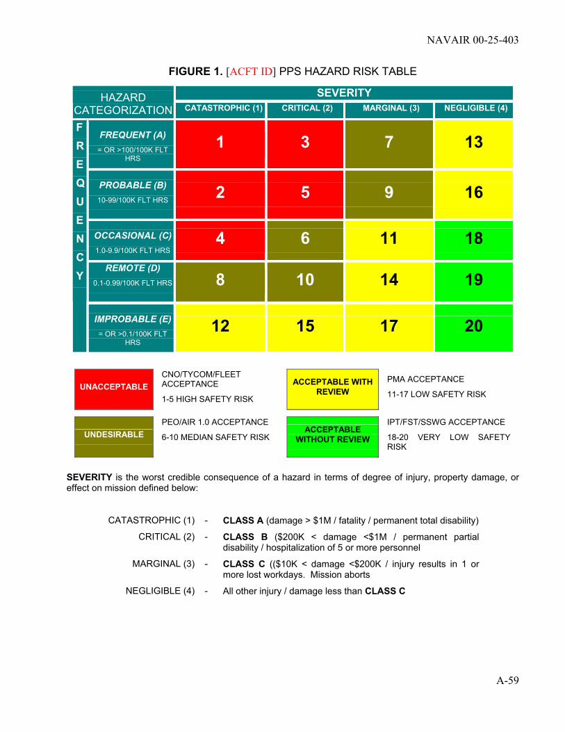
NAVAIR 00-25-403
A-59
FIGURE 1. [ACFT ID] PPS HAZARD RISK TABLE
SEVERITY HAZARD CATEGORIZATION CATASTROPHIC (1) CRITICAL (2) MARGINAL (3) NEGLIGIBLE (4)
FREQUENT (A) = OR >100/100K FLT
HRS
1 3 7 13
PROBABLE (B) 10-99/100K FLT HRS
2 5 9 16
OCCASIONAL (C) 1.0-9.9/100K FLT HRS
4 6 11 18 REMOTE (D)
0.1-0.99/100K FLT HRS
8 10 14 19
F R E Q U E N C Y
IMPROBABLE (E) = OR >0.1/100K FLT
HRS
12 15 17 20
UNACCEPTABLE CNO/TYCOM/FLEET
ACCEPTANCE
1-5 HIGH SAFETY RISK
ACCEPTABLE WITH REVIEW
PMA ACCEPTANCE
11-17 LOW SAFETY RISK
UNDESIRABLE PEO/AIR 1.0 ACCEPTANCE
6-10 MEDIAN SAFETY RISK ACCEPTABLE
WITHOUT REVIEW
IPT/FST/SSWG ACCEPTANCE
18-20 VERY LOW SAFETY RISK
SEVERITY is the worst credible consequence of a hazard in terms of degree of injury, property damage, or effect on mission defined below:
CATASTROPHIC (1) - CLASS A (damage > $1M / fatality / permanent total disability)
CRITICAL (2) - CLASS B ($200K < damage <$1M / permanent partial disability / hospitalization of 5 or more personnel
MARGINAL (3) - CLASS C (($10K < damage <$200K / injury results in 1 or more lost workdays. Mission aborts
NEGLIGIBLE (4) - All other injury / damage less than CLASS C

NAVAIR 00-25-403
A-60
4.3 ANALYSIS ASS UMPTIONS (ESTIMATED VALUES)
4.3.1 Cost Benefit Analysis Factors LABOR RATES: Organizational = $xx.xx per hour
(1) Intermediate = $xx.xx per hour
(1) Depot = $xx.xx (1)
AIRCRAFT COST: [ACFT ID] = $xx.xx
NEW ENGINE COST: [ENGINE ID] = $xx.xx(2)
MISHAP REPORTABLE ENGINE REPAIR COST:
[ENGINE ID] = $xx.xx(2)
NOTES: (1) Labor rates listed are for RCM task cost comparisons only and may not be representative of actual labor rates. These rates will be used for both organic and commercial. (2) Costs information obtained from COMNAVSAFECEN NORFOLK VA WEB SITE posted document (FILE NAME: 2003eng.txt, SUBJECT: 2003 Engine Cost Data For Aviation Mishap Reporting). These costs are not actual, but are used when actual costs are not known.
4.3.2 Hardware Utilization Rates and Life UTILIZATION RATES (AVERAGE): [ACFT ID] = xx.x FH per Month
UTILIZATION RATES (MAX.): [ACFT ID] = xx.x FH per Month
NORMAL MISSION TIME [ACFT ID] = xx.x hours
CROSS COUNTRY MISSION TIME [ACFT ID] = xx.x hours
TRANSOCEANIC MISSION TIME [ACFT ID] = xx.x hours
AIRCRAFT OPERATING LIFE: [ACFT ID] = xxxxx FH
ENGINE DESIGN LIFE: [ENGINE ID] = xxxxx FH

NAVAIR 00-25-403
A-61
4.3.3 Maximum Operating Population Size - This information is used in the prediction of when various failures can be expected to occur.
NOMENCLATURE IRCMS ITEM ID.
MAX. POPULATION
[ACFT ID] FLEET SIZE: = [ENGINE ID] ENGINE POPULATION =
Low Pressure Compressor Module or Assembly = High Pressure Compressor Module or Assembly =
Combustion Module or Assembly High Pressure Turbine Module or Assembly = Low Pressure Turbine Module or Assembly =
Exhaust Diffuser Module or Assembly = Exhaust Duct Module or Assembly =
Accessory Gearbox Assembly = Fuel Control Unit =
All other Assemblies Various =
4.3.4 Maintenance Task-Related Assumptions - The following table information is used in the calculation of the cost due to lost operations:
Maintenance Task-Related Assumptions
ENGINE TASK
TOTAL DIRECT MAINTENANCE
MANHOURS (LSA Prediction)
NO. OF REPAIR DAYS
NO. OF MISSED SORTIES
ENGINE remove/replace (R/R)
xx.x
x
x
Fuel Control Unit R/R
xx.x
x
x
ACCESSORY GEARBOX R/R
xx.x
x
x
IGV CONTROLLER R/R
xx.x
x
x
PERFORMANCE LOSS
xx.x
x
x
DIGITAL ENGINE CONTROL UNIT R/R
xx.x
x
x
OIL SYSTEM
xx.x
x
x
NOTES: Average number of days to complete repair is from fleet input. Component maintenance man-hours is from 3M data for [DATE] to [DATE].
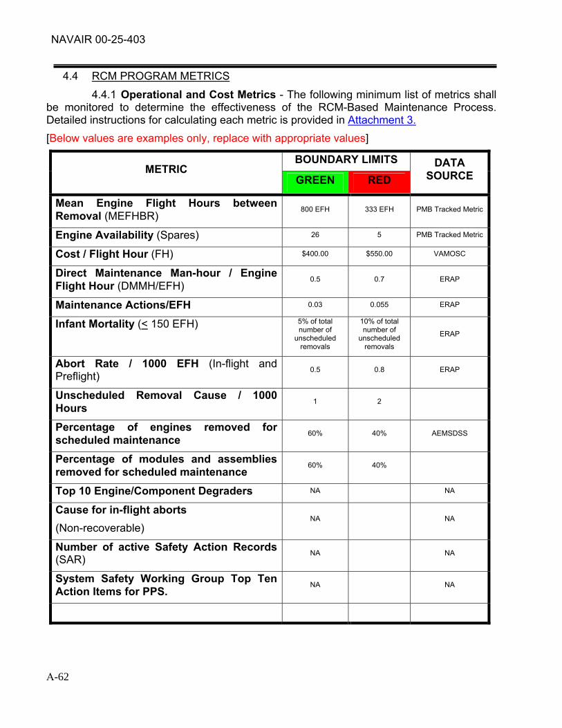
NAVAIR 00-25-403
A-62
4.4 RCM PROGRAM METRICS
4.4.1 Operational and Cost Metrics - The following minimum list of metrics shall be monitored to determine the effectiveness of the RCM-Based Maintenance Process. Detailed instructions for calculating each metric is provided in Attachment 3. [Below values are examples only, replace with appropriate values]
BOUNDARY LIMITS METRIC
GREEN RED DATA
SOURCE
Mean Engine Flight Hours between Removal (MEFHBR)
800 EFH 333 EFH PMB Tracked Metric
Engine Availability (Spares) 26 5 PMB Tracked Metric
Cost / Flight Hour (FH) $400.00 $550.00 VAMOSC
Direct Maintenance Man-hour / Engine Flight Hour (DMMH/EFH)
0.5 0.7 ERAP
Maintenance Actions/EFH 0.03 0.055 ERAP
Infant Mortality (< 150 EFH) 5% of total number of
unscheduled removals
10% of total number of
unscheduled removals
ERAP
Abort Rate / 1000 EFH (In-flight and Preflight)
0.5 0.8 ERAP
Unscheduled Removal Cause / 1000 Hours
1 2
Percentage of engines removed for scheduled maintenance
60% 40% AEMSDSS
Percentage of modules and assemblies removed for scheduled maintenance
60% 40%
Top 10 Engine/Component Degraders NA NA
Cause for in-flight aborts (Non-recoverable)
NA NA
Number of active Safety Action Records (SAR)
NA NA
System Safety Working Group Top Ten Action Items for PPS.
NA NA

NAVAIR 00-25-403
A-63
4.4.2 RCM Goals for Major Intermediate and Depot PM Task Intervals Attachment 4 provides charts that show the PM task interval History and Goals for various engine modules and starting system components.
4.4.3 RCM Acceptable Probability of Failure (PACC) 4.4.3.1 Safety PACC
[Below values are examples only, replace with appropriate values]
Severity Class Safety PACC
I 1 x 10⁻⁶
II 1 x 10⁻⁶
III 1 x 10⁻³
IV NA
4.5 SINGLE INSPECTION EFFECTIVENESS – Single Inspection Effectiveness Workbook (Excel) provides estimated single inspection effectiveness values for various inspection methods, materials, defect sizes, surface condition, etc. 4.6 MINIMUM DETECTABLE FLAW SIZES - Single Inspection Effectiveness Workbook (Excel) provides estimated minimum detectable flaw sizes for various inspection methods, materials, defect sizes, surface condition, etc. 4.7 FAILURE MODE EFFECTS AND CRITICALITY ANALYSIS
4.7.1 Sources for Hardware Nomenclature 4.7.1.1 For in-service hardware, obtain hardware nomenclature from the IPB section contained in the manuals listed in paragraphs 3.1.2.1.1 through 3.1.2.1.3. 4.7.1.2 For new hardware, obtain hardware nomenclature for the applicable hardware drawing.
4.7.2 Hardware Indenture Level Numbering System 4.7.2.1 The hardware indenture level numbering system will be based on the LCN numbering system used in the [ENGINE ID] LSA.
4.7.3 Function Identification Data Sources and Methodologies - Refer to NAVAIR 00-25-403 manual for required information.
4.7.4 Failure Mode Identification Data Sources and Methodologies - Refer to NAVAIR 00-25-403 manual for required information. 4.7.4.1 Failure modes will also be identified using inspection tables from [ACFT ID] PPS Maintenance Manuals. These inspection tables normally cover defects that have occurred in-service.

NAVAIR 00-25-403
A-64
4.7.5 Mission Profiles The following table defines the various mission phases and duration of each. Additional details of the composite mission profile can be obtained from NAVAIR AIR–[CODE].
[Below values are examples only, replace with appropriate values]
[AIRCRAFT MODEL ID] COMPOSITE MISSION PROFILE
DURATION (hrs) REFERENCE NO.
PHASE ENGINE FLIGHT
1 Preflight and Taxi
1A Preflight and Ground Start
1B Taxi
0.175 -
2 Takeoff and transition
2A STO or CTO to V1 takeoff speed
2B V1 takeoff speed to transition
0.004 0.004
3 Transition to conventional flight 0.427 0.427
4 Close air support 0.050 0.050
5 Interdiction 0.050 0.050
6 Air to air combat 0.080 0.080
7 Climb and return to base 0.385 0.385
8 Transition and vertical landing
8A Hover
0.004 0.004
9 Taxi, post flight and ground checkout 0.125 -
TOTAL 1.300 1.000
4.7.6 Failure Detection Methods - Refer to NAVAIR 00-25-403 manual for required information.
4.7.7 Failure Distribution Curve Methodologies 4.7.7.1 Weibull Analysis 4.7.7.1.1 Weibull Analysis is a statistical technique useful for various aspects of failure analysis. P&P Weibull Analysis Module (Excel Workbook) for performing Weibull analysis for RCM, RCM-P01, is contained in Propulsion and Power RCM Training Handbook. Weibull Analysis can provide information such as the following:
• The conditional probability of failure of a part versus a given age.
• The expected number of failures over any period. The type of failure mode, i.e. infant mortality, wear-out, batch problems, combinations of failure modes, etc.
• The percentage of items expected to fail by a given age.

NAVAIR 00-25-403
A-65
• The impact of design changes on failure risk.
• The number of samples required for specific AE inspections. 4.7.7.1.2 When enough failure data is not available to do a proper
Weibull analysis, a Weibayes analysis will be performed using Default Beta and ETA values supplied by the OEM or from Weibull Support Module Workbook (Excel). 4.7.7.2 Fracture Mechanics Analysis 4.7.7.2.1 Fracture mechanics is an analytical method for determining crack growth rates. Fracture mechanics analysis predicts the number of cycles of some applied load required to "grow' a crack from detectable size to critical size at which complete fracture of the part occurs. Its primary benefit to the RCM analysis is to help determine the interval from potential to functional failure for structural components or other components subject to cracks. RCM uses this information to determine an effective inspection interval. 4.7.7.3 Other Methods 4.7.7.3.1 Propulsion and Power RCM Training Handbook provides preferred calculation methodologies used to determine a Failure Distribution Curve for each failure mode. 4.7.7.3.2 Calculation methodologies not listed in the NAVAIR 00-25-403 manual or Propulsion and Power RCM Training Handbook can be used provided:
• The reasons for use and the methodology is documented in the memo field in the IRCMS database.
• If used repeatedly, the methodology will be submitted to the NAVAIR RCM Steering Committee for consideration to be added to the NAVAIR 00-25-403 manual and to the Propulsion and Power RCM Training Handbook.
4.7.8 Mean Time between Failures (MTBF) Data Sources and Calculation Methodologies - Propulsion and Power RCM Training Handbook, RCM-P12, provides calculation methods for MTBF. 4.8 TASK ANALYSIS 4.8.1 RCM task analyses will be conducted using IRCMS, the RCM Analyst Course Student Guide, Propulsion and Power RCM Training Handbook, and NAVAIR 00-25-403. 4.8.2 Re-design costs shall be obtained from [ACFT ID] PPS CIP program.
4.9 SUSTAINING TASK PRIORITIES
4.9.1 DUE TO FUNDING CONSTRAINTS, PERSONNEL LIMITATIONS, OR OTHER FACTORS, ALL OF THE DESCRIBED ELEMENTS OF THE RCM PROGRAM MAY NOT ALWAYS BE PERFORMED. DURING TIMES OF REDUCED EFFORT, ELEMENTS WILL BE PERFORMED ACCORDING TO PRIORITY.
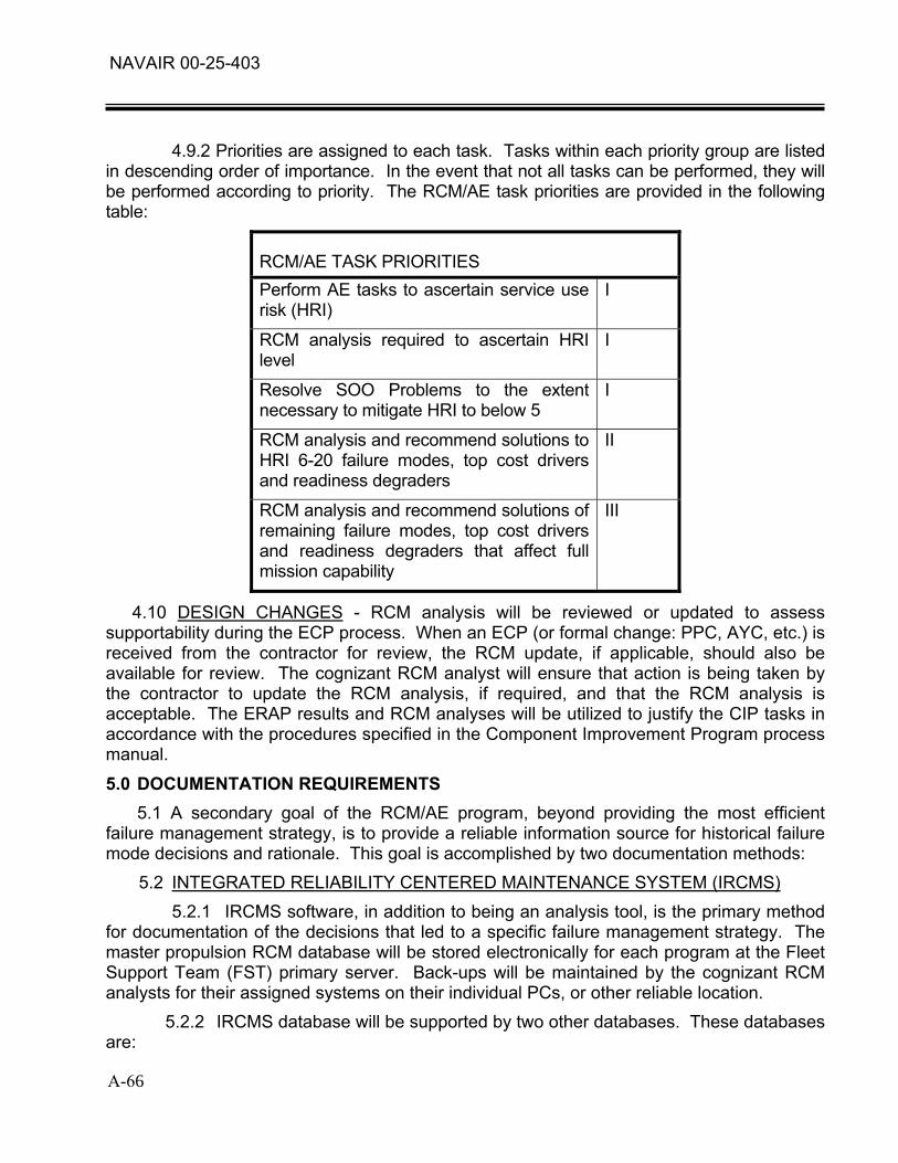
NAVAIR 00-25-403
A-66
4.9.2 Priorities are assigned to each task. Tasks within each priority group are listed in descending order of importance. In the event that not all tasks can be performed, they will be performed according to priority. The RCM/AE task priorities are provided in the following table:
RCM/AE TASK PRIORITIES Perform AE tasks to ascertain service use risk (HRI)
I
RCM analysis required to ascertain HRI level
I
Resolve SOO Problems to the extent necessary to mitigate HRI to below 5
I
RCM analysis and recommend solutions to HRI 6-20 failure modes, top cost drivers and readiness degraders
II
RCM analysis and recommend solutions of remaining failure modes, top cost drivers and readiness degraders that affect full mission capability
III
4.10 DESIGN CHANGES - RCM analysis will be reviewed or updated to assess supportability during the ECP process. When an ECP (or formal change: PPC, AYC, etc.) is received from the contractor for review, the RCM update, if applicable, should also be available for review. The cognizant RCM analyst will ensure that action is being taken by the contractor to update the RCM analysis, if required, and that the RCM analysis is acceptable. The ERAP results and RCM analyses will be utilized to justify the CIP tasks in accordance with the procedures specified in the Component Improvement Program process manual.
5.0 DOCUMENTATION REQUIREMENTS 5.1 A secondary goal of the RCM/AE program, beyond providing the most efficient failure management strategy, is to provide a reliable information source for historical failure mode decisions and rationale. This goal is accomplished by two documentation methods: 5.2 INTEGRATED RELIABILITY CENTERED MAINTENANCE SYSTEM (IRCMS) 5.2.1 IRCMS software, in addition to being an analysis tool, is the primary method for documentation of the decisions that led to a specific failure management strategy. The master propulsion RCM database will be stored electronically for each program at the Fleet Support Team (FST) primary server. Back-ups will be maintained by the cognizant RCM analysts for their assigned systems on their individual PCs, or other reliable location. 5.2.2 IRCMS database will be supported by two other databases. These databases are:

NAVAIR 00-25-403
A-67
5.2.2.1 Failure mode database which documents the failure distribution curves, failure intervals, fatigue related information (resonance bands, time at resonance, crack propagation rates, etc). 5.2.2.2 PM task log database that tracks task numbers and records information not documented in IRCMS database. 5.2.3 Additional documents (failure data information, pictures, test results, etc) will be created and maintained as required. These documents should be in electronic format, and maintained in a directory with the [ACFT ID] PPS IRCMS database files. 5.2.4 All supporting document file names will be included in the Failure Mode Memo Field in the IRCMS software. 5.3 AE DATABASE - The AE database will be maintained on the [FST ID] FST server. The AE Database shall be used to: 5.3.1 Record all data required to develop a failure distribution curve for each failure mode (both potential and functional failures). The data required include failure cause, failure component time since new and time since repair, and the total number of failures for each failure mode. 5.3.2 Record all data used to determine various failure intervals of each failure mode. The data required includes crack growth rates, wear rates, time in resonance bands, and stress loads which propagate defects to failure. 5.3.3 Adequately track the life of all engines, assemblies, and components as required by the RCM analysis.
5.3.4 Adequately track all discrepancies, and AE inspection requirements. 5.3.5 Adequately track the status of AE engines, modules, assemblies, and components. 5.3.6 Data sources used to document the AE database include: 5.3.6.1 El reports (organic and vendor) 5.3.6.2 HMR and vendor equivalent report 5.3.6.3 QDR and vendor equivalent report 5.3.6.4 TPDR and vendor equivalent report 5.3.6.5 Mishap report (organic and vendor) 5.3.6.6 Vendor specification compliance reports and mission profile models 5.3.6.7 Test, laboratory, 3D modeling results and reports 5.3.6.8 MRB and scrap reviews (organic and vendor) 5.3.6.9 3M/NALDA system and/or vendor equivalent 5.4 RCM AUDIT LOG – The RCM Audit Log database shall be maintained as a record

NAVAIR 00-25-403
A-68
of actions taken to modify or change Preventive Maintenance requirements and identify needed RCM updates and reviews so they can be planned and prioritized. The RCM Audit Log database shall be maintained on the [FST ID] FST server 5.5 QUARTERLY RCM REPORTS 5.5.1 These reports provide the results of trend analysis and RCM metrics results. 5.5.2 Attachment 5 provides a sample report. Distribution of Quarterly reports shall be to the FST Lead, the APML, and others as directed. The RCM Lead Engineer shall be responsible for developing and issuing the report.
6.0 RCM PROGRAM EVALUATION 6.1 RCM REVIEWS - Annual RCM reviews will be used to as a method of verifying/adjusting the RCM analysis. The reviews will be scheduled annually and chaired by the [FST ID] FST at [LOCATION]. 6.1.1 Attendance by CLS contractor, other pertinent vendors, and CSS support contractors is recommended, as applicable. 6.1.2 At least two weeks prior to the review, a letter will be sent announcing the meeting date, site, and agenda. As a minimum, candidates for the review will be determined from data collected, (i.e. AEB, fleet usage data, MRB actions, EI(s), etc), since the last review. 6.1.3 The RCM analysis will be updated to reflect the results of the review and published, in a timely manner, based on severity classification. 6.1.4 The most current RCM analysis, reflecting all updates, will be available on the NAVAIR Propulsion Online Web site (https://www.napol.navy.mil). 6.1.5 Failure management strategies that are determined ineffective shall be modified, eliminated, or replaced by new requirements resulting from updated analyses, using best available information. The results of these analyses will be clearly documented in the IRCMS and RCM Audit Log databases. The following methods can be used to evaluate the effectiveness of the failure management strategies program on an annual basis: 6.1.5.1 ECA reports and NALDA queries can provide an indication of overall maintenance effectiveness. These can be used to compare maintenance data from one year to the next. Any significant changes in the maintenance or availability data should be cause for investigation. However, there are many factors that can affect maintenance effectiveness indicators and care must be taken to ensure the actual cause or causes of the change are determined. 6.1.5.2 RCM Audit Log (paragraph 5.4) reports can provide an indication of which RCM/AE program tasks generated most of the PM changes, and which RCM/AE program tasks required the most effort. Using NALDA data to estimate maintenance effectiveness and this information from the RCM Audit Log, an estimate of the return on each program task can then be developed. Note that this will always be a rough estimate because the actual effects of not having a task in place where one currently exists or vice

NAVAIR 00-25-403
A-69/ (A-70 Blank)
versa can only be assumed.
7.0 TRAINING REQUIREMENTS 7.1 All personnel (organic and contractor) involved in the application of the [ACFT ID] PPS RCM program shall meet the training and certification requirements contained in NAVAIR 00-25-403 and/or local team training requirements.
8.0 MILESTONE CHART 8.1 Attachment 6 is the milestone chart for implementing [ACFT ID] PPS RCM program.
9.0 PERSONNEL/FUNDING REQUIREMENTS 9.1 MANPOWER REQUIREMENTS: Manpower listed below is to implement and
maintain the [ENGINE ID] RCM-Based Maintenance Program described herein. It includes manpower to perform analysis, collect data, analysis data, make and implement recommendations and ensure program goals are met.
MAN YEARS CATEGORIES
FY04 FY05 FY06 FY07
PRL Funded xx.xx xx.xx xx.xx xx.xx
IMC Funded xx.xx xx.xx xx.xx xx.xx
SOO Requirements xx.xx xx.xx xx.xx xx.xx
FY Total xx.xx xx.xx xx.xx xx.xx
MAN YEARS CATEGORIES
FY08 FY09 FY10
PRL Funded xx.xx xx.xx xx.xx
IMC Funded xx.xx xx.xx xx.xx
SOO Requirements xx.xx xx.xx xx.xx
FY Total xx.xx xx.xx xx.xx
9.2 ADDITIONAL FUNDING ASSUMPTIONS – To adequately implement RCM-base
failure management strategies, it is assumed that $xxK are available in the CIP budget, $xxK in the APN budget, and that adequate depot and AVDLR funding is available to execute rework strategies.

THIS PAGE INTENTIONALLY LEFT
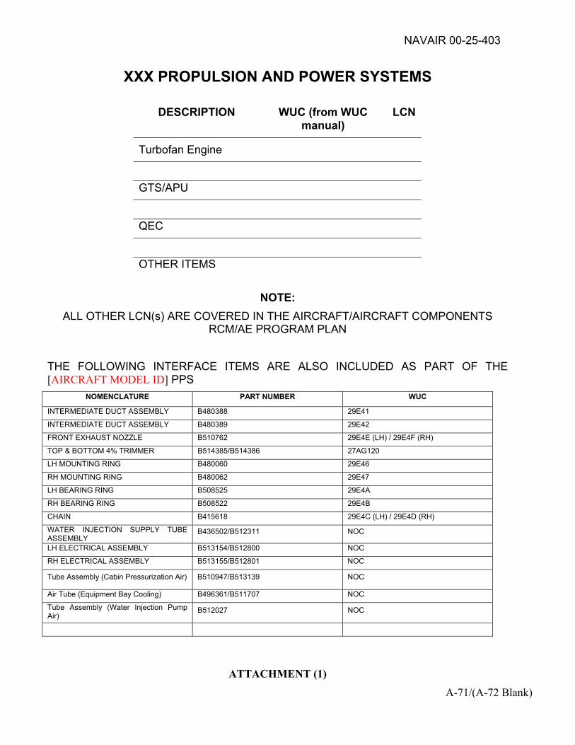
NAVAIR 00-25-403
ATTACHMENT (1) A-71/(A-72 Blank)
XXX PROPULSION AND POWER SYSTEMS
DESCRIPTION WUC (from WUC manual)
LCN
Turbofan Engine
GTS/APU
QEC
OTHER ITEMS
NOTE: ALL OTHER LCN(s) ARE COVERED IN THE AIRCRAFT/AIRCRAFT COMPONENTS
RCM/AE PROGRAM PLAN THE FOLLOWING INTERFACE ITEMS ARE ALSO INCLUDED AS PART OF THE [AIRCRAFT MODEL ID] PPS
NOMENCLATURE PART NUMBER WUC
INTERMEDIATE DUCT ASSEMBLY B480388 29E41
INTERMEDIATE DUCT ASSEMBLY B480389 29E42
FRONT EXHAUST NOZZLE B510762 29E4E (LH) / 29E4F (RH)
TOP & BOTTOM 4% TRIMMER B514385/B514386 27AG120
LH MOUNTING RING B480060 29E46
RH MOUNTING RING B480062 29E47
LH BEARING RING B508525 29E4A
RH BEARING RING B508522 29E4B
CHAIN B415618 29E4C (LH) / 29E4D (RH)
WATER INJECTION SUPPLY TUBE ASSEMBLY
B436502/B512311 NOC
LH ELECTRICAL ASSEMBLY B513154/B512800 NOC
RH ELECTRICAL ASSEMBLY B513155/B512801 NOC
Tube Assembly (Cabin Pressurization Air) B510947/B513139 NOC
Air Tube (Equipment Bay Cooling) B496361/B511707 NOC
Tube Assembly (Water Injection Pump Air)
B512027 NOC

THIS PAGE INTENTIONALLY BLANK

NAVAIR 00-25-403
ATTACHMENT (2) A-73
RCM BASED MAINTENANCE PROCESS
RCM Based Maintenance Process is made up of two processes:
1. FEEDBACK PROCESS:
a. Flight operations and reporting
b. Unscheduled and scheduled maintenance tasks
c. Data collection programs:
(1) Navy wide data collection programs (e.g., 3-M, Ecomtrack, ERAP, etc.)
(2) Program data collection tasks (e.g., Engineering investigations, Age and power plant bulletins, Fleet meetings and messages, etc.)
d. The various data sources are gathered together and sorted.
e. The sorted data then analyzed using:
(1) Weibull and trending analysis
(2) Fatigue life monitoring
(3) Age exploration data analysis
(4) Failure consequences & rates analyzed
FEEDBACK PROCESS
PREVENTATIVEMAINTENANCEREQUIREMENT
DESIGN OF EQUIPMENTFUNCTIONAL BREAKDOWNPERFORMANCE SPECS
TEST DATAPPC(s)
PMA/APMLDIRECTED
TASKS
RCM PROCESS
RCM DECISION LOGIC
REDESIGN(CIP)
REPAIRS
3MEI/MISHAPTPDR/REI
MELRHMR/QDR
MRB/SCRAP REVIEWSPROCESS REVIEWS
SITE VISITSIPECIP
PPBTHRESHOLD SAMPLINGLEAD THE FLEET / ACI
CORRECTIVEMAINTENANCEPERFORMED
(UNSCHEDULED)
FAILURES
OPERATIONS
EQUIPMENT PERFORMANCE
RELIABILI TY AND MAINTAINABILITY DATA ANALYSISFAILURE RATES
FAILURE DISTRIBUTIONSAGE EXPLORATION DATE COLLECTEDAGE EXPLORATION DATA ANALYSIS
WEIBULL & TRENDING ANALYSIS
NOPREVENTATIVEMAINTENANCE
MAINTENANCE PLANLORA
LOGISTICS SUPPORT
IMPLEMENT PM REQUIREMENTS
LOGISTIC ELEMENT REQUIREMENTS
SUPPLY & TRAINING SUPPORT
SSWGREVIEW &
INPUTS
ACQUISITIONOPERATIONAL
RCM ANALYSIS TASKS
PREVENTATIVEMAINTENANCEPERFORMED(SCHEDULED)
FMECA
IMPLEMENTATION TASKS FEEDBACK TASKS
AGE EXPLORATION (AE)SAMPLING REQUIREMENTS
DATA UPDATE
DOCUMENT TASK
IN-SERVICE ENGINEERING / LOGISTICS
ENGINEERING INVESTIGATIONSINSPECTION BULLETINS
REWORK / REPAIRFATIGUE LIFE MONTORING

NAVAIR 00-25-403
ATTACHMENT (2) A-74
2. RCM PROCESS:
a. RCM ANALYSIS TASKS:
(1) All the failure data is inputted into IRCMS database and is analyzed using RCM decision logic.
(a) If required, the FMECA is updated.
(b) New PM actions recommended.
(c) Changes to existing PM tasks are identified.
(2) SSWG to review of RCM recommendations.
(3) Documenting and recommending:
(a) CIP actions
(b) Fatigue life-monitoring changes
(c) Age exploration tasks
(d) Failure consequences & rates change
b. IMPLEMENTATION TASKS:
(1) Determine manpower, support equipment, and material requirements for PM task.
(2) Input PM costs into the IRCMS database.
(3) Perform cost effectiveness analysis of RCM recommended PM tasks.
(4) Perform packaging of accepted RCM PM tasks.
(5) Update LSA/MP.
(6) Update publications including MRC decks.

NAVAIR 00-25-403
ATTACHMENT (3) A-75
DETAILED INFORMATION FOR CALCULATING [AIRCRAFT MODEL ID] PPS METRICS
Note: (1) Engine Flight Hours (EFH) = Aircraft Flight Hours x
Number of Engines (2) Goals/Norms should be established for Metrics 1,2,3,4.
1. Cost / Engine Flight Hour - Total cost of engine operation, including Contractor Engineering and Technical Services (CETS), Modification (Mod) Kits, CIP, Depot engine rework cost, I and O level consumables and labor, and Aviation Depot Level Repairable (AVDRL), divided by total Engine Flight Hours (EFH).
2. Time on Wing (Mean Time between Removal) - The total number of EFH(s) divided by the total number of items removed from that system during a stated period. Mean engine flight hours between unscheduled removals, excluding removals to facilitate maintenance and removals for product improvement (Change incorporation).
3. Abort Rate / 1000 EFH (In-flight and preflight) - Based on VIDS/MAF records with: a. A transaction code of 11 or 12 b. A when discovered code of –A- or –C- c. A maintenance level of 1 d. The job control number suffix blank and an action taken code other than J, K, L, M, N, Q, S, or T Rate is computed by dividing the number of aborts by the total EFH over the same period and then multiplying by 1000.
4. Direct MMH / EFH - Total maintenance man-hours (scheduled and unscheduled) expended on an engine divided by the total engine flight hours over the same period of time.
5. Unscheduled Removal Cause / 1000 Hours - All engines having a status-star code of 2474 and not having a reason code of: 3W Cannibalization 3X Cannibalization (Administrative) 4D Direct Removal 5G High Time 6A Mod/Technical Directive Compliance (TDC) Incorporation 6V LCF 7C High Time Component 7D High Time Engine

NAVAIR 00-25-403
ATTACHMENT (3) A-76
7E Hourly Engine Maintenance Program (HEMP)/Hot Section Inspection (HSI) Rate is computed by dividing the number of removals for each cause by the total EFH over the same period and then multiplying by 1000.
6. Top 10 Engine/Component Degraders - A ranking list of aircraft/engine components, developed by the Assistant Program Managers, Logistics (APML)/Logistics Managers (LM), which are having the highest adverse impact on readiness and operational support cost.
7. Cause for in-flight aborts - A ranking of the major causes of aborts also showing the number of aborts for each cause. Ranking may also be broken down to the module or component level.
8. Maintenance Actions / EFH - A count of O-level jobs (Visual Information Display System/Maintenance Action Form (VIDS/MAF) records) divided by the total EFH for the same period.
9. Number of active Safety Action Records (SAR) - The number of open and monitor category SAR(s) obtained from the program System Safety Working Group.
10. System Safety Working Group top ten action items, Propulsion and Power related - A ranking from the System Safety Working Group of the propulsion and power related top concerns from a safety stand point.

NAVAIR 00-25-403
ATTACHMENT (4) A-77/(A-78 Blank)
AI AV-8B PPS MAJOR INTERMEDIATE AND DEPOT PREVENTATIVE TASK INTERVAL HISTORY AND RCM GOALS
9 RCRAFT MODEL IDX
0
500
1000
1500
2000
2500
3000
Engine LPC MRA HPC Rotor CombustionMRA
HPT MRA LPT MRA ExhaustDiffuser MRA
Exhaust DuctMRA
F402-RR-408A/B PM Intervals History/Goals
Entry IntoService
Reduction in PMInterval
Current Interval
RCM Goal
LPC 2 Spacer LCF life driven

THIS PAGE INTENTIONALLY LEFT BLANK

NAVAIR 00-25-403
ATTACHMENT (5)
A-79/(A-80 Blank)
EXAMPLE OF QUARTERLY REPORT 1. OBJECTIVE: This condition monitoring report was developed as part of the [ACFT ID] PPS RCM/AE Program to identify potential problem areas and PM actions.
2. DESCRIPTION: The condition monitoring report provides the results of trend analysis and top degrader analyses performed on the [ENGINE ID] PPS for (specified time period). a. Trend analysis is performed by using failure data from the baseline period (calendar year 19__) to develop a mean and upper and lower control limits (UCL and LCL) of the analysis parameters. The analysis parameters are derived from the metrics identified in paragraph 4.5.1. The UCL and LCL are three standard deviations from the mean. Data is analyzed quarterly to identify items exceeding the UCL or LCL. An investigation is performed to determine the cause action is proposed. The item is then monitored to ensure the action has the desired effect. b. Top degrader analysis identifies the top ten degraders in terms readiness, reliability and cost. An investigation is performed to determine the cause of the problem, and action is proposed.
3. DATA SOURCE: Data is obtained through Naval Aviation Logistics Data Analysis (NALDA) queries of Naval Aviation 3-M data. Data is obtained and analyzed through the ERAP program.
4. CURRENT TREND ANALYSIS INVESTIGATIONS: (For each item that is outside the control limits for the current data period or for items which have previously been investigated and are open for action.)
NOTE Items may be removed from the report after being closed in a
previous report. a. Investigation results. b. Recommendation (Should include RCM efforts/results). c. Action required. d. Status (open or closed). e. A plot of the current trend data.
5. TOP DEGRADERS a. List of top degraders for each analysis parameter. b. Investigation results for each item. c. Recommendation for each item. d. Action required for each item. e. Status for each item
6. PREVENTIVE MAINTENANCE PROGRAM ACTIVITY Changes made to PM program to enhance Cost-wise Readiness.

THIS PAGE INTENTIONALLY LEFT BLANK

NAVAIR 00-25-403
ATTACHMENT (6) A-81
IMPLEMENTATION SCHEDULE
RCM IMPLEMENTATION SCHEDULE (FY)
2000 2003 2004 2005 2006 ACTION
1 2 3 4 1 2 3 4 1 2 3 4 1 2 3 4 1 2 3 4A. RCM DEFINITION
PROGRAM PLAN UPDATES A A A
IDENTIFY METRICS UPDATES A A A A
B. RCM IMPLEMENTATION
POPULATE IRCMS FMECA DATABASEFROM AWS FMECA DATABASE
C
COMPLETE FUNCTIONS ANDFUNCTIONAL FAILURES ENTRIES
VENDOR REVIEW OF FUNCTION &FUNCTIONAL FAILURE ENTRIES
COMPLETE FAILURE MODEENTRIES
VENDOR REVIEW OF FAILUREMODE ENTRIES
PERFORM RCM ANALYSIS
REVIEW ANALYSIS RESULTS
PACKAGE PM TASKS
RCM REVIEW MEETINGS Q Q Q Q
IMPLEMENT PM TASK CHANGES
AGE IMPLEMENTATION PLAN ISSUED
IMPLEMENT AE TASKS
CORRECT OTHER PUBLICATIONDEFICIENCIES

NAVAIR 00-25-403
ATTACHMENT (6) A-82
C. RCM SUSTAINMENT
COLLECT FAILURE DATA
PERFORM RCM REVIEWS S S S S
UPDATE IRCMS DATABASE S S S S
REVIEW ANALYSIS RESULTS S S S S
PACKAGE PM TASKS S S S S
IMPLEMENT PM TASK CHANGES S S S S
IMPLEMENT AE TASKS A A
PERFORM RCM PROGRAMEVALUATIONS
A A
RCM PROGRAM REVIEW MEETINGS A A
ISSUE RCM PROGRAM QUARTERLYREPORTS
Q Q Q Q Q Q Q Q
LEGEND: - Planned time to complete task
- Slippage
- Continuing task
A - Annual task
C - Task Completed
S - Semi annual task
Q - Quarterly task
-

NAVAIR 00-25-403 01 July 2005
B-1
APPENDIX B
RCM METHODS
TABLE OF CONTENTS
1.1 Introduction................................................................................................................. 2
1.2 On condition task interval determination ................................................................ 2 1.2.1 Using Acceptable Probability of Failure and Task Effectiveness ........................ 2 1.2.2 Optimizing Task Intervals for Failure Modes with Non-Safety Consequences ... 4 1.2.3 Methods for Estimating Potential-to-Functional (PF) Interval............................. 5
1.3 Hard time task interval determination ..................................................................... 7 1.3.1 Weibull analysis.................................................................................................... 7 1.3.2 Testing................................................................................................................... 7 1.3.3 Fatigue analyses .................................................................................................... 7 1.3.4 Determining Hard Time Intervals for Non-Safety Related Failures..................... 7
1.4 Failure Finding Task interval Determination .......................................................... 8

NAVAIR 00-25-403
B-2
1.1 INTRODUCTION Various methods are available for meeting the quantitative and qualitative needs of the RCM analysis process. Some methods are widely accepted, while others are applicable only under certain circumstances or applications. Additionally, some methods that were previously used have been found to be suspect after review. Care must be taken to ensure that any method adopted for performing RCM analysis is appropriate, and that any mathematical or statistical methodology is consistent with the data inputs or assumptions used. No method or formula should be used unless there is a clear understanding of their derivations and of the appropriate data or assumptions that must be made for them to be valid. The following RCM methods have been developed for computing or estimating task intervals for the various types of RCM tasks. These methods have been reviewed and are endorsed by the NAVAIR RCM Steering Committee for use in applications where appropriate. Other methods may be found at the NAVAIR RCM web site or by contacting the Steering Committee. It is the responsibility of the user to determine the appropriateness of a given method to a specific application. Programs are encouraged to submit additional methods found helpful in conducting the analysis to the Steering Committee via the NAVAIR RCM web site.
1.2 ON CONDITION TASK INTERVAL DETERMINATION
1.2.1 Using Acceptable Probability of Failure and Task Effectiveness On Condition task intervals are usually based on some fraction of a potential failure to functional failure (PF) interval. One method of determining an On Condition task interval is based on the premise that any inspection will not be 100% effective. When acceptable probability of failure is the basis for an on-condition task interval (such as for safety and environmental failure modes), it will require some number of inspections over the PF interval to ensure that the probability of failure is reduced to an acceptable level. Shown mathematically:
NOTE:
In some cases the following equation will require modification due to the continuous operation of a system (i.e., the inspection is performed while the equipment is operating), or the inability to take corrective action immediately upon recognition of the potential failure. In these cases, time must be allotted to the time shut down the system (or make it available) prior to having the ability to repair the potential failure. This will be referred to as the “time to correct” or deferral time (TC), and the equation is modified to: I=(PF-TC)/n. This should only be used when the equipment will be used unrestricted or unmonitored following the recognition of a potential failure condition, prior to repair.
Equation (1) I = PF/n Where:
I = Inspection interval

NAVAIR 00-25-403
B-3
PF = Potential failure to functional failure interval
n = Number of inspections in the PF interval
Assigning an acceptable probability of failure to detect a potential failure condition (and therefore expose the item to functional failure) yields a second equation that can be used to determine n.
Equation (2) n = ln (Pacc) / ln (1-θ)
Where:
I = Inspection interval
θ = Probability of detecting a potential failure with one occurrence of the proposed On Condition task, assuming the potential failure exists
Pacc = Acceptable probability of failure
The derivation for this method is as follows:
If θ is the probability of detecting a potential failure in one inspection, assuming the potential failure exists, the probability of not detecting it is (1 - θ). The probability of not detecting the potential failure in n inspections is (1 - θ)n. The intent of the task is to reduce probability of missing the potential failure to an acceptable level, Pacc. The Pacc is that established for a single failure mode. (For hidden failures, the acceptable probability of failure will be based on the probability of the failure/event that makes the hidden failure evident. Therefore Pacc of the hidden failure equals the Pacc established for the critical failure (i.e., for the multiple failure/demand event) divided by the probability of the protected failure or demand event)
Described mathematically: Pacc = (1 - θ)n. Solving for n yields equation (2) above.
NOTE:
Recognize this equation is not precise in that it calculates the Pacc based on the assumption the potential failure exists. This is a conservative assumption and encourages the use of highly reliable inspection techniques. If a more precise interval were desired, the actual failure rate and failure mechanism and distribution would need to be considered in more detail. However, as more precision is pursued, the loss of conservatism must be weighed against the confidence in the data sources to ensure adequate levels of protection against failure are maintained. If more precision is attempted, the analyst must also consider, when establishing the acceptable levels of probability at the end item level, that there are usually multiple safety/environmental consequence failure modes.

NAVAIR 00-25-403
B-4
This method is appropriate for failure modes with safety/environmental and hidden safety/environmental consequences. It may also be used to provide an estimated value for n for non-safety consequences provided an acceptable probability of failure is identified. However, for economic failure modes an additional step to ensure that the task is cost-effective must be performed as follows:
Cpm + Ccm < Cnopm
Where:
Cpm = Cost of the preventive maintenance program
Ccm = Cost of corrective maintenance with preventive maintenance in place considering the potential and functional failures that will occur
Cnopm = Cost of correcting functional failures as they occur without the preventive maintenance program in place
1.2.2 Optimizing Task Intervals for Failure Modes with Non-Safety Consequences Another method for determining the number of inspections, n, in the potential failure to functional failure interval for failure modes with non-safety consequences is to use a cost optimization formula such as the following:
Where:
PF = Potential failure to functional failure interval
CI = Cost of one preventive maintenance task
= (DMMH for inspection) (Labor Cost per hour) + Consumable cost
Cpf = Cost of correcting one potential failure
= (DMMH to correct potential failure) (Labor Cost per hour) + Spares and Material costs
Cnpm = Cost of not doing preventive maintenance
= Ccm + Copc
( ) ( )
−−
−
θ1 ln CpfCnpm
CiPF
MTBFln n
=
ln ( )θ−1

NAVAIR 00-25-403
B-5
Note
If Cnpm is equal to Cpf, there is no benefit in discovering potential failure before functional failure.
Ccm = Cost of corrective maintenance
= (DMMH for repair) (Labor Cost per hour) + (Spares and material costs)
Copc = Costs due to operational impact (if established). (If not easily defined, one method to quantify this impact is to divide lost operational time due to unscheduled repair of functional failures by total planned operational time (e.g., divide unscheduled downtime hours by total planned available hours) and multiply by the acquisition cost of the end item.)
θ = Probability of detecting a potential failure with the proposed On Condition task, assuming the potential failure exists
If the solution to the above equation shows n ≤ 0, it is not cost effective to perform an On Condition task to address the failure mode under evaluation. If n ≥ 1, divide the PF by n to determine the appropriate task interval. If 0 < n < 1, the minimum cost effective task interval is obtained by setting n = 1 and PF becomes the task interval.
The above equation should be used carefully since it is built on the assumption that each potential failure prevents one functional failure. If the equation is being used to evaluate a task that is expected to result in repeated potential failure repairs to prevent one functional failure, the cost of all repaired potential failures for each functional failure must be considered. Failure to do so will invalidate the equation and promote implementation of tasks that are not cost effective.
1.2.3 Methods for Estimating Potential-to-Functional (PF) Interval Various methods may be used to estimate PF intervals, including engineering judgment, maintenance and operating personnel input, test and engineering data, material properties, and statistical methods using maintenance and operations data. One method that has been used to estimate the PF interval is to utilize findings from an existing On Condition task.
If an existing task is effective at finding potential failures and preventing functional failures, it may be reasonable to conclude the PF interval is significantly longer than the current inspection interval. Discussion with maintenance and operational personnel, evaluation of the inspection technique (to estimate probability of detection), and review of maintenance data (to determine how far into the failure/degradation process the potential failures have progressed) will aid in establishing the estimated PF. Once the PF is determined, the above methods can be used to set the inspection interval. However, care should be taken not to be overly conservative in estimating the PF such that the new task interval is significantly shorter than an existing effective task, without justification.
If an existing PM task is less effective than desired (i.e., more than an acceptable number of functional failures have occurred with the current task in place), and that task is being considered for continued use, an estimate of PF can be made from the current task interval.

NAVAIR 00-25-403
B-6
However, this method requires significant in-service data on potential and functional failures found, to determine the current task's effectiveness, as follows:
If PF is expected to be longer than the existing inspection interval, PF can be estimated by the following:
PF = ( ln (1 - α) / ln (1-θ)) * I
When PF expected to be shorter than the existing inspection interval, the formula becomes:
PF = (α / θ) * I
NOTE:
If the first equation is used, and PF is determined to be shorter than I, consider whether θ may be less effective than estimated and recalculate, or recalculate PF using the second equation. If the second equation is used, and PF is determined to be longer than I, consider whether θ may be more effective than estimated and recalculate, or recalculate PF using the first equation.
Where:
α = Task Effectiveness (i.e., number of potential failures found divided by total failures (potential and functional)
θ = Probability of detecting a potential failure with the current On Condition task (assuming the potential failure exists)
I = Current Task Interval
Care should be taken in using this method as it is dependent on good in-service data and estimates of θ. The resulting PF should be evaluated using engineering judgment, maintainer/operator input, and any other information sources to ensure it is reasonable and consistent with the failure mode under consideration. The analyst must also consider whether the information from the existing task is indicative of a situation where a consistent PF condition or progression is not a characteristic of the failure mode under consideration, and therefore an OC task would be inappropriate. Once the PF is determined, the methods described in previous paragraphs can be used to set the new inspection interval.
If a different inspection method will be considered for replacing an existing task for a given failure mode, the new inspection interval should be based on the probability of detection of the PF condition (θ) using the new inspection method.

NAVAIR 00-25-403
B-7
1.3 HARD TIME TASK INTERVAL DETERMINATION
1.3.1 Weibull analysis Weibull analysis is a statistical technique that uses failure data to provide accurate failure predictions. It provides a method for determining probability of failure as a function of time. This is useful for determining Hard Time task intervals by selecting the time at which the number of occurrences of the failure mode reaches an unacceptable level.
1.3.2 Testing Testing is another means to determine safe-life limits or wear out ages of items. Many components require certification tests that ensure that the component will operate for a certain period without failure. Aircraft structure, for example, is usually tested to failure under a full-scale fatigue test to ensure that it will remain crack-free for the life of the aircraft. When airframe cracks are found unexpectedly, coupon testing is sometimes performed to determine the life to crack initiation of the suspect component. Statistical techniques such as Weibull may then be applied using the test data to determine appropriate task intervals.
1.3.3 Fatigue analyses Fatigue analysis can be used to determine an item’s life to crack initiation, which, in turn, can be used as a basis to establish a Hard Time task interval. In-service failures that occur because of fatigue may be avoided by setting Hard Time limits at or below the life to crack initiation limit. Appropriate safety factors must be considered and included when establishing these limits.
1.3.4 Determining Hard Time Intervals for Non-Safety Related Failures Non-safety related Hard Time tasks are only required to cost less than the failure consequences they are designed to prevent. The formula used to ensure this is as follows:
MTBFC
MTTFNtNNCNC
CBRAF
PSS
SAFSBF
])1[())1(()(
−+−×+×
=
Where: CBR = cost benefit ratio
CBF = cost of rework/replacement before failure
NS = the percent of items that survive to the proposed task interval
t = the proposed task interval CAF = cost of repair/replacement and collateral damage (if any) after failure
(if operational impacts have been converted to costs, ensure they are included)

NAVAIR 00-25-403
B-8
MTBF = mean time between failure (with no preventive task in place)
MTTFP = mean time to failure of items that fail before the proposed task interval
Tasks that have CBR values of less than 1 are considered cost effective. Since MTTFP may be difficult to obtain, a reasonable estimate may be made using the estimated percentage of the proposed replacement age premature failures will achieve (on average) (i.e., replace MTTFP with (K x t) where K is estimated percent of task interval premature failures achieve). Items with infant mortality issues following rework or replacement will generally have a lower percentage (i.e., lower MTTFP). If premature failures are expected to be evenly distributed throughout the period before replacement, 50 percent may be a reasonable estimate for this entry (K).
1.4 FAILURE FINDING TASK INTERVAL DETERMINATION The probability of multiple failure can be set to a level that is acceptable to a program following the same logic as that used in establishing the acceptable probability of functional failures for evaluating On Condition tasks for hidden safety/environmental failure modes.
The following equation can be used to model the probability of multiple failure condition:
Equation (1) Pmf = Phidden x Padditional Where:
Pmf = Probability of multiple failure occurring
Phidden = Probability of the hidden failure occurring
Padditional = Probability of an additional failure occurring
Assuming a random failure distribution for Phidden and Padditional, equation (2) can be used to model these probabilities of failure from equation (1) by establishing the probability over time:
Equation (2) P = 1 - e-t / MTBF Where:
P = Probability over the time period
t = Time period
MTBF = Mean Time Between Failures
The desired MTBF for the function (i.e., multiple failure) can be established by setting an acceptable probability of failure over a known timeframe (e.g., life of the item) and solving for MTBF. If the MTBF for the hidden and additional failure (or event) can be determined (or estimated), the equation is easily solved by iterating the two equations on a spreadsheet to find the appropriate time period (t), which becomes the inspection interval.