nature materials volume 11 issue 5 2012 bookmarked.pdf
TRANSCRIPT

372 NATURE MATERIALS | VOL 11 | MAY 2012 | www.nature.com/naturematerials
Ferromagnets are characterized by a magnetization that has long been used to store information. The magnetization is largely due to localized electron spins with their associated
magnetic moments aligning in a particular direction in space, which gives rise to a collective magnetic moment and magnetiza-tion that is far larger than that of non-ferromagnetic materials. The magnetization direction of a ferromagnet can represent a bit of information (for example, orientation up = 1 and down = 0), such as that used in hard-disk drives. The principal means of altering the magnetic moment direction has been to use applied magnetic fields from currents through wires that generate Oersted fields. However, there have been major new discoveries in con-densed matter and materials physics — known as spin-transfer torques — that have expanded the means available to manipulate the magnetization of ferromagnets and, as a result, have acceler-ated technological development of high-performance and high-density magnetic storage devices. These new magnetic devices are all electronic (that is, they do not have moving parts like a hard-disk drive) and can be integrated with, and add functionality to, semiconductor devices.
Current-induced torques in magnetic materialsArne Brataas1*, Andrew D. Kent2 and Hideo Ohno3,4
The magnetization of a magnetic material can be reversed by using electric currents that transport spin angular momentum. In the reciprocal process a changing magnetization orientation produces currents that transport spin angular momentum. Understanding how these processes occur reveals the intricate connection between magnetization and spin transport, and can transform technologies that generate, store or process information via the magnetization direction. Here we explain how cur-rents can generate torques that affect the magnetic orientation and the reciprocal effect in a wide variety of magnetic materi-als and structures. We also discuss recent state-of-the-art demonstrations of current-induced torque devices that show great promise for enhancing the functionality of semiconductor devices.
Similar to electric currents being carried by moving charge, the spin current occurs due to moving spins. The spin current carries angular momentum, which can be transferred to the magnetiza-tion, a phenomenon known as spin-transfer torques. Sloncwezski and Berger were the first to theorize about the existence of this phenomenon1,2. The torques are a result of an interaction between itinerant electrons in a ferromagnet that are spin polarized (spin currents) and the magnetization. The interaction can be very strong and occurs locally; it only occurs in regions in which spin currents flow, and thus can be precisely directed for applications. Spin-transfer torques have been found to be both present and important in all known magnetic materials, including transition metal fer-romagnets, magnetic semiconductors and oxide ferromagnets. In fact, spin-transfer torques are not limited to ferromagnetic materi-als, or even to ferromagnetic conductors or semiconductors. Not only can they also be important in ferromagnets and antiferromag-nets, but they also occur at interfaces of insulating magnetic mate-rials. Furthermore, spin transfer is also seen in a variety of material structures and device geometries, including point contacts and nanopillars composed of magnetic–non-magnetic multilayers as well as in nanowires and magnetic tunnel junctions. The latter are now widely used in hard-disk drives and are of particular impor-tance to the development of all electronic magnetic memories.
This article reviews the fundamentals, phenomena, devices and materials of spin-transfer torques, at the heart of this rapidly advancing field of current-induced magnetization dynamics. We discuss how spin-transfer torques will permit the ultimate minia-turization of magnetic random access memories (MRAM), com-mercially available memories that at present use magnetic fields to reorient magnetization to store information. Although spin-trans-fer torques can reorient magnetization by spin currents, we also discuss a new way of probing spin transport in materials using a reciprocal process, known as spin pumping, which is the emission of spin currents by magnetization reorientation. The most signifi-cant developments are in recent experiments confirming sophisti-cated theories of spin-transfer torques and spin pumping, and they clearly show how they directly open up possibilities for improved nanometre-scale electronic devices.
Spin-transfer torques are associated with spin currents in mate-rials, a flow of electron spin angular momentum that arises when there is an imbalance between a flow of up- and down-oriented electron spins. Figure 1 illustrates the basic physics of spin-transfer torques. An electron spin interacts with the magnetization of a thin ferromagnetic layer and this interaction results in a reorientation
1Department of Physics, Norwegian University of Science and Technology, NO-7191 Trondheim, Norway, 2Department of Physics, New York University, 4 Washington Place, New York, New York 10003, USA,3Center for Spintronics Integrated Systems, Tohoku University, 2-1-1 Katahira, Aoba-ku, Sendai 980-8577, Japan,4Laboratory for Nanoelectronics and Spintronics, Research Institute of Electrical Communication, Tohoku University, 2-1-1 Katahira, Aoba-ku, Sendai 980-8577, Japan. *e-mail: [email protected]
Spin-transfer torque
Field-liketorque
Incidentelectron
Outgoingelectron
Figure 1 | Illustration of current-induced torques. A spin-polarized current enters a ferromagnet. The interaction between the spin-polarized current and the magnetization causes a change in the spin direction of the outgoing electron compared with the incident electron. The difference in spin polarization causes torques on the ferromagnet, both a torque in the plane of the incident and outgoing electron spin directions (a spin-transfer torque) and a torque perpendicular to that plane, called the field-like torque. The bold vertical arrow is the magnetization of the ferromagnetic layer.
REVIEW ARTICLES | INSIGHTPUBLISHED ONLINE: 23 APRIL 2012 | DOI: 10.1038/NMAT3311
© 2012 Macmillan Publishers Limited. All rights reserved
NATURE MATERIALS | VOL 11 | MAY 2012 | www.nature.com/naturematerials 373
of the electron spin on transmission through (or reflection from) the ferromagnetic layer. By conservation of angular momentum, a change in the direction of an electron spin angular momentum leads to a torque on the magnetization of the ferromagnet. These torques can be directed as shown in Fig. 1. They can either be in the plane of the incoming and outgoing electron spin direction or perpendicular to that plane. The former is often called the in-plane (or adiabatic) spin-transfer torque and the latter is known as the perpendicular torque (or non-adiabatic or field-like torque). The relative importance and magnitude of the two spin-transfer tor-ques is dependent on material and device structure and is critical to applications in that they determine the threshold currents for magnetization switching and magnetization precession frequen-cies, as we discuss in this Review.
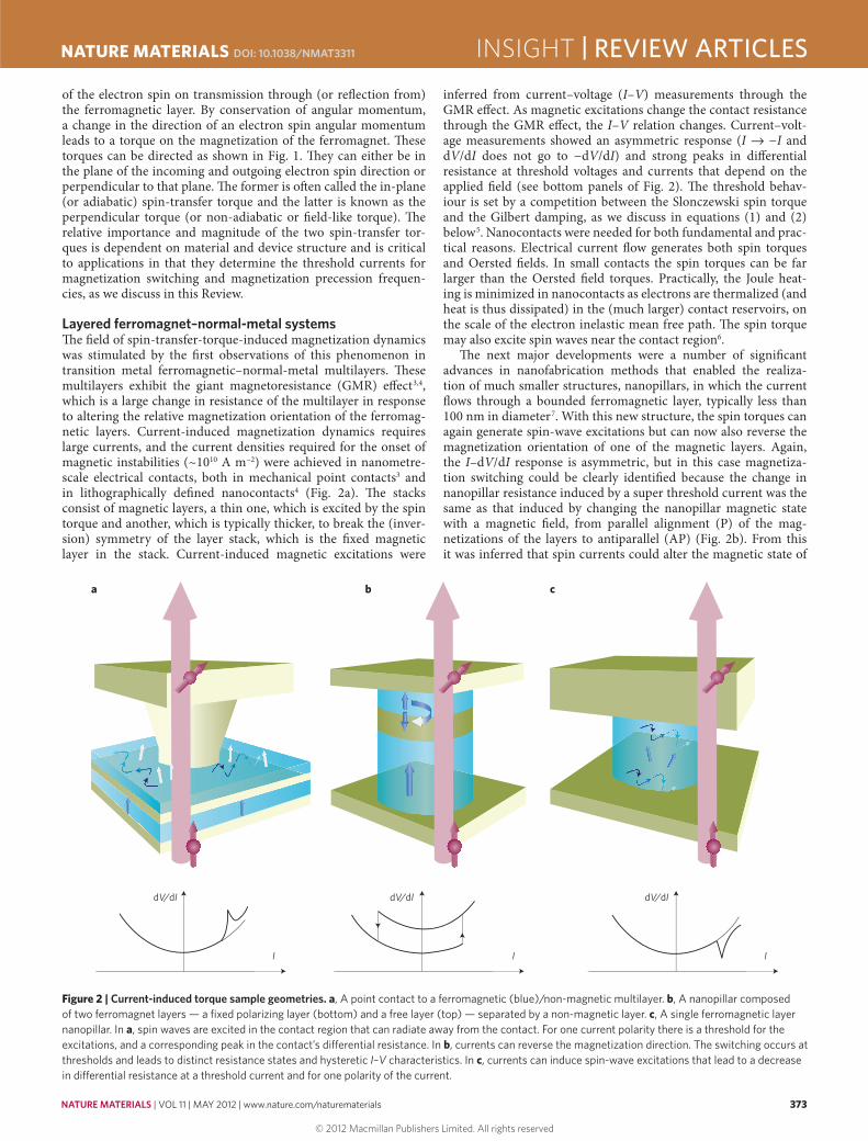
Layered ferromagnet–normal-metal systemsThe field of spin-transfer-torque-induced magnetization dynamics was stimulated by the first observations of this phenomenon in transition metal ferromagnetic–normal-metal multilayers. These multilayers exhibit the giant magnetoresistance (GMR) effect3,4, which is a large change in resistance of the multilayer in response to altering the relative magnetization orientation of the ferromag-netic layers. Current-induced magnetization dynamics requires large currents, and the current densities required for the onset of magnetic instabilities (~1010 A m−2) were achieved in nanometre-scale electrical contacts, both in mechanical point contacts3 and in lithographically defined nanocontacts4 (Fig. 2a). The stacks consist of magnetic layers, a thin one, which is excited by the spin torque and another, which is typically thicker, to break the (inver-sion) symmetry of the layer stack, which is the fixed magnetic layer in the stack. Current-induced magnetic excitations were
a b c
dV/dI dV/dI dV/dI
I I I
inferred from current–voltage (I–V) measurements through the GMR effect. As magnetic excitations change the contact resistance through the GMR effect, the I–V relation changes. Current–volt-age measurements showed an asymmetric response (I → −I and dV/dI does not go to −dV/dI) and strong peaks in differential resistance at threshold voltages and currents that depend on the applied field (see bottom panels of Fig. 2). The threshold behav-iour is set by a competition between the Slonczewski spin torque and the Gilbert damping, as we discuss in equations (1) and (2) below5. Nanocontacts were needed for both fundamental and prac-tical reasons. Electrical current flow generates both spin torques and Oersted fields. In small contacts the spin torques can be far larger than the Oersted field torques. Practically, the Joule heat-ing is minimized in nanocontacts as electrons are thermalized (and heat is thus dissipated) in the (much larger) contact reservoirs, on the scale of the electron inelastic mean free path. The spin torque may also excite spin waves near the contact region6.
The next major developments were a number of significant advances in nanofabrication methods that enabled the realiza-tion of much smaller structures, nanopillars, in which the current flows through a bounded ferromagnetic layer, typically less than 100 nm in diameter7. With this new structure, the spin torques can again generate spin-wave excitations but can now also reverse the magnetization orientation of one of the magnetic layers. Again, the I–dV/dI response is asymmetric, but in this case magnetiza-tion switching could be clearly identified because the change in nanopillar resistance induced by a super threshold current was the same as that induced by changing the nanopillar magnetic state with a magnetic field, from parallel alignment (P) of the mag-netizations of the layers to antiparallel (AP) (Fig. 2b). From this it was inferred that spin currents could alter the magnetic state of
Figure 2 | Current-induced torque sample geometries. a, A point contact to a ferromagnetic (blue)/non-magnetic multilayer. b, A nanopillar composed of two ferromagnet layers — a fixed polarizing layer (bottom) and a free layer (top) — separated by a non-magnetic layer. c, A single ferromagnetic layer nanopillar. In a, spin waves are excited in the contact region that can radiate away from the contact. For one current polarity there is a threshold for the excitations, and a corresponding peak in the contact’s differential resistance. In b, currents can reverse the magnetization direction. The switching occurs at thresholds and leads to distinct resistance states and hysteretic I–V characteristics. In c, currents can induce spin-wave excitations that lead to a decrease in differential resistance at a threshold current and for one polarity of the current.
INSIGHT | REVIEW ARTICLESNATURE MATERIALS DOI: 10.1038/NMAT3311
© 2012 Macmillan Publishers Limited. All rights reserved
374 NATURE MATERIALS | VOL 11 | MAY 2012 | www.nature.com/naturematerials
a nanopillar between P and AP states depending on the current polarity. This latter identification is of substantial interest for spin-transfer-torque magnetic random access memories (STT-MRAM). Experiments also show that spin-transfer torques lead to mag-netic states that would be inaccessible with magnetic fields alone, which can form the basis of new spin-based devices. For instance, a spin current can drive a magnetic layer into a state of maximum magnetic energy8, as if the effective dissipation acting on the layer changed sign owing to the presence of the spin torque9. Spin-transfer effects have also been observed in samples that consist of just a single magnetic layer, showing that a distinction between fixed polarizing and free layer is not essential10 (Fig. 2c). Most sig-nificant for the fundamentals of spin-transfer torque devices; a d.c. spin current was shown to lead to narrow band voltage noise in the microwave (gigahertz) range and the spin torque drives per-sistent oscillations of the magnetization11. Oscillations at gigahertz frequencies have been seen in nanopillars, nanocontacts, all metal-lic structures and magnetic tunnel junctions. In contrast, Oersted fields from a d.c. current can lead to magnetization reorientation but not to long-term magnetization precession and gigahertz noise. This clearly demonstrates that spin torques produce fundamentally new types of magnetic excitations and is also of great interest for electric-current controllable microwave oscillators.
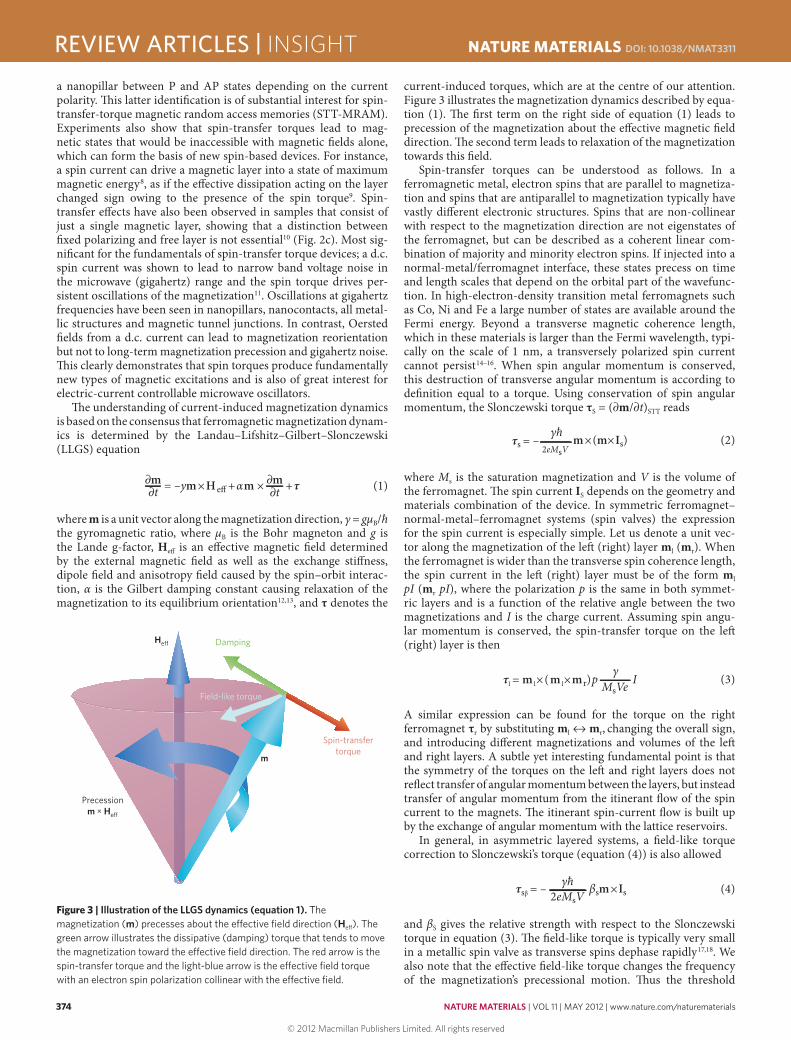
The understanding of current-induced magnetization dynamics is based on the consensus that ferromagnetic magnetization dynam-ics is determined by the Landau–Lifshitz–Gilbert–Slonczewski (LLGS) equation
= –ym×H e� + αm × +τ∂m∂t
∂m∂t (1)
where m is a unit vector along the magnetization direction, γ = gμB/ħ the gyromagnetic ratio, where μB is the Bohr magneton and g is the Lande g-factor, Heff is an effective magnetic field determined by the external magnetic field as well as the exchange stiffness, dipole field and anisotropy field caused by the spin–orbit interac-tion, α is the Gilbert damping constant causing relaxation of the magnetization to its equilibrium orientation12,13, and τ denotes the
current-induced torques, which are at the centre of our attention. Figure 3 illustrates the magnetization dynamics described by equa-tion (1). The first term on the right side of equation (1) leads to precession of the magnetization about the effective magnetic field direction. The second term leads to relaxation of the magnetization towards this field.
Spin-transfer torques can be understood as follows. In a ferromagnetic metal, electron spins that are parallel to magnetiza-tion and spins that are antiparallel to magnetization typically have vastly different electronic structures. Spins that are non-collinear with respect to the magnetization direction are not eigenstates of the ferromagnet, but can be described as a coherent linear com-bination of majority and minority electron spins. If injected into a normal-metal/ferromagnet interface, these states precess on time and length scales that depend on the orbital part of the wavefunc-tion. In high-electron-density transition metal ferromagnets such as Co, Ni and Fe a large number of states are available around the Fermi energy. Beyond a transverse magnetic coherence length, which in these materials is larger than the Fermi wavelength, typi-cally on the scale of 1 nm, a transversely polarized spin current cannot persist14–16. When spin angular momentum is conserved, this destruction of transverse angular momentum is according to definition equal to a torque. Using conservation of spin angular momentum, the Slonczewski torque τS = (∂m/∂t)STT reads
τs = –2eMsV
m×(m×Is)γħ
(2)
where Ms is the saturation magnetization and V is the volume of the ferromagnet. The spin current IS depends on the geometry and materials combination of the device. In symmetric ferromagnet–normal-metal–ferromagnet systems (spin valves) the expression for the spin current is especially simple. Let us denote a unit vec-tor along the magnetization of the left (right) layer ml (mr). When the ferromagnet is wider than the transverse spin coherence length, the spin current in the left (right) layer must be of the form ml pI (mr pI), where the polarization p is the same in both symmet-ric layers and is a function of the relative angle between the two magnetizations and I is the charge current. Assuming spin angu-lar momentum is conserved, the spin-transfer torque on the left (right) layer is then
τl = m l×(m l×mr)p IMsVeγ
(3)
A similar expression can be found for the torque on the right ferromagnet τr by substituting ml ↔ mr, changing the overall sign, and introducing different magnetizations and volumes of the left and right layers. A subtle yet interesting fundamental point is that the symmetry of the torques on the left and right layers does not reflect transfer of angular momentum between the layers, but instead transfer of angular momentum from the itinerant flow of the spin current to the magnets. The itinerant spin-current flow is built up by the exchange of angular momentum with the lattice reservoirs.
In general, in asymmetric layered systems, a field-like torque correction to Slonczewski’s torque (equation (4)) is also allowed
τsβ = – 2eMsVγħ βsm×Is (4)
and βS gives the relative strength with respect to the Slonczewski torque in equation (3). The field-like torque is typically very small in a metallic spin valve as transverse spins dephase rapidly17,18. We also note that the effective field-like torque changes the frequency of the magnetization’s precessional motion. Thus the threshold
Spin-transfertorque
Field-like torque
Precessionm × He�
He� Damping
m
Figure 3 | Illustration of the LLGS dynamics (equation 1). The magnetization (m) precesses about the effective field direction (Heff). The green arrow illustrates the dissipative (damping) torque that tends to move the magnetization toward the effective field direction. The red arrow is the spin-transfer torque and the light-blue arrow is the effective field torque with an electron spin polarization collinear with the effective field.
REVIEW ARTICLES | INSIGHT NATURE MATERIALS DOI: 10.1038/NMAT3311
© 2012 Macmillan Publishers Limited. All rights reserved

NATURE MATERIALS | VOL 11 | MAY 2012 | www.nature.com/naturematerials 375
for current-induced excitation of the magnetization is mainly determined by a competition between the Slonczewski torque (equation (2)) and the damping torque in equation (1). In general, the threshold is proportional to the damping and the total angular momentum of the free magnetic layer. This physics explains the main phenomenology of spin transfer in metallic systems, includ-ing the magnitude of the threshold current and its dependence on material parameters, such as the Gilbert damping. Slonczewski’s seminal work2, the scattering approach19 and magnetoelectronic circuit theory14–16,20 are all consistent with each other in their appro-priate limits and give further insight of more complex devices and phenomena than discussed here16,21. A pedagogical explanation of the loss of transverse spin current at normal-metal–ferromagnet systems is given in ref. 22.
Layered ferromagnet–insulator systemsIn layered systems, attention has shifted from metallic spin valves to magnetic tunnel junctions (MTJs) because MTJs’ potential for applications is far greater, as they exhibit far larger magneto-resistance and a resistance compatible with semiconductor devices. MTJs consist of two ferromagnetic electrodes separated by an insu-lator that is sufficiently thin (around 1 nm) that electrons can tun-nel between the electrodes. The resistance of an MTJ depends on the relative orientation of the magnetization of the electrodes23,24. When the electrode materials are the same, parallel magnetization results in low resistance, RP, and antiparallel in high resistance RAP. The resistance ratio is called tunnel magnetoresistance (TMR) ratio and is defined as (RAP − RP)/RP. The TMR ratio is much greater than the GMR ratio25,26, particularly when CoFe–MgO–CoFe (001) junctions are used27–30; TMR ratios of over 600% have been achieved at room temperature31. The high TMR ratio is achieved by choosing materials with different symmetries of the wavefunc-tion for spin-up and spin-down electrons so that the conductance depending on the overlap of the wavefunctions is very small when the MTJ is in the antiparallel configuration.
It has been established that spin-transfer torque in MTJs induce magnetization switching from parallel to antiparallel and antiparallel to parallel depending on the direction of current32–35, as in metallic systems. Whereas an initial challenge was producing MTJs that can carry the current densities required for spin-torque switching without breaking down, this is now routinely achieved in laboratories worldwide. In contrast to metallic structures (or GMR structures) in-plane and out-of-plane spin torques are comparable in magnitude, and both play important roles in inducing mag-netization switching and precession36–38. In symmetric systems, the in-plane torque changes sign with current bias direction, whereas the out-of-plane torque is an even function of the bias39. A precise determination of how the barrier and electrode materials influence this form of the torque in general asymmetric systems remains a challenge that is critical to understand to improve the performance of MTJ devices. A consequence of the out-of-plane-torque is that MTJs with an in-plane magnetic easy axis can switch under a volt-age pulse and then switch back to the original state at still higher biases of the same polarity40. This is a result of the competition between the spin-transfer torque and the out-of-plane torque that favour opposite magnetic states41.
Non-uniform magnetization in ferromagnetsSpin-transfer torques are not only important in systems where the magnetization is uniform within each magnet, but also in sys-tems where the magnetization gradually changes its direction. A region of non-uniform magnetization, called the domain wall (DW), appears at a boundary between two domains having differ-ent magnetization directions. The width of a DW is in the range of 10 to 100 nm and is determined by the competition between
the exchange stiffness that aligns spins and the anisotropy energy that orients spins in energetically favoured directions. For example, consider spin-polarized itinerant electrons passing through a DW. As the electrons traverse the DW, the spin of electrons precesses and changes their direction as a result of the exchange interaction with the localized spins of magnetic ions (Fig. 4). Conservation of angular momentum dictates that the change of angular momentum of the traversing electrons is transferred to that of magnetic ions. This transfer exerts a torque on the local magnetization, changes its direction, and results in a displacement of the DW called cur-rent-induced DW motion. This is not a new understanding, Berger realized in the 1970s that “a flow of electrons crossing a wall, and having their spins flipped, will apply a reaction torque on the wall”42. Berger’s group measured how currents could move DWs, but the relatively large samples required huge currents, making it difficult to obtain straightforward experimental confirmation of the current-induced DW motion because of the local heating43. The advent of modern nanoscale fabrication techniques made it possi-ble to observe this current-induced motion of a DW in the absence of a magnetic field and to make experimental progress. In the case of NiFe (refs 44–47), a magnetic strip with a cross-sectional dimen-sion of 10 nm × 240 nm, for example, was fabricated to reduce the current to an experimentally manageable and much more interest-ing level for use in devices35. Another approach was to use a mag-netic strip of a ferromagnetic semiconductor (Ga,Mn)As (ref. 48), which required much less current density to observe the motion because of its small anisotropy.
To develop a quantitative description of the current-induced DW motion, let us formulate the torque that acts on a DW. Each electron carries an electric charge −e and an angular momentum ±ħ/2. To the lowest order in the magnetization gradient, the spin-current density j(s) flowing along x at position r is polarized along the local magnetization, j(s)(r) = m(r)j(s), where the scalar spin-current density j(s) is measured in the units of an electrical current density (A m−2). The gradual change of the magnetization direction corresponds to a loss of the angular momentum of the itinerant electron subsystem, ∂xj(s) = j(s)∂xm. This change of spin current does not leave the system, but flows into the magnetic order, thus induc-ing a torque on the magnetization ∂(mMs)STT/∂t. To the first order in texture gradient, or adiabatic limit, and for arbitrary current directions, the Berger spin-transfer torque is
τB (r) = p( j . )m2eMs
γħ Δ (5)
where P = j(s)/j is the spin polarization of the electric current density j. A torque perpendicular to (though smaller than) equation (5) is
Current Current
Figure 4 | A head-to-head magnetic domain wall. The blue arrows indicate how the magnetization changes gradually from the magnetic domain with a magnetization pointing to the right and to a magnetic domain with the magnetization pointing to the left. The purple arrows show the spin of an electron passing from left to right through a magnetic domain wall that is wider than the electron wavelength; its spin adiabatically follows the magnetization direction resulting in a spin flip. The loss of spin angular moment is transferred as a spin-transfer torque to the magnetization (red arrows).
INSIGHT | REVIEW ARTICLESNATURE MATERIALS DOI: 10.1038/NMAT3311
© 2012 Macmillan Publishers Limited. All rights reserved

376 NATURE MATERIALS | VOL 11 | MAY 2012 | www.nature.com/naturematerials
also allowed49,50 in magnetic textures, which leads to qualitative new effects. To the lowest order in the magnetization gradient and for magnetic isotropic systems this torque is expressed as
τBβ (r) = βBPm×( j . )m2eMs
γħ Δ (6)
where the so-called βB parameter characterizes its relative strength to Berger’s torque of equation (5). τBβ is called the magnetic-field-like or non-adiabatic torque because its direction is the same as the magnetic field that induces DW motion and it is a correction to the simplest adiabatic torque (equation (5)). In magnetic textures, the in-plane and out-of-plane torques are computed and discussed in refs 51–54.
In the absence of the non-adiabatic torque in equation (6), DWs move when the current density exceeds the threshold current density jc (ref. 51)
2eKλwjc = πħP (7)
where λw is the DW width and K is the hard axis anisotropy. The threshold current density of equation (7) is called intrinsic because it originates only from the magnetization texture and not from extrinsic pinning centres. In metal wires with an in-plane magnetic easy axis, jc of equation (7) is too high >1013 A m−2 to explain the much lower currents observed in experiments. It was later discov-ered49,50 that the torque responsible for the DW motion in materials with in-plane easy axis metals is τBβ of equation (6). In this case, the current-induced DW motion is characterized by the βB parameter and the Gilbert damping constant α. In soft magnetic metals like NiFe, where DWs are rather wide, it is found that βB is sensitive to the nature of the DW55,56. In this case, the steady-state DW drift velocity is proportional to the βB parameter and inversely propor-tional to α. So, even though the non-adiabatic torque in equation (6) might be much smaller than the adiabatic torque of equation (5), it totally dominates how fast the DW moves and is very important.
In contrast, the non-adiabatic torque of equation (6) is much less important in explaining experiments on DW motion in per-pendicular magnetic materials like (Ga,Mn)As (ref. 57) and Co/Ni (ref. 58). These experiments are explained well by equation (7). An examination shows that perpendicular magnetic materials reduce the hard axis anisotropy K by more than an order of magnitude, resulting in narrow DWs that are influenced by extrinsic pinning. This implies that the field-like dissipative torque of equation (6) is insufficient to overcome the stronger pinning force. At the same time, the threshold current of equation (7) is greatly reduced because of the smaller value of K. As a result, in perpendicular magnetic materials, the adiabatic torque of equation (5) dominates the DW motion59,60.
An interesting frontier in the study of current-induced DW motion is the universality classes to which DW creep motion induced by current and field belongs. The classes were shown to differ for the field-driven and current-driven motion in (Ga,Mn)As (ref. 61), indicating that the nature of the torques acting on a DW in a disordered background is qualitatively dif-ferent. Subsequent experiments on Co/Pt, where τBβ dominates, showed that both field- and current-driven cases belong to the same universality class62,63. Whether the difference is due to the nature of disorder in the system or due to the nature of torque is an open question.
Spin–orbit coupling can enhance current-induced torques because angular momentum driving the magnetization dynam-ics can also be supplied by the lattice. A recent experiment saw effects of spin–orbit coupling on the current-induced DW veloc-ity64, but it is unclear if these effects occurred by an effective Rashba enhanced spin–orbit torque or by a spin Hall effect from an adja-cent normal-metal layer65. In either case, it opens the potential for the assistance of spin–orbit coupling to increase the efficiency of current-induced torques.
Spin pumpingCurrent-induced magnetization dynamics is directly related to spin-pumping and spin-motive force. Spin pumping can be used as a new way to probe spin-dependent phenomena in condensed matter, for example, to generate spin-transfer torques on magnetic materials. Furthermore, investigating and exploiting the connec-tion between spin-transfer torques and spin-pumping and spin-motive force give complementary information about spin-transfer torques that can be hard to obtain from current-induced magneti-zation dynamics.
Spin pumping is emission of a spin current induced by the mag-netization dynamics. This spin current flows into adjacent normal metals in contact with a magnet with a precessing magnetization, as in Fig. 5. This implies that spin pumping is the reciprocal phe-nomenon to spin-transfer torques caused by the absorption of spin currents from normal metals into ferromagnets. This follows from Onsager’s reciprocity relations showing that spin pump-ing and spin-transfer torque are two fundamentally equivalent dynamic processes in magnetic structures66,67. The microscopic parameters that govern these processes are therefore identical. Spin dynamics generates spin currents in adjacent normal metals68–70. Tserkovnyak et al. developed the scattering theory of spin pumping induced by magnetization dynamics on the basis of the theory of adiabatic quantum pumping71–73. In thin-film ferromagnets, which are in contact with normal metals, the spin-pumped current is lost in the adjacent normal metals when they are good spin sinks (for example, in metals with strong spin-flip scattering such as Pt); this leads to an enhanced magnetization dissipation in thin-film ferromagnets, which can be used to tune the relaxation time of the
Ferromagnet Normal metal Ferromagnet
Spin pumpingand
spin-transfer torque
m1(t) m2(t)
Figure 5 | Spin pumping from a ferromagnet via an adjacent normal metal gives rise to a spin-transfer torque on a second ferromagnet. The dynamical precession of the ferromagnet generates a spin current into the adjacent normal metal.
REVIEW ARTICLES | INSIGHT NATURE MATERIALS DOI: 10.1038/NMAT3311
© 2012 Macmillan Publishers Limited. All rights reserved

NATURE MATERIALS | VOL 11 | MAY 2012 | www.nature.com/naturematerials 377
magnetization orientation, but often results in a larger threshold current for current-induced magnetization switching.
Theoretical results were confirmed by the quantitative agree-ment of the spin-pumping-induced increase in the magnetization dissipation74–77. The reciprocity of spin pumping and spin-transfer torque in two ferromagnetic layers separated by a normal metal has also been tested. When one ferromagnet precesses, it emits a spin current to the second ferromagnet where the spin angular momen-tum is absorbed. This can be seen in an enhanced broadening of the ferromagnetic resonance. When the resonance fields are tuned so that both ferromagnets precess, the emission and absorption of the spin currents compensate each other and no additional broadening is seen, showing the direct equivalence between spin pumping and spin-transfer torques.
The reciprocity between spin-transfer torques and spin pumping was used in a ground-breaking demonstration that electric signals can be converted into pure spin signals, transported through an insulating magnet as spin waves, and re-converted into electric signals78. The sophisticated experiment cleverly uses established mechanisms, by which charge information is converted into spin information by the spin Hall effect79 (in which a longitudinal charge current induces a transverse spin current), and the spin informa-tion is transmitted from the normal metal to the magnetic insulator by spin transfer between the metal conduction electrons and the magnetic insulator spin waves. Extraction and detection of spin-wave currents are carried out by the reciprocal effects; spin pump-ing from dynamic magnetic insulators emits spin currents in the metal72 and the inverse spin Hall effect converts this spin current into an electrical signal80. The experiments suggest a route to the creation of spin circuits in insulators where there is no charge flow that might have superior low dissipation loss as well as novel forms of signal transmission. Many researchers are at present exploring the frontiers of this new field of pure spintronics in charge insula-tors, because the systems might exhibit phenomena that are radi-cally different than charge-based electronics devices.
In layered systems, the spin-pumped current out of the ferro-magnet is transverse to the magnetization direction81
∂m∂t
∂m∂t
eħ Is,pump = GRm× +GIm× (8)
where G⊥R (G⊥
I ) is the real (imaginary) part of the transverse (‘mixing’) conductance of the normal-metal–ferromagnet system14. Analogous to discrete systems, there is a reciprocal process to the spin-transfer torques of equations (2) and (5) in ferromagnetic textures. In a ferromagnet, a pumped spin current is transformed into a charge current as the conductivities for majority and minor-ity electrons differ. To leading order a time-dependent texture is expected to pump a current that is proportional both to the rate of change of the magnetization and the gradient of the magnetization texture. For isotropic systems, the most general expression for the pumped charge current is82,83
2eħji
(pump) = σP [ ∂m
∂t[.m× +βB∂m∂ri
∂m∂ri
(9)
where σ is the conductivity and ri is the component i of the spatial coordinate. Note that here we have assumed a strong spin-flip rate so that the spin-diffusion length is much smaller than the typical length of the magnetization texture.
The pumped currents in equations (8) and (9) can be viewed as arising from spin-motive forces due to the time-dependent magnetizations84,85. In its simplest limit in systems with weak spin-flip relaxations, the pumped spin current corresponds to a spin-battery bias, which is determined by the ferromagnetic resonance
frequency of the ferromagnet71. This spin battery can in turn be used to create spintronics devices based on pure spin currents, where only spins and no charges flow, where one should expect to see new exciting physics not influenced by charge flow.
Physics perspectivesAs this Review shows, there have been many new and exciting developments in the field of current-induced magnetization dynam-ics and spin pumping. The field continues to fascinate researchers because the coupling between magnetization dynamics and out-of-equilibrium current flow leads to rich physics where there are unexplored aspects even in conventional (transition metal) ferro-magnets and is unexplored in novel magnetic materials. Indicative of the challenge in conventional ferromagnets is the relatively large variation in the measured spin-transfer torque in permalloy, a very important material for device applications. Creative, qualitative new ways of direct measurements of the in- and out-of-plane tor-ques are needed. Furthermore, developments in theory are needed to make quantitative microscopic prediction of the spin torques. The developments in spin-transfer torque and spin pumping have led to four areas of ongoing research that are crucial to its exploita-tion in novel devices: spin–orbit-induced torques, magnetic insula-tors, antiferromagnets and electric-field-induced torques without any currents.
Most theories of spin-transfer torques in layered systems ignore spin–orbit coupling, an assumption that is probably not justified in, for example, permalloy where the spin-memory loss length is as short as 5–6 nm. Spin–orbit coupling is not only detrimental to the spin-transfer torque because of spin memory loss, but also enables transfer of orbital angular momentum to the collective magnetization. Thus, an initially unpolarized current can induce a torque on the magnetization even in magnetic homogenous sys-tems; we expect this effect to be important in certain classes of materials. This has recently been studied theoretically86–89 and has been experimentally seen in (Ga,Mn)As (ref. 90). The spin–orbit interaction can be described in the form of an effective magnetic field that depends on the electron orbital motion. In systems with spatial inversion symmetry the spin–orbit-induced torque vanishes to the lowest order in the spin–orbit interaction. Systems with bro-ken spatial inversion symmetry are more interesting because they exhibit a spin–orbit-induced torque and we believe this should be investigated further, both theoretically and experimentally. So far, the theorized forms of the spin–orbit-induced torque do not compete with damping in the LLGS equation and cannot be used to induce d.c.-current-driven magnetization precessions. An extension of the understanding and measurements of spin–orbit-induced torques might allow d.c.-current-driven magnetic pre-cessions in single homogenous ferromagnets. Spin–orbit-induced torques should also exist in tunnel junctions, where both in-plane and out-of-plane torques may be generated91.
Exploring spin-transfer torques and spin pumping in magnetic materials that differ from conventional ferromagnets is today a very dynamic area of the coupling between magnetization and current. The groundbreaking experiments by Saitoh et al. on spin-transfer torques and spin pumping in ferrimagnetic insulators open a new playground78. This enables the study of spintronics devices where there is spin current propagation and no charge flow. Another benefit of these systems is that the magnetic insulator yttrium iron garnet (YIG) has the lowest magnetization dissipation that is known. This enables the transfer of spin current over macroscopic distances (centimetres). We also anticipate that more exotic effects of the quantum nature of the magnetic excitations can be explored in these systems. Bose–Einstein condensation of magnons has been achieved by parametric pumping in YIG (ref. 92) and we expect to see electrical control of magnon Bose–Einstein condensation
INSIGHT | REVIEW ARTICLESNATURE MATERIALS DOI: 10.1038/NMAT3311
© 2012 Macmillan Publishers Limited. All rights reserved

378 NATURE MATERIALS | VOL 11 | MAY 2012 | www.nature.com/naturematerials
by spin transfer and spin pumping. For this to be possible, a quantum understanding of spin transfer and spin pumping must be further developed.
Theoretical93–96 and experimental97 work indicate that current-induced torques also appear in antiferromagnets. Antiferromagnets are ordered spin systems where the magnetic moments of all elec-trons in each unit cell compensate each other in equilibrium. They also share another transport property with ferromagnets, namely, the anisotropic magnetoresistance effect98, which enables a detailed experimental study of current-induced dynamics in antiferromag-nets. Even more importantly, creating high-temperature antifer-romagnetic semiconductors, where the carrier concentration is tuned by doping and/or gate voltages99, seems feasible, whereas this is not possible at present in ferromagnets. Because the sensitivity to changes in gate voltages and magnetic fields in antiferromagnetic semiconductors might offer new ways to manipulate spin infor-mation, exploring how antiferromagnets may be an alternative to ferromagnets in antiferromagnetic spintronics is an increasingly prominent focus in current-induced magnetization dynamics.
A promising avenue that we believe should be further explored and used in the near future is the control of magnetization dynam-ics by electric fields without any currents. This can be viewed as an internal generation of spin currents by electric fields. Apart from beautiful studies on multiferroic materials, there is already ample evidence that the anisotropy can be modulated by applying electric fields to metal ferromagnets100. When the magnetization direction is switched by electric field alone, the energy required for switching can be smaller than the present current-induced switching101–106. This development is therefore important for the creation of devices that requires magnetization switching.
ApplicationsTechnology based on current-induced magnetization switching and DW motion is under intense development. The industry’s initial targets are high performance and density memory, particu-larly STT-MRAM and race-track memories. Another important focus is on enhancing functionality and reducing energy use by closely integrating semiconductor logic circuits with STT magnetic memory. In all cases the MTJ is a central element that permits the fast readout of memory and logic states. We discuss each of these technologies below.
MRAM. Magnetization switching is one of the fundamental processes that is used in modern technology such as hard-disk drives and MRAM. MTJs are used as the storage device in com-mercially available MRAM, where magnetic fields are used to write information as a direction of magnetization in one of the two
electrodes of an MTJ. However, as a magnetic bit is reduced in size its coercive field must be increased for the bit to remain stable in the presence of thermal fluctuations. Thus the current required to generate magnetic fields high enough for magnetization switching increases as the dimension of the magnetic bit is reduced. In con-trast, a current-induced torque provides a scalable means for the switching, because spin-transfer torques present an efficient means to switch very high anisotropy elements; the switching current is expected to scale in direct proportion to the energy barrier to magnetization reversal and not the bit dimension. This is impor-tant because it means that technologies based on spin transfer, and not magnetic field induced by charge currents, become more competitive as the magnetic bits continue to shrink. This is lead-ing to the development of low-power non-volatile memory cells based on current-induced STT and impressive demonstrations of STT-MRAM devices integrated with CMOS have been reported. A 4 kbit STT-MRAM with CoFe(B)–MgO MTJ was first reported in 2005107 followed by demonstrations of 2 Mbit (ref. 108), 32 Mbit (ref. 109) and 64 Mbit STT-RAM110. All these demos employ (001) body-centred-cubic CoFe(B)–MgO (refs 27–30) MTJs to achieve high magnetoresistance ratios along with STT switching33–35.
Ensuring the scalability of MTJ is the key issue for making high-density MRAM devices based on spin-transfer torques commer-cially attractive; the MTJ needs to be reduced along with the feature size reduction in semiconductor integrated circuits, while keeping a TMR ratio greater than 100%, good thermal stability of the mag-netic storage element and low switching current. The thermal stabil-ity determined by Δ = E/kBT, where E is the energy barrier between the P and AP states, kB is the Boltzmann constant and T = 300 K, needs to be 60 or greater for long-term data retention depending on the application. Because E is a product of the magnetic storage ele-ment’s anisotropy energy density K and volume V, this means that higher K is required as the size of the MTJ is reduced to keep Δ > 60. This has led to the use of thin films with strong perpendicular ani-sotropy and a geometry in which both electrodes of the MTJ are magnetized perpendicular to the film plane (Fig. 6a). On the other hand, the threshold current that needs to be reduced along with the size of the device is proportional to the product of E and the Gilbert damping constant α. This makes it necessary to continue to develop a material having high K and low α. Currently a perpendicular MTJ based on CoFeB–MgO shows, simultaneously, high TMR ratio (>100%), low switching current (~50 μA) and Δ = 40 at a dimension of 40 nm in diameter (ref. 111). The development of MTJ devices with dimensions less than 20 nm is under way.
In MRAM applications, another key issue is switching speed. In collinearly magnetized devices (either perpendicular- or in-plane-magnetized MTJ elements), the initial current-induced spin
Figure 6 | Three different concepts for magnetic random access memories. a, Two-terminal collinear device. b, A device with three magnetic layers that includes a perpendicular magnetized spin-polarizing layer, an in-plane magnetized free layer and reference layer. c, Three-terminal device. The devices are integrated with CMOS select transistors as illustrated. In a and b short current pulses that flow perpendicular to the layer planes are used to change the magnetic state of a free layer and write information. In c, an in-plane current is used to move a domain wall in a nanowire. In each case a magnetic tunnel junction is used to read the magnetic state of the storage magnetic element.
a b c
Domain wall
Reference layer
Free layer
Polarizer
Freelayer
Hardlayer
REVIEW ARTICLES | INSIGHT NATURE MATERIALS DOI: 10.1038/NMAT3311
© 2012 Macmillan Publishers Limited. All rights reserved
NATURE MATERIALS | VOL 11 | MAY 2012 | www.nature.com/naturematerials 379
torque is zero (equation (2)), and thermal fluctuations or small misalignments of the layer magnetizations are needed to initiate the switching. This can lead to undesirable nanosecond incubation delays112 and broad switching distributions113. For this reason, mag-netic tunnel junction stacks with non-collinear magnetization are also being intensely explored for MRAM applications114,115 as shown in Fig. 6b. In this case, a perpendicularly magnetized polarizing layer is combined with an in-plane magnetized MTJ. Geometries that combine perpendicular magnetized MTJs and in-plane polar-izers are also being explored.
There has also been great interest in realizing three-terminal STT-MRAM bit cells in which there are separate read and write contacts. This is very desirable because high current densities are needed for writing and in two terminal devices (Fig. 6a,b) this can lead to a breakdown of the MTJ. Also, reading the magnetic state requires a current flow through the MTJ that in some instances can change the magnetic state, events known as read disturbs. This issue can be addressed by having separate read and write contacts, a low impedance contact for writing and an MTJ for readout. In Fig. 6c, current-induced DW motion is used to write data and the DW position (left or right of the MTJ) is read out with a MTJ. A disadvantage of this approach is that the bit cell is larger than that of a two-terminal one. However, a vertical three-terminal STT switch is also possible116.
Logic-in-memory integrated circuits. Because MTJs consist of metals and insulators and do not use semiconductors, they can be integrated in the interconnection layer above the semiconductor transistor layer. This opens up an entirely new way of designing inte-grated circuits, employing a logic-in-memory architecture, where non-volatile memories are distributed over the logic plane. With this architecture, one can counter the recent dramatic increase in dynamic as well as static power consumption and interconnection delay, the two main obstacles that hinder the performance increase of the present integrated circuits. In addition to being able to inte-grate with the interconnection, the required attributes of memories for this purpose are non-volatility, high endurance, high speed, scal-ability and low-voltage operation; MTJ-based devices are currently the only candidate that satisfies all of these criteria. The advantages of this approach are; first, by employing non-volatile memory, one can reduce the standby power because there is no need to supply power when they are not in use. Second, by placing memories on top of the logic plane, the interconnection delay between memory and logic that constitutes the so-called von Neuman bottleneck is greatly reduced. Third, circuits can be designed in such a way that MTJs are part of the logic block, resulting in the reduction of the number of transistors involved, which reduces the power consumption as well as interconnection delay. Experimental circuit blocks integrating MTJs or its three-terminal variant with CMOS integrated circuits have been demonstrated117–119.
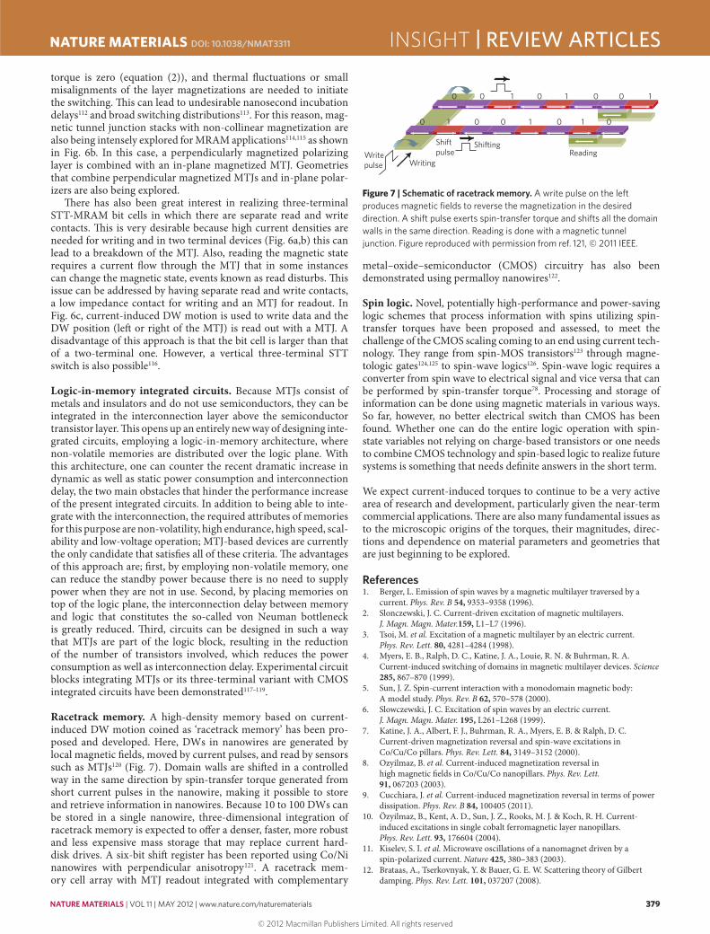
Racetrack memory. A high-density memory based on current-induced DW motion coined as ‘racetrack memory’ has been pro-posed and developed. Here, DWs in nanowires are generated by local magnetic fields, moved by current pulses, and read by sensors such as MTJs120 (Fig. 7). Domain walls are shifted in a controlled way in the same direction by spin-transfer torque generated from short current pulses in the nanowire, making it possible to store and retrieve information in nanowires. Because 10 to 100 DWs can be stored in a single nanowire, three-dimensional integration of racetrack memory is expected to offer a denser, faster, more robust and less expensive mass storage that may replace current hard-disk drives. A six-bit shift register has been reported using Co/Ni nanowires with perpendicular anisotropy121. A racetrack mem-ory cell array with MTJ readout integrated with complementary
metal–oxide–semiconductor (CMOS) circuitry has also been demonstrated using permalloy nanowires122.
Spin logic. Novel, potentially high-performance and power-saving logic schemes that process information with spins utilizing spin-transfer torques have been proposed and assessed, to meet the challenge of the CMOS scaling coming to an end using current tech-nology. They range from spin-MOS transistors123 through magne-tologic gates124,125 to spin-wave logics126. Spin-wave logic requires a converter from spin wave to electrical signal and vice versa that can be performed by spin-transfer torque78. Processing and storage of information can be done using magnetic materials in various ways. So far, however, no better electrical switch than CMOS has been found. Whether one can do the entire logic operation with spin-state variables not relying on charge-based transistors or one needs to combine CMOS technology and spin-based logic to realize future systems is something that needs definite answers in the short term.
We expect current-induced torques to continue to be a very active area of research and development, particularly given the near-term commercial applications. There are also many fundamental issues as to the microscopic origins of the torques, their magnitudes, direc-tions and dependence on material parameters and geometries that are just beginning to be explored.
References1. Berger, L. Emission of spin waves by a magnetic multilayer traversed by a
current. Phys. Rev. B 54, 9353–9358 (1996).2. Slonczewski, J. C. Current-driven excitation of magnetic multilayers.
J. Magn. Magn. Mater.159, L1–L7 (1996).3. Tsoi, M. et al. Excitation of a magnetic multilayer by an electric current.
Phys. Rev. Lett. 80, 4281–4284 (1998).4. Myers, E. B., Ralph, D. C., Katine, J. A., Louie, R. N. & Buhrman, R. A.
Current-induced switching of domains in magnetic multilayer devices. Science 285, 867–870 (1999).
5. Sun, J. Z. Spin-current interaction with a monodomain magnetic body: A model study. Phys. Rev. B 62, 570–578 (2000).
6. Slowczewski, J. C. Excitation of spin waves by an electric current. J. Magn. Magn. Mater. 195, L261–L268 (1999).
7. Katine, J. A., Albert, F. J., Buhrman, R. A., Myers, E. B. & Ralph, D. C. Current-driven magnetization reversal and spin-wave excitations in Co/Cu/Co pillars. Phys. Rev. Lett. 84, 3149–3152 (2000).
8. Ozyilmaz, B. et al. Current-induced magnetization reversal in high magnetic fields in Co/Cu/Co nanopillars. Phys. Rev. Lett. 91, 067203 (2003).
9. Cucchiara, J. et al. Current-induced magnetization reversal in terms of power dissipation. Phys. Rev. B 84, 100405 (2011).
10. Özyilmaz, B., Kent, A. D., Sun, J. Z., Rooks, M. J. & Koch, R. H. Current-induced excitations in single cobalt ferromagnetic layer nanopillars. Phys. Rev. Lett. 93, 176604 (2004).
11. Kiselev, S. I. et al. Microwave oscillations of a nanomagnet driven by a spin-polarized current. Nature 425, 380–383 (2003).
12. Brataas, A., Tserkovnyak, Y. & Bauer, G. E. W. Scattering theory of Gilbert damping. Phys. Rev. Lett. 101, 037207 (2008).
Figure 7 | Schematic of racetrack memory. A write pulse on the left produces magnetic fields to reverse the magnetization in the desired direction. A shift pulse exerts spin-transfer torque and shifts all the domain walls in the same direction. Reading is done with a magnetic tunnel junction. Figure reproduced with permission from ref. 121, © 2011 IEEE.
0 0
00 0 11 0 1 0
1 0 1 0 0 1
WritingReading
ShiftingWritepulse
Shiftpulse
INSIGHT | REVIEW ARTICLESNATURE MATERIALS DOI: 10.1038/NMAT3311
© 2012 Macmillan Publishers Limited. All rights reserved

380 NATURE MATERIALS | VOL 11 | MAY 2012 | www.nature.com/naturematerials
13. Starikov, A. A., Kelly, P. J., Brataas, A., Tserkovnyak, Y. & Bauer, G. E. W. Unified first-principles study of Gilbert damping, spin-flip diffusion, and resistivity in transition metal alloys. Phys. Rev. Lett. 105, 236601 (2010).
14. Brataas, A., Nazarov, Y. V. & Bauer, G. E. W. Finite-element theory of transport in ferromagnet–normal metal systems. Phys. Rev. Lett. 84, 2481–2484 (2000).
15. Kovalev, A. A., Brataas, A. & Bauer, G. E. W. Spin transfer in diffusive ferromagnet-normal metal systems with spin-flip scattering. Phys. Rev. B 66, 224424 (2002).
16. Brataas, A., Bauer, G. E. W. & Kelly, P. J. Non-collinear magnetoelectronics. Phys. Rep. 427, 157–255 (2006).
17. Xia, K., Kelly, P. J., Bauer, G. E. W., Brataas, A. & Turek, I. Spin torques in ferromagnetic/normal-metal structures. Phys. Rev. B 65, 220401 (2002).
18. Zimmler, M. A. et al. Current-induced effective magnetic fields in Co∕Cu∕Co nanopillars. Phys. Rev. B 70, 184438 (2004).
19. Waintal, X., Myers, E. B., Brouwer, P. W. & Ralph, D. C. Role of spin-dependent interface scattering in generating current-induced torques in magnetic multilayers. Phys. Rev. B 62, 12317 (2000).
20. Brataas, A., Nazarov, Y. V. & Bauer, G. E. W. Spin-transport in multi-terminal normal metal-ferromagnet systems with non-collinear magnetizations. Eur. Phys. J. B 22, 99–110 (2001).
21. Rychkov, V. S., Borlenghi, S., Jaffres, H., Fert, A. & Waintal, X. Spin torque and waviness in magnetic multilayers: A bridge between Valet–Fert theory and quantum approaches. Phys. Rev. Lett. 103, 066602 (2009).
22. Stiles, M. D. & Zangwill, A. Anatomy of spin-transfer torque. Phys. Rev. B 66, 014407 (2002).
23. Julliere, M. Tunneling between ferromagnetic films. Phys. Lett. A 54, 225–226 (1975).
24. Maekawa, S. & Gafvert, U. Electron tunneling between ferromagnetic films. IEEE Trans. Magn. 18, 707–708 (1982).
25. Miyazaki, T. & Tezuka, N. Giant magnetic tunneling effect in Fe/Al2O3/Fe junction. J. Magn. Magn. Mater. 139, L231–L234 (1995).
26. Moodera, J. S., Kinder, L. R., Wong, T. M. & Meservey, R. Large magnetoresistance at room temperature in ferromagnetic thin film tunnel junctions. Phys. Rev. Lett. 74, 3273–3276 (1995).
27. Butler, W. H., Zhang, X. G., Schulthess, T. C. & MacLaren, J. M. Spin-dependent tunneling conductance of Fe|MgO|Fe sandwiches. Phys. Rev. B 63, 054416 (2001).
28. Mathon, J. & Umerski, A. Theory of tunneling magnetoresistance of an epitaxial Fe/MgO/Fe(001) junction. Phys. Rev. B 63, 220403 (2001).
29. Parkin, S. S. P. et al. Giant tunnelling magnetoresistance at room temperature with MgO (100) tunnel barriers. Nature Mater. 3, 862–867 (2004).
30. Yuasa, S., Nagahama, T., Fukushima, A., Suzuki, Y. & Ando, K. Giant room-temperature magnetoresistance in single-crystal Fe/MgO/Fe magnetic tunnel junctions. Nature Mater. 3, 868–871 (2004).
31. Ikeda, S. et al. Tunnel magnetoresistance of 604% at 300 K by suppression of Ta diffusion in CoFeB/MgO/CoFeB pseudo-spin-valves annealed at high temperature. Appl. Phys. Lett. 93, 082508 (2008).
32. Huai, Y., Albert, F., Nguyen, P., Pakala, M. & Valet, T. Observation of spin-transfer switching in deep submicron-sized and low-resistance magnetic tunnel junctions. Appl. Phys. Lett. 84, 3118–3120 (2004).
33. Diao, Z. et al. Spin transfer switching and spin polarization in magnetic tunnel junctions with MgO and AlOx barriers. Appl. Phys. Lett. 87, 232502–232503 (2005).
34. Hitoshi, K. et al. Evaluation of spin-transfer switching in CoFeB/MgO/CoFeB magnetic tunnel junctions. Jpn. J. Appl. Phys. 44, L1237–L1240 (2005).
35. Jun, H. et al. Current-driven magnetization switching in CoFeB/MgO/CoFeB magnetic tunnel junctions. Jpn. J. Appl. Phys. 44, L1267–L1270 (2005).
36. Sankey, J. C. et al. Measurement of the spin-transfer-torque vector in magnetic tunnel junctions. Nature Phys. 4, 67–71 (2008).
37. Kubota, H. et al. Quantitative measurement of voltage dependence of spin-transfer torque in MgO-based magnetic tunnel junctions. Nature Phys. 4, 37–41 (2008).
38. Theodonis, I., Kioussis, N., Kalitsov, A., Chshiev, M. & Butler, W. H. Anomalous bias dependence of spin torque in magnetic tunnel junctions. Phys. Rev. Lett. 97, 237205 (2006).
39. Xiao, J., Bauer, G. E. W. & Brataas, A. Spin-transfer torque in magnetic tunnel junctions: Scattering theory. Phys. Rev. B 77, 224419 (2008).
40. Min, T., Sun, J. Z., Beach, R., Tang, D. & Wang, P. Back-hopping after spin torque transfer induced magnetization switching in magnetic tunneling junction cells. J. Appl. Phys. 105, 07D126 (2009).
41. Oh, S-C. et al. Bias-voltage dependence of perpendicular spin-transfer torque in asymmetric MgO-based magnetic tunnel junctions. Nature Phys. 5, 898–902 (2009).
42. Berger, L. Low-field magnetoresistance and domain drag in ferromagnets. J. Appl. Phys. 49, 2516–2161 (1978).
43. Freitas, P. P. & Berger, L. Observation of s-d exchange force between domain walls and electric current in very thin permalloy films. J. Appl. Phys. 57, 1266–1269 (1985).
44. Yamaguchi, A. et al. Real-space observation of current-driven domain wall motion in submicron magnetic wires. Phys. Rev. Lett. 92, 077205 (2004).
45. Vernier, N., Allwood, D. A., Atkinson, D., Cooke, M. D. & Cowburn, R. P. Domain wall propagation in magnetic nanowires by spin-polarized current injection. Europhys. Lett. 65, 526–532 (2004).
46. Kläui, M. et al. Controlled and reproducible domain wall displacement by current pulses injected into ferromagnetic ring structures. Phys. Rev. Lett. 94, 106601 (2005).
47. Hayashi, M. et al. Influence of current on field-driven domain wall motion in permalloy nanowires from time resolved measurements of anisotropic magnetoresistance. Phys. Rev. Lett. 96, 197207 (2006).
48. Yamanouchi, M., Chiba, D., Matsukura, F. & Ohno, H. Current-induced domain-wall switching in a ferromagnetic semiconductor structure. Nature 428, 539–542 (2004).
49. Zhang, S. & Li, Z. Roles of nonequilibrium conduction electrons on the magnetization dynamics of ferromagnets. Phys. Rev. Lett. 93, 127204 (2004).
50. Thiaville, A., Nakatani, Y., Miltat, J. & Suzuki, Y. Micromagnetic understanding of current-driven domain wall motion in patterned nanowires. Europhys. Lett. 69, 990–996 (2005).
51. Tatara, G. & Kohno, H. Theory of current-driven domain wall motion: Spin transfer versus momentum transfer. Phys. Rev. Lett. 92, 086601 (2004).
52. Barnes, S. E. & Maekawa, S. Current-spin coupling for ferromagnetic domain walls in fine wires. Phys. Rev. Lett. 95, 107204 (2005).
53. Tserkovnyak, Y., Skadsem, H. J., Brataas, A. & Bauer, G. E. W. Current-induced magnetization dynamics in disordered itinerant ferromagnets. Phys. Rev. B 74, 144405 (2006).
54. Kohno, H., Tatara, G. & Shibata, J. Microscopic calculation of spin torques in disordered ferromagnets. J. Phys. Soc. Jpn 75, 113706 (2006).
55. Eltschka, M. et al. Nonadiabatic spin torque investigated using thermally activated magnetic domain wall dynamics. Phys. Rev. Lett. 105, 056601 (2010).
56. Heyne, L. et al. Direct determination of large spin-torque nonadiabaticity in vortex core dynamics. Phys. Rev. Lett. 105, 187203 (2010).
57. Yamanouchi, M., Chiba, D., Matsukura, F., Dietl, T. & Ohno, H. Velocity of domain-wall motion induced by electrical current in the ferromagnetic semiconductor (Ga,Mn)As. Phys. Rev. Lett. 96, 096601 (2006).
58. Koyama, T. et al. Observation of the intrinsic pinning of a magnetic domain wall in a ferromagnetic nanowire. Nature Mater. 10, 194–197 (2011).
59. Tatara, G. et al. Threshold current of domain wall motion under extrinsic pinning, β-term and non-adiabaticity. J. Phys. Soc. Jpn 75, 064708 (2006).
60. Jung, S. Current-induced domain wall motion in a nanowire with perpendicular magnetic anisotropy. Appl. Phys. Lett. 92, 202508 (2008).
61. Yamanouchi, M. et al. Universality classes for domain wall motion in the ferromagnetic semiconductor (Ga,Mn)As. Science 317, 1726–1729 (2007).
62. San Emeterio Alvarez, L. et al. Spin-transfer-torque-assisted domain-wall creep in a Co/Pt multilayer wire. Phys. Rev. Lett. 104, 137205 (2010).
63. Lee, J-C. et al. Universality classes of magnetic domain wall motion. Phys. Rev. Lett. 107, 067201 (2011).
64. Mihai Miron, I. et al. Current-driven spin torque induced by the Rashba effect in a ferromagnetic metal layer. Nature Mater. 9, 230–234 (2010).
65. Liu, L., Lee, O. J., Gudmundsen, T. J., Ralph, D. C. & Buhrman, R. A. Magnetic switching by spin torque from the spin Hall effect. Preprint at http://arXiv.org/abs/1110.6846 (2011).
66. Tserkovnyak, Y. & Mecklenburg, M. Electron transport driven by nonequilibrium magnetic textures. Phys. Rev. B 77, 134407 (2008).
67. Brataas, A., Tserkovnyak, Y., Bauer, G. E. W. & Kelly, P. J. Spin pumping and spin transfer. Preprint at http://arXiv.org/abs/1108.0385 (2011).
68. Barnes, S. E. The effect that finite lattice spacing has upon the ESR Bloch equations. J. Phys. F 4, 1535–1551 (1974).
69. Janossy, A. & Monod, P. Spin waves for single electrons in paramagnetic metals. Phys. Rev. Lett. 37, 612–615 (1976).
70. Silsbee, R. H., Janossy, A. & Monod, P. Coupling between ferromagnetic and conduction-spin-resonance modes at a ferromagnetic–normal-metal interface. Phys. Rev. B 19, 4382–4399 (1979).
71. Brataas, A., Tserkovnyak, Y., Bauer, G. E. W. & Halperin, B. I. Spin battery operated by ferromagnetic resonance. Phys. Rev. B 66, 060404 (2002).
72. Tserkovnyak, Y., Brataas, A., Bauer, G. E. W. & Halperin, B. I. Nonlocal magnetization dynamics in ferromagnetic heterostructures. Rev. Mod. Phys. 77, 1375–1421 (2005).
73. Tserkovnyak, Y., Brataas, A. & Bauer, G. E. W. Enhanced Gilbert damping in thin ferromagnetic films. Phys. Rev. Lett. 88, 117601 (2002).
74. Mizukami, S., Ando, Y. & Miazaki, T. The study on ferromagnetic resonance linewidth for NM/80NiFe/NM (NM=Cu, Ta, Pd and Pt) Films. Jpn. J. Appl. Phys. 40, 580–585 (2001).
REVIEW ARTICLES | INSIGHT NATURE MATERIALS DOI: 10.1038/NMAT3311
© 2012 Macmillan Publishers Limited. All rights reserved

NATURE MATERIALS | VOL 11 | MAY 2012 | www.nature.com/naturematerials 381
75. Mizukami, S., Ando, Y. & Miyazaki, T. Effect of spin diffusion on Gilbert damping for a very thin permalloy layer in Cu/permalloy/Cu/Pt films. Phys. Rev. B 66, 104413 (2002).
76. Heinrich, B. et al. Dynamic exchange coupling in magnetic bilayers. Phys. Rev. Lett. 90, 187601 (2003).
77. Urban, R., Woltersdorf, G. & Heinrich, B. Gilbert damping in single and multilayer ultrathin films: Role of interfaces in nonlocal spin dynamics. Phys. Rev. Lett. 87, 217204 (2001).
78. Kajiwara, Y. et al. Transmission of electrical signals by spin-wave interconversion in a magnetic insulator. Nature 464, 262–266 (2010).
79. Hirsch, J. E. Spin Hall effect. Phys. Rev. Lett. 83, 1834–1837 (1999).80. Valenzuela, S. O. & Tinkham, M. Direct electronic measurement of the spin
Hall effect. Nature 442, 176–179 (2006).81. Tserkovnyak, Y., Brataas, A. & Bauer, G. E. W. Enhanced Gilbert damping in
thin ferromagnetic films. Phys. Rev. Lett. 88, 117601 (2002).82. Volovik, G. E. Linear momentum in ferromagnets. J. Phys. C 20, L83–L87 (1987).83. Duine, R. A. Spin pumping by a field-driven domain wall. Phys. Rev. B
77, 014409 (2008).84. Barnes, S. E. & Maekawa, S. Generalization of Faraday’s law to include
nonconservative spin forces. Phys. Rev. Lett. 98, 246601 (2007).85. Yang, S. A. et al. Universal electromotive force induced by domain wall
motion. Phys. Rev. Lett. 102, 067201 (2009).86. Manchon, A. & Zhang, S. Theory of nonequilibrium intrinsic spin torque in a
single nanomagnet. Phys. Rev. B 78, 212405 (2008).87. Manchon, A. & Zhang, S. Theory of spin torque due to spin–orbit coupling.
Phys. Rev. B 79, 094422 (2009).88. Hals, K. M. D. et al. Scattering theory of charge-current-induced
magnetization dynamics. Europhys. Lett. 90, 47002 (2010).89. Haney, P. M. & Stiles, M. D. Current-induced torques in the presence of
spin–orbit coupling. Phys. Rev. Lett. 105, 126602 (2010).90. Chernyshov, A. et al. Evidence for reversible control of magnetization in a
ferromagnetic material by means of spin–orbit magnetic field. Nature Phys. 5, 656–659 (2009).
91. Manchon, A. Interfacial spin–orbit splitting and current-driven spin torque in anisotropic tunnel junctions. Phys. Rev. B 83, 172403 (2011).
92. Demokritov, S. O. et al. Bose–Einstein condensation of quasi-equilibrium magnons at room temperature under pumping. Nature 443, 430–433 (2006).
93. Nunez, A. S., Duine, R. A., Haney, P. & MacDonald, A. H. Theory of spin torques and giant magnetoresistance in antiferromagnetic metals. Phys. Rev. B 73, 214426 (2006).
94. Haney, P. M. & MacDonald, A. H. Current-induced torques due to compensated antiferromagnets. Phys. Rev. Lett. 100, 196801 (2008).
95. Swaving, A. C. & Duine, R. A. Current-induced torques in continuous antiferromagnetic textures. Phys. Rev. B 83, 054428 (2011).
96. Hals, K. M. D., Tserkovnyak, Y. & Brataas, A. Phenomenology of current-induced dynamics in antiferromagnets. Phys. Rev. Lett. 106, 107206 (2011).
97. Urazhdin, S. & Anthony, N. Effect of polarized current on the magnetic state of an antiferromagnet. Phys. Rev. Lett. 99, 046602 (2007).
98. Shick, A. B., Khmelevskyi, S., Mryasov, O. N., Wunderlich, J. & Jungwirth, T. Spin–orbit coupling induced anisotropy effects in bimetallic antiferromagnets: A route towards antiferromagnetic spintronics. Phys. Rev. B 81, 212409 (2010).
99. Maca, F. et al. CuMn–V compounds: a transition from semimetal low-temperature to semiconductor high-temperature antiferromagnets. Preprint at http://arXiv.org/abs/1102.5373 (2011).
100. Shiota, Y. et al. Induction of coherent magnetization switching in a few atomic layers of FeCo using voltage pulses. Nature Mater. 11, 39–43 (2012).
101. Ohno, H. et al. Electric-field control of ferromagnetism. Nature 408, 944–946 (2000).
102. Weisheit, M. et al. Electric field-induced modification of magnetism in thin-film ferromagnets. Science 315, 349–351 (2007).
103. Chiba, D. et al. Magnetization vector manipulation by electric fields. Nature 455, 515–518 (2008).
104. Maruyama, T. et al. Large voltage-induced magnetic anisotropy change in a few atomic layers of iron. Nature Nanotech. 4, 158–161 (2009).
105. Endo, M., Kanai, S., Ikeda, S., Matsukura, F. & Ohno, H. Electric-field effects on thickness dependent magnetic anisotropy of sputtered MgO/Co40Fe40B20/Ta structures. Appl. Phys. Lett. 96, 212503 (2010).
106. Chiba, D., Yamanouchi, M., Matsukura, F. & Ohno, H. Electrical manipulation of magnetization reversal in a ferromagnetic semiconductor. Science 301, 943–945 (2003).
107. Hosomi, M. et al. in Electron Devices Meeting (IEDM) 459–462 (IEEE, 2005).108. Kawahara, T. et al. in Solid-State Circuits Conference, ISSCC 2007 480–617
(IEEE, 2007). 109. Takemura, R. et al. in VLSI Circuits, 2009 Symp. 84–85 (IEEE, 2009).110. Tsuchida, K. et al. in Solid-State Circuits Conference 258–259 (IEEE, 2010). 111. Ikeda, S. et al. A perpendicular-anisotropy CoFeB–MgO magnetic tunnel
junction. Nature Mater. 9, 721–724 (2010).112. Devolder, T. et al. Single-shot time-resolved measurements of nanosecond-
scale spin-transfer induced switching: Stochastic versus deterministic aspects. Phys. Rev. Lett. 100, 057206 (2008).
113. Bedau, D. et al. Spin-transfer pulse switching: From the dynamic to the thermally activated regime. Appl. Phys. Lett. 97, 262502 (2010).
114. Kent, A. D., Ozyilmaz, B. & del Barco, E. Spin-transfer-induced precessional magnetization reversal. Appl. Phys. Lett. 84, 3897 (2004).
115. Liu, H. et al. Ultrafast switching in magnetic tunnel junction based orthogonal spin transfer devices. Appl. Phys. Lett. 97, 242510 (2010).
116. Sun, J. Z. et al. A three-terminal spin-torque-driven magnetic switch. Appl. Phys. Lett. 95, 083506 (2009).
117. Matsunaga, S. et al. Fabrication of a nonvolatile full adder based on logic-in-memory architecture using magnetic tunnel junctions. Appl. Phys. Exp. 1, 091301 (2008).
118. Matsunaga, S. et al. in VLSI Circuits (VLSIC), 2011 Symp. 298–299 (IEEE, 2011).119. Endoh, T. et al. in Electron Devices Meeting (IEDM) 2011 4.3.1–4.3.4.
(IEEE, 2011). 120. Parkin, S. S. P., Hayashi, M. & Thomas, L. Magnetic domain-wall racetrack
memory. Science 320, 190–194 (2008).121. Thomas, L. et al. in Electron Devices Meeting (IEDM) 24.22.21–24.22.24
(IEEE, 2011).122. Annunziata, A. J. et al. in Electron Devices Meeting (IEDM) 24.23.21–24.23.24
(IEEE, 2011).123. Tanaka, M. & Sugahara, S. MOS-based spin devices for reconfigurable logic.
IEEE Trans. Electron. Dev. 54, 961–976 (2007).124. Dery, H. et al. Nanospintronics based on magnetologic gates.
IEEE Trans. Electron. Dev. 59, 259–262 (2012).125. Xiaofeng, Y. et al. Magnetic tunnel junction-based spintronic logic
units operated by spin transfer torque. IEEE Trans. Nanotechnol. 11, 120–126 (2012).
126. Kostylev, M. P., Serga, A. A., Schneider, T., Leven, B. & Hillebrands, B. Spin-wave logical gates. Appl. Phys. Lett. 87, 153501 (2005).
AcknowledgementsWe acknowledge useful discussions with Ferran Macia at New York University, who prepared some figures for the manuscript. A.B. was supported by EU-ICT-7 contract no. 257159 MACALO – Magneto Caloritronics. A.D.K. was supported by the National Science Foundation, the US Army Research Office and Spin-Transfer Technologies. HO was supported by the FIRST program of the Japan Society for the Promotion of Sciences.
Additional information The authors declare no competing financial interests. Reprints and permission information is available online at http://www.nature.com/reprints. Correspondence should be addressed to A.B.
INSIGHT | REVIEW ARTICLESNATURE MATERIALS DOI: 10.1038/NMAT3311
© 2012 Macmillan Publishers Limited. All rights reserved