natoli’s 4 technical secrets of tablet manufacturing natoli engineering company • 636.926.8900...
TRANSCRIPT
• First Impressions: Tablet Shape Can Impact Patient Acceptance• Increase Tablet Quality by Checking These 7 Inspection Points• Prevention & Repair of J-Hook• How Crucial Is Compaction Dwell Time?
Natoli’s 4 Technical Secrets ofTablet Manufacturing

{
natoli.com
Natoli Engineering Company • 636.926.8900 • [email protected] 1
CHAPTER 1: FIRST IMPRESSIONS: TABLET SHAPECAN IMPACT PATIENT ACCEPTANCE
A tablet’s size, shape, color, and perceived ease of use are quickly determined by the consumer from their first encounter with the product. The tablet’s appearance must impart the sense that the customer/patient can successfully and easily swallow it, without an undesirable taste.
A tablet manufacturer can influence customer acceptance by producing tablets that appear simple to utilize. Tablet design drives much of the visual impact of a tablet, and design features such as a smooth tablet shape improve product appeal and influences consumer preference.
Because a tablet’s design can so strongly influence consumer acceptance, a company’s marketing department often provides significant input as design and coating decisions are made. However, it is highly advised to include the production department in these decisions as it is their responsibility to deliver the final product. The production department’s experience and expertise can greatly reduce production costs and issues as some tablet designs present difficult manufacturing challenges, higher tooling costs and suboptimal physical properties of the tablets.
First impressions are everything. This is especially true for pharmaceutical, nutritional and confectionery tablets. Discriminating consumers may decide if they will be repeat customers based on a tablet’s appearance and their experience with it. This article discusses the limitations of the flat faced bevel edge and the benefits of a flat faced radius edge tablet design.

natoli.com
Natoli Engineering Company • 636.926.8900 • [email protected] 2
A good tablet design can help a company gain market share, consumer confidence and higher profits, whereas a bad design can cost literally thousands, if not millions, of dollars in lost sales, revenues and additional operating expenses.”
DALE NATOLIPresident
Natoli Engineering Company
Tablet designs that have been developed to improve tablet quality and reduce production costs, include the flat faced bevel edge (FFBE) tablet design. FFBE became popular early in the development of tablet manufacturing using rotary tablet presses because it offered significant improvement to the flat faced design. The flat faced tablet design suffered from weak tablet edges because of powder leakage at the punch tip die wall interface. Weak edges were prone to chipping and excessive friability. Adding a beveled edge to the tooling was very simple for the tooling machinist to do and allowed for the formulation powder to be pushed back to the center of the die-making for stronger tablet edges. Over decades, the FFBE configuration became a very popular design for the tableting industry. However, the FFBE design has limitations on the maximum compression force that can be used without risking tip damage due to over compression.
SMOOTHER EDGES, GREATER ACCEPTANCE
Based on clients’ experiences and its own investigations, we recommend customers use the flat faced radius edge (FFRE) design rather than the FFBE design for their flat, uncoated tablets.
Finite element engineering analysis of the FFBE and FFRE designs for the same size tablet indicate a significant increase
natoli.com
Natoli Engineering Company • 636.926.8900 • [email protected] 3
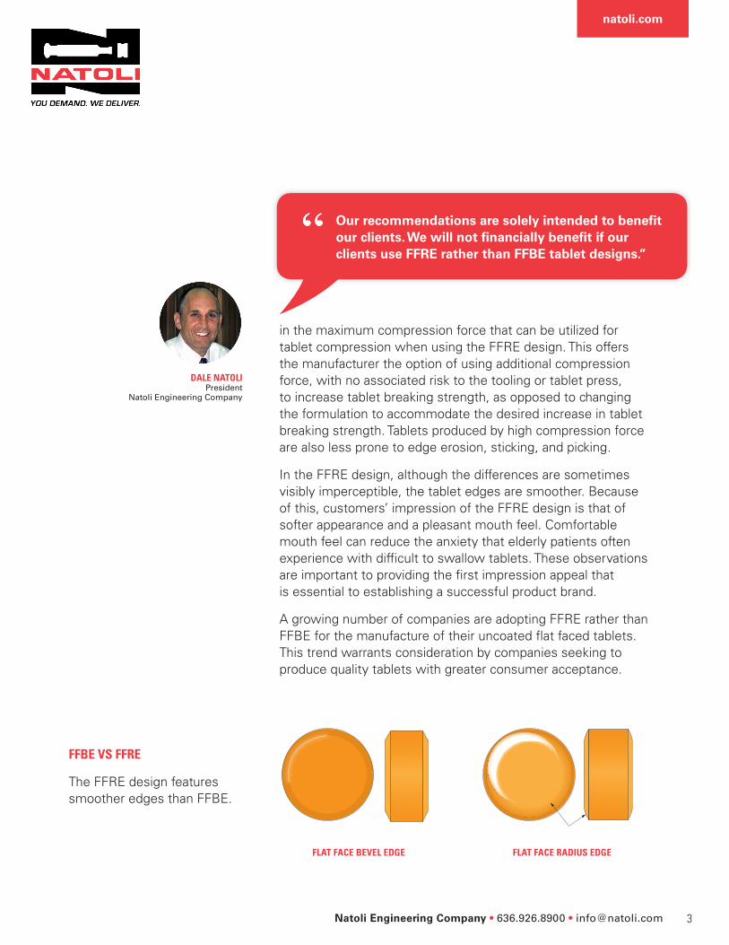
in the maximum compression force that can be utilized for tablet compression when using the FFRE design. This offers the manufacturer the option of using additional compression force, with no associated risk to the tooling or tablet press, to increase tablet breaking strength, as opposed to changing the formulation to accommodate the desired increase in tablet breaking strength. Tablets produced by high compression force are also less prone to edge erosion, sticking, and picking.
In the FFRE design, although the differences are sometimes visibly imperceptible, the tablet edges are smoother. Because of this, customers’ impression of the FFRE design is that of softer appearance and a pleasant mouth feel. Comfortable mouth feel can reduce the anxiety that elderly patients often experience with difficult to swallow tablets. These observations are important to providing the first impression appeal that is essential to establishing a successful product brand.
A growing number of companies are adopting FFRE rather than FFBE for the manufacture of their uncoated flat faced tablets. This trend warrants consideration by companies seeking to produce quality tablets with greater consumer acceptance.
FFBE VS FFRE
The FFRE design features smoother edges than FFBE.
FLAT FACE RADIUS EDGEFLAT FACE BEVEL EDGE
Our recommendations are solely intended to benefit our clients. We will not financially benefit if our clients use FFRE rather than FFBE tablet designs.”
DALE NATOLIPresident
Natoli Engineering Company

natoli.com
Natoli Engineering Company • 636.926.8900 • [email protected] 4
INCREASE STRENGTH BY INCREASING BEVEL TO FLAT RADIUS

{
natoli.com
Natoli Engineering Company • 636.926.8900 • [email protected] 5
CHAPTER 2: INCREASE TABLET QUALITY BY CHECKING THESE 7 INSPECTION POINTS
1. WORKING LENGTH
Working length is most critical punch dimension when using a rotary press as it is responsible for consistency in tablet weight, hardness, and thickness. This should be measured directly and shouldn’t exceed a variation of 0.002 inches (0.051 mm) across a set of upper or lower punches. Working length should be spot checked on new tools when received and thoroughly inspected on in-process tooling.
2. DIE BORE WEAR
Inspecting for die bore wear is often overlooked during in-process tool inspection because, until recently, a lack of effective and affordable technology prevented wear measurement. New machines such as a Tooling Condition Monitor allow tooling wear to be measured and tracked. Die bore wear can cause capping, laminating, and excessive tablet flashing.
Inspecting tooling and press components for wear or defects could be the most important step in improving tablet quality. There are certain inspection points that are easy to overlook yet can cause significant tablet quality issues and limit tool life. Spend a little time checking the following items for wear or defects to quickly increase tablet quality and reduce tooling cost.

natoli.com
Natoli Engineering Company • 636.926.8900 • [email protected] 6
TOOLING CONDITION MONITOR
A dial indicator is used to check concentricity on a pressure roll.
3. PUNCH TIP AND CUP WEAR
Punch cups should be checked for a condition called “J-hook.” J-hook is characterized by the edge of the punch tip curling inward toward the punch face. This type of wear can cause capping during tablet production. Punch tips should also be inspected for excessive clearance as they correspond to die bore wear. Just as with die bore wears, this can be measured using a Tooling Condition Monitor or by using an optical comparator. A traditional micrometer cannot properly check tip wear.
4. PUNCH RETAINERS
A part of the tablet press, punch retainers can play an important role in tablet quality. Check the punch retainer tips for excessive wear. If they are worn out, they should be replaced, as wear can cause variances in tablet weight. Punch retainers are properly adjusted when they can hold the lower punch up against its own weight.
5. PRESSURE ROLLS
Another inspection point on the tablet press, pressure rolls, should be checked for “run-out” or concentricity. It is recommended that run-out be measured on the pressure roller as it can cause inconsistencies in tablet hardness and weight. Check by using a dial indicator affixed to a metal pole and magnetic base. Manually spin the roller while the indicator is slightly pressed on the roller. The measurement is taken and averaged to determine if pressure roll wear is within the tolerance range.

natoli.com
Natoli Engineering Company • 636.926.8900 • [email protected] 7
6. CAM WEAR AND DEPTH OF FILL
Cams should be inspected for wear either visually on the machine, or more thoroughly after removal. Cams should also be inspected and selected for proper depth of fill. Too much fill depth can lead to excessive product loss and weight variance in tablets.
7. EJECTION CAMS
Ejection cams should be checked with a straight edge on the die table. The edge should just meet the lower punch tip to ensure there is adequate clearance during tablet takeoff. Setting ejection cams to a proper height will reduce tablet chipping.
Checking the suggested inspection areas and correcting any wear issues or defects is a step that is well worth its time, as it will improve product quality and reduce tooling cost due to wear and breakage.
It’s also important for written inspection procedures to be developed to ensure that best practices are followed. It is crucial for staff to thoroughly check that press parts and tooling are within their respective tolerances, and in good condition.
Whatever your tableting needs, Natoli Engineering can provide a product or solution to meet them. We’re the best in the tablet compression industry at what we do. Contact one of our tablet tooling and press experts to receive a customized solution.
Check out our Accessories Catalog at natoli.com for items mentioned in this article.

{
natoli.com
Natoli Engineering Company • 636.926.8900 • [email protected] 8
CHAPTER 3: PREVENTION & REPAIR OF J-HOOK
J-hooks are the distinctive wear patterns on punch tips that are a cause of such tablet defects as capping and lamination. If detected early, J-hooks can be easily and quickly repaired, thereby eliminating the need to purchase replacement tools.
By emphasizing tool maintenance as a standard operating procedure, tablet manufacturers can:
A manufacturer whose SOPs require routine cleaning, inspection, repair, lubrication, as well as careful handling and storage of punches will discover that these maintenance practices are an inexpensive way to ensure the consistent production of high quality tablets and thus improve the company’s bottom-line.
Anyone who has experienced capping or lamination during tablet production knows the frustration that comes from trying to diagnose the issue. In this article, we discuss a possible cause and several solutions.
WHAT IS J-HOOK?
A punch tip wear pattern that is a leading cause of tablet capping, lamination and poor friability.
à Increase the life of their tools as much as 80 percent, thereby protecting the company’s considerable investment in the purchase of these instruments.
à Eliminate need for press downtime to repair or replace punches with J-hooks.
à Reduce tooling and operating costs.
à Minimize the manufacture of defective tablets and thereby boost productivity.

natoli.com
Natoli Engineering Company • 636.926.8900 • [email protected] 9
The following are J-hook basics for press operators and other tablet manufacturing staff.
WEAR CAUSES J-HOOKS
Over time punches and other compression tools lose their luster and develop nicks, scratches, and/or J-hooks. Wear from abrasive products and even the smallest contact between the upper punch tip and the die during entry can create J-hook on punches.
Tooling wear and J-hook can result from worn punch guides. The same type of wear can also be the result of improper die installation. Tools such as die driving rods, a die insertion tool, and present torque wrenches are all great instruments to prolong die pocket wear which will increase tool life and maintain tablet quality.
When the land erodes away, the upper punch is very susceptible to the formation of J-hook. However, J-hooks can form on both the upper and lower tips if the conditions are right. Inspection of upper and lower punch tips is essential.
REGULAR INSPECTION AND MAINTENANCE CAN HELP PREVENT AND MINIMIZE J-HOOKS
Like all manufacturing tools, compression tools should be inspected on a defined schedule. Visual inspection for deteriorated outer tip edge and/or J-hook is important. An inspector can simply drag their fingernail from the inside of the cup out to the outer edge and if a J-hook is present, his or her nail will
Typically the first area of the punch to wear is the land, the flat and narrow area at the tip’s perimeter. With wear, the tip becomes very thin and is more susceptible to damage.”
BILL TURNERTechnical Service Manager
Natoli Engineering Company

natoli.com
Natoli Engineering Company • 636.926.8900 • [email protected] 10
catch on the hook. If the J-hook is light, it can be removed by polishing. In addition, polishing restores the cup’s mirror luster.
A factory-trained staff member should be given the responsibility of repairing and refurbishing punches with J-hooks.
Natoli recommends the large unsewn cotton buff wheel, rather than the drag finisher, as the best method to polish punches. Using a drag finisher will not effectively or efficiently restore land to the punch, nor will it help the tool perform as new. And as it doesn’t restore land, it will not correct issues such as capping and laminating.
A large unsewn cotton buff wheel effectively eliminates J-hook and restores land to punch.
BEFORE AFTER
A clean, smooth surface will release product better, produce better finished tablets, and reduce problems during production.”
Proper hands-on training is essential, you have to get a feel for the amount of pressure that’s required.”
DAVE PERRYAssistant Plant Manager
Natoli Engineering Company
DAVE PERRYAssistant Plant Manager
Natoli Engineering Company

{
natoli.com
Natoli Engineering Company • 636.926.8900 • [email protected] 11
CHAPTER 4: HOW CRUCIAL IS COMPACTION DWELL TIME?
When developing a new formulation scientists are equipped with a small scale tablet press to study and understand their product’s tabletability. These small scale systems are very useful at the research level but do not always successfully transfer to the larger scale manufacturing machines. Ideally, developing the product on a manufacturing press would eliminate the transfer challenges, but the amount of powder required to operate such a machine is very high and not cost effective.
There are many stages that occur during tablet production on the rotary tablet press and a full understanding of their functions is crucial to the success of producing a quality tablet.
Stages include: à Powder filling from the hopper into the feed system
à Powder filling from the feed system into the die cavity
à Proper fill cam and dosing cam settings
à Centrifugal acceleration and the need for a pull-down cam
à Pre-compression – is it needed and how much force?
à Main compression consolidation time and rate
à Main compression dwell time
à Main compression decompression event
à Ejection force and rate
à Tablet take off – sticking and picking adherence removal
Transitioning product from one tablet press to another during scale-up has been an ongoing challenge in the industry for many decades. There are many different approaches and aspects that must be considered including the tablet press and punch design, and powder characteristics.

natoli.com
Natoli Engineering Company • 636.926.8900 • [email protected] 12
Figure 1. – Turret Pitch Circle Diameter
Figure 2. – Examples of Different Pitch Circle Diameters
Every step in the tablet press process merits a full discussion but this article will focus on the compression dwell time and how the tablet press and punch head design’s impact this process.
DISCUSSION
Dwell time expressed in milliseconds is the time in which the punches achieve maximum penetration in the die under the main compression rollers and the punches are no longer moving vertically. In other words, dwell time occurs when the compression rollers are in contact with the punch head flat. Dwell time is a contributing factor to the tablet strength and a means for product transfer from one tablet press to another. Although turret RPM or tablets-per-minute are a common language for the turret speed, it doesn’t allow a true comparison for tablet presses with different turret sizes but the turret velocity is a normalization of turret size and the dwell time is a normalization of the turret size and punch head flat. It is important to understand the turret velocity before we can discuss dwell time.
TURRET VELOCITY
When comparing press speed, the tangential velocity or TV expressed in mm/sec allows for a true comparison. The TV is a function of the turret RPM and pitch circle diameter or PCD, which is the measurement of the turret from center of the die to the opposite die center. (See Figure 1.) The PCD is critical, as this is where the compression event occurs.
At a particular turret RPM the TV is dependent on the PCD, which varies depending on the number of stations on a turret. Figure 3. depicts examples of different sized machines and the relationship between turret RPM and TV.

natoli.com
Natoli Engineering Company • 636.926.8900 • [email protected] 13
As the turret PCD increases the required turret RPM is reduced to match a particular TV. A representable manufacturing velocity is above 1,000mm/sec. At 1,000mm/sec, the larger scale NP-500 press will operate at a turret speed of 34-RPM, where the medium scale NP-400 operates at 65-RPM and the smaller scale BLP-16 at 84-RPM. Running at 84-RPM turret speed can pose some challenges with powder flow into the die cavity, inhibiting the ability to evaluate tablet attributes. In fact, some industry small-scale tablet presses are not able to generate manufacturing velocities due to their smaller PCD or limited turret RPM. This is where the punch head flat can be designed to provide this gap for scale-up matching.
HEAD FLAT AND DWELL TIME
Compression tooling heads are designed with a flat, providing a constant strain to the powder bed while under the compression rollers. The longer the head flat the longer the dwell time and depending on your powder deformation characteristics and strain rate sensitivity, a longer dwell time may be needed to produce a robust tablet. Slowing the turret speed can also increase the dwell time but slowing the turret speed will also decrease production rates.
There are many different types of tools used in the industry that have different head configurations. Some are designed specifically to increase dwell time, while others are designed to reduce
Figure 3. – Tangential Velocity for Different Sized Presses

natoli.com
Natoli Engineering Company • 636.926.8900 • [email protected] 14
Figure 4. – “B” Type Tooling Dwell Time Comparison
Figure 5. – “D” Type Tooling Dwell Time
Figure 6. – Production Press vs. R&D “D” Tablet Presses
premature wear. The two most recognized tool configurations are the European ISO standard and the American TSM. These standards are provided to allow tablet press tool interchangeability, consistent quality between tooling vendors, simplified inspection processes and inventory. Within both configurations, the “B” and “D” type tools are the most common. “B” tooling is designed with a smaller body allowing a higher population of punches in a turret which is favorable for high tablet output, where the “D” tooling is designed with a larger body, allowing for larger tablets approaching up to one inch. As a “D” tool is larger the head profile and flat for a standard configuration is also larger, providing a longer dwell time. Figures 4. and 5. provide a chart of different head designs and their respective dwell times for a given TV. Notice that the TSM Domed Std. and EU 19 Std. are almost identical as their head profiles are very similar. Also notice that the dwell time is less sensitive at the higher turret rates.
Dwell time can be calculated by taking the punch head flat dimension divided by the turret tangential velocity. This simple calculation is helpful when transferring product to a different size press. And in the case of the large gap between TV as discussed previously with smaller R&D machines and larger scale machines, the tooling head flat can be designed by your tool manufacturer to match, or closely match, dwell times. The flexibility you have on your flat dimension is dependent on the punch neck diameter. To ensure the robustness and integrity of the punch, the neck diameter should be larger than the head flat and with some safety margin.
Figure 6. is an example of comparing the dwell time of a production press (NP-500) and an R&D tablet press (BLP16-D). The NP-500 is a high-speed, 45-station, double-sided production tablet press with extended head flat tooling, and the BLP16-D is a 16-station, “D” tooled development press. The NP-500 running at 80% of its maximum speed reaches 50RPM and 17m of dwell time. With standard TSM domed

natoli.com
Natoli Engineering Company • 636.926.8900 • [email protected] 15
Figure 7. – Production Press vs. R&D “B” Tablet Presses
Figure 9. – European Punch Head Tolerances & Impact to Dwell Time
heads the BLP16-D must reach 80RPM turret speed to match 17ms. It can be challenging to maintain consistent tablet weights at such a
high speed. When using the reduced head flat of 7.95mm on the BLP16-D, the required turret speed is now only 40-RPM, which is a more manageable speed for tablet weight consistency and helps reduce powder wastes.
Another challenge that can be resolved with head flat designs is transferring product from a “B” tooled machine to a “D” tooled machine or visa versa.
Figure 7. is an example of matching dwell time from an NP-500 to a BLP-16 utilizing “B” tooling. The standard “B” tooling matches dwell time of the NP-500 at similar turret speeds. When using the 50% of standard “B” head, the turret speed is reduced to 25-RPM, which again, at slower speeds, helps reduce powder wastes.
As previously discussed the European ISO standard and American TSM are the references for tooling specifications. They provide the acceptable tolerances to ensure proper installation, alignment and tablet consistency. The punch head flat also specifies an acceptable tolerance of ±0.2mm for the Euro standard and +0.00 /-0.76mm for the TSM standard. At common production rates the extreme difference is less than 1ms and as low as 0.2ms at higher production rates. Figure 9. depicts the small dwell time differences for the European tolerances. To accurately measure your punch head dimension a Horizontal Optical Comparator can be used.
CONCLUSION
Tooling designs and dwell time are one of many important parameters that play a role in tablet quality. Tooling head flats can be designed to achieve your desired dwell to assist in product transfer scalability processes or tablet robustness issues. Normalizing for turret size, speeds and tooling allows for a clearer understanding and comparison of different size tablet presses.

{
natoli.com
Natoli Engineering Company • 636.926.8900 • [email protected] 16
Questions? Ask the tableting experts at Natoli. Our experts have decades of tableting experience and are available to help prevent potential production problems or troubleshoot existing issues you may be experiencing.
To meet the growing demands of the tableting industry, two divisions of Natoli Engineering have been developed: Natoli Metallurgy has the capability to assist your business in the selection and treatment of steels to improve the longevity of your processing equipment. Natoli Scientific, partnered with Long Island University to establish the Natoli Engineering Institute for Industrial Pharmacy Development and Research, which is dedicated to assisting customers with unique solutions to their product formulation and tooling requirements.
Visit natoli.com today to gain access to our collection of how-to videos, technical articles, and more. Want to discuss a specific tableting issue? Contact a Natoli expert at 636.926.8900 or by email at [email protected].
FIND OUT HOW NATOLI CAN HELP YOU
Natoli maintains a large selection of accessories and over 250,000 replacement parts in stock, on site, and ready for immediate worldwide delivery.
When a part wears out or breaks, contact us and we’ll ship your part anywhere in the world—fast, quick, right away. How fast? Next business day.
And because we carry over 250,000 parts in stock, we can save you up to 50% of the Original Equipment Manufacturers’ price.
Browse natoli.com for your accessories or replacement parts now.

Natoli Engineering Company 28 Research Park Circle, Saint Charles, MO 63304, USA 636-926-8900 • [email protected] • natoli.com
©2017 Natoli Engineering Company