nationaladvisorycommittee foraeronautics...
TRANSCRIPT

~-. . =.->=. .. . . ..
,.,
, “
al_.. _.—_...-
NATIONAL ADVISORYCOMMITTEEFOR AERONAUTICS
TECHNICAL
Lmlqcopy
A METHOD FOR PREDICTING LIFT INCREMENTS DUE TO FLAP
DEFLECTION AT LOW ANGLES 03’ ATTACK IN
INCOMPRESSIBLE FLOW
By John G. Lowry and Edward C. Pol.hamus
Langley Aeronautical LaboratoryLangley Field, Va.
Washington
January 1957

G
-,. .-48’7
NATIONAL ADVISORY COMMITTEE FOR AERONAUTICS
*-. TECHNICAL NOTE 3911
“-. A METHOD FOR PREDICTING LIFT INCREMENTS DUE TO FLAP
DEFLECTION AT LOW ANGLES OF ATTACK IN
INCOMPRESSIBLEFLOW
By John G. Larry end Edward C. pOhS211US
SHY
A method is presented for estimating the lift due to flap deflectionat low angles of attack in incompressibleflow. lh this method provisionis made for the use of incremental section-lift data for estimating theeffectiveness of h@h-lift flaps. The method is applicable to swept wingsof any aspect ratio or taper ratio. The present method differs from
%. other current methods mainly in its ease of application and its moregeneral application. Also included is a simplified method of estimatingthe lift-curve slope throughout the subsonic speed range.
..●✎
INTRODUCTION
Although several methods are currently avaibble for estimating theeffectiveness of flaps on wings of various plan forms (for examplerefs. 1 to 4), they are generally restricted to small flap deflections;and furthermore each method has certain reservations in its application.For example reference 1, which is a semienrpiricalapproach, is limitedto specific wing plan forms and flap-chord ratios within the range ofexperimental data used as well as to small flap deflections. In addition,both references 1 and 2 may require considerable manipulation to obtainvalues for a particular plan form.
The present method attempts to combine the various existing methods ‘into a simple procedure that has more general applications than any one .of them alone. Section lift data are used as a basis of the calculations,and this approach provides a means of estimating the increments of liftdue to high-lift flaps at large deflections.
●.X
8-’

,. , ..
2 NAC!ATN 3911
SYMBOIS
A
%
-b
bf
CL
ACL
CL
cL5 =
c
Cf
Cz
Acl
c2a
Kb
Kc
M
a
(%)CL
aspect ratio
section lift-curve slope, per radian
wing span
flap span
three-dimensionallift coefficient
increment of three-dimensionallift coefficient due to flapdeflection
three-dimensionallift-curve slope, per deg
ZJ(constant a)
wing chord
flap chord
two-dimensional section-lift coefficient
increment of section-lift coefficient due to flap deflection
section lift-curve slope, per deg
flap-span factor (ratio of partial-span-flap lift coefficient
to full-span-flap lift coefficient),(ACL) partial spsm
(ACL) full SPSJI
flap-chord factor (ratio of three-dimensionalflap-effectivenessparameter to two-dimensionalflap-effectivenessparameter),
(%)cL/(%’)cz
Mach number
angle of attack, deg
three-dimensionalflap-effectivenessparameter at constant lift
“w.

NACA TN 3911 3
d-0
(qj)cz two-dimensional flap-effectivenessparameter at constant lift
““
6 flap deflection normal to hinge line, deg
5’ flap deflection streamwise, tan 5’ = tan 5 cos ~, deg
A angle of sweep, deg
Ah sweep of hinge line, deg
Jc/2 sweep of half-chord line, deg
f’Jc/4 sweep of quarter-chord line, deg
A taper ratio
Subscript:
eff effective*..
..DEVEH3PMENT OF METHOD
One reason for developing the present method is to provide a meansof estimating the lift increment of high-lift flaps. The method is there-fore based on the use of a section lift increment Act, either theoreti-
cal or experimental. The basic concept used in
ACL = Ck (c+= 8Kb
Since it is desired to use either a theoreticalof Acz in the method and since
Acl = CZa (UJC7 ~
multiplying the right-hand side of equation (1)
gives
the method is
(1)
or an eqerimental value
byA&l
Cza (%)CZ5
(2)

4 NACA TN 3911
~ is the aerodynamic induction factor,(a51CL
where — is the flap-(a~)cl
(AC!L)partial spanchord factor K&, and & is the flap-span factor,
(ACL) ftil S-
Section-Lift-CoefficientIncrements
The values of Acz used may be either two-dimensional experimental
or theoretical values. For the purpose of this paper the section valuesare obtained in a streamwise direction; and flap deflection in the streamdirection 51 is used, since this plane is used for measuring the angle ofattack. Several investigatorshave proposed that the section data shouldbe referred normal to some sweep line since this concept wouldbe inagreement with that used in the simple sweep theory. For airfoils in therange where the profile has a negligible effect on section characteristics(thin with small trailing-edge angle), the two methods give identicalresults for constant-percent-chordflaps on relatively untapered wings.For highly tapered wings the present method somewhat simplifies the
-.4
difficulties,with regard to flap-chord ratios in the vicinity of theroot and tip, that are encountered in the simple sweep theory. In viewof this simplificationand the fact that wings of current interest are
..
relatively thin, the use of section data relative to the airplane centerline is believed to be warranted. Since the values of Act are the basisof the method, the final results will be only as accurate as the sectiondata; therefore use of experimental data is advisable when such areavai~able.
The aerodynamic
Aerodynamic ~duction Factor
induction factor C!&/cla depends upon the three-
dimensi.onallift-curve slope c~. A simplified method is presented in
the appendix for estimating C~ which includes the effects of sweep,
aspect ratio, and taper ratio. The appendix gives the following simpleexpression for the incompressiblelift-curve slope (eq. (A6)):
“=++tik ?,-
...

NACA TN 3911 5~...
Dividing both sides of this equation by Cla gives the following expres-
sion for the aerodynamic-inductionfactor:-“
c~
cla–= $ +d(?f+(cosi+)’
If both sides of equation (3) are divided by A, the
is a unique function of Afor a given value
/cos Ac 2
relationship is shown in figure 1 for the case where
(3)
()
~ CL.—e~ressi.on A ~~a
of ao, and the
an = 2Yf. For esti-
mations of ACL normally required, this curve should p~ovide the value
CLof —; if a. differs appreciably from 2x, the term should be com-
chputed from equation (3) by using the most appropriate value of a.
0.. available. The choice of A=/2 rather than the more commonly used
&/J+ as the sweep angle for use in equation (3) is discussed in detail
in-the appendix. A nomograph for converting quarter-chord sweep angles,.. to half-chord sweep angles is given in figure 2 for wings of variousaspect ratio snd taper ratio. An extension of the expression for c~
to account for compressibility is given in the appendix.
Flap-Span Effect
In order to apply the method to flaps other thsn full-span flaps,it is necessary to obtain a span-effectivenessfactor Kb where
(AC!L)partialspan
‘b = (ACL)fu~ Span
An expression for the span-effectivenessfactor for inboard flaps hasbeen developed in reference 4 for wings having unswept trailing edgesand streamwise tips (rectangularin the vicinity of the trailing edge).Equation (37) of reference 4 can be written as
-.%
““
‘b=+wFF‘Si+il (4)
1- J
6 NACA TN 3911
., -#
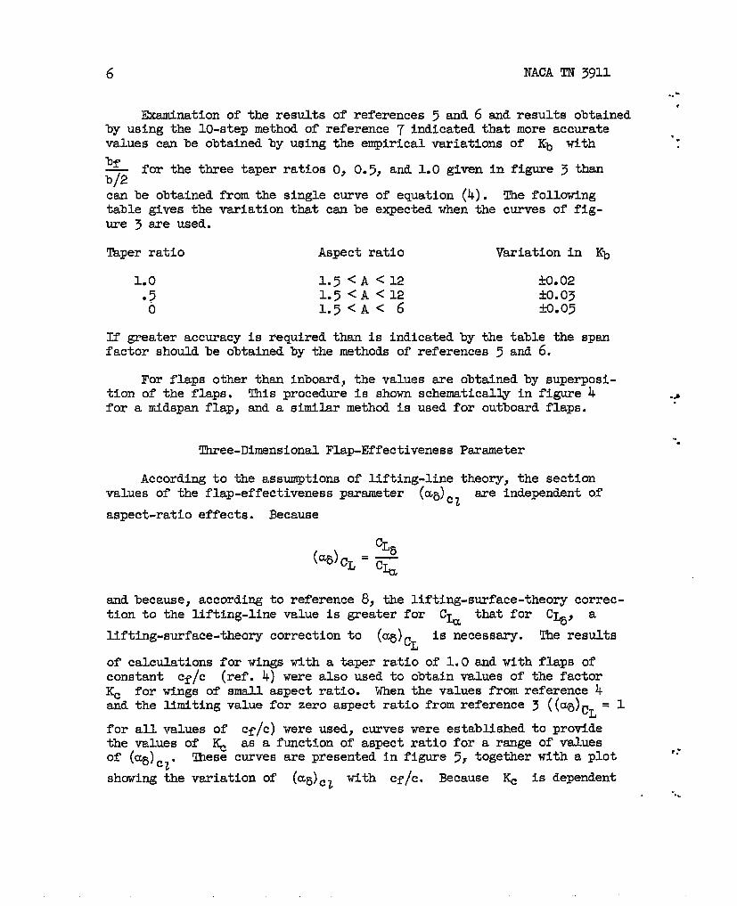
Examination of the results of references 5 and 6 and results obtainedby using the 10-step method of reference 7 indicated that more accuratevalues can be obtained by using the empirical variations of Kb with ‘“
bf— for the three taper ratios O, 0.5, and 1.0 given in figure 3 thanb/2c-w be obtained from the single curve of equation (4). The followingtable gives the variation that canbe expected when the curves of fig-ure 3 are used.
Taper ratio Aspect ratio V~iatiOn in Kb
1.0 1.5<A<12 +0.02●7 1.5<A<12 komo3o 1.5<A< 6 M.05
If greater accuracy is required than is indicated by the table the spanfactor should be obtained by the methods of references 5 and 6.
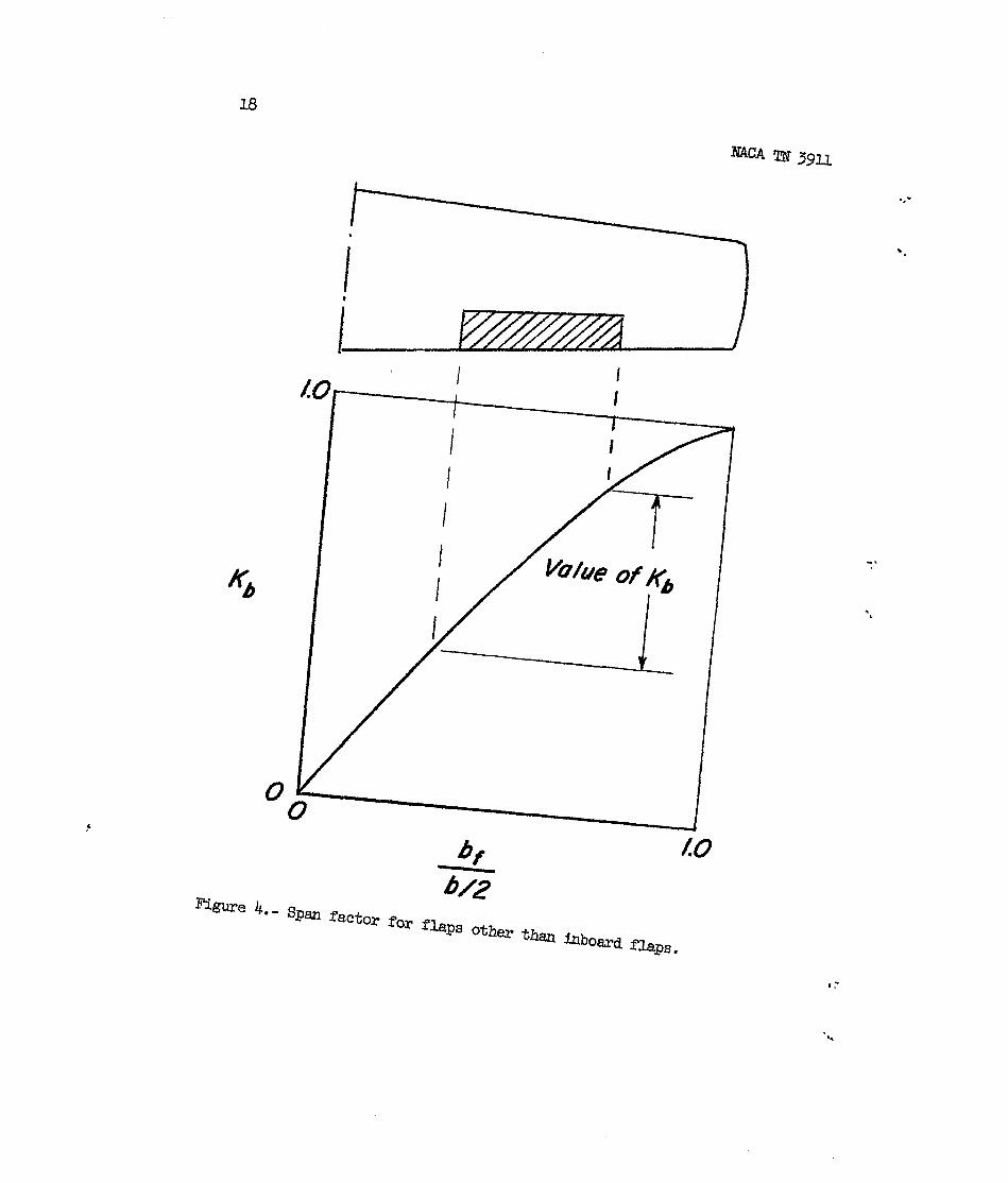
For flaps other than inboard, the values are obtained by superposi-tion of the flaps. T!hisprocedure is shown schematically in figure 4for a midspan flap, and a similar method is used for outboard flaps,
Three-DimensionalFlap-EffectivenessParameter
According to the assumptions of lifting-line theory, the sectionvalues of the flap-effectivenessparameter (a~]cl are independent of
aspect-ratio effects. Because
and because, according to reference 8, the lifting-surface-theorycorrec-tion to the lifting-line value is greater for c= that for C , a
%lifting-surface-theorycorrection to (~)CL is necessary. The results
of calculations for wings with a taper ratio of 1.0 and with flaps ofconstant cf/c (ref. 4) were also used to obtain values of the factor~ for wings of small aspect ratio. When the values from reference 4and the limiting value for zero aspect ratio from reference 3 ((qj)c~ = 1
for all values of cf/c) were used, curves were established to providethe values of & as a function of aspect ratio for a range of values
of (~~)cza These curves are presented in figure 5, together with a plot.f.
showing {he variation of (a~)cl with cf/c. Because & is dependent“..
NACA TN 3911 7
~..upon the type of chordwise loading, it might be expected to be more depend-ent upon
ICf c or upon the center of pressure than upon ~ ~~. How-
().“
ever, the data availablewith (LX5)CZ.
Figure 6 presents a
at the present time indicate a better’correlation
correlation of (%) CT with values obtainedJJ
from experimental C~ and CL5 data fr~m?eference 9 for wings having
a constant-percent-chordflap with a value of (a~)cz= 0.60. ~e agree-
ment between the estimated and the experimental variation with aspectratio is very good.
When experimental values of Act are used in order to estimate
ACL for small deflections, the value of (a~)cz used in determining
& canbe obtained from experimental values or from the inset chart infigure ~. When large flap deflections are used ad separation occursover the flap, the values of (cqj)cl csm be obtained from
---
,..(5)
If theoretical flap effectiveness islayer control, the values of (a~)cz
are used regardless of the value of
The effectiveness of flaps that
obtained by the use of boundary-from the inset chart in figure 5
5.
have variable values of (a~)cz
across the spsm is found by mechanical integration across the flap spanof the following equation:
[1 1 IKt),outboard
(U~)=zdKb (6)(a~)czeff =Kb,outboard - Kb,inboard Kb,inboard
where the values of
(a~)cl are plotted
flap span, then the
For most configurations,however, an average value of (a~~cz will:*
provide sufficient accuracy in the estimation of ACL.
Kb are obtained from figure 3. When the values of
against the values of Kb for all points along the
[1area under the curve is equal,to Kb a~)cz eff.

8 NACA TN 3911
.,*
For convenience, an e~erimentsl correlation of (@)cz for various
flap chords is given in figure 7 for deflections of ~lOO. The experimen-tal data were obtained from airfoils having trailing-edge angles of
“.
approximately 10° and includes both gap open and gap sealed conditions.
Experimental Verification
Since the usefulness of any method of estimating lift incrementsdepends on the agreement obtained with actual results, the values ofA(!L obtainedby the present method are compared with some experimental
results in figure 8. me results of ML are for the conditions of low
speed (M<O.4) at a = OO. The results at low flap deflections wereobtained on unswept wings varying in aspect ratios from 1 to 6 and havingflap-chord ratios varying from 0.10 to 0.40. The values of (%)cZ used
for the estimation were obtained from figuxe 7. A few comparisons areshown for double-slotted flaps deflected approximately 6@ on both aswept wing and a delta wing. The section lift increments Act wereobtained from experimental two-dimensionaldata. It is apparent thatthe method, at least for the configuration shown in figure 8, is accurate “
..-
for predicting the lift increment due to flap deflection..,.
CONCLUDINGIUMIlW8
A simplified method is presented to provide for the estimation ofthe lift due to flap deflection on swept wings in incompressible flowfrom section data. A comparison of the experimental finite-span liftincrements with those estimatedby this method provides a satisfactoryverification of the method.
Langley Aeronautical Laboratory,Nationsd.Advisory Committee for Aeronautics,
Langley Field, Vs., October 10, 1956.

NACATN 3911
APPENDIX
9
.’SIMPLDIED METHOD OF ESTIMATING C% THROUGHOUT
‘IEl!SUBSONIC SPEED RANGE
The purpose of this appendix is to describe simple but accuratemethods of estimating the effects of aspect ratio, sweep, taper ratio,and Mach number on
Effect
A very simple
the subsonic lift-curve
of Sweep, Aspect Ratio,
slope.
and Mach Number
but accurate equation for the subsonicslope is (for a. = 2fi)
--
“==’)
lift-curve
(Al)
.-.This equation, which is a modification of the Helmbo~d equation (ref. 10)to account for sweep and Mach number, was derived by the junior author,who originally presented it at a seminar (Ohio State University - WrightPatterson Air Force Base Graduate Center) in 1950. This expression issomewhat more accurate at low aspect ratios than the method presented inreference 110 An expression which gives identical results is derived inreference 12.
Equation (Al) can be derived simply by correcting the section lift-curve slope in Helmbold’s equation (ref. 10) for the effect of sweep(a. COSA) and applying the well-known three-dimensionalPrandtl-Glauerttransformation. Correcting HelmboldIs expression for the effect of sweepgives
( 4c““~ ,/-&) (A2)
-.,
.-

10
Applying the three-dimensionalfor compressibilitygives
Prandtl-Glauert
NACATN 3911
transformation to account..=
‘.
“’)”%-’) (A’)
where AM is defined as
‘“AM==
By trigonometric substitution it can be shown
~=A2(~-M2) ~+ 1COS2 AM
( cos2A(l -l@) -
that
1 )( )A—= — - (AM)2
1-M’ cos A ‘,.(ALL)
and by substitution of eqyation (Ah) in equation (A3)
()c&M=
ad
()(A5)
~+J(*Y + (*)2 - (AM,’ *
This equation differs from that for the incompressible case (eq. (A2))
by only the term (AM]2. The same result can be obtained by correctingthe section lift-curve slope a. in eqwtion (A2) for compressibilityby using the Mach number normal to the leading edge. Substituting
ao
~1- M?COS2A
for a. in equation (A2) and rearranging results in
“’’”’’m(k)
which reduces to equation (A5).

NACA TN 3911 11
Effect of !lkperRatio
.’
+-
..
.. .
“- ‘
It will be noted that no term for wing-taper-ratio effects appearsin equation (Al). me effects of taper ratio, however, can be essentiallyeliminated if the half-chord line is used for the sweep reference line.This fact is illustrated in figure 9 where the incompressible lift-curveslope, as determined by the Weissinger 15-point method (refs. 5 snd 6),is plotted as a function of the sweep of the quarter-chord line and thesweep of the half-chord line for various taper ratios. The results foran aspect ratio of 1.5 are presented in figure 9(a), and those for anaspect ratio of 3.0 are presented in figure 9(b). The results indicatethat, when the usual procedure of referencing the sweep angle to thequarter-chord line is used, the effects of taper ratio on the lift-curve slope are rather large. However, when the half-chord line is used,the effect of taper is eliminated to a large extent. The fact thatrather large effects of taper ratio occur for wings having the same sweepof the quarter-chord line (see left part of figs. 9(a) and 9(b)) can beexplained to some extent at least by the reversibility theorem (ref. 13),which states that the lift-curve slope of a wing is the same in forwardas in reversed flow. This theorem implies that if the sweep is referencedto a line other than the half-chord line, only the lift-curve slopes ofthe untapered wings (X= 1.0) will be symmetrical about zero sweep. Ittherefore is impossible for the lift-curve slopes of tapered wings tocoincide with those of’untapered wings throughout the sweep range, andat least an apparent taper-ratio effect must exist. The reversibilitytheorem itself, of course, does not exclude an actual taper-ratio effect;however, figure 9 shows that when the curves are made symmetrical by useof the half-chord line for the sweep reference, relatively little dis-placement due to taper ratio occurs. Also, in the modified lifting-linemethods such as the Weissinger method, taper effects are dependent uponthe sweep and the relative position of both the quarter-chord line(bound-vortexlocation) and the three-quarter-chordline (boundary-condition location). This fact suggests the possibility that wirigshaving the ssme sweep of the intermediate or half-chord line might beless affected by taper than those having some other common sweep line.
Accuracy of Method
The preceding results indicate that equation (A2) may be applicableto all plan forms, providing the sweep of the half-chord line is used.Use of A42 results in the following expression for the lift-curve
slope:

12 NACATN 3911
Dividing both sides by A and letting a. equal 2Z gives the
following expression:
(%) M+o = 2X(A7)
which indicates that %— is a unique function of AA
In orderCos &/.2 “
that the accuracy of the method may be evaluated, equation (A7) is comp-ared with available lifting-surfacesolutions (refs. 14 to 18) in fig-ure 10. The Swanson method used for the 600 sweptback elliptical wingis described in reference 8. The lifting-surface solutions presentedare probably the most accurate solutions available, end it will be notedthat they cover a wide range of plan forms. me fact, therefore, thatthe lifting-surfacesolutions sre in excellent agreement with equa-
c~tion (A7) appears to indicate both that ~ is, for all practical pur-
poses, a unique function of A and that equation (AT) is stifi-Cos A@
ciently accurate.
“.
...
‘.
Design charts
For the convenient determination of the lift-cuxve slope, somedesiga charts are presented. Figure 11 presents the variation of
c%— with A for incompressibleflow. For the convenient cor-A Cos A@
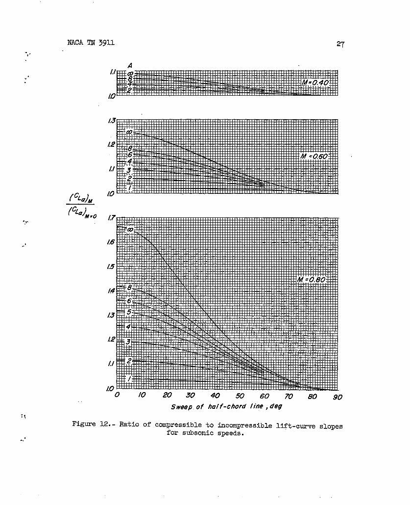
rection of these results for the effect of Mach number, correction fac-tors are presented in figure 12 as a function of the half-chord sweepfor various aspect ratios at Mach numbers of 0.40, 0.60, 0.80, 0.$33$ando.~. Since sweep angles are quite often referred to the quarter-chordline, a nomograph for converting from quarter-chord sweeps to half-chordsweeps is presented in figure 2.

NACATN 3911 13
---
,.
+..
.
1. Lowry, John G., and Schneiter, Ieslie E.: Estimation of’Effective-ness of Flap-Type Controls on Sweptback Wings. NACA TN 1674, 1948.
2. DeYoung, John: Theoretical Symmetric Span Loading Due to Flap ’Deflec-tion for Wings of Arbitrary Plan Form at Subsonic Speeds. NACARep. 1071, 1952. (SupersedesNACA TN 2278.)
3. DeYoung, John: Spanwise Loading for Wings and Control Surfaces ofLow Aspect Ratio. NACA TN2011, 1950.
4. Stone, H. N.: Aerodynamic Characteristics of Low-Aspect-RatioWingsWith Various Flaps at Subsonic Speeds. Rep. No. &l?-743-A-2(Con-tract NO. Al?33(038)-17397), Cornell Aero. Lab., lhc., Jsm. 1952.
5. Diederich, Franklin W., and Zlotnick, Martin: Calculated SpanwiseLift Distributions, Influence Functions, and Influence Coefficientsfor Unswept Wings in Subsonic Flow. ~ACA Rep. 1228, 1955. (Super.sedes NACA TN 3014.)
6. Diederich, Franklin W., and Zlotnick, Martin: Calculated SpanwiseLift Distributions and Aerodynamic Influence Coefficients forSwept Wings in Subsonic Flow. NACATN 3476, 1955.
7. Campbell.,George S.: A Finite-Step Method for the Calculation ofSpan Loadings of Unusual Plsm Forms. NACA RM L501113,1951.
8. Swanson, Robert S., and Crandall, Stewart M.: Lifting-Surface-l%eory.Aspect-Ratio Corrections to the Lift and Hinge-Moment Parameters forFull-Span Elevators on Horizontal Tail Surfaces. NACA Rep. 911,1948. (SupersedesNACATN1175. )
9. Dods, Jules B., Jr., and Tinling, Bruce E.: Summary of Results of aWind-Tunnel Investigation of Nine Related Horizontal Tails. NACATN 3497, 1955.
10. Helmbold, H. B.: Der unverwundene Ellipsenfl~gel als tragende Fl~che.Jskrb. 1942 der Deutschen Luftfahrtforschung,R. Oldenbourg (Munich),pp. Ild.1 - 1113.
11. pOfiamUS, Edward Co: A Simple Method of Estimating the Subsonic Liftand Dsmping in Roll of Sweptback Wings. NACA TN 1862, 1949.
:. 12. Diederich, Franklin W.: A Plan-Form Parameter for Correlating CertainAerodynamic Characteristics of Swept Wings. NACATN 2335, 1951.
.-‘
14 NACA TN 3911
13. Brown, Clinton E.: The Reversibility Theorem for Thin Airfoils inSubsonic and Supersonic Flow. NACA Rep. 986, 1950. (SupersedesNAC!ATN 1944.)
14. Krienes, Klaus: The Elliptic Wing Based on the Potential Theory.NACA TM971, 1941.
la. Falkner, V. M. (With Appendixby Doris Lehrian): Calculated LoadingsDue to lhcidence of a Ihmiberof Straight and Swept-Back Wings.R. &M. No. 2596, British A.R.C., June 1948.
16. Dickson, R.: Comparison of Tho Methods of Calculating AerodynamicLoading on an Aerofoil With Iarge Sweepback and Small Aspect Ratio.R. &M. No. 2353, British A.R.C., June 1946.
17. Schneider, William C.: A Comparison of the Spanwise Loading Calcu-lated by Various Methods With Experimental Iaadings Obtained on a45° Sweptback Wing of Aspect Ratio 8.02 at a Reynolds Number of
4.0 x 10⁶. NACA Rep. 1.208,1954. (SupersedesNACA RM L51G30.)
18. Jones, Robert T.: Properties of Iow-Aspect-RatiaPointed Wings atSpeeds Below and Above the Speed of Sound. NACA Rep. 835, 1946.(SupersedesNACA TN 1032.)
. .
..-
..

.!.
‘,., .,
b “,
Figure 1.-
0
Variation
/
of
2
aerodynamic
3 4 5 6
A/cos AC,=
7 8 9 /0
()~cLainduction factor — —
A cla
Awith
Cos &/Z”ao=Zh; M=O.

0!
Figure 2.-
Sweep of half-chord line, deg
Nomograph
Aspect rath, A
for converting quarter-cho~d sweep angles to
.i .,
half-chord
78
sweep angles.
, .““,

NACA TN 3911
Figure 3.-
.2 4 .6 .8
Variation of span factor Kb with flap span for inboard
Lo
flaps.
0
~/2F%mre 4.. Spm factor for flaps other tk inbood
Lo
flaps ●
-.
*,
.f!
‘ b.

NACA TN 3911 19-.,
.,.*
. ‘“
Figure 5.- Variation
0 .2 .6 .8
2 3 4 5 6 7 B 9-/0
A
of flap-chord factor with (%)CZ smd aspect ratio.
-,. .
.,-

20 NACA TN 3911
.‘,
.
.8C
.6C
I I(From fig 5 (@’&L= Kc @’&t)
,
0
Figure 6.-
2 3 4 5 6 7
A
Comparison of estimated values of (~)CL with experimental
values of reference 9. (%)c~ = 0.60.
*;.
“.
,,
“..

●✎ ✎✌
.7
.6
,5
.3
.2
./
o
Figure 7.-
0 .04
Variation ofedge
Fs’!3
.08 ./2 ./6 .20Cf
T
flap-effectivenesspsrameter withangle approximately 10°; M S 0.2;
.24 .28 .32 ,36
control-chord ratio. Averageflap deflection, ~lOO.
go
trailing- Nr

22 NACA TN 3911
0
n
A
af A ~g A
Plo/’ff flop 10° 0 1
Double - slotted fbp 60” 40° .4/
Double - slotted fhp 60° 4/0 0
7.
.*=
A .:
/to6
3.7
2.3 /
-.
‘.
o .2 4 .6 .8 /.0Es fimufed A CL
1’Figure 8.- Correlation of experimental and estimated ValUeS of ML.—
u= OO; M <0.4. “**

) .(
.-.0.5
.04I
●✌ ‘;
——– /4=!5A=Lo
—- /l=o
.—~ —./ ~—1’ \.03 - \
,02 -
.0/ -
0 a I 1 I I J
. ,.. “ .’
——
I I I i i
-60 -40-200204060 -60 -40
Sweep of quarter- chord line, o’eg Sweep
(a) A = 1.5.
Figure 9.- Variation of ~ with sweep; Weissingez
-20 0 20 40 60of half -chord Iine, o’eg
15-petit method.

—–– J=L5A=/o
—- A’o
/
.(25-
.05 -
04 -
.03 -
.02 -
.0/ -
0 A I I
/
I
-60 -W -20 0 20 40 60 -60 -40 -20 0 20 40 60
Sweep of quarter-chord /inel deg Sweep of ha/f-chord line, deg
(b) A = 3.o.
Figure 9.- Concluded.gr
,t●“
. .-, ,. ,

.< .
/4 l% Method Ret
0° Krienes /4
27° Fa/kner /5
.020 -4/” Falkner /5
.3/ 55° Falher /6
95 43” M/Hhopp 17.0/6 -
A
_/
0° Falkner /5
Eq@ v45° Fi71kffer /5
.0/2 -
v
.008 -
.c04 -
0 I 1 1 1 1 1 1 I I I 1 1
0/23456 789/0///2
A/cos Avp
.%a A
Figure 10.- Variation of — withA
as determined by several methods. a. = 2x; M = O.Cos A@

.032
.028
024
.020
c~a .0/6
A
.0/2
.008
,004
0
.; .*
o / 234567 8 9
Akos Aq2
c%Figure H. - Variation of ~
Awith in incompressible
Cos &/2–, —
.4b“ ,
n)(h
/0 // /2
flow.
-, ..
...
NACA TN 3911
(cL.)M(%=)M=O
“y
-’
o /0
Figure 12. - Ratio of
20 30 40 50 60 70 80 90
Sweep, of half-chord Iine, cfeg
compressible to incompressible lift-curve slopesfor subsonic speeds.
-.

28 NACA TN 3911.
Sweep of half-chord /ine,deg
Figure 12. - Continued.
L
.
.
w.’
‘.
?:
,#-

NACA TN 3911 29
=“ .
.
w’4
*,*
- *’(%)M
(CL=)M=O
2.5
24
2.3
22
2./
20
/,9
18
/.7
16
/5
/4
13
L2
1./
/,o 10 20 30 40 50 GO 70 BO 90’
Sweep of half-chord line, deg
Figure 12.- Concluded.
NACA -Langley Field, VJ.