national roads authority manual of contract documents … · volume 1 series 900 specification for...
TRANSCRIPT

Volume 1 Series 900
Specification for Road Works Road Pavements – Bituminous Bound Materials
December 2014 i
National Roads Authority
Manual of Contract Documents for Road Works
(NRA MCDRW)
AMENDMENT No. 1 (December 2014) to NRA Specification for Road
Works Series 900 Road Pavement – Bituminous Bound Materials
Dated March 2011
The NRA Specification for Road Works (NRA MCDRW), Series 900 Road Pavement – Bituminous Bound
Materials, dated March 2011 is amended as follows:-
1. Page 1, new Clause 900;
Add text for new Clause 900 to the Contents as “900 NRA IAN 10/14”.
2. Page 3, new Clause 900;
Add text for new Clause 900 to include the following;
“900 NRA IAN 10/14
It is intended that the requirements set out in NRA IAN 10/14 NRA entitled ‘Specification for
Road Works – Series 900 Road Pavements – Bituminous Materials’ will replace this
specification by 15th April 2015.”


Volume 1 Series 900
Specification for Road Works Road Pavements – Bituminous Bound Materials
March 2011 1
ROAD PAVEMENTS –
BITUMINOUS BOUND MATERIALS
Contents
Clause Title Page
900 NRA IAN 10/141 ............................................................................................................ 3
901 Bituminous Pavement Mixtures .................................................................................. 3
902 Reclaimed Asphalt ........................................................................................................ 4
903 Placing and Compaction of Bituminous Mixtures ...................................................... 5
904 Not Used ........................................................................................................................ 8
905 Not Used ........................................................................................................................ 8
906 Dense Base and Binder Course Asphalt Concrete (Recipe Mixtures)....................... 9
907 Regulating Course ...................................................................................................... 10
908 Not Used ...................................................................................................................... 10
909 Dense Asphalt Concrete Surface Course .................................................................. 10
910 Hot Rolled Asphalt Surface Course (Recipe Mixtures) ............................................ 13
911 Hot Rolled Asphalt Surface Course (Design Mixtures)............................................ 15
912 Close Graded Asphalt Concrete Surface Course ...................................................... 16
913 Not Used ...................................................................................................................... 18
914 Not Used ...................................................................................................................... 18
915 Coated Chippings for Application to Hot Rolled Asphalt Surface Course .............. 18
916 Open Graded Asphalt Concrete Surface Course ...................................................... 18
917 Cold-milling (Planing) of Bituminous Bound Flexible Pavement ........................... 20
918 Slurry Sealing ............................................................................................................. 20
919 Surface Dressing: Recipe Specification ..................................................................... 22
920 Bond Coats, Tack Coats and other Bituminous Sprays ........................................... 23
921 Surface Macrotexture of Bituminous Surface Courses ............................................ 23
922 Not Used ...................................................................................................................... 24
923 Binder Reclaimed using the Rapid Recovery Test (RRT) and Accelerated Ageing
using the Modified Ageing Rolling Thin Film Oven Test (RTFOT) ........................ 24
1 Amended as per Amendment No. 1, Item No. 1

Volume 1 Series 900
Specification for Road Works Road Pavements – Bituminous Bound Materials
March 2011 2
924 High Friction Surfacing .............................................................................................. 29
925 Testing of Bituminous Mixtures ................................................................................ 30
926 Not Used ...................................................................................................................... 30
927 Not Used ...................................................................................................................... 30
928 Determination of the Complex Shear (Stiffness) Modulus (G*) and Phase Angle (δ)
of Bituminous Binders using a Dynamic Shear Rheometer (DSR) Scope .............. 30
929 Dense Base and Binder Course Asphalt Concrete (Design Mixtures) .................... 34
930 EME2 Base and Binder Course Asphalt Concrete ................................................... 38
931 Not Used ...................................................................................................................... 43
932 Not Used ...................................................................................................................... 43
933 Not Used ...................................................................................................................... 43
934 Not Used ...................................................................................................................... 43
935 Not Used ...................................................................................................................... 43
936 Not Used ...................................................................................................................... 43
937 Stone Mastic Asphalt (SMA) Regulating Course ...................................................... 43
938 Porous Asphalt ............................................................................................................ 47
939 Not Used ...................................................................................................................... 52
940 Relative Hydraulic Conductivity Test ....................................................................... 52
941 Modified Binder Storage Stability Test ..................................................................... 54
942 Polymer Modified Stone Mastic Asphalt Surface Course ........................................ 56
943 Hot Rolled Asphalt Surface Course and Binder Course (Performance-Related
Design Mixtures) ........................................................................................................ 60
944 Not Used ...................................................................................................................... 61
945 Weather Conditions for Laying of Hot Bituminous Mixtures ................................. 62

Volume 1 Series 900
Specification for Road Works Road Pavements – Bituminous Bound Materials
March 2011 3
Road Pavements – Bituminous Bound Materials
900 NRA IAN 10/142
It is intended that the requirements set out
in NRA IAN 10/14 entitled ‘NRA
Specification for Road Works – Series 900
Road Pavements – Bituminous Materials’
will replace this specification by 15th April
2015.
901 Bituminous Pavement
Mixtures
General
1 This clause gives general requirements for the
properties of the aggregates and bitumen used
in plant-produced bituminous mixtures. These
requirements apply to all plant produced
bituminous mixtures unless other
requirements are given in specific Clauses in
this Series.
2 Bituminous mixtures shall be produced in
plants that are independently accredited to
ISEN 9001 or equivalent quality management
system. Products specified in accordance with
IS EN 13108 shall be CE marked. All
bituminous mixtures shall be laid by
contractors operating in compliance with Series
700, relevant clauses of this series and
BS594987.
3 Evaluation of conformity shall be carried out in
accordance with the appropriate sections of IS
EN 13108.
Aggregates for Bituminous Mixtures
4 Aggregates shall be natural, clean, hard and
durable crushed rock or crushed gravel and
shall comply with the selected requirements of
IS EN 13043. Crushed gravel shall comply with
category C100/0 as defined in IS EN 13043.
Additionally, aggregates for use in surface
course mixes, surface dressing, and in coated
chippings for application to rolled asphalt
surface courses shall be of a single rock type
and source. Where different PSV requirements
demand different surface course mixes within
the same scheme, the aggregates for each mix
shall be selected to provide a similar colour
throughout the area of surfacing within the
contract.
2 Amended as per Amendment No. 1, Item No. 2
Where recycled coarse aggregate is used in
bituminous mixtures, it shall have been tested
and the content of other materials (Class X)
including wood, plastic and metal shall not
exceed 1% by mass. Reclaimed asphalt shall
comply with Clause 902.
Resistance to Fragmentation (Hardness)
5 Irrespective of source, coarse aggregates for
bituminous mixtures shall be considered
suitable if:
(i) the resistance to fragmentation category
of the coarse aggregate as defined in
clause 4.2.2 of EN 13043 shall be LA30 or
less;
or
(ii) crushed rock aggregate has a Los Angeles
Value greater than 30 but less than 35,
where evidence can be presented to the
Employer’s Representative of previous
satisfactory use of the source in asphalt;
and the material complies with any additional
requirements in Appendix 7/1.
Natural and manufactured (artificial)
aggregates recovered from a previous use in an
unbound form shall comply with the
requirements of this Clause.
Resistance to Freezing and Thawing
(Durability)
6 When required in Appendix 1/5, the resistance
of the coarse aggregate to freezing and thawing
shall be tested. The freezing and thawing
(soundness) category, as defined in IS EN
13043, clause 4.2.9.2, shall be MS25 unless
otherwise specified in Appendix 7/1. The water
absorption value of the coarse aggregate shall
be determined in accordance with IS EN 13043,
clause 4.2.9.1. If the water absorption value of
the coarse aggregate is greater than WA242, the
soundness test shall be carried out on the
material delivered to Site. The requirements
for water absorption do not apply to blast
furnace slag aggregate.
Cleanness
7 The proportion of coarse and fine aggregates for
bituminous mixtures passing the 0,063mm test
sieve (fines content) shall not exceed the limits

Volume 1 Series 900
Specification for Road Works Road Pavements – Bituminous Bound Materials
March 2011 4
stated in the relevant target composition tables
included within this Series, when tested in
accordance with the washing and sieving
method of IS EN 933-1.
Resistance to Polishing and Surface
Abrasion
8 When specified in the appropriate clause or
Appendix 7/1, the aggregate shall conform to
the required declared PSV category in
accordance with IS EN 13043 clause 4.2.3 and
the relevant section of SR17.
9 An aggregate shall be deemed acceptable if the
mean of the two most recent consecutive PSV
results from tests relating to the aggregate to
be supplied complies with the declared
categories specified in Appendix 7/1. The tests
must be carried out within the previous 12
months by testing by an appropriate INAB or
equivalent accredited organisation.
10 The resistance to surface abrasion of coarse
aggregate used in surface courses in accordance
with IS EN 13043 clause 4.2.4, and the relevant
section of SR17 shall conform to category
AAV10 or such other category as specified in
the appropriate clause.
Chemical Requirements
Dicalcium Silicate Disintegration
11 Air-cooled blast furnace slag aggregates shall
be free from iron dicalcium silicate
disintegration as defined in IS EN 13043,
clause 4.3.4.1.
Iron Disintegration
12 Air-cooled blast furnace slag aggregates shall
be free from iron disintegration as defined in IS
EN 13043, clause 4.3.4.2.
Volume Stability
13 The volume stability category of steel slag
aggregates as defined in IS EN 13043, clause
4.3.4.3 shall not exceed V10.
Bitumen
14 Paving grade bitumen shall comply with IS EN
12591 and/or IS EN 13924 as appropriate and
supplied from locations that are independently
accredited to ISO 9001 or equivalent quality
management system with specific reference to
the requirements of IS EN 13108-21.
15 Polymer modified bitumen shall comply with IS
EN 14023 and shall only be used where
specifically permitted within this 900 series
and be supplied from locations that are
independently accredited to ISO 9001 or
equivalent quality management system with
specific reference to the requirements of IS EN
13108-21.
902 Reclaimed Asphalt
1 Reclaimed bituminous materials may be used
in the production of bituminous base and
binder course, subject to the requirements of IS
EN 13108-8 for foreign matter category F5. The
maximum amount of reclaimed bituminous
material permitted shall be 50% for Asphalt
Concrete base and/or binder course.
2 After mixing with recycled materials, the
binder reclaimed from the mixture shall have a
recovered penetration value not less than the
value specified in table 9/1. The binder shall be
reclaimed from the mixture in accordance with
the requirements of IS EN 12697 part 3 and
tested in accordance with the requirements of
IS EN 1426. Samples of the final plant mixed
material must be taken at a frequency of once
per thousand tonnes or a minimum of one per
day.
Table 9/1
Specified Grade of
Binder to IS EN
12591 (Paving
Grade)
Minimum recovered
penetration value of
binder after mixing
40/60 30
70/100 40-60
160/220 80-120
3 When reclaimed bituminous materials are to be
used in the mixture, the recovered penetration
value of the binder in the reclaimed bituminous
materials before mixing shall exceed 15 pen,
after recovery of binder in accordance with the
requirements of IS EN 12697 part 3 and testing
in accordance with the requirements of IS EN
1426.
4 Where reclaimed asphalt is to be used in
asphalt concrete mixtures the following
requirements shall apply. All reclaimed
bituminous materials shall be pre-treated
before use such that the material is
homogeneously mixed and the maximum
particle size of reclaimed material does not
exceed the upper size of the mixture or 0/32
whichever is the lesser. All reclaimed asphalt
shall be classified in accordance with IS EN
13108-8. It is recommended that reclaimed
asphalt comply with the following categories:
Foreign matter – Category F5.
Volume 1 Series 900
Specification for Road Works Road Pavements – Bituminous Bound Materials
March 2011 5
The IS EN 13108-8 Category F5 can be used to
define the reclaimed asphalt at any stage
between the raw planed or excavated material
and a fully processed feedstock for a mixing
plant.
In cases where reclaimed asphalt is added to
the mixture, it is necessary to confirm that the
properties of the total binder in the mixture,
calculated from the combination of the
properties of the fresh binder and the
properties determined on the recovered binder
from the reclaimed asphalt, conform to the
grade specification for the mixture. IS EN
13108 gives the option of carrying out this
calculation on either penetration or softening
point. It is recommended that the penetration
method is adopted in Ireland.
For all additions of reclaimed mixture, the
penetration of the recovered binder from the
reclaimed material shall be no less than 15 mm
at 25oC, i.e. Category P15.
5 The use of reclaimed asphalt in surface courses
shall not be allowed.
903 Placing and Compaction of
Bituminous Mixtures
General
1 This clause gives general requirements for
placing and compaction of bituminous
mixtures, which are complementary and
additional to the requirements of BS 594987
and the Series 700. These requirements and the
requirements of BS 594987 apply to all
bituminous mixtures, unless otherwise
specified in the other Clauses in this Series.
Where there is conflict between this Clause, or
other Clauses in this Series, and BS594987,
this Clause, or other Clauses in this Series,
shall take precedence over BS594987.
2 Bituminous pavements shall be constructed
using the materials specified in Appendix 7/1.
3 In order to exclude moisture from interfaces
and ensure full interlayer bonding, the surface
of all bituminous material shall be kept clean
and uncontaminated. Unless agreed with the
Employer, the only traffic permitted to run on
the surface of bituminous material to be
overlaid shall be that engaged in laying and
compacting the next course or, where a binder
course is to be blinded or surface dressed, that
is engaged on such surface treatment. If any
surface becomes contaminated, it shall be made
good by cleaning and, if this proves
impracticable, by rectification in compliance
with Series 700.
4 Prior to placing bituminous material on any
new or existing bound substrate, a bond coat or
tack coat shall be applied in accordance with
Clauses 920 or 942, as appropriate.
5 Before work commences, the Contractor shall
submit a method statement to the Employer’s
Representative that includes:
(i) Laying and compaction procedures for
each layer – including paving speed and
paved width; size, type and number of
rollers; and number of roller passes.
(ii) The joint formation procedures for each
layer – including the location of
longitudinal and transverse joints; and
the method(s) of treating upstanding
edges.
Temperature of the Mixture
6 When using paving grade binder, the maximum
temperatures of the mixture, measured
according to IS EN 12697-13, shall be within
the general limits contained in Table 9/2 and
the overriding limits contained in sub-clauses
937.17, 938.11 and 942.15 for specific mixtures
and modified binders. The maximum
temperature applies at any place in the plant.
The minimum temperatures given here are for
guidance only.
7 The minimum temperature at delivery (i.e.
discharge into the truck at the plant) shall be
declared by the manufacturer within the type
test report. Suitable minimum temperatures at
delivery to site and for compaction shall be in
accordance with BS 594987.
Transporting
8 Hot bituminous mixtures shall be transported
in accordance with the requirements of BS
594987 and shall remain covered whilst
awaiting tipping.

Volume 1 Series 900
Specification for Road Works Road Pavements – Bituminous Bound Materials
March 2011 6
Table 9/2 — Temperature limits of the mixture
Paving grade of binder Temperature oC
Recommended minimum
discharge at plant
Maximum
10/20, 15/25 160 200
40/60 150 190
70/100 140 180
160/220 130 170
Modified Binders See NOTE 1 See NOTE 1
Notes:
1 When using modified bitumen or additives, different temperatures may be applicable and advice
should be sought on the mixing & handling temperatures from the binder manufacturer. These
temperatures shall be documented and declared as part of the type testing report.
2 Producers should note that care should be taken to avoid damage to the mixture properties arising
from excessive or prolonged heating.
Layer Thickness
9 Nominal and minimum compacted layer
thicknesses for asphalt concrete, hot rolled
asphalt and stone mastic asphalt mixtures
shall be in accordance with the relevant tables
in BS. 594987 unless otherwise specified in
Appendix 7/1.
Laying
10 Hot bituminous mixtures, other than those
specified under Clause 938 and 942, shall be
laid in accordance with the requirements of BS
594987 and sub-Clauses 10 to 16 of this Clause.
Surfacings specified under Clause 938 and 942
shall be laid in accordance with the
requirements of that Clause and sub-Clauses
10 to 16 of this Clause. Hot bituminous
mixtures shall only be laid in weather
conditions complying with Clause 945.
11 Wherever practicable, hot bituminous mixtures
shall be spread, levelled and tamped by a self-
propelled paving machine. The rate of delivery
of material to the paver shall be regulated to
enable the paver to operate continuously.
12 Hand placing of hot bituminous mixtures shall
be restricted to the following circumstances:
(i) For laying regulating courses of irregular
shape and varying thickness.
(ii) In confined spaces where it is
impracticable for a paver to operate.
(iii) For footways.
(iv) At the approaches to expansion joints at
bridges, viaducts or other structures.
(v) For laying mastic asphalt.
13 Hand-raking of surface course material or the
addition of such material by hand spreading to
the paved area, for adjustment of level, shall be
restricted to the following circumstances:
(i) At the edges of the layers of material and
at gullies, manholes and other ironwork.
(ii) At the approaches to expansion joints at
bridges, viaducts or other structures.
(iii) In confined spaces where it is
impracticable for a paver to operate.
14 The method of laying shall be such that the
finished mat is free from dragging, tearing and
segregation of the material.
15 When laying mixtures from more than one
source, the mixtures shall have equivalent
laying and compaction characteristics so that
surface evenness is not compromised.
16 When paving adjacent to an expansion joint of
a structure, the joint or joint cavity shall be
kept clear of material. When laying binder
course or surface course, the paver shall be
taken out of use whilst laying the remainder of

Volume 1 Series 900
Specification for Road Works Road Pavements – Bituminous Bound Materials
March 2011 7
the pavement up to the joint and the
corresponding area beyond it.
17 When paving directly onto bridge deck
waterproofing systems, any special
requirements which apply to that system shall
be complied with.
Compaction
18 The compaction and compaction control of hot
bituminous mixtures shall be in accordance
with BS 594987 and the requirements for
specific mixtures in:
(i) Clause 906 for Dense Base and Binder
Course Asphalt Concrete (Recipe
Mixtures)
(ii) Clause 929 for Dense Base and Binder
Course Asphalt Concrete (Design
Mixtures).
(iii) Clause 930 EME2 Base and Binder
Course Asphalt Concrete
(iv) Clause 937 Stone Mastic Asphalt (SMA)
Binder Course and Regulating Course
(v) Clause 938 Porous Asphalt Surface
Course
(vi) Clause 943 Hot Rolled Asphalt Surface
Course and Binder Course (Performance-
Related Design Mixtures)
Materials covered by clauses 910, 911, 912 and
916 will rely upon method specifications in
accordance with BS594987 for compaction
control.
19 Except where otherwise specified, rollers shall
comply with the general requirements of BS
594987 except that the minimum mass of
deadweight smooth wheeled rollers shall be 8
tonnes. Multi-wheeled pneumatic-tyred rollers
and vibratory rollers may be used if they are
capable of achieving at least the standard of
compaction of an 8-tonnes deadweight roller.
20 Where compaction is to be determined in
accordance with Clauses 929 and 930 the
requirements to prove the performance of
rollers do not apply. In such cases, the
Contractor may use any plant to achieve the
specified level of compaction and shall finish
compaction at temperatures above the
minimum specified rolling temperature.
21 Vibratory rollers shall not be used in vibrating
mode on bridge decks.
22 Where core specimens are required for the
determination of properties of the laid and
compacted materials, they shall be cut in
accordance with BS EN 12697-27, from
locations to be representative of the area or
material under investigation. Cores shall be
extracted without the use of excessive force and
without causing damage to the core. Cores shall
not be taken from freshly laid asphalt until it
has cooled to a temperature of 40°C or less at
mid-depth of the course to be cored.
Chippings
23 The application of coated chippings to areas of
surface course shall be by a mechanical
spreader capable of distributing chippings to an
even rate of spread. Addition of chippings by
hand operation shall only be permitted in the
following circumstances:
(i) In confined spaces, where it is
impracticable for a chipping spreader to
operate.
(ii) As a temporary expedient, when
adjustments have to be made to the
spreader distribution mechanism.
(iii) When hand laying of the surface course
is permitted.
(iv) To correct uneven distribution of
chippings.
24 Chippings shall be applied uniformly and rolled
into the surface so they are effectively held and
provide the initial macrotexture depth specified
in Clause 921.
Joints
25 Unless agreed otherwise with both the
Employer’s Representative and Specialist
responsible for the design, longitudinal joints in
all layers shall be situated outside wheel-track
zones. For the purposes of this Clause, the
wheel-track zones shall be taken to be between
0,4m and 1,0m and between 2,45m and 3,05m
from the centre of the nearside lane markings
for each traffic lane (or, in the absence of lane
markings, lane edges). All joints shall be offset
at least 150mm from parallel joints in the layer
beneath. Joints in the surface course shall
coincide with either the lane edge or the lane
marking, whichever is appropriate.
26 The faces of all cold upstanding edges,
including previously laid asphalt, against
which hot bituminous mixtures are to be laid to
form joints shall be treated with one of the
following:
Volume 1 Series 900
Specification for Road Works Road Pavements – Bituminous Bound Materials
March 2011 8
(i) hot bituminous binder with a penetration
of not less than 40 pen.
(ii) hot elastomeric polymer-modified
bituminous binder complying with IS EN
14023 with a penetration of not less than
40 pen.
(iii) cold applied thixotropic bituminous
compound of similar bitumen or polymer-
modified bitumen grade.
(iv) polymer-modified adhesive bitumen strip
with a minimum thickness of 2mm.
This operation shall be done so that the binder
adheres to both the cold and the warm
upstanding edges when the asphalt is placed.
27 Joints in regulating and binder courses that are
less than 50mm thick shall be treated as
specified in BS 594987 for surface courses.
28 Joints in binder courses and bases shall be
compacted such that the air voids content
measured from core pairs whose centres are not
more than 100mm from the final joint is not
greater than 2% above the maximum permitted
limit for core pairs in the body of the mat. The
air voids content shall be calculated in
accordance with IS EN 12697-8 using the
relevant bulk and maximum densities defined
in Appendix B of IS EN 13108-20 for the
relevant mixture type.
29 Within 24 hours of the joint being formed, a
sealant shall be applied to the top surface of all
base and binder course joints such that there is
not less than 0,50kg/m² of residual bitumen
75mm either side of the joint. The sealant,
which may contain mineral filler to IS EN
13043, shall be one of the following:
(i) hot elastomeric polymer-modified
bituminous binder complying with IS EN
14023 with a penetration of not less than
40 pen.
(ii) bitumen emulsion with a cohesion by
pendulum of Class 4 or above in
accordance with IS EN 13808.
(iii) slurry surfacing complying with Clause
918.
30 A sealant, as specified in sub-Clause 29 of this
Clause, shall be applied to the whole of any
freestanding edge on the outside of the finished
pavement on the high side of the camber and,
when specified in Appendix 7/1, on the low side.
Regulating Course
31 Regulating course material shall be made and
laid in accordance with the requirements of
Clause 907.
Use of Surfaces by Traffic
32 If due to unforeseen circumstances, a base or
binder course material must unavoidably be
left unsurfaced over a period of time, during
which construction activity is not ongoing at
the site, the local authority should implement
appropriate measures to ensure that drivers
are adequately alerted to the unfinished nature
of the surface. These measures should include:
Appropriate signage and lining in
accordance with Chapter 8 of the Traffic
Signs Manual DOT,
The use of Cautionary Speed Plates or
Statutory Road Works Speed Limits as
appropriate.
In addition, in such circumstances distinctive
orange coloured road marking tape or paint
should be used as temporary centre line and
edge markings to further emphasise the
unfinished nature of the road.
The measures outlined should remain in place
until the final surface course is laid.
33 Construction plant used on pavements under
construction shall be suitable in relation to the
material, condition and thickness of the courses
it traverses so that damage is not caused to the
subgrade or the pavement courses already
constructed. The wheels or tracks of plant
moving over the various pavement courses
shall be kept free from deleterious materials.
Trafficking Newly Laid Surfacing
34 The Contractor shall ensure the pavement
material has adequately cooled and hardened
before the road is opened to traffic. Unless
otherwise agreed by the Employer’s
Representative, the road shall not be opened to
traffic if its surface temperature exceeds 25°C
unless the maximum temperature within the
mat has fallen below 35°C.
904 Not Used
905 Not Used
Volume 1 Series 900
Specification for Road Works Road Pavements – Bituminous Bound Materials
March 2011 9
906 Dense Base and Binder Course
Asphalt Concrete (Recipe
Mixtures)
1 Dense base and binder course asphalt concrete
recipe mixtures shall be asphalt concrete
conforming to IS EN 13108-1, the requirements
specified in this Clause and Appendix 7/1. The
mixture designation shall be one of the
following:
(i) AC 32 dense base 40/60 rec
(ii) AC 32 dense base 70/100 rec
(iii) AC 32 dense bin 40/60 rec
(iv) AC 32 dense bin 70/100 rec
(v) AC 20 dense bin 40/60 rec
(vi) AC 20 dense bin 70/100 rec
(vii) AC 32 HDM bin 40/60 rec
(viii) AC 32 HDM base 40/60 rec
(ix) AC 20 HDM bin 40/60 rec
2 When the mixture designation is not specified
in Appendix 7/1, the mixture selected by the
Contractor shall be notified to the Employer’s
Representative prior to its use in the Works.
Composition
3 Evaluation of conformity shall be carried out in
accordance with IS EN 13108 -1 which requires
specifications to be presented as a grading
envelope within which the producer's declared
target grading must fall. The grading
specification in Table 9/3 gives single point
and/or very narrow envelope gradings, which,
in combination with the tolerances from IS EN
13108-21 result in overall grading envelopes
similar to those previously specified in BS 4987.
4 For base and binder course mixtures, the target
and/or minimum binder content is defined in
Table 9/3.
5 The aggregate grading of the target
composition shall fall within the envelope given
in Table 9/3.
Aggregate
6 The coarse aggregate shall consist of crushed
rock complying with Clause 901.4.
7 The fine aggregate shall comply with the
requirements of IS EN 13043.
8 The fine aggregate shall be either a 0/2 mm or
a 0/4 mm aggregate fraction and be of one of the
following types:
(a) crushed rock fines produced from
coarse aggregate defined in IS EN
13043 or
(b) sand; or
(c) a mixture of a) and b).
9 If added filler is used in dense mixtures it shall
consist of crushed rock, crushed slag, hydrated
lime, cement (CEM I or CEM II complying with
IS EN 197-1).
10 All aggregate shall be in a surface dry condition
prior to mixing.
Binder
11 The binder shall be petroleum bitumen of
paving grade 40/60 or 70/100 Pen complying
with IS EN 12591 as described in Appendix 7/1.
Compaction Control Procedures
12 The compaction level of base and binder course
macadams shall be continuously assessed using
an indirect density gauge in accordance with
BS 594987 Clause 9.4.2 with readings taken at
20m intervals in alternate wheel tracks. Gauge
readings shall also be taken at each core
location specified in sub clauses 16 and 18.
Each gauge shall be individually calibrated on
each mixture from each mixing plant and the
calibrations shall be continually checked and
updated based on correlations between gauge
readings and core densities at the same
locations.
13 For each location, the in situ void content shall
be determined in accordance with IS EN 12697-
8 using the bulk density from the gauge reading
and a maximum density taken from the
mixture type testing data and updated with
values from testing in accordance with sub-
Clause 15.
14 The average in situ void content calculated
from any six consecutive indirect gauge
readings shall not exceed 7%.
15 In the event of a failure to meet the
requirements in sub-Clause 14, cores shall be
taken at each location and void contents
determined as described in sub-Clause 20 and
the evaluation of the extent of any non
conformity shall be based on these. In the event
of dispute or discrepancy between the two
methods, only results obtained from the cores
will be considered for compliance purposes. If it
is necessary to remove and replace any
material to restore conformity this shall be in
lengths not less than 15m unless otherwise
agreed by the Employer.

Volume 1 Series 900
Specification for Road Works Road Pavements – Bituminous Bound Materials
March 2011 10
16 For the material from each mixing plant, a pair
of cores shall be taken from the wheel tracks
every 1000 metres laid and the void content
shall be determined in accordance with BS
594987, such that for each of the cores, the in
situ void content shall be determined in
accordance with IS EN 12697-8, using the bulk
density in accordance with IS EN 12697-
6:2003, procedure B, saturated surface dry
condition and the mean maximum density from
the broken down core determined in accordance
with IS EN 12697-5:2002, procedure A, in
water.
17 The average in situ air voids for each core pair
shall not exceed Vmax7.
18 For the material from each mixing plant a pair
of cores shall be taken every 250 metres laid,
centred 100mm from the final joint position at
any unsupported edge and the air void shall be
determined in accordance with BS 594987, such
that for each of the cores, the in situ void
content shall be determined in accordance with
IS EN 12697-8, using the bulk density in
accordance with IS EN 12697-6:2003,
procedure B, saturated surface dry condition
and the mean maximum density from the
broken down core determined in accordance
with IS EN 12697-5:2002, procedure A, in
water.
19 The average in situ void content for each of
these pairs shall not exceed Vmax9.
20 In the event of non conformity with sub-Clauses
17 or 19 then density readings with indirect
gauges and, if necessary, further cores shall be
taken to establish the extent. In the event of
dispute or discrepancy between the two
methods, only results obtained from the cores
will be considered for compliance purposes. If
it is necessary to remove and replace any
material to restore conformity, this shall be in
lengths not less than 15m unless otherwise
agreed by the Employer.
21 Each core extracted shall be examined for
evidence of excessive voids below the depth to
which the indirect density gauge penetrates. If
excessive voids are observed, further cores shall
be taken to determine its extent.
22 Two copies of the final indirect density test
results obtained and their correlation with in
situ air void contents shall be passed to the
Employer’s Representative within 72 hours.
907 Regulating Course
1 Regulating courses, which may consist of one or
more layers of a bituminous material, shall
have their finished surfaces laid to achieve the
appropriate tolerances for horizontal
alignments, surface levels and surface
regularity for pavement layers, in accordance
with Series 700. Adopted material shall be
appropriate for the layer thickness as defined
in BS594987.
2 Unless otherwise specified in Appendix 7/1,
Stone Mastic Asphalt complying with Clause
937, Base or Binder course asphalt concrete
complying with Clause 906 or Hot Rolled
Asphalt complying with Clause 910, shall be
used for regulating courses immediately below
surface courses. Bituminous mixtures for
regulating courses shall meet the requirements
for the appropriate material, as specified above.
3 Where the total depth of a regulating course
exceeds 100mm then the course shall be laid so
that each regulating layer has a compacted
thickness of between 50mm and 100mm.
908 Not Used
909 Dense Asphalt Concrete
Surface Course
1 Dense Asphalt Concrete surface course shall be
asphalt concrete conforming to IS EN 13108-1,
the requirements specified in this Clause and
Appendix 7/1. The mixture designation shall be
one of the following:
(i) AC 6 Dense Surf 70/100 rec
(ii) AC 6 Dense Surf 160/220 rec
2 When the mixture designation is not specified
in Appendix 7/1, the mixture selected by the
Contractor shall be notified to the Employer’s
Representative prior to its use in the Works.
3 Evaluation of conformity shall be carried out in
accordance with IS EN 13108-1.
Additives
4 Additives permitted for inclusion may include:
fibres, pigments and adhesion agents. The
suitability of such additives shall be
demonstrated in accordance with clause 901.2
and IS EN 13108-4.

Volume 1 Series 900
Specification for Road Works Road Pavements – Bituminous Bound Materials
March 2011 11
Composition
5 Evaluation of conformity shall be carried out in
accordance with IS EN 13108 -1 which requires
specifications to be presented as a grading
envelope within which the producer's declared
target grading must fall. The grading
specification in Table 9/4 gives single point
and/or very narrow envelope gradings, which,
in combination with the tolerances from IS EN
13108-21 result in overall grading envelopes
similar to those previously specified in BS 4987.
6 For surface course mixtures, the target and/or
minimum binder content is defined in Table
9/4.
7 The aggregate grading of the target
composition shall fall within the envelope given
in Table 9/4.

Volume 1 Series 900
Specification for Road Works Road Pavements – Bituminous Bound Materials
March 2011 12
Table 9/3 — Target limits for composition of AC 32 Base and Binder Course and AC 20 Binder
Course recipe mixtures
Recipe Mixtures
Previous BS
nomenclature:
32 mm base 32 mm binder course 20 mm binder course
New EN nomenclature: AC 32 DBM/HDMa base AC 32 DBM/HDMa bin AC 20 DBM/ HDMa bin
Test sieve aperture size
(mm)
% by mass Passing % by mass passing % by mass passing
40 100 100 -
31,5 99 – 100 99 - 100 100
20 80 – 86 80 – 86 99 – 100
14 - - -
10 - - 61 – 63
6,3 52 b,c 52 b,c 47 b,c
2 27 – 33 27 – 33 27 – 33
0,250 11 – 15 11 – 15 11 – 15
0,063 DBM & HMB 6 b 6 b 6 b
0,063 HDM 9 b 9 b 9 b
Binder content Bact
Aggregate type Target Target Target
Limestone 4,0 4,7 4,7
Other crushed rock 4,0 4,7 4,7
Gravel 4,5 5,0 5,0
a Delete as appropriate
b Single values are recommended to ensure consistency between the original BS 4987 mixtures and those
derived from the European Standard.
c There is no requirement in IS EN 13108-21 to apply a conformity tolerance to an optional extra coarse or fine
aggregate sieve. However, to monitor mixture consistency it may be appropriate for the producer to apply the
same tolerance as that applied to the characteristic coarse or fine sieve.
NOTE For Design mixtures Bact is the minimum target binder content.

Volume 1 Series 900
Specification for Road Works Road Pavements – Bituminous Bound Materials
March 2011 13
Table 9/4 — Target limits for composition for
AC 6 Surface Course Mixtures
Recipe Mixtures
Previous
BS nomenclature:
6 mm dense surface
course
New
EN nomenclature: AC 6 dense surf
Test sieve
aperture size
(mm)
% by mass passing
10 100
6,3 98 a
4 -
2 42 – 56
1 24 – 46
0,250 11 – 19
0,063 4 – 8
Binder content Bact
Aggregate type Target
Limestone 6,0
Other crushed rock 6,3
Gravel b
a Single values are recommended to ensure
consistency between the original BS 4987 mixtures
and those derived from the European Standard.
b The information on the target bitumen contents
required for these mixtures made with gravel is not
sufficient for a single target value to be specified.
The bitumen content to be used should be chosen
within the range 5,4 % to 6,6 %.
Aggregate
8 The coarse aggregate shall consist of crushed
rock complying with Clause 901.4.
9 The fine aggregate shall comply with the
requirements of IS EN 13043
10 The fine aggregate shall be either a 0/2 mm or
a 0/4 mm aggregate fraction and be of one of the
following types:
a) crushed rock fines produced from coarse
aggregate defined in IS EN 13043 or
b) sand; or
c) a mixture of a) and b).
11 If added filler is used in dense mixtures it shall
consist of crushed rock, crushed slag, hydrated
lime, cement (CEM I or CEM II complying with
IS EN 197-1).
12 All aggregate shall be in a surface dry condition
prior to mixing.
Binder
13 The binder shall be petroleum bitumen of
paving grade 70/100 or 160/220 Pen complying
with IS EN 12591 as described in Appendix 7/1.
910 Hot Rolled Asphalt Surface
Course (Recipe Mixtures)
1 Hot Rolled Asphalt surface course recipe mixes
shall conform to IS EN 13108-4, and the
requirements specified in Appendix 7/1. The
mixture designation shall be one of the
following, unless a stiffer binder is required by
Appendix 7/1:
(i) HRA 0/2 F surf 40/60
(ii) HRA 30/14 F surf 40/60
(iii) HRA 35/14 F surf 40/60
2 When the mixture designation is not specified
in Appendix 7/1, the mixture selected by the
Contractor shall be notified to the Employer’s
Representative prior to its use in the Works.
3 The binder shall be petroleum bitumen of
paving grade 40/60 Pen complying with IS EN
12591 as described in Appendix 7/1.
4 Evaluation of conformity shall be carried out in
accordance with IS EN 13108 -4 which requires
specifications to be presented as a grading
envelope within which the producer's declared
target grading must fall. The grading
specification in Table 9/6 gives single point
and/or very narrow envelope gradings, which
must be used in combination with the
tolerances from IS EN 13108-21 resulting in
overall conformity grading envelopes.
Volume 1 Series 900
Specification for Road Works Road Pavements – Bituminous Bound Materials
March 2011 14
Coarse Aggregate
5 The resistance to polishing of the coarse
aggregate for chipped mixtures shall be
category PSV44 as defined in IS EN 13043,
clause 4.2.3.
Fine Aggregate
6 The fine aggregate shall be either a 0/2 mm or
a 0/4 mm aggregate fraction and be of one of the
following types:
(a) sand; or
(b) crushed rock fines produced from coarse
aggregate;
(c) or a mixture of a) and b).
Added Filler
7 Added filler shall consist of crushed rock,
crushed slag, hydrated lime, cement (CEM I or
CEM II complying with IS EN 197-1) or other
material approved by both the Employer’s
Representative and the Specialist responsible
for the design.
8 The loose bulk density in kerosene of added
filler, with the exception of hydrated lime, shall
be in accordance with clause 5.5.5 of IS EN
13043.
Additives
9 Additives permitted for inclusion may include:
fibres, pigments and adhesion agents. The
suitability of such additives shall be
demonstrated in accordance with clause 901.2
and IS EN 13108-4.
Composition
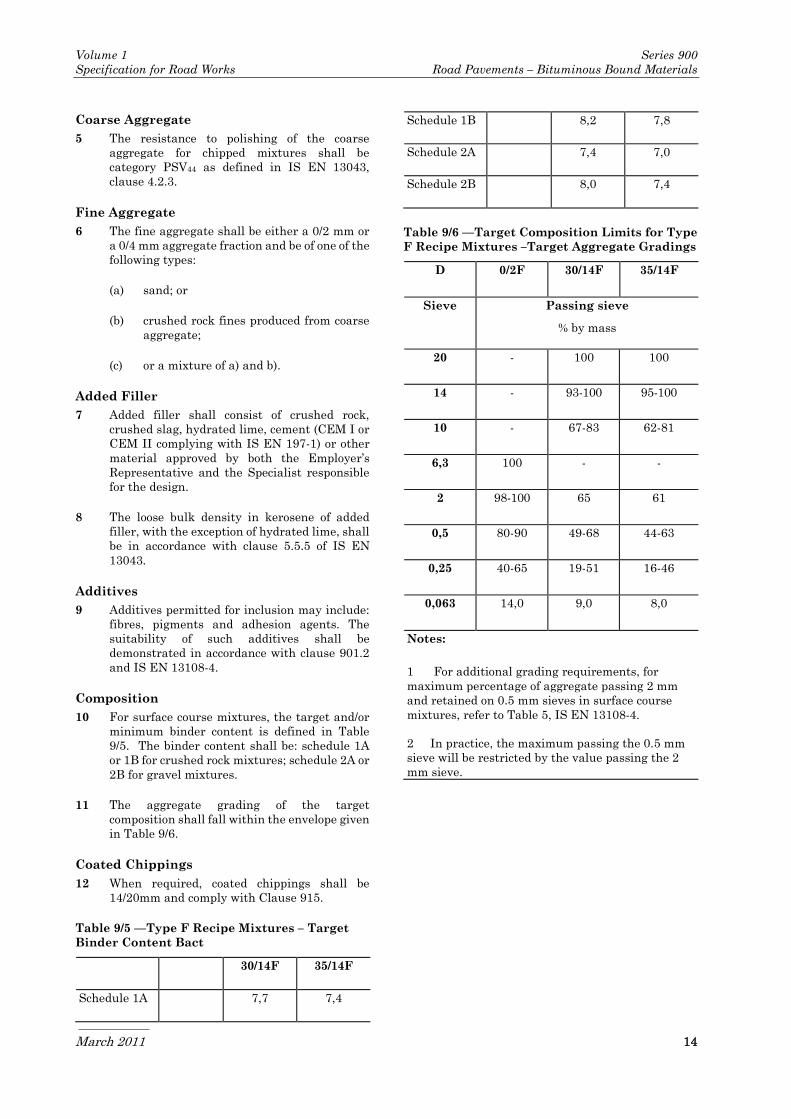
10 For surface course mixtures, the target and/or
minimum binder content is defined in Table
9/5. The binder content shall be: schedule 1A
or 1B for crushed rock mixtures; schedule 2A or
2B for gravel mixtures.
11 The aggregate grading of the target
composition shall fall within the envelope given
in Table 9/6.
Coated Chippings
12 When required, coated chippings shall be
14/20mm and comply with Clause 915.
Table 9/5 —Type F Recipe Mixtures – Target
Binder Content Bact
0/2F 30/14F 35/14F
Schedule 1A 10,2 7,7 7,4
Schedule 1B 10,8 8,2 7,8
Schedule 2A 10,2 7,4 7,0
Schedule 2B 10,8 8,0 7,4
Table 9/6 —Target Composition Limits for Type
F Recipe Mixtures –Target Aggregate Gradings
D 0/2F 30/14F 35/14F
Sieve Passing sieve
% by mass
20 - 100 100
14 - 93-100 95-100
10 - 67-83 62-81
6,3 100 - -
2 98-100 65 61
0,5 80-90 49-68 44-63
0,25 40-65 19-51 16-46
0,063 14,0 9,0 8,0
Notes:
1 For additional grading requirements, for
maximum percentage of aggregate passing 2 mm
and retained on 0.5 mm sieves in surface course
mixtures, refer to Table 5, IS EN 13108-4.
2 In practice, the maximum passing the 0.5 mm
sieve will be restricted by the value passing the 2
mm sieve.
Volume 1 Series 900
Specification for Road Works Road Pavements – Bituminous Bound Materials
March 2011 15
911 Hot Rolled Asphalt Surface
Course (Design Mixtures)
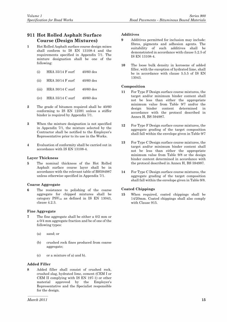
1 Hot Rolled Asphalt surface course design mixes
shall conform to IS EN 13108-4 and the
requirements specified in Appendix 7/1. The
mixture designation shall be one of the
following:
(i) HRA 35/14 F surf 40/60 des
(ii) HRA 30/14 F surf 40/60 des
(iii) HRA 30/14 C surf 40/60 des
(iv) HRA 35/14 C surf 40/60 des
2 The grade of bitumen required shall be 40/60
conforming to IS EN 12591 unless a stiffer
binder is required by Appendix 7/1.
3 When the mixture designation is not specified
in Appendix 7/1, the mixture selected by the
Contractor shall be notified to the Employer’s
Representative prior to its use in the Works.
4 Evaluation of conformity shall be carried out in
accordance with IS EN 13108-4.
Layer Thickness
5 The nominal thickness of the Hot Rolled
Asphalt surface course layer shall be in
accordance with the relevant table of BS594987
unless otherwise specified in Appendix 7/1.
Coarse Aggregate
6 The resistance to polishing of the coarse
aggregate for chipped mixtures shall be
category PSV44 as defined in IS EN 13043,
clause 4.2.3.
Fine Aggregate
7 The fine aggregate shall be either a 0/2 mm or
a 0/4 mm aggregate fraction and be of one of the
following types:
(a) sand; or
(b) crushed rock fines produced from coarse
aggregate;
(c) or a mixture of a) and b).
Added Filler
8 Added filler shall consist of crushed rock,
crushed slag, hydrated lime, cement (CEM I or
CEM II complying with IS EN 197-1) or other
material approved by the Employer’s
Representative and the Specialist responsible
for the design.
Additives
9 Additives permitted for inclusion may include:
fibres, pigments and adhesion agents. The
suitability of such additives shall be
demonstrated in accordance with clause 5.2.5 of
IS EN 13108-4.
10 The loose bulk density in kerosene of added
filler, with the exception of hydrated lime, shall
be in accordance with clause 5.5.5 of IS EN
13043.
Composition
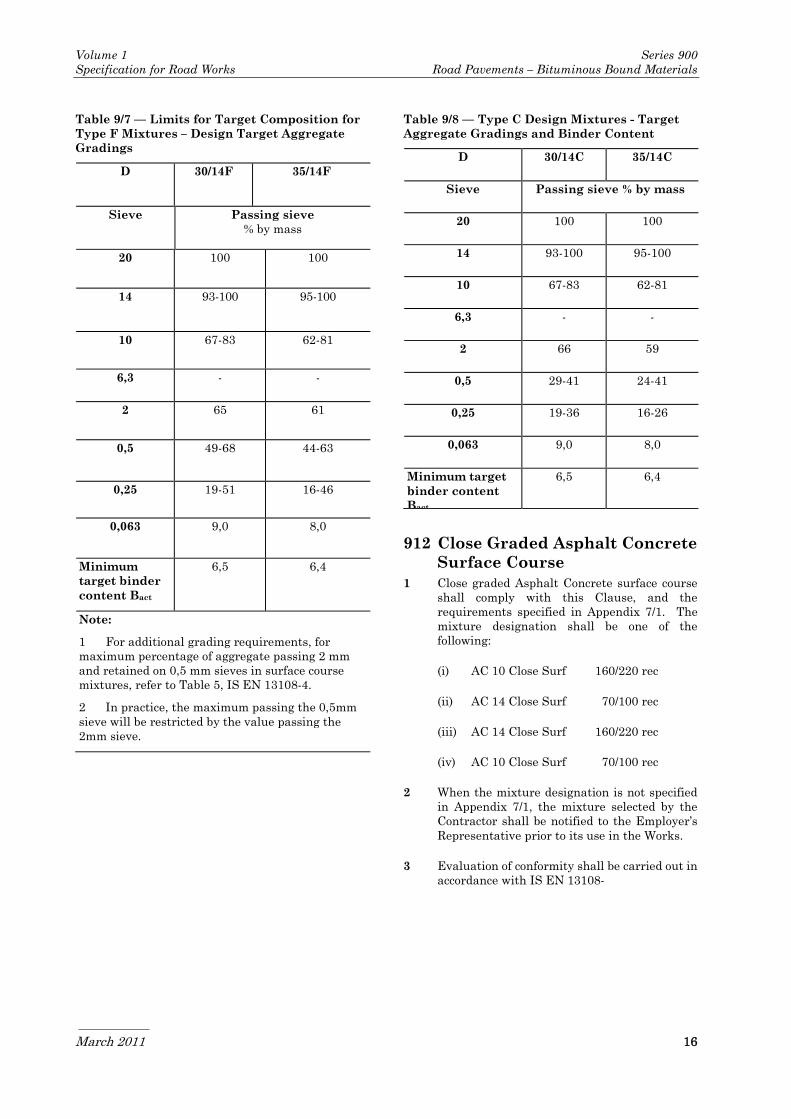
11 For Type F Design surface course mixtures, the
target and/or minimum binder content shall
not be less than either the appropriate
minimum value from Table 9/7 and/or the
design binder content determined in
accordance with the protocol described in
Annex H, BS 594987.
12 For Type F Design surface course mixtures, the
aggregate grading of the target composition
shall fall within the envelope given in Table 9/7
13 For Type C Design surface course mixtures, the
target and/or minimum binder content shall
not be less than either the appropriate
minimum value from Table 9/8 or the design
binder content determined in accordance with
the protocol described in Annex H, BS 594987.
14 For Type C Design surface course mixtures, the
aggregate grading of the target composition
shall fall within the envelope given in Table 9/8.
Coated Chippings
15 When required, coated chippings shall be
14/20mm. Coated chippings shall also comply
with Clause 915.
Volume 1 Series 900
Specification for Road Works Road Pavements – Bituminous Bound Materials
March 2011 16
Table 9/7 — Limits for Target Composition for
Type F Mixtures – Design Target Aggregate
Gradings
D 30/14F 35/14F
Sieve Passing sieve
% by mass
20 100 100
14 93-100 95-100
10 67-83 62-81
6,3 - -
2 65 61
0,5 49-68 44-63
0,25 19-51 16-46
0,063 9,0 8,0
Minimum
target binder
content Bact
6,5 6,4
Note:
1 For additional grading requirements, for
maximum percentage of aggregate passing 2 mm
and retained on 0,5 mm sieves in surface course
mixtures, refer to Table 5, IS EN 13108-4.
2 In practice, the maximum passing the 0,5mm
sieve will be restricted by the value passing the
2mm sieve.
Table 9/8 — Type C Design Mixtures - Target
Aggregate Gradings and Binder Content
D 30/14C 35/14C
Sieve Passing sieve % by mass
20 100 100
14 93-100 95-100
10 67-83 62-81
6,3 - -
2 66 59
0,5 29-41 24-41
0,25 19-36 16-26
0,063 9,0 8,0
Minimum target
binder content
Bact
6,5 6,4
912 Close Graded Asphalt Concrete
Surface Course
1 Close graded Asphalt Concrete surface course
shall comply with this Clause, and the
requirements specified in Appendix 7/1. The
mixture designation shall be one of the
following:
(i) AC 10 Close Surf 160/220 rec
(ii) AC 14 Close Surf 70/100 rec
(iii) AC 14 Close Surf 160/220 rec
(iv) AC 10 Close Surf 70/100 rec
2 When the mixture designation is not specified
in Appendix 7/1, the mixture selected by the
Contractor shall be notified to the Employer’s
Representative prior to its use in the Works.
3 Evaluation of conformity shall be carried out in
accordance with IS EN 13108-

Volume 1 Series 900
Specification for Road Works Road Pavements – Bituminous Bound Materials
March 2011 17
Table 9/9 — Target limits for composition for AC 14 and AC 10 Close Graded Surface Course recipe
mixtures
Previous BS nomenclature:
New EN nomenclature:
Recipe Mixtures
14 mm close
graded surface
course
AC 14 close surf
10 mm close
graded surface
course
AC 10 close surf
Test sieve
aperture size
(mm)
% by mass passing % by mass passing
20 100 -
14
100 a 100
10 77 – 83 100 a
6,3 52 – 58 62 – 68
2 25 – 31 25 – 31
1 14 – 26 14 – 26
0,063 6 a 6 a
Binder content Bact
Aggregate type Target Target
Limestone 4,9 5,2
Other crushed rock 5,1 5,3
Gravel b b
a Single values are recommended to ensure consistency between the original BS 4987 mixtures and those
derived from the European Standard.
b The information on the target bitumen contents required for these mixtures made with gravel is not sufficient
for a single target value to be specified. The bitumen content to be used should be chosen within the range 5,4
% to 6,6 %.
Composition
4 Evaluation of conformity shall be carried out in
accordance with IS EN 13108 -1 which requires
specifications to be presented as a grading
envelope within which the producer's declared
target grading must fall. The grading
specification in Table 9/9 gives single point
and/or very narrow envelope gradings, which,
in combination with the tolerances from IS EN
13108-21 result in overall grading envelopes
similar to those previously specified in BS 4987.
5 For surface course mixtures, the target and/or
minimum binder content is defined in Table
9/9.
6 The aggregate grading of the target
composition shall fall within the envelope given
in Table 9/9.
Aggregate
7 The coarse aggregate shall consist of crushed
rock complying with Clause 901.4.
8 The coarse aggregate shall have a minimum
resistance to polishing of PSV 55declared in
accordance with IS EN 13043 Clause 4.2.3
unless a higher PSV category is required by
Appendix 7/1. In addition, the resistance to
abrasion of the coarse aggregate shall have a
maximum category of AAV10 in accordance with
IS EN 13043 Clause 4.2.4.
9 The fine aggregate shall be either a 0/2 mm or
a 0/4 mm aggregate fraction and be of one of the
following types:
(a) crushed rock fines produced from coarse
aggregate defined in IS EN 13043 or
Volume 1 Series 900
Specification for Road Works Road Pavements – Bituminous Bound Materials
March 2011 18
(b) sand; or
(c) a mixture of a) and b).
10 If added filler is used in close graded mixtures
it shall consist of crushed rock, crushed slag,
hydrated lime, cement (CEM I or CEM II
complying with IS EN 197-1).
11 All aggregate shall be in a surface dry condition
prior to mixing.
Binder
12 The binder shall be petroleum bitumen of
paving grade 70/100 or 160/220 Pen complying
with IS EN 12591, as described in Appendix
7/1.
913 Not Used
914 Not Used
915 Coated Chippings for
Application to Hot Rolled
Asphalt Surface Course
1 The chippings and the manner of coating, when
used for rolling into the surface of rolled
asphalt, shall be in accordance with IS EN
13108-4, the following sub clauses and with
sub-clause 901.4.
2 The resistance to polishing of the chippings
shall be a minimum category PSV 55 declared, in
accordance with IS EN 13043 Clause 4.2.3
unless a higher PSV category is required by
Appendix 7/1. In addition, the resistance to
abrasion of the coarse aggregate shall have a
maximum category of AAV10 in accordance with
IS EN 13043 Clause 4.2.4. The shape of the
chippings shall comply with FI15 as defined in
IS EN 13043 Clause 4.1.6.
3 The polished stone value shall be determined in
accordance with IS EN 1097-8. The aggregate
shall be deemed to comply if the 2 most recent
consecutive results, from tests relating to the
material to be supplied, and carried out within
the previous 12 months by a testing laboratory
accredited to ISO 17025 (INAB) approved by
the Employer's Representative, are equal to or
greater than that required by Appendix 7/1.
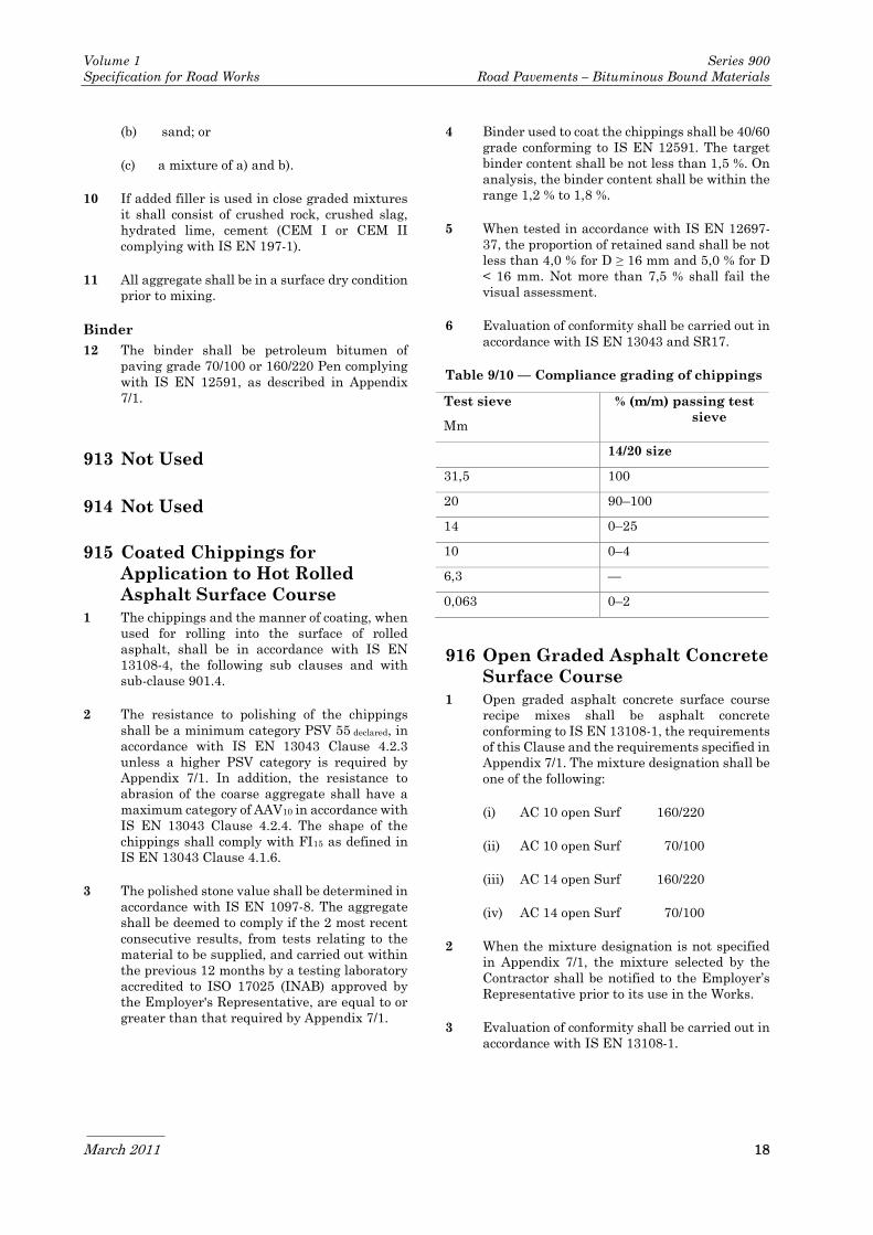
4 Binder used to coat the chippings shall be 40/60
grade conforming to IS EN 12591. The target
binder content shall be not less than 1,5 %. On
analysis, the binder content shall be within the
range 1,2 % to 1,8 %.
5 When tested in accordance with IS EN 12697-
37, the proportion of retained sand shall be not
less than 4,0 % for D ≥ 16 mm and 5,0 % for D
< 16 mm. Not more than 7,5 % shall fail the
visual assessment.
6 Evaluation of conformity shall be carried out in
accordance with IS EN 13043 and SR17.
Table 9/10 — Compliance grading of chippings
916 Open Graded Asphalt Concrete
Surface Course
1 Open graded asphalt concrete surface course
recipe mixes shall be asphalt concrete
conforming to IS EN 13108-1, the requirements
of this Clause and the requirements specified in
Appendix 7/1. The mixture designation shall be
one of the following:
(i) AC 10 open Surf 160/220
(ii) AC 10 open Surf 70/100
(iii) AC 14 open Surf 160/220
(iv) AC 14 open Surf 70/100
2 When the mixture designation is not specified
in Appendix 7/1, the mixture selected by the
Contractor shall be notified to the Employer’s
Representative prior to its use in the Works.
3 Evaluation of conformity shall be carried out in
accordance with IS EN 13108-1.
Test sieve
Mm
% (m/m) passing test
sieve
14/20 size
31,5 100
20 90–100
14 0–25
10 0–4
6,3 —
0,063 0–2

Volume 1 Series 900
Specification for Road Works Road Pavements – Bituminous Bound Materials
March 2011 19
Table 9/11 — Target limits for composition for AC 14 and AC 10 Open Surface Course recipe
mixtures
Previous BS nomenclature:
New EN nomenclature:
Recipe Mixtures
14 mm open
graded surface
course
AC 14 open surf
10 mm open
graded surface
course
AC 10 open surf
Test sieve
aperture size
(mm)
% by mass passing % by mass passing
20 100 -
14 98 –100 100
10 62-68 93 – 95
6,3 32 – 38 37 – 53
2 16 – 17 16 – 17
1 - -
0,063 5 a 5 a
Binder content Bact
Aggregate type Target Target
Limestone 4,6 5,1
Other crushed rock 4,8 5,3
Gravel b b
a Single values are recommended to ensure consistency between the original BS 4987 mixtures and those
derived from the European Standard.
b The information on the target bitumen contents required for these mixtures made with gravel is not
sufficient for a single target value to be specified. The bitumen content to be used should be chosen within the
range 5,4 % to 6,6 %.
Composition
4 Evaluation of conformity shall be carried out in
accordance with IS EN 13108 -1 which requires
specifications to be presented as a grading
envelope within which the producer's declared
target grading must fall. The grading
specification in Table 9/11 gives single point
and/or very narrow envelope gradings, which,
in combination with the tolerances from IS EN
13108-21 result in overall grading envelopes
similar to those previously specified in BS 4987.
5 For surface course mixtures, the target and/or
minimum binder content is defined in Table
9/11.
6 The aggregate grading of the target
composition shall fall within the envelope given
in Table 9/11.
Aggregate
7 The coarse aggregate shall consist of crushed
rock complying with Clause 901.4.
8 To ensure adequate resistance to polishing and
abrasion, the coarse aggregate shall have a
minimum declared PSV and a maximum AAV,
as specified in Appendix 7/1.
9 The fine aggregate shall be either a 0/2 mm or
a 0/4 mm aggregate fraction and be of one of the
following types:

Volume 1 Series 900
Specification for Road Works Road Pavements – Bituminous Bound Materials
March 2011 20
a) crushed rock fines produced from coarse
aggregate defined in IS EN 13043 or
b) sand; or
c) a mixture of a) and b).
10 If added filler is used in open graded mixtures
it shall consist of crushed rock, crushed slag,
hydrated lime, cement (CEM I or CEM II
complying with IS EN 197-1).
11 All aggregate shall be in a surface dry condition
prior to mixing.
Binder
12 The binder shall be petroleum bitumen of
paving grade 70/100 or 160/220 Pen complying
with IS EN 12591 as described in Appendix 7/1.
917 Cold-milling (Planing) of
Bituminous Bound Flexible
Pavement
1 Where cold-milling of bituminous bound
flexible pavement is required, the area of
carriageway to be milled shall be removed to
the specified depth by a suitable milling
machine. The process shall be carried out so as
not to produce excessive quantities of either
fumes, smoke or dust. Dust shall be minimised
by damping with water sprays.
2 The cut edges shall be left neat, vertical and in
straight lines. The Contractor shall brush and
sweep the milled surface by mechanical means
to produce a clean and regular running surface
with a groove depth not greater than 10 mm,
and with a uniform texture.
3 Carriageways shall be milled to the tolerance
for surface levels specified in Clause 702 for
binder course. If the tolerances in this Clause
are exceeded, the full extent of the area, which
does not comply, shall be rectified by further
milling or by regulating with materials in
accordance with Clause 907.
4 Existing ironwork shall not be disturbed by the
milling action. Where necessary, surfacing in
the vicinity of ironwork and in other small or
irregular areas shall be cut out by pneumatic
tools or other suitable methods and removed.
5 Where milling is carried out on a carriageway
open to traffic, temporary ramping to ensure
the safe passage of vehicles shall be provided in
accordance with the requirements of Appendix
1/17.
6 If the milled surface profile varies by more than
10 mm, when measured transversely or
longitudinally by a 3 metre straight edge,
adjustments or replacements shall be made to
the cutting teeth on the milling drum before
work continues. Any discontinuity between
adjacent milling passes exceeding 10 mm, when
measured transversely by a 3 metre straight
edge, shall be rectified by further milling or
regulating before placing bituminous
materials.
7 Where milling is required over extensive areas,
the Contractor shall programme the work to
allow removal of full lane widths unless this is
impracticable. The Contractor shall notify his
proposed programme of milling to the
Employer's Representative prior to
commencement of the work.
8 Immediately after milling, surplus material
shall be removed by a machine of suitable and
efficient design and the milled surface swept to
remove all dust and loose debris.
9 Where possible the material removed from the
carriageway shall be reused in accordance with
Clause 902 or in other such locations as
approved by the Employer’s Representative. All
other surplus material shall be run to licensed
tips identified by the contractor. No stockpiling
shall be allowed on Site unless the material is
to be used in the Works.
10 Carriageways, which are closed to traffic, shall
be resurfaced after milling prior to reopening
the carriageway to traffic, unless otherwise
agreed by the Employer's Representative.
918 Slurry Sealing
1 Slurry sealing shall comply with IS EN 13808,
BS 434: Part 2, Table 3 of RC380 National
Roads Authority Binder specifications and with
sub-Clauses 2 to 22 of this Clause.
Aggregate
2 Crushed or natural sand free from silt, clay or
other fine material. The aggregate, whether a
mixture or not, shall have a smooth grading
within the limits of Table 9/12.
Additive
3 The additive shall be CEM1 or CEM2 Portland
cement complying with IS EN 197: Part 1 or
hydrated lime complying with IS EN 459-1 At
least 75% shall pass the 63 micron sieve.

Volume 1 Series 900
Specification for Road Works Road Pavements – Bituminous Bound Materials
March 2011 21
Table 9/12 Aggregate Grading
Sieve Size
(mm)
Percentage by mass of total
aggregate and additive
passing
3mm finished
thickness
1,5mm
finished
thickness
6,3 100 100
4 80 – 100 100
2 75 – 100 95 – 100
1 55 – 90 70 – 95
0,250 20 – 45 30 – 50
0,063 5 – 15 5 – 15
Bitumen Emulsion
4 The slurry seal bitumen emulsion shall comply
with IS EN 13808 and the specific
requirements of Table 3 of RC380 National
Roads Authority binder specifications.
Tack Coat
5 Where required, or described in Appendix 7/3,
tack coat shall be cationic bitumen emulsion
complying with IS EN 13808 and the specific
requirements of Table 3 of R380 National Road
Authority binder specifications.
Composition of Mixed Material
6 The mixed material shall comprise aggregate,
bitumen emulsion and, where necessary,
additive complying with sub- Clause 3 of this
Clause. The amount of emulsion used shall be
between 180 litres/tonne and 250 litres/tonne of
dry aggregate; the precise proportions of each
constituent being selected after laboratory tests
and trials using the same plant intended to be
used in the Works. When additive complying
with sub-clause 3 of this Clause is used, the
proportion shall not normally exceed 2% by
mass of aggregate.
Mixing
7 The materials shall be measured into a
mechanical mixer and mixed such that the
aggregate is completely and uniformly coated
with bitumen emulsion and slurry is produced
of consistency that can be satisfactorily laid as
described in sub-Clauses 12 to 14 of this Clause.
When required, an additive complying with
sub-Clause 3 of this Clause, shall be used to
control consistency, mix, segregation and
setting rate.
Preparation of Site
8 Before applying tack coat or spreading slurry,
any necessary patching of the road surface
shall be completed. Immediately before
application of bituminous materials, loose
material, dust and vegetation shall be cleaned
from the existing surface by sweeping,
supplemented if necessary by air jet, and
removed from the site. All ironwork, road studs
and road markings, shall be masked. At
junctions with surfaces not to be treated, clean
lines shall be defined by masking, or other
suitable means.
Laying
9 If required, a tack coat shall be applied in
accordance with BS 434: Part 2 before
spreading the slurry seal.
10 The rate of spread of tack coat shall depend on
the surface to be treated, and shall be in
accordance with Tables 1 and 2 of BS594987.
11 Slurry shall be evenly spread by mechanical
means such that the aggregate cover (dry mass
equivalent) is 4-6kg/m2 for 3 mm finished
thickness and 2-4kg/m2 for 1,5 mm finished
thickness.
12 All voids, cracks and surface irregularities shall
be completely filled. Spreading shall not be
undertaken when the ground temperature falls
below 4°C or when standing water is present on
the surface. In warm dry weather the surfacing,
immediately ahead of the spreading, shall be
slightly damped by mist water spray applied
mechanically.
13 The slurry shall be rolled by a self propelled or
towed multi-wheeled smooth tread rubber-
tyred roller, having an individual wheel load
between 0,75 and 1,5 tonnes, making at least
six passes unless the Contractor demonstrates
that rolling is unnecessary or that a smaller
number of passes is satisfactory for a particular
process. Rolling shall commence as soon as the
slurry has set sufficiently to ensure rutting or
excessive movement will not occur.
14 The finished slurry shall have uniform surface
texture and colour throughout the work,
without variations of texture within the lane
width, or from lane to lane, due to segregation
of aggregates or colour, due to variations in the
emulsion water content of the mixture.
15 The finished surface shall be free from
blowholes and surface irregularities due to
scraping, scabbing, dragging, droppings, excess
overlapping or badly aligned longitudinal or
transverse joints, damage by rain or frost, or

Volume 1 Series 900
Specification for Road Works Road Pavements – Bituminous Bound Materials
March 2011 22
other defects. Slurry sealing which does not
comply with this Clause or is non-uniform in
surface texture or colour 24 hours after laying
shall be rectified by removal and replacement
with fresh material rolled in compliance with
the Specification or, if this is impractical, by
having fresh material superimposed and rolled
in compliance with the Specification. Areas so
treated shall be not less than 5m long and not
less than one lane wide. All areas being worked
on shall be kept free of traffic until permitted
by the Employer's Representative.
Preliminary Slurry Mixture Design and
Trial Areas
16 Using the same plant proposed for the Works,
the Contractor shall make trial mixes of the
slurry, varying the bitumen emulsion
aggregate ratio to produce a slurry of creamy
consistency which, whilst the screed box is
travelling at the laying speed, will flow ahead
of the screeding blade across the whole width of
the spreader at all times. At least three trial
mixes shall be made, each sufficient to spread a
trial area of 40 square metres, to the specified
finished thickness. The preparation of the
existing surface for the trials, the tack coat
spreading and the rolling methods shall comply
in all respects with this Clause. Trial areas,
which achieve the required spreading
consistency, will be examined after 24 hours,
for surface texture and adhesion, and if
satisfactory the test specified in sub-clause 17
of this Clause shall be carried out on samples of
the same composition.
17 For each of the satisfactory trial mixes, at least
two circular specimens shall be prepared, as
described in BS 434: Part 2, for a wet track
abrasion test. The approved mix proportions for
the main work shall be selected following
laboratory tests using a combination of
bitumen emulsion, aggregate blended where
necessary with additive and water, having a
wet track abrasion test result of less than
500g/m2.
18 When a proposed mix has been approved
variations shall not be made in mixing time,
mix proportions or in the type, size, grading or
source of any of the constituents without the
agreement of the Employer’s Representative
who may require further tests to be made.
Site Control Tests
19 The mix proportions shall be controlled and the
mass of all materials incorporated shall be
checked and recorded at least four times daily.
The quantity of emulsion used, and the rate of
spread of mixed material, in kilogram’s of
aggregate per square metre, shall be recorded
for each load of aggregate and, if required, for
each separate run within a load of aggregate.
20 The Contractor shall provide all necessary
testing equipment and whenever spreading is
taking place shall carry out the tests specified
in Table 9/13 at the frequency stated therein. A
copy of the results of each of the tests, and of
each recorded mass and check for rate of
spread, shall be passed to the Employer’s
Representative.
21 75g of the blended aggregate shall be weighed
in a glass beaker or similar container and the
corresponding quantities of water and cationic
emulsion in the slurry mix added. The slurry
shall be stirred with a slow deliberate action
(about 60rpm) for 15 to 30 seconds, after which
a specimen of about half the mixture shall be
cast upon an impervious surface.
22 The cast specimen shall exhibit cohesive
properties in not more than 10 minutes and
when set and drenched in water shall be water
fast as demonstrated by the absence of brown
colour in the wash water.
Table 9/13 Site Control Tests
Test
Frequency
Batch
Mixing
Continuous
Mixing
Wet Track
Abrasion Test
(BS 434: Part
2)
4 times daily Every second
run
Grading of each
separate
stockpile of
sand and
crusher run
fine aggregate
Every 20
tonnes
Every 20
tonnes
Grading of the
samples of the
blended
aggregate
4 times daily 4 times daily
Percentage of
the bitumen in
cured seal
4 times daily 4 times daily
919 Surface Dressing: Recipe
Specification
1 Surface dressing shall be designed and carried
out in accordance with the recommendations of
the Institute of Asphalt Technology (IAT) –
Guidelines for Surface Dressing in Ireland,
Volume 1 Series 900
Specification for Road Works Road Pavements – Bituminous Bound Materials
March 2011 23
current revision, and the requirements as
stated in Appendix 7/3.
Aggregates
2 The chippings shall be crushed rock or crushed
gravel complying with the requirements of
clause 901.4 of this series.
3 The polished stone value requirements from
Table III of the IAT guidelines shall be category
PSV60declared PSV57declared or PSV52declared as
appropriate and as specified in Appendix 7/3.
Aftercare
4 Aftercare shall be carried out in accordance
with section 5 of the IAT guidelines.
5 Any defects arising from deficiencies in the
materials, workmanship and aftercare
manifest during or at the end of the Defects
Period shall be rectified by the Contractor at his
own expense.
As Built Manual
6 Not more than 30 days after completion of the
work the Contractor shall provide a record of
the progress of the work in accordance with
section 6 of the IAT Guidelines and any such
other information that the Employers
Representative may reasonably require to be
included.
920 Bond Coats, Tack Coats and
other Bituminous Sprays
1 A bond or tack coat shall be sprayed onto the
surface prior to overlay in accordance with sub-
Clauses 3 and 4. Bond or tack coats for Asphalt
Concrete and Hot Rolled Asphalt shall be in
accordance with BS 594987 and sub-Clause 3.
Application shall be by spray tanker. For small
areas application may be by hand held sprayer
with the agreement of the Employer's
Representative. The surface shall be prepared
for the application of a bituminous spray and
when undertaking spraying and any specified
blinding. This shall be done in accordance with
the requirements as set out in BS594987 in so
far as it applies to the work to be undertaken in
accordance with the under mentioned general
requirements and any specified requirements
as described in Appendix 7/4.
2 The bond coat, tack coat or bituminous spray
shall be sprayed grade cationic bitumen
emulsion complying with BS 594987, the
Binder Specification and RC380 published by
the National Roads Authority. Where a bond
coat incorporating a polymer modified emulsion
is proposed for use it shall have prior written
approval from the Employer’s Representative.
The binder shall be sprayed at a rate as
specified in BS 594987.
3 The Employer's Representative may require
the Contractor to provide a test certificate
showing that a particular binder distributor
has been tested since the previous surface
dressing season and that the test indicates
conformity of the distributor with the
requirements of IS EN 12272-1 for emulsion
distributors.
4 Before spraying is commenced, the surface
shall be free of all loose material, the surface as
a whole shall be dry and any damp areas shall
be completely free of standing water.
5 Blinding material, where required by the
Contract, shall consist of a hard clean crushed
rock, fine aggregate or sand: it shall not contain
more than 15 per cent retained on a 6,3 mm
sieve. It shall be applied to the binder and left
unrolled. The rate of application shall be 5,5-
7,0kg/m2.
6 All loose material on the sprayed surface,
including any blinding material, shall be
removed before any further layer of the
pavement is laid.
921 Surface Macrotexture of
Bituminous Surface Courses
1 The initial surface macrotexture for bituminous
surface courses after compaction and before
traffic measured using the volumetric patch
method described in IS EN 13036-1 and the
procedures in BS 594987, clause 8.2 shall not
be less than the appropriate values shown in
Table 9/14.
2 For newly laid surfaces, measure the surface
texture as soon as possible after the surfacing
has been laid and before opening to traffic. For
all carriageways i.e. Single, Dual etc, these
measurements should be carried out for each
individual carriageway lane width. Make
measurements on 50m lane lengths regularly
spaced along the section and covering not less
than one-third of the section tested. On each
50m lane length, take 10 individual
measurements of the texture depth at
approximately 5m spacings along a diagonal
line across the carriageway lane width. Do not
take measurements within 300mm of the
longitudinal edge of the carriageway.
To reduce the variability, base the
determination of the average texture depth of a
test section on not less than six sets of ten

Volume 1 Series 900
Specification for Road Works Road Pavements – Bituminous Bound Materials
March 2011 24
individual measurements. For small schemes it
may be practicable to carry out measurements
over all of the surface course or over alternate
50m lengths covering 50 percent of the work.
Where this cannot reasonably be done make the
test measurements over regularly spaced 50m
lengths of carriageway lane, covering not less
than one-third of the surfacing laid in one lane.
On larger schemes, exceeding a kilometre in
length, select test sections of carriageway lane
1000m long in the same way.
3 For surface courses the surface texture may be
measured using a Laser system to the
specification necessary to enable the Mean
Profile Depth (MPD) to be calculated at one
metre intervals in accordance with ISO 13473-
1-2004 e.g. RSP or equivalent.
4 Whilst measurement of macrotexture for
compliance purposes is by the volumetric patch
technique specified in IS EN 13036-1 only, the
measurement using MPD may be used as a
screening procedure. In the event of dispute or
discrepancy between the two methods, only
results obtained using the volumetric patch
technique will be considered for compliance
purposes.
922 Not Used
923 Binder Reclaimed using the
Rapid Recovery Test (RRT)
and Accelerated Ageing using
the Modified Ageing Rolling
Thin Film Oven Test (RTFOT)
Scope
1 This Clause specifies the procedure for
obtaining a quantity of ‘Recovered Binder’ from
modified or unmodified cutback or emulsion
binder (Rapid Recovery Test - RRT) and an
extended procedure for obtaining a quantity of
‘Aged Binder’ (Modified Ageing Rolling Thin
Film Oven Test). ‘Aged Binder’ may be
prepared directly from ‘Recovered Binder’ or
from other binder samples. Binders used to
manufacture hot mix asphalt are first subjected
to a ‘short term ageing test’ (RTFOT) to
simulate the effects of manufacture, transport
and laying. The Modified Ageing RTFOT is
suitable for all bituminous binders and rapidly
provides homogeneous samples at different
ages so that a plot of a relevant characteristic
with ageing may be generated.
Definitions
2 For the purposes of the procedure specified in
this Clause, ‘Recovered Binder’ shall be defined
as: the material remaining after treatment of
the original product under the conditions
specified by the Rapid Recovery Test method
(RRT). ‘Aged Binder’ shall be defined as: the
material remaining after the Ageing protocol
specified by the Modified Ageing RTFOT
method.
Table 9/14: Requirements for Initial Macrotexture Depth
Road Type Surfacing Type
Average per
1000m section,
mm
Average for a set
of 10
Measurements,
mm
Mandatory speed of traffic
> 60 km/hr
Chipped Hot Rolled Asphalt and
surface dressing: Not less than
1,5 Not less than 1,2
Mandatory speed of traffic
≤ 60 km/hr and
roundabouts
All surface course materials
Chipped Hot Rolled Asphalt,
surface dressing and asphaltic
concrete.
Not less than
1,2 Not less than 1,0
Note:
For initial macro texture depth of Polymer Modified Stone Mastic Asphalt refer to Clause 942 Table 9/37

Volume 1 Series 900
Specification for Road Works Road Pavements – Bituminous Bound Materials
March 2011 25
Principle of the Rapid Recovery Test (RRT)
for Bituminous Emulsions, Cutbacks or
Fluxed Binders - Polymer Modified or
Unmodified
3 A thin film of binder is rotated in
polytetrafluoroethylene bottles using the
rolling thin film oven test apparatus (RTFOT),
as described in BS EN 12607-1, to evaporate
water from bituminous emulsion and/or the
light solvent or highly volatile fraction from
cutback, fluxed or other binder. Special screws
are used to disturb the binder and maintain a
homogenous material during breaking and/or
curing. Nitrogen gas instead of air is jetted over
the film of emulsion, cutback or fluxed binder
and a lower temperature is used in order to
minimise ageing effects and simulate the
condition of the binder soon after application (it
is assumed that these binders when used are
not subjected to the high temperature mixing
associated with an asphalt plant where the
appropriate test is the RTFOT using air at
163ºC).
Test Apparatus
4 The following test apparatus shall be used:
(i) RTFOT apparatus to BS EN 12607-
(ii) Eight identifiable bottles manufactured
from polytetrafluoroethylene (PTFE)
with threaded screw top lid (or other
fixing system) with internal dimensions
and aperture diameter (L2) as shown
below:
PTFE Bottle
The taper in throat is 45o + 5o (11/04)
Bottle dimensions
L1 129 ± 1,2mm
L2 31,75 ± 1,2mm
L3 70 ± 1,2mm
L4 64.0 ± 1,2mm
Note: All other dimensions are approximate.
(11/04)
(iii) Eight screws manufactured from high
quality stainless steel (surgical quality)
complying with BS EN 10088-3,
designation 1.4404 to a ‘fine machined
15m
m
10mm
5mm
11mm
4mm
4mm
L1
L4
5mm
3mm
L3
L2
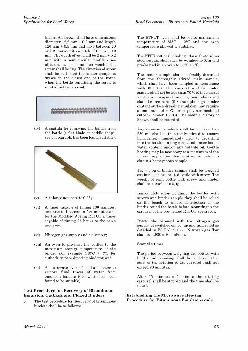
Volume 1 Series 900
Specification for Road Works Road Pavements – Bituminous Bound Materials
March 2011 26
finish’. All screws shall have dimensions:
diameter 12,2 mm ± 0,2 mm and length
120 mm ± 0,5 mm and have between 20
and 21 turns with a pitch of 6 mm ± 0,2
mm. The depth of cut shall be 2 mm ± 0,2
mm with a semi-circular profile - see
photograph. The minimum weight of a
screw shall be 70g. The direction of screw
shall be such that the binder sample is
drawn to the closed end of the bottle
when the bottle containing the screw is
rotated in the carousel;
(iv) A spatula for removing the binder from
the bottle (a flat blade or paddle shape,
see photograph, has been found suitable);
(v) A balance accurate to 0,05g;
(vi) A timer capable of timing 100 minutes,
accurate to 1 second in five minutes and
for the Modified Ageing RTFOT a timer
capable of timing 25 hours to the same
accuracy;
(vi) Nitrogen gas supply and air supply;
(vii) An oven to pre-heat the bottles to the
maximum storage temperature of the
binder (for example 140ºC ± 5ºC for
cutback surface dressing binders); and
(xi) A microwave oven of medium power to
remove final traces of water from
emulsion binders (650 watts has been
found to be suitable).
Test Procedure for Recovery of Bituminous
Emulsion, Cutback and Fluxed Binders
5 The test procedure for ‘Recovery’ of bituminous
binders shall be as follows:
The RTFOT oven shall be set to maintain a
temperature of 85°C ± 2°C and the oven
temperature allowed to stabilise.
The PTFE bottles (including lids) with stainless
steel screws, shall each be weighed to 0,1g and
pre-heated in an oven to 85ºC ± 2ºC.
The binder sample shall be freshly decanted
from the thoroughly stirred main sample,
which shall have been sampled in accordance
with BS EN 58. The temperature of the binder
sample shall not be less than 70 % of the normal
application temperature in degrees Celsius and
shall be recorded (for example high binder
content surface dressing emulsion may require
a minimum of 60ºC or a polymer modified
cutback binder 130ºC). The sample history if
known shall be recorded.
Any sub-sample, which shall be not less than
250 ml, shall be thoroughly stirred to ensure
homogeneity immediately prior to decanting
into the bottles, taking care to minimise loss of
water content and/or any volatile oil. Gentle
heating may be necessary to a maximum of the
normal application temperature in order to
obtain a homogenous sample.
19g ± 0,5g of binder sample shall be weighed
out into each pre-heated bottle with screw. The
weight of each bottle with screw and binder
shall be recorded to 0,1g.
Immediately after weighing the bottles with
screws and binder sample they shall be rolled
on the bench to ensure distribution of the
binder round the bottle before mounting in the
carousel of the pre-heated RTFOT apparatus.
Rotate the carousel with the nitrogen gas
supply jet switched on, set up and calibrated as
detailed in BS EN 12607-1. Nitrogen gas flow
shall be 4,000 ± 200 ml/min.
Start the timer.
The period between weighing the bottles with
binder and mounting of all the bottles and the
start of the rotation of the carousel shall not
exceed 20 minutes.
After 75 minutes ± 1 minute the rotating
carousel shall be stopped and the time shall be
noted.
Establishing the Microwave Heating
Procedure for Bituminous Emulsions only

Volume 1 Series 900
Specification for Road Works Road Pavements – Bituminous Bound Materials
March 2011 27
(not needed if proceeding to the Modified
Ageing RTFOT without sampling)
Remove two bottles with their screws and
binder from the carousel, weigh them and
record the weight loss to 0,1g. Remove the
screw from a bottle and return as much as
possible of the binder sample clinging to the
screw back into the bottle. The lids may need to
be removed and replaced. Re-weigh the bottles.
Place the two bottles with the binder sample
and any reclaimed binder sample from their
respective screws in the microwave oven
together with a glass beaker containing water
as a heat sink (around 200 ml has been found
to be suitable to prevent spitting and
overheating of the sample) and set a cycle time
(two minutes has been found to be suitable in a
medium power microwave). The cycle time
shall be such that the temperature of the
sample does not exceed 90ºC as measured at the
end of each cycle. After heating, re-weigh and
record the weight loss as before. The time taken
to weigh the bottles after the first cycle shall be
recorded as the ‘rest period’ and used between
further cycles (generally about two minutes).
Cycles shall be repeated until the recorded
weight loss is within 0,05g of that of the
previous cycle (generally just one or two cycles
are required). Report the average percentage
binder weight loss to 0,2%. Record the number
of cycles and cycle time. The individual results
shall be within 2,0% of the mean or the test
repeated.
If the binder sample has been shown to possess
a high flash point (greater than any localised
temperature experienced in the test) and/or the
screws are used in such a way as to minimise
any risk of sparking or arcing (electrical
discharge) then the screws may be left in the
bottles during the microwave heating
procedure.
Except where the bottles are to be subsequently
used for the Modified Ageing RTFOT, remove
the other six bottles from the carousel. Repeat
the procedure as for the two bottles using the
same rest period, but with one cycle time less.
If an estimate of binder content is needed then
record the weight loss to 0,1g.
The whole of this procedure shall not exceed 30
minutes. If more binder from the same main
sample is to be ‘Recovered’ then the procedure
to establish the cycle time need not be repeated
unless significant changes to the binder in
storage are expected (for example the water
content may change).
Note: It has been found to be advantageous to
place the bottles on their sides in the
microwave oven. This allows the binder to drain
collecting to one side of the bottle, which is more
easily removed with the scraper.
The weight loss after ‘Recovery’ shall be
recorded by weighing two bottles.
The ‘Recovered Binder’ shall be scraped from
the bottles and screws.
Unless the ‘Recovered Binder’ is to be treated
by the Modified Ageing RTFOT it shall be
transferred, before it cools to ambient, to other
test apparatus such as a Dynamic Shear
Rheometer (Clause 928), in order to minimise
further changes to the binder.
If the ‘Recovered Binder’ is to be stored or
transferred to another location for testing, it
shall be placed on a silicone sheet or in a
warmed penetration pot (at a temperature not
greater than 90ºC) and the binder surface
sealed using aluminium foil or other suitable
material to prevent further loss of volatiles and
minimise exposure to air. ‘Recovered Binder’
shall be stored at a temperature of between 0ºC
and 5ºC.
During transfer ‘Recovered’ samples shall not
be subjected to temperatures greater than
ambient and the delay before testing shall not
exceed 120 hours.
Re-heating for testing shall be in accordance
with BS 2000: Part 72 except that the
‘Recovered Binder’ shall not be heated above 90
ºC unless absolutely necessary for the test. The
thermal history shall be recorded.
Modified Ageing Rolling Thin Film Oven
Test (RTFOT)
Principle of the Modified Ageing RTFOT
6 A thin film of binder is rotated in bottles using
the rolling thin film oven test apparatus, as
described in BS EN 12607-1. Special screws are
used to disturb the binder and maintain a
homogenous material during ‘Ageing’. Air is
jetted over the film of binder for a much longer
period than in the conventional test and a lower
temperature used in order to simulate the
‘ageing’ of the binder in the road after
application. The binder tested may be
‘Recovered Binder’, or Binder after RTFOT,
either using the procedure detailed in this
Clause or BS EN 12607-1, or other binder
sample.
The Modified Ageing RTFOT shall be carried
out as follows:
(i) Bituminous Emulsion, Cutback and
Fluxed Binders Stabilising

Volume 1 Series 900
Specification for Road Works Road Pavements – Bituminous Bound Materials
March 2011 28
The bottles, with screws remaining,
containing the samples after the Rapid
Recovery Test, shall be treated in the
Modified Ageing RTFOT maintaining a
temperature of (135ºC ± 2ºC) with the
same nitrogen gas supply at 4000 ± 200
ml/min. After 1 hour ± 5mins two bottles
shall be removed and shall be weighed to
0,1g. If the weight loss is less than 2,0%
of the ‘Recovered Binder’ then the ageing
protocol shall commence by switching to
an air supply at 4000 ± 200 ml/min. If not
then the bottles shall be placed back in
the carousel with the nitrogen supply
maintained and the weight loss recorded
for these two bottles after each hour until
the weight loss has stabilised to less than
2,0% of the previous binder weight.
If the same binder from the same main
sample is to be ‘Stabilised’ after
‘Recovery’ then the procedure to establish
the stabilising time need not be repeated
unless there are expected significant
changes to the binder sample in storage.
Ageing
The samples shall be rotated in the air
supply and two bottles removed if
required for testing after three periods:
3hrs ± 10mins; 8hrs ± 10mins; and 22hrs
± 10mins.
The bottles and screws shall be scraped
to transfer the binder samples to the
appropriate test equipment or, if
required to be used later, placed on a
silicone sheet, or in a penetration pot,
and sealed and stored at between 0ºC to
5ºC.
‘Aged Binder’ is deemed to be the sample
from the 8 hr period.
The combined test may be run
continuously without interruption from
the beginning of the Rapid Recovery Test,
except for change in temperature and
changeover from nitrogen gas to air
supply and any ‘Recovered Binder’
samples removed for testing.
For the continuous treatment of samples
(combined test) there is no need for the
microwave procedure to be used.
(ii) Binders for Manufacturing Asphalt or
other Hot Mixed Materials.
The initial conditioning test is to
simulate the changes to the properties of
the binder caused by the high
temperatures during manufacture,
transport and laying. The screws
accelerate the process, and are necessary
to maintain a homogeneous material
especially when testing polymer modified
binders, which tend to form a skin and
separate into phases.
The standard ‘short term ageing test’
RTFOT shall be carried out in accordance
with BS EN 12607-1, at the same test
temperature of 163ºC but with the
following exceptions: a test time of 45
minutes ± 1 minute; PTFE bottles with
screws inserted shall replace the glass
bottles; 19g ± 0,5g of binder shall be
weighed out into each preheated bottle;
weighing of bottles to determine weight
loss shall be carried out within 2 minutes
of removal from the carousel without the
need to be placed in a desiccator; and
bottles and screws shall be scraped to
remove the ‘short term aged binder’.
The RTFOT treated binder shall be
tested for weight change by removing two
of the bottles and weighing within 2
minutes ± 1 minute. If required for
testing the ‘short term aged binder’ shall
be removed by scraping and transferred
to the appropriate test equipment or, if
required to be used later, placed on a
silicone sheet, or in a heated penetration
pot (maximum 170ºC), and sealed and
stored at between 0ºC to 5ºC.
The remaining samples shall then be
subjected to the Modified Aging RTFOT.
The temperature is reduced/set to (135 ºC
± 2ºC) and the Modified Ageing RTFOT
carried out:
The air supply shall be set at 4000 ±
200ml/min.
Start the timer.
The samples shall be rotated in the air
supply and two bottles removed if
required for testing after three periods:
4hrs ± 10mins; 8hrs ± 10mins; and 22hrs
± 10mins.
Note: It has been found to be
advantageous to place the bottles on
their sides. This allows the binder to
drain to one side of the bottle, which is
more easily removed with the scraper.
The bottles and screws shall be scraped
to transfer the binder to the appropriate

Volume 1 Series 900
Specification for Road Works Road Pavements – Bituminous Bound Materials
March 2011 29
test equipment or, if required to be used
later, placed on a silicone sheet, or in a
heated penetration pot (maximum
170ºC), and sealed and stored at between
0ºC to 5ºC.
‘Aged Binder’ is deemed to be the sample
from the 8 hr period.
The combined test may be run
continuously without interruption from
the beginning, except for the reduction in
temperature after 45mins from 163ºC to
135ºC and at that time removal of bottles
for test after RTFOT if required.
During transfer ‘Aged’ samples shall not
be subjected to temperatures greater
than ambient and the delay before
testing shall not exceed 120 hours.
Re-heating for testing shall be in
accordance with BS 2000-72 except that
the ‘Aged Binder’ shall not be heated
above 140ºC unless absolutely necessary
for the test. The thermal history of the
sample shall be recorded.
924 High Friction Surfacing
1 High Friction Surfacing shall be produced and
manufactured by a company independently
accredited to ISO 9001 or equivalent quality
management system. High skid resistant
surface treatments, made with aggregate of
high polishing resistance and resin-based
binders, shall consist of a film of binder sprayed
on to a sound substrate and covered with
aggregate to provide a textured, durable matrix
of high skid resistance.
Binder
2 The binder shall contain an epoxy or other
approved resin component.
Aggregate
3 The aggregate shall be calcined bauxite which
has, when determined in accordance with IS
EN 1097-8, a minimum polished stone value of
PSV72declared. The grading of the aggregate
shall be such that not more than 5% is retained
on a 4mm sieve and not more than 5% passes a
1mm sieve. The aggregate shall be clean and
free from foreign matter.
4 At least one month before surfacing is to take
place the Contractor shall submit to the
Employers Representative full details of the
constituent materials of the mixture, all test
results and the mixing and laying proposals
including mix temperatures both at production
and delivery to the site.
Mixing of Binder and Accuracy of Spraying
5 The binder shall be sprayed by a metered
machine that accurately and continuously
batches together the components of the binder;
intimately mixing them before spraying. A
control mechanism shall maintain each
component within 5% by mass of the normal
proportion specified by the resin manufacturer
and a calibrated flow meter (or other approved
means) shall be provided for each component. If
the components of the binder are heated to
facilitate spraying, the temperature shall not
exceed the maximum recommended by the
resin manufacturer. A temperature gauge
accurate to ± 2°C shall be used with all binders
that require heating.
6 The vessels containing the components shall
each be provided with an approved method of
measuring the volume of material used.
7 The machine shall spray the binder, such that
the amount collected on any longitudinal
stretch of the surface 50mm wide within the
width of the spray shall not be less than 90% of
the overall minimum requirement for the
surface being treated (see sub-clause 8 of this
Clause). The mean amount of binder collected
on any four adjacent 50mm wide strips shall be
not less than 95% of the overall minimum
requirement. Before work commences, and
thereafter at intervals not exceeding one
month, the Contractor shall provide evidence
that the sprayer and all metering gauges
complies with the requirements of the
Specification. The test to measure the spray
pattern shall be carried out in the presence of
the Employer's Representative unless the
Employer’s Representative declines to attend.
Preparation
8 The surface shall be vigorously brushed to
remove dust, laitance and other loose matter.
Any oil visible on the surface shall be removed
by washing and scrubbing with a detergent
solution followed by flushing with clean water
or by another approved method. The surface
shall be allowed to dry before application of the
binder. Existing road markings, ironwork and
road studs shall be suitably masked.
Application
9 The binder shall be sprayed on to a dry surface
at a rate which will vary according to the
texture and porosity of the surface. On a
smooth close textured surface the amount of
binder shall be not less than 1,35kg/m2 or such
rate specified by the resin manufacturer; on a

Volume 1 Series 900
Specification for Road Works Road Pavements – Bituminous Bound Materials
March 2011 30
more rugous surface a greater rate of spread
may be required. Heated binders shall be
allowed to cool before application of the
aggregate. A mechanically metered plant shall
be used to cover the binder uniformly with an
excess of aggregate. Rolling of the aggregate is
not permitted.
10 Hand application of the binder and/or
aggregate shall not be permitted, except within
areas not accessible to the mechanical sprayer
and/or spreader. Where hand application is
necessary, the proposed methods of batching,
mixing and application of binder and/or
aggregate to the road surface shall be agreed
with the Employer’s Representative.
Aftercare
11 The material used as masking shall be removed
together with the binder sprayed upon it and
the remainder of the binder allowed to cure.
During the curing period no disturbance or
trafficking of the treated surface will be
permitted. Before opening to traffic at the end
of the curing period, the excess aggregate shall
be removed by vacuum sweeper or other
approved means.
12 The Contractor shall have regard to the
increase in cure time of the resin binder with
decrease in temperature in order to allow
sufficient time for the resin binder to cure
between the end of the spray operation and the
time when the road is to be opened to traffic.
Details of cure time variation of the resin with
respect to temperature shall be supplied by the
resin manufacturer.
Checking and Testing
13 A check shall be made by the Contractor at the
end of each working shift to determine the
quantities used of each binder component. The
check shall be made by means of dip-sticks or
other approved devices. The measured
volumetric quantities of the components shall
be converted to mass units to estimate the
average rate of spread of binder upon the
surface, by dividing the total mass of the
components by the measured area of the
surface treated. The net aggregate coverage
rate shall also be recorded.
14 The average accuracy of batching shall be
determined from the known used masses of the
components. The relative proportions of
components so determined shall fall within the
limits specified in sub-clause 4 of this Clause.
15 The Contractor shall guarantee the adhesion to
the underlying road surface and integrity of the
high friction surfacing materials and
workmanship for a period of five years from the
date of opening the surfacing to traffic. This
guarantee shall exclude defects arising from
damage caused by settlement, subsidence or
failure of the carriageway on which the
surfacing has been applied.
925 Testing of Bituminous
Mixtures
1 The demonstration of the conformity of asphalt
mixtures specified in accordance with IS EN
13108 shall be covered by the following:
IS EN 13108-20 Type testing; and
IS EN 13108-21 Factory production
control.
Type test reports shall be supplied to the
Employer’s Representative and factory
production control records shall be submitted at
weekly intervals during production of material
for incorporation into the works.
2 The sampling and testing of bituminous
mixtures shall comply with IS EN 12697,
except where otherwise specified in this Series.
3 Any tests additional to those required by IS EN
13108–20, IS EN 13108–21 or the relevant
MCDRW Clause are specified in Appendices 1/5
and/or 7/1.
4 Noting that factory production control applies
up to the point of delivery, samples for quality
assurance tests defined in Appendix 1/5 shall
be taken from the delivery vehicle at the point
of delivery. Half of these samples will be
handed to the Employer for retention and
possible future testing. The remainder of
samples received shall be tested by the
contractor with such testing being incorporated
into the contractor’s factory production control
testing process.
926 Not Used
927 Not Used
928 Determination of the Complex
Shear (Stiffness) Modulus (G*)
and Phase Angle (δ) of
Bituminous Binders using a

Volume 1 Series 900
Specification for Road Works Road Pavements – Bituminous Bound Materials
March 2011 31
Dynamic Shear Rheometer
(DSR) Scope
1 This Clause describes the test method for the
determination of the Complex Shear (Stiffness)
Modulus (G*) and Phase Angle (δ) of a
bituminous binder over a range of
temperatures and frequencies when tested in
harmonic, sinusoidal oscillatory shear mode
using a dynamic shear rheometer (DSR) with
parallel plate test geometry and where both
plates are controlled at the same temperature.
Two methods are described. The first is the
conventional equilibrated temperature method
using frequency sweeps and is detailed in the
Institute of Petroleum (IP) test method IP PM
CM/02 and with the amendments stated in this
Clause shall be used for Type Approval (type
testing) purposes. The second is the
temperature sweep method, where the
temperature of the binder is raised at a known
rate and tested at a fixed frequency. The second
test, which requires less time to perform, may
be used for quality control purposes.
This Clause is applicable to unmodified and
polymer modified binder as supplied, after the
Rolling Thin Film Oven Test (RTFOT), after an
Ageing Test or as recovered from a mixture.
Bituminous binders containing fine mineral or
organic matter or fibres may also be tested. For
cutback bitumens, bituminous emulsions and
polymer variants the binder shall be sampled
from the delivery and a recovered binder
prepared in accordance with the following:
Principle of the Rapid Recovery Test (RRT)
for Bituminous Emulsions, cutbacks or
Fluxed Binders - Polymer Modified or
Unmodified
2 A thin film of binder is rotated in
polytetrafluoroethylene bottles using the
rolling thin film oven test apparatus (RTFOT),
as described in IS EN 12607-1, to evaporate
water from bituminous emulsion and/or the
light solvent or highly volatile fraction from
cutback, fluxed or other binder. Special screws
are used to disturb the binder and maintain a
homogenous material during breaking and/or
curing. Nitrogen gas instead of air is jetted over
the film of emulsion, cutback or fluxed binder
and a lower temperature is used in order to
minimise ageing effects and simulate the
condition of the binder soon after application (it
is assumed that these binders when used are
not subjected to the high temperature mixing
associated with an asphalt plant where the
appropriate test is the RTFOT using air at
163ºC).
Definitions
3 For the purposes of this Clause the following
definitions apply:
(i) Complex Shear Modulus (G*) (sometimes
referred to as Complex Stiffness
Modulus): ratio of peak stress to peak
strain in harmonic, sinusoidal oscillation
mode.
(ii) Phase Angle (δ): the phase difference
between stress and strain in harmonic,
sinusoidal oscillation mode.
(iii) Isotherm: an equation or curve on a
graph representing the behaviour of the
material at a constant temperature.
(iv) Linear region is defined as the range of
strain over which the strain is directly
proportional to the applied stress.
(v) High Equi-stiffness Temperature (T2kPa):
the temperature at which G* is equal to
2 kPa at 0,4 Hz determined from the plot
of G* vs. temperature.
(vi) Low Equi-stiffness Temperature (T2MPa):
the temperature at which G* is equal to
2 MPa at 0,4 Hz determined from the plot
of G* vs. temperature.
(vii) G*(pen): the Complex Stiffness Modulus at
25°C and frequency 0,4 Hz.
(viii) δ (low): the Phase Angle from the
temperature equilibrated data at 5°C
and at a frequency of 0,4 Hz.
(ix) δ (high): the Phase Angle from the
temperature equilibrated data at 60°C
and at a frequency of 0,4 Hz.
(x) Black Diagram: a graph of the magnitude
of G* against δ.
(xi) Zero-Shear-Viscosity: the limiting value
of viscosity of a visco-elastic liquid at a
given temperature and a very low shear
rate such that the material in deforming
does not build up any structural changes
and maintains equilibrium in the linear
region.
Apparatus
4 The apparatus for the test is detailed in IP PM
CM/02. The rheometer and the temperature
control system shall be calibrated and traceable
to national standards, where applicable, at
intervals not exceeding 13 months.

Volume 1 Series 900
Specification for Road Works Road Pavements – Bituminous Bound Materials
March 2011 32
Determination of Complex Shear (Stiffness),
Modulus (G*) and Phase Angle (δ)
5 Determination of G* and δ for binders used to
manufacture products at temperatures above
120°C (for example asphalt) shall be as
described in the IP method, except that the
target strain shall be set within the range 0,005
and 0,02 and the sample preparation shall be
Method A. For binders used at lower
temperatures such as bituminous emulsions, or
where volatile flux oil is present (for example
cutback bitumen), the maximum 100°C and
preferably less than 85°C. The IP Method shall
be amended as follows:
6 Method for Emulsions and Cutbacks:
(i) Sample preparation: Warm the recovered
binder obtained using Clause 923
sufficiently to be able to remove small
quantities from the bulk using a suitable
spatula or other tool (A temperature
around the softening point or the High
Equi-stiffness Temperature (T2kPa°C) is
usually found to be suitable). The binder
shall not be heated above 100°C and not
stored for longer than 1 hour at the target
temperature. The binder shall be sealed
with silicone release paper and/or metal
foil to minimise ageing and loss of
volatiles.
(ii) Sample loading: Weigh a pre-calculated
amount of binder, to suit the geometry,
directly onto one of the rheometer plates
or onto a silicone-based material for
subsequent transfer to one of the plates.
The time for transfer shall be recorded.
(iii) Sample gapping: The plates shall be at
the same temperature prior to setting the
gap. The required gap shall be set
immediately and no trimming is
required.
(iv) Allow the sample and both plates to
equilibrate at a temperature above the
softening point or T2kPa°C for at least 15
minutes prior to commencement of the
test.
(v) If the recovered binder is heavily
modified such that the elastic properties
prevent normal loading of the sample
then a higher temperature shall be
selected as near to 100°C as possible and
this shall be reported in the test report.
Data Acceptability Criteria
7 The acceptability criteria detailed in the IP
Method shall be used for different test
geometries or for at least two samples.
8 If the acceptability criteria are not met for two
samples then a third verification test shall be
carried out, the shortened procedure may be
used (25°C and frequency sweep) for the second
and subsequent samples. If the acceptability
criteria are met for the first and third tests, the
results of the first test shall be accepted. If the
acceptability criteria are met for the second and
third tests, discard the results for the first test
and continue testing the third sample by the
full procedure used for the first sample, these
results are verified by the second test. If none
of the three tests are within the acceptability
criteria then the mean of the results obtained
in two full tests shall be reported with a note
that the acceptability criteria could not be met.
Temperature Sweep Test Procedure for
Quality Control
9 After equilibration of the sample above the
softening point or the High Equi-stiffness
Temperature (T2kPa°C) for at least 15 minutes a
temperature sweep shall be carried out from
the lowest test temperature to at least 60°C or
T2kPa°C whichever is the higher. The test
frequency shall be 0,4Hz (± 0,04Hz). G* and
Phase Angle (δ) shall be measured at
temperature intervals not greater than 5,5 °C.
The rate of temperature increase shall be 2,5°C
per minute or a lesser-fixed rate, which shall be
stated with tolerances (not greater than ±
0,5°C).
10 The plot of G* and Phase Angle (δ) against
temperature may be used to compare a sample
with a type test for the product by the
equilibrated temperature method. If the value
for G* is within ± 30% and Phase Angle (δ)
within ± 10 degrees at 25°C then the data is
deemed to be valid for comparison. If not, then
a second sample shall be tested, if the values for
G* are within ± 30% and Phase Angle (δ) are
within ± 10 degrees for 90% of the results for
the first test the data is deemed to be valid and
different to the type test. If the supplier has
reasoned that higher tolerances are necessary
for the particular product at Type Approval
(type testing) stage these shall be used instead
for comparison. The supplier may also state the
sample preparation technique to be used for
this comparison.
11 Alternatively the equilibrated temperature
data from frequency sweeps (the IP method)
may be used, although the number of
equilibrated temperature tests at 0,4Hz will
need to be increased (5°C intervals).

Volume 1 Series 900
Specification for Road Works Road Pavements – Bituminous Bound Materials
March 2011 33
12 If required the temperature sweep shall be
carried out with a reducing temperature from
80°C to the lowest test temperature in addition
to the normal test, this shall be noted in the test
report.
Expression of Results
13 A table of results, based on the individual test
results, shall be produced which shall include
the following information at each temperature:
(i) Test temperature ºC
(ii) Test frequency Hz
(iii) Strain %
(iv) Phase Angle (δ) Degrees
(v) Complex Stiffness Modulus (G*) Pascals.
14 A graph of G* against temperature shall be
produced, in decades from 101 to 108 Pa as a
curve at 0,4 Hz ± 0,04 Hz with a linear
temperature x-axis of -10°C to 90°C.
15 A graph of Phase Angle (δ) against temperature
shall be produced from 20 to 90 degrees
ascending with a linear temperature x-axis of -
10°C to 90°C at a frequency of 0,4Hz ± 0,04Hz.
16 A graph of G* against Phase Angle (δ) (Black
Diagram) shall be produced in decades from
101 to 108 Pa with a linear x-axis of 90 to 20
degrees descending.
17 Plots of isotherms for G* against frequency
tested at each test temperature shall be
produced in decades from 101 to 108 Pa with an
x-axis in decades of frequency from 10-2Hz to
101Hz.
18 Plots of isotherms for Phase Angle (δ) against
frequency tested at each test temperature shall
be produced from 20 to 90 degrees with an x-
axis in decades of frequency from 10-2Hz to
101Hz.
19 The x-axes of the graphs shall have dimensions
of at least 200mm and the y-axes at least
150mm.
20 The following test values shall be reported:
(i) T2kPa: the High Equi-stiffness
temperature.
(ii) T2Mpa: the Low Equi-stiffness
temperature.
(iii) G*(5°C): the value of G* at the equilibrated
temperature of 5°C and 0,4 Hz.
(iv) G*(pen): the value of G* at the equilibrated
temperature of 25°C and 0,4 Hz.
(v) G*(60°C): the value of G* at the
equilibrated temperature of 60°C and 0,4
Hz.
(vi) δ(low): the value of δ at low temperature
5°C and loading time of 0,4 Hz.
(vii) δ (high): the value of δ at high temperature
60°C and loading time of 0,4 Hz.
(viii) Zero-Shear-Viscosity at 45°C (ZSV45) and
60°C (ZSV60) calculated from the
procedure outlined in a paper by
Baumgaertel, M. and Winter, H.H.,
“Determination of discrete relaxation
and retardation time spectra from
dynamic mechanical data”, Rheol Acta
28:511-519 (1989) or equivalent method
with procedure outlined.
The complex stiffness modulus (G*) shall be
reported to three significant figures, phase
angle to the nearest 0,1 of a degree and
temperature to 0,1°C.
Test Report
21 The test report shall contain at least the
following information:
(i) A reference to this test procedure.
(ii) Place of test.
(iii) The rheometer type, model and test
geometries (plates and gaps) used.
(iv) The compliance limitations of the
machine/geometry (including whether
software corrections have been applied in
terms of the maximum sample stiffness
at which the result reported will be in
error by less than 10%). The limitations
shall be reported for each plate geometry
used to obtain the results reported.
(v) The type and identification of the product
tested.
(vi) Sample thermal history: how, when and
where the sample was taken; the size of
the sample and whether it was sub-
divided; the period it was stored and the
conditions of storage; and whether it was
treated by RTFOT and/or Ageing Test or
was a recovered binder from emulsion or
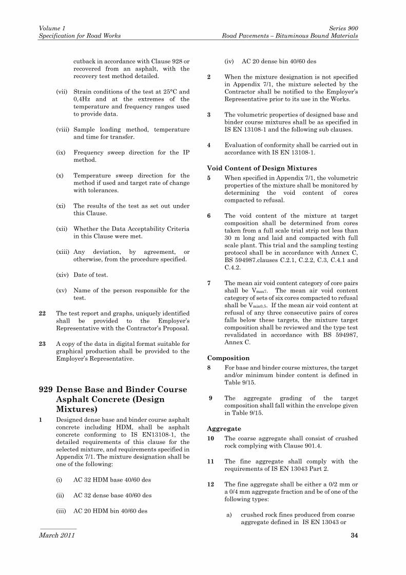
Volume 1 Series 900
Specification for Road Works Road Pavements – Bituminous Bound Materials
March 2011 34
cutback in accordance with Clause 928 or
recovered from an asphalt, with the
recovery test method detailed.
(vii) Strain conditions of the test at 25°C and
0,4Hz and at the extremes of the
temperature and frequency ranges used
to provide data.
(viii) Sample loading method, temperature
and time for transfer.
(ix) Frequency sweep direction for the IP
method.
(x) Temperature sweep direction for the
method if used and target rate of change
with tolerances.
(xi) The results of the test as set out under
this Clause.
(xii) Whether the Data Acceptability Criteria
in this Clause were met.
(xiii) Any deviation, by agreement, or
otherwise, from the procedure specified.
(xiv) Date of test.
(xv) Name of the person responsible for the
test.
22 The test report and graphs, uniquely identified
shall be provided to the Employer’s
Representative with the Contractor’s Proposal.
23 A copy of the data in digital format suitable for
graphical production shall be provided to the
Employer’s Representative.
929 Dense Base and Binder Course
Asphalt Concrete (Design
Mixtures)
1 Designed dense base and binder course asphalt
concrete including HDM, shall be asphalt
concrete conforming to IS EN13108-1, the
detailed requirements of this clause for the
selected mixture, and requirements specified in
Appendix 7/1. The mixture designation shall be
one of the following:
(i) AC 32 HDM base 40/60 des
(ii) AC 32 dense base 40/60 des
(iii) AC 20 HDM bin 40/60 des
(iv) AC 20 dense bin 40/60 des
2 When the mixture designation is not specified
in Appendix 7/1, the mixture selected by the
Contractor shall be notified to the Employer’s
Representative prior to its use in the Works.
3 The volumetric properties of designed base and
binder course mixtures shall be as specified in
IS EN 13108-1 and the following sub clauses.
4 Evaluation of conformity shall be carried out in
accordance with IS EN 13108-1.
Void Content of Design Mixtures
5 When specified in Appendix 7/1, the volumetric
properties of the mixture shall be monitored by
determining the void content of cores
compacted to refusal.
6 The void content of the mixture at target
composition shall be determined from cores
taken from a full scale trial strip not less than
30 m long and laid and compacted with full
scale plant. This trial and the sampling testing
protocol shall be in accordance with Annex C,
BS 594987.clauses C.2.1, C.2.2, C.3, C.4.1 and
C.4.2.
7 The mean air void content category of core pairs
shall be Vmax7. The mean air void content
category of sets of six cores compacted to refusal
shall be Vmin0,5. If the mean air void content at
refusal of any three consecutive pairs of cores
falls below these targets, the mixture target
composition shall be reviewed and the type test
revalidated in accordance with BS 594987,
Annex C.
Composition
8 For base and binder course mixtures, the target
and/or minimum binder content is defined in
Table 9/15.
9 The aggregate grading of the target
composition shall fall within the envelope given
in Table 9/15.
Aggregate
10 The coarse aggregate shall consist of crushed
rock complying with Clause 901.4.
11 The fine aggregate shall comply with the
requirements of IS EN 13043 Part 2.
12 The fine aggregate shall be either a 0/2 mm or
a 0/4 mm aggregate fraction and be of one of the
following types:
a) crushed rock fines produced from coarse
aggregate defined in IS EN 13043 or
Volume 1 Series 900
Specification for Road Works Road Pavements – Bituminous Bound Materials
March 2011 35
b) sand; or
c) a mixture of a) and b).
13 If added filler is used in dense mixtures it shall
consist of crushed rock, crushed slag, hydrated
lime, cement (CEM I or CEM II complying with
IS EN 197-1).
Binder
14 The binder shall be petroleum bitumen of
paving grade 40/60 or 70/100 Pen complying
with IS EN 12591 as described in Appendix 7/1.
Resistance to Permanent Deformation of
Design Mixtures
15 The resistance to permanent deformation of the
mixture shall be in accordance with the
appropriate class as specified in Appendix 7/1.
16 The resistance to permanent deformation shall
comply with Table 9/16. Tests shall be carried
out on specimens at the target composition
using the small wheel tracking device on 305
mm square slabs which are compacted by a
laboratory roller compactor in accordance with
IS EN 12697-33. Alternatively, 200 mm
diameter core specimens can be taken from a
full scale trial strip in accordance with the trial
strip protocol in Annex D, BS 594987.
17 When specified in Appendix 7/1, the resistance
to permanent deformation of material laid in
the Works shall be monitored by testing in
accordance with clauses D 3.1, 3.2 and 3.3 of BS
594987 Annex D. Six cores shall be taken from
the first kilometre length of material from each
mixing plant and thereafter one further core
from each subsequent lane kilometre. Results
shall be assessed on successive rolling means of
sets of six consecutive results and shall be
deemed to conform if the mean is no greater
than the specified value and individual values
not more than 50% greater than the specified
value.
Stiffness
18 Stiffness of the mixture shall be assessed in
accordance with BS 594987, Annex E. Mixtures
with 40/60 grade binder shall conform to
category Smin1800 as defined in IS EN 13108:
Part 1, clause 5.4.2.
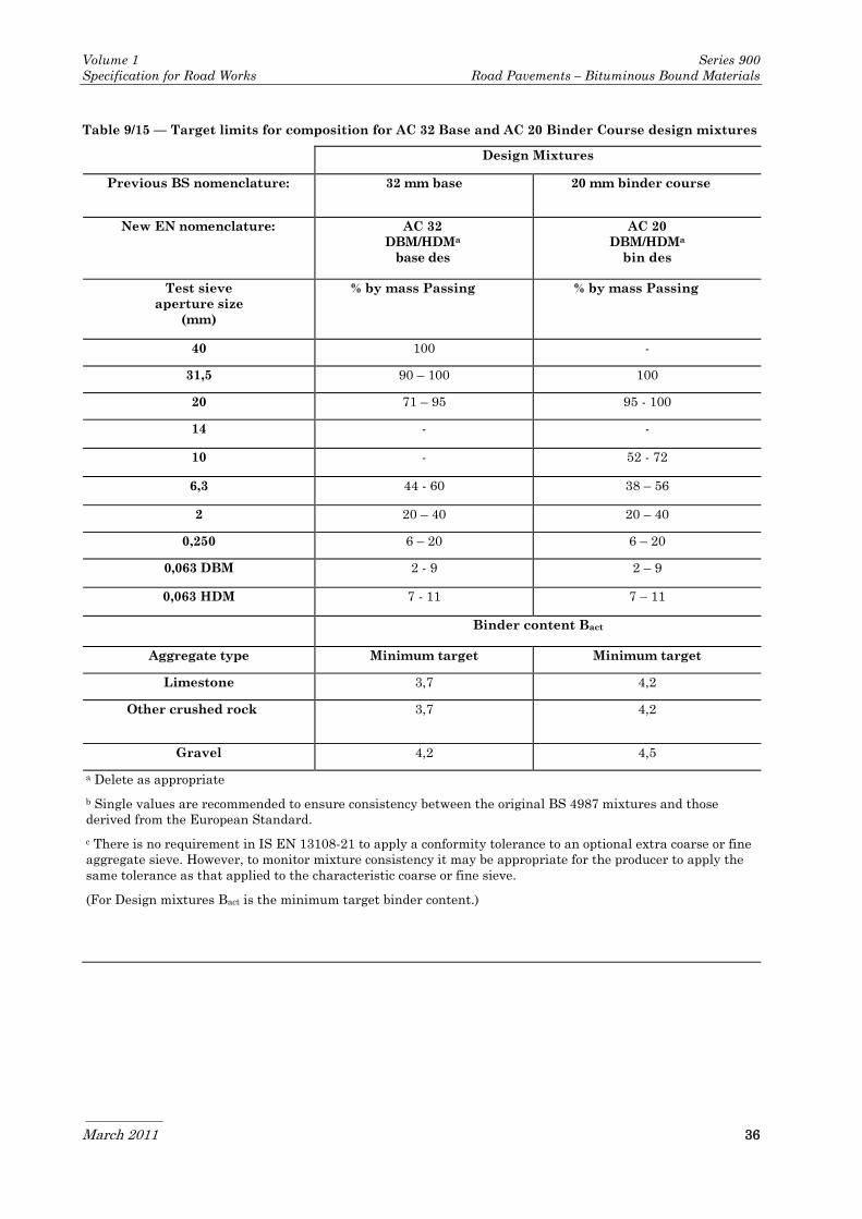
Volume 1 Series 900
Specification for Road Works Road Pavements – Bituminous Bound Materials
March 2011 36
Table 9/15 — Target limits for composition for AC 32 Base and AC 20 Binder Course design mixtures
Design Mixtures
Previous BS nomenclature: 32 mm base 20 mm binder course
New EN nomenclature: AC 32
DBM/HDMa
base des
AC 20
DBM/HDMa
bin des
Test sieve
aperture size
(mm)
% by mass Passing % by mass Passing
40 100 -
31,5 90 – 100 100
20 71 – 95 95 - 100
14 - -
10 - 52 - 72
6,3 44 - 60 38 – 56
2 20 – 40 20 – 40
0,250 6 – 20 6 – 20
0,063 DBM 2 - 9 2 – 9
0,063 HDM 7 - 11 7 – 11
Binder content Bact
Aggregate type Minimum target Minimum target
Limestone 3,7 4,2
Other crushed rock 3,7 4,2
Gravel 4,2 4,5
a Delete as appropriate
b Single values are recommended to ensure consistency between the original BS 4987 mixtures and those
derived from the European Standard.
c There is no requirement in IS EN 13108-21 to apply a conformity tolerance to an optional extra coarse or fine
aggregate sieve. However, to monitor mixture consistency it may be appropriate for the producer to apply the
same tolerance as that applied to the characteristic coarse or fine sieve.
(For Design mixtures Bact is the minimum target binder content.)

Volume 1 Series 900
Specification for Road Works Road Pavements – Bituminous Bound Materials
March 2011 37
Table 9/16 — Limiting wheel-tracking requirements for Design Asphalt Concrete
Test
temperature Category
WTSAIR
Category
PRDAIR
Requirements
Classification Test method IS EN 12697-22,
Small device,
Procedure B
IS EN 12697-22,
Small device,
Procedure B
when tested to BS
598-110
No. Description oC Wheel track slope
μm/cycle
Maximum rut
depth (mm)
Max rut
rate
(mm/hr)
Max rut
depth
(mm)
1 Moderate to
heavily stressed
sites requiring
high rut
resistance
45 WTSAIR DECLARED PRDAIR DECLARED 2 4
2 Very heavily
stressed sites
requiring very
high rut
resistance
60 WTSAIR DECLARED PRDAIR DECLARED 5 7
3 Other sites N/A WTSAIR NR PRDAIR NR - -
Notes:
The values for WTSAIR and PRDAIR categories in Table 9/16 shall be declared until experience with the test
methods has been established in Ireland. It is therefore recommended that dual testing for resistance to
permanent deformation be carried out with the method described in BS 598-110 and the method described in IS
EN 12697-22 (small device) for a period of 24 months from the date of publication of SR28. After this time and
following a review of the test results available, guidance will be given on the approved test method and
appropriate specification limits. The values given in Table 9/16 for the British Standard method should be
used until an acceptable correlation has been established The values given in Table 9/16 for the British
Standard method should be used until an acceptable correlation has been established.
.
Compaction Control for the Works
19 Compaction shall be controlled and monitored
in accordance with the general requirements of
BS 594987 Clause 9.5.1 and the specific
requirements of this Clause.
20 Compaction shall be continuously assessed
using an indirect density gauge in accordance
with BS 594987 Clause 9.4.2 with readings
taken at 20m intervals in alternate wheel
tracks. Gauge readings shall also be taken at
each core location specified in sub clauses 24
and 26. Each gauge shall be individually
calibrated on each mixture from each mixing
plant and the calibrations shall be continually
checked and updated based on correlations
between gauge readings and core densities at
the same locations.
21 For each location, the in situ void content shall
be determined in accordance with IS EN 12697-
8 using the bulk density from the gauge reading
and a maximum density taken from the
mixture type testing data and updated with
values from testing in accordance with sub-
Clause 23.
22 The average in situ void content calculated
from any six consecutive indirect gauge
readings shall not exceed 7%.
23 In the event of a failure to meet the
requirements in sub-Clause 22, cores shall be
taken at each location and void contents
determined as described in sub-Clause 24 and
the evaluation of the extent of any non
conformity shall be based on these. If it is
necessary to remove and replace any material
to restore conformity this shall be in lengths not

Volume 1 Series 900
Specification for Road Works Road Pavements – Bituminous Bound Materials
March 2011 38
less than 15m unless otherwise agreed by the
Employer.
24 For the material from each mixing plant, a pair
of cores shall be taken from the wheel tracks
every 1000 metres laid and the void content
shall be determined in accordance with BS
594987, clause 9.5.1.3.
25 The average in situ air voids for each core pair
shall not exceed Vmax7.
26 For the material from each mixing plant a pair
of cores shall be taken every 250 metres laid,
centred 100mm from the final joint position at
any unsupported edge and the air void shall be
determined in accordance with BS 594987,
clause 9.5.1.3.
27 The average in situ void content for each of
these pairs shall not exceed Vmax9.
28 In the event of non conformity with sub-Clauses
25 or 27 then density readings with indirect
gauges and, if necessary, further cores shall be
taken to establish the extent. If it is necessary
to remove and replace any material to restore
conformity, this shall be in lengths not less
than 15m unless otherwise agreed by the
Employer.
29 Each core extracted shall be examined for
evidence of excessive voids below the depth to
which the indirect density gauge penetrates. If
excessive voids are observed, further cores shall
be taken to determine its extent.
30 Two copies of the final indirect density test
results obtained and their correlation with in
situ air void contents shall be passed to the
Employer’s Representative within 72 hours.
930 EME2 Base and Binder Course
Asphalt Concrete
1 EME2 base and binder course asphalt concrete
shall conform to IS EN13108-1, for the selected
mixture, the requirements of this Clause and
those specified in Appendix 7/1. The mixture
designation shall be one of the following:
i) AC 10 EME2 bin/base 10/20 des
ii) AC 10 EME2 bin/base 15/25 des
iii) AC 14 EME2 bin/base 10/20 des
iv) AC 14 EME2 bin/base 15/25 des
v) AC 20 EME2 bin/base 10/20 des
vi) AC 20 EME2 bin/base 15/25 des
2 When the mixture designation is not specified
in Appendix 7/1, the mixture selected by the
Contractor shall be notified to the Employer’s
Representative prior to its use in the Works.
3 Evaluation of conformity shall be carried out in
accordance with IS EN 13108-1.
Binder
4 The binder shall be grade 10/20 or 15/25 Hard
Paving Grade Bitumen in accordance with IS
EN 13924 and the requirements specified in
Tables 9/17, 9/18 and 9/19.
5 EME2 mixtures, otherwise conforming to IS
EN 13108-1 and the detailed requirements of
this clause, but using alternative paving grade
bitumens or polymer modified paving grade
bitumens, shall not be used without the design
being approved by the National Roads
Authority Standards Section.
6 The binder content at the target composition,
determined in accordance with IS EN 12697-1,
shall comply with the requirements of Table
9/20.
7 A separate assessment shall be made of the
conformity of soluble binder content analysis
results of EME2 mixtures using the principles
of the ‘mean of four results’ approach used in IS
EN 13108-21. Binder content shall be assessed
on a continuous basis by taking the mean value
of the previous four analysis results. This will
give ‘rolling mean binder content’. In addition
to the analysis results meeting all of the
standard conformity requirements of EN
13108-21, this rolling mean binder content
shall comply with the target composition +
0,3%.

Volume 1 Series 900
Specification for Road Works Road Pavements – Bituminous Bound Materials
March 2011 39
Table 9/17 Initial Binder Characteristics
Characteristic Test Method Unit Hard Grade binders for EME 2 FPC
10/20 pen 15/25 pen Test
frequency
Penetration at 25°C IS EN 1426 0,1mm 10-20 15-25 D
Softening point IS EN 1427 °C 58-78
Target Value
71max (1)
55-71
Target Value
68 max(1)
W
Penetration index,
max
IS EN 13924
Annex A
- +0,7
Target value
+0,5max (1)
+0,7
Target value
+0,5max (1)
W
Fraass Breaking
point, max
IS EN 12593 °C Target mean (2)
0 max
Range -10 to +5
Target mean (2)
0 max
Range -10 to +5
Q
Viscosity at 135°C,
min
IS EN 12595 mm2/s 1100 900 Q
Flash Point minimum IS EN 2592 °C 245 245 A
Solubility, minimum IS EN 12592 %(m/m) 99,0 99,0 A
Notes:
(1) Target max value based on a rolling mean of the last 6 consecutive results in compliance testing or FPC as
appropriate.
(2) Target max value based on a rolling mean of the last 3 consecutive results in compliance testing or FPC as
appropriate.
All tests to be carried out on sub-samples of a single bulk sample of binder.
Minimum test frequency: D = Daily, W = Weekly, Q = Quarterly, A = Annually.
(Indicated frequencies apply only if product is in regular supplied).
Table 9/18 Binder Characteristics, after short term ageing to EN1260-1 (RTFOT)
Characteristic Test Method Unit Hard Grade binders for EME 2 FPC
10-20 pen 15-25 pen Test
Frequency
Change of Mass, Max % 0,5 0,5 A
Retained pen 25°C,
min
IS EN 1426 % 65 65 Q
Increase in softening
point, maximum
IS EN 1427 °C 8 8 Q
Fraass breaking point
min
IS EN 12593 °C Target Mean (1)
+2 max range -8
to +7
Target Mean (1)
+2 max range -8
to +7
Q
Notes:
(1) Target max value based on a rolling mean of the last 3 consecutive results in compliance testing or FPC as
appropriate.
All tests to be carried out on sub-samples of a single bulk sample of binder.
Minimum test frequency: Q = Quarterly, A = Annually.
(Indicated frequencies apply only if product is in regular supply).

Volume 1 Series 900
Specification for Road Works Road Pavements – Bituminous Bound Materials
March 2011 40
Table 9/19 Binder Characteristic To Be Reported
Characteristic Test Method Unit Binder
for EME2
FPC frequency
AS STA LTA
Brookfield Viscosity
T200 cP
IS EN 13302 °C TBR A
T2000 cP °C TBR A
T5000cP °C TBR A
G* and Phase Angle prEN 14770
Clause 928
Graphical
output
Pa, degrees TBR A A A
VPT Temperature, G’
=G”, at 0,4Hz
°C TBR A A A
G* at the VPT
temperature
Pa TBR A A A
G’ and G2 Master curves
80°C to 0°C
Graphical
Output
TBR A A A
G2 & phase angle at
15°C, 10Hz and 20°C, 1Hz
Pa, Degrees TBR A A A
Ts=300Mpa, by BBR prEN 14771 °C TBR Q Q Q
Tm=0,3, by BBR °C TBR Q Q Q
Pendulum Cohesion,
min
SRW Cl 939
(reported
graphically)
J/Cm2
TBR Q Q Q
Notes:
AS = As Supplied; STA = After EN12607-1 (RTFOT) * LTA = After PAV85 *
*An ageing profile determined in accordance with SRW Cl 923 is an acceptable alternative to STA and PAV85.
All tests to be carried out on sub-samples of a single bulk sample of binder. Minimum test frequency: Q =
Quarterly, A = Annually. (Indicated frequencies apply only if product is in regular supply).
Table 9/20 — Target limits for composition for EME2 Base and Binder Course Mixtures
Mix Designation AC 20 EME2 AC 14 EME2 AC 10 EME2
Test sieve
aperture size
mm
% by mass passing % by mass passing % by mass
passing
31,5 100 -
20 90 – 99 100
14 70 – 95 90 – 99 100
10 55 – 90 – 90 – 99
6,3 42 – 75 42 – 65 60 – 80
4 - - 35 – 65
2 18 – 35 19 – 42 27 – 42
0,250 8 – 18 8 – 18 8 – 18
0,063 5 – 9 5 – 9 5 – 9
Binder content Bact Binder content Bact

Volume 1 Series 900
Specification for Road Works Road Pavements – Bituminous Bound Materials
March 2011 41
Minimum target Minimum target Minimum target
5,1 5,3 5,5
Aggregate
8 The aggregate grading of the target
composition shall fall within the envelope given
in Table 9/20. The aggregate grading curve
shall be continuous and shall not vary from the
low limit on one size of sieve to the high limit
on the adjacent sieve or vice versa.
9 The coarse aggregate shall consist of crushed
rock complying with Clause 901.4.
10 The fine aggregate shall comply with the
requirements of IS EN 13108 Part 2.
11 The fine aggregate shall be either a 0/2 mm or
a 0/4 mm aggregate fraction and be of one of the
following types:
a) crushed rock fines produced from coarse
aggregate defined in IS EN 13043 or
b) sand; or
c) a mixture of a) and b).
12 If added filler is used in dense mixtures it shall
consist of crushed rock, crushed slag, hydrated
lime, cement (CEM I or CEM II complying with
IS EN 197-1).
13 All aggregate shall be in a surface dry condition
prior to mixing.
Void Content
14 The void content of specimens compacted in the
gyratory compactor in accordance with IS EN
12697–31, using the appropriate number of
gyrations from Table 9/21, from mixtures at
target composition prepared in the laboratory
in accordance with IS EN 12697-35 shall be as
follows:
Table 9/21 — Number of Gyrations
Mix type Number of gyrations
AC 10 EME2 80 gyrations
AC 14 EME2 100 gyrations
AC 20 EME2 120 gyrations
15 The void content of the mixture at target
composition shall be determined from cores
taken from a full scale trial strip not less than
30 m long and laid and compacted with full
scale plant. This trial and the sampling and
testing protocol shall be in accordance with
Annex E, BS 594987.
16 The average void content category of core pairs
shall be Vmax6,0.
Water Sensitivity
17 Water sensitivity (IS EN 12697-12) is specified
in terms of the ratio of the indirect Tensile
Strengths (IS EN 12697-23) of compacted
cylinders of the mixture, determined from
soaked and unsoaked specimens conditioned at
25°C.
18 The IS EN 12697-12 water sensitivity test is
not considered suitable for EME2 mixtures.
Therefore the Duriez Test shall be applied as
follows: 'The retained strength of specimens
manufactured at target composition and tested
in accordance with the Duriez test to NF P 98
251 1 shall be not less than 0,75.'
Deformation Resistance
19 For EME2 mixtures both the small device and
the large device methods described in IS EN
12697-22 shall be carried out and the results
reported for a period of 24 months from the date
of publication of SR28. After this time and
following a review of the test results available,
this requirement may be amended. The
deformation resistance of the mixture, at target
composition, tested in accordance with the
large wheel tracking test to IS EN 12697-22,
Large Device, shall conform to category P7,5.
20 Testing of materials on the large wheel
tracking device requires the preparation of test
specimens (slabs), compacted in accordance
with IS EN 12697-33. This method permits the
test laboratory to establish a roller compaction
pattern, which must be symmetrical, in order to
achieve the air void requirement. For EME2,
the target void content shall be 4,5%, with
compaction of the slabs deemed to be acceptable
for wheel tracking testing if the void content V
is between 3% and 6%, when determined in
accordance with IS EN 12697-8, Procedure A
(Bulk dry density) of IS EN 12697-6, and IS EN
12697-5.
Stiffness Modulus
21 The mean Indirect Tensile Stiffness Modulus
determined from cores taken from a full scale
trial strip not less than 30 m long and laid and

Volume 1 Series 900
Specification for Road Works Road Pavements – Bituminous Bound Materials
March 2011 42
compacted with full scale plant shall conform to
category Smin5 500. This trial and the
sampling and testing protocol shall be in
accordance with Annex E, BS 594987.
Fatigue Properties
22 For EME2 mixtures with a richness modulus as
defined in Annex E, BS 594987 equal to or
greater than 3,6, resistance to fatigue shall be
ε6-NR.
23 For EME2 mixtures with a richness modulus of
less than 3,6 resistance to fatigue shall be
assessed as follows:
the resistance to fatigue of specimens
shall be prepared in accordance with
clause 6.4 of IS EN 13108-20,
testing shall be in accordance with I.S.
EN 12697-24:2004, Annex A (2PB TZ).
Microstrain for 106 cycles at 10°C and 25
Hz shall conform to category ε6-130,
the compaction of test specimens shall be
selected from Table C.1 of IS EN 13108-
20,
the void content of the specimens shall be
between 3,0 and 4,0%.
Compaction
24 EME2 shall be delivered to site at a
temperature which enables laying with a
minimum paver-out temperature of 140°C.
25 EME2 mixtures shall be compacted with either
(i) Steel rollers exceeding 8 tonnes, provided
compaction is speedily undertaken. Any
vibration shall be switched off when
traversing compacted material to avoid
micro-cracking the cooling surface,
or
(ii) Pneumatic tyred rollers (PTR’s) weighted
at a minimum of 1,0 tonne per wheel,
finishing with wide steel non-vibrating
rollers and 3- point rollers.
26 Compaction must be substantially completed
before the temperature falls below 120°C.
Limited rolling without vibration may be
carried out below this temperature to improve
the finish.
Compaction Control for the Works
27 Compaction shall be controlled and monitored
in accordance with the general requirements of
BS 594987 9.5.1 and the specific requirements
of the following sub-clauses.
28 Compaction shall be continuously assessed
using an indirect density gauge in accordance
with BS 594987 9.4.2 with readings taken at
20m intervals in alternate wheel tracks. Gauge
readings shall also be taken at each core
location specified in sub clauses 32 and 34.
Each gauge shall be individually calibrated on
each mixture from each mixing plant and the
calibrations shall be continually checked and
updated based on correlations between gauge
readings and core densities at the same
locations.
29 For each location, determine the in situ void
content in accordance with IS EN12697-8 using
the bulk density from the gauge reading and a
maximum density taken from the mixture type
testing data and updated with values from
testing in accordance with sub clauses 31 and
32.
30 The average in situ void content calculated
from any six consecutive indirect gauge
readings shall not exceed 6%.
31 In the event of a failure to meet the
requirements in sub clause 30, cores shall be
taken and void contents determined in
accordance with BS 594987 clause 9.5.1.3 and
the evaluation of the extent of any non
conformity shall be based on these. If it is
necessary to remove and replace any material
to restore conformity this shall be in lengths not
less than 15m unless otherwise agreed by the
Employer.
32 For the material from each mixing plant a pair
of cores shall be taken from the wheel tracks
every 1000 metres laid and the void content
shall be determined in accordance with BS
594987 clause 9.5.1.3.
33 The average in situ air voids for each core pair
shall not exceed 6%.
34 For the material from each mixing plant a pair
of cores shall be taken every 250metres laid,
centred 100mm from the final joint position at
any unsupported edge and the air void shall be
determined in accordance with BS 594987
clause 9.5.1.3.
35 The average in situ void content for each of
these pairs shall not exceed 8%.
36 In the event of non conformity with sub clauses
33 or 35 then density readings with indirect
gauges and, if necessary, further cores shall be
taken to establish the extent. If it is necessary
to remove and replace any material to restore
conformity this shall be in lengths not less than
15m unless otherwise agreed by the Employer.

Volume 1 Series 900
Specification for Road Works Road Pavements – Bituminous Bound Materials
March 2011 43
37 Each core extracted shall be examined for
evidence of excessive voids below the depth to
which the indirect density gauge penetrates. If
excessive voids are observed, further cores shall
be taken to determine its extent.
38 Two copies of the final indirect density test
results obtained and their correlation within
situ air void contents shall be passed to the
Employer’s Representative within 72 hours of
the material being laid.
931 Not Used
932 Not Used
933 Not Used
934 Not Used
935 Not Used
936 Not Used
937 Stone Mastic Asphalt (SMA)
Regulating Course
General
1 Stone Mastic Asphalt regulating course shall
conform to IS EN 13108-5, the requirements of
this Clause and those specified in Appendix 7/1.
The mixture designation shall be one of the
following, and shall only be used within
regulating courses:
i) SMA 6 bin 70/100 reg
ii) SMA 6 bin PMB 65/105-60 reg
iii) SMA 10 bin 40/60 reg
iv) SMA 10 bin 70/100 reg
v) SMA 10 bin PMB 65/105-60 reg
vi) SMA 14 bin 40/60 reg
vii) SMA 14 bin 70/100 reg
viii) SMA 14 bin PMB 65/105-60 reg
2 When the mixture designation is not specified
in Appendix 7/1, the mixture selected by the
Contractor shall be notified to the Employer’s
Representative prior to its use in the Works.
3 Evaluation of conformity shall be carried out in
accordance with IS EN 13108-5.
Binder
4 The binder shall be paving grade bitumen
conforming to IS EN 12591 or polymer modified
bitumen conforming to IS EN 14023.
5 The permitted grades for SMA regulating
course are 40/60 or 70/100 penetration grade
and polymer modified bitumen PMB 65-105/60
(in accordance with table 9/33).
Aggregates
6 The coarse aggregate, including crushed gravel,
shall be material substantially retained on a 2
mm test sieve and shall conform to all
appropriate requirements of IS EN 13043.
7 The fine aggregate shall comply with the
requirements of IS EN 13043.
8 The fine aggregate shall be either a 0/2 mm or
0/4 mm aggregate and be of one of the following
types:
a) fines produced by crushing the course
aggregate material specified in this
clause;
b) a mixture of fines as in a) above and
natural sand subject to a maximum sand
content of 50%.
Added Filler
9 Added filler shall be in accordance with IS EN
13043. Added filler includes crushed rock,
crushed slag, hydrated lime, cement or other
material as agreed with the specifier.
10 The loose bulk density in kerosene of added
filler, with the exception of hydrated lime, shall
be in accordance with clause 5.5.5 of IS EN
13043.
Reclaimed Asphalt
11 Reclaimed asphalt shall not be used within
SMA mixtures unless otherwise approved by
the National Roads Authority.
Additives
12 Additives permitted for inclusion include:
fibres, special fillers, pigments and adhesion or
modifying agents. The suitability of such
additives shall be demonstrated in accordance
with clause 4.1, IS EN 13108-5. The Contractor
shall submit data sheets giving details of the
properties of the binder additives proposed,
including those specified in Appendix 7/1.

Volume 1 Series 900
Specification for Road Works Road Pavements – Bituminous Bound Materials
March 2011 44
Composition
13 Evaluation of conformity shall be carried out in
accordance with IS EN 13108 -1 which requires
specifications to be presented as a grading
envelope within which the producer's declared
target grading must fall. The grading
specification in Table 9/22 gives single point
and/or very narrow envelope gradings, which,
in combination with the tolerances from IS EN
13108-21 result in overall grading envelopes
similar to those previously specified in BS 4987.
14 The target and/or minimum binder content for
regulating course mixtures is defined in Table
9/22.
15 The aggregate grading of the target
composition shall fall within the envelope given
in Table 9/22.
Compaction Control for Works
16 Control testing for compaction and resistance
to permanent deformation shall be carried out
in accordance with BS 594987 section 9.5.3.
Table 9/22 — Target limits for composition for SMA Regulating Course
Mix Designation SMA 6 SMA 10 SMA 14
Test sieve aperture size
(mm) Passing sieve (% by mass)
31,5 - - -
20 - - 100
14 - 100 90 - 100
10 100 90 - 100 35 - 60
6,3 90 – 100 30 - 55 20 - 45
4 22 – 45 - -
2 20 – 34 20 - 35 15 - 30
0,063 8 – 14 6 - 12 6 - 12
Minimum Target Binder Content (% by mass of total mixture) Bact
Penetration Grade
Bitumen 6,3 5,7 5,5
Polymer Modified
Bitumen 5,8 5,3 5,3
Table 9/23 – Temperature limits of the mixture
Paving grade of binder Temperature °C
Recommended minimum
discharge at plant Maximum
40/60 160 200
70/100 140 180
Polymer Modified Binders See NOTE 1 See NOTE 1
Notes:
1 When using modified bitumen or additives, different temperatures may be applicable and advice should be sought on
the mixing & handling temperatures from the binder manufacturer. These temperatures shall be documented and
declared as part of the type testing report.

Volume 1 Series 900
Specification for Road Works Road Pavements – Bituminous Bound Materials
March 2011 45
Table 9/24 – Nominal and minimum compacted layer thicknesses for SMA regulating course
mixtures
Material
Description
BS EN 13108-5
Reference
Coarse
Aggregate
Size
(mm)
Nominal Layer
Thickness
(mm)
Minimum
Thickness at any
point
(mm)
SMA 6 SMA 6 bin 6 15-40 10
SMA 10 SMA 10 bin 10 20-50 15
SMA 14 SMA 14 bin 14 30-60 25
Temperature
17 When using paving grade binder, the
temperatures of the mixture, measured
according to IS EN 12697-13, shall be within
the limits of Table 9/23. The maximum
temperature applies at any place in the plant.
The minimum temperature applies at
discharge from the mixer and is included for
guidance only. The minimum temperature at
delivery shall be declared by the manufacturer.
This information would normally be declared in
the type test report.
Thickness
18 The nominal thickness of a layer and the
minimum thickness of a layer at any point shall
conform to the thicknesses given in Table 9/24.
It should be noted that thicknesses in excess of
those given in the table can provide better
compaction if adequate equipment is used but
could lead to problems with surface irregularity
and level control.
Coating and Homogeneity
19 When discharged from the mixer, the material,
including any additives, shall be homogenous
with the aggregate completely coated with
binder. Particular attention should be paid to
the potential for binder drainage in SMA
mixtures which shall be avoided in all
circumstances.
Binder Drainage
20 Binder drainage is determined in accordance
with clause 5 of IS EN 12697-18, (Schellenberg
method). Maximum binder drainage category of
a set of specimens shall be D0,3.
21 Stabilising additives (fibres) shall be included
when the mixture contains penetration grade
bitumen. When the mixture contains polymer
modified bitumen, the requirement for
stabilising additives shall be determined and
agreed with the Employer.
Void Content
22 The compaction of the test specimens shall be
selected from Table B.5, IS EN 13108-20. The
void content shall be determined in accordance
with Table B.5, IS EN 13108-20.
23 The minimum void content category of a set of
three specimens is: Vmin2; The maximum void
content category of a set of three specimens is:
Vmax8.
Water Sensitivity
24 Water sensitivity (IS EN 12697-12) is specified
in terms of the ratio of the indirect Tensile
Strengths (IS EN 12697-23) of compacted
cylinders of the mixture, determined from
soaked and unsoaked specimens conditioned at
25°C.
25 Water sensitivity of SMA binder course and
regulating mixtures shall be ITSR80.
Resistance to Permanent Deformation
26 The resistance to permanent deformation at the
target composition determined from tests with
the small wheel tracking device on 305 mm
square slabs which are compacted by a
laboratory roller compactor, in accordance with
IS EN 12697-33 shall meet the criteria set out
in Table 9/25. Alternatively, 200 mm diameter
core specimens taken from a full scale trial
strip in accordance with the trial strip protocol
in BS 594987: 2007 shall be as follows:
Bond Coat
27 Polymer modified bond coats shall be used.

Volume 1 Series 900
Specification for Road Works Road Pavements – Bituminous Bound Materials
March 2011 46
Table 9/25 — Limiting wheel-tracking requirements for SMA Regulating Course
Test
temperature
Category
WTSAIR
Category
PRDAIR
Requirements when
tested to BS 598-110
Classification Test method IS EN 12697-22,
Small device,
Procedure B
IS EN 12697-22,
Small device,
Procedure B
No. Description oC Wheel track
slope
μm/cycle
Maximum rut
depth (mm)
Max rut
rate
(mm/hr)
Max rut
depth
(mm)
1 Moderate to
heavily stressed
sites requiring
high rut
resistance
45 WTSAIR DECLARED PRDAIR DECLARED 2 4
2 Very heavily
stressed sites
requiring very
high rut
resistance
60 WTSAIR DECLARED PRDAIR DECLARED 5 7
3 Other sites N/A WTSAIR NR PRDAIR NR - -
Note:
The values for WTSAIR and PRDAIR categories in Table 9/25 shall be declared until experience with the test
methods has been established. It is therefore recommended that the test method described in BS 598-110 be
used in conjunction with the EN method, and that the results be correlated with results obtained on the same
mixtures. The values given in Table 9/25 for the British Standard method should be used until an acceptable
correlation has been established.
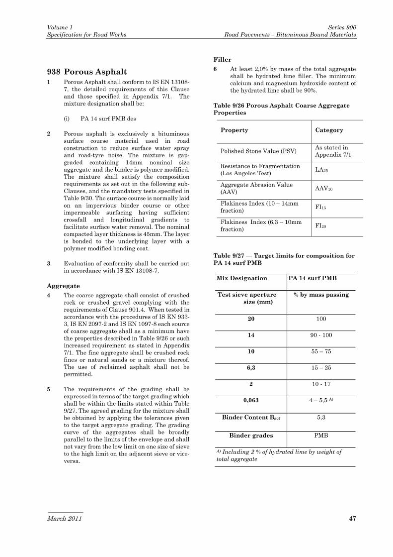
Volume 1 Series 900
Specification for Road Works Road Pavements – Bituminous Bound Materials
March 2011 47
938 Porous Asphalt
1 Porous Asphalt shall conform to IS EN 13108-
7, the detailed requirements of this Clause
and those specified in Appendix 7/1. The
mixture designation shall be:
(i) PA 14 surf PMB des
2 Porous asphalt is exclusively a bituminous
surface course material used in road
construction to reduce surface water spray
and road-tyre noise. The mixture is gap-
graded containing 14mm nominal size
aggregate and the binder is polymer modified.
The mixture shall satisfy the composition
requirements as set out in the following sub-
Clauses, and the mandatory tests specified in
Table 9/30. The surface course is normally laid
on an impervious binder course or other
impermeable surfacing having sufficient
crossfall and longitudinal gradients to
facilitate surface water removal. The nominal
compacted layer thickness is 45mm. The layer
is bonded to the underlying layer with a
polymer modified bonding coat.
3 Evaluation of conformity shall be carried out
in accordance with IS EN 13108-7.
Aggregate
4 The coarse aggregate shall consist of crushed
rock or crushed gravel complying with the
requirements of Clause 901.4. When tested in
accordance with the procedures of IS EN 933-
3, IS EN 2097-2 and IS EN 1097-8 each source
of coarse aggregate shall as a minimum have
the properties described in Table 9/26 or such
increased requirement as stated in Appendix
7/1. The fine aggregate shall be crushed rock
fines or natural sands or a mixture thereof.
The use of reclaimed asphalt shall not be
permitted.
5 The requirements of the grading shall be
expressed in terms of the target grading which
shall be within the limits stated within Table
9/27. The agreed grading for the mixture shall
be obtained by applying the tolerances given
to the target aggregate grading. The grading
curve of the aggregates shall be broadly
parallel to the limits of the envelope and shall
not vary from the low limit on one size of sieve
to the high limit on the adjacent sieve or vice-
versa.
Filler
6 At least 2,0% by mass of the total aggregate
shall be hydrated lime filler. The minimum
calcium and magnesium hydroxide content of
the hydrated lime shall be 90%.
Table 9/26 Porous Asphalt Coarse Aggregate
Properties
Property Category
Polished Stone Value (PSV) As stated in
Appendix 7/1
Resistance to Fragmentation
(Los Angeles Test) LA25
Aggregate Abrasion Value
(AAV) AAV10
Flakiness Index (10 – 14mm
fraction) FI15
Flakiness Index (6,3 – 10mm
fraction) FI20
Table 9/27 — Target limits for composition for
PA 14 surf PMB
Mix Designation PA 14 surf PMB
Test sieve aperture
size (mm)
% by mass passing
20 100
14 90 - 100
10 55 – 75
6,3 15 – 25
2 10 - 17
0,063 4 – 5,5 A)
Binder Content Bact 5,3
Binder grades PMB
A) Including 2 % of hydrated lime by weight of
total aggregate

Volume 1 Series 900
Specification for Road Works Road Pavements – Bituminous Bound Materials
March 2011 48
Figure 9/1: Binder drainage test plot - Diagram indicating definitions
Binder
7 The binder shall be preblended polymer
modified bitumen and shall comply with the
selected requirements of IS EN 14023 as
detailed in Table 9/28. During storage the
binder shall be agitated / circulated in
accordance with the manufacturer’s
instructions to ensure the homogeneity of the
binder. When tested in accordance with Clause
941, 'Modified Binder Storage Stability Test'
preblended modified binders shall meet the
original specification for softening point and
penetration for that binder after the four day
storage period. The supplier shall ensure the
preblended modified binder is manufactured to
the same specification as that for the sample
submitted for the 'Binder Drainage Test', in
accordance with IS EN 12697-18 (Basket
Method).
The quantity of binder lost through drainage,
after a specified time at the maximum mixing
temperature, shall be measured in duplicate for
mixes with the same aggregate contents but
with different binder contents. The target
binder content shall be defined as the value 0,3
per cent less than that at which 0,3 per cent
binder drainage occurs.
From Figure 9/1, the mixed binder content (M)
shall be determined where the binder drainage
is 0,3 per cent (yz). The target binder content
shall be (M-0,3) per cent. As a check, the
abscissa, (xy), should also equal 0,3 per cent
between the line of equality and the point on
the drainage curve where the binder drainage
is 0,3 per cent (yz).
Binder Content
8 The target binder content (polymer modified
bitumen) as defined in Table 9/27 shall be
established from binder drainage tests as
described in IS EN 12697-18 (Basket Method)
and in accordance with sub clause 8 and Figure
9/1. In addition, at the target binder content
the porous asphalt mixture shall comply with
the requirements of the Cantabro Wear Test as
specified in sub- Clause 938.19, with the Water
Sensitivity Test as specified in sub-clause
938.18 and with the Relative Hydraulic
Conductivity requirements as specified in
Clause 938.16. The tolerance for the binder
content to be used in the Works shall not exceed
5.0 5.5 6.0 6.5 7.05.0
5.5
6.0
6.5
7.0
Ret
ain
ed b
ind
er (
per
cen
t)
Mixed binder (percent)
Maximum retainedbinder content
x
z
y
Line of
equ
ality
Bin
der
dra
inag
e
0.3%
0.3%
Cri
tica
l b
ind
er c
on
ten
t 5
.75
%
Tar
get
bin
der
co
nte
nt
6.1
%
Mix
ed b
ind
er c
on
ten
t fo
r 0
.3%
dra
inag
e -
6.4
%
Max
. m
ixed
bin
der
co
nte
nt
M

Volume 1 Series 900
Specification for Road Works Road Pavements – Bituminous Bound Materials
March 2011 49
±0,3% of the target value. Notwithstanding the
above requirements the found binder content
on analysis shall not be less than 5% of the total
mixture.
Additives
9 Inorganic or organic fibres may be used to
assist in preventing binder draining from the
aggregate. Adhesion agents or other additives
may be added to the binder to improve the
stripping resistance of the mixture. The
suitability of such additives shall be
demonstrated in accordance with clause 4.1, IS
EN 13108-7.
Mixing
10 The constituent materials shall be accurately
weighed into a mechanical mixer of approved
type and thoroughly mixed in such a manner
that all particles are completely coated. All
weighing mechanisms shall be properly
maintained within the accuracy's
recommended by the manufacturer. The
Contractor shall supply a service certificate
showing that the weighing devices have been
calibrated against standard loads, in
accordance with the quality plan and audited to
IS0 9001, within six months prior to the
Contract Date. The mixing temperature shall
be as shown in Table 9/29 and this is based on
a required binder viscosity of 0,5Pas. To
minimize temperature fluctuations, production
shall be continuous, and where practicable, not
interrupted.
Transporting
11 Porous asphalt shall be transported to site in
double-sheeted insulated vehicles with tight
fitting covers. To facilitate discharge of porous
asphalt, the floor of the vehicle may be coated
with the minimum of liquid soap, vegetable oil,
or other non solvent solution. When a coating is
used then, prior to loading the body shall be
tipped to its fullest extent, with the tailboard
open, to ensure drainage of any excess. The
floor of the vehicle shall be free from adherent
bituminous materials or other contaminants.
Porous asphalt shall be delivered to site within
the temperature range shown in Table 9/29.
Bonding Coat
12 Notwithstanding the advice provided in Clause
920, the following should apply. On all
occasions that porous asphalt is used the
substrate should be sprayed with a polymer
modified bitumen emulsion bonding coat. The
rate of application of the bonding coat shall be
such as to ensure that the residual bitumen
coverage, after curing, is between 0,4kg/m2 and
0,7kg/m2The bonding coat shall be allowed to
break before porous asphalt is laid and shall be
of a composition to prevent 'pick up' on the tyres
of pavers and delivery trucks.
Laying
13 Porous asphalt shall be laid by machine and
compacted within three hours of mixing. The
thickness of the porous asphalt layer, after
compacting, shall be 45 +/- 5 mm. Where more
than one lane is to be covered, and where
possible, porous asphalt shall be laid by at least
two pavers working in echelon, so that
longitudinal joints can be effectively rolled
together whilst hot. The stagger between
paving machines shall not exceed 20 metres.
Bitumen coating shall not be applied to exposed
longitudinal edges. 'Throwing-back' of material
and walking on the uncompacted porous
asphalt shall be avoided. Except in
circumstances approved by the Employer's
Representative all construction plant must be
kept off the surface before opening to traffic in
order to prevent damage to and clogging of the
material. Porous asphalt shall not be laid
during heavy and/or persistent rain or when
standing water is present. Porous asphalt shall
be laid within the limits of air temperature and
wind speed stated in Figure 9/2. Laying shall
not be permitted at any temperature if the
average wind speed over the preceding hour
exceeds 50km/h at 10m height (40km/h at 2m
height). Wind speed shall be measured either
by anemometer erected at a height of 10m ±
0,5m situated at the site office, or by portable
anemometer erected at a height of 2m ± 0,1m
situated in close proximity to the laying works.
The anemometer shall be fitted with a digital
accumulative device.
Compacting
14 Porous asphalt shall be compacted using at
least two 6-8 tonne, non-vibrating, steel wheel
tandem drum rollers for each paving machine.
If a vibratory type roller is used it shall be
operated in the non-vibrating mode. To avoid
pick-up, the rollers drum surfaces shall be
initially clean and completely wetted prior to
and during rolling. Rubber tyred rollers and 3-
wheeled rollers shall not be used. Rolling shall
commence at the highest mat temperature
consistent with no shoving and shall be
substantially completed within the
temperature range given in Table 9/29. The
first roller pass shall be on the low edge of the
mat, followed by the high edge. Rolling of the
rest of the mat shall then proceed from low to
high side and shall continue until all roller
marks have been removed.
Longitudinal and Transverse Joints
15 Wherever possible pavers shall be used in
echelon, as described in sub-clause 13 of this
Clause, to eliminate longitudinal joints. Where

Volume 1 Series 900
Specification for Road Works Road Pavements – Bituminous Bound Materials
March 2011 50
exposed longitudinal joints are unavoidable
they may be cold butted, provided that the edge
of the porous asphalt layer laid previously has
not been damaged and is clean. Where damage
to edges has occurred they shall be trimmed by
power saw with appropriate measures
including suction extraction, to prevent
clogging of the pores with detritus.
Longitudinal joints shall be placed adjacent to
pavement lane markings or outside wheel track
zones and shall be formed by butting-up to the
adjacent porous asphalt to form a tight joint.
Transverse joints shall be formed against a
200mm wide and 45mm thick hard timber stop-
end nailed to the road surface in advance of the
paving operation. The cutting of edges shall be
avoided but where transverse edge cutting is
essential, only sawing with appropriate
measures, including suction extraction shall be
permitted. Nothing shall be done, nor any
articles positioned, such as to impede the run-
off water freely entering the drainage channel
or filter drain provided to remove the water
from the pavement surface edge. Where an
impermeable surface is to be laid downstream
of the porous asphalt, the lane ends of the
porous asphalt shall be staggered across the
carriageway in the direction of the drainage
path in order to prevent excess rainwater from
welling up over the transverse joint.
Relative Hydraulic Conductivity
16 After the porous asphalt has cooled to ambient
temperature, and before trafficking, the
relative hydraulic conductivity of the material
shall be measured, in accordance with the
procedures specified in Clause 940. The
average value, from any 5 consecutive
determinations at 20m spacing in the near-side
wheel track of each lane of a carriageway, shall
be not less than 0,12s-1 and no single value shall
be less than 0,08s-1'.
17 Whilst the above testing will take contractual
precedence additional European in-situ
drainability testing shall be carried out in
accordance with IS EN 12697-40.
Water Sensitivity
18 The water sensitivity shall be determined in
accordance with IS EN 12697 Parts 12 & 23.
The ratio of wet to dry strength shall not be less
than ITSR80. The specimen compacting
procedure shall be such as to provide the air
voids content expected in the field, i.e. in the
range 20-28 percent without causing significant
crushing of the large aggregate particles as
observed from analysis of the specimens and
measurement of any reduction in size. A
reduction such that the grading no longer lies
within the grading envelope shall not be
acceptable.
Particle Loss (Cantabro Wear Test)
19 When tested in accordance with the procedure
described in IS EN 12697-17 the wear of the
mixture shall not exceed PL20, 20% at 25°C.
(i) The Cantabro test shall be carried out on
mixture specimens unconditioned by any
simulated ageing procedures or by
soaking in water and,
(ii) The specimen compaction shall achieve
maximum air voids up to 28 per cent
without causing significant crushing of
the coarse aggregate as defined in sub-
clause 18 of this Clause.

Volume 1 Series 900
Specification for Road Works Road Pavements – Bituminous Bound Materials
March 2011 51
Figure 9/2: Limiting weather conditions for laying porous asphalt
Table 9/28: Properties of Polymer Modified Porous Asphalt Binder
Properties Test Method Specified Value
Penetration at 25oC 0,1mm IS EN 1426 60 – 105
Softening Point OC IS EN 1427 >70
Fraass Brittle Point OC IS EN 12593 < -12
Storage Stability, OC difference in softening point, top-bottom,
after four days at 160OC Clause 941 <5
Resistance to hardening (Rolling Thin-film Test) Mass Change
(percent). IS EN 12607:1 <1,0
Retained Penetration (percent) IS EN 1426 >60
Retained softening point increase (OC) IS EN 1427 <8
Retained softening point decrease (OC) IS EN 1472 <2
Table 9/29: Mixing and Handling Temperatures
Binder Type Mixing
Temperature
Range (°C)
Delivery
Temperature
Range (°C)
Minimum Compacting
Temperature (°C)
Polymer modified
In accordance with
manufacturers’
requirements
150(A) - 190
145 - 170
Start Finish
140 115
(A) Minimum temperature applies at discharge from the mixer and is included for guidance only.
0 5 10 15 20 25
0
5
10
15
20
25
30
35
40
45
50
0
5
10
15
20
25
30
35
40
Air temperature (°C)
Polymer modified
binder
Av
erag
e w
ind
sp
eed
(k
m/h
) at
2m
hei
gh
t
mea
sure
d o
ver
th
e p
rece
din
g h
ou
r
Av
erag
e w
ind
sp
eed
(k
m/h
) at
10
m h
eig
ht
mea
sure
d o
ver
th
e p
rece
din
g h
ou
r
CANNOT LAY
CAN LAY

Volume 1 Series 900
Specification for Road Works Road Pavements – Bituminous Bound Materials
March 2011 52
Table 9/30 Mandatory design tests required on Porous Asphalt Mixtures
Design Tests Parameter Performance Levels Applicability of
Test
Grading Target composition in
accordance with Table 9/27. Percentage by mass passing
Design & Quality
Control
Binder Drainage Test at
170C
Drainage characteristics of
the binder from asphalt
mixture in accordance with
IS EN 12697 Part 18
Target binder content Design & Quality
Control
Percent Air Voids Void Content in accordance
with IS EN 12697-8
Max air void content 28
percent.
Min air void content 20
percent
Design
Relative hydraulic
conductivity
Measurement of water
outflow in accordance with
Clause 940
Relative Hydraulic
Conductivity Ave. 0,12 seconds
(min value 0,8s)
Design & Quality
Control
Water Sensitivity Test*
Tensile strength test in
accordance with IS EN
12697 Parts 12 & 23
ITSR80 Design
Cantabro Wear Test* Percent loss in accordance
with IS EN 12697-17
PL20,20% at 25OC
(20% at 25OC) Design
* The specimen compaction procedure shall be such as to provide a maximum air void content of 28 percent.
The procedure shall not alter the determined grading of the mixture on any sieve by more than +/- 3 percent.
Landscaping Close to Porous Asphalt
Surfacing
20 Landscaping operations shall be carried out
such that soil and other materials are not
placed on the surface or cause any clogging of
the porous asphalt. Porous asphalt shall be
allowed to cool to ambient temperature before
opening to any traffic. To avoid damage and to
prevent detritus being spread over the surface,
traffic and construction plant shall be kept off
the surface after its completion and until
opening of the road or until issue of the
Certificate of Completion for the relevant
Section of the Works, whichever is the later,
unless otherwise agreed by the Employer’s
Representative.
939 Not Used
940 Relative Hydraulic
Conductivity Test
Scope
1 This test determines the in situ relative
hydraulic conductivity, at specific locations, of
a permeable road surfacing. An estimate of the
average value for the surfacing is obtained from
the mean value of a number of determinations
on each section of road.
Summary of Method
2 A radial-flow, falling-head, permeameter shall
be used to determine the time taken for a
specified amount of water, under known head
conditions, to dissipate through an annular
area of the surfacing. The reciprocal of the
corrected outflow time shall be used to calculate
the relative hydraulic conductivity of the
surfacing.
Apparatus
3 The apparatus shall consist of:
(i) Radial-flow falling head permeameter
and standing board, constructed to the
requirements and critical dimensions as
described in DD229: 1996.
(ii) Stopwatch, accurate to 0,1 s.
(iii) Thermometer, with an accuracy of at
least ± 1°C in the range 0 to 25°C.
(iv) Clean water, in the range 0 to 25 °C.

Volume 1 Series 900
Specification for Road Works Road Pavements – Bituminous Bound Materials
March 2011 53
Definitions
4 The outflow time shall be the time that elapses
for an outflow of 2,0 litres through the
permeameter, between the meniscus at the 2,5
litre mark and when it falls to the 0,5 litre
mark. The series resistance time, r, shall be the
outflow time(s), corrected to 20°C, when the
outlet is not restricted by a surfacing. It shall
be subtracted from measurements of outflow
time when the permeameter is used on a
surfacing. The parallel leakage time shall be
the outflow time when the outlet is restricted
by an impermeable surface. The relative
hydraulic conductivity (HC) is the reciprocal of
the outflow time, after correction to 20°C, less
the series resistance time.
Apparatus Constants and Calibration
5 The following checks shall be performed before
using the equipment:
(i) Dimensions
All dimensions shall comply with those
given in DD 229.1996.
(ii) Volume Calibration
Stand the permeameter on a flat and
level surface. After inserting the
plunger, fill the standpipe with 500 ±
0,25 ml of water, using a calibrated
volumetric flask of 500 ml capacity. Mark
the standpipe permanently at the
meniscus level. Now fill the standpipe
with a further 2000 ± 0,6ml of water,
using a calibrated volumetric flask of
2000 ml capacity, and again mark the
standpipe permanently at the new
meniscus level.
(iii) Series Resistance Timer
Place the permeameter on blocks, of not
less than 80 ± 5 mm height, to expose the
100 mm diameter aperture in the base.
Fit the plunger in the orifice. Fill the
standpipe completely with clean water.
Measure and record the temperature of
the water in the standpipe to the nearest
1°C. Remove the plunger and hang by its
rest on the top of the standpipe. Start the
stopwatch when the meniscus falls to the
2,5 litre mark. Stop the stopwatch when
the meniscus falls to the 0,5 litre mark.
Record the outflow time and repeat the
measurement a further nine times.
Calculate the average outflow time and
correct to 20°C by dividing by the
appropriate temperature correction
factor from Table 9/31. Record the series
resistance time, r, as the corrected
average outflow time, to the nearest 0,1s.
(iv) Parallel Leakage Time
Place the permeameter on a flat and level
impermeable surface. Fit the standing
board on the base. Two operatives of
approximately similar mass, within the
range 75 ± 25 kg shall stand, one on each
side of the standing board. Fit the
plunger in the orifice. Fill the standpipe
completely with clean water. Remove the
plunger and hang by its rest on the top of
the standpipe. Allow air bubbles to rise to
the top and, if necessary, add more water
to bring the water level above the 2,5 litre
mark after all bubbles have ceased
rising. Start the stopwatch when the
meniscus falls to the 2,5 litre mark. Stop
the stopwatch when the meniscus falls to
the 0,51itre mark, or end the test if the
outflow time exceeds 10 minutes. If the
outflow time is less than 5 minutes,
leakage is excessive and the
permeameter is unsuitable for use for
this test.
Procedure
6 The procedure shall be as flows:
(i) Place the permeameter over the
surfacing at the point where the relative
hydraulic conductivity is to be measured.
Fit the standing board on the base. Fit
the plunger in the orifice. An operative
shall stand on each side of the standing
board, throughout the duration of the
test, to hold the permeameter in place
and compress the rubber annular disc to
provide a seal.
(ii) Fill the standpipe completely with clean
water. Measure the temperature of the
water in the standpipe and record it to
the nearest 1°C.
(iii) Remove the plunger and hang by its rest
on the top of the standpipe. Allow air
bubbles to rise up through the water in
the standpipe until they no longer rise
through the water, which is dissipating
into the road surface.
(iv) Replace the plunger and refill the
standpipe to at least 50 mm above the 2,5
litre mark. Without delay, remove the
plunger and hang by its rest on the top of
the standpipe. Start the stopwatch when
the meniscus falls to the 2,5 litre mark.
Stop the stopwatch when the meniscus

Volume 1 Series 900
Specification for Road Works Road Pavements – Bituminous Bound Materials
March 2011 54
falls to the 0,5 litre mark. Record the
outflow time, t1, to the nearest 0,1s.
(v) Repeat step (iv) to obtain t2.
(vi) Calculate the average outflow time and
the range, both to the nearest 0,1s. If the
range exceeds 5 per cent of the average
outflow time, repeat step (iv) until the
range criterion is met by two successive
outflow times and discard other readings.
Correct the average outflow time to 20°C
by dividing by the appropriate
temperature correction factor from Table
9/31 and record the corrected average
outflow time, t, to the nearest 0,1s.
Table 9/31: Temperature Correction Factors
Temperature of water
(°C)
Temperature Correction
factor
0 1,79
1 1,73
2 1,67
3 1,62
4 1,57
5 1,52
6 1,47
7 1,43
8 1,39
9 1,34
10 1,31
11 1,27
12 1,24
13 1,20
14 1,17
15 1,14
16 1,11
17 1,08
18 1,06
19 1,03
20 1,00
21 ,98
22 ,96
23 ,94
24 ,91
25 ,89
(i) The relative hydraulic conductivity (HC),
corrected to 20°C is calculated from:
HC = 1/(t-r)s-1
Where t is the average outflow time(s)
corrected to 20°C;
r is the series resistance outflow time(s)
corrected to 20°C
(ii) Report the relative hydraulic
conductivity, corrected to 20°C, to the
nearest 0,01s-1.
Measurement of the Average Relative
Hydraulic Conductivity of a Section.
7 The procedure shall be as follows:
(i) Measure the relative hydraulic
conductivity as soon as possible after the
surfacing has been laid and cooled to
ambient temperature, but before the
surfacing has been opened to traffic. The
road shall be clean and free from loose
material. Measurements can be made
when the road is wet, but not if in a
frozen state.
(ii) Make individual determinations of the
relative hydraulic conductivity in the
nearside wheel path at 20m intervals
along each carriageway lane.
(iii) Calculate the running mean of each 5
consecutive measurements along each
carriageway lane.
(iv) Report the average relative hydraulic
conductivity and the individual results,
all corrected to 20°C, of each running
mean of 5 individual determinations
along each carriageway lane to the
nearest 0,01s-1.
(v) When an individual determination does
not comply with the specified minimum
requirement for relative hydraulic
conductivity, further determinations
shall be carried out at 5 m intervals in
the wheel-path on either side of the non-
complying location to determine the
extent of the non-complying length. If the
non-complying length exceeds 20 m,
rectification shall be carried out by
removing the full depth of the course and
replacing it with fresh material laid and
compacted in accordance with the
Specification. The area rectified shall be
the full width of the paving laid in one
operation, and at least 30m long.
941 Modified Binder Storage
Stability Test
Scope
1 This test determines the susceptibility of a
preblended modified binder to separation or
instability during prolonged storage at high
temperature.

Volume 1 Series 900
Specification for Road Works Road Pavements – Bituminous Bound Materials
March 2011 55
Summary of Method
2 A sample of modified binder shall be contained
in a closed vessel of specific dimensions and
shall be maintained at 160 ± 2°C for 7 days ± 2
hours. A binder sample shall then be taken
from the top and bottom thirds of the vessel and
both samples shall be tested for compliance
with the binder specification.
Apparatus
3 The apparatus shall consist of:
(i) Cylinder, made of heat resistant glass,
190 ± 30mm long and 65 ± 5mm internal
diameter having a removable lid, flush
fitting to exclude air when the cylinder is
filled with binder, and provided with
three drain valves, one at the base, the
other two spaced equally down the side of
the cylinder, to allow the sample to be
divided into three equal portions as in
sub-Clause 4 (vii) of the procedure.
Alternatively, a thin-wall sheet metal
tube or similar vessel such as a 500 ml
beverage can, of similar dimensions to
the glass cylinder, and having a similarly
removable lid, fitted either with or
without drain-valves.
(ii) Oven, electrically heated, fan assisted,
and capable of maintaining a
temperature of 160 ± 2°C, having interior
dimensions not less than 330mm from
the top of the heating element to the top
of the chamber and not less than 305mm
in width and depth.
(iii) Tube holder, made of metal, that will
hold either the glass cylinder or sheet
metal can, in a vertical position, such
that the base of the cylinder or can is not
in direct contact with the oven floor.
(iv) Apparatus for determining the
penetration and softening point of
bitumen in accordance with IS EN 1426
and IS EN 1427.
(v) Transfer dishes (3), made of metal, each
of a capacity sufficient to hold at least one
third of the test sample.
Test Procedure
4 The procedure shall be as follows:
(i) The bulk sample of modified binder shall
be obtained by sampling in accordance
with IS EN 58.
(ii) Place the bulk sample of modified binder
and the glass cylinder (or metal tube or
equivalent vessel) in the preheated oven
at 160 ± 2°C for a period not exceeding
3,75 ± 0,25 hours.
(iii) Remove the bulk sample from the oven
and thoroughly mix by stirring to ensure
obtaining a representative test sample.
(iv) Remove the glass cylinder (or metal tube
or equivalent vessel) from the oven and
completely fill with the modified binder
test sample to allow no air space when
the lid is fitted.
(v) Support the filled cylinder in a vertical
position in the holder and transfer to the
oven which shall be controlled at a
temperature of 160 ± 2°C and allow to
stand undisturbed for a period of 168 ± 2
hours.
(vi) If a vessel having drain-valves has been
used for the test proceed using Method A
below, otherwise proceed using Method
B.
(vii) Method A
(a) Remove the glass cylinder (or
alternative approved vessel) from the
oven, keeping the cylinder vertical.
(b) Open the uppermost drain-valve and
run off the top third portion of the
test sample into a transfer dish for
testing.
(c) Open the middle drain-valve and run
off the middle third portion of the
test sample into a suitable container
and discard.
(d) Open the lower drain-valve and run
off the bottom third portion of the
test sample into a transfer dish for
testing.
(viii) Method B
(a) Remove the tube or vessel containing
the test sample from the oven and
allow it to cool at room temperature
for 2 ± 0,25 hours whilst maintaining
the vessel vertical in the holder.
(b) When the vessel of modified binder
has cooled to ambient temperature,
remove it from the tube holder and
make two cuts through the vessel
and the sample at positions one-third
and two-thirds of the length from,
and parallel, to the base.

Volume 1 Series 900
Specification for Road Works Road Pavements – Bituminous Bound Materials
March 2011 56
(c) Retain the top and bottom thirds of
the test sample for further testing
and discard the middle third.
(ix) Determine the penetrations and
softening points of the top and bottom
thirds of the test sample, in accordance
with IS EN 1426 and IS EN 1427.
Reporting
5 For both the top and bottom thirds of the test
sample the following shall be reported:
(i) The penetration, to IS EN 1426.
(ii) The softening point, to IS EN 1427.
(iii) Whether Method A or Method B was
used.
(iv) The location and date of obtaining the
bulk sample, and the dates of test.
942 Polymer Modified Stone Mastic
Asphalt Surface Course
General
1 Polymer Modified Stone Mastic Asphalt
(PMSMA) surface courses shall conform to IS
EN 13108-5, the requirements specified in this
clause and Appendix 7/1. They are here defined
as an application of a polymer modified
bitumen emulsion bond coat overlaid by a
polymer modified hot bituminous mixture. This
specification is for hot laid surfacings with a
compacted thickness of 20mm to 40mm, in
which the aggregate particles are necessarily
gap-graded to form a stone to stone contact and
to provide an open surface texture.
2 The mixture designation shall be one of the
following;
(i) SMA 10 surf PMB 65/105-60 des
(ii) SMA 14 surf PMB 65/105-60 des
3 Evaluation of conformity shall be carried out in
accordance with IS EN 13108-5.
Layer Thickness
4 The nominal thickness of the PMSMA surface
course layer shall be in accordance with BS
594987 Table 6C.
Aggregate
5 The coarse aggregate shall consist of crushed
rock complying with Clause 901.4 and the
specific requirements of table 9/32.
6 The fine aggregate shall comply with the
requirements of IS EN 13043 Part 2.
7 The fine aggregate shall be either a 0/2 mm or
a 0/4 mm aggregate fraction and be of one of the
following types:
a) crushed rock fines produced from coarse
aggregate defined in IS EN 13043 or
b) sand; or
c) a mixture of a) and b).
Filler
8 The filler shall be crushed rock or limestone or
hydrated lime or Portland cement as approved
by the Employers Representative and not less
than 75 percent shall pass the 0,063mm sieve.
It shall conform to IS EN 13043.
Table 9/32: Coarse Aggregate Properties
Property Category
Polished Stone Value As stated in
Appendix 7/1
Resistance to Fragmentation
(Los Angeles Test)
LA25
Aggregate Abrasion Value AAV10
Flakiness Index FI15
Binder
9 The binder shall be preblended polymer
modified bitumen and shall comply with the
selected requirements of IS EN 14023 as
detailed in Table 9/33. The tolerance for the
binder content in the mix shall be ± 0,3 percent
of the target binder content given by the
Contractor. The maximum Binder Drainage
shall be D0,3.
Bond Coat
10 Notwithstanding Clause 920, the following
requirements shall apply. On all occasions that
hot applied PMSMA surfacings are used the
substrate should be sprayed with a polymer
modified bitumen emulsion (PMBE). The rate
of application of the bonding coat shall be such
as to ensure that the residual bitumen
coverage, after curing, in accordance with Table
3 and 4 of BS 594987. The bond coat and
PMSMA surfacing shall be applied either by a
paving machine fitted with spray bar i.e.
integrated paver or alternatively the bond coat
can be applied separately provided that after a
reasonable time period (10 to 20 minutes) it is
resistant to “pick up” on the wheels of rubber
tyred vehicles and the footwear of operatives.
In this case it shall provide a strong bond
between the substrate and the hot-mixed thin
surfacing when the latter is applied by a

Volume 1 Series 900
Specification for Road Works Road Pavements – Bituminous Bound Materials
March 2011 57
conventional paving machine. Fine aggregate
dust shall never be used to prevent “pick up” as
this will inhibit bonding between substrate and
the PMSMA surfacing.
Additives
11 Inorganic or organic fibres may be used to
assist in preventing binder draining from the
aggregate. Adhesion agents or other additives
may be added to the binder to improve the
stripping resistance of the mixture. The
suitability of such additives shall be
demonstrated in accordance with clause 4.1, IS
EN 13108-5.
Mixture Requirements
12 The target composition of the mixture in terms
of its constituent materials, the percentages
passing the specified sieves, the binder type
and binder content and the percentage and type
of additive shall be declared and documented.
The target aggregate grading and target binder
content proposed by the Contractor shall be
that which is required to satisfy the specific
requirements of table 9/35. In addition
compacted specimens at the target composition
shall meet the wheel tracking requirements of
Table 9/36 and shall have a Water Sensitivity
value of ITSR80. The method of laboratory
compaction is by the Gyratory compaction
method in accordance with IS EN 12697-31.The
water sensitivity is expressed as the indirect
tensile strength ratio (ITSR). The ITSR is
calculated as the ratio of the indirect tensile
strength of wet (water conditioned) specimens
to that of dry specimens, expressed in percent.
This test should be carried out in accordance
with IS EN 12697-12 and at a test temperature
of 25°C.
Mixing
13 The materials including any added filler shall
be accurately weighed into a mechanical mixer
and thoroughly mixed in such a manner that all
particles are completely coated. The Contractor
shall supply a service certificate showing that
all weighing devices have been calibrated in
accordance with the quality plan and audited to
ISO 9001, within six months prior to the
Contract Date.
Laying
14 PMSMA surface course materials shall not be
laid during heavy and/or persistent rain or
when standing water is present. It shall be laid
within the limits of air temperature and wind
speed stated in Figure 9/3. The range of
delivery and rolling temperatures shall be as
stated in Table 9/34. Prior to laying operations
the Contractor shall carry out any necessary
remedial repairs. The type and extent of such
repairs shall be agreed with the Employers
Representative. Where necessary, existing
surfaces shall be regulated in accordance with
the requirements of Clause 907, in advance of
laying surfacing material to this clause.
Performance Requirements
15 The Contractor shall guarantee the
performance, surfacing materials and
workmanship for a period of three years from
the date of opening the surfacing to traffic or for
such longer period as specified in Appendix 7/1.
In the event of failure of the surface to meet the
performance specification for the guarantee
period, the Contractor shall replace the
material in accordance with this specification
and in accordance clause 702.10. The
requirements for Texture Depth - initial and
after three years in service shall be as stated in
Table 9/37. The texture depth of the surfacing
after compaction and before opening to traffic
shall be measured in accordance with Clause
921 of this series and shall conform to the
requirements of Table 9/37.
Surface texture measurements made after
periods in service shall be made in the nearside
wheel track at 5 metre intervals in a
longitudinal direction. These shall be carried
out on both sides of the carriageway, i.e. in both
traffic directions. After three years in service
visual assessment shall show no loss of the
surfacing material due to attrition or debonding
or ravelling or surface disintegration or
cracking. The guarantee shall exclude defects
arising from damage caused by settlement,
subsidence or failure of the carriageway on
which the material has been laid.
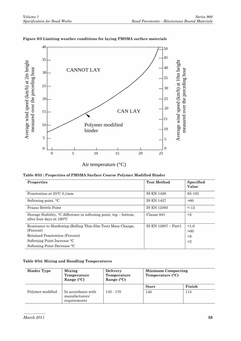
Volume 1 Series 900
Specification for Road Works Road Pavements – Bituminous Bound Materials
March 2011 58
Figure 9/3 Limiting weather conditions for laying PMSMA surface materials
Table 9/33 : Properties of PMSMA Surface Course Polymer Modified Binder
Properties Test Method Specified
Value
Penetration at 25°C 0,1mm IS EN 1426 65-105
Softening point, °C IS EN 1427 >60
Fraass Brittle Point IS EN 12593 <-12
Storage Stability, °C difference in softening point, top – bottom,
after four days at 160°C
Clause 941 <5
Resistance to Hardening (Rolling Thin-film Test) Mass Change,
(Percent)
Retained Penetration (Percent)
Softening Point Increase °C
Softening Point Decrease °C
IS EN 12607 – Part1 <1,0
>60
<8
<2
Table 9/34: Mixing and Handling Temperatures
0 5 10 15 20 25
0
5
10
15
20
25
30
35
40
45
50
0
5
10
15
20
25
30
35
40
Air temperature (°C)
Polymer modified
binder
Aver
age
win
d s
pee
d (
km
/h)
at 2
m h
eight
mea
sure
d o
ver
th
e pre
cedin
g h
our
Aver
age
win
d s
pee
d (
km
/h)
at 1
0m
hei
gh
t
mea
sure
d o
ver
th
e pre
cedin
g h
our
CANNOT LAY
CAN LAY
Binder Type Mixing
Temperature
Range (°C)
Delivery
Temperature
Range (°C)
Minimum Compacting
Temperature (°C)
Polymer modified
In accordance with
manufacturers’
requirements
145 - 170
Start Finish
140 115
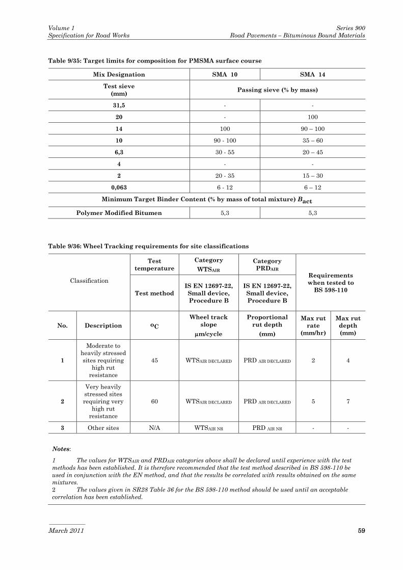
Volume 1 Series 900
Specification for Road Works Road Pavements – Bituminous Bound Materials
March 2011 59
Table 9/35: Target limits for composition for PMSMA surface course
Mix Designation SMA 10 SMA 14
Test sieve
(mm) Passing sieve (% by mass)
31,5 - -
20 - 100
14 100 90 – 100
10 90 - 100 35 – 60
6,3 30 - 55 20 – 45
4 - -
2 20 - 35 15 – 30
0,063 6 - 12 6 – 12
Minimum Target Binder Content (% by mass of total mixture) Bact
Polymer Modified Bitumen 5,3 5,3
Table 9/36: Wheel Tracking requirements for site classifications
Classification
Test
temperature
Category
WTSAIR
Category
PRDAIR Requirements
when tested to
BS 598-110 Test method
IS EN 12697-22,
Small device,
Procedure B
IS EN 12697-22,
Small device,
Procedure B
No. Description oC
Wheel track
slope
m/cycle
Proportional
rut depth
(mm)
Max rut
rate
(mm/hr)
Max rut
depth
(mm)
1
Moderate to
heavily stressed
sites requiring
high rut
resistance
45 WTSAIR DECLARED PRD AIR DECLARED 2 4
2
Very heavily
stressed sites
requiring very
high rut
resistance
60 WTSAIR DECLARED PRD AIR DECLARED 5 7
3 Other sites N/A WTSAIR NR PRD AIR NR - -
Notes:
1 The values for WTSAIR and PRDAIR categories above shall be declared until experience with the test
methods has been established. It is therefore recommended that the test method described in BS 598-110 be
used in conjunction with the EN method, and that the results be correlated with results obtained on the same
mixtures.
2 The values given in SR28 Table 36 for the BS 598-110 method should be used until an acceptable
correlation has been established.

Volume 1 Series 900
Specification for Road Works Road Pavements – Bituminous Bound Materials
March 2011 60
Table 9/37: Requirements for texture depth
Road Type Nominal
stone size of
mix, mm
Initial, after laying After 3 years
Average for
each lane
km or
surfaced
length if
less than 1
Km
Average for a set
of 10
measurements,
mm
Average for
each lane
km or
surfaced
length if
less than 1
Km
Average for a set of
10 measurements,
mm
Mandatory
speed of
traffic
>60km/h
10 ≥1,5mm ≥1,2mm ≥1,3mm ≥1,0mm
14 ≥1,5mm ≥1,2mm ≥1,3mm ≥1,0mm
Mandatory
speed of
traffic
≤60km/h and
roundabouts
10 ≥1,2mm ≥1,0mm ≥1,0mm
14 ≥1,2mm ≥1,0mm ≥1,0mm
943 Hot Rolled Asphalt Surface
Course and Binder Course
(Performance-Related Design
Mixtures)
1 Hot Rolled Asphalt performance related design
surface course and binder course shall conform
to IS EN 13108-4, the requirements of this
Clause and those specified in Appendix 7/1.
2 Performance related surface course mixtures
shall be 35/14F and 30/14F. Target composition
requirements are provided in Clause 910 of this
Series.
3 Evaluation of conformity shall be carried out in
accordance with IS EN 13108-4.
Layer Thickness
4 The nominal thickness of the Hot Rolled
Asphalt surface course layer shall be either
45mm or 50mm unless otherwise specified in
Appendix 7/1.
Binder and Binder Modification
5 For performance based materials, either a
paving grade bitumen or a polymer modified
bitumen to IS EN 14023 or a blend of one of
these with natural bitumen in accordance with
Annex B, IS EN 13108-4 may be used. The
Contractor shall provide data sheets giving
details of the properties of modified binders,
whether the modifier is preblended with
bitumen, the bitumen is modified during
refinery processing or modified by addition into
the asphalt mixer, including those specified in
Appendix 7/1. These shall include rheological
data in accordance with Clause 928 and
cohesion in accordance with Clause 939.
Polymer modified binders, modified binders or
additives shall not be used without the
approval of National Roads Authority; unless
already specified within the Clauses of this
Series.
Binder Volume
6 The minimum binder volume determined in
accordance with clause 5.2.4, IS EN 13108-4,
and the trial strip protocol in Annex F, BS
594987 shall be category Bvol 15,5.
Aggregate
7 The coarse aggregate shall consist of crushed
rock complying with Clause 901.4.
8 The fine aggregate shall comply with the
requirements of IS EN 13043 Part 2.
9 The fine aggregate shall be either a 0/2 mm or
a 0/4 mm aggregate fraction and be of one of the
following types:
a) crushed rock fines produced from coarse
aggregate defined in IS EN 13043 or
b) sand; or
c) a mixture of a) and b).
Added Filler
10 Added filler shall consist of crushed rock,
crushed slag, hydrated lime, cement (CEM I or
CEM II complying with IS EN 197-1) or other
material approved by the specifier.
11 The loose bulk density in kerosene of added
filler, with the exception of hydrated lime, shall
be in accordance with clause 5.5.5 of IS EN
13043.

Volume 1 Series 900
Specification for Road Works Road Pavements – Bituminous Bound Materials
March 2011 61
Additives
12 Additives permitted for inclusion may include:
fibres, pigments and adhesion agents. The
suitability of such additives shall be
demonstrated in accordance with clause 901.2
and IS EN 13108-4.
Void Content
13 The void content of the mixture at target
composition determined in accordance with the
trial strip protocol in Annex F, BS 594987 shall
be as follows:
The average void content category of core
pairs shall be Vmax7,5.
The average void content category of the
set of six cores shall be Vmax5.
Deformation Resistance
14 The resistance to permanent deformation of the
mixture shall be determined in accordance with
IS EN 12697-22 and shall meet the following
requirements for the appropriate class as
specified in Appendix 7/1.
15 The resistance to permanent deformation shall
comply with Table 9/38. Tests can be carried
out on specimens at the target composition
using the small wheel tracking device on 305
mm square slabs which are compacted by a
laboratory roller compactor in accordance with
IS EN 12697-33. Alternatively, 200 mm
diameter core specimens can be taken from a
full scale trial strip in accordance with the trial
strip protocol in Annex F, BS 594987.
16 When specified in Appendix 7/1, the resistance
to permanent deformation of material laid in
the Works shall be monitored by testing in
accordance with clause F.3 of BS 594987 Annex
F. Six cores shall be taken from the first
kilometre length of material from each mixing
plant and thereafter one further core from each
subsequent lane kilometre. Results shall be
assessed on successive rolling means of sets of
six consecutive results and shall be deemed to
conform if the mean is no greater than the
specified value and individual values not more
than 50% greater than the specified value.
Coated Chippings for Surface Course
17 When required, coated chippings shall be
14/20mm as specified in Appendix 7/1 and
comply with Clause 915.
Surface Macrotexture for Surface Course
18 The surface macrotexture shall comply with
Clause 921.
Compaction Control Procedures
19 Control testing for compaction and resistance
to permanent deformation shall be carried out
in accordance with BS 594987 section 9.5.2.
944 Not Used

Volume 1 Series 900
Specification for Road Works Road Pavements – Bituminous Bound Materials
March 2011 62
Table 9/38 — Limiting wheel tracking recommendations for Performance Related HRA
Test Category Category
Classification temperature WTSAair PDRAair
Requirements when
tested to BS 598-110
Test method IS EN 12697-22, IS EN 12697-22,
Small device, Small device,
Procedure A Procedure A
No. Description oC Wheel track rate Maximum rut
depth
Max rut Max rut µm/cycle (mm) rate
(mm/hr)
depth
(mm)
1 Moderate to
heavily stressed
sites requiring
high rut
resistance
45 WTSAair Declared PRDAair Declared 2 4
2 Very heavily
stressed sites
requiring very
high rut
resistance
60 WTSAair Declared PRDAair Declared 5 7
3 Other sites N/A WTSAair NR PRD Aair NR - -
Notes:
1 Guidance on Site Classifications relating to design requirements for Performance-related Hot Rolled Asphalt
surface course is given in BS 594987.
2 The values for WTSAair and PRDAair categories in Table 9/38 — Limiting wheel tracking recommendations
shall be declared until experience with the test methods has been established in Ireland. It is therefore
recommended that the test method described in BS 598-110 be used in conjunction with the EN method, and
that the results be correlated with results obtained on the same mixtures. The values given in Table 9/38 for the
British Standard method should be used until an acceptable correlation has been established.
945 Weather Conditions for Laying
of Hot Bituminous Mixtures
1 The Contractor shall take account of the
weather conditions when planning his working
methods. The Contractor’s working methods
shall comply with all weather-related
requirements of BS 594987 and any additional
requirements of this clause. When laying is to
be undertaken during winter (October to April)
and/or night time (9 p.m. to 6 a.m.), the
Contractor shall work to a Quality Plan that
allows for the specific issues raised by winter
and/or night time working.
2 Hot bituminous materials laid less than 50mm
thick, other than those supplied to Clause 942
and 938, shall be laid within the wind speed
and temperature constraints of Figure 9/4.
Laying of road pavement materials containing
bitumen binders may proceed provided the
temperature of the surface to be covered is 2oC
or more, the air temperature is at or above 0oC
and rising and the surface to be covered is dry,
unfrozen and free from ice. snow, salt and grit.
Additional overriding constraints on wind
speed and temperature during laying for
specific materials are identified in sub-clauses
3, 4 and 5 below.
Porous Asphalt and Polymer Modified Stone
Mastic Asphalt Surface Courses
3 The weather conditions for laying Porous
Asphalt and Polymer Modified Stone Mastic
Asphalt Surface Courses shall comply with
those identified as being acceptable in Clauses
938.14 and 942.12 respectively together with
the associated Quality Plan and Installation
Method Statement.
Hot Rolled Asphalt with pre-coated
chippings
4 Hot Rolled Asphalt surface course mixtures
incorporating 35% coarse aggregate with pre-
coated chippings shall be laid 50mm thick,

Volume 1 Series 900
Specification for Road Works Road Pavements – Bituminous Bound Materials
March 2011 63
within the following constraints of delivery
temperature, wind speed and air temperature.
Air temperature (minimum): 0 °C
Wind speed
(maximum at any air temperature): 40km/h
(at 2m height), or
Minimum delivery
temperature of materials: 155°C.
When an anemometer is not available, with
approval of the Employer’s Representative, hot
rolled asphalt wearing course materials
incorporating 30% coarse aggregate shall have
a minimum delivery temperature of 165oC and
shall be laid 50 mm thick. It shall not be laid
when the air temperature falls below 5oC
unless the temperature of the surface to be
covered is 3oC or more.
Wind Speed
5 When measurements are required for
assessment, wind speed shall be measured by
anemometer positioned near the laying site to
accurately reflect conditions at the laying site.
The anemometer shall be fitted with a digital
accumulative device.
Figure 9/4: Wind Speed and Air temperature
Laying restrictions for Layers less than 50mm
thick
0 5 10 15 20 250
10
20
30
40
50
0
5
10
15
20
25
30
35
40
Air temperature (°C)A
ver
age
win
d s
pee
d (
km
/h)
at 2
m h
eig
ht
mea
sure
d o
ver
th
e p
rev
iou
s h
ou
r
Av
erag
e w
ind
sp
eed
(k
m/h
) at
10
m h
eig
ht
mea
sure
d o
ver
th
e p
rev
iou
s h
ou
r
MAY NOTLAY
MAY LAY