national iranioec spec. - صفحه اصلي - مهندسين مشاور موننکو...
TRANSCRIPT

NIOEC-SP-90-02(0) DOCUMENT CODE NO. OF PAGES: 74
PLAN/PRJ/SUB UNIT PHASE DISCIPLAN DOCUMENT TYPE SERIAL NO. REV. NO. DATE NIOEC 000 EG TP SP 9002 0 JULY, 2005
NATIONAL IRANIAN OIL REFINING & DISTRIBUTION COMPANY
NATIONAL IRANIAN OIL ENGINEERING
& CONSTRUCTION COMPANY
NIOEC SPECIFICATION
FOR
WELDING OF PLANT PIPING SYSTEMS
FIRST EDITION
JULY, 2005
THIS SPECIFICATION IS THE PROPERTY OF NATIONAL IRANIAN OIL ENGINEERING & CONSTRUCTION COMPANY. IT IS CONFIDENTIAL AND ALL RIGHTS RESERVED TO THE OWNER. NEITHER WHOLE NOR ANY PART OF THIS DOCUMENT MAY BE DISCLOSED TO ANY THIRD PARTY, REPRODUCTED, STORED IN ANY RETRIEVAL SYSTEM OR TRANSMITTED IN ANY FORM OR BY ANY MEANS WITHOUT THE PRIOR WRITTEN CONSENT OF THE NATIONAL IRANIAN OIL ENGINEERING & CONSTRUCTION COMPANY

JULY, 2005 NIOEC-SP-90-02(0)

JULY, 2005 NIOEC-SP-90-02(0)
REVISION INDEX REV. PAGE
1 2 3 4 5 REV. PAGE
1 2 3 4 5 REV. PAGE
1 2 3 4 5 REV. PAGE
1 2 3 4 5
1 26 51 76
2 27 52 77
3 28 53 78
4 29 54 79
5 30 55 80
6 31 56 81
7 32 57 82
8 33 58 83
9 34 59 84
10 35 60 85
11 36 61 86
12 37 62 87
13 38 63 88
14 39 64 89
15 40 65 90
16 41 66 91
17 42 67 92
18 43 68 93
19 44 69 94
20 45 70 95
21 46 71 96
22 47 72 97
23 48 73 98
24 49 74 99
25 50 75 100
NOTES: 1) THIS SHEET IS A RECORD OF ALL REVISIONS TO THIS SPECIFICATION.
2) REMARKS RELATED TO EACH REVISION SHOW A BRIEF DESCRIPTION. THESE REMARKS SHALL BE INTERPRETED IN CONJUNCTION WITH THE REVISED TEXT MARKED BY REVISION NUMBERS.
3) WHEN APPROVED EACH REVISION SHALL BE CONSIDERED AS A PART OF THE ORIGINAL DOCUMENT.
4) NUMBER OF PAGES EXCLUDES THIS SHEET AND THE COVER SHEET.
5 4 3 2 1 0 JULY, 2005 M.TAVARI S.PAKDEL M.R.FARZAM M.A.A.SAJEDI
REV. DATE PREPARED CHECKED APPROVED AUTHORIZED

JULY, 2005 NIOEC-SP-90-02(0)
CONTENTS: PAGE NO. 1. SCOPE ...........................................................................................................................................2
2. REFERENCES..............................................................................................................................2
3. UNITS ............................................................................................................................................2
4. DEFINITIONS AND TERMINOLOGY ....................................................................................2
5.0 GENERAL REQUIREMENTS.................................................................................................3
6. QUALIFICATION OF WELDING PROCEDURE , WELDER PERFORMANCE AND TEST RECORDS..............................................................................................................................4
7.0 USE OF BACKING RINGS AND CONSUMABLE INSERTS.............................................5
8.0 ACCEPTABLE WELDING PROCESSES .............................................................................5
9.0 PRODUCTION WELDING ......................................................................................................5
9.1 Filler Metal Requirements ...................................................................................................6 9.2 Weld Joint Preparation ..........................................................................................................7
9.3 Alignment.............................................................................................................................7 9.4 Production Welding Operation .............................................................................................8
10. INSPECTION OF PRODUCTION WELD..............................................................................8
10.1 Visual Inspection...................................................................................................................8 10.2 Inspection by Non-Destructive Testing.............................................................................10
11.0 WELD DEFECTS AND ACCEPTANCE CRITERIA .......................................................17
12.0 WELD REPAIR......................................................................................................................18
13.0 PRE-AND POST-WELD HEAT TREATMENT ................................................................18
13.1 General Requirements........................................................................................................18 13.2 Preheat Requirements ........................................................................................................19 13.3 Post-Weld Heat Treatments (PWHT)...............................................................................20
APPENDIX A: RECOMMENDED WPS.....................................................................................24
TABLE 1: HEAT TREATMENT AND INSPECTION REQUIREMENT FOR WELDED PIPING.............................................................................................................................................60
TABLE 2: RECOMMENDED WELDING PROCEDURE WITH RELATED REQUIREMENTS..........................................................................................................................70
TABLE 3: RECOMMENDED FILLER METALS/COVERED ELECTRODES FOR PIPE WELDING.......................................................................................................................................73
1

JULY, 2005 NIOEC-SP-90-02(0)
1. SCOPE
NIOEC Specifications covers the general requirements for detail engineering, procurement, testing, inspection & construction of refinery / oil plants. This specification covers the welding, heat treatment, and welds inspection Requirements for shop and field fabrication of carbon and alloy steel piping.
2. REFERENCES
Throughout this Specification the following dated and undated standards/ codes are referred to. These referenced documents shall, to the extent specified herein, form a part of this Specification. For undated references, the latest edition of the referenced document (including any supplements and amendments) applies. For dated references, the edition cited applies. The applicability of changes in dated references that occur after the cited date, shall mutually be agreed upon by NIOEC and the Vendor/Contractor.
ASME (American society of Mechanical Engineers ) Sec II Part C (2002)"Welding Consumables"
Sec V (2002)"Nondestructive Examination" Sec IX (2002)"Welding and Brazing Qualifications" B 31.3 (2002)"Process Piping"
AWS (American Welding society ) AWS 3.0 (2001)"Terms and definitions" AWS z 49.1 (1988) " Safety in Welding and Cutting"
IPS ( Iranian petroleum standards ) IPS-G-SF-110(2002) "General standard for protection against radioactive sealed
source"
NIOEC ( National Iranian oil Engineering and Construction ) NIOEC-SP-50-02 (2005)"General Piping-Process and Utility Fabrication" NIOEC-SP-50-04 (2005)"Piping Material Specification"
NIOEC-SP-00-10(2005)"Units" 3. UNITS
International system of units (SI) shall be used in accordance with NIOEC-SP-00-10, unless otherwise specified.
4. DEFINITIONS AND TERMINOLOGY
Definitions and terms used in this Standard conform to those adopted by AWS A3.0. In addition, following definition shall be considered:
4.1 Sour Water Service All process streams containing either:
a) Liquid water and at least 10 PPM of H2S or; b) Liquid water and at least 10 PPM of H2S, cyanides and small amounts of water- soluble
organic acid. 4.2 Employer: National Iranian Oil Engineering and Construction Company(NIOEC) . 4.3 Contractor : the person , company or consortium whose tender has been accepted by the
Employer or legal successors in title to such person .
2

JULY, 2005 NIOEC-SP-90-02(0)
4.4 Construction Contractor: Any person , firm or company ( other an the contractor ) named in the
contract for any part of the works or any person,firm or company to whom any part of the works has been sub contracted in accordance with provisions of clause of general conditions of contract or the legal , successors in title to such person , firm or company .
4.5 Inspector: A person or persons appointed in writing by the Employer who is (are) entrusted with inspection of pipework during installation.
5.0 GENERAL REQUIREMENTS
5.1 All welding shall conform to the requirements of Section IX, ASME BPV Code.
5.2 Welding procedure qualifications and welder’s performance qualifications shall conform to the requirements of Section IX of the ASME BPV Code, latest edition, and to the additional requirements of this specification.
5.3 Safety measures for the protection of welders and operators involved in Welding and
cutting shall be in accordance with the practices specified in the American National Standard institute z 49.1.
5.4 Procedure qualification for chromium-molybdenum and straight chromium Piping, P-4, P-
5, and P6 shall include Brinell hardness tests.(Refer to para.10.2.6)
5.5 Procedure qualification for P-1 and P-3 steels using submerged arc welding process shall include hardness tests.
5.6 Procedure qualifications for material subjected to low temperature Service as defined in
ASME B31.3 shall include impact tests.
5.7 For double-welded butt joints, (joints welded on both sides) the welding procedure shall specify fabricator’s standard inspection procedure used to assure metal soundness after gouging and cleaning the backside of the weld.
5.8 Table 1(attached) summarizes heat treatment related requirements and notes 1 to 16, for
shop and field welds, contractor shall complete field weld procedures. 5.9 Table 2(attached)is the summary of recommended welding procedures with related
requirements for shop/field fabrication piping. 5.10 Table 3(attached)is the list of recommended filler metal/covered electrodes for pipe
welding. 5.11 Recommended WPS(wps NO.P001 to P017)for existing piping classes,as defined in
NIOEC SP-50-4,are given in APPENDIX A. For new piping class(es),if any,contractor shall supplement the recommended welding
procedures and related requirements as required. 5.12 Construction contractor shall review the aforementioned recommended WPS(es),complete
them with detailed information,and submit them with his comments to Employer/Contractor for approval.
3

JULY, 2005 NIOEC-SP-90-02(0)
6. QUALIFICATION OF WELDING PROCEDURE , WELDER PERFORMANCE AND TEST RECORDS
6.1 No production welding shall be carried out before Welding Procedure Specification (WPS), and Welding Performance tests are qualified in accordance with requirements of ASME BPV, Section IX.
6.2 All the welding procedure specifications recommended in this standard specification or those proposed by the Contractor/Construction contractor shall be qualified in accordance with requirements of ASME BPV sec.IX,prior to start of work.
6.3 For automatic submerged arc processes, all welding procedure specification and procedure qualifications shall be submitted and approved prior to start of fabrication. The procedure qualification test shall be conducted on plate at least 0.9 the maximum thickness to be welded in production. Fabrication shall be performed using the same name brand and AWS-ASME classification of wire and flux combination, amperage and voltage as used for the procedure qualification.
6.4 Tests required for qualification of WPS shall be organized by the Construction Contractor taking the followings into consideration:
6.4.1 All materials and equipment required for preparation of test piece and welding
including measuring instruments, etc. shall be supplied by the Construction Contractor unless otherwise specified.
6.4.2After completion of welding, the Construction Contractor shall prepare test specimens
for delivery to an approved test center.
6.4.3After completion of mechanical test three copies of WPS(S) and related PQR(S) approved by the Employer Inspector shall be submitted to the Employer.
6.4.4 Weld performance, preparation of test specimens and conducting of the mechanical
test shall be in the presence of the Inspector, unless otherwise specified.
6.4.5All expenses involved in preparation of test weld, test specimen and conducting mechanical test shall be incurred by the Construction Contractor unless otherwise specified.
6.5 The Construction Contractor shall submit to the Employer a list containing names of the
welders to be qualified at least one week before date of the test.
6.6 All activities for the welder(s) test shall be organized by the Construction Contractor who is responsible for the costs involved.
6.7 A welder whose sample welds fail to meet the Acceptance Requirements of this Standard
may be retested, at the Employer discretion, after he has had further training. The retest shall consist of one sample weld in each position in which the welder failed in his previous test.
4

JULY, 2005 NIOEC-SP-90-02(0)
6.8 Re-qualification of a welder may be required whenever there is reason to question his ability to make welds that meet the requirements of this Standard or when he has not performed welding of similar qualification for a period of two months.
6.9 Test pieces to qualify the welder(s) shall be selected from pipe diameter, wall thickness
ranges and position of welding that will be involved in production welding.
6.10 The welder qualification test may be terminated at any stage of the testing wherever it becomes apparent to the inspector supervising the test that the welder is not following the welding procedures or does not have the skill required to produce satisfactory results. 6.11 For shop supplied piping fabricated in vendor´s shop, Welding procedure specifications and procedure qualification records shall be made available by the fabricator for Employer review and approval, upon request.
7.0 USE OF BACKING RINGS AND CONSUMABLE INSERTS
High quality root pass welds should be made using a butt joint without backing. Backing rings, when used, shall conform to requirements of ASME B 31.3.
Permanent back-up rings are not permitted. If back-up rings are used and then removed, the weld area shall be dressed and examined for cracks by the magnetic particle method or by the liquid penetrent method if the base material is non-ferromagnetic.
8.0 ACCEPTABLE WELDING PROCESSES
8.1 Shield Metal Arc Welding(SMAW)
8.2 Manual and automatic Inert Gas Arc Welding(GTAW)
8.3 Automatic Submerged Arc Welding(SAW)
8.4 A combination of the above processes.
8.5 Manual Submerged Arc Welding process shall not be used for pressure containing parts.
8.6 Other processes,such as Gas Metal Arc Welding(GMAW),upon specific approval.Contractor shall submit all of the pertinent data and application of said process for evaluation by Employer.
9.0 PRODUCTION WELDING
a) Before any production welding is started, a detailed WPS and PQR shall be qualified and/or established “related to the intended specific project.
b) All essential variables of the WPS shall be listed.
c) Under no circumstances may a welder perform any welding on piping systems in any
position other than those for which he has been successfully qualified. Any such weld will be completed, removed and replaced at the Contractor’s expense by a qualified welder.
5

JULY, 2005 NIOEC-SP-90-02(0)
9.1 Filler Metal Requirements
9.1.1 The Construction Contractor shall protect all electrodes from any deterioration or damage. Electrodes that show sings of deterioration or damage shall be rejected and replaced at Contractor’s expenses,if not properly stored or purchased by him.Welding machines shall be operated within the amperage and voltage ranges recommended by the manufacturer for each size and type of electrode. Any welding equipment which does not meet these requirements shall be repaired or replaced upon the Employer’s instruction.
9.1.2 Filler rod shall be selected so that the principal elements in the deposited weld metal, joining base metal to base metal shall be of the same nominal composition as the base metal, except as specified in 9.1.4, 9.1.5 and 9.1.6.
9.1.3 The use of carbon-1/2 moly filler metal for welding carbon steel is not permitted without Employer approval.
9.1.4 For dissimilar joints in base metals consisting of ferritic materials, carbon steel (P-1) through 12 chrome (P-7), the filler metal shall be of the low hydrogen type and comparable to the analysis of either base metal. The lower base metal is generally preferred.
9.1.5 For dissimilar joints consisting of ferritic materials on one side and austenitic stainless steel, higher chrome-nickel and nickel-chrome, including monel on the other side; the filler metal shall meet the requirements of ASME Classification NiCrFe-2 or NiCrFe-3, except that type 309, 309L 309Cb, or 310 filler metal may be used upon specific approval by Employer.
9.1.6 For field fabrication, Type 309 filler metal may be used for socket and seal welds on carbon- 1/2 moly through 12 chrome piping where the service temperature does not exceed 428ºC. Use ENiCrFe-2 or ENiCrFe-3 filler metal where service temperature exceeds 428ºC. Preheat but do not post heat.
9.1.7 Where post weld heat treatment is required for process of special metallurgical conditions, paragraph 9.1.6 does not apply.
9.1.8 For ferritic weld deposits, filler wire for automatic welding processes shall contain the principal elements in the wire. Ferritic welds made using the submerged arc process shall use a neutral flux, that is, a flux which does not increase the alloy content of the weld metal compared to the filler metal.
9.1.9 ASTM A251 (AWS A5.2-69) filler wire is not permitted for use with the inert gas tungsten arc process.
9.1.10 Electrodes of the following classifications are not acceptable for pressure containing welds: E-6012, E-6013, E-7014, E-7020 and E-7024.
9.1.11 Argon gas used in GTA welding for shielding and purging purposes shall be 99.995% pure. The purity of the gas shall be certified by the manufacturer.
9.1.12 Electrodes and filler wires shall be bought from reputable manufacturers approved by employer and supplied in properly sealed and suitable boxes,together with production certificates for each lot or batch.Electrodes and filler wires shall be kept clean, dry, and properly stored according to the manufactures recommendation. No electrodes or filler wires may be used which are damp, greasy, or oxidized.
6

JULY, 2005 NIOEC-SP-90-02(0)
9.2 Weld Joint Preparation
9.2.1 Joint preparation shall be made according to approved WPS and/or ASME B 31.3.
9.2.2 Weld bevels shall be made by machining, grinding, plasma or thermal cutting. The
surfaces shall be reasonably smooth and true for good fit-up. Materials that require preheat for welding shall be preheated in the same manner for tack-welding, thermal cutting or gouging.
9.2.3 When thermal cutting is used on austenitic stainless or other high alloys, the bevel surfaces shall be ground to bright metal before welding. The surfaces shall be reasonably smooth and true. Grinding wheels and stainless steel wire brushes used on high alloy materials shall not have been used on ferrous materials.
9.2.4 Tack-welds shall be made with the same type of electrode that is used for the root pass.
9.2.5 Double-welded butt joints are preferred and shall be used wherever the size of the pipe or plate cylinder makes it practical and for all pipe 30 inches O.D. and larger where accessible.
9.2.6 Peening is only permitted to the extent necessary to clean the weld.
9.2.7 Before welding, all surfaces to be welded shall be clean and free from paint, oil, dirt, scale, oxides, and other foreign material detrimental to welding.. If any of the ends of the pipe joints are damaged to the extent that satisfactory welding contact can not be obtained, the damaged pipe ends shall be cut and beveled to the satisfaction of the Employer 's inspector.
9.2.8 The cost of all beveling shall be borne by Contractor, who supplied the material, should lamination, split ends, or other defects in the pipe be discovered the pipe joints containing such defects shall be repaired or rejected as directed by the Employer.
9.2. 9 Weld edges of stainless steels, low alloy steels and nickel base pipes prepared on the manner mentioned above shall be inspected before welding by either magnetic particle or dye penetrant method,as applicable.
9.2.10 Flux, weld spatter and slag shall be removed from weld beads before starting to deposit a succeeding pass.
9.2.11 Compressor piping requiring special cleaning as indicated on spool drawings, shall have the root pass deposited with the gas tungsten arc process. The backside of the root pass shall be purged with inert gas.
9.3 Alignment 9.3.1 In socket weld assembly, the pipe shall be inserted into the socket to the maximum
depth and than withdrawn approximately 2mm away from contact between the end of the pipe and the shoulder of the socket. In sleeve pipe joints without internal shoulder, there shall be a distance of approximately 2mm between the butting ends of the pipe.
7

JULY, 2005 NIOEC-SP-90-02(0)
9.3.2 The fit between the socket and the pipe shall conform to applicable standards for
socket weld fittings and in to case shall the inside diameter of the socket or sleeve exceed the outside diameter of the pipe by more than 2mm.
9.3.3 The space between abutting pipe ends, when aligned for welding, shall be such as to insure complete penetration without burn-through. For pipe having the same dimensions the spacing shall be as specified on WPS. The alignment of the abutting pipe ends shall be such as to minimize the offset between pipe surfaces. For pipe of the same nominal wall thickness the offset shall not exceed 1.5mm.
9.3.4 Flanges shall be attached to piping so that the bolt holes straddle the established centerlines (horizontal, vertical, or layout centerlines) but shall meet the orientation of equipment.
9.4 Production Welding Operation
9.4.1 Documents relating to qualified welding procedures and result of tests on performance of welders/operators shall be available before production welding get started.
9.4.2 No welding shall be performed if there is undesired weather condition including rain, snow, high wind, blowing sand etc., windshield may be used when practical.
9.4.3 Preheating shall be performed if specified in the relevant WPS.
9.4.4 Seal welds
Where seal welding of threaded joints is performed, threads shall be entirely covered by the seal weld. Seal welding shall be done by qualified welders.
10. INSPECTION OF PRODUCTION WELD
10.1 Visual Inspection 10.1.1 Visual inspection before performing production weld
a) Pipe end
Inspect that the form and dimensions of the pipe end are in accordance with the approved WPS using appropriate measuring devices.
b) Cleanness
Inspect immediately prior to welding to ensure that fusion faces and adjacent material have the cleanness required. Wire brushing, dry grinding or other mechanical means or solvent as appropriate, may be used for cleaning.
c) Fit-Up
Check that fit-up (gap and alignment) of the parts to be welded including any backing material is in accordance with approved WPS, using appropriate measuring devices.
d) Welding consumables
Check the classification of the welding consumables and trade name(es) against what is cited in welding procedure.
8
JULY, 2005 NIOEC-SP-90-02(0)
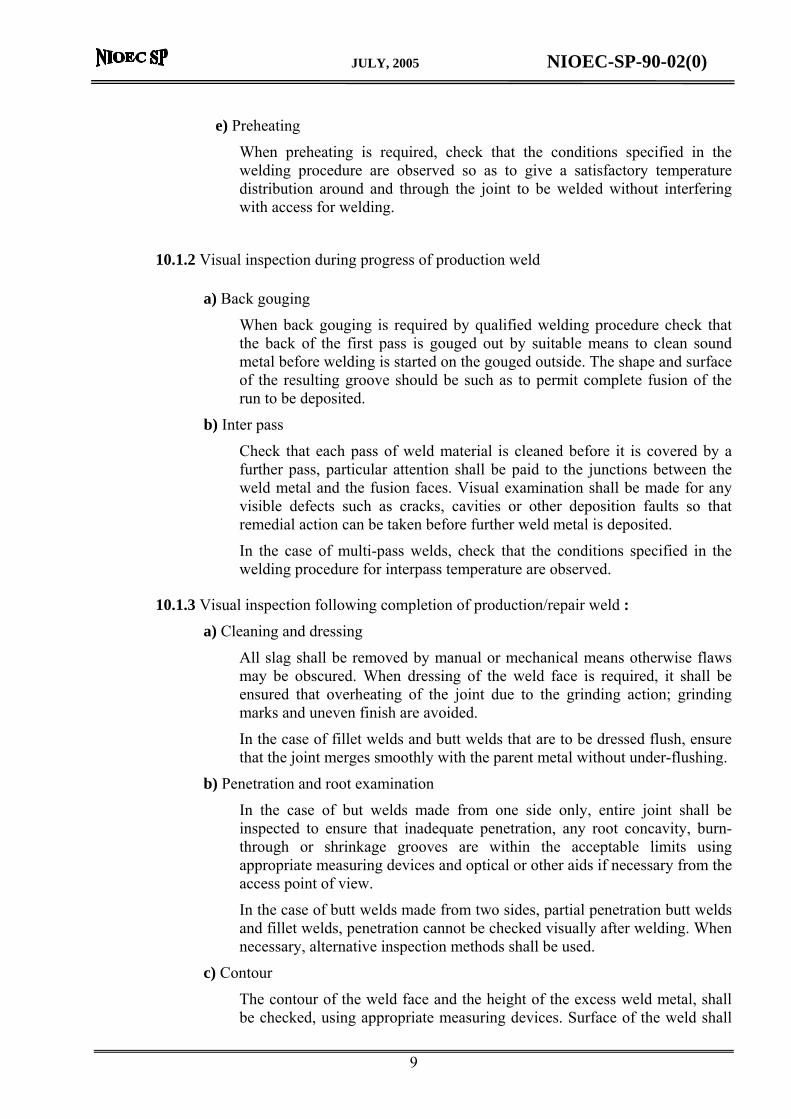
e) Preheating
When preheating is required, check that the conditions specified in the welding procedure are observed so as to give a satisfactory temperature distribution around and through the joint to be welded without interfering with access for welding.
10.1.2 Visual inspection during progress of production weld
a) Back gouging
When back gouging is required by qualified welding procedure check that the back of the first pass is gouged out by suitable means to clean sound metal before welding is started on the gouged outside. The shape and surface of the resulting groove should be such as to permit complete fusion of the run to be deposited.
b) Inter pass
Check that each pass of weld material is cleaned before it is covered by a further pass, particular attention shall be paid to the junctions between the weld metal and the fusion faces. Visual examination shall be made for any visible defects such as cracks, cavities or other deposition faults so that remedial action can be taken before further weld metal is deposited.
In the case of multi-pass welds, check that the conditions specified in the welding procedure for interpass temperature are observed.
10.1.3 Visual inspection following completion of production/repair weld :
a) Cleaning and dressing
All slag shall be removed by manual or mechanical means otherwise flaws may be obscured. When dressing of the weld face is required, it shall be ensured that overheating of the joint due to the grinding action; grinding marks and uneven finish are avoided.
In the case of fillet welds and butt welds that are to be dressed flush, ensure that the joint merges smoothly with the parent metal without under-flushing.
b) Penetration and root examination
In the case of but welds made from one side only, entire joint shall be inspected to ensure that inadequate penetration, any root concavity, burn-through or shrinkage grooves are within the acceptable limits using appropriate measuring devices and optical or other aids if necessary from the access point of view.
In the case of butt welds made from two sides, partial penetration butt welds and fillet welds, penetration cannot be checked visually after welding. When necessary, alternative inspection methods shall be used.
c) Contour
The contour of the weld face and the height of the excess weld metal, shall be checked, using appropriate measuring devices. Surface of the weld shall
9

JULY, 2005 NIOEC-SP-90-02(0)
be regular and the pattern and pitch of weave marks shall present an even and satisfactory visual appearance.
d)Weld width
The weld width shall be consistent over the whole of the joint and shall be according to dimensional requirements given on the working drawing. In the case of butt welds, the weld preparation shall be at least completely filled.
e) Undercut
Any undercut shall be measured with appropriate measuring devices and shall be checked against the acceptance criteria.
f) Overlap
Toes of the weld where the weld width is excessive shall be carefully inspected for weld fusion.
g) Weld flaws
Weldment and heat-affected zone shall be inspected using optical aids (if necessary).
h)Internal and external weld reinforcement and finish(weld contour) shall be as required by the applicable code.
10.2 Inspection by Non-Destructive Testing
10.2.1 General
10.2.1.1 All non- destructive testing shall be performed in accordance with the requirements and methods specified in ASME, Section V.
10.2.1.2 Non- destructive testing and examination of welds shall be carried out according to detailed written procedures prepared by the Contractor and approved by the Inspector.
10.2.1.3 Personnel responsible for various aspects of non-destructive testing including testing operation, interpretation, evaluation and reporting shall have qualifications and experience acceptable to the Employer.
10.2.1.4 Selected welds for N.D.T. shall include representative sample of each welder’s work. Selection of welds for N.D.T shall be made by the Inspector.
10.2.1.5 The welds shall be accepted in the undressed condition unless dressing is necessary, in the opinion of the inspector, to effect satisfactory non-destructive testing.
10.2.1.6 The Contractor shall submit to the Inspector certificate of calibration for all NDT equipment to be used for weld inspection.
10.2.2 Liquid penetrant examination
10.2.2.1 Initial procedure
Liquid penetrant examination shall be performed in accordance with Article 6 of ASME, Section V.
10

JULY, 2005 NIOEC-SP-90-02(0)
10.2.2.2 Procedure revision
A revised procedure shall be prepared by the Contractor and approved by the Inspector for the following cases:
a) whenever a change or substitution is made in the type or family group of penetrant materials (including developers, emulsifiers, etc.) or in the processing techniques;
b) whenever a change or substitution is made in the type of pre-
cleaning materials or processes;
c) for any change in part processing that can close surface opening of discontinuities or leave interfering deposits, such as grinding, grit blasting and power brush cleaning or acid treatments.
10.2.2.3 Techniques
Either a color contrast penetrant technique or a fluorescent penetrant technique shall be used. For each technique, one of the following three types of penetrant systems shall be used:
a) Water washable. b) Post-emulsifying. c) Solvent removable.
10.2.3 Magnetic particle examination
10.2.3.1 Procedure
Examination procedures shall be prepared in accordance with ASME, Section V,Article7.
10.2.3.2 Method of examination
Examination shall be done by the continuous method; that is, the magnetizing current remains on while the examination medium is being applied and while excess of the examination medium is being removed.
10.2.3.3 Material of particle
The ferromagnetic particles used as an examination medium may be either wet or dry, and may be either fluorescent or non-fluorescent. If dry particles are used prior approval of the inspector shall be obtained.
10.2.3.4 Techniques
One or more of the following five magnetization techniques may be used provided that prior approval of the inspector is obtained.
a) prod technique; b) longitudinal magnetization technique; c) circular magnetization technique; d) yoke technique; e) Multidirectional magnetization technique. When carrying out MP, care shall be taken to avoid spark on the metal surfaces,specially for air hardening steels.
11

JULY, 2005 NIOEC-SP-90-02(0)
10.2.3.5 Calibration of equipment
Calibration shall be made according to ASME Section V clause760.
10.2.3.6 System and sensitivity evaluation
The overall performance and sensitivity of examination system (i.e. combination of the magnetic particle material/magnetic particle equipment. The sequence of operation and the level of magnetizing field) shall be monitored with the test block at regular intervals to assure the system performance is properly maintained: A reference block or fabricated test piece with known discontinuities shall be prepared for above demonstration.
10.2.3.7 Demagnetization
When residual magnetism in the part could harmfully interfere with the subsequent processing or usage, the part shall be demagnetized after completion of the examination.
10.2.3.8 The final pass of attachment welds to P-4, P-5 and P-6 materials shall be magnetic particle examined after final post weld heat treatment.
10.2.3.9 On completion of MT test,all spark spots shall be ground flash to sound metal(care shall be taken not to thining metal thickness)and for P-4,P-5,P-6 materials,these locations shall be inspected to detect microfissure cracks by dye peneterant method,and taking necessary remedial action.
10.2.4 Ultrasonic examination
10.2.4.1 General
The ultrasonic testing of the weld shall be carried out by manual scanning using an A-scan and shall be performed with written procedure. The procedure shall include but not limited to the following information:
a) Type of ultrasonic flaw detector. b) Weld type and welding procedure. c) Joint design. d) Surface condition. e) Type of standard block. f) Reference block and it’s relative reflectors. g) Type of probes. h) Method of sensitivity setting for parent metal testing. i) Method of sensitivity setting for weld metal. j) Scanning techniques. k) Reporting requirements. l) Acceptance standard. m) Operators qualification.
12

JULY, 2005 NIOEC-SP-90-02(0)
10.2.4.2 Equipment
10.2.4.2.1 Frequency
The equipment shall be capable of working frequency within the range 1MHz to 5MHz
10.2.4.2.2 Time base linearity
The linearity of time base shall be within 2% over the whole range.
10.2.4.2.3 Amplifier linearity
The amplifier shall be linear to an accuracy of ±1 dB at any point within the range 20% to 80% of full screen height.
The amplitude control of flaw detector shall be made according to Appendix I, Article 5, ASME, Section V.
10.2.4.3 Operators
Operators shall be certified by the requirements of ASNT recommended practice SNT-TC-1A Level II or III.
If required, the operator shall demonstrate his ability to perform the test, using the actual equipment and the technique to be employed.
10.2.4.4 Scanning
10.2.4.4.1 Parent metal
Parent metal at both sides of welded joints, to the extend necessary for weld examination, shall be scanned using straight beam technique for:
a) Locating any flaws, such as laminations and tears. b) Determining actual material thickness.
10.2.4.4.2 Weld metal
The weld examination shall consist of scan from both sides:
a) of the weld root; b) of the side fusion faces; c) of the weld body; d) in addition to scanning for defects lying transverse of
the weld. 10.2.4.5 Sensitivity setting
Sensitivity setting for straight and angle beam probe shall be made according to T.542.2-ARTICLE 5 ASME SEC.V.
13

JULY, 2005 NIOEC-SP-90-02(0)
10.2.5 Radiographic examination
10.2.5.1 General
Production welds shall be inspected by radiographic examination according to approved procedure, and carried out after post weld heat treatment when required.Construction Contractor may prefer to carry out radiography examination to detect defective weldment prior to heat treatment to avoid undue heat treatment operation.However the acceptance judjement is based on radiography examination after heat treatment.
10.2.5.2 Procedure
Radiographic procedure shall include but not limited to the following:
a) material and thickness range; b) type of X-ray tube or isotope; c) strength of isotope used or X-ray voltage; d) radiography technique; e) film type; f) intensifying screens used; g) type of image quality indicator, place and numbers; h) sensitivity; i) density; j) processing time and temperature; k) reporting requirements
10.2.5.3 Techniques
A single wall exposure technique shall be used for radiography whenever practical. When it is not practical to use single wall technique, a double wall single image technique (DWSI) and for pipes with DN less than 90 (NPS 3½) double wall double image (DWDI) technique may be used,upon approved by Employer.
10.2.5.4 Film type
Radiography shall be made using industrial radiography film type Class II ASTM, equivalent to D7 normally and D4, if required in the opinion of the Inspector, in special cases. Fluorescent and fluorometallic screens are not acceptable.
10.2.5.5 Image quality indicators (IQI)
Wire type penetrameter shall be used to measure radiographic sensitivity. In special cases other type of penetrameters may be used. Max. Sensitivity shall not exceed 2% where:
100×=specimenofthickness
wirethinnestofsizeSensivity
Number of penetrameters and placement shall be as per ASME sec V.
14

JULY, 2005 NIOEC-SP-90-02(0)
10.2.5.6 Selection of radiation sources,shall be accordance with T-272 ARTICLE 2 ASME SEC V.
10.2.5.7 Darkroom
Processing shall be carried out in a darkroom with the following facilities as minimum requirement:
a) Automatic or manual processing devices with temperature indicating controller (T.I.C).
b) Loading bench. c) Red light (subdued light). d) Adequate ventilation. e) Drying bench. f) Clean and washable floor.
10.2.5.8 Processing
Processing shall follow a standard technique with five separate stages; Development, stop bath, fixing, washing and drying. Development time and temperature shall be controlled according to standard (4 min. at 20ºC) or film manufacturer’s recommendations.
Excess density due to additional developing time or higher temperature shall not be allowed.
The Employer engineer is allowed to visit processing condition to evaluate the quality and density of radiographs.
10.2.5.9 Personnel
The personnel employed in carrying out radiography conforming to this standard shall be certified in accordance with the recommendations of ANST recommended practice SNT-TC-1A. Radiographic personnel should obtain a certificate of competence for working with radiation sources from Atomic Energy Organization of Iran.
10.2.5.10 Quality of radiographs
All radiographs shall be free from mechanical, chemical and other blemishes to the extent that they do not mask and are not confused with the image of any discontinuity in the area of interest of the object being radiographed.Such blemishes include,but are not limited to:
a) fogging
b) processing defects such as streaks,watermarks or chemical stains;
15

JULY, 2005 NIOEC-SP-90-02(0)
c) scratches,fingermarks,crimps,dirtiness,staticmarks,smudges,or tears;
d) false indications due to defective screens.
e) Film shall be exposed so that the H & D density through the weld metal shall not be less than 1.8 not greater than 3.0 for transparent based film.
10.2.5.11 Identification
a) Consideration shall be given to the following for image identification. A system shall be used to produce permanent identification on the radiograph of weld. Consecutive / number series and the date of the radiograph shall be plainly and permanently included on the radiograph.
b) Markers, usually in the form of lead arrows or other symbols, shall be placed alongside but clear of the outer edges of the weld to identify its position.
c) In general, permanent marking of the work piece shall be used to provide reference points for the accurate relocation of the position of each radiograph.
10.2.5.12 Interpretation
Only level II or III NDT personnel in accordance with SNT-TC-1A for radiography shall interpret images. The radiographer shall examine each radiograph and shall determine the acceptability of each weld based on Chapter VI ASME B 31.3. The radiographer shall describe to the Inspector those weld defects that he considers cause for rejection of the weld. The Inspector will make final interpretation on all welds.However this will not relieve the Contractor/Construction Contractor from his responsibilities as outlined in the contract.
10.2.5.13 Radiation safety
Whenever X-ray equipment or radioactive sources are in use, adequate precautions shall be taken to protect the radiographer and others in the vicinity. Radiation hazards shall be minimized by adherence to requirements cited in IPS-G-SF-110.
10.2.5.14 Random radiography
Where 10 percent radiography is specified the following rules shall be applied:
a) At least 10 percent of the number of welds within the specified line class shall be radiographed around their total circumference.
b) At least 10 percent of the number of welds made by each welder
shall be radiographed around their total circumference. If a welder makes less than 10 welds, one of these shall be fully radiographed.
c) Radiographs shall sample the entire range of pipe sizes that have
been welded, where practicable.
16

JULY, 2005 NIOEC-SP-90-02(0)
d) Since the intent of 10 percent examination is to evaluate the
quality of welder performance, radiographs shall be made as soon after weld completion as practicable.
10.2.6 Brinell hardness test
10.2.6.1 Submerged arc welding procedure qualifications for P-1, -P-3 and P-4 group materials shall have a hardness not exceeding 225 Brinell in the weld deposit.
10.2.6.2 On production welds for P-4,P-5 and P-6 group material a Brinell hardness test shall be taken on the butt-welds in each P-groups material for all air hardening filler metal.. Brinell hardness shall not exceed 225 BHN.
10.2.6.3 The Brinell hardness testing shall be limited to piping and tubing greater than DN 100 (NPS 4) and a wall thickness over 6.35mm.
10.2.6.4 Hardness test results and locations shall be recorded. The Employer shall be permitted to witness hardness testing and shall have access to test results.
10.2.7 Charpy Impact Test
10.2.7.1 Procedure qualifications for low temperature service shall include Charpy V-Notch Impact tests as per ASME B31.3 of the weld metal and heat affected zone at the lowest design temperature for the equipment. A change in the electrodes or wire classification shall require requalification.
11.0 WELD DEFECTS AND ACCEPTANCE CRITERIA
11.1 Welds which are deposited by procedures differing from those properly qualified
approved shall be rejected and completely removed from the piping.
11.2Weld metal shall be properly fused with the parent metal without significant undercutting or overlapping at the toes of the weld; slight intermittent undercut shall be permitted provided that it does not form a sharp notch and that it meets the following requirements.
The stop and start of each run of weld shall merge smoothly and shall show no pronounced hump or crater in the weld surface.
11.3 Acceptance criteria shall be as stated in the engineering design and shall at least meet
the limits stated in Table 341-3.2 of ASME B.31.3. 11.4 For ultrasonic examination of welds supplementary acceptance criteria cited in Clause
344.6.2 of ASME B.31.3 shall be considered.
17

JULY, 2005 NIOEC-SP-90-02(0)
12.0 WELD REPAIR
12.1 When a defective weld is detected either visually or by any other method in accordance with Section 10 of this Standard, it shall be removed to sound metal and repaired. Repair weld shall be made using qualified welding procedure as well as qualified welders/welding operators. Preheating and heat treatment shall be as required for the original welding.
12.2 External undercut shall be repaired by grinding off the weld cap in the undercut location
and recapping the location.
12.3 No weld containing cracks, regardless of size or location, is acceptable. Cracked welds shall be cut, removed and re-welded.
12.4 On completion of repair the weld shall be radiographed whether the defect in the original weld was detected by radiographic examination or not.
12.5 When a required examination reveals that weld examined fails to meet applicable quality requirements, the weld shall be repaired or replaced to meet requirements of the applicable Code. Also, two additional examinations of the same type shall be made of the same kind of weld by the same welder or welding operator that was deficient in quality. If the second group of welds examined meets applicable quality requirements, all welds represented by these additional examinations shall be accepted. For each of the second groups of welds which fails to meet applicable quality requirements, two additional welds shall be examined. If all of the third groups of welds examined meet applicable quality requirements, the items which were deficient shall be repaired or replaced to meet the requirements of the applicable Code and all items represented by the examined welds shall be accepted. . If any of the third group of welds examined fail to meet applicable quality requirements, all comparable welds may be replaced or they shall be fully examined and repaired as necessary to meet applicable quality requirements,at Contractor/Construction Contractor´s expense.
13.0 PRE-AND POST-WELD HEAT TREATMENT
13.1 General Requirements
13.1.1 Heat treatments may be carried out either full body or locally, depending on:
- Type of heat treatment - Material composition of pipe. - Number and sizes of pipe. - Availability and cost of energy. - Required accuracy of heat treatment. - Welding process and welding consumable. - Code requirement.
13.1.2 Heat treatment shall be carried out it accordance with a qualified heat treatment procedure specification which is submitted by the Contractor/Construction Contractor for approval of the Employer.
13.1.3 During heating up and cooling down, no temperature gradient shall exceed:
100ºC/m in axial direction, nor 40ºC/m in tangential direction, to be checked by temperature recorder.
18

JULY, 2005 NIOEC-SP-90-02(0)
13.1.4 For wall thicknesses of pipe up to and including 20 mm the rate of heating shall not exceed 200-250ºC/h.
13.1.5 For wall thicknesses of pipe over 20 mm the rate of heating shall not exceed:
5500/t ºC/h (t = maximum pipe wall thickness) or 55ºC/h Whichever is greater.
13.1.6 The work piece shall be cooled to 300ºC whereby the cooling rate is limited as follows:
- For wall thickness of pipe < 20mm 275ºC/h
- For wall thicknesses ≥ 20mm 6875/t ºC/h (t = maximum pipe wall thickness)
or 55ºC/h , whichever is the greater.
13.2 Preheat Requirements
13.2.1 Preheating of the parent metal prior to any welding, tack welding and thermal cutting where specified in approved WPS,is necessary to avoid cold cracking of certain ferritic steels in the weld and HAZ. Preheating could also be required for welding of non-ferrous materials to remove moisture or to prevent hot cracking.
13.2.2 An even temperature distribution is required.
13.2.3 Temperature control may be carried out with temple stick, digital pyrometers or contact thermometer.
13.2.4 Where preheating is necessary to be carried out by electrical resistance method,automatic temperature control facilities shall be utilized and the specified preheat temperature shall be maintained throughout the welding course.
13.2.5 When required for field welds of piping, the following methods of preheating shall be applied,exept for heavy wall thickness alloy steel piping which electrical resistance elements shall be used.
a) For DN<250 (NPS<10) heating by appropriate torches is allowed
b) For DN≥250 (NPS≥10) electrical resistance heating element or heating by means of infrared or ring burners is required.
13.2.6The following requirements shall be adhered to for the preheating zone:
a) Width of the heated zone is 2 t (t = wall thickness) with a minimum of 100 mm on each side of the weld.
Width of the insulated zone = width of zone heated + 150mm.
b) For pipe butt welds, the width of the heated band on each side of the weld is 2.5 t, with a minimum of 75mm.
c) Special attention shall be paid to the extent of heated bands in order not to aggravate the problems related to residual stress distribution, such as cracking, buckling and distortion.
19
JULY, 2005 NIOEC-SP-90-02(0)
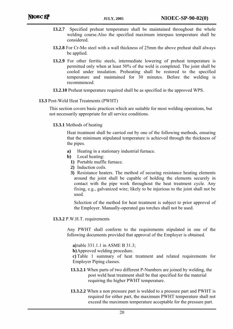
13.2.7 Specified preheat temperature shall be maintained throughout the whole welding course.Also the specified maximum interpass temperature shall be considered.
13.2.8 For Cr-Mo steel with a wall thickness of 25mm the above preheat shall always be applied.
13.2.9 For other ferritic steels, intermediate lowering of preheat temperature is permitted only when at least 50% of the weld is completed. The joint shall be cooled under insulation. Preheating shall be restored to the specified temperature and maintained for 30 minutes. Before the welding is recommenced.
13.2.10 Preheat temperature required shall be as specified in the approved WPS.
13.3 Post-Weld Heat Treatments (PWHT)
This section covers basic practices which are suitable for most welding operations, but not necessarily appropriate for all service conditions.
13.3.1 Methods of heating
Heat treatment shall be carried out by one of the following methods, ensuring that the minimum stipulated temperature is achieved through the thickness of the pipes.
a) Heating in a stationary industrial furnace. b) Local heating:
1) Portable muffle furnace. 2) Induction coils. 3) Resistance heaters. The method of securing resistance heating elements
around the joint shall be capable of holding the elements securely in contact with the pipe work throughout the heat treatment cycle. Any fixing, e.g., galvanized wire; likely to be injurious to the joint shall not be used.
Selection of the method for heat treatment is subject to prior approval of the Employer. Manually-operated gas torches shall not be used.
13.3.2 P.W.H.T. requirements
Any PWHT shall conform to the requirements stipulated in one of the following documents provided that approval of the Employer is obtained.
a) table 331.1.1 in ASME B 31.3; b) Approved welding procedure. c) Table 1 summary of heat treatment and related requirements for Employer Piping classes.
13.3.2.1 When parts of two different P-Numbers are joined by welding, the post weld heat treatment shall be that specified for the material requiring the higher PWHT temperature.
13.3.2.2 When a non pressure part is welded to a pressure part and PWHT is required for either part, the maximum PWHT temperature shall not exceed the maximum temperature acceptable for the pressure part.
20

JULY, 2005 NIOEC-SP-90-02(0)
13.3.2.3 Caution is necessary to preclude metallurgical damage to some materials or welds not intended or qualified to withstand the PWHT temperature required.
13.3.2.4 It is preferred that PWHT be carried out in a stationary industrial furnace, but when it is necessary to apply a local heat treatment, the temperature gradient shall be such that:
a) For the butt joint welds the length of material on each side of weld is at least 2.5 √r.t where r is the bore radius and t is the pipe thickness at the weld, and minimum insulation width shall be 10 √r.t.
MINIMUM INSULATION WIDTH
b)For branch connection welds the length of material from each crotch is at least:
1) 2.5 √rm tm along the main pipe where rm is the bore radius and tm is the thickness of the main pipe;
2) 2.5 √rb tb along the branch pipe where rb is the bore radius and tb is the thickness of the branch pipe;
21

JULY, 2005 NIOEC-SP-90-02(0)
Notes:
rm is the bore radius of main pipe;
tm is the thickness of main pipe;
rb is the bore radius of branch pipe;
tb is the thickness of branch pipe.
AREA (SHADED) TO BE HEATED FOR THE LOCAL TREATMENT OF BRANCH CONNECTIONS
13.3.2.5 PWHT is not required for non ferrous material. Note:
Definition of thickness referred to in sub Section 12.3 of this Standard shall be that cited in ASME B31.1 Clause 132.4.
13.3.2.6 All lines in caustic service with operating temperature more than 60ºC or with caustic concentration exceeding 25% by weight or if line is steam traced and eitheris in stagnant or intermittent service,shall be post weld heat treated according to Table 331.1.1 of ASME B31.3 P-No. 1. Max hardness of welds after postweld heat treatment shall not exceed 200BHN.
13.3.2.7 All lines in sour water service shall be post weld heat treated according to Table 331.1.1 of ASME B31.3 P-No. 1. Max hardness of welds after postweld heat treatment shall not exceed 200BHN
22
JULY, 2005 NIOEC-SP-90-02(0)
for welds subject to para. 3.1.a and 185 BHN for welds subject to para. 3.1.b.
13.3.2.8 All lines operating in amine service above 65ºC shall be post weld
heat treated according to Table 331.1.1 of ASME B31.3 P-No. 1. . Max hardness of welds after postweld heat treatment shall not exceed 200 BHN.
13.3.3 Hardness test
Hardness tests of production welds are intended to verify satisfactory heat treatment. Where a hardness limit is specified in Table 331.1.1 in ASME B31.3, at least 10% of welds in each furnace heat treated batch and 100% of those locally heat treated shall be tested. The hardness limit applied to the weld and to the heat affected zone (tested as close as practicable to the edge of the weld).
23

JULY, 2005 NIOEC-SP-90-02(0)
APPENDIX A: RECOMMENDED WPS
NO. P-001 TO P-017
24

JULY, 2005 NIOEC-SP-90-02(0)
WPS No. P 001 Rev. Date Supporting PQR No.(s) (By Manufacturer) Welding Process(es) GTAW and/or SMAW Type(s) Manual Applicable Code ASME Sec. IX & ASME B31.3 Joints Joint Design Joint No. - Joint Design Butt, Fillet Backing : Yes No See Fig. 1 Backing Material --- Method of Fit Up See Fig. 2 Edge Preparation Machining or Grinding Other Base Metal P. No. 1 Group No. 1 to P. No. 1 Group No. 1 Specification Type & Grade A53-B to A53-B Chem. Analysis & Mech. Prop. C-Mn, 60ksi to C-Mn, 60ksi Thickness Range : Groove ≤19mm Fillet <25.4mm Pipe Dia. Range : Groove ≥1/2 inch Fillet All Other Filler Metals F. No. 6 or 3 / 4 A. No. 1 or 1 / 1 Spec. No.(SFA) A5.18 or A5.1 / A5.1 AWS. No.(Class) ER70S or E6010 / E7016 or E7018 JIS. No. --- / --- Brand Name of Electrode or Filler Metal (By Manufacturer) Wire Type for GMAW --- Electrode-Flux(Class) --- Brand Name of Flux --- Drying Condition : Temp. (E6010) 80~100 ºC Time 1 hours Other (E7016-E7018)300~350ºC--- Twice Only Position Position of Groove All (Qualified : 6G) Welding Progression : Up Down Position of Fillet Other
25

JULY, 2005 NIOEC-SP-90-02(0)
WPS No. P001 (cont′d). Preheat : Yes No Post Heat : Yes No Preheat Temp. ºC (Min. 10) Post Heat Temp. --- Interpass Temp. ºC (Min. 10) Holding Time --- min. Method --- Method --- Other Other Postweld Heat Treatment. : Yes No Temperature Range --- Holding Time Increasing & Decreasing Rate. --- ºC/Hr(max.) Other Gas Shielding Gas(es) Argon Flow Rate 8~15 l/min. Percent Composition 99.9 % Gas Backing : Yes No --- l/min. Trailing Shielding Gas Composition --- % Other Electrical Characteristics & Technique Tungsten Electrode Size 1.6~3.2 mm Type 2% Thorium Mode of Metal Transfer for GMAW --- Electrode Wire Feed Speed Range --- Bead : String Weave Orifice or Gas Cup Size 8.0~12.5 mm Initial & Interpass Cleaning : Brushing Grinding Other Pass(per side) : Multi Single Electrode : Multi Single Method of Back Gouging --- Other
Filler Current Weld Layer
WeldingProcess Bran
d Class Dia. (mm)
Type Polar.
Amp. Range
Volt Range
Travel Speed Range cm/min
Root Fill
GTAW or SMAW SMAW
ER70S E6010
E7016 E7018
26

JULY, 2005 NIOEC-SP-90-02(0)
WPS No. P 002 Rev. Date Supporting PQR No.(s) (By Manufacturer) Welding Process(es) GTAW and/or SMAW Type(s) Manual Applicable Code ASME Sec. IX & ASME B31.3 Joints Joint Design Joint No. - Joint Design Butt, Fillet Backing : Yes No See Fig. 1 Backing Material --- Method of Fit Up See Fig. 2 Edge Preparation Machining or Grinding
Other Base Metal P. No. 1 Group No. 1 to P. No. 1 Group No. 1 Specification Type & Grade A53-B to A53-B Chem. Analysis & Mech. Prop. C-Mn , 60ksi to C-Mn, 60ksi Thickness Range : Groove 19mm<x<25.4mm Fillet <25.4mm Pipe Dia. Range : Groove ≥2 inch Fillet All Other Filler Metals F. No. 6 or 3 / 4 A. No. 1 or 1 / 1 Spec. No.(SFA) A5.18 or A5.1 / A5.1 AWS. No.(Class) ER70S or E6010 / E7016 orE7018 JIS. No. --- / --- Brand Name of Electrode or Filler Metal (By Manufacturer) Wire Type for GMAW --- Electrode-Flux(Class) --- Brand Name of Flux Drying Condition : Temp. (E6010) 80~100 ºC ºC Time 1 hours Other (E7016 or E7018)300~350ºC--- Twice Only Position Position of Groove All (Qualified : 6G) Welding Progression : Up Down Position of Fillet All Other
27

JULY, 2005 NIOEC-SP-90-02(0)
WPS No. P 002 (cont′d). Preheat : Yes No Post Heat : Yes No Preheat Temp. ºC (Min. 10) ºC Post Heat Temp. --- ºC Interpass Temp. ºC (Min. 10) ºC Holding Time --- min. Method --- Method --- Other Other Postweld Heat Treatment. : Yes No Temperature Range 593~649ºC ºC Holding Time 1 Hr/25.4mm(Min. 2 Hr) Increasing & Decreasing Rate. Heating:200, Cooling:275 ºC/Hr(max.) Other Gas Shielding Gas(es) Argon Flow Rate 8~15 l/min. Percent Composition 99.9 % Gas Backing : Yes No --- l/min. Trailing Shielding Gas Composition --- % Other Electrical Characteristics & Technique Tungsten Electrode Size 1.6~3.2 mm Type 2% Thorium Mode of Metal Transfer for GMAW --- Electrode Wire Feed Speed Range --- Bead : String Weave Orifice or Gas Cup Size 8.0~12.5 mm Initial & lnterpass Cleaning : Brushing Grinding Other Pass(per side) : Multi Single Electrode : Multi Single Method of Back Gouging --- Other
Filler Metal Current Weld Layer
Welding Process Brand Class Dia.
(mm) Type Polar.
Amp. Range
Volt Range
Travel Speed Range
cm/min Root Fill
GTAW or SMAW
ER70S E6010 E7018 E7016
28

JULY, 2005 NIOEC-SP-90-02(0)
WPS No. P 003 Rev. Date Supporting PQR No.(s) (By Manufacturer) Welding Process(es) GTAW and/or SMAW Type(s) Manual Applicable Code ASME Sec. IX & ASME B31.3 Joints Joint Design Joint No. - Joint Design Butt, Fillet Backing : Yes No See Fig. 1 Backing Material --- Method of Fit Up See Fig. 2 Edge Preparation Machining or Grinding
Other Base Metal P. No. 1 Group No. 1 to P. No. 1 Group No. 1 Specification Type & Grade A106B to A106B Chem. Analysis & Mech. Prop. C-Si, 60ksi to C-Si , 60ksi Thickness Range : Groove ≥ 25.4mm Fillet ≥25.4mm Pipe Dia. Range : Groove ≥2 inch Fillet All Other Filler Metals F. No. 6 or 3 / 4 A. No. 1 or 1 / 1 Spec. No.(SFA) A5.18 or A5.1 / A5.1 AWS. No.(Class) ER70S or E6010 / E7016 orE7018 JIS. No. --- / --- Brand Name of Electrode or Filler Metal (By Manufacturer) Wire Type for GMAW --- Electrode-Flux(Class) --- Brand Name of Flux --- Drying Condition : Temp. (E6010) 80~100 ºC Time 1 hours Other (E7018orE7016)300~350ºC Twice Only Position Position of Groove All (Qualified : 6G) Welding Progression : Up Down Position of Fillet All Other
29

JULY, 2005 NIOEC-SP-90-02(0)
WPS No. P 003 (cont′d). Preheat : Yes No Post Heat : Yes No Preheat Temp. 80~200 ºC Post Heat Temp. --- ºC Interpass Temp. 80 ºC Holding Time --- min. Method Gas Burner or Electric Heater
Method ---
Other Other Postweld Heat Treatment. : Yes No Temperature Range 593ºC~649ºC Holding Time 1 Hr/25.4mm(Min. 2 Hr) Increasing & Decreasing Rate. Heating:200, Cooling:275 ºC/Hr(max.) Other Gas Shielding Gas(es) Argon Flow Rate 8~15 l/min. Percent Composition 99.9 % Gas Backing : Yes No --- l/min. Trailing Shielding Gas Composition --- % Other Electrical Characteristics & Technique Tungsten Electrode Size 1.6~3.2 mm Type 2% Thorium Mode of Metal Transfer for GMAW --- Electrode Wire Feed Speed Range --- Bead : String Weave Orifice or Gas Cup Size 8.0~12.5 mm Initial & lnterpass Cleaning : Brushing Grinding Other Pass(per side) : Multi Single Electrode : Multi Single Method of Back Gouging --- Other
Filler Current Weld Layer
Welding Process Brand Class Dia
(mm) Type Polar.
Amp. Range
Volt Range
Travel Speed Range
cm/min. Root Fill
GTAW or SMAW or
ER70S E6010 E7018
E7016
Note: Procedure qualifications shall include Charpy V-notch impact tests of the weld metal and heat affected zone.
30
JULY, 2005 NIOEC-SP-90-02(0)
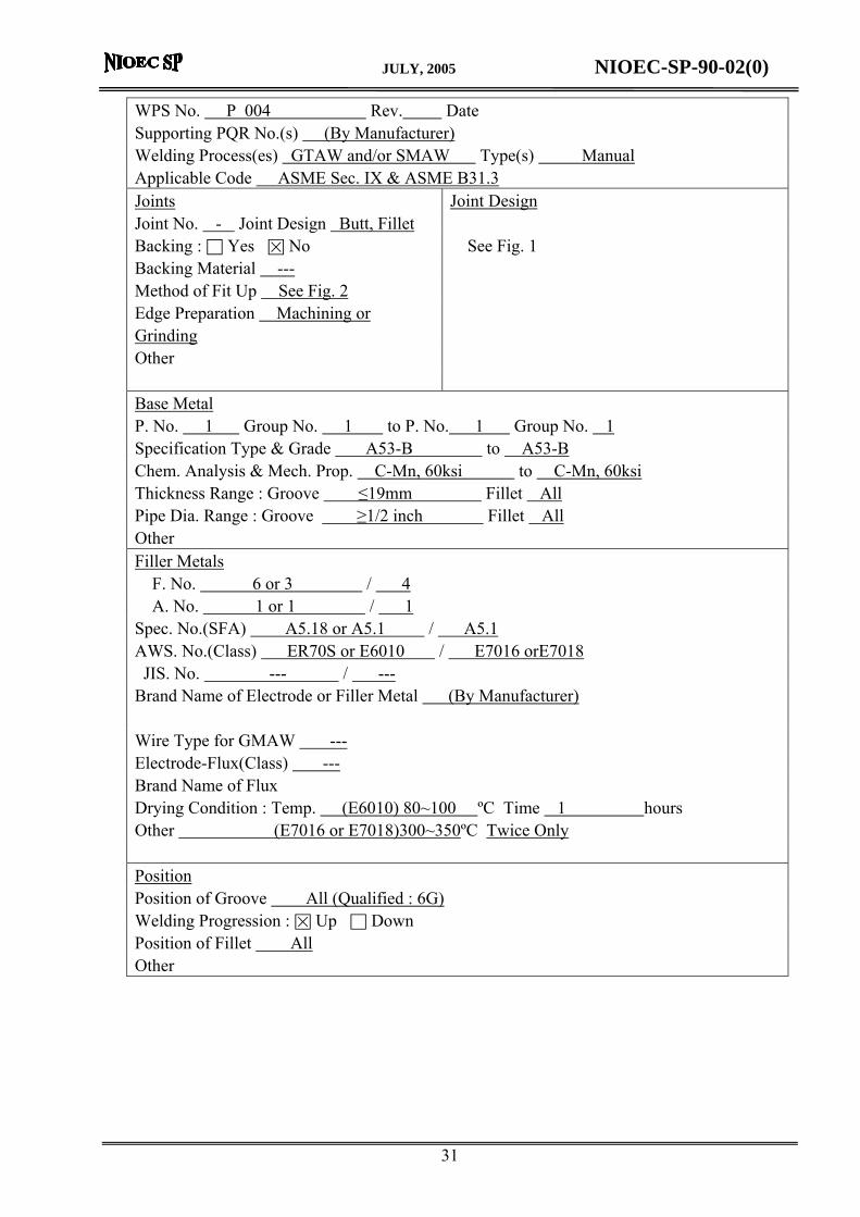
WPS No. P 004 Rev. Date Supporting PQR No.(s) (By Manufacturer) Welding Process(es) GTAW and/or SMAW Type(s) Manual Applicable Code ASME Sec. IX & ASME B31.3 Joints Joint Design Joint No. - Joint Design Butt, Fillet Backing : Yes No See Fig. 1 Backing Material --- Method of Fit Up See Fig. 2 Edge Preparation Machining or Grinding
Other Base Metal P. No. 1 Group No. 1 to P. No. 1 Group No. 1 Specification Type & Grade A53-B to A53-B Chem. Analysis & Mech. Prop. C-Mn, 60ksi to C-Mn, 60ksi Thickness Range : Groove ≤19mm Fillet All Pipe Dia. Range : Groove ≥1/2 inch Fillet All Other Filler Metals F. No. 6 or 3 / 4 A. No. 1 or 1 / 1 Spec. No.(SFA) A5.18 or A5.1 / A5.1 AWS. No.(Class) ER70S or E6010 / E7016 orE7018 JIS. No. --- / --- Brand Name of Electrode or Filler Metal (By Manufacturer) Wire Type for GMAW --- Electrode-Flux(Class) --- Brand Name of Flux Drying Condition : Temp. (E6010) 80~100 ºC Time 1 hours Other (E7016 or E7018)300~350ºC Twice Only Position Position of Groove All (Qualified : 6G) Welding Progression : Up Down Position of Fillet All Other
31

JULY, 2005 NIOEC-SP-90-02(0)
WPS No. P 004 (cont′d). Preheat : Yes No Post Heat : Yes No Preheat Temp. (Min. 10) ºC Post Heat Temp. --- ºC Interpass Temp. (Min. 10) ºC Holding Time --- min. Method --- Method --- Other Other Postweld Heat Treatment. : Yes No Temperature Range 593ºC~649ºC Holding Time 1 Hr/25.4mm (Min. 3/4Hr) Increasing & Decreasing Rate. Heating:200 Cooling :275 ºC/Hr(max.) Other Gas Shielding Gas(es) Argon Flow Rate 8~15 l/min. Percent Composition 99.9 % Gas Backing : Yes No --- l/min. Trailing Shielding Gas Composition --- % Other Electrical Characteristics & Technique Tungsten Electrode Size 1.6~3.2 mm Type 2% Thorium Mode of Metal Transfer for GMAW --- Electrode Wire Feed Speed Range --- Bead : String Weave Orifice or Gas Cup Size 8.0~12.5 mm Initial & Interpass Cleaning : Brushing Grinding Other Pass(per side) : Multi Single Electrode : Multi Single Method of Back Gouging --- Other
Filler Current Weld Layer
Welding Process Brand Class Dia
(mm) Type Polar.
Amp. Range
Volt Range
Travel Speed Range cm/min
Root Fill
GTAW or SMAW SMAW
ER70S or E6010
E7016 orE7018
Note: Hardness test shall be required. (Max. BHN200)
32

JULY, 2005 NIOEC-SP-90-02(0)
WPS No. P 005 Rev. Date Supporting PQR No.(s) (By Manufacturer) Welding Process(es) GTAW and SMAW Type(s) Manual Applicable Code ASME Sec. IX & ASME B31.3 Joints Joint Design Joint No. - Joint Design Butt, Fillet Backing : Yes No See Fig. 1 Backing Material --- Method of Fit Up See Fig. 2 Edge Preparation Machining or Grinding
Other Base Metal P. No. 4 Group No. 1 to P. No. 4 Group No. 1 Specification Type & Grade A-335 P11 to A-335 P11 Chem. Analysis & Mech. Prop. 1-1/4Cr-1/2Mo, 60ksi to 1-1/4Cr-1/2Mo, 60ksi Thickness Range : Groove ≤19mm Fillet ≤19mm Pipe Dia. Range : Groove ≥1/2 inch Fillet All Other Filler Metals F. No. 6 / 4 A. No. 3 / 3 Spec. No.(SFA) A5.28 / A5.5 AWS. No.(Class) ER80S-B2 / E8016-B2 JIS. No. --- / --- Brand Name of Electrode or Filler Metal (By Manufacturer) Wire Type for GMAW --- Electrode-Flux(Class) --- Brand Name of Flux --- Drying Condition : Temp. (E8016-B2) 350~400 ºC Time 1 hours Other --- Twice Only Position Position of Groove All (Qualified : 6G) Welding Progression : Up Down Position of Fillet All Other
33

JULY, 2005 NIOEC-SP-90-02(0)
WPS No. P 005 (cont′d). Preheat : Yes No Post Heat : Yes No Preheat Temp. 150~300 ºC Post Heat Temp. 300~350 ºC Interpass Temp. 150 ºC Holding Time 10 min. Method Gas Burner or Electric Heater Method Gas Burner or Electric Heater Other Other Postweld Heat Treatment. : Yes No Temperature Range 704ºC~745ºC Holding Time 1 Hr/25.4mm(Min. 1 Hr) Increasing & Decreasing Rate. Heating:200, Cooling:275 ºC/Hr(max.) Other Gas Shielding Gas(es) Argon Flow Rate 8~15 l/min. Percent Composition 99.9 % Gas Backing : Yes No --- l/min. Trailing Shielding Gas Composition --- % Other Electrical Characteristics & Technique Tungsten Electrode Size 1.6~3.2 mm Type 2% Thorium Mode of Metal Transfer for GMAW --- Electrode Wire Feed Speed Range --- Bead : String Weave Orifice or Gas Cup Size 8.0~12.5 mm Initial & lnterpass Cleaning : Brushing Grinding Other Pass(per side) : Multi Single Electrode : Multi Single Method of Back Gouging --- Other
Filler Current Weld Layer
Welding Process Brand Class Dia
(mm) Type
Travel
Amp. Range
Volt Range
Speed Range cm/min Polar.
Root Fill
GTAW SMAW
ER80S-B2 E8016-B2
Note : Hardness test shall be required. (Max. BHN225)
34
JULY, 2005 NIOEC-SP-90-02(0)
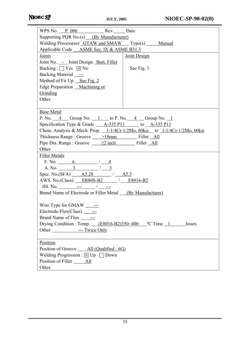
WPS No. P 006 Rev. Date Supporting PQR No.(s) (By Manufacturer) Welding Process(es) GTAW and SMAW Type(s) Manual Applicable Code ASME Sec. IX & ASME B31.3 Joints Joint Design Joint No. - Joint Design Butt, Fillet Backing : Yes No See Fig. 1 Backing Material --- Method of Fit Up See Fig. 2 Edge Preparation Machining or Grinding
Other Base Metal P. No. 4 Group No. 1 to P. No. 4 Group No. 1 Specification Type & Grade A-335 P11 to A-335 P11 Chem. Analysis & Mech. Prop. 1-1/4Cr-1/2Mo, 60ksi to 1-1/4Cr-1/2Mo, 60ksi Thickness Range : Groove >18mm Fillet All Pipe Dia. Range : Groove ≥2 inch Fillet All Other Filler Metals F. No. 6 / 4 A. No. 3 / 3 Spec. No.(SFA) A5.28 / A5.5 AWS. No.(Class) ER80S-B2 / E8016-B2 JIS. No. --- / --- Brand Name of Electrode or Filler Metal (By Manufacturer) Wire Type for GMAW --- Electrode-Flux(Class) --- Brand Name of Flux --- Drying Condition : Temp. (E8016-B2)350~400 ºC Time 1 hours Other --- Twice Only Position Position of Groove All (Qualified : 6G) Welding Progression : Up Down Position of Fillet All Other
35

JULY, 2005 NIOEC-SP-90-02(0)
WPS No. P 006 (cont′d). Preheat : Yes No Post Heat : Yes No Preheat Temp. 150~300ºC ºC Post Heat Temp. 300~350 ºC Interpass Temp. 150 ºC Holding Time 10 min. Method Gas Burner of Electric Heater
Method Gas Burner of Electric Heater
Other Other Postweld Heat Treatment. : Yes No Temperature Range 704ºC~745ºC Holding Time 1 Hr/25.4mm(Min. 2 Hr) Increasing & Decreasing Rate. Heating:200, Cooling:275 ºC/Hr(max.) Other Gas Shielding Gas(es) Argon Flow Rate 8~15 l/min. Percent Composition 99.9 % Gas Backing : Yes No --- l/min. Trailing Shielding Gas Composition --- % Other Electrical Characteristics & Technique Tungsten Electrode Size 1.6~3.2 mm Type 2% Thorium Mode of Metal Transfer for GMAW --- Electrode Wire Feed Speed Range --- Bead : String Weave Orifice or Gas Cup Size 8.0~12.5 mm Initial & lnterpass Cleaning : Brushing Grinding Other Pass(per side) : Multi Single Electrode : Multi Single Method of Back Gouging --- Other
Filler Current Weld Layer
Welding Process Brand Class Dia
(mm) Type Polar.
Amp. Range
Volt Range
Travel Speed Range cm/min
Root Fill
GTAW SMAW
ER80S-B2 E8016-B2
Note : Hardness test shall be required. (Max. BHN225) Note : Procedure qualifications shall include Charpy V-notch impact tests of the weld metal and heat affected zone.
36

JULY, 2005 NIOEC-SP-90-02(0)
WPS No. P 007 Rev. Date Supporting PQR No.(s) (By Manufacturer) Welding Process(es) SMAW Type(s) Manual Applicable Code ASME Sec. IX & ASME B31.3 Joints Joint Design Joint No. - Joint Design Socket, Seal Backing : Yes No See Fig. 1 Backing Material --- Method of Fit Up See Fig. 2 Edge Preparation Machining or Grinding
Other Base Metal P. No. 4 Group No. 1 to P. No. 4 Group No. 1 Specification Type & Grade A-335 P11 to A-335 P11 Chem. Analysis & Mech. Prop. 1-1/4Cr-1/2Mo, 60ksi to 1-1/4Cr-1/2Mo, 60ksi Thickness Range : Groove --- Fillet All Pipe Dia. Range : Groove --- Fillet All Other Filler Metals F. No. 43 / A. No. / Spec. No.(SFA) A5.11 / AWS. No.(Class) ENiCrFe 2 or 3 / JIS. No. --- / Brand Name of Electrode or Filler Metal (By Manufacturer) Wire Type for GMAW --- Electrode-Flux(Class) --- Brand Name of Flux --- Drying Condition : Temp. 350 ºC Time 1 hours Other --- Twice Only Position Position of Groove --- Welding Progression : Up Down Position of Fillet All Other
37

JULY, 2005 NIOEC-SP-90-02(0)
WPS No. P007 (cont′d). Preheat : Yes No Post Heat : Yes No Preheat Temp. 150~300 ºC Post Heat Temp. - ºC Interpass Temp. 150 ºC Holding Time - min. Method Gas Burner or Electric Heater Method - Other Other Postweld Heat Treatment. : Yes No Temperature Range --- Holding Time --- Increasing & Decreasing Rate. --- ºC/Hr(max.) Other Gas Shielding Gas(es) --- Flow Rate --- l/min. Percent Composition --- % Gas Backing : Yes No --- l/min. Trailing Shielding Gas Composition --- % Other Electrical Characteristics & Technique Tungsten Electrode Size --- mm Type --- Mode of Metal Transfer for GMAW --- Electrode Wire Feed Speed Range --- Bead : String Weave Orifice or Gas Cup Size --- mm Initial & lnterpass Cleaning : Brushing Grinding Other Pass(per side) : Multi Single Electrode : Multi Single Method of Back Gouging --- Other
Filler Current Weld Layer
Welding Process Brand Class Dia
(mm) Type Polar.
Amp. Range
Volt Range
Travel Speed Range
cm/min. Root & Fill
SMAW
ENiCrFe 2 or 3
38

JULY, 2005 NIOEC-SP-90-02(0)
WPS No. P008 Rev. Date Supporting PQR No.(s) (By Manufacturer) Welding Process(es) GTAW and SMAW Type(s) Manual Applicable Code ASME Sec. IX & ASME B31.3 Joints Joint Design Joint No. - Joint Design Butt, Fillet Backing : Yes No See Fig. 1 Backing Material --- Method of Fit Up See Fig. 2 Edge Preparation Machining or Grinding Other Base Metal P. No. 5 Group No. 2 to P. No. 5 Group No. 2 Specification Type & Grade A-335 P5 to A-335 P5 Chem. Analysis & Mech. Prop. 5Cr-1/2Mo,60ksi to 5Cr-1/2Mo,60ksi Thickness Range : Groove ≤18mm Fillet All Pipe Dia. Range : Groove ≥1/2 inch Fillet All Other Filler Metals F. No. 6 / 4 A. No. 4 / 4 Spec. No.(SFA) A5.9 / A5.4 AWS. No.(Class) ER502 / E502 JIS. No. --- / --- Brand Name of Electrode or Filler Metal (By Manufacturer) Wire Type for GMAW --- Electrode-Flux(Class) --- Brand Name of Flux --- Drying Condition : Temp. (E502) 350~400 ºC Time 1 hours Other --- Twice Only Position Position of Groove All (Qualified : 6G) Welding Progression : Up Down Position of Fillet Other
39

JULY, 2005 NIOEC-SP-90-02(0)
WPS No. P008 (cont′d). Preheat : Yes No Post Heat : Yes No Preheat Temp. 175~350 ºC Post Heat Temp. 300~400 ºC Interpass Temp. 175 ºC Holding Time 10 min. Method Gas Burner of Electric Heater
Method Gas Burner of Electric Heater
Other Other Postweld Heat Treatment. : Yes No Temperature Range 704ºC~760ºC Holding Time 1 Hr/25.4mm(Min. 2 Hr) Increasing & Decreasing Rate. Heating:200, Cooling:275 ºC/Hr(max.) Other Gas Shielding Gas(es) Argon Flow Rate 8~15 l/min. Percent Composition 99.9 % Gas Backing : Yes No 8~15 l/min. Trailing Shielding Gas Composition --- % Other Electrical Characteristics & Technique Tungsten Electrode Size 1.6~3.2 mm Type 2% Thorium Mode of Metal Transfer for GMAW --- Electrode Wire Feed Speed Range --- Bead : String Weave Orifice or Gas Cup Size 8.0~12.5 mm Initial & lnterpass Cleaning : Brushing Grinding Other Pass(per side) : Multi Single Electrode : Multi Single Method of Back Gouging --- Other
Filler Current Weld Layer
Welding
Process Brand Class Dia. (mm)
Type Polar.
Amp. Range
Volt Range
Travel Speed Range
cm/min. Root Fill
GTAW SMAW
ER502 E502
Note: Hardness test shall be required.(Max. BHN225)
40

JULY, 2005 NIOEC-SP-90-02(0)
WPS No. P009 Rev. Date Supporting PQR No.(s) (By Manufacturer) Welding Process(es) GTAW and SMAW Type(s) Manual Applicable Code ASME Sec. IX & ASME B31.3 Joints Joint Design Joint No. - Joint Design Butt, Fillet Backing : Yes No See Fig. 1 Backing Material --- Method of Fit Up See Fig. 2 Edge Preparation Machining or Grinding
Other Base Metal P. No. 5 Group No. 2 to P. No. 5 Group No. 2 Specification Type & Grade A-335 P5 to A-335 P5 Chem. Analysis & Mech. Prop. 5Cr-1/2Mo,60ksi to 5Cr-1/2Mo,60ksi Thickness Range : Groove >18mm Fillet All Pipe Dia. Range : Groove ≥2 inch Fillet All Other Filler Metals F. No. 6 / 4 A. No. 4 / 4 Spec. No.(SFA) A5.9 / A5.4 AWS. No.(Class) ER502 / E502 JIS. No. --- / --- Brand Name of Electrode or Filler Metal (By Manufacturer) Wire Type for GMAW --- Electrode-Flux(Class) --- Brand Name of Flux --- Drying Condition : Temp. (E502) 350~400 ºC Time 1 hours Other --- Twice Only Position Position of Groove All (Qualified : 6G) Welding Progression : Up Down Position of Fillet ALL Other
41

JULY, 2005 NIOEC-SP-90-02(0)
WPS No. P 009 (cont′d). Preheat : Yes No Post Heat : Yes No Preheat Temp. 175~350ºC ºC Post Heat Temp. 300~400 ºC Interpass Temp. 175 ºC Holding Time 10 min. Method Gas Burner of Electric Heater Method Gas Burner of Electric Heater Other Other Postweld Heat Treatment. : Yes No Temperature Range 704ºC~760ºC Holding Time 1 Hr/25.4mm(Min. 2 Hr) Increasing & Decreasing Rate. Heating:200, Cooling:275 ºC/Hr(max.) Other Gas Shielding Gas(es) Argon Flow Rate 8~15 l/min. Percent Composition 99.9 % Gas Backing : Yes No 8~15 l/min. Trailing Shielding Gas Composition --- % Other Electrical Characteristics & Technique Tungsten Electrode Size 1.6~3.2 mm Type 2% Thorium Mode of Metal Transfer for GMAW --- Electrode Wire Feed Speed Range --- Bead : String Weave Orifice or Gas Cup Size 8.0~12.5 mm Initial & lnterpass Cleaning : Brushing Grinding Other Pass(per side) : Multi Single Electrode : Multi Single Method of Back Gouging --- Other
Filler Current
Weld Layer
Welding Process Brand Class Dia
(mm) Type Polar.
Amp. Range
Volt Range
Travel Speed Range
cm/min
Root Fill
GTAW SMAW
ER502 E502
Note : Hardness test shall be required. (Max. BHN225) Note : Procedure qualifications shall include Charpy V-notch impact tests of the weld metal and heat affected zone.
42

JULY, 2005 NIOEC-SP-90-02(0)
WPS No. P 010 Rev. Date Supporting PQR No.(s) (By Manufacturer) Welding Process(es) GTAW and SMAW Type(s) Manual Applicable Code ASME Sec. IX & ASME B31.3 Joints Joint Design Joint No. - Joint Design Butt, Fillet Backing : Yes No See Fig. 1 Backing Material --- Method of Fit Up See Fig. 2 Edge Preparation Machining or Grinding
Other Base Metal P. No. 5 Group No. 2 to P. No. 5 Group No. 2 Specification Type & Grade A-335 P9 to A-335 P9 Chem. Analysis & Mech. Prop. 9Cr-1Mo, 60ksi to 9Cr-1Mo, 60ksi Thickness Range : Groove ≤18mm Fillet All Pipe Dia. Range : Groove ≥1/2inch Fillet All Other Filler Metals F. No. 6 / 4 A. No. 5 / 5 Spec. No.(SFA) A5.9 / A5.4 AWS. No.(Class) ER505 / E505 JIS. No. --- / --- Brand Name of Electrode or Filler Metal (By Manufacturer) Wire Type for GMAW --- Electrode-Flux(Class) --- Brand Name of Flux --- Drying Condition : Temp. (E505)350~400 ºC Time 1 hours Other --- Twice Only Position Position of Groove All (Qualified : 6G) Welding Progression : Up Down Position of Fillet All Other
43

JULY, 2005 NIOEC-SP-90-02(0)
WPS No. P010 (cont′d). Preheat : Yes No Post Heat : Yes No Preheat Temp. 175~350 ºC Post Heat Temp. 300~400 ºC Interpass Temp. 175 ºC Holding Time 10 min. Method Gas Burner or Electric Heater Method Gas Burner or Electric Heater Other Other Postweld Heat Treatment. : Yes No Temperature Range 704ºC~760ºC Holding Time 1Hr/25.4mm(Min.2Hr) Increasing & Decreasing Rate. Heating:200, Cooling:275 ºC/Hr(max.) Other Gas Shielding Gas(es) Argon Flow Rate 8~15 l/min. Percent Composition 99.9 % Gas Backing : Yes No 8~15 l/min. Trailing Shielding Gas Composition --- % Other Electrical Characteristics & Technique Tungsten Electrode Size 1.6~3.2 mm Type 2%Thorium Mode of Metal Transfer for GMAW --- Electrode Wire Feed Speed Range --- Bead : String Weave Orifice or Gas Cup Size 8.0~12.5 mm Initial & lnterpass Cleaning : Brushing Grinding Other Pass(per side) : Multi Single Electrode : Multi Single Method of Back Gouging --- Other
Filler Current Weld Layer
Welding Process Brand Class Dia
(mm) Type Polar.
Amp. Range
Volt Range
Travel Speed Range cm/min
Root Fill
GTAW SMAW
ER505 E505
Note: Hardness test shall be required. (Max. BHN225)
44
JULY, 2005 NIOEC-SP-90-02(0)
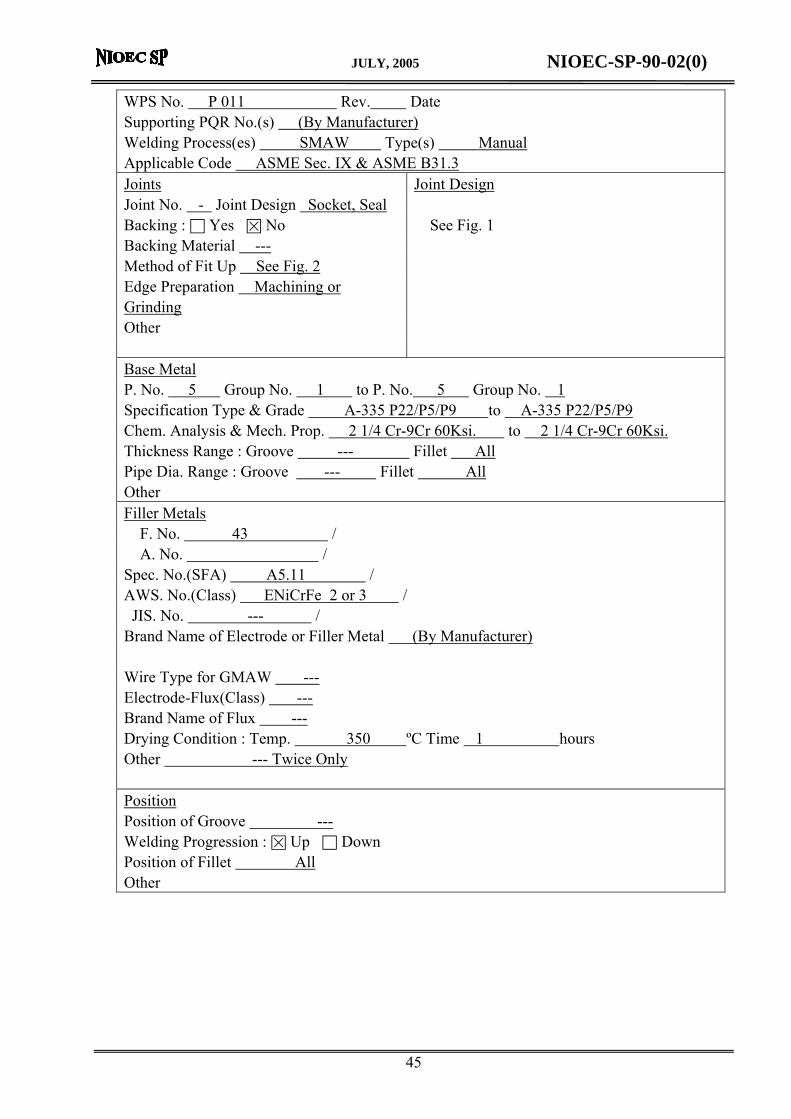
WPS No. P 011 Rev. Date Supporting PQR No.(s) (By Manufacturer) Welding Process(es) SMAW Type(s) Manual Applicable Code ASME Sec. IX & ASME B31.3 Joints Joint Design Joint No. - Joint Design Socket, Seal Backing : Yes No See Fig. 1 Backing Material --- Method of Fit Up See Fig. 2 Edge Preparation Machining or Grinding
Other Base Metal P. No. 5 Group No. 1 to P. No. 5 Group No. 1 Specification Type & Grade A-335 P22/P5/P9 to A-335 P22/P5/P9 Chem. Analysis & Mech. Prop. 2 1/4 Cr-9Cr 60Ksi. to 2 1/4 Cr-9Cr 60Ksi. Thickness Range : Groove --- Fillet All Pipe Dia. Range : Groove --- Fillet All Other Filler Metals F. No. 43 / A. No. / Spec. No.(SFA) A5.11 / AWS. No.(Class) ENiCrFe 2 or 3 / JIS. No. --- / Brand Name of Electrode or Filler Metal (By Manufacturer) Wire Type for GMAW --- Electrode-Flux(Class) --- Brand Name of Flux --- Drying Condition : Temp. 350 ºC Time 1 hours Other --- Twice Only Position Position of Groove --- Welding Progression : Up Down Position of Fillet All Other
45

JULY, 2005 NIOEC-SP-90-02(0)
WPS No. P011 (cont′d). Preheat : Yes No Post Heat : Yes No Preheat Temp. 175~350 ºC Post Heat Temp. --- ºC Interpass Temp. 175 ºC Holding Time --- min. Method Gas Burner or Electric Heater
Method ---
Other Other Postweld Heat Treatment. : Yes No Temperature Range --- Holding Time --- Increasing & Decreasing Rate. --- ºC/Hr(max.) Other Gas Shielding Gas(es) --- Flow Rate --- l/min. Percent Composition --- % Gas Backing : Yes No --- l/min. Trailing Shielding Gas Composition --- % Other Electrical Characteristics & Technique Tungsten Electrode Size --- mm Type --- Mode of Metal Transfer for GMAW --- Electrode Wire Feed Speed Range --- Bead : String Weave Orifice or Gas Cup Size --- mm Initial & lnterpass Cleaning : Brushing Grinding Other Pass(per side) : Multi Single Electrode : Multi Single Method of Back Gouging --- Other
Filler Metal Current Weld Layer
Welding Process Brand Class Dia.
(mm) Type Polar.
Amp. Range
Volt Range
Travel Speed Range cm/min
Root & Fill
SMAW
ENiCrFe 2 or 3
46

JULY, 2005 NIOEC-SP-90-02(0)
WPS No. P012 Rev. Date Supporting PQR No.(s) (By Manufacturer) Welding Process(es) GTAW and SMAW Type(s) Manual Applicable Code ASME Sec. IX & ASME B31.3 Joints Joint Design Joint No. - Joint Design Butt, Fillet Backing : Yes No See Fig. 1 Backing Material --- Method of Fit Up See Fig. 2 Edge Preparation Machining or Grinding
Other Base Metal P. No. 8 Group No. 1 to P. No. 8 Group No. 1 Specification Type & Grade A-312 TP304 /TP304L/TP316/316L to A-312 TP304 /TP304L/TP316/316L Chem. Analysis & Mech. Prop. 16Cr-12Ni-2Mo, 75ksi to 16Cr-12Ni-2Mo, 75ksi Thickness Range : Groove ≥1.6mm Fillet All Pipe Dia. Range : Groove ≥1/2 inch Fillet All Other Filler Metals F. No. 6 / 5 A. No. 8 / 8 Spec. No.(SFA) A5.9 / A5.4 AWS. No.(Class) ER308/ ER308L/ER316L / E308/ E308L/E316L JIS. No. --- / --- Brand Name of Electrode or Filler Metal (By Manufacturer) Wire Type for GMAW --- Electrode-Flux(Class) --- Brand Name of Flux --- Drying Condition : Temp. (E308) 150~250 ºC Time 1 hours Other --- Twice Only Position Position of Groove All (Qualified : 6G) Welding Progression : Up Down Position of Fillet All Other
47

JULY, 2005 NIOEC-SP-90-02(0)
WPS No. P 012 (cont′d). Preheat : Yes No Post Heat : Yes No Preheat Temp. (Min.10) ºC Post Heat Temp. --- ºC Interpass Temp. (Min.10) ºC Holding Time --- min. Method --- Method --- Other Other Postweld Heat Treatment. : Yes No Temperature Range --- Holding Time --- Increasing & Decreasing Rate. ºC/Hr(max.) Other Gas Shielding Gas(es) Argon Flow Rate 8~15 l/min. Percent Composition 99.9 % Gas Backing : Yes No 8~15 l/min. Trailing Shielding Gas Composition --- % Other Electrical Characteristics & Technique Tungsten Electrode Size 1.6~3.2 mm Type 2% Thorium Mode of Metal Transfer for GMAW --- Electrode Wire Feed Speed Range --- Bead : String Weave Orifice or Gas Cup Size 8.0~12.5 mm Initial & lnterpass Cleaning : Brushing Grinding Other Pass(per side) : Multi Single Electrode : Multi Single Method of Back Gouging --- Other
Filler Metal Current Weld Layer
Welding Process Brand Class Dia
(mm) Type Polar.
Amp. Range
Volt Range
Travel Speed Range cm/min
Root Fill
GTAW SMAW
ER308/ ER308L/ ER316L E308/ E308L/ E316L
48
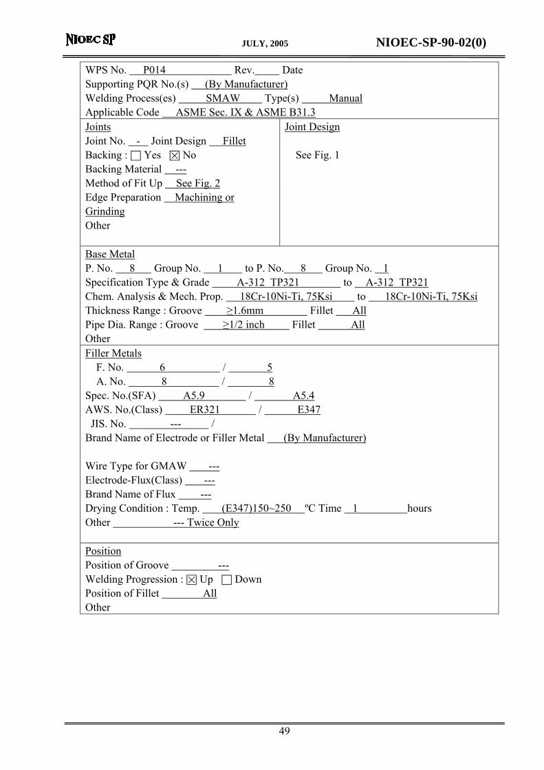
JULY, 2005 NIOEC-SP-90-02(0)
WPS No. P014 Rev. Date Supporting PQR No.(s) (By Manufacturer) Welding Process(es) SMAW Type(s) Manual Applicable Code ASME Sec. IX & ASME B31.3 Joints Joint Design Joint No. - Joint Design Fillet Backing : Yes No See Fig. 1 Backing Material --- Method of Fit Up See Fig. 2 Edge Preparation Machining or Grinding
Other Base Metal P. No. 8 Group No. 1 to P. No. 8 Group No. 1 Specification Type & Grade A-312 TP321 to A-312 TP321 Chem. Analysis & Mech. Prop. 18Cr-10Ni-Ti, 75Ksi to 18Cr-10Ni-Ti, 75Ksi Thickness Range : Groove ≥1.6mm Fillet All Pipe Dia. Range : Groove ≥1/2 inch Fillet All Other Filler Metals F. No. 6 / 5 A. No. 8 / 8 Spec. No.(SFA) A5.9 / A5.4 AWS. No.(Class) ER321 / E347 JIS. No. --- / Brand Name of Electrode or Filler Metal (By Manufacturer) Wire Type for GMAW --- Electrode-Flux(Class) --- Brand Name of Flux --- Drying Condition : Temp. (E347)150~250 ºC Time 1 hours Other --- Twice Only Position Position of Groove --- Welding Progression : Up Down Position of Fillet All Other
49

JULY, 2005 NIOEC-SP-90-02(0)
WPS No. P014 (cont′d). Preheat : Yes No Post Heat : Yes No Preheat Temp. (Min.10) ºC Post Heat Temp. --- ºC Interpass Temp. (Min.10) ºC Holding Time --- min. Method --- Method --- Other Other Postweld Heat Treatment. : Yes No Temperature Range --- Holding Time --- Increasing & Decreasing Rate. --- ºC/Hr(max.) Other Gas Shielding Gas(es) --- Flow Rate --- l/min. Percent Composition --- % Gas Backing : Yes No --- l/min. Trailing Shielding Gas Composition --- % Other Electrical Characteristics & Technique Tungsten Electrode Size --- mm Type --- Mode of Metal Transfer for GMAW --- Electrode Wire Feed Speed Range --- Bead : String Weave Orifice or Gas Cup Size --- mm Initial & lnterpass Cleaning : Brushing Grinding Other Pass(per side) : Multi Single Electrode : Multi Single Method of Back Gouging --- Other
Filler Metal Current Weld Layer
Welding Process Brand Class Dia
(mm) Type Polar.
Amp. Range
Volt Range
Travel Speed Range cm/min
Root Fill
GTAW SMAW
ER321 E347
50

JULY, 2005 NIOEC-SP-90-02(0)
WPS No. P015 Rev. Date Supporting PQR No.(s) (By Manufacturer) Welding Process(es) SMAW Type(s) Manual Applicable Code ASME Sec. IX & ASME B31.3 Joints Joint Design Joint No. - Joint Design Fillet Backing : Yes No See Fig. 1 Backing Material --- Method of Fit Up See Fig. 2 Edge Preparation Machining or Grinding
Other Base Metal P. No. 8 Group No. 1 to P. No. 1 Group No. 1 Specification Type & Grade A-312 to A53-B Chem. Analysis & Mech. Prop. AUSTENITIC STAINLESS STEEL, 75Ksi to C-Mn, 60Ksi Thickness Range : Groove --- Fillet All Pipe Dia. Range : Groove --- Fillet All Other Filler Metals F. No. 43 / or5 A. No. / Spec. No.(SFA) A5.11 / A5.4 AWS. No.(Class) ENiCrFe2or3 / E309 JIS. No. ↑>428ºC↑ / (≤428ºC) ↑ Brand Name of Electrode or Filler Metal (By Manufacturer) Wire Type for GMAW --- Electrode-Flux(Class) --- Brand Name of Flux --- Drying Condition : Temp. (ENiCrFe)350 ºC Time 1 hours Other (E309)150~250 1 --- Twice Only Position Position of Groove --- Welding Progression : Up Down Position of Fillet All Other
51

JULY, 2005 NIOEC-SP-90-02(0)
WPS No. P015 (cont′d). Preheat : Yes No Post Heat : Yes No Preheat Temp. (Min. 10) ºC Post Heat Temp. --- ºC Interpass Temp. (Min. 10) ºC Holding Time --- min. Method --- Method --- Other Other Postweld Heat Treatment. : Yes No Temperature Range --- Holding Time --- Increasing & Decreasing Rate. --- ºC/Hr(max.) Other Gas Shielding Gas(es) --- Flow Rate --- l/min. Percent Composition --- % Gas Backing : Yes No --- l/min. Trailing Shielding Gas Composition --- % Other Elecrtical Characteristics & Technique Tungsten Electrode Size --- mm Type --- Mode of Metal Transfer for GMAW --- Electrode Wire Feed Speed Range --- Bead : String Weave Orifice or Gas Cup Size --- mm Initial & Interpass Cleaning : Brushing Grinding Other Pass(per side) : Multi Single Electrode : Multi Single Method of Back Gouging --- Other
Filler Metal Current Weld Layer
Welding Process Brand Class Dia.
(mm)
Type Polar.
Amp. Range
Volt Range
Travel Speed Range cm/min
Fill
SMAW
ENiCrFe 2 -or 3 or E309
52

JULY, 2005 NIOEC-SP-90-02(0)
WPS No. P 016 Rev. Date Supporting PQR No.(s) (By Manufacturer) Welding Process(es) GTAW and SMAW Type(s) Manual Applicable Code ASME Sec. IX & ASME B31.3 Joints Joint Design Joint No. - Joint Design Butt, Fillet Backing : Yes No See Fig. 1 Backing Material --- Method of Fit Up See Fig. 2 Edge Preparation Machining or Grinding Other Base Metal P. No. 5 Group No. 1 to P. No. 4 Group No. 1 Specification Type & Grade A-335 P22 to A-335 P11 Chem. Analysis & Mech. Prop. 2 1/4 Cr-1/2 Mo, 60ksi to 1- 1/4 Cr-1/2 Mo, 60ksi Thickness Range : Groove ≤18mm Fillet All Pipe Dia. Range : Groove ≥1/2inch Fillet All Other Filler Metals F. No. 6 / 4 A. No. 3 / 3 Spec. No.(SFA) A5.28 / A5.5 AWS. No.(Class) ER80S-B2 / E8016-B2 JIS. No. --- / --- Brand Name of Electrode or Filler Metal (By Manufacturer) Wire Type for GMAW --- Electrode-Flux(Class) --- Brand Name of Flux --- Drying Condition : Temp. (E8016-B2) 350~400 ºC Time 1 hours Other --- Twice Only Position Position of Groove All (Qualified : 6G) Welding Progression : Up Down Position of Fillet All Other
53

JULY, 2005 NIOEC-SP-90-02(0)
WPS No. P016 (cont′d). Preheat : Yes No Post Heat : Yes No Preheat Temp. 150-300 ºC Post Heat Temp. --- ºC Interpass Temp. 150 ºC Holding Time --- min. Method --- Method --- Other Other Postweld Heat Treatment. : Yes No Temperature Range 704ºC~745ºC Holding Time 1Hr / 25.4mm(Min. 1 Hr) Increasing & Decreasing Rate. Heating : 200, Cooling :275 ºC/Hr(max.) Other Gas Shielding Gas(es) Argon Flow Rate 8~15 l/min. Percent Composition 99.9 % Gas Backing : Yes No 8~15 l/min. Trailing Shielding Gas Composition --- % Other Electrical Characteristics & Technique Tungsten Electrode Size 1.6~3.2 mm Type 2%Thorium Mode of Metal Transfer for GMAW --- Electrode Wire Feed Speed Range --- Bead : String Weave Orifice or Gas Cup Size 8.0~12.5 mm Initial & lnterpass Cleaning : Brushing Grinding Other Pass(per side) : Multi Single Electrode : Multi Single Method of Back Gouging --- Other
Filler Metal1 Current Weld Layer
Welding Process Brand Class Dia
(mm) Type Polar.
Amp. Range
Volt Range
Travel Speed Range cm/min
Root Fill
GTAW SMAW
ER80S-B2 E8016-B2
Note: Hardness test shall be required. (Max. BHN225)
54

JULY, 2005 NIOEC-SP-90-02(0)
WPS No. P 017 Rev. Date Supporting PQR No.(s) (By Manufacturer) Welding Process(es) GTAW and SMAW Type(s) Manual Applicable Code ASME Sec. IX & ASME B31.3 Joints Joint Design Joint No. - Joint Design Butt, Fillet Backing : Yes No See Fig. 1 Backing Material --- Method of Fit Up See Fig. 2 Edge Preparation Machining or Grinding Other Base Metal P. No. 5 Group No. 1 to P. No. 5 Group No. 1 Specification Type & Grade A-335 P22 to A-335 P22 Chem. Analysis & Mech. Prop. 2 1/4 Cr-1/2 M0 , 60ksi to 2 1/4 Cr-1/2 M0 , 60ksi Thickness Range : Groove ≤18mm Fillet All Pipe Dia. Range : Groove ≥ 2inch Fillet All Other Filler Metals F. No. 6 / 4 A. No. 4 / 4 Spec. No.(SFA) A5.28 / A5.5 AWS. No.(Class) ER90S-G / E9016-B3 JIS. No. --- / --- Brand Name of Electrode or Filler Metal (By Manufacturer) Wire Type for GMAW --- Electrode-Flux(Class) --- Brand Name of Flux --- Drying Condition : Temp. (E9016)350~400 ºC Time 1 hours Other --- Twice Only Position Position of Groove All (Qualified : 6G) Welding Progression : Up Down Position of Fillet All Other
55

JULY, 2005 NIOEC-SP-90-02(0)
WPS No. P017 (cont′d). Preheat : Yes No Post Heat : Yes No Preheat Temp. 175-350 ºC Post Heat Temp. 300-350 ºC Interpass Temp. 175Min-350 ºC Holding Time 10 min. Method Gas burner or Electric Heater Method Gas burner or Electric Heater Other Other Postweld Heat Treatment. : Yes No Temperature Range 704ºC~760ºC Holding Time 1Hr / 25.4mm(Min. 2 Hr) Increasing & Decreasing Rate. Heating : 200, Cooling :275 ºC/Hr(max.) Other Gas Shielding Gas(es) Argon Flow Rate 8~15 l/min. Percent Composition 99.9 % Gas Backing : Yes No 8~15 l/min. Trailing Shielding Gas Composition --- % Other Electrical Characteristics & Technique Tungsten Electrode Size 1.6~3.2 mm Type 2%Thorium Mode of Metal Transfer for GMAW --- Electrode Wire Feed Speed Range --- Bead : String Weave Orifice or Gas Cup Size 8.0~12.5 mm Initial & lnterpass Cleaning : Brushing Grinding Other Pass(per side) : Multi Single Electrode : Multi Single Method of Back Gouging --- Other
Filler Metal1 Current Weld Layer
Welding Process Brand Class Dia
(mm) Type Polar.
Amp. Range
Volt Range
Travel Speed Range cm/min
Root Fill
GTAW SMAW
ER90S-G E9016-B3
56

JULY, 2005 NIOEC-SP-90-02(0)
FIG.1 SHAPE OF EDGE
TYPE OF JOINT SHAPE OF EDGE NOTE
Pipe wall
thickness
up to 22.2 mm
BUTT WELD
Pipe wall
thickness
above 22.2 mm
SOCKET
WELD
Cx (min.) = 1.25t
but not less than
3.2mm
57

JULY, 2005 NIOEC-SP-90-02(0)
SLIP-ON
FLANGE
tc = t or 6.3 mm
(whichever is
smaller)
X min.= 1.4 t or
Th
(whichever is
smaller)
(UNIT : mm)
FIG. cont′d
TYPE OFJOINT SHAPE OF EDGE NOTE
BRANCH
CONNECTION
or BOSS
tc = 0.7 tn or 6.4 mm
(whichever is
smaller)
O – LET
58

JULY, 2005 NIOEC-SP-90-02(0)
FIG 2(method of fit-up) INTERNAL MISALIGNMENT
Fi8.2 – Method of Fit Up (Examp.)
NUMBER OF TACKS REQUIRED
PIPE SIZE No.OF TACKS SIZE OF THE
TACK
1/2”-2” 3 6mm
3”-12” 4 12mm
14”-18” 6 18mm
20”&LARGER 8 25mm
59
JULY, 2005 NIOEC-SP-90-02(0)
60
TABLE 1: HEAT TREATMENT AND INSPECTION REQUIREMENT FOR
WELDED PIPING
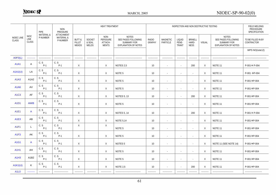
MARCH, 2005 NIOEC-SP-90-02(0)
HEAT TREATMENT
INSPECTION AND NON DESTRUCTIVE TESTING FIELD WELDING
PROCEDURE SPECIFICATION
NOTES SEE PAGES FOLLOWING
SUMMARY FOR EXPLANATION OF NOTES
NOTES SEE PAGES FOLLOWING
SUMMARY FOR EXPLANATION OF NOTES
TO BE FILLED IN BY CONTRACTOR
NIOEC LINE CLASS
NIOC LINE CLASS
PIPE MATERIAL & P-NUMBER
NON-
PRESSURE ATTACHMENT MATERIAL & P-NUMBER
BUTT & FILLET WEKDS
SOCKET & SEAL WELDS
NON- PERSSURE
ATTACH- MENTS
RADIO GRAPHY
MAGNETIC PARTICLE
LIQUID PENE- TRANT
BRINELL HARD- NESS
VISUAL
WPS NO(note12)
A0F0(L) ---------- ---------------- ---------------------- ----------- ------------- ---------------- ------------------------------------ ------------- -------------- ----------- ----------- ----------- --------------------------------- -----------------------------
A1A1 A C. S P-1
C. S P-1
X
X
NOTES 2,5
10
-
-
200
X
NOTE 11
P-001 P-004
A1A1(U) LA C. S P-1
C. S P-1
X
X
NOTE 5
10
-
-
-
X
NOTE 11
P-001 P-004
A1A3 A1A2 C. S P-1
C. S P-1
X
X
NOTE 5
10
-
-
-
X
NOTE 11
P-001 P-004
A1A6 AV C. S P-1
C. S P-1
X
X
NOTE 5
10
-
-
-
X
NOTE 11
P-001 P-004
A1C3 AF C. S P-1
C. S P-1
X
X
NOTES 5, 13
10
-
-
200
X
NOTE 11
P-001 P-004
A1D1 AM/B C. S P-1
C. S P-1
X
X
NOTE 5
10
-
-
-
X
NOTE 11
P-001 P-004
A1E1 A C. S P-1
C. S P-1
X
X
NOTES 5, 14
10
-
-
200
X
NOTE 11
P-001 P-004
A1E3 AB C. S P-1
C. S P-1
X
X
NOTE 5,14
10
-
-
-
X
NOTE 11
P-001 P-004
A1F1 L C. S P-1
C. S P-1
X X NOTE 5
10
-
-
-
X
NOTE 11
P-001 P-004
A1F3 AK C. S P-1
C. S P-1
X
X
NOTE 5
10
-
-
-
X
NOTE 11
P-001 P-004
A1G1 A C. S P-1
C. S P-1
X
X
NOTES 5
10
-
-
-
X
NOTE 11 (SEE NOTE 14)
P-001 P-004
A1H1 AH C. S P-1
C. S P-1
X
X
NOTE 5
10
-
-
-
X
NOTE 11
P-001 P-004
A1H3 A1B2 C. S P-1
C. S P-1
X
X
NOTE 5
10
-
-
-
X
NOTE 11
P-001 P-004
A1K1(U) K C. S P-1
C. S P-1
X
X
NOTE 2,5
10
-
-
200
X
NOTE 11
P-001 P-004
A1L0 --------- --------------- ------------------- ----------- ------------ -------------- ---------------------------------- ----------- ------------- ----------- ----------- ---------- ---------------------------- -----------------------
61
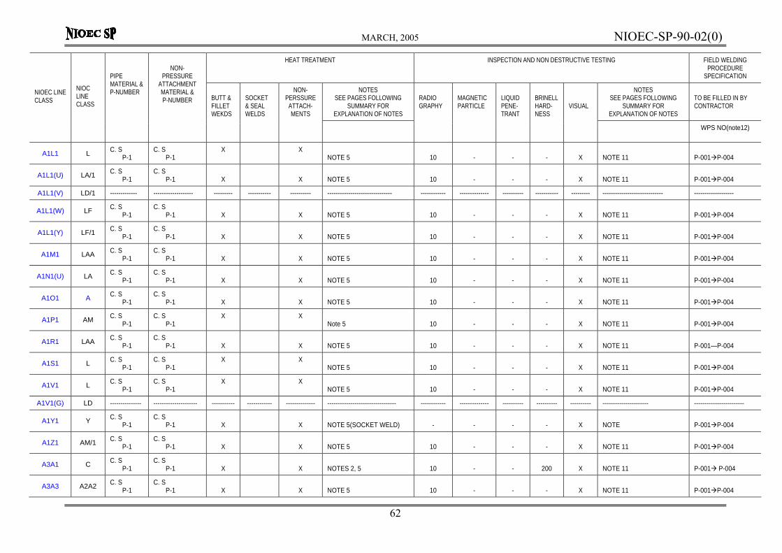
MARCH, 2005 NIOEC-SP-90-02(0)
HEAT TREATMENT
INSPECTION AND NON DESTRUCTIVE TESTING FIELD WELDING PROCEDURE
SPECIFICATION
NOTES SEE PAGES FOLLOWING
SUMMARY FOR EXPLANATION OF NOTES
NOTES SEE PAGES FOLLOWING
SUMMARY FOR EXPLANATION OF NOTES
TO BE FILLED IN BY CONTRACTOR
NIOEC LINE CLASS
NIOC LINE CLASS
PIPE MATERIAL & P-NUMBER
NON-
PRESSURE ATTACHMENT MATERIAL & P-NUMBER
BUTT & FILLET WEKDS
SOCKET & SEAL WELDS
NON- PERSSURE
ATTACH- MENTS
RADIO GRAPHY
MAGNETIC PARTICLE
LIQUID PENE- TRANT
BRINELL HARD- NESS
VISUAL
WPS NO(note12)
A1L1 L C. S P-1
C. S P-1
X X NOTE 5
10
-
-
-
X
NOTE 11
P-001 P-004
A1L1(U) LA/1 C. S P-1
C. S P-1
X
X
NOTE 5
10
-
-
-
X
NOTE 11
P-001 P-004
A1L1(V) LD/1 ------------- ------------------- --------- ----------- ---------- ------------------------------- ------------ -------------- ---------- ----------- --------- ----------------------------- -------------------
A1L1(W) LF C. S P-1
C. S P-1
X
X
NOTE 5
10
-
-
-
X
NOTE 11
P-001 P-004
A1L1(Y) LF/1 C. S P-1
C. S P-1
X
X
NOTE 5
10
-
-
-
X
NOTE 11
P-001 P-004
A1M1 LAA C. S P-1
C. S P-1
X
X
NOTE 5
10
-
-
-
X
NOTE 11
P-001 P-004
A1N1(U) LA C. S P-1
C. S P-1
X
X
NOTE 5
10
-
-
-
X
NOTE 11
P-001 P-004
A1O1 A C. S P-1
C. S P-1
X
X
NOTE 5
10
-
-
-
X
NOTE 11
P-001 P-004
A1P1 AM C. S P-1
C. S P-1
X X Note 5
10
-
-
-
X
NOTE 11
P-001 P-004
A1R1 LAA C. S P-1
C. S P-1
X
X
NOTE 5
10
-
-
-
X
NOTE 11
P-001—P-004
A1S1 L C. S P-1
C. S P-1
X X NOTE 5
10
-
-
-
X
NOTE 11
P-001 P-004
A1V1 L C. S P-1
C. S P-1
X X NOTE 5
10
-
-
-
X
NOTE 11
P-001 P-004
A1V1(G) LD --------------- --------------------- ----------- ------------ -------------- --------------------------------- ------------ -------------- ---------- ---------- ---------- ---------------------- ------------------------
A1Y1 Y C. S P-1
C. S P-1
X
X
NOTE 5(SOCKET WELD)
-
-
-
-
X
NOTE
P-001 P-004
A1Z1 AM/1 C. S P-1
C. S P-1
X
X
NOTE 5
10
-
-
-
X
NOTE 11
P-001 P-004
A3A1 C C. S P-1
C. S P-1
X
X
NOTES 2, 5
10
-
-
200
X
NOTE 11
P-001 P-004
A3A3 A2A2 C. S P-1
C. S P-1
X
X
NOTE 5
10
-
-
-
X
NOTE 11
P-001 P-004
62

MARCH, 2005 NIOEC-SP-90-02(0)
HEAT TREATMENT
INSPECTION AND NON DESTRUCTIVE TESTING FIELD WELDING PROCEDURE
SPECIFICATION
NOTES SEE PAGES FOLLOWING
SUMMARY FOR EXPLANATION OF NOTES
NOTES SEE PAGES FOLLOWING
SUMMARY FOR EXPLANATION OF NOTES
TO BE FILLED IN BY CONTRACTOR
NIOEC LINE CLASS
NIOC LINE CLASS
PIPE MATERIAL & P-NUMBER
NON-
PRESSURE ATTACHMENT MATERIAL & P-NUMBER
BUTT & FILLET WEKDS
SOCKET & SEAL WELDS
NON- PERSSURE
ATTACH- MENTS
RADIO GRAPHY
MAGNETIC PARTICLE
LIQUID PENE- TRANT
BRINELL HARD- NESS
VISUAL
WPS NO(note12)
A3A4 ---------- C. S P-1
C. S P-1
X
X
NOTE 5
10
-
-
-
X
NOTE 11
P-001 P-004
A3D1 AM/A C. S P-1
C. S P-1
X
X
NOTE 5
10
-
-
-
X
NOTE 11
P-001 P-004
A3E1 C C. S P-1
C. S P-1
X
X
NOTES 5, 14
10
-
-
200
X
NOTE 11
P-001 P-004
A3E3 CB C. S P-1
C. S P-1
X
X
NOTE 5,14
10
-
-
-
X
NOTE 11
P-001 P-004
A3F3 CK C. S P-1
C. S P-1
X
X
NOTE 5
10
-
-
-
X
NOTE 11
P-001 P-004
A3G1 C C. S P-1
C. S P-1
X
X
NOTES 5
10
-
-
-
X
NOTE 11
P-001, P-004
A3H1 CH C. S P-1
C. S P-1
X
X
NOTE 5
10
-
-
-
X
NOTE 11
P-001 P-004
A3H3 A2B2 C. S P-1
C. S P-1
X
X
NOTE 5
10
-
-
-
X
NOTE 11
P-001 P-004
A3L1 R C. S P-1
C. S P-1
X
X
NOTE 5
10
-
-
-
X
NOTE 11
P-001 P-004
A3M1 RA C. S P-1
C. S P-1
X
X
NONE 5
10
-
-
-
X
NOTE 11
P-001 P-004
A3N1 --------- C. S P-1
C. S P-1
NONE
10
-
-
-
X
NOTE 11
P-001 P-004
A3S1 R C. S P-1
C. S P-1
X
X
NOTE 5
10
-
-
-
X
NOTE 11
P-001 P-004
A3T1 RA C. S P-1
C. S P-1
X
X
NOTE 5
10
-
-
-
X
NOTE 11
P-001 P-004
A3V1(G) --------- -------------- ---------------- ----------- ----------- ------------ ------------------------- ------------- -------------- ----------- ----------- ---------- --------------------------------- -------------------------
A3Y1 Z C. S P-1
C. S P-1
X
X
NOTE 5.(SOCKET WELD)
-
-
-
-
X
NOTE
P-001 P-004
A3Z1 AM/2 C. S P-1
C. S P-1
X
X
NOTE 5
10
-
-
-
X
NOTE 11
P-001 P-004
63

MARCH, 2005 NIOEC-SP-90-02(0)
HEAT TREATMENT
INSPECTION AND NON DESTRUCTIVE TESTING FIELD WELDING PROCEDURE
SPECIFICATION
NOTES SEE PAGES FOLLOWING
SUMMARY FOR EXPLANATION OF NOTES
NOTES SEE PAGES FOLLOWING
SUMMARY FOR EXPLANATION OF NOTES
TO BE FILLED IN BY CONTRACTOR
NIOEC LINE CLASS
NIOC LINE CLASS
PIPE MATERIAL & P-NUMBER
NON-
PRESSURE ATTACHMENT MATERIAL & P-NUMBER
BUTT & FILLET WEKDS
SOCKET & SEAL WELDS
NON- PERSSURE
ATTACH- MENTS
RADIO GRAPHY
MAGNETIC PARTICLE
LIQUID PENE- TRANT
BRINELL HARD- NESS
VISUAL
WPS NO(note12)
A6A1 A4A1 C. S P-1
C. S P-1
X
X
NOTE 5
10
-
-
- X NOTE 11 P-001 P-004
C. S C. S NOTE 5
-
-
X
NOTE 11
A6B1 F P-1 P-1 X X 10 - P-001 P-004
A6H3 ---------- C. S P-1
C. S P-1
X X NOTE 5 10 - - - X NOTE 11 P-001 P-004
A6L1 C. S C. S S P-1 P-1 X X NOTE 5 10 - - - X NOTE 11 P-001 P-004
A6M1 S/1 C. S C. S 10
-
-
X
P-1 P-1 X X NOTE 5 - NOTE 11
P-001 P-004
A6S1 C. S C. S S P-1 P-1 X X NOTE 5 10 - - - X NOTE 11 P-001 P-004
A6T1 S/1 C. S C. S NOTE 5
10
-
-
-
X
P-1 P-1 X X NOTE 11
P-001 P-004
A8F1(R) HH C. S P-1
C. S P-1
X
X
NOTE 5
10
-
-
-
X
NOTE 11
P-001 P-004
A8H1(R) HH C. S P-1
C. S P-1 X X NOTE 5 10 - - - X NOTE 11 P-001 P-004
B1A4 ---------- C. S P-1
C. S X
X
NOTES 5, 13
-
-
X
P-1 10 200 NOTE 11 P-001 P-004
B1A4(N) --------- C. S C. S P-1 P-1 X X NOTES 2, 5, 13 10 - - 200 X NOTE 11 P-001 P-004
B1E4(N) ---------- C. S C. S P-1 P-1 X X NOTES 5, 14 10 - - 200 X NOTE 11 P-001 P-004
B3A3(N) ---------- C. S P-1
C. S X
X
NOTES 2, 5, 13
P-1 10 - - 200 X NOTE 11 P-001 P-004
B3H3 --------- C. S C. S P-1 P-1 X X NOTE 5 10 - - - X NOTE 11
P-001 P-004
B6A1 ---------- C. S P-1
C. S P-1
X
X
NOTE 5
10
-
-
-
X
NOTE 11
P-001 P-004
B6A3(N) --------- C. S P-1
C. S P-1
X
X
NOTES 5, 13
10
-
-
200
X
NOTE 11
P-001 P-004
64

MARCH, 2005 NIOEC-SP-90-02(0)
65
HEAT TREATMENT
INSPECTION AND NON DESTRUCTIVE TESTING FIELD WELDING PROCEDURE
SPECIFICATION
NOTES SEE PAGES FOLLOWING
SUMMARY FOR EXPLANATION OF NOTES
NOTES SEE PAGES FOLLOWING
SUMMARY FOR EXPLANATION OF NOTES
TO BE FILLED IN BY CONTRACTOR
NIOEC LINE CLASS
NIOC LINE CLASS
PIPE MATERIAL & P-NUMBER
NON-
PRESSURE ATTACHMENT MATERIAL & P-NUMBER
BUTT & FILLET WEKDS
SOCKET & SEAL WELDS
NON- PERSSURE
ATTACH- MENTS
RADIO GRAPHY
MAGNETIC PARTICLE
LIQUID PENE- TRANT
BRINELL HARD- NESS
VISUAL
WPS NO(note12)
B6H3 B4B2 C. S P-1
C. S P-1
X
X
NOTE 5
10
-
-
-
X
NOTE 11
P-001 P-004
B6L3(N) --------- C. S P-1
C. S P-1
X
X
NOTES 5, 13
10
-
-
200
X
NOTE 11
P-001 P-004
B8A1 B6A1 K. C. S P-1
C. S P-1
X
X
NOTE 5
10
MP (SOCKET)
-
-
X
NOTE 11
P-001 P-004
B8A3(N) --------- C. S P-1
C. S P-1
X
X
NOTES 5, 13
10
-
-
200
X
NOTE 11
P-001 P-004
B8H3 B6B2 K. C. S P-1
C. S P-1
X
X
NOTE 5
10
MP (SOCKET)
-
-
X
NOTE 11
P-001 P-004
B9A3 B5A2 K. C. S P-1
C. S P-1
X
X
NOTE 5
10
-
-
-
X
NOTE 11
P-001 P-004
B9H3 B5B2 K.C. S P-1
C. S P-1
X
X
NOTE 5
10
-
-
X
NOTE 11
P-001 P-004
B9H3(R) B7C2 K. C. S P-1
C. S P-1
X
X
NOTE 5
10
MP (SOCKET)
-
-
X
NOTE 11
P-001 P-004
D1K0 K/1 ------------- ------------- --------- -------- --------- ---------------------------- --------- --------- ------- -------- -------- ------------------------------ ----------------------
D1L0(U) K/2 ---------------- --------------- --------- ---------- ---------- ---------------------------- ---------- ----------- ---------- -------- --------- ------------------------------ -----------------------
D1L1(J) LD -------------- ---------------- --------- ----------- ------------- ----------------------------- ---------- ------------ ---------- ----------- ---------- ------------------------------ ------------------------
D1L1(U) LD/1 --------------- ------------------ ---------- ------------ ------------ ----------------------------- ----------- ------------- ----------- ----------- ----------- ----------------------------- ------------------------
E3H3 ------- C. S(.5MO) P-1
C. S P-1
X
X
NOTE 6
10
-
-
-
X
NOTE 11
P-001,
E5H3 -------- C. S(.5MO) P-1
C. S P-1
X
X
NOTE 5
10
-
-
-
X
NOTE 11
P-001
F3G1 E2B1 1-1/4 Cr P-4
1-1/4 Cr P-4
X
X
NOTE 1, 3, 6
100
MP
-
225
X
NOTES 8, 11
P-005, P-006,P-007
F3H1 CMH 1-1/4 Cr P-4
1-1/4 Cr P-4
X
X
NOTE 1, 3, 6
100
MP
-
225
X
NOTE 8,11
P-005, P-006,P-007
F3H3 E2B2 1-1/4 Cr P-4
1-1/4 Cr P-4
X
X
NOTE 1, 3, 6
100
MP
-
225
X
NOTES 8,11
P-005, P-006,P-007
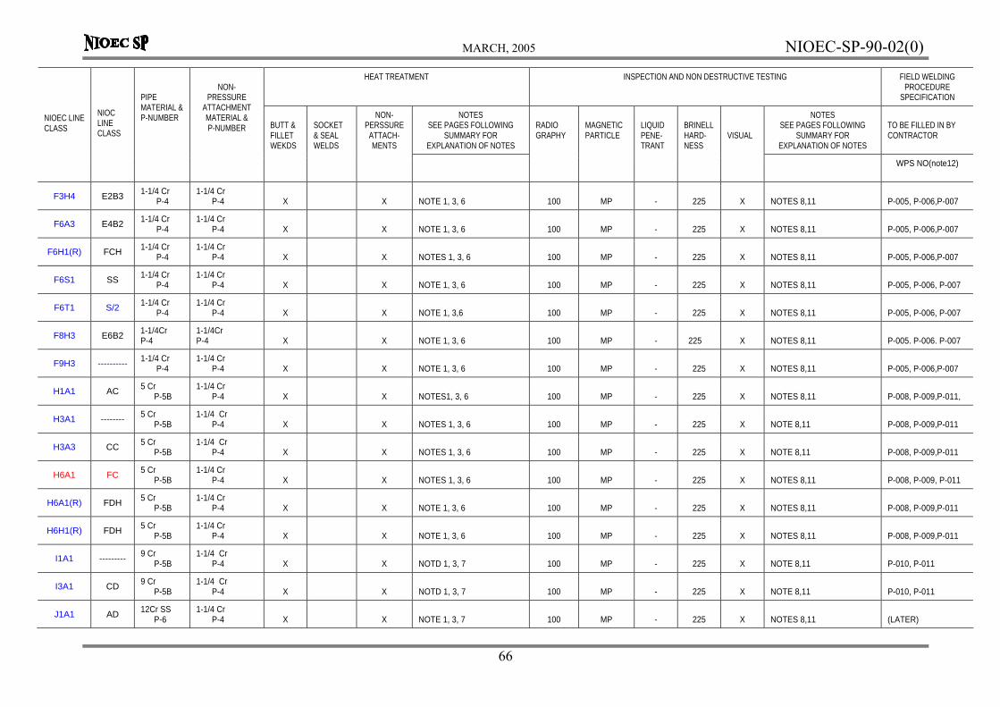
MARCH, 2005 NIOEC-SP-90-02(0)
HEAT TREATMENT
INSPECTION AND NON DESTRUCTIVE TESTING FIELD WELDING PROCEDURE
SPECIFICATION
NOTES SEE PAGES FOLLOWING
SUMMARY FOR EXPLANATION OF NOTES
NOTES SEE PAGES FOLLOWING
SUMMARY FOR EXPLANATION OF NOTES
TO BE FILLED IN BY CONTRACTOR
NIOEC LINE CLASS
NIOC LINE CLASS
PIPE MATERIAL & P-NUMBER
NON-
PRESSURE ATTACHMENT MATERIAL & P-NUMBER
BUTT & FILLET WEKDS
SOCKET & SEAL WELDS
NON- PERSSURE
ATTACH- MENTS
RADIO GRAPHY
MAGNETIC PARTICLE
LIQUID PENE- TRANT
BRINELL HARD- NESS
VISUAL
WPS NO(note12)
F3H4 E2B3 1-1/4 Cr P-4
1-1/4 Cr P-4
X
X
NOTE 1, 3, 6
100
MP
-
225
X
NOTES 8,11
P-005, P-006,P-007
F6A3 E4B2 1-1/4 Cr P-4
1-1/4 Cr P-4
X
X
NOTE 1, 3, 6
100
MP
-
225
X
NOTES 8,11
P-005, P-006,P-007
F6H1(R) FCH 1-1/4 Cr P-4
1-1/4 Cr P-4
X
X
NOTES 1, 3, 6
100
MP
-
225
X
NOTES 8,11
P-005, P-006,P-007
F6S1 SS 1-1/4 Cr P-4
1-1/4 Cr P-4
X
X
NOTE 1, 3, 6
100
MP
-
225
X
NOTES 8,11
P-005, P-006, P-007
F6T1 S/2 1-1/4 Cr P-4
1-1/4 Cr P-4
X
X
NOTE 1, 3,6
100
MP
-
225
X
NOTES 8,11
P-005, P-006, P-007
F8H3 E6B2 1-1/4Cr P-4
1-1/4Cr P-4
X
X
NOTE 1, 3, 6
100
MP
-
225
X
NOTES 8,11
P-005. P-006. P-007
F9H3 ---------- 1-1/4 Cr P-4
1-1/4 Cr P-4
X
X
NOTE 1, 3, 6
100
MP
-
225
X
NOTES 8,11
P-005, P-006,P-007
H1A1 AC 5 Cr P-5B
1-1/4 Cr P-4
X
X
NOTES1, 3, 6
100
MP
-
225
X
NOTES 8,11
P-008, P-009,P-011,
H3A1 -------- 5 Cr P-5B
1-1/4 Cr P-4
X
X
NOTES 1, 3, 6
100
MP
-
225
X
NOTE 8,11
P-008, P-009,P-011
H3A3 CC 5 Cr P-5B
1-1/4 Cr P-4
X
X
NOTES 1, 3, 6
100
MP
-
225
X
NOTE 8,11
P-008, P-009,P-011
H6A1 FC 5 Cr P-5B
1-1/4 Cr P-4
X
X
NOTES 1, 3, 6
100
MP
-
225
X
NOTES 8,11
P-008, P-009, P-011
H6A1(R) FDH 5 Cr P-5B
1-1/4 Cr P-4
X
X
NOTE 1, 3, 6
100
MP
-
225
X
NOTES 8,11
P-008, P-009,P-011
H6H1(R) FDH 5 Cr P-5B
1-1/4 Cr P-4
X
X
NOTE 1, 3, 6
100
MP
-
225
X
NOTES 8,11
P-008, P-009,P-011
I1A1 --------- 9 Cr P-5B
1-1/4 Cr P-4
X
X
NOTD 1, 3, 7
100
MP
-
225
X
NOTE 8,11
P-010, P-011
I3A1 CD 9 Cr P-5B
1-1/4 Cr P-4
X
X
NOTD 1, 3, 7
100
MP
-
225
X
NOTE 8,11
P-010, P-011
J1A1 AD 12Cr SS P-6
1-1/4 Cr P-4
X
X
NOTE 1, 3, 7
100
MP
-
225
X
NOTES 8,11
(LATER)
66

MARCH, 2005 NIOEC-SP-90-02(0)
HEAT TREATMENT
INSPECTION AND NON DESTRUCTIVE TESTING FIELD WELDING PROCEDURE
SPECIFICATION
NOTES SEE PAGES FOLLOWING
SUMMARY FOR EXPLANATION OF NOTES
NOTES SEE PAGES FOLLOWING
SUMMARY FOR EXPLANATION OF NOTES
TO BE FILLED IN BY CONTRACTOR
NIOEC LINE CLASS
NIOC LINE CLASS
PIPE MATERIAL & P-NUMBER
NON-
PRESSURE ATTACHMENT MATERIAL & P-NUMBER
BUTT & FILLET WEKDS
SOCKET & SEAL WELDS
NON- PERSSURE
ATTACH- MENTS
RADIO GRAPHY
MAGNETIC PARTICLE
LIQUID PENE- TRANT
BRINELL HARD- NESS
VISUAL
WPS NO(note12)
K1A1 AL 304 SS P-8
304 SS P-8
NONE
100
-
DP
-
X
NOTE 9,11
P-012
K1F1 AL/1 304SS P-8
304SS P-8
NONE
100
-
DP
-
X
NOTE 9,11
P-012
K1L0 -------- 304 SS P-8
304 SS P-8
NONE
100
-
DP
-
X
NOTE 9,11
P-012
K3A1 CL 304 SS P-8
304 SS P-8
NONE
100
-
DP
-
X
NOTE 9,11
P-012
K3H1 CN 304 SS P-8
304 SS P-8
NONE
100
-
DP
-
X
NOTE 9,11
P-012
L1C1 AS 304L SS P-8
304 SS P-8
NONE
100
-
DP
-
X
NOTE 9,11
P-012
L1E1 AS 304L SS P-8
304 SS P-8
NONE
100
-
DP
-
X
NOTE 9,11
P-012
L3H1 CS 304L SS P-8
304 SS P-8
NONE
100
-
DP
-
X
NOTE 9,11
P-012
M1A0 ------- 316 SS P-8
316 SS P-8
NONE
100
-
DP
-
X
NOTE 9,11
P-012
M1A1 ------- 316 SS P-8
316 SS P-8
NONE
100
-
DP
-
X
NOTE 9,11
P-012
M1F0 ------- 316 SS P-8
316 SS P-8
NONE
100
-
DP
-
X
NOTE 9,11
P-012
M1F1 M1A1 316L SS P-8
316 SS P-8
NONE
100
-
DP
-
X
NOTE 9,11
P-012
N1C1 ASS 316L SS P-8
316 SS P-8
NONE
100
-
DP
-
X
NOTE 9,11
P-012
N1E1 ASS 316L SS P-8
316 SS P-8
NONE
100
-
DP
-
X
NOTE 9,11
P-012
N1F1 N1A1 316L SS P-8
316L SS P-8
NONE
100
-
DP
-
X
NOTES 9,11
P-012
N1L0 -------- 316L SS P-8
316 SS P-8
NONE
100
-
DP
-
X
NOTE 9,11
P-012
67

MARCH, 2005 NIOEC-SP-90-02(0)
68
HEAT TREATMENT
INSPECTION AND NON DESTRUCTIVE TESTING FIELD WELDING PROCEDURE
SPECIFICATION
NOTES SEE PAGES FOLLOWING
SUMMARY FOR EXPLANATION OF NOTES
NOTES SEE PAGES FOLLOWING
SUMMARY FOR EXPLANATION OF NOTES
TO BE FILLED IN BY CONTRACTOR
NIOEC LINE CLASS
NIOC LINE CLASS
PIPE MATERIAL & P-NUMBER
NON-
PRESSURE ATTACHMENT MATERIAL & P-NUMBER
BUTT & FILLET WEKDS
SOCKET & SEAL WELDS
NON- PERSSURE
ATTACH- MENTS
RADIO GRAPHY
MAGNETIC PARTICLE
LIQUID PENE- TRANT
BRINELL HARD- NESS
VISUAL
WPS NO(note12)
P3A1 Q2A1 321 SS P-8
321 SS P-8
NONE
100
-
DP
-
X
NOTES 9,11
P-014
P3P1 CSH 321 SS P-8
321 SS P-8
NONE
100
-
DP
-
X
NOTE 9,11
P-014
P9H1(R) Q7C1 321 SS P-8
321 SS P-8
NONE
100
--
DP
-
X
NOTES 9,11
P-014
V3L0(F)
X1F0(F) LB --------------- --------------------- ----------- ------------ -------------- --------------------------------- ------------ ------------- ---------- ---------- ----------- ------------------------------ --------------------------
Y1K0 K/4 -------------- -------------------- ---------- ---------- ------------- ---------------------------------- ------------ -------------- ----------- ---------- ----------- ------------------------------- ----------------------------

MARCH, 2005 NIOEC-SP-90-02(0)
SUMMARY OF HEAT TREATMENT AND RELATED
REQUIREMENTS FOR WELDED PIPING
1. Seal welds and socket welds shall be made with stainless weld metal; for lines in service over (4280C) use inconel filler metal.
2. Postweld heat treat all lines in caustic service at (5930C) to (6490C) for 1 hr/25.4mm. of wall thickness, minimum 1 hour, if operating temperature exceeds (600C) or if caustic concentration exceeds 25z by weight or if line is steam traced and either in stagnant or intermittent service, BHN shall not exceed 200.
3. Maximum hardness of welds and heat affected zone after heat treatment shall not exceed 225 BHN.
4. Postweld heat treat (7040C) to 13750F(7450C) for 1 hr/25.4mm. of wall thickness, minimum 2 hours, for all thickness, except seal and socket welds.
5. Postweld heat treat at (5930C) to (6490C) for 1 hr/25.4mm. of wall thickness, minimum 1 hour,
for wall thickness greater than 19mm. 6. Postweld heat treat at (7040C) to (7450C) for 1 hr/25.4mm. of wall thickness, minimum 2 hour
for all wall thickness,except seal and socket welds. 7. Postweld heat treat at (7050C) to (7600C) for 1 hr/25.4mm. of wall thickness minimum 2 hour. 8. (MP) Magnetic particle inspection of the Root pass and of the completed weld shall be in
accordance with ASME BPV Code,SecV,Article7. This is to include welds of Nozzles, reinforcing pads, couplings and attachment welds or welded areas. Procedure shall be established and executed by qualified personnel.
9. (DP) Liquid penetrant inspections of the Root Pass and the complete weld testing shall be made
with a non-water soluble system procedure shall be established. There shall be no sulfur or sulfur compound contained in the liquid employed.
10. (V) Visual examination shall be in accordance with the ASME BPV Code,SecV,Article9.
Visual aids such as optics, mirrors and magnifier's shall be used where practicable. 11. Radiographic testing and acceptance criteria shall be in accordance with ASME BPV Code,Sec
V,Article2.This is to include girth,butt,miter and branch welds. 12. Line classes of carbon steel material over 600# ,or instrument air lines and compressor suction
line shall be welded using GTAW ,with ER70S filler wire for root pass and SMAW,with E7016 or E7018 electrode for fill passes.
13. Postweld Heat Treat all welds in sour water (Foul condensate) service , (593-6490C) 1
hr/25.4mm.thick. , 3/4 hr. min. Brinell hardness not to exceed 200. 14. Postweld heat treat all lines operating in amine service above (65.5 ºC), or if the line is steam
traced and either in stagnant or intermittent service, Postweld heat treat at (593 to 649 ºC) for 1 hr/25.4mm. thickness, 3/4 hour minimum. Brinell hardness number shall not exceed 200.
69

MARCH, 2005 NIOEC-SP-90-02(0)
TABLE 2: RECOMMENDED WELDING PROCEDURE WITH RELATED
REQUIREMENTS
70

MARCH, 2005 NIOEC-SP-90-02(0)
WPS NO.
MAT’LS
FILLER F NO.
TYPE OF JOINT
THK. RANGE(mm)
PRE- HEAT(1)
PWHT
(2)
IMPACT (WPQT)(3)
HARDNESS MAX.
P001
P1-P1
6 OR 3 &4
ALL
<19
NA
NA
NA
NA
P002 P1-P1 6 OR 3 &4
ALL 19<& <25.4
NA YES NA NA
P003 P1-P1 6 OR 3 &4
ALL >25.4 YES YES YES NA
P004 P1-P1 (CAUSTIC /AMINE/ SOUR- WATER)
6 OR 3 &4
ALL <19 NA YES NA 200
P005 P4-P4 6 & 4 BUTT & FILLET
<18 YES YES NA 225
P006 P4-P4 6 & 4 BUTT & FILLET
>18 YES YES YES 225
P007 P4-P4 43 SOCKET & SEAL
ALL YES NA NA NA
P008 P5B-P5B (5Cr-Mo)
6 & 4 BUTT & FILLET
<18 YES YES NA 225
P010 P5B-P5B (9Cr-Mo)
6 & 4 BUTT & FILLET
<18 YES YES NA 225
P011 P5-P5 (21/4Cr-Mo, 5Cr-Mo, 9Cr-Mo)
43 SOCKET & SEAL
ALL YES NA NA NA
P012 P8-P8 (304 &316)
6 & 5 ALL ALL NA NA NA NA
P014 P8-P8 (321)
6 & 5 ALL ALL NA NA NA NA
71

MARCH, 2005 NIOEC-SP-90-02(0)
WPS NO.
MAT’LS
FILLER F NO.
TYPE OF JOINT
THK. RANGE(mm)
PRE- HEAT(1)
PWHT
(2)
IMPACT (WPQT)(3)
HARDNESS MAX.
P015
P8-P1
43 OR 5
FILLET
ALL
NA
NA
NA
NA
P016
P5A-P4 (21/4Cr -11/4Cr)
6 & 4
BUTT & FILLET (FOR MANUFOLD)
<18
YES
YES
NA
225
P017 P5A-P5A (21/4Cr )
6 & 4 BUTT & FILLET (FOR MANUFOLD)
<18 YES YES NA 225
Note: (1) The minimum preheating temperatures for welding including tack-welding shall be as
specified in ASME B31.3 shall be mandatory.
(2) The requirements of heat treatment for welded piping shall be conformed to Table-1. (3) Charpy V-notch impact tests on procedure qualifications for low temperature service shall
be produced in accordance with ASME 31.3, for the weld metal and heat affected zone at the lowest design temperature.
72
MARCH, 2005 NIOEC-SP-90-02(0)
TABLE 3: RECOMMENDED FILLER METALS/COVERED ELECTRODES FOR
PIPE WELDING
73

MARCH, 2005 NIOEC-SP-90-02(0)
P-8
TP
321
-
ER
321
AN
D/O
R
E34
7(7)
P-8
TP
347
ER
NiC
rFe5
.6
AN
D/O
R
EN
iCrF
e2.3
-
ER
308L
A
ND
/OR
E
308L
ER
347
AN
D/O
R
E34
7
P-8
TP
316L
(3) (4)
ER
316L
A
ND
/OR
E
316L
P-8
TP
304L
(3) - (4)
ER
308L
A
ND
/OR
E
308L
P-8
TP
304
ER
309
AN
D/O
R
E30
9(3)
ER
NiC
rFe5
.6
AN
D/O
R
EN
iCrF
e2.3
ER
NiC
rFe5
.6
AN
D/O
R
EN
iCrF
e2.3
ER
NiC
rFe5
.6
AN
D/O
R
EN
iCrF
e2.3
ER
308
AN
D/O
R
E30
8
P-5
B
9Cr-0
.5M
o
(5) (6) (6)
ER
505
AN
D/O
R
E50
5(6)
P-5
B
5Cr-0
.5M
o
ER
80S
- B2
AN
D/O
R
E80
16-B
2(5
) (6)
ER
502
AN
D/O
R
E50
2(6)
P-4
1.
25C
r-0.
5Mo
ER
70S
-G
AN
D/O
R
E70
16E
R80
S-B
2 A
ND
/OR
E
8016
-B2(
6)
P-1
C
.S
ER
70S
-G
AN
D/O
R
E60
10(2
)
TAB
LE-3
: LI
ST
OF
RE
CO
MM
EN
DE
D F
ILLR
ME
TAL
FOR
PIP
ING
WE
LDIN
G
C.S
1.25
Cr-
0.5M
o
5Cr-
0.5M
o
9Cr-
1Mo
TP30
4
TP30
4L
TP31
6L
TP34
7
TP32
1
N
IOE
C A
PP
RO
VAL
SH
ALL
BE
NE
CE
SS
AR
Y
N
OTE
(1) F
ILLE
T, S
OC
KE
T &
SE
AL
WE
LD M
AY
BE
MA
DE
BY
SM
AW
ELE
CTR
OD
E O
NLY
. (A
LL)
NO
TE (2
) E70
16 M
AY
BE
US
ED
IN L
IEU
OF
E60
10.
NO
TE (3
) ER
309
AN
D E
309
MA
Y B
E U
SE
D J
OIN
TS W
HE
RE
TH
E S
ER
VIC
E T
EM
PE
RA
TUR
E D
OE
S N
O E
XC
EE
D 4
28O C
.
US
E E
NiC
rFe-
2 O
R E
NiC
rFe-
3 FI
LLE
R M
ETA
L W
HE
RE
SE
RV
ICE
TE
MP
ER
ATU
RE
EX
CE
ED
428
O C
. N
OTE
(4) T
O B
E U
SE
D F
OR
ON
LY F
ILLE
T, S
OC
KE
T &
SE
AL
WE
LDS
(BU
T N
OT
VIC
E V
ER
SA
). N
OTE
(5) E
7016
MA
Y B
E U
SE
D, O
NLY
FO
R F
ILLE
T &
SO
CK
ET
WE
LDS
IN L
IEU
OF
E80
16-B
2.
NO
TE (6
) EN
iCrF
e2,3
OR
ER
NiC
rFe5
,6 S
HA
LL B
E U
SE
D F
OR
SE
AL
& S
OC
KE
T W
ELD
FO
R L
INE
IN S
ER
VIC
E O
VE
R 4
28O C
. N
OTE
(7) R
OO
T FI
LLE
R T
O T
P32
1 S
HA
LL B
E U
SE
D E
R32
1, B
UT
FILL
ET
WE
LD B
Y E
347.
74