national institute of justice - ncjrs · national institute of justice antenna system guide nij...
TRANSCRIPT

Law Enforcement and Corrections Standards and Testing Program
U.S. Department of JusticeOffice of Justice ProgramsNational Institute of Justice
National Institute of Justice
Antenna System Guide
NIJ Guide 202–00

The National Institute of Justice is a component of the Office of JusticePrograms, which also includes the Bureau of Justice Assistance, theBureau of Justice Statistics, the Office of Juvenile Justice andDelinquency Prevention, and the Office for Victims of Crime.
ABOUT THE LAW ENFORCEMENT AND CORRECTIONS STANDARDS AND TESTING PROGRAM
The Law Enforcement and Corrections Standards and Testing Program is sponsored by the Office of Science andTechnology of the National Institute of Justice (NIJ), U.S. Department of Justice. The program responds to the mandateof the Justice System Improvement Act of 1979, which directed NIJ to encourage research and development to improvethe criminal justice system and to disseminate the results to Federal, State, and local agencies.
The Law Enforcement and Corrections Standards and Testing Program is an applied research effort thatdetermines the technological needs of justice system agencies, sets minimum performance standards for specific devices,tests commercially available equipment against those standards, and disseminates the standards and the test results tocriminal justice agencies nationally and internationally.
The program operates through:The Law Enforcement and Corrections Technology Advisory Council (LECTAC), consisting of nationally
recognized criminal justice practitioners from Federal, State, and local agencies, which assesses technological needs andsets priorities for research programs and items to be evaluated and tested.
The Office of Law Enforcement Standards (OLES) at the National Institute of Standards and Technology, whichdevelops voluntary national performance standards for compliance testing to ensure that individual items of equipmentare suitable for use by criminal justice agencies. The standards are based upon laboratory testing and evaluation ofrepresentative samples of each item of equipment to determine the key attributes, develop test methods, and establishminimum performance requirements for each essential attribute. In addition to the highly technical standards, OLES alsoproduces technical reports and user guidelines that explain in nontechnical terms the capabilities of available equipment.
The National Law Enforcement and Corrections Technology Center (NLECTC), operated by a grantee, whichsupervises a national compliance testing program conducted by independent laboratories. The standards developed byOLES serve as performance benchmarks against which commercial equipment is measured. The facilities, personnel,and testing capabilities of the independent laboratories are evaluated by OLES prior to testing each item of equipment,and OLES helps the NLECTC staff review and analyze data. Test results are published in Equipment PerformanceReports designed to help justice system procurement officials make informed purchasing decisions.
Publications are available at no charge from the National Law Enforcement and Corrections Technology Center.Some documents are also available online through the Internet/World Wide Web. To request a document or additionalinformation, call 800–248–2742 or 301–519–5060, or write:
National Law Enforcement and Corrections Technology CenterP.O. Box 1160Rockville, MD 20849–1160E-mail: [email protected] Wide Web address: http://www.nlectc.org
U.S. Department of JusticeOffice of Justice ProgramsNational Institute of Justice
Antenna System Guide
NIJ Guide 202–00
W.A. Kissick, W.J. Ingram, J.M. Vanderau, R.D. JenningsInstitute for Telecommunication SciencesBoulder, CO 80305–3328
Prepared for:National Institute of JusticeOffice of Science and TechnologyWashington, DC 20531
April 2001
NCJ 185030

National Institute of Justice
The technical effort to develop this guide was conductedunder Interagency Agreement 94–IJ–R–004,
Project No. 97–030–CTT.
This guide was prepared by theOffice of Law Enforcement Standards (OLES)
of the National Institute of Standards and Technology (NIST)under the direction of A. George Lieberman, Program
Manager, Detection, Inspection, and EnforcementTechnologies, and Kathleen M. Higgins, Director of OLES.
The work resulting in this guide was sponsored by theNational Institute of Justice, Dr. David G. Boyd,
Director, Office of Science and Technology.
iii
FOREWORD
The Office of Law Enforcement Standards (OLES) of the National Institute of Standards andTechnology furnishes technical support to the National Institute of Justice program to strengthenlaw enforcement and criminal justice in the United States. OLES’s function is to conductresearch that will assist law enforcement and criminal justice agencies in the selection andprocurement of quality equipment.
OLES is: (1) subjecting existing equipment to laboratory testing and evaluation, and(2) conducting research leading to the development of several series of documents, includingnational standards, user guides, and technical reports.
This document covers research conducted by OLES under the sponsorship of the NationalInstitute of Justice. Additional reports as well as other documents are being issued under theOLES program in the areas of protective clothing and equipment, communications systems,emergency equipment, investigative aids, security systems, vehicles, weapons, and analyticaltechniques and standard reference materials used by the forensic community.
Technical comments and suggestions concerning this document are invited from all interestedparties. They may be addressed to the Director, Office of Law Enforcement Standards, NationalInstitute of Standards and Technology, Gaithersburg, MD 20899–8102.
Dr. David G. Boyd, DirectorOffice of Science and Technology
National Institute of Justice

v
BACKGROUND
The Office of Law Enforcement Standards (OLES) was established by the National Institute ofJustice (NIJ) to provide focus on two major objectives: (1) to find existing equipment which canbe purchased today, and (2) to develop new law-enforcement equipment which can be madeavailable as soon as possible. A part of OLES’s mission is to become thoroughly familiar withexisting equipment, to evaluate its performance by means of objective laboratory tests, todevelop and improve these methods of test, to develop performance standards for selectedequipment items, and to prepare guidelines for the selection and use of this equipment. All ofthese activities are directed toward providing law enforcement agencies with assistance inmaking good equipment selections and acquisitions in accordance with their own requirements.
As the OLES program has matured, there has been a gradual shift in the objectives of the OLESprojects. The initial emphasis on the development of standards has decreased, and the emphasison the development of guidelines has increased. For the significance of this shift in emphasis tobe appreciated, the precise definitions of the words “standard” and “guideline” as used in thiscontext must be clearly understood.
A “standard” for a particular item of equipment is understood to be a formal document, in aconventional format, that details the performance that the equipment is required to give anddescribes test methods by which its actual performance can be measured. These requirements aretechnical and are stated in terms directly related to the equipment’s use. The basic purposes of astandard are (1) to be a reference in procurement documents created by purchasing officers whowish to specify equipment of the “standard” quality, and (2) to objectively identify equipment ofacceptable performance.
Note that a standard is not intended to inform and guide the reader; that is the function of a“guideline.” Guidelines are written in nontechnical language and are addressed to the potentialuser of the equipment. They include a general discussion of the equipment, its importantperformance attributes, the various models currently on the market, objective test data whereavailable, and any other information that might help the reader make a rational selection amongthe various options or alternatives available.
Kathleen HigginsNational Institute of Standards and Technology
April 2001


vii
CONTENTS
FOREWORD . . . . . . . . . . . . . . . . . . . . . . . . . . . . . . . . . . . . . . . . . . . . . . . . . . . . . . . . . . . . . . . . iiiBACKGROUND . . . . . . . . . . . . . . . . . . . . . . . . . . . . . . . . . . . . . . . . . . . . . . . . . . . . . . . . . . . . . . vFIGURES . . . . . . . . . . . . . . . . . . . . . . . . . . . . . . . . . . . . . . . . . . . . . . . . . . . . . . . . . . . . . . . . . . viiiCOMMONLY USED SYMBOLS AND ABBREVIATIONS . . . . . . . . . . . . . . . . . . . . . . . . . . x1. INTRODUCTION . . . . . . . . . . . . . . . . . . . . . . . . . . . . . . . . . . . . . . . . . . . . . . . . . . . . . . . . . . . 1
1.1 Scope . . . . . . . . . . . . . . . . . . . . . . . . . . . . . . . . . . . . . . . . . . . . . . . . . . . . . . . . . . . . . . . . . 11.2 Organization . . . . . . . . . . . . . . . . . . . . . . . . . . . . . . . . . . . . . . . . . . . . . . . . . . . . . . . . . . . . 1
2. LAND MOBILE RADIO . . . . . . . . . . . . . . . . . . . . . . . . . . . . . . . . . . . . . . . . . . . . . . . . . . . . . 32.1 Users . . . . . . . . . . . . . . . . . . . . . . . . . . . . . . . . . . . . . . . . . . . . . . . . . . . . . . . . . . . . . . . . . . 32.2 Frequency Bands . . . . . . . . . . . . . . . . . . . . . . . . . . . . . . . . . . . . . . . . . . . . . . . . . . . . . . . . 32.3 Rules and Regulations . . . . . . . . . . . . . . . . . . . . . . . . . . . . . . . . . . . . . . . . . . . . . . . . . . . . 5
3. ANTENNA FUNDAMENTALS . . . . . . . . . . . . . . . . . . . . . . . . . . . . . . . . . . . . . . . . . . . . . . . 73.1 History of the Antenna . . . . . . . . . . . . . . . . . . . . . . . . . . . . . . . . . . . . . . . . . . . . . . . . . . . . 73.2 Frequency and Wavelength . . . . . . . . . . . . . . . . . . . . . . . . . . . . . . . . . . . . . . . . . . . . . . . . 83.3 Radiation Principles . . . . . . . . . . . . . . . . . . . . . . . . . . . . . . . . . . . . . . . . . . . . . . . . . . . . . . 9
4. ANTENNA CHARACTERISTICS . . . . . . . . . . . . . . . . . . . . . . . . . . . . . . . . . . . . . . . . . . . . 114.1 Gain and Directivity . . . . . . . . . . . . . . . . . . . . . . . . . . . . . . . . . . . . . . . . . . . . . . . . . . . . . 114.2 Radiation Pattern . . . . . . . . . . . . . . . . . . . . . . . . . . . . . . . . . . . . . . . . . . . . . . . . . . . . . . . 124.3 Antenna Polarization . . . . . . . . . . . . . . . . . . . . . . . . . . . . . . . . . . . . . . . . . . . . . . . . . . . . 134.4 Antenna Terminal Impedance . . . . . . . . . . . . . . . . . . . . . . . . . . . . . . . . . . . . . . . . . . . . . 134.5 Voltage Standing Wave Ratio . . . . . . . . . . . . . . . . . . . . . . . . . . . . . . . . . . . . . . . . . . . . . 154.6 Effective Length and Effective Area . . . . . . . . . . . . . . . . . . . . . . . . . . . . . . . . . . . . . . . . 154.7 Bandwidth . . . . . . . . . . . . . . . . . . . . . . . . . . . . . . . . . . . . . . . . . . . . . . . . . . . . . . . . . . . . 16
5. ANTENNA TYPES . . . . . . . . . . . . . . . . . . . . . . . . . . . . . . . . . . . . . . . . . . . . . . . . . . . . . . . . 175.1 Dipoles and Monopoles . . . . . . . . . . . . . . . . . . . . . . . . . . . . . . . . . . . . . . . . . . . . . . . . . . 175.2 Base-Station Applications . . . . . . . . . . . . . . . . . . . . . . . . . . . . . . . . . . . . . . . . . . . . . . . . 185.3 Corner Reflector . . . . . . . . . . . . . . . . . . . . . . . . . . . . . . . . . . . . . . . . . . . . . . . . . . . . . . . . 205.4 Yagi . . . . . . . . . . . . . . . . . . . . . . . . . . . . . . . . . . . . . . . . . . . . . . . . . . . . . . . . . . . . . . . . . 205.5 Log-Periodic . . . . . . . . . . . . . . . . . . . . . . . . . . . . . . . . . . . . . . . . . . . . . . . . . . . . . . . . . . . 215.6 Arrays . . . . . . . . . . . . . . . . . . . . . . . . . . . . . . . . . . . . . . . . . . . . . . . . . . . . . . . . . . . . . . . . 225.7 Unusual Antennas . . . . . . . . . . . . . . . . . . . . . . . . . . . . . . . . . . . . . . . . . . . . . . . . . . . . . . 245.8 Active Antennas . . . . . . . . . . . . . . . . . . . . . . . . . . . . . . . . . . . . . . . . . . . . . . . . . . . . . . . . 255.9 Diversity Antennas . . . . . . . . . . . . . . . . . . . . . . . . . . . . . . . . . . . . . . . . . . . . . . . . . . . . . . 25
6. TRANSMISSION LINES AND OTHER COMPONENTS . . . . . . . . . . . . . . . . . . . . . . . . . . 276.1 Transmission Line Types . . . . . . . . . . . . . . . . . . . . . . . . . . . . . . . . . . . . . . . . . . . . . . . . . 276.2 Baluns . . . . . . . . . . . . . . . . . . . . . . . . . . . . . . . . . . . . . . . . . . . . . . . . . . . . . . . . . . . . . . . . 286.3 Duplexers . . . . . . . . . . . . . . . . . . . . . . . . . . . . . . . . . . . . . . . . . . . . . . . . . . . . . . . . . . . . . 296.4 Combiners . . . . . . . . . . . . . . . . . . . . . . . . . . . . . . . . . . . . . . . . . . . . . . . . . . . . . . . . . . . . 306.5 Intermodulation Suppression . . . . . . . . . . . . . . . . . . . . . . . . . . . . . . . . . . . . . . . . . . . . . . 306.6 Multicouplers . . . . . . . . . . . . . . . . . . . . . . . . . . . . . . . . . . . . . . . . . . . . . . . . . . . . . . . . . . 30

viii
7. RADIO WAVE PROPAGATION . . . . . . . . . . . . . . . . . . . . . . . . . . . . . . . . . . . . . . . . . . . . . 337.1 Transmission Loss and the Power Budget . . . . . . . . . . . . . . . . . . . . . . . . . . . . . . . . . . . . 337.2 Free-Space Basic Transmission Loss . . . . . . . . . . . . . . . . . . . . . . . . . . . . . . . . . . . . . . . . 347.3 Terrestrial Propagation . . . . . . . . . . . . . . . . . . . . . . . . . . . . . . . . . . . . . . . . . . . . . . . . . . . 357.4 Co-Site Analysis . . . . . . . . . . . . . . . . . . . . . . . . . . . . . . . . . . . . . . . . . . . . . . . . . . . . . . . . 37
8. ANTENNA SYSTEM REQUIREMENTS AND DESIGN . . . . . . . . . . . . . . . . . . . . . . . . . . 398.1 Define System Requirements . . . . . . . . . . . . . . . . . . . . . . . . . . . . . . . . . . . . . . . . . . . . . . 398.2 Design System . . . . . . . . . . . . . . . . . . . . . . . . . . . . . . . . . . . . . . . . . . . . . . . . . . . . . . . . . 418.3 Select Appropriate Components . . . . . . . . . . . . . . . . . . . . . . . . . . . . . . . . . . . . . . . . . . . 41
9. INSTALLATION, MAINTENANCE, AND SAFETY . . . . . . . . . . . . . . . . . . . . . . . . . . . . . 439.1 Vehicular Antenna Systems . . . . . . . . . . . . . . . . . . . . . . . . . . . . . . . . . . . . . . . . . . . . . . . 439.2 Fixed-Site Antenna Systems . . . . . . . . . . . . . . . . . . . . . . . . . . . . . . . . . . . . . . . . . . . . . . 439.3 Lightning Protection . . . . . . . . . . . . . . . . . . . . . . . . . . . . . . . . . . . . . . . . . . . . . . . . . . . . . 449.4 During Installation . . . . . . . . . . . . . . . . . . . . . . . . . . . . . . . . . . . . . . . . . . . . . . . . . . . . . . 449.5 Perform Routine Maintenance . . . . . . . . . . . . . . . . . . . . . . . . . . . . . . . . . . . . . . . . . . . . . 45
10. ANTENNA SYSTEM RESOURCES . . . . . . . . . . . . . . . . . . . . . . . . . . . . . . . . . . . . . . . . . 4910.1 Internet Resources . . . . . . . . . . . . . . . . . . . . . . . . . . . . . . . . . . . . . . . . . . . . . . . . . . . . . 4910.2 Periodicals . . . . . . . . . . . . . . . . . . . . . . . . . . . . . . . . . . . . . . . . . . . . . . . . . . . . . . . . . . . 4910.3 Manufacturers’ and Vendors’ Catalogs . . . . . . . . . . . . . . . . . . . . . . . . . . . . . . . . . . . . . 49
11. PROFESSIONAL AND STANDARDS ORGANIZATIONS . . . . . . . . . . . . . . . . . . . . . . . 5112. ACRONYMS . . . . . . . . . . . . . . . . . . . . . . . . . . . . . . . . . . . . . . . . . . . . . . . . . . . . . . . . . . . . 5713. REFERENCES . . . . . . . . . . . . . . . . . . . . . . . . . . . . . . . . . . . . . . . . . . . . . . . . . . . . . . . . . . . 5914. ACKNOWLEDGMENTS . . . . . . . . . . . . . . . . . . . . . . . . . . . . . . . . . . . . . . . . . . . . . . . . . . 61
FIGURES
Figure 1. Elements of a radio system . . . . . . . . . . . . . . . . . . . . . . . . . . . . . . . . . . . . . . . . . . . . . 7Figure 2. The propagation of a plane electromagnetic wave . . . . . . . . . . . . . . . . . . . . . . . . . . 10Figure 3. The horizontal-plane and vertical-plane patterns of a vertical
half-wavelength dipole . . . . . . . . . . . . . . . . . . . . . . . . . . . . . . . . . . . . . . . . . . . . . . . 12Figure 4. Vertical-plane radiation patterns [12] showing increasing complexity of
lobes and nulls . . . . . . . . . . . . . . . . . . . . . . . . . . . . . . . . . . . . . . . . . . . . . . . . . . . . . 13Figure 5. The vertical dipole and its electromagnetic equivalent, the vertical
monopole . . . . . . . . . . . . . . . . . . . . . . . . . . . . . . . . . . . . . . . . . . . . . . . . . . . . . . . . . 17Figure 6. Typical monopole antennas for (a) base-station applications and (b) mobile
applications . . . . . . . . . . . . . . . . . . . . . . . . . . . . . . . . . . . . . . . . . . . . . . . . . . . . . . . . 18Figure 7. Omnidirectional base-station antennas . . . . . . . . . . . . . . . . . . . . . . . . . . . . . . . . . . . 18Figure 8. A monopole antenna horizontal-plane pattern, base-station application. The
uniform maximum gain corresponds to the outer line on the polar plot . . . . . . . . . . 18Figure 9. A folded-dipole antenna . . . . . . . . . . . . . . . . . . . . . . . . . . . . . . . . . . . . . . . . . . . . . . 19Figure 10. Typical mobile antennas . . . . . . . . . . . . . . . . . . . . . . . . . . . . . . . . . . . . . . . . . . . . . . 19Figure 11. A mobile antenna horizontal-plane pattern [13] . . . . . . . . . . . . . . . . . . . . . . . . . . . . 20

ix
Figure 12. Corner reflector antennas . . . . . . . . . . . . . . . . . . . . . . . . . . . . . . . . . . . . . . . . . . . . . 20Figure 13. A typical corner-reflector antenna . . . . . . . . . . . . . . . . . . . . . . . . . . . . . . . . . . . . . . 20Figure 14. A corner-reflector antenna horizontal-plane pattern . . . . . . . . . . . . . . . . . . . . . . . . . 20Figure 15. The Yagi antenna — (a) three elements and (b) multiple elements . . . . . . . . . . . . . 21Figure 16. A typical Yagi antenna . . . . . . . . . . . . . . . . . . . . . . . . . . . . . . . . . . . . . . . . . . . . . . . 21Figure 17. A Yagi antenna horizontal-plane pattern . . . . . . . . . . . . . . . . . . . . . . . . . . . . . . . . . 21Figure 18. A log-periodic antenna . . . . . . . . . . . . . . . . . . . . . . . . . . . . . . . . . . . . . . . . . . . . . . . 22Figure 19. A typical log-periodic antenna . . . . . . . . . . . . . . . . . . . . . . . . . . . . . . . . . . . . . . . . . 22Figure 20. A log-periodic antenna horizontal-plane pattern . . . . . . . . . . . . . . . . . . . . . . . . . . . 22Figure 21. A typical vertical array using folded dipoles . . . . . . . . . . . . . . . . . . . . . . . . . . . . . . 23Figure 22. Vertical-plane radiation patterns for (a) single half-wave dipole,
(b) two-element array, and (c) three-element array . . . . . . . . . . . . . . . . . . . . . . . . . . 23Figure 23. A coaxial collinear array . . . . . . . . . . . . . . . . . . . . . . . . . . . . . . . . . . . . . . . . . . . . . . 24Figure 24. A vertical-plane radiation pattern without “tilt” . . . . . . . . . . . . . . . . . . . . . . . . . . . . 24Figure 25. A vertical-plane radiation pattern with 8/ “tilt” . . . . . . . . . . . . . . . . . . . . . . . . . . . . 24Figure 26. A slot antenna . . . . . . . . . . . . . . . . . . . . . . . . . . . . . . . . . . . . . . . . . . . . . . . . . . . . . . 25Figure 27. A simple active antenna . . . . . . . . . . . . . . . . . . . . . . . . . . . . . . . . . . . . . . . . . . . . . . 25Figure 28. Common types of transmission lines . . . . . . . . . . . . . . . . . . . . . . . . . . . . . . . . . . . . 27Figure 29. Coaxial cables commonly used for LMR — (a) base station applications
and (b) mobile applications . . . . . . . . . . . . . . . . . . . . . . . . . . . . . . . . . . . . . . . . . . . 28Figure 30. A VHF duplexer . . . . . . . . . . . . . . . . . . . . . . . . . . . . . . . . . . . . . . . . . . . . . . . . . . . . 29Figure 31. Typical types of combiners — (a) hybrid combiner and
(b) cavity combiner . . . . . . . . . . . . . . . . . . . . . . . . . . . . . . . . . . . . . . . . . . . . . . . . . . 30Figure 32. Intermodulation suppression device . . . . . . . . . . . . . . . . . . . . . . . . . . . . . . . . . . . . . 30Figure 33. A multicoupler . . . . . . . . . . . . . . . . . . . . . . . . . . . . . . . . . . . . . . . . . . . . . . . . . . . . . 31Figure 34. Gains and losses as described in the power-budget equation . . . . . . . . . . . . . . . . . . 33Figure 35. A propagation path illustrating direct and reflected rays . . . . . . . . . . . . . . . . . . . . . 35Figure 36. An example of diffraction . . . . . . . . . . . . . . . . . . . . . . . . . . . . . . . . . . . . . . . . . . . . . 36
TABLE
Table 1. Characteristics of selected coaxial cable . . . . . . . . . . . . . . . . . . . . . . . . . . . . . . . . . . . . 29

x
COMMONLY USED SYMBOLS AND ABBREVIATIONS
A ampere H henry nm nanometerac alternating current h hour No. numberAM amplitude modulation hf high frequency o.d. outside diametercd candela Hz hertz S ohmcm centimeter i.d. inside diameter p. pageCP chemically pure in inch Pa pascalc/s cycle per second IR infrared pe probable errord day J joule pp. pagesdB decibel L lambert ppm parts per milliondc direct current L liter qt quart/C degree Celsius lb pound rad radian/F degree Fahrenheit lbf pound-force rf radio frequencydia diameter lbf•in pound-force inch rh relative humidityemf electromotive force lm lumen s secondeq equation ln logarithm (base e) SD standard deviationF farad log logarithm (base 10) sec. sectionfc footcandle M molar SWR standing wave ratiofig. figure m meter uhf ultrahigh frequencyFM frequency modulation min minute UV ultravioletft foot mm millimeter V voltft/s foot per second mph miles per hour vhf very high frequencyg acceleration m/s meter per second W wattg gram N newton 8 wavelengthgr grain N•m newton meter wt weight
area=unit2 (e.g., ft2, in2, etc.); volume=unit3 (e.g., ft3, m3, etc.)
PREFIXES
d deci (10-1) da deka (10)c centi (10-2) h hecto (102)m milli (10-3) k kilo (103): micro (10-6) M mega (106)n nano (10-9) G giga (109)p pico (10-12) T tera (1012)
COMMON CONVERSIONS (See ASTM E380)
0.30480 m = 1 ft 4.448222 N = 1 lbf2.54 cm = 1 in 1.355818 J = 1 ft•lbf0.4535924 kg = 1 lb 0.1129848 N m = 1 lbf•in0.06479891g = 1gr 14.59390 N/m = 1 lbf/ft0.9463529 L = 1 qt 6894.757 Pa = 1 lbf/in2
3600000 J = 1 kW•hr 1.609344 km/h = 1 mph
Temperature: T°C = (T°F-32)×5/9Temperature: T°F = (T°C×9/5)+32
1
1. INTRODUCTION
Radio communications are essential to theoperations of Federal, State, and local lawenforcement and correction agencies.Effective and reliable communicationssystems not only enable personnel toperform their functions efficiently, but alsohelp ensure their safety. It is, therefore, veryimportant that all components of a radiocommunications system be selected andintegrated to produce an effective design.Understanding the capabilities andlimitations of a communications systemensures that it is used most effectively andthat performance expectations are realistic.
This guide focuses on a key portion(subsystem) of the radio communicationssystem—the antenna system. Although theantenna itself may be the most visibleelement of radio communicationsequipment, it is often the least understood.This guide defines and describes thecomponents of the antenna system as well asthe fundamentals and characteristics of theantenna itself.1
1.1 Scope
The theory and empiricism upon whichantenna technology is based are verycomplex. It is not the purpose of this guideto tutor the reader in the study ofelectromagnetic theory. Rather, it is toprovide the reader with sufficientunderstanding of the fundamentals,
characteristics, and functions of antennas toenable him or her to develop requirementsand discuss antennas with vendors,installers, repair shops, etc. To this end, thenumber of equations and references totheory are kept to a minimum, and theinformation is generally restricted to thekind of antennas used by law enforcementagencies.
This guide is intended for a wide audience.It is written so that the reader can study onlythose sections of interest. Cross-referencingis provided where needed to direct the readerto related, important information.
1.2 Organization
Section 2 of this guide provides the readerwith a brief description of land mobile radio(LMR), which is the radio service used bynearly all law enforcement agencies. Thefrequency bands used by LMR aredescribed. The information provided onantennas in this guide is generally limited toLMR applications and the radio frequenciesused by LMR.
Section 3 begins with an overview of themajor elements of a radio communicationssystem. The function of the antenna(sub)system is described. The remainder ofthe section provides a brief history of theantenna and an introduction to thefundamentals of antennas and radio wavepropagation. Several of the subsections areimportant to the understanding of antennas.These are section 3.2 on frequency andwavelength and section 3.3 on radiationprinciples. The reader is encouraged toreview the simple, but important, concepts
1 Certain commercial companies and their products andinformation are identified in this report to specify adequately thetechnical concepts and principles being presented. In no case doessuch identification imply recommendation or endorsement by theNational Institute of Justice, or any other U.S. Governmentdepartment or agency, nor does it imply that the sources, products,and information identified are necessarily the best available for thepurpose.

2
in these subsections to fully understand thefollowing sections.
Section 4 is the most important part of thisguide, as it presents the engineering, orfunctional, characteristics of antennas. Itdefines gain, directivity, and radiationpattern and how these are used in a radiocommunications system design. These andother characteristics are also used to specifyan antenna. Section 5 contains descriptionsof common antennas including theirelectrical and radiation characteristics aswell as their physical characteristics.Although there are many different kinds ofantennas, the emphasis is on those antennascommonly used for LMR.
Sections 6 and 7 relate to the use of antennaswithin a radio communications system.Section 6 describes the transmission linesand related components needed to connectan antenna to a transmitter or a receiver, andsection 7 describes the modes of radio wavepropagation commonly used for LMRsystems. Section 7 also discusses how anantenna pattern and propagation effects areused to achieve required geographicalcoverage.
The next three sections (8, 9, and 10) coverthe practical aspects of developing andexpressing requirements for an antenna; theinstallation, maintenance, and safety ofantennas; and examples of some of theproducts and services available, respectively.
Section 11 provides the reader with a list ofthe relevant regulatory, standards, andprofessional organizations. The last twosections (12 and 13) provide referencematerial. Section 12 is a list of acronymsused in this guide or related to antennas.Section 13 contains the references cited inthis guide.

3
2. LAND MOBILE RADIO
The formal title of the type of radio serviceused by law enforcement agencies for theirradio communications is “land mobileservice,” and the frequency bands reservedfor their use are labeled “public safety.”Land mobile service is defined as “a mobileradio service between base stations and landmobile stations, or between land mobilestations,” by the National Telecommuni-cations and Information Administration(NTIA) [1]2 and the Federal Communi-cations Commission (FCC) [2]. Anothercommonly used phrase for “land mobileservice” is “land mobile radio” (LMR).
2.1 Users
There are two general classes of users. Oneclass of users is radio common carrier(RCC). RCC owners build and operate LMRsystems and charge a fee to third parties thatactually use the system. The other class ofusers includes groups that meet specificrequirements for LMR use. These groupsinclude: Public Safety Radio Services,Special Emergency Radio Services,Industrial Radio Services, Land Transpor-tation Radio Services, Radio LocationServices, and Specialized Mobile RadioServices. The first group listed here, thePublic Safety Radio Services, is the categorythat includes State and local governments,law enforcement and corrections, fire,emergency medical services, highwaymaintenance, and forestry conservation.Federal law enforcement and correctionsagencies also belong to this category ofLMR users. These Federal agencies may usesome of the same frequency bands and
channels as State and local agencies, but, inmany cases, they use frequency bands andchannel assignments unique to the FederalGovernment.
Most LMR user groups maintain formalassociations that provide for the exchange ofinformation within their groups andrepresent their members before the FCC andother official or government bodies. Thoseassociations relevant to the law enforcementcommunity include the Association ofPublic-Safety Communications Officials(APCO), the National Association of StateTelecommunications Directors (NASTD),and the Telecommunications IndustryAssociation (TIA). The first two of theserepresent the users, and the last representsthe manufacturers of the equipment used forLMR. More details on these associations andother relevant organizations are presented insection 11.
2.2 Frequency Bands
There are a number of frequency bandsallocated for use by LMR. The particularfrequency ranges for these bands have beenestablished at the international level, inplenipotentiary conferences, by theInternational Telecommunications Union(ITU). Administration and assignment offrequencies within the LMR bands in theUnited States are performed by two differentgovernment agencies. The FCC providesfrequency assignments and licenses for allnon-Federal users. Federal users obtain theirfrequency assignments through NTIA.
The LMR bands described in the followingsections are subdivided for Federal use only,shared Federal and non-Federal use, and
2 Numerals in square brackets refer to references identified insection 13.

4
non-Federal use only. Portions of somebands may be shared with other servicessuch as maritime mobile, mobile satellite,and broadcast television.
2.2.1 VHF Low-Band
This band is located at 25 MHz to 50 MHzand generally uses channels 20 kHz wide.Communications ranges can be the greatestin this band; however, the radio signals donot reflect effectively off hills, buildings,and other surfaces, so there may be deadspots within the general area of coverage ofa base station. These frequencies, especiallyat the lower end of the band, are subject toionospheric “skip,” which can carry a signalvery long distances (and cause interferenceto other users). This band also has thehighest level of ambient noise, whichreduces the performance of receiversoperating in this band compared to other,higher frequency-bands.
2.2.2 VHF High-Band
This band is located at 150 MHz to174 MHz and uses channels 25 kHz or30 kHz wide. Adjacent channels may beseparated by 12.5 kHz to 15 kHz forgeographically separated systems. Radiosignals in this band have a shorterpropagation range, experience less noisethan those in the VHF low-band, and are notsubject to ionospheric “skip.” Diffractionover hills and around other obstacles reducesdead areas of coverage.
2.2.3 UHF Bands
The first UHF band is located at 406 MHz to420 MHz and is designated for Federalusage. The second band is located at450 MHz to 470 MHz and is designated fornon-Federal usage. The last band, from
470 MHz to 512 MHz, shares spectrum withUHF television channels 14 through 20 in afew major urban areas. Channels in all threeUHF bands are 25 kHz wide. Thepropagation range in the UHF band is evenless than that found in the VHF high-band;however, the radio signals easily reflect offhills and buildings, so dead areas aregenerally very small.
2.2.4 700 MHz Band
New bands from 764 MHz to 776 MHz and794 MHz to 806 MHz have been proposedby the FCC. These new channels would beconverted from TV channels 63–64 and68–69 to Public Safety use. The channelswould be either narrowband for voice pluslow-speed data or wideband (up to 150 kHz)for high-speed data.
2.2.5 800/900 MHz Band
The portion of the radio spectrum from806 MHz to 940 MHz is apportioned amongmany services, including cellular telephone,paging, nonpublic safety, and conventionaland trunked public safety. FederalGovernment users, however, have noauthorizations in this spectrum. Channels forpublic safety are reserved in blocks that aregenerally 25 kHz wide. These blocks residein several locations within this portion of theradio spectrum. These radio signals reflectoff hills, buildings, vehicles, etc., wellenough that dead areas are nearlynonexistent. The propagation range for thisband is shorter than for the UHF bands.
5
2.3 Rules and Regulations
2.3.1 General
In the United States, the FCC allocatesdifferent bands of the radio-frequencyspectrum to different entities for a widevariety of commercial and privateapplications [2]. The NTIA performs thisfunction for the Federal Government. Inrecent years, with the proliferation ofportable phones and other mobilecommunications devices, the FCC and theNTIA have received an increasing numberof requests for an ever-dwindling amount ofspectrum available for allocation.
One way that the FCC and NTIA attempt tomaximize spectrum usage is to assign theright to transmit over the same channel todifferent commercial or private groups thatare located in different geographic regions,so that their signal coverage areas will notoverlap. Consideration is also given whenassigning adjacent channels, so signals fromone transmission channel will not affectadjacent channels.
Further description of the allocation processand the most recent listing of allocations canbe found in the NTIA Manual of Regulationsand Procedures for Federal RadioFrequency Management [1] and the Code ofFederal Regulations [3] pertaining totelecommunications.
2.3.2 Future Options
At the present time, LMR bands are crowdedand channel assignments can be difficult toobtain in some areas of the country. For thisreason, work is underway to develop new,spectrally efficient modulation and signal-processing methods and improvedtechniques to share existing channels.Historically, this problem has beenaddressed by making narrower channelswithin a band. Frequency-modulation (FM)systems have been improved to allow themto operate in bandwidths as small as12.5 kHz. Further improvement requiresdifferent modulation methods, but care mustbe taken in choosing and standardizing themodulation method and channel widths toensure interoperability among differentsystems and equipment from differentmanufacturers.
New LMR systems conforming to the“Project 25" standard [4] use narrowbandmodulation techniques and channel-sharingmethods (called trunking). These new digitalmodulation methods will be able to usechannels as narrow as 6.25 kHz. Trunkingtechniques will accommodate two, three, ormore times as many users for a givennumber of channels.


7
3. ANTENNA FUNDAMENTALS
The antenna is often the most visibleelement of a radio system. The sizes andshapes of the conductors that comprise theantenna determine the directionalcharacteristics of the electromagnetic (radio)waves it radiates. However, the antennacannot be considered independently.Additional elements, such as thetransmission line, duplexers, matchingnetworks, etc., must be considered as part ofthe antenna system.
The full description of the interaction of anantenna with its surrounding environment isbased on very complex mathematics, but itsfunction in a radio system is quite simple.Figure 1 shows the key elements of a radiocommunications system. When an antenna isused for transmitting, it converts electricalsignals, delivered by a transmission line,from a transmitter into propagatingelectromagnetic waves. When an antenna isused for receiving, it convertselectromagnetic waves back into electricalsignals that are delivered by a transmissionline to a receiver for processing. In fact, the
same antenna (used for both transmittingand receiving) is often attached to atransmitter and a receiver using either aduplexer or a transmit/receive (XMT/RCV)switch. A duplexer allows one antenna to beused by both the transmitter and receiver atthe same time (see sec. 6.3), and atransmit/receive switch connects the antennato either the transmitter or receiver.
3.1 History of the Antenna
Over a century has elapsed since JamesClerk Maxwell [5] formulated his celebratedequations that provide the foundation ofclassical electromagnetism. By means ofthese equations, Maxwell was able to predictthe existence of electromagnetic waveswhich, 20 years later in 1887, wereconfirmed experimentally by Heinrich Hertz[6]. Hertz constructed a center-driven wireabout 60 cm long, terminated at each end bya 40 cm square metal plate. Driven by aspark-gap generator (broadband source), thisantenna resonated at about 50 MHz andeffectively generated and radiated
Figure 1. Elements of a radio system

8
electromagnetic waves. He detected thosewaves using a loop of wire, 35 cm in radius,with a very small gap where he couldobserve a spark. Although a number ofresearchers became interested in this newphenomenon, it was Gugliermo Marconiwho, in 1897, described and thendemonstrated a complete system for thetransmission of signals. On December 12,1901, the first transatlantic communicationwas achieved. The transmitting antenna inCornwall, England, was a fan-like structureof 50 copper wires supported by a horizontalwire stretched between two poles about45 m high and 65 m apart. The receivingantenna in Newfoundland was comprised ofcopper wires supported by kites. By 1907,commercial, transatlantic telegraph serviceshad been established [7].
It is interesting to note that the original,commonly used term for a signaling systemthat uses the phenomenon ofelectromagnetic waves was “wireless.”Although the term “radioconductor” (acontraction of radiation conductor) appearsas early as 1897, the term “radio” does notemerge until later. The Radio Ship Act of1910 contains the terms “radio” and “radio-communication” but not “wireless.” In 1912,the U.S. Navy directed the use of the term“radio” in place of “wireless” [8].
3.2 Frequency and Wavelength
A propagating electromagnetic wave existsbecause of the fundamental interdependenceof the electric and magnetic fields thatcomprise it. An electric field that changeswith time produces a magnetic field whosestrength is determined by the rate of changeof the electric field. And, in complementaryfashion, a magnetic field that changes withtime produces an electric field whose
strength is determined by the rate of changeof the magnetic field. This means that theenergy contained in, and transmitted by, theradio wave is shared by the two fields.
When transmitting, the electrical current onan antenna produces the magnetic field, andthe voltage on that antenna produces theelectric field. Similarly, when receiving, anelectromagnetic wave incident on theantenna produces electrical current andvoltage. If these currents and voltages have asinusoidal time dependence (sine or cosinewave), then several very important,fundamental phenomena occur. The firstderivative (rate of change) of a sine wave isanother sine wave shifted in time by onequarter of the period of the first sine wave.This means that if the changing electric fieldin the radio wave is sinusoidal, then so is themagnetic field. These two sinusoidal time-varying fields, in effect, regenerate eachother as they travel. This is called wavepropagation.
The frequency of a sine wave is expressed asthe number of cycles per second or hertz.The period of the wave is the reciprocal ofits frequency and is expressed in seconds.The wavelength is the length of one cycle ofthe traveling wave in space, or the distancethe wave travels during one period. Therelationship between frequency andwavelength is
where 8 is the wavelength (m), c is thespeed of light (2.9979 × 10⁸ m/s), and f isthe frequency (Hz). A practical, approximateversion of this equation is
(1)

9
where 8 is in meters and f is in megahertz.
3.3 Radiation Principles
The important characteristics of an antennaare its radiation properties, such as gain,directionality, and polarization; and theelectrical property, input impedance. Theseand other characteristics can be determinedtheoretically, or they can be obtained bymeasurement. In practice, both theory andmeasurement are used to design or evaluatean antenna.
The remainder of this section is necessary tothe understanding and usefulness ofsection 4, Antenna Characteristics. Althoughbased in electromagnetic theory, thesefundamental principles are not complicatedand they are essential to an understanding ofantennas.
3.3.1 What Is an Antenna?
An antenna is a device that provides suitablylocalized and oriented paths for oscillatingelectric currents. The sizes and shapes of theconductors that comprise the antennadetermine the directional characteristics ofthe radio waves it radiates. A transmittingantenna converts electrical currents,delivered by the transmission line from atransmitter, into propagating radio waves,and a receiving antenna converts radiowaves back into electrical currents that aredelivered by a transmission line to areceiver.
3.3.2 Reciprocity
The theoretical determination of anantenna’s characteristics is usuallyaccomplished by treating the antenna as atransmitting device. However, under mostconditions, the antenna characteristics areexactly the same when it is used as areceiving device. If the antenna is linear(i.e., it contains neither active elements nornonlinear components such as ferrites), thenthe principle of reciprocity holds. Thisprinciple was first described by the famousmathematician Lord Rayleigh [9]. Theprinciple of reciprocity means that anantenna will have exactly the samecharacteristics whether it is used fortransmitting or receiving. So, if a particularcharacteristic of an antenna is obtained bymeasurement while using the antenna forreception, then it is known that the sameantenna will have exactly the samecharacteristic when used for transmission.
3.3.3 Radiated Waves and the NearField
The electromagnetic field produced by anantenna is quite complex near the antenna,and it can be described as having severalcomponents. Only one of these actuallypropagates, or travels though space. Thiscomponent is called the radiated field,radiated wave, or radio wave. Thepropagation of this radiated field, or radio-wave propagation, is usually treated as aseparate topic. The strength of the radiatedfield does decrease with distance, as it must,since the energy must spread as it travels.Some knowledge of propagation is useful inunderstanding antennas or in choosing anantenna to meet certain requirements, suchas coverage—the area over which a radiowave has sufficient strength to be useful.
(2)

10
Section 7 presents a brief overview of radio-wave propagation.
The other components of the electro-magnetic field remain near the antenna anddo not propagate. There are generally twoother components: the static field and theinduction field. Even though they do notpropagate, their strength decreases veryrapidly with distance. The entire field—allof the components—near the antenna iscalled the near field. In this region,approximately one wavelength in extent, thefield strength can be relatively high and posea hazard to the human body. Seesection 9.5.4 for more information on thisradiation hazard.
3.3.4 Plane Waves
The radiated wave, as with allelectromagnetic waves including light, iscomposed of an electric field and a magneticfield. For most cases, the field lines, and thevectors that are used to illustrate them, are ata right angle to each other and to thedirection of propagation, as shown infigure 2.
At large distances from the antenna, saybeyond ten wavelengths, the radiated field isessentially a plane wave. This means thatthere is no curvature of the field lines.
3.3.5 Wave Polarization
The polarization of a wave, by definition, issimply the orientation of the electric fieldvector. The plane wave depicted in theillustration of figure 2 is vertically polarized.For nearly all cases encountered in LMR, thepolarization of the wave does not change asit propagates. This is called linearpolarization, and the two most common
examples in practice are vertical orhorizontal polarization. Other polarizationsinclude circular, where the electric fieldvector (and the magnetic field vector) rotateas the wave travels.
Figure 2. The propagation of a planeelectromagnetic wave
11
4. ANTENNA CHARACTERISTICS
In a radio communications system, anantenna has two basic functions. Theprimary function is to radiate, as radiowaves, the RF signals from the transmitter,or to convert radio waves into RF signals forprocessing by a receiver. The other functionis to direct the radiated energy in the desireddirection or directions, or to be “sensitive”to reception from the desired direction ordirections. Another, often overlooked, aspectof an antenna’s directional properties is thesuppression of radiation in undesireddirections, or the rejection of reception fromundesired directions.
The directional characteristics of an antennaare fundamental to an understanding of theantenna and how it is used in a radiocommunications system. These interrelatedcharacteristics include gain, directivity,radiation (antenna) pattern, andpolarization. Other characteristics such as beamwidth, effective length, and effectiveaperture are derived from the four listedabove. Terminal (input) impedance is oneother characteristic that is of fundamentalimportance. It is necessary to know theimpedance of an antenna in order toefficiently couple the transmitter’s outputpower into it, or to efficiently couple thepower from it into the receiver. All of theseantenna characteristics are a function offrequency.
4.1 Gain and Directivity
The gain of an antenna is the radiationintensity3 in a given direction divided by theradiation intensity that would be obtained if
the antenna radiated all of the RF powerdelivered to it equally in all directions [10,11]. Note that this definition of gain requiresthe concept of an isotropic radiator; that is,one that radiates the same power in alldirections. Examples of nondirectionalsources can be achieved (at leastapproximately) with sound and light; theseare sometimes called point sources.
An isotropic antenna, however, is just aconcept, because all practical radio antennasmust have some directional properties.Nevertheless, the isotropic antenna is veryimportant as a reference. It has a gain ofunity (g = 1 or G = 0 dB) in all directions,since all of the power delivered to it isradiated equally well in all directions.
Although the isotrope is a fundamentalreference for antenna gain, anothercommonly used reference is the dipole. Inthis case the gain of an ideal (lossless) half-wavelength dipole is used. Its gain is 1.64(G = 2.15 dB) relative to an isotropicradiator.
The gain of an antenna is usually expressedin decibels (dB). When the gain isreferenced to the isotropic radiator, the unitsare expressed as dBi; but when referenced tothe half-wave dipole, the units are expressedas dBd. The relationship between these unitsis
Directivity is the same as gain, but with onedifference. It does not include the effects ofpower lost (inefficiency) in the antenna3 Radiation intensity is defined as the power density in terms of
power per unit solid angle.
(3)

12
itself. Recall that the definition of gain isbased on the power delivered to (andaccepted by) the antenna. In practice, someof that power is lost in the antenna due toohmic losses (heating) in the elements,leakage across insulators, etc. If an antennawere lossless (100 % efficient), then the gainand directivity (in a given direction) wouldbe the same.
4.2 Radiation Pattern
The radiation pattern (also called antennapattern) is a representation of the gain of anantenna for all directions. Since this is athree-dimensional description of the powerdensity, it is difficult to display or use. It iscommon to display or plot cross-sections ofit. Figure 3 shows the radiation pattern of avertical half-wavelength dipole in thehorizontal plane and a vertical plane. As onecan see in this figure, the patten in thehorizontal plane has no structure. Thisantenna has constant gain versus azimuth.On the other hand, the pattern in a verticalplane shows that the antenna has maximumgain in the horizontal plane and no radiationin the directions coincident with the axis ofthe antenna. Therefore, one can nowvisualize the three-dimensional pattern as atorus (doughnut shaped).
Often, the direction is not specified whenreferring to an antenna’s gain. In this case, itis assumed that the gain’s direction is thedirection of maximum radiation—themaximum gain for the antenna. Anassociated pattern then will present valuesrelative to that maximum gain.
4.2.1 Lobes and Nulls
The regions of a pattern where the gain haslocal maxima are called lobes, and thoseplaces where the gain has local minima arecalled nulls. The vertical plane “cut” for thehalf-wave dipole (fig. 3b) has two lobes andtwo nulls. Figure 4 shows several otherexamples. A complex antenna pattern mayhave many lobes and nulls in both thehorizontal-plane and vertical-plane patterns.The lobe with the greatest gain is called themain lobe or main beam of the antenna. If asingle value of gain is given for an antenna,it is assumed to be the main lobe or mainbeam gain.
Figure 3. The horizontal-plane andvertical-plane patterns of a vertical half-
wavelength dipole

13
Figure 4. Vertical-plane radiation patterns [12] showing increasing complexity of lobes and nulls
4.2.2 Beamwidth
Beamwidth is an angular measure of themain lobe (or main beam) in either (or both)the horizontal-plane or vertical-plane pattern[11]. There are several definitions forbeamwidth, including: half-power or 3 dBbeamwidth, 10 dB beamwidth, and first-nullbeamwidth. The 3 dB beamwidth is theangular extent about the maximum value ofgain for which the gain is 3 dB below themaximum. First-null beamwidth is theangular extent about the maximum value ofgain of the first occurring local minima inthe pattern. The half-power, or 3 dB,beamwidth is most commonly used.
4.3 Antenna Polarization
The term polarization has several meanings.In a strict sense, it is the orientation of theelectric field vector E at some point in space.If the E-field vector retains its orientation ateach point in space, then the polarization islinear; if it rotates as the wave travels inspace, then the polarization is circular orelliptical. In most cases, the radiated-wavepolarization is linear and either vertical orhorizontal. At sufficiently large distancesfrom an antenna, e.g., well beyond10 wavelengths, the radiated, far-field waveis a plane wave (see sec. 3.3.4).
The term polarization is often applied to theantenna itself. In this sense, the polarizationof the antenna is the polarization of theplane wave it radiates. Based on theprinciple of reciprocity (see sec. 3.3.2), thisis true for a receiving antenna, as well. Forexample, if a receiving antenna is verticallypolarized, this means that a verticallypolarized, incoming wave will producemaximum output from that antenna. If theincoming wave were polarized at some otherangle, only the vertical component would bedetected by the antenna. Ideally, ahorizontally polarized incoming wave wouldnot be detected at all by a verticallypolarized antenna. Vertical polarization isused for most LMR applications.
4.4 Antenna Terminal Impedance
There are three different kinds of impedancerelevant to antennas. One is the terminalimpedance of the antenna, another is thecharacteristic impedance of a transmissionline, and the third is wave impedance.Antenna terminal impedance is discussed inthis section. Transmission line characteristicimpedance is discussed in section 6, andwave impedance is the ratio of the electricfield strength to the magnetic field strengthof a propagating wave (see sec. 3.2 andsec. 3.3.4).

14
(5)
Terminal impedance is defined as the ratioof voltage to current at the connections ofthe antenna (i.e., the point where thetransmission line is connected). Thecomplex form of Ohm’s law definesimpedance as the ratio of voltage across adevice to the current flowing through it. Theterminal impedance is expressedmathematically as
where Z is the impedance, in ohms, V is thevoltage, in volts, and I is the current, inamperes, at the antenna terminals for a givenfrequency. Each of these variables can beexpressed as a complex number, each withreal and imaginary parts. Such complexnumbers can also be expressed by using amagnitude and phase angle—this is calledphasor notation.
The real part of the impedance is called theresistive component, and the imaginary partis called the reactive component. This isoften expressed as
where R is the resistive (real) component, Xis the reactive (imaginary) component, and j = .−1
The most efficient coupling of energybetween an antenna and its transmission lineoccurs when the characteristic impedance ofthe transmission line and the terminalimpedance of the antenna are the same andhave no reactive component. When this isthe case, the antenna is considered to bematched to the line.
Matching usually requires that the antennabe designed so that it has a terminalimpedance of about 50 S or 75 S to matchthe common values of available coaxialcable. A half-wave dipole can be shortenedslightly to achieve this. For other antennas, itcan be difficult to remove (reduce to zero)the reactive component. In these cases, amatching network is often made part of theantenna to change its complex terminalimpedance into something that bettermatches a transmission line.
The resistive part R of the terminalimpedance is the sum of two componentsand is expressed in ohms,
The radiation resistance Rr is the “effectiveload” that represents the power radiated bythat antenna as radio waves, and thedissipative resistance Rd is the “load” intowhich power is lost. The efficiency of anantenna is the ratio of the power radiated tothe total power delivered to the antenna. Itcan be expressed as
As discussed in section 4.1, the dissipativelosses are due to ohmic losses (heating) inthe antenna elements, leakage acrossinsulators, and similar effects. Furthermore,it should be noted that the efficiency of anantenna can also be expressed as the ratio ofthe gain to the directivity (for a givendirection).
(4)
(6)
(7)

15
4.5 Voltage Standing Wave Ratio
The standing wave ratio (SWR), also knownas the voltage standing wave ratio (VSWR),is not strictly an antenna characteristic, but isused to describe the performance of anantenna when attached to a transmissionline. It is a measure of how well the antennaterminal impedance is matched to thecharacteristic impedance of the transmissionline. Specifically, the VSWR is the ratio ofthe maximum to the minimum RF voltagealong the transmission line. The maxima andminima along the lines are caused by partialreinforcement and cancellation of a forward-moving RF signal on the transmission lineand its reflection from the antenna terminals.
If the antenna terminal impedance exhibitsno reactive (imaginary) part and if theresistive (real) part is equal to thecharacteristic impedance of the transmissionline, then the antenna and transmission lineare said to be matched. If this is true, thennone of the RF signal sent to the antennawill be reflected at its terminals. There is nostanding wave on the transmission line andthe VSWR has a value of one. However, ifthe antenna and transmission line are notmatched, then some fraction of the RF signalsent to the antenna is reflected back alongthe transmission line. This causes a standingwave, characterized by maxima and minima,to exist on the line. In this case, the VSWRhas a value greater than one.
The VSWR is easily measured with a devicecalled an SWR meter. It is inserted in thetransmission line and directly gives a valuefor the VSWR. At a VSWR value of 1.5,approximately 4 % of the power incident atthe antenna terminals is reflected. At a valueof 2.0, approximately 11 % of the incidentpower is reflected. VSWR values of 1.1 to
1.5 are considered excellent, values of 1.5 to2.0 are considered good, and values higherthan 2.0 may be unacceptable.
As stated above and elsewhere, an idealmatch between the antenna and transmissionline is desired; but this can often be achievedonly for a single frequency. In practice, anantenna may be used for an entire frequencyband, and its terminal impedance will varyacross the band. In an antenna specification,either the impedance versus frequencyacross a band is given or the VSWR versusfrequency is given.
4.6 Effective Length and Effective Area
The effective length and the effective area(also called effective aperture) arealternative ways of expressing the gain of anantenna. These characteristics are mostuseful and meaningful when the antenna isused for receiving. Of course, due to theprinciple of reciprocity, these characteristicsare the same if the antenna is used fortransmitting.
The effective length defines the ability of anantenna to produce a voltage at its terminalsfrom an incident electric field. It is definedas
where Re is expressed in meters, V is theopen circuit voltage in volts, and E is theelectric field strength in volts/meter. Thisdefinition assumes that the polarization ofthe incident field and the antenna are thesame. The effective length can also becomputed from the gain and the radiationresistance.
(8)

16
(10)
Effective area, or aperture, is morecommonly used than effective length. It isdefined as
where Pr is the power available at theterminals of the antenna in watts, and p isthe power density of the incident wave inwatts per square meter. The relationshipbetween effective area and gain is
4.7 Bandwidth
Bandwidth is the difference between twofrequencies, or the frequency range, withinwhich the performance of an antenna isacceptable. In other words, one or morecharacteristics (e.g., gain, pattern, terminalimpedance) have acceptable values betweenthe bandwidth limits. For most antennas,gain and pattern do not change as rapidlywith frequency as the terminal impedancedoes, so the latter is often used to describethe bandwidth of an antenna.
VSWR (see sec. 4.5) is a measure of theeffect of mismatch between an antenna’sterminal impedance and the transmissionline characteristic impedance. Since thetransmission line characteristic impedancehardly changes with frequency, VSWR is auseful, practical way to describe the effectsof terminal impedance and to specify anantenna’s bandwidth. For example, anantenna specification may give a plot of theVSWR across some frequency band. It willlikely have a minimum value at about themiddle of the band. Another way ofspecifying the bandwidth is a statement ofthe maximum VSWR within a band.
Half-wave dipoles, and similar antennas,have a narrow bandwidth. Other antennas,like the log-periodic, are designedspecifically to be broadband.
(9)

17
Figure 5. The vertical dipole and itselectromagnetic equivalent, the vertical
monopole
5. ANTENNA TYPES
Antennas can be classified in several ways.One way is the frequency band of operation.Others include physical structure andelectrical/electromagnetic design. Theantennas commonly used for LMR—both atbase stations and mobile units—representonly a very small portion of all the antennatypes.
Most simple, nondirectional antennas arebasic dipoles or monopoles. More complex,directional antennas consist of arrays ofelements, such as dipoles, or use one activeand several passive elements, as in the Yagiantenna.
New antenna technologies are beingdeveloped that allow an antenna to rapidlychange its pattern in response to changes indirection of arrival of the received signal.These antennas and the supportingtechnology are called adaptive or “smart”antennas and may be used for the higher-frequency LMR bands in the future.
5.1 Dipoles and Monopoles
The vertical dipole—or its electromagneticequivalent, the monopole—could beconsidered one of the best antennas for LMRapplications. It is omnidirectional (inazimuth) and, if it is a half-wavelength long,has a gain of 1.64 (or G = 2.15 dBi) in thehorizontal plane. A center-fed, verticaldipole is illustrated in figure 5(a). Althoughthis is a simple antenna, it can be difficult tomount on a mast or vehicle. The idealvertical monopole is illustrated infigure 5(b). It is half a dipole placed in half-space, with a perfectly conducting, infinitesurface at the boundary.
A monopole over an infinite ground plane istheoretically the same (identical gain,pattern, etc., in the half-space above theground plane) as the dipole in free space. Inpractice, a ground plane cannot be infinite,but a ground plane with a radiusapproximately the same as the length of theactive element, is an effective, practicalsolution. The flat surface of a vehicle’s trunkor roof can act as an adequate ground plane.Figure 6 shows typical monopole antennasfor base-station and mobile applications.
18
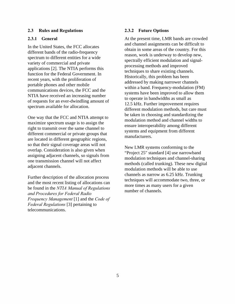
Figure 6. Typical monopole antennas for(a) base-station applications and (b) mobile
applications
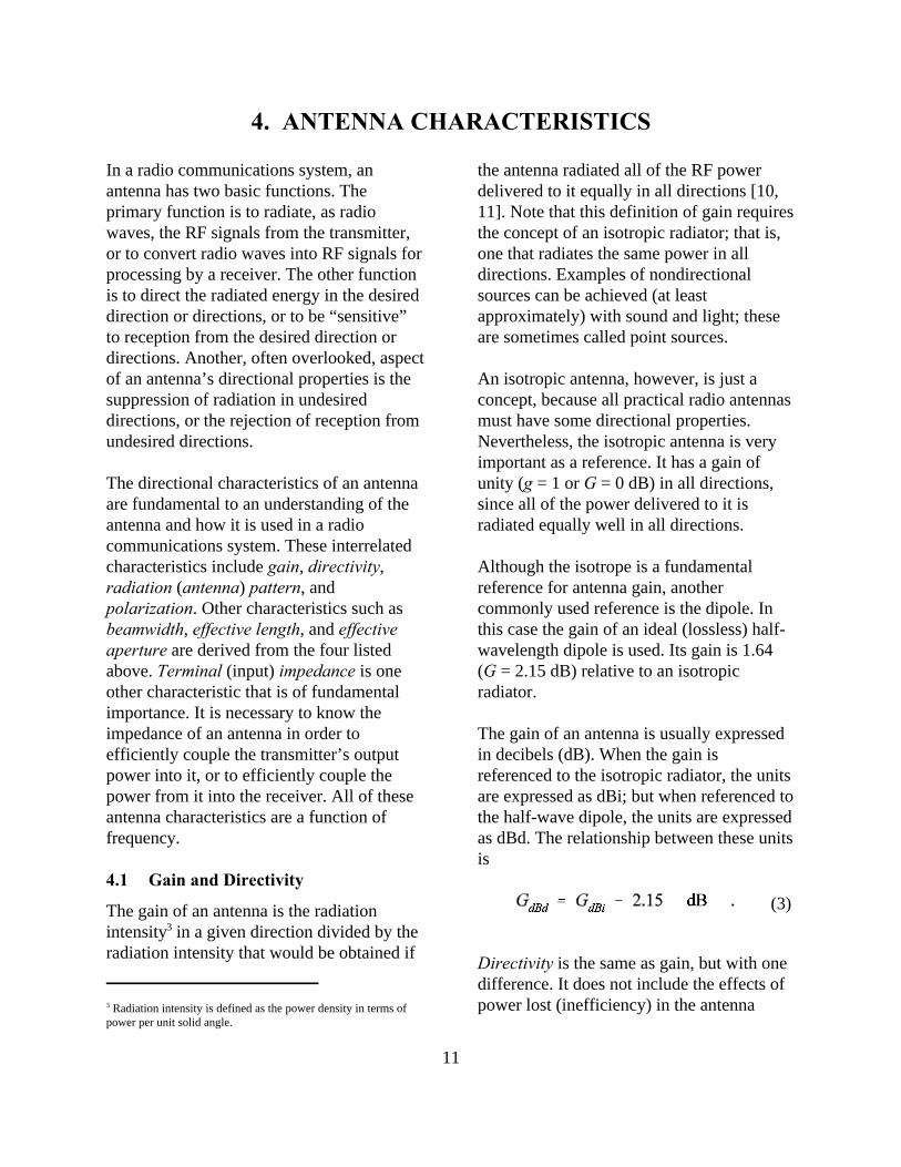
Figure 7. Omnidirectional base-stationantennas
Figure 8. A monopole antenna horizontal-plane pattern, base-station application. Theuniform maximum gain corresponds to the
outer line on the polar plot
5.2 Base-Station Applications
For base-station installations (where anomnidirectional pattern is desired), there aretwo practical implementations of the verticaldipole. The first type is the sleeve antenna,as illustrated in figure 7(a). The sleeveantenna is a vertical dipole with the feed(transmission line) entering from one end ofa hollow element. The second type is amonopole over a ground plane, as illustratedin figure 7(b). The monopole in this illustra-tion uses a set of four wire elements toprovide the ground plane. Figure 8 shows atypical pattern for a base-station monopole.
A variation of the dipole antenna is thefolded dipole as shown in figure 9. Itsradiation pattern is very similar to the simpledipole, but its impedance is higher and it hasa wider bandwidth.

19
Figure 10. Typical mobile antennas
5.2.1 Mobile Applications
Nearly all vehicular antennas are monopolesmounted over a (relatively) flat body surface(as described above). In this application, themonopole is often called a “whip” antenna.At VHF low-band, a quarter-wave monopolecan be 2.5 m (approximately 8 ft) long.However, an inductor (coil) at the base of amonopole adds electrical length, so thephysical length of the antenna can beshorter. Although this kind of “loaded”antenna will appear to be a quarter-waveantenna, it will have a gain value somewhatless than a true quarter-wave monopole. Thisdisadvantage can be somewhat offset,however, by the ability to mount the(shorter) antenna in the center of a surfacethat will act as an acceptable ground plane(e.g., the roof or trunk of the vehicle).Figure 10(a) shows an illustration of thiskind of antenna.
Many of the vehicular antennas at VHFhigh-band are quarter-wave monopoles. At150 MHz, this would mean that a whipantenna, approximately 0.5 m (1.5 ft) long,is needed. Half-wave and 5/8 wavemonopoles also are used, but they requiresome sort of matching network (i.e.,inductors and/or capacitors) in order tomatch the antenna impedance to that of thetransmission line. These longer antennashave a gain of approximately 3 dBi.
At UHF, a quarter-wave whip isapproximately 15 cm (6 in) long. Since thislength is physically small, some designconsiderations can be used to increase thegain. For example, as shown in figure 10(b),two 5/8 wave monopoles can be “stacked”with a phasing coil between them. This is,effectively, an antenna array (see sec. 5.5)that provides a gain of approximately 5 dBi.
At 800 MHz, a quarter-wave monopole doesnot perform well, so the approach ofstacking two monopoles, with a phasing coilbetween, is used. Such an antenna,illustrated in figure 10(c), looks much like amobile cellular phone antenna and has a gainof approximately 3 dBi.
The azimuthal pattern of all monopoles isideally a circle. In other words, the gainversus azimuth angle in the horizontal planeis constant. In practice, the pattern in thehorizontal plane generally is notomnidirectional, since the portion of thevehicle used as a ground plane is notsymmetric, and usually there are otherobstructions. Figure 11 shows the horizontalplane pattern for an 840 MHz whip locatedin the center of the roof of a vehicle [13].The dotted line in the figure shows theeffects, on the pattern, of a law-enforcement
Figure 9. A folded-dipole antenna

20
Figure 11. A mobile antenna horizontal-plane pattern [13]
Figure 12. Corner-reflector antennas
light bar mounted on the roof ahead of theantenna.
5.3 Corner Reflector
An antenna comprised of one or more dipoleelements in front of a corner reflector, calledthe corner-reflector antenna, is illustrated infigure 12. A photograph of a typical cornerreflector is shown in figure 13.
This antenna has moderately high gain, butits most important pattern feature is that theforward (main beam) gain is much higherthan the gain in the opposite direction. Thisis called the front-to-back ratio and isevident in the pattern shown in figure 14.
5.4 Yagi
Another antenna design that uses passiveelements is the Yagi antenna. This antenna,illustrated in figure 15, is inexpensive andeffective. It can be constructed with one or
Figure 13. A typical corner-reflectorantenna
Figure 14. A corner-reflector antennahorizontal-plane pattern

21
Figure 15. The Yagi antenna —(a) three elements and (b) multiple
elements
more (usually one or two) reflector elementsand one or more (usually two or more)director elements. Figure 16 shows a Yagiantenna with one reflector, a folded-dipoleactive element, and seven directors, mountedfor horizontal polarization.
Figure 17 is a typical pattern for a three-element (one reflector, one active element,and one director) Yagi antenna. Generally,the more elements a Yagi has, the higher thegain, and the narrower the beamwidth. This
antenna can be mounted to support eitherhorizontal or vertical polarization and isoften used for point-to-point applications, asbetween a base station and repeater-stationsites.
5.5 Log-Periodic
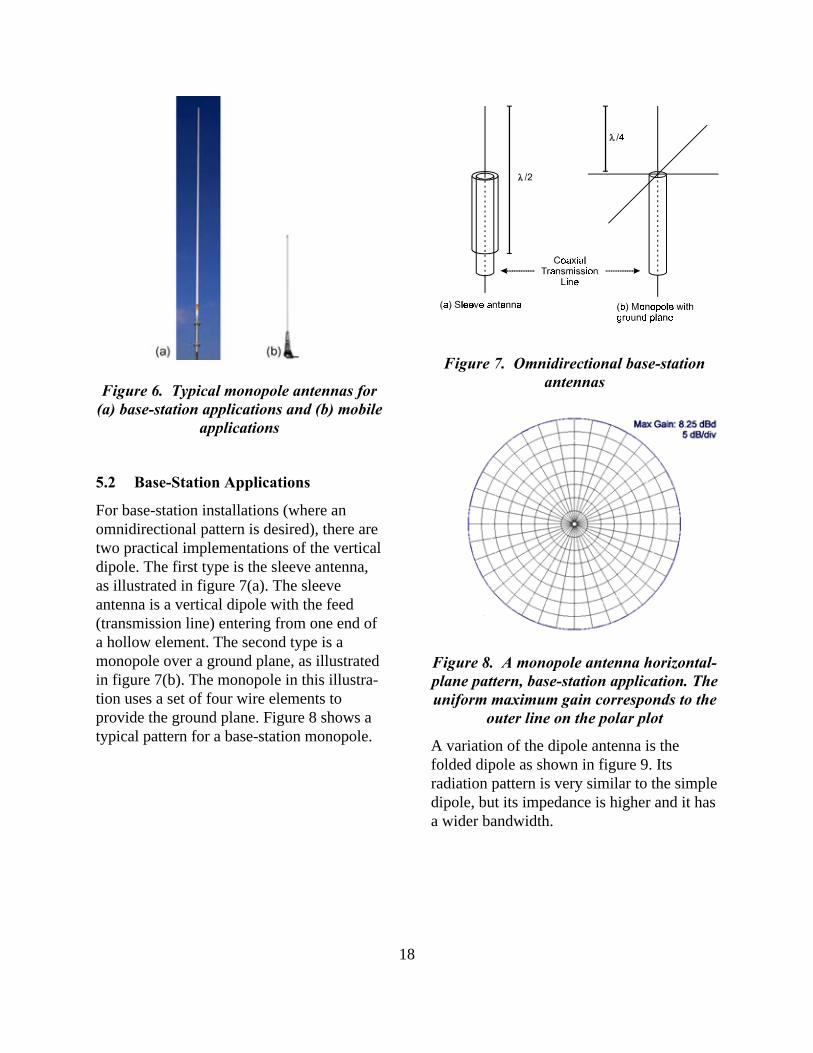
A somewhat novel, but very useful, design isthe log-periodic antenna. This antenna isbased on the dipole element. As shown inthe illustration of figure 18, it is in factcomprised of a set of dipoles, all active, thatvary in size from smallest at the front tolargest at the rear. Usually, this antenna isconstructed so the antenna terminals arelocated at the front (on the shortest dipole).Figure 19 shows a typical installation. Thekey features of this antenna are, first of all,its broadband nature, and second, itsrelatively high front-to-back gain ratio. Thelatter feature is evident in the typicalradiation pattern shown in figure 20.
Figure 16. A typical Yagi antenna
Figure 17. A Yagi antenna horizontal-plane pattern
22
Figure 18. A log-periodic antenna
Figure 19. A typical log-periodic antenna
Figure 20. A log-periodic antennahorizontal-plane pattern
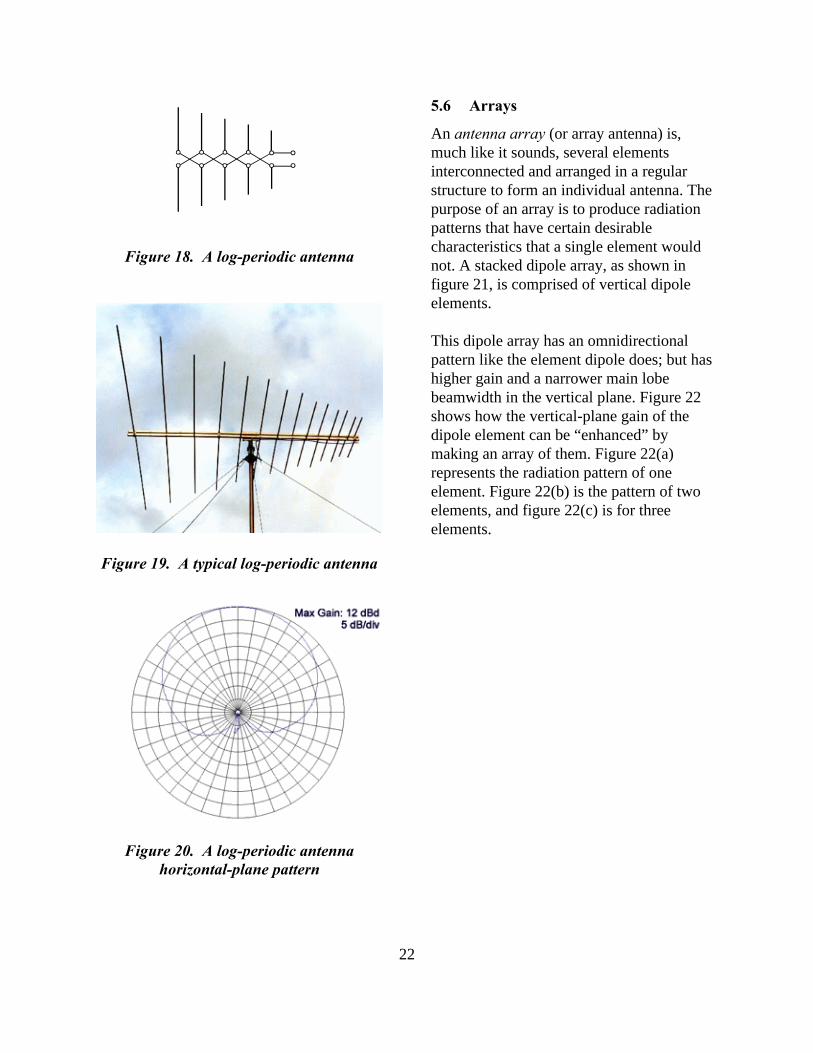
5.6 Arrays
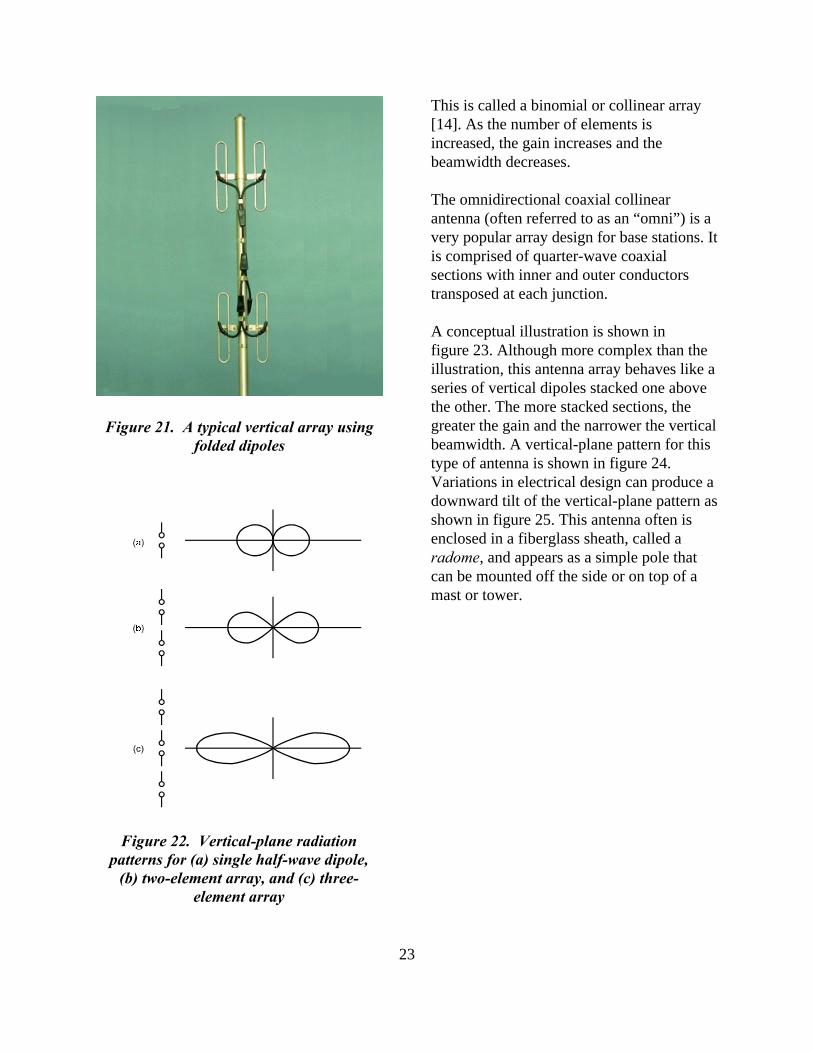
An antenna array (or array antenna) is,much like it sounds, several elementsinterconnected and arranged in a regularstructure to form an individual antenna. Thepurpose of an array is to produce radiationpatterns that have certain desirablecharacteristics that a single element wouldnot. A stacked dipole array, as shown infigure 21, is comprised of vertical dipoleelements.
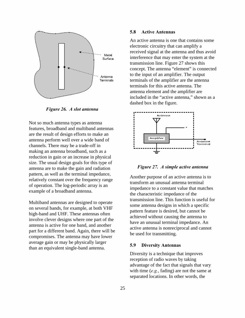
This dipole array has an omnidirectionalpattern like the element dipole does; but hashigher gain and a narrower main lobebeamwidth in the vertical plane. Figure 22shows how the vertical-plane gain of thedipole element can be “enhanced” bymaking an array of them. Figure 22(a)represents the radiation pattern of oneelement. Figure 22(b) is the pattern of twoelements, and figure 22(c) is for threeelements.
23
Figure 21. A typical vertical array usingfolded dipoles
Figure 22. Vertical-plane radiationpatterns for (a) single half-wave dipole,
(b) two-element array, and (c) three-element array
This is called a binomial or collinear array[14]. As the number of elements isincreased, the gain increases and thebeamwidth decreases.
The omnidirectional coaxial collinearantenna (often referred to as an “omni”) is avery popular array design for base stations. Itis comprised of quarter-wave coaxialsections with inner and outer conductorstransposed at each junction.
A conceptual illustration is shown infigure 23. Although more complex than theillustration, this antenna array behaves like aseries of vertical dipoles stacked one abovethe other. The more stacked sections, thegreater the gain and the narrower the verticalbeamwidth. A vertical-plane pattern for thistype of antenna is shown in figure 24.Variations in electrical design can produce adownward tilt of the vertical-plane pattern asshown in figure 25. This antenna often isenclosed in a fiberglass sheath, called aradome, and appears as a simple pole thatcan be mounted off the side or on top of amast or tower.

24
Figure 23. A coaxial collinear array
Figure 25. A vertical-plane radiationpattern with 8// “tilt”
As with all antennas, the array is frequency-dependent. The gain, directivity, andradiation pattern are each a function offrequency. Some antennas will work wellonly for the design frequency, and theirperformance will degrade as the operatingfrequency is separated from the designfrequency.
5.7 Unusual Antennas
There are many other antenna types. Most ofthese are beyond the scope of this report, butknowledge about some may be useful forLMR users.
While not as commonplace as wire or rodantennas, aperture antennas are by no meansunusual. These antennas are implemented asan opening in a relatively large, conductive(metal) surface.
The simplest aperture antenna is the slotantenna, which is equivalent to a dipole. Asshown in figure 26, it is a long, narrowopening with terminals located at the middleof the long sides of the slot. This simple slotand more complex versions are well-suitedto covert operations. They can be located ona vehicle surface and concealed behind acover of thin insulating material. Slotantennas are common on aircraft andmissiles.
Figure 24. A vertical-plane radiationpattern without “tilt”
25
Figure 26. A slot antenna
Figure 27. A simple active antenna
Not so much antenna types as antennafeatures, broadband and multiband antennasare the result of design efforts to make anantenna perform well over a wide band ofchannels. There may be a trade-off inmaking an antenna broadband, such as areduction in gain or an increase in physicalsize. The usual design goals for this type ofantenna are to make the gain and radiationpattern, as well as the terminal impedance,relatively constant over the frequency rangeof operation. The log-periodic array is anexample of a broadband antenna.
Multiband antennas are designed to operateon several bands, for example, at both VHFhigh-band and UHF. These antennas ofteninvolve clever designs where one part of theantenna is active for one band, and anotherpart for a different band. Again, there will becompromises. The antenna may have loweraverage gain or may be physically largerthan an equivalent single-band antenna.
5.8 Active Antennas
An active antenna is one that contains someelectronic circuitry that can amplify areceived signal at the antenna and thus avoidinterference that may enter the system at thetransmission line. Figure 27 shows thisconcept. The antenna “element” is connectedto the input of an amplifier. The outputterminals of the amplifier are the antennaterminals for this active antenna. Theantenna element and the amplifier areincluded in the “active antenna,” shown as adashed box in the figure.
Another purpose of an active antenna is totransform an unusual antenna terminalimpedance to a constant value that matchesthe characteristic impedance of thetransmission line. This function is useful forsome antenna designs in which a specificpattern feature is desired, but cannot beachieved without causing the antenna tohave an unusual terminal impedance. Anactive antenna is nonreciprocal and cannotbe used for transmitting.
5.9 Diversity Antennas
Diversity is a technique that improvesreception of radio waves by takingadvantage of the fact that signals that varywith time (e.g., fading) are not the same atseparated locations. In other words, the

26
fading of a signal may be quite different fortwo locations separated by as little as onewavelength. To take advantage of this, twoantennas, separated by some distance, areused to receive the same signal. Of the twosignals, the one with the highest signal level,at any given time, is automatically sent tothe receiver. This process is only useful forreception. The electronics required for thiskind of signal processing are sometimes partof the antenna system.
Adaptive antennas extend the concept ofdiversity another step further. Theseantennas usually incorporate more than justtwo elements (i.e., individual antennas) inthe array. An adaptive antenna can modifyits radiation pattern (within limits) in realtime to ensure that the main lobe points inthe direction of greatest signal level.Alternatively (or, possibly, simultaneously),the same technique can be used to point anull in the direction of an unwanted,interfering signal.

27
6. TRANSMISSION LINES AND OTHER COMPONENTS
Transmission lines are conduits fortransporting RF signals (and the energycontained in those signals) between elementsof a communications system (fig. 1).
Transmission lines are not simplyconductors that carry electrical current likethe power cord for an electrical appliancedoes. Transmission line principles, derivedfrom electromagnetic theory, must be usedwhen the line exceeds a few tenths of awavelength.
On a transmission line, not only do currentsflow within and on the surfaces of theconductors, but traveling electromagneticfields are also “guided” by the conductors.Therefore, the geometry of the transmissionline is fundamental to its electricalcharacteristics.
6.1 Transmission Line Types
Figure 28 shows the arrangement ofconductors for several common types oftransmission lines. The open, two-wire line,shown in figure 28(a), is easy to constructand its characteristics are readily adjusted bychanging the diameter and spacing of thewires. However, the electromagnetic fieldcreated between and around the conductorextends far beyond the line, so radiationlosses become excessive at high frequencies.For this reason, it is only practical for usebelow several hundred megahertz. This lineis also called “ribbon,” “parallel,” or “twin-lead” cable and was used extensively, fromthe 1950s to the 1970s, to connect a hometelevision set to its antenna.
The most common transmission line in usetoday is coaxial cable, which gets its namefrom the coaxial arrangement of itsconductors, as shown in figure 28(b). Thecenter conductor may be held in positionwith periodically-spaced dielectric(insulating) beads or with a continuous,
Figure 28. Common types of transmission lines

28
Figure 29. Coaxial cables commonly usedfor LMR — (a) base-station applications
and (b) mobile applications
solid dielectric that fills the space betweenthe conductors. The outer conductor can beeither solid or braided; the latter making amore flexible cable. The coaxial cable iseffectively self-shielded and has no externalfields. For this reason, its losses are low andit is useful for frequencies as high as 3 GHz.Since the outer conductor of a coaxial line isusually grounded, it is not a balanced line. Inother words, both conductors are not equallyisolated from ground as is the case with theopen, two-wire line. This distinction is animportant factor at the connection to theantenna. A balun (see sec. 6.2) may beneeded at that point to “match” the unbalanced line to an antenna.
A very wide variety of coaxial cable (oftencalled “coax”) is available to meet differentrequirements. Generally available in onlytwo values of characteristicimpedance—50 S and 75 S—coaxial cableis made in many sizes of various materials.
Figure 29 shows two common coax types.The cable shown in figure 29(a) has a semi-rigid, helical outer conductor, so it is lessflexible. This cable is commonly used forbase-station applications. The cable shownin figure 29(b) has a braided outerconductor. This type of cable is commonlyused in mobile applications and for less-demanding base-station applications.
Coaxial cable is described by nomenclaturederived from military standards [15]. The“JAN type” or “RG-“ number assigned to acoaxial cable defines specific values for awide range of physical and electricalcharacteristics. Selected characteristics for afew of the several hundred types of cablesare given in table 1. Not shown in this tableare other physical and electricalcharacteristics such as weight, tensilestrength, materials used for the dielectric andsheath, maximum voltage, and attenuation.
There are many other transmission linegeometries. The shielded pair, shown infigure 28(c), is not uncommon. It offers thefully shielded characteristic of a coaxial lineand the balanced nature of a two-wire,parallel line.
6.2 Baluns
Since the outer conductor of a coaxial line isgrounded, it is not a balanced line. In otherwords, the voltage potential differencebetween the inner conductor and ground isdifferent from the voltage potentialdifference between the outer conductor andground. This distinction is an importantfactor at the connection to the antenna.Antennas such as dipoles are balanced. Abalun will be needed at the antennaterminals to connect the unbalanced coaxialtransmission line to the antenna.
A balun is a device for transforming a loadon an unbalanced transmission line (coaxial)or system to a balanced line or system. Thename balun is a contraction of the termsbalanced and unbalanced.

29
Figure 30. A VHF duplexer
6.3 Duplexers
In order for transmitters and receivers toshare a single antenna, a duplexer must beused. The duplexer acts as two parallel,frequency selective filters, directingtransmitted signals to the antenna,preventing those signals from reaching andoverloading collocated receivers, androuting all of the received signals from theantenna to the receivers. Duplexers used inthe VHF and UHF bands are typicallyconstructed from mechanically tunable,highly selective cavity filters, as depicted infigure 30.
TypeImpe-dance
InnerConductor
OuterConductor
DiameterMax.
PowerNotes
RG-58/U 50 S 19×0.0071 in(19×0.018cm) stranded(tinnedcopper)
braid(tinnedcopper)
0.195 in(0.49 cm)
200 W small,flexible, low
loss
RG-55/U 50 S 0.032 in(0.08 cm)solid(silveredcopper)
doublebraid(silveredcopper)
0.206 in(0.52 cm)
200 W small,flexible, low
loss
RG-11/U 75 S 7× #26 AWG(tinnedcopper)
braid(copper)
0.412 in(1.05 cm)
750 W mediumsized,
flexible
Table 1. Characteristics of selected coaxial cable

30
Figure 31. Typical types of combiners —(a) hybrid combiner and (b) cavity
combiner
Figure 32. Intermodulation suppressiondevice
6.4 Combiners
In order to combine more than onetransmitter onto one antenna system,combiners are used. Two typicalconfigurations, shown in figure 31, useeither hybrid combiners (commonly calledhybrids), or mechanically tuned, highlyselective cavity combiners that use cavityfilters quite similar to those used induplexers. Depending on a number offactors, such as how close in frequency thetransmitters are to one another and howmany transmitters must be combined, oneapproach will offer superior performanceover the others. Vendors and manufacturersshould be able to explain why they selectedone combining method as opposed to theother for their design.
6.5 Intermodulation Suppression
Cavities and hybrids will likely not providesufficient attenuation to RF signals (fromother collocated transmitters) that couldcause intermodulation interference. Isolatorsare used to provide additional protectionagainst intermodulation interference. Thesedevices provide very low attenuation tosignals passing through them in onedirection, while providing a high degree ofattenuation to signals passing through themin the other direction. They are the principalcomponents of intermodulation suppressiondevices (fig. 32).
6.6 Multicouplers
Just as multiple transmitters can share anantenna, so can multiple receivers. InboundRF signals are “split” and routed to theappropriate receivers. Because RF splittersattenuate the signals passed through them, apreamplifier precedes the splitter. Itsamplifier gain is carefully adjusted tocompensate for the splitter loss, but is notset too high, as the resultant intermodulation

31
Figure 33. A multicoupler
interference signals would be detrimental toproper receiver performance. Thesepreamplifiers and signal splitters arecombined into a single assembly known as amulticoupler (fig. 33).

33
(11)
7. RADIO WAVE PROPAGATION
The propagation of radio waves throughspace (and the atmosphere) is the essentialphenomenon exploited by a radiocommunications system. As describedearlier (sec. 3), this phenomenon has beenstudied extensively using theoretical andempirical methods. The simplest mode ofpropagation occurs between two point-sources in free space—the ideal situation.
Radio-wave propagation, in realisticsituations, is affected by reflections from theearth, scattering by particles, diffraction overhills, and bending due to atmosphericrefractivity. The study of propagation has ledto models that can be used to predict thefield strength (and/or power density)expected at a specific receiver location of aradio wave radiated from a distanttransmitter location.
7.1 Transmission Loss and the PowerBudget
The concept of transmission loss is used toquantify the effects of radio wavepropagation in the analysis and engineeringof radio communications systems. It isdefined as the ratio of power delivered to theterminals of the transmitter antenna to thepower available at the terminals of thereceiver antenna. The transmitter andreceiver antenna gains are implicitlyincluded in this definition. In practice, this isnot useful, so the concept of basictransmission loss is used. It does not includethe antenna gains. Basic transmission loss Lb
is defined as the ratio of the power deliveredto a lossless isotropic antenna at the transmitlocation to the power available at theterminals of a lossless isotropic antenna atthe receive location.
With this definition of basic transmissionloss, a power budget can be developed. Thisis shown graphically in figure 34, whichshows the effects of the major elements inthe radio link.
It begins with the power output of thetransmitter Pt in decibels relative to somereference (if referenced to 1 W, this isexpressed as dBW). The loss, in decibels,due to the transmitter transmission line Lt issubtracted from Pt. Then the transmitterantenna gain Gt is added. The basictransmission loss Lb is subtracted. Then atthe receive end of the link, the receive gainGr is added; and the receiver transmissionline loss Lr is subtracted to arrive at thepower delivered to the receiver input Pr.
Expressed as an equation, the power budgetis
The received power is in the same units asthose used to express the transmitted power.
Figure 34. Gains and losses as describedin the power-budget equation

34
(12)
(13)
(14)
(15)
(16)
(17)
(18)
For example, a transmit power of 25 W,expressed in decibels, would be 10 log10 (25)or 14 dBW. The result is that the poweravailable at the receiver input Pr is expressedin the same units (dBW in this example).
7.2 Free-Space Basic Transmission Loss
The transmission loss between two losslessisotropic antennas in free space4 is ahypothetical, but very useful, propagationmodel. It can be used as a “first estimate” inradio link design or a “best case” value fortransmission loss over any real, terrestrialpath.
The free-space basic transmission loss Lbf isvery easy to calculate. Since the transmitantenna is considered to be a losslessisotrope (and the transmission line isconsidered to be lossless as well), all of thetransmitter power is radiated equally in alldirections. At a distance d selected to bemuch greater than the wavelength 8, theradiated power density (expressed in wattsper square meter) is simply the transmitterpower divided by the area of a sphere withradius d, as follows:
Now, looking at the receive side of the link,the signal power output Pr in watts, of alossless, isotropic receive antenna can becomputed using equation 9. It is the productof that antenna’s effective area Ae times thepower density p of the incident wave asfollows,
Using equation 10, the effective area, insquare meters, of a lossless isotropic antenna(g = 1) is
Substituting equations 12 and 14 intoequation 13, the result is
Rearranging this equation to form thedefinition of Lbf as the ratio of Pt to Pr (seesec. 7.1),
In decibels, this equation becomes,
By converting wavelength to frequencyusing equation 1 and taking the logarithm ofthe terms in parentheses, a very practicalversion of this equation results.
where d is expressed in kilometers and f isexpressed in megahertz.
This last equation is the propagation modelfor free-space, basic transmission loss. Itpredicts a value of basic transmission lossunder a set of assumptions (i.e., lossless
4 Free space is a theoretical concept of space devoid of all matter.In practice, free space implies remoteness from material objectsthat could influence the propagation of electromagnetic waves.
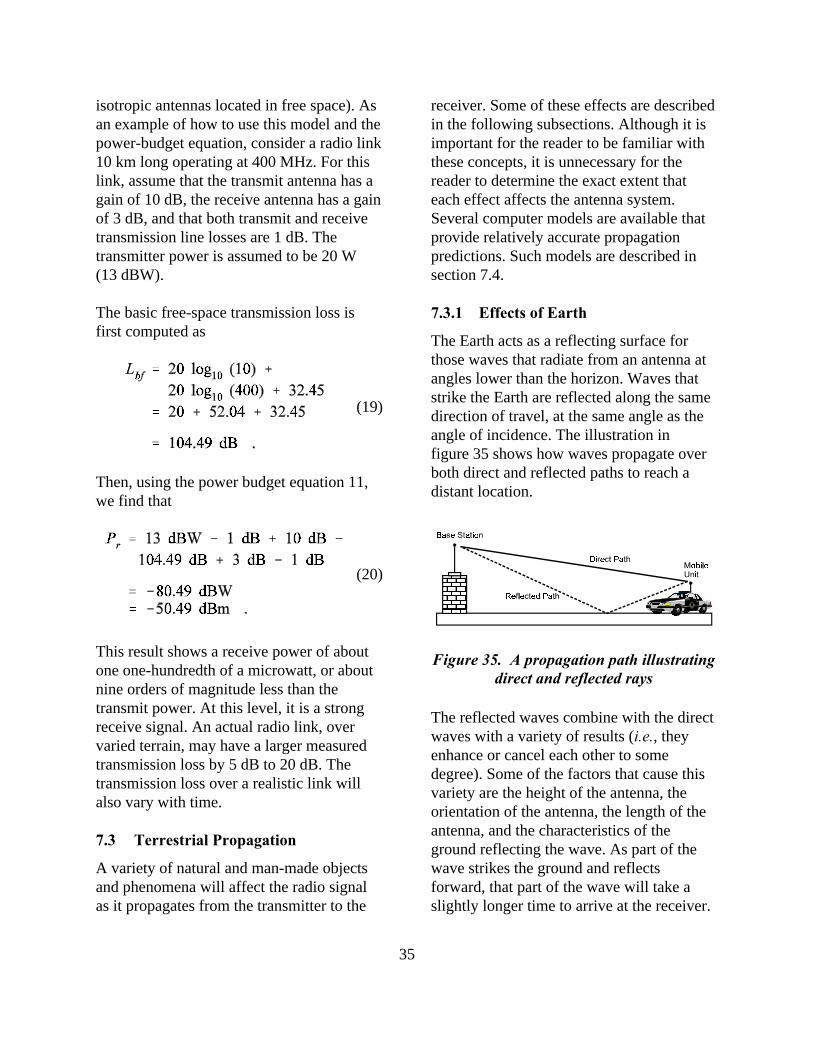
35
(19)
(20)
isotropic antennas located in free space). Asan example of how to use this model and thepower-budget equation, consider a radio link10 km long operating at 400 MHz. For thislink, assume that the transmit antenna has again of 10 dB, the receive antenna has a gainof 3 dB, and that both transmit and receivetransmission line losses are 1 dB. Thetransmitter power is assumed to be 20 W(13 dBW).
The basic free-space transmission loss isfirst computed as
Then, using the power budget equation 11,we find that
This result shows a receive power of aboutone one-hundredth of a microwatt, or aboutnine orders of magnitude less than thetransmit power. At this level, it is a strongreceive signal. An actual radio link, overvaried terrain, may have a larger measuredtransmission loss by 5 dB to 20 dB. Thetransmission loss over a realistic link willalso vary with time.
7.3 Terrestrial Propagation
A variety of natural and man-made objectsand phenomena will affect the radio signalas it propagates from the transmitter to the
receiver. Some of these effects are describedin the following subsections. Although it isimportant for the reader to be familiar withthese concepts, it is unnecessary for thereader to determine the exact extent thateach effect affects the antenna system.Several computer models are available thatprovide relatively accurate propagationpredictions. Such models are described insection 7.4.
7.3.1 Effects of Earth
The Earth acts as a reflecting surface forthose waves that radiate from an antenna atangles lower than the horizon. Waves thatstrike the Earth are reflected along the samedirection of travel, at the same angle as theangle of incidence. The illustration infigure 35 shows how waves propagate overboth direct and reflected paths to reach adistant location.
The reflected waves combine with the directwaves with a variety of results (i.e., theyenhance or cancel each other to somedegree). Some of the factors that cause thisvariety are the height of the antenna, theorientation of the antenna, the length of theantenna, and the characteristics of theground reflecting the wave. As part of thewave strikes the ground and reflectsforward, that part of the wave will take aslightly longer time to arrive at the receiver.
Figure 35. A propagation path illustratingdirect and reflected rays

36
At some reflection angles, the direct waveand reflected wave will arrive almost inphase (i.e., the amplitude of each wave willbe at its maximum at the same time). Whenthis happens, the power of the received waveis approximately twice that of the directwave. At some angles, the reflected wave isexactly out of phase with the direct wave,essentially nullifying the wave. This isknown as cancellation. At other angles, theresultant wave will be somewhere inbetween.
As radio waves strike a radio-opaque object,some of the signal will be reflected indirections away from the receiver. Some ofthe signal will be absorbed by the object.
The waves that strike the edges of the object,however, will be diffracted into the shadowof the object. To a receiver positioned withinsuch a shadow, the object’s edge will seemlike another source. This can causeinterference with the original signal orprovide signals to areas that should notreceive them. This phenomenon is shown infigure 36.
7.3.2 Coverage
The area over which the signal can bedetected is called the coverage area for theantenna. The coverage area is oftendisplayed as contours on a two-dimensionaldrawing or on a map.
A radiation pattern is not the same thing as acoverage area, although they are related. Theradiation pattern for an antenna is a gainfactor, in every direction away from theantenna, and is a function only of theantenna design.
The coverage area for an antenna is the areaover which a signal, of predeterminedstrength (or greater), can be received. Thecoverage area is a function of the transmitpower, antenna gain, radiation pattern, noise,and propagation factors related to theenvironment.
7.3.3 Noise and Interference
All things emit some radiation at allfrequencies. In most cases, for most objects,the level of this continuous radiation, at anygiven frequency, is small and of littleconcern. This radiation is called noise. Themost common sources of noise for a radioreceiver are:
• Atmospheric and galactic noise.• Noise from the first amplifier in the
receiver.• Man-made noise (motors, flourescent
lights, etc.).
When a radio receiver is far enough awayfrom a transmitter (or in an antenna patternnull where reception is difficult), thestrength of the transmitted signal is lowenough that ambient radiation noise fromother objects or transmissions in the area
Figure 36. An example of diffraction

37
can obscure the desired signal. When thestrength of a received signal is less than thestrength of the ambient noise for thatfrequency, the signal is said to be “lost in thenoise.”
Ambient noise for a specific transmission isusually measured at the transmissionfrequency.
Interference is the term for unwantedsignals, generated from other transmitters,that interfere with clear reception of theintended signal. Interference is nottechnically included under the definition ofnoise, although slang usage of the term“noise” includes any unwanted signals.
7.3.4 Terrestrial Propagation Models
Radio-wave propagation in the terrestrialenvironment is an enigmatic phenomenonwhose properties are difficult to predict.This is particularly true for LMRapplications where terrain features (hills,trees, buildings, etc.) and the ever-changingatmosphere provide scattering, reflection,refraction, and diffraction obstacles withdimensions of the same order of magnitudeas the wavelengths.
Some models are general and some are morespecialized. An example of the former is amodel that would predict radio coverageareas in “generic” urban areas or “generic”rural areas, without regard to specific terrainprofiles. One of these generalized models isthe Okumura-Hata model [16]. Models suchas the Okumura-Hata model are based onextensive collections of empiricalmeasurements.
Other more sophisticated computerprograms predict transmission loss, and
account for the time and location variabilityof that loss, over defined terrain profiles.These terrain profiles are compiled fromterrain-elevation data tabulated by agenciessuch as the Defense Mapping Agency andthe U.S. Geological Survey. One suchcomputer program, written and maintainedby the U.S. Department of Commerce’sInstitute for Telecommunication Sciences(ITS), is the Communication SystemsPerformance Model (CSPM) [17]. Thisprogram is based on the ITS IrregularTerrain Model [18].
Usually, manufacturers and vendors of radioand antenna systems and components havecomputer programs similar to CSPM toassist customers in defining radio-coverageareas. Private-industry radio-engineeringconsultants also have computer programslike CSPM to perform radio-coverageanalysis for customers. Alternatively,agencies can access CSPM on afee-reimbursable basis through the ITSInternet site5.
7.4 Co-Site Analysis
Intermodulation (IM) interference (i.e.,“intermod”) and receiver desensitization aredetrimental to the performance of co-sitedrepeaters and base stations. There are severaldifferent ways intermod interference can begenerated. One way is when sufficientlylarge power from a transmitter enters intothe final output power stage of anothertransmitter. This may occur when, forexample, the transmitters are connected to acombiner junction and the combiningcavity/isolators of the affected transmitter do
5 http://flattop.its.bldrdoc.gov/tas.html.For additional information, contact the Institute forTelecommunication Sciences at 325 Broadway (ITS.E), Boulder,Colorado 80305–3328, Telephone 303–497–5301.

38
not provide sufficient rejection betweentransmitters.
Intermodulation may also arise when severaltransmitting antennas are located in veryclose proximity to each other, such asmultiple omni-directional antennas on abuilding rooftop. In these situations, mixingof signals may occur between the offendingtransmitter(s) and the desired signal, therebygenerating new signals in the victimtransmitter, at frequencies determined by theintermod products. These intermod signalswill be emitted by the victim transmitter.
Other ways that intermod can occur are bythe mixing of signals from two or moretransmitters in the front-end of a receiver.Off-frequency signals strong enough toovercome the suppression of bandpasscavities and preselector filters may saturatethe nonlinear first or second intermediatefrequency (IF) mixers of the victim receiver,creating intermod products which adverselyaffect receiver performance.
External intermod can also be created inelements such as corroded antenna guywires, anchor rods, and even chain linkfences. As strong signals impinge upon theseitems, the corroded objects act as diodes anddetect the signals, mix them, and passivelyreradiate the energy at the intermod productfrequencies.

39
8. ANTENNA SYSTEM REQUIREMENTS AND DESIGN
The selection of a particular antenna systemfor use in a radio communications system isone of many interrelated decisions that mustbe made to meet the system-levelrequirements for a complete LMR system.Other system-level decisions include thenumber and locations of base and repeaterstations, the antenna heights, and thetransmitter powers.
Selecting the appropriate antennas forvehicular and hand-held units is a muchsimpler process than selecting theappropriate antennas for fixed stations.Although there are exceptions, the whipantenna is, essentially, the only practicalantenna design for vehicular and hand-heldradios. The most important aspect forvehicular antennas has to do with where it ismounted on the vehicle. The best locationfor vehicular antennas is in the middle of theroof. This is the highest point and presentsthe flattest and most symmetric ground planeto the antenna, both important factors tooptimize communications range andperformance. Vehicular obstructions, suchas the light bar on law enforcement vehicles,will, however, distort the radiation patternand/or alter the antenna’s terminalimpedance slightly.
Bumper mount installations for low-bandVHF, for example, may be selected basedmore on the antenna installation structuralrigidity requirements than on ground planesymmetry, radiation pattern distortion, andother RF performance parameters.
Choices for hand-held radio antennas are, inpractice, limited to short whip antennas.These antennas are physically very short, are
typically inductively or resistively loaded (tosimulate, electrically, a longer antennaand/or to provide a better impedance match).These features and attributes areaccomplished at the cost of decreasedantenna gain.
Selecting appropriate antennas for fixedstations is more critical than selecting theantennas for mobile and hand-held units.This is because antennas for fixed stationsmust be chosen to adequately receive signalsfrom the least-capable mobile/hand-heldunits (those with low transmitter power, lowantenna gain, low antenna height, etc.).
When designing a radio system for LMRuse, a systematic development plan must becreated and followed:
• Define System Requirements.• Design System.• Select Appropriate Components.• Procure and Install Components.• Perform Routine Maintenance.
Each of these steps is dependent on theprevious step in the chain.
8.1 Define System Requirements
The design and deployment of an LMRcommunications system, or the upgrade orexpansion of an existing system, generallybegins with some knowledge of whatgeographic regions need to be “covered” bythe radio communications system. This is afundamental requirement that is determinedby the nature of an agency’s jurisdiction,where population and transportation routesare located, and so on. These requirementsmust be developed by the agency itself.

40
Several other system-level requirements canalso be developed by the agency beforeobtaining the services of a radio systemvendor or consultant. Larger lawenforcement agencies will have acommunications department that willperform these services. The number ofmobile and handheld units, for example, isusually determined by the number of usersthat must be supported.
Next, some decisions must be maderegarding how many channels will beneeded. For example, one or more channelsmay be needed for dispatch functions.Additional channels may be needed formobile-to-mobile communications. Otherchannels that might be needed couldinclude:
• A local command channel foroperations at an event site.
• A channel to interoperate with otheragencies in mutual-aid situations.
• A channel dedicated to tactical forces.• Other channels to support the
operational and administrativeactivities of the agency.
Other aspects that may affect system designinclude:
• The typical length of messages for thevarious channels and talk groups.
• Maximum level of activity for thedispatch channel.
• The nature of operations that use thelocal command channel.
• Geographic coverage requirements.• The specific level of performance (i.e.,
speech intelligibility and/or data-transmission throughput) required.
Having a working knowledge of thesesystem-level requirements will help ensureefficiency in the system design process thatfollows, and will help ensure the reliableperformance of the system when it is fullydeployed.
Begin by developing some initial system requirements. Consider, for example, thefollowing:
• At what frequencies will you betransmitting? Lower frequenciesrequire larger antennas. Higherfrequencies have more limited range.A wide range of frequencies willrequire multiple antennas, multibandantennas, or broadband antennas.
• What is the maximum distance overwhich your users must communicate?Systems to support distant itinerantusers will require a combination ofhigher-power transmitters andantennas with greater gain.
• What is your coverage area? Requiredantenna radiation patterns will bedictated by the location of the fixedsite relative to the required coveragearea.
• Are there other nearby radio systemsoperating in neighboring frequencybands or on the same or adjacentfrequency channels? Your systemmight cause interference to these otherusers, or conversely, these systemsmight cause interference to your newsystem.
• What physical limits are there on yourdesign? Is there sufficient property toconstruct a site, or is there sufficientspace on shared antenna towers foryour system? Will building code andzoning ordinances impact theconstruction of your system?

41
• What about standby/back-up systemsat this site or at another antenna site?
• What level of speech intelligibility isrequired? How much noise anddistortion can be tolerated? For datatransmissions, what data-throughputrates are required (how large is thedata file and how much time isavailable for transmission)?
8.2 Design System
The decisions that must be made during thedesign of a new system or the expansion ofan existing system include:
• The number of base and repeaterstations and their locations.
• Some initial choices of antennas andantenna heights for those fixed sites.
The design process will require theidentification of:
• The availability of channels in thevarious LMR frequency bands.
• Potential/alternative base and repeaterstation locations.
• The potential for sharing fixed-stationinfrastructure among multipleagencies.
• The estimated cost of the system.
8.3 Select Appropriate Components
Once the system performance and systemdesign requirements have been ascertained,the antenna characteristics that must beconsidered are the antenna system gain andradiation pattern. The process of identifyingthe needed gain and pattern is usually aniterative one. The process might proceed asfollows:
First, coverage predictions are made. Valuesfor transmitter power, operating frequency,antenna system losses, antenna gain, antennaheight, antenna pattern, and minimumacceptable received signal strength for somespecified level of speech intelligibility arerequired in order to make these coveragepredictions.
Intermodulation interference analysis mustalso be considered during the design phase,particularly where multiple transmitters,receivers, and/or repeaters are collocated.Antenna system manufacturers and vendorscan assist agencies in predicting thelikelihood of IM interference or receiverdesensitization, either caused by or inflictedupon the proposed new system. To mitigateIM interference at repeater and base stationantenna sites, their designs will includeisolators, cavity filters, duplexers,combiners, and multicouplers. The numberof collocated systems and the frequencyseparations between them also influences thechoice of combiner and duplexercomponents.
System design and component selectioncontinue by interactively trying differentantenna gains, patterns, and heights at eachpotential site location until the desiredcoverage is attained. Then, antenna systeminstallation at each fixed site needs to beconsidered. Points to consider include:
• Antenna tower height—Will theproposed antenna tower conform tolocal building codes and zoningordinances?
• Environmental considerations—Willthe antenna system and supportingstructure survive expected windloading, ice loading, and otheranticipated environmental
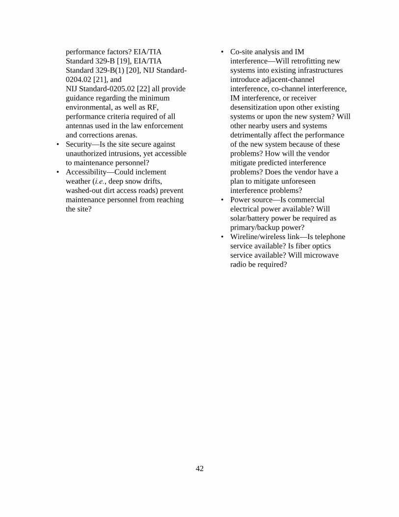
42
performance factors? EIA/TIAStandard 329-B [19], EIA/TIAStandard 329-B(1) [20], NIJ Standard-0204.02 [21], andNIJ Standard-0205.02 [22] all provideguidance regarding the minimumenvironmental, as well as RF,performance criteria required of allantennas used in the law enforcementand corrections arenas.
• Security—Is the site secure againstunauthorized intrusions, yet accessibleto maintenance personnel?
• Accessibility—Could inclementweather (i.e., deep snow drifts,washed-out dirt access roads) preventmaintenance personnel from reachingthe site?
• Co-site analysis and IMinterference—Will retrofitting newsystems into existing infrastructuresintroduce adjacent-channelinterference, co-channel interference,IM interference, or receiverdesensitization upon other existingsystems or upon the new system? Willother nearby users and systemsdetrimentally affect the performanceof the new system because of theseproblems? How will the vendormitigate predicted interferenceproblems? Does the vendor have aplan to mitigate unforeseeninterference problems?
• Power source—Is commercialelectrical power available? Willsolar/battery power be required asprimary/backup power?
• Wireline/wireless link—Is telephoneservice available? Is fiber opticsservice available? Will microwaveradio be required?
43
9. INSTALLATION, MAINTENANCE, AND SAFETY
9.1 Vehicular Antenna Systems
The procurement and installation ofvehicular antenna systems are relativelystraightforward. If the design requirementshave been well thought out and adequatelydescribed in the procurement documents, acompetitive procurement will deliver anacceptable product.
When installing a vehicular antenna system,care must be given to routing the coaxialcable between the radio and antenna. Thecable should not be exposed to the elements(wind, road salt and sand, rain, intensesunlight, extreme heat, etc.) nor should it bein a location where it could be severed orpinched (by opening and closing vehicledoors, for example) or where a vehicle’soccupants might become entangled with it.One preferred routing for a roof-mountedantenna might be between the roof andinterior headliner of the vehicle, downthrough a windshield pillar, and behind thedashboard panel to the radio. Otherequipment, such as duplexers (to combinemultiple radios operating in differentfrequency bands onto one multibandantenna), should likewise be installed inlocations not readily accessible to vehicleoccupants. For example, they should beinstalled under seats or in trunks where theyare “out of the way,” yet reasonablyaccessible to maintenance personnel.
RF cable connections should be torqued tothe proper force recommended for theparticular connectors used, and the outergrounded conductor of the antenna basemount must be RF-bonded to the metal ofthe roof or trunk deck. Trunk deckinstallations also require excellent RF
bonding from the trunk lid to the mainvehicle body. One way to accomplish this isby using a short length of low-impedancecopper grounding strap affixed to bare areasof (interior) sheet metal on the underside ofthe trunk deck and the main vehicle body,using noncorrosive bolts, star washers, andlock nuts. A poor ground connection willdetrimentally affect antenna operation,resulting in erratic or unacceptableperformance.
9.2 Fixed-Site Antenna Systems
Most new installations of fixed-repeater andbase-station antenna systems will likely beperformed by contracted installers orequipment suppliers. In many cases,retrofitting new or upgraded componentsinto existing facilities will similarly beperformed by contracted installers orequipment suppliers. Procuring agenciesshould, nevertheless, ensure that the installerobserves sound installation practices. Aswith vehicular grounding, proper groundprotection of fixed station antenna facilitiesis important.
9.2.1 Fixed-Site Antenna SystemGrounding and Bonding Practices
An effective grounding system is necessaryfor every antenna tower. In addition to theprotection a grounding system offers fromlightning strikes, grounding also:
• Reduces the hazards of electricalshock resulting from ground/neutralpower faults.
• Protects wiring and circuitry bylimiting extraneous over-voltages.

44
• Facilitates rapid discharge of faultedpower circuits.
• Reduces noise voltages.• Provides a path to dissipate any stray
RF current present inside thetransmitter station; ungrounded RFcurrents can contribute to equipmentmalfunction, or create interferencewith other receivers.
9.2.2 Fixed-Station RF Bonding
RF bonding is another important aspect offixed-station antenna systems. Simplyconnecting each element of a transmitterfacility to a metal pipe stuck in the ground isbarely adequate to act as a groundingsystem. The components of such agrounding system are not perfect conductorsand each will have different, finite values forresistance. The resistance and physicaldesign of the grounding system adds to theoverall resistance and reactance of theantenna system and transmission line,causing the system to have different voltagepotentials at different points within thesystem, inducing stray currents to flowbetween equipment chassis. These straycurrents can affect internal circuits of theequipment and cause erratic operation andunpredictable behavior.
A bonding system ensures that all equipmentgrounding points are at the same electricalpotential. A good dc and RF bonding systemwill use high-quality, low-impedance copperstrap or braid and attach all equipmentchassis to a low-impedance copper bus strapinstalled on the walls throughout the stationfacilities. The copper bus leaves the stationand is attached to the Earth using a copperground rod approximately 3 m long. Thepoint of egress for the facility ground should
be at the same entry point as RF cable,telephone, and power connections.
9.3 Lightning Protection
The National Fire Protection Association(NFPA) publishes a guideline related tolightning protection [23]. This guidelinedetails many additional practices forprotecting radio equipment from lightningstrikes.
Metal antennas and towers should beconnected to the building’s lightningprotection system. Wires and metallicelements comprising an antenna tower’slightning protection system should beelectrically attached to the Earth. Towersand guy wires anchored to concrete forms inthe ground are often assumed to be wellgrounded, but concrete is a poor electricalconductor. Tower legs should be electricallyattached to the Earth with a copper groundstake approximately 3 m long. Lightning-ground connecting leads connecting thetower to the ground stake should be at leastAWG #10 copper, AWG #8 aluminum, or3/4 in copper braid. The transmission lines must be protected bylightning arresters, protectors, and dischargeunits. Arresters can be placed at both ends ofthe transmission line for added protection.
9.4 During Installation
Be sure the installer knows exactly where onthe vehicle or on the antenna tower theantenna components are to be installed.Make sure they are installed in the correctorientation and positioned correctly.
Make sure that the ends of the transmissionline cable have been prepared properlybefore affixing RF connectors to the

45
transmission line. Make sure that the RFconnectors are properly installed on thetransmission line. Loose connectorassemblies will result in poor groundconnections between the outer connectorshell and the outer shield of the transmissionline. Make sure that the center pin issecurely affixed to the center conductor ofthe coaxial transmission line and that thecenter pin’s depth, relative to the connectorshell, is maintained at the correct distance,or an impedance mismatch or connectordamage will result. Make sure that theantenna and transmission line connectorswill mate properly before connection toother equipment is attempted. Connectorscan be easily misaligned or over- or under-torqued, resulting in degraded or erraticoverall RF performance. Make sure that thetransmission line has not been damaged inany way, such as crushed, severed, orpinched.
Check the VSWR as soon as possible afterinstallation, and, if possible, before theinstaller leaves the job site. In addition toVSWR measurements, time-domainreflectometry (TDR), line-faultmeasurements are helpful. Use a portabletransmitting unit if the radio transmitter isnot yet installed. Record the VSWR valuesand TDR data for future reference.
Measure and record the ambient noise powerlevels for future reference.
If possible, the installer should conduct“over-the-air” RF power sensitivitymeasurements immediately after installation,and document the test configuration andmeasurement results for future reference.For example, a portable antenna mast, 7 mto 10 m high, could be placed at a geologicalsurvey marker that has unobstructed, clear,
visual line-of-sight to the repeater or basestation-antenna tower. A portable transmittercould serve as the signal source. A similarmethod could be used to measure the powerreceived by a portable radio service monitor(such as an IFR1500 or Motorola R-2670)located at the survey-marker point.
Make a physical inspection of theinstallation. Be sure all connectors andtransmission lines are secured properly.
9.5 Perform Routine Maintenance
After a vehicular or repeater/base-stationantenna system has been installed, thesystem will require periodic maintenance toensure optimum performance.
Agencies should practice three tiers ofmaintenance. The first is performed by theradio operators and consists of simple,“common-sense” inspection of theequipment. The second level of maintenanceis performed by site technicians and requiresthe use of land mobile radio test equipment.The third level of maintenance is performedby factory-authorized technicians.
9.5.1 Local Inspection
Radio operators themselves can perform awide variety of simple aural and visualinspections of their radio equipment andantennas. For instance:
• Isolated problems noted with receptionor transmission in the field. Directcomparison between two radios(“I cannot hear the base station when Iam in this location.” “Oh, really? I canhear the base station okay.”) gives anexcellent indication of a problem witha subscriber unit.
46
• Loose or missing connectors—Overtime, temperature variations, shock,vibration, exposure to the elements,and handling can cause connectionsand connector flanges to become looseor missing altogether. Rubber O-ringgrommet seals may deteriorate,allowing moisture to penetrate intoconnectors or the transmission line,altering their performance.
• Cracked or broken whip antenna base-loading coils—Cracks in the plastichousing of vehicular antenna base-loading coils can permit moisture andcorrosive materials to penetrate intothe loading coil, altering the antenna’selectrical performance. Weathering ofrubber grommet O-ring seals (wherethe loading coil is affixed to the roofor trunk deck of the vehicle) maysimilarly permit moisture andcorrosive materials to penetrate intothe connector between the loading coiland its attachment to the coaxial cableconnector, altering the antenna’selectrical performance.
9.5.2 Site Technician
The site technician will often have an arrayof RF test equipment at his or her disposal.For example, a communications servicemonitor can determine whether a radio istransmitting on the proper frequency, at theproper power level, with the properfrequency bandwidth. A VSWR meter givesan indication of how well RF energy iscoupled from the radio system into theantenna. A time-domain reflectometer candetermine where faults or otherdiscontinuities exist along the length of atransmission line. Portable field strengthmeters can give an indication as to whether
the antenna radiates electromagnetic energyas expected.
Vehicular antenna systems should beperiodically checked according to anestablished maintenance schedule, typicallyconcurrent with the maintenance schedule ofthe mobile radio (perhaps once or twice peryear). Performance values such as VSWRshould be recorded, compared to theperformance values measured just afterinstallation, and tracked over time in orderto assist in keeping the antenna systemfunctioning at an optimal performance level.
The above statements apply equally to fixed-site repeaters and base stations.Unfortunately, whereas problems withmobile and portable radio systems can bereadily identified by direct performancecomparison at the operator level, such is notnecessarily the case for fixed sites. Becauseperformance degradation at the fixed siteaffects all subscriber units equally, slowlyoccurring degradation in performance,caused by corrosion effects, weathering, etc.,may go unnoticed for years untilcatastrophic failure finally occurs.Therefore, regularly scheduled site visits toconduct maintenance performanceinspections must be a part of the sitetechnician’s routine. Recording a timehistory of the RF performance, andcomparing it to the RF performancemeasured immediately following therepeater or base-station installation, will bean invaluable maintenance aid.
Remote automated in-line diagnostic testequipment can also provide indications ofneeded maintenance. Several vendors ofantenna system equipment, such as BirdElectronic Corp., Decibel Products, SinclairTechnologies, Telewave, and many others,

47
manufacture remote in-line diagnosticmeasurement equipment. This equipmentcan report the health and status of a fixedrepeater/base-station site’s RF performance,up to the point where the radio wave islaunched into space. For example,conditions of low transmitter power and/orexcessive VSWR, which might result fromdetuned combiner cavities or duplexers,failing radios, weathering of components,etc., can be sensed by the automateddiagnostic equipment. Alarm conditions canautomatically be reported to a computer bypreconfigured telephone dial-up to thecentralized maintenance facility.
9.5.3 Factory-Authorized Technicians
If an antenna system or radio problem is toocomplicated for the local site technician torepair, the manufacturer should becontacted. Many large public safetyorganizations have service contracts withfactory-authorized repair facilities tomaintain, repair, and replace equipment.Even without a contract, contacting themanufacturer about specific problems isadvised if the problems are beyond theabilities of the agency to repair.
9.5.4 Antenna Tower Safety
Working on antenna towers can bedangerous and potentially fatal. Seriouspersonal injury and equipment damage canresult from personnel falling, improperlyinstalled equipment, and RF radiationexposure.
When maintenance personnel must work onantenna towers, safety equipment should beselected, used, and cared for as if their livesdepend on it—because they do! A list ofsafety equipment should include:
• Safety belt.• Safety glasses.• Work boots with firm, nonslip soles
and well-defined heels.• Hard hat.
It is recommended that antenna towerinstallations have a personnel fall-arrestersystem. These systems permit maintenancepersonnel to attach their safety belts atground level, and remain attached duringtower ascent and descent, as well as whileworking at height. Antenna towermanufacturers, such as Rohn Tower, offerfall arrester systems, which comply withOSHA regulations.
In addition to personnel safety whileascending, working on, or descendingantenna towers, maintenance personnel mustbe cognizant to the danger of RF electricalburns arising from direct contact withenergized antenna elements, and to exposureto high levels of RF radiation. Industrystandards have been developed that specifythe levels of electromagnetic exposure towhich personnel can be “safely” exposed[24]. Personnel working on transmittingantenna towers must ensure that all antennasthat they are working on or near aredisconnected from their associatedtransmitters, and that the transmitters arerouted into dummy loads (to prevent damageto the transmitter final amplifier in the eventof inadvertent transmissions), or that somesort of fail-safe mechanism fordisconnecting power to those transmittershas been engaged.
Lastly, maintenance personnel should bealert to weather conditions. It is ill-advisedto work on an antenna tower during anelectrical storm or in high winds.Remember—safety first!
48
9.5.5 Vehicular Antenna Systems
The same precautions regarding RFexposure on antenna towers should beobserved when operating or performingmaintenance on vehicular antenna systems.For example, personnel should not standoutside and next to their vehicle (where theydo not have the benefit of RF shieldingafforded by the vehicle’s roof that theywould have if they were inside the passengercompartment of the vehicle) while operatinga 45 W (or greater) mobile radio transmitter,nor should they touch the antenna whentransmitting.
9.5.6 The Importance of MaintainingYour Radio System
It must be stressed that regularly scheduled,periodic testing and preventive maintenanceof the entire radio system is of paramountimportance. Motor vehicles used by lawenforcement and corrections, fire,emergency medical services, and otherpublic-safety agencies are maintained bycomplying with strict maintenanceschedules. Weapons are maintained byfollowing regular preventive maintenanceschedules of cleaning, lubrication, andinspection for worn or damaged parts. Thesame must hold true for all parts of a radiocommunications system—the lives of fire,emergency medical services, and lawenforcement and corrections personnel maydepend on it.

49
10. ANTENNA SYSTEM RESOURCES
This section describes some of the resourcesavailable to agencies to research informationabout and identify pertinent products,antenna systems and related components.There are many qualified and conscientiousmanufacturers and products available; only afew are cited herein in order to provide asampling of what is available.
10.1 Internet Resources
As the World Wide Web (WWW or Web)has grown in recent years, many antennamanufacturers and suppliers have createdWeb pages devoted to their products.
Most Web-page authors will register theirpage with one or more of the major “searchengines” on the Web. A search engine is aprogram that will use a search phraseprovided by a user (usually a single word orsimple phrase) to search hundreds ofthousands of Web pages looking foroccurrences of the phrase. The engine willthen return a list of those Web pages thatmost closely match the search criteria (i.e.,those that contain the search phrase). A fewsearch engines, such as Metacrawler(http://www.metacrawler.com) conductsearches by simultaneously querying morethan one search engine.
10.2 Periodicals
Several periodicals are written for the landmobile radio industry. Most are free to“qualified” subscribers. These periodicalscontain articles of technical interest relatedto land mobile radio, and advertisements forland mobile radio systems, components, andservices. These periodicals publish, asspecial issues, buyers’ guides on an annual
or biannual basis. One such periodical thatdoes this is Mobile Radio Technology (URL:http://mrtmag.com, telephone1–913–341–1300). Another is APCO’smonthly APCO Bulletin (URL:http://www.apcointl.org/bulletin/, telephone1–888–APCO–911). Public libraries maymaintain subscriptions to this and otherLMR-related periodicals, or they may beable to obtain issues under interlibrary loanagreements.
10.3 Manufacturers’ and Vendors’Catalogs
Most antenna manufacturers and vendorsdistribute free catalogs that describeantennas, transmission lines, and relatedcomponents that they offer for sale. Mostcatalogs provide useful technicalinformation such as antenna patterns,operating frequencies, physical dimensions,and costs. Frequently, these catalogs willprovide basic explanations about variousaspects of antenna systems, such ascollocated transmitter-combiningtechniques, intermodulation interference,transmission line theory, etc.
Many manufacturers have more than oneproduct line, e.g., antennas and duplexers.Information about manufacturers’ offeringscan be identified and researched via theInternet or through the periodicals andbuyers' guides discussed in the previous twosubsections.

51
11. PROFESSIONAL AND STANDARDS ORGANIZATIONS
The following subsections describe some of the various organizations that create and maintainantenna and radio standards or are otherwise of interest to the law enforcement or correctionsofficials interested in learning about antennas.
Most of the descriptive text in these subsections is taken directly from the Web site listed foreach subsection and edited slightly for format or clarity.
1–800–248–2742 http://www.nlectc.org/
The Justice Technology Information Network (JUSTNET) was created in 1995 at the NationalLaw Enforcement and Corrections Technology Center (NLECTC) National Center in Rockville,MD, and serves as a gateway to the products and services of the NLECTC System as well asother technology information and services of interest to the law enforcement and correctionscommunities. JUSTNET is a central element of the National Institute of Justice Office of Scienceand Technology's information collection and dissemination mission. Through JUSTNET, usershave access to interactive bulletin boards on a variety of topics, a comprehensive database of lawenforcement products and technologies, and NLECTC publications.
1–606–244–8182 http://www.nastd.org
The National Association of State Telecommunications Directors (NASTD) is a member-drivenorganization whose purpose is to advance and promote the effective use of telecommunicationstechnology and services to improve the operation of State government.
NASTD members represent telecommunications professionals from the 50 States, the District ofColumbia, the U.S. territories, and the private sector. State members are responsible for theprovision and management of State government communications facilities and systems for Stateagencies and other public entities including hospitals, prisons, colleges, and universities. Thesemembers also play a strategic role in planning and shaping their States’ telecommunicationsinfrastructures and policies. Corporate members represent companies that providetelecommunications technology services and equipment to State government.

52
NASTD was founded in 1978 and has been an affiliate of the Council of State Governments(CSG) since 1980, with its headquarters in Lexington, KY.
1–888–APCO–911 http://www.apcointl.org/
The Association of Public-Safety Communications Officials International, Inc. (APCOInternational), is the world's oldest and largest not-for-profit professional organization dedicatedto the enhancement of public safety communications.
With more than 13 000 members around the world, APCO International exists to serve thepeople who manage, operate, maintain, and supply the communications systems used tosafeguard the lives and property of citizens everywhere.
APCO members come from many public safety organizations, including:
• Law Enforcement Agencies.• Emergency Medical Services.• Fire Departments.• Public Safety Departments.• Colleges and Universities.• Military Units.• Manufacturers.
APCO's mission is to:
• Foster the development and progress of the art of public safety communications by meansof research, planning, training, and education.
• Promote cooperation between towns, cities, counties, States, and Federal public safetyagencies in the area of communications.
• Represent its members before communications regulatory agencies and policy makingbodies as may be appropriate.
• Through its efforts strive toward the end that the safety of human life, the protection ofproperty, and the civic welfare are benefitted to the utmost degree.
• Aid and assist in the rapid and accurate collection, exchange, and dissemination ofinformation relating to emergencies and other vital public safety functions.

53
1–212–642–4900 http://web.ansi.org/
The American National Standards Institute (ANSI) has served in its capacity as administrator andcoordinator of the United States private sector voluntary standardization system for 80 years.
Founded in 1918 by five engineering societies and three government agencies, the Instituteremains a private, nonprofit membership organization supported by a diverse constituency ofprivate and public sector organizations.
Throughout its history, the ANSI Federation has maintained as its primary goal the enhancementof global competitiveness of U.S. business and the American quality of life by promoting andfacilitating voluntary consensus standards and conformity assessment systems and promotingtheir integrity. The Institute represents the interests of its nearly 1 000 company, organization,government agency, institutional, and international members through its office in New YorkCity, and its headquarters in Washington, DC.
ANSI does not develop American National Standards (ANSs); rather, it facilitates developmentby establishing consensus among qualified groups. The Institute ensures that its guidingprinciples—consensus, due process, and openness—are followed by the more than 175 distinctentities currently accredited under one of the Federation’s three methods of accreditation(organization, committee, or canvass). In 1999 alone, the number of American NationalStandards increased by nearly 5.5 % to a new total of 14 650. ANSI-accredited developers arecommitted to supporting the development of national and, in many cases, international standards,addressing the critical trends of technological innovation, marketplace globalization, andregulatory reform.

54
1–800–678–IEEE http://www.ieee.org/
The Institute of Electrical and Electronics Engineers (IEEE) is the world's largest technicalprofessional society. Founded in 1884 by a handful of practitioners of the new electricalengineering discipline, today's Institute is comprised of more than 320 000 members whoconduct and participate in its activities in 152 countries. The men and women of the IEEE are thetechnical and scientific professionals making the revolutionary engineering advances that arereshaping our world today.
The technical objectives of the IEEE focus on advancing the theory and practice of electrical,electronics, and computer engineering, and computer science. To realize these objectives, theIEEE sponsors technical conferences, symposia and local meetings worldwide: publishes nearly25 % of the world's technical papers in electrical, electronics, and computer engineering;provides educational programs to keep its members' knowledge and expertise state-of-the-art.The purpose of all these activities is twofold: (1) to enhance the quality of life for all peoplesthrough improved public awareness of the influences and applications of its technologies; and (2)to advance the standing of the engineering profession and its members.
The IEEE, through its members, provides leadership in areas ranging from aerospace, computers,and communications to biomedical technology, electric power, and consumer electronics. For thelatest research and innovations in the many diverse fields of electrical and electronicsengineering, industry and individuals look to the IEEE.
1–703–907–7500 http://www.eia.org/
For more than 70 years, the Electronics Industry Alliance (EIA) has been the primary tradeorganization representing the U.S. high technology community. EIA has created a host ofactivities to enhance the competitiveness of the American producer including such valuableservices as technical standards development, market analysis, government relations, trade shows,and seminar programs.

55
1–703–907–7700 http://www.tiaonline.org/
The Telecommunications Industry Association (TIA) is a full-service national trade organizationwith membership of 900 large and small companies that provide communications andinformation technology products, materials, systems, distribution services, and professionalservices in the United States and around the world. The association's member companiesmanufacture or supply virtually all of the products used in the modern communications network.TIA represents the telecommunications industry with its subsidiary, the MultiMediaTelecommunications Association (MMTA), in conjunction with the Electronic IndustriesAlliance (EIA).
The TIA seeks to provide its members a forum for the examination of industry issues andinformation. The association serves as the voice of the manufacturers and suppliers ofcommunications and information technology products on public policy and international issuesaffecting its membership. TIA supports and strives to further the growth of our economy, theprogress of technology, and the betterment of humankind through improved communications.In 1924, a small group of suppliers to the independent telephone industry organized to plan anindustry trade show. Later, that group became a committee of the United States IndependentTelephone Association. In 1979, the groups split off as a separate affiliated association, theUnited States Telecommunications Suppliers Association (USTSA), and became one of theworld's premier organizers of telecom exhibitions and seminars. TIA was formed in April 1988after a merger of USTSA and the Information and Telecommunications Technologies Group ofEIA. EIA began as the Radio Manufacturers Association (RMA) in 1924.
TIA is a member-driven organization. Thirty-one board members are selected from membercompanies to formulate policy, which is carried out by a staff of more than 50 in the Washington,DC area. There are six issue-oriented standing committees:
• Membership Scope and Development.• International.• Marketing and Trade Shows.• Public Policy and Government Relations.• Small Company.• Technical.
Each committee addresses the subject areas of major concern to TIA members. Each committeeis chaired by a board member.

56
TIA's five product-oriented divisions are:
• User Premises Equipment.• Network Equipment.• Wireless Communications.• Fiber Optics.• Satellite Communications.
Each division is concerned with legislative and regulatory issues of product manufacturers andprepares standards dealing with performance testing and compatibility.
1–800–565–PSWN http://www.pswn.gov/
Everyone living within the United States expects government entities to respond, mitigatedamage, and provide emergency assistance during disasters. Emergency workers are trained torespond to a variety of events, such as natural and technological disasters, terrorist actions, andcriminal activities, as well as to conduct other life-saving activities such as search and rescueoperations. To be effective before, during, and after their response, public safety officials,throughout all levels of government, must be able to communicate with each other. Currently,Federal, State, and local public safety entities compete for limited radio spectrum, have limitedpublic safety budgets, and face challenges in keeping pace with advances in technology.Moreover, public safety officials operate separate tactical communications networks.
Upon these premises, PSWN’s mission is to provide seamless, coordinated, and integrated publicsafety communications for the safe, effective, and efficient protection of life and property.PSWN’s vision of improved communications is shared with local, State, and Federal agencieswhose missions encompass the protection of life and property.
57
12. ACRONYMS
AM Amplitude ModulationANSI American National Standards InstituteAPCO Association of Public-Safety Communications Officials
CSG Council of State Governments
EIA Electronics Industry Alliance
FCC Federal Communications CommissionFM Frequency Modulation
IRAC Interdepartmental Radio Advisory CommitteeIEEE Institute of Electrical and Electronics EngineersIF Intermediate FrequencyIM IntermodulationITS Institute for Telecommunication SciencesITU International Telecommunications Union
JAN Joint Army-NavyJUSTNET Justice Technology Information Network
LMR Land Mobile Radio
MMTA MultiMedia Telecommunications Association
NASTD National Association of State Telecommunications DirectorsNFPA National Fire Protection AssociationNIJ National Institute of JusticeNIST National Institute of Standards and TechnologyNLECTC National Law Enforcement and Corrections Technology CenterNTIA National Telecommunications and Information Administration
OLES Office of Law Enforcement StandardsOSHA Occupational Safety and Health Administration
PSWN Public Safety Wireless Network
RCC Radio Common CarrierRF Radio FrequencyRG Radio Grade (very old term)RMA Radio Manufacturers Association
58
SMR Specialized Mobile RadioSWR Standing Wave Ratio
TDR Time-Domain ReflectometryTIA Telecommunications Industry Association
UHF Ultra-High FrequencyUSTSA United States Telecommunications Suppliers Association
VHF Very-High FrequencyVSWR Voltage Standing Wave Ratio
WWW World Wide Web

59
13. REFERENCES
[1] NTIA, Manual of Regulations and Procedures for Federal Frequency Management, U.S.Government Printing Office, Superintendent of Documents, Washington, DC.
[2] FCC, “Private Land Mobile Services,” Title 47, Code of Federal Regulations, Part 90,Oct. 1, 1997, U.S. Government Printing Office, Superintendent of Documents,Washington, DC.
[3] FCC, “Private Radio Services Applications and Proceedings,” Title 47, Code of FederalRegulations, Part 1, Subpart F, Oct. 1, 1997, U.S. Government Printing Office,Superintendent of Documents, Washington, DC.
[4] Telecommunications Industry Association, “Project 25, the TIA-Published 102–SeriesDocuments,” Jun. 1998, Arlington, VA.
[5] J.C. Maxwell, “A Dynamical Theory of the Electromagnetic Field,” Proc. Royal Soc.(London), Vol. 13, p. 531, 1864.
[6] H. Hertz, “Uber Sehr Schnelle Electrische Schwingungen,” Wied. Ann., Vol. 31, p. 421,1887.
[7] W.L. Weeks, Antenna Engineering, McGraw-Hill, 1968.
[8] W.F. Snyder and C.L. Bragaw, “Achievement in Radio,” NBS Sp. Pub. 555, Oct. 1986.
[9] V.H. Rumsey, “Reaction Concept in Electromagnetic Theory,” Phys. Rev., Vol. 94,No. 6, pp. 1483–1491, Jun. 1954.
[10] IEEE, “Standard Dictionary of Electrical and Electronics Terms,” ANSI/IEEE Std.100–1996.
[11] IEEE, “Standard Definitions of Terms for Antennas,” IEEE Std. 145–1993.
[12] J.D. Kraus, Antennas, McGraw-Hill, 1950, pp. 69, 81, and 83.
[13] W.A. Kissick and J.M. Harman, Communications Range Predictions for Mobile RadioSystems, NIJ Rept. 201–88, Jan. 1988.
[14] E.C. Jordan, “Acoustic Models of Radio Antennas,” Ohio State Experiment Station,Bulletin 108, 1938.
[15] Dept. of Defense, “RF Transmission Lines and Fittings,” MIL-HDBK-216, Jan. 1962.

60
[16] M. Hata, “Empirical Formula for Propagation Loss in Land Mobile Radio Services,”IEEE Trans. on Veh. Tech., Vol. VT-29, No. 3, Aug. 1980, pp. 317–325.
[17] R.D. Jennings and S.J. Paulson, Communication System Performance Model for VHF andHigher Frequencies, OT Rept. 77–128, Oct. 1977.
[18] G.A. Hufford, A.G. Longley, and W.A. Kissick, A Guide to the Use of the ITS IrregularTerrain Model in the Area Prediction Mode, NTIA Rept. 82–100, Apr. 1982.
[19] Telecommunications Industry Association, “Minimum Standards for CommunicationAntennas, Part I - Base Station Antennas,” EIA/TIA-329-B, Sep. 1989.
[20] National Institute of Justice, Mobile Antennas, NIJ Standard-0205.02, Oct. 1997.
[21] National Institute of Justice, Fixed and Base Station Antennas, NIJ Standard-0204.02,Jun. 1998.
[22] Telecommunications Industry Association, “Minimum Standards for CommunicationAntennas, Part II - Vehicular Antennas,” EIA/TIA-329-B-1, Sep. 1989.
[23] National Fire Protection Association, Lightning Protection Code, NFPA No. 78–1983, Quincy, MA.
[24] IEEE, “IEEE Standard Safety Levels with Respect to Human Exposure to RadioFrequency Electromagnetic Fields, 3 kHz to 300 GHz,” ANSI/IEEE Std. C95.1-1991,revised 1997.

61
14. ACKNOWLEDGMENTS
Numerous manufacturers have kindly granted permission for photographs and measured data forcertain of their products to be used in this report. As stated in Footnote 1 (sec. 1), these productsand data have been referenced as typical examples or to explain more clearly the technicalconcepts and principles being presented. In no case does such reference to these sources, theirproducts, and their data imply recommendation or endorsement by the National Institute ofJustice, or any other U.S. Government department or agency, nor does it imply that the sources,products, or data identified are necessarily the best available for the selected purpose.
Those manufacturers who have granted permission for photographs of their products or plots oftheir measured data to be included in this report and the World Wide Web references for theinformation are the following:
P ©Andrew CorporationOrlando Park, IL< Figure 29(a)—coaxial cable commonly used for LMR base-station applications.Accessed at http://www.andrew.com/products/basestation/heliax/lowd.asp on 03/17/99.
P ©Antenna SpecialistsCleveland, OH< Figure 6(b)—a typical monopole antenna for mobile applications.Accessed at http://www.decibelproducts.com/marketing/catalog/asp-701/pasp-701.html on 03/12/99.< Figure 29(b)—coaxial cable commonly used for LMR mobile applications.Accessed at http://allentele.com/antenna/lm_cat/lmrpg35.html on 03/09/99.
P ©Bluewave Antenna Systems Ltd.Calgary, Alberta, Canada< Figure 9 —a typical folded-dipole antenna.Accessed at http://www.bluewave.ab.ca/bw421e.html on 03/16/99.
P ©Decibel ProductsDallas, TX< Figure 6(a)—a typical monopole antenna for base-station applications.Accessed at http://www.allentele.com/antenna/lm_cat/lmrpg09.html on 03/15/99.< Figure 8—a typical monopole antenna horizontal-plane pattern, base-stationapplication.Accessed at http://www.decibelproducts.com/patterns/patterns.cfm?path=patterns/ASP682_Serieson 03/12/99.< Figure 13—a typical corner-reflector antenna.Accessed at http://www.decibelproducts.com/marketing/catalog/db252/pdb252.html on 03/13/99.

62
< Figure 14—a typical corner-reflector antenna horizontal-plane pattern.Accessed at http://www.decibelproducts.com/patterns/patterns.cfm?path=patterns/ASP960_Serieson 03/09/99.< Figure 16—a typical Yagi antenna.Accessed at http://www.decibelproducts.com/marketing/catalog/asp-960/pasp-962.html on 03/12/99.< Figure 17—a typical Yagi antenna horizontal-plane pattern.Accessed at http://www.decibelproducts.com/patterns/patterns.cfm?path=patterns/ASP816_Serieson 03/12/99.< Figure 20—a typical log-periodic antenna horizontal-plane pattern.Accessed at http://www.decibelproducts.com/patterns/patterns.cfm?path=patterns/ASP2894_Serieson 03/15/99.< Figure 21—a typical vertical array using folded dipoles.Accessed at http://www.decibelproducts.com/marketing/catalog/db404/pdb404.html on 03/12/99.< Figure 24—a typical vertical-plane radiation pattern without “tilt.”Accessed at http://www.decibelproducts.com/patterns/patterns.cfm?path=patterns/DB420_Series/420Con 03/15/99.< Figure 25—a typical vertical-plane radiation pattern with 8o “tilt.”Accessed athttp://www.decibelproducts.com/patterns/patterns.cfm?path=patterns/ASP975_Series/ASPD975on 03/15/99.< Figure 30—a VHF duplexer.Accessed at http://www.decibelproducts.com/marketing/catalog/db4060/pdb4060.html on 03/17/99.< Figure 31(a)—a hybrid combiner.Accessed at http://www.decibelproducts.com/marketing/catalog/db43516/pdb4351-2.html on 03/17/99.< Figure 31(b)—a cavity combiner.Accessed at http://www.decibleproducts.com/marketing/catalog/db4360/pdb4360.html on 03/17/99.< Figure 32—an intermodulation suppression device.Accessed at http://www.decibelproducts.com/marketing/catalog/db47104/pdb4713ht.html on 03/17/99.< Figure 33—a multicoupler.Accessed at http://www.decibelproducts.com/marketing/catalog/db8100/pdb8100.html on 03/17/99.
P ©R.N. Electronics Ltd.Mountnessing, Essex, UK< Figure 19—a typical log-periodic antenna.Accessed at http://www.rfdesign.co.uk/mlpa30121.htm on 03/18/99.