national ignition facility target design and fabrication/67531/metadc... · 1 national ignition...
TRANSCRIPT

LLNL-PROC-400011
National Ignition Facility TargetDesign and Fabrication
R. C. Cook, B. J. Kozioziemski, A. Nikroo, H. L. Wilkens, S.Bhandarkar, A. C. Forsman, S. W. Haan, M. L. Hoppe, H.Huang, E. Mapoles, J. D. Moody, J. D. Sater, R. M. Seugling,R. B. Stephens, M. Takagi, H. W. Xu
December 19, 2007
3rd Moscow Workshop TARGETS & APPLICATIONSMoscow, RussiaOctober 11, 2007 through October 26, 2007

Disclaimer
This document was prepared as an account of work sponsored by an agency of the United States government. Neither the United States government nor Lawrence Livermore National Security, LLC, nor any of their employees makes any warranty, expressed or implied, or assumes any legal liability or responsibility for the accuracy, completeness, or usefulness of any information, apparatus, product, or process disclosed, or represents that its use would not infringe privately owned rights. Reference herein to any specific commercial product, process, or service by trade name, trademark, manufacturer, or otherwise does not necessarily constitute or imply its endorsement, recommendation, or favoring by the United States government or Lawrence Livermore National Security, LLC. The views and opinions of authors expressed herein do not necessarily state or reflect those of the United States government or Lawrence Livermore National Security, LLC, and shall not be used for advertising or product endorsement purposes.

1
National Ignition Facility Target Design and Fabrication
Robert C. Cook,1 Bernard J. Kozioziemski,1 Abbas Nikroo,2 Heather L. Wilkens,2 Suhas Bhandarkar,1 Andrew C. Forsman,2 Steven W. Haan,1 Martin L. Hoppe,2 Haibo Huang,2
Evan Mapoles,1 John D. Moody,1 James D. Sater,1 Richard M. Seugling,1 Richard B. Stephens,2 Masaru Takagi,1 Hongwei W. Xu2
1Lawrence Livermore National Laboratory, Livermore, CA 94550
2General Atomics, San Diego, CA 92186
Corresponding Author: Dr. Robert Cook
L-479 Lawrence Livermore National Laboratory
PO Box 808 Livermore, CA 94550
Ph. 925-422-3117 Email: [email protected]
Abstract The current capsule target design for the first ignition experiments at the NIF Facility beginning in 2009 will be a copper-doped beryllium capsule, roughly 2 mm in diameter with 160-µm walls. The capsule will have a 75-µm layer of solid DT on the inside surface, and the capsule will driven with x-rays generated from a gold/uranium cocktail hohlraum. The design specifications are extremely rigorous, particularly with respect to interfaces, which must be very smooth to inhibit Rayleigh-Taylor instability growth. This paper outlines the current design, and focuses on the challenges and advances in capsule fabrication and characterization; hohlraum fabrication, and D-T layering and characterization.

2
1. INTRODUCTION This paper is a summary of the status of the National Ignition Facility (NIF) and the target design and fabrication capabilities as of October, 2007, and is based on a presentation at the 3rd Moscow Workshop for ICF Targets & Applications held in mid-October at the Lebedev Institute in Moscow. Much of the information presented at the meeting, and included in this paper has previously been published in various places, and will be referenced appropriately. Because of space, this paper will only touch on various aspects, but hopefully sufficient references will be given for the interested reader to get a more complete picture. We will first give a brief update on the status and plans for the NIF. Following this, we will outline the current target design, highlighting some of the fabrication challenges that will be detailed in the remaining three sections on the capsule and hohlraum fabrication, and deuterium-tritium (D-T) fuel layer formation. 2. THE NATIONAL IGNITION FACILITY The National Ignition Facility (Moses & Wuest, 2005; Moses et al., 2006, 2007; Hayman et al., 2007; Landen et al., 2007) is a laser fusion facility being constructed at the Lawrence Livermore National Laboratory in Livermore, California. When completed in mid-2009 it will have 192 neodymium glass laser beams and is designed to deliver 1.8 MJ at 500 TW at 351 nm in order to achieve energy gain (ignition) in a deuterium-tritium nuclear fusion target. The facility has a 10-m diameter target chamber and room for 100 diagnostics. Matter temperatures in excess of 108 K, and radiation temperatures in excess of 3.5 x 10⁶ K are expected, along with matter densities in excess of 103 g/cm3. The first 96 beams will be completed in mid-2008, and will allow for preliminary experiments on symmetry, shock timing and ablation rate. With 192 beams a set of experiments will be performed to optimize various aspects of the ignition configuration before the ignition campaign begins in mid-2010. The NIF master strategy is to open the NIF to the outside scientific community to pursue the frontiers of high energy density laboratory science. 3. IGNITION TARGET DESIGN The design of ignition targets for the NIF is an ongoing task. The basic physics required for ignition has been detailed by Lindl (Lindl, 1998; Lindl et al., 2004), and specific target designs have been documented by Haan (Haan et al., 2005, 2006, 2007a, 2007b). These designs are for indirect-drive ignition, in which the laser energy is focused onto the inside walls of a hohlraum and converted to x-rays which drive the target capsule. Direct-drive designs for ignition have also been developed (McCrory et al., 2007), but are not covered in this paper. The basic indirect-drive target consists of a 2-mm diameter Cu-doped Be capsule with 160-µm walls, with 75 µm of D-T fuel layered on the inside, the capsule being suspended in a Au/U cocktail hohlraum with thin polymer membranes. The Cu-doping, which is present to prevent preheat of the D-T fuel layer and limit the growth of hydrodynamic instabilities, is not uniform, but rather in layers. The doping concentration and layer thickness are shown in Table 1. The purpose of the varying dopant concentration is to minimize the density discontinuity at the

3
shell/D-T interface, which contributes to Rayleigh-Taylor instability growth. Be absorbs x-rays from the drive much better than the relatively transparent D-T, and the Cu-doped layers are even better absorbers. The hot Be expands, and will be at a lower density than the cold compressed solid D-T. Reducing the Cu-doping on the inside layers near the fuel layer allows them to stay cooler, and thus at a higher density, reducing the density mismatch at the ablator-fuel interface. Table 1. Cu-doping concentration and layer thickness for the Be capsule in the current NIF design target. Layers are listed from the inside wall. The layer thickness is given in µm, the Cu concentration [Cu] is given in atom %. Layer thickness [Cu] 1 5 0.0 2 5 0.5 3 35 1.0 4 10 0.5 5 105 0.0 Another feature of the target design that is new is the use of a “cocktail” hohlraum. The basic purpose of the hohlraum is to convert laser light to x-rays. Important in this conversion is the loss of energy to the hohlraum material, historically pure Au. It has now been shown that if the hohlraum wall is composed of a mixture of materials, a higher net wall opacity can be achieved, resulting in less energy loss and a higher net conversion (Schein et al., 2007). The current design calls for a cocktail that is 75% U and 25% Au. A 100% U hohlraum is also being considered. In either case, the inside of the hohlraum is coated with 0.1 to 0.5 µm of Au. The design calls for the D-T fuel layer to be at 18.3 K, about 1.5 K below its triple point temperature (Souers, 1986). The solid D-T temperature is chosen to reduce the D-T vapor pressure in the capsule center to 0.3 mg/cm3 from the 0.6 mg/cm3 at the triple point. Calculations show that such a reduction in gas density increases the capsule yield in otherwise identical targets (Strobel et al., 2004). The reasons for this are complex, but fundamentally a lower internal vapor density decreases the work of compression and thus increases the convergence for a given laser energy. 4. CAPSULE FABRICATION The fabrication of graded, Cu-doped Be capsules has been well documented (Xu et al., 2007; McElfresh et al., 2006) and the details will not be repeated here. Basically the capsules are produced by sputtering Be and as needed co-sputtering Cu onto CH mandrels (McQuillan et al., 1997; Nikroo et al., 2004) in a bounce pan. Variation in the power to the Cu-sputter-gun allows one to precisely control the radial Cu concentration in the deposited material, and meeting the specification outlined in the previous section has not been a problem. The coating rate is

4
from 0.25 to 0.40 µm/h depending on power conditions used, thus 3-4 weeks are necessary in order to produce a capsule with a 160-µm wall. Typically 10 to 20 capsules are coated together. The accurate characterization of coated shells for dopant layer geometry and concentration has required considerable development, the details of which have been published (Huang et al., 2007a, 2007b). Basically the measurement is made by a careful analysis of a contact radiographic image of the shell. There is also a requirement that there be azimuthal x-ray optical depth uniformity of at least 1 part in 104 at mode 25. This requirement stems from the need to suppress Rayleigh-Taylor instability growth during the implosion. Surface roughness is of course one manifestation of this requirement, and on the outside of the capsule it can easily be measured. But the specification is also impacted by “roughness” at doping layer interfaces or azimuthal variations in either the Cu concentration (quite unlikely) or the material density. There has been concern about this last factor since the deposited material is known to contain small voids (Xu et al., 2007; Nikroo et al., 2007) which can lead to azimuthal variations. The measurement is made by continuous radiographic analysis of the shell while it is rotated in front of an x-ray source, the transmission through the shell being measured by 16 detectors, data taken at each 0.1°. A cartoon of the apparatus is shown in Figure 1. X-rays pass through the 2 shell walls, the transmission, T, is given by
T = T
0e!µx , where µx is the optical depth. The shell
rotates at about 1 rpm, and the data is interleaved to eliminate long term drift. The system counts every photon, and thus by counting long enough the noise, which is proportional to 1 / counts , can be sufficiently reduced so that the measurement can give the required 1 part in 104 accuracy (Eddinger et al., 2007). Current measurements show that our Cu-doped Be capsules meet the specification, though a recent tightening of the internal capsule-fuel interface roughness specification requires re-evaluation of the data.
Figure 1. Shown is a cartoon of the precision radiograph apparatus. As noted above, the outside surface roughness can be easily measured. Polishing is necessary to achieve the required high mode outer surface finish (Hoppe & Castillo, 2006). Figure 2 shows the effect polishing can have on the outer surface finish, dramatically lowering the high mode roughness while leaving unchanged the low mode shell geometry, which is fixed primarily by the mandrel. Historically, measurement of the outer surface finish has been done with an atomic force microscope (AFM) based spheremapper (McEachern et al., 1995; Stephens

5
et al., 2004). More recently a phase sensitive diffractive interferometer (PSDI) has been adapted to provide complete mapping of the exterior capsule surface (Montesanti et al., 2006). The PSDI provides detailed information for 500-µm circular patches with lateral and height resolutions of 700 and 2 nm respectively. This is particularly useful for detecting and quantifying isolated defects on the capsule surface, which may be partially or totally missed by traditional spheremapper technology. Perhaps more important is that this technique can be used to analyze patches on the inside surface of a shell. Although such analysis is destructive for the shell being analyzed, confidence can be gained that the inside surfaces of similar shells from the same batch are acceptable (Xu et al., 2007).
Figure 2. Shown is an example of the effect of polishing on the outer surface power spectra. The CH mandrel upon which the Be is deposited must be removed after the full thickness coating is deposited. This is accomplished by laser drilling a hole through the wall and “burning out” the mandrel in air at elevated temperature (Cook et al., 2006; Bhandarkar et al., 2007, Youngblood et al., 2007). The specification on the hole, which is necessary for D-T fuel filling as well, are severe, with a diameter of 5-µm maximum through most of the 160-µm wall. This is accomplished with a Nd-YAG laser, wavelength equal to 532 nm, 4-ns laser pulses using a double pulse technique (Forsman et al., 2005). A radiographic image of a typical laser drilled hole through a 167.1-µm Be capsule wall is shown in Figure 3. The darkening in the bottom third of the image is due to the Cu-doping in the shell wall. A counterbore at the outside surface is also drilled to accommodate fill tube attachment.

6
Figure 3. A radiograph of a typical laser drilled hole through a 167.1 µm Be capsule wall is shown. The darkening in the bottom third of the image is due to the Cu-doping in the shell wall. The shells are filled with D-T through a fill tube attached at the laser drilled hole. Precise polyimide fill tubes are fabricated with a custom micro-heater which pulls commercial polyimide tubes with an outer diameter of 150 µm to tubes with an outer diameter of 10-12 µm and an inner diameter of 5-6 µm (Takagi et al., 2007). The tips of the fabricated fill tubes are laser cut in order to produce a flat surface. Glass tubes, which can be obtained commercially with the right dimensions, can be hand cut to the proper length. To achieve a gastight attachment, the hole entrance is enlarged to 12-15 µm in diameter to a depth of ~20 µm. The fill tube is inserted into the hole and securely bonded in place with not more than 2 pl of UV curable epoxy. An SEM image of a fill tube bonded into a Be capsule is shown in Figure 4.

7
Figure 4. Shown is an SEM image of a fill tube bonded into a Be capsule. In summary, graded Cu-doped Be capsule fabrication and fill tube attachment is in good shape, all design specifications have been met. Current effort focuses on optimizing all of the steps and improving techniques for the precise assembly of both the fill tube to the capsule and the fill tube/capsule assembly into the hohlraum. In closing this section it should be noted that graded, Ge-doped CH designs exist and that capsules meeting these specifications have also been successfully fabricated (Chen et al., 2006, 2007; Theobald et al., 2007). We also note that good progress is being made on a high density carbon capsule via diamond chemical vapor deposition techniques (Biener et al., 2006). 5. HOHLRAUM FABRICATION It has been a significant challenge to fabricate Au/U cocktail hohlraums (Wilkens et al., 2007). Pure Au hohlraums have been fabricated for many years by electroplating coating Au onto an appropriately shaped Cu mandrel which is then leached out with HNO3 to leave the chemically inert Au hohlraum. Details such as diagnostic windows could easily be machined before the leaching. It is relatively easy to co-sputter Au and U in the proper design cocktail proportions, and if ambient oxygen exposure is carefully controlled the problems begin with the leach step, for coatings on either Al (NaOH leach) or Cu (HNO3 leach) mandrels. Uranium is very susceptible to oxidation which is bad for two reasons. First the effectiveness of the cocktail in reducing wall energy losses is markedly reduced by the presence of O in the wall. Secondly, and perhaps more immediately important, the oxidation leads to loss of the hohlraum physical integrity. The solution to the problem was to protect the U from oxidation by developing a dense, multi-layer Au/U coating and then developing techniques to limit the time the cocktail surfaces are exposed to the leaching bath. To limit the time in the leach bath a hybrid mandrel was developed. A basic mandrel was machined from solid Al stock and then overcoated with a thin layer of Cu. This was then overcoated with 0.2 to 0.5 µm of Au before 185 – 30 nm U and 8 nm of Au layers were applied

8
in a specially designed high vacuum sputter chamber, building up a 7-µm thick wall of cocktail. Finally a 30-µm capping layer of Au was applied. The Al mandrel is then exposed by machining out the laser entrance hole and cutting to make two half hohlraums. As shown in Figure 5, the first leach is done in NaOH to remove the solid Al mandrel. The thin layer of Cu is not affected by NaOH, and protects the cocktail layers. After the Al is completely removed, the part is exposed to a very short leach in HNO3 to remove the Cu, the leach being completed in about 3 minutes. During this leach the part is watched carefully under a microscope so that it spends no longer in the leach bath than necessary. Preliminary work on pure U hohlraums has shown that the combination of the short final leach and the promotion of a dense structure has resulted in more than 50% of the finished parts remaining in pristine condition for up to 4 weeks, the shelf life required for assembly. In some cases damage still initiates through the back-machined edges and diagnostic patterns (see next section) and work is ongoing to improve this situation.
Figure 5. Shown is the leaching process for cocktail hohlraums. The dimensions in the figure are not to scale. 6. D-T FUEL LAYERS The current ICF design for the ignition target involves having a capsule with an inside layer of solid D-T, 75-µm thick, at 18.3 K. The solid must have a smooth surface and uniform thickness, with a total root-mean-square (rms) deviation of less than 1.25 µm (all modes). Fortunately, a natural process known as beta layering (Hoffer & Forman, 1988; Sater et al., 1999), makes it possible to make such a smooth surface in an inherently non-contact environment. The basic process is as follows. Imagine a shell of D-T below its triple point in a spherically symmetric isothermal environment containing enough D-T to form a 75-µm solid layer. The nuclear decay of the tritium produces 3He, a beta particle, and an antineutrino. The beta-particle quickly loses its mean energy of 5 keV to the solid as heat, uniformly distributed in the solid D-T (Souers, 1986). Since the entire capsule is kept in a spherical isothermal environment, there is a an increase in solid D-T temperature as one moves away from the ablator wall toward the center of the shell. Thus the temperature on the inside surface of the solid D-T is highest where the solid D-T is thickest. Because of this higher temperature, the rate of sublimation is highest where the fuel layer is thickest, resulting in a redistribution of the D-T from the thickest parts of the layer to the thinnest. This natural process has become known as beta layering, and has a time constant for redistribution of about 30 min for a 50-50 deuterium-tritium mixture, with an additional dependence on ablator thermal conductivity and 3He concentration (Martin et al., 1988; Bernat et al., 1991; Geidt et al., 2006 ).

9
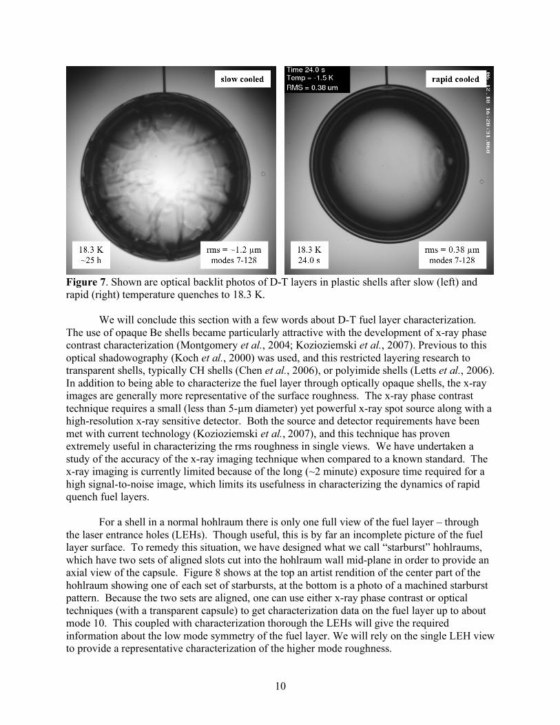
The beta-layering process works qualitatively very well, however the specification for the surface quality of the D-T solid-vapor interface is very stringent. At a few tenths of a Kelvin below the triple point temperature of 19.8 K, it has been demonstrated that sufficiently smooth layers can be formed (Moody et al., 2006; Kozioziemski et al., 2007). However, as the temperature is dropped to the design temperature of 18.3 K the layer roughens and surface defects develop, generally to a level in excess of the specification. Up until recently these experiments have involved a slow decrease in temperature over 24 h. However we are now exploring a “rapid quench” technique recently documented (Martin et al., 2006,2007) that shows promise. The idea is to first form a quality layer near the triple point, characterize it, and then rapidly quench to 1.5 K below the triple point. The current NIF cryogenic target fielding system will support rapid cooling and calculations show that a cool down of 1.5 K in a NIF hohlraum is feasible in a few seconds. Our experiments show that the layer begins to roughen as soon as the temperature is dropped, but the NIF laser shot can occur before the roughness exceeds the specification. Several example runs of the time dependent roughening after a rapid cool down are shown in Figure 6. Plotted is a rms roughness in µm over modes 7 to 128 as a function of time in seconds. The time dependent quench profile is shown, about 20 s are needed in this case for the quench. What we see is that if the laser is fired within 15 s after the quench is complete, the roughness of the layer is still within specification (0.83 µm rms for modes 7-128). Figure 7 shows optical backlit images of slow and rapid cooled D-T layers in 2-mm CH shells. The difference is striking. Work is on-going to optimize this technique, for instance by exploring different cooling rates and understanding time dependent surface roughness mechanisms, but it shows promise for enabling D-T fuel layers that meet all the ignition specifications at 18.3 K.
2.5
2.0
1.5
1.0
0.5
0.0
rms
mo
des
7-1
28
(!
m)
806040200
time (s)
18.25 K
19.5 K
specification
threeseparatelayers
Shoot here
Figure 6. Plotted are the rms data for three separate experimental runs. In each case a good D-T layer was made near the triple point (19.8 K) and then the shell was quenched in about 20 s to 18.25 K. The rms of the layer was monitored as a function of time.
10
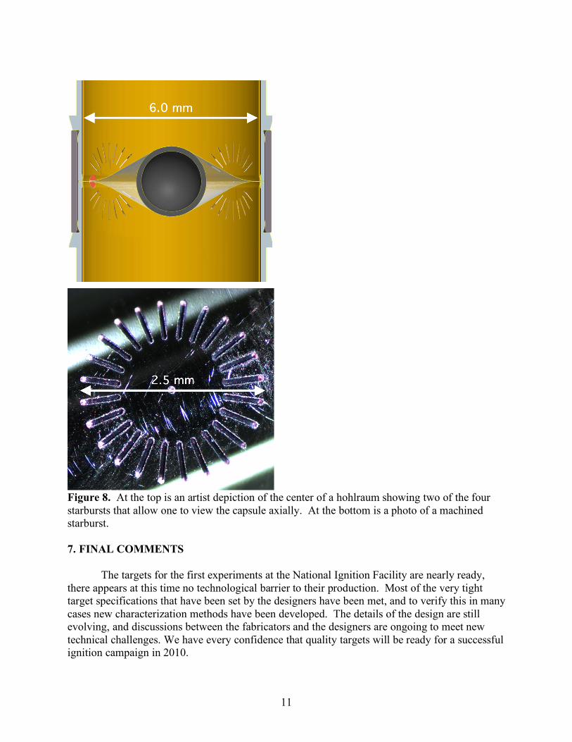
Figure 7. Shown are optical backlit photos of D-T layers in plastic shells after slow (left) and rapid (right) temperature quenches to 18.3 K. We will conclude this section with a few words about D-T fuel layer characterization. The use of opaque Be shells became particularly attractive with the development of x-ray phase contrast characterization (Montgomery et al., 2004; Kozioziemski et al., 2007). Previous to this optical shadowography (Koch et al., 2000) was used, and this restricted layering research to transparent shells, typically CH shells (Chen et al., 2006), or polyimide shells (Letts et al., 2006). In addition to being able to characterize the fuel layer through optically opaque shells, the x-ray images are generally more representative of the surface roughness. The x-ray phase contrast technique requires a small (less than 5-µm diameter) yet powerful x-ray spot source along with a high-resolution x-ray sensitive detector. Both the source and detector requirements have been met with current technology (Kozioziemski et al., 2007), and this technique has proven extremely useful in characterizing the rms roughness in single views. We have undertaken a study of the accuracy of the x-ray imaging technique when compared to a known standard. The x-ray imaging is currently limited because of the long (~2 minute) exposure time required for a high signal-to-noise image, which limits its usefulness in characterizing the dynamics of rapid quench fuel layers. For a shell in a normal hohlraum there is only one full view of the fuel layer – through the laser entrance holes (LEHs). Though useful, this is by far an incomplete picture of the fuel layer surface. To remedy this situation, we have designed what we call “starburst” hohlraums, which have two sets of aligned slots cut into the hohlraum wall mid-plane in order to provide an axial view of the capsule. Figure 8 shows at the top an artist rendition of the center part of the hohlraum showing one of each set of starbursts, at the bottom is a photo of a machined starburst pattern. Because the two sets are aligned, one can use either x-ray phase contrast or optical techniques (with a transparent capsule) to get characterization data on the fuel layer up to about mode 10. This coupled with characterization thorough the LEHs will give the required information about the low mode symmetry of the fuel layer. We will rely on the single LEH view to provide a representative characterization of the higher mode roughness.
11
Figure 8. At the top is an artist depiction of the center of a hohlraum showing two of the four starbursts that allow one to view the capsule axially. At the bottom is a photo of a machined starburst. 7. FINAL COMMENTS The targets for the first experiments at the National Ignition Facility are nearly ready, there appears at this time no technological barrier to their production. Most of the very tight target specifications that have been set by the designers have been met, and to verify this in many cases new characterization methods have been developed. The details of the design are still evolving, and discussions between the fabricators and the designers are ongoing to meet new technical challenges. We have every confidence that quality targets will be ready for a successful ignition campaign in 2010.
12
ACKNOWLEDGMENTS The work presented here is the result of the efforts of many at General Atomics and the Lawrence Livermore National Laboratory. This work was performed under the auspices of the U.S. Department of Energy by General Atomics under Contract DE-AC52-06NA27279 and by the Lawrence Livermore National Laboratory under Contract DE-AC52-07NA27344. REFERENCES Bernat, T.P., Mapoles, E.R. & Sanchez, J.J. (1991). Temperature and age dependence of
redistribution rates of frozen deuterium-tritium. LLNL 1991 ICF Annual Report, pp. 55-59. Biener, J., Mirkarimi, P.B., Tringe, J.W., Baker, S.L., Wang, Y., Kucheyev, S.O., Teslich, N.E.,
Wu, K.J.J., Hamza, A.V., Wild, C., Woerner, E., Koidl, P., Bruehne K. & Fecht, H.J. (2006). Diamond ablators for inertial confinement fusion. Fusion Sci. Technol. 49, 737-742.
Bhandarkar, S., Letts, S.A., Buckley, S., Alford, C., Lindsey, E., Hughes, J., Youngblood, K.P.,
Moreno, K., Xu, H., Huang, H. & Nikroo, A. (2007). Removal of the mandrel from beryllium sputter coated capsules for NIF targets. Fusion Sci. Technol. 51, 564-571.
Chen, K.C., Cook, R.C., Huang, H., Letts, S.A. & Nikroo, A. (2006). Fabrication of graded
germanium-doped CH shells. Fusion Sci. Technol. 49, 750-756. Chen, K.C., Lee, Y.T., Huang, H., Gibson, J.B., Nikroo, A., Johnson, M.A., Mapoles, E. (2007).
Reduction of isolated defects on Ge-doped CH capsules to below ignition specifications. Fusion Sci. Technol. 51, 593-599.
Cook, R.C., Letts, S.A., Buckley, S.R. & Fearon, E. (2006). Pyrolytic removal of the plastic
mandrel from sputtered beryllium shells. Fusion Sci. Technol. 49, 802-808. Eddinger, S.A., Stephens, R.B., Huang, H., Drake, T.J., Nikroo, A., Flint, G. & Bystedt, C.R.
(2007). Precision X-ray optical depth measurements in ICF shells. Fusion Sci. Technol. 51, 525-529.
Forsman, A.C., Banks, P.S., Perry, M.D., Campbell, E.M., Dodell A.L. & Armas, M.S. (2005).
Double-pulse machining as a technique for the enhancement of material removal rates in laser machining of metals. J. Appl. Phys. 98, 033302-1 – 033302-6.
Geidt, W.H., Sanchez, J.J. & Bernat, T.P. (2006). Theory and numerical modeling of the effects
of ablator wall and hohlraum transfer gas thermal resistances on deuterium-tritium redistribution rates. Fusion Sci. Technol. 49, 588-599.
Haan, S.W., Herrmann, M.C., Dittrich, T.R., Fetterman, A.J., Marinak, M.M., Munro, D.H.,
Pollaine, S.M., Salmonson, J.D., Strobel, G.L. & Suter, L.J. (2005). Increasing robustness of
13
indirect drive capsule designs against short wavelength hydrodynamic instabilities. Phys. Plasmas 12, 056316-1 – 056316-8.
Haan, S.W., Herrmann, M.C., Amendt, P.A., Callahan, D.A., Dittrich, T.R., Edwards, M.J.,
Jones, O.S., Marinak, M.M., Munro, D.H., Pollaine, S.M., Salmonson, J.D., Spears, B.K. & Suter, L.J. (2006). Update on specifications for NIF ignition targets, and their rollup into an error budget. Fusion Sci. Technol. 49, 553-557.
Haan, S.W., Amendt, P.A., Callahan, D.A., Dittrich, T.R., Edwards, M.J., Hammel, B.A., Ho,
D.D., Jones, O.S., Lindl, J.D., Marinak, M.M., Munro, D.H., Pollaine, S.M., Salmonson, J.D., Spears, B.K. & Suter, L.J. (2007a). Update on specifications for NIF ignition targets. Fusion Sci. Technol. 51, 509-513.
Haan, S.W., Herrmann, M.C., Salmonson, J.D., Amendt, P.A., Callahan, D.A., Dittrich, T.R.,
Edwards, M.J., Jones, O.S., Marinak, M.M., Munro, D.H., Pollaine, S.M., Spears, B.K. & Suter, L.J. (2007b). Update on design simulations for NIF ignition targets, and the rollup of all specifications into an error budget. Eur. Phys. J. D 44, 249-258.
Haynam, C.A., Wegner, P.J., Auerbach, J.M., Bowers, M.W., Dixit, S.N., Erbert, G.V.,
Heestand, G.M., Henesian, M.A., Hermann, M.R., Jancaitis, K.S., Manes, K.R., Marshall, C.D., Mehta, N.C., Menapace, J., Moses, E., Murray, J.R., Nostrand, M.C., Orth, C.D., Patterson, R., Sacks, R.A., Shaw, M.J., Spaeth, M., Sutton, S.B., Williams, W.H., Widmayer, C.C., White, R.K., Yang, S.T. & Van Wonterghem, B.M. (2007). National ignition facility laser performance status. Appl. Optics 46, 3276-3303.
Hoffer, J.K. & Foreman, L.R. (1988). Radioactively induced sublimation in solid tritium. Phys.
Rev. Lett. 60, 1310-1313. Hoppe, M.L. & Castillo, E. (2006). Polishing of beryllium capsules to meet NIF specifications. J.
de Physique IV 133, 895-898. Huang, H., Kozioziemski, B.J., Stephens, R.B., Nikroo, A., Eddinger, S.A., Chen, K.C., Xu,
H.W. & Moreno, K.A. (2007a). Quantitative radiography: Submicron dimension calibration for ICF ablator shell characterization. Fusion Sci. Technol. 51, 519-524.
Huang, H., Stephens, R.B., Nikroo, A., Eddinger, S.A., Chen, K.C., Xu, H.W., Moreno, K.A.,
Youngblood, K.P. & Skelton, M. (2007b). Quantitative radiography: Film model calibration and dopant/impurity measurement in ICF ablators. Fusion Sci. Technol. 51, 530-538.
Koch, J.A., Bernat, T.P., Collins, G.W., Hammel, B.A., Kozioziemski, B.J., MacKinnon, A.J.,
Sater, J.D., Bittner, D.N. & Lee, Y. (2000). Quantitative analysis of backlit shadowgraphy as a diagnostic of hydrogen ice surface quality in ICF capsules. Fusion Technol. 38, 123-131.
Kozioziemski, B.J., Montgomery, D.S., Sater, J.D., Moody, J.D., Gautier, C., and Pipes, J.W.
(2007). Solid Deuterium-Tritium Surface Roughness in a Beryllium Inertial Confinement Fusion Shell. Nucl. Fusion 47, 1-8.

14
Landen O.L., Glenzer S.H., Froula D.H., Dewald, E.L., Suter, L.J., Schneider, M.B., Hinkel,
D.E., Fernandez, J.C., Kline, J.L., Goldman, S.R., Braun, D.G., Celliers, P.M., Moon, S.J., Robey, H.S., Lanier, N.E., Glendinning, S.G., Blue, B.E., Wilde, B.H., Jones, O.S., Schein, J., Divol, L., Kalantar, D.H., Campbell, K.M., Holder, J.P., McDonald, J.W., Niemann, C., Mackinnon, A.J., Collins, G.W., Bradley, D.K., Eggert, J.H., Hicks, D.C., Gregori, G., Kirkwood, R.K., Young, B.K., Foster, J.M., Hansen, J.F., Perry, T.S., Munro, D.H., Baldis, H.A., Grim, G.P., Heeter, R.F., Hegelich, M.B., Montgomery, D.S., Rochau, G.A., Olson, R.E., Turner, R.E., Workman, J.B., Berger, R.L., Cohen, B.I., Kruer, W.L., Langdon, A.B., Langer, S.H., Meezan, N.B., Rose, H.A., Still, C.H., Williams, E.A., Dodd, E.S., Edwards, M.J., Monteil, M.C., Stevenson, R.M., Thomas, B.R., Coker, R.F., Magelssen, C.R., Rosen, P.A., Stry, P.E., Woods, D., Weber, S.V., Young, P.E., Alvarez, S., Armstrong, G., Bahr, R., Bourgade, J.L., Bower, D., Celeste, J., Chrisp, M., Compton, S., Cox, J., Constantin, C., Costa, R., Duncan, J., Ellis, A., Emig, J., Gautier, C., Greenwood, A., Griffith, R., Holdner, F., Holtmeier, G., Hargrove, D., James, T., Kamperschroer, J., Kimbrough, J., Landon, M., Lee, F.D., Malone, R., May, M., Montelongo, S., Moody, J., Ng, E., Nikitin, A., Pellinen, D., Piston, K., Poole, M., Rekow, V., Rhodes, M., Shepherd, R., Shiromizu, S., Voloshin, D., Warrick, A., Watts, P., Weber, F., Young, P., Arnold, P., Atherton, L., , G., Bonanno, R., Borger, T., Bowers, M., Bryant, R., Buckman, S., Burkhart, S., Cooper, F., Dixit, S.N., Erbert, G., Eder, D.C., Ehrlich, R.E., Felker, B., Fornes, J., Frieders, G., Gardner, S., Gates, C., Gonzalez, M., Grace, S., Hall, T., Haynam, C.A., Heestand, G., Henesian, M.A., Hermann, M., Hermes, G., Huber, S., Jancaitis, K., Johnson, S., Kauffman, B., Kelleher, T., Kohut, T., Koniges, A.E., Labiak, T., Latray, D., Lee, A., Lund, D., Mahavandi, S., Manes, K.R., Marshall, C., McBride, J., McCarville, T., McGrew, L., McNapace, J., Mertens, E., Murray, J., Neumann, J., Newton, A., , P., Padilla, E., Parham, T., Parrish, G., Petty, C., Polk, M., Powell, C., Reinbachs, I., Rinnert, R., Riordan, B., Ross, G., Robert, V., Tobin, M., Sailors, S., Saunders, R., Schmitt, M., Shaw, M., Singh, M., Spaeth, M., Stephens, A., Tietbohl, G., Tuck, J., Van Wonterghem, B.M., Vidal, R., Wegner, P.J., Whitman, P., Williams, K., Winward, K., Work, K., Wallace, R., Nobile, A., Bono, M., Day, B., Elliott, J., Hatch, D., Louis, H., Manzenares, R., O'Brien, D., Papin, P., Pierce, T., Rivera, G., Ruppe, J., Sandoval, D., Schmidt, D., Valdez, L., Zapata, K., MacGowan, B.J., Eckart, M.J., Hsing, W.W., Springer, P.T., Hammel, B.A., Moses, E.I. & Miller, G.H. (2007). The first target experiments on the national ignition facility. Eur. Phys. J. D 44, 273-281.
Letts, S., Fearon, E., Anthamatten, M., Buckley, S., King, C. & Cook, R. (2006). Preparation of
polyimide ablator coatings using an improved solvent vapor smoothing process. Fusion Sci. Technol. 49, 714-720.
Lindl, J.D. (1998). Inertial Confinement Fusion. New York: Springer-Verlag. Lindl, J.D., Amendt, P., Berger, R.L., Glendinning, S.G., Glenzer, S.H., Haan, S.W., Kauffman,
R.L., Landen, O.L. & Suter, L.J. (2004). The physics basis for ignition using indirect-drive targets on the National Ignition Facility. Phys. Plasmas 11, 339-491.
McCrory, R.L., Meyerhofer, D.D., Loucks, S.J., Skupsky, S., Betti, R., Boehly, T.R., Collins,
T.J.B., Craxton, R.S., Delettrez, J.A., Edgell, D.H., Epstein, R., Fletcher, K.A., Freeman, C.,

15
Frenje, J.A., Glebovi, V.Y., Concharov, V.N., Harding, D.R., Igumenshchev, I.V., Keck, R.L., Kilkenny, J.D., Knauer, J.P., Li, C.K., Marciante, J., Marozas, J.A., Marshall, F.J., Maximov, A.V., McKenty, P.W., Morse, S.F.B., Myatt, J., Padalino, S., Petrasso, R.D., Radha, P.B., Regan, S.P., Sangster, T.C., Seguin, F.H., Seka, W., Smalyuk, V.A., Soures, J.M., Stoeckl, C., Yaakobi, B. & Zuegel, J.D. (2007). Progress in direct-drive inertial confinement fusion research at the Laboratory for Laser Energetics. Eur. Phys. J. D 44, 233-238.
McEachern, R.L. Moore, C.E. & Wallace, R.J. (1995). The design, performance, and application
of an atomic force microscope-based profilometer. J. Vac. Sci. Technol. A, 13, 983-989. McElfresh, M., Gunther, J., Alford, C., Fought, E. & Cook, R. (2006). Fabrication of beryllium
capsules with copper-doped layers for NIF targets: A progress report. Fusion Sci. Technol. 49, 786-795.
McQuillan, B.W., Nikroo, A., Steinman, D.A., Elsner, F.H., Czechowicz, D.G., Hoppe, M.L.,
Sixtus, M. & Miller, W.J. (1997). The PαMS/GDP process for production of ICF target mandrels. Fusion Technol. 31, 381-384.
Martin, A.J., Simms, R.J. & Jacobs, R.B. (1988). Beta energy driven uniform deuterium-tritium
ice layer in reactor-size cryogenic inertial fusion targets. J. Vac. Sci Technol. A 6, 1885-1888. Martin, M., Gauvin, C., Choux, A., Baclet, P. & Pascal, G. (2006). The cryogenic target for
ignition on the LMJ: Useful tools to achieve nominal temperature and roughness conditions of the DT solid layer. Fusion Sci. Technol. 49, 600-607.
Martin, M., Gauvin, C., Choux, A., Baclet, P. & Pascal, G. (2007). A way to reach the
cryogenic's temperature and roughness requirements for the laser megajoule facility. Fusion Sci. Technol. 51, 747-752.
Montesanti, R.C., Johnson, R.A., Mapoles, E.R., Atkinson, D.P., Hughes, J.D. & Reynolds, J.L.
(2006). Phase-shifting diffraction interferometer for inspecting NIF ignition-target shells. Proceedings of the American Society for Precision Engineering 2006 Annual Meeting 39, 15-18.
Montgomery, D.S., Nobile, A. & Walsh, P.J. (2004). Characterization of National Ignition
Facility cryogenic beryllium capsules using x-ray phase contrast imaging. Rev. Sci. Instrum. 75, 3986-3988.
Moody, J.D., Kozioziemski, B.J., London, R.L., Montgomery, D.S., Sanchez, J.J., Sater, J.D.,
Bittner, D.N., Burmann, J.A., Jones, R.L., Pipes, J. & Stefanescu, D. (2006). Status of cryogenic layering for NIF ignition targets. J. de Physique IV 133, 863-867.
Moses, E.I. & Wuest, C.R. (2005). The National Ignition Facility: Laser performance and first
experiments. Fusion Sci. Technol. 47, 314-322.

16
Moses, E.I., Miller, G.H. & Kauffman R.L. (2006). The ICF status and plans in the United States. J. de Physique IV 133, 9-16.
Moses, E.I., Bonanno, R.E., Haynam, C.A., Kauffman, R.L., MacGowan, B.J., Patterson, R.W.,
Sawicki, R.H. & Van Wonterghem, B.M. (2007). The National Ignition Facility: Path to ignition in the laboratory. Eur. Phys. J. D 44, 215-218.
Nikroo, A., Bousquet, J., Cook, R., McQuillan, B.W., Paguio, R. & Takagi, M. (2004). Progress
in 2 mm glow discharge polymer mandrel development for NIF. Fusion Sci. Technol. 45, 165-170.
Nikroo, A., Xu, H.W., Moreno, K.A., Youngblood, K.P., Cooley, J., Alford, C.S., Letts, S.A.,
Cook, R.C. (2007). Investigation of deuterium permeability of sputtered beryllium and graded copper-doped beryllium shells. Fusion Sci Technol. 51, 553-558.
Sater, J., Kozioziemski, B., Collins, G.W., Mapoles, E.R., Pipes, J., Burmann, J. & Bernat, T.P.
(1999). Cryogenic D-T fuel layers formed in 1 mm spheres by beta-layering. Fusion Technol. 35, 229-233.
Schein, J., Jones, O., Rosen, M., Dewald, E., Glenzer, S., Gunther, J., Hammel, B., Landen, O.,
Suter, L. & Wallace, R. (2007). Demonstration of enhanced radiation drive in hohlraums made from a mixture of high-Z wall materials. Phys. Rev. Lett. 98, 175003-1 – 175003-4.
Souers, P.C. (1986). Hydrogen Properties for Fusion Energy, Berkeley: University of California
Press. Stephens, R.B., Olson, D., Huang, H. & Gibson J.B. (2004). Complete surface mapping of ICF
shells. Fusion Sci. Technol. 45, 210-213 Strobel, G.L., Haan, S.W., Munro, D.H. & Dittrich, T.R. (2004). Design of a 250 eV cryogenic
ignition capsule for the National Ignition Facility. Phys. Plasmas 11, 4261-4266. Takagi, M., Saito, K., Frederick, C., Nikroo, A. & Cook, R. (2007). Fabrication and attachment
of polyimide fill tubes to plastic NIF capsules. Fusion Sci Technol. 51, 638-642. Theobald, M., Baudin, F., Barnouin, J., Peche, E., Bednarczyk, S., Legaie, O. & Baclet, P.
(2007). Graded germanium-doped CHx microshells meeting the specifications of the Megajoule Laser cryogenic target. Fusion Sci. Technol. 51, 586-592.
Wilkens, H.L., Nikroo, A., Wall, D.R. & Wall, J.R. (2007). Developing depleted uranium and
gold cocktail hohlraums for the National Ignition Facility. Phys. Plasmas 14, 056310-1 – 056310-6.
Xu, H.W., Alford, C.S., Cooley, J.C., Dixon, L.A., Hackenberg, R.E., Letts, S.A., Moreno, K.A.,
Nikroo, A., Wall, J.R. & Youngblood, K.P. (2007). Beryllium capsule coating development for NIF targets. Fusion Sci. Technol. 51, 547-552.

17
Youngblood, K.P., Moreno, K.A., Nikroo, A., Huang, H., Lee, Y.T., Letts, S.A., Alford, C.S. &
Buckley, S.R. (2007). Removal of GDP mandrels from sputter-coated beryllium capsules for NIF targets. Fusion Sci. Technol. 51, 572-575.