national board subcommittee repairs and alterations · a vessel, do repairs require pwht or...
TRANSCRIPT

1
Date Distributed: 8/20/18
NATIONAL BOARD SUBCOMMITTEE
REPAIRS AND ALTERATIONS
MINUTES
Meeting of July 18th, 2018 Columbus, OH
These minutes are subject to approval and are for the committee use only. They are not to be duplicated or quoted for other than committee use.
The National Board of Boiler & Pressure Vessel Inspectors 1055 Crupper Avenue
Columbus, Ohio 43229-1183 Phone: (614)888-8320 FAX: (614)847-1828
2
1. Call to OrderThe meeting was called to order at 8:00 a.m. on July 17, 2018 by Chairman, Mr. George Galanes.
2. Introduction of Members and VisitorsThe attendees are identified on the attendance sign in sheet (Attachment Pages 1-2). With the attached attendance listing, a quorum was established.
3. Announcements
Announcements were made to the subgroup by Mr. Terrence Hellman.• Items not approved at Main Committee this week will not make the 2019 Edition of the NBIC.
.• The National Board will be hosting a reception for all committee members and visitors on Wednesday
evening at 5:30pm at the pavilion.
• Breakfast will be provided on Thursday morning to NBIC Committee members and visitors.
• Lunch will be provided on Wednesday and Thursday to NBIC Committee members and visitors
4. Adoption of the Agenda• Added membership approvals for SG Graphite elected Chair and membership reappointments.
The above listed item was added to the agenda and a motion was made to adopt the agenda as revised. The motion was unanimously approved.
5. Approval of the Minutes of January 10th, 2018 Meeting
The minutes from the January 2018 SC Repairs and Alterations meeting were unanimously approved.
6. Review of Rosters (Attachment Page 3)
a. Membership Nominations
• Michael Quisenberry – (Interest Category: National Board Certificate Holder) (Attachment Page 4 )• John Siefert – (Interest Cagegory – General Interest) (Attachment Page 9)
The SC discussed the nominees and a motion was made to approve the nominees as members of the
Repairs and Alteration SG. The motion was unanimously approved.
b. Membership Reappointments
• Mr. Galanes, Mr. Boseo, Mr. Edwards, and Mr. Sekely all have memberships to SC R&A expiring on8/30/2018. The members reaffirmed their commitment to participate on the Committee. A motion wasmade to reappoint all members. The motion was unanimously approved.

3
• Mr. Carter, Mr. Edwards, Mr. Galanes, Mr. Miletti, Mr. Pillow, Mr. Sekely, and Mr. Walker all havememberships to SG R&A expiring on 8/30/2018. The members reaffirmed their commitment toparticipate on the Subgroup. A motion was made to reappoint all members. The motion wasunanimously approved.
• Mr Andrew Stupica and Greg Becherer were reappointed and Aaron Viet was elected Chair to SGGraphite. A motion was made to accept the reappointment of the members and the elected Chair to SGGraphite. The motion was unanimously approved.
c. Officer Appointments
• Mr. Galanes’s term as Chair expires 8/30/2018. Mr. Galanes stated that nominations for newmembership on the Repair and Alteration SC will need to wait until the next meeting when the newChair for the SC has been elected.
• Nominations were taken for the Repair and Alteration SC Chair. Mr. Robby Troutt and Mr. BenjamenShaefer were nominated. The nominees addressed the Subcommittee as to why they would like tobecome Chair, and how their experience and knowledge would benefit the group. A motion was made tocall a vote by ballot to elect the new Chair. The motion passed unanimously and written ballots werecast by the SC membership. Mr. Robby Troutt was elected as Chair of the SC Repairs and Alterationsby majority vote.
7. Interpretations
Item Number: 17-143 NBIC Location: Part 3 No Attachment General Description: Can an "R" stamp certified shop manufacture and use parts for use on the pressure boundary to complete the repair of a boiler?
Subgroup: Locomotive Task Group: L. Moedinger (PM)
July 2018 Meeting Action: Progress Report: Mr. Moedinger gave a progress report that work is still being done on the item and it will be put out to Letter Ballot to Repair and Alteration SG.
Item Number: 18-30 NBIC Location: Part 3 Attachment Page 20 General Description: Interchange of Convection Sections from one OSTG to another OSTG
Subgroup: Repairs and Alterations Task Group: Jamie Walker – PM
July 2018 Meeting Action: Mr. Jamie Walker proposed responding to the inquirer with the interpretations 07-06, 01-28, and 95-15 to answer their question. The SC discussed the need to address these issues within the NBIC, and a new action Item 18-65 was assigned. A motion was made to have the NBIC Secretary respond with the referenced interpretations and close this Item. The motion was unanimously approved.

4
Item Number: 18-31 NBIC Location: Part 3, 2.5.2 a) Attachment Pages 21-22 General Description: Post-weld heat treatment of a full penetration groove pipe nozzle neck repair
Subgroup: Repairs and Alterations Task Group: Nathan Carter
July 2018 Meeting Action: The SC discussed if PWHT is not required, but is optionally performed on a vessel, do repairs require PWHT or Alternative Welding Methods. The proposed response was that the repair can be made without PWHT or using Alternative Welding Methods as long as the WPS is qualified without PWHT, Note: For Pressure Vessels, See Interpretation 95-14. A motion was made to accept the Committee's question and reply. The motion was approved with 1 abstention. The abstention was from a committee member who felt this was "consulting". Chair G. Galanes requested an Action Item be opened to better address PWHT and Pre-Heat requirements in Repairs and Alterations. Action Item 18-68 was created.
Item Number: 18-32 NBIC Location: Part 3 Attachment Page 23 General Description: Interchange of convective box (economizers) in Once Through Steam Generators (OSTG)
Subgroup: Repairs and Alterations Task Group: Ben Schaefer
July 2018 Meeting Action: Mr. Benjamin Schaefer proposed responding in line with Item 18-30 with a response to the inquirer with the interpretations 07-06, 01-28, and 95-15 to answer their question. The SC discussed the need to address these issues within the NBIC, and this subject will be included within the newly opened Item 18-65 (see Item 18-30). A motion was made to have the NBIC Secretary respond with the referenced interpretations and close this Item. The motion was unanimously approved.
Item Number: 18-33 NBIC Location: Part 3, 3.4.4 c) Attachment Page 24 General Description: Providing an additional stiffener ring to compensate for corrosion levels being above allowance
Subgroup: Repairs and Alterations Task Group: Kathy Moore – PM, Paul Shanks, David Martinez
July 2018 Meeting Action: Progress Report: The Repair and Alteration SG has reviewed this inquiry, and task group was created. The task group will come up with a proposal for the January 2019 meeting.
Task Group assigned: Kathy Moore – PM, Paul Shanks, David Martinez
Item Number: 18-34 NBIC Location: Part 3, 8.4 Attachment Page 25 General Description: Does an R certificate holder assume responsibility for safety/integrity of a vessel outside the scope of repair?
Subgroup: Repairs and Alterations Task Group: Nathan Carter, Mike Quisenberry
July 2018 Meeting Action: The proposed response of “no” along with Interpretations 95-41 and 95-17 as reference was discussed. A motion was made to accept the interpretation with proposed committee question and reply and was unanimously approved.
5
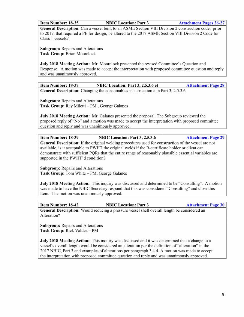
Item Number: 18-35 NBIC Location: Part 3 Attachment Pages 26-27 General Description: Can a vessel built to an ASME Section VIII Division 2 construction code, prior to 2017, that required a PE for design, be altered to the 2017 ASME Section VIII Division 2 Code for Class 1 vessels?
Subgroup: Repairs and Alterations Task Group: Brian Moorelock
July 2018 Meeting Action: Mr. Moorelock presented the revised Committee’s Question and Response. A motion was made to accept the interpretation with proposed committee question and reply and was unanimously approved.
Item Number: 18-37 NBIC Location: Part 3, 2.5.3.6 e) Attachment Page 28 General Description: Changing the consumables in subsection e in Part 3, 2.5.3.6
Subgroup: Repairs and Alterations Task Group: Ray Miletti – PM , George Galanes
July 2018 Meeting Action: Mr. Galanes presented the proposal. The Subgroup reviewed the proposed reply of “No” and a motion was made to accept the interpretation with proposed committee question and reply and was unanimously approved.
Item Number: 18-39 NBIC Location: Part 3, 2.5.3.6 Attachment Page 29 General Description: If the original welding procedures used for construction of the vessel are not available, is it acceptable to PWHT the original welds if the R-certificate holder or client can demonstrate with sufficient PQRs that the entire range of reasonably plausible essential variables are supported in the PWHT’d condition?
Subgroup: Repairs and Alterations Task Group: Tom White – PM, George Galanes
July 2018 Meeting Action: This inquiry was discussed and determined to be “Consulting”. A motion was made to have the NBIC Secretary respond that this was considered “Consulting” and close this Item. The motion was unanimously approved.
Item Number: 18-42 NBIC Location: Part 3 Attachment Page 30 General Description: Would reducing a pressure vessel shell overall length be considered an Alteration?
Subgroup: Repairs and Alterations Task Group: Rick Valdez – PM
July 2018 Meeting Action: This inquiry was discussed and it was determined that a change to a vessel’s overall length would be considered an alteration per the definition of “alteration” in the 2017 NBIC, Part 3 and examples of alterations per paragraph 3.4.4. A motion was made to accept the interpretation with proposed committee question and reply and was unanimously approved.
6
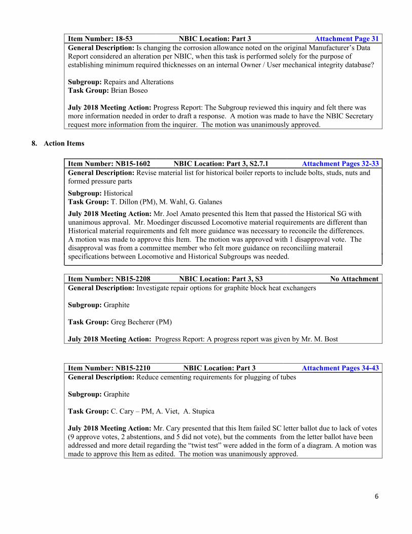
Item Number: 18-53 NBIC Location: Part 3 Attachment Page 31 General Description: Is changing the corrosion allowance noted on the original Manufacturer’s Data Report considered an alteration per NBIC, when this task is performed solely for the purpose of establishing minimum required thicknesses on an internal Owner / User mechanical integrity database?
Subgroup: Repairs and Alterations Task Group: Brian Boseo
July 2018 Meeting Action: Progress Report: The Subgroup reviewed this inquiry and felt there was more information needed in order to draft a response. A motion was made to have the NBIC Secretary request more information from the inquirer. The motion was unanimously approved.
8. Action Items
Item Number: NB15-1602 NBIC Location: Part 3, S2.7.1 Attachment Pages 32-33 General Description: Revise material list for historical boiler reports to include bolts, studs, nuts and formed pressure parts Subgroup: Historical Task Group: T. Dillon (PM), M. Wahl, G. Galanes July 2018 Meeting Action: Mr. Joel Amato presented this Item that passed the Historical SG with unanimous approval. Mr. Moedinger discussed Locomotive material requirements are different than Historical material requirements and felt more guidance was necessary to reconcile the differences. A motion was made to approve this Item. The motion was approved with 1 disapproval vote. The disapproval was from a committee member who felt more guidance on reconciliing materail specifications between Locomotive and Historical Subgroups was needed.
Item Number: NB15-2208 NBIC Location: Part 3, S3 No Attachment General Description: Investigate repair options for graphite block heat exchangers
Subgroup: Graphite
Task Group: Greg Becherer (PM)
July 2018 Meeting Action: Progress Report: A progress report was given by Mr. M. Bost
Item Number: NB15-2210 NBIC Location: Part 3 Attachment Pages 34-43 General Description: Reduce cementing requirements for plugging of tubes
Subgroup: Graphite
Task Group: C. Cary – PM, A. Viet, A. Stupica
July 2018 Meeting Action: Mr. Cary presented that this Item failed SC letter ballot due to lack of votes (9 approve votes, 2 abstentions, and 5 did not vote), but the comments from the letter ballot have been addressed and more detail regarding the “twist test” were added in the form of a diagram. A motion was made to approve this Item as edited. The motion was unanimously approved.

7
Item Number: NB16-0303 NBIC Location: Part 3 Attachment Page 44 General Description: Fillet welded patches Subgroup: SG Repairs and Alterations Task Group: B. Boseo – PM, B. Morelock, R Underwood, J. Walker
July 2018 Meeting Action: This Item failed the SG Repairs and Alterations with 9 Approvals, 11 Disapprovals, and 1 Abstention, but a second motion at the SG level was made to present this item to the Repair and Alteration SC. After discussion, a motion was made to close this item with no action. The motion was unanimously approved. Disapprovals were mainly due to concerns that this type of temporary repair would be unsafe and should not be included in the NBIC.
Item Number: NB16-0503 NBIC Location: Part 3, S2.13.13.4 Attachment Page 45 General Description: Add types of rivet heads
Subgroup: Historical Task Group: None Assigned.
July 2018 Meeting Action: This Item passed SC R&A via letter ballot on 02-23-2018 and is ready for consideration by the Main Committee. No action was taken on this Item.
Item Number: NB16-0608 NBIC Location: Part 3, 1.6.2 Attachment Pages 48-50 General Description: Address Nuclear QA program requirements for owner and certificate holder
Subgroup: Repairs and Alterations Task Group: NR Task Group
July 2018 Meeting Action: Paul Edwards presented the item referencing the edition and addenda of NQA-1 that can be utilized within Table 1.6.2 and Table 1.6.2.1. A motion was made to accept and approve the revision. The motion was unanimously approved.
Item Number: NB16-1402 NBIC Location: Part 3 Attachment Page 51 General Description: Life extension for high pressure vessels above 20 years
Subgroup: FRP
Task Group: M. Gorman (PM)
July 2018 Meeting Action: Progress Report: No information was received from FRP Subgroup at the time of this meeting. No action taken.
Item Number: NB16-1403 NBIC Location: Part 3, S4 No Attachment General Description: Add information on repair of high pressure vessels
Subgroup: FRP
Task Group: N. Sirosh (PM)
July 2018 Meeting Action: Progress Report: No information was received from FRP Subgroup at the time of this meeting. No action taken.

8
Item Number: NB16-1502 NBIC Location: Part 3 No Attachment General Description: Develop supplement for repairs and alterations based on international construction standards
Subgroup: SG Repairs and Alterations Task Group: International Repair Supplement Task Group, Chuck Withers – PM
July 2018 Meeting Action: Progress Report: Mr. Withers was not present and could not present the item.
Item Number: NB16-1801 NBIC Location: Part 3, S1 Attachment Pages 56-57 General Description: Review Part 3 S1 for revisions based on the publication of ASME Section 1, Part PL
Subgroup: Locomotive Task Group: L. Moedinger (PM)
July 2018 Meeting Action: Mr. Moedinger presented that this item failed the letter ballot to Main Committee in June due to a lack of votes. A motion was made to reaffirm and approve this item for consideration at the Main Committee. The motion was unanimously approved.
Item Number: NB16-2602 NBIC Location: Part 3, Section 9 No Attachment General Description: Add definitions for practicable and impracticable to glossary
Subgroup: Repairs and Alterations Task Group: R. Underwood (PM), R. Milletti, J. Sekely
July 2018 Meeting Action: Mr. Robert Underwood stated that this definition was unnecessary and made a motion to close this Item with no action. The motion was unanimously approved.
Item Number: NB17-0602 NBIC Location: Part 3 No Attachment General Description: Scope of repair/new historical boiler with an R Stamp
Subgroup: Historical Task Group: R. Underwood (PM), M. Wahl, J. Amato, D. Rose, M. Jordan
July 2018 Meeting Action: Mr. Underwood presented that this Item was deemed unnecessary and was voted to be closed with no action at the Historical SG. A motion was made for the SC to close with no action. The motion was unanimously approved.
Item Number: NB17-0701 NBIC Location: Part 3 Attachment Pages 58-59 General Description: Add references to Commercial Grade Dedication (CGD) to 1.6.7.1 and 1.6.8.1
Subgroup: Repairs and Alterations Task Group: NR Task Group
July 2018 Meeting Action: Mr. Paul Edwards presented the Item and discussed that the NR TG recommended not referencing CGD in 1.6.7.1 or in 1.6.8.1, effectively closing this Item with no action. A motion to close with no action was made. The motion was unanimously approved.

9
Item Number: 17-134 NBIC Location: Part 3, Section 5 No Attachment General Description: Proposed Revision for registration of Form R-1 with the National Board containing ASME pressure part data reports attached.
Subgroup: Repairs and Alterations Task Group: P. Shanks (PM), Rob Troutt, Joel Amato, Kathy Moore, Paul Edwards
July 2018 Meeting Action: Progress Report: P. Shanks gave a progress report.
Item Number: 17-137 NBIC Location: Part 3, S4.18.2 Attachment Pages 60-61 General Description: Remove "sand" blasting and replace with "abrasive" in Part 3, S4.18.2
Subgroup: FRP Task Group: Terry Cowley
July 2018 Meeting Action: Progress Report: No FRP members were present to present the item. History: Mr. Cowley submitted a new proposal to be letter balloted to SG FRP after their meeting in April. The item was approved via letter ballot in June.
Item Number: 17-139 NBIC Location: Part 3, 2.2.3 No Attachment General Description: Performance qualification by independent qualifier
Subgroup: Repairs and Alterations Task Group: Jim Pillow
July 2018 Meeting Action: Jim Pillow reported ASME Section IX is not going to act on a similar item and recommended closing this Item with no action. A motion to close with no action was made. The motion was unanimously approved.
Item Number: 17-155 NBIC Location: Part 3, S1 Attachment Page 62 General Description: Throttle pipes, dry pipes, superheater headers, and front end steam pipes requirements
Subgroup: SG Locomotive Task Group: R. Stone (PM)
July 2018 Meeting Action: Mr. Moedinger presented that this item has been revised to address comments form the Main Committee letter ballot. A motion was made to approve this item as revised for consideration at the Main Committee. The motion was unanimously approved.
Item Number: 17-156 NBIC Location: Part 3, S1 Attachment Page 63 General Description: Welding/brazing activities for Locomotive Boilers
Subgroup: SG Locomotive Task Group: G. M Ray (PM)
July 2018 Meeting Action: Mr. Moedinger presented that this item is being addressed by another Item (Item 18-40) and moved to close with no action. The motion was unanimously approved.

10
Item Number: 17-160 NBIC Location: Part 3, S1 Attachment Page 64 General Description: Partial knuckle replacement
Subgroup: SG Locomotive Task Group: R. Franzen (PM)
July 2018 Meeting Action: Progress Report: Mr. Moedinger presented that this Item was passed unanimously by SG Locomotive at their April 2018 meeting, and it also passed SC R&A letter ballot on June 15th. It will be on the Main Committee agenda for the July meeting. No action taken.
Item Number: 17-166 NBIC Location: Part 3, S3 No Attachment General Description: Remove nozzle replacement and tube replacement from graphite routine repair list
Subgroup: SG Graphite Task Group: F. Brown (PM)
July 2018 Meeting Action: Progress Report: Task group is working on preparing a proposal.
Item Number: 17-167 NBIC Location: Part 3, S3 No Attachment General Description: Clarify repair inspection requirements for machined only graphite parts
Subgroup: SG Graphite
Task Group: A. Viet (PM)
July 2018 Meeting Action: Progress Report: Task group is working on preparing a proposal.
Item Number: 17-179 NBIC Location: Part 3, Section 5 Attachment Pages 66-82 General Description: R Form Guides
Subgroup: SG Repairs and Alterations Task Group: Tom White PM , Bill Vallance
July 2018 Meeting Action: Tom White presented the Item to revise the Report of Repair instructions and form field numbering. Discussion by the SG resulted in a new Action Item being created to move all Report Forms and their instructions to a supplement within Part 3 for the 2021 Edition of the NBIC (Item 18-66). A motion was made to approve this item. The motion was unanimously approved.
Item Number: 18-12 NBIC Location: Part 3 Attachment Pages 83-85 General Description: Adding Weld Buildup to WM #6
Subgroup: SG Repairs and Alterations Task Group: John Siefert PM, George Galanes
July 2018 Meeting Action: Progress Report: Mr. George Galanes presented that this Item was opened at the January 2018 meeting and the proposed revision to Welding Method 6 to limit weld build up to 100 square inches on only Grade 91 tubes is still being worked on.

11
Item Number: 18-13 NBIC Location: Part 3 Attachment Pages 86-89 General Description: Weld Methods 7 addition for dissimilar weld metal-Gr. 91.
Subgroup: SG Repairs and Alterations Task Group: John Siefert PM, George Galanes
July 2018 Meeting Action: Progress Report: Mr. George Galanes presented that this Item was opened at the January 2018 meeting and the proposed revision to add a Welding Method 7 to allow for dissimilar metal welding on Grade 91 to austenitic steels and low allow steels.
New Items:
Item Number: 18-5 NBIC Location: Part 3, S1.2.9.6 Attachment Page 90 General Description: Installation of boiler flues
Subgroup: SG Locomotive Task Group: L. Moedinger (PM)
July 2018 Meeting Action: Mr. Moedeinger presented that this item was passed unanimously by SG Locomotive at their April 2018 meeting. Editorial revision to address comments was made and a motion to reaffirm and approve the item for consideration at Main Committee was made. The motion was unanimously approved.
Item Number: NB18-7 NBIC Location: Part 3, S1.2.5.1 Attachment Page 92 General Description: Fillet welded staybolts
Subgroup: SG Locomotive
Task Group: L. Moedinger (PM)
July 2018 Meeting Action: Item was passed unanimously by SG Locomotive at their April 2018 meeting, and it also passed SC R&A letter ballot on June 15th. Editorial revision to address comments was made and a motion to reaffirm and approve the item for consideration at Main Committee was made. The motion was unanimously approved.
Item Number: 18-14 NBIC Location: Part 3 Attachment Pages 93-98 General Description: SWPS Revisions
Subgroup: SG Repairs and Alterations Task Group: Jim Sekely (PM).
July 2018 Meeting Action: Mr. Jim Sekely presented that this item passed both SG and SC R&A letter ballots on June 30th, and the comments have been addressed. A motion was made to reaffirm this Item as revised for presentation at the Main Committee. The motion was unanimously approved.
12
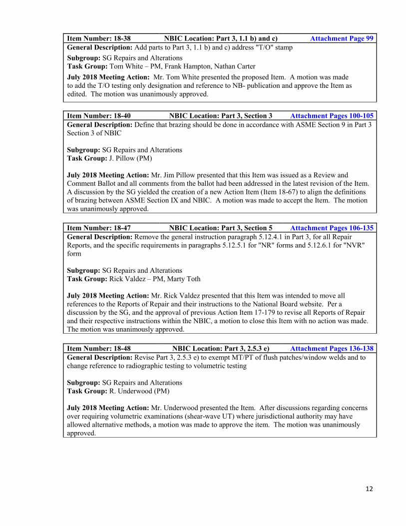
Item Number: 18-38 NBIC Location: Part 3, 1.1 b) and c) Attachment Page 99 General Description: Add parts to Part 3, 1.1 b) and c) address "T/O" stamp Subgroup: SG Repairs and Alterations Task Group: Tom White – PM, Frank Hampton, Nathan Carter July 2018 Meeting Action: Mr. Tom White presented the proposed Item. A motion was made to add the T/O testing only designation and reference to NB- publication and approve the Item as edited. The motion was unanimously approved.
Item Number: 18-40 NBIC Location: Part 3, Section 3 Attachment Pages 100-105 General Description: Define that brazing should be done in accordance with ASME Section 9 in Part 3 Section 3 of NBIC
Subgroup: SG Repairs and Alterations Task Group: J. Pillow (PM)
July 2018 Meeting Action: Mr. Jim Pillow presented that this Item was issued as a Review and Comment Ballot and all comments from the ballot had been addressed in the latest revision of the Item. A discussion by the SG yielded the creation of a new Action Item (Item 18-67) to align the definitions of brazing between ASME Section IX and NBIC. A motion was made to accept the Item. The motion was unanimously approved.
Item Number: 18-47 NBIC Location: Part 3, Section 5 Attachment Pages 106-135 General Description: Remove the general instruction paragraph 5.12.4.1 in Part 3, for all Repair Reports, and the specific requirements in paragraphs 5.12.5.1 for "NR" forms and 5.12.6.1 for "NVR" form
Subgroup: SG Repairs and Alterations Task Group: Rick Valdez – PM, Marty Toth
July 2018 Meeting Action: Mr. Rick Valdez presented that this Item was intended to move all references to the Reports of Repair and their instructions to the National Board website. Per a discussion by the SG, and the approval of previous Action Item 17-179 to revise all Reports of Repair and their respective instructions within the NBIC, a motion to close this Item with no action was made. The motion was unanimously approved.
Item Number: 18-48 NBIC Location: Part 3, 2.5.3 e) Attachment Pages 136-138 General Description: Revise Part 3, 2.5.3 e) to exempt MT/PT of flush patches/window welds and to change reference to radiographic testing to volumetric testing
Subgroup: SG Repairs and Alterations Task Group: R. Underwood (PM)
July 2018 Meeting Action: Mr. Underwood presented the Item. After discussions regarding concerns over requiring volumetric examinations (shear-wave UT) where jurisdictional authority may have allowed alternative methods, a motion was made to approve the item. The motion was unanimously approved.

13
Item Number: 18-50 NBIC Location: Part 3, Section 3 Attachment Page 139 General Description: Revision to Part 3, S2.11 a) to remove VT examination
Subgroup: SG Historical
Task Group: None assigned
July 2018 Meeting Action: Mr. Moedinger presented the NBIC Part 3 only allows the use of VT for routine repairs, (see NBIC Part 3, 4.4.1 e)). Section S2.10 does refer you to this paragraph, however says VT " as necessary to ensure satisfactory welded repairs have been accomplished. This item seeks to remove “VT” form the S2.11a). A motion was made to approve this for MC consideration. The motion was unanimously approved.
Item Number: 18-51 NBIC Location: Part 3, Section 3 Attachment Pages 140-141 General Description: Adding controls in accordance with NBIC Part 3, 2.5.2 and 4.4.1e) to Part 3, Supp 6 when alternatives to PWHT and NDE are used
Subgroup: SG Repairs and Alterations Task Group: G. Galanes – PM, Walter Sperko
July 2018 Meeting Action: Mr. George Galanes presented the Item to require alternative welding methods referenced in Supplement 6 be done in accordance with 2.5.3 based on recommendations from NB staff. A motion was made to approve the item. The motion was unanimously approved.
Item Number: 18-52 NBIC Location: Part 3, Section 9 Attachment Page 142 General Description: Revise the definition of "Jurisdiction" in the NBIC glossary
Subgroup: SG Repairs and Alterations Task Group: Rick Valdez – PM, Paul Shanks
July 2018 Meeting Action: Mr. Rick Valdez presented the revised definition of “Jurisdiction” A motion was made to approve the Item. The motion was unanimously approved.
Item Number: 18-54 NBIC Location: Part 3, Section 2, S2.7.2
Attachment Page 143
General Description: Code Revision to NBIC Part 3, Supplement 2, paragraph S2.7.2 to delete the last sentence that permits an “NR” Stamp holder to provide welded replacement parts for Historical Boilers
Subgroup: SG Historical Task Group: None assigned
July 2018 Meeting Action: Mr. Rob Underwood presented. This Item passed SG Historical with a unanimous vote. After discussion, a motion was made to approve the Item. The motion was unanimously approved.

14
New Items Created During NBIC Week:
Item Number: 18-65 NBIC Location: Part 3, Section 3 No Attachment General Description: Draft rules for “used” material in repairs and/or alterations.
Subgroup: SG Repairs and Alterations Task Group: Jamie Walker – PM, Marty Toth, Pat Becker, Michael Quisenberry, Issac Osborn, Paul Shanks.
July 2018 Meeting Action: Progress Report: As a result of Interpretation Item 18-30, the Repair and Alteration SG decided to open this new Item to draft rules for “used” material utilized in repairs and/or alterations. A Task Group was formed: Jamie Walker – PM, Marty Toth, Pat Becker, Michael Quisenberry, Issac Osborn, Paul Shanks.
Item Number: 18-66 NBIC Location: Part 3, Section 5 No AttachmentGeneral Description: Move sample forms and the instructions/guides for completing Reports of Repair from Section 5 to a new Supplement.
Subgroup: SG Repairs and Alterations Task Group: Marty Toth – PM, Ben Schaefer
July 2018 Meeting Action: Progress Report: As a result of Action Item 17-179, the Repair and Alteration SG decided to open this new Item to move the Reports of Repair and their instructions to a new Supplement. A Task Group was formed: Marty Toth – PM, Ben Schaefer
Item Number: 18-67 NBIC Location: Part 3, Section 2&9 No Attachment General Description: Align definition of “Brazing” with ASME Section IX and address non-metallic pre-heat requirements.
Subgroup: SG Repairs and Alterations Task Group: Jim Pillow – PM, Paul Edwards, Walter Sperko
July 2018 Meeting Action: Progress Report: As a result of Action Item 18-40, the Repair and Alteration SG decided to address the term “Brazing” as defined by the NBIC and non-metallic pre-heat requirements. A Task Group was formed: Jim Pillow – PM, Paul Edwards, Walter Sperko
Item Number: 18-68 NBIC Location: Part 3, Section 2 No Attachment General Description: PWHT and Pre-Heat requirements for repairs and alterations
Subgroup: SG Repairs and Alterations Task Group: George Galanes – PM, Paul Shanks, Rob Troutt, Philip Gilston
July 2018 Meeting Action: Progress Report: As a result of discussion on Interpretation Item 18-31, the Repair and Alteration SC decided to create new Action Item 18-68 to address PWHT and pre-heat requirements for repairs/alterations. A Task Group was formed: George Galanes – PM, Paul Shanks, Rob Troutt, Philip Gilston

15
9. Future Meetings
• January 14th-17th – San Antonio, TX• July, 2019 – Kansas City or Minneapolis
10. Adjournment
A motion was made and unanimously approved to adjourn the meeting at 2:00 PM.
Respectfully submitted,
Terrence Hellman SG Repairs and Alterations Secretary

Attachment Page 1 of 145
Attachment Page 1 of 145

Attachment Page 2 of 145
Attachment Page 2 of 145

Attachment Page 3 of 145
Attachment Page 3 of 145

Michael J. Quisenberry 806.316.7174 6117 Yale St., Amarillo, TX 79109 [email protected]
Education: West Texas A&M University Canyon, TX ~ Bachelors of Business Administration in Finance ~ Bachelors of Business Administration in Economics
Pi Gamma Mu Honor Society (Economics) Omnicron Delta Epsilon Honor Society (Finance)
Texas A&M University College Station, TX
~ Masters of Business Administration Organizational Leadership Qualifications:
Microsoft Office Certified (Extensive Experience with Excel, Word, and Power Point) Experience working in manufacturing and building trades environment Skilled in managing employees and delegating responsibilities Adept in sourcing equipment and materials and issuing / tracking purchasing documentation Extensive Project Management experience with a focus on repair / maintenance jobs
~ Tradesman Limited Plumbing License – State of Texas ~ Texas State Certified Class III Water Treatment Specialist Experience: Allen’s Tri-State Mechanical, Inc Deputy Division Manager – Heavy Industrial Amarillo, TX
Manage crew of plumbers, pipefitters, and welders. Work in a division that focuses on serving large commercial, industrial, and institutional mechanical systems. Extensive knowledge in steam plant piping and design; intimately familiar with Scotch Marine Boilers, packaged water-tube boilers, and ancillary boiler room equipment. Knowledgeable in domestic potable water piping, closed loop systems, condensate return systems, air handler units (AHU’s) and roof top units (RTU’s). Extensively experienced in water treatment systems such as water softeners, Reverse Osmosis (RO) machines, carbon filters, green sand filters, and sediment filtration. Bid and quoted scheduled work to customers on a regular basis, always coming in on budget. Managed technicians to respond to unscheduled and emergency repairs. Coordinated subcontractors, material procurement, labor schedules, and out of town travel accommodations (i.e. per diem, lodging, and travel expenses).
ASME /NBIC Code Welding Quality Control Manager Managed crew of NBIC and ASME qualified code welders who repair and alter ASME rated pressure vessels. Developed from the ground up and implemented new quality control program with certified manual. Conducted and passed Joint Reviews from both the National Board of Boiler and Pressure Vessel Inspectors
Attachment Page 4 of 145
Attachment Page 4 of 145

(NBIC) and the American Society of Mechanical Engineers (ASME). Currently a sitting committee member of the National Board Code Committee which develops and implements new legislation for construction, repair, and alteration of boilers and pressure vessels. (Youngest person to ever sit on this committee in it’s 98 year history)
Plains Plumbing Co., LLC Amarillo, TX Purchasing Agent / Service Manager Nov. 2012 – February 2016 / May 2003 - 2008
Source and procure materials for construction and service jobs. Maintain relationships with numerous vendors in the manufacturing and building trades industries. Proactively search for best prices and anticipate needs of the company to perform upcoming work. Schedule work to be performed for customers and dispatch service technicians to jobsites. Ensure that projects meet deadlines and expected budgetary constraints.
Journeyman Licensed Plumber
Managed crew of men in bid project work as well as service and repair work on piping and large mechanical systems. Worked primarily on steam and domestic potable water applications in large commercial, industrial, and institutional applications. Took rotational on-call schedule with other technicians and ensured that jobs came in on time and within budget.
Plumber’s Apprentice
Worked various Journeyman plumbers in plan built construction, design build construction, and service and repair capacities. Learned fundamental principles of plumbing and pipefitting. Became knowledgeable in all manner of mechanical systems including engineered equipment such as SMFT boilers, centrifigul chillers (screw & scroll), closed loop piping systems, water treatment equipment, and both process heating and cooling as well as environmental.
Ruby Tequila’s Mexican Kitchen Amarillo, TX Assistant Manager
Oversaw staff of over 50 employees. Managed day to day financials of the company. Responsible for anticipating inventory needs and ordering accordingly. Learned to develop and foster relationships with individuals to increase revenues for the company.
Leal’s Mexican Restaurant Amarillo, TX Bar and Assistant Manager
Responsible for anticipating the needs of the bar area and ordering inventory as needed. Managed small staff of 3-5 bartenders and shift scheduling. Developed new recipes for the bar and supplemented other management staff when needed.
Attachment Page 5 of 145
Attachment Page 5 of 145

Michael J. Quisenberry 806.316.7174 1703 S Madison St. Amarillo, TX 79102 [email protected]
References:
Howard E. Allen President/CEO Allen’s Tri-State Mechanical, Inc. 404 S. Hayden St. Amarillo, TX 79101 (806) 376-8345 Supervisor – 3 years
Gary Guinn Energy Service Project Manager DOE and DOHS Security Clearance Noresco / Pantex 6203 Rutgers Amarillo, TX 79109 806-336-4281 Business Associate & Friend, 10 years
Dr. Anne Macy Professor in the College of Business West Texas A&M University 2501 4th Ave. CC 215C Canyon, TX 79016 806-651-2523 Former Professor, 3 years
Libby Leal General Manager Leal’s Mexican Restaurant 1619 S Kentucky Amarillo, TX 79102 806-444-6860 Manager - 2 years
Simmie Callahan Service Manager Plains Plumbing Co. 1301 W. 7th St Amarillo, TX 79101 806-679-6450 Supervisor - 4 years
Attachment Page 6 of 145
Attachment Page 6 of 145

Attachment Page 7 of 145
Attachment Page 7 of 145

Attachment Page 8 of 145
Attachment Page 8 of 145

John A. Siefert [email protected]
Home Contact Information: Work Contact Information: 13104 Serenity St. 1300 West W. T. Harris Blvd. Huntersville, NC, 28078 Charlotte, NC, 28262 (704) 804-4579 (704) 595-2886
OBJECTIVE Welding engineering occupation applying hands on problem solving, leadership, and teamwork skills; no geographic limitations EDUCATION
The Ohio State University, Columbus, OH Graduation Date: March 16, 2008 Bachelor of Science in Welding Engineering GPA upon Graduation: 3.24 Loughborough University, Leicestershire, United Kingdom Graduation Date: March 2019 Doctor of Philosophy through the Department of Materials First year report approved July 2016 Second year report approved 2017
EXPERIENCE
Electric Power Research Institute (EPRI), July 2011 – Present Principal Technical Leader – responsibilities include managing approximately ten projects per year through Program 87 Fossil Materials and Repair, Technology Innovation and Supplemental Projects. Project execution includes conducting and coordinating efforts within EPRI using facilities such as the machine shop, metallography lab, welding lab, heat treatment lab and generation lab. Contractors are utilized when EPRI facilities or expertise are not available to properly complete a given project; coordination with contractors includes interaction with testing labs (i.e. destructive evaluation), universities, independently employed individuals and engineering-based organizations. Project management skills also required included budgeting, reporting, task layout of projects with key goals and objectives, planning/road-mapping, basic knowledge of SAP, reporting of results to membership, etc.
1. Program 87 Fossil Materials and Repair – Program 87 assists membership organizations in the welding, corrosion, high temperature behavior and characterization of fossil fired power plant materials. Within this program, responsibilities are generally focused in the management of day to day welding activities and coordinating projects within EPRI’s state-of-the-art facilities. Past projects and efforts include: development of EPRI P87 filler metal, assembling the creep strength enhanced ferritic welding guide, leading the effort to address innovative report delivery in the form of a specialized web application, residual stress examination in bainitic and martensitic creep strength enhanced ferritic (CSEF) steels, and assessing the weldability of advanced stainless steels.
2. Technology Innovation – Technology Innovation provides EPRI membership with long-term research and development separate from the efforts in the base programs. Past projects include the examination of wear behavior of candidate Co-free hardfacing materials, assessing the integrity of powder metallurgy and hot isostatic pressed (PM/HIP) components for stainless steel 316L and CSEF steel Grade 91, materials scouting for EPRI Materials Strategic Program, behavior of 10-12Cr high oxidation resistant CSEF steels in creep, stress relaxation cracking behavior across multiple alloy systems and dissimilar metal welds between ferritic and austenitic stainless steels.
3. Supplemental Projects – Supplemental projects are established at EPRI to involve non-traditional members in critical projects and provide a second funding mechanism in the case that insufficient funds are available in a base program. There has been substantial participation and coordination in several projects including: Weld Repair of Grade 91 Piping and Components; Life Management of Boiler and Piping Components fabricated from Grade 92 Steels; Non-Destructive Methods for Detection of High-Temperature Damage in Creep Strength Enhanced Ferritic Steels and Cracking and Disbonding of Hardfacing Alloys in Combined Cycle Plant Valves and Weld Repair of Conventional CrMo Steels to New Code Requirements. Managed several projects including: Tempering Behavior and Characterization of Grades 23/24 Steels; and Application of Well-Engineered Weld Repairs for Grade 91 and other Creep Strength-Enhanced Ferritic (CSEF) Steels.
4. DOE-sponsored Projects – In rare cases, EPRI will submit proposals for government funding. One such project, “Optimization of Advanced Steels for Cyclic Operation through an Integration of Material Testing, Modeling and Novel Component Test Validation” involved the project management and coordination of ~$900k in funding across three institutions in the 2015 to 2018 timeframe.
Attachment Page 9 of 145
Attachment Page 9 of 145

Babcock and Wilcox Research Center (BWRC), April 2008 – June 2011
Welding Engineer – Project management responsibilities include running the welding lab on a day-to-day basis (including the welding of necessary weldments), and tracking multiple research projects including the results, purchase orders, additional paperwork, reporting/project updates and costs. The goal of the welding lab is to adequately and arduously research and develop the necessary welding process(es) to join new, emerging and existing alloys regardless of the technical challenge, timeframe or project cost restriction. A couple of key projects spanning the listed timeframe at BWRC are described below:
1. Development of EPRI P87 solid wire – ‘EPRI P87’ is the trade name for an improved, nickel-base filler metal, which has primary use in dissimilar metal weldments (DMWs). Following EPRI’s development of a SMAW product, B&W approached EPRI and co-developed a solid wire product with EPRI and Euroweld, LTD. The details of this work were reported in several papers and conferences, and an EPRI report was authored by B&W, EPRI and Euroweld detailing this several year effort.
2. A-USC – The department of energy (DOE) has sponsored the advanced ultrasupercritical (A-USC) project for several years. BWRC has been intimately involved in this research and the welding lab has been responsible for solving welding issues associated with thick-section, nickel-based, solid-solution strengthened and gamma prime strengthened alloys. The welding lab successfully solved welding issues associated with INCONEL® 740 and welded many other alloys as a part of this project including HAYNES® 230®, INCONEL® 617, and HAYNES® 282®.
3. Waterwall Panel Research – BWRC did preliminary investigations into new waterwall panel materials for existing boiler designs as well as for future A-USC boilers. This initial research resulted in the fabrication and on-site management of a full-sized production waterwall panel section constructed over the course of four weeks in Beijing, China at the Babcock and Wilcox Beijing Company facility. Following the production of the waterwall panel, it was shipped back to BWRC where it was dissected and analyzed for flaws and defects. A large piece of the panel was kept intact to develop PWHT procedures that would be applicable in the field construction of large waterwall panels.
4. Welding Process Development – New processes or approaches to the welding of existing parts in boilers are developed at BWRC. Full penetration stub to header welds was developed over the course of a year and involved the selection of adequate equipment, procedures and acceptable welding parameter windows to be applied in B&W fabrication shops. This project was conducted as B&W normally welds a stub to a header utilizing a socket weld, but Europeans and others utilities in Asia require full penetration stub to header welds if the plant is to be cycled often. Full penetration welds help reduce failure due to a corrosion fatigue mechanism caused by an oxide penetration and frequent cycling of the plant.
Construction and Repair Code Activities
ASME B&PV Code. Participation or membership in ASME B&PV Code activities requires attendance at four meetings per year. As a part of active, future and relevant research within EPRI, it is typical to make presentations and provide technical guidance at key meetings to the relevant working groups, subgroups, task groups or main committees in ASME B&PV Sections I and II.
1. Secretary, WG-Creep Strength Enhanced Ferritic Steels (since 2014). 2. Participation, SG-Strength of Weldments (since 2015) 3. Participation, B&PV Section I SG-Design (since 2015) 4. Participation, B&PV Section I SG-Fabrication and Examination (since 2014) 5. Participation, B&PV Section I SG-Materials (since 2015) 6. Participation, B&PV Section I TG-Modernization (since 2015)
National Board Inspection Code (NBIC). Participation in the NBIC requires attendance at two meetings per year. As a part of active, future and relevant research within EPRI, it is typical to make presentations and provide technical guidance at key meetings to Part 3 Repairs and Alterations and the Main Committee.
1. NBIC Part 3 Repairs and Alterations Subgroup Repairs and Alterations (since 2012) 2. NBIC Part 3 Repairs and Alterations Subcommittee Repairs and Alterations (since 2012)
Attachment Page 10 of 145
Attachment Page 10 of 145

Awards and Recognition Electric Power Research Institute Technology Transfer Award – 2009 For “P87 Weld Filler Metal for Dissimilar Metal Weld Joints” Performance Recognition Award – 2011 “For an immediate impact at EPRI in updating and substantially improving the Creep Strength-Enhanced Ferritic (CSEF) steel welding guide” Performance Recognition Award – 2012 For “Successful creation of the EPRI CSEF Welding App” Performance Recognition Award – 2013 For “Outstanding generation council presentation on the CSEF welding web application demonstrating an improved approach to transferring EPRI technology” Performance Recognition Award – 2014 “For above and beyond support of EPRI member engagement and Program 87 European members” Performance Recognition Award – 2014 For “Exemplifying research excellence in the development and publication of the effect of optimization in Vickers hardness parameters for micro- and macro- indentation of Grade 91 steel and receiving the ASTM international 2013 Committee on publications award for outstanding article in the Journal of Testing and Evaluation” ASTM International Committee on Publications 2013 Award for Outstanding Article in the Journal of Testing and Evaluation – 2014 “For your outstanding manuscript JTE20120290, Optimization of Vickers Hardness Parameters for Micro- and Macro- Indentation of Grade 91 Steel”
EPRI Chauncey Award – 2016 “Development and Industry Implementation of Innovative Repairs for Advanced 9Cr Steels” EPRI Chauncey Award – 2017 “Powder Metallurgy-Hot Isostatic Pressing Manufacturing Technology” SUMMARY OF PUBLICATIONS
Type of Publication Number Trade Journal Articles 7 Refereed Conference Publications 35 Journal Articles 20 EPRI Reports – Primary Author 16 EPRI Reports – Contributing Author or Managed 44 EPRI Success Stories – Primary Author 5
Total 127
Attachment Page 11 of 145
Attachment Page 11 of 145

TRADE JOURNAL ARTICLES 1. J. P. Shingledecker, D. Purdy, J. A. Siefert, J. Tedesco and A. Szafarczyk. “Advantages of 3D Laser Scanning
Confocal Microscopy.” Advanced Materials and Processes 174 (10), 2016. pp. 22 to 25.
2. J. A. Siefert and J. D. Parker. “Improved Weld Repair Options for Grade 91 Steel.” Energy Tech Magazine, September 2015.
3. J. A. Siefert, D. W. Gandy, D. Purdy, J. P. Shingledecker, R. Smith, T. Lolla, S. S. Babu, L. Lherbier, and D. Novotnak. “Development of Hardfacing Alloys for Power Generation Applications.” Advanced Materials & Processes 172 (1), 2014. pp. 21-24.
4. J. A. Siefert and J. P. Shingledecker. “New Web-based App for Welding CSEF Steel.” Energy Tech Magazine, 2013.
5. J. D. Parker, K. Coleman, J. A. Siefert and J. P. Shingledecker. “Challenges with NDE and Weld Repair of Creep-Strength Enhanced Ferritic Steels.” Advanced Materials & Processes 170 (10), 2012. pp. 20-23.
6. D. W. Gandy, J. P. Shingledecker and J. A. Siefert. “Overcoming Barriers for Using PM/HIP Technology to Manufacture Large Power Generation Components.” Advanced Materials & Processes 170 (1), 2012. pp. 19-23.
7. W. F. Newell, J. P. Shingledecker, J. A. Siefert., and J. M. Tanzosh. “EPRI P87: A Promising New Filler Metal for Dissimilar Metal Welding.” Welding Journal 90 (3), 2011. pp. 30-37.
REFEREED CONFERENCE PUBLICATIONS 1. Y. Takahashi, H. Shigeyama, J. A. Siefert and J. D. Parker. “Creep Deformation Analyses for Grade 91 Steels
Considering Heat-to-Heat Variation.” Proceedings of the ASME 2018 Pressure Vessels and Piping Conference, July 2018. PVP2018-85058.
2. Y. Takahashi, H. Shigeyama, J. A. Siefert and J. D. Parker. “Effect of Simulated Heat Affected Zone Thermal Cycle on the Creep Deformation and Damage Response of Grade 91 Steel including Heat-to-Heat Variation.” Proceedings of the ASME 2018 Pressure Vessels and Piping Conference, July 2018. PVP2018-85012.
3. J. A. Siefert, J. D. Parker, R. C. Thomson. “Effect of PWHT on the Fracture Toughness and Burst Test Response of Grade 91 Tube Weldments.” Proceedings of the ASME 2018 Elevated Temperature Application and Materials Conference, April 2018. ETAM2018-6714.
4. J. A. Siefert, J. D. Parker, R. C. Thomson. “Microstructure Features Contributing to Heat Affected Zone Damage in Grade 91 Steel Feature Type Cross-weld Tests.” Proceedings of the ASME 2018 Elevated Temperature Application and Materials Conference, April 2018. ETAM2018-6709.
5. J. A. Siefert, J. D. Parker, R. C. Thomson. “Factors Contributing to Heat Affected Zone Damage in Grade 91 Steel Feature Type Cross-weld Tests.” Proceedings to the 4th International ECCC Conference on Creep and Fracture, September 2017.
6. J. A. Siefert and J. D. Parker. “Best Practice Guidelines for Dissimilar Metal Welds between Grade 91 Steel and Austenitic Stainless Steel.” Proceedings to the 4th International ECCC Conference on Creep and Fracture, September 2017.
7. J. D. Parker and J. A. Siefert. “The Effect of Metallurgical Factors and Stress State on the Performance of High Energy Components Manufactured from Creep Strength Enhanced Steels.” Proceedings to the 4th International ECCC Conference on Creep and Fracture, September 2017.
8. J. A. Siefert, J. D. Parker and R. C. Thomson. “Linking Performance of Parent Grade 91 Steel to the Cross-weld Creep Performance using Feature Type Tests.” Proceedings from the Eighth International Conference on Advances in Materials Technology for Fossil Power Plants, ASM International, 2016. pp. 531 to 544.
9. J. A. Siefert, J. D. Parker and T. Totemeier. “Complexities of In-service Failures in Dissimilar Metal Welds between Grade 91 and Austenitic Stainless Steels.” Proceedings of the 16th Pressure Vessels and Piping Conference, July 17-20, Vancouver, BC, Canada. Paper PVP2016-63982.
10. J. A. Siefert, C. Libby and J. P. Shingledecker. “Concentrating Solar Power (CSP) Power Cycle Improvements through Application of Advanced Materials.” SOLARPACES 2015: International Conference on Concentrating Solar Power and Chemical Energy Systems 1734 (1).
Attachment Page 12 of 145
Attachment Page 12 of 145

11. J. A. Siefert and J. D. Parker. “Well-Engineered Weld Repair of Grade 91 Steel.” Proceedings to the 11th EPRI International Conference on Welding and Repair Technology for Power Plants. Naples, FL. June 25-27, 2014. EPRI, Palo Alto CA: 2014. Paper F5.
12. S. J. Pawel and J. A. Siefert. “Stress Corrosion Cracking of Ferritic Materials for Fossil Power Generation Applications.” Proceedings to the 11th EPRI International Conference on Welding and Repair Technology for Power Plants. Naples, FL. June 25-27, 2014. EPRI, Palo Alto CA: 2014. Paper F11.
13. J. Galler, J. N. DuPont and J. A. Siefert. “Residual Stress Accumulation in High-Temperature Alloys Used for Energy Applications.” Proceedings to the 11th EPRI International Conference on Welding and Repair Technology for Power Plants. Naples, FL. June 25-27, 2014. EPRI, Palo Alto CA: 2014. Paper F14.
14. D. Purdy, J. P. Shingledecker and J. A. Siefert. “Experiences in Valve Hardfacing Disbonding.” Proceedings to the 11th EPRI International Conference on Welding and Repair Technology for Power Plants. Naples, FL. June 25-27, 2014. EPRI, Palo Alto CA: 2014. Paper G8.
15. D. W. Gandy, J. A. Siefert, R. Smith, T. Lolla, S. S. Babu, D. Novotnak and L. Lherbier. “Development and Application of and Advanced Co-free Hardfacing Alloy for Nuclear Applications.” Proceedings to the 11th EPRI International Conference on Welding and Repair Technology for Power Plants. Naples, FL. June 25-27, 2014. EPRI, Palo Alto CA: 2014. Paper N20.
16. D. W. Gandy, J. A. Siefert, L. Lherbier and D. Novotnak. “PM-HIP Research, Applications and Technology Gaps for the Electric Power Industry.” Proceedings of the 11th International Conference of Hot Isostatic Pressing. June 9-13, 2014. Stockholm, Sweden.
17. J. A. Siefert and J. R. Foulds. “Cracking in Grade 23 Weldments at Elevated Temperatures.” Proceedings of the ASME Symposium on Elevated Temperature Application of Materials for Fossil, Nuclear and Petrochemical Industries. March 25-27, 2014, Seattle, WA.
18. J. A. Siefert and J. N. DuPont. “Material Behavior of T23 and T24.” Proceedings from the Seventh International Conference on Advances in Materials Technology for Fossil Power Plants, ASM International, 2014. pp. 513 to 524.
19. J. A. Siefert and J. R. Foulds. “Creep Crack Growth in T23.” Proceedings from the Seventh International Conference on Advances in Materials Technology for Fossil Power Plants, ASM International, 2014. pp. 1372-1387.
20. J. A. Siefert and J. D. Parker. “Weld Repair of Grade 91 Steel.” Metal 2013, Brno, Czech Republic, May, 2013.
21. J. P. Shingledecker, H. Hendrix, J. Phillips, J. A. Siefert, R. Purgert and P. Rawls. “U.S. Program on Advanced Ultrasupercritical Power Plant Materials – The Economy of Using Advanced Alloys.” Proceedings to the IEA Clean Coal Centre Workshop: Advanced ultrasupercritical coal-fired power plants. Vienna, Austria, 19-20 Sept. 2012.
22. J. A. Siefert and J. P. Shingledecker. “Repair without PWHT of T91 – Use of EPRI P87 and Temperbead Welding Approach.” Proceedings to IIW Conference. July 11-13, 2012. Denver, CO, USA.
23. J. A. Siefert and J. P. Shingledecker. “Repair without PWHT of T91 – Use of EPRI P87 and Temperbead Welding Approach.” Proceedings to the EPRI International Conference on Welding and Repair Technology for Power Plants. Marco Island, FL. June 27-29, 2012. EPRI, Palo Alto CA: 2012. Paper F13.
24. S. R. Paterson, J. A. Siefert and J. P. Shingledecker. “Steam Turbine Casing and Valve Body Repair Guide.” Proceedings to the EPRI International Conference on Welding and Repair Technology for Power Plants. Marco Island, FL. June 27-29, 2012. EPRI, Palo Alto CA: 2012. Paper G9.
25. J. A. Siefert and J. P. Shingledecker. “Temperbead Repair of T91 Using EPRI P87 Filler Metal.” Proceedings of the 9th International Conference on Trends in Welding Research. Ed. T. DeRoy, S. A. David, T. Kosecki, and H. Basdeshia. ASM International, 2012. pp. 235-241.
26. W. F. Newell, J. P. Shingledecker., J. A. Siefert, K. Coleman, and J. M. Tanzosh. “High-Temperature Performance of a New Nickel-Based Filler Metal for Power Generation Applications.” Proceedings: 9th Liege Conference: Materials for Advanced Power Engineering 2010. Ed. J. Lecomte-Beckers, Q. Contrepois, T. Beck, and B. Kuhn. September 27-29, 2010. pp. 340-348.
27. J. P. Shingledecker, J. A. Siefert, and J. M. Tanzosh. “Weldability of EPRI P87.” Proceedings from the Sixth International Conference on Advances in Materials Technology for Fossil Power Plants, ASM International, 2011. pp. 995 to 1013.
Attachment Page 13 of 145
Attachment Page 13 of 145

28. J. E. Ramirez, J. A. Siefert, and J. M. Tanzosh. “Weldability of INCONEL Alloy 740.” Proceedings from the Sixth International Conference on Advances in Materials Technology for Fossil Power Plants, ASM International, 2011. pp. 1045 to 1066.
29. B. T. Alexandrov, J. C. Lippold, J. M. Sanders, J. A. Siefert, and J. M. Tanzosh. “An Update of Phase Transformations during PWHT of Grade 91.” Materials Science and Technology 2009 Conference and Exhibition, Pittsburgh, PA, October, 2009.
30. W. F. Newell, J. M. Sanders, J. P. Shingledecker, J. A. Siefert, and J. M. Tanzosh. “Development of EPRI P87 Solid Wire.” International Conference WELDS 2009, Fort Myers, FL, June, 2009.
31. B. T. Alexandrov, J. C. Lippold, J. M. Sanders, J. A. Siefert, and J. M. Tanzosh. “An Update of Phase Transformations during PWHT of Grade 91.” EPRI Welding and Fabrication Technology for New Power Plants, 1st International Conference, Fort Myers, FL, June, 2009.
32. J. A. Siefert, W. F. Newell, J. M. Sanders, J. P. Shingledecker, and J. M. Tanzosh. “Development of EPRI P87 Solid Wire.” EPRI Welding and Fabrication Technology for New Power Plants, 1st International Conference, Fort Myers, FL, June, 2009.
33. B. A. Baker, R. D. Gollihue, J. M. Sanders and J. A. Siefert. “Elimination of Fissures in Thick Section INCONEL Alloy 740 Welds.” 34th International Technical Conference on Clean Coal and Fuel Systems, Clearwater, FL, June, 2009.
34. J. A. Siefert, B. T. Alexandrov, J. C. Lippold, J. M. Sanders, and J. M. Tanzosh. “An Examination of Phase Transformations during PWHT of Grade 91.” Proceedings of the IIW International Conference: Safety and Reliability of Welded Components in Energy and Processing Industry, Graz University of Technology, 2008. pp. 75 to 80.
35. J. A. Siefert, B. T. Alexandrov, J. C. Lippold, J. M. Sanders, and J. M. Tanzosh. “An Examination of Phase Transformations during PWHT of Grade 91.” Welding and Repair Technology for Power Plants, 8th International Conference EPRI Conference, Fort Myers, FL, June 2008.
JOURNAL PUBLICATIONS 1. J. D. Parker and J. A. Siefert. “The Creep and Fracture Behaviour of Tempered Martensitic Steels.” Materials at
High Temperatures, published online October 19, 2017.
2. X. X., G. West, J. A. Siefert, J. D. Parker and R. Thomson. “Microstructural Characterisation of the Heat Affected Zones in Grade 92 Steel Welds: Double Pass and Multi-Pass Welds.” Metallurgical and Materials Transactions A, manuscript E-TP-16-1684-A submitted March 21, 2017.
3. X. X., G. West, J. A. Siefert, J. D. Parker and R. Thomson. “The Influence of Thermal Cycles on the Microstructure of Grade 92 Steel.” Metallurgical and Materials Transactions A 48A (11), 2017. pp. 5396 to 5414.
4. P. Mayr, C. Schlacher, J. A. Siefert and J. D. Parker. “Microstructural Features, Mechanical Properties and High Temperature Failures of Ferritic to Ferritic Dissimilar Welds.” International Materials Review, accepted for publication, manuscript YIMR 1410943.
5. J. N. DuPont, J. A. Siefert and J. P. Shingledecker. “A Review of Microstructural Evolution and Mechanical Properties of Grades 23 and 24 Creep Strength Enhanced Ferritic Steels.” International Materials Review 62 (1), 2016. pp. 32 to 56.
6. D. H. Bechetti, J. N. DuPont, J. A. Siefert and J. P. Shingledecker. “Microstructural Evolution and Creep-Rupture Behavior of A-USC Alloy Fusion Welds.” Metallurgical and Materials Transactions A 47 (9), 2016. pp. 4502 to 4518.
7. J. A. Siefert, J. P. Shingledecker, J. N. DuPont and S. A. David. “Weldability and Weld Performance of Candidate Nickel Base Superalloys for Advanced Ultrasupercritical Fossil Power Plants Part II: Weldability and Cross-weld Creep Performance.” Science and Technology of Welding and Joining 21 (5), 2016. pp. 397 to 427.
8. J. D. Parker and J. A. Siefert. “Evaluation of the Creep Cavitation Behavior in Grade 91 Steels.” International Journal of Pressure Vessels and Piping 138 (2), 2016. pp. 31 to 44.
9. J. D. Parker and J. A. Siefert. “Weld Repair of Grade 91 Piping and Components in Power Generation Applications, Creep Performance of Repair Welds.” Materials at High Temperatures 33 (1), 2016. pp. 58 to 67.
Attachment Page 14 of 145
Attachment Page 14 of 145

10. J. P. Galler, J. N. DuPont and J. A. Siefert. “Influence of Alloy Type, Peak Temperature and Constraint on Residual Stress Evolution in Satoh Test.” Science and Technology of Welding and Joining 21 (2), 2016. pp. 106 to 113.
11. S. A. David, J. A. Siefert, J. N. DuPont and J. P. Shingledecker. “Weldability and Weld Performance of Candidate Nickel Base Superalloys for Advanced Ultrasupercritical Fossil Power Plants Part I: Fundamentals.” Science and Technology of Welding and Joining 20 (7), 2015. pp. 532 to 552.
12. J. A. Siefert, B. M. Leister and J. N. DuPont. “Considerations in the Development of CCT Diagrams for Complex Ferritic Materials.” Materials Science and Technology, 31 (6), 2015. pp. 651 to 660.
13. J. A. Siefert and S. S. Babu. “Experimental Observations of Wear in Specimens Tested to ASTM G98.” Wear 320 (1-2), 2014. pp. 111 to 119.
14. T. Lolla, J. A. Siefert, S. S. Babu and D. Gandy. “Delamination Failures of Stellite Hardfacing in Power Plants: A Microstructural Characterisation Study.” Science and Technology of Welding and Joining 19 (6), 2014. pp. 476 to 486.
15. J. A. Siefert and S. A. David. “Weldability and Weld Performance of Candidate Austenitic Alloys for Advanced Ultrasupercritical Fossil Power Plants.” Science and Technology of Welding and Joining 19 (4), 2014. pp. 271 to 294.
16. J. A. Siefert, K. Coleman, and J. D. Parker. “Assessment of the Tempering Behavior of Grade 91 steel.” Materials Performance and Characterization 2 (1), 2013.
17. S. A. David, J. A. Siefert, and Z. Feng. “Welding and Weldability of Candidate Ferritic Alloys for Future Advanced Ultrasupercritical Fossil Power Plants.” Science and Technology of Welding and Joining 18 (8), 2013. pp. 631 to 651.
18. J. A. Siefert and J. D. Parker. “Evaluation of Options for Weld Repair of Grade 91 Piping and Components: Metallographic Characterization.” Science and Technology of Welding and Joining 18 (6), 2013. pp. 507 to 517.
19. J. A. Siefert, J. P. Shingledecker and J. D. Parker. “Optimization of Vickers Hardness Parameters for Micro and Macro Indentation of Grade 91 Steel.” Journal of Testing and Evaluation 41 (5), 2013. pp. 778 to 787.
20. J. A. Siefert, J. M. Sanders, J. M. Tanzosh, W. F. Newell, J. P. Shingledecker. “Development of EPRI P87 solid wire.” Materials at High Temperature 27 (3), 2010. pp. 243 to 252.
EPRI REPORTS [Primary Author or Significant Contributions] 1. Repair Methods for Dissimilar Metal Welds—Development, Weldability, and Properties of EPRI P87 Solid Wire
Filler Metal. EPRI, Palo Alto, CA: 2011. 1019786.
2. Literature Review of Temperbead Welding Techniques and Considerations for Grade 91 Components. EPRI, Palo Alto, CA: 2012.1026505.
3. Program on Technology Innovation: Manufacture of Large Nuclear and Fossil Components Using Powder Metallurgy and Hot Isostatic Processing Technologies. EPRI, Palo Alto, CA: 2012. 1025491.
4. Creep Strength–Enhanced Ferritic (CSEF) Steel Welding Guide. EPRI, Palo Alto, CA: 2013. 1026584.
5. Program on Technology Innovation: Galling and Sliding Wear Test Results for Candidate Hardfacing Alloys Manufactured by PM/HIP. EPRI, Palo Alto, CA: 2013. 3002001737.
6. Assessment of the Flux-Cored Arc Welding (FCAW) Process for Productivity and Proper Utilization. EPRI, Palo Alto, CA: 2013. 3002001471.
7. State of Knowledge for Advanced Bainitic Creep-Strength-Enhanced Ferritic Steel Grades 23 and 24. EPRI, Palo Alto, CA: 2013. 3002002303
8. Steam Turbine Casing and Valve Body Repair Guidelines. EPRI, Palo Alto, CA: 2013. 3002001473.
9. Well-Engineered Weld Repairs of Grade 91 Steel: Results for 2.25Cr Type Filler Materials. EPRI, Palo Alto, CA: 2014. 3002003834.
10. Well-Engineered Weld Repairs of Grade 91 Steel: Results for 9Cr Type Filler Materials. EPRI, Palo Alto, CA: 2014. 3002003835.
Attachment Page 15 of 145
Attachment Page 15 of 145

11. Well-Engineered Weld Repairs of Grade 91 Steel: Results for Nickel-Base Type Filler Materials. EPRI, Palo Alto, CA: 2014. 3002003837.
12. Well-Engineered Weld Repair of Grade 91 Steel: Results for Through-thickness Repair Welds. EPRI, Palo Alto, CA: 2014. 3002004476.
13. The Benefits of Improved Control of Composition of Creep-Strength-Enhanced Ferritic Steel Grade 91. EPRI, Palo Alto, CA: 2014. 3002003472.
14. The Influence of Steel Making and Processing Variables on the Microstructure and Properties of Creep-Strength-Enhanced Ferritic (CSEF) Steel Grade 91. EPRI, Palo Alto, CA: 2014. 3002004370.
15. Well-Engineered Weld Repair of Grade 91 Steel Using the Flux Cored Arc Welding (FCAW) Process. EPRI, Palo Alto, CA: 2014. 3002004419.
16. Well-Engineered Weld Repair of Grade 91 Steel – Results of T91 Weld Repair Using EPRI P87 Filler Metal. EPRI, Palo Alto, CA: 2014. 3002003363.
17. Program on Technology Innovation: Galling and Sliding Wear Test Results for Candidate Hardfacing Alloys Manufactured by Powder Metallurgy and Hot Isostatic Processing: Phase 2 Test Results. EPRI, Palo Alto, CA: 2014. 3002003923.
18. Cracking in Thick-section Dissimilar Metal Welds – Case Studies. EPRI, Palo Alto, CA: 2014. 3002004189.
19. Best Practice Guideline for Well-Engineered Weld Repair of Grade 91 Steel. EPRI, Palo Alto, CA: 2014. 3002003833.
20. Alternative Well-Engineered Weld Repair Options for Grade 91 Steel: An Executive Summary of Results from 2010 to 2014. EPRI. Palo Alto, CA: May 2015. 3002006403.
21. A Well-Engineered Approach for Establishing the Minimum Allowable Post Weld Heat Treatment for Power Generation Applications of Grade 91 Steel. EPRI, Palo Alto, CA: 2015. 3002005350.
22. A Perspective on the Selection of Preheat, Interpass and Post-weld Cool Temperatures Using Grade 91 Steel as an Example. EPRI, Palo Alto, CA: 2015. 3002005351.
23. Guidelines and Specifications for High-Reliability Fossil Power Plants, 2nd Edition: Best Practice Guideline for Manufacturing and Construction of Grade 91 Steel Components. EPRI, Palo Alto, CA: 2015. 3002006390.
24. Analysis of the Performance of 9Cr-1Mo (E8015-B8) Filler Metal. EPRI, Palo Alto, CA: 2015. 3002004478.
25. Supporting Data for Reducing the Minimum Allowable Post Weld Heat Treatment for Power Generation Applications of Grade 91 Steel. EPRI, Palo Alto, CA: 2015. 3002006757.
26. Well-Engineered Weld Repair of Grade 91 Steel: Results for Minor Repair Welds, Part I: Excavation on One Side of the Original Weld. EPRI, Palo Alto, CA: 2016. 3002004477.
27. Well-Engineered Weld Repair of Grade 91 Steel: Results for Partial Repair Welds, Part II: Excavation of the Original Weld to 25% or 50% Thickness. EPRI, Palo Alto, CA: 2016. 3002004483.
28. Well-Engineered Weld Repair of Grade 91 Steel: Performance of Repair Welds Manufactured in an Ex-service Grade 91 Steel Header. EPRI, Palo Alto, CA: 2016. 3002004479.
29. Well-Engineered Weld Repair of Grade 91 Steel: Welding Procedure Qualification to ASME B&PV Code Section IX and Supporting Data for Alternative Weld Repair Procedures. EPRI, Palo Alto, CA: 2016. 3002004482.
30. Well-Engineered Weld Repair of Grade 91 Steel: Welding Procedure Qualification to ASME Boiler and Pressure Vessel Code Section IX, Part II. EPRI, Palo Alto, CA: 2016. 3002007233.
31. Well-Engineered Weld Repair of Grade 91 Steel: Analysis of the Effect of Welding Geometry on Creep Performance and a Summary of Lessons Learned. EPRI, Palo Alto, CA: 2016. 3002004484.
32. Factors Affecting Performance of Dissimilar Metal Welds: Creep Performance of Screening Dissimilar Metal Welds Between Grade 91 Steel and Stainless Steel 347H. EPRI, Palo Alto, CA: 2016. 3002007216.
33. Factors Affecting Performance of Dissimilar Metal Welds: Residual Stress Analysis of Welds Between Grade 91 Steel and Stainless Steel 347H. EPRI, Palo Alto, CA: 2016. 3002007217.
Attachment Page 16 of 145
Attachment Page 16 of 145

34. Factors Affecting Performance of Dissimilar Metal Welds: Fabrication and Metallurgical Assessment of Screening Dissimilar Metal Welds Between Grade 91 Steel and Stainless Steel 347H. EPRI, Palo Alto, CA: 2016. 3002007218. EPRI, Palo Alto, CA: 2016. 3002007218.
35. An Informed Perspective on the use of Hardness Testing in an Integrated Approach to the Life Management of Grade 91 Steel Components. EPRI, Palo Alto, CA: 2016. 3002007320.
36. Alternative Well-Engineered Weld Repair Options for Grade 91 Steel Girth Welds in Piping Systems and Thick-Walled Components. EPRI, Palo Alto, CA: 2016. 3002007322.
37. Alternative Well-Engineered Weld Repair Options for Grade 91 Steel Fabricated Fittings and Laterals in Thick-walled Piping Systems. EPRI, Palo Alto, CA: 2016. 3002007323.
38. 30-Plus Years of Long-seam Weld Failures in the Power Generation Industry – Perspective and Continuing Challenges with Life Management. EPRI, Palo Alto, CA: 2017. 3002011587.
39. Life Management of 9%Cr Steels - Evaluation of Metallurgical Risk Factors in Grade 91 Steel Parent Metal. EPRI, Palo Alto, CA: 2017. 3002009678.
40. Creep Performance of Screening Dissimilar Metal Welds between Grade 91 Steel and Stainless Steel 347H: 2017 Update. EPRI, Palo Alto, CA: 2017. 3002007219
41. Guidelines and Specifications for High-Reliability Fossil Power Plants: Best Practice Guideline for Manufacturing and Construction of Grade 91 to Austenitic Stainless Steel Dissimilar Metal Welds. EPRI, Palo Alto, CA: 2017. 3002007221.
42. Life Management of 9%Cr Steels - Guidelines for the Assessment of Composition using Scoop or Bulk Samples. EPRI, Palo Alto, CA: 2017. 3002009682.
43. Alternative Well-Engineered Weld Repair Options for Grade 91 Steel Small Bore Welds. EPRI, Palo Alto, CA: 2017. 3002009688.
44. Alternative Well-Engineered Weld Repair Options for Grade 91 Steel Tube to Tube, Tube Attachment and Tube Pad Repairs. EPRI, Palo Alto, CA: 2017. 3002009689.
EPRI REPORTS [Contributing Author or Managed] 1. Cold Weld Repair of Ferritic Components – Case Studies of UK Power Stations. EPRI, Palo Alto, CA: 2015.
3002006758.
2. Evaluation of the Resistance of Creep Strength Enhanced Ferritic Steels (CSEF) to Stress Corrosion Cracking (SCC) in Various Environments. EPRI, Palo Alto, CA: 2013. 3002001470.
3. Evaluation of an Ex-service Ferritic to Ferritic Dissimilar Metal Weld between Grade 22 and Grade 91. EPRI, Palo Alto, CA: 2015. 3002006227.
4. Cracking in Thick-section Dissimilar Metal Welds – Case Studies. EPRI, Palo Alto, CA: 2015. 3002006759.
5. Evaluation of the Resistance of Creep Strength Enhanced Ferritic Steels to Stress Corrosion Cracking in Various Environments: Follow-On Studies Using the Jones Test. EPRI, Palo Alto, CA: 2015. 3002006755.
6. Program on Technology Innovation: Mechanical Analysis of Dissimilar Metal Welds, Part I: Insight into Potential Failure Modes. EPRI, Palo Alto, CA: 2016. 3002007215.
7. Factors Affecting Performance of Dissimilar Metal Welds: Microstructural Characterization and Modeling of In-Service Failures Involving Welds Between Grade 91 Steel and Austenitic Stainless Steel. EPRI, Palo Alto, CA: 2016. 3002007222.
8. Life Management of 9Cr Steels – Basic Approach to Risk Ranking Systems of Components. EPRI, Palo Alto, CA: 2016. 3002009231.
9. Life Management of 9Cr Steels – Development of a Creep Continuum Damage Mechanics Constitutive Model for Creep Strength Enhanced Ferritic Steels. EPRI, Palo Alto, CA: 2016. 3002009232.
10. Service Experience of Fabricated Wyes, Laterals, Branches and Seam Welded Components Manufactured from Grade 91 Steel. EPRI, Palo Alto, CA: 2016. 3002007882.
Attachment Page 17 of 145
Attachment Page 17 of 145
11. Life Management of 9%Cr Steels - Assessment of Grade 91 Steel Parent Metal and Simulated Heat Affected Zone Behavior in Creep. EPRI, Palo Alto, CA: 2017. 3002009679.
12. Grade 23 Handbook. EPRI, Palo Alto, CA: 2017. 3002009201.
13. Life Management of 9%Cr Steels - Assessment of Damage in Ex-service Grade 91 Steel Stub to Header Welds. EPRI, Palo Alto, CA: 2017. 3002009234.
14. Life Management of 9%Cr Steels - Damage Tolerance Assessment of Header End Cap Geometries. EPRI, Palo Alto, CA: 2017. 3002011049.
15. Life Management of 9%Cr Steels - Damage Tolerance Assessment of Novel Step Weld Geometry for Girth Welds in Thick-section Components. EPRI, Palo Alto, CA: 2017. 3002011053.
EPRI SUCCESS STORIES [Managed] 1. TVA Applies an Alternative Well-Engineered Weld Repair Method for Grade 91 Steel. EPRI. Palo Alto, CA: 2014.
3002006394.
2. AEP Successfully Applies Alternative Weld Repair Method for Grade 91 Steel Tubing. EPRI. Palo Alto, CA: 2016. 3002008903.
3. Florida Power and Light Leads the World in the Application of Alternative Weld Repair Methods in Grade 91 Steel Components. EPRI. Palo Alto, CA: 2016. 3002008972.
4. Prairie State Generating Company Demonstrates Large-Scale Application of Welding Method 6. EPRI. Palo Alto, CA: 2016. 3002008973.
5. Xcel Energy Performs First Alternative Weld Repair in Grade 91 Steel in Hot Reheat Stop Check Valve. EPRI. Palo Alto, CA: 2016. 3002008974.
Attachment Page 18 of 145
Attachment Page 18 of 145

Attachment Page 19 of 145
Attachment Page 19 of 145

Action Item 18‐30: Inquiry (Original) Inquirer: Veera Kommisetti [email protected] Question: Does the NBIC prohibit interchanging the convection section of one OSTG with another OSTG? Background information: Occidental of Oman has installed about 85 Nos OTSG (Once through steam generator) in one of oil concession. All OTSG are of similar configuration and they comprise of two main parts i.e. Radiant section and Convection section. Now, OTSGs have aged and Occidental intends to replace a few tubes of the convection section, which require dismantling of the convection section and shipping to repair shop (“R” stamp holder) for repair. We have shipped two convection sections of OTSG 100 and OTSG 200 to a fabrication shop and after repair we intend to use convection sections of OTSG 100 on OTSG 200 due to operational constraints.
Proposed Inquiry:
Question:
Does the NBIC allow for replacement parts of like construction originally installed in an in-service PRI to be used in a PRI having like materials of similar construction?
Reply:
Yes, provided the replacement parts are installed in accordance with the requirements of the NBIC, and if applicable, with concurrence from the Jurisdiction and the Authorized Inspection Agency.
Justification:
Ref. Interpretation 07-06, 01-28, 95-15
Attachment Page 20 of 145
Attachment Page 20 of 145

PROPOSED INTERPRETATION
Inquiry No. 18-31 Source Roderick Kaiser [email protected]
Subject PART 3, Paragraph 2.5.2, POSTWELD HEAT TREATMENT Edition 2017 Question Question 1: A full penetration groove weld repair was made on a 1” schedule 160 (0.250”)
flanged nozzle pipe section. When the vessel was originally fabricated it received PWHT per ASME BPVC. SECT. 1 PW-39-1 for P-No. 1 Group No. 1, 2, 3. Due to the nozzle thickness of 0.250” it was exempt from PWHT, but it went through the PWHT cycle with the vessel. Would the new full penetration groove pipe nozzle neck repair weld require PWHT? Question 2: Would the repair to the nozzle pipe require the Preheat requirements of Method 1? Question 3: Would the repair to the nozzle pipe be exempted from PWHT?
Reply None Committee’s Question
In the original construction of a Section I Boiler, a full penetration groove weld, exempt from PostWeld Heat Treatment (PWHT) by the original Code of construction, was subjected to PWHT meeting the requirements of ASME BPV Section I, PW-39. May the repair of this weld be performed in accordance with the NBIC, Part 3 without PWHT or acceptable alternative to PWHT?
Committee’s Reply
Yes, as long as the WPS is qualified without PWHT. Note: For Pressure Vessels, see Interpretation 95-14.
Rationale
Unlike Section VIII, Section I does not require that the PWHT time and temperature, if performed, be reported on the MDR. For Section I repairs, a “R” Certificate Holder only having the MDR and/or Nameplate would not necessarily know, if a weld exempt from PWHT, received a PWHT cycle“R” Certificate Holder“R” Certificate Holder anyway. As a result, if a weld is exempt from PWHT by PW-39, then the “R” Certificate Holder is not required to perform a PWHT of the repair weld.
SC Vote
No. Affirmative
No. Negative No. Abstain No. Not Voting
NBIC Vote
No. Affirmative
No. Negative No. Abstain No. Not Voting
Negative Vote Comments
Attachment Page 21 of 145
Attachment Page 21 of 145

BACKGROUND INFORMATION ONLY
INTERPRETATION 95-14
Subject: R-202 Alteration
1992 Edition with the 1994 Addendum
Question: May a welded repair to a pressure vessel be performed without postweld heat treatment or acceptable alternative to postweld heat treatment, when the pressure vessel as reported on the data report was postweld heat treated during construction?
Reply: No.
Back to Index
Attachment Page 22 of 145
Attachment Page 22 of 145

Action Item 18-32: Inquiry Inquirer: Melwin Dsouza [email protected] Purpose
Code Interpretation – Interchange of convective box (Economizers) in Once through steam Generators (OTSG).
Background Information
During the repair of Convictive box of Once through steam Generators, to meet the site requirement user would like to use Convictive box of other OTSG.
Inquiry Is the interchange of Convective Box on the OTSG is allowed if we record the same on the R Form?
NBIC Reply
Attachment Page 23 of 145
Attachment Page 23 of 145

Action Item 18-33: Inquiry Inquirer: Mohammed Sirajudeen [email protected] Subject: 3.4.4 c) Alteration of corroded Pressure Vessel Edition: 2017 edition Inquiry 1) The entire vessel corroded its corrosion allowance given data report. However by providing additional external stiffener ring the vessel meets design condition as per original code of construction. Is it considered as an alteration ? 2) if answer "yes" for the question 1 New corrosion allowance other than the one given in original data report can be considered if proposed by owner ? Background: The vessel is governed by external pressure. Thickness survey carried out for complete vessel. Even in corroded condition still the vessel has required thickness plus corrosion allowance for internal pressure. By providing external stiffener ring vessel meets original design condition.
Attachment Page 24 of 145
Attachment Page 24 of 145

PROPOSED INTERPRETATION
Inquiry No. 18-34 Source James Barlow [email protected]
Subject Scope of Work Edition 2017 Question Background
We received a vessel for repair of a cracked nozzle weld. The repair was performed per Part 3. During this work a discussion was started concerning the scope of responsibility for the “R” Certificate Holder. One side of the team said we should only be responsible for the requested repair. That our scope of work is defined by the owner/user and completion of the requested repair meets the requirements of NBIC Part 3. The other side, that I am on, feels we have a responsibility to inspect the vessel to ensure that what we are sending back into service is safe. As a licensed Engineer I am struggling with balancing wanting to ensure the vessel integrity is sound with the wants of a customer who may think that a repair means “the vessel” and not just what was in our scope of work. Question: When an “R” Certificate Holder performs a repair on a vessel, does the Certificate Holder assume responsibility for the integrity or condition of the rest of the vessel outside the scope of the repair?
Reply No Committee’s Question
When an “R” Certificate Holder performs a repair to a pressure retaining item, does the Certificate Holder assume responsibility for the integrity or condition of the rest of the pressure retaining item outside the scope of the repair?
Committee’s Reply
No
Rationale
SC Vote
No. Affirmative
No. Negative No. Abstain No. Not Voting
NBIC Vote
No. Affirmative
No. Negative No. Abstain No. Not Voting
Negative Vote Comments
Attachment Page 25 of 145
Attachment Page 25 of 145

Interpretation IN18-35
PROPOSED INTERPRETATION
Inquiry No.
IN18-35, Altering Pre-2017 ASME Section VIII-2 Vessel to 2017 ASME Section VIII Division 2 Code for Class 1 vessels
Source
No background information.
Subject
ASME Section VIII, Division 2, Class 1 Vessels.
Edition
2017
INQUIRY QUESTION 1:
Can a vessel built to an ASME Section VIII Division 2 construction code, prior to 2017, that required a PE for design, be altered to the 2017 ASME Section VIII Division 2 Code for Class 1 vessels?
Inquirer’s PROPOSED REPLY 1:
Committee’s Question-1
May a vessel built to an ASME Section VIII Division 2 construction Code between 2007 and 2017 be altered to the 2017 ASME Section VIII Division 2 Code for Class 1 vessels?
Committee’s Reply-1
No.
Rationale Q-1 The 2007 Edition of ASME Section VIII, Division 2 incorporated a new design margin of 2.4. A 2017 ASME Section VIII, Division 2, Class 1 vessel would have a design margin of 3.0.
Committee’s Question-2
May a vessel built to an ASME Section VIII Division 2 construction Code, prior to 2007, that required a PE for design, be altered to the 2017 ASME Section VIII Division 2 Code for Class 1 vessels, provided the User’s Design Specification (UDS) and Manufacturer’s Design Report (MDR) are available and the ASME Section VIII, Division 2 vessel that was built prior to 2007 has no fatigue analysis or design-by-analysis to determine materials thicknesses?
Committee’s Reply-2
Yes.
Rationale Q-2 Prior to the 2007 Edition of ASME Section VIII, Division 2, the design margin was 3.0 which is identical to the 2017 ASME Section VIII, Division 2, Class 1 design margin. If the original UDS and MDR for the ASME Section VIII, Division 2 vessel that was built prior to 2017 shows that a fatigue analysis was performed or design-by-analysis was performed to determine materials thicknesses, the requirement for review by a registered professional engineer would still apply.
SC Vote
NBIC Vote
Negative Vote Comments
Background from 2017 ASME Section VIII, Division 2: 1-B.2 DEFINITION OF TERMS 1-B.2.9 Class 1 Vessel – a vessel that is designed using the allowable stresses from Section II, Part D, Subpart 1, Table 2A or Table 2B. 1-B.2.10 Class 2 Vessel – a vessel that is designed using the allowable stresses from Section II, Part D, Subpart 1, Table 5A or Table 5B.
Attachment Page 26 of 145
Attachment Page 26 of 145

2.2.2 USER’S DESIGN SPECIFICATION 2.2.2.1 The User’s Design Specification shall include but not necessarily be limited to the following: 2.2.1.1 Class 1. The User’s Design Specification shall be certified by an individual or individuals meeting the requirements described in Annex 2-A when the user provides the data required by 2.2.2.1(f)(1) and 2.2.2.1(f)(2) to perform a fatigue analysis. 2.2.1.2 Class 2. The User’s Design Specification shall be certified in accordance with Annex 2-A. (f) Design Fatigue Life (1) Cyclic operating conditions and whether or not a fatigue analysis of the vessel as required shall be determined in accordance with 4.1.1.4. When a fatigue analysis is required, provide information in sufficient detail so that an analysis of the cyclic operation can be carried out in accordance with 5.5. (2) When a vessel is designed for cyclic conditions, the number of design cycles per year and the required vessel design life in years shall be stated. 2.3.3 MANUFACTURER’S DESIGN REPORT 2.3.3.1 See below. (a) Class 1. The Manufacturer’s Design Report shall be certified in accordance with Annex 2-B when either of the following are performed: (1) fatigue analysis (2) use of Part 5 to determine thickness of pressure parts when design rules are not provided in Part 4 (b) Class 2. The Manufacturer’s Design Report shall be certified in accordance with Annex 2-B.
Attachment Page 27 of 145
Attachment Page 27 of 145

Inquiry No. 18-37
Source Mr. Rob Cox / Matrix Service Company
Subject NBIC Part 3, 2.5.3.6 e) Changing of Welding Consumables
Edition 2017
Question:
Background:
Since this is specific to Grade 91 material, shouldn’t the required filler metal (Fno4 or Fno6) be a closer metallurgical match? (i.e. E9015-B9, E9018-B9 or ER90S-B9)
The below referenced welding method is specific to Grade 91 material:
Subsection e) States: A martensitic, iron-base filler metal having a designation F-No. 4 or F-No. 6 and limited to the following consumables: E8015-B8, E8018-B8 or ER80S-B8.
Reply: None
Committee’s Question:
For Welding Method 6 in 2.5.3.6 (e), Part 3 of the NBIC 2017 Edition, may welding consumables E9015-B9, E9018-B9 and ER90S-B9 also be used for weld repair of Grade 91 material?
Committee’s reply:
No
Attachment Page 28 of 145
Attachment Page 28 of 145

Item 18-39
Item Number: 18-39 NBIC Location: Part 3, 2.5.3.6
Attachment Page 25
General Description: If the original welding procedures used for construction of the vessel are not available, is it acceptable to PWHT the original welds if the R-certificate holder or client can demonstrate with sufficient PQRs that the entire range of reasonably plausible essential variables are supported in the PWHT’d condition?
Subgroup: Repairs and Alterations CONSULTING. It is up to the Certificate holder and owner/user and possibly the Jurisdiction to decide on what demonstration is required to ensure PWHT does not adversely affect the performance of the vessel welds after PWHT. Task Group: None Assigned.
Attachment Page 29 of 145
Attachment Page 29 of 145
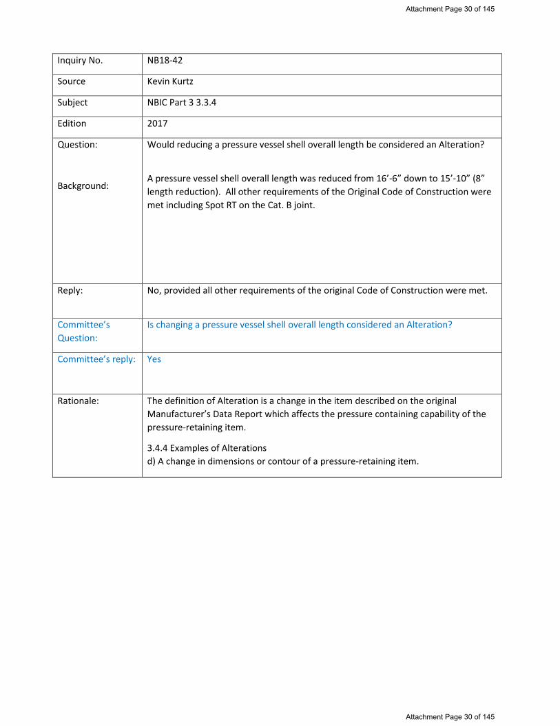
Inquiry No. NB18-42
Source Kevin Kurtz
Subject NBIC Part 3 3.3.4
Edition 2017
Question:
Background:
Would reducing a pressure vessel shell overall length be considered an Alteration?
A pressure vessel shell overall length was reduced from 16’-6” down to 15’-10” (8” length reduction). All other requirements of the Original Code of Construction were met including Spot RT on the Cat. B joint.
Reply: No, provided all other requirements of the original Code of Construction were met.
Committee’s Question:
Is changing a pressure vessel shell overall length considered an Alteration?
Committee’s reply:
Yes
Rationale:
The definition of Alteration is a change in the item described on the original Manufacturer’s Data Report which affects the pressure containing capability of the pressure-retaining item.
3.4.4 Examples of Alterations d) A change in dimensions or contour of a pressure-retaining item.
Attachment Page 30 of 145
Attachment Page 30 of 145

Action Item 18-53: Interpretation Request
Inquirer: Angel Rodriguez [email protected] Subject: Definition of Alteration (NBIC Part 3, Section 9, 9.1) Examples of Alteration (NBIC Part 3, 3.4.3) Question: Is changing the corrosion allowance noted on the original Manufacturer’s Data Report considered an alteration per NBIC, when this task is performed solely for the purpose of establishing minimum required thicknesses on an internal Owner / User mechanical integrity database?
Attachment Page 31 of 145
Attachment Page 31 of 145

NB15-1602 (Metzmaier - 180716) S2.7.1 MATERIAL LIST FOR HISTORICAL BOILERS REPAIRS Table S2.7.1 is intended as a basic guideline only and covers just the basic carbon steel and some alloy steel material specifications. Other alloy materials may be available for these applications if necessary. Note: See ASME Section II for Other Acceptable Section I Materials. TABLE S2.7.1 MATERIALS LIST FOR HISTORIC BOILERS
Application Specification
Boiler Tubes & Flues SA-178 Grade A, SA-192, SA-210
Boiler & Firebox Plate SA-285 Grade C, SA-515, SA-516
Staybolts & Patch Bolts SA-675, SA-36, ASTM A-31
Boiler Braces SA-675, SA-36
Rivets SA-675,SA-31
Forged Parts & Fittings SA-105, SA-217
Hollow Cylindrical Pressure Retaining Parts SA-105 Forgings SA-675 Bar Stock,
Pipe Flanges SA-181, SA-105
Flange Bolts, Studs & Nuts SA-193-B7, SA-194-2H
Bronze Castings & Washout Plugs SB-61, SB-62
REFERENCE:
S1.1.3.1 MATERIAL LIST FOR STEAM LOCOMOTIVE BOILERS
Attachment Page 32 of 145
Attachment Page 32 of 145

Attachment Page 33 of 145
Attachment Page 33 of 145

166
2017
SECTION 6
SU
PPL. 3
NB-23
SUPPLEMENT 3 REPAIR AND ALTERATION OF GRAPHITE PRESSURE EQUIPMENT
S3.1 SCOPE
a) This supplement provides requirements and guidelines for repairs to graphite pressure equipment require the use of erti ed impregnated graphite and ement The determining fa tor in esta lishing the desired material properties is the resin impregnation cycle. If the resin impregnation cycle is not con-trolled, it is not possible to meet the minimum design values.
b) The letter “G” shall be included on the “R” for those organizations authorized to perform repairs/alterations of graphite pressure equipment.
S3.2 REPAIRS
The requirements provided in this supplement shall apply, insofar as they are applicable to graphite pres-sure equipment. Graphite speci c requirements include
a) hen the original code of construction is other than , replacement parts sub ect to internal or e ternal pressure shall be manufactured by an organization certi ed as required by the original code of construction. The item shall be inspected and stamped as required by the original code of construc-tion. erti cation to the original code of construction as required by the original code of construction or equivalent shall be supplied with the item. When this is not possible or practicable, the organization fabricating the part shall have a National Board ; replacement parts shall be documented on Form R-3 and the “R” Symbol Stamp applied as described in NBIC Part 3, Section 5
b) When the standard governing the original construction is not the S Code, repairs or alterations shall conform to the edition of the original construction standard or speci cation most applicable to the wor . Where the original code of construction is un nown, the edition and addenda of the S Code most appropriate for the wor shall be used, provided the “R” Certi cate older has the concurrence of the Inspector and the Jurisdiction where the pressure-retaining item is installed.
c) The materials used in making repairs or alterations shall conform to the requirements of the original code of construction e cept as provided in NBIC Part 3, S3. ). The “R” Certi cate older is responsible for verifying identi cation of e isting materials from original data, drawings, or unit records and identi cation of the materials to be installed.
d) When S is the original code of construction, replacement parts sub ect to internal or e ternal pressure, which require shop inspection by an Authorized Inspector, shall be fabricated by an organization having an appropriate AS . The item shall be inspected and stamped as required by the applicable section of the AS Code. A completed AS Manufacturer’s Partial Data Report shall be supplied by the manufacturer. Further, all impregnated graphite material sub ect to internal or e ternal pressure shall be fabricated by an organization having the appropriate AS erti cate of ut ori ation. The impregnated graphite material shall be inspected and stamped as required by the applicable section of the AS Code. A completed AS Manufacturer’s Partial Data Report with supplementary B shall be supplied by the impregnated graphite material manufacturer.
e) When the original code of construction is other than AS , replacement parts sub ect to internal or e ternal pressure shall be manufactured by an organization certi ed as required by the original code of construction. The item shall be inspected and stamped as required by the original code of construction. Certi cation to the original code of construction as required by the original code of construction or equivalent shall be supplied with the item. When this is not possible or practicable, the organization fabricating the part may have a National Board erti cate of ut ori ation; replacement parts shall be documented on Form R-3 and the “R” Symbol Stamp applied as described in NBIC Part 3, Section 5.
(17)
(17)
For Committee Use Only Attachment Page 34 of 145
Attachment Page 34 of 145

177
NATIONAL BOARD INSPECTION CODE2017
SECTION 6
SU
PPL. 3
e) e ) e e e e e e e e e e e The depth and direction of the crack can be checked with hydrophilic solvent.
f) A 7/8 in. (22 mm) diameter reamer may be used to true the drilled holes.
g) ry t a plug into the holes. There should be . in. to . in. ( . mm to .2 mm) clearance for the cement oint. At no time should there be a force t of plugs into any drilled hole. rovisions shall be provided for venting trapped air.
h) Sand the outside surface of the plugs. Thoroughly clean all the surfaces of the repair, plugs, and drilled holes with hydrophilic solvent.
i) Apply graphite cement to both plugs and holes. All surfaces of plugs and holes to be joined are to be wetted with cement.
j) nsert the cemented plugs into the holes allowing / in. ( . mm) of the plug to e tend beyond the surface of the graphite part.
k) Cure the graphite cement according to the cement manufacturer’s instruction.
l) At this point, half of the plug stitch repair is completed. A row of plugs has been installed with 1/4 in. (6 mm) pilot holes between them.
m) Redrill the remaining pilot holes to 7/8 in. (22 mm) diameter. The drill will remove part of the plugs that were installed. It is important to have the plugs replace all of the fracture. If the new holes do not cut into the installed plugs, it will be necessary to repeat the procedure between these holes and plug loca-tions to ensure that all of the crack has been repaired. The line of fracture is completely removed by the overlapping effect of the graphite plugs.
n) After the second set of holes have been drilled, repeat the plug cementing procedures.
o) Contour the plugs to provide a smooth transition into the adjoining surface area. The nished repair may be coated with a wash coat for appearance.
S3.5.3.2 FIGURES — TYPICAL PLUG STITCHING PROCEDURE
a) Step one ayout hole centers.
b) Step two rilling pilot holes.
c) Step three rilling the rst set of holes.
d) Step four Cementing and curing the rst set of plugs.
e) Step ve rilling the second set of holes.
f) Step si lug stitching repair completed.
S3.5.4 REIMPREGNATION OF GRAPHITE PARTS (TUBESHEETS, HEADS, AND BLOCKS)
a) As a function of time, temperature, and chemical e posure, the resin used to impregnate graphite may shrink and/or degrade. As such, it is possible for voids to develop in impregnated graphite that has been in chemical service for a period of time. The resin loss can vary from slight to almost complete loss of impregnation. There is no practical way to determine the amount of resin remaining in the pores. ow-ever, a pressure test will determine if the graphite has continuous porosity.
For Committee Use Only Attachment Page 35 of 145
Attachment Page 35 of 145

178
2017
SECTION 6
SU
PPL. 3
NB-23
b) Reimpregnation of a graphite component may be used to reduce porosity in an e isting graphite component, which in turn will improve the performance and e pected life of the e isting graphite components. A written re-impregnation procedure acceptable to the Inspector is required. The reimpreg-nation procedure shall include as a minimum
1) Decontamination and drying of the graphite component
2) Subjecting the component to a vacuum
3) Introducing resin under pressure
4) Curing the resin at a speci ed temperature and time
5) Leak test
S3.5.4.1 CONTROL OF IMPREGNATION MATERIAL
a) Impregnation material shall be the same as that speci ed in the Reimpregnation rocedure. ach impregnation material shall be traceable by the name of its manufacturer and the trade name or number of that manufacturer.
b) The impregnation material manufacturer shall supply the Certi cate older a for each material. It shall include the following
1) Impregnation material identi cation
2) Batch number(s)
3) Date of manufacture
4) Shelf life
5) iscosity per AST D 23 3
6) Speci c gravity
c) rior to reimpregnation, and at subsequent intervals not to e ceed 14 days, the Certi cate older shall test each batch of impregnation material to assure that the characteristics of the material have not changed from values speci ed in the Reimpregnation rocedure. The values obtained for viscosity and speci c gravity for the impregnation material shall be within the limits speci ed by the manufacturer and as listed in the Reimpregnation Procedure. The test values shall be made available to the Inspector.
S3.5.4.2 FINISHING THE REPAIR
a) The parts should be held in place to prevent movement while curing the cemented joint to achieve a proper repair. The repair rm should take care to ensure that the cement joint thickness is within the range recommended by the cement manufacturer. Care spent in precisely aligning the parts while clamping will avoid many nishing and machining operations later. Particular attention should be given to gasket and other bearing surfaces.
b) asket and bearing surfaces may have to be machined, led, or sanded before the job is completed. Gasket serrations must be clean and continuous. Serrations can be easily re-cut into graphite and any repair plugs that cross the gasket surface.
For Committee Use Only Attachment Page 36 of 145
Attachment Page 36 of 145

179
NATIONAL BOARD INSPECTION CODE2017
SECTION 6
SU
PPL. 3
S3.5.5 PLUGGING OF LEAKING OR DAMAGED TUBES
a) The material used for plugging tubes shall comply with the requirements of the AS Boiler and Pressure essel Code, Section III, Division 1, Part IG.
b) The point(s) of leakage shall be veri ed, and the corresponding leak site(s) shall be marked/labeled on the tubesheet, and recorded.
c) A plug shall be used to plug each end of the tube(s) in question and each plug shall have a minimum length of 1 in. (25 mm). ultiple plugs may be used.
d) The tube(s) shall be prepared for plugging by enlarging the inside of the tube(s) with a suitable drill bit or reamer.
1) To ensure a sound cement joint between the tube sidewall and the plug, a slightly smaller diameter plug shall be selected. The ma imum clearance between the tube inside diameter and the outside diameter of the plug shall not e ceed 3/32 in. (2.4 mm).
2) As an alternative to d)1) a mandrel with an abrasive, such as sandpaper, may be used, as long as the ma imum tube I.D. to plug .D. clearance of 3/32 in. (2.4 mm) is not e ceeded.
3) The minimum plug insertion depth of the prepared hole(s) shall meet the minimum combined plug length requirements of c . hen the minimum plug length of c is e ceeded, the total insertion depth of the plugs may e ceed the combined length of the plugs however, the longer plugs shall not project outside the face of the tube(s) being plugged.
e) Plugging of leaking or damaged tubes shall be performed by certi ed cementing technicians, using quali ed cementing procedures, in accordance with the requirements of the AS Boiler and Pressure
essel Code, Section III, Division 1, Part IG.
f) The cement shall be prepared per the cement manufacturer’s instructions.
g) When cementing the plugs, 100% of individual plugs, as well as the inside diameter of the tube opening(s), shall be coated with cement. The plugs shall then be inserted one by one, against each other, into each end of the tube(s) being plugged.
h) nce the plugging is completed, and before the cement cures, the endplugs may need to be held in place, as newly cemented plugs may e hibit a tendency to dislodge from the plugged tube(s) prior to nal curing of the cement.
i) Curing time is dependent upon the cement manufacturer’s instructions, and is considered complete when the cement is hardened to the point that it cannot be indented with pressure from a at screwdriver or other similar instrument.
j) After the cement is completely cured, the plugged, cemented area(s) on the tubesheet face may be dressed with sandpaper or other suitable abrasive.
k) Repaired tubes shall be tested in accordance with this code, using a method acceptable to the Inspector, with a written procedure as approved by the manufacturer’s internal quality system, to ensure leaks have been repaired.
l) The scope of the work completed shall be described and reported on a Form R-1.
S3.5.6 TUBE REPLACEMENT
Tube replacement should be performed with the unit preferably in the horizontal position. Avoid replacing adjacent tubes simultaneously because the replacement areas may overlap or reduce the ligament between
(17)
For Committee Use Only Attachment Page 37 of 145
Attachment Page 37 of 145

180
2017
SECTION 6
SU
PPL. 3
NB-23
holes and possibly damage the tubesheet. The general steps used in horizontal tube replacement follow below.
a) The material used for tube replacement shall comply with the requirements of the AS Boiler and Pressure essel Code, Section III, Division 1, Part IG.
b) Tube replacement shall be performed by quali ed cementing technicians, using quali ed cementing procedures, in accordance with the requirements of the AS Boiler and Pressure essel Code, Section III, Division 1, Part IG-7 and IG-80.
c) Determine the thickness of each tubesheet and inside distance between the tubesheets to obtain tube and sleeve length.
d) Access each tubesheet face, clearly identify and mark each tube hole on each tubesheet of the tubes to be replaced.
e) Prepare/clean the e isting tube hole in preparation for e tracting the damaged tube. Some holes may contain plugs which require removal. A boring tool slightly larger than the outside diameter of the tube being replaced is required.
f) Drill/bore out the tube hole in each tubesheet to release the tube from the tubesheet. ercise caution when centering and align cutting to the common a is of the tube.
g) The damaged tube should disengage and become loose. sing guides, remove the damaged tube. nsure that no debris is trapped in the space where the tube was removed (Fig. S3.5.6-a).
h) Replacement tube shall have sleeves at the ends cemented in the bored holes to replace the material in the tubesheet that was bored out to access the damaged tube (Fig. S3.5.6-b and S3.5.6-c).
1) Dry- t a new tube and sleeve.
2) The sleeve length may vary.
3) Prior to applying cement, prepare and clean all surfaces to be cemented.
i) Cement the ID of the prepared bore in the oating tubesheet and the tube end D at the ed tubesheet. (Fig. S3.5.6-b).
j) Insert the tube through the ed tubesheet and through the oating tubesheet cemented bore so that it protrudes. Cement the ID of the ed tubesheet bore as shown in (Fig. S3.5.6-c). The use of alignment dowels can assist/guide in tube handling.
k) Cement the D of the tube end protruding from the oating tubesheet. Cement the ID of the mating sleeve end, t it to the cemented tube end and push the assembly part-way into the oating tubesheet. Cement the remainder of the D of the oating tube end sleeve. Push this cemented assembly the rest of the way into the oating tubesheet (Fig S3.5.6-c).
l) Cement the ID and D of the sleeve for the ed tubesheet and insert it until it mates with the tube end inside. Push together cemented tube/sleeve assemblies. (Fig S3.5.6-d). Clean/wipe away any e cess cement.
m) Apply slight pressure on the sleeves to seat the joints. Remove e cess cement.
n) aintain pressure and cure both ends of the cemented assembly according to the cement manufacturer’s instructions.
o) Sleeves may be trimmed after curing.
For Committee Use Only Attachment Page 38 of 145
Attachment Page 38 of 145

181
NATIONAL BOARD INSPECTION CODE2017
SECTION 6
SU
PPL. 3
p) Replaced tubes shall be tested in accordance with this code per a written procedure acceptable to the Inspector.
q) The scope of work completed shall be described and reported on a Form R-1.
FIGURE S3.5.6-a CL A D A D PR PAR D T B S TS
FIGURE S3.5.6-b STARTI G T B R PLAC T
For Committee Use Only Attachment Page 39 of 145
Attachment Page 39 of 145

182
2017
SECTION 6
SU
PPL. 3
NB-23
FIGURE S3.5.6-c SL C TI G
FIGURE S3.5.6-d C PL T D T B R PLAC T
S3.5.7 REIMPREGNATION OF GRAPHITE PARTS (TUBESHEETS, HEADS, AND BLOCKS)
a) As a function of time, temperature, and chemical e posure, the resin used to impregnate graphite may shrink and/or degrade. As such, it is possible for voids to develop in impregnated graphite that has been in chemical service for a period of time. The resin loss can vary from slight to almost complete loss of impregnation. There is no practical way to determine the amount of resin remaining in the pores. ow-ever a pressure test will determine if the graphite has continuous porosity.
b) Reimpregnation of a graphite component may be used to reduce porosity in an e isting graphite component, which in turn will improve the performance and e pected life of the e isting graphite components. A written re-impregnation procedure acceptable to the Inspector is required. The reimpreg-nation procedure shall include as a minimum
(17)
For Committee Use Only Attachment Page 40 of 145
Attachment Page 40 of 145
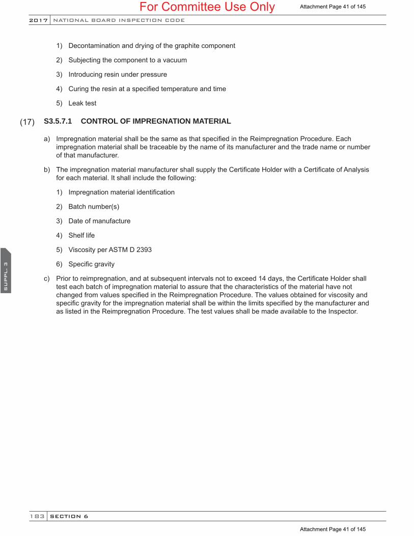
183
NATIONAL BOARD INSPECTION CODE2017
SECTION 6
SU
PPL. 3
1) Decontamination and drying of the graphite component
2) Subjecting the component to a vacuum
3) Introducing resin under pressure
4) Curing the resin at a speci ed temperature and time
5) Leak test
S3.5.7.1 CONTROL OF IMPREGNATION MATERIAL
a) Impregnation material shall be the same as that speci ed in the Reimpregnation Procedure. ach impregnation material shall be traceable by the name of its manufacturer and the trade name or number of that manufacturer.
b) The impregnation material manufacturer shall supply the Certi cate older with a Certi cate of Analysis for each material. It shall include the following
1) Impregnation material identi cation
2) Batch number(s)
3) Date of manufacture
4) Shelf life
5) iscosity per AST D 23 3
6) Speci c gravity
c) Prior to reimpregnation, and at subsequent intervals not to e ceed 14 days, the Certi cate older shall test each batch of impregnation material to assure that the characteristics of the material have not changed from values speci ed in the Reimpregnation Procedure. The values obtained for viscosity and speci c gravity for the impregnation material shall be within the limits speci ed by the manufacturer and as listed in the Reimpregnation Procedure. The test values shall be made available to the Inspector.
(17)
For Committee Use Only Attachment Page 41 of 145
Attachment Page 41 of 145

New S3.5.4 f)
f) As an alternative to e) any R Certificate Holder, with or without the letter “G” included on the “R”
Certificate of Authorization, may install graphite tube plugs provided the following conditions are met.
The R Certificate Holder shall gain the concurrence of the Inspector, and shall utilize a tube plugging kit
provided by an ASME Certificate Holder authorized to use the G designator. The kit shall include the
following items:
1. Certified graphite plugs and certified cement ingredients, both accompanied by the
appropriate documentation (Partial Data Report).
2. The qualified cementing procedure of the ASME Certificate Holder authorized to use the G
designator, and a step‐by‐step procedural checklist that shall be followed explicitly. The
procedure shall address the entire tube plugging process including plug configuration, tube hole
cleaning and preparation, mixing and applying of the cement, application of the plugs, securing
the plugs during the curing process, controlling the curing process, and leak testing, thereby
meeting S3.3.
3. Additional materials and procedure shall be provided and used to prepare a demonstration
plug joint prior to performing the repair. This demonstration plug joint shall be tested by a twist
(torsional) test designed to demonstrate acceptable application and curing of the cement (Fig.
S3.5.4). The test procedure shall include acceptance criteria, which may be based on a principle
of breakage of part of the test piece. A successful twist test, in conjunction with the completed
procedural checklist, shall serve as a valid cement technician certification for a single repair
operation.
The R Certificate Holder shall review the material certifications including verification that the shelf life of
the cement has not been exceeded, and assure that the certified cement technician has completed the
qualification demonstration, and has access to the procedure and checklist. The Inspector shall review
and verify that the procedure and the other elements of the certified kit, as provided by the authorized
G‐designated ASME Certificate Holder, have been administered and completed prior to his acceptance.
The R‐certificate Holder shall note on Line 8 of the R‐1 Form the installation of cemented graphite tube
plugs in accordance with this section. The letter “G” shall not be applied to the vessel when performing
this alternative repair. The R Certificate Holder shall identify and document the location of the plugged
tubes on the R Form.
Attachment Page 42 of 145
Attachment Page 42 of 145

FIGURE S3.5.4
DEMONSTRATION PLUG JOINT TWIST TEST
Attachment Page 43 of 145
Attachment Page 43 of 145

Item NB16-0303, add Fillet Welded Patch as a method of Repairing a Pressure Retaining Item (PRI)
All New 3.4.4 Paragraph PROPOSED:
3.4.4 FILLET WELDED PATCH
A fillet welded patch is a repair method used to maintain the pressure retaining capability of shells, heads, drums and pipe by providing a pressure containing boundary over the area exhibiting damage in the form of a “fillet welded patch” as described by ASME PCC-2, Article 2.7 or Article 2.12.
a) Except as required in 3.4.4 c)(1), ASME PCC-2 should shall be used as a guideline for the design of the fillet welded patch and shall be in accordance with the original code of construction, when practicable. Design of the fillet welded patch shall consider original design conditions, taking in to account current service conditions and damage mechanisms. Use of this method shall be acceptable to the inspector and when required, the jurisdiction and shall be limited to pressure containing equipment owned and operated by an Owner-User..
1) Replacement of a pressure-retaining part with a material of different nominal composition and, equal to or greater in allowable stress from that used in the original design, provided the replacement material satisfies the material and design requirements of the original code of construction under which the vessel was built. The minimum required thickness shall be at least equal to the thickness stated on the original Manufacturer's Data Report.
b) The “R” Certificate Holder responsible for the design of the fillet welded patch shall ensure a Fitness for Service Assessment (FFSA) has been performed on the portion of the item being patched in accordance with NBIC, Part 2, 4.4.1, supporting the continued service of the item. The fillet welded patch repair method shall not remain in place beyond the calculated remaining life of the covered portion of the pressure retaining item.
1) The remaining life of the pressure retaining item shall be documented on the Report of FFSA in the Remarks section. The Report of FFSA Form shall be affixed to the Form R-2 and identified in the Remarks section.
2) The thinned or leaking area shall be fully covered, as specified in the FFSA, to the distance where the minimum required metal thickness is verified. Wall thickness shall be verified in the area to be welded.
3) A fillet welded patch method shall not be used where cracks are present unless the cracks have been removed and repaired in accordance with Part 3, Paragraph 3.3.4.2 a); the condition that led to the crack formation and propagation have been eliminated.
c) Hazards associated with welding on degraded components should be addressed with the Owner-User by the use of engineering controls, administrative controls and personal protective equipment.
1) When the pressure retaining item will remain in service while implementing a fillet welded patch, the requirements and limitations described within ASME PCC-2, Part-1 shall be used in conjunction with ASME PCC-2, Part-2, Article 2.10.
2) API RP-2201, “Safe Hot Tapping Practices in the Petroleum and Petrochemical Industries” may be used as a guideline for identifying hazards associated with welding to a component that is under pressure, including service restrictions.
d) Visual examination shall be in accordance with the NBIC, Part 3, Paragraph 4.4.1 e).
e) Completion of the FORM R-1 shall follow the requirements for PREPARATION, DISTRIBUTION, and REGISTRATION as described in Part 3, Section 5.
Additional actions required by accepting this item:
Revise the succeeding paragraph numbering order (ref.2017-edition) to:
3.4.5 EXAMPLES OF Repairs
l) The installation of a fillet welded patch.
Attachment Page 44 of 145
Attachment Page 44 of 145
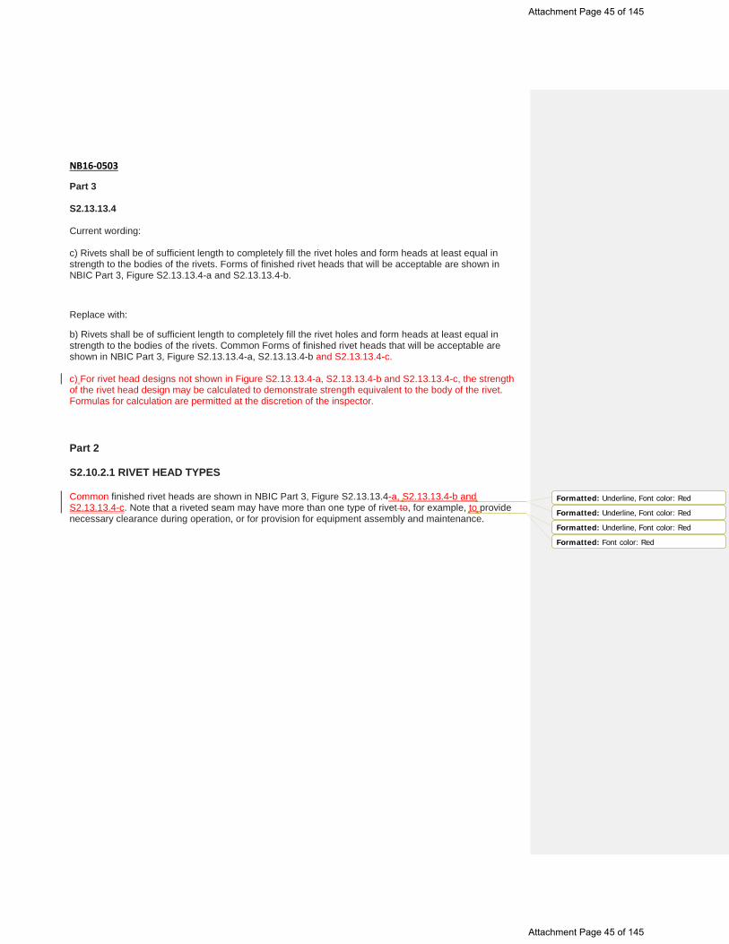
NB16-0503
Part 3 S2.13.13.4 Current wording: c) Rivets shall be of sufficient length to completely fill the rivet holes and form heads at least equal in strength to the bodies of the rivets. Forms of finished rivet heads that will be acceptable are shown in NBIC Part 3, Figure S2.13.13.4-a and S2.13.13.4-b.
Replace with:
b) Rivets shall be of sufficient length to completely fill the rivet holes and form heads at least equal in strength to the bodies of the rivets. Common Forms of finished rivet heads that will be acceptable are shown in NBIC Part 3, Figure S2.13.13.4-a, S2.13.13.4-b and S2.13.13.4-c. c) For rivet head designs not shown in Figure S2.13.13.4-a, S2.13.13.4-b and S2.13.13.4-c, the strength of the rivet head design may be calculated to demonstrate strength equivalent to the body of the rivet. Formulas for calculation are permitted at the discretion of the inspector. Part 2 S2.10.2.1 RIVET HEAD TYPES Common finished rivet heads are shown in NBIC Part 3, Figure S2.13.13.4-a, S2.13.13.4-b and S2.13.13.4-c. Note that a riveted seam may have more than one type of rivet to, for example, to provide necessary clearance during operation, or for provision for equipment assembly and maintenance.
Formatted: Underline, Font color: Red
Formatted: Underline, Font color: Red
Formatted: Underline, Font color: Red
Formatted: Font color: Red
Attachment Page 45 of 145
Attachment Page 45 of 145

Figure S2.13.13.4-c Historic Large Rivets (C.I.S)
Nom. Body Dia. D Head Dia. A Height H Head Dia. A Height H Head Dia. A Height H
Double Radius Button
Head Steeple Head Flat Head
1/2 0.950 0.350 1.000 0.500 0.875 0.250 5/8 1.188 0.438 1.250 0.625 1.094 0.313 3/4 1.425 0.525 1.500 0.750 1.313 0.375 7/8 1.663 0.613 1.750 0.875 1.531 0.438
1 1.900 0.700 2.000 1.000 1.750 0.500 1-1/8 2.138 0.788 2.250 1.125 1.969 0.563 1-1/4 2.375 0.875 2.500 1.250 2.188 0.625 1-3/8 2.613 0.963 2.750 1.375 2.406 0.688 1-1/2 2.850 1.050 3.000 1.500 2.625 0.750 1-5/8 3.088 1.138 3.250 1.625 2.844 0.813 1-3/4 3.325 1.225 3.500 1.750 3.063 0.875
All Dimensions are given in inches.
Tolerance for diameter of body is plus and minus 10% of nominal (shank diameter).
The following formulas give basic dimensions for manufactured shapes:
Double Radius Button Head, A=1.900D; H=0.700D; G=2.000D.
Steeple Head, A=2.000D; H=1.000D.
Flat Head, A=1.750D; H=0.500D.
Length L is measured parallel to the rivet axis, from the etreme end to the bearing surface
plane for flat bearing surface head-type rivets, or to the intersection of the head top surface
with the head diameter for countersunk head-type rivets.
Attachment Page 46 of 145
Attachment Page 46 of 145

Attachment Page 47 of 145
Attachment Page 47 of 145

TABLE 1.6.2 “NR” QUALITY ASSURANCE PROGRAM (QAP) REQUIREMENTS
Note 1: Code of Federal Regulations (CFR) – rules and regulations published by the executive departments and agencies of the federal government of the United States. Note 2: 10 CFR 50 Appendix B – Title 10 of the Code of Federal Regulations Part 50 Appendix B describes the quality assurance criteria for nuclear plants and fuel reprocessing plants.
Note 3: The Edition (and Addenda , as applicable) of NQA-1 to be utilized shall be the latest endorsed by the Regulatory Authority, or as specified in the Owner's QA Program descriptions reviewed and approved by the Regulatory Authority.
(17) 1.6.2.1 DEFINITIONS
The NBIC terms and definitions shall be supplemented, as applicable, by the terms and definitions of ASME Section III, Section XI, NQA-1, or other standards specified by the Regulatory Authority.
The following terms are as defined in the NBIC Glossary of Terms Section 9:
a) Authorized Inspection Agency
b) Authorized Nuclear Inspection Agency
c) Jurisdiction
d) “NR” Certificate Holder
Proposal NB16-0608 – Hellman – 7-16-18
Category of Activity Owner Orga
Category 1 10 CFR Part 50 Appendix B1, 2
and ASME Section III NCA-4000 & NQA-1 Part 1
Category 2 10 CFR Part 50, Appendix B1, 2 or
NQA-13, Part 1 and ASME Section XI, IWA-4142
nizations other than Owner 10 CFR Part 50 Appendix B1, 2 and ASME Section III
NCA-4000 & NQA-1, Part 1
10 CFR Part 50, Appendix B1, 2 supplemented as needed with Owner’s QA program; or ASME
NQA-13, Part 1; or ASME Section III, NCA-4000
Category 3 ASME NQA-13, Parts 1, or
Specify the Standard to which certification is desired
ASME NQA-13, Parts 1, or Specify the Standard to which certification is desired
SECTI
ON
1
Attachment Page 48 of 145
Attachment Page 48 of 145

NB-23 2017
SECTION 1 10
TABLE 1.6.2.1 ACRONYMS
ASME American Society of Mechanical Engineers
Applicant An Organization applying for “NR” Certificate of Authorization (new or renewal)
CFR Code of Federal Regulations
Code ASME Code of Construction, Section III, Division I, (NCA, NB, NC, ND, NE, NF, NG, and NH) or ASME Section XI Rules for Inservice Inspection of Nuclear Power Plant Components as applicable.
Jurisdiction Enforcement Authority NB National Board of Boiler and Pressure Vessel Inspectors
NBIC National Board Inspection Code NB-263, RCI-1 Rules for Commissioned Inspectors
NCA ASME Section III, Subsection NCA, General Requirements for Division 1 and Division 2
NQA–1* ASME Quality Assurance Requirements for Nuclear Facility Applications
NR Nuclear Repair “NR” CH “NR” Certificate Holder
QA Quality Assurance QAI–1 ASME Qualifications for Authorized Inspection QAM Quality Assurance Manual
QAP Quality Assurance Program
QC Quality Control
WA ASME Section III, Division 3, Subsection WA, General Requirements
Note: * Latest Edition(s) endorsed by the Regulatory Authority
1.6.3 PREREQUISITES FOR ISSUING A NATIONAL BOARD “NR” CERTIFICATE OF AUTHORIZATION
Before an organization can obtain a National Board “NR” Certificate of Authorization, the organization shall:
a) Have and maintain an inspection agreement with an Authorized Nuclear Inspection Agency accepted
in accordance with NB-360, Criteria for Acceptance of Authorized Inspection Agencies for New Con- struction or accredited in accordance with NB-369, Qualifications and Duties for Authorized Inspection Agencies (AIAs) Performing Inservice Inspection Activities and Qualification of Inspectors of Boilers and Pressure Vessels.
b) Have a written Quality Assurance Program that complies with the requirements of this section and
address all controls for the intended category and scope of activities.
c) Have a current edition of the NBIC.
(17)
s) Authorized Nuclear Inspector
Measures shall be taken to reference the commissioned rules for National Board Authorized Nuclear
SECTI
ON
1
SECTI
ON
1
Attachment Page 49 of 145
Attachment Page 49 of 145

Inspector, in accordance with NB-263, RCI-1 Rules for Commissioned Inspectors. The “NR” Certificate Holder shall ensure that the latest documents including the Quality Assurance Manual, procedures and instructions are made available to the Authorized Nuclear Inspector. The Authorized Nuclear Inspector shall be consulted prior to the issuance of a repair/replacement plan by the “NR” Certificate Holder in order that the Authorized Nuclear Inspector may select any in-process inspection or hold points when performing repair/replacement activities. The “NR” Certificate Holder shall keep the Authorized Nuclear Inspector informed of progress of the repair/replacement activity so that inspections may be performed. The Authorized Nuclear Inspector shall not sign Form NR-1 or Form NVR-1, as applicable, unless satisfied that all work carried out is in accordance with this Section. The Authorized Nuclear Inspector and Authorized Nuclear Inspector Supervisor shall have access to areas where work is being performed including subcontractors facilities in order to perform their required duties. The ANI shall be involved in dispositions and verification for non-conformances and corrective actions involving quality or code requirements.
t) Exhibits
Forms and exhibits referenced in the Quality Assurance Manual shall be explained in the text and included as part of the referencing document or as an appendix to the Quality Assurance Manual. Forms shall be controlled and identified to show the latest approved revision, name, and other corresponding references as stated in the Quality Assurance Manual.
Attachment Page 50 of 145
Attachment Page 50 of 145

Item NB16-1402 (NBIC Part 3, Section 6)
Supplement 14 Life Extension of High Pressure Fiber Reinforced Plastic Pressure Vessels
S14.1 Scope This document may be used to evaluate whether the service life of high pressure fiber reinforced plastic pressure vessels (FRP) can be extended for an additional lifetime. High pressure means vessels with a working pressure from 3,000 psi (20 MPa) to 15,000 psi (103 MPa). For vessels intended for cyclic service, fatigue testing of new vessels is carried out by the vessel manufacturer to be certain that the vessel will not fail in service and such testing is typically required by regulatory authorities. Fatigue design and testing is the starting point for consideration of life extension. S14.2 General
a) The procedure for in-service testing of high pressure composite pressure vessels, Supplement 10 herein, is incorporated by reference into this procedure for life extension of high pressure composite pressure vessels. Supplement 10 is based on acoustic emission (AE) testing, specifically modal AE (MAE) testing. The MAE inspection procedure employs detection and analysis techniques similar to those found in seismology and SONAR. Much as with earthquakes, transient acoustical impulses arise in a composite material due to the motion of sources such as the rupture of fibers. These transients propagate as waves through the material and, if properly measured and analyzed by the methods in Supplement 10, the captured waves reveal, for example, how many fibers have ruptured. Similar information about other sources is also determinable, such as the presence and size of delaminations. Delaminations can play a significant role in vessel fatigue life, particularly delaminations near the transition regions and in the heads. The rupture behavior can be used to determine the integrity of the vessel. However, the development of criteria for life extension (LE) requires an understanding of the vessel design and fatigue life.
b) Fatigue testing of out of life vessels is a crucial part of the life extension process. It is used to validate the mechanical behavior of the vessels and to develop the numerical values for the allowables in the MAE pass/fail criteria for the particular design, material and construction.
S 14.3 Life Extension Procedure
a) New vessel fatigue life testing data shall be obtained from the Manufacturer’s Design Report (MDR) and the number of cycles in a lifetime shall be determined from the MDR. The type of vessel under consideration for life extension shall have been shown through testing to be capable of sustaining at least three lifetimes of cycles to developed fill pressure followed by a subsequent burst test at a pressure greater than minimum design burst pressure.
b) An evaluation of the service the vessel has seen should take into account any operational
conditions that may have differed from those used in the design testing and analysis. Such conditions include for example exposure to more severe weather than expected, more cycles
Attachment Page 51 of 145
Attachment Page 51 of 145

per year, constant high temperature and humidity, chemical attack or any other of a number of conditions under which operations take place that were not specifically included in testing at manufacture. Any such conditions shall be listed on the attached form. If no such conditions exist, it shall be so noted on the form. The test program delineated herein shall be revised to reflect the modified conditions as documented by the user and submitted for approval to the proper authorities.
c) Data and records for all vessels considered for life extension shall be kept and made readily
available to inspectors or examination personnel. This includes an operating log, number of operating cycles since the previous examination, total number of operating cycles, examinations, examination techniques and results, maximum operating pressure and any unexpected pressures, temperatures, temperature cycles, damage events or other significant events that were outside the intended operating parameters or conditions.
d) A life extension test program shall be carried out for each type of vessel under consideration. Type of vessel means the particular manufacturer, materials (fiber and resin), water volume and design. If the type of vessel passes all requirements, then that type shall be eligible for life extension testing. If such a vessel passes the life extension MAE test its lifetime can be extended for one additional lifetime in five-year increments. In order to maintain life extension a vessel must be requalified every five years using the MAE test.
S14.4 Life Extension Test Program
a) The type of vessel under consideration for LE shall be noted. Manufacturer, place of manufacture and manufacturing date shall be recorded. The vessel dimensions shall be recorded. The specific fiber, matrix and winding pattern shall be recorded. If the fiber, matrix and winding pattern are not available from the manufacturer, then a vessel of the type under consideration shall be used to verify the winding pattern (hoop and helical angles and number of plies) through destructive testing.
b) Ten out-of-life vessels of the particular type shall be tested in the manner described herein.
MAE techniques shall be applied to every vessel tested. Analysis of the MAE data is described herein. Two strain gages, one in the 0-degree and one in the 90-degree direction, shall be applied to every vessel pressure tested under this program. The purpose of strain gage data is to compute the 0 and 90 modulus values and to confirm that the modulus values of the material do not vary during the fatigue cycling required herein. Strain data shall be recorded and analyzed as described later on.
c) The LE test program proceeds by Steps. If the Step 1 is not successful, then there is no need to
proceed to Step 2, and so forth. S14.5 Life Extension Test Program Steps S14.5.1 Step 1
Attachment Page 52 of 145
Attachment Page 52 of 145

Three vessels shall be selected from the ten and pressurized to burst. The vessels shall be inspected for visible damage, i.e., cuts, scrapes, discolored areas, and the vessel appearance shall be documented with photographs. MAE testing shall be done in conjunction with this testing as specified in Supplement 10, except for transducer spacing, pressurization plan and accept/reject criteria values. The values in Supplement 10 are for requalification testing. The transducer spacing shall be determined by the distance at which the 400 kHz component of a suitable pulser source is detectable along the axis of the vessel (essentially across the hoop fibers) and in the perpendicular direction (essentially parallel to the hoop fibers). Detectable means that the resulting signal component has an amplitude with at least a signal to noise ratio of 1.4. Transducer frequency response calibration and energy scale shall be carried out as specified in SUPPLEMENT 10. The pressurization plan shall follow that in ASME Section X Mandatory Appendix 8, i.e., there shall be two pressure cycles to test pressure with holds at test pressure as prescribed therein, however, the time interval between the two cycles may be reduced to one minute. For the purposes of life extension, the fiber fracture energy and BEO (background energy oscillation) values shall be as specified below.
a) No BEO greater than 2 times the quiescent energy (see Supplement 10) shall be observed up to test pressure or during pressure holds.
b) No fiber break event energy shall be greater than 24 x 103 x UFB (see Supplement 10) during the second pressurization cycle.
c) No single event shall have an energy greater than 24 x 105 x UFB during the second pressurization cycle.
Note: The numerical values specified in b) and c) can be adjusted through documented testing and stress analysis methods in order to account for the particular design, material and construction. d) At least two sensors shall remain on each vessel all the way to burst in order to establish the
BEO pressure for this type of vessel. e) Plots of stress versus strain shall show linear behavior up to 90% of burst pressure. f) The burst pressures of all three vessels shall be greater than the minimum design burst
pressure. g) If the burst pressure of any one of the three vessels is not greater than the minimum design
burst pressure, then these vessels shall not be eligible for life extension and there is no need to proceed with Step 2 below.
Note: It is possible that one or more of the vessels selected had damage not obvious to visual inspection. If during this burst testing phase the MAE test identifies a vessel as damaged, the substitution of three other randomly selected vessels is allowed.
S14.5.2 Step 2 If the vessels pass Step 1, fatigue testing shall be carried out on a minimum of three vessels of the same type being considered for life extension.
a) Prior to testing, the vessels shall be inspected for visible damage, i.e., cuts, scrapes, discolored areas, and the vessel appearance shall be documented with photographs.
b) Prior to fatigue testing, MAE testing as specified in Step 1 shall be done in conjunction with the fatigue testing, hereinafter called the MAE test or MAE testing, in order to determine the suitability of the vessels for fatigue testing, i.e., that they pass the MAE test.
c) Next, the vessels shall be subjected to fatigue cycles. Pressure shall be 100 psi +0, -50% to at least 1.05 x working pressure. Vessels shall survive one and one-half (1.5) additional lifetimes. If they survive then they shall be tested by an MAE test as was done prior to fatigue cycling.
Attachment Page 53 of 145
Attachment Page 53 of 145

d) Provided they pass the MAE test, they shall be burst tested. At least two sensors shall remain on each vessel all the way to burst in order to establish that the BEO (background energy oscillation) pressure for the fatigued vessels is consistent, i.e., is the same percentage of ultimate, with that of the vessels tested in Step 1.
e) Plots of stress versus strain shall show linear behavior up to 90% of burst pressure. f) The burst pressures at the end of the fatigue testing shall be greater than or equal to the
minimum design burst. If the burst pressure of any one of the three vessels is not greater than the minimum design burst pressure, then these vessels shall not be eligible for life extension.
S14.5.3 Step 3 If the vessels pass Step 2, impact testing shall be carried out on a minimum of three vessels of the same type being considered for life extension.
a) Prior to testing, the vessels shall be inspected for visible damage, i.e., cuts, scrapes, discolored areas, and the vessel appearance shall be documented with photographs. Prior to impact testing, MAE testing shall be done in order to determine the suitability of the vessels for impact testing, i.e., that they pass the MAE test.
b) Two vessels shall be subjected to an ISO 11119.2 drop test and then subjected to the MAE test. If they pass the MAE test, then one vessel shall be burst tested. At least two sensors shall remain on the vessel all the way to burst in order to establish that the BEO (background energy oscillation) pressure for the fatigued vessels is consistent, i.e., is the same percentage of ultimate, with that of the vessels tested in Step 1.
c) Plots of stress versus strain shall show linear behavior up to 90% of burst pressure. d) If the burst pressure is not greater than the minimum design burst pressure, then these vessels
shall not be eligible for life extension. e) If the first vessel passes the burst test, the other dropped vessel shall be fatigue cycled and
subsequently subjected to the MAE test and, if it passes, shall be burst tested under the same conditions as before. If the vessel fails during fatigue cycling, i.e., bursts or leaks, then these vessels shall not be eligible for life extension.
f) If the modulus changes by more than 10%, then these vessels shall not be eligible for life extension. The strain gages should be mounted in a location that is away from the impact zone.
g) The burst pressure at the end of the fatigue testing of the dropped vessel shall be greater than or equal to the minimum design burst. The vessels shall have MAE testing applied during burst testing as before and the BEO shall be consistent with the previously established percent of burst ±10%.
S14.5.4 Step 4 If the vessels pass Step 3, cut testing shall be carried out on a minimum of two vessels of the same type being considered for life extension.
a) Prior to testing, the vessels shall be inspected for visible damage, i.e., cuts, scrapes, discolored areas, and the vessel appearance shall be documented with photographs. Prior to cut testing, MAE testing shall be done in order to determine the suitability of the vessels for cut testing, i.e., that they pass the MAE test.
Attachment Page 54 of 145
Attachment Page 54 of 145

b) Two vessels shall be subjected to an ISO 11119.2 cut test and then subjected to the MAE test. If they pass, then one shall be burst tested under all the conditions and procedures delineated in Step 2. If the burst pressure is not greater than the minimum design burst pressure, then these vessels shall not be eligible for life extension.
c) If the cut vessel passes, then the other cut vessel shall be fatigue cycled as described in Step 2 and subsequently subjected to the MAE test and then burst tested with at least two MAE sensors remaining on and monitoring the vessel as before. If it does not survive fatigue cycling, then these vessels shall not be eligible for life extension.
d) The burst pressure at the end of the fatigue testing of the cut vessel shall be greater than or equal to the minimum burst pressure specified by ISO 11119.2.
If the vessel type passes Steps 1 to 4, then that type is eligible for life extension. An out of life vessel of the type subjected to the program above may have its life extended for one additional lifetime if it passes the MAE test. The vessel shall pass the MAE test at subsequent five-year intervals or at one-third of the lifetime, whichever is less, in order to continue in service. The vessel shall be labeled as having passed the NBIC life extension test.
Attachment Page 55 of 145
Attachment Page 55 of 145

NB16-1801 approved April 2018 by SGL
Materials - NBIC S1.1.3.1-d); Maximum staybolt tensile strength shall be 7,500 psi? Errata. Should be tensile stress Bolts and Studs; NBIC Table S1.1.3.1; SA-307 A and B. Add SA-675 grade 60, 65, 70 Threaded Staybolts; NBIC Table S1.1.3.1; SA-31 Gr. A, SA-675 47 ksi to 65 ksi inclusive. Remove 47ksi to 65 ksi inclusive. Add grade 45, 50, and 55 Staybolt Sleeves and Caps; NBIC Table S1.1.3.1; SA-105, SA-675, and SA-696. Add SA-216 WCA and SA-217 WC1 Threaded Staybolts – NBIC S1.2.2 a); The thread pitch shall be either 11 or 12. Current wording: All threaded staybolts shall have either 11- or 12-thread pitch. Staybolt threads shall have a good close fit in sheets. Changing the staybolt thread pitch from 11 to 12 or the reverse shall be considered a repair. Proposed wording: All threaded staybolts shall have a pitch between 10 and 13 threads per inch inclusive, (2 mm to 2.5 mm). Staybolt threads shall have a good close fit in sheets. Changing the staybolt thread pitch from any pitch within the allowed range to another pitch within the allowed range shall be considered a repair. NBIC S1.2.2 h) Current wording: Installation of larger diameter staybolts shall be considered a repair. Proposed wording: Installation of different diameter staybolts shall be considered a repair provided the stay stress does not exceed 7500 psi (52.5 MPa). Cautionary Note: Larger diameter staybolts will transfer stresses to other structures and will be subject to higher extreme fiber stresses. NBIC S1.2.5 d) Current wording: Installation of different diameter staybolts shall be considered a repair. Proposed wording: Installation of different diameter staybolts shall be considered a repair provided the stay stress does not exceed 7500 psi (52.5 MPa). Cautionary Note: Larger diameter staybolts will transfer stresses to other structures and will be subject to higher extreme fiber stresses.
Attachment Page 56 of 145
Attachment Page 56 of 145
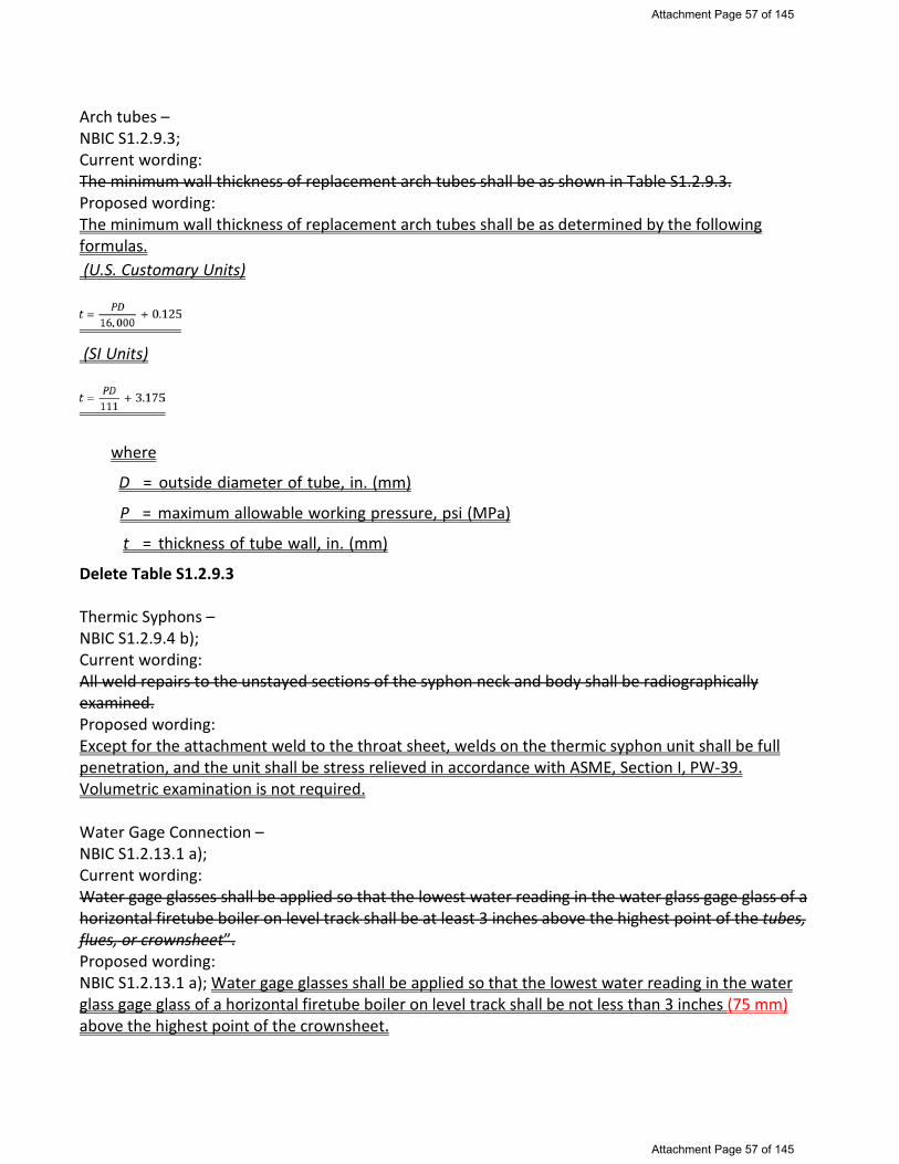
Arch tubes – NBIC S1.2.9.3; Current wording: The minimum wall thickness of replacement arch tubes shall be as shown in Table S1.2.9.3. Proposed wording: The minimum wall thickness of replacement arch tubes shall be as determined by the following formulas. (U.S. Customary Units)
(SI Units)
where
D = outside diameter of tube, in. (mm)
P = maximum allowable working pressure, psi (MPa)
t = thickness of tube wall, in. (mm)
Delete Table S1.2.9.3 Thermic Syphons – NBIC S1.2.9.4 b); Current wording: All weld repairs to the unstayed sections of the syphon neck and body shall be radiographically examined. Proposed wording: Except for the attachment weld to the throat sheet, welds on the thermic syphon unit shall be full penetration, and the unit shall be stress relieved in accordance with ASME, Section I, PW-39. Volumetric examination is not required. Water Gage Connection – NBIC S1.2.13.1 a); Current wording: Water gage glasses shall be applied so that the lowest water reading in the water glass gage glass of a horizontal firetube boiler on level track shall be at least 3 inches above the highest point of the tubes, flues, or crownsheet”. Proposed wording: NBIC S1.2.13.1 a); Water gage glasses shall be applied so that the lowest water reading in the water glass gage glass of a horizontal firetube boiler on level track shall be not less than 3 inches (75 mm) above the highest point of the crownsheet.
Attachment Page 57 of 145
Attachment Page 57 of 145

SECTION 1 18
Proposal NB17-0701 – Hellman – 7-16-18 NOTE: 7/16/18 - TG NR has voted to not add the originally proposed verbiage in 1.6.7.1 and 1.6.8.1, effectively closing Item NB17-0701 with no action.
1.6.7 QUALITY ASSURANCE PROGRAM REQUIREMENTS FOR CATEGORY 2 ACTIVITIES
1.6.7.1 SCOPE
Owners or organizations other than owners shall have a written Quality Assurance Program meeting one of the criteria specified in Table 1.6.2 of this section. Organizations applying for a Category 2 “NR” Certificate of Authorization shall specify in their written Quality Assurance Program which program criteria their Quality Assurance Program follows. Owners shall have a Quality Assurance Program meeting the requirements of either 10 CFR 50, Appendix B or NQA-1 Part 1 and shall include the additional requirements specified in ASME Section XI, IWA-4142 when applicable. Organizations other than the owner shall comply with requirements specified in either 10 CFR 50, Appendix B supplemented as needed with the owner’s QAP; NQA-1 Part 1; or NCA-4000. Organizations may elect to choose to follow all the rules specified in one of the allowed QAP criteria specified in Table 1.6.2 or they may elect to combine or supplement requirements from other specified QAP’s. When organizations elect to combine QAP requirements, it shall be clearly specified and understood in the QAM which QAP requirement is being followed for each activity specified in their QAM. The following quality elements shall be specified and described within the QAM. When Commercial Grade Dedication (CGD) is utilized, it shall be performed in accordance with NQA-1, Subpart 2.14.
1.6.7.2 QUALITY PROGRAM ELEMENTS a) Organization
The authority and responsibility for individuals involved in activities affecting quality shall be clearly established and documented throughout the Quality Assurance Program and identified on a functional organizational chart contained within the QA Manual.
b) Quality Assurance Program (QAP)
1) Qualification of non-destructive examination personnel shall be as required by the code or as speci-
fied in the owner’s Quality Assurance Program.
(17)
Attachment Page 58 of 145
Attachment Page 58 of 145

1.6.8 QUALITY ASSURANCE PROGRAM REQUIREMENTS FOR CATEGORY 3 ACTIVITIES
(17)
1.6.8.1 SCOPE
Organizations requesting a Category 3 “NR” Certificate of Authorization may elect to follow the requirements specified in ASME NQA-1 Part 1 or follow specific Quality Assurance Program requirements outlined in other specified standards as required by the owner, Regulatory Authority or Jurisdiction. Organizations shall specify in the QAM what QAP requirements are followed. When standards other than ASME NQA-1 are followed, the organization shall have available a copy of that standard for review by the NB Survey Team and the ANIA, as applicable. Each organization shall, as a minimum, include in their written QAM the specified elements listed in Category 1 and/or 2 (1.6.6, 1.6.7) QAP requirements. Additional requirements, as specified within NBIC Part 3, 1.6.8 and 1.6.9 shall be included within the QAP. Also, limitations or additions to ASME NQA-1, as specified for Category 1 or 2 may be incorporated and referenced within the QAM. When Commercial Grade Dedication (CGD) is utilized, it shall be performed in accordance with NQA-1, Subpart 2.14
1.6.8.2 QUALITY PROGRAM ELEMENTS
a) Organization
Persons and organization shall have authority and freedom to identify quality problems; initiate, recommend or provide solutions and verify implementation of solutions.
b) QAP
Shall account for special controls, processes, test equipment, tools and skills to obtain quality and for verification of quality by inspections and tests. Indoctrination, training and maintaining proficiency of personnel effecting quality shall be described. The status and adequacy of the QAP shall be regularly reviewed. The scope shall be included within the written QAM. The “NR” Certificate Holder shall make a current controlled copy of the Quality Assurance Manual available to the Authorized Nuclear Inspector and Authorized Nuclear Inspector Supervisor. The “NR” Certificate Holder shall address in their QAM the requirements for interfacing with the owner specified in 1.6.9 of this section.
c) Design Control
Established measures to assure approximate quality standards are specified and included in design documents. Any deviations shall be identified and controlled.
d) Document Control
Documents for procurement of material, equipment and services shall ensure regulatory requirements, design bases and other quality requirements and are included or referenced. Procurement documents shall require contractors or subcontractors provide a Quality Assurance Program consistent with the provisions specified in this NBIC Part 3, 1.6.8.
e) Instructions, Procedures and Drawings
Activities affecting quality shall be accomplished in accordance with prescribed instructions, procedures or drawings and shall include approximate quantitative or qualified acceptance criteria to determine activities are satisfactorily accomplished.
f) Document Control
Shall define measures to control the preparation, issuance, use, approval, revisions and distribution of all documents related to quality.
SECTI
ON
1
Attachment Page 59 of 145
Attachment Page 59 of 145

Item 18-41 Part 3, S4.18.2.1 2) d. 2. and 4.
1) …
2) Applying Test Patches to Verify Adequate Surface Preparation
a. Test patches should be applied to any substrate that will require a secondary bond to determine the integrity of the primer bond prior to the application of the laminate.
b. The subsequent steps shall be followed:
1. Apply the primer (0,003 -0.005 in. (0.08 to 0.13 mm)) to the prepared surface,
and allow primer to cure.
2. Coat the primed surface with the same resin to be used in the laminate repair. Apply 4 in. (100 mm) x 14 in. (360 mm) piece of polyester, such as Mylar®, strip to one edge of primed area. Allow the polyester film to protrude from beneath the patch.
3. Apply two layers of 1-1/2 oz/sq. ft (0.46 kg/sq. m) chopped strand mat saturated with the same resin that will be used for the repair. Mat shall be 12 in. (305 mm) x 12 in. (305 mm) square.
4. Allow the mat layers to cure completely, this may be verified by checking the hardness of the laminate.
5. Pry patch from surface using a screwdriver, chisel, or pry bar.
6. A clean separation indicates a poor bond.
7. Torn patch laminate or pulled substrate indicates that the bond is acceptable.
c. If the bond is not adequate, go back to step a) and repeat the procedure.
Note: If the repair area is smaller than the test patch dimensions, decrease the test patch size accordingly.
d. As a last resort, if the previous procedure does not provide an adequate bond, the permeated laminate must be handled differently using the following procedure:
1. Hot water wash the equipment.
2. Abrasive blast with #3 sand, or equal to achieve a 0.003 to 0.005 in. (0.08 to 0.12 mm) anchor pattern, and allow to completely dry.
3. Prime with the recommended primer, an area 12 in. (305 mm) x 12 in. (305 mm)
and apply a test patch.
4. Prime a second spot 12 in. (305 mm) x 12 in. (305 mm) and prime with a recommended epoxy resin alternate primer.
5. Allow this primer to cure.
Attachment Page 60 of 145
Attachment Page 60 of 145

Part 3, S4.18.2.2 2)
1) …
2) Note that any cracks, delaminations, or permeated surfaces must be removed. If the damage is
deeper than the corrosion barrier and the material removed reaches the structural laminate, the vessel is not repairable. An adequate size abrasive or proper sanding disc must be used to obtain a 0.003 to 0.005 0.002 to 0.003 in (0.05 to 0.08 mm) anchor pattern to the area that requires the repair.
3) Preparation of any surface requires that basic rules, common to all substrates, be followed. These rules are as outlined below:
a. Surface must be free of contaminants;
b. Surface must be structurally sound;
c. Surface must have adequate anchor pattern;
d. Surface must be dry;
e. Surface must be primed with recommended primer. Note: After the surface has been properly prepared, it must be kept clean and dry until laminating can be started. Dust, moisture, or traces of oil that come in contact with the surface may act as a mold release or act to inhibit the cure and prevent a good secondary bond. Laminating should be done within two hours of the surface preparation.
Attachment Page 61 of 145
Attachment Page 61 of 145

NB17-155
Approved by SGL April 2018
S1.2.14 Throttle Pipes, Dry Pipes, Superheater Headers & Front End Steam Pipes 1) Cracks in throttle pipes, dry pipes, superheater headers, and front end steam pipes made from steel may be repaired by welding. All welded repairs shall be done in accordance with NBIC Part 3.
2) Throttle castings, dry pipes, super heater headers, and front end steam pipes constructed of cast iron may be repaired by brazing provided the components are internal to the boiler shell or smokebox shell. Brazing shall be done in accordance with NBIC Part 3, appropriate to the type of repair, and shall be acceptable to the Inspector and the jurisdiction if applicable. Cast iron shall not be fusion welded. 3) Weld build-up may be used for repair of steel components in accordance with NBIC Part 3. 4) Throttle pipes, dry pipes and superheater headers, should be supported by hangers, brackets or other structural methods as needed.
Attachment Page 62 of 145
Attachment Page 62 of 145

NB17-156 Approved by SGL April 2018 S1.1.2 REQUIREMENTS FOR WELDING AND BRAZING ACTIVITIES a) Before performing any welding activities, consideration shall be given to ensure the weldability of locomotive boiler materials. b) Special jurisdictional approval may be required prior to starting welding activity on locomotive boilers. c) Performance of welded repairs on locomotive boilers shall meet the requirements of NBIC Part 3. d) Performance of brazed repairs on locomotive boilers shall meet the requirements of ASME Section IX.
Attachment Page 63 of 145
Attachment Page 63 of 145

Action Item-Rivet Joint to One Piece Welded Joint NB17-160 S1.2.11.5 REPAIR OF FIREBOX AND TUBESHEET KNUCKLES S1.2.11.5 Repair of Firebox, Wrapper, and Tubesheet Knuckles a) Welds within the points of tangency of a knuckle are permitted. Welds with angles of less than 45 degrees to the longitudinal axis of the knuckle shall be radiographically examined. (See NBIC Part 3, Figures S1.2.11.5-a through S1.2.11.5-g). b) Any patch not supported by means other than the weld, such as rivets, staybolts, tubes, or other forms of construction, shall have all weld seams radiographically examined. c) Patches shall be formed to proper shape and curvature. d) Wasted sections of knuckles that have not wasted below 60% of the minimum required thickness may be repaired by weld buildup provided the strength of the structure will not be impaired. Where weld buildup is employed, the Inspector may require an appropriate method of NDE for the repair. e) Wasted sections of knuckles that have wasted below 60% of the minimum required thickness shall be replaced. f) Flanges shall be made so as to avoid stress intensifiers such as abrupt ridges and grooves. g) Flanges shall be made smooth and free of ridges, valleys and grooves. h) Flanges may be welded in accordance with this section and all applicable sections of this code. i) For one-piece flange knuckle joint patches in portions of a riveted lap joint or in mud ring corners with a lap joint in the firebox, the knuckle patch shall be supported on at least one of the two planes adjacent to the flange, by means other than the weld. See Figure S1.2.11.5-c1. The weld shall be at least the full thickness of the new plate being installed. Volumetric examination is not required. This type of repair shall be considered a repair.
Cautionary note: Where a double-riveted lap joint is replaced with a seamless plate, stay pitch and stress must be considered since the doubling effect of the lap seam is being eliminated.
Add Figure S1.2.11.5-c1
Attachment Page 64 of 145
Attachment Page 64 of 145

Figure S1.2.11.5-c1
Attachment Page 65 of 145
Attachment Page 65 of 145

PART 3, SECTION 5
REPAIRS AND ALTERATIONS — CERTIFICATION/DOCUMENTATION AND STAMPING
5.1 SCOPE This section provides requirements for certification, stamping, and documentation of repairs and alterations to pressure-retaining items. Applicable forms are provided in this section for reference. Forms may be obtained from the National Board website. 5.2 DOCUMENTATION a) Repairs that have been performed in accordance with the NBIC shall be documented on a Form R-1, Report of Repair, as shown in this section. A Form R-4, Report Supplementary Sheet, shall be used as needed to record additional data when the space provided on Form R-1 is not sufficient. b) Alterations performed in accordance with the NBIC shall be documented on a Form R-2, Report of Alteration, as shown in this section. A Form R-4, Report Supplementary Sheet, shall be used as needed to record additional data when the space provided on Form R-2 is not sufficient. c) The organization performing repairs and alterations shall retain a copy of the completed Form “R” Report on file and all records and documentation substantiating the summary of work as described throughout Section 5, and as identified in the “R” Certificate Holder’s Quality System Manual. 5.2.1 PREPARATION OF FORM R-1 (REPAIRS) REPORT OF REPAIR a) Using the instructions found at NBIC Part 3, 5.12.4.1 preparation of Form R-1 shall be the responsibility of the “R” Certificate Holder performing the repair. b) Information describing the scope of work used to repair a pressure-retaining item (PRI) shall be documented on a Form R-1 and extended to a Form R-4 as needed to fully describe the repair activities completed per the instructions at NBIC Part 3, 5.12.4.1. c) An Inspector shall indicate acceptance by signing Form R-1, and Form R-4, if attached. d) The Form R-3, Report of Parts Fabricated by Welding, Manufacturer’s Data Reports, and Certificates of Compliance described in this section shall be a part of the completed Form R-1 and shall be attached thereto. 5.2.2 PREPARATION OF FORM R-2 (ALTERATIONS) REPORT OF ALTERATION a) Using the instructions found at NBIC Part 3, 5.12.4.2, initial preparation of Form R-2 shall be the responsibility of the “R” Certificate Holder responsible for the design portion of the alteration. The design organization shall complete and sign the “Design Certification” section of the Form R-2. An Inspector shall indicate acceptance of the design by signing the “Certificate of Design Change Review” section of the Form R-2. b) The information describing an alteration to a pressure-retaining item shall be identified on Form R-2 with a complete description of the scope of work for physical or non-physical changes. When the scope of work represents a change that will increase the Minimum Required Relieving Capacity (MRRC) of a pressure-retaining item, such as a change in heating surface, Maximum Designed Steaming Capacity (MDSC), or BTU/hr (W) heating capacity, the new MRRC shall be documented on Form R-2 and indicated on the appropriate nameplate of NBIC Part 3, Figure 5.7.5-b or NBIC Part 3, Figure 5.7.5-c.
17-179
Attachment Page 66 of 145
Attachment Page 66 of 145

c) Final preparation of Form R-2, including gathering and attaching supporting reports, shall be the responsibility of the “R” Certificate Holder that performed the construction portion of the alteration. The construction organization shall complete the Form R-2 provided by the design organization, including the “Construction Certification” section of the form. An Inspector shall indicate that the work complies with the applicable requirements of this code by completing and signing the “Certificate of Inspection” section of the form. When no construction work is performed (e.g., a re-rating with no physical changes), the “R” Certificate Holder responsible for the design shall prepare the Form R-2, including gathering and attaching of supporting reports documentation. d) The following shall be attached to and become a part of completed Form R-2: 1) For ASME boilers and pressure vessels, a copy of the original Manufacturer’s Data Report, when available; 2) Form R-3, Report of Parts Fabricated Parts by Welding, Manufacturer’s Partial Data Reports, or Certificates of Compliance, if applicable; and 3) For other than ASME, the manufacturer’s reports (i.e., reports required by the original code of construction, etc.), when available. 5.2.3 PREPARATION OF FORM R-3 REPORT OF PARTS FABRICATED BY WELDING a) Using the instructions found at NBIC Part 3, 5.12.4.3 preparation of Form R-3 shall be the responsibility of the “R” Certificate Holder responsible for performing the work. 5.2.4 PREPARATION OF FORM R-4 REPORT SUPPLEMENT SHEET a) Using the instructions found at NBIC Part 3, 5.12.4.4 preparation of Form R-4 shall be the responsibility of the “R” Certificate Holder responsible for performing the work. SKIP 5.3 through 5.11 5.12 REPAIR AND ALTERATION FORMS AND INSTRUCTIONS FOR COMPLETING FORMS The following forms may be used for documenting specific requirements as indicated on the top of each form. 5.12.1 FORM R-1, REPORT OF REPAIR, NB-66 5.12.2 FORM R-2, REPORT OF ALTERATIONS, NB-229 5.12.3 FORM R-3, REPORT OF PARTS FABRICATED BY WELDING, NB-230 5.12.4 FORM R-4, REPORT SUPPLEMENTARY SHEET, NB-231 5.12.4.1 INSTRUCTIONS FOR COMPLETING NATIONAL BOARD FORM “R” REPORTS R-1 These instructions are to be used when completing the National Board Form “R” Reports R-1, Report of Repair. When computer generated, the format of the form shall replicate the type and relative location of the information depicted on the Form “R” Reports R-1 shown in NBIC Part 3, 5.12.1 through 5.12.4. The
Attachment Page 67 of 145
Attachment Page 67 of 145

numbers below correspond to the “circled” numbers shown on the Form R-1. Note that a fillable version of the Form R-1 (NB-66,) is available on the National Board website, www.nationalboard.org. INFO NOTE: DELETE NUMBERS 1 THROUGH 55 and INSERT 1 THROUGH 40 LISTED BELOW ALONG WITH 5.12.4.2, 5.12.4.3, and 5.12.4.4 1) Initials of the authorized representative of the “R” Certificate Holder. 2) Initials of the Inspector reviewing the “R” Certificate Holders work 3) When registering a Form R-1 Report with the National Board, this line is solely designated for a unique sequential number assigned by the “R” Certificate Holder. When the “R” Form is not to be registered, indicate so by “N/A”. As described in NBIC Part 3, 5.6, a log shall be maintained identifying sequentially, any Form “R” registered with the National Board. 4) If applicable, document the unique purchase order, job, or tracking number assigned by organization
performing work. 5) The name and address of the National Board “R” Certificate Holder performing the work as it appears on the “Certificate of Authorization”. 6) Name and address of the owner of the pressure-retaining item. 7) Name and address of plant or facility where the pressure-retaining item is installed. 8) Description of the pressure-retaining item, such as boiler or pressure vessel, or piping. Include the applicable unit identification. 9) Name of the original manufacturer of the pressure-retaining item. If the original manufacturer is unknown, indicate by, “unknown.” 10) Document the serial number of the pressure-retaining item if assigned by the original manufacturer. If there is no serial number assigned or is unknown, indicate “unknown.” 11) When the pressure-retaining item is registered with the National Board, document the applicable registration number. If the pressure-retaining item is installed in Canada, indicate the Canadian design registration number (CRN), and list the drawing number under “other.” If the item is not registered, indicate, “none.” 12) Indicate the jurisdiction number assigned to the pressure retaining item, if available. 13) Indicate any other unique identifying nomenclature assigned to the pressure retaining item by the owner or user. 14) Identify the year in which fabrication/construction of the pressure retaining item was completed. 15) Indicate edition and addenda of the NBIC under which this work is being performed. 16) Indicate the name, section, division, edition, and addenda (if applicable) of the original code of construction for the pressure-retaining item. 17) Indicate the name, section, division, edition, and addenda (if applicable) of the construction code used for the work being performed. If code cases are used, they shall be identified in the “Remarks” section. 18) Check the repair type performed on the pressure retaining item.
Attachment Page 68 of 145
Attachment Page 68 of 145

19) Provide a detailed summary describing the scope of work that was completed to a pressure retaining item (PRI). The information to be considered when describing the scope of work should include such items as, the nature of the repair (i.e. welding, bonding, cementing), the specific location of the work performed to the PRI, the steps taken to remove a defect or as allowed by 3.3.4.8 to remain in place, the method of repair described as listed in the examples of Part 3, Section 3 or supplemental section if applicable, and the acceptance testing and or examination method used in accordance with the NBIC. When additional space is required to describe the scope of work, a Form R-4 shall be used and attached (check box). If a FITNESS FOR SERVICE Form (NB-403) is part of the Form R-1 repair package, check box and attach the form. Information determined to be of a proprietary nature need not be included, but shall be stated on the form.
20) Indicate type of pressure test applied (Liquid, Pneumatic, Vacuum, Leak). If no pressure test applied, indicate “none.” 21) Indicate test pressure applied. 22) Indicate maximum allowable working pressure (MAWP) for the pressure retaining item, if known. 23) As applicable, identify what Replacement Parts manufactured by welding or bonding were introduced as
needed to complete the scope of work. Indicate part, item number, manufacturer’s name, stamped identification, and data report type or Certificate of Compliance.
24) Indicate any additional information pertaining to the work involved (e.g., routine repairs, code cases). 25) When registering a Form R-1 Report with the National Board, this line is solely designated for a unique sequential number assigned by the “R” Certificate Holder. When the “R” Form is not to be registered, indicate so by “N/A”. As described in NBIC Part 3, 5.6, a log shall be maintained identifying sequentially, any Form “R” registered with the National Board. 26) If applicable, document the unique purchase order, job, or tracking number assigned by organization
performing work. 27) Type or print name of authorized representative of the “R” Certificate Holder attesting to accuracy of the work described. 28) Indicate National Board “R” Certificate or Authorization number. 29) Indicate month, day, and year that the “R” Certificate or Authorization expires. 30) Record name of “R” Certificate Holder who performed the described work, using full name as shown on the Certificate of Authorization or an abbreviation acceptable to the National Board. 31) Signature of “R” Certificate Holder authorized representative. 32) Enter month, day, and year repair certified. 33) Type or print name of Inspector. 34) Indicate Inspector’s Jurisdiction. 35) Indicate Inspector’s employer. 36) Indicate address of Inspector’s employer (city and state or province). 37) Indicate month, day, and year of final inspection by Inspector. For routine repairs this shall be the month, day, and year the Inspector reviews the completed routine repair package.
Attachment Page 69 of 145
Attachment Page 69 of 145

38) Inspectors National Board commission number and endorsement that qualifies the Inspector to sign this report, and when required by the Jurisdiction, the applicable State or Provincial numbers. 39) Signature of Inspector. 40) Indicate month, day, and year of Inspector signature. 5.12.4.2 INSTRUCTIONS FOR COMPLETING NATIONAL BOARD FORM R-2 REPORT INFO NOTE: THE FORM R-2 ON PAGE 91 DOES NOT HAVE THE “BUBBLED’ NUMBERS. USE (INSERT) TEMPLATE FROM THE R-2 GUIDE FOR NUMBERING These instructions are to be used when completing the National Board Form R-2, Report of Alteration. The numbers below correspond to the “circled” numbers depicted on Form R-2 in NBIC Part 3, 5.12.2. When computer generated, the format of the form shall replicate the type and relative location of the information depicted on the Form R-2 Report of Alteration. Note that a fillable version of the Form R-2 (NB-229) is available on the National Board website. 1) Initials of the National Board “R” Certificate of Authorization authorized representative who registers the Form R-2. 2) Initials of the Inspector who certified the completed Form R-2 for registration.
3) When registering a Form R-2 with the National Board, this line is solely designated for a unique sequential number assigned by the “R” Certificate Holder. As described in NBIC Part 3, Paragraph 5.6, a log shall be maintained identifying unique and sequentially numbered Form “R” reports that are registered with the National Board. For rerating only, the Design Organization registers the Form R-2. 4) If applicable, document the unique purchase order, job, or tracking number assigned by organization
performing work. 5) The name and address of the National Board “R” Certificate of Authorization holder performing the
design as it appears on the “Certificate of Authorization”.
6) The name and address of the National Board “R” Certificate of Authorization holder performing the construction activity as it appears on the “Certificate of Authorization.”
7) Name and address of the owner of the pressure-retaining item.
8) Name and address of the plant or facility where the pressure-retaining item is installed.
9) Description of the pressure-retaining item, such as boiler or pressure vessel, or piping. Include the
applicable unit identification.
10) Name of the original manufacturer of the pressure-retaining item. If the original manufacturer is unknown,
indicate by, “unknown.”
11) Document the serial number of the pressure-retaining item if assigned by the original manufacturer. If
there is no serial number assigned or it is unknown, indicate “unknown.”
12) When the pressure-retaining item is registered with the National Board, document the applicable
Attachment Page 70 of 145
Attachment Page 70 of 145

registration number. If the pressure-retaining item is installed in Canada, indicate the Canadian design,
registration number (CRN), and list the drawing number under “other.” If the item is not registered,
indicate, “none.”
13) Indicate the jurisdiction number assigned to the pressure retaining item, if available.
14) Indicate any other unique identifying nomenclature assigned to the pressure retaining item by the owner
or user.
15) Identify the year in which fabrication/construction of the pressure retaining item was completed.
16) Indicate edition and addenda of the NBIC under which this work is being performed, as applicable. 17) Indicate the name, section, division, edition, and addenda (if applicable) of the original code of construction for the pressure-retaining item. 18) Indicate the name, section, division, edition, and addenda (if applicable) of the construction code used for the work being performed. If code cases are used, they shall be identified in the “Remarks” section. 19) Provide a detailed summary of the scope of design that was performed. When additional space is required to describe the design scope, a Form R-4 shall be used and attached (check box if needed). 20) The information to be considered when describing the construction scope of work should include such items as, the nature of the alteration (i.e. welding, bonding, cementing), the specific location of the work performed to the pressure retaining item, the steps taken to remove a defect or as allowed by NBIC Part 3, Paragraph 3.3.4.8 to remain in place, and the method of alteration described as listed in the examples of NBIC Part 3, Paragraph 3.4.4 or applicable supplement. When additional space is required to describe the construction scope, a Form R-4 shall be used and attached (check box if needed). 21) Indicate type of pressure test applied (liquid, pneumatic, vacuum, leak). If no pressure test applied, indicate “none.” 22) Indicate test pressure applied. 23) Indicate maximum allowable working pressure (MAWP) for the pressure retaining item. (As altered) 24) When registering a Form R-2 with the National Board, this line is solely designated for a unique sequential number assigned by the “R” Certificate Holder. As described in NBIC Part 3, Paragraph 5.6, a log shall be maintained identifying unique and sequentially numbered Form “R” reports that are registered with the National Board. For rerating only, the Design Organization registers the Form R-2. 25) If applicable, document the unique purchase order, job, or tracking number assigned by organization
performing work. 26) As applicable, identify what parts manufactured by welding or bonding were introduced as needed to complete the scope of work. Indicate part, item number, manufacturer’s name, stamped identification, and data report type or Certificate of Compliance. 27) Indicate any additional information pertaining to the work involved (e.g. code cases, interpretations used). 28) Type or print name of the National Board “R” Certificate of Authorization authorized representative responsible for design certification. 29) Indicate National Board “R” Certificate or Authorization number.
Attachment Page 71 of 145
Attachment Page 71 of 145

30) Indicate month, day, and year that the “R” Certificate or Authorization expires.
31) Indicate month, day, and year the alteration was certified.
32) Record the name of National Board “R” Certificate of Authorization holder who performed the design portion of the work, using full name as shown on the “Certificate of Authorization” or an abbreviation acceptable to the National Board.
33) Signature of National Board “R” Certificate of Authorization authorized representative for the design change.
34) Type or print the name of Inspector certifying the design review.
35) Indicate Inspector’s Jurisdiction. 36) Indicate Inspector’s employer. 37) Indicate address of Inspector’s employer (city and state or province). 38) Indicate the month, day and year of the design certification by the Inspector.
39) Signature of the Inspector certifying the design review.
40) Inspectors National Board commission number and endorsement that qualifies the Inspector to sign this report, and when required by the Jurisdiction, the applicable State or Provincial numbers.
41) Type or print name of the National Board “R” Certificate of Authorization authorized representative responsible for any construction.
42) Indicate the National Board “R” Certificate or Authorization number.
43) Indicate month, day, and year the National Board “R” Certificate of Authorization expires.
44) Indicate the date the alteration was certified.
45) Record the name of National Board “R” Certificate of Authorization holder who performed the construction portion of the described work, using full name as shown on the Certificate of Authorization or an abbreviation acceptable to the National Board.
46) Signature of National Board “R” Certificate of Authorization authorized representative.
47) Type or print the name of Inspector certifying the construction inspection.
48) Indicate the Inspector’s Jurisdiction.
49) Indicate Inspector’s employer. 50) Indicate address of Inspector’s employer (city and state or province). 51) Indicate the month, day and year of the final inspection by the Inspector. 52) Indicate the month, day and year the completed Form R-2 was signed by the Inspector.
53) Signature of the Inspector certifying the construction inspection.
Attachment Page 72 of 145
Attachment Page 72 of 145

54) Inspectors National Board commission number and endorsement that qualifies the Inspector to sign this report, and when required by the Jurisdiction, the applicable State or Provincial numbers.
5.12.4.3 INSTRUCTIONS FOR COMPLETING NATIONAL BOARD FORM R-3 REPORT
This guide is to be used when completing the National Board Form R-3, Report of Parts Fabricated by Welding. The numbers below correspond to the “circled” numbers shown on the Form R-3 in NBIC Part 3, 5.12.3. When computer generated, the format of the form shall replicate the type and relative location of the information depicted on the Form R-3 Report of Parts Fabricated by Welding. Note that a fillable version of the Form R-3 (NB-230) is available on the National Board website.
1) Initials of the National Board “R” Certificate of Authorization authorized representative who registers the Form R-3. 2) Initials of the Inspector who certified the completed Form R-3 for registration.
3) When registering a Form R-3 Report with the National Board, this line is solely designated for a unique sequential number assigned by the “R” Certificate Holder. When the “R” Form is not to be registered, indicated so by “N/A”. As described in NBIC Part 3, Paragraph 5.6, a log shall be maintained identifying unique and sequentially numbered Form “R” reports that are registered with the National Board. 4) The name and address of the National Board “R” Certificate Holder who manufactured the welded parts
as it appears on the “Certificate of Authorization”. 5) If applicable, document the unique purchase order, job, or tracking number assigned by organization
performing work.
6) Document name and address of organization that purchased the parts for incorporation into the repair or alteration. If the part’s origin is unknown or the part was built for stock, so state.
7) Document name of organization responsible for specifying the code design conditions, if known. If origin of design conditions are not known, state “unknown.”
8) Document name of organization responsible for performing the code design, if known. If code design organization is not known, state “unknown.”
9) Name, section, and division of the design code, if known. If the design is not known, state “unknown.”
10) Indicate code edition year used for fabrication.
11) Indicate code addenda date used for fabrication, if applicable.
12) Indicate the code paragraph reference for formula used to establish the MAWP, if known. If the code
reference of the formula is not known, state “unknown.”
13) If available, identify component by part’s original name, function, or use the original equipment
manufacturers “mark or item number.”
14) Indicate quantity of named parts. 15) Match line number of part references for Identification of Parts in item 5 and the Description of Parts in
item 6.
16) Indicate manufacturer’s serial number or identification number for the named part.
17) Indicate drawing number for the named part.
Attachment Page 73 of 145
Attachment Page 73 of 145

18) Indicate maximum allowable working pressure (MAWP) for the part, if known.
19) Indicate test pressure, if applied.
20) Identify the year in which fabrication/construction of the item was completed.
21) Use inside diameter for size: indicate shape as square, round, etc.
22) Indicate the complete material specification number and grade.
23) Indicate nominal thickness of plate and minimum thickness after forming.
24) Indicate shape as flat, dished, ellipsoidal, or hemispherical.
25) Indicate minimum thickness after forming.
26) Indicate the complete material specification number and grade for the head or end.
27) Indicate outside diameter. 28) Indicate minimum thickness of tubes.
29) Indicate the complete material specification number and grade for tubes.
30) Indicate any additional information pertaining to the work involved (e.g. code cases). The part manufacturer is to indicate the extent he has performed any or all of the design function. If only a portion of the design, state which portion.
31) When registering a Form R-3 Report with the National Board, this line is solely designated for a unique sequential number assigned by the “R” Certificate Holder. When the “R” Form is not to be registered, indicated so by “N/A”. As described in NBIC Part 3, Paragraph 5.6, a log shall be maintained identifying unique and sequentially numbered Form “R” reports that are registered with the National Board. 32) If applicable, document the unique purchase order, job, or tracking number assigned by organization
performing work.
33) Type or print name of authorized representative of the “R” Certificate Holder attesting to accuracy of the work described.
34) Indicate National Board “R” Certificate of Authorization number.
35) Indicate month, day, and year that the “R” Certificate of Authorization expires.
36) Indicate the date the repair was certified.
37) Record name of “R” Certificate Holder who performed the described work, using full name as shown on the Certificate of Authorization or an abbreviation acceptable to the National Board.
38) Signature of National Board “R” Certificate of Authorization authorized representative.
39) Type or print name of Inspector.
40) Indicate Inspector’s Jurisdiction.
41) Indicate Inspector’s employer.
42) Indicate address of Inspector’s employer (city and state or province).
43) Indicate month, day, and year of final inspection by Inspector.
Attachment Page 74 of 145
Attachment Page 74 of 145

44) Indicate the month, day and year the completed Form “R” was signed by the Inspector.
45) Signature of Inspector.
46) Inspectors National Board commission number and endorsement that qualifies the Inspector to sign this report, and when required by the Jurisdiction, the applicable State or Provincial numbers.
5.12.4.4 INSTRUCTIONS FOR COMPLETING NATIONAL BOARD FORM R-4 REPORT
This guide is to be used when completing the National Board Form R-4, Report Supplement Sheet. The numbers below correspond to the “circled” numbers shown on the Form R-4 in NBIC Part 3, 5.12.4. When computer generated, the format of the form shall replicate the type and relative location of the information depicted on the Form R-4, Report Supplement Sheet. Note that a fillable version of the Form R-4 (NB-231) is available on the National Board website.
1) When registering a Form “R” Report with the National Board, this line is solely designated for a unique sequential number assigned by the “R” Certificate Holder. When the “R” Form is not to be registered, indicate so by “N/A”. As described in NBIC Part 3, Paragraph 5.6, a log shall be maintained identifying unique and sequentially numbered Form “R” reports that are registered with the National Board. Complete information identical to that shown on the Form “R” to which this sheet is a supplement.
2) If applicable, document the unique purchase order, job, or tracking number, assigned by the organization performing work.
3) The name and address of the Certificate Holder performing the work as it appears on the “Certificate of Authorization”.
4) Name and address of the owner of the pressure-retaining item.
5) Name and address of plant or facility where the pressure-retaining item is installed.
6) Indicate the Form “R” type to which this report is supplementary. Example: Form R-1, Form R-2, Form R-3.
7) Indicate the reference line number from the Form “R” to which this report is supplementary.
8) Complete information for which there was insufficient space on the reference Form “R”.
9) Indicate the date certified.
10) Signature of the repair organizations authorized representative.
11) Record name of “R” Certificate Holder who performed the described work, using full name as shown on
the Certificate of Authorization or an abbreviation acceptable to the National Board.
12) Indicate the date the form was completed by the Inspector.
13) Signature of the Inspector.
14) Inspectors National Board commission number and endorsement that qualifies the Inspector to sign this
report, and when required by the Jurisdiction, the applicable State or Province numbers.
Attachment Page 75 of 145
Attachment Page 75 of 145

Attachment Page 76 of 145
Attachment Page 76 of 145

Attachment Page 77 of 145
Attachment Page 77 of 145

Attachment Page 78 of 145
Attachment Page 78 of 145

Attachment Page 79 of 145
Attachment Page 79 of 145

Attachment Page 80 of 145
Attachment Page 80 of 145

Attachment Page 81 of 145
Attachment Page 81 of 145

This form may be obtained from The National Board of Boiler and Pressure Vessel Inspectors 1055 Crupper Avenue, Columbus, Ohio 43229-1183
FORM R-4 REPORT SUPPLEMENT SHEETin accordance with provisions of the National Board Inspection Code
1. WORK PERFORMED BY: (name)
(address)
2. OWNER: (name)
(address)
3. LOCATION OF INSTALLATION: (name)
(address)
REFERENCELINE NO. CONTINUED FROM FORM R–
Date Signed Name (authorized representative) (Name of “R” certificate holder)
Date Signed Commissions (inspector) (National Board and jurisdiction no. including endorsement)
NB-231, Rev. 3, (12/08/16)
Page 1 of 1
(form “R” referenced)
(P.O. no., job no., etc.)
Attachment Page 82 of 145
Attachment Page 82 of 145

Subject Code Revision to Part 3, 2.5.3.6 File Number NB18-12 Prop. on Pg. 2 Proposed Revision
Statement of Need
The revision is to Welding Method 6 to allow for weld build-up limited to 100 square inches on only Grade 91 tube OD surfaces for local erosion or mechanical damage.
Project Manager
John Siefert/G. Galanes
SubGroup Negatives
SG Meeting Date
Background; Welding Method 6 was successfully introduced into the NBIC, part 3 to permit butt weld repair with no PWHT. This action permits weld build-up of the Grade 91 tubes within the boiler setting and same limitations to repair erosion or mechanical damage without the need for complete tube replacement. To ensure adequate controls, the size of the repair are using a weld overlay is limited to 100 square inches.
Attachment Page 83 of 145
Attachment Page 83 of 145

Item 18-12 2.5.3.6 WELDING METHOD 6 This welding method provides requirements for welding only Grade 91 tube material within the steam boiler setting. When using this welding method, the following applies:
a) This method is limited to butt welds or weld build-up repairs limited to 100 square inches (64,500 square mm) or less in size in tubing NPS 5 (DN 125) or less in diameter and ½ in. (13 mm) or less in wall thickness for which the applicable rules of the original code of construction did not require notch toughness testing; b) Application shall be limited to only boiler tube repairs at a location internal to the boiler setting; c) Upon the completion of weld repair, the repair area shall be kept above the dew point temperature so that condensation does not form on the repair surface before returned to service or a moisture-barrier coating shall be applied to the surface.
1) The material shall be limited to P-No 15E, Group 1, Grade 91, creep strength enhanced ferritic steel (CSEF). 2) The welding shall be limited to the SMAW and/or GTAW processes, manual or automatic, using suitably controlled maintenance procedures to avoid contamination by hydrogen producing sources. The surface of the metal shall be free of contaminants and kept dry. 3) The welding procedure qualification test coupon shall be P-No 15 E, Group 1, Grade 91. 4) Qualification thickness limits of base metal and weld deposit thickness shall be in accordance with ASME Section IX, QW-451. 5) The Welding Procedure Specification (WPS) shall be qualified in accordance with the requirements of ASME Section IX. No postweld heat treatment shall be applied to the test coupon. Additionally, the WPS shall include the following requirements:
a. The minimum preheat for the GTAW process shall be 200°F (100°C). The minimum preheat for the SMAW process shall be 300°F (150°C). The preheat temperature shall be checked to ensure the minimum preheat temperature is maintained during welding and until welding is completed. The maximum interpass temperature shall be 550°F (290°C). b. When the SMAW process is specified for a fill pass layer, the electrode diameter is restricted to a maximum size of 1/8 in. (3.2 mm). When the GTAW-process is specified any limits in filler size is to be shown on the WPS. c. Regardless of the welding process (SMAW and/or GTAW), only the use of stringer beads shall be permitted. d. The filler metal shall be limited to an austenitic, nickel-base filler metal having a designation F-No. 43 and limited to the following consumables: ERNiCr-3, ENiCrFe-3, ENiCrFe-
Attachment Page 84 of 145
Attachment Page 84 of 145

2, ASME B&PV Code Cases 2733 and 2734 (e.g. EPRI P87); or e. A martensitic, iron-base filler metal having a designation F-No. 4 or F-No. 6 and limited to the following consumables: E8015-B8, E8018-B8 or ER80S-B8. f. For weld build-up repairs due to wastage, the filler metal shall be limited to an austenitic, nickel-base filler metal having a designation F-No. 43. There is not a limit on the consumable for this repair application.
Attachment Page 85 of 145
Attachment Page 85 of 145

Subject Code Revision to Part 3, 2.5.3.6 File Number NB18-13 Prop. on Pg. 2 Proposed Revision
Statement of Need
The revision is to add a new Welding Method 7 to allow for dissimilar metal welding of Grade 91 to austenitic steels and low alloy steels in a boiler setting and limited to butt welds, in accordance with approved welding method 6.
Project Manager
John Siefert/G. Galanes
SubGroup Negatives
SG Meeting Date
Background; Welding Method 7 is being introduced to permit dissimilar metal weld repair with no PWHT between Grade 91 boiler tubes to austenitic steels and low alloy ferritic steels. This action permits DMW of Grade 91 tubes within the boiler setting following welding method 6 with no PWHT.
Attachment Page 86 of 145
Attachment Page 86 of 145

NB Item 18-13 2.5.3.7 WELDING METHOD 7 This repair method provides requirements for dissimilar metal welding (DMW) of Grade 91 tube material to either austenitic or low alloy ferritic steel tubing within the steam boiler setting. When using this welding method, the following applies:
a) This method is limited to butt welds in tubing NPS 5 (DN 125) or less in diameter and ½ in. (13 mm) or less in wall thickness for which the applicable rules of the original code of construction did not require notch toughness testing; b) Application shall be limited to only boiler tube repairs at a location internal to the boiler setting; c) Upon the completion of weld repair, the repair area shall be kept above the dew point temperature so that condensation does not form on the repair surface before returned to service or a moisture-barrier coating shall be applied to the surface.
For DMW of Grade 91 to austenitic steel steel tubing; 1) The materials shall be limited to P-No 15E, Group 1, Grade 91, creep strength enhanced ferritic steel (CSEF) joined to either P-No. 8, P-No. 42, P-No. 43, or P-No. 45, as permitted for welded construction by the applicable rules of the original code of construction.. 2) The welding shall be limited to the SMAW and GTAW processes, manual or automatic, using suitably controlled maintenance procedures to avoid contamination by hydrogen producing sources. The surface of the metal shall be free of contaminants and kept dry. 3) The welding procedure qualification test coupon shall be P-No 15 E, Group 1, Grade 91 joined to either P-No. 8, P-No. 42, P-No. 43, or P-No. 45 and as required for the repair application. 4) Qualification thickness limits of base metal and weld deposit thickness shall be in accordance with ASME Section IX, QW-451. 5) The Welding Procedure Specification (WPS) shall be qualified in accordance with the requirements of ASME Section IX. No postweld heat treatment shall be applied to the test coupon. Additionally, the WPS shall include the following requirements:
a). The minimum preheat for the GTAW process shall be 200°F (100°C). The minimum preheat for the SMAW process shall be 300°F (150°C). The preheat temperature shall be checked to ensure the minimum preheat temperature is maintained during welding and until welding is completed.
Attachment Page 87 of 145
Attachment Page 87 of 145

The maximum interpass temperature shall be 550°F (290°C). b). When the SMAW process is specified for a fill pass layer, the electrode diameter is restricted to a maximum size of 1/8 in. (3.2 mm). When the GTAW-process is specified any limits in filler size is to be shown on the WPS. c). Regardless of the welding process (SMAW or GTAW), only the use of stringer beads shall be permitted. d). The filler metal shall be limited to an austenitic, nickel-base filler metal having a designation F-No. 43 and limited to the following consumables: ERNiCr-3 (e.g., Filler Metal 82), ENiCrFe-3 (e.g., INCONEL Welding Electrode 182), ENiCrFe-2 (e.g., INCO-WELD A), ASME B&PV Code Cases 2733 and 2734 (e.g. EPRI P87); e. A martensitic, iron-base filler metal having a designation F-No. 4 or F-No. 6 and limited to the following consumables: E8015-B8, E8018-B8 or ER80S-B8.
For DMW of Grade 91 to low alloy (P-No 5A) steel tubing; 1) The materials shall be limited to P-No 15E, Group 1, Grade 91, creep strength enhanced ferritic steel (CSEF) joined to P-No. 5A steel. 2) The welding shall be limited to the SMAW and/or GTAW processes, manual or automatic, using suitably controlled maintenance procedures to avoid contamination by hydrogen producing sources. The surface of the metal shall be free of contaminants and kept dry. 3) The welding procedure qualification test coupon shall be P-No 15 E, Group 1, Grade 91 joined to P-No. 5A steels. 4) Qualification thickness limits of base metal and weld deposit thickness shall be in accordance with ASME Section IX, QW-451. 5) The Welding Procedure Specification (WPS) shall be qualified in accordance with the requirements of ASME Section IX. No postweld heat treatment shall be applied to the test coupon. Additionally, the WPS shall include the following requirements:
(a). The minimum preheat for the GTAW process shall be 200°F (100°C). The minimum preheat for the SMAW process shall be 300°F (150°C). The preheat temperature shall be checked to ensure the minimum
Attachment Page 88 of 145
Attachment Page 88 of 145

preheat temperature is maintained during welding and until welding is completed. The maximum interpass temperature shall be 550°F (290°C). (b). When the SMAW process is specified for a fill pass layer, the electrode diameter is restricted to a maximum size of 1/8 in. (3.2 mm). When the GTAW-process is specified any limits in filler size is to be shown on the WPS. (c). Regardless of the welding process (SMAW or GTAW), only the use of stringer beads shall be permitted. (d). The filler metal shall be limited to a martensitic, iron-base filler metal having a designation F-No. 4 or F-No. 6 and limited to the following consumables: E8015-B8, E8018-B8 or ER80S-B8.
Attachment Page 89 of 145
Attachment Page 89 of 145

NB18-5 replaces NB13-1401 S1.2.9.6 RE-ROLLING OF FLUE-TUBES AFTER SEAL WELDING All flues and tubes that are installed by rolling and seal welding shall be re-rolled after seal welding is complete. S1.2.9.6 INSTALLATION OF BOILER FLUES Maximum allowable working pressure and nominal wall thickness for flues shall be determined using TABLE S1.2.9.1 and TABLE S1.2.9.1M Except as otherwise specified in this Part, flues shall be attached as illustrated in Figure S1.2.9.6 (a thru e). Flues shall not be attached by welding alone. All flues smaller than 3 in. (75 mm) O.D. shall be expanded and beaded, with or without seal welding, or expanded and welded on the firebox end. At least 1 in 10 distributed evenly on the front flue sheet shall be expanded and beaded or expanded and welded. All flues 3 in. (75 mm) O.D. and larger shall be expanded and beaded, with or without seal welding, or expanded and welded at both ends. All adjacent flues smaller than 3 in. (75 mm) O.D. that are within the area occupied by the larger superheater flues shall be expanded and beaded or expanded and welded at both ends. At least 1 in 10 of the remaining flues smaller than 3 in.(75 mm) O.D. shall be beaded and/or welded on the front flue sheet, in addition to expanding. Where less than all flues are welded or beaded on the front flue sheet, those welded or beaded shall be distributed as evenly as practicable throughout the flue pack. Flues shall be re-expanded upon completion of seal welding or beading, or both. The new reduced wall thickness of the enlarged flue end shall be reviewed to confirm that upon completion of the flue expansion process the new wall thickness will be sufficient for the MAWP. When stipulated by the original design, the ends of boiler flues may be swaged to a smaller or larger diameter as required to fit the tube sheet holes. The swaging shall create smooth surfaces, smooth curves, and a uniform diameter reduction across the entire swaged length. Swaging or not swaging is considered a repair. When flues are applied by expanding and seal welding, the seal weld shall protrude beyond the sheet a distance of 1/8 in. to 1/4 in. (3 mm to 6 mm) inclusive [see Figure S1.2.9.1-b] and the end of the flue shall not protrude past the weld. The end of the flue shall be ground or polished to eliminate any sharp edges. Prior to welding, beading, or both, ensure that the flue is satisfactorily seated in the sheet. Seal welding may be done with water in the boiler, provided the water is heated to between 100°F and 120°F (38°C and 50°C). Ferrous or nonferrous ferrules may be used on either or both ends of flues. When seal welding over ferrous ferrules used in straight-expanded and seal-welded flues, the weld shall attach to the sheet and
Attachment Page 90 of 145
Attachment Page 90 of 145
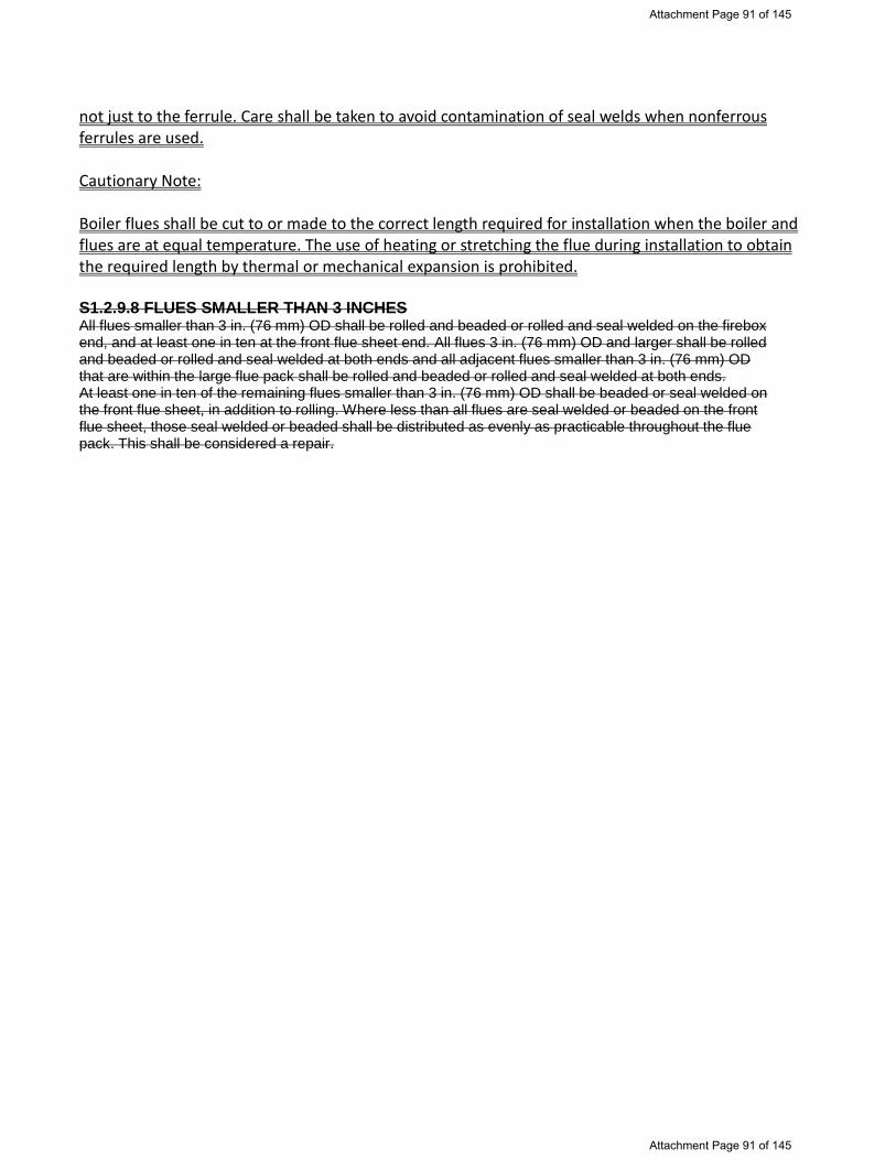
not just to the ferrule. Care shall be taken to avoid contamination of seal welds when nonferrous ferrules are used. Cautionary Note: Boiler flues shall be cut to or made to the correct length required for installation when the boiler and flues are at equal temperature. The use of heating or stretching the flue during installation to obtain the required length by thermal or mechanical expansion is prohibited. S1.2.9.8 FLUES SMALLER THAN 3 INCHES All flues smaller than 3 in. (76 mm) OD shall be rolled and beaded or rolled and seal welded on the firebox end, and at least one in ten at the front flue sheet end. All flues 3 in. (76 mm) OD and larger shall be rolled and beaded or rolled and seal welded at both ends and all adjacent flues smaller than 3 in. (76 mm) OD that are within the large flue pack shall be rolled and beaded or rolled and seal welded at both ends. At least one in ten of the remaining flues smaller than 3 in. (76 mm) OD shall be beaded or seal welded on the front flue sheet, in addition to rolling. Where less than all flues are seal welded or beaded on the front flue sheet, those seal welded or beaded shall be distributed as evenly as practicable throughout the flue pack. This shall be considered a repair.
Attachment Page 91 of 145
Attachment Page 91 of 145

NB18-7
Fillet Welded Staybolts
NBIC Part 3, S1.2.5.1; The replacement of threaded staybolts with fillet welded staybolts is permissible. The work shall be done in accordance with the ASME BPVC, Section I, Part PL-30 and Figure PL-30.4.2-1. When replacing a threaded staybolt with a fillet welded staybolt, the existing threads in the sheets must be removed prior to installation. Cautionary Note: Larger minimum diameter staybolts will transfer stresses to other structures and will be subject to higher extreme fiber stresses. Repairs to un-threaded fillet welded staybolts shall be performed in accordance with the original code of construction. If the original code of construction is not known, repairs shall be performed as follows in accordance with an appropriate code of construction that allows fillet welded staybolts:
a) The replacement of un-threaded fillet welded staybolts is permissible.
b) Existing un-threaded fillet welded staybolts that leak shall be repaired by re-welding after mechanically removing the entire weld. Only the leaking stays are to be re-welded.
c) Minor leakages (sweat pores) may be repaired by gently caulking the fillet weld.
However, identifiable cracks shall be removed before re-welding.
Attachment Page 92 of 145
Attachment Page 92 of 145

NB Item # 18-14, Update NBIC Part 3, Clause 2.3 and Table 2.3 Revise Clause 2.3 to recognize Re-affirmed, Amended and Revised SWPS confirming that suitability is as listed in Table 2.3 EXISTING TEXT 2.3 STANDARD WELDING PROCEDURE SPECIFICATIONS a) One or more SWPSs from NBIC Part 3, Table 2.3 may be used as an alternative to one or more WPS documents qualified by the organization making the repair or alteration, provided the organization accepts by certification (contained therein) full responsibility for the application of the SWPS in conformance with the application as stated in the SWPS. When using SWPSs, all variables listed on the Standard Welding Procedure are considered essential and, therefore, the repair organization cannot deviate, modify, amend, or revise any SWPSs. US Customary Units or metric units may be used for all SWPSs in NBIC Part 3, Table 2.3, but one system shall be used for application of the entire SWPS in accordance with the metric conversation table contained in the SWPS. The user may issue supplementary instructions as allowed by the SWPS. Standard Welding Procedures Specifications shall not be used in the same product joint together with the other Standard Welding Procedure Specifications or other welding procedure specifications qualified by the organization. b) The AWS reaffirms SWPSs in accordance with ANSI procedures. When reaffirmation occurs without revision to the SWPS, the letter “R” is added to the SWPS designation prior to the year. Such designation is considered to be identical with the previously published version and may be used pending incorporation herein, on the same basis as the version listed in NBIC Part 3, Table 2.3.
PROPOSED REVISION 2.3 STANDARD WELDING PROCEDURE SPECIFICATIONS a) One or more SWPSs from NBIC Part 3, Table 2.3 may be used as an alternative to one or more WPS documents qualified by the organization making the repair or alteration, provided the organization accepts by certification (contained therein) full responsibility for the application of the SWPS in conformance with the application as stated in the SWPS. When using SWPSs, all variables listed on the Standard Welding Procedure are considered essential and, therefore, the repair organization cannot deviate, modify, amend, or revise any SWPSs. US Customary Units or metric units may be used for all SWPSs in NBIC Part 3, Table 2.3, but one system shall be used for application of the entire SWPS in accordance with the metric conversation table contained in the SWPS. The user may issue supplementary instructions as allowed by the SWPS. Standard Welding Procedures Specifications shall not be used in the same product joint together with the other Standard Welding Procedure Specifications or other welding procedure specifications qualified by the organization. b) The AWS reaffirms, amends or revises SWPSs in accordance with ANSI procedures. • Reaffirmed SWPSs: When reaffirmation occurs without
revision to the SWPS, the letter R is added to the SWPS designation.
• Amended SWPSs: When an amendment occurs the initials AMD1 is added to the SWPS designation Amendments are issued when essential for the prompt correction of an error that could be misleading. Amendments are incorporated into the existing text of the SWPS, which is reprinted and clearly marked as incorporating an amendment(s), and which is identified in the revised Foreword of the amended SWPS.
• Revised SWPSs: When a revision to a published SWPS occurs, the publication date is added to the SWPS designation. The date of the superseded SWPS is also noted on the cover page. Previous versions of the superseded SWPS may be used at the option of the R Certificate holder.
Attachment Page 93 of 145
Attachment Page 93 of 145

See the addition of 5 amended SWPS Highlighted in Red Type and 1 SWPS correction also Highlighted in Red; Type
Carbon Steel — (P1 Materials)
SMAW — Shielded Metal Arc Welding
Standard Welding Procedure Specification for Shielded Metal Arc Welding of Carbon Steel, (M-1/P-1, Group 1 or 2), 3/16 in. (5 mm) through 3/4 in. (19 mm), in the As-Welded Condition, With Backing.
B2.1.001-90 and B2.1-1-001: 90(R2006)
Standard Welding Procedure Specification for Shielded Metal Arc Welding of Carbon Steel (M-1/P-1/S-1, Group 1 or 2), 1/8 in. (3.2 mm) through 1 ½ in. (38 mm) Thick, E7018, As-Welded or PWHT Condition.
B2.1-1-016-94 and B2.1-1-016-94R
Standard Welding Procedure Specification for Shielded Metal Arc Welding of Carbon Steel (M-1/P-1/S-1, Group 1 or 2), 1/8 in. (3.2 mm) through 1 ½ in. (38 mm) Thick, E6010, As-Welded or PWHT Condition.
B2.1-1-017-94 and B2.1-1-017-94R
Standard Welding Procedure Specification for Shielded Metal Arc Welding of Carbon Steel (M-1/P-1/S-1, Group 1 or 2), 1/8 in. (3.2 mm) through 1 ½ in. (38 mm) Thick, E6010 (Vertical Uphill) followed by E7018, As-Welded or PWHT Condition.
B2.1-1-022-94 and B2.1-1-022-94R
Standard Welding Procedure Specification for Shielded Metal Arc Welding of Carbon Steel (M-1/P-1/S-1, Group 1 or 2), 1/8 in. (3.2 mm) through 1 ½ in. (38 mm) Thick, E6010 (Vertical Downhill) followed by E7018, As-Welded or PWHT Condition.
B2.1-1-026-94 and B2.1-1-026-94R
Standard Welding Procedure Specification for Shielded Metal Arc Welding of Carbon Steel (M-1/P-1/S-1, Group 1 or 2), 1/8 in. (3.2 mm) through 3/4 in. (19 mm) Thick, E6010 (Vertical Uphill) followed by E7018, (Vertical Uphill) As-Welded Condition, Primarily Pipe Applications.
B2.1-1-201-96, and B2.1-1-201-96(R2007)
Standard Welding Procedure Specification for Shielded Metal Arc Welding of Carbon Steel (M-1/P-1/S-1, Group 1 or 2), 1/8 in. (3.2 mm) through 3/4 in. (19 mm) thick, E6010 (Vertical Downhill) followed by E7018 (Vertical Uphill), As-Welded Condition, Primarily Pipe Applications.
B2.1-1-202-96(R2007)
Standard Welding Procedure Specification for Shielded Metal Arc Welding of Carbon Steel (M-1/P-1/S-1, Group 1 or 2), 1/8 in. (3.2 mm) through 3/4 in. (19 mm) Thick, E6010 (Vertical Uphill), As-Welded Condition, Primarily Pipe Applications.
B2.1-1-203-96 and B2.1-1-203-96(R2007)
Standard Welding Procedure Specification for Shielded Metal Arc Welding of Carbon Steel (M-1/P-1/S-1, Group 1 or 2), 1/8 in. (3.2 mm) through 3/4 in. (19 mm) Thick, E6010 (Vertical downhill root with balance vertical uphill), As-Welded Condition, Primarily Pipe Applications.
B2.1-1-204-96 and B2.1-1-204-96(R2007)
Standard Welding Procedure Specification for Shielded Metal Arc Welding of Carbon Steel (M-1/P-1/S-1, Group 1 or 2), 1/8 in. (3.2 mm) through 1 ½ in. (38 mm) Thick, E6010 (Vertical Uphill) followed by E7018 (Vertical Uphill), As-Welded or PWHT Condition, Primarily Pipe Applications.
B2.1-1-205-96 and B2.1-1-205-96(R2007)
Standard Welding Procedure Specification for Shielded Metal Arc Welding of Carbon Steel (M-1/P-1/S-1, Group 1 or 2), 1/8 in. (3.2 mm) through 3/4 in. (19 mm) Thick, E6010 (Vertical Downhill) followed by E7018 (Vertical Uphill), As-Welded or PWHT Condition, Primarily Pipe Applications.
B2.1-1-206-96 and B2.1-1-206-96(R2007)
Standard Welding Procedure Specification for Shielded Metal Arc Welding of Carbon Steel (M-1/P-1/S-1, Group 1 or 2), 1/8 in. (3.2 mm) through 3/4 in. (19 mm) Thick, E7018, As-Welded or PWHT Condition, Primarily Pipe Applications. B2.1-1-208-96
Standard Welding Procedure Specification for Shielded Metal Arc Welding of Carbon Steel (M-1/P-1/S-1, Group 1 or 2), 1/8 in. (3.2 mm) through1 ½ in. (38 mm) Thick, E7018, As-Welded or PWHT Condition, Primarily Pipe Applications.
B2.1-1-208-96(R2007)
GTAW — Gas Tungsten Arc Welding
Standard Welding Procedure Specification for Gas Tungsten Arc Welding of Carbon Steel, (M-1/P-1, Group 1 or 2), 3/16 in. (5 mm) through 7/8 in. (22 mm) Thick, in the As-Welded Condition, With or Without Backing.
B2.1-002-90, B2.1-002-90(R2006) and B2.1-1-002-90R
Standard Welding Procedure Specification for Gas Tungsten Arc Welding of Carbon Steel (M-1/P-1/S-1, Group 1 or 2), 1/8 in. (3.2 mm) through 3/4 in. (19 mm) Thick, ER70S-2, As-Welded or PWHT Condition, Primarily Pipe Application. B2.1-1-207-96
Attachment Page 94 of 145
Attachment Page 94 of 145

Standard Welding Procedure Specification for Gas Tungsten Arc Welding of Carbon Steel (M-1/P-1/S-1, Group 1 or 2), 1/8 in. (3.2 mm) through 1 ½in. (38 mm) Thick, ER70S-2, As-Welded or PWHT Condition, Primarily Pipe Application.
B2.1-1-207-96 (R2007)
Standard Welding Procedure Specification for Gas Tungsten Arc Welding (Consumable Insert) of Carbon Steel (M-1/P-1/S-1, Group 1 or 2), 1/8 in. (3.2 mm) through 3/4 in. (19 mm) Thick, INMs1 and ER70S-2, As-Welded or PWHT Condition, Primarily Pipe Application.
B2.1-1-210-96
Standard Welding Procedure Specification for Gas Tungsten Arc Welding with Consumable Insert Root of Carbon Steel (M-1/P-1/S-1, Group 1 or 2), 1/8 in. (3.2 mm) through 1-1/2 in. (38 mm) Thick, INMs-1, ER70S-2, As-Welded or PWHT Condition, Primarily Pipe Applications.
B2.1-1-210:2001 R2012
FCAW — Flux Core Arc Welding Standard Welding Procedure Specification for Self-Shielded Flux Cored Arc Welding of Carbon Steel (M-1/P-1/S-1, Group 1 or 2), 1/8 in. (3.2 mm) through 1 ½ in. (38 mm) Thick, E71T-8, As-Welded Condition.
B2.1-1-018-94 and B2.1-1.018-94R
Standard Welding Procedure Specification for CO2 Shielded Flux Cored Arc Welding of Carbon Steel (M-1/P-1/S-1, Group 1 or 2), 1/8 in. (3.2 mm) through 1 ½ in. (38 mm) Thick, E70T-1 and E71T-1, As-Welded Condition.
B2.1-1-019-94, B2.1-1-019-94R and B2.1-1-94 AMD1
Standard Welding Procedure Specification for 75% Ar/25% CO2 Shielded Flux Cored Arc Welding of Carbon Steel (M-1/P-1/S-1, Group 1 or 2), 1/8 in. (3.2 mm) through 1-1/2 in. (38 mm) Thick, E70T-1M and E71T-1M, As-Welded or PWHT Condition.
B2.1-1-020-94, B2.1-1-020-94R and B2.1-1-020 94-AMD1
Standard Welding Procedure for Self-Shielded Flux Cored Arc Welding of Carbon Steel (M-1/P-1/S-1, Group 1 or 2), 1/8 in. (3.2 mm) through 1/2 in. (13 mm) Thick, E71T-11, As-Welded Condition.
B2.1-1-027:1995 and B2.1-1-027-1998
Standard Welding Procedure Specification (SWPS) for Argon Plus 25% Carbon Dioxide Shielded Flux Cored Arc Welding of Carbon Steel (M-1/P-1/S-1, Groups 1 and 2), 1/8 in. (3.2 mm) through 1 ½ in. (38 mm) Thick, E7XT-XM, As-Welded or PWHT Condition, Primarily Pipe Applications.
B2.1-1-234: 2006
GMAW – Gas Metal Arc Welding Standard Welding Procedure Specification for Argon Plus 25% Carbon Dioxide Shielded Gas Metal Arc Welding (Short Circuiting Transfer Mode) followed by Argon Plus 2% Oxygen Shielded Gas Metal Arc Welding (Spray Transfer Mode) of Carbon Steel (M-1/P-1/S-1, Groups 1 and 2), 1/8 in. (3.2 mm) through 1 ½ in. (38 mm) Thick, ER70S-3, Flat Position Only, As-Welded or PWHT Condition, Primarily Pipe Applications.
B2.1-1-233: 2006
Standard Welding Procedure Specification for Argon Plus 2% Oxygen Shielded Gas Metal Arc Welding (Spray Transfer Mode) of Carbon Steel (M-1/P-1/S-1, Groups 1 and 2), 1/8 in. (3.2 mm) through 1 ½ in. (38 mm) Thick, ER70S-3, Flat Position Only, As-Welded or PWHT Condition, Primarily Pipe Applications.
B2.1-1-235: 2006
GTAW/SMAW Combination of Welding Processes Standard Welding Procedure Specification for Gas Tungsten Arc Welding Followed by Shielded Metal Arc Welding of Carbon Steel (M-1/P-1/S-1, Group 1 or 2), 1/8 in. (3.2 mm) through 1 ½ in. (38 mm) Thick, ER70S-2 and E7018, As-Welded or PWHT Condition.
B2.1-1-021-94 and B2.1-1-021-94R
Standard Welding Procedure Specification for Gas Tungsten Arc Welding followed by Shielded Metal Arc Welding of Carbon Steel (M-1/P-1/S-1, Groups 1 or 2), 1/8 in. (3.2 mm) through 3/4 in. (19 mm) Thick, ER70S-2 and E7018, As-Welded or PWHT Condition, Primarily Pipe Applications.
B2.1-1-209-96
Standard Welding Procedure Specification for Gas Tungsten Arc Welding followed by Shielded Metal Arc Welding of Carbon Steel (M-1/P-1/S-1, Groups 1 or 2), 1/8 in. (3.2 mm) through 1 ½ in. (38 mm) Thick, ER70S-2 and E7018, As-Welded or PWHT Condition, Primarily Pipe Applications.
B2.1-1-209-96 (R2007)
Standard Welding Procedure Specification for Gas Tungsten Arc Welding (Consumable Insert) Followed by Shielded Metal Arc Welding of Carbon Steel (M-1/P-1/S-1, Group 1 or 2), 1/8 in. (3.2 mm) through 3/4 in. (19 mm) Thick, INMs1 and E7018, As-
B2.1-1-211-96
Attachment Page 95 of 145
Attachment Page 95 of 145

Welded or PWHT Condition, Primarily Pipe Applications.
Standard Welding Procedure Specification for Gas Tungsten Arc Welding with Consumable Insert Root Followed by Shielded Metal Arc Welding of Carbon Steel (M-1/P-1/S-1, Group 1 or 2), 1/8 in. (3.2 mm) through 1 ½ in. (38 mm) Thick, INMs-1, ER70S-2, and E7018 As-Welded or PWHT Condition, Primarily Pipe Applications.
B2.1-1-211:2001 R2012
GMAW/FCAW – Combination of Welding Processes Standard Welding Procedure Specification for Argon Plus 25% Carbon Dioxide Shielded Gas Metal Arc Welding (Short Circuiting Transfer Mode) Followed by Argon Plus 25% Carbon Dioxide Shielded Flux Cored Arc Welding of Carbon Steel (m-1/P-1/S-1, Groups 1 and 2), 1/8 in. (3.2 mm) through 1 ½ in. (38 mm) Thick, ER70S-3 and EXT-X, As-Welded or PWHT Condition, Primarily Pipe Applications.
B2.1-1-232:2006
Austenitic Stainless Steel — (M8/P8/S8 Materials)
SMAW — Shielded Metal Arc Welding
Standard Welding Procedure Specification for Shielded Metal Arc Welding of Austenitic Stainless Steel (M-8/P-8/S-8, Group 1), 1/8 in. (3.2 mm) through 1½ in. (38 mm) Thick, As-Welded Condition. B2.1-8-023-94
Standard Welding Procedure Specification for Shielded Metal Arc Welding of Austenitic Stainless Steel (M-8/P-8/S-8, Group 1), 1/8 in. (3.2 mm) through 1½ in. (38 mm) Thick, E3XX-XX, As-Welded Condition, Primarily Pipe Application.
B2.1-8-213-97 and B2.1-8-213-96(R2007)
GTAW — Gas Tungsten Arc Welding Standard Welding Procedure Specification for Gas Tungsten Arc Welding of Austenitic Stainless Steel (M-8/P-8/S-8, Group 1), 1/8 in. (3.2 mm) through 1 ½ in. (38 mm) Thick, As-Welded Condition. B2.1-8-024-94
Standard Welding Procedure Specification for Gas Tungsten Arc Welding of Austenitic Stainless Steel (M-8/P-8/S-8, Group 1), 1/16 in. (1.6 mm) through 1 ½ in. (38 mm) Thick, ER3XX, As-Welded Condition, Primarily Plate and Structural Applications. B2.1-8-024:2001
Standard Welding Procedure Specification for Gas Tungsten Arc Welding of Austenitic Stainless Steel (M-8/P-8/S-8, Group 1), 1/16 in. (1.6 mm) through 1 ½ in. (38 mm) Thick, ER3XX, As-Welded Condition, Primarily Pipe Applications. B2.1-8-212-97
Standard Welding Procedure Specification for Gas Tungsten Arc Welding of Austenitic Stainless Steel (M-8/P-8/S-8, Group 1), 1/16 in. (1.6 mm) through 1 ½ in. (38 mm) thick, ER3XX, As-Welded Condition, Primarily Pipe Applications.
B2.1-8-212:2001 R2012
Standard Welding Procedure Specification for Gas Tungsten Arc Welding With Consumable Insert Root of Austenitic Stainless Steel (M-8/P-8/S-8, Group 1), 1/8 in. (3.2 mm) through 1 ½ in. (38 mm) Thick, IN3XX and ER3XX As-Welded Condition, Primarily Pipe Applications.
B2.1-8-215:1998 B2.1-8-215:2001 R2012
Combination Processes GTAW/SMAW Standard Welding Procedure Specification for Gas Tungsten Arc Welding followed by Shielded Metal Arc Welding of Austenitic Stainless Steel (M-8/P-8/S-8, Group 1), 1/8 in. (3.2 mm) through 1 ½ in. (38 mm) Thick, As-Welded Condition. B2.1-8-025-94
Standard Welding Procedure Specification for Gas Tungsten Arc Welding followed by Shielded Metal Arc Welding of Austenitic Stainless Steel (M-8/P-8/S-8, Group 1), 1/8 in. (3.2 mm) through 1 ½ in. (38 mm) Thick, ER3XX and E3XX-XX, As-Welded Condition, Primarily Plate and Structural Applications.
B2.1-8-025:2001
Standard Welding Procedure Specification for Gas Tungsten Arc Welding Followed by Shielded Metal Arc Welding of Austenitic Stainless Steel (M-8/P-8/S-8, Group 1), 1/8 in. (3.2 mm) through 1 ½ in. (38 mm) Thick, ER3XX and E3XX-XX, As-Welded Condition, Primarily Pipe Applications.
B2.1-8-214-97
Standard Welding Procedure Specification for Gas Tungsten Arc Welding Followed by Shielded Metal Arc Welding of Austenitic Stainless Steel (M-8/P-8/S-8, Group 1), 1/8 in. (3.2 mm) through 1 ½ in. (38 mm) Thick, ER3XX and E3XX-XX, As-Welded Condition, Primarily Pipe Applications.
B2.1-8-214:2001 R2012
Attachment Page 96 of 145
Attachment Page 96 of 145

Standard Welding Procedure Specification for Gas Tungsten Arc Welding With Consumable Insert Followed by Shielded Metal Arc Welding of Austenitic Stainless Steel (M-8/P-8/S-8, Group 1), 1/8 in. (3.2 mm) through 1 ½ in. (38 mm) thick, IN3XX, ER3XX, and E3XX-XX As-Welded Condition, Primarily Pipe Application.
B2.1-8-216-1998
Standard Welding Procedure Specification for Gas Tungsten Arc Welding with Consumable Insert Root followed by Shielded Metal Arc Welding of Austenitic Stainless Steel (M-8/P-8/S-8, Group 1), 1/8 in. (3.2 mm) through 1 ½ in. (38 mm) Thick, IN3XX, ER3XX, and E3XX-XX As-Welded Condition, Primarily Pipe Applications.
B2.1-8-216:2001 R2012
Combination of Carbon Steel (P-1 Material) To Austenitic Stainless Steel (P-8 Material)
SMAW — Shielded Metal Arc Welding
Standard Welding Procedure Specifications for Shielded Metal Arc Welding of Carbon Steel (M-1/P-1/S-1, Groups 1 or 2) to Austenitic Stainless Steel (M-8/P-8/S-8, Group 1), 1/8 in. (3.2 mm) through 1 ½ in. (38 mm) Thick, E309 (L)-15, -16, or -17, As-Welded Condition, Primarily Pipe Applications.
B2.1-1/8-228:2002 R2013
GTAW — Gas Tungsten Arc Welding Standard Welding Procedure Specification for Gas Tungsten Arc Welding of Carbon Steel (M-1/P-1/S-1, Groups 1 or 2) to Austenitic Stainless Steel (M-8/P-8/S-8, Group 1), 1/16 in. (1.6 mm) through 1 ½ in. (38 mm) Thick, ER309 (L), As-Welded Condition, Primarily Pipe Applications.
B2.1-1/8-227:2002, 2002 AMD1 and R2013
Standard Welding Procedure Specifications for Gas Tungsten Arc Welding with Consumable Insert Root of Carbon Steel (M-1/P-1/S-1, Groups 1 or 2) to Austenitic Stainless Steel (M-8/P-8/S-8, Group 1), 1/16 in. (1.6 mm) through 1½ in. (38 mm) Thick, IN309 and ER309(L), As-Welded Condition, Primarily Pipe Applications.
B2.1-1/8-230:2002, 2002 AMD1 and R2013
GTAW/SMAW Combination of Welding Processes Standard Welding Procedure Specifications for Gas Tungsten Arc Welding followed by Shielded Metal Arc Welding of Carbon Steel (M-1/P-1/S-1,Groups 1 or 2) to Austenitic Stainless Steel (M-8/P-8/S-8, Group 1), 1/8 in. (3.2 mm) through 1½ in. (38 mm) Thick, ER309(L) and E309(L)-15, -16, or -17, As-Welded Condition, Primarily Pipe Applications.
B2.1-1/8-229:2002, 2002-AMD1 and R2013
Standard Welding Procedure Specifications for Gas Tungsten Arc Welding with Consumable Insert Root followed by Shielded Metal Arc Welding of Carbon Steel (M-1/P-1/S-1, Groups 1 or 2) to Austenitic Stainless Steel (M-8/P-8/S-8, Group 1), 1/8 in. (3.2 mm) through 1½ in. (38 mm) Thick, IN3009, ER309, and E309-15, -16, or -17 or IN309, ER309(L) and ER309(L)-15, -16, or -17, As-Welded Condition, Primarily Pipe Applications.
B2.1-1/8-231:2002 R2015
Chromium Molybdenum Steel (M4/P4 and M5a/P5A Materials)
SMAW — Shielded Metal Arc Welding
Standard Welding Procedure Specifications for Shielded Metal Arc Welding of Chromium-Molybdenum Steel (M-4/P-4, Group 1 or 2), E8018-B2, 1/8 in. (3.2 mm) through 1 ½ in. (38 mm) Thick, As-Welded Condition, 1/8 in. (3.2 mm) through 1½ in. (38 mm) Thick, PWHT Condition, Primarily Pipe Applications.
B2.1-4-218:1999 R2009
Standard Welding Procedure Specifications for Shielded Metal Arc Welding of Chromium-Molybdenum Steel (M-5A/P-5A), E9018-B3, 1/8 in. (3.2 mm) through 1 ½ in. (38 mm) Thick, As-Welded Condition, 1/8 in. (3.2 mm) through 1½ in. (38 mm) Thick, PWHT Condition, Primarily Pipe Applications.
B2.1-5A-223:1999 R2009
GTAW — Gas Tungsten Arc Welding Standard Welding Procedure Specifications for Gas Tungsten Arc Welding of Chromium-Molybdenum Steel (M-4/P-4, Group 1 or 2), ER80S-B2, 1/8 in. (3.2 mm) through 1 ½ in. (38 mm) Thick, As-Welded Condition, 1/8 in. (3.2 mm) through 3/4 in. (19 mm) Thick, PWHT Condition, Primarily Pipe Applications.
B2.1-4-217:1999 R2009
Standard Welding Procedure Specifications for Gas Tungsten Arc Welding (Consumable Insert Root) of Chromium-Molybdenum Steel (M-4/P-4, Group 1 or 2), E8018-B2, 1/8 in. (3.2 mm) through 1 ½ in. (38 mm) Thick, As-Welded Condition, 1/8 in. (3.2 mm) through 3/4 in. (19
B2.1-4-220:1999
Attachment Page 97 of 145
Attachment Page 97 of 145

mm) Thick, PWHT Condition, IN515 and ER80S-B2, Primarily Pipe Applications. R2009
Standard Welding Procedure Specifications for Gas Tungsten Arc Welding of Chromium-Molybdenum Steel (M-5A/P-5A), ER90S-B3, 1/8 in. (3.2 mm) through 1½ in. (38 mm) Thick, As-Welded Condition, 1/8 in. (3.2 mm) through 3/4 in. (19 mm) Thick, PWHT Condition, Primarily Pipe Applications.
B2.1-5A-222:1999 R2009
Standard Welding Procedure Specifications for Gas Tungsten Arc Welding (Consumable Insert Root) of Chromium-Molybdenum Steel (M-5A/P-5A), 1/8 in. (3.2 mm) through 1-1/2 in. (38 mm) Thick, As-Welded Condition, 1/8 in. (3.2 mm) through 3/4 in. (19 mm) Thick, PWHT Condition, IN521 and ER90S-B3, Primarily Pipe Applications.
B2.1-5A-225:1999 R2009
Chromium-Molybdenum Steel Processes GTAW/SMAW Standard Welding Procedure Specifications for Gas Tungsten Arc Welding (Consumable Insert Root) followed by Shielded Metal Arc Welding of Chromium-Molybdenum Steel (M-4/P-4, Group 1 or 2), 1/8 in. (3.2 mm) through 1-1/2 in. (38 mm) Thick, As-Welded Condition, 1/8 in. (3.2 mm) through 1 ½ in. (38 mm) Thick, PWHT Condition, IN515, ER80S-B2, and E8018-B2, Primarily Pipe Applications.
B2.1-4-221:1999 R2009
Standard Welding Procedure Specifications for Gas Tungsten Arc Welded followed by Shielded Metal Arc Welding of Chromium-Molybdenum Steel (M-5A/P-5A), 1/8 in. (3.2 mm) through 1 ½ in. (38 mm) Thick, As-Welded Condition, 1/8 in. (3.2 mm) through 1 ½ in. (38 mm) Thick, PWHT Condition, ER90S-B3 and E9018-B3, Primarily Pipe Applications.
B2.1-5A-224:1999 R2009
Standard Welding Procedure Specifications for Gas Tungsten Arc Welding (Consumable Insert Root) followed by Shielded Metal Arc Welding of Chromium-Molybdenum Steel (M-5A/P-5A), 1/8 in. (3.2 mm) through 1 ½ in. (38 mm) Thick, As-Welded Condition, 1/8 in. (3.2 mm) through 1 ½ in. (38 mm) Thick, PWHT Condition, IN521, ER90S-B3, and E9018-B3, Primarily Pipe Applications.
B2.1-5A-226:1999 R2009
Standard Welding Procedure Specifications (SWPS) for Gas Tungsten Arc Welded followed by Shielded Metal Arc Welding of Chromium-Molybdenum Steel (M-4A/P-4, Group 1 or 2), 1/8 in. (3.2 mm) through 1/2 in. (13 mm) Thick, As-Welded Condition, 1/8 in. (3.2 mm) through 1 ½ in. (38 mm) Thick, PWHT Condition, ER80S-B2 and E9018-B2, Primarily Pipe Applications.
B2.1-4-219:199 R2009
Attachment Page 98 of 145
Attachment Page 98 of 145

PART 3, SECTION 1REPAIRS AND ALTERATIONS — GENERAL AND
ADMINISTRATIVE REQUIREMENTS1.1 SCOPE
a) This part provides requirements and guidelines that apply when performing repairs andalterations to pressure-retaining items.
b) The National Board administers three four specific accreditation programs:
1) “R” — Repairs and Alterations to Pressure-Retaining Items2) “NR” — Repair and Replacement Activities for Nuclear Items3) “VR” — Repairs to Pressure Relief Valves4) “T/O” – Test Only In-service testing only of Pressure Relief Valves
c) This part describes some of the administrative requirements for the accreditation of repairorganizations. Additional administrative requirements can be found in:
1) NB-415, ACCREDITATION OF “R” REPAIR ORGANIZATIONS2) NB-417, ACCREDITATION OF “NR” REPAIR ORGANIZATIONS3) NB-514, ACCREDITATION OF “VR” REPAIR ORGANIZATIONS4) NB-528, ACCREDITATION OF “T/O” TEST ONLY ORGANIZATIONS
d) Requirements for repairs to pressure relief valves can be found in NBIC Part 4.
Attachment Page 99 of 145
Attachment Page 99 of 145
Item 18-38

REQUEST FOR CODE REVISION
The following are proposed revisions to Part 3 Section 2 and the Glossary. The proposal expands Section 2 to include rules for brazing and fusing and definitions for brazing, fusing and welding in the Glossary.
EXPLANATION
In a recent request for revision to the rules relating to locomotive boilers, it was proposed to allow brazing on certain boiler parts. While considering the proposal, it was noted that the NBIC does not yet provide rules for brazing. While developing this proposal for revision, it was decided to expand Part 3 Section 2 to include fusing as well as brazing.
CURRENT PROPOSED MODIFIED PART 3, SECTION 2
REPAIRS AND ALTERATIONS —
WELDING AND HEAT TREATMENT
PART 3, SECTION 2 REPAIRS AND ALTERATIONS — WELDING, BRAZING, FUSING AND HEAT TREATMENT
No changes to proposal.
2.1 SCOPEThis section provides requirements and guidelines for welding and heat treating when performing welded repairs and alterations to pressure-retaining items. Careful consideration shall be given to pressure-retaining items that have been fabricated of either creep strength enhanced ferritic materials or ferritic materials enhanced by heat treatment. The tensile and creep strength properties of these materials can be degraded by not following specific welding and heat treatment requirements. The user is cautioned to seek technical guidance for welding and heat treating requirements in accordance with the original code of construction.
2.1 SCOPEa) This section providesrequirements and guidelines for welding, brazing, fusing and heat treating when performing welded repairs and alterations to pressure-retaining items. b) Careful consideration shall begiven to pressure-retaining items that have been fabricated of either creep strength enhanced ferritic steel materials or ferritic steel materials enhanced by heat treatment. The tensile and creep strength properties of these materials can be degraded by not following specific welding procedure specification and heat treatment requirements. The user is cautioned to seek technical guidance for welding and heat treating requirements for these materials in accordance with the original code of construction.
Add subparagraph (c) in response to Mr. Richard’s comment.
(c) Careful consideration shall be given to pressure-retaining items that have been previously repaired by brazing brazed to preclude the possibility of degrading the prior work.
2.2 WELDINGWelding shall be performed in accordance with the
2.2 WELDING, BRAZING ANDFUSINGWelding, brazing and fusing shall
No change to proposal.
Attachment Page 100 of 145
Attachment Page 100 of 145

requirements of the original code of construction used for the pressure-retaining item whenever possible.
be performed in accordance with the requirements of the original code of construction used for the pressure-retaining item whenever possible.
2.2.1 WELDING PROCEDURE SPECIFICATIONS Welding shall be performed in accordance with Welding Procedure Specifications (WPS) qualified in accordance with the original code of construction or the construction standard or code selected. When this is not possible or practicable, the WPS may be qualified in accordance with ASME Section IX.
2.2.1 WELDING PROCEDURE SPECIFICATIONS A procedure specification is a written document providing direction to the person applying the material joining process. Welding, brazing and fusing shall be performed in accordance with Welding Procedure Specifications (WPS) procedure specifications for welding (WPS), brazing (BPS), and fusing (FPS) qualified in accordance with the original code of construction or the construction standard or code selected. When this is not possible or practicable, the WPS procedure specification may be qualified in accordance with ASME Section IX.
No change to proposal.
2.2.2 STANDARD WELDING PROCEDURE SPECIFICATIONS An “R” Certificate Holder may use one or more applicable Standard Welding Procedure Specifications (SWPS) shown in NBIC Part 3, Table 2.3 without supporting Procedure Qualification Records (PQRs) since SWPS are pre-qualified.
No change to this paragraph. No change to proposal.
2.2.3 PERFORMANCE QUALIFICATION Welders and welding operators shall be qualified for the welding processes that are used. Such qualification shall be in accordance with the requirements of the original code of construction, the construction standard, code selected or ASME Section IX. Use of a Standard Welding Procedure Specification shown in NBIC Part 3, 2.3 is permitted for performance qualification testing.
2.2.3 PERFORMANCE QUALIFICATION Welders and welding operators shall be qualified for the welding processes that are used. The “R” Certificate Holder shall qualify the performance of personnel for each process they will use for repairs and alterations of pressure retaining items. Such qualification shall be in accordance with the requirements of the original code of construction, the construction standard, code selected, or ASME Section IX. Use of a Standard Welding Procedure Specification shown in NBIC Part 3, 2.3 is permitted for performance qualification testing.
No change to proposal.
Attachment Page 101 of 145
Attachment Page 101 of 145

2.2.4 WELDING RECORDS The “R” Certificate Holder shall maintain a record of the results obtained in Welding Procedure Qualifications, except for those qualifications for which the provisions of NBIC Part 3, 2.2.2 are used and of the results obtained in welding performance qualifications. These records shall be certified by the “R” Certificate Holder and shall be available to the Inspector.
2.2.4 WELDING QUALIFICATION RECORDS The “R” Certificate Holder shall maintain a record of the results obtained in Welding Procedure Qualifications, procedure specification qualification (except for those qualifications for which the provisions of NBIC Part 3, 2.2.2 are used) and of the results obtained in welding performance qualifications. These records shall be certified by the “R” Certificate Holder and shall be available to the Inspector.
No change to proposal.
2.2.5 WELDER’S IDENTIFICATION The “R” Certificate Holder shall establish a system for the assignment of a unique identification mark to each welder/welding operator qualified in accordance with the requirements of the NBIC. The “R” Certificate Holder shall also establish a written procedure whereby welded joints are identified as to the welder or welding operator who made them. This procedure shall use one or more of the following methods and be acceptable to the Inspector. The welder’s or welding operator’s identification mark may be stamped (low stress stamp) adjacent to welded joints made by the individual, or the “R” Certificate Holder may keep a documented record of welded joints and the welders or welding operators used in making the joints.
2.2.5 WELDER’S QUALIFIED PERSONNEL IDENTIFICATION The “R” Certificate Holder shall establish a system for the assignment of a unique identification mark to each welder/welding operator person qualified in accordance with the requirements of the NBIC. The “R” Certificate Holder shall also establish a written procedure whereby welded production joints are identified and traceable to the person as to the welder or welding operator who made them. This procedure shall use one or more of the following methods and be acceptable to the Inspector. a) The welder’s or welding operator’s person’s identification mark may be stamped (low stress stamp, if used) adjacent to welded production joints made by the individual, or, b) the “R” Certificate Holder may keep a documented record of welded production joints and the welders or welding operators persons used in making the joints.
No change to proposal.
2.2.6 WELDER’S CONTINUITY The performance qualification of a welder or welding operator shall be affected when one of the following conditions occur: a) When the welder or welding operator has not welded using a specific process during a period of six months or more, their
2.2.6 WELDER’S CONTINUITY OF QUALIFIED PERSONNEL The performance qualification of a welder or welding operator qualified person shall be affected when one of the following conditions occur: a) When the welder or welding operator person has not welded using used a specific process during a period of six months or
No change to proposal.
Attachment Page 102 of 145
Attachment Page 102 of 145

qualifications for that process shall expire; or b) When there is specific reason to question a welder’s ability to make welds that meet the specification, the qualification which supports the welding that is being performed shall be revoked. All other qualifications not questioned remain in effect.
more, their qualifications for that process shall expire; or b) When there is specific reason to question a welder’s the person’s ability to make welds joints that meet the specification, the qualification which supports the welding process that is being performed shall be revoked. All other qualifications not questioned remain in effect.
2.2.6.1 WELDER’S CONTINUITY RECORDS a) The “R” Certificate Holder shall maintain a welding continuity record and shall make the record available to the Inspector. b) The method of recording welding continuity and the record retention period shall be described in the “R” Certificate Holder’s Quality System Manual. c) When there is specific reason to question a welder’s ability to make welds that meet the specification, the qualification which supports the welding that is being performed shall be revoked. All other qualifications not questioned remain in effect.
2.2.6.1 WELDER’S PROCESS CONTINUITY RECORDS a) The “R” Certificate Holder shall maintain a welding process continuity records and shall make the records available to the Inspector. b) The method of recording welding process continuity and the record retention period shall be described in the “R” Certificate Holder’s Quality System Manual. c) When there is specific reason to question a welder’s person’s ability to make welds joints that meet the specification, the qualification which supports the welding process that is being performed shall be revoked. All other qualifications not questioned remain in effect.
No change to proposal.
2.3 STANDARD WELDING PROCEDURE SPECIFICATIONS
No change to this paragraph No change to proposal.
2.4 AWS REFERENCE STANDARDS
No change to this paragraph. No change to proposal.
2.5 HEAT TREATMENT 2.5 HEAT TREATMENT No change to proposal. 2.5.1 PREHEATING a) Preheating may be employed during welding to assist in completion of the welded joint. The need for and the temperature of preheat are dependent on a number of factors such as chemical analysis, degree of restraint of the items being joined, material thickness, and mechanical properties. The Welding Procedure Specification for the material being welded shall specify the preheat temperature requirements.
2.5.1 PREHEATING a) Preheating may be employed during welding use of a process to assist in completion of the welded joint. The need for and the temperature of preheat are dependent on a number of factors such as chemical analysis, degree of restraint of the items being joined, material thickness, and mechanical properties. The Welding Procedure Specification procedure specification for the material being welded joined shall specify the preheat temperature requirements. b) See minimum temperatures for
No change to proposal.
Attachment Page 103 of 145
Attachment Page 103 of 145

b) See minimum temperatures for preheating given in NBIC Part 3, Table 2.5.1 as a general guide. It is cautioned that the preheating temperatures listed do not necessarily ensure satisfactory completion of the welded joint. Requirements for individual materials within the P-Number listing may have preheating requirements more or less restrictive than this general guide. When reference is made in this section to materials by the ASME designation, P-Number and Group Number, the suggestions of this section apply to the applicable materials of the original code of construction, either ASME or other, which conform by chemical composition and mechanical properties to ASME materials having the ASME P-Number and Group Number designations.
preheating given in NBIC Part 3, Table 2.5.1 as a general guide. It is cautioned that the preheating temperatures listed may not be the same as those of the original code of construction and do not necessarily ensure satisfactory completion of the welded joint. Requirements for individual materials within the P-Number listing may have preheating requirements more or less restrictive than this general guide. When reference is made in this section to materials by the ASME designation, P-Number and Group Number, the suggestions of this section apply to the applicable materials of the original code of construction, either ASME or other, which conform by chemical composition and mechanical properties to ASME materials having the ASME P-Number and Group Number designations.
TABLE 2.5.1 MINIMUM TEMPERATURES FOR PREHEATI
No change to this Table.
No change to proposal.
2.5.2 POSTWELD HEAT TREATMENT (PWHT) a) Postweld heat treatment shall be performed as required by the original code of construction, the construction standard or code selected in accordance with a written procedure. The procedure shall contain the parameters for postweld heat treatment.
No change to this paragraph. No change to proposal.
No additional changes for the remainder of Part 3 Section 2.
No change to proposal.
PART 3, SECTION 9 REPAIRS AND ALTERATIONS— GLOSSARY OF TERMS 9.1 DEFINITIONS
PART 3, SECTION 9 REPAIRS AND ALTERATIONS— GLOSSARY OF TERMS 9.1 DEFINITIONS
No change to proposal.
Add the following:
Attachment Page 104 of 145
Attachment Page 104 of 145

Brazing – see Welding No change to proposal. Fusing – see Welding No change to proposal. Welding (Brazing, Fusing) – a
group of processes which produce a localized coalescence of metal or nonmetal materials.
Add “d” to “localize” so it reads “localized”.
Attachment Page 105 of 145
Attachment Page 105 of 145

18-47 Repair Form Guides on Web – Hellman – 3-23-18
CODE REVISION AND ADDITION Proposed Revisions or Additions
Proposing revision to Part 3, 5.12 by removing:
• the general instructions for completing all “R” Report forms in paragraph 5.12.4.1,• the instructions for completing “NR” Report forms in paragraph 5.12.5.1, and• the instructions for completing “NVR” Report forms in paragraph 5.12.6.1
Proposing revision to Part 3, by adding a new paragraph (5.13 – Instructions for Completing National Board Form “R”, “NR”, and “NVR” Reports) that would make reference to the National Board website for the latest revision and current instructions on completing each specific form.
Blank “R”, “NR”, and “NVR” forms can be left in place as “example forms”, but the balloon numbers identifying each field within the forms are to be deleted.
The proposed text revision can be seen in the attached document: 2017NBICPart3 – R and NR Forms and Guides – Web Reference – Hellman – 3-23-18 (ATTACHMENT 1).
Statement of Need
Currently, instructions for completing all National Board “R” Reports are under a single paragraph (5.12.4.1). Due to revisions of specific forms, these general instructions no longer coincide with all intended report forms (R-1, R- 2, R-3, and R-4).
Proposed addition of paragraph 5.13 will reference the National Board website for the instructions specific to each Report of Repair, as well as the instructions for “NR” and “NVR” forms. This will help ensure that the most current revision of all Report forms are used and completed correctly.
Background Information
A screen shot of the NBIC website with the specific instructions for reference is attached (ATTACHMENT 2).
A copy of the “GUIDE FOR COMPETING NATIONAL BAORD FORM R-2, REPORT OF ALTERATION” is attached as an example of the instructions available on the website (ATTACHMENT 3).
Attachment Page 106 of 145
Attachment Page 106 of 145

ATTACHMENT 1 - Page 1 of 22
6) If the characters are incorrect or damaged, wipe off the cement with a compatible solvent and reapply.
Note: The preceding methods can be applied jointly to identify the graphite part and to transfer the "R" stamp.
5.11 REMOVAL OF ORIGINAL STAMPING OR NAMEPLATE
If it becomes necessary to remove original stamping, the Inspector shall, subject to the approval of the Juris- diction, witness making of a facsimile of stamping, the obliteration of old stamping, and transfer of stamping to the new item. When stamping is on a nameplate, the Inspector shall witness transfer of nameplate to the new location. Any relocation shall be described on the applicable NBIC "R" Form. The re-stamping or replacement of a code symbol stamp shall be performed only as permitted by the governing code of construction.
5.12 REPAIR AND ALTERATION FORMS AND INSTRUCTIONS FOR COMPLETING
FORMS
The following forms may be used for documenting specific requirements as indicated on the top of each form.
5.12.1 FORM R-1, REPORT OF REPAIR, see Pg. 89
5.12.2 FORM R-2, REPORT OF ALTERATIONS, see Pg. 91
5.12.3 FORM R-3, REPORT OF PARTS FABRICATED BY WELDING, see Pg. 93
5.12.4 FORM R-4, REPORT SUPPLEMENTARY SHEET, see Pg. 95
5.12.4.1 INSTRUCTIONS FOR COMPLETING NATIONAL BOARD FORM “R” REPORTS
These instructions are to be used when completing the National Board Form "R" Reports. When computer generated, the format of the form shall replicate the type and relative location of the information depicted on the Form "R" Reports shown in NBIC Part 3, 5.12.1 through 5.12.4.
1) The name and address of the "R" Certificate Holder performing the work as it appears on the "Certifi- cate of Authorization". On a Form R-2, the organization that performed the design work will complete line 1a) and the organization completing the construction activities will complete line 1b).
2) When registering a Form "R" Report with the National Board, this line is solely designated for a unique sequential number assigned by the "R" Certificate Holder. When the "R" Form is not to be registered, indicate so by "N/A". As described in NBIC Part 3,5.6, a log shall be maintained identifying sequentially, any Form "R" registered with the National Board. For re-rating only, the Design Organization registers the Form R-2. Where physical work is also performed, the Construction Organization registers the Form R-2.
3)Name and address of the owner of the pressure-retaining item.
4)Name and address of plant or facility where the pressure-retaining item is installed.
5) Description of the pressure-retaining item, such as boiler or pressure vessel, or piping. Include the applicable unit identification.
6) Name of the original manufacturer of the pressure-retaining item. If the original manufacturer is unknown, indicate by, "unknown."
ATTACHMENT 1 C
opyright 2017 by The National Board of Boiler and Pressure Vessel Inspectors, distributed for the exclusive use of Terrence H
ellman.
SE
CT
ION
5
Attachment Page 107 of 145
Attachment Page 107 of 145

ATTACHMENT 1 - Page 2 of 22
7) Document the serial number of the pressure-retaining item if assigned by the original manufacturer. If there is no serial number assigned or is unknown, indicate "unknown."
8) When the pressure-retaining item is registered with the National Board, document the applicable reg- istration number. If the pressure-retaining item is installed in Canada, indicate the Canadian design registration number (CRN), and list the drawing number under "other." If the item is not registered, indi- cate, "none."
9)Identify the year in which fabrication/construction of the item was completed.
10) Indicate edition and addenda of the NBIC under which this work is being performed.
11) Indicate the name, section, division, edition, and addenda of the original code of construction for the pressure-retaining item. Also indicate the name, section, division, edition, and addenda of the construc- tion code used for the work being performed. If code cases are used, they shall be identified in the "Remarks" section.
12) Provide a detailed summary describing the scope of work that was completed to a pressure retaining item (PRI). The information to be considered when describing the scope of work should include such items as, the nature of the repair or alteration (i.e. welding, bonding, cementing), the specific location of the work performed to the PRI, the steps taken to remove a defect or as allowed by 3.3.4.8 to remain in place, the method of repair or alteration described as listed in the examples of Part 3, Section 3 or supplemental section if applicable, and the acceptance testing and or examination method used in accordance with the NBIC. When additional space is needed to describe the scope of work, a Form R-4 shall be used and attached. Information determined to be of a proprietary nature need not be included, but shall be stated on the form.
13) Indicate test pressure applied.
14) As applicable, identify what parts manufactured by welding or bonding were introduced as needed to complete the scope of work. Indicate part, item number, manufacturer's name, stamped identification, and data report type or Certificate of Compliance.
15) Indicate any additional information pertaining to the work involved (e.g., routine repairs, code cases). For Form R-3, the part manufacturer is to indicate the extent he has performed any or all of the design function. If only a portion of the design, state which portion.
16) Type or print name of authorized representative of the "R" Certificate Holder attesting to accuracy of the work described.
17) Indicate National Board "R" Certificate or Authorization number.
18) Indicate month, day, and year that the "R" certificate expires.
19) Enter date certified.
20) Record name of "R" Certificate Holder who performed the described work, using full name as shown on the Certificate of Authorization or an abbreviation acceptable to the National Board.
21) Signature of authorized representative.
22) Type or print name of Inspector.
23) Indicate Inspector's Jurisdiction.
24) Indicate Inspector's employer.
25) Indicate address of Inspector's employer (city and state or province).
Copyright 2017 by The N
ational Board of Boiler and Pressure Vessel Inspectors, distributed for the exclusive use of Terrence Hellm
an. S
EC
TIO
N 5
Attachment Page 108 of 145
Attachment Page 108 of 145

ATTACHMENT 1 - Page 3 of 22
26) Indicate month, day, and year of inspection by Inspector. In case of routine repairs this shall be the month, day, and year the Inspector reviews the completed routine repair package.
27) Signature of Inspector.
28) National Board commission number of Inspector, and when required by the Jurisdiction, the applicable State or Provincial numbers.
29) Document name and address of organization that purchased the parts for incorporation into the repair or alteration. If the part's origin is unknown or the part was built for stock, so state.
30) Document name of organization responsible for specifying the code design conditions, if known. If origin of design conditions are unknown, state "unknown."
31) Document name of organization responsible for performing the code design, if known. If code design organization is unknown, state "unknown."
32) Name, section, and division of the design code, if known. If the design is unknown, state "unknown"
33) Indicate code edition year used for fabrication.
34) Indicate code addenda date used for fabrication.
35) Indicate the code paragraph reference for formula used to establish the MAW P, if known. If the code reference of the formula is unknown, state "unknown."
36) If available, identify component by part's original name, function, or use the original equipment manu- facturer's "mark or item number."
37) Indicate quantity of named parts.
38) Match line number references for identification of parts and description of parts.
39) Indicate manufacturer's serial number for the named part.
40) Indicate drawing number for the named part.
41) Indicate maximum allowable working pressure for the part, if known.
42) Use inside diameter for size: indicate shape as square, round, etc.
43) Indicate the complete material specification number and grade.
44) Indicate nominal thickness of plate and minimum thickness after forming.
45) Indicate shape as fat, dished, ellipsoidal, or hemispherical.
46) Indicate minimum thickness after forming.
47) Indicate outside diameter.
48) Indicate minimum thickness of tubes.
49) Complete information identical to that shown on the Form "R" to which this sheet is supplementary.
50) Indicate the Form "R" type. Example: Form R-1, Form R-2, Form R-3.
51) Indicate the reference line number from the Form R to which this sheet is supplementary.
52) Complete information for which there was insufficient space on the reference Form "R".
Copyright 2017 by The N
ational Board of Boiler and Pressure Vessel Inspectors, distributed for the exclusive use of Terrence Hellm
an.
SE
CT
ION
5
Attachment Page 109 of 145
Attachment Page 109 of 145
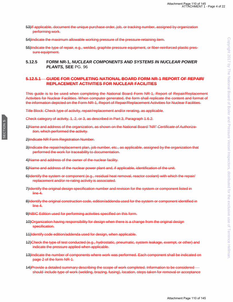
ATTACHMENT 1 - Page 4 of 22
53) If applicable, document the unique purchase order, job, or tracking number, assigned by organization performing work.
54) Indicate the maximum allowable working pressure of the pressure-retaining item.
55) Indicate the type of repair, e.g., welded, graphite pressure equipment, or fiber-reinforced plastic pres- sure equipment.
5.12.5 FORM NR-1, NUCLEAR COMPONENTS AND SYSTEMS IN NUCLEAR POWER PLANTS, SEE PG. 96
5.12.5.1 GUIDE FOR COMPLETING NATIONAL BOARD FORM NR-1 REPORT OF REPAIR/
REPLACEMENT ACTIVITIES FOR NUCLEAR FACILITIES
This guide is to be used when completing the National Board Form NR-1, Report of Repair/Replacement Activities for Nuclear Facilities. When computer generated, the form shall replicate the content and format of the information depicted on the Form NR-1, Report of Repair/Replacement Activities for Nuclear Facilities.
Title Block: Check type of activity, repair/replacement and/or rerating, as applicable.
Check category of activity, 1, 2, or 3, as described in Part 3, Paragraph 1.6.2.
1) Name and address of the organization, as shown on the National Board "NR" Certificate of Authoriza- tion, which performed the activity.
2)Indicate NR Form Registration Number.
3) Indicate the repair/replacement plan, job number, etc., as applicable, assigned by the organization that performed the work for traceability to documentation.
4)Name and address of the owner of the nuclear facility.
5)Name and address of the nuclear power plant and, if applicable, identification of the unit.
6) Identify the system or component (e.g., residual heat removal, reactor coolant) with which the repair/ replacement and/or re-rating activity is associated.
7) Identify the original design specification number and revision for the system or component listed in line 4.
8) Identify the original construction code, edition/addenda used for the system or component identified in line 4.
9)NBIC Edition used for performing activities specified on this form.
10) Organization having responsibility for design when there is a change from the original design specification.
11) Identify code edition/addenda used for design, when applicable.
12) Check the type of test conducted (e.g., hydrostatic, pneumatic, system leakage, exempt, or other) and indicate the pressure applied when applicable.
13) Indicate the number of components where work was performed. Each component shall be indicated on page 2 of the form NR-1.
14) Provide a detailed summary describing the scope of work completed. Information to be considered should include type of work (welding, brazing, fusing), location, steps taken for removal or acceptance
Copyright 2017 by The N
ational Board of Boiler and Pressure Vessel Inspectors, distributed for the exclusive use of Terrence Hellm
an. S
EC
TIO
N 5
Attachment Page 110 of 145
Attachment Page 110 of 145

ATTACHMENT 1 - Page 5 of 22
of defects, examinations, testing, heat treat, and other special processes or methods utilized. If Nec- essary, attach additional data, sketch, drawing, Form R-4, etc. In the remarks section state if additional data is attached.
15) Indicate any additional information pertaining to the work, including manufacturer's data reports.
16) Number in sequence beginning with No. 1 to identify each component work was performed. This number may be used to correspond with the detailed description of work performed.
17) Identify the type of item. i.e. piping, pump, valve, etc.
18) Identify the manufacturer's name of component.
19) Identify the manufacturer's serial no. or other assigned number for traceability.
20) Identify the National Board registration number, if previously assigned.
21) Identify the code class criteria, as assigned for each component.
22) Identify the code section used to perform work.
23) Identify Code section year and/or addenda used to perform work.
24) Identify any code cases used for work performed.
25) Identify any revisions to be made to the design specifications or if any design reconciliations were performed.
26) Type or print name of authorized representative from the certificate holder.
27) Name of the organization that performed the identified work, using the full name as shown on the Certif- icate of Authorization, or an abbreviation acceptable to the National Board.
28) Indicate code section as applicable to the repair/replacement activity and/or re-rating activity performed.
29) Indicate National Board Certificate of Authorization number.
30) Indicate month, day, and year the certificate expires.
31) Signature of authorized representative from the NR certificate holder.
32) Indicate month, day and year of signature by the Authorized Representative
33) Title of authorized representative as defined in the Quality Program.
34) Type or print name of Authorized Nuclear Inspector.
35) Indicate the Jurisdiction where the activity is performed, when required.
36) Indicate Authorized Nuclear Inspector's employer.
37) Indicate month, day, and year of inspection by the Authorized Nuclear Inspector.
38) Signature of Authorized Nuclear Inspector.
39) Indicate month, day, and year of signature by the Authorized Nuclear Inspector.
40) National Board Commission number and required endorsements.
Copyright 2017 by The N
ational Board of Boiler and Pressure Vessel Inspectors, distributed for the exclusive use of Terrence Hellm
an.
SE
CT
ION
5
Attachment Page 111 of 145
Attachment Page 111 of 145

ATTACHMENT 1 - Page 6 of 22
5.12.6 FORM NVR-1, NUCLEAR PRESSURE RELIEF DEVICES, SEE PG. 99
5.12.6.1 GUIDE FOR COMPLETING NATIONAL BOARD FORM NVR-1 REPORT OF REPAIR/REPLACEMENT ACTIVITIES FOR NUCLEAR PRESSURE RELIEF DEVICES
This guide is to be used when completing the National Board Form NVR-1, Report of Repair/Replacement Activities for Nuclear Pressure Relief Devices. When computer generated, the format of the form shall replicate the type and relative location of the information depicted on the Form NVR-1, Report of Repair/Replacement Activities for Nuclear Pressure Relief Devices.
Title Block: Check type of activity, repair/replacement, as applicable.
Check category of activity, 1, 2, or 3, as described in Part 3, Paragraph 1.6.2.
1) Name and address of the organization, as shown on the National Board "VR" and "NR" Certificates of Authorization, which performed the activity.
2)Indicate NVR Form Registration Number.
3) Indicate the repair/replacement plan number, job number, etc., as applicable for traceability, assigned by the organization that performed the work
4) Name and address of the organization for which the work was performed. 5)
Name and address of the owner nuclear facility.
6) Name and address of the nuclear facility and, if applicable, identification of the unit.
7) Identify the edition, addenda, and as applicable, code cases of the code used for the inservice inspec- tion activity.
8) Identify the edition, addenda, and as applicable, code cases of the code used for the repair/replacement activity.
9)Identify the NBIC edition used for the repair/replacement activity
10) Identify the organization responsible for design or design reconciliation, if applicable.
11) Indicate the set pressure of the valve.
12) Indicate the blowdown, if applicable, as a percentage of set pressure.
13) Indicate the location of testing.
14) Indicate medium (steam, air, etc.) used for the adjustment of the set pressure and, if applicable, blowdown.
15) Provide a detailed summary describing the scope of work completed. Information to be considered should include type of work (welding, brazing, fusing), location, steps taken for removal or acceptance of defects, examinations, testing, heat treat, and other special processes or methods utilized. If Neces- sary, attach additional data, sketch, drawing, Form R-4, etc. If additional data is attached, so state in the remarks section.
16) Indicate any additional information pertaining to the work, such as, additional documentation that is attached to this form to further support item 15.
17) Manufacturer's name of the affected item.
Copyright 2017 by The N
ational Board of Boiler and Pressure Vessel Inspectors, distributed for the exclusive use of Terrence Hellm
an. S
EC
TIO
N 5
Attachment Page 112 of 145
Attachment Page 112 of 145

ATTACHMENT 1 - Page 7 of 22
18) Describe the type of pressure relief device (e.g., safety valve, safety relief valve, pressure relief valve).
19) Manufacturer's serial number of the affected item.
20) National Board number, if applicable, of the affected item.
21) Indicate the service as steam, liquid, air/gas, etc.
22) Indicate the pressure relief device by inlet size, in inches.
23) Indicate the year the affected item was manufactured.
24) Indicate the name, section and division of the original construction code for the affected item.
25) Indicate the code class for the affected item as applicable, i.e. Class 1, 2 or 3.
26) Indicate the construction code edition for the affected item.
27) Indicate the construction code addenda, as applicable, for the affected item. 28)
Indicate any applicable code cases used for manufacturing of the affected item. 29)
Name of the replacement part.
30) Identifying number of the replacement part.
31) Number/quantity of each replacement part used.
32) Indicate the Serial number or other traceability used by the manufacturer of the replacement part.
33) Type or print name of authorized representative from the certificate holder.
34) Indicate code as applicable to the repair/replacement activity performed.
35) Indicate National Board Certificate of Authorization number, if applicable for the "VR" Stamp.
36) Indicate month, day, and year the certificate expires, if applicable for the "VR" Stamp.
37) Indicate National Board Certificate of Authorization number, if applicable for the "NR" Stamp.
38) Indicate month, day, and year the certificate expires, if applicable for the "NR" Stamp.
39) Signature of authorized representative from the certificate holder defined in item 27 above.
40) Indicate month, day, and year of signature by the authorized representative.
41) Title of authorized representative as defined in the Quality Program.
42) Type or print name of Authorized Nuclear Inspector.
43) Indicate the Jurisdiction where the activity is performed, when required.
44) Indicate Authorized Nuclear Inspector's employer.
45) Indicate address of Authorized Nuclear Inspector's employer (city and state or province).
46) Indicate month, day, and year of inspection by the Authorized Nuclear Inspector.
47) Signature of Authorized Nuclear Inspector defined in item 42 above.
48) Indicate month, day, and year of signature by the Authorized Nuclear Inspector.
49) National Board Commission number and required endorsements.
Copyright 2017 by The N
ational Board of Boiler and Pressure Vessel Inspectors, distributed for the exclusive use of Terrence Hellm
an.
SE
CT
ION
5
Attachment Page 113 of 145
Attachment Page 113 of 145

ATTACHMENT 1 - Page 8 of 22 5.13 INSTRUCTIONS FOR COMPLETING NATIONAL BOARD FORM “R”, “NR”, and “NVR”
REPORTS
The current National Board Form "R", “NR”, and “NVR” Reports, and the instructions for completing them, can be found on the National Board website: https://www.nationalboard.org. . When computer generated, the format of the form shall replicate the type and relative location of the information depicted on the example Form "R", “NR”, and “NVR” Reports shown in NBIC Part 3, 5.12.1 through 5.12.6.
Attachment Page 114 of 145
Attachment Page 114 of 145
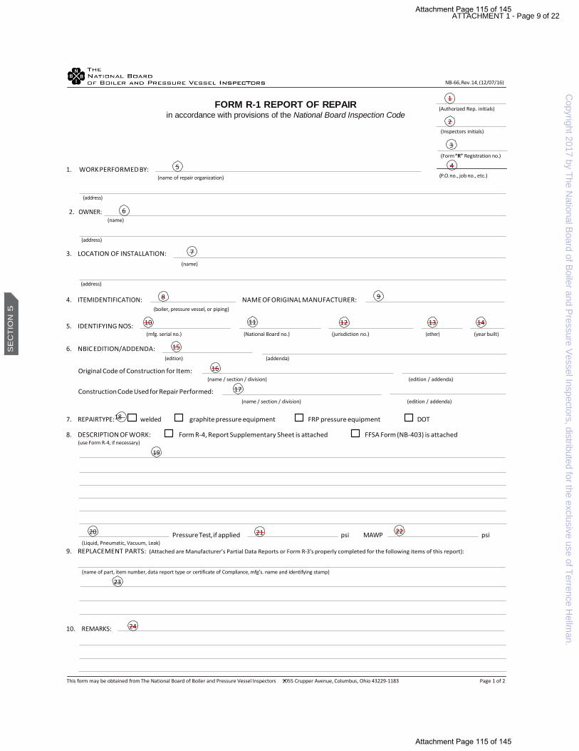
8
ATTACHMENT 1 - Page 9 of 22
FORM R-1 REPORT OF REPAIR in accordance with provisions of the National Board Inspection Code
(Inspectors initials)
(Form “R” Registration no.)
1. WORK PERFORMED BY:
(name of repair organization)
(P.O. no., job no., etc.)
(address)
2. OWNER:
(name)
(address)
3. LOCATION OF INSTALLATION:
(name)
(address)
4. ITEMIDENTIFICATION: NAME OF ORIGINAL MANUFACTURER: (boiler, pressure vessel, or piping)
5. IDENTIFYING NOS:
(mfg. serial no.) (National Board no.) (jurisdiction no.) (other) (year built)
6. NBIC EDITION/ADDENDA:
(edition) (addenda)
Original Code of Construction for Item:
(name / section / division) (edition / addenda)
Construction Code Used for Repair Performed:
(name / section / division) (edition / addenda)
7. REPAIRTYPE:18 welded graphite pressure equipment FRP pressure equipment DOT
8. DESCRIPTION OF WORK: Form R-4, Report Supplementary Sheet is attached FFSA Form (NB-403) is attached (use Form R-4, if necessary)
(Liquid, Pneumatic, Vacuum, Leak)
9. REPLACEMENT PARTS: (Attached are Manufacturer’s Partial Data Reports or Form R-3’s properly completed for the following items of this report):
(name of part, item number, data report type or certificate of Compliance, mfg’s. name and identifying stamp)
10. REMARKS:
This form may be obtained from The National Board of Boiler and Pressure Vessel Inspectors 1055 Crupper Avenue, Columbus, Ohio 43229-1183 Page 1 of 2
23
20 Pressure Test, if applied 21 psi MAWP 22 psi
19
17
16
15
7
6
4
3
NB-66, Rev. 14, (12/07/16)
5
9
10 11 12 13 14
24
2
1 (Authorized Rep. initials)
Copyright 2017 by The N
ational Board of Boiler and Pressure Vessel Inspectors, distributed for the exclusive use of Terrence Hellm
an. S
EC
TIO
N 5
Attachment Page 115 of 145
Attachment Page 115 of 145

4
ATTACHMENT 1 - Page 10 of 22
(Form “R” Registration no.)
(P.O. no., job no., etc.)
CERTIFICATE OF COMPLIANCE
I, 25 , certify that to the best of my knowledge and belief the statements made in this report are correct and that all material, construction, and workmanship on this Repair conforms to the National Board Inspection Code. National Board “R” Certificate of Authorization No. 26 expires on 27 , Date 28 , 29 Signed 30
(name of repair organization) (authorized representative)
CERTIFICATE OF INSPECTION
I, 31 , holding a valid commission issued by the National Board of Boiler and Pressure Vessel Inspectors and certificate of competency, where required, issued by the Jurisdiction of 32 and employed by
33 of 34 have inspected the work described in this report on 35 , and state that to the best of my knowledge and belief, this work complies with the applicable requirements of the National Board Inspection Code. By signing this certificate, neither the undersigned nor my employer makes any warranty, expressed or implied, concerning the work described in this report. Furthermore, neither the undersigned nor my employer shall be liable in any manner for any personal injury, property damage, or loss of any kind arising from or connected with this inspection. Date 36 Signed 37 38
(inspector) (National Board and Jurisdiction no. including endorsement)
NB-66, Rev. 14, (12/07/16)
3 Copyright 2017 by The N
ational Board of Boiler and Pressure Vessel Inspectors, distributed for the exclusive use of Terrence Hellm
an.
SE
CT
ION
5
Attachment Page 116 of 145
Attachment Page 116 of 145

ATTACHMENT 1 - Page 11 of 22
FORM R-2 REPORT OF ALTERATION in accordance with provisions of the National Board Inspection Code
(Authorized Rep. initials)
(Inspectors initials)
1a. DESIGN PERFORMED BY:
(name of“R” organization responsible fordesign)
(Form “R” Registration no.)
(P.O. no., job no., etc.)
(address)
1b. CONSTRUCTION PERFORMED BY: (name of “R” organization responsible for construction)
(address)
2. OWNER OF PRESSURE RETAINING ITEM: (name)
(address)
3. LOCATION OF INSTALLATION: (name)
(address)
4. ITEM IDENTIFICATION: NAME OF ORIGINAL MANUFACTURER: (boiler, pressure vessel, or piping)
5. IDENTIFYING NOS:
(mfg. serial no.) (National Board no.) (jurisdiction no.) (other) (year built)
6. NBIC EDITION/ADDENDA: (edition) (addenda)
Original Code of Construction for Item: (name / section / division) (edition / addenda)
Construction Code Used for Alteration Performed: (name / section / division) (edition / addenda)
7a. DESCRIPTION OF DESIGN SCOPE: Form R-4, Report Supplementary Sheet is attached
7b. DESCRIPTION OF CONSTRUCTION SCOPE: Form R-4, Report Supplementary Sheet is attached
Pressure Test, if applied psi MAWP psi
NB-229, Rev. 8, (12/07/16)
Copyright 2017 by The N
ational Board of Boiler and Pressure Vessel Inspectors, distributed for the exclusive use of Terrence Hellm
an. S
EC
TIO
N 5
Attachment Page 117 of 145
Attachment Page 117 of 145

ATTACHMENT 1 - Page 12 of 22
(Form “R” Registration no.)
(P.O. no., job no., etc.)
8. REPLACEMENT PARTS: (Attached are Manufacturer’s Partial Data Reports or Form R-3’s properly completed for the following items of this report):
(name of part, item number, data report type or Certificate of Compliance, mfg’s. name and identifying stamp)
9. REMARKS:
DESIGN CERTIFICATION
I, , certify that to the best of my knowledge and belief the statements in this report are correct and that the Design Change described in this report conforms to the National Board Inspection Code. National Board “R” Certificate of Authorization No. expires on Date , Signed
(name of design organization) (authorized representative)
CERTIFICATE OF DESIGN CHANGE REVIEW
I, , holding a valid Commission issued by The National Board of Boiler and Pressure Vessel Inspector and certificate of competency, where required, issued by the jurisdiction of and employed by of have reviewed the design change as described in this report and state that to the best of my knowledge and belief such change complies with the applicable requirements of the National Board Inspection Code. By signing this certificate, neither the undersigned nor my employer makes any warranty, expressed or implied, concerning the work described in this report. Furthermore, neither the undersigned nor my employer shall be liable in any manner for any personal injury, property damage or loss of any kind arising from or connected with this inspection. Date Signed Commissions
(inspector) (National Board and jurisdiction no. including endorsement)
CONSTRUCTION CERTIFICATION
I, , certify that to the best of my knowledge and belief the statements in this report are correct and that all material, construction, and workmanship on this Alteration conforms to the National Board Inspection Code. National Board “R” Certificate of Authorization No. expires on Date , Signed
(name of alteration organization) (authorized representative)
CERTIFICATE OF INSPECTION
I, , holding a valid commission issued by the National Board of Boiler and Pressure Vessel Inspectors and certificate of competency, where required, issued by the Jurisdiction of and employed by of have inspected the work described in this report on , and state that to the best of my knowledge and belief, this work complies with the applicable requirements of the National Board Inspection Code. By signing this certificate, neither the undersigned nor my employer makes any warranty, expressed or implied, concerning the work described in this report. Furthermore, neither the undersigned nor my employer shall be liable in any manner for any personal injury, property damage, or loss of any kind arising from or connected with this inspection. Date Signed
(inspector) (National Board and jurisdiction no. including endorsement)
NB-229, Rev. 8, (12/07/16)
Copyright 2017 by The N
ational Board of Boiler and Pressure Vessel Inspectors, distributed for the exclusive use of Terrence Hellm
an.
SE
CT
ION
5
Attachment Page 118 of 145
Attachment Page 118 of 145

7
5
ATTACHMENT 1 - Page 13 of 22
FORM R-3 REPORT OF PARTS FABRICATED BY WELDING in accordance with provisions of the National Board Inspection Code
(Authorized Rep. initials)
(Inspectors initials)
1. MANUFACTURED BY:
(name of “NR” certificate holder)
(Form “R-3” Registration no.)
(P.O. no., job no., etc.)
(address)
2. MANUFACTURED FOR: (name)
(address)
3. DESIGN CONDITION SPECIFIED BY: CODE DESIGN BY:
4. DESIGN CODE:
5. REPAIR/ALTERATION/MODIFICATION ACTIVITIES
Name of Part
Qty. Line No.
Manufacturer’s Identifying No.
Manufacturer’s Drawing No.
MAWP Shop Hydro PSI
Year Built
13 14 15 16 17 18 19 20
6. DESCRIPTION OF PARTS
(a) Connections other than tubes
Heads or Ends
(b) Tubes
Line No.
Size and Shape
Material Spec. No.
Thickness (in.)
Shape Thickness (in.)
Material Spec. No.
Diameter (in.)
Thickness (in.)
Material Spec. No.
15 21 22 23 24 25 26 27 28 29
7. REMARKS:
3
2
NB-230, Rev. 4 (12/08/16)
4
6
8
9 10 11 12
30
1
Copyright 2017 by The N
ational Board of Boiler and Pressure Vessel Inspectors, distributed for the exclusive use of Terrence Hellm
an. S
EC
TIO
N 5
Attachment Page 119 of 145
Attachment Page 119 of 145

5
ATTACHMENT 1 - Page 14 of 22
(Form “R-3” Registration no.)
(P.O. no., job no., etc.)
CERTIFICATE OF COMPLIANCE
I, 31 , certify that to the best of my knowledge and belief the statements made in this report are correct and that all material, fabrication, construction, and workmanship of the described parts conforms to the National Board Inspection Code and the standards of construction cited.
National Board“R”Certificate of Authorization No. 32 expires on: 33 ,
Date 34 , 35 Signed 36 (name of “R” Certificate holder) (Authorized Representative)
CERTIFICATE OF INSPECTION
I, 37 , holding a valid commission issued by the National Board of Boiler and Pressure Vessel Inspectors and certificate of competency, where required, issued by the Jurisdiction of 38 and employed by
39 of 40 have inspected the part described in this report on 41 , and state that to the best of my knowledge and belief the parts comply with the applicable requirements of the National Board Inspection Code.
By signing this certificate, neither the undersigned nor my employer makes any warranty, expressed or implied, concerning the work described in this report. Furthermore, neither the undersigned nor my employer shall be liable in any manner for any personal injury, property damage, or loss of any kind arising from or connected with this inspection. Date 42 , Signed 43 Commissions 44
(inspector) (National Board and jurisdiction No. including endorsement)
NB-230, Rev. 4 (12/08/16)
3 Copyright 2017 by The N
ational Board of Boiler and Pressure Vessel Inspectors, distributed for the exclusive use of Terrence Hellm
an.
SE
CT
ION
5
Attachment Page 120 of 145
Attachment Page 120 of 145

10
13
ATTACHMENT 1 - Page 15 of 22
FORM R-4 REPORT SUPPLEMENT SHEET in accordance with provisions of the National Board Inspection Code
1. WORK PERFORMED BY:
(name)
(P.O. no., job no., etc.)
(address)
2. OWNER:
(name)
(address)
3. LOCATION OF INSTALLATION:
(name)
(address)
REFERENCE LINE NO. CONTINUED FROM FORM R– 6
Date 9
Date 12
, Signed Name
(authorized representative) (Name of “R” certificate holder)
, Signed Commissions (inspector) (National Board and jurisdiction no. including endorsement)
8 7
5
4
(form “R” referenced) 2
1
NB-231, Rev. 3, (12/08/16)
3
11
14
Copyright 2017 by The N
ational Board of Boiler and Pressure Vessel Inspectors, distributed for the exclusive use of Terrence Hellm
an. S
EC
TIO
N 5
Attachment Page 121 of 145
Attachment Page 121 of 145

ATTACHMENT 1 - Page 16 of 22
FORM NR-1, REPORT OF REPAIR/REPLACEMENT ACTIVITIES FOR NUCLEAR FACILITIES
CATEGORY OF ACTIVITY: 1 2 3
REPAIR/REPLACEMENT RE-RATING
1. WORK PERFORMED BY:
(R/R Plan No., Job No., etc.)
(name of “NR” certificate holder)
(address)
2. OWNER: (name)
(address)
3. NAME, ADDRESS, AND IDENTIFICATION OF NUCLEAR FACILITY:
(name)
(address)
(unit identification)
4. SYSTEM/COMPONENT:
5 ORIGINAL DESIGN SPECIFICATION NO./REV.:
5. CONSTRUCTION CODE, SECTION & EDITION/ADDENDA AND APPLICABLE CODE CASES USED FOR THE SYSTEM OR COMPONENT: 8
6. NBIC EDITION USED FOR PERFORMING REPAIRS/REPLACEMENT OR RE-RATING ACTIVITY: 9
7. DESIGN RESPONSIBILITY: 10 CODE ED/AD:
8. TESTS CONDUCTED: Hydrostatic Pneumatic System Leakage Pressure psi (MPa) 12 Exempt Other
9. NUMBER OF COMPONENTS REPAIRED/REPLACED AND/OR RE-RATED (refer to page 2): 13
10. DESCRIPTION OF WORK (use of properly identified additional sheet[s] or sketch[es] is acceptable):
11. REMARKS:
This form may be obtained from The National Board of Boiler and Pressure Vessel Inspectors 1055 Crupper Avenue, Columbus, Ohio 43229-1183 Page 1 of 3
14
NB-81, Rev. 8, (03/30/17)
6 7
11
1
4
15
2 (NR Form Registration No.)
3
Copyright 2017 by The N
ational Board of Boiler and Pressure Vessel Inspectors, distributed for the exclusive use of Terrence Hellm
an.
SE
CT
ION
5
Attachment Page 122 of 145
Attachment Page 122 of 145

ATTACHMENT 1 - Page 17 of 22
WORK PERFORMED BY: 1
(Name of “NR” certificate holder)
(Address of “NR” certificate holder)
COMPONENT IDENTIFICATION
No. Type of Item
Mfg. Name
Serial No. Nat’l Bd No.
Code Class
Code Section
Year/ Addenda
Code Case
Revised Design Specification No./Rev. or Design Reconciliation No./Rev.
16
17
18
19
20
21
22
23
24
25
ATTACHMENT 1 - Page 17 of 22
SECTION 5
20
17
N
AT
ION
AL B
OA
RD
INS
PE
CT
ION
CO
DE
NB-81, Rev. 8, (03/30/17)
2 (N
R Form Registration No.)
3 (R/R Plan No., Job No., etc.)
This form m
ay be obtained from The National Board of Boiler and Pressure Vessel Inspectors
1055 Crupper Avenue, Columbus, O
hio 43229-1183 Page 2 of 3
97
S
EC
TIO
N 5
Attachment Page 123 of 145
Attachment Page 123 of 145

ATTACHMENT 1 - Page 18 of 22 Attachment Page 124 of 145
Attachment Page 124 of 145

ATTACHMENT 1 - Page 19 of 22
(NR Form Registration No.)
(R/R Plan No., Job No., etc.)
This form may be obtained from The National Board of Boiler and Pressure Vessel Inspectors 1055 Crupper Avenue, Columbus, Ohio 43229-1183 Page 3 of 3
CERTIFICATE OF COMPLIANCE
I, 26 , employed by 27 certify that to the best of my knowledge and belief the statements made in this report are correct and the repair/replacement activities or re-rating described above conform to 28 and the National Board Inspection Code“NR”rules.
National Board Certificate of Authorization No. 29 Expiration date: 30
Signed: 31 Date: 32
Title: 33 (authorized representative)
CERTIFICATE OF INSPECTION
I, 34 , holding a valid commission issued by the National Board of Boiler and Pressure Vessel Inspectors and certificate of competency, where required, issued by the Jurisdiction of 35 and employed by 36 have inspected the repair/replacement and/or re-rating activities described in this report on 37 and state that to the best of my knowledge and belief, these activities have been completed in accordance with the Code specified and the National Board Inspection Code “NR” rules.
By signing this certificate, neither the undersigned nor my employer makes any warranty, expressed or implied, concerning the work described in this report. Furthermore, neither the undersigned nor my employer shall be liable in any manner for any personal injury, property damage, or loss of any kind arising from or connected with this inspection.
Signed: 38 Date: 39 Commissions 40 (inspector) (National Board and endorsement)
NB-81, Rev. 8, (03/30/17)
Copyright 2017 by The N
ational Board of Boiler and Pressure Vessel Inspectors, distributed for the exclusive use of Terrence Hellm
an.
SE
CT
ION
5
Attachment Page 125 of 145
Attachment Page 125 of 145

11
13
2
ATTACHMENT 1 - Page 20 of 22
FORM NVR-1, REPORT OF REPAIR/REPLACEMENT ACTIVITIES FOR NUCLEAR PRESSURE RELIEF DEVICES
CATEGORY OF ACTIVITY: 1 2 3
REPAIR/REPLACEMENT RE-RATING
1. WORK PERFORMED BY:
(R/R Plan No., Job No., etc.)
(name of “NVR” authorized organization )
(address)
2. WORK PERFORMED FOR: (name)
(address)
3. OWNER: (name)
(address)
4. NAME, ADDRESS, AND IDENTIFICATION OF NUCLEAR FACILITY: (name)
(address)/ (unit identification)
5. CODE APPLICABLE FOR INSERVICE INSPECTION:
6. CODE USED FOR REPAIR/REPLACEMENT ACTIVITY:
7. NBIC USED FOR REPAIR/REPLACEMENT ACTIVITY:
8. DESIGN RESPONSIBILITY:
(edition) (addenda) (code case(s))
(edition) (addenda) (code case(s))
(edition)
9. REPAIRED PRESSURE RELIEF DEVICE: SEE PAGE 2
10. OPENING PRESSURE: BLOWDOWN (if applicable):
11. SET PRESSURE AND BLOWDOWN ADJUSTMENT MADE AT: USING:
12. DESCRIPTION OF WORK: (include name and identifying number of replacement parts):
12.
This form may be obtained from The National Board of Boiler and Pressure Vessel Inspectors 1055 Crupper Avenue, Columbus, Ohio 43229-1183 Page 1 of 3
15
9
NB-160, Rev. 8, (03/30/17)
1
4
5
6
7
8
10
12
14
REMARKS: 16
(NVR Form Registration No.) 3
Copyright 2017 by The N
ational Board of Boiler and Pressure Vessel Inspectors, distributed for the exclusive use of Terrence Hellm
an. S
EC
TIO
N 5
Attachment Page 126 of 145
Attachment Page 126 of 145

This form m
ay be obtained from The National Board of Boiler and Pressure Vessel Inspectors 1055 Crupper Avenue, Colum
bus, Ohio 43229-1183
ATTACHMENT 1 - Page 21 of 22
WORK PERFORMED BY: 1
(Name of “NR” certificate holder)
(Address of “NR” certificate holder)
PRESSURE RELIEF DEVICE
Name of Mfg. Type Mfg. Serial No. Nat’l Bd No. Service Size Year Built
17
18
19
20
21
22
23
CONSTRUCTION CODE
Section Class Edition Addenda Code Case(s)
24
25
26
27
28
NAME AND IDENTIFYING NUMBER OF REPLACEMENT PARTS
No. Part Name Part Number Quantity Serial Number/Traceability No.
1. 29 30 31 32
2.
3.
4.
5.
6.
7.
ATTACHMENT 1 - Page 21 of 22 SECTION 5
NB
-23
2
01
7
NB-160, Rev. 8, (03/30/17)
2 (N
R Form Registration No.)
3 (R/R Plan No., Job No., etc.)
Page 2 of 3
SE
CT
ION
5 1
00
Attachment Page 127 of 145
Attachment Page 127 of 145

ATTACHMENT 1 - Page 22 of 22
(form “NVR” registration no.)
(R/R Plan No., Job No., etc.)
This form may be obtained from The National Board of Boiler and Pressure Vessel Inspectors 1055 Crupper Avenue, Columbus, Ohio 43229-1183 Page 3 of 3
ATTACHMENT 1 - Page 22 of 22
CERTIFICATE OF COMPLIANCE
I, 33 , certify that to the best of my knowledge and belief the statements made in this report are correct and the repair/replacement of the pressure relief devices described above conform to NationalBoardInspectionCode“VR”&“NR”rules.
34 and the
National Board Certificate of Authorization No. National Board Certificate of Authorization No.
35
37 Date 39 Signed 40
(authorized representative)
to use the“VR” stamp expires to use the“NR” stamp expires
41 (title)
36
38
CERTIFICATE OF INSPECTION
I, 42 , holding a valid commission issued by the National Board of Boiler and Pressure Vessel Inspectors and certificate of competency, where required, issued by the Jurisdiction of 43 and employed by
44 have inspected the repair/replacement described in this report on
of 45 46 and state that to the best of my
knowledge and belief, this repair/replacement has been completed in accordance with the Code specified and the National Board Inspection Code “VR” & “NR” rules. By signing this certificate, neither the undersigned nor my employer makes any warranty, expressed or implied, concerning the repair/ replacement described in this report. Furthermore, neither the undersigned nor my employer shall be liable in any manner for any personal injury, property damage, or loss of any kind arising from or connected with this inspection. Signed 47
(inspector) Date 48 49
(National Board and endorsement)
NB-160, Rev. 8, (03/30/17)
Copyright 2017 by The N
ational Board of Boiler and Pressure Vessel Inspectors, distributed for the exclusive use of Terrence Hellm
an. S
EC
TIO
N 5
Attachment Page 128 of 145
Attachment Page 128 of 145
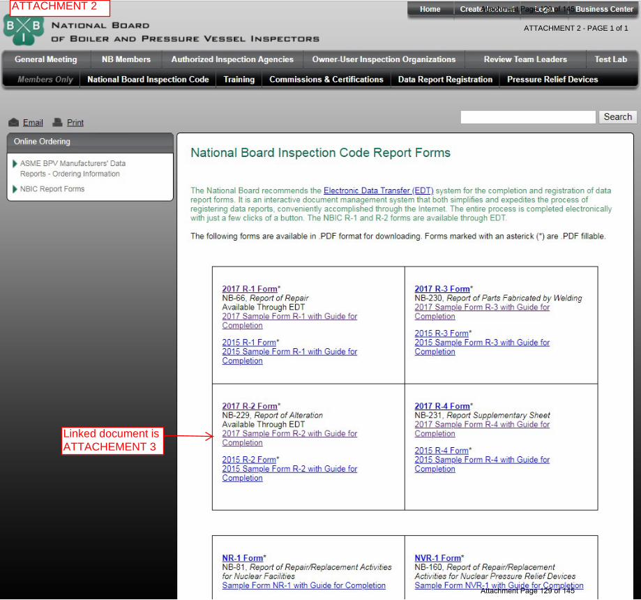
ATTACHMENT 2
ATTACHMENT 2 - PAGE 1 of 1
Linked document is ATTACHEMENT 3
Attachment Page 129 of 145
Attachment Page 129 of 145

ATTACHMENT 2 - PAGE 1 of 1 Attachment Page 130 of 145
Attachment Page 130 of 145
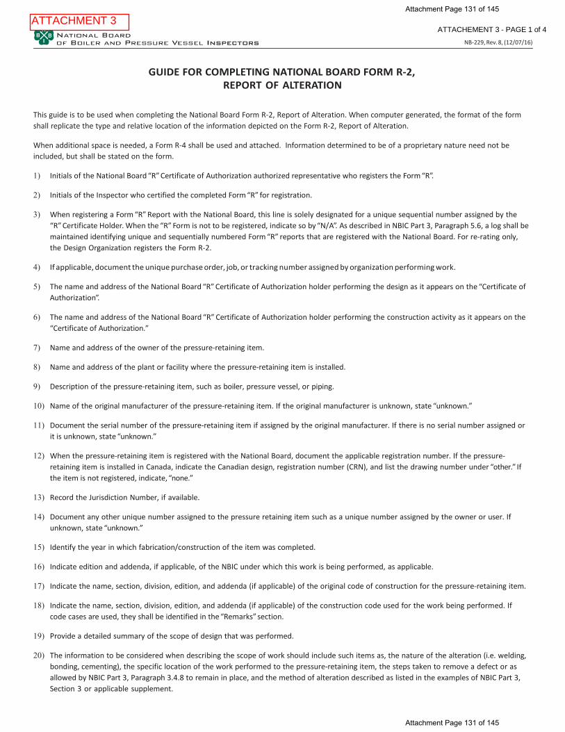
GUIDE FOR COMPLETING NATIONAL BOARD FORM R-2, REPORT OF ALTERATION
This guide is to be used when completing the National Board Form R-2, Report of Alteration. When computer generated, the format of the form shall replicate the type and relative location of the information depicted on the Form R-2, Report of Alteration.
When additional space is needed, a Form R-4 shall be used and attached. Information determined to be of a proprietary nature need not be included, but shall be stated on the form.
1) Initials of the National Board “R” Certificate of Authorization authorized representative who registers the Form “R”.
2) Initials of the Inspector who certified the completed Form “R” for registration.
3) When registering a Form “R” Report with the National Board, this line is solely designated for a unique sequential number assigned by the
“R” Certificate Holder. When the “R” Form is not to be registered, indicate so by “N/A”. As described in NBIC Part 3, Paragraph 5.6, a log shall be maintained identifying unique and sequentially numbered Form “R” reports that are registered with the National Board. For re-rating only, the Design Organization registers the Form R-2.
4) If applicable, document the unique purchase order, job, or tracking number assigned by organization performing work.
5) The name and address of the National Board “R” Certificate of Authorization holder performing the design as it appears on the “Certificate of
Authorization”.
6) The name and address of the National Board “R” Certificate of Authorization holder performing the construction activity as it appears on the “Certificate of Authorization.”
7) Name and address of the owner of the pressure-retaining item.
8) Name and address of the plant or facility where the pressure-retaining item is installed.
9) Description of the pressure-retaining item, such as boiler, pressure vessel, or piping.
10) Name of the original manufacturer of the pressure-retaining item. If the original manufacturer is unknown, state “unknown.”
11) Document the serial number of the pressure-retaining item if assigned by the original manufacturer. If there is no serial number assigned or
it is unknown, state “unknown.”
12) When the pressure-retaining item is registered with the National Board, document the applicable registration number. If the pressure- retaining item is installed in Canada, indicate the Canadian design, registration number (CRN), and list the drawing number under “other.” If the item is not registered, indicate, “none.”
13) Record the Jurisdiction Number, if available.
14) Document any other unique number assigned to the pressure retaining item such as a unique number assigned by the owner or user. If
unknown, state “unknown.”
15) Identify the year in which fabrication/construction of the item was completed.
16) Indicate edition and addenda, if applicable, of the NBIC under which this work is being performed, as applicable.
17) Indicate the name, section, division, edition, and addenda (if applicable) of the original code of construction for the pressure-retaining item.
18) Indicate the name, section, division, edition, and addenda (if applicable) of the construction code used for the work being performed. If code cases are used, they shall be identified in the “Remarks” section.
19) Provide a detailed summary of the scope of design that was performed.
20) The information to be considered when describing the scope of work should include such items as, the nature of the alteration (i.e. welding,
bonding, cementing), the specific location of the work performed to the pressure-retaining item, the steps taken to remove a defect or as allowed by NBIC Part 3, Paragraph 3.4.8 to remain in place, and the method of alteration described as listed in the examples of NBIC Part 3, Section 3 or applicable supplement.
ATTACHMENT 3 ATTACHEMENT 3 - PAGE 1 of 4
NB-229, Rev. 8, (12/07/16)
Attachment Page 131 of 145
Attachment Page 131 of 145

21) Indicate the type of Pressure test performed (Liquid, Pneumatic, Vacuum)
22) Indicate test pressure applied.
23) Indicate the maximum allowable working pressure of the part. (As altered)
24) As applicable, identify which parts manufactured by welding or bonding were introduced as needed to complete the scope of work. Indi- cate part, item number, manufacturer’s name, stamped identification, and data report type or Certificate of Compliance.
25) Indicate any additional information pertaining to the work involved (e.g., routine repairs, code cases, interpretations used).
26) Type or print name of the National Board “R” Certificate of Authorization authorized representative responsible for design certification.
27) Indicate National Board “R” Certificate or Authorization number.
28) Indicate month, day, and year the National Board “R” Certificate of Authorization expires.
29) Indicate the date the alteration was certified.
30) Record the name of National Board “R” Certificate of Authorization holder who performed the described work, using full name as shown on
the “Certificate of Authorization” or an abbreviation acceptable to the National Board.
31) Signature of National Board “R” Certificate of Authorization authorized representative.
32) Type or print the name of Inspector certifying the design review.
33) Indicate the Inspector’s Jurisdiction.
34) Indicate the Inspector’s employer; also indicate the address of the Inspector’s employer (city and state or province).
35) Indicate the month, day and year of the design certification by the Inspector.
36) Signature of the Inspector certifying the design review.
37) Inspectors National Board commission number and endorsement that qualifies the Inspector to sign this report, and when required by the Jurisdiction, the applicable State or Provincial numbers.
38) Type or print name of the National Board “R” Certificate of Authorization authorized representative responsible for any construction.
39) Indicate the National Board “R” Certificate or Authorization number.
40) Indicate month, day, and year the National Board “R” Certificate of Authorization expires.
41) Indicate the date the alteration was certified.
42) Record the name of National Board “R” Certificate of Authorization holder who performed the described work, using full name as shown on
the Certificate of Authorization or an abbreviation acceptable to the National Board.
43) Signature of National Board “R” Certificate of Authorization authorized representative
44) Type or print the name of Inspector certifying the construction inspection.
45) Indicate the Inspector’s Jurisdiction.
46) Indicate the Inspector’s employer; also indicate the address of the Inspector’s employer (city and state or province).
47) Indicate the month, day and year of the inspection by the Inspector.
48) Indicate the month, day and year the completed Form “R” was signed by the Inspector.
49) Signature of the Inspector certifying the construction inspection.
50) Inspectors National Board commission number and endorsement that qualifies the Inspector to sign this report, and when required by the Jurisdiction, the applicable State or Provincial numbers.
ATTACHEMENT 3 - PAGE 2 of 4
NB-229, Rev. 8, (12/07/16)
Attachment Page 132 of 145
Attachment Page 132 of 145
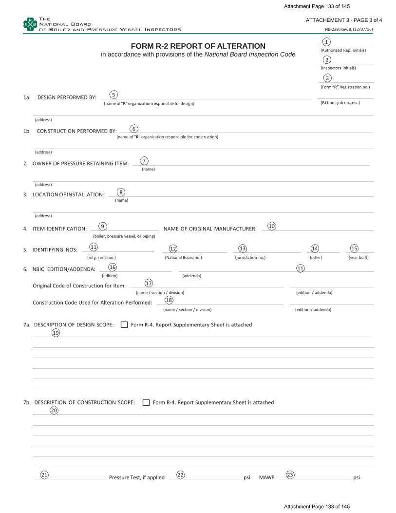
9
22 23
FORM R-2 REPORT OF ALTERATION in accordance with provisions of the National Board Inspection Code
(Authorized Rep. initials)
(Inspectors initials)
1a. DESIGN PERFORMED BY:
(name of “R” organization responsible for design)
(Form “R” Registration no.)
(P.O. no., job no., etc.)
(address)
1b. CONSTRUCTION PERFORMED BY: (name of “R” organization responsible for construction)
(address)
2. OWNER OF PRESSURE RETAINING ITEM:
(name)
(address)
3. LOCATION OF INSTALLATION:
(name)
(address)
4. ITEM IDENTIFICATION: NAME OF ORIGINAL MANUFACTURER: (boiler, pressure vessel, or piping)
5. IDENTIFYING NOS: (mfg. serial no.) (National Board no.) (jurisdiction no.) (other) (year built)
6. NBIC EDITION/ADDENDA:
(edition) (addenda)
Original Code of Construction for Item:
(name / section / division) (edition / addenda)
Construction Code Used for Alteration Performed:
(name / section / division) (edition / addenda)
7a. DESCRIPTION OF DESIGN SCOPE: Form R-4, Report Supplementary Sheet is attached 19
7b. DESCRIPTION OF CONSTRUCTION SCOPE: Form R-4, Report Supplementary Sheet is attached 20
Pressure Test, if applied psi MAWP psi
18
17
11 16
15 14 13 12
3
ATTACHEMENT 3 - PAGE 3 of 4
NB-229, Rev. 8, (12/07/16)
5
6
7
8
10
11
21
2
1
Attachment Page 133 of 145
Attachment Page 133 of 145

4
(Form “R” Registration no.)
(P.O. no., job no., etc.)
8. REPLACEMENT PARTS: (Attached are Manufacturer’s Partial Data Reports or Form R-3’s properly completed for the following items of this report):
(name of part, item number, data report type or Certificate of Compliance, mfg’s. name and identifying stamp)
9. REMARKS:
Design Certification
I, 26 , certify that to the best of my knowledge and belief the statements in this report are correct and that the Design Change described in this report conforms to the National Board Inspection Code. National Board “R” Certificate of Authorization No.
27 expires on 28 Date 29 , 30 Signed 31
(name of design organization) (authorized representative)
certificate of design change review I, 32 , holding a valid Commission issued by The National Board of Boiler and Pressure Vessel Inspector and certificate of competency, where required, issued by the jurisdiction of 33 and employed by
34 34 of have reviewed the design change as described in this report and state that to the best of my knowledge and belief such change complies with the applicable requirements of the National Board Inspection Code. By signing this certificate, neither the undersigned nor my employer makes any warranty, expressed or implied, concerning the work described in this report. Furthermore, neither the undersigned nor my employer shall be liable in any manner for any personal injury, property damage or loss of any kind arising from or connected with this inspection. Date 35 Signed 36 Commissions 37
(inspector) (National Board and jurisdiction no. including endorsement)
CONSTRUCTION CERTIFICATION
I, 38 , certify that to the best of my knowledge and belief the statements in this report are correct and that all material, construction, and workmanship on this Alteration conforms to the National Board Inspection Code. National Board “R” Certificate of Authorization No. 39 expires on 40 Date 41 , 42 Signed 43
(name of alteration organization) (authorized representative)
CERTIFICATE OF INSPECTION
I, 44 , holding a valid commission issued by the National Board of Boiler and Pressure Vessel Inspectors and certificate of competency, where required, issued by the Jurisdiction of 45 and employed by
44 of 44 have inspected the work described in this report on 46 , 47 and state that to the best of my knowledge and belief, this work complies with the applicable requirements of the National Board Inspection Code. By signing this certificate, neither the undersigned nor my employer makes any warranty, expressed or implied, concerning the work described in this report. Furthermore, neither the undersigned nor my employer shall be liable in any manner for any personal injury, property damage, or loss of any kind arising from or connected with this inspection. Date 48 Signed 49 50
(inspector) (National Board and jurisdiction no. including endorsement)
24
ATTACHEMENT 3 - PAGE 4 of 4
NB-229, Rev. 8, (12/07/16)
3
25
Attachment Page 134 of 145
Attachment Page 134 of 145

Attachment Page 135 of 145
Attachment Page 135 of 145

18-48 7/17/18
Request for NBIC Part 3, Section 2 Revision Robert V. Underwood-The Hartford Steam Boiler Inspection & Insurance Company
Purpose To clarify and revise paragraph 2.5.3(e) of NBIC Part 3 relating to Alternative Welding Methods Without Postweld Heat Treatment.
Scope: 1) Replace reference to “boiler, pressure vessel, and piping systems” with “pressureretaining items.”
2) Replace references to radiography with volumetric examination.
3) Replace the last sentence of 2.5.3(e) relating to MT/PT of final weld if RT is notpractical and re-evaluation of maximum allowable working pressure and/or designtemperature with reference to existing requirements in 4.2(a) of Part 3.
Background 1) Using “pressure retaining items” in lieu of specific items such as boilers, pressure
vessels, and piping systems is consistent with other areas of the NBIC.
2) The construction Codes were recently revised to permit UT in lieu of radiography.Replacing references to radiography in the 2.5.3(e) with volumetric examination isconsistent with other areas of the NBIC Part 3.
3) The last sentence of 2.5.3(e) is redundant and NDE requirements are alreadyaddressed in 4.2(a) of Part 3.
Proposed Revision See page 2 for proposed revisions.
Attachment Page 136 of 145
Attachment Page 136 of 145
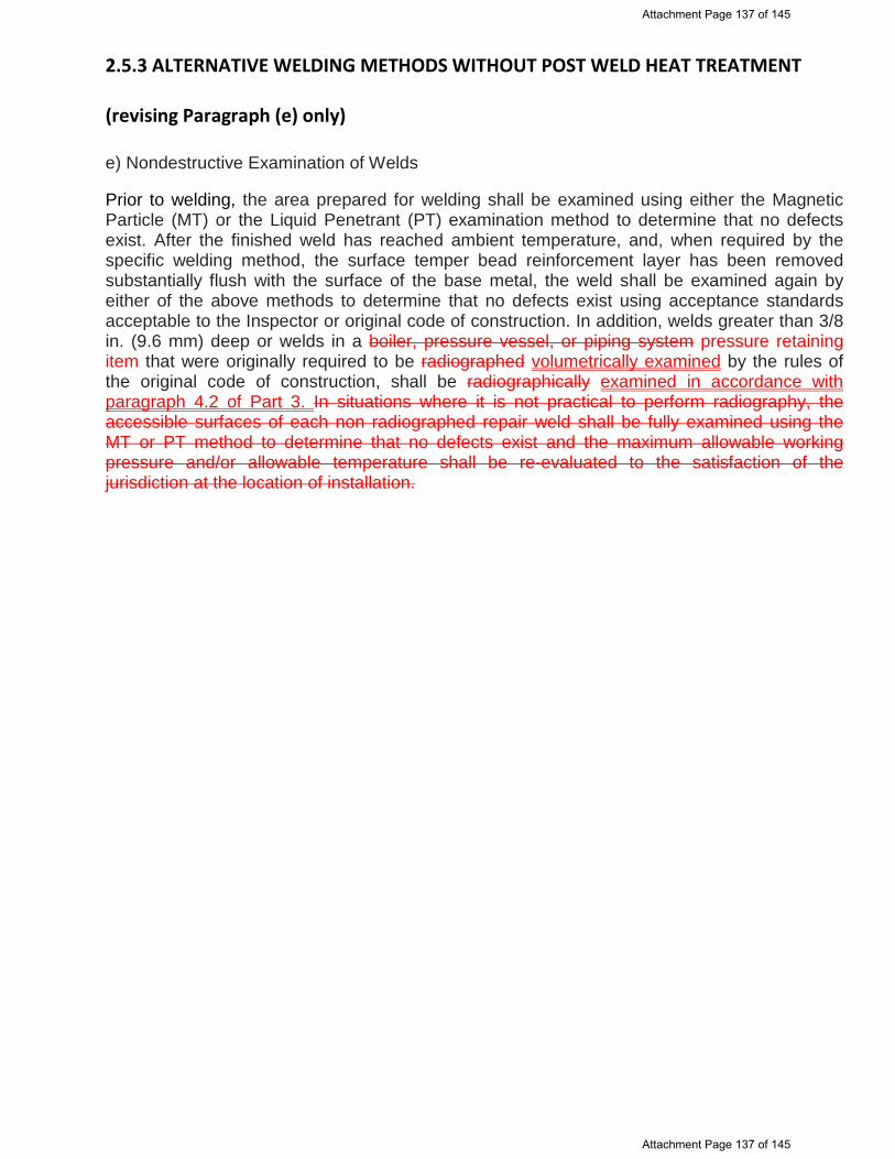
2.5.3 ALTERNATIVE WELDING METHODS WITHOUT POST WELD HEAT TREATMENT (revising Paragraph (e) only) e) Nondestructive Examination of Welds Prior to welding, the area prepared for welding shall be examined using either the Magnetic Particle (MT) or the Liquid Penetrant (PT) examination method to determine that no defects exist. After the finished weld has reached ambient temperature, and, when required by the specific welding method, the surface temper bead reinforcement layer has been removed substantially flush with the surface of the base metal, the weld shall be examined again by either of the above methods to determine that no defects exist using acceptance standards acceptable to the Inspector or original code of construction. In addition, welds greater than 3/8 in. (9.6 mm) deep or welds in a boiler, pressure vessel, or piping system pressure retaining item that were originally required to be radiographed volumetrically examined by the rules of the original code of construction, shall be radiographically examined in accordance with paragraph 4.2 of Part 3. In situations where it is not practical to perform radiography, the accessible surfaces of each non radiographed repair weld shall be fully examined using the MT or PT method to determine that no defects exist and the maximum allowable working pressure and/or allowable temperature shall be re-evaluated to the satisfaction of the jurisdiction at the location of installation.
Attachment Page 137 of 145
Attachment Page 137 of 145

Attachment Page 138 of 145
Attachment Page 138 of 145
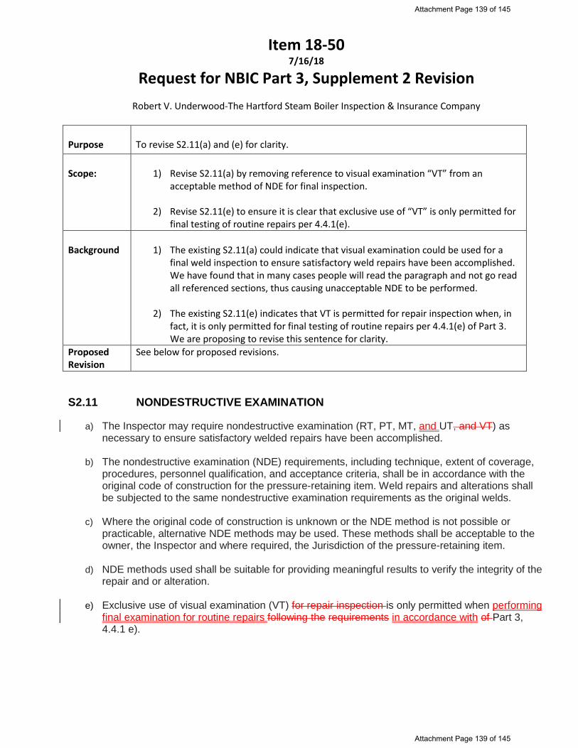
Item 18-50 7/16/18
Request for NBIC Part 3, Supplement 2 Revision Robert V. Underwood-The Hartford Steam Boiler Inspection & Insurance Company
Purpose To revise S2.11(a) and (e) for clarity.
Scope: 1) Revise S2.11(a) by removing reference to visual examination “VT” from anacceptable method of NDE for final inspection.
2) Revise S2.11(e) to ensure it is clear that exclusive use of “VT” is only permitted forfinal testing of routine repairs per 4.4.1(e).
Background 1) The existing S2.11(a) could indicate that visual examination could be used for afinal weld inspection to ensure satisfactory weld repairs have been accomplished.We have found that in many cases people will read the paragraph and not go readall referenced sections, thus causing unacceptable NDE to be performed.
2) The existing S2.11(e) indicates that VT is permitted for repair inspection when, infact, it is only permitted for final testing of routine repairs per 4.4.1(e) of Part 3.We are proposing to revise this sentence for clarity.
Proposed Revision
See below for proposed revisions.
S2.11 NONDESTRUCTIVE EXAMINATION
a) The Inspector may require nondestructive examination (RT, PT, MT, and UT, and VT) asnecessary to ensure satisfactory welded repairs have been accomplished.
b) The nondestructive examination (NDE) requirements, including technique, extent of coverage,procedures, personnel qualification, and acceptance criteria, shall be in accordance with theoriginal code of construction for the pressure-retaining item. Weld repairs and alterations shallbe subjected to the same nondestructive examination requirements as the original welds.
c) Where the original code of construction is unknown or the NDE method is not possible orpracticable, alternative NDE methods may be used. These methods shall be acceptable to theowner, the Inspector and where required, the Jurisdiction of the pressure-retaining item.
d) NDE methods used shall be suitable for providing meaningful results to verify the integrity of therepair and or alteration.
e) Exclusive use of visual examination (VT) for repair inspection is only permitted when performingfinal examination for routine repairs following the requirements in accordance with of Part 3,4.4.1 e).
Attachment Page 139 of 145
Attachment Page 139 of 145

18-51 CODE REVISION OF NBIC PART 3, SECTION 6, SUPPLEMENT 6
REPAIR, ALTERATION, AND MODIFICATION OF DOT TRANSPORT TANKS, S6.10.3
a) Proposed Revision to S6.10.3: S6.10 HEAT TREATMENT S6.10.1 PREHEATING Preheating may be employed during welding to assist in completion of the welded joint (see NBIC Part 3, 2.5.1). The need for and the temperature of preheat are dependent on a number of factors such as chemical analysis, degree of restraint of the items being joined, material thickness, and mechanical properties of the base metals being joined. The Welding Procedure Specification for the material being welded shall specify the preheat temperature requirements. S6.10.2 POSTWELD HEAT TREATMENT Postweld heat treatment may be performed as required by the original code of construction in accordance with a written procedure. The procedure shall contain the parameters for postweld heat treatment. Local PWHT that is not specified by the original code of construction may be performed in accordance with an Alternative Postweld Heat Treatment Method described in NBIC Part 3, 2.5.3 2 with acceptance by the Inspector and required by the Competent Authority. S6.10.3 ALTERNATIVES TO POSTWELD HEAT TREATMENT a) Under certain conditions, postweld heat treatment in accordance with the original code of construction may be
inadvisable or impractical. In such instances, alternative methods of postweld heat treatment or special welding methods in accordance with NBIC Part 3, 2.5.3, and acceptable to the Inspector and Competent Authority may be used.
b) When the standard governing the original construction is the Code of Federal regulation for DOT/MC 331 cargo tanks for propane, butane, anhydrous ammonia, and other DOT permitted commodities, and the tanks are made to the ASME Code, Section VIII, Division 1, Part UHT, repairs, alterations, or modifications shall conform insofar as possible, to the edition of the construction standard or specification most applicable to the work. Where this is not possible or practicable, it is permissible to use other codes, standards, or specifications provided the “TR” Certificate Holder has the concurrence of the DOT. Shells and heads of MC 331 cargo tanks were made from quenched and tempered alloy steel plate, SA517, Grade E (originally Code Case 1298) and Grade F (originally Code Case 1204) prior to 1994.
c) The 1994 ASME Code Addenda revised UHT-5(b) to permit the joining of UHT materials to UCS or UHA
materials in head and shell sections. Propane, butane, and anhydrous ammonia are the most common transported commodities and the shipper is required by DOT to comply with certain composition limitations. Propane and butane transported must have sufficiently low hydrogen sulfide content so as not to exceed the limitations for Classification One of the ASTM D1838-74 copper strip test, and the anhydrous ammonia transported must be inhibited with a minimum water content of 0.2% by weight. In addition, such cargo tanks made for propane, butane, and anhydrous ammonia service must be postweld heat treated, unless specifically exempted by a DOT special permit that exempts PWHT.
S6.11 NONDESTRUCTIVE EXAMINATION b) The nondestructive examination (NDE) requirements, including technique, extent of coverage, procedures,
personnel qualification, and acceptance criteria, shall be in accordance with the original code of construction used for the pressure vessel, and repairs, alterations, and modifications shall be subjected to the same nondestructive examination requirements as the original welds. Where this is not possible or practicable, alternative NDE methods acceptable to the Inspector and the Competent Authority may be used on a case-by-case basis.
c) NDE personnel shall be qualified and certified in accordance with the requirements of the original code of construction. When this is not possible or practicable, NDE personnel may be qualified and certified in accordance with their employer’s written practice. ASNT SNT-TC-1A, Recommended Practice for Nondestructive
Attachment Page 140 of 145
Attachment Page 140 of 145
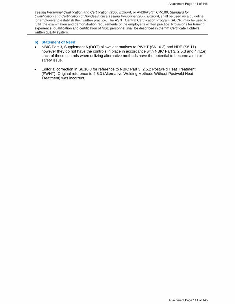
Testing Personnel Qualification and Certification (2006 Edition), or ANSI/ASNT CP-189, Standard for Qualification and Certification of Nondestructive Testing Personnel (2006 Edition), shall be used as a guideline for employers to establish their written practice. The ASNT Central Certification Program (ACCP) may be used to fulfill the examination and demonstration requirements of the employer’s written practice. Provisions for training, experience, qualification and certification of NDE personnel shall be described in the “R” Certificate Holder’s written quality system.
b) Statement of Need: • NBIC Part 3, Supplement 6 (DOT) allows alternatives to PWHT (S6.10.3) and NDE (S6.11)
however they do not have the controls in place in accordance with NBIC Part 3, 2.5.3 and 4.4.1e). Lack of these controls when utilizing alternative methods have the potential to become a major safety issue.
• Editorial correction in S6.10.3 for reference to NBIC Part 3, 2.5.2 Postweld Heat Treatment (PWHT). Original reference to 2.5.3 (Alternative Welding Methods Without Postweld Heat Treatment) was incorrect.
Attachment Page 141 of 145
Attachment Page 141 of 145
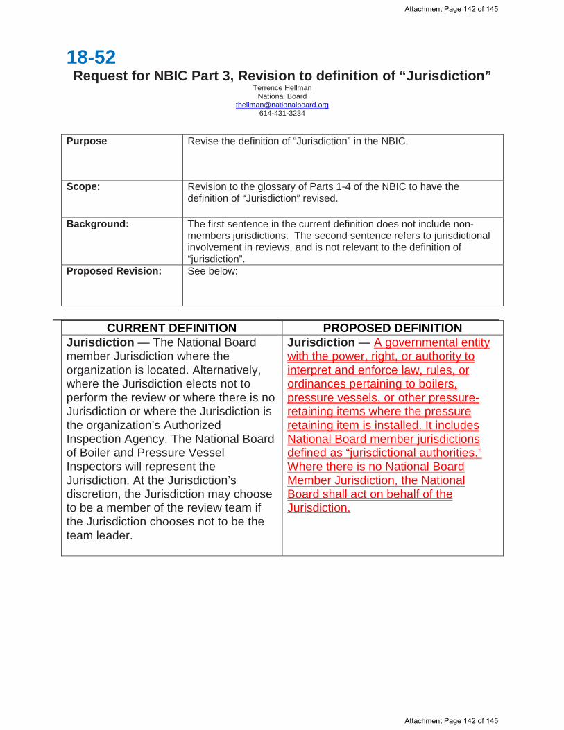
18-52 Request for NBIC Part 3, Revision to definition of “Jurisdiction”
Terrence Hellman National Board
[email protected] 614-431-3234
Purpose Revise the definition of “Jurisdiction” in the NBIC.
Scope: Revision to the glossary of Parts 1-4 of the NBIC to have the definition of “Jurisdiction” revised.
Background: The first sentence in the current definition does not include non-members jurisdictions. The second sentence refers to jurisdictional involvement in reviews, and is not relevant to the definition of “jurisdiction”.
Proposed Revision: See below:
CURRENT DEFINITION PROPOSED DEFINITION
Jurisdiction — The National Board member Jurisdiction where the organization is located. Alternatively, where the Jurisdiction elects not to perform the review or where there is no Jurisdiction or where the Jurisdiction is the organization’s Authorized Inspection Agency, The National Board of Boiler and Pressure Vessel Inspectors will represent the Jurisdiction. At the Jurisdiction’s discretion, the Jurisdiction may choose to be a member of the review team if the Jurisdiction chooses not to be the team leader.
Jurisdiction — A governmental entity with the power, right, or authority to interpret and enforce law, rules, or ordinances pertaining to boilers, pressure vessels, or other pressure-retaining items where the pressure retaining item is installed. It includes National Board member jurisdictions defined as “jurisdictional authorities.” Where there is no National Board Member Jurisdiction, the National Board shall act on behalf of the Jurisdiction.
Attachment Page 142 of 145
Attachment Page 142 of 145

Item 18-54 7/16/18
Request for NBIC Part 3, Supplement 2 Revision Robert V. Underwood-The Hartford Steam Boiler Inspection & Insurance Company
Purpose To delete the last sentence in S2.7.2 relating to welded replacement parts.
Scope: To delete the last sentence of S2.7.2 which could permit an “NR” Certificate Holder to provide welded replacement parts if it isn’t possible for the manufacturer to provide them.
Background S2.7.2 addresses welded replacement parts for historical boilers. The last sentence permits an “NR” Certificate Holder to provide a welded replacement part if it isn’t possible for the manufacturer to provide them (by referring to organizations accredited per 1.6 of Part 3).
Paragraph 1.6 of the NBIC Part 3 was revised in the 2015 Edition from “R” Certificate Holder Quality Program requirements to “NR” Certificate Holder Quality Program requirements. Going back to at least the 2001 Edition of the NBIC, an “R” Certificate Holder was permitted to provide welded replacement parts for historical boilers if it wasn’t possible for the Manufacturer to provide them.
NBIC Part 3, 3.2.2(c) requires ASME Certificate Holders provide welded replacement parts. The deletion of the last sentence of S2.7.2 is for consistency of general NBIC requirements.
I am proposing to either delete the last sentence of S2.7.2 to be consistent with the rest of the NBIC.
Proposed Revision See page 2 for proposed revision
Attachment Page 143 of 145
Attachment Page 143 of 145

OPTION 1: Delete last sentence which will require ASME Certificate Holders provide welded replacement parts.
S2.7.2 REPLACEMENT PARTS
Replacement pressure parts formed by casting, forging, or die forming, and on which no welding has been performed shall be supplied as material. Such parts shall be marked with the material identification required by the construction standard used for the repair. Replacement parts fabricated by welding shall be manufactured by an organization certified as required by the construction standard used for the repair. When it is not possible or practical for a manufacturer to supply replacement parts fabricated by welding, an organization accredited as described in NBIC Part 3, 1.6 may fabricate the part with the approval of the Jurisdiction.
REFERENCE:
Existing 3.2.2(c) of NBIC Part 3 (Requires ASME Certificate Holder to supply parts)
Attachment Page 144 of 145
Attachment Page 144 of 145

Attachment Page 145 of 145
Attachment Page 145 of 145