national aluminium company limited - rites.comrites.com/web/images/stories/uploaddocs/po_bbsr_tender...
TRANSCRIPT

NATIONAL ALUMINIUM COMPANY LIMITED
BID DOCUMENT NO.
(DOMESTRIC COMPETITIVE BEDDING)
Construction of Railway formation in filling/cutting, minor & major bridges,
drain works, pathway etc. for new Railway line from holding yard (Loco shed)
to West grid inside plant for new Wagon T
Damanjodi (Odisha).
CONTENTS
1. NOTICE INVITING TENDER (NIT)
2. CHECK LIST
3. COMMERCIAL QUESTIONNARIE
4. INSTRUCTION TO BIDDERS (ITB)
5. SPECIAL CONDITIONS OF CONTRACT
6. PROFORMA FOR THE CREDENTIAL OF THE TENDERER
7. TECHNICAL SPECIFICATIONS
8. QUALITY ASSURANCE PLANS
9. TENTATIVE DRAWINGS FOR TENDER PURPOSE
10. GENERAL CONDITIONS OF CONTRACT AND ITS
11. PART-II (BILL OF QUANTITY)
( A GOVERNMENT OF INDIA ENTERPRISE )
BHAGWAN TOWER, 1
0 Signature of the tenderer
NATIONAL ALUMINIUM COMPANY LIMITED
BID DOCUMENT NO. OT/02/2015-16/RITES-BBSR/NALCO-
(DOMESTRIC COMPETITIVE BEDDING)
PACKAGE-I (Formation & Bridge Works)
TENDER DOCUMENT
FOR
Construction of Railway formation in filling/cutting, minor & major bridges,
drain works, pathway etc. for new Railway line from holding yard (Loco shed)
rid inside plant for new Wagon Tippler at NALCO M&R complex,
PART – I
NOTICE INVITING TENDER (NIT)
COMMERCIAL QUESTIONNARIE
INSTRUCTION TO BIDDERS (ITB)
SPECIAL CONDITIONS OF CONTRACT
PROFORMA FOR THE CREDENTIAL OF THE TENDERER
TECHNICAL SPECIFICATIONS
QUALITY ASSURANCE PLANS
TENTATIVE DRAWINGS FOR TENDER PURPOSE
GENERAL CONDITIONS OF CONTRACT AND ITS
II (BILL OF QUANTITY)
RITES LTD ( A GOVERNMENT OF INDIA ENTERPRISE )
PROJECT OFFICE
BHAGWAN TOWER, 1ST
FLOOR
CUTTACK ROAD,
BHUBANESWAR – 751006
Signature of the tenderer
Under seal of the Firm
NATIONAL ALUMINIUM COMPANY LIMITED
-DMJ(CIVIL)
(DOMESTRIC COMPETITIVE BEDDING)
Construction of Railway formation in filling/cutting, minor & major bridges,
drain works, pathway etc. for new Railway line from holding yard (Loco shed)
ippler at NALCO M&R complex,
PROFORMA FOR THE CREDENTIAL OF THE TENDERER
TENTATIVE DRAWINGS FOR TENDER PURPOSE
GENERAL CONDITIONS OF CONTRACT AND ITS AMMENDMENTS
( A GOVERNMENT OF INDIA ENTERPRISE )

1 Signature of the tenderer
Under seal of the Firm
MASTER INDEX
Sl. No. Description Page No.
From - To
1. NIT 2 - 3
2. Detailed NIT 4 -10
3. Bid submission letter cum declaration by the bidder
along with Master Index (which is included at Sl. No. 7)
67 - 70
4. Check List & Questionnaire 11 - 18
5. Instructions to Bidders 19 - 25
6. Special Conditions of Contract 26 - 54
7 Proforma for Credential of the Tenderer along with
Proforma for Agreement
(Appendix IA to IX also included in GCC)
55 - 75
8. Technical Specifications 76 - 203
9. Quality Assurance Plan 204 - 218
10. Tender Drawings 219 - 225
11. General Conditions of Contract (GCC)
(2 Mandate forms are also given at the end of GCC)
1 - 98
(NALCO GCC)
12. Bill of Quantity 1 - 16
(Bill of Quantity)

2 Signature of the tenderer
Under seal of the Firm
NOTICE INVITING TENDER

3 Signature of the tenderer
Under seal of the Firm

4 Signature of the tenderer
Under seal of the Firm
RITES
DETAILED NOTICE INVITING TENDER
BID DOCUMENT NO. OT/02/2015-16/RITES-BBSR/NALCO-DMJ(CIVIL)
(DOMESTIC COMPETITIVE BIDDING)
PACKAGE-I (Formation & Bridge Works)
Name of work: Construction of Railway formation in filling/cutting, minor & major bridges,
drain works, pathway etc. for new Railway line from holding yard (Loco shed) to West grid
inside plant for new Wagon tippler at NALCO M&R complex, Damanjodi (Odisha).
1.0 INTRODUCTION
1.1 Tenders are invited by RITES Ltd, a Public Sector Enterprise under the Ministry of
Railways acting on behalf of NALCO for the above mentioned work under single stage two
bid system (Part-I: Techno-commercial part along with GCC and its amendments and Part-
II: Price part) from competent agencies with sound technical and financial capabilities
fulfilling the pre-qualification criteria stated under para 4.0 below.
2.0 BRIEF SCOPE OF WORK AND TIME SCHEDULE
2.1 The scope of work shall include all the works connected with following as defined in
Bidding Document:
- Construction of Railway formation in filling/cutting, minor & major bridges, drain
works, pathway etc. for new Railway line from holding yard (Loco shed) to West
grid inside plant for new Wagon tippler at NALCO M&R complex, Damanjodi
(Odisha).
2.2 Time Schedule for Completion of Work: 12 (twelve) months from date of issue of
Letter of Acceptance.
3.0 SALIENT FEATURES OF BIDDING DOCUMENT
A NAME OF WORK : Construction of Railway formation in
filling/cutting, minor & major bridges,
drain works, pathway etc. for new Railway
line from holding yard (Loco shed) to West
grid inside plant for new Wagon tippler at
NALCO M&R complex, Damanjodi
(Odisha).

5 Signature of the tenderer
Under seal of the Firm
B SCOPE OF WORK : As detailed in Special Conditions of
Contract.
C COMPLETION TIME : 12 (twelve) months
D SALE / DOWNLOAD
OF BID DOCUMENT
: Up to 13/10/2015 on working days.
E COST OF BID
DOCUMENT (NON-
REFUNDABLE)
: Rs.1,000/- (Rupees one thousand only)
F EARNEST MONEY
DEPOSIT
: Rs.17,80,000/- (Rupees seventeen lakhs
eighty thousand only) valid for 6 months
from the last date of submission.
G LAST DATE, TIME &
VENUE FOR
RECEIPT OF
TENDER
: 14/10/2015 at 14.30 hrs
In the office of General Manager(C),
RITES Ltd, Regional Project Office,
Bhagwan Tower(1st floor), Cuttack Road,
Bhubaneswar – 751006
H OPENING OF
TECHNO
COMMERCIAL
PART BID
:
15.00 hrs on 14/10/2015 in presence of
authorized representative of attending
bidders.
4.0 PRE-QUALIFICATION CRITERIA
Agencies intending to participate shall fulfill the following minimum pre-qualification
criteria -
4.1 Experience Criteria:
The bidder shall have past experience of having successfully completed works during last
seven 7 years which is ending last day of month previous to the one in which the tenders are
invited :
a) Three similar works each costing not less than Rs.7,12,66,000/- .
b) Two similar works each costing not less than Rs.8,90,83,000/- .
c) One similar work each costing not less than Rs.14,25,32,000/-.
Note: “Similar work means the tenderer should successfully completed earth work in
formation for Railway track / Roads / earthen dams
(or)
Bridge / Culvert / Cross drainage / Spillway
(or)
Combination of both the above work”
Total value of the similar nature of works successfully/ satisfactorily completed
as on the qualifying date shall be considered with appropriate documentary
proof in this regard from the client.

6 Signature of the tenderer
Under seal of the Firm
4.2 Financial criteria –
a) Average annual financial turnover during the last 3 year ending 31st March of the
previous financial year (2011–12, 2012–13, 2013-14) should be at least
Rs.5,34,50,000/-.
b) Experience of only bidding entity shall be considered for pre-qualification. In-house
work experience shall not be considered as valid experience for the purpose of pre-
qualification.
c) The bidder shall submit documentary evidence showing satisfactory completion of
the work from their principals with present communication details, like Name of
contact person, Phone/Fax No., E-mail ID etc.
The Bidder may furnish their offer on consortium basis also. In such case, all
members of the consortium shall be responsible & liable jointly and severally for the
execution of the scope of work under the technical specification. However, the
leader of the consortium shall be solely responsible for the integration, interfacing,
and co-ordination completeness of the total scope of work.
The consortium leader shall be authorized to honour liabilities, receive instructions
from Purchaser for and on behalf of any one or all members of consortium during
the entire Execution of contract, including payment which shall be done to the
consortium leader or with his consent to other consortium members. The leader of
the consortium shall operate as single window for all communications.
In case of Consortium Bid or Bid involving Back up Agencies, at least one of the
associated parties/agencies shall be designated as lead partner who meets the
financial criteria of PQC singly and all partner experience together should meet the
experience criteria of PQC and this party shall be fully responsible for carrying out
the supervision and quality control of the work including the performance guarantee
test to be executed by other party or parties who do not meet the requirements as
stated above fully.
Bidder shall submit a copy of the valid Collaboration Agreement Memorandum of
Understanding with the associated parties identifying their respective responsibilities
for the subject work, along-with the bid.
Bids may be submitted by a consortium of maximum 3 (three) parties as members
and shall comply with the following requirements.
- The bid shall include all the information required for the bidder as described in Bid
Document for each consortium member.
- The bids shall be signed so as to be legally binding on all members.
- In case of Consortium, the member having the maximum share of work in value
terms shall be the leader. Leader of Consortium shall fulfill Commercial Criteria
mentioned in the tender document. The criteria for claiming the role of Lead
Partner should be clearly indicated in the bid.
- The leader shall be authorized to incur liabilities and receive instructions for and
on behalf of any and all members of the consortium, and the entire execution of
the Contract, including related payments, shall be done with the leader.

7 Signature of the tenderer
Under seal of the Firm
- In case of Consortium becoming the successful bidder, all the members of the
Consortium should be signatories to the Contract Leader of the Consortium shall
be overall responsible for the execution of the contract. The leader and other
members of the Consortium shall be jointly responsible for execution of the
Contract but will be liable for damages in proportion to the respective scope of
facilities.
- Separate bid by a consortium member shall not be accepted for this package.
- A bidder can be member only in one consortium. Bids submitted by another
consortium including the same bidder as member for this package will be
rejected.
- On the offer of the bidder being accepted by NALCO, the Security
Deposit/Performance Bank Guarantee as per stipulations has to be submitted by
the Leader of the Consortium.
- The fee towards cost of Tender Document can be submitted by any of the
members of the Consortium subject to proper authorization from the leader of
Consortium.
d) Failure to meet the above criteria, the bid may be/ liable to be rejected. Therefore,
the bidder shall in his own interest furnish complete documentary evidence by way
of copies of work orders, work completion certificates (either notarized by Notary
Public or Gazetted officer ) and annual reports containing audited balance sheets and
profit & loss accounts statement (certified by Chartered Accountant), in the first
instance itself, in support of their fulfilling the pre-qualification criteria.
NALCO/RITES reserve the right to complete the evaluation based on the details
furnished in the bid without seeking any additional information.
e) Evaluation criteria: Cost of the completed works by the bidder and the Turn over
shall be escalated @10% per annum (simple interest) to bring them at the current
price level.
(The cost of work completed within one year prior to original date of bid opening
and the turnover of the latest previous year shall not be considered for any
weightage. The weightage shall only be considered for work completed prior to one
year of original date of bid opening on annual basis and no weightage shall be given
for part of the year.)
f) Certificates from private individual, for whom the tenderer has worked, shall not be
considered. Certificates from only those Organizations/Institutions/Bodies will be
considered, which execute works in public view and maintain verifiable records. As
such, the organization/bodies, from which certificates will be considered, are as
follow:
i) Government Departments, PSUs & other Government Institutions.
ii) Public Limited Company
iii) Private Limited Company
iv) Government recognized institutions
v) Cooperatives registered with Registrar of firms
vi) Partnership firms Registered with Registrar of firms
vii) Sole proprietary firms.

8 Signature of the tenderer
Under seal of the Firm
However the certificate should be on the organizations letter pad, bearing contact address,
telephone no., fax no., e-mail address etc. Further, the certificates from the sources listed at
Sr. No.(ii) to (vii) should invariably be accompanied with the TDS certificate issued by the
client , without which such certificate shall not be considered as adequate proof for the
purpose of this tender.
5.0 Others
5.1 Even though the bidders meet the above pre-qualification criteria, they are subject to be
disqualified if they have
a) Made misleading or false representation in the forms, statements and attachments in
proof of the qualification requirements;
b) Records of poor performance such as abandoning the work, not properly completing
the contract, inordinate delays in completion, litigation history or financial failures
etc.
c) Their business banned by any Central/State Government Department/ Public Sector
Undertakings or Enterprises of Central / State Government.
d) Not submitted all the supporting documents or not furnished the relevant details as
per the prescribed format.
5.2 A declaration to the above effect in the form of affidavit on stamp paper of Rs 10/- duly
attested by Notary/Magistrate should be submitted as per format given in Appendix-XI
enclosed.
6.0 Documents to be submitted
i) Financial criterion of PQC : Attested copies of Auditor’s Report along with the
Balance Sheet and Profit and Loss Statement for the relevant financial year in which
the minimum criterion is made(refer para 4.2.
ii) Experience Criterion of PQC : Documentary proof in support of having met the
criterion(refer para 4.1.
iii) Declaration: Appendix-XI (refer para 5.2)
iv) Attested Copies of E.P.F Certificate
v) Attested Copies of E.S.I Certificate
vi) Attested Copies of PAN card
vii) Attested Copies of Service Tax Registration
viii) Solvency Certificate from Bank
ix) Power of Attorney of the signatory to the Tender if signed by other than proprietor
x) Proof of ownership/partnership of the firm/company of tenderer.
Note: Submission of proof of possession of independent PF and ESI code by the
Bidder is a must for participation in Tender.

9 Signature of the tenderer
Under seal of the Firm
7.0 Sub-Contractor's experience and resources will not be taken into account in determining the
bidder's compliances with the qualifying criteria.
8.0 Bidder should not be under liquidation, court receivership or similar proceeding and shall
submit certificate for the same.
9.0 NALCO/ RITES reserve the right to use in-house information for assessment of Bidder’s
capability.
10.0 The complete Bidding Document is available on the website of RITES www.rites.com
and only NIT is available on the website of NALCO www.nalcoindia.com &
www.eprocure.gov.in. Bidders submitting their bid on the basis of downloaded
document have to pay cost of bidding document, in the form of demand draft in favour
of National Aluminium Co Ltd payable at Damanjodi as mentioned in Para 3.0 (E)
above, while submitting the bid, failing which their bid shall not be considered for
evaluation.
11.0 Bidding documents (non-transferable) is also available on sale and may be purchased
on any working day between 14.30 Hrs. and 16.00 Hrs. during the sale period specified
in Para 3.0 above from office of The General Manager (C), RITES Ltd, Bhubaneswar,
by paying the Cost of Bidding Document in the form of crossed demand draft only
(DD should be issued by a listed bank mentioned elsewhere in the Tender), in favour of
National Aluminium Company Limited payable at Damanjodi. Request for sending
Bidding Document by post, courier or any other mode shall not be entertained.
12.0 EMD as specified in Para 3.0 above shall be paid in favour of National Aluminium
Company Limited in the form of a Demand Draft payable at Damanjodi or Bank
Guarantee in the prescribed proforma issued by a listed Bank as specified elsewhere in
the Tender document and valid for 6 months from the due date of submission of bid.
The bids not accompanied with EMD shall be considered, as non-responsive and such
bid shall be rejected.
13.0 Sealed bids will be received up to last date and time specified in Para 3 (G) above as
specified. Techno-commercial part shall be opened at 1500 Hrs. on the last date for
submission of bids specified in Para 3.0 (G) above, in the presence of authorized
representatives of attending bidders. Time and date of opening of Price bids shall be
notified to the qualified and acceptable bidders at a later date.
14.0 Bids not received by the due date and time shall be rejected and representative of such
bidders shall not be allowed to attend the bid opening.
15.0 NALCO/RITES shall not be responsible for any expense incurred by bidders in connection
with the preparation & delivery of their bids, site visit and other expenses incurred during
bidding process.
16.0 Bidders on their own interest may visit site and get acquainted with the site conditions,
before quoting the bids.
17.0 Validity of Bids: The bids once submitted shall remain valid upto 06 (six) months from the
due date/ extended date of submission.

10 Signature of the tenderer
Under seal of the Firm
18.0 Telex/ Telegraphic/ Fax/ E-mail bids shall not be accepted.
19.0 RITES/NALCO reserve the right to reject any or all bids without assigning any reason.
20.0 Amendment of Tender Document
i) Before the deadlines for the submission of bids, NALCO/RITES may modify the Tender
Document by issuing ADDENDUM/Corrigendum
ii) Tenderers are advised to download tender documents well in advance and submit the
tender before the stipulated time. It is the responsibility of the Tenderer to check any
correction or any modifications published subsequently in Web site and the same shall
be taken into account while submitting the tender. Tenderer shall, print it out, sign and
attach with the main tender document. Tender document not accompanied by
published corrigendum/s is liable to be rejected. NALCO/RITES will not be
responsible for any postal delays/delay in downloading of tender document from the
internet.
iii) To give prospective bidders a reasonable time to take ADDENDUM/ Corrigendum into
account in preparing their bids, the NALCO/RITES may at their discretion extend as
necessary, the deadline for submission of Tender document.
iv) For site visit, the intending bidder may contact Dy.General Manager (Civil) of
M&R Complex, NALCO, Damanjodi, Orissa Phone- 06853- 253124, Telefax –
06853–254280, Mobile No.9437011364 or AGM(Civil), NALCO, Damanjodi,
Mobile No. 9437579844 or General Manager(C), RITES Ltd, Bhubaneswar,
Phone: 0674 2572690, Fax–0674-2575284 . Sr.DGM(Civil), M/s RITES Limited,
Mob-07752023201, 0674-2572527.
21.0 Any addendum/corrigendum will be published in website of RITES and NALCO only.
General Manager(C)
RITES Ltd, Bhubaneswar For and on behalf of M/s NALCO

11 Signature of the tenderer
Under seal of the Firm
CHECK LIST
12 Signature of the tenderer
Under seal of the Firm
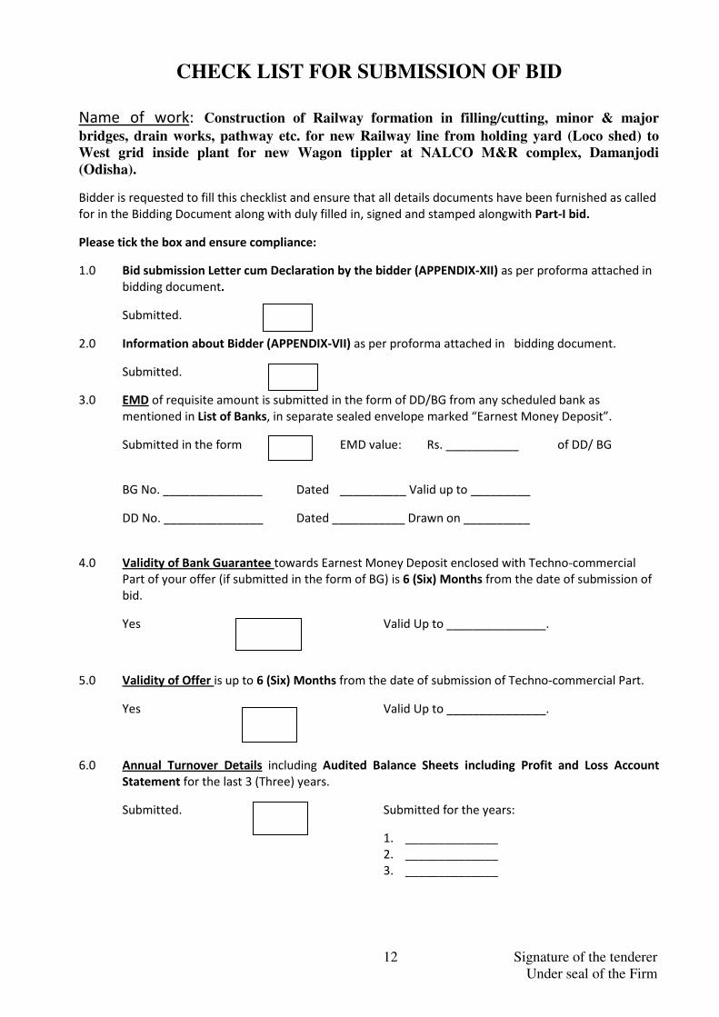
CHECK LIST FOR SUBMISSION OF BID
Name of work: Construction of Railway formation in filling/cutting, minor & major
bridges, drain works, pathway etc. for new Railway line from holding yard (Loco shed) to
West grid inside plant for new Wagon tippler at NALCO M&R complex, Damanjodi
(Odisha).
Bidder is requested to fill this checklist and ensure that all details documents have been furnished as called
for in the Bidding Document along with duly filled in, signed and stamped alongwith Part-I bid.
Please tick the box and ensure compliance:
1.0 Bid submission Letter cum Declaration by the bidder (APPENDIX-XII) as per proforma attached in
bidding document.
Submitted.
2.0 Information about Bidder (APPENDIX-VII) as per proforma attached in bidding document.
Submitted.
3.0 EMD of requisite amount is submitted in the form of DD/BG from any scheduled bank as
mentioned in List of Banks, in separate sealed envelope marked “Earnest Money Deposit”.
Submitted in the form EMD value: Rs. ___________ of DD/ BG
BG No. _______________ Dated __________ Valid up to _________
DD No. _______________ Dated ___________ Drawn on __________
4.0 Validity of Bank Guarantee towards Earnest Money Deposit enclosed with Techno-commercial
Part of your offer (if submitted in the form of BG) is 6 (Six) Months from the date of submission of
bid.
Yes Valid Up to _______________.
5.0 Validity of Offer is up to 6 (Six) Months from the date of submission of Techno-commercial Part.
Yes Valid Up to _______________.
6.0 Annual Turnover Details including Audited Balance Sheets including Profit and Loss Account
Statement for the last 3 (Three) years.
Submitted. Submitted for the years:
1. ______________
2. ______________
3. ______________

13 Signature of the tenderer
Under seal of the Firm
7.0 Fresh Solvency Certificate (APPENDIX-X) from your Bankers (Date of issue of this certificate should
not be earlier than one year from the date of opening of Techno-commercial Part).
Submitted. Certificate dated ___________
From (Name of Bank) ___________
8.0 Details of Past Experience (APPENDIX-IA) in the proforma enclosed in the Bidding Document.
Submitted.
9.0 Details of Present Commitments (APPENDIX-IB) in the proforma enclosed in the proforma
enclosed in the Bidding Document.
Submitted.
10.0 List of equipment (APPENDIX-II) proposed to be deployed for the work in the proforma enclosed
in the Bidding Document.
Submitted. Ref.: ___________________
11.0 Power of Attorney in favour of person who has signed the offer in stamp paper of appropriate
value.
Submitted.
12.0 Partnership Deed in case of partnership firm and Articles of Association in case of limited
company.
Submitted.
13.0 E.P.F. Registration Certificate of the firm :
Submitted.
14.0 E.S.I. Registration Certificate of the firm :
Submitted.
15.0 Service tax Registration Certificate of the firm :
Submitted.
16.0 PAN Card copy :
Submitted.

14 Signature of the tenderer
Under seal of the Firm
17.0 Bid Compliance Statement (APPENDIX-XIII)(confirmation for no deviation stipulated in Bid) in the
proforma enclosed.
Submitted.
18.0 Exception and Deviation Statement (APPENDIX-IX) in proforma in GCC.
Submitted.
19.0 All the documents submitted in requisite number of copies as mentioned in the Bidding
Document.
Submitted. No. of copies submitted: ________
20.0 Original Biding Document along with blank (un-priced) copy of Price Bid/ Bill of Quantities and
addendum, if any.
Submitted.
21.0 All pages/ documents are stamped and signed by the authorised signatory of the bidder.
Yes.
22.0 Declaration by the bidder(appendix- XI).
Yes.
23.0 Sales Tax clearance certificate.
Yes
SIGNATURE OF BIDDER: _________________________
NAME OF BIDDER: _________________________
COMPANY SEAL:

15 Signature of the tenderer
Under seal of the Firm
COMMERCIAL QUESTIONNAIRE

16 Signature of the tenderer
Under seal of the Firm
COMMERCIAL QUESTIONNAIRE
Bidder’s reply/ confirmation as furnished in the Commercial Questionnaire (CQ) shall
supersede the stipulations mentioned elsewhere in their bid.
SL.
NO. NALCO/RITES’S QUERY BIDDER’S REPLY/ CONFIRMATION
1.0 Confirm that your Bid is valid for 06 (six) months
from the date of submission of Bid.
2.0 Confirm that Earnest Money Deposit (EMD) as per
bid stipulations have been furnished along with bid.
3.0 Confirm that the following documents as submitted
with Part-I & II:
a) All documents as per CHECK LIST.
b) Blank Schedule of Rates/ Prices (without specifying
the rates/ prices) are submitted in unpriced part,
exactly as per the priced portion submitted in Part-II.
In case some of items have not been quoted, such
items should be identified in blank price format.
c) Addendum duly signed and stamped on each page as
a token of acceptance. (Applicable, if issued).
4.0 Confirm that price has been submitted in ORIGINAL
only in a separately sealed envelope superscribing
“PRICE PART”.
5.0 Schedule of Price.
a) Price must be filled in format for SOR enclosed as per
of Bidding Document. If price quoted in separate
typed sheets and any variation in item description,
unit or quantity is noticed and no deviations are
specified by bidder in unpriced bid, confirm that
Owner shall presume that the price quoted are as
per the price format attached with bidding
document.
b) Confirm that rate quoted for similar items in
different Parts are same in each part.

17 Signature of the tenderer
Under seal of the Firm
c) Confirm that in case of variation in quoted rates for
similar items, the lowest quoted rate of such items
shall be considered.
d) Confirm that deviation/ terms and conditions are not
mentioned in the price part. In case any terms and
condition is mentioned in the price part, the same
shall be treated as null and void.
e) Confirm that correction fluid is not used in the price
part. (In case of any correction, same shall be
stamped by authorised signatory.)
6.0 Confirm that you have studied complete Bidding
Document including Technical and commercial part
and your Bid is in accordance with the requirements
of the Bidding Document.
7.0 Confirm your compliance to total Scope of Work
mentioned in the Bidding Document.
8.0 Confirm your acceptance for ‘Scope of Supply’
mentioned in the Bidding Document and confirm
that all materials shall be supplied as per Standards
and Specifications.
9.0 Confirm your acceptance for Time Schedule as
mentioned in Bidding Document.
10.0 Confirm that your quoted price includes all taxes,
duties as applicable for this WORK in accordance
with the provision of General Conditions of Contract
& SCC.
11.0 Confirm that your quoted price includes all types of
insurance as per the provisions of General
Conditions of Contract and Special Conditions of
Contract.
12.0 Confirm that all costs resulting from safe execution
of WORK, such as safety induction, use of protective
clothing, safety glasses and helmet, safety
precaution taken during monsoon, or any other
safety measures to be undertaken by the Contractor
for execution of work are included in the quoted
rates.

18 Signature of the tenderer
Under seal of the Firm
13.0 Confirm that adequate numbers of construction
equipments, tools, tackles etc. have been proposed
which will be sufficient to complete the work as per
the time schedule.
14.0 Confirm that you have proposed adequate project/
site organisation with qualified supervisory
personnel having requisite experience including
personnel responsible for safety, planning, stores,
QA/ QC etc.
SIGNATURE OF BIDDER: __________________________________
NAME OF BIDDER: __________________________________
COMPANY SEAL: __________________________________

19 Signature of the tenderer
Under seal of the Firm
INSTRUCTION TO BIDDERS (ITB)

20 Signature of the tenderer
Under seal of the Firm
Name of Work: Construction of Railway formation in filling/cutting, minor & major bridges, drain
works, pathway etc. for new Railway line from holding yard (Loco shed) to West grid inside plant for
new Wagon tippler at NALCO M&R complex, Damanjodi (Odisha).
INSTRUCTION TO BIDDERS (ITB)
1. SUBMISSION OF TENDER
1.1 As the tender is hosted on website, the intending bidder is free to download the same from
the website. However, the bidder must submit the tender by filling up of all relevant
information as required by typing or printing with indelible blue or black ink on white paper
in consecutively numbered pages and be in solid binding and each page signed along with
duly filled in enclosed formats attached to this Tender document.
1.2 The tenderers are advised to submit the tender based strictly on the Terms and Conditions
and Specifications contained in the tender documents including amendments, if any, issued
prior to submission of offer. For amendment if any, with financial implications, issued after
submission of offer, the tenderer shall be entitled to amend his price, however, no price
implication shall be entitled due to any amendment prior to submission offer.
1.3 The offer shall be prepared and submitted in 2 (two) separate sealed envelopes as per the
following:
PART-I: TECHNICAL AND UNPRICED COMMERCIAL OFFER INCLUDING
PRE-QUALIFYING DOCUMENTS (IN 2 COPIES IN SEPARATE
ENVELOPES) DULY SUPERSCRIBED
A) Bank Guarantee as per proforma given in the enclosed GCC or demand Draft towards
Earnest Money Deposit as specified in detailed NIT. Tenders submitted without Earnest
Money Deposit shall not be considered and are liable for rejection.
B) Bidders to furnish all relevant information required to fulfill the PQ criteria as spelt out.
C) Un-priced tender consisting of complete technical package including, drawings and
documents. One original and 1 identical copies shall be submitted. The technical part of
the tender shall interalia include the total tender document duly signed and stamped by
the bidder on each page along with any other technical information the tenderer wishes
to furnish.
D) Unpriced tender shall also include commercial terms and conditions and copy of BILL
OF QUANTITY (PRICE PART) BLANKING THE PRICE. One original and 1
identical copy shall be submitted.
The commercial part of tender will interalia include the following:
i) Copy of tender document marked “Original “ duly signed and stamped on each page
as a token of acceptance.
ii) Duly filled in “Form of Tender”.

21 Signature of the tenderer
Under seal of the Firm
iii) Power of attorney duly executed by the authority having concurrence of Board of
Directors and duly notarised as well as with the seal of the company in favour of
the person signing the tender.
iv) Details of present commitments of the tenderer.
v) Duly filled in financial questionnaire as per annexed table.
vi) SALES Tax clearance Certificate / registration certificate etc.
PART-II: PRICE BID (IN TWO COPIES IN ONE ENVELOPE) DULY
SUPERSCRIBED.
“Bill of Quantities ” duly filled in figures and words in one original copy and shall be
signed and stamped on each page. The prices shall be furnished strictly as per the schedule
of quantities enclosed.
In this part of the bid the Tenderer shall not stipulate any condition. In case of any
condition being mentioned in this part, the same shall render the bid for rejection.
Correction/ overwriting (if any) must be signed and stamped.
1.4 Tender shall be submitted under a covering letter.
1.5 Insertion, postscript, addition and alteration shall not be recognised unless confirmed by the
tenderer’s signature.
1.6 All the copies of tenders shall be complete in all respects with all their
attachments/enclosures.
1.7 The tenderer shall satisfy the owner that he possesses the necessary experience and that he
has at his disposal suitable modern facilities and specialised employees to ensure that his
work is of best quality and workmanship according to the latest proven technology and
engineering practices. The tenderer shall satisfy the owner that he is financially in a position
to fulfill contractual obligations offered to be undertaken by him.
1.8 Tenderer’s offer (all the parts) shall be prepared and submitted in double sealed envelope
and the following shall be separately SUPERSCRIBED prominently on the outside of the
envelope:
22 Signature of the tenderer
Under seal of the Firm
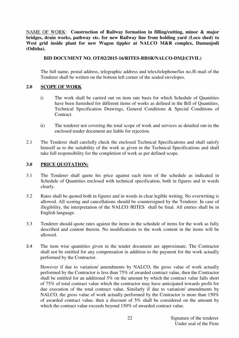
NAME OF WORK: Construction of Railway formation in filling/cutting, minor & major
bridges, drain works, pathway etc. for new Railway line from holding yard (Loco shed) to
West grid inside plant for new Wagon tippler at NALCO M&R complex, Damanjodi
(Odisha).
BID DOCUMENT NO. OT/02/2015-16/RITES-BBSR/NALCO-DMJ(CIVIL)
The full name, postal address, telegraphic address and telex/telephone/fax no./E-mail of the
Tenderer shall be written on the bottom left corner of the sealed envelopes.
2.0 SCOPE OF WORK
i) The work shall be carried out on item rate basis for which Schedule of Quantities
have been furnished for different items of works as defined in the Bill of Quantities,
Technical Specification Drawings, General Conditions & Special Conditions of
Contract.
ii) The tenderer not covering the total scope of work and services as detailed out-in the
enclosed tender document are liable for rejection.
2.1 The Tenderer shall carefully check the enclosed Technical Specifications and shall satisfy
himself as to the suitability of the work as given in the Technical Specifications and shall
take full responsibility for the completion of work as per defined scope.
3.0 PRICE QUOTATION:
3.1 The Tenderer shall quote his price against each item of the schedule as indicated in
Schedule of Quantities enclosed with technical specification, both in figures and in words
clearly.
3.2 Rates shall be quoted both in figures and in words in clear legible writing. No overwriting is
allowed. All scoring and cancellations should be countersigned by the Tenderer. In case of
illegibility, the interpretation of the NALCO /RITES shall be final. All entries shall be in
English language.
3.3 Tenderer should quote rates against the items in the schedule of items for the work as fully
described and content therein. No modifications to the work content in the items will be
allowed.
3.4 The item wise quantities given in the tender document are approximate. The Contractor
shall not be entitled for any compensation in addition to the payment for the work actually
performed by the Contractor.
However if due to variation/ amendments by NALCO, the gross value of work actually
performed by the Contractor is less than 75% of awarded contract value, then the Contractor
shall be entitled for an additional 5% on the amount by which the contract value falls short
of 75% of total contract value which the contractor may have anticipated towards profit for
due execution of the total contract value. Similarly if due to variation/ amendments by
NALCO, the gross value of work actually performed by the Contractor is more than 150%
of awarded contract value, then a discount of 5% shall be considered on the amount by
which the contract value exceeds beyond 150% of awarded contract value.

23 Signature of the tenderer
Under seal of the Firm
3.5 Any request from the Tenderer in respect of additions, alterations, modifications,
corrections etc of either terms and conditions or rates of his Tender after opening of Tenders
may lead to rejection of his Tender.
4.0 RECEIPT OF TENDER
Tender will be received at the following address:
RITES Ltd
Regional Project Office
Bhagwan Tower ( 1st floor),
Cuttack Road,
Bhubaneswar - 751006
The tenderer has the option of sending the tender by Registered Post or submitting the
tender in person, so as to reach on or before the date and time set out for the same in the
Invitation to Tender. Tender submitted by FAX/TELEX/TELEGRAM shall not be
accepted. However NALCO /RITES is no way responsible for late delivery of any tender
by Postal authorities or Courier service.
5.0 TENDER OPENING:
The tenders will be opened in the manner and at the time and date set for opening of tenders
as described in the Notice Inviting Tender.
6.0 VALIDITY OF TENDER
6.1 The tender shall remain valid for six months from the date of opening of the Tender.
6.2 Any suo-moto reduction offered by the Tenderer after opening of the price bids may make
the whole tender liable for rejection.
7.0 LANGUAGE
The tender shall be submitted in English language only.
8.0 EARNEST MONEY
Tenderers shall submit Earnest Money in the form of Bank Guarantee as per proforma
attached herewith, issued by a listed Bank ( list of Bank mentioned elsewhere in the
Tender) or in shape of Demand draft( from a Listed Bank ). Only original copy of Bank
Guarantee will be accepted, photocopy will not be accepted.
Earnest Money shall be returned to the unsuccessful Tenderers at the earliest after
finalisation of the contract. Earnest Money of the successful tenderer shall be returned only
after the tenderer furnishes the Initial Security Deposit and Contract Agreement is signed.
The Earnest Money Deposit in the form of Bank Guarantees shall be kept valid initially for
a period of 6 months from the date of opening of the tender.
No interest shall be paid on Earnest Money Deposit. The offer without Earnest Money or
with short Earnest Money or Earnest Money deposit in the form other than specified herein
above shall be liable for rejection.

24 Signature of the tenderer
Under seal of the Firm
The Earnest Money shall be forfeited if:
a) The tender is revoked during its validity period.
b) The prices are increased unilaterally after the tender opening and during validity of offer
by the tenderer,
c) The owner accepts the tenderer’s bid proposal and the tenderer refuse to enter into
contract after the contract is awarded to him,
d) The tenderer fails to submit Bank Guarantee towards Initial Security Deposit within the
period specified as per NIT.
9.0 SECURITY DEPOSIT :
Clause no-19.0 of GCC shall be referred.
10.0 NO CLAIM OR COMPENSATION FOR SUBMISSION OF TENDER
The Tenderer whose tender is not accepted shall not be entitled to claim any costs, charges
and expenses incidental to or incurred by him through or in connection with his submission
of tender or its consideration by the Purchaser, even though the Purchaser may elect to
modify/withdraw the Invitation to Tender or does not accept the tender.
11.0 REGISTRATION CERTIFICATES
The Tenderer shall furnish copies of Orissa Sales Tax (OST), Central Sales Tax (CST),
Service Tax registration, PF & ESI certificates as required for due completion of work.
12.0 SIGNING OF CONTRACTS
12.1 The enclosed General Conditions of the Contract AND ALL OTHER ENCLOSED Contract
stipulations shall form the basis of the final Contract/ Letter of Acceptance. The tenderer
shall carefully go through all the stipulations given in the said documents.
12.2 On the Tender being accepted by the owner, Contract will be signed and executed by and
between the owner and the Successful Tenderer at the earliest to be notified by the owner in
due course.
12.3 Contract Agreement
The contractor shall have to execute an agreement on `50/- non-judicial stamp paper to be
purchased from any stamp vendor under the jurisdiction of the Orissa High Court, in the
specific format. Competent authority of NALCO shall sign the agreement on behalf of
NALCO.
13.0 NOTICE ON BEHALF OF OWNER:
All notices of technical/ commercial nature shall be issued by the authorised representative
of Engineer in charge, after award of work.

25 Signature of the tenderer
Under seal of the Firm
14.0 OTHER CONDITIONS:
i) The Tenderer is required to carefully examine the Technical Specification, General
Conditions of the Contract, Special Conditions of contract, drawings and other details relating to work and given in the Tender Documents and fully acquaint himself as to all conditions and matters which may in any way affect the work or the cost thereof.
ii) The tenderer shall be deemed to have on his own and independently obtained all
necessary information for the purpose of preparing the tender and his tender as accepted shall be deemed to have taken into account all contingencies as may arise due to such information or lack of the same.
iii) The tenderer shall be deemed to have exhaustively examined the tender documents
including the General Conditions of the contract, to have obtained all information and clarifications on all matters whatsoever that might affect the carrying out the work and to have satisfied himself as to the adequacy of his tender. He is deemed to have known the scope, nature and magnitude of the work and the requirements of materials and labour involved etc and as to all work he has to complete in accordance with the Contract whatever be the defects, omissions or errors that may be found in the Tender Documents.
iv) The tenderer should visit site to acquaint himself about site condition. For site visit,
the intending tenderer may contact Dy.General Manager (Civil) of M&R
Complex, NALCO, Damanjodi, Orissa Phone- 06853- 253124, Telefax – 06853–
254280, Mobile No.9437011364 & AGM(Civil), NALCO, Damanjodi, Mobile
No. 9437579844 or General Manager (C), RITES Ltd, Bhubaneswar, Phone:
0674 2572690, Fax–0674-2575284 . Sr.DGM(Civil), M/s RITES Limited, Mob-
07752023201, 0674-2572527.
v) Tenderers may please note -
a) RITES is only an agent acting as consultant on behalf of the
Principal/client/Owner. It should also be stated that the Client is the principal as
well as Employer for the work.
b) In case of any dispute between RITES and contractor, being RITES merely an
agent, client should be made first respondent and should be liable for all
monetary losses.
c) RITES is only agent/Consultant acting on behalf of the client/employer and in
case of arbitration the client shall be the first respondent.

26 Signature of the tenderer
Under seal of the Firm
SPECIAL CONDITIONS OF CONTRACT
27 Signature of the tenderer
Under seal of the Firm
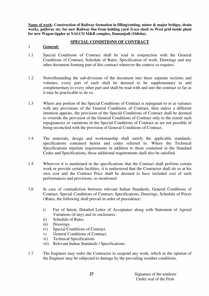
Name of work: Construction of Railway formation in filling/cutting, minor & major bridges, drain
works, pathway etc. for new Railway line from holding yard (Loco shed) to West grid inside plant
for new Wagon tippler at NALCO M&R complex, Damanjodi (Odisha).
SPECIAL CONDITIONS OF CONTRACT
1 General:
1.1 Special Conditions of Contract shall be read in conjunction with the General
Conditions of Contract, Schedule of Rates, Specification of work, Drawings and any
other document forming part of this contract wherever the context so requires.
1.2 Notwithstanding the sub-divisions of the document into these separate sections and
volumes, every part of each shall be deemed to be supplementary to and
complementary to every other part and shall be read with and into the contract so far as
it may be practicable to do so.
1.3 Where any portion of the Special Conditions of Contract is repugnant to or at variance
with any provisions of the General Conditions of Contract, then unless a different
intention appears, the provision of the Special Conditions of Contract shall be deemed
to override the provision of the General Conditions of Contract only to the extent such
repugnancies or variations in the Special Conditions of Contract as are not possible of
being reconciled with the provision of General Conditions of Contract.
1.4 The materials, design and workmanship shall satisfy the applicable standards,
specifications contained herein and codes referred to. Where the Technical
Specifications stipulate requirements in addition to those contained in the Standard
Codes and Specifications, those additional requirements shall also be satisfied.
1.5 Wherever it is mentioned in the specifications that the Contract shall perform certain
work or provide certain facilities, it is understood that the Contractor shall do so at his
own cost and the Contract Price shall be deemed to have included cost of such
performances and provisions, so mentioned.
1.6 In case of contradiction between relevant Indian Standards, General Conditions of
Contract, Special Conditions of Contract, Specifications, Drawings, Schedule of Prices
/ Rates, the following shall prevail in order of precedence:
i) Fax of Intent, Detailed Letter of Acceptance along with Statement of Agreed
Variations (if any) and its enclosures.
ii) Schedule of Rates.
iii) Drawings.
iv) Special Conditions of Contract.
v) General Conditions of Contract.
vi) Technical Specifications
vii) Relevant Indian Standards / Specifications.
1.7 The Engineer may order the Contractor to suspend any work, which in the opinion of
the Engineer may be subjected to damage by the prevailing weather conditions.

28 Signature of the tenderer
Under seal of the Firm
1.8 Unless specifically mentioned otherwise in the contract, the bidder shall quote rates for
the finished items and shall provide for the complete cost towards power, fuel, tools,
tackles, equipment, construction plant, temporary work, labour materials, levies, taxes,
transport, layout, repairs, rectification, maintenance till handing over, supervision,
colonies, shops, establishments, services, temporary roads, revenue expenses,
contingencies, overheads, profits and all incidental items not specifically mentioned but
reasonably implied and necessary to complete the work according to the contract.
1.9 The decision of the Engineer-in-charge shall be final and binding on the Contractor
regarding clarification of items in the schedule with respect to other sections of the
contract/specifications.
1.10 NALCO/RITES reserves the right to award the whole works to a single contractor or
split the work between more than one contractor. The rates should remain firm
irrespective of the above.
1.11 The specification shall be read in conjunction with the description of item in the
schedule. The schedule of items shall have precedence over any contrary statement
mentioned anywhere in the document.
2.0 Scope of work:
The Scope of work shall include :
• Construction of Railway formation in filling/cutting, minor & major bridges,
drain works, pathway etc. for new Railway line from holding yard (Loco shed) to
West grid inside plant for new Wagon tippler at NALCO M&R complex,
Damanjodi (Odisha).
• Diversion of water way ,diversion road for carrying out the work at no extra cost.
2.1 The technical specifications and drawings enclosed with the tender document broadly
covers the General concept & requirements of work.
2.2 Scope of work shall read in conjunction with item description in Schedules of Rates and
contractor’s scope shall include all activities of work specified in the item description in
SOR/BOQ etc.
3.0 General information on site:
The site for Construction of proposed Railway siding is located at inside the NALCO
plant for new Wagon Tippler. NALCO’s existing Alumina Refinery is located at
aproximately 40 Km from the nearest town Koraput in the Odisha State of India,
Nearest Railway Station connected with plant is Damanjodi of E. Co. Railway at about
3Km.
The Bidder has to acquaint himself with the access to the site, local working
environment, local interference, interruption of work (if any), that they may encounter
during the pendency of contract, availability of local facilities such as railway
connectivity, transport facilities, material, labour and the bidder shall quote the price
taking into account all expenses likely to arise in this regard. The bidder has to follow
the civic rules regarding disposal of debris, storing of construction material as per
prevailing governing rules.

29 Signature of the tenderer
Under seal of the Firm
The intending tenderer shall be deemed to have visited the site and familiarised
themselves thoroughly with the site conditions before submitting their tenders. Non-
familiarity with the site conditions will not be considered a reason either for extra
claims or for not carrying out work in strict conformity with drawings and
specifications.
4.0 Construction water supply and power supply:
In partial modification of Clause 2.2 and 2.3 of General Conditions of Contract (GCC),
the Bidder should note the following:
- Subject to availability Owner may supply Construction Water at source at inside
Plant premises to the contractor as per provision in above clause. It may however
noted that no water shall be supplied to the contractor for the labour colony.
- Subject to availability construction power may be supplied by Owner at source at
inside Plant premises as per provision made in Clause No. 2.3 of GCC and its
amendment.
5.0 Earnest Money Deposit (EMD): Bidder shall furnish earnest money deposit (EMD) as
indicated in the NIT. The bids not accompanied with full amount of EMD shall be
rejected. The Earnest Money Deposit. if deposited in shape of Bank Guarantee as per
relevant Clause of General Conditions of Contract shall be kept valid for a period as
indicated in the NIT from the date of opening of tender. EMD of unsuccessful bidders
will be returned upon award of contract. EMD ( Incase submitted in shape of BG ) of
the successful bidder will be returned upon Bidders furnishing the Initial Security
Deposit/ Security Deposit and signing of contract agreement. EMD ( Incase submitted
in shape of DD ) of the successful bidder may be adjusted to Initial Security Deposit.
5.1 In case the successful bidder fails to submit the ISD / SD within a period of 21 day from
the date of issue of Work Order / FOI, the ISD amount along with a simple interest @
12% per annum as penalty, applicable from the date of Work Order / FOI till the date of
submission of ISD or submission of Ist RA bill, shall be recovered starting from Ist RA
Bill.
6.0 Price basis
6.1 Works Contract
The entire works as per Scope of Work covered under this contract shall be treated as
“Works Contract”. The quoted prices/ rates of the Bidders indicated in schedule of
rates shall include incidence of Works Contract Tax/ Turnover Tax as applicable.
6.2 Taxes and Duties
In addition to the relevant clause in GCC, Bidders to note the following:
6.2.1 The quoted prices shall be deemed to be inclusive of all taxes duties, octroi, levies etc.
except service tax and education cess with respect to CONTRACTOR’s scope of work/
scope of supply till the completion of the work. If after the due date of submission of
last price bid, any increase occurs in the applicable rate(s) of sales tax, excise duty,
works contract tax/ turnover tax or new levies are imposed, the OWNER shall
reimburse the CONTRACTOR the increase in the resultant sales tax, excise duty,
works contract tax/ turnover tax and new levy as the case may be, on satisfactory proof
of payment. Conversely, if there is any reduction in the rates of sales tax, excise duty,

30 Signature of the tenderer
Under seal of the Firm
works contract tax/ turnover tax or deletion of taxes/ duties after the date of submission
of the last price bid, the OWNER shall be entitled to benefit of such reduction,
remission or exemption in the rate(s) of the said taxes, which benefit shall be passed on
to the OWNER by way of reduction in the price. This variation shall be paid only for
finished goods incorporated in Works.
6.2.2 For Service Tax and education cess, the clauses in the para 6.2.2.1, 6.2.2.2, 6.2.2.3,
6.2.2.4 and 6.2.2.5 below will be applicable.
6.2.2.1 The contractor is required to get themselves registered under the Jurisdictional Range
Office of Central Excise & Customs (the Service Tax Registration No. should be PAN
based) and submit documentary evidence along with their tender, failing which their
claim for service tax from NALCO will not be entertained.
6.2.2.2 It is the responsibility of the successful bidder to satisfy Excise Authorities with
supporting documents as demanded by Excise Authorities regarding price of items
shown in Annexure-II.
6.2.2.3 Service Tax and Education Cess shall be paid extra at applicable rate prevailing at the
time of execution.
6.2.2.4 (i) Wherever the Service Tax and the Education Cess paid to the Central Excise
authorities on the input services availed by NALCO are CENVATABLE, the
Contractor shall issue Invoice / R.A. Bill in accordance with the Excise Rules /
Cenvat Credit Rules giving all the information as required under the said rules.
(ii) Wherever service tax and education cess is NON-CENVATABLE, the Service
Tax & Education Cess amount payable by NALCO towards the same shall be
loaded on the bidder’s quoted value to arrive at the relative position of the bids.
(iii) For claiming Service Tax from NALCO, the contactor’s invoice should contain
details like Serial no. of documents, Date of issue, Description of work, price of
the input service, service tax payable, service tax registration no., name and
address of the input Service Provider, class / category under which Service Tax is
leviable etc. Invoice for Service tax shall be as per NALCO’s standard.
6.2.2.5 Any variation in the rates of Service Tax / Education Cess or inclusion/exclusion of
certain services in the Service Tax net after award of the contract will be to the account
of NALCO.
NB:- The contractor shall be fully & solely responsible to the statutory authorities
for compliance of all the provisions of Service Tax Act / Rules, Cenvat Rules and
other statutory provisions applicable to this work as a service provider.
7.0 Sales tax clearance certificate:
Bidders must submit attested copy of registration/clearance certificate in prescribed
proforma under the Orissa Sales Tax Act. Alternatively, bidders must give an
undertaking that they would comply with this statutory requirement after award of
work. Owner shall deduct Sales Tax on Works Contract as per prevalent rates from
each RA bill and remit the same with Sales tax authorities as statutory deductions.

31 Signature of the tenderer
Under seal of the Firm
8.0 Income Tax
(i) Income Tax as applicable at the prevailing rate on the gross amount billed shall
be deducted from the contractor’s bills.
(ii) Notwithstanding anything contained elsewhere in the contract, NALCO shall
deduct at source from the payment due to the contractor, the taxes as required
under Section-13(AA) of Orissa Sales Tax act or as amended from time to time or
under any statute. The amount so deducted shall be deposited by NALCO with
the Sales Tax Authorities as per Law. It is for the contractor to deal with the Sales
Tax Authorities directly in respect of any claim or refund relating to the above
deductions and NALCO shall not be liable or responsible for any claims or
payments or reimbursement in this regard.
9.0 Time of completion
9.1 Time is the essence of contract. The work shall be executed strictly as per the Time
Schedule given in Notice Inviting Tender (NIT). The period of completion includes the
time required for mobilization as well as testing, rectifications if any, retesting,
demobilization and completion in all respect to the satisfaction of Engineer-In-Charge.
9.2 All work within scope of this tender must be completed within a period as stipulated in
the NIT from the date of order/ Fax of Intent (FOI) and strictly in accordance with the
construction programme to be drawn up between owner & contractor. Construction
work at site must commence within three (3) weeks from the date of FOI. The date of
order (FOI) shall be reckoned as the date of commencement of work.
9.3 The bidder shall furnish his proposed construction programme along with his offer.
9.4 The construction programme should be in the form of PERT network considering the
date of issue of Fax of intent as the zero date and should show completion of various
events/activities there from.
9.5 Defect liability period :
The defect liability period shall be governed as per Clause 65 and 68 of General
Conditions of Contract.
10.0 Schedule of rates
10.1 The Schedule of Rates shall be read in conjunction with Special Conditions of
Contract, General Conditions of Contract, Scope of Work, Scope of Supply, Technical
Specification, Drawings and any other document forming a part of this Contract.
10.2 All expenses towards mobilisation at site and demobilization including bringing all
required equipment, work force, materials, dismantling/ demobilization of equipment,
clearing of site including site office etc. shall be deemed to be included in the rates
quoted and no separate payments on account of such expenses shall be entertained.

32 Signature of the tenderer
Under seal of the Firm
11.0 Contractor’s Remuneration
The price to be paid by the Owner to the Contractor for the whole work done and for
the performance of all the obligation undertaken by the Contractor under the contract
document shall be ascertained by the application of the respective schedule of rates and
payment to be made accordingly to the work actually executed and approved by the
Engineer-in-Charge.
12.0 Schedule of Rates to be inclusive
The prices / rates quoted by the Contractor shall remain firm till the issue of final
certificate. Schedule of rates shall be deemed to include and cover all costs,
expenses and liabilities of every description and all risks of every kind including all
type of interference/ obstruction/ interruption or any other problems which may likely
to occur from time to time to be taken care during execution of work for completion
and handing over the work to the Owner by the contractor. The Contractor shall be
deemed to have known the nature, scope, magnitude and the extent of the works and
materials required though the contract document may not fully and precisely furnish
them. Contractor shall make such provision in the schedule rates as he may consider
necessary to cover the cost of such items of work and materials as may be reasonable
and necessary to complete the work. The opinion of the Engineer-in-Charge as to the
items of work which are necessary and reasonable for completion of work shall be final
and binding on the contractor although the same may not be shown on or described
specifically in contract documents.
Generally of this present provision shall not be deemed to cut down or limited in any
way because in certain cases it may and in other cases it may not be expressly stated
that the contractor shall do or perform a work or supply articles or perform with
services at his own cost or without addition of payment or without extra charge of
works to the same effect or that it may be stated or not stated that the same are included
in and covered by the Schedule of Rates.
12.1 Cement, reinforcement Steel to be used for the entire work shall be supplied by
Contractor.
12.2 Schedule of Rates to cover Constructional plant, Material, Labour etc
Without in any way limiting the provisions of other sub clauses the schedule of rates
shall be deemed to include and cover the cost of all constructional plant, temporary
works, materials except FIM, labour, insurance, fuel, stores, and appliances etc. to be
supplied by the contractor and all other matters in connection with each item in the
schedule of quantities and the execution of the work or any portion thereof finished
complete in all respect and maintained as shown or described in the contract document
or as may be ordered in writing during the continuance of the contract.
12.3 Schedule of Rates to cover Royalties, Rents and Claims
The schedule of rates shall be deemed to include and cover the cost of all royalties and
fees for the article, processes, protected by letters, patent or otherwise incorporated in
or used in connection with the works, also all royalties, rents and other payments in

33 Signature of the tenderer
Under seal of the Firm
connection with obtaining materials of whatsoever kind for the works and shall include
and indemnify the owner, which the contractor hereby gives against all actions,
proceedings, claims, damages, costs and expenses arising from the incorporation in or
use on the works of any such articles, process or charges if levied on materials,
equipment or machinery to be brought to site for use on work, shall be borne by the
contractor.
12.4 Schedule of Rates to cover taxes and duties
No exemption of reduction of custom duties, excise duties, sales, tax, quay or any port
duties, transport charges, stamp duties or Central or State Government or Local Body
(or from any other body) or Municipal Taxes and duties, taxes or charges whatsoever
will be granted or obtained and all expenses of which shall be deemed to be included in
and covered by the schedule of rates. The contractor shall also obtain and pay for all
permits or other privileges necessary to complete the work.
12.5 Schedule of Rates to cover Risk of Delay
The schedule of rates shall be deemed to include and cover the risks of all possibilities
of delay and interference with the contractors conduct of work which occur from any
cause including orders of owner in the exercise of his powers and on account of
extension of time granted due to various reasons and for all other possible causes of
delay.
12.6 Schedule of Rates cannot be altered
For work under unit rate basis no alteration will be allowed in the schedule of rates by
reasons of works or any part of them being modified, altered, extended, diminished or
omitted. The schedule of rates is of fully inclusive rates which have been fixed by the
contractor and agreed to by the Owner and cannot be altered.
12.7 Rate shall be quoted both in figure and in words in clear legible writing. No over
writing is allowed. All scoring and cancellation should counter-signed by the tenderer.
In case of illegibility, the interpretation of the engineer-in-charge shall be final.
13.0 Project scheduling & monitoring
The successful tenderer shall submit a Master Network within three weeks from date of
issue of Fax of Intent.
13.1 The master network will be in the form of PERT/CPM NETWORK prepared system
wise containing major milestones in all phases of execution of contract. Each
event/activity will also have earliest completion date, latest completion date and float in
number of days/weeks.
13.2 The final master network as mutually agreed upon will form the basic document from
which schedules for design, engineering, procurement, construction and commissioning
will be arrived at. These schedules will be prepared discipline or system wise.
13.3 The final master network shall also form the basis for review of schedules, short-term
programme and progress reporting for the entire run of the contract. The
frequency/periodicity of programming and reporting will be mutually agreed upon.

34 Signature of the tenderer
Under seal of the Firm
13.4 Progress reporting shall be done by the Contractor on mutually agreed formats. Reports
on such formats will be sent regularly to the Engineer-in-Charge in reproducible with
six copies of print as per frequency/periodicity agreed upon from time to time.
14.0 Statutory Approvals/Labour laws etc.
14.1 The approval from any authority required as per statutory rules and regulations of
Central/State Government shall be the responsibility of CONTRACTOR.
14.2 The Contractor shall have independent account codes from concerned Regional
Provident Fund Commissioner for Provident Fund and Independent account code from
Regional Director ESIC for ESI. Fulfilling all statutory stipulations towards PF & ESI
is mandatory for the bidders.
14.3 It is to be noted that the subject contract would be awarded only to those agencies who
have fulfilled the following requirements:
a) P.F. Registration Number allotted to them by RPFC.
b) The agencies should promptly deposit P.F. deduction of the eligible contract
employees plus the employer’s contribution to the RPFC. For this purpose agency
must submit a certificate in their Bill that PF amount has been deducted from the
eligible employees and along with the employer’s contribution has been deposited
with R.P.F.C. For this purpose agency must submit a certificate in their Bill that PF
amount has been deducted from the eligible employees and along with the
employer’s contribution has been deposited with R.P.F.C. In support of this the
agency must furnish the challan/ receipt for the payment made to RPFC for the
earlier months.
c) ESI Registration Number allotted to them by ESIC.
14.4 If the certificate and the challan/ receipt referred to in clause 14.2(c) above are not
furnished, the Finance & Accounts Dept. of NALCO will deduct 16% (Sixteen percent)
of the amount of the Contractor’s bill and retained deposits may only be refunded to the
Contractor on production of the challan/ receipt.
15.0 Labour license
Before starting of work, the Contractor shall obtain a license from the concerned
authorities under the Contract Labour (Abolition and Regulation) Act 1970, and furnish
copy of the same to the Owner.
16.0 Construction:
16.1 Contractor shall observe all Codes specified in respective specification, all national and
local laws, ordinances, rules and regulations and requirements pertaining to the work and
shall be responsible to fulfill all such norms.
16.2 Contractor shall have at all times during performance of the work, post a technically
competent person to supervise the work at the work premises. Any
instruction given to such a person by the Owner/ Engineer in charge shall be construed
as having been given to the Contractor.
35 Signature of the tenderer
Under seal of the Firm
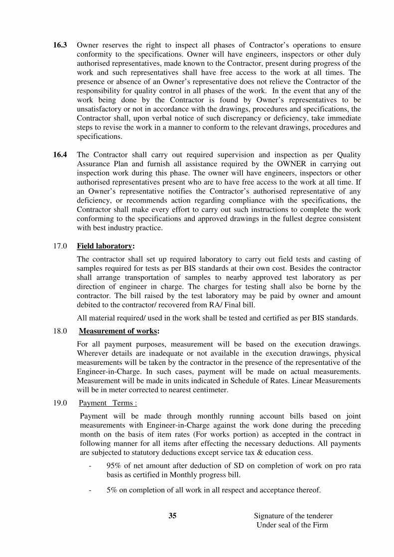
16.3 Owner reserves the right to inspect all phases of Contractor’s operations to ensure
conformity to the specifications. Owner will have engineers, inspectors or other duly
authorised representatives, made known to the Contractor, present during progress of the
work and such representatives shall have free access to the work at all times. The
presence or absence of an Owner’s representative does not relieve the Contractor of the
responsibility for quality control in all phases of the work. In the event that any of the
work being done by the Contractor is found by Owner’s representatives to be
unsatisfactory or not in accordance with the drawings, procedures and specifications, the
Contractor shall, upon verbal notice of such discrepancy or deficiency, take immediate
steps to revise the work in a manner to conform to the relevant drawings, procedures and
specifications.
16.4 The Contractor shall carry out required supervision and inspection as per Quality
Assurance Plan and furnish all assistance required by the OWNER in carrying out
inspection work during this phase. The owner will have engineers, inspectors or other
authorised representatives present who are to have free access to the work at all time. If
an Owner’s representative notifies the Contractor’s authorised representative of any
deficiency, or recommends action regarding compliance with the specifications, the
Contractor shall make every effort to carry out such instructions to complete the work
conforming to the specifications and approved drawings in the fullest degree consistent
with best industry practice.
17.0 Field laboratory:
The contractor shall set up required laboratory to carry out field tests and casting of
samples required for tests as per BIS standards at their own cost. Besides the contractor
shall arrange transportation of samples to nearby approved test laboratory as per
direction of engineer in charge. The charges for testing shall also be borne by the
contractor. The bill raised by the test laboratory may be paid by owner and amount
debited to the contractor/ recovered from RA/ Final bill.
All material required/ used in the work shall be tested and certified as per BIS standards.
18.0 Measurement of works:
For all payment purposes, measurement will be based on the execution drawings.
Wherever details are inadequate or not available in the execution drawings, physical
measurements will be taken by the contractor in the presence of the representative of the
Engineer-in-Charge. In such cases, payment will be made on actual measurements.
Measurement will be made in units indicated in Schedule of Rates. Linear Measurements
will be in meter corrected to nearest centimeter.
19.0 Payment Terms :
Payment will be made through monthly running account bills based on joint
measurements with Engineer-in-Charge against the work done during the preceding
month on the basis of item rates (For works portion) as accepted in the contract in
following manner for all items after effecting the necessary deductions. All payments
are subjected to statutory deductions except service tax & education cess.
- 95% of net amount after deduction of SD on completion of work on pro rata
basis as certified in Monthly progress bill.
- 5% on completion of all work in all respect and acceptance thereof.
36 Signature of the tenderer
Under seal of the Firm
20.0 Construction methodology/requirements:
20.1 The contractor shall be entirely responsible for execution of the work covered under
this tender in a workmanlike and expeditious manner, as per the technical
specifications, drawings and as per instructions of Engineer-in-Charge.
20.2 The work shall be executed strictly in accordance with the Technical specifications.
21.0 Construction Equipment
The Contractor shall without prejudice to his overall responsibility to execute and
complete the work as per specifications and time schedule, progressively deploy
adequate number of suitable construction equipment and machineries required for due
completion of work, tools and tackles and augment the same as decided by the
Engineer-in-Charge depending on the exigencies of the work so as to suit the
construction schedule and complete the works within the contractual completion period
without any additional cost of Owner.
21.1 Site Organisation & Contractor’s site establishment:
The Contractor shall without prejudice to his overall responsibility to execute and
complete the works as per specifications and time schedule progressively deploy
adequate qualified and experienced personnel together with skilled/unskilled
manpower and augment the same as decided by Engineer-in-Charge depending on the
exigencies of work to suit the construction schedule without any additional cost to
Owner.
The Contractor shall build and maintain at his own cost a suitable site office and
necessary stores on the portion of the land allotted to him in an appropriate manner.
The Contractor shall also make available an appropriate shed of 15 Sqm area for setting
up a site office for use by the owner/engineer-in-charge. No separate payments will be
made for making available such shed.
21.2 Safety Regulations
The work shall be carried out as per safety practices that need be enforced for any
construction site. The Contractor shall abide by all such safety regulations that are
required to be followed. The contractor shall have to take necessary safety
arrangements / precautions for the workmen engaged by him and shall be liable for any
First Aid / Emergency treatment for his labourers / workmen. In addition, the contractor
shall have to abide by all fire & safety regulations as prevalent. The contractor has to
execute work after taking necessary instructions and clearance from the safety officer/
NALCO.
All lifting / handling tools and tackles should have been tested as per rule.
All mobile equipment like trucks, tractors, tippers, dumpers used in work shall have
valid fitness certificate and Insurance etc. as required under law of the land.

37 Signature of the tenderer
Under seal of the Firm
21.3 Site cleaning:
The contractor shall be responsible to promote awareness on the Environmental
requirements among the workmen engaged by them for the subject work and ensure
adherence to sound environmental practices as detailed in the General Environmental
requirement and Environmental Policy.
The contractor shall remove all the waste / debris generated during the work on each
occasion and dispose off to a place as identified by Engineer I/C. If the contractor fails
to comply with the above, the owner may get the up keeping done and will recover the
expenses from the bill of the contractor.
Any dust generated during construction will not be allowed to fly over the roads,
houses etc. Necessary provision of protection will be adopted by the contractor at his
own cost for the same.
Contractor shall comply with the provisions of ISO 14000 (EMS Criteria) for proper
disposal of debris, unused oils, lubricants etc. In consultation with Engineer-in-Charge.
The Contractor shall take care of cleaning the working site from time to time for easy
access to work site and also from safety point of view.
The Contractor shall from time to time clear and remove all rubbish and constructions,
equipment, unused materials, etc. resulting in the execution of the work. The disposal
of rubbish will have to be done only in the areas earmarked by the Owner as per the
direction of the Engineer-in-Charge. All streets and driveways in the work area shall be
kept clear and unobstructed at all times.
Working site should be always kept cleaned up to the entire satisfaction of Engineer-
in-Charge. Before handing over of any work to Owner, the Contractor in addition to
other formalities to be observed as detailed in the document shall clear the site to the
entire satisfaction of Engineer-in-Charge.
21.4 Survey and level/setting out of work: The engineer-in-Charge shall furnish the
relevant existing grid point with benchmark on the land. It shall be Contractor’s
responsibility to set out the necessary control points in and to set out the alignment of
the various works. The Contractor shall have in his employ efficient survey team for
this purpose and accuracy of such setting out works shall be Contractor’s
responsibility.
21.5 The various works shall be done true to line, level and grade. The periodical checking
of these by NALCO/RITES staff not absolve the Contractor of his responsibility
regarding their accuracy. In case of any deviation in the discrepancy in line, level or
grade at the meeting face or elsewhere, the Contractor shall make good involved, if
any. Wherever such a discrepancy is found to arise at the junction of works of
different Contractor, the relative liability to set right their respective discrepancy shall
be fixed by the Engineer-in-Charge whose decision shall be final and binding on the
Contractors concerned. The Engineer-in-Charge, shall further have unquestioned right,
if need be, to rectify the discrepancies and recover the costs from the Contractor in the
proportion as he may consider reasonable.

38 Signature of the tenderer
Under seal of the Firm
21.6 The Contractor shall give the Engineer-in-Charge not less than 24 (twenty four) hours
notice in writing of his intention to set out or give levels for any part of the work so
that arrangements may be made for checking the same.
21.7 Work shall be suspended for such time as necessary for checking lines and levels on
any part of the works.
21.8 The Contractor shall at his own expense provide all assistance, which the Engineer-in-
Charge require, for checking the setting out of works.
22.0 Drawings and documents
22.1 The drawings accompanying the Tender Document are of indicative nature and issued
for tendering purpose only. Purpose of these drawings is to enable the Bidder to make
an offer in line with requirements of the Owner.
22.2 These are preliminary drawings for tender purpose only and are by no means the final
drawings or show the full range of the work under the scope. Work has to be carried
out on the basis of the drawings marked, “Released for Construction” with additions,
alterations and modifications made from time to time and also according to any other
that would be supplied to the contractor progressively during execution of the work.
22.3 Construction shall be as per drawings/specifications issued/approved by Engineer-in-
Charge issued from time to time during the course of execution of work. The quoted
rates shall be deemed to include cost of preparation and submission of fabrication
drawings (if any) for review and approval of Engineer-in-Charge. It is however, clearly
agreed by the Contractor that review and approval of the drawings by Engineer-in-
Charge shall not absolve the Contractor of his responsibility to carry out the work as
per specifications.
22.4 However, no extra claim whatsoever, shall be entertained for variation in the
“Approved for Construction” and “Tender Drawings” regarding any changes/ units.
Construction shall be as per drawings/ specifications issued/ approved by Engineer-in-
Charge during the course of execution of work. The quoted rates shall be deemed to
include cost of preparation and submission of fabrication drawings as specified
elsewhere in the Tender Document for review and approval of Engineer-in-Charge. It is
however, clearly agreed by the Contractor that review and approval of the drawings by
Engineer-in-charge shall not absolve the Contractor of his responsibility to carry out
the work as per specifications.
22.5 Contractor shall submit everyday a report on category wise layout and equipment
deployed along with the progress of work done on previous day in the proforma
prescribed by the Engineer-in-Charge.
23.0 Inspection of supply items:
All inspection and test on bought out items required for due completion of work shall
be made as required by specifications forming part of this contract. Various stages of
inspection and testing shall be identified after receipt of Quality Assurance Programme
from the Contractor / manufacturer.

39 Signature of the tenderer
Under seal of the Firm
Inspection calls shall be given for association of Engineer-in-charge as per mutually
agreed programme in prescribed proforma with 15 days margin, giving details of
equipment and attaching relevant test certificates and internal inspection report of the
Contractor. All drawings, general arrangement and other contract drawings,
specifications, catalogues etc., pertaining to equipment offered for inspection shall be
got approved by Engineer-in-charge and copies shall be made available to Engineer-in-
charge before hand for undertaking inspection. The Contractor shall ensure full and
free access to the Engineer-in-charge at the Contractor’s or their sub-vendor’s premises
at any time during contract period to facilitate him to carry out inspection and testing
assignments.
The Contractor shall provide all instruments, tools, necessary testing and other
inspection facilities to inspection engineer of Engineer-in-charge free of cost for
carrying out inspection.
Where facilities for testing do not exist in the Contractor’s laboratories, samples and
test pieces shall be drawn by the Contractor in the presence of Engineer-in-charge and
duly sealed by the later and sent for tests in Government approved Test House or any
other testing laboratories approved by the inspection Engineer at the Contractor’s cost.
The Contractor shall comply with the instructions of the inspection Engineer fully and
with promptitude.
24.0 Scope of supply by the contractor wherever applicable :
24.1 Scope of supply shall be as detailed in Specification of this Tender Document.
24.2 The procurement and supply of all other materials, consumables etc. including
necessary tools & tackles required for the completion of work shall be the
responsibility of Contractor and the quoted price shall be deemed to include cost
towards the same.
24.3 Debris generated by the Contractor shall be disposed of by the Contractor at his own
cost at suitable location as mutually agreed with the Engineer-in-Charge.
25.0 Responsibility of contractor:
25.1 It shall be the responsibility of the Contractor to obtain the approval for any revision
and/or modifications decided by the Contractor from the Owner/ Engineer-in-charge
before implementation. Also such revisions and/ or modifications if accepted/ approved
by the Owner/ Engineer-in-Charge shall be carried out at no extra cost to the Owner.
25.2 All expenses towards mobilisation at site and demobilisation including bringing in
equipment, work force, materials, dismantling the equipment, clearing the site etc. shall
be deemed to be included in the prices quoted and no separate payments on account of
such expenses shall be entertained.
25.3 It shall be entirely the Contractor’s responsibility to provide, operate and maintain all
necessary construction equipment, scaffoldings and safety gadgets, cranes and other
lifting tackles, tools and appliances to perform the work in a workmanlike and efficient
manner and complete all the jobs as per time schedule.

40 Signature of the tenderer
Under seal of the Firm
25.4 The Contractor shall acquaint himself with access availability, facilities such as railway
siding, local labour etc. to provide suitable allowances in his quotation. The Contractor
may have to build temporary access roads to aid his own work, which shall also be
taken care while quoting for the work.
25.5 The procurement and supply in sequence and at the appropriate time of all materials
and consumables shall be entirely the Contractor’s responsibility and his rates for
execution of work will be inclusive of supply of all these items.
25.6 The contractor is fully responsible for shifting of materials viz. Suitable earth/soil from
the soil dump area/approved borrows areas to the work site. If any eventualities such as
stoppage/ hindrance are caused by local people/ villagers so arises during the
transportation or shifting of earth/soil shall be dealt by the contractor at no extra cost to
the Owner.
26.0 Measurement of work:
26.1 For all payment purposes, measurements shall be based on the execution drawings.
Wherever details are not available or inadequate in the execution drawings, physical
measurements shall be taken by the Contractor in the presence of representative of the
Engineer-in-Charge. In such cases, payment shall be made on actual measurements.
Measurements shall be made in units indicated in Schedule of Rates.
26.2 Measurement of weights shall be in metric tonnes corrected to the nearest kilogram.
26.3 Linear measurement shall be in meters corrected to the nearest centimeter.
26.4 Wherever the unit of items has been indicated as lumpsum, the payment shall be made
on lumpsum basis on completion and no made of measurement shall be applicable.
27.0 Variation in Contract value:
The quantity of the various items mentioned in the schedule is estimated quantities only
and may vary up to any extent or may be deleted altogether. The quoted rates of each
item shall remain firm for any variation in the value of the work executed under this
tender specification, including extra items, (if any).
28.0 Computerized contractor’s billing system
Without prejudice to stipulation in General Conditions of Contract, Contractor shall
follow the following Computerised Billing System:
The bills will be prepared by the Contractor on his own PCs as per the standard formats
and codification scheme proposed by the Owner. The Contractor will be provided with
data entry software to capture the relevant billing data for subsequent processing. The
contractor shall submit the monthly bills in two hard copies and one floppy/ CD
incorporating all jointly accepted measurements of work done in the previous month. If

41 Signature of the tenderer
Under seal of the Firm
the relevant pages shall be marked by flagging in hard copy and such bill shall be
returned to the Contractor. The date of re-submission of the same after incorporating all
such corrections only shall be reckoned as the date of submission of the bill. The
Contractor shall also ensure the correctness and consistency of data so entered with the
hard copy of the bill, submitted for payment. No additional payment on account of
computer hire or peripherals of consumables shall be made.
29.0 Quality assurance/quality control programme:
29.1 Bidder shall include in his offer the Quality Assurance Programme containing the over
all quality management and procedures which is required to be adhered to during the
execution of contract. After the award of the contract, detailed quality assurance
programme shall be prepared by the Contractor for the execution of contract for various
works, which will be mutually discussed and agreed to.
29.2 The Contractor shall establish document and maintain an effective quality assurance
system.
29.3 The Owner/ Consultant or their representative reserve the right to inspect / witness,
review any or all stages of work at shop / site as deemed necessary for quality
assurance.
29.4 The final acceptance of work shall be based on the test results of the quality control
laboratory set up by the owner. The Contractor shall make suitable arrangements to see
that one of his representatives remains present at the time of taking samples and shall
authenticate the facts, if so required. Should the Contractor fail to keep his
representative present at site at the time of taking samples or fail to provide required
labourers and other equipment to collect the samples, it shall be taken by the Owner
and the samples selected shall be considered as authentic. The cost incurred by the
Owner when the Contractor fails to provide required men and material for collecting
samples and for their transport shall be recovered from the Contractor.
30.0 General environment requirement
30.1 The bidder has to ensure efficient use of natural resources like water, fuel oil and
lubricants.
30.2 In case the bidders are quoting for oil, grease, chemicals and toxic substances or these
substances form a part of materials quoted, they should ensure proper storage, handling,
packing and shifting of materials to Owner’s site properly so that the same should not
pollute the environment.
30.3 The bidder should ensure that materials/equipment quoted are manufactured/ supplied
through Eco-friendly process/system.
30.4 The bidder should ensure proper awareness of workers working in their factory / plant
to maintain for a green and clean environment inside/outside their plant.
30.5 It will be the responsibility of the bidder to use Eco friendly packing materials.

42 Signature of the tenderer
Under seal of the Firm
30.6 The contract agencies must collect and dispose of all the waste and scrap materials at
the designated place only as directed by Engineer-in-Charge.
31.0 Modification to GCC :
31.1 Para (a) of Amendment at Sl. No. 12 (GCC page no. 95 of 96) stands replaced by the
following:
The payment of minimum wages to contract labour shall be as per the rates notified by
the Central Govt. as per Minimum Wage Act, 1948 and as adopted by the NALCO
Management from time to time including any additional element and statutory dues
there on.
31.2 Sl. No. 02 & 03(GCC page no. 93 of 96) of Amendment stands replaced by the
following:
i) Land for Contractor’s Field office, Godown and Workshop:
The owner shall provide land to the Contractor for their offices, godown and
workshop inside the plant boundary limit.
ii) Land for Residential Accommodation:
The Land/houses for residential accommodation for staff and labour shall be arranged
by Contractor at his own cost outside plant boundary limit.
31.3 In the list of Standard banks (page 81 of GCC), Sl no-19 i.e. Indian Overseas
Bank is to be read as deleted.
32.0 Scrap & Surplus material for Rail:
The contactor shall return all the surplus/unused/unutilized as well as the scraps and
wastages out of the materials supplied to him to the Owner’s stores in good condition at
the contractor’s cost. Unaccountable scrap allowances permissible for Rail will be nil.
Rail below 6.0 m length will be considered as scrap material
33.0 Bill of Quantities (BOQ) and Schedule of Rates (SOR) shall be read as same meaning.
34.0 i) No mobilization advance will be paid to the contractor.
ii) The work will be carried out as per the availability of front and no extra payment
will be admissible towards it.
35.0 For any further requirement, labour component will be considered as per CPWD Rate
analysis (Latest edition).
36.0 FREE ISSUE MATERIAL(FIM)
Following materials will be issued as FIM at NALCO’s store . The agency will have to
transport including loading, unloading these materials from Owner’s store to the work
site.
i. Fly Ash bricks
ii. Stone boulders (available boulder at site)
iii. 52 Kg Rails (old), if required.

43 Signature of the tenderer
Under seal of the Firm
36.1 The Bank Guarantee / Indemnity Bond as follows:-
i) Bank Guarantee =NIL
ii) Indemnity Bond = Rs.53,200.00
37 The contractor has to have a site laboratory as per IS requirement at his own cost.
However when the equipments are out of order, tests will be conducted in the outside
laboratory approved by the EIC.
38 All Measurements will be after compaction wherever applicable ..
39 The agency has to provide approach roads if required for easy movement of vehicles to
carry out the work at no extra cost.
40 Wherever mixing of materials are required, the party has to mix the material as per
requirement without any extra cost.
41 No change in the unit rate will be admissible for any variation In quantities.
42 Backfilling has to be done in layers of thickness not exceeding 200 mm well watered
are rammed with pneumatic or mechanical means. Core samples are to be taken for
each layer to determine the dry density and reading shall be recorded.
43 In area, where special compaction is requested of this will be carried out by depositing
in layers of 150 mm to 200 mm thickness as may be compacting to the required density
testing and trimming the side slopes. The layers of earth laid may required watering to
attain optimum moisture content and they must be watered before rolling as directed by
the Engineer. In inaccessible places, such as around culverts, pipes, foundations etc.
filling is to be compacted as specified.
44 All material and labour required for fencing in and protecting against risk or accidents
due to open excavations shall be provided without any extra cost to Employer.
45 In the excavation of trenches for laying pipes and for foundations, construction work
below the ground level and refilling the earth should be carried out in the shortest
possible time so as to avoid sinking of ground and consequent reduction in the bearing
capacity at the bottom of the pits.
46 Wherever not mentioned in specification, all work will be done according to IS:456 and
sampling and testing will be as per IS: 1199 and IS:516 respectively and the Contractor
shall be free to design their mix to obtain the most economical use of cement and
aggregate and supply concrete of correct design strength. All aggregates must be
machine crushed unless otherwise specified. The maximum size of the aggregate will
be used as required by the drawings and specifications and the material should conform
to IS:383.
47 The levels are to be referred from the level of the TBM shown in the drawing or to be
shown at site by engineer in charge.

44 Signature of the tenderer
Under seal of the Firm
48 Storage of cement for at least 21 day's consumption at peak period must be planned by
the Contractor.
49 The quality of concrete will be tested by cube strength and test cubes of size 15 cm x
15 cm x 15 cm will be taken and tested as per relevant IS code.
50 Samples will be taken by the Contractor in the presence of the Manager in charge or his
representative. Moulds for the cubes from the cubes and transportation of cubes from
the site to the laboratory will be provided by the Contractor. Contractor will provide
facilities at the site for casting and the proper storage of cubes until they are transported
to the laboratory.
51 Testing will be done by the Employer's staff in the laboratory when, the Contractor's
representative may be present. The presence of the Contractor's representative shall
however not be a condition for carrying out tests.
52 The cost of testing works cubes will be borne by the Contractor.
53 The rates for concrete items shall hold good for all concreting work irrespective of the
thickness, size, shapes, volume, etc. And no extra shall be paid except what is provided
for in the Contract.
54 The rates shall cover leaving of holes and pockets as shown in the drawings. Neither
deduction will be made from the concrete for pockets/holes nor extra payment be -
made for providing such holes.
55 In assessing the quantity of reinforcement to be paid for, extra steel used in authorised
spacers, fixtures, stays, overlaps, chairs, will be taken into account including additional
steel used in welding. Normally where additional overlaps are necessary because of the
actual commercial lengths of bar supplied these extra overlaps as authorised and
provided will be paid for. Where angles or other structural sections are used for welds,
these will be paid for at the rate as for reinforcement. The weights of the'
reinforcement/steel will be computed on theoretical basis from lengths and standards
weights.
56 The rate for steel reinforcement item shall cover all types of steel reinforcement such as
plain MS rounds or squares, deformed bars, twisted deformed bars etc., whether in
straight length or coils. In case of rods in coils the rate shall also include the cost of
decoiling operation involved.
57 The bars shall be bent cold, correctly and accurately to the size and shape and shall be
thoroughly cleaned of rust, scales, grease, oil and any other foreign matter. As far as
possible bars of full length shall be used. But where this cannot be done, overlapping or
welding of bars shall be done as directed by the Manager in charge. The overlapping
bars shall be bound with annealed steel wire of 20 SWG twisted tight. The overlaps
shall be staggered. For bigger diameter, rods should be joggled for overlapping so that
when rods are replaced in position bottom faces of the rods will come in one line.

45 Signature of the tenderer
Under seal of the Firm
58 The cover of concrete to the reinforcement shall be provided as directed and maintained
within a tolerance of 3 mm by means of distant pieces cover block of cement mortar or
of approved material.
59 The rate of shuttering shall cover all form work including strutting and supports, bolts,
tension devices, wedges, fillets to form chamfers or splays, rebates and grooves,
overlaps at angles, all cutting and additional labour and waste at connections and
intersections, notching, splayed edges, applying approved form releasing agents, raking
or circular cutting, cutting and waste in casing, stripping and removing.
60 Recovery of shuttering and repeated use in work, etc., shall be the Contractor's
responsibility and no extra payment will be made for irrecoverable or blocking of
shuttering.
61 Irrecoverable bolts or any other steel fixtures used for keeping the shuttering from
bulging out under instruction of Engineer, will be not paid extra.
62 Centering and shuttering shall be tight so that the cement slurry may not escape from
the shuttering and cause deformations/honey combing in the structures. Joint of
shuttering are to be stopped with proper materials. The inner surface of shuttering shall
be such as to produce a smooth surface of the concrete. Approved form releasing agent
is to be, applied on, the inner surface of shuttering before placing' concrete. Formwork
shall not be removed till the concrete has attained proper strength and till the
permission of the Engineer is obtained.
63 The Contractor shall take adequate precautions to ensure complete safety and
prevention of accidents at site as per relevant latest IS Codes.
64 The Employer shall not be responsible nor accountable for any of the accidents at site
due to the negligence of the Contractor in not taking adequate precautions for complete
safety of men and materials.
65 No separate payment will be made for de-watering, de-sludging and allied operations at
any stage of the work. The cost of such operations, if becomes necessary, will be
deemed to have been included in the contract rates.
66 The Contractor shall support and maintain adjoining and/or abutting property and
structures to render work safe to persons, property and structures /installation.
67 The Contractor shall provide necessary decking guard, fences, planking with red flags
and red lights at night to maintain safe pedestrian and vehicular traffic wherever
necessary.
68 The Contractor shall replace or repair at his own cost in an approved manner, all work
damaged through removal of such temporary work or improper protective work.
69 On completion of the works undertaken by the Contractor, he shall remove all
temporary works erected by him and have the site cleared as directed by the Engineer-
in-Charge. If the Contractor fails to comply with these requirements, the Engineer-in-
Charge has the right to remove any structure, such surplus, rubbish materials and
46 Signature of the tenderer
Under seal of the Firm
dispose off the same as he deems fit and get the site cleared and the contractor shall
forthwith pay the amount of all expenses so incurred and shall have no claim in respect
of any such surplus materials disposed as aforesaid. The Owner reserves the right to ask
the Contractor at any time during the pendency of the contract, to vacate the land by
giving 7 (seven) days notice on security reasons or on national interest or otherwise.
70 Notwithstanding the sub-divisions of the 'documents into the separate sections and
volumes each part shall be deemed to be supplementary to complementary of every
other part and shall be read with and into the contract so far as it may be practicable to
do so.
71 Slips and falls in excavation shall be cleared by the contractor at his own cost.
Excessive heaving shall have to cut and refill with lean concrete by the contractor at his
own cost. The contractor shall have to adopt under-water work in case of occurrence of
piping/quick condition without any additional cost to the Owner.
72 The contractor will be paid for the earthwork as per the drawing. The slopes etc. as
required for the safety of the work has to be provided as per the decision of the
Engineer-in-Charge at his own cost. All types of dewatering including seepage, rain
water , natural nalla water etc shall be carried out by the contractor at no extra cost .
73 No Compensation In case of Change of Location of Site: Change of location of site do
not invalidate the contract and tenderer have no claim for any compensation for such
changes.
74 With respect to any sub-contract entered into by the contractor pursuant to the
provisions of the relevant clause thereof, the contractor shall obtain from the sub
contractor an undertaking to provide the Owner with the same patent protection that
contractor is required to provide under the provisions or this clause.
75 Any change in layout due to site conditions or technological requirement shall be
binding on the contractor and no extra claim on this account shall be entertained.
76 No verbal agreement or inference from conversation with any officer or employee of
the Owner either before, during or after the execution of the contract agreement shall in
any way affect or modify and of the terms or obligations herein contained.
77 The execution of work may entail working in the monsoon also. The contractor must
maintain a minimum labour force as may be required for the job and plan execute the
construction and erection according to the prescribed schedule. No extra rate will be
considered for such work in monsoon.
78 During monsoon and other period, it shall be the responsibility of the contractor to keep
the construction work site free from water at his own cost.
79 The contractor shall submit to the Engineer-in-Charge reports at regular intervals
regarding the state and progress of work. The contract shall provide display boards
showing progress and labour strength at work site as directed by the Engineer-in-
Charge.

47 Signature of the tenderer
Under seal of the Firm
80 The site of work will be released progressively in stages and no claim for any
compensation or damages will be tenable for non-release of the entire site at a time.
81 As built drawing showing all Corrections, adjustments etc. shall be furnished by the
Contractor in five copies ,soft form in one CD & one transparent for record Purposes to
the owner.
82 Copies of all detailed working drawings relating to the works shall be kept at the
contractor's office on the site and shall be made available to the Engineer-in-Charge at
any time during the contract period. The drawings and other documents issued shall be
returned to the Owner on completion of the works.
83 The Engineer-in-Charge shall furnish to the contractor with only the four corners of the
work site that is plant boundary limits, and a level bench mark only. The contractor
shall set out the works, provide an efficient staff for the purpose and shall be solely
responsible for the accuracy of such setting out.
84 The contractor shall provide, fix and be responsible for the maintenance of all stacks,
templates, level marks, profiles and other similar things and shall take all necessary
precautions to prevent their removal or disturbance. He shall be responsible for the
consequences arising of such removals, disturbances, corrections thereon and for their
efficient and timely reinstatement. The contractor shall also be responsible for the
maintenance of all existing survey marks, boundary marks distance marks and centre
line marks, either existing or supplied and fixed by the contractor. The work shall be set
out to the satisfaction of the Engineer-in-Charge. The approval thereof or jointly with
the contractor by the Engineer-in-Charge in setting out the work, shall not relieve the
contractor of any of his responsibilities.
85 Before beginning the work the contractor shall at his own cost, provide all necessary
reference and level posts, pegs, bamboos, flags, ranging rods, strings and other
materials for proper layout of the work in accordance with the scheme for bearing
marks acceptable to the Engineer-in-Charge. The centre, longitudinal, face, and cross
lines shall be marked by means of small masonry pillers. Each pillars shall have distinct
mark at the centre to enable the theodolite to be set over it. No work shall be started
until all these points are checked and approved .by Engineer-in-Charge in writing, but
such approval shall not relieve the contractor of any of his responsibilities. The
contractor shall also provide all labour, materials and other facilities as necessary, for
the proper checking or layout and inspection of the points during construction.
86 Pillars bearing geodetic marks located at the sites of units of works under construction
should be protected and fenced by the contractor.
87 On completion of work, the contractor must submit the geodetic documents according
to which the work was carried out.
88 The contractor shall be entirely and exclusively responsible for the horizontal and
vertical alignment, the level and correctness of every part of the work and shall rectify
effectually any errors or imperfections therein. Such rectifications shall be carried out
by the contractor at his own cost, when instructions are issued to that effect by the
Engineer-in-Charge.

48 Signature of the tenderer
Under seal of the Firm
89 The contractor shall in connection with works provide and maintain at his own cost all
lightings, guards, fencing and watch and ward and the security of the entire work in
progress including all. the machineries, materials shall be the responsibility of the
contractor till taken over by the owner by way of the written taking over certificate.
90 The contractor shall properly store all materials either issued to him or brought by him
to the worksite to prevent damages due to rain, wind, direct exposure to sun etc. as also
from theft, pilferage, etc. [or proper and speedy execution of his works. The contractor
shall maintain sufficient stocks of all materials required by him.
91 The contractor is to provide at all times during the progress of the work and
maintenance period proper means at access with ladders gangways etc. and the
necessary attendance to move and adopt as directed for inspection or measurement of
the works by the Engineering-in-Charge.
92 HR , SHE & Accounts related matters will be dealt by NALCO .
93.0 SOCIAL ACCOUNTABILITY (SA-8000)
i) The Organization/supplier shall not engage in or support any form of child labour.
ii) The Organization/supplier shall refrain from any form of forced labour
iii) The Organization/supplier shall provide to all its employees the necessary health
and safety benefits as per the statutory and regulatory authorities.
iv) The Organization/supplier shall respect the right of worker to organize themselves
and bargain collectively.
v) The Organization/supplier shall not allow or support any form of discrimination
among its workers and shall not engage in or tolerate any form of corporal
punishment.
vi) The Organization/supplier shall follow the statutory requirements described for
normal working hours, remuneration and social benefits
94.0 SAFETY REQUIREMENT:
(a) The party should supply Safety shoes, gum boot & safety helmets ,safety belt,
safety jacket ,safety net ,safety goggles ,face shield, nose mask and other PPEs as
per PPE Matrix to all workman during execution of the work.
(b) The area should be cordoned with proper signage .
(c) Necessary scaffolding, gang ways, platform etc. for workmen shall be provided
for the works at higher elevation.
(d) Necessary head load carrying helmets shall be provided.
(e) Cleaning of the debris/paint/dust/dirt /peel offs /paints etc from the floor / area
after cleaning of the structure and painting .

49 Signature of the tenderer
Under seal of the Firm
(f) Necessary work permits ,height permits, confined space entry permits, line
clearances should be obtained before starting the work .
(g) Medical test certificate with respect to fitness to work at height before
commencement of the work from a registered doctor/hospital shall be arranged.
(h) All the lifting equipments, machinery, tools & tackles shall be tested and
necessary test certificates shall be obtained from a approved competent authority
95.0 ENVIRONMENT REQUIREMENTS:
(a) Proper storage of toxic materials so that it can not pollute the environment.
(b) Transportation of debris should be proper and should not harm the environment.
(c) The contractor should use equipments having permissible noise limit and not
polluting the atmosphere at any cost.
(d) The contractor should ensure that oil grease are stored/ handled and disposed
properly so that they don’t find their way into the industrial drain / natural water
ways etc.
(e) Contractor should ensure proper awareness among workers to maintained green
and clean environment, safety and health related issues.
(f) The contractor should train his workers about the PPEs and their safe uses.
(g) The contractor should clean the paint drums as per relevant IS standard and keep
them safely in his store and dispose them periodically .
(h) Sludge, silt, Grass, debris, water weeds bush and other waste etc. generated from
work should be carefully disposed in designated dumping yard to keep the area
clean.
(i) It is the responsibility of the contractor not to cause damage to the afforestation
and the green belt inside the plant.
(j) The contractor has to water the roads through which its vehicles are plying with a
water tank having sprinkling system to prevent dust and ash nuisance.
(k) Environment pollution due to dust, fly ash, bitumen fumes etc. during
transportation and placement shall be averted at any cost.

50 Signature of the tenderer
Under seal of the Firm
96.0 TRANSPORATION OF BORROW EARTH
(i.) The earth will be transported from designated borrow area from outside Plant.
Necessary opening of boundary wall if required has to be made by the Contractor
with temporary gate provision and the same will be closed after Completion of
the transportation of earth work.
ii) The contractor is fully responsible for shifting of materials viz. Suitable earth/soil
from the soil dump area/approved borrows areas to the work site. If any
eventualities such as stoppage/ hindrance are caused by local people/ villagers so
arises during the transportation or shifting of earth/soil shall be dealt by the
contractor at no extra cost to the Owner.
**********

51 Signature of the tenderer
Under seal of the Firm
CONDITIONS FOR ISSUE OF MATERIALS
The OWNER shall supply Rails as FREE ISSUE MATERIAL(FIM) for due completion of the
work subject to fulfilling following conditions:
1.0 CONDITIONS FOR ISSUE OF MATERIALS
Whenever any material is issued by Owner, following conditions for issue of material in
addition to other conditions specified in the contract shall be applicable:
1.1 Contractor shall submit Indemnity Bond for 100% of the value of material for use inside
the Plant premises, whereas they shall submit Bank Guarantee for 100% of the value of
the materials in NALCO’s approved proforma for the material taken out of the plant
boundary for due completion of the work. Bank Guarantee will be returned back on use
of material in the work.
1.2 Necessary indents will have to be raised by the Contractor as per procedure laid down by
the Engineer-in-Charge from time to time, when he requires the above material for
incorporation in permanent works.
1.3 Materials will be issued only for permanent works or otherwise stated in BOQ and not
for temporary works, enabling works etc. unless specifically approved by the Engineer-
in-Charge .
1.4 The Contractor shall bear all other cost including lifting, carting from issue points to
work site/Contractor's store, custody and handling etc. and return of surplus/serviceable
scrap of owner issue materials to Owner's storage points to be designated by the
Engineer-in-Charge etc. No separate payment for such expenditure will be made.
1.5 No material shall be allowed to be taken outside the plant without a gate pass.
1.6 The Contractor shall be responsible for proper storage, preservation and watch & ward of
the materials.
1.7 RETURN OF UNUSED MATERIAL
1.7.1 All unused/scrap owner issue materials shall be the property of the Owner and shall be
returned in good and acceptable condition size wise, category wise by the Contractor at
his own cost to Owner's Store(s).
1.7.2 No credit will be given to the Contractor for return of scrap. The Contractor should quote
the rates accordingly.
1.7.3 In case the Contractor fails to return unused/scrap materials, then recovery for such
quantity of materials, not returned by the Contractor shall be affected at following penal
rates from the Contractor's bills or from any other dues of the Contractor to the Owner.
Contractor shall make his own arrangements for weighing the off cuts to be returned to
Owner's stores.

52 Signature of the tenderer
Under seal of the Firm
1.7.4 Following Penal rates shall be applicable for non return of materials:
Sl.No Material Penal Rates
(a) Penal rate for non
return of accountable
scrap
Issue Rate + 25%
or
Landed Rate + 25% (in case issue rate are
not indicated in the contract)
(b) Penal rates for non
return of Unused
material/ generation of
excess scrap
Twice the Issue Rates
or
Twice the Landed Rates
(in case Issue Rates are not indicated in the
Contract)
NOTE:
1) Landed Rate shall be arrived from the latest Purchase Order of respective material
received at site by Owner.
2) 2) In case different penal rates have been indicated in the Contract (based on
Project requirement), the same will supersede the above rates.
2.0 CEMENT
2.1 Cement of approved quality will be supplied by Contractor at his own cost for use in the
work.
2.2 The Contractor will have to submit their design mix for different grades of concrete,
keeping in view the requirements stipulated in IS:456 and IS 10262, specifically
regarding durability, slump and water cement ratio, and specific gravity of materials
brought to site as analysed in the laboratories. For design mix concrete items, theoretical
consumption of cement shall be as per report of design mix. For other than design mix
concrete items, the coefficients for consumption of cement shall be adopted as per CPWD
practice.
2.3 The permissible variation between Cement actually used on the job and theoretical
consumption worked out on the basis stipulated in above para 2.2 and as determined by
Engineer-in-Charge shall be 3% (Three percent only).
2.3.1 If the actual consumption is more than 03% of the theoretical consumption, then no
payment for the excess over 03% of the quantity of cement will be made.
2.3.2 If the actual consumption is less than 3% of the theoretical consumption then recovery at
the penal rates for the quantity of cement used less than the limit of 3% of the theoretical
consumption shall be effected from the Contractor's bill(s) or any other dues of the
Contractor to the Owner, provided that the quality of the work has been found acceptable
by the Owner @ Rs 350 per 50kg of cement.
2.4 Void.
2.5 The Contractor shall maintain a good store for storing cement The flooring of the storage
house, the clearances of cement bags from the side walls/ floor & stack height etc. shall
be as instructed by the Engineer-in-Charge.

53 Signature of the tenderer
Under seal of the Firm
2.6 The cement store shall be open for inspection and verification by the Engineer-in-Charge
or his authorised representative at any time when the Engineer-in-Charge feels the need to
do so.
2.7 Periodical stock taking as decided by the Engineer-in-Charge shall be done by the
Contractor in the presence of Engineer-in-Charge or his authorised representative and a
statement of stocks duly verified shall be submitted to Engineer-in-Charge.
2.8 Empty cement bags shall be the property of the Contractor and shall have to be disposed
off by him.
2.9 Penal rates for excess/less consumption with respect to “theoretical consumption”
allowance as explained in each type of material shall be charged as given in the Contract.
3.0 REINFORCEMENT BARS / STRUCTRUL STEEL/PLATES / RAILS/P- WAY
MATERIALS:
3.1 The unaccountable scrap allowance for the rail issued by the Owner, shall be nil.
3.2 Rails shall be issued as a free issue materials in available length/shapes/sizes and no
claims for extra payment on account of issue of non-standard lengths/shapes/sizes
bending etc. shall be entertained. Rails shall be issued on Weighment/linear measurement
basis as per normal NALCO’s practice. The standard coefficients for unit weight shall be
considered to convert the unit. For the purpose of billing and accounting, only linear
measurements will be taken in two decimals.
3.3 Reinforcement bars/structural steel/steel plates/Rails shall be issued only for those items
where Owner's supply has been specifically mentioned in Schedule of Rates/ Scope of
Supply. Materials which will be supplied by tenderer, no scrap/wastage will be
considered for payment. Payment will be made as per approved drawing.
3.4 All reinforcement bars/structural steel except M.S. Plates in length of 2 meters and above
shall be considered as serviceable materials provided the material is in good and
acceptable condition. Reinforcement bars/structural steel section except M.S. Plates in
lengths less than 2M shall be treated as scrap.
3.5 For the purpose of accounting of the plates, all plates measuring not less than 1 Sqm in
area and having any dimensions not less than 200mm when returned to Owner's store,
will be considered as serviceable material. All other pieces will be treated as
wastage/scrap. The Contractor will prepare a plate-cutting diagram in such a way that the
minimum scrap is generated. Also the cut plates should be used at a proper place to
reduce scrap.
3.6 As regards rails - rail shall be refunded based on reconciliation statement at site and
issued on actual basis. If agency would not be able to refund the actual cut piece of the
rail, penal rate of recovery shall be made twice the landed rate.

54 Signature of the tenderer
Under seal of the Firm
3.7 Above serviceable cut pieces as mentioned in 3.4 & 3.5 above shall be considered as
unused material.
3.8 For non return of unused quantity of material shall be charged at penal rates.
3.9 The wastage generated by the Contractor in excess of the allowable percentage shall also
be charged at the penal rates.
3.10 As regards P-way materials - P-way materials shall be refunded based on reconciliation
statement at site and issued on actual basis. If agency would not be able to refund the
actual excess materials, penal rate of recovery shall be made twice the landed rate.
Wastage on Ballast will be considered as per Specification.

55 Signature of the tenderer
Under seal of the Firm
PROFORMA FOR THE CREDENTIAL
OF THE TENDERER

56 Signature of the tenderer
Under seal of the Firm
APPENDIX-1 A
DETAILS OF WORKS OF SIMILAR NATURE & MAGNITUDE CARRIED OUT
DURING THE LAST 7 YEARS
Sl.No. Name of
work done
Estimated
cost
When
started
When
completed
Date of
Completion
as per
contract
Remarks
Note: 1 In the remarks column, please state whether the works stated above are carried out by
you in the name of the Firm in which the present Bid is submitted or any other names.
If later, state the relationship of the firm and also a copy of the Partnership Deed.
2 Please enclose the true copy of the certificate issued by the authorities, if any.

57 Signature of the tenderer
Under seal of the Firm
APPENDIX-1 B
Name of Work :
Name of Tenderer
CONCURRENT COMMITMENTS OF THE TENDERER
Full
Postal
Address
of Client
& Name
of
Officer-
in-
Charge
Description
of the work
Value of
contract
Date of
commencement
of work
Scheduled
Completio
n period
Percenta
ge
Completi
on as on
date
Expecte
d date of
completi
on
Remarks
if any

58 Signature of the tenderer
Under seal of the Firm
APPENDIX-II
Name of Work :
Name of Tenderer :
DETAILS OF EQUIPMENTS, TOOLS TRACKLES
Tenderer shall submit herein details of equipment, tools, tackles, etc required to perform the
work and shall note in each case whether the same is (a) already owned by tenderer and
available for use on this contract (b) anticipated to be hired by contractor or (c) anticipated to be
purchased by contractor, in case of (a) anticipated (b) and (c) Location of hirer or supplier shall
be stated.
Sl No. Description,
Make, Mode &
Capacity
Year of
Manufacture
Category(a) or
(b) or (c) below
Location Remarks
1 2 3 4 5 6
1. Contractor agrees to augment the above chart with additional number/categories of
equipment, if required to complete the work within the agreed time schedule of completion
and directed by the Engineer-in-charge.
2. In case of hiring of equipment form other agencies, copies of the arrangements made with
the hirer/supplier shall have to be furnished.

59 Signature of the tenderer
Under seal of the Firm
APPENDIX-III
DETAILS OF MINIMUM MANPOWER PROPOSED TO BE
DEPLOYED ON THIS WORK
Sl.No. Details of Manpower No. Remarks
Note : Please furnish the above details in two categories – To be deployed by (i) Contractor and
(ii) Sub-contractors.
Minimum manpower deployment shall be based broadly as above and will be modified
as mutually agreed to suit the detailed construction programme jointly worked out;
further if any additional manpower is required for completion of work in time, the same
shall be provided by you as directed by Engineer without any extra cost.
The manpower proposed to be deployed in the work needs to be given quarter wise
separately for direct personnel of the contractor and the manpower proposed to be
deployed through the sub-contractors.

60 Signature of the tenderer
Under seal of the Firm
APPENDIX-IV
ORGANISATION CHART SHOWING NO. OF QUALIFIED
ENGINEERS & SUPERVISORY PERSONNEL ETC.
Sl.
No.
Details of personnel to be deployed on this work No.
Note: Names and short resume of their experiences may also be given for key personnel
The tentative chart of your site organization as above furnished by you shall be subject to
variation to suit the construction programme/requirement and as directed by
owner/Engineer.

61 Signature of the tenderer
Under seal of the Firm
APPENDIX-V
LIST OF PROPOSED SUB CONTRACTORS
Sl.
No.
Name of sub-contractor Description of work or trade Amount (Rs)
1 Type of work executed by the sub-contractors
2 The particulars of clients where the sub-contractors did the works
3 Approximate value of the work carried by the sub-contractors in the last 3 years
62 Signature of the tenderer
Under seal of the Firm
APPENDIX-VI
PROGRESS BILLINGS
(Bidder’s anticipated progress billing month by month to be inserted here)
Tentative construction schedule indicating the expected dates of start of activity is to be given
by the contractor. This schedule shall be updated within specified milestones from time to time
depending upon the availability of fronts equipment and priorities fixed by Engineer. Contractor
shall submit within 15 days of the date of letter of intent programme/schedule for supply of
items covering all phases of work including design, procurement, manufacture, assembly,
fabrication, testing, transportation, erection, testing at site and commissioning matching the
overall completion schedule.
The billing as well as all the connected documents shall be computerized.

63 Signature of the tenderer
Under seal of the Firm
APPENDIX-VII
NAME OF WORK :
NAME OF TENDERER :
INFORMATION ABOUT TENDERERS (FORM-H)
1.0 In case of individual :
1.1 Name of Business :
1.2 Whether his business is registered :
1.3 Date of Commencement of Business :
1.4 Whether he pays Income Tax over Rs 10,000/- per year
2.0 In case of partnership :
2.1 Name of partnership with qualification :
2.2 Whether the Partnership is Registered :
2.3 Date of Establishment of firm :
2.4 If each of the partners of the firm pays Income Tax over Rs 10,000/- a year and if not,
who of them pays the same.
3.0 In case of Limited Liability Company or Company Limited by Guarantees :
3.1 Amount of paid of capital :
3.2 Name of Directors :
3.3 Date of Registration of Company :
Copies of the Balance Sheet of the Company of the last two years :
Copies of audited Profit & Loss Account and the Balance sheet shall be enclosed in case
of Individuals, partnerships as well as limited companies for the last 3 years

64 Signature of the tenderer
Under seal of the Firm
APPENDIX-VIII
NAME OF WORK :
NAME OF TENDERER :
LIST OF ENCLOSURES (FORM-I)
The tenderer is required to enclose the following documents as part of his tender.
1 Power of attorney of the signatory to the tender
2 Sales Tax Clearance Certificate in the proforma prescribed by the Govt of India.
3 Documents showing annual turnover for similar works for the past two years such as
annual report, profit and loss account etc.
4 Solvency Certificate by Nationalized Schedule Bank.

65 Signature of the tenderer
Under seal of the Firm
APPENDIX-IX
NAME OF WORK :
NAME OF TENDERER :
EXCEPTION AND DEVIATION (FORM-J)
As pointed out in the NIT/LIT, tenderer may stipulate here exceptions and deviation to the
tender conditions, if considered un-avoidable.
Sl.
No.
Page No. of tenderer document Sl.No. of tender
document
Subject Deviation

66 Signature of the tenderer
Under seal of the Firm
APPENDIX-X
SOLVENCY CERTIFICATE
This is to certify that M/s __________________________________________
is a reputed Company with a good financial standing and solvent to
the extent of Rs. ______________
Signature of authorized Signatory
with Name and Date
seal and Address of Bank

67 Signature of the tenderer
Under seal of the Firm
APPENDIX-XI
DECLARATION BY THE BIDDER
I representing
the bidder, do declaration on behalf of the firm as here under :
• That I am the PROPRIATOR of the bidder firm. I undertake to submit proof of
ownership as and when demanded by NALCO.
OR
• That I am the authorized signatory to the tender documents holding valid Power of
attorney, certified copy of the valid power of Attorney is enclosed with the offer.
NOTE : Strike out whichever is not applicable.
(a) That, we don’t have any FINANCIAL/PROFFESSIONAL stake in any of the
other bidders participating in this tender.
(b) That, this firm has not been blacklisted/debarred/banned in any unit of
NALCO/other PSUs/ GOVTs of India/states.
(c) That, we are not in any arbitration/ legal cases with NALCO and no cases are
pending in court of law and we have never been prosecuted by any statutory
authority.
(d) That, I/we have not been convicted /or any case has been initiated against me /us
by a court of law or indictment / adverse order by a regulatory authority against
me/ us, or my/our company or against any sister concern or mine/ours which
relates to a criminal offence.
(e) That any change in the constitution of the firm shall be made with prior clearance
from NALCO.
(f) That, we have studied all the clauses/ sub clauses terms and conditions of the
tender documents and our offer fully complies with the requirements spelt out in
the tender documents.
(g) We undertake to abide by and comply with all the safety and environmental
regulations in force in NALCO during the execution of work.
(h) We undertake to abide by and comply with all the applicable provisions of laws
governing contract workers engaged by you for this work.
(i) The appendix I & II regarding relatives working in NALCO are filled up and
enclosed.
68 Signature of the tenderer
Under seal of the Firm
(j) That we have quoted the rates in figures as well as words.
(k) We undertake that we don’t have any authorized structure / construction inside
Nalco nagar Township or Plant. We also undertake to remove any/ all such
structures, if detected by Nalco later on in compliance of GCC terms and
conditions.
(l) We declare that all supporting documents of the offer submitted are attested by a
gazette officer/ Notary public.
(m) We agree for enlistment of our firm in the registered vendor list of NALCO, if
found suitable. We undertake to submit additional documents if any as per
requirement of Nalco for the same.
I further declare that all above statements are true and if found otherwise any time during
preordering/post ordering stage of the contract, action as deemed fit by Nalco including
‘rejection of my offer’ and debarring/blacklisting’ may be taken against me/my firm/ my
company and shall be binding on me/firm/my company represented by me.
Name of Signatory
Postal Address of
the firm
PAN NO TIN NO
EPF NO ESI NO
Phone no Mobile no
Fax no
Email Address

69 Signature of the tenderer
Under seal of the Firm
APPENDIX - XII
BID SUBMISSION LETTER CUM DECLARATION BY THE BIDDER
No. Dated:
From
M/s _____________________
_____________________
_____________________
To,
M/s RITES Ltd.,
Bhagwan Tower(1st floor)
Cuttack Road, Bhubaneswar- 751006(Orissa).
Dear Sirs,
Sub:
Ref: Bid document No.:
Dated:
-----
We ____________________________(Name of the Bidder) hereby represent that, we
have gone through and understood the Bidding Document (in two parts), Part-I (Commercial
Part & Technical Part) and Part-II (Price Part) and that our Bid has been prepared accordingly in
compliance with the requirement stipulated in the said documents.
We are submitting Master Index of Bidding Document as part of our Bid duly signed and
stamped on each page in token of our acceptance to the above mentioned bid document. We
undertake that Part-I and Part-II of the Bidding Document shall be deemed to form part of our
bid and in the event of award of work to us, the same shall be considered for constitution of
Contract Agreement. Further, we shall sign and stamp each page of this Part-I and Part-II as a
token of Acceptance and as a part of the Contract Agreement in the event of award of Contract
to us.
We further confirm that we have indicated prices in Schedule of Rates (Short
Description), which is print out of Excel file of SOR, considering detailed description of items
given in Schedule of Rates (Detailed Description) and submitted in Price Bid in separately
sealed envelope. We confirm that rate quoted by us includes price for all works/activities/supply
etc as mentioned in item description of the items in Schedule of Rates (with detailed item
description) which has been issued to us in hard copy of Schedule of Rates.
SIGNATURE OF BIDDER : ___________________________
NAME OF BIDDER : ___________________________
COMPANY SEAL : ___________________________
NOTE : This declaration should be signed by the Bidder’s representative
who is signing the Bid.

70 Signature of the tenderer
Under seal of the Firm
MASTER INDEX
Sl. No. Description Page No.
From - To
1. NIT 2 - 3
2. Detailed NIT 4 -10
3. Bid submission letter cum declaration by the bidder
along with Master Index (which is included at Sl. No. 7)
67 - 70
4. Check List & Questionnaire 11 - 18
5. Instructions to Bidders 19 - 25
6. Special Conditions of Contract 26 - 54
7 Proforma for Credential of the Tenderer along with
Proforma for Agreement
(Appendix IA to IX also included in GCC)
55 - 75
8. Technical Specifications 76 - 203
9. Quality Assurance Plan 204 - 218
10. Tender Drawings 219 - 225
11. General Conditions of Contract (GCC)
(2 Mandate forms are also given at the end of GCC)
1 - 98
(NALCO GCC)
12. Bill of Quantity 1 - 16
(Bill of Quantity)

71 Signature of the tenderer
Under seal of the Firm
APPENDIX - XIII
BID COMPLIANCE STATEMENT
We hereby agree to fully comply with, abide by and accept without variation, deviation or
reservation all technical, commercial and other conditions whatsoever of the Bidding
Documents and Addendum to the Bidding Documents, if any for subject work issued by RITES
Ltd.
We hereby further confirm that any terms and conditions if mentioned in our bid (Un-priced as
well as Priced Part), shall not be recognized and shall be treated as null and void.
SIGNATURE OF BIDDER : ______________________
NAME OF BIDDER : ______________________
COMPANY SEAL : ______________________

72 Signature of the tenderer
Under seal of the Firm
AGREEMENT
(To be executed between successful bidder & NALCO on non judicial stamp paper of Rs. 50.00
and jurisdiction of Orissa High Court)
Contract Agreement for the work “Construction of Railway formation in filling/cutting,
minor & major bridges, drain works, pathway etc. for new Railway line from holding yard
(Loco shed) to West grid inside plant for new Wagon tippler at NALCO M&R complex,
Damanjodi (Odisha)”
dated ______________ (The _______day of the month of ______________of the year Two
Thousand Eight) between ________________(party’s name) ________hereinafter called the
“CONTRACTOR” (which terms shall unless excluded by or repugnant to the subject or context
include its successors and permitted assignees) of the one part and the national Aluminium
Company Limited hereinafter called the “Owner” (which term shall unless excluded by or
repugnant to the subject or context include its Successors and permitted assignees) of the other
part.
Whereas :
A. The Owner being desirous of having provided and executed certain works mentioned,
enumerated or referred to in the tender documents including Notice Inviting
Tender/Letter Inviting Tender, General Conditions, Drawings, Plans, Time Schedule of
Completion of jobs and other documents has called for Tender.
B. The contractor has inspected the site and surroundings of the works specified in the
tender documents and has satisfied himself by careful examination before submitting his
tender as to the nature of the surface strata, soil, sub-soil and ground, the form and nature
of site and local conditions, the quantities, nature and magnitude of the work, the
availability of labour and materials necessary for the execution of work, the means of
access to site, the supply of power and water thereto and the accommodation he may
require and has made local and independent enquiries and obtained complete information
as to the matters and things referred to or implied in the tender documents or having any
connection therewith, and has considered the nature and extent of all probable and
possible situations, delays, hindrances or interferences to do or with the executions and
completion of the work to be carried.

73 Signature of the tenderer
Under seal of the Firm
C. out under the Contract, and has examined and considered all other matters, conditions
and things and probable and possible contingencies, and generally all matters incidental
thereto and ancillary thereof affecting the execution and completion of the work and
which might have influenced him in making his tender.
D. The Notice Inviting Tender/Letter Inviting Tender, General Conditions of Contract,
Special Conditions of Contract, General Obligations, Specifications, Drawings, Plans,
Time Schedule of Completion of jobs, Letter of Acceptance of Tender and any statement
of agreed variations with its enclosures, copies for which are hereto annexed from part of
this contract though separately set out herein and are included in the expression
“CONTRACT” wherever herein used.
And whereas :
The Owner accepted the Tender of the Contractor for the provision and the execution of the said
work at the rates stated in the Schedule of Quantities of works and finally approved by Owner
(hereinafter called the “Schedule of Rates”) upon the terms and subject to the conditions of
contract :
Now this agreement witnesses and it is hereby agreed and declared as follows :
1. In consideration of the payment to be made to the contractor for the work to be executed
by him, the contractor hereby covenants with the Owner that the contractor shall and will
duly provide, execute and complete the said works and shall do and perform all other
acts and things in the contract mentioned or described or which are to be implied there
from or may be reasonably necessary for the completion of the said works and at the
said times and in the manner subject to the terms and conditions or stipulations
mentioned in the contract.
2. In consideration of the due provision execution and completion of the said work, the
Owner does hereby agree with the contractor that the owner will pay to the contractor the
respective amounts for the works actually done by him and approved by the Owner at the
Scheduled Rates and such other sum payable to the contractor under provision of the
such contract, payment to be made at such time and in such manner as provided for in
the contract.

74 Signature of the tenderer
Under seal of the Firm
AND
3. In consideration of the due provision, execution and completion of the said work the
contractor does hereby agree to pay such sums as may be due to the owner for the
services rendered by the owner to the contractor, such as power supply, water supply and
others as set for in the said contract and such other sums as many become payable to the
owner towards the controlled items of consumable materials or towards loss, damages to
the owner’s equipment, materials, construction plant and machinery, such payments to
be made at such time and in such manner as is provided in the contract.
It is specifically and distinctly understood and agreed between the owner and the
contractor that the contractor shall have no right, title or interest in the site made
available by the owner for execution of the works or in the building, structure or works
executed on the said site by the contractor or in the goods, articles, materials etc. brought
on the said site (unless the same specifically belongs to the contractor) and the contractor
shall not have or deemed to have any lien whatsoever charge for unpaid bills nor will be
entitled to assume or retain possession or control of the site or structures and the owner
shall have an absolute and unfettered right to take full possession of the site and to
remove the contractor, his servants, agents and materials belong to the contractor and
lying on the site.
The contractor shall be allowed to enter upon the site for execution of the works only as
a licensee simplicitor and shall not have any claim, right, title or interest in the site or the
structures erected thereon and the Owner shall be entitled to terminate such license at
any time without assigning any reason.
The materials including sand gravel, stone, loose earth, rock etc dug up or excavated
from the said site shall unless otherwise expressly agreed under this contract, exclusively
belong to the
Owner and the contractor shall have no right to claim over the same and such
excavations and materials should be disposed off on account of the Owner according to
the instructions in writing issued from time to time by the Engineer-in-charge.

75 Signature of the tenderer
Under seal of the Firm
In witness whereof the parties have executed these presents in the day and the year first
above written.
Signed and delivered for Signed and delivered for
and on behalf of Owner and on behalf of Owner
(M/s National Aluminium Co. Ltd.) (M/s (Name of party)_______)
Date - Date –
Place - Place –
In presence of two witnesses In presence of two witnesses
1. 1.
2. 2.

76 Signature of the tenderer
Under seal of the Firm
TECHNICAL
SPECIFICATIONS

77 Signature of the tenderer
Under seal of the Firm
SPECIFICATIONS FOR BRIDGE WORKS
CONTENTS
SUBJECT
1 EARTHWORK AND BLANKETING IN
RAILWAY FORMATION
2 BRIDGE WORKS
3 BORED PILE FOUNDATIONS
4 PRESTRESSED CONCRETE GIRDERS/
SLABS
5 ELASTOMERIC BEARINGS FOR
PRESTRESSED CONCRETE GIRDERS
6 STRIPSEAL EXPANSION JOINT
7 FUSION BONDED EPOXY COATED
REINFORCING BARS

78 Signature of the tenderer
Under seal of the Firm
SPECIFICATION FOR EARTHWORK AND BLANKETTING IN RAILWAY FORMATION

79 Signature of the tenderer
Under seal of the Firm
TECHNICAL SPECIFICATIONS
EARTHWORK AND BLANKETTING IN RAILWAY FORMATION
1.1 EARTHWORK - GENERAL
1.1.1 Site Clearance : Before work is started, the whole area between the toes of banks or tops of cuttings plus 2m in on both sides shall be properly and effectively cleared by the contractor of all small trees (of girth upto 30 cm), roots, bushes, heavy grass etc; The Contractor shall also clear the site of all buildings, abandoned structures etc as directed by the Engineer, for which extra will be made unless otherwise stated in the agreement The Contractor shall arrange removal of rubbish and other excavated material excluding earth upto a distance of 50 the periphery of the area under site clearance. High portions of the ground shall be cut down and hollow depressions filled upto the required level with the excavated earth so as to give an even neat and tidy look. The work of this nature will be covered by the initial rate for earth work, unless stated to the contrary in the agreement.
1.1.1.1 Trees of girth over 30 cm, measured at a height of 1m above ground level, shall be considered as large trees. Cutting down of large trees shall be paid extra at the rate specified when stumps are grubbed up in addition. Large trees shall not be cut without specific orders from the Engineer. As few trees shall be cut as is absolutely necessary for the execution of work. The roots of trees and saplings shall be removed to a depth of 60 cm below ground level or 30 cm below formation level or 15 cm below subgrade level, whichever is lower. All holes or hollows formed due to removal of roots shall be filled up with earth rammed and levelled. Trees, shrubs, poles, fences, signs, monuments, pipe lines, cable, etc adjacent to the area which are not required to be disturbed during site clearance shall be properly protected by the contractor at his own cost and nothing extra shall be payable. In case any damage to the pipe lines, cables, etc is done due to negligence on part of the contractor the necessary damage charges will be recovered accordingly.
1.1.1.2 Any trees cut down or building materials released from dismantling of structures shall be stacked by the contractor within a distance of 100 metres outside the periphery of the area under site clearance as per instructions of the Engineer. The contractor shall have no claim to the trees or other material removed during site clearance and the same shall be the property of the Employer.
1.1.2 Demarcation and Profiles : The contractor, before starting work, is to demarcate with a deep furrow, at least 20 cm wide and 15 cm deep, 1m away from the toes of slopes of banks and the outside limits of cuttings on both sides of the centre line, the boundaries of the bottom and the top of the slopes of the borrow pits. This is to be considered as part of the setting out of work, and preliminary to contractor being allowed to start the work; and this dag belling is to be maintained and renewed by contractor as and when necessary, or when ordered by the Engineer. The cost of this is included in the initial rate for earth-work.
1.1.2.1 The centre line will be initially set out by the Engineer-in-charge. The contractor shall, at his own expense, provide all building materials as cement, stone chips, sand, bricks, steel plates, nails, markers, stakes, bamboos, strings, pegs and labour necessary for setting out the centre line and profiles required for the correct execution of work and for marking out borrow pits and slopes and will be responsible to ensure that they are maintained in proper order. The costs of providing and maintaining the above including all materials and labour is included in the initial rate for earth-work.

80 Signature of the tenderer
Under seal of the Firm
1.1.2.2 The contractor before starting any work, shall take charge of all bench marks, centre line, demarcation and other field stones and reference pegs and be responsible for their subsequent preservation, and should they disappear or be destroyed after he has taken them over, he shall pay the cost of their replacement or replace them at his own level in consultation with the department.
1.1.3 Maintenance : Banks and cuttings are to be correctly dressed and finished in profile with slopes as specified in each case. Where gullies or water-cuts commence to form on the slopes of embankments or cuttings, the erosion is to be checked as early as practicable and made good with suitable material well rammed into place. Where a gully or water-cut has not been checked at its commencement, it may be advisable to cut it out or step it before filling it in, and to further protect the place by turfing, pitching or other means as may be ordered by the Engineer. Work, before being finally paid for, is to be checked by the Engineer as having been correctly brought up, or carried down, to the proper level and to be otherwise complete in all respects in accordance with the specifications, and with the proper allowance for settlement as specified in para 1.2.6.
1.1.3.1 As soon as the work has been satisfactorily completed, the Engineer shall issue a certificate of completion in respect of the work as specified in the General Conditions of Contract. Unless otherwise specified in the Tender conditions, the contractor shall maintain the banks / cuttings for a period of six months or as per conditions of contract and hand over banks / cuttings to Engineer-in-charge in proper condition and where necessary, for their restoration to such condition, at the end of maintenance period. Until then, contractor is responsible for all losses due to subsidence, wastage or guttering due to rain, wind, wear, wash or from any other cause whatsoever and he shall have no claim for any extra work or payment on this account.
1.1.4 Spoil from cutting to bank : Up to the normal lead of 50 metres, material from each end of every cutting shall be led forward into the adjoining bank as a matter of course, and the rate to be paid for such material shall be the rate for cutting only. Both bank and cutting will not be paid for. The Engineer shall specify in each case from what point in each cutting to what point in the adjoining bank, spoil shall be led out, payment being made only for the excess lead over and above the initial lead included in the rate for cutting. The Engineer can modify these limits at any stage of the work and all such changes shall be binding on the contractor without any claim for any extra payment on this account. Dressing and compaction of the bank will, however, be paid for in addition.
1.1.5 Classification of Soils : The classification of soils met with in executing the work shall be made by the Engineer/ Engineers’ representative authorized by the Engineer for this purpose subject to the approval and final decision of the Engineer, if not made by him. The rates to be paid to the contractor in his bills shall be based on these classifications.
Earth work can be divided under the following heads :
1.1.5.1 Soft / Loose Soil : Generally any soil which yields to the ordinary application of pick and shovel, or to phawra, rake or other ordinary digging implements; such as vegetable or organic soil, turf, gravel, sand, silt, loam, clay, peat, etc.
1.1.5.2 Hard/Dense Soil : Generally any soil which requires the close application of picks or jumpers or scarifiers to loosen; such as stiff clay, compact moorum, macadam surfaces of any description, (water bound, grouted, tarmac etc), kankar soil, shingle and boulder studded soil and soft conglomerate etc.
1.1.5.3 Mud (Soil) : A mixture of soil and water in fluid or weak solid state and where inflow of sub soil water is not involved.
81 Signature of the tenderer
Under seal of the Firm
1.1.5.4 Soft/Disintegrated Rock (Not Requiring Blasting) : Rock or boulders which may be quarried or split with crow bars. This will also include laterite and hard conglomerate.
1.1.5.5 Hard Rock (Requiring Blasting) : Any rock for the excavation of which blasting is required.
1.1.5.6 Hard Rock (Blasting Prohibited) : Hard rock requiring blasting as described under sub para 1.1.5.5, but where blasting is prohibited for any reason and excavation has to be carried out by chiselling, wedging or any other agreed method.
1.1.6 Measurements : Cutting and banks are to be excavated and made up neatly to the lines shown in the cross section as per approved construction drawing. No payment will be made for excess work done outside these lines except when such work is so ordered in writing by the Engineer. However, if any bulges are left in the slopes of cuttings due to practical difficulties and are permitted, deduction as per actual measurements will be made. Similar action will be taken in case of concave surfaces in the slopes of embankments, if permitted.
1.1.6.1 Should the Engineer so desire, he may, at any stage of the work, order the Contractor to increase or reduce the slopes of any cutting or bank or alter the formation level, in which case the amount of work actually done will be paid for in accordance with the specifications and the Schedule of Rates.
1.1.6.2 Unless otherwise specified the initial rate for Earth work is inclusive of an initial lead upto 50 metres and lift of 1.5 metres.
1.1.6.3 Additional lead for the purpose of payment will be measured from the centre of gravity of excavation to the centre of gravity of the bank or spoil heap, and shall be measured along the shortest practicable route and not necessarily the route actually taken.
1.1.6.4 Additional lift for the purpose of payment will be estimated by dividing the cross section of the bank or cutting into successive stages of 1.5m high or deep respectively from the natural ground level and only the quantity contained in each strip shall be paid for at the rate appertaining to its height or depth above or below the natural ground level, respectively. Lift from the borrow-pit to the ground level or from ground level to the spoil bank shall not be taken into account in any payment for lift unless the depth of the borrow- pit or the height of the spoil bank has been made in excess of 1.5m under instructions from the Engineer, and in such cases, only the portion of the borrow-pit below 1.5m depth or of the spoil bank above 1.5m height as measured from the natural ground level, shall be, measured separately for payment of lift on the same basis as for cuttings or banks respectively. No extra payment will be made for descent, ascents, crossing of nallahs and ridges.
1.1.6.5 For purpose of payment, cuttings shall be assumed to be composed of such soil / soils only, as stand exposed on both or one side of the finished cuttings, depending upon whether the cutting is box type or one sided on a transversely sloping ground. The content of each type of soil thus assigned to any cross section shall be determined as indicated below. It is to be noted that no portion of cutting will be payable for any such type of soil as is not exhibited on the finished side slope, where the side slope exists. The only exception will be in cases where a hard or soft rock layer exists in cutting but is not exhibited in the original and finished side slopes. In such cases, the hard / soft rock excavated should be stacked separately and paid for after deducting 30% for voids.
(a) For box type cutting : The centre line of the alignment will be marked vertically on the cross section and the content of each type of soil will be determined by computing the area of the strip, formed by joining the points, which form the extremity of occurrence of the particular soil on the finished side slope of cutting, by straight horizontal lines terminating on the centre line. Figure No.1.1 is illustrative of the manner in which payment is to be made.

82 Signature of the tenderer
Under seal of the Firm
(b) For one sided cutting on a transversely sloping ground : Content of each type of soil will be determined by computing the area of the strip, formed by joining the points, which form the extremity of occurrence of the particular soil on the finished side slope of the cutting, by straight lines to the zero point. Figure No.1.2 is illustrative of the manner in which the payment for the cutting will be made
(c) For widening of existing cuttings for one or more lines where the existing cutting slope disappears and a fresh slope stands : Before undertaking widening of the cutting, pre-classification of the existing cutting slope (which will disappear) should be done after clearing and cleaning the surface and the strata met marked on the cross-section sheets. After completion of the work various strata as stand exposed on the new finished slope of the cutting shall again be marked on the cross-sections. Then the demarcation points of adjacent strata as determined by classification of the existing slope and the final slope should be joined as shown in Figure No. 1.3.
The cross-sectional areas for different strata may be worked out and quantities payable classification-wise assessed accordingly.
(d) For extension to the existing cutting where no fresh cutting slope is available after work : Before execution of the work pre-classification of the existing cutting slope which will not be finally available, should be done and recorded in the initial cross-section. Figure No. 1.4 is illustrative of the manner in which the payment for the cutting is to be made for soil of different classifications.
1.1.6.6 Classification in the above manner shall be made only at such points where the cross sections giving the ground profile have been recorded. The classification as recorded in the above manner in case of cuttings shall be signed by the contractor in token of his acceptance. The classification as recorded by the Authorized representative of the Engineer in the above cases for cuttings is subject to confirmation by the Engineer, whose decision shall be final and binding on the contractor. Where there is disagreement between the Contractor and the Authorized representative of the Engineer on classification of soil, payment shall be effected “on account” as per lower classification as made by the Authorised representative of the Engineer. Payment for extra at the rate for higher classification shall be made after final decision by the Engineer on the admissibility of the Contractor’s claim for higher classification.
1.1.6.7 In computing the quantity of earth work in cuttings and side drains, no cognizance will be taken of the additional excavation, which may be necessitated during the progress of the work due to the presence of boulders or other material, and payment will only be made for the quantity as per cross sections required to be provided.
1.1.6.8 Where cutting spoil is utilised for making the bank, stones over 15 cm size, which are not to be used in the bank, shall be stacked separately at a site to be indicated by the Engineer. To determine the quantity of cutting spoil led out for making the bank, the sectional quantity of the cutting shall be reduced by the volume of stones and boulders stacked outside, which will be arrived at by deducting 50% for voids from the stack measurements of these stones and boulders. The stacking of these stones and boulders including lead upto 50 metres and lift upto 1.5 metres is covered by the initial rate of Earth work.
1.1.6.9 Stones and boulders over 15 cm size shall not be used in making embankments. In embankments where payment is made on the basis of cross section measurements, the stones and boulders over 15 cm size shall be stacked separately, and their volume, after deducting 50% for voids from the stack measurements of these stones and boulders, shall be included as extra, for payment for earthwork in excavation from borrow pits.

83 Signature of the tenderer
Under seal of the Firm
1.1.6.10 Payment : It must be clearly understood that the Contract rates are intended to cover the full cost of finished work. Banks and cuttings are to be carefully dressed to formation with such slopes as may be specified in each case. The payment for the quantity of earth work in cutting / bank shall normally be made on cross sectional measurements. The existing ground / bank profile shall be taken and plotted by the Authorised representative of the Engineer in the presence of contractor or his authorized agent before commencement of the work. The profile of the bank or the cutting required to be provided including allowance of settlement in case of embankment, shall also be plotted on the same sheets. The levels and cross sections shall be signed by both the Authorised representative of the Engineer and the contractor / his authorized agent. The profiles of the bank or cutting as required to be provided are for the guidance of the contractor and not for the purpose of measurements.
The profiles of the finished and plotted bank/ cutting shall like-wise be taken in the presence of the contractor or his authorised agent and super-imposed on the original ground profile. These profiles are to be taken at locations as directed by the Engineer, atleast at 25m intervals on straight and at least at every 15m on Curves with radii sharper than 600m and at extra locations in special cases such as irregular or side long ground etc. The gross volume of earth work shall be calculated from the original and finished profile of the bank/ cutting. For the purpose of payment the gross quantity thus calculated shall be reduced by 10% towards shrinkage allowance for earth work in embankments only, but no such deductions shall be made for earth work in cuttings. Where the embankment has been compacted by heavy machinery as stipulated in subsequent Para 1.9 or in accordance with any other special specifications, on the specific instructions of the Engineer in writing, shrinkage allowance shall be deducted at the rate of 5% of the gross quantity of earth work. Irrespective of the type of soil, number of monsoons passed over the embankment, shrinkage / compaction which may be caused due to base settlement, wash out, mode of working, i.e. use of trucks, camel carts, donkeys etc, and other reasons, whatsoever and the actual shrinkage allowance provided in setting out the profiles in different sections.
As it may, at times, be difficult to measure by means of cross sections the quantity of rock excavated by blasting or chiselling, owing to its irregular configuration or intermixture with other materials, the quantity of rock may be measured after stacking the excavated rock spoil. The same procedure also applies to any other type of soil, which requires to be measured separately from the material constituting the bulk of the spoil. In all such cases, the payable quantity of the stacked material is to be arrived at by making suitable deductions for voids from the measured cubical contents of the stacks as specified below:-
Type of soil stacked Deduction (a) Rock spoil of different sizes 30 per cent (b) Sandy materials 7 ½ per cent (c) Black cotton soil 20 per cent (d) Other soils, including coal ashes 15 per cent
To facilitate measurement, all stacks to be measured shall be made rectangular in plan and of uniform height, on level ground or ground levelled for this purpose. The stacking of spoil shall be done in a compact manner to the satisfaction of the Engineer. The rates provided shall include all charges on account of such stacking as well as any lead or lift, as also the re-stacking of stacks or portions of stacks which the Engineer considers, in his sole discretion, as not properly stacked.

84 Signature of the tenderer
Under seal of the Firm
As far as possible spoils from cuttings fit for embankment shall be used to make up the bank. If however, this is found to be uneconomical due to excessive lead or lift, the earth if available from the borrow pits in the Employer’s land may be used if permitted. If sufficient quantity of good earth fit for embankment is not available from the source of cut spoils and the source of borrow pits, Contractor’s earth shall be utilised. As far as possible each stretch of bank should be made of earth from only one source so as to avoid mix up. If however, this is not possible due to exigencies of work, earth from one source should be utilised first and compaction done before earth from the next source is allowed to be dumped. Initial cross section of bank and cross section after compaction of earth from each of the sources should be taken. Based on the cross sectional areas, the gross quantity of earth work embankment executed by utilising the earth from different sources shall be determined. The net quantity shall be assessed after deduction of shrinkage allowance at the rate of 10%/5% as the case may be, depending upon the type of compaction done.
Final measurements shall be taken only after the bank/ cutting has been completed to the required profile as directed by the Engineer irrespective of the period of completion and number of monsoons that may pass during execution. Shrinkage allowance shall be applied on these final measurements for banks.
1.1.6.11 At the end of final measurements, following certificate shall be recorded in the Measurement Book by Authorised representative of the Engineer.
“Certified that necessary allowance for shrinkage as prescribed was made while giving profiles to the contractor for doing earth work and the same has been provided by the Contractor”.
1.1.6.12 Where, for any reason at the discretion of the Engineer, borrow-pit measurements are resorted to, all matams and roads and excess earth work, such as bulges in the slopes of the banks / cuttings, shall be excluded from the measurements.
1.1.6.13 Nothing extra shall be paid for :
(i) Excavation for insertion of planking and strutting. (ii) Removing slips or falls in excavations (iii) Bailing out water in excavations from rains, ordinary springs not requiring
pumping etc. (Note : Pumping out water caused by powerful springs, tidal or river seepage,
broken water mains or drains and the like, shall be paid separately if provided for in the Agreement)
(iv) Unauthorised battering or benching of excavations. (v) Forming steps in sides of deep excavations and their removal after
measurements. (vi) Protective measures for protection against risk of accidents to the public due to
open excavation. (vii) Protective measures / precautions taken to avoid damage to existing Signal /
Electrical / Telecom / other Miscellaneous Cables, Pipes, installations etc.
1.1.7 Dressing Surface :
1.1.7.1 This specification is applicable to Surface dressing executed as a separate work for purposes other than Earthwork for Embankment or Cutting. In case of Earthwork for Embankment or cutting, provisions of Para 1.1.1 will apply and the surface dressing will be covered by the initial rate of earthwork unless stated to the contrary in the Agreement. This specification shall also be applicable only to work involving Soft / Loose soil and Hard / Dense soil.
1.1.7.2 The terms “Dressing Surface” shall be taken to mean the cutting down of high portion of a specified area of ground and using the excavated earth to fill up the hollows and the depressions. The maximum depth of excavation or filling shall be restricted to 15 cms.

85 Signature of the tenderer
Under seal of the Firm
1.1.7.3 The levels to which the ground is to be dressed shall be such that the quantity filled is nearly equal to the quantity cut and the finished surface is even and tidy with such slopes as may be necessary for proper drainage. Before the work is commenced the proposed levels shall be set up at regular intervals both for the cuts and for the fills, by suitable means as directed by the Engineer and these shall be got checked and approved by him.
1.1.7.4 Unless otherwise provided for in the Contract, the rates shall be inclusive of removal of rubbish upto a distance of 50m outside the periphery of the area cleared.
1.2 EARTH WORK IN EMBANKMENTS
1.2.1 Embankment in Water-logged ground etc. : When embankments are to be carried across water-logged or swampy ground or to be made in soil which requires special protective measures, it rests with the Contractor in all such cases to bring these facts to the notice of the Engineer concerned who will direct on the methods to be adopted and the rates to be paid, and will arrange for a special agreement for the same if necessary.
1.2.2 Selection of Earth : If due to non availability of adequate quantity of earth from the Employer’s land, the contract provides for contractor’s earth the contractor shall get the prior approval of the Engineer for the quality of earth and where Contract Conditions provide for lead based on the distance from the sources of supply to site, the lead to be paid. The disturbed / undisturbed soil samples along with the test results as per specifications will be submitted by the contractor for approval of the source from where the earth is proposed to be borrowed before the Earth work in embankment is started or in case of change in location of the source.
1.2.3 Formation Width : The formation widths are to be as shown in the drawings.
1.2.4 Side Slopes : The side slopes will ordinarily be 2:1, but the Engineer or his Authorised representative may, by order in writing, vary this slope to suit local conditions. The side slopes shall be carried up simultaneously with the rest of the work and not filled in afterwards. This can only be ensured by insisting on the whole width of embankment from the toes of the slope coming up simultaneously. The slopes of banks composed of sand shall, if directed by the Engineer be covered by a layer of not less than 30 cm thickness of Moorum or other good soil to facilitate turfing and extra payment will be made for the same.
1.2.5 Profiles : Profiles for banks shall be set out where-ever cross section has been taken. These profiles shall be set up atleast every 25m on the straight and every 15m on curves with radii shorter than 600m. Profiles shall also be set up at any additional places if ordered by the Engineer.
1.2.6 Allowance for settlement : In width of formation 50mm extra should be provided for each 30 cm of the height of the bank as shown on the section upto a maximum of 0.60m. This does not affect the width at the toes of the slopes, which will be set out from the height given on the section. In setting up profiles for bank, due allowance for settlement must be made and added to the height of the profile over and above the height of formation as shown in the approved drawing. As a guide the following shrinkage allowances per metre height are suggested for adoption with different classes of soil:-The additional earth has to be removed after final dressing and it can be used elsewhere after a stretch of the work is completed, dressed to final profile and taken over by the Engineer-in-charge.
Shrinkage allowance for work Done manually per metre height
Bank made of rocky fills 0 to 2 cm
Bank made of moorum and sandy soils 8 to 12 cm
Bank made of fills with considerable clay content 16 to 20 cm

86 Signature of the tenderer
Under seal of the Firm
The Engineer will decide the scale of allowance for settlement for each section and shall be at liberty to vary the same during the progress of the work to suit the nature of soil met with, the method adopted for executing the earth work, the consolidation achieved during the progress of the work and any other factors affecting the earth work.
1.2.6.1 The above shrinkage allowances are only for the purpose of setting out of the work. For payment, the deduction for shrinkage shall be as specified in para 1.1.6.10.
1.2.7 Borrow Pits : The Engineer concerned will direct from where material is to be obtained and has powers to refuse to allow any unsuitable material to be put into a bank. As far as possible, Bank should be made of homogeneous material with no mix of rubble or boulders with soil. No excavation for borrow pits shall be made within 2m of the limits of the acquired land. Borrow pits shall not be dug close to level crossings, bridges or culverts, telegraph poles, electric poles, or close to inhabited areas, unless they can be properly drained to prevent water stagnating. Borrow pits within station limits shall be avoided as far as possible. The earth is to be excavated and thrown to such width, depth and height and in such places as may be from time to time decided.
1.2.7.1 During excavation, the contractor shall take particular care to avoid damage to drains, water mains, cables or other underground work. Should any damage be caused, the Engineer shall be notified immediately and the damage shall be made good at the contractor’s expense.
1.2.7.2 Borrow pits shall be excavated within the limits of the Employer’s land as directed by the Engineer. The pits must be rectangular or conform to the land boundaries. The sides of the pits next to the toe of the bank are to be sloped down at 2:1, and elsewhere at a slope of 1:1 unless otherwise directed by the Engineer. Any pits wrongly excavated shall be refilled by the contractor at his own cost, and in such a manner as the Engineer directs.
1.2.7.3 Borrow pits are not to be made of uneven depth but the whole area of each pit is to be neatly excavated to the same level. The outer or the most distant half of the borrow-pits is to be excavated first, so that in the event of the pits being flooded by rain, there will still be ground available for work.
1.2.7.4 A berm 15m wide is to be left untouched initially at every 85m between edges of borrow-pits, and is not to be encroached upon for any excavation except under the instructions of the Engineer. If it is necessary for drainage purposes to cut through the berm, the channel will be made on the side remote from the Bank.
1.2.7.5 In side long ground, the borrow pits are to be dug on the upper side of the bank, and are to be continuous to serve as catch water drains; and, if so ordered, the contractor shall get the earth for the bank exclusively from such pits till the catch water drain is complete to the required length, section and level as prescribed by the Engineer.
1.2.7.6 When doing repair work to banks it is absolutely essential that diagonal bunds be kept, when digging fresh borrow-pits in the old ones, as a precautionary measure for correct assessment of the work. Diagonal bunds are also to be kept in borrow-pits for new works where payments are to be made on borrow-pit measurements. When doing earthwork repairs, Authorised representative of the Engineer should bear this point in mind and refuse to measure up any pit in which a diagonal bund has not been kept. For repair works it would save a large amount of unnecessary detailed measurements if all pits were excavated to a uniform size as far as practicable.
1.2.8 Bank executed manually : All banks, if executed manually shall be made in successive layers, not more than 30 cm in depth, over the whole width and slightly concave in section so as to retain water for subsidence. The subsequent top layer shall be started only when the previous layer has been completed for a length not less than 30m along the embankment.
1.2.9 Clods:- All large clods ( larger the 15 cm ) shall be broken up in the borrow pits or bank by labour specially deputed for this work. This shall be strictly ensured.

87 Signature of the tenderer
Under seal of the Firm
1.2.10 Bunding of Bank Top : In banks executed manually/mechanically, before the commencement of monsoon, continuous longitudinal earth bunds, 25 cm high and 30 cm wide on the top with side slopes of 2:1, are to be made on the outer edges of the top of embankments, together with cross bunds of the same dimensions at every 15m, so as to impound rain water to expedite consolidation. This work shall be paid for separately at the rate for soft/loose soil and may be left uncompacted.
1.2.11 Benching : In widening an existing bank, steps 30cm in height and approximately 60 cm wide, shall be cut in the existing bank before any new earth is placed, to form a bond between the new and old earth work. Similar benching is to be provided in side-long ground of which the slope at right angles to the alignment of the banks is 3 Horizontal to 1 vertical or steeper or if ordered by the Engineer. The benching in side long ground will not be separately measured or paid for, but is deemed to be covered by the initial rate for earth work.
1.2.12 Stream diversions : When it has been decided to divert a stream adjoining the bank, the excavation for this work is to be undertaken and completed before any borrow pit work is done at site and all earth from such diversion is to be put into the main bank, if so ordered. If earth excavated from the drain is led into the bank, payment will only be made for the quantity excavated including lead and lift if any and not for both cut and fill. In excavating for diversion of stream, care must be exercised by the Engineer that such diversion does not start a land slip.
1.2.13 Backing to bridges : In carrying embankments over a bridge or a culvert intended to be covered by the work, the earth work shall be brought up evenly on both sides of the structure so that the pressure may be equalised. In filling in the approaches of a bridge, or the spandrels between small arches, the earth filling shall be raised simultaneously with the wing walls in the former case and with the face walls in the latter, in order that the filling may be well trodden down under the feet of the labourers; and in filling in foundations and backing to revetments, the earth work shall similarly be brought up level as the masonry proceeds. Filling for the backing of bridges or culverts will conform to specifications under Para 1.6, and subsequent sub paras, or as ordered by the Engineer. Cast iron rammers should be used to consolidate the earthwork where meachanical compaction can not be done due to practical constraints.
1.2.14 Dressing : After completion of earth work the slopes shall be neatly dressed to the correct profiles, and shall be made up where required during the maintenance period. The top should be neatly dressed off sloping at an inclination of 1 in 30 either side from the centre line unless otherwise specified in the drawings.
1.2.15 Turfing : Turfing of banks shall be done during the monsoon season, preferably after a heavy shower, when it can be ensured that the bank slopes will remain wet for a long time after planting the grass. Turfing shall be paid for separately. Turfing shall not be commenced without the prior written permission of the Engineer. The stretch of embankment where turfing is to be done should be completed in all respects and should be so recorded in the level books and profiles. Contractor should be given permission in writing to this effect before starting the Turfing.
1.2.15.1 Before turfing is commenced, the side slopes are to be dressed to the specified section. This dressing is included in the initial rate for earth work, and should a contractor stop work before dressing the bank, he shall be debited with the estimated cost of the dressing to be done by another contractor or departmental labour, as decided by the Engineer. Where the slope is already consolidated, it should be loosened for a depth of about 4 cms before the sods are laid.

88 Signature of the tenderer
Under seal of the Firm
1.2.15.2 Turfing shall consist of sods, not less than 10 cm thick and 20 cm square well beaten into the bank till they get a proper hold and form a level and compact mat. The contractor shall be responsible for watering where necessary to ensure that the turf grows properly; and in the event of it not doing so, he will returf such parts as have not grown, at his own cost. The turfing shall be measured and taken over only after the grass has rooted well and has formed a sufficiently dense growth over the earth slopes. Turing with sarkanda or other varieties of locally available grass may also be permitted by the Engineer incharge depending upon the local conditions.
1.2.15.3 Turfing of side slopes of cuttings if ordered by the Engineer shall be carried out in a manner similar to Turfing of bank.
1.2.16 Sarkanda or similar type of planting on bank slopes : Where Sarkanda is planted on bank slopes, the minimum distance centre to centre in rows shall be 40 cm in either direction. The plantation in adjacent rows will be staggered for proper coverage of the area. For other types of plantation, the local practice shall be followed as directed by the Engineer. Where directed to be done, this item will be paid for extra.
1.3 EARTH WORK IN CUTTINGS:
1.3.1 Formation width : The formation widths, exclusive of side drains, are to be as shown in the drawings :
The top width of each side drain will ordinarily be 120 cm at formation level and depth 30 cm, unless shown otherwise in the drawing. For longer drains specially designed sections will be adopted depending upon the catchment area, length and slope of the drain which should be finalized before completion of the cuttings .
1.3.2 Side Slopes : The side slopes will ordinarily be 1:1 unless otherwise ordered by the Engineer.
1.3.3 Excavation :
1.3.3.1 When so ordered, the centre portion of gullet of the cutting shall be first taken out to the full width of formation to enable the Engineer to determine the slopes suitable to the full length of the particular cutting or to different lengths of it. When the gullet is cut out to its full depth in shallow cuttings, or to the depth of the first cut in deep cuttings, the side portions or triangular sections up to the slopes may be excavated. In deep cuttings, the, second cut will not be started until the top portion is thus completed.
The necessity of excavating cuttings in this manner is evident as, in the event of heavy rain occurring with work partly completed, and the bottom of the excavation uneven and incapable of drainage, excessive delay might occur or excessive pumping might become necessary. The contractor is solely responsible for any such contingency and the Employer will not be liable for any compensation.
1.3.3.2 All cuttings shall be taken down carefully to the precise level and section as delineated in the drawings or as ordered by the Engineer. In case the bottom of the cutting is taken down deeper than is necessary by over sight or neglect of the contractor or due to blasting operations, the hollow must be filled up to true depth with selected material and rammed, at contractor’s expense. Cuttings with the formation in rock will be excavated upto 15 cm (Max.) below the true formation and filled up to true level with cutting spoil to ensure that no lumps of solid rock project above formation level. The bottom sloping from centre towards side drains shall be as given in Sub Para 1.3.3.3 below. Payment will, however be made for earth work in cutting up to the true formation level only.
1.3.3.3 In soft soil the excavation of cuttings shall, in the first instances be carried to about 15 cms short of the full depth, so much being left for dressing the bottom true to the formation. The side slopes shall be dressed true and straight and the bottom shall then be completed by sloping if from the centre line towards the side drains to a slope of 1 in 30 or any other slope as shown in the drawing.

89 Signature of the tenderer
Under seal of the Firm
1.3.4 Drainage of cuttings :
1.3.4.1 In excavating cuttings, special precautions are to be taken to ensure that the excavations drain themselves automatically. To ensure this, the central block of earth or gullet is to be excavated first. This will be done in such a manner that the bottom of the excavation shall, where possible, slope downwards from the centre of the cutting towards the ends. It will be made in such cuts or steps as may from time to time, be directed. Generally, in deep cuttings the first cut or step will approximately follow the surface of the ground, where this will secure the necessary slope for drainage, and will be excavated to such depth not exceeding 3m as may be ordered, with perpendicular sides leaving pathways for workmen along the sides of the cut parallel to the central line about every 15 m. In shallow cuttings, not exceeding 2m in the deepest part, the gullet may be cut out at once to formation level.
1.3.4.2 Side drains according to the cross section shown in the drawing shall be provided at the toe of the slope in all cuttings to ensure proper drainage. Excavation to the required cross section and longitudinal slope to form the side drain will be paid for at the same rates for cutting.
1.3.5 Catch-water drains : Where required, catch water drains cut to the section and profile prescribed, shall be constructed on the up hill side leaving a berm of one metre from the boundary of the Employer’s land or as decided to suit the local conditions and shall be paid for at the same rates as for cutting. The cross sectional area of the catch water drain shall normally not exceed 0.75 sqm.
The spoil from the catch water drain will be deposited to make a uniform slope from the edge of the cutting towards the drain. The material derived from the catch water drain will be used to the extent required to provide the slope and the surplus earth should be deposited in the spoil bank of the cuttings. Unless ordered to the contrary by the Engineer, the Catch water drain must be excavated before the cutting is started.
1.3.6 Berms and spoil banks : No spoil shall be deposited within a distance of 10 m from the top edge of the slope of any cutting duly taking into account the location of the catch water drain, if any. While doing so, the Engineer may bear in mind the side on which the doubling may eventually be done and may be suitably increased.
1.3.6.1 The spoil heap shall be roughly but neatly dressed off to a slope of 1 ½: 1, and shall form a continuous bund along the top of the cutting. In country where there is any cross fall, sufficient spoil shall be thrown on the up hill side of the cutting to supplement the catch water drain and assist in keeping drainage out. This work must be done first.
1.3.6.2 (a) All material excavated from cuttings suitable for pitching, ballast, masonry or any other purpose whatever, shall be the property of the Employer, and shall be stacked, as also disposed off, as directed by the Engineer, within the limits of lead specified for stacking of spoil. This is included in the rate for cutting.
(b) Any finds of archaeological interest such as relics of antiquity, coins, fossils or other articles of value shall be delivered to the Engineer and shall be the property of the Employer.
1.3.7 Springs or Inflow : Should springs or inflow of water appear in cuttings, or should they be flooded, the contractor must arrange for bailing, pumping or drainage of water, without obstruction to adjacent works. Payment for the same shall not be made unless otherwise provided for in the Agreement with the Contractor.
1.3.8 Protections : Excavation, where directed by the Engineer, shall be securely fenced and provided with proper caution signs, conspicuously displayed during the day and properly illuminated with red lights during the night, to avoid accidents. The Contractor shall take adequate protective measures to see that the excavation operations do not damage the adjoining structures or dislocate the services. Water supply pipes, sluice valve chambers, sewerage pipes, manholes, drainage pipes & chambers, communication cables, power supply cables etc. met within the course of excavation shall be properly supported and adequately protected, so that these services remain

90 Signature of the tenderer
Under seal of the Firm
functional. No extra payment will be made for taking such measures unless otherwise specifically provided for in the Contract.
Excavation shall not be carried out below the foundation level of adjacent buildings untill underpinning; shoring etc. is done as per the directions of the Engineer for which payment shall be made separately. The temporary arrangement drawings should be submitted by the contractor and got approved before undertaking such excavation.
1.3.9 Blasting : If any blasting operations are necessary, they shall be carried out in accordance with the Explosives Act and the Rules as amended upto date. Extracts from the Explosives Rules 1983 are kept at Annexure 1.1 for strict adherence by the Contractor’s staff as well as other employees engaged in blasting operations. For general guidance, the instructions contained in Chapter X of Indian Railways Works Manual may be referred to. The following specifications are supplementary to the above.
1.3.9.1 Where hard rock is met with and blasting operations are considered necessary, the contractor shall obtain the approval of the Engineer in writing for resorting to blasting operation.
Note : In ordinary rock, not requiring blasting, blasting operations shall not be generally adopted. However, the contractor may resort to blasting with the permission of the Engineer, but nothing extra shall be paid for such blasting operations.
The contractor shall obtain licence from the competent authority for undertaking blasting work as well as for containing and storing the explosive as per the Explosive Act, 1884 as amended upto date and the Explosive Rules, 1983. The contractor shall purchase the explosives fuses, detonators etc. only from a licenced dealer. Transportation and storage of explosive at site shall conform to the aforesaid Explosive Act and Explosive Rules. The contractor shall be responsible for the safe custody and proper accounting of the explosive materials. Fuses and detonators shall be stored separately and away from the explosives. The Engineer or his authorised representative shall have the right to check the contractor’s store and account of explosives. The contractor shall provide necessary facilities for this.
The contractor shall be responsible for any damage arising out of accident to workmen public or property due to storage, transportation and use of explosive during blasting operation.
1.3.9.2 Blasting operations shall be carried out under the supervision of a responsible authorized agent of the contractor (referred subsequently as agent on duty), during specified hours as approved in writing by the Engineer. The agent shall be a licensed blaster. In case of blasting with dynamite or any other high explosive, the position of all the bore holes to be drilled shall be marked in circles with white paint. These shall be inspected by the Contractor’s agent. Bore holes shall be of a size that the cartridge can easily pass down. After the drilling operation, the agent shall inspect the holes to ensure that drilling has been done only at the marked locations and no extra hole has been drilled. The agent shall then prepare the necessary charge separately for each bore hole. The bore holes shall be thoroughly cleaned before a cartridge is inserted. Only cylindrical wooden tamping rods shall be used for tamping. Metal rods or rods having pointed ends shall never be used for tamping. One cartridge shall be placed in the bore hole and gently pressed but not rammed down. Other cartridges shall then be added as may be required to makeup the necessary charge for the bore hole. The top most cartridge shall be connected to the detonator which shall in turn be connected to the safety fuses of required length. All fuses shall be cut to the length required before being inserted into the holes. Joints in fuses shall be avoided. Where joints are unavoidable, a semi-circular nitch shall be cut in one piece of fuse about 2 cm deep from the end and the end of other piece inserted into the nitch. The two pieces shall then be wrapped together with string. All joints exposed to dampness shall be wrapped with rubber tape.

91 Signature of the tenderer
Under seal of the Firm
The charges shall be fired successively and not simultaneously. Immediately before firing, warning shall be given and the agent shall see that all persons have retired to a place of safety. The safety fuses of the charged holes shall be ignited in the presence of the agent, who shall see that all the fuses are properly ignited.
Careful count shall be kept by the agent and others of each blast as it explodes. In case all the charged bore holes have exploded, the agent shall inspect the site soon after the blast but in case of misfire, the agent shall inspect the site after half an hour and mark red crosses (X) over the holes which have not exploded. During this interval of half an hour, nobody shall approach the misfired holes. No driller shall work near such bore until either of the following operations have been done by the agent for the misfired boreholes.
(a) The contractor’s agent shall very carefully (when the tamping is of damp clay) extract the tamping with a wooden scraper and withdraw the fuse, primer and detonator.
(b) The holes shall be cleaned for 30 cm of tamping and its direction ascertained by placing a stick in the hole. Another hole shall then be drilled 15cm away and parallel to it. This hole shall be charged and fired. The misfired holes shall also explode along with the new one.
Before leaving the site of work, the agent of one shift shall inform the agent relieving him for the next shift, of any case of misfire and each such location shall be jointly inspected and the action to be taken in the matter shall be explained to the relieving agent.
The Engineer shall also be informed by the agent of all cases of misfires, their causes and steps taken in that connection.
1.3.9.3 General Precautions : For safety of persons, red flags shall be prominently displayed around the area where blasting operations are to be carried out. All the workers at site, except those who actually ignite the fuse, shall withdraw to a safe distance of atleast 150 metres from the blasting site. Audio warning by blowing whistle shall be given before igniting the fuse.
Blasting work shall be done under careful supervision of a licensed blaster and trained personnel shall be employed. Blasting shall not be done within 100 metres of an existing structure, unless specifically permitted by the Engineer in writing. In such cases, the Authorised representative of the Engineer must be present to ensure that special precautions as may be prescribed by the Engineer and those stipulated by the licensing authority are taken and that necessary warning is given to the inhabitants.
All procedures and safety precautions for the use of explosives drilling and loading of explosives before and after shot firing and disposal of explosives shall be taken by the contractor as detailed in IS 4081, Safety code for blasting and related drilling operation.
1.3.9.4 Precautions against misfire : The safety fuse shall be cut in an oblique direction with a knife. All saw dust shall be cleared from inside of the detonator. This can be done by blowing down the detonator and tapping the open end. No tools shall be inserted into the detonator for this purpose.
If there is water present or if the bore hole is damp, the junction of the fuse and detonator shall be made water tight by means of tough grease or any other suitable material.
The detonator shall be inserted into the cartridge so that about one-third of the copper tube is left exposed outside the explosive. The safety fuse just above the detonator shall be securely tied in position in the cartridge. Water proof fuse only shall be used in the damp bore hole or when water is present in the bore hole.

92 Signature of the tenderer
Under seal of the Firm
If a misfire has been found to be due to defective fuse, detonator or dynamite, the entire consignment from which the fuse, detonator or dynamite was taken shall be got inspected by the Engineer or his authorised representative before resuming the blasting or returning the consignment.
1.4 EARTH WORK BY DEPARTMENTAL MATERIAL TRAINS ; Since earthwork is not done by DMT these days, specifications have not been included.
1.5 EXCAVATION OF FOUNDATIONS FOR BUILDINGS / TRENCHES FOR PIPELINES ETC.
1.5.1 Clearance of Site : The contractor will, at his own expense, clear the site of all obstructions to enable the setting out to be done, and will also provide all necessary labour, pegs, string ,building materials including cement etc. required for the proper setting out of the work. If any huts or other structures, trees (girth 30 cm and above) etc. are to be removed they will be paid for separately.
1.5.2 Setting out : The centre longitudinal or face line and atleast one main cross line shall be marked by means of small masonry pillars built clear of the point to which the slopes of the excavation will extend. On each pillar there shall be an accurate mark to enable a theodolite being set up over it for setting out purposes. These pillars shall be adequately protected from any possibility of damage during the course of the work. The provision and protection of the pillars shall be at the expense of the contractor, for which nothing extra shall be paid.
1.5.3 Size and Form of Excavation : The excavation for the foundations of bridges, culverts, columns and buildings and all other structures as well as trenches for sewers, drains and pipes, shall be executed to the depths shown on the drawings, or to such greater or lesser depth as the character of the ground necessitates to ensure a stable and solid foundation, and as directed by the Engineer. Should the trenches be excavated by the contractor by negligence or mistake to greater dimensions than are necessary, no payment shall be made for this extra excavation and the contractor will bear the cost of the concrete of the mix proportion stipulated for bed concrete and for levelling the concrete required to fill up the excess excavation.
1.5.4 Sides and Shoring : Excavations for foundations and trenches shall be executed with sloping sides, or shall be properly timbered with vertical sides as may be necessary and as directed by the Engineer. Whatever be the method adopted for the excavation, it shall be efficiently carried out to ensure its stability and safety of adjoining lands, railway line, pipes and other structures, as also the safety of the labourers employed on excavation work. No excavation shall be carried out below the foundation level of adjacent structures until adequate safety measures, as directed by the Engineer, have been taken. Any measures as may be necessary or as directed by the Engineer for protection against risk of accidents to the public due to open excavation shall be provided by the Contractor. These may include temporary fencing, lighting of site etc.
1.5.5 Trenches for Sewers, Pipe lines or drains : The excavation of the trench shall be carried out accurately to the depths, gradients, lengths and directions shown in the drawing. All trenches which are to be with gradients, must be excavated commencing from the lowest point and advancing towards the highest point, the excavation of man-holes, chambers, etc. at the different points being completed before the excavation of the trench advances beyond those points. Trenches for laying of pipes shall be excavated wide enough to allow a space of 22.5cm unless otherwise directed by the Engineer, on either side of the collars, sockets or flanges of the pipes when laid, so as to provide walking space for workmen. No extra payment shall be made for making a trench to any special shape as may be specified in the case of drains, pipes bedded on earth etc.

93 Signature of the tenderer
Under seal of the Firm
1.5.6 Sight rails etc. : The Contractor shall supply and erect proper sight rails and supply boning rods, as necessary for the proper execution of the excavation work. Boning shall be done at intervals not exceeding 1.8m along the length of the trench. In the case of trenches for pipes and drains, where the boning rod is devised to show the invert level, a block of wood of height equal to the difference in level between the invert and the bottom of foundation should be used in boning the excavated trench.
1.5.7 Wet Excavation : All excavations in foundations shall be paid for as “dry”, except such as is actually below sub-soil water level and requiring continuous bailing or pumping. The contractor will be responsible that no work in excavation at the increased rate for “wet” excavation is commenced, until the work has been inspected by the Engineer or the Authorised representative of the Engineer, and approval obtained stating the point from which the “wet” excavation commences.
1.5.7.1 In all pumping and other operations, special care shall be taken to prevent “blowing” and to ensure that sand or other material is not withdrawn from the bottom or sides of the trenches and the adjoining ground. The contractor shall take adequate measures for bailing and / or pumping out water from excavations and construct diversion channels, bunds, sumps, coffer dams etc. as may be required. Pumping shall be done directly from the foundation trenches or from a sump outside the excavation in such a manner as to preclude the possibility of movement of water through any fresh concrete or masonry and washing away parts of concrete or mortar. During laying of concrete or masonry and for a period of atleast 24 hours thereafter, pumping shall be done from a suitable sump separated from concrete or masonry by effective means. Capacity and number of pumps, locations at which the pumps are to be installed, pumping hours etc. shall be decided from time to time in consultation with the Engineer.
Pumping shall be done in such a way as not to cause damage to the work or adjoining property by subsidence etc. Disposal of water shall not cause inconvenience or nuisance in the area or cause damage to the property and structures nearby.
1.5.7.2 The rate for dry excavation includes seepage water standing up to a maximum of 15 cm in depth in 3 hours when work is not in progress. The rate for wet excavation includes the cost of pumping or bailing out water with the contractor’s tools, plants, fuel and labour.
1.5.7.3 Should it be necessary to do “Shoring” as approved by the Engineer the same will be paid for as extra.
1.5.8 Bottom of foundations : The bottom of all foundations and trenches shall be accurately excavated to the form of the permanent work, and carefully levelled and cleaned, and if dry, shall be well watered and thoroughly rammed, and all loose or soft material of every kind shall be entirely removed before building work is started. Where the excavation is in rock, the sides of the trenches shall be properly sheared and cut, and the bottom shall be dressed and stepped for proper bearing as per plans or as directed by the Engineer, all without any extra payment beyond the contract rates.
1.5.9 Special measures : When a safe and solid foundation cannot be obtained at the depth shown in the plans, special measures (to be determined in all cases by the Engineer) may be necessary, and the carrying out of these must be made the matter of a special agreement before hand.
1.5.10 Disposal of soil : All spoil from excavation of foundations shall be neatly spread to make up the adjacent ground, or otherwise disposed of as directed by the Engineer. Nothing extra shall be paid for the neat spreading of the spoil.
1.5.10.1 No excavated earth is to be heaped within 2 m of the edge of the trench or half the depth of the trench, whichever is more.

94 Signature of the tenderer
Under seal of the Firm
1.5.11 Inspection : Foundation trenches shall be passed by the Engineer or the Authorised representative of the Engineer before laying the concrete. The bottom of the excavation shall be carefully examined for any soft spots. Should any such places be found, all the soft earth must be removed and the hollow space filled with concrete with the same mix as the foundation concrete or as directed by the Engineer. If differences of level have to be provided for, it shall be done by means of vertical steps.
1.5.12 Measurements : The quantity of excavation to be paid for is to be the product of the area of the foundation trench as shown in the plan and the depth to which the trench has been carried, and is not to include slopes and slips due to the falling in of the sides or due to undermining, or any other cause whatsoever. Where shoring is considered necessary and approved by the Engineer, it shall be paid for at the rate as provided for in the Contract.
However, in case where excavations with sloping sides or with varying widths at different depths has been specifically permitted by the Engineer, the quantity of earth work in excavation will be paid for as actually executed.
1.6 EARTH FILLING IN FOUNDATION TRENCHES AND PLINTH, UNDER FLOORS AND BEHIND ABUTMENTS ETC.
1.6.1 Foundation Trenches : The space between the sides of the foundation trenches and the masonry is to be filled with sound impervious material such as moorum, chips, spawls, gravel or other sandy material well rammed in layers not exceeding 15 cm, each layer being watered, rammed and consolidated before the succeeding one is laid. Earth shall be rammed with iron rammers where feasible, and with the butt ends of crow bars / wooden ballies where rammers cannot be used. Earth used for filling shall be free from salts, organic or other foreign matter. All clods of earth shall be broken or removed.
1.6.1.1 Where there is likelihood of rain, the earth filling may closely follow the masonry until ground level is reached, but the contractor shall only do this after obtaining the written permission of the Engineer.
1.6.1.2 Where concrete foundations are brought up in reducing off-sets, it will be necessary to bring the earth filling up with the form walls but in such cases special care shall be taken that no earth is allowed to fall on the concrete surface, on which further concrete is to be laid.
1.6.2 Plinth filling or filling under floors: After allowing 7 days / 14 days setting time respectively for Cement / Lime masonry, filling in plinth or under floors shall be similarly done with earth in layers not exceeding 15 cm, watered and consolidated by ramming with iron rammers and with butt ends of crow bars / wooden ballies. Only sandy soil, free from salts, organic or other foreign matter and white ants shall be used for such filling. Where there is black cotton soil, this shall be removed to a depth of 60 cm as it is liable to absorb moisture and expand and thus ruin a floor. The top 30 cm immediately below or as shown in the drawings the floor shall be filled with sand or cinder. If earth of good quality fit for this filling is not available from earth generated by excavation for foundation etc, or from borrow pits from within the Employer’s land, good contractor’s earth should be used.
1.6.2.1 To prevent future sinkage, and damage to the floor it is necessary, when convenient to do so, that the plinth area be flooded with water for minimum 3 days so as to enable the earth filling to consolidate thoroughly. In this case, however, the earth filling shall be allowed to dry and then rammed and consolidated, before the pucca flooring is laid.
1.6.2.2 In all fillings sufficient allowance shall be made for settlement of all materials and restoration of the surface to the required level.

95 Signature of the tenderer
Under seal of the Firm
1.6.2.3 The filling shall not be commenced until the recording of levels, measurements etc as maybe necessary in respect of the existing ground or of any work to be filled over or likely to be hidden by the filling has been completed and permission in writing has been given to the contractor by the Engineer to start the filling.
1.6.2.4 The finished level of the filling shall be kept to slope intended to be given to the floor.
1.6.3 Filling behind abutments etc. : Unless otherwise specified, the space next to the masonry at the back of all bridge abutments, wing walls and return walls is to be “Backed” or filled by hand packed graded coarse material such as boulders and cobbles, quarry rubbish, chips, spalls, hand packed dry rubble or other hard and drainable materials for a thickness of at least 60 cm. or to such thickness as may be shown in the drawings, or as directed by the Engineer with the smaller size material towards the back.
1.6.3.1 The space at the back of this packing is to be filled with granular material such as moorum, sand or sandy oil, well watered and rammed in layers 15 cm or less thick. Under no circumstances is black cotton soil or any clayey or silty soil to be used for backing. Each layer shall have a slope of about 45o towards the ground level, toe slope to commence from immediately behind the abutments. Compactions of the layers shall be done by vibratory plate compactors or as directed by the Engineer.
1.6.4 Dressing of surrounding ground : On the completion of a building, the ground all round up to a distance of 15m is to be carefully dressed, and when practicable, given a gentle slope outwards. This dressing will be paid for separately.
1.6.5 Use of earth from excavation : If the excavated earth from the foundations of a bridge is thrown up to form part of the guide bund, embankment or backing of a bridge, it is to be understood that the only items (over and above the rate for the excavation) to be paid for are any extra “Lift”, “Lead” “Dressing” and “Compaction” which may be thus necessitated.
1.6.6 Filling of Trenches for Pipes etc.: The filling back of pipe-line trenches shall not be commenced until any testing as required to be done has been carried out and the pipe-line passed. The filling shall generally be done using the material excavated from the same trench. But any excavated rock used for filling back shall be mixed with finer material so as to fill up all the voids. In refilling, care shall be exercised to avoid damaging or disturbing the pipe line or other work being covered up. The manner in which filling and consolidation are to be done shall, in other respects, be the same as laid down for foundation trenches. Where the trench carries a pipe-line or an arch barrel, sand or other stable soil approved by the Engineer shall be used upto a height of 15 cm above the top of the pipe or barrel. This height shall be increased to 30 cm in the case of trenches cut in rock. In case of sand filling as per drawing additional payment as per relevant item will be made.
1.6.7 Measurement: The measurement shall in all cases be of the space filled and all the hidden details required for the same shall be measured up before being filled over and deductions made accordingly. No deduction shall be made for shrinkage or subsidence, provided the Engineer is satisfied that the consolidation has been done properly, as specified in each case. In the filling for foundations and other trenches, any extra work done on account of over cuts, slips, etc. shall not be paid for.
1.6.8 Rates: The rate for each type of filling shall include the cost of all the operations as described above for each, except that in cases where the excavated earth available within the initial lead and lift is not adequate for the filling, the procurement of the extra earth required will be a matter of special agreement.

96 Signature of the tenderer
Under seal of the Firm
1.7 SHORING OR TIMBERING FOR TRENCHES:
1.7.1 General : In case of deep trenches, exceeding 2 metres or where the soil is soft or slushy, the sides of trenches shall be prevented from collapsing by stepping, sloping and / or shoring or timbering as may be decided by the Engineer or the Authorized representative of the Engineer. Timbering shall be “Close” or “Open” depending on the nature of soil and the depth of the trench and the type of timbering shall be determined by the Authorised representative of the Engineer or the Engineer. It shall be the responsibility of the contractor to take all necessary steps to prevent the sides of trenches from collapsing. Guidance may be taken from IS 3764 for designing the shoring and strutting arrangements.
1.7.2 Close Timbering : Close timbering shall be done by completely covering the sides of the trench generally with short, upright members called ‘polling boards’. These shall be 25 cm x 4cm section or as directed by the Engineer. The boards shall generally be placed in position vertically in pairs, one board on each side of cutting, and shall be kept apart by horizontal wallings of strong wood at 1.0 to 1.2m spacings, cross strutted with ballies or as directed by the Engineer. The length of the ballies shall depend upon the width of the trench. Typical sketch of close timbering is given in Figure Nos. 1.5A & 1.5B.
1.7.2.1 In case the soil is very soft and loose, the boards shall be placed horizontally against the sides of the excavation and supported by vertical wallings, which shall be strutted to similar timber pieces on the opposite fact of the trench. The lowest boards supporting the sides shall be taken into the ground. No portion of the vertical side of the trench shall remain exposed, so that earth is not liable to slip out.
1.7.2.2 The withdrawal of the timber shall be done very carefully to prevent the collapse of the trench. It shall be started at one end and proceed systematically to the other end. Concrete or masonry shall not be damaged in the removal of timber. Where planking and strutting are required to be left permanently in position as directed by the Engineer, extra payment will be made under the relevant schedule item. In cases where there is no such specific directive of the Engineer no claim shall be entertained for any timber, which cannot be withdrawn and is lost, damaged or buried.
1.7.3 Open Timbering : In case of open timbering, the entire side of the trench is not required to be covered. The vertical boards of 25 cm width shall be spaced sufficiently apart to leave unsupported strips of 50 cm average width. The detailed arrangement, sizes of the timber and the distances apart shall be subject to the approval of the Engineer. In all other respects, specifications for close timbering shall apply to open timbering. A typical sketch of open timbering is given in Figure Nos. 1.5A & 1.5B.
1.7.4 Measurements : The area of longitudinal section of the timbered trench shall be measured for the purpose of payment. This shall be the area of one side of the trench timbered on both sides. In case of basements, where the opposite sides, are not connected by struts but, each side is supported by slanting struts and toe supports, the measurements for timbering shall be taken for the area of all the walls supported by timbering. The dimensions shall be measured correct to a cm.
1.8 PUDDLE
1.8.1 Composition : Puddle shall consist of good adhesive and stiff clay containing nearly 20% sand by weight. So called ‘Sodium Clays’, containing sodium carbonate shall generally be preferred. If adequate quantity of sand is not present in the clay, suitable amount of sand may be mixed with the clay after it has been weathered and pulverised. The clay shall be free from roots, turf, shale and other injurious materials, and should be approved by the Engineer.

97 Signature of the tenderer
Under seal of the Firm
1.8.2 Preparation : The clay should be dry and exposed to the sun and pulverised with rammers. Additional sand if necessary shall be uniformly mixed with the powdered clay two days previous to that on which the clay is required for use. The clay and sand mixture shall be wetted and thoroughly worked up into a plastic homogeneous mass of the toughest consistency, in a pug mill or under men’s feet.
1.8.3 Laying As soon as possible after it has been worked up into puddle it shall be deposited in place, spread in even layers 15 cm thick, each layer laid out to its full extent, rammed, trodden and if necessary, cross cut and made perfectly water-tight.
1.8.3.1 The puddle shall be carried in baskets or wheel-borrow as convenient. Each batch shall be well consolidated with rammers or trodden under feet until it is thoroughly integrated with the batch already in place. Stones, bricks, roots, grass, etc. shall not be allowed to remain in the puddle.
1.8.3.2 If at any time the puddle surface should become dry/hard or soft, it shall be excavated and removed from the work before another layer is laid. Puddle walls must be supported on each side by selected material.
1.8.4 Protection : All puddle after placing shall be protected from the strong rays of the sun by covering with wet gunny bags or mats.
1.8.4.1 Contractor’s liability and maintenance : The contractor shall make good at his own expense any defect that may occur either in the puddle or in its junction with the ground or walls whether during the construction stage or during the period of maintenance.
1.9 MECHANICAL COMPACTION OF EARTHWORK
Note : Based on RDSO’s “Guidelines for Earthwork in Railway Projects” (July 2003 – Guideline No.GE:G-1 to which reference may be made for further details.)
1.9.1 Orders for compaction : Depending upon the height of the embankment the type of the soil, time available for completing the embankment, the importance of the line and other relevant factors such as axle load, permitting higher speeds within a limited time etc, the Engineer shall decide whether Mechanical compaction is to be done for the full or part height of the embankment.
1.9.2 Advantages of Compaction :
1.9.2.1 Compaction is the process of increasing the density of soil by mechanical means by packing the soil particles closer together with reduction of air voids and to obtain a homogeneous soil mass having improved soil properties. Compaction brings many desirable changes in the soil properties as follows:
a) Helps soils to acquire increase in strength in both bearing resistance and shear strength.
b) Reduces compressibility, thus minimising uneven settlement during services. c) Increased density and reduces permeability, thereby reducing susceptibility to
change in moisture content. d) Reduction in erodibility e) Results in homogeneous uniform soil mass of known properties. f) Reduction in frost susceptibility in cold regions.

98 Signature of the tenderer
Under seal of the Firm
1.9.3 Factors affecting Compaction in the filed :
Compaction of a particular soil is affected by moisture content, compacting effort, type of roller etc as explained below:
(a) Compacting Effort : In modern construction projects, heavy compaction machinery is deployed to provide compaction energy. Types of machinery required are decided based on type of soil to be compacted. The method of compaction is primarily of four types viz kneading compaction, static compaction, dynamic or impact compaction and vibratory compaction. Different type of action is effective in different type of soils such as for cohesive soils, Sheep’s foot rollers or pneumatic rollers provide the kneading action. Silty soil can be effectively compacted by Sheep’s-foot roller / pneumatic roller or smooth wheel roller. For compacting sandy and gravelly soil, vibratory rollers are most effective. If granular soil has some fines both smooth wheeled and pneumatic rollers can be used.
(b) Moisture Control : Proper control of moisture content in soil is necessary for achieving desired density. Maximum density with minimum compacting effort can be achieved by compaction of soil near its OMC (Optimum Moisture Content). If natural moisture content of the soil is less than the OMC, calculated amount of water should be added with sprinkler attached to water tanker and mixed with soil by motor grader for uniform moisture content. When soil is too wet it is required to be dried by aeration to reach upto OMC.
(c) Soil Type : Type of soil has a great influence on its compaction characteristics. Normally, heavy clays, clays and silts offer higher resistance to compaction, whereas, sandy soils and coarse grained or gravelly soils are amenable for easy compaction. Coarse-grained soils yield higher densities in comparison to clay. A well-graded soil can be compacted to higher density.
(d) Thickness of Layer : Suitable thickness of soil of each layer is necessary to achieve uniform compaction. Layer thickness depends upon type of soil involved and type of roller, its weight and contact pressure of its drums. Normally, 200-300mm layer thickness is optimum in the field for achieving homogeneous compaction.
(e) Number of Passes : Density of soil will increase with the number of passes of roller but after optimum number of passes, further increase in density is insignificant for additional number of passes. For determination of optimum number of passes for given type or roller and optimum thickness of layer at a predetermined moisture content, a field trial for compaction is necessary which will be arranged by the Engineer for which the Contractor shall make all arrangements and bear the cost of test / tests as required.
1.9.4 Compaction procedure for Different soils
The embankments are constructed with locally available soil provided it fulfils the specified requirements. Procedure of compaction to be adopted will depend on the type of soil being used in construction. General guidelines to deal with compaction of various types of soils for attaining optimum dry density/ relative density at minimum effort, have been briefly given as under. The procedure to be adopted will be decided by the Engineer for strict adherence by the Contractor.
1.9.4.1 Compaction of Cohesion less gravely and Sandy soil
i) Sandy & gravely soils should be compacted with vibratory rollers. If fines are less in these types of soils, it can be compacted with minimum number of passes of vibratory rollers without strict control of moisture to achieve desired Relative Density. With higher percentage of fines, sandy and gravely soils need to be brought to OMC level to get effective compaction. Uniformly graded sand and gravel are difficult to be compacted. Top layer of sand and gravel remains loose in vibratory compaction. Therefore, in final pass the roller should move smoothly without vibration. Dry densities attained in field trials normally should be around MDD/ specified Relative

99 Signature of the tenderer
Under seal of the Firm
Density as obtained from laboratory tests and should form the basis for specification and quality control.
ii) Poorly graded sand and gravel with Cu<2.0, should not be used in earthwork for the banks to safeguard against liquefaction under moving loads or especially due to earthquake tremor. Generally, fine sand is prone to liquefaction. This aspect should be specifically examined to prevent possibility of any liquefaction.
1.9.4.2 Compaction of Silty- Clayey Soils
Silty soil is a fine-grained soil. These can be plastic or non-plastic depending upon the clay content in it. Silts and fine sands with high water content have a tendency to undergo liquefaction under vibrating rolling due to the pore water pressure generated by mechanical work. Silty soils can be compacted satisfactorily near about OMC either with smooth rollers or vibratory rollers. Vibratory roller will give high degree of compaction and higher lift. Compaction of silty clays will have to be handled in a manner similar to clays.
1.9.4.3 Compaction of Clays
i) Water content plays very important role in compaction of clays. Main objective of compacting predominantly clays is to achieve uniform mass of soil with no voids between the lumps of clays. If moisture content is too high, roller tends to sink into the soil and if too low the chunks would not yield to rolling by rollers. Appropriate water content i.e. OMC of the soil is in the range of about plastic limit plus two percent. Sheeps-foot rollers are most effective in breaking the clods and filling large spaces.
ii) Thickness of layer should not be more than depth of feet of roller plus 50mm. Pad foot vibratory roller with drum module weight of 7 tonne (total static weight of 11 tons) for a lift thickness of 30 cm is found quite effective for compaction of clays. For better results, initial rolling with static pad foot roller followed by 15 tons vibratory roller can be tried.
iii) In case of such soils, the MDD and OMC as determined in the Laboratory may not be very relevant and therefore achievable MDD and practicable moisture content at which such soils can be compacted should be determined by conducting field trials for which the Contractor shall make all arrangements and bear the cost of field trials as required.
1.9.5 Selection of Compacting Equipment :
The performance of roller is dependent mainly on type of soil used in construction. Guidelines on selection of compacting equipment are given in Annexure 1.2. Vibratory rollers which can be used in static as well as dynamic mode with plain and pad drum, are now being manufactured by reputed Indian Companies also. Salient features of some of models are given in Annexure 1.3. The Contractor should get the Engineer’s approval for the type of equipment to be deployed for compaction.
1.9.6 General aspects of Mechanical Compaction
a) The spreading of material in layers of desired thickness over the entire width of embankment should be done by mechanical means and finished by a motor grader. The motor grader blade shall have hydraulic control suitable for initial adjustment and maintain the same so as to achieve the slope and grade.
b) Thickness of layer is decided based on field compaction trials. However, as a good practice thickness of layer should be generally kept as 300mm for fill material and 250mm for blanket material in loose state before compaction.
c) If natural moisture content (NMC) of the soil is less than the OMC, calculated amount of water based on the difference between OMC and NMC and quantity of earthwork being done at a time, should be added with sprinkler attached to water tanker and mixed with soil by motor grader or by other means for obtaining uniform moisture content. When soil is too wet, it is required to be dried by aeration to reduce moisture content near to OMC. Efforts should be made to keep moisture content level of the soil in the range of OMC + 2% at the time of compaction.

100 Signature of the tenderer
Under seal of the Firm
d) Fill shall be placed and compacted in layers of specified thickness. The rate of progress should be, as far as possible, uniform so that the work is completed to final level almost at the same time.
e) The rolling for compaction of fill material should commence from edges towards center with minimum overlap of 200mm between each run of the roller. In final pass, roller should simply move over the surface without vibration so that top surface is properly finished.
f) Extra bank width of 500mm on either side shall be rolled to ensure proper compaction at the edges. The extra soil would be cut and dressed to avoid any loose earth at the slopes. This should preferably be done with help of grade cutter. The earth so cut in final stages will not be paid but can be used at other places by the contractor.
g) At the end of the working day, fill material should not be left uncompacted. Care should be taken during rolling to provide suitable slope on toe of the bank to facilitate quick shedding of water and avoid ponding on formation.
h) During construction of formation, there may be rainfall to the extent that rain cuts may develop on the surface of formation due to erosion of soil. Care should be taken that these rain cuts are not allowed to develop wide and deep otherwise these locations will remain weak spots.
i) Top of the formation should be finished to cross slope of 1 in 30 from one end to other towards cess / drain in multiple lines and from center of formation to both sides in single line.
j) Once the top surface of the formation has been finished to proper slope and level, movement of material vehicle for transportation of ballast, sleepers etc. should be avoided since these movements will cause development of unevenness, ruts on the surface which will accumulate water and weaken the formation.
k) In conversion / doubling / rehabilitation projects, suitable benching of existing slope shall be done as provided for in the contract before new earthwork is taken up to provide proper bonding between old and new earthworks. It should be ensured that there is no humus material left on the benched slope. Care needs to be taken to avoid entry of rainwater into the formation from this weak junction, otherwise this would result in development of weak formation, slope failure, maintenance problem due to uneven settlement etc.
l) At locations where the water table is high and the fill soil is fine-grained, it may be desirable to provide a granular layer of about 30 cm thickness at the base, above subsoil across the full width of formation. This work will be carried out if directed by the Engineer for which extra rate will be paid.
1.9.7 Quality Control of Compacted Earth / Blanket layer
1.9.7.1 Compacted Earth : Degree of compaction of each layer of compacted soil should be ascertained by measurement of dry density / Relative Density of soil at locations selected in specified pattern. The method of sampling, frequency of tests, method of tests to be conducted and acceptance criteria to be adopted are as under.
a) Method of Sampling:
i) Various methods of selection of sample points for check of in-situ dry density are in vogue. The sampling adopted has to be such that effectiveness of proper compaction having been done for the entire area under consideration can be judged. For this, the Engineer will lay down in detail the method to be adopted in detail depending on site conditions and accordingly records of checks done are to be properly maintained. However, in absence of such procedure laid down, following method should be adopted.

101 Signature of the tenderer
Under seal of the Firm
Suggested Method of Sampling : For each layer, a minimum of one sample at a predetermined interval (in compliance with the requirement stated in next para) along the centre line of the alignment, would be taken in a staggered pattern so as to attain a minimum frequency of tests as given in sub para “b” below. For subsequent layer, the stagger should be such that the point of sampling does not fall vertically on the earlier sampling points of the layer immediately below. Additional sampling points can be taken, as considered necessary.
ii) In case of bank widening, sampling should be done at an interval of minimum 25 metres on widened side(s) of embankment.
b) Frequency of Tests :
Density check would be done for every layer of compacted fill / blanket material as per following minimum frequency (Ref : Annexure - VII RDSO guide line No GE:G-1, July 2003).
i) At least one density check for every 200 sqm. for blanket layers and top one metre of sub-grade.
ii) Atleast one density check for every 500 sqm. for other than blanket and top one metre of sub-grade.
In case of bridge approaches or special locations closer frequency may be adopted.
c) Method of In-situ Dry Density Measurements
Any of the following methods could be adopted as per the requirements at site. RDSO’s guidance may be taken for adoption of other methods such as by use of Nuclear Moisture Density gauge and Compact Meter fitted on rollers.
Method Of Measurement
Procedure Of Test
Parameters To Be Measured
Remarks
i) Sand Replace-ment Method
As per IS-2720 (Part 28) 1974
a) In-situ Dry Density
b) Moisture content
May be adopted for all type of soils
ii) Core Cutter Method
As per IS-2720 (Part 29) 1975
a) In-situ Dry Density
b) Moisture content
In some of the coarse grained soils (with little fines) taking core cutter samples is difficult. In such cases, sand replacement method may be used for density measurement.
d) Acceptance Criteria :
i) Coarse grained soils which contains fines passing 75 micron IS Sieve, upto 5 percent should have the Density Index (Relative Density) a minimum of 70% as obtained in accordance with IS:2720 (Part-14)-1983.
ii) For other soils, field dry density should not be less than maximum attainable dry density obtained in field compaction trial. However, in field compaction trial, the maximum attainable dry density should not be less than 98% of MDD values as obtained by Heavy Compaction Test (IS 2720 (part 8) – 1983) in the laboratory.

102 Signature of the tenderer
Under seal of the Firm
In case, there are difficulties in achieving 98% of the MDD values as obtained by Laboratory test, in the field trials, the same may be relaxed upto 95% of MDD with the specific approval of the Engineer, recording reasons of such relaxation.
iii) During widening of bank in case of gauge conversion and rehabilitation of unstable formation, compaction of earthwork should be minimum 95% of MDD as obtained by Laboratory test as per Heavy Compaction Test (IS:2720 (part 8) – 1983) or 70% Relative Density for cohesion less soil (IS:2720 (Part 14) –1983).
1.9.7.2 Formation Level : Finished top of sub-grade level may have variation from design level by + 25 mm and finished top of blanket layer may also be permitted to have variation from design level by plus 25mm. The ballast should be placed only on level formation without ruts or low pockets.
1.9.7.3 Cross Slope : Cross slope should be within 1 in 28 to 1 in 30.
1.9.7.4 Side Slopes : Side slope should in no case be steeper than designed side slope. Provision of berm width should not be less than the designed width.
1.9.7.5 Formation Width : Formation width should not be less than the specified width.
1.10 BLANKETING
Note: Based on RDSO’s Specification No. GE.IRS.2 (Final) dated July 2005 on “Mechanically produced Blanketing Material for Railway formation including Guidelines for Laying” to which reference may be made for further details.
1.10.1 Scope : Where the drawings provide for a Blanket of coarse and granular material of thickness as shown therein over the full width of formation, the contractor shall arrange for the supply of the materials at site, spreading over the formation earthwork and for consolidation as detailed below. The thickness of blanketing layer shall be fixed in light of the Guidelines dated July 2005 of RDSO referred to in the Note above.
1.10.2 Sample for Material : The successful contractor should submit for approval by the Engineer samples of the Blanketing material in three wide mouth sealed glass jars of a quantity of 0.035 Cum. each. The material to be used by the contractor for blanketing should strictly adhere to the quality of material as approved by the Engineer.
1.10.3 Specifications of Blanket Material
Blanket material produced in a plant should generally conform to following specifications :
a) It should be coarse, granular and well graded.
b) Skip graded material is not permitted.
c) Non -plastic fines (particles of size less than 75 micron) are limited maximum to 12%, whereas plastic fines are limited maximum to 5%.
d) The blanket material should have particle size distribution curve within one of the bands of enveloping curves shown in Figure 1.6 or the percent passing of the material through each IS sieves should lie between the upper and lower limit of blanket material as given in the Table 1.1
e) The material should be well graded with Cu & Cc as under : Uniformity coefficient, Cu = D 60/D10 > 7
Coefficient of curvature, 1060
2
30
xDD
DCC = between 1 and 3
f) Particle size distribution must follow one of the gradation ranges tabulated below.

103 Signature of the tenderer
Under seal of the Firm
Table 1.1 : Particle size distribution ranges for different grades of blanket material
1.
40 mm 100 95-100 95-100
2.
20 mm 100 93-100 80-100
3.
10 mm 95-100 85-95 65-85
4.
4.75 mm 92-99 70-92 43-70
5.
2 mm 65-90 46-65 22-46
6.
600 micron 33-50 22-33 08-22
7.
425 micron 28-40 18-28 05-18
8.
212 micron 16-27 10-16 00-10
9.
75 micron 00-12 00-10 00-08
1.10.4 Selection of Blanket Material
Depending on the source of material, the blanket material can be categorized in the following categories:
• Natural material
• Machine manufactured material � Crushed material � Blended material
1.10.4.1 Proper survey of area close to projects needs to be carried out to identify suitable sources of blanket material required for the project. Aim of such source identification survey is to use naturally available material, or select alternatives of machine manufactured blanket material through crushing, blending or a combination, which is cheap and conforms to the specifications laid down.
1.10.4.2 The parent material of the blanket material so chosen should be chemically inactive and sturdy in normal working environment. Brickbats, factory slag, weak dissolvable stones like lime, shale, laterite etc. need not be selected as blanket material.
1.10.4.3 The choice of gradation as provided in 1.10.3 (f), above, may be exercised judiciously, based on the availability of material. It may be advisable to choose the grade A for finest subgrade soils (requiring 1.0m thick layer of blanket), and grade B or C for coarser subgrades (requiring less thickness of blanket).
1.10.5 Mechanical Production :
The Blanket can be produced by adopting either crushing methodology or Blending Methodology as described in Paras 6.1 and 6.2 respectively of RDSO’s Specification No.GE.IRS.2 (Final) dated July 2005 and to which reference can be made for any details. Crushing Methodology is resorted to in the event of non availability of natural source of blanket materials and involves crushing the rock / boulder to produce crushed blanket material. Blending methodology involves proper blending of two or more soils or in combination with soils crushed material like stone chips or quarry dust.

104 Signature of the tenderer
Under seal of the Firm
1.10.6 Quality Control on Blanket Material at Production site
1.10.6.1 The source of blanket material, detailed in para 1.10.4, needs to be identified based on tests & studies conducted and conformity of the material to the Specification as laid down in para 1.10.3.
1.10.6.2 It is desirable to have a check on quality of material at source/manufacturing point so that major deviation in quality of the material being sent to site does not exist. It would be in the interest of the supplier to have such tests conducted on his own to avoid any complication at a later stage.
1.10.6.3 The frequency of such test could be laid down by the engineer in-charge, if need be. In the absence of any other instructions, at least one test may be performed per day to check the particle size gradation at the point of loading into the trucks. However, the final acceptance of the blanket material should be at the site where it is laid, as per para 1.10.6.6.
1.10.6.4 The supplier/ Engineer may also lay down proforma for 'Incoming Material Register' to be maintained at manufacturing point for having a control on utilization of different grades of material, especially where blending is done using crushed as well as local material.
1.10.6.5 Test for Quality : Blanket material should be tested as per IS: 2720 (Part 4) of a minimum of one test per 500 cum. or part thereof to plot particle size distribution curve, so as to assess its suitability. It would be necessary to carry out wet analysis to assess actual percentage of fines. To expedite testing work, dry sieve analysis may be carried out if variation between results of dry and wet analysis is not significant and adequate margin exists with respect to acceptance criteria. However, in such cases also, wet analysis has to be carried out at frequent interval to verify the extent of variation. In any situation, acceptance of blanket material would be based on wet analysis only. The sample for wet analysis should be prepared as per para 4.3 of IS: 2720 (Part 4).
1.10.6.6 Acceptance Criteria :
The material should generally conform to specification as given at para 1.10.3.
1.10.7 Transportation:
The blanket material should be transported wet after mixing water in order to achieve OMC, in tippers for direct unloading on formation.
1.10.8 Laying, Spreading and Compacting
1.10.8.1 The blanket material must be spread with a tractor mounted grader or a paver- finisher in layers of uniform thickness, before allowing compaction.
1.10.8.2 Compaction to specified levels of RD or percentage of MDD (para 1.10.10.3) will be carried out through a number of passes of vibratory rollers of 100-120 kN static weight or equivalent capacity. A combination of vibrating rolling initially and static finishing rolling may be established through trials. Speed of roller shall not exceed 5 km/hr.
1.10.8.3 Proper control of moisture is required to optimize the compaction effort. Optimum moisture content may be established through Modified Proctor Apparatus (IS: 2720, part 8) and moisture may be added by sprinkling at the plant or at site as per the requirement.
1.10.8.4 Rolling is to be carried out in layers of not more than 300 mm each, following the same camber profile as provided in the subgrade layer and to be maintained upto the top layer.
1.10.8.5 No provision for uncompacted portion may be made on the edges of embankment. The sides may be hand rammed with a suitable rammer.
Note : The engineer should generally expect to get MDD above 2.1 gm/cc, and OMC in the range of 5-9%, as matter of guidance.

105 Signature of the tenderer
Under seal of the Firm
1.10.9 Quality Control Checks on Finished blanket work :
1.10.9.1 Degree of compaction of each layer of compacted blanket should be ascertained by measurement of dry density/Relative Density of soil at locations selected in specified pattern. The method of sampling, frequency of tests, method of tests to be conducted and acceptance criteria to be adopted are as under.
1.10.9.2 Method of Sampling :
(a) The sampling adopted has to be such that effectiveness of proper compaction having been done for the entire area under consideration can be judged. For this, the Engineer in-charge should lay down the method adopted in detail depending on site conditions and accordingly records of checks done are properly maintained. However, in absence of such procedure laid down, following method should be adopted:
(b) Suggested method of sampling : For each layer, a minimum of one sample at a predetermined interval (in compliance with the requirement stated in next para) along the centre line of the alignment would be taken. The checking points may be staggered to the extent possible.
(c) Frequency of Tests : Density check would be done for every layer of blanket material as per following minimum frequency:
At least one density check for every 200 sqm of blanket layer. (say, every 18 to 30 m for single line, or doubling work and every 12 to 16 m for a double line construction.)
1.10.9.3 Method of in-situ dry density measurements :
Any of the following methods could be adopted as per the requirements at site -
Method of measurement
Procedure of test
Parameters to be measured
Remarks
Sand Replacement Method
As per IS-2720 (Part 28) 1974
Insitu Dry Density Moisture content
May be adopted for all type of material
ii) Core Cutter Method
As per IS-2720 (Part 29) 1975
-do-
In some of the coarse-grained soils (with little fines) taking core cutter samples is difficult. In such cases, sand replacement method may be used for density measurement.
iii) Nuclear Moisture
Density Gauge
As issued by RDSO
a) Bulk density b) Moisture
content c) Dry density d) Degree of compaction
May be used in consultation with RDSO
iv) Compactor meters fitted on roller (On roller
continuous compaction control)
As issued by RDSO
As issued by RDSO
May be used in consultation with RDSO

106 Signature of the tenderer
Under seal of the Firm
1.10.10 Acceptance Criteria :
1.10.10.1 1.10.1 to 1.10.4 above.
1.10.10.2 The blanket material, which contains fines passing 75 micron IS Sieve, upto 5 percent should have the Density Index (Relative Density) a minimum of 70% as obtained in accordance with IS: 2720 ( Part 14) – 1983.
1.10.10.3 For other materials, field dry density should not be less than maximum attainable dry density obtained in field compaction trial. However, in field compaction trial, the maximum attainable dry density should not be less than 98% of MDD values as obtained by Heavy Compaction Test (IS: 2720 (part 8) – 1983) in the laboratory. In case, there are difficulties in achieving 98% of the MDD values as obtained by Laboratory test, in the field trials, the same may be relaxed upto 95% of MDD with the specific approval of Chief Engineer/construction, recording reasons of such relaxation.
1.10.10.4 During widening of bank in case of gauge conversion and rehabilitation of unstable formation, compaction of blanket layer should be minimum 95% of MDD as obtained by Laboratory test as per Heavy Compaction Test (IS: 2720 (part 8) – 1983) or 70% Relative Density for cohesionless soil (IS: 2720 ( Part 14) – 1983).
1.10.11 Measurement :
1.10.11.1 Measurement of blanket material should be done on the basis of finished cross section after the material and workmanship have been accepted as per the above criteria. No deduction is to be made towards voids.
1.10.11.2 In very rare cases, where it is not possible to take blanket material on finished subgrade, measurement may be done on the basis of stack measurement with the permission of Chief Engineer in-charge. It may be necessary to frame different schedule items for different methods of measurement. There should be no occasion to change the method of measurement unless specifically provided for in the tender documents duly approved by competent authority.
1.10.11.3 Method of measurement in case of stack measurement may be the same as in case of ballast incorporated in "Specification for track ballast-2004".
1.10.11.4 It is advisable to tally the quantity and quality measured at site with the ' Incoming Materials Register' maintained at plant (para 1.10.6.4) as a means of double check.
1.11 SPECIFICATIONS OF BIAXIAL GEOGRIDS FOR TRACKBED STABILIZATION
Biaxial Geogrids of Punched & oriented type with large aperture with below mentioned specifications are to be used for trackbed stabilization application.
Biaxial Geogrids shall be manufactured from carefully selected polypropylene (PP). Grade of PP used shall in manufacturing of Geogrids shall combine optimum values of strength, stiffness, toughness and durability. Biaxial Geogrids shall be made by extruding a sheet of PP to very precise tolerances, punching an accurate pattern of holes, then stretching the sheet under controlled temperature, firstly in longitudinal direction, then in transverse direction. Process shall create a geogrid with square or almost square apertures by stretching in two orthogonal directions.
The polymers long chain molecules shall be orientated in the direction of stretching resulting in a dramatic increase in both strength and stiffness. This orientation shall pass through both the narrower ribs and the thicker nodes. The resulting product shall be monolithic grid with square edged ribs and integral junctions which possesses both geometrical and molecular symmetry; critical for consistency in manufacture and efficient load transfer in service.

107 Signature of the tenderer
Under seal of the Firm
The geogrid shall be supplied in standard width of 3.8m and roll length of minimum 40m.
SL Property Test Method Values Testing Facilities At
General Properties :
1. Polymer Polypropylene / HDPE or similar polymer
IIT-Chennai, IIT-Delhi, IIT-Bombay, BTRA-Mumbai, BICS-Hyderabad, BTTG-Ahmedabad, SASMIRA-Mumbai, CBRI-Roorkee, CIPET-Chennai
3. Carbon Black BS 2782 Part-4
Method 452B:1993 2% (min.)
2. Mass Per Unit
Area IS:14716 /
ASTM D : 3776 320 g/m2
(min.)
IIT-Chennai, IIT-Delhi, IIT-Bombay, BTRA-Mumbai, BICS-Hyderabad, BTTG-Ahmedabad, SASMIRA-Mumbai, CBRI-Roorkee
4. Aperture Size
Square opening of suitable size with tolerance of ±10% : Size of 60mm to 70mm at the interface of ballast & blanket, i.e. for ballast reinforcement application, such that effective interlocking takes place with existing ballast particles.
5. Rib Profile & Thickness
Rectangular with 1.5mm rib depth (min.)
6. Roll Width 3.8m to 4.0m, as per site requirement and width attachment to BCM
Not Applicable
7. Roll Length
40m to 50m (However, it has to be ensured that final roll dia does not exceed 350mm or else geo-grids may get struck underneath the sleepers during installation on existing tracks)
Not Applicable
Mechanical Properties :
8. Ultimate Tensile Strength (CD & MD)
IS:13162 Part-5 & IS:13325
And
ASTM D 6637/ BS EN ISO
10319:1996
30 kN/m (min.)
IIT-Chennai, IIT-Delhi, IIT-Bombay, BTRA-Mumbai, BICS-Hyderabad, BTTG-Ahmedabad, SASMIRA-Mumbai, CBRI-Roorkee
9. Strain at Ultimate Tensile Strength (CD & MD)
8% To 12%
10. Load at 5% Strain (CD & MD)
21.0 kN/m
(min.)
11. Junction Efficiency (CD & MD)
GRI-GG2-87 and GRI-GG1-87
95 %
IIT-Chennai, IIT-Delhi, IIT-Bombay, BTRA-Mumbai, BICS-Hyderabad, BTTG-Ahmedabad, CBRI-Roorkee

12. Radial Stiffness at low strain, (@ 0.5% strain)
13. Aperture Stability
U.S. Army Corps of
14. Resistance to Installation Damage
15. Resistance to Chemical Degradation
16. Resistance to UV Light Weathering
1.11.1 Installation Methodology
The formation shall be prepared as per Indian Railway from stumps, stones or other large protrusions which could cause damage to the grids.
Biaxial Geogrids shall be placed over the formation just below the ballast.
Adjacent rolls are secured along both the longitudinal and transvforming 300mm overlaps. Ballast must be placed over Geogrid so that it is able to fully interlock with the grid to ensure continuity of strength between adjacent rolls.
108 Signature of the tenderer
Under seal of the Firm
ISO 10319:1996 350 kN/m
(min.)
IIT-Chennai, IITIIT-Bombay, Mumbai, BICSHyderabad, BTTGAhmedabad, SASMIRACBRI-
U.S. Army Corps of Engineers
Methodology for measurement of Torsional Rigidity
3.5 Kg-cm/deg
(min.)
BICS-BTTGTensar
BS 8006:1995 & ISO 10319:1996
> 90 %
IIT-Chennai, IITIIT-Bombay, BICSHyderabad, BTTGAhmedabad, CBRIRoorkee
EPA 9090 100 % IIT-Chennai, IITIIT-Bombay, Mumbai, BICSHyderabad, BTTGAhmedabad, SASMIRACBRI-Chennai
ASTM D4355 100 %
Installation Methodology
The formation shall be prepared as per Indian Railway standards. It shall be free from stumps, stones or other large protrusions which could cause damage to the
Biaxial Geogrids shall be placed over the formation just below the ballast.
Adjacent rolls are secured along both the longitudinal and transvforming 300mm overlaps. Ballast must be placed over Geogrid so that it is able to fully interlock with the grid to ensure continuity of strength between adjacent rolls.
Signature of the tenderer
Under seal of the Firm
Chennai, IIT-Delhi, Bombay, BTRA-
Mumbai, BICS-Hyderabad, BTTG-Ahmedabad, SASMIRA-Mumbai,
-Roorkee
-Hyderabad, BTTG-Ahmedabad, Tensar – UK
Chennai, IIT-Delhi, Bombay, BICS-
Hyderabad, BTTG-Ahmedabad, CBRI-Roorkee
Chennai, IIT-Delhi, Bombay, BTRA-
Mumbai, BICS-Hyderabad, BTTG-Ahmedabad, SASMIRA-Mumbai,
-Roorkee, CIPET-Chennai
standards. It shall be free from stumps, stones or other large protrusions which could cause damage to the
Biaxial Geogrids shall be placed over the formation just below the ballast.
Adjacent rolls are secured along both the longitudinal and transverse edges by forming 300mm overlaps. Ballast must be placed over Geogrid so that it is able to fully interlock with the grid to ensure continuity of strength between adjacent rolls.

1.12 WOVEN GEOTEXTILE AS SEPERATOR TO SUBGRADE AND BLANKET LAYER
The geotextile shall be made from polypropylene multifilament yarns, woven together into a stable fabric structure with a superior combination of mechanical and hydraulic properties. Finished product shall have excellent resistance to biological and chemical environments normally found in soils and shall be stable against short-term exposure to ultraviolet radiation.
The woven geotextile shall conform to property values listed below :
Specifications of Multifilament Woven Geotextile
SL Property
I Polymer Composition, Structure and Physical Properties
1 Polymer
2 Structure
3 Mass per unit area
II
1 Tensile strength
2 Elongation at specified
Tensile Strength
3 Trapezoid tearing strength
4 Puncture strength
III
1 Apparent opening size
2 Water flow rate normal to the
plane
Roll Dimensions
1. Values listed are minimum average roll values except for IImaximum average roll values.
2. The elongations reported are the actual fabric elongations at the specified tensile strength measured over a gauge length of 100mm marked at th
3. Roll length and Roll width may vary as per requirement.
109 Signature of the tenderer
Under seal of the Firm
WOVEN GEOTEXTILE AS SEPERATOR TO SUBGRADE AND BLANKET
The geotextile shall be made from polypropylene multifilament yarns, woven together into a stable fabric structure with a superior combination of mechanical and hydraulic properties. Finished product shall have excellent resistance to biological
chemical environments normally found in soils and shall be stable against term exposure to ultraviolet radiation.
The woven geotextile shall conform to property values listed below :
Specifications of Multifilament Woven Geotextile
Test Method Value (MARV)
Polymer Composition, Structure and Physical Properties
Polymer Polypropylene
Structure Woven with multifilament yarn in both
warp and weft directions
Mass per unit area ASTM D 5261
Mechanical Properties
Tensile strength Warp
IS 1969 Weft
Elongation at specified Tensile Strength
Warp
Weft
Trapezoid tearing strength Warp
ASTM D 4533 Weft
Puncture strength ASTM D 4833
Hydraulic Properties
Apparent opening size ASTM D 4751
Water flow rate normal to the ASTM D 4491
Roll Dimensions Standard roll length : 100m, Standard roll
width : 5m
Values listed are minimum average roll values except for II-2 and IIImaximum average roll values.
The elongations reported are the actual fabric elongations at the specified tensile strength measured over a gauge length of 100mm marked at the center of specimen.
Roll length and Roll width may vary as per requirement.
Signature of the tenderer
Under seal of the Firm
WOVEN GEOTEXTILE AS SEPERATOR TO SUBGRADE AND BLANKET
The geotextile shall be made from polypropylene multifilament yarns, woven together into a stable fabric structure with a superior combination of mechanical and hydraulic properties. Finished product shall have excellent resistance to biological
chemical environments normally found in soils and shall be stable against
The woven geotextile shall conform to property values listed below :
Value (MARV)
Polypropylene
Woven with multifilament yarn in both warp and weft directions
240 g/m2
55 kN/m
40 kN/m
25 %
25 %
1100 N
750 N
600 N
150 microns
32 l/m2/s
Standard roll length : 100m, Standard roll
2 and III-1, which are
The elongations reported are the actual fabric elongations at the specified tensile e center of specimen.

110 Signature of the tenderer
Under seal of the Firm
1.12.1 Installation of Woven Geotextile as Separator
The woven geotextile shall be laid directly on the site, having removed major protrusions such as rocks and bush stumps and also having filled local hollows and depressions with the approved fill.
The geotextile rolls of specified width shall be laid in the longitudinal direction (parallel to the track) on the prepared subgrade. A 300mm overlap shall be provided between any joint of two geotextile rolls (transversely or longitudinally).
After laying the geotextile, first layer of blanket layer as per drawing is to be constructed and compacted.
1.13 SPECIAL PRECAUTIONS – WORKS NEAR RUNNING TRACK:
1.13.1 When any work is required to be carried out near a Running Track (Track which is in use for train or shunting movements) extra care is required to be taken to ensure safety of the moving rail traffic as well as of the Contractor’s working personnel. Brief details of the precautions to be taken are detailed below.
1.13.2 The contractor shall, at all times, adopt such safe methods of works as will ensure safety of structures, equipment and labour. If at any time the Employer finds the safety arrangements inadequate or unsafe the Contractor’s attention shall be drawn to the same and the contractor shall take immediate corrective step at site. The absence of any such warning by the Engineer-in-charge shall in no way absolve the contractor of his sole responsibility to adopt safe working methods.
1.13.3 The contractor shall not allow any road vehicle belonging to him or his suppliers etc., to ply in Railway land next to the running line. If, for execution of Earthwork, Minor bridges, platforms and other works, road vehicles are necessarily to be used in Railway land next to the Railway line, the contractor shall apply to the Engineer-in-charge for permission giving the type and No. of individual vehicles, names and license particulars of the drivers, location, duration and timing of such work/movement. The Engineer-in-charge or his authorised representative will arrange for the Railway representative to personally counsel, examine and certify the road vehicle drivers, contractor’s flagmen and supervisor and give written permission giving names of road vehicle drivers, contractor’s flagmen and supervisors to be deployed on the work as well as location, period and timing of the work. This permission will be subject to the following obligatory conditions.
i) The road vehicles can ply along the track after suitable cordoning of track with minimum distance of 6.00metres from the center of nearest track. For plying of road vehicles during night hours, adequate safety measures will have to be followed which will be communicated in writing by the Railway representative through Engineer-in-charge, along-with a sketch, to the contractor/contractor’s representative and controlling engineer/supervisor-in-charge of the work and concerned Railway officers and the in-charge of the section.
ii) Nominated vehicles and drivers will be utilised for work in the presence of at least one flagman and one supervisor certified for such work.
iii) The vehicles shall ply 6 m. clear of track. Any movement or work at less than 6 m. and up to minimum 3.5 m. clear of track center shall be done only in the presence of Railway employee authorised by the Railways. No part of the road vehicle will be allowed at less than 3.5 m. from track center. Cost of such Railway employee shall be borne by the Employer.

111 Signature of the tenderer
Under seal of the Firm
iv) The contractor shall remain fully responsible for ensuring safety and in case of any accident, shall bear cost of all damages to his equipment and men and also damages to Railway and its passengers.
1.13.4 When the vehicle is to be worked closer to 6 Mt but not less than 3.5 Metres from centerline of running track due to site conditions or requirement of work, following further precautions shall be observed:
i) In no case the road vehicle shall run or machinery shall work at distance less than 3.5m from center line of track.
ii) Demarcation of land shall be done by bright colored ribbon/nylon chord suspended on 75 cm. High wooden/bamboo posts at distance of 3.5m from center line of nearest running track.
iii) Presence of an authorised Railways representative shall be ensured before plying of vehicle or working of machinery.
iv) Railway’s supervisor shall issue suitable caution order to drivers of approaching trains about road vehicles plying or machineries working close to running tracks.
The train drivers shall be advised to whistle freely to warn about the approaching train. Whistle boards shall be provided wherever considered necessary.
v) Lookout men shall be posted along the track at a distance of 800m from such locations who will carry red flag and whistles to warn the road vehicle/machinery users about the approaching trains.
vi) On curves where visibility is poor, additional lookout men shall be posted.
1.13.5 When the vehicle is to be worked closer to 3.5 Metres from centerline of running track,
the following provisions will apply.
i) Plying of vehicle or working of machinery closer to 3.5m of running track shall be done only under protection of track. Traffic block shall be imposed wherever considered necessary. The site shall be protected as per provisions of Para Nos.806 & 807 of Permanent-Way manual as the case may be.
ii) Presence of a Railway’s supervisor shall be ensured at work site.
iii) Railway’s supervisor shall issue suitable caution order to drivers of approaching
train about road vehicles plying or machineries working close to running tracks.
The train drivers shall be advised to whistle freely to warn about the approaching train.
1.13.6 The following general safety measures should invariably be adopted when any work is
to be carried out in the vicinity of running trade.
i) The contractor shall not start any work without the presence of railway supervisor at
site.
ii) Wherever the road vehicles and/or machinery are required to work in the close
vicinity of railway line, the work shall be so carried out that there is no infringement to the Railway’s schedule of dimensions. For this purpose the area where road vehicles and/or machinery are required to ply, shall be demarcated and acknowledged by the contractor. Special care shall be taken for turning/reversal of
112 Signature of the tenderer
Under seal of the Firm
road vehicles/machinery without infringing the running track. Barricading shall be provided wherever justified and feasible as per site conditions.
iii) The look out and whistle caution orders shall be issue to the trains and speed
restrictions imposed where considered necessary. Suitable flagmen/detonators shall be provided where necessary for protection of trains.
iv)The supervisor/workmen should be counseled about safety measures. A
competency certificate to the contractor’s supervisors as per proforma below shall be issued by the Assistant Engineer of the Railway which will be valid only for the work for which it has been issued.
Certified that Sri __________________________________ P.way supervisor of M/s. ________________________________ has been examined regarding P.way working on ____________________ work. His knowledge has been found satisfactory and he is capable of supervising the work safely.
iv) Ballast/rails/sleepers/other P-way materials, after unloading along track, should be kept clear of moving dimensions and stacked with stack heights and distance from the running track as directed by the Railway representative.
vi) Supplementary site specific instructions, wherever considered necessary, shall be
issued by the Engineer-in-charge for any particular worksites.

113 Signature of the tenderer
Under seal of the Firm
ANNEXURE 1.1
EXTRACTS FROM THE EXPLOSIVES RULES, 1983
4. Safety distance categories of explosives:
(1) Explosives are divided into four categories according to the risks which they present when initiated, namely—
(i) Category X — those explosives which have a fire or a slight explosion risk or both but the effect of which will be local.
(ii) Category Y — Those explosives which have a mass fire risk or a moderate explosion risk, but not the risk of mass explosion.
(iii) Category Z — Those explosives which have a mass explosion risk and major missile effect.
(iv) Category ZZ. — Those explosives which have a mass explosion risk and minor missile effect.
(2) If any question arises as to whether any explosive belongs to Category X, Category Y, Category Z or Category 22, the matter shall be referred to the Chief Controller whose decision shall be final.
General Provisions
7. Restriction on delivery and dispatch of explosives:
(1) No person shall deliver or dispatch any explosive to any one other than a person who
(a) is the holder of a licence, to possess the explosives or the agent of a holder of such a licence duly authorised by him in writing in this behalf; or
(b) is entitled under these rules to possess the explosives without a licence.
(2) The explosives so delivered or dispatched shall in no case exceed the quantity which the person to whom they are delivered or dispatched is authorised to possess with or without a licence under these rules.
(3) (i) No person shall receive explosives from any person other than the holder of a licence granted under these rules.
(ii) No person shall receive from or transfer explosives to any person for a temporary storage or safe custody in a licensed premises, unless prior approval is obtained from the Chief Controller.
11. Competent person to be Incharge of operations — Every person holding or acting under a licence granted under these rules shall, whenever explosives are loaded, unloaded or handled, depute a competent person experienced in the handling of explosives to be present at and to conduct the operations in accordance with these rules.
12. Precautions to be observed in handling explosives — (1) The floor of any place or any carriage or vessel in which any explosive is or is to be laid and the ground gangway, decks and other places over which the explosive is to be conveyed during loading or unloading shall be —
(i) carefully examined to ensure that there is nothing thereon in contravention of these rules or likely to endanger the safety of the consignment;
(ii) thoroughly cleaned and swept before and after use,
(2) The packages containing the explosives shall not be thrown or dropped down or rolled or pulled along the ground or floor but shall be passed from hand to hand and carefully deposited and stored.
(3) Where a package is to be slung, due precaution shall be taken to slung it in such a manner as effectively to prevent the possibility of a fall.
(4) After the handling of explosives has commenced, the operations shall proceed with due diligence and without unnecessary stoppage.
13. Restriction on handling of explosives after sunset — No person shall handle or cause to be handled any explosive between the hours of sunset and sunrise:

114 Signature of the tenderer
Under seal of the Firm
Provided that nothing in this rule shall apply to handling of explosives during the dark hours if proper illumination is provided in the area and the place is guarded,
14. Prohibition of smoking, fires, lights and dangerous substances — No person shall smoke, and no fires, lights or articles or substances of a flammable nature or liable to spontaneous ignition, or to cause or communicate fire or explosion such as acids, petroleum, carbide of calcium, compressed gases or such other hazardous substances, shall be allowed —
(a) at any time within 15 metres from a place where an explosive is stored; or
(b) at any place where an explosive is handled, during transport, one hour before and during such handling:
Provided that nothing in this rule shall apply to the use on a ship of :
(i) an engine room fire, if such fire has been previously carefully banked up or
(ii) any artificial light or ship's signal lights or of a type approved in writing by the Chief Controller in areas outside port limits and by the Conservator of the Port within port limits.
15. Prohibition of matches etc. — No person on, in, or near any place where explosives are stored or handled or on any carriage conveying explosives shall —
(a) have in his possession any matches, fuses or other appliances for producing ignition or explosion or any knives or other articles made of iron or steel; or
(b) wear boots or shoes with iron nails or shod or strengthened with iron, unless such boots or shoes are covered with leather, rubber, felt or other material, in the form overshoes or other.
41. Protection from fire or explosion —
(1) No carriage or aircraft or vessel shall be used for transporting explosives unless all iron or steel therein with which a package containing any explosive is likely to come in contact is effectually covered with lead, leather, wood, cloth or other suitable material.
(2) Where the weight of the explosives transported in any carriage exceeds 1000 kg, they shall be placed in the interior of the carriage which shall be enclosed on all sides with wood or metal so as effectually to protect the explosives from communication of fire and the carriage shall be locked.
(3) Where the weight of explosives transported in any vessel exceeds 1000 kgs. they shall be placed in the hold of the vessel which shall have a closed deck and closely fitting hatches and double water-tight bulk heads shall be provided at each end of the hold where the explosives are stowed and the hatches shall be locked.
(4) Where the explosives carried in carriage or vessel do not exceed 1000 kgs. in weight, the explosives shall, unless they are conveyed in the manner specified in sub-rule (2) or sub-rule (3), as the case may be, be completely covered with fireproof cloth tarpaulin or any other suitable material as effectually to protect the explosives from communication of fire.
(5) All doors, hatches and coverings of every compartments or hold containing explosives in or on any carriage or vessel shall be kept closed and secured except when explosives are being loaded or unloaded into, onto or from it.
(6) When explosives are being carried in or on a carriage or aircraft or vessel, they shall be kept away from anything whether in the carriage or vessel or elsewhere that would be liable to cause them to ignite or explode.
42. Delay in transit to be avoided —
If the quantity of explosives transported in any carriage or vessel exceeds 2.5 kgs., the person or persons incharge of such carriage of vessel shall not stop or delay at any place for a longer time than may be reasonably necessary, nor stop unnecessarily at any place where such stopping would be attended with danger to public.
44. Small quantities of fireworks:
Exempted nothing contained in Rules 35, 40 and 41 shall apply to the transport of manufactured fireworks in the custody of a person entitled to possess them without a

115 Signature of the tenderer
Under seal of the Firm
licence under Rule 14 provided that not more than 2.5 kg. of manufactured fireworks, securely packed, shall be so transported in any motor vehicle licensed for conveyance of more than six passengers.
113. Licence for possession, sale and use —
(1) No person shall possess, sell or use any explosive except under and in accordance with a licence granted under these rules.
(2) The licensee shall be responsible for all operations in connection with the possession, sale or use of explosives which may be conducted in the premises covered by the licence.
114. No licence needed for possession and sale in certain cases -
(l) notwithstanding anything contained in Rule 113, no licence shall be necessary for the possession.
(a) of any explosive by a carrier or other person for the purpose of ( transport, when the same is being kept or transported in accordance with the provisions of Chapter IV regulating transport of such explosives: or
(b) by any person of manufactured fireworks in any quantity not exceeding 25 kgs. Provided that the fireworks -
(i) are obtained and intended by such person for immediate use and not for sale and are possessed by him for a period not exceeding 14 days; and
(ii) are kept in substantial receptacle which is exclusively appropriated to the keeping of explosives and is closed and secured so as to prevent unauthorised person from having access to the explosives; or
(c) by any person for his own private use and not for sale of gunpowder not exceeding 5 kgs. and 50 metres of safety fuse for blasting in any State, other than Bihar, Kerala, Tamil Nadu and West Bengal, and of small arm nitre-compound not exceeding 5 kgs. except in the State of Kerala and Tamil Nadu;
(d) by Railway Administration for flare lights or other explosives for its own use and not for sale to any other person by transfer or otherwise for maintaining railways, tracks, tunnels, provided that the provisions of the Act and these rules or otherwise complied with;
(e) of any explosive, which is not for sale and is required solely for the navigation of aircraft, when kept in an aircraft for use | therein, or for distribution to other aircraft or to aerodromes or at an aerodrome for use there or for distribution to aircraft or to other aerodromes, provided that the maximum quantity so possessed shall not exceed 25 kgs. when carried in an aircraft and 50 kgs., when kept at an aerodrome;
(f) and sale from a shop of amorces (an explosive of Class 7 and division 2) in quantity not exceeding 12.5 kgs, Provided that in respect of clauses (b) and (c) the Central Government may prohibit the possession of any explosive or prescribe any conditions under which the explosives can be possessed without a licence when considered necessary for the security of public peace.
(2) Notwithstanding anything contained in Rule 113, no licence shall be necessary for the sale of such explosives manufactured by the Armed Forces of the Union and Ordnance Factories or other establishment of such Forces as are sold or delivered to any person who is in possession of a valid licence issued under these rules for the class and quantity of the explosives so sold or delivered.
116. Protection from lightning —
(1) Every magazine shall have attached thereto one or more efficient lightning, conductors designed and erected in accordance with the specification laid down in Indian Standard Specification No. 2309 as amended from time to time.

116 Signature of the tenderer
Under seal of the Firm
(2) The connections to various parts of earth resistance of the lightning conductor terminal on the building to the earth shall be tested at least once in every year by a qualified electrical engineer or any other competent person holding a certificate of competency in this behalf from the State Electricity Department. A certificate showing the results of such test and the date of the last test shall be hung up in conspicuous place in the building-
117. Precautions during thunderstorm –
Whenever a thunderstorm appears to be imminent in the vicinity of a magazine or store house every person engaged In or about such magazine or store house shall be withdrawn to a safe distance from such magazine and store house and the magazine and the store house shall be kept closed and locked until the thunderstorm has ceased or the threat of it has passed.
119. Maintenance of records —
Every person holding a licence granted under these rules for possession, sale or use of explosives shall maintain records in the prescribed Forms and shall produce such records on demand to an inspecting officer.
120. Repairing of licensed magazine or store house —
Before repairs are done to any magazine or store house or part thereof used for storage of explosives, that magazine or Store house shall be cleaned by removal of all explosives and by thorough washing.
122. Premises to be kept locked —
(1) Any licensed magazine or store house shall be kept securely closed or locked at all times except when goods, are being placed in or taken from it or when it must be kept open for some other purpose in connection with the management of such premises.
(2) The keys of the licensed magazine shall, at all times be kept secured in license's, own custody or of his authorised agent and shall be produced for opening the magazine or store house whenever so required by an inspecting officer. The name and address of the person with whom the keys will be kept shall be intimated to the licensing authority and the controller of Explosives having Jurisdiction.
123. Guards to be provided —
(1) The licensee shall at his own expenses provide for round the clock safe custody of the magazine or store house a guard which shall be of such strength as the District Authority may consider it to be sufficient.
(2) The licensee, shall provide a shelter for the watchman on duty near the magazine or store house,
124. Repacking or opening of packages —
(1) No packages containing explosives shall be opened in magazine or store house.
(2) Repacking of explosives shall be done, where the necessary in an approved open sided shed having smoothly finished cemented floor at a distance as approved by licensing authority.
125. Explosives not to be kept in damaged boxes —
The licensee of every magazine or store house shall ensure that the explosives are always kept in their original outer package. In case the outer package gets damaged so that the explosives contained therein cannot be stored or transported, such explosives shall be repacked only after the same are examined by a Cont
126. Storage of explosives In excess of licensed quantity —
(1) The quantity of any kind of explosives kept in any licensed magazine or store house shall not exceed the quantity entered in the licence against such kind of explosives,
(2) Notwithstanding anything contained in sub-rule (1), the Chief Controller may issue a permit, on payment of the prescribed fee to a holder of licence in Form 22 and such holders of licence in Form 21 who also have licence in Form 20 (for the class of explosives) for keeping of explosives in excess of the licensed quantity entered in the

117 Signature of the tenderer
Under seal of the Firm
licence when he is satisfied that such excess storage is essential and unavoidable due to circumstances beyond the control of the licensee. The validity of such permit shall not exceed 30 days
(i) the licensing authority shall not issue any permit for excess storage of explosives if the magazine or store house cannot observe the requisite safety distances for the total quantity entered in the licence plus the additional quantity of the explosives so permitted.
(ii) no permit for storage of explosives in excess of the licensed capacity shall be granted if the specified distances on the licence around the magazine or store house or the floor space in the specified rooms for storage of each kind of explosives is not adequate for keeping of the total quantity of explosives, including the excess quantity applied for.
(iii) The licensing authority may refuse to grant a permit for excess storage of explosives if such excess storage is of a repeated nature.
(iv) No explosive in excess of the licensed quantity shall be stored in the magazine or store house unless a permit in this behalf is obtained from the licensing authority by a letter or telegram.
129. Storage in a magazine —
An explosive if stored in a magazine shall be stored either in Mode 'A' or Mode 'B' magazine as specified in Schedule VII.
130. Restriction, on use of Mode 'B' magazine —
Mode 'B' magazine shall be used for storage of explosive required (or use for a temporary period for a specific purpose and such magazine shall not be used for sale of explosives.
131. Mound of magazines —
A substantial mound shall be provided near a magazine, if so required by the licensing authority. Such mound shall be of a type approved by the licensing authority and shall always be maintained in good condition to provide effective protection.
135. Construction of premises :
(1) All explosives on the premises shall be kept in a brick, stone or concrete building which is closed and secured so as to prevent unauthorized person from having access thereto.
(2) The premises shall have a floor area of minimum nine square metres.
(3) The premises shall have independent entry and exit.
(4) If the premises are situated in a building used for other purposes also, such premises shall not be situated under a staircase and shall be so located as not to obstruct any passage in from or to the building in case of fire or accident.
(5) The premises shall be situated at ground level.

118 Signature of the tenderer
Under seal of the Firm
ANNEXURE 1.2
Typical Compaction Characteristics for natural soils, rocks and artificial materials
(Ref: BS: 6031-1981, Table 4)
Material Major Divisions
Subgroups Suitable type of compaction
plant
Maximum number of passes for satisfactor
y compactio
n
Maximum
thickness of compacted layer (mm)
Remarks
(1) (2) (3) (4) (5) (6) (7)
Rock-like materials
Natural rocks
All rock fill (except chalk)
Heavy vibratory roller not less than 180 kg per 100mm of roll Grid roller not less 180 kg per 100mm of roll
4 to 12 500 to 1500
depending on
plant used
If well graded or easily broken down then this can be classified as a coarse-grained soil for the purpose of compaction. The maximum diameter of the rock fragment should not exceed two third of the later thickness.
Chalk See remarks 3 500 This material can be very sensitive to weight and opearation of compacting effort and spreading plant. Less compactive effort is needed than with other rocks
Artificial Waste material
Burnt and unburnt colliery shale
Vibratory roller Smooth wheeled roller Self-propelled
4 to 12 depending on weight of plant
300

119 Signature of the tenderer
Under seal of the Firm
tamping roller
Pulverized fuel ash
Vibratory roller Self - propelled tamping roller Smooth wheeled roller Pneumatic tired roller
Includes lagoon and furnace bottom ash
Broken concrete, bricks, steel works, slag, etc.
Heavy vibratory roller Self- propelled tamping roller Smooth wheeled roller
Non-processed sulphide brick slag should be use with caution
Coarse-grained soils
Gravel sand, gravelly soils
Well graded gravel and gravel/ sand mixture: little or no fines Well graded gravel / sand mixtures with excellent clay binder Uniform gravel: little or no fines Poorly graded grave and gravel / sand mixtures: little or no fines. Gravel with excess fines, silty gravel, clayey gravel, poorly graded gravel / sand / clay mixtures
Grid roller over 540 kg per 100mm of roll. Pneumatic tired over 2000 kg per wheel Vibratory plate compactor over 1100 kg /Sq.m. of base plate Smooth wheel roller Vibratory roller Vibro rammer Self-propelled temping roller
3 to 12 depending on type of
plant
75 to 275
depending on
type of plant

120 Signature of the tenderer
Under seal of the Firm
Sand and sandy soils
Well graded gravel and gravel/ sand mixture: little or no fines Well graded gravel / sand mixtures with excellent clay binder Uniform gravel: little or no fines Poorly graded grave and gravel / sand mixtures: little or no fines. Gravel with excess fines
Unifrom sands and
gravels
Uniform gravels; little or no fines. Uniform sands; little or no fines. Poorly graded sands; little or no fines. Sands with fines, silty sands, clayey sands, poorly graded sand / clay mixtures
Smooth wheeled roller below 500 kg per 100mm of roll. Grid roller below 540 kgper 100mm of rolling. Pneumatic tired roller below 1500 kg per wheel. Vibratory roller. Vibrating plate compactor Vibro-tamper
3 to 16 depending on type of plant
75 to 300
depending on
type of plant
Fines soils
Soils having low plasticity
Silts (inorganic) and very fine sands, rock flour, silty or clayey fine sands with slight plasticity Clayey silts (inorganic)
Sheepsfoot roller Smooth wheeled roller Pneumatic tired roller Vibratory roller over 70 kg per 100 mm of roll Vibratory plate compactor
4 to 8 depending on type of plant
100 to 450 depending on type of plant
If water content is low, it may be preferable to use vibratory roller. Sheeps foot rollers are best suited to soils at water contents below their plastic limit.

121 Signature of the tenderer
Under seal of the Firm
Organic silts of low plasticity
over 1400 kgs./sqm. of base plate Vibro tamper Power rammer
Soils having medium plasticity
Silty and sandy clays (inorganic) of medium plasticity Clays (inorganic) of medium plasticity
Organic clays of medium plasticity
Generally unsuitable for Earthworks
Soils having high plasticity
Micaceous or diatomaceous fine sandy and silty soils, plastic silts Clay (inorganic) of high plasticity, fat clays
Should only be used when circumstances are favourable
Organic clays of high plasticity
Should not be used for earthworks
Note: The information in this table should be taken only as a general guide. Field trials for compaction should be conducted for working out optimum layer thickness and number of roller passes for the type of compaction equipment being used. Compaction of mixed soils should be based on that subgrade requiring most compactive effort.
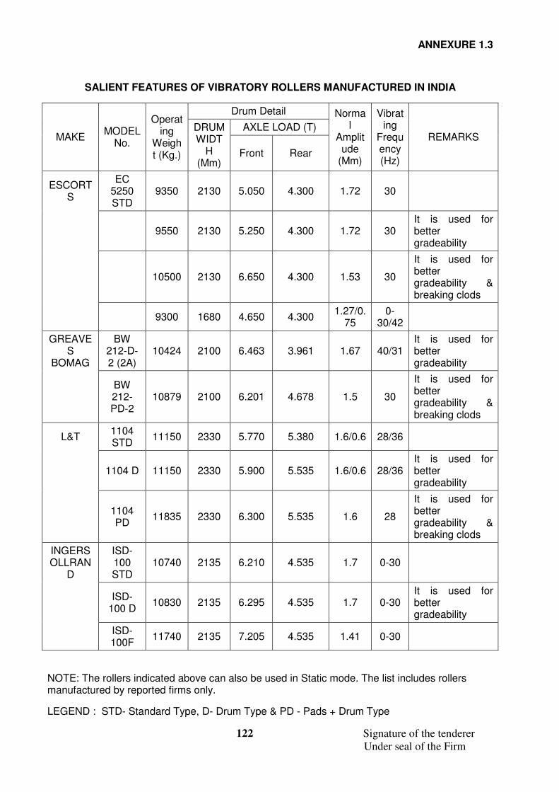
122 Signature of the tenderer
Under seal of the Firm
ANNEXURE 1.3
SALIENT FEATURES OF VIBRATORY ROLLERS MANUFACTURED IN INDIA
MAKE MODEL
No.
Operating
Weight (Kg.)
Drum Detail Normal
Amplitude
(Mm)
Vibrating
Frequency (Hz)
REMARKS DRUM WIDT
H (Mm)
AXLE LOAD (T)
Front Rear
ESCORTS
EC 5250 STD
9350 2130 5.050 4.300 1.72 30
9550 2130 5.250 4.300 1.72 30 It is used for better gradeability
10500 2130 6.650 4.300 1.53 30
It is used for better gradeability & breaking clods
9300 1680 4.650 4.300 1.27/0.
75 0-
30/42
GREAVES
BOMAG
BW 212-D-2 (2A)
10424 2100 6.463 3.961 1.67 40/31 It is used for better gradeability
BW 212-PD-2
10879 2100 6.201 4.678 1.5 30
It is used for better gradeability & breaking clods
L&T 1104 STD
11150 2330 5.770 5.380 1.6/0.6 28/36
1104 D 11150 2330 5.900 5.535 1.6/0.6 28/36 It is used for better gradeability
1104 PD
11835 2330 6.300 5.535 1.6 28
It is used for better gradeability & breaking clods
INGERSOLLRAN
D
ISD-100 STD
10740 2135 6.210 4.535 1.7 0-30
ISD-
100 D 10830 2135 6.295 4.535 1.7 0-30
It is used for better gradeability
ISD-100F
11740 2135 7.205 4.535 1.41 0-30
NOTE: The rollers indicated above can also be used in Static mode. The list includes rollers manufactured by reported firms only.
LEGEND : STD- Standard Type, D- Drum Type & PD - Pads + Drum Type

123 Signature of the tenderer
Under seal of the Firm
SKETCHES SHOWING MANNER OF COMPUTATION OF QUANTITIES OF VARIOUS CLASSIFICATIONS OF SOIL
(FIG. NOS.1.1 TO1.4)
SOFT/LOOSE SOIL
FINAL EXPOSEDSLOPE OF CUTTING
HARD/DENSE SOIL
HARD ROCK
BOX TYPE CUTTING
FINAL EXPOSED
(Figure No.1.1)
SLOPE OF CUTTING
SOFT/LOOSE SOIL
SOFT/DISINTEGRATEDROCK
HARD ROCK
FINAL EXPOSED
SLOPE OF CUTTING
SOFT/LOOSE SOIL
SOFT/DISINTEGRATED
ROCK
HAED ROCK
ONE SIDED CUTTING IN A TRANSVERSE SLOPING GROUND
SLOPE OFORIGINAL
CUTTING
CL
FINAL BASE OF CUTTING
(Figure No.1.2)
SOFT/LOOSE SOIL
FINAL EXPOSED
SLOPE OF CUTTING
HARD/DENSE
ORIGINAL SLOPE OF CUTTING
SOFT/LOOSESOIL
FINAL EXPOSEDSLOPE OFCUTTING
HARD ROCK
SOFT/DISINTEGRATED
ROCKHARD ROCK
WIDENING OF CUTTING WHERE THE EXISTING
CUTTING SLOPE DISAPPEARS AND A FRESH SLOPE ARISES (Figure No.1.3)
(Figure No.1.4)
SOFT/LOOSE SOIL
HARD/DENSE SOIL
ORIGINAL SLOPEOF CUTTING
HARD ROCK
ORIGINAL EXPOSED
SURFACE
FRESH CUTTING SLOPE IS AVAILABLE AFTER THE WORK.
EXTENSION OF EXISTING CUTTING WHERE NO
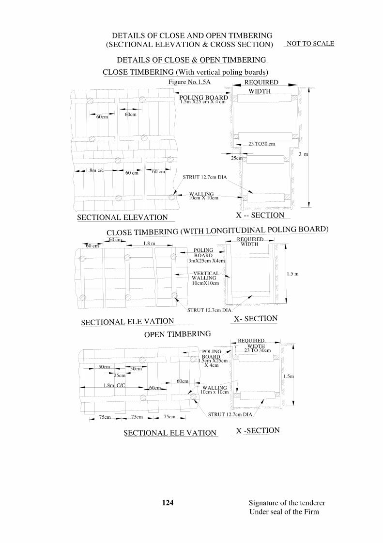
124 Signature of the tenderer
Under seal of the Firm
(SECTIONAL ELEVATION & CROSS SECTION)DETAILS OF CLOSE AND OPEN TIMBERING
Figure No.1.5A
DETAILS OF CLOSE & OPEN TIMBERING
CLOSE TIMBERING (With vertical poling boards)
NOT TO SCALE
60cm
POLING BOARD1.5m X25 cm X 4 cm
REQUIRED
WIDTH
23 TO30 cm
CLOSE TIMBERING (WITH LONGITUDINAL POLING BOARD)
SECTIONAL ELEVATION X -- SECTION
STRUT 12.7cm DIA
WALLING10cm X 10cm
POLING BOARD
3mX25cm X4cm
VERTICALWALLING10cmX10cm
REQUIREDWIDTH
STRUT 12.7cm DIA.
SECTIONAL ELE VATION
OPEN TIMBERING
X- SECTION
POLINGBOARD
1.5cm X25cmX 4cm
REQUIREDWIDTH
23 TO 30cm
STRUT 12.7cm DIA.
WALLING10cm x 10cm
SECTIONAL ELE VATION X -SECTION
1.8m c/c 60 cm60 cm
60cm
1.8 m60 cm
60 cm
1.5 m
1.5m
50cm
25cm
50cm
1.8m C/C60cm
60cm
75cm75cm 75cm
25cm3 m
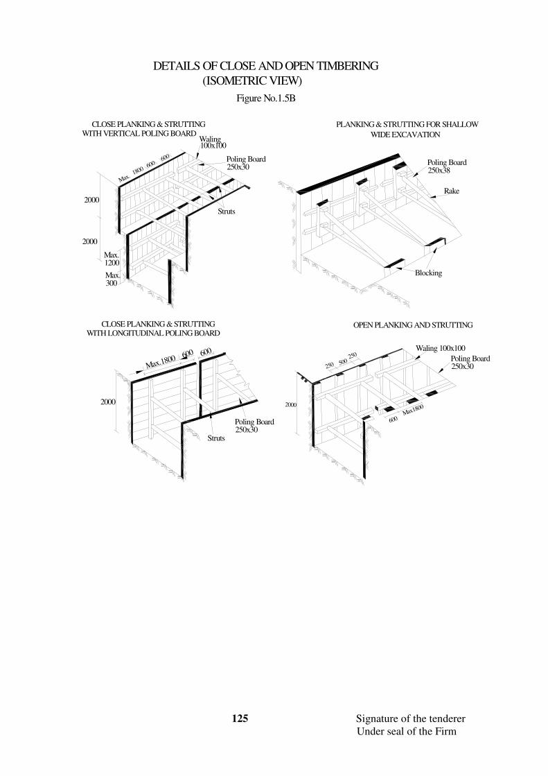
125 Signature of the tenderer
Under seal of the Firm
Figure No.1.5B
DETAILS OF CLOSE AND OPEN TIMBERING
(ISOMETRIC VIEW)
CLOSE PLANKING & STRUTTING WITH VERTICAL POLING BOARD WIDE EXCAVATION
PLANKING & STRUTTING FOR SHALLOW
WITH LONGITUDINAL POLING BOARDCLOSE PLANKING & STRUTTING OPEN PLANKING AND STRUTTING
Waling100x100
250x30Poling Board
Max.1800
600600
Struts
Max.1200
300Max.
600600
250x38Poling Board
Rake
Blocking
250 500250
250x30Poling Board
600Max1800
Poling Board250x30
Struts
Waling 100x100
2000
2000
2000
2000
Max.1800

126 Signature of the tenderer
Under seal of the Firm
Signature of the tenderer
Under seal of the Firm

127 Signature of the tenderer
Under seal of the Firm
SPECIFICATION FOR BRIDGE WORKS

128 Signature of the tenderer
Under seal of the Firm
BRIDGE WORKS
1.0 GENERAL
1.1 General requirement The contractor shall furnish all labour, equipment and materials required for complete
performance of the work in accordance with the drawings and as described herein. 1.2 Reference Points and Bench Marks z Permanent reference pillars established and fixed in the area shall not be removed or
disturbed under any circumstances without the approval of the Engineer. The Engineer-in-Charge will locate initially the centre line of the bridges and set out the centre point. Contractor will provide all labour and materials required for this purpose. The contractor shall set out details of position/profile of individual foundations, piers, abutments etc. and be responsible for accuracy thereof. The contractor shall carefully maintain and protect all benchmarks and reference points and shall lay out all his work by accurate reference there to. The relevant level of structure at different part will be checked by Engineer-in-charge or his representative. Para 401 of Indian Railways Bridge Manual, 1998 may be referred to for details on “Setting Layout of Bridges”.
1.3 For items not covered by these Specifications but required for Bridge Works such as Brick Masonry, Stone Masonry, Steel work etc, relevant CPWD Specifications may be referred to.
1.4 In Girder and Slab Bridges, Bearing areas for members shall be finished to true plane so as to give uniform bearing on the entire area. Bearing plane shall be horizontal even for the bridges in grades.
1.5 In major works, a field laboratory should be set up by the Contractor at his cost at the
work site, which should be equipped with necessary equipments to carry out the various tests on coarse and fine aggregates, cement, water and concrete.
2.0 EXCAVATION
2.1 Site Clearance
The contractor shall remove all vegetation, trees, structures and any foreign material existing at the site of proposed work. The area shall be stripped to remove roots of grass/trees, and other organic materials which shall be burnt and/or removed to approved disposal areas or other locations as indicated by the Engineer-in-Charge. Cost of labour, tools, transport etc. required for this is deemed to be included in the overall rates unless otherwise specified.
2.2 General requirements
The Contractor shall furnish all labour, equipment and materials required for complete performance of the works n accordance with the approved drawings and as described herein.
2.3 Drainage in the Vicinity of Excavations The contractor shall control the surface grade in the vicinity of all excavations so that the surface of the ground in vicinity is properly sloped or diked to prevent surface water from running into the excavated areas during the progress of the construction.
2.4 Excavations shall include the removal of all materials as per direction of the Engineer-in-Charge, as may be required to execute the work properly. Excavation shall be made

129 Signature of the tenderer
Under seal of the Firm
with sufficient clearance to permit the placing, inspection and setting of forms and completion of all works for which the excavation is made.
2.5 Sides and bottoms of excavation shall be cut sharp and true. Undercutting shall not be permitted. Earth sides of excavation shall not be used in lieu of formwork for placement of concrete unless otherwise authorised in special cases, by the Engineer-in-Charge where limitations of space for larger excavation necessitate such a decision.
2.6 When machines are used for excavation, the last 300 mm before reaching the required level shall be excavated by hand or by such equipment that will leave the soil at the required final level, in its natural condition.
2.7 The Bearing capacity of the soil at the bottom of excavation shall be determined by the Engineer-in-Charge, so as to decide on the depth of foundation.
2.8 The bottom of excavation shall be trimmed to the required levels and when carried below such levels by error shall be brought to level by filling with concrete 1:3:6 or as specified, at the contractor's cost. If the contractor is directed by the Engineer-in-Charge to excavate to a lower level than that indicated on the drawings and the work is covered by through rates, such additional excavation shall be paid for at the applicable unit rate.
2.9 The foundation for Bridges should be taken to a depth not less than 1.75 metres below
the lowest anticipated scoured bed level in ordinary soil. In rocky soil, it will be adequate if it is properly keyed into the rocks for a minimum of 0.30 metre in case of hard rock and 1.50 metres in case of soft rock. Sloping rock is to be suitably benched. Fissures and weathered rocks are to be avoided. In soft soils, raft foundations may be provided protected by means of suitable aprons and cut off walls or launching apron both on the upstream and downstream side to prevent undermining of the foundation.
2.10 The contractor shall be responsible for assumptions and conditions regarding the nature
of materials to be excavated and the difficulty of making and maintaining the required excavations and performing the work required as shown on the drawing and in accordance with these specifications. Coffer-dams, sheeting, shoring, bracing, draining, dewatering, etc. shall be arranged and installed as required and the cost thereof shall be included in the unit rate quoted for the item of excavation. The contractor shall be held responsible for any damage to any part of the work and property caused by collapse of sides of excavations. Material used for temporary works may be salvaged if it can be done without jeopardising safety of the work and structures and subject to approval of the Engineer-in-Charge. However, no extra claim shall be entertained for material not salvaged or any other damage to contractor's property as a result of the collapse. He shall not be entitled to any claim for additional payment for having to re-do the excavation as a result of the same.
2.11 All excavation for installation of underground facilities, such as piping, sewer lines, tunnels, ducts, drain lines etc. shall be open cuts.
2.12 Where excavation requires bracing, sheeting, or shoring etc. the contractor shall submit to the Engineer-in-Charge, drawings showing arrangements and details of proposed installations and shall not proceed until he has received approval from the Engineer-in-Charge.
2.13 Classification of earth for excavation for bridges shall be same as applicable for earth work, unless otherwise stipulated in the Contract.
2.14 Measurement

130 Signature of the tenderer
Under seal of the Firm
Except where otherwise provided for in BOQ, for foundation in bridges, the following specific provisions will apply.
Measurement for payment will be based on volume calculations determined by the existing grade, (ground level) and the bottom elevation (level) of structure/lean concrete with lateral dimensions (vertical sides) as per concrete outline of lowest footing Concrete dimensions determined from drawings). The unit of measurement shall be cubic metre. Nothing extra would be payable for slope, shoring, strutting etc. irrespective of the fact that they are actually provided. Payment includes leading excavated soil to a spoil dump or for reuse in a location in the vicinity as directed by Engineer-in-Charge.
2.15 Excavation in Rock- Hard, Soft or Decomposed:
2.15.1 For the purpose of classification of rock in excavation, the following definitions shall apply
a) Hard rock requiring blasting:
Any rock excavation for which blasting is required.
b) Soft or Decomposed rock:
Lime stone, sand stone, laterite, hard conglomerate or other soft or disintegrated rock which can be quarried or split with crow bars or wedges.
2.15.2 Excavation
The specifications for excavation Clause No.2.0 to 2.13 above shall apply to excavation
work in rock also, except for the bottom of excavation, where depending on the type of rock, over-breaks upto a maximum depth of 0.3 m below the required level may be allowed by the Engineer-in-Charge at his discretion and paid accordingly. Concrete backfill in such over-breaks shall also be paid for. No payment shall, however, be allowed for backfilling, if such overbreaks are required to be brought to grade by filling with only soil including its proper compaction.
2.15.3 Blasting
Blasting material required for excavation work shall be arranged by the contractor at his
cost, from any authorised dealer of such approved material. Necessary assistance for obtaining approval for procurement of the material will be given by the RITES/Employer. The contractor shall be fully responsible for entering into agreement with any authorised magazine contractor in respect of rates, regularity of supply etc. Contractor will also obtain necessary license for transporting, stocking and use of explosives and depute only suitable qualified and licensed personnel for handling the explosives.
All rules under the Explosives Act or other local rules in force shall be fully observed. All blasting works shall be done in accordance with the stipulations contained in the Indian Standard Specification No. IS:4081. Blasting shall be done by employing qualified personnel and under careful supervision. Proper precautions for safety of persons and property shall be taken, where blasting is to be carried out in the proximity of other structures. Sand bags etc. shall be used on top of the blast holes to prevent the rock fragments, from causing damage to adjacent structures and other property. The unit rate for excavation involving blasting shall be inclusive of the cost of providing all necessary materials, labour and arranging for such precautions.
2.15.4 Unexploded charge

131 Signature of the tenderer
Under seal of the Firm
The number of blasts to be fired and the actual number of shots heard shall be compared and the person responsible shall satisfy himself by site examination that all blasts have exploded before any person working in the area is permitted to re-approach the work site. The withdrawal of the unexploded charge shall not be permitted under any circumstances. Unless any other procedure is considered advisable by the person in charge of blasting operation, the unexploded charge shall be flooded with water and the hole marked in a distinguishable manner. Another hole shall be made at a distance as decided by the person in charge of blasting operation, off the old hole and fired in the usual way. This process shall be continued till the original blast is exploded.
2.15.5 Decomposed or Soft rock
Excavation in "decomposed or soft rock" shall be carried out by blasting or by crow bars, by shovel and pick axes etc. or both the methods. Nothing extra shall be paid for the use of any particular method.
2.15.6 Chiseling in Hard Rock :
Where blasting is prohibited or not practicable, excavation shall be carried out by chiseling and payment shall be made at the same rate as provided for hard rock requiring blasting. The decision of the Engineer-in-Charge in this regard shall be final.
2.15.7 All excavated materials obtained from excavation shall be disposed off by the contractor as directed by Engineer-in-charge.
2.16 Measurement for Excavation in rock:
(i) As soon as level of rock is reached, the contractor shall intimate the Engineer-in-
Charge, who shall record the level for calculating quantities of excavation in rock.
(ii) When "hard rock" and "decomposed or soft rock" are mixed together and separate
rates have been provided for in the contract, the entire quantity of excavation done below rock level shall be recorded from cross-section taken before commencement and after completion of rock excavation, payment lines being as provided in clauses 2.14 and 2.15.2. The hard rock excavated shall be stacked, measured and reduced by 30% to allow for bulking and voids to arrive at the quantity payable under "hard rock". The difference between the entire excavation below rock level (between the pay lines) and the quantity payable under "hard rock" shall be paid for as "decomposed or soft rock".
(iii) In case, the quantity of "hard rock" alone as measured above is in excess of the
theoretical total payable quantity of excavation below rock level, then payment under "hard rock" shall be restricted to the total theoretical payable quantity.
(iv) All excavated material, rock or soil, obtained as a result of over-excavation and for which payment shall not be made, shall also be carried and disposed of as directed and stacked at places shown by the Engineer-in-Charge, at the cost of the contractor.
(v) In the case of stray boulders which are classified as "hard rock", measurements of such outcrops shall be made on the basis of linear measurements of the outcrop

132 Signature of the tenderer
Under seal of the Firm
made before excavation. Such measurements shall be signed by the contractor in token of acceptance before excavation is taken in hand.
(vi) When the excavation in rock is paid for as a single item for all classes of rock, the
measurement will be made based on cross-sectional area after recording rock level at commencement and finishing.
2.17 Excavation below water Table
2.17.1 Wherever water table is met with during the excavation. the Contractor shall immediately report the fact to the Engineer-in-Charge who shall arrange to record the exact level of the water table. The decision of the Engineer-in-Charge in the matter shall be final.
2.17.2 The Contractor shall dewater and maintain the water table below the bottom of the excavation level during excavation. concreting and back-filling.
2.18 Methods of Measurements
In the case of excavation in rock, payment for overbreaks upto a maximum depth of 0.3 m below the required level may be allowed by the Engineer-in-Charge at his discretion. Nothing extra is payable for dewatering operation during execution of work for earthwork carried out above sub-soil water level.
3.0 RUBBLE BACKING
3.1 A backing of dry rubble walling or Boulder filling will be provided behind abutments, wing walls and Return walls for facilitating proper drainage. It shall be provided to dimensions in accordance with the drawings. The Boulder filling will be for full height and of thickness not less than 600mm with smaller size towards the back behind the boulder filling.
3.2 The materials used should be broken stone of quality approved by Engineer-in-Charge. The stones used will be of least dimension of 15 cm in any direction and not friable. Materials selected from out of excavated material may be permitted to be used by Engineer-in-Charge, in which case only labour rate is payable for the work. Otherwise, the cost will include supply of all materials, labour and tools.
3.3 For typical arrangements of Rubble Packing and Backfill behind the Abutments, wing walls and Return walls. Sketch 1 relating to Para 6.4.2 of RDSo’s Guidelines for Earthwork in Railway Projects GE G-1 may be referred to.
4.0 BACKFILL
4.1 The contractor shall furnish all labour, equipment and materials required for
complete performance of the work in accordance with the drawings and as described herein. Back fill material shall consist of Granular materials of Soil Groups GW, GP and SW as per IS 1498-1970.
4.2 After completion of foundation footings, abutments and wing walls and other constructions below the elevation of the final grades and prior to backfilling, all forms, temporary shoring, timber etc. shall be removed and the excavation cleaned of all trash, debris, and perishable materials. Backfilling shall begin only with the approval of the Engineer-in-Charge.

133 Signature of the tenderer
Under seal of the Firm
4.3 Backfilling shall be done with inorganic materials, obtained from the excavation if found suitable or from borrow pits and subject to the approval of the Engineer-in-Charge. Filling behind abutments and wing walls shall be done with sandy materials to be obtained from approved source.
4.4 Backfill shall not be dropped directly upon or against any structure in locations where there is danger of displacement or damage.
4.5 Backfill shall be placed in horizontal layers not exceeding 20 cm in thickness. Each layer shall be compacted under proper moisture content and with such equipment as may be required to obtain a density equal to or greater than 95 % of maximum dry density as determined by the relevant Indian Standards. Trucks or heavy equipment for depositing or compacting backfill shall not be used within 1.5 m of building walls, piers, or other facilities which may be damaged by their weight or operation. The methods of compaction shall be subject to the approval of the Engineer-in-Charge. Pushing of earth for backfilling shall not be adopted under any circumstances.
4.6 Backfill adjacent to pipes shall be hand placed, free of stones, concrete, etc.
compacted uniformly on both sides of the pipe and where practicable, to a depth of 300 mm over the top of pipes. While tamping around piping, care shall be taken to avoid unequal pressures.
4.7 On completion of structures, the earth surrounding them shall be accurately finished to line and grade as shown on the drawings. Finished surface shall be free of irregularities and depressions and shall be within 50 mm of the specified level.
4.8 Measurements of backfill
Measurements shall be based on the volume by computed cross-sections.
5.0 CONCRETE
5.1 Scope
5.1.1 This section of the Specification covers the technical requirements for furnishing, forming, placing and finishing all concrete, plain and reinforced complete for all structures at all elevations, superstructures, ducts and trenches and including encasement of steel section as shown on the drawings except as otherwise specified, and providing necessary recesses, weepholes etc.
5.1.2 All concrete works as indicated in the scope of this contract shall be carried out as per these specifications.
5.2 General Requirements
5.2.1 The contractor shall furnish all labour, material and equipment to form, place and finish all structural concrete and miscellaneous items complete, as indicated on the drawings and as described herein.
5.2.2 All materials, tests, mixing, placing, formwork, reinforcing and workmanship shall conform to the Indian Railway Standard Code of Practice for Plain and Reinforced Concrete for General Bridge Construction (Revised latest edition) (Concrete Bridge Code) and subsequent amendments and other relevant codes of the Bureau of Indian Standards and/or as shown on drawings and/or described herein.

134 Signature of the tenderer
Under seal of the Firm
5.3 Materials
5.3.1 Cement shall conform to Clause 4.1 of IRS Concrete Bridge Code of year 1997
incorporating all Correction Slips upto date (currently C.S.No.11 dated 27.12.2007)
5.3.2 Concrete aggregates shall conform to "Specification for Coarse and Fine Aggregate from Natural Sources for Concrete" IS : 383 (Latest Edition) as indicated in Clause 4.2 of Concrete Bridge Code.
5.3.3 Water used in mixing concrete shall be clean and free from injurious amounts of oils, acids, alkalies, organic materials, or other deleterious substances. Reference may be made to Clause 4.3 of Concrete Bridge Code.
5.3.4 Reinforcement shall conform to the provisions in Clause 4.5 of Concrete Bridge Code from reputed manufacturer like SAIL, TISCON, RINL. All reinforcement shall be clean and free from loose, mild scales, dust, loose rust and coats of paint, oil or other coatings, which may destroy or reduce bond. The exact IS Specifications to which Steel should conform to IS 432 Pt.I or IS 1786 or both shall be indicated in the Drawings or advised by the Engineer-in-charge. Where directed by the Engineer in charge, anticorrosive protective coating of reinforcement bars shall be provided as stipulated in Clause 7.1.5 of Concrete Bridge Code.
5.3.5 Reinforcement accessories shall be furnished by the contractor. Binding wire shall be annealed from wire quality not less than No. 16 S.W. gauge (1.65 mm dia). Bar supports, chairs and bolsters (as approved by the Engineer- in-Charge) shall be sufficiently strong to support the steel properly.
5.4 Concrete Mix
5.4.1 The compression strength as measured by works test at 28 days, shall be as
indicated on the drawings for the different areas and types of construction or as indicated in Clause 5.1 of IRS-Concrete Bridge Code 1997.
5.4.2 Where controlled concrete is used. the minimum cementious Material content will be as per Clause 5.4.5 of IRS Concrete Bridge Code 1997.
5.4.3 Unless otherwise specified in the BOQ Concrete grade M-20 will be Nominal Mix Concrete with proportions of materials as per Clause-5..5.3 and Table-5 of Concrete Bridge Code for M-20 Concrete. For Nominal Mix concrete of Grades M5, M7.5, M10 and M15, Clause 9.3 and Table 9 of IS 456-2000 may be referred to. Concrete grade above M-20 will be as per mix design to be submitted by the contractor conforming to Code IS-10262:1982(SP-23:1982). Such mix design will be carried out jointly by the Contractor and the Site Engineer of RITES and cement consumption thereon will be decided on the basis of mix design in terms of Clause 5.4.5 of Concrete Bride Code. No extra payment will be made for this mix design of any grade.
5.5 Sampling and Testing in the Field
5.5.1 Workability of the Concrete should be controlled by direct measurement of water content with or without use of admixtures. Samples of concrete shall be taken at the direction of Engineer-in-Charge in the field and workability checked in accordance with IS : 1199 "Methods of sampling and analysis of concrete".

135 Signature of the tenderer
Under seal of the Firm
5.5.2 These samples shall be tested for strength and consistency at testing laboratory set up at the Project site or at any other Government Laboratory, approved by the Engineer-in-Charge, in accordance with IS : 516. The moulds, labour and material for cubes shall be supplied by the contractor who shall also arrange to transport the cubes to laboratory at his cost. Actual cost of the testing shall be borne by the contractor.
5.5.3 The acceptance criteria for concrete shall be as given in subsequent paras. Only the
slumps indicated in the approved design mix shall be adopted. However, larger slumps than those indicated in the approved design mix of concrete of a specified grade (strength) may be necessary to get a workable consistency for concrete in the case of beams, walls columns and other heavily reinforced members. No extra payment shall be made for extra cement that may have to be added in such cases to get the concrete of the same specified grade (strength) with larger slumps. The decision of Engineer-in-Charge regarding the degree of consistency or the amount of slump shall be final.
5.5.4 Samples shall be cured under laboratory conditions, except when in the opinion of the Engineer-in-Charge extreme weather condition may prevail at which time the Engineer-in-Charge may require curing under job (field) conditions.
5.5.5 If the 'test strength' of the laboratory controlled cubes for any portion of the concrete work falls below the compressive strength specified, the Engineer-in-Charge shall have the right to order a change in the proportions or the water content for the remaining portion of the structure.
5.5.6 If the 'test strength' of the job cubes falls below the specified strength, the Engineer-in-Charge shall have the right to require provisions for temperature and moisture control during the period of curing as necessary to secure the required strength, and may require re-tests in accordance with "standard method of securing, preparing and testing specimens for hardened concrete for compressive and flexural strengths".
5.5.7 When the cubes tested reveal a strength lower than those specified, the acceptance criteria for such concrete shall be decided as stipulated in subsequent paras. The Engineer-in-Charge shall also reserve the right to reject whole or any part of the work. In case of acceptance of such works the standard deviations shall be worked out, and examined by the Engineer-in-Charge and if he is satisfied only then such works can be accepted at the accepted or at the reduced rate.
5.6 General Storage
5.6.1 All materials shall be stored by the contractor in a manner affording convenient access for identification and inspection at all times. The storage facilities arrangements shall be subject to the approval of the Engineer-in-Charge. Reference may be made to Clause 4.7 of Concrete Bridge Code on Handling and Storage of materials which also refers to IS 4082.
5.6.2 Cement shall be stored by the contractor in silos or suitable weather-proof buildings with dry floors, to be provided by the contractor, in a manner so as to prevent deterioration.
5.6.3 Aggregate shall be stored by the contractor in areas floored with tightly laid wooden planks or other approved hard, smooth and clean surface, in a manner precluding intrusion of any foreign material. Aggregates of different classes shall be stored in separate piles sufficiently separated from each other to prevent the material at edges of the piles from getting intermixed.

136 Signature of the tenderer
Under seal of the Firm
5.6.4 Reinforcement shall be stored off the ground in a manner to prevent objectionable changes in original surface characteristics, in separate piles or racks above grade.
5.7 Mixing and Placing Concrete
5.7.1 For detailed provisions on “Production and Control of Concrete” clause 5.6 of Concrete Bridge Code may be referred to. On Transportation, placing and compaction of Concrete, Clauses 8.1 to 8.3 of Concrete Bridge Code may be referred to. Concrete shall not be placed in any unit of the work until after the forms, bracing, reinforcing steel and other preparations for casting have been approved by the Engineer-in-Charge and approval given in writing to proceed with the casting. Concreting under extreme weather conditions shall not normally be permitted. Where concreting has to be done under Special conditions, reference may be made to Clause 8.6 of Concrete Bridge Code which deals with concreting in extreme weather conditions, under water concreting, concrete in sea water and concrete in aggressive soils and water.
5.7.2 No concrete shall be placed except in the presence of the Engineer-in-Charge or his authorised representative. Concrete which is not placed in accordance with the specifications or which is of inferior quality shall be removed and replaced by the contractor at his cost.
5.7.3 It is imperative that all excavations prepared for concrete construction are maintained free of water until such concrete work is completed. The contractor shall make provisions and furnish equipment as required for such dewatering, . Water used for flushing concrete placing equipment shall be discharged clear of the concrete and forms.
5.7.4 All concrete shall be mixed until there is a uniform distribution of materials, and shall be discharged completely before the mixer is recharged. Mixing shall be done in a mechanical mixer and the type and size shall be subject to the approval by the Engineer-in-Charge. The mixer shall be rotated at a speed recommended by the manufacturer and mixing shall be continued at least two minutes after all materials are in the drum. For batches larger than 0.75 cum, mixing time shall be increased at the rate of 15 seconds for each additional 0.75 cum or fraction thereof. All concrete shall be discharged within 3 minutes after the introduction of mixing water to the cement and aggregates unless a different time is specified by the Engineer-in-Charge.
5.7.5 Before beginning a run of concrete, all hardened concrete and foreign materials shall be removed from the inner surfaces of mixing and conveying equipment. The first batch of concrete through a cleaned mixer for use in the works shall contain 15% less coarse aggregates than normal in order to compensate for coating the interior of the mixer. All conveyance buggies and borrows shall be thoroughly cleaned at frequent intervals during the placing of concrete. Concrete shall be rapidly handled from the mixer to the place of final deposit and shall not be delivered by spout or troughs nor dumped into carriers with a free fall from the mixer of more than 1.50 m. Every possible precaution shall be taken to prevent separation or loss of the ingredients while transporting the concrete.
5.7.6 The placing of concrete shall be a continuous operation with no interruption in excess of
30 minutes between the placing of continuous portions of concrete. Concrete shall be deposited in such a manner as would prevent displacement of forms or reinforcement above the level of the fresh concrete, and the formation of seams or planes of weakness within the sections. Each layer shall be plastic where a new layer is placed upon it. Concrete shall be deposited as close to its final position as practicable in order to prevent segregation. After initial set of concrete the forms shall not be jarred and no vibrating equipment shall be placed on the ends of projecting

137 Signature of the tenderer
Under seal of the Firm
reinforcement. Chutes used to convey concrete shall be surfaced with metal or other material, and there slopes shall not be such as to cause segregation. Suitable spouts or baffles shall be provided to prevent segregation during discharge. Where concrete is placed manually by use of pans, the entire pan with the concrete shall be dropped to the surface where concrete is to be deposited instead of emptying the pan manually.
5.7.7 Concrete shall not ordinarily be placed under water. In unavoidable cases, such
concreting shall be done only with the specific approval of procedure and application by the Engineer-in-Charge Additional cement shall be added as necessary and shall be paid for if the accepted rate for concrete provides for separate payment for cement as opposed to through rate for cement Concrete.
5.7.8 To secure maximum density and eliminate formation of air pockets the concrete shall be thoroughly vibrated and worked around all reinforcement, embedded facilities and into corners of forms. Unless other methods are authorised by the Engineer-in-Charge, mechanical vibrators shall be used for the purpose, the type and operation of which is subject to the approval of the Engineer-in-Charge. The extent of vibration shall be through the entire depth of each new layer and several centimetres into the layer below with vibration applied at the point of deposit and uniformly through out the freshly placed concrete, not farther apart then the radius over which the vibration shall be sufficient to accomplish thorough compaction and complete embedment of reinforcement. The tendency for large aggregate to gravitate to lower elevations due to vibration shall not relieve the contractor from his responsibility for obtaining a uniform density throughout the mass. Excess cement paste thus formed at the top of each layer shall be removed before the succeeding layer is deposited. Hand tamping shall not be permitted. Contractor shall provide proper equipment for compaction of concrete in areas where conventional methods would not be adequate. Immersion type vibrators shall be provided at the rate of at least one 65 mm unit per 4 cum per hour together with at least one stand-by vibrator of the appropriate size. Vibrators shall be inserted in the concrete at a sufficient number of places so that their fields of influence overlap and shall not be used to work the concrete along the forms or screens. Vibrators shall be withdrawn in time to prevent the formation of voids. Over-vibration causing segregation, surface laitance, or leakage through the forms shall be avoided. Where electrically operated vibrators are used, diesel or petrol driven stand-by vibrators shall be available for carrying on uninterrupted vibration in case of power failure.
5.7.9 Form Vibrators shall be used in addition to internal vibration in case of Prestressed concrete girders, slabs etc.
5.7.10 The use of vibrators complying with IS 2505, IS 2506, IS 2514 and IS 4656 for compacting concrete is recommended.
5.7.11 Re-tamping of concrete or mortar which has partially hardened shall not be permitted.
5.7.12 Concrete cover blocks of the same strength and density as parent concrete shall be
used.
5.8 Construction Joints 5.8.1 The location and details of construction joints not indicated on the drawings must be
approved of by the Engineer-in-Charge before concrete is poured. Reference may be made to Clause 8.5 of Concrete Bridge Code read with Appendix A of the Code.

138 Signature of the tenderer
Under seal of the Firm
5.8.2 Construction joints in foundations shall not be provided without specific concurrence of the Engineer-in-Charge.
5.8.3 When the work has to be resumed on a surface which has hardened, such surface shall be roughened, clean with wire brushes etc. thoroughly wetted and excess water removed before placing of the concrete.
5.8.4 Where the concrete has not fully hardened, all laitance shall be removed by scrubbing the wet surface with wire or bristle brushes, care being taken to avoid dislodgment of particles of aggregate. The first layer of concrete shall be placed on this surface with care and shall be well-rammed against old work, particular attention being paid to corners and close spots.
5.8.5 The unit rate of concrete work shall include the cost of preparation of construction joints as mentioned above and no extra payment shall be admissible on this account.
5.9 Inserts
5.9.1 All anchors, anchor bolts, inserts, pipes, conduits, sleeves, brackets, frames,
nosings, bolts, etc. and any other items that are required to be embedded in the concrete shall be placed in correct position before pouring. Extra care shall be taken during pouring operation to maintain their location. Blockouts and openings shall be kept as indicated in the drawings. These inserts shall be welded to the nearest reinforcement to keep them in position and all such weldings shall be deemed to be included in the unit rate quoted and no extra shall be payable on this account.
5.9.2 Provision will be made for insertion of holding down bolts on piers/bed-blocks in form of
necessary holes by leaving a suitable insert before concreting and removing the same after the concrete attains adequate strength. These holes will be filled with cement sand mortar after the girders are aligned and holding down bolts inserted and fixed in position.
5.10 Curing of Concrete
5.10.1 Reference may be made to Clause 8.4 of Concrete Bridge Code on the Specifications
relating to Curing of Concrete.
5.10.2 Unless otherwise specified, all concrete shall be moist cured by keeping all exposed
surfaces, edges and corners continuously moist for at least seven days after being placed, by spraying, ponding or covering with waterproof paper or moisture retaining fabric. Where air temperature is expected to fall below 5 deg.C during the curing period, additional covering by blanketing material shall be provided so that concrete temperature at surface does not fall below 10 deg. C. Immediately after stripping of the forms, water shall be applied directly to the concrete surfaces, the wetting down operations shall be continuous within the curing time specified.
5.10.3 As an alternative to continual wetting down of pier/abutment/girder faces, the use of
a sprayed-on membrane may be substituted subject to approval by the Engineer-in-Charge. Such approved curing compounds shall be applied to all exposed surfaces of the concrete along with stripping of form work.
5.11 Method of Measurement of Concrete Measurement shall be in cubic metres correct upto second place of decimal.
Deductions shall be made for all block outs and openings but not for embedments, reinforcements, and weep holes.

139 Signature of the tenderer
Under seal of the Firm
6.0 FALSE WORK AND FORMWORK 6.1 Reference may be made to Clauses 6.1 and 6.2 of Concrete Bridge Code respectively
for Falsework and Formwork.
6.2 All details of formwork, placing, tieing etc. shall be subject to the approval of the
Engineer-in-Charge and the contractor, when required, shall submit drawings, showing details of form construction. The contractor shall be responsible for the adequacy of the formwork to withstand the pressure of freshly placed concrete or other loads imposed without failure, movement or deflection of the component parts. Forms shall be true to the shape, lines and dimensions of the concrete work as shown on the drawings. Wherever vibration has to be applied externally the design of the formwork should receive special consideration based on the disposition of vibrators.
6.3 For concrete surfaces that are exposed to view and for all other concrete surfaces that are to be finished smooth, the lining of forms shall be of smooth, non-absorbent lining material. The type and conditions of such lining for forms shall be subject to the approval of the Engineer-in-Charge. All edges of panels shall be square and straight in both directions, and all panels shall match perfectly in length, width and alignment as required.
6.4 All forms shall be sufficiently tight to prevent the loss of liquid from the concrete. All rubbish particularly chipping, shaving and saw dust shall be removed from the interior of the forms before the concrete is placed and the formwork in contact with concrete shall be cleaned and thoroughly wetted or treated with an approved composition or release agent to prevent absorption of water from adherence of form to the concrete. Such composition or release agent shall be kept out of contact with reinforcement and shall be non-staining and non- injurious to concrete.
6.5 Form lumber may be reused, provided it is true, unwarped, thoroughly clean and without broken or damaged edges and equal in every respect to new lumber. All reformed lumber shall have the contact surfaces reoiled or recoated with an approved composition prior to usage.
6.6 Contractor shall keep an accurate record of the date on which the concrete is cast for each part of the work and the date on which the form work is removed.
6.7 Removal of forms from structural concrete shall be in accordance with the requirements stipulated on stripping time in Clause 6.4 of Concrete Bridge Code.
6.8 No supporting forms shall be removed suddenly in such a manner as to create shock-loading.
6.9 The tolerances for Finished Concrete Bridge structures shall be as stipulated in Clause
6.5 of Concrete Bridge Code.
6.10 Method of Measurement
Measurement of form work where separately provided for and so included in the Schedule shall be based on contact area of concrete worked out from dimensions shown on the drawings. The unit of measurement shall be sq. metres correct to second place of decimal. Otherwise, the cost will be part of rate quoted for concrete works.
7.0 BENDING AND PLACING REINFORCEMENT
7.1 For specifications relating to ordinary reinforcement (other than Prestressing Tenders)
reference may be made to Clause 7.1 of Concrete Bridge Code. Contractor shall, as

140 Signature of the tenderer
Under seal of the Firm
per instruction of Engineer-in-Charge, fabricate and place reinforcement to shapes and dimensions as indicated or required to carry out intent of drawings and specifications. The reinforcement shall conform to the provisions detailed in Para 5.3.4 above.
7.2 The contractor shall prepare bar-bending Schedule on the basis of the drawings marked "released for construction" and submit the same for approval. No work shall be commenced without the approval of the Schedule.
7.3 Any adjustments in reinforcement to suit field conditions and construction joints other than those shown on drawings shall be subject to the approval of the Engineer-in-Charge.
7.4 The contractor shall adhere strictly to requirements for concrete cover over steel reinforcement, protection of bars for bonding with future extensions, columns ties, splices, laps, spacer bars, temperature reinforcement, mesh reinforcement and other items in connection with proper placing.
7.5 Reinforcement shall be placed accurately, conforming to tolerances not exceeding those stipulated in Clause 7.1.3.3 of Concrete Bridge Code, tied or welded securely at intersections and splices, and held in position with spacers or other approved supports during concrete placement. Tie wire ends shall be pointed away from surface. Where bars at laps are welded, the length of weld shall be minimum butt welded on both sides of the joint and shall be in accordance with the relevant Indian Standards specially IS 2751. The contractor will not be entitled to any extra payment for welding the reinforcements.
7.6 Payment for steel reinforcement bars shall be on the basis of weight of bare steel irrespective of any coating applied, in metric tonnes. The weight of the bar shall be derived from the sizes and corresponding unit weights given in hand book of BIS. Standard hook lengths, chairs, spacer bars and authorised laps only shall be included in the weight calculated. Binding wires shall not be weighed nor otherwise measured. Measurements for weight shall not include cutting allowance etc.
7.7 Bending of bars will normally be done 'cold'. Engineer-in-Charge's specific approval will be obtained for hot-bending of bars. Torsteel/Deformed bars will under no circumstances be hot-bent. No extra will be payable for hot-bending in lieu of cold bending.
8.0 TESTING OF GRADE MIX CONCRETE
For Grades M-20 and above Sampling, Strength Test and Acceptance Criteria shall be as stipulated in Clause 8.7 of Concrete Bridge Code. Extracts are at Annexure A. Procedure for carrying out Cube Compressive Test is at Annexure B.
9.0 CONCRETE PIPE CULVERTS
9.1 General
9.1.1 The pipe used shall be in accordance with IS:458-56 "Concrete Pipes" and the type will generally be to class NP-4 or as per approved RDSO drawing, unless otherwise specified in the drawing. They shall also be provided with collar unless otherwise specified or permitted by the Engineer-in-Charge.
9.1.2 The laying of pipes will be in accordance with IS:783 Code of Practice for laying of concrete pipes and guidelines in Section 2300 of Ministry of Shipping and Transport Specification for Road and Bridge works.
9.2 Materials and Handling

141 Signature of the tenderer
Under seal of the Firm
9.2.1 All materials used in the manufacture of pipes as well as laying in the pipe culverts shall conform to the general requirements contained in the IS Specification mentioned above and indicated in the foregoing paras.
9.2.2 Each consignment of the pipes shall be inspected, tested where considered
necessary and approved by the Engineer-in-Charge before their incorporation in the works. If the pipes are not being cast in the vicinity of the works, suitable facilities shall be provided for the Engineer-in-Charge to inspect them during the process of manufacture at the place of manufacture. Necessary test certificates for the materials used shall be produced to the Engineer-in-Charge when demanded.
9.3 Excavation
9.3.1 The foundation bed for the pipes shall be excavated true to the levels and grades shown
in the drawing or as directed by the Engineer-in-Charge. The pipes shall be placed in shallow excavation made in natural ground, or in trenches cut in the previously made embankments. Where the height of fill exceeds 3 times the external diameter of the pipe before excavating for pipe laying, the embankment shall first be made and properly consolidated upto a level of one pipe diameter above the proposed top of the pipe for length equal to 5 pipe diameters on either side of centre line, trenching being done thereafter. The sides of the trench shall be as nearly vertical as possible, and the clearance between sides, and pipe shall not be less than 150 mm or more than 1/3rd the pipe diameter.
9.3.2 If soft, spongy or other type of unstable soil is met with during such excavation, the
unsuitable material shall be removed to depth, width and length as directed by the Engineer-in-Charge and be back filled with approved granular soil which shall be thoroughly compacted and shaped to the specified level and shape.
9.3.3 Where bed-rock-boulder, hard clay, shale or other hard material is met with, the excavation shall be taken for at least 20 mm below the bottom level of the pipe and space filled with approved soil, free of stone, fragmented material etc. and compacted for providing adequate support unless concrete bedding is specified otherwise.
9.3.4 Generally pipes for railway culverts will be laid on concrete bedding unless otherwise specified in the drawing.
9.4 Bedding for Pipe
The concrete used for the bedding shall have mix which shall have a 28-day compressive strength of not less then M15 grade. Unless otherwise specified bedding shall have a minimum thickness of 1/4th of the normal diameter of the pipe and form a cradle extending for 1/4th of the diameter of the pipe above the lowest bedding level. Suitable recess will be provided in the bedding for resting the projection, collars, etc. for the pipe.
9.5 Back Filling
9.5.1 Trenches shall be back filled soon after the jointing material has hardened. Back filling shall be made of selected good soil free of stones, roots or other organic matter and the soil shall be approved by the Engineer-in-Charge. The back filling shall be done carefully with selected/approved material upto 30 cm above the top of pipe and fully rammed and consolidated at optimum moisture content. It shall be laid in layers not exceeding 150 mm. Care should be taken particularly while consolidating the soil under the haunches of the pipe. Consolidation below and above haunches of the

142 Signature of the tenderer
Under seal of the Firm
back fill shall be done by foot, light tampers or hand-operated mechanical equipment approved by Engineer-in-Charge.
9.5.2 Filling shall be done simultaneously on both sides of the pipe so that unequal pressures do not occur. No walking or working out the completed pipe shall be permitted till it is back-filled upto 30 cm over the pipe.
9.5.3 In case of high embankment after filling the trench upto the top of the pipe, a loose fill of a depth equal to the external diameter of the pipe shall be placed over the pipe before further layers are added and compacted. This shall be done for the full width of the trench. Only further layers placed above this level, shall be compacted.
9.6 Face Walls and Wing Walls
Face walls, wing walls and aprons, etc. shall be constructed in accordance with the details shown in the drawing or as approved by the Engineer-in-Charge. No traffic shall be permitted over the pipe culvert unless the filling over the pipe is at least 60 cm.
9.7 Measurements for Payment
9.7.1 RCC pipe culverts shall be measured along their centre between the inlet and outlet
ends, in linear meters. Length for supply and laying includes supply of collars jointing material and all labour required for laying, aligning, jointing and curing joints.
9.7.2 Selected granular material and cement concrete for pipe bedding shall be measured as laid in cubic metres. Ancillary work like head walls, etc. shall be measured as provided under the respective items of BOQ.
9.8 Rates
9.8.1 The rate for the pipe shall include the cost of pipe and matching collars including
loading, unloading hauling handling, storing, laying in position and jointing complete.
9.8.2 Ancillary work such as excavation including back filling, concrete and masonry shall be paid for separately, as provided under the respective clauses.
10.0 RIVER PROTECTION WORKS
10.1 Pitching
General
Pitching shall not be laid until the banks on which it is to be laid have become consolidated. Before slope pitching is commenced, unless a floor apron is also provided, a trench is to be dug at the toe of the bank, 50 cm deep, or to the depth shown on the drawings, and 15 cm layer of quarry chips or ballast must be laid in trench, on the bed of the pitching.
All earth surfaces that are to be pitched and subsequently exposed to the action of running water, must be covered with a rammed layer of gravel, moorum or quarry refuse to a depth of about 15 cm or as ordered by the Engineer In charge. This under layer prevents the finer material of the bank from being sucked out by the flowing water.
10.2 Stone pitching and flooring
The stones for stone pitching shall be set in the work as received from the quarry, and without any dressing except knocking off weak corners and edges with a mason's hammer. A small proportion of chips may be allowed to show in the face work. The face stones must in general weigh at least 40 Kg and not more than 60 Kg unless otherwise specified, and be well-bedded and hand set in the earth or dry stone

143 Signature of the tenderer
Under seal of the Firm
backing, which must be brought up at the same time as the hand set face work. If the backing is of earth, it shall be rammed in 30 cm layers. For bank protection, only rough stone pitching should be used for reasons of economy.
Stone pitching in continuous lengths will be divided suitably in the form of panels by stone masonry walls 45 cm wide and equal to a depth of pitching with cement mortar 1 : 6 or otherwise specified in such a way that total enclosed area does not exceed 10 sq.m.
11.0 FLOORING - BRIDGE WORKS
11.1 Base
Except where otherwise shown in the Drawings, the base shall consist of dry rammed moorum or dry rammed quarry refuse of 15 cm thickness as decided by the Engineer- in-Charge.
11.2 Drop Walls & Curtain walls
The drop walls both on the upstream and down stream shall be built in Cement concrete or as specified in the Drawing. On the upstream side the foundation shall be taken to a depth of 90 cm below the bed level while on the down stream side it shall be taken to a sufficient depth so as to effectively dissipate the hydraulic head due to high flood level and afflux thereby preventing seepage underneath the flooring towards the down stream side. Alternatively the depth of the drop walls and the length of the flooring should be as shown in the drawings so that the minimum flow line is longer than the piping gradient line. The foundation for the drop wall shall also be laid in cement concrete and dimensions shall be in accordance with the drawings.
11.3 Aprons 11.3.1 Aprons are provided at the toes of Banks in continuation of the slope pitching for
affording protection to the banks. These are provided to overcome the effects of scour that will be caused in the bed of the river at this location due to high velocities, whirls etc. Aprons are provided in such a manner that they can launch slope pitching below bed level, extending beyond scour level. Hence such aprons are provided in form of loose stones to a predetermined thickness and width.
11.3.2 A base consisting of smaller stones not exceeding 25 Kg in weight and not exceeding 20 cm in any direction shall be laid first over a layer of stones varying from 25 to 60 Kg in weight. The stones in the pitching shall be laid in such a way that the longest side is bedded vertically. Aprons shall be grouted by cement mortar as specified in the drawing.
11.4 Payment
Measurement will be taken in Cubic meters for pitching and flooring where thickness is predetermined and specified uniformly in drawing.
12.0 MISCELLANEOUS
Stone masonry random rubble/coursed rubble/dry course rubble would be used in breast/retaining walls, drop and curtain walls, top, toe and intermediate walls of supporting panels in pitching and flooring in bridges as shown in the drawing and/or as directed by the Engineer-in-Charge.
13.0 WEEP HOLES 100 mm dia PVC pipe of suitable length would be provided in retaining walls at regular intervals as specified in the drawings/directed by the Engineer-in-Charge. Keeping these holes would be a part of the masonry work/ concrete but no deduction

144 Signature of the tenderer
Under seal of the Firm
would be made in the quantities for holes. In abutments, weep holes should be provided at vertical intervals of 1 metre and horizontal intervals of 1 metre in a staggered manner.
14.0 PROTECTIVE COATING FOR R.C.C. GIRDERS/ SLABS AND OTHER CONCRETE
STRUCTURES:
Where specifically provided for in the contract, for durability R.C.C. girders/slabs and other Concrete structures located in areas with aggression environment, coastal areas and heavy rainy areas should be given a protective coating with epoxy / polymer based paints as per specifications given in Annexure C. Extra payment will be made for providing such protective coating, unless this item is specifically covered under the Lumpsum rate for the concrete structure. It is advisable to provide such protective coating where High strength Rebars have been proposed for use as reinforcement as against ordinary mild steel round bars.

145 Signature of the tenderer
Under seal of the Firm
ANNEXURE A
(Para 8.0)
GRADE MIX CONCRETE WORKS TESTS ON CONCRETE SAMPLING, STRENGTH TESTING AND ACCEPTANCE CRITERIA
EXTRACTED FROM CONCRETE BRIDGE CODE (REVISED – 1997)
Note: Unless otherwise specified in the Contract the cost of tests including Materials, labour
and testing charge in Laboratory will be borne by the contractor.
8.7. Sampling, Strength Tests and Acceptance Criteria
8.7.1. General:
Samples from fresh concrete shall be taken as per IS: 1199 and cubes shall be made, cured and tested at 28 days in accordance with IS: 516.
8.7.1.1. In order to get a relatively quick idea of the quality of concrete, optional tests on beams for modulus of rupture at 72 + 2 hours or at 7 days, or compressive strength tests at 7 days may be carried out in addition to 28 days compressive strength tests. For this purpose, the values given in Table 7 may be taken for general guidance in case of concrete made with ordinary Portland cement. In all cases, the 28 days compressive strength specified in Table 2 shall alone be the criterion for acceptance or rejection of the concrete.
(Note:-Table 2 is on “Grading Concrete” in terms of which the specified characteristic compressive strength at 28 days in N/mm2 is 20 in case of M-20, 25 in case of M-25 and so on).
TABLE 7
OPTIONAL TESTS REQUIREMENTS OF CONCRETE (Clause 8.7.1.1)
GRADE OF CONCRETE
COMPRESSIVE STRENGTH ON 15 CM CUBES (N/mm2)
MODULUS OF RUPTURE BY BEAM TEST Min. (N/mm2)
Min. at 7 days At 72 + 2 h At 7 days
(1) (2) (3) (4) M 20
13.5 1.7 2.4
M 25
17.0 1.9 2.7
M 30
20.0 2.1 3.0
M 35
23.5 2.3 3.2
M 40
27.0 2.5 3.4
M 45
30.0 2.7 3.6
M 50
33.5 2.9 3.8
M 55
37.0 3.1 4.0
M 60
40.0 3.3 4.2

146 Signature of the tenderer
Under seal of the Firm
8.7.2. Frequency of sampling
8.7.2.1. Sampling Procedure –
A random sampling procedure shall be adopted to ensure that each concrete batch shall have a reasonable chance of being tested: that is, the sampling should be spread over the entire period of concreting and cover all mixing units.
8.7.2.2. Frequency -
The minimum frequency of sampling of concrete of each grade shall be in accordance with the following:-
Quantity of concrete in the work m3
Number of Samples
1-5 1
6-15 2
16-30 3
31-50 4
51 and above 4 plus one additional sample for each additional 50m3 or part thereof.
NOTE - At least one sample comprising of 3 cubes shall be taken from each shift.
8.7.3. Test Specimen -
Three test specimens shall be made from each sample for testing at 28 days. Additional cubes may be required for various purposes such as to determine the strength of concrete at 7 days or at the time of striking the form work, or to check the testing error. Additional cubes may also be required for testing cubes cured by accelerated methods as described in IS: 9013. The specimen shall be tested as described in IS: 516.
8.7.4 Test Strength of Samples – The test strength of the sample shall be the average of the strength of three specimens. The individual variation should not be more than + 15 percent of the average. If more, the test results of the sample are invalid. When individual variation exceeds this limit, the procedure for the fabrication of specimen and calibration of the testing machine should be checked.
8.7.5 Standard Deviation
8.7.5.1. Standard Deviation Based on Test Results
(a) Number of Test Results: The total number of test results required to constitute an acceptable record for calculation of standard deviation shall not be less than 30. Attempts should be made to obtain 30 test results, as early as possible, when a mix is used for the first time.

147 Signature of the tenderer
Under seal of the Firm
(b) Standard Deviation to be brought up to date
The calculation of the standard deviation shall be brought up to date after every change of mix design and at least once a month.
8.7.5.2 Determination of Standard Deviations (Not given in this Annexure)
8.7.5.3 Assumed Standard Deviation –
Where sufficient test results for a particular grade of concrete are not available, the value of standard deviation given in Table 8 may be assumed.
TABLE 8 ASSUMED STANDARD DEVIATION (Clause 8.7.5.2)
GRADE OF CONCRETE ASSUMED STANDARD DEVIATION N/mm2
M 20 4.6
M 25 5.3
M 30 6.0
M 35 6.3
M 40 6.6
M 45 7.0
M 50 7.4
M 55 7.6
M 60 7.8
However, when adequate past records for a similar grade exist and justify to the designer a value of standard deviation different from that shown in Table 8, it shall be permissible to use that value.
8.7.6 Acceptance Criteria
8.7.6.1. Compressive Strength
When both the following conditions are met, the concrete complies with the specified compressive strength:
(a) The mean strength determined from any group of four consecutive test results complies with the appropriate limits in column A of Table.9.; and
(b) Any individual test result complies with the appropriate limits in column B of
Table.9.
8.7.6.2. Flexural strength:
when both the following conditions are met, the concrete complies with the specified flexural strength:

148 Signature of the tenderer
Under seal of the Firm
(a) The mean strength determined from any group of four consecutive test results exceeds the specified characteristic strength by at least 0.3 N/mm2.
(b) The strength determined from any test result is not less than the specified characteristic strength less 0.3 N/mm2.
TABLE 9 CHARACTERISTIC COMPRESSIVE STRENGTH COMPLIANCE REQUIREMENTS (Clauses 8.7.6.1 & 8.7.6.2)
Specified grade
Group of test results
A
The mean of the group of test results exceeds the specified characteristic compressive strength by at least
B
Any individual test result is not less than the specified characteristic compressive strength less
N/mm2. N/mm2.
M20 & above Any consecutive
4 Tests
3 3
Special note for Table. 9
8.7.6.3 Quantity of Concrete Represented by Strength Test Results
The quantity of concrete represented by a group of 4 consecutive test results shall include the batches from which the first and last samples where taken together with all intervening batches.
For the individual test result requirements given in column B of Table 9 or in item (b) of para 8.7.6.2. only the particular batch from which the sample was taken shall be at risk.
Where the mean rate of sampling is not specified the maximum quantity of concrete that four consecutive test results represent shall be limited to 60 m3.
8.7.6.4. If the concrete is deemed not to comply pursuant to para 8.7.6.2. the structural adequacy of the parts affected shall be investigated and any consequential action as needed shall be taken.
8.7.6.5. Concrete of each grade shall be assessed separately.
8.7.6.6. Concrete shall be assessed daily for compliance.
8.7.6.7. Concrete is liable to be rejected if it is porous or honey combed; its placing has been
interrupted without providing a proper construction joint, the reinforcement has been displaced beyond the tolerances specified; or construction tolerances have not been met. However, the hardened concrete may be accepted after carrying out suitable remedial measures to the satisfaction of the Engineer.

149 Signature of the tenderer
Under seal of the Firm
ANNEXURE B
(Para 8.0)
CUBE TEST FOR COMPRESSIVE STRENGTH OF CONCRETE A-0 One sample (consisting of six cubes 15 x 15 x 15 cm) shall be taken for every 20 cum or
part thereof of concrete work, ignoring any part less than 5 cum or as often as considered necessary by the Engineer. The test of concrete cubes shall be carried out in accordance with the procedure as described below. A register of cubes shall be maintained at the site of work. The casting of cubes, concrete used for cubes and all other incidental charges such as curing, carriage to the testing laboratory shall be borne by the Contractor The testing fee for the cubes, if any, shall also be borne by the Contractor unless the contract provides otherwise.
A-1 Test procedure: A – 1.1 Mould: The mould shall be of size 15 cm x 15 cm x 15 cm for the maximum nominal size of
aggregate not exceeding 40 mm. For concrete with aggregate size more than 40 mm. Size of mould shall be specified by the Engineer, keeping in view the fact that the length of size of mould should be about four times the size of aggregate.
The moulds for test specimens shall be made of non-absorbent material and shall be
substantially strong enough to hold their form during the moulding of test specimens. They shall not vary from the standard dimensions by more than one percent. The moulds shall be so constructed that there is no leakage of water from the test specimen during moulding. All the cube moulds for particular site should, prior to use, by checked for accuracy in dimensions and geometric form and such test should at least be made once a year.
Each mould shall be provided with a base plate having a plane surface and made of non-
absorbent material. This plate shall be large enough in diameter to support the moulds properly without leakage. Glass plates not less than 6.5 mm thick or plain metal not less than 12 mm thick shall be used for this purpose. A similar plate shall be provided for covering the top surface of the test specimen when moulded.
Note Satisfactory moulds can be made from machine or steel castings, rolled metal
plastes or galvanized iron. A.1.2. Sample of Concrete: Sample of concrete for test specimen shall be taken at the mixer or in the case of ready
mixed concrete from the transportation vehicle discharge or as directed by the Engineer. Such samples shall be obtained by repeatedly passing a scoop or pail through the discharge stream of concrete. The sampling operation should be spread over evenly to the entire discharging operation. The samples thus obtained shall be transported to the place of moulding of the specimen. To counteract segregation, the concrete shall be mixed with a shovel until it is uniform in appearance. The location in the work of the batch of concrete thus sampled shall be noted for further reference. In case of paving concrete, samples shall be taken from the batch immediately after deposition of the sub-grade. At least five samples shall be taken from different portion of the pile and these samples shall be thoroughly mixed before being used to form the test specimen The sampling shall be spread as evenly possible through out the day. When wide changes occur during concreting, additional samples shall be taken if so desired by the Engineer.
150 Signature of the tenderer
Under seal of the Firm
A.1.3. Preparation of Test Specimens:
The interior surfaces of the mould and base plate shall be lightly oiled before the concrete is placed in the mould. The samples of concrete obtained as described under the test specimen shall be immediately moulded by one of the following methods as indicated below:-
When the job concrete is compacted by manual methods, the test specimen shall be moulded by placing the fresh concrete in the mould in three layers, each approximately one third of the volume of the mould. In placing each scoopful of concrete the scoop shall be moved around the top edge of the mould as the concrete there slides from it, in order to ensure a uniform distribution of concrete within the mould. Each layer shall be pounded 35 time with 16mm rod, 60 cm in length, bullet pointed at the lower end. The strokes shall be distributed in uniform manner over the cross section of the mould and shall penetrate into underlying layer. The bottom layer shall be pounded through its depth. After the top layer has been rodded, the surface of the concrete shall be struck off with a trowel and covered with a glass plate at least 6.5 mm thick or a machined plate. The whole process of moulding shall be carried out in a such a manner as to preclude the alteration of water- cement ratio of the concrete by loss of water, either by leakage from the bottom or everflow from the top of the mould.
When the job concrete is placed by vibration and the consistency of the concrete is such that the test specimens cannot be properly moulded by handrodding as described above, the specimens shall be vibrated to give a compaction corresponding to that of the job concrete. The fresh concrete shall be placed in mould in two layers, each approximately half the volume of the mould. In placing each scoopful of concrete the scoop shall be moved around the top edge of the mould as the concrete there slides from it, in order to ensure a symmetrical distribution of concrete within the mould. Either internal or external vibrators may be used. The vibration of each layer shall not be continued longer than is necessary to secure the required density. The internal vibrators shall vibrate only the layer to be compacted. In compacting the first layer, the vibrators shall not be allowed to rest on the bottom of the mould. In placing the concrete for top layer there should be no mortar loss during vibrations. After vibrating the second layer enough concrete shall be added to bring level above the top of the mould. The surface of the concrete shall then be struck off with a trowel and covered with a glass or steel plate as specified above. The whole process of moulding shall be carried out in such a manner as to preclude the alteration of water-cement ratio of the concrete by loss of water, either by leakage from the bottom or over flow from the top of the mould.
A 1-4 Curing and Storage of Specimen:
In order to ensure reasonably uniform temperature and moisture conditions during the first 24 hours for curing the specimen and to protect them from damage, moulds shall be covered with wet straw or gunny sacking and placed in a storage box so constructed and kept on the work site that its air temperature when containing concrete shall remain 22oC to 33oC , Other suitable means which provide such a temperature and moisture conditions may be used.
NOTE:- It is suggested that the storage box be made of 25 mm dressed tongued and grooved timber, well braced with battens to avoid warping. The box should be well painted inside and outside and should be provided with a hinged cover and padlock.
The test specimen shall be removed from the moulds at the end of 24 hours and stored in a moist condition at a temperature within 24oC to 30oC until the time of test. If storage in water is desired, a saturated lime solution shall be used.

151 Signature of the tenderer
Under seal of the Firm
A – 1.5 Testing: The specimens shall be tested in accordance with procedure as described below:-
(a) The tests shall be made at an age of concrete corresponding to that for which the strengths are specified.
(b) Compression tests shall be made immediately upon removal of the concrete test
specimen from the curing room i.e. the test specimen shall be loaded in damp condition. The dimensions of the test specimens shall be measured in mm accurate to 0.5 mm.
(c) The metal bearing plates of the testing machine shall be placed in contact with the
ends of the test specimens. Cushioning materials shall not be used. In the case of cubes, the test specimen shall be placed in the machine in such a manner that the load is applied to sides of the specimens as cast. An adjustable bearing block shall be used to transmit the load to the test specimen. The size of the bearing block shall be the same or slightly larger than that of test specimen. The upper or lower section of the bearing block shall be kept in motion as the head of the testing machine is brought to a bearing on the test specimen.
The load shall be applied axially without shock at the rate of approximately 140 kgs. per/ Sq.cm. per minute. The total load indicated by the testing machine at failure of test specimen shall be recorded and the unit compressive strength is calculated in kg per sq.cm. using the area computed from the measured dimensions of the test specimen. The type of failure and appearance of the concrete shall be noted.

152 Signature of the tenderer
Under seal of the Firm
ANNEXURE C
(Para 14)
SPECIFICATION FOR COATING OF PSC GIRDERS AND RCC SUBSTRUCTURES AS PER EPOXY PHENOLIC INTERPENETRATING POLYMER NETWORK (IPN) SYSTEM OF CBRI / ROORKEE.
1.0 MATERIALS
1.1 The coating materials shall meet the standards specified by various codes and
formulation setforth by the patentor.
1.2 A written certification shall be furnished to the Railways that properly identifies the number of each batch of coating material used in the work, material, quantity represented, date of manufacture, name and address of manufacturer and a statement that the coating material used must meet the requirements specified by CBRI/ Roorkee. Also proof of purchase from the CBRI’s approved manufacturer shall be submitted.
1.3 The coating material shall be stored in the manner as per recommendations of the manufacturer until ready for use. The coating material shall be used within the manufacturer’s written recommended shelf life.
1.4 When a representative sample of the material is to be sent to CBRI, Roorkee laboratory, then the sample shall be packaged in an airtight container and identified by batch number. The cost of testing will be borne by the Contractor.
2.0 SPECIFICATION OF COATING MATERIAL
Sl.No. Description Primer Coat Middle Coat Top Coat
1 Base Interpenetrating Polymer (Dpoxy phenolic)
Interpenetrating Polymer (Epoxy phenolic)
Interpenetrating Polymer (Aliphatic Polyurethane)
2 Pot life 1 hour for 2 lt. Mix
1 hour for 2 lt. Mix.
1 hour for 2 ltr. Mix
3 Curing Air curing Air curing Air curing
4 Colour Clear or as specified by the Engineer in charge
Yellow / Grey or as specified by the Engineer in charge
Yellow / Grey or as specified by the Engineer in charge
5 Shelf Life One year in tightly sealed container
One year in tightly sealed container
One year in tightly sealed container
6 Dry film thickness
55064 microns 90-100 microns per coat
40-50 microns per coat

153 Signature of the tenderer
Under seal of the Firm
7 Coverage 5-6 sq.mt./lt. (5.5 sq.m./lt. Average)
4-5 sq.mt./lt (4.5 sq.mt./lt Average)
6-7 sq.mt./lt(6.5 sq.mt./lt Average)
8 Recommended No. of coats
One One One
9 Recoatibility Subsequent coat shall be applied after 6 hours to 7 days
4 hours to 7 days. Ensure the surface is dust and deposit free prior to application
NA
10 Mix proportion Base:1 PBV*/ Curing Agent: 1 PBV*
* PBV parts by volume
Base:1 PBV*/ Curing Agent: 1 PBV*
* PBV parts by volume
Base:1 PBV*/ Curing Agent: 1 PBV* * PBV parts by volume
2.1 Tensile strength: Minimum tensile strength of the coating must be 15 N/mm2 and it should be determined as per ASTM D-2370-73.
2.2 Elongation: Minimum elongation of the coating must be 15% and it should be determined as per ASTM D –2370-73.
2.3 Specific permeability: The maximum value must be 0.15 mg/cm2/mm/24 hr. and it should be determined as per ASTM D-1653-74.
2.4 Adhesion with concrete: The minimum adhesion with concrete by pullout method must be 2.5N/mm2 and it should be determined as per BS-3900-E-2-70.
2.5 For consumption calculation of various coats (primer, middle and top) average values of the specified coverage shall be adopted.
3.0 SURFACE PREPARAITON
3.3.1 In order to have better bonding, the concrete surface should be clean, dry and
mechanically sound. The surface of the concrete structure to be coated shall be cleaned of all traces of mould oil, laitance, salt deposits by mechanised means. Finally, the surface should be washed with clean water jet to remove any salt deposits. The surface should be dried. All the productions should be removed and cracks, joints should be seated with IPNet putty as per Central Building Research Institute (CBRI), Rookee’s recommendations.

154 Signature of the tenderer
Under seal of the Firm
4.0 APPLICATION OF COATING
4.1 Mix the base and curing agent in prescribed proportion by volume thoroughly for 5-10
minutes and allow it to remain in a container for five minutes.
4.2 A primer coating of IPN polymer (transparent) shall be applied to the cleaned surface after surface preparation within the pot lift.
4.3 After air curing, intermediate and top coating should be applied with time lag as per
manufacturer’s specification.
4.4 The coating shall be applied by aidess spray or other approved means.
5.0 COATING THICKNESS
5.1 The minimum total thickness of all coats (primer coat + middle coat + top coat) must be
200 + 15 microns.
6.0 MEASUREMENT OF COATING THICKNESS
6.1 During the application of IP Net systems clean abraded steel plates of approximately 10
cm x 8 cm shall be adhered to the concrete surface by means of putty / adhesive in such a way that these can be detached. IP Net system can be applied over the plates in the course of application over the concrete surface. Dry film thickness (DFT) can be measured using magnetic electrometer. DFT measurement should be done at every 500 to 600 sqm area or as per the direction of Engineer-in-charge.
7.0 COATING CONTINUITY
7.1 The coating shall be visually inspected after curing for continuity of the coating and shall
be free from holes, voids, contamination, cracks and damaged areas discernible to the unaided eye.
8.0 PERMISSIBLE COATING DAMAGE AND REPAIR OF DAMAGED COATING
8.1 All coating damage shall be repaired with patching material by the contractor at his own
cost.
8.2 Repaired areas shall have a minimum coating thickness of 200 + 15 microns for prestressed girders and sub structures and a minimum coating thickness of 105 + 10 microns for parapet walls.
8.3 Repair of damaged coating shall be done in accordance with the patching material
manfacturer’s written recommendations within the accepted rates.
9.0 INSPECTIONS
The official representing the Railway’s shall have free entry at all times to the parts of
the contractor’s works. The contractor shall afford the Railway’s representative all reasonable facilities to satisfy that the material is being furnished in accordance with this specification. Site visits of CBRI/ Roorkee scientists must be arranged for 2-3 days at the start of the application work and 3 visits during total period of application i.e. total 4 visits, including submission of test reports.

155 Signature of the tenderer
Under seal of the Firm
10.0 TESTING OF MATERIALS
Following tests may be performed on the coating materials at CBRI/ Roorkee testing
laboratory by the contractor and testing report should be furnished to the MTP (Railways).
i) Tensile strength, N/ mm2
ii) Elongation, %
iii) Specific permeability, mg / cm2/ mm/24 hours.
iv) Adhesion with concrete, N/ mm2
11.0 CERTIFICATION AND TEST REPORT
Railways shall be furnished with, at the time of completion, written certification that samples representing each lot have been tested as directed in this specification and the requirements have been met. A report of the test results shall be furnished to the Railways.

156 Signature of the tenderer
Under seal of the Firm
SPECIFICATIONS FOR BORED PILE FOUNDATIONS

157 Signature of the tenderer
Under seal of the Firm
TECHNICAL SPECIFICATIONS FOR BORED PILE FOUNDATIONS
1.0 GENERAL
1.1 The bored pile foundations shall be of cast-in-situ RCC solid bored piles. The
Construction of the bored piles shall generally conform to IS:2911 (Part –1/ Section 2-1979 as per Railway design and the following specifications. Technical Specifications for Bridge Works will apply in general.
1.2 The mix of the concrete for the piles shall be “Controlled Concrete” of mix M 35 except
where otherwise indicated in the Drawing. An additional 10% quantity of cement shall be added to the designed requirement of cement for any mix adopted where the piling work is to be done in water. The concreting under water shall be done in accordance with the specifications i.e. IS:2911 (Part –I/ Section-2 latest edition).
1.3 After reaching the level considered for founding the piles, the Engineer-in-charge may
require the contractor, if there is any doubt in the opinion of the Engineer as to the exact nature of the strata met with, to perform a standard penetration test if soil is encountered and crushing strength test if rock is encountered as per relevant IS Specifications. The Engineer-in-charge reserves the right to decide whether or not and where the above test shall be conducted. The contractor, if required by the Engineer-in-charge shall repeat the test, at different depths till the level of foundations is finally decided by the Engineer. The rate quoted by the tenderer for the piles shall be deemed to exclude the cost of the above tests to be done as per the Employer'’ requirements and extra payment for any such additional SPTs ordered shall be made under the relevant Schedule or as a Non-Schedule item as the case may be.
The piles will have to be founded on hard rocks/ coarse sand / other suitable soil as per the direction of the Engineer-in-charge. Minimum anchorage in sheet rock should be 0.50 Metre and the rate quoted shall include this also. Additional anchorage in hard / sheet rocks over this minimum of 0.50 metre shall also be provided, if ordered by the Engineer-in-charge. Payment for such extra depth of anchorage shall be done. Where hard rock is not met with, the Engineer-in-charge may at his sole discretion order that the pile be founded on coarse sand strata or any other strata as decided upon. In such cases, no recovery shall be made for not having provided 0.50 metre minimum anchorage in rock. The top level of the pile cap will be decided by the Engineer-in-charge, in cases of piles for Bridge works in streams, sea etc depending on the low water level and bed level. The spoils arising out of the borings shall be disposed off as directed by the Engineer-in-charge within the quoted rates.
1.4 The pile shall be extended upto 150mm height into the pile cap except where Otherwise
stipulated. The weak concrete above the extended portion shall be cutoff. The reinforcement of piles shall project into pile cap to the required bond length to develop necessary designed strength in the reinforcement. The level of the pile cap shall be decided by the Engineer at the time of execution of the work. In the portion of the pile which will be embedded in pile cap there shall be no laitance or weak concrete which should be ensured by the contractor before progressing pile caps above the cut off level.

158 Signature of the tenderer
Under seal of the Firm
1.5 The control of alignment of piles should be within the tolerances specified in Para 7 of IS:2911 Part I Sec.2 (with latest amendments). For large diameter bored piles the permissible positional deviation for bored piles should not be greater than 7.5cm. for piles upto 750mm diameter and not greater than 10cm. for piles of 1800mm in diameter at the level of the bottom of pile cap. For pile diameter in range 750mm to 1800mm tolerances may be interpolated linearly. The deviation from vertical should not be more than 1.5% and all works accepted within the above tolerances shall be measured and paid for at the quoted rates. While cutting the soil / rock for construction of pile frequent checks should be made to satisfy the Engineer-in-chare that the pile to be concreted will be within the above tolerances. In cases where these tolerances are exceeded, steps should be taken by additional cutting to achieve the above tolerances. Cost of any additional cutting involved in rectification shall be borne by the contractor.
1.6 Level marks shall be put accurately on each pile immediately after it is installed. If any
pile shows subsequently a tendency to heave up due to installation of other piles or due to any other reason, the same shall be reinstalled firmly without having heaving tendency in a suitable manner as approved by the Engineer-in-charge, without any extra cost.
1.7 If any pile during driving or boring has deviated from the designed position or from the
verticality or if the allowable load of the pile is not obtainable as per the design all these facts shall be reported promptly to the Engineer-in-Charge during the execution of work with suggestion from the Contractor regarding adequate corrective measure. The Engineer-in-charge shall consider the suggestions of the Contractor and shall give necessary directions for the corrective measures which will be done by the Contractor at his own cost and risk. If certain piles are rejected by the Engineer-in-charge on account of their improper location, the contractor shall pull out the rejected piles and reinstall the piles with proper workmanship and materials to the satisfaction of the Engineer-in-charge without any extra cost. The Engineer-in-charge may allow the rejected piles to be left in their places and additional piles may be installed to take up the safe working load of the rejected piles, without any extra cost including for the liner if he considers it feasible and correct. If any such change involves additional expenditure due to increased size of pile cap etc., the same will be borne by the Contractor including the cost involved in the extra quantity of cement and steel used in such changes. In a group of two or more piles, piles of same diameter and size and same load carrying capacity shall be installed. The distance between centres of such piles shall be governed by IS 2911 (Part I – Section 2) 1985. In case any pile is to be driven closer than this spacing, the safe working load of the pile will have to be suitably reduced.
1.8 No payment will be made for rejected piles as also the reinforcement steel and the MS
liners provided for the rejected piles.
1.9 In the finishing of pile heads, the clearances of the reinforcement in the pile cap and the
keying of the pile head into the pile cap shall be as given in IS 2911 Part-I Section 2 with latest amendments. While inserting the reinforcement cage, care shall be taken to provide extra length so as to enable interlacing with the cappiing slab.
1.10 The stiffeners for reinforcement should be tack welded to the main reinforcement and
binding wire / tack welding can be used elsewhere. It should, however, be ensured that the reinforcement cage is done in such a manner that there is no likelihood of the rods getting displaced.
1.11 When the tube or bore has reached its final depth, it shall be free from any foreign matter before the placing of the reinforcement and concrete filling for the pile, is started. The reinforcement for the pile shall be carefully placed in position and concreting then started.

159 Signature of the tenderer
Under seal of the Firm
1.12 Use of drilling mud (Bentonite) in stabilizing the sides of the bore holes is permitted wherever necessary. The consistency of Bentonite suspension shall be as per IS 2911 (Part –1/Sec.2). The Contractor cannot claim any extra cost on account of the use of Bentonite for piling.
1.13 Removal of obstruction if any met with during pile driving or boring shall also be done
by the Contractor. No extra payment will be made for this work.
1.14 Under water concreting shall be done as per Para 14.2 of IS 456-2000 and IS 2911 read
with Para 415 on “Tremie concreting” in Indian Railways Bridge Manual. Concrete is to be placed in the pile only by Tremie method ensuring that tip of the Tremie is atleast 500mm below the top of concrete at any time. The concrete should be coherent, rich in cement (not less than 370 kg/ m3 ) and of a slump between 150 and 180mm. When concreteing is carried out under water, a temporary casing should be installed to the full depth of the borehole or 2 Metres into non-collapsible stratum so that fragments of ground cannot drop from side of the hole into concrete as it is placed. The temporary casing may not be required except near the top when concreting under Drilling mud (Bentonite slurry). The Tremie shall be water tight throughout its length and have a hopper attached at its head by a water tight connector. The Tremie pipe shall be large enough in relation to the size of aggregate. For 20mm aggregate, the Tremie pipe shall be of dia not less than 200mm Larger size aggregates, shall not be used. The top of concrete in a pile shall be brought above cut-off level to permit removal of all laitance and weak concrete before capping and to ensure good concrete at the cut off level for proper embedment into pile cap. No payment will be made for providing overflow concrete or scum concrete beyond cut off level. The depth of over flow will be decided by the Engineer in charge. The pile cut off level shall be 150mm above bottom of pile cap except where otherwise stipulated. Where BOQ provides for separate payment for cement used in pile work, the quantity of Concrete shall be calculated on the spot and rechecked with the actual quantity of concrete used. The quantity of concrete used as jointly recorded by the representatives of the Contractor and the Engineer-in-charge, shall form the basis for determining the quantity of cement used. The concrete shall be machine mixed.
1.15 The rate quoted by the contractor for the piles shall be an all inclusive rate including amongst others bailing out water, strutting, shoring, empty boring, using bentonite while doing boring etc., where necessary and making working platforms, with either earthern bund or temporary structural steel platform as required for piling in difficult conditions, the cost of labour and any special arrangements to be made by the contractor (ii) drilling, excavation through all strata of every description including stiff clay, shales, boulder filling and soft decomposed disintegrated fragmented or hard rock etc.
1.16 The rate quoted by the contractor for the piles shall, unless specified otherwise in BOQ,
include cost of all materials excluding supply and usage of cement, supply and provision of steel for reinforcement, application of anticorrosive treatment to reinforcement bars and supply and fabrication of MS sheet for liners but including all lead and lifts, labour, tools, plant, machinery, equipment, consumables etc., complete. Payment will be made for cement, steel reinforcement, anticorrosive treatment to steel reinforcement and MS sheet liners as per items provided under relevant Schedule.
1.17 Payment for cutting the RCC pile weak concrete up to a maximum height of 300mm
only will be made separately under relevant item. Payment for the pile concrete will be made from the bottom of the foundation to the bottom of pile cap including 150mm or as indicated in the Drawing for projection portion in pile cap. No payment will be made for weak concrete portion of piles. No extra payment will be made for interlacing of the reinforcement of the Pile with Pile Cap slab.
160 Signature of the tenderer
Under seal of the Firm
1.18 It should also be noted that where applicable utmost care and precautions be taken while operating the machinery in the electrified territory to ensure safety of the workmen from the moving electric train traffic in the section.
1.19 The quoted rate for piles is inclusive of placing the M.S. liners wherever necessary. But
the cost of liner will be paid separately under relevant item of the schedule.
1.20 Where applicable sequence of Piling in a pile group shall be as indicated in Para 413 of
Indian Railways Bridge Manual.
2.0 PROVIDING MS LINERS FOR PILES
2.1 MS liners shall be provided for all the piles from minimum 30cm inside hard strata for
the heights as decided by the Engineer-in-charge. In cases where cavities are encountered the liners should extend below further, to depths as decided by the Engineer.
2.2 Except where otherwise shown in the BOQ, the thickness of the liner shall be not less than 5mm except for the bottom length of 1.2 M or such increased length as the Engineer may decide where the thickness shall be 10mm.
2.3 The rate quoted by the contractor for liner work shall include fabrication by cutting to
sizes, bending, grinding, welding and placing in position and cutting off the liners at the required cut off level. The rate shall include all lead and lifts, expenses towards labor and machinery deployed for the work, cost of all consumables stores required and special arrangements to be made.
2.4 Payment will be made on the basis of theoretical weight of MS plate for the finished
liner. No payment shall be made for the portion of liner above the safe cut off level, removed by gas cutting. There is no objection to such surplus liner pieces being rewelded for reuse in piling work.
3.0 PILE LOAD TEST
3.1 Either one trial pile or one or more working piles, as decided by the Engineer-in-charge of the work, shall be tested for a load not less than one and a half time the estimated safe load carrying capacity of the pile. The pile test shall be carried out in accordance with the Clauses D.3 and D.4 of IS 2911 Part IV (Latest edition).
3.2 Payment for the test of the pile or group of piles shall be made to the contractor only when the test is found to be satisfactory. For the tests, which are found unsatisfactory or which are not completed due to any reason whatsoever, no payment shall be made
3.3 The test shall be considered satisfactory if the safe load from the vertical load test with
settlement not exceeding 12 mm works out to be not less than one and a half times safe bearing capacity of the pile and the behaviour of pile or pile group during the period of testing does not disclose any defects.
3.4 If the pile or the pile group does not satisfy the above conditions for accepting the same
as satisfactory the corrective measures shall be carried out as directed by the Engineer-in-charge. These corrective measures may include provision of additional piles. If in the opinion of the Engineer-in-Charge, it is necessary to reject the pile and provide entirely additional piles as corrective measures, the contractor shall do so. If the Engineer in charge considers it necessary to extract any rejected piles, the same shall be extracted and fresh pile reinstalled in the place The additional expenditure incurred by the Contractor for such corrective measures shall be borne by the Contractor himself.

161 Signature of the tenderer
Under seal of the Firm
3.5 (i) The contractor shall furnish on completion of load test the results of the test
showing separately the skin friction and point resistance. The safe load shall be assessed as the least of the following:
- 2/3 of the final load at which the total settlement attains a value of 12mm.
- 2/3 of the final load at which the net settlement increases to 6mm.
ii) The contractor, for the purposes of the above test, shall make his own loading platform and erect the same on the pile to be tested. He shall also make all arrangements for the test load. No materials will be issued for the purpose by the Employer. The testing shall be done under the supervision of the Engineers-in-charge maintaining proper records as required in terms of the relevant IS code for loading jointly signed by the contractor’s representative and the Engineer-in-charge’s representative. Pile load test scheme should be submitted by the contractor and approval of the Engineer-in-charge taken before starting the testing. If the testing is to be carried out near an electrified section, necessary safety precautions should be taken while executing the work and testing.
iii) The rate for load test shall be an all inclusive one per each pile tested. This includes all the arrangements necessary to ensure satisfactory completion of the load test, erection and removal of platform, all measures to ensure stability of the platform, trimming of pile and arranging of all tools, plant and machinery required for the same including all lead and lifts. The rate should also include submission of final test report including the technical interpretation of the load test. It should be submitted in two copies.
iv) When a pile is taken up for testing, work should not be done on other piles in that group till testing is completed and the Engineer gives clearance based on the results of the pile load test.
v) The rates for tests, include arranging of necessary kentledge, RS joists, sand bags etc., required for loading the platform for successful testing of the pile or group of piles and removing the same from the site of work after the test is completed and clearing the site to the satisfaction of the Engineer-in-charge and no extra payment shall be made on this account. The Employer will not supply any staging materials free of cost and the contractor has to make his own arrangements for erecting temporary staging.
vi) The contractor shall indemnify the Employer against any claim or obligations arising out of any damage to structure or any injury to any person / persons due to piling work done by him.
4.0 PAYMENT FOR PILES
Where directed by the Employer-in-charge, the contractor has to cast the test pile and then only take up the balance piles. The contractor has to do load testing on either test pile or one of the working piles as directed for assessing the depth of termination of pile. The decision of the Engineer-in-charge is final and binding on the contractor on whether casting of test pile is required or not. At the first stage, payment will be made for the working piles as well as test pile at the rate of 75% of the accepted rate. Once the piles are cast to the depths finalised based on satisfactory results of load test on trial pile / working pile, payment will be made for the piles at the accepted rate fully. If it is found necessary to conduct subsequent load test on other working piles also, payment will be made for such piles at the rate of 75% of the accepted rate only. After successful completion of load test and satisfactory results as prescribed by the code are obtained the balance 25% payment will be released for all the piles cast. All the

162 Signature of the tenderer
Under seal of the Firm
preliminary arrangements required for load test such as chipping of concrete, casting of pile cap to required size etc., will be covered by the quoted rate.
5.0 PILE CAPS
5.1 The minimum embedment of cast-in-situ concrete piles into pile cap shall be 150mm. Any defective concrete at the head of the completed pile shall be cut away and made good with new concrete. The clear cover between the bottom reinforcement in pile cap from the top of pile shall be not less than 25mm. The reinforcement in the pile shall be exposed for full anchorage length to permit it to be adequately bonded with the pile cap. Exposing such length shall be done carefully so as to avoid damaging the rest of the pile. In cases where the pile cap is to be laid on ground a levelling course of M 15 or the stipulated Nominal mix concrete 100mm thick shall be provided. Pile caps shall be of reinforced concrete of minimum grade M 30 unless otherwise stated in the Drawings / BOQ or directed by the Engineer. A minimum offset of 150mm shall be provided beyond the outer face of the outermost pile in the group. The permissible tolerances for pile caps are as under:
a) Variation in dimension 50mm - 10mm
b) Misplacement from specified position in plan 5mm c) Surface irregularities measured with 3m straight edge 5mm

163 Signature of the tenderer
Under seal of the Firm
SPECIFICATION FOR PRESTRESSED CONCRETE GIRDERS / SLABS

164 Signature of the tenderer
Under seal of the Firm
PRESTRESSED CONCRETE GIRDERS / SLABS
1.0 GENERAL
1.1 CODES AND SPECIFICATIONS
Provisions in Concrete Bridge Code (Second Revision 1997) with all upto date Correction Slips should be strictly followed in all Prestressed Concrete Works in Bridge Construction. The Code gives reference to IS Codes which govern different aspects of materials and workmanship. Where required by the contract Document to make out the Design and Drawings for any PSC elements, the Contractor should carryout the design strictly meeting the requirements indicated in the contract Document and the provisions in the relevant sections of Concrete Bridge Code and get the Design and Drawings accepted by the Engineer-in-charge.
1.2 Methodology Statement
a) The Contractor will submit a ‘methodology statement’ if not already furnished with the bid at tendering stage itself and have it approved by the Engineer-in-charge before start of work. This statement shall include:
i) Sequencing of superstructure work, vis-à-vis the substructure work ii) PERT chart to fit in with overall duration within targeted completion dates iii) Requirement and arrangements proposed in base depot / precasting yard including
form work designs and details. iv) Scheme for transport of precast elements. v) Girder erection scheme including prestressing, grouting, alignment etc. vi) Scheme for providing accessories / appurtenances.
b) Before commencement of work, Contractor will discuss with the Engineer-in-charge and finalise the details listed above. If any changes in the scheme are called for, the Contractor will promptly bring such necessity to the notice of Engineer-in-charge and give his proposals in writing. They will be discussed and finalised in a workmanlike manner. Any delay and cost involved will be to contractor’s account unless such change has been called for due to any major change in design or scope of the work or change of policy of the Employer.
c) No extra is payable for preparation and finalisation of the Methodology/ Methods Statement and discussions mentioned above.
2. MATERIALS
2.1 Cement, Aggregate, Water and Admixtures shall conform respectively to Clauses
4.1,4.2, 4.3 and 4.4 of Concrete Bridge Code. Prestressing Steel shall be any one of the following conforming to IS Codes referred to in Clause 4.6.1 of Concrete Bridge Code a) Plain Hard drawn Steel wire b) Uncoated Stress relieved strand c) High Tensile Steel bar d) Uncoated stress relieved low relaxation strand

165 Signature of the tenderer
Under seal of the Firm
All prestressing steel shall be free from splits, harmful scratch, surface flaws, rough, jagged and imperfect edges and other defects likely to impair its use in Prestressed Concrete works. Coupling units and other similar fixtures used in conjunction with the wires or bars shall have an ultimate tensile strength of not less than the individual strength of the wires or bars being joined.
2.2 Use of admixtures such as superplasticisers for concrete may be made with the approval of the Engineer. Manufacturer should provide satisfactory evidence that such admixtures do not have adverse effect on the properties of concrete or mortar particularly with respect to strength, volume change & durability and has no deleterious effect on the reinforcement. Admixtures used should conform to the provisions of IS 9103. Calcium chloride or admixtures containing Calcium chloride shall not be used in structural concrete containing reinforcement, prestressing tendons or other embedded metal. Also admixture containing Cl and SO3 ions or nitrates shall not be used. Admixture based on thiocyaniate can promote corrosion and hence is prohibited.
2.3 Handling and storage of different types of materials shall be as per IS 4082as
described in Clause 4.7 of Concrete Bridge Code.
3 CONCRETE
3.1 Minimum Grade of Concrete etc.
Minimum Grades of Concrete for prestessed concrete work in terms of Correction Slip No.8 dated 15.02.2006 to Concrete Bridge Code are as under. Other relevant requirements have also been listed below, all as given in C.S.No.8.
Environment Min. Grade of Concrete
Specified characteristic strength at 28 days N/mm3
Min. Cementitious material content Kg/m3 *
Maximum water cement ratio
Mild M-35 35 350 0.45
Moderate M-35 35 400 0.40
Severe M-45 45 430 0.40
Very Severe M-50 50 440 0.35
Extreme M-50 50 440 0.35
For under-water concrete 10% extra cement is to be added.
3.2 Concrete Mix Proportioning:
Since PSC works require Concrete Mix of Grade above M-20, Nominal Mix Concrete is not permitted. Only Design Mix Concrete is to be used. The mix is to be designed to produce the grade of Concrete having the required workability, durability and required minimum characteristic strength. The procedure given in IS 10262 is to be followed for mix design.

166 Signature of the tenderer
Under seal of the Firm
3.3 Production and Control of Concrete
a) Provisions in Clause 5.6 of Concrete Bridge Code are to be adhered to on supervision
at all stages of production including batching of cocrete, ensuring proper quality and uniformity in the materials used, mixing and controlling workability of the concrete.
b) Unless, specified otherwise, equipment for production of concrete shall be as under: i) Batch type concrete mixer diesel or electric operated with a minimum size of 200
litres, automatic water measuring system and integral weigher (Hydraulic/ Pneumatic type). However it will be preferable to use Concrete batching and mixing plant fully automatic with minimum capacity of 15 cubic metres per hour.
All measuring devices shall be periodically checked for accuracy and shall be within the range of + 3% for measurement of cement, water, aggregate and admixtures.
3.4 Construction Joints
Construction joints shall be avoided as far as possible and in no case the location of such joints shall be changed or increased from those shown in the drawings, except with the approval of the Engineer-in-charge. Annexure A gives the detailed specifications for construction joints.
4.0 FALSE WORK AND FORM WORK
4.1 Provisions contained in Clause 6 of Concrete Bridge Code shall apply. Clause 6.1
gives details of the requirements on False work regarding design, detailing of connections, loads for which to be designed, materials and false work plans.
4.2 Clause 6.2 of Concrete Bridge Code relates to the Formwork and refers to the requirements on strength of form work, finishing, clearing and Treatment of forms. Moulds for Pretension works shall be sufficiently strong and rigid to withstand without distortion the effects of placing and compacting concrete as well as those of prestressing in the case of manufacture by individual mould process where the prestressing tendon is supported by the mould before transfer.
4.3 The formwork shall be constructed with Precamber to the soffit to allow for settlement / deflection of the form work. Pre-camber to allow for deflection of form work shall be in addition to that indicated for the permanent structure in the drawings. Where centering trusses or launching trusses are adopted for casting of superstructure, the joints of such trusses whether welded, rivetted or bolted should be checked thoroughly periodically. The various members of the trusses should also be periodically examined for alignment, level, deformation, corrosion, loose joint etc. The formwork shall be made to produce a finished concrete true to shape, line, levels and dimensions as shown in the drawings subject to permissible tolerances. Unless otherwise specified, fillets of sizes 25mm shall be provided at sharp corners. Where ties are used they shall be with HDPE Sheathing for ease of removal after concreting. Sheathing shall be grouted with cement mortar of same strength as concrete.

167 Signature of the tenderer
Under seal of the Firm
4.4 For slip or moving form, the rate of slipping or moving of the form work should be designed for each individual case taking into account various parameters including the grade of concrete, concrete strength, concrete temperature, ambient temperature, concrete admixtures etc. In the case of segmented construction, the concrete mix shall be normally designed for developing high early strength so that the form work can be released as early as possible.
4.5 The Stripping time for concrete works under different situations will be varying from 24 hours to 7 days with time for removal of props from 7 days to 21 days as detailed in Clause 6.4.1 of Concrete Bridge Code. These periods are applicable for Ordinary Portland Cement and for other types of cement they should be suitably modified.
4.6 (i) Immediately after the removal of forms, exposed bars or bolts, if any, shall be cut
inside the concrete member to a depth of at least 50mm below the surface of the concrete and the resulting holes filled with cement mortar. All fins caused by form joints, all cavities produced by the removal of form ties and all other holes and depressions, honeycomb spots, broken edges or corners, and other defects, shall be thoroughly cleaned, saturated with water, and carefully pointed and rendered true with mortar of cement and fine aggregate mixed in the proportions used in the grade of concrete that is being finished and of as dry a consistency as is possible to use. Adequate pressure shall be applied in filling and pointing to ensure thorough filling in all voids. Surfaces which have been pointed shall be kept moist for a period of twenty four hours. Special pre-packaged proprietary mortars shall be used where appropriate or where specified in the drawing or by the Engineer.
ii) All construction and expansion joints in the completed work shall be left carefully tooled and free from any mortar and concrete. Expansion joint filler shall be left exposed for its full length with clean and true edges.
iii) Immediately on removal of forms, the concrete work shall be examined by the Engineer before any defects are made good.
a) The work that has sagged or contains honeycombing to an extent detrimental to structural safety or architectural appearance shall be rejected.
b) Surface defect of a minor nature may be accepted. On acceptance of such work by the Engineer, the same shall be rectified as directed by the Engineer.
iv) After making the necessary repairs, the surface should be finished with wood float so
as to be free from streaks, discolourations or other imperfections. Plastering will not be permitted and steel trowel shall not be used to finish the surfaces.
5) TOLERANCES FOR FINISHED CONCRETE BRIDGE STRUCTURES:
Specifications in Clause 6.5 of Concrete Bridge Code will apply.
6) REINFORCEMENT – ORDINARY
6.1 The types of steel that can be used should be as stipulated in Clause 4.5 of Concrete
Bridge Code.

168 Signature of the tenderer
Under seal of the Firm
6.2 For stipulations relating to straightening, cutting, bending, coating of reinforcement when used in severe and very severe exposure conditions, placing including Tolerances, and welding / mechanical connections, Clause 7.1 of Concrete Bridge Code may be referred to.
7.0 PRESTRESSING TENDONS
7.1 Specifications relating to straightening, coating of Tendons under Severe and very
severe exposure conditions, cutting, jointing and arrangement of Tendons and their positioning shall be as stipulated respectively in Clauses 7.2.1 to 7.2.5 of Concrete Bridge Code.
7.2 Tensioning the Tendons
Provisions in Clause 7.2.6.1 should be strictly adhered to. The order in which the wires
or cables forming a part of prestressing tendons are to be stressed should be in such a way that stresses permitted are not exceeded at any stage. The tensioning of each Tendon should be such as to cause as little eccentric stress as possible and it should be ensured that symmetrical tendons are successively stressed.
7.3 Tensioning Apparatus
Pre or Post Tensioning may be carried out by Hydraulic Jacks or mechanical apparatus.
The type of Tensioning apparatus shall satisfy the following requirements as detailed in Clause 7.2.6.2 of Concrete Bridge Code.
i) Shall be such that a controlled force can be applied without inducing dangerous
secondary stresses, torsional force etc.
ii) The means of attachment of the Tendon to the tensioning device shall be safe and
secure.
iii) Load measuring device should be incorporated in the Tensioning apparatus. Facilities
shall be provided to measure extension of the Tendons and movement of the Tendons in the gripping device.
iv) The temporary gripping device shall be such that in a tensile test, the wire or wires fixed
by them would break before failure of the grip itself.
v) The releasing device shall be so designed that during the period between tensioning
and release, the tension in the prestressing elements is fully maintained by positive means such as external anchorage.
7.4 Pre Tensioning
Provisions in Clause 7.2.6.3 of Concrete Bridge Code will apply with regard to Straight
Tendons and Deflected Tendons. In the individual mould system, the moulds shall be sufficiently rigid to provide the reaction to the prestressing force without distortion.
7.5 Post Tensioning

169 Signature of the tenderer
Under seal of the Firm
a) Provisions in Clause 7.2.6.4 of Concrete Bridge Code will apply. Where wires, strands
or bars in a tendon are not stressed simultaneously, spacers shall be used as recommended by the system manufacturer. Sheathing can be Cold Rolled Cold Annealed (CRCA) Mild Steel intended for mechanical treatment and surfacing refining. Alternatively, if found cost effective, High Density Polyethylene (HDPE) Sheathing can be used. The anchorage device should be capable of holding without more than nominal slip the prestresing Tendon subject to a load midway between the proposed initial prestressing load and the ultimate strength of the Tendon. The anchoring device shall be strong enough to resist the force equal to atleast the breaking strength of the Tendon it anchors and transfer the entire force from the tendon to the concrete without inducing undesirable secondary or local stresses.
b) Prestressing tendons shall be accurately located and maintained in position, both
vertically and horizontally, as per drawings. Tendons shall be so arranged that they have a smooth profile without sudden bends or kinks.
The locationing of prestressed cables shall be such as to facilitate easy placement and vibration of concrete in between the tendons. High capacity tendon shall be used to reduce the number of cables thereby eliminating the necessity of grouping. The selected profiles of the tendons shall be such that their anchorages are not located in the top deck surface. Where two or more rows of cables have to be used, the cables shall be vertically in line to enable easy flow of concrete. The clear vertical and horizontal distances between any two cables shall in no case be less than 100mm anywhere along the length of the superstructure. Where precast segments are used, the clear distance shall be atleast 150mm.
c) Sheathing shall be placed in correct position and profile by providing suitable ladders
and spacers. Such ladders may be provided at intervals of approximately 1.0m. Sheathing shall be tied rigidly with such ladders / space bars so that they do not get disturbed during concreting. Sheathing in which the permanent tendon will not be in place during concreting shall have a temporary tendon inserted or shall be stiffened by some other method to be approved by the Engineer. The temporary tendon shall be pulled out before threading the permanent tendon into place by a special threading machine or other contrivance.
d) Where possible, tendons shall not be placed until immediately prior to stressing. Tendons shall be handled with care to avoid damage or contamination, to either the tendon or the sheathing. Any tendon damaged or contaminated shall be cleaned or replaced.
Provision should be made to cater for an additional prestresing force of 15% of the Design prestressing force, for easy installation of prestressing steel at a later date.
i) Post tensioning system shall be installed in accordance with the manufacturer’s directions and proven procedures. Manufacturer’s recommendations regarding end block details and special arrangements in anchorage zones applicable to their particular system should be observed.

170 Signature of the tenderer
Under seal of the Firm
ii) Details and positions of ducts: Ferrous metal is recommended for duct material. Aluminium should not be used. Metal ducts must be such that destructive galvanic action on duct and tendon will not occur.
iii) As the alignment and position of ducts within the member are critical, short kinks and wobbles shall be avoided. The trajectory of ducts shall not depart from the curve or straight lines shown in the drawing by more than 1 in 240. The cable position shall not deviate by more than 5 mm from the designed trajectory vertically. The area and alignment of ducts shall be such that tendons are free to move within them and there shall be sufficient area left out to permit free passage of grout.
iv) Any slack in the prestressing tendon shall first be taken up by applying a small tension. For arriving at the extent of correction and the actual elongation, the procedure given in IS:1343 shall be followed. The rate of application of load shall be in accordance with manufacturer’s recommended procedure for post tensioning.
Slip must be measured at each end and the extension for the total length.
g) Tensioning of the prestressing steel shall not be commenced until all the necessary tests of the concrete cubes manufactured of the same concrete and cured under the same conditions have been carried out and the results found satisfactory.
7.6 Stressing
a) As described in Clause 7.2.6.5 of Concrete Bridge Code, the tensioning of prestressing
tendons shall be carried out in a manner that will induce a smooth and even rate of increase of stress in the Tendons. All wires / strands of a tendon shall be stressed simultaneously. The placement of cables or ducts and the order of stressing and grouting shall be so arranged that the prestressing steel when tensioned and grouted does not affect adversely the adjoining ducts. The force induced in the prestressing tendon shall be determined by means of gauges attached to the tensioning apparatus as well as by measuring the extension of the steel and relating it to the stress – strain curve. The variation between the two measurements shall be within + 5%. In measuring the extension of prestressing steel, any slip which may occur in the gripping device shall be taken into consideration. The transfer of the prestress shall be carried out gradually so as to avoid large difference of tension between the wires in a tendon, severe eccentricities of prestressing force and the sudden application of stress to the concrete. Prestressing steel and anchorage shall be protected against corrosion during the prestressing operators.
b) Safety Precautions during Tensioning
These are applicable for both pre-tensioning and post tensioning operations.
i) Care shall be taken during tensioning to ensure the safety of all persons in the vicinity.
ii) Jacks shall be secured in such a manner that they will be held in position, should they
lose their grip on the tendons.
iii) No person shall be allowed to stand behind the jacks or close to the line of the tendons
while tensioning is in progress.

171 Signature of the tenderer
Under seal of the Firm
iv) The operations of the jacks and the measurement of the elongation and associated operations shall be carried out in such a manner and from such a position that the safety of all concerned is ensured.
v) A safety barrier shall be provided at both ends to prevent any tendon, which might become loose from recoiling unchecked.
vi) During actual tensioning operation, warning sign shall be displayed at both ends of the
tendon. No person will stand behind in line with jacks while tendon / wire are being stressed.
vii) After prestressing, concrete shall neither be drilled nor any portion cut nor chipped away
nor disturbed, without express approval of the Engineer.
viii) No welding shall be permitted on or near tendons nor shall any heat be applied to tendons. Any tendon which has been affected by welding, weld spatter or heat shall be rejected.
7.7 TRANSPORTATION AND STORAGE OF PRECAST CONCRETE UNITS
i) Precast girders or elements shall be transported in an upright position. Points of support
and the direction of reactions with respect to the girder shall approximately be the same during transportation, and storage as when the girder is placed in final position.
ii) When members are to be stacked, they shall be firmly supported at such bearing
positions as will ensure that the stresses induced in them are always less than the permissible design stresses. Further, inclined side supports shall be provided at the ends and along the length of a precast girder to prevent lateral movements or instability.
iii) Care shall be taken during storage, hoisting and handling of the precast units to prevent
their cracking or being otherwise damaged. Units worked or damaged by improper storing or handling or transport shall be replaced by the Contractor at his expense.
8 TRANSPORTATION, PLACEMENT, COMPACTION & CURING OF CONCRETE
The provisions contained in Clause 8.1 on Transportation, 8.2 on Placing, 8.3 on compaction and 8.4 on Curing of Concrete in Concrete Bridge Code should be complied with by the Contractor. If Ready Mix Concrete is used, and cast-in-situ concreting is done, special care should be exercised in transportation of concrete. Where placement of concrete in situ is done by mechanical means, proper arrangements will be required to be done such as Concrete Pumps, Tower Cranes, Hoisting lifts etc. A record shall be kept of the time and date of placing of the concrete in each portion. In case of Pre-stressed Concrete Girders / slabs etc., Form Vibrators shall be used as addition to internal vibrators. When vibration has to be applied externally the design of form work and the disposition of vibrators should receive special attention to avoid surface blemishes. The curing of concrete should be done for a minimum period of 14 days by either system of Moist curing or by use of curing compounds as acceptable to the Engineer in charge.

172 Signature of the tenderer
Under seal of the Firm
9.0 SAMPLING, STRENGTH TESTS AND ACCEPTANCE CRITERIA:
9.1 Clause 8.7 of Concrete Bridge Code, which lays down the detailed specifications should be adhered to in full with regard to frequency of sampling. The Acceptance Criteria on compressive strength and Flexural strength have been stipulated in clause 8.7.6 of the Code. For each mix, attempts should be made to obtain as early as possible Standard Deviation Value based on 30 Test results to obviate the need for use of Assumed Standard Deviation Value. Extracts from Clause 8.7 of Concrete Bridge Code have been given as an Annexure to the Technical Specifications in Bridge works.
9.2 Density of Fresh concrete:
Where minimum density of fresh concrete is specified, the mean of any four consecutive samples shall not be less than the specified value and any individual sample result shall not be less than 97.5 per cent of the specified value.
9.3 Density of Hardened Concrete:
Where minimum density of hardened concrete is specified, the mean of any four consecutive samples shall not be less than the specified value and any individual sample result shall not be less than 97.5 per cent of the specified value.
9.4 Permeability Test:
The concrete should pass the following test if it is properly compacted and is not considered permeable.
i) Prepare a cylindrical test specimen 150mm dia and 160mm high
ii) After 28 days of curing, the test specimen is fitted in a machine such that the specimen can be placed in water under pressure upto 7 bars.
iii) At first a pressure of one bar is applied for 48 hours, followed by 3 bars for 24 hours and 7 bars for next 24 hours.
iv) After the passage of the above period, the specimen is taken out and split in the middle by compression applied on two round bars on opposite sides above and below.
v) The water penetration in the broken core is to be measured with a scale and the depth of penetration assessed in mm (max. permissible limit 25mm).
If the concrete is not able to meet any of the standards of acceptance as prescribed, the effect of such deficiency on the structure shall be investigated by the Contractor as directed by the Engineer. The Engineer may accept the concrete as sub-standard work. Any additional work required by the Engineer for such acceptance shall be carried out by the Contractor at his cost. In case the concrete is not found to be acceptable after investigation, the Contractor shall remove the rejected concrete forthwith. Payment for sub-standard concrete shall be made at reduced rates.
173 Signature of the tenderer
Under seal of the Firm
10 GROUTING OF PRESTERSSING CABLE:
Recommend practice for grouting of cables has been given at Appendix D of Concrete Bridge Code. The same has been enclosed as Annexure B for ready reference.
11. TESTING OF THE GIRDER
Testing of the girders to destruction is not required. However it will be necessary to carry out non-destructive tests on one or more girder / span as directed by the Engineer-in-charge. The Contractor is to make all necessary arrangements for carrying out such Non-destructive tests and the tests shall be done in the presence of the Engineer-in-charge or his representative. The load for carrying out the test on complete superstructure shall be static load equal to 1.25 times the design live load in addition to the dead load complete including in the case of Railway Bridges load of track and ballast. The applied load should be maintained for a period of 24 hours before removal. If, within 24 hours after removal of the load, the structure does not show a recovery of atleast 85% of the observed deflection under load, the test should be repeated. The structure shall be considered to have failed in the test, if the recovery even after the second test is not atleast 85% of observed deflection under the applied load. If cracking of concrete occurs under the test had, the structure shall be considered to have failed in the test. The pattern of test load would conform to the pattern of design load on the girder.
12.0 Protective coating for PSC Girders and Concrete Structures:
Where specifically provided for in the contract, for durability PSC girders/ slabs and other Concrete structures located in areas with aggressive environment, coastal areas and heavy rainy areas should be given a protective coating with epoxy / polymer based paints as per specifications given in Annexure C. Extra payment will be made for providing such protective coating, unless this item is specifically covered under the Lumpsum rate for the concrete structure. It is advisable to provide such protective coating where High strength Rebars have been proposed for use as reinforcement as against ordinary mild steel bars.

174 Signature of the tenderer
Under seal of the Firm
Annexure A
(Para 3.4)
SPECIFICATION FOR CONSTRUCTION JOINTS
(EXTRACTED FROM APPENDIX A OF CONCRETE BRIDGE CODE)
A-1. CONSTRUCTION JOINTS
A.1.1 The Position of Construction Joints
A.1.1.1 Constructions Joints should be positioned to minimise the effect of the discontinuity on the durability, structural integrity and appearance of the structure.
A.1.1.2 As far as possible, joints should be positioned in non-aggressive zones, but if aggressive zones cannot be avoided, joints should be sealed.
A.1.1.3 Joints should be positioned where they are readily accessible for preparation and concreting. The preparation of the joints is more likely to be satisfactory where the cross section is relatively small, and where reinforcement is not congested.
A.1.1.4 As far as possible, joints for fairfaced concrete should be located where they conform with the architectural features of the construction. Unless they are masked in this way, the position of the joints are always obvious, even when the concrete is given a textured finish.
A.1.1.5 If substantial changes in the cross section of a member are necessary, the joints should be formed where they minimise stresses caused by temperature gradients and shrinkage.
A.1.1.6 Joints should be located away from regions of maximum stress caused by loading, particularly where shear and bond stresses are high. Construction joints between slabs and ribs in composite beam should be avoided. As a general rule, joints in column are made as near as possible to the beam haunching. Joints in beams and slabs should normally be made at the centre or within the middle third of the span.
A.1.2 Preparing the Surface of the Joint
A.1.2.1 The minimum number of joints should be used and their construction should be simple.
They should be either horizontal or vertical, because concreting sloping surfaces is usually unsatisfactory.

175 Signature of the tenderer
Under seal of the Firm
A.1.2.2 Where concrete is placed in vertical members e.g. walls, columns and the like, the lift of concrete shall finish level or at right angles to the axis of the member, the joint line matching the features of the finished work. Concreting shall be carried out continuously up to the construction joint.
A.1.2.3 Laitance, both on the horizontal and vertical surfaces of the concrete, should be removed before fresh concrete is cast. The surface should be roughened to promote good adhesion. Various methods for removal can be used but they should not dislodge the coarse aggregate particles. Concrete may be brushed with a soft brush soon after casting while the concrete is still fresh, and while it has only slightly stiffened.
A.1.2.4 If the concrete has partially hardened, it may be treated by wire brushing or with a high pressure water jet, followed by drying with an air jet, immediately before the new concrete is placed.
A.1.2.5 Fully hardened concrete should be treated with mechanical hand tools or grit blasting, taking care not to split or crack aggregate particles.
A.1.2.6 The best time for treating the joint is a matter of judgement because it depends on the rate of setting and hardening which is itself dependent on the temperature of the concrete. Before further concrete is cast, the surface should be thoroughly cleaned to remove debris and accumulated rubbish, one effective method being air jet.
A.1.2.7 Where there is likely to be a delay before placing the new concrete lift, protruding reinforcement should be protected. Before the next lift is placed, rust, loose mortar, or other contamination should be removed from the bars and, where conditions are particularly aggressive and there has been a substantial delay between lifts, the concrete should be cut back to expose the bars for a length of about 50mm to ensure that contaminated concrete is removed.
A.1.2.8 In all cases, when construction joints are made, it is essential to ensure that the joint surface is not contaminated with release agents, dust, or cutting membrane, and that the reinforcement is fixed firmly in position at the correct cover.
A-1-3 Concreting at Construction joints:
A.1.3.1 When the formwork is fixed for the next lift, it should be inspected to ensure that no leakage can occur from the fresh concrete. It is a good practice to fix a 6mm thick sponge which seals the gap completely.
A.1.3.2 The practice of first placing a layer of mortar or grout is not recommended. The old surface should be soaked with water without leaving puddles, immediately before starting concreting then the new concrete should be thoroughly compacted against it. When fresh concrete is cast against existing mature concrete on masonry, the older surfaces should be thoroughly cleaned and soaked to prevent the absorption of water from the new concrete. Standing water should be removed shortly before the new concrete is placed and the new concrete should be thoroughly vibrated in the region of the joint.

176 Signature of the tenderer
Under seal of the Firm
ANNEXURE B
(Para 10)
RECOMMENDED PRACTICE FOR GROUTING OF CABLES IN PRESTRESSED CONCRETE BRIDGES
D-1. GENERAL
D-1.1 The recommendation cover the cement grouting of post tensioned tendons of prestressed concrete members of bridges. This also covers some of the essential protective measures to be adopted for minimizing corrosion in PSC bridges.
D-1.2 The purpose of grouting is to provide permanent protection to the post tensioned steel against corrosion and to develop bond between the prestressing steel and the surrounding structural concrete. The grout ensures encasement of steel in an alkaline environment for corrosion protection and by filling the duct space, it prevents water collection and freezing.
D-2. MATERIALS
D-2.1 Water.-- Water free from impurities conforming to 4.3 of this code shall only be permitted.
D-2.2 Cement.-- Ordinary Portland Cement should be used for preparation of the grout. It should be as fresh as possible and free from any lumps. Pozzolana cement shall not be used.
D-2.3 Sand.-- It is not recommended to use sand for grouting of prestressing tendons. In case the internal diameter of the ducts exceed 150 mm, use of sand may be considered. Sand, if used shall conform to IS: 383. The weight of sand in the grout shall not be more than 10 % of weight of cement, unless proper workability can be ensured by addition of suitable plasticizers.
D-2.4 Admixtures.-- Acceptable admixtures conforming to IS:9103 and 4.4 of this code may be used with the approval of the engineer-in-charge, if tests have shown that their use improves the properties of grout, i.e. increasing fluidity, reducing bleeding entraining air or expanding the grout. Admixtures must not contain chlorides, nitrates, sulphides, sulphates or any other products which are likely to damage the steel or grout. When an expanding agent is used, the total un restrained expansion should preferably be between 4 to 6%. Aluminium powder as an expanding agent is not recommended for grouting because its long term effect are not free from doubt.
D-3. GROUT OPENINGS OR VENTS:
D-3.1 All ducts should have grout openings at both ends. For this purpose special openings should be provided where such openings are not available at end anchorages. For draped (curved) cables crown points should have a grout vent. For draped cables longer than 50 m grout vents or drain holes may be provided at or near the lowest points. All grout openings or vents should include provisions for preventing grout leakage.
D-3.2 Standard details of fixing couplers, inlets, outlets and air vents to the duct anchorage shall be followed as recommended by the supplier of the system of prestressing.

177 Signature of the tenderer
Under seal of the Firm
D-3.3 Ducts should be securely fastened at close intervals. All unintended holes or openings in the duct must be repaired prior to concrete placing. The joints of the couplers and the sheathing should be made water proof by use of tape or similar suitable system capable of giving leak proof joints. Grout openings and vents must be securely anchored to the duct and to either the forms or to reinforcing steel to prevent displacement during concreting operations due to weight, buoyancy and vibrations.
D-3.4 Ducts require very careful handling as, being of thin metal, they are succeptible to leakage due to corrosion in transit or storage, by tearing/ripping in handling particularly when placed adjoining to reinforcement steel, by pulling apart of joints while inserting tendons, prior to concreting, or by accidental puncturing while drilling for form ties/inserts. Ducts are also liable to damage by rough use of internal vibrator and sparks from welding being done close.
D-4. EQUIPMENT:
D-4.1 Grout Agitator.-- It is essential that the grout is maintained in a homogenous state and of uniform consistency so that there is no separation of cement. It is therefore, necessary that the grout be continuously agitated by a suitable mixer with a minimum speed of 1000 RPM and travel of discharge not exceeding 15 m per second.
D-4.2 Grout Pump.-- The pump should be a positive displacement type and should be capable of injecting the grout in a continuous operation and not by way of pulses. The grout pump must be fitted with a pressure gauge to enable pressure of injection being controlled. The minimum pressure at which grout should be pumped should be 0.3MPa and the grout pump must have a relief arrangement for bypass of the grout in case of build up of pressure beyond IMPa. The capacity of the grout pump should be such as to achieve a forward speed of grout of around 5 to 10 metres per minute. The slower rates are preferable as they reduce the possibility of occurrence of voids. If the capacity of the pump is large, it is usual to grout two or more cables simultaneously through a common manifold.
Use of hand pumps for grouting is not recommended. Use of compressed air operated equipment for injection is prohibited as it is likely that there will be some air entrapped in grout.
D-4.3 Water Pump-- before commencement of grouting, a standby direct feed high pressure water pump should be available at site for an emergency. In case of any problem in grouting the ducts, such pump shall immediately be connected to the duct and all grout in flushed by use of high pressure flushing. It is, therefore, necessary to have adequate storage of clean potable water for operation of the water pump for such emergencies.
D-4.4 Grout Screen.-- The grouting equipment should contain a screen having a mesh size of 100 Micron (150 Micron if sand is used). Prior to introduction into the grout pump, the grout should be passed through such screen. This screen should be easily accessible for inspection and cleaning.
D-4.5 Connections and Air Vents Standard details of fixing inlets, outlets and air vents to the sheathing and/or anchorage should be followed as recommended by specialist supplier of the system of prestressing. In general, all connections are to be of the “Quick Couple” type and at change of diameters, suitable reducers are to be provided.

178 Signature of the tenderer
Under seal of the Firm
D-5 PROPERTIES OF THE GROUT
D-5.1 Water/cement ratio should be as low as possible, consistent with workability. This ratio should not normally exceed 0.45.
D-5.2 Before grouting the properties of the grout mix should be tested in a laboratory depending on the facilities available. Tests should be conducted for each job periodically. The recommended test is described below:-
D-5.3 Compressive Strength.-- The compressive strength of 100 mm cubes of the grout shall not be less than 17 N/mm² at 7 days. Cubes shall be cured in a moist atmosphere for the first 24 hours and subsequently in water. These tests shall be conducted in advance to ascertain the suitability of the grout mix.
D-5.4 Cement.-- Which shall normally be ordinary Portland cement shall be less than one month old. The cement shall be stored in a dry place. When used, its temperature shall not exceed 40°C unless special precautions are taken.
D-6 MIXING OF GROUT:
D-6.1 Proportion of materials should be based on field trials made on the grout before commencement of grouting, but subject to the limits specified above. The materials should be measured by weight.
D-6.2 Water should be added to the mixer first, followed by cement and sand, if used. Admixture if any, may be added as recommended by the manufacturer.
D-6.3 Mixing time depends upon the type of the mixer but will normally be between 2 and 3 minutes. However, mixing should be for such a duration as to obtain uniform and thoroughly blended grout, without excessive temperature increase or loss of expansive properties of the admixtures. The grout should be continuously agitated until it is injected.
D-6.4 Once mixed, no water shall be added to the grout to increase its fluidity.
D-6.5 Hand mixing is not permitted.
D-7. GROUTING OPERATIONS
D-7.1 General
D-7.1.1 Grouting shall be carried out as early as possible but not later than one week of stressing a tendon. Whenever this stipulation cannot be complied with for unavoidable reasons, adequate temporary protection of the steel against corrosion by methods or products which will not impair the ultimate adherence of the injected grout should be ensured till grouting. The sealing of the anchorage ends after concreting is considered to be a good practice to prevent ingress of water. For structures in aggressive environment, sealing of the anchorage ends is mandatory.
NOTES: 1. Application of some patented water soluble oils for coating of steel / VPI powder injections/sending in of hot, dry and oilfree compressed air through the vents at frequent intervals have shown some good results.
2. Some of the methods recommended for sealing of anchorages are to seal the openings with bitumen impregnated gunny bag or water proof paper or by building a brick pedestal plastered on all faces enclosing the exposed wires outside the anchorages.

179 Signature of the tenderer
Under seal of the Firm
D-7.1.2 Any traces of oil if applied to steel for preventing corrosion should be removed before grouting operation.
D-7.1.3 Ducts shall be flushed with water for cleaning as well as for wetting the surfaces of the duct walls. Water used for flushing should be of the same quality as used for grouting. It may, however, contain about 1 per cent of slaked lime or quick lime. All water should be drained through the lowest drain pipe or by blowing compressed air through the duct.
D-7.1..4 The water in the duct should be blown out with oil free compressed air. Blowing out water from duct for cables longer than 50m draped up at both ends by compressed air may not be effective; outlet/vent provided at or near the lowest point shall be used to drain out water from duct.
D-7.1.5 The connection between the nozzle of the injection pipe and duct should be such that air cannot be sucked in.
D-7.1.6 All outlet points including vent openings should be kept open prior to the commencement of injection of grout.
D-7.1.7 Before grouting, all air in the pump and hose should be expelled. The suction circuit of the pump should be airtight.
D-7.2 Injection of Grout:
D-7.2.1 After mixing, the grout should be kept in continuous movement.
D-7.2.2 Injection of grout must be continuous and should not be interrupted.
D-7.2.3 The method of injection should ensure complete filling of the ducts. To verify this, it is advisable to compare the volume of the space to be filled by injected grout with the quantity of grout actually injected. Also, the bypass system indicated in D-4.2 above is essential for further safety.
DE-7.2.4Grouting should be commenced initially with a low pressure of injection of upto 0.3 N/mm² increasing it until the grout comes out at the other end. The grout should be allowed to flow freely from the other end until consistency of the grout at this end is the same as that of the grout at the injection end. When the grout flows at the other end, it should be closed off and build up of pressure commenced. Full injection pressure at about 0.5 N/mm² shall be maintained for at least one minute before closing the injection pipe. It is a recommended practice to provide a stand pipe at the highest point of the tendon profile to hold all water displaced by sedimentation or bleeding. If there is a build up of pressure much in excess of 1 N/mm² without flow of grout coming at the other end, the grouting operation should be discontinued and the entire duct flushed with high water pressure.
D-7.2.5 Grout not used within 30 minutes of mixing should be rejected.
D-7.2.6 Disconnection is facilitated if a short length of flexible tube connects the duct and injection pipe. This can be squeezed and cut off after the grout has hardened.
D-8 PRECAUTIONS AND RECOMMENDTIONS FOR EFFECTIVE GROUTING
D-8.1 When the ambient temperature during the day is likely to exceed 400 C, grouting should be done in the early morning or late evening hours.

180 Signature of the tenderer
Under seal of the Firm
D-8.2 When the cables are threaded after concreting, the duct may be temporarily protected during concreting by inserting a stiff rod or a rigid PVC pipe or any other suitable method.
D-8.3 During concreting, care shall be taken to ensure that I the sheathing is not damaged. Needle vibrators shall be used with extreme care by well experienced staff only to ensure protection against such damage.
D-8.4 It is a good practice to move the cables in both directions during the concreting operations. This can easily be done by light hammering of the ends of the wires/strands during concreting. It is also advisable that 3 to 4 hours after concreting the cable should be moved both ways through a distance of about 20 cms. With such movement, any leakage of mortar which has taken place in spite all precautions loses bond with the cables, thus reducing the chance of blockages. This operation can also be done by fixing prestressing jacks at one end, pulling the entire cable and then repeating the operation by fixing the jack at the other end. Compressed air should also be pumped to clear leaked mortar plug.
D-8.5 In case of stage prestressing, cables tensioned in the first stage should not remain ungrouted till all cables are stressed. It is good practice while grouting any duct in stage prestressing, to keep all the remaining ducts filled up with water containing 1 per cent lime or by running water through such ducts till the grout has set. After grouting the particular cable, the water in the other cable should be drained and removed with compressed air to prevent corrosion.
D-8.6 Care should be taken to avoid leaks from one duct to another at joints of precast members.
D-8.7 End faces where anchorages are located are vulnerable points of entry of water. They have to be necessarily protected with an effective barrier. Recesses should be packed with mortar/concrete and should preferably be painted with water proof paint.
D-8.8 After grouting is completed, the projecting portion of the vents should be cut off and the face protected to prevent corrosion.

181 Signature of the tenderer
Under seal of the Firm
ANNEXURE C (Para 12)
SPECIFICATION FOR COATING OF PSC GIRDERS AND RCC SUBSTRUCTURES AS PER EPOXY PHENOLIC INTERPENETRATING POLYMER NETWORK (IPN) SYSTEM OF CBRI / ROORKEE.
12.0 MATERIALS
1.1 The coating materials shall meet the standards specified by various codes and formulation setforth by the patentor.
1.2 A written certification shall be furnished to the Railways that properly identifies the number of each batch of coating material used in the work, material, quantity represented, date of manufacture, name and address of manufacturer and a statement that the coating material used must meet the requirements specified by CBRI/ Roorkee. Also proof of purchase from the CBRI’s approved manufacturer shall be submitted.
1.3 The coating material shall be stored in the manner as per recommendations of the manufacturer until ready for use. The coating material shall be used within the manufacturer’s written recommended shelf life.
1.4 When a representative sample of the material is to be sent to CBRI, Roorkee laboratory, then the sample shall be packaged in an airtight container and identified by batch number. The cost of testing will be borne by the Contractor.
13.0 SPECIFICATION OF COATING MATERIAL Sl.No. Description Primer Coat Middle Coat Top Coat
1 Base Interpenetrating Polymer (Dpoxy phenolic)
Interpenetrating Polymer (Epoxy phenolic)
Interpenetrating Polymer (Aliphatic Polyurethane)
2 Pot life 1 hour for 2 lt. Mix 1 hour for 2 lt. Mix.
1 hour for 2 ltr. Mix
3 Curing Air curing Air curing Air curing
4 Colour Clear or as specified by the Engineer in charge
Yellow / Grey or as specified by the Engineer in charge
Yellow / Grey or as specified by the Engineer in charge
5 Shelf Life One year in tightly sealed container
One year in tightly sealed container
One year in tightly sealed container
6 Dry film thickness
55 - 64 microns 90-100 microns per coat
40-50 microns per coat

182 Signature of the tenderer
Under seal of the Firm
7 Coverage 5-6 sq.mt./lt. (5.5 sq.m./lt. Average)
4-5 sq.mt./lt (4.5 sq.mt./lt Average)
6-7 sq.mt./lt(6.5 sq.mt./lt Average)
8 Recommended No. of coats
One One One
9 Recoatibility Subsequent coat shall be applied after 6 hours to 7 days
4 hours to 7 days. Ensure the surface is dust and deposit free prior to application
NA
10 Mix proportion Base:1 PBV*/ Curing Agent: 1 PBV*
* PBV parts by volume
Base:1 PBV*/ Curing Agent: 1 PBV*
* PBV parts by volume
Base:1 PBV*/ Curing Agent: 1 PBV* * PBV parts by volume
2.1 Tensile strength: Minimum tensile strength of the coating must be 15 N/mm2 and it
should be determined as per ASTM D-2370-73.
2.6 Elongation: Minimum elongation of the coating must be 15% and it should be
determined as per ASTM D –2370-73.
2.7 Specific permeability: The maximum value must be 0.15 mg/cm2/mm/24 hr. and it
should be determined as per ASTM D-1653-74.
2.8 Adhesion with concrete: The minimum adhesion with concrete by pullout method must
be 2.5N/mm2 and it should be determined as per BS-3900-E-2-70.
2.9 For consumption calculation of various coats (primer, middle and top) average values of
the specified coverage shall be adopted.
14.0 SURFACE PREPARAITON 3.3.1 In order to have better bonding, the concrete surface should be clean, dry and
mechanically sound. The surface of the concrete structure to be coated shall be cleaned of all traces of mould oil, laitance, salt deposits by mechanised means. Finally, the surface should be washed with clean water jet to remove any salt deposits. The surface should be dried. All the productions should be removed and cracks, joints should be seated with IPNet putty as per Central Building Research Institute (CBRI), Rookee’s recommendations.
15.0 APPLICATION OF COATING 4.1 Mix the base and curing agent in prescribed proportion by volume thoroughly for 5-10
minutes and allow it to remain in a container for five minutes.
4.5 A primer coating of IPN polymer (transparent) shall be applied to the cleaned surface after surface preparation within the pot lift.
4.6 After air curing, intermediate and top coating should be applied with time lag as per manufacturer’s specification.
4.7 The coating shall be applied by aidess spray or other approved means.

183 Signature of the tenderer
Under seal of the Firm
16.0 COATING THICKNESS 5.1 The minimum total thickness of all coats (primer coat + middle coat + top coat) must be
200 + 15 microns.
17.0 MEASUREMENT OF COATING THICKNESS
6.1 During the application of IP Net systems clean abraded steel plates of approximately 10
cm x 8 cm shall be adhered to the concrete surface by means of putty / adhesive in such a way that these can be detached. IP Net system can be applied over the plates in the course of application over the concrete surface. Dry film thickness (DFT) can be measured using magnetic electrometer. DFT measurement should be done at every 500 sqm area subject to a minimum one test per span.
18.0 COATING CONTINUITY
7.1 The coating shall be visually inspected after curing for continuity of the coating and shall
be free from holes, voids, contamination, cracks and damaged areas discernible to the unaided eye.
19.0 PERMISSIBLE COATING DAMAGE AND REPAIR OF DAMAGED COATING
8.1 All coating damage shall be repaired with patching material by the contractor at his own
cost.
8.4 Repaired areas shall have a minimum coating thickness of 200 + 15 microns for prestressed girders and sub structures and a minimum coating thickness of 105 + 10 microns for parapet walls.
8.5 Repair of damaged coating shall be done in accordance with the patching material manfacturer’s written recommendations within the accepted rates.
20.0 INSPECTIONS
The official representing the Railway’s shall have free entry at all times to the parts of the contractor’s works. The contractor shall afford the Railway’s representative all reasonable facilities to satisfy that the material is being furnished in accordance with this specification. The work shall be got inspected and passed by CBRI representatives at contractor’s cost. Payment shall be made only after certification by CBRI.
21.0 TESTING OF MATERIALS
Following tests may be performed on the coating materials at CBRI/ Roorkee testing laboratory by the contractor and testing report should be furnished to the MTP (Railways).
i) Tensile strength, N/ mm2
ii) Elongation, % iii) Specific permeability, mg / cm2/ mm/24 hours. iv) Adhesion with concrete, N/ mm2
22.0 CERTIFICATION AND TEST REPORT
Railways shall be furnished with, at the time of completion, written certification that samples representing each lot have been tested as directed in this specification and the requirements have been met. A report of the test results shall be furnished to the Railways.

184 Signature of the tenderer
Under seal of the Firm
SPECIFICATION FOR ELASTOMERIC BEARINGS FOR PRESTRESSED
CONCRETE GIRDERS

185 Signature of the tenderer
Under seal of the Firm
ELASTOMERIC BEARINGS FOR PRESTRESSED CONCRETE GIRDERS
1.0 GENERAL
The term “Elastomeric Bearing” refers to Bearing consisting of one or more internal layers of Elastomer bonded to internal steel laminates by the process of vulcanisation. The Bearing shall cater for translation and / or rotation of the superstructure by elastic deformation.
1.1 Raw Material
a) Chloroprene (CR) only shall be used in the manufacture of bearing. Grades of raw elastomer of proven use in elastomeric bearings, with low crystalization rates and adequate shelf life (e.g. Neoprene WRT, Bayprene 110, Skyprene B-5 and Denka S-40V) shall be used.
b) No reclaimed rubber or vulcanized wastes or natural rubber shall be used.
The raw elastomer content of the compound shall not be lower than 60 per cent by its weight. The ash content shall not exceed 5 per cent (as per tests conducted in accordance with ASTM D-297, sub-section 10)
c) EPDM & other similar candidate elastomers for bridge bearing use shall not be permitted.
d) Properties and Tests -The elastomer shall conform to properties specified in
Table 1.1
Table 1.1 Properties of Elastomer for Bearings
Property
Unit Test Method, IS Specification reference
Specified Characteristic Value
1 Physical properties
1.1 Hardness IRHD IS:3400 (Part II) 60+5
1.2 Minimum Tensile Strength
Mpa IS:3400 (Part I) 17
1.3 Minimum Elongation at break
Per cent IS:3400 (Part I) 400
2 Maximum Compression
Set Per cent IS:3400 (Part X) duration (h)
Temperature (deg C)
CR +0 to 24.2 100+1 35

186 Signature of the tenderer
Under seal of the Firm
3 Accelerated Ageing
IS:3400 (Part IV) duration (h)
Temperature (deg C)
CR 70 100+1
3.1 Max. change in Hardness
IRHD +15
3.2 Max. change in Tensile Strength
Per cent -15
3.3 Max. change in Elongation
Per cent -40
Shear modulus of the elastomer bearing shall neither be less than 0.80MPa nor greater than 1.20 MPa.
e) The adhesion strength of elastomer to steel plates determined according to IS:3400 (Part XIV) method A shall not be less than 7 kN/m.
For elastomeric bearings (CR) used in adverse climatic conditions the following ozone resistance test shall be satisified:
f) The ozone resistance of elastomer shall be proved satisfactory when assessed by test according to IS:3400 (Part XX). The strain, temperature, duration and ozone concentration of the test shall be 20 per cent, 40 + 1 degree Celsius, 96h and 50 pphm by volume respectively.
g) No cracking detected by visual observation at the end of the test shall be considered
satisfactory. No specific tests for assessment of low temperature resistance may be deemed necessary.
NOTE: For use of elastomer in extreme cold climates, the Engineer may specify special grade of low temperature resistant elastomer in conformity with operating ambient temperature conditions. The specifications of such special grade elastomer including the tests for low temperature resistance shall be mutually agreed to by the Engineer and the producer supplier and are outside the purview of these specifications.
h) Laminates of mild steel conforming to IS:226 shall only be permitted to be used. Use of any other material like fibre glass or similar fabric as laminates shall not be permitted.
i) The manufacturers of elastomeric bearings shall satisfy the Engineer that they have in-house facilities for testing the elastomer for carrying out the following tests in accordance with the relevant provisions of ASTM D-297 as given below:-
i) Identification of polymers : to confirm the usage of
Chloroprene (Appendix X-2)

187 Signature of the tenderer
Under seal of the Firm
ii) Ash content test : to determine the percentage
(sub-section 34)
iii) Specific gravity test : (sub-section 15)
iv) Polymer content test : (sub-section 10)
j) The Engineer shall invariably get the test (i) performed in his presence or in the
presence of his authorized representative to satisfy the requirement. In case of any disputes regarding interpretation of results the Engineer may carry out test as per ASTM S-3452-78 (Chromatography test) at the manufacturer’s cost in a recognised test house.
k) The elastomer specimen to conduct the test shall be obtained from the bearings selected at random for destructive test. Remaining part of the test bearing shall be preserved by the Engineer for any test to be done in future, if required.
1.2 Fabrication
a) Steel plates for laminates shall be sand blasted, clean of all mill scales and shall be
free from all contaminants, prior to bonding by vulcanisation. Rusted plates with pitting shall not be used. All edges of plates shall be rounded.
c) Each bearing with steel laminates shall be cast as a single unit in a mould and vulcanised under heat and pressure. Casting of elements in separate units and subsequent bonding shall not be permitted, nor shall cutting from large size cast be permitted.
Bearings of similar size to be used in particular bridge project shall be produced by identical process and in one lot as far as practicable. Phased production may only be resorted to when the total number of bearings is large enough.
The moulds used shall have standard surface finish adequate to produce bearings free from any surface blemishes.
d) Spacers used in mould to ensure cover and location of laminates shall be of maximum size and number practicable. Any hole at surface or in edge cover shall be filled in subsequently.
Care shall be taken to ensure uniform vulcanising conditions and homogeneity of elastomer through the surface and body of bearings.
e) The bearings shall be fabricated to comply with the tolerances specified in Table 1.2.
TABLE 1.2 TOLERANCES
ITEMS TOLERANCES
1. Overall plan dimensions -0, + 6mm
2. Total bearing thickness
-0, + 5mm

188 Signature of the tenderer
Under seal of the Firm
f) The vulcanising equipment / press shall be such that between the plattens of press
the pressure and temperature are uniform and capable of being maintained at constant values as required for effecting a uniform vulcanisation of the bearing.
g) The moulding dies utilised for manufacturing the bearings shall be so set inside the
platten of the press so that the pressure developed during vulcanisation of the product is evenly distributed and the thickness maintained at all places within acceptable tolerance limits taking into consideration the shrinkage allowance of vulcanizate.
h) The raw compound which has been introduced inside the metal dies for
vulcanisation shall be accurately weighed each time and it must be ensured that sufficient quantity has been put inside the die for proper flow of material at every place so that a homogeneous and compact bearing is produced without any sign of sponginess or deficiency of material at any place.
i) Before any vulcanizate of any batch of production is used for producing vulcanised
bearings, test pieces in the form of standard slab and buttons shall be prepared in accordance with prescribed standards and salient properties tested and recorded regularly against each batch of production to monitor the quality of the products.
1.3 Acceptance Specifications
a) All acceptance and process control tests shall be conducted at the manufacturer’s
plant. Cost of all materials, equipment and labour shall be borne by the manufacturer unless otherwise specified or specially agreed to between the manufacturer and the Engineer.
The manufacturer shall have all the test facilities required for the process and acceptance control tests installed at his plant to the complete satisfaction of the Engineer. The test facilities and their operation shall be open to inspection by the Engineer on demand.
3. Parallelism
a) Of top surface of bearing with respect to the bottom surface as datum
in 200
b) Of one side surface with respect to the other as datum
1 in 100
4a) Thickness of individual internal layer of elastomer
+ 20 per cent (max. of 2mm)
b) Thickness of individual outer layer -0, +1mm
5a) Plan dimensions of laminates -3mm, +0
b) Thickness of laminates + 10 per cent
c) Parallelism of laminate with respect to bearing base as datum
1 in 100

189 Signature of the tenderer
Under seal of the Firm
b) Acceptance testing shall be commenced with the prior submittal of testing programme by the manufacturer to the Engineer and after obtaining his approval. Any acceptance testing delayed beyond 180 days of production shall require special approval of the Engineer and modified acceptance specification, if deemed necessary by him.
All acceptance testing shall be conducted by the Inspector with aid of the personnel having adequate expertise and experience in rubber testing provided by the manufacturer, working under the supervision of the Inspector and to his complete satisfaction.
c) The size and composition of acceptance lot shall be got approved by the Engineer. Acceptance lot shall comprise all bearings including pair of extra bearings, where applicable, of equal or near equal size produced under identical conditions of manufacture to be supplied for the particular project.
d) Testing lots shall be classified as follows:
i) a lot of size 24 or larger number of bearings shall be defined as a large lot
ii) a lot of less than 24 bearings shall be defined as a small lot
When production of a number of bearings of equal or near equal size for a large (single) bridge project is permitted to be manufactured in phases, the number of bearings supplied from each phase shall be treated as a lot and each such lot shall be considered a large lot.
e) Lot by lot inspection and acceptance shall be made.
1.4 Levels of Acceptance Inspection and Testing:
a) The level of acceptance testing shall generally be graded into the following two levels depending on lot size:
Level 1 acceptance testing
Level 2 acceptance testing
b) Acceptance testing Level 1 is a higher level inspection and shall be applicable to large lots only, unless otherwise specified. This shall involve manufacture of two extra bearings for each lot to be used as test bearing and eventually consumed in destructive testing.
c) Acceptance testing Level 2 shall be applicable to small lots only, (i.e. less than 24 sets) for which one extra bearing shall be manufactured. Out of the lot, one bearing shall be selected at random for carrying out material tests. This bearing shall be excluded from the lot accepted.
d) Acceptance inspection level 1 may be specified at the sole discretion of the Engineer taking into account the special importance of bridge project for small lots also under the purview of special acceptance inspection. The cost of extra bearings, in such cases shall be borne by the user, while the cost of all other materials, equipment and testing shall be borne by the manufacturer.

190 Signature of the tenderer
Under seal of the Firm
e) Testing: Acceptance testing shall comprise general inspection, test on specially moulded test pieces and test on complete bearings or sections for measurement of various quality characteristics as detailed in relevant paras of MOST Specifications for Roads and Bridges and IRC 83 Part II – 1996 Appendices 2 and 3, which may be referred to for details.
1.5 Certification and Marking:
a) Bearings shall be transported to bridge site after final acceptance by the Engineer
and shall be accompanied by an authenticated copy of the certificate to that effect.
c) An information card giving the following details for the bearings, duly certified by the
manufacturer shall also be appended:
Name of manufacturer
Date of manufacture
Elastomer grade used
Bearing dimensions
Production batch no.
Acceptance lot no. Date of testing
Specific bridge location, if any
Explanation of markings used on the bearing
c) All bearings shall have suitable index markings for identifying the information. The
markings shall be made in indelible ink or flexible paint and if practicable should be visible after installation. The top of the bearing and direction of installation shall be indicated.
1.6 Storage and Handling
Each elastomeric bearing shall be clearly labelled or marked. The bearing shall be wrapped in a cover. They shall be packed in timber crates with suitable arrangement to prevent movement and to protect corners and edges.
Care shall be taken to avoid mechanical damage, contamination with oil, grease and dirt, undue exposure to sunlight and weather to the bearings during transport and handling prior to and during installation.
1.7 Installation of Elastomeric Bearings
i) Multiple bearings to be installed one behind the other on a single line of support shall
be of identical dimensions.
ii) Bearings must be placed between true horizontal surfaces (maximum tolerance 0.2 per cent perpendicular to the load) and at true plan position of their control lines marked on receiving surfaces (maximum tolerance + 3mm.)

191 Signature of the tenderer
Under seal of the Firm
iii) Concrete surfaces shall be free from local irregularities (maximum tolerance + 1mm in height)
iv) Design shall be checked for the actual inclination in seating if larger inaccuracies than those specified are permitted.
v) For cast-in place concrete construction of superstructure, where bearings are installed prior to its concreting, the forms around the bearings shall be soft enough for easy removal. Forms shall also fit the bearings snugly and prevent any leakage of mortar grout. Any mortar contaminating the bearings during concreting shall be completely removed before setting.
vi) For precast concrete or steel superstructure elements, fixing of bearing to them may be done by application of epoxy resin adhesive to interface, after specified surface preparation. The specifications for adhesive material, workmanship and control shall be approved by the Engineer. Care shall be taken to guard against faulty application and consequent behaviour of the adhesive layer as a lubricant. The bonding by the adhesive shall be deemed effective only as a device for installation and shall not be deemed to secure bearings against displacement for the purpose of design.
vii) As a measure of ample safety against accidental displacement, the bearings shall be placed in a recess as shown in Fig. 9 of IRC: 83 (Part II).
1.1 Seating of Elastomeric Bearings on a Non-Horizontal Plane:
Normally for railway bridges, Bearings are seated in a horizontal plane even if girders are at grade. However, if bearings are to be seated in grade , following specifications shall be applicable.
i) Elastomeric bearings shall be delivered with MS backing plate fastened to the bearing from the manufacturer.
ii) Template of 6mm M.S. plate and of size same as bearing holding base plate with matching holes for the anchor screws shall be used. Anchors shall be fitted to the templates with the anchor screws but with MS washers in place of elastomer washers. The above template assembly shall be fitted in the form work at its proper location and in a vertical plane.
iii) After casting of the pedestal and removal of the form work, the template is to be removed.
Installation with Face Plate and without Template in-situ Casting:
i) The sub-assembly of elastomeric bearing with the MS backing plate shall be fitted to the
embedded anchors with anchor screws and elastomeric washers replacing the steel washer.
ii) A clearance is required between the stainless steel face of the elastomeric bearing and that of the vertical face of the face plate with stainless steel top installed on the projection below the soffit. This shall be achieved by inserting removable steel sheeting of thickness as per the drawing, during preparation of the form work before casting of the superstructure.
iii) The face plate with stainless steel top and pack plate shall be assembled with the anchors with elastomeric washers and anchor screws. The assembly shall be fitted in the form work at its proper location and in a vertical plane. The removable steel shims shall be removed at an appropriate time after the casting of the super-structure.

192 Signature of the tenderer
Under seal of the Firm
Installation with Face Plate and with Template in-situ Casting:
i) Template of 6 mm MS plate and of size same as face plate with stainless steel top and
matching holes for the anchor screws shall be used. Anchors shall be fitted to the templates with the anchor screws but with MS washers in place of elastomer washers. Separate screws may be used in case of inconvenience of fixing the washers in the length of original anchor screws. The above template assembly shall be fitted in the form work for the super structure at its proper location and in a vertical plane.
ii) After removal of the superstructure form work, the template shall be removed.
iii) The face plate with the required thickness of pack plate shall be loosely fitted to the anchors embedded in the projection below the superstructure, with elastomer washers and anchor screws.
iv) The sub-assembly of elastomeric bearing with the MS backing plate shall be fitted to the
embedded anchors in the pedestal with anchor screws and elastomeric washers replacing the steel washer this time.
v) The required clearance between the stainless steel face of the elastomeric bearing and that of the vertical face plate installed on the projection below the soffit shall be checked. After adjustment of the required working clearance the small gap between the vertical face of the projection below the soffit and the back of the face plate (with pack plates, if any) shall be grouted with epoxy grout.

193 Signature of the tenderer
Under seal of the Firm
SPECIFICATION FOR STRIP SEAL EXPANSION JOINT

194 Signature of the tenderer
Under seal of the Firm
STRIP SEAL EXPANSION JOINT
1.1 Components - Strip seal expansion joint shall comprise the following items:
a) Edge beams – This special claw leg profiled member shall be of extruded rolled steel section combining good weldability with notch toughness.
b) Strip seal – This shall be of chloroprene with high tear strength, insensitive to oil, gasoline, and ozone. It shall have high resistance to aging. This component, provided to ensure water tightness, shall have bulbous shape of the part of the seal which is inserted into the groove, provided in the edge beam. The seal should be vulcanized in single operation for minimum full length of joint.
c) Rigid Anchorage – This shall be welded to the edge beam at staggered distance.
d) Anchor loops – This shall be made of weldable steel connecting the rigid
anchorage with deck reinforcement.
1.2 Material
a) Edge beams of this special section are at present being directly imported in India. The steel shall conform to steel grade Rst 37-2 of Geman Standard or equivalent. Import documents and certificate from manufacturer shall be supplied by the contractor.
b) Chloroprene of strip seal shall conform to clause 915.1 of IRC:83 (Part II) . The properties of chloroprene shall conform to Table 1.1.
c) Anchorage steel shall conform to IS: 2062.
d) Anchor loop shall conform to IS: 2062.
TABLE 1.1 STRIP SEAL ELEMENT SPECIFICATION
Sealing element is made of chloroprene and must be an extruded section. The working movement range of the sealing element shall be at least 80 mm with a maximum of 100 mm at right angles to the joint and + 40 mm parallel to the joint.
PROPERTY SPECIFIED VALUE
Hardness 63 + 5 Shore A
Tensile Strength Min 11 MPa
Elongation at Fracture Min 350 per cent

195 Signature of the tenderer
Under seal of the Firm
Tear Propagation Strength
Longitudinal Min 10 N/mm
Transverse Min 10 N/mm
Shock Elasticity Min 25 per cent
Abrasion Min 220 mm³
Residual Compressive Strain
(22 h/70 deg C/30 per cent strain) Max 28 per cent
Ageing in hot air
(14 days/70 deg C)
Change in hardness Max +5 Shore A
Change in tensile strength Max -20 per cent
Change in elongation at fracture Max -20 per cent
Ageing in ozone
(24 h/50pphm/25 deg C/20 per cent strain) No cracks
Swelling behaviour in Oil
(116 h/25 per cent C) ASTM Oil no.
Volume Change Max 5 per cent
Change in hardness Max 10 Shore A
ASTM Oil no.3
Volume Change Max 25 per cent
Change in hardness Max 20 Shore A
Cold Hardening Point Min – 35deg C

196 Signature of the tenderer
Under seal of the Firm
1.3 Fabrication (Pre-installation):
a) Rolled steel profiles for edge beams shall be long enough to cater for a 2-lane carriageway in case of Road Bridges. These shall be cut to size of actual requirements by means of a mitre box saw. Alignment of the cut-to-size steel profiles shall then be made in accordance with the actual bridge cross-section on work tables. For this purpose, the contour of bridge cross-section shall be sketched onto these tables. After the steel profiles are aligned, they will be chucked to the tables by means of screw clamps and tacked by are welding.
b) Anchor plates shall be cut to the required size by gas cutting. These shall be welded to the edge beams.
c) Anchor loops shall be bent to the required shape and welded to anchor plates.
d) The finally assembled joints shall then be clamped and transported to the work site.
1.4 Handling and Storage:
a) For transportation and storage, auxiliary brackets shall be provided to hold the joint assembly together.
b) The manufacturer shall supply either directly to the Engineer or to the Bridge Contractor all the materials of strip seal joints including sealants and all other accessories for the effective installation of the jointing.
c) Expansion joint material shall be handled with care. It shall be stored under cover on suitable lumber padding by the Contractor to prevent damage. Any damage occurring after delivery shall be made good at the Bridge Contractor’s expense to the satisfaction of the Engineer.
1.5 Installation
i) The width of the gap to cater for movement due to thermal effect, prestress, shrinkage and creep, superstructure deformations (if any) and sub-structure deformations (if any) shall be determined and intimated to the manufacturer. Depending upon the temperature at which the joint is likely to be installed, the gap dimension shall be preset.
ii) Taking the width of gap for movement of the joint into account, the dimensions of the recess in the decking shall be established in accordance with the drawings or design data of the manufacturer. The surfaces of the recess shall be thoroughly cleaned and all dirt and debris removed. The exposed reinforcement shall be suitably adjusted to permit unobstructed lowering of the joint into the recess.
iii) The recess shall be shuttered in such a way that dimensions in the joint drawing are maintained. The formwork shall be tight.
iv) Immediately prior to placing the joint, the presetting shall be inspected. Should the actual temperature of the structure be different from the temperature provided for presetting, correction of the presetting shall be done. After adjustment, the brackets shall be tightened again.
v) The joint shall be lowered in a pre-determined position. Following placement of
the joint in the prepared recess, the joint shall be leveled and finally aligned and the anchor loops on one side of the joint welded to the exposed reinforcement bars of the structure. Upon completion, the same procedure shall be followed for the other side of the joint. With the expansion joint finally held at both sides, the auxiliary brackets shall be released, allowing the joint to take up the movement of the structure.

197 Signature of the tenderer
Under seal of the Firm
vi) High quality concrete shall then be filled into the recess. The packing concrete
must feature low shrinkage and have the same strength as that of the superstructure, but in any case not less than M 35 grade. Good compaction and careful curing of concrete is particularly important. After the concrete has cured, the movable installation brackets still in place shall be removed.
vii) Rolled up neoprene strip seal shall be cut into the required length and inserted
between the edge beams by using a crow bar pushing the bulb of the seal into the steel grooves of the edge beams. A landing to a bead shall be formed in the thickened end of the edges of the seal which would force the thickened end against the steel beam due to wedge effect when the strip seal is buttoned in place.
viii) As soon as the concrete in the recess has become initially set, a sturdy ramp shall
be placed over the joint to protect the exposed steel beams and neoprene seals from site traffic. Expansion joint shall not be exposed to traffic loading before the carriageway surfacing is placed.
ix) The carriageway surfacing shall be finished flush with the top of the steel sections.
The actual junction of the surfacing/wearing coat with the steel edge section shall be formed by a wedge shaped joint with a sealing compound. The horizontal leg of the edge beam shall be cleaned beforehand. It is particularly important to ensure thorough and careful compaction of the surfacing in order to prevent any premature depression forming in it.
1.6 Acceptance Test
i) All steel elements shall be finished with corrosion protection system.
ii) For neoprene seal, the acceptance test shall conform to the requirements stipulated in Table 1.1. It shall also be stretch tested. If a manufacturer is to supply this type of joint, they will have to produce a test certificate accordingly conducted in a recognized laboratory, in India or abroad.
iii) In view of the importance of the built up edge beams, special investigation of fatigue strength of this section with anchorages to withstand 2 x 10⁶ load change cycles without showing signs of damage, will be required. The supplier shall have to produce a test certificate in this regard, conducted in a recognized laboratory, in India or abroad.
iv) The manufacturer shall produce test certificates indicating that anchorage system had been tested in a recognized laboratory to determine optimum configuration of anchorage assembly under dynamic loading.
v) The manufacturer shall satisfy the Engineer that water tightness test for the type of joint has been carried out in a recognized laboratory to check the water tightness under a water pressure of 4 bars.
vi) As strip seal type of joint is specialized in nature, generally of the proprietary type, the manufacturer shall be required to produce evidence of satisfactory performance of this type of joint.

198 Signature of the tenderer
Under seal of the Firm
SPECIFICATION FOR FUSION BONDED EPOXY COATED REINFORCING BARS

199 Signature of the tenderer
Under seal of the Firm
FUSION BONDED EPOXY COATED REINFORCING BARS
These specifications cover method of fusion bonded epoxy coating over HYSD steel bars conforming to IS-1786 as per IS 13620 : 1993. Steel bars shall be supplied and paid for as per relevant item. Payment for straightening/cutting/bending/hooking and placing in position incl. cost of binding wire shall be paid separately. Some important paras of the above IS code are reproduced below for information and guidance.
1 SCOPE
This standard covers deformed steel reinforcing bars with protective epoxy coating applied by electrostatic spray method.
2 REFERENCES
The Indian Standards mentioned below are a necessary adjunct to this standard:
IS NO. Title
1786 : 1985 High strength deformed steel bars and wires for concrete reinforcement (third revision)
6885 : 1973 Method for knoop hardness testing of metals
3 COATING MATERIALS
3.1 The coating material shall meet the requirements specified in Annex A.
3.2 The patching or repairing material or both, shall be compatible with the coating, inert in concrete and feasible for repairs at the coating pant or in the field. This material shall be approved by the purchaser prior to use. The patching or repair shall be performed in accordance with the recommendation of the material manufacturer.
4 REINFORCING STEEL
4.1 Steel reinforcing bars to be coated shall conform to IS 1786 : 1985.
5. SURFACE PREPARATION
5.1 The surface of the steel reinforcing bars to be coated shall be cleaned by abrasive blast cleaning to near white metal. The surface profile shall be free from mill scale, rust and foreign matter when viewed under well-lit conditions.
5.2 The coating shall be applied to the cleaned surface as soon as possible after cleaning. Any formation of rust blooms on the cleaned bars are to be removed by blast cleaning before application of the coating. However, in no case shall the coating be delayed more than eight hours after cleaning unless otherwise permitted by the purchaser.
6 APPLICATION OF COATING
The coating shall be applied as an electro statically charged dry powder sprayed onto the grounded steel bar using an electrostatic spray gun. The powder may be applied to either a hot or cold bar. The coated bar shall be given a thermal treatment specified by the manufacturer of the epoxy resin which will provided a fully cured finish coating. Temperature shall be controlled as recommended by the manufacturer of the coating to ensure a workman like job without blistering or other defects.

200 Signature of the tenderer
Under seal of the Firm
7 REQUIREMENTS OF COATED BARS
Coating Thickness
7.1.1 For acceptance purpose at least 90 percent of all coating thickness measurements shall be 0.1 mm to 0.3 mm after curing. The coating thickness limits do not apply to patched areas. A minimum of 15 measurements shall be taken approximately evenly spaced along each side of the test bar. At least 90 percent of these measurements shall be within the specified limits.
NOTE- By mutual agreement between the purchaser and the manufacturer, thicker coating may be accepted where the bars are not to be bent or worked after the coating has been applied.
7.1 Continuity of Coating
The coating shall be visually inspected after curing for continuity of the coating and shall be free from holes, voids, contamination, cracks and damaged areas discernible to the unaided eye. In addition, there shall be not more than an average of two holidays per 300mm when tested in accordance with 8.2.
7.2 Adhesion
The adhesion of coating shall be evaluated on a representative number of bars selected in accordance with 9.4 from each production lot No visible cracks of disbanding in the coating on the outside radius shall be allowed when tested in accordance with 8.3.
8 TEST METHODS
8.1 The thickness of the coating shall be measured on the body of reinforcing bar between deformations and ribs or both, on a straight length. Non-destructive coating thickness measurements using magnetic gauges shall be used.
8.1.1 ‘Pencil’ type pull-off gauges which require the operator to observe the reading at the instant the magnet is pulled from the surface and do not hold shims tightly against the steel plate during calibration are not recommended for use.
8.1.2 Gauge calibrating with shims shall be performed on a smooth, clean, low-carbon steel plate (at least 75x75x13 mm), rather than on a clean reinforcing bar.
8.1.3 A correction factor defining the effect of the bar preparation process shall be obtained as the difference between (a) the average of the 10 gauge readings on a cleaned but uncoated reinforcing bar of the size and lot being coated and (b) the average of 5 gauge readings on a smooth mild steel plate. This correction factor shall than be subtracted from all subsequent gauge readings on coated bars.
8.1.4 Fixed probe gauges shall be checked to ensure that the force generated by the spring loaded probe housing is sufficient to ensure intimate contact between the probe tip and the coating on the curved bar surface. If intimate contact does not result, it will be necessary to remove the probe housing and utilize hand-pressure to obtain valid indicated thicknesses.

201 Signature of the tenderer
Under seal of the Firm
8.2 Holidays
A 67.5 volts holiday detector shall be used in accordance with the detector manufacturer’s instructions. The detector may be an in line DC detector or a hand held DC detector.
8.3 Adhesion of Coating
The adhesion of the coating shall be evaluated by bending production coated bars 120 degrees (after rebound) around a mandrel of size as prescribed in Table 1. The bend test shall be made at a uniform rate and shall take up to 90 seconds to complete. The two longitudinal deformations shall be placed in a plane perpendicular to the mandrel radius and the test specimen shall be at thermal equilibrium between 25 C and 35 C.
NOTE – the fracture of partial failure of steel reinforcing bar in the bend test for adhesion of coating shall not be considered as an adhesion failure of the coating.
Table 1 Mandrel diameter for Bend Test Requirement (Clause 8.3)
_________________________________________________________________
Bar diameter, mm Mandrel Diameter, mm
(1) (2) 6 60 7 80 10 100
12 100
16 125
18 150
20 150
22 200
25 200
28 225
32 280
36 280
40 400
45 450
50 500
___________________________________________________________

202 Signature of the tenderer
Under seal of the Firm
9 FREQUENCY OF TEST
9.1 Coating thickness shall be tested at a frequency of not less than one full length bar every twenty bars for each size.
9.2 Continuity of coating shall be determined by testing one full length bars for each size.
9.3 Coating thickness over the whole of the coated bar section shall be determined by sectioning and examining one bar in every twenty tones for each size.
9.4 For testing adhesion of coating, samples shall be selected from each size according to the frequency given below:
Nominal Size of Bar, mm No. of Samples
Up to 16 1 for every 1 tones
Above 16 and up to 25 1 for every 2 tones
Above 25 1 for every 4 tones
10 RETEST
10.1 If the specimen for coating thickness or for adhesion of coating fails to meet the specified requirements, twice the number of samples originally selected shall be tested for each failure test. If the results of these retests meet the specified requirements, the coated bar represented by the samples shall be accepted.
11 HANDLING AND IDENTIFICATION
11.1 All systems for handling coated bars shall have padded contact areas. All bundling shall be used to prevent damage to the coating. All bundles of coated bars shall be lifted with a strong back, spreader bar, multiple supports, or a platform bridge to prevent bar-to-bar abrasion from sags in the bundles of coated bars. The bars or bundles shall not be dropped or dragged.
11.2 The identification of all reinforcing bars shall be maintained throughout the fabrication and coating processes to the pint of shipment.
12 INSPECTION
All tests and inspection shall be made at the place of manufacture prior to shipment, unless otherwise specified.
13 PERMISSIBLE COATING DAMAGE AND REPAIR AFTER COATING APPLICATION
13.1 Coating damage due to fabrication and handling need not be repaired in case where the damaged area is 40 mm2 or smaller.
13.2 All damaged areas larger than 40 mm2 shall be repaired with patching material.

203 Signature of the tenderer
Under seal of the Firm
13.3 Maximum amount of damage shall not exceed 2 percent of the surface area of each bar (total of damage in 13.1 and 13.2)
13.4 Patching shall be done in accordance with the patching material manufacturer’s recommendations.
14 REJECTION
Coated bars represented by the samples that do not meet the requirements of this specification shall be rejected. By mutual agreement between the purchaser and the manufacturer, such bar may be stripped of coating, re cleaned, re-coated, and resubmitted for acceptance test in accordance with the requirements of the specification.
15 MANUFACTURER’S CERTIFICATE
If requested by the purchaser, the manufacturer shall furnish, at the time of shipment, a written certificate that the coated reinforcing bars meet the requirements of this specification.
16 IDENTIFICATION AND MARKING
16.1 The manufacturer or supplier shall mark the bars in such a way that all finished bars can be traced to the cast from which they are made or the original identification mark of the bars.
16.2 Each bundle containing the bars may also be suitably marked with the Standard Mark in which case the concerned test certificate shall also bear the Standard Mark.
For each bundle of bars a tag shall be attached indicating the Cast No./Lot No., grade and size of bars
Items to be operated –
Description of Item Unit
Supply of HYSD bars conforming to IS – 1786 duly Fusion bonded epoxy coated as per IS 13620
A. up to 16mm dia bars
quintal
B. above 16 mm dia bars quintal

204 Signature of the tenderer
Under seal of the Firm
QUALITY ASSURANCE PLANS

205 Signature of the tenderer
Under seal of the Firm
CLIENT QUALITY PROCEDURE CONSULTANT
NALCO ALUMINIUM COMPANY LTD
CAPTIVE POWER PLANT
ANGUL
ORISSA - 759128
RITES LTD
REGIONAL PROJECT OFFICE
BHAGWAN TOWER( 1ST FLOOR)
CUTTACK ROAD,
BHUBANESWAR(ORISSA) - 751006
REFERENCE:
ISO-9001 :2000
Clause No. – 7.4, 3 & 8.2.4
QUALITY MANUAL SECTION
NO. QM: 7.4 & 8.2
TITLE: QUALITY ASURANCE PLAN FOR
FIELD/LAB TESTS FOR CIVIL ENGINEERING
WORKS
PAGE No. 1 of 14
Sl.No. Description of
Item
Characteristic Check Type of
Check
Frequency
of Check
Reference
Documents
Acceptance
norms
Format of
Document
Agency
(A) (B) (C) (D) (E) (F) (G) (H) (I)
1 CEMENT i) Fineness LAB TEST One test in
Every 100
MT
Cement/per
lot of
incoming
stock
IS Code for grade
of cement
As per IS
Specification
Manufactures
test certificate
& test result
from testing
agency/Field
test report
Consultant/Approv
ed testing agency
ii) Compressive Strength -do- -do-
iii) Setting Time -do- -do-
iv) Soundness -do- -do-
v) Consistency -do- -do-
vi) Manufacturing Week
Month, Year
Visual
vii) Grade of cement -do- -do-
viii) Weight of Bag By Spring
Balance
-do-
ix) IS Marking Visual -do-

206 Signature of the tenderer
Under seal of the Firm
CLIENT QUALITY PROCEDURE CONSULTANT
NALCO ALUMINIUM COMPANY LTD
CAPTIVE POWER PLANT
ANGUL
ORISSA - 759128
RITES LTD
REGIONAL PROJECT OFFICE
BHAGWAN TOWER( 1ST FLOOR)
CUTTACK ROAD,
BHUBANESWAR(ORISSA) - 751006
REFERENCE:
ISO-9001 :2000
Clause No. – 7.4, 3 & 8.2.4
QUALITY MANUAL SECTION
NO. QM: 7.4 & 8.2
TITLE: QUALITY ASURANCE PLAN FOR
FIELD/LAB TESTS FOR CIVIL ENGINEERING
WORKS
PAGE No. 2 of 14
Sl.No. Description of Item Characteristic Check Type of Check Frequency of
Check
Reference
Documents
Acceptance
norms
Format of
Document
Agency
(A) (B) (C) (D) (E) (F) (G) (H) (I)
2 Reinforcement
Steel (HT)
i) Chemical Composition LAB TEST One test
upto 50 MT/
per lot of
incoming
stock
IS Code As per IS
Specification
Manufactures
test certificate &
test result from
testing
agency/Field
test report
Consultant/Approve
d test agency
ii) 0.2% Proof Stress -do-
iii) Ultimate Tensile
Strength
-do-
iv) % Elongation -do-
v) Bent Test -do-
vi) Rebend test -do-
vii) Unit weight Field Test
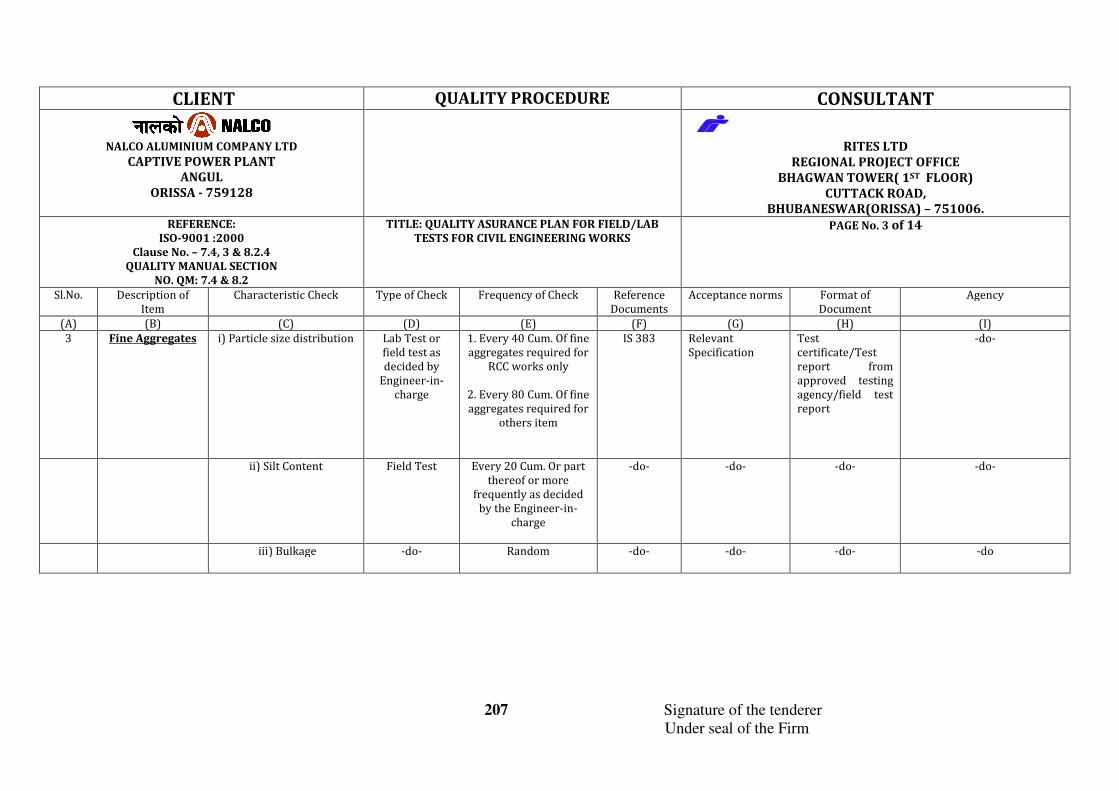
207 Signature of the tenderer
Under seal of the Firm
CLIENT QUALITY PROCEDURE CONSULTANT
NALCO ALUMINIUM COMPANY LTD
CAPTIVE POWER PLANT
ANGUL
ORISSA - 759128
RITES LTD
REGIONAL PROJECT OFFICE
BHAGWAN TOWER( 1ST FLOOR)
CUTTACK ROAD,
BHUBANESWAR(ORISSA) – 751006. REFERENCE:
ISO-9001 :2000
Clause No. – 7.4, 3 & 8.2.4
QUALITY MANUAL SECTION
NO. QM: 7.4 & 8.2
TITLE: QUALITY ASURANCE PLAN FOR FIELD/LAB
TESTS FOR CIVIL ENGINEERING WORKS PAGE No. 3 of 14
Sl.No. Description of
Item
Characteristic Check Type of Check Frequency of Check Reference
Documents
Acceptance norms Format of
Document
Agency
(A) (B) (C) (D) (E) (F) (G) (H) (I)
3 Fine Aggregates i) Particle size distribution Lab Test or
field test as
decided by
Engineer-in-
charge
1. Every 40 Cum. Of fine
aggregates required for
RCC works only
2. Every 80 Cum. Of fine
aggregates required for
others item
IS 383 Relevant
Specification
Test
certificate/Test
report from
approved testing
agency/field test
report
-do-
ii) Silt Content Field Test Every 20 Cum. Or part
thereof or more
frequently as decided
by the Engineer-in-
charge
-do- -do- -do- -do-
iii) Bulkage -do- Random
-do- -do- -do- -do

208 Signature of the tenderer
Under seal of the Firm
CLIENT QUALITY PROCEDURE CONSULTANT
NALCO ALUMINIUM COMPANY LTD
CAPTIVE POWER PLANT
ANGUL
ORISSA - 759128
RITES LTD
REGIONAL PROJECT OFFICE
BHAGWAN TOWER( 1ST FLOOR)
CUTTACK ROAD,
BHUBANESWAR(ORISSA) – 751006. REFERENCE:
ISO-9001 :2000
Clause No. – 7.4, 3 & 8.2.4
QUALITY MANUAL SECTION
NO. QM: 7.4 & 8.2
TITLE: QUALITY ASURANCE PLAN FOR FIELD/LAB TESTS
FOR CIVIL ENGINEERING WORKS PAGE No. 4 of 14
Sl.No. Description of
Item
Characteristic Check Type of Check Frequency of
Check
Reference
Documents
Acceptance norms Format of
Document
Agency
(A) (B) (C) (D) (E) (F) (G) (H) (I)
4 Coarse Aggregate
i) Grading LabTest One test in every
60 Cum.
IS 383/IS 2386
Pt.I
Test
Certificate/Test
Result from
approved testing
agency/field test
report
Test
certificate/test
result from testing
agency/field test
report
Consultant/Approved
test agency
ii) Flakiness/Elongation -do- -do- -do- -do- -do-
iii) Impact Value -do- -do- IS 383/IS 2386
Pt.IV
-do- -do-
v) Soft & deleterious
materials
-do- -do-
IS 383/IS 2386
pt.II
5 BRICKS i) Compressive Strength Lab Test Before
commencement
of work for each
brand brick as per
IS 5454, Table
no.1(Clause 4.1.1,
4.2 & 4.3.2) and
Table No.2
(Clause 5.1, 5.2.3
and 5.2.4)
IS 5454, IS 3495
(Parts 1 to 4), IS
1077
As per Bureau of
Indian Standards
Test
Certificate/Test
Result from Govt.
approved testing
agency/field test
report
Approved testing agency

209 Signature of the tenderer
Under seal of the Firm
CLIENT QUALITY PROCEDURE CONSULTANT
NALCO ALUMINIUM COMPANY LTD
CAPTIVE POWER PLANT
ANGUL
ORISSA - 759128
RITES LTD RITES LTD
REGIONAL PROJECT OFFICE
BHAGWAN TOWER( 1ST FLOOR)
CUTTACK ROAD,
BHUBANESWAR(ORISSA) – 751006.
REFERENCE:
ISO-9001 :2000
Clause No. – 7.4, 3 & 8.2.4
QUALITY MANUAL SECTION
NO. QM: 7.4 & 8.2
TITLE: QUALITY ASURANCE PLAN FOR
FIELD/LAB TESTS FOR CIVIL ENGINEERING
WORKS
PAGE No. 5 of 14
Sl.No. Description of Item Characteristic Check Type of
Check
Frequency of Check Reference
Documents
Acceptance
norms
Format of
Document
Agency
(A) (B) (C) (D) (E) (F) (G) (H) (I)
BRICKS ii) Water Absorption Lab Test Before
commencement of
work for each brand
brick as per IS 5454,
Table no.I (Clause
4.1.1, 4.2 & 4.3.2) and
Table no.2 (Clause
5.1, 5.2.3 and 5.2.4)
IS 5454, IS
3495 (Parts 1 to
4), IS 1077
As per Bureau
of Indian
standards
Test
Certificate/Test
Result from
Govt. approved
testing
agency/field test
report
Approved testing
agency
iii) Efflorescence -do- -do- -do- -do- -do- -do-
iv) Dimension -do- -do- -do- -do- -do- -do-

210 Signature of the tenderer
Under seal of the Firm
CLIENT QUALITY PROCEDURE CONSULTANT
NALCO ALUMINIUM COMPANY LTD
CAPTIVE POWER PLANT
ANGUL
ORISSA - 759128
RITES LTD
REGIONAL PROJECT OFFICE
BHAGWAN TOWER( 1ST FLOOR)
CUTTACK ROAD,
BHUBANESWAR(ORISSA) – 751006.
REFERENCE:
ISO-9001 :2000
Clause No. – 7.4, 3 & 8.2.4
QUALITY MANUAL SECTION
NO. QM: 7.4 & 8.2
TITLE: QUALITY ASURANCE PLAN FOR
FIELD/LAB TESTS FOR CIVIL ENGINEERING
WORKS
PAGE No. 6 of 14
Sl.No. Description of Item Characteristic Check Type of Check Frequency of
Check
Reference
Documents
Acceptance
norms
Format of
Document
Agency
(A) (B) (C) (D) (E) (F) (G) (H) (I)
6 WATER
i) PH-Value LAB TEST Before
commencement
of work and
thereafter
every three
months till
completion of
work
IS 456 3025 Relevant
Specification
Test
Certificate/Test
Result from
Approved
testing
agency/field
test report
Consultant/Approved
testing agency
ii) Sulphate Content -do- -do-
-do- -do- -do- -do-
iii) Chloride Content -do- -do-
-do- -do- -do- -do-

211 Signature of the tenderer
Under seal of the Firm
CLIENT QUALITY PROCEDURE CONSULTANT
NALCO ALUMINIUM COMPANY LTD
CAPTIVE POWER PLANT
ANGUL
ORISSA - 759128
RITES LTD RITES LTD
REGIONAL PROJECT OFFICE
BHAGWAN TOWER( 1ST FLOOR)
CUTTACK ROAD,
BHUBANESWAR(ORISSA) – 751006.
REFERENCE:
ISO-9001 :2000
Clause No. – 7.4, 3 & 8.2.4
QUALITY MANUAL SECTION
NO. QM: 7.4 & 8.2
TITLE: QUALITY ASURANCE PLAN FOR
FIELD/LAB TESTS FOR CIVIL ENGINEERING
WORKS
PAGE No. 7 of 14
Sl.No. Description of Item Characteristic Check Type of Check Frequency of
Check
Reference
Documents
Acceptance
norms
Format of
Document
Agency
(A) (B) (C) (D) (E) (F) (G) (H) (I)
7 MARBLE 1. Moisture absorption Lab Test 50 Sqm. IS:1124 As per contract
specification
-do- -do-
8 FLOOR
TILES/TERRAZZO
TILES
i) Transverse strength Lab Test
Manufactures
test certificate &
test result from
testing
agency/Field
test report
Consultant/Approved
test agency
ii) Water absorption -do- -do-
-do- -do- -do- -do-
iii) Abrasion Test -do- -do-
-do- -do- -do- -do-

212 Signature of the tenderer
Under seal of the Firm
CLIENT QUALITY PROCEDURE CONSULTANT
NALCO ALUMINIUM COMPANY LTD
CAPTIVE POWER PLANT
ANGUL
ORISSA - 759128
RITES LTD
REGIONAL PROJECT OFFICE
BHAGWAN TOWER( 1ST FLOOR)
CUTTACK ROAD,
BHUBANESWAR(ORISSA) – 751006. REFERENCE:
ISO-9001 :2000
Clause No. – 7.4, 3 & 8.2.4
QUALITY MANUAL SECTION
NO. QM: 7.4 & 8.2
TITLE: QUALITY ASURANCE PLAN FOR FIELD/LAB
TESTS FOR CIVIL ENGINEERING WORKS PAGE No.8 of 14
Sl.No. Description of Item Characteristic Check Type of Check Frequency of
Check
Reference
Documents
Acceptance
norms
Format of Document Agency
(A) (B) (C) (D) (E) (F) (G) (H) (I)
9 GLAZED TILES (for
floor & wall)
i) Water absorption LAB TEST 3000 nos. or
part thereof
IS:777-1988 As per contract
Specification
-do- -do-
ii) Crushing Test -do- -do-
-do- -do- -do- -do-
iii) Impact strength -do- -do-
-do- -do- -do- -do-
iv) Chemical resistant test -do- -do-
-do- -do- -do- -do-
10 BALLAST i) Grading Field Test As per contract
specification
1. IS:2386
(Part-I)
As per contract
specification
Field/Lab test result
from approved testing
agency/field data
-do-
ii) Aggregates Impact Lab test -do-
2. IS:5640-1970 -do- -do- -do-
iii) Los Angles Abrasion Lab test -do-
3. IS:2386
(Part-IV)
-do- Test Certificates/Test
Result from Approved
testing agency/field
test report
Consultant/Approved
testing agency
iv) Crushing Value -do- -do- 4. IS:2386
(Part-I)
-do- -do- -do-

213 Signature of the tenderer
Under seal of the Firm
CLIENT QUALITY PROCEDURE CONSULTANT
NALCO ALUMINIUM COMPANY LTD
CAPTIVE POWER PLANT
ANGUL
ORISSA - 759128
RITES LTD
REGIONAL PROJECT OFFICE
BHAGWAN TOWER( 1ST FLOOR)
CUTTACK ROAD,
BHUBANESWAR(ORISSA) – 751006.
REFERENCE:
ISO-9001 :2000
Clause No. – 7.4, 3 & 8.2.4
QUALITY MANUAL SECTION
NO. QM: 7.4 & 8.2
TITLE: QUALITY ASURANCE PLAN FOR
FIELD/LAB TESTS FOR CIVIL ENGINEERING
WORKS
PAGE No. 9 of 14
Sl.No. Description of
Item
Characteristic Check Type of Check Frequency of
Check
Reference
Documents
Acceptance
norms
Format of
Document
Agency
(A) (B) (C) (D) (E) (F) (G) (H) (I)
BALLAST v) Water absorption
Chemical Composition
LAB TEST As per
contract
specification
5. IS:2386
(Part-III)
As per contract
specification
Test
Certificates/Test
Result from
Approved testing
agency/field test
report
Consultant/Approved
testing agency
vi) Flakiness Index -do- -do-
6. IS:2386
(Part-I)
-do- -do- -do-

214 Signature of the tenderer
Under seal of the Firm
CLIENT QUALITY PROCEDURE CONSULTANT
NALCO ALUMINIUM COMPANY LTD
CAPTIVE POWER PLANT
ANGUL
ORISSA - 759128
RITES LTD
REGIONAL PROJECT OFFICE
BHAGWAN TOWER( 1ST FLOOR)
CUTTACK ROAD,
BHUBANESWAR(ORISSA) – 751006.
REFERENCE:
ISO-9001 :2000
Clause No. – 7.4, 3 & 8.2.4
QUALITY MANUAL SECTION
NO. QM: 7.4 & 8.2
TITLE: QUALITY ASURANCE PLAN FOR
FIELD/LAB TESTS FOR CIVIL ENGINEERING
WORKS
PAGE No. 10 of 14
Sl.No. Description of Item Characteristic Check Type of
Check
Frequency of
Check
Reference
Documents
Acceptance
norms
Format of
Document
Agency
(A) (B) (C) (D) (E) (F) (G) (H) (I)
11 CONCRETE
ADMIXTIURE
i) Permeability to water LAB TEST As decided by
the Engineer-in-
charge before
commencement
of work
IS:9103 As per contract
Specification
-do- -do-
ii) Setting time -do- -do-
-do- -do- -do- -do-
iii) Complete strength -do- -do-
-do- -do- -do- -do-
iv) Chloride content -do- -do-
-do- -do- -do- -do-

215 Signature of the tenderer
Under seal of the Firm
CLIENT QUALITY PROCEDURE CONSULTANT
NALCO ALUMINIUM COMPANY LTD
CAPTIVE POWER PLANT
ANGUL
ORISSA - 759128
RITES LTD
REGIONAL PROJECT OFFICE
BHAGWAN TOWER( 1ST FLOOR)
CUTTACK ROAD,
BHUBANESWAR(ORISSA) – 751006.
REFERENCE:
ISO-9001 :2000
Clause No. – 7.4, 3 & 8.2.4
QUALITY MANUAL SECTION
NO. QM: 7.4 & 8.2
TITLE: QUALITY ASURANCE PLAN FOR
FIELD/LAB TESTS FOR CIVIL ENGINEERING
WORKS
PAGE No.11 of 14
Sl.No. Description of Item Characteristic Check Type of Check Frequency of
Check
Reference
Documents
Acceptance
norms
Format of
Document
Agency
(A) (B) (C) (D) (E) (F) (G) (H) (I)
12 BENTONITE i) Sand Content Bentonite
powder
LAB TEST -do- 1. IS:2911 (Part-I) As per contract
Specification
-do- -do-
ii) Liquid Limit -do- -do-
-do- -do- -do- -do-
iii) Density of Bentonite
Slurry (using Hydrometer)
-do- -do-
-do- -do- -do- -do-
iv) Marsh viscosity (using
Marsh core)
-do- -do-
-do- -do- -do- -do-
v) Swelling Index -do- -do- -do- -do-
-do- -do-
vi) PH value of Bentonite
suspension
-do- -do-
-do- -do- -do- -do-

216 Signature of the tenderer
Under seal of the Firm
CLIENT QUALITY PROCEDURE CONSULTANT
NALCO ALUMINIUM COMPANY LTD
CAPTIVE POWER PLANT
ANGUL
ORISSA - 759128
RITES LTD
REGIONAL PROJECT OFFICE
BHAGWAN TOWER( 1ST FLOOR)
CUTTACK ROAD,
BHUBANESWAR(ORISSA) –751006.
REFERENCE:
ISO-9001 :2000
Clause No. – 7.4, 3 & 8.2.4
QUALITY MANUAL SECTION
NO. QM: 7.4 & 8.2
TITLE: QUALITY ASURANCE PLAN FOR
FIELD/LAB TESTS FOR CIVIL ENGINEERING
WORKS
PAGE No.12 of 14
Sl.No. Description of Item Characteristic Check Type of
Check
Frequency
of Check
Reference
Documents
Acceptance
norms
Format of
Document
Agency
(A) (B) (C) (D) (E) (F) (G) (H) (I)
13 CONSTRUCTION
QUALITY (CONCRETE)
i) Mix Design LAB TEST Regular IS-465-2000
IS-10262
SP-23
IS-10262 –
SP-23
Test
Certificate/Test
Result from
Approved testing
agency/field test
report
Consultancy/Approved
testing agency
ii) Slump Test Field Test Random
Specification
iii) Crushing Strength at
7 & 28 days
Lab Test Regular and
as per codal
provision
IS-Code IS-Code 456-
2000
-do- -do-

217 Signature of the tenderer
Under seal of the Firm
CLIENT QUALITY PROCEDURE CONSULTANT
NALCO ALUMINIUM COMPANY LTD
CAPTIVE POWER PLANT
ANGUL
ORISSA - 759128
RITES LTD
REGIONAL PROJECT OFFICE
BHAGWAN TOWER( 1ST FLOOR)
CUTTACK ROAD,
BHUBANESWAR(ORISSA) – 751006.
REFERENCE:
ISO-9001 :2000
Clause No. – 7.4, 3 & 8.2.4
QUALITY MANUAL SECTION
NO. QM: 7.4 & 8.2
TITLE: QUALITY ASURANCE PLAN FOR
FIELD/LAB TESTS FOR CIVIL ENGINEERING
WORKS
PAGE No.13 of 14
Sl.No. Description of Item Characteristic Check Type of
Check
Frequency of
Check
Reference
Documents
Acceptance
norms
Format of
Document
Agency
(A) (B) (C) (D) (E) (F) (G) (H) (I)
14 SHUTTERING &
REINFORCEMENT
i) Level Field Test 100% Contracts
specification
As per codal
provision
Inspection
Report or Pour
Card
Consultancy/Approved
testing agency
ii) Level -do- -do-
-do- -do- -do- -do-
iii) Support -do- -do-
-do- -do- -do- -do-
iv) Cover -do -do- -do- -do- -do- -do-
15 EQUIPMENTS i) Weighbatcher Field Test Regular
condition to
be checked
As per contract
specification
As per contract
specification
Inspection
Report by site
engineer
-do-
iii) Vibrator -do- -do- -do- -do- -do-
iv) Cube moulds -do- -do- -do- -do- -do- -do-
v) Slump cone -do- -do- -do- -do- -do- -do-
vi) Sieve -do- -do- -do- -do- -do- -do-

218 Signature of the tenderer
Under seal of the Firm
CLIENT QUALITY PROCEDURE CONSULTANT
NALCO ALUMINIUM COMPANY LTD
CAPTIVE POWER PLANT
ANGUL
ORISSA - 759128
RITES LTD
REGIONAL PROJECT OFFICE
BHAGWAN TOWER( 1ST FLOOR)
CUTTACK ROAD,
BHUBANESWAR(ORISSA) – 751006.
REFERENCE:
ISO-9001 :2000
Clause No. – 7.4, 3 & 8.2.4
QUALITY MANUAL SECTION
NO. QM: 7.4 & 8.2
TITLE: QUALITY ASURANCE PLAN FOR
FIELD/LAB TESTS FOR CIVIL
ENGINEERING WORKS
PAGE No.14 of 14
Sl.N
o.
Description of Item Characteristic Check Type of
Check
Frequency of
Check
Reference
Documents
Acceptance
norms
Format of Document Agency
(A) (B) (C) (D) (E) (F) (G) (H) (I)
16 Earthwork in
embankment under
O.M.C. condition (
Ref : RDSO guide line
No. GE:G-1, July-
2003)
Soil classification; (
i) Grain size analysis
ii) Liquid Limit &
Plastic Limit )
Lab
Test
Minimum 1 test
per 5000 cu.m or
as decided by
Engineer-in-
Charge
1. IS:2720 Pt.IV
2. IS:2720 Pt.V
As per contract
specification
Test
Certificate/Test
Result from
Approved testing
agency/field test
report
Consultancy/Appro
ved testing agency
iii) Max. Dry
Density
-do- Minimum 1 test
per 5000 Cu.m or
as desided by
engineer.
IS 2720 Pt.VIII-
1998
-do- -do- -do-
iv) Omtimum
Moisture content
Lab
Test
-do-
IS:2720 Pt.II -do- -do- -do-
v) Dry Density and
moisture content
As per contract
specification
RDSO guide line
No. GE:G-1, July-
2003
-do- -do- -do-
17 Plastering i) Morter proportion Field
check
Random As per contract
specification
As per contract
specification
-do- Inspection Report
by Site Engineer of
Consultant
ii) Thickness -do- -do- -do- -do- -do- -do-

219 Signature of the tenderer
Under seal of the Firm
TENTATIVE DRAWINGS FOR TENDER PURPOSE

220 Signature of the tenderer
Under seal of the Firm
LIST OF DRAWINGS (TENTATIVE)
Sl No. TITLE
1. Layout plan
2. L-section
3. Bridge drawings. Br. No. 15 & 16
4. Bridge drawings. Br. No. 17

221 Signature of the tenderer
Under seal of the Firm

222 Signature of the tenderer
Under seal of the Firm
Signature of the tenderer

223 Signature of the tenderer
Under seal of the Firm
������ ����� �� ���� �� �� �� �� �� �� ����
��� ��������� ���� ����� �� �� �� �� ���� ��� �� ������ �� �� �����
H.M. LOADING STANDARD - 1995
��� �� � ���� �� � ������ ����� �� ���� ��� ��� ���� !!!!" �#$ ���� ���������� $��!"�$!!%�
TP
AT
CH
: 48
34
.41
m
BR
NO
15
, 2X
1. 2
m D
I A H
P A
T C
H: 4
69
1.0
0m
TO
BE
EX
TE
ND
ED
1x
3. 0
mx2
. 00
m R
CC
BO
X
SR
J A
T C
H:4
66
8. 4
0m
T--15
TP
AT
CH
: 46
28
. 11
m
FM
AT
CH
: 46
18
.40
m
TP
AT
CH
:46
11. 5
0m
TP
AT
CH
: 46
09
.60
m
R= 437.5m
R= 437.5m
TP
2 A
T C
H: 4
59
8. 5
5m
TP
2 A
T C
H:4
59
6. 9
5m
LOAD LINE, CAL =794.56m(FM TO FM)ENGINE REVERSAL LINE, CAL = 723.56m(FM TO SRJ)
? 22°-6'-11"
R 437.50m(4°)
TL 85.449mCL 168.774m
CURVE NO 2A
SR
J AT
CH
: 48
45
. 00
m
SR
J A
T C
H: 4
76
1. 0
0m
EM
ER
GE
NC
Y C
RO
SS
OV
ER
PRE TIPPLING YARD
TO WAGON TIPPLER WEST GRID
CHECKED BYDY CE(BRIDGE)E.Co. RLY/BBSR
XEN(BRIDGE)E.Co. RLY/BBSR
Sr. DGM(C)RITES/BBSR
GM(P)RITES/BBSR
GM(TECH)NALCO/BBSR
CHECKED BY
DRAWN BY
ENGINEER (C)RITES/BBSR
CHECKED BY
ENGINEER (C)RITES/BBSR
E.Co. RLY/BBSR E.Co. RLY/BBSR
CBEE.Co. RLY/BBSR
TO
DA
MA
NJ
OD
IT
O W
AG
ON
TIP
PL
ER
TO
SO
UT
H G
RID
U/S D/S
R.C.C. BOX SECTION AT B-B
SECTION OF RETAINING WALL AT A-A
%� �� ��������� ����� �� ���� ��� �� ����� �& %!!
'� ��� � (� �� ��� ������ �� �� ���� � $! )�)�
�� ������� ���� � �� � ��*����
�� �� � ���� ��� ��� ����� ��� �� �� ����� �� � ���
�!! '% ))� *� � �!!! )�)�� *���� + �%!! ))� ����
+ ������� �� �����
�� ����� ��*�� �� %!)�)� + �� �� �� ���� �� �� �� ��������
��� ���� � �� �� ������ �� �� �� �� '�% �� �� �� ��� ������������
������ �� �� �� �'�,#���% �
�!� ��� ����� �� �� ��* ��� � ������ ����� �� �� ��
�$� ���� � �� �� �� �� ���� � �� �������� ���� ��� ��
������ ���
*��� �� �� � � �� ���� � �� + �� �� ��� ��� �� ���
�"� ��� ���� �� ��� �� ��☺����� �� �� � �� ���� � ��� �� �������
�%� ���� �� ������� �� ����� ������ *���� ����*��. �� � ��
�,� ��� ���� �� � �� ������ ��� ��� � ���� � �� ��� ������ �� �� ��
�'� � � ���� �� ��� � �� �� �� � / $%�! 0 �1)�
�2� ��������� ����� �� �������� � � �� �� �������� �� ��� �����
��� ����# � ������ �� � ���
� � ��������� � ���
���� ���� 2%3
,� �������� ����� #
44� �� ��� ���� ������������������������������������������$% 4� ��� ��� + ������ ���� ���������������������2%
2� ���� �� �������� ����� ���*� ����� ���� ���
"� ��� ��������. ��� � ��� �� ����� ��� "%, #$!!! + ����� �����
�� ��� � ��� ��� ��� � �� ����� ����� ������ �� �������
$� ��*��� ��� � ������
�� �� � �����
SECTION OF CURTAIN /DROP WALL
TYPICAL DETAILS AT 'A' & 'B'
� ��� � ���� ��� � ���� ��� � ���� ��� � ���
NATIONAL ALUMINIUM COMPANY LTD.
DAMANJODI, ORISSA
BR NO. 15

224 Signature of the tenderer
Under seal of the Firm
R. C. C. DETAILS OF RETAINING WALL AT A-A
SECTION OF CURTAIN /
DROP WALL R.C.C. BOX DETAILS SECTION AT B-BTYPICAL DETAILS AT 'A' & 'B'
� ��� � ���� ��� � ���� ��� � ���� ��� � ���
NATIONAL ALUMINIUM COMPANY LTD.
DAMANJODI, ORISSA
BR NO.
16
CHECKED BYDY CE(BRIDGE)E.Co. RLY/BBSR
XEN(BRIDGE)E.Co. RLY/BBSR
Sr. DGM(C)RITES/BBSR
GM(P)RITES/BBSR
GM(TECH)NALCO/BBSR
CHECKED BY
%� �� ��������� ����� �� ���� ��� �� ����� �& %!!
'� ��� � (� �� ��������� �� �� ���� � $! )�)�
�� ������� ���� � �� � ��*����
�� ��� ���� ��� ��� ����� ��� �� �� ����� �� � ���
�!! '% ))� *� � �!!! )�)�� *���� + �%!! ))� ����
+ ������� �� �����
�� ����� ��*�� �� %! )�)� + �� �� �� ���� �� �� �� ��������
��� ���� � �� �� ������ �� �� �� �� '�% �� �� �� ��� ������������
������ �� �� �� �'�,#���% �
�!� � �� ����� �� �� ��* ��� � ������ ����� �� �� ��
�$� ���� � �� �� �� �� ���� � �� �������� ���� ��� ��
������ ���
*��� �� �� � � �� ���� � �� + �� �� ��� ��� �� ���
�"� ��� ���� ����� �� ��☺����� �� �� � �� ���� � ��� �� �������
�%� ���� �� ������� �� ����� ������ *���� ����*��. �� � ��
�,� ��� ���� � � � �� �� ���� ��� ��� � ���� � �� ��� ������ �� �� ��
�'� �� �������� �� ������� � / �%�! 0 �1)� ���� ��� ��� ��� +
�2� ��������� ����� �� �������� �� �� �� �������� �� ��� �����
��� ����# � ������ �� � ���
� � ��������� ����
���� ���� 2%3
,� �������� ����� #
44� �� ����������������$% 4� ��� ���������������������2%
2� ���� �� �������� ����� ���*� ����� ���� ���
"� ��� ��������. ��� � ��� �� ����� ��� "%, #$!!! + ����� �����
�� ��� � ��� ��� ��� � �� ����� ����� ������ �� �������
$� ��*��� ��� � ������
�� ��� �����
�2�! 0 �1)� ���� ������ � ����� ��� � ������ �� ������� �� � ���
��� �� � ���� �� � �� �� ���� ��� ��� ���� !!!!" �#$ ���� ����� ����� # $��!"�$!!%
��� ��������� ���� ����� �� �� �� �� ���� ��� �� ������ �� �� �����
DRAWN BY
ENGINEER (C)RITES/BBSR
CHECKED BY
ENGINEER (C)RITES/BBSR
E.Co. RLY/BBSR E.Co. RLY/BBSR
CBEE.Co. RLY/BBSR
H. M. LOADING STANDARD - 1995
3000
600
1100
600
600
600
600
600
600
600
680 6001
50
300 CC 1 :3:6
CC 1:3:6
RL 888.440m
27
02
70
270
27
02
70
27
030
0
620
3000
300 1
50
680 600
270
270
270
270
270
270
300
3650
51
20
600
TO
DA
MA
NJ
OD
IT
O W
AG
ON
TIP
PL
ER
TO
SO
UT
H G
RID
U/S
D/S
U/S D/S

225 Signature of the tenderer
Under seal of the Firm
2 : 1
1.5
: 1
2 : 1
1.5
: 1
RETURN WALL
SECTION ON X-XTOE WALL
1. ALL DIMENSIONS ARE IN MILLIMETRE & ALL LEVELS ARE IN METRE UNLESS
OTHERWISE SPECIFIED.
2. SAFE BEARING CAPACITY OF SOIL AT 3.0m BELOW BED LEVEL 18.3 t/sqm AS PERCOMPLETION DRAWING OF EXISTING BRIDGE. (SIGNED ON 1.10.1986.)
3. DESIGN CRITERIA.
I. IRS BRIDGE RULES INCORPORATING A @ C SLIP No. 37II. IRS CONCRETE BRIDGE CODE INCORPORATING A @ C SLIP No. 11.
III. IRS BRIDGE SUBSTRUCTURE & FOUNDATION CODE INCORPORATING A @ C SLIP No. 27.
4. EXPOSURE CONDITION SEVERE.
5. CONCRETE GRADE.I, ALL MASS CONCRETE - M 25
II. ALL RCC WORKS - M 35 (DESIGN MIX).6. CLEAR COVER TO REINFORCEMENT = 50mm.
7. LAPPING OF BARS SHOULD BE MINIMISED AND ALL STAGGERED WHEREVER
NECESSARY. MINIMUM LENGTH OF LAP SHALL BE AS GIVEN IN IS:456-1978(DESIGNS AIDS) FOR TOR STEEL. THE NUMBER & LOCATION OF LAP IS TO BE
DECIDED AT SITE.
8. LOADING STANDARD: HM LOADING - 1995
9. HIGH YIELD STRENGTH DEFORMED BARS OF GRADE Fe 500 CONFORMING TO
IS: 1786- 1985 SHALL BE USED AS REINFORCEMENT.
10. ANGLE OF REPOSE OF BACK FILL SHALL NOT BE LESS THAN 35°.
11. BACK FILL SHOULD BE AS PER CLAUSE 7.5 OF IRS BRIDGE SUBSTRUCTURE
AND FOUNDATION CODE.
12. ALL DIMENSIONS AND LEVELS SHOULD BE VERIFIED AND RECONCILED ATSITE BEFORE EXECUTION.
13. WEEP HOLES SHALL BE OF 75/100 DIA PVC PIPES STAGGERED @ 1000 C/C
HORIZONTALLY AND @ 1000 C/C VERTICALLY ABOVE LOW WATER LEVEL INMASS CONCRETE ONLY.
14. THE DRAWING IS TO BE READ ONLY AND NOT TO BE SCALED.
15. THIS DRAWING AND DESIGN IS PREPARED BASED ON RDSO DRG.NO: RDSO/M/00005 / 1-2 (DUPLICATE) DATED 31.08.2005.
16. CONCRETE SHALL BE MECHANICALLY MIXED. VIBRATED AND THOROUGHLYCURED.
17. IN CASE THE SOIL BEARING CAPACITY IS LESS THAN THE SPECIFIED VALUE,THE SAME WILL BE IMPROVED BY REPLACING THE EXISTING SOIL WITHMOORUM UP TO 1.0m DEPTH BELOW THE FOUNDATION LEVEL. MOORUM
SHALL BE SPREAD, WATERED AND THOROUGHLY COMPACTED IN LAYERS OF250mm.
18. THE PROPOSED RAIL LEVEL AND THE FORMATION LEVEL HAVE BEEN CHECKEDWITH RESPECT TO THE APPROVED L-SECTION. THE DETAILS HAVE BEEN VERIFIED
BY M/s RITES Ltd. / BHUBANESWAR.
H. M. LOADING STANDARD - 1995
TYPCAL DETAILS AT 'A' & 'B'
SE
CT
ION
B-B
1.5
:1
CURTAIN / DROP WALL
BR.NO:-17
SPAN:-4X5.0X6.30m R.C.C.BOXES
AT CH:-5260.00M
N: 4
40
AT
CH
: 506
0m
FR
OM
CS
B
400400
898.10
SR
J A
T C
H 4
98
7m
TO WEST GRID
SR
J A
T C
H 5
05
6m
TO SOUTH GRID
N 368.00
E-931.575
CL
OF
WA
GO
N T
IPP
LE
R, C
H.: 5
30
5m
FR
OM
CS
B
(ALO
NG
EX
IST
ING
TR
AC
K)
CL O
F P
RO
P. W
AG
ON
TI P
PL
ER
, CH
.: 52
30
.81
m F
RO
M C
SB
SR
J, C
H.: 5
44
1.7
0m
FR
OM
CS
B
SR
J A
T C
H:5
04
9.8
1m
SR
J A
T C
H:5
17
5.8
1m
SR
J A
T C
H:5
34
7.6
8m
TP
1 A
T C
H:5
47
8.4
8m
TP
2 A
T C
H:5
52
7.7
5m
1 IN 8 1
2 (CS)
SR
J, C
H.: 5
42
8.7
m F
RO
M C
SB
SR
J, C
H.: 5
32
0m
FR
OM
CS
B
SR
J, C
H.: 5
295
m F
RO
M C
SB
SR
J, C
H.: 5
17
3m
FR
OM
CS
B
SR
J, C
H.: 5
186
m F
RO
M C
SB
SR
J, C
H.: 5
06
5m
FR
OM
CS
B
(CH
. 53
56.4
4m
ALO
NG
EX
IST
ING
TR
AC
K)
AT
CH
: 520
0m
FR
OM
CS
B
LEVEL
400
FL
=8
97. 7
5
FL
TO
BE
EX
TE
ND
ED
4X
5.0
0m
X6.0
0m
RC
C B
OX
BR
NO
17
,4X
5.0
0m
X6
.00
m R
CC
BO
X A
T C
H;5
26
0.0
0M
FM
CH
:51
20.8
1m
FM
CH
:510
4.8
1m
FM
CH
:629
2.6
8m
FM
CH
:51
23
m
FM
CH
:50
06
m
FM
CH
:503
7m
FM
CH
:50
16m
FM
, CH
.: 537
0m
FR
OM
CS
B
POST TIPPLING YARD1 IN 8 1
2 (C S)1 IN 8 1
2 (CS)
TO DMNJ STN
TO WEST GRID
KEY PLAN
DAMANJODI
1.5
:1
DRAWN BY
RITES/BBSRSr.DGM(C)
RITES/BBSRGM(P)
RITES/BBSR
GM(TECH)NALCO/BBSR
CHECKED BY
DY CE(BRIDGE)E.Co. RLY/BBSR
XEN(BRIDGE)E.Co. RLY/BBSR
CBE
E.Co. RAILWAYCHECKED BY
CHECKED BY
RITES/BBSR
SECTION A-A
PLAN
CONTENT : -GENERAL ARRANGEMENT DRAWING
EAST COAST RAILWAY
RITES LTD.RITES LTD.
NATIONAL ALUMINIUM CO. LTD.

GENERAL CONDITIONS OF CONTRACT
NATIONAL ALUMINIUM COMPANY LIMITED NALCO BHAWAN, P-1 NAYAPALLI,
BHUBANESWAR – 751 013
Web site: www.nalcoindia.com
Page 1 of 96

INDEX
Sl.No Title Page No.
1. Definitions and Interpretation (Section-1)
1.1 2.
Definitions Facilities to Contractor (Section-II)
2.1 Location of Site climatic conditions and Access by
Road
2.1.1 Location of Site
2.1.2 Access by Road
2.2 Water Supply
2.3 Power Supply
2.4 Land for Contractor’s field office, godown and workshop
2.5 Land and Residential Accommodation
General Instructions to Tenderers (Section-III)
3. Submission of Tender :
4. Documents:
4.1.2 Details to be submitted alongwith the tender
4.2 All pages to b e initiated
4.3 Rates to be in figures and words
4.4 Corrections and Erasures
4.5 Signature of Tenderer
4.6 Witness
5 T ransfer of Tender Documents
6
7
Earnest Money
Validity
8 Addends/ Corrigenda
9 Right of Owner to accept or reject Tender
10 T ime Schedule
11 Collection of data Tenderer’s responsibility
12 Retired Government or Company Officers
13 Signing of the Contract
14 Field Management and Controlling Authority
15 Note to schedule of Rates
General Obligations (Section-IV)
16 Interpretation of contract documents
17 Special Conditions of Contract
18 Tenderer to obtain his own information
19 Security Deposit
20 Forfeiture of Security Deposit
Page 2 of 96
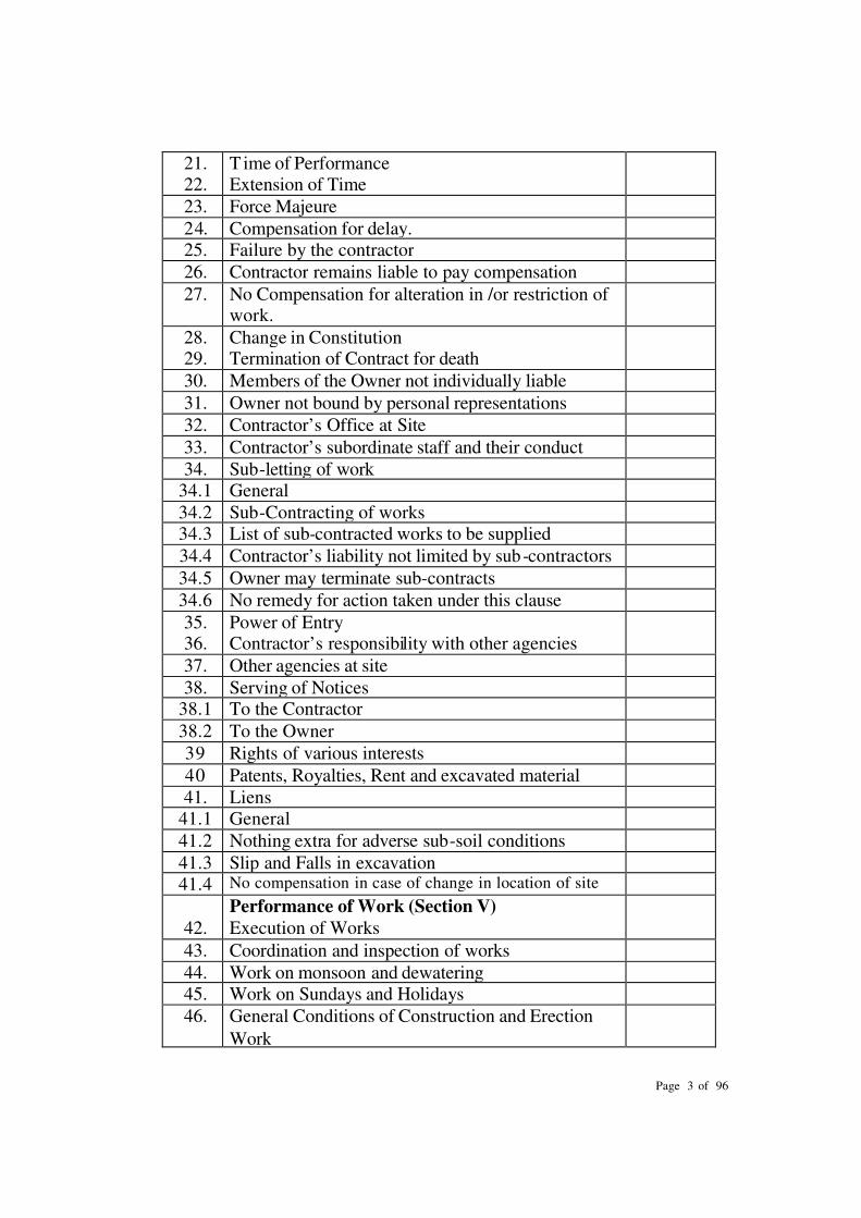
21. 22.
T ime of Performance Extension of Time
23. Force Majeure
24. Compensation for delay.
25. Failure by the contractor
26. Contractor remains liable to pay compensation
27. No Compensation for alteration in /or restriction of work.
28. 29.
Change in Constitution Termination of Contract for death
30. Members of the Owner not individually liable
31. Owner not bound by personal representations
32. Contractor’s Office at Site
33. Contractor’s subordinate staff and their conduct
34. Sub-letting of work
34.1 General
34.2 Sub-Contracting of works
34.3 List of sub-contracted works to be supplied
34.4 Contractor’s liability not limited by sub -contractors
34.5 Owner may terminate sub-contracts
34.6 No remedy for action taken under this clause
35. 36.
Power of Entry Contractor’s responsibility with other agencies
37. Other agencies at site
38. Serving of Notices
38.1 To the Contractor
38.2 To the Owner
39 Rights of various interests
40 Patents, Royalties, Rent and excavated material
41. Liens
41.1 General
41.2 Nothing extra for adverse sub-soil conditions
41.3 Slip and Falls in excavation
41.4 No compensation in case of change in location of site
42.
Performance of Work (Section V)
Execution of Works
43. Coordination and inspection of works
44. Work on monsoon and dewatering
45. Work on Sundays and Holidays
46. General Conditions of Construction and Erection
Work
Page 3 of 96

47. 48.
Drawing to be supplied by the Owner Drawings to be supplied by the Contractor
49. Setting out works
50. Responsibility for Level and Alignment
50.1 General
50.2. Lighting, Watch and Ward
51. Materials to be supplied by Contractor
52. Stores supplied by the Owner
53 Conditions for issue of materials
54. Return of Surplus
55. Materials obtained from dismantling
56. Articles of value found
57. Inspection of works
58. Assistance to the Engineer
59. Discrepancies between Instructions
60. Alterations in specifications & designs and extra works
61. Action where no specification is issued
62. Abnormal Rates
63. Test for quality of Works
64. Samples
65.
66.
Liabilities for defect imperfections etc and
rectification’s thereof
Suspension of works
67. Possession prior to completion
68. Twelve months period of liability form the date of issue of completion certificate
68.1 Guarantee
68.2 Suggestions to fulfill the guarantees
68.3 Care of works
68.4 68.5
Defects prior to taking over Defects after taking over
68.6 Guarantee/ Transfer of Guarantee
Certificate and Payments (Section-VI)
69. Schedule of Rates and Payments.
69.1 Contractor’s Remuneration.
69.2 Schedule of Rates to be inclusive.
69.3 Schedule of Rates to cover constructional plant, materials, labour etc.
69.4 Schedule of Rates to cover royalties, rents and claims
69.5 Schedule of Rates to cover taxes and duties.
Page 4 of 96

69.6 69.7
Schedule of Rates to cover risks of delays. Schedule of Rates can not be altered.
70. Procedure for measurement/ billing of work in progress.
70.1 Measurements.
70.2 Billing.
70.3 Secured Advance on materials.
70.4 Dispute in mode of measurement.
70.5 71.
Rounding of Amounts Lump sum in Tender
72. Running Account payment to be regarded as
advances
73. Notice of claims for additional payment
74. Payment of Contractor’s Bill
75. Receipt for payment.
76. Completion Certificate.
76.1 Application for completion certificate.
76.2 Completion Certificate.
76.3 Completion Documents.
77. Final Decision and final Certificate.
78. Certificate and payments no evidence of completion.
Taxes and Insurance (Section –VII)
79. Taxes, duties, octroi etc.
80. Insurance
80.1 Employees State Insurance act.
80.2 Workmen compensation and employer’s liability Insurance.
80.3 Any other insurance required under law or regulations or by Owner.
80.4 Accident or Injury to workmen.
80.5 Transit Insurance.
81. Damage to property or to any person or any third party
82. Demurrage dues.
Labour Laws and Arbitration (Section – VIII)
83. Labour laws.
84. Implementation of Apprentices Act 1961.
85. Contractor to Indemnify the Owner
86. Health and sanitary arrangements for workers
87. Arbitration
88 Jurisdiction/ Governing Laws
Page 5 of 96

89. Safety Code (Section-IX). General
90. Safety Regulations
91. First Aid and Industrial Injuries
92. General Rules.
93. Contractor’s Barricades.
94. Scaffolding.
95. Excavation and Trenching.
96. General Safety
97. Care in handling Inflammable gas.
98. Temporary combustible Structures.
99. Precautions against fire.
100. E xplosives.
101. Mines Act.
102. P reservation of peace.
103. Out Break of infectious diseases.
104. T reatment of Contractor’s Staff in Owner’s Hospital
105. Use of intoxicants.
Proforma (Section-X)
A. Formats for Bank Guarantees.
B. List of standardized Banks
IA.
Proposal forms - (Appendices) Details of works of similar nature and magnitude
carried out during the last 5 years.
IB. Concurrent commitment of the bidder
II Details of equipment, tools tackle.
III. Details of Minimum manpower proposed to be
deployed on this work.
IV.
V.
Organisation Chart showing no. of qualified engineers and supervision)
List of proposed sub -contractors.
VI. Progress Billings.
VII. Information about Tenderers (Form H)
VIII List of enclosures (Form-I)
IX Exceptions and Deviations (Form –J)
Page 6 of 96

GENERAL CONDITIONS OF CONTRACT
Page 7 of 96
SECTION – 1
DEFINITIONS AND INTERPRETATION
1. DEFINITION & INTERPRETATION:
1.1 Definition:
In the contract (as hereinafter defined) the following words and expressions
shall have the meanings hereby assigned to them except where the context
otherwise requires.
1.1.1 The ‘Owner’ shall mean the National Aluminium Company Limited
(NALCO), a Company incorporated under the Companies Act, 1956 having its
registered office at IDCO Tower, 8th
Floor, Janapath, Bhubaneswar –751007
or any other place as modified subsequently and shall include its Chairman-
cum-Managing Director or other Administrative Officers authorised to deal
with these presents are concerned on his behalf posted in the any of the
Offices of NALCO and shall also include Owner’s successors and assignees.
The Chairman-cum-Managing Director has nominated the following persons
as the representative of the ‘Owner’ for the purpose of all contractual matters.
Smelter - General Manager (Smelter)
CPP - General Manager (CPP) Projects
Mines - General Manager (Mines) Alumina - General Manager (Alumina)
1.1.2 The ‘Tender’ shall mean the tender submitted by the tenderer for acceptance
by the Owner.
1.1.3. The ‘Chairman-cum-Managing Director’ shall mean the Chairman-cum-
Managing Director of National Aluminium Co. Ltd., or his successors in
office as designated by the Owner.
1.1.4. The ‘Project Head’ shall mean General Manager/ Deputy General Manager of
the Project of National Aluminium Company Ltd., or his successor in office or
his authorised representative.
1.1.5. The ‘Contractor’ shall mean the person or persons, firm or company whose
tender has been accepted by owner and includes the contractor’s legal
representatives, his successors and permitted assigns.
1.1.6. The ‘Sub-contractor’ shall mean any person or firm or company (other than
the contractor to whom any part of the work has been entrusted by the
contractor, with the written consent of the owner or his representative and the
legal representatives, successors and permitted assignee of such person, firm
or company.

GENERAL CONDITIONS OF CONTRACT
Page 8 of 96
1.1.7. The ‘Engineer-in-Charge’ shall mean the person nominated by the Owner
from time to time and shall include those who are expressly authorised by the
Owner to act for and on his behalf for all function pertaining to operation of
this contract. All functions pertaining to the operation of contract means all
acts necessary for execution of the contract coordinating between the different
agencies and final closing of the contract.
1.1.8. The ‘Works’ shall mean and include all works to be executed in accordance
with the contract or part thereof as the case may and shall include all extras,
addition, altered or substituted works as required for the purpose of the
contract or as may be required to be executed by the owner/ engineer-in-
charge.
1.1.9. The ‘Contract’ shall mean the agreement between the Owner and the
contractor for the execution of the works including therein all documents such
as the invitation to tender, instructions to Tenders, General Conditions of
Contract, Special Conditions of Contract, Job Specifications, General
Requirements, Time Schedule of Completion of Job, Drawings, Letter of
Intent awarding the work, Agreed variations, if any etc.
1.1.10. The ‘Contract Document’ shall mean collectively the tender documents,
designs, drawings specifications, agreed variations, if any and other
documents constituting the tender and acceptance thereof.
1.1.11. ‘Constitutional Plant’ shall mean all appliances or things of whatsoever nature
required in or about the execution, completion or maintenance of the works or
temporary works (as hereinafter defined) but does not include materials or
other things intended to form of forming part of the permanent work.
1.1.12. ‘Temporary Works’ shall mean all temporary works of every kind required in
or about the execution, completion or maintenance of the works.
1.1.13. ‘Specifications’ shall mean all directions, various technical specification,
provisions, and requirements, attached to the contract, which pertain to the
method and manner of performing the work or works to the quantities and
qualities of the work or works and the materials to be furnished under the
contract for the work or works as may be amplified or modified by the Owner
or the Engineer-in-charge during the performance of Contract in order to
provide the unforeseen conditions or in the best interests of the work or works.
It shall also include the latest edition including all addenda/ corrigenda or
relevant Indian Standard Specifications and other relevant codes.
1.1.14. ‘Plans’ shall mean all maps, sketches, and layouts as are incorporated in the
contract in order to define broadly the scope and specifications of the work or
works, and all reproductions thereof.

GENERAL CONDITIONS OF CONTRACT
Page 9 of 96
1.1.15. ‘Drawings’ shall include maps, plans and tracings or prints thereof with any
modifications approved in writing by the Engineer-in-Charge and such other
drawings as may, from time to time, be furnished or approved in writing by
the Engineer-in-charge.
1.1.16. ‘Foreign consultant’ shall mean a person, agency or firm including their
successors and assigns, who are non-residents of India and are responsible for
supply of process Technology for expansion plant based on review of existing
plant including material flow, energy balance, additional facilities and
improvement on the basis of the recent experience.
1.1.17. ‘Indian Consultant’ shall mean a person, agency or firm including their
successors and assign who are responsible for detailed engineering and
construction management of the project.
1.1.18. ‘Project manager’ shall mean the authorised representative of the consultant
posted at site. He shall be responsible for supervision of the work by the
contractors as well as coordinate with different agencies within the
organisation or otherwise.
1.1.19. ‘Site’ shall mean the lands and other places on, under in or through which the
permanent works are to be carried out and any other lands or places provided
by the owner for the purpose of the contract.
1.1.20. ‘Notice in writing or written Notice’ shall mean a notice in written, typed or
printed characters sent (unless delivered personally or other wise proved to
have been received) by registered post to the last known private or business
address or registered office of the addressee and shall be deemed to have been
received in the ordinary course of post it would have been delivered.
1.1.21. The ‘Completion Certificate’ shall mean the certificate to be issued by the
owner or his representative when the works have been completed to his
satisfaction.
1.1.22. The ‘Final Certificate’ in relation to the work shall mean the certificate
regarding the satisfactory compliance of the various provisions of the contract
to be issued by the owner or his representative after the period of liability is
over.
1.1.23. ‘Approved’ shall mean approved in writing including subsequent written
conformation of previous verbal approval and ‘Approval’ means approved in
writing including as aforesaid.
1.1.24. The ‘Period of Liability’ in relation to a work means the specified period from
the date of issue of completion certificate up to the date of issue of final
certificate which the contractor stands responsible for rectifying all defects
that may appear in the works.

GENERAL CONDITIONS OF CONTRACT
Page 10 of 96
1.1.25. The ‘Appointing Authority’ for the purpose of arbitration shall be the
Chairman and managing Director or any other person so designated by him.
1.1.26. The ‘Alteration Variation Order’ means an order given in writing by the
Engineer-in-Charge/ owner to effect additions to or deletions from or
alteration in the works.
1.1.27. ‘Letter of Intent’ shall mean an intimation by a letter to tenderer that the tender
has been accepted in accordance with the provisions contained in the letter.
1.1.28. ‘Days’ means a day of 24 hours from mid night irrespective of the number of
hours worked in that day.
1.1.29. ‘Working Day’ mean any day which is not declared to be holiday or rest day
by the Owner.
1.1.30. ‘Week’ means a period of any consecutive seven days.
1.1.31. ‘Metric System’: All technical documents regarding the construction of works
are given in the metric system and all work in the project should be carried out
accordingly to the metric system. All documents concerning the work shall
also be maintained in the metric system.
1.1.32. ‘Value of Contract’ shall mean the sum accepted or the sum calculated in
accordance with the prices accepted in tender and / or the contract rates as
payable to the contractor for the entire execution and full completion of the
work.
1.1.33. ‘Headings and Marginal Notes’ in these contract documents are given solely
for facility of reference and are not part of the contract documents and are not
to be taken into account in the interpretation of the provisions of the contract.
1.1.34. ‘Language for Drawings & Instruction’: All the drawings, titles, notes,
instruction, dimensions etc. shall be in English Language.
1.1.35. ‘Singular and Plural’: The singular shall include the plural and vice versa
wherever the context so requires.

GENERAL CONDITIONS OF CONTRACT
Page 11 of 96
SECTION - II
2. FACILITIES TO CONTRACTOR
2.1 Location of Sites and Access by Road:
2.1.1 Locations of Sites:
The general information about Mines Alumina, Aluminium Smelter and
Captive power Plants furnished below is of indicative nature only and shall
not be considered as binding in any way on the Owner and shall not govern
either the scope of work or the nature of the respective rights and the
obligations of the parties to such contract.
(a) Alumina Plant and Mines:
Alumina plant is on south-western side of the Panchpatmali hill near Damanjodi village in Koraput District, Orissa State. The site is situated at
12 Km from the national highway No. 43 off Semiliguda village. The
Alumina Plant Site has the form of saddle between groups of low hills. The
location of Red Mud Pond is in the natural basis of hills situated at a
distance of 2 Km from the western side of the plant. The Bauxite mine is
located at 14 Km away from the Alumina Plant Site.
(b) Smelter Plant:
Aluminium Smelter is on the Southern side of National Highway No. 42,
with its approximate latitude and longitude as 20o51’N and 85
o10’E
respectively. The area, at a higher elevation in comparison with adjacent land, is not subjected to either normal or flash foods. The prevalent directions of wind are from North-West and West.
(c) Captive Power Plant:
Captive Power Plant is located at Angul, District Angul, Orissa on the south
of Talcher Thermal Power Station of Orissa State Electricity Board the
main plant site is about 3 Km on the north of the junction of the National
Highway Nos. 42 and 23, between the villages Balaram Prasad Patna and
Gotamara. The access roads to the main plant site may be taken from
either of the highways.
2.1.2. Access by Road:
Contractor, if necessary, shall build other temporary access roads to the
actual site of construction for his own work at his own cost. The Contractor
shall be required to permit the use of the roads so constructed by him for
vehicles of any other parties who may be engaged on the project site. The
Contractor shall also facilitate the construction of the permanent roads
should the construction thereof start while he is engaged on this work. He
shall make due allowance in his tender for any inconvenience he anticipates
on such account.
Non-availability of access roads, railway siding and railway wagons for the
use of contractor shall in no case condone any delay in the execution of
works not be the cause for any claim for compensation against the Owner.

GENERAL CONDITIONS OF CONTRACT
Page 12 of 96
2.2 Water Supply:
2.2.1. Unless other wise provided in the Contract, the Contractor shall be
responsible for the arrangements to obtain supply of water necessary for
the works, his labour colony, his workshops, his offices etc. All pumping
installations, pipe network and distribution system will have to be carried
out by the Contractor at his own cost.
2.2.2. The Owner may agree to supply water to the Contractor for use in the
Owner’s works on specified terms and conditions as shall be determined
by the Owner, which shall be binding on the Contractors. The tenderer is
however required to exercise his option to receive such water supply from
Owner’s main at the time of submission of his tender.
2.2.3. When the water is supplied by the Owner, the Owner’s main will be within
500 metres form the site of work. The Contractor shall provide at his own
cost, all necessary ferrules, pipes, fitting, couplings and tanks and
temporary works required and he shall maintain all such works in
satisfactory condition. The Contractor shall remove all such works and
shall re-instate and make good any work disturbed, to the satisfaction of
the Engineer-in-Charge.
2.2.4. In the event of the Contractor’s drawing water from the Owner’s main/
source, he shall not claim any compensation for interruption or failure of
Owner’s water supply caused due to any reasons beyond the control of the
owner.
2.2.5. The water so supplied by the Owner shall be free of cost for the
Constructional work only.
2.3. Power Supply:
2.3.1 Subject to availability, Owner will supply power at 400/440 V at only one
point at the nearest substation, from where the contractor will make his
own arrangement for temporary distribution. The point of supply will not
be more than 500 Metres away from the Contractor’s premises. All the
works will be done as per IEA regulations and passed by the Engineer-in-
Charge. The temporary line will be removed forthwith after the
completion of work or if there is any hindrance caused to the other works
due to the alignment of these lines, the contractor will re-route or remove
the temporary lines at his own cost. The Contractor at his cost will also
provide suitable electric metres, fuses, switches, etc. for purposes of
payment to the Owner which should be in the custody and control of the
Owner. The cost of power supply shall be payable to the owner every
month. Rs. 1/- per kWh for power, which will be deducted from the
running bills. The owner shall not, however, guarantee the supply of
electricity and no compensation for any failure or short supply of
electricity will be entertained and this does not relieve the contractor of his

GENERAL CONDITIONS OF CONTRACT
Page 13 of 96
responsibility for timely completion of this works as stipulated in the
contract.
2.3.2 It shall be the responsibility of the contractor to provide and maintain the
complete installation of the load side of the supply with due regard to
safety requirement at site. All cabling, equipment, installations etc. shall
comply in all respects with the latest statutory requirements and safety
provisions i.e. as per and the Central/ State Electricity Acts and Rules etc.
The Contractor will ensure that his equipment and Electrical wiring etc.
are installed modified, maintained by a licensed Electrician/ Supervisor. A
rest certificate is to be produced to the Engineer-in-Charge for his
approval, before power is made available.
2.3.3 At all times, IEA regulations shall be followed failing which the Owner
has a right to disconnect the power supply without any reference to the
contractor. No claim shall be entertained for such disconnection by the
Engineer-in-Charge. Power supply will be reconnected only after
production of fresh certificate from authorised electrical supervisors.
2.3.4 The Owner is not liable for any loss or damage to the Contractor’s
equipment as a result of variation in voltage or frequency or interruption in
power supply or other loss to the Contractor arising there from.
2.3.5 The Contractor shall ensure that the Electrical equipment installed by him
are such that average power factor does not fall below 0.90 at his premises.
In case power factor falls below 0.90 in any month, he will reimburse to
the Owner at the penal rate determined by the Owner for all units
consumed during the month.
2.3.6 The Power supply required for Contractor’s colony near the plant site will
be determined by the Owner and shall as per state Electricity Board’s
Rules and other Statutory provisions applicable for such installations from
time to time. In case of power supply to Contractor’s colony, the power
will be made available at a single point and the Contractor shall make his
own arrangement at his own cost for distribution to the occupants of the
colony as per Electricity Rules & Acts. The site area and colony shall be
sufficiently illuminated to avoid accidents.
2.3.7 The Contractor will have to provide and install his own light and power
meters, which will be governed as per Central/ State Government
Electricity Rules. The meters shall be sealed by the Owner.
2.3.8 In case of damage to any of the Owner’s equipment on account of fault,
intentional or unintentional on the part of the Contractor the Owner
reserves the right to recover the cost of such damage from the contractor’s
bill. Cost of HRC Fuses replaced at the Owner’s terminals due to any fault

GENERAL CONDITIONS OF CONTRACT
Page 14 of 96
in the Contractor’s installation shall be to contractor’s account at the rates
decided by the Engineer-in-Charge.
2.3.9 Only motors upto 3 HP will be allowed to be started direct on line. For
motors above 3 HP and up to 100 HP a suitable starting devices approved
by the Engineer-in-Charge shall be provided by the Contractor For Motor s
above 100 HP slipping induction motors will suitable starting devices as
approved by the Engineer-in-Charge shall be provided by the Contractor.
2.3.10 The Contractor shall ensure at his cost that all electric lines and equipment
and all installations are approved by the State Electricity Inspector before
power can be supplied by the Owner.
2.3.11 The total requirement of power shall be indicated by the tenderer along
with his tender.
2.4. Land for Contractor’s Filed Office, Godown and Workshop :
2.4.1. The Owner will at his discretion and convenience and for the duration of
the execution of the work may provide the land for construction of
Contractor’s field office, godown, workshops and assembly yard required
for the execution of the contract nearer to the site.
The Contractor shall at his cost construct all these temporary buildings
structures and provide suitable water supply and sanitary arrangement as
approved by the Engineer-in-Charge and other inspectorates.
2.4.2. On completion of the works undertaken by the Contractor, he shall remove
all temporary works erected by him and have the site cleared as directed
by Engineer-in-Charge. If the Contractor fails to comply with these
requirements, the Engineer-in-Charge has the right to remove any structure,
such surplus, rubbish materials and depose off the same as he deems fit and
get the site cleared and the contractor shall forthwith pay the amount of all
expenses so incurred and shall have no claim in respect of any such
surplus materials disposed as aforesaid. The Owner reserves the right to
ask the Contractor at any time during the pendancy of the contract, to
vacate the land by giving 7 (seven) days notice on security reasons or on
national interest or otherwise. A token rent of Rs. 100/- (Rupees One
hundred only) per hectare or part thereof per annum or part thereof shall
be charged for the land so made available.
Land provided shall be solely on licence basis which is terminable by at
any time without notice or without assigning any reasons. In the event of
any such termination or the termination of the contract/completion thereof,
the contractor shall forthwith vacate the premises.

GENERAL CONDITIONS OF CONTRACT
Page 15 of 96
2.5. Land for Residential Accommodation:
Land for residential accommodation for staff and labour may be made
available at the discretion of the Engineer-in-Charge and rent for the same
will be as decided by the Engineer-in-Charge according to location and the
area occupied by the Contractor.

GENERAL CONDITIONS OF CONTRACT
Page 16 of 96
SECTION - III GENERAL INSTRUCTIONS TO TENDERERS
3. SUBMISSION OF TENDER:
3.1. The documents issued to the tenderers shall be as follows:
(i) One complete set of tender documents as per index sheet and drawings marked
‘ORIGINAL’ (To be submitted along-with the quotation).
(ii) One complete set of tender documents as per index sheet marked
‘TENDERER’S COPY’ (To be retained by the tenderer for reference).
3.1.1. The tender documents shall be in 2 parts viz. Technical Bid and Price Bid.
Technical and Price Bid should be put in separate sealed cover and marked
with the tender reference and name of the work. In addition, a note on the
Price Bid “Quotation do not open” is to be superscribed. Both the sealed
covers are to be put in a single sealed cover. The name of the work the tender
reference and date of opening are to be superscribed on this sealed envelope
also.
The technical Bid shall be opened in the first instance. Clarifications,
confirmations, if any, shall be obtained with regard to technical specifications.
After technical specifications are firmed up, if a tenderer revises his price bid,
he is required to submit justification in support of the revision made. The
price bid shall be opened thereafter.
3.2. If Addenda/ Corrigenda are issued to this tender document, they must be
signed, submitted along-with the tender documents. The tenderer should write
clearly the revised quantities in schedule of Rates of Tender Document and
should price the work based on revised quantities when amendments on
quantities are issued in addenda.
3.3. Tenderers are advised to submit quotations based strictly on the terms and
conditions and specifications contained in the tender documents and not
stipulate any deviations. Should it however become unavoidable, deviations
should be stipulated in the prescribed proforma only, contained in the proposal
form. Owner reserves the right to evaluate the quotations containing
deviations having financial implications, by adding the cost for such
deviations are determined by Owner.
3.4. Tenders should be submitted in double sealed envelope with the name of work
superscribed thereon and with the note “QUOTATION DO NOT OPEN”
written prominently. The full name, postal address and telegraphic address of
the tenderer shall be written on the bottom left hand corner of the sealed cover.
4.0. DOCUMENTS:

GENERAL CONDITIONS OF CONTRACT
Page 17 of 96
4.1.1 Bidders shall submit with his bids the particular/ documents as envisaged from
Appendix (i) to (x) along with tentative construction net work/ Bar chart for
completion of work taking into account various intermediate completion
milestones/ component milestones and the overall completion of work under
the contract.
4.1.2. Details to be submitted along with tender:
The tenders, as submitted will consist of the following:
The technical Bid and Price Bid shall be submitted as stated in para 3.1.1
Documents to be attached with price bid.
(i) Complete set of the tender document (marked ORIGINAL) as issued
duly filled in by the tenderer as prescribed in different clauses of the
tender document, signed and date affixed.
Documents to be attached with Technical Bid.
(ii) Earnest money in the manner specified in Clause 6 hereof.
(iii) The following proposal forms in FIVE copies
(a) Details of works of similar nature and magnitude carried out during
last 5 years as per the Appendix – 1(A)
(b) Concurrent commitments of the tenderer as per the Appendix – 1(B).
(c) Details of equipments, tools and tackles proposed to be deployed for
this work as per the Appendix – (II). (d) Details of manpower proposed to be deployed for this work as per
the Appendix – (III), indicating the qualification.
(e) Site organisation chart showing number of qualified engineers and
supervisors etc. indicating their bio-data as per the Appendix – (IV),
indicating the qualification.
(f) List of proposed sub-contractors to be deployed as per the Appendix
– (V).
(g) Progress Billing as per the Appendix – (VI).
(h) Information about tenderers as per the Appendix – (VII).
(i) List of enclosures as per the Appendix – (VIII).
a) Power of attorney
b) Income tax & Sales tax clearance certificate.
c) Solvency certificate from nationalised Bank
d) Documents showing annual turnover.
(j) Exception and deviation which tenderer may desire to stipulate as per
Appendix – (IX).
4.2 All pages to be initialled:

GENERAL CONDITIONS OF CONTRACT
Page 18 of 96
All signatures in tender documents shall be dated, as well as the pages of all
sections of tender documents shall be initialled at the lower right hand corner
or signed wherever required in the tender papers by the tenderer or by a person
holding power of attorney authorising him to sign on behalf of the tenderer
before submission of tender.
4.3. Rates to be in Figures and Words:
The tenderer shall quote in English, in figures and in words for the rates and
amount tendered by him in the Schedule of Rates forming part of the
documents, in such a way that interpolation is not possible. The amount of
each item shall be worked out and entered and requisite total given of all items.
The tendered amount for the work shall be entered in the tender and duly
signed by the tenderer.
If some discrepancies are found between the rates given in works and figures or
the amount shown in the tender, the following procedure shall be followed:-
a) When there is difference between the rates in figures and words, the rate
which corresponds to the amount worked out by the tenderer shall be
taken as correct.
b) When the rate quoted by the tenderer in figures and words tally but the
amount is incorrect, the rate quoted by the tenderer shall be taken as
correct.
c) When it is not possible to ascertain the correct rate by either of above
methods the rate quoted in words shall be taken as correct.
4.4. Corrections and Erasures:
All corrections and alterations in the entries of tender papers shall be signed in
full by the tenderer with date. No erasures or over writings are permissible.
4.5. Signature of Tenderer:
4.5.1. The tender shall contain the name, residence and place of business of person
or persons making the tender and shall be signed by the tenderer with his usual
signature. Partnership firms shall furnish the full names of the partners in the
tender. It should be signed in the partnership’s name by all the partners or by
duly authorised representative followed by the name and designation of the
person signing. Tender by a corporation shall be signed by an authorised
representative and a power of attorney on the behalf shall accompany the
tender. A copy of constitution of the firm with names of all partners shall be
furnished.
4.5.2. When the tenderer signs a tender in a language other than English, the total
amount tendered should in addition be written in the same language. The
signature should be attested by at least one witness.
GENERAL CONDITIONS OF CONTRACT
Page 19 of 96
4.6 Witness: Witness and sureties shall be persons of status and property. Their
name occupation and address shall be stated below their signature.
5. TRANSFER OF TENDER DOCUMENTS:
Transfer of tender document purchased by one intending tenderer to another is no
permissible.
6. EARNEST MONEY:
6.1. The tenderer must pay earnest money as given in the Letter/ Notice Inviting
Tenders. Tenders not accompanied with earnest money deposit will be rejected.
The earnest money can be paid in cash or by crossed demand draft or fixed
deposit or Bank Guarantee from any Nationalised/ Scheduled Bank or Insurance
Guarantee in the prescribed proforma as indicated in the tender document in
favour of National Aluminium Company Ltd.
6.2. The Bank Guarantee so furnished by the tenderer shall be only in the proforma
prescribed by the Owner and valid for six months from the date of opening of
the tender. No interest shall be paid by the Owner on the Earnest Money
deposited by the tenderer.
7. VALIDITY: Tender submitted by tenderers shall remain valid for acceptance for
a period of four months from the date of opening of the tender. The tenderers
shall not be entitled during the said period of four months, without the consent in
writing of the Owner, to revoke or cancel his tender or to vary the tender given or
any term thereof. In case of tenderer revoking or canceling his tender or varying
any terms in regard thereof without the consent a Owner in writing, the earnest
money paid by him along-with the tender shall be forfeited.
8. ADDENDA/ CORRIGENDA:
8.1. Addenda/ Corrigenda to the tender documents may be issued prior to the date of
opening of the tenders to clarify documents or to reflect modification in the
design or contract terms.
8.2. The Addenda/ Corrigenda will be issued in duplicate to each person or
organisation to whom a set of tender documents has been issued. Each recipient
should acknowledge the receipt of the same and attach one copy of the addenda/
corrigenda along-with his offer. All addenda/ corrigenda issued shall become
part of Tender Documents.
9. RIGHT OF OWNER TO ACCEPT OR REJECT TENDER:
9.1.The right to accept the tender will rest with the Owner. The Owner further does
not bind himself to accept the lowest tender and reserves the authority to reject
any or all the tenders received without assigning any reason whatsoever. The
whole work may be split up between two or more contractors or accepted in part
(not entirely) if considered expedient. The quoted rates would hold good for such
eventualities. Tenders in which any of the particulars and prescribed information
are missing or incomplete in any respect and / or the prescribed conditions are not

GENERAL CONDITIONS OF CONTRACT
Page 20 of 96
fulfilled are liable to be rejected. The decision for the owner in respect of the
above shall be final and binding on the contractor.
9.2.Canvassing in connection with tenders is strictly prohibited. The submitted
tenders of the tenderers who resort to canvassing are liable to rejection. Tenders
containing uncalled remarks or any additional conditions are liable to be rejected.
10. THE SCHEDULE:
10.1. The work shall be executed strictly as per the Time Schedule given in
Appendix –1. The period of construction given in time Schedule includes the
time required for mobilisation as well as testing, rectification if any, re-testing
and completion in all respects to entire satisfaction of the Engineer-in-Charge.
10.2. A joint programme of execution of the work will be prepared by the Engineer-
in-Charge and contractor based on priority requirement of this project. This
programme will take into account the time of completion mentioned in 19.1
above and the time allowed for the priority works by the Engineer-in-Charge.
10.3. Monthly/ weekly construction programme will be drawn up by the Engineer-
in-Charge jointly with the Contractor, based on availability of work fronts and
the joint construction programme as per 10.2 above. The contractor shall
scrupulously adhere to these targets/ programs by deploying adequate
personnel construction tools and tackles and he shall also supply himself
materials of his scope of supply in good time to achieve the targets/
programmes. In all matters concerning the extents of targets set out in the
weekly and monthly programmes and the degree of achievement, the decision
of the Engineer-in-Charge will be final and binding on the contractor.
10.4. CONSTRUCTION SCHEDULE AND PRESENTATION:
The construction schedule shall be in the form of network of PERT CHART/
CPM or other suitable presentation for the programme of the work indicating
therein the different components item of works and time required for
completion of each components item wise/ month wise season wise so as to
complete the work in all respects within the stipulated period. Before award
of the work the contractor is also required to make the presentation to satisfy
owner of their proposal for construction schedule in the form of BAR CHART
and organizational resources, equipments, machinaries, manpower to be
deployed for timely completion of the project.
11. TENDERER’S RESPONSIBILITY:
The intending tenderers shall be deemed to have visited the site and
familiarised themselves thoroughly with the site conditions before submitting
the tender. Non-familiarity with the site conditions will not be considered a
reason either for extra claims or for not carrying out the works in strict
conformity with the drawings and specifications.
12. RETIRED GOVERNMENT OR COMPANY OFFICERS:

GENERAL CONDITIONS OF CONTRACT
Page 21 of 96
No Engineer of Gazetted rank or other Gazetted Officer employed in
Engineering or Administrative duties in an Engineering department of the
State/ Central Government or of the owner is allowed to work as a contractor
for a period of two years after his retirement from Government service or from
the employment of the Owner without the previous permission of the Owner.
The contract if awarded, is liable to be cancelled if either the contractor or any
of his employees is found at any time to be such a person, who had not
obtained permission of the owner as aforesaid before submission of tender or
engagement in the contractor’s service as the case may be.
13. SIGNING OF THE CONTRACT:
The successful tenderer shall be required to execute an agreement with the
Owner in the proforma attached with tender document within 10 days of the
receipt by him of the notification of acceptance of the tender. In the event of
failure on the part of the successful tenderer to sign the agreement within the
above stipulated period, the earnest money or his initial security deposit will be
forfeited and the acceptance of the tender shall be considered as cancelled. No
bills shall be payable unless the agreement is executed.
14. FIELD MANAGEMENTS AND CONTROLLING AUTHORITY:
14.1 The field management will be responsibility of the Project Manager posted at
site by the consultant and nominated by the owner. The Project manager shall
work in accordance with the directions given to him from time to time by the
project head.
14.2. The Engineer-in-Charge shall only co-ordinate with the other agencies
engaged to work at site, to ensure minimum disruption of work carried out by
different agencies. It shall be the responsibility of the contractor to plan and
execute the works strictly in accordance with site instructions and avoid
hindrance to the works being executed by other agencies. The instructions of
the Engineer-in-Charge shall be binding on the contractor.
15. NOTE TO SCHEDULE OF RATES:
15.1. The schedule of rates should be read in conjunction with all the other sections
of the tender.
15.2. The tenderer shall be deemed to have studied the drawings, specifications and
details of work to be done within time schedule and to have acquainted
himself of the conditions prevailing at site.
15.3. Rates must be filled in the original tender document. If quoted in separate
typed sheets, no variation in time description or specification shall be
accepted. Any exceptions taken by the tenderer to the schedule of rates shall
be brought out in the terms and conditions of offer.
15.4. The quantities shown against the various items are only approximate. Any
increase or decrease in the quantities shall not form the basis of alternation of
the rates quoted and accepted.
15.5. The owner reserves the right to interpolate the rates for such items of work
falling between similar items of lower and higher magnitude.

GENERAL CONDITIONS OF CONTRACT
Page 22 of 96
SECTION - IV GENERAL OBLIGATIONS
16. INTERPRETATION OF CONTRACT DOCUMENTS:
16.1. Complete documents forming the contract are to be taken as mutually
explanatory. Should there by any discrepancy, inconsistency, error or
omission in the contracts or any of them the matter may be referred to
Engineer-in-Charge who shall give decisions and Issue to the contractor
instructions directing in what manner the work is to be carried out. The
decision of Engineer-in-Charge shall be final and conclusive and the
contractor shall carry out work in accordance with this decision.
16.2. Works shown in the drawing but not mentioned in the specification or
described in specification but not shown in the drawings shall nevertheless be
deemed to be included in the same manner as if they had been specifically
shown upon the drawings as well as described in the specifications.
16.3. Unless otherwise stated specifically, the ‘singular’ shall also mean ‘plural’
and vice versa wherever the context so requires words implying ‘persons’
shall include relevant ‘corporate companies or registered association’ or
‘body of individuals’ or ‘firm of partnership’ as case may be.
17. SPECIAL CONDITIONS OF CONTRACT:
17.1. Special Conditions of Contract shall be read in conjunction with the General
Condition of Contract Specifications of work, drawing and any other
documents forming part of this contract wherever the context so requires.
17.2. Notwithstanding the sub-divisions of the documents into the separate sections
and volumes each part shall be deemed to be supplementary to
complementary of every other part and shall be read with and into the
contract so far as it may be practicable to do so.
17.3. In case of any discrepancy between various sections of the contract, the
following order of preference shall be observed.
(1) Schedule of quantities
(2) Technical specifications
(3) Special Conditions of Contract
(4) General Conditions of Contract
17.4. Wherever it is mentioned in the specifications that the Contractor shall
perform certain work or provide certain facilities it is understood that the
Contractor shall do so at his cost.
17.5. The materials, design and workmanship shall satisfy the relevant Indian
Standard, the job specifications contained herein and codes referred to.

GENERAL CONDITIONS OF CONTRACT
Page 23 of 96
Where the job specifications stipulate the requirements in addition to those
contained in the standard codes and specification, these additional
requirements hall also be satisfied.
18. Tenderer to Obtain his Own Information:
18.1. The tenderer shall for all purposes and whatsoever reason may be, deemed to
have himself independently obtained all necessary information for the
purpose of preparing his tender. The correctness of the details given in the
Tender Document as guideline information to help the tenderer but to make-
up the tender is not guaranteed.
18.2. The tenderer shall be deemed to have examined the tender documents, to
have obtained his own information in all matters whatsoever that might
influence carrying out of the works at the scheduled rates and satisfied
himself to the sufficiency of his tender. Any error in description or quantity
or omission therefrom shall not vitiate the contract or release the contractor
from executing the work comprised in the contract according to drawings and
specifications at the scheduled rates. He is deemed to know the scope, nature
and magnitude of the works, the requirements of materials and labour
involved etc. and as what works he has to complete in accordance with the
contract document whatever be the defects, omissions or errors that may be
found in the Contract Document. The contractor shall be deemed to have
visited site and surroundings areas, to have satisfied himself to the nature of
all existing structures, and also as to the nature and the conditions of available
facilities like Railways, roadways, bridges culverts, means of transport and
communications like by land, water or air and possible interruptions thereto
the access to and egress from site and to have made enquiries, examined
satisfied himself of the sites for obtaining sand, stones, bricks and other
materials, the sites for disposal of surplus materials, the available
accommodation like depots, buildings as may be necessary for executing and
completing the works, to have made local independent enquiries as to the
sub-soil water and variations thereof, storms, prevailing winds and climatic
conditions and all other similar matters affecting the works. He is deemed to
have acquainted himself his liability for payment of Government Taxes,
Customs Duties and other charges.
18.3. Any neglect or failure on the part of the tenderer in obtaining necessary and
reliable information or issues stated at 18.2 or any other matters affecting the
contract shall not relieve him from any risks or liabilities or the entire
responsibility for completion of the works at the scheduled rates and time in
strict accordance with the contract documents.
18.4. Any change in layout due to site conditions or technological requirement
shall be binding on the contractor and no extra claim on this account shall be
entertained.

GENERAL CONDITIONS OF CONTRACT
Page 24 of 96
18.5. No verbal agreement or inference from conversation with any officer or
employee of the Owner either before, during or after the execution of the
contract agreement shall in any way affect or modify and of the terms or
obligations herein contained.
19. Security Deposit:
19.1. A sum of 10% of the accepted value of the tender or actual value of the work
done whichever is higher for contracts not exceeding Rs. 1 Crore, 71/2 % for
the value of contracts over Rs. 1 up to Rs. 5 crores and 5%for the value of
contracts over Rs. 5 crores shall have to be deposited by the person/ persons
(hereinafter called as contractor) as security deposit with the owner until the
expiry of defect liability period.
19.2. This may be deposited initially at 2 ½% of the value of the contract (referred
as initial Security deposit) within 20 days of receipt by him of the notification
of acceptance of tender and the balance will be recovered in installments
through the deduction @ 10% of the gross value of the each running account
bill for the contract upto Rs. 1 crore, 71/2 % for contract between Rs. 1 to
Rs.5 crores and 5% for contract over Rs. 5 crores, till total security deposit is
collected. No further deduction from the bills will be made on this account
subject to clause 19.6 below.
19.3. Alternatively the contractor may at his option to deposit the full amount
percentage as mentioned 19.1 above towards deposit within 10 days of issue
of notification accepting his tender. This amount will have to be suitably
enhanced to the tune of above percentage of the executed value.
19.4. The earnest money deposited with the tender shall be adjusted towards
security deposit.
19.5. Contractor can furnish the initial or total security deposit amount (a) in
Demand Draft or (b) through a Bank Guarantee from any Scheduled bank in
the prescribed proforma.
19.6. If contractor /sub-contractor or their employees damages, breaks, deface or
destroy the property belonging to the owner or other during the execution of
the contract, the same shall be made good by the contractor at his own
expense and in default thereof; the Engineer-in-Charge may cause the same to
be made good by other agencies and recover expenses form the contractor
(for which the certificate of Engineer-in-Charge shall be final).
19.7. All compensation or other sums of money payable by the contractor to the
Owner or recoveries to be made under terms of this contract may be deducted
from or paid by the sale of a sufficient part of his security deposit or from any
sums which may be due or may become due to the contractor by the Owner
on any account whatsoever. In the event of his security being reduced by
reasons of any such deduction or sale, the contractor shall within ten days

GENERAL CONDITIONS OF CONTRACT
Page 25 of 96
thereafter make good in cash, bank drafts, any sum or sums which may have
fallen short or Security deposit amount or any part thereof. No interest shall
be payable by the Owner for sum deposited as security deposit.
19.8. The security deposit will be refunded after the expiry of the period of liability
as stipulated in the contract.
20. Forfeiture of Security Deposit:
Whenever any claim against the Contractor for the payment of a sum of
money arises out of or under the contract, the Owner shall be entitled to
recover such sum by appropriating in part or whole the security deposit of the
contractor, and to sell any Government securities, etc. forming whole or part
of such security deposit. In the event of security being insufficient or if no
security has been taken from the contractor, then the balance or the total sum
recoverable as the case may be, shall be deducted from any sum then due or
which at any time thereafter may become due to the contractor. The
contractor shall pay to the Owner on demand any balance remaining due.
In the event of any breach by the contractor or any loss or damage occasioned
to the owner which in the opinion of the owner has arises, the decision where
of shall be final and binding on the contractor or in the event of the
termination of the contract for any such breach, the security deposit is liable
to be forfeited. The decision of forfeiture by the Owner shall be final and
binding on the contractor.
21. Time of performance:
The work covered by this contract shall be commenced within twenty one
days after the issue of the letter of acceptance of tender and be completed in
stages on or before the dates as mentioned in the time schedule of completion
of works. The contractor should bear in mind that time is the essence of the
contract, unless such time be extended pursuant to the provision of clause
No.22 Request for Revision of Construction time after tenders are opened
will not receive consideration. The above period of twenty one days is
included within the overall completion schedule, not over and above the
completion time.
22. Extension of Time.
22.0. The application for extension of time is to be given to project head through
the engineer –in-charge and the project head may authorise extension of time
after considering the due merits.
Whenever extension of time is granted by the project head, the same shall be
on the existing terms and conditions of the contract and without any
additional financial liability to the Owner. The contractor in any case shall
have no claim whatsoever for any type of compensation on account of any
delay attributable to any one.

GENERAL CONDITIONS OF CONTRACT
Page 26 of 96
23. Force Majeure:
23.1 Any delays in or failure of the performance of either parties thereto shall not
constitute default hereunder or give rise to any claims for damages, if any, to
the extent such delays or failure of performance caused by occurrences such
as acts of God or the public enemy, expropriation or confiscation of facilities
by Government authority, compliance with any order or request of any
Governmental authorities, acts or war rebellion, sabotage, fire, floods,
explosions riots or illegal strikes, provided always that such occurrences
result in impossibility of performances of the contract.
23.2 Only events of Force Majeure which impedes the execution of the contract at
the time of its occurrence shall be taken into cognizance.
24. Compensation For Delay:
24.1. Time is essence of the contract. In case the contractor fails to complete the
work within the stipulated period, he shall be liable to pay to the Owner as
compensation, an amount equal to 1% of the value of contract per week of the
delay subject to a maximum of 10% of the value of the contract. This is a
genuine pre-estimate of the loss/ damage which will be suffered on account
of delay /breach on the part of the contractor and he agrees to pay the said
amount on demand without going in for any proof of the actual loss or
damages caused by such delay/ breach.
24.2. To ensure good progress during execution of work, the contractor shall be
bound in all case in which the time allowed for any work exceeds by one
month to complete one-fifth of the work before one-fourth of the time
allowed under the contractor has elapsed, three-eighth of the work before the
half of such time has elapsed and three-fourth of the work before three–fourth
of such time has elapsed. In the event of the contractor failing to comply with
this condition, he shall be liable to pay as compensation for delay an amount
as stipulated above. The compensation for delay so paid shall not relieve the
contractor from his obligations to complete the work or from any other
obligations and liabilities under this contract.
25. Failure by the Contractor to Comply with the Provisions of the Contract:
25.1. If the contractor refuses or fails to execute the work or any separate part
thereof with such diligence as will ensure its completion within the time
specified in the contract or extension thereof or fails to perform any of his
obligation under the Contract or in any manner commits a breach of any of
the provisions of the contract it shall be open to the Owner at its option by
written notice to the Contractor to: -
(a) Determine the Contract: In which event the Contract shall stand terminated
and shall cease to be in force and effect on and from the date appointed by the
Owner on that behalf, whereupon the contractor shall stop forth with any of
the contractor’s work then in progress, except such work as the Owner may,
in writing, requires to be done to safeguard any property or work, or

GENERAL CONDITIONS OF CONTRACT
Page 27 of 96
installations from damage, and the owner, for its part, may take over the work
remaining unfinished by the Contractor and complete the same through fresh
contractor or by other means, at the risk and cost of the Contractor, and any
of his sureties if any, shall be liable to the owner for any excess cost
occasioned by such work having to be so taken over and completed by the
Owner over and above the cost at the rates specified in the schedule of
quantities and rates.
(b) Without determining the Contract: To take over the work of the contractor or
any part thereof and complete the same through a fresh contractor or by other
means at the risk and cost of the Contractor. The contractor and any of his
sureties are liable to the Owner for any excess cost over and above the cost at
the rates specified in the schedule of quantities/ rates, occasioned by such
works having been taken over and completed by the Owner. Besides, the
contractor shall also be liable for any compensation accruing under clause 24.
(c) In other cases, the decision of the Owner is binding on the contractor.
25.2. In such events of clause 25.1 (a) or (b) above
(a) The whole or part of the security deposit furnished by the Contractor is liable
to be forfeited without prejudice to the right of the Owner to recover from the
contractor the excess cost referred to in the sub-clause aforesaid, the Owner
shall also have the right of taking possession and utilizing in completing the
works or any part thereof, such of materials, equipment and plants available
at work site belonging to the contractor as may be necessary and the
Contractor shall not be entitled for any compensation for use or damage to
such materials, equipment and plant.
(b) The amount that may have become due to the Contractor on account of work
already executed by him shall not be payable to him until after the expiry of
six (6) calendar months reckoned from the date of termination of contract or
from the taking over of the work or part thereof by the Owner as the case may
be, during which period the responsibility for faulty materials or
workmanship in respect of such work shall under the contract, rest
exclusively with the contractor. This amount shall be subject to deduction of
any amounts due from the Contractor to the Owner under the terms of the
contract authorised or required to be reserved or retained by the Owner.
25.3. Before determining the contract as per clause 25.1 ( a) or (b) provided in the
judgement of the Owner, the default or defaults committed by the Contractor
is/are curable and can be cured by the Contract if an opportunity given to
him, then the Owner may issue notice in writing calling the Contractor to
cure the default within such time specified in the notice.
25.4. The Owner shall also have the right to proceed or take action as per 25.1 (a)
or Clause 25.1(b) above, in the event that the contractor becomes bankrupt,
insolvent, compounds with his creditors, assigns the contract in favour of his

GENERAL CONDITIONS OF CONTRACT
Page 28 of 96
creditors or any other person or persons or being a company or a corporation
goes into liquidation, provided that in the said events it shall not be necessary
for the Owner to give any prior notice to the contractor.
25.5. Termination of the Contract as provided for in sub-Clause 25.1 (a) above
shall not prejudice or affect their rights of the Owner which may have
accrued upto the date of such termination.
26. Contractor Remains Liable to Pay Compensation if Action Not Taken
Under Clause 25.
In any case in which any of the powers conferred upon the owner by clause 25 hereof shall have become exercisable and the same had not been
exercised, the non-exercise thereof shall not constitute a waiver of any of the
conditions hereof and such powers shall not withstanding be exercisable in
the event of any further case of default by the contractor for which by any
clause or clauses hereof he is declared liable to pay compensation amount to
the whole of his security deposit and the liability of the contractor for past
and future compensation shall remain unaffected. In the event of the Owner
putting in force the powers vested in him under the proceeding clause no. 25
he may if he do so desires, take possession of all or any tools and plants,
materials and stores in or upon the works of the site thereof belonging to the
contractor or procured by him and intended to be used for the execution of
the work or any part thereof paying or allowing for the same in account at the
contract rates or in case of these not being applicable at current market rates
to be certified by the Engineer-in-Charge whose certificate thereof shall be
final, otherwise the Engineer-in-Charge may give notice in writing to the
contractor or his clerk of the works, foremen or other authorised agent,
requiring him to remove such tools, plant, materials or stores form the
premises (within a time to be specified in such notice), and in the event of the
contractor failing to comply with any such requisition, the Engineer-in-
Charge may remove them at the contractor’s expenses or sell them by auction
or private sale on account of the contract and at his risk in all respects without
any further notice as to the date, time or place of sale and the certificate of the
Engineer-in-Charge as to the expense of any such removal and the amount of
the proceeds and expenses of any such sale shall be final and conclusive
against the contractor.
27. No Compensation For Alteration in or Restriction of Work:
At any time from the commencement of the work if the Owner decides for
whatsoever reason, not to carryout the whole work or part thereof as specified
in the tender, then owner shall give notice in writing of the fact to the
contractor, who shall have no claim to any payment or compensation on
whatsoever account (profit or advantage which he might have derived by
executing the work in full) neither shall he have any claim for compensation
by reason of any alterations having been made from the original
specifications, drawings, designs and instructions which may involve any
curtailment of the work as originally contemplated.

GENERAL CONDITIONS OF CONTRACT
Page 29 of 96
28. Change in Constitution:
When the contractor is a partnership firm the prior approval in writing from
the Owner shall be obtained before any changes are made in the constitution
of the firm, where the contractor is an individual or a Hindu undivided family
business concern. Such approval as aforesaid shall, like wise be obtained
before such contractor enters into any agreement with other parties, where
under the reconstituted firm would have the right to carry out the work hereby
undertaken by the contractor. In either case if prior approval is not obtained.
The contractor shall be deemed to have been allotted in contravention of
Clause - 34 hereof and the action and consequence shall ensure as provided in
that clause.
29. Termination of Contract For Death:
If the Contractor is an individual or a proprietary concern and the individual
or the proprietor dies or if the contractor is a partnership concern and one of
the partners dies then, unless the Owner is satisfied that the legal
representative of the individual or the proprietary concern or the surviving
partners are capable of carrying out and completing contract, he (the Owner)
is entitled to cancel the contract for the uncompleted part without being in
any way liable for any compensation payment to the estate of the diseased
contractor and/or to the surviving partners of the contractor’s firm on account
of the cancellation of contract. The decision of the Owner in such assessment
shall be final and binding on the parties. In the event of such cancellation, the
Owner shall not hold the estate of the diseased contractor and / or the
surviving partners of the contractor’s firm liable for any damages for non- completion of contract.
30. Members of the Owner Not individually Liable:
No Director or official or employee of the Owner shall in any way be
personally bound or liable for the acts or obligations of the Owner under the
contract or answerable for any default or omission in the observance or
performance of the acts, matters or things which are herein contained.
31. Owner Not Bound by Personal Representation:
The Contractor shall not be entitled to any increase on the scheduled rates or
any other rights or claims whatsoever by reason of any representation,
explanation, statement or alleged understanding promise or guarantees given
or to have been given to him by any person.
32. Contractors Office at Site:
The Contractor shall provide and maintain an office at the site for the
accommodation of his agent and staff and such office shall be open at all
reasonable hours to receive instructions, notices or other communications.
The contractor at all time shall maintain a site instruction book and
compliance of these shall be communicated to the Engineer –in-Charge from
time to time and the whole document to be preserved and handed over after
completion of works.

GENERAL CONDITIONS OF CONTRACT
Page 30 of 96
33. Contractor’s Sub-ordinate Staff and their conduct :
33.1. The contractor on award of the work shall name and depute a qualified
engineer having sufficient experience in carrying out work of similar nature
to whom the equipment, materials if any, shall be issued and instruction for
works given. The contractor shall also provide to the satisfaction of the
Engineer-in-charge sufficient and qualified staff to supervise the execution of
the works, competent sub-agents, foremen and leading hands including those
specially qualified by previous experience to supervise the types works
comprised in the contract in such manner as will ensure the best quality and
expeditious working. At any time of in the opinion of the Engineer-in-
Charge any additional, qualified experienced staff is considered necessary,
they shall be employed by the contractor without additional charge. The
contractor shall ensure to the satisfaction of the Engineer-in-Charge that sub-
contractors, if any, shall provide competent and efficient supervision over the
work entrusted to them.
33 .2. If any of the contractor’s sub-contractor’s, agents, sub-agents, assistants,
foremen or any employee in the opinion of Engineer-in-Charge be guilty of
any misconduct or be incompetent or insufficiently qualified or negligent in
the performance of their duties or that in the opinion of the Owner Engineer-
in-Charge, undesirable for administrative or any other reasons, for such or
person (s) to be employed on the works, then at the directions of Engineer-in-
Charge the Contractor shall at once remove such person (s) from employment
with the works without the written permission of the Engineer –in-Charge.
Vacancy so created shall be immediately filled at the expenses of the
contractor by a qualified and competent substitute. Should the contractor be
requested to repatriate any person removed from the works he shall do so and
shall bear all costs in connection therewith.
33.3. The contractor shall be responsible for the proper behaviour of all the staff,
foremen, workmen and others, shall exercise proper degree of control over
them and in particular without prejudice to the said generality the contractor
shall be bound to prohibit/ prevent any employees from trespassing or acting
in any way detrimental or prejudicial to the interest of the community or the
properties or the occupiers of land or properties in the neighborhood. In the
event of such trespassing, the contractor shall be responsible for all
consequent claims or actions for damages or injury or any other grounds
whatsoever. The decision of the Engineer-in-Charge upon any matter arising
under this clause shall be final.
33.4. If and when required by the Owner, all contractor’s personnel entering upon
the owner’s premises shall be properly identified by badges of a type
acceptable to the owner which must be worn at all times on Owner’s
premises.

GENERAL CONDITIONS OF CONTRACT
Page 31 of 96
33.5. It is made clear that no relationship of employer and employee is created
between the owner and the contractor labourer and no claim for employment
of any such labourer shall be tenable or entertained.
34. Sub-Letting Work:
34.1. No part of the contract nor any share or interest there in shall in any manner
or degree be transferred, assigned or sublet by the contractor directly or
indirectly to any person, firm or corporation whatsoever except as provided
for in the succeeding sub-clauses without the consent in writing of the Owner.
34.2. Sub – Contracting of Works:
The Engineer-in-Charge may give written consent to sub-contract for the
execution of any part of the works at the site, provided the contractor submits
each individual sub-contract to the Engineer-in-Charge for approval of mode
of operation and agency for the work. The contractor is advised not to enter
into contract before the consent of Engineer-in-Charge.
34.3. List of sub-contracted works to be furnished:
At the commencement of each month, the contractor shall furnish to the
Engineer-in-charge, a list of sub-contractors, persons or firms engaged by the
contractor and worked at the site during the previous month with particulars
like general nature of the sub-contract or works done by them.
34.4. Contractor’s liability not Limited by Sub-Contractors:
Notwithstanding any sub-letting with such approval as aforesaid and
notwithstanding that the Engineer-in-Charge shall have received copies of
any sub-contracts, the contractors shall be and shall remain solely responsible
for the quality and proper and expeditious execution of the works and the
performance of all the conditions of the contract in all respects as if such sub-
contract or sub-letting had not taken place, and as if such work had been done
directly by the contractor.
34.5. Owner may terminate sub-contracts:
If any sub-contractor engaged upon the works at the site executes any work
which in the opinion of the Engineer-in-Charge is not in accordance with the
contract documents, the owner may by written notice to the contractor request
him to terminate such sub-contract. The contractor upon the receipt of such
notice shall terminate and dismiss the sub-contract and the sub-contractor.
The owner shall have the right to remove such sub-contractor from the site if
contractor fails to vacate the sub-contractor immediately.
34.6. No remedy for action taken under this clause:
For action taken by the owner under the clause shall not relieve the contractor
of any of his liabilities under the contract or give rise to any right or
compensation, extension of time or otherwise.
35. Power of Entry:

GENERAL CONDITIONS OF CONTRACT
Page 32 of 96
If the contractor shall not commence the work in the manner described in the
contract documents or if he at any time in the opinion of the Engineer-in-
Charge.
(i) fail to carry on the works in conformity with the contract documents or
(ii) fail to carry on the works in accordance with the contract schedule or
(iii) substantially suspend work or the works for a period of fourteen days
without authority from the Engineer-in-Charge or
(iv) fail to carry on and execute the works to the satisfaction of Engineer-
in-Charge or
(v) fail to supply sufficient or suitable constructional plant, temporary
works, labour materials or other things or
(vi) Commit, suffer or permit any other breach of any of the provisions of
the contract on his part to be performed or observed or persist in any of
the above mentioned breaches of the contract for fourteen days, after
notice in writing shall have been given to the contractor by the
Engineer-in-Charge requiring such breach to be remedied or
(vii) If the contractor abandons the works or
(viii) If the contractor during the continuance of the contract shall become
bankrupt, make any arrangement or composition with his creditors, or
permit any execution to be levied or go into liquidation whether
compulsory or voluntary not being merely a voluntary liquidation for
the purpose of amalgamation or reconstruction then in any such case,
the owner shall have the power to enter upon the works and take
possession thereof and of the materials, temporary works,
constructional plant, and stock thereon, and to revoke the contractor’s
licence to use the same, and to complete the works by his agents, other
contractors, or workmen, or to relate the same upon any terms and to
such other person, firm or corporation as the Owner in his absolute
discretion may think proper to employ and for the purpose aforesaid to
use or authorize the use of any materials, temporary works,
constructional plant, and stock as aforesaid, without making payment
or allowance to the contractor for the said materials other than such as
may be certified in writing by the Engineer-in-Charge to be reasonable,
and without making any payment or allowance to the contractor for the
use of temporary said works, constructional plant and stock or being
liable for any loss or damage thereto and if the Owner shall by reason
or his taking possession of the work or of the works being completed
by other contractor (due account being taken of any such extra work or
works which may be omitted) than the amount of such excess as
certified by the Engineer–in-Charge shall be deducted form any money
which may be due for work done by the contractor under the contract
and not paid for any deficiency shall forthwith be made good and paid
to the Owner by the contractor and the Owner shall have power to sell
in such manner and for such price as he may think fit all or any of the
constructional plan, materials etc. constructed by or belonging to and

GENERAL CONDITIONS OF CONTRACT
Page 33 of 96
to recoup and retain the said deficiency or any part thereof out of the
proceeds or the sale.
36. Contractor’s Responsibility with other Agencies:
36.1 Without repugnance to any other condition, it shall be the responsibility of
the contractor executing the work of civil construction to work in close
cooperation and to coordinate in the works with the mechanical, electrical,
air-conditioning and intercommunication contractors and other agencies or
their authorised representatives, in providing the necessary grooves, recesses,
cuts and opening etc. in wall, slabs beams and column etc. and making good
the same to the desired finish as per specification, for the placement of
electrical and intercommunication cables, conduits, air-conditioning inlets
and outlets, grills and other equipment in the false ceiling and other
partitions, the contractor before starting up the work shall in consultation,
with the electrical, mechanical, inter-communication, air-conditioning
contractors and other agencies prepare and put up a joint scheme, showing the
necessary opening, grooves, recesses, cuts, the methods of fixing required for
the works of the aforesaid, and the finishes therein, to the Engineer-in-Charge
and get the approval. The contractor before finally submitting the scheme to
the Engineer-in-Charge, shall have the written agreement of the other
agencies. The Engineer-in-Charge, before communicating his approval to the
scheme, with any required modifications shall get the final agreements of all
the agencies, which shall be binding. No claim shall be entertained on account
of the above.
36.2 The contractor shall conform in all respect with the provisions any statutory
regulation, ordinance or bye-laws of any local or duly constituted authorities
or public bodies which may be applicable from time to time to the works or
any temporary works. The contractor shall keep the Owner indemnified
against all penalties and liabilities of every kind, arising out of non-adherence
to such statues, ordinances, laws, rules, regulations, etc.
37. Other Agencies at Site:
The contractor shall have to execute the work in such place and condition
where other agencies will also be engaged for other works such as site
grading, filling and leveling, electrical and mechanical engineering works etc.
No claim shall be entertained due to work being executed in the above
circumstances.
38. Serving of Notices:
38.1. To the Contractor:
Any notice may be served on the contractor or his duly authorised
representatives at the job site or by registered mail directly to the address
furnished by the contractor. Proof of issue of such notice should be conclusive
of the contractor having been duly informed of the contents.
38.2. To the Owner:

GENERAL CONDITIONS OF CONTRACT
Page 34 of 96
Any notice to be given to the Owner under the terms of the contract shall be
served by sending the same by Registered mail to or delivering the same at
the respective site offices of M/s. National Aluminium Co. Ltd. addressed to
the head/ site in-charge.
38.3. Rights of various Interests:
(i) The Owner reserves the right to distribute the work between more than one
contractor. The contractor shall cooperate and afford the other contractors all
reasonable opportunity for access to the works for the carriage and storage of
materials and execution of their works.
(ii) Wherever the work being done by any department of the Owner or by the
contractor employed by the Owner as per the contingent upon work covered
by this contract, the respective rights and various interests involved shall be
determined by the Engineer-in-Charge to secure the completion of the various
portions of the work in general harmony.
40. Patents, Royalties, Rent and Excavated Material:
40.1. The contractor, if licensed under any patent covering equipment, machinery,
materials or compositions of matter to be used or supplied or methods and
process to be practiced or employed in the performance of this contract,
agrees to pay all royalties and licence fees which may be due with respect
thereto. If any equipment, machinery, materials composition matters, to be
used or supplied or methods and processes to be practiced or employed the
performance of this contract, is covered by a patent under which the
contractor is not licensed then the contractor before supplying or using the equipment, machinery, materials, composition, method or processes shall
obtain such licenses and pay such royalties and license fees as may be
necessary for performance of this contract. In the event the contractor fails to
pay any royalty or obtain any such license, any suit for infringement of such
patents which is brought against the contractor or the Owner as a result of
such failure will be defended by the contractor at his Own expense and the
contractor will pay damages and costs awarded in such suit. The contractor
shall promptly notify the Owner if the contractor has acquired knowledge of
any plant under which a suit for infringement could be reasonably brought
because of the use by the owner of any equipment, machinery, materials,
process, methods, to be supplied hereunder. The contractor agrees to and
does hereby grant to Owner, together with the right to extent the same to any
of the subsidiaries of the Owner as irrevocable, royalty-free licence to use in
country, any invention made by the contractor or his employee in or as a
result of the performance of the work under the contract.
40.2. All charges on account of royalty, tollage, rent octroi terminal or sales tax
and/ or other duties or any other levy on materials obtained for the work or
temporary work or part thereof (excluding materials provided by the Owner)
shall be borne by the contractor.
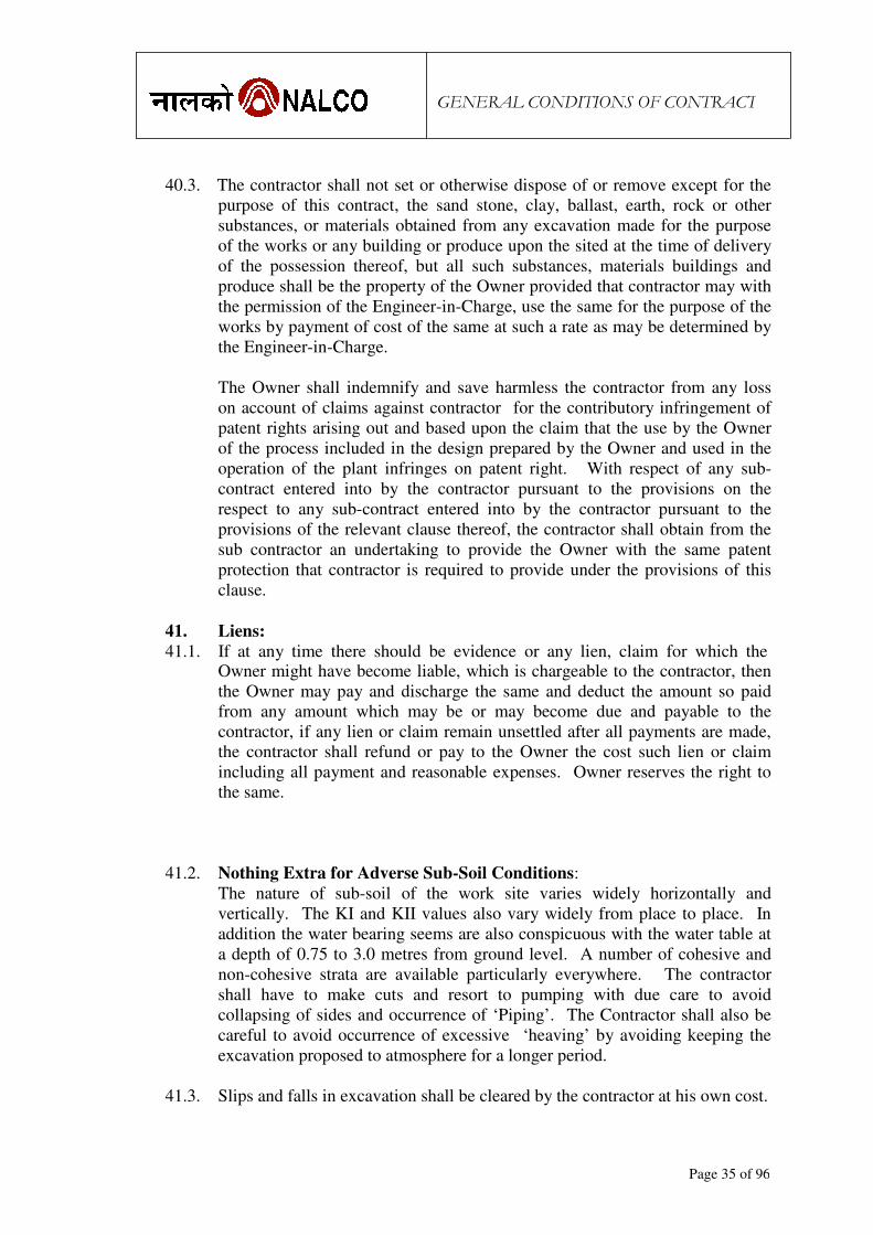
GENERAL CONDITIONS OF CONTRACT
Page 35 of 96
40.3. The contractor shall not set or otherwise dispose of or remove except for the
purpose of this contract, the sand stone, clay, ballast, earth, rock or other
substances, or materials obtained from any excavation made for the purpose
of the works or any building or produce upon the sited at the time of delivery
of the possession thereof, but all such substances, materials buildings and
produce shall be the property of the Owner provided that contractor may with
the permission of the Engineer-in-Charge, use the same for the purpose of the
works by payment of cost of the same at such a rate as may be determined by
the Engineer-in-Charge.
The Owner shall indemnify and save harmless the contractor from any loss
on account of claims against contractor for the contributory infringement of
patent rights arising out and based upon the claim that the use by the Owner
of the process included in the design prepared by the Owner and used in the
operation of the plant infringes on patent right. With respect of any sub-
contract entered into by the contractor pursuant to the provisions on the
respect to any sub-contract entered into by the contractor pursuant to the
provisions of the relevant clause thereof, the contractor shall obtain from the
sub contractor an undertaking to provide the Owner with the same patent
protection that contractor is required to provide under the provisions of this
clause.
41. Liens:
41.1. If at any time there should be evidence or any lien, claim for which the Owner might have become liable, which is chargeable to the contractor, then
the Owner may pay and discharge the same and deduct the amount so paid
from any amount which may be or may become due and payable to the
contractor, if any lien or claim remain unsettled after all payments are made,
the contractor shall refund or pay to the Owner the cost such lien or claim
including all payment and reasonable expenses. Owner reserves the right to
the same.
41.2. Nothing Extra for Adverse Sub-Soil Conditions:
The nature of sub-soil of the work site varies widely horizontally and
vertically. The KI and KII values also vary widely from place to place. In
addition the water bearing seems are also conspicuous with the water table at
a depth of 0.75 to 3.0 metres from ground level. A number of cohesive and
non-cohesive strata are available particularly everywhere. The contractor
shall have to make cuts and resort to pumping with due care to avoid
collapsing of sides and occurrence of ‘Piping’. The Contractor shall also be
careful to avoid occurrence of excessive ‘heaving’ by avoiding keeping the
excavation proposed to atmosphere for a longer period.
41.3. Slips and falls in excavation shall be cleared by the contractor at his own cost.

GENERAL CONDITIONS OF CONTRACT
Page 36 of 96
Excessive heaving shall have to cut and refill with lean concrete by the
contractor at his own cost. The contractor shall have to adopt under-water
work in case of occurrence of piping/ quick condition without any additional
cost to the Owner.
The contractor will be paid for the earthwork as per the drawing. The slopes
etc. as required for the safety of the work has to be provided as per the
decision of the Engineer-in-Charge at his own cost. All types of dewatering
including seepage, rain water entering. The earthwork in excavation or from
any other source is to be done by the contractor at his own cost till the
completion of foundation upto ground level including back filling.
41.3. No Compensation in case of change of Location of site :
Change of location of site do not invalidate the contract and tenderer have no
claim for any compensation for such changes.

GENERAL CONDITIONS OF CONTRACT
Page 37 of 96
SECTION – V PERFORMANCE OF WORK
42. Execution of Works:
All the work shall be executed in strict conformity with the provisions of the
contract documents explanatory detailed drawings, specifications and
instructions by the Engineer-in-Charge whether mentioned in the contract or
not. The contractor shall be responsible for ensuring that works are executed
in the most substantial, proper and workman like manner using the quality
materials and labour, through out the job Completion in strict accordance with
the specifications and to the entire satisfaction of the Engineer-in-Charge.
43. Coordination and inspection of Works:
The coordination and inspection of the day-to-day work under the contract
shall be the responsibility of the Engineer-in-Charge or his authorised
representative. A work order book will be maintained by the contractor for
each sector in which the aforesaid written instructions will be entered. These
will be signed by the contractor or his authorised representative by way of
acknowledgement within 12 hours.
44. Works in Monsoon and Dewatering:
44.1 The execution of work may entail working in the monsoon also. The
contractor must maintain a minimum labour force as may be required for the
job. And plan execute the construction and erection according to the
prescribed schedule. No extra will be considered for such work in monsoon.
44.2 During monsoon and other period, it shall be the responsibility of the
contractor to keep the construction work site free from water at his own cost.
45. Work on Sundays and Holidays:
For carrying out works on Sundays and holidays, the contractor will to keep
Engineer-in-Charge or his representative at least two days in advance and
obtain permission in writing. The contractor shall observe all labour laws and
other statutory rules and regulations in force. In case of any violation of such
laws, rules and regulations, consequence if any, including the cost thereto shall
be exclusively borne by the contractor and the Owner shall have no liability
whatsoever on his account.
46. General Conditions of Construction and Erection Work:
46.1 The working time at the time of work is 48 hours per week. Overtime work is
permitted in case of need and the owner will not compensate the same. Shift-
working at 2 or 3 shifts per day will become necessary and the contractor
should take this aspect into consideration for formulating his rates for
quotation. No extra claims will be entertained by the Owner on this account.

GENERAL CONDITIONS OF CONTRACT
Page 38 of 96
46.2 The contractor must arrange for the placement of workers in such a way that
the delayed completion of the work or any part thereof or for any reason
whatsoever will not affect their proper employment. The Owner will not
entertain any claim for old time payment whatsoever.
46.3 The contractor shall submit to the Engineer-in-Charge reports at regular
intervals regarding the state and progress of work. The contract shall provide
display boards showing progress and labour strength at work site, as directed
by the Engineer-in-Charge.
46.4 The site of work will be released progressively in stages and no claim for any
compensation or damages will be tenable for non-release of the entire site at a
time.
47. Drawings to be supplied by Owner:
47.1 The drawings attached with tender are only for the general guidance to the
contractor to enable him to visualise the type of work contemplated. The
contractor will be deemed to have studied the drawings and formed an idea
about the total work involved.
47.2 In the Course the progress of work detailed working drawings on the basis of
which actual execution of the work has to proceed, shall be furnished in
stages. The contractor shall be deemed to have gone through the drawings
supplied to him thoroughly and carefully, in conjunction will all other
connected drawings and discrepancies if any, shall be brought to the notice of
the Engineer-in-Charge, before actually carrying out the works.
47.3 Copies of all detailed working drawings relating to the works shall be kept at
the contractor’s office on the site and shall be made available to the Engineer-
in-Charge at any time during the contract period. The drawings and other
documents issued shall be returned to the Owner on completion of the works.
48. Drawings to be supplied by the Contractor:
48.1 The drawings/data which are to be furnished by the contractor are enumerated
in the special conditions of contract and shall be furnished within the specified
time.
48.2 Where approval of drawings for manufacture/construction/fabrication has
been specified it shall be contractor’s resposibility to have these drawings
prepared as pe r the directions of Engineer-in-Charge and get them approved
before proceeding with manufacture/construction/fabriction works as the case
may be. Any changes that may have become necessary in these drawings
during the execution of the work shall have to be carried out by the contractor
to the satisfaction of Engineer-in-Charge at no extra cost. All final approved
drawings shall bear the certification stamp duly signed by both the contractor
and the Engineer-in-Charge as indicated below.

GENERAL CONDITIONS OF CONTRACT
Page 39 of 96
“Certified true for ……………………………………….
(Name of work)
Agreement No ……………………………………
Signed
(Contractor) (Engineer-in-Charge)
48.3 A period of 3 weeks from the date of receipt shall be required for approval of
drawings by the Engineer-in-Charge.
48.4 As built drawing showing all Corrections, adjustments etc. shall be furnished
by the Contractor in five copies and one transparent to record purposes to the
owner.
49 Setting Out Works:
49.1 The Engineer-in-Charge shall furnish to the contractor with only the four
corners of the work site that is plant boundary limits, and a level bench mark
only. The contractor shall set out the works, provide an efficient staff for the
purpose and shall be solely responsible for the accuracy of such setting out.
49.2 The contractor shall provide, fix and be responsible for the maintenance of all
stacks, templates, level marks, profiles and other similar things and shall take
all necessary precautions to prevent their removal or disturbance. He shall be
responsible for their consequences arising of such removals, disturbances
corrections thereon and for their efficient and timely reinstatement. The
contractor shall also be responsible for the maintenance of all existing survey
marks, boundary marks, distance marks and centre line marks, either existing
or supplied and fixed by the contractor. The work shall be set out to the
satisfation of the Engineer-in-Charge. The approval thereon or jointing with
the contractor by the Engineer-in-Charge in setting out the work, shall not
relive the contractor of any of his responsibilities.
49.3 Before beginning the work the contractor shall at his own cost, provide all
necessary reference and level posts-pegs, bamboos, flags, ranging rods,
strings, and other materials for proper layout of the work in accordance with
the scheme for bearing marks acceptable to the Engineer-in-Charge. The
centre, longitudinal, face and cross lines shall be marked by means of small
masonry pillars. Each pillar shall have distinct mark at the centre to eable the
theodolite to be set over it. No work shall be started until all these points
arechecked and approved by Engineer-in-Charge in writing, but such approval
shall not relieve the contractor of any of his responsibilities. The contractor
shall also provide all labour, materials and other facilities as necessary, for the
proper checking or layout and inspection of the points during construction.
49.4 Pillars bearing geodetic marks located at the sites of units of works under
construction should be protected and faced by the contractor.

GENERAL CONDITIONS OF CONTRACT
Page 40 of 96
49.5 On completion of work, the contractor must submit the geodetic documents
according to which the work was carried out.
50. Responsibility for Level and Alignment:
50.1 The contractor shall be entirely and exclusively responsible for the horizontal
and vertical alignment, the level and correctness of every part of the work
shall rectify effectually any errors or imperfections therein. Such rectification
shall be carried out by the contractor at his own cost, when instructions are
issued to that effect by the Engineer-in-Charge.
50.2 Lighting, Watch & Ward:
The contractor shall in connection with works provide and maintain at his
own cost all lightings, guards, fencing and watch and ward and the security of
the entire work in progress in cluding all the machineries, materials shall be
the responsibility of the contractor till taken over by the owner by way of the
written taking over certificate.
51. Materials to be Supplied by Contractor :
51.1 The contractor shall procure and provide the whole of the materials required
for the construction including M.S. Rods, Cement and other building
materials, tools, tackles, construction plant and equipment for the completion
and maintenance of the work except the materials which will be issued by the
Owner and shall make his own arrangement for procuring such materials and
for the transport thereof. The owner may give necessary recommendation to the respective authorities, if so desired by the contractor, but assumes no
further responsibility of any nature. The owner will insist on the procurement
of materials which has the approval of Indian Standards Institution having ISI
stamp and/or which are supplied by reputed suppliers borne on DGS & D list.
51.2 The contractor shall properly store all materials either issued to him or brought
by him to the worksite to prevent damages due to rain, wind, direct exposure
to sun etc. as also from theft, pilferage, etc. for proper and speedy execution of
his works. The contractor shall maintain sufficient stocks of all meterials
required by him.
51.3 No material shall be despatched from the contractor’s stores before obtaining
the approval in writing of the Engineer-in-Charge.
51.4 All plants, tools and other materials brought by the contractor to the site must
be declared at the time of bringing the same to the site.
52. Stores Supplied by the Owner:
52.1 If the specification of the work provides for the use of any material other than
Steel & Cement of special description to be supplied from the Owner’s stores
or it is required that the contractor shall use certain stores to be provided by

GENERAL CONDITIONS OF CONTRACT
Page 41 of 96
the Engineer-in-Charge, such materials and stores, and price to be charged
therefore as hereinafter mentioned being so far as practicable for the
convinience of the contractor, but no so as in way to control the meaning or
effect of the contract, the contract shall be bound to purchase and shall be
supplied much materials and stores as are from time to time required to be
used by him for the purpose of the contract only. The sums due from the
contractor for the value of materials supplied by the Owner will be recovered
from the Running Account Bill on the basis of actual consumption of materials
(after taking into account any wastage allowance as may be provided for in the
contract). The contractor should raise requisite copies of indents in a
proforma as prescribed by the Engineer-in-Charge and no claim whatsoever
will be entertained by the Engineer-in-Charge on this account. After
completion of the works, the contractor is required to account as per relevant
clauses in this document, for the full quantity of materials supplied to him.
52.2The value of the stores/materials as may be supplied to the contractor by the
Owner will be debited to the contractor’s account at the rates shown in the
schedule of materials and if they are not entered in the schedule, they will be
debited at cost price, which for the purpose of thecontract shall include the cost of
carriage and all other expenses whatsoever such as normal storage supervision
charges which shall have been incurred in obtaining the same at the Owner’s
stores. All materials so supplied to the contractor shall remain the obsolute
property of the Owner and shall not be removed on any account from the site of
the work and shall be at all times open for inspection to the Engineer-in-Charge.
Any such materials remaining unused at the time of the completion or termination
of the contract shall be returned to the Owner’s stores or at a place as directed by
the Engineer-in-Charge in perfectly good condition at contractor’s cost.
52.3 Steel & Cement:
52.3.1 If the specification of the work provides for the use of steel or cement such
items of steel and cement to the extent required as per the specification of the
works, shall be supplied at Owner’s stores by the Owner for utilisation in the
work on non-chargable basis from time to time depending upon the progress
of the work. The tender rates shall be exclusive of the cost of steel and cement
to be supplied as per the specification of the work, However, in case of flats
and chequeuered plates the same have to be procured by the contractor at his
own cost.
52.3.2 Such materials of steel and cement shall be issued only for permanent works
and not for making other temporary works etc. Contractor shall bear all cost
including lifting and loading carting from issue points to work site/contractor
stores, custody and handling etc. and return of surplus
serviceable/unserviceable materials to owner’s store or other places to be
designed by owner and no separate payment for such expenditure shall be
made.

GENERAL CONDITIONS OF CONTRACT
Page 42 of 96
52.3.3 Items of steel as per specification of the work as mentioned above shall be
supplied in the available length only. No claim on account of supply of non-
standard length shall be entertained. Steel materials shall be issued on actual
weight basis.
52.3.4 Cement as mentioned above will be supplied to the contractor a receive from
the manufacturer/stockist. The theoretical weight of each bag of cement
supplied will be considered as 50 Kg.
52.3.5 Scraps & Surplus Material:
The Contractor shall return all the surplus/unutilised as well as the scraps and
wastages out of the materials supplied to him to the Owner’s stores in a
perfectly good condition at the contractor’s cost. However, the following
scraps allowances are permissible.
Unaccountable Accountable
(i) Cement 3% Nil
(ii) Reinforcement Steel ½% 2.5%
(iii) Steel structural (Plates & Sections) ½% 4.5%
(iv) M.S. Plates for fabrication of Pipes ½% As per cutting diagrams
approved by Engineer-in-
Charge before cutting and
fabrication.
52.3.6 Return of unutilised/surplus materials and scrap/wastage:
In respect of any utilised/surplus quantities of cement and steel supplied by not
accounted for and or returned by the contractor shall pay to the Owner
amounts at the penal rate of twice the SAIL, Bhubaneswar Stock-yard rate of
that particular section of steel and cement as the case may be as on the date of
accountability. If the Contractor fails to return the scraps/wastage generated
as per the above percentage, recovery of such scrap/wastage shall be made at
the rate of Rs. 7000/- per tonne.
The charging of penal rate shall be without the prejudice to the other remedies
or action available to the owner against the contractor including any criminal
action.
52.3.7. Accounting for Materials:
Every month the Contractor shall submit a statement for all the materials
supplied to him by the owner in the proforma prescribed by the Engineer-in-
Charge.
52.3.8 On completion of the work, the Contractor shall submit material appropriation
statement for the materials supplied to him by the Owner.
52.3.9 All materials supplied to the contractor shall remain the absolute property of
the all times and title therein shall not pass to the contractor at any time. The
possession of the materials in the hands of the contractor is only for the

GENERAL CONDITIONS OF CONTRACT
Page 43 of 96
purpose of incorporating the same in the Owner’s work. The material supplied
shall not be removed by the contractor on any account from the site of work
and shall be at all times open for inspection by the Engineer-in-Charge or
owners representative. The contractor shall not use the materials supplied
to him for any purpose or work other than the work, which the said materials
are supplied.
53. Conditions for issue of Materials:
(i) Materials specified as to be issued by the Owner will be supplied to the
contractor by the Owner from his stores. It shall be the responsibility of the
contractor to take delivery of the materials and arrange for its loading,
transport and unloading at the site work at his own cost. The material shall
be issued during the working hours of his Stores and as pe the rules of the
Owner framed from time to time.
(ii) The contractor shall bear all incidental charges for the storage and safe
custody of materials at site after these have been issued to him.
(iii) The contractor shall construct suitable godown at the site of work for storing
the materials safe against damage by rain, dampness, fire, theft, etc. He shall
also employ necessary watch and ward establishment for the purpose.
(iv) Materials specified as to be issued by the Owner shall be issued in standard
sizes as obtained from the manufacturers.
(v) It shall be duty of the contractor to inspect the materials supplied to his at the
time of taking delivery and satisfy himself that they are in good condition.
After the materials have been delivered by the Owner, it shall be the
responsility of the contractor to keep them in good condition and if the
materials are damaged or lost, at any time, they shall be repaired and.or replaced by him at his own cost according to the directions of the Engineer-
in-Charge.
(vi) The Owner shall not be liable for delay in supply or non-supply of any
materials, which the Owner has unertaken to supply where such failure or
delay is due to natural calamities, act of enemies, transport and procurement
difficulties and any circumstances beyond the control of the Owner. In no
case, the contractor shall be entitled to claim any compensation or loss
suffered by him on his account.
(vii) It shall be the responsibility of the contractor to arrange in time all materials
required for the works other than those to be supplied by the Owner. If
however in the opinion of the Engineer-in-Charge the execution of the work.
Is likely to be delayed due to the contractor’s inability’s to make
arrangements for supply of materials which normally he has to arrange for,
the Engineer-in-Charge shall have the right at his own discretion to issue such
materials if available with the Owner or procure the materials from the
market or elswhere. The contractor will be bound to take such materials at
the rates decided by the Engineer-in-Charge. This however, does not in
anyway absolve the contractor from responsibility of making arrangement for
the supply of such materials in part or in full, should such a situation occur
nor shall this constitute a reason for the delay in the exectution of the work.

GENERAL CONDITIONS OF CONTRACT
Page 44 of 96
(viii) Non of the materials supplied to the contractor will be utilised by the
contractor for manufacturing item which can be obtained as supplied from
standard manufacturer in finished form unless approved by Engineer-in-
Charge in writing.
(ix) The contractor shall, if desired by the Engineer-in-Charge, be required to
execute an indemnity bond in the prescribed form for safe custody, usage and
accounting of all materials issued by the Owner.
(x) The contractor shall furnish to Engineer-in-Charge sufficiently in advance a
statement showing his requirements of the quantities of the materials to be
supplied by the Owner and the time when the same will be required by him
for the works, so as to enable the Engineer-in-Charge to make necessary
arrangement for procurement and supply of material.
(xi) Account of the materials to be issued by the Owner shall be maintained by
the contractor indicating the daily receipt, consumption and balance in hand
in a manner prescribed by the Enginner-in-Charge. All connected papers
requisitions, issues returns etc. shall be always available for inspection in the
contractor’s office at site.
(xii) The contractor should see that only the required quantities of materials are
got issued. The contractor shall not be entitled to cartage and incidential
charges for returning the surplus materials, if any, to the stores, place of issue
or to the place as directed by the Engineer-in-Charge.
(xiii) Materials/equipment supplied by Owner shall not be utilised for any other
purpose (s) than issued for.
(xiv) The owner may issue the material in phases at his discretion keeping in view
the programmes of the work.
(xv) In case of free issue of materials, the contractor shall submit an indemnity
bond in the prescribed format for 80% (eighty) value of the materials and a
bank guarantee for 20% (twenty) of the value of the materials. The indemnity
bond and bank guarantee shall be valid till the material acount is totally
settled.
54. Return of Surplus:
Notwithstanding anything contained to the contrary in any or all the clauses of
this contract where any materials for the execution of the contract are procured
with the assistance of the Owner either by issue from Owner’s stock or
purchases made under orders, or permits or licences issued by government the
contractor shall hold the said materials as trustee for the owner and use such
materials economically and solely for the purpose of the contract and not
dispose them off without the permission of the Owner and return, if required
by the project head all surplus or unserviceable materials that may be left with
him after the completion of the contract or at its termination for any reason
whatsoever on his being paid or credited such price as the Project head shall
determine having due regard so the condition of the materials. The price
allowed to the contractor however, shall not exceed the amount charged to him
excluding the storage charges, if any. The decision of the project head shall be
final and conclusive in such matter. In the event of breach of the aforesaid
conditions, the contractor shall, in the terms of the licences, or permits and/ or

GENERAL CONDITIONS OF CONTRACT
Page 45 of 96
for criminal breach of trust, be liable to compensate the Owner at double rate
or any higher, in the event of those materials at the time having higher rate or
not being available in the market, then any other rate to be determined by the
project head and his decision shall be final and conclusive.
55. Materials Obtained From Dismantling:
If the contractor in the course of execution of the work is called upon to
dismantle any part for reasons other than those stipulated in clauses 57 and 65
hereunder, the materials obtained in the work of dismantling etc. will be
considered as the Owner’s property and will be disposed off to the best
advantage of the Owner.
56. Articles of Value Found:
All gold silver and other materials of any descriptions, precious stones, coins,
treasures, relics, antiques and other similar things which shall be found, in,
under or upon the site, shall be property of the Owner and the contractor shall
duly preserve the same to the satisfaction of the Engineer-in-Charge and shall
from time to time delivery the same to such person or persons indicated by the
Owner.
57. Inspection of Works:
57.1 The Engineer-in-Charge will have full power and authority to inspect the
works in progress at any time wherever the premises/ workshops situated, of the
Contractor, person, firm or corporation where works in connection with the
contract may be or where materials are being or intended to be supplied.
The contractor shall afford or procure every facility and assistance to
Engineer-in-Charge carry out such inspection. The contractor shall, at all
time during the usual working hours and at all other times at which reasonable
notice of the intention of the Engineer-in-Charge or his representative to visit
the works shall have been given to the contractor, either himself be present to
receive orders and instructions or have a responsible agent duly accredited in
writing be present for the purpose. Orders given to the contractor’s agent
shall be considered to have the same force as if they had been given to the
contractor himself. 57.2 The contractor shall give not less than seven days notice in writing to the
Engineer-in-Charge before covering up or otherwise placing beyond reach of
inspection and measurement any work in order that the same may be
inspected and measured. In the event of failure of above the same shall be
uncovered and all facilities made available again at contractor’s expense for
carrying out such measurement or inspection.
57.3 The contractor is to provide at all times during the progress of the work and
maintenance period proper means at access with ladders gangways etc. and the
necessary attendance to move and adopt as directed for inspection
or measurement of the works by the Engineer-in-Charge.
58. Assistance to the Engineer:
The Contractor shall make available to the Engineer-in-Charge free of cost all
necessary instructions and assistance in checking of settling out of works and

GENERAL CONDITIONS OF CONTRACT
Page 46 of 96
in the checking of any works made by the contractor for the purpose 0f setting
out and taking measurements of work.
59. Discrepancies between instructions:
Should any discrepancy arise between the various instructions furnished to the
contractor or his agents or staff or if any doubt arises on the meaning or
implementation of any such instructions or should there be any difference of
opinion on the issues, the contractor shall refer the matter immediately in
writing to the Engineer-in-Charge whose decisions thereon shall be final and
conclusive. No claim on losses alleged to have been caused by such
discrepancies between instructions, doubts or misunderstanding shall in any
event be admissible.
60. Alterations in Specifications and Designs and Extra Works:
(a) The Project Head shall have power to make any alterations, in omission
from additions to or substitutions, for the schedule of rates, the original
specifications, drawings and instructions that may appear to him to be
necessary or advisable during the progress of the work, and the contractor
shall be bound to carry out such altered/ extra/ new items of work in
accordance with any instructions which may be given to him in writing
signed by the Project Head and such alterations, omissions, additions or
substitutions shall not invalidate the contract and any altered, additional or
substituted work which the contractor may be directed to do in the manner
above specified as part of the work shall be carried out by the contractor
on the same conditions in all respects on which he agreed to do the main
work. The time of completion of work may be extended for the part of the particular job at the discretion of the Project Head for any such alterations,
additions, or substitutions of the work, as he may consider as just and
reasonable. The rates for such additional, altered or substituted work
under the clause shall be worked out in accordance with the following
provisions:-
(b) If the rates for the additional, altered or substituted work are specified in
the contract for the work, the contractor is bound to carry out the
additional, altered or substituted work at the same rates as are specified in
the contract.
(c) If the rates for the additional, altered or substituted work are not
specifically provided in the contract for the work, the rates will be derived
from rates for similar class of work as are specified in the contract for the
work. The opinion of the Project head as to whether or not the rates can be
reasonably so derived from the items in this contract will be final and
binding on the contractor.
(d) If the rates for the additional, altered or substituted work can not be
determined in the manner specified in sub-clause (a) & (b) above, then the
contractor shall within 7 days of the date of receipt of order to carry out

GENERAL CONDITIONS OF CONTRACT
Page 47 of 96
the work, inform the Project Head of the rate which it is his intention to
charge for such class of work, supported by analysis of the rate or rates
claimed, and the project Head shall determine the rate or rates on the basis
of the prevailing market rates of materials plus labour cost including
equipment hire charge at schedule of hourly/ daily rates plus 15% to cover
contractor’s supervisions overhead and profit and pay to the contractor
accordingly. The opinion of the Project Head to current market rates of
the materials and the quantum of labour and equipment involved per unit
of measurement will be final and binding on the contractor. The schedule
of hourly/ daily rates shall be as enclosed.
61. Action Where no Specification is issued:
In case of any class of work for which there is no such specification supplied
by the Owner as is mentioned in the tender document such work shall be
carried out in accordance with the Indian Standard Specifications. If the
Indian Standard Specifications do not cover the same, the work should carried
out as per standard Engineer in Practice subject to the approval of the
Engineer-in-Charge.
62 Abnormal Rates:
The contractor is expected to quote the rate for each item after careful analysis
of cost involved for the satisfactory performance and completion of item work
considering all specifications and conditions of contract. This will avoid loss
of profit or gain in case ofcurtailment or change in specification for any other
item. In case the rate quoted by the tenderer for any item are usually high or
unusually low it will be sufficient cause of the rejection of the tender unless the Owner is convinced about the reasonableness of the analysis for such rate
furnished by the tenderer (on demand) after scrutiny.
63. Tests For Quality Works:
63.1 All materials and workmanship shall be of the respective kinds described in
the contract documents and in accordance with the instructions of the
Engineer-in-Charge and shall be subjected from time to time to such tests at
contractor’s cost as the Engineer-in-Charge may direct at the place of
manufacture or fabrication or at the site or at all or any such places. The
contractor shall provide assistance, instruments, machines, labour and
materials as are required for examining, measuring and testing any
workmanship as may be selected and required by the Engineer-in-Charge.
63.2 All the tests that will be necessary in connection with the execution of the
work as decided by Engineer-in-Charge shall be carried out at the field testing
laboratory of this Owner if available by paying the charges as decided by the
Owner from time to time. In case of non-availability of testing facilities with
the Owner, the required laboratory as directed by Engineer-in-Charge.
63.3 If any tests are required to be carried out in connection with the work or
materials or workmanship not supplied by the contractor, such tests shall be

GENERAL CONDITIONS OF CONTRACT
Page 48 of 96
carried out by the contractor as per the instructions of Engineer-in-Charge and
cost of such tests shall be reimbursed by the Owner.
64. Samples:
The contractor shall furnish to the Engineer-in-Charge for approval when
request or if required by the specifications, adequate samples of all materials
and finished to be used in the work. Such samples shall be submitted before
the work is commenced and in sample time to permit tests and examinations
thereof. All materials furnished and finishes applied in actual work shall be
fully equal to the approved samples.
65 Liabilities for Defect, Imperfections etc. and Rectifications Thereof:
If it shall appear to the Engineer-in-Charge that any work has been executed
with unsound, imperfect or unskilled workmanship, or with materials of any
inferior description, or that any matrials or articles provided by the contractor
for the execution of work are unsound or of quality inferior to that contracted
for, or otherwise not in accordance with the contract, the contractor shall on
demand in writing from the Engineer-in-Charge or his authorised
representative specifying the work, materials or articles complained of,
notwithstanding that the same may have been inadvertently passed, certified
and paid for, forthwith rectify or remove and reconstruct that work so
specified and provide other proper and suitable materials or articles at his own
charge and cost, and in the event of failure to do so within a period to be
specified by the Engineer-in-Charge in his demand aforesaid, the Engineer-in-
charge may on expiry of notice period rectify or remove, and re-execute the
work or remove and replace with others, the materials or articles complained of as the case may be at the risk and expense in all respects of the contract.
The decision of the Engineer-in-Charge as to any question arising under this
clause shall be final and conclusive.
66. Suspension of Works:
(i) Subject to the provision of sub para (ii) of this clause, the contractor shall if
orderded in writing by the Engineer-in-Charge., or his representative,
temporarily suspend the works or any part thereof such period and such time
as so orderded and shall not, after receiving such written orders, proceeds with
the work therein, orderded to be suspended until he shall have received a
written order to proceed therewith. The contractor shall not be entitled to
claim compesation for any loss or damage sustained by him by reason of
temporary suspension of the works aforesaid. An extension of time for
completion, corresponding with the delay caused by any such suspension of
the works as aforesaid will be granted to the contractor should be apply for the
same provided that the suspension was not consequent to any default or failure
on the part of the contractor.
(ii) In case of suspension of entire work, orderded in writing by the Enginner-in-
Charge, for a period of more than two months, the contractor shall have the
option to terminate contract.

GENERAL CONDITIONS OF CONTRACT
Page 49 of 96
67. Possession Prior to Completion:
The Engineer-in-Charge shall have the right to take possession of or any
completed or partially completed work or part of the work. Such possession or
use shall not be deemed to be an acceptance of any work completed in
accordance with the contract. If such prior possession or use by the Engineer-
in-Charge delay the progress of work, equitable adjustment in the time of
completion will be made and the contract agreement shall be deemed to be
modified accordingly.
68 Twelve months Period of Liability from the Date of Issue of Completion
Certificate:
68.1 The contractor shall gurantee the installation/work for a period of 12 months
from the date of completion of work as certified by the Engineer-in-Charge
which is indicated in the completion certificate. Any damage or defect that
may arise though remained undeiscovered at the time of issue of completion
certificate, connected in any way with the equipment or materials supplied by
him or in the workmanship shall be rectified or replaced by the contractor at
his own expenses as deemed necessary by the Engineer-in-Charge or in
default the Engineer-in-Charge may cause the same to be made good by other
agency and deduct expenses (of which the certificate or Engineer-in-Charge
shall be final) from any sums that may be then or at any time thereafter
become due to the contractor or from his security deposit, or the proceeds of
sale thereof or of a sufficient portion thereof.
68.2 If the contractor feels that any variation in work or in quality of materials or
proportions would be beneficial or necessary to fulfil the guarantees called for,
he shall bring this in writing to the notice of the Engineer-in-Charge.
68.3 Care of works:
From the commencement of completion of the work, the contractor shall take
full responsibility for the care of all works including all temporary works and
in case any damage, loss or injury shall happen to the work or to any part
thereof or to any temporary works from any cause whatsoever, shall at his own
cost repair and make good the same so that on completion the work shall be in
good order and in conformity in every respects with the requirements of the
contract and the Engineer-in-Charge’s Instructions.
68.4 Defects Prior to Taking Over:
If at any time before the work is taken over, the Engineer-in-Charge shall: (a) Decide that any work done or materials used by the contractor or any sub-
contractor is defective or not in accordance with the contract, or that the
works or any portion therof are defective, or do not fulfil the requirements
of contract (allsuch matter, being hereinafter, called ‘Defects’ in this clause)
and (b) as soon as reasonably practicable gives to the contractor notice in
writing of the said decision specifying particulars of the defects claimed to
exist or to have occurred then the contractor shall at his own expenses and
with all speed make good the defects so specified.

GENERAL CONDITIONS OF CONTRACT
Page 50 of 96
In case contractor shall fail to do so, the Owner may take, at the cost of
contractor, such steps as may in all circumstances be reasonable to make
good such defects. The expenditure so incurred by the owner be recovered
from the amount due to the contractor. The decision of the Engineer-in-
Charge with regard to the amount to be recovered from the contractor will
be final and binding on the contractor. As soon as the works have been
completed in accordance with the contract (except minor respects that do
not affect their use for the purpose for which they are intended and except
for maintenance thereof provided in clause 68.1 of General Conditions of
Contract) and have passed the tests on completion, the Engineer-in-Charge
shall issue a certificate (hereinafter called completion certificate) in which
he shall certify the date on which the works have been so completed and
have passed the said tests and the Owner shall be deemed to have taken
over the works on the date so certified. If the works have been divided into
various groups in the contract, the Owner shall be entitled to take over any
group or groups before the other or others.
68.5 Defect After Taking Over:
In order that the contractor could obtain a completion certificate he shall make
good with all possible speed, any defect arising from the defective materials
supplied by the contractor or that may have been notices or developed, after
the works or group of the works has been taken over, the period allowed, for
carrying our such work will be normally one month. If any defect be not
remedied within a reasonable time, the owner may proceed to do the work at
contractor’s Risk and expenses and deduct from the final bill such amount as
may be decided by the Owner.
If by reason of any default on the part of the contractor a completion
certificate has not been issued in respect of every portion of the works within
one month after date fixed by the contract for the completion of the works, the
Owner shall be a liberty to use the work or any portion therof in respect of
which a completion certificate has not been issued, provided that the works or
the portion thereof so used as aforesaid shall be afforded reasonable
opportunity for completion of these works for the issue of completion
certificate.
68.6 Guarantee/Transfer of Guarantee:
For works like water-proofing, acid & alkali resisting materials, pre-
construction soil treatment against termite or any other specialized works etc.
the contractor shall invariable engage sub-contractors who are specialists in
the field and firms or repute and such a sub-conractor shall furnish guarantees
for their workmanship to the Owner, through the contractor. In case such a
sub-contractor/firm is not prepared to furnish a guarantee to the owner, the
contractor shall give that guarantee to the Owner directly.

GENERAL CONDITIONS OF CONTRACT
Page 51 of 96
SECTION – VI CERTIFICATE AND PAYMENT
69. SCHEDULE OF RATE AND PAYMENTS:
69.1 Contractor’s Remuneration: The price to be paid by the Owner to the contractor for the whole of the work
done and for the performance of all the obligations undertaken by the
contractor under the contract document shall be ascertained by the application
of the respective schedule of rates (the inclusive nature of which is more
particularly defined by way of application but not of limitation, with clause
No. 69.2) and payment to be made accordingly to the work actually executed
and approved by the Engineer-in-Charge. The sum so ascertained
shall(exception only as and to the extent expressly provided here in )
constitute the sole and inclusive of remunaeration of the contractor under the
contract and no further or other payment whatsoever shall be or become due or
payable to the contractor under the contract.
69.2 Schedule of Rates to the Inclusive:
The prices/rates quoted by the contractor shall remain firm till the issue of
final certificate and shall not be subject to escalation. Schedule of rates shall
be deemed to include and cover all costs, expenses and liabilities of every
description and all risks of every kind to be taken in executing, completion and
handing over the work to the Owner by the contractor. The contractor shall be
deemed to have known the nature, scope, magnitude and the extent of the
works and materials required though the contract document may not fully and
precisely furnish them. Hr shall make such provision in the schedule of rates as he may consider necessary to cover the cost of such items of work and
materials as may be reasonable and necessary to completer the work. The
opinion of the Engineer-in-Charge as to the items of work which are necessary
and reasonable for completion of work shall be final and binding on the
contractor although the same may not be shown on or described specifically in
contract documents.
Generality of this present provision shall not be deemed to cut down or limited
in any way because in certain cases it may and in other cases it may not
expressly stated that the contractor shall do or perform a work or supply
articles or perform with services at his own cost or without addition of
payment or without extra charge or works to the same effect or that it may be
stated or not stated that the same are included in and covered by the schedule
of rates.
69.3 Schedule of rates to cover Cconstructional Plant, Materials. Labours etc.:
Without in any way limiting the provision of other subclauses the schedule of
rates shall be deemed to include the cover the cost of all constructional plant,
temporary works (except as provided for herein), pumps, materials, labour,
insurance, fuel, stores, and appliances to be supplied by the contractor and all
other matters in connection with each items in the schedule of quantities and
GENERAL CONDITIONS OF CONTRACT
Page 52 of 96
the execution of the works or any portion thereof finished complete in every
respect and maintained as shown or described in the contract documents or as
may be orderded in writing during the continuance of the contract.
69.4 Schedule of Rates to cover Royalties, Rents and Claims:
The schedule of rates shall be deemed to include and cover the cost of all
royalties and fees for the articles, processes, protected by letters, patent or
otherwise incorporated in or used in connection with the works, also all
royalties, rents, and other payments in. connection with obtaining materials of
whatsoever kind for the works and shall include an indemnity to the owner
which the contractor hereby gives against all actions, proceedings, claims,
damages, costs and expenses arising from the incorporation in or use on the
works of any such articles, processes or charges if levied on materials,
equipment or machinery to be brought to site for use on work, shll be borne by
the contractor.
69.5 Schedule of Rates to cover taxes and duties:
No exemption or reduction of custom duties, excise duties, sales tax, quay or
any port duties, transport charges, stamp duties or Central or State
Government or Local Body (or from any other body) or Municipal Taxes or
duties, taxes or charges whatsoever will be granted or obtained and all
expenses of which shall be deemed to be included in and covered by the
schedule of rates. The contractor shall be obtain and pay for all permits or
other privileges necessary to complete the work.
69.6 Schedule of Rates to cover Risk of Delay:
The schedule of rates shall be deemed to include and cover the risk of all
responsibilities of delay and interference with the contractor’s conduct of work
which occur from any cause including orders of the owner in the exercise of
his powers and on account of extension of time granted due to various and for
all other possible or probable causes of delay.
69.7 Schedule of Rates cannot be altered:
For work under unit rate basis no alteration will be allowed in the schedule of
rates by reasons of works or any part of them being modified, altered,
extended, diminished or omitted. The schedule of rates is of fully inclusive
rates which have been fixed by the contractor and agreed to by the Owner and
cannot be altered.
69.7.1 The schedule of rates to cover for working in operating plant. Contractor’s
rates shall be deemed to include taking into account that he has to work in
operating plant and shall take sufficient care in moving the plants, equipments
and materials from one place to another, so that they do not cause any damage
to any person or to the property of the owner or to thirty party including over
head and underground cable/pipe lines. In the event of such damages
including eventual loss of production and operation of the plant or services in
any plant or establishment as estimated by the owner or ascertained or by the

GENERAL CONDITIONS OF CONTRACT
Page 53 of 96
third party shall be borne by the contractor. Since the work is to be executed
for the expansion of the plant, the rate of the contractor shall also deem to
include all interference/obstruction/interruption for which no compensation
shall be paid to be contractor.
70. Procedure For Measurement/ Billing of Work in Progress:
70.1 All measurements shall be in metric system. All the works in progress will be
jointly measured by the representative of the Engineer-in-Charge and the
contractor’s authorised agent progressively. Such measurements will be got
recorded in the measurement book by the Engineer-in-Charge or his
authorised representative and signed in token of acceptance by the contractor
or his authorised representative.
For the purpose of taking joint measurement the contractor’s representative
shall be bound to be present whenever required by the Engineer-in-Charge. If,
however, he absents for any reason whatsoever the measurements will be
taken by the Engineer-in-Charge or his representative and this will be deemed
to be correct and binding on the contractor.
70.2 Billing:
The contractor will submit a bill in approved proforma in accordance with the
contract terms and the agreed billing schedules in quintuplicate to the
Engineer-in-Charge giving abstract and detailed measurement for the various
items executed during a month, before the expiry of the first week of the
succeeding month. The Engineer-in-Charge shall take or cause to be taken the
requisite measurements for the purpose of having the same verified and the claim as far as admissible, adjusted, if possible, before the expiry of 10 days
form presentation of the bill.
70.2.1 The bill shall be submitted by the contractor in computerised formats
approved by the owner. The bills along-with floppies containing measurement
of work, particulars of materials, recoveries etc. have to be submitted to the
owner.
70.2.2 For lump-sum contracts, the payment will be according to agreed billing
schedule. No adjustment shall be allowed in lump-sum prices for any
variations in the quantities, specifications etc. shall take or a cause to be taken
the requisite measurement for the purposes of having the same verified and the
claim as far as admissible, adjusted, if possible, before the expiry of 10 days
from presentation of the bill.
70.3 Secured Advance on Materials:
In case of tenders for completed items of works, contractor may be allowed
“Secured Advance” on the security of materials brought to site for execution
of the contracted items of work to the extent of 75% of the value of materials
which go into the completed works as assessed by the Engineer-in-Charge
provided that the materials are of an imperishable nature and that formal

GENERAL CONDITIONS OF CONTRACT
Page 54 of 96
agreement is drawn up with the contractor under which the Owner secures a
lien on the materials and is safe guarded against losses due to the contractor
postponing the execution of the work or to the improper storage &/or misuse
of the materials and against the expenses entitled for their proper watch and
safe custody. Recoveries of advances so made would not be postponed until
the whole of the work entrusted to the contractor is completed. They should
be adjusted from his running account bills for work done as the materials are
used, the necessary deductions being made whenever the items of work in
which they are used and billed for.
70.4 Dispute in Mode of Measurement:
In case of any dispute as to the made of measurement not covered by the
contract to be adopted for any item of work, mode of measurement as per
latest Indian Standard Specifications shall be followed.
70.5 Rounding of Amounts:
In calculating the amount of each item due to the contractor in every
certificate prepared for payment, sum of less than 50 paisa shall be omitted
and the total amount on each certificates shall be rounded off to the nearest,
i.e. sum of less than 0.50.p shall be omitted and sums of 0.50p and more upto
one rupee shall be reckoned as one rupee.
71. LUMPSUMS IN TENDER:
For the item in tender where it includes lumpsum in respect of parts of work,
the contractor shall be entitled to payment in respect of the items at the same
as are payable under this contract for such items, or if the part of the work in question is not, in the opinion of the Engineer-in-Charge capable of
measurement, or determination, the Owner may at his discretion pay the lump-
sum amount entered in the tender or a percentage thereof and the certificate in
writing of the Engineer-in-Charge shall be final and conclusive against the
contractor with regards to any sum payable to him, under the provisions of this
clause.
72. RUNNING ACCOUNT PAYMENTS TO BE REGARDED AS
ADVANCE:
All Running Account Payment shall be regarded as Payments by way of
advance against the final payment only and not as payment for work actually
done and completed, and shall not preclude the requiring of bad, unsound and
imperfect or unskilled work to be removed and taken away and reconstructed
or re-erected or be considered as an admission of the due Performance of the
contract, or any part thereof, in this respect, or of the accruing of any claim by
the contractor, nor shall it, conclude, determine or affect in any way the
powers of the Owner under these conditions or any of them as to the final
settlement and adjustments of the accounts or otherwise, or in any other way
vary or affect the contract. The final bill shall be submitted by the contractor
within one month from the sate of physical completion of the work, otherwise,

GENERAL CONDITIONS OF CONTRACT
Page 55 of 96
the Engineer-in-Charge’s certificate of the measurement and of total amount
payable for the work accordingly shall be final and binding on all parties.
73. NOTICE OF CLAIMS FOR ADDITIONAL PAYMENT:
Should the contractor consider that he is entitled to any extra payment or
compensation or to make any claims whatsoever in respect of the works
arising under the terms of this contract he shall forthwith give notice in writing
to the Engineer-in-Charge that he claims extra payment within ten days from
the ordering of any work or happening of any event upon which the contractor
bases such claims and such notice shall contain full particulars of the nature of
such claims with necessary particulars as above within the time above
specified shall be an absolute waiver thereof. No omission by the Owner to
reject any such claim and no delay in dealing therewith shall be waiver by the
Owner of any right in respect thereof.
74. PAYMENT OF CONTRACTOR’S BILL:
No payment shall be made for works estimated to cost less that Rs. 10,000/-
till the whole of the work shall have been completed and a certificate of
completion given. But in case of works estimated to cost more that Rs.
10,000/- the contractor, on submitting the bill thereof be entitled to receive a
monthly payment proportionate to the part thereof approved and passed by the
Engineer-in-Charge, whose certificate of such approval and passing of the sum
so payable be final and conclusive against the contractor. This payment will
be made after making necessary deductions as stipulated elsewhere in the
contract document for materials, security deposit etc. or any statutory recoveries.
Payment due to the contractor shall be made by the Owner, by Crossed
Account Payee Cheque forwarding the same to registered office or the notified
office of the contractor. In no case will owner be responsible if the Cheque is
mislaid or misappropriated by un-authorised person/ persons. In all cases, the
contractor shall present his bill duly pre-receipted on proper revenue stamp.
All payment shall be made in Indian Currency.
75. Receipt For Payment:
Receipt for payment made on account of work when executed by a firm, must
be signed by a person holding due power of attorney in this respect on behalf
of the contractor, except when the contractors are described in their tender as
limited company in which case the receipts must be signed in the name of the
company by one of its principal officers or by some other persons having
authority to give effectual receipt for the company.
76. Completion Certificate:
76.1. Application for completion certificate:

GENERAL CONDITIONS OF CONTRACT
Page 56 of 96
When the contractor fulfils his obligation under clause 69.4 he shall be eligible
to apply for completion certificate in respect of the work by submitting the
completion documents along with such application for completion certificate.
The Owner or his representative shall normally issue to the contractor the
completion certificate within one month after receiving an application therefor
from the contractors after verifying from the completion documents and
satisfying himself that the work has been completed in accordance with and as
set out in the construction and erection drawings, and the contract documents.
The contractor, after obtaining the completion certificate, is eligible to present
the final bill for the work executed by him under the terms of contract.
76.2. Completion Certificate:
Within one month of the completion of work in all respects, the contractor,
shall be furnished with a certificate by the owner or his representative of such
completion but no completion certificate shall be given not shall the work be
deemed to have executed until all, scaffolding, surplus materials and rubbish is
cleared off the site completely not until the work shall have been measured by
the Engineer-in-Charge, whole measurement shall be binding and conclusive.
The work will not be considered as complete and taken over by the owner,
until all the temporary work, labour and staff colonies etc. constructed are
removed and work site cleared to the satisfaction of the Engineer-in-Charge.
If the contractor shall fail to comply with the requirements of this clause on or
before the date fixed for the completion of the work, the Engineer-in-Charge
may at the expenses of contractor remove such scaffolding, surplus materials
and rubbish and dispose off the same as he thinks fit and clean off such dirt as
aforesaid, and the contractor shall forthwith pay the amount for all expenses so
incurred and shall have no claim in respect of any such scaffolding or surplus
materials as aforesaid except for any sum actually realized by the sale thereof.
Completion Certificate shall be in 3 parts as follows:
(1) Physical/ Mechanical Completion work.
(2) Satisfactory completion of commissioning of equipment with load.
(3) Satisfactory completion of guarantee.
The contractor shall clearly indicate the 3 dates separately.
76.3. Completion Documents:
For the purpose of Clause 76 the following documents will be deemed to form
the completion documents:
(i) The technical documents according to which the work was carried out.

GENERAL CONDITIONS OF CONTRACT
Page 57 of 96
(ii) Three sets of construction drawings showing therein the modification
and corrections made during the course of execution and signed by the
Engineer-in-Charge.
(iii) Completion Certificate for embedded and covered –up works.
(iv) Certificate of final levels as set out for various works.
(v) Certificate of tests performed for various works.
(vi) Material appropriation statement to the materials issued by the owner
for the works and list of surplus materials returned to the owner’s store
duly supported by necessary documents.
(vii) Physical/ Mechanical Completion work.
(viii) Satisfactory completion of commissioning of equipment with load.
(ix) Satisfactory completion of guarantee.
The Contractor shall clearly indicate the 3 dates separately.
77. Final Decision And Final Certificate:
Upon the expiration of the period of liability and subject to the Engineer-in-
Charge being satisfied that the works have been duly maintained by the
contractor during monsoon or such period as herein provided in clause 68.1 and that the contractor has in all respect duly made up all subsidence and
performed all his obligations under the contract, the Engineer-in-Charge shall
(without prejudice to the right of the Owner to retain the provisions of relevant
clause hereof) otherwise give a certificate, herein referred to as the final
certificate, to the effect and the contractor shall not be considered to have
fulfilled the whole of his obligations under the contract until Final Certificate
shall have been given by the Engineer-in-Charge notwithstanding any
previous entry upon the work and taking possession, working or using of the
same or any part thereof by the Owner.
78. Certificate And Payments No Evidence of Completion:
Except the final certificate no other certificate or payment against a certificate
or on general account shall be taken to be an admission by the Owner of the
due performance of the contract of any part thereof or of occupancy or validity
of any claim by the Contractor.

GENERAL CONDITIONS OF CONTRACT
Page 58 of 96
SECTION – VII
TAXES AND INSURANCE
79. TAXES, DUTIES, OCTROI ETC.
79.1. The Contractor shall defray all charges, such as rent, toll local taxes excise
duty, other payments and compensations, if any, in connection with the
procurement and handling of materials, fabrication and execution of works or
any method or process connected with the works or Temporary works.
Sales Tax or any other tax on materials required for the works as also Tax on
works contract shall be payable by the Contractor and the Owner will not
entertain any claim whatsoever in this regard.
79.2. Notwithstanding anything contained elsewhere in the contract, the owner shall
deduct at source from the payments due to the contractor, the taxes as required
under Section -13–AA of the Orissa Sales Tax Act or as amended from time to
time or under any other statue. The amounts so deducted shall be deposited by
the Owner with the Sales Tax authorities as per Law. It is for the contractor
to deal with the Sales Tax authorities directly in respect of any claim or refund
relating to the above deductions and the owner shall not be liable or
responsible for any claims or payments or reimbursement in this regard.
80. INSURANCE:
Contractor shall at his own expense carry and maintain insurance with reputed
insurance companies to the satisfaction of the Owner as follows:
80.1 Employees State Insurance Act:
The contractor agrees to and does hereby accept full and exclusive liability for
compliance with all obligations imposed by the Employees State Insurance
Act., 1948, and the contractor further agrees to defend, indemnify and hold
Owner harmless form any liability of penalty which may be imposed by the
Central, State or Local authority by the reason of any asserted violation by
contractor or Sub-contractor of the Employee’s State Insurance Act, 1948 and
also from all claims, suits or proceeding that may be brought against the
Owner arising under, growing out of or by reasons of the work provided for by
this contract whether brought by employees of the contractor, by third parties
or by Central or State Government authority or any political sub-division
thereof.
The contractor agrees to fill in with the Employees State Insurance
Corporation, the Declaration Forms and all forms which may be required in
respect of the contractor’s or sub-contractor’s employees, whose aggregate
remuneration is Rs. 560.00 per month or less and who are employed in the
work provided for or those covered by ESI from time to time under the
Agreement. The contractor shall deduct and secure the agreement of the sub-
contractor to deduct the employee’s contribution as per the first schedule of
the Employee’s State Insurance Act from wages and affix the employee’s

GENERAL CONDITIONS OF CONTRACT
Page 59 of 96
contribution cards at wages payments intervals. The contractor shall remit and
secure the agreement of the sub-contractor to remit to the State Bank of India,
Employees State Insurance Corporation Account, the employee’s contribution
as required by the Act. The contractor agrees to maintain all cards and records
as required under the Act in respect of employees and payments and the
contractor shall secure the agreement of the sub-contractor to maintain such
records. Any expenses incurred for the contributions, making contributions or
maintaining records shall be to the contractor’s or sub-contractor’s account.
The Owner shall retain such sum as may be necessary from the total contract
value until the contractor shall furnish satisfactory proof that all contribution
as required by the Employees State Insurance Act, 1984, have been paid. This
will be pending on the contractor when the Employees State Insurance Act is
extended to the place of work.
80.2 Workmen Compensation and Employees Liability Insurance:
Insurance shall be affected for all the contractor’s employees engaged in the
performance of this contract. If any of the work is subject, the contractor shall
require the sub-contractor to provide workmen’s compensation and
employer’s liability insurance for the latter’s employees if such employees are
not covered under the contractor insurance.
80.3 Any other insurance required under Law or Regulations or by Owner:
Contractor shall also carry and maintain any and all other insurance, which he
may be required under any law or regulation from time to time. He shall also
carry and maintain any other insurance, which may be required by the Owner.
80.4 Accident or Injury to workmen:
The owner shall not be liable for or in respect of any damages or
compensation payable at law in respect or in consequence of any accident or
injury to any workman or other person in the Employment of the contractor or
any sub-contractor save and except and accident or injury resulting from any
act or default of the Owner, his agents or servants and the contractor shall
indemnify and keep indemnified the Owner against all such damages and
compensation (save and except as aforesaid) and against all claims, demands,
proceeding, costs, charges and expenses, whatsoever in respect or in relation
thereto.
80.5 Transit Insurance:
In respect of all items to be transported by the Contractor to the site of work,
the cost of transit insurance should be borne by the contractor and the quoted
price shall be inclusive of this cost.
81 DAMAGE TO PROPERTY OR TO ANY PERSON OR ANY THIRD PARTY:
81.1 Contractor’s rate shall deem to include taking into account that he has to work
in operating plant and shall take sufficient care in moving the plants,
equipment and materials from one place to another so that they do not cause

GENERAL CONDITIONS OF CONTRACT
Page 60 of 96
any damage to any person or to the property of the Owner or to a third party
including over head and underground cables, pipelines. In the event of such
damages including eventual loss of production and operation of the plants or
services in any plant or establishment as estimated by the Owner or
ascertained or by the third party shall be borne by the Contractor.
81.2 Contractor shall also be responsible for making good to the satisfaction of the
Owner any loss or any damage to all structures and properties belonging to the
Owner or being executed or procured or being procured by owner or by other
agency within the premises of all the work or Owner. If such loss or damages
is due to fault and or the negligence or willful acts or omission of the
contractors, his employees, agents, representatives or sub-contractors.
81.3 The contractor shall indemnify and keep the owner harmless of all claims for
damages to property other than owner’s property arising under or by reason of
this contract if such claims result from the fault and/ or negligence or willful
acts or omission of the contractor, agents, representative or sub-contractor.
82 DEMURRAGE DUES:
The contractor shall pay demurrage charges incurred by the Owner because of
the contractor’s failure to load or unload any goods or materials within the
time allowed by the Railway and/ or Transport Agency for such loading or
unloading as charges incurred by the contractor within the permissible time as
also charges due on consignments booked by or to him. In case the contractor
fails to pay these charges, these charges shall be deducted from any sums,
which may be due or become due to the contractor in terms of this contract and/ or any other contract.

GENERAL CONDITIONS OF CONTRACT
Page 61 of 96
SECTION – VIII LABOUR LAWS AND ARBITRATION
83 LABOURER LAWS:
Contractor shall comply with any and all laws, ordinances, regulations and
decision of courts (which shall be deemed to be a part of this Agreement)
concerning the health, sanitary arrangements, wages, welfare, safety and
employment of any and all of his workers upon the Project or any portion thereof
and shall exclusively bear the consequences of failure to comply therewith
Contractor shall Indemnify and hold Engineer and Owner harmless from any
claims, fines or penalties which may be made against Engineer or Owner as
result of Contractor’s failure to fulfil these obligations.
Without limiting the generality of the foregoing, Contractor shall fully comply
with.
The contractor shall obtain clearance from the Labour Department regarding the
compliance of the labour laws on 6 monthly basis and submit to the owner for
record.
(i) No labour below the age of 18 (eighteen) years shall be employed on
the work.
(ii) The contractor shall not pay less than what is provided under law to
labourers engaged by him on the work.
(iii) The contractor shall at his expense comply with all labour laws and
keep the Owner indemnified in respect thereof .
(iv) The contractor shall pay equal wages for men and women in
accordance with applicable labour laws.
(v) If the contractor is covered under the contractor labour (Regulation and
Abolition) Act, he shall obtain a licence from licensing authority (i.e.
office of the labour commissioner) by payment of necessary prescribed
fee and the deposit, if any, before starting the work under the contract.
(vi) The Contractor shall employ labour in sufficient numbers either
directly or through sub-contractors to maintain the required rate of
progress and of quality to ensure workmanship of the degree specified
in the Contract and to satisfaction of the Engineer-in-Charge. The
contractor shall not employ in connection with the works any person
who has not completed his 18 (eighteen) years of age.
(vii) The Contractor shall furnish to the Engineer-in-Charge the distribution
return of the number and description, by trades of the work people

GENERAL CONDITIONS OF CONTRACT
Page 62 of 96
employed on the works. The Contractor shall also submit on the 4th
and 19th
of every month to the Engineer-in-Charge a true statement
showing in respect of the second half of the preceding month and the
first half of the current month (1) the accidents that occurred during the
said fortnight showing the circumstance-under which they happened
and the extent of damage and injury caused by them and (2) the
number of female workers who have been allowed Maternity benefit as
provided in the Maternity Benefit Act 1961 or Rules made thereunder
and the amount paid to them.
(viii) The contractor shall comply with the provisions of the payment of
Wages Act 1936, Minimum Wages Act 1938, Employees Liability Act
1928. Workmen’s Compensation Act, 1923, Industrial Dispute Act
1947, the Maternity Benefit Act 1961, Employees Provident Fund Act,
1952 and Contract Labour regulation and abolition Act 1937,
Employment of Children Act 1938 or any modifications thereof or any
other law relating thereto and rules made thereunder from time to time.
(ix) The Engineer-in-Charge shall on a report having been made by an
Inspecting Officer as defined in Contract Labour (Regulation and
Abolition) Act 1970 have the power to deduct from the moneys due to
the Contractor any sum required or estimated to be required for making
good the loss suffered by a worker or Workers by reason of non-
fulfillment of the Conditions of the Contractor for the benefit of
workers, non-payment of wages or of deductions made from his or
their wages which are not justified by the terms of the Contract or non-
observance of the said regulations.
(x) The Contractor shall indemnify the Owner against any payments to be
made under and for the observance of the provisions of the aforesaid
Acts without prejudice to his right to obtain indemnity from his sub-
contractors. In the event of the contractor committing a default or
breach of any of the provisions of the aforesaid Acts as amended from
time to time, of furnishing any information or submitting or filling any
Form/Register/Slip under the provisions of these Acts which is
materially incorrect then on the report of the inspecting Officers the
Contractor shall without prejudice to any other liability pay to the
owner a sum not exceeding Rs. 50.00 as liquidated damages for every
default, breach of furnishing, making submitting, filling materially
incorrect statement as may be fixed by the Engineer-in-Charge and in
the event of the contractor's default continuing in this respect the
liquidated damages may be enhanced to Rs. 50.00 per day of default
subject to a maximum of one percent of the estimated cost of the works
put to tender. The Engineer-in-Charge shall deduct such amount from
bills or security deposit of the Contractor and credit the same to the
welfare fund constituted under these acts. The decision of the
Engineer-in-Charge in this respect shall be final and binding.

GENERAL CONDITIONS OF CONTRACT
Page 63 of 96
84 Implementation Of Apprentices Act 1961:
The contractor shall comply with the provisions of the Apprentices Act 1961
and the Rules and orders issued thereunder from time to time. If he fails to do
so, his failure will be a breach of the contract and the Engineer-in-Charge
may, at his discretion, cancel the contract. The contractor shall also be liable
for any pecuniary liability arising of any violation by him of the provisions of
the Act.
85 Contractor to Indemnify the Owner:
85.1 The contractor shall indemnify the Owner and every member, Officer and
employee of the owner, also the Engineer-in-Charge and his staff against all
actions, proceedings, claims, demands costs and expenses whatsoever arising
out of or in connection with the matter referred to in clause 81 and elsewhere
and all actions, proceedings, claims demands costs and expenses which may
be made against the Owner for or in respect of or arising out of any failure by
the contractor in the performance of his obligations under the contract. The
Owner shall not be liable for or in respect of any demand or compensation
payable by law in respect or in consequence of any accident or injury to any
workman or other person in the employment of the contractor or his sub-
contractor and contractor shall indemnify and keep indemnified the Owner
against all such damage and compensation and against all claims, damages,
proceedings, costs, charges and expenses whatsoever thereof or in relation
thereto.
85.2 Payment of Claims and Damages:
Should the Owner have to pay any money in respect of such claims or
demands as aforesaid the amount so paid and the cost incurred by the Owner
shall be charged to and paid by the Contractor and the contractor shall not be
at liberty to dispute or question the right of the Owner to make such payments
notwithstanding the same may have been made without his consent or
authority or in law or otherwise to the contrary.
85.3 In every case in which by virtue of the provisions of section 12, sub-section (i)
of workmen’s compensation Act, 1923 or other applicable provision of
Workman Compensation act or any other act, the Owner is obliged to pay
compensation to workman employed by the contractor in execution of the
works, the Owner will recover from the contractor the amount of the
compensation so paid, and without prejudice to the rights of Owner under
section 12, sub-section (2) of the said act. Owner shall be at liberty to recover
such amount or any part thereof by deducting it from the security deposit or
from any sum due to the contractor whether under this contract or otherwise.
The Owner shall not be bound to contest any claim made under section 12
sub-section (I) of the said Act except on the written request of the contractor
and upon his giving to the Owner full security for all costs for which the
Owner might become liable in consequence of contesting such claims.

GENERAL CONDITIONS OF CONTRACT
Page 64 of 96
86. Health and Sanitary Arrangements For Workers:
86.1 In respect of all labour directly or indirectly employed in the works for the
performance the contractor’s part of this agreement, the contractor shall
comply with or cause to be complied with all the rules and regulations of the
local sanitary and other authorities or as framed by the Owner from time to
time for the protection of health and sanitary arrangements for all workers.
86.2 The contractor shall provide in the labour colony all amenities such as
Electricity, water and other sanitary and health arrangements. The Contractor
shall also provide necessary surface transportation to the place of work and
back to the colony for their personnel accommodated in the labour colony.
87. Arbitration:
All disputes or differences whatsoever which shall at any time arise between
the parties hereto touching or concerning the works or the execution or
maintenance thereof of the contract or the rights touching or concerning the
works or the execution or maintenance thereof of this contract or the
construction meaning operation or effect thereof or to the rights or liabilities of
the parties or arising out of or in relation thereto whether during or after
completion of the contract or whether before or after determination, fore
closure or breach of the contract (other than those in respect of which the
decision of any person is by the contract expressed to be final and binding
shall after written notice by either party to the contract to the other of them
and to the Appointing Authority hereinafter mentioned be referred for
adjudication to a sole Arbitrator to be appointed as hereinafter provided.
For the purpose of appointing the sole Arbitrator referred to above, the
Appointing Authority will send within thirty days of receipt of the notice, to
the contractor a panel of three names of persons.
The contractor shall on receipt of the names as referred selected any one of the
person names to be appointed as a sole Arbitrator and communicate his name
to the Appointing Authority within thirty days of receipt of the names. The
appointing Authority shall there upon without any delay appoint the said
person as the sole Arbitrator. If the contractor fails to communicate such
selection as provided above within the period specified, the Appointing
Authority shall make the selection and appoint the selected person as the sole
Arbitrator.
If the Arbitrator so appointed is unable or unwilling to act or resigns his
appointment or vacate his office due to any reason whatsoever sole Arbitrators
shall be appointed as aforesaid. The work under the contract shall, however
continue during the arbitration proceedings.
The Arbitrator shall be deemed to have entered on the reference on the date he
issues notices to both the parties fixing the date of the first hearing.

GENERAL CONDITIONS OF CONTRACT
Page 65 of 96
The Arbitrator may, from time to time, with the consent of the parties, enlarge
the time for making and publishing the award.
The Arbitrator shall give a separate award in respect of each dispute or
difference and shall give a reasoned and speaking award/ awards.
The venue of arbitration shall be at Bhubaneswar. However, if the situation so
warrants, it may, as and when required, be held at the place where the site of
work is situated.
The fees, if any, of the Arbitrator shall, if required to be paid before the award
is made and published be paid half and half by each of the parties. The costs
of the reference and of the award including the fees, if any of the Arbitrator
shall be in the discretion of the Arbitrator who may direct to and by whom and
in what manner, such costs or any part thereof shall be paid may fix or settle
the amount of costs to be so paid.
The award of the arbitrator shall be final and binding on both the parties.
Subject to aforesaid, the provisions of the Arbitration Act 1940 or any
statutory modification or re-enactment thereof and the rules made thereunder,
and for the time being in force shall apply to the arbitration proceeding under
this clause.
For Public Sector Enterprises guidelines as per the circular of BPE No.
15/9/86-BPE (FIN) dated 30.03.89 as amended time to time will be followed.
88. Jurisdiction/ Governing Laws:
(a) Jurisdiction:
For all disputes arising of this contract, the jurisdiction shall be lie under the
jurisdiction of direct courts in the respective areas in the State of ORISSA
(India) only.
(b) Governing Laws:
The contract shall be governed by and constructed according to the laws in
force in INDIA.

GENERAL CONDITIONS OF CONTRACT
Page 66 of 96
SECTION – IX SAFETY CODE
89. GENERAL:
Contractor shall adhere to safe construction practice and guard against
hazardous and unsafe working conditions and shall comply with Owner’s
safety rules as set forth herein. Prior to start of construction, contractor will be
furnished copies of Owner’s ‘Safety Code’ for information and guidance, if it has been prepared.
90. SAFETY REGULATIONS:
90.1. In respect of all labour, directly or indirectly employed in the work for the
performance of contractor’s part of this agreement, the contractor shall at his
own expense arrange for all the safety provisions as per (i) Safety codes of
CPWD & Indian Standards Instructions (ii) The electricity Act, (iii) The
Mines Act, and (iv) Regulations. Rules and orders made thereunder and such
other acts as applicable.
90.2. The contractor shall observe and abide by all fire and safety regulations of the
Owner. Before starting construction work, contractor shall consult Owner’s
Safety Engineer or Engineer-in-Charge and must make good to the satisfaction
of the Owner any loss or damage due to fire to any portion of the work done
under this contract or to any of the Owner’s existing property.
91. First Aid and Industrial Injuries:
(i) Contractor shall maintain first aid facilities for his employees and those of
his subcontractors.
(ii)Contractors shall make outside arrangements for ambulance service and for
treatment of industrial injuries. Name of those providing these services shall
be furnished to Owner prior to start of constructions and their telephone
numbers shall be prominently posted in Contractor’s field office.
(iii)All critical industrial injuries shall be reported promptly to owner, and a
copy of Contractor’s report covering each personal injury requiring the
attention of a physical shall be furnished to the Owner.
92. General Rules:
Smoking within the Battery Areas, rank farm, or dock limits in strictly
prohibited. Violators of the “No Smoking” rules shall be discharged
immediately”.
93. Contractor’s Barricades:
(i) Contractor shall erect and maintain barricades required in connection with
his operation to guard or protect.

GENERAL CONDITIONS OF CONTRACT
Page 67 of 96
(a) Excavations.
(b) Hosting Areas.
(c) Areas adjudged hazardous by Contractor’s or Owner’s Inspectors.
(d) Owner’s existing property subject to damage by Contractor’s operation.
(e) Rail road unloading spots.
(ii) Contractor’s employees and those of his sub-contractors shall become
acquainted with Owner’s barricading practice and shall respect the
provisions thereof.
(iii) Barricades and hazardous areas adjacent to but not located in normal routes
of travel shall be marked by red flasher lanterns at nights.
94. Scaffolding:
(i) Suitable scaffoldings should be provided for workmen for all works that
cannot safety be done from the ground or from solid construction except
such short period works as can be done safely from ladders. When a
ladder is used a Mazdoor shall be engaged for holding the ladder and if
the ladder is used for carrying materials as well, suitable footholds and
handholds shall be provided on the ladder and the ladder shall be given an
inclination not steeper than 1 in 4 (1 horizontal and 4 vertical).
(ii) Scaffolding or staging more than 4 metres above the ground or floor
swing on suspended from an overhead support or erected with stationary
support shall have a guard rail properly attached, bolted, braced and
otherwise retarded at least one metre high above the floor or platform of
such scaffolding or staging and extending along with entire length of the
outside and ends thereof with only such openings as may be necessary for
the delivery of materials. Such scaffolding or staging shall be so fastened
as to prevent it from swaying from the building or structure.
(iii) Working platform, gangways and stairways should be so constructed that
they should not sag unduly or unequally and if the height of the platform
of gangway or the stairway is more than 4 metres above ground level or
floor level, they should closely boarded, should have adequate width and
should be suitable fastened as described in (ii) above.
(iv) Every opening in the floor of a building or in a working platform be
provided with suitable means to prevent the fall of persons or materials by
providing suitable fencing or railing whose minimum height shall be 1
metre.
(v) Safe means of access shall be provided to all working platforms and other
working places. Every ladder shall be security fixed. No portable single
ladder shall be over 9 metres in length. The width between the side rails
in run ladder shall in no case be less than 30 cm. For ladder upto and
including 3 metres in length; for longer ladders this width should be

GENERAL CONDITIONS OF CONTRACT
Page 68 of 96
increase at least 15 mm for each additional metre of length. Uniform step
spacing shall not exceed 30 cms. Adequate precautions shall be taken to
prevent danger from electrical equipment. No materials on any of the
sites of work shall be so stacked or placed as to cause danger or
inconvenience to any person or public. The contractor shall also provide
all necessary fencing and lights to protect the workers and staff from
accidents, and shall be bound to bear the expenses of defence of every
suit, action or other proceedings of law that may be brought by any
person for injury sustained owing to neglect of the above precautions and
to pay any damages and cost which may be awarded in any such suit or
action or proceedings to any such person or which may with the consent
of the contractor be paid to compromise any claim by any such person.
95. Excavation and Trenching:
All trenches 1.2 metres or more in depth, shall at all times be supplied with at
least one ladder for each 50 M length or fraction thereof.
Ladder shall be extended from bottom of the trench to at least 1 metre above
the surface of the ground. The sides of the trenches which are 1.5 metres in
depth shall be stepped back to give suitable slope, or securely held by timber
bracing, so as to avoid the danger of sides to collapse. The excavated materials
shall not be placed within 1.5 metres of the edge of the trench or half of the
trench width whichever is more. Cutting shall be done from top to bottom.
Under no circumstances undermining or under-cutting shall be done.
96. General Safety:
(i) Before any demolition work is commenced and also during the process
of the demolition work.
(a) All roads and open areas adjacent to the work site shall either be closed
or suitably protected.
(b) No electric cable or apparatus which is liable to be a source of danger
shall remain electrically charged.
(c) All practical steps shall be taken to prevent danger to persons employed
from risk of fire or explosion or flooding. No floor, roof or other part of
the building shall be so overloaded with debris or materials as to render
it unsafe.
(ii) All necessary personal safety equipment as considered adequate by the
Engineer-in-Charge, should be kept available for the use of the persons
employed at the site and maintained condition suitable for immediate use
and the contractor should take adequate steps to ensure proper use of
equipment by persons concerned as outlined below:

GENERAL CONDITIONS OF CONTRACT
Page 69 of 96
(a) Workers employed on mixing asphalt materials, cement and lime
mortars shall be provided with protective footwear and protective
gloves.
(b) Those engaged in white washing and mixing or stacking of cements
bags or any materials which are injurious to the eyes shall be provided
with protective goggles.
(c) Those engaged in welding and cutting works, shall be provided with
protective face and eye –shields, hand gloves etc.
(d) Stonebreakers shall be provided with protective goggle and protective
clothing and seated at sufficiently safe intervals.
(e) When workers are employed in sewers and manholes which are in use,
the contractor shall ensure that the manhole cover are opened and are
ventilated at least for an hour before the workers are allowed to get into
the manholes, and the manholes so opened shall be cordoned off with
suitable railing and provided with warning signals or board to prevent
accident to the public.
(f) The contractor shall not employ men below the age of 18 years and
women on the work of painting with products containing lead in any
form. Wherever men above the age of 18 years are employed on the
work of lead painting, the following precautions should be taken:
(1) No paint containing lead or lead products shall be used except
in the form paste or readymade paint.
(2) Suitable facemasks should be supplied for use by the workers
when paint is applied in the form of spray or a surface having
lead paint dry rubbed and scrapped.
(3) Overalls shall be supplied by the Contractor to the workmen
and adequate facilities shall be provided to enable the working
painters to wash them on cessation of work.
(iii) When the work is done near any place where there is a risk of drowning
all necessary safety equipment shall be provided and kept ready for use
and all necessary steps taken for prompt rescue of any person in danger
and adequate provision should be made for prompt first aid treatment of
all injuries likely to be sustained during the course of the work.
(iv) Use of hoisting machines and tackles including their attachments
anchorage and supports shall conform to the following standard or
conditions:
(a) These shall be of good mechanical construction, sound materials and
adequate strength and free from patent defect and shall be kept in good
working order.
(b) Every rope used in hoisting or lowering materials or as means of
suspension shall be of durable quality and adequate strength and free
from patent defects.

GENERAL CONDITIONS OF CONTRACT
Page 70 of 96
(c) Every crane driver or hoisting appliance operator shall be properly
qualified and no person under the age of 21 years should be in charge
of any hoisting machine including any scaffolding which or give
signals to the operator.
(d) In case of every hoisting machine and of every chain ring hook,
shackle swivel and pulley block used in hoisting or lowering or as
means of suspension, the safe working load shall be ascertained by
adequate means. Every hoisting machine and all gear referred to above
shall be marked with the safe working load and the conditions under
which it is applicable shall be clearly indicated. No part of any
machine or any gear referred to above in this paragraph shall be loaded
beyond the safe working load except for the purpose of testing.
(e) In case of department machines, the safe working load shall be notified
by the Engineer-in-Charge. As regards contractor’s machines, the
contractor shall notify the safe working load of the machine to the
Engineer-in-Charge, whenever he brings any machinery to site of work
and get it verified by the Engineer-in-Charge.
(v) Motors, gears, transmission lines, electric wiring and other dangerous parts
of hoisting appliances should be provided with efficient safe-guards.
Hoisting appliances should be provided with such means as to reduce to the
minimum the accidental descent of the load, adequate precaution should be
taken to reduce to the minimum the risk of any part or parts of a suspended
load becoming accidentally displaced. When workers are employed on
electrical installations, which are already energized, insulating mats, wearing
apparel such as gloves sleeves and boots as may be necessary should be
provided. The workers shall not wear any rings, watches and carry keys or
other materials, which are good conductors or electricity.
(vi) All scaffolding, ladders and other safety devices mentioned or described
herein shall be maintained in safe conditions and no scaffoldings, ladder or
equipment shall be altered or removed while it is in use. Adequate washing
facilities should be provided at or near places of works.
(vii) These safety provisions should be brought to the notice of all concerned by
displaying on a notice board at a prominent place at the work spot. The
person responsible for compliance of the safety code shall be named therein
by the contractor.
(viii) The ensure effective enforcement of the rules and regulations relating to
safety precautions, the arrangements made by the contractor shall be open to
inspection by the welfare officer Engineer-in-Charge or safety Engineer of
the Administration or their representatives.
(ix) Notwithstanding the above clauses there is nothing in these to exempt the
contractor from the operations of any other Act or rules in force in the
Republic of India. The works throughout, including any temporary works,
shall be carried out in such a manner as n9ot to interfere in any way
whatsoever with the traffic on any roads or footpaths at the site or in vicinity
thereto or any existing works whether the property of the Administrations or
of a third party.

GENERAL CONDITIONS OF CONTRACT
Page 71 of 96
97. Care in handling Inflammable gas:
The Contractor has to ensure all precautionary measures and exercise utmost
care in handling the inflammable gas cylinder/ inflammable liquids/ paints etc.
as required under the law and/ or as advised by the fire authorities of the
Owner.
98. Temporary Combustible Structures:
Temporary combustible structures will not be built near or around work site.
99. Precautions Against Fire:
The Contractor will have to provide Fire Extinguisher/ Fire Buckets and
drums at work site as recommended by Engineer-in-Charge. They will have
to ensure all precautionary measures and exercise utmost care in handling the
inflammable gas cylinders/ inflammable liquid/ paints etc. as advised by
Engineer-in-Charge. Temporary combustible structures will not be build near
or around the work-site.
100. Explosives:
Explosives shall not be stored or used on the works or on the site by the
contractor without the permission of the Engineer-in-Charge in writing and
then only in the manner and to the extent to which such permission is given.
When explosives are required for the works they shall be stored in a special
magazine to be provided at the cost of the contractor in accordance with the
Explosive Rules. The contractor shall obtain the necessary licence for the
storage and the use of explosives and all operations in which or for which
explosives are employed shall be at sole risk and responsibility of the contractor and the contractor shall indemnify the owner against any loss or
damage resulting directly or indirectly therefrom.
101. Mines Act:
101.1 Safety Code: The contractor shall at his own expense arrange for the safety
provisions as required by the Engineer-in-Charge in respect of all labour
directly employed for performance of the works and shall provide all facilities
in connection therewith. In case the Contractor fails to make arrangements and
provides necessary facilities as aforesaid. The Engineer-in-Charge shall be
entitled to do so and recover the costs thereof from the Contractor.
101.2 Failure to comply with Safety code or the provisions relating to report on
accidents and to grant of maternity benefits to female worker shall make the
Contractor liable to pay Company liquidated damages an amount not exceeding
Rs. 50/- for each default or materially incorrect statement. The decision of the
Engineer-in-Charge in such matters based on reports from the Inspecting
Officer or from representatives of Engineer-in-Charge shall be final and
binding and deductions for recovery of such liquidated damages may be made
from any amount payable to the Contractor from all the provisions of the Mines
Act 1952 or any statutory modification’s or re-enactment thereof the time being
in force and any Rules and Regulations made thereunder in respect of all the

GENERAL CONDITIONS OF CONTRACT
Page 72 of 96
persons employed by him under this contractor and shall indemnify the Owner
from and against any claim under the Mines Act or the rules and regulations
framed thereunder by or on behalf of and persons employed by him or
otherwise.
102. Preservation of Peace:
The Contractor shall taken requisite precautions and use his best endeavors to
prevent any riotous or unlawful behaviour by or amongst his workmen and
other employed on the works and for the preservation of peace and protection
of the inhabitants and Security of property in the neighborhood of the work.
In the event of the Owner requiring the maintenance of a special Police force
at or in the vicinity of the site during the tenure of works, the expenses thereof
shall be borne by the Contractor and if paid by the Owner shall be recoverable
from the Contractor.
103. Outbreak of Infectious Diseases:
The Contractor shall remove from his camp such labour and their families as
refuse protective inoculation and vaccination when called upon to do so by the
Engineer-in-Charge’s Representative. Should Cholera, Plague or other
infectious diseases break out the Contractor shall burn the huts, bedding
clothes and other belonging of or used by the infected parties and promptly
erect new huts on healthy sites as required by the Engineer-in-Charge failing
which within the time specified in the Engineer’s requisition, the work may be
done by the Owner and the cost thereof recovered from the Contractor.
104. Treatment of Contractor’s Staff in Company’s Hospital:
The Contractor and his staff, other than labourers and their families requiring
medical aid from the Owner’s hospitals and dispensaries will be treated as
private patients and charged accordingly. The contractor’s labourers and their
families will be granted from treatment in the Owner’s hospitals and
dispensaries where no other hospitals or dispensaries are available provided
the contractor pays the cost of medicines dressing and money accordingly to
the normal scale as also additional charges if any for special examination e.g.
X- Ray etc.
105. Use of Intoxicants:
The sale of dent spirits or other intoxicating beverages upon the work in any of
the buildings, encampments or tenements owned, occupied by or within the
control of Contractor or any of his employee is forbidden and the contractor
shall exercise his influence and authority to the utmost extent to secure strict
compliance with this condition.
In addition to the above, the contractor shall abide by the safety code provision
as per CPWD safety code and Indian Standard Code framed from time to time.

Page 73 of 96
PROFORMA FOR BANK GUARANTEE FOR EARNEST MONEY DEPOSIT (To be executed on non- judicial stamped paper of appropriate value)
B. G. No. Date:
1. WHEREAS M/s National Aluminium Company Limited (A Government of India
Enterprise), having its Corporate Office at NALCO BHAWAN, P-1 Nayapalli,
Bhubaneswar (hereinafter called “The Company Owner” which expression shall unless repugnant to the subject or context includes its legal representatives, successors and
assigns) has issued tender paper vide its Tender No……………………………………………for ----------------------------------------------
--------------------------------------------- (hereinafter called “the said tender”) to M/s.
……………………………(hereinafter called the said Tenderer(s)” which expression
shall unless repugnant to the subject or context includes their legal representatives, successors and assigns and as per terms and conditions of the said tender, the tenderer shall submit a Bank guarantee for Rs. …………….(Rupees ……………..only) towards earnest money in lieu of cash.
2. WE ……………………………..Bank having its branch office at ………………..do
hereby undertake to pay the amount due and payable under this guarantee without any demur, merely on a demand from the Company stating that in the opinion of the company which is final and binding, the amount claimed is due because of any
withdrawal of the tender or any material alteration to the tender after the opening of the tender by way of any loss or damage caused to or would be caused or suffered by the Company by reason of any breach by the said tenderer(s) of any of the terms and conditions contained in the said tender or failure to accept the letter of Intent Agreement or that the amount covered under this Guarantee is forfeited. Any such demand made on the Bank by the owner shall be conclusive as regards the amount due and payable by the Bank under this guarantee, However, our liability under this guarantee shall be restricted to an amount not exceeding
Rs………………..(Rupees………………..only).
3. We undertake to pay to the Company any money so demanded not withstanding any
dispute or disputes raised by the tenderer (s) in any suit or proceeding pending before
any office, court or tribunal relating thereto our liability under this present guarantee being absolute and unequivocal. The payment so made by us under this bond shall be
a valid discharge of our liability for payment thereunder. Our liability to pay is not dependent or conditional on the owner proceeding against the tenderer.
4. The guarantee herein contained shall not be determined or affected or suspended by the
liquidation or winding up, dissolution or change of constitution or insolvency of the
said tenderer(s) but shall in all respect and for all purposes be binding and operative until payment of all money due or liabilities under the said contract(s)/ Order(s) are
fulfilled.
5. WE ……………..Bank Ltd. further agree that the guarantee herein contained shall
remain in full force and effect during the period that would be taken for the finalisation
of the said tender and that it shall continue to be enforceable till the said tender is

Page 74 of 96
finally decided and order placed on the successful tenderer(s) and or till all the dues of
the company under or by virtue of the said tender have been fully paid and its claims satisfied or discharged or till a duly authorised officer of the company certifies that the
terms and conditions of the said tender have been fully and properly carried out by the said tenderer (s) and accordingly discharges the guarantee.
6. That the Owner Company will have full liberty without reference to us and without
affecting this guarantee to postpone for any time or from time to time. The exercise of
any of the power of the owner under the tender.
7. Notwithstanding anything contained herein before, our liability shall not exceed
Rs………………….(Rupees…………………………only) and shall remain in force
till……………..Unless a demand or claim under this Guarantee is made on us within
three months from the date of expiry we shall be discharged form all the liabilities
under this guarantee.
8. We………………Bank, lastly undertake not to revoke this guarantee during its
currency except with the previous consent of the Company in writing. We further
undertake to keep this Guarantee renewed from time to time on the request of Tenderer
(s).
Date………. ………………………….Bank
Corporate Seal of the Bank By its constitutional Attorney
Signature of duly
Authorised person On behalf of the Bank
With seal & signature code
Note: BGs to be furnished from any of the banks listed earlier.

Page 75 of 96
BANK GUARANTEE FOR SECURITY DEPOSIT (To be executed on non- judicial stamped paper of appropriate value)
B. G. No. Date:
1. In consideration of National Aluminium Company Limited (A Government of India
Enterprise), having its office at (hereinafter called “ The Company
Owner” which expression shall unless repugnant to the subject or context includes its
legal representatives, successors and assigns) having agreed to exempt M/s.
…………………………..(Hereinafter called “the said Contractor (s)/ Seller(s)” which expression shall unless repugnant to the subject or context includes their legal representatives, successors and assigns) from the demand under the terms and conditions of Contract(s)/ Order(s) No. ………………. dt. ………………of cash
security deposit for the due fulfillment by the said contractor(s) seller(s) of the terms
and conditions contained in the said Contract(s)/Order(s), on production of Bank
Guarantee for Rs. …………(Rupees…………………………………..on ly).
2. We ……………………………..Bank having its branch office at ……..do hereby agree
and undertake to pay the amount due and payable under this guarantee without any
demur, merely on a demand from the Company stating that in the opinion of the
company which is final and binding, the amount claimed is due by way of loss or
damage caused to or would be caused to or suffered by the Company by reason of any
breach by the said Contractor(s)/seller(s) of any of the terms and conditions contained
in the said contract(s) or ders(s) or by reasons of the said Contractor(s)/ Seller(s) failure
to perform the said Contract(s)/ Order(s) including defect liability obligations or that
the amount covered under this guarantee is forfeited. Any such demand made on the
Bank by the owner shall be conclusive as regards the amount due and payable by the
Bank under this guarantee, However, our liability under this guarantee shall be
restricted to an amount not exceeding Rs……………..(Rupees………………..only).
3. We undertake to pay to the Company any money so demanded notwithstanding any
dispute or disputes raised by the contractor (s)/ Seller(s) in any suit or proceeding
pending before any office, court or tribunal relating thereto our liability under present
guarantee being absolute and unequivocal. The payment so made by us under this bond
shall be valid discharge of our liability for payment there under. Our liability to pay is
not dependent or conditional on the owner proceeding against the Contractor(s)/
Seller(s).
4. The guarantee herein contained shall not be determined or affected or suspended by the
liquidation or winding up, dissolution or change of constitution or insolvency of the said Contractor(s)/ Seller(s) but shall in all respect and for all purposes be binding and
operative until payment of all money due or liabilities under the said contract(s)/
Order(s) are fulfilled.
5. We ……………..Bank further agree that the guarantee herein contained shall remain in
full force and effect during the period that would be taken for the performance of the
said Contract(s)/ Order(s) and that it shall continue to be enforceable till all the dues of
the company under or by virtue of the said Contract(s)/Order(s) have been fully paid
and its claims satisfied or discharged or till a duly Authorised officer of the company
certifies that the terms and conditions of the said Contract(s)/Order(s) have been fully

Page 76 of 96
and properly carried out by the said contractor(s) and accordingly discharges the guarantee.
6. We ……………Bank further agree with the Company that the company sha ll have the
fullest liberty without our consent and without affecting in any manner our obligations
hereunder to vary any of the terms and conditions of the said Contract(s)/ Order(s) or
to extend the time of performance by the said Contractor(s) Seller(s) form time to time
or to postpone for any time or from time to time any of the powers exercisable by the
Company against the said Contractor(s)/ Seller(s) and to forbear or enforce any of the
terms and conditions relating to the said Contract(s)/ Order(s) and we shall not be
relieved from our liability by reason of any such variations, or extension being granted
to the said Contractor (s)/ Seller(s) or for any forbearance, act or omissions on the part
of the Company or any indulgence by the Company to the said Contractor(s)/ Seller(s)
or by any such matter or thing whatsoever which under the law relating to sureties
would, but for this provision, have affect of so relieving us.
7. Notwithstanding anything contained herein before, our liability shall not exc eed
Rs………………….(Rupees…………………………only) and shall remain in force
till……………..Unless a demand or claim under this Guarantee is made on us within
three months from the date of expiry we shall be discharged form all the liabilities
under this guarantee.
8. We…………………Bank, lastly undertake not to revoke this guarantee during its
currency except with the previous consent of the Company in writing. We further
undertake to keep this Guarantee renewed from time to time at the request of
Contractor(s)/ Sellers(s).
Date………. ………………………….Bank
Corporate Seal of the Bank By its constitutional Attorney
Signature of duly
Authorised person
On behalf of the Bank With seal & signature code
BGs to be furnished from any of the banks listed as per Annexure.

Page 77 of 96
PROFORMA FOR CONTRACT CUM PERFORMANCE GUARANTEE BY SELLER/ CONTRACTOR.
(To be executed on non- judicial stamped paper of appropriate value)
B. G. No…………………… Date……………….
1. WHEREAS National Aluminium Company Limited (A Government of India
Enterprise) having its office at ………………(hereinafter referred to as “The
Company/Owner” which expressions shall unless repugnant to the subject or context
includes its legal representatives, successors and assigns) has entered into a contract
with M/s. ………………………………../ has placed a purchase order on
M/s………………………….( hereinafter referred to as “Contractor(s)/ Seller(s)”
which expression shall unless repugnant to the subject or context includes their legal
representatives, successors and assigns ) for …………………………….on the terms
and conditions as set out inter alia, in the Company’s contract No./ P.O. No.
…………..date …………and various documents forming part thereof hereinafter referred to as the “said contract” which expression include all amendments,
modifications and/ or variations thereto and where as the Contractor(s)/ Seller(s) has
agreed for due execution of the entire contract and guarantees its performance including
any parts executed through any other agencies/ subcontractors.
AND WHEREAS one of the conditions of the “said contract” is that
“contractor(s)/seller(s) shall furnish to the owner a Bank Guarantee from a bank for ….% (……….percent) of the total value of the “said contract” against due and faithful
performance of the “said contract” inc luding defect liability obligations” and the performance guarantee obligations of the contractor(s)/seller(s) for execution/ supplies made under the “said contract.”
2. We …………………………….Bank having its branch office at ……….……..do
hereby agree and undertake to pay the amount due and payable under this guarantee
without any demur merely on a demand from the Company stating that in the opinion
of the Company, which is final & binding, the amount claimed is due by reason of
default made by the Contractor(s)/ Seller(s) in performing any of the terms &
conditions of the said Contract including defect liability obligations, in fulfilling the
performance guarantee obligation or loss or damage caused to or would be caused to or
suffered by the Company by reason of any breach by the said Contractor (s)/ Seller(s)
of any of the terms & conditions of the contract. Any such demand made on the Bank
by the owner shall be conclusive as regards the amount due and payable by the Bank
under this guarantee. However our liability under this guarantee shall be restricted to
Rs. ……(Rupees………………………only).
3. We undertake to pay to the Company any money so demanded not withstanding any
dispute or disputes raised by the contractor(s)/ Seller(s) in any suit or proceeding
pending before any office, court or tribunal relating thereto our liability under this
present guarantee being absolute and unequivocal. The payment so made by us under
this bond shall be a valid discharge of our liability for payment there under. Our
liability to pay is not dependent or conditional on the owner proceeding against the
Contractor(s)/ Seller(s).

Page 78 of 96
4. The guarantee herein contained shall not be determined or affected or suspended by the
liquidation or winding up, dissolution or change of constitution or insolvency of the said Contractor(s)/ Seller(s) but shall in all respect and for all purposes be binding and
operative until payment of all money due or liabilities under the said contract(s)/ Order(s) are fulfilled.
5. We ……………..Bank further agree that the guarantee herein contained shall remain
in full force and effect during the period that would be taken for the performance of the
said Contract(s)/ Order(s) and that it shall continue to be enforceable till all the dues of
the company under or by virtue of the said Contract(s)/Order(s) have been fully paid
and its claims satisfied or discharged or till a duly authorised officer of the Company certifies that the terms and conditions of the said Contract(s)/Order(s) have been fully
and properly carried out by the said contractor(s) and accordingly discharges the
guarantee.
6. We ……………Bank further agree with the Company that the company shall have the
fullest liberty without our consent and without affecting in any manner our obligations hereunder to vary any of the terms and conditions of the said Contract(s)/ Order(s) or to extend the time of performance by the said Contractor(s) Seller(s) form time to time or to postpone for any time or from time to time any of the powers exercisable by the Company against the said Contractor(s)/ Seller(s) and to forbear or enforce any of the terms and conditions relating to the said Contract(s)/ Order(s) and we shall not be relieved from our liability by reason of any such variation, or extension being granted to the said Contractor (s) / Seller(s) or for any forbearance, act or omission on the part of
the Company or any indulgence by the Company to the said Contractor(s)/ Seller(s) or by any such matter or thing whatsoever which under the law relating to sureties would, but for this provision, have affect of so relieving us.
7. Notwithstanding anything contained herein before, our liability shall not exceed
Rs…………….(Rupees…………only) and shall remain in force till..……..Unless a demand or claim under this Guarantee is made on us within three months from the date of expiry we shall be discharged form all the liabilities under this guarantee.
8. We…………………Bank, lastly undertake not to revoke this guarantee during its
currency except with the previous consent of the Company in writing. We further undertake to keep this Guarantee renewed from time to time at the request of Contractor(s)/ Sellers(s).
Date………. ………………………….Bank
Corporate Seal of the Bank By its constitutional Attorney
Signature of duly
Authorised person On behalf of the Bank
With seal & signature code
BGs to be furnished from any of the banks listed as per Annexure.

Page 79 of 96
BANK GUARANTEE FOR ADVANCE PAYMENT (To be executed on non- judicial stamped paper of appropriate value)
B. G. No. Date:
1. In consideration of National Aluminium Company Limited (A Government of India
Enterprise), having its office at (hereinafter called “ The Company Owner” which expression shall unless repugnant to the subject or context includes its legal
representatives, successors and assigns) having agreed to make an advance payment of Rs…………(Rupees…………………..only) to M/s. ……………………. (hereinafter
called “the said Contractor (s)/ Seller(s)” which expression shall unless repugnant to the subject or context includes their legal representatives, successors and assigns) from the
demand, terms and conditions of Contract/Order dated. ………………on production of a bank guarantee of equivalent amount.
2. We ……………………………..Bank having its branch office at ……..do hereby agree
and undertake to pay the amount due and payable under this guarantee without any demur, merely on a demand from the Company stating that in the opinion of the Company which is final and binding, the amount claimed is due by way of loss or damage caused to or would
be caused to or suffered by the Company by reason of non-payment / adjustment of any part of the said advance or any dues to the company or any breach by the said Contractor(s)/seller(s) of any of the terms and conditions contained in the said contract(s) orders(s) or by reasons of the Contractor(s)/ Seller(s) failure to perform the said Contract(s)/ Order(s). Any such demand made on the Bank by the owner shall be conclusive as regards the amount due and payable by the Bank under this guarantee, However, our liability under this guarantee shall be restricted to an amount not exceeding Rs………………..(Rupees………………..only).
3. We undertake to pay to the Company any money so demanded not withstanding any claim
dispute or disputes raised by the contractor (s)/ Seller(s) in any suit or proceeding pending
before any office, court or tribunal relating thereto our liability under this present guarantee being absolute and unequivocal. The payment so made by us under this bond shall be valid
discharge of our liability for payment thereunder. Our liability to pay is not dependable or conditional on the owner proceeding against the Contractor(s)/ Seller(s).
4. The guarantee herein contained shall not be determined or affected or suspended by the
liquidation or winding up, dissolution or change of constitution or insolvency of the said tenderer(s) but shall in all respect and for all purposes be binding and operative until payment of all money due or liabilities under the said tenderer(s) are fulfilled.
5. We ……………..Bank further agree that the guarantee herein contained shall remain in
full force and effect during the period that would be taken for the finalisation of the said
tenderer(s) and that it shall continue to be enforceable till the said tender is finally decided
and order placed on the successful tender and/or till all the dues of the company under or
by virtue of the said tender have been fully paid and its claims satisfied or discharged or till
a duly authorised officer of the Company certifies that the terms and conditions of the said Contractor(s)/ Order(s)have been fully and properly carried out by the said tenderer(s)and
accordingly discharges the guarantee.

Page 80 of 96
6. That the owner/Company will have fully liberty without reference to us and without affecting this guarantee to postpone for any time or from time to time the exercise of any of the power of the owner under the tender.
7. Notwithstanding anything contained herein before, our liability shall not exceed
Rs………………….(Rupees…………………………only) and shall remain in force till……………..Unless a demand or claim under this Guarantee is made on us within three
months from the date of expiry we shall be discharged form all the liabilities under this guarantee.
8. We…………………Bank, lastly undertake not to revoke this guarantee during its currency
except with the previous consent of the Company in writing. We further undertake to keep
this Guarantee renewed from time to time on the request of the Contractor(s)/ Seller(s).
Date………. ………………………….Bank
Corporate Seal of the Bank By its constitutional Attorney
Signature of duly
Authorised person
On behalf of the Bank With seal & signature code
i) BGs to be furnished from any of the banks listed as per Annexure.
ii) Addr ess of Corporate Office should be referred in case of Foreign BG.

LIST OF STANDARDISED BANKS
SCHEDULED PUBLIC SECTOR BANKS (INDIAN)
1. State Bank of India.
2. State Bank of Bikaner and Jaipur
3. State Bank of Hyderabad
4. State Bank of Indore.
5. State Bank of Mysore.
6. State Bank of Patialia.
7. State Bank of Saurashtra
8. State Bank of Travancore.
9. Allahabad Bank
10. Andhra Bank
11. Bank of Baroda.
12. Bank of India
13. Bank of Maharashtra
14. Canara Bank 15. Central Bank of India
16. Corporation Bank
17. Dena Bank 18. Indian Bank
19. Indian Oversea Bank
20. Oriental Bank of Commerce
21. Punjab National Bank
22. Punjab and Sid Bank
23. Syndicate Bank 24. Union Bank of India
25. United Bank of India (Deleted) 26. UCO Bank
27. Vijaya Bank.
----------------------------------
Page 81 of 96

LIST OF STANDARDIED BANKS
SCHEDULED PRIVATE SECTOR BANKS (INDIAN)
1. Vyasa Bank 2. UTI Bank Ltd.
3. SBI Commercial & International Bank Ltd.
4. ICICI Banking Corporation Bank Ltd.
5. HDFC Bank Ltd.
6. IDBI Bank Ltd. ------------------------
SCHEDULED FOREIGN BANKS
1. American Express Bank Ltd.
2. ANZ Grindlays Bank Plc
3. Bank of American NT & SA
4. Bank of Tokyo Ltd.
5. Banque Nationale de Paris
6. Barclays Bank Plc 7. Citi Bank N.A.
8. Deutsche Bank A.G.
9. Hongkong & Shanghai Banking Corporation.
10. Standard Chartered Bank 11. The Chase Manhattan Bank Ltd.
12. Dresdner Bank AG.
----------------------------
Page 82 of 96

APPENDIX – I A
DETAILS OF WORKS OF SIMILAR NATURE & MAGNITUDE CARRIED OT
DURING THE LAST 5 YEARS
Sl. Name of work Estimated When When Date of Remarks No. done cost started completed Completion As per contract.
Note : 1. In the remarks column, please state whether the works stated above are carried
out by you in the name of the Firm in which the present Bid is submitted or any other names, if later, state relationship of the firm and also a copy of the Partnership Deed.
2. Please enclose the true copy of the certificate issued by the authorities, if any.
Signature of Bidder
Page 83 of 96

Name of Work:
Name of Tenderer:
Appendix – I-B
CONCURRENT COMMITMENTS OF THE TENDERER
Full Postal Address of
Client & Name of
Officer -in-Charge
Description of the
work Value
of contract
Date of
commenceme nt of work
Scheduled
Completion period
Percentage
Completion as on date
Expected date
of completion Remarks if any
SIGNATURE OF BIDDER
Page 84 of 96

Page 85 of 96
APPENDIX –II
NAME OF WORK:
NAME OF TENDERER:
DETAILS OF EQUIPMETNS, TOOLS TACKLES Tenderer shall submit herein details of equipment, tools, tackles, etc required to
perform the work and shall note in each case whether the same is (a) already owned by
tenderer and available for use on this contract (b) anticipated to be hired by Contractor or (c) anticipated to be purchased by Contractor, in case of (a) anticipated (b) and (c) Location of hirer or supplier shall be stated.
Sl.
No. Description, Make Mode
& Capacity Year of
Manufacture Category
(a) or (b)
or (c)
below
Location Remarks
(1) (2) (3) (4) (5) (6)
1. Contractor agrees to augment the above chart with additional number/ categories of equipment, if required to complete the work within the agreed time schedule of completion and directed by the Engineer- in-charge.
2. In case of hiring of equipment form other agencies, copies of the arrangements made
with the hirer/ supplier shall have to be furnished.
(Signature of Bidder)

Page 86 of 96
APPENDIX – III
DETAILS OF MINIMUM MANPOWER PROPOSED TO BE
DEPLOYED ON THIS WORK
Sl. No. Details of Manpower No. Remarks
Note : Please furnish the above details in two categories – To be deployed by (I) Contractor and (ii) Sub- contractors.
Minimum manpower deployment shall be based broadly as above and will be modified as mutually agreed to suit the detailed construction programme
jointly worked out; further if any additional man power is required for completion of work in time, the same shall be provided by you as directed by
Engineer without any extra cost.
The manpower proposed to be deployed in the work needs to be given quarter wise separately for direct personnel of the contractor and the manpower proposed to be deployed through the sub-contractors.
(Signature of Bidder)

Page 87 of 96
APPENDIX - IV
ORGANISATION CHART SHOWING NO. OF QUALIFIED
ENGINEERS & SUPERVISORY PERSONNEL ETC.
Sl. Details of personnel to be No. No. deployed on this work
Note: Names and short resume of their experiences may also be given for key personnel.
The tentative chart of your site organisation as above furnished by you shall be subject
to variation to suit the construction programme/ requirement and as directed by
Owner/ Engineer.
(Signature of Bidder)

Page 88 of 96
APPENDIX – V
LIST OF PROPOSED SUB CONTRACTORS
Sl. Name of Description of Amount (Rs.) No. sub-contractor work or trade
1) Types of work executed by the sub-contractors.
2) The particulars of clients where the sub-contractors did the works.
3) Approximate value of the work carried by the sub- contractors in the last 3 years.
(Signature of Bidder)

Page 89 of 96
APPENDIX – VI
PPROGRESS BILLINGS
(Bidder’s anticipated progress billing month by month to be inserted here)
Tentative construction schedule indicating the expected dates of start of activity is to be given by the contractor. This schedule shall be updated within specified milestones from time to
time depending upon the availability of fronts equipment and priorities fixed by Engineer. Contractor shall submit within 15 days of the date of letter of intent programme/ schedule for supply of items covering all phases of work including design, procurement, manufacture, assembly, fabrication, testing, transportation, erection, testing at site and commissioning matching the overall completion schedule.
The billing as well as all the connected documents shall be computerized.
(Signature of Bidder)

Page 90 of 96
APPENDIX – VII
NAME OF WORK
NAME OF TENDERER :
INFORMATION ABOUT TENDERERS (FORM – H)
1.0. In case of Individual:
1.1. Name of Business:
1.2. Whether his business is registered:
1.3. Date of Commencement of Business:
1.4. Whether he pays Income Tax over Rs. 10,000/- per year:
2.0. In case of Partnership:
2.1. Name of Partnership with qualification:
2.2. Whether the Partnership is Registered:
2.3. Date of Establishment of firm:
2.4. If each of the partners of the firm pays Income Tax over Rs. 10,000/- a year and if not,
who of them pays the same.
3.0. In case of Limited Liability Company or Company Limited by Guarantees:
3.1. Amount of paid of capital:
3.2. Name of Directors:
3.3. Date of Registration of Company:
3.4. Copies of the Balance Sheet of the Company of the last two years:
Copies of audited Profit & Loss Account and the Balance sheet shall be enclosed in
case of Individuals, partnerships as well as limited companies for the last 3 years.
(Signature of Bidder) Name & Address of the Bidder

Page 91 of 96
APPENDIX – VIII
NAME OF WORK:
NAME OF TENDERER:
LIST OF ENCLOSURES (FORM – I)
The tenderer is required to enclose the following documents as part of his tenderer.
1. Power of attorne y of the signatory to the tender.
2. Income Tax/ Sales Tax Clearance Certificate in the proforma prescribed by the Govt.
of India.
3. Documents showing annual turnover for similar works for the past two eyars such as
annual report, profit and loss account etc.
4. Solvency Certificate by Nationalized Schedule Bank.
(Signature of Bidder)
** In absence of Income Tax Clearance Certificate tenderer may not be awarded the work tendered for as per Central Govt. Directives.

Page 92 of 96
APPENDIX – IX
NAME OF WORK:
NAME OF TENDERER:
EXCEPTION AND DEVIATION (FORM – J)
As pointed out in the NIT/ LIT, tenderer may stipulate here exceptions and deviations
to the tender conditions, if considered un-avoidable.
______ Sl. Page No. of Sl. No. of Subject Deviation No. tenderer document tender document
(Signature of Bidder)

AMENDMENT TO GCC
Sl
No. Clause
No Brief Description
of Clause Modification
01 2.3
2.3.10
Power Supply i) Clause No. 2.3 of General Condition of Contract stands modified to the following extend:
The cost of construction power appearing in the 10th
and 11th
line as Rs 1/- per kwh shall be read as Rs.4.30 (Rupees four and thirty praise only) per kwh
The state Electricity Inspector appearing in the second line shall be read as ‘Central Electricity Authority at Chenai’.
02 2.4 Land for Contractor’s Field office, Godown and Workshop
Clause No. 2.4 of General Condition of Contract modified to the following extend:
“The owner shall provide land to the Contractor for their offices, godown and workshop “
03 2.5 Land for
Residential
Accommodation
Cla use No. 2.5 of General Condition of Contract
modified to the following extend: “The land for residential accommodation for staff and labour may be made available to Contractor outside plant boundary limit.”
04 22 Extension of time The word “any one” appearing in the end of the
second para of Clause No. 22.0 shall be read as
“OWNER”. 05 52.3.6 Return of
unutilised materials and scrap/wastage.
i) The words “SAIL, Bhubaneswar stock yard rate”
appearing in 3rd line of first para shall be replaced by “Landed cost”.
ii) The words “ Rs.7000/- per tonne” Appearing
in last para shall be replaced by “ twice the landed cost of materials”.
06 53 (xv) Conditions for issue of materials
The contents of the sub- clause No.53.(xv) shall stand deleted and replaced with the following:
“For the free issue materials, the following norms shall be adopted:
i. For issue of materials within plant boundary wall
limit, the Contractor shall submit only indemnity
bond for the entire value of the materials issued to
them free of cost as Clause 53 (ix) of GCC. ii. For the materials which are issued to out side plant
boundary like township etc., the Contractor shall furnish Bank Guarantee equivalent to 20 % of value of materials and indemnity bond for the 80
Page 93 of 96

Sl
No. Clause
No Brief Description
of Clause Modification
% value of the materials.
iii. For materials taken out side Damanjodi/ Angul to
the vendor’s Shop, 100 % Bank Guarantee against value of the materials will be submitted by the vendor before taking of the materials. The Indemnity Bond and the Bank Guarantee shall remain valid till the material account is totally
settled.
07 60 (c) Alterations in Specifications and
Design and Extra
Works
The words “including equipment hire charges at
Schedule hourly/ daily rates” appearing in 7th
line
shall be replaced by the words “ prevalent at site the time of execution”.
08 60(d) Alterations in Specifications and
Design and Extra
Works
Add new sub-Clause 60 (d) as follows: “The quoted prices/rates indicated in Schedule of
Rates shall remain firm for all variations in contract
value within range of (+) 50 % and (-) 25 % for the
entire duration of the contract. In case the actual contract value varies from the awarded contract value
beyond the above mentioned limit than adjustment to contract value shall be made in accordance with
procedure specified in proforma for adjustment for increase/ decrease in contract value enclosed as per
Annexure to SCC.”
09 76.3 (ii) Completion documents
Clause No. 76(ii) of General Condition of Contract shall be replaced by: “Six sets of construction drawings showing there in
execution of the work duly approved by Engineer-in- charge and one set of reproducible on polyester film.”
10 80.1 Employees State Insurance Act
Delete the word “whose aggregate remuneration is
Rs.560.00 per month or less and” appearing in the 3rd
& 4th
line of the 2nd
para of this sub clause.
11 New Sub
clause - Add a new clause designated as Sub clause 80.6 after
existing Cl no. 80.5,
“80.6 – The contractor shall comply with all relevant and applicable statutory provisions in respect of the workers engaged by him at his cost and above stipulation are only indicative are not exhaustive.”
Page 94 of 96

Sl
No. Clause
No Brief Description
of Clause Modification
12 83 (viii) Labour Laws Clause 83 (viii) of GCC shall be modified to the following extent:
Add the words “all relevant statutes at their own
costs including ” betw een the words “provisions of”
and “the payment of Wages Act 1936” appearing in
the first line of this sub-clause.
Provided further that-
a) The payment of minimum wages to contract
labour shall be as per the rates notified by the Central Govt. as per Minim um Wage Act, 1948
and as adopted by the NALCO Management from time to time including any additional element and
statutory dues there on
b) The minimum wage as notified by the Chief Labour Commissioner (Central) has a variable component as Special Allowance which is linked to average AICPI for Industrial workers, which keeps on changing every six months. The contractor has to absorb all such variations due to increase in Minimum wage in their quoted price, and no claim whatsoever on this account shall be entertained.
c) Where the minimum wages notified by the
concerned State Government are higher than the
rates notified by Central Government, the State
Government rates should apply in concerned
scheduled employment as long as the same
remains higher than the Central Government rates
d) The classification of workers in different categories will be as per the notification issued by the Central Government fixing the minimum wages for the above scheduled appointment.
13 New Clause
Jurisdiction/ Governing Law
Add a new clause designated as Sub clause 88 (c) after existing Cl no. 88 (b)
All the works that will be carried out inside the
factory premises shall attract the provisions of factory
act for the contract labourers engaged therein.
Page 95 of 96

Sl
No. Clause
No Brief Description
of Clause Modification
The Contractor, before commencement of work will arrange medical examination at his cost and shall
submit the certificate of fitness in respect of the workers in the prescribed form from the nearby District HQ hospital or any Govt. Hospital for his workers, who will be handling or working with hazardous substance.
In respect of contracts having more than one year, the
medical check up of such workers shall have to be
repeated by the contractor on completion of every
one year.
14 79 Taxes & Duties The rates quoted by the tenderer will cover all the taxes, duties, and levies as applicable on the date of bid/ revised bid (if any). -In case of any imposition of new taxes by Govt notification at a later date, same shall be reimbursed
to the contractor against submission of authentic document towards payment of such taxes by them.
-In case of revision of rate of Works Contract Tax by Govt notification, same shall be reimbursed to the
contractor against submission of documentary evidence towards payment of such extra amount by
them.
15 74 Payment of Contractor’s Bill
Insert the following after the last para: “However, owner prefers to release the payment due
to the contractor electronically. The e- payment
facility is available under INTERNET mode through
company banker as well as in NEFT/RTGS mode
through designated enabled branches. The contractor
shall submit duly filled Bank Mandate form in
duplicate with due authentication from their banker
to avail e-payment facility. The payment of Rs. 1
lakh and above shall be made only through e- mode.
The prescribed mandate form is appended as
Appendix to GCC. The bid documents submitted
without bank mandate is liable for rejection”
Page 96 of 96

(To be submitted in duplicate)
MANDATE FORM FOR ELECTRONIC PAYMENT THROUGH INTERNET & RBI
To
National Aluminium Company Limited,
--------------------------------
--------------------------------
---------------------------------
Dear Sir,
Sub: Authorization for release of payment due from NALCO, _ _ _ _ _ _ _ _ _ _ _ _ _ _ _ _ _ _ _ _ _ _ _ _ _ _ _ _ _ _ _ _ _ through
Electronic fund transfer(RBI-EFT)/Internet / RTGS.
Refer Order No……………..dt……………and/or Tender/Enquiry/Letter No……………..dt……………..
(Please fill in the information in CAPITAL LETTERS. Please TICK wherever it is applicable)
1. Name of the Party :
2. Address of the party :…………………………………………
………………………………………….
…………………………………………
City :…………….Pin Code:………….
E-mail Id: ……………………………..
Permanent Account Number :……………………………………….
3. Particulars of Bank:
Bank Name Branch Name Branch Place Branch City Pin Code Branch Code MICR No (9 Digits code number appearing on the MICR Band of the cheque supplied by the Bank. Please attach Xerox copy of a
cheque of your bank for ensuring accuracy of the bank name, branch name and code number) Account Type Savings ڤ Current ڤ Cash Credit ڤ
Account Number(as appearing in the Cheque
Book)
RTGS / IFSC Code 4. Date from which the mandate should be effective :
I hereby declare that the particulars given above are correct and complete. If any transaction is delayed or not
effected for reasons of incomplete or incorrect information, I shall not hold National Aluminium Company Limited
responsible. I also undertake to advise any change in the particulars of my account to facilitate updation of records for
purpose of credit of amount through RBI EFT / Internet / RTGS.
Place:
Date:
Signature of the party/Authorized Signatory
--------------------------------------------------------------------------------------------------------------------------------------------
Certified that particulars furnished above are correct as per our records.
Bank’s Stamp:
Date:
N.B. : RBI EFT / RTGS facilities Centre:
(Signature of the Authorized Official from the Banks)
New Delhi,Chandigarh,Kanpur,Jaipur,Ahmedabad,Mumbai,Nagpur,Hyderabad,Banglaore,Chennai,
Trivandrum,Kolkata,Bhubaneswar,Guwahati,Patna.
N.B. : RTGS charges if any, is to be borne by the party.

98 of 16 Signature of the tenderer
Under seal of the Firm
(To be submitted in duplicate)
MANDATE FORM FOR ELECTRONIC PAYMENT THROUGH INTERNET
To
National Aluminium Company Limited,
--------------------------------
--------------------------------
---------------------------------
.
Dear Sir,
Sub: Authorisation for release of payment due from NALCO, _ _ _ _ _ _ _ _ _ _ _ _ _ _ _ _ _ _ _ _ _ _ _ _ _ _ _ _ _ _ _ _ _through
Electronic fund transfer by Internet Mode .
Refer Order No……………..dt……………and/or Tender/Enquiry/Letter No……………..dt……………..
(Please fill in the information in CAPITAL LETTERS. Please TICK wherever it is applicable)
1. Name of the Party :
2. Address of the party :…………………………………………
………………………………………….
…………………………………………
City :…………….Pin Code:………….
E-mail Id: ……………………………..
Permanent Account Number :……………………………………….
3. Particulars of Bank:
Bank Name Branch Name Branch Place Branch City Pin Code Branch Code Account Type Savings ڤ Current ڤ Cash Credit ڤ
Account Number(as appearing in the Cheque
Book)
Please attach Xerox copy of a cheque of your bank for ensuring accuracy of the bank name, branch name and code number . 4. Date from which the mandate should be effective :
I hereby declare that the particulars given above are correct and complete. If any transaction is delayed or not
effected for reasons of incomplete or incorrect information, I shall not hold National Aluminium Company Limited
responsible. I also undertake to advise any change in the particulars of my account to facilitate updation of records for
purpose of credit of amount through Internet.
Place:
Date:
Signature of the party/Authorized Signatory
--------------------------------------------------------------------------------------------------------------------------------------------
Certified that particulars furnished above are correct as per our records.
Bank’s Stamp:
Date:
(Signature of the Authorized Official from the Banks)

NATIONAL ALUMINIUM COMPANY LIMITED
BID DOCUMENT NO.
(DOMESTIC COMPETITIVE BIDDING)
Construction of Railway formation in filling/cutting, minor & major bridges, drain works, pathway etc. for new Railway line f
holding yard (Loco shed) to West grid inside plant for new Wagon Tippler at NALCO M&R complex, Damanjodi (Odisha).
1 of 16
NATIONAL ALUMINIUM COMPANY LIMITED
BID DOCUMENT NO. OT/02/2015-16/RITES-BBSR/NALCO-DMJ(CIVIL)
(DOMESTIC COMPETITIVE BIDDING)
PACKAGE-I (Formation & Bridge Works)
Construction of Railway formation in filling/cutting, minor & major bridges, drain works, pathway etc. for new Railway line f
West grid inside plant for new Wagon Tippler at NALCO M&R complex, Damanjodi (Odisha).
PART – II
BILL OF QUANTITY
RITES LTD ( A GOVERNMENT OF INDIA ENTERPRISE )
PROJECT OFFICE
BHAGWAN TOWER, 1ST
FLOOR
CUTTACK ROAD,
BHUBANESWAR – 751006
of 16 Signature of the tenderer
Under seal of the Firm
NATIONAL ALUMINIUM COMPANY LIMITED
DMJ(CIVIL)
Construction of Railway formation in filling/cutting, minor & major bridges, drain works, pathway etc. for new Railway line from
West grid inside plant for new Wagon Tippler at NALCO M&R complex, Damanjodi (Odisha).

2 of 16 Signature of the tenderer
Under seal of the Firm
SCHEDULE (BILL) OF QUANTITIES
NAME OF WORK : Construction of Railway formation in filling/cutting, minor & major bridges, drain works, pathway etc. for new Railway line from holding yard (Loco shed) to West grid inside plant for new Wagon Tippler at NALCO M&R complex, Damanjodi (Odisha).
S.N Description Unit Quantity Material Component
In Rs.
Service Component
In Rs.
Total Unit Rate to be quoted In figures &
in words (Rs.).
Amount In Rs.
1 2 3 4 5 6 7 = (5+6) 8 = (4x7)
Schedule - A (Earthwork in Formation)
1 Earthwork in filling in embankment, guide bunds, around buried type abutments, bridge gaps, trolley refuges, rain bunds if provided, platforms etc. with earth excavated from NALCO's land as per RDSO's latest guidelines and specifications and special condition of contract including all leads, royalty, lifts, ascents, descents, crossing of nallahs or any other obstructions. The rates shall include all dressing of bank to final profile, demarcation and setting out of profile, site clearance, removing of shrubs, roots of vegetations growth, heavy grass, benching of existing slope of old bank, all handling/re-handling. taxes, octroi and royalty etc. as a complete job. Cut trees if any shall be property of NALCO and to be deposited in the NALCO godown unless specified otherwise in the Special conditions of contract.

3 of 16 Signature of the tenderer
Under seal of the Firm
S.N Description Unit Quantity Material Component
In Rs.
Service Component
In Rs.
Total Unit Rate to be quoted In figures &
in words (Rs.).
Amount In Rs.
1 2 3 4 5 6 7 = (5+6) 8 = (4x7)
i) Earth to be borrowed from inside the plant boundary.
Cum 150000
ii) Earth to be borrowed from outside plant boundary with lead upto 7 Km (Distance from longitudinal centre point for filling area to centre of borrow area) at shortest feasible path.
Cum 200000
iii) Extra payment on above item 1 (ii) for Earth to be borrowed from beyond the lead of 7 Km. but up to 11 Km.
Cum 19300

4 of 16 Signature of the tenderer
Under seal of the Firm
S.N Description Unit Quantity Material Component In
Rs.
Service Component In
Rs.
Total Unit Rate to be quoted In figures & in
words (Rs.).
Amount In Rs.
1 2 3 4 5 6 7 = (5+6) 8 = (4x7)
2 Earthwork in cutting in formation, trolley refuges, side drains, level crossing approaches, platforms, catch water drains, diversion of nallah & finishing to required dimension and slopes to obtain a neat appearance to standard profile inclusive of all labour, machine and materials and removing & leading all cut spoils either to make spoil dumps beyond 10m. from cutting edge or for filling in embankment with all leads within the section limit, lifts, ascent, descent, loading, unloading, all taxes/royalty, clearance of site and all incidental charges, bailing & pumping out water if required, etc., complete as per directions of the Engineer-in-Charge. The work is to be executed as per Latest / updated edition of "Guidelines for Earthwork in Railway Projects" issued by RDSO, Lucknow. Cut trees shall be property of NALCO and to be deposited in the NALCO godown unless specified otherwise in the Special conditions of contract.
Note - (i) All usable earth arising from cut spoils shall be led into bank formation and Unusable spoils shall be dumped / stacked (ii) All hard rock /and boulders not fit for filling will be stacked by the contractor and will be property of the NALCO. In all conditions and classifications of soil except rock.
Cum
945

5 of 16 Signature of the tenderer
Under seal of the Firm
S.N Description Unit Quantity Material Component
In Rs.
Service Component
In Rs.
Total Unit Rate to be quoted In figures &
in words (Rs.).
Amount In Rs.
1
2 3 4 5 6 7 = (5+6) 8 = (4x7)
3 Laying and spreading moorum blanketing materials (Natural or Mechanically prepared as per GE-1 or G.E.IRS-2) over new / old embankment / cutting in layers of 30 cm in loose state to make the embankment of designed profile as per specifications. The rate is inclusive of initial site clearance, cutting of shrubs, removal of roots of vegetation growth & heavy grass, surfacing and levelling to give required slope, benching if required on existing bank slope, dressing and finishing of bank, all lead & lift, ascent, descent, crossing of nallahs/ other obstructions, spreading the material and final dressing of slopes and top surface as per specified camber using contractor’s own machinery, equipment, T&P labour etc, as a complete job. Note - The rate includes excavate & supply of blanketing materials from “NALCO’s land at out side plant boundary wall” with removal of overburden but does not includes compaction of blanketing material at site which shall be paid separately.
Cum
38100

6 of 16 Signature of the tenderer
Under seal of the Firm
S.N Description Unit Quantity Material Component
In Rs.
Service Component
In Rs.
Total Unit Rate to be quoted In figures &
in words (Rs.).
Amount In Rs.
1
2 3 4 5 6 7 = (5+6) 8 = (4x7)
4 Extra for mechanical compaction of earth/blanketing material filled in embankment with contractor’s rollers of suitable capacity, type and size to achieve specified density as per specification, testing as per IS codes incl. cost of water, T&P consumable material and all labour as a complete job. The work is to be executed as per Latest edition of "Guidelines for Earthwork in Railway Projects" issued by RDSO, Lucknow.
Cum 360600
5 Turfing / planting, including all lead and lift, and watering as required until properly rooted, with. Note - Initially payment of only 40% will be made. Balance 60% will be paid only after 3 months of maintenance period if the turfing is properly rooted. Turfing with sods, 10cm thick and 20cm square closely laid.
Sqm 26600

7 of 16 Signature of the tenderer
Under seal of the Firm
S.N Description Unit Quantity Material Component
In Rs.
Service Component
In Rs.
Total Unit Rate to be quoted In figures &
in words (Rs.).
Amount In Rs.
2 3 4
5 6 7 = (5+6) 8 = (4x7)
6 Providing and removing barricading with the help of portable fencing along the running track where the work is to be done in close vicinity of the track. Fencing shall consist of self supporting steel angles of size 50 x50x6mm, 1.5m long provided with hooks etc. and embedded in CC 1:2:4 block of size 0.23x0.23x0.23M placed at c/c distance of 2.0 M along the track. 12 mm dia rods in three horizontal layers tack welded with the angle posts including providing Retro-reflective tapes in Horizontal & vertical direction. Note : Released material will be the property of the contractor after the completion of work. Rate includes cost of cement and all other materials & labour.
Metre
1425
7 Demolishing of dry stone pitching including stacking of serviceable material and disposal of unserviceable material within 50m lead.
cum 8700
Total of Schedule A
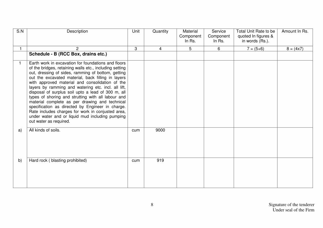
8 of 16 Signature of the tenderer
Under seal of the Firm
S.N Description Unit Quantity Material Component
In Rs.
Service Component
In Rs.
Total Unit Rate to be quoted In figures &
in words (Rs.).
Amount In Rs.
1 2 3 4 5 6 7 = (5+6) 8 = (4x7) Schedule - B (RCC Box, drains etc.)
1 Earth work in excavation for foundations and floors of the bridges, retaining walls etc., including setting out, dressing of sides, ramming of bottom, getting out the excavated material, back filling in layers with approved material and consolidation of the layers by ramming and watering etc. incl. all lift, disposal of surplus soil upto a lead of 300 m, all types of shoring and strutting with all labour and material complete as per drawing and technical specification as directed by Engineer in charge. Rate includes charges for work in conjusted area, under water and or liquid mud including pumping out water as required.
a) All kinds of soils. cum 9000
b) Hard rock ( blasting prohibited) cum 919
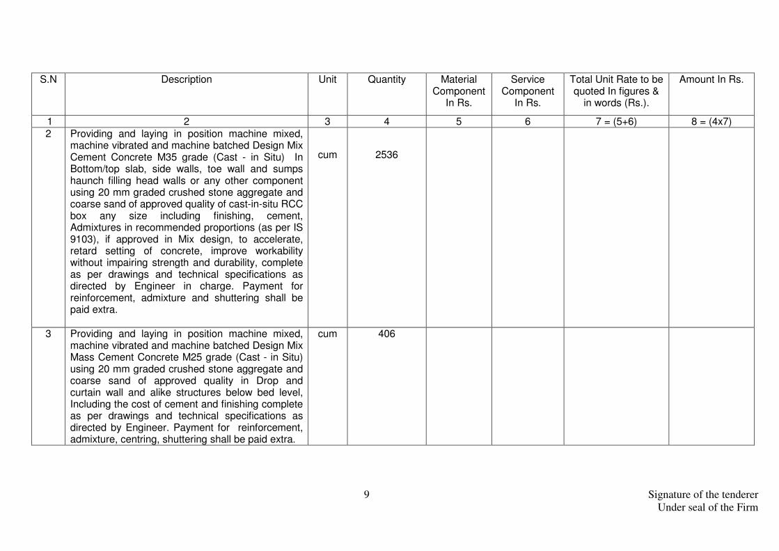
9 of 16 Signature of the tenderer
Under seal of the Firm
S.N Description Unit Quantity Material
Component In Rs.
Service Component
In Rs.
Total Unit Rate to be quoted In figures &
in words (Rs.).
Amount In Rs.
1 2 3 4 5 6 7 = (5+6) 8 = (4x7) 2 Providing and laying in position machine mixed,
machine vibrated and machine batched Design Mix Cement Concrete M35 grade (Cast - in Situ) In Bottom/top slab, side walls, toe wall and sumps haunch filling head walls or any other component using 20 mm graded crushed stone aggregate and coarse sand of approved quality of cast-in-situ RCC box any size including finishing, cement, Admixtures in recommended proportions (as per IS 9103), if approved in Mix design, to accelerate, retard setting of concrete, improve workability without impairing strength and durability, complete as per drawings and technical specifications as directed by Engineer in charge. Payment for reinforcement, admixture and shuttering shall be paid extra.
cum
2536
3 Providing and laying in position machine mixed, machine vibrated and machine batched Design Mix Mass Cement Concrete M25 grade (Cast - in Situ) using 20 mm graded crushed stone aggregate and coarse sand of approved quality in Drop and curtain wall and alike structures below bed level, Including the cost of cement and finishing complete as per drawings and technical specifications as directed by Engineer. Payment for reinforcement, admixture, centring, shuttering shall be paid extra.
cum 406

10 of 16 Signature of the tenderer
Under seal of the Firm
S.N Description Unit Quantity Material Component
In Rs.
Service Component
In Rs.
Total Unit Rate to be quoted In figures &
in words (Rs.).
Amount In Rs.
1 2 3 4 5 6 7 = (5+6) 8 = (4x7) 4 Providing and laying Pitching with stone boulders
with the voids filled with cement sand mortar 1:4 on slopes laid over prepared including boulder apron laid dry in front of toe of embankment complete as per drawing and Technical specifications. Rate inculding cement and other materials except filter media (filter media to be paid separtely uder the relevant item). Stone boulder to be taken as a free issue material and transport from stacks of dismantled stone boulder vide item A/7 above.
cum
241
5 Providing and laying filter material as per RDSO Specifications underneath pitching slopes complete as per drawing and Technical specification.
cum 121
6 Providing Boulder backing behind wing wall, return wall, retaining wall with hand packed boulders & cobbles with smaller size boulders toward the back including all lead, lift, labour & other incidental charges as complete work in all respect. Boulder to be taken as a free issue material and transporting by contractor from stacks of dismantled stone vide item A/7 above.
cum 582
7 Providing and fixing in position 20mm thick bitumen impregnated fibre board conforming to IS: 1838 including cost of primer, sealing compound in expansion joints.
Sqm 137

11 of 16 Signature of the tenderer
Under seal of the Firm
S.N Description Unit Quantity Material Component
In Rs.
Service Component
In Rs.
Total Unit Rate to be quoted In figures &
in words (Rs.).
Amount In Rs.
1 2 3 4 5 6 7 = (5+6) 8 = (4x7) 8 Supplying & mixing high range poly carboxylate ether
base water reducing admixture quality conforming to IS:9103-1999 (to be added @ about 1% by weight of cement) for CC & RCC work for controlling water cement ratio and for gaining early strength.
Kg
8706
9 Supply and laying of coarse sand including consolidation, supply of all materials, labour, lead, lift, tools, plants, crossing of tracks as per drawing and technical specification as directed by the Engineer incharge in case loose slush is encountered at site of foundation before casting the foundation or before laying the filtering media.
cum 4950
10 Centring and shuttering including strutting, propping etc. and removal of form for : In Bottom/top slab, side walls, toe wall and sumps haunch filling head walls or any other component. Rate includes staging for required height.
sqm 4890
11 i) Structural steel work in single section including cutting, bending, straightening, drilling, riveting or bolting, hoisting, fixing in position, including applying a priming coat of approved steel primer, complete - upto 6m height above GL In RSJ, tees, angles and channels.
Kg 5000

12 of 16 Signature of the tenderer
Under seal of the Firm
S.N Description Unit Quantity Material Component
In Rs.
Service Component
In Rs.
Total Unit Rate to be quoted In figures &
in words (Rs.).
Amount In Rs.
1 2 3 4 5 6 7 = (5+6) 8 = (4x7)
ii)
Structural steel work welded in built up section trusses and framed work, girder, stagings,racks, etc including cutting, bending, straightening, hoisting, fixing in position, including applying a priming coat of approved steel primer, complete - upto 6m height above GL. In RSJ, tees, angles and channels.
Kg.
5000
iii)
Painting two coats(excluding priming coat) with chocolate, red, grey or buff ready mixed paint or apporved quality, on steel or wood work. Rate including the cost of enamel paint.
Sqm 400
12
Providing fly ash brick work in cement mortar of proportion 1:6 (1 cement : 6 sand) in foundation and plinth as per drawing, specification and instructions of the engineer, in Fly Ash bricks, Fly Ash bricks to be supplied by NALCO as free issue material at NALCO's owned manufacturing plant at Damanjodi. Except bricks, all other cost to be born by contractor. Reconciliation of bricks issued are to be made in each RA Bill submitted by the contractor.
Cum 30

13 of 16 Signature of the tenderer
Under seal of the Firm
S.N Description Unit Quantity Material Component
In Rs.
Service Component
In Rs.
Total Unit Rate to be quoted In figures &
in words (Rs.).
Amount In Rs.
1 2 3 4 5 6 7 = (5+6) 8 = (4x7) 13 12 mm cement plaster of mix -
1:4 (1cement: 4 fine sand). Rate includes cement.
Sqm
308
14 Demolishing brick work including stacking of serviceable material and disposal of unserviceable material within 50m lead. In cement mortar.
cum 3
15 Demolishing stone rubble masonry/ stone pitching including stacking of serviceable material and disposal of unserviceable material within 50m lead In cement mortar.
cum 72
16 Demolishing plain cement concrete including disposal of material within 50m lead Mix leaner than 1:2:4 with coarse aggregate larger than 20mm.
cum 172

14 of 16 Signature of the tenderer
Under seal of the Firm
S.N Description Unit Quantity Material Component
In Rs.
Service Component
In Rs.
Total Unit Rate to be quoted In figures &
in words (Rs.).
Amount In Rs.
1 2 3 4 5 6 7 = (5+6) 8 = (4x7) 17 Demolishing R.C.C. work including cutting and
stacking of steel bars and disposal of unserviceable material within 50m lead. (Extra payment for scraping, cleaning and straightening of bars to be made separately).
cum
30
Total of Schedule B
Schedule-C (Supply of Reinforcement).
1 Supplying Reinforcement for R.C.C. work including straightening, cutting, bending, placing in position and binding all complete. HYSD - TMT bars, Fe500/500D.
Kg. 415000
Total of Schedule C
Schedule-D (Unforeseen/miscellaneous Items)
1 Any other unforeseen/miscellaneous item which have not been covered in the above items will be operated as per USSR-2010 except banned items by Eco rly. (Rate should be quoted in above or below or at par).
LS Rs.
1360000.00 ______% above/
below / At par
Total D =
GRAND TOTAL (A+B+C+D)
(In words)

15 of 16 Signature of the tenderer
Under seal of the Firm
Note: Unless otherwise specified the unit rate shall include the cost of following -
a) All labour and materials, tools and plants, equipment , machinery etc.
b) All lead, lift, ascent , descent, crossing of Rail tracks etc
c) All handling , rehandling, loading, unloading, freight, consumable stores fuels, lubricants, transportation, vehicles deploring when & where required and crossing one or more lines if necessary.
d) All taxes including octroi on materials, royalty and all incidental charges complete but excluding service tax & education cess. Service tax will be reimbursed on documentary evidence of deposit with statutory authority by the agency.
e) Cement should be OPC(43 Grade) confirming to IS -8112 :1989 or as approved quality by Engineer-in-charge from reputed manufacturers i.g. Ultra Tech, Grasim, Idcol, Lafarge, ACC, Ramco, Zuari, Century, India Cement (approved vender of NALCO) etc or equivalent in HDPE/Gunny bags of 50kg net in each bag & stacking the same in contractor's godown at the site of construction. Date of manufacturing of cement should be mentioned on bags.
f) Manufacturer test certificate indicating the date of manufacturing, batch number and other test result for cement will be produced by the contractor before using the cement. Cement should be brought to site only in such quantity that it will be utilised within a month or so from the date of supply and within 45-60 days from date of packing. Under no circumstances cement older than six months shall be used.
g) Steel should be as per specification and from reputed manufacturers such as SAIL, RINL, TATA or as approved by Engineer-in-charge and stacking the same in contractor's godown at the site of construction. Manufacturer test certificate should be submitted at the time of supply of steel.
h) Cost of all materials are including the cost of inspection, testing wherever required.
i) Unless/Otherwise specified, dewatering to be done by the contractor at his own cost to make the area water free.
j) Width/ Length of excavation will be paid only as per maximum plan size of foundation.
k) No material will be issued by NALCO for execution of work except 52 Kg Rail (old), if required from NALCO’s stores, Ash brick from NALCO's manufacturing plant, Stone boulder from stacks of dismantled stone. Earth/moorum to be borrowed from NALCO’s land. Transportation including loading, unloading of material will be under scope of bidder.

16 of 16 Signature of the tenderer
Under seal of the Firm
l) The contractor will have to submit their Design Mix at their own cost for different grades of concrete, keeping in view the requirements stipulated in technical specifications.
m) No extra payment will be made for work under traffic block.
n) The agency has to ensured the water sprinkling for haul road as when required. The making of haul road & cross drainage works for transporting the borrow earth from borrow area to the work place is the responsible of the agency at it's own cost.
o) The sand should be used in the work should be Nawarangpur variety approved sand which is around 120 Km from Damanjodi.
p) The Bridge work will be executed through the different process running pipe lines in phase manner. The work will be executed without disturbing the running rail/pipe lines. The necessary precaution and safety measure will be taken by the contractor at his own cost. The modification of the pipe lines will be done by NALCO.
q) Borrow area for earth/moorum to be shown by NALCO Authority.
r) Rate includes site clearance for borrow area of earth / moorum also.