national: aela”6ncs . aid space administranon · summary the current test program successfully...
TRANSCRIPT

u, 4 3:
NATIONAL: A E l A ” 6 n C S _ . A I D SPACE ADMINISTRAnON
- 7 . . ””?,-- - . .- -. - . . . ...... ,...- . .
https://ntrs.nasa.gov/search.jsp?R=19750022493 2018-07-27T10:28:49+00:00Z

TECH LIBRARY KAFB, NY
. .. . .. .~ . .
1. Report No. " -. . " . . . - - . . . ~
2. Government Accession No. - ~~~~
NASA CR- 2553 - ." , . .. ~. . " -~ 4. Title and Subtitle
FLEXIBLE ROTOR BALANCING BY THE INFLUENCE COEFFICIENT METHOD - MULTIPLE CRITICAL SPEEDS
. . " WITH RIGID OR 7. Author[s)
Juergen M.. Tessarzik
-. ."
9. Performing Organization Name and Address . . . . . .
Mechanical Technology Incorporated 968 Albany-Shaker Road Latham, New York 12110
~ . - 12. Sponsoring Agency Name and Address
National Aeronautics and Space Administration -
Washington, D.C. 20546
3. Recipient's Catalog No.
5. Report Date AUGUST 1975
6. Performing Organization Code
8. Perfoiming Organization Report No. MTI"75TR3
10. Work Unit No.
11. Contract or Grant No.
NAS 3-14420 13. Type of Report and Period Covered
Contractor Report 14. Sponsoring Agency Code
.. . . . ~ . - - ..: .- . - .. ." .. . -I ~
15. Supplementary Notes Final Report. Project Manager, David P. Fleming, Fluid System Components Division, NASA Lewis ,Research Center, Cleveland, Ohio
L -. -~ ,. . ~- ~ ." ..~ ~. ." "" ~. - 16. Abstract
Experimental tests were conducted to further demonstrate the ability of the influence coefficient method to achieve precise balance of flexible rotors of virtually any design for operation through virtually any speed range. Four distinct practical aspects of flexible-rotor balancing were inves tigated in the present work:
1 . Balancing for operation through multiple bending critical speeds 2. Balancing of rotors mounted in both rigid and flexible bearing supports, the latter having
significantly different stiffnesses in the horizontal and vertical directions so as to cause severe ellipticity in the vibration orbits
3 . Balancing of rotors with various amounts of measured vibration response information (e.g., numbers of vibration data sets and numbers and types of vibration sensors) and with different numbers of correction planes
4. Balancing of rotors with different (though arbitrary) initial unbalance configurations Tests were made on a laboratory quality machine having a 122 c m (48 in. ) long rotor weighing 50 kg (110 lb) and covering a speed range up to 18 000 rpm. The balancing method was in every instance effective, practical, and economical and permitted safe rotor operation over the full speed range covering four rotor bending critical speeds. Improved correction weight removal methods for rotor balancing were investigated. Material removal from a rotating disk was demonstrated through application of a commercially available laser.
- . -. . . . - .
17. Key Words (Suggested by Author(s) ) - . - . .
18. Distribution Statement ~~
Flexible rotor balancing experiments Unclassified - unlimited Multiple bending critical speeds Computer methods Rotor balancing corrections with laser
19. Security Classif. (of this report) ~ - I 20. Security Classif. (of this page) "" ~. ~ - - .~ ~~ . -. ~~ - ~
21. NO. of Pages 22. Price'
Unclassified Unclassified 129 $5.75
*For sale by the National Technical Information Service, Springfield, Virginia 22151


TABLE OF CONTENTS Page
SUMMARY_””””””_””””._””” 1
FLEXIBLE ROTOR BALANCING TEST APPARATUS_------------
T e s t R o t o r C o n f i g u r a t i o n _ _ _ _ - - _ _ - - - - _ _ _ _ - -
Test Rotor Support Bearings _ _ _ _ _ _ _ _ _ _ _ _ _ _ _ _ M e c h a n i c a l F e a t u r e s o f t h e A p p a r a t u s - _ _ _ - - - - - _ _ -
5 5 5 7
8
9 10
14
14
Instrumentation- - - - - - - - - - - - - - - - - - - - - - General Analysis of t he Ro to r -Bea r ing Sys t em-_- - - -_ -
Sequence of Balancing R u n s _ - _ - - _ _ - _ _ , - - - - _ - -
TEST RESULTS - - - - - - - - - - - - - - - - - - - - - - - - - - I n i t i a l R o t o r C o n d i t i o n P r i o r t o A l l T e s t s - - - - - - - - -
First Test Case: Rotor With Rigid Bearing Pedestals; In- Line, In-Phase Unbalance; Seven Displacement Sensors”“
Second Test Case: Rotor With Rigid Pedestals ; In-Line In-Phase Unbalance; Four Displacement Sensors - - - - - - - Third Test Case: Rotor With Rigid Pedestals; In-Line, In-Phase Unbalance; Two Displacement Sensors - - - -_- - -
Fourth Test Case: Rotor With Rigid Pedestals ; In-Line, In-Phase Unbalance; Two Acce le ra t ion Senso r s - - - - - - - -
Fifth Test Case: Rotor With Rigid Pedestals ; In-Line, Alternating-Phase Unbalance; Four Displacement Sensors-”
Sixth Test Case: Rotor With F lex ib le Bear ing Pedes ta l s ; In-Line, In-Phase Unbalance _ L _ _ C _ _ _ _ _ _ _ _ _ _ _
Seventh Test Case: Rotor With F lexfb le Bear ing Pedes ta l s ; In-Line, Alternating-Phase Unbalance- - - - - - - - - - - -
DYNAMIC ROTOR CHARACTERISTICS I N POLAR COORDINATES _ _ _ _ _ _ _ Polar Ampli tude Plots for Test R o t o r - - _ _ - _ - _ - - - -
14
16
17
17
19
21
22
25 26
THE USE OF A LASER FOR MATERIAL REMOVAL DURING ROTOR BALANCING OPERATIONS - - - - - - - - - - c - - - - - - - - - - -
Experimental Tests- - - - - - - - - - - - c - - - - - - - - 29
Laser CaPabilitY””””””””””” 30
30
iii

iv

SUMMARY
The c u r r e n t tes t program successfully extended the proven balancing capa- b i l i t y o f t h e I n f l u e n c e C o e f f i c i e n t Method to i nc lude fou r ro to r sys t em bending cr i t i ca l speeds in the opera t ing speed range . Addi t iona l p rogram accomplishments included ver i f icat ion of the balancing method on a r o t o r d i s p l a y i n g n o n c i r c u l a r o r b i t s ( d u e t o d i s s i m i l a r b e a r i n g s u p p o r t s t i f f - nesses) and a r o t o r b u r d e n e d w i t h d i f f e r e n t i n i t i a l u n b a l a n c e d i s t r i b u t i o n s . Fu r the r , t he e f f i c i ency o f t he ba l anc ing method with varying amounts of measured ro to r r e sponse da t a was a l so eva lua ted . This was accomplished through t h e u s e o f d i f f e r e n t numbers of displacement sensors located along the l eng th o f t he ro to r . The c a p a b i l i t y o f t h e method to ba l ance a f l e x i - b le ro tor us ing da ta ob ta ined f rom acce lerometers on ly , loca ted on the bearing support housings, was a l so i nves t iga t ed ( r ig id bea r ing suppor t s only) .
The t e s t r o t o r was 122 c m (48 in . ) long and weighed 50 kg (110 l b ) . It c a r r i e d f i v e d i s c s , and was de l ibe ra t e ly des igned t o accen tua te t he bend ing mode shape as i t o c c u r r e d a t t h e f o u r t h c r i t i c a l s p e e d . The r o t o r was opera ted a t speeds up t o 18,000 rpm. The f i r s t system bending c r i t i c a l speed occurred a t 4,360 rpm and t h e f o u r t h a t 10,960 rpm. The bear ings were loca ted nea r t he ro to r noda l po in t s a s soc ia t ed w i th t hese c r i t i ca l speeds. Consequently, low bearing damping fo rces were t r ansmi t t ed t o t he r o t o r and s u b s t a n t i a l r o t o r o r b i t s were experienced a t t h o s e c r i t i c a l speeds. L i t t l e amplitude buildup was observed a t the second and third c r i t i c a l s p e e d s .
For the case where s ignif icant unbalances were i n i t i a l l y added t o t h e . r o t o r i n a n i n - l i n e , i n - p h a s e c o n f i g u r a t i o n ( s i n g l e a x i a l p l a n e , w e i g h t s a l l on same s i d e o f s h a f t c e n t e r l i n e ) a re la t ionship be tween the number of d i s - placement sensors used for balancing and the number of t r i a l weight runs could be observed. With seven displacement sensors employed, only three t r i a l weight runs were requi red for acceptab le ro tor opera t ion th rough four bending c r i t i ca l speeds . Reduc t ion i n t he number of sensors down t o two (one sensor located next to each journal bear ing) increased the number of r e q u i r e d t r i a l w e i g h t r u n s t o f o u r , w i t h n o t i c e a b l y p o o r e r end r e s u l t s than were obtained for seven sensors.
Subs t i t u t ion o f two acce lerometers , loca ted on the journa l bear ing hous ings , l e d t o a n i n i t i a l improvement of ro tor ba lance , bu t on ly to the po in t where the bear ing forces were reduced below the measurement sensit ivity of the accelerometers. This came about through a s h i f t i n r o t o r b a l a n c e t h a t v e r y near ly a l igned the nodal po in ts wi th the journa l bear ing cen ters , thus re- ducing the forces measured a t the acce le rometers , bu t never the less increas- i ng ro to r de f l ec t ion ampl i tudes a t nea r ly a l l rotor displacement measure- ment s t a t i o n s . F o r t h i s c a s e , two accelerometers a t t h e s e l o c a t i o n s a r e s imply inadequate to descr ibe the comple te na ture o f the ro tor v ibra t ions .
The i n t r o d u c t i o n o f f l e x i b l e b e a r i n g s u p p o r t s w i t h d i s s i m i l a r s t i f f n e s s e s in t he ve r t i ca l and ho r i zon ta l d i r ec t ions p roduced cons ide rab le change i n
1
ro tor behavior . The o rb i t s o f t he unba lanced ro to r were predominantly e l l i p t i c a l , w i t h t h e m a j o r a x i s o f t h e e l l i p s e h o r i z o n t a l . B a l a n c i n g f o r passage through the first bending c r i t i ca l speed proved t o be much easier than on the r ig id ly-suppor ted ro tor ; on ly a s i n g l e t r ia l weight run ( in four balancing planes) was required. Balancing for passage through the f o u r t h c r i t i c a l speed required one o r two more t r ia l weight runs. Experi- ments fur ther ind ica ted tha t ba lanc ing of the f lex ib ly-suppor ted ro tor w a s s l i g h t l y more e f f i c i e n t w i t h d a t a obtained from four displacement sensors measuring rotor ver t ical motion, ra ther than f rom four measuring horizontal mot ion. ' r ",' '.;'>,:
The extensive application of the balancing procedure again confirmed the value of such features as computationally-subtracted rotor out-of-roundness a t the displacement-measured stations, and the freedom t o employ t r i a l we igh t s o f d i f f e ren t s i ze s a t d i f f e ren t angu la r l oca t ions fo r each of the tr ial weight planes. The balancing method, as w e l l as the instrumentat ion developed for i t s implementation, has now reached a proven level of capa- b i l i t y which should recommend i t t o commercial users.
Through a sepa ra t e i nves t iga t ion o f cu r ren t laser c a p a b i l i t i e s i n t h e a r e a of metal removal , the groundwork for fur ther advances in rotor balancing has been l a i d . It was found t h a t a commercial ly avai lable laser can re- move meta l f rom ro ta t ing d i scs a t r a t e s su i t ab le fo r non- s top ba l anc ing of ro to r s i n t he we igh t r ange t yp ica l ly r ep resen ted by high-speed rotors . Controlled material removal from a r o t a t i n g s t e e l d i s c w a s demonstrated a t var ious ro tor speeds up t o 3000 rpm.
2
r
The in fo rma t ion p re sen ted i n t h i s r epor t , t oge the r w i th t ha t t o be found i n e a r l i e r r e f e r e n c e s [ 1-4]*, desc r ibes a series o f s tud ie s des igned t o p robe t he capab i l i t i e s and limits of the Inf luence Coeff ic ien t Method f o r b a l a n c i n g f l e x i b l e r o t o r s . The test r e s u l t s , o b s e r v a t i o n s , d i s c u s s i o n s and conclusions are therefore expec ted t o be most u s e f u l t o t h e e n g i n e e r concerned wi th ques t ions o f genera l appl icabi l i ty of t h i s method t o classes of rotor-bearing systems, as opposed t o t h e r e a d e r who may wish t o o b t a i n a be t t e r ba l ance on a s p e c i f i c r o t o r . The la t ter ind iv idua l may w i s h t o r e f e r t o one of the appl icat ion-oriented references [S- l l ] for more de- t a i l ed gu idance on pa r t i cu la r con f igu ra t ions .
There i s now i n e x i s t e n c e a rapidly-expanding body o f t e c h n i c a l l i t e r a t u r e descr ib ing an immensely success fu l method f o r t h e b a l a n c i n g o f f l e x i b l e ro to r s . Th i s method, based upon l i n e a r i n f l u e n c e - c o e f f i c i e n t d e f l e c t i o n theory , is g e n e r a l l y r e f e r r e d t o as the In f luence Coef f i c i en t Method. The theo ry o f t h i s method was presented by Goodman i n 1963 [ 12).
Beginning i n 1969 under NASA sponsorsh ip , an adopt ion of th i s theory to f l e x i b l e r o t o r b a l a n c i n g was examined a n a l y t i c a l l y by Rieger [ 133 and ex- per imenta l ly by Tessarz ik [ 1, 21. References [l, 21 d e s c r i b e d i n d e t a i l the Exact Point-Speed Procedure, which is computa t iona l ly the s imples t app l i ca t ion o f t he In f luence Coef f i c i en t Method t o f l e x i b l e r o t o r b a l a n c i n g . References [l, 21 a l so p re sen ted exp? r imen ta l r e su l t s where a f l u i d - f i l m bear ing suppor ted ro tor was ba lanced for sa fe (and slow) passage through t h e t h i r d ( f i r s t f l e x u r a l ) b e n d i n g c r i t i c a l s p e e d . An experimental compar- ison of balancing effect iveness provided by the Exact Point-Speed and the Least Squares Balancing Procedures was made i n C33 and [41. Results of t ha t i nves t iga t ion i nd ica t ed nea r ly equa l p ro f i c i ency fo r bo th p rocedures f o r a l l t e s t c a s e s . However, t e s t i n g was l imi ted to ro tor ba lanc ing th rough one bending c r i t i c a l s p e e d . I f a r o t o r i s to be balanced for passage through more than one bending cr i t ical speed, the Least Squares Procedure i s preferred because i t a c c e p t s r e l a t i v e l y l a r g e amounts of experimentally
'of t he r e s idua l ampl i tudes when the ba l anc ing da t a f ed i n to t he program exceeds the square mat r ix l imi ta t ion of t he bas i c mass -eccen t r i c i ty equa- t i o n used t o f i n d t h e r o t o r b a l a n c e c o r r e c t i o n w e i g h t s . A square matr ix is " fu l l " when e.g., on a rotor equipped with four displacement sensors , four balancing planes are selected for the placement of correct ion weights and t r i a l weight data i s o b t a i n e d a t one r o t o r s p e e d . I f d a t a is t o be a c q u i r e d a t more than one rotor speed (as is necessary when ba lanc ing for more than one bend ing c r i t i ca l speed) e i t he r t he number of c o r r e c t i o n p l anes o r t he number of probes would have to be reduced i f the Exact Point- Speed Procedure were to be used. This would c o n s t i t u t e a s e r i o u s o b s t a c l e t o e f f e c t i v e and e f f i c i e n t b a l a n c i n g . A d e s c r i p t i o n of the Leas t Squares Procedure i s given by Lund i n [ 141 and [ 151.
' .- obtained balancing data. The procedure uses minimization of the squares
*Numbers i n b r a c k e t s d e s i g n a t e R e f e r e n c e s a t end o f r epor t .
3

Other appl ica t ions o f the Leas t Squares Procedure to the ba lanc in of f l ex ib l e ro to r s have been r epor t ed by Tonnesen [ 16, 171, Badgley f5-71 , Rieger and Badgley [ 8 ] , and Badgley and Rieger [SI. An a p p l i c a t i o n of t h e procedure to the ba lanc ing of gas turbine engine s imulator hardware i s re- p o r t e d i n [ 103.
The ba lanc ing exper iments descr ibed in th i s repor t were set up t o g i v e con- c lus ive ev idence of t he e f f ec t iveness o f t he i n f luence coe f f i c i en t method under adverse conditions which might be encountered in t he ba l anc ing o f p r o d u c t i o n r o t o r s . E s s e n t i a l l y , f o u r d i s t i n c t a s p e c t s o f p r a c t i c a l ; 1
f lex ib le - ro tor ba lanc ing were inves t iga ted :
1. Balanc ing th rough mul t ip le bending c r i t i ca l speeds .
2 . Ba lanc ing o f ro to r s i n r i g id and f l ex ib l e bea r ing suppor t s .
3 . Balancing of rotors with maximum and minimum t r i a l weight response information, (number of t r i a l weight d a t a s e t s ; d i sp lacement and acce lera t ion sensors ) .
4 . Balanc ing o f ro to r s w i th d i f f e ren t ( t hough a rb i t r a ry ) i n i t i a l unbalance configurat ions.
The computer programs used for the successful balancing of t h e test r o t o r d e s c r i b e d i n t h i s r e p o r t , as w e l l as t h e a n a l y s i s upon which the computer programs are based, were w r i t t e n by D r . Jorgen Lund, c o n s u l t a n t t o MTI. The laser i n v e s t i g a t i o n was c a r r i e d o u t by Mark S. Darlow, of MTI.
4

FLEXIBLE "" . ROTOR BALANCING TEST APPARATUS
The bas ic mechanica l appara tus had or ig ina l ly been des igned and bu i l t fo r sensit ive rotor unbalance response measurements, and was r ecen t ly u sed fo r f lexible rotor balancing experiments (References 1, 2 , 3, 4). The r o t o r t h a t was o r i g i n a l l y p a r t o f t h i s t es t r i g had been designed for operation through three c r i t i c a l s p e e d s , w i t h t h e f i r s t two e s s e n t i a l l y r i g i d body cr i t ica l$+: For the exper iments descr ibed here in , a new r o t o r w i t h much g r e a t e r f l e x i b i l i t y was designed and bui l t . This rotor has four bending c r i t i ca l speeds w i th in t he ope ra t ing speed limits of the bear ing and dr ive s y s t e m , w i t h t h e f i r s t c r i t i ca l occurr ing a t about , 4400 rpm. The r o t o r was spec i f i ca l ly des igned t o exh ib i t p ronounced bend ing a t t he f i r s t and t h e f o u r t h c r i t i c a l speeds.
Test Rotor Configuration
The tes t r o t o r , shown in F igure 1 , was nea r ly 122 crn (48 in.) long and weighed 50 kg (110 l b ) . The two end d i sc s o f 5 kg (11 l b ) each , and t h e l a r g e s t d i s c 6.8 kg (15 lb) (second f rom lef t in Figure 1) were shrunk onto t h e s h a f t . A l l discs had outs ide diameters of 151 nun (5 .95 i n . ) . The bas ic journa l bear ing d iameter was 63.5 mm (2 .5 in.) and the small-diameter sec t ions on the shaf t , which were des igned to fac i l i t a te ro tor bending in t h e mode shape o f t he fou r th c r i t i ca l speed were 38 mm (1 .5 i n . ) .
Each d i s c was equipped on one face with a row of axial , tapped holes in- tended for the placement of t r i a l weights and the subsequent addi t ion o f co r rec t ion we igh t s . The tapped ho les , 10 degrees apar t , were a t a 66.7 mm (2.625 i n . ) r ad ius f rom the cen te r o f t he sha f t . On t h e i r b a c k s i d e s , t h e th ree sh runk-on d i sc s con ta ined add i t iona l s e t s o f fou r ho le s 90 degrees apar t for the p lacement o f re la t ive ly l a rge unbalance weights . The h o l e p a t t e r n s were i n l i n e i n a l l f i v e d i s c s .
One of t h e end d i s c s was equipped on i t s outer face wi th a 6.3 mm (0 .25 i n . ) wide r e f l ec t ive fo i l annu lus ex t end ing ove r 180 degrees c i r cumfe ren t i a l ly and a t a 5 c m (2 i n . ) r ad ius f rom the sha f t cen te r . The o t h e r h a l f o f t h e annulus was pa in t ed du l l b l ack . The c i r cumfe ren t i a l mid -po in t pos i t i on on t h e r e f l e c t i v e s t r i p was the r e f e rence po in t on t he ro to r from which t h e a n g l e s f o r maximum dynamic displacement a t t h e o t h e r r o t o r s t a t i o n s were measured (phase angles).
Test Rotor Support Bearings
The tes t r o t o r was r ad ia l ly suppor t ed by two i d e n t i c a l t i l t i n g - p a d t y p e jou rna l bea r ings , shown i n F i g u r e s 2 and 3.. The dis tance between bear ings was 783 mm (30.837 i n . ) . Each of the bear ings cons is ted o f four rad ia l ly r ig id pads [ 6 ] f ~ , with each pad extending over an 8 0 degree arc and with a p ivo t pos i t i on o f 44 degrees (55 percen t ) from the leading edge. The p i v o t conf igu ra t ion was t h a t o f a f ixed sphe re ( i n t eg ra l w i th t he p ivo t [ 8 ] ) i n
* In t h i s s ec t ion , numbers i n b r a c k e t s r e f e r t o d e t a i l p a r t numbers i n Figure 2 .
5
contac t wi th a c y l i n d r i c a l s u r f a c e . The bal l - in-cyl inder pivot geometry a l lowed the pad to t ilt i n b o t h t h e p i t c h and r o l l d i r e c t i o n s . Thus, it pe rmi t t ed t he pads t o t r ack bo th t r ans l a to ry and con ica l sha f t mo t ions . The l a t t e r c a p a b i l i t y i s p a r t i c u l a r l y u s e f u l i n a test machine, because i t a l l o w s t h e e x p e r i m e n t e r g r e a t e r l a t i t u d e i n s e t t i n g t h e maximum pe rmis s ib l e o rb i t s w i thou t f ea r o f con tac t be tween t he sha f t and t he edges of the pads.
Pad l e n g t h i n t h e a x i a l d i r e c t i o n was 63.5 mm (2.5 i n . ) and t h e r a d i a l c learance be tween each pad (a t the p ivot loca t ion) and the shaf t was 0.062 nun (0.0025 i n . ) . The pads were assembled i n t h e b e a r i n g w i t h a pre- load of 0.3 ( t h e r a d i a l p i v o t c l e a r a n c e was set a t 70 p e r c e n t o f ' t l i e ' d i f - fe rence be tween the g round- in rad ius in the pad and the shaf t rad ius) . ( C a l c u l a t e d j o u r n a l b e a r i n g f l u i d - f i l m r a d i a l s t i f f n e s s a s a funct ion of rotor speed i s presented and discussed below). Horizontal and vertical r ad ia l s t i f fnes ses a r e i den t i ca l fo r t he bea r ings , wh ich were o r i en ted i n the load-between-pivots configuration.
The l u b r i c a t i n g f l u i d f o r t h e j o u r n a l b e a r i n g was Dow Corning 200, with a k inemat ic v i scos i ty o f 0.65 cs a t 25OC (77'F). The bear ings were operated i n a f looded condi t ion with a maximum temperature r ise of 5.5OC (10'F).
A x i a l p o s i t i o n i n g o f t h e t e s t r o t o r was provided by two ex te rna l ly -p res su r i zed a i r - lubr ica ted th rus t bear ings loca ted on oppos ing s ides o f the two smaller ro tor cen ter masses . Each th rus t bea r ing cons i s t ed o f fou r r i g id ly mounted pads with an outer diameter of 114 nun (4.5 i n . ) , an i nne r d i ame te r of 70 mm (2.75 i n . ) and an angular arc of 6 0 degrees . The a x i a l c l e a r a n c e i n t h e th rus t bea r ing was approximately 0.25 mm (0.010 in . ) . Loca t ions o f the t h r u s t b e a r i n g s a r e i n d i c a t e d i n F i g u r e 4, and i n S e c t i o n B-B of Figure 2.
F o r t h e f l e x i b l e r o t o r b a l a n c e tests r epor t ed he re in , two test ro to r -bea r ing support system configurat ions were used . In i t s o r i g i n a l c o n f i g u r a t i o n , t h e t e s t r o t o r had a r i g i d b e a r i n g s u p p o r t s t r u c t u r e (items 12 and 13 i n F i g u r e 2). After modi f ica t ion , the p ivot suppor t r ing [ 6 ] was reduced in diam- eter by approximately 3 mm (1/8 in . ) , and he ld i n a c o n c e n t r i c p o s i t i o n r e l a t i v e t o t h e h o u s i n g [ 7 1 by fou r ax i a l rods which were anchored i n t h e ad jacent sea l hous ings on e i ther s ide o f the bear ing suppor t main housing. (See Figure 5). A l l four of the axial support rods were of rectangular c ross -sec t ion , wi th the hor izonta l d imens ions smal le r (as seen in the in - s t a l l e d p o s i t i o n o n t h e test r i g ) t h a n t h e v e r t i c a l d i m e n s i o n . T h i s a r rangement resu l ted in a bea r ing suppor t s t i f fnes s t ha t was lower i n t h e h o r i z o n t a l t h a n i n t h e v e r t i c a l d i r e c t i o n . C o n s e q u e n t l y , e l l i p t i c a l r o t o r o r b i t s were observed.
Figure 6 shows a s e r i e s of ro to r o rb i t pho tographs a t s ix p rox imi ty p robe s ta t ions a long the l ength o f the ro tor . These photos were taken a t t h r e e ro to r speeds be low the f i r s t c r i t i ca l speed , w i th t he i n i t i a l heavy ro to r unbalance arranged i n a n i n - l i n e , a l t e r n a t i n g - p h a s e c o n f i g u r a t i o n . With two of the four unbalance weights moved through 180' i n t h e i r r e s p e c t i v e planes, so tha t the resu l tan t unbalance conf igura t ion cor responded to the in- l ine, in-phase arrangement , rotor orbi ts were recorded as shown i n Figure 7 . Comparison of r o t o r o r b i t s i z e s i n F i g u r e s 6 and 7 i n d i c a t e s a much more pronounced response o f the ro tor a t the f i r s t c r i t i c a l speed t o
6

the in - l ine , in -phase unbalance a r rangement than to the in - l ine , a l te rna t ing- phase conf igura t ion . The l a t t e r was s p e c i f i c a l l y s e l e c t e d t o p r o d u c e a seve re r e sponse o f t he ro to r i n t he mode o f t h e f o u r t h c r i t i c a l s p e e d .
The s t i f f n e s s of each bearing support was approximately 3.15 x 10 N/m (180,000 l b / i n . ) i n t h e v e r t i c a l d i r e c t i o n ( Y - a x i s ) and approximately 2.62
x 10 N/m (150,000 l b / i n . ) i n t h e h o r i z o n t a l d i r e c t i o n ( X - a x i s ) . The un- e q u a l s t i f f n e s s i n t h e two d i r e c t i o n s p r o d u c e s r o t o r o r b i t s ( r e l a t i v e t o t h e fixed machcine,casing) that are e l l i p t i c a l , and causes each c r i t i ca l speed t o e x h i b i t s e p a r a t e maximum amplitudes i n t h e v e r t i c a l and h o r i z o n t a l d i r e c t i o n s , separa ted in f requency by t h e r a t i o o f t h e s q u a r e r o o t o f t h e i r r e s p e c t i v e s t i f f n e s s e s (1:1.2). Ind iv idua l bea r ing suppor t s t i f fnes s ( fou r f l exures ) had been determined experimentally by monitoring the assembled journal bear- ing support housing on a v i b r a t i o n t a b l e and scanning the v ibra t ion input f r e q u e n c y u n t i l t h e v e r t i c a l and horizontal resonances of the assembly had been found. The s t i f f n e s s e s o f t h e f l e x u r e a s s e m b l i e s i n t h e v e r t i c a l and h o r i z o n t a l d i r e c t i o n s were then ca lcu la ted based upon the r e spec t ive r e so - nance frequencies and the known mass of the journa l bear ing suppor t r ing .
/
7
Mechanical . . " Features of the Apparatus
The t e s t machine (Figures 4 and 8 ) was mounted on a s t r u c t u r a l s t e e l b a s e weighing approximately 1455 kg (3200 l b ) . The base was i s o l a t e d from t h e f l o o r by rubber pads. (These details of the base assembly are mentioned here only for reasons of documentation. There i s no inhe ren t l imi t a t ion of the Least Squares Balancing procedure re la t ive to the type of machinery to be ba lanced . ) Bol ted to the top p la te o f the base was an aluminum j i g p l a t e [ 1]* t o which were fastened the individual housings [ 2 and 31 f o r t h e j o u r n a l and t h r u s t b e a r i n g s , and the p roximi ty p robe ho lders [ 4 ] which he ld capacitance probes [ I S ] used t o measure motions of the end masses [ 6 ] . Motions of the large center mass [ 7 ] were measured with capacitance probes [ 8 ] mounted i n a guard housing [ ! I] . Additional capacitance probes [ l o ] were loca ted next to each journa l bear ing and above each of the shaft-integral d i scs [probes 11 and 121 . Also mounted to t h e same p l a t e was t h e e l e c t r i c d r i v e motor [ 131.
The journal bear ing housings [ 2 ] were equipped with seal r ings [ 141 on both s i d e s . Each o f t hese r i ngs had a c l e a r a n c e s e a l a d j a c e n t t o t h e b e a r i n g housing with an outboard annular scavenging cavity. Outside the scavenging c a v i t y was a l a b y r i n t h seal t o r e s t r i c t e n t r y of a i r i n t o t h e c a v i t y . Bear- i n g f l u i d l e a k i n g i n t o t h e c a v i t y was pumped back in to the sump by two s e p a r a t e e l e c t r i c a l l y - d r i v e n pumps. A posit ive-displacement pump d r i v e n by a n a i r motor forced the bear ing f luid through a water-cooled heat exchanger and back in to t he j ou rna l bea r ing hous ings . Jou rna l bea r ing supp ly p re s su re was c o n t r o l l e d t o e n s u r e a f looded condi t ion . Journa l bear ing tempera ture was measured by thermocouples welded to t he backs o f t he two lower pads i n each bearing.
The d r i v e motor [ 131 was a 30-hp, 3OY000-rpm, 600-Hz, 600-volt e lec t r ic
"In t h i s s e c t i o n , numbers i n b r a c k e t s r e f e r t o d e t a i l p a r t numbers i n F i g . 4 .
7

motor, powered from a var iab le- f requency genera tor set . The t e s t r o t o r was coupled t o t h e d r i v e motor by a crowned sp l ine coup l ing [15]. The t ee th on the shaf t par t o f the coupl ing were crowned so tha t the coupl ing could accommodate up t o 0.76 m (0.030 in . ) radial misal ignment between the axes of the motor and the t es t s h a f t w i t h o u t s h a f t r e s t r a i n t .
Instrumentat ion
The in s t rumen ta t ion r equ i r ed t o run t he t e s t machine consisted of pressure gages ind ica t ing th rus t bear ing a i r supp ly p re s su re , j ou rna l bea r ing , f lu id supply p ressure , d r ive motor bear ing a i r -mis t lubr ica t ion pressure , thermo- couples ind ica t ing journa l bear ing pad and bear ing f luid temperature , and a speed counter for shaf t ro ta t iona l speed . To a s s u r e s a f e r o t o r o p e r a t i o n under heavy unbalance loads, vertical and hor izonta l capac i tance- type proximity probes (with 2.5 mm (0.10 in . ) range) were i n s t a l l e d i n s e v e n loca t ions a long t he ro to r ax i s fo r o rb i t i nd ica t ions . These o rb i t s were monitored during tes t runs th rough osc i l loscope observa t ion . The speed counter and capaci tance probes were a lso used to acquire balancing data .
Add i t iona l i n s t rumen ta t ion r equ i r ed fo r acqu i s i t i on o f ba l anc ing da t a con- s i s t e d o f two crys ta l acce le rometers mounted on each of t he j ou rna l bea r ing hous ings , and one op t ica l p robe for the ident i f ica t ion of angular ro tor pos i t i ons (phase ang le s ) . The locat ions of the proximity probes a long the r o t o r a x i s a r e shown i n F i g u r e s 4 , 22 , and 37, among o t h e r f i g u r e s .
A schematic of the complete data acquis i t ion system as i t was used f o r t h e f l e x i b l e r o t o r b a l a n c i n g tests d e s c r i b e d i n t h i s r e p o r t i s shown i n F i g u r e 9 .
An overa l l v iew of the t es t r ig con t ro l ha rdware and data monitoring and acqu i s i t i on i n s t rumen ta t ion i s g iven i n F igu re 10. I n a d d i t i o n t o t h e mag- netic tape system which was used fo r t he p lo t t i ng of simultaneously-recorded ro to r d i sp l acemen t ampl i tudes f rom va r ious ro to r s t a t ions , a paper p r in tout system was u s e d f o r f a s t e r and more accurate displacement probe readouts .
When t h e t es t r i g was opera ted wi th r ig id bear ing suppor ts , on ly the ver t ical ly-mounted capaci tance probes were used for balancing purposes . The s e l e c t i o n o f t h e v e r t i c a l p l a n e i n s t e a d o f t h e h o r i z o n t a l p l a n e f o r d i s p l a c e - ment measurements was a n a r b i t r a r y d e c i s i o n . S i n c e r o t o r o r b i t s were gen- e r a l l y o b s e r v e d t o b e c i r c u l a r , no p a r t i c u l a r s i g n i f i c a n c e was a t t a c h e d t o this choice. For balancing tes ts c o n d u c t e d o n t h e t e s t r i g w i t h f l e x i b l e bear ing suppor ts , ver t ica l p robes a lone , hor izonta l p robes a lone , and com- binat ions of both were se lec ted as par t o f the exper imenta l ba lanc ing process .
A t t h i s t ime , no f i x e d r u l e i s a v a i l a b l e f o r s p e c i f y i n g a p r i o r i t h e r e - quired number of measuring s ta t ions a long the axis of the rotor for balanc- ing by t h e p r o c e d u r e s i n v e s t i g a t e d . I n f a c t , t h i s t o p i c r e c e i v e d c o n s i d e r - ab le s tudy i n t he cou r se of the herein-reported experiments . The maximum number of displacement sensors (capaci tance- type probes) that could sensi- b l y b e i n s t a l l e d on t h e t e s t r i g was seven. However, signals from a l l seven probe s ta t ions were no t a lways used for the acquis i t ion o f t r ia l weight data during balancing tes ts . Only f o r t h e f i r s t t r i a l w e i g h t r u n i n
8
each series was data f rom every s ta t ion recorded so t h a t d i f f e r e n t combina- t ions of speeds and measuring s ta t ions could be selected, as desired, for computat ions of correct ion weight values .
An a d d i t i o n a l s i g n a l (commonly r e f e r r e d t o as t h e r e f e r e n c e s i g n a l ) was used t o r e l a t e a f ixed angu la r pos i t i on on t he ro to r ( t he equ iva len t o f t he com- monly used 'mark ' ) to the angular pos i t ion a t which maximum dynamic d i s - placement occurred a t each of the seven measurement s ta t ions for displacement measuremen.ts,-or the two accelerometers for housing acceleration measurements.
General Analysis of . . the Rotor-Bearing System
A basic understanding of the dynamic r e s p o n s e c h a r a c t e r i s t i c s of a pa r t i cu - l a r ro to r t o be ba l anced can be ex t r eme ly va luab le w i th r e spec t t o s e l ec t ion of both balancing planes and measurement s t a t i o n s . C r i t i c a l s p e e d c a l c u l a - t i o n s , and a s soc ia t ed undamped mode shapes, w i l l i d e n t i f y t h e number of c r i t i c a l s w i t h i n o r c l o s e t o t h e o p e r a t i n g s p e e d r a n g e of t h e r o t o r , a s w e l l a s t he deg ree o f " f l ex ib i l i t y" o f t he ro to r ove r t he speed r ange . The mode s h a p e p l o t s c a n g r e a t l y a s s i s t i n t h e s e l e c t i o n o f b a l a n c e p l a n e s , b o t h number and loca t ion .
I .
A s a ma t t e r of p rac t i ca l p repa ra t ion fo r t he ba l anc ing p rocess , t he l oca t ions of the p roximi ty p robes a long the ro tor ax is should be a t o ther than the s h a f t n o d a l p o i n t s a s t h e y o c c u r i n t h e v i c i n i t y of the balancing speeds. Should the probes be a t o r n e a r t h e n o d a l p o i n t s , t h e low amplitude readings obtained may be a s o u r c e o f e r r o r i n t h e c a l c u l a t i o n .
Similar comments app ly t o t he l oca t ions s e l ec t ed fo r ba l anc ing p l anes . Highes t ba lanc ing e f fec t iveness w i l l in general be obtained through the loca t ion of the ba lanc ing p lanes a t non-nodal pos i t ions a long the ro tor for the ro tor speeds o f in te res t ( inc luding the e f fec ts o f damping) . This i s because unbalances located at such non-nodal posit ions are most e f f e c t i v e i n producing large ampli tudes. Qui te obviously, the c loser the balancing planes a r e t o t h e most important unbalances, the better w i l l b e t h e r e s u l t of t h e balancing procedure.
The fo l lowing ca l cu la t ions were pe r fo rmed p r io r t o t he ba l anc ing t e s t s . The f i r s t t h r e e a p p l y t o t h e t e s t r o t o r on both types of bearing supports (r igid and f l e x i b l e ) . The remaining three (calculated damped ro tor ampl i tudes) a p p l y t o e i t h e r t h e r i g i d l y o r t h e f l e x i b l y - s u p p o r t e d r o t o r , a s n o t e d .
1.
2.
3.
J o u r n a l b e a r i n g s t i f f n e s s as a func t ion of ro ta t iona l speed for bear ing p re load f ac to r s o f 0, 0.3, and 0.5, Figure 11. The tes t r i g b e a r i n g s were set up with a preload factor of 0.3. Because of bearing symnetry, h o r i z o n t a l a n d v e r t i c a l s t i f f n e s s e s were equal .
Ro to r c r i t i ca l speeds a s func t ions o f bea r ing s t i f fnes s ( cu rves marked 1st l a t e r a l , 2nd l a t e r a l , 3 r d l a t e r a l , and 4 t h l a t e r a l , F i g u r e 11). The second and t h i r d c r i t i c a l s p e e d s e f f e c t i v e l y c o i n c i d e a t 5800 rpm.
Rotor undamped mode shapes a t t h e c a l c u l a t e d c r i t i c a l speeds for var ious bea r ing s t i f fnes ses (F igu re 1 2 ) .
9
4 .
5 .
6 .
Damped ro tor ampl i tudes as a func t ion of speed a t s e v e r a l s t a t i o n s a l o n g the t e s t ro to r w i th i n - l i ne , a l t e rna t ing -phase unba lance and r i g i d r o t o r bearing supports (Figure 1 3 ) . The second and t h i r d c r i t i c a l s p e e d s are e f f e c t i v e l y damped out .
Damped rotor ampli tudes a t t h e f i r s t t h r o u g h f o u r t h l a t e r a l c r i t i ca l speeds with in- l ine, a l ternat ing-phase unbalance and r i g i d r o t o r b e a r i n g supports (Figure 14). The c a l c u l a t e d r o t o r mode shapes are g e n e r a l l y not p lanar .
Damped rotor ampli tudes as a func t ion of speed a t severa l s , tg$ ions wi th f l ex ib ly - suppor t ed ro to r bea r ings w i th i n - l i ne , a l t e rna t ing -phase un - balance, (Figure 15).
1 . . I '
. I . . . .
, .
Sequence of Balancing Runs
The fo l lowing aspec ts o f f lex ib le ro tor ba lanc ing were inves t iga ted .
1. Mul t ip l e bend ing c r i t i ca l speeds. Balancing of a f l e x i b l e r o t o r f o r s a f e and slow passage through more than one bending c r i t i ca l speed w a s the main - - -
o b j e c t i v e o f t h i s i n v e s t i g a t i o n . Each ba lanc ing s e r i e s was therefore con- t inued un t i l the in i t ia l ly-heavi ly-unbalanced ro tor had been improved t o the po in t o f sa t i s fac tory opera t ion th rough four bending c r i t i ca l speeds .
2 . Rig id vs f lex ib le suppor ts . Rotors having bo th r ig id and f l e x i b l e bear ing pedes ta l s were th rough t t o r ep resen t w ide ly d i f f e ren t app l i ca t ions of the balancing method. Consequently, the main body of experiments was repea ted for bo th r ig id and f l e x i b l e b e a r i n g p e d e s t a l s o n t h e t e s t r i g .
3 . Number and type of sensors-. The q u a l i t y and quan t i ty of t r ial weight response information depends upon the number, l o c a t i o n and type of sensors employed t o record the response of the rotor-bearing system to t r ia l weights during the balancing process . The same senso r s a r e a l so u sed t o de t e rmine the i n i t i a l ro to r cond i t ion , ( i . e . , t he ro to r r e sponse t o t he unba lance e x i s t i n g p r i o r t o b a l a n c i n g ) , and the ro to r cond i t ion a f t e r ba l anc ing .
Information on ro tor response can be maximized through i n s t a l l a t i o n a l o n g the ax i s o f t he ro to r of many sensors which produce direct displacement readings between the rotor surface and the bearing support housing. A d d i - t i ona l fo rce o r acce l e ra t ion s enso r s which record the effect of the rotor v i b r a t i o n s upon the bearing supports, and thus upon the machine structure, may a l s o be of value. A l a rge number of s enso r s would be very informative, but would c l e a r l y be impract ical because of space and cost requirements . On the other hand, the minimum number of s e n s o r s t h a t w i l l provide a l l e s sen t i a l i n fo rma t ion i s d i f f icu l t to de te rmine beforehand un less computer - implemented response-balancing optimization studies are conducted.
The r equ i r emen t fo r ve r i f i ca t ion of s a t i s f a c t o r y r o t o r o p e r a t i o n may a l s o have considerable bearing upon the number, type, and l o c a t i o n of s enso r s . It i s conceivable , for example, that a f l e x i b l e r o t o r c a n be balanced for minimum bearing forces from information obtained from accelerometers on the bea r ing pedes t a l on ly , bu t t ha t t he same ro tor could exhib i t excess ive
10
deformation a t c r i t i c a l c l e a r a n c e l o c a t i o n s ( s e a l s , e tc ) . In such a case, d i sp l acemen t s enso r s i n add i t ion t o , o r i n s t ead o f , f o rce o r acce l e ra t ion .
sensors should be se lec ted for the ba lanc ing opera t ion . Successfu l ba lanc- ing depends as much upon se l ec t ion o f s enso r t ype a n d b a l a n c i n g c r i t e r i a a s upon the ac tua l ba lance cor rec t ion process .
The capab i l i t y o f t he In f luence Coef f i c i en t Ba lanc ing Method t o b a l a n c e t h e tes t r o t o r from information supplied by seven, four, and two displacement sensors o r two acce lerometers has therefore been ex tens ive ly inves t iga ted f o r o n e i n i t i a l u n b a l a n c e c o n f i g u r a t i o n w i t h b o t h t h e r i g i d and f l e x i b l e bearing su$$orts:
4 . I n i t i a l u n b a l a n c e c o n f i g u r a t i o n . Two d i s t i n c t l y d i f f e r e n t i n i t i a l ' r o t o r unbalance configurat ions were used in th i s ba lanc ing exper iment . One i n i t i a l unbalance configurat ion was des igned t o exc i t e t he f i r s t bend ing c r i t i c a l speed of the ro tor ( in - l ine , in -phase unbalance) , and the o ther in i t ia l un- ba lance conf igura t ion was in tended to p roduce espec ia l ly severe ro tor def lec- t i o n s a t t h e f o u r t h r o t o r b e n d i n g c r i t i c a l speed ( in - l ine , a l te rna t ing-phase unbalance) . Actual ly , for many r o t o r s , t h e i n i t i a l r o t o r u n b a l a n c e c o n f i g - u r a t i o n s a r e o f s i g n i f i c a n c e o n l y i n t h e i r r e l a t i o n s h i p t o t h e r o t o r mode s h a p e o f t h e f i r s t b e n d i n g c r i t i c a l s p e e d , p a r t i c u l a r l y i f b e a r i n g damping i s r e l a t i v e l y low f o r t h i s mode. Once the ro tor has been ba lanced for the f i r s t mode, t h e i n i t i a l u n b a l a n c e c o n f i g u r a t i o n h a s b e e n a l t e r e d s i g n i f i - can t ly and i t may no longe r be poss ib l e t o exc i t e a h i g h e r c r i t i c a l r o t o r speed i n t h e manner i n i t i a l l y p l a n n e d . F o r t h e tes t rotor the predominant number of ba lanc ing runs were made w i t h t h e i n i t i a l i n - p h a s e , i n - l i n e con- f igu ra t ion . (Ex tens ive tests wi th d i f f e ren t i n i t i a l unba lance conf igu ra - t ions for ba lanc ing th rough one bending ro tor in i t ia l speed were r epor t ed in References [ 1-43. The i n i t i a l , i n t e n t i o n a l l y added unbalance t o t h e test r o t o r was of equal magnitude for a l l balancing tests. It cons i s t ed of four individual unbalances of 26.7 gr-cm (0.371 oz-in.) each, which were pos i - t i oned i n fou r o f t he f i ve ro to r masses , a s i nd ica t ed i n F igu res 17 , 25 o r 3 9 . I n t h e s e p i c t u r e s , t h e i n d i c a t e d a n g u l a r p o s i t i o n o f a l l w e i g h t s (45O) i s representat ive of the in- l ine, in-phase unbalance configurat ion. For the in - l ine , a l te rna t ing-phase conf igura t ion , the second and fourth weights were moved angular ly by 180°. The pos i t ion ing of the weights for the l a t t e r unbalance configurat ion i s schemat i ca l ly i nd ica t ed i n F igu res 6 , and 13 through 15. However, i n F i g u r e s 6 , 13 and 14 the indicated magni tude of the unbalances i s n o t i d e n t i c a l t o t h e u n b a l a n c e u s e d i n t h e c o u r s e o f t h e exp er irnent s . The f low cha r t i n F igu re 16 provides a g u i d e t o t h e tes t sequence and the documentation of t h e r e s u l t s i n t h e f o r m o f r o t o r a m p l i t u d e p l o t s f o r t h e above four fac tors as they were i n v e s t i g a t e d on t h e test ro to r . De ta i l ed examination of Figure 16 w i l l r e v e a l two add i t iona l va r i ab le s wh ich were not systematical ly invest igated but nevertheless were touched upon i n i s o l a t e d i n s t a n c e s . These were (1) number of balancing planes and (2) number of speeds a t which data i s taken.
The number o f ba l anc ing o r co r rec t ion p l anes s e l ec t ed and t h e number of balancing speeds a t which t r i a l weight data i s taken, are bo th d i sc re t iona ry v a r i a b l e s f o r which only the lower limits seem obvious. The number of
11
balancing planes should, as a minimum, be equal to the number o f c r i t i c a l speeds for which a r o t o r i s t o be balanced. ( I t may be advantageous or e x p e d i t i o u s t o s e l e c t a l a r g e r number of balancing planes, but that depends l a r g e l y upon the des ign of the par t icu lar ro tor under cons idera t ion . ) The tes t ro tor has been .ba lanced in four p lanes , wi th the except ion of the very f i r s t ba lanc ing run ( r ig id pedes ta l s , in - l ine , in -phase unbalance and seven d isp lacement sensors ) , in which f ive ba lanc ing p lanes were used. Since the balancing process was g e n e r a l l y j u s t as success fu l w i th t he number of balancing planes reduced to four, i t was concluded that a t least i n t h e case o f the t es t r o t o r t h e number of balancing planes need not exceed the number of bending c r i t i ca l speeds for successfu l ba lanc ing . (The ques t ion of the number of balancing planes had previously received some a t t e n t i o n (e .g . , Reference 1, page 24) where the s e l ec t ion o f ba l anc ing p l anes a t t h e ends of a r o t o r s e c t i o n t h a t was very much s t i f f e r t h a n t h e r e s t o f t h e r o t o r ( t h e wide c e n t e r mass) was not always a desirable choice. That was however a special case and should probably not be compared with rotors which have e i t h e r a sepa ra t e d i sc ava i l ab le fo r each ba l anc ing p l ane o r which a r e o f ve ry nea r ly cons t an t ax i a l s t i f fnes s . )
The second var iable involved the number of balancing speeds. There appears t o be only one f i rm requirement for the select ion of the number of balancing speeds a t which t r ia l weight data i s t o be taken for a f l e x i b l e r o t o r . When ba lanc ing above t he f i r s t bend ing c r i t i ca l speed , t r i a l weight data taken a t or near each of the preceding ampli tude peaks associated with a bending c r i t i c a l speed must be included in t he co r rec t ion we igh t ca l cu la t ion . In t h e c a s e o f t h e t e s t r o t o r , t r i a l weight data obtained a t t h e f i r s t b e n d i n g c r i t i c a l s p e e d had t o be included in every balancing run that was aimed a t reducing rotor ampli tudes a t t h e a p p r o a c h t o t h e f o u r t h c r i t i c a l . (The second and th i rd c r i t i ca l speeds could sa fe ly be ignored when ba lanc ing for the fourth, because they were i n s u f f i c i e n t l y e x i c t e d t o p r o d u c e s h a r p amplitude peaks.) The f low char t (Figure 1 6 ) , i n d i c a t e s one t e s t case where the r e su l t o f i gnor ing t he above rule has been invest igated (Case 2b) . (The r u l e t h a t t r i a l weight data f rom lower bending cr i t ical speeds ex- h ib i t ing sharp ampl i tude peaks has to be inc luded in a l l correct ion weight c a l c u l a t i o n s was o r i g i n a l l y found i n a p a p e r s tudy, [Reference 111 where a ro tor o f un i form c ross -sec t ion was balanced for passage through multiple bend ing c r i t i ca l speeds . )
When the Least Squares Balancing Method i s used, separate t r i a l weight data runs may be required below each of the bending cri t ical speeds, depending upon vibrat ion ampli tudes experienced. It i s genera l ly qu i te economica l to take da ta a t several speeds, because all t h a t i s necessary for each addi- t i o n a l s e t o f d a t a i s a s e t o f s imu l t aneous v ib ra t ion r ead ings a t each se lec ted speed . Therefore , the dec is ion to use mul t ip le speeds in ba lanc- ing should be based upon the des i r ed o r r equ i r ed e f f i c i ency o f t he ba l anc - ing improvement. Accuracy of the trrial weight da ta , and par t icu lar ly the absence of gross errors, i s the key to rapid balance improvements. Gross e r r o r s may sometimes be d i lu t ed t h rough t he add i t ion o f be t t e r qua l i t y t r i a l weight da ta t aken a t s l igh t ly d i f fe ren t ro tor speeds . On t h e o t h e r hand, i t may be apparent from the observation of the balancing instrumenta- t i o n t h a t one p a r t i c u l a r r o t o r s p e e d g i v e s b e t t e r ( e . g . , more s t a b l e ) d a t a than any other balancing speed considered. In that case, the s ingle set of
12

d a t a i s preferab le . In any case , the ba lanc ing engineer must take such d e t a i l s i n t o c o n s i d e r a t i o n when d e s i g n i n g h i s p a r t i c u l a r a p p l i c a t i o n .
The f low char t in Figure 16 ind ica tes one case where a set of cor rec t ion weights was ca l cu la t ed from da ta ob ta ined a t t h r e e r o t a t i o n a l s p e e d s and a l s o from d a t a o b t a i n e d a t two of these th ree speeds . The r e s u l t a n t r o t o r co r rec t ions were recorded for both of these cases for ready comparison (Cases 7a and 7b, Figures 78-81).
There a re th ree more d e t a i l s i n t h e b a l a n c i n g p r o c e s s which were no t va r i ed during these experiments, because they are o u t s i d e t h e main l i ne o f i nves - t i g a t i o n and could poss ib ly have confused the in te rpre ta t ion o f the resu l t s obtained when o t h e r v a r i a b l e s were changed. These three items were:
1. A l l t r i a l weight runs were performed with the t r i a l we igh t p l aced f i r s t a t t he ze ro deg ree l oca t ion and then, for a second run, 180 degrees away i n t h e same plane. The purpose of this procedure i s t o o b t a i n a n improvement in experimental accuracy through vector ia l averaging of t h e measurements. Attempts were not made to eva lua te the need for t h i s p rocedure w i th t h i s t e s t s e tup . Th i s f ace t was inves t iga t ed b r i e f l y i n [3 ] where i t was found that the second t r ia l weight run general ly increased the accuracy of the balance correct ions. Obviously, t he need f o r t h i s i n c r e a s e d e f f o r t w i l l decrease wi th increases in the q u a l i t y o f measurements.
2. The e f f e c t t h a t t r i a l w e i g h t s o f d i f f e r e n t s i z e s might have had upon ba lanc ing e f f ec t iveness was not express ly s tud ied in these exper iments . It has already been concluded, as ind ica t ed i n t he fo rego ing d i scuss ion on the se lec t ion of ba lanc ing speed , tha t t r ial weight s i z e s e l e c t i o n cannot be completely arbi t rary for a given rotor-bearing system. Within the limits provided by the Mechanical and Instrumental systems, the t r ia l weight s ize was k e p t r e l a t i v e l y low for convenience of operation. For r e fe rence , i t may be no ted t ha t t he t yp ica l t r i a l we igh t was on t h e order of two to twelve percent o f the to ta l maximum del ibera te unbalance weights added to the rotor . For t e s t c a s e s 1 through 5 a t r i a l un- balance of 13.67 gr-cm (0.19 oz- in . ) was u s e d f o r t h e f i r s t t r i a l weight run. This t r i a l unbalance was a l s o used for the second and t h i r d t r i a l weight run of test case 5. For a l l o the r t r ial weight runs a smaller t r i a l unbalance of 5.2 gr-cm (0.07 oz-in.) was used.
3 . The ba lanc ing speed se lec ted for t r ial weight runs was always as high as poss ib le . The upper l i m i t of the balancing speed was determined by the l i m i t e s t a b l i s h e d f o r maximum r o t o r o r b i t s and t h e s i z e o f t h e t r i a l weight. After completion of the first balancing run, wi th cor- r ec t ion we igh t s i n se r t ed i n t he ro to r , t he re u sua l ly a l so was an e f f e c t i v e lower speed l i m i t below which f u r t h e r t r i a l weight runs could not be conducted. This i s because ro tor o rb i t s (wi thout the add i t ion o f t he t r i a l we igh t ) f r equen t ly became too small a t one o r more r o t o r s t a t i o n s f o r r e l i a b l e p h a s e a n g l e measurement. The s e l e c t e d balancing speeds are l i s t e d i n F i g u r e 16 f o r a l l t e s t c a s e s .
13

TEST RESULTS
Initial Rotor Condition Prior to All Tests Prior to assembly of the test rig, in which the three discs were attached through heavy shrink fits to the shaft, all rotating components were indi- vidually balanced at low speeds in a commercial balancing machine. The shaft was dynamically balanced while rotating on solid supports at the bearing locations and the discs were balanced on short arbors. After assembly, the rotor was not sufficiently balanced to permit safe passage through the first critical speed. No further attempt was made to reduce initial rotor unbalance. Instead some fairly substantial unbalance weights were added to the rotor at several locations prior to each balancing series. (Safe passage has arbitrarily been defined as rotor orbits at nonbearing locations not exceeding 0.09 mm (0.0035 in.), and rotor orbits right next to journal bearing locations not exceeding approximately one-half of the available bearing clearance, or 0.062 rn (0 .0025 in.) for the rigidly supported rotor. For the flexibly supported rotor, larger rotor orbits were allowed, even at the bearing stations (up to 0.075 nun (0.003 in.)). Rotor motion relative to the journal bearings was not measured in these setups.
First Test Case: Rotor With Rigid Bearing Pedestals: In-Line, In-Phase Unbalance; Seven Displacement Sensors
This test case was the first attempt to apply the Influence Coefficient Method to the balancing of a rotor for operation through more than one bending critical speed. The selection of the number of displacement sensors and balancing probes was conservative - all available balancing planes and probes were used. The relative locations of sensors, balancing planes and initial unbalance locations are shown in Figure 17, where the test rotor was photographed prior to installation in the test rig. For this test case, four unbalance weights of equal magnitude were placed in the rotor, one in each of four of the five rotor discs. On three discs, the unbalance weights were installed on the disc face opposite from the side where later trial and correction weights were placed.
The initial amplitudes for the speed range from 2,000 to 4,100 rpm are recorded as curves A in Figures 18 through 2 4 , which represent amplitude data for probe stations 1 through 7. Only vertical amplitudes are shown, since rotor orbits were generally circular. All correction weight calcula- tions were based upon vertical rotor amplitude measurements.
Test Results for Rotor With Rigid Pedestals; In-Line, In-Phase Unbalance; Seven Displacement Sensors
The most informative way to show rotor balance improvement is through graphic representation of rotor orbits over the operating speed range. Visual inspection of initial amplitudes obtained for the unbalanced rotor demonstrates quickly, by virtue of their magnitude and gradient over rotor speed, why passage through the first bending critical speed was not
14

a t tempted . (Passage th rough the f i r s t c r i t i c a l speed was not assumed t o b e impossible . Pr ior experience had shown, however, t h a t t h e r o t o r would have h i t a number of the displacement sensors , which were in s t a l l ed w i th 0 .20 t o 0.25 mm (0.008 to 0 .010 in . ) ver t ical offset . Excessive ampli tudes might a lso have jeopardized the journal 'bear ing seals and the journa l bear ings . , I .
themselves, which could have eas i ly been subjec t to sur face damage had metal-to-metal contact occurred, because they were ope ra t ing i n a f l u i d with very poor lubricity.) Without a r e c o r d f o r i n i t i a l r o t o r a m p l i t u d e s above the f i r s t c r i t i c a l s p e e d , n u m e r i c a l e v a l u a t i o n s of t h e e f f e c t i v e n e s s of the ro tor ba lanc ing process becomes a l l but meaningless. Relying solely upon a g raph ica l d i sp l ay o f ro to r ampl i tudes fo r t he eva lua t ion of r o t o r balance improvements not only avoids ' infinite' numerical improvement ratios above t he f i r s t c r i t i ca l speed , bu t a l so p rec ludes u s ing ' ave rage ' ampl i tude numbers over speed ranges encompassing one or more sharp and possibly dangerous peaks.
. .
Figures 18 through 24 conta in the record o f t e s t rotor amplitude improve- ments as obtained from three consecutive balancing runs. Each f i g u r e represents ampl i tudes a t one p a r t i c u l a r r o t o r s t a t i o n a l o n g t h e l e n g t h o f t h e r o t o r . When e v a l u a t i n g r o t o r improvement a f t e r a pa r t i cu la r ba l anc ing run, i t may b e n e c e s s a r y t o c o n s u l t a l l o f t h e i d e n t i c a l l y l e t t e r e d c u r v e s in t he fu l l s e t o f s even f i gu res , because occas iona l ly t he l a rge ampl i tude a t j u s t one ro to r s t a t ion de t e rmined t he maximum sa fe ro to r ope ra t ing speed .
Inspec t ion of F igures 18 through 24 shows with utmost c lar i ty the progres- s i o n and success o f the f lex ib le - ro tor ba lanc ing method a p p l i e d t o t h e t es t r o t o r . A f t e r t h e f i r s t b a l a n c i n g r u n , f o r which t r i a l weight data was obtained a t 3315 rpm, ro to r ampl i tudes be low the f i r s t bend ing c r i t i ca l speed improved t o t h e p o i n t where the rotor could pass slowly through the c r i t i c a l speed and proceed unt i l ampli tudes increased again on the approach to t he fou r th c r i t i ca l speed , wh ich , i f r eached , would produce peak ampli- tudes a t approximately 11,000 rpm. The r e su l t s o f t he f i r s t ba l anc ing run are shown as curves B in Figures 18 through 24.
Rotor amplitudes depicted as curves C in F igures 18 through 24 r e s u l t e d from a r epea t ba l anc ing run be low the f i r s t c r i t i ca l speed , w i th t r i a l weight data now taken a t the s l igh t ly h igher ba lanc ing speed of 4265 rpm as compared t o 3315 rpm f o r t h e f i r s t r u n . The increase in balancing speed r e f l e c t s t h e improvement of ro to r ba l ance ; t he f ac t t ha t no t r i a l weight da t a was t a k e n a b o v e t h e f i r s t c r i t i c a l s p e e d r e f l e c t s t h e n e c e s s i t y o f pas s ing t h rough t he f i r s t c r i t i ca l w i th t r i a l we igh t s i n p l ace , which .
would have caused amplitudes exceeding the arbitrari ly preset safe ampli- tude l imits. The second balancing run was very successfu l , reducing amplitudes a t t h e f i r s t c r i t i ca l speed t o v e r y low levels and improving cons iderably ampl i tudes near the four th c r i t i ca l speed .
The t h i r d and l a s t ba l anc ing run , fo r which t r i a l weight data was taken at 4395 rpm and 8885 rprn, reduced ro tor ampl i tude l eve ls to very acceptab le opera t iona l va lues . The r e s u l t s are shown as curves D in F igures 18 th rough 24. There i s no off-hand reason why amplitudes could not have been reduce'd f u r t h e r , had i t been so desired.
15
Second Test Case: Rotor With Rigid Pedestals; In-Line, In-Phase Unbalance. Four Displacement Sensors
For the second tes t case the balancing condi t ions were made more d i f f i c u l t through omission of one balancing plane and three displacement sensors. Omiss ion of the f i f th ba lanc ing p lane was not expec ted to create t o o d i f - f i c u l t a s i tua t ion , because the remain ing four p lanes were well d i s t r i b u t e d on t h e r o t o r , a t o r nea r l oca t ions o f maximum r o t o r d e f l e c t i o n s p e r t a i n i n g t o t h e f o u r t h c r i t i c a l s p e e d . The omission of three adjacent displacement s enso r s f rom th ree o f t he f i ve ro to r masses was a more d r a s t i c s t e p , t a k e n in o rder to approach somewhat more c l o s e l y t h e number of sensors ava i lab le in general machinery configurat ions. The loca t ions re la t ive t o t h e r o t o r of balancing planes, displacement sensors and i n i t i a l u n b a l a n c e f o r t h e second t e s t c a s e are shown i n F i g u r e 25.
Test Resul t s for Rotor With Rigid Pedestals; In-Line, In-Phase Unbalance; Four Displacement Sensors
The r e su l t s fo r t he s econd t e s t case were highly successful and most en- couraging , p roving the ab i l i ty o f the ba lanc ing method t o b e e f f e c t i v e under less than ideal condi t ions. Represent ing the ini t ia l unbalance rotor condition, curves A i n F igu res 26 through 32 a r e i d e n t i c a l t o t h o s e i n Figures 1 8 through 24 . Based upon t r i a l weight data obtained a t 3315 rpm f o r t h e f i r s t t e s t c a s e , b u t w i t h a l l information obtained f rom the three cen te r p robes ( ro to r s t a t ions 2 , 4 and 5) and from balancing plane 4 omitted, correct ion weights were c a l c u l a t e d and placed in balancing planes 1, 2 , 3 and 5 . The r e su l t an t ro to r ampl i tude improvements are shown as curves B i n Figures 26 through 32 . Improvements i n ro to r ba l ance were s i g n i f i c a n t , however they were no t su f f i c i en t t o a l l ow sa fe pas sage t h rough t he f i r s t '
bending c r i t i c a l s p e e d .
The r e s u l t s o f a second and th i rd ba lanc ing run , wi th da ta t aken a t 4225 rpm for the former and a t 4295 and 8885 rpm f o r t h e l a t t e r are shown as curves C and D r e spec t ive ly i n F igu res 26 through 32. Both show very good improvement in ro to r ba l ance w i th f i na l r e su l t s comparab le t o t hose ob ta ined fo r t he f i r s t t e s t ca se . S ince fu l ly accep tab le r e su l t s o f comparab le q u a l i t y were achieved with an identical number of balancing runs, i t can be concluded that nei ther omission of the f i f th balancing plane, nor that of three displacement sensors , was d e t r i m e n t a l t o e f f i c i e n t b a l a n c i n g .
A s part of the second tes t case, another aspect of the Least Squares Balanc- ing Method was checked out: the requirement that t r i a l weight data taken a t o r n e a r lower c r i t i c a l s p e e d s be inc luded i n t he co r rec t ion we igh t tal- cu la t ions when ba lanc ing for h igher c r i t i ca l speeds . The l a s t s e t of cor- rec t ion weights tha t had resu l ted in ro tor ampl i tudes I D ' i n F i g u r e s 26 through 32 was removed from t h e r o t o r and a new set o f we igh t s i n s t a l l ed which was based only upon half of the previously used da t a , namely t h e d a t a acquired a t 8885 rpm only. Rotor amplitudes were then recorded which had much higher values a t t h e f i r s t c r i t i c a l s p e e d . They are shown i n F i g u r e s 33 through 38 f o r s i x of the seven ro tor s ta t ions and should be compared with curves D i n F igu res 26 through 32 . The case for inc luding da ta t aken a t lower c r i t i c a l s p e e d s i s apparent.
-
16
- Third Tes.t"Cas.e: ~. .Rotor With Rigid- Pedestals: In-Line,. In-Phase Unbalance; Two Displacement Sensors
Following the successful nature of the second tes t case, two more d i sp lace - ment sensors were e l imina ted f romthe da ta - tak ing process for ba lanc ing , leaving only two sensors . Both remaining sensors were located inboard of each of the two journa l bear ings . The same four cor rec t ion p lanes were used as i n t h e second tes t case (see Figure 3 9 ) .
T e g t Resul ts for Rotor With Rig id Pedes ta l s ; ~- In-Line, In-Phase Unbalance; Two Displacement Sensors
The r e s u l t s o f t h e t h i r d tes t case are shown as curves B through E i n Figures 40 through 46 for the seven s ta t ions a long the t es t r o t o r . It i s qui te obvious now, tha t ba lanc ing the test r o t o r w i t h j u s t two senso r s , loca ted near the nodal po in t s o f t he mode shape a t t h e f i r s t c r i t i c a l s p e e d , i s not the best approach. Three balancing runs were r e q u i r e d t o b r i n g t h e r o t o r p a s t t h e f i r s t c r i t i c a l s p e e d and the r e su l t o f ba l anc ing a t the f o u r t h c r i t i c a l s p e e d was no t as good as those previously achieved with ei ther four or seven sensors . Nevertheless , balancing proved to be pos- s ib le under these adverse condi t ions , and t h a t i s f e l t t o b e a remarkable achievement.
Inspect ion of Figures 40 through 46 c l e a r l y shows the i n su f f i c i ency o f t he two-probe da ta ava i lab le for the ca lcu la t ion of cor rec t ion weights . There i s no longer a s teady progress ion towards be t te r ro tor ba lance a t a l l r o t o r s t a t i o n s . A t t h ree ro to r s t a t ions , ampl i tudes were g e n e r a l l y h i g h e r a f t e r t h e f i r s t c o r r e c t i o n , and improvement a f te r each ba lanc ing run was errat ic when viewed f o r a l l measurement s ta t ions . Vibra t ion ampl i tudes a t those s t a t i o n s a t which t r ia l weight data was acquired (No. 2 and 6 ) gene ra l ly d id show a c o n s i s t e n t improvement with each balancing run, however.
Fourth __ . T e s t ~~~ _Cas.e_: Rotor Wi.th Rigid Pedestals; In-Line, In-Phase Unbalance; Two Acceleration Sensors
The swi tchover f rom rad ia l d i sp lacement sensors to acce le ra t ion sensors located on the bear ing pedes ta l s i s a s i g n i f i c a n t s t e p i n t h e d i r e c t i o n o f mee t ing t he r e s t r i c t ive s enso r accessab i l i t y l imi t a t ions encoun te red i n actual product ion machinery. In the preceding third t es t case , t he ro to r was balanced using data obtained by two displacement sensors located adja- cent to each of the bear ing housings. The s u b s t i t u t i o n of accelerometers mounted on each of the bearing housings (see Figure 47) was, the re fo re , expected to provide a diFeee measure of the degradation of information obtained about rotor behavior when bear ing t ransmit ted forces (as recorded by the accelerometers) are subs t i t u t ed fo r ro to r d i sp l acemen t s as halancing c r i t e r i a .
Aga in , t he f i r s t se t of ca lcu la ted cor rec t ion weights was based upon d a t a r eco rded du r ing t he ve ry f i r s t t r ial weight run, from which each of the f i r s t c o r r e c t i o n w e i g h t sets in the p receding th ree t e s t cases was obtained. (Al l p rev ious ly ins ta l led cor rec t ion weights were, of course , aga in removed from t h e r o t o r p r i o r t o i n s t a l l a t i o n o f t h e f i r s t c o r r e c t i o n w e i g h t se t calculated f rom accelerometer data . )
17

The second tr ial weight d a t a run was conducted a t the reduced rotor speed of 3200 rpm (versus 3315 rpm f o r t h e o r i g i n a l d a t a run) because it appeared t h a t l a r g e r and s teadier acce le rometer s igna ls could be ob ta ined a t t h i s speed. For the third and last tr ial weight run, rotor speeds of 2650, 2980, and 3400 rpm were s e l e c t e d . It was obviou's, however, from visual observa- t i o n of the data mon i to r ing o sc i l l o scope s c reens t ha t t he v ib ra t ion d a t a a t each of these speeds was o f p o o r q u a l i t y i n t h i s last run . Correc t ion weight sample calculations confirmed this and t h e r e f o r e no balancing was performed based on the third t r i a l weight data run.
Tes t Resu l t s fo r Ro to r With Rigid Pedestals; In-Line, In-Phase Unbalance; Two Acclera t ion Sensors
Ba lanc ing o f t he t e s t ro to r w i th ro to r v ib ra t ion d a t a ob ta ined exc lus ive ly from accelerometers located on the bearing housings produced unexpected re- s u l t s , which a t f i r s t g l a n c e a p p e a r e d t o be c o n t r a d i c t o r y . It was found t h a t t h e amount of unbalance i n t h e r o t o r w a s appa ren t ly subs t an t i a l ly re- duced (a t l e a s t t o t h e p o i n t where accelerometer signals became too small t o be d i s c e r n i b l e by the ava i lab le ins t rumenta t ion) bu t a t the same time the "cor rec ted" ro tor showed ampli tude increases a t a l l s t a t i o n s where rotor displacements were monitored (Figures 48 and 49, curves B ) . To as- c e r t a i n t h e v a l i d i t y of t hese expe r imen ta l r e su l t s , r o to r r e sponse ca l cu la - t i o n s were made,s imulat ing the ini t ia l unbalanced rotor condi t ion and the l ' improvedll condition after balancing from accelerometer data . The ca l cu la - t ions confirmed the experimental resul ts , i l luminat ing an excel lent example of a n u n d e s i r a b l e r e s u l t which can occur i n f l e x i b l e r o t o r b a l a n c i n g when the l oca t ion of the v ibra t ion sensors happens to co inc ide wi th the nodal po in t s on t he ro to r fo r t he pa r t i cu la r ro to r speed a t which balancing i s attempted. Under such condi t ions , the sensors used a re inadequate to descr ibe the comple te na ture o f the ro tor v ibra t ion , and the balancing process i s f a l se ly conc luded t o be successfu l . Addi t iona l sensors o f course immediately correct th is erroneous conclusion.
Figure 50 shows ca l cu la t ed mode s h a p e s f o r t h e t e s t r o t o r a t 3000 and 4000 rpm, assuming unbalance of ident ical magni tude and l o c a t i o n as was placed i n t h e r o t o r p r i o r t o t h e b a l a n c i n g tests. (Some discrepancy between cal- cu la t ed and measured values, perhaps up t o 20 percent, must be allowed due t o t h e unknown amount of r e s idua l unba lance p re sen t i n t he ro to r p r io r t o the placement of the intent ional in- l ine, in-phase unbalance.) The c a l - cu la t ed mode shapes in F igure 50 show an increas ing ro tor d i sp lacement amplitude between 3000 and 4000 rpm, which i s the speed range in which the f i r s t s e t o f t r i a l weight da ta is taken. (Below 3000 rpm, ro tor ampl i tudes a r e t o o small f o r a c c u r a t e d a t a a c q u i s i t i o n , and above 4000 rpm amplitudes would be too large due t o t h e c l o s e v i c i n i t y o f t h e f i r s t c r i t i c a l s p e e d . ) Accelerations of the bearing housings due t o t h e r o t o r v i b r a t i o n s u n d e r the i n f luence o f t he i n i t i a l unba lance were successfu l ly recorded and used f o r t h e c a l c u l a t i o n of t h e f i r s t s e t of co r rec t ion we igh t s . The c r i t e r i o n f o r s u c c e s s f u l d a t a a c q u i s i t i o n i s that recorded phase angles between the a c c e l e r a t i o n s i g n a l and the re fe rence s igna l (Fotonic sensor s igna l ) do not va ry subs t an t i a l ly w i th t i m e (at c o n s t a n t r o t o r s p e e d ) . ( I n t h i s c o n t e x t "subs tan t ia l l1 phase angle var ia t ion means va r i a t ions o f + 30° or more, which do seem to occu r whenever the d a t a s igna l beg ins to s l i p below the threshold o f i n s t rumen ta t ion s ens i t i v i ty . ) The u s u a l c r i t e r i o n f o r
18

successful correction weight calculation is that the addition to the rotor of the calculated correction weights will result in reduced amplitudes, at least at the balancing speed.
For the test case where a known heavy unbalance has been intentionally added to the rotor, a preview of the effectiveness of the calculated correction weights may be obtained by comparing the unbalance weight vectors with the correction weight vectors for angular location and magnitude. This is, of course, only a very approximate comparison when unbalance and correction weights are not located in identical axial rotor planes, as is the case for this test rotor. Nevertheless, Figure 51 clearly indicates that the first set of corrections, obtained with accelerometer data only, resulted in a substantial reduction of the initial rotor unbalance.
The full significance of the effect of the first unbalance reduction be- comes apparent only from inspection of Figure 50(b), where a new set of rotor mode shapes is shown. This set was calculated with inclusion of the correction weight determined for the actual test rotor. The new unbalance configuration in the rotor causes the nodal points to shift towards the midpoint of the rotor so that they will almost exactly coincide with the (axial) bearing center lines in the speed range in which trial weight data has to be taken. With rotor amplitudes reduced nearly to zero at the bear- ing location, bearing displacements and accelerations diminish, making further balancing with accelerometer data alone impossible. Actually, this condition was reached after a second successful trial weight run, which resulted in slightly improved rotor amplitudes at all rotor stations (over the results of the first trial weight run) (Figure 48 and 49 curves C). The actual test also showed a slight increase in rotor amplitudes at those measuring stations where amplitudes should have decreased slightly accord- ing to the response calculations.
The most important conclusion that may be drawn from this test series is that sensor locations at the nodal points of the rotor must be avoided, particularly when the number of sensors does not exceed the number of nodal points encountered in the rotor at the highest critical speed to be balanced for. There is no reason to assume that the same problem would not be en- countered with displacement probes instead of accelerometers. In the par- ticular case of this test rotor, two displacement probes mounted directly next to the bearing housings (third test case) worked quite well - probably for the simple reason that the nodal points never shifted far enough towards the center of the rotor to coincide exactly with the probe locations.
- Fifth Test Case: Rotorwith Rigid Pedestals; In-Line, Alternating-Phase Unbalance; Four Displacement Sensors
When a rotor has completed its manufacturing cycle, the built-in unbalance is of unknown magnitude and location. The severity of dynamic rotor re- sponse is known to vary not only with the magnitude of the unbalance (at any given rotor speed) but also with the axial and radial location of the unbalance. Depending upon the mode shape of the rotor elastic axis, even an in-plane ci-rcumferential shift of a particular unbalance by 180° may cause a large change in rotor amplitudes. For a rotor which is to operate
19

over a speed range encompassing more than one bending mode shape (critical speed), there is therefore no unique "most severe" unbalance combination. Deliberate addition of "initial" unbalance to a rotor for test purposes should, therefore, include suitable variations in the unbalance distribu- tion to cover the most severe combinations at each of the critical speeds that are to be encountered.
For the test rotor two unbalance arrangements were used: the in-line, in- phase configuration of equal weights attached to each disc; and a second arrangement where every second weight was rotated by 180° to give an in- line, alternating-phase configuration. This latter configuration accentu- ates rotor deflections at the fourth critical speed, because each unbalance weight is located at a point of maximum deflection of the rotor for that mode.
This section contains the balancing results obtained for the test rotor intentionally unbalanced with an in-line, alternating-phase weight config- uration. Four displacement sensors were used to record rotor amplitudes and phase angles for the calculation of correction weights, which were applied in four axial rotor planes. This set of intermediate conditions was chosen for a fair comparison of the results obtained with this unbalance configuration and the in-line, in-phase configuration examined previously (see Figures 26 through 32). (Four measuring probes and four correction planes were determined to be a reasonable balancing configuration in the previous section, while seven probes and five planes were determined to provide ample information for ''easy" balancing and two measuring probes and four trial weight planes resulted in "difficult" balancing.)
Test Results for Rotor With Rigid Pedestals; In-Line, Alternating-Phase Unbalance; Four Displacement Sensors
The test results for this case are shown in Figures 52 through 57. Compar- ison of these figures with those obtained under identical conditions but with an in-line, in-phase unbalance configuration (Figures 26 through 32) indicates a slightly reduced efficiency in rotor orbit reductions. Three, instead of two, trial weight runs were now required before the rotor exhibited small (less than 0.25 mm (0.001 in.)) orbits at the first critical speed. Interestingly, balancing of the test rotor for passage through the fourth critical speed still required only one additional trial weight run. There thus appeared to be no "left-over" effect above the first critical speed from an initial unbalance arrangement which had been designed to excite strongly the mode shape of the fourth critical speed. Nominally this balancing test case required the same number of trial weight runs (four) as were previously necessary to complete the balancing with only two probes and the unbalance initially arranged in an in-line, in-phase configuration. However, inspection of rotor amplitudes as they were monitored and recorded after each successive balancing run clearly in- dicates a much more orderly progression in the balancing improvement when readings from four probes were used for correction weight calculations, than when data from only two probes were used.
20

Sixth Test Case: Rotor With Flexible Bearing Pedestals: In-Line, In-Phase Unbalance
The in t roduc t ion of f l e x i b i l i t y i n t o t h e j o u r n a l b e a r i n g s u p p o r t s p r o d u c e d some very no t iceable changes in the observed ro tor o rb i t s , as seen f rom t h e r i g i d machine bed. (See Figures 6 and 7.) The changes i n observed ro tor behavior were due exc lus ive ly to the f lexures , s ince journa l bear ing c learances (bear ing-pad to shaf t ) were l e f t undis turbed when t h e change- over was made. For t h i s t e s t c a s e t h e i n i t i a l r o t o r u n b a l a n c e d i s t r i b u t i o n was again arranged in the in- l ine, in-phase configurat ion. Displacement sensors loca ted in four ro tor ax ia l p lanes were used (F igure 25) . The r o t o r was balanced for operation over the complete speed range through four c r i t i c a l s p e e d s w i t h d a t a o b t a i n e d from four ver t ical probes.
The e f f e c t i v e n e s s o f t h e f i r s t t r i a l w e i g h t r u n was a d d i t i o n a l l y t e s t e d wi th co r rec t ion we igh t s ca l cu la t ed from data obtained through only the four horizontal d isplacement sensors , and a lso f rom data obtained s imultaneously through bo th the four ver t ica l and the fou r ho r i zon ta l p robes . The selec- t ion o f four sensor loca t ions a long the ro tor aas based upon t h e r e s u l t s of t he i nves t iga t ion conduc ted w i th t he ro to r on r i g id suppor t s ( t e s t ca ses one through three) where balancing effectiveness was examined a s a func t ion of t h e number of sensor locations. Four sensor planes were found to make t h e most e f f i c i e n t u s e o f t h e d a t a a c q u i s i t i o n and computat ion effor t for t h i s test r o t o r .
Test Resul t s for Rotor With Flexible Bearing Pedestals; In-Line, In-Phase Unba lance
ne test r e s u l t s from t h i s t e s t c a s e a s w e l l a s f rom the succeeding case, when t h e i n i t i a l r o t o r u n b a l a n c e was a r r a n g e d i n a n i n - l i n e , a l t e r n a t i n g - p h a s e c o n f i g u r a t i o n , d i f f e r e d s i g n i f i c a n t l y i n o n e respect from a l l exper imenta l resu l t s ob ta ined prev ious ly when t h e r o t o r had been equipped wi th r i g id ly suppor t ed j ou rna l bea r ings . Only one s e r i e s o f t r i a l w e i g h t runs was r equ i r ed t o ach ieve s a t i s f ac to ry ro to r ba l ance fo r pas sage t h rough t h e f i r s t s y s t e m c r i t i c a l s p e e d . F o r t h i s test case , on ly one addi t iona l t r i a l weight run was required (with t r i a l weight da ta t aken a t 4200 and 9300 rpm) t o r e d u c e r o t o r a m p l i t u d e s t o s u f f i c i e n t l y low l eve l s ove r t he f u l l speed range, including safe and slow passage through the fourth c r i t i c a l s p e e d . The r e s u l t s of t h i s b a l a n c i n g e f f o r t a r e shown i n F i g u r e s 58 through 62. In each f igure, curve A des igna te s ro to r ampl i tudes a s t hey were recorded for the unbalanced ro tor , curve B shows t h e r e s u l t o f t h e f i r s t t r i a l weight run and curve C i n d i c a t e s t h e f i n a l r e s u l t o f two t r i a l weight runs. Inspection of curves B and C c l e a r l y r e v e a l s t h e e f f e c t exer ted by t h e d i s s i m i l a r s t i f f n e s s e s o f t h e j o u r n a l b e a r i n g s u p p o r t f l exures . The ro tor sys tem now experiences two separa te resonances , wi th t h e r e s o n a n c e i n t h e h o r i z o n t a l d i r e c t i o n o c c u r r i n g a t a p p r o x i m a t e l y 4300 rpm and the ve r t i ca l r e sonance a t app rox ima te ly 4900 rpm. Tr ia l weight da t a t aken fo r t he pu rpose o f suppres s ing t he f i r s t c r i t i ca l speed was always taken a t a rotor speed below where t h e f i r s t peak (horizontal reso- nance) occurred. However, when ba lanc ing fo r t he fou r th c r i t i ca l speed , no d i f f e r e n c e v7as observed i n t h e r e s u l t s i f f i r s t c r i t i ca l speed t r i a l weight data was c o l l e c t e d j u s t bel01.7 the hor izonta l resonance (4300 rpm) o r t h e v e r t i c a l r e s o n a n c e (4900 rpm).
21

After completion of the balancing run which had brought the rotor into a s ta te o f ba lance permi t t ing opera t ion over the f u l l speed range (up t o 15,000 rpm) i n c l u d i n g p a s s a g e t h r o u g h t h e f o u r t h c r i t i c a l s p e e d , a l l c o r - rec t ion weights were removed and a new set of cor rec t ion weights was added. These new weights had been c a l c u l a t e d from data obtained f rom the four hor izonta l d i sp lacement p robes loca ted in the same r o t o r a x i a l l o c a t i o n a s the cor responding ver t ica l p robes . The t r i a l weight data for those probes had been obtained a t t h e same time a s t h e d a t a f o r t h e v e r t i c a l p r o b e s . The r e s u l t s o f t h i s c o r r e c t i o n a re shown as curves C in Figures 63 through 67.
The balancing process was not cont inued fur ther wi th these weights in p lace . In s t ead , a f t e r the curve C runs had been completed, the weights were re- moved and a new set was i n s t a l l e d which had been calculated based upon response data recorded by b o t h t h e v e r t i c a l and the ho r i zon ta l p robes ( e i g h t p r o b e s i n a l l ) . The r e s u l t s f o r t h i s t h i r d r u n a r e shown as cu rves D in Figures 63 through 67. Curves A and B a r e i d e n t i c a l t o t h o s e shown i n F i g u r e s 58 through 62 and represent the o r ig ina l , unbalanced ro tor con- d i t i o n and t h e r e s u l t of t h e f i r s t c o r r e c t i o n b a s e d upon d a t a from v e r t i c a l p robes on ly , respec t ive ly . Inspec t ion of F igures 63 th rough 67 i n d i c a t e s t h a t b e s t r e s u l t s were obtained from the set o f ve r t i ca l p robes , wh i l e t he lowest ranking i s ass igned to ro tor cor rec t ion f rom the combina t ion da ta set o f v e r t i c a l and hor izonta l p robes .
Seventh Test Case: Rotor With Flexible Bearing Pedestals; In-Line, Alternating-Phase Unbalance
After removal of a l l p rev ious ly app l i ed co r rec t ion we igh t s , two of the un- balance weights were moved by 180° i n t h e i r r e s p e c t i v e r o t o r p l a n e s t o create an arrangement of i n t e n t i o n a l l y added in - l ine , a l t e rna t ing -phase un- ba lances in the ro tor . This unbalance a r rangement , as well a s t h e l o c a t i o n of the four d i sp lacement sensor p lanes used for th i s t es t case, was i d e n t i - c a l t o t h a t i n v e s t i g a t e d f o r t h e F i f t h Test Case. The t e s t c o n d i t i o n s f o r the F i f th and the Seventh Test C a s e s d i f f e r t h e r e f o r e o n l y i n t h e a d d i t i o n of j o u r n a l b e a r i n g s u p p o r t f l e x u r e s t o t h e l a t t e r .
The sequence followed in t he execu t ion o f test r u n s f o r t h i s t e s t c a s e i s shown i n Figure 16. Inspection of Figure 16 r e v e a l s t h a t i n t h i s tes t c a s e t h e r o t o r was ba lanced in th ree sequences for opera t ion th rough a l l four c r i t i ca l speeds: twice wi th da ta ob ta ined f rom four ver t ica l p robes (cases 7a and b, and 7e), and once with data f rom four horizontal probes (case 7f) . In addi t ion , th ree subexper iments (cases 7b - 7d) were performed i n r e s p o n s e to ques t ions t ha t a rose i n t he cou r se o f t he expe r imen t s .
The f i r s t ba l anc ing s equence (7a ) s t a r t ed w i th a t r i a l we igh t run a t 3330 rpm, a t which balancing data was acqui red for four ver t ica l p robes and cor rec t ion weights were calculated which permit ted rotor passage through t h e f i r s t c r i t i c a l s p e e d . T h i s was followed by two a d d i t i o n a l t r i a l weight runs, which achieved sat isfactory rotor balance for passage through t h e f o u r t h c r i t i c a l s p e e d (cases 7a and 7b). Two of the three subexperi- ments (7c and 7d) were based upon the completed f i r s t ba lanc ing run where da t a had been obtained a t 3330 rpm wi th fou r ve r t i ca l p robes and a second
22

t r i a l weight run where data had been obtained a t 4590 and 8800 rpm f o r t h e f u l l complement of s ix v e r t i c a l and four hor izonta l p robes . In the f irst subexper iment (7c) , da ta f rom the s ix ver t ica l p robes v7as used t o c a l c u l a t e a set of correct ion weights . In the second subexperiment (7d) correct ion weights were c a l c u l a t e d from the fou r ho r i zon ta l p robes i n s t ead . The re- su l t s ob ta ined f rom e i the r t he fou r ve r t i ca l p robes (7a ) , o r s i x v e r t i c a l probes (7c) or four horizontal probes (7d) a r e compared i n F i g u r e s 73 through 77. The third subexperiment (Case 7b) was based upon two completed b a l a n c i n g r u n s o f t h e f i r s t t es t sequence. A t t h e t h i r d t r i a l w e i g h t r u n , d a t a was acqu i r ed a t t h ree speeds (4200, 9600 and 10,600 rpm). I n Case 7a t h e d a t a f r o m a l l t h r e e s p e e d s v7as u s e d f o r t h e c a l c u l a t i o n o f c o r r e c t i o n weights, while for Case 7b the da t a t aken a t t h e t h i r d s p e e d was omitted from t h e i n p u t t o t h e c o r r e c t i o n w e i g h t c a l c u l a t i o n s .
The second tes t sequence (Case 7e, Figures 82 through 85) i s e s s e n t i a l l y a repea t o f the f i r s t sequence , where the uncorrec ted ro tor was completely balanced for passage through a l l f o u r b e n d i n g c r i t i ca l speeds us ing da ta obtained through the same four ver t ica l p robes used prev ious ly , bu t wi th only two t r i a l w e i g h t r u n s .
Test Resul t s for Rotor With Flexible Bearing Pedestals , In-Line, Al ternat ing- Phase Unbalance
F o r t h e f i r s t t es t sequence of the Seventh Test Case (7a and b, Figures 68 through 72), a t o t a l o f t h r e e t r i a l weight runs was r e q u i r e d t o a c h i e v e passage through the fourth c r i t i ca l speed. This was t h e o n l y i n s t a n c e t h i s t es t ro to r r equ i r ed two t r i a l weight runs to improve performance between t h e f i r s t and fou r th c r i t i ca l speeds to the po in t where sa fe passage th rough t h e f o u r t h c r i t i c a l s p e e d v7as poss ib l e .
Data f o r t h e f i n a l t r i a l weight run, mhich formed the basis for the f inal c o r r e c t i o n i n t h i s f i r s t tes t sequence, had been acquired a t t h r e e r o t o r speeds: 4200, 9600 and 10,600 rpm (Test Case 7a).
An a l t e r n a t e set of cor rec t ion weights s a s la te r ca lcu la ted f rom da ta obtained a t t h e two lower rotor speeds only (Test Case 7b). When t h i s second set o f we igh t s vas subs t i t u t ed fo r t he one p rev ious ly i n s t a l l ed , a new, b u t s l i g h t l y i n f e r i o r set of rotor response curves vas obtained. For comparison, the two sets o f r e su l t an t ro to r ampl i tude cu rves a r e p lo t t ed on Figures 78 through 81. Curves D which are i d e n t i c a l t o c u r v e s D i n 3 Figures 68 through 72 represent ro tor ampl i tudes ob ta ined by ba ianc ing wi th da t a from three ro tor speeds . Curves D a re the i r coun te rpa r t s , ob ta ined
af te r ba lanc ing based upon data f rom two speeds only. Curves C , which d e p i c t t h e c o n d i t i o n o f t h e r o t o r p r i o r t o e i t h e r o n e o f t h e s e two balanc- i n g r u n s , a r e a l s o i d e n t i c a l t o c u r v e s C i n F i g u r e s 68 through 72.
2
Before proceeding to the second t e s t sequence (Case 7e) , the resul ts of two addi t iona l subexper iments a re b r ie f ly no ted (F igures 73 th rough 77) .
P u r s u i n g f u r t h e r t h e d i f f e r e n c e i n r e s u l t s (from Case 6) obtained for ver- t i c a l and h o r i z o n t a l p r o b e s , a d d i t i o n a l t r i a l w e i g h t d a t a ( s i x v e r t i c a l
23
\

and four horizontal probes) was t a k e n a t 4590 and 8800 rpm f o r t h e test sequence which had been i n i t i a t e d w i t h a t r i a l we igh t run a t 3330 rpm. Each o f t h e s e t h r e e d i f f e r e n t sets of correct ion weights were in turn in- s t a l l e d i n t h e r o t o r and the cor responding ro tor responses recorded .
Fo r compar i son , t he r e su l t s a r e p lo t t ed i n F igu res 73 through 77. Curves By which a r e i d e n t i c a l t o c u r v e s B i n F i g u r e s 68 through 72, indicate the s ta r t ing condi t ion for the second cor rec t ion run . Curves C y D and E in- d i c a t e r e s u l t s o b t a i n e d f r o m f o u r v e r t i c a l , s i x v e r t i c a l , and four horizon- ta l p robes , respec t ive ly . Curves E (from the ho r i zon ta l p robes ) i nd ica t e the poores t overa l l ro tor per formance (h ighes t ro tor ampl i tudes in the speed range between 10,000 and 11,000 rpm) . No c l e a r - c u t s u p e r i o r i t y c a n b e a s c r i b e d t o e i t h e r t h e f o u r o r t h e s i x ver t ical probe case. This f inding contradicts any expectat ion of superior r e s u l t s from u t i l i z a t i o n o f s i x p r o b e s . Such an expectation could be based, for example, upon t h e o b s e r v a t i o n t h a t r o t o r a m p l i t u d e s a t t h e two a d d i t i o n a l r o t o r s t a t i o n s (No. 3 and 4, Figure 7) were of ten h igher than a t any of the four o ther ro tor s ta t ions f rom which t r ia l weight da ta was c o l l e c t e d .
The second test sequence (Test Case 7e) i n t h i s t e s t c a s e d e v e l o p e d from t h e d e s i r e t o a s c e r t a i n t h e need f o r two t r i a l we igh t runs fo r t he ro to r t o be ab le t o ope ra t e t h rough t he fou r th bend ing c r i t i ca l speed a f t e r hav ing pas sed t he f i r s t c r i t i ca l speed . An e f f o r t was made t o o p t i m i z e t h e e f f e c t i v e n e s s o f t h e f i r s t and second s e t s of t r i a l weight data by pushing the ba l anc ing speeds c lose r t o t he l i m i t o f s a fe ro to r ope ra t ion , w i thou t r educ t ion of t r i a l weight s ize . The r e s u l t s o f t h e f i r s t t r i a l w e i g h t r u n (cases 7c and 7f) d id not indicate any apparent success of that s t ra tegy a s f a r a s r o t o r a m p l i t u d e s a t t h e f i r s t c r i t i c a l s p e e d a r e c o n c e r n e d . Those were gene ra l ly much h ighe r t han t hose obse rved fo r t he f i r s t ba l anc ing sequence i n t h i s test case , where t he f i r s t set of t r i a l weight data was o b t a i n e d a t 3330 rpm (Test Case 7a). However, a b o v e t h e f i r s t c r i t i c a l speed, amplitudes increased now much less r a p i d l y (compare curves B i n Figures 82 through 85 with curves B i n F i g u r e s 68 through 72). Consequently, t h e second da ta co l lec t ion speed in the second t r ia l weight run was now in- creased from 8800 rpm t o 9800 rpm and t h e r o t o r was ve ry success fu l ly balanced with two t r i a l weight runs (see curves C i n F i g u r e s 82 through 85). However, when us ing t he da t a from the four horizontal probes (Test Case 7f) , t h e r e s u l t s were n o t q u i t e t h e same. The f i r s t t r i a l weight run yielded l a r g e r e d u c t i o n s i n r o t o r a m p l i t u d e a t t h e f i r s t c r i t i c a l s p e e d , b u t r a p i d l y inc reas ing ro to r ampl i tudes ex i s t ed above t he f i r s t c r i t i ca l ( cu rves By Figures 86' through 90). Consequently, the second balancing speed of the second t r5a l we igh t run had t o be reduced to 8800 rpm. The r e s u l t a n t r o t o r balance f iom the second t r ia l weight run with data f rom horizontal probes was only bare ly acceptab le . A t h i r d t r i a l w e i g h t r u n would have been re- qu i r ed i f r o to r ampl i tudes were t o be b rough t down to previously achieved low leveJ+, p a r t i c u l a r l y a t t h e r e s o n a n c e l o c a t i o n s . Comparing t h e o v e r a l l r e s u l t s o f t h e f i r s t and the second balancing sequence from this test case, i t i s concluded that balancing of the f lexibly-supported test ro tor wi th an i n i t i a l i n - l i n e , a l t e r n a t i n g - p h a s e u n b a l a n c e f o r o p e r a t i o n above t h e f i r s t and th rough the four th c r i t i ca l speed proved s l igh t ly more d i f f i c u l t t h a n
i
24
under any o ther t es t condi t ion inves t iga ted . This i s t h e t h i r d i n d i c a t i o n ( s e e a l s o r e s u l t s o f p r e v i o u s t e s t c a s e s 6 a , 6b and 7a and 7d) tha t ba lanc- ing o f th i s ro tor (on f lex ib le bear ing suppor ts ) p roved less successfh l from data obtained by the hor izonta l p robes than by the ve r t i ca l p robes . The explanat ion may poss ib ly l i e i n t he obse rved ro to r mo t ion a t the second probe ( journal bear ing opposi te f rom drive end) which 1.7as a lmost exc lus ive ly i n t h e v e r t i c a l d i r e c t i o n , when t h e r o t o r vas i n i t i a l l y unbalanced by a n in- l ine, a l ternat ing-phase unbalance (see Figure 6 ) .
In the course of the second tes t sequence i n t h i s t e s t c a s e a subexperiment (not shovm i n F i g u r e 16) was performed which emphasizes the desirabi l i ty to include rotor out-of-roundness values a t the measurement s t a t i o n s i n a l l c a l c u l a t i o n s of balancing correction weights. Rotor out-of-roundness of 0.0075 mm (0.0003 i n . ) T.I.R. a t the drive-end d i s c was inadve r t en t ly omi t ted f rom the ca lcu la t ions for the f irst s e t of cor rec t ion weights based upon t r ia l weight data taken a t 3750 rpm from ver t ica l p robes on ly . A s
' shown in Figures 91 through 95, curves B , a n a p p r e c i a b l e d e t e r i o r a t i o n of ro tor ba lance vas observed i n t h e v i c i n i t y of t h e f o u r t h c r i t i ca l speed when rotor out-of-roundness v7as not taken into account a t only one of the fou r measurement s t a t i o n s . However, improvement of ro to r ba l ance a t the f o u r t h c r i t i ca l speed through the inclusion of rotor out-of-roundness values d i d r e s u l t i n somewhat higher ampli tudes a t t h e f i r s t c r i t i ca l speed than had e x i s t e d af ter the correction which neglected out-of-roundness (see curves C in Figure 91 through 95).
DYNAEZIC ROTOR CHARACTERISTICS I N POLAR COORDINATES
For balancing purposes the dynamic behavior of a rotor can be adequately described by three parameters : rotor ampli tude, rotor phase angle and r o t o r s p e e d . I n t h i s r e p o r t , t h e d e s c r i p t i o n of r o t o r p h a s e a n g l e i n re- l a t i o n t o e i t h e r r o t o r s p e e d o r a m p l i t u d e h a s , s o far , been omit ted, most ly because of space l imitat ions. The comple te descr ip t ion of ro tor behavior through separate amplitude and phase angle p lo ts over the fu l l ro tor speed range is no t commonly provided i n r o t o r b a l a n c i n g work, because most balanc- ing is done a t one pa r t i cu la r speed . In s t ead , combined amplitude-phase angle information is gene ra l ly sough t i n t he form of ro to r d i sp l acemen t o r bear ing force vec tors a t discrete balancing speeds. (This i s u l t i m a t e l y the information which i s used i n a l l ba l anc ing p rocesses fo r t he ca l cu la t ion o f co r rec t ion we igh t s fo r t he unba lanced ro to r . )
The spa t i a l de fo rma t ion o f an unba lanced , f l ex ib l e ro to r is most d i f f i c u l t t o v i s u a l i z e from ro tor ampl i tude and phase angle plots alone. For this purpose, a combinat ion of rotor ampli tude plots in the form of rotor orbi t p i c t u r e s (as p resen ted i n F igu res 6 and 7) and superimposed phase angle in- fofmation is gene ra l ly p re fe r r ed as the basic information f rom which def lec- ted ro tor shapes a t var ious speeds may be i n f e r r e d . The obvious drawback of th i s approach i s the noncontinuous nature of the descriptive process between ro tor speed po in ts , and the fact tha t ampl i tude and phase angle information have t o be acqui red separa te ly .
25

Recently, electronic instrumentation has been developed to overcome t h e s e drawbacks. With t h e a i d of such instrumentation, a speed-continuous plot of rotor ampli tudes and phase angles may be ob ta ined in po lar coord ina tes . Such a p l o t d e p i c t s t h e r o t o r d i s p l a c e m e n t v e c t o r l o c i as seen by t h e par t icu lar d i sp lacement sensor , wi th an angular re fe rence p rovided by a separate reference sensor which records a knovm angular loca t ion on the ro to r ( t he equ iva len t of t h e t r a d i t i o n a l 'mark' on the rotor , which appears as a sharp sp ike on t ime-base osci l loscope pictures of rotor ampli tudes) .
Fo r t he spec ia l case of a r o t o r t h a t moves i n c i r c u l a r o r b i t s relative t o t h e measurement base, a v e c t o r l o c i p l o t may be produced from j u s t one displacement sensor a t e a c h r o t o r a x i a l measurement location, and each sensor may have an a rb i t r a ry , bu t known angular loca t ion relative t o t h e re ference sensor . For the genera l case of n o n c i r c u l a r r o t o r o r b i t s , two
degrees, should be used. The p lo t s f rom the two probes (here ca l led vertical" and "horizontal") , may be qui te different f rom each other and
r o t o r spatial r e l a t i o n s h i p s are now much harder to v i sua l ize . Never the- less, such p lo ts p rovide the opera tor o f ro ta t ing machinery wi th eas i ly monitored information on the behavior of h i s machine. With experience, complete response pat terns may be recognizable from such data. Examples o f such pa t t e rns fo r t he test r o t o r are presented and discussed in the next sec t ion .
'Sensors in each measurement plane, preferably separated angularly by 90
11
Polar Ampl i tude P lo ts for Test Rotor
During the course of the balancing experiments performed on t h e test r o t o r wi th f lex ib le bear ing suppor ts , a newly developed multichannel tracking filter became avai lable f rom the manufacturer on a t ry-out bas i s . This mul t ichannel ins t rument p rovides no t on ly the f i l t e red ampl i tude o f the d a t a s i g n a l , b u t a l s o t h e s i n e and cosine components of the signal, thus e l imina t ing t he need fo r a separa te phase meter. (A sepa ra t e r e f e rence s ignal for phase angle measurements is, of course, required.) When t h e values of t h e s i n e and cosine components are p l o t t e d as the x and y com- ponents on polar coord ina tes , the vec tor loc i for the p rocessed ampl i tude s i g n a l are found.
Some of the test r o t o r r e s p o n s e d a t a t h a t had previously been recorded on magnet ic tape for balancing purposes were reprocessed for the purpose of p l o t t i n g u n b a l a n c e v e c t o r l o c i . A f t e r p l o t t i n g j u s t a few cases of t h e test ro to r i n d i f f e ren t unba lance cond i t ions (va r ious states of balance) , some well-knovm and eas i ly r ecogn izab le pa t t e rns i n ro to r r e sponse became apparent. The most eas i ly recognizable response pa t te rn is t h a t o f r o t o r passage through a c r i t i c a l s p e e d . The increase and decrease o f ro tor amplitude and the change in phase angle by about 180 degrees assoc ia ted with passage through a cr i t ical speed produce a d i s t i n c t , n e a r l y c i r c u l a r . loop on t h e p o l a r p l o t . Between criticals, con t inua l g rowth i n ro to r ampli tude with no perceptable change in phase angle shows as s t r a i g h t outward-bound l ines . There are many more d i s t i n g u i s h a b l e f e a t u r e s i n these p lo ts ( such as small loops , angular osc i l la t ions , e tc . ) tha t might y i e l d some in te res t ing in format ion , i f ana lyzed .
26

The po ten t i a l o f t he po la r ampl i tude p lo t t o g ive a r e f l e c t i o n o f t h e un- ba lance conf igura t ion present in an unbalance ro tor i s i n d i c a t e d i n F i g u r e s 96 and 97, where t h e test ro tor ampl i tude p ro jec t ions as seen by the vertical and horizontal d isplacement probes are shown p lo t t ed i n po la r coo rd ina te s . In F igu re 96 t h e r o t o r t7as in the unbalanced condi t ion , wi th the unbalance a r r anged i n an i n - l i ne , i n -phase conf igu ra t ion , i n an angu la r pos i t i on 45 degrees ahead of the zero mark on t h e r o t o r . The reference probe, which was used for the phase angle measurement between the zero mark on t h e r o t o r and t h e maximum dynamic displacement of the rotor, was loca ted i n t h e same angu la r pos i t i on as the ver t ical probe. There has been no co r rec t ion made in F igu re 96 o r any o f t he subsequen t f i gu res fo r t h i s f ac t , t he re fo re , t he angles as determined by the horizontal probes include a l a g of 90 degrees. Keeping t h i s i n mind, a s t r ik ing s imi l a r i t y be tween t he ampl i tude p ro j ec - t i o n s o f t h e v e r t i c a l and horizontal probes and between those of the vertical and horizontal probes among themselves, is e v i d e n t . P a r t i a l l y , t h i s similar- i t y i s t h e r e s u l t o f a t least a p p r o x i m a t e l y c i r c u l a r r o t o r o r b i t s ( s e e Figure 7 f o r r o t o r o r b i t p h o t o g r a p h f o r t h e i n i t i a l l y u n b a l a n c e d r o t o r with in- l ine, in-phase unbalance) and the near ly cyl indrical motion into which the par t icu lar unbalance conf igura t ion i s f o r c i n g t h e r o t o r a t low speeds.
When two of the in ten t iona l unbalance weights in the tes t r o t o r were moved to c r ea t e an i n - l i ne , a l t e rna t ing -phase unba lance conf igu ra t ion , d ra s t i ca l ly d i f f e r e n t r o t o r a m p l i t u d e v e c t o r l o c i were recorded (Figure 97). The ve r t i ca l ro to r ampl i tude vec to r l oca t ions s t i l l e x h i b i t some order ly arrange- ment , whi le their hor izontal counterpar ts no longer seem t o f o l l o w a recog- n i z a b l e p a t t e r n . The amplitudes a t the maximum rotor speed (which corres- pond t o t h e end points of each probe s ignal t race) have been indicated by a r rows wi th the i r appropr ia te p robe des igna t ions . It i s impor t an t t o remember, tha t those a r rows des igna te the p ro lec t ions o f the s igna ls f rom t h e v e r t i c a l and horizontal probes and the phase angle thus shown i s t h e angle between the maximum pro jec t ed ve r t i ca l o r ho r i zon ta l p robe s igna l amplitude and the r e f e rence s igna l . The s p a t i a l d e f l e c t i o n o f t h e r o t o r cannot be seen in the arrangement of the amplitude vectors of e i t h e r t h e ve r t i ca l o r ho r i zon ta l p ro j ec t ions a lone . To f ac i l i t a t e compara t ive s tudy , t he ro to r o rb i t s a s soc ia t ed w i th t he ampl i tude vec to r s as recorded a t t h e maximum rotor speed (4550 rpm) are a l s o shown i n F i g u r e 97.
Examinat ion of the orbi ts associated with the ampli tude vector locat ions c l e a r l y shows a very complicated set of rotor motions as recorded by the f u l l set of displacement sensors arranged along the length of the rotor. It seems a s ton i sh ing t hen , t ha t t he ba l anc ing p rocess app l i ed t o t he f lex ib ly-suppor ted ro tor wi th e i ther the in - l ine , in -phase o r the in - l ine , a l ternat ing-phase unbalance configurat ion, was equal ly successfu l wi th on ly the s l i gh te s t h in t o f t he compl i ca t ions t ha t shou ld have been expec ted f rom an examination of Figures 96 and 97. (The balancing results associated with these two unbalance configurations were shown i n F i g u r e s 58 through 62 f o r t h e in- l ine, in-phase case and in Figures 82 th rough 85 for the in - l ine , a l te rna t ing-phase conf igura t ion . )
A second se t o f ampl i tude vec to r l oc i fo r t he ro to r i n i t i a l ly unba lanced by an in- l ine, in-phase unbalance configurat ion i s sholm i n F i g u r e 98. How- ever , in th i s case the ro tor had a l ready been ba lanced for passage th rough
27

t h e f i r s t c r i t i c a l s p e e d , b u t n o t y e t well enough balanced for passage through the fourth cr i t ical speed. The ampl i tude vec to r l oca t ion t r aces i n Figure 98 d i sp lay t he t yp ica l l a rge , a lmos t c i r cu la r l oop i nd ica t ive o f t he phase ang le sh i f t a t the passage th rough the c r i t i ca l speed and the s t ra ight - l i n e t a i l s , which ind ica t e i nc reas ing ampl i tudes be tween c r i t i ca l speeds , a t minimal phase angle changes.
In F igu re 98 the ampl i tudes assoc ia ted wi th the passage th rough the f i r s t cr i t ical speed (diameter of large loops) are q u i t e l a r g e , and do not r ep resen t a wel l -ba lanced ro tor ( see a l so curves B , Figures 58 through 62 for the cor responding ampl i tude versus ro tor speed curves) .
A much smaller loop i n F igu re 99 i nd ica t ed a be t t e r ba l anced ro to r a t t h e f i r s t c r i t i c a l s p e e d , where t h e r o t o r was i n i t i a l l y unbalanced by an in- l i ne , a l t e rna t ing -phase unba lance conf igu ra t ion . Fo r c l a r i t y , i n F igu re 99 the traces from only the two probes a t a s i n g l e r o t o r l o c a t i o n ( S t a t i o n 3) are shown. The remaining t races were ve ry similar, w i t h t h e o r i e n t a t i o n o f t h e "tails" divided between the same angu la r o r i en ta t ion as shown, and approximately 180 degrees away.
The f i n a l s t a g e o f r o t o r b a l a n c e f o r t h e r o t o r w i t h t h e i n i t i a l i n - l i n e , in-phase unbalance and the ini t ia l in- l ine, a l ternat ing-phase unbalance i s ind ica t ed by the ampl i tude vec to r l oca t ions a t S t a t i o n 3, in F igures 100 and 101, respectively. Both sets o f t r a c e s are now v i r t u a l l y i n d i s t i n g u i s h a b l e , with double loops indicat ing passage through two bending c r i t i c a l s p e e d s and acceptably small peak amplitudes. In Figure 101, rotor speeds are ind ica t ed a t var ious points on the ampli tude curves . The spacing of these speed markers makes it abundantly clear t h a t by far t h e l a r g e s t p a r t o f t h e s e curves (almost a l l of the loops) i s produced during a v e r y l i m i t e d p a r t o f the rotor speed curve, namely a t the passage th rough the c r i t i ca l speeds .
28
THE USE OF A LASER FOR NATERIAL REPDVAL DURING ROTOR BALANCING OPERATIONS
Mass balancing of a ro to r gene ra l ly r equ i r e s t ha t material be e i ther added t o o r removed from t h e r o t o r i n one o r more axial p l anes . Ord ina r i ly , t h i s is accomplished by e i t h e r i n s e r t i o n o f p r e c i s e l y weighed screws or weights into previously prepared holes or s lots , or the removal of raaterial from t h e r o t o r a t predetermined locations by standard machining methods, such as hand g r ind ing o r d r i l l i ng . Ma te r i a l may a l s o be removed from t h e r o t o r by a laser.
The app l i ca t ion o f a l a se r fo r t h i s pu rpose i s not a new idea. Known app l i ca t ions o f l a se r s i nc lude t he s ing le -p lane ba l anc ing o f small gyros and o the r s imi l a r sma l l ro to r s [ l S , 19 I. In these appl icat ions, unbalances are detected and located, and a l a s e r i s used for removing material i n a more o r less t r i a l - and-e r ro r f a sh ion . However, f o r t h e p r e s e n t a p p l i c a t i o n t h e i n t e n t i s to use a l a s e r t o improve the speed , e f f ic iency and f l e x i b i l - i t y of a mult iplane balancing technique which has already been proved t o be ex t remely e f fec t ive .
There are several important advantages to using a laser f o r m a t e r i a l re- moval i n r o t o r b a l a n c i n g . The most important of these advantages is t h a t the mater ia l can be removed whi le the ro tor i s spinning a t i t s normal balancing speed. T h i s e l imina tes the necess i ty o f s topping the ro tor to add o r remove mater ia l a f te r each ba lanc ing run , and t h e n s t a r t i n g t h e r o t o r up again for the next balancing run. A l a r g e amount of t i m e may be saved espec ia l ly when dea l ing w i th h igh i ne r t i a ro to r s , o r t hose t ha t r equ i r e t empera tu re s t ab i l i za t ion . Ano the r r e l a t ed advan tage t o u s ing a laser is t h a t i t V70Uld allot7 a r o t o r t o be balanced inside i t s normal housing without disassembly. For example, a turb ine engine ro tor could be balanced while operating in i t s normal configurat ion in the engine. Por t s need mere ly to be des igned in to the engine hous ing in the ba lanc ing p l anes , i n to which lenses o r ad jus tab le focus l ens tubes may be inser ted i n o r d e r t o converge the laser beam on the su r f ace from which material i s t o be removed. In such a manner, t h e t u r b i n e r o t o r may be balanced to a much f iner degree than it could outs ide of the engine. In addi t ion, the r o t o r may be rebalanced whenever and wherever necessary after simply re- connec t ing the ins t rumenta t ion and re - inser t ing the l enses . In th i s ~7ay , t he ro to r may be rebalanced while the engine i s s t i l l i n i t s normal operat- ing locat ion, be it i n a power p lan t , on an a i rp lane wing or almost any- where. O f course , there a re innumerable o ther cases in which t h i s i s a d is t inc t advantage bes ides tu rb ine engines .
A th i rd advantage to us ing a laser i s t h a t t h e t i m e r e q u i r e d t o remove the necessary amount of material t70Uld amount t o o n l y a fev7 seconds or a t most a few minutes. This is much less than the t ime requi red to remove a similar amount of material using standard machining methods.
29

Laser Capabi l i ty
A search was made for the type o f laser bes t su i t ed t o t he t u rb ine -eng ine r o t o r a p p l i c a t i o n . T h i s l a s e r would have t o be capable of producing short duration, high-energy pulses a t a reasonably h igh repe t i t ion rate.# It would have t o have a wel l -def ined t ime lag be tween t r igger ing and f i r ing . In addi t ion , it would have t o be por tab le , of reasonable cost , and with minimum maintenance. The type of laser most n e a r l y f i t t i n g t h i s d e s c r i p - t i o n i s a neodymium-doped laser wi th g lass as the hos t material. The major drawback of t h i s t ype o f laser i s the i nhe ren t d i f f i cu l ty o f coo l ing g l a s s , which creates a p r a c t i c a l limit on energy dens i ty and repe t i t ion r a t e . However, both are s t i l l s u f f i c i e n t l y h i g h t o be acceptable. This type of laser i s p resen t ly i n w idesp read u se fo r d r i l l i ng and welding steel and similar materials. Therefore, i t s a p p l i c a b i l i t y t o material removal i s wel l es tab l i shed .
; Experimental Tests
In o rde r t o demons t r a t e t he f eas ib i l i t y and e f f ec t iveness of l a s e r m a t e r i a l removal for balancing, a test was c a r r i e d o u t i n which a laser was used t o remove material from a r o t a t i n g d i s c , 15.2 cm ( 6 in . ) in diameter , and also from s t a t i c samples. On t h e r o t a t i n g d i s c , a t a rge t cons i s t ing o f one b lack and one re f lec t ive semic i rc le was placed on the bot tom of each disc and a FotonigM Sensor was used t o t r i g g e r t h e laser so t h a t t h e l o c a t i o n of mater ia l removal could be control led.
The e n t i r e test apparatus , including the laser head and power supply, i s shown i n F i g u r e 102. The laser used i n t h e tests was a "Laser Incorporated" Model 11 l a s e r d r i l l e r . The laser pu l se du ra t ion was 800 microseconds with an output energy of 25 jou le s a t the operat ing point , which was maintained throughout the experiment. This laser i s capable o f de l iver ing up t o one pulse per second. In t h e r o t a t i n g d i s c p a r t o f t h e e x p e r i m e n t , t h e t o t a l o p t i c a l p a t h was about 140 cent imeters , laser t o d i s c s u r f a c e , and near f i e l d imaging was used, exclusively, throughout the experiment, Under ac tua l opera t ing condi t ions , the pu lse dura t ion could be reduced to as l i t t l e as 300 microseconds. Shorter pulse durat ion becomes more important when h igher ro tor speeds are encountered.
The d i s c was i r r a d i a t e d as descr ibed in Table I. The major purpose of this series of tests was to determine the re la t ionship between rotor speed and the l eng th o f t he s lo t where material was removed. It i s noted tha t p ro- por t iona l i ty could no t be es tab l i shed . This i s because the laser does not de l ive r an equa l amount of energy throughout each pulse , but ra ther there i s a well-defined reduction in energy toward the end of the pulse. Con- sequent ly , as the ro to r speed is increased and the a rc l ength o f the d i sc exposed t o t h e laser s lo t i nc reases , t he ene rgy dens i ty i s dec reased un t i l the energy being del ivered at the end of the pulse does not reach the vapor iza t ion th reshold o f the material. However, t h i s does no t necessa r i ly mean t h a t h i g h e r r o t o r s p e e d s r e s u l t i n less material being removed. Actually, i t i s e n t i r e l y p o s s i b l e t h a t more material is removed a t higher rotor speeds because a longer s lo t does no t need to be as deep to remove as much mater ia l . S ince the laser beam goes increasingly more out o f
30

Table 1
Length Of Laser-Removed Mate r i a l S lo t A s A Function O f Disc Speed (10 Pulses A t 25 Joules Per Pulse; Spot Size (Slot Width), 0.5 rmn)
Disc S l o t RPM Length
750 9mm I
1000 10 mm 1250 11 mm I
1500 11 mm 2000 12 mm 3000 13 mm I
Table 2
C h a r a c t e r i s t i c s O f Laser Mater ia l Removal Tests (Laser Energy, 25 Joules Per Pulse)
Disc Test No. RPM Lens Spot Size -
1 2 3 4 5 6 7 8 9
10 1 l*
1500 1500 1500 1500 1500 1500 1500 3000
500 1500 1500
10 d iop te r 8 d i o p t e r 8 d i o p t e r 8 d iop te r
3 .75 d iopter 6 .5 d iop te r 6 .5 d iop te r 6 .5 d iop te r 6 .5 d iop te r 6 .5 diopter 6 .5 d iopter
.5 mm
.66 mm
.66 nun
.66 mm 2.06 mm
.86 mm '86 mm .86 mm .86 mm .86 mm .86 mm
Number O f Pulses
95 95 95 47 50 95 32 95 32 32 32
*For t h i s tes t on ly , ma te r i a l was removed from sh iny ( la the tu rned) sur face .
31

focus, and consequently becomes less e f f i c i e n t , as t h e s l o t g e t s d e e p e r , a long sha l low s lo t may produce more material removal provided the amount of energy de l ivered per un i t area does not drop below the vaporization th re sho ld o f t he ro to r material. By i n s p e c t i o n o f t h e d i s c , it could be seen t ha t t he quan t i ty o f material (estimated 150 mg) removed a t d i f f e r e n t t es t speeds w a s roughly the same. Therefore , a t least fo r t he r ange of speeds examined, rotor speed i s apparent ly not a c r i t i c a l f a c t o r i n material removal. In addi t ion , h igher speeds w i l l probably be accompanied by smaller rotor diameters , thus reducing the surface veloci ty .
For the experiments a lmost the ent i re edge of the disc was coated with machine blue. ?'he purpose was t o improve the absorp t ion of the sur face , thereby improving the eff ic iency of the metal removal process. The machine blue edge of t he d i sc was i r r a d i a t e d as descr ibed by tests 1 - 10 i n Table 11. Severa l o f t hese s lo t s a r e shown i n t h e p h o t o g r a p h i n Figure 103. For comparison, the portion of the edge of the disc which
. was not coated with machine blue was i r r a d i a t e d i n t e s t 11, under the same condi t ions as t e s t 10. The r e s u l t i n g s l o t , which does not appear t o be s ign i f icant ly longer than those on the b lue areas, i s shown in F igu re 104. Shown i n t h e same photograph are three ho les c rea ted by s t a t i c i r r a d i a - t ion o f the d i sc . F igure 105 shows the d i sc w i th s eve ra l series of pulses a t s l i g h t l y d i f f e r e n t a x i a l l o c a t i o n s . The pu rpose o f t h i s test was t o increase the wid th o f the s lo t , thereby increas ing the sur face area being i r r a d i a t e d . I n t h i s way, more mater ia l can be removed without having to r ead jus t t he focus o f t he l a se r beam i n o r d e r t o remove material i n s i d e t h e s l o t . S i m i l a r l y , s e v e r a l s l o t s c a n be cut which are completely axial ly separated. This would probably be even more effect ive than widening a s i n g l e s l o t b e c a u s e i n a s ingle s lot gradual ly being widened, molten or vapoi-ized material seems t o r e a t t a c h i t s e l f t o t h e l o w e s t p o i n t s o f t h e prev ious ly cu t indenta t ion . An o v e r a l l v i e w o f t h e d i s c a f t e r i r r a d i a t i o n i s shown in the photograph in F igure 106. Figure 106 a l s o shows t h e Fotonic Sensor target on the face o f the d i sc .
S t a t i c laser d r i l l i n g tes ts were conducted t o compare laser d r i l i n g e f f i c i e n c y f o r d i f f e r e n t m a t e r i a l s . S e v e r a l s t a t i c s a m p l e s were i r r a d i a t e d with ten pulses with an 800 microsecond pulse duration a t 25 jou les ou tput . The samples included bars of low carbon s tee l (which i s the material t h e d i s c s a r e made o f ) , and SAE 4140 s t a i n l e s s s t e e l , which i s a common r o t o r s h a f t and d i s c material. Approximately f i f teen to twenty mil l igrams of material were removed from each sample. This demonstrates that the results obtained above are, a t l e a s t i n a q u a l i t a t i v e way, a p p l i c a b l e t o a l a r g e number o f r o t o r s h a f t s .
Fu r the r expe r imen ta t ion i n l a se r d r i l l i ng o f ro t a t ing su r f aces i s necessary i n o r d e r t o d e v e l o p a more quant i ta t ive unders tanding of the e f fec ts o f several parameters on t h e removal of material. These parameters include, bu t a re no t l imi ted to , ro tor speed , ro tor material, s u r f a c e f i n i s h and co lor o f ro tor , ro tor envi ronment , laser power, pu l se du ra t ion , pu l se r e p e t i t i o n r a t e , l e n s s i z e , l o c a t i o n and arrangement . In addi t ion, a de t a i l ed s tudy i s needed to determine whether the material removed w i l l c r e a t e any problems, especial ly inside an operat ing engine. It i s p robab le t ha t t he ma te r i a l would be e i ther vapor ized or burned and c a r r i e d
32

away from the rotor by the operating mechanism (i.e., combustible gases, air, or steam).
In summary, it has been shown experimentally that a laser can remove quantities of material of the order of 150 milligrams from the edge of a six-inch diameter disc rotating at speeds up to 3000 rpm in well under two minutes. In addition, it is reasonable to believe that substantially larger quantities of material could be removed by simply readjusting the focus of the laser beams as the slot gets deeper, or by moving the;laser beam slightly in the axial direction. The latter could be accomplished within reasonable limits by simply moving the laser head without having to alter the positions of the lenses. In any case, it appears that a laser is capable of removing sufficient quantities of material from a rotating surface to be useful in practical rotor balancing operations.
33

CONCLUSIONS
The experimental program documented i n t h i s r e p o r t h a s shown t h a t a l i g h t l y damped, f lex ib le ro tor can be ba lanced sys temat ica l ly and e f f i c i en t ly fo r ope ra t ion t h rough fou r bend ing c r i t i ca l speeds. The successfu l na ture o f the exper imenta l work i n d i c a t e s t h a t t h e i n f l u e n c e coe f f i c i en t ba l anc ing method shou ld be equa l ly app l i cab le t o ro to r s o r shaf t s having more t h a n f o u r b e n d i n g c r i t i c a l s p e e d s i n t h e i r o p e r a t i n g speed ranges.
All balancing experiments reported here were performed on a 122 cm (48 in . ) long rotor weighing 50 kg (110 lb) , opera t ing in the speed range up t o 18,000 rpm. The r o t o r was suppor ted wi th l iqu id- lubr ica ted t i l t ing- pad j o u r n a l b e a r i n g s h a v i n g e q u a l f l u i d - f i l m s t i f f n e s s e s i n t h e v e r t i c a l and h o r i z o n t a l d i r e c t i o n s . With journa l bear ing hous ings r ig id ly bo l ted t o t h e machine bed, the rotor was successfully balanced from data obtained from displacement probes located a t a number of l oca t ions a long t he ro to r axis. Balancing was also conducted with accelerometers only, mounted on t h e two journal bear ing housings. This balancing resul ted in a s i g n i f i c a n t reduct ion of bear ing housing vibrat ions, which was, however , achieved a t the expense o f genera l ly h igher ro tor d i sp lacements e l sewhere . In th i s case , the ba lanc ing e f for t appears to have sh i f ted ro tor nodal po in ts towards the bear ing locat ions. Under such dynamic condi t ions , the bear ing hous ing sensors a lone a re inadequate to descr ibe the comple te na ture of r o t o r v i b r a t i o n . An addi t iona l sensor of course immedia te ly cor rec ts th i s problem.
The abso lu te number of displacement sensors used for balancing was not found t o be c r i t i c a l . The r o t o r was success fu l ly ba l anced fo r ope ra t ion through a l l f ou r bend ing c r i t i ca l speeds w i th two , fou r and seven displace- ment sensors . It must be noted, however, that for the two sensor case , the displacement sensors were located adjacent to the journal bear ings and s u f f i c i e n t l y f a r away from ro tor nodal po in ts for meaningfu l record ing of r o t o r v i b r a t i o n s . The balancing eff ic iency increased markedly when t h e number of displacement sensors was increased from two t o f o u r , b u t showed ins igni f icant ga ins wi th the increase f rom four to seven sensors . When only two sensors were used, a t o t a l of four t r ia l weight runs were needed t o a c h i e v e s a t i s f a c t o r y r o t o r b a l a n c e , w h i l e a t o t a l of three runs each suf f iced for ba lanc ing wi th four and seven probes.
Four co r rec t ion p l anes were found s a t i s f a c t o r y t o b a l a n c e f o r o p e r a t i o n through four bending cr i t ical speeds; the addi t ion of a f i f t h c o r r e c t i o n p l a n e , l o c a t e d i n t h e f i f t h r o t o r d i s c , d i d n o t n o t i c e a b l y improve balanc- i ng e f f i c i ency . The a d d i t i o n of f l exure ba r s w i th unequa l s t i f fnes ses i n two mutually per- p e n d i c u l a r d i r e c t i o n s t o t h e s u p p o r t s t r u c t u r e of t he j ou rna l bea r ings caused a s ign i f icant change in the observed response of t h e r o t o r t o intent ional ly-added unbalances. Rotor orbi ts became g e n e r a l l y e l l i p t i c a l , wi th the major axis of the e l l i p se o r i en ted ho r i zon ta l ly ( i n a l i gnmen t
34

with the 'soft' direction of the support flexures). At the first bending critical speed, a double peak was observed in the amplitude resonance (separated in frequency proportional to the square root of the support flexure stiffnesses in the vertical and horizontal directions). Balanc- ing of the flexibly-supported rotor proved to be even more effective, with most of the gain in efficiency obtained at the first critical speed. Bal- ancing for passage through the fourth critical speed appeared to be slightly more difficult in certain cases. The use of vertical probes (recording generally smaller signals than the horizontal probes) appeared to be slightly more advantageous. An increase in the number of sensors above four offered no advantage.
Tihe effect of two different unbalance configurations upon balancing was investigated on the rigidly-as well as the flexibly-supported rotor: an in-line, in-phase configuration where nearly equal unbalance weights were arranged in identical angular locations on the rotor (on the same side of the rotor center line), and an in-line, alternating-phase arrangement where every second weight had been moved by 180 degrees in its own plane.
The in-line, alternating-phase arrangement produced much more diverse types of rotor orbits when applied to the flexibly-supported rotor, but did not affect balancing at all. In the rigidly-supported rotor, the in-line, alternating-phase unbalance arrangement did not produce a noticeable change in orbital response, but nevertheless seemed to cause an increase in the required balancing effort from three trial weight runs previously required for the in-line, in-phase unbalance configuration, to four trial weight runs . In the test rotor, balancing corrections were accomplished through addi- tion of weighed setscrews in predrilled holes. A s an alternative means of providing rotor balancing corrections, a laser drilling process was briefly investigated. Available laser metal removal systems were found to be capable of metal removal from a spinning rotor at rates suitable for balancing of rotors in the small to medium weight range. Electronic con- trol of a laser for automatic balance weight correction has been demon- strated on a rotating steel disc.
35
REFERENCES
1.
2.
3.
4.
5.
6.
7.
8.
9.
Tessarzik, J.M., "Flexible Rotor Balancing by the Exact Point-Speed Influence Coefficient Method," MTI Technical Report No. MTI-70TR59, NASA Contractor Report CR-72774, prepared for NASA-Lewis Research Center under Contract No. NAS3-13473, October 1970.
Tessarzik, J.M., Badgley, R.H., and Anderson, W.J., "Flexible Rotor Balancing by the Exact Point-Speed Influence Coefficient Method," Journal of Engineering for Industry, ASME Trans., Series B, Vol. 94, No. 1, February 1972, p 148.
Tessarzik, J.M., "Flexible Rotor Balancing by the Influence Coefficient Method: Part 1 - Evaluation of the Exact Point-Speed and Least Squares Procedures," MTI Technical Report No. MTI-72TR32, NASA Contractor Report CR-121107, prepared for NASA-Lewis Research Center under Con- tract No. NAS3-14420, July 1972.
Tessarzik, J.M., and Badgley, R.H., "Experimental Evaluation of the Exact Point-Speed and Least-Squares Procedures for Flexible Rotor Balancing by the Influence Coefficient Method," Journal of Engineering for Industry, ASME Trans., Series By Vol. 96, No. 2, May 1974, pp 633 - 643.
Badgley, R.H., "The Potential Impact of Multiplane-Multispeed Balanc- ing on Gas Turbine Production and Overhaul Costs," ASME Paper No. 74- GT-96, presented at the ASME Gas Turbine Conference and Products Show, Zurich, Switzerland, April 2, 1974.
Badgley, R.H., "Recent Developments in Multiplane-Multispeed Balanc- ing of Flexible Rotors in the United States," presented at the Symposium on Dynamics of Rotors, IUTAM, Lyngby, Denmark, August 12, 1974.
Badgley, R.H., "Implications of Multiplane-Multispeed Balancing for Future Turbine Engine Design and Cost," Paper presented at the 1974 Aerospace Engineering & Manufacturing Meeting of the Society of Auto- motive Engineers, September 30 - October 4, 1974, San Diego, California. Rieger, N.F., and Badgley, R.H., "Flexible Rotor Balancing of a High- Speed Gas Turbine Engine," SAE Paper No. 720741, presented at SAE National Combined Farm, Construction & Industrial Machinery and Power Plant Meeting, Milwaukee, Wisconsin, September 11-14, 1972.
Badgley, R.H., and Rieger, N.F., "The Effects of Multiplane Balancing on Flexible Rotor Whirl Amplitudes," S A E Paper No. 730102, presented at S A E International Automotive Engineering Congress, Detroit, Michigan, January 8-12, 1973.
36

10.
11.
12.
13.
14.
15.
16.
17.
18.
19.
Cundiff , R.A., Badgley, R.H., and Reddecl i f f , J . , "Design, Manufacture, and Operation of a Dynamic S imula tor for Tes t ing Advanced S m a l l Gas Turbine Engine Components," paper presented a t t h e Symposium on Pro- pu l s ion Sys t em S t ruc tu ra l In t eg ra t ion and Engine I n t e g r i t y , Monterey, California, September 6, 1974.
Badgley, R.H., and Tessarzik, J . M . , "Balancing of High Speed Inter- connect Shaft ing for Operat ion Above Mul t ip l e Bending Cr i t i ca l Speeds , " AHS Paper No. 873 , p re sen ted a t t he 30 th Annual National Forum of the American Helicopter Society, Washington, D.C. , May 1974.
Goodman, T.P., "A Least-Squares Method f o r Computing Balance Correc- t ' ions ,'I Journal of Engineer ing for Industry, Trans. ASME, S e r i e s B , Vol. 86, NO. 3, August 1964, pp 273-279.
Rieger, N.F. , "Balancing High-speed Rotors to Reduce Vibration Levels," paper presented a t ASME Design Conference, Chicago, May 11, 1972.
Lund, J . W . , and Tonnesen, J., "Experimental and Analyt ic Invest igat ion of High-speed Rotor Balancing - Phase I," Department of Machine Design Technical Universi ty of Denmark, Research Report No. FR-8, P r o j e c t No. FP-4, December 1970.
Lund, J . W . , and Tonnesen, J . , Analysis and Experiments on Multiplane Balancing of Flexible Rotors ," Journal of Engineer ing for Industry, ASME Trans. , Ser ies B, Vol. 94, No. 1, February 1972, p 233.
II
Tonnesen, J., "Experimental Investigation of High-speed Rotor Balanc- ing," Department of Machine Design Technical University of Denmark, Research Report No. FR-9, December 1972.
Tonnesen, J., "Further Experiments on Balancing of a High-speed Flexible Rotor ," Journal of Engineer ing for Industry, ASME Trans. , S e r i e s B, Vol . 96 , No. 2 , May 1974, pp 431-440.
"Proposed Method of Rotary Dynamic Balancing by Laser," Technical Support Package, Brief 67-10452, Technology Utilization Office, Marshall Space Fl ight Center , Alabama.
Damon, W.E., "Research on Laser Balancing of Rotating Turbine Components,' ' AFML-TR-69-206, Wright-Patterson A i r Force Base, Ohio, 1969.
37


Thrus t Bear ing
S e c t i o n B-B (From Fig. 4)
Fig . 2a Thrust Bearing Assembly Drawing of F l e x i b l e Rotor Test Rig with R i g i d B e a r i n g P e d e s t a l s
39

S e c t i o n C-C (From Fig. . 4 )
Fig. 2b Journal Bearing Assembly Drawing of FlexPble Rotor Test Rig with Rigid Bearing Pedestals
40

Fig. 3 Tilting-Pad Journal Bearing for Test Rig Rotor
41
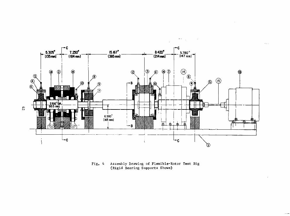
F C P C
I I I
P B! f IP Yl P r
.P N
Fig . 4 Assembly Drawing of Flexible-Rotor Test Rig (Rigid Bearing Supports Shown)
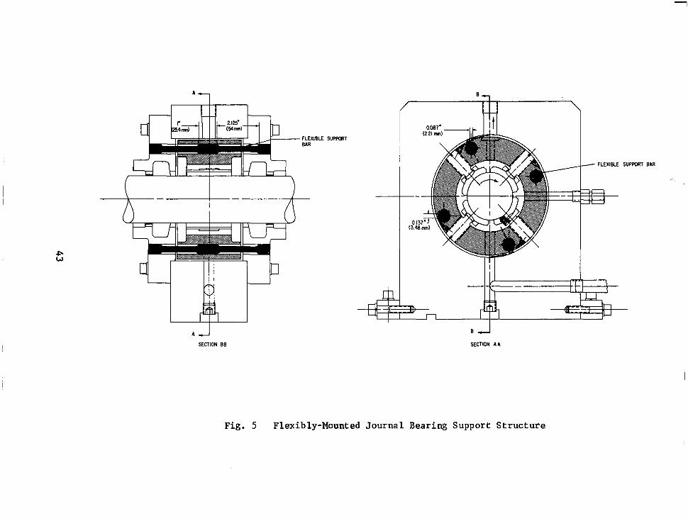
1
FLEXIBLE SUPPMT BAR
4 I I l l I P w A I
SECTION BE
B
/ \
T / FLEXIBLE SUPPORT BAR
SECTION A A
Fig. 5 Flexibly-Mounted Journal Bearing Support Structure

-
0.265 OZ-IN (19 gr-cm)EACH UNBALANCE LOCATION I
"
-
. .
ROTOR SPEED
(RPM) qJ 4 Lo Q Q Q
ONE MAJOR DIVISION EQUALS 0.001 INCH (0.025 mm)
Fig. 6 Test Rotor Orbits at Subcritical Rotor Speeds (Rotor With Initial In-Line, Alternating-Phase Unbalance)

1 0.265 02-IN (19gr-cm)EACH ,UNBALANCE LOCATION -
ROTOR SPEED 0-l 6 (RPM)
ONE MAJOR DIVISION EQUALS 0.001 INCH (0.025 mm)
Fig. 7 Test Rotor Orbits at Subcritical Rotor Speeds (Rotor With Initial In-Line, In-Phase Unbalance)

Fig. 8 Test Rig Assembly Used for Demonstration of High-speed Multiplane Flexible-Rotor Balancing System

1
r
I
1 Il. I 1 1 I t 1 I
Wayne-Kerr Amplifiers
Digital P I Vol tmeter
JFotonic Sensor /I \\
Volce Input / I I
Tracking Analyr n
I J 1
Fig. 9 Schematfc of Flexible-Rotor Balancing Instrumentation
1 7
I I
Tcmperature Ibdlcator
p r i n t e r
I

Fig. 10 Test Rig Control Hardware and Data lbnitoring and Acquisition Instrumentation Used During High-speed Multiplane Flexible-Rotor Balancing Teats

104 lo5 INDIVIDUAL BEARING RADIAL STIFFNESS - LB/IN
" I 2 4 1x10⁷ 2 4 1x10⁸ 2
I
INDIVIDUAL BEARING RAMAL STIFFNESS - N /m
Fig. 11 Calcu la ted Cr i t i ca l Speed Map and B e a r i n g S t i f f n e s s e s f o r Shaft-Bearing System Used During High-speed Multiplane F lex ib le Rotor Ba lanc ing Tests
49
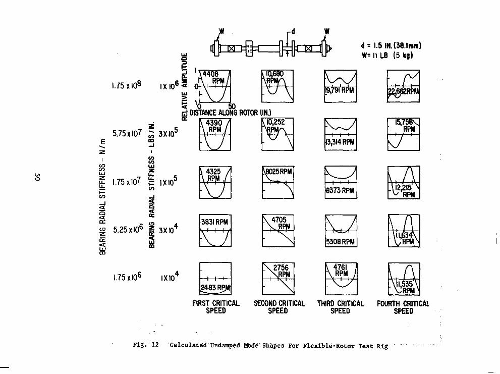
cn 0
1.75 x 10⁸
i 5 .75~ IO7 3; 3x10 5
E m
5.25 x IO6 3 x 1 0 ~ s
1.75 x106 IX104
w d = 1.5 IN.(38.lmm) W= 11 LE (5 kg)
E3 3,314 RPM
403 RP II, 35
FIRST CRITICAL SECOND CRITICAL THIRD CRITICAL FOURTH CRITIC& SPEED SPEED SPEED SPEED

I
0.002f
I
0 2000 4000 6000 8000 l0,OOO 12,000 14,000 16,000 18 ROTOR SPEED - RPM
Fig. 13 Calculated Damped Rotor Amplitudes (Peak) at Stations A, B, and c With In-Line, Alternating-Phase Unbalance

0.20
0.15
0.1ot
0.051 P
3 0.025-
0 -
0.1
0.075
0.050
0.025 - 0-
- - -
Fig. 14
ROTOR LENGTH - IN. L 1
0 IO 20 30 40 50 60 70 80 90 IO0 110 120 ROTOR LENGTH - CM
Calculated Damped Rotor Amplitudes at the First, Third and Fourth Lateral Critical Speeds With In-Line, Alternating-Phase Unbalance and Rigid Bearing Supports
52

i
2.5
0.25 E E I
W n 3 I- i e ZE a E
0 e 0.025 a
0.0025
*'2 ROTO AMPL TUDE
1 I 0.37/ OZ-lN.(26.7 kR-CMj EACH '
-1 K,,,,,=140,000 LB/IN (2.45 x IO7 N/m) =57,000 LB/IN
( I xIO7 N/m)
XI0 1 2 p o o 14,000 16,000 18,000 2OpoO ROTOR SPEED (R PM)
Fig. 15 Calculated Maximum Damped Rotor Amplitudes (Peak) at Stations A, B, and C With In-Line, Alternating-Phase Unbalance and Flexible Bearing Supports
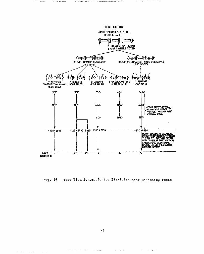
TEST ROTOR RIGID BEARING PEDESTALS
(FIGS. 18-57)
4 CORRECTION PLANES, EXCEPT WHERE NOTED
INLINE , INPHASE UNBALANCE [FIGS 18-49)
7 SENSORS 4 SENSORS 2 SENSORS 2 ACCELEROMETERS 4 SENSORS
(FIGS. 18-22) 5 CORRECTION PLANES (FIGS. ~ 6 - 3 8 1 (FIGS. 40-46) (FIGS~B a 49) (FIGS. 52-51]
3 r 3115 3115 315 3115'
4265 4225 3r 3r 3gr mmSRDOGm
CRITICAL SPEED RSSAGE THROUGH FRST ,wElGHT"T
4300 2980 4165
t r v , 4395+0885 4295+ 8885 8885 4350+ 8\00 4400 +888Q
R u N s F o R C P E R h ~ T H I Q l o n RQTORSPEODSmBaummo
(UTA TAKEN AT FlRST CRITICAL T t E ~ c J ? m c u ~
spEEDsBuwn€FouR7H WEEDANDAT-
CRITtW. SPaDs t t i v
CASE I 20 2b 3 4 5 NUMBER
54
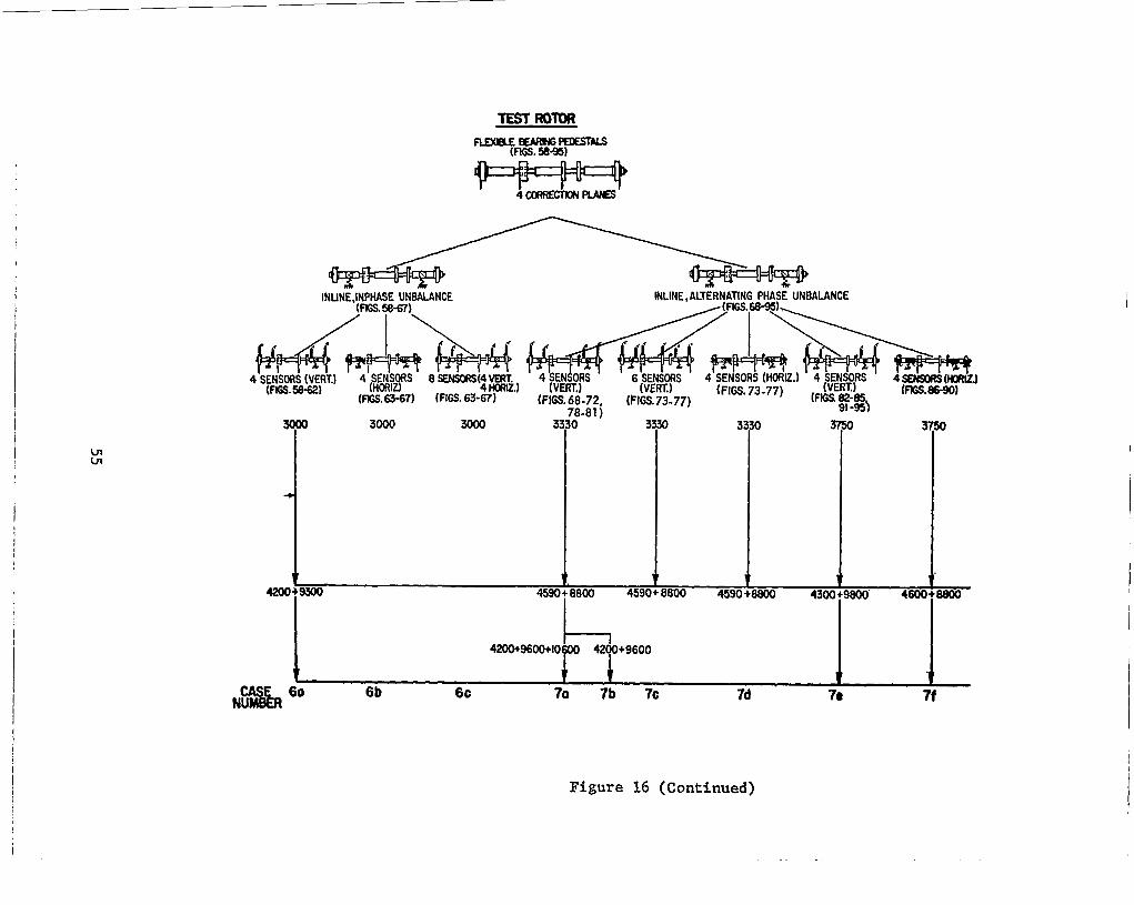
INUNE,INPHASE UNBALANCE INLINE, ALTERNATING PHASE UNBALANCE (rn.58-67)
T 3000 3Ooo 33r- - - , 3r ’$ 37r
I I 4200+9600+IO~ 42dO+9600
I I t t t t
N E & 6o 6b 6c 70 7b 7c 7d 70 7f
Figure 16 (Continued)

Fig. 17 Shaft-Disc Assembly for Operation Through. Four Flexible Critical Sp eds, Shown With Location of Seven Displacement Probe Sensors, Five Correction Planes and In-Line, In-Phase Initial Unbalance Location
e
.075 -
c 2.5 z Y Q
Y
? .050 - F Y
w Q a Ui
t
8 -025 -
e SZ
0 => -I
0-
Fig.
- .
18 Vertical Rotor Amplitudes at Station 1 - Initial Condition (In-Line, In-Phase Unbalance) and 'After Three Consecutive Balancing Runs by the Least Squares Procedure (Seven Probes)
56
/
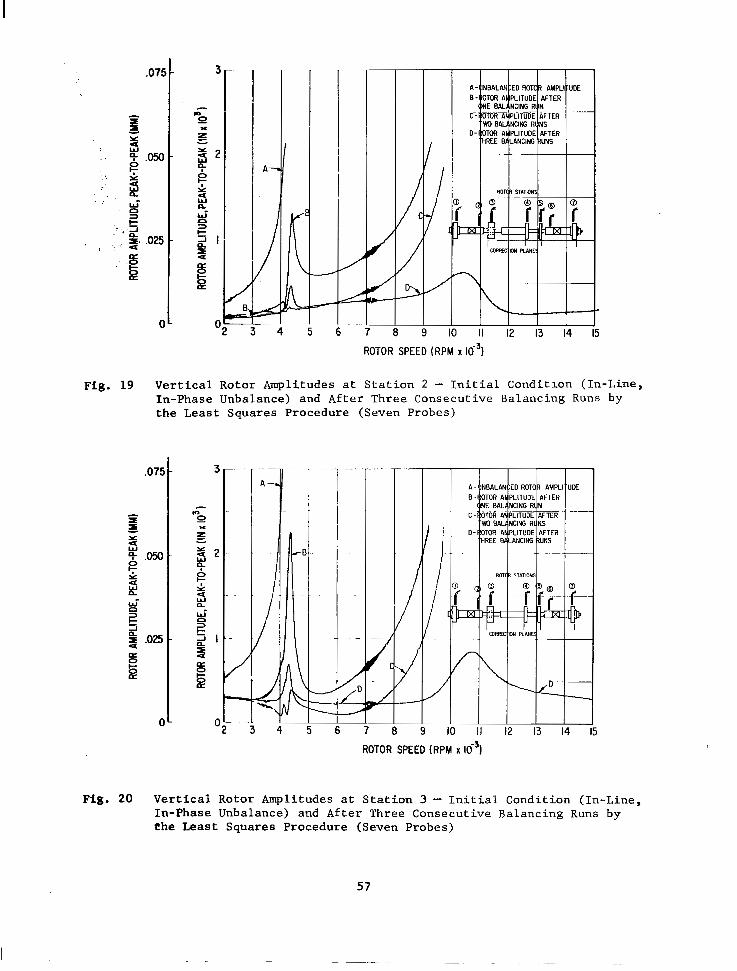
.07f
ROTOR SPEED (RPM x lo3)
Fig. 19 Vertical Rotor Amplitudes at Station 2 - Initial Conditlon (In-Line, In-Phase Unbalance) and After Three Consecutive Balancing Runs by the Least Squares Procedure (Seven Probes)
.~
A 7
I /I
4 5 6
I I I
~-
II 12 13
ROTOR SPEED (RPM X
Fig. 20 Vertical Rotor Amplitudes at Station 3 - Initial Condition (In-Line, In-Phase Unbalance) and After Three Consecutive Balancing Runs by the Least Squares Procedure (Seven Probes)
57
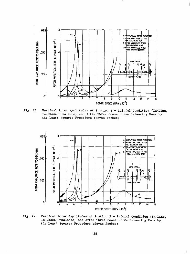
.071
aE I 1
Y
2 g .050 5 a n W-
t n 5 ,025 a
W
0 3
2
0 E
0 8 9 IO I I 12 13 14
ROTOR SPEED (RPM x
Fig. 21 Vertical Rotor 4mplitudes at Station 4 - Initial Condition (In-Line, In-Phase Unbalance) and After Three Consecutive Balancing Runs by the Least Squares Procedure (Seven Probes)
9 W’
n
t n
a
0 3
-I
5 0 E
Fig. 22
025
0 IO II 12 13 14
ROTOR SPEED (RPM x 16~)
Vertical Rotor Amplitudes at Station 5 - Initial Condition (In-Line, In-Phase Unbalance) and After Three Consecutive Balancing Runs by the Least Squares Procedure (Seven Probes)
58

.07!
- I I Y U
- 5 .om z k! U
W’
t c3 3
-1
.025
0 a
E
C
; 4
ROTOR SPEED (RPM X lo3)
Fig. 23 Vertical Rotor Amplitudes at Station 6 - Initial Condition (In-Line, In-Phase Unbalance) and After Three Consecutive Balancing Runs by the Least Squares Procedure (Seven Probes)
.075
I I I
9 Y
g .050 z i2 W’ n t 3
J
,025 a
(I
ROTOR SPEED (RPM x
Fig. 24 Vertical Rotor Amplitudes at Station 7 - Initial Condition (In-Line, In-Phase Unbalance) and After Three Consecutive Balancing Runs by the Least Squares Procedure (Seven Probes)
59

. . . . J . . , . , . . . ..: I ~,;;$j@pY;.;~. . . . . . < . . , .:, . . ... . . . - . - _ . , . , '... . . _ . ,. : ...."., ;.?,>,2,?>
Fig. 25 Shaft-Disc Assembly For Operation Through Four Flexible Critical Speeds, Shown With Location of Four Displacement Probe Sensors, Four Correction Planes and In-Line, In-Phase Initial Unbalance Location
075
1
5 3
4- ,050
Y 4 w
0 z U
!? W- n != 2 ,025 a
a
=3
J
e 0
C
Fig. 26
4
ROTOR SPEED (RPM x IO-^ I
Vertical Rotor Amplitudes at Station 1 - Initial Condition (In-Line, In-Phase Unbalance) and After Three Consecutive Balancing Runs by the Least Squares Procedure (Four Probes)
60

Fig. 28
ROTOR SPEED(RPM x i 8 1
Vertical Rotor Amplitudes at Station 3 - Initial Condition (In-Line, In-Phase Unbalance) and After Three Procedure (Four Probes)
Consecutive Balancing Runs by the Least Squares
61

.075 -
I
Y w d 5
B 5- .050 - i: n W-
t
4 ,025 -
a
4 W
0 D
2
0-
ROTOR SPEED(RPM xlOJ)
Fig. 29 Vertical Rotor Amplitudes at Station 4 - Initial Condition (In-Line, In-Phase Unbalance) and After Three Consecutive Balancing Runs by the Least Squares Procedure (Four Probes)
Fig.
.075 -
I
4 4 Y
W A50 -
Y c; 2 w-
t
4 .025 - a s a
0 2
J
0
0-
ROTOR SPEED(RPM xD3)
30 Vertical Rotor Amplitudes at Station 5 - Initial Condition (In-Line, In-Phase Unbalance) and After Three Consecutive Balancing Runs by the Least Squares Procedure (Four Probes) 9
62

ROTOR SPEED(RPM x~031
Fig. 31 Vertical Rotor Amplitudes at Station 6 - Initial Condition (In-Line, In-Phase Unbalance) and After Three Consecutive Balancing Runs by the Least Squares Procedure (Four Probes)
,075 -
I a 5
W U Y
4- .050 B
- 2 n W-
t n
U W
=3
-1
,025 - a e B
0"
ROTOR SPEED(RPM x ~ ~ - 3 )
Fig. 32 Vertical Rotor Amplitudes at Station 7 - Initial Condition (In-Line, In-Phase Unbalance) and After Three Consecutive Balancing Runs by the Least Squares Procedure (Four Probes)
63
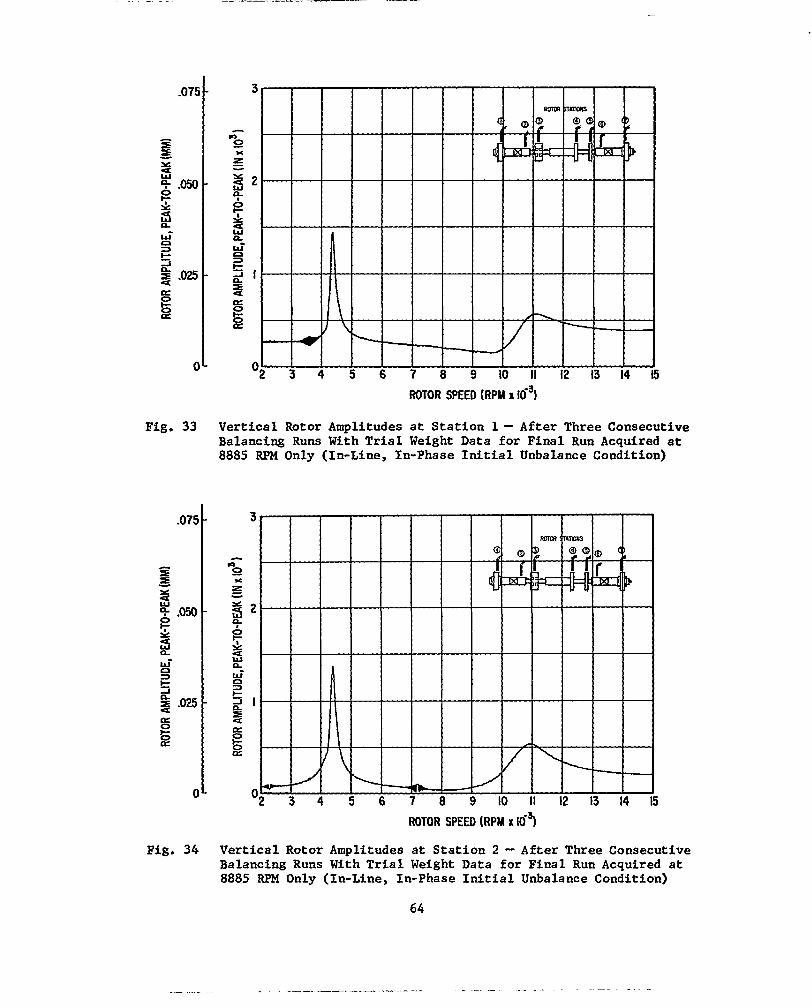
Fig. 34
ROTOR SPEED (RPM x 163
Vertical Rotor Amplitudes a t S t a t i o n 1 - After Three Consecutive Balancing Runs With T r i a l Weight Data for Final Run Acquired a t 8885 RPM Only (In-Line, In-Phase I n i t i a l Unbalance Condition)
3 4 5 ROTOR SPEED (RPM x 169
Vertical Rotor Amplitudes a t S t a t i o n 2 - After Three Consecutive Balancing Runs With T r i a l Weight Data for F ina l Run Acquired a t 8885 RPM Only (In-Line, In-Phase I n i t i a l Unbalance Condition)
64

.075 -
- zz z Y
2
z .050 -
i5 n wi n
k
4 .025 - a
si a
=3
-I
0
0-
ROTOR SPEED (RPM X 16~1
Fig. 35 Vertical Rotor Amplitudes at Station 3 - After Three Consecutive Balancing Runs With T r i a l Weight Data for F ina l Run Acquired a t 8885 RPM Only (In-Line, In-Phase Initial Unbalance Condition)
.075 -
I I Y - 2 4- .050 e
-
& B
g .OB E
-
W'
t 0 3
-I
a 0
0 -
n - 0 x
ROTOR SPEED (RPM x 10-3 Fig. 36 Vertical Rotor Amplitudes at Station 4 - After Three Consecutive
Balancing Runs With Tria l Weight Data for F ina l Run Acquired a t 8885 RPM Only (In-Line, In-Phase Initial Unbalance Condition)
65
\
\
\
, \
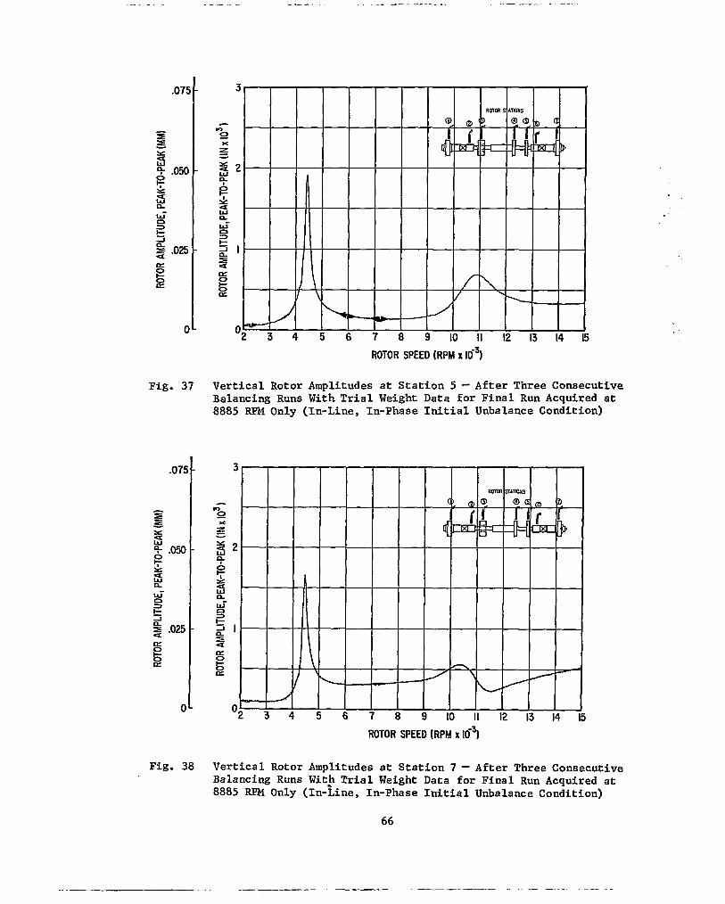
.075 -
- =e =E Y U
- 0 e . O N
8 z
-
W' a t 2 .025 -
a e a
3
-I
U
0
0 -
a 0
E
ROTOR SPEED (RPM x 167
Fig. 37 V e r t i c a l R o t o r A m p l i t u d e s a t S t a t i o n 5 - Afte r Three Consecu t ive Balancing Runs With T r i a l Weight Data for F i n a l Run A c q u i r e d a t 8885 RPM Only ( In -L ine , In -Phase In i t i a l Unba lance Cond i t ion )
ROTOR SPEED (RPM x 167
Fig. 38 V e r t i c a l R o t o r A m p l i t u d e s a t S t a t i o n 7 - Afte r Three Consecu t ive Balancing Runs Wit) T r i a l Weight Data f o r F i n a l Run A c q u i r e d a t 8885 RPM Only ( In -L ine , In -Phase In i t i a l Unba lance Cond i t ion )
66
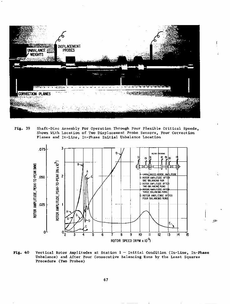
Fig. 39 Shaft-Disc Assembly For Operation Through Four Flexible Critical Speeds, Shown With Location of Two Displacement Probe Sensors, Four Correction Planes and In-Line, In-Phase Initial Unbalance Location
I IO II 12 13 14
ROTOR SPEED (RPM X lo3)
I I 7-
-.
Fig. 40 Vertical Rotor Amplitudes at Station 1 - Initial Condition (In-Line-, In-Phase Unbalance) and After Four Consecutive Balancing Runs by the Least Squares Procedure (Two Probes)
67

.075 -
c I I
s g .050 z
-
z J t 0 = -I
4 P .OB 8
-
E
0-
Fig. 41 Vertical Rotor Amplitudes at Station 2 - Initial Condition (In-Line, In-Phaae Unbalance) and After Four Consecucive Balancing Runs by the Least Squares Procedure (Two Probes)
.075 -
I
a! Y
2 e .050 z
-
;5
0
n u-
t
a ,025 -
a
0 3
a J
0
E
0-
ROTOR SPEED (RPM X l o 3 ) 1
In-Phase Fig. 42 Vertical Rotor Amplitudes at Station 3 - Initial Condition (In-Line, Unbalance) and After Three Consecutive Balancing Runs by the Least Squares Procedure (Two Probes)
68

m 1 It 12 13 14 15
ROTOR SPEED (RPM X 16~)
ROTOR SPEED (RPM X 16~1
Fig. 44 Vertical Rotor Amplitudes at Station 5 - Initial Condition (Ih-Line, In-Phase Unbalance) and After Four Consecutive Balancing Runs by the Least Squares Procedure (Two Probes)
69

ROTOR SPEED (RPM X 16~1
Fig. 45 Vertical Rotor Amplitudes at Station 6 - Initial Condition (In-Linea In-Phase Unbalance) and After Four Consecutive Balancing Runs by the Least Squares Procedure (Two Probes)
ROTOR SPEED (RPM X 16~1
Fig. 46 Vertical Rotor Amplitudes at Station 7 - Initial Condition (In-Line, In-Phase Unbalance) and After Four Consecutive Balancing Runs by the Least Squares Procedure (Two Probes)
70
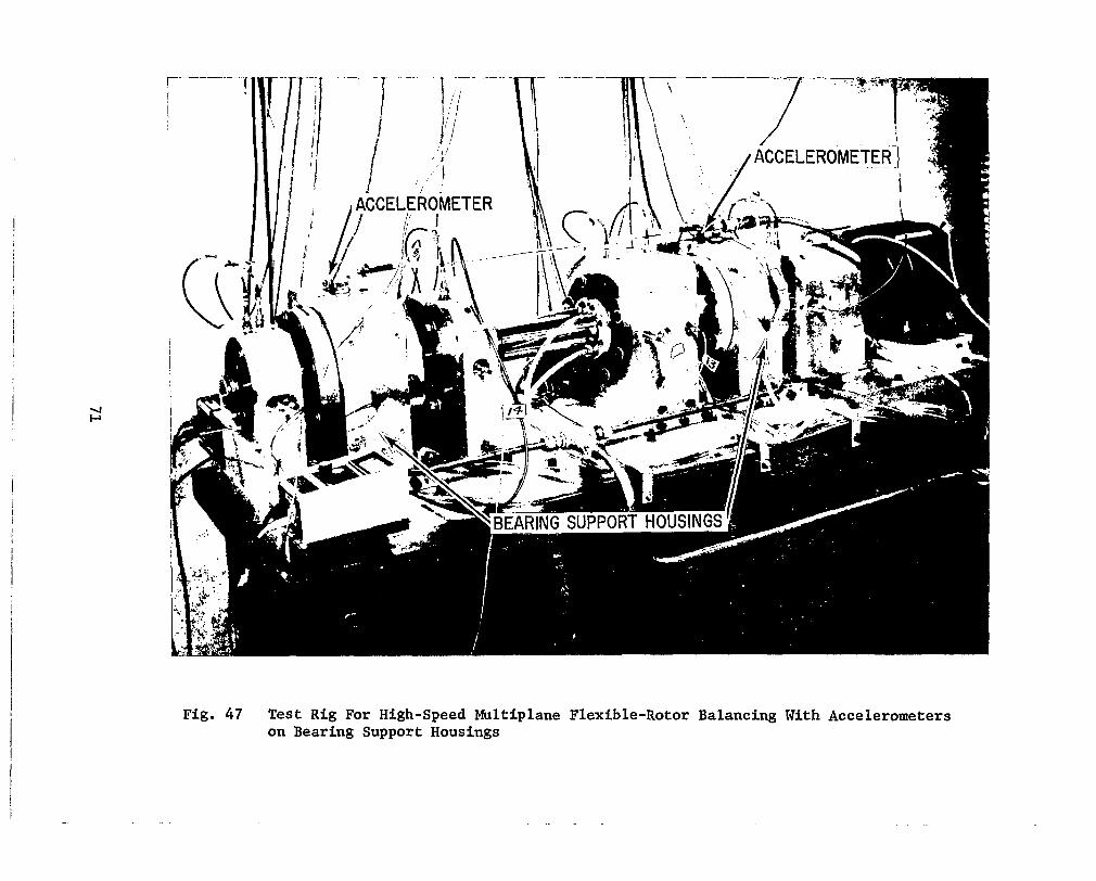
,
I
I
I
I
Fig. 47 Test Rig For High-speed Multiplane Flexible-Rotor Balancing With Accelerometers on Bearing Support Housings

. . - I" .. - . ... "- ".
ROTOR SPEED IRPM X
Fig. 48 Vertical Rotor Amplitudes at Stations 1 and 3 - Initial Condition (In-Line, In-Phase Unbalance) and After TWO Consecutive Balancing Runs by the Least Squares Procedure (Two Accelerometers on Journal Bearing Housings)
ROTOR SPEED (RPM X 1 6 ~ )
Fig- 49 Vertical Rotor Amplitudes at Stations 4 and 5 - Initial Condition (In-Line, In-Phase Unbalance) and After Two Consecutive Balancing Runs by the Least Squares Procedure (Two Accelerometers on Journal Bearing Housings)
72

U w
UNBALANCE PLANES u CORRECTION WEIGHT PLANES
, -@Yo w SCHEMATIC OF
TEST ROTOR
ROTOR MODE SHAPE AT 3OOO RPM
\
ROTOR MOOE SHAPE AT 4000 RPM
(U ) UNBALANCE: 26.7 GR-CM (b) UNBALANCE: 26.7 GR-CM (45' ANGULAR LOCATION 1 (45' ANGULAR LOCATION 1 IN IN EACH UNBALANCE EACH UNBALANCE PLANE, PLANE PLUS 0.135 (203'),0.65 (245'1,
0.45 ( 1 8 0 ° ) , AND 0.22 (234') GR- CM IN CORRECTION WEIGHT PLANES ONE' THROUGH FOUR

A = UNBALANCE VECTORS
B = CORRECTION WEIGHT VECTORS AFTER FIRST A42 BALANCING RUN (ACCELERATION SIGNALS ONLY 1
Fig. 51 Unbalance Vectors and Correction Weight Vectors For Test Rotor With In-Line, In-Phase Unbalance Condition
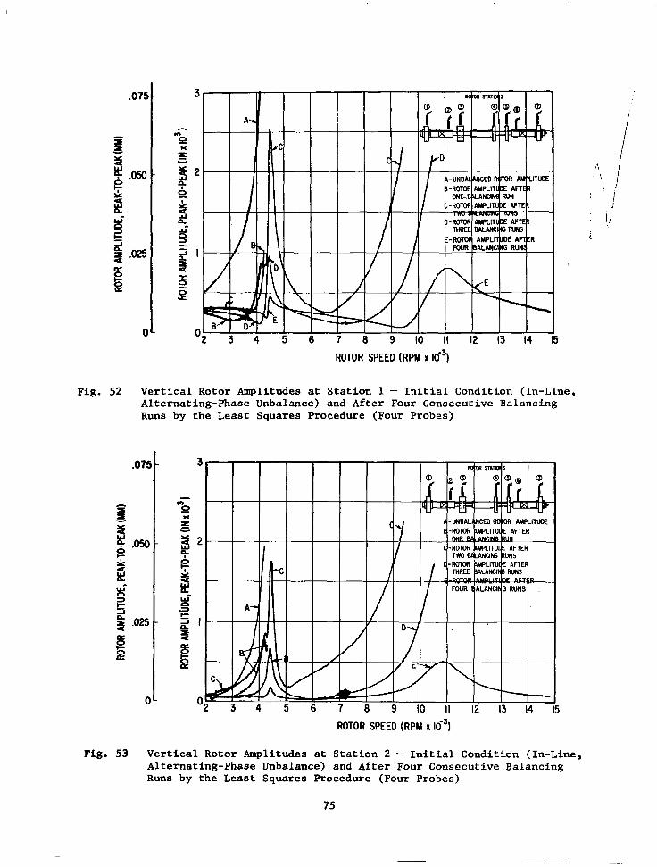
E
Fig. 52
c
ROTOR SPEED (RPM X
Vertical Rotor Amplitudes at Station 1 - Initial Condition (In-Line, Alternating-Phase Unbalance) and After Four Consecutive Balancing Runs by the Least Squares Procedure (Four Probes)
Fig. 53
5
0 I ROTOR SPEED (RPM X lo3)
Vertical Rotor Amplitudes at Station 2 - Initial Condition (In-Line, Alternating-Phase Unbalance) and After Four Consecutive Balancing Runs by the Least Squares Procedure (Four Probes)
75

E
Fig. 54
0
E
Fig. 55
ROTOR SPEED (RPM x 165
Vertical Rotor Amplitudes at Station 3 - Initial Condition (In-Line, Alternating-Phase Unbalance) and After Four Consecutive Balancing Runs by the Least Squares Procedure (Four Probes)
I II 12 13 14
Vertical Rotor Amplitudes at Station 4 - Initial Condition (In-Line, Alternating-Phase Unbalance) and After Four Consecutive Balancing Runs by the Least Squares Procedure (Four Probes)
76

c
Fig. 56
ROTOR SPEED (RPM x Kf?
Vertical Rotor Amplitudes at Station 5 - Initial Condition (In-Line, Alternating-Phase Unbalance) and After Four Consecutive Balancing Runs by the Least Squares Procedure (Four Probes)
ROTOR SPEED (RPM X 16~)
Fig. 57 Vertical Rotor Amplitudes at Station 7 - Initial Condition (In-Line, Alternating-Phase Unbalance) and After Four Consecutive Balancing Runs by the Least Squares Procedure (Four Probes)
77
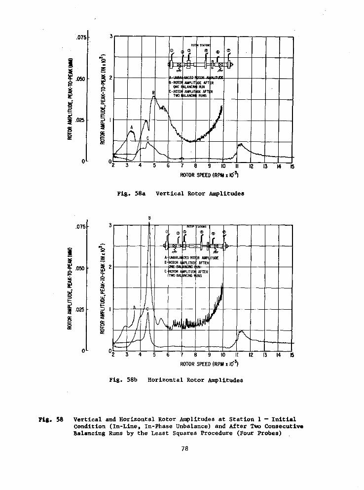
.075 -
- P t.050- d # .025
E -
P
d 3 I-
0-
.075 -
P 1
a .m-
2 t,
d 3
-I t
8 .OB -
0-
ROTOR SPEED (RPM x Ki?
Fig. 58a Vertical Rotor Amplitudes
B
14
ROTOR SPEED (RPM x I O 3 )
Fig. 58b Horizontal Rotor Amplitudes
Pig. 58 Vertical and Horizontal Rotor Amplitudes at Station 1 - Initial Condition (In-Line, In-Phase Unbalance) and After Two Consecutive Balancing Rune by the Least Squares Procedure (Four Probes)
78

I
,075 -
I
I
Y
9
z 2
.ow -
w a a t 2
,025 -
rT 0 E
0 -
/ 7
ROTOR SPEED (RPM X
Fig. 59a Vertical Rotor Amolitudes
A I
3 3
Fig. 59b
I
5 7 8
ROTOR SPEED (RPM X
Horizontal Rotor Amplitudes
12 13 14 15
Fig. 59 Vertical and Horizontal Rotor Amplitudes at Station 2 - Initial Condition (In-Line, In-Phase Unbalance) and After Two Consecutive Balancing Runs by the Least Squares Procedure (Four Probes)
79
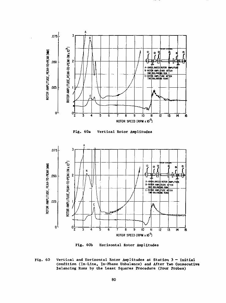
,075 -
1
I I - a t 5 .ow - Y
B J
t
4 ,025 -
a 6
0 3
A
0
e
0 -
ROTOR SPEED (RPM X 16~1
Fig. 60a Vertical Rotor Amplitudes
\ 1
B n
J \
C
4
ROTOR SPEED (RPM X io3)
Fig. 60b Horizontal Rotor Amplitudes
Fig. 60 Vertical and Horizontal Rotor Amplitudes at Station 3 - Initial Condition (In-Line, In-Phase Unbalance) and After T m Consecutive Balancing Runs by the Least Squares Procedure (Four Probes)
80

A
"" 2 3 4
Fig. 61a
Fig. 61b
Vertical Rotor Amplitudes
ROTOR SPEED (RPM X
Horizontal Rotor Amplitudes
"-- I 14 15
"- ! 13 14 i
Fig. 61 Vertical and Horizontal Rotor Amplitudes at Station 4 - Initial Condition (In-Line, In-Phase Unbalance) and After Two Consecutive Balancing Runs by the Least Squares Procedure (Four Probes)
81

8 s a
0
ROTOR SPEED (RPM X
Fig. 62a Vertical Rotor Amplitudes
B
ROTOR SPEED (RPM X 16~)
Fig. 62b Horizontal Rotor Amplitudes
Fig. 62 Vertical and Horizontal Rotor Amplitudes at Station 7 - Initial Condition (In-Line, In-Phase Unbalance) and After "m Consecutive Balancing Runs by the Least Squares Procedure (Four Probes)
82

,075
1 = - Y U 5 .050
z B W-
t 4 ,025 a
0 3
-I
0 E
0
,075
- I x! Y - 5
.050
z B W-
t 2 .025 a a
c3 3
-I
0 E
0
Fig. 63
Fig. 63a
4
)NE 0P =OUR I
6 ROTOR SPEED (RPM X 16~)
Vertical Rotor Amplitudes
6 I I I I I 7 8 9 IO II 12 13
ROTOR SPEED (RPM X
i
Fig. 63b Horizontal Rotor Amplitudes
Vertical and Horizontal Rotor Amplitudes at Station 1 - Initial Condition (In-Line, In-Phase Unbalance) and After h e Balancing Run by the Least Squares Procedure (Four Vertical Probes, or Four Horizontal Probes, or Four Vertical Plus Four Horizontal probes)
83
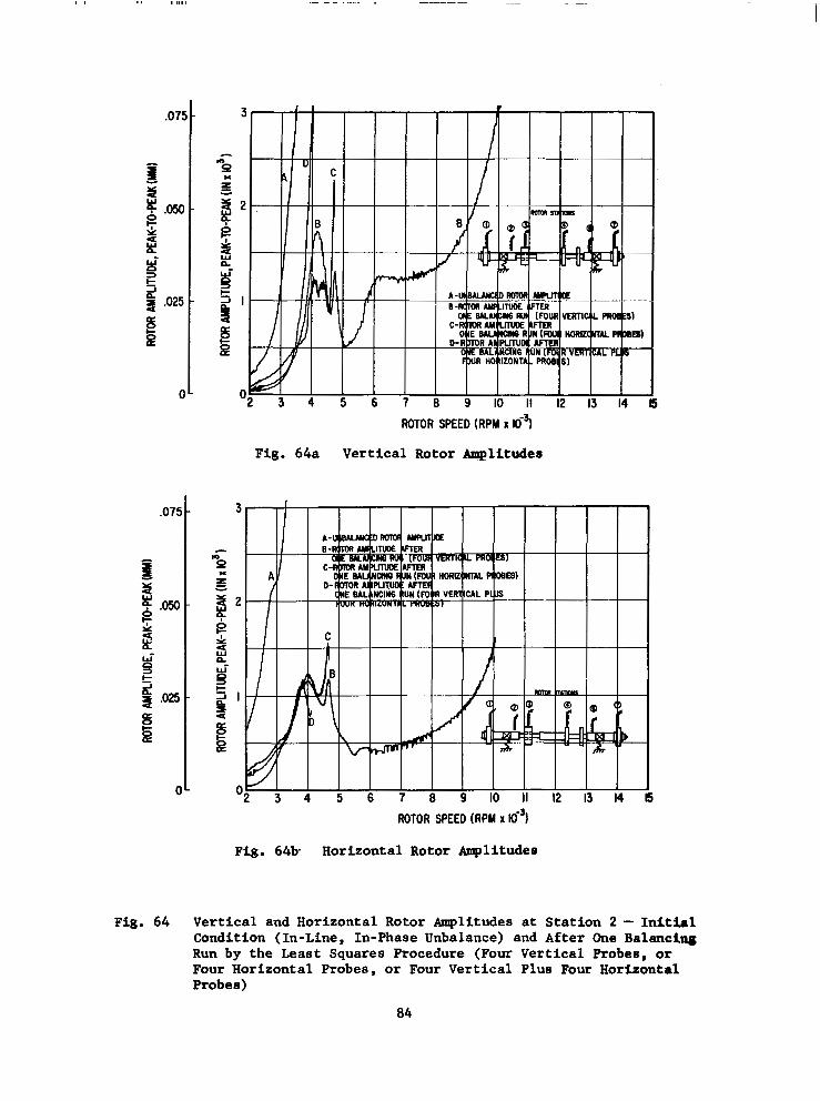
ROTOR SPEED (RPM x 169
Fig. 64a Vertical Rotor Amplitudes
Fig. 64b Horizontal Rotor Amplitudes
Fig. 64 Vertical and Horizontal Rotor Amplitudes at Station 2 - Initial Condition (In-Line, In-Phase Unbalance) and After One Balanci- Run by the Least Squares Procedure (Four Vertical Probes, or Four Horizontal Probes, or Four Vertical Plus Four Horizontal Probes)
84

ROTOR SPEED (RPM X
Fig. 65a Vertical Rotor Amplitudes
r
I I IJ - 4 5 6 7 9 10 II 12
ROTOR SPEED (RPM X 16~)
Fig. 65b Horizontal Rotor Amplitudes
i 14 i
Fig. 65 Vertical and Horizontal Rotor Amplitudes at Station 3 - Initial Condition (In-Line, In-Phase Unbalance) and After One Balancing Run by the Least Squares Procedure (Four Vertical Probes, or Four Horizontal Probes, or Four Vertical Plus Four Horizontal Probes)
85
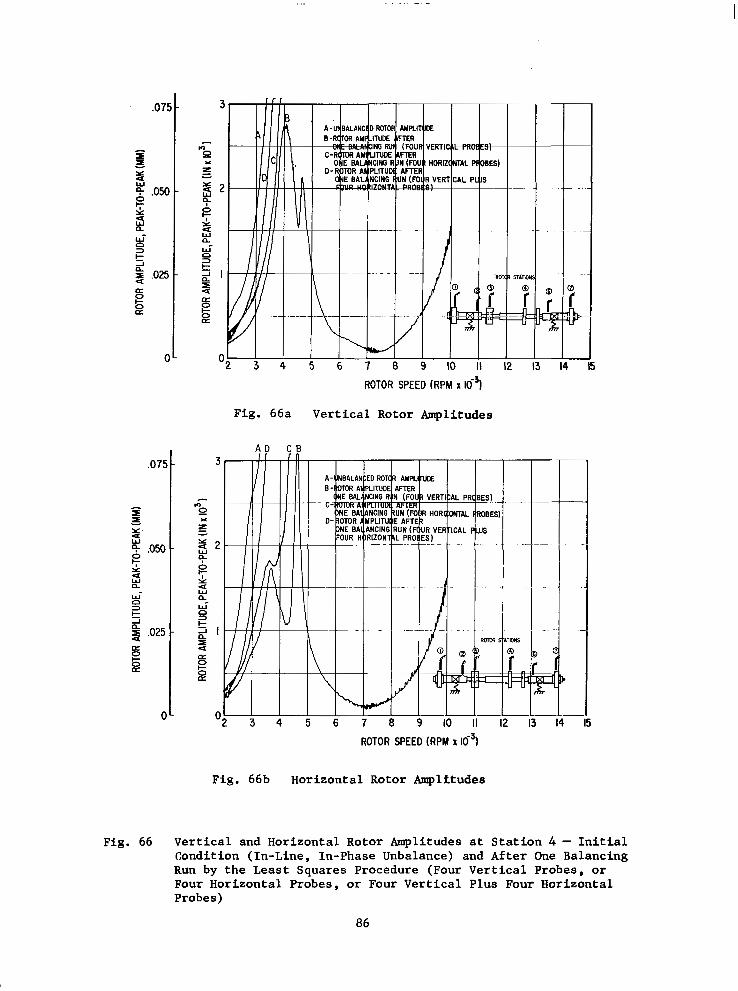
. . .
.075 -
1
I I - 3 !g .050
- z 2 W-
n
n t
4 .025 -
a
s a
3
J
0
0-
ROTOR SPEED (RPM X
Fig. 66a Vertical Rotor Amplitudes
A D C B
ROTOR SPEED (RPM X lo3)
Fig. 66b Horizontal Rotor Amplitudes
Fig. 66 Vertical and Horizontal Rotor Amplitudes at Station 4 - Initial condition (In-Line, In-Phase Unbalance) and After One Balancing Run by the Least Squares Procedure (Four Vertical Probes, or Four Horizontal Probes, or Four Vertical Plus Four Horizontal Probes)
86

,075 -
- Y
5 g .050 z
-
9 a W- n r-
4 ,025
3
-I -
PI
E
0-
3
A
8 D t u ' .
4
ROTOR SPEED ( R P M x
Fig. 67a Vertical Rotor Amplitudes
fbL" 4 5 6 7
nh-
9 IO II 12 13 14
ROTOR SPEED ( R P M X
Fig. 67b Horizontal Rotor Amplitudes
i
Fig. 67 Vertical and Horizontal Rotor Amplitudes at Station 7 - Initial Condition (In-Line, In-Phase Unbalance) and After One Balancing Run by the Least Squares Procedure (Four Vertical Probes, or Four Horizontal Probes, or Four Vertical Plus Four Horizontal Probes)
87

.07S -
I - 3i
e
d
Y .050 -
d
E
3
-I t-
4 .OB -
0 -
.075 -
I - s 0
.050 -
6 W'
I= 0 3
-I
2 .OB -
0 -
A
ROTOR SPEED (RPM x lo'? Fig. 68a Vertical Rotor Amplitudes
A
ROTOR SPEED (RPM x Id?
Fig. 68b Horizontal Rotor Amplitudes
Fig. 68 Vert ica l and Horizontal Rotor Amplitudes a t S t a t i o n 1 - I n i t i a l Condition (In-Line, Alternating-Phase Unbalance) and After Three Consecutive Balancing Runs by the Least Squares Procedure (Four Vertical Probes)
88

3 4 5 6
C
I I I I I 1 8 9 10 11 12 13 14 15
ROTOR SPEED (APM X
Fig. 69a Vertical Rotor Amplitudes
3 4 5 6 7 8 9 1 0
ROTOR SPEED (RPM x 163)
F i g . 69b Horizontal Rotor Amplitudes
12 13 14 15
I
Fig. 69 V e r t i c a l and Horizontal Rotor Amplitudes a t S t a t i o n 2 - I n i t i a l Condition (In-Line, Alternating-Phase Unbalance) and After Three Consecutive Balancing Runs by the Least Squares Procedure (Four Vertical Probes)
89
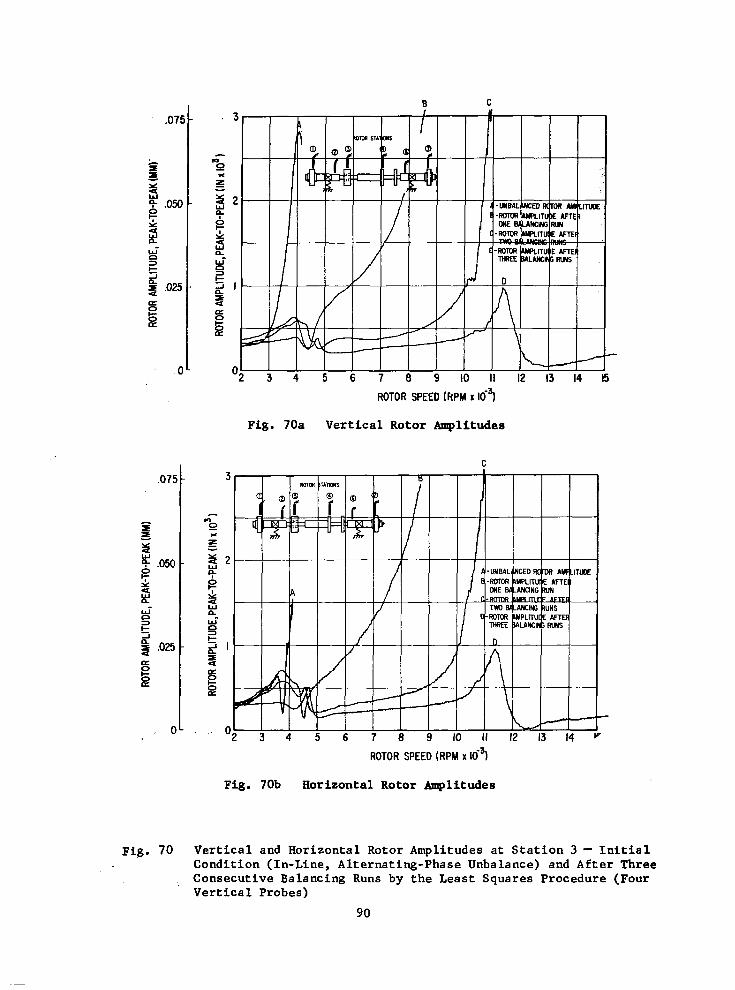
,075
I
= I - a 0 F .050 z 2 W- n t 2 .025 a
3
J
E
. o
Fig . 70
B C
Fig. 70a
ROTOR SPEED (kPM x 164
Vertical Rotor Amplitudes
ROTOR SPEED (RPM x 16~1
Fig. 70b Horizontal Rotor Amplitudes
V e r t i c a l and Horizontal Rotor Amplitudes at Station 3 - I n i t i a l Condition (In-Line, Alternating-Phase Unbalance) and After Three Consecutive Balancing Runs by the Least Squares Procedure (Four Vertical Probes)
90

ROTOR SPEED (RPM x Ki? Fig. 71a Vertical Rotor Anplituder
A
10 II 12 13 14
ROTOR SPEED (RPM x Kf? Fig. 71b Horizontal Rotor @lituder
Fig. 71 Ver t i ca l and Horizontal Rotor Amplitudes a t S t a t i o n 4 - In1,ti . l Condition (In-Line, Alternating-Phase Unbalance) and After Three Consecutive Balancing Runs by the Least Squares Procedure (Four Vertical Probes)
91
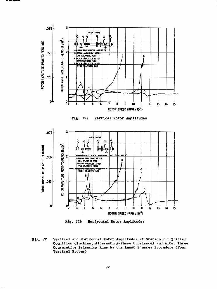
ROTOR SPEED (RPM x 10-3
Fig. 72a Vertical Rotor Anplitudea
D
It 12
ROTOR SPEED (RPM X l o 3 )
Fig. 72b Horizontal Rotor Amplitudes
F i g . 72 V e r t i c a l and Horizontal Rotor Amplitudes at Station 7 - I n i t i a l Condition (In-Line, Altermting-Phase Unbalance) and After Three Consecutive Balancing Runs by the Least Squares Procedure (Four Vertical Probes)
92

~
3 4 5 6 7 8 II 12 13 14
ROTOR SPEED (RPM X lo3)
Fig. 73a Vertical Rotor Amplitudes
4 5 6 7 8 9 1 0 1 1
ROTOR SPEED (RPM X 16~)
Fig. 73b Horizontal Rotor Amplitudes
i
13 14 IS
Fig. 73 Vertical and Horizontal Rotor Amplitudes at Station 1 - (In-Line, Alternating-Phase Unbalance) After Two Consecutive Balancing Runs by the Least Squares Procedure (Four Vertical Probes at the First Run, and Either Four Vertical Probes, or Six Vertical Probes or Four Horizontal Probes at the Second Run)
93

.075 -
- I I x I
g .w- 4 W
z n
n W-
L= 3
J
4 ,025 -
8 s a
0-
ROTOR SPEED (RPM X 16~)
Fig. 74a Vertical Rotor Amplitudes
ROTOR SPEED (RPM x
Fig. 74b Horizontal Rotor Amplitudes
12 13 14 15
Fig. 74 Vertical and Horizontal Rotor Amplitudes at Station 2 - (In-Line, Alternating-Phase Unbalance) After Two Consecutive Balancing Rune by the Least Squares Procedure (Four Vertical Probes at the First Run, and Either Four Vertical Probes, or S i x Vertical Probes or Four Horizontal Probes at the Second Run)
94

Fig. 75
ROTOR SPEED (RPM X
Fig. 75a Vertical Rotor Amplitudes
5 ROTOR SPEED (RPM X 64
Fig. 75b Horizontal Rotor Amplitudes
?ertical and Horizontal Rotor Amplitudes at Station 3 - (In-Line, alternating-Phase Unbalance) After Two Consecutive Balancing Rune >y the Least Squares Procedure (Four Vertical Probes at the First hn, and Either Four Vertical Probes, or S i x Vertical Probes or Four Horizontal Probes at the Second Run)
95

,075 -
= - 3 g .050 -
3 W'
t
2 ,025 -
a
0 3
-I
0
E
0-
"2 3 4 5 6 7 8 9 1 0 1 1
ROTOR SPEED (RPM X 1 6 ~ )
Fig. 76a Vertical Rotor Amplitudes
! 1 t 12
Fig. 76b Horizontal Rotor Amplitudes
13 14 15
Fig. 76 Vertical and Horizontal Rotor Amplitudes at Station 4 - (In-Line, Alternating-Phase Unbalance) After Two Consecutive Balancing Runs by the Least Squares Procedure (Four Vertical Probes at the First Run, and Either Four Vertical Probes, or Six Vertical Probes or Four Horizontal Probes at the Second Run)
96
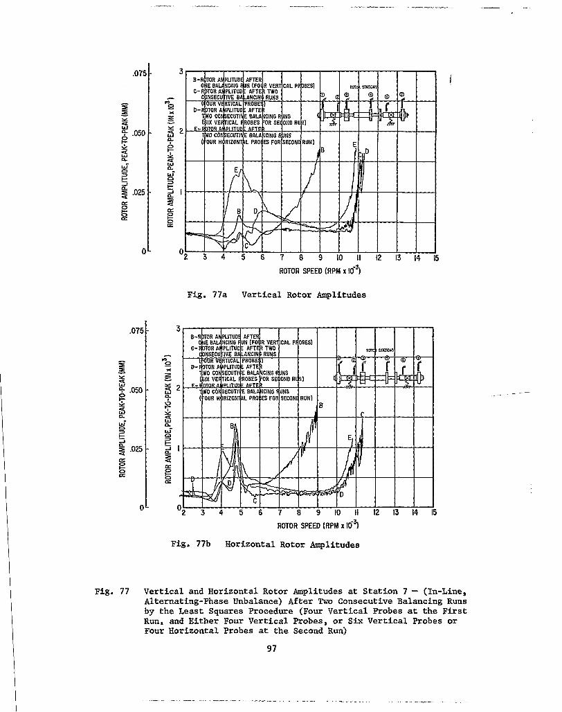
a 0
E
Fig. 77
OL
ROTOR SPEED IRPM X
Fig. 77a Vertical Rotor Amplitudes
ROTOR SPEED (RPM x 167
Fig. 77b Horizontal Rotor Amplitudes
Vertical and Horizontal Rotor Amplitudes at Station 7 - (In-Line, Alternating-Phase Unbalance) After Two Consecutive Balancing Runs by the Least Squares Procedure (Four Vertical Probes at the First Run, and Either Four Vertical Probes, or S i x Vertical Probes or Four Horizontal Probes at the Second Run)
97

.075 -
=E =E Y - Qw .050 - z w e
W'
n
n t=
2 .025 a
- x -I
E =
0-
ROTOR SPEED (RPM X 164
Fig. 78a Vertical Rotor Amplitudes
c) 0 x
ROTOR SPEED (RPM x Kf31
Fig. 78b Horizontal Rotor Amplitudes
Fig. 78 Vertical and Horizontal Rotor Amplitudes at Station 1 - (In-Line, Alternating-Phase Unbalance) After Two and Three Consecutive Balancing Runs by the Least Squares Procedure (Four Probes, Two Speeds and Four Probes, Three Speeds)
98
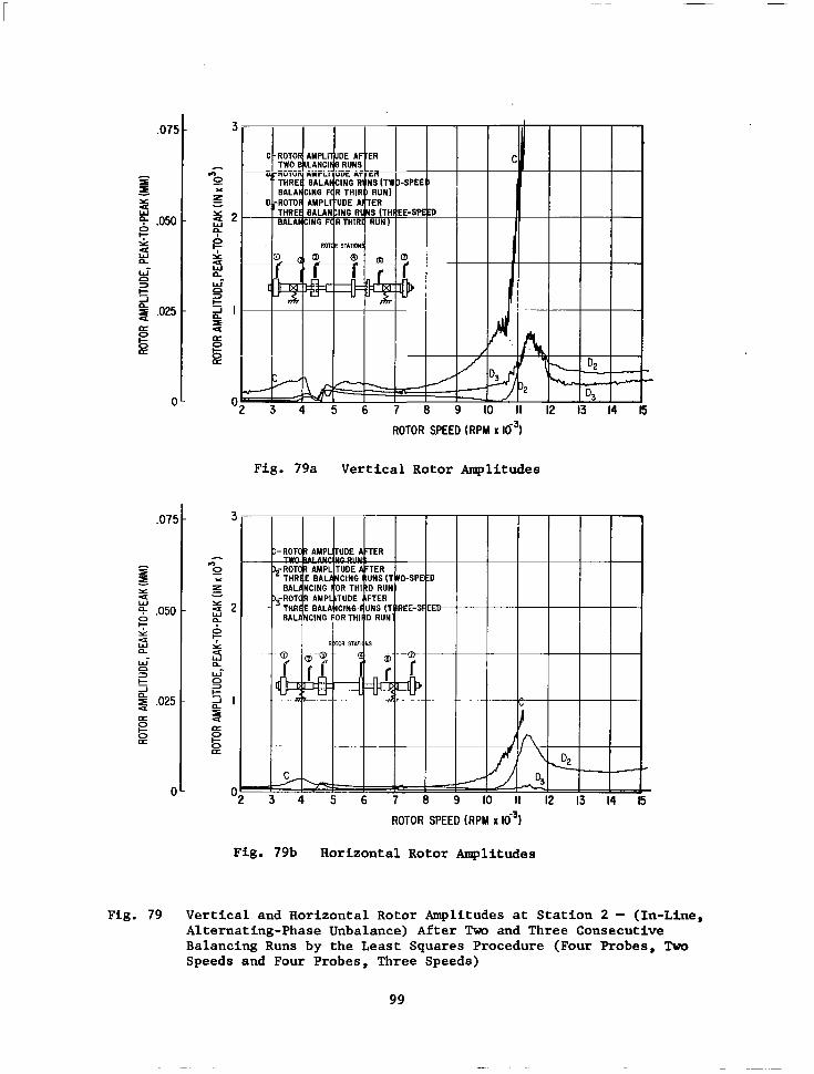
.07!
- I I Y
25
z .ow
U W P W- n t 2 ,025 a
3
2
0 E
c
.07!
- =E = W
Y a
0
- 9- ,050
3 z a
n
t
4 ,025
W
3
J
a 0 z
C
I I I I I
m I II 12 13 14
ROTOR SPEED ( R P M X lo3)
Fig. 79a Vertical Rotor Amplitudes
I l l
4 5 6 7 8 9 1 I I 12 13 14 15 ROTOR SPEED ( R P M X lo3)
Fig. 79b Horizontal Rotor Amplitudes
Fig. 79 Vertical and Horizontal Rotor Amplitudes at Station 2 - (In-Line, Alternating-Phase Unbalance) After Two and Three Consecutive Balancing Runs by the Least Squares Procedure (Four Probes, Two Speeds and Four Probes, Three Speeds)
99

1
10 11 12 13 14
ROTOR SPEED (RPM x 10-3
Fig. 80a Vertical Rotor Amplitudes
CT
ROTOR SPEED (RPM X 16~)
Fig. 80b Horizontal Rotor Amplitudes
Fig. 80 Vertical and Horizontal Rotor Amplitudes at Station 3 - (In-Line, Alternating-Phase Unbalance) After Two and Three Consecutive Balancing Runs by the Least Squares Procedure (Four Probes, TM Speeds and Four Probes, Three Speeds)
100
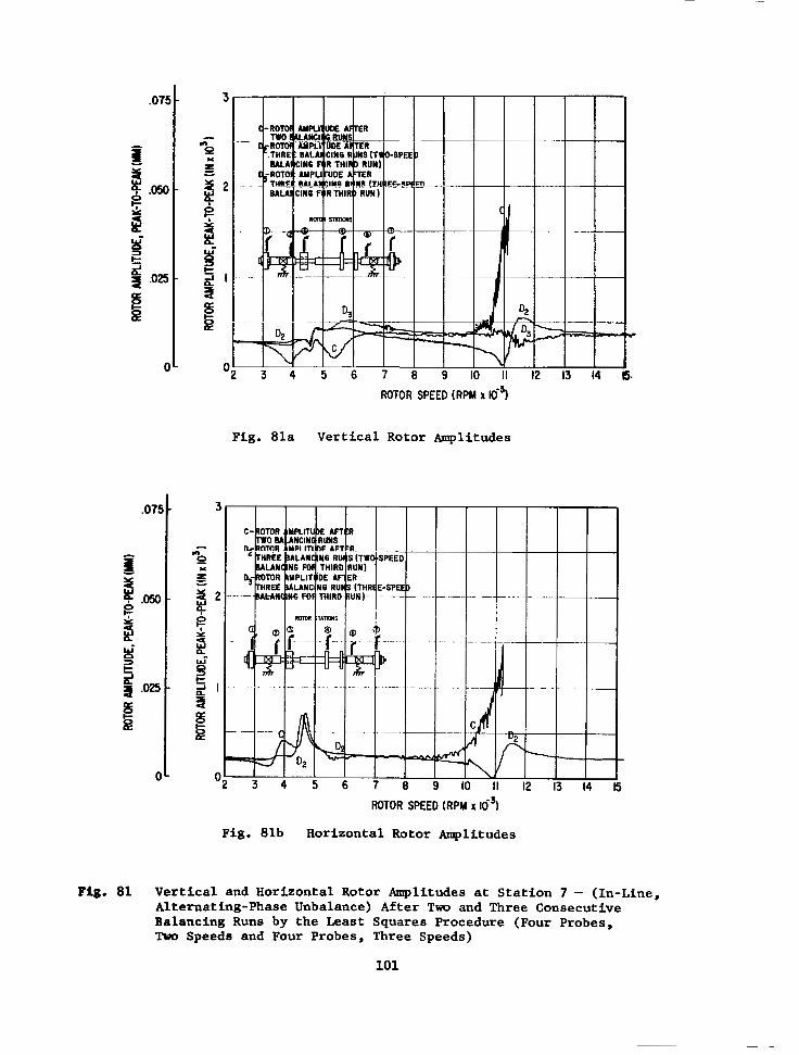
ROTOR SPEED (RPM x u3)
Fig. 81a Vertical Rotor Amplitudes
ROTOR SPEED (RPW X 16~)
Fig. 81b Horizontal Rotor Amplitudes
Pig. 81 Vertical and Horizontal Rotor Amplitudes at Station 7 - (In-Line, Alternating-Phase Unbalance) After Two and Three Consecutive Balancing Runs by the Least Squares Procedure (Four Probes, Two Speeds and Four Probes, Three Speeds)
101

.075 -
I I - Y 4
5 .050 -
5 J t
2 .025 -
a 6 a
0 3
-I
0
0 -
J75 -
a! I - :: 5.050 - z B J t
2 ,025 -
a
0 3
-I
0
E
OL
ROTOR SPEED (RPM x
Fig. 82a Vertical Rotor Amplitudes
4 I
3 u
5 6 7 9 IO ROTOR SPEED (RPM X l o 3 )
Fig. 82b Horizontal Rotor Amplitudes
Fig. 82 Vertical and Horizontal Rotor Amplitudes at Station 1 - Initial Condition (In-Line, Alternating-Phase Unbalance) and After Consecutive Balancing Runs by the Least Squares Procedure (Four Vertical Probes)
102

4 5 6 7 8 9 I I 12 13 14 15 ROTOR SPEED (RPM X lo3)
Fig. 83a Vertical Rotor Amplitudes
5 6 8 I I 12 13 14 15
ROTOR SPEED (RPM X
Fig. 83b Horizontal Rotor Amplitudes
Fig. 83 Vertical and Horizontal Rotor Amplitudes at Station 2 - Initial Condition (In-Line, Alternating-Phase Unbalance) and After TWO Consecutive Balancing Runs by the Least Squares Procedure (Four Vertical Probes)
103

5 a
Fig. 8
t
ROTOR SPEED (RPM X 1 6 ~ )
Fig. 84a Vertical Rotor Amplitudes
ROTOR SPEED (RPM X lo3)
Fig. 84b Horizontal Rotor Amplitudes
'4 Vertical and Horizontal Rotor Amplitudes at Station 4 - Initial Condition (In-Line, Alternating-Phase Unbalance) and After Two Consecutive Balancing Runs by the Least Squares Procedure (Four Vertical Probes)
104

., k 5
IO II 12 13 14
ROTOR SPEED (RPM X
Fig. 85a Vertical Rotor Amplitudes
3 4 5 6 7 8 9 IO II 12 1 3 1 4
ROTOR SPEED (RPM X
Fig. 85b Horizontal Rotor Amplitudes
i
Fig. 85 Vertical and Horizontal Rotor Amplitudes at Station 7 - Initial Condition (In-Line, Alternating-Phase Unbalance) and After Two Consecutive Balancing Runs by the Least Squares Procedure (Four Vertical Probes)
105

,075 -
1
I I Y 4
- 5 .050 - z 4 W n wi n
t
4 .025 -
a P 8
3
-I
0-
,075 -
I x z I
Y
2 0 4- ,050 - z 4 W n Li- n 3
J
2 ,025 -
a 0 z
0-
ROTOR SPEED (RPM X 16~)
Fig. 86a Vertical Rotor Amplitudes
ROTOR SPEED (RPM x
Fig. 86b Horizontal Rotor Amplitudes
I
Fig. 86 Vertical and Horizontal Rotor Amplitudes at Station 1 - Ini t ia l Condition (In-Line, Alternating-Phase Unbalance) and After Two Consecutive Balancing Runs by the Least Squares Procedure (Four Horizontal Probes)
10 6
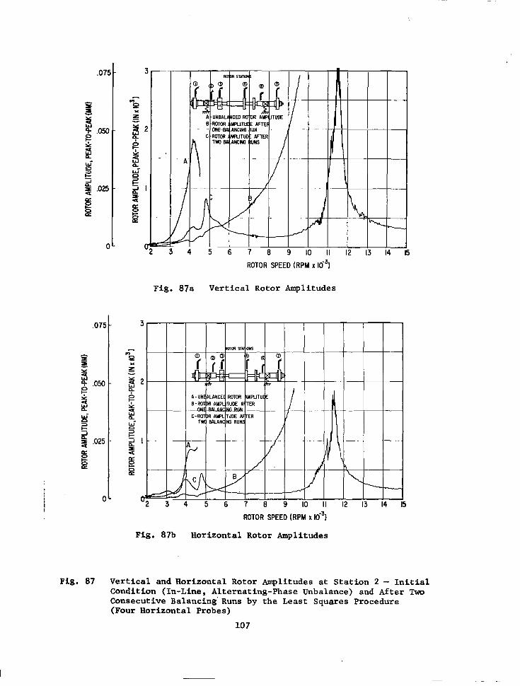
C
ROTOR SPEED (RPM x
Fig. 87a Vertical Rotor Amplitudes
12 13
i 1 II 12 13 14 15
ROTOR SPEED (RPM X
Fig. 87b Horizontal Rotor Amplitudes
Fig. 87 Vertical and Horizontal Rotor Amplitudes at Station 2 - Initial Condition (In-Line, Alternating-Phase Unbalance) and After Two Consecutive Balancing' Runs by the Least Squares Procedure (Four Horizontal Probes)
10 7
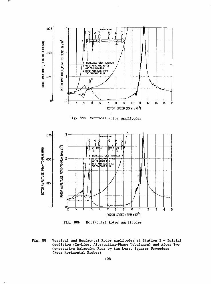
.075 -
- I I - Y
3 g .ow z
-
9 n W-
t % ,025 - a
0 3
-l
4
8
0-
ROTOR SPEED (RPM X 16~)
Fig. 88a Vertical Rotor Amplitudes
ROTOR SPEED (RPM X 16~)
Fig. 88b Horizontal Rotor Amplitudes
Fig. 88 Vertical and Horizontal Rotor Amplitudes at Station 3 - Initial Condition (In-Line, Alternating-Phase Unbalance) and After Two Consecutive Balancing Runs by the Least Squares Procedure (Four Horizontal Probes)
10 8

ROTOR SPEED (RPN x Ki?
Fig. 89a Vertical Rotor Amplituder
ROTOR SPEED (RPY x 10-9 Fig. 89b Horizontal Rotor mlitudar
Fig. 89 Vertical and Horizontal Rotor Amplitudes at Station 4 - Initial Condition (In-Line, Alternating-Phare Unbalance) and After Two Consecutive Balancing Runs by the Ltwt Squarer Procedure (Four Horizontai Prober)
109

.075 -
2 3 .”
t
g ,025 -
0‘
ROTOR SPEED (RPM x 163
Fig. 90 Horizontal Rotor Amplitudes a t S t a t i o n 7 - In i t ia l Condi t ion (In-Line, Alternating-Phase Unbalance) and After Two Con- secutive Balancing Runs by the Least Squares Procedure (Four Horizontal Probes)
110

ROTOR SPEED [RPM x ICi?
Fig. 91a Vertical Rotor Amplitude8
5
ROTOR SPEED (RPY x ~? Fig. 91b Horizontal Rotor Amplitudes
Fig. 91 Vcrtic.1 and Horizontal Rotor Amplitudes at Station 1 - Initial Condition (In-Line, Alternating-Phamc Unbalance) and After One Balancing Run by the Least Squares Procedure (Four Vertical Probe8 With and Without Out-Of-Roundnese.at Station 7 Cons idcrcd)
111

.07!
- I B - Y z 4- ,050
9
0 z 8- Q
3
-I c 4 ,025 a s a 0
0
,075
0
ROTOR SPEED (RPM X
Fig. 92a Vertical Rotor Amplitudes
ROTOR SPEED (RPM x 16~)
Fig. 92b Horizontal Rotor Amplitudes
Fig. 92 Vertical and Horizontal Rotor Amplitudes at Station 2 - Initial Condition (In-Line, Alternating-Phase Unbalance) and After One Balancing Run by the Least Squares Procedure (Four Vertical Probes With and Without Out-Of-Roundness at Station 7 Considered)
112

12 13 14 15 ROTOR SPEED (RPM X
Fig. 93a Vertical Rotor Amplitudes
ROTOR SPEED (RPM X
Fig. 93b Horizontal Rotor Amplitudes
Fig. 93 Vertical and Horizontal Rotor Amplitudes at Station 3 - Initial Condition (In-Line, Alternating-Phase Unbalance) and After One Balancing Run by the Least Squares Procedure (Four Vertical Probes With and Without Out-Of-Roundness at Station 7 Considered)
113

.07f
- I I - s
,050
B u-
t 4 ,025 a k a
0 3
A
0
C
.075
- = I - Y
i3 .050
B J
t 4 ,025 a
0 3
A
0
ROTOR SPEED (RPM x 10-j)
Fig. 94a Vertical Rotor Amplitudes
ROTOR SPEED (RPM x
Fig. 94b Horizontal Rotor Amplitudes
Fig. 94 Vertical and Horizontal Rotor Amplitudes at Station 4 - Initial Condition (In-Line, Alternating-Phase Unbalance) and After One Balancing Run by the Least Squares Procedure (Four Vertical '
Probes With and Without Out-Of-Roundness at Station 7 Considered)
114
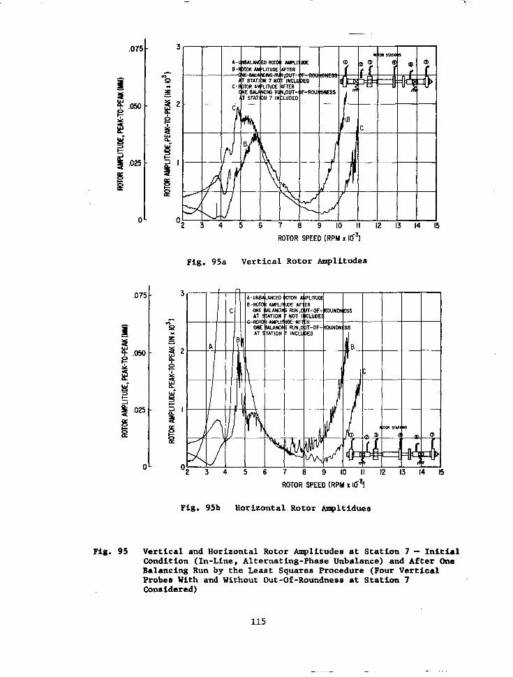
ROTOR SPEED (RPM x 16~)
Fig. 95a Vertical Rotor Amplitudes
ROTOR SPEED (RPM X IO$
Fig. 95b Horizontal Rotor Ampltidues
Fig. 95 Vertical and Horizontal Rotor Amplitudes at Station 7 - Initial Condition (In-Line, Alternating-Phase Unbalance) and After One Balancing Run by the Least Squares Procedure (Four Vertical Prober With and Without Out-Of-Roundness at Station 7 Considered)
115

LANGULAR UNBALANCE LOCATION
ROTOR STATONS
\ i ~ ~ ~ ~ ~ UNBALANCE LOCATION^
REF.
ANGULAR UNBALANCE LOCATION
Fig. 96 Vertical and Horizontal Amplitude Vector Locations For Flexibly-Supported Rotor (With In-Line, In-Phase Unbalance) at Subcritical Rotor Speeds

0. ot
P P
-I
90.
I800
VERTICAL ROTOR AMPLITUDE VECTOR LOCATION BETWEEN 2000 AND 4550 RPY ROTOR ORBITS AT 4 5 5 0 RPY (ARROWS DESIGNATE VECTORS (VERTICAL AND HORIZONTAL OR 4550 RPY) AYPLITUDE VECTORS CONBINEO)
HORIZONTAL ROTOR AYPLITUOE VECTOR LOCATIONS BETWEEN 2000 AN0 4 5 5 0 RPY (ARROWS DESIGNATE VECTORS AT 4550 R P Y )
Fig. 97 Vertical and Horizontal Amplitude Vector Locations for Flexibly- Supported Rotor (With In-Line, Alternating-Phase Unbalance) at Subcritical Rotor Speeds

IAL UNBALANCE WCATI
Fig. 98 Vertical and Horizontal Anplitude Vector Location8 for Flexibly-Supported Rotor After Balancing For Passage Through One Bending Critical Sged (In-Line, In-Phase Unbalance)

1
Fig. 99 Vertical and Horirontal Amplitude Vector Locations (At Station. 3) For Flexibly Supported Rotor After Balancing For Passage Through One Bendla Critical Speed (In-Line, A1ternating-Pha8c Unbalance)

I
~ X U L UNBALANCE LOCATIOW”
0 h,
Fig. 100 Vertical and Horizontal Amplitude Vector Locations (At Station 3) For Flexibly- Supported Rotor After Balancing (In-Line, In-Phase .Unbalance)
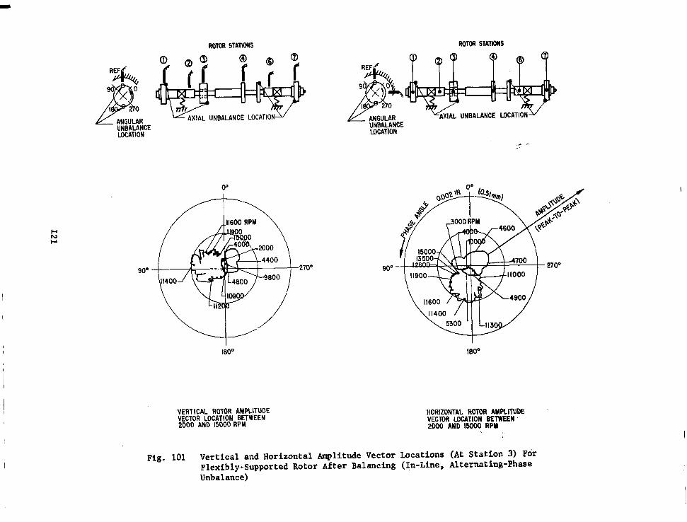
ROTOR STATIONS ROTOR STATIONS
ANGULAR UNBALANCE LOCATION
L UNBALANCE LOCAT1 ANGULAR UNBALANCE ~OCAT~ON
90'
I
00
\"" 180'
VERTICAL ROTOR AMPLITUDE VECTOR LOCATION BETWEEN 2000 AND 15000 RPM
90"
Moo
HORIZONTAL ROTOR AMPLITUDE VECTOR LOCATION BETWEEN ZOO0 AND 1 5 0 0 0 RPM
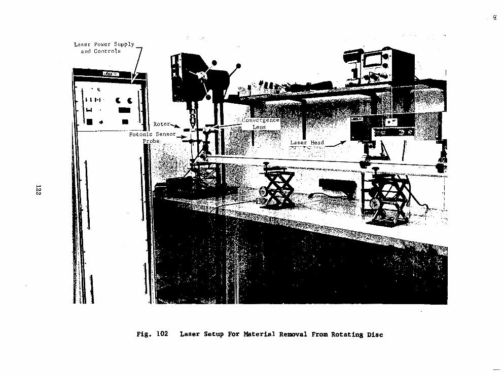
Laser Power S u p p l y and C o n t r o l s
c. tu tu
Fig. 102 Laser Setup For Material Removal From Rotating Disc
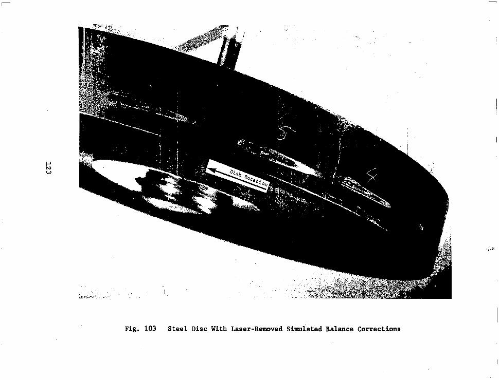
Fig. 103 Steel Disc With Laser-Removed Simulated Balance Corrections
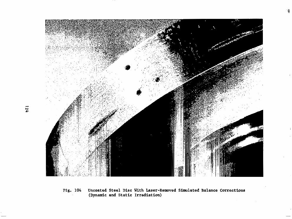
Fig. 104 Uncoated Steel Disc With Laser-Removed Simulated Balance Corrections (Dynamic and Static Irradiation)


Fig. 106 Steel Disc With Laser-Removed Simulated Balance Corrections and Fotonic Sensor Target
*U.S. GOVERNMENT PRINTING OFFICE: 1975 - 635-275/9
126