national advisory committee fqr aeronautics/67531/metadc58258/m... · · 2018-02-224...
TRANSCRIPT

EFFECT5 OF SEVERAL LEADING-EDGE MODIFKATIONS
ON THE STALLING CHARACTERISTICS
OF A 45O SWEPT-FORWARD WING
By Gerald M. McCormack and Woodrow L. Cook
Ames Aeronautical Laboratory Moffett Field, Calif.
NATIONAL ADVISORY COMMITTEE FQR AERONAUTICS

NACA RM A9D29
$WxoNALADVISCRYcOMkIEEE FCR AERONADTICS
EZFECTS OF SEVERAL IEADING4EEE MCDIFICATIONS
ONTHE STAILINGC!EARACTERISTICS
OF A 45’ SWEIT-FORWARD WING
By Gerald M. McCormack andWoodro6 L. Cook
SUMMARY
An investigation has been conducted to determine the effect6 of several leading-edge modification6 on the maximum lift and pitching- moment characteristics of a 1arg~cal.e 45O swept-forward wing.
The results show that, of the modifications tested, a fullrspan leading--edge flap deflected 30° down gave the largest gati of maxi- mum lift (an increment of 0.22). Use of the full-span leadingddge. flap delayed the occurrence of separation to a higher liftbcoeffi- cient but, in general, the Drogreesion and sequence of separation were unchanged. A6 a result, for-d-aft shifts of the aerody- namic center occurred which were similar to the shifts of the aero- dynamic center of the basic wing. The aerodynamic-center shifts, however, occurred at higher lift coefficients.
The addition of a more highly cambered nose to the airfoil section, which increased the camber of the airfoil from 0.68 to 1.07 percent, increased the maximum lift very lfttle and had little effect on the aerodynamic-center shift.
The use of a leading-edge flap deflected 30° down over the inboard on&f of the wing in combination with a leading-e flap deflected loo up over the outboard half increased the maxi- mum lift coefficient approximately the same amount as a half-span leadingddge flap alone. This combination, however, altered the prOgre66iOn Of the 6tall 60 that 0dy a mild movement Of aerody- namic center occurred in contrast to the abrupt shifts that took place with the other configurations,

2 NACA RM AgD29
When operated at moderate and high lift aoefPlaisnt6, highs wept wings, in general, e-bit undeslrsble aerodynamic chsrsa- terl6tiae. The underlying causes of these chsraaterletics in the case of a 450 6vepM~ wing were dieaueeed in referewe 1. It vas found that, at a lift coefficient of 0.49, turlmlent sepsra- tion occurred at the trailing edge of the inbcmrd seations and, as the angle of attsck was increased, 6pead outward and f-. Thie form of separation caused a rW shift of asrcdymmlc center and an lnaresse in drag but aaumd no loee of lift, Before turbulent separation had progressed very far, leading-edge separation oaaurred over the inboard sections, spreading rapidly outboard ss the angle of attsak us8 Increased. The effects of bedinpedge separation overbalanced the effects of turbulent sepsaratiou snd caused a forward shift of aerodynamic center, great inareases in drag, and a decreased lffL4xarve slope. It also established the mxinum lift coefficient of the wing eeotions and of the entire wing.
In order to obtain 6atisfaatory longitudinal chsraateristias for the 45' swept-forward wing, as concluded in reference 1, both forms of separation must be postponed to an angle of attack at least as highas.the meximumthstmightbe enaountered in steady flight. Further, sinae my evidenae of longltudinsl instabilIty would possibly aurtsil the usable lift range, the stall. progres6fon, even though it oacurs beyond the flight range of angle of attack, should be suah that no lon&tuZlinsl instability results. ,
As the first stew toward improving the stalling ahamateristias of the 45O suept-forusxd wing, effort was directed toward delaying and controlling leading-edge eepmation since it w&s thfs form of separaticm that caused the more deleterious effects. This report preeents the resulta of an investigation conducted in the Ames 4C- by 80900-t wind tunnel to determine the ef’feativeness of several leadi- modificstions intended to delay and control. leading- edge separstian over the large-saals 450 swepLfcmsll¶ wing.
The data are presented in the form of stsndsrd &A coefficients aud synibols which are defined in the following tabulation:
CL lift coeffiaient lift ( ) -z

XACA RM AgD29 3
cz
CD
cm
a-c.
P
P
P-L
P
S
a
b
C
X
Y
a
'n
runit 6P6Jl qc >
drag coefficient 9 ( >
pitchiwment coefficient computed about the quarter-chord point of the mean aerodynamdc chord ( itching
s=
aerodynamic center measured in percent chord aft of the leading edge of the mean aercdynamic chord
pressure coefficient
free-stresm static pre6sure, pounds per square foot
local static preesure, pound6 per square foot
freedtream dynamic pressure, pounds per square foot
Wing 6x88, square feet
mean line designation
wing span, feet
11y9an aerodynamic-ahord
local chord, feet
ohordtise coordinate parallel to plane of synanstry, feet
spanwise coord&ate perpendicular to plane of symmetry, feet
angle of attack of chord plane of basic wing, degrees
angle of deflection of leadimdge flap, positive downxard, degrees

NACA RM AgD29
MODEL, TEsrs, Am RESULTS
The geometric characteristics of the aweptcforward wing are shown in figure 1. The wing had 45O of sweep forward of the quarter- chord line, an aspect ratio of 3.55, a taper ratio of 0.5, no twist, and no dihedral. The wing eectione were constant across the epan, end were IVACA 641~1~ eections perpendicular to the quarter-chord line. A photograph of the wing mounted in the wind tunnel is ehown in figure 2. .
The wing wan equipped tith a plain leading-edge flap, (See fig. 3.) This flap wan hinged about the l2,~ercenLchord line (of sections perpendicular to the quarter-chord line) on the lower eurface of the wing when deflected downward, and w&s hinged about the l&percentihord line on the upper surface of the wing when deflected upward. (The tinge lines on the upper and lower surface8 were different due to structural reasons.) When the leading-edge flap WELB deflected, the transition eurface between the flap and the wing had a radius of curvature equaltothe radix fromthe hinge line.
After taste of the wing equippedwdththe leadiwdge flaps were completed, the wing X&B fitted with a no88 piece which incor- porated more camber than the original 64lAJ.12 section. (See fig. 3.) The lines of the cambered nose were obtained from the forward 12.5 percent of a 641~~ thickness distribution combined with an a = LO mean line which was cambered for an ideal lift coeffioient of 2 (that ie, an NACA f&SO12 eection). Thie nose piece was fitted HO that both the upper surface and the lower surface becetme tangent to the contour of the msin portion of the wing at l2.Spercent chord.
Pressure orifices were positioned over the upper and lower surfaces of streamwise section6 which were located at 28.I+ercent, 57.4-percent, a;nd 85.~peroent se~~~spctn. the chordwise locat~om are given in table I.
Force and pressure-distribution meaeuremente were made through an an@-f-attack range at zero sideslip. The data were obtained at approximately 110 milee per hour (Reynolds number of 10.6 X lo8 based on the mean aerodynamic chord length of 10.41 ft). The data were obtained at one value of Reynolds number, since data obtained on the plain wing (reference 1) showed no significant Reynolds znmiber effects, particularly within the purpose of this report.
An index to the teat results is given in the following tabulation:

NACA RM A9D29 -. 5
c Figure No. Configur8tion Results Showu
4 Wingwithfull-spanleading- CDt%Cm vs CL edge flaps
5 Wing with leading-edge flaps of Do. varying spanwise extent
6 Wing with inboard one-half speu Do. leading-edge flap deflected down, outboard one4haIf span leading-edge flap deflected up
7 Wing with cambered nose of vaxying spenwise extent
Do.
8 Wing with full-span leading- Chordwise edge flaps Pres sure8
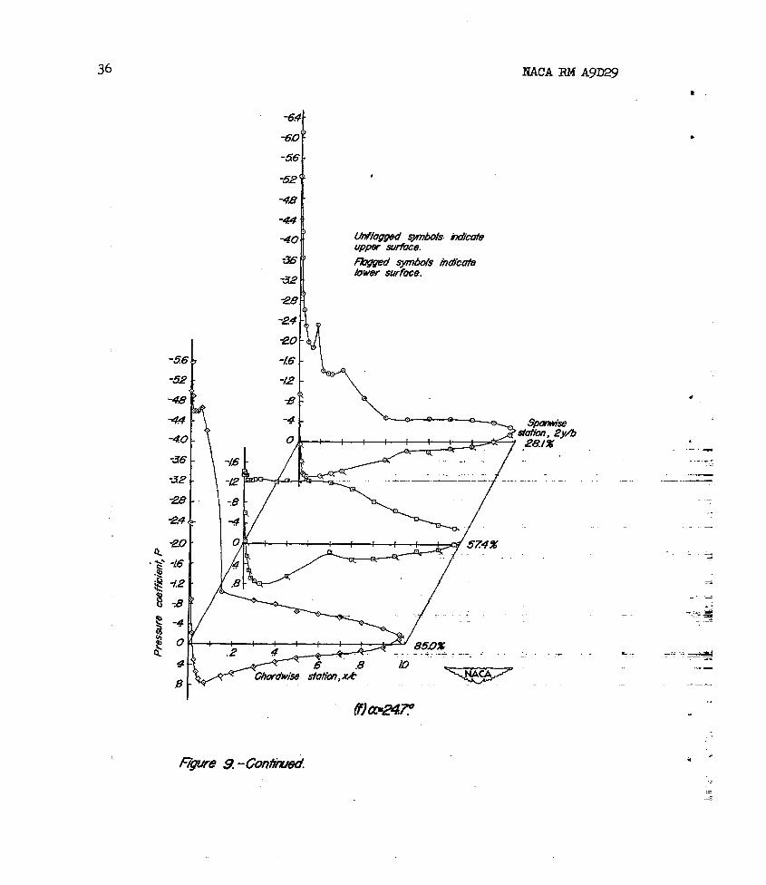
9 Wing with inboard one-half Do. span leading-e fl&p deflected down, outboard on~lf-span leading-edge flap deflected up
10 Wing with full-pan canibered nose
Do.
Standard ixmnel-wall corrections for a straight wing of the same area and span as the swept-forward wiug have been applied to the angle-of-attack and drag-coefficient d&x. This procedure was followed since a brief analysis indicated that tunnel-wall correc- tions were approximately the same for straight and swept wings of the size under consideration. The corrections applied are RS follows:
cur = 0.74 CL
&CD - 0.013 Cf
!The datawere correctedfor drag tares. PLtchingammenttares were not applied since they were not lmoxn with sufficient accuracy to warrant 8pplica.tion. Indications are that they are not of sufficient magnitude to materially affect the results.

6
DIXXJS6IOIV
NACA RM AgD@
As previously mentioned, in the endeavor to attain satisfactory longitudinal chsracteristics for the swept-f -a wing, effort was first directed toward controlling the leading-edge type of separation. This was taken RS the first step in spite of the fact that turbulent separation occurred prior to leading-edge separation. It was felt that any alleviation of the effects of turbulent separation that might be obtained would have little influence on lead- separation. Hence, the effects of leading-edge sepsration would soon overshadow any beneficial effects obtained in the trailing-edge separation pattern. On the other hand, it was reasonable to expect that beneficial changes of the leadiwdge flow would be reflected by beneficial changes in the traili~dge flow. In order to control leading-edge separation the peak suction pressure must be decreased since the magnitude and the gradient of the pressure recovery appear to be the principal factors c8using separation. The devices used to lower the suction peak on the swepLforws,rdwingwere a plainleadi~-edge flap and increased ca&er in the f orward portion of the wing.
PlainLeadin@dge Flaps
Full4ran f lava.- The longitudinal characteristics of the swept- forward wing equipped with a full-epan ptiin leadiwdge flap are shown in figure 4. Compared to the basic wing, the linear portion of the lift curve was extended from a lift coefficient of O.&J to 0.87 (an increment of 0.22) and the maximum lift was increased from 1.04 to 1.26 (ELII increment of 0.22). Drag coefficients in the moderate- lift range were significantly reduced. The first break of the pitchivnt curve (rearward shift of aerodynamic center) was delayed from a lift coefficient of 0.49 to 0.76 (an increment of O-27); the second break (forward shift of aerodynamic center) was delayed from 0.75 to about 0.93 (an increment of 0.18).
Although the fulLspan leading-edge flaps delayed the occurrence of separation, allowing attainment of higher maximum lift and incress- ing the.lift coefficients at which irregularities appeared in the force characteristios, they had essentially no effect on the progression of stall. This was indicated by the large, abrupt shifts of aerodynamic center which were encountered once separation had occurred. The pr- gression of the stall can more easily be seen by examination of the pressure distributions. In figure ll, comparisons can be made between the pressure distributions at the 28.Lpercent-semisp station for the basic wing and for the wing with the full-span lead.i.n&+3dge flaps. The distributions at that semispan station are typical of all distributions
.

NACA RM AgDi3 7 .
obtained. It can be seen in figure IL(a) that, on the basic wing, starting at about 12.50 angle of attack, the pressures failed to recover over the trailing edge, while the growth of pressures over the leading edge was little affected. This, as described in reference 1, indicated that turbulent separation was taking place. When the leading- edge flap was deflected the seme chsnges in pressure distribution occurred but were delayed to about 16.6O angle of attack. Thus, the leading-e flap delayed the occurrence of turbulent separation approximately 4O. The chordwise redistribution of load resulting from turbulent separation caused 8 negative increment of pitching moment (Em - -0.03) of essenti- ally the same magnitude 8s the increment associated with the basic wing.
Within a short angle-of-attack range after the onset of turbulent separation, leading-edge separation occurred over the inboard sections of both the basic wing and the wing with the leading-edge flap. The resulting changes in the pressure distributions can be seen in figure U(b). On the basic wing the suction peak begsn to decrease at about 16.6O angle of attack. This, RB described in reference 1, indicated that leadingedge separation WRS taking place. When the leading-edge flap was deflected, two suction peaks occurred: one over the hinge line, dU8 to camber: the other at the leading edge, due to angle of attack. The suction peak over the hinge line began to decrease at about 20.8~ angle of attack. This caused a decrease of slope of the section lift curve but did not define the msximum lift of the section. Section lift continued to increase until the auction peak at the leading edge began to decrease at about 24.0° angle of attack. Beyond this angle of attack the section began to lose lift. This loss of lift occurred first over the inboard sections, and, as angle'of attack was further increased, occurred over sections farther outboard.
The decreased section lift-curve slope resulting from loss of the suction peak over the hinge line caused an outwsrd, hence, forward shift of the spsnwise center of load. This, in turn, caused R forward shift of the aerodynamic center similar to that which occurred on the basic wing. On the wing with leading-edge flap, the aerodynsmic center moved forward to about the T-percent point of the mean aerodynsmic chord in the high lift range; whereas on the basic wing it moved to a point 11 percent of the mean aerodynamic chord forward of the leading edge. The lesser movement in the case of the flapped wing is attributable to the fact that lift was not lost suddenly as it was in the case of the basic wing, but instead occurred over 8 range of angles of attack extending from-the angle at which the suction peak over the hinge line began to decrease to the angle at which the suction peak at the leading edge began to decrease.
.
There are little two-dimensional data available on which to predict the benefits obtainable by deflecting a plain leading-e flap. It is of considerable interest, however, to compare such two-dimensional

NACA RM AgD29 .
results that are available with swept-wing results. The effect of deflecting a leadin@;-edge flap on an NACA 0009 airfoil in two- dimensional flow at a, Reynolds number of 1.2 x 10' is given in reference 2. Leading-edge separation w&s delayed to the extent that sn increment of maximum lift coefficient of about 0.55 WRS obtained. Similsr to the swept-forward wing, however, the maximum lift coefficient was still limited by the leading-age type of separ8tion. Thus, it is reasonable to make a comparison between the two c&ses. The two-dimensional value, when corrected for the effects of sweep,' is equivalent to an increment of maximum lift coefficient of about 0.27 on a 45O swept wing. On the swept- forward wing (641~112 section perpendicular to the quarter4hord line), a maximum-lift increment of 0.22 was obtained using the full-span leading-edge flap. The two values agree reasonably well, indicating that the effects of a leading-edge flap on swept-xing chsracteristics can be approximated by using simplified sweep theory (reference 3) to correct two-dimensional data.
Parti814pan flaps.- In an attempt to lessen the forwsr d shift of aerodynsmic center which was still present with the full-span leading4dge flaps, the spsanwise extent (from the center line outward) of the leading4dge flap was varied. By this means it was intended to delay leadimdge separation over the inboard sections (relative to the basic wing) without appreciably changing that over the outboard sections. Thereby the progressive outward and forwex d shift of center of load would be lessened and the forward movement of aerodynamic center would be decretised.
.
I
The longitudinal characteristics of the wing with leading-edge flaps of various spans are shown in figure 5. It is seen that the beneficial effects of the leading-edge flap were in all cases directly dependent upon the spsn of the flap. The greater the span of the flap the greater were the reductions in drag, and the smaller were the shifts of aerodwc center, particularly the forward shift, and the higher were the increases in maximum' lift. Thus the partial--span leading-edge flap did not change the progression of stall as anticipated. This
IIn accordance with the concepts of Betz (reference 31, on an oblique wing, only the velocity component normal to the quarter-chord line -_ influences the pressures over the wing. Thus, on an oblique wing, since the dynamic pressure perpendicular to the qusrter-chord line will decrease in proportion to the square of the cosine of the angle I of sweep, the maximum lift coefficient of the section should also decrease in proportion to the squsre of the cosine of the angle of sweep. L .?Y
.
-.

NACA PM A9DS 9
ineffectiveness was shown by the pressure distributions to be due to the disturbing effect on the flow of the discontinuity at midspan between the deflected and undeflected portions of the flap. This discontinuity caused an earlier stall over the inbcerd part of the wing thus negating any beneficial effects that might have been obtained.
Differentiallv deflected flans.- A further attempt was made to modify the sequence of separation in the effort to improve the longi- tudinal stability of the wing by deflecting the inboard half semispan of the leading-edge flap downward
3 O" and the outbosrd half semispan
of the leadwdge flap upward10 m Thereby, it was anticipated that, while the ddeflected flap would delay the stall over the inboard area, the up-deflected flap would cause the outboard area to stall at an earlier angle of attack. The longitudinal characteristics of the wing with this configuration are shown in figure 6, It is evident that considerably less sh5f-t of aerodynamic center was encountered with this configuration than tith the full-span leadie flap. This is further shown by 8 comparison of the aerodynamic center travel of the various configurations in the following tabulation:
COnfig+ uration c A
t B
L c
D
Position of Approx, aft Approx. folr- Msximum &&I at low ward position 8-C.
CL position of
(percent 5) (peZti E) of adz. movement
(percent a) (percent Z)
30 41 -ll 52
25 53 7 46
29 59 -32. 70
28 28 16 I2
Note: A. Basic wing B. Wing with full-span leading edge flap deflected 30° down c. Wing with inboard one-half-span leading-edge flap deflected 30° down D. Wing with leading-edge flap with inboard one&alf span deflected
30° down and outboard on-f span deflected loo up
The large diminution of aerodynamic-center travel obtained by differential deflection of the leading-edge flap is desirable from the longitudinsl-etability standpoint. It should be noted, however, that, comparedto the full-spanleading-edge flap, the dragrisewas very rapid and some loss of lift was sustained.

10 NACA RM AgD29
The longitudinal characteristics of the wing equipped with a full- span end tan inboard half&pan cambered nose are shown in figure 7. Although slight gains were evidenced, the ovex~KU effect of the cambered nose on the wing characteristics was insignificant.
The reason for this can be seen upon examination of the pressure distributions. Examples of the pressure distributions over the upper surface of streamwise sections at 28.1 percent of the semispan of the basic wing, the wing with cambered nom, and the wing with leadirqpedge flap deflected 30° are compared in figure 12. It can be aeen in figure 12(a) that, conrpared to the plain wing, the suction peak and the recovery gradient obtained over the wing with cambered nose were decreased, It is of interest to compare these changes in pressure distributions with the changes which would be theoretically predicted. Pressure dietributions for the three configurations tested computed in accordance with the methods of reference 4 are shown in figure ='(b) m It is seen that the nature of the changes to be expected by modifying the airfoil contour are indicated qualitatively by the theoretical pressure distributions.
The changes in the pressure distribution obtained by using the cambered nose were not sufficient to significantly alter the separa- tion characteristics. This was indicated by the smmll changes evi- denced in the force data. The information is not available to determine how much the pressure distribution must be changed, that is, how much camber should be incorporated to appreciably delay separation, The airfoil was composed of the forward l.242 percent of a very highly cambered airfoil (6ti-012 cambered for an ideal lift coefficient of 2) ccmbinsd with the aft 87-i/2 percent of the original C&lAll2 airfoil. The result was a maximum man line camber of 1.07 percent of chord located at approximately E-1 2 percent chord, This uas considerably more than the camber of the 6 4 All2 airfoil (which had a xmximmn camber of 0.68 percent of chord located at 50-percent chord) but was far less than the King equipped with the leadiwdge flap deflected 300 (which had a mxdnnmt camber of 7.04 percent of chord lccated at 12-l/2- perceti chord). As a further comparison, an WA 4412 airfoil which. stalls from progressive turbulent separation (the kind of stall desired) has a mximum man line camber of 4 percent of chord located at approxi- mately 40-percent chord. Judging from the foregoing, the indications are that a cambered nose should have four or five timss the amount of camber used in the present tests to significantly alter the stalling chmacteristics of the wing.

WACA I&f AgD29 ll
The results of the tests made to improve the maximum lift and the longitudinal characteristics of e 45' swepkforwsrd wing by usingleading-edgemodificationsere an ized in the following table:
Position CL et Approx. CL et Approx.
COIlfig- of e.c.
c* &&,x et low which which a.c, postL adz.
fOXW&Z?d
uration position
CL moved of arc. moved of e.c+ (percent a) aft (percent3 forward (percent 75)
A 1.04 -- 30 0.49 41 O-75
B 1.26 ,z 25 076 53 .93 7
c 1.18 -1.4 29 .‘16 59 -94 4l.l
D Ll4 .lO 28 none 28 963 16
E. 1.05 .01 30 -53 41 -78 -23
pate: A. Basicwing B. Wing with full.-sps.n leading-edge flap deflected 30° down C. Wing with inboard onelf span leading-edge flap deflected 30° down D. Wing with leading-edge flap with inboard one-half span deflected
30° down and outboard one&elf span deflected loo up E. Wing with full-span cambered nose
Insofar as maximum lift is concerned, the greatest gain was obtaill- able by using a full-span leadi-e flap deflected 30° down. Use of the leading-edge flap delayed separation, but, in general, the progression end sequence of separation were unchanged. The fore-a& aft shifts of aerodynemic center of the plain wing, therefore, were also associated with the wing with leadimge flap, The aerodynamic center shifts were, however, evidenced at higher lift coefficients es indicated in the table.
Addtng a more highly cambered nose to the atifoil section, which increased the camber from O-68 to 1.07 percent of the chord, increased the maximum lift very little and had little effect on the eerodynamic- center shift.

I2 NACA RM WE29
Ths uss of e leading-edge flap deflected 30’ down over the Inboard one-half of the wing in eombinetion with a leedingedge flap deflected 10' up over the outboard half Increased the maximum lift coefficient approximately the sams amount es the inboard half-span leading-dge flap deflected 30’ down. This combtition, howevsr, altered the progression of the stall so that only a mild movement of aerodynamic center occurred without tbs abrupt shifts that took place with the other configuretions.
Amss Aeronautical Laboratory, National Advisory Committee for Aeronautics,
Moffett Field, CsXf.
1. McCormeck, Gerald M., end Cook, Woodrow L.: A Study of Stall Phenomena on a 45O Swept-Forward Wing. NACA TN 1797, 1949.
2. Lemme, H. R.: ICraft~ssuagenundDruckverteilungElmessungenan einem Flugs& mit Knickness, Vorflkel, Wolbungs- und Spreizklepps. Aerodynemischs Versuchsenstalt G&tingsn E. V. Forschungsbericht Nr. 1676. Oct. 15, 1942.
3. Betz, A.: Applfed Airfoil Theory. Unsyrmnetricel end Non-Steady Types of Motion. Vol. IV of Aer&Qnemic Theory, div. J, Ch. IV, set 4, W. F. Durand,‘ed., Julius Springsr (Berlin), 1935, PP. 94-107.
4. Allen, H. J.: Gsnsrel Theory of Airfoil Sections He&g Arbitrary Sheps or Pressure Distribution. NACA Rep. 833, 1945.
t
-..* .I -w

.-
‘1 1 I I
CHm O~ICE PWtTION AT SmTIOW 28 se~~cmr, 57,Wm, MID ~~.-EI?T SEMISPM
--- l --- I -mm I --c
*No orifice no. 14 station 28.~percent semispan ~1 the upper surface on bading-eage flap aefleha 300 dcwn.

.

NACA BM A9D29 15
Figufe /. - Geometfic chufucfefisticts of
45” swept- fofwufd wing

-
.

. .- !


NACA RM AgD29 19
3‘-- 4 -4 &----.
deflected down
Wing section with leuding-edge flop
W&g section wt?b cumbered 1~1se
Figufe 3.-Skefch of wing secfioffs fesfed on 450 swept-forward wing.

fu 0
- .2 .3 .4 5 .6 .G9 04 ti ~64 98 1/Z Drug coefficien( Ca fWching-moment coefficient, C,
-4 0 4 8 1’2 i6 20 24 28 .%? Angle of attack, cc, deg
Figure 4. --Lovlghdha/ ch~acteristics of Me 45”~wqt-hwd bwhg ~29 a fWspxm /eaa@e@ f&p detlected down fo vcrnbus angies
. . . m

a 4 I c
0 .I .2 .3 R .5 .6 .08 04 0 94 708 712 Drag coefficienf, CD Pitching-moment cos fficieff( Cm
-4 0 4 8 I2 16 20 24 28 32 Ang/e of aft&, a~, deg
Figure 5 - Longhl&hu/ chorucferhks of the SW swepf- forward wing with a leadng-edp flap of varyhg spunwise eihnf deflected 3C doM.

0 .I 2 .3 4 5 8 a8 04 0 -04 a hg meffhient$a RWMg-tmmenf coeff..i9v&
-A?
-4 0 4 8 1’2 I6 20 24 28 3? An@? of c#tack,a, deg
fl’pvre 6 - Lmgti’uaM’ chmm’erisfics of the 45” mwpf-hwrd w&g wi# fhe inhard holy-span of tie leting-edge flap deflected dorm and fhe o&md holy-Sloan of #e leadi-e&e
g F
flap &flectd up. g
. .

0 ./ 2 .3 .4 .s .6 a? .04 0 To4 YCH ;I2 Drag coefflchi, G Pitchhg-moment coeffM9nnf, C;,
-4 0 4 8 I2 16 20 24 28 2 Angle of &tack, C, deg
Figwfe Z--Lfnn3ihM chu#acten’s~s af Hh9 4.5” swpt-timwfd whg witi a full--sia#, md half-span cmbered nose.

24 NACA RM A9D29
-r-
.__-
f&n? 8. -Chor&ise pressWe G&tri~im for m” swept- fofwutd wfhg WA% u Bf/kqxm /eaaBg-edge f/up &fleeted 3P down.

NACA RM A9D2$l
Unfagpd q.mWs h&de uiopw swfbce.
.

26 HACA RI4 AgD29
-.8 c k
-7z:
c, -
-.

NACA RM AgD29
--..-.- , -a- -
2&f%

%6
-12
-
---
. . ‘:’ -
* -:

RACA RM AgD29 29
-48
-44
-40
-3fi
-32
-81
-72
-72
-EC
-63
-6L
-51
-52
-44
-44
-4L
a U!laggW gmbaf!s hakfe uppdbc swi%ce. M symbds h&cafe rbwef surfme.
fl a-24

30 NACA RM A9D29 i --
-84.
-&7-
725.
z- &a& pfessufes of==-96
-6.8- q P=-m
-69.
s3Q
36.
-a?-
-4.8.
l -.

NACA RM A9D29 31
Unfhggsd gmbak hahfe uppe- s-mke. wed symWs hakafs kwer s&ace.
.
@we 9. -Chordwise pressure disffir/iims for 45” swept- fovword wing with th Mourd hu# spun of /ew’hg-edge flop defikcfed 30” down und the m%wrd huF spun defected /O*up.

32
-28
I 24,. I
.
--. NACA RM AgD29
9,n: 0-c
l
r-7 . . -.-a
. .

NACA RM AgD29 33
-a5- -72
-68
-64
-60
-56 -
-52 .
-4.8 -
-44 f
-ZO It
28
-24
-20
-I!6
-12
-B
-c?
0
iJ
fiife 9. - confikx/eoI

34 NACA FU4 AgM9 .
.
-R
-6.!
-6!
-6.t
-51
-51
-28
4
.8
-=t -28
k -24’
-20
-/fi I.
-p’
L.kd@pd symbds in&ate u/p!?f surfm.
?ragged symbd tiic& kwef sunlxe.
/
.8 I!!
.

NACA RM AgD29 35
if.. b -a4
-km
-96
-92
-8
-64
-8D
-z?F
22
-68
-6~7
-60.
36
-52
-48
-4x
-40 ; >
36 .‘-
bM42gged symbds hakate umr surface.
7z4
-4.0
35
-32
-28
if?4
20
-16
72
:8
%+!4
46
-A6
-I!2
8
-4
0
4
B
36 IJACA RM AgD29
B
728 w -24 = ‘. -116 k
.
&we 9. -Con&.

NACA RM AgD29 37
.
.
I. “F
Wed symWs h&ate rbwef smface.
figure 9. -&ndud&

38 NACA FM A9D29
4 -6 --.. _.
- _-
Chordvise
I_

RACA RM AgD29 39
figure /O.-Cmfiiwetf.

ITACA RM AgD29
‘1% J
.
-- -;-i
-
-s - .-

IIACA RI4 A9D29
-40
-36
-32
-t -24
-36

42
-.
NACA FM AgD29
R?ak pressure m P=406
-56 c
-32 . p1
-28
.- I
figm? /o. -Conf/~.

NACA RM A9D29 43
-32
-28 i -48
-44:
-40
I i -36.
24 t
iY&ged sphis indicafe kwef swface.
20 -k6
t
figure IO. -Confihued.

44 NACA RM AgD2g
1 --
-28
24 siz$?>b
20 2&/%
36 -
-I!2
x
- --
- ..-_.=
I
.-

NACARMA9D29 45
‘0 .I 2 J .5 .6
moldda9 s2crlkn.x/%
(0) Effecfs of fur&fflenf sepafufion.
-8. I I I I I I
-6.0
(b) Effecfs of /e ffding- edge sepufofion.
figure /I.- Gomparisons befween upper- surface pressure d.sfri&utions of &as/c whg and wing with full-spun feuding-edge f/up def/ecfed 30° down showing the effecfs of seporafion over the sfreamwhe section of 28.1% semispan.

46 RACA RM AgD29
. Peuk presswe on n&g with a cambeied nose. -
- Basic wing
--a-- Wing with a cum&red nose --D - Whg wL+h /eodingmedqe f2’qa
deflected 30. down.
.3 4 .a5 .8 .9
/4/ Experhr?enib/ pressure disfrihfions over section af 28.1% semispan.
-0 ./ .2 .3 R .5 .6 .7 B .9 LO CbmMse sfof&~ x/c
(23) T..eore f/M pressure dis fkbufions. v
Figufe /2. - Cofnpufisons between upper - sufface pressure
disfribufions of busic wing, wing w/fh fu//-spuc leudhg- edge f/up deflected 30” down, crnd wing wifh fuff-
spun cumbeied nose.
.
. _*
f -