national advisory committee for aeronautics · k thermal conductivity, ... cr = 39. 5 6 atmospheres...
TRANSCRIPT

NATIONAL ADVISORY COMMITTEE
FOR AERONAUTICS
TECHNICAL NOTE
No. 102L
USE OF FPE01,11-12 AS I. FLUID FOE
AEFODYNAMIC TETI UG
By Paul T. Huber
Lan1ey Me'iorial Aeronautical Laboratory Lariley Field, Va.
L
o
Washington Aoril iL
2L https://ntrs.nasa.gov/search.jsp?R=19930081863 2018-09-01T05:57:06+00:00Z

NATIONAL ADVISORY COMMITTEE FOR AERONAUTICS
TECHNICAL NOTE NO. 1024
USE OF FBEON-12 AS FLUID FOR
AERODYNAMIC TETTNG
By Paul W. Huber
SUMMARY
The thermodynamic prooerties of Freon12 haVe been investigated to determine the possibi1itie of the use of this gas as a fluid for aerodynamic testing. The values of velocity of sound in-Freon-12, which are les than one-half those in air, are presented as functions of temp eratures and pressure, including measurements at room temperture. The density of Freon-12 is about Pour times that of air. Changes in state of Freon-12 may be predlcted by means of the ideal gas law with an accuracy of better than 1 percent at pressures below 1 atmosphere at room temperature. Freon-12 is shown not to condense during an adiabatic expansibn from normal conditions up tb.a Mach number of . The values of the ratio of speifIc heats y for Freon-12 are lower than that for ir, and therefore an additibnal parameter is introduced, whici must be conideredwhen comparisons are made of aerodynamic tests using Freon-12 with those, using air. ... . .
The time lag of the vibrational heat capacity of Freon-12 to a change in temperatre has been
measured and found to be of the order of 2 Y, 10_U second
at atmospheric temperature and pressure. This time is so short that no important energy .dissiratibxs should result in most engineering applications.

2
NACA TN No. .10214
INTRODUCTION :..
Some. types of aerodynamic testing can be rnademore' c-o-venient by the use of a testing fluid having a lower velocity of sound than air. By the use of such a testing fluid aerodynamic tests of rotating.machinery at high Mach numbers can be made at lower rotational sneeds, at which structural problems are less serious, and also less power is required to obtain the same Mach number and Reynolds number as in air.
In order to become 'a suitable substitute for air, the fluid should have certain thermodynamic properties as well as the necessary chemical inertness. If the fluid has a substantially lower velocity of sound than air, it will be more dense. This dense gas should not depart greatly from a perfect gas because such a dar-ture would necessitate the introluction of complicated correction factors.
The time lag of the vibrational heat capacity of the gas to a change intemperature must -be - short to avoid important energy dissipations as a result of this lag. At room temperature, air has very little vibrational heat capacity so that even though its time lag is long,, resulting energy defects are negligible. Also, the gas must not condense over a sufficient rang-- .of pressure and temperature above and below atmospheric.
Freon-12 (CC1F2 ) has been proposed as a possible fluid for aerodynamic testing. Some thermodynamic properties of this gas, including the time lag of its vibrational heat capacity and the velocity, of sound, are p resented and discussed herein.
SYMBOLS AND UNITS
Tcr critical tem:oerature, °T'
cr critical pressure, atmosphere re
gas constant, •cubic ce.ntimeter. atmosp1ere p er gram mole per or foot-pounds per slug. per

NACA TN No. 1024
3
at Van der Waals'.constant atmosphere (cubic centi-meter per gram mole)
b i Van der Waals' constant, cubic centimeter per gram mole •. •:.
c specific heat at constant vlume, units of H
CT)specific heat at constant pressure, units of R
Y ratio of specific heats, nondimensional (cp/c)
Q pressure
vapor pressure, millimeters of mercury
V specific volume
T temperature, 0Y or °F absolute
U internal energy
a velocity of sound, feet -,-.Der second
m molecular weight
S entropy
P density
Pr Prandtl number, nondimensional (
k thermal conductivity, Btu per second per square foot per (°F per foot)
p. viscosity, slugs per foot per second
M local Wach number, nondimensional
Ml Mach number of undisturbed stream when body is at' critical s peed, nondi:mensional
Mass flow at M
SacrPcr (Area at M)(Speed of sound at Ml)(Dnsity at M=l)

NACA TN No. 1024
u/u1 ratio of maximum local low-speed velocity on body to velocity of undisturbed stream, nondimensional
P2/pl ratio of static pressure after shock to static p ressure before shock, nondirnensional
Tsat temperature at which Freon-12 vapor becoies saturated at pressure corresponding to M
x fraction of air in mixture of Freon-12 and air, by wei;ht
Subscripts:
s stagnation conditions
n-ixture of Freon-12 and air
THERMODYNAIC FOP TIES. OF FREOI'T-12
Van der lpaalst constants.- The values of critical temperature and pressure for Freon-12 veret obtained from references 1 (p. ).74) and 2, which were in good agreement. By. use of these values and the equations for a'. and b? from page 12 of reference 3, Van der 'aals' constants were calculated as follows:
aT = 2( or = 10.62 x 10⁶ aLL P cr
FT b' =or = 9.72
cr
where
T =38L.. 6° K = 232° F
cr = 39 . 5 6 atmospheres = 581 pounds per square inch

NACA TN No, 1024 5
R = 82.064 cubic centimeter atmosphere per gran mole p er 0K
+. - b') = RT I-i
Equation (1) is Vander waals' equation of State.
By use of these values of a 3 and b' and equa-tion (1), values of pV/FT were plotted in figure 1 to show departure of Freon- 12 froo.. a perfect gas. Van der Waals eQuaticn of state was selected for its simlic:t and indicates the order of magnitude of the departure. Since Van der ITTaals l equation is not accurate in the neighborhood of the condensation pnint, the curves are not extended to the condensation point.
Specific _heats.- ?easured and calculated values of
for Freon-12 are taken from reference !L. These values are plotted over a range of temperature in figure 2 By use of these valies of C1?9 1_0 was calculated for
the Van der Vaa1s'.as as fol1ow:
Ftorl. page to of reference 3,
(2)
since, from Page 65 of reference 3,
- a'
T
and, from. equation (1),
P
= -..--- a' LL++ J..

6
NACA TN No. 104
Therefdre
Ra'V + RV3 - = (3)
2a'b 1 - a'V + pY
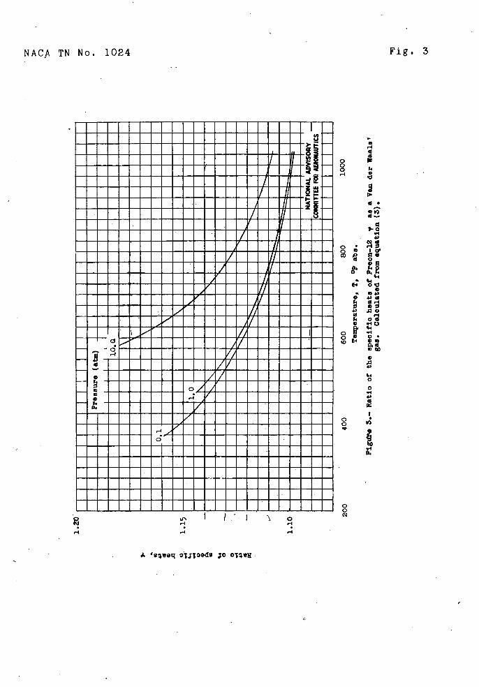
A plot of c,/CV against temperature at pressures of 0.1, 1, end l0 atmos pheres is shown in figure 3.
VELOCITY OF SOUND
The velocity of sound in Freon-12 as a Van der Waals gas was calculated over a range of temperature at p res-sures of 0.1, 1, and 10 atmospheres as fo1los:
From page 318 of reference 3,
a2
= -___
(Lv)
os
Also
(àç
P
- Gs"àT) T)
p P- T
Q S (ài (às'\ - Cv
-
and, from p =.
m V2 àT)0

NACA TN No. 102L
7
When the foregoing equations are combined,
(2\ - T
S cv (o',
V2y ()
(5) (a V\ m
Substitution inequation (5) for and
from equstion (1) results in
2a'b' a' 2
2 J'y v-
V- b'(6)
Values of a, calculated from equation (6), are plotted in figure Li.. The velocity of sound in Freon-12 at room temperature and at pressures of 0.1 and 1 atmosphere was also measured. (See fig. L.) The measurements were made by use of a Helmholtz resonator and were in agreement with the calculated values to better than 0.5 percent, which was the experimental accuracy of the measurements.
Heat-capacity lag. - The time lag of the vibrational heat capacity of Freon-12 was determined by the methods used in references 5 and 6. The sample consisted of a 145-pound bottle of the commercial liquid, which was sufficient-for all the tests. The gas analysis submitted by the manufacturer of this samp le showed that impurities were present to less than 0.1 percent. After the Freon-12

8 NACA TN No. 102t1
g is was evaporated into the test apparatus, data were taken at various sets of conditions and the total-head defects obtained are plotted in figure 5. The defects shown are small and vary almost inversely as the diameter of the imp act, tube, which is the case for a gas with a very snort relaxation time. (See references 5 and 6.)
In order to establish further the rela y atioh time
as short, a nozzle 2 inches long was substituted for
the 12--inch nozzle and the defects were found to remain
the same. The total-head defects remained almost constant with a chan.e in tem;erature. Also, the addition of b percent water, 5 percent air, and 1.5 per-cent alcohol into the r,.-as had but little effect on the defects obtained, the effect being to slightly reduce: the total-heso (letects. A very rapid ad . ustment or the vibrational heat capacity . of Freon-12 with a sudden change in temperature was thus indicated; The relaxation times calculated from a few of the coint.s in figure 5 are of the order of 2 X 1O second (at atmospheric pressure), if all the vibrational beat capacity is assumed to adjust with a single relaxation time.
Other_pronerties.-Jalues of the vapor pressure of Freon-12 were calculated over a range of temperature from the following formula taken from reference 2
log p = 3),.5l23 - ll6.5T' - 10.959 log T + 0.007175T () 71
where
2O.l < T < 38L,.6°
The values of p calculated are plotted in atmospheres in figure 6. The data in the following table of viscosity and thermal conductivity at a pressure of 1 atmosphere for Freon-_12 can he obtained from reference 1, pages 790 and 959, espectiveIy. The Prend.tl number for Freon-12 is useful in p roblems involving heat transfer and in problems involving viscous comoTessihle flow, such as the flow In a compressible boundary layer. The following values of the Prandtl number for Freon-12 have been

NACA TIT Nc. 1024
calculated for, a pressure Of I atmosnhere and are pre- sented along with,viscosity and thermal conductivity in comparison with a few of those of air:
Temper- Thermal Prandtl number
atireI°F abs.)
Viscosity, (slug/ft-sec)
conductivity, k Btu/( sec)(sq t)(°F/ft =
(nondimensional)
AirFreon-12 Air Freon-12 Air Freon-12
02 ----------- 2.13 x1'D ------------ ----------
49 3.61 x 10 7 2.1414 o.38q x ic -S 0.133 10 0.717 0.825 502 --------------2.7L. ------------- .170 .751 672 1)4 .55 3.03 .508 222 .6 1 .706 762 -------------060
aUnits of k are in ft-lb rather than in J3tu in order to make n.ondimensional.
The latent heats of vap orization of Freon-12 are given in reference-7-
DIFJCVSSTON OF PR0?l'RTIES OF FFEON-12
The emrirical constants a' and b' in Van der Waals' equation of state (equation (1)) are corrections for the attractions between olecules and for the size of the molecules, which are oath zero in the equation of state for a nerfect gas. These ,rooerties of Freon-12 cause it to depart from a .oerfect gas by only a small ampunt at pressures below 1 atmoschere arid at ordinary temperatures. The departure from a aerfect gas is of the order of 1 ijercent at atmospoeric conditions and, for a given temperature, varies aoproxia.ate.ly as 'the Pressure. The density of Freon-12 at pressures of 1 atmosphere and 70° F' is 000b L5 slug per cubic foot where F = LL11.5 foot-pounds per slug per °F andDV
R'T = from figure 1. This density is more than
four tires that of air.
a -i

10 NACA TN No. 1024
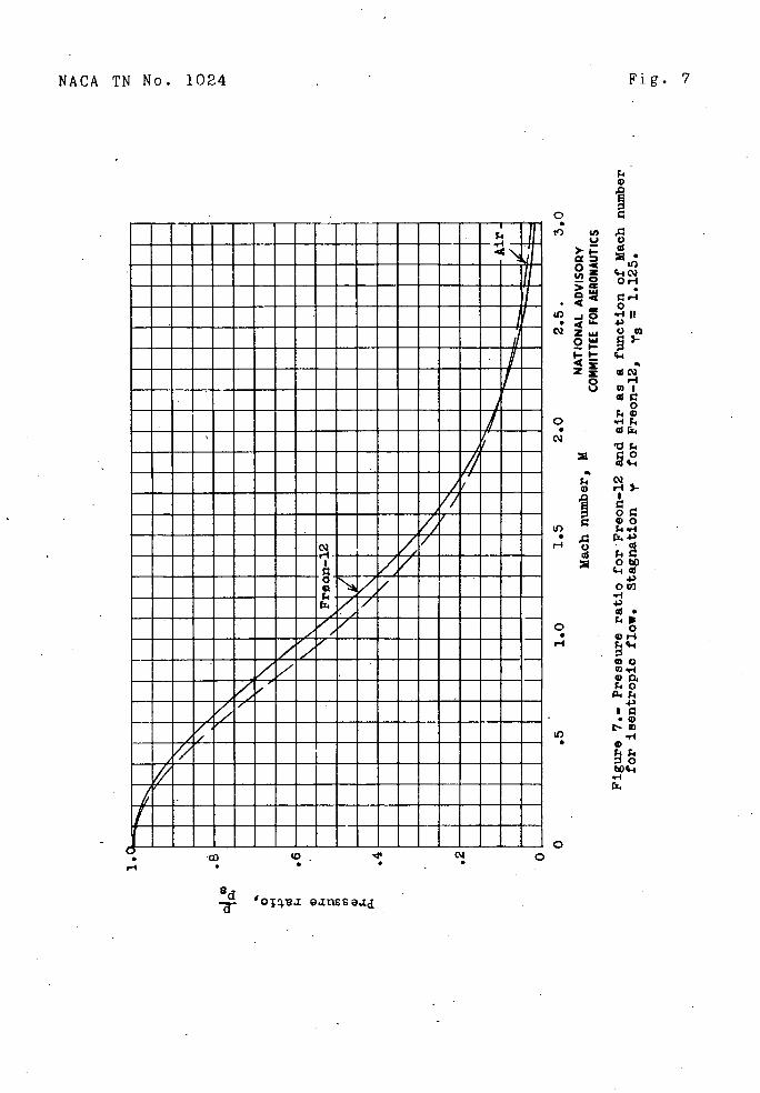
The values of c/R for Freon-12 (fig. 2) are much higher than those for air, which results in noticeably lower values of. '. The value of y for Freon-12, as may be seen in figure 3,at'orñial con- ditions is about 1.13 as com p ared with 1.41 for air. Since any of the aerodynamic relationshi p s are func-tions of y, these relationshins for 117 reon-12 would be expected to be somewhat different from the relationships for air. In order to compare so- ,e of these aerodynamic relationships for E--reon-12 v.ith those for 1ots of p/p 5 5 T/T5 , and mass flow per unit area are oresentd in nondimensional form as functions of the local Mach number in figures 7, 8, and 9, respectively. These relations were obtained from compressible-fluid theory
-
T+T by use of values of y corresponding, to . The
2 results in figures 7 and. 9, however, are approximately the same as the results obtained when y is treated as constant end equal to 1.125.
The difference between T/T 3 for Freon-12 and air is largely due to the difference in 'y (fig. 8) Little difference can he seen between the values of n/n 5 for Freon-12 and for air in fIgure 7 and. between the values of mass f1or ner u:nit area- for Freon-12 and for air in fl. ure 9 up to a bh ac number of 1.5. The large differ- ence between the curves for air and Freon-12 in figure 8 will become noticeable In tests of rotating turbines or comp ressors in which simulation of the Mach numbers entering both the rotors and stators will not he possible. Tn aerodynamic tests-of nonrotati.ng systems, however, it can he seen from figure 9 t.ht Bach numbers may he closely simulated at all points below Mach numbers of lii.
The effect of the differences shown in figure 3 on tests of rotatina machinery can best he-ex p lained as follows. If the Bscb. numbe'rs entering the rotor are equal in 7reon-12 and air, the iatio of rotational speeds will he the ratio of the entering velocity ofsound of air and Freon-l2. Because of the temperature changes that take place in the rotor blades, however, the ratio of velocity of sound in air and 1--i-reon-12 leaving the rotor will then no1oner he equal to the ratio of rotational speeds. The Mach numbers entering the rotor and the stator, therefore, cannot be simultaneously simulated.
%_ Y q

NACA TN No. 1024 ' 11
A plot of u2/u12 as a function of Di l for Freon-12
is
presented in figure 10. The calculations were' based on the methods ofreference. 8. Plots of static-pressure and total-l:::'ressure ratios across a. shock wave in 17;reon-12 as a function of Wach 'number are presented in figure 11. In figures 7 to 11, the. deoarture of Freon12 from a perfect gas is assumed to be zero.
The velocity of sound in TTecn-l2 can be seen in figure L. to be less than one-half that in air at standard conditions., This low velocity of sound 'in Freon is largely due' to the low value of F and rartly due to the low value of y. The variation of velocity of sound with pressure at pressures of 1 atmos phere or lower are not large and can be calculated with reasonable accuracy from the equat.on for the velocity of 'sound in a perfe-ct gas, in which F. = 11.5 foot-pounds per slug per 01. In aerodynamic tests, the velocity of sound and the den- sity will change apreciably w.hep small amounts of air are present in the Freon-12. Probably the most convenient method of correct'ns: for this oresence of air is to measure the velocity of sound. The values of y and R for the mixture can be found if the velocity of sound is known, for mixtures of rerfect gases, as follows
am2 = çFT
Rm = Fairx + Rp 0 (l -. x)
(-CPF')m
/ \-1
where
c c,- x+•c (1-x) Pm "air Freon

12 NACA TN No. 1024
The short relaxation time measured in Preon-12 means that this gas will adjust its vibrational heat capacity to a change in temperature rapidly enough to allon no important dissloations to occur in most engineering apolications. The relaxation time has been measured at atmospheric tressure and it will increase as the tempera-ture and 'pressure are lowered. (see references 5 and 6.) If a comoression takes place within a distance of 0.10 inch
h at . a Mac number of 2 in Freon-12 at a pressure of 1 atmos-phere, the com p ression time would be 1000 times longer than the relaxation time. 9onditions inside a shock wave will be altered. because of heat-cacacity lag. In narticular, the thickness of the shock wave wil1 be increased (to the order of 0.001 in. at 0.1 atm. pressure). if the boundary-layer thickness were of this order, it is p ossible that changes in the boundary-layer separation effects due to shocks would be noticeable. A discussion of the effects of heat-canacity la g on shock waves i. s presented in reference 9.
In order to determine the possibilities that ITreon.-12 will condense at the low temoeratures encountered from adiabatic exp ansion to high Mach numbers, calculations have been made and are presented in fi gure 12. Ourves are given for a stagnation temperature of 5500 F absolute and vanj.ous stagnation pressures. As can be seen from figure 12, Freon12 will remain a gas to Mach numbers of 3 or more, depending upon the stagnation pressure, for the stagnation temperature shown. In figure 12, the departure of Freon-12 from a perfect gas is assumed equal to zero.. .
CO NC LUDI N BEMAFF S
Various thermodynamic nroerties of Freon-12 have been presented, in order to determine the possibilities of Freon-12 as a fluid for aerodynamic testing. The velocity of sound in Freon-12 i. s less than one-half that in air and. the density of Freon is approximately four times that of air. The value of the ratio of specific heats ' for Freon-12 is lower than that for air but the effect of this lower value cif or Freon-12 is shown to he small at Mach numbers less than iii.. In rotating machinery, however, the acb. numbers in rotating and stationary coordinates cannot be sim.ul-taneouslysiriulated in Freon-12 and in air. Freon-12

NACA TN No. 1024
13
does not depart markedly from a perfect gas at pressures of 1 atmosphere and lower and will not condense at normal conditions up to a Mach number of 3.
The time lag of the vibrational heat capacity of Freon-12 to a change in temperature is so short that no imp ortant energy dissimatlon should occur as a result of this lag in most engineerincç a pp 1icatyons.
Freon-12 must necessarily be used in a closed system and the presence of small smou' ts of air will noticeably change the velocity of send so that measure-ments of the velocity of sound would be necessary for a reasonably accurate 'knowledge of the working fluid.
In ener5l, the properties of Freon-12 are such that interpretation of aerodmamic tests using this fluid in terms of similar tests using air seems possible. An actual comparison of aerodynamic data-obtained from tests using air with data obtained from tests using Freon-12 will he necessary to establish this relationship.
Langley 1V ei-rorial Aeronautical Laboratory National Advisory Committee for Aeronautics
Langley Field, Va., Dacember 7, 1945

iL FACA TN No. 102L
RE -T EE RE NOES
1. Perry, John F. ChemIcal Engineers Handbook. Second ed., McGraw-Hill Book Co., Inc., 19)i.
2. Tables annuelles de constantes et donr!e'es numriques. Vol. xi, secs. i, iL., no. 6, Bermann & Ole (Paris), 1937;
Jorissen,. W. P., and van Keelc.em, 1P. C. Tension de vapeur - tempratui'es d'.bu]lition. 1-19.
Keesom, W. P. , van Santen, J. J. M. , and. H.aantjes, J.: Lois des gaz. P. i..-6,
. Epstein, Paul S.: Textbook of Thermodynamics. John Wiley & Sons, Inc., 197.
L. Eucken, A. and Bertrsni, A. Die Ermittelun,c., der Meiwrme etniger Gase bei tiefen Temperaturen ndch der Var1ie lei t1ahiets ethode Zeitscr-ir f. phys. Chem., Abt. .B, Bd. 31, r. 5, Feb. 1961 0. 36.
5. Kantrowitz, Arthur: Effects of Heat-Capacity Lag in Gas Dynamics. NACA AFF. No. 1-A22, ii±L. Classifi- cation canceled June 19).5.
6. iant'owitz, Arthur, and Fuher, Paul . : Heat-Canacit La in Turbine-working Fluids. 'PT
RB No. LLLE29, 19L.1..
7. McAdams, VBlliam F.: Heat Transmission. Second ed., McGrsw-Hill Book Co., Inc., 19 1 2, p
8. von Ka'rmn, Th.: Compressibility Effects in Aero- dynamics. Jour. Aero. Sc., vol. b, no. 9, July 19L!.l, p. 7-56.
9. Bethe ' H. A., and Teller, B.: Deviations from Thermal Equilibrurn in Shoc.k.Waves. Fee. No. X-117, Ballistic Res. Lab. Aberdeen Proving Ground, l9L1.5.

NACA TN No. 1024
Fig. 1
Q 4..
oCd
o o
Cd
C)
43
Cd
) ) '4 o •
4)
.0 0...-..
00 •
• • r10
l '4)
434)0
.. •4
4) li44 0.
) 4 4) 0
Ci
4)
0.
4-I
4)
-1
uuuuu•uuaumm••a•uaauuiuu•auaua ••iu•••aiaaaaa•a•uau•u••••uuau a•iiaa•uivaa•uuaaaaauauai a uii•imaaiaua•uuua•aa•amuuua. a •aiiu•m•aaiauuauua•uaaauasaa •uiiivauuaauauuua•uuaau••aaa a •uiuia•uu•u•auiaauua••••uaaa uuauum•••iuu•••auuu•muau•. a •ai•aa••••aivaau•auaaam•uu• ••ua•u•uuaaa•uua•uuu•aa• ••ivaauauuuuauuiaaaaauaa• a •uiutu•uuaauuua••u•uuau•aaaauia •uiuivaaaaaaaauuuuuuua•a•aauu•a ••iiiiauaua•aa•au•auaa•u••uuai •uiiiiauaaa•uuuauauau•aau•a•a•a •uiiiii•a•aaa•auuu•uaa•••u••aua
•.lw.u.laa.a....a..aua5.ua.a. aaiiaiauaa•a•iaa•aaaaaaaa•uua •uiuiiiuuauuu•a••uu•auuauaiiaa asiuin•ua•ua•aa•auu•uuuu•aai•a aaiia•u•u•aua•aui•aaaa•uaa•u•a auiiaauaaauua•uu•auuauuam• •Milo a•aaaa•aaaaauaa•uuaaauu
p
•aauuuauaiaaaaaaaa•a wauauuuu•a•u•aaa•uaaau.
uauauau•a••auaauaua•a aumaaaauunuuuauaaa• aaaaauaau•auauaa•uau •aaarnauuuu•aa••uauuuuu
om••uuaaauuuau•aa••auaua•a•• auuaua•••aaumaa•ua•uiaua•uuai• •ua•auauauuuuauauauaauu•a•u•a a!aIualaI!umuulaauauluuuaua:
aj to

c o
0 o o o
a' IZ
to _Jo:
c'J 0
0 0 0
0
co
4). H -
•-.. .E • 10 4.)0
0 4.4 Cd00 0 0 F. U
4)
U, 0 S.i.
o o
E .
0,
CdCD
04' II
0
0,
00
0bo -I
U) U
o . 11 z >
0 0
0 c.. • o o 'I 4) 0
00 9 - '
0 . 0
09
Fig. 2
NACA TN No. 1024
NACA TN No. 1024
Fig. 3
uuuuuuuuuuuuuuuuuimuuu ••uuuuuu••uuuuuuuu•uuiu rnuuu••U•.u...uU.u..'L11u •uuuu•umuuuuuuuu•iu'iiuiu
•uuu•uu•uuuuuuuuurnuiururn •uurnu•uuuauuuuuwiuiia•wu •uuu•uuuuuuuuuuuwuuriiuuiu uu•uu•uu•uuuuuuuriuuriauiu •uuu•uuuuuuuuuumiuuiiuuuu
••uuuuuuuuuu•umauuriuuuuu ••UNUU•UU•UWA•UWIiUlUU
rnuuuauuuuuuuuruuuwiauuurn •l.uu.u...I.P.UUV/....u. •urnuurnuu•uuuu•w/iuuuuuu urnuuauumuuuuuuviuuuuuu •uuuamumrnrnuuuuuuuuumu uumrnusuuuuuuuwiumuuurnu mu •muuuuuuuruuuuurnurn • - uuuuuuuuwiuuuuiumu • rn
• U:
•' •uuumuuuuuzuuuuuuurn• RNUIUU•UU•A1•UUUS•••U •uuuuuuu.uuu.u..rnu. •uuuuuuiuuuuuuuuuu •rnuuuurnmuuuuiuuuuuu rn •uuuuu•urauuuuuuuuuuuu
uuuuuuuu•rnruuuuuuuuuuuuu
•uu•uuu uuum•uuuuuuuuu
•uiuuuu uuuuuuuuuuuuuua
•umuauuuuuuumuuuuuuuuuu
•uu.uuuuuumurnauuuuuum•uu
..u...u..u•uuuu.•uu••...
uuumuuu•uurnummuuuuuuuuurn
uusuuuuuuuiuuuuuuuuumuuu
•uuuuuuumrnuuuuuu•uuuuu
-
-'-4
.I '9t( o;ed ;o OTqvV
r-4
oCd
cr
'-4
)-0 .4
o •
Id
- .I.) • 4,
V 4' .O
4 V
o ' o • o El
ho
C
'.4 0
0 .4 .0
0 0
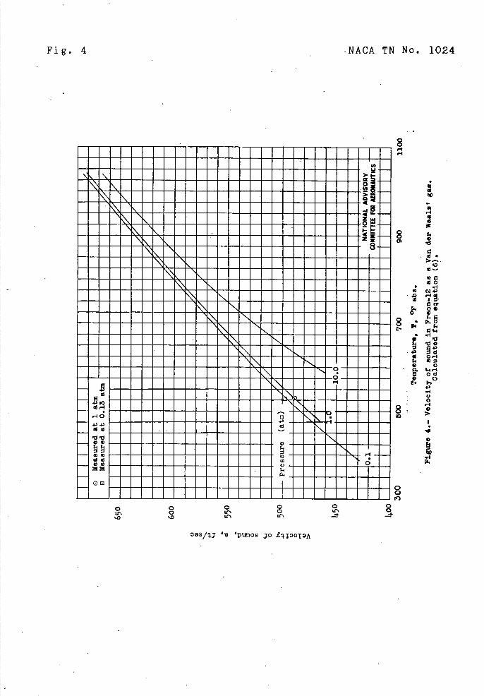
Fig. 4
NACA TN No. 1024
to
II '-I
8 G
0
. ..4
.. ,. D.
r.. 0
8 ,,• i
-' 0
Q 0 43
C) • 0
8 '-I
to -4 I.
••auauuu•uuau•ii•iuiuui•ui
muu•ui•uuuuuu•u•uuuu. •
- ••Li•lUU••UIUU•UUI•Ul••UU 1 II•k••lI••••••UUu•••••. •iliL•••ii•••UU•lURU••i •
_. •uuu••iuu•uaa••••us••u• • iu••uuu•uuiu••u••u••u•uu• •m•uuuu••uiu•u•uuuu•••uuui
NU•ISIIU•••••URU•I•UI•U••U •uuuiu•••uiuuuui••i•i•u •uiiu•u•uuuuuu•iug•uuuam
•...uu•uu•iu•uuu MEMOu.MEN •ua•auuu•uuu•••uuummiu•i•
u •uuuuuuu•u•uiii••u•uu •m•••uuuuu•uuuu••u••u•uuu
8 rq '-I
0 0 0 0 0 Lr. C
10 '0 U'. Lf
S t4)
0 0 0
' 'PtmOs JO L4100TOA

w I-. 0
043
o
c. 0
I4
O4
cd 00
ID
U. 00
0
03 .3 o 0 0 S. • p.
S. .3 .1-)
jII
. '-I
NACA TN No. 1024
Fig. 5
--IA OR
4 -I 4'-z-1
'-I- 4x z 8
4 0 Q C)
r4.-1
CAI 0: 0
I-)O M QQWQ ..-Io CJ0
000. -.
. . g0 0.0 o it) F-I 43 'U)
43 t4
N00000 C)
090000 . . . .
H Id
El -4 D -1
xC 0 0
I)
'ojap p-Toj

IA U
o. IA Z
>
<x
8
0) 4) 01 H C) H 01 C)
Fig. 6
NACA TN No. 1024
0 0 to
0 o IL)
0) I 01 0
0) cz. .s D
4-4--E. 0 • 0)0
0)
0) 4) 0) 01 Qo
0) 0. 0. E
0) O. o E-' 0.4.. o 01
(0
0) 1.
0 0 to
Us 0 H .-I 0
tn ' d 'GJfl9Jd .zodeA
NACA TN No. 1024 Fig. 7
a C
0 •0
o
Al
tO U) . U C) >--.
. to Or
Cr-I
.4 0 U) •.-IuI • 4 43
02 Z LaC) C
2 •'-,-t '4
-
Z Cs) o r-U $
0 40
o • cla
cH4
oC C 00
U) 41 • .0 E.4•3
H cd
0
43 00')
43
o • OH H
CO U) .,4 .I0
43 IC .0
It) • 0 44
0 -, --. - .
ed _a-
'O.I OIId

Fig. 8
NACA TN No. 1024
0 • t')
Ix oo 0
> -
4 0
I— '— 0
Z0
ILI ;4
o • cla
'-10
4 0
. l'* rT4 as
U).-. 43
•
1.-I •j
0 4-4•
cd o •i40 43,—I Cd q4
0 O s-4
o • 434
I—I Cd 4.3
00 P.O g.rI ID
E-'i 0
-0
U) •
0
bo '-4
0 C a c
'0ThZ 9dTU

NACA TN No. 1024
Fig. 9
0
U) o • f-I
S #A Or4 U
)-, H
o..0
q-1
> d U) •
4 _J8
ir-I
W
-- k ,-t I. 4z z •rli
a cd 0 U
o • C-4 CQ
r. q-I
4
U) • OD)
— 40
•rlC) q-4
o o • i-•1
P4
0.-I
'44 0
• IS
o
40
o U)
0
.13 .13 d

c'J
SA
___
• __
0 co U) I4'4
)
U)
U
*
I 4)
o 0
4 • ad o I.
V o o
a, .'•
-4 434 4) 0.4
4r4
Id Q.
i)0.
4) Q .4 .Q o CQ o
'.4 •
.-4
. .10
. 4 • a, p. a,
oc..
o 4)0 '.4
4.) Ow
C,
'-4
Fig. 10
NACA TN No. 1024
Tq 'poq Jo p99dS •E 314T Io qv MOJ peqJnBpun jo .iqtznu tOBy,

NACA TN No. 1024
Fig. 11
Static-pressure ratio,
o 0 0 0 0 0 S • • S
H t) -
us u•iuuu...,au.uu..
•ususu•uuuus•s•swu•uu
uuuusisuuuuuuuvsusu
•uuu•uiiuuuuui•uis
•uuusuuuiuiuiuvsu
••UUUU55I•U••V1•5M5• •uusuuusuuuiriusiuu •.U5UN5ULI55WU5AUU• •.uuuuu.uui.viuuuuu •5U•IUI5U5W1UVAU555 MEEMEEMEMEMMEMEMENIM uuuuuuuuuss,iuuusss. IUU55RU•5!1•ULI55I5 •suuuuuuuuviuuutiusu• MEMENEMMMEMERNME NOON •uuuusuuusuuuuu••uuu •uuusus•usuusuuuu •uuuusuusu•uuuuuus •uuussuuriuuuuuusuu•ss •uuuu•uuriusuuurisuuuu
•uuusuvuuu•uuuiuuusu •.••uurva••u••A&u•uuu •iuuwuuuuuu WINuuu
uuisuuuuuuruusuu iiusiiuuuuu•susuuuu •t. NNEEMENEEMOMMEMENo •raruuuuuuuuuui•su uusuuuuuuuuussiuu •usuuuusu•uuuuuiuu mow,auuuuuuuuuusuiuu U•I4RIU5U•UUUU•••I• •snuup.uuuuuuuuuuuuui• •RFIISSIIIIIIIISII\1I uuiusuusuuuuussuuuuuutu •usuusuuuuusuusu•uuui •s'uuuus•uuuuuusu•uuuuii ••sssuu•uuuusuusuuuuuii •iuuuusuuuuuuuuuiiuu
(0 0) o • • 0 S •
H
p.)
CD
C) • 0
0)
If)
0. 0
• II 0) 4).
0 •rl .
4)0 • 0)
4) 0a.
o • 91 44
C.) Os-I
•0
• i-I 4t
P0
bo It
I.I H.-1
(0 5. 4)4) H
-I I4
S H
C.)
,-1
0

0 .
o 0) U) 0 0 0 •
'-4
wi 4) cd
0 0
\\ U \ '-I-\
-q
CQ LO
-o U)
5-
U) S
U)
I)
0
U) S
c'
0
0 e
C,
U) S
0
'-4
0 4-I
0
00 q-4 4) ar-I
Id as
ri.
00 4iO
4)
Cd
•1-4 0 0-I rl 4)
00 .'-I.
4)
•0•0 00
. r-I 0
tio
0
I4 -
Fig. 12
NACA TN No. 1024