nass solar dc pool pumps · function and display of the solar pump controller: low-voltage...
TRANSCRIPT

Solar Pool Pumps
Page | 1
Head Office 496773 Grey Road 2 Clarksburg, Ontario
Canada, 705-999-2105 www.solardcpumps.com
Technical Data Manual
For NASS Models:
NASS 500
NASS 900
NASS 1200
NASS 2200 X
NASS 2200
JP15-14/600
JP31-19/1000
JP35-22/2000
JP60-13/2200
NASS Solar DC Pool Pumps
NASS JP Type DC Pool Pumps For pumping, circulating, and filling applications for both commercial and residential pool and irrigation purposes

Solar Pool Pumps
Page | 2
Head Office 496773 Grey Road 2 Clarksburg, Ontario
Canada, 705-999-2105 www.solardcpumps.com
Introduction
Congratulations on the purchase of your Solar Pool Pump from North American Solar Solutions.
Solar powered products are environmentally friendly, self-sufficient as well financial benefit to reduce rising electrical
cost. Our product range is designed with durability and reliability in mind to provide trouble free service throughout the
life of the product.
Our Solar Dc Pumps can be used for:
Agriculture
Pool applications
Water pumping needs
Water Fountains
Care and disclaimer
It is recommended that you familiarise yourself with these important instructions. Read the complete manual before
commencing the installation.
Although the solar panel connections are considered low voltage, there is still a possibility of electrical shock. During the
connection stage of the solar panels, it is recommended that the panels be covered with dark cloth or cardboard until
connections are complete and you are ready to carry out voltage tests.
Do not switch the power on unless all connections and voltage readings are correct. The pump leaf basket must be filled
with water before attempting to start the system.
Failure to comply will void warranty

Solar Pool Pumps
Page | 3
Head Office 496773 Grey Road 2 Clarksburg, Ontario
Canada, 705-999-2105 www.solardcpumps.com
Installation Details
Solar photovoltaic panels convert sunlight to electrical energy which is fed to the solar controller. Using MPPT
(Maximum Power Point Tracking) technology, the solar controller maintains constant voltage and converts the single
phase DC to 3 phase DC to power the pumps 3 phase DC motor.
Sizing the solar panel array to suit the system
If you have not purchased a complete system from your Certified Distributer the following formula will be useful. Your
certified distributer will be able to help you with panel selection.
The optimum loaded DC voltage (Vmp) for the solar controller is between 35VDC to 80VDC.
The maximum open circuit voltage (Voc) is 100VDC. CONNECTION OF SOLAR PANELS WITH
TOTAL OPEN CIRCUIT VOLTAGE GREATER THAN 100VDC WILL VOID WARRANTY.
FOR: NASS 500, NASS 750, NASS 1000
TOTAL OPEN CIRCUIT VOLTAGE GREATER THAN 400VDC WILL VOID WARRANTY.
FOR: NASS 2200 &NASS 2200X

Solar Pool Pumps
Page | 4
Head Office 496773 Grey Road 2 Clarksburg, Ontario
Canada, 705-999-2105 www.solardcpumps.com
Solar Panel Requirements:
Recommended Power of PV panels (watts) = Rated power of pump (watts) x 1. 3 ~ 2.0
Example:
One Nass 500 pump Power = 500 watt pump needs a minimum of 500 watts multiplied by 1.3 to maximum 2.0 to drive the DC motor (500w
x 1.3 = Minimum Panel wattage required 650w) Optimum 1,000 Watt
You may need combinations of series and parallel connections of panels, especially for the larger pumps. The required
voltage is achieved by connecting the solar panels in series (series string). The total power requirement (watts) is achieved
by connecting further series strings in parallel.
Panels in series; add the voltage and the wattage of the panels.
Example 2 x 36 volt, 8 Amp 200 watt panels in series becomes a 72 volt 8 Amp 400 watt system.
Panels in parallel; add the current and the wattage of the panels.
Example 2 x 36 volt, 8 Amp 200 watt panels in parallel becomes a 36 volt 16 Amp 400 watt system

Solar Pool Pumps
Page | 5
Head Office 496773 Grey Road 2 Clarksburg, Ontario
Canada, 705-999-2105 www.solardcpumps.com
In the schematic below are the connection details for the pumps available from North American Solar Solutions Pumps
Division.

Solar Pool Pumps
Page | 6
Head Office 496773 Grey Road 2 Clarksburg, Ontario
Canada, 705-999-2105 www.solardcpumps.com
Solar Controller
Function and display of the solar pump controller:
Low-voltage protection (automatic)
Over current protection (automatic)
Control of motor running speed (speed regulator)
MPPT function (Maximum Power Point Tracking)
The row of LED’s at the top of the controller have the following meanings
L.E.D. Operation Explanation
Power Solar Power Green – Power is within specification
Pump Running Green - Pump Running condition starts 6 seconds after Power L.E.D
status is Green
MPPT Maximum Power Point
Tracking
Green – The Controller is calculating the MPPT
Well Water available When using for water pumping to reservoir use sensor to sensor if
water is available. If using for pool pumping connect bridge between
WC & WH. Led must be lid else pump doesn’t start.
TANK Identifies if reservoir is
full
When pumping to reservoir and level sensing is required connect
sensor to TC & TH. Light will lid when reservoir is full.

Solar Pool Pumps
Page | 7
Head Office 496773 Grey Road 2 Clarksburg, Ontario
Canada, 705-999-2105 www.solardcpumps.com
Pool connections using Existing AC Pump

Solar Pool Pumps
Page | 8
Head Office 496773 Grey Road 2 Clarksburg, Ontario
Canada, 705-999-2105 www.solardcpumps.com
Testing the pump
Once all connections to controller and the pump are complete, and voltages and polarity have been confirmed, FILL
LEAF BASKET reservoir with water then the pump can be started:
1. Switch Internal controller switch ON
The pump has a “soft start function” and will start slowly after 6 seconds and then spin up to full speed within the next 6
seconds.
NOTE: Looking at the motor from the back (fan) the motor should spin clockwise.
If not, turn power off, swap the wires on U and V, turn power on and check again. Do not allow the pump to rotate
anticlockwise or the pump and / or motor will be damaged and warranty will be void. If the motor continues to spin
backwards, turn everything off and call for service advice.
NOTE: Once installation is complete the internal ON/OFF switch will remain ON and the isolator will be used as
the main ON/OFF switch.
Do’s and don’ts
Do be careful with wiring
Do put your solar PV panels in a sunny position facing true north (southern hemisphere) or true south (northern
hemisphere). For best results tilt the panels at an angle equal to your latitude.
Don’t run the pump dry, even momentarily, as warranty will be void.
Don’t use the pump in dirty and or contaminated water. Premature wear will not be covered by warranty.
Don’t disassemble the controller. There are no user parts inside.
Do’s Strainer basket to be cleaned to prevent the pump from water starvation
Do’s Install spark arrestor for high voltage spike
Do’s Install appropriate AC breakers for panels & battery bank
Solar Pool Pumps
Page | 9
Head Office 496773 Grey Road 2 Clarksburg, Ontario
Canada, 705-999-2105 www.solardcpumps.com
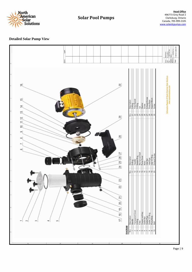
Detailed Solar Pump View

Solar Pool Pumps
Page | 10
Head Office 496773 Grey Road 2 Clarksburg, Ontario
Canada, 705-999-2105 www.solardcpumps.com
Solar Pool Pumps
Page | 11
Head Office 496773 Grey Road 2 Clarksburg, Ontario
Canada, 705-999-2105 www.solardcpumps.com

Solar Pool Pumps
Page | 12
Head Office 496773 Grey Road 2 Clarksburg, Ontario
Canada, 705-999-2105 www.solardcpumps.com

Solar Pool Pumps
Page | 13
Head Office 496773 Grey Road 2 Clarksburg, Ontario
Canada, 705-999-2105 www.solardcpumps.com
5. TROUBLE SHOOTING
Problem Possible solution
System light off
1.Verify voltage input
2. Turn power switch on
3. Check if all connections are correct.
4. It is during 30mins delay after water level sensor
protection from low water level in well. Please restart the
switch on/off on controller.
Water level in tower is lower
than “TH” sensor, but the
indicator light of “TANK_F”
lights on.
1. Disconnect “TH” wiring terminal and “TC” wiring
terminal. Then if “TANK_F” lights off, it means the
problem may be caused by short circuit of the water level
sensors. Please change the water level sensors.
2. Please check if there is any other metal material in tank
that is lower than TH sensor. If yes, remove the metal
material.
3. If “TANK_F” still lights on, please contact with your
supplier.
Water level in well is higher
than “WH” sensor, but the
indicator light of “WELL_L”
lights off.
1. Connect “WH” wiring terminal and “WC” wiring
terminal directly with a piece of wire to get a short circuit.
Then if “WELL_L” lights on, it means the problem may be
caused by open circuit of the water level sensors. Please
change the water level sensors.
2. If “WELL_L” still lights off, please contact with your
supplier.
The indicator lights flicker
continuously, and water pump
does not run normally
It may be caused by the low input voltage.
2. Please increase the input voltage.
3. If the lights still flicker, please contact with your
supplier.

Solar Pool Pumps
Page | 14
Head Office 496773 Grey Road 2 Clarksburg, Ontario
Canada, 705-999-2105 www.solardcpumps.com
Customer record card
Name
Address
Tel
Model number
Date of purchase
Limited 3 year Warranty
1. The manufacturer extends only to the original consumer purchaser a limited warranty against defects in material
and workmanship for a period of three years from the date of purchase. This warranty covers the pump &
controller , not including standard wear parts as seals, rotor and standard wear parts
2. The manufacturer or authorized factory representative will repair, or at its option replace any defective part or
parts of the product free of charge. In the event of a malfunction the purchaser must return the product to an
authorized distributer/dealer/agent at their expense. The warranty is limited to the repair or replacement of the
product and the manufacturer or it dealers disclaim all liability for indirect and or consequential damages such as
any installation charges.
3. Electronic parts have standard a 1 year limited warranty, fuse and spark arrester most be installed and proven to
be covered under the warranty program. The warranty does not apply when the equipment has not been installed
as per the instructions or damage has occurred through abuse, carelessness, improper installation, accident of
mishandling , connecting to an improper voltage or it has been serviced by anyone other than an authorized
factory representative.
4. A purchase receipt or invoice for proof of purchase must be presented to claim warranty.
5. All repairs not covered by warranty or outside the warranty period will be charged at normal rates.